
Locating hosts by TULIP (Trilateration Utility for Locating IP hosts)
Upload
trinhkhanhCategory
view
213download
0
Instruction Manual
MORSØ Notch Cutting Machine
Model NEH - NLEH Distributed in the US exclusively by:
Hoffmann Machine Company, Inc. 1386 Drexel Road Valdese, NC 28690 Toll-free technical support: 866 – 248 – 0100 e-mail: [email protected] website: www.Hoffmann-USA.com

Instructions Manual MORSØ Notch Cutting Machine Type NEH
Contents 0-1
Introduction page A-1 Work Piece Shortening of the work piece on a circular saw before cutting page B-1 Functional Description General description page C-1 Machine description page C-2 Description of the hydraulic system page C-3 Description of the electric equipment page C-4 Description of cutting page C-5 Technical Data page D-1 Mounting Instructions General page E-1 Mounting of table extension and fences page E-1 Operating Instructions Operating devices page F-1 Before starting page F-2 Adjustment of the cock-bead stops page F-3 Adjustment of sensors of the cock-bead stops page F-3.1 Adjustment of the centre stop page F-4 Adjustment of flip stops page F-5 Adjustment of clamping cylinders page F-6 Working procedure page F-7 After working procedure page F-7 Cutting of bars with rebate Description page G-1
Instructions Manual MORSØ Notch Cutting Machine Type NEH
Contents 0-2
Service References Lubrication instructions page H-1 Change of hydraulic oil page H-2 Cleaning page H-3 Changing of knives and chip breakers - adjustment page H-4 Grinding of knives page H-5 Adjustment of length of stroke of the knife block page H-6 Locating Faults / Methods for Repair page I-1 Safety Safety devices page J-1 Regulations page J-1 Index of Spare Parts Survey page K-1 Machine page K-2 Knife block page K-3 Hydraulic equipment page K-4 Hydraulic unit page K-4-1 Hydraulic cylinder page K-4-2 Electric equipment page K-5 Control page K-5-1 Clamping cylinders page K-6 Supplement Hydraulic diagram page L-1 Electric diagram page L-2-1 to page L-2-6

Instructions Manual MORSØ Notch Cutting Machine Type NEH
Introduction A-1
We recommend to read this instruction manual carefully before the machine is started up for the first time. Defects on the machine provably arson due to mistakes in operation will not be covered by the warranty. Use of the Instruction Manual: In this instruction manual all information needed for using all possibilities of the MORSØ-guillotine is found. (see picture A-1-1) (1) Head Lines Refers to the headline of the chapter. (2) Index of pages The letter is the description of the chapter. The figure is the consecutive page number in the (3) Text The texts belonging to the chapter in which you will find all information and explanations necessary. (4) Illustration Drawing to the text in (3).

Instructions Manual MORSØ Notch Cutting Machine Type NEH
WORK PIECE B-1
Shortening of work piece on a circular saw before cutting Before the cutting of the work piece it must be shortened in the correct length on a circular saw. It is very important that the saw blade is exactly adjusted in 90° proportional to the machine table (see fig. 1). The blade must also be exactly adjusted in 90° proportional to the fence (see fig. 2). If this adjustment is not correct on there will be a gap in the finished joints.
Fig. 1
Fig. 2
Instructions Manual MORSØ Notch Cutting Machine Type NEH
Functional Description C-1
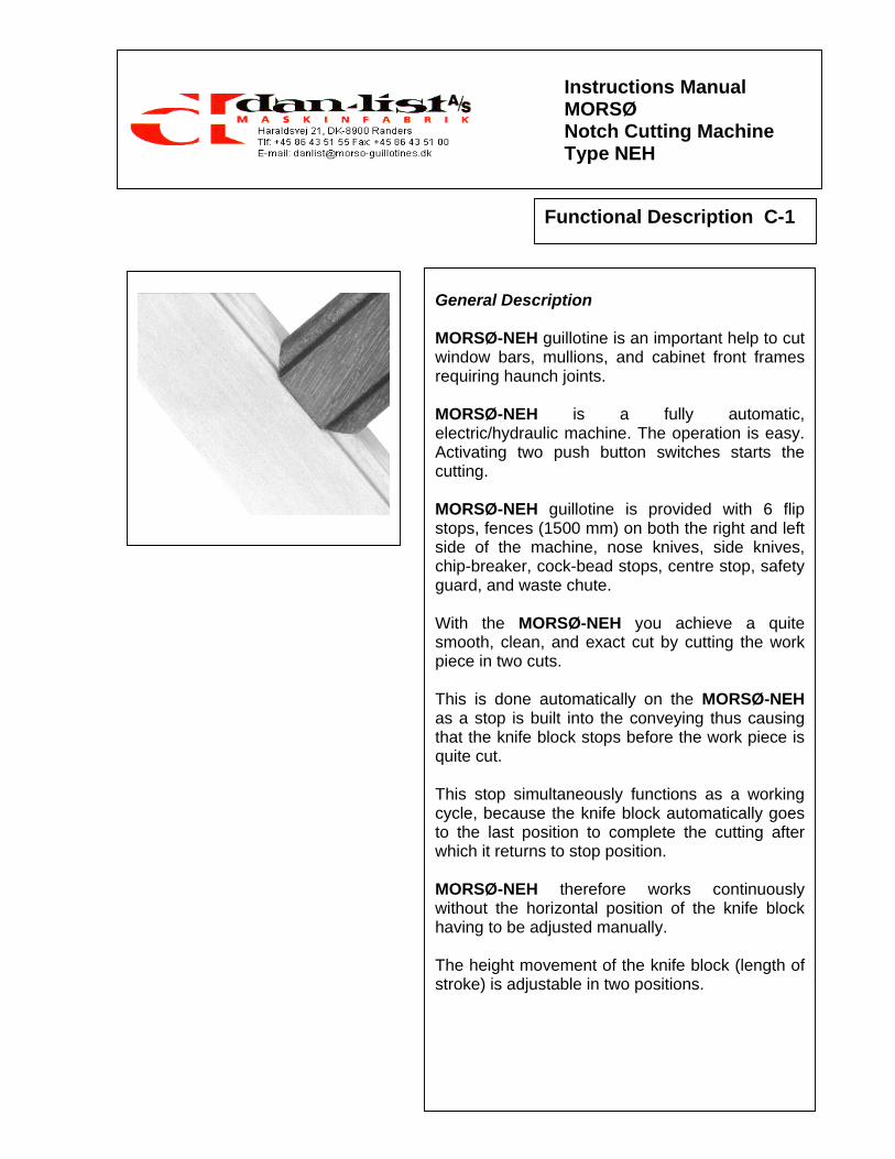
General Description MORSØ-NEH guillotine is an important help to cut window bars, mullions, and cabinet front frames requiring haunch joints. MORSØ-NEH is a fully automatic, electric/hydraulic machine. The operation is easy. Activating two push button switches starts the cutting. MORSØ-NEH guillotine is provided with 6 flip stops, fences (1500 mm) on both the right and left side of the machine, nose knives, side knives, chip-breaker, cock-bead stops, centre stop, safety guard, and waste chute. With the MORSØ-NEH you achieve a quite smooth, clean, and exact cut by cutting the work piece in two cuts. This is done automatically on the MORSØ-NEH as a stop is built into the conveying thus causing that the knife block stops before the work piece is quite cut. This stop simultaneously functions as a working cycle, because the knife block automatically goes to the last position to complete the cutting after which it returns to stop position. MORSØ-NEH therefore works continuously without the horizontal position of the knife block having to be adjusted manually. The height movement of the knife block (length of stroke) is adjustable in two positions.

Instructions Manual MORSØ Notch Cutting Machine Type NEH
Functional Description C-2
Machine Description The MORSØ-NEH is constructed as a compact machine with a solid dimensioned frame (1), with built in hydraulic system (2) and electric equip-ment (3). The cutting function (4) is placed on top of the machine. In the slide frame (5) fitted at the cross (6) the knife block (7) is moved up and down. The cross (6) runs in the guidings of the table. The knives (8) fitted on the knife block cut the work piece. Hydraulic cylinders draw the conveying and the knife block. The work piece is placed on the table (9) against the fence (10). The cock-bead stops (11) are adjusted to the required cutting depth. The clamping cylinders (12) are adjusted to the width of the work piece. The clamping cylinders are fitted direct on the table. The adjustment of the flip stops (13) is done by means of a template of the work piece. The waste is falling via a slide (cover of the hydraulic system) on the floor or in a waste receiver. MORSØ-NLEH can be fitted with nose knives from 12 to 26 mm MORSØ-NSEH can be fitted with nose knives from 6 to 20 mm,

Instructions Manual MORSØ Notch Cutting Machine Type NEH
Functional Description C-3
Description of the Hydraulic System All automatic movements are carried out by means of the hydraulic system. All the functions of the hydraulic system are ad-justed from the factory. This must not be changed as it can lead to disturbances in the process. The hydraulic system is always working. After starting the machine, wait about 10 seconds before the cutting is started. During this period the oil pressure for the process is built up. The hydraulic pump (2) driven by an electric motor (1) gives the hydraulic pressure necessary to be used in the hydraulic cylinders (3), (4) + (5) for the conveying and the movements of the knife block and clamping cylinders. The hydraulic pump (2) draws the oil through a suction filter out of the tank (7) and to the valves. After the pulse release the electronic control regu-lates the opening and the closing, respectively, of the valves (8) so that the controlled cylinders are provided with oil. The oil that is not used for the process goes back to the tank through the return filter (9). WARNING The built in hydraulic system must not be covered up and must be kept free of waste as these things can cause extreme heating resulting in the worst damages.

Instructions Manual MORSØ Notch Cutting Machine Type NEH
Functional Description C-4
Description of the Electric Equipment All process sequences are controlled after a manual release of the control system (1). With the pushbutton switches (3) + (4) the ma-chine is switched on and off, respectively. At the same time while the machine is switched on the motor of the hydraulic pump starts via a relay (14) and the control (13) is ready for start. The voltage for the specific functions is adapted in the transformer (16). The motor for the hydraulic system is protected with a thermo relay (15) against overload. Fine fuses (17) protect the control (13) and the working relays (18). By adjusting the machine you have the possibility to disconnect specific conveying sequences of the process. The current for the clamping cylinders is controlled by the switch (2). The length of stroke of the knife block is controlled by the switch (19) The conveying of the slide frame unit is controlled by adjustment of length stop and cutting depth. Pushbutton switches (5) + (6): Simultaneous activating: The cutting process is started. Separate activating: Stepless horizontal movement of the knife block forwards and backwards, respectively. Inductive tracers (7), (8), (9), (10) limit all stop positions.

Instructions Manual MORSØ Notch Cutting Machine Type NEH
Functional Description C-5
Description of cutting Adjustment before cutting: The knife block (1) is in top position. The clamping cylinders (2) are adjusted manually 5 – 6 mm from the work piece. A) Automatic cutting - cycle for work pieces (2 cuts) The knife block (1) is in front position. Switching contact (11) is in position “0”. Switching contact (12) is in position “ON” (the clamping cylinders (2) are activated). By activating pushbutton switches (3) + (4) (two-hand-operation) the clamping cylinders (2) press the work piece against the fences (7) + (8) and two cuts are made (the last cut is a so-called trim-cut). Conveying cylinder (5): horizontal movement (forward and backward) of the slide frame part (6). Hydraulic cylinder (9): Vertical movement (cutting function) of the knife block (1). If you during cutting require bringing the knife block backwards and releasing the clamping cylinders (2), the pushbutton switch (3) is activated separately. B) Automatic cutting with smaller length of stroke of the knife block (1). The length of stroke can be adjusted in two fixed positions with switching contact (10) according to the height of the work piece. Thus you avoid a too long vertical movement of the knife block. The cutting cycle remains the same as at the automatic cutting.

Instructions Manual MORSØ Notch Cutting Machine Type NEH
Technical Data D-1
Machine Dimensions (max.): Length (a) : 3700 mm Width (b) : 510 mm Height (c) : 1150 mm Weight : 145 kg Placing Measures: Spaciousness to Wall min. : 1000 mm Hydraulics : Motor : 1,1 kW Capacity of Pump : 7 l/min. Working Pressure : 80 bar Power Transmission : 660 kg Tank Contents : 8 l Noise/Pollution: Noise Level : below 70 dBA Pollution : none/dustfree Working Capacity: Nose widths (NSEH) : 6 - 20 mm Nose widths (NLEH) : 12 - 26 mm Working Width (max.) : 70 mm Working Height (max.) : 140 mm Extension tables (right and left) : 1000 mm Fences (right and left) : 1500 mm

Instructions Manual MORSØ Notch Cutting Machine Type NEH
Mounting Instructions E-1
In General The machine is delivered ready for start and complete with standard equipment. Only the table extensions (1) and fences (2) are dismounted during transport. NOTE before starting up first time: Remove the locking pin in the machine table (marked with a yellow/black wing). Placing according to the spaciousness to wall stated in D-1. Electric connection: We recommend electric connection with earth conductor. At three-phase electric connection the knife block must go into top position within a few seconds. If not, the machine is disconnected immediately, as the motor is running the wrong way. Control before each start that all protection devices are fitted correctly. Fitting of the Table Extensions and Fences (The drawing shows the fitting of extension table and fence from the right side of the machine. The same procedure is used for the left side.) Before fitting the table extension (1) the end of the table extension and the table must be cleaned very thoroughly. Special attention must be paid to the pin and screw holes, as the smallest amount of dirt will prevent the correct alignment. After the cleaning the table extension is pressed against the table so that the pins placed in the table extension are inserted in the pinholes in the table. The included screw is now inserted in the screw hole and fastened with a standard screwdriver. The fence (2) is fitted on the table extension (pins are fitted in the table extensions). It is fastened with cylinder screw. (Extra extension table and supporting leg can be delivered as accessories).

Instructions Manual MORSØ Notch Cutting Machine Type NEH
Operating Instructions F-1
Operating Devices 1 = Start Switch (green) Switches the machine on (the hydraulic pump and the control start) 2 = Control Lamp (green) The machine is started 3 = Switch (red) Switches the machine off (the hydraulic pump and the control stop) 4 = Switch (2 steps) Pre-selection of the length of stroke of the knife block Position 1 = shortest length of stroke Position 2 = full length of stroke 5 = Switch Position 0 = the automatic conveying is in- active Position 1 = the automatic conveying is active 6 = Switch
Position OFF: Clamping cylinders disconnected.
Position ON: Clamping cylinders connected 7 = Pushbutton Switch single-hand operation: switch (6) OFF = clamping cylinders are released conveying backwards two-hand operation = starting of cutting process 8 = Pushbutton Switch single-hand operation: switch (6) ON = clamping cylinders are fastened conveying forward two-hand operation: = starting of cutting process 9 = Tightening Lever - fastens the left moulding clamp 10 = Tightening Lever - fastens the right moulding clamp 11 = Flip Stop 12 = Hand Wheel - fastens the guard over the knife block

Instructions Manual MORSØ Notch Cutting Machine Type NEH
Operating Instructions F-2
Before Starting Before starting the machine the following must be checked and adjusted: 1. Check a) electric connection electric wire (1)
OBS: At three-phase electric connection the knife block must go into top position within a few seconds. If not, the direction of rotation of the motor must be turned (the phases are turned).
b) Hydraulics oil level in the tank (2)
(the oil must be between the two markings on the oil level glass)
hoses, pipes, and cylinders for leakage. c) knives (3) general condition - sharpness d) waste - room for waste e) safety devices fitting of all safety devices: safety guard for knives (4) f) table and table extension cleanness and undamaged surface 2. Adjustments: a) Cock-bead stops (5) (adjustment instructions page F-3) b) centre stop (6) (adjustment instructions page F-4) c) flip stops (7) (adjustment instructions page F-5) d) Switch for Length of Stroke (8) (adjustment instructions page H-6)
e) Clamping cylinders (9) (adjustment instructions page F-6)

Instructions Manual MORSØ Notch Cutting Machine Type NEH
Operating Instructions F-3
Adjustment of the cock-bead stops The cock-bead stops (1) are adjusted as follows: 1. Loosen the Allen screws on the cock-bead
stops (1) and move these to rear of the sliding guide.
2. Using a test piece (2) make a notch cut into
the cock-bead. This cut must be the same depth as the cock-bead. The overall width must be equal to the width of the centre cross-rail. When you are satisfied the two sizes are equal, we can now position the cock-bead stops (1).
3. The switch (4) must be in position 1. Activate
push buttons (5) + (6) in order to bring the knife block in bottom position. Activate push button (5) to bring the knife block (3) forward into the previously cut notch. Position the cock-bead stops (1) against the cock-bead and lock them in place using the Allen screws. When these stops are fixed in position the knife block (3) can only cut into the cock-bead as far as this setting. The notch cut depth is then referenced from the face of the cock-bead. The width of stile can vary without changing this setting.
4. To have the knife block go into top position
turn switch (4) into position 0. 5. Check the alignment of the two cock-bead
stops (1) using a straight edge. By bringing the knife block (3) forward, check that they are level and true with the fence.
6. Lock the second Allen screws on the cock-
bead stops (1). 7. This setting will allow you to make regularly
accurate notch cuts in the stiles. These stops will need no further adjustment unless the size of the cock-bead changes.

Instructions Manual MORSØ Notch Cutting Machine Type NEH
Operating Instructions F-3.1
Adjustment of the sensor in the cock-bead stops The sensor (2) causes that the machine automatically does two cuts. If this is not the case the sensor (2) is either wrongly adjusted or broke. The sensor (2) is adjusted in the following way: 1. Start the machine 2. Loosen screw (3) and press the wire for the
sensor (2) 1 – 1.5 mm inwards. With a light pressure on the axle (4) for the sensor with a finger the sensor gives a red light immediately. When the pressure is removed, the sensor (2) must stop giving the red light. Fasten screw (3) again.
3. If the sensor (2) does not react as described
under paragraph 2, the procedure is repeated until the correct reaction of the sensor (2) is achieved.

Instructions Manual MORSØ Notch Cutting Machine Type NEH
Operating Instructions F-4
Adjustment of the centre stop The centre stop regulates the amount of material cut from the corners of the cross-rails. The centre stop is adjusted as follows: 1. The adjustment screws (1) are located in each
side of the Teflon head (3) on the centre stop (2). They can be turned in or out, to allow more or less material to be cut from the corner of the cross-rail. The adjustment screws (1) are adjusted exactly equal on both sides so that the distance from the screw head to the centre of the Teflon piece (3) is equal Example: Nose width 12 mm: The width of the Teflon piece (3) is measured. The screws (1) are adjusted exactly equal on both sides, so that the distance from the screw head to the centre of the Teflon piece (3) is 6 mm.
2. You can make minor adjustments if the width of the cross rail should vary (e.g. 11.9 or 12.2 mm instead of 12 mm). Make a 45° cut in a test piece on the cross-rail and offer it up to the notch cut already made in the test stile (see page F-3). If there is a gap in either of the two corners, adjustments can be made on the screws until an exact and tight joint is achieved.
3. To achieve this balance, take a test piece of
centre-rail and cut one corner (4). Turn the centre-rail to the opposite side of the knife block up side down so that you cut in the same corner. Place it against the centre stop and make another cut. If this causes a fine cut or the knives do not touch the centre-rail, the two screws are not balanced with each other. The adjustment screws are balanced until the cut is correct. It is particularly important to get this balance, when frames are made with single cock-beads on top and bottom rails. If the two corners are not taken off exactly equal, there will be a gap on one corner and an over-tight joint on the other. This will also produce frames that are not square.

Instructions Manual MORSØ Notch Cutting Machine Type NEH
Operating Instructions F-5
Adjustment of the flip-stops Making a Template For setting the flip stop positions a template of the stile (upright section) is made. Mark the centre of the positions on the cross-rails, incl. the top and bottom rails (see fig. 2) on the stile. 1. To make the template, put the stile in the
machine. For the top and bottom rails always start cutting from the end of the stile. Feed the section in by 5 mm at each cut (to prevent break out along the end grain). See fig. 1
2. When a few cuts have been made, align the
rail with the set mark and the centre line on th e nose knife (see fig. 2). Make a proper cut in the position.
3. Bring the first stop forward against the end of
the template and lock it. 4. Flip this stop over and go to the next position
marked on the rail. Make the second cut and bring the second stop to the same end of the rail. Lock the stop in position. Continue the procedure until all stops have been positioned and set.
5. When setting the last stop, make a few 5 mm
cuts from the end and in (see fig. 1) (to pre-vent break out) before setting the stop and locking it.
6. The same template is used to position the
stops on the other side. Place the template on the other side of the knife block up side down when setting the stops. Bring the cutting block into the existing notch cut outs and position each stop in turn – as described above.
Fig. 1
Fig. 2

Instructions Manual MORSØ Notch Cutting Machine Type NEH
Operating Instructions F-6
Adjustment of the Clamping cylinders The clamping cylinders work hydraulic and con-tinuously. The length of stroke is 10 mm. The work piece to be cut is placed in the machine. The tightening lever (2) is loosened and the clamping cylinders (1) are pushed against the work piece. Then the clamping cylinders are drawn approx. 5-6 mm backwards. After the adjustment the clamping cylinders are fastened with tightening lever (2).

Instructions Manual MORSØ Notch Cutting Machine Type NEH
Operating Instructions F-7
Working Procedure The machine is switched on by starting switch “I” - green (1) (the lamp (2) has a green light). Wait approx. 10 seconds (building up of the hydraulic pressure). Place the work piece on the machine table and push it up to the adjusted stop. With the switch (3) the required length of stroke of the knife block (4) is adjusted: Position 1 = shortest length of stroke Position 2 = full length of stroke With the switch (5) the automatic conveying is adjusted: Position 0 = the automatic conveying is inactive Position 1 = the automatic conveying is active Switch (12) activates the clamping cylinders (7) + (8): Position OFF = Clamping cylinders disconnected. Position ON = Clamping cylinders connected. Activate both pushbutton switches (9) + (10) simultaneously and the cutting procedure starts. After finished cutting the clamping cylinders are automatically released. The machine is switched off by switch - red “O” -red (11) (the lamp (2) is turned off)
After Working Procedure Clean the machine. Remove the waste. Check the whole machine. Remove the wire from the wall socket

Instructions Manual MORSØ Notch Cutting Machine Type NEH
Cutting of Bars G-1
Cutting of bars with rebate With the MORSØ-NEH machine it is also possible to cut bars with rebate. You must make support work pieces (1) and support blocks (3) for the rebate in the bar. If these devises are not used the rebate will splinter during cutting. The support work pieces and support blocks can be made out of hard wood or nylon. IMPORTANT: The height of the support blocks (3) must be approximately 1/10 mm lower that the height of the rebate. Use the following procedure: 1. The support work pieces (1) for the bar rebate
is fastened onto the fences (2) with screws. 2. The support blocks (3) are fastened on the
cock-bead stops (4) with screws. All adjustments before cutting are the same as described on pages F-2 to F-6. The carving of the coggin takes place manually on a circular saw or a spindle moulder.
Instructions Manual MORSØ Notch Cutting Machine Type NEH
Service References H-1
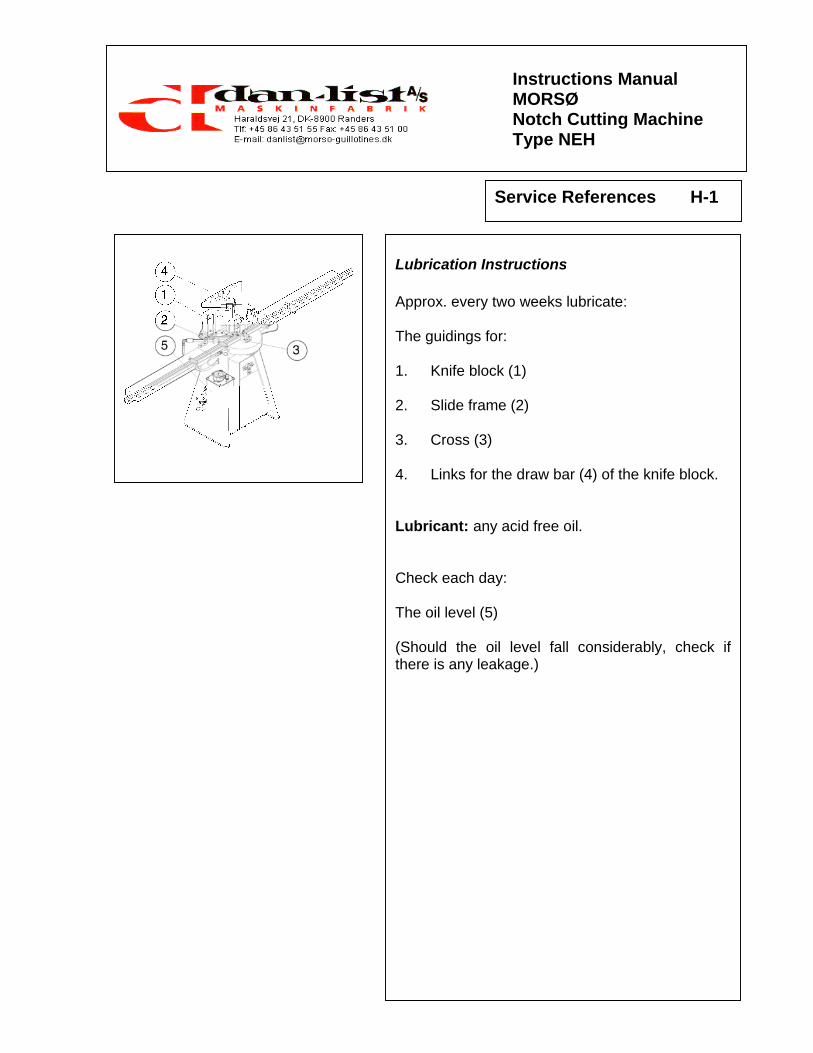
Lubrication Instructions Approx. every two weeks lubricate: The guidings for: 1. Knife block (1) 2. Slide frame (2) 3. Cross (3) 4. Links for the draw bar (4) of the knife block. Lubricant: any acid free oil. Check each day: The oil level (5) (Should the oil level fall considerably, check if there is any leakage.)

Instructions Manual MORSØ Notch Cutting Machine Type NEH
Service References H-2
Change of the Hydraulic Oil It is recommended to change the hydraulic oil each year. The machine must be warm after work, but switched off. 1. Remove the slide (1). 2. Dismount the vent screw (2) from the tank (3). 3. Place a waste container under the tank and remove the outlet screw from the drain cock (4) on the side of the tank. 4. Dismount screws (5) from the cover of the
return filter (6). 5. Remove the cover (6), O-ring (7) and spring (8). 6. Remove the insert filter (9) (to be replaced by a new one). 7. Remove O-ring (11) from the bottom of the
filter housing. 8. Rinse the tank (3) with cleaning oil. 9. Clean the filter housing (10). 10. Fit a new O-ring (11) before new insert filter
(9) is fitted. (check for correct placing). 11. Fit spring (8). 12. New O-ring (7) is fitted under the cover (6) before fitting of the cover. 13. Fit and fasten screws (5). (turning moment approx. 2 Nm). 14. Outlet screw (4) is fitted (take care of the packing). 15. The tank is filled with hydraulic oil through the air escape connection piece until the upper marking of the oil glass (12). 16. Outlet screw (2) is fitted. 17. The machine is started. 18. Check for leakage. Hydraulic Oil: SHELL TELLUS S 32 or similar oil of another make.

Instructions Manual MORSØ Notch Cutting Machine Type NEH
Service References H-3
Cleaning MORSØ-NEH must be cleaned thoroughly after use. Remove any waste wood from the guidings. Remove the waste wood from behind the machine. Keep the build-in hydraulic system free from waste and cover. This might cause super-heating in the electric motor.

Instructions Manual MORSØ Notch Cutting Machine Type NEH
Service References H-4
Changing of Knives and Chip Breaker – Adjustment 1. Knife Block (1) is placed in top position 2. The side knives (2) + (3) are dismounted by
loosening screws (6). The nose knife (4) is dismounted by loosening screws (5).
TAKE CARE OF YOUR FINGERS. 3. Clean the surfaces of the knife block and the
new side knives (2) + (3) very carefully as even the smallest impurity between side knife and knife block can cause an incorrect cut.
4. The nose knife (4) that fits the width of the
cock-bead of the rail is fitted by means of the screws (5) on the front of the knife block.
5. The chip-breaker (7) is placed in the angle
where the bottom knives meet. The width of the chip-breaker must be the same as the width of the nose knife (a = b). OBS: When changing the chip-breaker (7) the knives must be dismounted.
6. Both side knives (2) + (3) are fitted with the screws (6) on the knife block (1). The screws must not be fastened.
7. The side knives (2) + (3) must meet precisely
with the nose knife and neither front edge must be further ahead (they must balance with the corners of the nose knife).
8. The screws (6) are fastened. 9. Check the length of travel on the knife block
(1) by activating the two push button switches. The nose knife (4) must cut through the chip-breaker (7) by only 1-2 mm. Adjust as necessary using the height stop.
Instructions Manual MORSØ Notch Cutting Machine Type NEH
Service References H-5
Grinding of Knives
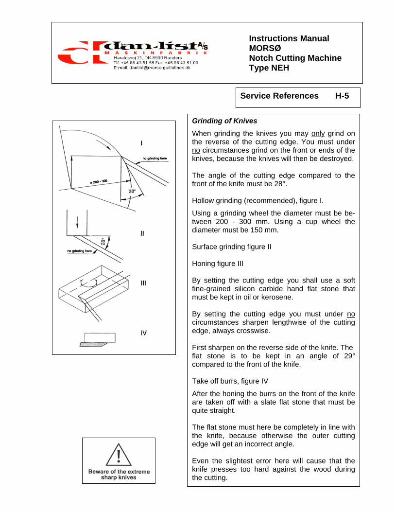
When grinding the knives you may only grind on the reverse of the cutting edge. You must under no circumstances grind on the front or ends of the knives, because the knives will then be destroyed. The angle of the cutting edge compared to the front of the knife must be 28°. Hollow grinding (recommended), figure I.
Using a grinding wheel the diameter must be be-tween 200 - 300 mm. Using a cup wheel the diameter must be 150 mm. Surface grinding figure II Honing figure III By setting the cutting edge you shall use a soft fine-grained silicon carbide hand flat stone that must be kept in oil or kerosene. By setting the cutting edge you must under no circumstances sharpen lengthwise of the cutting edge, always crosswise. First sharpen on the reverse side of the knife. The flat stone is to be kept in an angle of 29° compared to the front of the knife. Take off burrs, figure IV
After the honing the burrs on the front of the knife are taken off with a slate flat stone that must be quite straight. The flat stone must here be completely in line with the knife, because otherwise the outer cutting edge will get an incorrect angle. Even the slightest error here will cause that the knife presses too hard against the wood during the cutting.

Instructions Manual MORSØ Notch Cutting Machine Type NEH
Service References H-6
Adjustment of stroke of the knife block The length of stroke of the knife block can be changed with the switch (7): Position 1 = shortest length of stroke Position 2 = full length of stroke Adjustment of 1. Inductive tracer (1) for full length of stroke
Should a longer length of stroke than the preset length be necessary the inductive tracer (1) is moved upwards.
2. Inductive tracer (2) for shortest length of stroke 3. Inductive tracer (3) for bottom stop

Instructions Manual MORSØ Notch Cutting Machine Type NEH
Locating Faults I-1
Faults Cause Repair
Incorrect cuttings Dull Knives Replace the knives See page H-4
Knives incorrectly installed Check the installation See page H-4
The work piece is not firm on the table during cutting
The Clamping cylinders incorrectly adjusted
Correct the adjustment See page F-6
The machine does not start Connecting cable not connected Put the cable in the wall socket. Connecting cable destroyed Exchange the connecting cable Incorrect activation of start button
Start again
Fine fuse destroyed due to overloading
Find out why the overloading arises and exchange the fine fuse
The machine stops during cutting
Hydraulic motor over-heated Remove the waste from the hydraulic housing Press the thermal cut-out on the fitting plate
Incorrect measures The flip stops incorrectly set Correct the flip stop settings See page F-4
Flip stop loose Fasten flip stop The length of stroke of the knife block is changing
The height stop for the knife block is displaced during cutting
Correct the adjustment See page H-6
OBS: The clamping cylinders must always be activated (Pos. ON) for the manual activation of the hydraulic cylinders mentioned below
Knife block does not go up or down
Hydraulic valve not functioning correctly
Activate manually hydraulic valve No. 38. See page K-4-1.1
Knife block does not go forward or backwards
Hydraulic valve not functioning correctly
Activate manually hydraulic valve No. 42 See page K-4-1.1
Clamping cylinders do not work Hydraulic valve not functioning correctly
Activate manually hydraulic valve No. 45 See page K-4-1.1
Should the above manual activation not solve the problem, there might be a defect in the control system

Instructions Manual MORSØ Notch Cutting Machine Type NEH
Safety J-1
Safety Devices According to current safety regulations MORSØ-EH must not be used without the following safety devices: 1. Safety Guard (1) for knife block 2. Safety Guard (2) for slide frame. 3. Front Plate (3) for electric control 4. Waste Slide (4) over the hydraulic system. 5. Distance between the push buttons on the
fences (5) + (6) must not be changed. Safety Regulations On delivery of the machine to the consumer
guarantees that MORSØ-NEH mitring machine is constructed and fitted according the CEN/TC 142 (Safety Regulations for wood working machinery). At start and use of the mitring machine MORSØ-NEH the operator must pay attention to current national and international safety regulations. If the operator does not observe the above mentioned regulations the factory does not gua-rantee for damages to the machine or the operator.