NLC Klystron Development - Stanford University · John Cornuelle 10/2/03 Slide 2 NLC Klystron...
18
NLC - The Next Linear Collider Project John Cornuelle 10/2/03 NLC Klystron Development October 2, 2003
Transcript of NLC Klystron Development - Stanford University · John Cornuelle 10/2/03 Slide 2 NLC Klystron...

NLC - The Next Linear Collider Project
John Cornuelle
10/2/03
NLC Klystron Development
October 2, 2003

John Cornuelle10/2/03Slide 2
NLC Klystron Development
NLC - The Next Linear Collider Project
Naked 75 MW Klystron(No Magnets, No Lead, No Wires, No Water)
Collector
Electron Gun
Output RF(Two)
RFAmplification
All DoneHere

John Cornuelle10/2/03Slide 3
NLC Klystron Development
NLC - The Next Linear Collider Project
75XP-3 Klystron Cross-Section
Electron Gun
Collector
RFAmplification
All DoneHere

John Cornuelle10/2/03Slide 4
NLC Klystron Development
NLC - The Next Linear Collider Project
General Klystron Approach
• Base Program Must Provide a Usable Device with Little Advance Notice– Lack of a Viable Device Could Indicate NLC is “Not Ready”– Need to Obtain Industrial Suppliers Makes for a Long Lead-Time
• Undertake Smaller R&D Efforts on More Novel Devices– e.g. Multi-Beam Klystrons; Sheet-Beam Klystrons
• Work on Average Power, Not Peak Power– Historically Had Poor Results Chasing Peak Power– Increasing Peak Power Stresses Most All Areas of Tube– Average Power Stresses Thermal Issues Only in Just a Few Places
– Generally Well-Understood and Tractable• Therefore, Lowest Relative Risk

John Cornuelle10/2/03Slide 5
NLC Klystron Development
NLC - The Next Linear Collider Project
Fundamental Background
• Klystron is Part of the Power Conversion Cycle– Converts Pulsed DC Power to Pulsed RF Power
• Large Quantity (4,464) Requires Either Permanent Magnet or SC Magnet Focussing– 110 MW if Use Electromagnet Solenoids
• Lowest Overall Collider Cost and Highest Reliability from Smallest Quantity of Klystrons– However, Peak Power in Single Device May be Limited to 75 MW– So, Extend the Klystron Pulse Width and “Store” the Power
• Acceptably Efficient Systems Can Store the Power by Up to a Factor of Eight
– At Snowmass, 1996 This Factor Was Five– At Snowmass, 2001 This Factor Was Eight– It is Now Four

John Cornuelle10/2/03Slide 6
NLC Klystron Development
NLC - The Next Linear Collider Project
Klystron Specification
• Pulse Width– With 270 ns of Bunch Train Length, 115 ns of Fill Time, and 15 ns
to Switch Phase, Needed Pulse Width is 400 ns– Using a System that Can Delay (Compress) the Power by a Factor
of Four Puts the Klystron Pulse at 4 x 400 ns = 1.6 µsecs• Peak Power
– Was 50 MW at Snowmass, 1996; Now 75 MW• Pretty Much Demonstrated That 100 MW is Impossible
• Repetition Rate– Set by Accelerator Physics – 120 Hz
• Other– Average Power is 14,400 W (Product of the Above)– Efficiency Set to 55% (Highest Feasible With Voltage at 500 kV)– Frequency is Four Times SLC Frequency – 11,424 MHz

John Cornuelle10/2/03Slide 7
NLC Klystron Development
NLC - The Next Linear Collider Project
Degree of Difficulty
• Microwave Tube Difficulty Scales as Pavef2
– 1.2 MW B-Factory Klystron at 476 MHz Scales to 2 kW– 65 MW S-Band SLC Linac Klystron Scales to 3 kW
• These Are Both Solenoid-Focussed Tubes– Solenoid to PPM Approximately Factor of Four in Difficulty– These Two Tubes Scale to Under One kW; 14.4 kW are Required
• Conclusion– This Tube on Paper is Beyond the State of the Art by Over a Decade
• Other Factors– For Maximum Range, All High Power Search Radars Using
Klystrons Run at 3 GHz or Below• i.e. No Industry Experience at 11.424 GHz

John Cornuelle10/2/03Slide 8
NLC Klystron Development
NLC - The Next Linear Collider Project
X-Band Klystron Overview
• TRC Requirement:– No R1 Requirement (KEK PPM-2 Klystron is Existence Proof)– R2 Requirement
• Fully-Tested at Full Repetition Rate• Tested as Part of Linac Sub-Unit Test
• Tubes to Date:– Four at KEK/Toshiba, Five at SLAC, Two Industrial– Built Over a Span of Six Years– Two Tubes Now at Test at SLAC– One Tube to Date That Meets Spec (All Key Parameters Concurrently)
• Tube Specification Will Change Over Time– Major Factors are Perceived Difficulty, Date Demonstration is Needed,
Status of the Competition, Cost versus Risk Tradeoff
John Cornuelle10/2/03Slide 9
NLC Klystron Development
NLC - The Next Linear Collider Project
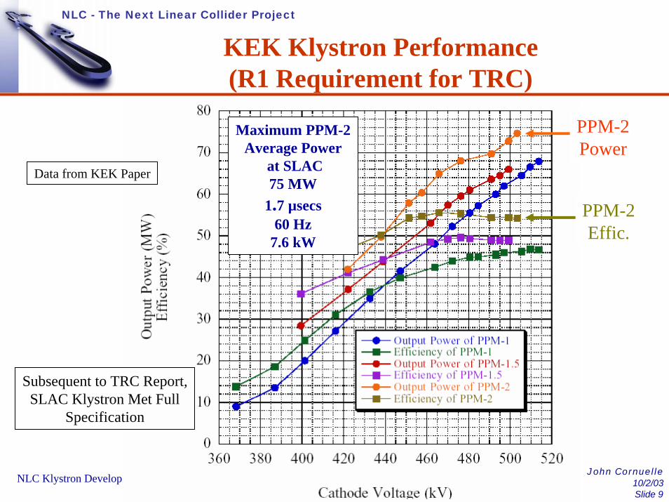
KEK Klystron Performance(R1 Requirement for TRC)
PPM-2Power
PPM-2Effic.
Maximum PPM-2Average Power
at SLAC75 MW
1.7 µsecs60 Hz
7.6 kW
Data from KEK Paper
Subsequent to TRC Report,SLAC Klystron Met Full
Specification
John Cornuelle10/2/03
Slide 10NLC Klystron Development
NLC - The Next Linear Collider Project
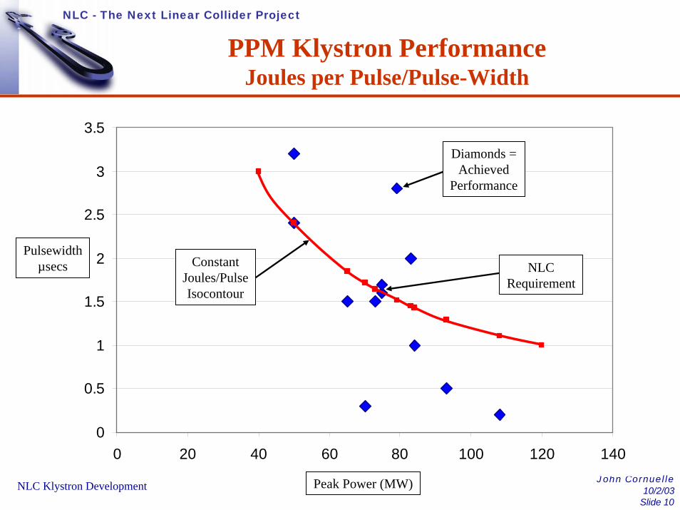
PPM Klystron PerformanceJoules per Pulse/Pulse-Width
0
0.5
1
1.5
2
2.5
3
3.5
0 20 40 60 80 100 120 140
Diamonds =Achieved
Performance
NLCRequirement
ConstantJoules/PulseIsocontour
Pulsewidthµsecs
Peak Power (MW)

John Cornuelle10/2/03
Slide 11NLC Klystron Development
NLC - The Next Linear Collider Project
Peak Power vs. Pulse-Width(SLAC 75XP1 Klystron)
60
70
80
90
100
110
0 500 1000 1500 2000 2500 3000nanoseconds
MWMW
Nanoseconds
Indicates No Peak Power orPulse-Width Problems Expected
John Cornuelle10/2/03
Slide 12NLC Klystron Development
NLC - The Next Linear Collider Project
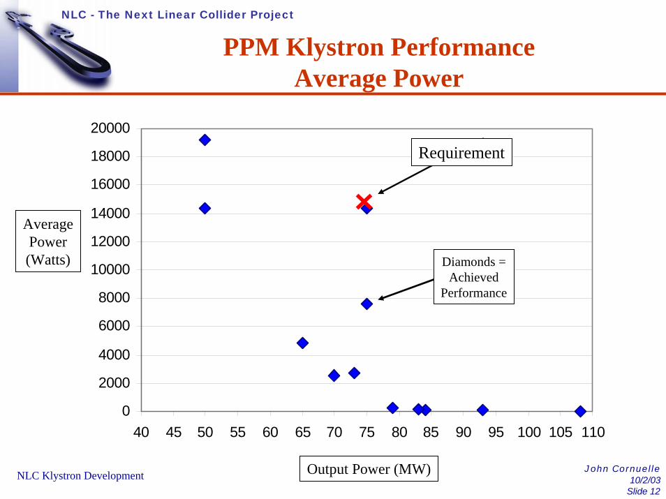
PPM Klystron PerformanceAverage Power
0
2000
4000
6000
8000
10000
12000
14000
16000
18000
20000
40 45 50 55 60 65 70 75 80 85 90 95 100 105 110
Requirement
Diamonds =Achieved
Performance
Output Power (MW)
AveragePower(Watts)

John Cornuelle10/2/03
Slide 13NLC Klystron Development
NLC - The Next Linear Collider Project
Current StatusAll Usable X-Band PPM Klystrons
• KEK/Toshiba Tubes– PPM-2 at Test at SLAC
• Maximum of 75 MW, 1.7 µsecs, 60 Hz– PPM-4 Having Windows Replaced
• Did 75 MW, 1.6 µsecs, 50 Hz (Modulator Limit) at KEK– PPM-2 and PPM-4 are Effectively Identical– PPM-5 (New Tube) Due in December
• SLAC Tubes– XP3-3 at Test
• Maximum of 75 MW, 1.6 µsecs, 120 Hz (Full Requirement)– XP3-4 to Begin Test in December– XP4 to Begin Test in May, 2004– XP3-4 and XP4 Will Have Integral Polepiece Bodies and Will be
Nearly Identical
John Cornuelle10/2/03
Slide 14NLC Klystron Development
NLC - The Next Linear Collider Project
Status of Tubes at Test
• KEK PPM-2 is Processing Very Slowly– Very Slow to Initially Process
• Much Work Done to Protect Output Windows (Generic Issue)– Electron Gun Now Having High Voltage Ticks/Breakdowns
• Vacuum in Gun Region Degrading• Cathode Emission Degrading• Recovery Uncertain
• XP3-3 Has Periodic Break-Up/Tearing in Output Power Pulse– Being Re-Processed After Attempted Repair of the Above– Now About Half-Way Back (50 MW at 1.6 µsecs)– Problem Diminished But Still Present– May be Further Reduced/Eliminated With Processing – Need More
Time

John Cornuelle10/2/03
Slide 15NLC Klystron Development
NLC - The Next Linear Collider Project
XP3-3 Area of Concern(More Than You Want to Know)
Gun “Z” Collector
This Seal is Welded on the Outside Diameter.It May Have Opened in “Z” Enough to AllowElectric Fields to Enter and to Cause Arcing.The Arcing Often Does Not Produce Gas.
This is a Known Problem on the SLACS-Band Klystrons Powering the Linac.

John Cornuelle10/2/03
Slide 16NLC Klystron Development
NLC - The Next Linear Collider Project
PPM-2 Area of Concern(Also More Than You Want to Know)
Transition from Rectangular to Circular
Thin Ceramic WindowTiN-Coated to Suppress Multipactor
Transitionfrom Circularto Rectangular
Pumping Manifolds
WR90
WR90
John Cornuelle10/2/03
Slide 17NLC Klystron Development
NLC - The Next Linear Collider Project
Conclusions
• Any Conclusions are Tentative at This Stage, But -• Although Device is Well-Beyond State of the Art
– All Key Parameters Have Been Met– Performance Beyond That Required Has Been Demonstrated– Tubes From Industry Already Work– Problems That Appear Are Not Related to State of the Art
• i.e. Tubes Do Not Seem to be on the Edge of a Technical Precipice
• Toshiba Tubes Have Vulnerable Windows But SLAC Does Not
• Holding Off Voltage in a Gun is Just Good Design and Good Manufacturing Practice
• Exciting Unwanted Resonances Can Happen in Any Klystron– Need to Isolate and Short Out or Loss Out

John Cornuelle10/2/03
Slide 18NLC Klystron Development
NLC - The Next Linear Collider Project
Plans
• PPM-2– Continue to Process to Maximum Performance– Rebuild if Necessary
• PPM-4– Send to SLAC for Additional Testing When Windows Rebuilt
• PPM-5– Not Yet Decided Who Will Test First
• XP3-3– Continue to Process to Maximum Performance
• Reserve Tube for Two-Pack Modulator Due March, 2004• XP3-4 and XP4
– Reserve XP3-4 For Two-Pack Test