NITC 3-203 Elevation Acquisition using LiDAR Standards · Elevation Acquisition using LiDAR...
19
1 NITC 3-203 Elevation Acquisition using LiDAR Standards Category: Data and Information Architecture Applicability: See Each Section of Standards History: Adopted on October 28, 2014 NEBRASKA INFORMATION TECHNOLOGY COMMISSION GIS COUNCIL
-
Upload
hoanghuong -
Category
Documents
-
view
221 -
download
0
Transcript of NITC 3-203 Elevation Acquisition using LiDAR Standards · Elevation Acquisition using LiDAR...
1
NITC 3-203 Elevation Acquisition using LiDAR
Standards
Category: Data and Information Architecture
Applicability: See Each Section of Standards
History: Adopted on October 28, 2014
NEBRASKA INFORMATION TECHNOLOGY COMMISSION GIS COUNCIL

2
TABLE OF CONTENTS
1.0 Standards ........................................................................................................................................................ 1
1.1 Federal Connection ............................................................................................................................................. 1
1.2 Technical and Operation ..................................................................................................................................... 1
1.3 Maintenance ....................................................................................................................................................... 2
2.0 Purpose and Objectives .................................................................................................................................. 2
2.1 Purpose ............................................................................................................................................................... 2
2.2 Objectives ........................................................................................................................................................... 4
3.0 Definitions ...................................................................................................................................................... 4
4.0 Applicability .................................................................................................................................................... 6
4.1 State Government Agencies ............................................................................................................................... 6
4.2 State Funded Entities .......................................................................................................................................... 6
4.3 Other ................................................................................................................................................................... 6
5.0 Responsibility ................................................................................................................................................. 6
5.1 NITC ..................................................................................................................................................................... 6
5.2 State Agencies ..................................................................................................................................................... 6
5.3 Granting Agencies and Entities ........................................................................................................................... 6
5.4 Other ................................................................................................................................................................... 7
6.0 Authority ........................................................................................................................................................ 7
6.1 NITC GIS Council .................................................................................................................................................. 7
7.0 Related Documents ......................................................................................................................................... 7
8.0 Appendices ..................................................................................................................................................... 8
8.1 Nebraska LiDAR Base Specifications ................................................................................................................... 8

1
1.0 Standards
These standards are intended for entities participating in collaborative efforts to acquire airborne
LiDAR (Light Detection and Ranging) elevations that may contribute to a comprehensive statewide
elevation dataset in Nebraska. The standards provide a consistent structure for data producers and
users to ensure compatibility of datasets within the same framework layer and among other
framework layers.
1.1 Federal Connection
At the national level, the 3D Elevation Program (3DEP) initiative is being developed to respond to growing needs for high-quality topographic data and for a wide range of other three-dimensional representations of the Nation's natural and constructed features. The primary goal of 3DEP is to systematically collect enhanced elevation data in the form of high-quality LiDAR data over the conterminous United States, Hawaii, and the U.S. territories, with data acquired over an 8-year period.
The U.S. Geological Survey (USGS) National Geospatial Program’s (NGP) has published LiDAR
Base Specification Version 1.0 to create consistency across NGP and partner funded LiDAR
collections. The intent of Nebraska’s standards is also to facilitate participation in collaborative
efforts to acquire airborne LiDAR elevations and thus the LiDAR Base Specification Version 1.0 is
adopted as the basis of the standards, guidelines, and recommendations in this document. The
following Technical and Operation section provides additional detail to the Base Specification
where Nebraska’s requirements depart from the specifications in the document or where
additional clarity is necessary. All such standards/guidelines, not specifically addressed in the
body of this document are subject to the specifications in the LiDAR Base Specification Version
1.0.
1.2 Technical and Operation
The following standards are intended to provide additional detail specifically related to LiDAR
projects in Nebraska:
1.2.1 Collection
1.2.1.1 Nominal Pulse Spacing (NPS)
a) Required: An NPS of 1.4 meters or less
b) Recommended: An NPS of 0.7 meters
1.2.1.2 Vertical Accuracy
a) Required: Fundamental Vertical Accuracy <= 24.5 centimeters (cm)
AccuracyZ(Accz), 95 percent (12.5 cm Root Mean Square Error (RMSE)z) for
LiDAR acquired at a NPS greater than one meter.
b) Required: Fundamental Vertical Accuracy <= 18.2 centimeters (cm)
AccuracyZ(Accz), 95 percent (9.25 cm Root Mean Square Error (RMSE)z) for
LiDAR acquired at a NPS of 1.0 meters or less.
1.2.1.3 Data Processing and Handling
a) Recommended: Coordinate Reference System - Nebraska State Plane,
NAD83 HARN, NAVD88, U.S. Survey feet.
b) Optional: Hydro-Flattening – Optional (USGS required).
2
c) Optional: Hydro-Enforced – The state of Nebraska recommends collection of
breaklines for the development of a Hydro-enforced, Bare-earth Digital
Elevation Model (DEM).
1.2.1.4 Deliverables—In addition to the raw and classified point cloud and the metadata,
deliverables will include:
a) Required: Bare-Earth DEM
i. Cell size 2 meters for LiDAR acquired at greater than 1.0 meter NPS
ii. Cell size 1 meter for LiDAR acquired at 1.0 meter or less NPS
b) Recommended: Hydro-Enforced, Bare-Earth DEM
i. Cell size 2 meters for LiDAR acquired at greater than 1.0 meter NPS
ii. Cell size 1 meter for LiDAR acquired at 1.0 meter or less NPS
iii. Breaklines used for Hydro-Enforcement (required if hydro-enforced)
1.3 Maintenance
Entities responsible for data acquisition and deliverables will need to assure data meets
standards and are updated and maintained in a timely manner. After spatial and attribute updates
and/or modifications are performed to the data it shall be submitted to the appropriate entity(s)
responsible for performing quality control and maintenance of the data acquisition.
Maintenance of elevation data determines the suitability to support the greatest range of applications.
Many projects require up-to-date, accurate and consistent elevation data and maintenance of this
data is necessary to provide the maximum return on investment.
1.3.1 Reporting Errors and Handling Updates
The reporting of errors need to be directed to the appropriate entity in a timely manner.
Updated spatial and attribute information in the data will also need to be redistributed.
The date field in the metadata when the last record was modified will also need to be
updated to ensure proper records management and communication with others in the
workflow.
2.0 Purpose and Objectives
2.1 Purpose
The primary purpose of these standards/guidelines is to realize the maximum long-term benefit of
elevation data acquisitions, and in doing so, help protect the public’s investment in Nebraska’s
geospatial infrastructure. These standards will help ensure that elevation data acquisitions are
current, consistent, accurate, high-resolution, accessible, and cost-effective.
Background
Elevation data is foundational to the development of the Nebraska Spatial Data Infrastructure
(NESDI). First, it is required for the rectification of imagery which is the foundation for most of the
other geospatial data layers in the NESDI and is a valuable base map in its own right. The
accuracy of infrastructure data layers, in part, determines the extent to which they can be
integrated and ultimately their suitability to support the greatest range of applications.
Additionally, many projects and programs in Nebraska require up-to-date, accurate and
consistent elevation data.

3
LiDAR has been collected for approximately 59% of the state on a project by project basis.
Applications that require high-quality elevation data have been limited in that the data is not
always consistent across project boundaries, and the fact that LiDAR elevations are not available
for the whole state, thus falling short of the maximum return on investment. A statewide elevation
dataset would provide instantaneous access to accurate elevation data, reducing costs and time
required to merge together projects, or worse, to acquire missing data via less cost-effective
methods. A sample of applications that rely on high quality elevation data in Nebraska include:
2.1.1 Hydrology and hydraulics
a) Base Flood Elevation (BFE) determinations
b) Floodplain and flood inundation mapping
c) Dam breach analysis and hazard potential classification
2.1.2 Engineering design and design reviews
a) Bridge and roadway design
b) Siting of transmission lines, power lines, cell towers, pipelines
c) Flood control structures
d) Conservation structures
2.1.3 Emergency Management
2.1.3.1 The Hazards U.S. Multi-Hazard (HAZUS-MH) estimates of potential dollars
lost during flood disasters
2.1.4 Natural resources applications
2.1.4.1 Sediment erosion and transport
2.1.4.2 Watershed delineation and flow analyses
2.1.4.3 Suitability analyses for plants, animals and other species
2.1.5 Conservation planning
2.1.5.1 Modeling of landforms, habitat, vegetation, etc.
2.1.5.2 Channel topography
2.1.5.3 Vegetation and land cover studies
2.1.5.4 Precision agriculture
2.1.6 Cartographic applications
2.1.6.1 Soil survey
2.1.6.2 Imagery rectification
2.1.6.3 Building and other structural footprints

4
2.1.7 Fire Modeling
2.1.7.1 Vegetative density and their placement in the landscape
2.2 Objectives
These standards and guidelines to guide the acquisition and development of LiDAR data in
Nebraska have the following objectives.
2.2.1 Provide guidance to state and local officials as they work, either in-house or with private contractors, to develop and/or acquire LiDAR elevation data and thereby increase the likelihood that the data acquired and/or developed will be suitable for the range of intended applications and likely future applications. The maintenance of elevation data is necessary for the data to be current and accurate. The requirements of maintenance involving stewardship and reporting of errors and handling updates is located in the NESDI Governance Plan and current Elevation Business Plan. These plans are currently in draft and are forthcoming.
2.2.2 Improve public policy development and implementation by helping to make elevation data
more current and readily accessible.
2.2.3 Enhance coordination and program management across jurisdictional boundaries by
insuring that elevation data can be horizontally integrated across jurisdictional and/or
project boundaries for regional or statewide applications.2.2.4 Save public resources
by facilitating the sharing of elevation data among public agencies or sub-divisions of
agencies by incorporating data standards and following guidelines which will make it
more likely that the elevation data developed by one entity will also be suitable to serve
the multiple needs of other entities and thereby avoid the costly duplication of developing
and maintaining similar elevation data.
2.2.5 Make elevation data more readily accessible to the wide range of potential users.
2.2.6 Facilitate harmonious, trans-agency public policy decision-making and implementation by
enabling multiple agencies and levels of government to access and appropriately use
common geospatial datasets and thereby make it more likely that intersecting public
policy decisions, across levels of government, will be based on the same information.
2.2.7 Lay the foundation for facilitating intergovernmental partnerships for the acquisition and
development of high-quality elevation data by defining standards and guidelines that
increase the likelihood that the elevation data will meet the needs of multiple users.
2.2.8 Establish and promote the integration and interrelationships of elevation data with related NESDI framework layers through geometric placement and attributes.
3.0 Definitions
Refer to the LiDAR Base Specification Version 1.0 glossary for a more complete set of definitions.
3.1 Accuracyz (ACCz) (Vertical Accuracy) - The NSSDA reporting standard in the vertical
component that equals the linear uncertainty value, such that the true or theoretical
vertical location of the point falls within that linear uncertainty value 95 percent of the
time. ACCz = 1.9600x RMSEz.
5
3.2 Bare earth - Digital elevation data of the terrain, free from vegetation, buildings and other man-made structures. Elevations of the ground.
3.3 Breakline - linear feature that describes a change in the smoothness or continuity of a
surface.
3.4 Contour - Lines of equal elevation on a surface. An imaginary line on the ground, all
points of which are at the same elevation above or below a specified vertical datum.
(FEMA’s Definition)
3.5 Digital Elevation Model (DEM) - the digital cartographic representation of the elevation of
the land at regularly spaced intervals in x and y directions, using z-values referenced to a
common vertical datum.
3.6 Digital Surface Model (DSM) - Similar to Digital Elevation Models (DEMs) or digital terrain
models (DTMs), except that they may depict the elevations of the top surfaces of
buildings, trees, towers, and other features elevated above the bare earth.
3.7 Fundamental Vertical Accuracy (FVA) - The value by which vertical accuracy of LiDAR
can be equitably assessed and compared among datasets. The fundamental vertical
accuracy of a dataset must be determined with well-distributed checkpoints located only
in open terrain, free of vegetation, where there is a high probability that the sensor will
have detected the ground surface. It is obtained using standard tests for Root Mean
Square Error (RMSE), where FVA = ACCz = RMSEz x 1.9600.
3.8 Hydrologically-conditioned (hydro-conditioned) - Processing of a DEM or Triangulated
Irregular Network (TIN) so that the flow of water is continuous across the entire terrain
surface, including the removal of all spurious sinks or pits.
3.9 Hydrologically-enforced (hydro-enforced) - Processing of water bodies so that lakes and
reservoirs are level and streams flow downhill. For example, a DEM, TIN or topographic
contour dataset with elevations removed from the tops of selected drainage structures
(bridges and culverts) so as to depict the terrain under those structures. Hydro-
enforcement enables hydrologic and hydraulic models to depict water flowing under
these structures, rather than appearing in the computer model to be dammed by them
because of road deck elevations higher than the water levels. Hydro-enforced TINs also
use breaklines along shorelines and stream centerlines. An example of this is where
breaklines form the edges of TIN triangles along the alignment of drainage features.
Shore breaklines for streams would be 3-D breaklines with elevations that decrease as
the stream flows downstream; however, shore breaklines for lakes or reservoirs would
have the same elevation for the entire shoreline if the water surface is known or assumed
to be level throughout.
3.10 Hydrologically-flattened (hydro-flattened) - Processing of a LiDAR-derived surface DEM
or TIN Model so that mapped water bodies, rivers, reservoirs, and other cartographically
polygonal water surfaces are flat, and where appropriate, level from bank-to-bank.
3.11 LiDAR - An instrument that measures distance to a reflecting object by emitting timed
pulses of light and measuring the time difference between the emission of a laser pulse
and the reception of the pulse’s reflection(s). The measured time interval for each
reflection is converted to distance, which when combined with position and altitude
information from Global Positioning System (GPS), Inertial Measurement Unit (IMU), and
the instrument itself, allows the derivation of the 3-dimensional point location of the
reflecting target’s location.
3.12 Nebraska Spatial Data Infrastructure - A framework of geospatial data layers that have
multiple applications, used by a vast majority of stakeholders, meet quality standards and
6
have data stewards to maintain and improve the data on an ongoing basis. These layers
are also consistent with the Federal National Spatial Data Infrastructure (NSDI).
3.13 Nominal Point Spacing (NPS) - A common measure of the density of a LiDAR dataset, it
is the typical or average lateral distance between points in a LiDAR dataset, most often
expressed in meters. Often it is simply calculated as the square root of the average area
per point. This value is predicted in mission planning and empirically calculated from the
collected data. In high-density collections (<1 meter NPS), this may be directly expressed
as Points per Square Meter (PPSM). PPSM = 1/NPS2.
3.14 Points – In the context for elevation, points are geospatial objects that represent spot
elevations of randomly intersected features. Attributes are X, Y, and Z coordinates at a
minimum, but may also include pulse number, return number, intensity, flight line number,
scan angle, GPS time and feature class.
4.0 Applicability
4.1 State Government Agencies
State agencies that are involved in the acquisition of elevation data are required to comply with the standards as described in Section 1.
4.2 State Funded Entities
Entities that are not state agencies but receive direct or indirect state funding for acquisition of elevation data are also required to comply with the standards as described in Section 1.
4.3 Other
Other entities, such as local government agencies (e.g. County Offices, Natural Resources Districts, municipalities) involved in the acquisition of elevation data are required to comply with the standards as described in Section 1.
5.0 Responsibility
5.1 NITC
The NITC shall be responsible for adopting minimum technical standards, guidelines, and
architectures upon recommendation by the technical panel. Neb. Rev. Stat. § 86-516(6)
5.2 State Agencies
The OCIO GIS Shared Services will be responsible for assuring that metadata is completed and
the data is registered and available for distribution through NebraskaMAP.
5.3 Granting Agencies and Entities
State granting or fund disbursement entities or agencies will be responsible for ensuring that
these standards are included in requirements and regulations related to fund disbursements as
they relate to LiDAR acquisition.

7
5.4 Other
Local government agencies will be responsible for ensuring that these standards are included in
requirements and regulations related to fund disbursements as they relate to LiDAR acquisition.
6.0 Authority
6.1 NITC GIS Council
According to Neb. Rev. Stat. § 86-572(2), the GIS Council shall: Establish guidelines and policies
for statewide Geographic Information Systems operations and management (a) The acquisition,
development, maintenance, quality assurance such as standards, access, ownership, cost
recovery, and priorities of data bases; (b) The compatibility, acquisition, and communications of
hardware and software; (c) The assessment of needs, identification of scope, setting of
standards, and determination of an appropriate enforcement mechanism; (d) The fostering of
training programs and promoting education and information about the Geographic Information
Systems; and (e) The promoting of the Geographic Information Systems development in the
State of Nebraska and providing or coordinating additional support to address Geographic
Information Systems issues as such issues arise.
7.0 Related Documents
7.1 United State Geological Survey (USGS) National Geospatial Program (NGP) LiDAR
Base Specification Version 1.0: http://pubs.usgs.gov/tm/11b4/
7.2 American Society for Photogrammetry and Remote Sensing (ASPRS) LAS Specification
Version 1.4. November 2011.
8
8.0 Appendices
8.1 Nebraska LiDAR Base Specifications
The following is an adaptation of the LiDAR Base Specification Version 1.0 specific to Nebraska LiDAR acquisitions. Specific differences between the LiDAR Base Specification Version 1.0 and Nebraska specifications include: Collection
Nebraska requires a NPS of 1.4 meters or less.
Nebraska projects typically collect LiDAR points at 1 of 2 Nominal Pulse Spacings, 0.7 and 1.4 meters. Each has specific accuracy requirements.
Data Processing and Handling
Preferred CRS is Nebraska State Plane, NAD83, Feet, NAVD88, Feet
Nebraska does not require Hydro-Flattening of DEMs
Deliverables • Recommends 2 DEMs,
o Bare-Earth topographic DEM (Required. Hydro-flattening not required) o Bare-Earth Hydro-conditioned DEM (Optional)
Collection Multiple Discrete Returns Data collection must be capable of at least three returns per pulse. Full waveform collection is acceptable. Intensity Values Intensity values are required for each return. The values are to be recorded in the .las files in their native radiometric resolution. Nominal Pulse Spacing (NPS) An NPS of 1.4 meters or less is required. Assessment of the NPS will be made against single swath, first-return only data, located within the geometrically usable center portion (typically 90 percent) of each swath, acceptable data voids excluded. NPS will be calculated as the square root of the average area per point. Average along-track and cross-track point spacing should be comparable (within 10 percent). In general, the target NPS for a project should not be achieved through swath overlap or multiple passes. Such collection techniques may be permitted with prior approval. Data Voids Data voids within a single swath are not acceptable, except in the following circumstances: • Where caused by water bodies, • Where caused by areas of low near infra-red (NIR) reflectivity such as asphalt or composition
roofing, or • Where appropriately filled-in by another swath. Spatial Distribution The spatial distribution of geometrically usable points is expected to be uniform. Although it is understood that LiDAR instruments do not produce regularly gridded points, collections should be planned and executed to produce a first-return point cloud that approaches a regular lattice of points, rather than a collection of widely spaced high density profiles of the terrain. The uniformity of the point density throughout the dataset is important and will be assessed using the following steps: • Generating a density grid from the data with cell sizes equal to the design NPS times 2, using a
radius equal to the design NPS.
9
• Ensuring at least 90 percent of the cells in the grid contain at least one LiDAR point. • The assessment is to be made against individual (single) swaths, using only the first-return points
located within the geometrically usable center portion (typically 90 percent) of each swath. • Excluding acceptable data voids previously identified in this specification.
Note: This requirement may be relaxed in areas of substantial relief where it is impractical to maintain a consistent and uniform distribution. Note: The process described in this section relates only to the uniformity of the point distribution. It in no way relates to, nor can it be used for the assessment of point density or NPS.
Scan Angle Scan angle will support horizontal and vertical accuracy within the requirements as specified in the next two sections. Note: This requirement primarily is applicable to oscillating mirror LiDAR systems. Other instrument technologies may be exempt from this requirement. Vertical Accuracy Vertical accuracy of the LiDAR data will be assessed and reported in accordance with the guidelines developed by the National Digital Elevation Program (NDEP) and subsequently adopted by the American Society for Photogrammetry and Remote Sensing (ASPRS). Complete definitions for vertical accuracy assessments are in Section 1.5 of the NDEP Elevation Guidelines (NDEP, 2004). The minimum vertical accuracy requirement for the unclassified LiDAR point cloud, using the NDEP/ASPRS methodology, is listed below:
• Fundamental Vertical Accuracy (FVA) <= 24.5 centimeters (cm) Accuracyz (ACCz), 95 percent (12.5 cm Root Mean Square Error (RMSE)z).
• The minimum vertical accuracy requirements for the derived DEM, using the NDEP/ASPRS methodology are listed below:
• Fundamental Vertical Accuracy (FVA) <= 24.5 cm ACCz, 95 percent (12.5cm RMSEz); • Consolidated Vertical Accuracy (CVA) <= 36.3cm, 95th percentile, and • Supplemental Vertical Accuracy (SVA) <= 36.3 cm, 95th percentile. • The minimum vertical accuracy requirement for the unclassified LiDAR point cloud for LIDAR
collected at 0,7 m NPS, using the NDEP/ASPRS methodology, is listed below: • Fundamental Vertical Accuracy (FVA) <= 18.5 centimeters (cm) Accuracyz (ACCz), 95
percent (9.25 cm Root Mean Square Error (RMSE)z). • The minimum vertical accuracy requirements for the derived DEM, using the NDEP/ASPRS
methodology are listed below: • Fundamental Vertical Accuracy (FVA) <= 18.5 cm ACCz, 95 percent (9.255cm RMSEz); • Consolidated Vertical Accuracy (CVA) <= 27.7 cm, 95th percentile, and • Supplemental Vertical Accuracy (SVA) <= 27.7 cm, 95th percentile.
Point cloud data accuracy is to be tested against a Triangulated Irregular Network (TIN) constructed from LiDAR points in clear and open areas. A clear and open area can be characterized with respect to topographic and ground cover variation such that a minimum of 5 times the NPS exists with less than 1/3 of the RMSEz deviation from a low-slope plane. Slopes that exceed 10 percent should be avoided. Ground that has been plowed or otherwise disturbed is not acceptable. All tested locations should be photographed showing the position of the tripod and the surrounding area ground condition. Each land cover type representing 10 percent or more of the total project area must be tested and reported with an SVA. In areas where a land cover category is something other than forested or dense urban, the tested point should not have any obstructions 45 degrees above the horizon to ensure a sufficient TIN surface. Additionally, tested areas should not be in proximity to low NIR reflective surfaces such as asphalt or composition roofing materials.
10
The SVA value is provided as a target. It is understood that in areas of dense vegetation, swamps, or extremely difficult terrain, this value may be exceeded. The CVA value is a requirement that must be met, regardless of any allowed “busts” in the SVA(s) for individual land cover types within the project. Checkpoints for each assessment (FVA, CVA, and all SVAs) are required to be well-distributed throughout the land cover type, for the entire project area. See Glossary for definition of well-distributed. Exceptions: These requirements may be relaxed in cases:
• Where there exists a demonstrable and substantial increase in cost to obtain this accuracy. • Where an alternate specification is needed to conform to previously contracted phases of a
single larger overall collection effort, for example, multi-year statewide collections. • Where the USGS agrees that it is reasonable and in the best interest of all stakeholders to
use an alternate specification.
Relative Accuracy The requirements for relative accuracy are listed below:
• Within individual swaths: <= 7 cm RMSEz • Within overlap between adjacent swaths: <=10 cm RMSEz
Flightline Overlap Flightline overlap of 10 percent or greater is required to ensure there are no data gaps between the usable portions of the swaths. Collections in high relief terrain are expected to require greater overlap. Any data with gaps between the geometrically usable portions of the swaths will be rejected. Collection Area
• Data collection for the Defined Project Area, buffered by a minimum of 100 meters, is required. The buffered boundary is the Buffered Project Area.
• In order that all products are consistent to the edge of the Defined Project Area, all products must be generated to the limit of the Buffered Project Area. Since these areas are being generated, they shall also be delivered.
Collection Conditions • Atmospheric conditions must be cloud and fog-free between the aircraft and ground during all
collection operations. • Ground conditions must be snow free. Very light, undrifted snow may be acceptable in
special cases, with prior approval. • Water conditions must be free of any unusual flooding or inundation, except in cases where
the goal of the collection is to map the inundation. • Leaf-off vegetation conditions are preferred, however, as numerous factors beyond human
control may affect the vegetative condition at the time of any collection, the USGS NGP only requires that penetration to the ground must be adequate to produce an accurate and reliable bare-earth surface suitable for incorporation into the 1/9 (3-meter) NED. Collections for specific scientific research projects may be exempted from this requirement, with prior approval.
Data Processing and Handling ASPRS LAS File Format All processing should be carried out with the understanding that all point deliverables are required to be in fully compliant LAS format, either v1.2 or v1.3. The version selected must be used for all LAS deliverables in the project. Data producers are encouraged to review the LAS specification in detail (ASPRS, 2011).
11
Full Waveform If full waveform data are collected, delivery of the waveform packets is required. LAS v1.3 deliverables with waveform data are to use external auxiliary files with the extension .wdp for the storage of waveform packet data. See the LAS v1.3 Specification for additional information (ASPRS, 2011). Global Positioning System (GPS) Times GPS times are to be recorded as Adjusted GPS Time, at a precision sufficient to allow unique timestamps for each pulse. Adjusted GPS Time is defined to be Standard (or satellite) GPS time minus 1x10
9. See the LAS v1.4
Specification for more detail (ASPRS, 2011). Datums All data collected must be tied to the datums listed below:
• Horizontal datum reference to the North American Datum of 1983/HARN adjustment (NAD83 HARN) is required.
• Vertical datum reference to the North American Vertical Datum of 1988 (NAVD 88) is required.
• The most recent National Geodetic Survey (NGS)-approved geoid model is required to perform conversions from ellipsoidal heights to orthometric heights.
Coordinate Reference System
• The Nebraska preferred Coordinate Reference System for projects conducted within the state is Nebraska State Plane, NAD83 HARN, Feet; NAVD88, Feet.
• The USGS preferred Coordinate Reference System for the Conterminous United States (CONUS) is Universal Transverse Mercator UTM, NAD83 HARN, Meters; NAVD88, Meters and this Coordinate Reference System may be used. Each discrete project is to be processed using the single predominant UTM zone for the overall collection area.
Units of Reference All references to the unit of measure “Feet” and “Foot” must specify “International”, “Intl”, “U.S. Survey”, or “US”. Swath Identification Each swath will be assigned a unique File Source ID. It is required that the Point Source ID field for each point within each LAS swath file be set equal to the File Source ID before any processing of the data. See the LAS v1.3 Specification (ASPRS, 2011). Point Families Point families (multiple return “children” of a single “parent” pulse) shall be maintained intact through all processing before tiling. Multiple returns from a given pulse will be stored in sequential (collected) order. Swath Size and Segmentation Swath files will be 2 gigabytes (GB) in size or less. Long swaths (those which result in a LAS file larger than 2 GB) will be split into segments no greater than 2 GB each.
• Each sub-swath will retain the original File Source ID of the original complete swath. • Points within each sub-swath will retain the Point Source ID of the original complete swath. • Each sub-swath file will be named identically to the original complete swath, with the addition
of an ordered alphabetic suffix to the name (“-a”, “-b” … “-n”). The order of the named sub-swaths shall be consistent with the collection order of the points (“-a” will be the chronological beginning of the swath; “-n” will be the chronological end of the swath).
• Point families shall be maintained intact within each sub-swath. • Sub-swaths should be broken at the edge of the scan line. • Other swath segmentation approaches may be acceptable, with prior approval.
12
Scope of Collection
• All collected swaths are to be delivered as part of the Raw Data Deliverable. This includes calibration swaths and crossties.
• This in no way requires or implies that calibration swath data are to be included in product generation. All collected points are to be delivered. No points are to be deleted from the swath LAS files. Excepted from this are extraneous data outside of the buffered project area (aircraft turns, transit between the collection area and airport, transit between fill-in areas, and the like).
• These points may be permanently removed. Busted swaths that are being completely discarded by the vendor and re-flown do not need to be delivered.
Use of the LAS Withheld Flag
• Outliers, blunders, noise points, geometrically unreliable points near the extreme edge of the swath, and other points the vendor deems unusable are to be identified using the Withheld flag, as defined in the LAS specification.
• This applies primarily to points that are identified during pre-processing or through automated post-processing routines.
• If processing software is not capable of populating the Withheld bit, these points may be identified using Class=11.
• Noise points subsequently identified during manual Classification and Quality Assurance/Quality Control (QA/QC) may be assigned the standard LAS classification value for Noise (Class=7), regardless of whether the noise is “low” or “high” relative to the ground surface.
Point Classification • ALL points not identified as Withheld are to be classified. • No points in the Classified LAS deliverable will be assigned Class=0. • Use of the ASPRS/LAS Overlap classification (Class=12) is prohibited. • If overlap points are required to be differentiated by the data producer or cooperating partner,
they must be identified using a method that does not interfere with their classification: • Overlap points are tagged using Bit:0 of the User Data byte, as defined in the LAS
specification. (SET=Overlap). • Overlap points are classified using the Standard Class values + 16. • Other techniques as agreed upon in advance.
The technique used to identify overlap must be clearly described in the project metadata files. Note: A standard bit flag for identification of overlap points has been included in LAS v1.4, released on November 14, 2011. Positional Accuracy Validation Before classification of and development of derivative products from the point cloud, verification of the vertical accuracy of the point cloud, absolute and relative, is required. The Fundamental Vertical Accuracy (absolute) is to be assessed in clear, open areas as described in the section called Vertical Accuracy above. Swath-to-swath and within swath accuracies (relative) are to be documented. A detailed report of this validation process is a required deliverable. Classification Accuracy It is required that due diligence in the classification process will produce data that meet the following tests:
• Following classification processing, no non-withheld points should remain in Class 0. • Within any 1 kilometer (km) x 1 km area, no more than 2 percent of non-withheld points will
possess a demonstrably erroneous classification value. • Points remaining in Class 1 that should be classified in any other required Class are subject
to these accuracy requirements and will be counted towards the 2 percent threshold. Note: These requirements may be relaxed to accommodate collections in areas where the USGS agrees classification to be particularly difficult.
13
Classification Consistency Point classification is to be consistent across the entire project. Noticeable variations in the character, texture, or quality of the classification between tiles, swaths, lifts, or other non-natural divisions will be cause for rejection of the entire deliverable. Tiles Note: This section assumes a projected coordinate reference system. A single non-overlapped tiling scheme (the Project Tiling Scheme) will be established and agreed upon by the data producer and the USGS before collection. This scheme will be used for ALL tiled deliverables.
• Tile size is required to be an integer multiple of the cell size of raster deliverables. • Tiles are required to be sized using the same units as the coordinate system of the data. • Tiles are required to be indexed in X and Y to an integer multiple of the tile’s X-Y dimensions. • All tiled deliverables will conform to the Project Tiling Scheme, without added overlap. • Tiled deliverables will edge-match seamlessly and without gaps.
Hydro-Enforcement Processing of mapped water bodies so that streams flow downhill. Specifically, Nebraska Digital Elevation Models (DEMs) are derived with elevations removed from the tops of selected drainage structures (bridges and culverts) so as to depict the terrain under those structures. Hydro-enforcement enables hydrologic and hydraulic models to depict water flowing under these structures, rather than appearing in the computer model to be dammed by them because of road deck elevations higher than the water levels. Hydro-Flattening Note: Hydro-Flattening is not required for any known Nebraska application and imposes a significant increase in costs. This section applies only to LiDAR acquisitions in which USGS participation covers this cost increase in its entirety. Hydro-flattening pertains only to the creation of derived DEMs. No manipulation of or changes to originally computed LiDAR point elevations are to be made. Breaklines may be used to help classify the point data. The goal of the NGP is for the delivered DEMs to represent water bodies in a cartographically and aesthetically pleasing manner. It is not the goal of the NGP to accurately map water surface elevations within the NED. The requirements for hydro-flattening are listed below. Inland Ponds and Lakes
• 2 acres or greater surface area (approximately equal to a round pond 350 feet in diameter) at the time of collection.
• Flat and level water bodies (single elevation for every bank vertex defining a given water body).
• The entire water surface edge must be at or below the immediately surrounding terrain. The presence of floating water bodies will be cause for rejection of the deliverable.
• Long impoundments such as reservoirs, inlets, and fjords, whose water surface elevations drop when moving downstream, are required to be treated as rivers.
Inland Streams and Rivers • 100 feet nominal width: This should not unnecessarily break a stream or river into multiple
segments. At times it may squeeze slightly below 100 feet for short segments. Data producers should use their best professional cartographic judgment.
• Flat and level bank-to-bank (perpendicular to the apparent flow centerline); gradient to follow the immediately surrounding terrain. In cases of sharp turns of rapidly moving water, where the natural water surface is notably not level bank- to- bank, it is appropriate to represent the water surface as it exists in nature, while maintaining an aesthetic cartographic appearance.
• The entire water surface edge must be at or below the immediately surrounding terrain.
14
• Stream channels are required to break at road crossings (culvert locations). The roadway over a culvert should be continuous.
• A culvert, regardless of size, is defined as having earth between the road surface and the top of the structure.
• Bridges are required to be removed from the DEM. Streams and rivers should be continuous at bridge locations. Bridges are defined as having an elevated deck structure that does not rest on earth.
• When the identification of a structure such as a bridge or culvert cannot be made reliably, the feature should be regarded as a culvert.
Non-Tidal Boundary Waters
• Represented only as an edge or edges within the project area; collection does not include the opposing shore.
• Water surface is to be flat and level, as appropriate for the type of water body (level for lakes; gradient for rivers)
• The entire water surface edge must be at or below the immediately surrounding terrain. Tidal Waters
• Tidal water bodies are defined as water bodies such as oceans, seas, gulfs, bays, inlets, salt marshes, large lakes, and the like. This includes any water body that is affected by tidal variations.
• Tidal variations over the course of a collection or between different collections will result in lateral and vertical discontinuities along shorelines. This is considered normal and these anomalies should be retained. The final DEM is required to represent as much ground as the collected data permits.
• Water surface is to be flat and level, to the degree allowed by the irregularities noted above. • Scientific research projects in coastal areas often have specific requirements with regard to
how tidal land-water boundaries are to be handled. For such projects, the requirements of the research will take precedence.
Islands • Permanent islands 1 acre or larger shall be delineated within all water bodies.
Single-Line Streams Cooperating partners may require collection and integration of single-line streams within their LiDAR projects. Although the USGS does not require these breaklines be collected or integrated, it does require that if used and incorporated into the DEMs, the following guidelines are met:
• All vertices along single-line stream breaklines are at or below the immediately surrounding terrain.
• Single-line stream breaklines are not to be used to introduce cuts into the DEM at road crossings (culverts), dams, or other such features. This is hydro-enforcement and as discussed in appendix 3 will create a non-topographic DEM that is unsuitable for integration into the NED.
• All breaklines used to modify the surface are to be delivered to the USGS with the DEMs. Deliverables The USGS requires unrestricted rights to all delivered data and reports, which will be placed in the public domain. This specification places no restrictions on the data provider’s rights to resell data or derivative products as they see fit. Metadata The term “metadata” refers to all descriptive information about the project. This includes textual reports, graphics, supporting shapefiles, and Federal Geographic Data Committee (FGDC)-compliant metadata files. Metadata deliverables include the following items:
• Collection report detailing mission planning and flight logs.
15
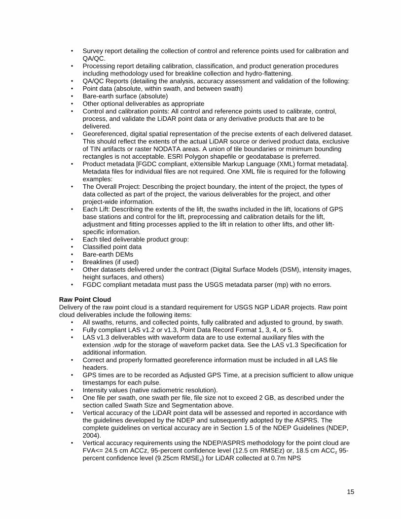
• Survey report detailing the collection of control and reference points used for calibration and QA/QC.
• Processing report detailing calibration, classification, and product generation procedures including methodology used for breakline collection and hydro-flattening.
• QA/QC Reports (detailing the analysis, accuracy assessment and validation of the following: • Point data (absolute, within swath, and between swath) • Bare-earth surface (absolute) • Other optional deliverables as appropriate • Control and calibration points: All control and reference points used to calibrate, control,
process, and validate the LiDAR point data or any derivative products that are to be delivered.
• Georeferenced, digital spatial representation of the precise extents of each delivered dataset. This should reflect the extents of the actual LiDAR source or derived product data, exclusive of TIN artifacts or raster NODATA areas. A union of tile boundaries or minimum bounding rectangles is not acceptable. ESRI Polygon shapefile or geodatabase is preferred.
• Product metadata [FGDC compliant, eXtensible Markup Language (XML) format metadata]. Metadata files for individual files are not required. One XML file is required for the following examples:
• The Overall Project: Describing the project boundary, the intent of the project, the types of data collected as part of the project, the various deliverables for the project, and other project-wide information.
• Each Lift: Describing the extents of the lift, the swaths included in the lift, locations of GPS base stations and control for the lift, preprocessing and calibration details for the lift, adjustment and fitting processes applied to the lift in relation to other lifts, and other lift-specific information.
• Each tiled deliverable product group: • Classified point data • Bare-earth DEMs • Breaklines (if used) • Other datasets delivered under the contract (Digital Surface Models (DSM), intensity images,
height surfaces, and others) • FGDC compliant metadata must pass the USGS metadata parser (mp) with no errors.
Raw Point Cloud Delivery of the raw point cloud is a standard requirement for USGS NGP LiDAR projects. Raw point cloud deliverables include the following items:
• All swaths, returns, and collected points, fully calibrated and adjusted to ground, by swath. • Fully compliant LAS v1.2 or v1.3, Point Data Record Format 1, 3, 4, or 5. • LAS v1.3 deliverables with waveform data are to use external auxiliary files with the
extension .wdp for the storage of waveform packet data. See the LAS v1.3 Specification for additional information.
• Correct and properly formatted georeference information must be included in all LAS file headers.
• GPS times are to be recorded as Adjusted GPS Time, at a precision sufficient to allow unique timestamps for each pulse.
• Intensity values (native radiometric resolution). • One file per swath, one swath per file, file size not to exceed 2 GB, as described under the
section called Swath Size and Segmentation above. • Vertical accuracy of the LiDAR point data will be assessed and reported in accordance with
the guidelines developed by the NDEP and subsequently adopted by the ASPRS. The complete guidelines on vertical accuracy are in Section 1.5 of the NDEP Guidelines (NDEP, 2004).
• Vertical accuracy requirements using the NDEP/ASPRS methodology for the point cloud are FVA<= 24.5 cm ACCz, 95-percent confidence level (12.5 cm RMSEz) or, 18.5 cm ACCz 95-percent confidence level (9.25cm RMSEz) for LiDAR collected at 0.7m NPS
16
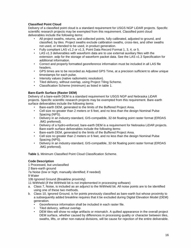
Classified Point Cloud Delivery of a classified point cloud is a standard requirement for USGS NGP LiDAR projects. Specific scientific research projects may be exempted from this requirement. Classified point cloud deliverables include the following items:
• All project swaths, returns, and collected points, fully calibrated, adjusted to ground, and classified, by tiles. Project swaths exclude calibration swaths, cross-ties, and other swaths not used, or intended to be used, in product generation.
• Fully compliant LAS v1.2 or v1.3, Point Data Record Format 1, 3, 4, or 5. • LAS v1.3 deliverables with waveform data are to use external auxiliary files with the
extension .wdp for the storage of waveform packet data. See the LAS v1.3 Specification for additional information.
• Correct and properly formatted georeference information must be included in all LAS file headers.
• GPS times are to be recorded as Adjusted GPS Time, at a precision sufficient to allow unique timestamps for each pulse.
• Intensity values (native radiometric resolution). • Tiled delivery, without overlap, using Project Tiling Scheme. • Classification Scheme (minimum) as listed in table 1.
Bare-Earth Surface (Raster DEM) Delivery of a bare-earth DEM is a standard requirement for USGS NGP and Nebraska LiDAR projects. Specific scientific research projects may be exempted from this requirement. Bare-earth surface deliverables include the following items:
• Bare-earth DEM, generated to the limits of the Buffered Project Area. • Cell size no greater than 2 meters or 6 feet, and no less than the design Nominal Pulse
Spacing (NPS). • Delivery in an industry-standard, GIS-compatible, 32-bit floating point raster format (ERDAS
.IMG preferred). • Delivery of a hydro-enforced, bare-earth DEM is a requirement for Nebraska LiDAR projects.
Bare-earth surface deliverables include the following items: • Bare-earth DEM, generated to the limits of the Buffered Project Area. • Cell size no greater than 2 meters or 6 feet, and no less than the design Nominal Pulse
Spacing (NPS). • Delivery in an industry-standard, GIS-compatible, 32-bit floating point raster format (ERDAS
.IMG preferred). Table 1. Minimum Classified Point Cloud Classification Scheme. Code Description 1 Processed, but unclassified 2 Bare-earth ground 7a Noise (low or high; manually identified; if needed) 9 Water 10b Ignored Ground (Breakline proximity) 11 Withheld (if the Withheld bit is not implemented in processing software) a. Class 7, Noise, is included as an adjunct to the Withheld bit. All noise points are to be identified
using one of these two methods. b. Class 10, Ignored Ground, is for points previously classified as bare-earth but whose proximity to
a subsequently added breakline requires that it be excluded during Digital Elevation Model (DEM) generation. • Georeference information shall be included in each raster file. • Tiled delivery, without overlap. • DEM tiles will show no edge artifacts or mismatch. A quilted appearance in the overall project
DEM surface, whether caused by differences in processing quality or character between tiles, swaths, lifts, or other non-natural divisions, will be cause for rejection of the entire deliverable.
17
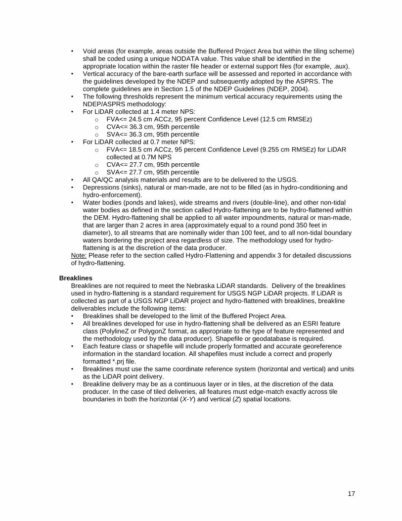
• Void areas (for example, areas outside the Buffered Project Area but within the tiling scheme) shall be coded using a unique NODATA value. This value shall be identified in the appropriate location within the raster file header or external support files (for example, .aux).
• Vertical accuracy of the bare-earth surface will be assessed and reported in accordance with the guidelines developed by the NDEP and subsequently adopted by the ASPRS. The complete guidelines are in Section 1.5 of the NDEP Guidelines (NDEP, 2004).
• The following thresholds represent the minimum vertical accuracy requirements using the NDEP/ASPRS methodology:
• For LiDAR collected at 1.4 meter NPS: o FVA<= 24.5 cm ACCz, 95 percent Confidence Level (12.5 cm RMSEz) o CVA<= 36.3 cm, 95th percentile o SVA<= 36.3 cm, 95th percentile
• For LiDAR collected at 0.7 meter NPS: o FVA<= 18.5 cm ACCz, 95 percent Confidence Level (9.255 cm RMSEz) for LiDAR
collected at 0.7M NPS o CVA<= 27.7 cm, 95th percentile o SVA<= 27.7 cm, 95th percentile
• All QA/QC analysis materials and results are to be delivered to the USGS. • Depressions (sinks), natural or man-made, are not to be filled (as in hydro-conditioning and
hydro-enforcement). • Water bodies (ponds and lakes), wide streams and rivers (double-line), and other non-tidal
water bodies as defined in the section called Hydro-flattening are to be hydro-flattened within the DEM. Hydro-flattening shall be applied to all water impoundments, natural or man-made, that are larger than 2 acres in area (approximately equal to a round pond 350 feet in diameter), to all streams that are nominally wider than 100 feet, and to all non-tidal boundary waters bordering the project area regardless of size. The methodology used for hydro-flattening is at the discretion of the data producer.
Note: Please refer to the section called Hydro-Flattening and appendix 3 for detailed discussions of hydro-flattening.
Breaklines
Breaklines are not required to meet the Nebraska LiDAR standards. Delivery of the breaklines used in hydro-flattening is a standard requirement for USGS NGP LiDAR projects. If LiDAR is collected as part of a USGS NGP LiDAR project and hydro-flattened with breaklines, breakline deliverables include the following items: • Breaklines shall be developed to the limit of the Buffered Project Area. • All breaklines developed for use in hydro-flattening shall be delivered as an ESRI feature
class (PolylineZ or PolygonZ format, as appropriate to the type of feature represented and the methodology used by the data producer). Shapefile or geodatabase is required.
• Each feature class or shapefile will include properly formatted and accurate georeference information in the standard location. All shapefiles must include a correct and properly formatted *.prj file.
• Breaklines must use the same coordinate reference system (horizontal and vertical) and units as the LiDAR point delivery.
• Breakline delivery may be as a continuous layer or in tiles, at the discretion of the data producer. In the case of tiled deliveries, all features must edge-match exactly across tile boundaries in both the horizontal (X-Y) and vertical (Z) spatial locations.