Niobium Machining & Forming Operations
13
Data are typical and should not be construed as maximum or minimum values for specification or for final design. Data on any particular piece of material may vary from those herein. © Copyright Wah Chang 2004. PO Box 460 • 1600 Old Salem Road NE • Albany, Oregon 97321 • (888) 926-4211 ext. 6977 • Fax (541) 967-6994 [email protected] • www.alleghenytechnologies.com/wahchang Page 1 of 13 NioMac-021 Machining and Forming Operations for Niobium/Nb Alloys INTRODUCTION Niobium is a highly ductile, soft refractory metal. The machining characteristics of niobium and its common alloys are similar to those of 316 stainless steel, and in lathe turning they behave much like soft copper. The chemical compositions, along with the physical and mechanical properties of niobium and its two most common alloys are listed in Tables 1 and 2. Guidelines and recommendations for specific machining and forming operations are given below. The advice and data should be used as starting points for working with niobium and its alloys. Fine chips and grinding dust of niobium and niobium based alloys may burn and sustain combustion. Please read the safety warning at the end of this data sheet. TABLE 1: CHEMICAL COMPOSITIONS OF NIOBIUM / NIOBIUM ALLOYS Nb Nb – 1 Zr C-103 Niobium 99.7 98.5 86-89 Zirconium --- 0.8 – 1.2 0.7 Hafnium --- 0.01 9.0 – 11.0 Titanium --- --- 0.7 – 1.3 Tantalum --- 0.2 0.5 Tungsten --- 0.05 0.5 Other Impurities: <0.3 total < 0.03 oxygen < 0.03 nitrogen < 0.03 nitrogen < 0.03 nitrogen < 0.002 hydrogen < 0.002 hydrogen
Transcript of Niobium Machining & Forming Operations

Data are typical and should not be construed as maximum or minimum values for specification or for final design. Data on any particular piece of material may vary from those herein. © Copyright Wah Chang 2004.
PO Box 460 • 1600 Old Salem Road NE • Albany, Oregon 97321 • (888) 926-4211 ext. 6977 • Fax (541) 967-6994
[email protected] • www.alleghenytechnologies.com/wahchang
Page 1 of 13NioMac-021
Machining and Forming Operations for Niobium/Nb Alloys INTRODUCTION
Niobium is a highly ductile, soft refractory metal. The machining characteristics of niobium and its common alloys are similar to those of 316 stainless steel, and in lathe turning they behave much like soft copper. The chemical compositions, along with the physical and mechanical properties of niobium and its two most common alloys are listed in Tables 1 and 2. Guidelines and recommendations for specific machining and forming operations are given below. The advice and data should be used as starting points for working with niobium and its alloys. Fine chips and grinding dust of niobium and niobium based alloys may burn and sustain combustion. Please read the safety warning at the end of this data sheet. TABLE 1: CHEMICAL COMPOSITIONS OF NIOBIUM / NIOBIUM ALLOYS Nb Nb – 1 Zr C-103 Niobium 99.7 98.5 86-89 Zirconium --- 0.8 – 1.2 0.7 Hafnium --- 0.01 9.0 – 11.0 Titanium --- --- 0.7 – 1.3 Tantalum --- 0.2 0.5 Tungsten --- 0.05 0.5 Other Impurities: <0.3 total < 0.03 oxygen < 0.03 nitrogen < 0.03 nitrogen < 0.03 nitrogen
< 0.002 hydrogen < 0.002 hydrogen

Data are typical and should not be construed as maximum or minimum values for specification or for final design. Data on any particular piece of material may vary from those herein. © Copyright Wah Chang 2004.
PO Box 460 • 1600 Old Salem Road NE • Albany, Oregon 97321 • (888) 926-4211 ext. 6977 • Fax (541) 967-6994
[email protected] • www.alleghenytechnologies.com/wahchang
Page 2 of 13NioMac-021
TABLE 2: PHYSICAL AND MECHANICAL PROPERTIES OF NIOBIUM
Physical Properties Nb Nb-1Zr C-103
ATOMIC NUMBER 41 --- ---
ATOMIC WEIGHT 92.91 --- ---
DENSITY (g/cc at 20 ºC) (lbs/cubic inch)
8.66 0.310
8.59 0.310
8.87 0.320
MELTING POINT 2468 ºC (4474 ºF) 2407 ºC (4365 ºF) 2350 ºC (4260 ºF)
BOILING POINT 4927 ºC (8900 ºF) --- ---
COEFFICIENT OF THERMAL EXPANSION (per °C at 25 ºC/73F) 7.3 x 10⁻⁶ 7.54 x 10⁻⁶ 8.10 x 10⁻⁶
SPECIFIC HEAT (BTU / lb / °F) --- 0.065 0.082
ELECT. RESISTIVITY ohm-cm at 20 ºC (68F) 15.0 14.7 ---
LATENT HEAT OF FUSION (kJ/mol) 26.8 --- ---
LATENT HEAT OF VAPORIZATION(kJ/mol) 697 --- ---
Mechanical Properties
HARDNESS Brinell (MN/m2) Vickers (MN/m2)
736 1320
--- --- ---
TENSILE STRENGTH MPa (psi)
--- ---
241 (35)
725 (105)
YIELD STRENGTH MPa (psi)
--- ---
138 (20)
670 (97)
POISSON’S RATIO 0.38 --- ---

Data are typical and should not be construed as maximum or minimum values for specification or for final design. Data on any particular piece of material may vary from those herein. © Copyright Wah Chang 2004.
PO Box 460 • 1600 Old Salem Road NE • Albany, Oregon 97321 • (888) 926-4211 ext. 6977 • Fax (541) 967-6994
[email protected] • www.alleghenytechnologies.com/wahchang
Page 3 of 13NioMac-021
MACHINING OPERATIONS
Normal machining techniques may be used for niobium, however it does have a tendency to gall, tear and weld to the face of the cutting tool, which makes tool design and lubricant selection very important. Both carbide and high-speed steel tools may be used, although the tendency to gall is greater with the carbide tools. Water-soluble cutting oils that contain sulfur or chlorine are preferred for most machining operations on niobium, except in turning, where a soluble-oil emulsion is satisfactory. A dilute soluble-oil emulsion as a grinding fluid is also recommended, which is better for producing fine finishes. Information for specific operations are given below: Turning Niobium and niobium alloys can be turned using standard shop equipment, however there are a few special guidelines to follow. It is important to use high positive rake angles to reduce cratering and abrasive wear. Also, chip breakers have not proven to be practical because of niobium’s tough, stringy nature. This makes tool design and selection critical to turning operations. Recommended operating parameters are given in Tables 3 and 4. TABLE 3: SINGLE POINT TURNING OF NIOBIUM
Carbide Tool High Speed Steel Tool
DEPTH OF CUT in (mm)
TOOL MATERIAL AISI (ISO)
SPEED fpm (m/min)
FEED ipr (mm/r)
TOOL MATERIAL AISI (ISO)
SPEED fpm (m/min)
FEED ipr (mm/r)
0.040 C-2 250 0.005 T15, M42 80 0.005
0.150 C-2 240 0.005 T15, M42 70 0.005
(1.0) (K20, M20) (80) (0.13) (S9, S11) (24) (0.13)
(4.0) (K20, M20) (75) (0.13) (S9, S11) (21) (0.13)
TABLE 4: CUTOFF AND FORM TOOL TURNING OF NIOBIUM

Data are typical and should not be construed as maximum or minimum values for specification or for final design. Data on any particular piece of material may vary from those herein. © Copyright Wah Chang 2004.
PO Box 460 • 1600 Old Salem Road NE • Albany, Oregon 97321 • (888) 926-4211 ext. 6977 • Fax (541) 967-6994
[email protected] • www.alleghenytechnologies.com/wahchang
Page 4 of 13NioMac-021
FEED ipr (mm/r)
TOOL SPEED Cutoff Tool Width Form Tool Width
AISI (ISO)
fpm (m/m)
.062 in (1.5mm)
.125in (3mm)
.250in (6mm)
.500 in (12mm)
.750 in (18mm)
1.00 in (25mm)
1.50 in (35mm)
2.00 in (50mm)
T15, M42
55 .001 .001 .0015 .0015 .0015 .001 .0007 .0007
C-2 185 .001 .001 .0015 .0015 .0015 .001 .0007 .0007
(S9, S11)
(20) (.025) (.025) (.038) (.038) (.038) (.025) (0.018) (0.018)
(K40, M40)
(58) (.025) (.025) (.038) (.038) (.038) (.025) (0.018) (0.018)
Milling There are two important factors to consider when milling niobium and its alloys: first, selecting a good cutting fluid, and also using the proper tool design. It is best to use a 0 axial rake angle and a positive 40 radial rake angle. Data for specific milling operations is listed in Tables 5 – 10. TABLE 5: FACE MILLING OF NIOBIUM
Carbide Tool High Speed
Steel Tool
DEPTH OF CUT in (mm)
TOOL MATERIAL AISI (ISO)
SPEED fpm (m/min)
FEED per TOOTH in (mm)
TOOL MATERIAL AISI (ISO)
SPEED fpm (m/min)
FEED per TOOTH in (mm)
0.040 C-2 150-165 0.002 T15, M42 100 0.003
0.150 C-2 140-155 0.004 T15, M42 80 0.003
(1.0) (K10, M20) (46-50) (0.10) (S9, S11) (30) (0.10)
(4.0) (K10, M20) (43-47) (0.15) (S9, S11) (24) (0.15)

Data are typical and should not be construed as maximum or minimum values for specification or for final design. Data on any particular piece of material may vary from those herein. © Copyright Wah Chang 2004.
PO Box 460 • 1600 Old Salem Road NE • Albany, Oregon 97321 • (888) 926-4211 ext. 6977 • Fax (541) 967-6994
[email protected] • www.alleghenytechnologies.com/wahchang
Page 5 of 13NioMac-021
TABLE 6: SLAB MILLING OF NIOBIUM
DEPTH OF CUT in (mm)
TOOL MATERIAL AISI (ISO)
SPEED fpm (m/min)
FEED PER TOOTH in (mm)
0.040 M2, M7 70 0.004
0.150 M2, M7 60 0.004
(1.0) (S4, S2) (21) (0.102)
(4.0) (S4, S2) (18) (0.102)
* 27° or more angle
TABLE 7: HOLLOW MILLING OF NIOBIUM
TOOL MATERIAL AISI or C (ISO)
SPEED fpm (m/min)
FEED ipr (mm/r)
M2, M7 40 0.004 C-2 110 0.008 (S4, S2) (12) (0.102) (K20) (34) (0.20) TABLE 8: SIDE AND SLOT MILLING OF NIOBIUM
Carbide Tool High Speed
Steel Tool
DEPTH OF CUT in (mm)
TOOL MATERIAL AISI (ISO)
SPEED fpm (m/min)
FEED per TOOTH in (mm)
TOOL MATERIAL AISI (ISO)
SPEED fpm (m/min)
FEED per TOOTH in (mm)
0.040 C-2 165 to 200 0.003 T15, M42 135 to 150 0.003
0.150 C-2 150 to 190 0.004 T15, M42 125 to 140 0.004
0.300 C-2 140 to 175 0.005 T15, M42 115 to 125 0.005
(1.0) (K10, M20) (46-55) (0.15) (S9, S11) (41) (0.13)
(4.0) (K10, M20) (43-52) (0.18) (S9, S11) (38) (0.15)
(8.0) (K10, M20) (40-49) (0.20) (S9, S11) (35) (0.18)

Data are typical and should not be construed as maximum or minimum values for specification or for final design. Data on any particular piece of material may vary from those herein. © Copyright Wah Chang 2004.
PO Box 460 • 1600 Old Salem Road NE • Albany, Oregon 97321 • (888) 926-4211 ext. 6977 • Fax (541) 967-6994
[email protected] • www.alleghenytechnologies.com/wahchang
Page 6 of 13NioMac-021
TABLE 9: END MILLING OF NIOBIUM
AXIAL DEPTH OF CUT
TOOL MATERIAL
SPEED FEED in/tooth (mm/tooth) Width of Slot
In (mm) AISI (ISO) fpm (m/min)
3/8 in (10mm)
1/4 in (12mm)
3/4 in (18mm)
1-2 in (25-50mm)
0.030 T15, M42 60 .0007 .001 .0015 .002
0.060 T15, M42 55 .0005 .0015 .002 .003
dia/4 T15, M42 50 --- .001 .0015 .002
(0.75) (S9, S11) (18) (.018) (.025) (.038) (.050)
(1.5) (S9, S11) (17) (.013) (.038) (.050) (.075)
(dia/4) (S9, S11) (15) --- (.025) (.038) (.050)
TABLE 10: THREAD MILLING OF NIOBIUM
TOOL MATERIAL AISI or C (ISO)
SPEED fpm (m/min)
FEED in/tooth/rev (mm/tooth/rev)
M2, M7 60 0.0015 (S4, S2) (18) (0.038) *Requires high rake angle

Data are typical and should not be construed as maximum or minimum values for specification or for final design. Data on any particular piece of material may vary from those herein. © Copyright Wah Chang 2004.
PO Box 460 • 1600 Old Salem Road NE • Albany, Oregon 97321 • (888) 926-4211 ext. 6977 • Fax (541) 967-6994
[email protected] • www.alleghenytechnologies.com/wahchang
Page 7 of 13NioMac-021
Drilling Drilling niobium and its alloys is accomplished using standard high-speed drills. It is necessary to check the peripheral lands of the drill often for excessive wear; this will prevent drilling undersized holes. A rigid setup and good drill design will give the best results. Drill may oversize up to 10%; double drilling may be appropriate. Operating recommendations for drilling niobium and its alloys are listed in Tables 11 – 14. TABLE 11: DRILLING OF NIOBIUM FEED ipr (mm/r) Nominal Hole Diameter
TOOL SPEED
AISI or C (ISO)
fpm (mm/min)
1/16 in (1.5mm)
1/8 in (3mm)
1/4 in (6mm)
1/2 in (12mm)
3/4 in (18mm)
1 in (25mm)
1-1/2 in (35mm)
2 in (50mm)
T15, M42 50 0.001 --- --- --- --- --- --- ---
T15, M42 80 --- 0.003 0.005 0.007 --- --- --- ---
(S9, S11) (15) (.025) --- --- --- --- --- --- ---
(S9, S11) (24) --- (.075) (0.13) (0.18) --- --- --- ---
TABLE 12: TAPPING OF NIOBIUM
TOOL MATERIAL SPEED
fpm (m/min) Threads per inch
7 or less 8-15 16-24 over 24
(Pitch – mm)
AISI (ISO) (over 3) (1.5-3) (1-1.5) (1 or less)
M10, M7, M1 3 7 9 10
(S2, S3) (0.9) (2.1) (2.7) (3.0)
As tapping is the most difficult operation listed here, broken taps are to be expected.
Data are typical and should not be construed as maximum or minimum values for specification or for final design. Data on any particular piece of material may vary from those herein. © Copyright Wah Chang 2004.
PO Box 460 • 1600 Old Salem Road NE • Albany, Oregon 97321 • (888) 926-4211 ext. 6977 • Fax (541) 967-6994
[email protected] • www.alleghenytechnologies.com/wahchang
Page 8 of 13NioMac-021
TABLE 13: BORING OF NIOBIUM
Carbide Tool High Speed
Steel Tool
DEPTH OF CUT in (mm)
TOOL MATERIAL AISI (ISO)
SPEED fpm (m/min)
FEED per TOOTH in (mm)
TOOL MATERIAL AISI (ISO)
SPEED fpm (m/min)
FEED per TOOTH in (mm)
0.010 C-2 280 to 250 0.002 M2, M3 80 0.002
0.050 C-2 225 to 200 0.004 M2, M3 65 0.004
0.100 C-2 175 to 158 0.005 M2, M3 55 0.005
(0.25) (K20, M20) (78) (0.050) (S4, S5) (24) (0.050)
(1.25) (K20, M20) (62) (0.102) (S4, S5) (20) (0.102)
(2.5) (K20, M20) (48) (0.13) (S4, S5) (17) (0.13)
TABLE 14: REAMING OF NIOBIUM
FEED ipr (mm/r) Nominal Hole Diameter
TOOL SPEED
AISI or C (ISO)
fpm (mm/min)
1/8 in (3mm)
1/4 in (6mm)
1/2 in (12mm)
1 in (25mm)
1-1/2 in (35mm)
2 in (50mm)
M1, M2, M7 90 (rough) 40 (finish)
.003 .004 .006 .008 .009 .010
C-2 120 (rough) 60 (finish)
.004 .005 .007 .009 .011 .012
(S2, S3, S4) 27 (rough) 12 (finish)
(.075) (.102) (.15) (.20) (.23) (.25)
(K20) 37 (rough) 18 (finish)
(.102) (.13) (.18) (.23) (.28) (.30)
* Anticpate 20 micro-inch surface finsih at best
Data are typical and should not be construed as maximum or minimum values for specification or for final design. Data on any particular piece of material may vary from those herein. © Copyright Wah Chang 2004.
PO Box 460 • 1600 Old Salem Road NE • Albany, Oregon 97321 • (888) 926-4211 ext. 6977 • Fax (541) 967-6994
[email protected] • www.alleghenytechnologies.com/wahchang
Page 9 of 13NioMac-021
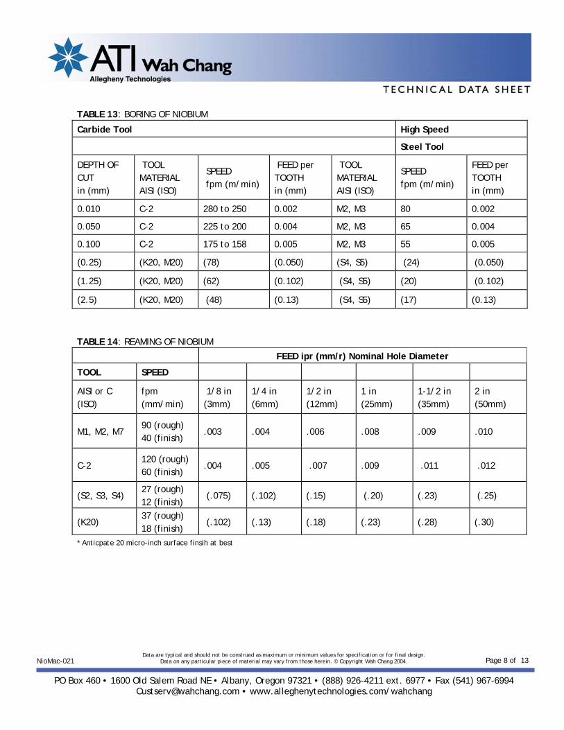
Grinding Niobium and its alloys can be difficult to grind. Most grinding wheels will quickly load, making selection and application of grinding fluid crucial to obtaining a good finish. Care must also be taken to prevent the metal surface from heating up during grinding to prevent a surface hydrogen pickup. Specific guidelines for the different grinding types are shown in Tables 15 – 18. TABLE 15: SURFACE GRINDING OF NIOBIUM
WHEEL SPEED fpm (m/s)
TABLE SPEED fpm (m/min)
DOWNFEED in/pass (mm/pass)
CROSSFEED in/pass (mm/pass)
WHEEL IDENTIFICATION ANSI (ISO)
2000-4000 40-60 Rough: 0.001 Finish: 0.0005 max
0.020 – 0.200 max=1/12 of wheel width
C46JV
(15) (12) (Rough: 0.025) (Finish: 0.013 max)
(0.5 – 5.0) (max=1/12 of wheel width)
C46JV
TABLE 16: CYLINDRICAL GRINDING OF NIOBIUM
WHEEL SPEED rpm
WORK SPEED fpm (mm/min)
INFEED On Diameter in/pass (mm/pass)
TRAVERSE wheel width per revolution of work
WHEEL IDENTIFICATION ANSI (ISO)
3600 to 6000 50 – 100 Rough: 0.001 Finish: 0.0003 max
1/5 – 1/10 C46jV
(15-30) (Rough: 0.025) (Finish: 0.008 max)
(1/5 – 1/10) (C46jV)

Data are typical and should not be construed as maximum or minimum values for specification or for final design. Data on any particular piece of material may vary from those herein. © Copyright Wah Chang 2004.
PO Box 460 • 1600 Old Salem Road NE • Albany, Oregon 97321 • (888) 926-4211 ext. 6977 • Fax (541) 967-6994
[email protected] • www.alleghenytechnologies.com/wahchang
Page 10 of 13NioMac-021
TABLE 17: INTERNAL GRINDING OF NIOBIUM
WHEEL SPEED rpm
WORK SPEED fpm (m/min)
INFEED On Diameter in/pass (mm/pass)
TRAVERSE wheel width per revolution of work
WHEEL IDENTIFICATION ANSI (ISO)
6000 50 – 150 Rough: 0.001 Finish: 0.0005 max
1/3 – 1/6 C46jV
(15-46) (Rough: 0.025) (Finish: 0.013max)
(1/3 – 1/6) (C46jV)
TABLE 18: CENTERLESS GRINDING OF NIOBIUM
WHEEL SPEED fpm (m/s)
THRUFEED OF WORK On Diameter in/min (m/min)
INFEED in/pass (mm/pass)
WHEEL IDENTIFICATION ANSI (ISO)
4000 50 – 150 Rough: 0.001 Finish: 0.0005 max
A60LV
(20) (1.3 – 3.8) (Rough: 0.025) (Finish: 0.013 max)
(A60LV)

Data are typical and should not be construed as maximum or minimum values for specification or for final design. Data on any particular piece of material may vary from those herein. © Copyright Wah Chang 2004.
PO Box 460 • 1600 Old Salem Road NE • Albany, Oregon 97321 • (888) 926-4211 ext. 6977 • Fax (541) 967-6994
[email protected] • www.alleghenytechnologies.com/wahchang
Page 11 of 13NioMac-021
Sawing No special considerations are necessary when sawing niobium and its alloys. High-speed steel blades can be used with power hacksaws, band saws, and circular saws. Sawing data is given in Tables 19 – 21. TABLE 19: POWER HACK SAWING OF NIOBIUM MATERIAL THICKNESS in (mm)
TEETH PER INCH pitch in (mm)
SPEED strokes/min (strokes/min)
FEED in/stroke (mm/stroke)
PRESSURE
< .25 10 60 0.003 Light
.25 - .75 10 60 0.003 Light
.75 – 3 6 55 0.006 Medium
> 2 4 55 0.006 Medium
(< 6) (2.5) (60) (0.075) (Light)
(6 – 18) (2.5) (60) (0.075) (Light)
(18 - 50) (4) (55) (0.15) (Medium)
(> 50) (6.3) (55) (0.15) (Medium)
TABLE 20: BAND SAWING OF NIOBIUM
MATERIAL THICKNESS in (mm)
TOOTH FORM
TEETH PER INCH pitch in (mm)
BAND SPEED fpm (m/min)
< .50 precision 14 100
.50 - 1 precision 10 90
1 – 3 precision 8 75
> 3 precision 6 65
(<12) (precision) (1.8) (30)
(12 – 25) (precision) (2.5) (27)
(25 – 75) (precision) (3) (23)
(>75) (precision) (4) (20)

Data are typical and should not be construed as maximum or minimum values for specification or for final design. Data on any particular piece of material may vary from those herein. © Copyright Wah Chang 2004.
PO Box 460 • 1600 Old Salem Road NE • Albany, Oregon 97321 • (888) 926-4211 ext. 6977 • Fax (541) 967-6994
[email protected] • www.alleghenytechnologies.com/wahchang
Page 12 of 13NioMac-021
TABLE 21: CIRCULAR SAWING OF NIOBIUM
STOCK DIAMETER OR THICKNESS in (mm)
TOOL MATERIAL AISI (ISO)
PITCH in/tooth (mm/tooth)
SPEED fpm (m/min)
FEED in/tooth (mm/tooth)
.25 - 3 M2, M7 0.20 – 0.75 70 0.005
3 – 6 M2, M7 0.50 – 1.10 55 0.005
6 – 9 M2, M7 0.75 – 1.30 45 0.007
9 – 15 M2, M7 0.90 – 1.75 35 0.007
(6 – 80) (S2, S4) (5 – 20) (21) (0.13)
(80 – 160) (S2, S4) (12 – 30) (17) (0.13)
(160 – 250) (S2, S4) (20 – 35) (14) (0.18)
(250-400) (S2, S4) (25 - 45) (11) (0.18)
FORMING OPERATIONS
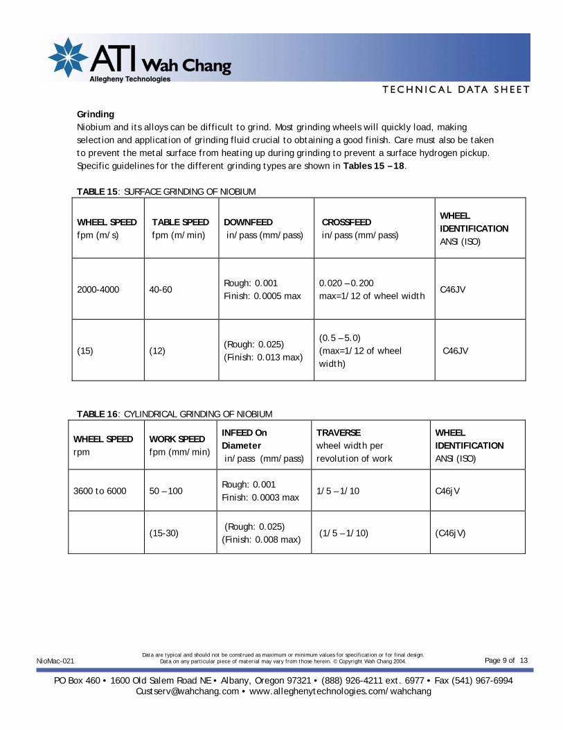
The forming characteristics of niobium and niobium alloys should be similar to copper and some mild steels. A copper blank is sometimes attempted before utilizing niobium. Niobium sheet metal can be formed easily without special working techniques. These operations are facilitated by niobium’s low rate of work hardening. There are two unusual features that must be considered when working with niobium and its alloys. First, no appreciable softening occurs below 400 ºC, because of its high melting point. Also, sheathing protection is not practical, since the sheathing material is likely to be softer than the niobium. Niobium’s cold working properties are excellent. Annealing is necessary after the surface has been worked 90%, with heat treatment at 1200 ºC for one hour causing complete recrystallization of material cold worked over 50%. The annealing must be performed in an inert gas, or preferably, in a high vacuum. Guidelines for a few select forming operations are given below: Spinning Normal techniques of metal spinning may be applied successfully to niobium, with minor modifications. It is generally better to work the metal in stages; for example, when spinning a right-handed cup from flat sheet, several formers should be used to give steps of approximately 10º. Wooden formers may be used for rough spinning, but a brass or bronze former is essential for finishing, because the metal is soft and takes up the contour of the former. For small work, aluminum bronze or Narite tools should be used with a radius of approximately 3/8 inch. If sharp angles are required, the tool must be shaped accordingly. Yellow soap, or tallow, is suitable for
Data are typical and should not be construed as maximum or minimum values for specification or for final design. Data on any particular piece of material may vary from those herein. © Copyright Wah Chang 2004.
PO Box 460 • 1600 Old Salem Road NE • Albany, Oregon 97321 • (888) 926-4211 ext. 6977 • Fax (541) 967-6994
[email protected] • www.alleghenytechnologies.com/wahchang
Page 13 of 13NioMac-021
lubricating the material, which must be cold worked continually. The peripheral speed of the work piece should be about 500 feet per minute. When spinning, niobium is prone to thinning and care must be taken to avoid this. The tool should be worked in many long sweeping strokes using a light pressure rather than a few heavy strokes. Deep Drawing Deep drawing of annealed niobium can be accomplished without much difficulty. Tool materials such as steel, aluminum bronzes, and beryllium copper can all be used for drawing operations. Single draws can be made if the depth of the draw does not exceed the diameter of the blank, and if multiple draws are made, the depth of the first draw should not exceed 40% of the blank diameter. For multiple draws, it may necessary to perform an intermediate vacuum anneal. Sulfonated tallow can be used as a lubricant. Punching and Blanking Normal dies and punches made of steel can be used satisfactorily for niobium and niobium alloys. The recommended clearance between the punch and die is 6% and light oils can be used to prevent scoring the dies. There are no special techniques required for stamping niobium. Tools made of steel, aluminum bronzes, and beryllium copper may be used, but they should be polished to prevent galling. A light oil lubricant can also be used to limit the amount of galling. Frequent cleaning of tooling may be necessary as galling and pickup of niobium on tooling can be expected.
SAFETY Niobium is non-toxic and there are no specific safety requirements for working with it. Although coarse metal niobium and niobium alloy powders are difficult to ignite, even at 300 ºC, small surface area powder, chips, or filings of less than 5 microns may auto-ignite at room temperature. If a fire does start, it is best to let it burn itself out. Small fires can be controlled with Type D dry powder extinguishers or with dry salt. Under no circumstances should water be used, as a violent explosion may result.