Nikolai Daskalov n Ivan Pushkarov n Venceslav Petrov -...
22
Nikolai Daskalov n Ivan Pushkarov n Venceslav Petrov Third Version of Terminal Device
Transcript of Nikolai Daskalov n Ivan Pushkarov n Venceslav Petrov -...

Nikolai Daskalov n Ivan Pushkarov n Venceslav Petrov
Third Version of Terminal Device

MOBILE3DTV
Project No. 216503
Third Version of Terminal Device
Nikolai Daskalov, Ivan Pushkarov, Venceslav Petrov
Abstract: This report describes the design and implementation of the third version of the terminal device. It is the final form factor of the mobile device, and this version includes all components of the final system. Namely, the chosen processing platform has been designed and produced in the final form factor and coupled to current version of the auto-stereoscopic LCD. Software support for the key project-specific components such as for processing and playing stereo video content, have been developed as well.
From platform perspective the goal of this version is to help the team to validate the integration of the proposed device, the performance of targeted components and the interoperability between them from both HW and SW.
The second goal is to verify the system interfaces (again both HW and SW), power management and to enable validation of the performance metrics like quantify the performance of the integrated display, DVB-H stack and developed player.
Keywords: OMAP, DVB-H, auto-stereoscopic LCD
MOBILE3DTV D6.4 Third Version of Terminal Device
Executive Summary
The third version of the terminal device (prototype) has been developed and implemented. At that stage the final form factor has been targeted, where all components such as the processing platform, auto-stereoscopic LCD, DVB_H receiver etc. have been coupled together and operate simultaneously.
From HW perspective, several new components were developed and produced:
• The new version of the auto stereoscopic LCD (3M) module was developed and integrated.
• The new version of the processing platform (OMAP3621) in final form factor
• The housing for the device was selected, procured and used for integration.
Key SW components and tools have been ported and used to support this version of the mobile terminal device. Those are the platform-specific operating system, file system, tool-chain, DVB-H low level drivers, auto-stereoscopic LCD drivers and a multi-view decoder based on H.264 decoder.
New HW and SW components have been integrated in order to accomplish the targeted version. After integration, the device software provides the capability to decode and render stereoscopic video content in MVC from stored files or received via the DVB-H (DVB-T) broadcast.

MOBILE3DTV D6.4 Third Version of Terminal Device
Table of Contents
1 Description of the third version of the mobile terminal device ............................................... 4
1.1 Form factor of the terminal device ................................................................................. 4
1.2 Third mobile terminal device HW features ..................................................................... 5
1.3 Third mobile terminal device SW support ...................................................................... 5
2 Auto-stereoscopic display production and integration ........................................................... 6
2.1 Selection of the display.................................................................................................. 6
2.2 Design of the auto-stereoscopic display module for the third version of the mobile terminal device ......................................................................................................................... 7
2.3 Operation of the auto-stereoscopic LCD module ........................................................... 8
3 Design of the processing platform for the third mobile terminal device ............................... 13
3.1 Processing platform selection ...................................................................................... 13
3.2 Processing platform design and implementation.......................................................... 13
3.2.1 Block diagram of the processing platform ............................................................. 13
3.2.2 Functional description of the processing platform ................................................. 14
3.2.3 Form factor of the processing platform ................................................................. 16
4 Housing of the third mobile terminal device ........................................................................ 18
4.1 Housing requirements ................................................................................................. 18
4.2 Selection of the housing .............................................................................................. 18
5 Third mobile terminal device SW support ........................................................................... 20
5.1 System requirements .................................................................................................. 20
5.2 Results ........................................................................................................................ 20

MOBILE3DTV D6.4 Third Version of Terminal Device
1 Description of the third version of the mobile terminal device
1.1 Form factor of the terminal device The assembled view of the terminal device is shown in Figure 1. The form factor is very close to recent smartphones and has typical features such as touch-screen and keyboard and can be run by battery operation. In addition to these, it hosts an auto-stereoscopic display and DVB-H receiver.
Figure 1. Assembled view of the third mobile terminal unit
Given the demonstration purpose of the device and the small amount of units to be produced, the housing of the mobile platform has been selected from available off-the-shelf solutions. It includes plastics, touch-screen, keyboard, battery pack and some connectivity options. Thus, the device has good-enough commercial outlook and can appeal to big manufacturers of mobile devices.
Several options for ready-made plastics for similar products were considered and the LogicPD Zoom2 platform has been selected due to the following reasons:

MOBILE3DTV D6.4 Third Version of Terminal Device
Very good finishing and integration
Provides all the means for UI control, battery operation, and connectivity, as main board
Allows replacement of the LCD module. The new auto-stereoscopic LCD module developed by MMS was embedded with minimal HW changes
The design allows integration of the different processing platforms in form of modules
Well known to handset OEMs. Already used by Texas Instruments to promote OMAP3430 to handset OEMs
For the purposes of the project, auto-stereoscopic LCD module and processing platform module were developed and integrated inside the cabinet.
For test purposes, the DVB-H receiver is connected via SDIO connector to the main board. Thji allows for replacing modules during the tests.
For the next stage of the project we will consider developing of replacement of the Zoom2 main board, where we will integrate DVB-H receiver on board.
1.2 Third mobile terminal device HW features The device HW incorporates:
Developed by MMS processing platform (OMAP3621, 2Gb LP-DDR, 16GB eMMC);
DibCom DVB-H receiver in form of SD card
Developed by MMS auto-stereoscopic LCD module
Battery and wall adapter power
Integrated audio system (stereo speakers)
Keyboard and navigation buttons
Touch screen
Connectivity options – WLAN, Bluetooth, 3G modem, UART, USB host and function
HDMI output
Debug interfaces – JTAG, UART, Ethernet (via add-on board)
1.3 Third mobile terminal device SW support The device SW is derived from the Texas Instruments L23 Linux release. This is what Texas Instruments delivers to it’s OEM manufactures using OMAP3630. Several customizations were implemented in order to support the processing platform (X-loader, U-boot) and device drivers were developed to support the new specific peripherals such as auto-stereoscopic LCD and DVB-H receiver.
Those enhancements and drivers were tested with unit test projects.
Software developments form the previous milestones such as the DVB-H processing stack, video decoder and player have been integrated and tested.

MOBILE3DTV D6.4 Third Version of Terminal Device
2 Auto-stereoscopic display production and integration
2.1 Selection of the display
To this version, a new 3D display procured from 3M has been integrated. The selected display is already used in production of the one of the first commercial devices incorporating auto-stereoscopic displays. The specifications are as follows:
Mobile form factor – 3.1”
Resolution - 400x480 pixels in 2D and 3D modes
Modes of operation - 2D and 3D modes, electrically switchable
Low power consumption
System interface - 24bit parallel RGB
The display uses standard TFT panel operating at 120Hz with special type of backlit, composed of two side backlits, light-guide and 3D film below the display.
Diagram illustrating the display construction and principle is shown in Figure 2.
Figure 2. Auto-stereoscopic display operation
The 3D effect is achieved by alternating the backlight LEDs on each side of the light-guide. The 3D film directs the light to the corresponding eye. In contract to parallax barrier types of displays, here the resolution is the same for 2D and 3D. However, as the operation of routing the light is time sequential, it require LDC working at 120 Hz, to provide 60 Hz refresh rate for each eye.

MOBILE3DTV D6.4 Third Version of Terminal Device
2.2 Design of the auto-stereoscopic display module for the third version of the mobile terminal device
3M delivered to MMS displays sets consisting of:
LCD panel
Two side backlits
Backlit light guide
Reflector
3D film
MMS task was to develop all other components in order to produce display modules, suitable for integration as follows:
PCB with system interconnect, backlit DC/DC controller and driver, etc
Bezel (metal frame), spacers, LED backlit holders, etc
Flex cable (0.3mm pitch) for connection to processing platform
The exploded view of the LCD module construction is shown in Figure 3 and block diagram of the electronic part of the final LCD module is shown in Figure 4.
Figure 3. Exlpoded view of the display module assembly

MOBILE3DTV D6.4 Third Version of Terminal Device
Figure 4. Block diagram of the auto-stereoscopic LCD module
Circuit diagram of the electronic part of the final LCD module and layout database are attached to the report as appendices (MT_V3_LCD_Schematic.pdf, MT_V3_LCD_B.Layer.pdf, MT_V3_LCD_T.Layer.pdf).
2.3 Operation of the auto-stereoscopic LCD module The major building block of the electronic part of the module is MSP430 (U1 on page 2 in the MT_V3_LCD_Schematic.pdf) type of microcontroller, synchronized to Vsync and L/R signals generated by the display driver. For each frame, it activates the left or right backlit according to the mode of operation (3D or 2D) according to the display requirements. The timing diagram of the sequencing is shown in Figure 5 and Figure 6. The MSP microcontroller controls a group of transistor switches. Additional protection circuit is added to avoid damage of the LED driver IC. The Backlight is interfaced to the display through two FPC cable, one for the left and one for the right side. The connectors used are 4 pins with 0,5 mm pitch. The PCB is designed considering all the currents that flow through it. The MSP also uses the SPI interface for receiving commands from the platform. JTAG interface is also presented on the PCB, if reprogramming of the MSP is required. The schematic is shown on page 2 in MT_V3_LCD_Schematic.pdf.

MOBILE3DTV D6.4 Third Version of Terminal Device
Figure 5. Display driving timing diagram – 3D mode
Figure 6. Display driving timing diagram – 2D mode
The microcontroller allows to program the start and stop timing of the activation of the corresponding backlit referenced to the beginning and end of the Vsynch pulse, as well as the duty cycle in 2D mode.
The current of the backlits is determined by the voltage of the applied and current limiting resistors. Currently two sources of the backlit voltages are provided – one developed on the LCD board and one external to it.

MOBILE3DTV D6.4 Third Version of Terminal Device
All needed signals to control the LCD module are provided to it via flex cable, connecting the module to the terminal device main board. Photo of the flex interconnect cable is shown in Figure 7.
Figure 7. Flexible interconnect cable for auto-stereoscopic display
Two types of flex connectors are placed on the PCB for the input signals. This allows PCB to be more flexible when interfacing it with different platforms. One of them is 51 pins with 0,3 mm pitch, and the other one is 50 pins with 0,5 mm pitch between the contacts. The display is interfaced the PCB via FPC cable and the mating connector is also placed. The display is driven in RGB666 mode, using the LS DSS signals of the OMAP. Because all the signals needed do not require level shifting, they are connected directly from the LCD module connectors to the 3D display connector. These connections are shown on page 1 in the MT_V3_LCD_Schematic.pdf.
For the proper functioning of the display, two additional voltages are required 1,8V an 2,8V. They are provided by U2 and U3 linear regulators, shown on page 3 in MT_V3_LCD_Schematic.pdf. On this page, TPS61170 is also presented (U4). This is a LED driver IC, for the Backlight. It works with voltage protection.
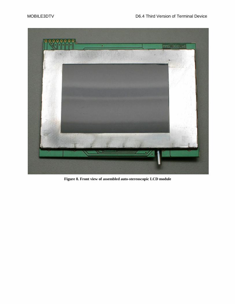
All the components for this implementation are selected considering the construction of the platform housing. It will be used for this version of the device. This makes the design more compact as it is required for a mobile device. Photos of assembled 3D auto-stereoscopic display are shown in Figure 8and Figure 9.
MOBILE3DTV D6.4 Third Version of Terminal Device
Figure 8. Front view of assembled auto-stereoscopic LCD module

MOBILE3DTV D6.4 Third Version of Terminal Device
Figure 9. Rear view of assembled auto-stereoscopic LCD module

MOBILE3DTV D6.4 Third Version of Terminal Device
3 Design of the processing platform for the third mobile terminal device
3.1 Processing platform selection During the initial study, Texas Instruments OMAP 3430 processing platform was selected, and OMAP3430 EVM was used in earlier versions of the mobile terminal device.
For the final version of the terminal device one of the recent products of TI OMAP3 platform was selected for several reasons:
Better performance – up to 1.3GHz
Better power consumption because of the new technology used
Lower cost
This new OMAP3 line is called OMAP3630 and is successor of 3430 line, ensuring full SW compatibility. It consists of several devices, where OMAP3630 targets OEM manufacturers of wireless handsets and OMAP3621 targets mobile consumer OEMs.
The differences between the devices are mainly in the level of integration and package options. OMAP3630 devices offer better integration because of the availability to use POP (package on package) for integration of the memories. MMS selected to use OMAP3621 devices for the following reasons:
Off the shelf availability – 3630 devices offers some very specific to handset manufacturers feature, which require many licensing agreements. Contrary, 3621 devices are free of these features and can be purchased for low volume production
Package is easier for production – 0.5mm ball pitch versus 0.4 for 3630
No need to have very sophisticated technology needed for POP assembly
MMS decided to has implemented the processing platform in form of separate module, replacing existing Zoom2 CPU module. Developing of the new module included work on integrating OMAP3621 CPU, memory and power management.
3.2 Processing platform design and implementation
3.2.1 Block diagram of the processing platform
The block diagram of the processing platform is shown in Figure 10. It consists of CPU (OMAP 3621), power management IC (PMIC), memory (LP-DDR 2Gbit and eMMC 16GB) and level shifters

MOBILE3DTV D6.4 Third Version of Terminal Device
Figure 10. Processing platform block diagram
Full schematic diagram and layout database is provided as attachment to this report (MT_V3_PP_Schematic.pdf, MT_V3_PP_B.Layer.pdf, MT_V3_PP_B.Overlay.pdf, MT_V3_PP_T.Layer.pdf, MT_V3_PP_T.Overlay.pdf).
3.2.2 Functional description of the processing platform
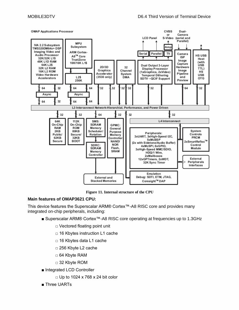
High-performance OMAP application processor is used in processing platform. The block diagram of the internal structure of the CPU is shown on the diagram below.
MOBILE3DTV D6.4 Third Version of Terminal Device
Figure 11. Internal structure of the CPU
Main features of OMAP3621 CPU:
This device features the Superscalar ARM® Cortex™-A8 RISC core and provides many integrated on-chip peripherals, including:
■ Superscalar ARM® Cortex™-A8 RISC core operating at frequencies up to 1.3GHz
□ Vectored floating point unit
□ 16 Kbytes instruction L1 cache
□ 16 Kbytes data L1 cache
□ 256 Kbyte L2 cache
□ 64 Kbyte RAM
□ 32 Kbyte ROM
■ Integrated LCD Controller
□ Up to 1024 x 768 x 24 bit color
■ Three UARTs

MOBILE3DTV D6.4 Third Version of Terminal Device
■ I2C codec interface
■ One high-speed USB 2.0 On-the-Go (OTG) interface and one high-speed USB 2.0 host
Interface
■ Many general purpose I/O (GPIO) signals
■ Programmable timers
■ Real time clock (RTC)
■ Low power modes
Power management IC (TPS65921) provides all the needed power supplies (1.2v, 1.8v, 3v) for
the operation of the CPU and memory, as well as their sequencing during power up and down and power saving modes. It provides all the control signals needed for the operation of the CPU and memory as reset, clocks, etc. In addition it provides keyboard control functions, audio ADC/DAC and other collateral functions.
The operating memory of the processing unit is 2 GB low-power Dual Date Rate SDRAM memory 32-bit (LP-DDR), operating at 166MHz.
The non-volatile memory is of eMMC type, which provides up to 16GB storage for kernel and
file system. It can be used for initial booting of the platform. Another non-volatile memory (EEPROM) is provided for identification of the module.
There are two 240 pins system connectors for connection of the processing platform with the
other components of the mobile terminal like LCD, DVB-H receiver, keyboard, USB, UART, I2C, CSI, SDMMC, MCSPI, JTAG and GPMC.
3.2.3 Form factor of the processing platform
The form factor of the processing platform is determined by the housing of the third mobile terminal device selected and is shown in Figure 12.

MOBILE3DTV D6.4 Third Version of Terminal Device
Figure 12. Processing platform module (top and bottom)

MOBILE3DTV D6.4 Third Version of Terminal Device
4 Housing of the third mobile terminal device
4.1 Housing requirements
The main requirements considered during the selection of the housing were:
To be able to accommodate all system components like processing platform, auto-stereoscopic LCD, DVB-H receiver, battery pack, etc
To have all the means to implement decent control UI – keyboard, navigation buttons, touch-screen, etc.
To be portable
To allow access to system components for debug purposes
4.2 Selection of the housing
Available housing were inspected for meeting the above requirements and the housing produced by company LogicPD, called Zoom2 was selected. It meets all the requirements at very reasonable cost. We targeted to reuse the most of the housing like plastic, battery pack, touch-screen, keyboard, etc. and to focus on adding on the processing platform, auto-stereoscopic LCD, DVB-H receiver and other project specific peripherals.
The housing design provides all the basic peripherals for the mobile device like connectivity, power, keyboard, etc and allows integrating custom processing platform via two system connectors.
In order to customize this housing for our need, MMS developed:
New auto-stereoscopic LCD module
New processing platform
For the DVB-H receiver interconnection, the existing SDIO slot was used. For the next version, the current main board of the Zoom2 platform will be redesigned in order to accommodate DVB-H receiver into the housing and to add some additional peripherals if needed.

MOBILE3DTV D6.4 Third Version of Terminal Device
The final form factor of the assembled third mobile terminal device with DVB-H receiver attached to SDIO slot is shown in Figure 1.

MOBILE3DTV D6.4 Third Version of Terminal Device
5 Third mobile terminal device SW support
5.1 System requirements
In the earlier phases of the project the following SW support was considered
Platform system SW is Linux based
To provide decent UI for control
To support as much as can of the typical for the similar mobile devices functions
To allow easy integration of the project specific functions like DVB-H receiver, auto stereoscopic LCD, etc
To have good power management allowing battery operation
To allow easy adoption of the handsets manufacturers
We decided to use for the third version of the mobile terminal device Linux-OMAP open source distribution and to customize it for selected processing platforms. The first step was to create customized versions of the X-loader and U-boot. The major function of these components is to do platform initialization.
The second step was to create kernel board configuration files in order different device drivers, available in the Linux kernel to operate properly with the peripherals on processing platform and external to it (connectivity, touch screen, etc).
The final step was to develop custom specific drivers for the project specific peripherals like DVB-H receiver and auto-stereoscopic LCD.
5.2 Results
We have achieved a fully functional Linux kernel supporting all the mobile terminal peripherals. Grace to the LCD selected supports 2D and 3D modes of operation, we have Linux-Omap UI (Poky, X-based) working properly with good quality.
The main goals for the next milestones can be summarized as follows
Integrate full end-to-end receiving system.
Modify the MVC decoder further (on the DSP core) in order to achieve the desired performance.
Integrate processing algorithms from other WPs.

Mobile 3DTV Content Delivery Optimization over DVB-H System
MOBILE3DTV - Mobile 3DTV Content Delivery Optimization over DVB-H System - is a three-yearproject which started in January 2008. The project is partly funded by the European Union 7th
RTD Framework Programme in the context of the Information & Communication Technology (ICT)Cooperation Theme.
The main objective of MOBILE3DTV is to demonstrate the viability of the new technology ofmobile 3DTV. The project develops a technology demonstration system for the creation andcoding of 3D video content, its delivery over DVB-H and display on a mobile device, equippedwith an auto-stereoscopic display.
The MOBILE3DTV consortium is formed by three universities, a public research institute and twoSMEs from Finland, Germany, Turkey, and Bulgaria. Partners span diverse yet complementaryexpertise in the areas of 3D content creation and coding, error resilient transmission, userstudies, visual quality enhancement and project management.
For further information about the project, please visit www.mobile3dtv.eu.
Tuotekehitys Oy TamlinkProject coordinator
FINLAND
Tampereen Teknillinen Yliopisto
Visual quality enhancement,
Scientific coordinator
FINLAND
Fraunhofer Gesellschaft zur Förderung der angewandten Forschung e.V
Middle East Technical UniversityError resilient transmission
TURKEY
Stereo video content creation and coding
GERMANY
Technische Universität IlmenauDesign and execution of subjective tests
GERMANY
MM Solutions Ltd. Design of prototype terminal device
BULGARIA
MOBILE3DTV project has received funding from the European Community’s ICT programme in the context of theSeventh Framework Programme (FP7/2007-2011) under grant agreement n° 216503. This document reflects onlythe authors’ views and the Community or other project partners are not liable for any use that may be made of theinformation contained therein.

![Dimitar I. Pushkarov - arXivII. NOTATION Following our previous works [1,2] (see also [5–7]) we consider a lattice with primitive vectors aα, α= 1,2,3 and introduce discrete coordinates](https://static.fdocuments.net/doc/165x107/606d62cc87f03272b74de0c4/dimitar-i-pushkarov-arxiv-ii-notation-following-our-previous-works-12-see.jpg)