
Nicolai Appendix
61
GUDMUNDSSON – GENERAL AVIATION AIRCRAFT DESIGN APPENDIX C1 – DESIGN OF CONVENTIONAL AIRCRAFT 1 ©2013 Elsevier, Inc. This material may not be copied or distributed without permission from the Publisher. APPENDIX C1: Design of Conventional Aircraft This appendix is a part of the book General Aviation Aircraft Design: Applied Methods and Procedures by Snorri Gudmundsson, published by Elsevier, Inc. The book is available through various bookstores and online retailers, such as www.elsevier.com, www.amazon.com, and many others. The purpose of the appendices denoted by C1 through C5 is to provide additional information on the design of selected aircraft configurations, beyond what is possible in the main part of Chapter 4, Aircraft Conceptual Layout. Some of the information is intended for the novice engineer, but other is advanced and well beyond what is possible to present in undergraduate design classes. This way, the appendices can serve as a refresher material for the experienced aircraft designer, while introducing new material to the student. Additionally, many helpful design philosophies are presented in the text. Since this appendix is offered online rather than in the actual book, it is possible to revise it regularly and both add to the information and new types of aircraft. The following appendices are offered: C1 – Design of Conventional Aircraft (this appendix) C2 – Design of Canard Aircraft C3 – Design of Seaplanes C4 – Design of Sailplanes C5 – Design of Unusual Configurations Figure C1-1: An EDRA Super Petrel LS on final. The airplane combines a number of configuration features presented in appendices C1 and C3; an amphibian, a biplane, and a pusher. (Photo by Phil Rademacher)
Transcript of Nicolai Appendix

GUDMUNDSSON – GENERAL AVIATION AIRCRAFT DESIGN APPENDIX C1 – DESIGN OF CONVENTIONAL AIRCRAFT 1 ©2013 Elsevier, Inc. This material may not be copied or distributed without permission from the Publisher.
APPENDIX C1: Design of Conventional Aircraft This appendix is a part of the book General Aviation Aircraft Design: Applied Methods and Procedures by Snorri Gudmundsson, published by Elsevier, Inc. The book is available through various bookstores and online retailers, such as www.elsevier.com, www.amazon.com, and many others. The purpose of the appendices denoted by C1 through C5 is to provide additional information on the design of selected aircraft configurations, beyond what is possible in the main part of Chapter 4, Aircraft Conceptual Layout. Some of the information is intended for the novice engineer, but other is advanced and well beyond what is possible to present in undergraduate design classes. This way, the appendices can serve as a refresher material for the experienced aircraft designer, while introducing new material to the student. Additionally, many helpful design philosophies are presented in the text. Since this appendix is offered online rather than in the actual book, it is possible to revise it regularly and both add to the information and new types of aircraft. The following appendices are offered:
C1 – Design of Conventional Aircraft (this appendix) C2 – Design of Canard Aircraft C3 – Design of Seaplanes C4 – Design of Sailplanes C5 – Design of Unusual Configurations
Figure C1-1: An EDRA Super Petrel LS on final. The airplane combines a number of configuration features presented in appendices C1 and C3; an amphibian, a biplane, and a pusher. (Photo by Phil Rademacher)

GUDMUNDSSON – GENERAL AVIATION AIRCRAFT DESIGN APPENDIX C1 – DESIGN OF CONVENTIONAL AIRCRAFT 2 ©2013 Elsevier, Inc. This material may not be copied or distributed without permission from the Publisher.
C1.1 Conventional Single Engine Propeller Aircraft This section is intended to elaborate on the design of small conventional aircraft. In this text, a small aircraft is one designed to carry one to ten people (e.g. 14 CFR Part 23, normal, utility, and aerobatic categories, or similar). Such aircraft are generally powered by piston or turbine engines, swinging 2- to 4-bladed propellers, although some are also driven by jet engines. Here, only propeller driven aircraft will be considered. The stalling speed for this class of aircraft is low, usually ranging from 35 to 70 KCAS. The cruising speed is typically in the 100-350 KTAS range and service ceiling varies from 13000 to 35000 ft. Such aircraft are often owner operated and their intended use ranges from activities like sport flying and pilot training to serious business transportation. The conventional propeller powered GA aircraft is either a tractor or a pusher (as discussed in Section 14.1.2, Propeller Configurations).
C1.1.1 Tractor Propeller Aircraft Tractor aircraft have already been thoroughly discussed in the book. Most of what is presented in Chapter 4, Aircraft Conceptual Layout regarding propeller aircraft pertains to this configuration. The purpose of this section is to provide additional information to help the reader weigh the merits of the different tail, wing position, cabin, and landing gear options suitable for such aircraft. A number of possible concepts are shown in Figure C1-2 and Figure C1-3. The reader should review the figures carefully and note the differences. The inevitable question is; which configuration is the best and why? The answer is that all of them can be shown to satisfy the same set of performance and stability and control requirements. Ultimately, there are other issues that determine which is the most appropriate. The final selection may consider desired structural arrangement, landing gear characteristics, ground handling, control system complexity, and many others. Aesthetics also plays an important role, because if all the configurations are essentially capable of fulfilling the performance requirements, then, effectively, looks can be a deciding factor as well. Many of these aircraft are designed with the sport pilot in mind, who wants nothing more than being able to jump into own aircraft and take-off for a fun filled flight without having to deal with the bureaucracy often associated with more formal operation of training and business aircraft. Some of these aircraft are built by amateurs (homebuilders), stored in conventional car garages, and easily transported on trailers to the nearest airfield, where they can be assembled and prepared for flight in as little as ten minutes. Some of these aircraft run on ordinary car fuel (mogas) and can take-off and land on unprepared grass fields, making them the ideal as touring aircraft. Others, for instance the turbine powered Cessna 208 Caravan and the piston powered Cirrus SR22 are serious business equipment. This is evident by their use as feeder or freight aircraft (Caravan) and a fast but economical business transport aircraft (SR22). The designer should be mindful of hangar sizes; most privately owned light-planes in the US are stored in hangars whose open door space is 40 ft. If possible, keep the wing span below 39 ft to allow the operator to use existing facilities. It is also important to consider how typical tractor airplanes are used. An aircraft like the 208 Caravan needs a large door to allow freight to be easily loaded and unloaded. It does not have to offer the responsiveness of an SR22, let alone an aerobatic airplane. It should have a high degree of static stability and a wide CG envelope. This helps making the airplane feel “solid” and “trusty.” Once the desired cruise heading and altitude have been established, the pilot “feels” like the airplane “wants” to maintain these with minimal correction, something that can help build a reputation of reliability. Such aircraft should be of rugged and dependable construction so they won’t become hangar queens. If possible, they should feature fixed landing gear with low drag wheel fairings and its wheel track should be wide to ensure great ground handling. Also, it should offer reasonably high cruising speeds and low stalling speeds.

GUDMUNDSSON – GENERAL AVIATION AIRCRAFT DESIGN APPENDIX C1 – DESIGN OF CONVENTIONAL AIRCRAFT 3 ©2013 Elsevier, Inc. This material may not be copied or distributed without permission from the Publisher.
Figure C1-2: A matrix of tricycle landing gear tractor configurations.

GUDMUNDSSON – GENERAL AVIATION AIRCRAFT DESIGN APPENDIX C1 – DESIGN OF CONVENTIONAL AIRCRAFT 4 ©2013 Elsevier, Inc. This material may not be copied or distributed without permission from the Publisher.
Figure C1-3: A matrix of taildragger landing gear tractor configurations.

GUDMUNDSSON – GENERAL AVIATION AIRCRAFT DESIGN APPENDIX C1 – DESIGN OF CONVENTIONAL AIRCRAFT 5 ©2013 Elsevier, Inc. This material may not be copied or distributed without permission from the Publisher.
An aircraft like the SR22 should offer entry doors on the left and right sides for an easy cabin entry. The cabin should be spacious and fuselage should be of the tadpole shape. It should feature a tricycle configuration for better ground handling. Also, it should offer the latest in avionics in a stylish interior with small area instrument panel to give a sense of openness to the occupants, many who become claustrophobic in small airplanes. The design of the SR20 and SR22 demonstrated that 50 inch wide cabins for aircraft powered by 200-300 BHP engines did not cost too much in terms of airspeed (i.e. drag). This is close to 8-10 inches wider than the competition (see Table 12-5 for other aircraft). Occupant comfort in such airplanes is vastly improved; such wide cabins have now become the norm in the design of modern small aircraft. Of course, tractor aircraft have a great utility potential, something impossible to address fully here. It explains the popularity of the configuration. Of course, it is important to complete a study of as many aircraft as possible that belong to the same class as the one being designed; certainly before beginning serious analysis work. Since so many tractor aircraft exist, clever, useful, and pilot-friendly features can be discovered among them and incorporated early on in the design process. This is always easier than if suggested later. In this context, obtaining operator input (e.g. pilot input) is strongly recommended. After all, the airplane is being designed for the end-user and not the engineering team. The following response is indicative of what can be discovered on one of the countless forums present online and intended for pilots. While it is but one of thousands of opinions expressed, it highlights the nature of the discussion that takes place between owners and operators of aircraft. And this can be very valuable to the designer of a new aircraft, as it demonstrates that owners and builders of light aircraft often consider a complicated combination of pros and cons when selecting aircraft, and not just one or two pros.
A friend and I looked thoroughly at Aircraft A last year. We got to look one over at Oshkosh and we signed up for a demo flight two weeks later, when the salespeople were in our area. Likes: The airplane is very impressive in appearance, performance, economy, and speed. The stall is a non-event, more of a mush or oscillation. The center stick felt a little awkward at first but several pilots told us you get used to it fast. The openness and room in the cabin without a yoke in front of you is nice. The rear seat is huge with lots of passenger space. It is fast enough to keep up with an SR22 with the same HP. Dislikes: We didn't like the low seating position, especially in the back seat. Also, getting in and out of the back seat was awkward. The standard model didn't have much cargo room nor did the enlarged model. In fact, it consisted of two tiny pockets in the wing root. We didn't care for the takeoff and landing technique. The plane requires a long paved runway. Landings are made relatively fast to maintain elevator effectiveness and brakes have to be used throughout the takeoff and landing roll to hold the center line. At speeds below about 90 knots, the ailerons lose effectiveness and most of the steering has to be done with the rudder. We thought the pusher-engine would make it quieter, but this is not the case. The engine is right behind the rear seats and is just as loud as any other airplane. In conclusion, we decided it wasn't the right plane for us. We are now pondering Aircraft B, as we had an opportunity to sit in one and talk with the builder. It too is an impressive aircraft. We have to fly one yet, but were told it flies like any other low-wing tricycle gear. It can be purchased and assembled in stages; where as Aircraft A must be bought all at once.
C1.1.2 Pusher Propeller Aircraft As stated in Section 14.1.2, Propeller Configuration, the pusher propeller is a good solution to some specialized mission requirements. In particular, it is ideal for single engine reconnaissance or observation aircraft, as well as sporting and touring aircraft. The configuration is also ideal for UAVs as the propeller will not obstruct the camera view, or blow foreign objects toward it when maneuvering on the ground. The aft placement of the propeller

GUDMUNDSSON – GENERAL AVIATION AIRCRAFT DESIGN APPENDIX C1 – DESIGN OF CONVENTIONAL AIRCRAFT 6 ©2013 Elsevier, Inc. This material may not be copied or distributed without permission from the Publisher.
allows a high field-of-view cockpit to be designed. All the pusher configurations in this section feature such cabins (see Configurations A through D in Figure C1-4). As discussed in Section 14.1.2, Propeller Configurations, the pusher configuration brings a number of challenges to propeller aircraft. It is imperative that an accurate assessment of the empty weight CG location and CG travel with loading precedes the configuration layout. The procedure of Section 12.3.1, Initial Design of the External Shape of the Fuselage will suffice in this respect. A likely pitfall is to size the fuselage and place the occupants too far forward of the engine (and wing). This can easily lead to a design whose empty weight CG location causes it to fall on the tail when empty and a large forward CG movement when loaded requires high airspeed before it can rotate to take-off. The solution requires the placement of the main and nose landing gear, as well as occupants, to be established early on. Additionally, the wing may have to be swept forward or aft to resolve CG issues associated with too much or too little static stability.
Figure C1-4: Five single-engine, tricycle pusher configurations with canopy.
All the configurations in Figure C1-4 feature a tricycle landing gear, which, as stated in Chapter 13, The Anatomy of the Landing Gear, improves ground handling. However, the designer must ensure ample propeller ground clearance when the airplane rotates for T-O or flares before touch-down. It is prudent to ensure sufficient propeller clearance for a touch-down without flaps (which most likely presents the highest flare angle), with flat main tires and main landing gear fully flexed. Clearance problems can be solved with a higher thrustline (drawbacks are discussed below), smaller diameter propeller, or longer landing gear (which would increase the weight of the landing gear strut and its support structure). It is a problem that the propeller may be damaged from pebbles that may shoot from the nose or main landing gear. Additional advantages of the configuration include that the forward part of the fuselage can be shaped to promote laminar boundary layer and, that way, reduce its drag. The pusher configuration will not blast turbulent air over the fuselage, promoting less drag. Furthermore, the configuration looks sporty to many and can be designed to allow an easy access to the cabin. Note that while the canopy makes for an excellent view, it may be expensive to produce.

GUDMUNDSSON – GENERAL AVIATION AIRCRAFT DESIGN APPENDIX C1 – DESIGN OF CONVENTIONAL AIRCRAFT 7 ©2013 Elsevier, Inc. This material may not be copied or distributed without permission from the Publisher.
All the configurations shown in here allow for a structural “hub,” a central structure to which the engine, wing, and main landing gear attach and may result in a lighter airframe. Configurations A through C enclose the propeller with the tail booms, rendering them much safer on the ground as it really takes “a focused effort” to walk into it. It is often thought the propeller and engine being mounted behind the cabin should reduce the noise in the cabin, although this may simply not be realized due to the fact that the wake from the fuselage generates additional broadband noise1 that often adds several dB(A) to the airplane’s overall noise level. It would be more appropriate to say it generates a “different” noise than a tractor. All the configurations in Figure C1-4 feature a high thrustline, which leads to the following disadvantages:
(1) A larger elevator deflection is required for trim in cruising flight or when climbing; in fact, noticeable pitch effects are noticed when throttling up or down. This effect is present regardless of whether the HT is immersed in the propwash, but can be ameliorated by a lower thrustline. (2) It loads up the nose landing gear during T-O and calls for an increased ground run, as a higher airspeed is required to rotate the nose.
Of the models shown, Configuration A is the least affected by propwash over the HT. The pusher configuration may bring about engine cooling problems. Naturally, one must remember that just because something adds a challenge does not mean there isn’t a solution to it. The Cessna 337 Skymaster is an example of a successful twin that has a tractor and pusher engine. The heating problem is solved with a scoop-type cooling air inlet, although this does not prevent the rear engine from running 20-30 °F warmer than the front one2. Other pushers, such as Rutan’s LongEz is well known for a persistent engine cooling problem which has called for carefully designed engine inlet and exits. Possible solutions are shown in Section 7.3.2, Piston Engine Inlet and Exit Sizing. In particular, refer to Figure 7-21 (reproduced below for convenience as Figure C1-5) and Figure 7-22 for rules-of-thumb regarding airflow through piston engine installations. Ultimately, some solutions may call for the installation of a cowl flap or the use of water-cooled engines.
Figure C1-5: Airflow through a conventional tractor engine installation (Figure 7-21 reproduced).
Configuration A provides an excellent low speed elevator authority (at high power settings) as the propwash is directed over the Horizontal Tail (HT). This will increase the drag of the HT and the designer (who should be able to assess the drag increase) can evaluate whether this drawback is greater than the improved low-speed handling. For small LSA type aircraft, the additional drag may indeed be minute. While this author seeks to eliminate drag wherever it can be found, for LSA aircraft, the added drag may simply be less important than the improved low-speed elevator authority. The height of the thrustline, combined with how the HT is immersed in the propwash, will dictate the magnitude of the pitch changes with power setting.

GUDMUNDSSON – GENERAL AVIATION AIRCRAFT DESIGN APPENDIX C1 – DESIGN OF CONVENTIONAL AIRCRAFT 8 ©2013 Elsevier, Inc. This material may not be copied or distributed without permission from the Publisher.
A well known version of this configuration is the Cessna XMC (nicknamed the Experimental Magic Carpet), which was designed in the late 1960s and early 1970s as a replacement for the Cessna 150 trainer aircraft. Like the Model 150, the XMC was a twin-seat, high-wing aircraft, powered by a 100 BHP Continental O-200 engine. The airplane was used to introduce some novelties in aircraft design, having control columns rather than a wheel, corrugated skins, and, initially, only 3 ribs per wing. Due to the aft CG of the aircraft, it featured a slightly swept aft wing leading edge. To paraphrase a former test pilot: “The airplane was OK statically but had a terrible Dutch roll mode. It flew like it was very nose heavy.” The swept high wing resulted in a very high dihedral effect, which almost certainly was detrimental to the Dutch roll mode. According to the test pilot, the airplane did not display bad T-O handling as one would suspect from a high thrustline. This may have been remedied by the horizontal tail, which was immersed in the propwash. The airplane was alleged to have a high cabin noise, but, ultimately, did not offer performance benefits above the Model 150 and the project was cancelled. Configuration B has an “A-tail”, which effectively is an inverted V-tail. With it come many advantages and disadvantages cited in Section 11.3.10, A-Tail. It is a clever way of introducing pro-verse roll when correcting a slip or skid, but requires a more complicated control system, as control cables (or pushrods) must go through both tailbooms. The tail configuration, as shown in Figure C1-4, also sits above the propwash, which reduces its low speed elevator authority (at higher power settings) and drag. However, being out of the propwash, there is no yaw contribution due to a VT sidewash (see Appendix C5, Design of Unusual Configurations). This will help reduce spiral instability due to propeller effects, which requires constant correction by the pilot (or autopilot). Configuration C is similar to A, but shares some of the characteristics of Configuration B (assuming a single prop as shown). It is less affected by propeller induced spiral instability, but suffers from reduced low speed elevator authority compared to Configuration A. Some drag reduction, associated with the tail not being immersed in the propwash, is to be expected, although (as already discussed) this may be negligible for many applications. Furthermore, the elevator control system will be slightly heavier, with a greater part-count, as control cables or pushrods must be run through one of the fins (something not required for Configuration A). Configuration D is a lightweight configuration, with a slender tailboom to which a T-tail is mounted. Many of the pros and cons already discussed apply to it. The tailboom must be very stiff and strong to allow the tail bending and torsional loads to be reacted and to resist flutter. While light, the presence of the tailboom prevents a large diameter propeller from being used, unless the engine is raised above what is shown in the figure. In order to allow the aircraft to rotate for take-off or flare for landing, the main landing gear should be made taller or the tailboom should be mounted at an angle so the aircraft can be rotated to its stall AOA on the ground. The configuration protects the propeller from damage caused by rocks being thrown by the landing gear, as the propeller inevitably sits high above the cone of trajectories. It effectively renders a propeller ground strike impossible.

GUDMUNDSSON – GENERAL AVIATION AIRCRAFT DESIGN APPENDIX C1 – DESIGN OF CONVENTIONAL AIRCRAFT 9 ©2013 Elsevier, Inc. This material may not be copied or distributed without permission from the Publisher.
C1.2 Conceptual Design of Small Biplanes The golden age of the biplane is usually considered to have lasted from 1903 to 19403. During this era the configuration dominated aircraft design. Although the monoplane has since surpassed the biplane, it is still a viable option for many tasks; e.g. as an aerobatic or agricultural aircraft. Both missions require rapid and responsive roll capability made possible by the compact size of its two wings. A shorter wing span is achieved by splitting the necessary wing area into two wing panels. This is beneficial in several ways. First, it substantially reduces roll damping when compared to a monoplane of the same wing area, resulting in greater roll rate. Second, the shorter wing span further reduces the moment of inertia about the roll axis, increasing the roll acceleration and reducing time required to achieve steady-state roll rate, giving the biplane great roll responsiveness. Third, the shorter wingspan reduces wing bending moments, so the wing can be made lighter and stiffer. Fourth, biplanes pack a large wing area inside a small span, allowing for reduced take-off and landing distances while eliminating the need for a heavy or complex high lift system. This also allows biplanes to operate out of unimproved landing strips with ease. Fifth, they can be designed to offer great stall characteristics by ensuring the upper wing (if a forward stagger configuration) or lower wing (if an aft stagger) stalls first. The sudden drop in lift of one of the two wings generates a nose down pitching moment, necessary for good stall recovery. Figure C1-6 shows examples of five single engine biplanes with different tail configurations, all taildraggers.
Figure C1-6: Five single-engine, taildragger biplane configurations with tractor propellers.
Among drawbacks of the configuration is the high drag of the external struts and bracing, which effectively renders the conventional biplane unsuitable for missions that involve extended range or endurance. A possible exception to this is the Griffon Aerospace Lionheart, a six-seat modernized replica of Beech’s famed 1930s Staggerwing. It was designed and built in the early 2000s. It featured Natural Laminar Flow airfoils and retractable landing gear and was completely void of external struts and bracing. It was both clean and fast for a biplane, although its 450 BHP Pratt & Whitney R-945 radial engine gave it a cruising speed similar to the 300 BHP Cirrus SR22 and Cessna Corvalis (both which enjoy the safety and reduced maintenance cost of a fixed landing gear). The original Beech Staggerwing, had the upper wing aft of the lower wing, a configuration relatively rare in the history of aviation. As

GUDMUNDSSON – GENERAL AVIATION AIRCRAFT DESIGN APPENDIX C1 – DESIGN OF CONVENTIONAL AIRCRAFT 10 ©2013 Elsevier, Inc. This material may not be copied or distributed without permission from the Publisher.
can be seen later, this configuration leads to a less “destructive” intereference between the two wings than the conventional arrangement, although only marginally so. An important shortcoming of the biplane configuration is how the high pressure region of the upper wing affects the low pressure region of the lower wing. This effect can also be explained in terms of spanwise vorticity: The lower wing increases the circulation around the upper wing, while suffering from the vorticity of the upper one. This is shown in Figure C1-7. The severity of this effect depends on the relative geometry of the two wings, in particular the decalage angle (see Figure C1-9). The influence is low for zero decalage, but otherwise can be quite significant. As an example, using potential flow analysis, an average AR biplane with a 4° decalage can easily result in the upper wing generating 2-times more lift than the lower one. A 2-to-1 ratio is a very inefficient configuration - ideally, both wings should contribute equally to the total lift. This, in effect, means the lower wing is there for the ride. The biplane must make up for this inefficiency by flying at a higher AOA than a comparable monoplane. A higher AOA means increased downwash, which, in turn, means higher lift-induced drag. This is also evident by the four wingtip vortices produced by the configuration; it is indicative of a less efficient lift generation.
Figure C1-7: The upper wing generates more lift than the lower one due to its contribution to the upper circulation. Similarly, the upper wing vortex reduces the lift of the lower one by slowing airflow over its top
surface.
Biplanes have a very shallow lift curve slope (see Figure C1-10). Therefore, they operate at high AOAs and are subject to relatively large changes in deck angle with airspeed. However, it is an advantage that it makes the airplane less susceptible to gust loading. The Biplane as an Agricultural Aircraft As stated earlier, the biplane configuration is well suited for agricultural aircraft. Examples of such aircraft include the Antonov An-2, Grumman Ag-Cat, Transavia PL-12 Airtruk, and the PZL M-15 Belphegor. The ideal Ag-plane must be efficient, safe and durable. In this context, efficiency refers to the airplane’s ability to spray a large acreage of farmland each hour. Frequent fuel stops are a significant drawback in the operation of such aircraft, so it should feature a large fuel tank in addition to a large fertilizer tank (or hopper as it is referred to by operators). The airplane should also be capable of high cruising speed to allow it to be quickly ferried from one farm field to the next. The Ag-plane should be strong, reliable, and durable; capable of providing years of hard service with minimum maintenance. The ideal Ag-plane has a strong protected cockpit capable of surviving in one piece in case of even a severe accident. The cockpit should be carefully designed with pilot ergonomics and safety as priorities. For instance, pilot egress should be made easy and lightning fast. It should also feature common sense amenities like air conditioning system for added comfort; after all, it is frequently the pilot’s office for up to 15 hours a day. The biplane offers an ideal solution to many of these considerations.

GUDMUNDSSON – GENERAL AVIATION AIRCRAFT DESIGN APPENDIX C1 – DESIGN OF CONVENTIONAL AIRCRAFT 11 ©2013 Elsevier, Inc. This material may not be copied or distributed without permission from the Publisher.
C1.2.1 Nomenclature for Biplanes Figure C1-8 shows the front view of a typical biplane and the nomenclature applied to the structural arrangement between the two wings. As will be shown later, the Aspect Ratio for a biplane is obtained by dividing the square of the span of the larger wing (the upper one in Figure C1-8) by the total planform area of both wings.
Figure C1-8: Nomenclature for the wing layout of a biplane.
C1.2.2 Various Effects that Apply to Biplanes Only Effect of Decalage Angle On a biplane, a decalage angle is the difference between the incidence angles of the top and bottom wing (see Figure C1-9). The decalage is called positive when the AOI of the lower wing is less than that of the upper wing, as shown in Figure C1-9. For one, decalage is a way to control whether the upper or lower wing stalls first. If the biplane has a positive stagger, it is desirable to ensure the upper wing stalls first. This will shift the center of lift farther aft, ensuring the airplane drops the nose gently at stall. However, the effect is more profound than that, as discussed in NACA TN-2694. The decalage also controls the circulation strength around the two wings. The stagger angle and gap are important characteristics because they dictate the pressure distribution between the two wings and impact the maximum lift capability (see discussion on combined effect momentarily). Stinton5 details that the average wing incidence for early biplanes (those that had thin undercambered airfoils) ranges from +2° to +5°. For post World War I biplanes, this value ranges from +2° to +3°. He also states that the decalage varies from 0° to +1° for both classes.
Figure C1-9: Definition of a decalage angle for a biplane.
Effect of Positive and Negative Stagger Stagger is the relative position of the leading edges of the upper and lower wings. A positive stagger is one in which the upper wing is ahead of the lower wing. A negative stagger is the opposite. Most biplanes feature a positive stagger. The effect of stagger is investigated in NACA R-706, where it was concluded that a positive stagger

GUDMUNDSSON – GENERAL AVIATION AIRCRAFT DESIGN APPENDIX C1 – DESIGN OF CONVENTIONAL AIRCRAFT 12 ©2013 Elsevier, Inc. This material may not be copied or distributed without permission from the Publisher.
yields a higher CLmax than a negative stagger. The greater the positive stagger, the greater the maximum lift. Additionally, positive stagger restricts the travel of the Aerodynamic Center (AC), which is helpful in stability and control. The cruise drag was marginally higher for the positive stagger, though. Stagger may be selected based on pilot visibility, as long as the designer is aware of the implications.
Figure C1-10: The impact of stagger on lift curve slope and stick fixed neutral point of a typical biplane wing configuration. Negative stagger means the LE of the upper wing is ahead of the lower wing LE.
Figure C1-10 shows how stagger affects the lift curve slope and the stick-fixed neutral point for a specific biplane configuration. In the graph, a positive stagger means the leading edge of the upper wing is ahead of the lower wing (note the inverted x-axis). This way, a positive stagger of 1xChord means that the trailing edge of the upper wing is directly above the leading edge of the lower one (assuming both wings have the same chord). With this in mind, consider first the lift curve slope (the solid curve). It can be seen that the maximum value of CL is reached at either extreme of the range evaluated. As one would expect, the minimum occurs when the upper wing is right on top of the lower one. As mentioned earlier, this is caused by the destructive interference between the high pressure region of the upper wing and the low pressure of the lower one. The lift curve slope of this configuration is approximately 93% of the extreme positive stagger (upper wing is forward of lower wing). The second observation is the change in the stick-fixed neutral point (dashed curve), here referenced to the upper wing, which moves fore and aft with it. This way, for the full positive stagger, the neutral point is approximately at 68% MGC. The MGC is considered on the upper wing. When the wings are right on top of each other, the neutral point has moved to approximately 27% MGC, and when at full positive stagger (top wing leading edge is right above the trailing edge of the lower wing), the neutral point is at -32% MGC. This way, the stagger is a tool to modify the longitudinal stability characteristics of the design. Combined Effect of Stagger and Decalage Figure C1-11 shows the influence of selected combinations of positive and negative stagger and decalage. Using the vortex analogy of Figure C1-7, it can be seen that the positive decalage results in the lift forces adding to form the total lift. However, the interference is destructive because it reduces the lift effectiveness of both wings (i.e. the total lift is less than it would be in its absence). The opposite holds for the negative stagger; the lift forces must be subtracted. However, the circulation direction will be additive – therefore, the magnitude of the two forces can be expected to be greater. Figure C1-12 shows an example of some arbitrary biplane configuration, for which the two wings have an equal chord. The upper wing of the left combination has an AOI of +6° and generates a CLtot of 0.2441. The upper wing of

GUDMUNDSSON – GENERAL AVIATION AIRCRAFT DESIGN APPENDIX C1 – DESIGN OF CONVENTIONAL AIRCRAFT 13 ©2013 Elsevier, Inc. This material may not be copied or distributed without permission from the Publisher.
the right combination has an AOI of -6° with a CLtot of 0.0163. Although this combination generates the least amount of total lift, the lower wing is operating at a higher CL than the others, due to the constructive interference of the wing circulation. The rightmost configuration presents a possible aircraft configuration in which the upper wing, of a reduced chord, can be used to enhance lift on the lower one (the main wing) while acting as a possible horizontal tail or as a part of a tandem wing layout.
Figure C1-11: The impact of stagger on lift curve slope and stick fixed neutral point of a typical biplane wing configuration. Positive stagger means the LE of the upper wing is ahead of the lower wing LE.
Figure C1-12: Typical results for a negative stagger for some arbitrary biplane configuration using potential flow theory. That of the lower wing is 2° for all combinations. The left combination has a positive decalage and the
right combination has a negative decalage. To generate a positive fixed CL, the rightmost configuration must operate at the largest AOA of the three.
Effect of Gap The gap is the space between the upper and lower wings. A large gap will generally reduce drag by improving the flow field between the two wings. Of course, the larger the separation, the larger will be the wetted area of the support struts and bracing wires, not to mention reduced buckling strength of struts that react compressive flight loads. The effect of drag is accounted for using the formulation that follows. Buckling strength is handled during the detail design phase.

GUDMUNDSSON – GENERAL AVIATION AIRCRAFT DESIGN APPENDIX C1 – DESIGN OF CONVENTIONAL AIRCRAFT 14 ©2013 Elsevier, Inc. This material may not be copied or distributed without permission from the Publisher.
C1.2.3 Aerodynamic Properties of the Biplane Configuration The following is a summary of how to determine important design parameters for the biplane configuration. Biplane Aspect Ratio The Aspect Ratio of a biplane is given by:
S
bARbiplane
2glarger win2
(C1-1)
Equivalent Monoplane Theorem The concept of an equivalent monoplane was proposed by Munk7 in the early 1900s to help simplify analyses of biplanes. It presumes the biplane configuration can be replaced with a monoplane wing of equal wing area and lift-induced drag. It has already been stated that the biplane must generate greater downwash than a monoplane to maintain altitude. This difference can be represented as follows:
11monoplane
biplane (C1-2)
Where: monoplane = Downwash by a monoplaneeAR
CL
biplane = Downwash by a biplane of equal weight and wing area
eARCL
1
= Biplane interference factor (to be discussed momentarily in more detail) Munk’s Span Factor, k As stated above, Munk’s Equivalent Monoplane Theorem replaces the biplane wings with a monoplane wing of equal area and lift-induced drag. This way, if the maximum wing span of the biplane is given by b, then a corresponding equivalent monoplane wingspan will be k·∙b, where k is called the Munk’s Span Factor8. The factor k has a value of 1 for monoplanes, but for biplanes it is always larger than 1 and is a function of the following ratios:
(1) Gap ratio, which is gap/(average wingspan) = avgbh ,
(2) Span ratio, which is (shorter wingspan)/(longer wingspan), longshort bb , and
(3) Area ratio, SSSSSr shortlong .
Where: h = Gap height (see Figure C1-9) shortlongavg bbb 2
1 (see Figure C1-8)
S = Total area of both wings. Slong and Sshort = Planform areas of the two wings. The Munk’s span factor is given by the following expression:
1
2k (C1-3)
Biplane Interference Factor, The biplane interference factor accounts for the fact that the presence of two lifting surfaces in a close proximity will affect the resulting flow field. In other words, the upper wing affects the lower wing and vice versa. This

GUDMUNDSSON – GENERAL AVIATION AIRCRAFT DESIGN APPENDIX C1 – DESIGN OF CONVENTIONAL AIRCRAFT 15 ©2013 Elsevier, Inc. This material may not be copied or distributed without permission from the Publisher.
interaction can be measured and is represented using the factor . A method developed by Prandtl9 can be used to estimate if both wings are of an equal span. It is valid for 5.005.0 avgbh :
avg
avg
bhbh
7.3055.166.01
(C1-4)
Diehl8 presents a graph of Prandtl’s biplane interference factors for other span ratios, . Using surreptitious mathematical wizardry, the following expression was derived to calculate for other span ratios. It is valid for
0.14.0 and 5.005.0 avgbh . It provides an acceptable fit for the curves in Diehl’s graph.
avg
avg
bhbh
5296202875
756
(C1-5)
This is plotted in Figure C1-13.
Figure C1-13: A map of Prandtl’s biplane interference factors as functions of the gap and span ratios. (Based on Reference 8.)
Lift-Induced Drag of a Biplane Once the biplane interference factor has been determined, the lift-induced drag can be determined using the following expression:
Biplane lift-induced drag:
12
1 2
22
ebSC
eARCC LL
Di (C1-6)

GUDMUNDSSON – GENERAL AVIATION AIRCRAFT DESIGN APPENDIX C1 – DESIGN OF CONVENTIONAL AIRCRAFT 16 ©2013 Elsevier, Inc. This material may not be copied or distributed without permission from the Publisher.
Prandtl also showed that the drag of one wing in the presence of the other is given by:
shortlong
shortlong
bbLL
qD
12 (C1-7)
Where: q = Dynamic pressure Llong and Lshort = Lift of the two wings blong and bshort = Span of the two wings. Furthermore, he determined the total lift-induced drag to be:
2
2
2
2
21
short
short
shortlong
shortlong
long
longi b
LbbLL
bL
qD (C1-8)
The expression allows the geometry for minimum lift-induced drag to be determined. This happens when:
1short
long
LL
The resulting minimum lift-induced drag is thus found to be:
Minimum lift-induced drag:
2
2
2
2
211
longi qb
LD (C1-9)
Where: L = Llong + Lshort = Lift (or weight of the aircraft) If the two wings are of different geometry, then it is traditional to assume the lift is proportional to the area ratio, r (defined earlier). This way, the following rules hold:
Wing areas: SrSandrSSSSS
SS
r shortlongshortlong
1
Wing lift: WrLrLandrWrLL shortlong 11
Substituting this into Equation (C1-9) leads to another helpful expression in terms of weight at condition, W, and the area ratio:
Minimum lift-induced drag:
22
2
2 112 rrrrqbWD
longi (C1-10)
Finally, as presented by Diehl8, the Munk’s span factor for this optimized configuration is then given by:
1121222
2
rr
k (C1-11)

GUDMUNDSSON – GENERAL AVIATION AIRCRAFT DESIGN APPENDIX C1 – DESIGN OF CONVENTIONAL AIRCRAFT 17 ©2013 Elsevier, Inc. This material may not be copied or distributed without permission from the Publisher.
Diehl also presents a number of graphs, not presented here, that will help further in the design of efficient biplanes. With these tools in hand, it is now possible to implement a reasonable performance analysis for the biplane. The foregoing formulation, and in particular the presence of the biplane interference factor, , reveals that even a very clean biplane will always generate more drag than a comparable monoplane. This is further compounded by a larger interference drag due to two rather than one wing, which increases CDmin as well. For this reason, L/D efficiency is not a compelling argument for such a design, but rather the other favorable properties discussed at the beginning of this section. DERIVATION OF EQUATION (C1-3): Lift-induced drag of the equivalent monoplane of wing span k·∙b is given by:
ebkSC
eSbkC
eARC
C LLLDi
22
2
22
22
(i)
Lift-induced drag of the biplane:
12
12
1 2
2
2
22
ebSC
eSbC
eARCC LLL
Di (ii)
Per Munk, the lift-induced drag for the biplane and its equivalent monoplane configuration must be equal, but this allows the factor k to be determined, yielding Equation (C1-3).
QED

GUDMUNDSSON – GENERAL AVIATION AIRCRAFT DESIGN APPENDIX C1 – DESIGN OF CONVENTIONAL AIRCRAFT 18 ©2013 Elsevier, Inc. This material may not be copied or distributed without permission from the Publisher.
C1.3 Conventional Multi-Engine GA Aircraft Twin-engine, and even four-engine propeller powered aircraft are widely used for short domestic routes and as “cargo-feeder” aircraft for cargo companies like UPS and Fedex. Many airlines use such aircraft in their hub-and-spoke airway systems, operating them between large cities and less dense rural area airports. Modern aircraft of this kind usually feature turboprop or turbofan engines and offer pressurized cabins, allowing them to be operated above weather, resulting in a more reliable scheduled service. In spite of great utility, multi-engine aircraft are challenging to operate and require special pilot ratings. The primary area of concern and the one that most forcefully requires additional pilot rating is operation with One Engine Inoperative (OEI). In addition to what is presented here, the designer of multi-propeller aircraft is encouraged to read Section 14.2.5, Asymmetric Yaw Effect for a Twin Engine Aircraft to better understand the flaws of the configuration. A number of such configurations will now be briefly discussed. C1.3.1 Turboprop Commuter Aircraft This section considers only conventional, tail-aft configurations with turboprop engines mounted on the wing. Distinction will be made for the wing’s vertical position. As with any other aircraft, a number of pros and cons apply to all turboprop aircraft, regardless of wing placement. In general, turboprop engines provide far better power/engine weight than piston engines (see Section 7.2.2, Turboprops). This is a great advantage as it leads to greater useful load. Turboprops are very reliable and operate with smoothness not possible in piston engines. Additionally, they offer abundant power at high altitudes. This allows many turboprop aircraft to operate from unimproved landing strips and then take-off and climb to altitudes above weather. Most multi-engine aircraft feature the engines on the wing, which reduces bending moments and lightens the wing structure. Among flaws is the size of the propeller, which requires longer landing gear that adds to structural weight. This is often remedied by the use of multi-blade propellers (five- to six-bladed props), which allow smaller diameter propellers. A separation of a propeller blade from the hub would present the passengers adjacent to it with fatal risk, although such events are exceedingly rare. There may be noticeable pitch-up effects due to normal force. Additionally, noise in the forward half of the cabin (next to the engines) is noticeably greater than in the front half, particularly during Take-Off. Another drawback is that the low weight of turboprop engines requires them to be mounted farther ahead of the firewall or the main spar of the wing for CG reasons. This can lead to large amplitude structural oscillations that can cause early metal fatigue due to the resulting stresses. This must be accounted for in the airframe design. The structure must be designed with whirl-flutter phenomena in mind. Additional drawbacks include that asymmetric yaw due to OEI calls for a large vertical tail to help bring down the minimum control speed, VMC. This requires larger fin loads to be reacted by the fuselage and, thus, leads to a heavier airframe. Of course this is a double-edged sword; it makes the turboprop a far more capable aircraft in an OEI situation. Low Wing Configuration This configuration shares many of the advantages of the low-wing, wing mounted jet aircraft (see Figure C1-14). Engine replacement and field maintenance is easier, as is fueling the aircraft. It is an advantage that the cabin is clear of structural members. The engine configuration results in high quality airflow through the propeller and the relatively small aerodynamically shaped nacelle limits blockage effects. The thrust line is relatively close to the vertical centerline of the aircraft, reducing pitch-up or -down effects with power changes. The low wing provides added safety for the passengers in landing gear up (or belly) landings, although some point out the wing may be subject to significant damage in such an event, possibly rupturing the fuel tanks with devastating consequences for passengers sitting nearby. Others point out that passengers sitting right above the wing structure may be affected by higher impact acceleration than passengers sitting farther away, while others argue the effects of angular acceleration are felt more forcefully away from the wing. Of course, no accident is similar and such debates are of limited value.

GUDMUNDSSON – GENERAL AVIATION AIRCRAFT DESIGN APPENDIX C1 – DESIGN OF CONVENTIONAL AIRCRAFT 19 ©2013 Elsevier, Inc. This material may not be copied or distributed without permission from the Publisher.
Additional drawbacks include that the movement of support vehicles during ground operations is made harder than for a high wing location. The lower vertical position of the propeller puts it at risk of damage due to small debris being launched from the nose landing gear. There is also a real risk of injuries to ground staff and traveling passengers around the propeller (although it can be argued the same holds for the high-wing configuration).
Figure C1-14: Example of a low wing configuration with engines mounted in nacelles.
Mid-Wing Configuration As was stated in Section 4.2.1, Vertical Wing Location, the mid-wing configuration is highly impractical for use in passenger aircraft, as this would result in a wing structure inside the cabin (see Figure C1-15). Unless the airplane is not being designed for passenger transportation, this configuration should be avoided.
Figure C1-15: A mid wing configurations showing the problem associated with cabin space.
High Wing Configuration Multi-engine propeller powered aircraft with wings mounted high on the fuselage are equally practical for short domestic routes (or as “cargo-feeder” aircraft) as are low winged aircraft (see Figure C1-16). Such aircraft share many of the characteristics of low winged aircraft with the exception of the following ones: Among disadvantages is that fueling requires step ladder, even on smaller aircraft, and engine replacement and field maintenance is harder than for the low winged configuration as the height of the engine above ground can present challenges. Of course, maintenance stations have developed equipment to make this easier. If the airplane carries substantial amounts of fuel (e.g. 1000 gallons or more – see Langton10 et al.), pressure refueling is used. This calls for special refueling stations on the aircraft that may not be on the wing. For instance, the Piaggio P.180 Avanti has a refueling station on the fuselage below the wing. The high wing configuration generally requires the main landing gear to be mounted in special housing mounted to the bottom of the fuselage, which increases the drag and structural weight. However, there are important exceptions. The Fokker F-27 Friendship and Fokker F-50, as well as the De Havilland of Canada DASH 8 twin turboprop aircraft feature main landing gear that retracts into the engine nacelles. This reduces the minimum drag

GUDMUNDSSON – GENERAL AVIATION AIRCRAFT DESIGN APPENDIX C1 – DESIGN OF CONVENTIONAL AIRCRAFT 20 ©2013 Elsevier, Inc. This material may not be copied or distributed without permission from the Publisher.
of the aircraft; however, the main landing gear on these aircraft is longer and heavier. The designer should be aware of this method as it eliminates the need to reinforce the fuselage in excess of what is needed for the wing-to-fuselage joining. It is hard to say whether featuring the main landing gear on the fuselage bottom is heavier than placing it in the engine nacelles, but the latter method has manufacturing advantages, as most of the frames for the fuselage can be of identical design. The absence of wing structure on the bottom of the fuselage is disadvantageous in case of a belly landing, requiring the bottom of the fuselage to be reinforced.
Figure C1-16: Five high wing configurations with engines mounted on the wing.
Among advantages of the high wing configuration is that the thrust line, which is relatively high and causes stabilizing longitudinal pitching moment, is partially offset by the destabilizing propeller normal force. This would alleviate some of the pitch changes due to power. As with the high winged jets, the configuration is advantageous because the fuselage to sits much closer to the ground and this, besides making loading and unloading easier, also allows smaller stairs to be used for passenger embarking and disembarking. This can be beneficial if the airplane is intended to operate from smaller airports where ground support equipment may not be readily available. Additionally, it allows for a practical use of the entry door as a walkway into and out of the airplane. Another benefit is that the propellers sit higher above ground, which reduces the risk of a propeller ground strike. Parasol Wings The parasol wing configuration, of which an example is shown in Figure C1-17, was discussed in Section 4.2.1, Vertical Wing Location and no additional information is presented here. Many of the same pros and cons apply to it as for the high wing configuration.
Figure C1-17: Five parasol wing configurations with engines mounted on the wing.
Three-Surface Aircraft A three-surface aircraft is one that features a system of two stabilizing surfaces and one main lifting surface. With the CG in the proper location, such aircraft achieve static stability with all three surfaces contributing to the total lift. The main lifting surface can consist of one or more separate wings. In this context, a biplane with two stabilizing surfaces is considered a three surface aircraft.

GUDMUNDSSON – GENERAL AVIATION AIRCRAFT DESIGN APPENDIX C1 – DESIGN OF CONVENTIONAL AIRCRAFT 21 ©2013 Elsevier, Inc. This material may not be copied or distributed without permission from the Publisher.
Modern times have only seen a few examples of such aircraft making it to the production stage. However, a number of three surface biplane configurations were developed in the early part of the 20th century. Among the first was the Voisin 1907 biplane, also called the Voisin-Farman No. 1 after the French aviator and aircraft designer Henri Farman (1874-1958). Farman designed and built the Henri Farman Biplane, which first flew in 1909. It is also known as the Farman III. Other airplanes include the Bristol Box Kite, which first flew in 1910, and the Cody Biplane No. 3, which first flew in 1911. At least three 3-surface aircraft designed by Joseph Albessard featured monoplane wings. These were the Albessard 1911, Albessard 1912, and the Albessard Triavion11, which flew for the first time in 1926. All are peculiar aircraft with the main wing in front, a smaller wing in the middle of the fuselage, and a smaller yet horizontal tail located aft. The best known modern three-surface aircraft is the Piaggio P.180 Avanti, an Italian twin-turboprop business transport that carries up to 10 occupants (see Figure C1-18). It is a truly unique design intended to compete with business jet aircraft and is touted as one of the fastest turboprop ever built, capable of 402 KTAS at 38000 ft (M 0.70). In comparison, the fastest turboprop ever built remains the Tupolev Tu-114, a four-engine passenger transport aircraft. It holds the maximum speed record for a turboprop, some 473.66 KTAS (M 0.82), set on April 9th, 196012 (it would routinely cruise at 415 KTAS or M 0.72). That aside, the Piaggio claims the three surface configuration results in 34% less drag than comparable turbofan aircraft and offers 40% improvement in fuel consumption. The aircraft features a flap on the forewing that deflects Trailing Edge Down (TED) when the flaps are deployed to counter the resulting pitch-down moment (irrefutably showing it is a stabilizing surface). The elevator is located on the aft surface.
Figure C1-18: A Piaggio P.180 Avanti turboprop taxiing. The forewing features a flap that deploys when the main wing flaps are deployed to help counter the nose-down pitching moment. (Photo by Phil Rademacher)
C1.3.2 Turbofan Commuter Aircraft There is an undeniable regularity in the shape of commuter and commercial jet aircraft. Such airplanes largely comprise a tubular fuselage to which various configurations of wings, stabilizing surfaces, and engines are mounted. This configuration is the established norm of today, supported by many decades of safe operational experience. Manufacturers see no pressing reason to change this safe and reliable recipe. As an example, the tubular fuselage represents the most efficient means of reacting pressurization loads of high-flying aircraft. This means that any other shape is structurally less efficient and results in a heavier airframe. There is an exception from such circular shapes in that Gulfstream Aerospace, a manufacturer of high end business jets, has developed a non-circular fuselage section for its Gulfstream 650 business jet. The purpose is to increase headroom for the occupants for improved comfort level. The result is higher bending moments in the oblong hoop frames, but this is cleverly reacted by structural design detail, whose description is beyond the scope of this book.

GUDMUNDSSON – GENERAL AVIATION AIRCRAFT DESIGN APPENDIX C1 – DESIGN OF CONVENTIONAL AIRCRAFT 22 ©2013 Elsevier, Inc. This material may not be copied or distributed without permission from the Publisher.
Regardless, even the fuselage of the Gulfstream 650 is largely circular. So, to stray from the norm and use a different shape requires a compelling justification. Similarly, a high or low wing position on the fuselage of commercial jetliners also is the norm. A mid-wing position simply places the wing structure inside the passenger cabin and, as already been discussed, this is clearly impractical. A number of unorthodox configurations have already been suggested in the literature: blended-wing-bodies, double-hulls, and many others. However, not one has made it to production at the time of this writing. Despite what the future beholds, the conventional configuration is here to stay and should really be revered as state of the art rather than something to be avoided. This section only considers conventional tail-aft commuter aircraft, powered by turbofan engines that are either mounted on the wing or the aft part of the fuselage. The turbofan engine is presented in detail in Section 7.2.4, Turbofans. Many of the pros and cons already discussed in the previous section also apply to turbofan commuters. For this reason, the discussion is limited to additional topics only. A number of configurations that primarily differ in tail configurations are shown in Figure C1-19, Figure C1-20, and Figure C1-21. They are presented as an aid for the student of aircraft design, when selecting a suitable configuration for a given mission. They also serve to help with aesthetic appraisals. Viewing variations of a particular configuration is helpful when comparing the implications on structures, systems, operation, potential production and maintenance issues, all of which should be discussed with the same prominence as the aerodynamic characteristics. Low Wing Jet Aircraft with Wing Mounted Engines All of the concepts in Figure C1-19 fall into this class of aircraft configuration. All, except Configuration D, will be affected by a powerful nose pitch-up moment in flight, when engine thrust is increased. The control system design must accommodate this important effect. This means that the horizontal tail must be capable of reacting this strong moment, particularly at low airspeeds, without requiring excessive control surface deflection or stick forces. Configuration D (which some might refer to as a Honda-jet configuration, although it is more accurately called the VFW-Fokker 614 configuration) may experience a powerful nose down pitching moment, governed by the height of the pylon. Again, all the configurations, except Configuration D, require the landing gear legs to be longer to accommodate the engines. The longer landing gear legs cause higher landing gear loads that increase structural weight. The engine configuration also exposes them to the risk of Foreign Object Damage (FOD), as their powerful suction can easily pick up and ingest loose objects. In case of an uncontained rotor burst, all the configurations expose fatal risks to passengers sitting adjacent to the engines. Note that 14 CFR 25.875 Reinforcement near propellers requires the fuselage adjacent to propeller tips to be reinforced to withstand ice thrown off the propeller. Traffic of support vehicles during ground operations is made harder than for a high wing location. Additionally, noise in the aft half of the cabin (behind the engines) is noticeably greater than in the front half, particularly during Take-Off. There is a possible fuel system problem if the airplane features aft swept wings. As the airplane rotates for Take-Off and begins to climb, the tip of wing is closer to the ground than the root. Therefore, if fuel tanks are not full, fuel may flow to the outboard tank causing a sudden aft shift of the Center-of-Gravity. This calls for a complicated fuel system that requires several interconnected fuel tanks in the wing with internal baffles, one-way gates that only permit inboard flow of fuel, and dedicated fuel pumps to resolve (see Reference 10 for further details). However, on the pro side is much easier engine replacement and field maintenance (naturally, this excludes Configuration D). Also, the weight of the engines offer great wing bending moment relief, which can be used to lighten the wing structure. The low wing configuration also makes it easier to fuel the aircraft, if the refueling points are under the wings. In flight, since the engines are placed far from the fuselage, they suffer higher quality air as the stream tube flowing into the engine is much less prone to distortion in yaw than, say, engine mounted to the aft part of the fuselage.

GUDMUNDSSON – GENERAL AVIATION AIRCRAFT DESIGN APPENDIX C1 – DESIGN OF CONVENTIONAL AIRCRAFT 23 ©2013 Elsevier, Inc. This material may not be copied or distributed without permission from the Publisher.
Figure C1-19: Nine configurations featuring the engines mounted on the wing.
In addition to what has already been discussed regarding the added safety of the low wing for passengers in landing gear up (or belly) landings, the engines will absorb a large part of such an emergency landing impact. Modern engine mounts are usually designed to enable the engines to break free and be “thrown” up and over the wing. This is done to prevent the structure from puncturing the fuel tanks and, that way, reduce fire hazard in such “wheels-up” landings. One of the primary advantages of mounting the engine low is that the cabin is kept clear of structural members required to mount the engine. It is also of importance to note that the engine and the pylon of the wing mounted configuration actually improves roll stability at high AOA through the formation of a vortex that delays wing tip separation. Then consider the Configurations G through I in Figure C1-19, which feature unconventional tail configurations. Regardless of any aerodynamic advantages such tails might offer (and are discussed in Section 11.3, On the Pros

GUDMUNDSSON – GENERAL AVIATION AIRCRAFT DESIGN APPENDIX C1 – DESIGN OF CONVENTIONAL AIRCRAFT 24 ©2013 Elsevier, Inc. This material may not be copied or distributed without permission from the Publisher.
and Cons of Tail Configurations), all will limit the rotation of the airplanes in the proximity of the ground, i.e during T-O rotation and flare before landing. The remedy would have to be longer landing gear legs, a very high empennage, or an excessively high wing angle-of-incidence to counteract this limitation. None is feasible for a passenger aircraft design. However, these tail configurations have seen use in some UAV aircraft designs. Low Wing Jet Aircraft with Aft Mounted Engines Aircraft configurations A through D in Figure C1-20 differ only from the ones in Figure C1-19 in the location of the engine, which is mounted to the aft part of the fuselage. This arrangement substantially lowers cabin noise, although the aft most seat rows are subject to louder noise than even the wing mounted engines, as they are simply much closer to the engine. The configuration is subject to substantially less pitch changes with thrust, as the engine is mounted closer the centerline of the aircraft. Also, FOD resistance is substantially improved as the engine sits higher above the ground and the wing is aerodynamically cleaner, thanks to the absence of a pylon.
Figure C1-20: Seven configurations featuring aft mounted engines.
Disadvantages include a loss of bending relief on the wing that may result in a heavier wing. Additionally, the aft fuselage must be reinforced to react the thrust and inertia loads. The stream tube going into the engines is sometimes affected by the wing in front of the engine and requires the engine compressor fact to be aligned at a slight angle (inlet up) to reduce inlet flow distortion. This may require a slightly adjusted nozzle to prevent the thrust vector from pointing a downward (which might introduce a nose pitch-down thrust effect). This may cause a reduction in maximum thrust, although this reduction is negligible for small angles. A jet engine on the leeward side may experience significant flow distortion in a yawed configuration and possibly suffer a flameout. It may also experience significant flow distortion at stall, if the separated flow from the wing is ingested. Another consequence

GUDMUNDSSON – GENERAL AVIATION AIRCRAFT DESIGN APPENDIX C1 – DESIGN OF CONVENTIONAL AIRCRAFT 25 ©2013 Elsevier, Inc. This material may not be copied or distributed without permission from the Publisher.
of the engine configuration is its impact on the CG, which is shifted farther aft. This calls for a more aft positioning of the wing, yielding a shorter tail arm. The remedy is to place the horizontal tail on top of an aft swept tail (T-tail) and enlarging the horizontal and vertical tail areas. Next, consider the configurations E through G in Figure C1-20, which feature unconventional tail configurations. Effectively, the same limitations apply as discussed for the wing mounted engines. Regardless of any aerodynamic advantages such tails might offer (and are discussed in Section 11.3, On the Pros and Cons of Tail Configurations), they will all limit the rotation of the airplanes in the proximity of the ground. High Wing Jet Aircraft with Wing Mounted Engines A number of high wing aircraft with wing mounted engines are shown in Figure C1-21. The configuration is used for many military transport aircraft. Among the best known are the Lockheed C-5 Galaxy and C-141 Starlifter, as well as the relatively recent Boeing C-17. The configuration has also been used for some specialty aircraft such as the Lockheed S-3A Viking and passenger jetliners, like the four-engine British Aerospace BAe-146 and the twin engine Fairchild Dornier 328JET. This configuration often requires anhedral to reduce the roll stability of the high wing, something needed to increase the roll responsiveness of the airplane. However, it is detrimental that the fuel in the wing tends to settle in the outboard fuel tanks in the wing, requiring a complicated fuel system to resolve. This compounds the impact of swept back wings on fuel, as described earlier under Low Wing Jet Aircraft with Wing Mounted Engines. Most of the time the configuration requires the main landing gear to be mounted in a special aerodynamically shaped housing mounted to the bottom of the fuselage. This increases the drag of the configuration and requires structural reinforcement of the fuselage in an area where the landing loads are reacted. Additionally, in order to avoid having the wing structure penetrate the ceiling of the cabin, the wing must be placed on top, which may require substantial wing root fairings to improve the aerodynamic properties of the geometry. Configurations A through I shown in Figure C1-21 present risks to passengers in case of an uncontained rotor burst. If equipped with jet engines, the tail of configuration E should be sized so it is outside of the hot jet exhaust, so its structural integrity is not compromised. The shortcomings of the tail configurations of options G through I have already been stated. An additional shortcoming is that, for cargo aircraft, the structure of such tail configurations would make it hard, if not impossible, to feature loading doors at the rear end of the airplane. The high wing configuration offers high roll stability (which is reduced with the anhedral). However, the strongest advantage of the configuration is that the fuselage sits close to the ground, making loading and unloading much easier. As stated earlier, this is very important for transport aircraft that have to operate from airfields that have a limited array of ground support equipment. This explains its common use for military transport aircraft.

GUDMUNDSSON – GENERAL AVIATION AIRCRAFT DESIGN APPENDIX C1 – DESIGN OF CONVENTIONAL AIRCRAFT 26 ©2013 Elsevier, Inc. This material may not be copied or distributed without permission from the Publisher.
Figure C1-21: Eight high wing configurations with engines mounted on the wing.

GUDMUNDSSON – GENERAL AVIATION AIRCRAFT DESIGN APPENDIX C1 – DESIGN OF CONVENTIONAL AIRCRAFT 27 ©2013 Elsevier, Inc. This material may not be copied or distributed without permission from the Publisher.
C1.4 Personal Jet Aircraft Configurations Recent years have seen the development of a number of small jets intended as an owner flown and operated aircraft. These aircraft carry 2-7 occupants at airspeed in the mid- to upper subsonic range. The best known among those are the Cirrus SF50 Vision, Diamond D-Jet, Eclipse 400. A number of other aircraft that may be of interest to the designer and some of those are listed in Table C1-1. Most are single engine aircraft. Of all these, only the SF50 appears to be headed toward certification and production, the others have either succumbed to a financial demise or are on hold for one reason or another. Note that the aforementioned aircraft should not be considered to belong to the so-called Very Light Jet (VLJ) category, which by itself is a rather tenuous concept. In the past, a VLJ has been considered a twin engine jet that carries 4-8 occupants, a single pilot, has a gross weight less than 10000 lbf, and cruises at high subsonic airspeeds at altitudes as high as 42000 ft. The aircraft considered here are more properly called Personal Jets (PJ) as they are both smaller, lighter (gross weight is <6000 lbf) and usually have lesser performance. Admittedly, some of the aircraft in Table C1-1 do not qualify as a PJ. This section briefly discusses PJs and some of their pros and cons. In short, these small jets are GA aircraft intended as a fast touring, VIP, or executive aircraft. Such aircraft have wingspan less than 40 ft, have one or two small jet engines with a total static thrust in the 1000-2000 lbf range, and may or may not feature pressurization or anti-ice systems. While some are rather large, such as the 5-7 seat Cirrus SF50, others are closer to that of a 2-4 seat piston propeller aircraft (e.g. the Caproni Vizzola C22 Ventura or the SIPA S-200). This means a maximum external fuselage width of some 42-65 inches. The author’s experience of guiding students designing PJs shows they tend to oversize them, as if they were in a class with much larger business jets. Unguided students will incorporate a large entry door, a foyer, and separate the cabin seats with a wide aisle (all which leads to an oversized fuselage) for an aircraft with a maximum of 1200-1400 lbf thrust. In fact, PJs are much smaller – their size more closely resembles that shown by the artist impression in Figure C1-22. While they should feature roomy cabins sized to seat two to four occupants in great comfort, a wide-body aisle between seats is not practical.
Figure C1-22: The author’s proposal for a small, twin engine, four seat personal jet, intended as a VIP transport or a primary military trainer, powered by two 730 lbf turbofan engines. The jet efflux will not impinge on the tail
surfaces.

GUDMUNDSSON – GENERAL AVIATION AIRCRAFT DESIGN APPENDIX C1 – DESIGN OF CONVENTIONAL AIRCRAFT 28 ©2013 Elsevier, Inc. This material may not be copied or distributed without permission from the Publisher.
Several possible configurations for a PJ are shown in Figure C1-23. While all are low wing and feature a canopy, there is no reason for not using a mid- or high wing configuration or a roofed cabin. The figure is intended to show various combinations of tail and engine installation. Configurations A and B feature a single engine on a pylon on top of the fuselage on the plane-of-symmetry. Both tail configurations are ideal for such an engine configuration, as it positions the lifting surfaces farther from the exhaust plume. Although not shown, it might be necessary to align the engine to the flow entering the engine. It is unlikely that either configuration will experience a risk of compressor distortion at stall – a common first glance concern. Both will have excellent pressure recovery at most AOAs, even well beyond post-stall. The same holds for Configuration F. Both configurations will experience nose pitch-up or –down moments with change in thrust, but this can be reduced by turning the tailpipe a few degrees up without a noticeable loss in thrust. The magnitude of this pitch-variation ultimately depends on the maximum engine thrust and the height of the engine above the Center of Gravity. The tail must be sized to arrest this moment, which is typically most critical at forward CG during a balked landing.
Figure C1-23: Light turbofan concepts, featuring a tricycle landing gear, low-wing with canopy.
Configurations C, D, and E feature a buried jet engine, which is fed air through bifurcated inlets. Some small turbofan engines may not work with such inlets due to poor pressure recovery. They can also present serious complications if the airplane is to be certified for Flight into Known Icing (FIKI). The reason is that ice tends to accumulate in the bends of the duct. A possible remedy is to install a thermal blanket in the duct to prevent the ice accretion. However, depending on the size of the installed engine, such a solution may pose serious challenges to the aircraft’s electrical system due to a demand for electric power. If selected for a new design to be certified for FIKI, it is prudent to investigate early the demand for electric power and seek consultation with the electronics group. The production of sufficient electricity will call for a larger generator and this may severely impact engine thrust of small engines while flying in ice. Alternatively, the duct may be heated using bleed air. However, this is not readily available using very small engines available for GA aircraft and it, too, reduces the available thrust. Another drawback of the buried engine configuration has to do with the structure around the engine, which must be both fail-safe in case of a rotor burst and fire-proof in case of an engine fire. Both requirements increase the weight of the structure.

GUDMUNDSSON – GENERAL AVIATION AIRCRAFT DESIGN APPENDIX C1 – DESIGN OF CONVENTIONAL AIRCRAFT 29 ©2013 Elsevier, Inc. This material may not be copied or distributed without permission from the Publisher.
Table C1-1: Selected Small Jets
Make and Model No. and type of engines Max thrust, lbf (total)
Gross weight, lbf
Occupants Cruise speed, KTAS
ATG Javelin 2 x Williams FJ33 3500 6900 2 400+ Bede BD-5J 1 x Microturbo TRS-18 225 850 1 209 Caproni Vizzola C22J 2 x Microturbo TRS-18 657 2760 2 260 Cessna 407 2 x Continental 356-9 2800 9300 4 404 Cirrus SF50 1 x Williams FJ33 1800 6000 5-7 300 CMC Leopard 2 x Noel Penny NPT301 700 4000 4 437 Cobra 400 1 x Turboméca Marboré II 880 3748 2 260 Diamon D-Jet 1 x Williams FJ33 1900 5115 5 240 Eclipse 400 1 x PW615F 1200 4480 3-5 330 Foxjet 2 x Williams WR44-800 1700 4550 6 356 Jet Squalus 1 x Garrett TFE/F109 1330 5260 2 280 Microjet 2 x Microturbo TRS-18 586 1719 2 250 Miles Student 1 x Turboméca Marboré II 880 3600 2 260 MS760 Paris Jet 2 x Turboméca Marboré 2116 8820 4 340 Peregrine 1 x Garrett TFE731 3500 9400 6 403 Piper PA-47 Piperjet 1 x Williams FJ44 2820 7250 8-9 360 Potez Heinkel C.M. 191 2 x Turboméca Marboré VI 2120 7695 4 380 SIPA 200 1 x Turboméca Palas 330 1819 2 194 SIPA 300R 1 x Turboméca Palas 350 2028 2 168 Viper Aircraft Viperjet 1 x GE J85 2850 5100 2 340 Weejet 800 1 x Continental J69 920 4541 2 246
A number of other small jet aircraft are presented on the website www.minijets.org. It is an advantage of the buried engine configuration that it effectively eliminates longitudinal pitch changes due to changes in thrust. This gives the airplane more pleasant flight characteristics. However, the length of the inlet duct and tailpipe is of concern. The length of either one amplifies the loss in thrust. For instance, an aft mounted engine reduces the length of the tailpipe, but lengthens the inlet (assuming no CG issues surface). The opposite holds as well. A good solution is to have a short tailpipe under the fuselage, a solution utilized by the Diamond D-jet. The PJ should have retractable landing gear and possibly even spoilers to allow approach to landing to be controlled. Engine preflight checks should be easily performed. For instance, Configurations A and B in Figure C1-23 would present challenges in this respect. Therefore, provisions, such as an aerodynamically shaped handle and a foot-step should be included so the pilot will not need a step ladder to perform this simple task. Refueling the aircraft should also be made as effortless as possible by placing fuel caps in accessible locations. The fuel system for jet aircraft often requires excess fuel to be redirected from the engine back to the fuel tank, adding to its complexity. This is compounded by an increase in fuel temperature compared to when it began its journey to the engine. It is imperative that the structures, powerplant, systems, avionics, and manufacturing groups work closely together to avoid space claim conflicts. Entry into the aircraft should be made as simple as possible. Means to enter and disembark gracefully should be offered without requiring ground equipment. All the configurations shown in Figure C1-23 could allow for cabin entry via wing walkway. But other means can be considered as well. For instance, a compact and retractable step ladder can be considered. Such a gadget can be designed to retract into the fuselage; not necessarily simple, but arguably a great task for the industrial engineers inside the organization. This will allow for an aircraft that can be operated from smaller airfields, something guaranteed to impress the customer. Doors and canopies present challenges for the structural and manufacturing engineers. It is easier said than done to get doors on light structures to work well. A common problem is a door the flexes just enough in flight to generate unacceptable wind noise in the cabin. Clearly for pressurized aircraft this would be unacceptable and could make it impossible to maintain cabin pressure.

GUDMUNDSSON – GENERAL AVIATION AIRCRAFT DESIGN APPENDIX C1 – DESIGN OF CONVENTIONAL AIRCRAFT 30 ©2013 Elsevier, Inc. This material may not be copied or distributed without permission from the Publisher.
C1.5 Wings Past and Present It is undeniable that aircraft designers have displayed both originality and willingness to experiment with a large number of geometric shapes for their wings. Some have been inspired by scientific knowledge, others by a desire to emulate nature, and, yes, a few have been motivated by wishful thinking. The results have ranged from sheer exhilaration to catastrophic disappointment. It is to be expected that some wing planform shapes would have been more successful than others. The elliptical planform featured on the Supermarine Spitfire is a perfect example of such geometry. So is the delta wing. Not only are the two well known by aircraft enthusiasts, even laypeople have heard of them; making them unique among wings. While the wing of the Spitfire is a marvel of engineering, the fame enjoyed by any particular planform is not always a measure of its superiority. Any given shape is a compromise. For instance, in the case of the Spitfire, while generating low induced drag, thanks to efficient lift distribution, the wing was costly to manufacture due to its compound geometry. And cost is the great equalizer – it shows there is far more to airplane design than aerodynamics only. The following discussion presents a few well known planform shapes, selected because they are interesting. All give a great insight into various design issues developers have had to contend with. First, however, we must point out a deficiency in the standard formulation of lift-induced drag, as this is paramount to the discussion that follows. Comments about Lift-Induced Drag and Efficiency There is an inherent deficiency in the standard formulation for the lift-induced drag; it does not account accurately for the geometry of the planform, outside of the Aspect Ratio, AR. (A case in point is the standard formulation provided in Section 9.5.14, Estimation of Oswald’s Span Efficiency.) This way, a Hershey bar wing appears equally as efficient as an elliptical wing as long as both have the same AR; something terribly askew with experience and theory. For why would we bother to manufacture an elliptical wing for efficiency if a Hershey bar of the same AR will do? Generally, it is possible to associate the lift-induced drag with the AOA at which a wing operates. This way, it is possible to present the following postulate for a typical quadratic drag polar that applies to some given wing geometry: Postulate: Within certain limits, the lower the AOA required to generate some desired positive lift coefficient, CL, the lower is the lift-induced drag coefficient, CDi. An example of this is shown in Figure C1-24, which depicts the drag coefficient CD as a function of AOA, rather than CL. It can be seen that inside the shaded region, the above postulate indeed holds true. In plotting the graph, the CL is calculated directly from Equation (9-48) using AOA (or ) and drag is calculated using Equation (15-5), repeated here for convenience:
Figure C1-24: A standard quadratic drag polar that references AOA rather than CL.
ZLLLLL CCCC 0
(9-48)
2min LDD kCCC (15-5)
This yields the following expression for the drag as a function of AOA:

GUDMUNDSSON – GENERAL AVIATION AIRCRAFT DESIGN APPENDIX C1 – DESIGN OF CONVENTIONAL AIRCRAFT 31 ©2013 Elsevier, Inc. This material may not be copied or distributed without permission from the Publisher.
22min ZLLDD kCCC
(C1-12)
The problem is that neither the standard expressions for the lift curve slope,
LC , nor the lift-induced drag
constant, k, accurately account for the actual planform shape beyond the AR (e.g., review Table 9-7). Now, consider the scenario in which we are comparing two wings (call them Wing A and Wing B) of equal wing area and AR, but dissimilar wing planform geometry. Furthermore, assume both wings feature identical airfoils. The equal area assumption means that each wing generates the same CL at any given flight condition and weight. It has already been demonstrated using potential flow theory in Chapter 9 that the two planform geometries will indeed yield different values of
LC . This matches experiment as well. For the following demonstration, let’s assume that
using potential flow theory we have already determined the L
C for the two wings and found these to equal
radianper 5.4 ALC and radianper 5.5
BLC , where the subscripts A and B refer to the two wings. It can
be argued that, aerodynamically, Wing B is more efficient because it generates more lift with a unit change in AOA than Wing A. Next we want to estimate drag using the standard quadratic drag modeling, so continuing to estimating the Oswald’s Using the methods of Section 9.5.14, we can use this information to plot the lift curve and drag polar as functions of the AOA for the two wings. Note that our standard formulation leads to the same value of the lift-induced drag constant, k, in Equation (15-5) above. For these reasons, the lift curve and drag polar for the two wings are rendered as shown in Figure C1-25.
Figure C1-25: Standard formulation of the drag polar for a 3-dimensional wing is incapable of revealing the effect of dissimilar wing planform shapes on the drag polar.
Now consider a scenario in which we are evaluating the capability of the two wings at a CL = 0.5. It can be seen in the left graph of Figure C1-25 that Wing A requires 4.4°, while Wing B requires 3.2°. We know from airfoil theory (Chapter 8 and 15) that the lower AOA of the latter yields less airfoil drag as flow separation is reduced (e.g. see the airfoil parasitic increase in Figure 15-4). This effect alone should lower the total drag of the wing. However, the right graph of Figure C1-25 reveals that the formulation does not detect this effect. In fact, the two wings appear to generate an equal amount of drag! The formulation is incapable of accounting for the effect of the wing planform shape. If it did, the drag coefficient of Wing B would simply be lower than that of Wing A. However, again the formulation is limited to differences in AR only. It is imperative the aircraft designer is aware of this deficiency and avoids unnecessarily penalizing an efficient wing by not accounting for this lesser drag.

GUDMUNDSSON – GENERAL AVIATION AIRCRAFT DESIGN APPENDIX C1 – DESIGN OF CONVENTIONAL AIRCRAFT 32 ©2013 Elsevier, Inc. This material may not be copied or distributed without permission from the Publisher.
If one is unaware of this effect and blindly relies on the standard drag formulation, one has no choice but to conclude that the postulate presented above must be invalid. However, this conclusion is erroneous because it implies that, when comes to drag, the wing planform shape is irrelevant, whereas we know from experience (and theory) it is not. That aside, if the planform shape were irrelevant, tapered wings would probably be exceedingly rare as they are more expensive to make than Hershey bars. All of this begs the question: How do we get around this deficiency and improve our analysis methodology? One way is to perform a more detailed evaluation of the distribution of section lift coefficients along each wing and estimate its total drag, for instance using actual airfoil drag characteristics with Equation (15-40), for instance in the following:
dyyCyCS
Cb
diDi 2
0
2
This information can be used to estimate a factor by dividing the drag of Wing B by that of Wing A and then use it to multiply the lift-induced drag constant, k. An example of this is shown in Figure C1-26. In this case it was found that the k for Wing B was about 90% of that for Wing A. At this particular CL (=0.5) Wing B generates some 10 drag counts less drag than Wing A. The designer of efficient aircraft would consider that a substantial improvement. This also shows that the postulate presented earlier is indeed valid and that, generally, designing a wing that operates at a lower AOA will indeed lead to a lower CDi.
Figure C1-26: When the drag polar is corrected to account for the improvements available by selecting a
“more efficient” planform, we can see this really improves the overall drag of the wing.
C1.5.1 The Davis Wing The Davis wing was conceived in the 1930s by David R. Davis, a self-taught aeronautical engineer whose contribution to aeronautics was to combine a thick “teardrop shaped” airfoil with a high Aspect Ratio wing. Davis’ airfoil was substantially thicker than contemporary airfoils and offered higher maximum lift and surprisingly low drag for such a thick geometry. The comparatively larger structural depth offered greater internal volume for fuel and was even beneficial to the philosophy of internal engines (a fashionable idea at the time). It is unquestionable that the wing’s rise to fame can be attributed to its use on a number of World War II aircraft, in particular aircraft produced by Consolidated Aircraft, such as the B-24 Liberator (see Figure C1-27). Surprisingly, the airfoil, often referred to as a “teardrop airfoil”13, was based on the designer’s contemporary understanding of what a teardrop “had to look like.” Luckily for Davis, this was long before slow-motion images revealed the true shape of a liquid droplet; it does not make a good airfoil. The use of Davis’ wing geometry, in particular the airfoil, ceased at the end of the war, although the high Aspect Ratio wing remains an attribute to its success. The airfoil’s thickness may explain why wet wings were invented by Consolidated Aircraft14. The history of how this wing became the focus of Consolidated is beyond the scope of this text, but it is a fascinating read offered by both Vincenti15 and Bradley16. This story is only bettered by the fact that wind tunnel testing of the wing, performed by NACA in the early 1940s17,18, supported Davis’ contentions. Later investigation of the Davis wing revealed that the airfoil sustained more extensive laminar boundary layer than other airfoils of the day. However, the intricacies of the phenomenon were not as clearly understood as they are today. At Davis’ time, natural laminar flow was not reliably achieved due to the crude finish on the leading edges of operational airplanes. Nevertheless, wind tunnel models, which featured surface qualities far superior to

GUDMUNDSSON – GENERAL AVIATION AIRCRAFT DESIGN APPENDIX C1 – DESIGN OF CONVENTIONAL AIRCRAFT 33 ©2013 Elsevier, Inc. This material may not be copied or distributed without permission from the Publisher.
that of real airplanes, demonstrated substantially lower drag and higher lift than researchers expected. Additionally, the high Aspect Ratio wing, on which it was featured, yielded less lift-induced drag than the standard geometry of the day. These characteristics gave the wing the high lift and low drag characteristics for which it became known for. As an example, the AR for the B-24 was 11.5, which contrasts 7.58 of the Boeing B-17, its nearest rival. The lift distribution of the Davis wing is akin to that shown for the straight tapered wing in Section 9.4.5, Straight Tapered Planforms. The B-24 Liberator has been accused of being susceptible to catastrophic in-flight failures when hit by anti-aircraft fire (poor resilience). This was attributed, at least in part, to the fuel carried in the wing. As such, it has been compared unfavorably to the Boeing B-17, which had better resilience even though it carried a lighter load of bombs.
Figure C1-27: A Consolidated B-24J-90-CF Liberator (USAAF Code 44-44272) bomber built in 1944 parked in Polk City, Florida, boasting its high Aspect Ratio Davis wing. (Photo by Phil Rademacher)
C1.5.2 The Schuemann Wing The wing type is named after Wil Schuemann, who in a 1983 article19 argued that a wing planform having a straight trailing edge and aft-swept wing tip reduced spanwise pressure gradients on the surface responsible for spanwise flow along the trailing edge at higher AOA. This, it was alleged, suppressed the formation of a more extensive separation region that extended from the wing tip to wing root, which among other things boosts the size of the wing/fuselage separation bubble. The overall effect of this suppression was a reduction in induced drag. Additionally, it was suggested that the swept planform would reduce tip stalling and improve handling qualities. In his article Mr. Schuemann acknowledged lack of evidence to support the hypothesis and expressed hope that future researchers would investigate it further. This, however, has not stopped the introduction of the Schuemann wing in a range of sailplanes, e.g. the Stemme S-10 (see Figure C1-28) and even commercial aircraft, most notably Dornier aircraft (228, 328, and others) where it is called the Dornier New Technology Wing. Further research of this planform can be found in AIAA paper 2777-2003 by Maughmer20. It states that linear theory such as Prandtl’s lifting line theory fails to predict important differences between elliptical planforms for which the Leading Edge (LE) is straight or the Trailing Edge (TE) is straight. This would support the notion that the Schuemann wing planform is really a “simplified” elliptical planform. The paper references work by Van Dam21 which argued that the induced drag reduction was due to and increased separation of the wingtip vortices (i.e. distance between the cores of the wingtip vortices is greater). However, further work has revealed that the improvement is in fact modest, a couple of percent at best.

GUDMUNDSSON – GENERAL AVIATION AIRCRAFT DESIGN APPENDIX C1 – DESIGN OF CONVENTIONAL AIRCRAFT 34 ©2013 Elsevier, Inc. This material may not be copied or distributed without permission from the Publisher.
Figure C1-28: Schuemann wing used for the Stemme S-10 self-launched sailplane.
Vortex-Lattice analysis on the Schuemann wing (see the planform in Section 9.4.7, Cranked Planforms) reveals how the distribution of section lift coefficients resembles that of an elliptical planform (see Figure C1-29). Its section lift coefficients are higher at the tip than, say, a rectangular baseline section, improving its overall lift coefficient at a given AOA (also see Figures 9-24 and 9-42). However, the analysis also indicates the aft-sweep of the outboard planform will promote tip stall at low AOAs, just as it would on any other swept back planform (see Section 9.6.5, Cause of Spanwise Flow for a Swept Back Wing Planform). The prevention of this would require substantial wing twist (washout) to bring down the local section lift coefficients, in part reducing the benefit of the design. Yet, as shown in Section 9.6.3, Deviation from Generic Stall Patterns, viscous effects at the wingtip may render this less severe than indicated by the inviscid analysis. These may involve vortex rollup at the tip at higher AOAs that delay full separation and may indeed improve stall characteristics. Sailplanes and other high AR aircraft experience large wingflex at stall that unloads the wingtip, even those that have highly swept leading edges, forcing the inboard wing to stall before the outboard one. For this reason sailplanes generally have good stall characteristics.
Figure C1-29: Comparison of the spanwise lift of untwisted elliptical and Schuemann wings.

GUDMUNDSSON – GENERAL AVIATION AIRCRAFT DESIGN APPENDIX C1 – DESIGN OF CONVENTIONAL AIRCRAFT 35 ©2013 Elsevier, Inc. This material may not be copied or distributed without permission from the Publisher.
C1.5.3 The Yehudi Flap The Yehudi flap is not exactly a type of a wing planform, nor is it a flap in the sense of a control surface deflected to increase lift. It is a modification to an existing wing planform achieved by increasing the root chord, while breaking the straight line of the trailing edge (see the dark area in Figure C1-30). Generally, two reasons are cited for the presence of this extra area: (1) It allows structure to be accommodated to help react main landing gear loads, and (2) it lowers the section lift coefficients in the area adjacent to the fuselage, and this helps preventing flow separation along the wing root. The added distance from the leading edge to the trailing edge of the root allows for a greater distance for pressure recovery, suppressing the tendency for flow separation. The effect on the section lift coefficient is depicted in Figure C1-31. Note that the example wing planform does not feature a washout, which explains the highly tip loaded distribution of section lift coefficients.
Figure C1-30: The Yehudi flap.
Figure C1-31: The effect of the Yehudi flap on section lift coefficients for a typical sweptback wing. Note that the wing area of the modified wing is larger than that of the original wing.

GUDMUNDSSON – GENERAL AVIATION AIRCRAFT DESIGN APPENDIX C1 – DESIGN OF CONVENTIONAL AIRCRAFT 36 ©2013 Elsevier, Inc. This material may not be copied or distributed without permission from the Publisher.
Cook22, pg. 83 explains the Yehudi flap was first introduced on the Boeing B-29 Superfortress bomber, as the small chord extension behind the inboard engine nacelle. This was done to make up for the loss of lift of the unmodified nacelle. More details on its aerodynamic benefits are given by Snyder23. Later it was introduced on the Boeing 707-320 and DC-8 jetliners. Mason24 explains in his online writing that the name Yehudi came from when the modification was being wind tunnel tested by Boeing. Each component being tested required a specific name, but the flap didn’t have one. At the time popular radio show starring the late Bob Hope featured the late violinist Yehudi Menuhin as a frequent guest. In the show Bob Hope’s sidekick Jerry Colonna, who apparently was entertained by the name, would repeatedly ask “Who’s Yehudi?” According to the reference, a Boeing engineer working on the wind tunnel testing thought that Yehudi was as good a name as any other, and decided to call the part a Yehudi flap.
C1.5.4 The Jodel Wing In 1946, the Frenchmen Edouard Joly and his son-in-law Jean Délémontez established a company intended to design, construct, and repair aircraft. A popular myth holds they did this work without any engineering training, however, others claim this is not accurate and that both individuals had gained experience of building and designing aircraft prior to founding their company. Allegedly, Mr. Délémontez was a trained aeronautical engineer, and Mr. Joly had built an aircraft before the Second World War. The company was named Jodel, from the first syllables of their last names. In January of 1947 they designed and built the D9 Bébé, the first among a number of subsequent models designed and built by the company. The D9 was a single-seat, single engine aircraft that could be powered by engines ranging from 35 to 70 BHP. Its most distinctive feature was its wing design, which boasted a cranked dihedral. This became a signature feature on all subsequent Jodel aircraft, as well as on another French aircraft; the Robin D400. In short, the company cited some specific advantages for this wing and various claims have been made about it among aviation enthusiasts. For instance, one website describes the wing’s advantages as follows:
“It would seem that the flat, parallel corded centre section with tapered outer panels (the crank), with their pronounced dihedral angle, produce a near elliptical lift envelope similar to that of a spitfire's wing. The outer panels have a considerable amount of washout, along with a reduced angle of incidence. When the aircraft is cruising, most of its weight is supported by the wider center section of the wing. The tapered outer portions, being at a lesser angle of attack, offer little drag and only start to work in earnest at lower airspeeds. The reduced angle of attack at the wingtips also prevents a wingtip-first stall to develop, contributing to the Jodels[sic] pleasant stall characteristics.25”
These claims are often heard repeated by the fans of this otherwise fine aircraft. It is of interest to take a closer look at their accuracy; is it spot on or is it just a half truth half myth perpetuated by Jodel believers? One way to assess its truthfulness is to evaluate the wing using a tool such as Potential Flow Theory (PFT). By modeling a typical “Jodel” style wing, it is possible to unlock many of its secrets. Since fans attribute the wing’s characteristics to the cranked dihedral, it is of importance to compare the wing style to a “flat” wing of identical planform to determine if any improvements are gained by introducing the cranked dihedral. Also, one of the above claims implies that the severe washout of the outboard wing panel aid by contributing “only” at lower airspeeds. Does it make a difference? A model of a typical ”Jodel wing configuration“ was created and analyzed using the Vortex-Lattice Method (VLM) at a low and high AOA. A generic “Jodel wing configuration” was modeled rather than picking a specific Jodel aircraft model, as the goal here is to only consider the properties of a general wing configuration. There are three claims made in the above quote and all will be addressed: (1) The first claim contends that the flat constant chord section combined with a tapered outboard section produces a near elliptical lift distribution, which is taken to mean: a lift distribution as produced by an elliptical wing, but as is well recognized, such a distribution is desirable as it produces the least amount of lift-induced drag. This is easily answered by the VLM analysis.

GUDMUNDSSON – GENERAL AVIATION AIRCRAFT DESIGN APPENDIX C1 – DESIGN OF CONVENTIONAL AIRCRAFT 37 ©2013 Elsevier, Inc. This material may not be copied or distributed without permission from the Publisher.
(2) The second claim argues that at high airspeeds most of the lift is generated by the inboard section of the wing and that the outboard wing panel, being at a lower AOA due to the considerable washout, somehow reduces the drag. The VLM analysis also addresses this. (3) The third claim asserts that the washout makes the wing “work in earnest” at higher AOA (lower airspeeds) and that this contributes to the airplane’s pleasant stall characteristics. To evaluate these claims, three VLM models were created, call them A, B, and C. All feature the same general semi-tapered planform. Model A is a flat wing, while both Model B and C feature Jodel’s easily recognizable cranked dihedral, which here is about 17°. Additionally, Model B does not have a washout, while Model C has a 5° washout. The distribution of section lift coefficients of the three models was determined at two AOAs, 0° and 14° and then compared qualitatively, as an inspection of the distribution of lift provides a strong argument for or against the three claims. Figure C1-32 shows two of the three configurations; the baseline Model A (flat planform, top) and the most complicated one, Model C (bottom), which features a cranked dihedral and washout. The resulting lift distribution of the three planforms at the two AOAs (0° and 14°) is depicted in Figure C1-33. The figure shows two sets of three curves; three at a low AOA (0° that represents high speed cruise) and three at a high AOA (14° that represents near stall). It should be pointed out that inviscid Computational Fluid Dynamics methods like the Vortex-Lattice Method (VLM) do not model flow separation like the one associated with a high AOA. Therefore, the high AOA curves should be regarded with caution; they really represent the flow of a perfect fluid (one which is void of flow separation). On the other hand, the curves at the low AOA are a reasonable presentation of the lift generated.
Figure C1-32: Three “Jodel” style planforms are evaluated, of which the flat (Model A top) and the cranked dihedral with a 5° washout
(Model C bottom) are shown.
A token representation of the performance of an elliptical planform has been superimposed on the graph in Figure C1-33. The first observation to be made is that at high airspeed ( = 0°) the section lift coefficient of Model A (flat) and B (dihedral only) are both much closer to an elliptical lift distribution (the horizontal dashed line) than is Model C (dihedral and washout, which most closely represents a Jodel wing). However, at low airspeed ( = 14°), all are far from being “close” to the elliptical lift distribution. The reader can develop an intuition for how the cranked dihedral affects the lift distribution by simply comparing a Model A style wing to one for which the dihedral angle is 90°. It is clear that the latter generates no lift, as the outboard portion is vertical. This should make it obvious that the section lift coefficients decrease with increased dihedral angle. This fact is evident in the analysis in Figure C1-33. As stated earlier, the elliptical representation indicates the “perfect” wing from the standpoint of the least amount of lift-induced drag generated. The “gap” on the right half of the graph, between the horizontal curve and the curves of the three configurations represents the difference in lift between the former and the latter. Of the three models, Model A is closest to the elliptical wing and Model C is farthest and, therefore, the least efficient. And Model C most closely resembles the standard Jodel wing. Also, the figure reveals clearly how effectively the pronounced washout suppresses the section lift coefficients in the outboard part of the wing – making it more dissimilar to an elliptical wing than without it. In light of the three claims listed above we can now make the following observations.

GUDMUNDSSON – GENERAL AVIATION AIRCRAFT DESIGN APPENDIX C1 – DESIGN OF CONVENTIONAL AIRCRAFT 38 ©2013 Elsevier, Inc. This material may not be copied or distributed without permission from the Publisher.
Figure C1-33: The distribution of section lift coefficients along a Jodel style planform at a low and high AOA.
(1) The first claim that the flat constant chord section combined with the tapered outboard section produces near elliptical lift distribution is simply not true. It might be arguable if the wing did not feature about 5° washout, something that effectively suppresses the outboard section lift coefficients. The flat Model A and the untwisted Model B are significantly closer to an elliptical distribution, although neither comes close to what, for instance, a Schuemann planform achieves. (2) The second claim states that, at high airspeeds, most of the lift is generated by the inboard section of the wing and, due to the considerable washout of the outboard section, the outboard wing, being at a lower AOA, somehow reduces the drag. This is only partly true. It is true that the inboard section generates more lift than the outboard section. However, this has an opposite effect to the one claimed. The lack of lift generated by the outboard section must be made up by other means. In other words, the aircraft must be flown at a higher AOA than otherwise. Consequently, the aircraft will generate higher induced drag than the flat wing planform (Model A), and not lower as claimed. It should be clear that by claiming a given wing is efficient, one must assume that most of its span is contributing equally to the total lift, something not evident in the Jodel wing. As an example, wing Model C must fly at an AOA of 0.6° to generate the same lift coefficient Model A generates at an AOA of 0°. (3) The third claim stated that the washout makes the wing “work in earnest” at higher AOA (lower airspeeds) and that this contributes the airplane’s pleasant stall characteristics. This claim is indeed supported by the analysis. As said earlier, the washout of the outboard wing of Model C significantly suppresses the section lift coefficients generated there. Consequently, the outboard section ought to remain un-stalled when the inboard wing stalls, promoting ample roll control during at stall. This, coupled with the higher lateral stability (dihedral effect) lends a theoretical support to the airplane’s reputation of pleasant stall characteristics.
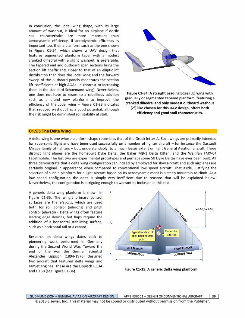
GUDMUNDSSON – GENERAL AVIATION AIRCRAFT DESIGN APPENDIX C1 – DESIGN OF CONVENTIONAL AIRCRAFT 39 ©2013 Elsevier, Inc. This material may not be copied or distributed without permission from the Publisher.
In conclusion, the Jodel wing shape, with its large amount of washout, is ideal for an airplane if docile stall characteristics are more important than aerodynamic efficiency. If aerodynamic efficiency is important too, then a planform such as the one shown in Figure C1-34, which shows a UAV design that features segmented planform taper with a modest cranked dihedral with a slight washout, is preferable. The tapered mid and outboard span sections bring the section lift coefficients closer to that of an elliptic lift distribution than does the Jodel wing and the forward sweep of the outboard panels moderates the section lift coefficients at high AOAs (in contrast to increasing them in the standard Schuemann wing). Nevertheless, one does not have to resort to a rebellious solution such as a brand new planform to improve the efficiency of the Jodel wing – Figure C1-33 indicates that reduced washout has a good potential, although the risk might be diminished roll stability at stall.
Figure C1-34: A straight Leading Edge (LE) wing with gradually or segmented tapered planform, featuring a cranked dihedral and only modest outboard washout
(2°) like chosen for this UAV design, offers both efficiency and good stall characteristics.
C1.5.5 The Delta Wing
A delta wing is one whose planform shape resembles that of the Greek letter . Such wings are primarily intended for supersonic flight and have been used successfully on a number of fighter aircraft – for instance the Dassault Mirage family of fighters – but, understandably, to a much lesser extent on light General Aviation aircraft. Three distinct light planes are the homebuilt Dyke Delta, the Baker MB-1 Delta Kitten, and the Wainfan FMX-04 Facetmobile. The last two are experimental prototypes and perhaps some 50 Dyke Deltas have ever been built. All three demonstrate that a delta wing configuration can indeed by employed for slow aircraft and such airplanes are certainly original in appearance when compared to conventional low speed aircraft. That aside, justifying the selection of such a planform for a light aircraft based on its aerodynamic merit is a steep mountain to climb. As a low speed configuration the delta is simply very inefficient due to reasons that will be explained below. Nevertheless, the configuration is intriguing enough to warrant its inclusion in this text. A generic delta wing planform is shown in Figure C1-35. The wing’s primary control surfaces are the elevons, which are used both for roll control (ailerons) and pitch control (elevator). Delta wings often feature leading edge devices, but flaps require the addition of a horizontal stabilizing surface, such as a horizontal tail or a canard. Research on delta wings dates back to pioneering work performed in Germany during the Second World War. Toward the end of the war the German scientist Alexander Lippisch (1894-1976) designed two aircraft that featured delta wings and ramjet engines. These are the Lippisch L.13A and L.13B (see Figure C1-36).
Figure C1-35: A generic delta wing planform.

GUDMUNDSSON – GENERAL AVIATION AIRCRAFT DESIGN APPENDIX C1 – DESIGN OF CONVENTIONAL AIRCRAFT 40 ©2013 Elsevier, Inc. This material may not be copied or distributed without permission from the Publisher.
Figure C1-36: An artist impression of the Lippisch P.13A, an example of early German pioneering work on delta wings.
In the 1950s, still early in the exploration of supersonic flight, the delta wing was a welcome advancement. Progress toward sustained supersonic flight had been slowed by the large number of engineering challenges that had yet to be tackled. The delta planform offered a number of solutions to a variety of problems and several aircraft manufacturers designed and manufactured delta winged aircraft with great success. These included American manufacturers such as Convair and Douglas. Among European manufacturers were SAAB and Dassault, just to name a few. The flow around the delta wing is highly influenced by the LE sweep, cross-section normal and parallel to the flow direction, and AOA26. The most prominent feature of the flow field at high AOA is the formation of two powerful vortices on the top surface of the wing that have a profound impact on its lifting capability (see Figure C1-37). As shown in the figure, this phenomenon is quite complicated. The vortices are offset from the leading edge and their cores form an angle greater than the LE sweep. The axial flow between the two is maintained by the downwash, which prevents further separation to AOAs as high as 30-40°. Figure C1-38 shows experimental data for two types of delta wings of AR = 1 (from Reference 27). The graph shows clearly the so-called vortex-lift, which is the difference between the lift predicted by the inviscid potential flow theory (e.g. Vortex-Lattice, Doublet-Lattice, and Panel codes) and, thus, does not predict the formation of the powerful vortex. This is usually remedied using the so-called Polhamus leading edge suction analogy28, which unfortunately is beyond the scope of this discussion. Two other important observations can be made with respect to Figure C1-38. First, at an AOA of almost 35° the test data indicates the delta wings have yet to stall. This contrasts conventional wings, which typically stall in the neighborhood of 15°. Second, at such an AOA (i.e. of 15°) the CL for the deltas is just around 0.50 versus 1.2-1.6 for conventional aircraft. This means that a delta wing will require a very high airspeed and deck angle when landing, something very unfavorable for a GA aircraft. A great listing of the pros and cons of delta wings is presented by Whitford29. Among a number of advantages offered by the configuration is a far more gradual rise in supersonic drag than conventional wings. This means that higher subsonic, transonic, and supersonic airspeeds can be maintained with a given engine. Additionally, the peak supersonic drag is found to be less because of a reduction in wave drag due to the volume of the vehicle. This is attributed to the high LE sweep and low thickness-to-chord ratio, both of which are important contributors to

GUDMUNDSSON – GENERAL AVIATION AIRCRAFT DESIGN APPENDIX C1 – DESIGN OF CONVENTIONAL AIRCRAFT 41 ©2013 Elsevier, Inc. This material may not be copied or distributed without permission from the Publisher.
wave drag. The high LE sweep ensures the wing is inside of the shock cone formed by the nose of the aircraft. The airspeed inside the cone is less than that outside of it, so secondary shocks formed by the wing are weaker. The wing configuration better complies with the so-called Area Rule than conventional configurations, making it less sensitive to changes in Mach Number (M) over a wider range of airspeeds. The maximum lift coefficient for the configuration also increases gradually with M up to Mach 1 and then decreases smoothly at supersonic speeds without abrupt changes in lift curve slope, making it ideal to perform high AOA maneuvers at high airspeeds. The powerful vortex that forms along its leading edge at high AOA reduces pre-stall buffeting. This yields a CLmax that is much greater than predicted by linear theory (such as unmodified Vortex-Lattice or Doublet-Lattice methods). Additionally, a large wing area is provided in a small compact aircraft, which is ideal for military aircraft as it results in less wing loading and, therefore, improved maneuverability at high altitudes.
Figure C1-37: Two powerful vortices form as the AOA of the delta increases. These are reason why the maximum lift of a delta is much higher than predicted by inviscid theory. (Based on Reference 26.)
Among structural advantages are that for a given wing area, the resulting span is small and the root chord is large. Even small thickness-to-chord ratios common among fighter aircraft (3-4%) result in a large structural depth and cross-sectional area, which give it great bending and torsional rigidity. Both improve resistance against flutter and aileron reversal. Coupled with a comparatively small bending moment (thanks to the center of lift acting closer to the centerline of the aircraft due to the smaller wing AR) the resulting structure ends up being much lighter. For the same reason, the inboard wing provides large volume for fuel tanks and stowage of the main landing gear. The large wing area allows military ordnance to be carried with ease under the wing. Delta wings also have a number of drawbacks. To begin with, the high LE sweep angle and low AR renders the lift generation of the configuration far less efficient by significantly lowering the lift curve slope (keep in mind Equation (9-57)). This, in turn, means the aircraft must be flown at a much higher AOA to generate the same lift at a given airspeed, which is detrimental for both T-O and landing. Consequently, the T-O run requires the aircraft to be rotated to a higher AOA or accelerated to a higher T-O speed than a comparable conventional wing aircraft. The latter is typically the more practical, albeit detrimental as it calls for a greater runway length and, thus, can present challenges in the operation of military aircraft. During landing, slowing down for landing requires a higher deck angle, limiting the pilot’s Field-of-View. This is further compounded by the inability of the delta to use a flap, unless

GUDMUNDSSON – GENERAL AVIATION AIRCRAFT DESIGN APPENDIX C1 – DESIGN OF CONVENTIONAL AIRCRAFT 42 ©2013 Elsevier, Inc. This material may not be copied or distributed without permission from the Publisher.
it has a separate horizontal tail to react the resulting nose-down pitching moment. The delta wing also suffers higher lift-induced drag as a result of its large area, but short span (see Equation 15-39), which is disadvantageous during maneuvering and requires higher thrust than otherwise. For military aircraft, the lower wing loading results in more sensitivity to gusts, making them harder to operate a high-speed tree-top level combat operations. Of course, gust loading is partly improved by the low lift curve slope of the configuration.
Figure C1-38: The consequence of the formation of the vortex is lift additional to that predicted by linear theory. This lift is called vortex lift. (Based on Reference 27.)
When comes to stability and control, the elevons become less effective at supersonic airspeeds. This is compounded by the long distance the aerodynamic center moves as the airplane accelerates (or decelerates) through Mach 1. Normally, when an airplane accelerates from subsonic to supersonic airspeeds the wing’s aerodynamic center moves approximately from the quarter-chord to the half-chord. This movement increases the distance between the CG and the aerodynamic center, causing a substantial increase in the nose pitch-down moment. A longitudinally statically stable delta wing aircraft would require a high TEU deflection of the elevons to compensate for this. It would also results in a large change in higher trim drag. Some aircraft, such as the SR-71 Blackbird and the Concorde (both of which have been phased out of service), would pump fuel to and from special fuel tanks in the aft part of the fuselage to help move the CG aft at supersonic airspeeds, significantly reducing trim drag. Among other stability and control related detriments is the higher Cl at higher AOA (low airspeeds). Generally, delta wing aircraft are designed for proper lateral-directional stability at higher speeds, such as cruising speed or some combat related airspeed. As the airplane slows down for landing and its AOA begins to increase, the high LE sweep may cause significant reduction in Dutch roll damping (because of the higher Cl). The remedy is an installation of yaw dampers. Additionally, since the configuration is often without a horizontal stabilizer, the pitch damping (CMq) is small making the longitudinal short period oscillation objectionable. This is not true for modern delta wing configurations, which all feature canards (Eurofighter Typhoon, Dassault Rafale, SAAB JAS-39 Gripen, and others). The pitch authority of delta wing configurations equipped with a Horizontal Tail (HT) may be detrimentally affected at high AOA due to the massive wing wake. This is remedied in the design of aircraft like the MiG-21, Sukhoi Su-22, and the A-4 Skyhawk, by low mounted HTs. A delta configuration like the Gloster Javelin featured a T-tail and suffered deep stall problems30.
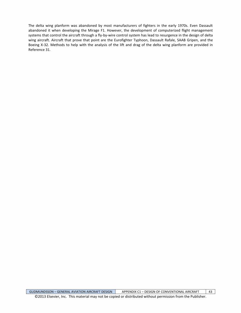
GUDMUNDSSON – GENERAL AVIATION AIRCRAFT DESIGN APPENDIX C1 – DESIGN OF CONVENTIONAL AIRCRAFT 43 ©2013 Elsevier, Inc. This material may not be copied or distributed without permission from the Publisher.
The delta wing planform was abandoned by most manufacturers of fighters in the early 1970s. Even Dassault abandoned it when developing the Mirage F1. However, the development of computerized flight management systems that control the aircraft through a fly-by-wire control system has lead to resurgence in the design of delta wing aircraft. Aircraft that prove that point are the Eurofighter Typhoon, Dassault Rafale, SAAB Gripen, and the Boeing X-32. Methods to help with the analysis of the lift and drag of the delta wing planform are provided in Reference 31.

GUDMUNDSSON – GENERAL AVIATION AIRCRAFT DESIGN APPENDIX C1 – DESIGN OF CONVENTIONAL AIRCRAFT 44 ©2013 Elsevier, Inc. This material may not be copied or distributed without permission from the Publisher.
C1.6 Additional Tools for Tail Sizing While the historical methods presented in Chapter 11 serve as a great way to come up with initial tail geometry, it is not always sufficient to guarantee unfavorable handling characteristics will not surface. This is why the reader is urged to check for possible tail sizing deficiencies using the checklist of Section 23.3, General Aviation Aircraft Design Checklist. In this section, additional tools are offered that could not be presented in the main text due to space constraints.
C1.6.1 Review of Applicable Longitudinal Formulation Several equations of importance have already been derived in Section 11.2, Fundamentals of Static Stability and Control. These are listed below for convenience and can be applied to a large number of configurations, provided the coefficients are properly estimated. Other variables are listed at the end of Chapter 11.
Total lift coefficient: fLeLLLL fe
CCCCC0
(11-7)
Total pitching moment coefficient: fmemmmom feCCCCC (11-10)
Static longitudinal equilibrium (Trim Equation):
fmmMGC
TN
fLL
fDD
e
MGC
Tmm
TLL
TDD
f
f
f
e
e
e
CCqSC
xT
CCqSW
CC
T
qSCzCC
qSCC
qSCC
0
0
min
sin
cos
(11-25)
Stick fixed neutral point: W
ACW
W
HT
L
mL
L
LHTHT
MGC
AC
MGC
n
CC
ARC
CC
VCh
Ch
21 (11-26)
Of these, the
ACmC , which is the longitudinal stability contribution of components other than the wing, is
probably the most mysterious one. It accounts for the contribution of the fuselage, nacelles, thrust, landing gear, and anything besides the wing to the total longitudinal stability of the aircraft. Of these, accounting for the fuselage, nacelles, and thrust often presents the greatest difficulty to the designer. It turns out that the fuselage and nacelles (if present) can be treated using the same basic theory and this is presented in Section C1.6.2, Contribution of the Fuselage and Nacelles. A treatment of thrust, in particular propeller thrust, which is harder to account for, is presented in Section C1.6.3, Contribution of Thrust. Both follow this discussion.
C1.6.2 Estimation of Selected Stability Derivatives A number of variables need to be estimated before Equation (11-25) can be utilized. During the conceptual design phase it is acceptable to use simplified expressions. The lift coefficient is approximated using the linear model
LLL CCC
0. It is acceptable to use the simplified drag model, 2
min LDD kCCC . Other variables can
be estimated as shown below.

GUDMUNDSSON – GENERAL AVIATION AIRCRAFT DESIGN APPENDIX C1 – DESIGN OF CONVENTIONAL AIRCRAFT 45 ©2013 Elsevier, Inc. This material may not be copied or distributed without permission from the Publisher.
Slope of the drag polar: LLD
D CkCCC
2 (C1-13)
Deflecting the elevator of a horizontal surface (aft tail or canard configuration) will change the total lift and pitching moment of the entire aircraft. Considering only changes due to elevator deflection and AOA, the change in lift is represented using Equation (11-7) and the change in pitching moment is represented using Equation (11-10), as follows: Change in lift coefficient: eLLLL e
CCCC 0
(11-7)
Change in pitching moment coefficient: emmmom e
CCCC (11-10)
Of these terms, only the change in lift and moment coefficients with elevator deflection,
eLC and
emC , need to
be elaborated on. Etkin32 shows that eLC
can be approximated by:
e
LHTHT
e
LHTHT
e
L
e
LL
HTHTW
e
CSSC
SSCCC
dominantnegligible
(C1-14)
Etkin also shows that the elevator authority derivative,
emC , can be approximated by:
e
LHTAC
HTHT
e
LHTACL
e
mm
HTHT
ee
CVhh
SSC
VhhCCC
(C1-15)
Where the derivative eLHT
C can be represented
using the following relation:
HT
HTL
HTHTL
e
HT
C
HT
L
e
L CCC
(C1-16) The value of is given in Reference 33, where it is estimated using a graph in terms of the ratio of the elevator area, Se, to the total area of the HT, SHT. Note that this is the total area behind the hingeline. For many applications, this is close to the chord of the elevator. Naturally, a graph is never convenient enough for the spreadsheet savvy engineer, so the curve has been digitized into the following relation, which can be used to estimate for elevator ratios of 0.025 < re < 0.5.
0316.085.244.679.866.4 234 eeee rrrr(C1-17)
Figure C1-39: Elevator effectiveness can be approximated using the polynomial shown.

GUDMUNDSSON – GENERAL AVIATION AIRCRAFT DESIGN APPENDIX C1 – DESIGN OF CONVENTIONAL AIRCRAFT 46 ©2013 Elsevier, Inc. This material may not be copied or distributed without permission from the Publisher.
Note that Reference 34 presents two other methods to approximate , but we will let this suffice here.
C1.6.3 Contribution of the Fuselage and Nacelles The contribution of the fuselage and nacelles to the static longitudinal stability is usually destabilizing. The function of such bodies usually requires a shape that is a derivative of a body of revolution. The geometry accelerates the airflow at their front and aft ends, such that high and low pressure regions are formed, as shown in Figure C1-40. Consequently, a net destabilizing pitching moment is generated. This is manifested as a tendency of the body to rotate away from a low AOA. Depending on the initial AOA, the body will either rotate to a higher or lower AOA. In fact, the body may have to rotate through a large AOA before a balancing pressure field forms, explaining why the neutral point of bodies of revolution is far ahead of the nose. In the absence of wind tunnel testing (or reliable CFD software), the magnitude of this moment can be estimated using the so-called Munk-Multhopp method. The magnitude of the lift and drag generated by the body can also be of importance. Methods to estimate each are presented below.
Figure C1-40: The cause of the destabilizing fuselage moment.
Fuselage Lift and Drag The forces and moments due to the fuselage are shown schematically in Figure C1-41. For most applications it is acceptable to assume these to act at the CG. Here, three methods can be used to calculate fuselage drag:
Figure C1-41: The contribution of the fuselage.

GUDMUNDSSON – GENERAL AVIATION AIRCRAFT DESIGN APPENDIX C1 – DESIGN OF CONVENTIONAL AIRCRAFT 47 ©2013 Elsevier, Inc. This material may not be copied or distributed without permission from the Publisher.
(1) The method of Section 15.4.5, The Rapid Drag Estimation Method. This is a low accuracy method. (2) The method of Section 15.4.6, The Component Drag Buildup Method. In this method, the drag of a body of revolution can be estimated by first calculating its skin friction coefficient using the method of Section 15.3.3, STEP-BY-STEP: Calculating the Skin Friction Drag Coefficient. Then, the appropriate Form Factor can be applied in accordance with Section 15.4.9, Form Factors for a Fuselage and a Smooth Canopy. Once, completed, the resulting drag coefficient is already in terms of the reference area, S, in accordance with:
S
SFFCC FUSFUS
FUS
WETFUSfD
(C1-18)
(3) The following method uses empirical approximations to estimate both lift and drag. The lift of a typical fuselage is generally modest compared to that of the wing, ranging from 2% to 12% of the total lift. NACA R-54035 investigated 209 wing-fuselage combinations, using a fuselage of round and rectangular cross-section. The reference provided the data used to generate Figure C1-42. Note that the data from Reference 35 has been normalized to the fuselage geometry, rather than the wing dimensions used in the reference, to make it more useful to other fuselage geometries. The adjustment for the force was done by multiplying the experimental values (Table II in the reference) by S/Amax, where S is the test wing area and Amax is the maximum cross-sectional area of the fuselage. Similarly, the pitching moment was adjusted by multiplying the experimental data by C/lFUS x S/Amax, where C is the average chord of the wing and lFUS is the fuselage length used in the reference. The lift and drag can be represented using the following polynomials.
Figure C1-42: Experimental lift, drag, and pitching moment for a generic round and rectangular fuselage (from Reference 35).
2
2
2
2
0008142.0003061.008157.0
001513.001654.0
0003603.0001406.006672.0
001153.00009223.0
RECTFUS
RECTFUS
ROUNDFUS
ROUNDFUS
D
L
D
L
C
C
C
C
(C1-19)

GUDMUNDSSON – GENERAL AVIATION AIRCRAFT DESIGN APPENDIX C1 – DESIGN OF CONVENTIONAL AIRCRAFT 48 ©2013 Elsevier, Inc. This material may not be copied or distributed without permission from the Publisher.
Again, the reference area is the maximum cross-sectional area of the fuselage and the expressions are applicable to fuselages whose fineness ratio is around 0.15 to 0.20. Note that in order to adjust these coefficients for use with the reference area, Sref, use Equation (15-79), where SS = Amax. Pitching Moment about the CG due to the Fuselage: This is most commonly accounted for using the Munk-Multhopp method, which is attributed to Max Munk (1890-1986) and Hans Multhopp (1913-1972). Munk’s work on airship hulls was presented in NACA R-18436. Using potential flow theory, he demonstrated that the pitching moment of a body of revolution was a function of its volume and the dynamic pressure. The effect of the slenderness of the body was accounted for using a special correction factor. Munk’s method was originally developed for airships. For that reason it did not account for the upwash and downwash that takes place in front of and behind a wing and affects the stability of the body. It was Multhopp, in NACA TM-103637, who improved Munk’s method so the influence of wings could be accounted for. This way, the pitching moment of a fuselage is computed using the following expression:
FUSFUSFUS mmm CCC
0 (C1-20)
Where the zero-alpha moment is calculated using the following expression, where the constant 36.5 converts radians to degrees (allowing the use of degrees rather than radian) and accounts for bodies that are not:
FUS
WFUS
l
fZLfMGC
m dxiwCSkkC
0
212
5.360 (C1-21)
The dependency on the AOA is given by:
FUS
FUS
l
fMGC
m dxwCS
C0
2
5.361
(C1-22)
Where: k2 – k1 = Correction factor to account for the fuselage slenderness ratio (see Figure C1-44 and
Equation (C1-23)). wf = Average width of a fuselage section
WZL Wing zero-lift angle relative to the fuselage reference line (see Figure C1-41). Considering Figure C1-43, if the zero lift AOA is -2° and the AOI of the wing is +1°, then this angle is +3°.
if = Fuselage camber incidence angle. See Figure C1-43 for more details of how it is defined.
Upwash gradient (see Figure C1-44) The slenderness ratio, k2 – k1, can be determined from Figure C1-44 or through the following approximation (curve fit) to the data:
100072446.524011
23
12fff.
fkk (C1-23)
Where: FUSFUS dlf Fuselage fineness ratio lFUS =
Fuselage length
dFUS = Fuselage width or depth

GUDMUNDSSON – GENERAL AVIATION AIRCRAFT DESIGN APPENDIX C1 – DESIGN OF CONVENTIONAL AIRCRAFT 49 ©2013 Elsevier, Inc. This material may not be copied or distributed without permission from the Publisher.
Figure C1-43: Definition of a positive and negative fuselage camber incidence.
The following curve fits will generate the curves in the right graph of Figure C1-44. See Figure C1-45 for instructions on where to apply them.
Upwash Curve 1
2
1
09107040485047581
MGCMGC Cx.+
Cx.. (C1-24)
Upwash Curve 2 4254.0
2
746111
MGCCx. (C1-25)
Figure C1-44: Fuselage slenderness correction and a handy approximation.
Usually, the computation of the two coefficients is implemented through numerical integration. This is done by segmenting the fuselage as shown in Figure C1-45. Note that the number of segments should be based on the complexity of the fuselage geometry. For most applications 10-20 segments most likely covers it. Then, the coefficients of Equation (C1-20) are calculated using the following discrete representations:

GUDMUNDSSON – GENERAL AVIATION AIRCRAFT DESIGN APPENDIX C1 – DESIGN OF CONVENTIONAL AIRCRAFT 50 ©2013 Elsevier, Inc. This material may not be copied or distributed without permission from the Publisher.
FUS
WFUS
lx
xfZLf
MGCm xiw
CSkkC
0
212
5.360 (C1-26)
FUS
FUS
lx
xf
MGCm xw
CSC
0
2
5.361
(C1-27)
The solution process is best demonstrated in Example C1-1, below.
Figure C1-45: The implementation of the Munk-Multhopp method for estimating the pitch contribution of a fuselage or a nacelle.
EXAMPLE C1-1: Determine the pitching moment coefficients for the fuselage of the SR22. SOLUTION: The process can be implemented as shown in the example in Table C1-3 below. In it, Column contains the distance to each segment, as shown in Figure C1-45. Column is the length of each segment, calculated by subtracting subsequent sections. This way, if the segment belongs to the forward fuselage, it is calculated using the expression xi = li-1 – li. This means that the segment distance in Row 3 is x3 = l2 – l3. The value of x for the wing row is simply the wing chord at root. For the aft fuselage, the process is reversed, i.e. xi = li – li+1. Therefore, in Row 7, we would get: x7 = l7 – l8.

GUDMUNDSSON – GENERAL AVIATION AIRCRAFT DESIGN APPENDIX C1 – DESIGN OF CONVENTIONAL AIRCRAFT 51 ©2013 Elsevier, Inc. This material may not be copied or distributed without permission from the Publisher.
Column is the distance to the center of the segment. It is equal to the length to the segment plus one-half of the width of the previous segment. This way, the center of a segment in the forward fuselage is xCi = li + ½ xi-1, while for the aft fuselage it is xCi = li - ½ xi+1.
Figure C1-46: The implementation of the Munk-Multhopp method for the SR22.
Column is the width of the segment at the station identified by ID (first column), while Column is the average width of the segment. Again the average of a segment belonging to the forward fuselage is calculated by wfi = ½ (wi + wi-1), while for the aft fuselage is is determined from: wfi = ½ (wi + wi+1). Column contains the sum of the angle the zero lift line of the wing makes to the Fuselage Reference Line (ZLW) and the angle of the fuselage camber line at the center of each segment with respect to the Fuselage Reference Line (if) as shown in Figure C1-43. The ZLW was estimated to be 2.9° and the slope of the fuselage camber was estimated by representing it with a fourth order polynomial that then was differentiated to get the slope. Finally, the slope was converted to an angle by evaluating the inverse tangent. Column is the product of Columns , , and . Column is the upwash and downwash around the fuselage, calculated depending on region as shown in Figure C1-45. An finally, Column is the product of Columns , , and . Once all the rows have been determined, the numbers in columns and are summed up. These are then used with Equations (C1-26) and (C1-27) to determine the two coefficients for the fuselage. This method is identical for nacelles, although there often is very limited aft “fuselage”. The nacelles of many twin engine aircraft featuring the engines mounted on the wing would only consist of a forward “fuselage”. The nacelles of aircraft such as the Fokker F-27 Friendship, on the other hand, would be represented using both a forward and aft “fuselage” segments. The nacelles of the Rockwell OV-10 Bronco, which also serve as tailbooms, would consist mostly of an aft section and practically negligible forward section. The resulting zero AOA and AOA dependent pitching moment coefficients are shown in the shaded box above the main table. These can be presented using Equation (C1-20) as shown below:
01028.000338.00 FUSFUSFUS mmm CCC
Where is in degrees.

GUDMUNDSSON – GENERAL AVIATION AIRCRAFT DESIGN APPENDIX C1 – DESIGN OF CONVENTIONAL AIRCRAFT 52 ©2013 Elsevier, Inc. This material may not be copied or distributed without permission from the Publisher.
Table C1-2: Determination of Fuselage Stability Derivatives
C1.6.4 Contribution of Thrust – Normal Force Thrust contributes to stability in two important ways. First, moment due to the location of the thrustline above or below the CG (zT) and, second, the normal force (TN) acting on a propeller or the nacelle of a jet engine (see Figure C1-47). For jet engines, the presence of the exhaust near a stabilizing surface can affect the local flow field as shown in Figure 11-29, although this effect is not considered here. The propeller normal force is also recognized as fin effect in some literature. Both contributions are very important and very noticeable to pilots.
Figure C1-47: The contribution of thrust only.

GUDMUNDSSON – GENERAL AVIATION AIRCRAFT DESIGN APPENDIX C1 – DESIGN OF CONVENTIONAL AIRCRAFT 53 ©2013 Elsevier, Inc. This material may not be copied or distributed without permission from the Publisher.
Pitching Moment about the CG due to Thrustline: The moment due to the location of the thrustline applies to all propulsive devices and is given by:
MGC
Tm qSC
zTCT
(C1-28)
Where T is the engine thrust and dimensional variables are shown in Figure C1-47. This moment is negative (stabilizing) if the thrustline is above the CG and positive (destabilizing) if it is below. The primary challenge is the estimation of thrust, but a number of methods are provided in this text, in Chapter 7, Selecting the Power Plant and Chapter 14, The Anatomy of the Propeller. Pitching Moment about the CG due to Normal Force: The normal force depends on whether the engine is a jet or a propeller.
MGC
TNm qSC
xTCNT
(C1-29)
Seckel38 presents an empirical method based on the work of Ribner39 to estimate the normal force using the following expression:
TfCAqNT bladeNPBN
(C1-30)
Where: q = Dynamic pressure NB = Number of blades AP = Propeller disc area = DP²/4, where DP = Propeller diameter
bladeNC Propeller normal force coefficient
Tf Propeller normal force factor The propeller normal force coefficient is dependent on the geometry of the blades and the Advance Ratio (see Section 14.3.5, Advance Ratio). In order to account for the blade geometry, a special parameter, called the Side-Force Factor (SFF) is defined and calculated using the expression below:
Side-Force Factor: RRR D
bDb
DbSFF
9.06.03.0
270525
(C1-31)
Where: b = Blade chord at stations 0.3R, 0.6R, and 0.9R (R = Propeller radius = D/2) D = Propeller diameter A propeller blade with an SFF = 132 is indicative of a wide chord blade (think Lockheed P-3C Orion props). A propeller blade with an SFF = 81 is indicative of a narrow chord blade (think Cessna 172 Skyhawk prop). The propeller normal force coefficient can be determined using the following approximations for wide and narrow bladed propellers. Wide bladed propellers are commonly found on turboprop aircraft, but are also found on a number of recent propeller driven GA piston aircraft. Narrow bladed propellers are typically found on GA aircraft:
Wide bladed propeller: 1000
4696.0392.669.3383.93773.1 432 JJJJCbladeN
(C1-32)
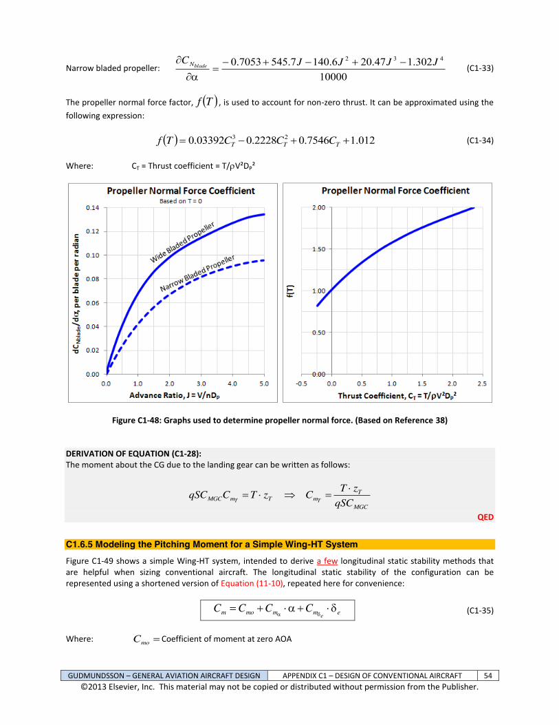
GUDMUNDSSON – GENERAL AVIATION AIRCRAFT DESIGN APPENDIX C1 – DESIGN OF CONVENTIONAL AIRCRAFT 54 ©2013 Elsevier, Inc. This material may not be copied or distributed without permission from the Publisher.
Narrow bladed propeller: 10000
302.147.206.1407.5457053.0 432 JJJJCbladeN
(C1-33)
The propeller normal force factor, Tf , is used to account for non-zero thrust. It can be approximated using the following expression: 012.17546.02228.003392.0 23 TTT CCCTf (C1-34) Where: CT = Thrust coefficient = T/V²DP²
Figure C1-48: Graphs used to determine propeller normal force. (Based on Reference 38)
DERIVATION OF EQUATION (C1-28): The moment about the CG due to the landing gear can be written as follows:
MGC
TmTmMGC qSC
zTCzTCqSCTT
QED
C1.6.5 Modeling the Pitching Moment for a Simple Wing-HT System Figure C1-49 shows a simple Wing-HT system, intended to derive a few longitudinal static stability methods that are helpful when sizing conventional aircraft. The longitudinal static stability of the configuration can be represented using a shortened version of Equation (11-10), repeated here for convenience:
emmmom eCCCC
(C1-35)
Where: moC Coefficient of moment at zero AOA

GUDMUNDSSON – GENERAL AVIATION AIRCRAFT DESIGN APPENDIX C1 – DESIGN OF CONVENTIONAL AIRCRAFT 55 ©2013 Elsevier, Inc. This material may not be copied or distributed without permission from the Publisher.
m
C Change in coefficient of pitching moment due to AOA
emC Elevator authority; change in coefficient of pitching moment due to elevator deflection
Figure C1-49: The basic Wing-HT-Fuselage system used for longitudinal stability analyses.
The above terms can be determined for this system using the following expressions:
HTWL
LLHTHTmomomo iiAR
CCCVCCC W
HTHTACW
0
0
2 (C1-36)
HT
W
ACW LL
HTHTmLMGC
ACm C
AR
CVCC
ChhC
21 (C1-37)
Where: MGCC = Mean Geometric Chord
hn = Physical location of the CG at which Cm = 0; i.e. the stick-fixed neutral point hAC = Physical location of the Aerodynamic Center (typically at 0.25CMGC) HTl = Distance between the aerodynamic centers of the HT and the CG S = Reference wing area SHT = Planform area of the HT
VHT = Horizontal tail volume MGC
HTHT
CSlS
ACmoC Longitudinal stability contribution of components other than the wing
WW L
MGC
ACmo C
Chh
C0
Wing pitching moment due to airfoil camber
HTLC 0
= HT lift coefficient at zero AOA
ACmC
= Longitudinal stability contribution of components other than the wing
HTLC
= Lift curve slope of the HT
WLC
= Wing lift curve slope

GUDMUNDSSON – GENERAL AVIATION AIRCRAFT DESIGN APPENDIX C1 – DESIGN OF CONVENTIONAL AIRCRAFT 56 ©2013 Elsevier, Inc. This material may not be copied or distributed without permission from the Publisher.
Note that the term ACmC
refers to the stabilizing effects of components such as the fuselage, nacelles, landing
gear, the wing itself, and so on, as a function of the AOA. If the sum of these moments acts to rotate the nose down, then 0ACM (has a negative sign and is stabilizing). If it acts to rotate nose up, then 0ACM (has a positive sign and is destabilizing). The sign ultimately depends on the aircraft configuration. Note that the destabilizing effects of fuselages and nacelles can be estimated using the so-called Munk-Multhopp method, which is presented in Section C1.6.3, Contribution of the Fuselage and Nacelles. DERIVATION: It is imperative to keep the orientation of the MAC in mind in the following derivation. Also, by default, it is assumed that the elevator deflection is neutral, i.e. e = 0°. Furthermore, the contribution of the thrust and fuselage is rolled into MAC. First, determine the sum of moments about the CG, assuming the orientation of forces and moments as shown in Figure C1-49. For static stability, this must equal zero. Taking nose down moments to be negative and positive forces to point up, this requires:
00 ACHTHTACWCG MlLhhLM (i)
Note that the sign for MAC here is “+”. Therefore, if MAC is stabilizing ( 0ACM ) we will get
ACAC MM , where |.| stands for the absolute value.
The definitions of wing lift is
WLW CSqL , the lift of the HT is HTLHTHT CSqL , and additional
moments, ACmMGCAC CCSqM . Insert these into Equation (i) and divide through by q·∙S·∙CMGC, as shown
below:
0
0
ACHT
HT
W
ACHTW
mL
V
MGC
HTHTHTL
MGC
AC
mMGCHTLHTHTACL
CCCSlSC
Chh
CCSqlCSqhhCSq
Where HT is the tail efficiency factor, which accounts for the increase in dynamic pressure due to propwash, and
VHT the horizontal tail volume. Note that HT can also be used to denote cases in which there is diminished tail effectiveness, for instance if the HT resides in a turbulent wake from the fuselage. Its range is typically 0.8 to 1.2. Next, insert the definitions for
WLC and
HTLC :
0
00
ACHTHTWW mHTLLHTHTLLMGC
AC CCCVCCC
hh (ii)
Rearrange the h and hAC to get:
0
00
ACHTHTWW mHTLLHTHTLL
MGC
AC CCCVCCChh
(iii)
Some aircraft use cambered airfoils for the HT, typically as an inverted or with a negative camber. This can be accounted for with a 0
0
HTLC . Naturally, if the airfoil is symmetrical, this value is zero. Since the HT resides in

GUDMUNDSSON – GENERAL AVIATION AIRCRAFT DESIGN APPENDIX C1 – DESIGN OF CONVENTIONAL AIRCRAFT 57 ©2013 Elsevier, Inc. This material may not be copied or distributed without permission from the Publisher.
the downwash of the wing, its AOA and, thus, lift coefficient is greatly affected. This effect is accounted for using Equation (11-16). Therefore;
HTWLL
HT iiAR
C
AR
CWW
0
221 (11-16)
This expression provides the designer with a few design variables; AR,
WLC
0, iW, and iHT. Next, expand Equation (iii):
0
00
ACHTHTWW mHTLHTHTLHTHTL
MGC
ACL
MGC
AC CCVCVCChhC
Chh
Let
WW LMGC
ACmo C
ChhC
0
and recall that
ACACAC mmom CCC . Then, simplify by gathering
contributions that do and do not change with the AOA:
02
1
2
AOA with changeson that Contributi
AOA with changenot doeson that Contributi
0
0
AR
CCVCC
Chh
iiAR
CCCVCC
W
HTACW
W
HTHTACW
LLHTHTmL
MGC
AC
HTWL
LLHTHTmomo
The contribution that does not change with AOA (constant terms) are typically denoted by Cmo, whereas contribution that changes with AOA is denoted by Cm. This convention is maintained here as well.
QED EXAMPLE C1-1: Consider the wing-HT configuration in Figure C1-50 and the additional data is given below. Estimate the following, assuming it has no fuselage and no power plant: (a) Estimate the location of the stick-fixed neutral point (b) Estimate Cmo and Cm and plot for AOAs ranging from -5° to 20°, using the following data. Also, determine the value of Cmo that allows the airplane to be trimmed at = 10°.
MAIN WING: CMGC = 2.0 ft b = 20.0 ft S = 40 ft² AR = 10
35.00
WL
C
WLC = 5.012 per radian
AOI = iW = 0°
HORIZONTAL TAIL CHT = 1.0 ft BHT = 6.0 ft SHT = 6.0 ft²
0.00
HTLC (symmetrical airfoil)
HTLC = 4.247 per radian
AOIHT = iHT = 0°
OTHER hAC = 0.25·∙CMGC = 0.5 ft h = 1.039 ft (aft of wing LE) lHT = 8.50+1.0/4-1.039 = 7.711 ft
00
ACmC
0ACmC
1HT

GUDMUNDSSON – GENERAL AVIATION AIRCRAFT DESIGN APPENDIX C1 – DESIGN OF CONVENTIONAL AIRCRAFT 58 ©2013 Elsevier, Inc. This material may not be copied or distributed without permission from the Publisher.
Assume the wing airfoil is NACA 4415 and that the HT has a symmetrical airfoil. Note that the lift curve slopes were calculated using Equation (9-57). Assume that the 3-dimensional
WLC
0to be the same as that of
the airfoil (0.4). SOLUTION: (a) Stick fixed neutral point is calculated using Equation (11-26), as shown below: Begin by calculating the HT volume:
5783.00.240
711.70.6
MGC
HTHTHT CS
lSV
Then, estimate lift properties. Cl for the NACA 4415 is given in Table 8-5, where it is seen to be 0.106 per degree or 6.073 per radian. Cl for a typical symmetrical NACA airfoil is 0.100 per degree or 5.730 per radian. Assuming low subsonic airspeed (M 0) and using Equation (9-57) to estimate the 3D lift curve slope of the wing (AR = 10) and canard (ARC = 6), yields a 012.5
WLC and 247.4HTLC ,
respectively. On similar notes, WL
C0
can be
estimated using Equation (9-61) and data from Table 8-5, where the ZL = -4° for the NACA 4415 airfoil. Therefore,
WLC
0is calculated as follows:
Figure C1-50: Example configuration.
350.0012.5180
40
WW LZLL CC
Then, to calculate the stick-fixed neutral point plug and chug Equation (11-26):
5837.0012.50
10012.521
012.5247.45783.01
0.25.0
21
W
ACW
W
HT
L
mL
L
LHTHT
MGC
AC
MGC
n
CC
ARC
CC
VCh
Ch
This corresponds to 58.4% of the CMGC, or 1.182 ft. In comparison, a potential flow solution using this geometry yielded the stick-fixed neutral point at 1.239 ft, or 62.0 %MGC.
(b) First calculate: 09433.035.0
0.25.0039.1
0
WW LMGC
ACmo C
ChhC
Where must be in radians. By plugging and chugging Equations (C1-36) and (C1-37) we get:

GUDMUNDSSON – GENERAL AVIATION AIRCRAFT DESIGN APPENDIX C1 – DESIGN OF CONVENTIONAL AIRCRAFT 59 ©2013 Elsevier, Inc. This material may not be copied or distributed without permission from the Publisher.
03960.0001035.02247.405783.01009433.0
20
0
HTWL
LLHTHTmomomo iiAR
CCCVCCC W
HTHTACW
and
HT
W
ACW LL
HTHTmLMGC
ACm C
AR
CVCC
ChhC
21
radianper 3217.0
247.410012.5215783.010012.5
0.25.0039.1
The positive Cmo and negative Cm show the configuration is indeed statically stable and trimmable at a positive AOA. A plot of the Cm from -5° < < 20° is shown in Figure C1-51. It shows that the above prediction places the pitching moment curve partially above the horizontal axis. To trim the aircraft at = 10°, the Cmo must by shifted up by a magnitude of 0.0165, or to Cmo = +0.05615. This additional moment is typically provided by playing with the variable e (elevator deflection) of Equation (C1-35). However, sometimes it is necessary to size the airplane such the elevator deflection is zero at some nominal loading and CG during cruise. Then, variables such as VHT,
WLC
0,
HTLC 0, iW, and iHT of Equation (C1-36) can be used to achieve the goal.
Figure C1-51: The pitching moment coefficient calculated directly, compared to potential flow analysis. One of the factors that explain the slight shift is that the downwash of the canard on the wing is not accounted for
using hand calculations, but is automatically determined using the Vortex-Lattice Method.

GUDMUNDSSON – GENERAL AVIATION AIRCRAFT DESIGN APPENDIX C1 – DESIGN OF CONVENTIONAL AIRCRAFT 60 ©2013 Elsevier, Inc. This material may not be copied or distributed without permission from the Publisher.
REFERENCES 1 Broadband noise refers to sound that, by definition, extends over a wide range of frequencies, perhaps even the entire range of audible frequencies. 2 See http://www.cessnaskymaster.com/rear-engine-cooling.html 3 Bowyer, Chaz, The Age of the Biplane, The Hamlyn Publishing Group, 1981. 4 NACA TN-269, The Distribution of Loads between the Wings of a Biplane having Decalage, Mock, Richard M., 1927. 5 Stinton, Darrol, The Design of the Aeroplane, Collins Professional and Technical Books, 1983. 6 NACA R-70, The Effect of Stagger, Norton, F. H., 1921. 7 Max M. Munk, Fundamentals of Fluid Dynamics for Aircraft Designers, 1923. 8 Diehl, Walter Stuart, Engineering Aerodynamics, Ronald Press Company, 1936. 9 NACA R-116, Applications of Modern Hydrodynamics to Aeronautics, Prandtl, Ludwig, 1923. 10 Langton, Roy, et al., Aircraft Fuel Systems, John Wiley and Sons, Ltd., 2009. 11 For instance see: NACA AC-89, Albessard Triavion Aircraft, J Serryer, 1929. 12 Taylor, John W. R. (ed.), Jane’s All the World’s Aircraft 1976-77, Jane’s Yearbooks, 1976, pg. [72]. 13 For which Davis holds the patent US 1942688 (Fluid Foil). 14 Convair Advanced Designs: Secret Projects from San Diego, 1923-1962, Robert E. Bradley, 2010. 15 The Davis Wing and the Problem of Airfoil Design, Walter G. Vincenti, Technology and Culture, Vol. 27, No. 4, Oct., 1986, pp. 717-758. 16 Convair Advanced Designs: Secret Projects from San Diego, 1923-1962, Robert E. Bradley, 2010. 17 NACA WR-L-677 Lift and Drag Tests of Three Airfoil Models with Fowler Flaps, submitted by Consolidated Aircraft Corporation, Turner, Harold R., Jr, 1941. 18 NACA WR-L-678 Pressure-Distribution Measurements of a Model of a Davis Wing Section with Fowler Flap, submitted by Consolidated Aircraft Corporation, Abbott, Ira H., 1942. 19 Schuemann, W., A New Wing Planform and Improved Low-Speed Performance, Soaring, Vol. 47, No. 2, Feb. 1983, pp. 16-26. 20 Maughmer, Mark D., The Evolution of Sailplane Wing Design, AIAA 2003-2777. 21 van Dam, C.P., Induced-Drag Characteristics of Crescent-Moon-Shaped Wings, Journal of Aircraft, Vol. 24, No. 2, Feb. 1987, pp. 115-119. 22 Cook, William C., The Road to the 707, TYC Publishing, Bellevue, 1991. 23 Snyder, George, Structural Design Problems in the B-29 Airplane, Aeronautical Engineering Review, Feb. 1946, pp. 9-12. 24 Mason, W. H., 6. Subsonic Aerodynamics of Airfoils and Wings. http://www.dept.aoe.vt.edu/~mason/Mason_f/ConfigAeroSubFoilWing.pdf. 25 Source: http://www.jodel.com/index.asp?p=wing&general 26 Hoerner, Sighard F., and Henry V. Borst, Fluid-Dynamic Lift, L. Hoerner, 1985. 27 R.&M. No. 3186, Low-Speed Wind-Tunnel Tests on a Series of Uncambered Slender Pointed Wings with Sharp Edges, Aeronautical Research Council, D. H. Peckham, 1959. 28 NACA TN D-3767, A Concept of the Vortex Lift on Sharp-Edge Delta Wings Based on a Leading-Edge Suction Analogy, Polhamus, Edward C., 1966. 29 Whitford, Ray, Design for Air Combat, Jane’s Publishing Company Limited, 1987. 30 Source: http://www.thunder-and-lightnings.co.uk/javelin/history.php?comm_page=2 31 Hoak, D. E., USAF Stability and Control DATCOM, Flight Control Division, Air Force Flight Dynamics Laboratory, April, 1978. 32 Etkin, Bernard, Dynamics of Flight – Stability and Control, 2nd Ed., John Wiley and Sons, 1982. 33 Perkins, Courtland D. and Robert E. Hage, Airplane Performance, Stability, and Control, John Wiley & Sons, 1949. 34 McCormick, Barnes W., Aerodynamics, Aeronautics, and Flight Mechanics, John Wiley & Sons, 1979. 35 NACA R-540, Interference of Wing and Fuselage from Tests of 209 Combinations in the NACA Variable-Density Tunnel, Jacobs, Eastman N and Kenneth E. Ward. 36 NACA R-184, The Aerodynamic Forces on Airship Hulls, Munk, Max M., 1924.

GUDMUNDSSON – GENERAL AVIATION AIRCRAFT DESIGN APPENDIX C1 – DESIGN OF CONVENTIONAL AIRCRAFT 61 ©2013 Elsevier, Inc. This material may not be copied or distributed without permission from the Publisher.
37 NACA TM-1036, Aerodynamics of the Fuselage, Multhopp, Hans, 1942. 38 Seckel, E., Stability and Control of Airplanes and Helicopters, Academic Press, 1964. 39 NACA R-819, Formulas for Propellers in Yaw and Charts of the Side-Force Derivative, Ribner, Herbert S., 1945.