NI USB-6008/6009 User Guide - National Instruments
26
USER GUIDE NI USB-6008/6009 Bus-Powered Multifunction DAQ USB Device Français Deutsch 日本語 한국어 简体中文 ni.com/manuals The National Instruments USB-6008/6009 devices provide eight single-ended analog input (AI) channels, two analog output (AO) channels, 12 DIO channels, and a 32-bit counter with a full-speed USB interface. This user guide describes how to use these devices. For specifications, refer to the NI USB-6008 Device Specifications and the NI USB-6009 Device Specifications available at ni.com/manuals. The following table compares the NI USB-6008 and NI USB-6009 devices. Table 1. NI USB-6008 and NI USB-6009 Comparison Feature NI USB-6008 NI USB-6009 AI resolution 12 bits differential, 11 bits single-ended 14 bits differential, 13 bits single-ended Maximum AI sample rate, single channel 1 10 kS/s 48 kS/s Maximum AI sample rate, multiple channels (aggregate) 1 10 kS/s 48 kS/s DIO configuration Open collector 2 Each channel individually programmable as open collector or active drive 2 The following figure shows key functional components of the NI USB-6008/6009. 1 System-dependent. 2 This document uses NI-DAQmx naming conventions. Open-drain is called open collector and push-pull is called active drive.
-
Upload
nguyenlien -
Category
Documents
-
view
238 -
download
6
Transcript of NI USB-6008/6009 User Guide - National Instruments
USER GUIDE
NI USB-6008/6009Bus-Powered Multifunction DAQ USB Device
Français Deutsch 日本語 한국어 简体中文
ni.com/manuals
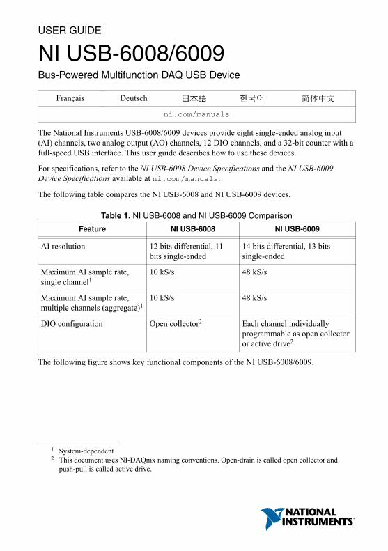
The National Instruments USB-6008/6009 devices provide eight single-ended analog input(AI) channels, two analog output (AO) channels, 12 DIO channels, and a 32-bit counter with afull-speed USB interface. This user guide describes how to use these devices.
For specifications, refer to the NI USB-6008 Device Specifications and the NI USB-6009Device Specifications available at ni.com/manuals.
The following table compares the NI USB-6008 and NI USB-6009 devices.
Table 1. NI USB-6008 and NI USB-6009 Comparison
Feature NI USB-6008 NI USB-6009
AI resolution 12 bits differential, 11bits single-ended
14 bits differential, 13 bitssingle-ended
Maximum AI sample rate,single channel1
10 kS/s 48 kS/s
Maximum AI sample rate,multiple channels (aggregate)1
10 kS/s 48 kS/s
DIO configuration Open collector2 Each channel individuallyprogrammable as open collectoror active drive2
The following figure shows key functional components of the NI USB-6008/6009.
1 System-dependent.2 This document uses NI-DAQmx naming conventions. Open-drain is called open collector and
push-pull is called active drive.
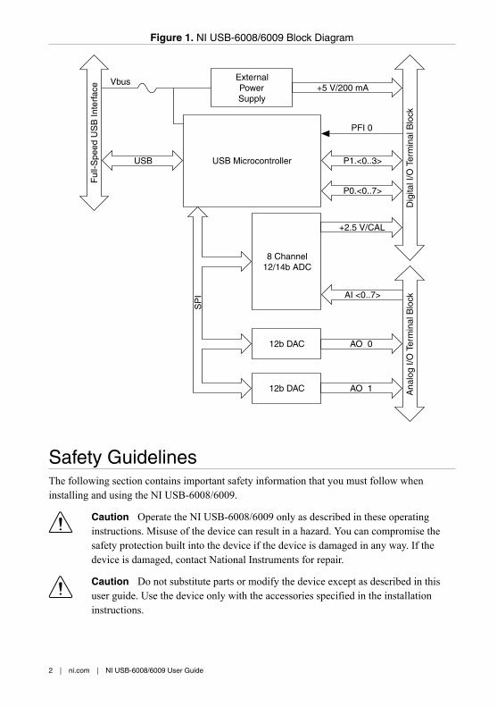
Figure 1. NI USB-6008/6009 Block Diagram
P1.<0..3>
P0.<0..7>
Dig
ital I
/O T
erm
inal
Blo
ck
AI <0..7>
AO 0
AO 1 Ana
log
I/O T
erm
inal
Blo
ck
+2.5 V/CAL
+5 V/200 mA
8 Channel12/14b ADC
12b DAC
12b DAC
USB Microcontroller
SP
I
ExternalPowerSupply
VbusF
ull-S
peed
US
B In
terf
ace
USB
PFI 0
Safety GuidelinesThe following section contains important safety information that you must follow wheninstalling and using the NI USB-6008/6009.
Caution Operate the NI USB-6008/6009 only as described in these operatinginstructions. Misuse of the device can result in a hazard. You can compromise thesafety protection built into the device if the device is damaged in any way. If thedevice is damaged, contact National Instruments for repair.
Caution Do not substitute parts or modify the device except as described in thisuser guide. Use the device only with the accessories specified in the installationinstructions.
2 | ni.com | NI USB-6008/6009 User Guide

Caution Do not operate the device in an explosive atmosphere or where there maybe flammable gases or fumes. If you must operate the device in such anenvironment, it must be in a suitably rated enclosure.
Electromagnetic Compatibility GuidelinesThis product was tested and complies with the regulatory requirements and limits forelectromagnetic compatibility (EMC) stated in the product specifications. These requirementsand limits provide reasonable protection against harmful interference when the product isoperated in the intended operational electromagnetic environment.
This product is intended for use in industrial locations. However, harmful interference mayoccur in some installations, when the product is connected to a peripheral device or test object,or if the product is used in residential or commercial areas. To minimize interference withradio and television reception and prevent unacceptable performance degradation, install anduse this product in strict accordance with the instructions in the product documentation.
Furthermore, any changes or modifications to the product not expressly approved by NationalInstruments could void your authority to operate it under your local regulatory rules.
Caution To ensure the specified EMC performance, operate this product only withshielded cables and accessories.
Caution This product may become more sensitive to electromagnetic disturbancesin the operational environment when test leads are attached or when the product isconnected to a test object.
Caution Emissions that exceed the regulatory requirements may occur when thisproduct is connected to a test object.
Note Changes or modifications to the product not expressly approved by NationalInstruments could void your authority to operate the product under your localregulatory rules.
Unpacking the KitCaution To prevent electrostatic discharge (ESD) from damaging the device,ground yourself using a grounding strap or by holding a grounded object, such asyour computer chassis.
1. Touch the antistatic package to a metal part of the computer chassis.2. Remove the device from the package and inspect the device for loose components or any
other sign of damage.
Caution Never touch the exposed pins of connectors.
NI USB-6008/6009 User Guide | © National Instruments | 3
Note Do not install a device if it appears damaged in any way.
3. Unpack any other items and documentation from the kit.
Store the device in the antistatic package when the device is not in use.
Setting Up the NI USB-6008/6009Complete the following steps to get started with the NI USB-6008/6009.
Note For information about non-Windows operating support, refer to the GettingStarted with NI-DAQmx Base document available from ni.com/manuals.
1. Install the application software (if applicable), as described in the installation instructionsthat accompany your software.
2. Install NI-DAQmx3.
Note The NI-DAQmx software is included on the disk shipped with your kitand is available for download at ni.com/support. The documentation forNI-DAQmx is available after installation from Start»All Programs»NationalInstruments»NI-DAQmx. Other NI documentation is available fromni.com/manuals.
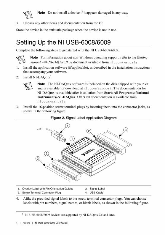
3. Install the 16-position screw terminal plugs by inserting them into the connector jacks, asshown in the following figure.
Figure 2. Signal Label Application Diagram
9006-BSUIN
O/InoitcnufitluM,tib-41,stupnI8
23
l ati gi D
71
1
golanA
61
3
2
4
1
2 3
1. Overlay Label with Pin Orientation Guides2. Screw Terminal Connector Plug
3. Signal Label4. USB Cable
4. Affix the provided signal labels to the screw terminal connector plugs. You can chooselabels with pin numbers, signal names, or blank labels, as shown in the following figure.
3 NI USB-6008/6009 devices are supported by NI-DAQmx 7.5 and later.
4 | ni.com | NI USB-6008/6009 User Guide

Choose one of the labels, align the correct label with the terminals printed on the toppanel of your device and apply the label, as shown in the previous figure.
Figure 3. NI USB-6008/6009 Signal Labels
GND + AI0 - + AI1 - + AI2 - + AI3 - AO0 AO1 GND
GND +5V+2.5V PFI0 P1.3 P1.2 P1.1 P1.0 P0.7 P0.6 P0.5 P0.4 P0.3 P0.2 P0.1 P0.0
1 2 3 4 5 6 7 8 9 10 11 12 13 14 15 16GND AI0 AI4 GND AI1 AI5 GND AI 2 AI6 GND AI3 AI7 GNDAO0 AO1 GND
DIGITALANALOG
32 31 30 29 28 27 26 25 24 23 22 21 20 19 18 17
GND GND GND GND
2
3
4
5
or1
1
1. User-Defined Custom Label2. Terminal Number Label3. Digital I/O Label
4. Analog Input Differential Signal Name Label5. Analog Input Single-Ended Signal Name Label
Note After you label the screw terminal connector plugs, you must only insertthem into the matching connector jack, as indicated by the overlay label on thedevice.
5. Plug one end of the USB cable into the NI USB-6008/6009 and the other end into anavailable USB port on the computer.
6. Double-click the NI MAX icon on the desktop to open Measurement & AutomationExplorer (MAX).
7. Expand My System»Devices and Interfaces and verify that the NI USB-6008/6009 islisted. If your device does not appear, press <F5> to refresh the view in MAX. If yourdevice is still not recognized, refer to ni.com/support/daqmx for troubleshootinginformation.
8. Self-test your device in MAX by right-clicking NI USB-6008 or NI USB-6009 andselecting Self-Test. Self-test performs a brief test to determine successful deviceinstallation. When the self-test finishes, a message indicates successful verification or ifan error occurred. If an error occurs, refer to ni.com/support/daqmx.
Caution To ensure the specified EMC performance, operate this product onlywith shielded cables and accessories.
9. Connect the wires (16 AWG to 28 AWG) of a shielded, multiconductor cable to screwterminals by stripping 6.35 mm (0.25 in) of insulation, inserting the wires into the screwterminals, and securely tightening the screws with the flathead screwdriver to a torque of0.22 N · m to 0.25 N · m (2.0 lb · in. to 2.2 lb · in.). Refer to the Pinout and SignalDescriptions section for an image of the NI USB-6008/6009 pinout.
If using a shielded cable, connect the cable shield to a nearby GND terminal.
Note For information about sensors, go to ni.com/sensors. Forinformation about IEEE 1451.4 TEDS smart sensors, go to ni.com/teds.
10. Run a Test Panel in MAX by right-clicking NI USB-6008 or NI USB-6009 and selectingTest Panels.
NI USB-6008/6009 User Guide | © National Instruments | 5

Click Start to test the device functions, or Help for operating instructions. Click Close toexit the test panel.
Using the NI USB-6008/6009 in an ApplicationYou can use the DAQ Assistant through many NI application software programs to configurevirtual and measurement channels. The following table lists DAQ Assistant tutorial locationsfor NI applications.
Table 2. DAQ Assistant Tutorial Locations
NI Application Tutorial Location
LabVIEW Go to Help»LabVIEW Help. Next, go to Getting Started withLabVIEW»Getting Started with DAQ»Taking an NI-DAQmxMeasurement in LabVIEW.
LabWindows™/CVI™ Go to Help»Contents. Next, go to Using LabWindows/CVI»Data Acquisition»Taking an NI-DAQmx Measurement inLabWindows/CVI.
Measurement Studio Go to NI Measurement Studio Help»Getting Started with theMeasurement Studio Class Libraries»Measurement StudioWalkthroughs»Walkthrough: Creating a Measurement StudioNI-DAQmx Application.
LabVIEWSignalExpress
Go to Help»Taking an NI-DAQmx Measurement inSignalExpress.
Refer to the Where to Go from Here section for information about programming examples forNI-DAQmx and NI-DAQmx Base.
FeaturesThe NI USB-6008/6009 features a USB connector, USB cable strain relief, two screw terminalconnector plugs for I/O, and an LED indicator, as shown in the following figure.
6 | ni.com | NI USB-6008/6009 User Guide

Figure 4. NI USB-6008/6009 Top and Back Views
NI USB-60098 Inputs, 14-bit, Multifunction I/O
32D
igit
al17
1A
nalo
g16
1
2 2 4
3
1. USB Cable Strain Relief2. Screw Terminal Connector Plug
3. LED Indicator4. USB Connector
USB Connector and USB Cable Strain ReliefThe NI USB-6008/6009 features a USB connector for full-speed USB interface. You canprovide strain relief for the USB cable by threading a zip tie through the USB cable strainrelief ring and tightening around a looped USB cable, as shown in the following figure.
Figure 5. NI USB-6008/6009 Strain Relief
1
LED IndicatorThe NI USB-6008/6009 device has a green LED indicator that indicates device status, as listedin the following table. When the device is connected to a USB port, the LED blinks steadily toindicate that the device is initialized and is receiving power from the connection.
NI USB-6008/6009 User Guide | © National Instruments | 7
Table 3. LED State/Device Status
LED State Device Status
Not lit Device not connected or in suspend
On, not blinking Device connected but not initialized, or the computer is in standby mode.In order for the device to be recognized, the device must be connected to acomputer that has NI-DAQmx installed on it.
Single-blink Operating normally
Screw Terminal Connector PlugsThe NI USB-6008/6009 ships with one detachable screw terminal connector plug for analogsignals and one detachable screw terminal connector plug for digital signals. These screwterminal connectors provide 16 connections that use 16 AWG to 28 AWG wire. Refer to step 4of the Setting Up the NI USB-6008/6009 section for information about selecting labels for thescrew terminal connector plugs. Refer to the Pinout and Signal Descriptions section for thedevice pinout and signal descriptions.
You can order additional connectors and labels for your device. Refer to the Cables andAccessories section for ordering information.
FirmwareThe firmware on the NI USB-6008/6009 refreshes whenever the device is connected to acomputer with NI-DAQmx. NI-DAQmx automatically uploads the compatible firmwareversion to the device. The firmware version may be upgraded when new versions ofNI-DAQmx release.
Cables and AccessoriesThe following table contains information about cables and accessories available for theNI USB-6008/6009. For a complete list of accessories and ordering information, refer to thepricing section of the NI USB-6008 or NI USB-6009 product page at ni.com.
8 | ni.com | NI USB-6008/6009 User Guide
Table 4. NI USB-6008/6009 Cables and Accessories
Accessory Part Number Description
USB-6008/6009 AccessoryKit
779371-01 Four additional screw-terminalconnectors, connector labels, and ascrewdriver
USB-6000 SeriesPrototyping Accessory
779511-01 Unshielded breadboarding accessory forcustom-defined signal conditioning andprototyping. You can use up to twoaccessories per device.
Hi-Speed USB Cable 184125-01,184125-02
1 m and 2 m lengths
Caution For compliance with Electromagnetic Compatibility (EMC) requirements,this product must be operated with shielded cables and accessories. If unshieldedcables or accessories are used, the EMC specifications are no longer guaranteedunless all unshielded cables and/or accessories are installed in a shielded enclosurewith properly designed and shielded input/output ports.
Pinout and Signal DescriptionsThe following figure shows the pinout of the NI USB-6008/6009. Analog input signal namesare listed as single-ended analog input name, AI x, and then differential analog input name,(AI x+/-). Refer to the following table for a detailed description of each signal.
NI USB-6008/6009 User Guide | © National Instruments | 9
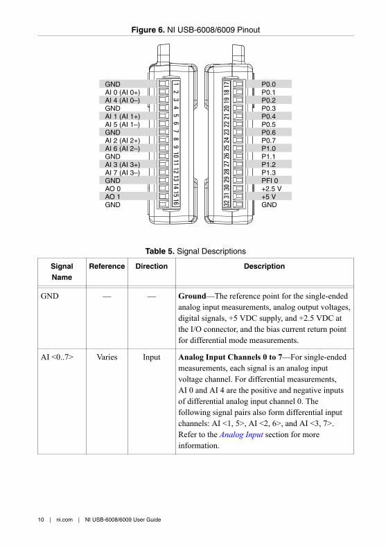
Figure 6. NI USB-6008/6009 Pinout
3231
3029
2827
2625
2423
2221
2019
1817
12
34
56
78
910
1112
1314
1516
GNDAI 0 (AI 0+) AI 4 (AI 0–)GNDAI 1 (AI 1+)AI 5 (AI 1–)GNDAI 2 (AI 2+)AI 6 (AI 2–)GNDAI 3 (AI 3+)AI 7 (AI 3–)GNDAO 0AO 1GND
P0.0P0.1P0.2P0.3P0.4P0.5P0.6P0.7P1.0P1.1P1.2P1.3PFI 0+2.5 V+5 VGND
Table 5. Signal Descriptions
SignalName
Reference Direction Description
GND — — Ground—The reference point for the single-endedanalog input measurements, analog output voltages,digital signals, +5 VDC supply, and +2.5 VDC atthe I/O connector, and the bias current return pointfor differential mode measurements.
AI <0..7> Varies Input Analog Input Channels 0 to 7—For single-endedmeasurements, each signal is an analog inputvoltage channel. For differential measurements,AI 0 and AI 4 are the positive and negative inputsof differential analog input channel 0. Thefollowing signal pairs also form differential inputchannels: AI <1, 5>, AI <2, 6>, and AI <3, 7>.Refer to the Analog Input section for moreinformation.
10 | ni.com | NI USB-6008/6009 User Guide
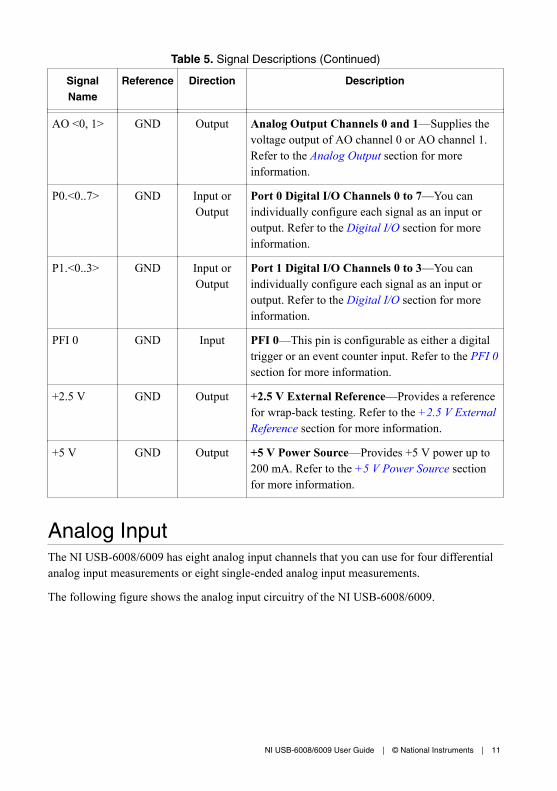
Table 5. Signal Descriptions (Continued)
SignalName
Reference Direction Description
AO <0, 1> GND Output Analog Output Channels 0 and 1—Supplies thevoltage output of AO channel 0 or AO channel 1.Refer to the Analog Output section for moreinformation.
P0.<0..7> GND Input orOutput
Port 0 Digital I/O Channels 0 to 7—You canindividually configure each signal as an input oroutput. Refer to the Digital I/O section for moreinformation.
P1.<0..3> GND Input orOutput
Port 1 Digital I/O Channels 0 to 3—You canindividually configure each signal as an input oroutput. Refer to the Digital I/O section for moreinformation.
PFI 0 GND Input PFI 0—This pin is configurable as either a digitaltrigger or an event counter input. Refer to the PFI 0section for more information.
+2.5 V GND Output +2.5 V External Reference—Provides a referencefor wrap-back testing. Refer to the +2.5 V ExternalReference section for more information.
+5 V GND Output +5 V Power Source—Provides +5 V power up to200 mA. Refer to the +5 V Power Source sectionfor more information.
Analog InputThe NI USB-6008/6009 has eight analog input channels that you can use for four differentialanalog input measurements or eight single-ended analog input measurements.
The following figure shows the analog input circuitry of the NI USB-6008/6009.
NI USB-6008/6009 User Guide | © National Instruments | 11

Figure 7. NI USB-6008/6009 Analog Input Circuitry
AI
+2.5 VREF
39.2 kΩ
127 kΩ
30.9 kΩ PGA
Input RangeSelection
AI FIFOADCMUX
The main blocks featured in the NI USB-6008/6009 analog input circuitry are as follows:• MUX—The NI USB-6008/6009 has one analog-to-digital converter (ADC). The
multiplexer (MUX) routes one AI channel at a time to the PGA.• PGA—The programmable-gain amplifier provides input gains of 1, 2, 4, 5, 8, 10, 16, or
20 when configured for differential measurements and gain of 1 when configured forsingle-ended measurements. The PGA gain is automatically calculated based on thevoltage range selected in the measurement application.
• ADC—The analog-to-digital converter (ADC) digitizes the AI signal by converting theanalog voltage into digital code.
• AI FIFO—The NI USB-6008/6009 can perform both single and multiple analog-to-digital conversions of a fixed or infinite number of samples. A first-in-first-out (FIFO)buffer holds data during AI acquisitions to ensure that no data is lost.
Analog Input Modes and Signal SourcesYou can configure the AI channels on the NI USB-6008/6009 to take differential or referencedsingle-ended (RSE) measurements. The following table summarizes the recommended analoginput mode(s) for floating signal sources and ground-references signal sources. Refer to thetable in the Pinout and Signal Descriptions section for more information about I/Oconfigurations for single-ended or differential measurements.
12 | ni.com | NI USB-6008/6009 User Guide

Table 6. Analog Input Configurations
Analog InputMode
Floating Signal Sources (NotConnected to Building Ground)
Ground-Referenced Signal Sources
Examples • Ungrounded thermocouples• Signal conditioning with
isolated outputs• Battery devices
Plug-in instruments with non-isolatedoutputs
Differential(DIFF)
+–
+
–
AI+
AI–
GND
Signal Source NI USB-6008/6009
+–
+
–
AI+
AI–
GND
Signal Source NI USB-6008/6009
ReferencedSingle-Ended(RSE) +
–
+
–
AI
GND
Signal Source NI USB-6008/6009
Ground-loop potential (VA – VB) are addedto measured signal.
NOT RECOMMENDED
+–
+
–
AI
GNDVB
VA
Signal Source NI USB-6008/6009
Floating Signal SourcesA floating signal source is not connected to the building ground system, but has an isolatedground-reference point. Some examples of floating signal sources are outputs of transformers,thermocouples, battery-powered devices, optical isolators, and isolation amplifiers. Aninstrument or device that has an isolated output is a floating signal source.
Refer to Field Wiring and Noise Considerations for Analog Signals for more information. Toaccess this document, go to ni.com/info and enter the Info Code rdfwn3.
When to Use Differential Connections with Floating Signal SourcesUse DIFF input connections for any channel that meets any of the following conditions:• Your application requires input ranges other than ±10 V.• The input signal is low level and requires greater accuracy.
NI USB-6008/6009 User Guide | © National Instruments | 13
• The leads connecting the signal to the device are greater than 3 m (10 ft).• The input signal requires a separate ground-reference point or return signal.• The signal leads travel through noisy environments.• Two analog channels, AI+ and AI-, are available for the signal.
DIFF signal connections reduce noise pickup and increase common-mode noise rejection.DIFF signal connections also allow input signals to float within the working voltage of thedevice.
Refer to the Taking Differential Measurements section for more information about differentialconnections.
When to Use Referenced Single-Ended (RSE) Connections with FloatingSignal SourcesOnly use RSE input connections if the input signal meets all of the following conditions:• The input signal can share a common reference point, GND, with other signals that use
RSE.• Your application permits the use of the ±10 V input range.• The leads connecting the signal to the device are less than 3 m (10 ft).
DIFF input connections are recommended for greater signal integrity for any input signal thatdoes not meet the preceding conditions.
In the single-ended modes, more electrostatic and magnetic noise couples into the signalconnections than in DIFF configurations. The coupling is the result of differences in the signalpath. Magnetic coupling is proportional to the area between the two signal conductors.Electrical coupling is a function of how much the electric field differs between the twoconductors.
With this type of connection, the PGA rejects both the common-mode noise in the signal andthe ground potential difference between the signal source and the device ground.
Refer to the Taking Referenced Single-Ended Measurements section for more informationabout RSE connections.
Ground-Referenced Signal SourcesA ground-referenced signal source is a signal source connected to the building system ground.It is already connected to a common ground point with respect to the device, assuming that thecomputer is plugged into the same power system as the source. Non-isolated outputs ofinstruments and devices that plug into the building power system fall into this category.
The difference in ground potential between two instruments connected to the same buildingpower system is typically between 1 mV and 100 mV, but the difference can be much higher ifpower distribution circuits are improperly connected. If a grounded signal source is incorrectlymeasured, this difference can appear as measurement error. Follow the connection instructions
14 | ni.com | NI USB-6008/6009 User Guide
for grounded signal sources to eliminate this ground potential difference from the measuredsignal.
Refer to Field Wiring and Noise Considerations for Analog Signals for more information. Toaccess this document, go to ni.com/info and enter the Info Code rdfwn3.
When to Use Differential Connections with Ground-Reference Signal SourcesUse DIFF input connections for any channel that meets any of the following conditions:• Your application requires input ranges other than ±10 V.• The input signal is low level and requires greater accuracy.• The leads connecting the signal to the device are greater than 3 m (10 ft).• The input signal requires a separate ground-reference point or return signal.• The signal leads travel through noisy environments.• Two analog channels, AI+ and AI-, are available for the signal.
DIFF signal connections reduce noise pickup and increase common-mode noise rejection.DIFF signal connections also allow input signals to float within the working voltage of thedevice.
Refer to the Taking Differential Measurements section for more information about differentialconnections.
When to Use Referenced Single-Ended (RSE) Connections withGround-Referenced Signal SourcesDo not use RSE connections with ground-referenced signal sources. Use differentialconnections instead.
As shown in the table in the Analog Input Modes and Signal Sources section, there can be apotential difference between GND and the ground of the sensor. In RSE mode, this groundloop causes measurement errors.
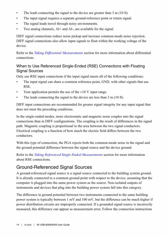
Taking Differential MeasurementsFor differential signals, connect the positive lead of the signal to the AI+ terminal, and thenegative lead to the AI- terminal.
Figure 8. Connecting a Differential Voltage Signal
AI+
NI USB-6008/6009
AI–
Voltage Source
NI USB-6008/6009 User Guide | © National Instruments | 15
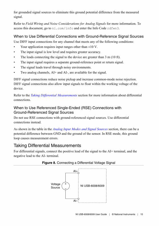
The differential input mode can measure ±20 V signals in the ±20 V range. However, themaximum voltage on any one pin is ±10 V with respect to GND. For example, if AI 1 is +10 Vand AI 5 is -10 V, then the measurement returned from the device is +20 V.
Figure 9. Example of a Differential 20 V Measurement
–5
–10
–15
–20
20
15
10
5
0
Am
plitu
de (
V)
AI 1
AI 5
Result
Connecting a signal greater than ±10 V on either pin results in a clipped output.
Figure 10. Exceeding ±10 V on AI Returns Clipped Output
–5
–10
–15
–20
20
15
10
5
0
Am
plitu
de (
V)
AI 1
AI 5
Result
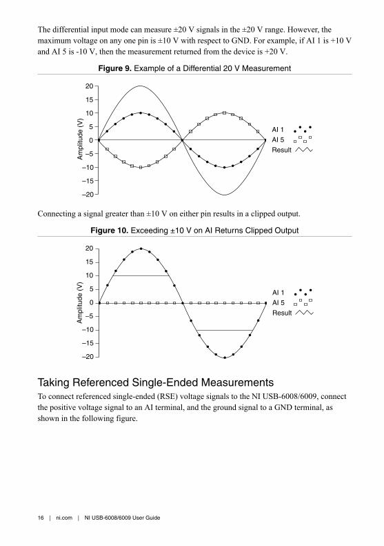
Taking Referenced Single-Ended MeasurementsTo connect referenced single-ended (RSE) voltage signals to the NI USB-6008/6009, connectthe positive voltage signal to an AI terminal, and the ground signal to a GND terminal, asshown in the following figure.
16 | ni.com | NI USB-6008/6009 User Guide
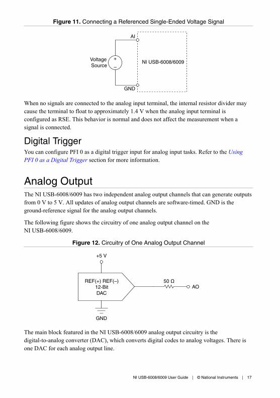
Figure 11. Connecting a Referenced Single-Ended Voltage Signal
AI
NI USB-6008/6009
GND
Voltage Source
When no signals are connected to the analog input terminal, the internal resistor divider maycause the terminal to float to approximately 1.4 V when the analog input terminal isconfigured as RSE. This behavior is normal and does not affect the measurement when asignal is connected.
Digital TriggerYou can configure PFI 0 as a digital trigger input for analog input tasks. Refer to the UsingPFI 0 as a Digital Trigger section for more information.
Analog OutputThe NI USB-6008/6009 has two independent analog output channels that can generate outputsfrom 0 V to 5 V. All updates of analog output channels are software-timed. GND is theground-reference signal for the analog output channels.
The following figure shows the circuitry of one analog output channel on theNI USB-6008/6009.
Figure 12. Circuitry of One Analog Output Channel
REF(+) REF(–)12-BitDAC
50 ΩAO
+5 V
GND
The main block featured in the NI USB-6008/6009 analog output circuitry is thedigital-to-analog converter (DAC), which converts digital codes to analog voltages. There isone DAC for each analog output line.
NI USB-6008/6009 User Guide | © National Instruments | 17
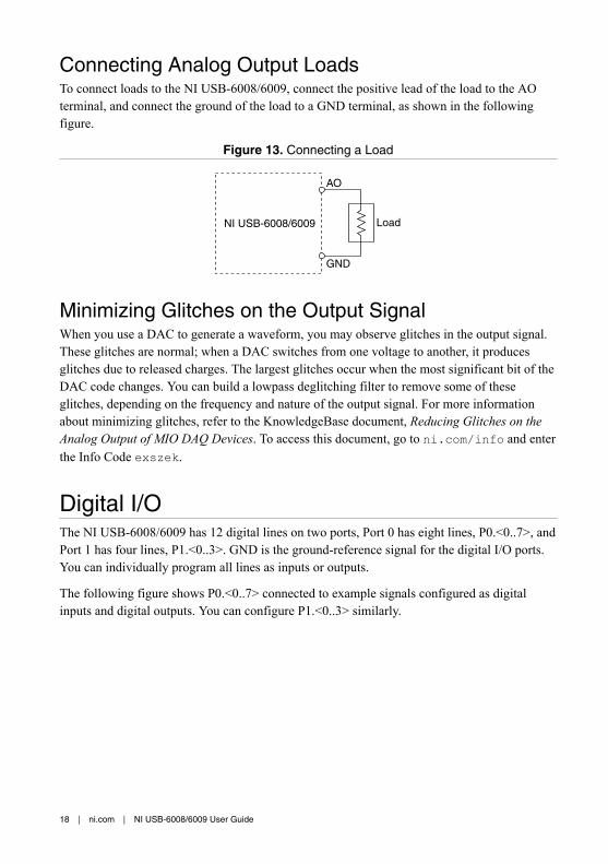
Connecting Analog Output LoadsTo connect loads to the NI USB-6008/6009, connect the positive lead of the load to the AOterminal, and connect the ground of the load to a GND terminal, as shown in the followingfigure.
Figure 13. Connecting a Load
NI USB-6008/6009
GND
AO
Load
Minimizing Glitches on the Output SignalWhen you use a DAC to generate a waveform, you may observe glitches in the output signal.These glitches are normal; when a DAC switches from one voltage to another, it producesglitches due to released charges. The largest glitches occur when the most significant bit of theDAC code changes. You can build a lowpass deglitching filter to remove some of theseglitches, depending on the frequency and nature of the output signal. For more informationabout minimizing glitches, refer to the KnowledgeBase document, Reducing Glitches on theAnalog Output of MIO DAQ Devices. To access this document, go to ni.com/info and enterthe Info Code exszek.
Digital I/OThe NI USB-6008/6009 has 12 digital lines on two ports, Port 0 has eight lines, P0.<0..7>, andPort 1 has four lines, P1.<0..3>. GND is the ground-reference signal for the digital I/O ports.You can individually program all lines as inputs or outputs.
The following figure shows P0.<0..7> connected to example signals configured as digitalinputs and digital outputs. You can configure P1.<0..3> similarly.
18 | ni.com | NI USB-6008/6009 User Guide

Figure 14. Example of Connecting a Load
+5 V
LED
Switch
I/O Connector
GND
P0.0P0.1P0.2P0.3P0.4P0.5P0.6P0.7
+5 V
LED
1
2
3
4
TTL Signal
NI USB-6008/6009
1. P0.0 configured as an open collector digital outputdriving an LED
2. P0.2 configured as an active drive digital outputdriving an LED
3. P0.4 configured as a digital input receiving a TTLsignal from a gated invertor
4. P0.7 configured as a digital input receiving a 0 Vor 5 V signal from a switch
Caution Exceeding the maximum input voltage ratings or maximum output ratingscan damage the device and the computer. National Instruments is not liable for anydamage resulting from such signal connections. Refer to the NI USB-6008 DeviceSpecifications or NI USB-6009 Device Specifications for more information.
Source/Sink InformationThe default configuration of the NI USB-6008/6009 digital I/O ports is open collector,allowing 5 V operation, with an onboard 4.7 kΩ pull-up resistor. An external user-providedpull-up resistor can be added to increase the source current drive up to a 8.5 mA limit per line,as shown in the following figure.4
4 This document uses NI-DAQmx naming conventions. Open-drain is called open collector andpush-pull is called active drive.
NI USB-6008/6009 User Guide | © National Instruments | 19

Figure 15. Example of Connecting an External User-Provided Resistor
GND
P0.0
+5 V
RpRe
Rl
NI USB-6008/6009
Load
A
+5 V
Port Pad
4.7 kΩ Onboard Resistor
ExternalPull-UpResistor
The NI USB-6009 ports can also be configured as active drive using the NI-DAQmx API,allowing 3.3 V operation with a source/sink current limit of ±8.5 mA. For more informationabout how to set the DIO configuration, refer to the KnowledgeBase document, How Do IConfigure My NI Device to be Open-Drain (Open Collector) or Push-Pull (Active Drive)?. Toaccess this document, go to ni.com/info and enter the Info Code ex52sp.
Determining the Value of the User-Provided Pull-Up ResistorComplete the following steps to determine the value of the user-provided pull-up resistor:1. Place an ammeter in series with the load.2. Place a variable resistor between the digital output line and the +5 V supply.3. Set P0.0 to high.4. Adjust the variable resistor until the ammeter current reads as the intended current. The
intended current must be less than 8.5 mA.5. Remove the ammeter and variable resistor from your circuit.6. Measure the resistance of the variable resistor. The measured resistance is the ideal value
of the pull-up resistor.7. Select a static resistor value for your pull-up resistor that is greater than or equal to the
ideal resistance.8. Reconnect the load circuit and the pull-up resistor.
20 | ni.com | NI USB-6008/6009 User Guide

I/O ProtectionTo protect the NI USB-6008/6009 against overvoltage, undervoltage, and overcurrentconditions, as well as ESD events, you should avoid these fault conditions by using thefollowing guidelines:• If you configure a DIO line as an output, do not connect it to any external signal source,
ground signal, or power supply.• If you configure a DIO line as an output, understand the current requirements of the load
connected to these signals. Do not exceed the specified current output limits of the DAQdevice.National Instruments has several signal conditioning solutions for digital applicationsrequiring high current drive.
• If you configure a DIO line as an input, do not drive the line with voltages outside of itsnormal operating range. The DIO lines have a smaller operating range than the AIsignals.
• Treat the DAQ device as you would treat any static-sensitive device. Always properlyground yourself and the equipment when handling the DAQ device or connecting to it.
Power-On StatesAt system startup and reset, the hardware sets all DIO lines to high-impedance inputs. TheDAQ device does not drive the signal high or low. Each line has a weak pull-up resistorconnected to it.
Static DIOEach of the NI USB-6008/6009 DIO lines can be used as a static DI or DO line. You can usestatic DIO lines to monitor or control digital signals. All samples of static DI lines and updatesof DO lines are software-timed.
PFI 0PFI 0 is configurable as either a digital trigger input or an event counter input.
Using PFI 0 as a Digital TriggerWhen an analog input task is defined, you can configure PFI 0 as a digital trigger input. Whenthe digital trigger is enabled, the AI task waits for a rising or falling edge on PFI 0 beforestarting the acquisition. To use AI Start Trigger (ai/StartTrigger) with a digital source, specifyPFI 0 as the source and select a rising or falling edge.
Using PFI 0 as an Event CounterYou can configure PFI 0 as a source for counting digital edges. In this mode, falling-edgeevents are counted using a 32-bit counter. For more information about event timing
NI USB-6008/6009 User Guide | © National Instruments | 21
requirements, refer to the NI USB-6008 Device Specifications and NI USB-6009 DeviceSpecifications documents available on ni.com/manuals.
External Reference and Power SourceThe NI USB-6008/6009 creates an external reference and supplies a power source. Allvoltages are relative to ground (GND).
+2.5 V External ReferenceThe NI USB-6008/6009 creates a high-purity reference voltage supply for the ADC using amulti-state regulator, amplifier, and filter circuit. You can use the resulting +2.5 V referencevoltage as a signal for self-test.
+5 V Power SourceThe NI USB-6008/6009 supplies a 5 V, 200 mA output. You can use this source to powerexternal components.
Note When the device is in USB suspend, the output is disabled.
Where to Go from HereThis section lists where you can find example programs for the NI USB-6008/6009 andrelevant documentation.
Example ProgramsNI-DAQmx and NI-DAQmx Base software include example programs to help you get startedprogramming with the NI USB-6008/6009. Modify example code and save it in an application,or use examples to develop a new application, or add example code to an existing application.
NI-DAQmxTo locate NI software examples, go to ni.com/info and enter the Info Code daqmxexp.
To run examples without the device installed, use an NI-DAQmx simulated device. For moreinformation, in Measurement & Automation Explorer (MAX), select Help»Help Topics»NI-DAQmx»MAX Help for NI-DAQmx and search for simulated devices.
NI-DAQmx BaseNI-DAQmx Base examples are accessible from Start»All Programs»National Instruments»NI-DAQmx Base Examples.
22 | ni.com | NI USB-6008/6009 User Guide

Related DocumentationEach application software package and driver includes information about writing applicationsfor taking measurements and controlling measurement devices. The following references todocuments assume you have NI-DAQmx 9.3 or later, and where applicable, version 8.5 orlater of the NI application software.
NI USB-6008/6009The NI USB-6008/6009 Quick Start included with the NI USB-6008/6009 describes how toinstall NI-DAQmx software, install the device, and confirm that your device is operatingproperly.
The NI USB-6008 Device Specifications and NI USB-6009 Device Specifications containdevice specifications and are available at ni.com/manuals.
NI-DAQmxThe NI-DAQmx Readme is available from the Windows Start menu and lists which applicationsoftware, devices, and ADEs are supported by this version of NI-DAQmx.
The NI-DAQmx Help is available from the Windows Start menu and contains API overviews,general information about measurement concepts, key NI-DAQmx concepts, and commonapplications that are applicable to all programming environments.
NI-DAQmx Base (Linux/Mac OS X/LabVIEW PDA 8.x)The Getting Started with NI-DAQmx Base document describes how to install the NI-DAQmxBase software, the NI-DAQmx Base-supported DAQ device, and how to confirm that thedevice is operating properly on your Windows, Linux, or Mac machine. In Windows, selectStart»All Programs»National Instruments»NI-DAQmx Base»Documentation»GettingStarted with NI-DAQmx Base.
The NI-DAQmx Base Readme lists devices supported in different versions of NI-DAQmxBase. In Windows, select Start»All Programs»National Instruments»NI-DAQmx Base»DAQmx Base Readme.
The NI-DAQmx Base VI Reference Help contains VI reference and general information aboutmeasurement concepts. In LabVIEW, select Help»NI-DAQmx Base VI Reference Help.
The NI-DAQmx Base C Function Reference Help contains C reference and generalinformation about measurement concepts. In Windows, select Start»All Programs»NationalInstruments»NI-DAQmx Base»Documentation»C Function Reference Help.
Note All NI-DAQmx Base documentation for Linux is installed at /usr/local/natinst/nidaqmxbase/documentation.
NI USB-6008/6009 User Guide | © National Instruments | 23
Note All NI-DAQmx Base documentation for Mac OS X is installed at /Applications/National Instruments/NI-DAQmx Base/documentation.
LabVIEWRefer to ni.com/gettingstarted for more information about LabVIEW.
Use the LabVIEW Help, available by selecting Help»LabVIEW Help in LabVIEW, to accessinformation about LabVIEW programming concepts, step-by-step instructions for usingLabVIEW, and reference information about LabVIEW VIs, functions, palettes, menus, andtools. Refer to the following locations on the Contents tab of the LabVIEW Help forinformation about NI-DAQmx:• VI and Function Reference»Measurement I/O VIs and Functions»DAQmx - Data
Acquisition VIs and Functions—Describes the LabVIEW NI-DAQmx VIs andfunctions.
• Property and Method Reference»NI-DAQmx Properties—Contains the propertyreference.
• Taking Measurements—Contains the conceptual and how-to information you need toacquire and analyze measurement data in LabVIEW, including common measurements,measurement fundamentals, NI-DAQmx key concepts, and device considerations.
LabWindows/CVIThe Data Acquisition section of the LabWindows/CVI Help contains Taking an NI-DAQmxMeasurement in LabWindows/CVI, which includes step-by-step instructions for creating ameasurement task using the DAQ Assistant. In LabWindows/CVI, select Help»Contents, andthen select Using LabWindows/CVI»Data Acquisition. This book also contains informationabout accessing detailed information through the NI-DAQmx Help.
The NI-DAQmx Library section of the LabWindows/CVI Help contains API overviews andfunction reference for NI-DAQmx. Select Library Reference»NI-DAQmx Library in theLabWindows/CVI Help.
Measurement StudioIf you program your NI-DAQmx-supported device in Measurement Studio using Visual C# orVisual Basic .NET, you can interactively create channels and tasks by launching the DAQAssistant from MAX or from within Visual Studio. You can use Measurement Studio togenerate the configuration code based on your task or channel. Refer to the DAQ AssistantHelp for additional information about generating code.
The NI Measurement Studio Help is fully integrated with the Microsoft Visual Studio help. Toview this help file in Visual Studio, select Measurement Studio»NI Measurement Studio
24 | ni.com | NI USB-6008/6009 User Guide

Help. For information related to developing with NI-DAQmx, refer to the following topicswithin the NI Measurement Studio Help:• For step-by-step instructions on how to create an NI-DAQmx application using the
Measurement Studio Application Wizard and the DAQ Assistant, refer to Walkthrough:Creating a Measurement Studio NI-DAQmx Application.
• For help with NI-DAQmx methods and properties, refer to NationalInstruments.DAQmxNamespace and NationalInstruments.DAQmx.ComponentModel Namespace.
• For conceptual help with NI-DAQmx, refer to Using the Measurement StudioNI-DAQmx .NET Library and Developing with Measurement Studio NI-DAQmx.
• For general help with programming in Measurement Studio, refer to Getting Started withthe Measurement Studio Class Libraries.
To create an application in Visual Basic .NET or Visual C#, follow these general steps:1. In Visual Studio, select File»New»Project to launch the New Project dialog box.2. In the Project types pane, expand the Visual Basic or Visual C# node, depending on
which language you want to create the project in, and select Measurement Studio.3. Choose a project type. You add DAQ tasks as a part of this step.
ANSI C without NI Application SoftwareThe NI-DAQmx Help contains API overviews and general information about measurementconcepts. Select Start»All Programs»National Instruments»NI-DAQmx»NI-DAQmxHelp.
The NI-DAQmx C Reference Help describes the NI-DAQmx Library functions, which you canuse with National Instruments data acquisition devices to develop instrumentation, acquisition,and control applications. Select Start»All Programs»National Instruments»NI-DAQmx»Text-Based Code Support»NI-DAQmx C Reference Help.
.NET Languages without NI Application SoftwareWith the Microsoft .NET Framework, you can use NI-DAQmx to create applications usingVisual C# and Visual Basic .NET without Measurement Studio. Refer to the NI-DAQmxReadme for specific versions supported.
Training CoursesIf you need more help getting started developing an application with NI products, NI offerstraining courses. To enroll in a course or obtain a detailed course outline, refer to ni.com/training.
Technical Support on the WebFor additional support, refer to ni.com/support or ni.com/examples.
Note You can download these documents at ni.com/manuals.
NI USB-6008/6009 User Guide | © National Instruments | 25
Many DAQ specifications and user guides/manuals are available as PDFs. You must haveAdobe Reader 7.0 or later (PDF 1.6 or later) installed to view the PDFs. Refer to the AdobeSystems Incorporated website at www.adobe.com to download Adobe Reader. Refer to theNational Instruments Product Manuals Library at ni.com/manuals for updateddocumentation resources.
Worldwide Support and ServicesThe National Instruments website is your complete resource for technical support. At ni.com/support, you have access to everything from troubleshooting and application developmentself-help resources to email and phone assistance from NI Application Engineers.
Visit ni.com/services for NI Factory Installation Services, repairs, extended warranty, andother services.
Visit ni.com/register to register your National Instruments product. Product registrationfacilitates technical support and ensures that you receive important information updates fromNI.
A Declaration of Conformity (DoC) is our claim of compliance with the Council of theEuropean Communities using the manufacturer’s declaration of conformity. This systemaffords the user protection for electromagnetic compatibility (EMC) and product safety. Youcan obtain the DoC for your product by visiting ni.com/certification. If your product supportscalibration, you can obtain the calibration certificate for your product at ni.com/calibration.
National Instruments corporate headquarters is located at 11500 North Mopac Expressway,Austin, Texas, 78759-3504. National Instruments also has offices located around the world.For telephone support in the United States, create your service request at ni.com/support ordial 1 866 ASK MYNI (275 6964). For telephone support outside the United States, visit theWorldwide Offices section of ni.com/niglobal to access the branch office websites, whichprovide up-to-date contact information, support phone numbers, email addresses, and currentevents.
Refer to the NI Trademarks and Logo Guidelines at ni.com/trademarks for information on National Instruments trademarks.Other product and company names mentioned herein are trademarks or trade names of their respective companies. For patentscovering National Instruments products/technology, refer to the appropriate location: Help»Patents in your software, thepatents.txt file on your media, or the National Instruments Patent Notice at ni.com/patents. You can find information aboutend-user license agreements (EULAs) and third-party legal notices in the readme file for your NI product. Refer to the ExportCompliance Information at ni.com/legal/export-compliance for the National Instruments global trade compliance policy andhow to obtain relevant HTS codes, ECCNs, and other import/export data. NI MAKES NO EXPRESS OR IMPLIED WARRANTIESAS TO THE ACCURACY OF THE INFORMATION CONTAINED HEREIN AND SHALL NOT BE LIABLE FOR ANY ERRORS.U.S. Government Customers: The data contained in this manual was developed at private expense and is subject to theapplicable limited rights and restricted data rights as set forth in FAR 52.227-14, DFAR 252.227-7014, and DFAR 252.227-7015.
© 2004—2015 National Instruments. All rights reserved.
371303N-01 Jul15