NGP Introduction
36
NGP Introduction Next Generation Enterprise Access Control System with optional Central Station Burg support Company Confidential 1 03/30/2022
-
Upload
carla-bradley -
Category
Documents
-
view
140 -
download
5
description
NGP Introduction. Next Generation Enterprise Access Control System with optional Central Station Burg support. NGP Mission Statement. The purpose of the NGP panel is to offer Lenel VARS and End Users an alternative enterprise-class access control panel family Adding value by offering, - PowerPoint PPT Presentation
Transcript of NGP Introduction
Company Confidential 1
NGP Introduction
Next Generation Enterprise Access Control System with optional Central Station Burg support
04/19/2023
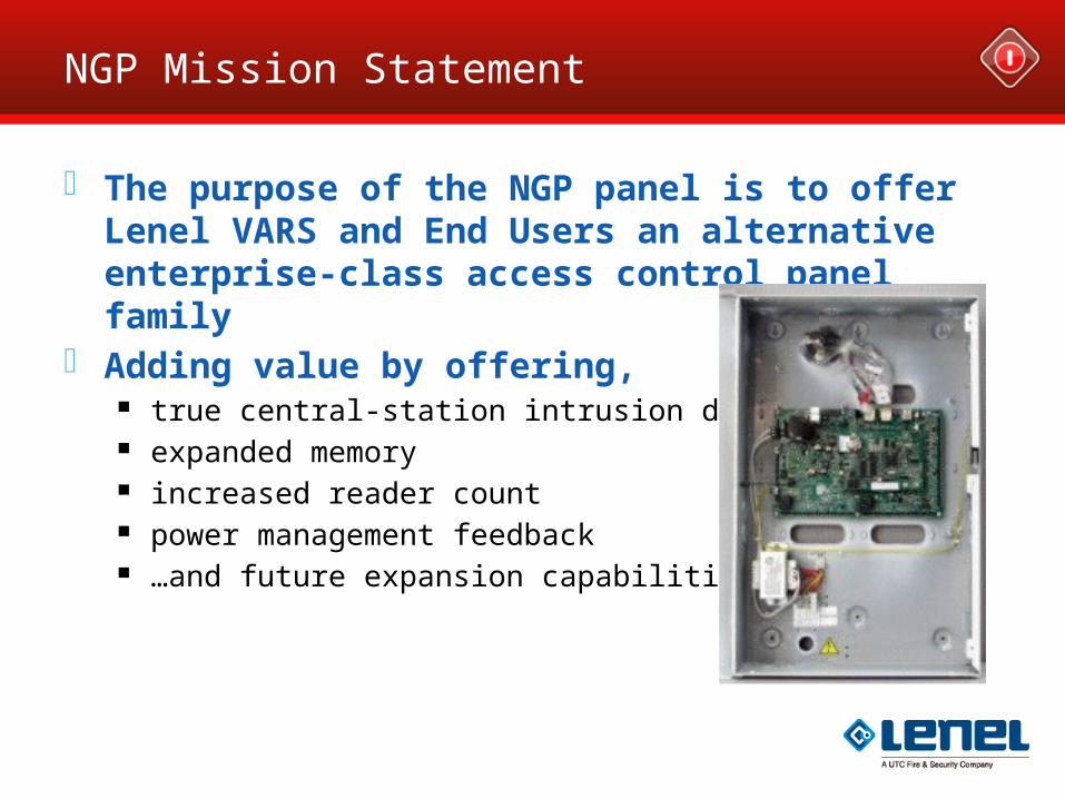
NGP Mission Statement
The purpose of the NGP panel is to offer Lenel VARS and End Users an alternative enterprise-class access control panel family
Adding value by offering, true central-station intrusion detection expanded memory increased reader count power management feedback …and future expansion capabilities
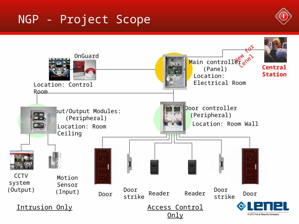
NGP - Project Scope
OnGuard
Location: Electrical Room
Location: Control Room
Location: Room Wall
ReaderDoor strikeDoor Door
Door strike
Reader
Door controller (Peripheral)
Input/Output Modules: (Peripheral)
Location: Room Ceiling
Motion Sensor (Input)
Central Station
CCTV system (Output)
Main controller (Panel)
New fo
r Len
el
Intrusion Only Access Control Only
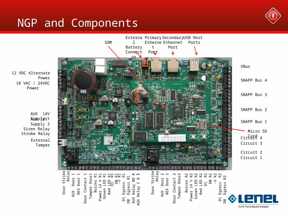
NGP and ComponentsUSB Host
PortsPrimaryEthernet
Port
SecondaryEthernet
Port
VBus
SNAPP Bus 4
SNAPP Bus 3
SNAPP Bus 2
SNAPP Bus 1
Micro SD Card
Circuit 4Circuit 3
Circuit 2Circuit 1
12 VDC Alternate Power
18 VAC / 24VDC Power
AUX 14V Supply 1AUX 14V Supply 2
Siren RelayStrobe Relay
External Tamper
SOM
Doo
r S
trik
e R
ela
y
AU
X
Do
or
1
RE
X D
oo
r 1
Doo
r C
onta
ct 1
Tam
pe
r D
oo
r1B
uzze
r R
1P
owe
r 14
V R
1G
ree
n L
ED
R1
Red
LE
D R
1D
1 R
1D
0 R
1-V
R1
D1
Eg
ress
R
1D
0 E
gre
ss R
1
Doo
r S
trik
e R
ela
y
AU
X
Do
or
2R
EX
Do
or
2
Doo
r C
onta
ct 2
Tam
pe
r D
oo
r2
Buz
zer
R2
Pow
er
14 V
R2
Gre
en
LE
D R
2R
ed L
ED
R2
D1
R2
D0
R2
-V R
2D
1 E
gre
ss
R2
D0
Eg
ress
R2
ExternalBattery
Connector
AU
X R
ela
y N
O R
1A
UX
Re
lay
C R
1
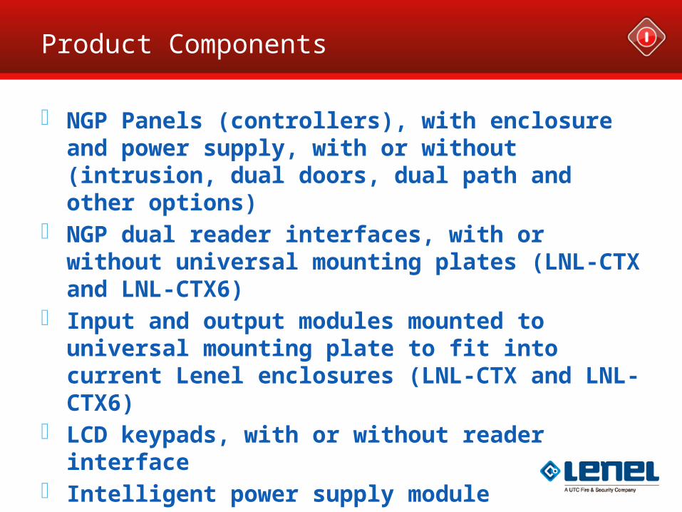
Product Components
NGP Panels (controllers), with enclosure and power supply, with or without (intrusion, dual doors, dual path and other options)
NGP dual reader interfaces, with or without universal mounting plates (LNL-CTX and LNL-CTX6)
Input and output modules mounted to universal mounting plate to fit into current Lenel enclosures (LNL-CTX and LNL-CTX6)
LCD keypads, with or without reader interface Intelligent power supply module Optional world wide modem for intrusion
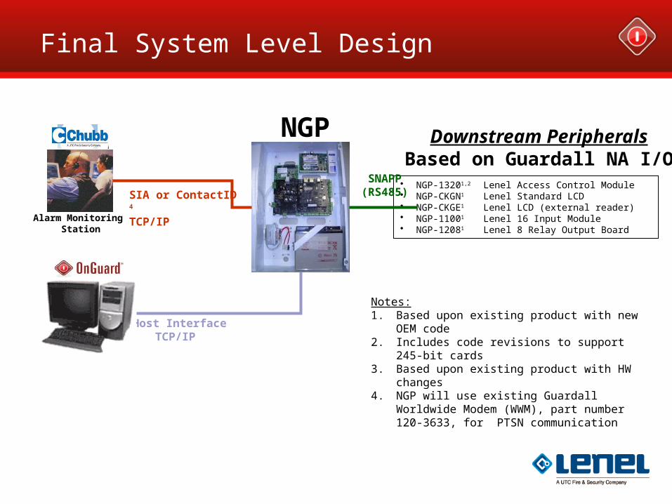
NGP
• NGP-13201,2 Lenel Access Control Module• NGP-CKGN1 Lenel Standard LCD• NGP-CKGE1 Lenel LCD (external reader)• NGP-11001 Lenel 16 Input Module• NGP-12081 Lenel 8 Relay Output Board
Notes:1. Based upon existing product with new OEM code2. Includes code revisions to support 245-bit cards3. Based upon existing product with HW changes4. NGP will use existing Guardall Worldwide Modem
(WWM), part number 120-3633, for PTSN communication
SNAPP(RS485)
Host Interface • TCP/IP
Alarm Monitoring Station
SIA or ContactID 4
TCP/IP
Downstream PeripheralsBased on Guardall NA I/O
Final System Level Design
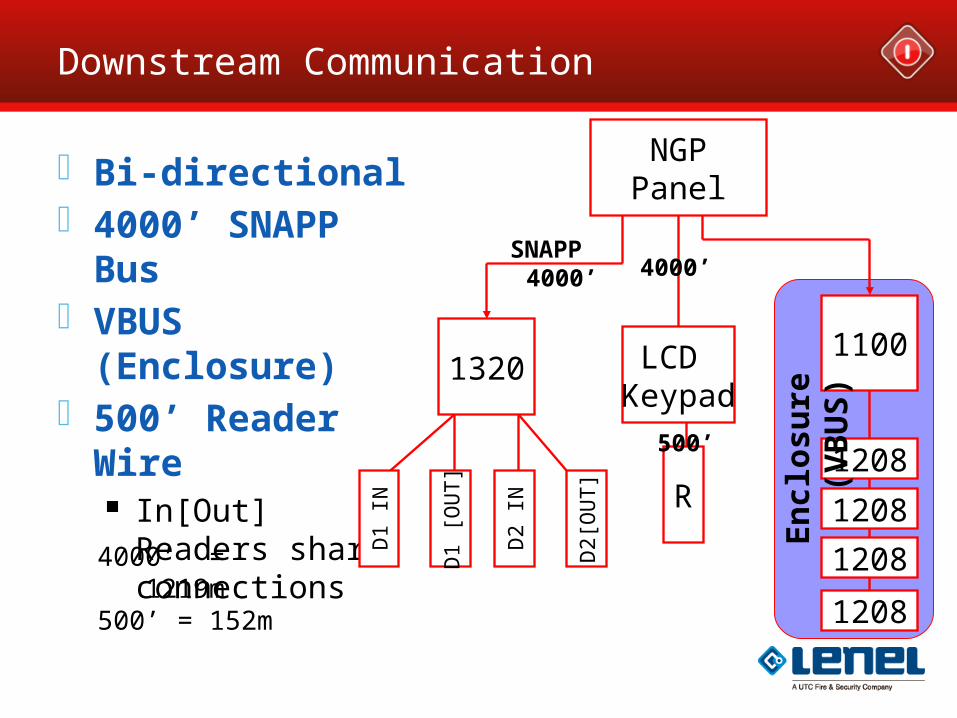
Downstream Communication
Bi-directional 4000’ SNAPP Bus VBUS (Enclosure) 500’ Reader Wire
In[Out] Readers share connections
NGPPanel
13201100
D1
[OU
T]
SNAPP4000’ 4000’
LCD Keypad
R
500’
4000’ = 1219m500’ = 152m
1208
1208
1208
1208
En
clos
ure
(V
BU
S)
D2
IN
D2[
OU
T]
D1
IN
Value Proposition Summary
A scalable hardware and software platform Reuse existing Guardall peripherals where possible Integration with OnGuard Host Software Integrated Access and Intrusion
With Central Station Support
Phased approach to ultimately include: NGP peripheral devices Guardall legacy peripherals
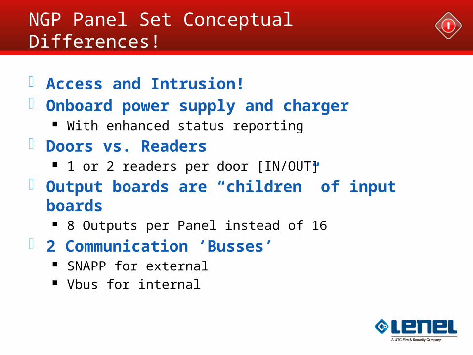
NGP Panel Set Conceptual Differences!
Access and Intrusion! Onboard power supply and charger
With enhanced status reporting
Doors vs. Readers 1 or 2 readers per door [IN/OUT]
Output boards are “children” of input boards 8 Outputs per Panel instead of 16
2 Communication ‘Busses’ SNAPP for external Vbus for internal
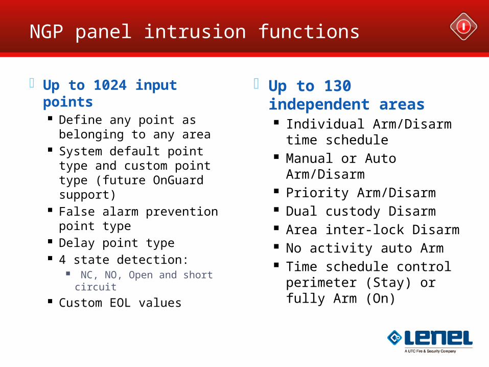
NGP panel intrusion functions
Up to 1024 input points Define any point as
belonging to any area System default point type
and custom point type (future OnGuard support)
False alarm prevention point type
Delay point type 4 state detection:
NC, NO, Open and short circuit
Custom EOL values
Up to 130 independent areas
Individual Arm/Disarm time schedule
Manual or Auto Arm/Disarm
Priority Arm/Disarm Dual custody Disarm Area inter-lock Disarm No activity auto Arm Time schedule control
perimeter (Stay) or fully Arm (On)
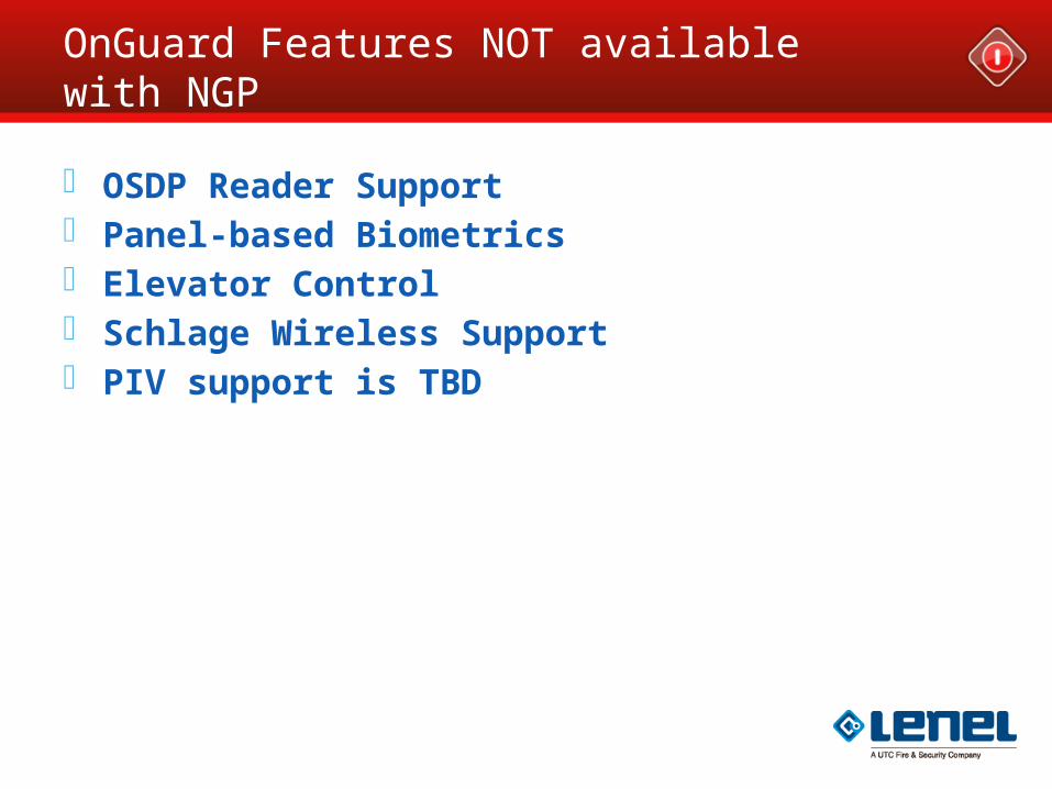
OnGuard Features NOT available with NGP
OSDP Reader Support Panel-based Biometrics Elevator Control Schlage Wireless Support PIV support is TBD
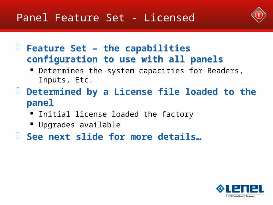
Panel Feature Set - Licensed
Feature Set – the capabilities configuration to use with all panels
Determines the system capacities for Readers, Inputs, Etc.
Determined by a License file loaded to the panel Initial license loaded the factory Upgrades available
See next slide for more details…
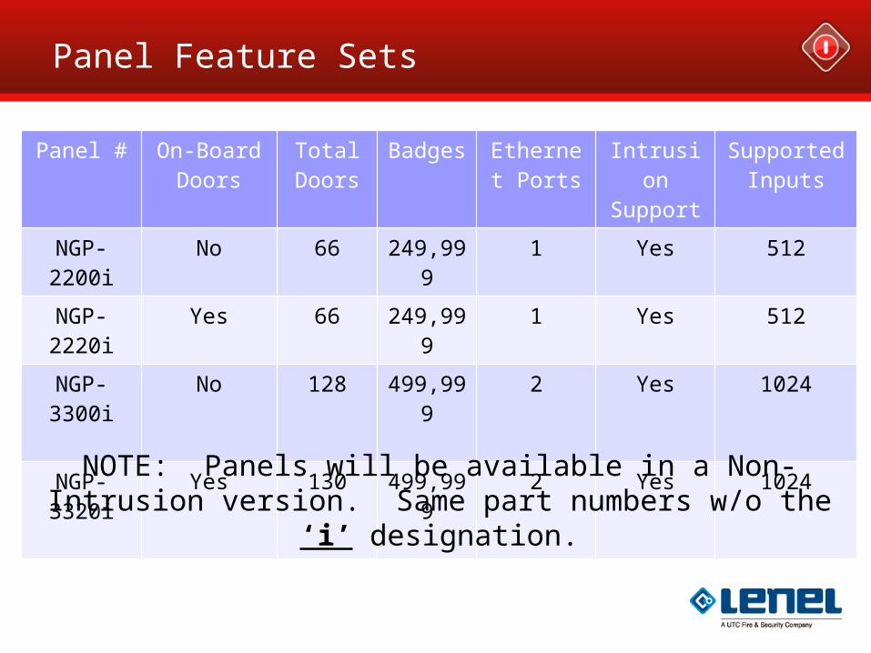
Panel Feature Sets
Panel # On-Board Doors
Total Doors
Badges Ethernet Ports
Intrusion Support
Supported Inputs
NGP-2200i
No 66 249,999 1 Yes 512
NGP-2220i
Yes 66 249,999 1 Yes 512
NGP-3300i
No 128 499,999 2 Yes 1024
NGP-3320i
Yes 130 499,999 2 Yes 1024
NOTE: Panels will be available in a Non-Intrusion version. Same part numbers w/o the ‘i’ designation.
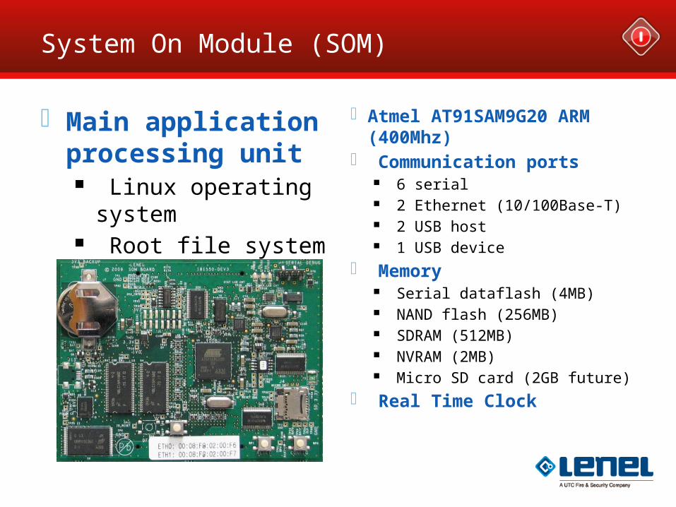
System On Module (SOM)
Main application processing unit
Linux operating system
Root file system Database
(configuration, users, etc.)
Event storage
Atmel AT91SAM9G20 ARM (400Mhz)
Communication ports 6 serial 2 Ethernet (10/100Base-T) 2 USB host 1 USB device
Memory Serial dataflash (4MB) NAND flash (256MB) SDRAM (512MB) NVRAM (2MB) Micro SD card (2GB future)
Real Time Clock
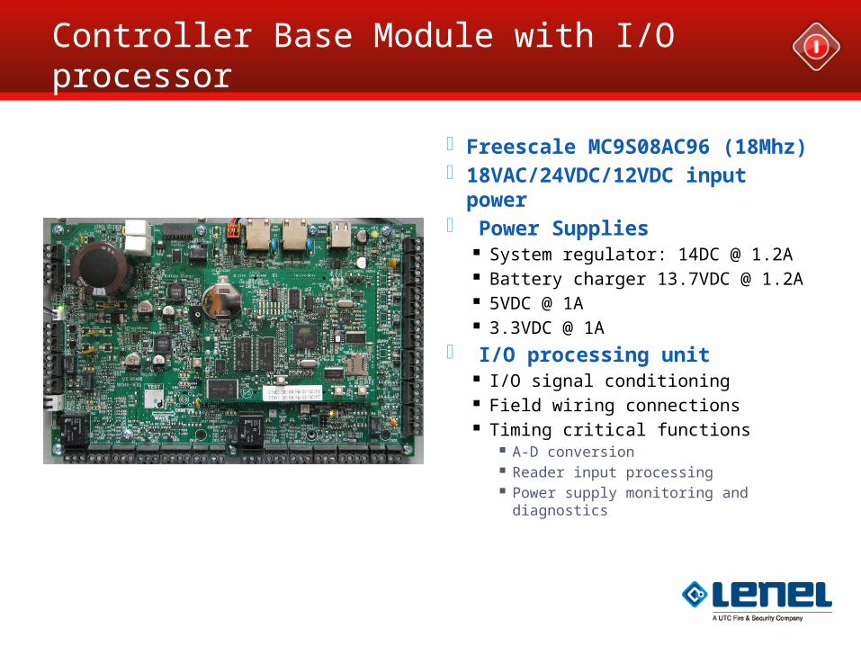
Controller Base Module with I/O processor
Freescale MC9S08AC96 (18Mhz) 18VAC/24VDC/12VDC input
power Power Supplies
System regulator: 14DC @ 1.2A Battery charger 13.7VDC @ 1.2A 5VDC @ 1A 3.3VDC @ 1A
I/O processing unit I/O signal conditioning Field wiring connections Timing critical functions
A-D conversion Reader input processing Power supply monitoring and
diagnostics
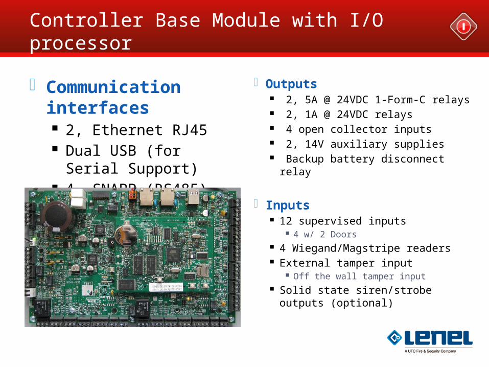
Controller Base Module with I/O processor
Communication interfaces
2, Ethernet RJ45 Dual USB (for Serial
Support) 4, SNAPP (RS485) Vbus for I/O
expansion Future Use
WWM for PTSN alarm reporting to Central Station
Outputs 2, 5A @ 24VDC 1-Form-C relays 2, 1A @ 24VDC relays 4 open collector inputs 2, 14V auxiliary supplies Backup battery disconnect relay
Inputs
12 supervised inputs 4 w/ 2 Doors
4 Wiegand/Magstripe readers External tamper input
Off the wall tamper input Solid state siren/strobe outputs
(optional)
NGP Memory
Onboard memory will retain specified information which includes:
Cardholder/Badge – 500,000 MAX Access levels – 31,199 Timezones – 255 (Holidays – 128) 50,000 Events
Battery backed memory and Flash storage Memory is not an issue with the NGP It was sized based on what we needed to hold
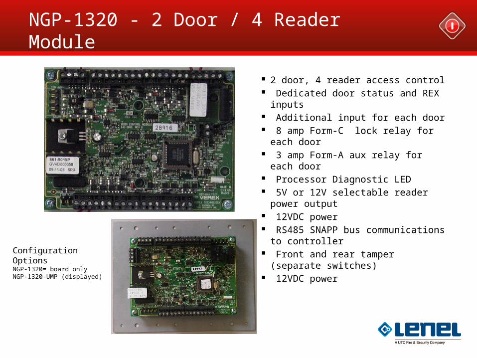
NGP-1320 - 2 Door / 4 Reader Module
2 door, 4 reader access control Dedicated door status and REX
inputs Additional input for each door 8 amp Form-C lock relay for each
door 3 amp Form-A aux relay for each
door Processor Diagnostic LED 5V or 12V selectable reader
power output 12VDC power RS485 SNAPP bus
communications to controller Front and rear tamper (separate
switches) 12VDC power
Configuration OptionsNGP-1320= board onlyNGP-1320-UMP (displayed)
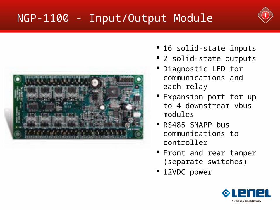
NGP-1100 - Input/Output Module
16 solid-state inputs 2 solid-state outputs Diagnostic LED for
communications and each relay
Expansion port for up to 4 downstream vbus modules
RS485 SNAPP bus communications to controller
Front and rear tamper (separate switches)
12VDC power
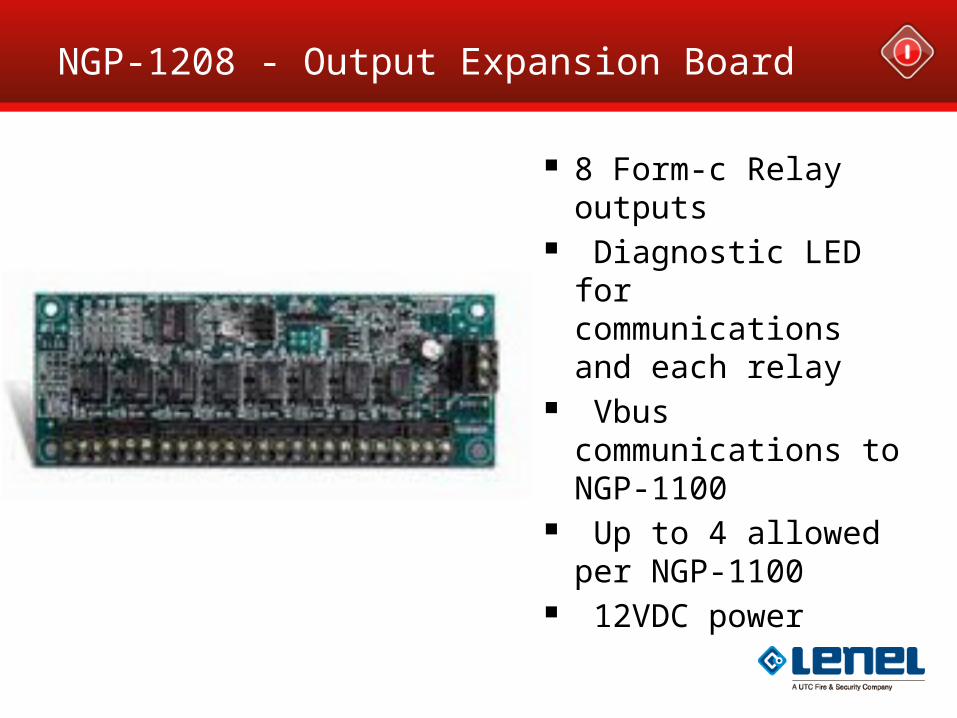
NGP-1208 - Output Expansion Board
8 Form-c Relay outputs
Diagnostic LED for communications and each relay
Vbus communications to NGP-1100
Up to 4 allowed per NGP-1100
12VDC power
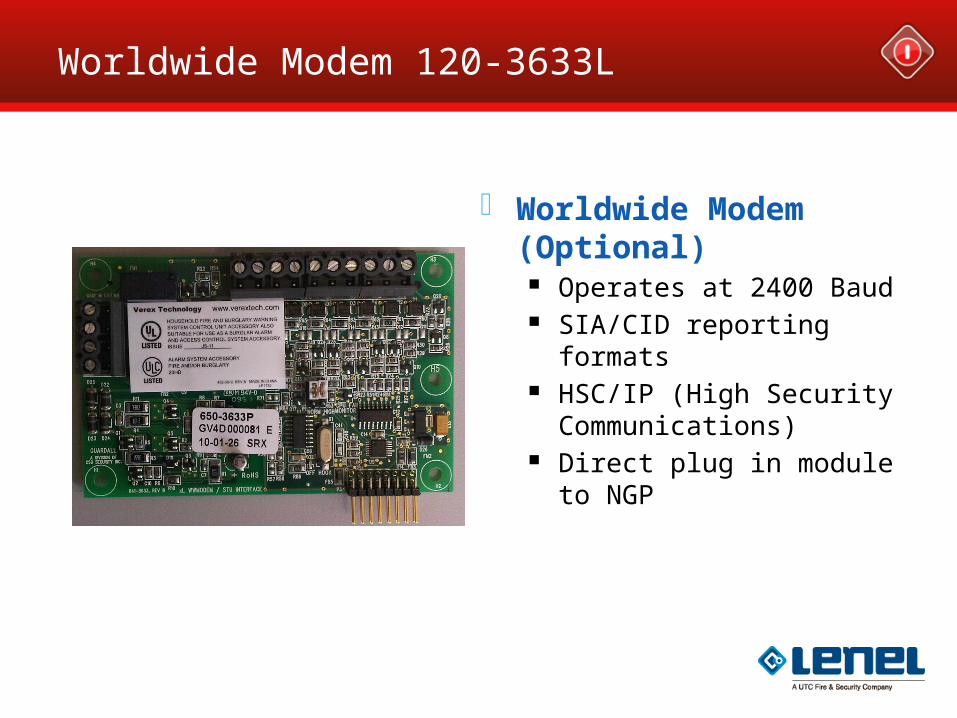
Worldwide Modem 120-3633L
Worldwide Modem (Optional)
Operates at 2400 Baud SIA/CID reporting formats HSC/IP (High Security
Communications) Direct plug in module to
NGP
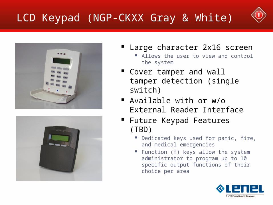
LCD Keypad (NGP-CKXX Gray & White)
Large character 2x16 screen Allows the user to view and control the system
Cover tamper and wall tamper detection (single switch)
Available with or w/o External Reader Interface
Future Keypad Features (TBD) Dedicated keys used for panic, fire, and medical
emergencies Function (f) keys allow the system administrator
to program up to 10 specific output functions of their choice per area
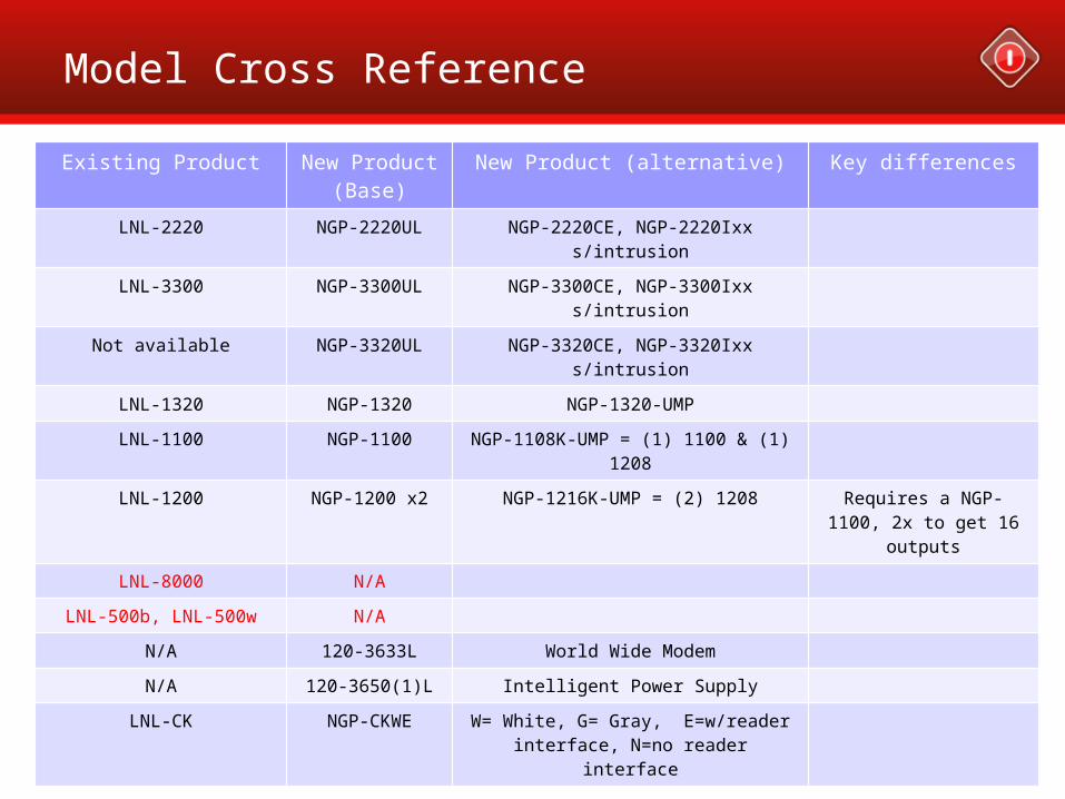
Model Cross Reference
Existing Product New Product (Base)
New Product (alternative) Key differences
LNL-2220 NGP-2220UL NGP-2220CE, NGP-2220Ixx s/intrusion
LNL-3300 NGP-3300UL NGP-3300CE, NGP-3300Ixx s/intrusion
Not available NGP-3320UL NGP-3320CE, NGP-3320Ixx s/intrusion
LNL-1320 NGP-1320 NGP-1320-UMP
LNL-1100 NGP-1100 NGP-1108K-UMP = (1) 1100 & (1) 1208
LNL-1200 NGP-1200 x2 NGP-1216K-UMP = (2) 1208 Requires a NGP-1100, 2x to get 16 outputs
LNL-8000 N/A
LNL-500b, LNL-500w N/A
N/A 120-3633L World Wide Modem
N/A 120-3650(1)L Intelligent Power Supply
LNL-CK NGP-CKWE W= White, G= Gray, E=w/reader interface, N=no reader interface
Configuration Examples
Configuring the Panel
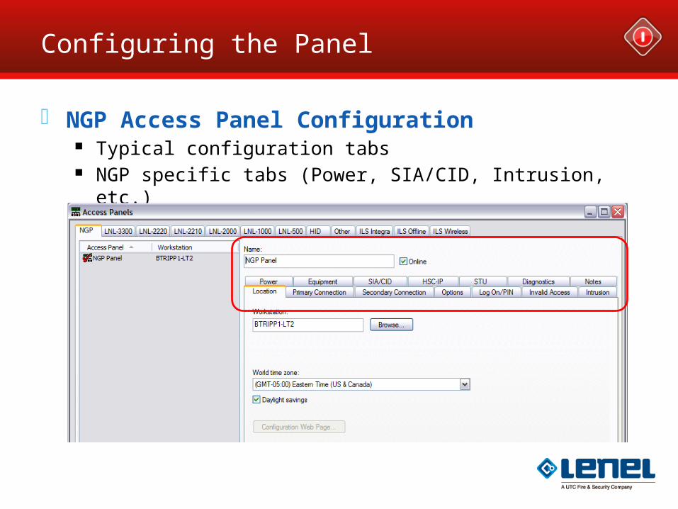
NGP Access Panel Configuration Typical configuration tabs NGP specific tabs (Power, SIA/CID, Intrusion, etc.)
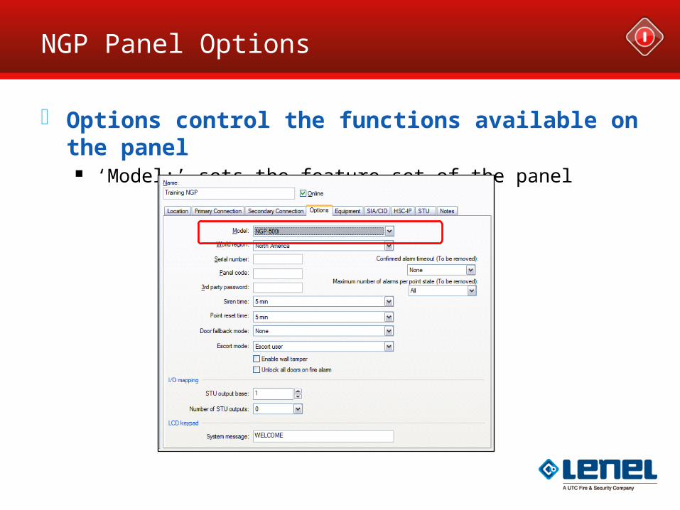
NGP Panel Options
Options control the functions available on the panel ‘Model:’ sets the feature set of the panel
Power Tab on NGP
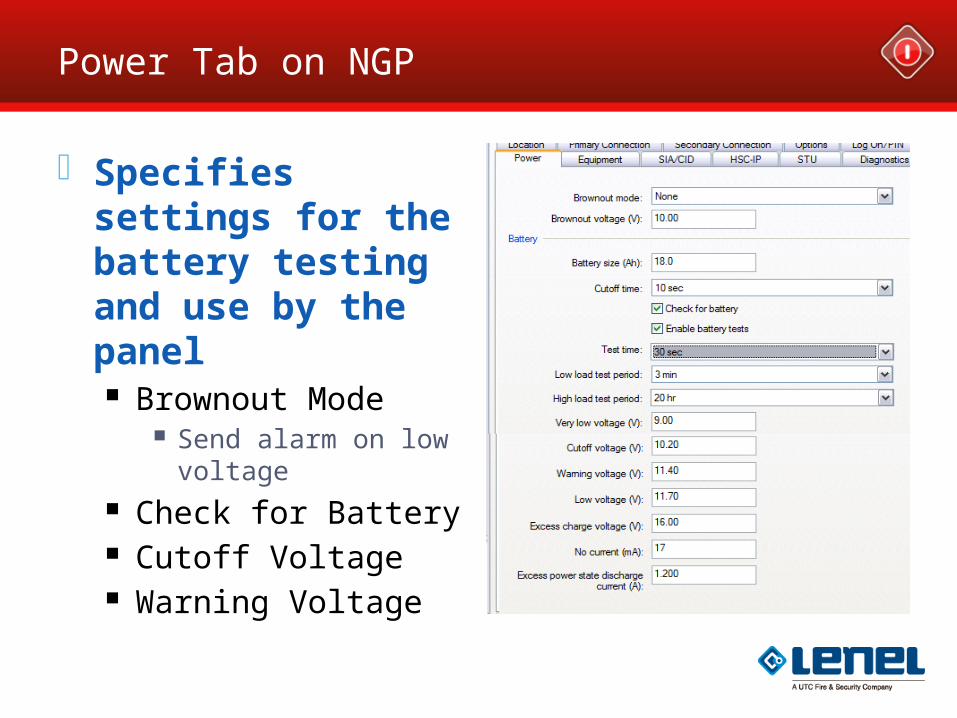
Specifies settings for the battery testing and use by the panel Brownout Mode
Send alarm on low voltage
Check for Battery Cutoff Voltage Warning Voltage
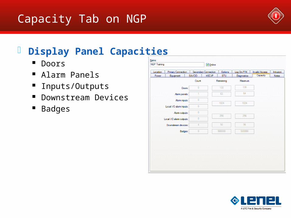
Capacity Tab on NGP
Display Panel Capacities Doors Alarm Panels Inputs/Outputs Downstream Devices Badges
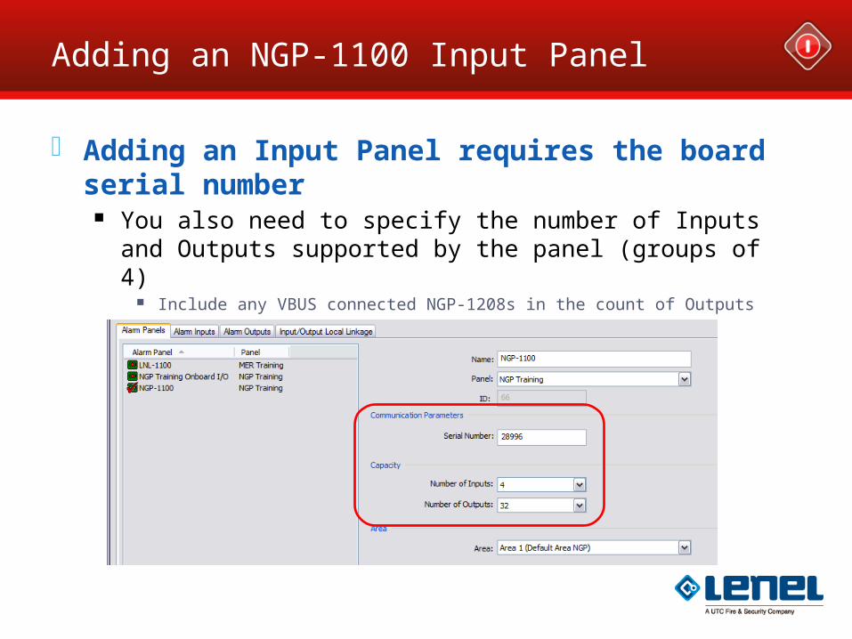
Adding an NGP-1100 Input Panel
Adding an Input Panel requires the board serial number
You also need to specify the number of Inputs and Outputs supported by the panel (groups of 4)
Include any VBUS connected NGP-1208s in the count of Outputs
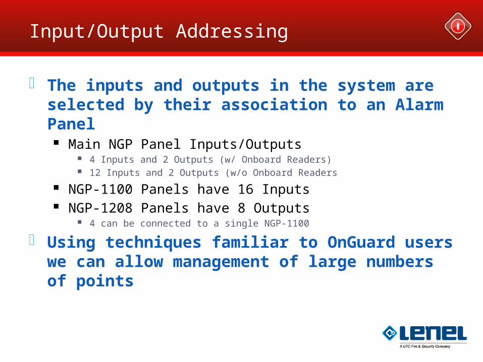
Input/Output Addressing
The inputs and outputs in the system are selected by their association to an Alarm Panel
Main NGP Panel Inputs/Outputs 4 Inputs and 2 Outputs (w/ Onboard Readers) 12 Inputs and 2 Outputs (w/o Onboard Readers
NGP-1100 Panels have 16 Inputs NGP-1208 Panels have 8 Outputs
4 can be connected to a single NGP-1100
Using techniques familiar to OnGuard users we can allow management of large numbers of points
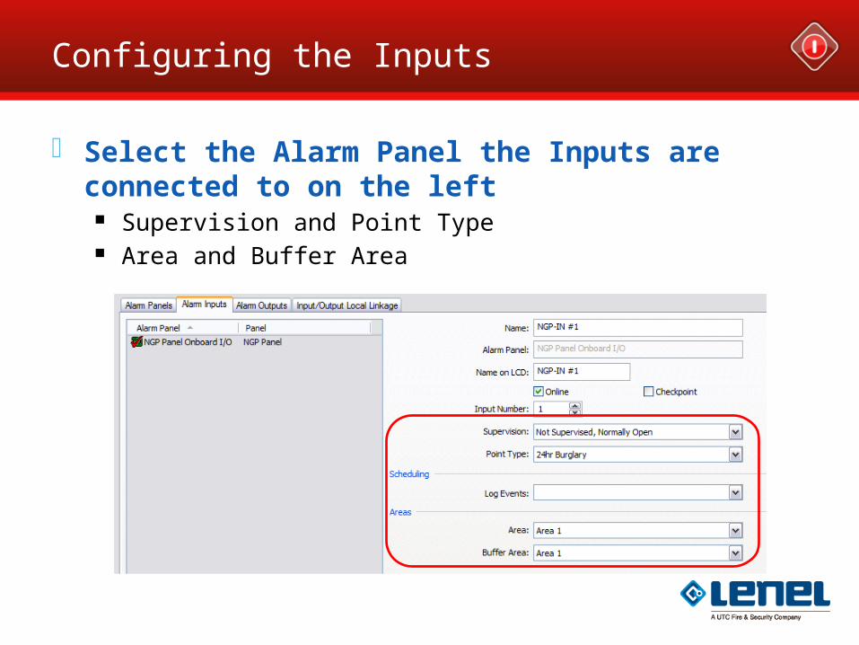
Configuring the Inputs
Select the Alarm Panel the Inputs are connected to on the left
Supervision and Point Type Area and Buffer Area
Point Types
16 Pre-defined Input Point Types Means that the installer can quickly program how a point
behaves Standard (Basic On/Off Point for Access Only Systems) Entry doors (triggers), route points (followers), perimeter points, supervisory points, fire
points and panic (hold up) points can be quickly defined
Easy to Use; configures commonly used inputs Burglary Life Safety Supervisory groups False Alarm Prevention Points
Typically used with Motion Detectors, it will only report if active for 10 seconds or if 2 separate sensors in the same area activate within 20 minuntes
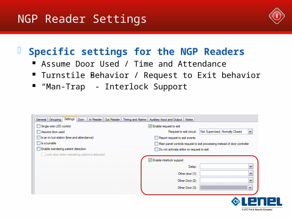
NGP Reader Settings
Specific settings for the NGP Readers Assume Door Used / Time and Attendance Turnstile Behavior / Request to Exit behavior “Man-Trap” - Interlock Support
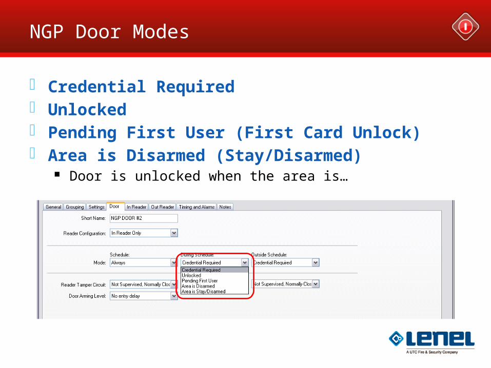
NGP Door Modes
Credential Required Unlocked Pending First User (First Card Unlock) Area is Disarmed (Stay/Disarmed)
Door is unlocked when the area is…
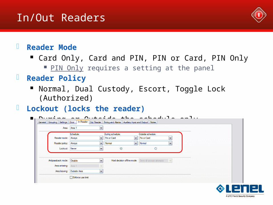
In/Out Readers
Reader Mode Card Only, Card and PIN, PIN or Card, PIN Only
PIN Only requires a setting at the panel Reader Policy
Normal, Dual Custody, Escort, Toggle Lock (Authorized) Lockout (locks the reader)
During or Outside the schedule only
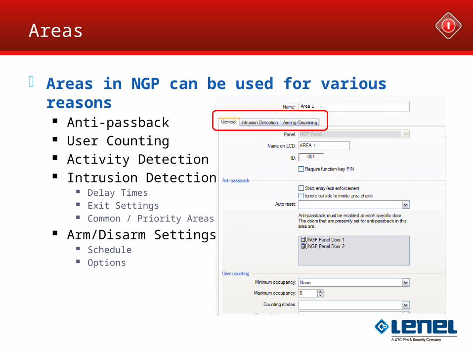
Areas
Areas in NGP can be used for various reasons Anti-passback User Counting Activity Detection Intrusion Detection
Delay Times Exit Settings Common / Priority Areas
Arm/Disarm Settings Schedule Options