
Next Step In Signaling Transport Protocol/General Internet ......Next Step In Signaling Transport...
147
1 Design and implementation of an NTLP/GIST prototype Next Step In Signaling Transport Protocol/General Internet Signaling Protocol (NTLP/GIST) Master of Science Thesis October, 10 2005 Mayi Zoumaro-Djayoon Faculty of Electrical Engineering Mathematics en Computer Science (EEMCS) University of Twente Enschede, The Netherlands Examination Committee Dr. ir. G. Karagiannis (Supervisor, UT) Dr. ir. P.T. de Boer (UT) Prof. dr. ir. B. R. Haverkort (UT)
Transcript of Next Step In Signaling Transport Protocol/General Internet ......Next Step In Signaling Transport...

1
Design and implementation of an NTLP/GIST prototype
Next Step In Signaling Transport Protocol/General Internet Signaling Protocol
(NTLP/GIST)
Master of Science Thesis October, 10 2005
Mayi Zoumaro-Djayoon Faculty of Electrical Engineering Mathematics en Computer Science (EEMCS) University of Twente Enschede, The Netherlands
Examination Committee Dr. ir. G. Karagiannis (Supervisor, UT) Dr. ir. P.T. de Boer (UT) Prof. dr. ir. B. R. Haverkort (UT)

2
Design and implementation of an NTLP/GIST prototype

3
Design and implementation of an NTLP/GIST prototype
Grateful Acknowledgements
I owe my thanks to all the lecturers of the University of Twente who shared their knowledge generously. I am grateful to the members of my examination committee Prof. dr. ir. Boudewijn Haverkort, dr. ir. Pieter-Tjerk de Boer and dr. ir. Georgios Karagiannis. Very special thanks go to my supervisor dr. ir. Georgios Karagiannis, for supportive and intellectual contributions. I am also thankful to Martijn Swanink who has been a great intellectual colleague. Along these lines I am grateful to Ninfoon, Jolie, Gaetan, H. Boros, C. Aikhorin and to B.Noumon who has been a wonderful and very supportive friend. Finally, I would like to celebrate my parents Ikpindi T. Zoumaro-Djayoon and Lantame Zoumaro-Djayoon. Much respect due to my Dad to have encouraged me to keep pushing forward. This project has been realised thanks to the passion, confidence, tenacity, faith and love that have served as guiding principles in their extraordinary parenting.

4
Design and implementation of an NTLP/GIST prototype
5
Design and implementation of an NTLP/GIST prototype
Preface In the last decade Internet applications such as real-time applications (video conferencing) have been growing. In order to deliver and guarantee a certain quality to the services they provide, these applications often require some features of network resources such as a certain amount of bandwidth, a maximum data delay and a maximum data loss rate. Next to that, applications seem to need some support for installation and manipulation of network control states. These network control states can be defined as the information related to network internal operations. This information may include for instance, the percentage of packets lost or the delay experienced in the network. The Resource Reservation Protocol (RSVP) was introduced to satisfy the need for signalling of Quality of Service (QoS) parameters in the fixed network. RSVP enables namely the signaling of network resource in unicast and IP multicast environments. Due to RSVP’s shortcomings and the fact that it is not widely deployed, the Next Steps in Signaling (NSIS) protocol suite has been defined by de NSIS working group (WG) of the IETF (Internet Engineering Task Force). The NSIS WG is designed to support multiple signaling applications such as QoS signaling applications, signaling applications for firewall and NAT traversal, etc. The NSIS protocol consists of two layers, which are the NSIS Transport Level Protocol (NTLP) and the NSIS Signaling Layer Protocol (NSLP). NSLP is the upper layer of the NSIS protocol stack. It is designed to support a signaling application and has two main interaction points. It interacts at one side with the NTLP and at the other side with the appropriate application, which is in fact not part of the NSIS protocol suite. Moreover an NSLP may define for instance the message formats (protocol data units), message sequences etc specific for a signaling application. NTLP is the lower layer of the NSIS protocol stack. It is designed to interact with the IP layer at one side and with different NSLPs at the other side. Its role is to transport signaling messages issued from the NSLP layer between two adjacent NSIS nodes. Next to these signaling messages, the NTLP enables the exchange of other control information such as error messages and route modification messages. The NLTP consists mainly of two sub-layers which are the General Internet Signaling Transport (GIST) layer and the existing network transport layers such as TCP and UDP. GIST is the core component of the NTLP protocol. When it receives a message from its upper layer (the NSLP layer) its main functions are to determine how to reach the adjacent NSIS node, to select the appropriate transport protocol and to pass/forward the data to the selected transport protocol. When it receives a message from its underlying layer, its function is to identify whether the received message should be forwarded to the NSLP layer or whether the message should be forwarded to the next GIST node. It is important to note that when this M.Sc. assignment started, the GIST protocol was denoted as GIMPS (General Internet Messaging Protocol for Signaling) but currently it has been renamed to GIST. Therefore in the rest of this thesis the name GIMPS is applied instead of the name GIST. The main purpose of this master project is to implement a prototype for the NSIS Transport Layer Protocol (NTLP) and to perform certain experiments to test the functionality of the implemented NTLP protocol. It is worth noting that this project has been completed in the department of Design and Analysis of Communication Systems of the faculty of Electrical Engineering, Mathematics and Computer Science (EEMCS) at the University of Twente.

6
Design and implementation of an NTLP/GIST prototype

7
Design and implementation of an NTLP/GIST prototype
Acronyms CASP Cross Application for Signaling Protocol Cmode Connection mode DCCP Datagram Congestion Control Protocol Diffserv Differentiated Services Dmode Datagram mode GIMPS General Internet Messaging Protocol for Signaling GIST General Internet Signaling Protocol IANA Internet Assigned Numbers Authority IETF Internet Engineering Task Force Intserv Integrated Services IP Internet Protocol MA-Node GIMPS messaging association node MA-State Messaging association state NAT Network Address Translator NTLP NSIS Transport Layer Protocol NSIS Next Steps in Signaling NSLP NSIS Signaling Layer Protocol OOP Object Oriented Programming PDU Protocol Data Unit QNode GIMPS querying node QoS Quality of Service RAO Router Alert Option RNode GIMPS responder node RState Routing state RSVP Resource Reservation Protocol SCTP Stream Control Transmission Protocol TCP Transport Control Protocol TOS Type of Service TTL Time –To-Live UDP User Datagram Protocol UML User Mode Linux UMTS Universal Mobile Telecommunications System
8
Design and implementation of an NTLP/GIST prototype
Table of contents PREFACE .................................................................................................................................................... 5
ACRONYMS................................................................................................................................................ 7
TABLE OF CONTENTS............................................................................................................................. 8
LIST OF FIGURES ................................................................................................................................... 10
LIST OF TABLES ..................................................................................................................................... 12
LIST OF TABLES ..................................................................................................................................... 12
1 INTRODUCTION.............................................................................................................................. 14
1.1 INTSERV WITH RSVP .................................................................................................................... 15 1.2 DIFFSERV...................................................................................................................................... 16 1.3 NEXT STEPS IN SIGNALLING .......................................................................................................... 16 1.4 SCOPE OF THESIS........................................................................................................................... 16 1.5 STRUCTURE OF THESIS .................................................................................................................. 17
2 NSIS OVERVIEW.............................................................................................................................. 18
2.1 NSIS PROTOCOL STACK ................................................................................................................ 18 2.2 BASICS.......................................................................................................................................... 19 2.3 NSIS TRANSPORT LAYER PROTOCOL (NTLP) ............................................................................... 20
2.3.1 Key Principles .......................................................................................................................... 20 2.3.2 NTLP Subdivision .................................................................................................................... 23
2.3.2.1 Transmission control protocol (TCP) ............................................................................. 23 2.3.2.2 User Datagram Protocol.................................................................................................. 24 2.3.2.3 General Internet Messaging Protocol for Signaling (GIMPS) ....................................... 24
2.4 NSIS SIGNALLING LAYER PROTOCOL [37] .................................................................................... 28 2.4.1 QoS-NSLP features .................................................................................................................. 28 2.4.2 QoS models .............................................................................................................................. 29 2.4.3 Basic sender-initiated reservation ............................................................................................ 30 2.4.4 Basic receiver-initiated reservation .......................................................................................... 32 2.4.5 Bidirectional Reservations........................................................................................................ 32
2.5 NSIS RMD QOS MODEL............................................................................................................... 34 2.5.1 RMD-QSPEC ........................................................................................................................... 34
2.5.1.1 RMD-QOSM QoS Description........................................................................................ 34 2.5.1.2 PHR RMD-QOSM control information container (PHR container) ............................. 34 2.5.1.3 PDR RMD-QOSM control information container (PDR container) ............................. 34
2.5.2 Basic operation for uni-directional reservations ...................................................................... 35 2.5.2.1 RMD Successful reservation ........................................................................................... 35 2.5.2.2 RMD Unsuccessful reservation ....................................................................................... 36 2.5.2.3 RMD Refresh reservation ............................................................................................... 37 2.5.2.4 RMD Release procedure ................................................................................................. 37 2.5.2.5 RMD Severe congestion handling with PHR marking ................................................... 39 2.5.2.6 RMD Severe congestion handling with proportional marking ...................................... 39
2.5.3 RMD Basic operation for bi-directional reservations ............................................................... 40
3 NTLP PROTOCOL DESIGN............................................................................................................ 42
3.1 GIMPS PROTOCOL DESIGN ............................................................................................................ 42 3.2 INTERNAL STRUCTURE OF GIMPS................................................................................................. 43
3.2.1 GIMPS API (Application Protocol Interface) .......................................................................... 43 3.2.2 GIMPS NodeLevel ................................................................................................................... 46 3.2.3 GIMPS querying node (QNode) ............................................................................................... 50 3.2.4 GIMPS responding node (RNode)............................................................................................ 53 3.2.5 GIMPS data node (DNode) ...................................................................................................... 58

9
Design and implementation of an NTLP/GIST prototype
3.2.6 MA-Node.................................................................................................................................. 59 3.3 GIMPS MESSAGES FORMAT .......................................................................................................... 62 3.4 DISCOVERY MECHANISM............................................................................................................... 63
3.4.1 Successful discovery mechanism .............................................................................................. 63 3.4.2 Unsuccessful discovery mechanism.......................................................................................... 66
3.5 GIMPS DATA TRANSPORT - BYPASS/FORWARDING OPERATIONS ................................................... 67 3.6 CONCLUSION ................................................................................................................................ 67
4 GIMPS PROTOTYPE IMPLEMENTATION.................................................................................. 69
4.1 OPEN ISSUES AND DIFFERENCES FROM THE DRAFT......................................................................... 69 4.1.1 Open issues .............................................................................................................................. 69
4.1.1.1 API Layer ........................................................................................................................ 69 4.1.1.2 Use of Data Message not explicitly defined ..................................................................... 70 4.1.1.3 Session states management.............................................................................................. 70 4.1.1.4 Interoperability ............................................................................................................... 70
4.1.2 Implementation decisions......................................................................................................... 71 4.1.2.1 API layer.......................................................................................................................... 71 4.1.2.2 Bypass/forwarding level .................................................................................................. 72 4.1.2.3 Session states maintenance .............................................................................................. 73 4.1.2.4 Type of Discovery procedure .......................................................................................... 73
4.2 THE PROTOTYPE IMPLEMENTATION ............................................................................................... 74 4.2.1 Linux implementation environment ......................................................................................... 74 4.2.2 From concept to implementation.............................................................................................. 74
4.2.2.1 Implementation approaches ............................................................................................ 74 4.2.2.2 Implementation of GIMPS components ......................................................................... 77
5 FUNCTIONAL EXPERIMENTS...................................................................................................... 95
5.1 SETUP TEST-BED ........................................................................................................................... 95 5.2 EXPERIMENTATION WITH THE PINGTOOL ...................................................................................... 97
5.2.1 Scenarios with the PingTool..................................................................................................... 98 5.2.1.1 Scenario 1: GIMPS nodes traversal ................................................................................ 99 5.2.1.2 Scenario 2- Bypass GIMPS nodes ..................................................................................102 5.2.1.3 Scenario 3- statefull functionality in Datagram mode ...................................................104 5.2.1.4 Scenario 4- statefull functionality in connection mode ..................................................110
5.3 FUNCTIONALITY EXPERIMENTS USING THE QOS-NSLP IMPLEMENTATION ....................................117 5.3.1 Scenario 1: GIMPS nodes traversal ........................................................................................118 5.3.2 Scenario 2- Bypass GIMPS nodes ...........................................................................................121
5.4 FUNCTIONALITY EXPERIMENT USING THE NSIS RMD QOS IMPLEMENTATION..............................124 5.4.1 Scenario 1: Statefull and stateless GIMPS functionality.........................................................124
6 CONCLUSION AND FUTURE WORK ..........................................................................................134
6.1 CONCLUSION ...............................................................................................................................134 6.2 FUTURE WORK .............................................................................................................................134
APPENDIX A: BIT LEVEL FORMAT OF GIMPS MESSAGES..........................................................138
APPENDIX B: BIT LEVEL FORMAT OF GIMPS API SERVICE PRIMITIVES ..............................143
10
Design and implementation of an NTLP/GIST prototype
List of Figures Figure 1-1: firewall traversal scenarios ....................................................................................................... 14 Figure 1-2: NAT traversal scenario.............................................................................................................. 15 Figure 1-3: Real time application data flow transfer using QoS.................................................................... 15 Figure 2-1: NSIS protocol stack ................................................................................................................... 18 Figure 2-2: Protocol suite of a normal router versus protocol suite of an NSIS aware router........................ 19 Figure 2-3: Relationship between NSIS entities ............................................................................................ 20 Figure 2-4: NTLP protocol suite .................................................................................................................. 23 Figure 2-5: illustration of GIMPS external behaviour .................................................................................. 25 Figure 2-6: Data encapsulation.................................................................................................................... 25 Figure 2-7: illustration of the discovery mechanism ..................................................................................... 27 Figure 2-8: QoS-NSLP model of operation (taken from [35]) ....................................................................... 28 Figure 2-9 : Multiple Quality of service in a data path ................................................................................. 30 Figure 2-10: (copied from [36]): Structure of the QSPEC ............................................................................ 30 Figure 2-11: (copied from [35]): Basic Sender Initiated Reservation........................................................... 31 Figure 2-12: (copied from [35]) sending a QUERY message ........................................................................ 32 Figure 2-13: (copied from [35]): Basic Receiver Initiated Reservation......................................................... 32 Figure 2-14: (copied from [35]): Bi-directional reservation for sender + sender scenario............................ 33 Figure 2-15 (copied from [35]): Bi-directional reservation for sender + receiver scenario........................... 33 Figure 2-16: (copied from [34]): Basic operation of successful reservation procedure used by the RMD-QOSM.......................................................................................................................................................... 36 Figure 2-17: (copied from [34]): Basic operation during unsuccessful reservation initiation used by the RMD-QOSM.......................................................................................................................................................... 37 Figure 2-18 (copied from [34]): Basic operation of RMD specific refresh procedure.................................... 37 Figure 2-19 (copied from [34]): Explicit release triggered by a RESERVE (Tear) message .......................... 38 Figure 2-20 (copied from [34]): Basic operation during RMD explicit release procedure triggered by RESPONSE message .................................................................................................................................... 38 Figure 2-21 (copied from [34]): Basic operation during RMD explicit release procedure triggered by NOTIFY message ....................................................................................................................................................... 39 Figure 2-22 (copied from [34]) RMD severe congestion handling with proportional marking....................... 40 Figure 2-23: (copied from [34]) the bi-directional reservation scenario in the RMD domain........................ 40 Figure 2-24: (copied from [34]) Intra-domain signaling operation for successful bi-directional reservation. 41 Figure 2-25: (copied from [34]) Intra-domain signaling operation for unsuccessful bi-directional reservation (rejection on path QNE(Ingress) towards QNE(Egress))............................................................................... 41 Figure 2-26: Intra-domain signaling normal operation for unsuccessful bi-directional reservation (rejection on path QNE (Egress) towards QNE(Ingress)) ............................................................................................. 41 Figure 3-1: Schematic functional block design of NTLP ............................................................................... 43 Figure 3-2: Architectural behaviour model of NTLP/GIMPS ........................................................................ 44 Figure 3-3: Overview of event- and trigger-based NTLP activity .................................................................. 46 Figure 3-4: Internal behaviour model of the NodeLevel entity. ..................................................................... 48 Figure 3-5: Internal behaviour model of the QNode entity............................................................................ 52 Figure 3-6: Internal behaviour model of the RNode entity ............................................................................ 56 Figure 3-7: Internal behaviour model of the DNode entity............................................................................ 59 Figure 3-8: Internal behaviour model of the MA-Node entity........................................................................ 61 Figure 3-9: GIMPS PDUs............................................................................................................................ 63 Figure 3-10: Successful discovery mechanism in datagram mode ................................................................. 64 Figure 3-11-A: Successful discovery mechanism in connection mode............................................................ 65 Figure 3-12: Bypass/Forwarding function................................................................................................... 67 Figure 4-1: Bypass/Forwarding levels.......................................................................................................... 72 Figure 4-2: Overview of the major implemented GIMPS modules................................................................. 79 Figure 4-3: Functional block of the IncomingEvents class of the gimpsNodeLevel.py module ....................... 80 Figure 4-4: Functional block of the gimps_Rstate.py module........................................................................ 82 Figure 4-5: Functional block of the gimps_MAState.py module .................................................................... 82 Figure 4-6: Functional block of the gimpsQueryNode.py module.................................................................. 84 Figure 4-7: Relation between the gimps_Server module and the other GIMPS modules ................................ 90

11
Design and implementation of an NTLP/GIST prototype
Figure 4-8: Functional block of the gimpsRespondingNode.py module ......................................................... 93 Figure 5-1: GIMPS prototype test network ................................................................................................... 97 Figure 5-2: External behaviour of the Ping tool ........................................................................................... 98 Figure 5-3: Results of GIMPS node traversal (Dmode) in Client 1 using the PingTool ................................100 Figure 5-4: Results of GIMPS node traversal (Dmode) in Edge 1 using the PingTool..................................100 Figure 5-5: Results of GIMPS node traversal (Dmode) in Core using the PingTool .....................................101 Figure 5-6: Results of GIMPS node traversal (Dmode) in Edge 2 using the PingTool..................................101 Figure 5-7: Results of GIMPS node traversal (Dmode) in Client 2 using the PingTool ................................102 Figure 5-8: Results of GIMPS node traversal (with bypassing) in Client 1 using the PingTool.....................103 Figure 5-9: Results of GIMPS node traversal (with bypassing) in Edge 1 using the PingTool ......................103 Figure 5-10: Results of GIMPS node traversal (with bypassing) in Core using the PingTool .......................104 Figure 5-11: Results of GIMPS node traversal (with bypassing) in Edge 2 using the PingTool ....................104 Figure 5-12: Results of GIMPS node traversal (with bypassing) in Client 2 using the PingTool...................104 Figure 5-13: Results of discovery pocedure (Dmode) in Client 1 using the PingTool ...................................106 Figure 5-14: Results of discovery pocedure (Dmode) in Edge 1 using the PingTool.....................................107 Figure 5-15: Routing states in Client 1 (Dmode) .........................................................................................109 Figure 5-16: Routing states in Edge 1 (Dmode)...........................................................................................109 Figure 5-17: Routing states in Edge 2 (Dmode)...........................................................................................110 Figure 5-18: Routing states in Client 2 (Dmode) .........................................................................................110 Figure 5-19: Results of discovery pocedure (Cmode) in Client 1 using the PingTool....................................112 Figure 5-20: Results of discovery pocedure (Cmode) in Edge 1 using the PingTool .....................................112 Figure 5-21: Results of discovery pocedure (Cmode) in Edge 2 using the PingTool .....................................113 Figure 5-22: Results of discovery pocedure (Cmode) in Client 2 using the PingTool....................................113 Figure 5-23: Routing states and messaging association states in Client 1 (Cmode) at t0..............................115 Figure 5-24: Routing states and messaging association states in Client 1 (Cmode) at t1..............................115 Figure 5-25: Overview of routing states and messaging association states in Client 1 and Edge 1 (Cmode)116 Figure 5-26: Overview of routing states and messaging association states in Client 2 and Edge2 (Cmode)..117 Figure 5-27: GIMPS and QoS-NSLP test network .......................................................................................118 Figure 5-28: Reserve/Response message traversal.......................................................................................118 Figure 5-29: Result of GIMPS node traversal experiment in Client 1...........................................................119 Figure 5-30: Result of GIMPS node traversal experiment in Edge 1 ............................................................120 Figure 5-31: Session states tables of Client 1 ..............................................................................................121 Figure 5-32: Session states tables of Edge 1................................................................................................121 Figure 5-33: Session states tables of Core ...................................................................................................121 Figure 5-34: Result of the Bypassing experiment in Client 1 ........................................................................122 Figure 5-35: Result of the Bypassing experiment in Edge 1 .........................................................................122 Figure 5-36: Result of the Bypassing experiment in Core.............................................................................123 Figure 5-37: Session states in Client 1 (Bypassing) .....................................................................................123 Figure 5-38: Session states in Core (Bypassing)..........................................................................................123 Figure 5-39: GIMPS – QoS-NSLP and RMD Reserve/Response message traversal......................................124 Figure 5-40: GIMPS – QoS-NSLP and RMD Reserve/Response message in Client 1 ...................................125 Figure 5-41: GIMPS session states in Client 1.............................................................................................126 Figure 5-42: GIMPS – QoS-NSLP and RMD Reserve/Response message in Edge 1.....................................128 Figure 5-43: GIMPS session states in Edge1...............................................................................................129 Figure 5-44: GIMPS –and RMD Reserve message in Core ..........................................................................129 Figure 5-45: GIMPS session states in Core .................................................................................................130 Figure 5-46: GIMPS – QoS-NSLP and RMD Reserve/Response message in Edge 1.....................................131 Figure 5-47: GIMPS session states in Edge2...............................................................................................132 Figure 5-48: GIMPS – QoS-NSLP and RMD Reserve/Response message in Client 2 ...................................133 Figure 5-49: GIMPS session states in Client 2.............................................................................................133

12
Design and implementation of an NTLP/GIST prototype
List of tables Table 3-1: Recapitulation of the GIMPS API service primitives .................................................................... 46 Table 3-2: Recapitulation of the NodeLevel entity’s state machine................................................................ 47 Table 3-3: Recapitulation of the QNode entity’s state machine ............................................................ 51 Table 3-4: Recapitulation of the RNode entity’s state machine............................................................. 55 Table 3-5: Recapitulation of the DNode entity’s state machine............................................................. 59 Table 3-6: Recapitulation of the MA-Node entity’s state machine ........................................................ 60 Table 3-7: Example of Router Alert values ................................................................................................... 67 Table 4-1: Routing state entries.................................................................................................................... 81 Table 4-2: MA-state entries.......................................................................................................................... 82

13
Design and implementation of an NTLP/GIST prototype
14
Design and implementation of an NTLP/GIST prototype
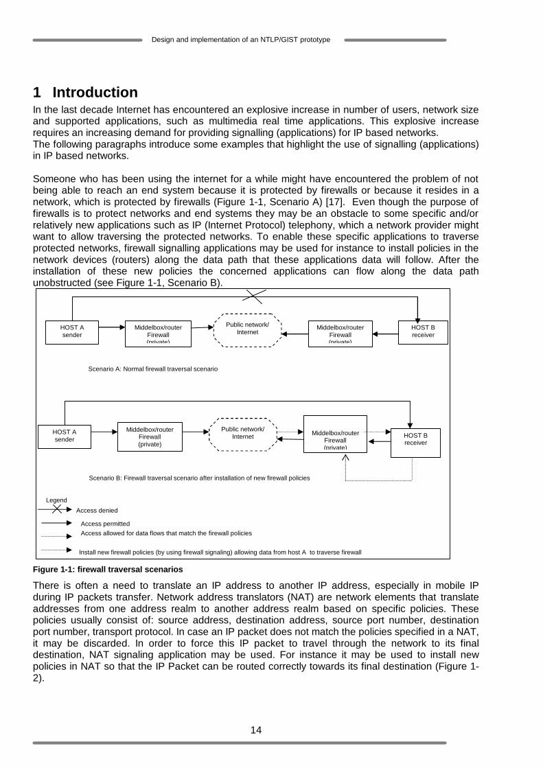
1 Introduction In the last decade Internet has encountered an explosive increase in number of users, network size and supported applications, such as multimedia real time applications. This explosive increase requires an increasing demand for providing signalling (applications) for IP based networks. The following paragraphs introduce some examples that highlight the use of signalling (applications) in IP based networks. Someone who has been using the internet for a while might have encountered the problem of not being able to reach an end system because it is protected by firewalls or because it resides in a network, which is protected by firewalls (Figure 1-1, Scenario A) [17]. Even though the purpose of firewalls is to protect networks and end systems they may be an obstacle to some specific and/or relatively new applications such as IP (Internet Protocol) telephony, which a network provider might want to allow traversing the protected networks. To enable these specific applications to traverse protected networks, firewall signalling applications may be used for instance to install policies in the network devices (routers) along the data path that these applications data will follow. After the installation of these new policies the concerned applications can flow along the data path unobstructed (see Figure 1-1, Scenario B).
Figure 1-1: firewall traversal scenarios
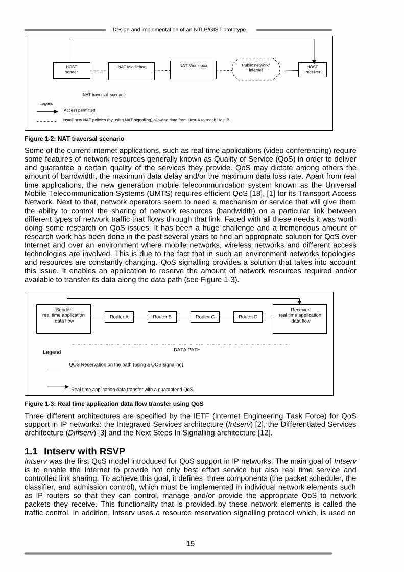
There is often a need to translate an IP address to another IP address, especially in mobile IP during IP packets transfer. Network address translators (NAT) are network elements that translate addresses from one address realm to another address realm based on specific policies. These policies usually consist of: source address, destination address, source port number, destination port number, transport protocol. In case an IP packet does not match the policies specified in a NAT, it may be discarded. In order to force this IP packet to travel through the network to its final destination, NAT signaling application may be used. For instance it may be used to install new policies in NAT so that the IP Packet can be routed correctly towards its final destination (Figure 1-2).
HOST A sender
HOST B receiver
Middelbox/router Firewall (private)
Middelbox/router Firewall (private)
Public network/ Internet
HOST A sender HOST B
receiver
Middelbox/router Firewall (private)
Middelbox/router
Firewall (private)
Public network/ Internet
Install new firewall policies (by using firewall signaling) allowing data from host A to traverse firewall
Legend
Access denied
Access permitted Access allowed for data flows that match the firewall policies
Scenario A: Normal firewall traversal scenario
Scenario B: Firewall traversal scenario after installation of new firewall policies
15
Design and implementation of an NTLP/GIST prototype
Figure 1-2: NAT traversal scenario
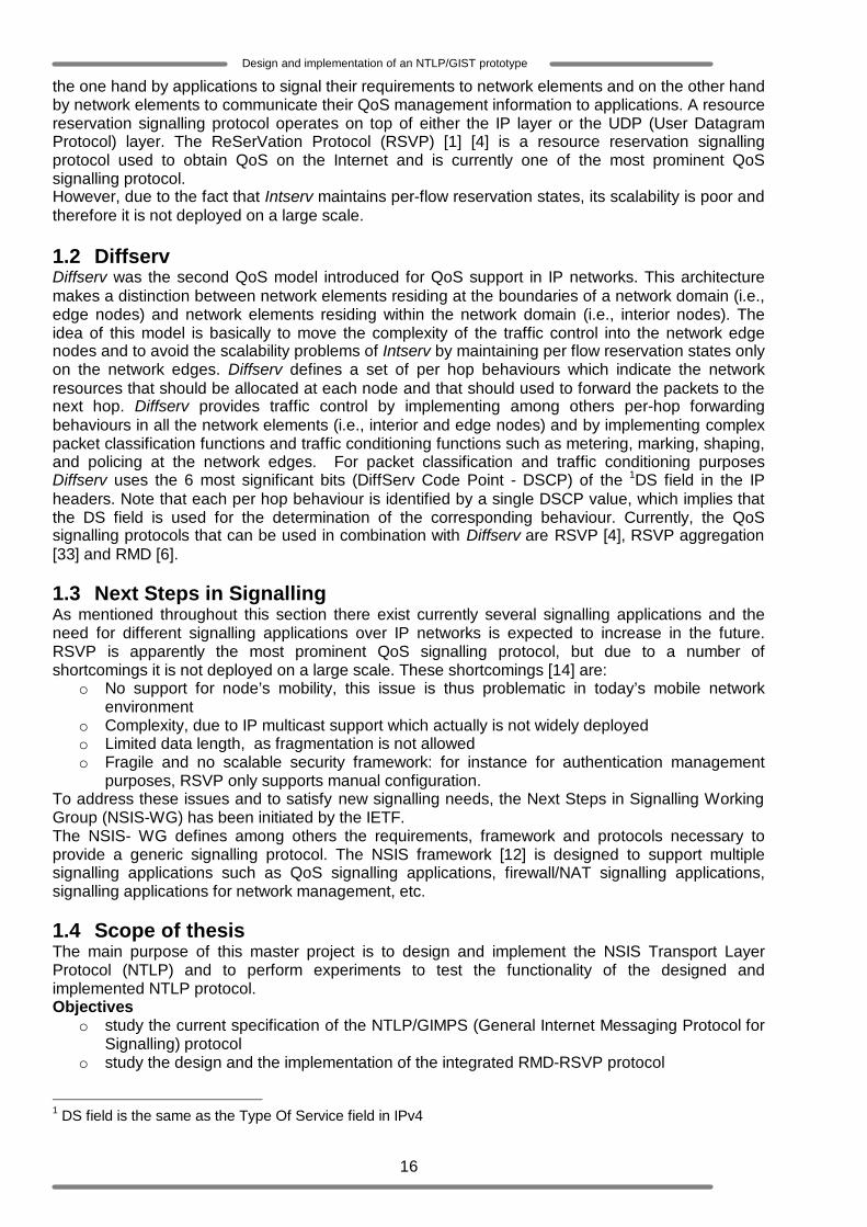
Some of the current internet applications, such as real-time applications (video conferencing) require some features of network resources generally known as Quality of Service (QoS) in order to deliver and guarantee a certain quality of the services they provide. QoS may dictate among others the amount of bandwidth, the maximum data delay and/or the maximum data loss rate. Apart from real time applications, the new generation mobile telecommunication system known as the Universal Mobile Telecommunication Systems (UMTS) requires efficient QoS [18], [1] for its Transport Access Network. Next to that, network operators seem to need a mechanism or service that will give them the ability to control the sharing of network resources (bandwidth) on a particular link between different types of network traffic that flows through that link. Faced with all these needs it was worth doing some research on QoS issues. It has been a huge challenge and a tremendous amount of research work has been done in the past several years to find an appropriate solution for QoS over Internet and over an environment where mobile networks, wireless networks and different access technologies are involved. This is due to the fact that in such an environment networks topologies and resources are constantly changing. QoS signalling provides a solution that takes into account this issue. It enables an application to reserve the amount of network resources required and/or available to transfer its data along the data path (see Figure 1-3).
Figure 1-3: Real time application data flow transfer using QoS
Three different architectures are specified by the IETF (Internet Engineering Task Force) for QoS support in IP networks: the Integrated Services architecture (Intserv) [2], the Differentiated Services architecture (Diffserv) [3] and the Next Steps In Signalling architecture [12]. 1.1 Intserv with RSVP Intserv was the first QoS model introduced for QoS support in IP networks. The main goal of Intserv is to enable the Internet to provide not only best effort service but also real time service and controlled link sharing. To achieve this goal, it defines three components (the packet scheduler, the classifier, and admission control), which must be implemented in individual network elements such as IP routers so that they can control, manage and/or provide the appropriate QoS to network packets they receive. This functionality that is provided by these network elements is called the traffic control. In addition, Intserv uses a resource reservation signalling protocol which, is used on
Real time application data transfer with a guaranteed QoS
Sender real time application
data flow Router A
Receiver real time application
data flow Router B Router C Router D
DATA PATH Legend
HOST sender
HOST receiver
NAT Middlebox
Public network/ Internet
Install new NAT policies (by using NAT signalling) allowing data from Host A to reach Host B
Legend
Access permitted
NAT traversal scenario
NAT Middlebox
QOS Reservation on the path (using a QOS signaling)
16
Design and implementation of an NTLP/GIST prototype
the one hand by applications to signal their requirements to network elements and on the other hand by network elements to communicate their QoS management information to applications. A resource reservation signalling protocol operates on top of either the IP layer or the UDP (User Datagram Protocol) layer. The ReSerVation Protocol (RSVP) [1] [4] is a resource reservation signalling protocol used to obtain QoS on the Internet and is currently one of the most prominent QoS signalling protocol. However, due to the fact that Intserv maintains per-flow reservation states, its scalability is poor and therefore it is not deployed on a large scale. 1.2 Diffserv Diffserv was the second QoS model introduced for QoS support in IP networks. This architecture makes a distinction between network elements residing at the boundaries of a network domain (i.e., edge nodes) and network elements residing within the network domain (i.e., interior nodes). The idea of this model is basically to move the complexity of the traffic control into the network edge nodes and to avoid the scalability problems of Intserv by maintaining per flow reservation states only on the network edges. Diffserv defines a set of per hop behaviours which indicate the network resources that should be allocated at each node and that should used to forward the packets to the next hop. Diffserv provides traffic control by implementing among others per-hop forwarding behaviours in all the network elements (i.e., interior and edge nodes) and by implementing complex packet classification functions and traffic conditioning functions such as metering, marking, shaping, and policing at the network edges. For packet classification and traffic conditioning purposes Diffserv uses the 6 most significant bits (DiffServ Code Point - DSCP) of the 1DS field in the IP headers. Note that each per hop behaviour is identified by a single DSCP value, which implies that the DS field is used for the determination of the corresponding behaviour. Currently, the QoS signalling protocols that can be used in combination with Diffserv are RSVP [4], RSVP aggregation [33] and RMD [6]. 1.3 Next Steps in Signalling As mentioned throughout this section there exist currently several signalling applications and the need for different signalling applications over IP networks is expected to increase in the future. RSVP is apparently the most prominent QoS signalling protocol, but due to a number of shortcomings it is not deployed on a large scale. These shortcomings [14] are:
o No support for node’s mobility, this issue is thus problematic in today’s mobile network environment
o Complexity, due to IP multicast support which actually is not widely deployed o Limited data length, as fragmentation is not allowed o Fragile and no scalable security framework: for instance for authentication management
purposes, RSVP only supports manual configuration. To address these issues and to satisfy new signalling needs, the Next Steps in Signalling Working Group (NSIS-WG) has been initiated by the IETF. The NSIS- WG defines among others the requirements, framework and protocols necessary to provide a generic signalling protocol. The NSIS framework [12] is designed to support multiple signalling applications such as QoS signalling applications, firewall/NAT signalling applications, signalling applications for network management, etc. 1.4 Scope of thesis The main purpose of this master project is to design and implement the NSIS Transport Layer Protocol (NTLP) and to perform experiments to test the functionality of the designed and implemented NTLP protocol. Objectives
o study the current specification of the NTLP/GIMPS (General Internet Messaging Protocol for Signalling) protocol
o study the design and the implementation of the integrated RMD-RSVP protocol
1 DS field is the same as the Type Of Service field in IPv4

17
Design and implementation of an NTLP/GIST prototype
o study the design and the implementation of the CASP (Cross Application Signalling Protocols) protocol
o study and identify the design and implementation steps of the NTLP/GIMPS protocol features that are needed in order to satisfy the NTLP/GIMPS protocol specification
o implement the GIMPS protocol o specify and accomplish functionality experiments on implemented GIMPS protocol
1.5 Structure of thesis This thesis is organized as follows: Chapter 2 presents an overview of the NSIS framework. Chapter 3 describes the design of the NTLP protocol and in particular the GIMPS layer. Chapter 4 discusses the differences between the design of the NTLP protocol described in Chapter 3 and the NTLP specified in [10]. It also presents the prototype implementation of GIMPS. Chapter 5 presents the functional experiments, which are performed to test the functionality of the designed and implemented NTLP. It also presents the experimental results obtained from these experiments. Chapter 6 finally presents the conclusion and future work that could eventually be done on GIMPS.

18
Design and implementation of an NTLP/GIST prototype
2 NSIS overview As stated in Chapter 1, the main goal of NSIS is to provide a general model capable of supporting several signalling applications. However the major work focuses on the QoS signalling. The layered model depicted in Figure 2-1 has been introduced in order to achieve this goal. This overview is based on [12] and [11]. Note that this chapter has been written in cooperation with Martijn Swanink, which has been working on the design and implementation of the QoS-NSLP. 2.1 NSIS protocol stack Figure 2-1 depicts the NSIS protocol stack.
Figure 2-1: NSIS protocol stack
The NSIS protocol consists of two layers, which are the NTLP and the NSIS Signalling Layer Protocol (NSLP):
o NSLP is the upper layer of the NSIS protocol stack. It is designed for a particular signalling application and has two main interaction points. It interacts at one side with the NTLP and at the other side with the appropriate signalling application, which is in fact not part of the NSIS protocol suite. Moreover an NSLP may define for instance the message formats (protocol data units), message sequences etc, specific for a signalling application.
GIMPS API
NSLP
Signalling application (Packet schedulers, NAT/Firewall settings, etc)
IP
UDP SCTP DCCP TCP
GIMPS (General Internet Messaging Protocol for Signalling)
NAT/Firewall NSLP Metering NSLP
TLS (Transport Layer Security)
IP Layer Security
QoS NSLP
NTLP
19
Design and implementation of an NTLP/GIST prototype
o NTLP is the lower layer of the NSIS protocol stack. It is designed to interact with the IP layer at one side and with different NSLPs at the other side. Its role is to transport signalling messages issued from the NSLP layer between two adjacent NSIS nodes. Next to these signalling messages, the NTLP enables the exchange of other control information such as error messages and route modification messages. The NTLP consists mainly of two sub-layers which are: the General Internet Messaging Protocol for Signalling (GIMPS) layer and the existing network transport layers such as TCP and UDP. GIMPS is the core component of the NTLP protocol. When it receives a message from its upper layer (the NSLP layer) it performs among others the following functions: it determines how to reach the adjacent NSIS node then it selects the appropriate transport protocol and passes/forwards the data to the selected transport protocol. When it receives a message from its underlying layer, its function is to identify whether the received message should be forwarded to the NSLP layer or whether the message should be forwarded to the next GIMPS node.
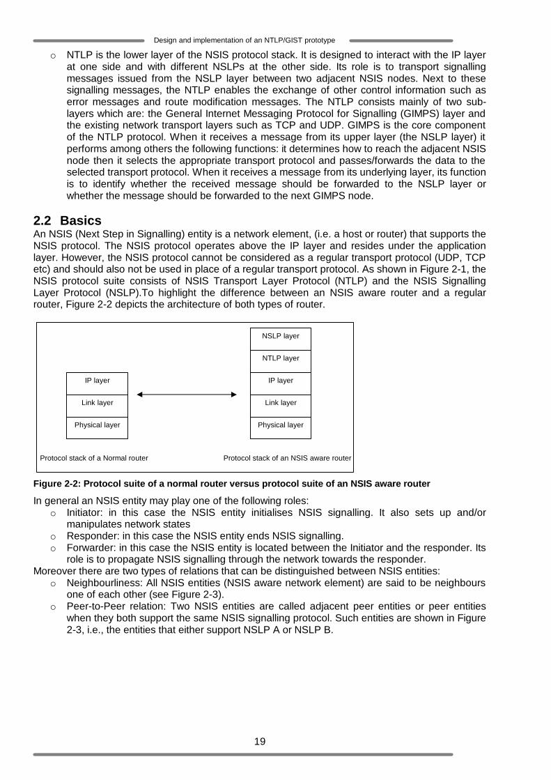
2.2 Basics An NSIS (Next Step in Signalling) entity is a network element, (i.e. a host or router) that supports the NSIS protocol. The NSIS protocol operates above the IP layer and resides under the application layer. However, the NSIS protocol cannot be considered as a regular transport protocol (UDP, TCP etc) and should also not be used in place of a regular transport protocol. As shown in Figure 2-1, the NSIS protocol suite consists of NSIS Transport Layer Protocol (NTLP) and the NSIS Signalling Layer Protocol (NSLP).To highlight the difference between an NSIS aware router and a regular router, Figure 2-2 depicts the architecture of both types of router.
Figure 2-2: Protocol suite of a normal router versus protocol suite of an NSIS aware router
In general an NSIS entity may play one of the following roles: o Initiator: in this case the NSIS entity initialises NSIS signalling. It also sets up and/or
manipulates network states o Responder: in this case the NSIS entity ends NSIS signalling. o Forwarder: in this case the NSIS entity is located between the Initiator and the responder. Its
role is to propagate NSIS signalling through the network towards the responder. Moreover there are two types of relations that can be distinguished between NSIS entities:
o Neighbourliness: All NSIS entities (NSIS aware network element) are said to be neighbours one of each other (see Figure 2-3).
o Peer-to-Peer relation: Two NSIS entities are called adjacent peer entities or peer entities when they both support the same NSIS signalling protocol. Such entities are shown in Figure 2-3, i.e., the entities that either support NSLP A or NSLP B.
Physical layer
Link layer
IP layer
Protocol stack of a Normal router
Physical layer
Link layer
IP layer
NTLP layer
NSLP layer
Protocol stack of an NSIS aware router

20
Design and implementation of an NTLP/GIST prototype
Figure 2-3: Relationship between NSIS entities
2.3 NSIS Transport Layer Protocol (NTLP) NTLP is designed to support different types of signalling applications; therefore its functionality is independent from a specific signalling application. The external behaviour of the NTLP is to transport and deliver transparently, signalling messages to the appropriate signalling applications. NTLP, itself is a peer-to-peer protocol. This means that along a data path, an NTLP node may receive NTLP data sent by its adjacent peer, even though this data is not destined to it. When the NTLP receives a signalling message from a specific signalling application it simply forwards this message to its next adjacent peer, which will deliver it to the appropriate NSLP. This peer will be the next NSIS aware network element/host along the data path of the signalling message that supports the same signalling application. The transport of a signalling message in NSIS depends thus on the ability for a node to find or correctly locate its next adjacent peer (see Figure 2-3). Before the specification and design work of NTLP, an analysis of existing QoS signalling protocols [8] has to be done. It appeared from this analysis that a considerable effort has been put in the specification and design of RSVP [4] and that this protocol offers a lot of features and building blocks which might certainly be needed in NTLP. The main drawback of RSVP is its complexity which is caused by its support of the 2multicast path-coupled signalling. NTLP compensates this drawback by supporting only the 3unicast path coupled signalling and soft state reservations. Besides the fact that RSVP features might be reused, taking RSVP into consideration has the following advantages:
o No need to reinvent new solutions o Saving specification design time o Decreasing implementation costs: Implementations reused o Shorter time needed for standardisation
2.3.1 Key Principles The key principles of NTLP are defined as follows:
1. Support of Path-Coupled Signalling. In the current specification of NTLP, signalling messages are routed on the same path as the path that will be followed by the data. Even though NTLP is implemented above the IP-layer it is not itself a routing protocol. If an NTLP process in a router desires to obtain routes it simply consults its local routing table (routing database).
2 A multicast group consists of several members which can join or leave the group at any time. The multicast support in RSVP implies thus the support of dynamic membership changes. This dynamism makes the maintenance of reservation states a heavy task. 3 The multicast path coupled signalling enables a sender to send signalling data to the members of a multicast group. Unicast path coupled signalling and soft state reservations may easily be used to provide the function that the multicast provide by sending signalling to individual receiver. Therefore NTLP does not support the multicast path coupled signalling and avoid that way the complexity introduced by RSVP.
NSIS node 1
NSLP A
NTLP
NSIS node 2
NSLP B
NTLP
NSIS node 3
NSLP A
NTLP
NSIS node 4
NSLP B
NTLP
NSIS node 5
NSLP C
NTLP
Legend Adjacent peers
neighbours

21
Design and implementation of an NTLP/GIST prototype
2. Globally unique state identifier (Session identifier): NTLP differentiates sessions from flows. A flow is usually defined as a sequence of data packets identified by its source IP address, destination IP address, source port number, destination port number and transport protocol. From this definition it must be clear that during the transport of data packets of a specific flow, the source or destination IP address may change (because of the source or destination node’s mobility). The rest of the data packets that still have to be transmitted will be grouped in a new flow which will be characterized by the new source or destination IP address. A session is defined as a sequence of application data packets between two NSIS nodes. These data packets might belong to one or several flows. Unlike RSVP which uses the flow-ID (5 tuples consisting of: source address, destination address, source port number, destination port number, transport protocol) to identify the data flows, NTLP defines a unique identifier for each of its states. This identifier is associated to application data flows and must always remain unchanged for the complete duration of the data flow even in a mobile IP scenario where the flow ID may change.
3. Establishment and maintenance of the routing states: Routing states consist of the information needed and used to route data flows towards their appropriate destination. Note that in NTLP, the GIMPS layer rather creates a state for each session than for each flow. Upon creating a routing state, this routing state is associated to a timer which indicates the life time of the state. When this timer is not refreshed and expires, the routing stated should be deleted. A routing state includes information such as:
a. Message Routing Information (MRI): the MRI provides information about the message routing method (path coupled or path decoupled). Further it contains among others the original flow source address and destination address. The latter is used to route the flow to the destination.
b. NSLP identifier (NSLP-ID): As mentioned before the NTLP is designed to support several NSLPs. Therefore the IANA (Internet Assigned Numbers Authority) assigns NSLP-IDs to NSIS signalling layer protocols for their identification.
c. Session identifier (SID): Globally unique routing state identifier d. IP hops: This defines the number of network elements that separates adjacent NTLP
peers. This routing state information indicates the IP distance between the peers. e. Downstream state: This is either the IP address of the next adjacent peer along the
data path or a reference/link to a messaging association state. f. Upstream state: This is the flow source IP address
4. Establishment and maintenance of the messaging association states: messaging association states are created between two adjacent peers when the connection mode operation is required. A messaging association state may be used by several sessions. It includes information about the transport and/or security protocols that can be used between the involved peers. It may also provide information about the state of the connection between these peers. Like routing states, messaging association states have associated timers. When a timer is not refreshed and therefore expires, the corresponding messaging association state must be deleted.
5. “Statefull” and “stateless” behaviour: As depicted in Figure 2-7, an NSIS node may create and maintain routing states (3) and/or messaging association (4) states at the NTLP layer. In such a case it is said to be statefull. When an NSIS node does not create any states it is said to be stateless. Two adjacent peers which are both statefull are said to have an end-to-end relationship.
6. Soft state support: The NTLP soft state is similar to RSVP soft state. Every created state should be periodically refreshed within a specific interval of time; otherwise the state is removed when the refresh time expires. Though, the state may also be removed or deleted after an explicit tear down request from the NSLP.
7. The NTLP signalling protocol is able to exchange local information between NSIS forwarders located within one single administrative domain.
8. In case of unexpected situations, e.g., errors (wrong destination address, connection failure, unreachable node, etc), any NSIS Forwarder is able to asynchronously generate a signalling error message.
22
Design and implementation of an NTLP/GIST prototype
9. NTLP does not access the content of application layer (NSLP) "objects" that it transports. These objects are totally opaque to NTLP.
10. NTLP does not affect or harm the functionality of existing networks. This means that it provides transparent operation through NTLP unaware network elements (routers). Moreover routers that support NTLP (i.e. NSIS in general) provide typical router functionalities as well.
11. NTLP is designed to support both IPv4 and IPv6. 12. NTLP provides the so called “bypass” function. This function is mainly performed during the
transport of data among NSIS nodes. It may be used by an NSIS node to pass around other NSIS aware nodes along the data path. There are several situations where the use of bypassing is judged to be useful:
a. The first situation refers to a network consisting of NSIS aware nodes which supports different kinds of NSLPs as shown in Figure 2-3. Bypassing requires in this case that each NSIS node is configured to support the appropriate IP Router Alert Option(s) [9], which correspond(s) to the NSLP(s) it supports. IANA assigns to each NSLP-ID a unique IP router value. When NSLP A in NSIS node1 would like to send some signalling data to NSIS node 3 whose location is not yet known; NSIS node1’s NTLP will make use of the bypass feature by including some additional information into the messages it will send towards NSIS node 3. This information is essentially represented by the IP router alert value. NSIS node 2 will not recognize the value included in the message and will ignore it. Unlike NSIS node 2, NSIS node 3 will recognize the router alert value and intercept the data. This situation clearly shows that, NSIS node 2 is 4bypassed during the transport of NSLP A’s signalling data towards its final destination.
b. The second situation refers to a network consisting of NSIS aware nodes which may only handle a specific type of messages of an NSLP they do support. In case a different type of message is sent along the data path the NSIS nodes that do not support these types are simply bypassed. Bypassing requires in this case that each NSIS node is configured to support a specific aggregation level. NTLP defines currently two aggregation levels. The aggregation level 0 and the aggregation level 1. A message sent with Aggregation level 0 may be examined by all NSIS nodes. A message sent with Aggregation level 1 must only be examine by NSIS nodes that are configured to support the same Aggregation level (and higher aggregation levels that will probably be defined in future).
13. NSIS nodes communicate with each other at the NTLP level by means of the GIMPS-Query message, the GIMPS-Response message, the GIMPS-Confirm message, the GIMPS-Data message, the GIMPS-Error message and the GIMPS-MA-Hello message.
a. GIMPS-Query, GIMPS-Response and GIMPS-Confirm are essentially implicated in the discovery mechanism. These messages are used in combination to set up and maintain GIMPS routing (3) and messaging association (4) states. Furthermore they may carry NSLP payloads.
b. GIMPS-Data is defined to carry only NSLP payload. GIMPS-Data may be transported in datagram mode or in connection mode, provided that a messaging association state already exists.
c. GIMPS-Error is defined to carry GIMPS error report. It is not allowed to carry any NSLP payload.
d. GIMPS-MA-Hello is defined to keep messaging association alive i.e. to enlarge the lifetime of existing messaging association states. Like GIMPS-Error GIMPS-MA-Hello does not carry NSLP payloads
14. Re-routing: The NTLP must be able to deal with different network problems and in particular problem that may lead to route changes such as link failure and interface or node changes since these problems may affect the routing function of the NTLP. Suppose for instance that the link between two NSIS nodes D and E is down. The routing state in node D associated to flows which traverse the path going from node D to node E will automatically become invalid,
4 Note that if the bypassing function was not applied, the NSIS node 2 would have intercepted the message even though it is not capable of handling NSLP A’s signalling messages.

23
Design and implementation of an NTLP/GIST prototype
since Node E is not reachable. Moreover the NSLPs supported by node D will have to be informed about the occurred link failure. Based on this example it should be clear that in order to handle network problems that may occur, an NTLP node should be able to detect the route changes in the direction of the responding node (downstream) and in the direction of the sending node (upstream), update its own routing state and inform interested signalling applications about these route changes.
15. Interaction with NAT and IP Tunnelling: In case a datagram mode GIMPS message has to traverse a GIMPS aware NAT residing on its data path, the content of this message’s MRI and Node Addressing may be modified by the NAT to enable a correct routing of the message. However the original MRI will not be deleted but it will be encapsulated in the new MRI which results from the done modifications. Connection mode messages will not be affected by NATs because the adjacent peers are already well identified. Therefore they can address each other directly. The interaction between NTLP and IP tunnelling is simple. Since GIMPS messages are encapsulated in IP packets, they are considered and treated as regular IP packets when traversing an IP tunnel.
2.3.2 NTLP Subdivision The NTLP protocol is subdivided in two layers as depicted in Figure 2-4.
Figure 2-4: NTLP protocol suite
NTLP consists of the General Internet Messaging Protocol for Signaling (GIMPS) and existing transport layers (TCP, UDP, SCTP, DCCP, etc). In the current GIMPS specification only UDP (see Section 2.3.2.2) and TCP (see Section 2.3.2.1) are considered. The choice of the transport protocol that must be used to send a signalling message depends on the requirements of the signaling application and/or the local policies defined in the NSIS node itself. A signaling application may require a reliable data transfer, an unreliable data transfer and/or a secure data transfer. Suppose a signalling application requires an unreliable transfer for its signalling data that appeared later to be too large and probably has to be fragmented, then the NTLP must consult the local policies. These policies will guide NTLP in the determination of the appropriate transport protocol, which will be used to transfer this signalling data. This means that signalling data meant to be transported by an unreliable transport protocol may end up been transported by a reliable transport protocol. In the following section the main characteristics of TCP and UDP will briefly be presented. Thereafter, GIMPS will be discussed. 2.3.2.1 Transmission control protocol (TCP) The TCP standard [38], which is broadly used in the Internet, provides a reliable end to end application data transmission. The main goals of the TCP protocol are to guaranty a correct data delivery and provide an end to end reliability. In order to provide reliability, TCP uses a “retransmission queue”. A copy of each transmitted data (called segment in the TCP jargon) is placed on the queue and a timer is set for it. When an acknowledgment is received for the segment, it is removed from the retransmission queue. If the timer expires before an acknowledgment is received the saved segment is retransmitted and
Existing transport and security protocols
GIMPS General Internet Messaging Protocol for Signalling
Transport Layer Security
IP Layer Security
UDP TCP SCTP DCCP
24
Design and implementation of an NTLP/GIST prototype
the timer restarts. An incorrect data or lost data is detected by the leak of its corresponding acknowledgement, thus this data will be retransmitted as well. All the TCP- operations lead to the exchange of a number of messages which cause source-to-destination round-trips. These round trips may increase the propagation delay of signalling messages and should be considered during the determination or establishment of the local policies that must be applied to signalling messages. The TCP protocol can be identified by the following properties:
o Very interactive communication between the sender and receiver: The 3-ways handshake occurs during the establishment of a connection between a sending node and a destination node. This operation is required before the exchange of any data between the source and the destination. During this phase the sender sends a request for synchronisation to the receiver by means of a “sync request” message. The receiver replies back by synchronizing with the sender. The success of this phase is terminated with a positive acknowledgement sent by the sender. Besides the 3-ways handshake, TCP protocol has a 4-ways handshake which is used to terminate or take down an eventual connection between the sender and receiver. Furthermore, every few messages/segments (containing the user data) sent by the source must be acknowledged at the destination. Essentially, the acknowledgement is the procedure used by TCP to guaranty a correct data delivery
o End-to-end reliability: As mentioned before the exchange of any data in the Internet is preceded by a connection establishment (virtual circuit) between the source and destination. Besides that acknowledgements are generated at the final destination. The TCP protocol makes sure that the end destination (and not the intermediary nodes) receives the transmitted data correctly.
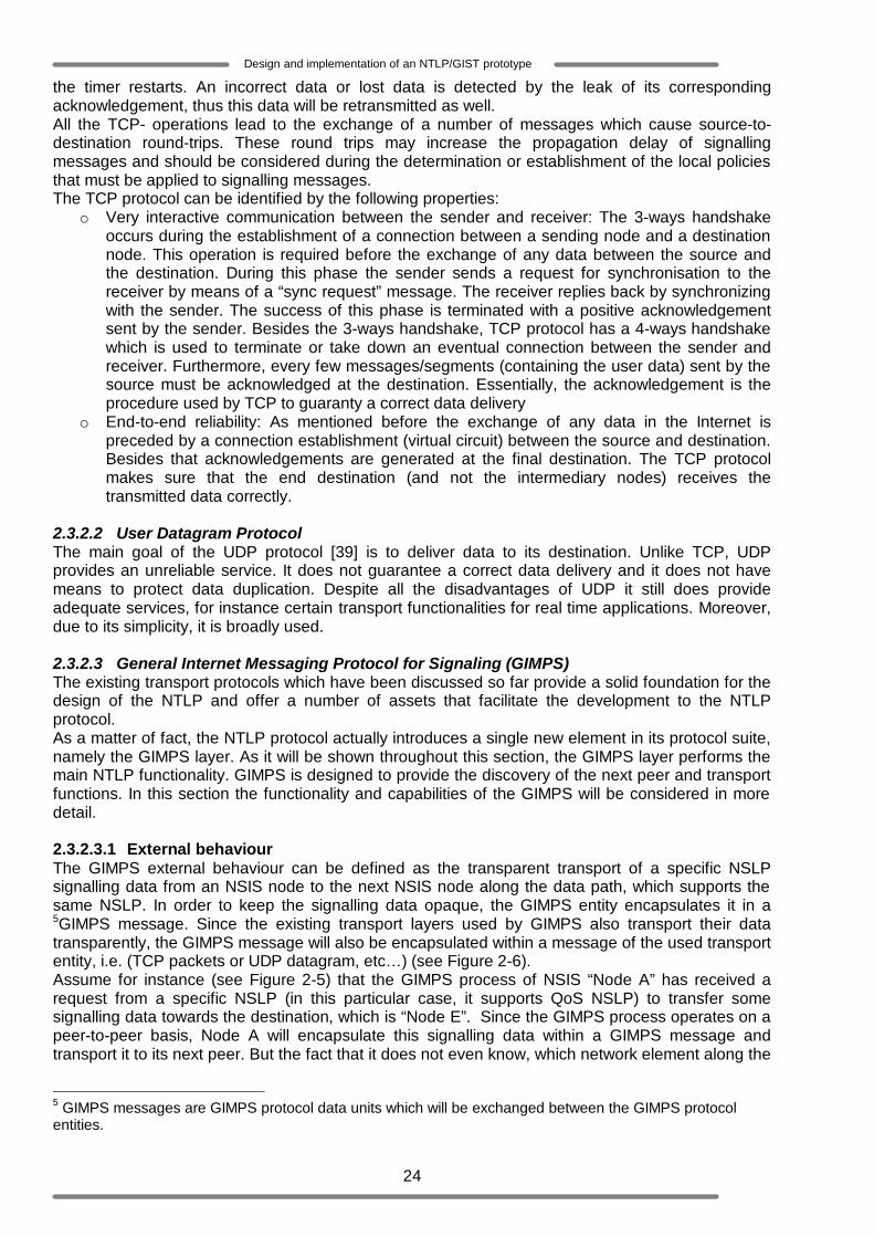
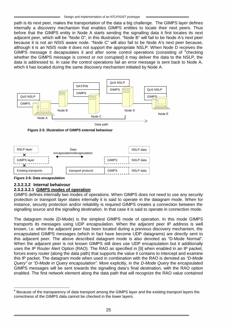
2.3.2.2 User Datagram Protocol The main goal of the UDP protocol [39] is to deliver data to its destination. Unlike TCP, UDP provides an unreliable service. It does not guarantee a correct data delivery and it does not have means to protect data duplication. Despite all the disadvantages of UDP it still does provide adequate services, for instance certain transport functionalities for real time applications. Moreover, due to its simplicity, it is broadly used. 2.3.2.3 General Internet Messaging Protocol for Signaling (GIMPS) The existing transport protocols which have been discussed so far provide a solid foundation for the design of the NTLP and offer a number of assets that facilitate the development to the NTLP protocol. As a matter of fact, the NTLP protocol actually introduces a single new element in its protocol suite, namely the GIMPS layer. As it will be shown throughout this section, the GIMPS layer performs the main NTLP functionality. GIMPS is designed to provide the discovery of the next peer and transport functions. In this section the functionality and capabilities of the GIMPS will be considered in more detail. 2.3.2.3.1 External behaviour The GIMPS external behaviour can be defined as the transparent transport of a specific NSLP signalling data from an NSIS node to the next NSIS node along the data path, which supports the same NSLP. In order to keep the signalling data opaque, the GIMPS entity encapsulates it in a 5GIMPS message. Since the existing transport layers used by GIMPS also transport their data transparently, the GIMPS message will also be encapsulated within a message of the used transport entity, i.e. (TCP packets or UDP datagram, etc… ) (see Figure 2-6). Assume for instance (see Figure 2-5) that the GIMPS process of NSIS “Node A” has received a request from a specific NSLP (in this particular case, it supports QoS NSLP) to transfer some signalling data towards the destination, which is “Node E”. Since the GIMPS process operates on a peer-to-peer basis, Node A will encapsulate this signalling data within a GIMPS message and transport it to its next peer. But the fact that it does not even know, which network element along the
5 GIMPS messages are GIMPS protocol data units which will be exchanged between the GIMPS protocol entities.
25
Design and implementation of an NTLP/GIST prototype
path is its next peer, makes the transportation of the data a big challenge. The GIMPS layer defines internally a discovery mechanism that enables GIMPS entities to locate their next peers. Thus before that the GIMPS entity in Node A starts sending the signalling data it first locates its next adjacent peer, which will be “Node D”, in this illustration. “Node B” will fail to be Node A’s next peer because it is not an NSIS aware node. “Node C” will also fail to be Node A’s next peer because, although it is an NSIS node it does not support the appropriate NSLP. When Node D receives the GIMPS message it decapsulates it and after some control operations (consisting of 6checking whether the GIMPS message is correct or not corrupted) it may deliver the data to the NSLP, the data is addressed to. In case the control operations fail an error message is sent back to Node A, which it has located during the same discovery mechanism initiated by Node A.
Figure 2-5: illustration of GIMPS external behaviour
Figure 2-6: Data encapsulation
2.3.2.3.2 Internal behaivour 2.3.2.3.2.1 GIMPS modes of operation GIMPS defines internally two modes of operations. When GIMPS does not need to use any security protection or transport layer states internally it is said to operate in the datagram mode. When for instance, security protection and/or reliability is required GIMPS creates a connection between the signalling source and the signalling destination. In that case it is said to operate in connection mode. The datagram mode (D-Mode) is the simplest GIMPS mode of operation. In this mode GIMPS transports its messages using UDP encapsulation. When the adjacent peer IP address is well known, i.e. when the adjacent peer has been located during a previous discovery mechanism, the encapsulated GIMPS messages (which in fact have become UDP datagrams) are directly sent to this adjacent peer. The above described datagram mode is also denoted as “D-Mode Normal”. When the adjacent peer is not known GIMPS still does use UDP encapsulation but it additionally uses the IP Router Alert Option (RAO). The RAO as specified in [9] when enabled in an IP packet, forces every router (along the data path) that supports the value it contains to intercept and examine this IP packet. The datagram mode when used in combination with the RAO is denoted as “D-Mode Query” or “D-Mode in Query encapsulation”. More explicitly, in the D-Mode Query the encapsulated GIMPS messages will be sent towards the signalling data’s final destination, with the RAO option enabled. The first network element along the data path that will recognize the RAO value contained
6 Because of the transparency of data transport among the GIMPS layer and the existing transport layers the correctness of the GIMPS data cannot be checked in the lower layers.
Node B
QoS NSLP
GIMPS
QoS NSLP
GIMPS NAT/FW NSLP GIMPS
QoS NSLP
GIMPS
Node A Node C Node D
Node E
Data path
GIMPS layer
NSLP layer
Existing transports layer
Data encapsulation/decapsulation
NSLP data
GIMPS header
NSLP data
GIMPS header
NSLP data transport protocol header

26
Design and implementation of an NTLP/GIST prototype
in the packet will take the packet over as if it was directly addressed to it. Consequently this network element will be the adjacent peer of the sending GIMPS node. The connection mode is more complicated than the datagram mode because it requires the identification of the communicating peer nodes. This means that GIMPS can only operate in the connection mode after the accomplishment of a discovery mechanism. Once both peers are identified a bidirectional connection will be established between them (see also Section 2.3.2.3.2.2). In the connection mode GIMPS must use a secure and or connection oriented transport protocol. In the current specification only TCP has been defined. 2.3.2.3.2.2 GIMPS internal functions There are two main functions that may be combined to provide to GIMPS its external behaviour. The routing function focuses on how to determine the next GIMPS peer. This function is based on the so called “discovery mechanism”. After the identification of the GIMPS peer, the transport function enables the delivery of the signalling data to this peer. Routing - Discovery mechanism During the discovery mechanism shown in Figure 2-7, three main actions are executed:
- Discovery of the next node: this consists of locating the next node along the data path - Installation of routing states: routing states includes important information about adjacent
peers such as: o IP address: source address of next/previous peer o Messaging association link: link to an existing messaging association. o IP hops: number of hops (network elements) that separates two adjacent peers o GIMPS hops: number of NSIS aware nodes that separates two adjacent peers o Message Routing Information: consists among others of the flow-ID and the signalling
path message. o Session identification: globally unique identifier associate to one or more flows which
belong to the same session. - Installation of messaging associations: stack of protocols that must be used for the
communication between two adjacent peers. The discovery mechanism may enable an NSIS node to discover the next NSIS node or the adjacent peer node. Each discovery procedure may be triggered by an NSLP request message that has to be sent to a given destination. GIMPS specify two different ways to discover the next node: the 2-ways handshake and the 3-ways handshake. The 2-ways handshake procedure consists of two steps. The initiator of the discovery procedure first sends a so called “GIMPS-Query message” towards the given destination using the D-Mode Query method (UDP encapsulation with RAO). In case a connection mode operation is not required, the first interceptor install the routing state related to the query sender and sends a GIMPS-Response message, using the D-Mode Normal method back to the sender. Upon receiving the GIMPS-Response message, the query initiator also installs the routing state related to the responder. In case a connection mode operation is required by the NSLP or by the local policies, the initiator includes in the GIMPS-Query message a list of the transport and/or security protocols it supports. Upon receiving this GIMPS-Query message, the first interceptor installed the routing state of the query sender. The responder checks the list of the proposed transport/security protocols provided that it is included in the GIMPS-Query message and retains the protocols that it supports among the proposed protocol in the stack. The retained protocol will be installed as messaging association. Moreover the responder will include this messaging association in its GIMPS-Response message and then it will send the GIMPS-Response message back to the sender using the installed messaging association. Upon receiving the GIMPS-Response message the GIMPS-Query message initiator will in turn install the routing state of the responder and eventually, the messaging association. Note that a routing state is not installed and kept indefinitely. Since GIMPS is a soft state protocol it requires each routing state to be refreshed otherwise the routing states are removed after the expiration of a specific default time.

27
Design and implementation of an NTLP/GIST prototype
The 3-ways handshake procedure extends the 2-ways handshake with one additional step. The 3-ways handshake is defined as follows: The initiator of the discovery procedure first sent a GIMPS-Query message towards the given destination using the D-Mode Query method. In case a connection mode operation is not required, the first interceptor handles the received Query message and sends a GIMPS-Response message, using the D-Mode Normal method back to the sender. Upon receiving the GIMPS-Response message, the GIMPS-Query message initiator installs the routing state related to the responder and sends a “GIMPS-Confirm message” to the responder using the D-Mode Normal. The responder only installs the routing state related to the query sender when it receives a correct GIMPS-Confirm message. In case a connection mode operation is required, the initiator includes in the GIMPS-Query message a list of the transport and/or security protocols it supports. Upon receiving this Query message, the responder checks the list of the proposed transport/security protocols included in the Query message and retains the protocols that it supports among the proposed protocol in the stack. The retained protocol will be installed as messaging association. The responder will send the GIMPS-Response message back to the sender using the messaging association and even include this messaging association in its GIMPS-Response message. Upon receiving the GIMPS-Response message the GIMPS-Query message initiator will install the routing state of the responder and eventually the messaging association and sends a GIMPS-Confirm message back to the responder using the received messaging association. Upon receiving the GIMPS-Confirm message the responder installs the routing state of the query sender and the messaging association.
Figure 2-7: illustration of the discovery mechanism
Transport function The transport function enables a GIMPS entity to choose the appropriate underlying transport protocol (according to the GIMPS specification [10] it will be UDP or TCP) and sends data to its peer entity through the chosen protocol. During the transport of GIMPS messages, GIMPS has the ability
GIMPS-confirm
GIMPS-response
GIMPS-query
Router Alert Options
Querying Node
Responding Node
Routing state installed at the Responding Node (1)
The responder can use an existing messaging association if available from here onwards to short-circuit messaging association setup
Set up messaging association if it is required
Routing state installed at the Querying Node (1)
Routing state installed at the Responding Node (2)
(1): 2-ways handshake (2): 3-ways handshake

28
Design and implementation of an NTLP/GIST prototype
to bypass some Nodes even though these nodes are potential GIMPS peer entities. The message aggregation level is an additional configuration parameter introduced to support the bypass/forwarding function. There are two levels that are currently defined: the aggregation level 0 and the aggregation level 1. A GIMPS peer configured to support messages at aggregation level 0 is allowed to receive messages of that aggregation level and higher. A GIMPS peer configured to support messages at aggregation level 1 must only receive GIMPS message of that aggregation level. 2.4 NSIS Signalling Layer Protocol [37] This section will discuss the Quality of Service (QoS) NSIS Signalling Layer Protocol (NSLP), henceforth referred to as the “QoS-NSLP” [35]. A QoS-NSLP model of operation is given in Figure 2-8. The protocol creates and maintains various states in the nodes along the path where the signalling and the data packets flow. This protocol is mainly used to signal certain QoS parameters for the data flow. The QoS-NSLP functional design is basically similar to the Resource Reservation Protocol (RSVP) [14], but it is not backward compatible to RSVP. The primary state management mechanism is based on soft-state peer-to-peer refresh messages. The QoS-NSLP protocol is not backward compatible with RSVP, but interworking between the two protocols might be possible at signalling gateways.
Figure 2-8: QoS-NSLP model of operation (taken from [35])
2.4.1 QoS-NSLP features QoS-NSLP supports a number of basic features and a number of advanced features. The basic features encompass all the functionalities that are required to signal the initiation, refresh and termination of reservation states. Such functionalities are:
o Use of soft states: the QoS-NSLP uses soft states for the reservations. After a defined period of time and no refresh message has been received to maintain the reservation, the reservation is removed.
o Support of the basic unidirectional sender initiated reservations: where a data path initiating entity initiates the reservation (see Section 2.4.3)
o Support of basic unidirectional receiver initiated reservations: where a data path receiving entity initiates the reservation (see Section 2.4.4)
o Support of bi-directional reservations: where sender and receiver initiated reservations can be used to signal the initiation, refresh and terminate reservations in
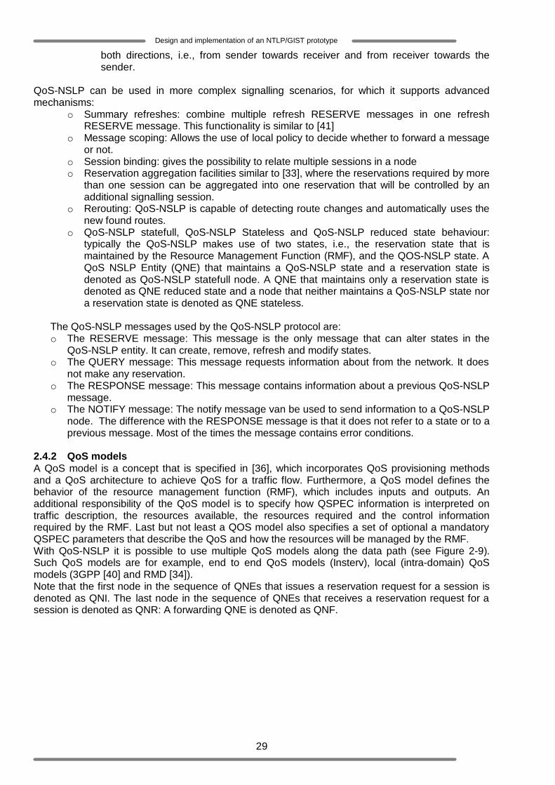
29
Design and implementation of an NTLP/GIST prototype
both directions, i.e., from sender towards receiver and from receiver towards the sender.
QoS-NSLP can be used in more complex signalling scenarios, for which it supports advanced mechanisms:
o Summary refreshes: combine multiple refresh RESERVE messages in one refresh RESERVE message. This functionality is similar to [41]
o Message scoping: Allows the use of local policy to decide whether to forward a message or not.
o Session binding: gives the possibility to relate multiple sessions in a node o Reservation aggregation facilities similar to [33], where the reservations required by more
than one session can be aggregated into one reservation that will be controlled by an additional signalling session.
o Rerouting: QoS-NSLP is capable of detecting route changes and automatically uses the new found routes.
o QoS-NSLP statefull, QoS-NSLP Stateless and QoS-NSLP reduced state behaviour: typically the QoS-NSLP makes use of two states, i.e., the reservation state that is maintained by the Resource Management Function (RMF), and the QOS-NSLP state. A QoS NSLP Entity (QNE) that maintains a QoS-NSLP state and a reservation state is denoted as QoS-NSLP statefull node. A QNE that maintains only a reservation state is denoted as QNE reduced state and a node that neither maintains a QoS-NSLP state nor a reservation state is denoted as QNE stateless.
The QoS-NSLP messages used by the QoS-NSLP protocol are: o The RESERVE message: This message is the only message that can alter states in the
QoS-NSLP entity. It can create, remove, refresh and modify states. o The QUERY message: This message requests information about from the network. It does
not make any reservation. o The RESPONSE message: This message contains information about a previous QoS-NSLP
message. o The NOTIFY message: The notify message van be used to send information to a QoS-NSLP
node. The difference with the RESPONSE message is that it does not refer to a state or to a previous message. Most of the times the message contains error conditions.
2.4.2 QoS models A QoS model is a concept that is specified in [36], which incorporates QoS provisioning methods and a QoS architecture to achieve QoS for a traffic flow. Furthermore, a QoS model defines the behavior of the resource management function (RMF), which includes inputs and outputs. An additional responsibility of the QoS model is to specify how QSPEC information is interpreted on traffic description, the resources available, the resources required and the control information required by the RMF. Last but not least a QOS model also specifies a set of optional a mandatory QSPEC parameters that describe the QoS and how the resources will be managed by the RMF. With QoS-NSLP it is possible to use multiple QoS models along the data path (see Figure 2-9). Such QoS models are for example, end to end QoS models (Insterv), local (intra-domain) QoS models (3GPP [40] and RMD [34]). Note that the first node in the sequence of QNEs that issues a reservation request for a session is denoted as QNI. The last node in the sequence of QNEs that receives a reservation request for a session is denoted as QNR: A forwarding QNE is denoted as QNF.

30
Design and implementation of an NTLP/GIST prototype
Figure 2-9 : Multiple Quality of service in a data path The [36] draft specifies a template for the QSPEC that is needed to help defining individual QOSM in order to promote their interoperability. Figure 2-10 illustrates the format of the QSPEC, which is composed of QSPEC control information and QoS description (i.e., actual resource description). The QoS description as shown in Figure 2-10 is composed up to four QSPEC objects, namely QoS Desired, QoS Available, QoS Reserved and Minimum QoS. Note that not all of these objects need to be present. Moreover, each of these QSPEC Objects, as well as QSPEC Control Information, consists of a number of mandatory and optional QSPEC parameters. In addition to the above, note that QSPEC contains an identifier for the QOSM. +-------------+---------------------------------------+ |QSPEC Control| QoS | | Information | Description | +-------------+---------------------------------------+ \________________ ______________________/ V +----------+----------+---------+-------+ \ |QoS Desir.|QoS Avail.|QoS Rsrv.|Min QoS| > QSPEC +----------+----------+---------+-------+ / Objects \_______ ____/\____ ____/\___ _____/\___ ____/\__ ___/ V V V V V +-------------+... +-------------+... |QSPEC Para. 1| |QSPEC Para. n| +-------------+... +-------------+...
Figure 2-10: (copied from [36]): Structure of the QSPEC A QSPEC parameter can be individually coded or alternatively, in order to make the coding more efficient, QOS models may define one or more optional 'container QSPEC parameter', which contain several sub-parameters. The examples given in the next paragraphs will be used to give an overview of the QoS-NSLP protocol operation [35]. 2.4.3 Basic sender-initiated reservation Two reservation schemes will be used in QoS-NSLP. A sender initiated reservation and a receiver based reservation. The first one is initiated by the sender of the information. For example a web server that sends a video stream to the user. The latter one, the reservation is made by the receiver of the data and not the sender. In the sender initiated reservation a new reservation is initiated by the first NSIS entity (QNI). This QNE generates a new RESERVE message with a QSPEC. The QSPEC is filled with the corresponding QoS parameters of the chosen QoS-Model. Note that a Query or a RESERVE message can trigger the initiation of a RESPONSE message, by including an object denoted as Request Identification Information (RII). When the QNR, receives such an object it has to generate a RESPONSE message.
Intra-domain QOSM
QNF interior
NTLP stateless
NSLP stateless or reduced state
Intra-domain QOSM
QNF ingress
NTLP stateful
NSLP stateful
end-to-end QOSM
QNF
NTLP stateful
NSLP stateful
end-to-end QOSM
Intra-domain QOSM
QNF interior
NTLP stateless
NSLP stateless or reduced state
Intra-domain QOSM
QNF egress
NTLP stateful
NSLP stateful
end-to-end QOSM
QNF
NTLP stateful
NSLP stateful
end-to-end QOSM
QNI (end)
NTLP stateful
NSLP stateful
end-to-end QOSM
QNR (end)
NTLP stateful
NSLP stateful
end-to-end QOSM
Wireless QOSM
Wireless QOSM
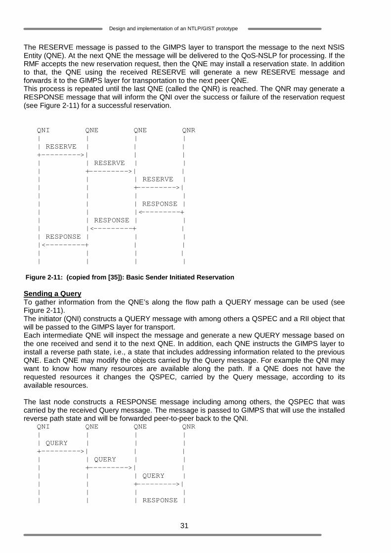
31
Design and implementation of an NTLP/GIST prototype
The RESERVE message is passed to the GIMPS layer to transport the message to the next NSIS Entity (QNE). At the next QNE the message will be delivered to the QoS-NSLP for processing. If the RMF accepts the new reservation request, then the QNE may install a reservation state. In addition to that, the QNE using the received RESERVE will generate a new RESERVE message and forwards it to the GIMPS layer for transportation to the next peer QNE. This process is repeated until the last QNE (called the QNR) is reached. The QNR may generate a RESPONSE message that will inform the QNI over the success or failure of the reservation request (see Figure 2-11) for a successful reservation. QNI QNE QNE QNR | | | | | RESERVE | | | +--------->| | | | | RESERVE | | | +--------->| | | | | RESERVE | | | +--------->| | | | | | | | RESPONSE | | | |<---------+ | | RESPONSE | | | |<---------+ | | RESPONSE | | | |<---------+ | | | | | | | | | | Figure 2-11: (copied from [35]): Basic Sender Initiated Reservation Sending a Query To gather information from the QNE’s along the flow path a QUERY message can be used (see Figure 2-11). The initiator (QNI) constructs a QUERY message with among others a QSPEC and a RII object that will be passed to the GIMPS layer for transport. Each intermediate QNE will inspect the message and generate a new QUERY message based on the one received and send it to the next QNE. In addition, each QNE instructs the GIMPS layer to install a reverse path state, i.e., a state that includes addressing information related to the previous QNE. Each QNE may modify the objects carried by the Query message. For example the QNI may want to know how many resources are available along the path. If a QNE does not have the requested resources it changes the QSPEC, carried by the Query message, according to its available resources. The last node constructs a RESPONSE message including among others, the QSPEC that was carried by the received Query message. The message is passed to GIMPS that will use the installed reverse path state and will be forwarded peer-to-peer back to the QNI. QNI QNE QNE QNR | | | | | QUERY | | | +--------->| | | | | QUERY | | | +--------->| | | | | QUERY | | | +--------->| | | | | | | | RESPONSE |
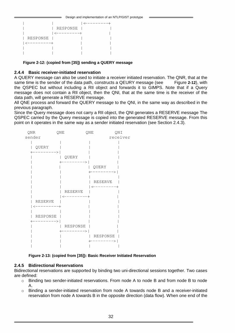
32
Design and implementation of an NTLP/GIST prototype
| | |<---------+ | | RESPONSE | | | |<---------+ | | RESPONSE | | | |<---------+ | | | | | | | | | | Figure 2-12: (copied from [35]) sending a QUERY message 2.4.4 Basic receiver-initiated reservation A QUERY message can also be used to initiate a receiver initiated reservation. The QNR, that at the same time is the sender of the data path, constructs a QEURY message (see Figure 2-12), with the QSPEC but without including a RII object and forwards it to GIMPS. Note that if a Query message does not contain a RII object, then the QNI, that at the same time is the receiver of the data path, will generate a RESERVE message. All QNE process and forward the QUERY message to the QNI, in the same way as described in the previous paragraph. Since the Query message does not carry a RII object, the QNI generates a RESERVE message The QSPEC carried by the Query message is copied into the generated RESERVE message. From this point on it operates in the same way as a sender initiated reservation (see Section 2.4.3). QNR QNE QNE QNI sender receiver | | | | | QUERY | | | +--------->| | | | | QUERY | | | +--------->| | | | | QUERY | | | +--------->| | | | | | | | RESERVE | | | |<---------+ | | RESERVE | | | |<---------+ | | RESERVE | | | |<---------+ | | | | | | | RESPONSE | | | +--------->| | | | | RESPONSE | | | +--------->| | | | | RESPONSE | | | +--------->| | | | | Figure 2-13: (copied from [35]): Basic Receiver Initiated Reservation 2.4.5 Bidirectional Reservations Bidirectional reservations are supported by binding two uni-directional sessions together. Two cases are defined:
o Binding two sender-initiated reservations. From node A to node B and from node B to node A.
o Binding a sender-initiated reservation from node A towards node B and a receiver-initiated reservation from node A towards B in the opposite direction (data flow). When one end of the
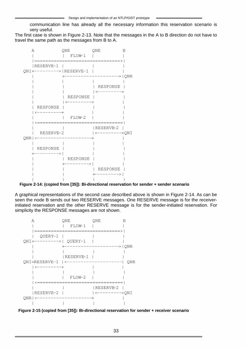
33
Design and implementation of an NTLP/GIST prototype
communication line has already all the necessary information this reservation scenario is very useful.
The first case is shown in Figure 2-13. Note that the messages in the A to B direction do not have to travel the same path as the messages from B to A. A QNE QNE B | | FLOW-1 | | |===============================>| |RESERVE-1 | | | QNI+--------->|RESERVE-1 | | | +-------------------->|QNR | | | | | | | RESPONSE | | | |<---------+ | | RESPONSE | | | |<---------+ | | RESPONSE | | | |<---------+ | | | | FLOW-2 | | |<===============================| | | |RESERVE-2 | | RESERVE-2 |<---------+QNI QNR|<--------------------+ | | | | | | RESPONSE | | | +--------->| | | | | RESPONSE | | | +--------->| | | | | RESPONSE | | | +--------->| | | | | Figure 2-14: (copied from [35]): Bi-directional reservation for sender + sender scenario A graphical representations of the second case described above is shown in Figure 2-14. As can be seen the node B sends out two RESERVE messages. One RESERVE message is for the receiver-initiated reservation and the other RESERVE message is for the sender-initiated reservation. For simplicity the RESPONSE messages are not shown. A QNE QNE B | | FLOW-1 | | |===============================>| | QUERY-1 | | | QNI+--------->| QUERY-1 | | | +-------------------->|QNR | | | | | |RESERVE-1 | | QNI+RESERVE-1 |<--------------------| QNR |<---------+ | | | | | | | | FLOW-2 | | |<===============================| | | |RESERVE-2 | |RESERVE-2 | |<---------+QNI QNR|<--------------------+ | | | | |
Figure 2-15 (copied from [35]): Bi-directional reservation for sender + receiver scenario
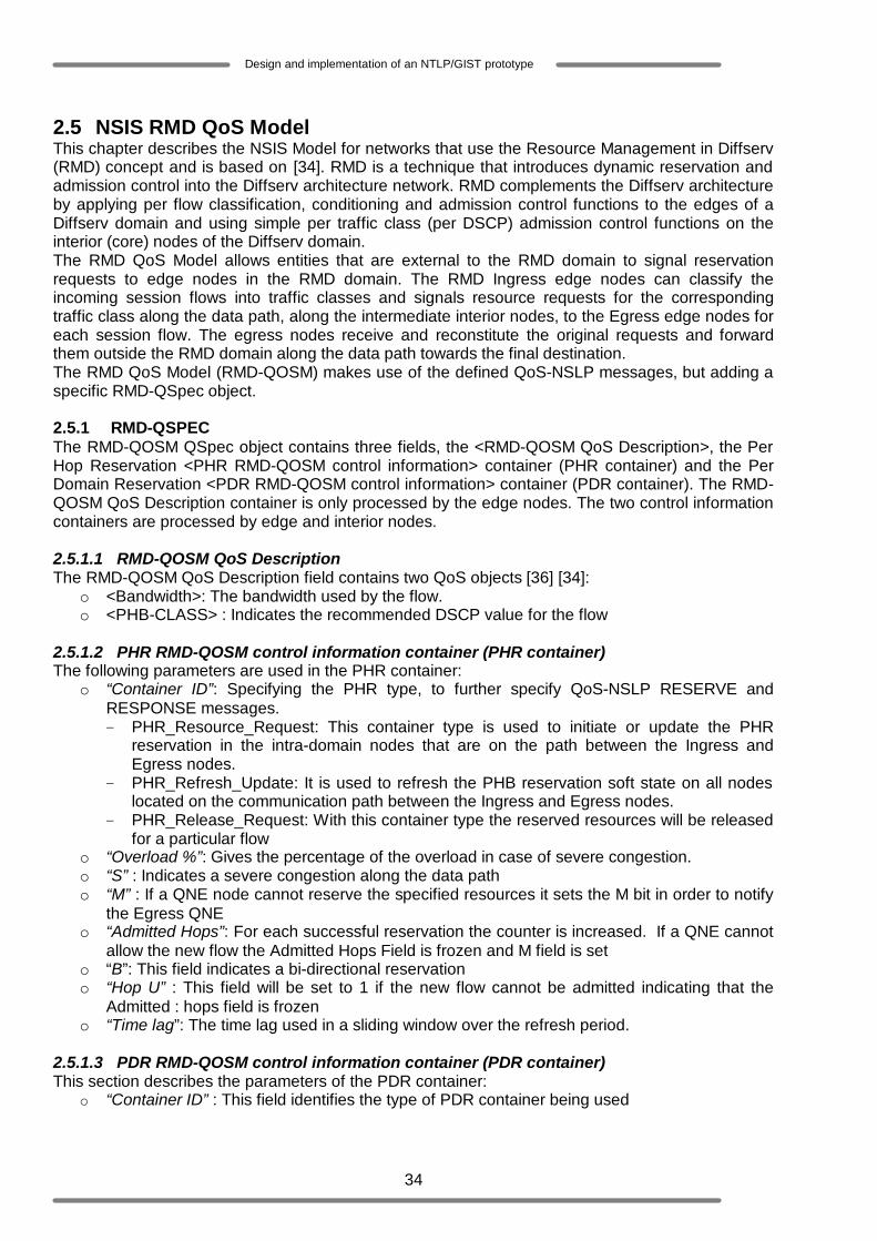
34
Design and implementation of an NTLP/GIST prototype
2.5 NSIS RMD QoS Model This chapter describes the NSIS Model for networks that use the Resource Management in Diffserv (RMD) concept and is based on [34]. RMD is a technique that introduces dynamic reservation and admission control into the Diffserv architecture network. RMD complements the Diffserv architecture by applying per flow classification, conditioning and admission control functions to the edges of a Diffserv domain and using simple per traffic class (per DSCP) admission control functions on the interior (core) nodes of the Diffserv domain. The RMD QoS Model allows entities that are external to the RMD domain to signal reservation requests to edge nodes in the RMD domain. The RMD Ingress edge nodes can classify the incoming session flows into traffic classes and signals resource requests for the corresponding traffic class along the data path, along the intermediate interior nodes, to the Egress edge nodes for each session flow. The egress nodes receive and reconstitute the original requests and forward them outside the RMD domain along the data path towards the final destination. The RMD QoS Model (RMD-QOSM) makes use of the defined QoS-NSLP messages, but adding a specific RMD-QSpec object. 2.5.1 RMD-QSPEC The RMD-QOSM QSpec object contains three fields, the <RMD-QOSM QoS Description>, the Per Hop Reservation <PHR RMD-QOSM control information> container (PHR container) and the Per Domain Reservation <PDR RMD-QOSM control information> container (PDR container). The RMD-QOSM QoS Description container is only processed by the edge nodes. The two control information containers are processed by edge and interior nodes. 2.5.1.1 RMD-QOSM QoS Description The RMD-QOSM QoS Description field contains two QoS objects [36] [34]:
o <Bandwidth>: The bandwidth used by the flow. o <PHB-CLASS> : Indicates the recommended DSCP value for the flow
2.5.1.2 PHR RMD-QOSM control information container (PHR container) The following parameters are used in the PHR container:
o “Container ID”: Specifying the PHR type, to further specify QoS-NSLP RESERVE and RESPONSE messages. - PHR_Resource_Request: This container type is used to initiate or update the PHR
reservation in the intra-domain nodes that are on the path between the Ingress and Egress nodes.
- PHR_Refresh_Update: It is used to refresh the PHB reservation soft state on all nodes located on the communication path between the Ingress and Egress nodes.
- PHR_Release_Request: With this container type the reserved resources will be released for a particular flow
o “Overload %”: Gives the percentage of the overload in case of severe congestion. o “S” : Indicates a severe congestion along the data path o “M” : If a QNE node cannot reserve the specified resources it sets the M bit in order to notify
the Egress QNE o “Admitted Hops”: For each successful reservation the counter is increased. If a QNE cannot
allow the new flow the Admitted Hops Field is frozen and M field is set o “B”: This field indicates a bi-directional reservation o “Hop U” : This field will be set to 1 if the new flow cannot be admitted indicating that the
Admitted : hops field is frozen o “Time lag”: The time lag used in a sliding window over the refresh period.
2.5.1.3 PDR RMD-QOSM control information container (PDR container) This section describes the parameters of the PDR container:
o “Container ID” : This field identifies the type of PDR container being used
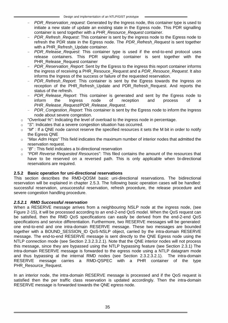
35
Design and implementation of an NTLP/GIST prototype
- PDR_Reservation_request: Generated by the Ingress node, this container type is used to initiate a new state of update an existing state in the Egress node. This PDR signalling container is send together with a PHR_Resource_Request container.
- PDR_Refresh_Request: This container is sent by the ingress node to the Egress node to refresh the PDR state in the Egress node. The PDR_Refresh_Request is sent together with a PHR_Refresh_Update container.
- PDR_Release_Request: This container type is used if the end-to-end protocol uses release containers. This PDR signalling container is sent together with the PHR_Release_Request container
- PDR_Reservation_Report: Sent by the Egress to the ingress this report container informs the ingress of receiving a PHR_Resouce_Request and a PDR_Resouce_Request. It also informs the Ingress of the success or failure of the requested reservation.
- PDR_Refresh_Report: This container is sent by the Egress towards the Ingress on reception of the PHR_Refresh_Update and PDR_Refresh_Request. And reports the status of the refresh.
- PDR_Release_Report: This container is generated and sent by the Egress node to inform the Ingress node of reception and process of a PHR_Release_Request/PDR_Release_Request.
- PDR_Congestion_Report: This container is sent by the Egress node to inform the Ingress node about severe congestion.
o “Overload %”: Indicating the level of overload to the ingress node in percentage. o “S”: Indicates that a severe congestion situation has occurred. o “M” : If a QNE node cannot reserve the specified resources it sets the M bit in order to notify
the Egress QNE o “Max Adm Hops” This field indicates the maximum number of interior nodes that admitted the
reservation request. o “B” : This field indicates a bi-directional reservation o “PDR Reverse Requested Resources”: This filed contains the amount of the resources that
have to be reserved on a reversed path. This is only applicable when bi-directional reservations are required.
2.5.2 Basic operation for uni-directional reservations This section describes the RMD-QOSM basic uni-directional reservations. The bidirectional reservation will be explained in chapter 2.5.3. The following basic operation cases will be handled: successful reservation, unsuccessful reservation, refresh procedure, the release procedure and severe congestion handling procedure. 2.5.2.1 RMD Successful reservation When a RESERVE message arrives from a neighbouring NSLP node at the ingress node, (see Figure 2-15), it will be processed according to an end-2-end QoS model. When the QoS request can be satisfied, then the RMD QoS specifications can easily be derived from the end-2-end QoS specifications and service differentiation. Furthermore, two RESERVE messages will be generated: one end-to-end and one intra-domain RESERVE message. These two messages are bounded together with a BOUND_SESSION_ID QoS-NSLP object, carried by the intra-domain RESERVE message. The end-to-end RESERVE message is sent directly to the QNE Egress node using the NTLP connection mode (see Section 2.3.2.3.2.1). Note that the QNE interior nodes will not process this message, since they are bypassed using the NTLP bypassing feature (see Section 2.3.1) The intra-domain RESERVE message is forwarded to the egress node using a NTLP datagram mode and thus bypassing al the internal RMD nodes (see Section 2.3.2.3.2.1). The intra-domain RESERVE message carries a RMD-QSPEC with a PHR container of the type PHR_Resource_Request. In an interior node, the intra-domain RESERVE message is processed and if the QoS request is satisfied then the per traffic class reservation is updated accordingly. Then the intra-domain RESERVE message is forwarded towards the QNE egress node.
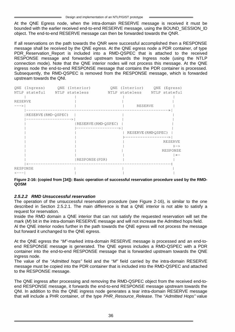
36
Design and implementation of an NTLP/GIST prototype
At the QNE Egress node, when the intra-domain RESERVE message is received it must be bounded with the earlier received end-to-end RESERVE message, using the BOUND_SESSION_ID object. The end-to-end RESERVE message can then be forwarded towards the QNR. If all reservations on the path towards the QNR were successful accomplished then a RESPONSE message shall be received by the QNE egress. At the QNE egress node a PDR container, of type PDR_Reservation_Report is included into a RMD-QSPEC that is attached to the received RESPONSE message and forwarded upstream towards the Ingress node (using the NTLP connection mode). Note that the QNE interior nodes will not process this message. At the QNE ingress node the end-to-end RESPONSE message that contains the PDR container is processed. Subsequently, the RMD-QSPEC is removed from the RESPONSE message, which is forwarded upstream towards the QNI. QNE (Ingress) QNE (Interior) QNE (Interior) QNE (Egress) NTLP stateful NTLP stateless NTLP stateless NTLP stateful | | | | RESERVE | | | --->| | | RESERVE | |------------------------------------------------------------>| |RESERVE(RMD-QSPEC) | | | |------------------->| | | | |RESERVE(RMD-QSPEC) | | | |------------------>| | | | | RESERVE(RMD-QSPEC) | | | |------------------->| | | | RESERVE | | | |--> | | | RESPONSE | | | |<-- | |RESPONSE(PDR) | | |<------------------------------------------------------------| RESPONSE | | | <---| | | |
Figure 2-16: (copied from [34]): Basic operation of successful reservation procedure used by the RMD-QOSM
2.5.2.2 RMD Unsuccessful reservation The operation of the unsuccessful reservation procedure (see Figure 2-16), is similar to the one described in Section 2.5.2.1. The main difference is that a QNE interior is not able to satisfy a request for reservation. Inside the RMD domain a QNE interior that can not satisfy the requested reservation will set the mark (M) bit in the intra-domain RESERVE message and will not increase the Admitted hops field. Al the QNE interior nodes further in the path towards the QNE egress will not process the message but forward it unchanged to the QNE egress. At the QNE egress the “M”-marked intra-domain RESERVE message is processed and an end-to-end RESPONSE message is generated. The QNE egress includes a RMD-QSPEC with a PDR container into the end-to-end RESPONSE message that is forwarded upstream towards the QNE ingress node. The value of the “Admitted hops” field and the “M” field carried by the intra-domain RESERVE message must be copied into the PDR container that is included into the RMD-QSPEC and attached to the RESPONSE message. The QNE ingress after processing and removing the RMD-QSPEC object from the received end-to-end RESPONSE message, it forwards the end-to-end RESPONSE message upstream towards the QNI. In addition to this the QNE ingress node generates a tear intra-domain RESERVE message that will include a PHR container, of the type PHR_Resource_Release. The “Admitted Hops” value
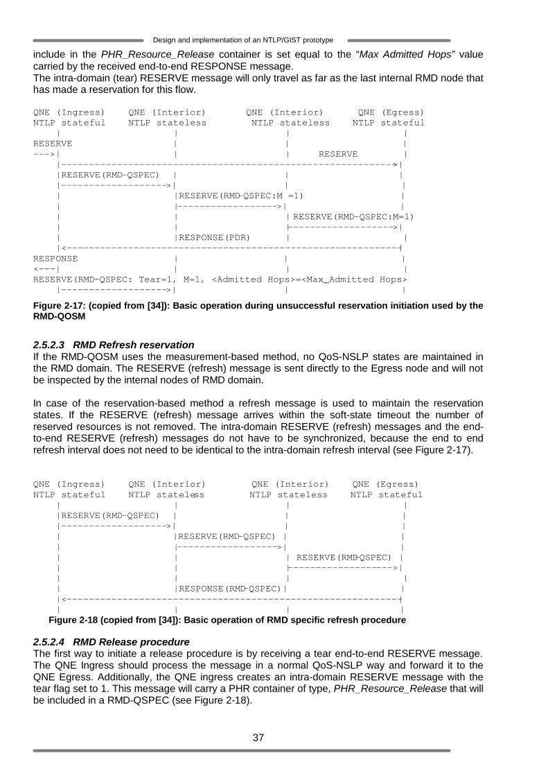
37
Design and implementation of an NTLP/GIST prototype
include in the PHR_Resource_Release container is set equal to the “Max Admitted Hops” value carried by the received end-to-end RESPONSE message. The intra-domain (tear) RESERVE message will only travel as far as the last internal RMD node that has made a reservation for this flow. QNE (Ingress) QNE (Interior) QNE (Interior) QNE (Egress) NTLP stateful NTLP stateless NTLP stateless NTLP stateful | | | | RESERVE | | | --->| | | RESERVE | |------------------------------------------------------------>| |RESERVE(RMD-QSPEC) | | | |------------------->| | | | |RESERVE(RMD-QSPEC:M =1) | | |------------------>| | | | | RESERVE(RMD-QSPEC:M=1) | | |------------------->| | |RESPONSE(PDR) | | |<------------------------------------------------------------| RESPONSE | | | <---| | | | RESERVE(RMD-QSPEC: Tear=1, M=1, <Admitted Hops>=<Max_Admitted Hops> |------------------->| | |
Figure 2-17: (copied from [34]): Basic operation during unsuccessful reservation initiation used by the RMD-QOSM
2.5.2.3 RMD Refresh reservation If the RMD-QOSM uses the measurement-based method, no QoS-NSLP states are maintained in the RMD domain. The RESERVE (refresh) message is sent directly to the Egress node and will not be inspected by the internal nodes of RMD domain. In case of the reservation-based method a refresh message is used to maintain the reservation states. If the RESERVE (refresh) message arrives within the soft-state timeout the number of reserved resources is not removed. The intra-domain RESERVE (refresh) messages and the end-to-end RESERVE (refresh) messages do not have to be synchronized, because the end to end refresh interval does not need to be identical to the intra-domain refresh interval (see Figure 2-17). QNE (Ingress) QNE (Interior) QNE (Interior) QNE (Egress) NTLP stateful NTLP stateless NTLP stateless NTLP stateful | | | | |RESERVE(RMD-QSPEC) | | | |------------------->| | | | |RESERVE(RMD-QSPEC) | | | |------------------>| | | | | RESERVE(RMD-QSPEC) | | | |------------------->| | | | | | |RESPONSE(RMD-QSPEC)| | |<------------------------------------------------------------| | | | | Figure 2-18 (copied from [34]): Basic operation of RMD specific refresh procedure 2.5.2.4 RMD Release procedure The first way to initiate a release procedure is by receiving a tear end-to-end RESERVE message. The QNE Ingress should process the message in a normal QoS-NSLP way and forward it to the QNE Egress. Additionally, the QNE ingress creates an intra-domain RESERVE message with the tear flag set to 1. This message will carry a PHR container of type, PHR_Resource_Release that will be included in a RMD-QSPEC (see Figure 2-18).

38
Design and implementation of an NTLP/GIST prototype
All QNE interior nodes will process this message and releases the number of resources defined in the RMD-QSPEC carried by the intra-domain (tear) RESERVE message. At the QNE egress node, the tear end-to-end RESERVE message is forwarded after receiving the tear intra-domain RESERVE message. A graphical representation of the explicit RMD release procedure is given in Figure 2-19. QNE (Ingress) QNE (Interior) QNE (Interior) QNE (Egress) NTLP stateful NTLP stateless NTLP stateless NTLP stateful | | | | RESERVE | | | --->| | | RESERVE | |------------------------------------------------------------>| |RESERVE(RMD-QSPEC:Tear=1) | | |------------------->| | | | |RESERVE(RMD-QSPEC:Tear=1) | | |------------------->| | | | RESERVE(RMD-QSPEC:Tear=1) | | |------------------->| | | | RESERVE | | | |--> | | | Figure 2-19 (copied from [34]): Explicit release triggered by a RESERVE (Tear) message
The second way to initiate an explicit release procedure can be triggered by either an end-to-end RESPONSE message with an “M” field marked PDR container or an intra-domain NOTIFY (PDR) message with an “M” or “S” field marked PDR container (see Figure 2-20). When the generation of the intra-domain RESERVE (RMD-QSPEC) message is triggered by an end-to-end RESPONSE (PDR) message (see Figure 19), then this intra domain message must contain the number of resources to be released and the PHR container type must be set to a PHR_Resource_Release. QNE (Ingress) QNE (Interior) QNE (Interior) QNE (Egress) Node that marked PHR_Resource_Request <PHR> object NTLP stateful NTLP stateless NTLP stateless NTLP stateful | | | | | | | | | RESPONSE (RMD-QSPEC: M=1) | |<------------------------------------------------------------| RESERVE(RMD-QSPEC: Tear=1, M=1, <Admitted Hops>=<Max_Admitted Hops>) |------------------->| | | | | | | Figure 2-20 (copied from [34]): Basic operation during RMD explicit release procedure triggered by RESPONSE message If the generation of the intra-domain RESERVE (RMD-QSPEC) message is triggered by an intra-domain NOTIFY (PDR) message (see Figure 2-21), then the intra-domain RESERVE (RMD-QSPEC) message must contain the number of resources to be released and the PHR container type must be set to PHR_Resource_Release. QNE (Ingress) QNE (Interior) QNE (Interior) QNE (Egress)
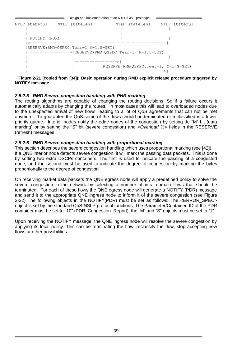
39
Design and implementation of an NTLP/GIST prototype
NTLP stateful NTLP stateless NTLP stateless NTLP stateful | | | | | | | | | NOTIFY (PDR) | | | |<-------------------------------------------------------| |RESERVE(RMD-QSPEC:Tear=1,M=1,S=SET) | | | ---------------->|RESERVE(RMD-QSPEC:Tear=1, M=1,S=SET) | | | | | | |----------------->| | | | RESERVE(RMD-QSPEC:Tear=1, M=1,S=SET) | | |----------------->|
Figure 2-21 (copied from [34]): Basic operation during RMD explicit release procedure triggered by NOTIFY message
2.5.2.5 RMD Severe congestion handling with PHR marking The routing algorithms are capable of changing the routing decisions. So if a failure occurs it automatically adapts by changing the routes. In most cases this will lead to overloaded nodes due to the unexpected arrival of new flows, leading to a lot of QoS agreements that can not be met anymore. To guarantee the QoS some of the flows should be terminated or reclassified in a lower priority queue. Interior nodes notify the edge nodes of the congestion by setting de “M” bit (data marking) or by setting the “S” bit (severe congestion) and <Overload %> fields in the RESERVE (refresh) messages 2.5.2.6 RMD Severe congestion handling with proportional marking This section describes the severe congestion handling which uses proportional marking (see [42]). If a QNE interior node detects severe congestion, it will mark the passing data packets. This is done by setting two extra DSCPs containers. The first is used to indicate the passing of a congested node, and the second must be used to indicate the degree of congestion by marking the bytes proportionally to the degree of congestion On receiving market data packets the QNE egress node will apply a predefined policy to solve the severe congestion in the network by selecting a number of intra domain flows that should be terminated. For each of these flows the QNE egress node will generate a NOTIFY (PDR) message and send it to the appropriate QNE ingress node to inform it of the severe congestion (see Figure 2-22) The following objects in the NOTIFY(PDR) must be set as follows: The <ERROR_SPEC> object is set by the standard QoS-NSLP protocol functions, The Parameter/Container_ID of the PDR container must be set to “10” (PDR_Congestion_Report), the “M” and “S” objects must be set to “1” Upon receiving the NOTIFY message, the QNE ingress node will resolve the severe congestion by applying its local policy. This can be terminating the flow, reclassify the flow, stop accepting new flows or other possibilities.
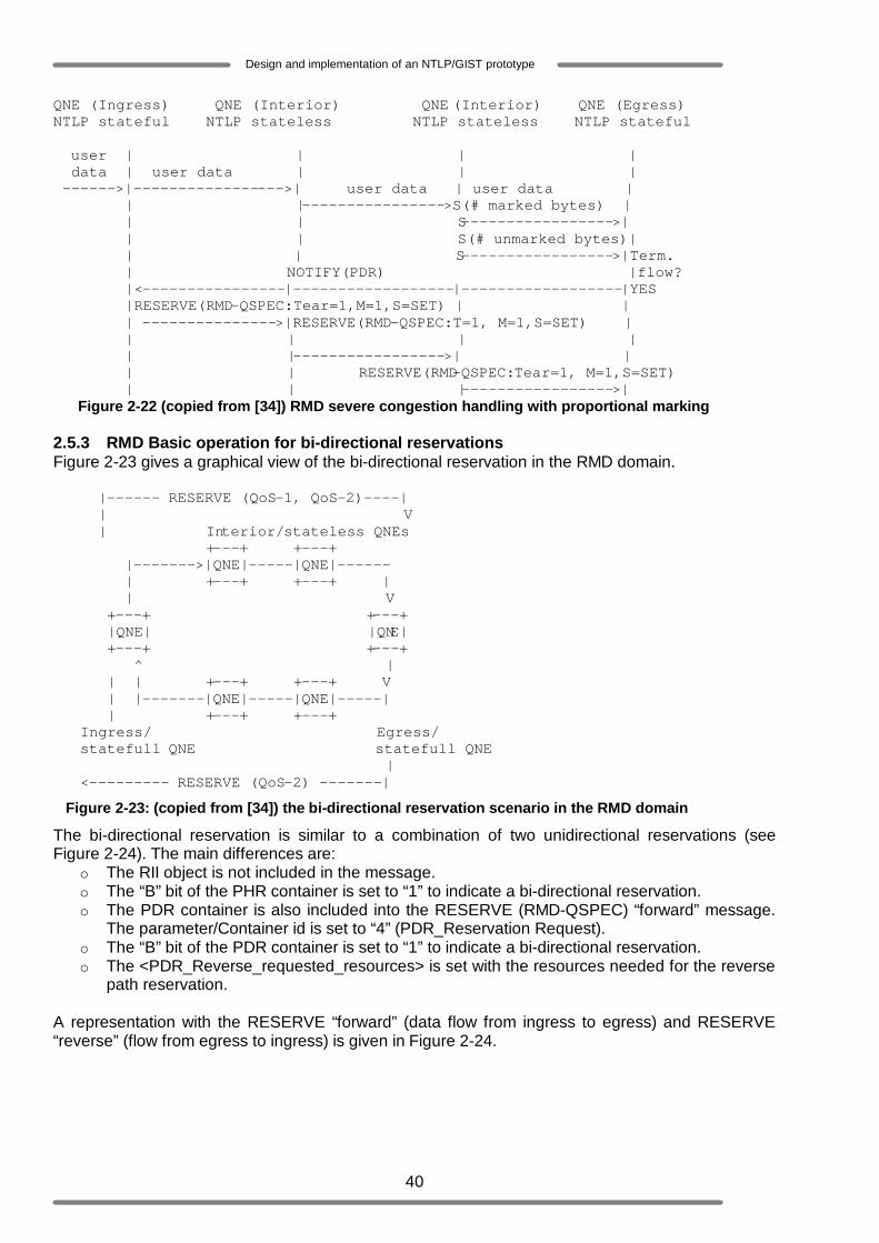
40
Design and implementation of an NTLP/GIST prototype
QNE (Ingress) QNE (Interior) QNE (Interior) QNE (Egress) NTLP stateful NTLP stateless NTLP stateless NTLP stateful user | | | | data | user data | | | ------>|----------------->| user data | user data | | |---------------->S(# marked bytes) | | | S----------------->| | | S(# unmarked bytes)| | | S----------------->|Term. | NOTIFY(PDR) |flow? |<----------------|------------------|------------------|YES |RESERVE(RMD-QSPEC:Tear=1,M=1,S=SET) | | | --------------->|RESERVE(RMD-QSPEC:T=1, M=1,S=SET) | | | | | | |----------------->| | | | RESERVE(RMD-QSPEC:Tear=1, M=1,S=SET) | | |----------------->| Figure 2-22 (copied from [34]) RMD severe congestion handling with proportional marking 2.5.3 RMD Basic operation for bi-directional reservations Figure 2-23 gives a graphical view of the bi-directional reservation in the RMD domain. |------ RESERVE (QoS-1, QoS-2)----| | V | Interior/stateless QNEs +---+ +---+ |------->|QNE|-----|QNE|------ | +---+ +---+ | | V +---+ +---+ |QNE| |QNE| +---+ +---+ ^ | | | +---+ +---+ V | |-------|QNE|-----|QNE|-----| | +---+ +---+ Ingress/ Egress/ statefull QNE statefull QNE | <--------- RESERVE (QoS-2) -------|
Figure 2-23: (copied from [34]) the bi-directional reservation scenario in the RMD domain
The bi-directional reservation is similar to a combination of two unidirectional reservations (see Figure 2-24). The main differences are:
o The RII object is not included in the message. o The “B” bit of the PHR container is set to “1” to indicate a bi-directional reservation. o The PDR container is also included into the RESERVE (RMD-QSPEC) “forward” message.
The parameter/Container id is set to “4” (PDR_Reservation Request). o The “B” bit of the PDR container is set to “1” to indicate a bi-directional reservation. o The <PDR_Reverse_requested_resources> is set with the resources needed for the reverse
path reservation. A representation with the RESERVE “forward” (data flow from ingress to egress) and RESERVE “reverse” (flow from egress to ingress) is given in Figure 2-24.
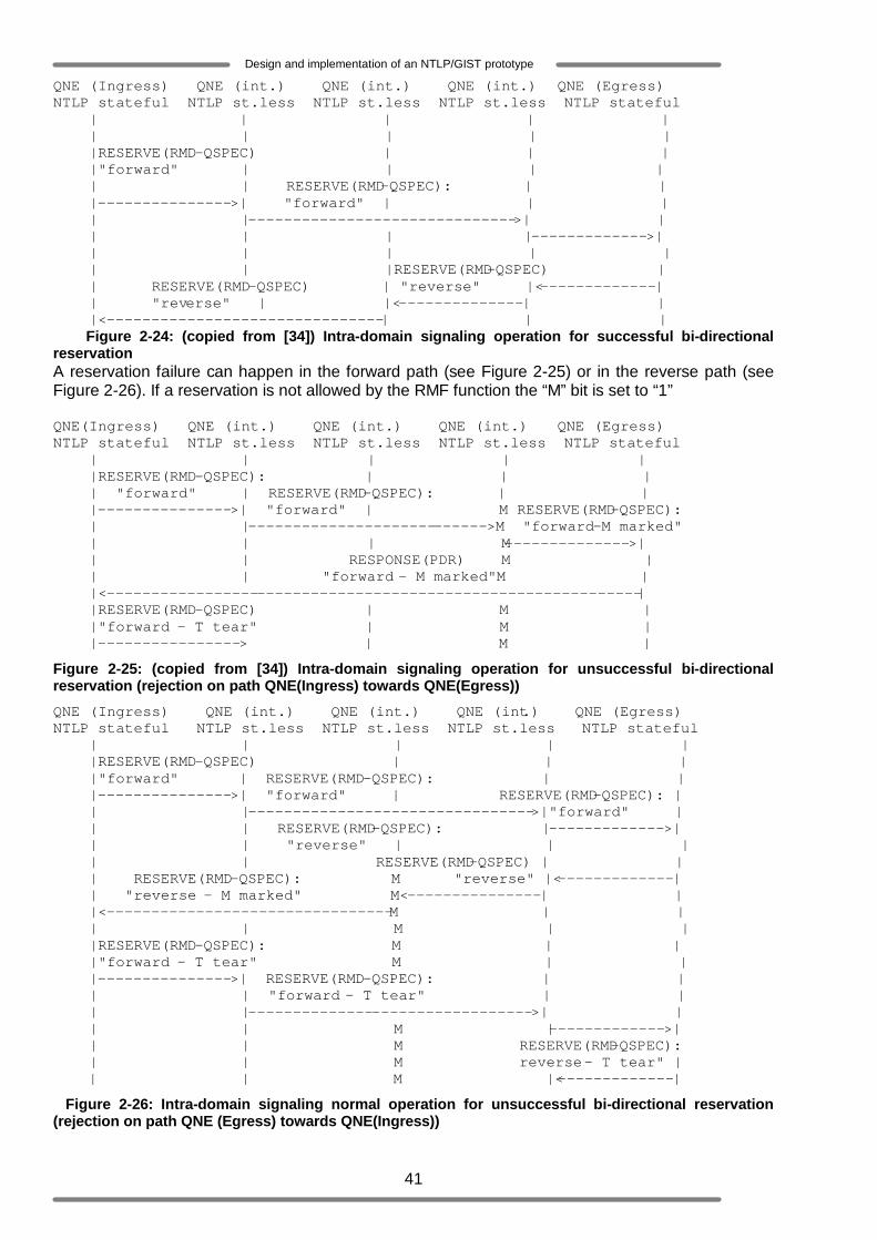
41
Design and implementation of an NTLP/GIST prototype
QNE (Ingress) QNE (int.) QNE (int.) QNE (int.) QNE (Egress) NTLP stateful NTLP st.less NTLP st.less NTLP st.less NTLP stateful | | | | | | | | | | |RESERVE(RMD-QSPEC) | | | |"forward" | | | | | | RESERVE(RMD-QSPEC): | | |--------------->| "forward" | | | | |------------------------------>| | | | | |------------->| | | | | | | | |RESERVE(RMD-QSPEC) | | RESERVE(RMD-QSPEC) | "reverse" |<-------------| | "reverse" | |<--------------| | |<-------------------------------| | | Figure 2-24: (copied from [34]) Intra-domain signaling operation for successful bi-directional reservation A reservation failure can happen in the forward path (see Figure 2-25) or in the reverse path (see Figure 2-26). If a reservation is not allowed by the RMF function the “M” bit is set to “1” QNE(Ingress) QNE (int.) QNE (int.) QNE (int.) QNE (Egress) NTLP stateful NTLP st.less NTLP st.less NTLP st.less NTLP stateful | | | | | |RESERVE(RMD-QSPEC): | | | | "forward" | RESERVE(RMD-QSPEC): | | |--------------->| "forward" | M RESERVE(RMD-QSPEC): | |--------------------------->M "forward-M marked" | | | M-------------->| | | RESPONSE(PDR) M | | | "forward - M marked"M | |<------------------------------------------------------------| |RESERVE(RMD-QSPEC) | M | |"forward - T tear" | M | |----------------> | M |
Figure 2-25: (copied from [34]) Intra-domain signaling operation for unsuccessful bi-directional reservation (rejection on path QNE(Ingress) towards QNE(Egress))
QNE (Ingress) QNE (int.) QNE (int.) QNE (int.) QNE (Egress) NTLP stateful NTLP st.less NTLP st.less NTLP st.less NTLP stateful | | | | | |RESERVE(RMD-QSPEC) | | | |"forward" | RESERVE(RMD-QSPEC): | | |--------------->| "forward" | RESERVE(RMD-QSPEC): | | |-------------------------------->|"forward" | | | RESERVE(RMD-QSPEC): |------------->| | | "reverse" | | | | | RESERVE(RMD-QSPEC) | | | RESERVE(RMD-QSPEC): M "reverse" |<-------------| | "reverse - M marked" M<---------------| | |<--------------------------------M | | | | M | | |RESERVE(RMD-QSPEC): M | | |"forward - T tear" M | | |--------------->| RESERVE(RMD-QSPEC): | | | | "forward - T tear" | | | |-------------------------------->| | | | M |------------->| | | M RESERVE(RMD-QSPEC): | | M reverse - T tear" | | | M |<-------------|
Figure 2-26: Intra-domain signaling normal operation for unsuccessful bi-directional reservation (rejection on path QNE (Egress) towards QNE(Ingress))
42
Design and implementation of an NTLP/GIST prototype
3 NTLP protocol design In Chapter 2 the functional overview of NSIS has been discussed, where among others it is emphasised that every NSIS node (NSIS aware network element) must support NTLP and consequently GIMPS. This chapter focuses on NTLP, the underlying layer of NSIS. For clarity and simplicity reasons, NSIS nodes will be denoted as GIMPS nodes and vice versa in the rest of this thesis. Protocol implementation, which is the main purpose of this project, can only be systematically performed if a complete protocol design is given. Therefore this chapter describes the design of the NTLP specified in [10]. This chapter is not intended to reproduce the specification of the NTLP. It rather presents the internal structure of a GIMPS node in terms of protocol entities and the formats of the messages they may exchange among each other. Each of these protocol entities is realized by using the state machine concept. Furthermore it describes how these entities interact with each other in order to deliver the services required by their service users, which are the NSLPs. 3.1 GIMPS protocol design Although the design presented in this chapter is based on the GIMPS state machine described in [19], it is worth noting that there are some major differences between both designs. First of all the state machine described in [19] only focuses on the discovery procedure of GIMPS. It only defines two GIMPS entities, namely the GIMPS querying node and the GIMPS responding node. Different aspect of the GIMPS protocol such as the re-utilisation of messaging associations and the use of the GIMPS Data message are not considered. Therefore the state machine described in [19] does not cover all the functionalities of GIMPS. The design presented in this chapter is a refinement and an extension of the state machines described in [19], as it will appear in the next coming sections. As depicted in Figure 3-1 a GIMPS node consists of 5 main protocol entities, which each fulfils a specific role [19] and is realized using a state machine. The QNode entity (“GIMPS querying node”) triggers the discovery procedure. This means that it plays the role of the initiator during this procedure. The RNode entity (“GIMPS responding node”), residing in the adjacent peer of a “GIMPS querying node” receives and handles the requests provenient or originating from the QNode entity. It acts as the receiver during the discovery procedure. The DNode entity (“GIMPS data node”) is the sender of the GIMPS-Data messages. Each of these entities may fulfil their role in collaboration with the so called NodeLevel entity (“GIMPS NodeLevel processing entity”) and/or the MA-Node entity (“Messaging Association node”). The NodeLevel entity processes the requests coming from the upper layer signalling applications whereas the MA-Node is essentially used in the connection mode. The underlying component that is present in the GIMPS layer is the so called “GIMPS server”. This component is a sort of Application Protocol Interface (API) between the GIMPS layer and the existing transport layers. At the one side, it gathers from the transport layers GIMPS signalling data destined to the different entities of the GIMPS layer and at the other side it forwards GIMPS signalling messages (destined to other entities(residing in other GMPS nodes) to the transport layer (see also Chapter 4). Figure 3-1 also illustrates how the different GIMPS entities may interact, provided that they reside within the same GIMPS node.
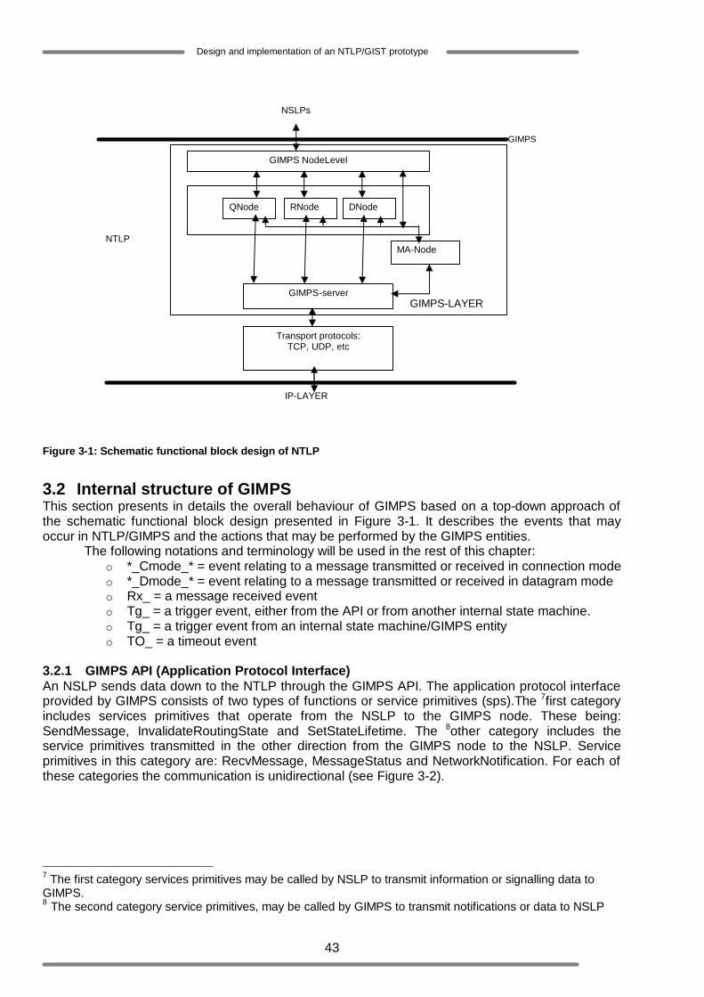
43
Design and implementation of an NTLP/GIST prototype
Figure 3-1: Schematic functional block design of NTLP
3.2 Internal structure of GIMPS This section presents in details the overall behaviour of GIMPS based on a top-down approach of the schematic functional block design presented in Figure 3-1. It describes the events that may occur in NTLP/GIMPS and the actions that may be performed by the GIMPS entities.
The following notations and terminology will be used in the rest of this chapter: o *_Cmode_* = event relating to a message transmitted or received in connection mode o *_Dmode_* = event relating to a message transmitted or received in datagram mode o Rx_ = a message received event o Tg_ = a trigger event, either from the API or from another internal state machine. o Tg_ = a trigger event from an internal state machine/GIMPS entity o TO_ = a timeout event
3.2.1 GIMPS API (Application Protocol Interface) An NSLP sends data down to the NTLP through the GIMPS API. The application protocol interface provided by GIMPS consists of two types of functions or service primitives (sps).The 7first category includes services primitives that operate from the NSLP to the GIMPS node. These being: SendMessage, InvalidateRoutingState and SetStateLifetime. The 8other category includes the service primitives transmitted in the other direction from the GIMPS node to the NSLP. Service primitives in this category are: RecvMessage, MessageStatus and NetworkNotification. For each of these categories the communication is unidirectional (see Figure 3-2).
7 The first category services primitives may be called by NSLP to transmit information or signalling data to GIMPS. 8 The second category service primitives, may be called by GIMPS to transmit notifications or data to NSLP
NTLP
GIMPS NodeLevel
QNode RNode DNode
MA-Node
GIMPS-server
Transport protocols: TCP, UDP, etc
IP-LAYER
GIMPS
NSLPs
GIMPS-LAYER

44
Design and implementation of an NTLP/GIST prototype
Figure 3-2: Architectural behaviour model of NTLP/GIMPS
The above mentioned service primitives play a role in the interaction between the GIMPS node and the NSLP. This interaction can be modeled by three major interaction points (also denoted as service access points (saps)): DataMsg_sap, MngRS_sap and NtwNtf_sap (see Figure 3-2). Table 3-1 shows the service primitives (sp), their associated parameters and the role of these parameters within GIMPS.
o DataMsg_sap: This interaction point models the SendMessage sp and the RecvMessage sp. The SendMessage sp indicates that an NSLP entity or node desires to send some signalling data to another NSLP entity of the same type (it means that both NSLPs should either be QoS NSLPs, or NAT/IP firewall NSLPs etc). The RecvMessage sp indicates that an NSLP entity receives some signalling data from another NSLP entity of the same type. When the signalling data belongs to a new session, the receiving NSLP may return a value to the GIMPS layer to indicate whether it wants GIMPS to install a session state for this session. Note that the establishment of a statefull session must always be approved by the receiver before it is truly setup.
o MngRS: This interaction point models the InvalidateRoutingState sp and the SetStateLifetime sp. The former indicates that a routing state associated with one or more NSLPs must no longer be used. The latter indicates that a routing state must be kept alive for a certain period of time.
o NtwNtf: This interaction point models the MessageStatus sp and NetworkNotification sp. The MessageStatus sp notifies an NSLP about the failure of a message transmission or about the transfer attributes associated to a message. NetworkNotification sp notifies an NSLP about network events (route change, end of NSIS domain) that have occurred.
Service primitives Parameters Description
NSLP-Data Opaque signalling data NSLP-Data-Size Size of signalling data NSLP-Message-Handle
A handle that may be used to identify the included NSLP-Data
NSLP-Id The NSLP identifier, which is supposed to be unique for each NSLP. This identifier is a number assigned by IANA
SendMessage
Session-ID Random number provided by GIMPS (see Section 2.3.1). When the SendMessage sp is invoked at the beginning of a session this parameter is null.
NTLP/GIMPS (Service provider)
NSLP (Service user)
Invalidate- RoutingState
NetworkNotification
DataMsg MngRS NtwNtf GIMPS API - sap (service access points)
RecvMessage MessageStatus
SendMessage SetStateLifetime

45
Design and implementation of an NTLP/GIST prototype
MRI (Message Routing Information)
This parameter contains among others all information included in the flow identifier and all the information needed to route the signalling data to its destination. (An MRI may include: flow source address, flow destination address, source port number, destination port number, flow direction, etc.).
Source-SII-Handle
This handle may initially be provided by GIMPS at the beginning of a session. It is associated to the source peer identity in combination with a specific interface address and may later be reused to easily identify the source node.
Transfer-Attributes
This parameter has the attributes: security, reliability and local policy. These attributes enable GIMPS to determine the mode of operation that must be used to send the NSLP data
Peer-SII-Handle
This handle may initially be provided by GIMPS at the beginning of a session. It is associated to the responding peer identity in combination with its interface address and may later be reused to easily identify the adjacent peer node.
9Disc
This parameter enables GIMPS to determine whether a discovery mechanism should be initiated (this actually implies the initiation of a statefull session) or not. In the former case, even though the GIMPS querying node is the formal initiator of a statefull session establishment, the final decision to truly setup a session is taken by the responding node (see the RecvMessage sp for more details). In the later case the session will simply be stateless (see Section 3.2.2).
10AggLevel This parameter enable GIMPS to indicate the aggregation level associated to the NSLP data
Timeout Within the time represented by the timeout parameter, GIMPS should try to resend the signalling data if it is not received. An error should only be sent when this time elapses.
9 The “Disc” parameter is not present in the GIMPS protocol specified in [10]. However it is needed for the distinction between stateful and stateless sessions (see Chapter 2 – Section 2.3.1). It is expected to be included in future versions of the GIMPS specification. 10 The “AggLevel” parameter is not present in the GIMPS protocol specified in [10]. However it is needed for the bypass/forwarding function (see Chapter 2 – Section 2.3.1). This parameter is also expected to be included in future versions of the GIMPS specification.
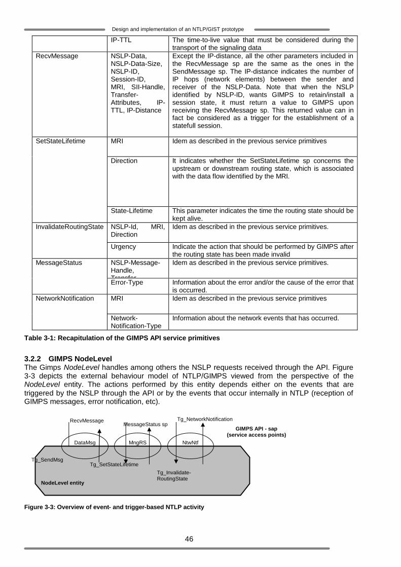
46
Design and implementation of an NTLP/GIST prototype
IP-TTL The time-to-live value that must be considered during the transport of the signaling data
RecvMessage NSLP-Data, NSLP-Data-Size, NSLP-ID, Session-ID, MRI, SII-Handle, Transfer-Attributes, IP-TTL, IP-Distance
Except the IP-distance, all the other parameters included in the RecvMessage sp are the same as the ones in the SendMessage sp. The IP-distance indicates the number of IP hops (network elements) between the sender and receiver of the NSLP-Data. Note that when the NSLP identified by NSLP-ID, wants GIMPS to retain/install a session state, it must return a value to GIMPS upon receiving the RecvMessage sp. This returned value can in fact be considered as a trigger for the establishment of a statefull session.
MRI Idem as described in the previous service primitives
Direction It indicates whether the SetStateLifetime sp concerns the upstream or downstream routing state, which is associated with the data flow identified by the MRI.
SetStateLifetime
State-Lifetime This parameter indicates the time the routing state should be kept alive.
NSLP-Id, MRI, Direction
Idem as described in the previous service primitives. InvalidateRoutingState
Urgency Indicate the action that should be performed by GIMPS after the routing state has been made invalid
NSLP-Message-Handle, Transfer-
Idem as described in the previous service primitives. MessageStatus
Error-Type Information about the error and/or the cause of the error that is occurred.
MRI Idem as described in the previous service primitives NetworkNotification
Network-Notification-Type
Information about the network events that has occurred.
Table 3-1: Recapitulation of the GIMPS API service primitives
3.2.2 GIMPS NodeLevel The Gimps NodeLevel handles among others the NSLP requests received through the API. Figure 3-3 depicts the external behaviour model of NTLP/GIMPS viewed from the perspective of the NodeLevel entity. The actions performed by this entity depends either on the events that are triggered by the NSLP through the API or by the events that occur internally in NTLP (reception of GIMPS messages, error notification, etc).
Figure 3-3: Overview of event- and trigger-based NTLP activity
NodeLevel entity
Tg_Invalidate- RoutingState
Tg_NetworkNotification
DataMsg MngRS NtwNtf
GIMPS API - sap (service access points)
RecvMessage MessageStatus sp
Tg_SendMsg Tg_SetStateLifetime

47
Design and implementation of an NTLP/GIST prototype
Table 3-2 gives an overview of the event -driven actions of the NTLP. Additionally, Figure 3-4 gives a schematic behaviour model of the functionality of the GIMPS NodeLevel. This figure is a refinement of the NTLP/GIMPS layer depicted in Figure 3-2, for it presents the GIMPS architecture at a lower abstraction level.
Cases State Events Conditions Actions Next
state New session&disc&Dmode
Create QNode for a datagram mode of operation and trigger Tx_Query_Dmode event
New session&disc &Cmode
Create QNode for a connection mode of operation and trigger Tx_Query_Cmode event
New session&Nodisc Create DNode in D-Mode Query and trigger Tx_Dmode_Query event
Existing session&NoMA
Create DNode in D-Mode Normal and trigger Tx_Dmode_Normal event
1 IDLE Tg_SendMsg
Existing session&MA Create DNode using the existing MA and trigger Tx_Dmode_MA event
IDLE
2 IDLE Tg_SetStateLifetime Existing session Set lifetime of session state
IDLE
3 IDLE Tg_InvalidateRoutingState Existing session Destroy Routing state IDLE 4 IDLE Rx_RecvMessage Existing NSLPID Deliver message by
means of the RecvMessage sp
IDLE
5 IDLE Rx_NetworkNotification Existing NSLPIDs Deliver Notification by means of the NetworkNotification sp
IDLE
6 IDLE Rx_MessageDeliveryError Unknown NSLPID Send error by means of the MessageDeliveryError sp
IDLE
Table 3-2: Recapitulation of the NodeLevel entity’s state machine
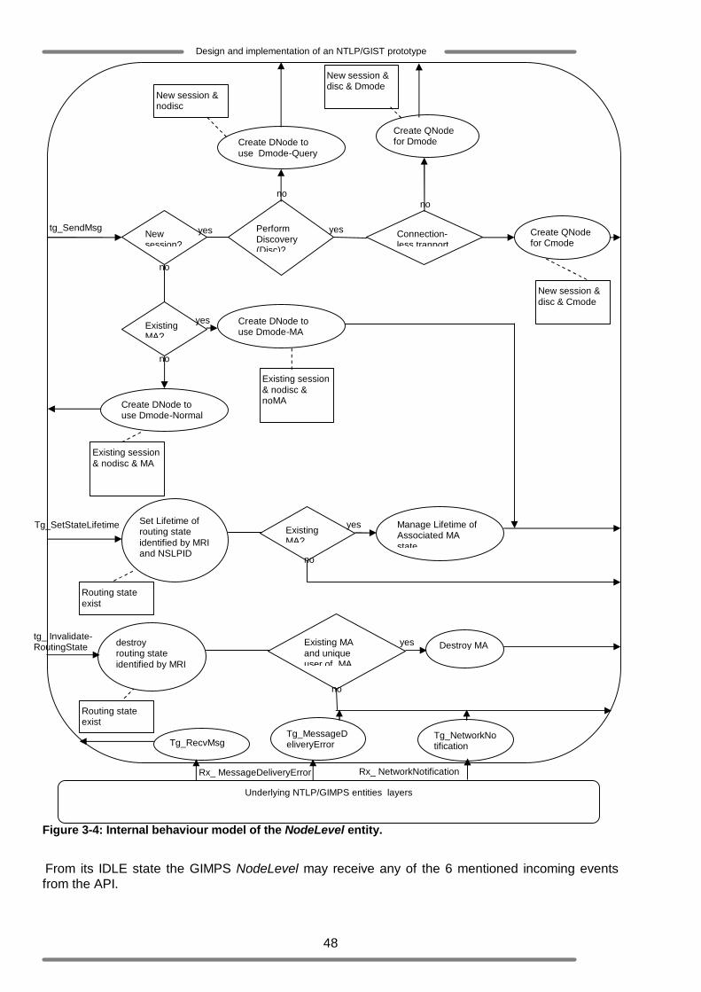
48
Design and implementation of an NTLP/GIST prototype
Figure 3-4: Internal behaviour model of the NodeLevel entity. From its IDLE state the GIMPS NodeLevel may receive any of the 6 mentioned incoming events from the API.
Rx_ NetworkNotification
tg_ Invalidate- RoutingState
Underlying NTLP/GIMPS entities layers
Tg_RecvMsg Tg_MessageDeliveryError
Tg_NetworkNotification
Rx_ MessageDeliveryError
Tg_SetStateLifetime
tg_SendMsg
Create QNode for Dmode
Create QNode for Cmode
Create DNode to use Dmode-Query
Create DNode to use Dmode-MA
New session & disc & Dmode
New session & disc & Cmode
New session & nodisc
Existing session & nodisc & noMA Create DNode to
use Dmode-Normal
Existing session & nodisc & MA
New session?
Perform Discovery (Disc)?
Existing MA?
yes
no
yes
no
no
Connection-less tranport
yes
no
Set Lifetime of routing state identified by MRI and NSLPID
Existing MA?
Manage Lifetime of Associated MA state
Destroy MA Existing MA and unique user of MA
Routing state exist
Routing state exist
no
no
yes
yes destroy routing state identified by MRI
49
Design and implementation of an NTLP/GIST prototype
1. Tg_SendMsg: This event is triggered when the SendMessage sp is called by an NSLP. Therefore SendMessage sp’s parameters may be associated to Tg_SendMsg. At occurrence of this event, the gimps NodeLevel must derive the following information, which are judged essential for GIMPS to process the occurred event.
o The NodeLevel must determine by means of the parameter Session-ID if a new session should be initiated or if the data it requests to send is part of an ongoing/existing session.
o In case a new session must be established the GIMPS NodeLevel must determine by means of the parameter Disc whether this session should be a stateless or stateful session.
o It must also derive the appropriate GIMPS mode of operation (datagram mode or connection mode) for the data transport based on the transfer-attributes parameter.
The combination of these three conditions leads to the following options (see Figure 3-4): a. New session&disc&Dmode: this condition holds when a new stateful session has
to be established in datagram mode. In consequence the NodeLevel creates a QNode entity and triggers the Tx_Query_Dmode event to initiate the discovery mechanism. This discovery mechanism will then be followed by the transport of the NSLP data in datagram mode (see Section 2.3.2.3.2.1 and Section3.2.3).
b. New session&disc &Cmode: this condition holds when a new stateful session has to be established in connection mode. In this option the NodeLevel creates a QNode entity as well but in this case it triggers the Tx_Query_Cmode event, which implies that the transport of the NSLP data must be performed in connection mode. The difference between the Tx_Query_Dmode event and the Tx_Query_Cmode event will be more clarified in Section3.2.3.
c. New session&Nodisc: this condition holds when a new stateless session has to be established. In this case there is no need for a discovery mechanism. The NodeLevel simply creates a DNode entity to transport the data in datagram mode and triggers the Tx_Dmode_Query event (see Section 3.2.5).
d. Existing session&NoMA: this condition holds when the NSLP data that has to be sent is part of an existing session. This means that the peer entity has already been discovered and identified during a previous discovery mechanism. In this case the gimps mode of operation does not really depend on the required GIMPS mode of operation (indicated by the transfer-attributes parameter). It rather depends on the existence of a messaging association between the involved peers. When a messaging association exists, Condition (e) holds. When no messaging association exists the NodeLevel creates the DNode to transport the NSLP data in datagram mode and triggers the Tx_Dmode_Normal event (see Section 3.2.5).
e. Existing session&MA: this condition holds when the NSLP data is part of an existing session and there exists a messaging association between the involved peers. In this case the NodeLevel makes use of the messaging association and creates the appropriate “MA client” node which will then be in charge of sending the data to the “MA server” node, residing on the peer node (see Section 3.2.6).
2. Tg_SetStateLifetime: This event is triggered when the SetStateLifetime sp is called by an NSLP. Therefore SetStateLifetime sp’s parameters may be associated to Tg_SetStateLifetime. This event always involves an existing session (between two peer nodes) that can be identified by the ‘MRI’, the ‘NSLP-ID’ and optionally the 11‘Direction’ parameters. When this event occurs the NodeLevel extends the duration of the session states (routing state, messaging association state if it exists) with the value included in the ‘statelifetime’ parameter at the GIMPS node. A statelifetime value of zero represents the cancellation of the established session states.
11 As a matter of fact the information carried by the Direction parameter is already included in the MRI (see Appendix-A), hence its use in this case is not necessary.
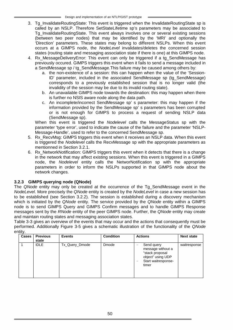
50
Design and implementation of an NTLP/GIST prototype
3. Tg_InvalidateRoutingState: This event is triggered when the InvalidateRoutingState sp is called by an NSLP. Therefore SetStateLifetime sp’s parameters may be associated to Tg_InvalidateRoutingState. This event always involves one or several existing sessions (between two peer nodes) that may be identified by the ‘MRI’ and optionally the ‘Direction’ parameters. These states may belong to different NSLPs. When this event occurs at a GIMPS node, the NodeLevel invalidates/deletes the concerned session states (routing state and messaging association state if there is one) at this GIMPS node.
4. Rx_MessageDeliveryError: This event can only be triggered if a tg_SendMessage has previously occured. GIMPS triggers this event when it fails to send a message included in a SendMessage sp / tg_SendMessage.This failure may be caused among others by:
a. the non-existence of a session: this can happen when the value of the ‘Session-ID’ parameter, included in the associated SendMessage sp (tg_SendMessage) corresponds to a previously established session that is no longer valid (the invalidity of the session may be due to its invalid routing state).
b. An unavailable GIMPS node towards the destination: this may happen when there is further no NSIS aware node along the data path.
c. An incomplete/incorrect SendMessage sp’ s parameter: this may happen if the information provided by the SendMessage sp’ s parameters has been corrupted or is not enough for GIMPS to process a request of sending NSLP data (SendMessage sp).
When this event is triggered the Nodelevel calls the MessageStatus sp with the parameter ‘type error’, used to indicate the cause of the failure and the parameter ‘NSLP-Message-Handle’, used to refer to the concerned SendMessage sp.
5. Rx_RecvMsg: GIMPS triggers this event when it receives an NSLP data. When this event is triggered the Nodelevel calls the RecvMessage sp with the appropriate parameters as mentionned in Section 3.2.1.
6. Rx_NetworkNotification: GIMPS triggers this event when it detects that there is a change in the network that may affect existing sessions. When this event is triggered in a GIMPS node, the Nodelevel entity calls the NetworNotification sp with the appropriate parameters in order to inform the NSLPs supported in that GIMPS node about the network changes.
3.2.3 GIMPS querying node (QNode) The QNode entity may only be created at the occurrence of the Tg_SendMessage event in the NodeLevel. More precisely the QNode entity is created by the NodeLevel in case a new session has to be established (see Section 3.2.2). The session is established during a discovery mechanism which is initiated by the QNode entity. The service provided by the QNode entity within a GIMPS node is to send GIMPS Query and GIMPS Confirm messages and to handle GIMPS Response messages sent by the RNode entity of the peer GIMPS node. Further, the QNode entity may create and maintain routing states and messaging association states. Table 3-3 gives an overview of the events that may occur and the actions that consequently must be performed. Additionally Figure 3-5 gives a schematic illustration of the functionality of the QNode entity.
Cases Previous state
Events Condition Actions Next state
1 IDLE
Tx_Query_Dmode
Dmode - Send query message without a “stack proposal object” using UDP
- Start waitresponse-timer
waitresponse
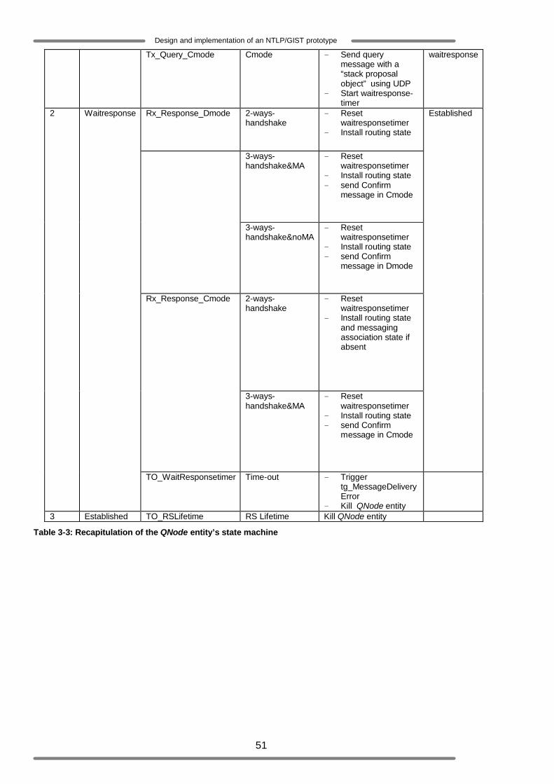
51
Design and implementation of an NTLP/GIST prototype
Tx_Query_Cmode
Cmode - Send query message with a “stack proposal object” using UDP
- Start waitresponse-timer
waitresponse
Rx_Response_Dmode 2-ways-handshake
- Reset waitresponsetimer
- Install routing state
3-ways-handshake&MA
- Reset waitresponsetimer
- Install routing state - send Confirm
message in Cmode
3-ways-handshake&noMA
- Reset waitresponsetimer
- Install routing state - send Confirm
message in Dmode
2-ways-handshake
- Reset waitresponsetimer
- Install routing state and messaging association state if absent
Rx_Response_Cmode
3-ways-handshake&MA
- Reset waitresponsetimer
- Install routing state - send Confirm
message in Cmode
Established 2
Waitresponse
TO_WaitResponsetimer Time-out - Trigger tg_MessageDeliveryError
- Kill QNode entity
3 Established TO_RSLifetime RS Lifetime Kill QNode entity
Table 3-3: Recapitulation of the QNode entity’s state machine

52
Design and implementation of an NTLP/GIST prototype
Figure 3-5: Internal behaviour model of the QNode entity
The QNode entity determines the specific actions it should performed based on some information/parameters derived by the GIMPS NodeLevel entity and/or included in the SendMessage sp /Tg_SendMessage (see Figure 3-5)
1- When the QNode entity is created (IDLE state), the Tx_Query_Dmode event is the only event that may occur. The NodeLevel provides the QNode entity several information such as:
a. the message aggregation Level: this information enables QNode to determine the router alert value it should used during the creation of the transport of the query message (see Section 3.5).
b. the gimps mode of operation: this information guides QNode in the construction of the Query message. It indicates for instance whether a protocol stack object should be included in the Query message or not.
Send GIMPS - Query
Tx_Query_Dmode
*Send GIMPS - Confirm
No Stack proposal object
2 - ways handshake?
Install Routing state
Create Message Delivery
Error Send GIMPS - Query
Tx_Query_Cmode
Include Stack proposal object
TO_ WaitResponsetimer
Install Routing state & MA state
Cmode required ?
Start the waitingresponse
Timer t
Reset the waitingresponse
timer
Waitresponse (state) ( QNode internal subentity )
Rx_MessageDeliveryError
no yes
TO_RSLifetime
Destroy installed session state(s )
Established (state) ( QNode internal subentity )
Start the routingstatelife -
Timer tr
tr ==0
t==0
yes
no
Underlying GIMPS layers
Rx_Response
NodeLevel
QNode Send GIMPS - Query
Tx_Query_Dmode
*Send GIMPS - Confirm
No Stack proposal object
2 - ways handshake?
Install Routing state
create Message Delivery
Error Send GIMPS - Query
Tx_Query_Cmode
Include Stack proposal object
TO_ WaitResponsetimer
Install Routing state & MA state
Cmode required ?
Start the waitingresponse
Timer t
Reset the waitingresponse
timer
Waitresponse (state) ( QNode internal subentity )
Rx_MessageDeliveryError
no yes
TO_RSLifetime
Destroy installed session state(s )
Established (state) ( QNode internal subentity )
Start the routingstatelife -
Timer tr
tr ==0
t==0
yes
no
Underlying GIMPS layers
Rx_Response
NodeLevel
Send GIMPS - Query
Tx_Query_Dmode
*Send GIMPS - Confirm
No Stack proposal object
2 - ways handshake?
Install Routing state
create Message Delivery
Error Send GIMPS - Query
Tx_Query_Cmode
Include Stack proposal object
TO_ WaitResponsetimer
Install Routing state & MA state
Cmode required ?
Start the waitingresponse
Timer t
Reset the waitingresponse
timer
Waitresponse (state) ( QNode internal subentity )
Rx_MessageDeliveryError
no yes
TO_RSLifetime
Destroy installed session state(s )
Established (state) ( QNode internal subentity )
Start the routingstatelife -
Timer tr
tr ==0
t==0
yes
no
Underlying GIMPS layers
Rx_Response
NodeLevel
QNode
* send GIMPS message (GIMPS-Response) using MA if there exists one already
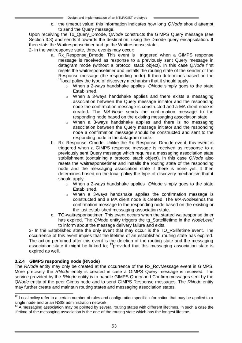
53
Design and implementation of an NTLP/GIST prototype
c. the timeout value: this information indicates how long QNode should attempt to send the Query message.
Upon receiving the Tx_Query_Dmode, QNode constructs the GIMPS Query message (see Section 3.3) and sends it towards the destination, using the Dmode query encapsulation. It then stats the Waitresponsetimer and go the Waitresponse state. 2- In the waitresponse state, three events may occur:
a. Rx_Response_Dmode: This event is triggered when a GIMPS response message is received as response to a previously sent Query message in datagram mode (without a protocol stack object). In this case QNode first resets the waitresponsetimer and installs the routing state of the sender of the Response message (the responding node). It then determines based on the 12local policy the type of discovery mechanism that it should apply.
o When a 2-ways handshake applies QNode simply goes to the state Established.
o When a 3-ways handshake applies and there exists a messaging association between the Query message initiator and the responding node the confirmation message is constructed and a MA client node is created. The MA-Node sends the confirmation message to the responding node based on the existing messaging association state.
o When a 3-ways handshake applies and there is no messaging association between the Query message initiator and the responding node a confirmation message should be constructed and sent to the responding node in the datagram mode.
b. Rx_Response_Cmode: Unlike the Rx_Response_Dmode event, this event is triggered when a GIMPS response message is received as response to a previously sent Query message which requires a messaging association state stablishment (containing a protocol stack object). In this case QNode also resets the waitresponsetimer and installs the routing state of the responding node and the messaging association state if there is none yet. It then determines based on the local policy the type of discovery mechanism that it should apply.
o When a 2-ways handshake applies QNode simply goes to the state Established.
o When a 3-ways handshake applies the confirmation message is constructed and a MA client node is created. The MA-Nodesends the confirmation message to the responding node based on the existing or the just established messaging association state.
c. TO-waitresponsetimer: This event occurs when the started waitresponse timer has expired. The QNode entity triggers the tg_Statelifetime in the NodeLevel to inform about the message delivery failure and exits.
3- In the Established state the only event that may occur is the TO_RSlifetime event. The occurrence of this event impies that the lifetime of an established routing state has expired. The action perfomed after this event is the deletion of the routing state and the messaging association state it might be linked to; 13provided that this messaging association state is expired as well.
3.2.4 GIMPS responding node (RNode) The RNode entity may only be created at the occurrence of the Rx_RcvMessage event in GIMPS. More precisely the RNode entity is created in case a GIMPS Query message is received. The service provided by the RNode entity is to handle GIMPS Query and Confirm messages sent by the QNode entity of the peer Gimps node and to send GIMPS Response messages. The RNode entity may further create and maintain routing states and messaging association states. 12 Local policy refer to a certain number of rules and configuration specific information that may be applied to a single node and or an NSIS administration network 13 A messaging association may be pointed by several routing states with different lifetimes. In such a case the lifetime of the messaging association is the one of the routing state which has the longest lifetime.

54
Design and implementation of an NTLP/GIST prototype
Table 3-4 gives an overview of the events that may occur and the actions that consequently must be performed by the RNode. Additionally Figure 3-6 gives a schematic illustration of the functionality of the RNode entity.
Cases Previous
state Events conditions Actions Next state
Dmode & noMA & 2-ways-handshake
- Install routing state - Send Response message
without a “stack proposal object” using UDP
- Trigger Rx_RecvMsg
Established
Dmode & noMA & 3-ways-handshake
- Install routing state - Send Response message
without a “stack proposal object” using UDP
- Buffer received NSLP data - Start Waitconfirmtimer
Waitconfirm
Dmode & MA & 2-ways-handshake
- Install routing state - Send Response message
without a “stack proposal object” using MA
- Trigger Rx_RecvMsg
Established
Dmode & MA & 3-ways-handshake
- Install routing state - Send Response message
without a “stack proposal object” using MA
- Buffer received NSLP data - Start Waitconfirmtimer
Waitconfirm
1 IDLE
Rx_Query
Cmode & noMA& 2-ways-handshake
- Install routing state - Send Response message with
a “stack proposal object” using UDP
- Trigger Rx_RecvMsg - Install messaging association
state and create MA-server node
Established
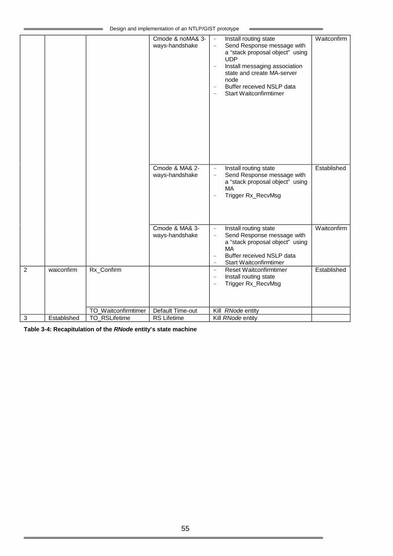
55
Design and implementation of an NTLP/GIST prototype
Cmode & noMA& 3-ways-handshake
- Install routing state - Send Response message with
a “stack proposal object” using UDP
- Install messaging association state and create MA-server node
- Buffer received NSLP data - Start Waitconfirmtimer
Waitconfirm
Cmode & MA& 2-ways-handshake
- Install routing state - Send Response message with
a “stack proposal object” using MA
- Trigger Rx_RecvMsg
Established
Cmode & MA& 3-ways-handshake
- Install routing state - Send Response message with
a “stack proposal object” using MA
- Buffer received NSLP data - Start Waitconfirmtimer
Waitconfirm
Rx_Confirm - Reset Waitconfirmtimer - Install routing state - Trigger Rx_RecvMsg
Established 2
waiconfirm
TO_Waitconfirmtimer Default Time-out Kill RNode entity 3 Established TO_RSLifetime RS Lifetime Kill RNode entity
Table 3-4: Recapitulation of the RNode entity’s state machine

56
Design and implementation of an NTLP/GIST prototype
Figure 3-6: Internal behaviour model of the RNode entity
The RNode entity determines the specific actions it should be performed based on some information/parameters included in the Query message it receives (see Figure 3-6).
1- When the RNode entity is created (IDLE state), the Rx_Query event is the first event that should occur. This event may lead to different actions based on the conditions that are satisfied. The following conditions may be distinguished:
a. Dmode & noMA & 2-ways-handshake: this condition holds when the local policy indicates that the responding node is configured to perform 2-ways-handshake discovery mechanisms, when the received Query message indicates (by means of the lack of the “stack proposal object”) that the initiated discovery mechanism must be performed in datagram mode and when there is no existing messaging association between the Query message sender and the responding node. As result a Response message is created without a stack proposal and sent back to the QNode in the datagram mode. Hereafter the event Rx_RecvMsg may be triggered for the delivery of an eventual included NSLP data. These actions are preceded by the installation of the routing state related to the Query message sender. Finally the RNode goes to the state Established.
b. Dmode & noMA & 3-ways-handshake: this condition holds when the local policy indicates that the responding node is configured to perform 3-ways-handshake discovery mechanisms, when the received Query message indicates that the initiated discovery mechanism must be performed in datagram mode and when there is no existing messaging association between the Query message sender and the responding node. Just like in (a) a Response message is created without a stack
Receive GIMPS - Query
Rx_Query
No Stack Proposal Object
Install Routing state
TO_RSLifetime Rx_Confirm
2 - Ways handshake?
Send GIMPS - Response
Cmode Required?
Install Routing state
with Stack proposal object
Send GIMPS - Response
Cmode required?
with Stack proposal object
Send GIMPS - Response
Start the waiting confirm
Timer tc
Install MA state
Destroy installed session state(s )
Install MA state
Waitconfirm (state) ( RNode internal subentity )
Established (state) ( RNode internal subentity )
Underlying GIMPS layers
Reset the waiting confirm
timer
Start the routingstatelife -
Timer tr
yes
no
no
yes
tr ==0
TO_Waitconfirmtimer
tc ==0
yes
no Stack proposal object
Send GIMPS - Response
no
NodeLevel
Rx_RecvMsg
Receive GIMPS - Query
Rx_Query
no Stack proposal object
Install Routing state
TO_RSLifetime Rx_Confirm
2 - ways handshake?
*Send GIMPS - Response
Cmode required?
Install Routing state
with Stack proposal object
*Send GIMPS - Response
Cmode required?
with Stack proposal object
*Send GIMPS - Response
Start the waiting confirm
Timer tc
Install MA state
Destroy installed session state(s )
Install MA state
Waitconfirm (state) ( RNode internal subentity )
Established (state) ( RNode internal subentity )
Underlying GIMPS layers
Reset the waiting confirm
timer
Start the routingstatelife -
Timer tr
yes
no
no
yes
tr ==0
TO_Waitconfirmtimer
tc ==0
yes
no Stack proposal object
*Send GIMPS - Response
no
NodeLevel
Rx_RecvMsg
RNode
* send GIMPS message (GIMPS-Response) using MA if there exists one already

57
Design and implementation of an NTLP/GIST prototype
proposal and sent back to the QNode in the datagram mode. However, in this case the routing state of the Query message sender will not yet be installed. An eventually received NSLP data will be buffer and the RNode will go to the state Waitconfirm.
c. Dmode & MA & 2-ways-handshake: this condition holds when the local policy indicates that the responding node is configured to perform 2-ways-handshake discovery mechanisms, when the received Query message indicates (absence of “stack proposal object”) that the initiated discovery mechanism must be performed in Datagram mode and when there exists a messaging association between the Query message sender and the responding node. The actions that the RNode performs in this case are quasi similar to the ones described in (a). The unique difference is that the Response message is sent back to the QNode using the existing MA. The RNode goes at the end to the state Established.
d. Dmode & MA & 3-ways-handshake: this condition holds when the local policy indicates that the responding node is configured to perform 3-ways-handshake discovery mechanisms, when the received Query message indicates (absence of “stack proposal object”) that the initiated discovery mechanism must be performed in Datagram mode and when there exists a messaging association between the Query message sender and the responding node. The actions that the RNode performs in this case are quasi similar to the ones described in (b). The unique difference is that the Response message is sent back to the QNode using the existing MA. The RNode goes at the end to the state Waitconfirm.
e. Cmode & noMA& 2-ways-handshake: this condition holds when the local policy indicates that the responding node is configured to perform 2-ways-handshake discovery mechanisms, when the received Query message indicates (presence of the “stack proposal object”) that the initiated discovery mechanism must establish a messaging association and when there is no existing messaging association between the Query message sender and the responding node. As result a 14Response message is created with a stack proposal object and sent back to the QNode in the datagram mode. Hereafter the event Rx_RcvMessage may be triggered for the delivery of an eventual included NSLP data. These actions are preceded by the installation of the routing state of the Query message sender and the installation of a messaging association state. Finally the RNode goes to the state Established.
f. Cmode & noMA& 3-ways-handshake: this condition holds when the local policy indicates that the responding node is configured to perform 3-ways-handshake discovery mechanisms, when the received Query message indicates (presence of the “stack proposal object”) that the initiated discovery mechanism must establish a messaging association and when there is no existing messaging association between the Query message sender and the responding node. As result a Response message is created with a stack proposal object and sent back to the QNode in the datagram mode. Hereafter an eventual included NSLP data is buffered. These actions are preceded by the installation of the messaging association state. Finally the RNode goes to the state Waitconfirm.
g. Cmode & MA& 2-ways-handshake: this condition holds o when the local policies indicate that the responding node is configured to
perform a 2-ways-handshake discovery mechanism; o when the received Query message indicates (presence of the “stack
proposal object”) that a messaging association should be setup during the initiated discovery mechanism; and
o when there exists already a messaging association between the querying node and the responding node.
The actions that the RNode performs in this case are quasi similar to the ones described in (e). The major differences are that the Response message is sent back
14 Note that the just created messaging association cannot be used during the transport of the Response message because the QNode installs the messaging association only after the reception of the Response message. Therefore the QNode will not receive messages sent by means of the ‘partially’ existing messaging association.

58
Design and implementation of an NTLP/GIST prototype
to the QNode using the existing MA and that no new messaging association is installed. The RNode goes at the end to the state Established.
h. Cmode & MA& 3-ways-handshake: this condition holds o when the local policy indicates that the responding node is configured to
perform 3-ways-handshake discovery mechanisms; o when the received Query message indicates (presence of the “stack
proposal object”) that the initiated discovery mechanism must establish a messaging association;
o and when there exists already a messaging association between the querying node and the responding node.
The actions that the RNode performs in this case are quasi similar to the ones described in (f). The major differences are that the Response message is sent back to the QNode using the existing MA and that no new messaging association is installed. The RNode goes at the end to the state Waitconfirm.
2- When the RNode is in the Waitconfirm state two events may occur.
a. Rx_Confirm: this event is triggered when a GIMPS Confirm message is received in response to a previously sent Response message during a 3-ways handshake discovery mechanism. The actions performed by the RNode entity upon receiving a confirm message are to reset the waitresponsetimer and install the routing state of the querying node. It may then trigger the event Rx_RecvMsg for the delivery of eventually buffered NSLP data.
b. TO-Waitconfirmtimer: This event occurs when the Waitconfirmtimer that has been started after the sending of a GIMPS-Response message, has expired. In this case the RNode simply clears the messaging association state it eventually has installed and exits.
3- In the Established state the only event that may occur is the TO_RSlifetime event. The occurrence of this event implies that the lifetime of an established routing state has expired. Just like in the QNode entity, the action perfomed by the RNode entity after this event is the deletion of the routing state and the messaging association state it is possibly linked to; provided that this messaging association state is expired as well.
3.2.5 GIMPS data node (DNode) Like the QNode entity, the DNode entity may only be created at the occurrence of the Tg_SendMessage event in the NodeLevel entity. It is essentially used to send NSLP data or NSLP payload. Moreover the DNode entity is created by the NodeLevel entity in case the NSLP does not require the establishment and maintenance of a session (see Section 3.2.2), thus the DNode entity is used to send NSLP data when the discovery mechanism is not required. The service provided by the DNode entity is to send and handle GIMPS Data messages. Table 3-5 gives an overview of the events that may occur and the actions that consequently must be performed. Additionally Figure 3-7 gives a schematic illustration of the functionality of the DNode entity.
Case Previous
state Events Decision Actions Next
state Tx_Dmode_Query
noRstate Send Data message using ‘Dmode query encapsulation’
Tx_Dmode_Normal Rstate & noMA
Send Data message using the ‘Dmode normal’ datagram mode
1
IDLE
Tx_Dmode_MA Rstate & MA Send Data message using the existing messaging association
IDLE

59
Design and implementation of an NTLP/GIST prototype
Rx_Data Trigger Rx_RecvMsg to deliver NSLP data
Table 3-5: Recapitulation of the DNode entity’s state machine
Figure 3-7: Internal behaviour model of the DNode entity
The DNode entity determines the specific actions it should performed based on some information derived by the GIMPS NodeLevel entity and/or included in the SendMessage SP/Tg_SendMessage.
a. When the DNode entity is created (IDLE state) and the Tx_Dmode_Query event occurs. The NodeLevel provides the DNode entity information such as the message aggregation Level. This information enables DNode to determine the router alert value it should used during the transport of the GIMPS Data message (see Section 3.3).
b. When the DNode entity is created (IDLE state) and the Tx_Dmode_Normal event occurs. The NodeLevel provides the DNode entity among others information about the routing state. This information enables DNodeto send the NSLP dat directly to the adjacent peer using UDP.
c. When the DNode entity is created (IDLE state) and the Tx_Dmode_MA event occurs. The NodeLevel entity provides the DNode entity among others information about the message association state. This information is used to send the NSLP data in connection mode.
d. When the DNode entity is created (IDLE state) and the Rx_Data event occurs. The Rx_RecvMsg is triggered so that the NodeLevel entity delivers the received NSLP data to the appropriate NSLP.
3.2.6 MA-Node The following example illustrates a basic use of the MA-node entity: Consider an NSIS aware network consisting of three adjacent nodes (Node a, Node b and Node c, which support all NSLP-1) with a single data path joining Node a to Node b and Node b to Node c. Suppose there exists a messaging association between Node a and Node b (this may for instance be a TCP connection between Node a and Node b). If NSLP-1 in Node a (flow source) wants to send signalling data to NSLP-1 in Node c (flow destination), this signalling data will obviously pass through the intermediary Node b. Thus Node a will simply create an MA-Node which will use the existing connection to send directly data to Node b. The service provided by the MA-node entity is to manage messaging associations and send data using these messaging associations.
NodeLevel
Send message Using Dmode - Query
Include RAO
Send message Using Dmode - Normal
Use UDP
Send message Using Dmode - MA
Use TCP
Receive and handle GIMPS Data
Include RAO
NTLP/GIMPS underlying layers
Tx_Dmode_Query Tx_Dmode_Normal Tx_Dmode_MA
Rx_Data
Rx_RecvMsg
NodeLevel
Using Dmode -
Include RAO
Send message Using Dmode - Normal
Use UDP
Send message Using Dmode - MA
Use TCP
Receive and handle GIMPS Data
Include RAO
NTLP/GIMPS underlying layers
Tx_Dmode_Query Tx_Dmode_Normal Tx_Dmode_MA
Rx_Data
Rx_RecvMsg
DNode
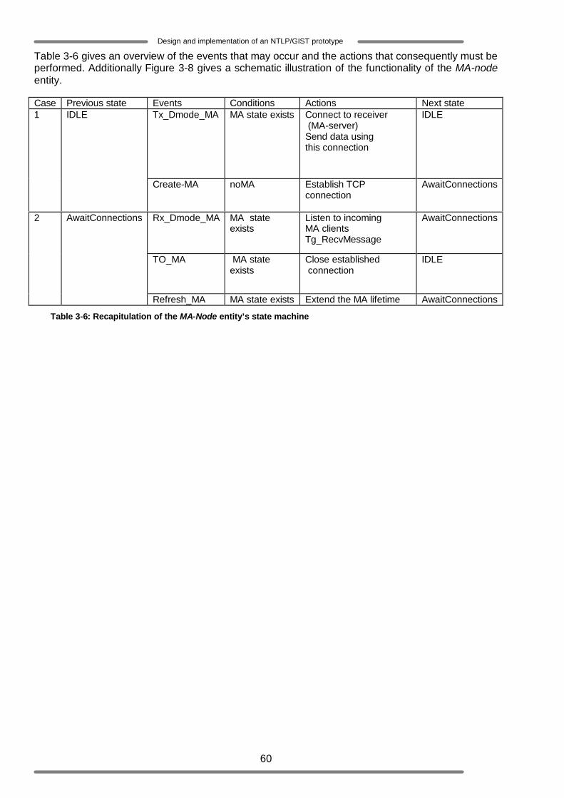
60
Design and implementation of an NTLP/GIST prototype
Table 3-6 gives an overview of the events that may occur and the actions that consequently must be performed. Additionally Figure 3-8 gives a schematic illustration of the functionality of the MA-node entity.
Table 3-6: Recapitulation of the MA-Node entity’s state machine
Case Previous state Events Conditions Actions Next state Tx_Dmode_MA
MA state exists Connect to receiver (MA-server) Send data using this connection
IDLE 1
IDLE
Create-MA noMA Establish TCP connection
AwaitConnections
Rx_Dmode_MA MA state exists
Listen to incoming MA clients Tg_RecvMessage
AwaitConnections
TO_MA MA state exists
Close established connection
IDLE
2 AwaitConnections
Refresh_MA MA state exists Extend the MA lifetime AwaitConnections
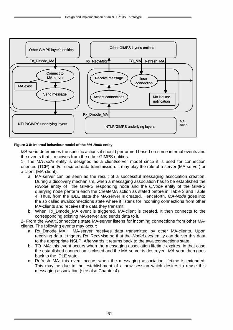
61
Design and implementation of an NTLP/GIST prototype
Figure 3-8: Internal behaviour model of the MA-Node entity
MA-node determines the specific actions it should performed based on some internal events and the events that it receives from the other GIMPS entities. 1- The MA-node entity is designed as a client/server model since it is used for connection oriented (TCP) and/or secured data transmission. It may play the role of a server (MA-server) or a client (MA-client).
a. MA-server can be seen as the result of a successful messaging association creation. During a discovery mechanism, when a messaging association has to be established the RNode entity of the GIMPS responding node and the QNode entity of the GIMPS querying node perform each the CreateMA action as stated before in Table 3 and Table 4. Thus, from the IDLE state the MA-server is created. Henceforth, MA-Node goes into the so called awaitconnections state where it listens for incoming connections from other MA-clients and receives the data they transmit.
b. When Tx_Dmode_MA event is triggered, MA-client is created. It then connects to the corresponding existing MA-server and sends data to it.
2- From the AwaitConnections state MA-server listens for incoming connections from other MA-clients. The following events may occur:
a. Rx_Dmode_MA: MA-server receives data transmitted by other MA-clients. Upon receiving data it triggers Rx_RecvMsg so that the NodeLevel entity can deliver this data to the appropriate NSLP. Afterwards it returns back to the awaitconnections state.
b. TO_MA: this event occurs when the messaging association lifetime expires. In that case the established connection is closed and the MA-server is destroyed. MA-node then goes back to the IDLE state.
c. Refresh_MA: this event occurs when the messaging association lifetime is extended. This may be due to the establishment of a new session which desires to reuse this messaging association (see also Chapter 4).
Other GIMPS layer’s entities
Send message
MA exist
NTLP/GIMPS underlying layers
Tx_Dmode_MA
Connect to MA - server
Other GIMPS layer’s entities
Accept connections
NTLP/GIMPS underlying layers
Rx_RecvMsg
Receive message
Rx_Dmode_MA
TO_MA Refresh_MA
close connection
MA - lifetime notification
Other GIMPS layer’s entities
Send message
MA exist
NTLP/GIMPS underlying layers
Tx_Dmode_MA
Connect to MA - server
Other GIMPS layer’s entities
Accept connections
NTLP/GIMPS underlying layers
Rx_RecvMsg
Receive message
Rx_Dmode_MA
TO_MA Refresh_MA
close connection
MA - lifetime notification
MA- Node

62
Design and implementation of an NTLP/GIST prototype
3.3 GIMPS messages format In the previous sections of this chapter, the internal behaviour of GIMPS protocol entities has been described using the state machine concept. These sections have also presented the way 15GIMPS entities interact with each other in order to provide the services required by NSLPs. These services are modelled by the different GIMPS service primitives discussed in Section 3.2.1. 16This section focuses on the design of the cooperation between the 17GIMPS protocol entities (GPE).
GPEs cooperate by exchanging units of information called 18Protocol Data Units (PDUs). The GIMPS protocol specified in [10] defines a generic PDU format that applies to all PDUs (see Figure 3-9). The generic PDU format consists of a common header, the GIMPS object Message Routing Information (MRI) and the GIMPS object session identification number (Session-ID). The MRI and Session-ID have already been described in Section 3.2.1. The common header contains the version number of the GIMPS protocol, the total length of the remaining PDU element, the NSLP-ID, a GIMPS hop counter, which is primary used to prevent NSLP data (NSLP signalling message) from looping and to keep track of the number of GIMPS hops between the signalling message sender and the destination, the PDU type and the so called source addressing mode, which is used to indicate whether a GIMPS node is the source of NSLP data or not. The GIMPS protocol has the following PDUs:
o GIMPS-Query PDU: a GPE uses this PDU to discover its next peer GPE and to initiate the establishment of a session. Besides the elements of the generic PDU, the GIMPS-Query PDU contains the Node addressing object, the Query-Cookie object, the Stack Proposal object, the Routing-State-Lifetime object and the NSLP data object. The Node addressing conveys among others the IP address of the discovering/querying node and its identification number (also denoted as peer-identity). This information is needed during the negotiation and establishment of messaging association when it is required. The Query-Cookie object is used for security purposes. The discovering node uses this object as a tool to authenticate itself. The Stack Proposal object is optional; it is therefore only included in the GIMPS-Query PDU in case a messaging association setup is required. It contains a list of transport and security protocols supported by the discovering node. Like the Stack Proposal object, the Routing-State-Lifetime object and the NSLP data object are optional. The former conveys the time that should be considered as the lifetime of the routing state that will be setup and the latter contains the NSLP payload.
o GIMPS-Response PDU: a GPE uses this PDU to answer the GPE that has sent the GIMPS-Query PDU. Besides the elements of the generic PDU, it contains the Node addressing object, the Query-Cookie object, the Response-Cookie object, the Stack Proposal object, the Routing-State-Lifetime object and the NSLP data object. The Node addressing conveys among others the IP address of the responding node (the discovered next peer of the querying node) and its peer identification number (this ID is meant to uniquely identified every GIMPS node within a GIMPS aware network). In the GIMPS-Response PDU, the Query-Cookie object must be identical to the one included in the received GIMPS-Query PDU to prove to the querying GPE that the responding GPE is indeed the receiver of the sent GIMPS-Query PDU. The responding node uses the Response-Cookie object as a tool to authenticate itself. As in the GIMPS-Query PDU the Stack Proposal object is optional. It contains a list of transport and security protocols that are both supported by the responding node and querying node. The Routing-State-Lifetime object if included should be the same as the one that is received in the GIMPS-
15 GIMPS entities are the different components present in the GIMPS layer within one GIMPS node (NSIS node). 16 In this section the format of the GIMPS PDUs (GIMPS messages) are described at a higher abstraction level. The bit-level format can be found in Appendix A. 17 A GIMPS protocol entity denotes the GIMPS protocol within one GIMPS node (NSIS node) 18 It should be clear that GIMPS Protocol Data Units represent the GIMPS messages, briefly discussed in Chapter 2

63
Design and implementation of an NTLP/GIST prototype
Query PDU. Finally the NSLP data object may be included to convey NSLP payload.
o GIMPS-Confirm PDU: This PDU is only used by the querying GPE in case it has initiated a 3-ways discovery mechanism. Besides the elements of the generic PDU, it contains the Node addressing object, the Response-Cookie object, the Stack Proposal object, the Routing-State-Lifetime object and the NSLP data object. Except the NSLP data object which may be included to convey some buffered NSLP payload. All the other objects are copies from the ones received in the GIMPS-Response PDU.
o GIMPS-Data PDU: This PDU is essentially used to carry NSLP data. As a matter of fact it is the only PDU that must contain NSLP payload. Besides the elements of the generic PDU, it contains the NSLP data object and may contain the Node addressing object when it is sent in the datagram mode.
Figure 3-9 shows the format of the PDUs defined above in terms of the precedence of their objects.
Common Header MRI Session-IDGeneric PDU
Node addressing Query -Cookie Routing-state-Lifetime NSLP-DataGIMPS-Query PDU(for datagram mode)
Node addressing Query -Cookie Stack-Proposal Routing-state-Lifetime NSLP-DataGIMPS-Query PDU(for connection mode)
Node addressing Query -Cookie Routing-state-Lifetime NSLP-DataGIMPS-Response PDU(for datagram mode)
Node addressing Query -Cookie Stack-Proposal Routing-state-Lifetime NSLP-DataGIMPS-Response PDU
(for connection mode)
Responder-Cookie
Responder-Cookie
Node addressing Responder-Cookie Routing-state-Lifetime NSLP-Data
Node addressing Responder-Cookie Stack-Proposal Routing-state-Lifetime NSLP-Data
GIMPS-Confirm PDU(for datagram mode)
GIMPS-Confirm PDU(for connection mode)
NSLP-DataGIMPS-Data PDU(for datagram mode)
NSLP-DataGIMPS-Data PDU(for connection mode)
Node addressing
Common Header MRI Session-ID
Common Header MRI Session-ID
Common Header MRI Session-ID
Common Header MRI Session-ID
Common Header MRI Session-ID
Common Header MRI Session-ID
Common Header MRI Session-ID
Common Header MRI Session-ID
Figure 3-9: GIMPS PDUs
3.4 Discovery mechanism This section presents how the different GIMPS protocol entities communicate with each other by means of the GIMPS PDU in order to provide the routing/discovery service and to manage the session states. As mentioned earlier, the discovery mechanism may be performed in datagram mode or connection mode. In the former case the GIMPS protocol entities involved are the QNode entity of the discovering GPE and the RNode entity of the responding GPE. In the latter case the involved entities are the QNode entity of the discovering GPE, the RNode entity of the responding GPE and the MA-node of both the discovering and the responding GPEs. 3.4.1 Successful discovery mechanism The normal behaviour of a GIMPS protocol entity during a 2-ways handshake discovery mechanism is defined in terms of the following rules (Figure 3-10). A GPE sends a GIMPS-Query PDU towards a destination that can be identified by the set of parameters destination address and destination port, included in the MRI. The GIMPS-Query PDU must be encapsulated in an IP datagram with a router alert value.
o A GPE that receives a GIMPS-Query PDU learns and keeps among others the IP address of the sender (this is basically the session state establishment) and then sends a GIMPS-Response PDU back to this sender.
o A GPE that receives a GIMPS-Response PDU learns and keeps the IP address of the responder and installs thus the session states.
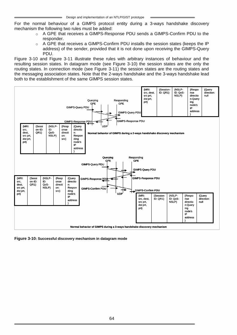
64
Design and implementation of an NTLP/GIST prototype
For the normal behaviour of a GIMPS protocol entity during a 3-ways handshake discovery mechanism the following two rules must be added:
o A GPE that receives a GIMPS-Response PDU sends a GIMPS-Confirm PDU to the responder.
o A GPE that receives a GIMPS-Confirm PDU installs the session states (keeps the IP address) of the sender, provided that it is not done upon receiving the GIMPS-Query PDU.
Figure 3-10 and Figure 3-11 illustrate these rules with arbitrary instances of behaviour and the resulting session states. In datagram mode (see Figure 3-10) the session states are the only the routing states. In connection mode (see Figure 3-11) the session states are the routing states and the messaging association states. Note that the 2-ways handshake and the 3-ways handshake lead both to the establishment of the same GIMPS session states.
GIMPS-Query PDU
GIMPS-Query PDU
GIMPS-Response PDUGIMPS-Response PDU
Querying GPE
Responding GPE
UDP
Normal behavior of GIMPS during a 2-ways handshake discovery mechanism
GIMPS-Confirm PDU
GIMPS-Query PDU
GIMPS-Query PDU
GIMPS-Response PDUGIMPS-Response PDU
Querying GPE
Responding GPE
UDPGIMPS-Confirm PDU
Normal behavior of GIMPS during a 3-ways handshake discovery mechanism
{Query direction: Responding node’s IP address}
{Response direction: src}
{NSLP-ID: QoS-NSLP}
{Session-ID: QR1}
{MRI: src, dest, src prt, dst prt, prt}
{Query direction: null
{Response direction:Queryingnode’s IP address}
{NSLP-ID: QoS-NSLP}
{Session-ID: QR1}
{MRI: src, dest, src prt, dst prt, prt}
{Query direction: null
{Response direction:Queryingnode’s IP address}
{NSLP-ID: QoS-NSLP}
{Session-ID: QR1}
{MRI: src, dest, src prt, dst prt, prt}
{Query direction: Responding node’s IP address}
{Response direction: src}
{NSLP-ID: QoS-NSLP}
{Session-ID: QR1}
{MRI: src, dest, src prt, dst prt, prt}
GIMPS-Query PDU
GIMPS-Query PDU
GIMPS-Response PDUGIMPS-Response PDU
Querying GPE
Responding GPE
UDP
Normal behavior of GIMPS during a 2-ways handshake discovery mechanism
GIMPS-Confirm PDU
GIMPS-Query PDU
GIMPS-Query PDU
GIMPS-Response PDUGIMPS-Response PDU
Querying GPE
Responding GPE
UDPGIMPS-Confirm PDU
GIMPS-Confirm PDU
GIMPS-Query PDU
GIMPS-Query PDU
GIMPS-Response PDUGIMPS-Response PDU
Querying GPE
Responding GPE
UDPGIMPS-Confirm PDU
Normal behavior of GIMPS during a 3-ways handshake discovery mechanism
{Query direction: Responding node’s IP address}
{Response direction: src}
{NSLP-ID: QoS-NSLP}
{Session-ID: QR1}
{MRI: src, dest, src prt, dst prt, prt}
{Query direction: null
{Response direction:Queryingnode’s IP address}
{NSLP-ID: QoS-NSLP}
{Session-ID: QR1}
{MRI: src, dest, src prt, dst prt, prt}
{Query direction: null
{Response direction:Queryingnode’s IP address}
{NSLP-ID: QoS-NSLP}
{Session-ID: QR1}
{MRI: src, dest, src prt, dst prt, prt}
{Query direction: Responding node’s IP address}
{Response direction: src}
{NSLP-ID: QoS-NSLP}
{Session-ID: QR1}
{MRI: src, dest, src prt, dst prt, prt}
Figure 3-10: Successful discovery mechanism in datagram mode
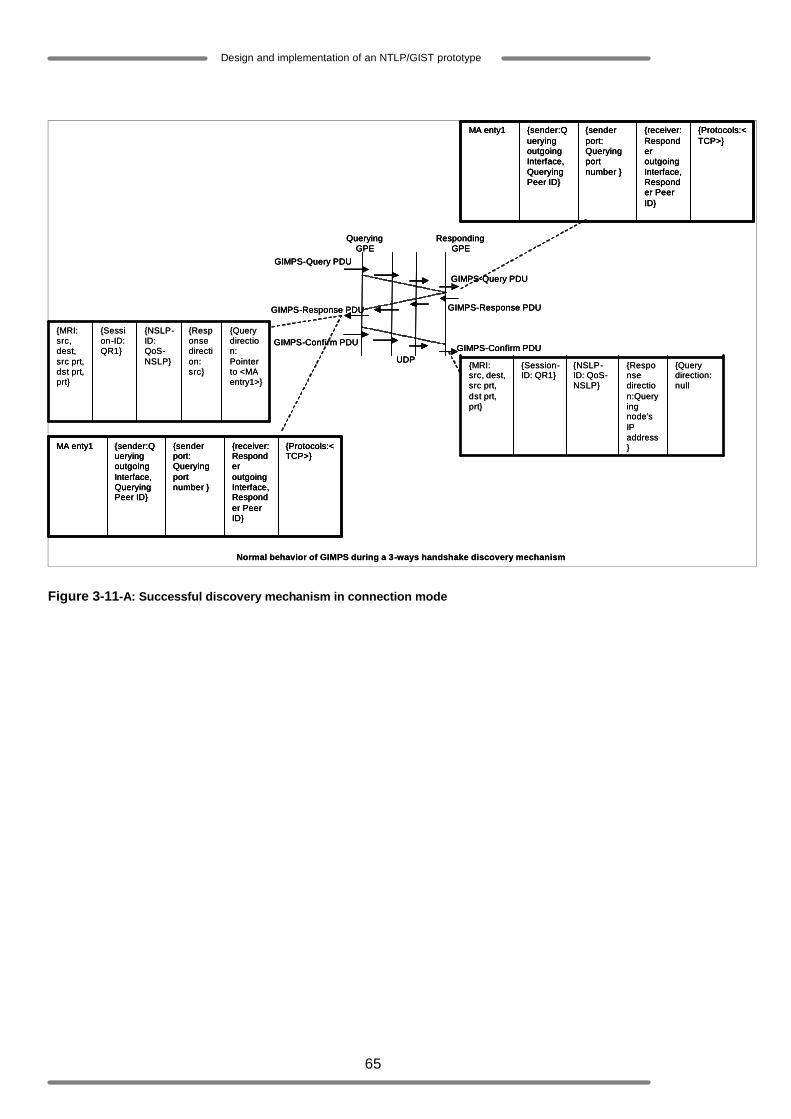
65
Design and implementation of an NTLP/GIST prototype
GIMPS-Confirm PDU
GIMPS-Query PDU
GIMPS-Query PDU
GIMPS-Response PDUGIMPS-Response PDU
Querying GPE
Responding GPE
UDPGIMPS-Confirm PDU
Normal behavior of GIMPS during a 3-ways handshake discovery mechanism
{Query direction: null
{Response direction:Queryingnode’s IP address}
{NSLP-ID: QoS-NSLP}
{Session-ID: QR1}
{MRI: src, dest, src prt, dst prt, prt}
{Query direction: Pointer to <MA entry1>}
{Response direction: src}
{NSLP-ID: QoS-NSLP}
{Session-ID: QR1}
{MRI: src, dest, src prt, dst prt, prt}
{Protocols:<TCP>}
{receiver: Responder outgoing Interface, Responder Peer ID}
{sender port: Querying port number }
{sender:Queryingoutgoing Interface, Querying Peer ID}
MA enty1
{Protocols:<TCP>}
{receiver: Responder outgoing Interface, Responder Peer ID}
{sender port: Querying port number }
{sender:Queryingoutgoing Interface, Querying Peer ID}
MA enty1
GIMPS-Confirm PDU
GIMPS-Query PDU
GIMPS-Query PDU
GIMPS-Response PDUGIMPS-Response PDU
Querying GPE
Responding GPE
UDPGIMPS-Confirm PDU
GIMPS-Confirm PDU
GIMPS-Query PDU
GIMPS-Query PDU
GIMPS-Response PDUGIMPS-Response PDU
Querying GPE
Responding GPE
UDPGIMPS-Confirm PDU
Normal behavior of GIMPS during a 3-ways handshake discovery mechanism
{Query direction: null
{Response direction:Queryingnode’s IP address}
{NSLP-ID: QoS-NSLP}
{Session-ID: QR1}
{MRI: src, dest, src prt, dst prt, prt}
{Query direction: Pointer to <MA entry1>}
{Response direction: src}
{NSLP-ID: QoS-NSLP}
{Session-ID: QR1}
{MRI: src, dest, src prt, dst prt, prt}
{Protocols:<TCP>}
{receiver: Responder outgoing Interface, Responder Peer ID}
{sender port: Querying port number }
{sender:Queryingoutgoing Interface, Querying Peer ID}
MA enty1 {Protocols:<TCP>}
{receiver: Responder outgoing Interface, Responder Peer ID}
{sender port: Querying port number }
{sender:Queryingoutgoing Interface, Querying Peer ID}
MA enty1
Figure 3-11-A: Successful discovery mechanism in connection mode
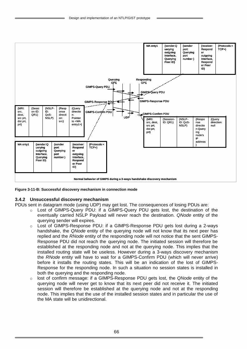
66
Design and implementation of an NTLP/GIST prototype
GIMPS-Confirm PDU
GIMPS-Query PDU
GIMPS-Query PDU
GIMPS-Response PDUGIMPS-Response PDU
Querying GPE
Responding GPE
UDPGIMPS-Confirm PDU
Normal behavior of GIMPS during a 3-ways handshake discovery mechanism
{Query direction: null
{Response direction:Queryingnode’s IP address}
{NSLP-ID: QoS-NSLP}
{Session-ID: QR1}
{MRI: src, dest, src prt, dst prt, prt}
{Query direction: Pointer to <MA entry1>}
{Response direction: src}
{NSLP-ID: QoS-NSLP}
{Session-ID: QR1}
{MRI: src, dest, src prt, dst prt, prt}
{Protocols:<TCP>}
{receiver: Responder outgoing Interface, Responder Peer ID}
{sender port: Querying port number }
{sender:Queryingoutgoing Interface, Querying Peer ID}
MA enty1
{Protocols:<TCP>}
{receiver: Responder outgoing Interface, Responder Peer ID}
{sender port: Querying port number }
{sender:Queryingoutgoing Interface, Querying Peer ID}
MA enty1
GIMPS-Confirm PDU
GIMPS-Query PDU
GIMPS-Query PDU
GIMPS-Response PDUGIMPS-Response PDU
Querying GPE
Responding GPE
UDPGIMPS-Confirm PDU
GIMPS-Confirm PDU
GIMPS-Query PDU
GIMPS-Query PDU
GIMPS-Response PDUGIMPS-Response PDU
Querying GPE
Responding GPE
UDPGIMPS-Confirm PDU
Normal behavior of GIMPS during a 3-ways handshake discovery mechanism
{Query direction: null
{Response direction:Queryingnode’s IP address}
{NSLP-ID: QoS-NSLP}
{Session-ID: QR1}
{MRI: src, dest, src prt, dst prt, prt}
{Query direction: Pointer to <MA entry1>}
{Response direction: src}
{NSLP-ID: QoS-NSLP}
{Session-ID: QR1}
{MRI: src, dest, src prt, dst prt, prt}
{Protocols:<TCP>}
{receiver: Responder outgoing Interface, Responder Peer ID}
{sender port: Querying port number }
{sender:Queryingoutgoing Interface, Querying Peer ID}
MA enty1 {Protocols:<TCP>}
{receiver: Responder outgoing Interface, Responder Peer ID}
{sender port: Querying port number }
{sender:Queryingoutgoing Interface, Querying Peer ID}
MA enty1
{Protocols:<TCP>}
{receiver: Responder outgoing Interface, Responder Peer ID}
{sender port: Querying port number }
{sender:Queryingoutgoing Interface, Querying Peer ID}
MA enty1 {Protocols:<TCP>}
{receiver: Responder outgoing Interface, Responder Peer ID}
{sender port: Querying port number }
{sender:Queryingoutgoing Interface, Querying Peer ID}
MA enty1
Figure 3-11-B: Successful discovery mechanism in connection mode 3.4.2 Unsuccessful discovery mechanism PDUs sent in datagram mode (using UDP) may get lost. The consequences of losing PDUs are:
o Lost of GIMPS-Query PDU: if a GIMPS-Query PDU gets lost, the destination of the eventually carried NSLP Payload will never reach the destination. QNode entity of the querying sender will expires.
o Lost of GIMPS-Response PDU: if a GIMPS-Response PDU gets lost during a 2-ways handshake, the QNode entity of the querying node will not know that its next peer has replied and the RNode entity of the responding node will not notice that the sent GIMPS-Response PDU did not reach the querying node. The initiated session will therefore be established at the responding node and not at the querying node. This implies that the installed routing state will be useless. However during a 3-ways discovery mechanism the RNode entity will have to wait for a GIMPS-Confirm PDU (which will never arrive) before it installs the routing states. This will be an indication of the lost of GIMPS-Response for the responding node. In such a situation no session states is installed in both the querying and the responding node.
o lost of confirm message: if a GIMPS-Response PDU gets lost, the QNode entity of the querying node will never get to know that its next peer did not receive it. The initiated session will therefore be established at the querying node and not at the responding node. This implies that the use of the installed session states and in particular the use of the MA state will be unidirectional.
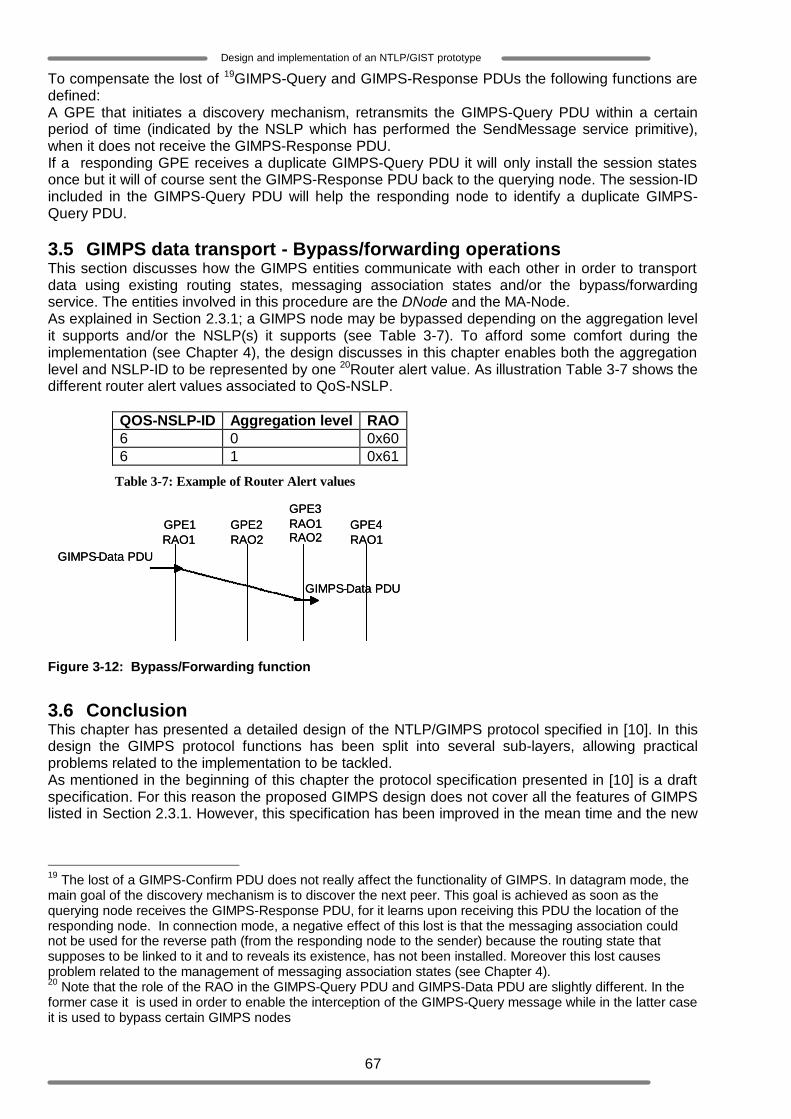
67
Design and implementation of an NTLP/GIST prototype
To compensate the lost of 19GIMPS-Query and GIMPS-Response PDUs the following functions are defined: A GPE that initiates a discovery mechanism, retransmits the GIMPS-Query PDU within a certain period of time (indicated by the NSLP which has performed the SendMessage service primitive), when it does not receive the GIMPS-Response PDU. If a responding GPE receives a duplicate GIMPS-Query PDU it will only install the session states once but it will of course sent the GIMPS-Response PDU back to the querying node. The session-ID included in the GIMPS-Query PDU will help the responding node to identify a duplicate GIMPS-Query PDU. 3.5 GIMPS data transport - Bypass/forwarding operations This section discusses how the GIMPS entities communicate with each other in order to transport data using existing routing states, messaging association states and/or the bypass/forwarding service. The entities involved in this procedure are the DNode and the MA-Node. As explained in Section 2.3.1; a GIMPS node may be bypassed depending on the aggregation level it supports and/or the NSLP(s) it supports (see Table 3-7). To afford some comfort during the implementation (see Chapter 4), the design discusses in this chapter enables both the aggregation level and NSLP-ID to be represented by one 20Router alert value. As illustration Table 3-7 shows the different router alert values associated to QoS-NSLP.
QOS-NSLP-ID Aggregation level RAO 6 0 0x60 6 1 0x61
Table 3-7: Example of Router Alert values
Figure 3-12: Bypass/Forwarding function
3.6 Conclusion This chapter has presented a detailed design of the NTLP/GIMPS protocol specified in [10]. In this design the GIMPS protocol functions has been split into several sub-layers, allowing practical problems related to the implementation to be tackled. As mentioned in the beginning of this chapter the protocol specification presented in [10] is a draft specification. For this reason the proposed GIMPS design does not cover all the features of GIMPS listed in Section 2.3.1. However, this specification has been improved in the mean time and the new
19 The lost of a GIMPS-Confirm PDU does not really affect the functionality of GIMPS. In datagram mode, the main goal of the discovery mechanism is to discover the next peer. This goal is achieved as soon as the querying node receives the GIMPS-Response PDU, for it learns upon receiving this PDU the location of the responding node. In connection mode, a negative effect of this lost is that the messaging association could not be used for the reverse path (from the responding node to the sender) because the routing state that supposes to be linked to it and to reveals its existence, has not been installed. Moreover this lost causes problem related to the management of messaging association states (see Chapter 4). 20 Note that the role of the RAO in the GIMPS-Query PDU and GIMPS-Data PDU are slightly different. In the former case it is used in order to enable the interception of the GIMPS-Query message while in the latter case it is used to bypass certain GIMPS nodes
GIMPS - Data PDU
GIMPS - Data PDU
GPE1 RAO1
GPE4 RAO1
GPE2 RAO2
GPE3 RAO1 RAO2
GIMPS - Data PDU
GIMPS - Data PDU
GPE1 RAO1
GPE4 RAO1
GPE2 RAO2
GPE3 RAO1 RAO2

68
Design and implementation of an NTLP/GIST prototype
GIMPS draft can be found in [20]. This draft is more consistent with respect to the GIMPS API service primitives and the GIMPS message handling. For instance the new draft switches the task of generating Session-IDs (see Section 3.2.1 to recall its function) to NSLPs. This implies that a valid Session-ID should be provided each time an NSLP is initiating a new session. Furthermore the new draft has defined among others a GIMPS Error message, which could be very useful in error situations. Several GIMPS functionalities related to session states management (in particular session states refresh), Nat and route changes (re-routing) have been specified in more details. Moreover, in order to enable the implementations of these functionalities in future GIMPS implementations there are some new objects introduced for instance in GIMPS Query and Response messages. The next chapter will focus on the GIMPS prototype implementation.
69
Design and implementation of an NTLP/GIST prototype
4 GIMPS prototype implementation This chapter presents the GIMPS prototype implementation. Although the NTLP/GIMPS protocol specified in [10] by the NSIS WG is not yet a complete specification, it does define the essential protocol elements and may therefore be explored (i.e. It got a go ahead for exploration). During the design phase, it appeared that this NTLP/GIMPS protocol partially or completely did not define certain key characteristics necessary for the basic operations of GIMPS. Therefore, some decisions had to be made over a certain number of issues. This chapter is subdivided in two parts. The first part gives an overview of the main open issues of the specification presented in [10], which are crucial for the GIMPS prototype implementation. It also presents the set of choices and decisions that have been made in order to accomplish the implementation of the GIMPS protocol. The second part describes the prototype implementation of GIMPS. 4.1 Open issues and differences from the draft This section highlights the open issues of the GIMPS protocol specified in [10]. It discusses the decisions that have been taken with respect to these issues and explains if and how these issues have been resolved in the latest version of the GIMPS draft specified in [20]. 4.1.1 Open issues 4.1.1.1 API Layer
o The GIMPS-API defines the SetStateLifetime service primitive which must be used by an NSLP to notify GIMPS that it would like GIMPS to manage (extend or delete) the routing state it has created on its behalf. The concrete definition of this service primitive in [10] is: 21SetStateLifetime (MRI, Direction, StateLifetime). Among the information that the SetStaLifetime’s parameters provides to GIMPS, there is none that enables GIMPS to identify the SetStaLifetime’s initiator (the NSLP which has initiated the SetStateLifetime’s request). This implies that, GIMPS will not be able to select and manage the routing state associated to that specific SetStaLifetime’s initiator. Instead, the information provided by the SetStaLifetime’s parameters will enable GIMPS to manage all the routing states that match the given MRI. Concretely, suppose a GIMPS node has created routing states on the behalf of different NSLPs and these routing states have the same MRI. When this GIMPS node receives a SetStaLifetime request, the operation(s) it will perform will affect all the routing states that contain the same MRI as the one of the received SetStaLifetime, regardless this SetStaLifetime’s initiator. The question is whether the performed operation(s) is (are) desired by all the concerned NSLPs. It is worth noting that in [20] the SetStateLifetime service primitive is slightly modified. It does no longer include the parameter Direction; because this parameter is already present in the MRI (see Appendix A for the complete definition of the MRI).
o The GIMPS-API defines the SendMessage service primitive which must be used whenever
an NSLP wants to send data to it peer node. In case this data does not belong to an existing session its transport may first be preceded by a discovering procedure, if required (i.e. if the NSLP requests a stateful session). GIMPS is also supposed to be able to send such a data without a discovering procedure (if the NSLP requests a stateless session). Moreover an NSLP must be able to indicate the aggregation level the data must be sent with. The concrete definition of the SendMessage service primitive is: 22 SendMessage (NSLP-Data, NSLP-Data-Size, NSLP-Message-Handle, NSLP-Id, Session-ID, MRI, Source-SII-Handle, Peer-SII-Handle, Transfer-Attributes, Timeout, IP-TTL). Among the information that these parameters provide to GIMPS, there is no parameter that indicates the aggregation level associated to the included NSLP-Data, though this aggregation level is needed in GIMPS for the selection of the appropriate IP router alert value (see Section 3.5). Furthermore, there is
21 The SetStateLifetime service primitive and its parameters have been defined in details in Chapter 3 22 The SendMessage service primitive and its parameters have been defined in details in Chapter 3

70
Design and implementation of an NTLP/GIST prototype
also no parameter that indicates to GIMPS whether a statefull session (which directly implies a discovery mechanism) should be initiated or not (stateless).
4.1.1.2 Use of Data Message not explicitly defined The GIMPS protocol specified in [10] does not explicitly define the use of the GIMPS-Data message (GIMPS-Data PDU). Currently a description of the use of this PDU has been provided in the GIMPS specification given in [20]. The following table highlights how this PDU may be used in GIMPS to transport signalling messages.
Message D-Mode Normal D-Mode Query C-Mode GIMPS-Data
If routing state exists for the flow but no appropriate message association
If no routing exists and the MRI can be used to derive the query encapsulation
If a messaging association exists
4.1.1.3 Session states management Session states management includes the maintenance of installed routing states and messaging association states. In the GIMPS protocol specified in [10] the session states maintenance consists of two concrete actions:
o Extension of the routing state lifetime: Each routing state within a GIMPS node is associated to an NSLP and has a so called lifetime. The lifetime is basically the time that a routing state’s information must be available for GIMPS internal operations. When a routing state is created its lifetime has a default value of 30 seconds. However the associated NSLP may use the SetStateLifetime service primitive (as explained earlier) to extend this lifetime (if the value held by the SetStateLifetime’s parameter “State-Lifetime” is greater than the default value).
o Deletion of the routing state: In case a routing state’s lifetime expires the information provided by it should no longer be available. However the associated NSLP may use the SetStateLifetime service primitive to end the lifetime prematurely by giving the SetStateLifetime’s parameter “State-Lifetime” the value zero.
The fact that the SetStateLifetime event only involves the routing states of the GIMPS node in which it has occurred may lead to the following issue: The installation of the routing state during the discovery mechanism always involves two GIMPS peer nodes (a querying node and a responding node). Consequently, each querying node’s routing state has a “peer state” in the responding node. According to the GIMPS protocol specification in [10] the maintenance of the routing states in the peer nodes are independent from each other. This implies for instance that when the routing state lifetime in the querying node is extended, its peer state in the responding node may be deleted, without notifying the querying node or vice versa. A problem that may surface in such a case is an unsuccessful data delivery from the querying node to the responding node. Another negative aspect is that a GIMPS node will be retaining routing states that are no longer needed, uselessly. An attempt to avoid these problems could be to define a mechanism that will enable the synchronisation of peer routing states. For example, one could introduce a new GIMPS PDU/GIMPS message which will be used by a GIMPS node to inform its peer entity about its routing state’s updates.
4.1.1.4 Interoperability As stated earlier, the GIMPS protocol specification in [10] defines two types of discovery mechanism:
o The 2-ways handshake: is simple, as it only requires the exchange of two messages (GIMPS-Query and GIMPS Response). Its main disadvantage however is that it is less secure. When a querying node receives a GIMPS-Response it can check the authentication of the responding node by comparing the Query-Cookie object included in that GIMPS-Response and the one it has sent (see Chapter 3). But the responding node does not have a mean to check the authenticity of the querying node.
o The 3-ways handshake: Unlike the 2-ways handshake, the 3-ways handshake provides better security. Thanks to the GIMPS-Confirm message the responding node can also
71
Design and implementation of an NTLP/GIST prototype
check the authenticity of the querying node by comparing the Responder-Cookie included in the GIMPS Confirm message with the one it sent. However the discovering mechanism (including the session state setup) in this case may be time-consuming, especially when there is a significant distance between the involved GIMPS nodes.
However this specification does not define when the 2-ways handshake or the 3-ways handshake should be used. This means that one could configure an NSIS network to support either the 2-ways handshake discovery procedure or the 3-ways handshake discovery procedure. The following example illustrates a problem that may arise as a result of this issue. Suppose an edge node E1 of an NSIS network, which is configured to support the 2-ways handshake, initiates a discovery procedure with an edge node E2 of another NSIS network, configured to support the 3-ways handshake discovery. It should be clear that during this discovering mechanism E2 will be waiting for a GIMPS-Confirm message that will never be sent, by E1. Consequently, E2 will not install any session states provenient from E1. Thus, for the sake of network-to-network interoperability (i.e. interoperability between NSIS aware networks) it is desirable that the GIMPS protocol specification provides some basic principles to avoid unnecessary deadlocks. 4.1.2 Implementation decisions Before presenting the GIMPS prototype implementation in section 4.2, the main implementation decisions associated with the open issues, which were previously presented will be discussed in these subsections. To be more specific, Subsection 4.1.2.1 will present the design decisions with respect to the open issues highlighted in Section 4.1.1.1, Subsection 4.1.2.2 will discuss the different solutions proposed in [10] and the implementation decision with respect to the implementation of the bypass/forwarding functionality, Subsection 4.1.2.3 will present the design decisions with respect to the open issues highlighted in Section 4.1.1.3, Subsection 4.1.2.4 will present the design decisions with respect to the open issues highlighted in Section 4.1.1.4. 4.1.2.1 API layer
o To avoid any ambiguity that may occur when using the SetStateLifetime, the parameter NSLP-ID as presented in Section 3.2.1, has been defined. This parameter is optional. It uniquely identifies each NSLP and enables GIMPS to find the routing state that belongs to the SetStateLifetime’s initiator so that it can perform the required operation on that specific routing state. But in case the NSLP-ID is null (i.e. not present in the SetStateLifetime request), all the routing states containing the same MRI as the one included in the SetStaLifetime request will then be affected. The new definition of the SetStateLifetime service primitive that is proposed is then: SetStateLifetime (MRI, Direction, StateLifetime, NSLP-ID).
o Two main solutions are provided to deal the issues regarding the SendMessage service
primitive :
- Use of additional parameters: Two parameters ‘Disc’ and ‘AggLevel’ as presented in 3.2.1, may be defined. These parameters will carry information regarding the discovery procedure and the message aggregation level, respectively. The new definition of the SendMessage service primitive in that case will become: (NSLP-Data, NSLP-Data-Size, NSLP-Message-Handle, NSLP-Id, Session-ID, MRI, Source-SII-Handle, Peer-SII-Handle, Transfer-Attributes, Timeout, IP-TTL, ‘AggLevel’, ‘Disc’).
- NSIS node configuration: Another solution is to configure a GIMPS node to send signaling messages of one specific aggregation level and to configure it to be capable of initiating statefull sessions.
The design proposed in Chapter 3 considers the first solution. The main reason for this choice is that this solution enables each GIMPS node within an NSIS aware network to be able to perform the same functions (i.e. perform discovery procedure and send/receive signalling messages of different aggregation levels) without configuration hassles. However, the application of this solution requires a redefinition of the SendMessage service primitive in the API. The second solution does not affect the API but it limits the GIMPS behaviour and
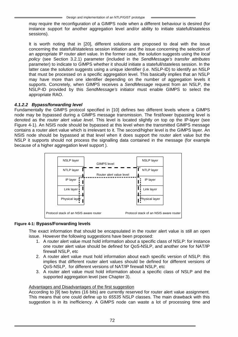
72
Design and implementation of an NTLP/GIST prototype
may require the reconfiguration of a GIMPS node when a different behaviour is desired (for instance support for another aggregation level and/or ability to initiate statefull/stateless sessions). It is worth noting that in [20], different solutions are proposed to deal with the issue concerning the statefull/stateless session initiation and the issue concerning the selection of an appropriate IP router alert value. In the former case, the solution suggests using the local policy (see Section 3.2.1) parameter (included in the SendMessage’s transfer attributes parameter) to indicate to GIMPS whether it should initiate a statefull/stateless session. In the latter case the solution suggests using a unique identifier (i.e. NSLP-ID) to identify an NSLP that must be processed on a specific aggregation level. This basically implies that an NSLP may have more than one identifier depending on the number of aggregation levels it supports. Concretely, when GIMPS receives a SendMessage request from an NSLP, the NSLP-ID provided by this SendMessage’s initiator must enable GIMPS to select the appropriate RAO.
4.1.2.2 Bypass/forwarding level Fundamentally the GIMPS protocol specified in [10] defines two different levels where a GIMPS node may be bypassed during a GIMPS message transmission. The first/lower bypassing level is denoted as the router alert value level. This level is located slightly on top op the IP-layer (see Figure 4-1). An NSIS node should be bypassed at this level when the transmitted GIMPS message contains a router alert value which is irrelevant to it. The second/higher level is the GIMPS layer. An NSIS node should be bypassed at that level when it does support the router alert value but the NSLP it supports should not process the signalling data contained in the message (for example because of a higher aggregation level support ).
Figure 4-1: Bypass/Forwarding levels
The exact information that should be encapsulated in the router alert value is still an open issue. However the following suggestions have been proposed:
1. A router alert value must hold information about a specific class of NSLP: for instance one router alert value should be defined for QoS-NSLP, and another one for NAT/IP firewall NSLP, etc
2. A router alert value must hold information about each specific version of NSLP: this implies that different router alert values should be defined for different versions of QoS-NSLP, for different versions of NAT/IP firewall NSLP, etc
3. A router alert value must hold information about a specific class of NSLP and the supported aggregation level (see Chapter 3).
Advantages and Disadvantages of the first suggestion According to [9] two bytes (16 bits) are currently reserved for router alert value assignment. This means that one could define up to 65535 NSLP classes. The main drawback with this suggestion is in its inefficiency. A GIMPS node can waste a lot of processing time and
Physical layer
Link layer
IP layer
NTLP layer
NSLP layer
Protocol stack of an NSIS aware router
Physical layer
Link layer
IP layer
NTLP layer
NSLP layer
Protocol stack of an NSIS aware router
Router alert value level
GIMPS level
73
Design and implementation of an NTLP/GIST prototype
capacity, intercepting and handling messages (because it supports the router alert value), which might later (in the GIMPS layer) not be processed by the NSLPs their destined to. Consequently the GIMPS node will have to forward those messages.
Advantages and Disadvantages of the second suggestion The second suggestion is a refinement of the first one, but it has the same disadvantage. As a matter of fact if one makes sure that the different versions of an NSLP are compatible, the definition of a routing state for each version of an NSLP could be avoided.
Advantages and Disadvantages of the third suggestion The third suggestion, which is the one considered in the design presented in Chapter 3 is that which is considered to be the most acceptable. The main disadvantage of this suggestion is that it lowers the number of NSLP classes that could be defined. For instance if two aggregation levels are defined for a specific NSLP class, two different router alert values should be defined for that NSLP class. However a GIMPS node will perform more efficiently when one applies this suggestion for the simple reason that this GIMPS node will only invest its time and capacity to handle messages which will really be processed by the NSLPs their destined to.
4.1.2.3 Session states maintenance Regarding the issues related to the refresh of installed session states, the design presented in Chapter 3, sticks to the states management principles defined in [10]. However one should note that the GIMPS protocol specified in [20] provides a mechanism that enables both the querying node and the responding node to synchronise their routing states lifetimes. This mechanism involves a recently defined GIMPS object denoted as the Network Layer Information (NLI) object. In the GIMPS specification presented in [20] the GIMPS message and the GIMPS Response message contain the NLI object. This object replaces in fact the Node Addressing Object (NAO), which is specified in [10]. One of the main differences between the NLI object and the NAO is that the NLI includes the so called Routing State Validity time parameter. The following text briefly explains the principle of routing states refresh based on the NLI object: During the discovery mechanism the querying node may assign some given value to the Routing State Validity time parameter of the NLI object that it will include in its GIMPS Query message. The value of this Routing State Validity time parameter will then be considered as the lifetime of the state that will be created (i.e. the routing state established as result of the initiated discovery procedure). At the other side the responding node may also assign a given value (this value will indicate to the querying node how long the responding node will retain the concerned state) to the Routing State Validity time parameter of the NLI object, which will be included in the GIMPS Response message. After the exchange of the GIMPS Query message and the GIMPS Response message, the querying node will get to know how long the created state will be valid at the responding node. In case the querying node notices that the state installed in the responding node is about to expire while it actually wants to use this state longer; it will generate a new GIMPS Query message (containing essentially a new NLI object with the desired state lifetime) which will be sent to the responding node. Upon receiving the Query message the responding node might update the lifetime of the concerned state with the value contained in the Routing State Validity parameter of the NLI object. 4.1.2.4 Type of Discovery procedure In the design presented in Chapter 3 both the 2- and 3-ways handshake are considered. Both types will also be implemented but the 3-ways handshake will be used as the default discovery mechanism, since it provides a better security. It is worth noting that the GIMPS protocol specified in [20] provides a solution to avoid the interoperability problems discussed in Section 4.1.1.4. This solution states that during the discovery procedure the responding node must request a GIMPS Confirm message, in case a connection mode of operation is required. This basically means that the 2-ways handshake discovery mechanism should be performed in datagram mode (for unreliable signalling data transfer) and the
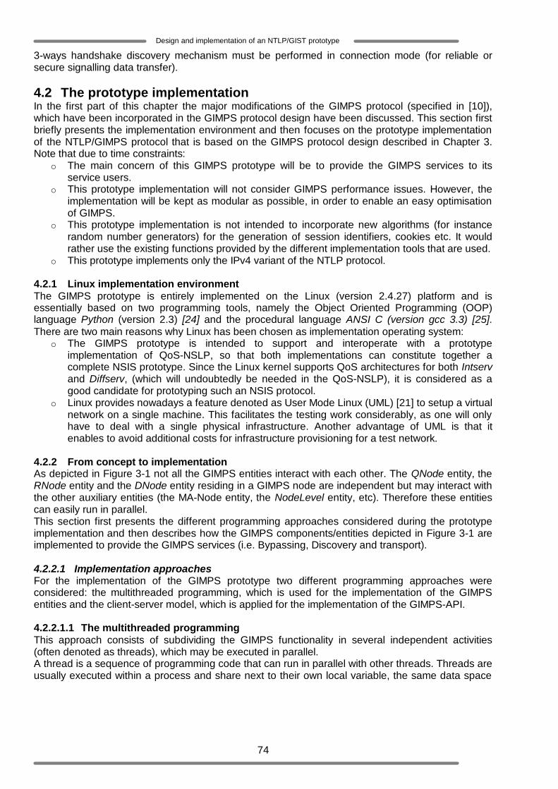
74
Design and implementation of an NTLP/GIST prototype
3-ways handshake discovery mechanism must be performed in connection mode (for reliable or secure signalling data transfer). 4.2 The prototype implementation In the first part of this chapter the major modifications of the GIMPS protocol (specified in [10]), which have been incorporated in the GIMPS protocol design have been discussed. This section first briefly presents the implementation environment and then focuses on the prototype implementation of the NTLP/GIMPS protocol that is based on the GIMPS protocol design described in Chapter 3. Note that due to time constraints:
o The main concern of this GIMPS prototype will be to provide the GIMPS services to its service users.
o This prototype implementation will not consider GIMPS performance issues. However, the implementation will be kept as modular as possible, in order to enable an easy optimisation of GIMPS.
o This prototype implementation is not intended to incorporate new algorithms (for instance random number generators) for the generation of session identifiers, cookies etc. It would rather use the existing functions provided by the different implementation tools that are used.
o This prototype implements only the IPv4 variant of the NTLP protocol. 4.2.1 Linux implementation environment The GIMPS prototype is entirely implemented on the Linux (version 2.4.27) platform and is essentially based on two programming tools, namely the Object Oriented Programming (OOP) language Python (version 2.3) [24] and the procedural language ANSI C (version gcc 3.3) [25]. There are two main reasons why Linux has been chosen as implementation operating system:
o The GIMPS prototype is intended to support and interoperate with a prototype implementation of QoS-NSLP, so that both implementations can constitute together a complete NSIS prototype. Since the Linux kernel supports QoS architectures for both Intserv and Diffserv, (which will undoubtedly be needed in the QoS-NSLP), it is considered as a good candidate for prototyping such an NSIS protocol.
o Linux provides nowadays a feature denoted as User Mode Linux (UML) [21] to setup a virtual network on a single machine. This facilitates the testing work considerably, as one will only have to deal with a single physical infrastructure. Another advantage of UML is that it enables to avoid additional costs for infrastructure provisioning for a test network.
4.2.2 From concept to implementation As depicted in Figure 3-1 not all the GIMPS entities interact with each other. The QNode entity, the RNode entity and the DNode entity residing in a GIMPS node are independent but may interact with the other auxiliary entities (the MA-Node entity, the NodeLevel entity, etc). Therefore these entities can easily run in parallel. This section first presents the different programming approaches considered during the prototype implementation and then describes how the GIMPS components/entities depicted in Figure 3-1 are implemented to provide the GIMPS services (i.e. Bypassing, Discovery and transport). 4.2.2.1 Implementation approaches For the implementation of the GIMPS prototype two different programming approaches were considered: the multithreaded programming, which is used for the implementation of the GIMPS entities and the client-server model, which is applied for the implementation of the GIMPS-API. 4.2.2.1.1 The multithreaded programming This approach consists of subdividing the GIMPS functionality in several independent activities (often denoted as threads), which may be executed in parallel. A thread is a sequence of programming code that can run in parallel with other threads. Threads are usually executed within a process and share next to their own local variable, the same data space

75
Design and implementation of an NTLP/GIST prototype
(i.e. global variables) and resources as the 23parent process[22][23]. This basically means that when a thread performs an operation on a variable, this variable will automatically be affected in all the other threads. Consequently, the other threads will be using this new variable in their individual computations. One of the major problems that may arise when multiple threads are modifying the same variable simultaneously is that this variable could end up being modified only once or not at all. This kind of problems (known as racing) makes the use of threads unsafe and can have severe consequences on the functionality of the parent process. Python (the programming tool used for this prototype implementation) provides a solution to enable a quasi safe multithreaded programming. It introduces a mechanism (based on the so called “lock” object) to synchronize the threads [24]. The basic principle is that within a process which deals with multiple threads, each thread can acquire or release the lock. The thread, which acquires the lock, is the one that is allowed to access and perform operations on the global shared resources. As soon as this thread releases the lock another thread may acquire it. Despite the solution provided by the lock object, it still has one big pitfall. The access to a free lock object is random and may cause starvation of certain threads or deadlocks. This means for instance that when a process consists of a large number of threads, some threads may never get the chance to acquire the lock or will have to wait a long time before acquiring it. To avoid the problems that the “locking” mechanism may engender in multithreaded programming, an alternative solution is proposed in the following paragraph. This solution is essentially based on the use of multiple independent threads (i.e. threads that only deals with their local variables) and the structured programming principles provided by Python. Alternative solution As any OOP language, Python provides the facility to interpret the GIMPS protocol design, presented in Chapter 3 into a well structured software system. The assets provided by Python enable each GIMPS entity to be totally represented by a software entity called in the Python jargon a class [24]. A class will be the description of a GIMPS entity’s states/properties and behaviour (these are denoted in the Python jargon as variables and functions, respectively); while a GIMPS entity itself will be an instance (denoted in python as class object) of its class. One benefit of using classes is that an unlimited number of class objects (instances) could be created from one single class. Beyong that, each of these class objects will own its instance variables (denoted in python as data attributes) and instance functions (denoted in python as methods). The key point of this solution is that by creating each class object within a thread, one could let these class objects perform their activities simultaneously without interfering with each other. Concretely, the data attributes and methods of a class object created within a thread become actually part of this thread’s local variables scope. Therefore this class object is only visible within this thread and any operation performed on the local variables will not affect other threads. Consequently, synchronisation of parallel threads is no more needed. Thus the proposed alternative solution excludes the use of the lock object and therefore does not have to deal with all the problems, it may cause. One of the results of this proposed solution regarding the GIMPS prototype implementation will be for instance, a system within a GIMPS node where multiple discovery procedures could be initiated or performed simultaneously (i.e. multiple QNode entities running in parallel or multiple RNode entities running in parallel, etc). As illustration, the procedure of a slave thread written in Python is depicted in Code 4-1. This slave thread defines its own local variables as shown in line 2. Line 2.i and line 2.ii show how the class object gimpsRespondingNode.Query_Handler(… ) is created within this thread.
23 The parent process (also denoted as main thread) in this case is the process associated to the program which starts a thread.

76
Design and implementation of an NTLP/GIST prototype
Code 4-1: Integration of a class object within a thread
The major benefits of the multithreaded programming o Parallel execution at the user level: In general there exist two different categories of threads.
The first one includes the kernel level threads (known as pthread in UNIX operating system and thread in Window’s operating system). These are quite similar to processes and may truly run in 24parallel in a multiprocessor system [25]. That is why the major advantage of kernel level multithreaded applications in a multiprocessor system is the increase of the processing speed. The second category includes the user level thread. Unlike the kernel level threads the user level threads are only visible within the parent process and can actually not be computed in parallel within the kernel. But at a higher abstraction level these threads seem to execute simultaneously and may be considered as parallel sub processes of the parent process.
o Asynchronous event: Multithreaded programming appeared to be very suitable for event based applications such as the GIMPS prototype. For instance by defining the operation related to each GIMPS API event that may occur, in a different thread, one could have these operations running in parallel and independently from each other. Additionally GIMPS must be able to deal with asynchronous events since it does not have any knowledge of the next incoming events. This means that it must be prepared to execute any kind of action related to the occurred event. Therefore having a separate thread for each event enables a more convenient and more efficient implementation.
4.2.2.1.2 Client-server model Traditionally the client-server model is a framework used to implement distributed applications. The server process usually runs on some computer system and waits for client’s requests. The client process may run on a different machine or on the same computer system. It sends requests to the server through the network which connects them. The fact that the communication between client and server goes trough a network often leads to unnecessary data overhead (due to transport and network protocols headers). The main characteristics of the client/server model that makes it interesting for GIMPS are the following:
o Heterogeneous processes: client and server processes may be implemented with different tools and on different platforms but can still intercommunicate with each other. This aspect implies that the implementation of NSLPs and GIMPS may completely be independent from
24 In a system consisting of a single processor (uniprocessor system) only one process can run at a time. But the operating system manage the existing processes in such a way that each process gets a turn to run within a certain time interval or time slice, also denoted as quantum. This means that the threads rather run one after each other in a cycle than simultaneously. However the speed of this cyclic operation gives the impression that these threads are running at the same time. Unlike uniprocessor system, multiprocessor system obviously consists of multiple processors. Therefore each process/thread can run on a different processor, enabling the achievement of true parallelism computation.
#DEFINITION OF THE RNODE SLAVE THREAD 1. class R_Thread(threading.Thread): 2. def __init__(self, rnewRport, rG_SAppId, rMsgBody, rrcvHost, rrcvPort,raddr):
i. threading.Thread.__init__(self) ii. … … … … .
3. def run(self): i. myRNode=gimpsRespondingNode.Query_Handler(self.rnewRp
ort, self.rG_SAppId, self.rMsgBody, self.rrcvHost, self.rrcvPort, self.raddr)
… … … … ii. myRNode.HandleQuery() iii. return 0

77
Design and implementation of an NTLP/GIST prototype
each other. Thus while implementing GIMPS one should not bother about integration issues with NSLPs.
o Use of sockets for interprocess communication: A socket is a strong software component that enables communication between two processes running within one computer system or on two distinct computer systems. It specifies the tuple (protocol, server-address, server-process/portnumber, remote/client-address, remote/client-process/port number) which uniquely defines each interprocess communication. Therefore the delivery of data to the right process is always guaranteed.
o Scalability: since the server process (GIMPS) is independent of the client processes (NSLPs), the amount of clients may easily be extended.
4.2.2.2 Implementation of GIMPS components The main functional blocks of the GIMPS prototype implementation are depicted in Figure 4-2. This prototype implements each GIMPS entity as a module, which basically regroups software objects by affinity. In order to preserve the separation of concerns and the granularity of the GIMPS protocol design presented in Chapter 3, the GIMPS prototype has been implemented according to a well defined structure described as follow:
1. The gimpApi.py module consists of the class gimpsApi. This module is the implementation of the GIMPS API as it is defined in Section 3.2.1. The major function of the gimpsApi is to send/receive the service primitives to/from the NSLP and resize them in appropriate formats. Hereafter it forwards the service primitives to the gimpsNodeLevel.py module.
2. The gimpsNodeLevel.py module consists of the class IncomingEvents and the class OutgoingEvents. This module is the implementation of the GIMPS Nodelevel entity as it is defined in Section 3.2.2.
a. The class IncomingEvents mainly implements a function to identify the incoming service primitives received from the gimpsApi and to process them (see Section 4.2.2.2.1).
b. The major function of the class OutgoingEvents is to receive data destined to NSLPs from the different GIMPS entities and to check the validity of this data. Hereafter, it forwards the received data to the gimpApi for formatting en transmission/delivery to the appropriate NSLP.
3. The gimpsQueryNode.py module consists of the class Query_Request_Handler and the class Confirm_Request_Handler. This module is the implementation of the GIMPS QNode entity as it is defined in Section 3.2.3.
a. The class Query_Request_Handler implements a function for the GIMPS Query message construction and encapsulation so that it can be intercepted by the appropriate adjacent peer (see Section 4.2.2.2.2). It also implements a mechanism to wait for GIMPS Response messages and to handle them. Finally the class Query_Request_Handler defines a function for the establishment and maintenance of routing- and eventually messaging association states (see Section 4.2.2.2.1).
b. The class Confirm_Request_Handler implements a function for the GIMPS Confirm message construction. It also implements a mechanism which enables it to evaluate the possibility of transmitting the constructed Confirm message using an existing messaging association.
4. The gimpsRespondingNode.py module consists of the class Query_Handler, the class NSLP_ReturnvalThread and the class RespondingNode. This module is the implementation of the GIMPS RNode entity as it is defined in Section 3.2.4.
a. The class Query_Handler implements a function for the GIMPS Query message handling and the delivery of an eventual NSLP data included in this GIMPS Query message to the class OutgoingEvent of the gimpsNodeLevel.py module.
b. The class NSLP_ReturnvalThread implements a function to evaluate the value retuned by the NSLP. The returned value is considered as the response to the data the Query_Handler class has sent to the NSLP via the OutgoingEvent class.
c. The class RespondingNode implements a function for the GIMPS Response message construction. It also implements a mechanism which enables it to evaluate the possibility of transmitting the constructed Response message using an existing
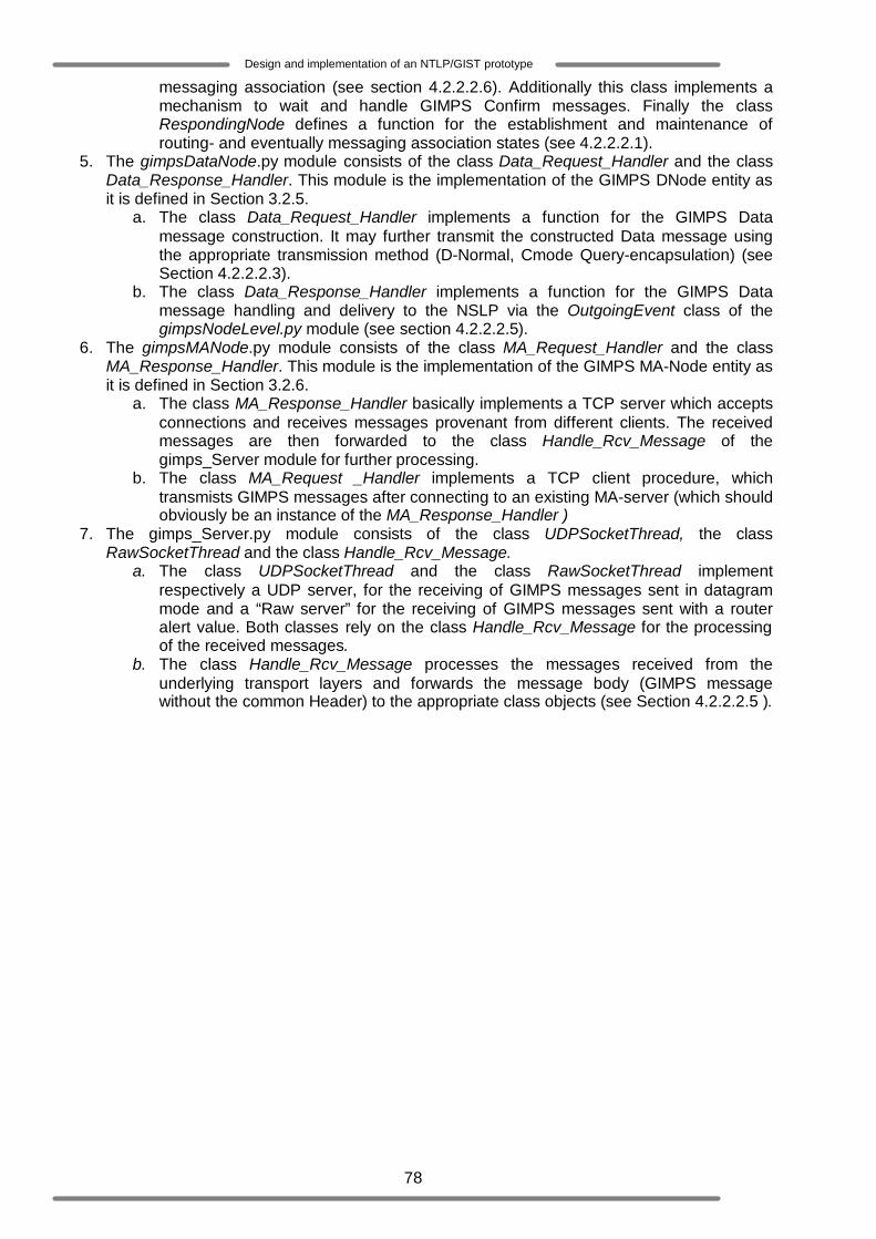
78
Design and implementation of an NTLP/GIST prototype
messaging association (see section 4.2.2.2.6). Additionally this class implements a mechanism to wait and handle GIMPS Confirm messages. Finally the class RespondingNode defines a function for the establishment and maintenance of routing- and eventually messaging association states (see 4.2.2.2.1).
5. The gimpsDataNode.py module consists of the class Data_Request_Handler and the class Data_Response_Handler. This module is the implementation of the GIMPS DNode entity as it is defined in Section 3.2.5.
a. The class Data_Request_Handler implements a function for the GIMPS Data message construction. It may further transmit the constructed Data message using the appropriate transmission method (D-Normal, Cmode Query-encapsulation) (see Section 4.2.2.2.3).
b. The class Data_Response_Handler implements a function for the GIMPS Data message handling and delivery to the NSLP via the OutgoingEvent class of the gimpsNodeLevel.py module (see section 4.2.2.2.5).
6. The gimpsMANode.py module consists of the class MA_Request_Handler and the class MA_Response_Handler. This module is the implementation of the GIMPS MA-Node entity as it is defined in Section 3.2.6.
a. The class MA_Response_Handler basically implements a TCP server which accepts connections and receives messages provenant from different clients. The received messages are then forwarded to the class Handle_Rcv_Message of the gimps_Server module for further processing.
b. The class MA_Request _Handler implements a TCP client procedure, which transmists GIMPS messages after connecting to an existing MA-server (which should obviously be an instance of the MA_Response_Handler )
7. The gimps_Server.py module consists of the class UDPSocketThread, the class RawSocketThread and the class Handle_Rcv_Message.
a. The class UDPSocketThread and the class RawSocketThread implement respectively a UDP server, for the receiving of GIMPS messages sent in datagram mode and a “Raw server” for the receiving of GIMPS messages sent with a router alert value. Both classes rely on the class Handle_Rcv_Message for the processing of the received messages.
b. The class Handle_Rcv_Message processes the messages received from the underlying transport layers and forwards the message body (GIMPS message without the common Header) to the appropriate class objects (see Section 4.2.2.2.5 ).

79
Design and implementation of an NTLP/GIST prototype
Figure 4-2: Overview of the major implemented GIMPS modules
4.2.2.2.1 The GIMPS NodeLevel implementation The multithreaded programming model used in the GIMPS prototype implementation fits in the well known Master-Slave model (also denoted as the Manager-Worker model). Typically, the Master is considered as the main thread. It responds to external events and creates among others other threads called Slaves to complete the required tasks. The gimpsNodeLevel.py module and in particular the IncomingEvents class plays the role of the master thread in the GIMPS prototype implementation. Figure 4-3 depicts the functional block of the IncomingEvents class of the gimpsNodeLevel.py module.
gimpsNodeLevel.py
IncomingEvents OutgoingEvents
gimpsQueryNode.py
Query_Request_Handler Confirm_Request_Handler
gimpsMANode.py
MA_Request_Handler MA_Response_Handler gimpsRespondingNode.py
Query_Handler NSLP_ReturnvalThread RespondingNode
gimpsDataNode.py
Data_Request_Handler Data_Response_Handler
gimps_Server.py
UDPSocketThread RawSocketThread Handle_Rcv_Message
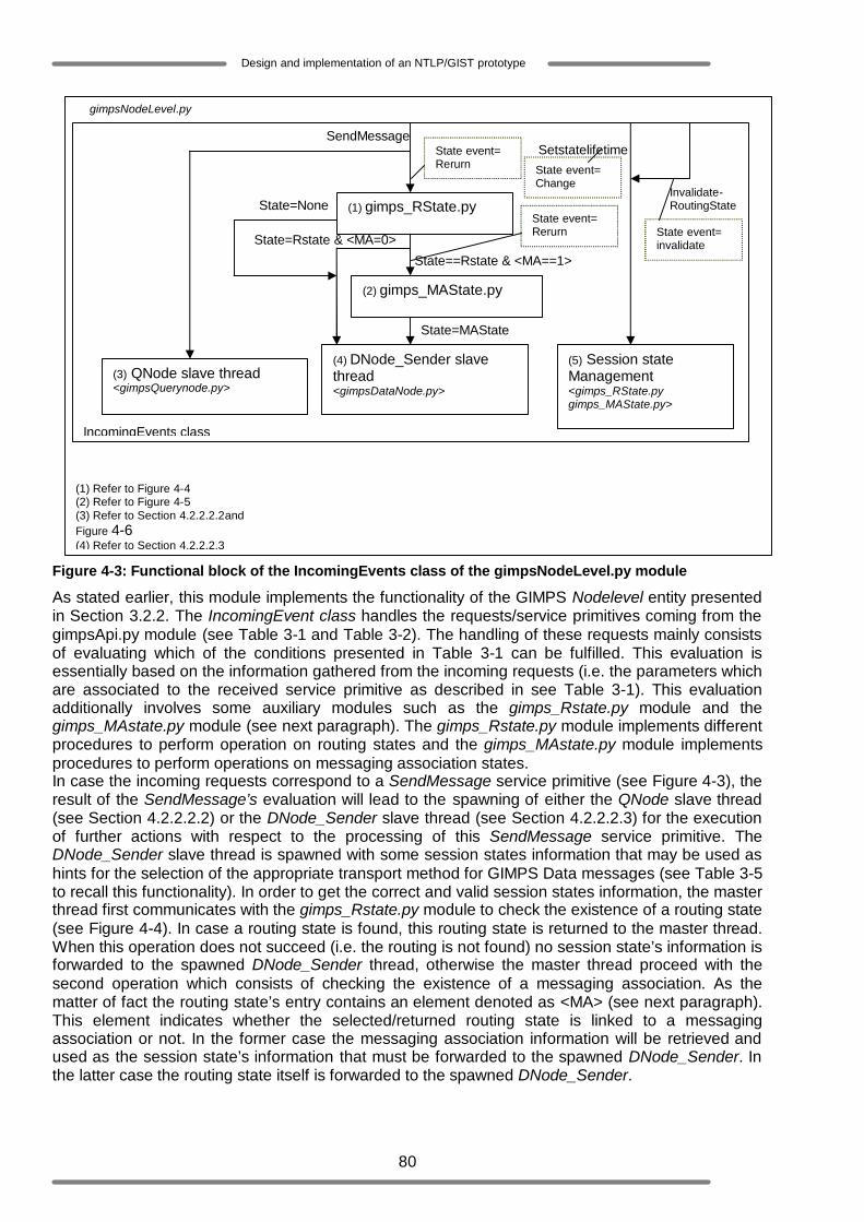
80
Design and implementation of an NTLP/GIST prototype
Figure 4-3: Functional block of the IncomingEvents class of the gimpsNodeLevel.py module
As stated earlier, this module implements the functionality of the GIMPS Nodelevel entity presented in Section 3.2.2. The IncomingEvent class handles the requests/service primitives coming from the gimpsApi.py module (see Table 3-1 and Table 3-2). The handling of these requests mainly consists of evaluating which of the conditions presented in Table 3-1 can be fulfilled. This evaluation is essentially based on the information gathered from the incoming requests (i.e. the parameters which are associated to the received service primitive as described in see Table 3-1). This evaluation additionally involves some auxiliary modules such as the gimps_Rstate.py module and the gimps_MAstate.py module (see next paragraph). The gimps_Rstate.py module implements different procedures to perform operation on routing states and the gimps_MAstate.py module implements procedures to perform operations on messaging association states. In case the incoming requests correspond to a SendMessage service primitive (see Figure 4-3), the result of the SendMessage’s evaluation will lead to the spawning of either the QNode slave thread (see Section 4.2.2.2.2) or the DNode_Sender slave thread (see Section 4.2.2.2.3) for the execution of further actions with respect to the processing of this SendMessage service primitive. The DNode_Sender slave thread is spawned with some session states information that may be used as hints for the selection of the appropriate transport method for GIMPS Data messages (see Table 3-5 to recall this functionality). In order to get the correct and valid session states information, the master thread first communicates with the gimps_Rstate.py module to check the existence of a routing state (see Figure 4-4). In case a routing state is found, this routing state is returned to the master thread. When this operation does not succeed (i.e. the routing is not found) no session state’s information is forwarded to the spawned DNode_Sender thread, otherwise the master thread proceed with the second operation which consists of checking the existence of a messaging association. As the matter of fact the routing state’s entry contains an element denoted as <MA> (see next paragraph). This element indicates whether the selected/returned routing state is linked to a messaging association or not. In the former case the messaging association information will be retrieved and used as the session state’s information that must be forwarded to the spawned DNode_Sender. In the latter case the routing state itself is forwarded to the spawned DNode_Sender.
gimpsNodeLevel.py
IncomingEvents class
(3) QNode slave thread <gimpsQuerynode.py>
(4) DNode_Sender slave thread <gimpsDataNode.py>
(5) Session state Management <gimps_RState.py gimps_MAState.py>
(1) gimps_RState.py
(2) gimps_MAState.py
State==Rstate & <MA==1>
State=MAState
State=None
State=Rstate & <MA=0>
Setstatelifetime SendMessage
Invalidate-RoutingState
State event= invalidate
State event= Rerurn
State event= Rerurn
State event= Change
(1) Refer to Figure 4-4 (2) Refer to Figure 4-5 (3) Refer to Section 4.2.2.2.2and Figure 4-6 (4) Refer to Section 4.2.2.2.3

81
Design and implementation of an NTLP/GIST prototype
In case the incoming request corresponds to the SetStateLifetime or the InvalidateRoutingState service primitive, the master thread (IncomingEvents class) performs all the required actions (see Section 3.2.2) itself. These tasks are basically related to the session states management, which is described along the next paragraph. Session state management Since the GIMPS protocol is designed to support different NSIS signaling protocols it must be capable of handling a large number of session states. However it is worth noting that the amount of session states, which may be installed within a GIMPS node, depends on the physical location of that node (for instance, the number of session states in a GIMPS node located at the edge of a GIMPS aware network might be larger than the one of an interior node). Session state handling is an important and challenging task for GIMPS. The difficulty of this task resides in the retrieval of specific session information (session state) from an erroneous number of other session states. Binary search trees and hash lookup tables [26] are well known techniques which might in future be evaluated in order to find out whether they can be used for GIMPS internal session state management. As mentioned in this chapter’s Introduction the evaluation and analyse of these techniques and/or algorithms are outside the scope of this thesis and will further not be discussed. Regarding the GIMPS prototype, session states are implemented as two distinct sets of the python built-in type dictionary [24]. The set of routing states consists of states which have the following semantic: {<MRI>:mri, <SID>:sid, <NSLP_ID>:NId, <Response_Dir>:ReverseHop, <Query_Dir>:nextHop, <IPHop_Count>:IPHopCount, <Life_Time>:Default_gLifeTime, <MA>:ma}. Table 4-1 explains briefly the role of each 25state’s elements. <Key> Value MRI This is the Message Routing Information (see Table 3-1) associated to the flows that
belongs to the session for which the state is created. SID This is the session identifier received from the SendMessage service primitive (see Table
3-1 and Section 2.3.1) NSLP_ID The NSLP identifier received from the SendMessage service primitive (see Table 3-1) Response_Dir This contains the IP address of the querying node Query_Dir This contains IP address of the responding node IPHop_Count This indicates the number of IP network elements between the querying node and the
responding node Life_Time This contains the default routing state life time or the StateLifetime value received from the
SetStateLifetime service primitive (see Table 3-1) MA This indicates whether the routing state has a messaging association (MA=1) or not (MA=0)
Table 4-1: Routing state entries
The semantic that corresponds to each state of the Messaging Association states set (MA-states set) is: {<peerID>:Peer_Identity, <outInt>:outInt, <incInt>:incInt, <Profile>:profiles, <Policies>:policies, <Port>:port, <state>:state} Table 4-2 explains briefly the role of each MA-state’s elements. <Key> Value peerID This is an identifier which is supposed to uniquely
identify every GIMPS node within a given GIMPS aware network
outInt This is the IP address of the outgoing interface through which the querying node sends the GIMPS query message.
incInt This is the IP address of the incoming interface where the responding node has received the GIMPS query
25 It is worth noting that all the routing- and messaging association state information are gathered during the discovery mechanism. This is due to the fact that the state information is essentially included in the GIMPS messages that are exchanged during the adjacent peer node discovery. One could refer to Appendix A to know in which GIMPS object the different state elements can be found.
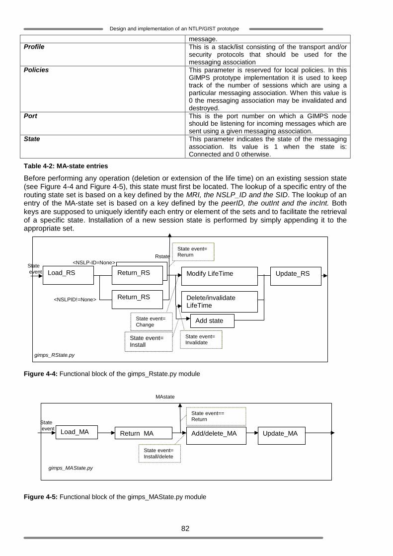
82
Design and implementation of an NTLP/GIST prototype
message. Profile This is a stack/list consisting of the transport and/or
security protocols that should be used for the messaging association
Policies This parameter is reserved for local policies. In this GIMPS prototype implementation it is used to keep track of the number of sessions which are using a particular messaging association. When this value is 0 the messaging association may be invalidated and destroyed.
Port This is the port number on which a GIMPS node should be listening for incoming messages which are sent using a given messaging association.
State This parameter indicates the state of the messaging association. Its value is 1 when the state is: Connected and 0 otherwise.
Table 4-2: MA-state entries
Before performing any operation (deletion or extension of the life time) on an existing session state (see Figure 4-4 and Figure 4-5), this state must first be located. The lookup of a specific entry of the routing state set is based on a key defined by the MRI, the NSLP_ID and the SID. The lookup of an entry of the MA-state set is based on a key defined by the peerID, the outInt and the incInt. Both keys are supposed to uniquely identify each entry or element of the sets and to facilitate the retrieval of a specific state. Installation of a new session state is performed by simply appending it to the appropriate set. Figure 4-4: Functional block of the gimps_Rstate.py module
Figure 4-5: Functional block of the gimps_MAState.py module
gimps_RState.py
<NSLPID!=None>
<NSLP-ID=None> Rstate
Update_RS Modify LifeTime
Delete/invalidate LifeTime
Return_RS
Return_RS Load_RS State event
State event= Rerurn
State event= Change
State event= Invalidate
Add state
State event= Install
State event== Return
Return_MA Add/delete_MA Update_MA Load_MA
MAstate
State event= Install/delete
State event
gimps_MAState.py

83
Design and implementation of an NTLP/GIST prototype
4.2.2.2.2 QNode slave thread The QNode slave thread is spawned to initiate and eventually setup a new session state, if required. It executes the gimpsQueryNode.py module, which implements the behaviour of the QNode entity presented in section 3.2.3. To limit the interactions between the QNode slave thread and the master thread (NodeLevel), the master thread first forwards all the necessary information to the slave so that it can execute its tasks individually. Hereafter it starts the QNode slave thread. As soon as this thread is started the master thread resumes with its own activity. The operations executed by the QNode slave thread are quite sequential and may be grouped in four blocks of operations. These operations are summarized in Figure 4-6.

84
Design and implementation of an NTLP/GIST prototype
Figure 4-6: Functional block of the gimpsQueryNode.py module The first block of operations: consists of the creation of the GIMPS Query message (see Appendix A) based on the information provided by the master thread. The core operation of this
Create Query Message
Encapsulate Query Message in UDP and create its IP header with RAO
Create Raw socket to send encapsulated Query Message
Listen for GIMPS response
Start waiting response timer t
no
yes
yes
no
T=remainig T-TO TO=2^ TO
Start T
Send/resend Query Message
(1)T-TO>0
(1) TO=timeout value included the sendmessage service primitive T= wait response timer (30 seconds by default) (2) Refer to Figure 4-4 and Figure 4-5 (3) See Section 3.2.3 to recall the conditions that shoulf be fulfilled for the establishment of the messaging association state (4) See Section 4.2.2.2.1 (5)This opreration depends on the configuration of the concerned GIMPS node
(2)gimps_Rstate.py (3)and/or gimps_MAState
State event= Install
(4)Session states maintenance
Fourth block of operation
thrird block of operation
First block of operation
second block of operation
gimpsQueryNode.py
t expired? Response received& correct?
(5) Create and Send Confirm Message

85
Design and implementation of an NTLP/GIST prototype
block is the encapsulation of this Query message into lower layers (UDP and IP) PDUs so that it can be intercepted by the right GIMPS node along the data path. To enable the Query message interception, the router alert value has to be included in the options field [27] of this message’s IP header. Typically the “options” field of IP datagrams headers is not set. And since that field is not broadly used, no mechanism has been implemented to enable one to assign a value to the “options” field without interfering with the IP protocol. Consequently when an application assigns a value to the “options” field, it directly provides the complete IP header to the IP layer. This implies that it is up to the QNode thread to provide the complete IP header including the right RAO value to the Query message. The last step of this block is the transfer of the constructed IP datagram. Raw sockets are the most appropriate sockets in this case because it provides a mean to inform the underlying 26IP layer that a header has already been added to the message. This operation is shown on line 3.ii of Code 4-2 which is a batch containing some relevant source codes. Line 2.i shows the initialisation of a raw socket to transport a UDP packet. Line 3.iii finally shows how the packet is sent towards a destination denoted as “host”.
Code 4-2: Use of raw socket for transport of IP encapsulated packet
The second block of operation: consists of waiting for a GIMPS Response message. In fact this block of operations corresponds to the implementation of the “waitresponse” state described in Table 3-3. GIMPS Response messages originate from other GIMPS nodes and are therefore received from the underlying GIMPS transport layers (UDP or TCP). The GIMPS prototype implements a 27daemon server (see Section 4.2.2.2.5) as an independent process that directly communicates with the transport layer and receives all data destined to the GIMPS entities running within their parent process. Before waiting for a GIMPS Response message the QNode slave threads first have to know how this response message will get to them. Thus, a mechanism should be implemented to enable the communication between the GIMPS server daemon and the different slave threads. Therefore the following approaches have been evaluated:
o Use of Python’s built-in condition object: the condition object is a tool provided by Python to enable a parent process/master thread to notify its slave threads which are waiting for a particular condition to hold or an event to occur. In order to use this approach the GIMPS server daemon should be integrated in the NodeLevel master thread so that they can constitute together one process. It should be clear that this integration will affect the granularity and “the separation of concerns” properties provided by the design proposed in Chapter 3. Beyong that, this approach does not provide a mean to forward/pass data to slave threads. Additionally the use of this approach is unsafe because there is a high probability of starvation of some threads. This is mainly due to the implementation of the
26 The IP layer needs to be explicitly informed about IP encapsulations performed by its upper layers; otherwise it will consider the received IP encapsulated GIMPS Query messages as its payload. Consequently it will re-encapsulate these messages and the RAO value will be hided from the network elements (including GIMPS nodes) along the data path. 27 A daemon process is basically a process running in the background within the kernel
#This socket might be used in order to send data towards another NTLP/GIMPS Node 1. class GIMPS_OI_IPv4_Socket(socket.socket): 2. def __init__(self):
i. socket.socket.__init__(self, socket.AF_INET, socket.SOCK_RAW, gimpsInet.IPPROTO_UDP)
# Sends data on a socket. 3. def my_send(self, packet, host):
i. hincl = 1 # 1 = on, 0 = off * ii. self.setsockopt(gimpsInet.IPPROTO_IP, gimpsInet.IP_HDRINCL,
hincl) iii. r = self.sendto(packet, (host, gimpsVar.GIMPS_Server_Port)) iv. self.close() v. return r

86
Design and implementation of an NTLP/GIST prototype
condition object in the Python interpreter. The interpreter basically maintains a list of threads waiting for a condition to be satisfied. When the parent process sends a notification to these threads the interpreter always attempts to notify the first ‘n’ waiting threads from the list. Consequently the remaining waiting threads will never get a notification [32].
o Interprocess communication via local sockets: The principle of this approach is that each
QNode slave thread gets dynamically a port number (AF_UNIX port number [24]) at which it will internally be listening to GIMPS response messages. All the port numbers of QNode slave threads which are waiting for a response are registered by the server so that it can forward the GIMPS Response messages to them. As soon as a QNode thread receives the appropriate response it releases its port number, which could then be assigned to another QNode thread. The major advantage of this approach is that the number of (AF_UNIX) ports is not limited and this makes GIMPS scalable. Any way due to time constraints other approaches could not be evaluated, thus for the current GIMPS prototype implementation this approach has been selected since it is much safer and less risky than the first approach.
During the waiting response operation (see Figure 4-6) the QNode slave thread mainly listens to the port number assigned to it. This operation further involves the timeout parameter of the SendMessage service primitive (see Table 3-1) and the default maximum waiting response time. In case the timeout value is not null, it is considered as the time interval within which the QNode thread may resend the Query message when an incorrect response is received. The default waiting time defined by the GIMPS protocol specification is 30 seconds. Typically when a GIMPS Response is received within this waiting time the slave thread resumes with the third block of operations which is described in the next paragraph, otherwise it simply exits. Note that no state will be installed in the latter case. In case an erroneous GIMPS Response is received within the waiting time slice and the timeout value is still valid, the slave thread discards this response, and then it exponentially increases the timeout value and resends the Query message. Hereafter this second block of operation is repeated. The third block of operation: consists of the installation and/or manipulation of session states. GIMPS session states set should in general be accessible by any slave threads. This third operation faces thus the threads synchronisation problem discussed in Section 4.2.2.1.1. In the present case it is obvious that the proposed alternative solution cannot be applied, since the session states are part of the global resources of the GIMPS process. However, by minimizing the operations performed by each thread when it holds the lock object, starvation problems can considerably be avoided. The lock object is thus used as follow: each slave thread must acquire the lock object before accessing the session states. But to minimise the waiting time of other threads to acquire the lock, each slave thread holds the lock object during a very small time slice, which is for instance the time needed to append a new state to the existing session states or to delete an existing session state. At the end of this operation a GIMPS confirm message may be created and sent back to the responding node, provided that the concerned node is configured to perform a 3-ways handshake discovery mechanism (see 4.1). In case the 3-ways handshake is required, and a messaging association was not setup during the session states installation the QNode thread will send the Confirm message back to the responding node by means of a datagram socket. Note that the responding node’s address is learned as soon as the Response message is received. In case a messaging association has been setup the QNode thread creates an MA- client to send the GIMPS Response message to the appropriate MA-server which is obviously expected to be running at the responding node. The fourth block of operation: consists of the session state handling (see Code 4-3 ). The main steps of this operation are listed in the batch of source code presented in Code 4-3. Each slave thread is responsible for handling the session state it has installed. The default routing state lifetime specified in the GIMPS protocol specification is 30 second. Therefore after the completion of the third operation the slave thread is put in a sleeping mode during 30 seconds (see Line 1). As soon as it wakes up it accesses the routing states set, deletes the state it has installed and exits (see Line 5.d.i – Line 5.d.iii), provided that the lifetime of this state has not been extended by the NodeLevel in

87
Design and implementation of an NTLP/GIST prototype
the mean time (see Line d.c). In case the lifetime has been modified the sleeping time is set to the new value of the lifetime (see Line 5.c.ii) and the fourth operation is repeated. It is also possible that the installed routing state is deleted by the master thread on request of an NSLP (see Section 3.2.2). In such a case the QNode thread simply exits.
Code 4-3: Session state management
4.2.2.2.3 DNode_Sender slave thread The DNode_Sender slave thread is spawned to send NSLP messages of some session. It executes the DNode_Request_Handler class (of the gimpsDataNode.py module), which implements the sending behaviour of the DNode entity presented in section 3.2.5.The interactions between the DNode_Sender slave thread and the master thread is also very limited. Before starting the DNode_Sender slave thread, the master slave forwards all the necessary information (including session’s routing and/or messaging association states information if they exist) to the slave (see section 4.2.2.2.1) so that it can transport the data. Hereafter the master slave resumes with its own activity. In case no session state information is provided, the DNode_Sender slave thread uses the same IP message encapsulation mechanism as the QNode thread (see previous paragraph) to sent the GIMPS Data Message. In case only routing state information is provided the DNode_Sender slave thread simply sends the Data message by means of a datagram socket. Note that in such a case the GIMPS Data is directly addressed to the GIMPS node identified by the 28routing state. In case an 29MA- state is provided the DNode_Sender slave thread creates an MA-client (which is for this GIMPS prototype a TCP client) which will first connect to the MA-server (TCP server identified by the given MA-state) and sends the Data message to this server by means of a stream socket. 4.2.2.2.4 GIMPS messages interception (IP layer) Typically IP packets that are not destined to a host are forwarded towards the final destination node. Since GIMPS messages are rather meant to adjacent peers regardless the final destination’s
28 Here, the routing state refers specifically to the value indicated by the <Response_Dir> or <Query_Dir> keys 29 Here, the MA-state essentially refers to a port number, indicated by the <Port> key and an IP address, indicated by the <outInt> or <incInt> key at which the receiving node is expected to be listening for incoming GIMPS messages
def ManageRS(lftime, mySid): mngTble=True while (mngTble):
1. time.sleep(lftime) 2. #load appropriate routing state 3. OwnStateCls=gimps_RState.ReturnRS() 4. rs_Tble=gimps_RState.Load_RTble() 5. try:
a. OwnState=OwnStateCls.rtn_entry(table=rs_Tble, sid_entry=mySid) b. OwnLfTime=OwnState[gimpsVar.rsLife_Time] c. if(OwnLfTime>lftime):
i. #maintain the routing state ii. lftime=OwnLfTime-lftime
d. else: i. RState=gimps_RState.UpdateRS()
ii. RState.del_entry(mySid) iii. mngTble=False iv. … … … … … .. v. return 0
..............
88
Design and implementation of an NTLP/GIST prototype
address, the GIMPS prototype implementation has to implement a mechanism to enforce the interception of IP packets containing GIMPS messages by adjacent peers. The mechanism that will enable the GIMPS messages interception will mainly concern GIMPS Query messages and in some cases GIMPS Data messages, for these messages are the ones which are sent using the query encapsulation (i.e. these messages are encapsulated in an IP datagram containing a specific RAO value) (see also Section 2.3.2.3.2.2). These messages have to be intercepted by the first GIMPS node along their data path, which recognizes their RAO values. IP packets interception mechanisms Nowadays there exist different techniques to intercept IP packets in the Linux operating system. However, not all these techniques match the criteria of GIMPS messages interception. These criteria are listed below:
1. Once an IP packet containing the GIMPS message is intercepted it must not be forwarded towards its destination
2. An intercepted IP packet containing the GIMPS message should not be a copy of an IP packet that is flowing towards its final destination
3. IP packets containing GIMPS messages that are not intercepted should be safely forwarded towards their destination
In the following paragraphs the explored IP packets interception techniques will be evaluated based on the above mentioned criteria:
o Raw sockets: these sockets provide in Linux a mechanism to listen and receive a copy of a packet flowing through the network, regardless these packets final destination. This basically means that Raw sockets do not allow true packets interception as they do not stop the packets from propagating and flowing towards their final destination. As conclusion this mechanism does not match the second listed criterion and could therefore not be used for GIMPS message interception.
o Libpcap: This is another technique that enables “interception” of packets which are received on a specific interface. Similarly to Raw sockets, Libpcap does not match the second criterion, as they do not stop the packets from propagating and flowing towards their final destination. Therefore it cannot be used for GIMPS message interception [29].
o Divert sockets: These sockets provide a mechanism to intercept packets by using firewall rules and to forward the intercepted packets to different ports. This means that intercepted packets can be received by distinct user space processes which are listening on the given ports. Additionally Divert socket enable packets that do not match the firewall filters to be safely reinjected in the network. Divert sockets seem to provide a simple and robust mechanism for packet interception, but this mechanism is only implemented in the older versions of Linux (up to Linux version 2.2.19). In the current Linux versions Netlink sockets [28] are proposed as a good replacement.
o Netlink sockets: the main functionalities of Netlink are among others to allow communication between the Linux kernel space and user space, to allow communication with the IP routing system and to enable IP packets interception. Similarly to Divert sockets, IP packets interception is based on firewall filters. The basic principle is to check whether incoming IP packets match the filters, which naturally must have been installed in the kernel. The packets that match these filters should then be forwarded to the user space; otherwise they should be forwarded or reinjected in the network towards their destination. According to the described principle the Netlink mechanism is a good candidate for GIMPS message interception. However, unlike Divert sockets, Netlink sockets have no ports. Therefore it is difficult to let, for instance different processes intercept packets which are redirected by different firewall filters. Nevertheless, this drawback does not affect the GIMPS prototype implementation since this prototype is seen as a single process from the kernel level perspective. Consequently, Netlink sockets are the selected solution for the Gimps message interception in the GIMPS prototype.
Byspass/forwarding implementation The implementation of bypassing strongly relates to the use of Netlink sockets. Netlink sockets work in conjunction with iptables. Iptables can be defined as sets of firewall rules/filters that have to be
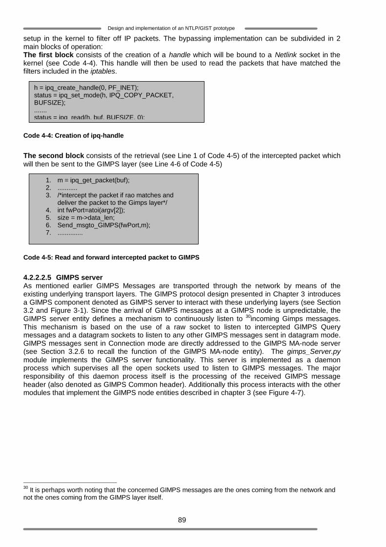
89
Design and implementation of an NTLP/GIST prototype
setup in the kernel to filter off IP packets. The bypassing implementation can be subdivided in 2 main blocks of operation: The first block consists of the creation of a handle which will be bound to a Netlink socket in the kernel (see Code 4-4). This handle will then be used to read the packets that have matched the filters included in the iptables.
Code 4-4: Creation of ipq-handle
The second block consists of the retrieval (see Line 1 of Code 4-5) of the intercepted packet which will then be sent to the GIMPS layer (see Line 4-6 of Code 4-5)
Code 4-5: Read and forward intercepted packet to GIMPS
4.2.2.2.5 GIMPS server As mentioned earlier GIMPS Messages are transported through the network by means of the existing underlying transport layers. The GIMPS protocol design presented in Chapter 3 introduces a GIMPS component denoted as GIMPS server to interact with these underlying layers (see Section 3.2 and Figure 3-1). Since the arrival of GIMPS messages at a GIMPS node is unpredictable, the GIMPS server entity defines a mechanism to continuously listen to 30incoming Gimps messages. This mechanism is based on the use of a raw socket to listen to intercepted GIMPS Query messages and a datagram sockets to listen to any other GIMPS messages sent in datagram mode. GIMPS messages sent in Connection mode are directly addressed to the GIMPS MA-node server (see Section 3.2.6 to recall the function of the GIMPS MA-node entity). The gimps_Server.py module implements the GIMPS server functionality. This server is implemented as a daemon process which supervises all the open sockets used to listen to GIMPS messages. The major responsibility of this daemon process itself is the processing of the received GIMPS message header (also denoted as GIMPS Common header). Additionally this process interacts with the other modules that implement the GIMPS node entities described in chapter 3 (see Figure 4-7).
30 It is perhaps worth noting that the concerned GIMPS messages are the ones coming from the network and not the ones coming from the GIMPS layer itself.
1. m = ipq_get_packet(buf); 2. ........... 3. /*intercept the packet if rao matches and
deliver the packet to the Gimps layer*/ 4. int fwPort=atoi(argv[2]); 5. size = m->data_len; 6. Send_msgto_GIMPS(fwPort,m); 7. ..............
h = ipq_create_handle(0, PF_INET); status = ipq_set_mode(h, IPQ_COPY_PACKET, BUFSIZE); ....... status = ipq_read(h, buf, BUFSIZE, 0);
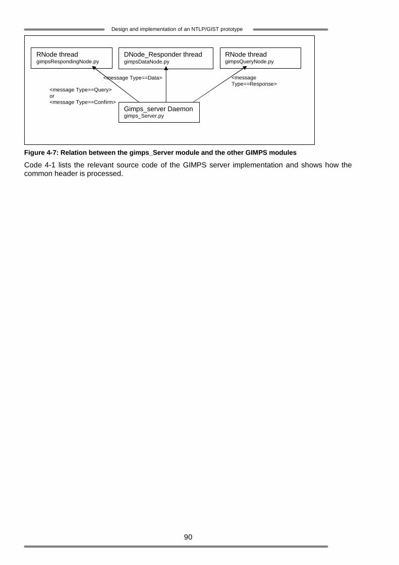
90
Design and implementation of an NTLP/GIST prototype
Figure 4-7: Relation between the gimps_Server module and the other GIMPS modules
Code 4-1 lists the relevant source code of the GIMPS server implementation and shows how the common header is processed.
Gimps_server Daemon gimps_Server.py
RNode thread gimpsRespondingNode.py
DNode_Responder thread gimpsDataNode.py
RNode thread gimpsQueryNode.py
<message Type==Query> or <message Type==Confirm>
<message Type==Data> <message Type==Response>

91
Design and implementation of an NTLP/GIST prototype
Code 4-6: GIMPS messages processing GIMPS Common header processing The handling of the common header (see Code 4-6 ) consists mainly of analyzing the following header fields. These fields are part of the GIMPS common header defined in [10] and in Appendix [A].
def Decode_Message(self, rcvData, rcvHost, rcvPort, addr): … … … ..
1. MsgCommonHeader=rcvData[0:gimpsMsg.Common_Header_Length] 2. MsgBody=rcvData[gimpsMsg.Common_Header_Length:] 3. rcvHeader=gimpsMsg.GIMPS_CommonHeader(MsgCommonHeader) 4. if (rcvHeader.Version!= gimpsVar.MY_GIMPS_Version):
a. print_error("Wrong version number") b. err_Code=10 c. return err_Code
5. #check NSLP ID 6. if (rcvHeader.G_SAppId in gimpsVar.NSLPIDs):
a. self.NId=rcvHeader.G_SAppId 7. else:
a. err_Code=10 b. return err_Code #Node does not support NSLPID, ignore everything
8. #check message length 9. if((rcvHeader.G_MsgLength*4)!=len(MsgBody)):
a. print_error("wrong message") b. err_code=10 c. return err_code
10. #Determine receided message 11. if (rcvHeader.G_Type==gimpsVar.Query):
a. #create an instance of the responding node to handle among others the query message b. … … … … … .. c. myR_Thread=R_Thread(newRport,rcvHeader.G_SAppId,MsgBody, rcvHost,
rcvPort,addr) d. … … … … … … e. myR_Thread.start()
12. elif (rcvHeader.G_Type==gimpsVar.Response): a. #send event to the appropriate query node b. NodeParameterTuple=(rcvHeader.G_SAppId, MsgBody, rcvHost, rcvPort)
… … … .. c. PacketToNode=pickle.dumps(NodeParameterTuple) d. IISocket.my_send(PacketToNode,Qport) e. … … … ..
13. elif (rcvHeader.G_Type==gimpsVar.Confirm): a. #send event to the appropriate responding node b. … … … … . c. PacketToNode=pickle.dumps(NodeParameterTuple) d. … … … .. e. IISocket.my_send(PacketToNode,Rport) f. … … … ..
14. elif (rcvHeader.G_Type==gimpsVar.Data): a. #create an instance of the data node to handle among others the data message b. … … c. myD_Thread=D_Thread(rcvHeader.G_SAppId,MsgBody, rcvHost, rcvPort) d. … … … e. myD_Thread.start() f. ................
92
Design and implementation of an NTLP/GIST prototype
o Version: the version field is checked to make sure that it is compatible with the GIMPS protocol implemented in the processing GIMPS node. In case it is incompatible the message is simply discarded (see Line 4).
o Message length: the Message length field is compared with the total length of the GIMPS payload (see Appendix A). In case both lengths do not match the received message is discarded (see Line 9).
o Signaling application ID: the Signaling application ID field contains the NSLP-ID the received message is addressed to. The question is whether the receiving GIMPS Node supports that signalling message or not (see Line 6-7). In this GIMPS prototype implementation this operation is not needed since it is implicitly performed in the bypass/forwarding function (see Section 3.5).
o Type: the type field indicates which type of GIMPS message is included in the payload (i.e. whether the received message is a GIMPS Query, GIMPS Response, GIMPS Confirm or GIMPS Data message). Further processing of the received message depends on the value of this field (see Line 11, 12, 13 and 14).
Query Message processing When the common header type field indicates that a Gimps Query Message has been received the server process spawns an RNode thread (see Line 11.c and 11.e). Note that the server daemon becomes in that case the master thread of the spawned slave thread. This master forwards all the necessary information to the spawned RNode thread so that the RNode can execute its task individually. This is also done, to limit interaction between them. As soon as the RNode thread is started the master thread resumes with its own activity (listening of new incoming Gimps messages). GIMPS Response Message processing When the common header type field indicates that a Gimps Response Message has been received, the server simply forwards it to the QNode threads which are waiting for a GIMPS Response; provided that these QNode threads have registered their listening port numbers by the GIMPS server (see Line 12.d). Upon receiving the Response message the QNode slave thread may create a Confirm message which will be sent back to the responding node. Hereafter it installs the required session states as explained in Section 4.2.2.2.2. GIMPS Confirm Message processing When the common header type field indicate that a Gimps Confirm Message has been received. The server forwards it to the RNode threads which are waiting for a GIMPS Response (see Line 13.d). The appropriate RNode thread will then proceed with the processing of the Confirm message (see Section 4.2.2.2.6). GIMPS Data Message processing When the common header type field indicates that a Gimps Data Message has been received. The server first spawns a DNode _Responder slave thread (see Line14.c and 14.e). This DNode _ Responder thread is completely different than the DNode_Sender thread discussed in Section 4.2.2.2.3, for it performs different operations (described in the DNode _Responder class) and does actually not interfere with the DNode_Sender. The server then forwards the Data message to the DNode _Responder thread for further processing. The DNode_responder class of the DNode entity handles the received Data Message and deliver the included GIMPS message to the appropriate NSLP. 4.2.2.2.6 The RNode slave thread The RNode slave thread is spawned to respond to the GIMPS querying node, setup a new session state if required and deliver the NSLP data included in the received GIMPS Query message. It executes the gimpsRespondeinNode.py module, which implements the behaviour of the RNode entity presented in section 3.2.4. The operations performed by the RNode slave thread are grouped in three blocks of operations and summarize in the Figure 4-8 .
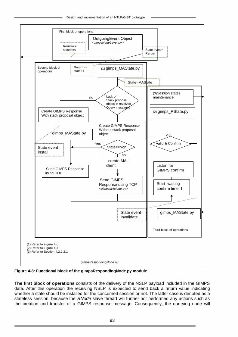
93
Design and implementation of an NTLP/GIST prototype
Figure 4-8: Functional block of the gimpsRespondingNode.py module
The first block of operations consists of the delivery of the NSLP payload included in the GIMPS data. After this operation the receiving NSLP is expected to send back a return value indicating whether a state should be installed for the concerned session or not. The latter case is denoted as a stateless session, because the RNode slave thread will further not performed any actions such as the creation and transfer of a GIMPS response message. Consequently, the querying node will
Create GIMPS Response Without stack proposal object
(1) Refer to Figure 4-5 (2) Refer to Figure 4-4 (3) Refer to Section 4.2.2.2.1
Send GIMPS Response using TCP <gimpsMANode.py>
(1) gimps_MAState.py
State=MAState
Rerurn== stateful
State event= Rerurn
OutgoingEvent Object <gimpsNodeLevel.py>
Rerurn== stateless
create MA-client
Send GIMPS Response using UDP
Lack of Stack proposal object in reveived Query message?
Create GIMPS Response With stack proposal object
gimps_MAState.py
State event= Install
no
State==None
yes
no
Listen for GIMPS confirm
Start waiting confirm timer t
T valid & Confirm
(2) gimps_RState.py
yes
(3)Session states maintenance
gimps_MAState.py State event= Invalidate
First block of operations
Second block of operations
Third block of operations
gimpsRespondingNode.py
94
Design and implementation of an NTLP/GIST prototype
never receive a response from the responding node and will also end up not installing any session states. In the former case the second block of operation is performed. The second block of operations consists of the creation of the GIMPS Response message based on the information provided by the master thread. Hereafter the RNode slave thread checks the MA-states set whether a messaging association already exists between the querying node and the responding node it belongs to. Secondly it checks (by looking for the presence of the Stack proposal object in the received Query message), whether the querying node has requested the installation of an MA-state.
o In case there is no messaging association and no stack proposal object, the RNode thread will send the Response message back to the querying node by means of a datagram socket. Note that the querying node address is learned as soon as it is received.
o In case a messaging association does exist the RNode thread creates an MA client to send the GIMPS Response message to the appropriate MA-server which is obviously expected to be running at the querying node.
o In case the stack proposal object is present and there is no existing messaging association between the querying node and the responding node, the RNode thread installs the MA-state by appending it to the MA-states set and creates the MA-server to listen to future incoming clients connections originating from the querying node. After the Response message has been sent the third block of operations is executed.
The third block of operations incorporates the waiting operation for a GIMPS Confirm messages. The default waiting time for a GIMPS Confirm message is 30 seconds GIMPS Confirm messages may be received via a typical datagram socket in datagram mode of operation or via stream sockets in connection mode of operation. Before waiting for a Confirm message in Datagram mode, the RNode slave gets a port number at which it will internally be listening to GIMPS Confirm messages. As soon as it receives a correct Confirm or the waiting time expires, it releases this port number. All the port numbers of RNode slave threads which are waiting for a Confirm are registered by the server so that it can forward the received confirm messages to them. When a Confirm message is received, the routing state related to the querying node is installed. Otherwise the RNode thread and the MA-server thread it has spawned exit.
95
Design and implementation of an NTLP/GIST prototype
5 Functional experiments This chapter presents the experiments that have been performed on the GIMPS prototype implementation discussed in Chapter 4. Since the GIMPS protocol is an underlying layer of NSIS signaling protocols it cannot communicate directly with signaling applications. In order to enable functional tests on GIMPS implementation, three methods are applied.
- In the first method of experimentation the so called PingTool [30] is used. This tool has been specified by the IETF and implemented [31] by a subgroup of the NSIS WG. The main functional experiments on the implemented GIMPS prototype will be based on the proposed NSLP stateless PingTool implementation and a QoS-NSLP prototype [37]. It is worth noting that the stateless property of the PingTool only affects the PingTool layer. This basically means that even though the PingTool does not install NSLP states for any sessions, GIMPS session states should be installed by the GIMPS protocol for, for instance sessions where reliability is required. The PingTool as specified in [30] can only be used to test the GIMPS statefull functionality. To test the stateless functionality of GIMPS some modifications are accomplished on the PingTool implementation.
- In the second method of experimentation the 31QoS-NSLP implementation described in [37] is used.
- In the third method of experimentation the RMD-QOSM implementation described in [34] is used.
Section 5.1 describes the test network used during the experiments, Section 5.2 describes the first method of experimentation, where the Ping tool is used, Section 5.3 describes the second method of experimentation and Section 5.4 describes the third method of experimentation. 5.1 Setup test-bed Figure 5-1 depicts the test network used during the experiments. This network consists of virtual hosts/Network elements that are configured by means of the User Mode Linux (UML) [21]. Along the following lines the configuration and the 32role of each network element residing in the test network will be described. Client 1 This network element is configured as a GIMPS aware node. It will play the role of an NSIS Initiator, which basically means that it will initialise NSIS signalling (PingTool- and QoS-NSLP signalling). It also sets up and/or manipulates session states if required. Client 1 is further configured as follow:
o network interface: eth0 o IP address: 192.168.3.2 o gateway: 192.168.3.254 o supported aggregation: level 0, level1 o supported NSLPs: PingTool (NSLP-ID=1010) , QoS-NSLP (NSLP-ID=6) o type of discovery: 2-ways handshake in datagram mode of operation, 3-ways handshake in
connection mode. Edge 1 Edge 1 is configured as a GIMPS aware node. It will play the role of an NSIS Forwarder, which means that it will be propagating NSIS signalling (PingTool- and QoS-NSLP signalling) through the network towards the responder (client 2). It will also set up and/or manipulates session states if required. Edge 1 is further configured as follow:
o network interfaces: eth0, eth1 eth0
o IP address: 192.168.3.1 o gateway: 192.168.3.254
eth1 31 The functional overview of the QoS-NSLP is given in Section 2.4. 32 One could refer to section 2.2 to recall the different roles that an NSIS/GIMPS node may play within a given network.
96
Design and implementation of an NTLP/GIST prototype
o IP address: 192.168.2.2 o gateway: 192.168.2.254 o supported aggregation: level 0, level1 o supported NSLPs: PingTool (NSLP-ID=1010) , QoS-NSLP (NSLP-ID=6, RMD QOSM-ID=7) o type of discovery: 2-ways handshake in datagram mode of operation, 3-ways handshake in
connection mode o support internally iptables (in the kernel) to enable GIMPS message interception
Core During the different experiments that will be performed, Core will at time be configured as a regular network element (which implies that it will be acting as a router within the network) or as a GIMPS aware node. In the later case it will play the role of an NSIS Forwarder, which means that it will be propagating NSIS signalling (PingTool- and QoS-NSLP signalling) through the network towards the responder (client 2). It will also set up and/or manipulates session states if required. Core is further configured as follow:
o network interfaces: eth0, eth1 eth0
o IP address: 192.168.2.1 o gateway: 192.168.2.254
eth1 o IP address: 192.168.1.2 o gateway: 192.168.1.254 The following configuration will additionally be performed in case Core must act like a GIMPS aware node o supported aggregation: level1 o supported NSLPs: PingTool (NSLP-ID=1010) , QoS-NSLP (RMD QOSM-ID=7) o type of discovery: 2-ways handshake in datagram mode of operation, 3-ways handshake in
connection mode. o support internally iptables (in the kernel) to enable GIMPS message interception
Edge 2 Edge 2 basically plays the same role as Edge1. It is also configured as a GIMPS aware node and plays the role of an NSIS Forwarder. It will also set up and/or manipulates session states if required. Edge 2 is further configured as follow:
o network interfaces: eth0, eth1 eth0
o IP address: 192.168.1.1 o gateway: 192.168.1.254
eth1 o IP address: 192.168.0.2 o gateway: 192.168.0.254 o supported aggregation: level1, level 0 o supported NSLPs: PingTool (NSLP-ID=1010) , QoS-NSLP (NSLP-ID=6, RMD QOSM-ID=7) o type of discovery: 2-ways handshake in datagram mode of operation, 3-ways handshake in
connection mode o support internally iptables (in the kernel) to enable GIMPS message interception
Client 2 This network element is configured as a GIMPS aware node. It will play the role of an NSIS Responder, which basically means that it will end the transmitted NSIS signalling and execute the actions specified by the receiving NSLP (For the PingTool this could for instance be the retransmission of the received message back to the sender/initiator or a simple internal action such as printing out a notification (“Final destination reached”)). It also sets up and/or manipulates session states if required. Client 2 is further configured as follow:
o network interface: eth0

97
Design and implementation of an NTLP/GIST prototype
o IP address: 192.168.0.1 o gateway: 192.168.0.254 o support aggregation: level 0, level1 o support NSLPs: PingTool (NSLP-ID=1010) , QoS-NSLP (NSLP-ID=6) o type of discovery: 2-ways handshake in datagram mode of operation, 3-ways handshake in
connection mode.
Figure 5-1: GIMPS prototype test network
5.2 Experimentation with the PingTool The PingTool is a simple stateless signaling application that is specified using the layered structure of NSIS. The PingTool makes use of the transport functions of the NTLP/GIMPS protocol to transport the so called PingMessages. These messages are the protocol data units used for the communication between the PingTool nodes. The PingTool consists of two layers:
o The Ping Daemon is the lower layer and may be considered as the NSLP application of the PingTool. This layer is meant to use the common API between GIMPS and NSLP to send messages coming from the Ping Client and to receive messages coming from the GIMPS protocol. The main API functions used by the proposed PingTool are the SendMessage and RecvMessage service primitives.
o The Ping client is the upper layer of the PingTool. This layer serves as the user-end application which triggers the Ping Daemon to send the so called PingMessage. Furthermore the Ping Client analyses the messages received from the Ping Daemon.
The PingTool messages are sent hop-to-hop towards a specific destination. Figure 5-2 illustrates the external behaviour of the PingTool. When a PingTool node wants to ping (send a PingMessage) another PingTool node, the concrete description of the PingTool operation is as follow (this description is based on Figure 5-2):
1. The initiator’s Ping client sends a request to its Ping Daemon to trigger the SendMessage event in order to send a Ping Message to the Responder
2. Along the data path, Hop 1’s Ping Daemon receives the PingMessage destined to the responder and forwards it towards the responder. All the other PingTool aware hops on the data path perform the same operation
3. When the responder’s Ping Daemon receives the PingMessage it resends the PingMessage backward to the Initiator. On the reverse path (from the Responder to the Initiator), the sent PingMessage will follow the same treatment as described above at the intermediary PingTool hops.
4. The initiator’s Ping Daemon finally receives the PingMessage and forwards it to the Ping client.
Considered data path

98
Design and implementation of an NTLP/GIST prototype
Figure 5-2: 33External behaviour of the Ping tool
The next following sections will describe the different scenarios which have served as guidelines to test the implemented GIMPS prototype. In this method of experimentation and for all of the concerned scenarios the PingTool will be used as NSLP. Every scenario emphasizes a specific functionality of GIMPS. 5.2.1 Scenarios with the PingTool In the following scenarios the PingTool will be used as NSLP. It is thus important to note that the Ping daemon will be running in all the network elements of the test network. The Basic idea of the different experiments is to let the network elements send PingMessages to each other by means of the following operation: ./gimpsPing <source address> [destination address] [reliability] The source address parameter indicates the address of the initiator and is mandatory. The used PingTool prototype may be configured with a default destination address, and a default reliability value. In case an initiator does not provide this information during the execution of the gimpsPing command, these default values are used. The destination address parameter is thus optional. When it is mentioned its argument should indicate the node that should be the responder or final destination. The reliability parameter is optional as well. In case a reliable data transfer is required, its argument is “1”, otherwise it is “0” or simply not mentioned. The used PingTool prototype implementation does not implement any mechanism to indicate whether it wishes GIMPS to retain session states or not (see Table 3-1). As the matter of fact the used PingTool prototype is based on the assumption that GIMPS is statefull (which means that each GIMPS aware node along the data path is supposed to install and maintain states for each PingTool session). Based on that assumption, only the statefull functionality of GIMPS could be tested with this PingTool prototype. In order to test the stateless functionality of GIMPS the PingTool prototype (in particular the Ping Daemon) has been slightly modified as follow: when the Ping Daemon receives a message, it returns a value back to the GIMPS layer if it wants GIMPS to be statefull otherwise it does not. The decision of returning a value is a configuration issue.
33 This Figure is derived from [30]
Ping client
Ping Daemon
Ping Daemon
Ping Daemon
Ping Daemon
Initiator Hop 1 Hop N Responder
Legend
Send data downstream
Send data upstream
Send data to Ping Daemon and forward it downstream Send data to Ping Daemon and forward it upstream
Data path

99
Design and implementation of an NTLP/GIST prototype
5.2.1.1 Scenario 1: GIMPS nodes traversal Performed experiment The main goal of this scenario is to test the GIMPS messages interception functionality. All the network elements of the test- network are configured as GIMPS aware nodes. This means that each of these nodes will be running the GIMPS server daemon. Additionally the PingTool is configured not to send a return value upon receiving a message from the GIMPS layer. Consequently, no session should be installed within GIMPS. In this experiment, Client1 (Initiator) sends a request to its Ping Daemon to send a PingMessage to Client 2 (Responder). When the Ping Daemon receives this request it first prints the PingMessage that will be sent and then sends it to the GIMPS layer. The executed operation is: ./gimpsPing 192.168.3.2 This operation does not require a reliable data transport (lack of the reliability parameter). This means that GIMPS should operate in datagram mode thus no messaging association is needed. In any case, at this stage of the experiment the focus should be on two aspects:
o The fist aspect is the question whether every GIMPS aware node along the data path (Edge 1, Core, Edge 2) and the final destination (Client 2) receives the sent PingMessage. According to the PingTool implementation a Ping Daemon that has received a PingMessage must print that PingMessage out. The printing of the PingMessage will thus be used as the criterion to judge whether a GIMPS node has indeed intercepted/received the PingMessage.
o The second aspect is the question whether each node receives the sent PingMessage unchanged.
34Experiment results The result of the above described experiment with respect to Client 1, Edge 1, Core, Edge 2 and Client 2 is depicted in Figure 5-3, Figure 5-4, Figure 5-5, Figure 5-6 and Figure 5-7, respectively. In general, the external behaviour of the PingTool shows by means of the following printout: <PingMessage: hops=1; length=28; version=1; seq#=0 hop:1123962465,976629 192.168.3.2> that the Ping Daemon of each node has received the same PingMessage as the one that is sent and has forwarded it towards client 2 which is indeed the final destination. It can be concluded that each GIMPS node has intercepted the sent ping message. The printouts shown on the different screenshots describes the main operations performed internally in GIMPS. Figure 5-3 presents the screenshot of Client 1 from the moment it has executed the ./gimpsPing command. First of all the constructed PingMessage that should be sent is printed out. This action is followed by a sequence of operations among which one could notice that the created message has been sent to Client 2 (192.168.0.1) via the interface “eth0”. Figure 5-4 presents the screenshot of Edge 1. Unlike Client 1, Edge1 does not execute the ./gimpsPing command. However its screenshot shows the same printout of the PingMessage as the one printed on Client1’s screenshot (see Figure 5-3). This means that this message has been received from the underlying layers via the running GIMPS server Daemon. It can thus be concluded that Edge 1 has intercepted the PingMessage which actually is destined to Client 2. Finally, one could notice that the message is resent to Client 2 via eth1. Figure 5-5 presents the screenshot of Core. Like Edge 1, Core does not execute the ./gimpsPing command. However its screenshot shows the same sequence of operations as Edge 1. This leads to the conclusion that Core has intercepted the PingMessage which is destined to Client 2 and resent this message to Client 2 via eth1. Figure 5-6 presents the screenshot of Edge 2. Like Edge 1 and Core, Edge 2 does not execute the ./gimpsPing command. However its screenshot shows that it has received a PingMessage. It also shows the same sequence of operations as Edge 1 and Core. This leads to the conclusion that Edge 2 has intercepted the PingMessage which is destined to Client 2 and resent this message to Client 2 via eth1. Figure 5-7 presents the screenshot of Client 2. As expected this message is identical to the one that is created and printed out by Client 1 (see Figure 5-3). Additionally the message “FINAL 34For the sake of clarity, the shown screenshots for scenario 1 en scenario 2 are captured at the end of the downstream data transport. Moreover the operations on the reverse path are similar to the ones performed downstream.
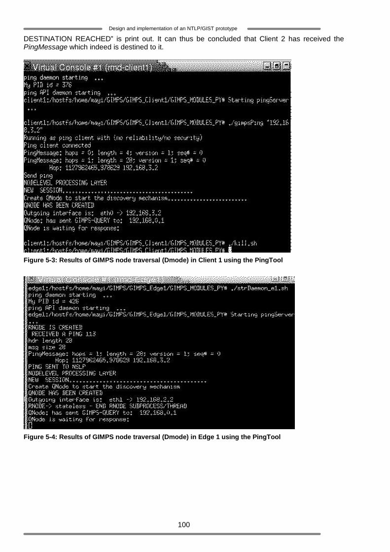
100
Design and implementation of an NTLP/GIST prototype
DESTINATION REACHED” is print out. It can thus be concluded that Client 2 has received the PingMessage which indeed is destined to it.
Figure 5-3: Results of GIMPS node traversal (Dmode) in Client 1 using the PingTool
Figure 5-4: Results of GIMPS node traversal (Dmode) in Edge 1 using the PingTool
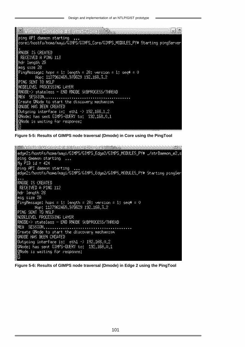
101
Design and implementation of an NTLP/GIST prototype
Figure 5-5: Results of GIMPS node traversal (Dmode) in Core using the PingTool
Figure 5-6: Results of GIMPS node traversal (Dmode) in Edge 2 using the PingTool
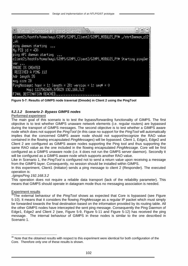
102
Design and implementation of an NTLP/GIST prototype
Figure 5-7: Results of GIMPS node traversal (Dmode) in Client 2 using the PingTool
5.2.1.2 Scenario 2- Bypass GIMPS nodes Performed experiment The main goal of this scenario is to test the bypass/forwarding functionality of GIMPS. The first objective is to test whether GIMPS unaware network elements (i.e. regular routers) are bypassed during the transport of GIMPS messages. The second objective is to test whether a GIMPS aware node which does not support the PingTool (in this case no support for the PingTool will automatically implies that the concerned GIMPS aware node should not support/recognize the RAO value contained in the flowing encapsulated PingMessages) will be bypassed. Client 1, Edge1, Edge2 and Client 2 are configured as GIMPS aware nodes supporting the Ping tool and thus supporting the same RAO value as the one included in the flowing encapsulated PingMessage. Core will be first configured as a GIMPS unaware node (i.e. it does not run the GIMPS server daemon). Secondly it will be configured as a GIMPS aware node which supports another RAO value. Like in Scenario 1, the PingTool is configured not to send a return value upon receiving a message from the GIMPS layer. Consequently, no session should be installed within GIMPS. In this experiment, Client1 (Initiator) sends a ping message to client 2 (Responder). The executed operation is: ./gimpsPing 192.168.3.2 This operation does not require a reliable data transport (lack of the reliability parameter). This means that GIMPS should operate in datagram mode thus no messaging association is needed. Experiment results 35The external behaviour of the PingTool shows as expected that Core is bypassed (see Figure 5-10). It means that it considers the flowing PingMessage as a regular IP packet which must simply be forwarded towards the final destination based on the information provided by its routing table. All the other GIMPS nodes have intercepted the sent ping message. Consequently the Ping Daemon of Edge1, Edge2 and Client 2 (see, Figure 5-9, Figure 5-11 and Figure 5-12) has received the ping message. The internal behaviour of GIMPS in these nodes is similar to the one described in Scenario 1.
35 Note that the obtained results with respect to this experiment were identical for both configuration of the Core. Therefore only one of these results is shown.

103
Design and implementation of an NTLP/GIST prototype
Figure 5-8: Results of GIMPS node traversal (with bypassing) in Client 1 using the PingTool
Figure 5-9: Results of GIMPS node traversal (with bypassing) in Edge 1 using the PingTool
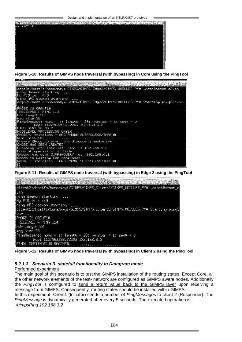
104
Design and implementation of an NTLP/GIST prototype
Figure 5-10: Results of GIMPS node traversal (with bypassing) in Core using the PingTool
Figure 5-11: Results of GIMPS node traversal (with bypassing) in Edge 2 using the PingTool
Figure 5-12: Results of GIMPS node traversal (with bypassing) in Client 2 using the PingTool
5.2.1.3 Scenario 3- statefull functionality in Datagram mode Performed experiment The main goal of this scenario is to test the GIMPS installation of the routing states. Except Core, all the other network elements of the test- network are configured as GIMPS aware nodes. Additionally the PingTool is configured to send a return value back to the GIMPS layer upon receiving a message from GIMPS. Consequently, routing states should be installed within GIMPS. In this experiment, Client1 (Initiator) sends a number of PingMessages to client 2 (Responder). The PingMessage is dynamically generated after every 5 seconds. The executed operation is: ./gimpsPing 192.168.3.2
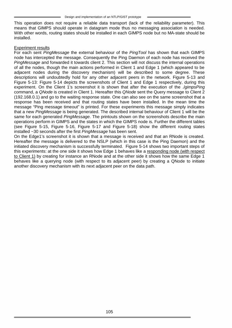
105
Design and implementation of an NTLP/GIST prototype
This operation does not require a reliable data transport (lack of the reliability parameter). This means that GIMPS should operate in datagram mode thus no messaging association is needed. With other words, routing states should be installed in each GIMPS node but no MA-state should be installed. Experiment results For each sent PingMessage the external behaviour of the PingTool has shown that each GIMPS node has intercepted the message. Consequently the Ping Daemon of each node has received the PingMessage and forwarded it towards client 2. This section will not discuss the internal operations of all the nodes, though the main actions performed in Client 1 and Edge 1 (which appeared to be adjacent nodes during the discovery mechanism) will be described to some degree. These descriptions will undoubtedly hold for any other adjacent peers in the network. Figure 5-13 and Figure 5-13: Figure 5-14 depicts the screenshots of Client 1 and Edge 1 respectively, during this experiment. On the Client 1’s screenshot it is shown that after the execution of the ./gimpsPing command, a QNode is created in Client 1. Hereafter this QNode sent the Query message to Client 2 (192.168.0.1) and go to the waiting response state. One can also see on the same screenshot that a response has been received and that routing states have been installed. In the mean time the message “Ping message timeout” is printed. For these experiments this message simply indicates that a new PingMessage is being generated. The described internal behaviour of Client 1 will be the same for each generated PingMessage. The printouts shown on the screenshots describe the main operations perform in GIMPS and the states in which the GIMPS node is. Further the different tables (see Figure 5-15, Figure 5-16, Figure 5-17 and Figure 5-18) show the different routing states installed ~30 seconds after the first PingMessage has been sent. On the Edge1’s screenshot it is shown that a message is received and that an RNode is created. Hereafter the message is delivered to the NSLP (which in this case is the Ping Daemon) and the initiated discovery mechanism is successfully terminated. Figure 5-14 shows two important steps of this experiments: at the one side it shows how Edge 1 behaves like a responding node (with respect to Client 1) by creating for instance an RNode and at the other side it shows how the same Edge 1 behaves like a querying node (with respect to its adjacent peer) by creating a QNode to initiate another discovery mechanism with its next adjacent peer on the data path.
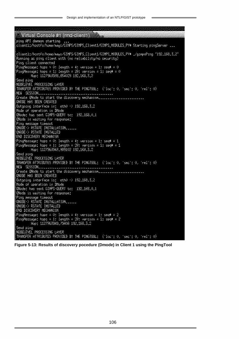
106
Design and implementation of an NTLP/GIST prototype
Figure 5-13: Results of discovery pocedure (Dmode) in Client 1 using the PingTool

107
Design and implementation of an NTLP/GIST prototype
Figure 5-14: Results of discovery pocedure (Dmode) in Edge 1 using the PingTool
Figure 5-15, Figure 5-16, Figure 5-17and Figure 5-18 show the routing states that have been installed in each node. Figure 5-15 is the result of the routing states setup in Client 1. Since the PingTool is a stateless NSLP it does not retain any states. Therefore every time a new Pingmessage is generated and must be transmitted to Client 2, a new session_ID is assigned to it regardless the MRI. It is worth noting that the MRI should be identical for each new Pingmessage as the Flow-ID <source (client 1), destination (client 2), source port, destination port, protocol> will not change. As explained in previous chapters GIMPS must install and maintain states per session if required. For the current experiment, this basically means that GIMPS should create a routing state for every PingMessage that is sent. Figure 5-15 consists of two main tables:
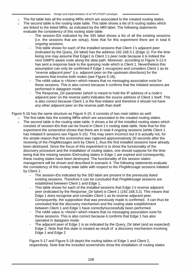
108
Design and implementation of an NTLP/GIST prototype
o The fist table lists all the existing MRIs which are associated to the created routing states. o The second table is the routing state table. This table shows a list of 6 routing states which
are linked to the listed MRIs, as indicated by the MRI label. The following statements evaluate the consistency of this routing state table:
- The session-IDs indicated by the SID label shows a list of all the existing sessions (i.e. the sessions that are setup). Note that for this experiment there are in total 6 ongoing sessions.
- This table shows for each of the installed sessions that Client 1’s adjacent peer (indicated by the Query_Dir label) has the address 192.168.3.1 (Edge 1). For the time being one may assume that Edge1 is Client 1’s peer node because it is indeed the next GIMPS aware node along the data path. Moreover, according to Figure 5-13 it has sent a response back to the querying node which is Client 1. Nevertheless this assumption can only be confirmed if Edge 1 recognizes and considers Client 1 as its “reverse adjacent peer” (i.e. adjacent peer on the upstream directions) for the sessions that involve both nodes (see Figure 5-16).
- The rsMA value is <None> which means that no messaging association exist for these sessions. This is also correct because it confirms that the initiated sessions are performed in datagram mode.
- The Response_Dir parameter (which is meant to hold the IP address of a node’s adjacent peer on the reverse path) indicates the source address of Client 1 itself. This is also correct because Client 1 is the flow initiator and therefore it should not have any other adjacent peer on the reverse path than itself.
Figure 5-16 has the same structure as Figure 5-15. It consists of two main tables as well:
o The first table lists the existing MRIs which are associated to the created routing states. o The second table is the routing state table. It shows a list of the installed routing states which
consists of session-IDs that can be found in Client 1’s routing state table. Note that for this experiment the screenshot shows that there are in total 4 ongoing sessions (while Client 1 has initiated 6 sessions see Figure 5-15). This may seem incorrect but it is actually not, for the simple reason that this screenshot was captured approximatively 30 seconds after the receiving of the PingMessages sent by Client 1, thus the first installed sessions have already been destroyed. Since the focus of this experiment is to show the functionality of the discovery procedure and the installation of routing states, one should suppose for the time being that the missing session IDs/routing states in Edge 1 are expired and consequently, these routing states have been destroyed. The functionality of the session states management will be shown and described in scenario 4. The following statements evaluate the consistency of this routing state table with respect to the PingMessage sessions initiated by Client 1:
- The session-IDs indicated by the SID label are present in the previously listed existing sessions. Therefore it can be concluded that PingMessage sessions are established between Client 1 and Edge 1.
- This table shows for each of the installed sessions that Edge 1‘s reverse adjacent peer (indicated by the Response_Dir label) is Client 1 (192.168.3.2). This means that Edge 1 does recognise and consider Client 1 as its reverse adjacent peer. Consequently, the supposition that was previously made is confirmed. It can thus be concluded that the discovery mechanism and the routing state establishment between Client 1 and Edge 1 have correctly/successfully been performed.
- The rsMA value is <None> which means that no messaging association exist for these sessions. This is also correct because it confirms that Edge 1 has also operated in datagram mode.
- The adjacent peer of Edge 1 is as indicated by the Query_Dir label (and as expected) Edge 2. Note that this state is created as result of a discovery mechanism involving Edge 1 and Edge 2
Figure 5-17 and Figure 5-18 depict the routing tables of Edge 1 and Client 2, respectively. Note that the included screenshots show the installation of routing states

109
Design and implementation of an NTLP/GIST prototype
which are all related to the sessions initiated by Client 1. Furthermore these routing states show that for each session, the adjacent and/or reverse adjacent peer has successfully been discovered.
Figure 5-15: Routing states in Client 1 (Dmode)
Figure 5-16: Routing states in Edge 1 (Dmode)
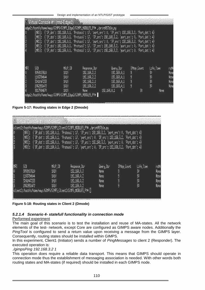
110
Design and implementation of an NTLP/GIST prototype
Figure 5-17: Routing states in Edge 2 (Dmode)
Figure 5-18: Routing states in Client 2 (Dmode)
5.2.1.4 Scenario 4- statefull functionality in connection mode Performed experiment The main goal of this scenario is to test the installation and reuse of MA-states. All the network elements of the test- network, except Core are configured as GIMPS aware nodes. Additionally the PingTool is configured to send a return value upon receiving a message from the GIMPS layer. Consequently, routing states should be installed within GIMPS. In this experiment, Client1 (Initiator) sends a number of PingMessages to client 2 (Responder). The executed operation is: ./gimpsPing 192.168.3.2 1 This operation does require a reliable data transport. This means that GIMPS should operate in connection mode thus the establishment of messaging association is needed. With other words both routing states and MA-states (if required) should be installed in each GIMPS node.
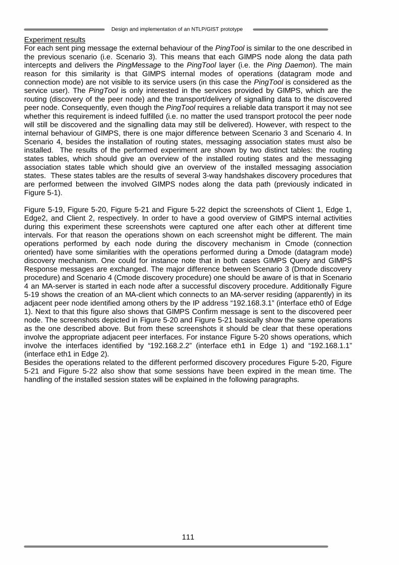
111
Design and implementation of an NTLP/GIST prototype
Experiment results For each sent ping message the external behaviour of the PingTool is similar to the one described in the previous scenario (i.e. Scenario 3). This means that each GIMPS node along the data path intercepts and delivers the PingMessage to the PingTool layer (i.e. the Ping Daemon). The main reason for this similarity is that GIMPS internal modes of operations (datagram mode and connection mode) are not visible to its service users (in this case the PingTool is considered as the service user). The PingTool is only interested in the services provided by GIMPS, which are the routing (discovery of the peer node) and the transport/delivery of signalling data to the discovered peer node. Consequently, even though the PingTool requires a reliable data transport it may not see whether this requirement is indeed fulfilled (i.e. no matter the used transport protocol the peer node will still be discovered and the signalling data may still be delivered). However, with respect to the internal behaviour of GIMPS, there is one major difference between Scenario 3 and Scenario 4. In Scenario 4, besides the installation of routing states, messaging association states must also be installed. The results of the performed experiment are shown by two distinct tables: the routing states tables, which should give an overview of the installed routing states and the messaging association states table which should give an overview of the installed messaging association states. These states tables are the results of several 3-way handshakes discovery procedures that are performed between the involved GIMPS nodes along the data path (previously indicated in Figure 5-1). Figure 5-19, Figure 5-20, Figure 5-21 and Figure 5-22 depict the screenshots of Client 1, Edge 1, Edge2, and Client 2, respectively. In order to have a good overview of GIMPS internal activities during this experiment these screenshots were captured one after each other at different time intervals. For that reason the operations shown on each screenshot might be different. The main operations performed by each node during the discovery mechanism in Cmode (connection oriented) have some similarities with the operations performed during a Dmode (datagram mode) discovery mechanism. One could for instance note that in both cases GIMPS Query and GIMPS Response messages are exchanged. The major difference between Scenario 3 (Dmode discovery procedure) and Scenario 4 (Cmode discovery procedure) one should be aware of is that in Scenario 4 an MA-server is started in each node after a successful discovery procedure. Additionally Figure 5-19 shows the creation of an MA-client which connects to an MA-server residing (apparently) in its adjacent peer node identified among others by the IP address “192.168.3.1” (interface eth0 of Edge 1). Next to that this figure also shows that GIMPS Confirm message is sent to the discovered peer node. The screenshots depicted in Figure 5-20 and Figure 5-21 basically show the same operations as the one described above. But from these screenshots it should be clear that these operations involve the appropriate adjacent peer interfaces. For instance Figure 5-20 shows operations, which involve the interfaces identified by “192.168.2.2” (interface eth1 in Edge 1) and “192.168.1.1” (interface eth1 in Edge 2). Besides the operations related to the different performed discovery procedures Figure 5-20, Figure 5-21 and Figure 5-22 also show that some sessions have been expired in the mean time. The handling of the installed session states will be explained in the following paragraphs.
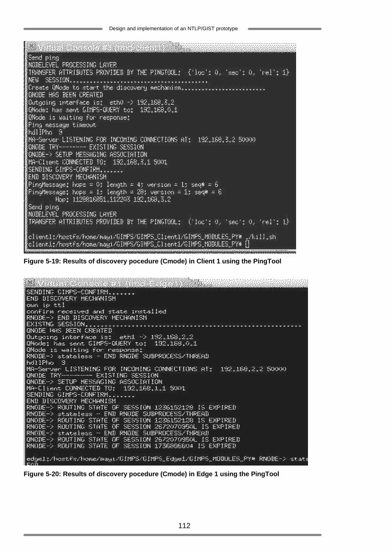
112
Design and implementation of an NTLP/GIST prototype
Figure 5-19: Results of discovery pocedure (Cmode) in Client 1 using the PingTool
Figure 5-20: Results of discovery pocedure (Cmode) in Edge 1 using the PingTool
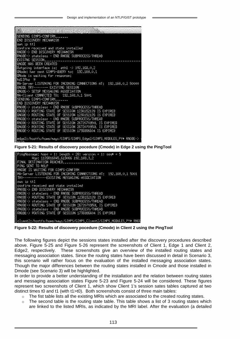
113
Design and implementation of an NTLP/GIST prototype
Figure 5-21: Results of discovery pocedure (Cmode) in Edge 2 using the PingTool
Figure 5-22: Results of discovery pocedure (Cmode) in Client 2 using the PingTool
The following figures depict the sessions states installed after the discovery procedures described above. Figure 5-25 and Figure 5-26 represent the screenshots of Client 1, Edge 1 and Client 2, Edge2, respectively. These screenshots give an overview of the installed routing states and messaging association states. Since the routing states have been discussed in detail in Scenario 3, this scenario will rather focus on the evaluation of the installed messaging association states. Though the major differences between the routing states installed in Cmode and those installed in Dmode (see Scenario 3) will be highlighted. In order to provide a better understanding of the installation and the relation between routing states and messaging association states Figure 5-23 and Figure 5-24 will be considered. These figures represent two screenshots of Client 1, which show Client 1’s session sates tables captured at two distinct times t0 and t1 (with t1>t0). Both screenshots consist of three main tables:
o The fist table lists all the existing MRIs which are associated to the created routing states. o The second table is the routing state table. This table shows a list of 3 routing states which
are linked to the listed MRIs, as indicated by the MRI label. After the evaluation (a detailed
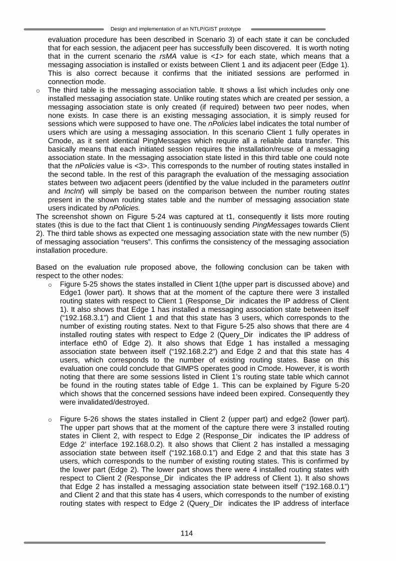
114
Design and implementation of an NTLP/GIST prototype
evaluation procedure has been described in Scenario 3) of each state it can be concluded that for each session, the adjacent peer has successfully been discovered. It is worth noting that in the current scenario the rsMA value is <1> for each state, which means that a messaging association is installed or exists between Client 1 and its adjacent peer (Edge 1). This is also correct because it confirms that the initiated sessions are performed in connection mode.
o The third table is the messaging association table. It shows a list which includes only one installed messaging association state. Unlike routing states which are created per session, a messaging association state is only created (if required) between two peer nodes, when none exists. In case there is an existing messaging association, it is simply reused for sessions which were supposed to have one. The nPolicies label indicates the total number of users which are using a messaging association. In this scenario Client 1 fully operates in Cmode, as it sent identical PingMessages which require all a reliable data transfer. This basically means that each initiated session requires the installation/reuse of a messaging association state. In the messaging association state listed in this third table one could note that the nPolicies value is <3>. This corresponds to the number of routing states installed in the second table. In the rest of this paragraph the evaluation of the messaging association states between two adjacent peers (identified by the value included in the parameters outInt and IncInt) will simply be based on the comparison between the number routing states present in the shown routing states table and the number of messaging association state users indicated by nPolicies.
The screenshot shown on Figure 5-24 was captured at t1, consequently it lists more routing states (this is due to the fact that Client 1 is continuously sending PingMessages towards Client 2). The third table shows as expected one messaging association state with the new number (5) of messaging association “reusers”. This confirms the consistency of the messaging association installation procedure.
Based on the evaluation rule proposed above, the following conclusion can be taken with respect to the other nodes:
o Figure 5-25 shows the states installed in Client 1(the upper part is discussed above) and Edge1 (lower part). It shows that at the moment of the capture there were 3 installed routing states with respect to Client 1 (Response_Dir indicates the IP address of Client 1). It also shows that Edge 1 has installed a messaging association state between itself (“192.168.3.1”) and Client 1 and that this state has 3 users, which corresponds to the number of existing routing states. Next to that Figure 5-25 also shows that there are 4 installed routing states with respect to Edge 2 (Query_Dir indicates the IP address of interface eth0 of Edge 2). It also shows that Edge 1 has installed a messaging association state between itself (“192.168.2.2”) and Edge 2 and that this state has 4 users, which corresponds to the number of existing routing states. Base on this evaluation one could conclude that GIMPS operates good in Cmode. However, it is worth noting that there are some sessions listed in Client 1’s routing state table which cannot be found in the routing states table of Edge 1. This can be explained by Figure 5-20 which shows that the concerned sessions have indeed been expired. Consequently they were invalidated/destroyed.
o Figure 5-26 shows the states installed in Client 2 (upper part) and edge2 (lower part).
The upper part shows that at the moment of the capture there were 3 installed routing states in Client 2, with respect to Edge 2 (Response_Dir indicates the IP address of Edge 2’ interface 192.168.0.2). It also shows that Client 2 has installed a messaging association state between itself (“192.168.0.1”) and Edge 2 and that this state has 3 users, which corresponds to the number of existing routing states. This is confirmed by the lower part (Edge 2). The lower part shows there were 4 installed routing states with respect to Client 2 (Response_Dir indicates the IP address of Client 1). It also shows that Edge 2 has installed a messaging association state between itself (“192.168.0.1”) and Client 2 and that this state has 4 users, which corresponds to the number of existing routing states with respect to Edge 2 (Query_Dir indicates the IP address of interface
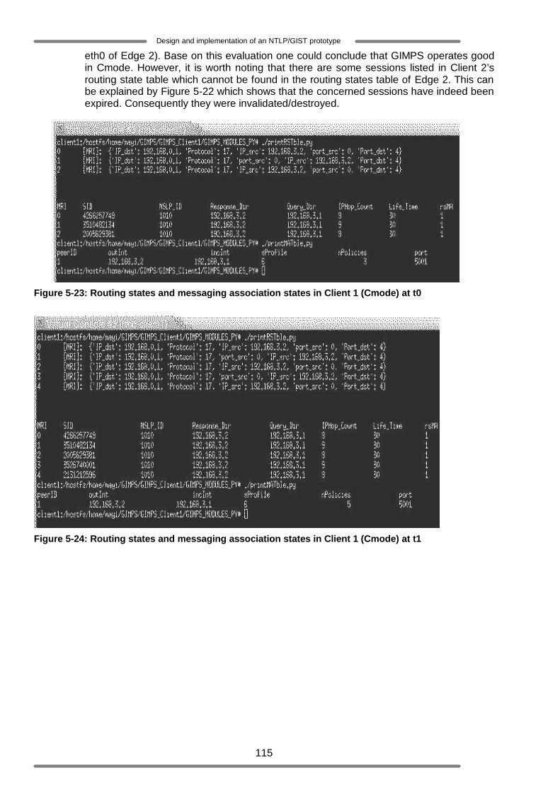
115
Design and implementation of an NTLP/GIST prototype
eth0 of Edge 2). Base on this evaluation one could conclude that GIMPS operates good in Cmode. However, it is worth noting that there are some sessions listed in Client 2’s routing state table which cannot be found in the routing states table of Edge 2. This can be explained by Figure 5-22 which shows that the concerned sessions have indeed been expired. Consequently they were invalidated/destroyed.
Figure 5-23: Routing states and messaging association states in Client 1 (Cmode) at t0
Figure 5-24: Routing states and messaging association states in Client 1 (Cmode) at t1

116
Design and implementation of an NTLP/GIST prototype
Figure 5-25: Overview of routing states and messaging association states in Client 1 and Edge 1 (Cmode)
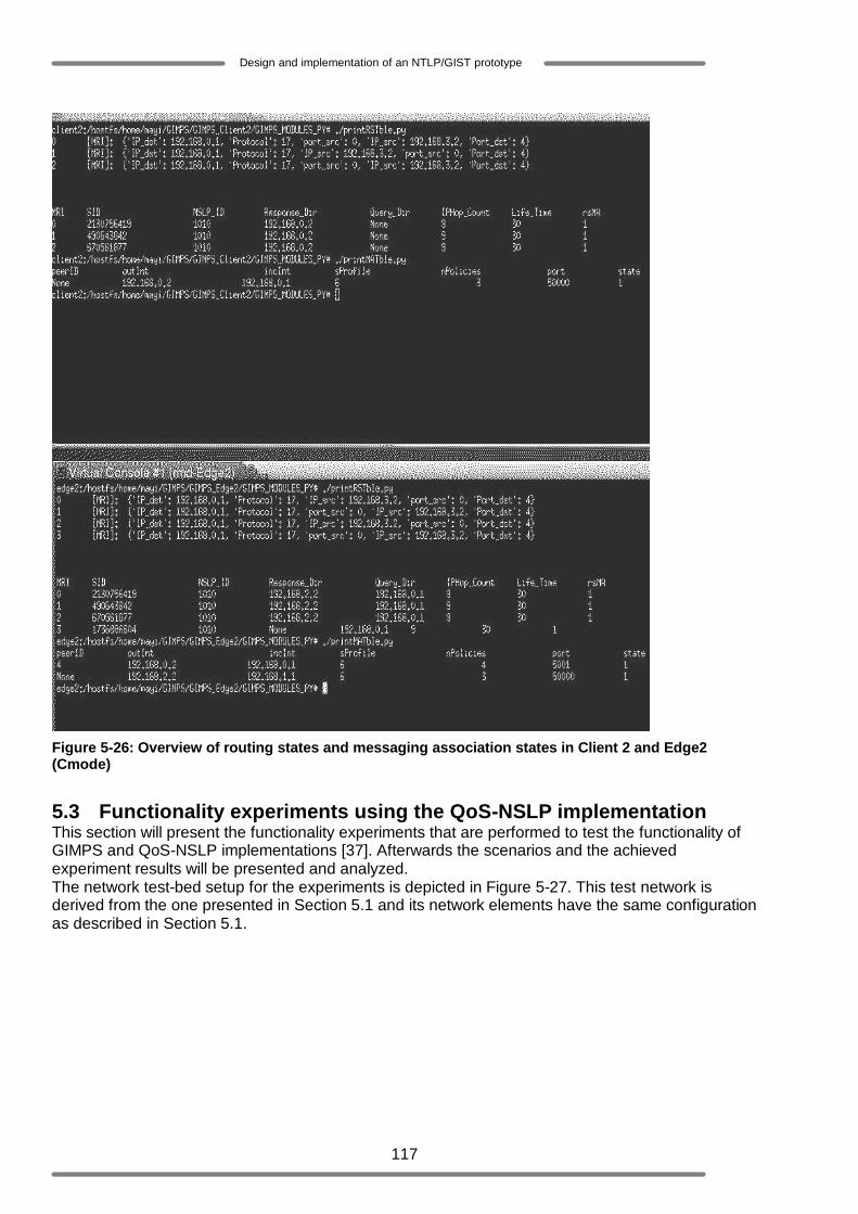
117
Design and implementation of an NTLP/GIST prototype
Figure 5-26: Overview of routing states and messaging association states in Client 2 and Edge2 (Cmode)
5.3 Functionality experiments using the QoS-NSLP implementation This section will present the functionality experiments that are performed to test the functionality of GIMPS and QoS-NSLP implementations [37]. Afterwards the scenarios and the achieved experiment results will be presented and analyzed. The network test-bed setup for the experiments is depicted in Figure 5-27. This test network is derived from the one presented in Section 5.1 and its network elements have the same configuration as described in Section 5.1.

118
Design and implementation of an NTLP/GIST prototype
Figure 5-27: GIMPS and QoS-NSLP test network
5.3.1 Scenario 1: GIMPS nodes traversal Performed experiment The main goal of this scenario is to test the GIMPS messages interception functionality and the installation of the session states. All the network elements of the test- network are configured as GIMPS aware nodes. Next to that, these network elements support the same QoS-NSLP-ID. This experiment is triggered by Client1 (Initiator), which sends a RESERVE message to Core. The executed operation is: ./startuml At this stage of the experiments the focus should be on the question which is whether every GIMPS aware node along the data path (Edge 1) and the final destination (Core) receives the sent RESERVE message. Note that, in case the receiving node is not the final destination it should forward the RESERVE message towards the final destination. According to the QoS-NSLP implementation (see Figure 5-28) a RESERVE message can trigger the initiation of a RESPONSE message, when an object denoted as Request Identification Information (RII) is included in this RESERVE message (see 2.4.3) [35]. Moreover a RESERVE message contains the so called “A flag”. When this flag is set (i.e. A=1) the RESPONSE message should be initiated and sent back by the immediate NSLP peer that has just received the RESERVE message [35]. For this experiment it is considered that the RII object is included in the RESERVE message but the “A flag” is not set. Consequently only the last NSLP node (final destination) that has received a RESERVE message must initiate and send the RESPONSE message back to the sender.
Figure 5-28: Reserve/Response message traversal
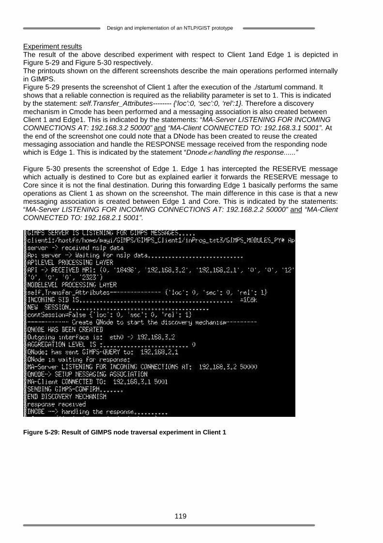
119
Design and implementation of an NTLP/GIST prototype
Experiment results The result of the above described experiment with respect to Client 1and Edge 1 is depicted in Figure 5-29 and Figure 5-30 respectively. The printouts shown on the different screenshots describe the main operations performed internally in GIMPS. Figure 5-29 presents the screenshot of Client 1 after the execution of the ./startuml command. It shows that a reliable connection is required as the reliability parameter is set to 1. This is indicated by the statement: self.Transfer_Attributes-------- {‘loc’:0, ‘sec’:0, ‘rel’:1}. Therefore a discovery mechanism in Cmode has been performed and a messaging association is also created between Client 1 and Edge1. This is indicated by the statements: “MA-Server LISTENING FOR INCOMING CONNECTIONS AT: 192.168.3.2 50000” and “MA-Client CONNECTED TO: 192.168.3.1 5001”. At the end of the screenshot one could note that a DNode has been created to reuse the created messaging association and handle the RESPONSE message received from the responding node which is Edge 1. This is indicated by the statement “Dnode?handling the response......” Figure 5-30 presents the screenshot of Edge 1. Edge 1 has intercepted the RESERVE message which actually is destined to Core but as explained earlier it forwards the RESERVE message to Core since it is not the final destination. During this forwarding Edge 1 basically performs the same operations as Client 1 as shown on the screenshot. The main difference in this case is that a new messaging association is created between Edge 1 and Core. This is indicated by the statements: “MA-Server LISTENING FOR INCOMING CONNECTIONS AT: 192.168.2.2 50000” and “MA-Client CONNECTED TO: 192.168.2.1 5001”.
Figure 5-29: Result of GIMPS node traversal experiment in Client 1

120
Design and implementation of an NTLP/GIST prototype
Figure 5-30: Result of GIMPS node traversal experiment in Edge 1
The following figures depict the sessions states installed after the discovery procedures. Figure 5-31, Figure 5-32 and Figure 5-33 represent the screenshots of Client 1, Edge 1 and Core respectively. These screenshots give an overview of the installed routing states and messaging association states.
o The fist table of these figures list the MRIs which are associated to the created routing states.
o The second table of these figures is the routing state table. The second table of Figure 5-31 shows that the adjacent peer of Client 1 has successfully been discovered. This adjacent peer is identified by the IP address 192.168.3.1 indicated by the Query_dir label. Since Client 1 is the initiator its reverse adjacent peer is itself. This is indicated by the Response_dir label. The second table of Figure 5-32 shows that the adjacent peer of Edge 1 has successfully been discovered. This adjacent peer is identified by the IP address 192.168.2.1 indicated by the Query_dir label. Since Client 1 is the querying node for Edge1 it is considered as the reverse adjacent peer. This is indicated by the Response_dir label. The second table of Figure 5-33 shows that Core is the final destination as the Query_dir label is ‘None’. Since Edge 1 is the Querying node for Core it is considered as the reverse adjacent peer. This is indicated by the Response_dir label. It is worth noting that the rsMA value is <1> for each
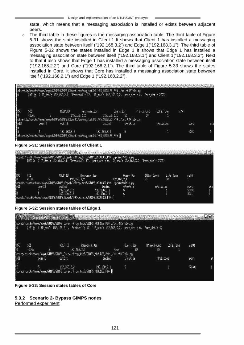
121
Design and implementation of an NTLP/GIST prototype
state, which means that a messaging association is installed or exists between adjacent peers.
o The third table in these figures is the messaging association table. The third table of Figure 5-31 shows the state installed in Client 1 It shows that Client 1 has installed a messaging association state between itself (“192.168.3.2”) and Edge 1(“192.168.3.1”). The third table of Figure 5-32 shows the states installed in Edge 1 It shows that Edge 1 has installed a messaging association state between itself (“192.168.3.1”) and Client 1(“192.168.3.2”). Next to that it also shows that Edge 1 has installed a messaging association state between itself (“192.168.2.2”) and Core (“192.168.2.1”). The third table of Figure 5-33 shows the states installed in Core. It shows that Core has installed a messaging association state between itself (“192.168.2.1”) and Edge 1 (“192.168.2.2”).
Figure 5-31: Session states tables of Client 1
Figure 5-32: Session states tables of Edge 1
Figure 5-33: Session states tables of Core
5.3.2 Scenario 2- Bypass GIMPS nodes Performed experiment

122
Design and implementation of an NTLP/GIST prototype
The main goal of this scenario is to test the bypass/forwarding functionality of GIMPS. The objective is to test whether a GIMPS aware node which does not support/recognize the QoS-NSLP-ID, i.e. the RAO value (see Section 3.5) contained in the flowing encapsulated RESERVE message will be bypassed. Client 1 and Core are configured as GIMPS aware nodes supporting the same QoS-NSLP-ID as the one included in the flowing RESERVE message. Edge 1 will be configured as a GIMPS aware node which supports another QoS-NSLP-ID value (for instance the QoS-NSLP-ID supported in an RMD-domain). This experiment is triggered by Client1 (Initiator), which sends a RESERVE message to Core. The executed operation is: ./startuml. Experiment results Figure 5-35 shows as expected that Edge 1 is bypassed. It means that it considers the flowing RESERVE message as a regular IP packet which must simply be forwarded towards the final destination (Core) based on the information provided by its routing table. Consequently the performed discovery mechanism involves only Client 1 and Core. The internal behaviour of GIMPS in these nodes (see Figure 5-34 and Figure 5-36) is similar to the one described in Scenario 1.
Figure 5-34: Result of the Bypassing experiment in Client 1
Figure 5-35: Result of the Bypassing experiment in Edge 1
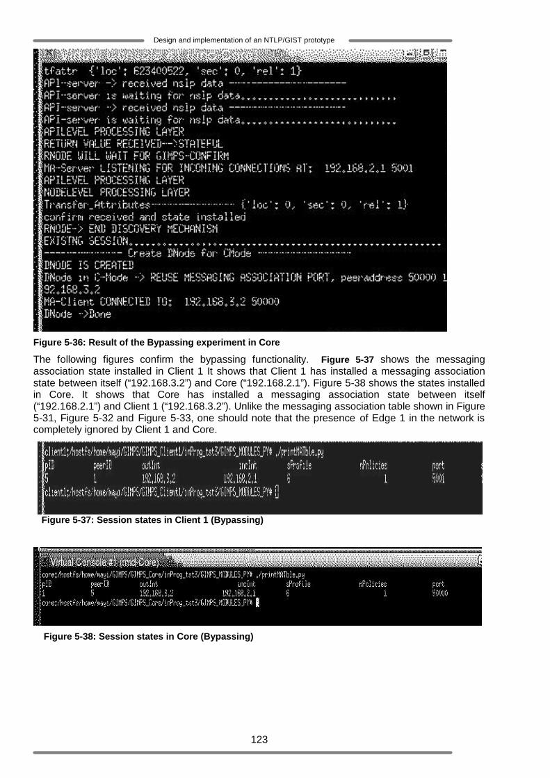
123
Design and implementation of an NTLP/GIST prototype
Figure 5-36: Result of the Bypassing experiment in Core
The following figures confirm the bypassing functionality. Figure 5-37 shows the messaging association state installed in Client 1 It shows that Client 1 has installed a messaging association state between itself (“192.168.3.2”) and Core (“192.168.2.1”). Figure 5-38 shows the states installed in Core. It shows that Core has installed a messaging association state between itself (“192.168.2.1”) and Client 1 (“192.168.3.2”). Unlike the messaging association table shown in Figure 5-31, Figure 5-32 and Figure 5-33, one should note that the presence of Edge 1 in the network is completely ignored by Client 1 and Core.
Figure 5-37: Session states in Client 1 (Bypassing)
Figure 5-38: Session states in Core (Bypassing)

124
Design and implementation of an NTLP/GIST prototype
5.4 Functionality experiment using the NSIS RMD QoS implementation This section will present the functionality experiments that are performed to test the functionality of GIMPS, QoS-NSLP and NSIS RMD implementations (see Section 2.5) [37]. Afterwards the scenarios and the achieved experiments results will be presented and analyzed. The network test-bed setup for this experiment is depicted in Figure 5-1 and presented in Section 5.1. 5.4.1 Scenario 1: Statefull and stateless GIMPS functionality Performed experiment The main goal of this scenario is to test both the stateful and stateless functionality of GIMPS. The sub networks identified by the network addresses 192.168.3.0/24 and 192.168.0.0/24 are configured to support the QoS-NSLP-ID (QoS-NSLP-ID=6) while the sub networks identified by the network addresses 192.168.2.0/24 and 192.168.0.0/24 are configured to support the QoS-NSLP-ID (QoS-NSLP-ID=7). The later sub networks are denoted as the RMD domain. Note that all the network elements of the test- network are configured as GIMPS aware nodes. This experiment is triggered by Client 1 (initiator), which sends a QoS-NSLP RESERVE message to Client 2 (the receiver). The executed operation is: ./startuml Experiment results In this paragraph the results obtained in each node during this experiment will be discussed. For every node, the actions and the expected results in the NSLP layer will be presented (see Figure 5-39) and then the internal behaviour of the GIMPS layer (of the concerned node) will be discussed.
Figure 5-39: GIMPS – QoS-NSLP and RMD Reserve/Response message traversal
Client1
o NSLP layer: During this experiment Client 1 sends a QoS-NSLP Reserve message towards Client2 and expects in turn a QoS-NSLP Response message (see Figure 5-39).
o GIMPS layer: The result of this experiment with respect to Client 1 is depicted in Figure
5-40. The printouts shown on the screenshot describe the main operations performed internally in GIMPS. The statement “API ->RECEIVED MRI:{0, ‘’18496’, ‘192.168.3.2’, ‘192.168.3.1’, ‘0’, ‘0’, ‘12’, ‘0’, ‘0’, ‘0’, ‘2323’}” shows that GIMPS has received an NSLP message (QoS-NSLP Reserve message) with an MRI that contains among others the flow source address and destination address. The statement “self.Transfer_Attributes-------- {‘loc’:0, ‘sec’:0, ‘rel’:1}” shows the transfer attributes parameters received with this QoS-NSLP Reserve message. From that statement one should node that a reliable transport protocol is required and therefore GIMPS should operate in Cmode (see 2.3.2.3.2.1). Consequently a discovery mechanism should be performed and both routing states and messaging association states should be installed. The statement “INCOMING SID IS...........................” shows the incoming Session-ID associated with the received QoS-
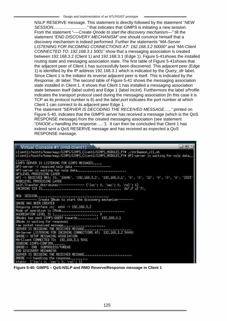
125
Design and implementation of an NTLP/GIST prototype
NSLP RESERVE message. This statement is directly followed by the statement “NEW SESSION.............................” that indicates that GIMPS is initiating a new session. From the statement “----Create Qnode to start the discovery mechanism---” till the statement “END DISCOVERY MECHANISM” one should convince himself that a discovery mechanism is indeed performed. Further the statements “MA-Server LISTENING FOR INCOMING CONNECTIONS AT: 192.168.3.2 50000” and “MA-Client CONNECTED TO: 192.168.3.1 5001” show that a messaging association is created between 192.168.3.2 (Client 1) and 192.168.3.1 (Edge 1). Figure 5-41shows the installed routing state and messaging association state. The first table of Figure 5-41shows that the adjacent peer of Client 1 has successfully been discovered. This adjacent peer (Edge 1) is identified by the IP address 192.168.3.1 which is indicated by the Query_dir label. Since Client 1 is the initiator its reverse adjacent peer is itself. This is indicated by the Response_dir label. The second table of Figure 5-41 shows the messaging association state installed in Client 1. It shows that Client 1 has installed a messaging association state between itself (label outInt) and Edge 1 (label incInt). Furthermore the label sProfile indicates the transport protocol used during the messaging association (In this case it is TCP as its protocol number is 6) and the label port indicates the port number at which Client 1 can connect to its adjacent peer Edge 1. The statement “SERVER IS DECODING THE RECEIVED MESSAGE......” printed on Figure 5-40, indicates that the GIMPS server has received a message (which is the QoS RESPONSE message) from the created messaging association (see statement “DNODE? handling the response......”). It can then be concluded that Client 1 has indeed sent a QoS RESERVE message and has received as expected a QoS RESPONSE message.
Figure 5-40: GIMPS – QoS-NSLP and RMD Reserve/Response message in Client 1

126
Design and implementation of an NTLP/GIST prototype
Figure 5-41: GIMPS session states in Client 1
Edge 1
o NSLP layer: Briefly explained, according to the NSIS RMD and QoS-NSLP implementation (see Section 2.5 and Figure 5-28) an 36ingress node that has received and processed the QoS-NSLP RESERVE message may forward this RESERVE message towards its final destination and may additionally create and send the so called RMD RESERVE message (see Section 2.5) towards the final destination. At the end of these operations Edge1 should expect in turn a QoS-NSLP Response message (see Figure 5-39).
o GIMPS layer: The result of this experiment with respect to Edge 1 is depicted in Figure
5-42. The printouts shown on the screenshot describe the main operations performed internally in GIMPS. The statement “SERVER IS DECODING THE RECEIVED MESSAGE......” shows that the GIMPS server has received a message (Query message) which is followed by the creation of an RNode thread (see statement “RNode is created”) to process the received Query message. After processing this message the RNode delivers the received message to the NSLP and waits for a return value (see statement “waiting for return value......”) that should indicate whether the session should be stateful or stateless. The statement “RETURN VALUE RECEIVED ? STATEFUL” indicates that a return value has been received from the NSLP and that the concerned session should be stateful. Consequently a GIMPS Response message is sent back to the Querying node and a messaging association state is installed (see statement “MA-Server LISTENING FOR INCOMING CONNECTIONS AT: 192.168.3.1 5001”). The RNode then waits for a GIMPS Confirm message (see statement “RNODE WILL WAIT FOR GIMPS-CONFIRM......”). Upon receiving the GIMPS Confirm message, the included NSLP payload (QoS RESERVE message) is delivered to the NSLP layer. Finally the statement “RNODE -> END DISCOVERY MECHANISM” indicates the end of the discovery mechanism with Client 1. From the statement “NEW SESSION............................” till the statement “DNode in QEncapsulation->: has sent message towards 192.168.0.1” one should note that GIMPS has received a request from the NSLP to send a message (RMD RESERVE message). It starts therefore a new session, where the RMD RESERVE message will be sent. The statements “self.Transfer_Attributes-------- {‘loc’:2, ‘sec’:0, ‘rel’:0}” indicates that no reliable transport protocol is required (‘rel’:0). Additionally the discovery procedure is not required (this is indicated by the local policy parameter, ‘loc’:2), which means that this new session should be stateless. The next following statements “INCOMING SESSION............................” and “EXISTING SESSION............................” indicate that GIMPS has again received a message (QoS RESERVE message) from the NSLP layer. This last message is part of the ongoing session initiated by Client 1. Unlike the RMD RESERVE message, this QoS RESERVE message will be sent towards the final destination using a reliable transport protocol. From the statement “----Create Qnode to start the discovery mechanism---” till the statement “END DISCOVERY MECHANISM” one should note that a new discovery mechanism is initiated by Edge1. Further the statements “MA-Server LISTENING FOR INCOMING CONNECTIONS AT: 192.168.2.2 50000” and “MA-Client CONNECTED TO:
36 NSLP edge node (located at the boundary of the RMD domain) which is able to process QoS-NSLP messages that are incoming into the RMD domain

127
Design and implementation of an NTLP/GIST prototype
192.168.1.1 5001” show that a messaging association is created between 192.168.2.2 (Edge 1) and 192.168.1.1 (Edge 2). It is worth noting that since Core is inside the RMD Domain and since it supports another QoS NSLP-ID, it is bypassed during the transport of the QoS RESERVE message. Figure 5-43 shows the installed routing state and the messaging association state (these session states have already been discussed in Section 5.3.2). The statement “SERVER IS DECODING THE RECEIVED MESSAGE......” indicates that the GIMPS server has received a message (the QoS RESPONSE message) from the created messaging association (see statement “DNODE? handling the response......”). From the statement “---- use Dnode for CMode-----” till the statement “MA-Client CONNECTED TO: 192.168.3.2 50000”, Edge1 forwards the QoS RESPONSE message to Client 1 using the existing messaging association. It can be concluded that Edge1 has indeed sent both a QoS RESERVE message and an RMD RESERVE message and has received as expected a QoS RESPONSE message which has been forwarded to Client 1.

128
Design and implementation of an NTLP/GIST prototype
Figure 5-42: GIMPS – QoS-NSLP and RMD Reserve/Response message in Edge 1
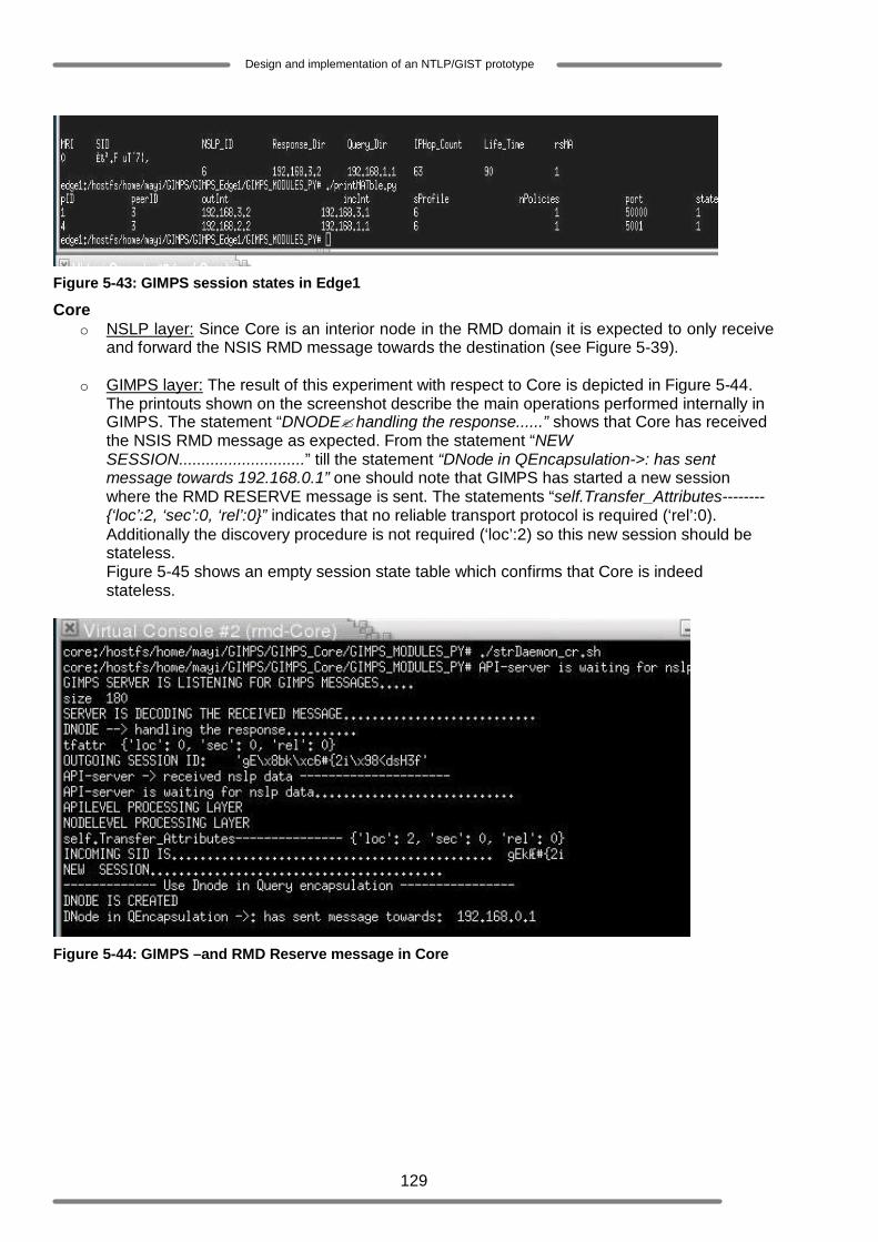
129
Design and implementation of an NTLP/GIST prototype
Figure 5-43: GIMPS session states in Edge1
Core o NSLP layer: Since Core is an interior node in the RMD domain it is expected to only receive
and forward the NSIS RMD message towards the destination (see Figure 5-39).
o GIMPS layer: The result of this experiment with respect to Core is depicted in Figure 5-44. The printouts shown on the screenshot describe the main operations performed internally in GIMPS. The statement “DNODE? handling the response......” shows that Core has received the NSIS RMD message as expected. From the statement “NEW SESSION............................” till the statement “DNode in QEncapsulation->: has sent message towards 192.168.0.1” one should note that GIMPS has started a new session where the RMD RESERVE message is sent. The statements “self.Transfer_Attributes-------- {‘loc’:2, ‘sec’:0, ‘rel’:0}” indicates that no reliable transport protocol is required (‘rel’:0). Additionally the discovery procedure is not required (‘loc’:2) so this new session should be stateless. Figure 5-45 shows an empty session state table which confirms that Core is indeed stateless.
Figure 5-44: GIMPS –and RMD Reserve message in Core
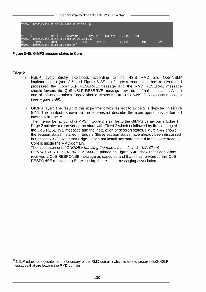
130
Design and implementation of an NTLP/GIST prototype
Figure 5-45: GIMPS session states in Core
Edge 2 o NSLP layer: Briefly explained, according to the NSIS RMD and QoS-NSLP
implementation (see 2.5 and Figure 5-28) an 37egress node that has received and processed the QoS-NSLP RESERVE message and the RMD RESERVE message should forward the QoS-NSLP RESERVE message towards its final destination. At the end of these operations Edge2 should expect in turn a QoS-NSLP Response message (see Figure 5-39).
o GIMPS layer: The result of this experiment with respect to Edge 2 is depicted in Figure
5-46. The printouts shown on the screenshot describe the main operations performed internally in GIMPS. The internal behaviour of GIMPS in Edge 2 is similar to the GIMPS behaviour in Edge 1. Edge 2 initiates a discovery procedure with Client 2 which is followed by the sending of the QoS RESERVE message and the installation of session states. Figure 5-47 shows the session states installed in Edge 2 (these session states have already been discussed in Section 5.3.2). Note that Edge 2 does not install any state related to the Core node as Core is inside the RMD domain. The last statements “DNODE? handling the response......” and “MA-Client CONNECTED TO: 192.168.2.2 50000” printed on Figure 5-46, show that Edge 2 has received a QoS RESPONSE message as expected and that it has forwarded this QoS RESPONSE message to Edge 1 using the existing messaging association.
37 NSLP edge node (located at the boundary of the RMD domain) which is able to process QoS-NSLP messages that are leaving the RMD domain

131
Design and implementation of an NTLP/GIST prototype
Figure 5-46: GIMPS – QoS-NSLP and RMD Reserve/Response message in Edge 1
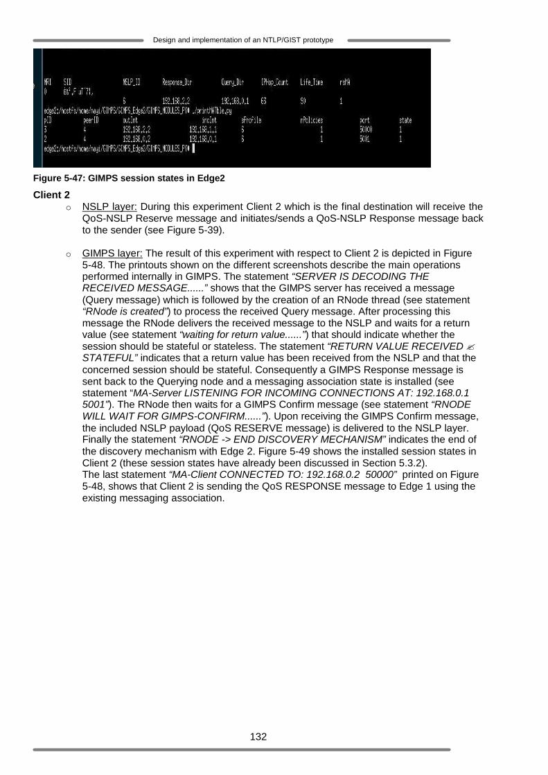
132
Design and implementation of an NTLP/GIST prototype
Figure 5-47: GIMPS session states in Edge2
Client 2 o NSLP layer: During this experiment Client 2 which is the final destination will receive the
QoS-NSLP Reserve message and initiates/sends a QoS-NSLP Response message back to the sender (see Figure 5-39).
o GIMPS layer: The result of this experiment with respect to Client 2 is depicted in Figure
5-48. The printouts shown on the different screenshots describe the main operations performed internally in GIMPS. The statement “SERVER IS DECODING THE RECEIVED MESSAGE......” shows that the GIMPS server has received a message (Query message) which is followed by the creation of an RNode thread (see statement “RNode is created”) to process the received Query message. After processing this message the RNode delivers the received message to the NSLP and waits for a return value (see statement “waiting for return value......”) that should indicate whether the session should be stateful or stateless. The statement “RETURN VALUE RECEIVED ? STATEFUL” indicates that a return value has been received from the NSLP and that the concerned session should be stateful. Consequently a GIMPS Response message is sent back to the Querying node and a messaging association state is installed (see statement “MA-Server LISTENING FOR INCOMING CONNECTIONS AT: 192.168.0.1 5001”). The RNode then waits for a GIMPS Confirm message (see statement “RNODE WILL WAIT FOR GIMPS-CONFIRM......”). Upon receiving the GIMPS Confirm message, the included NSLP payload (QoS RESERVE message) is delivered to the NSLP layer. Finally the statement “RNODE -> END DISCOVERY MECHANISM” indicates the end of the discovery mechanism with Edge 2. Figure 5-49 shows the installed session states in Client 2 (these session states have already been discussed in Section 5.3.2). The last statement “MA-Client CONNECTED TO: 192.168.0.2 50000” printed on Figure 5-48, shows that Client 2 is sending the QoS RESPONSE message to Edge 1 using the existing messaging association.
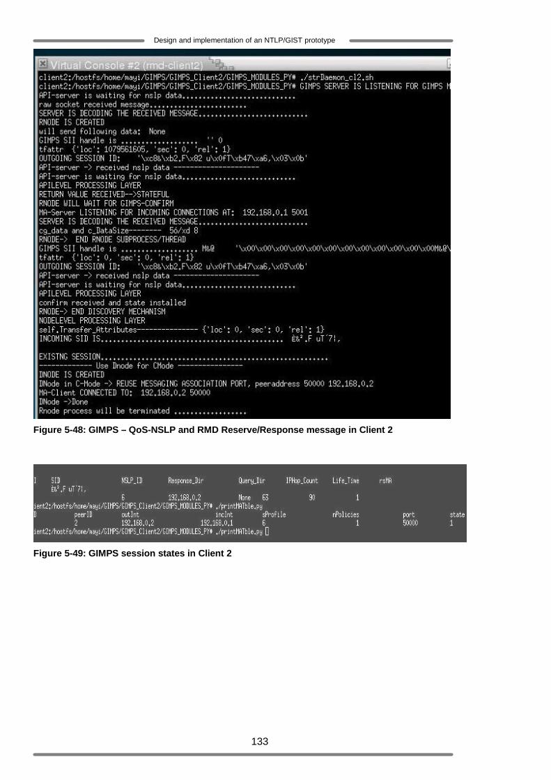
133
Design and implementation of an NTLP/GIST prototype
Figure 5-48: GIMPS – QoS-NSLP and RMD Reserve/Response message in Client 2
Figure 5-49: GIMPS session states in Client 2

134
Design and implementation of an NTLP/GIST prototype
6 Conclusion and future work This thesis is the final result of a project concerning the design and implementation of NTLP/GIMPS protocol specified in [10]. It describes the NSIS protocol suite and explains the motivation of developing such a protocol suite. Furthermore it focuses on the design and implementation of NTLP/GIMPS protocol, which is the underlying layer of the NSIS protocol suite. Different functional experiments are performed in order to test the functionality of the implemented protocol. The results of these experiments are presented and analysed. The functionality experiments have been performed using three methods of experimentation. The first method uses the Ping tool specified in [30] for this purpose, the second method of experimentation uses the QoS-NSLP implementation [37] and the third method of experimentation uses the combination of the NSIS RMD-QOSM and the QoS-NSLP implementation [37].This chapter concludes this thesis by recalling the main objectives of this project and showing to which degree these objectives have been achieved. Furthermore, this chapter gives some suggestions for future work. 6.1 Conclusion The NTLP/GIMPS protocol is designed to support different NSLP signalling applications. This protocol consists of existing transport protocols and one new defined component, which is the GIMPS protocol. The main functionality of GIMPS is essentially to carry and deliver signalling messages to the appropriate destinations. This function includes the discovery of the right NSIS peer, the use of the right or required transport protocol and the installation and maintenance of session states. The starting point of this thesis was among others the study of the NTLP/GIMPS protocol specified in [10]. Next to that the objectives of this project are to design and implement the NTLP/GIMPS protocol. Besides the design and implementation work, functional and/or performance experiments have to be performed to test the implementation.
o Regarding the design and implementation, the major functionalities of the NTLP/GIMPS protocol are completed as far as they are defined in [10]. This implementation only considered IPv4. Feature such as security and route change detection are not implemented in the GIMPS prototype because their definition was not complete. However the new draft version of GIMPS specified in [20] provides the description on how these functionalities could be implemented. The used specification does not define any GIMPS error message and errors handling. Therefore, there is no mechanism implemented to deal with errors that might occur during GIMPS operations involving two GIMPS nodes. Note that the GIMPS protocol specified in [20] does define the GIMPS error handling. This implies that future GIMPS prototype implementation must incorporate these missing functionalities.
o Due to time constraints no performance experiments were performed. But the functional experiments have been performed and the obtained results were satisfactory.
Finally it is worth to emphasize that the NTLP/GIMPS protocol specified in [10] by the NSIS WG was not a complete specification, however it defines the essential protocol elements and could therefore be explored (i.e. It got a go ahead for exploration). This master assignment has thus been part of the functionality evaluation of the GIMPS protocol. The findings and lessons learned during the design and implementation process will be taken into consideration and will contribute to the improvement of the future versions of the GIMPS specification.
6.2 Future work
o Due to time constraints and several unresolved issues the design and implementation of some GIMPS functions (described above) could not be completed. Therefore, it is recommended to complete these issues in the near future.
o Extensive performance experiments should be done to verify the performance behavior of GIMPS.
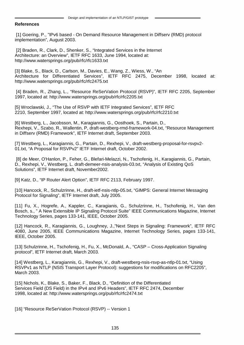
135
Design and implementation of an NTLP/GIST prototype
References [1] Goering, P., ”IPv6 based - On Demand Resource Management in Diffserv (RMD) protocol implementation”, August 2003. [2] Braden, R., Clark, D., Shenker, S., “Integrated Services in the Internet Architecture: an Overview”, IETF RFC 1633, June 1994, located at: http://www.watersprings.org/pub/rfc/rfc1633.txt [3] Blake, S., Black, D., Carlson, M., Davies, E., Wang, Z., Wiess, W., “An Architecture for Differentiated Services”, IETF RFC 2475, December 1998, located at: http://www.watersprings.org/pub/rfc/rfc2475.txt [4] Braden, R., Zhang, L., “Resource ReSerVation Protocol (RSVP)”, IETF RFC 2205, September 1997, located at: http://www.watersprings.org/pub/rfc/rfc2205.txt [5] Wroclawski, J., “The Use of RSVP with IETF Integrated Services”, IETF RFC 2210, September 1997, located at: http://www.watersprings.org/pub/rfc/rfc2210.txt [6] Westberg, L., Jacobsson, M., Karagiannis, G., Oosthoek, S., Partain, D., Rexhepi, V., Szabo, R., Wallentin, P, draft-westberg-rmd-framework-04.txt, “Resource Management in Diffserv (RMD) Framework”, IETF Internet draft, September 2003. [7] Westberg, L., Karagiannis, G., Partain, D., Rexhepi, V., draft-westberg-proposal-for-rsvpv2-01.txt, “A Proposal for RSVPv2” IETF Internet draft, October 2002. [8] de Meer, O'Hanlon, P., Feher, G., Blefari-Melazzi, N., Tschofenig, H., Karagiannis, G., Partain, D., Rexhepi, V., Westberg, L. draft-demeer-nsis-analysis-03.txt, “Analysis of Existing QoS Solutions”, IETF Internet draft, November2002. [9] Katz, D., “IP Router Alert Option”, IETF RFC 2113, February 1997. [10] Hancock, R., Schulzrinne, H., draft-ietf-nsis-ntlp-05.txt, “GIMPS: General Internet Messaging Protocol for Signaling”, IETF Internet draft, July 2005. [11] Fu, X., Hogrefe, A., Kappler, C., Karagianis, G., Schulzrinne, H., Tschofenig, H., Van den Bosch, s., ” A New Extensible IP Signaling Protocol Suite” IEEE Communications Magazine, Internet Technology Series, pages 133-141, IEEE, October 2005. [12] Hancock, R., Karagiannis, G., Loughney, J.,”Next Steps in Signaling: Framework”, IETF RFC 4080, June 2005, IEEE Communications Magazine, Internet Technology Series, pages 133-141, IEEE, October 2005. [13] Schulzrinne, H., Tschofenig, H., Fu, X., McDonald, A., “CASP – Cross-Application Signaling protocol”, IETF Internet draft, March 2003. [14] Westberg, L., Karagiannis, G., Rexhepi, V., draft-westberg-nsis-rsvp-as-ntlp-01.txt, “Using RSVPv1 as NTLP (NSIS Transport Layer Protocol): suggestions for modifications on RFC2205”, March 2003. [15] Nichols, K., Blake, S., Baker, F., Black, D., “Definition of the Differentiated Services Field (DS Field) in the IPv4 and IPv6 Headers”, IETF RFC 2474, December 1998, located at: http://www.watersprings.org/pub/rfc/rfc2474.txt [16] “Resource ReSerVation Protocol (RSVP) -- Version 1
136
Design and implementation of an NTLP/GIST prototype
Message Processing Rules”, IETF RFC 2209, September 1997, located at: http://www.watersprings.org/pub/rfc/rfc2209.txt [17] Stiemerling, M., Tschofenig, H., Martin, M., Aoun, C., “AT/Firewall NSIS Signaling layer protocol, draft-ietf-nsis-nslp-natfw-01.html”, IETF Intenet draft, February 2004. [18] Partain, D., Karagiannis, G., Wallentin, P., Westberg L., draft-westberg-rmd-cellular-issues-01.txt, “Resource Reservation Issues in Cellular Radio Access Networks”, Internet draft, June 2002 [19] Tsenov, T., Tschofenig, H., Fu, X., Aoun, C., Davies, E., draft-ietf-nsis-ntlp-statemachine-00.txt, “GIMPS State Machine”, IETF Internet draft, July 2005, located at [20] Schulzrinne, H., Hancock, R., draft-ietf-nsis-ntlp-08.txt, “GIST: General Internet Signaling Transport”, IETF Internet draft, September 2005. [21] The User-mode Linux Kernel Home Page, http://user-mode-linux.sourceforge.net/ [22] General Programming Concepts: Writing and Debugging Programs, http://publibn.boulder.ibm.com/doc_link/en_US/a_doc_lib/aixprggd/genprogc/multi-thread_prg.htm [23] Unix Multi-Process Programming and Inter-Process Communications (IPC), located at: http://users.actcom.co.il/~choo/lupg/tutorials/multi-process/multi-process.html [24] Python language website, located at:http://www.python.org. [25] C programming, located at:http://www.its.strath.ac.uk/courses/c/ [26] Lookup Tables, located at:http://www.csse.monash.edu.au/~lloyd/tildeAlgDS/Table/ [27] Postel, J., Internet Protocol, IETF RFC 791, September 1981. [28] The netfilter/iptables HOWTO's, located at: http://www.netfilter.org/documentation/index.html [29] “Packet Capture With libpcap and other Low Level Network Tricks”, located at: http://www.cet.nau.edu/~mc8/Socket/Tutorials/section1.html [30] Dickmann, C., Juchem, I., Willert, S., Fu, X., draft-juchem-nsis-ping-tool-01.txt “A stateless Ping tool for simple tests of GIMPS implementations”, IETF Intenet draft, May 2005. [31] Dickmann, C., “Implementation of Ping NSLP: a diagnostics tool for the General Internet Messaging Protocol for Signaling (GIMPS)”, located at: http://user.informatik.uni-goettingen.de/~nsis/release/ping/ [32] Python/C API Reference Manual, located at: http://docs.python.org/api/threads.html [33] Baker, F., Iturralde, C., Le Faucher, F., Davie, B., “Aggregation of RSVP for IPv4 and IPv6 Reservations”, IETF RFC 3175, 2001, located at: http://www.watersprings.org/pub/rfc/rfc3175.txt [34] Bader, A., Westberg, L., Karagiannis, G., Kappler, C., Phelan, T., draft-ietf-nsis-rmd-03.txt, “RMD-QOSM – The Resource Managment in Diffserv QoS Model”, IETF Intenet draft, June 2005. [35] Van den Bosch, S., Karagiannis, G., McDonald, A., draft-ietf-nsis-qos-nslp-06.txt, “NSLP for Quality-of-Service signalling”, IETF Intenet draft, February 2005. [36] Ash, J., Bader, A., Kappler, C., draft-ietf-nsis-qspec-04.txt, “QoS-NSLP Qspec Template”, IETF Intenet draft, May 2005.

137
Design and implementation of an NTLP/GIST prototype
[37] Swannink, M., “RMD (Resource Management in Diffserv) within NSIS (Next Steps in Signaling): protocol implementation”, December 2005. [38] Postel, J., Transmission Control Protocol, IETF RFC 793, September 1981. [39] Postel, J., User Datagram Protocol, IETF RFC 768, August 1980. [40] Jeong,S., Lee, S., Karagiannis, G., Lieshout, G., draft-jeong-nsis-3gpp-qosm-02.txt, ”3GPP QoS Model for Networks Using 3GPP QoS Classes”, IETF Intenet draft, October 2005. [41] Berger, L., Gan, D., Swallow, G., Pan, P., Tommasi, F., Molendini, S., “RSVP Refresh Overhead Reduction Extensions”, IETF RFC 2961, 2001, located at: http://www.watersprings.org/pub/rfc/rfc2961.txt [42] Westberg, L., Jacobsson, M., Karagiannis, G., Oosthoek, S., Partain, D., Rexhepi, V., Szabo, R., Wallentin, P, Resource Management in Diffserv (RMD) Framework, draft-westberg-rmd-framework-03.txt, IETF Internet draft, work in progress.

138
Design and implementation of an NTLP/GIST prototype
Appendix A: 38Bit level format of GIMPS Messages
GIMPS-DATA MESSAGE
38 This appendix is derived from the GIMPS protocol specification presented in [10]. It simply gives an overview of how the different GIMPS objects defined in [10] may be combined together to constitute the GIMPS messages. The exact definition of all the elements or parameters included in each object could be found in [10].
0 1 2 3 4 5 6 7 8 9 0 1 2 3 4 5 6 7 8 9 0 1 2 3 4 5 6 7 8 9 0 1 +-+-+-+-+-+-+-+-+-+-+-+-+-+-+-+-+-+-+-+-+-+-+-+-+-+-+-+-+-+-+-+-+ | Version | GIMPS hops | Message length | +-+-+-+-+-+-+-+-+-+-+-+-+-+-+-+-+-+-+-+-+-+-+-+-+-+-+-+-+-+-+-+-+ | Signaling Application ID | Type |S| Reserved | +-+-+-+-+-+-+-+-+-+-+-+-+-+-+-+-+-+-+-+-+-+-+-+-+-+-+-+-+-+-+-+-+ |A|B|r|r| Type |r|r|r|r| Length | +-+-+-+-+-+-+-+-+-+-+-+-+-+-+-+-+-+-+-+-+-+-+-+-+-+-+-+-+-+-+-+-+ | Message-Routing-Method |IP-Ver |P|T|F|I|A|B|D|Reserved | +-+-+-+-+-+-+-+-+-+-+-+-+-+-+-+-+-+-+-+-+-+-+-+-+-+-+-+-+-+-+-+-+ // Source Address // +-+-+-+-+-+-+-+-+-+-+-+-+-+-+-+-+-+-+-+-+-+-+-+-+-+-+-+-+-+-+-+-+ // Destination Address // +-+-+-+-+-+-+-+-+-+-+-+-+-+-+-+-+-+-+-+-+-+-+-+-+-+-+-+-+-+-+-+-+ | Source Prefix | Dest Prefix | Protocol | Traffic Class | +-+-+-+-+-+-+-+-+-+-+-+-+-+-+-+-+-+-+-+-+-+-+-+-+-+-+-+-+-+-+-+-+ : SPI : +-+-+-+-+-+-+-+-+-+-+-+-+-+-+-+-+-+-+-+-+-+-+-+-+-+-+-+-+-+-+-+-+ : Source Port : Destination Port : +-+-+-+-+-+-+-+-+-+-+-+-+-+-+-+-+-+-+-+-+-+-+-+-+-+-+-+-+-+-+-+-+ |A|B|r|r| Type |r|r|r|r| Length | +-+-+-+-+-+-+-+-+-+-+-+-+-+-+-+-+-+-+-+-+-+-+-+-+-+-+-+-+-+-+-+-+ | | + + | | + Session ID + | | + + | | +-+-+-+-+-+-+-+-+-+-+-+-+-+-+-+-+-+-+-+-+-+-+-+-+-+-+-+-+-+-+-+-+ |A|B|r|r| Type |r|r|r|r| Length | +-+-+-+-+-+-+-+-+-+-+-+-+-+-+-+-+-+-+-+-+-+-+-+-+-+-+-+-+-+-+-+-+ | PI-Length | HL-Count | IP-TTL |IP-Ver | Rsvd | +-+-+-+-+-+-+-+-+-+-+-+-+-+-+-+-+-+-+-+-+-+-+-+-+-+-+-+-+-+-+-+-+ // Peer Identity // +-+-+-+-+-+-+-+-+-+-+-+-+-+-+-+-+-+-+-+-+-+-+-+-+-+-+-+-+-+-+-+-+ // Interface Address // +-+-+-+-+-+-+-+-+-+-+-+-+-+-+-+-+-+-+-+-+-+-+-+-+-+-+-+-+-+-+-+-+ |A|B|r|r| Type |r|r|r|r| Length | +-+-+-+-+-+-+-+-+-+-+-+-+-+-+-+-+-+-+-+-+-+-+-+-+-+-+-+-+-+-+-+-+ | | // NSLP Data // | | +-+-+-+-+-+-+-+-+-+-+-+-+-+-+-+-+-+-+-+-+-+-+-+-+-+-+-+-+-+-+-+-+
CH
TLV
MRI
TLV
SID
TLV
NAO
Data
TLV
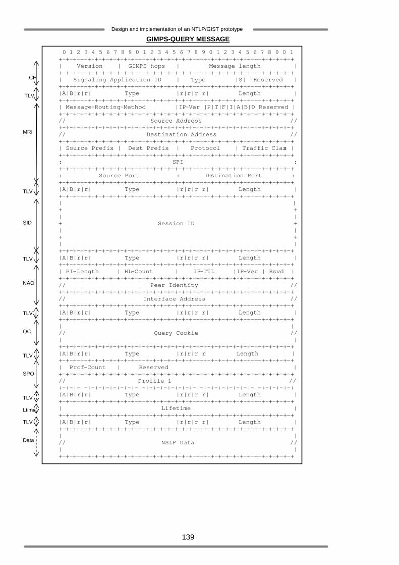
139
Design and implementation of an NTLP/GIST prototype
GIMPS-QUERY MESSAGE 0 1 2 3 4 5 6 7 8 9 0 1 2 3 4 5 6 7 8 9 0 1 2 3 4 5 6 7 8 9 0 1 +-+-+-+-+-+-+-+-+-+-+-+-+-+-+-+-+-+-+-+-+-+-+-+-+-+-+-+-+-+-+-+-+ | Version | GIMPS hops | Message length | +-+-+-+-+-+-+-+-+-+-+-+-+-+-+-+-+-+-+-+-+-+-+-+-+-+-+-+-+-+-+-+-+ | Signaling Application ID | Type |S| Reserved | +-+-+-+-+-+-+-+-+-+-+-+-+-+-+-+-+-+-+-+-+-+-+-+-+-+-+-+-+-+-+-+-+ |A|B|r|r| Type |r|r|r|r| Length | +-+-+-+-+-+-+-+-+-+-+-+-+-+-+-+-+-+-+-+-+-+-+-+-+-+-+-+-+-+-+-+-+ | Message-Routing-Method |IP-Ver |P|T|F|I|A|B|D|Reserved | +-+-+-+-+-+-+-+-+-+-+-+-+-+-+-+-+-+-+-+-+-+-+-+-+-+-+-+-+-+-+-+-+ // Source Address // +-+-+-+-+-+-+-+-+-+-+-+-+-+-+-+-+-+-+-+-+-+-+-+-+-+-+-+-+-+-+-+-+ // Destination Address // +-+-+-+-+-+-+-+-+-+-+-+-+-+-+-+-+-+-+-+-+-+-+-+-+-+-+-+-+-+-+-+-+ | Source Prefix | Dest Prefix | Protocol | Traffic Class | +-+-+-+-+-+-+-+-+-+-+-+-+-+-+-+-+-+-+-+-+-+-+-+-+-+-+-+-+-+-+-+-+ : SPI : +-+-+-+-+-+-+-+-+-+-+-+-+-+-+-+-+-+-+-+-+-+-+-+-+-+-+-+-+-+-+-+-+ : Source Port : Destination Port : +-+-+-+-+-+-+-+-+-+-+-+-+-+-+-+-+-+-+-+-+-+-+-+-+-+-+-+-+-+-+-+-+ |A|B|r|r| Type |r|r|r|r| Length | +-+-+-+-+-+-+-+-+-+-+-+-+-+-+-+-+-+-+-+-+-+-+-+-+-+-+-+-+-+-+-+-+ | | + + | | + Session ID + | | + + | | +-+-+-+-+-+-+-+-+-+-+-+-+-+-+-+-+-+-+-+-+-+-+-+-+-+-+-+-+-+-+-+-+ |A|B|r|r| Type |r|r|r|r| Length | +-+-+-+-+-+-+-+-+-+-+-+-+-+-+-+-+-+-+-+-+-+-+-+-+-+-+-+-+-+-+-+-+ | PI-Length | HL-Count | IP-TTL |IP-Ver | Rsvd | +-+-+-+-+-+-+-+-+-+-+-+-+-+-+-+-+-+-+-+-+-+-+-+-+-+-+-+-+-+-+-+-+ // Peer Identity // +-+-+-+-+-+-+-+-+-+-+-+-+-+-+-+-+-+-+-+-+-+-+-+-+-+-+-+-+-+-+-+-+ // Interface Address // +-+-+-+-+-+-+-+-+-+-+-+-+-+-+-+-+-+-+-+-+-+-+-+-+-+-+-+-+-+-+-+-+ |A|B|r|r| Type |r|r|r|r| Length | +-+-+-+-+-+-+-+-+-+-+-+-+-+-+-+-+-+-+-+-+-+-+-+-+-+-+-+-+-+-+-+-+ | | // Query Cookie // | | +-+-+-+-+-+-+-+-+-+-+-+-+-+-+-+-+-+-+-+-+-+-+-+-+-+-+-+-+-+-+-+-+ |A|B|r|r| Type |r|r|r|r| Length | +-+-+-+-+-+-+-+-+-+-+-+-+-+-+-+-+-+-+-+-+-+-+-+-+-+-+-+-+-+-+-+-+ | Prof-Count | Reserved | +-+-+-+-+-+-+-+-+-+-+-+-+-+-+-+-+-+-+-+-+-+-+-+-+-+-+-+-+-+-+-+-+ // Profile 1 // +-+-+-+-+-+-+-+-+-+-+-+-+-+-+-+-+-+-+-+-+-+-+-+-+-+-+-+-+-+-+-+-+ |A|B|r|r| Type |r|r|r|r| Length | +-+-+-+-+-+-+-+-+-+-+-+-+-+-+-+-+-+-+-+-+-+-+-+-+-+-+-+-+-+-+-+-+ | Lifetime | +-+-+-+-+-+-+-+-+-+-+-+-+-+-+-+-+-+-+-+-+-+-+-+-+-+-+-+-+-+-+-+-+ |A|B|r|r| Type |r|r|r|r| Length | +-+-+-+-+-+-+-+-+-+-+-+-+-+-+-+-+-+-+-+-+-+-+-+-+-+-+-+-+-+-+-+-+ | | // NSLP Data // | | +-+-+-+-+-+-+-+-+-+-+-+-+-+-+-+-+-+-+-+-+-+-+-+-+-+-+-+-+-+-+-+-+
CH
TLV
MRI
TLV
SID
TLV
NAO
TLV
QC
TLV
SPO
TLV
Data
TLV
Ltime
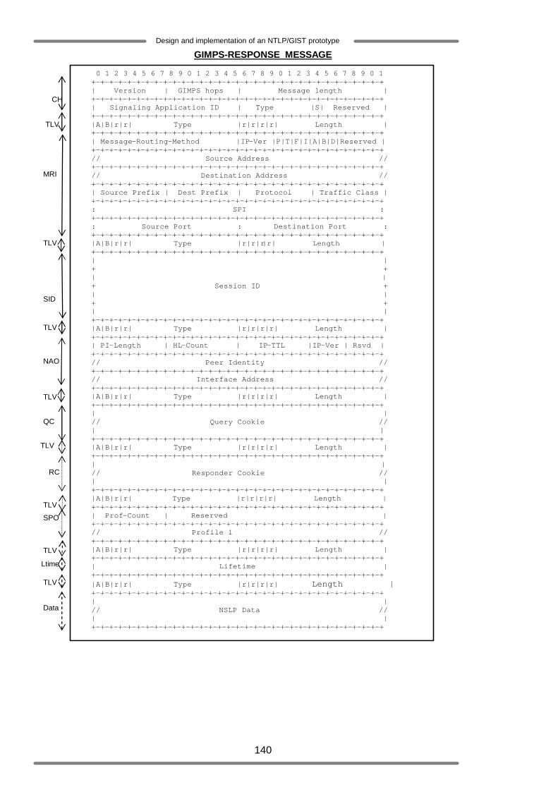
140
Design and implementation of an NTLP/GIST prototype
GIMPS-RESPONSE MESSAGE
0 1 2 3 4 5 6 7 8 9 0 1 2 3 4 5 6 7 8 9 0 1 2 3 4 5 6 7 8 9 0 1 +-+-+-+-+-+-+-+-+-+-+-+-+-+-+-+-+-+-+-+-+-+-+-+-+-+-+-+-+-+-+-+-+ | Version | GIMPS hops | Message length | +-+-+-+-+-+-+-+-+-+-+-+-+-+-+-+-+-+-+-+-+-+-+-+-+-+-+-+-+-+-+-+-+ | Signaling Application ID | Type |S| Reserved | +-+-+-+-+-+-+-+-+-+-+-+-+-+-+-+-+-+-+-+-+-+-+-+-+-+-+-+-+-+-+-+-+ |A|B|r|r| Type |r|r|r|r| Length | +-+-+-+-+-+-+-+-+-+-+-+-+-+-+-+-+-+-+-+-+-+-+-+-+-+-+-+-+-+-+-+-+ | Message-Routing-Method |IP-Ver |P|T|F|I|A|B|D|Reserved | +-+-+-+-+-+-+-+-+-+-+-+-+-+-+-+-+-+-+-+-+-+-+-+-+-+-+-+-+-+-+-+-+ // Source Address // +-+-+-+-+-+-+-+-+-+-+-+-+-+-+-+-+-+-+-+-+-+-+-+-+-+-+-+-+-+-+-+-+ // Destination Address // +-+-+-+-+-+-+-+-+-+-+-+-+-+-+-+-+-+-+-+-+-+-+-+-+-+-+-+-+-+-+-+-+ | Source Prefix | Dest Prefix | Protocol | Traffic Class | +-+-+-+-+-+-+-+-+-+-+-+-+-+-+-+-+-+-+-+-+-+-+-+-+-+-+-+-+-+-+-+-+ : SPI : +-+-+-+-+-+-+-+-+-+-+-+-+-+-+-+-+-+-+-+-+-+-+-+-+-+-+-+-+-+-+-+-+ : Source Port : Destination Port : +-+-+-+-+-+-+-+-+-+-+-+-+-+-+-+-+-+-+-+-+-+-+-+-+-+-+-+-+-+-+-+-+ |A|B|r|r| Type |r|r|r|r| Length | +-+-+-+-+-+-+-+-+-+-+-+-+-+-+-+-+-+-+-+-+-+-+-+-+-+-+-+-+-+-+-+-+ | | + + | | + Session ID + | | + + | | +-+-+-+-+-+-+-+-+-+-+-+-+-+-+-+-+-+-+-+-+-+-+-+-+-+-+-+-+-+-+-+-+ |A|B|r|r| Type |r|r|r|r| Length | +-+-+-+-+-+-+-+-+-+-+-+-+-+-+-+-+-+-+-+-+-+-+-+-+-+-+-+-+-+-+-+-+ | PI-Length | HL-Count | IP-TTL |IP-Ver | Rsvd | +-+-+-+-+-+-+-+-+-+-+-+-+-+-+-+-+-+-+-+-+-+-+-+-+-+-+-+-+-+-+-+-+ // Peer Identity // +-+-+-+-+-+-+-+-+-+-+-+-+-+-+-+-+-+-+-+-+-+-+-+-+-+-+-+-+-+-+-+-+ // Interface Address // +-+-+-+-+-+-+-+-+-+-+-+-+-+-+-+-+-+-+-+-+-+-+-+-+-+-+-+-+-+-+-+-+ |A|B|r|r| Type |r|r|r|r| Length | +-+-+-+-+-+-+-+-+-+-+-+-+-+-+-+-+-+-+-+-+-+-+-+-+-+-+-+-+-+-+-+-+ | | // Query Cookie // | | +-+-+-+-+-+-+-+-+-+-+-+-+-+-+-+-+-+-+-+-+-+-+-+-+-+-+-+-+-+-+-+-+ |A|B|r|r| Type |r|r|r|r| Length | +-+-+-+-+-+-+-+-+-+-+-+-+-+-+-+-+-+-+-+-+-+-+-+-+-+-+-+-+-+-+-+-+ | | // Responder Cookie // | | +-+-+-+-+-+-+-+-+-+-+-+-+-+-+-+-+-+-+-+-+-+-+-+-+-+-+-+-+-+-+-+-+ |A|B|r|r| Type |r|r|r|r| Length | +-+-+-+-+-+-+-+-+-+-+-+-+-+-+-+-+-+-+-+-+-+-+-+-+-+-+-+-+-+-+-+-+ | Prof-Count | Reserved | +-+-+-+-+-+-+-+-+-+-+-+-+-+-+-+-+-+-+-+-+-+-+-+-+-+-+-+-+-+-+-+-+ // Profile 1 // +-+-+-+-+-+-+-+-+-+-+-+-+-+-+-+-+-+-+-+-+-+-+-+-+-+-+-+-+-+-+-+-+ |A|B|r|r| Type |r|r|r|r| Length | +-+-+-+-+-+-+-+-+-+-+-+-+-+-+-+-+-+-+-+-+-+-+-+-+-+-+-+-+-+-+-+-+ | Lifetime | +-+-+-+-+-+-+-+-+-+-+-+-+-+-+-+-+-+-+-+-+-+-+-+-+-+-+-+-+-+-+-+-+ |A|B|r|r| Type |r|r|r|r| Length | +-+-+-+-+-+-+-+-+-+-+-+-+-+-+-+-+-+-+-+-+-+-+-+-+-+-+-+-+-+-+-+-+ | | // NSLP Data // | | +-+-+-+-+-+-+-+-+-+-+-+-+-+-+-+-+-+-+-+-+-+-+-+-+-+-+-+-+-+-+-+-+
CH
TLV
MRI
TLV
SID
TLV
NAO
TLV
QC
TLV
SPO
TLV
Data
TLV
Ltime
RC
TLV
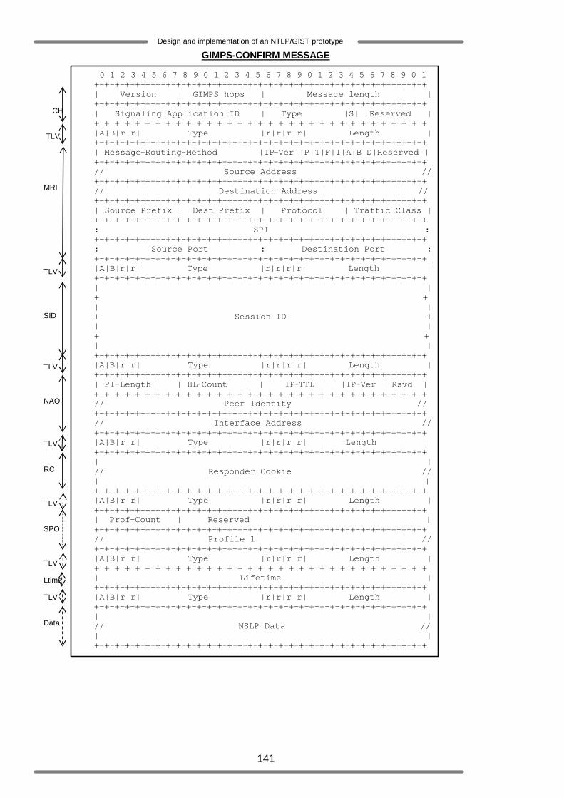
141
Design and implementation of an NTLP/GIST prototype
GIMPS-CONFIRM MESSAGE
0 1 2 3 4 5 6 7 8 9 0 1 2 3 4 5 6 7 8 9 0 1 2 3 4 5 6 7 8 9 0 1 +-+-+-+-+-+-+-+-+-+-+-+-+-+-+-+-+-+-+-+-+-+-+-+-+-+-+-+-+-+-+-+-+ | Version | GIMPS hops | Message length | +-+-+-+-+-+-+-+-+-+-+-+-+-+-+-+-+-+-+-+-+-+-+-+-+-+-+-+-+-+-+-+-+ | Signaling Application ID | Type |S| Reserved | +-+-+-+-+-+-+-+-+-+-+-+-+-+-+-+-+-+-+-+-+-+-+-+-+-+-+-+-+-+-+-+-+ |A|B|r|r| Type |r|r|r|r| Length | +-+-+-+-+-+-+-+-+-+-+-+-+-+-+-+-+-+-+-+-+-+-+-+-+-+-+-+-+-+-+-+-+ | Message-Routing-Method |IP-Ver |P|T|F|I|A|B|D|Reserved | +-+-+-+-+-+-+-+-+-+-+-+-+-+-+-+-+-+-+-+-+-+-+-+-+-+-+-+-+-+-+-+-+ // Source Address // +-+-+-+-+-+-+-+-+-+-+-+-+-+-+-+-+-+-+-+-+-+-+-+-+-+-+-+-+-+-+-+-+ // Destination Address // +-+-+-+-+-+-+-+-+-+-+-+-+-+-+-+-+-+-+-+-+-+-+-+-+-+-+-+-+-+-+-+-+ | Source Prefix | Dest Prefix | Protocol | Traffic Class | +-+-+-+-+-+-+-+-+-+-+-+-+-+-+-+-+-+-+-+-+-+-+-+-+-+-+-+-+-+-+-+-+ : SPI : +-+-+-+-+-+-+-+-+-+-+-+-+-+-+-+-+-+-+-+-+-+-+-+-+-+-+-+-+-+-+-+-+ : Source Port : Destination Port : +-+-+-+-+-+-+-+-+-+-+-+-+-+-+-+-+-+-+-+-+-+-+-+-+-+-+-+-+-+-+-+-+ |A|B|r|r| Type |r|r|r|r| Length | +-+-+-+-+-+-+-+-+-+-+-+-+-+-+-+-+-+-+-+-+-+-+-+-+-+-+-+-+-+-+-+-+ | | + + | | + Session ID + | | + + | | +-+-+-+-+-+-+-+-+-+-+-+-+-+-+-+-+-+-+-+-+-+-+-+-+-+-+-+-+-+-+-+-+ |A|B|r|r| Type |r|r|r|r| Length | +-+-+-+-+-+-+-+-+-+-+-+-+-+-+-+-+-+-+-+-+-+-+-+-+-+-+-+-+-+-+-+-+ | PI-Length | HL-Count | IP-TTL |IP-Ver | Rsvd | +-+-+-+-+-+-+-+-+-+-+-+-+-+-+-+-+-+-+-+-+-+-+-+-+-+-+-+-+-+-+-+-+ // Peer Identity // +-+-+-+-+-+-+-+-+-+-+-+-+-+-+-+-+-+-+-+-+-+-+-+-+-+-+-+-+-+-+-+-+ // Interface Address // +-+-+-+-+-+-+-+-+-+-+-+-+-+-+-+-+-+-+-+-+-+-+-+-+-+-+-+-+-+-+-+-+ |A|B|r|r| Type |r|r|r|r| Length | +-+-+-+-+-+-+-+-+-+-+-+-+-+-+-+-+-+-+-+-+-+-+-+-+-+-+-+-+-+-+-+-+ | | // Responder Cookie // | | +-+-+-+-+-+-+-+-+-+-+-+-+-+-+-+-+-+-+-+-+-+-+-+-+-+-+-+-+-+-+-+-+ |A|B|r|r| Type |r|r|r|r| Length | +-+-+-+-+-+-+-+-+-+-+-+-+-+-+-+-+-+-+-+-+-+-+-+-+-+-+-+-+-+-+-+-+ | Prof-Count | Reserved | +-+-+-+-+-+-+-+-+-+-+-+-+-+-+-+-+-+-+-+-+-+-+-+-+-+-+-+-+-+-+-+-+ // Profile 1 // +-+-+-+-+-+-+-+-+-+-+-+-+-+-+-+-+-+-+-+-+-+-+-+-+-+-+-+-+-+-+-+-+ |A|B|r|r| Type |r|r|r|r| Length | +-+-+-+-+-+-+-+-+-+-+-+-+-+-+-+-+-+-+-+-+-+-+-+-+-+-+-+-+-+-+-+-+ | Lifetime | +-+-+-+-+-+-+-+-+-+-+-+-+-+-+-+-+-+-+-+-+-+-+-+-+-+-+-+-+-+-+-+-+ |A|B|r|r| Type |r|r|r|r| Length | +-+-+-+-+-+-+-+-+-+-+-+-+-+-+-+-+-+-+-+-+-+-+-+-+-+-+-+-+-+-+-+-+ | | // NSLP Data // | | +-+-+-+-+-+-+-+-+-+-+-+-+-+-+-+-+-+-+-+-+-+-+-+-+-+-+-+-+-+-+-+-+
CH
TLV
MRI
TLV
SID
TLV
NAO
TLV
RC
TLV
SPO
TLV
Data
TLV
Ltime

142
Design and implementation of an NTLP/GIST prototype
Legend // variable length : Included element/parameter could be ignored
Mandatory GIMPS object Optional GIMPS object Mandatory GIMPS object in connection mode
CH = Common Header TLV = type-length-value objects MRI = Message-Routing-Information SID = Session-Identification NAO = Node-Addressing SPO = Stack Proposal QC = Query-Cookie/ RC = Responder-Cookie Ltime = Routing-State-Lifetime Data = NSLP-Data
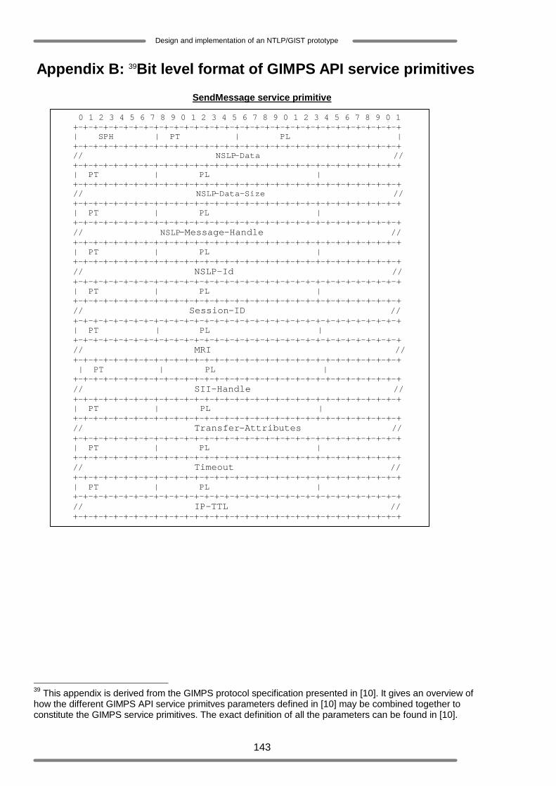
143
Design and implementation of an NTLP/GIST prototype
Appendix B: 39Bit level format of GIMPS API service primitives
SendMessage service primitive
39 This appendix is derived from the GIMPS protocol specification presented in [10]. It gives an overview of how the different GIMPS API service primitves parameters defined in [10] may be combined together to constitute the GIMPS service primitives. The exact definition of all the parameters can be found in [10].
0 1 2 3 4 5 6 7 8 9 0 1 2 3 4 5 6 7 8 9 0 1 2 3 4 5 6 7 8 9 0 1 +-+-+-+-+-+-+-+-+-+-+-+-+-+-+-+-+-+-+-+-+-+-+-+-+-+-+-+-+-+-+-+-+ | SPH | PT | PL | +-+-+-+-+-+-+-+-+-+-+-+-+-+-+-+-+-+-+-+-+-+-+-+-+-+-+-+-+-+-+-+-+ // NSLP-Data // +-+-+-+-+-+-+-+-+-+-+-+-+-+-+-+-+-+-+-+-+-+-+-+-+-+-+-+-+-+-+-+-+ | PT | PL | +-+-+-+-+-+-+-+-+-+-+-+-+-+-+-+-+-+-+-+-+-+-+-+-+-+-+-+-+-+-+-+-+ // NSLP-Data-Size // +-+-+-+-+-+-+-+-+-+-+-+-+-+-+-+-+-+-+-+-+-+-+-+-+-+-+-+-+-+-+-+-+ | PT | PL | +-+-+-+-+-+-+-+-+-+-+-+-+-+-+-+-+-+-+-+-+-+-+-+-+-+-+-+-+-+-+-+-+ // NSLP-Message-Handle // +-+-+-+-+-+-+-+-+-+-+-+-+-+-+-+-+-+-+-+-+-+-+-+-+-+-+-+-+-+-+-+-+ | PT | PL | +-+-+-+-+-+-+-+-+-+-+-+-+-+-+-+-+-+-+-+-+-+-+-+-+-+-+-+-+-+-+-+-+ // NSLP-Id // +-+-+-+-+-+-+-+-+-+-+-+-+-+-+-+-+-+-+-+-+-+-+-+-+-+-+-+-+-+-+-+-+ | PT | PL | +-+-+-+-+-+-+-+-+-+-+-+-+-+-+-+-+-+-+-+-+-+-+-+-+-+-+-+-+-+-+-+-+ // Session-ID // +-+-+-+-+-+-+-+-+-+-+-+-+-+-+-+-+-+-+-+-+-+-+-+-+-+-+-+-+-+-+-+-+ | PT | PL | +-+-+-+-+-+-+-+-+-+-+-+-+-+-+-+-+-+-+-+-+-+-+-+-+-+-+-+-+-+-+-+-+ // MRI // +-+-+-+-+-+-+-+-+-+-+-+-+-+-+-+-+-+-+-+-+-+-+-+-+-+-+-+-+-+-+-+-+ | PT | PL | +-+-+-+-+-+-+-+-+-+-+-+-+-+-+-+-+-+-+-+-+-+-+-+-+-+-+-+-+-+-+-+-+ // SII-Handle // +-+-+-+-+-+-+-+-+-+-+-+-+-+-+-+-+-+-+-+-+-+-+-+-+-+-+-+-+-+-+-+-+ | PT | PL | +-+-+-+-+-+-+-+-+-+-+-+-+-+-+-+-+-+-+-+-+-+-+-+-+-+-+-+-+-+-+-+-+ // Transfer-Attributes // +-+-+-+-+-+-+-+-+-+-+-+-+-+-+-+-+-+-+-+-+-+-+-+-+-+-+-+-+-+-+-+-+ | PT | PL | +-+-+-+-+-+-+-+-+-+-+-+-+-+-+-+-+-+-+-+-+-+-+-+-+-+-+-+-+-+-+-+-+ // Timeout // +-+-+-+-+-+-+-+-+-+-+-+-+-+-+-+-+-+-+-+-+-+-+-+-+-+-+-+-+-+-+-+-+ | PT | PL | +-+-+-+-+-+-+-+-+-+-+-+-+-+-+-+-+-+-+-+-+-+-+-+-+-+-+-+-+-+-+-+-+ // IP-TTL // +-+-+-+-+-+-+-+-+-+-+-+-+-+-+-+-+-+-+-+-+-+-+-+-+-+-+-+-+-+-+-+-+
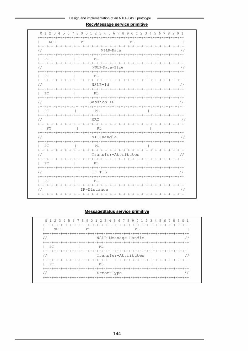
144
Design and implementation of an NTLP/GIST prototype
RecvMessage service primitive
MessageStatus service primitive
0 1 2 3 4 5 6 7 8 9 0 1 2 3 4 5 6 7 8 9 0 1 2 3 4 5 6 7 8 9 0 1 +-+-+-+-+-+-+-+-+-+-+-+-+-+-+-+-+-+-+-+-+-+-+-+-+-+-+-+-+-+-+-+-+ | SPH | PT | PL | +-+-+-+-+-+-+-+-+-+-+-+-+-+-+-+-+-+-+-+-+-+-+-+-+-+-+-+-+-+-+-+-+ // NSLP-Data // +-+-+-+-+-+-+-+-+-+-+-+-+-+-+-+-+-+-+-+-+-+-+-+-+-+-+-+-+-+-+-+-+ | PT | PL | +-+-+-+-+-+-+-+-+-+-+-+-+-+-+-+-+-+-+-+-+-+-+-+-+-+-+-+-+-+-+-+-+ // NSLP-Data-Size // +-+-+-+-+-+-+-+-+-+-+-+-+-+-+-+-+-+-+-+-+-+-+-+-+-+-+-+-+-+-+-+-+ | PT | PL | +-+-+-+-+-+-+-+-+-+-+-+-+-+-+-+-+-+-+-+-+-+-+-+-+-+-+-+-+-+-+-+-+ // NSLP-Id // +-+-+-+-+-+-+-+-+-+-+-+-+-+-+-+-+-+-+-+-+-+-+-+-+-+-+-+-+-+-+-+-+ | PT | PL | +-+-+-+-+-+-+-+-+-+-+-+-+-+-+-+-+-+-+-+-+-+-+-+-+-+-+-+-+-+-+-+-+ // Session-ID // +-+-+-+-+-+-+-+-+-+-+-+-+-+-+-+-+-+-+-+-+-+-+-+-+-+-+-+-+-+-+-+-+ | PT | PL | +-+-+-+-+-+-+-+-+-+-+-+-+-+-+-+-+-+-+-+-+-+-+-+-+-+-+-+-+-+-+-+-+ // MRI // +-+-+-+-+-+-+-+-+-+-+-+-+-+-+-+-+-+-+-+-+-+-+-+-+-+-+-+-+-+-+-+-+ | PT | PL | +-+-+-+-+-+-+-+-+-+-+-+-+-+-+-+-+-+-+-+-+-+-+-+-+-+-+-+-+-+-+-+-+ // SII-Handle // +-+-+-+-+-+-+-+-+-+-+-+-+-+-+-+-+-+-+-+-+-+-+-+-+-+-+-+-+-+-+-+-+ | PT | PL | +-+-+-+-+-+-+-+-+-+-+-+-+-+-+-+-+-+-+-+-+-+-+-+-+-+-+-+-+-+-+-+-+ // Transfer-Attributes // +-+-+-+-+-+-+-+-+-+-+-+-+-+-+-+-+-+-+-+-+-+-+-+-+-+-+-+-+-+-+-+-+ | PT | PL | +-+-+-+-+-+-+-+-+-+-+-+-+-+-+-+-+-+-+-+-+-+-+-+-+-+-+-+-+-+-+-+-+ // IP-TTL // +-+-+-+-+-+-+-+-+-+-+-+-+-+-+-+-+-+-+-+-+-+-+-+-+-+-+-+-+-+-+-+-+ | PT | PL | +-+-+-+-+-+-+-+-+-+-+-+-+-+-+-+-+-+-+-+-+-+-+-+-+-+-+-+-+-+-+-+-+ // IP-Distance // +-+-+-+-+-+-+-+-+-+-+-+-+-+-+-+-+-+-+-+-+-+-+-+-+-+-+-+-+-+-+-+-+
0 1 2 3 4 5 6 7 8 9 0 1 2 3 4 5 6 7 8 9 0 1 2 3 4 5 6 7 8 9 0 1 +-+-+-+-+-+-+-+-+-+-+-+-+-+-+-+-+-+-+-+-+-+-+-+-+-+-+-+-+-+-+-+-+ | SPH | PT | PL | +-+-+-+-+-+-+-+-+-+-+-+-+-+-+-+-+-+-+-+-+-+-+-+-+-+-+-+-+-+-+-+-+ // NSLP-Message-Handle // +-+-+-+-+-+-+-+-+-+-+-+-+-+-+-+-+-+-+-+-+-+-+-+-+-+-+-+-+-+-+-+-+ | PT | PL | +-+-+-+-+-+-+-+-+-+-+-+-+-+-+-+-+-+-+-+-+-+-+-+-+-+-+-+-+-+-+-+-+ // Transfer-Attributes // +-+-+-+-+-+-+-+-+-+-+-+-+-+-+-+-+-+-+-+-+-+-+-+-+-+-+-+-+-+-+-+-+ | PT | PL | +-+-+-+-+-+-+-+-+-+-+-+-+-+-+-+-+-+-+-+-+-+-+-+-+-+-+-+-+-+-+-+-+ // Error-Type // +-+-+-+-+-+-+-+-+-+-+-+-+-+-+-+-+-+-+-+-+-+-+-+-+-+-+-+-+-+-+-+-+
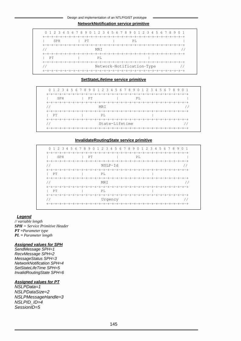
145
Design and implementation of an NTLP/GIST prototype
NetworkNotification service primitive
SetStateLifetime service primitive
InvalidateRoutingState service primitive
Legend // variable length SPH = Service Primitive Header PT =Parameter type PL = Parameter length Assigned values for SPH SendMessage SPH=1 RecvMessage SPH=2 MessageStatus SPH=3 NetworkNotification SPH=4 SetStateLifeTime SPH=5 InvalidRoutingState SPH=6 Assigned values for PT NSLPData=1 NSLPDataSize=2 NSLPMessageHandle=3 NSLPID_ID=4 SessionID=5
0 1 2 3 4 5 6 7 8 9 0 1 2 3 4 5 6 7 8 9 0 1 2 3 4 5 6 7 8 9 0 1 +-+-+-+-+-+-+-+-+-+-+-+-+-+-+-+-+-+-+-+-+-+-+-+-+-+-+-+-+-+-+-+-+ | SPH | PT | PL | +-+-+-+-+-+-+-+-+-+-+-+-+-+-+-+-+-+-+-+-+-+-+-+-+-+-+-+-+-+-+-+-+ // MRI // +-+-+-+-+-+-+-+-+-+-+-+-+-+-+-+-+-+-+-+-+-+-+-+-+-+-+-+-+-+-+-+-+ | PT | PL | +-+-+-+-+-+-+-+-+-+-+-+-+-+-+-+-+-+-+-+-+-+-+-+-+-+-+-+-+-+-+-+-+ // Network-Notification-Type // +-+-+-+-+-+-+-+-+-+-+-+-+-+-+-+-+-+-+-+-+-+-+-+-+-+-+-+-+-+-+-+-+
0 1 2 3 4 5 6 7 8 9 0 1 2 3 4 5 6 7 8 9 0 1 2 3 4 5 6 7 8 9 0 1 +-+-+-+-+-+-+-+-+-+-+-+-+-+-+-+-+-+-+-+-+-+-+-+-+-+-+-+-+-+-+-+-+ | SPH | PT | PL | +-+-+-+-+-+-+-+-+-+-+-+-+-+-+-+-+-+-+-+-+-+-+-+-+-+-+-+-+-+-+-+-+ // NSLP-Id // +-+-+-+-+-+-+-+-+-+-+-+-+-+-+-+-+-+-+-+-+-+-+-+-+-+-+-+-+-+-+-+-+ | PT | PL | +-+-+-+-+-+-+-+-+-+-+-+-+-+-+-+-+-+-+-+-+-+-+-+-+-+-+-+-+-+-+-+-+ // MRI // +-+-+-+-+-+-+-+-+-+-+-+-+-+-+-+-+-+-+-+-+-+-+-+-+-+-+-+-+-+-+-+-+ | PT | PL | +-+-+-+-+-+-+-+-+-+-+-+-+-+-+-+-+-+-+-+-+-+-+-+-+-+-+-+-+-+-+-+-+ // Urgency // +-+-+-+-+-+-+-+-+-+-+-+-+-+-+-+-+-+-+-+-+-+-+-+-+-+-+-+-+-+-+-+-+
0 1 2 3 4 5 6 7 8 9 0 1 2 3 4 5 6 7 8 9 0 1 2 3 4 5 6 7 8 9 0 1 +-+-+-+-+-+-+-+-+-+-+-+-+-+-+-+-+-+-+-+-+-+-+-+-+-+-+-+-+-+-+-+-+ | SPH | PT | PL | +-+-+-+-+-+-+-+-+-+-+-+-+-+-+-+-+-+-+-+-+-+-+-+-+-+-+-+-+-+-+-+-+ // MRI // +-+-+-+-+-+-+-+-+-+-+-+-+-+-+-+-+-+-+-+-+-+-+-+-+-+-+-+-+-+-+-+-+ | PT | PL | +-+-+-+-+-+-+-+-+-+-+-+-+-+-+-+-+-+-+-+-+-+-+-+-+-+-+-+-+-+-+-+-+ // State-Lifetime // +-+-+-+-+-+-+-+-+-+-+-+-+-+-+-+-+-+-+-+-+-+-+-+-+-+-+-+-+-+-+-+-+

146
Design and implementation of an NTLP/GIST prototype
MRI=6 Transfer Attributes=9 Time-out=10 IPttl=11 IPDistance=12 ErrorType=13 Network notification=14 Urgency=16 StateLifeTime_ID=17 Message Handle=18 SII_Handle=20

147
Design and implementation of an NTLP/GIST prototype