New Zealand Research Applications of, and …db.nzsee.org.nz/2017/O1A.1_MacRae.pdfDevelopments in,...
14
New Zealand Research Applications of, and Developments in, Low Damage Technology for Steel Structures 2017 NZSEE Conference G. A. MacRae Department of Civil Engineering, University of Canterbury, Christchurch. G. C. Clifton Department of Civil Engineering, University of Auckland, Auckland ABSTRACT: This paper describes New Zealand construction and research related to low damage construction. Following the large scale demolition of buildings in Christchurch after the 2010/2011 earthquake series, many of the buildings in the Christchurch rebuild are supported by structural steel framing. These steel buildings include BRB systems, EBF systems with replaceable active links, rocking systems, base isolation using friction pendulum systems and/or lead-rubber dissipaters, RBS beams, lead extrusion dissipaters, yielding flexural dissipaters, and friction connections. Some interesting structural systems are described, and concerns about a number of currently used systems are discussed. Research being conducted in NZ to address some of these issues is listed. Also, it is shown that subjective quantitative tools, rather than purely probabilistic ones, may be more useful to engineers. Also, some suggestions to make NZ low damage structures more robust are described. 1. INTRODUCTION After the 2010-2011 Canterbury earthquakes, almost all unreinforced masonry buildings, and the majority of buildings over 3 stories in height have been demolished as a result of direct damage, or irregular foundation settlement. In their place a new city is emerging. A significant majority of these structures have structural steel framing and a number are using some of newer techniques to dissipate energy resulting from the earthquakes. Many of these are intended to be “low-damage” structures, which are intended not require replacement after a major structural event, and some are intended to be directly useable soon after a major earthquake. This reflects the current emphasis from an increased number of clients for rapid return to service capability following the 1+ years operational disruption following that earthquake series. A number of these innovations are based on research that has been, or is being, conducted in NZ. The aims of this paper are to describe the construction, as well as some of the related research. In particular, the following questions are addressed: 1) What is legal framework by which buildings are constructed in NZ? 2) What type of systems are being built in NZ? 3) What interesting forms are being built? 4) What type of systems are not being built in NZ? 5) What design and /or construction concerns exist? 6) What research is currently underway related to low damage systems? 7) How are decisions made related to low damage steel buildings?
Transcript of New Zealand Research Applications of, and …db.nzsee.org.nz/2017/O1A.1_MacRae.pdfDevelopments in,...

New Zealand Research Applications of, and
Developments in, Low Damage Technology for Steel
Structures
2017 NZSEE Conference
G. A. MacRae
Department of Civil Engineering, University of Canterbury, Christchurch.
G. C. Clifton
Department of Civil Engineering, University of Auckland, Auckland
ABSTRACT: This paper describes New Zealand construction and research related to low
damage construction. Following the large scale demolition of buildings in Christchurch after
the 2010/2011 earthquake series, many of the buildings in the Christchurch rebuild are
supported by structural steel framing. These steel buildings include BRB systems, EBF
systems with replaceable active links, rocking systems, base isolation using friction pendulum
systems and/or lead-rubber dissipaters, RBS beams, lead extrusion dissipaters, yielding
flexural dissipaters, and friction connections. Some interesting structural systems are
described, and concerns about a number of currently used systems are discussed. Research
being conducted in NZ to address some of these issues is listed. Also, it is shown that
subjective quantitative tools, rather than purely probabilistic ones, may be more useful to
engineers. Also, some suggestions to make NZ low damage structures more robust are
described.
1. INTRODUCTION
After the 2010-2011 Canterbury earthquakes, almost all unreinforced masonry buildings, and the majority
of buildings over 3 stories in height have been demolished as a result of direct damage, or irregular
foundation settlement. In their place a new city is emerging. A significant majority of these structures
have structural steel framing and a number are using some of newer techniques to dissipate energy
resulting from the earthquakes. Many of these are intended to be “low-damage” structures, which are
intended not require replacement after a major structural event, and some are intended to be directly
useable soon after a major earthquake. This reflects the current emphasis from an increased number of
clients for rapid return to service capability following the 1+ years operational disruption following that
earthquake series. A number of these innovations are based on research that has been, or is being,
conducted in NZ. The aims of this paper are to describe the construction, as well as some of the related
research. In particular, the following questions are addressed:
1) What is legal framework by which buildings are constructed in NZ?
2) What type of systems are being built in NZ?
3) What interesting forms are being built?
4) What type of systems are not being built in NZ?
5) What design and /or construction concerns exist?
6) What research is currently underway related to low damage systems?
7) How are decisions made related to low damage steel buildings?

2
2. NZ BUILDING LEGISLATION
The NZ Building Code (1992), in Clause B1:Structure, describes some high level functionality and
performance requirements to safeguard people from injury, and loss of amenity or property due to
structural behavior/failure. These are written in simple, general terms. The NZ Building Act (2004)
provides the legislative framework to meet the NZ Building Code. It describes how the legislative systems
works, including penalties for non-compliance, as well as how Compliance Documents, which comprise
Acceptable Solutions and Verification Methods, can be established and are used. These, if followed, are
automatically deemed to satisfy the requirements of the Building Code and the Building Control Authority
(BCA) must accept their use. Acceptable Solutions are Compliance Documents presenting simple, highly
specified means of compliance, which allow very little freedom for specific design. (They are effectively
“cookbook” solutions). Verification Methods are also Compliance Documents but are dependent on
application of engineering procedures and some judgement. Alternatively, compliance with the Building
Code may be satisfied by “Alternative Solutions”. An Alternative Solution follows provisions that in
whole or part are outside the scope of the Compliance Documents. In practice, this Alternative Solution
may be deemed to comply with the Building Code, if the design is approved by a Licenced Building
Practitioner who is a Chartered Professional Engineer and the Building Consent Authority (BCA) is
satisfied as to the procedures used. As part of this, peer review will typically be required at the discretion
of the BCA. There are no Compliance Documents for most novel, or “low damage” structural systems, so
they are considered as Alternative Solutions.
The Alternative Solutions approach used to satisfy the performance requirements of the NZ Building Code
for low damage construction is quite flexible. It allows new solutions to be implemented in actual
structures without large disincentive. Sometimes though, peer reviewers may reject a particular solution
that is proposed. In other countries, such as Indonesia, Japan, and the USA, for special systems (e.g. tall.
irregular or very important buildings, and some buildings using new structural systems), standing expert
review panels are involved. This provides consistency over a region.
3. SYSTEMS USED
After the 2010/2011 Canterbury earthquakes, it took time for new buildings to be constructed. This was
influenced by many factors, especially the extent of the damage and deconstruction required, the
willingness of insurance companies to pay out on damaged buildings and to insure new buildings, and of
banks to lend. Some of the earliest buildings were completed after July 2013. Significant building
construction has been continuing since then. Steel Construction New Zealand (SCNZ) has collected
building data from Christchurch City Council within the Central Business District of Christchurch and
other main areas of re-construction, for structures of more than two stories. As at July 2015, the total
number of buildings completed or under construction since July 2013, was 69. Of these, 87% of the new
total floor area was supported by structural systems of steel, or steel-composite construction. Buildings
with mixed construction, or unknown construction were included with reinforced concrete and timber
structures as part of the remaining 13%. It is clear that Christchurch has become a structural steel city.
There is no accepted definition of low-damage construction, although proposals have been made (MacRae
et al. 2013). A number of possible low damage structural systems for steel buildings were described in
MacRae and Clifton (2013b). These include nominally elastic systems, EBF systems with replaceable
links, BRB systems, axially yielding devices, flexurally yielding devices, viscously damped systems, base
isolation (using sliding friction systems, lead-rubber dissipaters, or both), and rocking systems. These, in
addition to the traditional EBFs, MRFs with yielding beams (with or without RBS sections) are being used
with composite (CFT), or bare steel, columns. Some examples are given below:

3
a) Existing steel systems
Of the structures within Christchurch at the time of the earthquakes, only a small proportion of buildings
were supported by steel framing. Steel framing was not used until around 1990 and had 50% market share
within the CBD by 2010. Thus these buildings were also amongst the most recently built. These structures,
except for those with significant foundation issues, were rapidly repaired when repair was required, and
reused again. These include (i) the 22 story Pacific Tower on Manchester Street, where an EBF link
fractured, and repair of a number of links occurred. This is the tallest structure in Christchurch after the
earthquakes; (ii) the 11 storey Club Tower, which housed the Canterbury Earthquake Recovery Authority
(CERA) shortly after the earthquakes, and (iii) Les Mills Gym near the location of the collapsed CTV
building. It has been argued that since many steel structures are reusable after experiencing shaking which
is about 200% of what they were explicitly designed for, that even traditional design of steel structures
relying on ductility, may result in low-damage systems. Reasons for this good behavior have been
attributed to the high stiffness to strength ratio of steel sections, the contribution of non-structural
elements, the short duration of the earthquake shaking, and soil-structure interaction effects. The latter is a
major contributor (Storie et al. 2014).
b) Nominally elastic systems
Effective design peak ground accelerations for the 500 year event of about 0.13g, 0.3g and 0.4g, are used
in Auckland, Christchurch and Wellington respectively. For New Zealand they range from 0.10g for
Kaitaia to 0.60g in Arthurs Pass. Elastic, or nominally elastic (called “nominally ductile” in NZS1170.5),
design is more common in Auckland and other low seismic areas than in Christchurch or Wellington. One
particular structure is the central Christchurch bus exchange on the SE corner of Lichfield and Colombo
Streets. This has a truss roof as shown in Figure 1a. Other structures in Auckland, such as the new
University of Auckland labs, are also nominally ductile, as shown in Figure 1b.
Figure 1. Nominally Ductile Systems (MacRae) Figure 2. BRB Systems (MacRae)
c) BRB systems
While BRB systems are used widely around the world, no specific regulations exist in NZ and prior to
2011 there was only one home-designed and untested BRB retrofit on the psychology building at the
University of Canterbury in Christchurch; built in 1990. Since the earthquakes, these have become very
popular, being incorporated into approximately one half of the new steel buildings and often replacing
traditional EBFs, which was the principal seismic-resisting system used prior to 2010. BRBs are used in
diagonal, or super X, as well as in the Chevron configurations as shown in Figure 2. Some examples here
include: (a) UoC Science Annex, (b)14 Hazeldean Rd, Addington, Christchurch 8024, (c) 254 Montreal
Street, (d) PwC Centre, Cambridge Terrace. In order of decreasing popularity are braces from StarSeismic,
(a) (b)
(b)
(d)
(a)
(b)
(c)

4
Taiwan, and CoREBrace then “in-house” designs. Both StarSeismic and the Taiwanese braces are being
fabricated under licence in Auckland. One frame on the location of the old police station site on
Cambridge Terrace was constructed with temporary angles at the location of the BRBs until the braces
arrived.
Details of the brace end connections are shown in Figure 3 from (a) 254 Montreal Street, (b) NE corner
Lichfield and Colombo Street, (c) PwC centre, (d) UoC Science Annex. It may be seen that (i) columns
are a mix of bare steel and CFT, (ii) connections to the gusset plates are a mix of bolted and pinned, and
(iii) in general the gusset plates have no stiffeners. The advantage of the pin-end connection is that no
moment is induced due to in-plane action, however there are likely to be more issues with fit, and possibly
with gusset plate stability. Many NZ designers follow AISC specifications for gusset plate design, where
an effective length of the gusset plate used is k = 0.65, even though the mode of failure is sway, implying
that this effective length factor should be greater than unity. SCNZ is developing a design guide that is
expected to be available during 2016.
Figure 3. Gusset Plate Details (MacRae)
d) EBF systems with replaceable links
EBFs, with and without replaceable links, are being designed according to a guidance document from
HERA (2013). The replaceable link is required to be smaller than the main beam to allow it to be bolted in
place. It generally has about 50% of the traditional link shear force resistance. Relative advantages of the
replaceable link EBFs and traditional EBFs are given in Table 1. Examples of EBF structures in
Christchurch are given in Figure 4 including (a) 120 Hereford Street, (b) 329 Durham St, (c) NW Corner
of Lichfield and Barbadoes St, (d) 208 Barbadoes St. The EBF like replacement used in Pacific Tower is
shown in Figure 4e (Gardiner et al., 2013).
Table 1. Relative advantages of Replaceable link EBFs and Traditional EBFs
Traditional EBF Advantages:
Overall lower detailing costs
No butt weld is required at the critical beam
flange location.
Because the shear resistance of a traditional link
is about twice that of a replaceable EBF link,
half as many EBF bays are required.
EBFs damaged in the 2010/2011 Canterbury
earthquakes were relatively easily repaired
(Gardiner et al., 2015). This was by removing a
section of the EBF by making cuts in the beams
midway between the link end and end of the
beams, as well as midway along the braces, and
then replacing this portion with a new section.
Replaceable EBF Advantages:
The links are more easily replaceable.
They are easily imagined/sold as a low-damage
system.
Since the replaceable EBF link is smaller, it is
often more slender, deforming in flexure rather
than shear, so no intermediate web stiffeners
may be required.
Since the flexural demand at the end of the link is
generally significantly less than that of the beam
no special considerations are required to protect
the beam from yielding.
(d) (a) (b) (c)

Figure 4. Examples of EBF structures in Christchurch (MacRae)
e) Base Isolation
A number of steel structures are using base isolation. This includes (a) 151 Cambridge Terrace, (b) the
Justice Precinct at 121 Tuam Street shown in Figure 5a, and others. The Justice Precinct is required to
perform very well and composite circular CFT columns connected to beams with external diaphragm
connections using bolted connections. The beams have reduced beam sections (RBS) as shown in
Figure 5b. A bearing above the column is shown in Figure 5c, and low friction supports in Figure 5d.
Similar framing is also used on the north side Kilmore street west of Durham Street. In addition to
new design, the existing mainly concrete Art Gallery has been retrofit with base isolation. Lead-
rubber as well as sliding friction systems have been used. A guideline for the design of base-isolated
systems is due to be released soon by NZSEE.
Figure 5. Some details from the Justice Precinct (MacRae)
f) Friction Connections in Moment Frames
These were developed in NZ and used initially in the Te Puni Apartment building at Victoria
University in Wellington in 2007. In this building, sliding occurred at the columns at the base of the
structure and in the beam to column connections of the perimeter frame in the 2013 Grassmere
earthquake. Friction dissipation has been recently used in (a) Forte Health Building on Kilmore Street,
and (b) as the main energy dissipation system in the Terraces Project on Oxford Terrace. Oxford
Terrace was unique in that Friction connection were used in two directions using external diaphragm
connections on a RCFT column as shown in Figure 6b. The base connection was a two way
connection with the column sitting on a central pin and oversized holes placed in the baseplate to
allow flexural movement in both directions as shown in Figure 6c. No codified design guidelines
currently exist for the design of friction connections.
(a)
(a)
(b)
(c)
(d)
(e)
(a)
(b)
(c) (d)

6
Figure 6. Details of the Friction Connections on the Terrace Project (MacRae)
g) Rocking frame systems
Rocking steel concentrically braced frames with ring spring base hold down systems were also used in
the Te Puni Apartment building at Victoria University in Wellington in 2007 and exhibited uplift of
some 4 to 6mm in the 2013 Grassmere earthquake. A number of other rocking frames have been
constructed since then around the country. One rocking concrete wall was in Christchurch at the time
of the Canterbury earthquake. While it exhibited some movement, it was on the north side of
Christchurch were excitations were considerably less than in the central city. The first new rocking
steel frame buildings in Christchurch after the earthquakes was the Forte Health building, 132
Peterborough Street, which used many interesting systems including friction dissipaters. The rocking
walls were coupled and energy is dissipated during relative movement between the walls by lead
extrusion dissipaters as shown in Figure 7a. Here, the rocking frames are held down by tendons
extending over their height. Vertical deformations of the rocking frame are also decoupled from the
slab of the building while allowing horizontal force transfer. An alternative means to hold down the
building is used in 141 Cambridge Terrace. Here, the large springs at the base of the structure limit the
onset of rocking as shown in Figure 7b, flexural yielding U-shape dissipaters are placed up the side of
the frame. The advantage of this system is that the frame members over the height do not need to be
sized for the post-tensioning forces, and the spring size can be selected for the appropriate
deformations. However, the cost of the springs must be considered.
Figure 7. Rocking system implementations (MacRae)
h) Viscously damped systems
A few buildings are including these systems. Devices are either imported (e.g. Taylor devices), or
constructed in NZ. Figure 8 shows devices implemented in 12c Moorehouse Avenue.
Figure 8. Viscous devices (Google Maps and MacRae) Figure 9. CBF Application (MacRae)
(c)
(b)
(a)
(a) (b)
(a) (b)
(a) (b)
(b)
7
i) CBF systems
CBFs may be designed according to NZS3404. An example at 124 Kilmore Street is given in Figure 9.
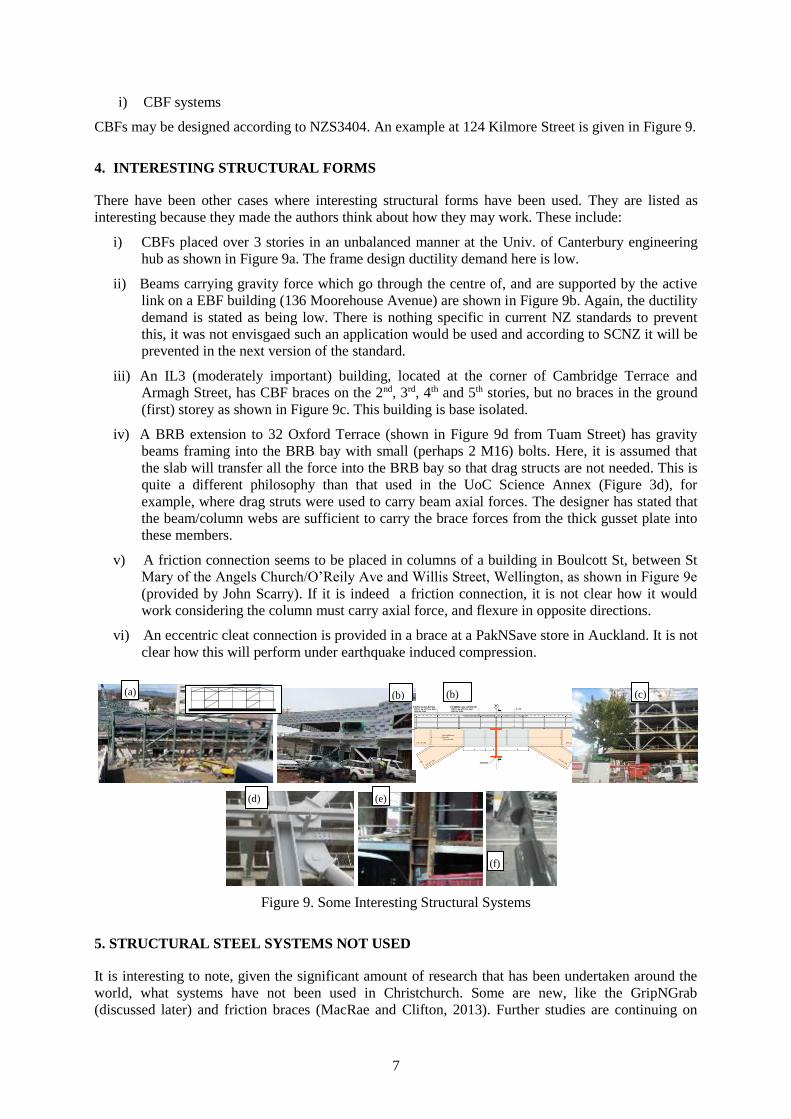
4. INTERESTING STRUCTURAL FORMS
There have been other cases where interesting structural forms have been used. They are listed as
interesting because they made the authors think about how they may work. These include:
i) CBFs placed over 3 stories in an unbalanced manner at the Univ. of Canterbury engineering
hub as shown in Figure 9a. The frame design ductility demand here is low.
ii) Beams carrying gravity force which go through the centre of, and are supported by the active
link on a EBF building (136 Moorehouse Avenue) are shown in Figure 9b. Again, the ductility
demand is stated as being low. There is nothing specific in current NZ standards to prevent
this, it was not envisgaed such an application would be used and according to SCNZ it will be
prevented in the next version of the standard.
iii) An IL3 (moderately important) building, located at the corner of Cambridge Terrace and
Armagh Street, has CBF braces on the 2nd, 3rd, 4th and 5th stories, but no braces in the ground
(first) storey as shown in Figure 9c. This building is base isolated.
iv) A BRB extension to 32 Oxford Terrace (shown in Figure 9d from Tuam Street) has gravity
beams framing into the BRB bay with small (perhaps 2 M16) bolts. Here, it is assumed that
the slab will transfer all the force into the BRB bay so that drag structs are not needed. This is
quite a different philosophy than that used in the UoC Science Annex (Figure 3d), for
example, where drag struts were used to carry beam axial forces. The designer has stated that
the beam/column webs are sufficient to carry the brace forces from the thick gusset plate into
these members.
v) A friction connection seems to be placed in columns of a building in Boulcott St, between St
Mary of the Angels Church/O’Reily Ave and Willis Street, Wellington, as shown in Figure 9e
(provided by John Scarry). If it is indeed a friction connection, it is not clear how it would
work considering the column must carry axial force, and flexure in opposite directions.
vi) An eccentric cleat connection is provided in a brace at a PakNSave store in Auckland. It is not
clear how this will perform under earthquake induced compression.
Figure 9. Some Interesting Structural Systems
5. STRUCTURAL STEEL SYSTEMS NOT USED
It is interesting to note, given the significant amount of research that has been undertaken around the
world, what systems have not been used in Christchurch. Some are new, like the GripNGrab
(discussed later) and friction braces (MacRae and Clifton, 2013). Further studies are continuing on
(a) (b)
(d) (e)
(b)
(f)
(c)

8
these topics. Another one that is not being used is the post-tensioned beam system. This is because
such a system seems to work well on simple subassemblies which are not part of a frame, and which
do not have a slab (MacRae and Clifton, 2013). It is interesting to note though, that even though the
same issues exist with these systems with other materials, they have been used in buildings with other
materials in NZ.
6. ISSUES WITH CURRENT CONSTRUCTION
Since low damage construction is a relatively new concept, many of the new systems being designed
and built don’t yet have robust design guidelines. While it has been illustrated that these devices be
effective in some cases, it does not mean that they will necessarily perform well is one of the design
parameters is slightly changed, or if the boundary conditions or loading is more realistic that than
considered in the experiments. This has been discussed with respect to the William Tell illustration
(MacRae and Clifton, 2015). A number of topical issues are discussed below many of which are
described in MacRae and Clifton (2015).
a) BRB issues
While it has been shown that BRBs can perform very well the overall sensitivity to construction
tolerances is not generally known or understood. Furthermore, the vast majority of BRB testing around
the world considers brace axial load only, or brace axial force together with some in-plane frame
action. Since, earthquake cause deformation in two horizontal directions, there is concern that this
should be considered when selecting a brace for a particular situation. Furthermore, brace inertial
effects, which may be significant on long braces, such as those which are now being built around the
world with lengths exceeding 50 feet (about 15m), are not considered. For these reasons, sufficient
evidence does not exist to indicate that the BRBs will behave well in all earthquake situations. Other
BRB issues are related to the connections at the end of the BRBs, which are generally gusset plates, as
described below.
b) BRB gusset plate issues
Gusset plates are attached to the ends of compression/tension members in frames subject to seismic
and non-seismic loading. A number of design recommendations – including the Uniform Force
Method of Thornton, the proportioning method, and the Generalized Uniform method, and some
simplified methods - are available to consider direct forces (MacRae and Clifton, 2013). While frame
action effects may be considered standardized generally accepted methods are not available. Methods
to explicitly consider the following actions on the gusset plates are not generally available:
i) In-plane moments from brace in-plane bending when brace connections are not fully pinned, and
ii) Out-of-plane moments (e.g. from frame out-of-plane deformation, brace buckling or inertia).
Most gusset plate design procedures (E.g. AISC) consider that the gusset plate has a buckling effective
length factor of 0.65-0.70 even though sway is the predominant failure mode. This issues is similar to
issues with axial cleat connections which sway and for which mitigation methods have been developed
(E.g. MBIE, 2010). Westeneng et al. (2015) used stability functions to obtain the actual gusset plate
effective length factor corresponding to overall buckling failure of an elastic gusset plate connected to
an elastic BRB brace member as shown in Figure 10a. The upper line on this graph can be
approximated by the equation kgusset = 1 + 0.550.58, where = (EI/L)g2/(EI/L)BRB
2. They showed that
the effective length factor is (i) dependent of the stiffness of the brace, (ii) greater than unity as would
be expected for sway elements, and (iii) may be greater than 3 for high gusset plate stiffnesses.
An implication of this is that gusset plates designed according to standard methods, with small
effective length factors, may fail under compressive load alone at strengths lower than that specified in
the standards. This has been shown and replicated by Westeneng et al. (2015) as shown in Figure 10b.
Westeneng et al. (2016) also demonstrated by calibrated FEM analysis that current recommendations
are not conservative. Furthermore Sitler et al. (2017) have shown that a number of failures of BRB
systems have occurred in the past and Takeuchi et al. (2016) have proposed a general method to

9
consider these things. Simple guidance from this method is not yet available in English. There is also
the concern that if gusset plates are too slender, they may buckle. However, if they are too stocky, they
may yield during out-of-plane deformation compromising their performance in subsequent cycles.
Figure 10. Gusset Plate Performance (Westeneng et al., 2015)
To prevent failure of the gusset plate, the weld may be sized for the capacity of the plate using
capacity design principles. While many engineers do size the welds this way, some use weaker welds,
or simply consider the capacity of the brace and to determine a uniform weld size. This may be
problematic if there are non-uniform distributions of force in the gusset plate due to element
flexibility, frame (beam-column) opening effects, brace in-plane moments, brace force eccentricity,
out-of-plane bending of the plate from member out-of-plane deformation etc. A weld distribution
factor which may account for some of these actions, but it is not clear how robust it is in general. In
addition to the weld, the elements in to which the gusset plate is connected, i.e. the beam and columns,
should have sufficient strength the carry the demands as described by Palmer et al. (2016).
Recent tests by Bruneau indicate good performance of BRBs in 2-D horizontal loading with drifts of
6% in each direction indicating that systems can, with care, provide satisfactory performance.
A group of concerned BRB researchers met at the Shanghai STESSA conference in July 2015 and
agreed to work together to solve the issues associated with gusset plates. These include key
researchers from Italy, Taiwan, USA as well as NZ and the committee chair is Kevin Cowie from
SCNZ. A further informal meeting was held at the 2016 NZSEE conference with representatives of
CoreBrace, StarSeismic, Takeuchi group, a consultant, a BRB fabricator, and research groups from
Auckland and Canterbury universities.
Development of design guidelines for BRB frames has been initiated by a Steel Construction NZ
(SCNZ) coordinated working group and the guidelines are expected in 2016.
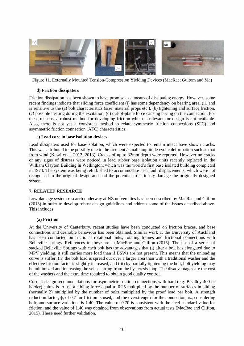
c) Externally Mounted Tension-Compression Yielding Devices (EMTCYD)
These are mini BRBs used by Marriott (2009) in tests with concrete rocking systems. They have been
implemented mainly in concrete and timber structures around NZ as a means to dissipate energy.
Implementation in a timber structure in 11 Birmingham Drive is shown in Figure 11a and b (MacRae).
The majority of the testing of these devices in their development was conducted under unidirectional
loading. However, in recent bi-directional testing by Gultom and Ma (2015), it was shown that they
buckled and lost strength. The test setup and buckled dissipater are shown in Figure 11c and d
(Gultom and Ma, 2015). The comment was also made that if the design had been different they may
have worked.
Stiffened Gusset Normal Gusset Design Strength
Stiffened Gusset Normal Gusset Design Strength
(a)
(b)
10
Figure 11. Externally Mounted Tension-Compression Yielding Devices (MacRae; Gultom and Ma)
d) Friction dissipaters
Friction dissipation has been shown to have promise as a means of dissipating energy. However, some
recent findings indicate that sliding force coefficient (i) has some dependency on bearing area, (ii) and
is sensitive to the (a) bolt characteristics (size, material props etc.), (b) tightening and surface friction,
(c) possible heating during the excitation, (d) out-of-plane force causing prying on the connection. For
these reasons, a robust method for developing friction which is relevant for design is not available.
Also, there is not yet a consistent method to relate symmetric friction connections (SFC) and
asymmetric friction connection (AFC) characteristics.
e) Lead core in base isolation devices
Lead dissipaters used for base-isolation, which were expected to remain intact have shown cracks.
This was attributed to be possibly due to the frequent / small amplitude cyclic deformation such as that
from wind (Kasai et al. 2012, 2013). Cracks of up to 32mm depth were reported. However no cracks
or any signs of distress were noticed in lead rubber base isolation units recently replaced in the
William Clayton Building in Wellington, which was the world’s first base isolated building completed
in 1974. The system was being refurbished to accommodate near fault displacements, which were not
recognised in the original design and had the potential to seriously damage the originally designed
system.
7. RELATED RESEARCH
Low-damage system research underway at NZ universities has been described by MacRae and Clifton
(2013) in order to develop robust design guidelines and address some of the issues described above.
This includes:
(a) Friction
At the University of Canterbury, recent studies have been conducted on friction braces, and base
connections and desirable behaviour has been obtained. Similar work at the University of Auckland
has been conducted on frictional rotational links, rotating frames and frictional connections with
Belleville springs. References to these are in MacRae and Clifton (2015). The use of a series of
stacked Belleville Springs with each bolt has the advantages that (i) after a bolt has elongated due to
MPV yielding, it still carries more load than if BSWs are not present. This means that the unloading
curve is stiffer, (ii) the bolt load is spread out over a larger area than with a traditional washer and the
effective friction factor is slightly increased, and (iii) by partially tightening the bolt, bolt yielding may
be minimized and increasing the self-centring from the hysteresis loop. The disadvantages are the cost
of the washers and the extra time required to obtain good quality control.
Current design recommendations for asymmetric friction connections with hard (e.g. Bisalloy 400 or
harder) shims is to use a sliding force equal to 0.25 multiplied by the number of surfaces in sliding
(normally 2) multiplied by the number of bolts multiplied by the proof load per bolt. A strength
reduction factor, , of 0.7 for friction is used, and the overstrength for the connection, o, considering
bolt, and surface variations is 1.40. The value of 0.70 is consistent with the steel standard value for
friction, and the value of 1.40 was obtained from observations from actual tests (MacRae and Clifton,
2015). These need further validation.
(d) (c)
(b)
(a)
11
(b) Rocking Systems
Studies are underway to determine the frame displacements, moments and shears, due to rocking (E.g.
Kordani et al, 2016).
(c) Building Straightening
Since low damage structures may have some residual displacement after a shaking event, studies are
being conducted about the best way of straightening a building manually as well as modifying the
building and using subsequent events (Rad et al. 2016).
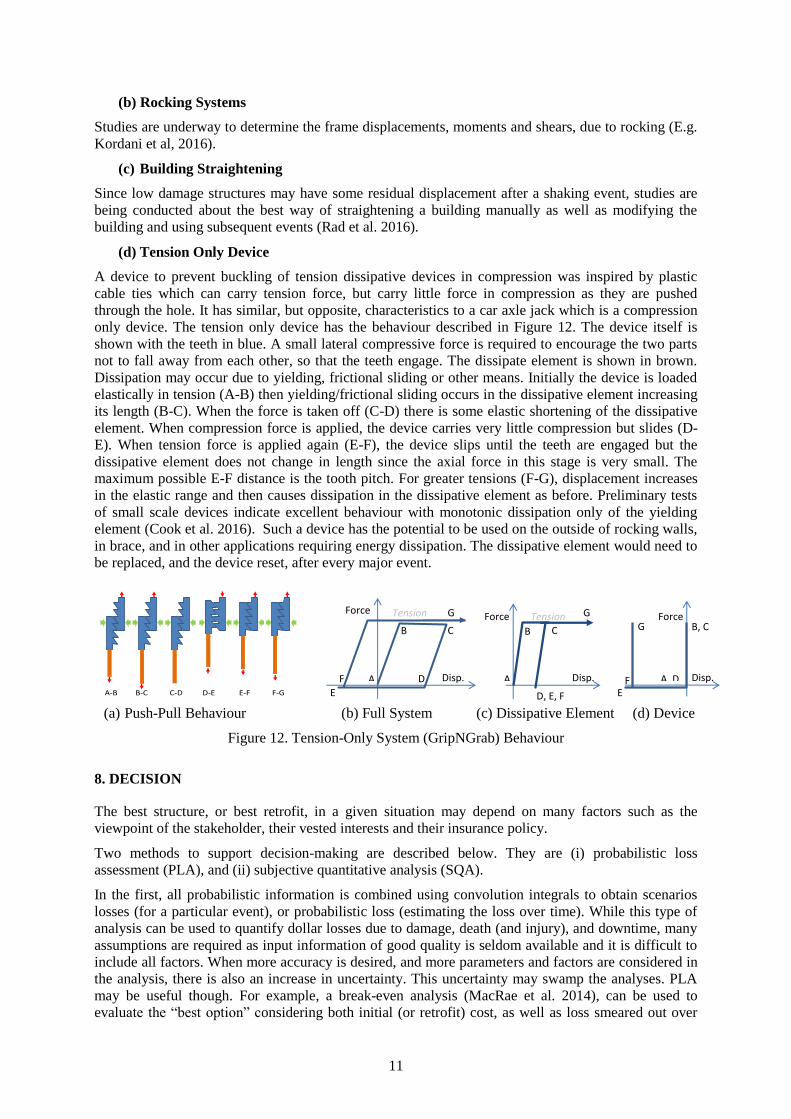
(d) Tension Only Device
A device to prevent buckling of tension dissipative devices in compression was inspired by plastic
cable ties which can carry tension force, but carry little force in compression as they are pushed
through the hole. It has similar, but opposite, characteristics to a car axle jack which is a compression
only device. The tension only device has the behaviour described in Figure 12. The device itself is
shown with the teeth in blue. A small lateral compressive force is required to encourage the two parts
not to fall away from each other, so that the teeth engage. The dissipate element is shown in brown.
Dissipation may occur due to yielding, frictional sliding or other means. Initially the device is loaded
elastically in tension (A-B) then yielding/frictional sliding occurs in the dissipative element increasing
its length (B-C). When the force is taken off (C-D) there is some elastic shortening of the dissipative
element. When compression force is applied, the device carries very little compression but slides (D-
E). When tension force is applied again (E-F), the device slips until the teeth are engaged but the
dissipative element does not change in length since the axial force in this stage is very small. The
maximum possible E-F distance is the tooth pitch. For greater tensions (F-G), displacement increases
in the elastic range and then causes dissipation in the dissipative element as before. Preliminary tests
of small scale devices indicate excellent behaviour with monotonic dissipation only of the yielding
element (Cook et al. 2016). Such a device has the potential to be used on the outside of rocking walls,
in brace, and in other applications requiring energy dissipation. The dissipative element would need to
be replaced, and the device reset, after every major event.
(a) Push-Pull Behaviour (b) Full System (c) Dissipative Element (d) Device
Figure 12. Tension-Only System (GripNGrab) Behaviour
8. DECISION
The best structure, or best retrofit, in a given situation may depend on many factors such as the
viewpoint of the stakeholder, their vested interests and their insurance policy.
Two methods to support decision-making are described below. They are (i) probabilistic loss
assessment (PLA), and (ii) subjective quantitative analysis (SQA).
In the first, all probabilistic information is combined using convolution integrals to obtain scenarios
losses (for a particular event), or probabilistic loss (estimating the loss over time). While this type of
analysis can be used to quantify dollar losses due to damage, death (and injury), and downtime, many
assumptions are required as input information of good quality is seldom available and it is difficult to
include all factors. When more accuracy is desired, and more parameters and factors are considered in
the analysis, there is also an increase in uncertainty. This uncertainty may swamp the analyses. PLA
may be useful though. For example, a break-even analysis (MacRae et al. 2014), can be used to
evaluate the “best option” considering both initial (or retrofit) cost, as well as loss smeared out over
A
B C
C
D, E, F
G
C Force Tension
Disp. A
B C
C
D
C E
C
F
C
G
C
Force Tension
Disp. A, D
B, C G
C
Force
Disp.
E
C
F
C
A-B B-C C-D D-E E-F F-G

12
time including discount rate as a result of natural hazards or other effects. This is the line with lowest
total loss at the time of interest.
In SQA, the decision is made based on the outcomes that are seen to be important. For each option, a
rating is given for each outcome, and then these are combined to obtain the final rating in a way that
seems appropriate to the decision makers using a decision matrix. The “best option” is the one with the
highest rating. In a recent study of some building structures (MacRae et al. 2014) factors considered
included (i) frame damage, (ii) slab damage, (iii) element replaceability and (iv) permanent
displacement. While this approach is subjective, it allows factors which are not quantified easily in a
probabilistic approach to be directly included empowering the decision makers. It also includes the
information in a way that allows it to be easily communicated to other audiences. A show of hands at
the 2014 ASEC conference (MacRae et al., 2014) indicated that the vast majority of consultants prefer
this SQA approach to the PLA approach which is regarded as being a black box, difficult to perform,
and difficult to check. PLA and SQA may be used together in the decision making process.
Typical low-damage systems offer a significant performance enhancement for additional costs
generally less than 5% of the structure cost (MBIE, 2015). However, other disincentives also exist.
Many low-damage systems do not satisfy the acceptable solution of the NZ Building Code. They are
therefore considered as alternative solutions to meet the minimum performance requirements of the
Building Code. This can involve increased design and consenting costs, with peer review as well as
testing or test records demanded by the Building Consent Authority (MBIE, 2015). Also, unfamiliarity
of different construction processes by the construction community can lead to higher costs.
When the first author was discussing these issues with Minister of Building and Construction Nick
Smith at the 2016 NZSEE dinner, the Minister’s comments were that, (i) Structural elements and
systems used in NZ should be robust for the 3-D shaking expected in an earthquake. If not, they
should not be used. (ii) As new structural elements and systems are developed they should be
incorporated into NZ standards, (iii) Standards need to be frequently and regularly updated to allow
incorporation of new and innovative systems and therefore, (iv) as a consequence, the “Alternative
Solution” should be only seldom used. There is an increased emphasis on funding and resourcing
Standards Development to achieve this outcome including the establishment of standing technical
committees to facilitate this. (v) If there are problems still, an enquiry may be requested.
9. CONCLUSIONS
This paper describes NZ construction and research related to low damage construction. It was shown
that:
1) NZ allows design of structures which are demonstrated to meet the Building Code performance
requirements. Since there is no NZ specification for low damage structures, most are designed
as Alternative Solutions.
2) Many of the buildings in the Christchurch rebuild are supported by structural steel framing.
These steel buildings include BRB systems, EBF systems with replaceable links, rocking
systems, base isolation using friction pendulum systems, lead-rubber dissipaters or both, RBS
beams, lead extrusion dissipaters, yielding flexural dissipaters, and friction connections.
Examples of these are provided.
3) A number of structural systems use interesting systems which are useful to initiate discussion
about possible seismic performance.
4) Post-tensioned beam systems are not being constructed in steel because they do not always
behave as low damage systems.
5) It is shown that significant further work is required on a number of systems before they can be
considered to be robust.
6) Some of the work being conducted was briefly described.
7) It was shown that while probabilistic tools may be useful to aid in decision making, most
engineers prefer to have a simpler method that they can understand and trust. Furthermore,
some suggestions to make NZ low damage structures more robust were described.

13
10. ACKNOWLEDGMENTS
The authors wish to acknowledge students and staff, Jarrod Cook, Gary Djojo, Jose Chanchi
Goldorino, Mahdi Hatami, Audsley Jones, Reza Kordani, Dr. Chin-Long Lee, Dr. Geoff Rodgers,
Robin Xie, Ben Westeneng, Shahab Ramhormozian, Trevor Yeow. They also wish to thank Ben
Sitler, Tokyo Tech, for references about base-isolation issues and Dr Quincy Ma for information about
the issues with yielding dissipaters. This paper was developed as course material by MacRae for his
postgraduate steel class. It presented at the 2016 SAVI workship, was also submitted and published at
the 2017 World Conference on Earthquake Engineering, Chile, 2017 and was subsequently submitted,
but published and presented earlier at the 2016 Australian Earthquake Engineering Conference,
Melbourne.
REFERENCES
Cook, J., Rodgers, G.W., MacRae, G.A. & Chase, J.G. (2016). Assessment of the Structural Response and
Cumulative Displacement Demand of Grip ‘N' Grab Tension-Only Bracing System. NZSEE Conference,
Wigram, Christchurch, New Zealand. 1-4 April 2016.
Gardiner, S., Clifton, G.C. & MacRae, G.A. (2013). Performance, Damage Assessment and Repair of a
Multistorey Eccentrically Braced Framed Building following the Christchurch Earthquake Series. Steel
Innovations Conference, Steel Construction New Zealand, Wigram, Christchurch, 21-22 February 2013,
Paper 19
Gultom, R., & Ma, Q.T. (2015). Biaxial pseudodynamic tests of a post-tensioned rocking column with externally
mounted energy dissipators. Proceedings of the 2015 NZSEE Annual Conference, 429-436. Rotorua, New
Zealand. URL: http://hdl.handle.net/2292/26824.
HERA. (2013). Seismic Design of Eccentrically Braced Frames. HERA Publication P:4001:2013.
Kasai, K., Mita, A., Kitamura, H., Matsuda, K., Morgan, T., Taylor, A., Pu, W. & Wada, A. (2012). JSSI’s
Investigations on Recorded Performance of Seismic Protection Systems for Buildings, 15 World Conference
on Earthquake Engineering. http://www.serc.titech.ac.jp/info/seminar/15WCEE_SS/SS_06_Kasai.pdf.
Kasai, K., Mita, A., Kitamura, H., Matsuda, K., Morgan, T.A. & Taylor, A.W. (2013). Performance of Seismic
Protection Technologies during the 2011 Tohoku-Oki Earthquake. Earthquake Spectra, March 2013, Vol. 29,
No. S1, pp. S265-S293 (doi: 10.1193/1.4000131), http://earthquakespectra.org/doi/pdf/10.1193/1.4000131.
Kordani, R., Rodgers, MacRae G. & Chase G. (2016). Prediction of Inter-Story Drift Demand in Rocking Wall
Structures. NZSEE Conference, Wigram, Christchurch, New Zealand. 1-4 April 2016.
MacRae, G.A. (2013). Low Damage Construction-Some Systems Issues. 10CUEE Conference Proceedings, 10th
International Conference on Urban Earthquake Engineering (10CUEE), March 1-2, Tokyo Institute of
Technology, Tokyo, Japan.
MacRae, G.A., Chanchi J. & Yeow T. (2014). What Structure is Best? Australian Structural Engineering
Conference (ASEC), 9 July to Friday 11 July 2014, Auckland, PN:177.
MacRae, G. A & Clifton G. C. (2013b). Low Damage Steel Construction. Steel Innovations Conference, Steel
Construction New Zealand, Wigram, Christchurch, 21-22 February, Paper 1.
MacRae, G.A. & Clifton, G.C. (2015). Research on Seismic Performance of Steel Structures, Steel Innovations
Conference, Auckland, New Zealand. https://sites.google.com/site/gregoryamacrae/home
Marriott, D.J. (2009). The development of high-performance post-tensioned rocking systems for the seismic
design of structures. PhD Dissertation, University of Canterbury.
MBIE. (2010). Unstiffened eccentric cleat connections in compression. NZ Ministry of Business, Industry and
Enterprise, Practice Advisory #12, http://www.dbh.govt.nz/practice-advisory-12.
MBIE. (2015). Using Low-Damage Building Technologies in Seismic Design & Construction. NZ Ministry of
Business, Industry and Enterprise, Practice Advisory.
NZ Building Act, http://www.legislation.govt.nz/act/public/2004/0072/latest/DLM306036.html
NZ Building Code http://www.building.govt.nz/assets/Uploads/building-code-compliance/b-stability/b1-
structure/asvm/b1-structure-amendment-12.pdf
Palmer, K.D., Roeder, C.W. & Lehman, D.E. (2016). Connection Design Recommendations for Improved BRBF
Performance. AISC, Engineering Journal / First Quarter / 2016, p29-46.
Rad, A.A., MacRae, G. & Bull, D. (2016). Dynamically Straightening of Low-Damage Steel Buildings after
Earthquake. NZSEE Conference, Wigram, Christchurch, New Zealand. 1-4 April 2016. Paper O-41.

14
Sitler, B., MacRae, G., Takeuchi, T., Matsui, R., Westeneng, B. & Jones, A. (2017). State-of-the-Art Design of
Buckling Restrained Braces (BRBs) and Recent Experimental Results. 16th World Conference on
Earthquake, 16WCEE 2017, Santiago Chile, January 9th to 13th 2017.
Storie, L.B., et al. (2014). Soil-foundation-structure-interaction for buildings on shallow foundations in the
Christchurch Earthquake. Tenth US National Conference on Earthquake Engineering. Anchorage, Alaska:
NCEE.
Takeuchi, T., Matsui, R. & Mihara, S. (2016). Out-of-plane stability assessment of buckling-restrained braces
including connections with chevron configuration. Earthquake Engng Struct. Dyn. 2016, DOI:
10.1002/eqe.2724.
Uma, S.R., MacRae, G., Nayyerloo, M. & Sadashiva, V. (2016). SQUADS: An Interactive Decision Support
Tool to Facilitate Dialogue between Clients and Engineers Towards Performance-Based Seismic Design.
NZSEE Conference, Wigram, Christchurch, New Zealand. 1-4 April 2016. Poster P-40.
Westeneng, B., Crake, M., Lee, C-L., MacRae, G. A. & Jones, A. (2015). Gusset Plate Effective Length Factor
and the Effect of Stiffened Gusset Plate Connection on Buckling Restrained Brace Frames. New Zealand
Society of Earthquake Engineering Annual Conference Proceedings, Rotorua, April.
Westeneng, B., Lee, C-L. & MacRae, G. (2016). Prevention of Gusset Plate Out-Of-Plane Sway Buckling
Failure in Buckling Restrained Braced Frames. NZSEE Conference, Wigram, Christchurch, New Zealand.
1-4 April 2016. Paper O-60.