New Zealand Building Information Modelling (BIM) … · Appendix F i – Project BIM Execution Plan...
21
July 2014 Appendix F i - Project BIM Execution Plan - Example New Zealand BIM Handbook
Transcript of New Zealand Building Information Modelling (BIM) … · Appendix F i – Project BIM Execution Plan...

July 2014Appendix F i - Project BIM Execution Plan - Example New Zealand BIM Handbook
Appendix F i – Project BIM Execution Plan – example
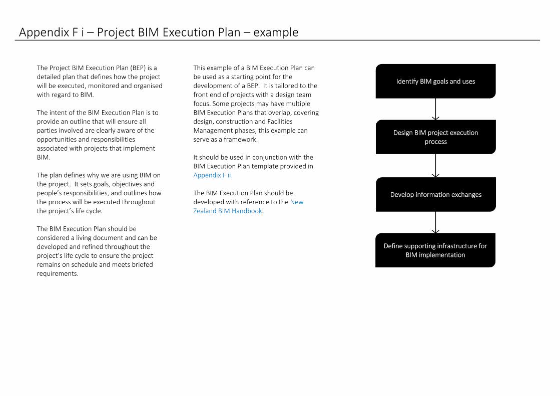
The Project BIM Execution Plan (BEP) is a detailed plan that defines how the project will be executed, monitored and organised with regard to BIM. The intent of the BIM Execution Plan is to provide an outline that will ensure all parties involved are clearly aware of the opportunities and responsibilities associated with projects that implement BIM. The plan defines why we are using BIM on the project. It sets goals, objectives and people’s responsibilities, and outlines how the process will be executed throughout the project’s life cycle. The BIM Execution Plan should be considered a living document and can be developed and refined throughout the project’s life cycle to ensure the project remains on schedule and meets briefed requirements.
This example of a BIM Execution Plan can be used as a starting point for the development of a BEP. It is tailored to the front end of projects with a design team focus. Some projects may have multiple BIM Execution Plans that overlap, covering design, construction and Facilities Management phases; this example can serve as a framework. It should be used in conjunction with the BIM Execution Plan template provided in Appendix F ii. The BIM Execution Plan should be developed with reference to the New Zealand BIM Handbook.
Identify BIM goals and uses
Design BIM project execution process
Develop information exchanges
Define supporting infrastructure for BIM implementation
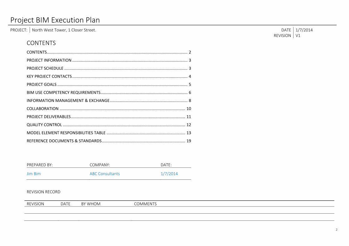
Project BIM Execution Plan PROJECT: North West Tower, 1 Closer Street. DATE 1/7/2014 REVISION V1
2
CONTENTS CONTENTS ........................................................................................................................... 2
PROJECT INFORMATION ..................................................................................................... 3
PROJECT SCHEDULE ............................................................................................................ 3
KEY PROJECT CONTACTS ..................................................................................................... 4
PROJECT GOALS .................................................................................................................. 5
BIM USE COMPETENCY REQUIREMENTS ............................................................................ 6
INFORMATION MANAGEMENT & EXCHANGE .................................................................... 8
COLLABORATION .............................................................................................................. 10
PROJECT DELIVERABLES .................................................................................................... 11
QUALITY CONTROL ........................................................................................................... 12
MODEL ELEMENT RESPONSIBILITIES TABLE ..................................................................... 13
REFERENCE DOCUMENTS & STANDARDS ......................................................................... 19
PREPARED BY: COMPANY: DATE:
Jim Bim ABC Consultants 1/7/2014
REVISION RECORD
REVISION DATE BY WHOM COMMENTS

Project BIM Execution Plan PROJECT: North West Tower, 1 Closer Street. DATE 1/7/2014 REVISION V1
3
PROJECT INFORMATION
Project name: North West Tower
Project owner: XYZ Ltd
Project address/location: 1 Closer Street
Brief project description: 30 storey office and residential tower with 6 levels below grade
Contract type/delivery method: Design and Build
Contractor engagement ‐ indicative date: December 2014
Has a Project BIM Brief been completed? Yes – issued 1/7/2014
PROJECT SCHEDULE Fill in the table below with any major project milestones which occur during the project’s life cycle.
Project phase/milestone Estimated start date Estimated completion date
Pre‐design 1 July 2014 1 September 2014
Concept design 15 September 2014 15 November 2014
Preliminary design 25 November 2014 25 January 2015
Developed design 10 February 2015 10 April 2015
Detailed design 15 April 2015 1 September 2015
Construction 1 July 2015 1 September 2017
Handover September 2017 November 2017
Operation November 2017 NA
Project BIM Execution Plan PROJECT: North West Tower, 1 Closer Street. DATE 1/7/2014 REVISION V1
4
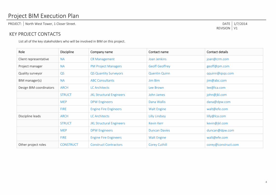
KEY PROJECT CONTACTS List all of the key stakeholders who will be involved in BIM on this project.
Role Discipline Company name Contact name Contact details
Client representative NA CR Management Joan Jenkins [email protected]
Project manager NA PM Project Managers Geoff Geoffrey [email protected]
Quality surveyor QS QS Quantity Surveyors Quentin Quinn [email protected]
BIM manager(s) NA ABC Consultants Jim Bim [email protected]
Design BIM coordinators ARCH LC Architects Lee Brown [email protected]
STRUCT JKL Structural Engineers John James [email protected]
MEP DPW Engineers Dana Wallis [email protected]
FIRE Engine Fire Engineers Walt Engine [email protected]
Discipline leads ARCH LC Architects Lilly Lindsey [email protected]
STRUCT JKL Structural Engineers Kevin Kerr [email protected]
MEP DPW Engineers Duncan Davies [email protected]
FIRE Engine Fire Engineers Walt Engine [email protected]
Other project roles CONSTRUCT Construct Contractors Corey Cuthill [email protected]

Project BIM Execution Plan PROJECT: North West Tower, 1 Closer Street. DATE 1/7/2014 REVISION V1
5
PROJECT GOALS
List client goals and expectations for the project. This table will help define the BIM Uses required for the project, in alignment with the project goals. Refer to Appendix D for BIM Uses. This information could be extracted from the Project BIM Brief and any associated documents, if one has been completed.
Priority (high/med/low)
Goal description ‐ value added objectives BIM Uses
High Optimisation of design, with respect to overall project value and budget control Design Authoring, Design Review, Cost Estimation
Med Have a digital asset (3D models) that can be used for future use in facility management Record Modelling
High Better coordinated documentation for the contractor Design Authoring, 3D Coordination
Med Effective communication of the design with key stakeholders in the design phase Design Authoring, Design Review, Phase Planning (4D Modelling)
Project BIM Execution Plan PROJECT: North West Tower, 1 Closer Street. DATE 1/7/2014 REVISION V1
6
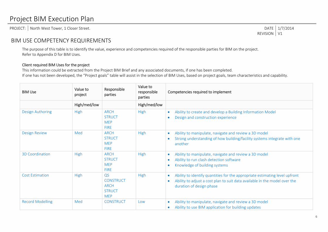
BIM USE COMPETENCY REQUIREMENTS The purpose of this table is to identify the value, experience and competencies required of the responsible parties for BIM on the project. Refer to Appendix D for BIM Uses. Client required BIM Uses for the project This information could be extracted from the Project BIM Brief and any associated documents, if one has been completed. If one has not been developed, the “Project goals” table will assist in the selection of BIM Uses, based on project goals, team characteristics and capability.
BIM Use Value to project
Responsible parties
Value to responsible parties
Competencies required to implement
High/med/low High/med/low
Design Authoring High ARCH STRUCT MEP FIRE
High Ability to create and develop a Building Information Model Design and construction experience
Design Review Med ARCH STRUCT MEP FIRE
High Ability to manipulate, navigate and review a 3D model Strong understanding of how building/facility systems integrate with one
another
3D Coordination High ARCH STRUCT MEP FIRE
High Ability to manipulate, navigate and review a 3D model Ability to run clash detection software Knowledge of building systems
Cost Estimation High QS CONSTRUCT ARCH STRUCT MEP
High Ability to identify quantities for the appropriate estimating level upfront Ability to adjust a cost plan to suit data available in the model over the
duration of design phase
Record Modelling Med CONSTRUCT Low Ability to manipulate, navigate and review a 3D model Ability to use BIM application for building updates

Project BIM Execution Plan PROJECT: North West Tower, 1 Closer Street. DATE 1/7/2014 REVISION V1
7
Ability to effectively communicate between the design, construction and Facilities Management teams
Phase Planning (4D Modelling)
Med CONSTRUCT High Knowledge of construction programming and general construction process ( a 4D model is connected to a programme, and is therefore only as good as the programme to which it is linked)
Knowledge of 4D software: ability to import geometry, manage links to programmes, produce and control animations, etc.
Project team additional BIM Uses for the project The project team may agree additional BIM Uses that will benefit them. Use the table below to record this information.
BIM Use Value to project
Responsible parties
Value to responsible parties
Competencies required to implement
High/med/low High/med/low
Construction System Design Med CONSTRUCT High Ability to manipulate, navigate and review a 3D model Ability to make appropriate construction decisions using a 3D system design
software Knowledge of typical and appropriate construction practices for each
component
Project BIM Execution Plan PROJECT: North West Tower, 1 Closer Street. DATE 1/7/2014 REVISION V1
8
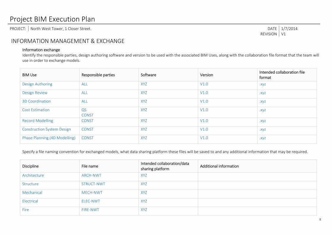
INFORMATION MANAGEMENT & EXCHANGE Information exchange
Identify the responsible parties, design authoring software and version to be used with the associated BIM Uses, along with the collaboration file format that the team will use in order to exchange models.
BIM Use Responsible parties Software Version Intended collaboration file format
Design Authoring ALL XYZ V1.0 .xyz
Design Review ALL XYZ V1.0 .xyz
3D Coordination ALL XYZ V1.0 .xyz
Cost Estimation QS CONST
XYZ V1.0 .xyz
Record Modelling CONST XYZ V1.0 .xyz
Construction System Design CONST XYZ V1.0 .xyz
Phase Planning (4D Modelling) CONST XYZ V1.0 .xyz
Specify a file naming convention for exchanged models, what data sharing platform these files will be saved to and any additional information that may be required.
Discipline File name Intended collaboration/data sharing platform
Additional information
Architecture ARCH‐NWT XYZ
Structure STRUCT‐NWT XYZ
Mechanical MECH‐NWT XYZ
Electrical ELEC‐NWT XYZ
Fire FIRE‐NWT XYZ
Project BIM Execution Plan PROJECT: North West Tower, 1 Closer Street. DATE 1/7/2014 REVISION V1
9
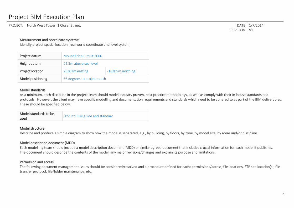
Measurement and coordinate systems: Identify project spatial location (real world coordinate and level system)
Project datum Mount Eden Circuit 2000
Height datum 22.5m above sea level
Project location 25307m easting ‐18305m northing
Model positioning 56 degrees to project north
Model standards As a minimum, each discipline in the project team should model industry proven, best practice methodology, as well as comply with their in‐house standards and protocols. However, the client may have specific modelling and documentation requirements and standards which need to be adhered to as part of the BIM deliverables. These should be specified below. Model standards to be used
XYZ Ltd BIM guide and standard
Model structure Describe and produce a simple diagram to show how the model is separated, e.g., by building, by floors, by zone, by model size, by areas and/or discipline.
Model description document (MDD) Each modelling team should include a model description document (MDD) or similar agreed document that includes crucial information for each model it publishes. The document should describe the contents of the model, any major revisions/changes and explain its purpose and limitations.
Permission and access The following document management issues should be considered/resolved and a procedure defined for each: permissions/access, file locations, FTP site location(s), file transfer protocol, file/folder maintenance, etc.
Project BIM Execution Plan PROJECT: North West Tower, 1 Closer Street. DATE 1/7/2014 REVISION V1
10
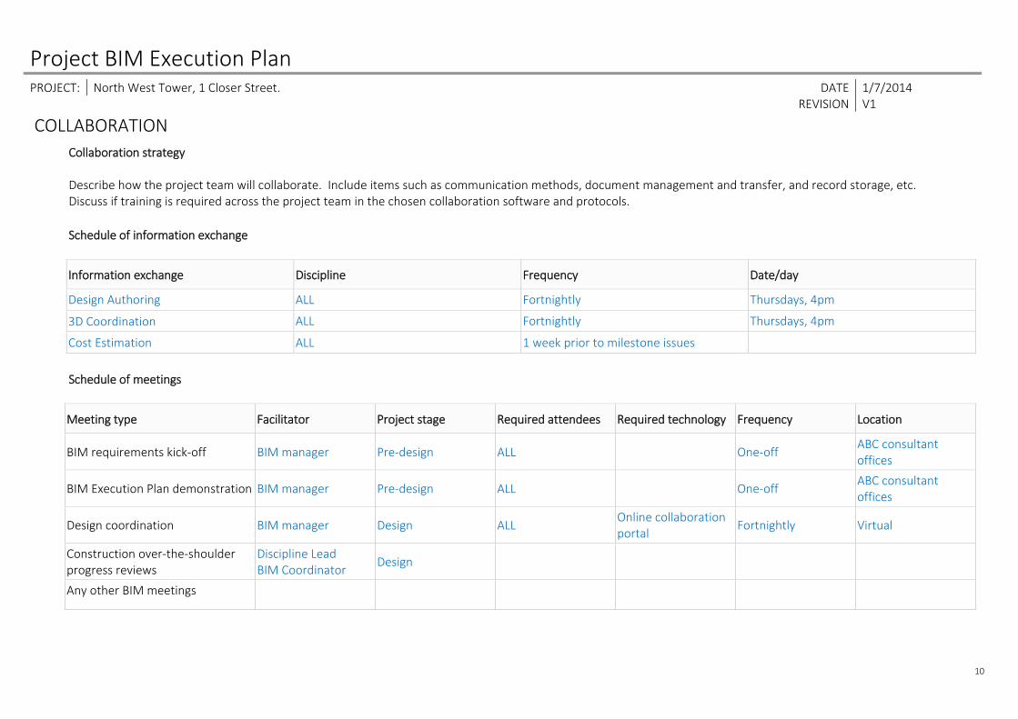
COLLABORATION Collaboration strategy Describe how the project team will collaborate. Include items such as communication methods, document management and transfer, and record storage, etc. Discuss if training is required across the project team in the chosen collaboration software and protocols.
Schedule of information exchange
Information exchange Discipline Frequency Date/day
Design Authoring ALL Fortnightly Thursdays, 4pm
3D Coordination ALL Fortnightly Thursdays, 4pm
Cost Estimation ALL 1 week prior to milestone issues
Schedule of meetings
Meeting type Facilitator Project stage Required attendees Required technology Frequency Location
BIM requirements kick‐off BIM manager Pre‐design ALL One‐off ABC consultant offices
BIM Execution Plan demonstration BIM manager Pre‐design ALL One‐off ABC consultant offices
Design coordination BIM manager Design ALL Online collaboration portal
Fortnightly Virtual
Construction over‐the‐shoulder progress reviews
Discipline Lead BIM Coordinator
Design
Any other BIM meetings
Project BIM Execution Plan PROJECT: North West Tower, 1 Closer Street. DATE 1/7/2014 REVISION V1
11
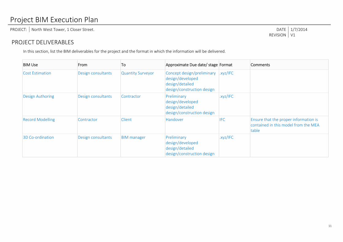
PROJECT DELIVERABLES In this section, list the BIM deliverables for the project and the format in which the information will be delivered.
BIM Use From To Approximate Due date/ stage Format Comments
Cost Estimation Design consultants Quantity Surveyor Concept design/preliminary design/developed design/detailed design/construction design
.xyz/IFC
Design Authoring Design consultants Contractor Preliminary design/developed design/detailed design/construction design
.xyz/IFC
Record Modelling Contractor Client Handover IFC Ensure that the proper information is contained in this model from the MEA table
3D Co‐ordination Design consultants BIM manager Preliminary design/developed design/detailed design/construction design
.xyz/IFC
Project BIM Execution Plan PROJECT: North West Tower, 1 Closer Street. DATE 1/7/2014 REVISION V1
12
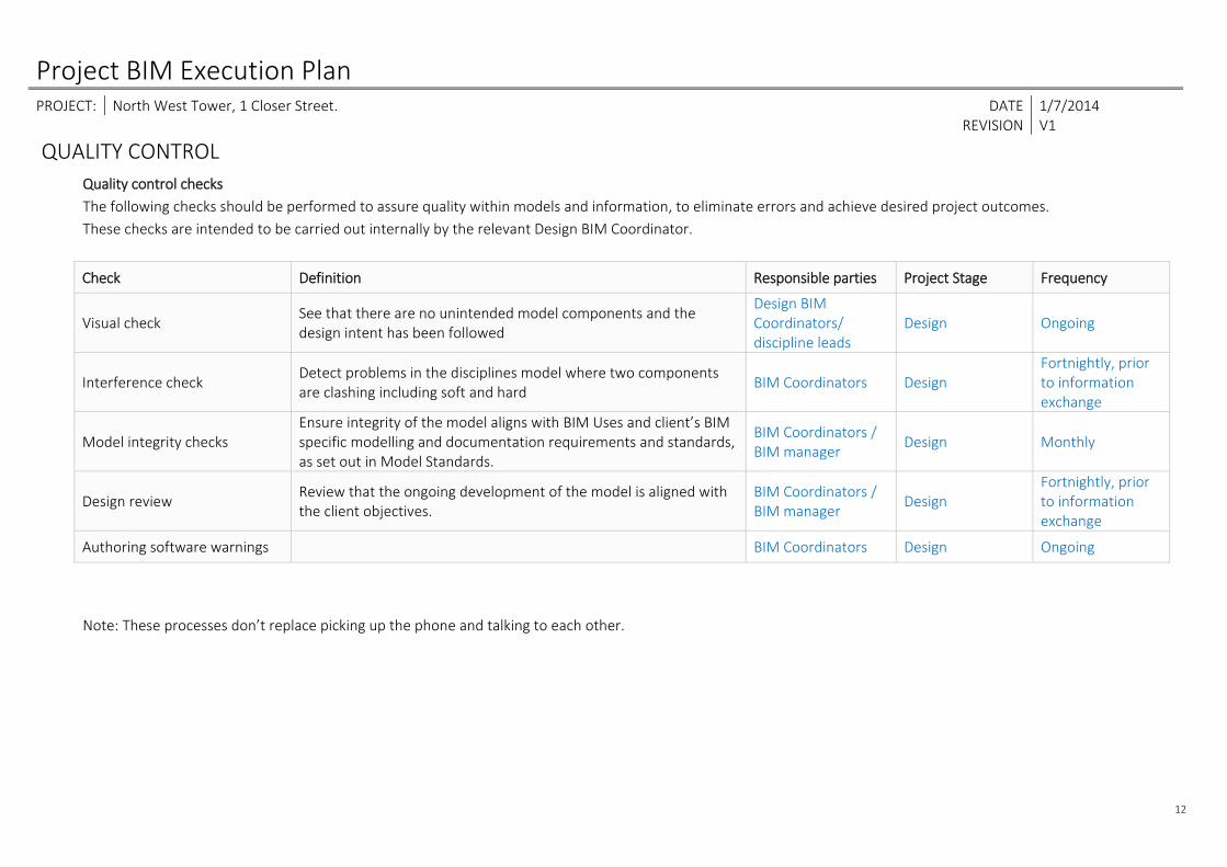
QUALITY CONTROL Quality control checks The following checks should be performed to assure quality within models and information, to eliminate errors and achieve desired project outcomes. These checks are intended to be carried out internally by the relevant Design BIM Coordinator.
Note: These processes don’t replace picking up the phone and talking to each other.
Check Definition Responsible parties Project Stage Frequency
Visual check See that there are no unintended model components and the design intent has been followed
Design BIM Coordinators/ discipline leads
Design Ongoing
Interference check Detect problems in the disciplines model where two components are clashing including soft and hard
BIM Coordinators Design Fortnightly, prior to information exchange
Model integrity checks Ensure integrity of the model aligns with BIM Uses and client’s BIM specific modelling and documentation requirements and standards, as set out in Model Standards.
BIM Coordinators / BIM manager
Design Monthly
Design review Review that the ongoing development of the model is aligned with the client objectives.
BIM Coordinators / BIM manager
Design Fortnightly, prior to information exchange
Authoring software warnings BIM Coordinators Design Ongoing
Project BIM Execution Plan PROJECT: North West Tower, 1 Closer Street. DATE 1/7/2014 REVISION V1
13
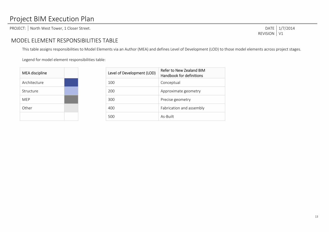
MODEL ELEMENT RESPONSIBILITIES TABLE This table assigns responsibilities to Model Elements via an Author (MEA) and defines Level of Development (LOD) to those model elements across project stages. Legend for model element responsibilities table:
MEA discipline Level of Development (LOD) Refer to New Zealand BIM Handbook for definitions
Architecture 100 Conceptual
Structure 200 Approximate geometry
MEP 300 Precise geometry
Other 400 Fabrication and assembly
500 As‐Built
Project BIM Execution Plan PROJECT: North West Tower, 1 Closer Street. DATE 1/7/2014 REVISION V1
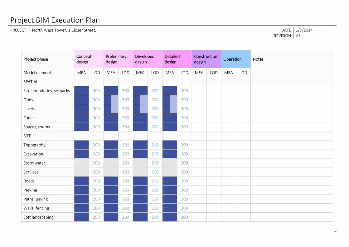
14
Project phase Concept design
Preliminary design
Developed design
Detailed design
Construction design
Operation Notes
Model element MEA LOD MEA LOD MEA LOD MEA LOD MEA LOD MEA LOD
SPATIAL
Site boundaries, setbacks 300 300 300 300
Grids 300 300 300 300
Levels 300 300 300 300
Zones 300 300 300 300
Spaces, rooms 300 300 300 300
SITE
Topography 200 200 200 200
Excavation 200 200 200 200
Stormwater 200 200 200 200
Services 200 200 200 200
Roads 200 200 200 200
Parking 200 200 200 200
Paths, paving 200 200 200 200
Walls, fencing 200 200 200 200
Soft landscaping 200 200 200 200

Project BIM Execution Plan PROJECT: North West Tower, 1 Closer Street. DATE 1/7/2014 REVISION V1
15
Project phase deliverable Concept design
Preliminary design
Developed design
Detailed design
Construction design
Operation Notes
Model element MEA LOD MEA LOD MEA LOD MEA LOD MEA LOD MEA LOD
SUBSTRUCTURE
Footings 200 200 200 300
Retaining walls 200 200 200 300
Subsoil drainage
STRUCTURE
Floor structures 100 200 200 300
Beams 100 200 200 300
Shaft openings 100 200 200 300
Stair & ramp structures 100 200 200 300
Walls – load bearing 100 200 200 300
Columns 100 200 200 300
ENCLOSURE
Roofing 100 200 200 300
Cladding 100 200 200 300
Column claddings 200 200 300
Curtain walls 100 200 200 300
Windows 100 200 200 300

Project BIM Execution Plan PROJECT: North West Tower, 1 Closer Street. DATE 1/7/2014 REVISION V1
16
External doors, openings 100 200 200 300
Project phase deliverable Concept design
Preliminary design
Developed design
Detailed design
Construction design
Operation Notes
Model element MEA LOD MEA LOD MEA LOD MEA LOD MEA LOD MEA LOD
INTERIOR
Partitions 200 200 300
Internal doors, openings 100 200 200 300
Ceilings 100 200 200 300
Flooring 100 200 200 300
Balustrading 100 200 200 300
F, F & E
Casework, joinery 200 200 300
Fixtures 200 200 300
Fittings 200 200 300
Equipment (non‐service) 200 200 300
Furniture 200 200 300
Signage 200 200 300
MECHANICAL
Plant external 200 200
Plant internal 200 200
Project BIM Execution Plan PROJECT: North West Tower, 1 Closer Street. DATE 1/7/2014 REVISION V1
17
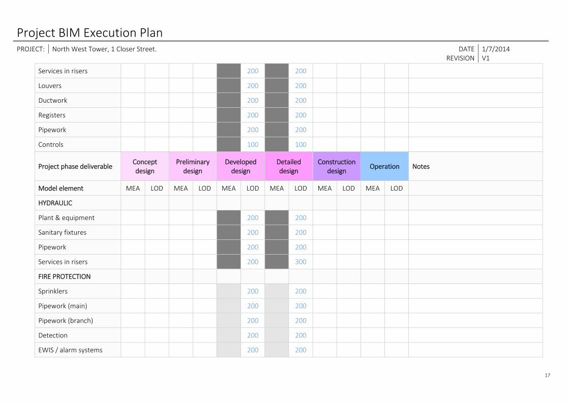
Services in risers 200 200
Louvers 200 200
Ductwork 200 200
Registers 200 200
Pipework 200 200
Controls 100 100
Project phase deliverable Concept design
Preliminary design
Developed design
Detailed design
Construction design
Operation Notes
Model element MEA LOD MEA LOD MEA LOD MEA LOD MEA LOD MEA LOD
HYDRAULIC
Plant & equipment 200 200
Sanitary fixtures 200 200
Pipework 200 200
Services in risers 200 300
FIRE PROTECTION
Sprinklers 200 200
Pipework (main) 200 200
Pipework (branch) 200 200
Detection 200 200
EWIS / alarm systems 200 200

Project BIM Execution Plan PROJECT: North West Tower, 1 Closer Street. DATE 1/7/2014 REVISION V1
18
Hydrants 200 200
Extinguishers 200 200
Services in risers 200 200 300
Project phase deliverable Concept design
Preliminary design
Developed design
Detailed design
Construction design
Operation Notes
Model element MEA LOD MEA LOD MEA LOD MEA LOD MEA LOD MEA LOD
ELECTRICAL
Electrical fixtures 200 200
Power outlets 200 200
Switch & distribution boards
100 200 200
Cable trays 200 200
Lighting 200 200
Light switches / controls 200 200
Communications 200 200
Security 200 200
Services in Risers 200 200 300
CONVEYING
Lifts, escalators 100 200 200 300
Project BIM Execution Plan PROJECT: North West Tower, 1 Closer Street. DATE 1/7/2014 REVISION V1
19
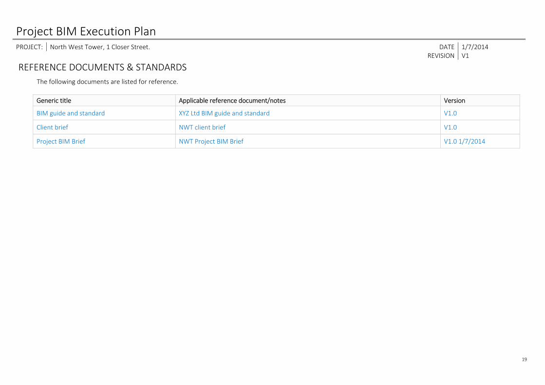
REFERENCE DOCUMENTS & STANDARDS The following documents are listed for reference.
Generic title Applicable reference document/notes Version
BIM guide and standard XYZ Ltd BIM guide and standard V1.0
Client brief NWT client brief V1.0
Project BIM Brief NWT Project BIM Brief V1.0 1/7/2014
Published by the BIM Acceleration Committee with the support of the Productivity Partnership and BRANZ Building Research Levy.
ISBN 978-0-473-29223-2


![BIM PROJECT EXECUTION PLAN - Oregon State Universityclasses.engr.oregonstate.edu/cce/winter2017/cce203/... · BIM PROJECT EXECUTION PLAN VERSION 2.0 FOR [PROJECT TITLE] DEVELOPED](https://static.fdocuments.net/doc/165x107/5aa72c9f7f8b9a50528bfbb8/bim-project-execution-plan-oregon-state-project-execution-plan-version-20-for.jpg)