New Western Sydney University, Bankstown City Campus
49
Taylor Thomson Whitting (NSW) Pty Ltd (ACN 113 578 377) as trustee for the Taylor Thomson Whitting NSW Trust (ABN 59 514 956 558) I Consulting Engineers Level 3, 48 Chandos Street, St Leonards NSW 2065 Structural Design Report New Western Sydney University, Bankstown City Campus Prepared for Walker Corporation / 13 August 2020 191530
Transcript of New Western Sydney University, Bankstown City Campus

Taylor Thomson Whitting (NSW) Pty Ltd (ACN 113 578 377) as trustee for the Taylor Thomson Whitting NSW Trust
(ABN 59 514 956 558) I Consulting Engineers Level 3, 48 Chandos Street, St Leonards NSW 2065
Structural Design Report
New Western Sydney University, Bankstown City Campus
Prepared for Walker Corporation / 13 August 2020
191530

New Western Sydney University, Bankstown City Campus 13 August 2020 Structural Design Report 191530
Taylor Thomson Whitting (NSW) Pty Ltd © 2020 Taylor Thomson Whitting Page 2 of 12
Contents
1.0 Executive Summary .................................................................................................................. 3
2.0 Scope ....................................................................................................................................... 3
3.0 Reference Documents............................................................................................................... 3
4.0 Geotechnical Investigation ........................................................................................................ 4
5.0 Proposed Development ............................................................................................................. 4
5.1 Foundations .................................................................................................................... 4
5.2 Basement Slab ................................................................................................................ 5
5.3 Shoring Walls .................................................................................................................. 5
5.4 Superstructure ................................................................................................................ 5
5.5 Vertical Structure............................................................................................................. 5
5.6 Tower Cantilever ............................................................................................................. 6
6.0 Design Parameters ................................................................................................................... 6
6.1 Loads .............................................................................................................................. 6
6.2 Serviceability ................................................................................................................... 8
7.0 Future Coordination and Structural Considerations .................................................................... 9
8.0 Safety In Design...................................................................................................................... 10
Appendix A Safety In Design Register .............................................................................................. 11
Appendix B Structural Drawings ....................................................................................................... 12

New Western Sydney University, Bankstown City Campus 13 August 2020 Structural Design Report 191530
Taylor Thomson Whitting (NSW) Pty Ltd © 2020 Taylor Thomson Whitting Page 3 of 12
1.0 Executive Summary
Taylor Thomson Whitting (NSW) Pty Ltd has been appointed as the structural design consultant for the new Western Sydney University (WSU) Bankstown City Campus (BCC) project at 74 Rickard Road, Bankstown. This project is a proposed new development which will host up to 2000 students on any one day across am and pm when built by 2022.
The total site area is approximately 3678 square metres. The proposed tower has 19 stories including ground floor, together with 2-story underground carpark. The building structure is proposed to be a conventional post tensioned slab and band beam system, with reinforced concrete coulmns and cores. The core located at the mid-eastern side of the building, consists of 8 lift cores and two stair cores that is joined together by header beams. Foundations comprise pad-footings sitting on the rock and a 600mm / 900mm diameter soldier pile shoring system.
A significant feature if the design will be a substantial cantilevered area above level 14, which consists of composite slabs supported by steel beams and a steel vierendeel truss on the western elevation. The floor is tied back to the main structure by inclined steel tension members.
2.0 Scope
The scope of this report is to summarise the following design aspects:
• Shoring wall and temporary wall anchors design.
• Foundations such as pad footings, spring stiffness, long term deformations, etc – subject to Early Works DA;
• Shoring wall design and temporary wall anchors – subject to Early Works DA;
• Structural steel and composite structures: · Steel Columns; · Steel & Composite Beams; · Steel to Steel Connections; · Steel to Concrete Connections; · Fire Protection (by others).
• Concrete Structures: · Concrete Columns; · Concrete Walls including header beams; · PT slab design; · Transfer beams · Stairs.
• Composite slabs.
3.0 Reference Documents
The following Australian Standards have been used in the detail design phase:
AS 1170.0-2002 Structural design actions Part 0: General principles
AS 1170.1-2002 Structural design actions Part 1: Permanent, imposed and other actions
AS 1170.2-2011 Structural design actions Part 2: Wind actions
AS 1170.4-2007 Structural design actions Part 4: Earthquake actions in Australia
AS 3600-2018 Concrete structures
AS4100-1998 Steel Structures
AS 2327.1-2017 Composite Structures

New Western Sydney University, Bankstown City Campus 13 August 2020 Structural Design Report 191530
Taylor Thomson Whitting (NSW) Pty Ltd © 2020 Taylor Thomson Whitting Page 4 of 12
Consultant Report
Geotechnical Report 86462.00.R.002.Rev0 Geotechnical Investigation August 2018 by Douglas Partners.
4.0 Geotechnical Investigation
The site is located in gently undulating terrain where natural surface slopes are estimated to be about 5% towards the south. The surface contours in the area of the site indicate that the site is located within a slight drainage depression into which surface waters from the north and north-east drain.
Douglas Partners Report 86462.00.R.002.Rev0 Geotechnical Investigation August 2018, summarises the subsurface profile as below:
▪ Filling and residual clays overlying extremely low and very low strength rock to depths between 4.2m and 6.8m, below which depth the rock becomes quite variable in strength between test locations, underlain by;
▪ Generally low to medium strength with significant thicknesses of very low to low and medium to high strength layers then;
▪ Medium and high to very high strength siltstone and sandstone which extends below depths between
12.2 and 14.8m.
Groundwater depths have been measured within the rock from monitoring wells on the site with depths
ranging from 7.9 m to 8.9 m (RL 14.9 m to RL 16.4 m).
5.0 Proposed Development
5.1 Foundations
Depending on the depth of the excavation the material exposed at the bulk excavation level is likely to be very low strength shale or better. Typical design bearing capacities for the different rock strengths are summarised in Table 9 in the geotechnical report.
Foundation
Maximum Allowable Pressure Maximum Ultimate Pressure
End Bearing (kPa)
Shaft Adhesion (Compression)
End Bearing (kPa)
Shaft Adhesion (Compression)
Extremely Low Strength Rock 700 70 2,500 100
Very Low to Low Strength Rock 1,500 150 5,000 200
Medium Strength Rock 3,500 350 20,000 1,000
Medium to High Strength Rock 8,000 800 100,000 2,500
The foundations for the columns/walls will be pad footings proportioned based on the allowable bearing pressures in this Table.
Some columns or walls may be located directly on the shoring system, with the proposed shoring piles being sized to carry the loads to the medium and medium/high strength rock.

New Western Sydney University, Bankstown City Campus 13 August 2020 Structural Design Report 191530
Taylor Thomson Whitting (NSW) Pty Ltd © 2020 Taylor Thomson Whitting Page 5 of 12
5.2 Basement Slab
Tthe geotechnical engineer has confirmed that the long term design water table below the base of the lowest basement slab. Further they have confirmed that the basement slab does not need to be designed for long term hydrostatic pressures provided that a drainage system is installed under the slab to relieve any hydrostatic pressure build-ups.
Therefore, the basement B2 slab has been designed as a slab on grade, however, we would recommend the addition of hydrostatic pressure relief valves or stand pipes at regular centres throughout the slab.
The project Hydraulic Engineer should seek advice from Douglas on likely inflow rates for the design of the sub-soil drainage system.
5.3 Shoring Walls
Based on the above Douglas Partners advice, Taylor Thomson Whitting carried out a design of the site retention system. We are proposing the retention system for the northern, eastern and southern elevations to be a drained ø600 mm soldier pile wall, with infill shotcete panels spanning between the piles. The piles will be temporarily tied back with post tensioned ground achors, sized to minimise the movement of the wall. Soldier piles have benn sized assuming a maximum 2.4 m spacing. The Western wall cannot have temporary ground anchors and has therefore been designed as ø900 mm cantilever soldier pile wall with socket into rock sized to suit.
Soldier pile walls are quite common in Sydney where major long term hydrostatic pressures are not present. They are probably the most cost effective site retention system used as the number of piles is dramatically reduced in favour of shotcrete infill panels. At each shotcrete panel a vertical strip drain is placed that links to the subsoil drainage system so that in the event of localised hydrostatic pressure build-ups behind the wall, the strip drain provides the pressure relief.
It should be noted that soldier pile walls may appear wet due to localised water penetration. It is recommended that drywall be placed in front of the soldier pile with an appropriate dish drain at each slab level to collect any water seepage. The proposed design of the basement allows for a such a wall to be constructed.
The temporary lateral restraint to the shoring walls will be provided by two rows of post tensioned ground anchors. The SWL of ground anchors is specified on the DD shoring elevations. These anchors will be destressed once the permanent structure is built, that provides the lateral restraint to the soldier pile walls. We note that in our opinion this is the safest solution to providing the temporary restraint, as it provides a clear site for construction of the building, If alternatives such as temporary braces were used, there is a significant risk of them being knocked or damaged suring construction, with a consequent movement in the gound outside if the site.
The portion of the shoring wall next to the ramp along the south boundary is proposed to be restrained by the slab and ramp systems at the Basement 1 level, resulting in the typical spacing of the piles being maintained Please refer shoring elevations for details.
5.4 Superstructure
The building has been designed primarily as a concrete frame with traditionally reinforced walls and columns with post-tensioned suspended floors. Post-tensioned slabs will be designed by D & C subcontractors.
5.5 Vertical Structure
Reinforced concrete columns have been adopted throughout the building and generally aligned through the building height to minimise the requirements for transfer structures. Typically the columns for the basement slabs will be constructed internally to the shoring line. As the suspended slab is post tensioned this option reduces the restraint that would be provided by the shoring wall, enabling a more efficient design of the slab and reducing the risk of cracking.

New Western Sydney University, Bankstown City Campus 13 August 2020 Structural Design Report 191530
Taylor Thomson Whitting (NSW) Pty Ltd © 2020 Taylor Thomson Whitting Page 6 of 12
All core walls are specified as reinforced concrete and generally retain the same geometry over the full height of the building. The selected contractor may choose to either build the walls conventionally or jump the walls ahead of the slab working deck using a jump form. Our expectation is the walls will be constructed with a modular jump form system.
5.6 Tower Cantilever
A significant feature if the design is the substantial cantilevered floor area above level 14, which consists of composite slabs supported by steel beams and a steel vierendeel truss on the western elevation. The floor is tied back to the main structure by inclined steel tension members.
Horizontal forces are transferred through the floor edge beams back through the structure to the concrete core.
6.0 Design Parameters
6.1 Loads
In general, all loads and load combinations shall comply with AS/NZS 1170 Parts 0 to 4 structural Design Actions. Live load reductions will be applied as permitted by AS/NZS 1170.1. Generally, the design loads are:
Permanent Actions – Dead Loads
The dead load shall be considered as the self-weight of the structure plus an allowance for services, toppings, walls and ceilings which vary significantly throughout the site.
The additional dead loads should not be less than the following:

New Western Sydney University, Bankstown City Campus 13 August 2020 Structural Design Report 191530
Taylor Thomson Whitting (NSW) Pty Ltd © 2020 Taylor Thomson Whitting Page 7 of 12
Area Services, ceilings, partitions etc.
Commercial areas 1.5 kPa
Ground Floor 2.0 kPa
Multi-purpose Space 5.0 kPa
Car Park Areas 0.5 kPa
Plant and concrete roof areas 2.2 kPa (Includes 1kPa allowance for metal deck roof over).
Non-trafficable roof (no steel roof over) 1.2 kPa
No façade or masonry wall loading is included in the above loads. We will allow for a façade loading of 1 kPa which equates to approximately 3.5 kN/m depending on the floor to floor heights. This will need to be confirmed once the façade type and extent is developed. In areas, with a full glass façade, the loading could be reduced to around 0.5kPa.
It is assumed that all internal partitions will be of lightweight stud construction and specific allowance will be made for masonry partitions if required. In particular, masonry walls will most likely be required around services risers and additional band beams will be quired around the major risers.
Imposed Actions – Live Loads
Area Uniformly Distributed Actions Concentrated Actions
Commercial Areas 3.0 kPa 2.7 kN
Ground Floor 3.0 kPa 4.5 kN
Multi-purpose Space 5.0kPa 4.5 kN
Library 7.5kPa 4.5 kN
Stair and Corridors 4.0 kPa 4.5 kN
Office Areas 3.0 kPa 2.7 kN
Car Parking 2.5 kPa 13 kN
Truck areas up to 10,000 kg gross mass
5 kPa 31 kN
Plant and Utility Areas Plant loads or 5.0 kPa (minimum) 4.5 kN (minimum)
Landscaping 5.0 kPa (minimum) 4.5 kN (minimum)
General Store Rooms 2.4 kPa for each metre of storage height (max 2.1m)
7.0 kN
Compactus 4.0 kPa for each metre of storage height. Locations to be confirmed.
To be calculated
Trafficable Roof 4 kPa 1.8 kN
New Western Sydney University, Bankstown City Campus 13 August 2020 Structural Design Report 191530
Taylor Thomson Whitting (NSW) Pty Ltd © 2020 Taylor Thomson Whitting Page 8 of 12
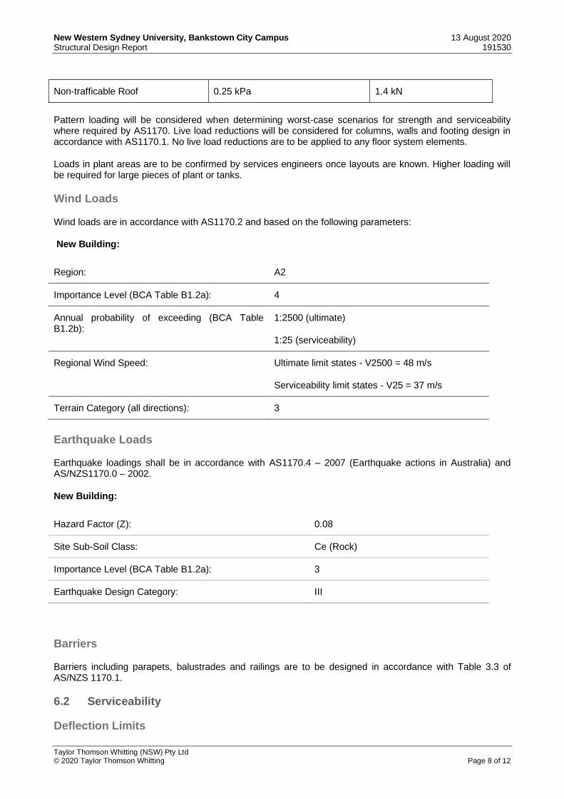
Non-trafficable Roof 0.25 kPa 1.4 kN
Pattern loading will be considered when determining worst-case scenarios for strength and serviceability where required by AS1170. Live load reductions will be considered for columns, walls and footing design in accordance with AS1170.1. No live load reductions are to be applied to any floor system elements.
Loads in plant areas are to be confirmed by services engineers once layouts are known. Higher loading will be required for large pieces of plant or tanks.
Wind Loads
Wind loads are in accordance with AS1170.2 and based on the following parameters:
New Building:
Region: A2
Importance Level (BCA Table B1.2a): 4
Annual probability of exceeding (BCA Table B1.2b):
1:2500 (ultimate)
1:25 (serviceability)
Regional Wind Speed: Ultimate limit states - V2500 = 48 m/s
Serviceability limit states - V25 = 37 m/s
Terrain Category (all directions): 3
Earthquake Loads
Earthquake loadings shall be in accordance with AS1170.4 – 2007 (Earthquake actions in Australia) and AS/NZS1170.0 – 2002.
New Building:
Hazard Factor (Z): 0.08
Site Sub-Soil Class: Ce (Rock)
Importance Level (BCA Table B1.2a): 3
Earthquake Design Category: III
Barriers
Barriers including parapets, balustrades and railings are to be designed in accordance with Table 3.3 of AS/NZS 1170.1.
6.2 Serviceability
Deflection Limits

New Western Sydney University, Bankstown City Campus 13 August 2020 Structural Design Report 191530
Taylor Thomson Whitting (NSW) Pty Ltd © 2020 Taylor Thomson Whitting Page 9 of 12
Deflection limits for the concrete structures are generally as follows;
Maximum floor deflection
Dead Incremental Live DL + LL
Floors supporting masonry walls
Span/360 Span/10001 Span/500 Span/300 (25mm
max)
Compactus areas N/A Span/7502 N/A 25mm max
Other floor areas Span/360 (20mm max)
N/A Span/500 Span/300 (25mm
max)
1. Areas supporting normal weight masonry partitions. 2. Incremental deflection after compactus installed.
Durability
For concrete elements, this will be achieved by specifying all elements in accordance with section 4 of AS 3600 which sets out requirements for plain, reinforced and post-tensioned concrete structures and members with a design life of 40 to 60 years. Exposure classifications are as follows;
Exposure Classification Elements
A2 Internal
B1 External
A2 – To be confirmed by Geotechnical Engineer In Ground
Protective coatings to structural steel elements shall comply with AS/NZS 2312 and ISO 2063 for the long-term protection category.
Fire Resistance Levels
The BCA type of construction required for this building will be type A. Fire Resistance Levels (FRL) for the structural elements will need to be in accordance with the Specification C1.1 of the BCA. Typically, the FRL (minutes) for concrete structural elements is 120/120/120.
7.0 Future Coordination and Structural Considerations
Items to be further coordinated in the design development phase are listed below:
1. To ensure temporary ground anchors are clear from the zone of influence of Council and Sydney Water assets, detailed checking and verification of survey information is required during the construction stage.
2. A detailed assessment of ground movements is being carried out by Douglas Partners, in particular to
review the extent oand impact of ground movements on the Sydney Water assets that surround the site.

New Western Sydney University, Bankstown City Campus 13 August 2020 Structural Design Report 191530
Taylor Thomson Whitting (NSW) Pty Ltd © 2020 Taylor Thomson Whitting Page 10 of 12
8.0 Safety In Design
Work Health and Safety (WHS) is important to all stages of the project and all stakeholders. Safety in Design (SiD), is the method of identifying design solutions to minimise hazards, not only to improve WHS outcomes but to also potentially reduce associated costs.
The following summarises the most relevant Work Health and Safety Acts and Regulations:
▪ Work Health and Safety Act 2011 – Sect 22: Duties of persons conducting business or undertakings that design plant, substance or structures; describes the requirements for the designer to ensure, so far as is reasonably practicable, that the structure is designed without risks to the health and safety of persons. This section also describes the requirements for risk assessment and communication of the risk assessment results.
▪ Work Health and Safety Act 2011 – Sect 46: Duty to consult with other duty holders; highlights that the designer has a duty, so far as is reasonably practicable, to consult, co-operate and coordinate with other persons who have a duty to the same matter.
▪ Work Health and Safety Regulation 2017 – Reg 36: Hierarchy of control measures; describes the process if it is not reasonably practicable for the designer to eliminate the risks to health and safety. It is the designer’s responsibility to minimize the risk, as far as practicable, by providing mitigation measures and giving rise to a hazard with lesser risk.
Refer to Appendix A for Taylor Thomson Whitting current Risk Register, highlighting potential health and safety hazards relating to the design services provided by Taylor Thomson Whitting, associated with the project during its construction, operational life, maintenance, and de-commissioning. Taylor Thomson Whitting will also be involved with an additional project wide Safety in Design workshop that required input from each of the designers.
Prepared by: TAYLOR THOMSON WHITTING (NSW) PTY LTD
Authorised by: TAYLOR THOMSON WHITTING (NSW) PTY LTD
MICHAEL BARRETT ROBERT MACKELLAR
Technical Director Managing Director
P:\2019\1915\191530\Reports\TTW\200813 Structural Design Report WSU RM lee.docx

New Western Sydney University, Bankstown City Campus 13 August 2020 Structural Design Report 191530
Taylor Thomson Whitting (NSW) Pty Ltd © 2020 Taylor Thomson Whitting Page 11 of 12
Appendix A Safety In Design Register

Walker Corporation Podium 2, 4 Parramatta Square 12 Darcy Street Paramatta NSW 2150 Attention: Patrick Polomka Dear Patrick, As part of Safe Work Australia's 'Safe Design of Structures Code of Practice' (July 2012) which endeavours to foster safer work places, we have recently undertaken a Safety in Design review of our design on the Bankstown City Campus Development project at 74 Rickard Rd, Bankstown. Our review is limited to our scope on the project, namely the Structural Design of the works described in our agreement. Attached is a summary of the findings of our review which identifies potential hazards and risks with the project and provides a method to address those hazards and risks relating to the design. It is a requirement of the Code of Practice for this information to be provided to the Principal Contractor for his review and incorporation into the project’s safety report. Any items designed by a Contractor for the Principal Contractor should be assessed for Safety in Design by the Contractor. For our scope of work shown on the TTW project documentation, we confirm that all hazards/risks have been identified, reviewed and managed, as listed in the following risk register, So Far As Is Reasonably Practicable (SFAIRP). For and on behalf of, TAYLOR THOMSON WHITTING (NSW) PTY LTD in its capacity as trustee for the TAYLOR THOMSON WHITTING NSW TRUST Mike BARRETT Technical Director
Structural Risks and Solutions Register
13/08/2020 191530 SAAA
Taylor Thomson Whitting (NSW) Pty Ltd (ACN 113 578 377) as trustee for the Taylor Thomson Whitting NSW Trust(ABN 59 514 956 558) | Consulting Engineers Level 3, 48 Chandos Street St Leonards NSW 2065

Demolition
Hazard: Overloading existing slabCauses: Heavy construction loads@ risk: Workers
High
4 likelihood
4 consequence
• Demolisher to provide work method statement• Provide floor loading diagram• Check capacity of existing structures• Limit size/speed of construction equipment• Provide temporary propping if required
Medium
1 likelihood
3 consequence
To be discussed with Builder / Contractor
Structural Risks and Solutions RegisterJob: Western Sydney University, Bankstown, Job Number: 191530 SAAA Date: 13/08/2020
Page: 1 of 8
Indentification Initial Risk Rating Risk Mitigation Residual Risk Rating Responsibility
Taylor Thomson Whitting (NSW) Pty Ltd (ACN 113 578 377) as trustee for the Taylor Thomson Whitting NSW Trust(ABN 59 514 956 558) | Consulting Engineers Level 3, 48 Chandos Street St Leonards NSW 2065

Shoring / Excavation
Hazard: Shoring / excavation collapseCauses: • Inadequate support• Not constructed in accordance with documentation
@ risk: Workers
High
4 likelihood
5 consequence
• Provide appropriate type of shoring and temporary ground anchor
• Provide recommended construction sequence and specification
Medium
1 likelihood
3 consequence
Structural Engineer in coordination with Builder / Contractor, Project Manager and Architect
Hazard: Presence of existing servicesCauses: Shoring or anchors clash with underground services@ risk: Workers
Significant
4 likelihood
3 consequence
• Request site investigation to determine all underground services
• Request and review all available information• Position shoring and temporary ground anchor
to avoid services• Relocate services prior to shoring works
Medium
2 likelihood
3 consequence
To be resolved with Builder / Contractor, Project Manager and Architect
Hazard: Undermine and destabilise any adjacent structuresCauses: • Lack of support• Ground movement
@ risk: Workers and Public
High
4 likelihood
4 consequence
• Structural inspection, site investigation, obtain and review existing drawings
• Provide underpinning sequence
Low
1 likelihood
2 consequence
Structural Engineer
Hazard: Risk of falling/tripping into open excavationCauses: @ risk: Workers
Significant
2 likelihood
5 consequence
Ensure the contractor is aware of this risk and precautions are included in the work method statement to prevent this to happen.
Significant
1 likelihood
5 consequence
Contractor
Hazard: Injury due to noise, vibration, dust & from falling debris includingCauses: • Inadequate technique• Safety equipment not used
@ risk: Workers
Medium
2 likelihood
2 consequence
• Ensure all safety equipment used.• Review method statement prior damplifier• Supervision by qualified staff
Medium
2 likelihood
2 consequence
Builder
Structural Risks and Solutions RegisterJob: Western Sydney University, Bankstown, Job Number: 191530 SAAA Date: 13/08/2020
Page: 2 of 8
Indentification Initial Risk Rating Risk Mitigation Residual Risk Rating Responsibility
Taylor Thomson Whitting (NSW) Pty Ltd (ACN 113 578 377) as trustee for the Taylor Thomson Whitting NSW Trust(ABN 59 514 956 558) | Consulting Engineers Level 3, 48 Chandos Street St Leonards NSW 2065

Foundations
Hazard: Poor quality of rockCauses: • Latent site conditions• Insufficient geotechnical advice
@ risk: Client
Significant
3 likelihood
3 consequence
• To be advised following geotechnical advice• Insure there are sufficient boreholes for the
site
Low
2 likelihood
1 consequence
Geotechnical Engineer
Hazard: Building loads increasedCauses: Change in design and floor layout@ risk: Client
Medium
2 likelihood
2 consequence
Confirm design loads early Low
1 likelihood
1 consequence
Client / Structural Engineer
Structural Risks and Solutions RegisterJob: Western Sydney University, Bankstown, Job Number: 191530 SAAA Date: 13/08/2020
Page: 3 of 8
Indentification Initial Risk Rating Risk Mitigation Residual Risk Rating Responsibility
Taylor Thomson Whitting (NSW) Pty Ltd (ACN 113 578 377) as trustee for the Taylor Thomson Whitting NSW Trust(ABN 59 514 956 558) | Consulting Engineers Level 3, 48 Chandos Street St Leonards NSW 2065

Concrete worksHazard: Temporary construction penetrationsCauses: Lack of support around the temporary penetrations@ risk: Workers
Significant
4 likelihood
3 consequence
Design floor for both temporary case with penetration and final case with infill slab
Low
1 likelihood
1 consequence
To be discussed with Builder / Contractor
Hazard: Early stripping formwork that results in structural failureCauses: Lack of concrete strength@ risk: Workers
Significant
3 likelihood
4 consequence
• Concrete test required• All PT to be fully stressed and approved prior
to formwork stripping
Medium
1 likelihood
3 consequence
To be discussed with Builder / Contractor
Hazard: Structural failure of cantilevered sections of slabCauses: Lack of temporary support@ risk: Workers
Significant
3 likelihood
4 consequence
Propping requirements to engineer’s details Medium
1 likelihood
3 consequence
To be discussed with Builder / Contractor
Hazard: Structural failure at column transfersCauses: Lack of temporary support@ risk: Workers
High
4 likelihood
4 consequence
Propping needs to stay to engineer’s instruction Medium
1 likelihood
3 consequence
To be discussed with Builder / Contractor
Hazard: Failure of PT anchorageCauses: • Lack of cover• Inadequate concrete strength at stressing• Overhead stressing
@ risk: Workers
Significant
4 likelihood
3 consequence
• Provide adequate cover and anti burst reo• Request concrete test results prior to stressing• Avoid specifying overhead stressing
Low
1 likelihood
2 consequence
Structural Engineer in coordination with Builder / Contractor, Project Manager and Architect
Hazard: Fall into deep beamCauses: Lack of safe walking platform@ risk: Workers
Significant
4 likelihood
3 consequence
Provide protection mesh over beam deeper than 350mm
Low
1 likelihood
2 consequence
Structural Engineer
Structural Risks and Solutions RegisterJob: Western Sydney University, Bankstown, Job Number: 191530 SAAA Date: 13/08/2020
Page: 4 of 8
Indentification Initial Risk Rating Risk Mitigation Residual Risk Rating Responsibility
Taylor Thomson Whitting (NSW) Pty Ltd (ACN 113 578 377) as trustee for the Taylor Thomson Whitting NSW Trust(ABN 59 514 956 558) | Consulting Engineers Level 3, 48 Chandos Street St Leonards NSW 2065

Hazard: Lifting heavy reinforcement barsCauses: Heavy Bars@ risk: Workers
Significant
4 likelihood
2 consequence
Limit length of large diameter reinforcement bars Low
1 likelihood
2 consequence
Structural Engineer
Hazard: Prefabricated structural elementsCauses: Fall during erection@ risk: Workers
High
4 likelihood
4 consequence
• Design prefabricated structural elements so they can be erected from above
• Limit size of prefabricated elements
Medium
1 likelihood
3 consequence
Structural Engineer
Hazard: Damage to structure due to penetrations being installed after structure is builtCauses: Cutting tendons or reinforcement@ risk: Workers
Significant
4 likelihood
3 consequence
• Coordinate all penetrations prior to construction
• Builder to receive approval from design engineer for any new penetrations prior to installation
Low
1 likelihood
2 consequence
Services Engineer
Hazard: Failure of Mechanical/Chemical anchors.Causes: Anchors not installed in accordance with manufacturer specification@ risk: Workers
Medium
2 likelihood
2 consequence
• Anchors installation to be carried out by experienced staff
• Obtain manufacturer documents for use on site• Involve manufacturer engineer for testing &
supervision
Medium
2 likelihood
2 consequence
Builder
Hazard: Injury from reinforcement barsCauses: Cuts/abrasions/impaling@ risk: Contractors, Operatives, Workers and Public
Significant
3 likelihood
3 consequence
Length of reinforcement to be kept as short as possible. Minimise projections
Low
1 likelihood
1 consequence
Contractor to provide safety ends to projecting bars.
Hazard: Risk associated with stressing of tendonCauses: • Fall of height slip• Accidental breakage of strands
@ risk: Workers
Medium
2 likelihood
2 consequence
• Check ensure safe platform for stressing• Provide adequate barrier when stressing is
carried out• Do not stress from behind stressing equipment
Medium
2 likelihood
2 consequence
Builder
Structural Risks and Solutions RegisterJob: Western Sydney University, Bankstown, Job Number: 191530 SAAA Date: 13/08/2020
Page: 5 of 8
Indentification Initial Risk Rating Risk Mitigation Residual Risk Rating Responsibility
Taylor Thomson Whitting (NSW) Pty Ltd (ACN 113 578 377) as trustee for the Taylor Thomson Whitting NSW Trust(ABN 59 514 956 558) | Consulting Engineers Level 3, 48 Chandos Street St Leonards NSW 2065

Hazard: PT Tendon / Reinforcement / Damage / Moved during concretingCauses: • Inadequate support for tendons / reinforcement• Inadequate support for concrete pump pipeline
@ risk: Workers
Medium
2 likelihood
2 consequence
• Carry out final inspection prior to concreting• Concreting process to be supervised by
experienced staff
Medium
2 likelihood
2 consequence
Builder
Structural Steel
Hazard: Fall at height during erection of steelworkCauses: • Lack of safe working platform• Complicated connections requiring large amounts of
work at height
@ risk: Workers
High
4 likelihood
4 consequence
• Maximise prefabrication• Simple connections• Limit site welds• Provide scaffolding• Use fall arrest systems
Low
1 likelihood
2 consequence
Structural Engineer / Builder
Hazard: Collapse of steelwork during erectionCauses: Insufficient bracing and or propping@ risk: Workers
High
4 likelihood
4 consequence
Provide temporary bracing until permanent component installed
Low
1 likelihood
2 consequence
Builder / Contractor
Facade
Hazard: Fall at height during building maintenanceCauses: • Access for maintenance not considered during
design• No fall arrest system provided
@ risk: End Users
High
4 likelihood
4 consequence
• Structure to be designed for fall arrest loads• In designing facade consideration given to how
facade will be maintained
Medium
1 likelihood
3 consequence
Architect, Structural Engineer and Facade Engineer
Structural Risks and Solutions RegisterJob: Western Sydney University, Bankstown, Job Number: 191530 SAAA Date: 13/08/2020
Page: 6 of 8
Indentification Initial Risk Rating Risk Mitigation Residual Risk Rating Responsibility
Taylor Thomson Whitting (NSW) Pty Ltd (ACN 113 578 377) as trustee for the Taylor Thomson Whitting NSW Trust(ABN 59 514 956 558) | Consulting Engineers Level 3, 48 Chandos Street St Leonards NSW 2065

Structural Adequacy
Hazard: Integrity of the structure in strength and stabilityCauses: Insufficient design@ risk: Workers and Public
Significant
2 likelihood
4 consequence
• Follow design brief• Work to be carried out in accordance with TTW
design procedure and QA system
Medium
1 likelihood
3 consequence
Structural Engineer
Hazard: Overloading structure during constructionCauses: Construction loads exceed design loads@ risk: Workers
High
4 likelihood
4 consequence
• Provide temporary bracing/propping if required
• Construction loads to be checked by engineer• Loading information for all hoist, cranes,
forklifts etc to be submitted to design engineer for checking prior to use
Medium
1 likelihood
3 consequence
To be discussed with Builder / Contractor
General Siteworks
Hazard: Disruption to the adjoining owners or users during constructionCauses: Poor planning and lack of communication with all stakeholders@ risk: Public and Client
Significant
4 likelihood
2 consequence
• Keep all stakeholders informed• Provide staging and sequence documentation
as required
Low
1 likelihood
1 consequence
To be discussed with Builder / Contractor
Hazard: Construction not in accordance with design documentationCauses: Misinterpreted drawings@ risk: Client and Workers
Significant
4 likelihood
2 consequence
• Regular site inspections• Clear and coordinated design documentation• Adequate site supervision
Low
1 likelihood
1 consequence
To be discussed with Builder / Contractor
Prepared By:Taylor Thomson Whitting (NSW) Pty Ltdin its capacity trustee for the Taylor Thomson Whitting NSW Trust
Nicholas FREELAND
Authorised By:Taylor Thomson Whitting (NSW) Pty Ltdin its capacity trustee for the Taylor Thomson Whitting NSW Trust
Mike BARRETTTechnical Director
Structural Risks and Solutions RegisterJob: Western Sydney University, Bankstown, Job Number: 191530 SAAA Date: 13/08/2020
Page: 7 of 8
Indentification Initial Risk Rating Risk Mitigation Residual Risk Rating Responsibility
Taylor Thomson Whitting (NSW) Pty Ltd (ACN 113 578 377) as trustee for the Taylor Thomson Whitting NSW Trust(ABN 59 514 956 558) | Consulting Engineers Level 3, 48 Chandos Street St Leonards NSW 2065

Legend:
Insignificant = 1 Minor = 2 Moderate = 3 Major = 4 Catastrophic = 5
Almost Certain = 5 Significant Significant High High High
Likely = 4 Medium Significant Significant High High
Possible = 3 Medium Medium Significant Significant High
Unlikely = 2 Low Medium Medium Significant Significant
Rare = 1 Low Low Medium Medium Significant
Likelihood Consequence
Almost Certain
Is expected to occur in most circumstances
Catastrophic Severe adverse impact - (Death)
Likely Will probably occur in most circumstances
Major Major adverse impact - (Extensive Injuries)
Possible Might occur at some time Moderate Moderate adverse impact - (Medical treatment required)
Unlikely Could occur at some time Minor Minor adverse impact - (First aid treatment)
Rare May only occur in exceptional circumstances
Insignificant Insignificant adverse impact - (No injuries)
Risk Control Actions
High The risk is unacceptable. Eliminate the design feature
Significant High Priority for action
Medium Responsibility to be allocated
Low Manage by routine procedure and control
Structural Risks and Solutions RegisterJob: Western Sydney University, Bankstown, Job Number: 191530 SAAA Date: 13/08/2020
Page: 8 of 8Taylor Thomson Whitting (NSW) Pty Ltd (ACN 113 578 377) as trustee for the Taylor Thomson Whitting NSW Trust(ABN 59 514 956 558) | Consulting Engineers Level 3, 48 Chandos Street St Leonards NSW 2065

New Western Sydney University, Bankstown City Campus 13 August 2020 Structural Design Report 191530
Taylor Thomson Whitting (NSW) Pty Ltd © 2020 Taylor Thomson Whitting Page 12 of 12
Appendix B Structural Drawings

SHORING ISOMETRIC
SHORING NOTES1. Test records shall be provided for test loadings of all anchors.2. Any variation in the location or inclination of anchors will require re-
calculation of the required working loads and shall be notified to the engineer for approval.
3. All anchors shall be located so as to avoid all services and pits.4. Refer to structural performance brief - piles and ground anchors5. Piles are to be designed in accordance with AS2159 by the contractor
to the requirements of the specification.6. The pile design and installation shall follow the recommendations outlined in the geotechnical report No 86462.00 dated August 2018 prepared by
Douglas PartnersAny additional geotechnical investigation work deemed necessary shall be
at the contractor's expense.7. Any necessary re-design of of pile caps to suit alternative systems shall
be at the expense of the contractor. Refer shoring elevations for pile size8. Prior to commencing on site, the contractor must submit for approval:
(a) pile type proposed(b) pile size(s), reinforcement details, founding depths and design
certificate. The design certificate is to certify the pile design is inaccordance with AS2159 for the loads listed in the piling scheduleand be signed by a NPER registered engineer experienced in the typeof piling proposed.
(c) a shop drawing setting out all pile locations from grid9. The contractor is to coordinate the location of all underground services and to be responsible for ensuring that these are either avoided or relocated as appropriate.10. The contractor shall provide a NPER registered engineer to supervise the
pile installation.11.At the satisfactory completion of the work the contractor shall provide
an inspection certificate signed by a NPER registered engineer.
Place concrete of the following characteristic compressive strength f'c as defined in AS 1379.
EXPOSURE CLASSIFICATION :
CONCRETE NOTES
CONCRETE
External - B1Internal - A2
Location
Shoring Piles
f'c MPa at 28 days
Specified Slump
Nominal Agg. size
S40 80 20
10. Indicates slab or band thickness
1. Use Type 'GP' cement, unless otherwise specified.2. All concrete shall be subject to project assessment and testing to AS 1379.3. Consolidate by mechanical vibration. Cure all concrete surfaces as directed
in the Specification.4. For all falls in slab, drip grooves, reglets, chamfers etc. refer to the
architect's drawings and specifications.5. Unless shown on the drawings, the location of all construction joints shall
be submitted to engineer for review.6. No holes or chases shall be made in the slab without the approval of the
Engineer.7. Conduits and pipes are to be fixed to the underside of the top reinforcement
layer.8. Slurry used to lubricate concrete pump lines is not to be used in any
structural members.9. All slabs cast on ground require sand blinding with a Concrete Underlay
175
FORMWORK
1. The design, certification, construction and performance of the formwork, falsework and backpropping is the responsibility of the contractor.
2. The proposed method of installation and removal of formwork is to be submitted to the Superintendent for comment prior to work being carried out.
FOOTING NOTES
1. Foundations have been designed for: Allowable Bearing Pressure - 3500 kPa (Medium strength rock)
- 8000 kPa (Medium to high strength rock)
Allowable Side Shear - 350 kPa (Medium strength rock)- 800 kPa (Medium to high strength rock)
Reactivity Class - A to AS 2870
2. Foundation material is to be inspected and approved by the geotechnicalengineer before casting footings.
3. Refer to geotechnical report No. 86462.00 dated August 2018 by Douglas Partners4. Locate all pipes, retaining walls and excavation outside a 1:2
( vertical:horizontal ) zone of influence from the bottom edge of the footing.5. Where side shear is required to be developed, clean and roughen thesides
of the excavation to the satisfaction of the geotechnical engineer.6. Footings shall be located centrally under walls and columns unless noted
otherwise.7. Footings to be constructed and backfilled as soon as possible following
excavation to avoid softening or drying out by exposure.8. Contractor is to allow for cost of geotechnical inspections and any required
certification.
SHORING WALL NOTES
GROUND ANCHORS
1. The design, supply, installation and tensioning of ground anchors, bolts and nails shall be carried out in compliance with the relevant Australian Standards and the Geotechnical Report. Anchorage lengths and curing times shall be determined by the Geotechnical Engineer.
2. Anchors, bolts and nail holes should be thoroughly cleaned and the bond grout should be allowed to cure before proof stressing.
3. Grouting shall conform to the requirements of AS 3600 and The Concrete Institute "Recommended Practice For Grouting 1982"
4. For proof stressing loads refer to the Geotech Report.5. Records of all anchor extensions and test loadings are to be
submitted to the Geotechnical Engineer for review.6. Modifications to the arrangement shown on the drawings will require
recalcuation of the required working loads and shall be notified to the Geotechnical Engineer for approval.
7. Safe Working load shown is the force required after all losses of prestress, including draw in.
8. All anchors, bolts and nails shall be located so as to avoid all services and pits etc.The contractor is to determine the location of all services etc prior to installation of anchors.
9. Any variation in location or inclination of anchors, nails and bolts shall be submitted to the Geotechnical Engineer for approval.
10. For ratio of ultimate load capacity of anchor to safe working load refer to the Specification.
11. For temporary and semi-permanent anchors the length of tendon protruding beyond wedge grip is not to be less than 600mm to enable monitoring.
12. For corrosion protection requirements refer to the Geotechnical Report.
13. Do not destress temporary or semi-permanent anchors until the Geotechnical Engineer's approval has been obtained.
14. For temporary and semi-permanent anchors : After destressing anchors, remove anchor head and wales. Cut strands at the face of pile and grout fill ducts. Make good piles with an approved epoxy repair mortar. Note: this is a minimum requirement. Contractor is to refer to Council requirements if anchors are to be fully removed.
PNEUMATICALLY APPLIED CONCRETE
1. Concrete to shoring walls to be pneumatically applied in one continuous operation. Concrete to be proportioned to achieve a batch target strength of 32MPa.
2. The pneumatically applied concrete shall be cured by keeping continuously wet over a period of not less than 7 days after placement or by other approved means.
3. Pneumatically applied concrete is to be placed by an experienced operator.
CONSTRUCTION SEQUENCE
1. Set out and drill holes for soldiers.2. Install and plumb soldiers as detailed and backfill holes with
1 : 12 - cement : sand mix.3. Excavate locally and place top row of anchors as specified.4. Place wedges on ground anchors to resist movement of wall.5. Excavate down to horizontal CJ.6. Place shotcrete wall as per the drawings.7. Stress the ground anchors to Design Loads after concrete is a
minimum of 4 days old.8. Continue second stage as above.
Note: Piling designer must supply shop drawings and calculation packages to TTW in accordance with requirments stated in TTW performance specification.
GENERAL NOTES1. These drawings are for structural purposes only and are to be read in
conjunction with the specification, architectural drawings, other contract documentation and the requirements of the relevant authorities.
2. Verify all setting out dimensions with the Architect.3. Do not obtain dimensions by scaling the structural elements.4. Should any ambiguity, error, omission, discrepancy, inconsistency or other
fault exist or seem to exist in the contract documents, immediately notify in writing to the Superintendent.
5. Maintain the structure in a stable condition during construction. Temporary bracing/shoring shall be provided by the contractor to keep the structure and excavations stable at all times, ensuring that no part of the documented structure becomes overstressed. For all temporary batters obtain geotechnical engineer's recommendations.
6. All workmanship and materials shall be in accordance with the requirements of current Standards Australia codes and the bylaws, ordinances or other requirements of the relevant building authorities.
7. All proprietary items are to be installed and fixed in accordance with the manufacturers specifications and instructions.
8. All work is to be carried out in accordance with all Workcover requirements and occupational health and safety act regulations
9. Construction using these drawings shall not commence until a Construction Certificate is issued by the Principal Certifying Authority.
Column loads : Refer to Elevation Drawing
DESIGN LOADS:
Surcharge loads on all shoring walls: 20kPa
Taylor Thomson Whitting (NSW) Pty Ltd operates under Safe Work Australia's Code of Conduct for the Safe Design of Structures.These drawings shall be read in conjunction with the Taylor Thomson Whitting Transfer of Information Letter and Structural Risk and Solutions Register.Under the Code of Conduct it is the Client's responsibility to provide a copy of the Structural Risk and Solutions Register to the Principal Contractor.It is the Principal Contractor's responsibility to review the hazards and risks identified during the design process to ensure a safe workplace ismaintained for the construction, maintenance and eventual demolition of the structure.
SAFETY IN DESIGN
REINFORCEMENT NOTES
1. Fix reinforcement as shown on drawings. The type and grade is indicated by a symbol as shown below. On the drawings this is followed by a numeral which indicatesthe size in millimetres of the reinforcement.
N Hot rolled ribbed bar grade D500NR Plain round bar grade R250NSL Square mesh grade 500LRL Rectangular mesh grade 500L
2. Provide bar supports or spacers to give the following concretecover to all reinforcement unless otherwise noted on drawings.
Footings - 50 top, 50 bottom, 50 sides.
Beams - 25 bottom, 25 sides, 25 top to ties.35 when exposed to weather or ground
3. Cover to reinforcement ends to be 50 mm UNO.4. Provide N12-450 support bars to top reinforcement as required.
Tension Lap UNO5. Maintain cover to all pipes, conduits, reglets, drip grooves etc. 6. All cogs to be standard cogs unless noted otherwise.7. Fabric end and side laps are to be placed strictly in accordance
with the manufacturers requirements to achieve a full tensile lap.Fabric shall be laid so that there is a maximum of 3 layers at any location.
FABRIC LAPS
8. Laps in reinforcement shall be made only where shown on the drawingsunless otherwise approved. Lap lengths as per table below.Gap between lapped bars to be no more than 3 bar diameters as per AS3600 clause 13.2
25
COMPRESSION LAPS
960
800
640
1120
1280
1440
TENSION LAPS
N12
N16
N20
N24
N28
N32
N36
1500
480
700
950
1250
1150
800
570
1850
2250
2700
1500
1800
2100
ALL OTHER BARSTOP BARS IN BANDSAND BEAMS
BARSIZE
N16
N20
N24
N28
N32
N36
BAR SIZE
EARLY WORKS DRAWING LIST
Drawing No. Drawing Name
S1001 SHORING AND FOOTING PLAN
S1011 SHORING ELEVATIONS
S1021 SHORING SECTIONS - SHEET 1
S1022 SHORING SECTIONS - SHEET 2
S1031 SHORING DETAILS - SHEET 1
74 RICKARD RD BANKSTOWN NSW 2200
BANKSTOWN CITY CAMPUS DEVELOPMENT
B10 1 2 3 54 6 7 8 9 10
Architect
Authorised
Drawing No
Scale : B1
Job No Revision
Sheet Subject
Project
Rev Description Eng DateDraft
Drawn
This drawing is copyright and is the property of TAYLOR THOMSONWHITTING (NSW) Pty Ltd and must not be used without authorisation.
THIS DRAWING TO BE READ IN CONJUNCTION WITH ALL RELEVANT NOTES ON DRAWING NO. S001
BANKSTOWN CITY CAMPUS DEVELOPMENT 74 RICKARD RD BANKSTOWN NSW 2200
Level 3, 246 Bourke Street Melbourne Victoria 3000LYONS
Structural Engineer
Pri
nte
d :
+61 2 9439 7288 | 48 Chandos Street St Leonards NSW 2065
NOT TO BE USED FOR CONSTRUCTION
1 : 1
28/07/2020 4:44:40 PM
28
/07
/20
20
4:4
4:4
0 P
MC
:\U
sers
\Ad
am
c\D
ocum
en
ts\S
T_W
SU
Ban
ksto
wn[1
9]_
Ad
am
.Ca
rrey@
ttw
.co
m.a
u.r
vt
ARC MB
191530 S0101
EARLY WORKS COVERSHEET
P1 01.07.20PRELIMINARY ISSUE KBMB
P2 28.07.20PRELIMINARY ISSUE ARCNJF
P2PRELIMINARY
S0
10
1P
2
EARLY WORKS PACKAGE

SHORING AND FOOTING PLANSCALE 1:100
1. NUMBER AND SPACING OF SHORING PILES/SOLDIERS IS INDICATIVE ONLY. REFER TO SHORING DETAILS FOR MAXIMUM SPACING. EXACT NUMBER OF PILES TO BE DETERMINED BY THE CONTRACTOR.2. REFER TO SHORING WALL ELEVATIONS FOR CUT OFF LEVELS AND FOUNDING LEVELS OF SHORING PILES / SOLDIERS.3. DETAILED EXCAVATION OF FOOTINGS, TRENCHES ETC IS NOT INCLUDED ON THIS DRAWING.
4. DENOTES BOREHOLE LOCATIONS. REFER TO GEOTECHNICAL REPORT BY DOUGLAS PARNTERS DATED AUGUST 20185. THE EXCAVATION IS TO BE INSPECTED BY THE GEOTECHNICAL ENGINEER EVERY 1500 OF EXCAVATED DEPTH.7. REFER TO SERVICE CONSULTANTS DRAWINGS FOR TERMINATION / DIVERSION OF EXISTING SERVICES.8. ALL SERVICES CROSSING THE SHORING WALL BELOW THE CAPPING BEAM ARE TO BE LOCATED BETWEEN PILES.
THE CONTRACTOR IS TO CO-ORDINATE THE LOCATION OF SERVICES AND PILES.9. THE CONTRACTOR IS TO CO-ORDINATE THE LOCATION OF SHORING PILES AND GROUND ANCHORS SO THAT THEY DO NOT CLASH WITH FUTURE COLUMNS AND SERVICES.10.PILES ADJACENT TO PAD FOOTINGS TO EXTEND BELOW THE BASE OF THE FOOTINGS / EXCAVATION. REFER TO SHORING ELEVATIONS.11. GEOTECHINCAL ENGINEER TO CONFIRM MINIMUM ULTIMATE PASSIVE PRESSURE OF PF1'S IS 1200kPa.12. PILING DESIGNER MUST SUPPLY SHOP DRAWINGS AND CALCULATION PACKAGES TO TTW IN ACCORDANCE WITH REQUIREMENTS STATED IN TTW PERFORMANCE SPECIFICATION.
C E HGF
A
1
2
4
6
7
8
9
10
5
B
D J
BE - RL:17.770
SW1
SW
2
SW
4
SW5
SW
6S
W7
CH45c
CH45c
CH45c
CH45c
PF1
PF1
PF1
PF1
PF1
457x12.7 CHS TEMPORARY INTERNAL SHORING STRUTS TYPICAL
1700mm x 1700mm x 400mm DEEPTEMPORARY FOOTING FOR STRUTS
CAPPING BEAM FOR SW7 T.B.C.
BE - RL:16.770
CH45c
PF1
PF1
PF1
PF1
PF7 PF9
PF14
PF5 PF5 PF5 PF14
PF14
PF7PF7PF7
PF14
PF8
PF2
PF10
PF12
PF2
PF12
PF3
PF3
PF2 PF3
PF3
PF12
PF5
PF12
PF5
PF8 PF8 PF11 PF11
PF5 PF5 PF5 PF5
PF5
PF6PF8
PF8 PF8
PF8
PF8
PF1
PF13
PF13
PF13
PF13
PF13
PF13
PF13
PF13 PF13PF13
PF13
PF13
PF13
PF13
PF13
PF13
PF13
PF13
PF13
PF12
PF8
BE - R
L:14
.770
BE - R
L:14
.730
FB1
EXISTING CULVERT LOCATION
CH45c
CH45c
CH45c
CH45c
CH45c
CH45c
CH45c
SW
9
SW
8
BE - RL:16.730
B10 1 2 3 54 6 7 8 9 10
Architect
Authorised
Drawing No
Scale : B1
Job No Revision
Sheet Subject
Project
Rev Description Eng DateDraft
Drawn
This drawing is copyright and is the property of TAYLOR THOMSONWHITTING (NSW) Pty Ltd and must not be used without authorisation.
THIS DRAWING TO BE READ IN CONJUNCTION WITH ALL RELEVANT NOTES ON DRAWING NO. S001
BANKSTOWN CITY CAMPUS DEVELOPMENT 74 RICKARD RD BANKSTOWN NSW 2200
Level 3, 246 Bourke Street Melbourne Victoria 3000LYONS
Structural Engineer
Pri
nte
d :
+61 2 9439 7288 | 48 Chandos Street St Leonards NSW 2065
NOT TO BE USED FOR CONSTRUCTION
1 : 100
28/07/2020 4:44:43 PM
28
/07
/20
20
4:4
4:4
3 P
MC
:\U
sers
\Ad
am
c\D
ocum
en
ts\S
T_W
SU
Ban
ksto
wn[1
9]_
Ad
am
.Ca
rrey@
ttw
.co
m.a
u.r
vt
ARC MB
191530 S1001
SHORING AND FOOTINGPLAN
P1 04.06.20ISSUED FOR INFORMATION KBMB
P2 22.06.20PRELIMINARY ISSUE KBMB
P3 01.07.20PRELIMINARY ISSUE KBMB
P4 28.07.20PRELIMINARY ISSUE ARCNJF
P4PRELIMINARY
S1
00
1P
4
PAD FOOTING SCHEDULE
MARK LENGTH WIDTH DEPTH
PF1 1700 1700 400
PF2 3500 3500 2300
PF3 3000 3000 2000
PF5 1100 1100 2000
PF6 2000 2000 1000
PF7 3700 1700 2000
PF8 2500 2500 2000
PF9 4000 2200 2000
PF10 1500 800 600
PF11 2800 2800 2000
PF12 1200 800 600
PF13 1500 550 300
PF14 1100 1100 800
FOOTING BEAM SCHEDULE
MARK WIDTH DEPTH
FB1 1100 2000
FOOTINGS UNDER REVIEW

GROUND LEVEL
BASEMENT 1
BASEMENT 2
C E HGF
23800
24100
ASSUMED EXISTING GROUND LINE
24580
TA2TA2
TA2
TA2TA2 TA2
TA2TA2
TA2TA2
TA2TA2
TA2TA2
TA2TA2
TA2
TA2 TA2TA2
TA2
2S1021
1S1021
GR
OU
ND
2500
BE
L OW
LOCALLY EXTEND PILES ADJACENT TO FOOTINGS
COLUMN LOADSSERVICE = 2800kNULTIMATE = 3600kN
COLUMN LOADSSERVICE = 17100kNULTIMATE = 21150kN
TA3TA4
TA4TA4
TA4TA4
TA4TA4
TA4
1530
1530
25300
P1
P1
P1
P1
P1
P1
P1
P1
P1
P1
P1
P1
P1
P1 P1
P1
P1
P1
P1
P1
P1 P2
P1
500
REFER DRAWING S1031 FOR DETAILS
CB1
P1
P1
P1
P1
TA2
P1
PILES AT 1500 SPACING PILES AT 1500 SPACING PILES AT 1500 SPACING
TA2
TA3
TA2TA2TA2
500
500
PILES AT 1500 SPACING1500 SPACING
PILES AT
TA3
GROUND LEVEL
BASEMENT 1
BASEMENT 2
ASSUMED EXISTING GROUND LINE
24000
TA1TA1
TA1TA1
TA1TA1
TA1TA1
TA1TA1
TA1TA1
TA1TA1
TA1TA1
TA1TA1
TA1TA1
TA1
TA1
5S1021
3S1021
TA2
4S1021
ALLOWABLE BEARING PRESSURE 8000kPa AND SOCKET 4100 INTO ROCKRL SHOWN IS APPROX
TA1TA1
COLUMN LOADSSERVICE = 17100kNULTIMATE = 21150kN
COLUMN LOADSSERVICE = 12000kNULTIMATE = 14790kN
COLUMN LOADSSERVICE = 11000kNULTIMATE = 12500kN
COLUMN LOADSSERVICE = 12000kNULTIMATE = 14790kN
COLUMN LOADSSERVICE = 6800kNULTIMATE = 8490kN
P2
P2
P1
P1 P
1
P1
P1 P
2
P2
P1
P1
P1 P
1
P2
P2
P1 P
1
P1
P1 P2
P2
P1 P
1
P1
P1
P2
13630 14600
13000
11600
ALLOWABLE BEARING PRESSURE 8000kPaRL SHOWN IS APPROX
ALLOWABLE BEARING PRESSURE 8000kPaRL SHOWN IS APPROX
ALLOWABLE BEARING PRESSURE 8000kPaRL SHOWN IS APPROX
11600
ALLOWABLE BEARING PRESSURE 8000kPaRL SHOWN IS APPROX
REFER DRAWING S1031 FOR DETAILS
CB2
BE
L OW
GR
OU
ND
2 50 0
GROUND LEVEL
BASEMENT 1
BASEMENT 2
23900
ASSUMED EXISTING GROUND LINE
TA1TA1
TA1
6S1021
GR
OU
ND
2500
BE
LOW
P2
P1
P1
REFER DRAWING S1031 FOR DETAILS
CB1
COLUMN LOADSSERVICE = 6800kNULTIMATE = 8490kN
GROUND LEVEL
BASEMENT 1
BASEMENT 2
ASSUMED EXISTING GROUND LINE
23900
TA1TA1
GR
OU
ND
2500
BE
LOW
TA1
COLUMN LOADSSERVICE = 2800kNULTIMATE = 3500kN
P1
P1
P1
P1
P1
REFER DRAWING S1031 FOR DETAILS
CB1
GROUND LEVEL
BASEMENT 1
BASEMENT 2
23900
24130
ASSUMED EXISTING GROUND LINE
TA1TA1
TA1TA1
TA1TA1
TA1TA1
TA1TA1
TA1TA1
TA1TA1
TA1TA1
TA1TA1
TA1
TA1
23450
8S1021
9S1021
7S1021
GR
OU
ND
2500
BE
LOW
COLUMN LOADSSERVICE = 4200kNULTIMATE = 5200kN
COLUMN LOADSSERVICE = 2800kNULTIMATE = 3500kN
COLUMN LOADSSERVICE = 2800kNULTIMATE = 3500kN
COLUMN LOADSSERVICE = 2800kNULTIMATE = 3500kN
TA1TA1
COLUMN LOADSSERVICE = 2800kNULTIMATE = 3500kN
TA1
P1 P
1
P1
P1
P1
P1 P1
P1
P1
P1 P
1
P1
P1
P1
P1
P1
P1
P1
P1
P1
P1
P1 P2
REFER DRAWING S1031 FOR DETAILS
CB1
GROUND LEVEL
BASEMENT 1
BASEMENT 2
23950
2345024130
24590
ASSUMED EXISTING GROUND LINE
TA1
10S1021
CH45
c
CH45
cCH45
c
CH45
c
CH45
c
COLUMN LOADSSERVICE = 4200kNULTIMATE = 5200kN
COLUMN LOADSSERVICE = 4200kNULTIMATE = 5200kN
COLUMN LOADSSERVICE = 2100kNULTIMATE = 2600kN
TY
PIC
AL
2500
MA
X
P2
P2
P2
P2 P2
P2
P2 P
2
P2 P
2
REFER DRAWING S1031 FOR DETAILS
CB2
GROUND LEVEL
BASEMENT 1
BASEMENT 2
26100
ASSUMED EXISTING GROUND LINE 11
S1021
TA2
COLUMN LOADSSERVICE = 2800kNULTIMATE = 3600kN
COLUMN LOADSSERVICE = 4200kNULTIMATE = 5200kN
CH
45
c
CH
45
c
CH
45
c
P2 P2 P
2
P2
P2 P
2
P2
P1
REFER DRAWING S1031 FOR DETAILS
CB2
GROUND LEVEL
BASEMENT 1
BASEMENT 2
6
23950
24615
ASSUMED EXISTING GROUND LINE
CAPPING BEAM FOR SW7 T.B.C.
P2
P2
P2
P2
P2
CH
45
c
CH
45c
REFER DRAWING S1031 FOR DETAILS
CB2
MARK
SW1
SW2
SW3
SW4
SW5
SW6
SW7
SW8
SOCKET LENGTH
3500
3100
3100
3100
3100
1500
1500
1500
SHORING SOCKET LENGTH SCHEDULE
GROUND LEVEL
BASEMENT 1
BASEMENT 2
CH
45
c
CH
45
c
CH
45c
CH
45c
P2
P2
P2
P2
P2
P2
P2
ASSUMED EXISTING GROUND LINE
REFER DRAWING S1031 FOR DETAILS
CB2
B10 1 2 3 54 6 7 8 9 10
Architect
Authorised
Drawing No
Scale : B1
Job No Revision
Sheet Subject
Project
Rev Description Eng DateDraft
Drawn
This drawing is copyright and is the property of TAYLOR THOMSONWHITTING (NSW) Pty Ltd and must not be used without authorisation.
THIS DRAWING TO BE READ IN CONJUNCTION WITH ALL RELEVANT NOTES ON DRAWING NO. S001
BANKSTOWN CITY CAMPUS DEVELOPMENT 74 RICKARD RD BANKSTOWN NSW 2200
Level 3, 246 Bourke Street Melbourne Victoria 3000LYONS
Structural Engineer
Pri
nte
d :
+61 2 9439 7288 | 48 Chandos Street St Leonards NSW 2065
NOT TO BE USED FOR CONSTRUCTION
Asindicated
28/07/2020 4:44:46 PM
28
/07
/20
20
4:4
4:4
6 P
MC
:\U
sers
\Ad
am
c\D
ocum
en
ts\S
T_W
SU
Ban
ksto
wn[1
9]_
Ad
am
.Ca
rrey@
ttw
.co
m.a
u.r
vt
ARC MB
191530 S1011
SHORING ELEVATIONS
P1 04.06.20ISSUED FOR INFORMATION KBMB
P2 22.06.20PRELIMINARY ISSUE KBMB
P3 01.07.20PRELIMINARY ISSUE KBMB
P4 28.07.20PRELIMINARY ISSUE ARCNJF
P4PRELIMINARY
S1
01
1P
4
Scale: 1 : 100ELEVATION - SW1
Scale: 1 : 100ELEVATION - SW2
Scale: 1 : 100ELEVATION - SW3
Scale: 1 : 100ELEVATION - SW4
Scale: 1 : 100ELEVATION - SW5 Scale: 1 : 100
ELEVATION - SW6
Scale: 1 : 100ELEVATION - SW9
ANCHOR LOADS
MARK SWL
TA1 690.00 kN
TA2 800.00 kN
TA3 500.00 kN
TA4 250.00 kN
Scale: 1 : 100ELEVATION - SW7
1. PILE SPACING 2400mm MAX.2. 200mm THICK SHOTCRETE WALLS3. REFER TO DRAWING S1031 FOR DETAILS
NOTE.
PILE SCHEDULE
MARK DIAMETER
P1 600
P2 900
Scale: 1 : 100ELEVATION - SW8

GROUND LEVEL
BASEMENT 1
BASEMENT 2
1
LOW STRENGTH ROCK
MEDIUM STRENGTH ROCK
EXISTING STORMWATER PIPES
ZONE OF INFLUENCE
23135
2500
MIN
TY
PIC
AL
EXISTING GROUND
RICHARD ROAD
BO
UN
DA
RY
TEMPORARY SHORING TO BE PROVIDED BY CONTRACTOR TO FORM CAPPING BEAM GROUND LEVEL
BASEMENT 1
BASEMENT 2
1
EXISTING CULVERT
LOW STRENGTH ROCK
MEDIUM STRENGTH ROCK
22585
24305
ZONE OF INFLUENCE
EXISTING GROUND RICHARD ROAD
BO
UN
DA
RY
GROUND LEVEL
BASEMENT 1
BASEMENT 2
J
MEDIUM STRENGTH ROCK
LOW STRENGTH ROCK
EXISTING GROUND
BO
UN
DA
RY
GROUND LEVEL
BASEMENT 1
BASEMENT 2
J
MEDIUM STRENGTH ROCK
LOW STRENGTH ROCK
EXISTING GROUND
BO
UN
DA
RY
BASEMENT 1
BASEMENT 2
9
MEDIUM STRENGTH ROCK
LOW STRENGTH ROCK
EXISTING GROUND
BO
UN
DA
RY
BASEMENT 1
BASEMENT 2
10
LOW STRENGTH ROCK
MEDIUM STRENGTH ROCK
PROPOSED SEWER LOCATION
2000mm DIA. ZONE OF INFLUENCE FOR PROPOSED SEWER
EXISTING SERVICE TO BE REMOVED. REFER TO CIVIL DRAWINGS
EXISTING STORMWATER EXISTING GROUND
ZONE OF INFLUENCE
BO
UN
DA
RY
BASEMENT 1
BASEMENT 2
10
EXISTING SERVICE TO BE REMOVED. REFER TO CIVIL DRAWINGS
EXISTING STORMWATER
PROPOSED SEWER LOCATION
2000mm DIA. ZONE OF INFLUENCE FOR PROPOSED SEWER
LOW STRENGTH
ROCK
MEDIUM STRENGTH ROCK
EXISTING GROUND
ZONE OF INFLUENCE
BO
UN
DA
RY
GROUND LEVEL
BASEMENT 1
BASEMENT 2
10
PROPOSED SEWER LOCATION
2000mm DIA. ZONE OF INFLUENCE FOR PROPOSED SEWER
EXISTING SERVICE TO BE REMOVED. REFER TO CIVIL DRAWINGS
LOW STRENGTH ROCK
MEDIUM STRENGTH ROCK
ZONE OF INFLUENCE
EXISTING GROUND
EXISTING STORMWATER PIT
EXISTING STORMWATERBO
UN
DA
RY
GROUND LEVEL
BASEMENT 1
BASEMENT 2
AB
LOW STRENGTH
ROCK
MEDIUM STRENGTH
ROCK
REFER TO DRAWINGS S1022 FOR WESTERN SHORING WALL INSTALLATION SEQUENCE
PF1
EXISTING GROUND
BO
UN
DA
RY
GROUND LEVEL
BASEMENT 1
BASEMENT 2
J
MEDIUM STRENGTH ROCK
LOW STRENGTH ROCK
EXISTING GROUNDBO
UN
DA
RY
GROUND LEVEL
BASEMENT 1
BASEMENT 2
AB
LOW STRENGTH
ROCK
MEDIUM STRENGTH
ROCK
EXISTING GROUND
CH45
c
PF1
TY
PIC
AL
2500
MA
X
REFER TO DRAWINGS S1022 FOR WESTERN SHORING WALL INSTALLATION SEQUENCE
BO
UN
DA
RY
B10 1 2 3 54 6 7 8 9 10
Architect
Authorised
Drawing No
Scale : B1
Job No Revision
Sheet Subject
Project
Rev Description Eng DateDraft
Drawn
This drawing is copyright and is the property of TAYLOR THOMSONWHITTING (NSW) Pty Ltd and must not be used without authorisation.
THIS DRAWING TO BE READ IN CONJUNCTION WITH ALL RELEVANT NOTES ON DRAWING NO. S001
BANKSTOWN CITY CAMPUS DEVELOPMENT 74 RICKARD RD BANKSTOWN NSW 2200
Level 3, 246 Bourke Street Melbourne Victoria 3000LYONS
Structural Engineer
TENDER NOTES1. These drawings are preliminary drawings issed for tendering purposes
only as an indication of the extent of works only. They are not a complete set of construction drawings and are not to be used for construction.
2. To determine the full extent of work, these drawings shall be read in conjunction with the architectural drawings and other contract documents. Allow for all items shown on architectural and other drawings as not all items are shown on the structural drawings.
3. Should any ambiguity, error, ommision, discrepancy, inconsistency or other fault exist or seem to exist in the documents, immediately notify, in writing, to the superintendent.
4. Rates shown on these drawings are for the final structure in place and do not allow for any wastage, rolling margins, over supply or fabrication requirements etc.
Pri
nte
d :
+61 2 9439 7288 | 48 Chandos Street St Leonards NSW 2065
NOT TO BE USED FOR CONSTRUCTION
1 : 50
28/07/2020 4:44:48 PM
28
/07
/20
20
4:4
4:4
8 P
MC
:\U
sers
\Ad
am
c\D
ocum
en
ts\S
T_W
SU
Ban
ksto
wn[1
9]_
Ad
am
.Ca
rrey@
ttw
.co
m.a
u.r
vt
KB MB
191530 S1021
SHORING SECTIONS -SHEET 1
P1 01.07.20PRELIMINARY ISSUE KBMB
P2 28.07.20PRELIMINARY ISSUE ARCNJF
P2PRELIMINARY
S1
02
1P
2
SECTIONScale 1 : 50 S1011
1 SECTIONScale 1 : 50 S1011
2 SECTIONScale 1 : 50 S1011
3
SECTIONScale 1 : 50 S1011
5 SECTIONScale 1 : 50 S1011
6 SECTIONScale 1 : 50 S1011
7 SECTIONScale 1 : 50 S1011
8
SECTIONScale 1 : 50 S1011
9 SECTIONScale 1 : 50 S1011
11
SECTIONScale 1 : 50 S1011
4
SECTIONScale 1 : 50 S1011
10
CONTRACTOR TO PROVIDE TEMPORARY SHORING, OR TEMPORARY BATTERS AS
REQURIED IN ORDER TO FROM CAPPING BEAMS

GROUND LEVEL
BASEMENT 1
BASEMENT 2
AB
LOW STRENGTH ROCK
MEDIUM STRENGTH ROCK
EXISTING GROUND
INSTALL PILE AND CAPPING BEAM
BO
UN
DA
RY
GROUND LEVEL
BASEMENT 1
BASEMENT 2
AB
LOW STRENGTH
ROCK
MEDIUM STRENGTH
ROCK
EXISTING GROUND
EXCAVATE DOWN TO STRUT HEIGHT
LOCALLY EXCAVATE FOR INSTALLTION OF STRUT AND FOOTING
INSTALL SHOTCRETE WALL DOWN TO EXCAVATION LEVEL
BO
UN
DA
RY
GROUND LEVEL
BASEMENT 1
BASEMENT 2
AB
LOW STRENGTH
ROCK
MEDIUM STRENGTH
ROCK
EXISTING GROUND
EXCAVATE DOWN TO BULK LEVEL
BO
UN
DA
RY
B10 1 2 3 54 6 7 8 9 10
Architect
Authorised
Drawing No
Scale : B1
Job No Revision
Sheet Subject
Project
Rev Description Eng DateDraft
Drawn
This drawing is copyright and is the property of TAYLOR THOMSONWHITTING (NSW) Pty Ltd and must not be used without authorisation.
THIS DRAWING TO BE READ IN CONJUNCTION WITH ALL RELEVANT NOTES ON DRAWING NO. S001
BANKSTOWN CITY CAMPUS DEVELOPMENT 74 RICKARD RD BANKSTOWN NSW 2200
Level 3, 246 Bourke Street Melbourne Victoria 3000LYONS
Structural Engineer
Pri
nte
d :
+61 2 9439 7288 | 48 Chandos Street St Leonards NSW 2065
NOT TO BE USED FOR CONSTRUCTION
1 : 50
28/07/2020 4:44:50 PM
28
/07
/20
20
4:4
4:5
0 P
MC
:\U
sers
\Ad
am
c\D
ocum
en
ts\S
T_W
SU
Ban
ksto
wn[1
9]_
Ad
am
.Ca
rrey@
ttw
.co
m.a
u.r
vt
ARC MB
191530 S1022
SHORING SECTIONS -SHEET 2
P1 01.07.20PRELIMINARY ISSUE KBMB
P2 28.07.20PRELIMINARY ISSUE ARCNJF
P2PRELIMINARY
S1
02
2P
2
Scale: 1 : 50WESTERN WALL SHORING WALL SEQUENCE - 1
Scale: 1 : 50WESTERN WALL SHORING WALL SEQUENCE - 2
Scale: 1 : 50WESTERN WALL SHORING WALL SEQUENCE - 3

FUTURE SLAB
FILL REBATE WITHWATERPROOF MORTAREQUAL TO VANDEX
50 x 30 REBATE
REFER WALLSCHEDULE FORFABRIC SIZE
LINE OF PIERBEHIND
NOTE: REFER GEOTECHNICALREPORT FOR EXTENT OFEXCAVATION FOR POSITIONOF CONSTRUCTION JOINTS (C.J)
300 WIDE DRAINAGESTRIP
REMOVE LATTANCEBEFORE COMMENCINGSECOND POUR
C.J.
4
1
BO
UN
DA
RY
EXCAVATION LEVEL
TEMPORARY GROUND ANCHORS REFER SHORING ELEVATIONS AND SCHEDULE FOR LOAD REQUIREMENTS
LINE OF SHOTCRETEWALL BEHIND
TOP OF PILE
OF ANCHORSREFERELEVATIONS
FUTURE SLAB
FUTURE CONCRETESTRUCTURE
BO
UN
DA
RY
TEMPORARY GROUND ANCHOR
STEEL ANCHOR SUPPORTTO CONTRACTORS DETAIL
MAKE GOOD PILE AFTERREMOVAL OF ANCHOR
REFER SHORING SECTIONSON DRAWING No.S3 FORGROUND ANCHOR ANGLES
LC
TYPICAL PILE SECTION
50 TYP
TYPICAL30 COVER
150
100
DE
SIG
NE
D
TO
BE
BOUNDARY
GROUND ANCHORREFER DETAILS
SCALE 1:20
N16-1000 DOWELS x 750 LONGDRILL 22 DIA x 150 HOLE ANDGROUT WITH HILTI HIT-HY 200.MINIMUM OF 2 DOWELS PER PANEL
300 WIDE DRAINAGE STRIP AT 1500 MAXIMUMCENTRES FOR FULL HEIGHT OF EXCAVATION.PROVIDE 50 DIA WEEP HOLES AT LOWEST BASEMENT LEVEL
PILE CENTRELINE
FABRIC SIZE AS NOTED ONTYPICAL SHOTCRETE WALL ELEVATION
TYPICAL SHOTCRETE WALL PLAN
2400 MAXIMUM
200
50
A-
SECTION-SCALE 1:10
DETAIL A-SCALE 1:10
SCALE 1:20
SPOON DRAIN
50 DIA WEEP HOLESAT STRIP DRAINS
DRIP GROOVE
85
FO
R L
EV
ELS
RE
FE
R T
O E
LEV
AT
ION
S
TYPICAL REFER ELEVATIONS
RE
FE
R T
O S
CH
ED
ULE
TYPICAL CAPPING BEAM STEP DETAIL
"Z" BARS EACH FACE SAME SIZE AND SPACING AS MAIN REINFORCEMENT
600
MA
XIM
UM
TO MATCH BEAM DEPTH
50 MIN
COG 300TYPICAL
CORNER BARS SAME SIZE AND SPACING AS SIDE FACE REINFORCEMENT. TENSION LAP
TYPICAL CAPPING BEAM PLAN AT CORNERS
= =
LAP
TENSION
LAP
TENSION
TENSION LAP
TENSION LAP
200
100
F A B R I C N O T E
FABRIC TO BE A CONTINUOUS SHEET BETWEEN SOLDIERS
FABRIC IN WALLS TO BE LAID THUS. U.N.O.
.
.
.. ...
FA
BR
IC
SCALE 1:50
C.J.
C.J.
C.J.
TO SUIT BULK EXCAVATIONLEVELS 500 MAX BELOWANCHOR TYPICAL
. ...
FA
BR
IC
RE
FE
R W
ALL
SC
HE
DU
LE
NOTE: REFER GEOTECHNICALREPORT FOR EXTENT OFEXCAVATION FOR POSITIONOF CONSTRUCTION JOINTS (C.J)R
EF
ER
WA
LLS
CH
ED
ULE
N12-400600 LONG
N12-400600 LONG
TYPICAL SHOTCRETE WALL REINFORCEMENT LAYOUT
.. ...
FA
BR
IC
N12-400600 LONG
C.J.
B O
U N
D A
R
Y
50 x 30 REBATE WITHWATERPROOF MORTAREQUAL TO VANDEX
DRAINAGE LAYER
30 COVER TO FABRIC
2N12 SPACERS
REMOVE LAITANCEBEFORE POURING SLAB
N16-300 N.S.O.E.PROJECT 500ABOVE JOINT
4
1
EXISTING GROUND LEVEL
TYPICAL C.J. AT TOP OF WALL
600
SCALE 1:10
750
600
1050
600
CAPPING BEAM TYPE DETAILS
CB1 CB2
SCALE 1:20
B10 1 2 3 54 6 7 8 9 10
Architect
Authorised
Drawing No
Scale : B1
Job No Revision
Sheet Subject
Project
Rev Description Eng DateDraft
Drawn
This drawing is copyright and is the property of TAYLOR THOMSONWHITTING (NSW) Pty Ltd and must not be used without authorisation.
THIS DRAWING TO BE READ IN CONJUNCTION WITH ALL RELEVANT NOTES ON DRAWING NO. S001
BANKSTOWN CITY CAMPUS DEVELOPMENT 74 RICKARD RD BANKSTOWN NSW 2200
Level 3, 246 Bourke Street Melbourne Victoria 3000LYONS
Structural Engineer
TENDER NOTES1. These drawings are preliminary drawings issed for tendering purposes
only as an indication of the extent of works only. They are not a complete set of construction drawings and are not to be used for construction.
2. To determine the full extent of work, these drawings shall be read in conjunction with the architectural drawings and other contract documents. Allow for all items shown on architectural and other drawings as not all items are shown on the structural drawings.
3. Should any ambiguity, error, ommision, discrepancy, inconsistency or other fault exist or seem to exist in the documents, immediately notify, in writing, to the superintendent.
4. Rates shown on these drawings are for the final structure in place and do not allow for any wastage, rolling margins, over supply or fabrication requirements etc.
Pri
nte
d :
+61 2 9439 7288 | 48 Chandos Street St Leonards NSW 2065
NOT TO BE USED FOR CONSTRUCTION
Asindicated
28/07/2020 4:44:51 PM
28
/07
/20
20
4:4
4:5
1 P
MC
:\U
sers
\Ad
am
c\D
ocum
en
ts\S
T_W
SU
Ban
ksto
wn[1
9]_
Ad
am
.Ca
rrey@
ttw
.co
m.a
u.r
vt
KB MB
191530 S1031
SHORING DETAILS - SHEET1
P1 04.06.20ISSUED FOR INFORMATION KBMB
P2 22.06.20PRELIMINARY ISSUE KBMB
P3 01.07.20PRELIMINARY ISSUE KBMB
P4 28.07.20PRELIMINARY ISSUE ARCNJF
P4PRELIMINARY
S1
03
1P
4

RA
MP
C E HGFA
1
2
4
6
7
8
9
10
5
B D J
1. SLABS ON ROCK TO BE CAST ON 2 LAYERS OF CONCRETE UNDERLAY (0.2mm THICK HIGH IMPACT RESISTANCE FILM TO AS/NZS 4347) OVER 50mm MINIMUM OF 10mm MAXIMUM AGGREGATE SIZE.
2. REINFORCE SLABS ON GROUND WITH 1 LAYER OF SL92 FABRIC TOP THROUGHOUT 30 COVER3. ALL LEVELS AND FALLS TO ARCHITECTS DETAILS.4. REFER TO HYDRAULIC ENGINEERS DETAILS FOR ALL SUB SOIL DRAINAGE, TRENCHES, SUMPS, PITS AND GRATED DRAINS U.N.O.5. BW1 DENOTES 190 CORE FILLED BLOCK WORK. ALLOW N16-400 HORIZONTAL AND VERTICAL.
BO
UN
DA
RY
BOUNDARY
BO
UN
DA
RY
BOUNDARY
W2
W1
W12
W14
W3
W11
W12
W13
W14
W7W8
W9
W10
W12
W14
BW
1
BW
1
BW1
BW1
FIR
E S
TA
IR 5
FIRE STAIR 1
FIRE STAIR 2
REFER TO DRAWING S4501 FOR RAMP PLAN AND DETAILS
1C 2
C
3C
4C
5C
6C
7C
8C 9
C
10C
11C
12C
13C
14C
15C
16C
17C
18C
19C
20C
21C 22
C
23C
24C
26C
25C
27C
28C
29C
30C
36C
40C
35C
34C
33C
32C
31C
37C
42C
43C
44C
38C
39C
45C
46C
51C
52C
53C
41C
50C
49C
48C
47C
54C
55C
61C
62C
56C
57C
64C
63C
58C
59C
60C
66C65
C
REFER TO HYDRAULIC ENGINEERS DRAWINGS FOR DETAILS
W5
W6
W4
250
B10 1 2 3 54 6 7 8 9 10
Architect
Authorised
Drawing No
Scale : B1
Job No Revision
Sheet Subject
Project
Rev Description Eng DateDraft
Drawn
This drawing is copyright and is the property of TAYLOR THOMSONWHITTING (NSW) Pty Ltd and must not be used without authorisation.
THIS DRAWING TO BE READ IN CONJUNCTION WITH ALL RELEVANT NOTES ON DRAWING NO. S001
BANKSTOWN CITY CAMPUS DEVELOPMENT 74 RICKARD RD BANKSTOWN NSW 2200
Level 3, 246 Bourke Street Melbourne Victoria 3000
Structural Engineer
Pri
nte
d :
+61 2 9439 7288 | 48 Chandos Street St Leonards NSW 2065
NOT TO BE USED FOR CONSTRUCTION
1 : 100
13/08/2020 12:02:44 PM
13
/08
/20
20
12
:02
:44
PM
C:\U
sers
\Ad
am
c\D
ocum
en
ts\S
T_W
SU
Ban
ksto
wn[1
9]_
Ad
am
.Ca
rrey@
ttw
.co
m.a
u.r
vt
ARC MB
191530 S5011
BASEMENT B2 OUTLINEPLAN
P1 13.08.20ISSUED FOR DA ARCNJF
P1PRELIMINARY
S5
01
1P
1
SCALE: 1 : 100BASEMENT 2 OUTLINE PLAN - 180 SLAB ON GROUND U.N.O.

RAMP
RAMP
ST
EP
ST
EP
STEP
ST
EP
C E HGFA
1
2
4
6
7
8
9
10
5
B
D
J2
SK50114
SK5011
12SK5013
13SK5013
14SK5014
15SK5014
10SK5013
11SK5013
BO
UN
DA
RY
BOUNDARY
BO
UN
DA
RY
BOUNDARY
W1
W2
W12
W14
W11
W12
W3
W7
W13
W14
W4
W8
W12
W9
W10
W14
16SK5014
200
250 250
220
350
220
200
400
400
280 200200
220220
400
300 300
W16
1200
250 250
W15
REFER TO DRAWING S4502 FOR RAMP PLAN AND DETAILS
REFER TO DRAWING S4501 FOR RAMP PLAN AND DETAILS
FIR
E S
TA
IR 5
FIR
E S
TA
IR 1
FIR
E S
TA
IR 218
00
1800
43C
45C
23C
32C
57C
56C
29C
62C
34C
10C
19C
42C
47C
54C
61C
25C
9C
24C
30C
41C
60C
36C
53C
66C65
C64C
63C
18C
37C
38C
27C
28C
39C
1C
6C
7C
5C
14C
15C
16C
11C
3C
8C
17C
4C
13C
20C
21C
22C
29C
59C
58C
57C
55C
50C
49C
48C
52C
51C
35C33
C31C
40C
2C
12C
46C
44C
26C
1200
1800 1800
1800
1200
1200
530
360
540
1800
1000
580
400
1. ALL BANDS TO BE 2400 WIDE UNLESS NOTED OTHERWISE.2. ALL BANDS TO BE 350 DEEP UNLESS NOTED OTHERWISE.3. REFER TO ARCHITECTS DRAWINGS FOR LOCATION AND SETOUT OF ALL COLUMNS, WALLS HOBS, PLINTHS AND SETDOWNS.4. ALL LEVELS, FALLS AND WATERPROOF MEMBRANE TO ARCHITECTS DETAILS.5. PROVIDE 1 LAYER OF SL92 GALVANISED MESH TOP 20 COVER TO ALL EXPOSED SLABS.6. ANY PENETRATIONS NOT SHOWN ON THE STRUCTURAL DRAWINGS ARE TO BE SUBMITTED TO THE PRINCIPAL PRIOR TO CASTING CONCRETE.
ALL HYDRAULIC SERVICES ARE TO BE PLACED PRIOR TO CASTING CONCRETE. NO CORING THROUGH CONCRETE IS PERMITTED.
TYPICAL TRIMMER DETAILPROVIDE TRIMMERS AT ALL PENETRATIONS, PITS, ETC
2N16 TOP AND BOTTOM EACH SIDEEXTEND 900 PAST OPENINGCOG 300 AT WALLS ETC
B10 1 2 3 54 6 7 8 9 10
Architect
Authorised
Drawing No
Scale : B1
Job No Revision
Sheet Subject
Project
Rev Description Eng DateDraft
Drawn
This drawing is copyright and is the property of TAYLOR THOMSONWHITTING (NSW) Pty Ltd and must not be used without authorisation.
THIS DRAWING TO BE READ IN CONJUNCTION WITH ALL RELEVANT NOTES ON DRAWING NO. S001
BANKSTOWN CITY CAMPUS DEVELOPMENT 74 RICKARD RD BANKSTOWN NSW 2200
Level 3, 246 Bourke Street Melbourne Victoria 3000
Structural Engineer
Pri
nte
d :
+61 2 9439 7288 | 48 Chandos Street St Leonards NSW 2065
NOT TO BE USED FOR CONSTRUCTION
Asindicated
13/08/2020 12:02:48 PM
13
/08
/20
20
12
:02
:48
PM
C:\U
sers
\Ad
am
c\D
ocum
en
ts\S
T_W
SU
Ban
ksto
wn[1
9]_
Ad
am
.Ca
rrey@
ttw
.co
m.a
u.r
vt
ARC MB
191530 S5021
BASEMENT B1 OUTLINEPLAN
P1 13.08.20ISSUED FOR DA ARCNJF
P1PRELIMINARY
S5
02
1P
1
SCALE: 1 : 100BASEMENT 1 OUTLINE PLAN - 180 SLAB U.N.O

RAMP
ST
EP
ST
EP
STEP
STEP
ST
EP
ST
EP
ST
EP
ST
EP
ST
EP
ST
EP
STEP
ST
EP
ST
EP
ST
EP
ST
EP
ST
EP
STEP
STEP
STEPSTEP
STEP
STEP
ST
EP
STEP STEP
ST
EP
ST
EP
ST
EP
STEP
STEP STEP
STEP
ST
EP
STEP
ST
EP
ST
EP
STEP
STEP
STEP
STEP
ST
EP
ST
EP
STEP
STEP
ST
EP
ST
EP
C E HGFA
1
2
4
6
7
8
9
10
5
B D J
SW1
SW
2
SW
4
SW5
1SK5011
2SK5011
3SK5011
4SK5011
6SK5012
8SK5012
5SK5012
7SK5012
12SK5013
13SK5013
14SK5014
15SK5014
10SK5013
9SK5012
11SK5013
BO
UN
DA
RY
BOUNDARY
BO
UN
DA
RY
BOUNDARY
R I C K A R D R O A D
P A U L K E A T I N G P A R K
A P
P I
A N
W
A Y
1900
1800
1200
1200
630
450 1300
4501450
600
1100
450
1500 1500
450 450 450
1700
600
300
250
2150
1000
16SK5014
205013201200
1200
1500
450450
2450
1150 1100
1100
220
450250
250
1500
2150
300
1850
450
905
250
250
250 250
250 250
250 250
220 220
300
FIR
E S
TA
IR 5
FIR
E S
TA
IR 1
FIR
E S
TA
IR 2
FIRE STAIR 3
FIRE STAIR 4
300
500
300
1100
600570
450
50069C
81C
80C
79C
74C
78C
58C
45C
7C
23C
46C
77C
52C
43C
62C
6C
67C
72C
73C
70C
76C
22C
29C
40C
68C
32C
71C
75C
21C
20C
5C
16C11
C
3C
8C
17C
2C
4C
13C
12C
59C
57C56
C
55C
50C
49C
48C
51C
35C
34C
33C
14C
15C
31C
40C
44C
26C
VOID
W2
W12
W11
W12
W3
W7
W13
W4
W8
W12
W9
W10
1. ALL BANDS TO BE 2400 WIDE UNLESS NOTED OTHERWISE.2. ALL BANDS TO BE 350 DEEP UNLESS NOTED OTHERWISE.3. REFER TO ARCHITECTS DRAWINGS FOR LOCATION AND SETOUT OF ALL COLUMNS, WALLS HOBS, PLINTHS AND SETDOWNS.4. ALL LEVELS, FALLS AND WATERPROOF MEMBRANE TO ARCHITECTS DETAILS.5. PROVIDE 1 LAYER OF SL92 GALVANISED MESH TOP 20 COVER TO ALL EXPOSED SLABS.6. ANY PENETRATIONS NOT SHOWN ON THE STRUCTURAL DRAWINGS ARE TO BE SUBMITTED TO THE PRINCIPAL PRIOR TO CASTING CONCRETE.
ALL HYDRAULIC SERVICES ARE TO BE PLACED PRIOR TO CASTING CONCRETE. NO CORING THROUGH CONCRETE IS PERMITTED.
B10 1 2 3 54 6 7 8 9 10
Architect
Authorised
Drawing No
Scale : B1
Job No Revision
Sheet Subject
Project
Rev Description Eng DateDraft
Drawn
This drawing is copyright and is the property of TAYLOR THOMSONWHITTING (NSW) Pty Ltd and must not be used without authorisation.
THIS DRAWING TO BE READ IN CONJUNCTION WITH ALL RELEVANT NOTES ON DRAWING NO. S001
BANKSTOWN CITY CAMPUS DEVELOPMENT 74 RICKARD RD BANKSTOWN NSW 2200
Level 3, 246 Bourke Street Melbourne Victoria 3000
Structural Engineer
Pri
nte
d :
+61 2 9439 7288 | 48 Chandos Street St Leonards NSW 2065
NOT TO BE USED FOR CONSTRUCTION
Asindicated
13/08/2020 12:02:50 PM
13
/08
/20
20
12
:02
:50
PM
C:\U
sers
\Ad
am
c\D
ocum
en
ts\S
T_W
SU
Ban
ksto
wn[1
9]_
Ad
am
.Ca
rrey@
ttw
.co
m.a
u.r
vt
ARC MB
191530 S5031
GROUND OUTLINE PLAN
P1 13.08.20ISSUED FOR DA ARCNJF
P1PRELIMINARY
S5
03
1P
1
SCALE: 1 : 100GROUND LEVEL OUTLINE PLAN - 200 SLAB U.N.O.

STEP
ST
EP
STEP
C E HGFA
1
2
4
6
7
8
9
10
5
B D J
BO
UN
DA
RY
BOUNDARY
BO
UN
DA
RY
BOUNDARY
1800180 180 180
1800
250
250
1200
250 250
750 450
450
450
300
500
1800
600 600
600
VO
ID
VOID
450 650 650 550 550 600
350
600
500
600
1200
VOID
1200
600
500
450
600
300
FIRE STAIR 3
FIR
E S
TA
IR 4
2000
2000
1200
1200
1200
FIR
E S
TA
IR 1
FIR
E S
TA
IR 2
67C
3C
5C
14C
6C
7C
68C
69C
20C
21C 22
C
23C
70C
71C
29C
35C
34C
32C
31C
72C
43C
44C
45C
46C 73
C
52C
74C
56C
75C
58C
59C
76C
77C
82C
62C
78C
79C
80C
81C
W2
W12
W11
W12
W3
W7
W13
W4
W8
W12
W9
W10
1. ALL BANDS TO BE 2400 WIDE UNLESS NOTED OTHERWISE.2. ALL BANDS TO BE 350 DEEP UNLESS NOTED OTHERWISE.3. REFER TO ARCHITECTS DRAWINGS FOR LOCATION AND SETOUT OF ALL COLUMNS, WALLS HOBS, PLINTHS AND SETDOWNS.4. ALL LEVELS, FALLS AND WATERPROOF MEMBRANE TO ARCHITECTS DETAILS.5. PROVIDE 1 LAYER OF SL92 GALVANISED MESH TOP 20 COVER TO ALL EXPOSED SLABS.6. ANY PENETRATIONS NOT SHOWN ON THE STRUCTURAL DRAWINGS ARE TO BE SUBMITTED TO THE PRINCIPAL PRIOR TO CASTING CONCRETE.
ALL HYDRAULIC SERVICES ARE TO BE PLACED PRIOR TO CASTING CONCRETE. NO CORING THROUGH CONCRETE IS PERMITTED.
TYPICAL TRIMMER DETAILPROVIDE TRIMMERS AT ALL PENETRATIONS, PITS, ETC
2N16 TOP AND BOTTOM EACH SIDEEXTEND 900 PAST OPENINGCOG 300 AT WALLS ETC
B10 1 2 3 54 6 7 8 9 10
Architect
Authorised
Drawing No
Scale : B1
Job No Revision
Sheet Subject
Project
Rev Description Eng DateDraft
Drawn
This drawing is copyright and is the property of TAYLOR THOMSONWHITTING (NSW) Pty Ltd and must not be used without authorisation.
THIS DRAWING TO BE READ IN CONJUNCTION WITH ALL RELEVANT NOTES ON DRAWING NO. S001
BANKSTOWN CITY CAMPUS DEVELOPMENT 74 RICKARD RD BANKSTOWN NSW 2200
Level 3, 246 Bourke Street Melbourne Victoria 3000
Structural Engineer
Pri
nte
d :
+61 2 9439 7288 | 48 Chandos Street St Leonards NSW 2065
NOT TO BE USED FOR CONSTRUCTION
Asindicated
13/08/2020 12:02:52 PM
13
/08
/20
20
12
:02
:52
PM
C:\U
sers
\Ad
am
c\D
ocum
en
ts\S
T_W
SU
Ban
ksto
wn[1
9]_
Ad
am
.Ca
rrey@
ttw
.co
m.a
u.r
vt
ARC MB
191530 S5041
LEVEL 1 OUTLINE PLAN
P1 13.08.20ISSUED FOR DA ARCNJF
P1PRELIMINARY
S5
04
1P
1
SCALE: 1 : 100LEVEL 1 OUTLINE PLAN - 200 SLAB UNO

C E HGFA
1
2
4
6
7
8
9
10
5
B D J
BO
UN
DA
RY
BOUNDARY
BO
UN
DA
RY
BOUNDARY
180 180
250
250
250 250
450
250
500
600450 650 600
350
1800
600
600600
500
500
550 550
1200
1200
1200
5100
1800
1800
550 550
VO
ID
VOID
VOID
500
FIR
E S
TA
IR 3
FIR
E S
TA
IR 4
2000
2000
200
FIR
E S
TA
IR 1
FIR
E S
TA
IR 2
67C
3C
5C
6C
7C
68C
70C
23C22
C
21C
20C
31C
32C
34C
35C
71C
29C
73C
69C
72C
43C
44C
45C
46C
76C
59C
58C
81C80
C79C
75C84
C
56C
83C
78C77
C
74C
62C
40C
W2
W12
W11
W12
W3
W7
W13
W4
W8
W12
W9
W10
85C
1. ALL BANDS TO BE 2400 WIDE UNLESS NOTED OTHERWISE.2. ALL BANDS TO BE 350 DEEP UNLESS NOTED OTHERWISE.3. REFER TO ARCHITECTS DRAWINGS FOR LOCATION AND SETOUT OF ALL COLUMNS, WALLS HOBS, PLINTHS AND SETDOWNS.4. ALL LEVELS, FALLS AND WATERPROOF MEMBRANE TO ARCHITECTS DETAILS.5. PROVIDE 1 LAYER OF SL92 GALVANISED MESH TOP 20 COVER TO ALL EXPOSED SLABS.6. ANY PENETRATIONS NOT SHOWN ON THE STRUCTURAL DRAWINGS ARE TO BE SUBMITTED TO THE PRINCIPAL PRIOR TO CASTING CONCRETE.
ALL HYDRAULIC SERVICES ARE TO BE PLACED PRIOR TO CASTING CONCRETE. NO CORING THROUGH CONCRETE IS PERMITTED.
TYPICAL TRIMMER DETAILPROVIDE TRIMMERS AT ALL PENETRATIONS, PITS, ETC
2N16 TOP AND BOTTOM EACH SIDEEXTEND 900 PAST OPENINGCOG 300 AT WALLS ETC
B10 1 2 3 54 6 7 8 9 10
Architect
Authorised
Drawing No
Scale : B1
Job No Revision
Sheet Subject
Project
Rev Description Eng DateDraft
Drawn
This drawing is copyright and is the property of TAYLOR THOMSONWHITTING (NSW) Pty Ltd and must not be used without authorisation.
THIS DRAWING TO BE READ IN CONJUNCTION WITH ALL RELEVANT NOTES ON DRAWING NO. S001
BANKSTOWN CITY CAMPUS DEVELOPMENT 74 RICKARD RD BANKSTOWN NSW 2200
Level 3, 246 Bourke Street Melbourne Victoria 3000
Structural Engineer
Pri
nte
d :
+61 2 9439 7288 | 48 Chandos Street St Leonards NSW 2065
NOT TO BE USED FOR CONSTRUCTION
Asindicated
13/08/2020 12:02:55 PM
13
/08
/20
20
12
:02
:55
PM
C:\U
sers
\Ad
am
c\D
ocum
en
ts\S
T_W
SU
Ban
ksto
wn[1
9]_
Ad
am
.Ca
rrey@
ttw
.co
m.a
u.r
vt
ARC MB
191530 S5051
LEVEL 2 OUTLINE PLAN
P1 13.08.20ISSUED FOR DA ARCNJF
P1PRELIMINARY
S5
05
1P
1
SCALE: 1 : 100LEVEL 2 OUTLINE PLAN - 200 SLAB UNO

C E HGFA
1
2
4
6
7
8
9
10
5
B D J
BO
UN
DA
RY
BOUNDARY
BO
UN
DA
RY
BOUNDARY
650 550 550 600
600 600
500
1800
1800
550
250 250
550
500
450 500
250
450
5100
250
450
450
VOID
VOID
VOID500 550
1200
1200
180 180 180 180600600
2000
2000
FIR
E S
TA
IR 1
FIRE STAIR 3
FIRE STAIR 4
FIR
E S
TA
IR 1
FIR
E S
TA
IR 2
3C
5C
6C
7C
68C
70C
23C22
C
21C
20C
32C
34C
35C
71C
29C
73C
43C
44C
45C
46C
76C
59C
58C
75C
84C
83C
40C
67C
69C
74C
77C
62C
78C
79C
80C
81C
W2
W12
W11
W12
W3
W7
W13
W4
W8
W12
W9
W10
1. ALL BANDS TO BE 2400 WIDE UNLESS NOTED OTHERWISE.2. ALL BANDS TO BE 350 DEEP UNLESS NOTED OTHERWISE.3. REFER TO ARCHITECTS DRAWINGS FOR LOCATION AND SETOUT OF ALL COLUMNS, WALLS HOBS, PLINTHS AND SETDOWNS.4. ALL LEVELS, FALLS AND WATERPROOF MEMBRANE TO ARCHITECTS DETAILS.5. PROVIDE 1 LAYER OF SL92 GALVANISED MESH TOP 20 COVER TO ALL EXPOSED SLABS.6. ANY PENETRATIONS NOT SHOWN ON THE STRUCTURAL DRAWINGS ARE TO BE SUBMITTED TO THE PRINCIPAL PRIOR TO CASTING CONCRETE.
ALL HYDRAULIC SERVICES ARE TO BE PLACED PRIOR TO CASTING CONCRETE. NO CORING THROUGH CONCRETE IS PERMITTED.
TYPICAL TRIMMER DETAILPROVIDE TRIMMERS AT ALL PENETRATIONS, PITS, ETC
2N16 TOP AND BOTTOM EACH SIDEEXTEND 900 PAST OPENINGCOG 300 AT WALLS ETC
B10 1 2 3 54 6 7 8 9 10
Architect
Authorised
Drawing No
Scale : B1
Job No Revision
Sheet Subject
Project
Rev Description Eng DateDraft
Drawn
This drawing is copyright and is the property of TAYLOR THOMSONWHITTING (NSW) Pty Ltd and must not be used without authorisation.
THIS DRAWING TO BE READ IN CONJUNCTION WITH ALL RELEVANT NOTES ON DRAWING NO. S001
BANKSTOWN CITY CAMPUS DEVELOPMENT 74 RICKARD RD BANKSTOWN NSW 2200
Level 3, 246 Bourke Street Melbourne Victoria 3000
Structural Engineer
Pri
nte
d :
+61 2 9439 7288 | 48 Chandos Street St Leonards NSW 2065
NOT TO BE USED FOR CONSTRUCTION
Asindicated
13/08/2020 12:02:57 PM
13
/08
/20
20
12
:02
:57
PM
C:\U
sers
\Ad
am
c\D
ocum
en
ts\S
T_W
SU
Ban
ksto
wn[1
9]_
Ad
am
.Ca
rrey@
ttw
.co
m.a
u.r
vt
ARC MB
191530 S5061
LEVEL 3 OUTLINE PLAN
P1 13.08.20ISSUED FOR DA ARCNJF
P1PRELIMINARY
S5
06
1P
1
SCALE: 1 : 100LEVEL 3 OUTLINE PLAN - 200 SLAB U.N.O

STEP STEP
ST
EP
ST
EP
C E HGFA
1
2
4
6
7
8
9
10
5
B D J
BO
UN
DA
RY
BOUNDARY
BO
UN
DA
RY
BOUNDARY
300
380
380
700700750
600
600
750
600 650
700
1800
2000
700
600 600
280
280
280
350
180
400
180 180
180550
600 250250
750
VOID
800
1200 2400
2400
850
FIR
E S
TA
IR 1
FIR
E S
TA
IR 2
FIRE STAIR 4
1200
400
750
3C
5C
6C
7C
68C
70C
23C
22C
21C
20C
32C
34C
35C
71C
29C
73C
43C
44C
45C
46C
76C
59C
58C
75C
84C
83C
40C
W1
W2
W12
W14
W11
W12
W3
W7
W13
W4
W8
W12
W9
W10
1. ALL BANDS TO BE 2400 WIDE UNLESS NOTED OTHERWISE.2. ALL BANDS TO BE 350 DEEP UNLESS NOTED OTHERWISE.3. REFER TO ARCHITECTS DRAWINGS FOR LOCATION AND SETOUT OF ALL COLUMNS, WALLS HOBS, PLINTHS AND SETDOWNS.4. ALL LEVELS, FALLS AND WATERPROOF MEMBRANE TO ARCHITECTS DETAILS.5. PROVIDE 1 LAYER OF SL92 GALVANISED MESH TOP 20 COVER TO ALL EXPOSED SLABS.6. ANY PENETRATIONS NOT SHOWN ON THE STRUCTURAL DRAWINGS ARE TO BE SUBMITTED TO THE PRINCIPAL PRIOR TO CASTING CONCRETE.
ALL HYDRAULIC SERVICES ARE TO BE PLACED PRIOR TO CASTING CONCRETE. NO CORING THROUGH CONCRETE IS PERMITTED.
TYPICAL TRIMMER DETAILPROVIDE TRIMMERS AT ALL PENETRATIONS, PITS, ETC
2N16 TOP AND BOTTOM EACH SIDEEXTEND 900 PAST OPENINGCOG 300 AT WALLS ETC
B10 1 2 3 54 6 7 8 9 10
Architect
Authorised
Drawing No
Scale : B1
Job No Revision
Sheet Subject
Project
Rev Description Eng DateDraft
Drawn
This drawing is copyright and is the property of TAYLOR THOMSONWHITTING (NSW) Pty Ltd and must not be used without authorisation.
THIS DRAWING TO BE READ IN CONJUNCTION WITH ALL RELEVANT NOTES ON DRAWING NO. S001
BANKSTOWN CITY CAMPUS DEVELOPMENT 74 RICKARD RD BANKSTOWN NSW 2200
Level 3, 246 Bourke Street Melbourne Victoria 3000
Structural Engineer
Pri
nte
d :
+61 2 9439 7288 | 48 Chandos Street St Leonards NSW 2065
NOT TO BE USED FOR CONSTRUCTION
Asindicated
13/08/2020 12:02:59 PM
13
/08
/20
20
12
:02
:59
PM
C:\U
sers
\Ad
am
c\D
ocum
en
ts\S
T_W
SU
Ban
ksto
wn[1
9]_
Ad
am
.Ca
rrey@
ttw
.co
m.a
u.r
vt
ARC MB
191530 S5071
LEVEL 4 OUTLINE PLAN
P1 13.08.20ISSUED FOR DA ARCNJF
P1PRELIMINARY
S5
07
1P
1
SCALE: 1 : 100LEVEL 4 OUTLINE PLAN - 220 SLAB U.N.O.

C E HGFA
1
2
4
6
7
8
9
10
5
B D J
BO
UN
DA
RY
BOUNDARY
BO
UN
DA
RY
BOUNDARY
280
550
500
650
280
280
280
350
180
180 180
180 550
550
600550550
VOID
VOID
550250550
1800
500 500550
2000
2400
2300
1200
1800
1200
550
750
1000 650
550
1000
FIR
E S
TA
IR 1
FIR
E S
TA
IR 2
FIRE STAIR 4
3C
5C
6C
7C
68C
70C
23C
22C
21C
20C
32C
34C
35C
71C
29C
73C
43C
44C
45C 46
C
76C
59C
58C
75C
84C
83C
40C
W1
W2
W12
W14
W11
W12
W3
W7
W13
?
W4
W8
W12
W9
W10
?
2400
2300
1. ALL BANDS TO BE 2400 WIDE UNLESS NOTED OTHERWISE.2. ALL BANDS TO BE 350 DEEP UNLESS NOTED OTHERWISE.3. REFER TO ARCHITECTS DRAWINGS FOR LOCATION AND SETOUT OF ALL COLUMNS, WALLS HOBS, PLINTHS AND SETDOWNS.4. ALL LEVELS, FALLS AND WATERPROOF MEMBRANE TO ARCHITECTS DETAILS.5. PROVIDE 1 LAYER OF SL92 GALVANISED MESH TOP 20 COVER TO ALL EXPOSED SLABS.6. ANY PENETRATIONS NOT SHOWN ON THE STRUCTURAL DRAWINGS ARE TO BE SUBMITTED TO THE PRINCIPAL PRIOR TO CASTING CONCRETE.
ALL HYDRAULIC SERVICES ARE TO BE PLACED PRIOR TO CASTING CONCRETE. NO CORING THROUGH CONCRETE IS PERMITTED.
TYPICAL TRIMMER DETAILPROVIDE TRIMMERS AT ALL PENETRATIONS, PITS, ETC
2N16 TOP AND BOTTOM EACH SIDEEXTEND 900 PAST OPENINGCOG 300 AT WALLS ETC
B10 1 2 3 54 6 7 8 9 10
Architect
Authorised
Drawing No
Scale : B1
Job No Revision
Sheet Subject
Project
Rev Description Eng DateDraft
Drawn
This drawing is copyright and is the property of TAYLOR THOMSONWHITTING (NSW) Pty Ltd and must not be used without authorisation.
THIS DRAWING TO BE READ IN CONJUNCTION WITH ALL RELEVANT NOTES ON DRAWING NO. S001
BANKSTOWN CITY CAMPUS DEVELOPMENT 74 RICKARD RD BANKSTOWN NSW 2200
Level 3, 246 Bourke Street Melbourne Victoria 3000
Structural Engineer
Pri
nte
d :
+61 2 9439 7288 | 48 Chandos Street St Leonards NSW 2065
NOT TO BE USED FOR CONSTRUCTION
Asindicated
13/08/2020 12:03:02 PM
13
/08
/20
20
12
:03
:02
PM
C:\U
sers
\Ad
am
c\D
ocum
en
ts\S
T_W
SU
Ban
ksto
wn[1
9]_
Ad
am
.Ca
rrey@
ttw
.co
m.a
u.r
vt
ARC MB
191530 S5081
LEVEL 5 OUTLINE PLAN
P1 13.08.20ISSUED FOR DA ARCNJF
P1PRELIMINARY
S5
08
1P
1
SCALE: 1 : 100LEVEL 5 OUTLINE PLAN - 200 SLAB U.N.O.

C E HGFA
1
2
4
6
7
8
9
10
5
B D J
BO
UN
DA
RY
BOUNDARY
BO
UN
DA
RY
BOUNDARY
550
500
650
280
280
280
350
180
180 180
180
550600550550
200550
200 200250550
VO
ID
VOID
550
500 500
550
2000
1200
1800
1200
280
2300
2400
2300
750
1000
550
550
2400
550
FIR
E S
TA
IR 1
FIR
E S
TA
IR 2
FIRE STAIR 4
3C
5C
6C
7C
68C
70C
23C
22C
21C
20C
32C
34C
35C 71
C
29C
73C
43C
44C
45C 46
C
76C
59C
58C
75C
84C
83C
40C
W1
W2
W12
W14
W11
W12
W3
W7
W13
?
W4
W8
W12
W9
W10
?
1. ALL BANDS TO BE 2400 WIDE UNLESS NOTED OTHERWISE.2. ALL BANDS TO BE 350 DEEP UNLESS NOTED OTHERWISE.3. REFER TO ARCHITECTS DRAWINGS FOR LOCATION AND SETOUT OF ALL COLUMNS, WALLS HOBS, PLINTHS AND SETDOWNS.4. ALL LEVELS, FALLS AND WATERPROOF MEMBRANE TO ARCHITECTS DETAILS.5. PROVIDE 1 LAYER OF SL92 GALVANISED MESH TOP 20 COVER TO ALL EXPOSED SLABS.6. ANY PENETRATIONS NOT SHOWN ON THE STRUCTURAL DRAWINGS ARE TO BE SUBMITTED TO THE PRINCIPAL PRIOR TO CASTING CONCRETE.
ALL HYDRAULIC SERVICES ARE TO BE PLACED PRIOR TO CASTING CONCRETE. NO CORING THROUGH CONCRETE IS PERMITTED.
TYPICAL TRIMMER DETAILPROVIDE TRIMMERS AT ALL PENETRATIONS, PITS, ETC
2N16 TOP AND BOTTOM EACH SIDEEXTEND 900 PAST OPENINGCOG 300 AT WALLS ETC
B10 1 2 3 54 6 7 8 9 10
Architect
Authorised
Drawing No
Scale : B1
Job No Revision
Sheet Subject
Project
Rev Description Eng DateDraft
Drawn
This drawing is copyright and is the property of TAYLOR THOMSONWHITTING (NSW) Pty Ltd and must not be used without authorisation.
THIS DRAWING TO BE READ IN CONJUNCTION WITH ALL RELEVANT NOTES ON DRAWING NO. S001
BANKSTOWN CITY CAMPUS DEVELOPMENT 74 RICKARD RD BANKSTOWN NSW 2200
Level 3, 246 Bourke Street Melbourne Victoria 3000
Structural Engineer
Pri
nte
d :
+61 2 9439 7288 | 48 Chandos Street St Leonards NSW 2065
NOT TO BE USED FOR CONSTRUCTION
Asindicated
13/08/2020 12:03:04 PM
13
/08
/20
20
12
:03
:04
PM
C:\U
sers
\Ad
am
c\D
ocum
en
ts\S
T_W
SU
Ban
ksto
wn[1
9]_
Ad
am
.Ca
rrey@
ttw
.co
m.a
u.r
vt
ARC MB
191530 S5091
LEVEL 6 OUTLINE PLAN
P1 13.08.20ISSUED FOR DA ARCNJF
P1PRELIMINARY
S5
09
1P
1
SCALE: 1 : 100LEVEL 6 OUTLINE PLAN - 200 SLAB U.N.O.

C E HGFA
1
2
4
6
7
8
9
10
5
B D J
BO
UN
DA
RY
BOUNDARY
BO
UN
DA
RY
BOUNDARY
650
280
280
280
350
180
180 180
550
600550550
550250550
VO
ID
VOID
500
550
550 280
1800
1200
1200
2300
2400
2300
500
2000
750
1000
550550
550
180
550
550
1150
2400
1800
FIR
E S
TA
IR 1
FIR
E S
TA
IR 2
FIRE STAIR 4
3C
5C
6C
7C
68C
70C
23C
22C
21C
20C
32C
34C
35C
71C
29C
73C
43C
44C
45C
46C
76C
59C
58C
75C
84C
83C
40C
W1
W2
W12
W14
W11
W12
W3
W7
W13
?
W4
W8
W12
W9
W10
?
1. ALL BANDS TO BE 2400 WIDE UNLESS NOTED OTHERWISE.2. ALL BANDS TO BE 350 DEEP UNLESS NOTED OTHERWISE.3. REFER TO ARCHITECTS DRAWINGS FOR LOCATION AND SETOUT OF ALL COLUMNS, WALLS HOBS, PLINTHS AND SETDOWNS.4. ALL LEVELS, FALLS AND WATERPROOF MEMBRANE TO ARCHITECTS DETAILS.5. PROVIDE 1 LAYER OF SL92 GALVANISED MESH TOP 20 COVER TO ALL EXPOSED SLABS.6. ANY PENETRATIONS NOT SHOWN ON THE STRUCTURAL DRAWINGS ARE TO BE SUBMITTED TO THE PRINCIPAL PRIOR TO CASTING CONCRETE.
ALL HYDRAULIC SERVICES ARE TO BE PLACED PRIOR TO CASTING CONCRETE. NO CORING THROUGH CONCRETE IS PERMITTED.
TYPICAL TRIMMER DETAILPROVIDE TRIMMERS AT ALL PENETRATIONS, PITS, ETC
2N16 TOP AND BOTTOM EACH SIDEEXTEND 900 PAST OPENINGCOG 300 AT WALLS ETC
B10 1 2 3 54 6 7 8 9 10
Architect
Authorised
Drawing No
Scale : B1
Job No Revision
Sheet Subject
Project
Rev Description Eng DateDraft
Drawn
This drawing is copyright and is the property of TAYLOR THOMSONWHITTING (NSW) Pty Ltd and must not be used without authorisation.
THIS DRAWING TO BE READ IN CONJUNCTION WITH ALL RELEVANT NOTES ON DRAWING NO. S001
BANKSTOWN CITY CAMPUS DEVELOPMENT 74 RICKARD RD BANKSTOWN NSW 2200
Level 3, 246 Bourke Street Melbourne Victoria 3000
Structural Engineer
Pri
nte
d :
+61 2 9439 7288 | 48 Chandos Street St Leonards NSW 2065
NOT TO BE USED FOR CONSTRUCTION
Asindicated
13/08/2020 12:03:06 PM
13
/08
/20
20
12
:03
:06
PM
C:\U
sers
\Ad
am
c\D
ocum
en
ts\S
T_W
SU
Ban
ksto
wn[1
9]_
Ad
am
.Ca
rrey@
ttw
.co
m.a
u.r
vt
ARC MB
191530 S5101
LEVEL 7 OUTLINE PLAN
P1 13.08.20ISSUED FOR DA ARCNJF
P1PRELIMINARY
S5
10
1P
1
SCALE: 1 : 100LEVEL 7 OUTLINE PLAN - 200 SLAB U.N.O.

C E HGFA
1
2
4
6
7
8
9
10
5
B D J
BO
UN
DA
RY
BOUNDARY
BO
UN
DA
RY
BOUNDARY
1000 650
280
350
180
180 180
180
550600550550
550220 220 180350
750
VO
ID
280
2400
550 550 550550
2400
2400
2400
1800
1150
550550
FIR
E S
TA
IR 1
FIR
E S
TA
IR 2
FIRE STAIR 4
3C
5C
6C
7C
68C
70C
23C
22C
21C
34C
35C
71C
29C
73C
45C
46C
76C
59C
58C
75C
40C
20C
32C
43C
44C
83C
84C
W1
W2
W12
W14
W11
W12
W3
W7
W13
?
W4
W8
W12
W9
W10
?
700
700
700
1800
350
1. ALL BANDS TO BE 2400 WIDE UNLESS NOTED OTHERWISE.2. ALL BANDS TO BE 350 DEEP UNLESS NOTED OTHERWISE.3. REFER TO ARCHITECTS DRAWINGS FOR LOCATION AND SETOUT OF ALL COLUMNS, WALLS HOBS, PLINTHS AND SETDOWNS.4. ALL LEVELS, FALLS AND WATERPROOF MEMBRANE TO ARCHITECTS DETAILS.5. PROVIDE 1 LAYER OF SL92 GALVANISED MESH TOP 20 COVER TO ALL EXPOSED SLABS.6. ANY PENETRATIONS NOT SHOWN ON THE STRUCTURAL DRAWINGS ARE TO BE SUBMITTED TO THE PRINCIPAL PRIOR TO CASTING CONCRETE.
ALL HYDRAULIC SERVICES ARE TO BE PLACED PRIOR TO CASTING CONCRETE. NO CORING THROUGH CONCRETE IS PERMITTED.
TYPICAL TRIMMER DETAILPROVIDE TRIMMERS AT ALL PENETRATIONS, PITS, ETC
2N16 TOP AND BOTTOM EACH SIDEEXTEND 900 PAST OPENINGCOG 300 AT WALLS ETC
B10 1 2 3 54 6 7 8 9 10
Architect
Authorised
Drawing No
Scale : B1
Job No Revision
Sheet Subject
Project
Rev Description Eng DateDraft
Drawn
This drawing is copyright and is the property of TAYLOR THOMSONWHITTING (NSW) Pty Ltd and must not be used without authorisation.
THIS DRAWING TO BE READ IN CONJUNCTION WITH ALL RELEVANT NOTES ON DRAWING NO. S001
BANKSTOWN CITY CAMPUS DEVELOPMENT 74 RICKARD RD BANKSTOWN NSW 2200
Level 3, 246 Bourke Street Melbourne Victoria 3000
Structural Engineer
Pri
nte
d :
+61 2 9439 7288 | 48 Chandos Street St Leonards NSW 2065
NOT TO BE USED FOR CONSTRUCTION
Asindicated
13/08/2020 12:03:08 PM
13
/08
/20
20
12
:03
:08
PM
C:\U
sers
\Ad
am
c\D
ocum
en
ts\S
T_W
SU
Ban
ksto
wn[1
9]_
Ad
am
.Ca
rrey@
ttw
.co
m.a
u.r
vt
ARC MB
191530 S5111
LEVEL 8 OUTLINE PLAN
P1 13.08.20ISSUED FOR DA ARCNJF
P1PRELIMINARY
S5
11
1P
1
SCALE: 1 : 100LEVEL 8 OUTLINE PLAN - 200 SLAB U.N.O.
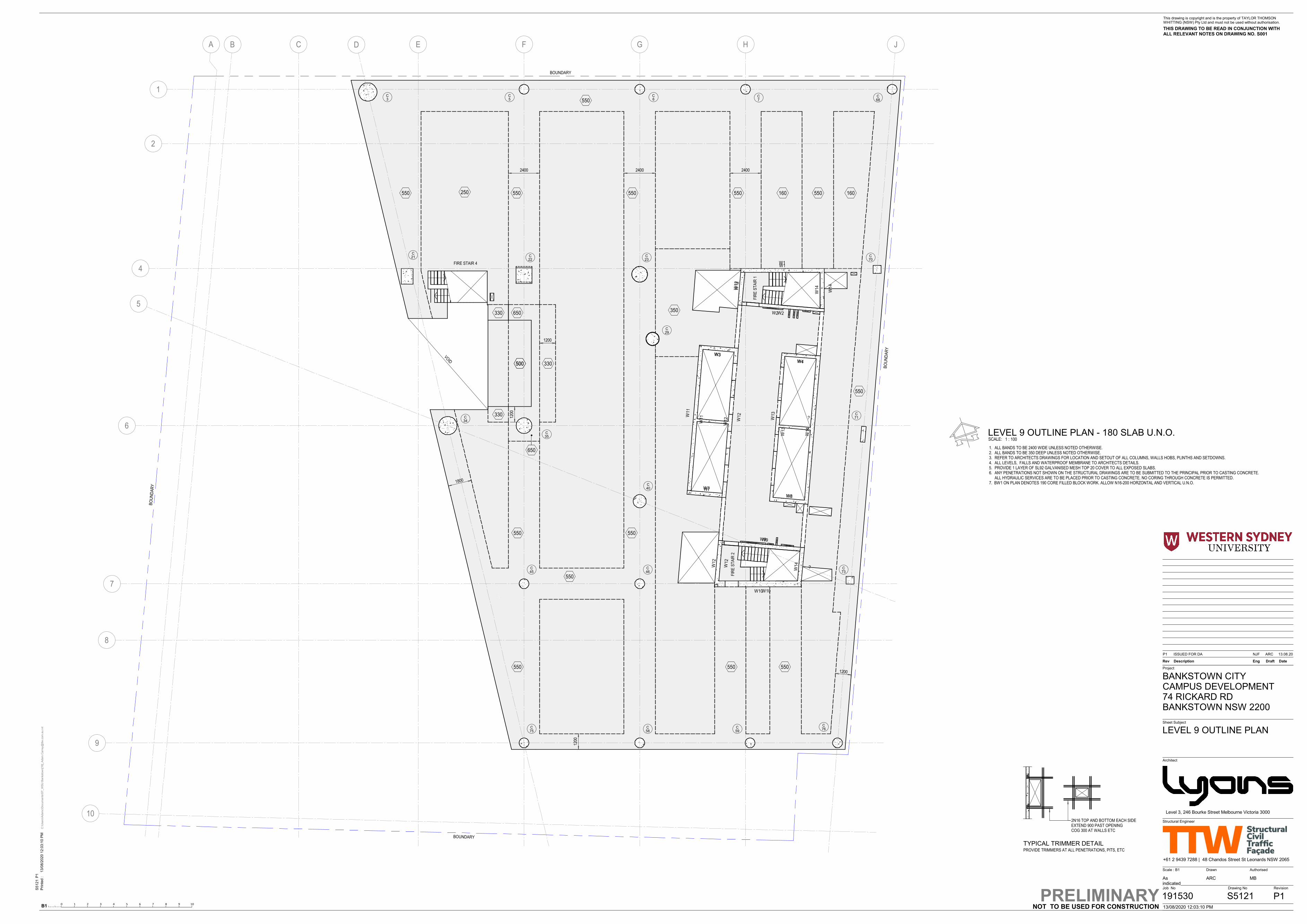
C E HGFA
1
2
4
6
7
8
9
10
5
B D J
BO
UN
DA
RY
BOUNDARY
BO
UN
DA
RY
BOUNDARY
550
550
550 550
2400 2400 2400
1200
550550
550 550 550
550
1800
250 160 160550
350650
500
650
330
330
500 330
1200
550
W1
W2
W12
W11
W12
W9
W10
W14
W14
W13
W4
W3
W14
W12
W8
W7
550
VOID
1200
1200
FIR
E S
TA
IR 1
FIR
E S
TA
IR 2
FIRE STAIR 4
3C
5C
6C
7C
68C
70C
23C
22C21
C
34C
35C
71C
29C
73C
45C
46C
76C
59C
58C
75C
40C
W1
W2
W12
W14
W11
W12
W3
W7
W13
?
W4
W8
W12
W9
W10
?
TYPICAL TRIMMER DETAILPROVIDE TRIMMERS AT ALL PENETRATIONS, PITS, ETC
2N16 TOP AND BOTTOM EACH SIDEEXTEND 900 PAST OPENINGCOG 300 AT WALLS ETC
1. ALL BANDS TO BE 2400 WIDE UNLESS NOTED OTHERWISE.2. ALL BANDS TO BE 350 DEEP UNLESS NOTED OTHERWISE.3. REFER TO ARCHITECTS DRAWINGS FOR LOCATION AND SETOUT OF ALL COLUMNS, WALLS HOBS, PLINTHS AND SETDOWNS.4. ALL LEVELS, FALLS AND WATERPROOF MEMBRANE TO ARCHITECTS DETAILS.5. PROVIDE 1 LAYER OF SL92 GALVANISED MESH TOP 20 COVER TO ALL EXPOSED SLABS.6. ANY PENETRATIONS NOT SHOWN ON THE STRUCTURAL DRAWINGS ARE TO BE SUBMITTED TO THE PRINCIPAL PRIOR TO CASTING CONCRETE.
ALL HYDRAULIC SERVICES ARE TO BE PLACED PRIOR TO CASTING CONCRETE. NO CORING THROUGH CONCRETE IS PERMITTED.7. BW1 ON PLAN DENOTES 190 CORE FILLED BLOCK WORK. ALLOW N16-200 HORZONTAL AND VERTICAL U.N.O.
B10 1 2 3 54 6 7 8 9 10
Architect
Authorised
Drawing No
Scale : B1
Job No Revision
Sheet Subject
Project
Rev Description Eng DateDraft
Drawn
This drawing is copyright and is the property of TAYLOR THOMSONWHITTING (NSW) Pty Ltd and must not be used without authorisation.
THIS DRAWING TO BE READ IN CONJUNCTION WITH ALL RELEVANT NOTES ON DRAWING NO. S001
BANKSTOWN CITY CAMPUS DEVELOPMENT 74 RICKARD RD BANKSTOWN NSW 2200
Level 3, 246 Bourke Street Melbourne Victoria 3000
Structural Engineer
Pri
nte
d :
+61 2 9439 7288 | 48 Chandos Street St Leonards NSW 2065
NOT TO BE USED FOR CONSTRUCTION
Asindicated
13/08/2020 12:03:10 PM
13
/08
/20
20
12
:03
:10
PM
C:\U
sers
\Ad
am
c\D
ocum
en
ts\S
T_W
SU
Ban
ksto
wn[1
9]_
Ad
am
.Ca
rrey@
ttw
.co
m.a
u.r
vt
ARC MB
191530 S5121
LEVEL 9 OUTLINE PLAN
P1 13.08.20ISSUED FOR DA ARCNJF
P1PRELIMINARY
S5
12
1P
1
SCALE: 1 : 100LEVEL 9 OUTLINE PLAN - 180 SLAB U.N.O.

ST
EP
STEP
ST
EP
C E HGFA
1
2
4
6
7
8
9
10
5
B
D
J
BO
UN
DA
RY
BOUNDARY
BO
UN
DA
RY
BOUNDARY
250 160 160550550 550 550 550
330
330
330
400
550
550550
500 500 500 500
1800
1800
1200
1200
1200
350
500
700
700
1200
500
550
FIR
E S
TA
IR 1
FIR
E S
TA
IR 2
FIRE STAIR 4
3C
5C
6C
7C
68C
70C
23C
22C21
C
34C
35C 71
C
29C
73C
45C
46C
76C
59C
58C
75C
40C
W1
W2
W12
W14
W11
W12
W3
W7
W13
?
W4
W8
W12
W9
W10
?
TYPICAL TRIMMER DETAILPROVIDE TRIMMERS AT ALL PENETRATIONS, PITS, ETC
2N16 TOP AND BOTTOM EACH SIDEEXTEND 900 PAST OPENINGCOG 300 AT WALLS ETC
1. ALL BANDS TO BE 2400 WIDE UNLESS NOTED OTHERWISE.2. ALL BANDS TO BE 350 DEEP UNLESS NOTED OTHERWISE.3. REFER TO ARCHITECTS DRAWINGS FOR LOCATION AND SETOUT OF ALL COLUMNS, WALLS HOBS, PLINTHS AND SETDOWNS.4. ALL LEVELS, FALLS AND WATERPROOF MEMBRANE TO ARCHITECTS DETAILS.5. PROVIDE 1 LAYER OF SL92 GALVANISED MESH TOP 20 COVER TO ALL EXPOSED SLABS.6. ANY PENETRATIONS NOT SHOWN ON THE STRUCTURAL DRAWINGS ARE TO BE SUBMITTED TO THE PRINCIPAL PRIOR TO CASTING CONCRETE.
ALL HYDRAULIC SERVICES ARE TO BE PLACED PRIOR TO CASTING CONCRETE. NO CORING THROUGH CONCRETE IS PERMITTED.7. BW1 ON PLAN DENOTES 190 CORE FILLED BLOCK WORK. ALLOW N16-200 HORZONTAL AND VERTICAL U.N.O.
B10 1 2 3 54 6 7 8 9 10
Architect
Authorised
Drawing No
Scale : B1
Job No Revision
Sheet Subject
Project
Rev Description Eng DateDraft
Drawn
This drawing is copyright and is the property of TAYLOR THOMSONWHITTING (NSW) Pty Ltd and must not be used without authorisation.
THIS DRAWING TO BE READ IN CONJUNCTION WITH ALL RELEVANT NOTES ON DRAWING NO. S001
BANKSTOWN CITY CAMPUS DEVELOPMENT 74 RICKARD RD BANKSTOWN NSW 2200
Level 3, 246 Bourke Street Melbourne Victoria 3000
Structural Engineer
Pri
nte
d :
+61 2 9439 7288 | 48 Chandos Street St Leonards NSW 2065
NOT TO BE USED FOR CONSTRUCTION
Asindicated
13/08/2020 12:03:13 PM
13
/08
/20
20
12
:03
:13
PM
C:\U
sers
\Ad
am
c\D
ocum
en
ts\S
T_W
SU
Ban
ksto
wn[1
9]_
Ad
am
.Ca
rrey@
ttw
.co
m.a
u.r
vt
ARC MB
191530 S5131
LEVEL 10 OUTLINE PLAN
P1 13.08.20ISSUED FOR DA ARCNJF
P1PRELIMINARY
S5
13
1P
1
SCALE: 1 : 100LEVEL 10 OUTLINE PLAN - 180 SLAB U.N.O.

ST
EP
STEP
ST
EP
C E HGFA
1
2
4
6
7
8
9
10
5
B
D
J
BO
UN
DA
RY
BOUNDARY
BO
UN
DA
RY
BOUNDARY
250 160 160550550 550 550 550
330
330
330
400
500
550 550
500 500 500 500
1200
1200
1200
350
700
700
500
550
1200
1800
700
FIR
E S
TA
IR 1
FIR
E S
TA
IR 2
FIRE STAIR 4
3C
5C
6C
7C
68C
70C
23C
22C21
C
34C
35C 71
C
29C
73C
45C
46C
76C
59C
58C
75C
40C
W1
W2
W12
W14
W11
W12
W3
W7
W13
?
W4
W8
W12
W9
W10
?
TYPICAL TRIMMER DETAILPROVIDE TRIMMERS AT ALL PENETRATIONS, PITS, ETC
2N16 TOP AND BOTTOM EACH SIDEEXTEND 900 PAST OPENINGCOG 300 AT WALLS ETC
1. ALL BANDS TO BE 2400 WIDE UNLESS NOTED OTHERWISE.2. ALL BANDS TO BE 350 DEEP UNLESS NOTED OTHERWISE.3. REFER TO ARCHITECTS DRAWINGS FOR LOCATION AND SETOUT OF ALL COLUMNS, WALLS HOBS, PLINTHS AND SETDOWNS.4. ALL LEVELS, FALLS AND WATERPROOF MEMBRANE TO ARCHITECTS DETAILS.5. PROVIDE 1 LAYER OF SL92 GALVANISED MESH TOP 20 COVER TO ALL EXPOSED SLABS.6. ANY PENETRATIONS NOT SHOWN ON THE STRUCTURAL DRAWINGS ARE TO BE SUBMITTED TO THE PRINCIPAL PRIOR TO CASTING CONCRETE.
ALL HYDRAULIC SERVICES ARE TO BE PLACED PRIOR TO CASTING CONCRETE. NO CORING THROUGH CONCRETE IS PERMITTED.7. BW1 ON PLAN DENOTES 190 CORE FILLED BLOCK WORK. ALLOW N16-200 HORZONTAL AND VERTICAL U.N.O.
B10 1 2 3 54 6 7 8 9 10
Architect
Authorised
Drawing No
Scale : B1
Job No Revision
Sheet Subject
Project
Rev Description Eng DateDraft
Drawn
This drawing is copyright and is the property of TAYLOR THOMSONWHITTING (NSW) Pty Ltd and must not be used without authorisation.
THIS DRAWING TO BE READ IN CONJUNCTION WITH ALL RELEVANT NOTES ON DRAWING NO. S001
BANKSTOWN CITY CAMPUS DEVELOPMENT 74 RICKARD RD BANKSTOWN NSW 2200
Level 3, 246 Bourke Street Melbourne Victoria 3000
Structural Engineer
Pri
nte
d :
+61 2 9439 7288 | 48 Chandos Street St Leonards NSW 2065
NOT TO BE USED FOR CONSTRUCTION
Asindicated
13/08/2020 12:03:15 PM
13
/08
/20
20
12
:03
:15
PM
C:\U
sers
\Ad
am
c\D
ocum
en
ts\S
T_W
SU
Ban
ksto
wn[1
9]_
Ad
am
.Ca
rrey@
ttw
.co
m.a
u.r
vt
ARC MB
191530 S5141
LEVEL 11 OUTLINE PLAN
P1 13.08.20ISSUED FOR DA ARCNJF
P1PRELIMINARY
S5
14
1P
1
SCALE: 1 : 100LEVEL 11 OUTLINE PLAN - 180 SLAB U.N.O.

STEP
ST
EP
ST
EP
C E HGFA
1
2
4
6
7
8
9
10
5
B
D
J
BO
UN
DA
RY
BOUNDARY
BO
UN
DA
RY
BOUNDARY
250 160 160550550 550 550 550
400
550
550500 500 500 500
1600
330
1200
500
1200
350
FIR
E S
TA
IR 1
FIR
E S
TA
IR 2
FIRE STAIR 4
3C
5C
6C
7C
68C
70C
23C
22C21
C
34C
35C
71C
29C
73C
45C
46C
76C
59C
58C
75C
40C
W1
W2
W12
W14
W11
W12
W3
W7
W13
?
W4
W8
W12
W9
W10
?
TYPICAL TRIMMER DETAILPROVIDE TRIMMERS AT ALL PENETRATIONS, PITS, ETC
2N16 TOP AND BOTTOM EACH SIDEEXTEND 900 PAST OPENINGCOG 300 AT WALLS ETC
1. ALL BANDS TO BE 2400 WIDE UNLESS NOTED OTHERWISE.2. ALL BANDS TO BE 350 DEEP UNLESS NOTED OTHERWISE.3. REFER TO ARCHITECTS DRAWINGS FOR LOCATION AND SETOUT OF ALL COLUMNS, WALLS HOBS, PLINTHS AND SETDOWNS.4. ALL LEVELS, FALLS AND WATERPROOF MEMBRANE TO ARCHITECTS DETAILS.5. PROVIDE 1 LAYER OF SL92 GALVANISED MESH TOP 20 COVER TO ALL EXPOSED SLABS.6. ANY PENETRATIONS NOT SHOWN ON THE STRUCTURAL DRAWINGS ARE TO BE SUBMITTED TO THE PRINCIPAL PRIOR TO CASTING CONCRETE.
ALL HYDRAULIC SERVICES ARE TO BE PLACED PRIOR TO CASTING CONCRETE. NO CORING THROUGH CONCRETE IS PERMITTED.7. BW1 ON PLAN DENOTES 190 CORE FILLED BLOCK WORK. ALLOW N16-200 HORZONTAL AND VERTICAL U.N.O.
B10 1 2 3 54 6 7 8 9 10
Architect
Authorised
Drawing No
Scale : B1
Job No Revision
Sheet Subject
Project
Rev Description Eng DateDraft
Drawn
This drawing is copyright and is the property of TAYLOR THOMSONWHITTING (NSW) Pty Ltd and must not be used without authorisation.
THIS DRAWING TO BE READ IN CONJUNCTION WITH ALL RELEVANT NOTES ON DRAWING NO. S001
BANKSTOWN CITY CAMPUS DEVELOPMENT 74 RICKARD RD BANKSTOWN NSW 2200
Level 3, 246 Bourke Street Melbourne Victoria 3000
Structural Engineer
Pri
nte
d :
+61 2 9439 7288 | 48 Chandos Street St Leonards NSW 2065
NOT TO BE USED FOR CONSTRUCTION
Asindicated
13/08/2020 12:03:17 PM
13
/08
/20
20
12
:03
:17
PM
C:\U
sers
\Ad
am
c\D
ocum
en
ts\S
T_W
SU
Ban
ksto
wn[1
9]_
Ad
am
.Ca
rrey@
ttw
.co
m.a
u.r
vt
ARC MB
191530 S5151
LEVEL 12 OUTLINE PLAN
P1 13.08.20ISSUED FOR DA ARCNJF
P1PRELIMINARY
S5
15
1P
1
SCALE: 1 : 100LEVEL 12 OUTLINE PLAN - 180 SLAB U.N.O.

ST
EP
STEP
ST
EP
C E HGFA
1
2
4
6
7
8
9
10
5
B
D
J
BO
UN
DA
RY
BOUNDARY
BO
UN
DA
RY
BOUNDARY
250 160 160550550 550 550 550
330
330
330
400
500
550550
500 500 500 500
1200
600
500
600
1200
1200
1600
500
500
1800
350
1200
FIR
E S
TA
IR 1
FIR
E S
TA
IR 2
FIRE STAIR 4
3C
5C
6C
7C
68C
70C
23C
22C21
C
34C
35C 71
C
29C
73C
45C
46C
76C
59C
58C
75C
40C
W1
W2
W12
W14
W11
W12
W3
W7
W13
W14
W4
W8
W12
W9
W10
W14
TYPICAL TRIMMER DETAILPROVIDE TRIMMERS AT ALL PENETRATIONS, PITS, ETC
2N16 TOP AND BOTTOM EACH SIDEEXTEND 900 PAST OPENINGCOG 300 AT WALLS ETC
1. ALL BANDS TO BE 2400 WIDE UNLESS NOTED OTHERWISE.2. ALL BANDS TO BE 350 DEEP UNLESS NOTED OTHERWISE.3. REFER TO ARCHITECTS DRAWINGS FOR LOCATION AND SETOUT OF ALL COLUMNS, WALLS HOBS, PLINTHS AND SETDOWNS.4. ALL LEVELS, FALLS AND WATERPROOF MEMBRANE TO ARCHITECTS DETAILS.5. PROVIDE 1 LAYER OF SL92 GALVANISED MESH TOP 20 COVER TO ALL EXPOSED SLABS.6. ANY PENETRATIONS NOT SHOWN ON THE STRUCTURAL DRAWINGS ARE TO BE SUBMITTED TO THE PRINCIPAL PRIOR TO CASTING CONCRETE.
ALL HYDRAULIC SERVICES ARE TO BE PLACED PRIOR TO CASTING CONCRETE. NO CORING THROUGH CONCRETE IS PERMITTED.7. BW1 ON PLAN DENOTES 190 CORE FILLED BLOCK WORK. ALLOW N16-200 HORZONTAL AND VERTICAL U.N.O.
B10 1 2 3 54 6 7 8 9 10
Architect
Authorised
Drawing No
Scale : B1
Job No Revision
Sheet Subject
Project
Rev Description Eng DateDraft
Drawn
This drawing is copyright and is the property of TAYLOR THOMSONWHITTING (NSW) Pty Ltd and must not be used without authorisation.
THIS DRAWING TO BE READ IN CONJUNCTION WITH ALL RELEVANT NOTES ON DRAWING NO. S001
BANKSTOWN CITY CAMPUS DEVELOPMENT 74 RICKARD RD BANKSTOWN NSW 2200
Level 3, 246 Bourke Street Melbourne Victoria 3000
Structural Engineer
Pri
nte
d :
+61 2 9439 7288 | 48 Chandos Street St Leonards NSW 2065
NOT TO BE USED FOR CONSTRUCTION
Asindicated
13/08/2020 12:03:19 PM
13
/08
/20
20
12
:03
:19
PM
C:\U
sers
\Ad
am
c\D
ocum
en
ts\S
T_W
SU
Ban
ksto
wn[1
9]_
Ad
am
.Ca
rrey@
ttw
.co
m.a
u.r
vt
ARC MB
191530 S5161
LEVEL 13 OUTLINE PLAN
P1 13.08.20ISSUED FOR DA ARCNJF
P1PRELIMINARY
S5
16
1P
1
SCALE: 1 : 100LEVEL 13 OUTLINE PLAN - 180 SLAB U.N.O.

ST
EP
ST
EP
C E HGFA
1
2
4
6
7
8
9
10
5
B D J
BO
UN
DA
RY
BOUNDARY
BO
UN
DA
RY
BOUNDARY
250 160 160
550550 550 550 550
550 550 550 550
600
600 600 600 550550
550
60012
00
1200
550
350
1200
FIR
E S
TA
IR 1
FIR
E S
TA
IR 2
FIRE STAIR 4
3C
5C
6C
7C
68C
70C
23C
22C21
C
34C
35C 71
C
29C
73C
40C
45C
46C
75C
58C
59C
76C
W1
W2
W12
W14
W11
W12
W3
W7
W13
W14
W4
W8
W12
W9
W10
W14
200 200
2700
2700
TYPICAL TRIMMER DETAILPROVIDE TRIMMERS AT ALL PENETRATIONS, PITS, ETC
2N16 TOP AND BOTTOM EACH SIDEEXTEND 900 PAST OPENINGCOG 300 AT WALLS ETC
1. ALL BANDS TO BE 2400 WIDE UNLESS NOTED OTHERWISE.2. ALL BANDS TO BE 350 DEEP UNLESS NOTED OTHERWISE.3. REFER TO ARCHITECTS DRAWINGS FOR LOCATION AND SETOUT OF ALL COLUMNS, WALLS HOBS, PLINTHS AND SETDOWNS.4. ALL LEVELS, FALLS AND WATERPROOF MEMBRANE TO ARCHITECTS DETAILS.5. PROVIDE 1 LAYER OF SL92 GALVANISED MESH TOP 20 COVER TO ALL EXPOSED SLABS.6. ANY PENETRATIONS NOT SHOWN ON THE STRUCTURAL DRAWINGS ARE TO BE SUBMITTED TO THE PRINCIPAL PRIOR TO CASTING CONCRETE.
ALL HYDRAULIC SERVICES ARE TO BE PLACED PRIOR TO CASTING CONCRETE. NO CORING THROUGH CONCRETE IS PERMITTED.7. BW1 ON PLAN DENOTES 190 CORE FILLED BLOCK WORK. ALLOW N16-200 HORZONTAL AND VERTICAL U.N.O.
B10 1 2 3 54 6 7 8 9 10
Architect
Authorised
Drawing No
Scale : B1
Job No Revision
Sheet Subject
Project
Rev Description Eng DateDraft
Drawn
This drawing is copyright and is the property of TAYLOR THOMSONWHITTING (NSW) Pty Ltd and must not be used without authorisation.
THIS DRAWING TO BE READ IN CONJUNCTION WITH ALL RELEVANT NOTES ON DRAWING NO. S001
BANKSTOWN CITY CAMPUS DEVELOPMENT 74 RICKARD RD BANKSTOWN NSW 2200
Level 3, 246 Bourke Street Melbourne Victoria 3000
Structural Engineer
Pri
nte
d :
+61 2 9439 7288 | 48 Chandos Street St Leonards NSW 2065
NOT TO BE USED FOR CONSTRUCTION
Asindicated
13/08/2020 12:03:21 PM
13
/08
/20
20
12
:03
:21
PM
C:\U
sers
\Ad
am
c\D
ocum
en
ts\S
T_W
SU
Ban
ksto
wn[1
9]_
Ad
am
.Ca
rrey@
ttw
.co
m.a
u.r
vt
ARC MB
191530 S5171
LEVEL 14 OUTLINE PLAN
P1 13.08.20ISSUED FOR DA ARCNJF
P1PRELIMINARY
S5
17
1P
1
SCALE: 1 : 100LEVEL 14 OUTLINE PLAN - 180 SLAB U.N.O.

C E HGFA
1
2
4
6
7
8
9
10
5
B
D
J
BO
UN
DA
RY
BOUNDARY
BO
UN
DA
RY
BOUNDARY
160 160550
550
550
500550
350
500
1800
40bWC
40bWC
40bWC
40bWC
40dWC
UB53a
UB53a
UB53a
UB53a
UB53a
UB53a
WC50a
UB53a
UB53a
UB41a
UB41a
UB41a
UB53a
UB
61c
40dWC
120Bondek
FIR
E S
TA
IR 1
FIRE STAIR 4
3C
5C
6C
7C
68C
21C
22C
23C
70C
34C
35C
29C
40C
71C
73C
W1
W2
W14
W11
W3
W7
W13
W4
W8
W12
W14
W12
550650
650
650
650
250
1. ALL BANDS TO BE 2400 WIDE UNLESS NOTED OTHERWISE.2. ALL BANDS TO BE 350 DEEP UNLESS NOTED OTHERWISE.3. REFER TO ARCHITECTS DRAWINGS FOR LOCATION AND SETOUT OF ALL COLUMNS, WALLS HOBS, PLINTHS AND SETDOWNS.4. ALL LEVELS, FALLS AND WATERPROOF MEMBRANE TO ARCHITECTS DETAILS.5. PROVIDE 1 LAYER OF SL92 GALVANISED MESH TOP 20 COVER TO ALL EXPOSED SLABS.6. ANY PENETRATIONS NOT SHOWN ON THE STRUCTURAL DRAWINGS ARE TO BE SUBMITTED TO THE PRINCIPAL PRIOR TO CASTING CONCRETE.
ALL HYDRAULIC SERVICES ARE TO BE PLACED PRIOR TO CASTING CONCRETE. NO CORING THROUGH CONCRETE IS PERMITTED.
TYPICAL TRIMMER DETAILPROVIDE TRIMMERS AT ALL PENETRATIONS, PITS, ETC
2N16 TOP AND BOTTOM EACH SIDEEXTEND 900 PAST OPENINGCOG 300 AT WALLS ETC
B10 1 2 3 54 6 7 8 9 10
Architect
Authorised
Drawing No
Scale : B1
Job No Revision
Sheet Subject
Project
Rev Description Eng DateDraft
Drawn
This drawing is copyright and is the property of TAYLOR THOMSONWHITTING (NSW) Pty Ltd and must not be used without authorisation.
THIS DRAWING TO BE READ IN CONJUNCTION WITH ALL RELEVANT NOTES ON DRAWING NO. S001
BANKSTOWN CITY CAMPUS DEVELOPMENT 74 RICKARD RD BANKSTOWN NSW 2200
Level 3, 246 Bourke Street Melbourne Victoria 3000
Structural Engineer
Pri
nte
d :
+61 2 9439 7288 | 48 Chandos Street St Leonards NSW 2065
NOT TO BE USED FOR CONSTRUCTION
Asindicated
13/08/2020 12:03:23 PM
13
/08
/20
20
12
:03
:23
PM
C:\U
sers
\Ad
am
c\D
ocum
en
ts\S
T_W
SU
Ban
ksto
wn[1
9]_
Ad
am
.Ca
rrey@
ttw
.co
m.a
u.r
vt
ARC MB
191530 S5181
LEVEL 15 OUTLINE PLAN
P1 13.08.20ISSUED FOR DA ARCNJF
P1PRELIMINARY
S5
18
1P
1
SCALE: 1 : 100LEVEL 15 OUTLINE PLAN - 200 SLAB U.N.O.

C E HGFA
1
2
4
6
7
8
9
10
5
B D J
BO
UN
DA
RY
BOUNDARY
BO
UN
DA
RY
BOUNDARY
1800
40bWC
40bWC
40bWC
40bWC
40dWC
UB53a
UB53a
UB53a
UB53a
UB53a
UB53a
WC50a
UB53a
UB53a
UB41a
UB41a
UB41a
UB53a
UB
61c
40dWC
FIR
E S
TA
IR 1
FIRE STAIR 4
3C
5C
6C
7C
68C
21C
22C
23C
70C
34C
35C
29C
40C
71C
73C
W1
W2
?
W14
W11
?
W3
W7
W13
?
W4
W8
160 160550
550
550
500550
350
500
120Bondek
550650
650
650
650
250
1. ALL BANDS TO BE 2400 WIDE UNLESS NOTED OTHERWISE.2. ALL BANDS TO BE 350 DEEP UNLESS NOTED OTHERWISE.3. REFER TO ARCHITECTS DRAWINGS FOR LOCATION AND SETOUT OF ALL COLUMNS, WALLS HOBS, PLINTHS AND SETDOWNS.4. ALL LEVELS, FALLS AND WATERPROOF MEMBRANE TO ARCHITECTS DETAILS.5. PROVIDE 1 LAYER OF SL92 GALVANISED MESH TOP 20 COVER TO ALL EXPOSED SLABS.6. ANY PENETRATIONS NOT SHOWN ON THE STRUCTURAL DRAWINGS ARE TO BE SUBMITTED TO THE PRINCIPAL PRIOR TO CASTING CONCRETE.
ALL HYDRAULIC SERVICES ARE TO BE PLACED PRIOR TO CASTING CONCRETE. NO CORING THROUGH CONCRETE IS PERMITTED.
TYPICAL TRIMMER DETAILPROVIDE TRIMMERS AT ALL PENETRATIONS, PITS, ETC
2N16 TOP AND BOTTOM EACH SIDEEXTEND 900 PAST OPENINGCOG 300 AT WALLS ETC
B10 1 2 3 54 6 7 8 9 10
Architect
Authorised
Drawing No
Scale : B1
Job No Revision
Sheet Subject
Project
Rev Description Eng DateDraft
Drawn
This drawing is copyright and is the property of TAYLOR THOMSONWHITTING (NSW) Pty Ltd and must not be used without authorisation.
THIS DRAWING TO BE READ IN CONJUNCTION WITH ALL RELEVANT NOTES ON DRAWING NO. S001
BANKSTOWN CITY CAMPUS DEVELOPMENT 74 RICKARD RD BANKSTOWN NSW 2200
Level 3, 246 Bourke Street Melbourne Victoria 3000
Structural Engineer
Pri
nte
d :
+61 2 9439 7288 | 48 Chandos Street St Leonards NSW 2065
NOT TO BE USED FOR CONSTRUCTION
Asindicated
13/08/2020 12:03:25 PM
13
/08
/20
20
12
:03
:25
PM
C:\U
sers
\Ad
am
c\D
ocum
en
ts\S
T_W
SU
Ban
ksto
wn[1
9]_
Ad
am
.Ca
rrey@
ttw
.co
m.a
u.r
vt
ARC MB
191530 S5191
LEVEL 16 OUTLINE PLAN
P1 13.08.20ISSUED FOR DA ARCNJF
P1PRELIMINARY
S5
19
1P
1
SCALE: 1 : 100LEVEL 16 OUTLINE PLAN - 200 SLAB U.N.O.

C E HGFA
1
2
4
6
7
8
9
10
5
B D J
BO
UN
DA
RY
BOUNDARY
BO
UN
DA
RY
BOUNDARY
1800
40bWC
40bWC
40bWC
40bWC
40dWC
UB53a
UB53a
UB53a
UB53a
UB53a
UB53a
WC50a
UB53a
UB53a
UB41a
UB41a
UB41a
UB53a
UB
61c
40dWC
FIR
E S
TA
IR 1
FIRE STAIR 4
3C
5C
6C
7C
68C
21C
22C
23C
70C
34C
35C
29C
71C
73C
W1
W2
W14
W11
W3
W7
W13
W4
W8
?
180 180
550
550550
350
550
120Bondek
550650
650
650
650
250
1500
7000
650 650
W12
W14
1. ALL BANDS TO BE 2400 WIDE UNLESS NOTED OTHERWISE.2. ALL BANDS TO BE 350 DEEP UNLESS NOTED OTHERWISE.3. REFER TO ARCHITECTS DRAWINGS FOR LOCATION AND SETOUT OF ALL COLUMNS, WALLS HOBS, PLINTHS AND SETDOWNS.4. ALL LEVELS, FALLS AND WATERPROOF MEMBRANE TO ARCHITECTS DETAILS.5. PROVIDE 1 LAYER OF SL92 GALVANISED MESH TOP 20 COVER TO ALL EXPOSED SLABS.6. ANY PENETRATIONS NOT SHOWN ON THE STRUCTURAL DRAWINGS ARE TO BE SUBMITTED TO THE PRINCIPAL PRIOR TO CASTING CONCRETE.
ALL HYDRAULIC SERVICES ARE TO BE PLACED PRIOR TO CASTING CONCRETE. NO CORING THROUGH CONCRETE IS PERMITTED.
TYPICAL TRIMMER DETAILPROVIDE TRIMMERS AT ALL PENETRATIONS, PITS, ETC
2N16 TOP AND BOTTOM EACH SIDEEXTEND 900 PAST OPENINGCOG 300 AT WALLS ETC
B10 1 2 3 54 6 7 8 9 10
Architect
Authorised
Drawing No
Scale : B1
Job No Revision
Sheet Subject
Project
Rev Description Eng DateDraft
Drawn
This drawing is copyright and is the property of TAYLOR THOMSONWHITTING (NSW) Pty Ltd and must not be used without authorisation.
THIS DRAWING TO BE READ IN CONJUNCTION WITH ALL RELEVANT NOTES ON DRAWING NO. S001
BANKSTOWN CITY CAMPUS DEVELOPMENT 74 RICKARD RD BANKSTOWN NSW 2200
Level 3, 246 Bourke Street Melbourne Victoria 3000
Structural Engineer
Pri
nte
d :
+61 2 9439 7288 | 48 Chandos Street St Leonards NSW 2065
NOT TO BE USED FOR CONSTRUCTION
Asindicated
13/08/2020 12:03:27 PM
13
/08
/20
20
12
:03
:27
PM
C:\U
sers
\Ad
am
c\D
ocum
en
ts\S
T_W
SU
Ban
ksto
wn[1
9]_
Ad
am
.Ca
rrey@
ttw
.co
m.a
u.r
vt
ARC MB
191530 S5201
LEVEL 17 OUTLINE PLAN
P1 13.08.20ISSUED FOR DA ARCNJF
P1PRELIMINARY
S5
20
1P
1
SCALE: 1 : 100LEVEL 17 OUTLINE PLAN - 200 SLAB U.N.O.

C E HGFA
1
2
4
6
7
8
9
10
5
B D J
BO
UN
DA
RY
BOUNDARY
BO
UN
DA
RY
BOUNDARY
1800
40bWC
40bWC
40bWC
40bWC
40dWC
UB53a
UB53a
UB53a
UB53a
UB53a
UB53a
WC50a
UB53a
UB53a
UB41a
UB41a
UB41a
UB53a
UB
61c
40dWC
FIR
E S
TA
IR 1
FIRE STAIR 4
3C
7C
68C
21C
22C
23C
70C
34C
35C
29C
40C
71C
73C
W1
W2
W14
W11
W3
W7
W13
W4
W8
W12
W12
W14
180 180
700
550700
350
550
120Bondek
700650
650
650
250 700 700
7005C 6
C
1. ALL BANDS TO BE 2400 WIDE UNLESS NOTED OTHERWISE.2. ALL BANDS TO BE 350 DEEP UNLESS NOTED OTHERWISE.3. REFER TO ARCHITECTS DRAWINGS FOR LOCATION AND SETOUT OF ALL COLUMNS, WALLS HOBS, PLINTHS AND SETDOWNS.4. ALL LEVELS, FALLS AND WATERPROOF MEMBRANE TO ARCHITECTS DETAILS.5. PROVIDE 1 LAYER OF SL92 GALVANISED MESH TOP 20 COVER TO ALL EXPOSED SLABS.6. ANY PENETRATIONS NOT SHOWN ON THE STRUCTURAL DRAWINGS ARE TO BE SUBMITTED TO THE PRINCIPAL PRIOR TO CASTING CONCRETE.
ALL HYDRAULIC SERVICES ARE TO BE PLACED PRIOR TO CASTING CONCRETE. NO CORING THROUGH CONCRETE IS PERMITTED.
TYPICAL TRIMMER DETAILPROVIDE TRIMMERS AT ALL PENETRATIONS, PITS, ETC
2N16 TOP AND BOTTOM EACH SIDEEXTEND 900 PAST OPENINGCOG 300 AT WALLS ETC
B10 1 2 3 54 6 7 8 9 10
Architect
Authorised
Drawing No
Scale : B1
Job No Revision
Sheet Subject
Project
Rev Description Eng DateDraft
Drawn
This drawing is copyright and is the property of TAYLOR THOMSONWHITTING (NSW) Pty Ltd and must not be used without authorisation.
THIS DRAWING TO BE READ IN CONJUNCTION WITH ALL RELEVANT NOTES ON DRAWING NO. S001
BANKSTOWN CITY CAMPUS DEVELOPMENT 74 RICKARD RD BANKSTOWN NSW 2200
Level 3, 246 Bourke Street Melbourne Victoria 3000
Structural Engineer
Pri
nte
d :
+61 2 9439 7288 | 48 Chandos Street St Leonards NSW 2065
NOT TO BE USED FOR CONSTRUCTION
Asindicated
13/08/2020 12:03:30 PM
13
/08
/20
20
12
:03
:30
PM
C:\U
sers
\Ad
am
c\D
ocum
en
ts\S
T_W
SU
Ban
ksto
wn[1
9]_
Ad
am
.Ca
rrey@
ttw
.co
m.a
u.r
vt
ARC MB
191530 S5211
LEVEL 18 OUTLINE PLAN
P1 13.08.20ISSUED FOR DA ARCNJF
P1PRELIMINARY
S5
21
1P
1
SCALE: 1 : 100LEVEL 18 OUTLINE PLAN - 200 SLAB U.N.O.

C E HGFA
1
2
4
6
7
8
9
10
5
B D J
BO
UN
DA
RY
BOUNDARY
BO
UN
DA
RY
BOUNDARY
W1
W2
?
W14
W11
W3
W7
W13
W4
W8
3C
5C
6C
7C
68C
21C
22C
23C
70C
73C
34C
35C
40C
UB41a
UB53a
UB53a
UB53a
UB53a
UB53a
UB53a
UB53a
UB53a
UB41a
UB
61c
WC50a
UB53a
W12
W14
TYPICAL TRIMMER DETAILPROVIDE TRIMMERS AT ALL PENETRATIONS, PITS, ETC
2N16 TOP AND BOTTOM EACH SIDEEXTEND 900 PAST OPENINGCOG 300 AT WALLS ETC
1. ALL BANDS TO BE 2400 WIDE UNLESS NOTED OTHERWISE.2. ALL BANDS TO BE 650 DEEP UNLESS NOTED OTHERWISE.3. REFER TO ARCHITECTS DRAWINGS FOR LOCATION AND SETOUT OF ALL COLUMNS, WALLS HOBS, PLINTHS AND SETDOWNS.4. ALL LEVELS, FALLS AND WATERPROOF MEMBRANE TO ARCHITECTS DETAILS.5. PROVIDE 1 LAYER OF SL92 GALVANISED MESH TOP 20 COVER TO ALL EXPOSED SLABS.6. ANY PENETRATIONS NOT SHOWN ON THE STRUCTURAL DRAWINGS ARE TO BE SUBMITTED TO THE PRINCIPAL PRIOR TO CASTING CONCRETE.
ALL HYDRAULIC SERVICES ARE TO BE PLACED PRIOR TO CASTING CONCRETE. NO CORING THROUGH CONCRETE IS PERMITTED.
B10 1 2 3 54 6 7 8 9 10
Architect
Authorised
Drawing No
Scale : B1
Job No Revision
Sheet Subject
Project
Rev Description Eng DateDraft
Drawn
This drawing is copyright and is the property of TAYLOR THOMSONWHITTING (NSW) Pty Ltd and must not be used without authorisation.
THIS DRAWING TO BE READ IN CONJUNCTION WITH ALL RELEVANT NOTES ON DRAWING NO. S001
BANKSTOWN CITY CAMPUS DEVELOPMENT 74 RICKARD RD BANKSTOWN NSW 2200
Level 3, 246 Bourke Street Melbourne Victoria 3000
Structural Engineer
Pri
nte
d :
+61 2 9439 7288 | 48 Chandos Street St Leonards NSW 2065
NOT TO BE USED FOR CONSTRUCTION
Asindicated
13/08/2020 12:06:24 PM
13
/08
/20
20
12
:06
:24
PM
C:\U
sers
\Ad
am
c\D
ocum
en
ts\S
T_W
SU
Ban
ksto
wn[1
9]_
Ad
am
.Ca
rrey@
ttw
.co
m.a
u.r
vt
ARC MB
191530 S5221
LEVEL 19 ROOF OUTLINEPLAN
P1 13.08.20ISSUED FOR DA ARCNJF
P1PRELIMINARY
S5
22
1P
1
SCALE: 1 : 100LEVEL 19 ROOF OUTLINE PLAN - 200 SLAB U.N.O.