copy 2015 Isola Group and its subsidiaries All rights reserved copy 2015 Isola Group and its subsidiaries All rights reserved
Vehicle RADAR Classification Long Range RADAR (LRR) Range up to 250m Vehicle velocity above 30 kmh to 250 kmh Narrow beams to control driving path in front of the
car to determine distance of vehicle driving ahead for maintaining minimum safety distance Bandwidth below 1 GHz and typical spatial resolution
05m
Short Range RADAR (SRR) Range up to 30m Speed range from 5 kmh to 150 kmh Wide field of view Bandwidth below 5 GHz and typical spatial resolution
01m
copy 2015 Isola Group and its subsidiaries All rights reserved copy 2015 Isola Group and its subsidiaries All rights reserved
RADAR Resolution Requirements Scenarios Requiring High Resolution
(wide bandwidth) Side Impact Cross Traffic Alert Narrow Pass Assistant Evasion Maneuver Pedestrian Protection Front Collision Warning Proximity Warning and Parking Assistant
Scenarios Needing Lower Resolution (narrow bandwidth) Adaptive Cruise Control ndash long range Lane Change Assist ndash 24 GHz
copy 2015 Isola Group and its subsidiaries All rights reserved copy 2015 Isola Group and its subsidiaries All rights reserved
Frequency Bands for Automotive RADAR
Source Infineon
copy 2015 Isola Group and its subsidiaries All rights reserved copy 2015 Isola Group and its subsidiaries All rights reserved
Active Safety System Development
Source Infineon
Systems are migrating to higher frequencies Change in frequency allocation Improved Performance Reduced size and improved affordability
copy 2015 Isola Group and its subsidiaries All rights reserved copy 2015 Isola Group and its subsidiaries All rights reserved
Active Safety System Trends Shift to higher frequencies 76 GHz to 81 GHz Development ongoing at 140 GHz
Integration of multiple system functions in one chipset RADAR front end Microcontroller
Reduction in system size Smaller size offers more options for integration into vehicle
front and rear fascia Single PCB combining RF and high speed digital
processing vs more common two-board configurations
Increasing demand for system cost reductions for a widening target market
copy 2015 Isola Group and its subsidiaries All rights reserved copy 2015 Isola Group and its subsidiaries All rights reserved
PCB Requirements
copy 2015 Isola Group and its subsidiaries All rights reserved copy 2015 Isola Group and its subsidiaries All rights reserved
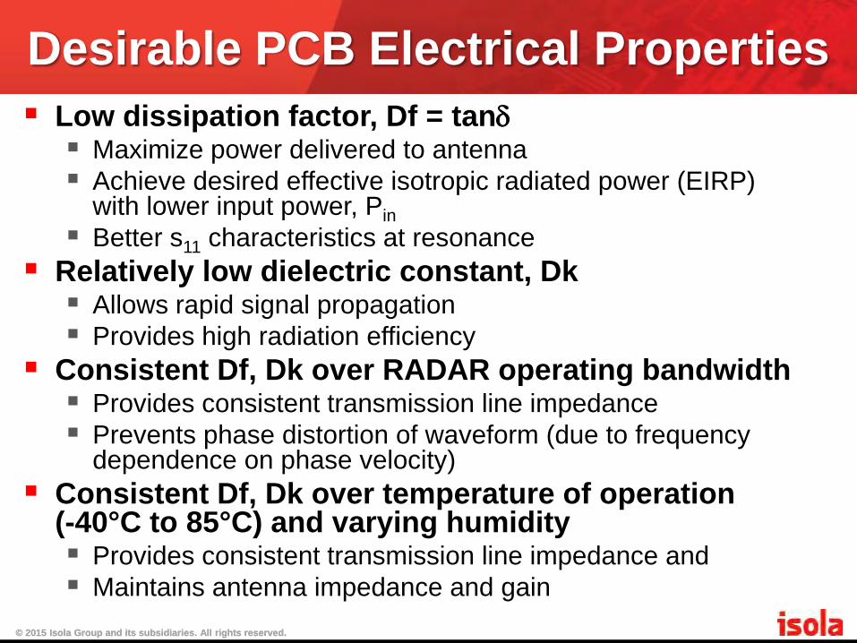
Desirable PCB Electrical Properties Low dissipation factor Df = tanδ Maximize power delivered to antenna Achieve desired effective isotropic radiated power (EIRP)
with lower input power Pin Better s11 characteristics at resonance
Relatively low dielectric constant Dk Allows rapid signal propagation Provides high radiation efficiency
Consistent Df Dk over RADAR operating bandwidth Provides consistent transmission line impedance Prevents phase distortion of waveform (due to frequency
dependence on phase velocity)
Consistent Df Dk over temperature of operation (-40degC to 85degC) and varying humidity Provides consistent transmission line impedance and Maintains antenna impedance and gain
copy 2015 Isola Group and its subsidiaries All rights reserved copy 2015 Isola Group and its subsidiaries All rights reserved
Additional PCB Attributes Material must have consistent physical properties Uniform electrical properties Consistent physical properties ndash thickness Dk Df Physical uniformity batch-to-batch and within batch
Ease of processing Minimum amount of special material treatment for PCB
fabrication Single cure cycle with parameters consistent with mature
products well established at board shops Compatibility with Hybrid Processing Systems are moving towards single board solution Single board will have RF and High Speed Digital channels
As low cost as possible Choose material process-compatible with hybrid PCB
construction Select material that meets performance requirements and
produces highest yields
copy 2015 Isola Group and its subsidiaries All rights reserved copy 2015 Isola Group and its subsidiaries All rights reserved
Sources of Loss in PCB Dielectric Loss Conduction Loss
copy 2015 Isola Group and its subsidiaries All rights reserved copy 2015 Isola Group and its subsidiaries All rights reserved
PCB Material Dielectric Loss Dielectric materials have polarized
molecules that move when subjected to the electric field of a digital signal This motion produces heat loss Loss results in signal attenuation that
increases in direct proportion to signal frequency
E
copy 2015 Isola Group and its subsidiaries All rights reserved copy 2015 Isola Group and its subsidiaries All rights reserved
PCB Material Conduction Loss The copper contributes to overall loss
through the metalrsquos resistive losses At high signal frequencies the current in
PCB copper is concentrated within a small depth near its surface (skin effect) Reduction in effective cross-sectional
area increases the effective resistance
copy 2015 Isola Group and its subsidiaries All rights reserved copy 2015 Isola Group and its subsidiaries All rights reserved
Conductor Surface Roughness Resist side Bonding side
Signal Path
The current is able to tunnel below the surface profile and through the bulk of the conductor
The current is forced to follow every peak and trough of the surface profile increasing path length and resistance
Standard foil
~10 microm
Presenter
Presentation Notes
Skin depth phenomenon forces the wave to experience the copper roughness at frequencies typically around 100 MHz ndash 300 MHz At higher frequencies the copper roughness becomes quite a significant factor1313
copy 2015 Isola Group and its subsidiaries All rights reserved copy 2015 Isola Group and its subsidiaries All rights reserved
Roughness parameters measured with profilometer
RTF and VLP Copper Profiles
Rq=26 um RF=185 Rq=068 um RF=13 RTF VLP
copy 2015 Isola Group and its subsidiaries All rights reserved copy 2015 Isola Group and its subsidiaries All rights reserved
Increase in capacitance due singular electric fields on surface spikes Increase in signal group delay over
perfectly smooth ldquoApparentrdquo increase in Dk to match
group delay vs frequency characteristics
Effects of Surface Roughness
copy 2015 Isola Group and its subsidiaries All rights reserved copy 2015 Isola Group and its subsidiaries All rights reserved
copy 2015 Isola Group and its subsidiaries All rights reserved copy 2015 Isola Group and its subsidiaries All rights reserved
Available materials PTFE
Highly Filled Hydrocarbon Based
Resins New Class of Thermoset Materials
copy 2015 Isola Group and its subsidiaries All rights reserved copy 2015 Isola Group and its subsidiaries All rights reserved
PTFE
copy 2015 Isola Group and its subsidiaries All rights reserved copy 2015 Isola Group and its subsidiaries All rights reserved
PTFE Dielectric Properties PTFE based materials are in used in RF
applications because of low Dk and Df Their material properties have been
found to be stable through mmwave frequencies Common belief that material properties
are very stable with temperature is somewhat of a misconception however
copy 2015 Isola Group and its subsidiaries All rights reserved copy 2015 Isola Group and its subsidiaries All rights reserved
PTFE Temperature Dependence PTFE has a crystalline structure after
polymerization The degree of crystallinity is affected
by changes in temperature and processing steps such as sintering above its melting point Changes in crystallinity result in
changes in effective density which result in changes in Dk
copy 2015 Isola Group and its subsidiaries All rights reserved copy 2015 Isola Group and its subsidiaries All rights reserved
PTFE Dk Dependence on Density Fabricated PTFE has crystallinity
ranging from 50 to 75 depending on rate of cooling Relative density of PTFE has been
found to vary from 23 for 100 crystallinity to 20 for 0 (amorphous) The Clausius-Mossotti relation can be
used to show the relationship between the density of PTFE and Dk
copy 2015 Isola Group and its subsidiaries All rights reserved copy 2015 Isola Group and its subsidiaries All rights reserved
PTFE Dk Dependence on Density
Dk is shown to be a function of PTFE density PTFE density can change with circuit board processing
2020
2040
2060
2080
2100
2120
2140
2160
2180
2200
2000 2050 2100 2150 2200 2250 2300
Die
lect
ric
Con
stan
t
PTFE Density
PTFE Density vs εr
copy 2015 Isola Group and its subsidiaries All rights reserved copy 2015 Isola Group and its subsidiaries All rights reserved
PTFE Dimensional Instability PTFE exhibits high degree of
permanent plastic deformation due to Low glass transition temperature Low yield strength
Deformation is on the order of a magnitude higher than FR-4 products This results in low yields and
processing difficulties particularly in hybrid constructions
copy 2015 Isola Group and its subsidiaries All rights reserved copy 2015 Isola Group and its subsidiaries All rights reserved
PTFE Dimensional Change
-6000
-5000
-4000
-3000
-2000
-1000
0
1000
2000
3000
00 500 1000 1500 2000 2500 3000
Dim
ensi
on C
han
ge P
PM
Process Temperature Deg C
Dim Change PPM- X Direction Microfiber filled PTFE
start
finish
copy 2015 Isola Group and its subsidiaries All rights reserved copy 2015 Isola Group and its subsidiaries All rights reserved
PTFE Dimensional Change
-6000
-5000
-4000
-3000
-2000
-1000
0
1000
2000
3000
4000
5000
0 50 100 150 200 250 300
Dim
ensi
onal
ch
ang
e P
PM
Process Temperature Deg C
Dim Change PPM Y-Direction microfiber filled PTFE
start
finish
copy 2015 Isola Group and its subsidiaries All rights reserved copy 2015 Isola Group and its subsidiaries All rights reserved
PTFE Mechanical Properties and Creep PTFE has a low elastic modulus of
approximately 05 GPa The coefficient of thermal expansion (CTE) of
PTFE is also highly variable and demonstrates high expansion At elevated temperatures permanent
deformation can occur over time at a stress level below itrsquos yield strength PTFE is highly prone to this deformation
known as creep
copy 2015 Isola Group and its subsidiaries All rights reserved copy 2015 Isola Group and its subsidiaries All rights reserved
Creep in PTFE Creep occurs at low stress levels and at
temperatures above 05Tm the absolute melting point (27degC for PTFE) Creep is measured by loading at a constant
stress level and measuring the deformation versus time In PTFE the creep rate can be shown to
double with a 20degC change in temperature The creep rate of PTFE materials raises
doubt about their suitability for applications with demanding environments such as automotive applications
copy 2015 Isola Group and its subsidiaries All rights reserved copy 2015 Isola Group and its subsidiaries All rights reserved
PTFE Process Challenges Technology is shifting to higher layer-count
boards combining RF and digital functions PTFE based materials are less desirable for
these boards due to higher cost high CTE and other processing concerns High temperature and pressure required Lack of bonding sheets available and absence of flow
and fill for encapsulation Limited compatibility with hybrids Increased drilling cost due to presence of abrasive
fillers added in attempt to lower CTE
copy 2015 Isola Group and its subsidiaries All rights reserved copy 2015 Isola Group and its subsidiaries All rights reserved
Effects of High CTE High CTE can lead to a number of
issues including Dimensional deformation Inter-laminar shear stress and residual stress
in the PCB High CTE in Z-direction affects plated
through hole reliability Copper has a low coefficient of expansion Mismatch causes stress and results in fatigue
failure
copy 2015 Isola Group and its subsidiaries All rights reserved copy 2015 Isola Group and its subsidiaries All rights reserved
Highly-filled Hydrocarbon-based Resins
copy 2015 Isola Group and its subsidiaries All rights reserved copy 2015 Isola Group and its subsidiaries All rights reserved
Highly-filled Hydrocarbon-based Resins
These materials are cross-linked with other polymers in an attempt to increase the Tg yet when measured the Tg is low
The materials donrsquot have the low loss properties of PTFE or the adhesion required for use of low profile copper
Their dielectric properties have been known to shift due to oxidation under operation at moderate temperatures
Materials offered as ldquooxidation resistantrdquo exhibit discoloration upon exposure to elevated temperatures
There are a number of issues using these in hybrid constructions
copy 2015 Isola Group and its subsidiaries All rights reserved copy 2015 Isola Group and its subsidiaries All rights reserved
Hybrid Construction CTE mismatch with other materials in
desirable hybrid construction presents many issues CTE in Z direction is very low due to highly filled
nature of the materials There is no Tg Above 60degC CTEs in X and Y show no inflection expanding at
uniform rates vs FR-4 materials which exhibit rapidly increasing Z expansion and significant drop in X Y When bonded together the hybrid board
experiences strain leading to high thermal stress and potential for delamination
copy 2015 Isola Group and its subsidiaries All rights reserved copy 2015 Isola Group and its subsidiaries All rights reserved
Factors Limiting Utility There are many attributes that limit their
utility for higher layer-count boards Inability to produce robust hybrid boards Higher dielectric loss and inability to
effectively use low-profile copper Lack of suitable bonding sheets Low dielectric stability under elevated
temperature Oxidation risks and associated change in
dielectric properties
copy 2015 Isola Group and its subsidiaries All rights reserved copy 2015 Isola Group and its subsidiaries All rights reserved
New Class of Thermoset Polymers
copy 2015 Isola Group and its subsidiaries All rights reserved copy 2015 Isola Group and its subsidiaries All rights reserved
Attributes Behavior like FR-4 materials for hybrid
processing while delivering excellent electrical and mechanical performance High peel strength while using the lowest
profile copper available for minimum conduction losses and PIM Stable dielectric properties from 1GHz through
100 GHz Low sensitivity to prolonged exposure to high
temperature Availability of full compliment of laminates and
prepregs meeting requirements for high-speed digital RF and mmwave designs
copy 2015 Isola Group and its subsidiaries All rights reserved copy 2015 Isola Group and its subsidiaries All rights reserved
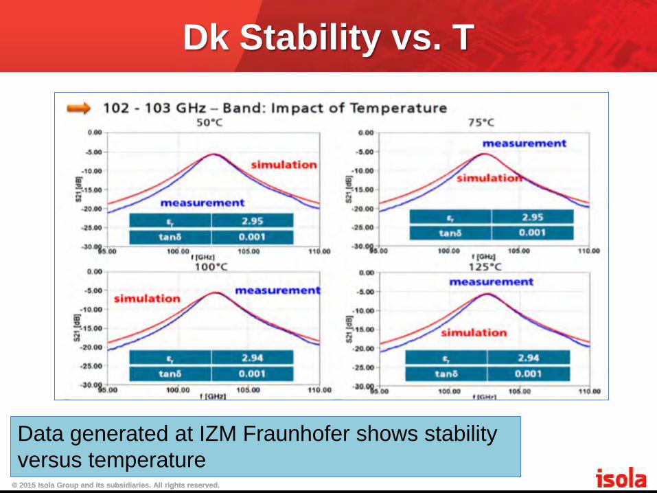
Dk Stability vs T
Data generated at IZM Fraunhofer shows stability versus temperature
copy 2015 Isola Group and its subsidiaries All rights reserved copy 2015 Isola Group and its subsidiaries All rights reserved
Permittivity vs Temperature
copy 2015 Isola Group and its subsidiaries All rights reserved copy 2015 Isola Group and its subsidiaries All rights reserved
Astrareg MT 77 and 100 GHz Testing
copy 2015 Isola Group and its subsidiaries All rights reserved copy 2015 Isola Group and its subsidiaries All rights reserved
Percent Change in Dk Percent change in dielectric constant after 1000 hours aging at 125degC is shown to be low for high Tg thermosets
copy 2015 Isola Group and its subsidiaries All rights reserved copy 2015 Isola Group and its subsidiaries All rights reserved
Percent Change in Df
Percent change in dielectric loss after 1000 hours aging at 125degC is shown to be low for high Tg thermosets
copy 2015 Isola Group and its subsidiaries All rights reserved copy 2015 Isola Group and its subsidiaries All rights reserved
Attenuation vs Frequency High-Tg thermoset shown to have lower
loss than filled PTFE product
copy 2015 Isola Group and its subsidiaries All rights reserved copy 2015 Isola Group and its subsidiaries All rights reserved
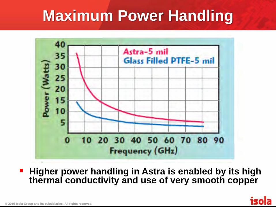
Maximum Power Handling
Higher power handling in Astra is enabled by its high thermal conductivity and use of very smooth copper
copy 2015 Isola Group and its subsidiaries All rights reserved copy 2015 Isola Group and its subsidiaries All rights reserved
Cost of Ownership Ease of processing using FR-4 standards Availability of many choices of laminates and
prepregs Superior dimensional stability resulting in higher
yields Lower processing and drilling costs (no plasma
de-smear needed no ceramic fillers to shorten drill life)
Fill and float properties offering compatibility with wider range of package options
Absence of creep and aging issues of alternative materials
Many factors contribute to the low cost of ownership of new high Tg thermoset polymers
copy 2015 Isola Group and its subsidiaries All rights reserved copy 2015 Isola Group and its subsidiaries All rights reserved
Astrareg MT
copy 2015 Isola Group and its subsidiaries All rights reserved copy 2015 Isola Group and its subsidiaries All rights reserved
copy 2015 Isola Group and its subsidiaries All rights reserved copy 2015 Isola Group and its subsidiaries All rights reserved
Prepreg thicknesses are as pressed between two solid copper planes The rheology of Astra MT prepreg allows for good flow and fill during
lamination Astra MT prepreg capable of multiple lamination cycles Astra MT prepreg - laser via formation can be done with CO2 and YAG
laser
Prepreg Resin Thickness Thickness Dk Dk Dk Dk Dk Dk Dk DkContent ( in ) ( mm ) at 100 MHz at 500 MHz at 1 GHz at 20 GHz at 50 GHz at 100 GHz at 15 GHz at 20 GHz
Prepreg Resin Thickness Thickness Df Df Df Df Df Df Df DfContent ( in ) ( mm ) at 100 MHz at 500 MHz at 1 GHz at 20 GHz at 50 GHz at 100 GHz at 15 GHz at 20 GHz
copy 2015 Isola Group and its subsidiaries All rights reserved copy 2015 Isola Group and its subsidiaries All rights reserved
Vehicle RADAR Classification Long Range RADAR (LRR) Range up to 250m Vehicle velocity above 30 kmh to 250 kmh Narrow beams to control driving path in front of the
car to determine distance of vehicle driving ahead for maintaining minimum safety distance Bandwidth below 1 GHz and typical spatial resolution
05m
Short Range RADAR (SRR) Range up to 30m Speed range from 5 kmh to 150 kmh Wide field of view Bandwidth below 5 GHz and typical spatial resolution
01m
copy 2015 Isola Group and its subsidiaries All rights reserved copy 2015 Isola Group and its subsidiaries All rights reserved
RADAR Resolution Requirements Scenarios Requiring High Resolution
(wide bandwidth) Side Impact Cross Traffic Alert Narrow Pass Assistant Evasion Maneuver Pedestrian Protection Front Collision Warning Proximity Warning and Parking Assistant
Scenarios Needing Lower Resolution (narrow bandwidth) Adaptive Cruise Control ndash long range Lane Change Assist ndash 24 GHz
copy 2015 Isola Group and its subsidiaries All rights reserved copy 2015 Isola Group and its subsidiaries All rights reserved
Frequency Bands for Automotive RADAR
Source Infineon
copy 2015 Isola Group and its subsidiaries All rights reserved copy 2015 Isola Group and its subsidiaries All rights reserved
Active Safety System Development
Source Infineon
Systems are migrating to higher frequencies Change in frequency allocation Improved Performance Reduced size and improved affordability
copy 2015 Isola Group and its subsidiaries All rights reserved copy 2015 Isola Group and its subsidiaries All rights reserved
Active Safety System Trends Shift to higher frequencies 76 GHz to 81 GHz Development ongoing at 140 GHz
Integration of multiple system functions in one chipset RADAR front end Microcontroller
Reduction in system size Smaller size offers more options for integration into vehicle
front and rear fascia Single PCB combining RF and high speed digital
processing vs more common two-board configurations
Increasing demand for system cost reductions for a widening target market
copy 2015 Isola Group and its subsidiaries All rights reserved copy 2015 Isola Group and its subsidiaries All rights reserved
PCB Requirements
copy 2015 Isola Group and its subsidiaries All rights reserved copy 2015 Isola Group and its subsidiaries All rights reserved
Desirable PCB Electrical Properties Low dissipation factor Df = tanδ Maximize power delivered to antenna Achieve desired effective isotropic radiated power (EIRP)
with lower input power Pin Better s11 characteristics at resonance
Relatively low dielectric constant Dk Allows rapid signal propagation Provides high radiation efficiency
Consistent Df Dk over RADAR operating bandwidth Provides consistent transmission line impedance Prevents phase distortion of waveform (due to frequency
dependence on phase velocity)
Consistent Df Dk over temperature of operation (-40degC to 85degC) and varying humidity Provides consistent transmission line impedance and Maintains antenna impedance and gain
copy 2015 Isola Group and its subsidiaries All rights reserved copy 2015 Isola Group and its subsidiaries All rights reserved
Additional PCB Attributes Material must have consistent physical properties Uniform electrical properties Consistent physical properties ndash thickness Dk Df Physical uniformity batch-to-batch and within batch
Ease of processing Minimum amount of special material treatment for PCB
fabrication Single cure cycle with parameters consistent with mature
products well established at board shops Compatibility with Hybrid Processing Systems are moving towards single board solution Single board will have RF and High Speed Digital channels
As low cost as possible Choose material process-compatible with hybrid PCB
construction Select material that meets performance requirements and
produces highest yields
copy 2015 Isola Group and its subsidiaries All rights reserved copy 2015 Isola Group and its subsidiaries All rights reserved
Sources of Loss in PCB Dielectric Loss Conduction Loss
copy 2015 Isola Group and its subsidiaries All rights reserved copy 2015 Isola Group and its subsidiaries All rights reserved
PCB Material Dielectric Loss Dielectric materials have polarized
molecules that move when subjected to the electric field of a digital signal This motion produces heat loss Loss results in signal attenuation that
increases in direct proportion to signal frequency
E
copy 2015 Isola Group and its subsidiaries All rights reserved copy 2015 Isola Group and its subsidiaries All rights reserved
PCB Material Conduction Loss The copper contributes to overall loss
through the metalrsquos resistive losses At high signal frequencies the current in
PCB copper is concentrated within a small depth near its surface (skin effect) Reduction in effective cross-sectional
area increases the effective resistance
copy 2015 Isola Group and its subsidiaries All rights reserved copy 2015 Isola Group and its subsidiaries All rights reserved
Conductor Surface Roughness Resist side Bonding side
Signal Path
The current is able to tunnel below the surface profile and through the bulk of the conductor
The current is forced to follow every peak and trough of the surface profile increasing path length and resistance
Standard foil
~10 microm
Presenter
Presentation Notes
Skin depth phenomenon forces the wave to experience the copper roughness at frequencies typically around 100 MHz ndash 300 MHz At higher frequencies the copper roughness becomes quite a significant factor1313
copy 2015 Isola Group and its subsidiaries All rights reserved copy 2015 Isola Group and its subsidiaries All rights reserved
Roughness parameters measured with profilometer
RTF and VLP Copper Profiles
Rq=26 um RF=185 Rq=068 um RF=13 RTF VLP
copy 2015 Isola Group and its subsidiaries All rights reserved copy 2015 Isola Group and its subsidiaries All rights reserved
Increase in capacitance due singular electric fields on surface spikes Increase in signal group delay over
perfectly smooth ldquoApparentrdquo increase in Dk to match
group delay vs frequency characteristics
Effects of Surface Roughness
copy 2015 Isola Group and its subsidiaries All rights reserved copy 2015 Isola Group and its subsidiaries All rights reserved
copy 2015 Isola Group and its subsidiaries All rights reserved copy 2015 Isola Group and its subsidiaries All rights reserved
Available materials PTFE
Highly Filled Hydrocarbon Based
Resins New Class of Thermoset Materials
copy 2015 Isola Group and its subsidiaries All rights reserved copy 2015 Isola Group and its subsidiaries All rights reserved
PTFE
copy 2015 Isola Group and its subsidiaries All rights reserved copy 2015 Isola Group and its subsidiaries All rights reserved
PTFE Dielectric Properties PTFE based materials are in used in RF
applications because of low Dk and Df Their material properties have been
found to be stable through mmwave frequencies Common belief that material properties
are very stable with temperature is somewhat of a misconception however
copy 2015 Isola Group and its subsidiaries All rights reserved copy 2015 Isola Group and its subsidiaries All rights reserved
PTFE Temperature Dependence PTFE has a crystalline structure after
polymerization The degree of crystallinity is affected
by changes in temperature and processing steps such as sintering above its melting point Changes in crystallinity result in
changes in effective density which result in changes in Dk
copy 2015 Isola Group and its subsidiaries All rights reserved copy 2015 Isola Group and its subsidiaries All rights reserved
PTFE Dk Dependence on Density Fabricated PTFE has crystallinity
ranging from 50 to 75 depending on rate of cooling Relative density of PTFE has been
found to vary from 23 for 100 crystallinity to 20 for 0 (amorphous) The Clausius-Mossotti relation can be
used to show the relationship between the density of PTFE and Dk
copy 2015 Isola Group and its subsidiaries All rights reserved copy 2015 Isola Group and its subsidiaries All rights reserved
PTFE Dk Dependence on Density
Dk is shown to be a function of PTFE density PTFE density can change with circuit board processing
2020
2040
2060
2080
2100
2120
2140
2160
2180
2200
2000 2050 2100 2150 2200 2250 2300
Die
lect
ric
Con
stan
t
PTFE Density
PTFE Density vs εr
copy 2015 Isola Group and its subsidiaries All rights reserved copy 2015 Isola Group and its subsidiaries All rights reserved
PTFE Dimensional Instability PTFE exhibits high degree of
permanent plastic deformation due to Low glass transition temperature Low yield strength
Deformation is on the order of a magnitude higher than FR-4 products This results in low yields and
processing difficulties particularly in hybrid constructions
copy 2015 Isola Group and its subsidiaries All rights reserved copy 2015 Isola Group and its subsidiaries All rights reserved
PTFE Dimensional Change
-6000
-5000
-4000
-3000
-2000
-1000
0
1000
2000
3000
00 500 1000 1500 2000 2500 3000
Dim
ensi
on C
han
ge P
PM
Process Temperature Deg C
Dim Change PPM- X Direction Microfiber filled PTFE
start
finish
copy 2015 Isola Group and its subsidiaries All rights reserved copy 2015 Isola Group and its subsidiaries All rights reserved
PTFE Dimensional Change
-6000
-5000
-4000
-3000
-2000
-1000
0
1000
2000
3000
4000
5000
0 50 100 150 200 250 300
Dim
ensi
onal
ch
ang
e P
PM
Process Temperature Deg C
Dim Change PPM Y-Direction microfiber filled PTFE
start
finish
copy 2015 Isola Group and its subsidiaries All rights reserved copy 2015 Isola Group and its subsidiaries All rights reserved
PTFE Mechanical Properties and Creep PTFE has a low elastic modulus of
approximately 05 GPa The coefficient of thermal expansion (CTE) of
PTFE is also highly variable and demonstrates high expansion At elevated temperatures permanent
deformation can occur over time at a stress level below itrsquos yield strength PTFE is highly prone to this deformation
known as creep
copy 2015 Isola Group and its subsidiaries All rights reserved copy 2015 Isola Group and its subsidiaries All rights reserved
Creep in PTFE Creep occurs at low stress levels and at
temperatures above 05Tm the absolute melting point (27degC for PTFE) Creep is measured by loading at a constant
stress level and measuring the deformation versus time In PTFE the creep rate can be shown to
double with a 20degC change in temperature The creep rate of PTFE materials raises
doubt about their suitability for applications with demanding environments such as automotive applications
copy 2015 Isola Group and its subsidiaries All rights reserved copy 2015 Isola Group and its subsidiaries All rights reserved
PTFE Process Challenges Technology is shifting to higher layer-count
boards combining RF and digital functions PTFE based materials are less desirable for
these boards due to higher cost high CTE and other processing concerns High temperature and pressure required Lack of bonding sheets available and absence of flow
and fill for encapsulation Limited compatibility with hybrids Increased drilling cost due to presence of abrasive
fillers added in attempt to lower CTE
copy 2015 Isola Group and its subsidiaries All rights reserved copy 2015 Isola Group and its subsidiaries All rights reserved
Effects of High CTE High CTE can lead to a number of
issues including Dimensional deformation Inter-laminar shear stress and residual stress
in the PCB High CTE in Z-direction affects plated
through hole reliability Copper has a low coefficient of expansion Mismatch causes stress and results in fatigue
failure
copy 2015 Isola Group and its subsidiaries All rights reserved copy 2015 Isola Group and its subsidiaries All rights reserved
Highly-filled Hydrocarbon-based Resins
copy 2015 Isola Group and its subsidiaries All rights reserved copy 2015 Isola Group and its subsidiaries All rights reserved
Highly-filled Hydrocarbon-based Resins
These materials are cross-linked with other polymers in an attempt to increase the Tg yet when measured the Tg is low
The materials donrsquot have the low loss properties of PTFE or the adhesion required for use of low profile copper
Their dielectric properties have been known to shift due to oxidation under operation at moderate temperatures
Materials offered as ldquooxidation resistantrdquo exhibit discoloration upon exposure to elevated temperatures
There are a number of issues using these in hybrid constructions
copy 2015 Isola Group and its subsidiaries All rights reserved copy 2015 Isola Group and its subsidiaries All rights reserved
Hybrid Construction CTE mismatch with other materials in
desirable hybrid construction presents many issues CTE in Z direction is very low due to highly filled
nature of the materials There is no Tg Above 60degC CTEs in X and Y show no inflection expanding at
uniform rates vs FR-4 materials which exhibit rapidly increasing Z expansion and significant drop in X Y When bonded together the hybrid board
experiences strain leading to high thermal stress and potential for delamination
copy 2015 Isola Group and its subsidiaries All rights reserved copy 2015 Isola Group and its subsidiaries All rights reserved
Factors Limiting Utility There are many attributes that limit their
utility for higher layer-count boards Inability to produce robust hybrid boards Higher dielectric loss and inability to
effectively use low-profile copper Lack of suitable bonding sheets Low dielectric stability under elevated
temperature Oxidation risks and associated change in
dielectric properties
copy 2015 Isola Group and its subsidiaries All rights reserved copy 2015 Isola Group and its subsidiaries All rights reserved
New Class of Thermoset Polymers
copy 2015 Isola Group and its subsidiaries All rights reserved copy 2015 Isola Group and its subsidiaries All rights reserved
Attributes Behavior like FR-4 materials for hybrid
processing while delivering excellent electrical and mechanical performance High peel strength while using the lowest
profile copper available for minimum conduction losses and PIM Stable dielectric properties from 1GHz through
100 GHz Low sensitivity to prolonged exposure to high
temperature Availability of full compliment of laminates and
prepregs meeting requirements for high-speed digital RF and mmwave designs
copy 2015 Isola Group and its subsidiaries All rights reserved copy 2015 Isola Group and its subsidiaries All rights reserved
Dk Stability vs T
Data generated at IZM Fraunhofer shows stability versus temperature
copy 2015 Isola Group and its subsidiaries All rights reserved copy 2015 Isola Group and its subsidiaries All rights reserved
Permittivity vs Temperature
copy 2015 Isola Group and its subsidiaries All rights reserved copy 2015 Isola Group and its subsidiaries All rights reserved
Astrareg MT 77 and 100 GHz Testing
copy 2015 Isola Group and its subsidiaries All rights reserved copy 2015 Isola Group and its subsidiaries All rights reserved
Percent Change in Dk Percent change in dielectric constant after 1000 hours aging at 125degC is shown to be low for high Tg thermosets
copy 2015 Isola Group and its subsidiaries All rights reserved copy 2015 Isola Group and its subsidiaries All rights reserved
Percent Change in Df
Percent change in dielectric loss after 1000 hours aging at 125degC is shown to be low for high Tg thermosets
copy 2015 Isola Group and its subsidiaries All rights reserved copy 2015 Isola Group and its subsidiaries All rights reserved
Attenuation vs Frequency High-Tg thermoset shown to have lower
loss than filled PTFE product
copy 2015 Isola Group and its subsidiaries All rights reserved copy 2015 Isola Group and its subsidiaries All rights reserved
Maximum Power Handling
Higher power handling in Astra is enabled by its high thermal conductivity and use of very smooth copper
copy 2015 Isola Group and its subsidiaries All rights reserved copy 2015 Isola Group and its subsidiaries All rights reserved
Cost of Ownership Ease of processing using FR-4 standards Availability of many choices of laminates and
prepregs Superior dimensional stability resulting in higher
yields Lower processing and drilling costs (no plasma
de-smear needed no ceramic fillers to shorten drill life)
Fill and float properties offering compatibility with wider range of package options
Absence of creep and aging issues of alternative materials
Many factors contribute to the low cost of ownership of new high Tg thermoset polymers
copy 2015 Isola Group and its subsidiaries All rights reserved copy 2015 Isola Group and its subsidiaries All rights reserved
Astrareg MT
copy 2015 Isola Group and its subsidiaries All rights reserved copy 2015 Isola Group and its subsidiaries All rights reserved
copy 2015 Isola Group and its subsidiaries All rights reserved copy 2015 Isola Group and its subsidiaries All rights reserved
Prepreg thicknesses are as pressed between two solid copper planes The rheology of Astra MT prepreg allows for good flow and fill during
lamination Astra MT prepreg capable of multiple lamination cycles Astra MT prepreg - laser via formation can be done with CO2 and YAG
laser
Prepreg Resin Thickness Thickness Dk Dk Dk Dk Dk Dk Dk DkContent ( in ) ( mm ) at 100 MHz at 500 MHz at 1 GHz at 20 GHz at 50 GHz at 100 GHz at 15 GHz at 20 GHz
Prepreg Resin Thickness Thickness Df Df Df Df Df Df Df DfContent ( in ) ( mm ) at 100 MHz at 500 MHz at 1 GHz at 20 GHz at 50 GHz at 100 GHz at 15 GHz at 20 GHz
copy 2015 Isola Group and its subsidiaries All rights reserved copy 2015 Isola Group and its subsidiaries All rights reserved
Case Study Automotive RADAR
copy 2015 Isola Group and its subsidiaries All rights reserved copy 2015 Isola Group and its subsidiaries All rights reserved
Freescale RADAR Starter Kit KITRADAR2001EVM is for demonstration
and evaluation of Freescale mmwave RADAR chipsets and micro-controllers Modular design consists of RADAR
process board RF front end board mechanical waveguide adapter antenna board System operates at 76 to 77 GHz and has
4 transmit channels and 6 receive channels Antennas are designed for both long
range and short range sensing
copy 2015 Isola Group and its subsidiaries All rights reserved copy 2015 Isola Group and its subsidiaries All rights reserved
Freescale KITRADAR2001EVM
Modular design of KITRADAR2001EVM
copy 2015 Isola Group and its subsidiaries All rights reserved copy 2015 Isola Group and its subsidiaries All rights reserved
Demonstration Hardware
Demonstration hardware consists of KITRADAR2001EVM power supply and PC for control
copy 2015 Isola Group and its subsidiaries All rights reserved copy 2015 Isola Group and its subsidiaries All rights reserved
Astra MT vs PTFE Astra MT was used for antennaRF board
replacing PTFE-based material Astra MT had superior mechanical properties
better registration and doesnrsquot experience the process challenges of PTFE Additionally substantial material cost saving
and fabrication cost savings are realized with use of Astra MT thermoset RF performance of Astra met or exceeded that
of the PTFE product ndash antenna gain and EIRP
copy 2015 Isola Group and its subsidiaries All rights reserved copy 2015 Isola Group and its subsidiaries All rights reserved
Conclusions Automotive safety systems present the designer
with challenges in balancing performance and cost
Further material constraints come from the challenging operating environment and thermal cycling necessary in the operational environment
Designs by several OEMs are trending towards single board solutions combining RF and High Speed Digital functionality
Current PTFE-based substrates are not suitable for hybrid technology required
High Tg thermoset polymer systems presented here can be used effectively in a high layer-count hybrid and offer high reliability and lower cost
copy 2015 Isola Group and its subsidiaries All rights reserved copy 2015 Isola Group and its subsidiaries All rights reserved
Summary Printed Circuit Board (PCB)
requirements for mm-wave frequency band Requirements for mm-wave Advanced
Automotive Safety Systems PCB Material Availability in Industry Case study using Astrareg MT on
mmwave automotive RADAR application
New Thermoset PCB Materials Improve Millimeter Wave Performance and Reliability at Reduced Cost
Outline
Active mmWave Applications
Advanced Automotive Safety Systems
Active Safety Systems
Vehicle RADAR Classification
RADAR Resolution Requirements
Frequency Bands for Automotive RADAR
Active Safety System Development
Active Safety System Trends
PCB Requirements
Desirable PCB Electrical Properties
Additional PCB Attributes
Sources of Loss in PCB
PCB Material Dielectric Loss
PCB Material Conduction Loss
Conductor Surface Roughness
RTF and VLP Copper Profiles
Effects of Surface Roughness
Relative Attenuation vs F (GHz)
Available materials
PTFE
PTFE Dielectric Properties
PTFE Temperature Dependence
PTFE Dk Dependence on Density
PTFE Dk Dependence on Density
PTFE Dimensional Instability
PTFE Dimensional Change
PTFE Dimensional Change
PTFE Mechanical Properties and Creep
Creep in PTFE
PTFE Process Challenges
Effects of High CTE
Highly-filled Hydrocarbon-based Resins
Highly-filled Hydrocarbon-based Resins
Hybrid Construction
Factors Limiting Utility
New Class of Thermoset Polymers
Attributes
Dk Stability vs T
Permittivity vs Temperature
Astrareg MT 77 and 100 GHz Testing
Percent Change in Dk
Percent Change in Df
Attenuation vs Frequency
Maximum Power Handling
Cost of Ownership
Astrareg MT
Astrareg MT
Astrareg MT Core Offering
Astrareg MT Prepreg Dk Df
Astrareg MT Properties
Case StudyAutomotive RADAR
Freescale RADAR Starter Kit
Freescale KITRADAR2001EVM
Demonstration Hardware
Astra MT vs PTFE
Conclusions
Summary
Property
Units
GreenSpeed
Tg ( DSC )
C
175
Td ( TGA - ASTM)
C
395
CTE - z-axis ( 50-260 C)
290
T-260 ( TMA )
minutes
gt 60
T-288 ( TMA )
minutes
gt 60
Dk - 2 Ghz
404 - 415
Dk - 5 Ghz
404 - 415
Dk - 10 Ghz
404 - 415
Df - 2 Ghz
0014 - 0016
Df - 5 Ghz
0014 - 0016
Df - 10 Ghz
0014 - 0016
Peels 1 oz after thermal stress
9
Property
Units
FR406
GreenSpeed
Tg ( DSC )
C
170
185
Td ( TGA - ASTM)
C
300
395
CTE - z-axis ( 50-260 C)
400
290
T-260 ( TMA )
minutes
10
gt 60
T-288 ( TMA )
minutes
gt 2
gt 60
Dk - 2 Ghz
379
404 - 415
Dk - 5 Ghz
376
404 - 415
Dk - 10 Ghz
376
404 - 415
Df - 2 Ghz
00180
0014 - 0016
Df - 5 Ghz
00186
0014 - 0016
Df - 10 Ghz
00186
0014 - 0016
Peels 1 oz after thermal stress
8
9
Moisture Absorption
020
Flammability
-
94 V-0
UL recognition
FR4
Property
Units
I-TeraregMT
Tg ( DSC )
C
200
Td ( TGA )
C
360
CTE - z-axis ( 50-260 C)
280
T-260 ( TMA )
minutes
60
T-288 ( TMA )
minutes
gt 60
Dk - 2 GHz
300 - 345
Dk - 5 GHz
300 - 345
Dk - 10 GHz
300 - 345
Df - 2 GHz
00030 - 00035
Df - 5 GHz
00030 - 00035
Df - 10 GHz
00030 - 00035
Peels 1 oz after thermal stress
5
Moisture Absorption
001
Flammability
-
94 V-0
UL recognition
non Ansi
Property
Units
Astra MT
Astra MT
Tg ( DSC )
C
200
Td ( TGA )
C
360
CTE - z-axis ( 50-260 C)
280
T-260 ( TMA )
minutes
60
T-288 ( TMA )
minutes
gt 60
Dk - 2 GHz
300
Dk - 5 GHz
300
Dk - 10 GHz
300
Df - 2 GHz
00017
Df - 5 GHz
00018
Df - 10 GHz
0002
Peels 1 oz after thermal stress
5
Moisture Absorption
001
Flammability
-
94 V-0
UL recognition
non Ansi
Property
Units
DE156
IS500
Tg ( DSC )
C
160
180
Td ( TGA - ASTM)
C
400
400
CTE- x-axis (amb-Tg)
ppm C
14
14
CTE - y-axis (amb-Tg)
ppmC
13
13
CTE - z-axis ( 50-260 C)
270
270
T-260 ( TMA )
minutes
60
60
T-288 ( TMA )
minutes
60
60
Dk - 100 MHz 2 Fluid Cell
425
401
Dk - 500 MHz 2 Fluid Cell
420
398
Dk - 1 GHz HP4291A Net Anyl
418
396
Dk - 2 Ghz Bereskin Stripline
412
394
Dk - 5 Ghz Bereskin Stripline
410
392
Dk - 10 Ghz Bereskin Stripline
410
392
Df - 100 MHz 2 Fluid Cell
00128
0012
Df - 500 MHz 2 Fluid Cell
00140
0013
Df - 1 GHz HP4291A Net Anyl
00158
00147
Df - 2 Ghz Bereskin Stripline
00164
00153
Df - 5 Ghz Bereskin Stripline
00170
00157
Df - 10 Ghz Bereskin Stripline
00173
00162
Peels 1 oz after thermal stress
N mm
14
10
Flammability
-
V-0
V-0
Moisture Absorption
014
020
Property
Units
FR406
FR406HR
IS410
370HR
IS415
Tg ( DSC )
C
170
190
180
180
200
Td ( TGA - ASTM)
C
300
325
350
340
370
CTE - z-axis ( 50-260 C)
400
300
350
280
280
T-260 ( TMA )
minutes
10
30
60
60
60
T-288 ( TMA )
minutes
gt 2
gt 5
gt 15
gt 10
gt 20
Dk - 2 Ghz
379
379
376
404
370
Dk - 5 Ghz
376
376
369
392
368
Dk - 10 Ghz
376
376
369
392
368
Df - 2 Ghz
0018
00171
0021
0021
00128
Df - 5 Ghz
00186
00178
0025
0025
00133
Df - 10 Ghz
00186
00176
0025
0025
00133
Peels 1 oz after thermal stress
8
8
8
8
8
Moisture Absorption
020
024
020
015
015
Flammability
-
94 V-0
94 V-0
94 V-0
94 V-0
94 V-0
UL recognition
FR4
FR4
FR4
FR4
FR4
Property
Units
FR406
IS415
GETEK
FR408
FR408HR
IS620i
IS680
Property
Units
FR406
370HR
Tg ( DSC )
C
170
200
180
180
200
225
200
Tg ( DSC )
C
170
180
Td ( TGA - ASTM)
C
300
370
345
360
360
364
360
Td ( TGA - ASTM)
C
300
340
CTE - z-axis ( 50-260 C)
400
280
380
350
280
250
280
CTE - z-axis ( 50-260 C)
400
280
T-260 ( TMA )
minutes
10
60
60
60
60
60
60
T-260 ( TMA )
minutes
10
60
T-288 ( TMA )
minutes
gt 2
gt 20
gt 20
gt 20
gt 20
gt 15
gt 60
T-288 ( TMA )
minutes
gt 2
gt 10
Dk - 2 Ghz
379
370
377
375
358
28 - 345
Dk - 2 Ghz
379
404
Dk - 5 Ghz
376
368
375
373
354
28 - 345
Dk - 5 Ghz
376
392
Dk - 10 Ghz
376
368
375
372
354
28 - 345
Dk - 10 Ghz
376
392
Df - 2 Ghz
00180
00130
00120
00092
0006
00028 - 00036
Df - 2 Ghz
00180
0021
Df - 5 Ghz
00186
00133
00123
00098
00066
00028 - 00036
Df - 5 Ghz
00186
0025
Df - 10 Ghz
00186
00133
00123
00095
00071
00028 - 00036
Df - 10 Ghz
00186
0025
Peels 1 oz after thermal stress
8
8
8
5
Peels 1 oz after thermal stress
8
8
Moisture Absorption
020
015
015
015
020
024
010
Moisture Absorption
020
015
Flammability
-
94 V-0
94 V-0
94 V - 0
Flammability
-
94 V-0
94 V-0
UL recognition
FR4
FR4
GPY
non-Ansi
UL recognition
FR4
FR4
Property
Units
DE156
IS500
Tg ( DSC )
C
160
180
Td ( TGA - ASTM)
C
400
400
CTE- x-axis (amb-Tg)
ppm C
14
14
CTE - y-axis (amb-Tg)
ppmC
13
13
CTE - z-axis ( 50-260 C)
270
270
T-260 ( TMA )
minutes
60
60
T-288 ( TMA )
minutes
60
60
Dk - 1 GHz
418
396
Dk - 2 GHz
412
394
Dk - 5 GHz
410
392
Dk - 10 GHz
410
392
Df - 1 GHz
00158
00147
Df - 2 GHz
00164
00153
Df - 5 GHz
00170
00157
Df - 10 GHz
00173
00162
Peels 1 oz after thermal stress
N mm
14
10
Flammability
-
V-0
V-0
Moisture Absorption
014
020
Property
Units
I-Teratrade
Tg ( DSC )
C
200
Td ( TGA - ASTM)
C
360
CTE - z-axis ( 50-260 C)
280
T-260 ( TMA )
minutes
60
T-288 ( TMA )
minutes
gt 60
Dk - 2 GHz
28 - 345
Dk - 5 GHz
28 - 345
Dk - 10 GHz
28 - 345
Df - 2 GHz
00028 - 00036
Df - 5 GHz
00028 - 00036
Df - 10 GHz
00028 - 00036
Peels 1 oz after thermal stress
5
Moisture Absorption
001
Flammability
-
in testing
UL recognition
in testing
copy 2015 Isola Group and its subsidiaries All rights reserved copy 2015 Isola Group and its subsidiaries All rights reserved
Frequency Bands for Automotive RADAR
Source Infineon
copy 2015 Isola Group and its subsidiaries All rights reserved copy 2015 Isola Group and its subsidiaries All rights reserved
Active Safety System Development
Source Infineon
Systems are migrating to higher frequencies Change in frequency allocation Improved Performance Reduced size and improved affordability
copy 2015 Isola Group and its subsidiaries All rights reserved copy 2015 Isola Group and its subsidiaries All rights reserved
Active Safety System Trends Shift to higher frequencies 76 GHz to 81 GHz Development ongoing at 140 GHz
Integration of multiple system functions in one chipset RADAR front end Microcontroller
Reduction in system size Smaller size offers more options for integration into vehicle
front and rear fascia Single PCB combining RF and high speed digital
processing vs more common two-board configurations
Increasing demand for system cost reductions for a widening target market
copy 2015 Isola Group and its subsidiaries All rights reserved copy 2015 Isola Group and its subsidiaries All rights reserved
PCB Requirements
copy 2015 Isola Group and its subsidiaries All rights reserved copy 2015 Isola Group and its subsidiaries All rights reserved
Desirable PCB Electrical Properties Low dissipation factor Df = tanδ Maximize power delivered to antenna Achieve desired effective isotropic radiated power (EIRP)
with lower input power Pin Better s11 characteristics at resonance
Relatively low dielectric constant Dk Allows rapid signal propagation Provides high radiation efficiency
Consistent Df Dk over RADAR operating bandwidth Provides consistent transmission line impedance Prevents phase distortion of waveform (due to frequency
dependence on phase velocity)
Consistent Df Dk over temperature of operation (-40degC to 85degC) and varying humidity Provides consistent transmission line impedance and Maintains antenna impedance and gain
copy 2015 Isola Group and its subsidiaries All rights reserved copy 2015 Isola Group and its subsidiaries All rights reserved
Additional PCB Attributes Material must have consistent physical properties Uniform electrical properties Consistent physical properties ndash thickness Dk Df Physical uniformity batch-to-batch and within batch
Ease of processing Minimum amount of special material treatment for PCB
fabrication Single cure cycle with parameters consistent with mature
products well established at board shops Compatibility with Hybrid Processing Systems are moving towards single board solution Single board will have RF and High Speed Digital channels
As low cost as possible Choose material process-compatible with hybrid PCB
construction Select material that meets performance requirements and
produces highest yields
copy 2015 Isola Group and its subsidiaries All rights reserved copy 2015 Isola Group and its subsidiaries All rights reserved
Sources of Loss in PCB Dielectric Loss Conduction Loss
copy 2015 Isola Group and its subsidiaries All rights reserved copy 2015 Isola Group and its subsidiaries All rights reserved
PCB Material Dielectric Loss Dielectric materials have polarized
molecules that move when subjected to the electric field of a digital signal This motion produces heat loss Loss results in signal attenuation that
increases in direct proportion to signal frequency
E
copy 2015 Isola Group and its subsidiaries All rights reserved copy 2015 Isola Group and its subsidiaries All rights reserved
PCB Material Conduction Loss The copper contributes to overall loss
through the metalrsquos resistive losses At high signal frequencies the current in
PCB copper is concentrated within a small depth near its surface (skin effect) Reduction in effective cross-sectional
area increases the effective resistance
copy 2015 Isola Group and its subsidiaries All rights reserved copy 2015 Isola Group and its subsidiaries All rights reserved
Conductor Surface Roughness Resist side Bonding side
Signal Path
The current is able to tunnel below the surface profile and through the bulk of the conductor
The current is forced to follow every peak and trough of the surface profile increasing path length and resistance
Standard foil
~10 microm
Presenter
Presentation Notes
Skin depth phenomenon forces the wave to experience the copper roughness at frequencies typically around 100 MHz ndash 300 MHz At higher frequencies the copper roughness becomes quite a significant factor1313
copy 2015 Isola Group and its subsidiaries All rights reserved copy 2015 Isola Group and its subsidiaries All rights reserved
Roughness parameters measured with profilometer
RTF and VLP Copper Profiles
Rq=26 um RF=185 Rq=068 um RF=13 RTF VLP
copy 2015 Isola Group and its subsidiaries All rights reserved copy 2015 Isola Group and its subsidiaries All rights reserved
Increase in capacitance due singular electric fields on surface spikes Increase in signal group delay over
perfectly smooth ldquoApparentrdquo increase in Dk to match
group delay vs frequency characteristics
Effects of Surface Roughness
copy 2015 Isola Group and its subsidiaries All rights reserved copy 2015 Isola Group and its subsidiaries All rights reserved
copy 2015 Isola Group and its subsidiaries All rights reserved copy 2015 Isola Group and its subsidiaries All rights reserved
Available materials PTFE
Highly Filled Hydrocarbon Based
Resins New Class of Thermoset Materials
copy 2015 Isola Group and its subsidiaries All rights reserved copy 2015 Isola Group and its subsidiaries All rights reserved
PTFE
copy 2015 Isola Group and its subsidiaries All rights reserved copy 2015 Isola Group and its subsidiaries All rights reserved
PTFE Dielectric Properties PTFE based materials are in used in RF
applications because of low Dk and Df Their material properties have been
found to be stable through mmwave frequencies Common belief that material properties
are very stable with temperature is somewhat of a misconception however
copy 2015 Isola Group and its subsidiaries All rights reserved copy 2015 Isola Group and its subsidiaries All rights reserved
PTFE Temperature Dependence PTFE has a crystalline structure after
polymerization The degree of crystallinity is affected
by changes in temperature and processing steps such as sintering above its melting point Changes in crystallinity result in
changes in effective density which result in changes in Dk
copy 2015 Isola Group and its subsidiaries All rights reserved copy 2015 Isola Group and its subsidiaries All rights reserved
PTFE Dk Dependence on Density Fabricated PTFE has crystallinity
ranging from 50 to 75 depending on rate of cooling Relative density of PTFE has been
found to vary from 23 for 100 crystallinity to 20 for 0 (amorphous) The Clausius-Mossotti relation can be
used to show the relationship between the density of PTFE and Dk
copy 2015 Isola Group and its subsidiaries All rights reserved copy 2015 Isola Group and its subsidiaries All rights reserved
PTFE Dk Dependence on Density
Dk is shown to be a function of PTFE density PTFE density can change with circuit board processing
2020
2040
2060
2080
2100
2120
2140
2160
2180
2200
2000 2050 2100 2150 2200 2250 2300
Die
lect
ric
Con
stan
t
PTFE Density
PTFE Density vs εr
copy 2015 Isola Group and its subsidiaries All rights reserved copy 2015 Isola Group and its subsidiaries All rights reserved
PTFE Dimensional Instability PTFE exhibits high degree of
permanent plastic deformation due to Low glass transition temperature Low yield strength
Deformation is on the order of a magnitude higher than FR-4 products This results in low yields and
processing difficulties particularly in hybrid constructions
copy 2015 Isola Group and its subsidiaries All rights reserved copy 2015 Isola Group and its subsidiaries All rights reserved
PTFE Dimensional Change
-6000
-5000
-4000
-3000
-2000
-1000
0
1000
2000
3000
00 500 1000 1500 2000 2500 3000
Dim
ensi
on C
han
ge P
PM
Process Temperature Deg C
Dim Change PPM- X Direction Microfiber filled PTFE
start
finish
copy 2015 Isola Group and its subsidiaries All rights reserved copy 2015 Isola Group and its subsidiaries All rights reserved
PTFE Dimensional Change
-6000
-5000
-4000
-3000
-2000
-1000
0
1000
2000
3000
4000
5000
0 50 100 150 200 250 300
Dim
ensi
onal
ch
ang
e P
PM
Process Temperature Deg C
Dim Change PPM Y-Direction microfiber filled PTFE
start
finish
copy 2015 Isola Group and its subsidiaries All rights reserved copy 2015 Isola Group and its subsidiaries All rights reserved
PTFE Mechanical Properties and Creep PTFE has a low elastic modulus of
approximately 05 GPa The coefficient of thermal expansion (CTE) of
PTFE is also highly variable and demonstrates high expansion At elevated temperatures permanent
deformation can occur over time at a stress level below itrsquos yield strength PTFE is highly prone to this deformation
known as creep
copy 2015 Isola Group and its subsidiaries All rights reserved copy 2015 Isola Group and its subsidiaries All rights reserved
Creep in PTFE Creep occurs at low stress levels and at
temperatures above 05Tm the absolute melting point (27degC for PTFE) Creep is measured by loading at a constant
stress level and measuring the deformation versus time In PTFE the creep rate can be shown to
double with a 20degC change in temperature The creep rate of PTFE materials raises
doubt about their suitability for applications with demanding environments such as automotive applications
copy 2015 Isola Group and its subsidiaries All rights reserved copy 2015 Isola Group and its subsidiaries All rights reserved
PTFE Process Challenges Technology is shifting to higher layer-count
boards combining RF and digital functions PTFE based materials are less desirable for
these boards due to higher cost high CTE and other processing concerns High temperature and pressure required Lack of bonding sheets available and absence of flow
and fill for encapsulation Limited compatibility with hybrids Increased drilling cost due to presence of abrasive
fillers added in attempt to lower CTE
copy 2015 Isola Group and its subsidiaries All rights reserved copy 2015 Isola Group and its subsidiaries All rights reserved
Effects of High CTE High CTE can lead to a number of
issues including Dimensional deformation Inter-laminar shear stress and residual stress
in the PCB High CTE in Z-direction affects plated
through hole reliability Copper has a low coefficient of expansion Mismatch causes stress and results in fatigue
failure
copy 2015 Isola Group and its subsidiaries All rights reserved copy 2015 Isola Group and its subsidiaries All rights reserved
Highly-filled Hydrocarbon-based Resins
copy 2015 Isola Group and its subsidiaries All rights reserved copy 2015 Isola Group and its subsidiaries All rights reserved
Highly-filled Hydrocarbon-based Resins
These materials are cross-linked with other polymers in an attempt to increase the Tg yet when measured the Tg is low
The materials donrsquot have the low loss properties of PTFE or the adhesion required for use of low profile copper
Their dielectric properties have been known to shift due to oxidation under operation at moderate temperatures
Materials offered as ldquooxidation resistantrdquo exhibit discoloration upon exposure to elevated temperatures
There are a number of issues using these in hybrid constructions
copy 2015 Isola Group and its subsidiaries All rights reserved copy 2015 Isola Group and its subsidiaries All rights reserved
Hybrid Construction CTE mismatch with other materials in
desirable hybrid construction presents many issues CTE in Z direction is very low due to highly filled
nature of the materials There is no Tg Above 60degC CTEs in X and Y show no inflection expanding at
uniform rates vs FR-4 materials which exhibit rapidly increasing Z expansion and significant drop in X Y When bonded together the hybrid board
experiences strain leading to high thermal stress and potential for delamination
copy 2015 Isola Group and its subsidiaries All rights reserved copy 2015 Isola Group and its subsidiaries All rights reserved
Factors Limiting Utility There are many attributes that limit their
utility for higher layer-count boards Inability to produce robust hybrid boards Higher dielectric loss and inability to
effectively use low-profile copper Lack of suitable bonding sheets Low dielectric stability under elevated
temperature Oxidation risks and associated change in
dielectric properties
copy 2015 Isola Group and its subsidiaries All rights reserved copy 2015 Isola Group and its subsidiaries All rights reserved
New Class of Thermoset Polymers
copy 2015 Isola Group and its subsidiaries All rights reserved copy 2015 Isola Group and its subsidiaries All rights reserved
Attributes Behavior like FR-4 materials for hybrid
processing while delivering excellent electrical and mechanical performance High peel strength while using the lowest
profile copper available for minimum conduction losses and PIM Stable dielectric properties from 1GHz through
100 GHz Low sensitivity to prolonged exposure to high
temperature Availability of full compliment of laminates and
prepregs meeting requirements for high-speed digital RF and mmwave designs
copy 2015 Isola Group and its subsidiaries All rights reserved copy 2015 Isola Group and its subsidiaries All rights reserved
Dk Stability vs T
Data generated at IZM Fraunhofer shows stability versus temperature
copy 2015 Isola Group and its subsidiaries All rights reserved copy 2015 Isola Group and its subsidiaries All rights reserved
Permittivity vs Temperature
copy 2015 Isola Group and its subsidiaries All rights reserved copy 2015 Isola Group and its subsidiaries All rights reserved
Astrareg MT 77 and 100 GHz Testing
copy 2015 Isola Group and its subsidiaries All rights reserved copy 2015 Isola Group and its subsidiaries All rights reserved
Percent Change in Dk Percent change in dielectric constant after 1000 hours aging at 125degC is shown to be low for high Tg thermosets
copy 2015 Isola Group and its subsidiaries All rights reserved copy 2015 Isola Group and its subsidiaries All rights reserved
Percent Change in Df
Percent change in dielectric loss after 1000 hours aging at 125degC is shown to be low for high Tg thermosets
copy 2015 Isola Group and its subsidiaries All rights reserved copy 2015 Isola Group and its subsidiaries All rights reserved
Attenuation vs Frequency High-Tg thermoset shown to have lower
loss than filled PTFE product
copy 2015 Isola Group and its subsidiaries All rights reserved copy 2015 Isola Group and its subsidiaries All rights reserved
Maximum Power Handling
Higher power handling in Astra is enabled by its high thermal conductivity and use of very smooth copper
copy 2015 Isola Group and its subsidiaries All rights reserved copy 2015 Isola Group and its subsidiaries All rights reserved
Cost of Ownership Ease of processing using FR-4 standards Availability of many choices of laminates and
prepregs Superior dimensional stability resulting in higher
yields Lower processing and drilling costs (no plasma
de-smear needed no ceramic fillers to shorten drill life)
Fill and float properties offering compatibility with wider range of package options
Absence of creep and aging issues of alternative materials
Many factors contribute to the low cost of ownership of new high Tg thermoset polymers
copy 2015 Isola Group and its subsidiaries All rights reserved copy 2015 Isola Group and its subsidiaries All rights reserved
Astrareg MT
copy 2015 Isola Group and its subsidiaries All rights reserved copy 2015 Isola Group and its subsidiaries All rights reserved
copy 2015 Isola Group and its subsidiaries All rights reserved copy 2015 Isola Group and its subsidiaries All rights reserved
Prepreg thicknesses are as pressed between two solid copper planes The rheology of Astra MT prepreg allows for good flow and fill during
lamination Astra MT prepreg capable of multiple lamination cycles Astra MT prepreg - laser via formation can be done with CO2 and YAG
laser
Prepreg Resin Thickness Thickness Dk Dk Dk Dk Dk Dk Dk DkContent ( in ) ( mm ) at 100 MHz at 500 MHz at 1 GHz at 20 GHz at 50 GHz at 100 GHz at 15 GHz at 20 GHz
Prepreg Resin Thickness Thickness Df Df Df Df Df Df Df DfContent ( in ) ( mm ) at 100 MHz at 500 MHz at 1 GHz at 20 GHz at 50 GHz at 100 GHz at 15 GHz at 20 GHz
copy 2015 Isola Group and its subsidiaries All rights reserved copy 2015 Isola Group and its subsidiaries All rights reserved
Case Study Automotive RADAR
copy 2015 Isola Group and its subsidiaries All rights reserved copy 2015 Isola Group and its subsidiaries All rights reserved
Freescale RADAR Starter Kit KITRADAR2001EVM is for demonstration
and evaluation of Freescale mmwave RADAR chipsets and micro-controllers Modular design consists of RADAR
process board RF front end board mechanical waveguide adapter antenna board System operates at 76 to 77 GHz and has
4 transmit channels and 6 receive channels Antennas are designed for both long
range and short range sensing
copy 2015 Isola Group and its subsidiaries All rights reserved copy 2015 Isola Group and its subsidiaries All rights reserved
Freescale KITRADAR2001EVM
Modular design of KITRADAR2001EVM
copy 2015 Isola Group and its subsidiaries All rights reserved copy 2015 Isola Group and its subsidiaries All rights reserved
Demonstration Hardware
Demonstration hardware consists of KITRADAR2001EVM power supply and PC for control
copy 2015 Isola Group and its subsidiaries All rights reserved copy 2015 Isola Group and its subsidiaries All rights reserved
Astra MT vs PTFE Astra MT was used for antennaRF board
replacing PTFE-based material Astra MT had superior mechanical properties
better registration and doesnrsquot experience the process challenges of PTFE Additionally substantial material cost saving
and fabrication cost savings are realized with use of Astra MT thermoset RF performance of Astra met or exceeded that
of the PTFE product ndash antenna gain and EIRP
copy 2015 Isola Group and its subsidiaries All rights reserved copy 2015 Isola Group and its subsidiaries All rights reserved
Conclusions Automotive safety systems present the designer
with challenges in balancing performance and cost
Further material constraints come from the challenging operating environment and thermal cycling necessary in the operational environment
Designs by several OEMs are trending towards single board solutions combining RF and High Speed Digital functionality
Current PTFE-based substrates are not suitable for hybrid technology required
High Tg thermoset polymer systems presented here can be used effectively in a high layer-count hybrid and offer high reliability and lower cost
copy 2015 Isola Group and its subsidiaries All rights reserved copy 2015 Isola Group and its subsidiaries All rights reserved
Summary Printed Circuit Board (PCB)
requirements for mm-wave frequency band Requirements for mm-wave Advanced
Automotive Safety Systems PCB Material Availability in Industry Case study using Astrareg MT on
mmwave automotive RADAR application
New Thermoset PCB Materials Improve Millimeter Wave Performance and Reliability at Reduced Cost
Outline
Active mmWave Applications
Advanced Automotive Safety Systems
Active Safety Systems
Vehicle RADAR Classification
RADAR Resolution Requirements
Frequency Bands for Automotive RADAR
Active Safety System Development
Active Safety System Trends
PCB Requirements
Desirable PCB Electrical Properties
Additional PCB Attributes
Sources of Loss in PCB
PCB Material Dielectric Loss
PCB Material Conduction Loss
Conductor Surface Roughness
RTF and VLP Copper Profiles
Effects of Surface Roughness
Relative Attenuation vs F (GHz)
Available materials
PTFE
PTFE Dielectric Properties
PTFE Temperature Dependence
PTFE Dk Dependence on Density
PTFE Dk Dependence on Density
PTFE Dimensional Instability
PTFE Dimensional Change
PTFE Dimensional Change
PTFE Mechanical Properties and Creep
Creep in PTFE
PTFE Process Challenges
Effects of High CTE
Highly-filled Hydrocarbon-based Resins
Highly-filled Hydrocarbon-based Resins
Hybrid Construction
Factors Limiting Utility
New Class of Thermoset Polymers
Attributes
Dk Stability vs T
Permittivity vs Temperature
Astrareg MT 77 and 100 GHz Testing
Percent Change in Dk
Percent Change in Df
Attenuation vs Frequency
Maximum Power Handling
Cost of Ownership
Astrareg MT
Astrareg MT
Astrareg MT Core Offering
Astrareg MT Prepreg Dk Df
Astrareg MT Properties
Case StudyAutomotive RADAR
Freescale RADAR Starter Kit
Freescale KITRADAR2001EVM
Demonstration Hardware
Astra MT vs PTFE
Conclusions
Summary
Property
Units
GreenSpeed
Tg ( DSC )
C
175
Td ( TGA - ASTM)
C
395
CTE - z-axis ( 50-260 C)
290
T-260 ( TMA )
minutes
gt 60
T-288 ( TMA )
minutes
gt 60
Dk - 2 Ghz
404 - 415
Dk - 5 Ghz
404 - 415
Dk - 10 Ghz
404 - 415
Df - 2 Ghz
0014 - 0016
Df - 5 Ghz
0014 - 0016
Df - 10 Ghz
0014 - 0016
Peels 1 oz after thermal stress
9
Property
Units
FR406
GreenSpeed
Tg ( DSC )
C
170
185
Td ( TGA - ASTM)
C
300
395
CTE - z-axis ( 50-260 C)
400
290
T-260 ( TMA )
minutes
10
gt 60
T-288 ( TMA )
minutes
gt 2
gt 60
Dk - 2 Ghz
379
404 - 415
Dk - 5 Ghz
376
404 - 415
Dk - 10 Ghz
376
404 - 415
Df - 2 Ghz
00180
0014 - 0016
Df - 5 Ghz
00186
0014 - 0016
Df - 10 Ghz
00186
0014 - 0016
Peels 1 oz after thermal stress
8
9
Moisture Absorption
020
Flammability
-
94 V-0
UL recognition
FR4
Property
Units
I-TeraregMT
Tg ( DSC )
C
200
Td ( TGA )
C
360
CTE - z-axis ( 50-260 C)
280
T-260 ( TMA )
minutes
60
T-288 ( TMA )
minutes
gt 60
Dk - 2 GHz
300 - 345
Dk - 5 GHz
300 - 345
Dk - 10 GHz
300 - 345
Df - 2 GHz
00030 - 00035
Df - 5 GHz
00030 - 00035
Df - 10 GHz
00030 - 00035
Peels 1 oz after thermal stress
5
Moisture Absorption
001
Flammability
-
94 V-0
UL recognition
non Ansi
Property
Units
Astra MT
Astra MT
Tg ( DSC )
C
200
Td ( TGA )
C
360
CTE - z-axis ( 50-260 C)
280
T-260 ( TMA )
minutes
60
T-288 ( TMA )
minutes
gt 60
Dk - 2 GHz
300
Dk - 5 GHz
300
Dk - 10 GHz
300
Df - 2 GHz
00017
Df - 5 GHz
00018
Df - 10 GHz
0002
Peels 1 oz after thermal stress
5
Moisture Absorption
001
Flammability
-
94 V-0
UL recognition
non Ansi
Property
Units
DE156
IS500
Tg ( DSC )
C
160
180
Td ( TGA - ASTM)
C
400
400
CTE- x-axis (amb-Tg)
ppm C
14
14
CTE - y-axis (amb-Tg)
ppmC
13
13
CTE - z-axis ( 50-260 C)
270
270
T-260 ( TMA )
minutes
60
60
T-288 ( TMA )
minutes
60
60
Dk - 100 MHz 2 Fluid Cell
425
401
Dk - 500 MHz 2 Fluid Cell
420
398
Dk - 1 GHz HP4291A Net Anyl
418
396
Dk - 2 Ghz Bereskin Stripline
412
394
Dk - 5 Ghz Bereskin Stripline
410
392
Dk - 10 Ghz Bereskin Stripline
410
392
Df - 100 MHz 2 Fluid Cell
00128
0012
Df - 500 MHz 2 Fluid Cell
00140
0013
Df - 1 GHz HP4291A Net Anyl
00158
00147
Df - 2 Ghz Bereskin Stripline
00164
00153
Df - 5 Ghz Bereskin Stripline
00170
00157
Df - 10 Ghz Bereskin Stripline
00173
00162
Peels 1 oz after thermal stress
N mm
14
10
Flammability
-
V-0
V-0
Moisture Absorption
014
020
Property
Units
FR406
FR406HR
IS410
370HR
IS415
Tg ( DSC )
C
170
190
180
180
200
Td ( TGA - ASTM)
C
300
325
350
340
370
CTE - z-axis ( 50-260 C)
400
300
350
280
280
T-260 ( TMA )
minutes
10
30
60
60
60
T-288 ( TMA )
minutes
gt 2
gt 5
gt 15
gt 10
gt 20
Dk - 2 Ghz
379
379
376
404
370
Dk - 5 Ghz
376
376
369
392
368
Dk - 10 Ghz
376
376
369
392
368
Df - 2 Ghz
0018
00171
0021
0021
00128
Df - 5 Ghz
00186
00178
0025
0025
00133
Df - 10 Ghz
00186
00176
0025
0025
00133
Peels 1 oz after thermal stress
8
8
8
8
8
Moisture Absorption
020
024
020
015
015
Flammability
-
94 V-0
94 V-0
94 V-0
94 V-0
94 V-0
UL recognition
FR4
FR4
FR4
FR4
FR4
Property
Units
FR406
IS415
GETEK
FR408
FR408HR
IS620i
IS680
Property
Units
FR406
370HR
Tg ( DSC )
C
170
200
180
180
200
225
200
Tg ( DSC )
C
170
180
Td ( TGA - ASTM)
C
300
370
345
360
360
364
360
Td ( TGA - ASTM)
C
300
340
CTE - z-axis ( 50-260 C)
400
280
380
350
280
250
280
CTE - z-axis ( 50-260 C)
400
280
T-260 ( TMA )
minutes
10
60
60
60
60
60
60
T-260 ( TMA )
minutes
10
60
T-288 ( TMA )
minutes
gt 2
gt 20
gt 20
gt 20
gt 20
gt 15
gt 60
T-288 ( TMA )
minutes
gt 2
gt 10
Dk - 2 Ghz
379
370
377
375
358
28 - 345
Dk - 2 Ghz
379
404
Dk - 5 Ghz
376
368
375
373
354
28 - 345
Dk - 5 Ghz
376
392
Dk - 10 Ghz
376
368
375
372
354
28 - 345
Dk - 10 Ghz
376
392
Df - 2 Ghz
00180
00130
00120
00092
0006
00028 - 00036
Df - 2 Ghz
00180
0021
Df - 5 Ghz
00186
00133
00123
00098
00066
00028 - 00036
Df - 5 Ghz
00186
0025
Df - 10 Ghz
00186
00133
00123
00095
00071
00028 - 00036
Df - 10 Ghz
00186
0025
Peels 1 oz after thermal stress
8
8
8
5
Peels 1 oz after thermal stress
8
8
Moisture Absorption
020
015
015
015
020
024
010
Moisture Absorption
020
015
Flammability
-
94 V-0
94 V-0
94 V - 0
Flammability
-
94 V-0
94 V-0
UL recognition
FR4
FR4
GPY
non-Ansi
UL recognition
FR4
FR4
Property
Units
DE156
IS500
Tg ( DSC )
C
160
180
Td ( TGA - ASTM)
C
400
400
CTE- x-axis (amb-Tg)
ppm C
14
14
CTE - y-axis (amb-Tg)
ppmC
13
13
CTE - z-axis ( 50-260 C)
270
270
T-260 ( TMA )
minutes
60
60
T-288 ( TMA )
minutes
60
60
Dk - 1 GHz
418
396
Dk - 2 GHz
412
394
Dk - 5 GHz
410
392
Dk - 10 GHz
410
392
Df - 1 GHz
00158
00147
Df - 2 GHz
00164
00153
Df - 5 GHz
00170
00157
Df - 10 GHz
00173
00162
Peels 1 oz after thermal stress
N mm
14
10
Flammability
-
V-0
V-0
Moisture Absorption
014
020
Property
Units
I-Teratrade
Tg ( DSC )
C
200
Td ( TGA - ASTM)
C
360
CTE - z-axis ( 50-260 C)
280
T-260 ( TMA )
minutes
60
T-288 ( TMA )
minutes
gt 60
Dk - 2 GHz
28 - 345
Dk - 5 GHz
28 - 345
Dk - 10 GHz
28 - 345
Df - 2 GHz
00028 - 00036
Df - 5 GHz
00028 - 00036
Df - 10 GHz
00028 - 00036
Peels 1 oz after thermal stress
5
Moisture Absorption
001
Flammability
-
in testing
UL recognition
in testing
copy 2015 Isola Group and its subsidiaries All rights reserved copy 2015 Isola Group and its subsidiaries All rights reserved
Active Safety System Development
Source Infineon
Systems are migrating to higher frequencies Change in frequency allocation Improved Performance Reduced size and improved affordability
copy 2015 Isola Group and its subsidiaries All rights reserved copy 2015 Isola Group and its subsidiaries All rights reserved
Active Safety System Trends Shift to higher frequencies 76 GHz to 81 GHz Development ongoing at 140 GHz
Integration of multiple system functions in one chipset RADAR front end Microcontroller
Reduction in system size Smaller size offers more options for integration into vehicle
front and rear fascia Single PCB combining RF and high speed digital
processing vs more common two-board configurations
Increasing demand for system cost reductions for a widening target market
copy 2015 Isola Group and its subsidiaries All rights reserved copy 2015 Isola Group and its subsidiaries All rights reserved
PCB Requirements
copy 2015 Isola Group and its subsidiaries All rights reserved copy 2015 Isola Group and its subsidiaries All rights reserved
Desirable PCB Electrical Properties Low dissipation factor Df = tanδ Maximize power delivered to antenna Achieve desired effective isotropic radiated power (EIRP)
with lower input power Pin Better s11 characteristics at resonance
Relatively low dielectric constant Dk Allows rapid signal propagation Provides high radiation efficiency
Consistent Df Dk over RADAR operating bandwidth Provides consistent transmission line impedance Prevents phase distortion of waveform (due to frequency
dependence on phase velocity)
Consistent Df Dk over temperature of operation (-40degC to 85degC) and varying humidity Provides consistent transmission line impedance and Maintains antenna impedance and gain
copy 2015 Isola Group and its subsidiaries All rights reserved copy 2015 Isola Group and its subsidiaries All rights reserved
Additional PCB Attributes Material must have consistent physical properties Uniform electrical properties Consistent physical properties ndash thickness Dk Df Physical uniformity batch-to-batch and within batch
Ease of processing Minimum amount of special material treatment for PCB
fabrication Single cure cycle with parameters consistent with mature
products well established at board shops Compatibility with Hybrid Processing Systems are moving towards single board solution Single board will have RF and High Speed Digital channels
As low cost as possible Choose material process-compatible with hybrid PCB
construction Select material that meets performance requirements and
produces highest yields
copy 2015 Isola Group and its subsidiaries All rights reserved copy 2015 Isola Group and its subsidiaries All rights reserved
Sources of Loss in PCB Dielectric Loss Conduction Loss
copy 2015 Isola Group and its subsidiaries All rights reserved copy 2015 Isola Group and its subsidiaries All rights reserved
PCB Material Dielectric Loss Dielectric materials have polarized
molecules that move when subjected to the electric field of a digital signal This motion produces heat loss Loss results in signal attenuation that
increases in direct proportion to signal frequency
E
copy 2015 Isola Group and its subsidiaries All rights reserved copy 2015 Isola Group and its subsidiaries All rights reserved
PCB Material Conduction Loss The copper contributes to overall loss
through the metalrsquos resistive losses At high signal frequencies the current in
PCB copper is concentrated within a small depth near its surface (skin effect) Reduction in effective cross-sectional
area increases the effective resistance
copy 2015 Isola Group and its subsidiaries All rights reserved copy 2015 Isola Group and its subsidiaries All rights reserved
Conductor Surface Roughness Resist side Bonding side
Signal Path
The current is able to tunnel below the surface profile and through the bulk of the conductor
The current is forced to follow every peak and trough of the surface profile increasing path length and resistance
Standard foil
~10 microm
Presenter
Presentation Notes
Skin depth phenomenon forces the wave to experience the copper roughness at frequencies typically around 100 MHz ndash 300 MHz At higher frequencies the copper roughness becomes quite a significant factor1313
copy 2015 Isola Group and its subsidiaries All rights reserved copy 2015 Isola Group and its subsidiaries All rights reserved
Roughness parameters measured with profilometer
RTF and VLP Copper Profiles
Rq=26 um RF=185 Rq=068 um RF=13 RTF VLP
copy 2015 Isola Group and its subsidiaries All rights reserved copy 2015 Isola Group and its subsidiaries All rights reserved
Increase in capacitance due singular electric fields on surface spikes Increase in signal group delay over
perfectly smooth ldquoApparentrdquo increase in Dk to match
group delay vs frequency characteristics
Effects of Surface Roughness
copy 2015 Isola Group and its subsidiaries All rights reserved copy 2015 Isola Group and its subsidiaries All rights reserved
copy 2015 Isola Group and its subsidiaries All rights reserved copy 2015 Isola Group and its subsidiaries All rights reserved
Available materials PTFE
Highly Filled Hydrocarbon Based
Resins New Class of Thermoset Materials
copy 2015 Isola Group and its subsidiaries All rights reserved copy 2015 Isola Group and its subsidiaries All rights reserved
PTFE
copy 2015 Isola Group and its subsidiaries All rights reserved copy 2015 Isola Group and its subsidiaries All rights reserved
PTFE Dielectric Properties PTFE based materials are in used in RF
applications because of low Dk and Df Their material properties have been
found to be stable through mmwave frequencies Common belief that material properties
are very stable with temperature is somewhat of a misconception however
copy 2015 Isola Group and its subsidiaries All rights reserved copy 2015 Isola Group and its subsidiaries All rights reserved
PTFE Temperature Dependence PTFE has a crystalline structure after
polymerization The degree of crystallinity is affected
by changes in temperature and processing steps such as sintering above its melting point Changes in crystallinity result in
changes in effective density which result in changes in Dk
copy 2015 Isola Group and its subsidiaries All rights reserved copy 2015 Isola Group and its subsidiaries All rights reserved
PTFE Dk Dependence on Density Fabricated PTFE has crystallinity
ranging from 50 to 75 depending on rate of cooling Relative density of PTFE has been
found to vary from 23 for 100 crystallinity to 20 for 0 (amorphous) The Clausius-Mossotti relation can be
used to show the relationship between the density of PTFE and Dk
copy 2015 Isola Group and its subsidiaries All rights reserved copy 2015 Isola Group and its subsidiaries All rights reserved
PTFE Dk Dependence on Density
Dk is shown to be a function of PTFE density PTFE density can change with circuit board processing
2020
2040
2060
2080
2100
2120
2140
2160
2180
2200
2000 2050 2100 2150 2200 2250 2300
Die
lect
ric
Con
stan
t
PTFE Density
PTFE Density vs εr
copy 2015 Isola Group and its subsidiaries All rights reserved copy 2015 Isola Group and its subsidiaries All rights reserved
PTFE Dimensional Instability PTFE exhibits high degree of
permanent plastic deformation due to Low glass transition temperature Low yield strength
Deformation is on the order of a magnitude higher than FR-4 products This results in low yields and
processing difficulties particularly in hybrid constructions
copy 2015 Isola Group and its subsidiaries All rights reserved copy 2015 Isola Group and its subsidiaries All rights reserved
PTFE Dimensional Change
-6000
-5000
-4000
-3000
-2000
-1000
0
1000
2000
3000
00 500 1000 1500 2000 2500 3000
Dim
ensi
on C
han
ge P
PM
Process Temperature Deg C
Dim Change PPM- X Direction Microfiber filled PTFE
start
finish
copy 2015 Isola Group and its subsidiaries All rights reserved copy 2015 Isola Group and its subsidiaries All rights reserved
PTFE Dimensional Change
-6000
-5000
-4000
-3000
-2000
-1000
0
1000
2000
3000
4000
5000
0 50 100 150 200 250 300
Dim
ensi
onal
ch
ang
e P
PM
Process Temperature Deg C
Dim Change PPM Y-Direction microfiber filled PTFE
start
finish
copy 2015 Isola Group and its subsidiaries All rights reserved copy 2015 Isola Group and its subsidiaries All rights reserved
PTFE Mechanical Properties and Creep PTFE has a low elastic modulus of
approximately 05 GPa The coefficient of thermal expansion (CTE) of
PTFE is also highly variable and demonstrates high expansion At elevated temperatures permanent
deformation can occur over time at a stress level below itrsquos yield strength PTFE is highly prone to this deformation
known as creep
copy 2015 Isola Group and its subsidiaries All rights reserved copy 2015 Isola Group and its subsidiaries All rights reserved
Creep in PTFE Creep occurs at low stress levels and at
temperatures above 05Tm the absolute melting point (27degC for PTFE) Creep is measured by loading at a constant
stress level and measuring the deformation versus time In PTFE the creep rate can be shown to
double with a 20degC change in temperature The creep rate of PTFE materials raises
doubt about their suitability for applications with demanding environments such as automotive applications
copy 2015 Isola Group and its subsidiaries All rights reserved copy 2015 Isola Group and its subsidiaries All rights reserved
PTFE Process Challenges Technology is shifting to higher layer-count
boards combining RF and digital functions PTFE based materials are less desirable for
these boards due to higher cost high CTE and other processing concerns High temperature and pressure required Lack of bonding sheets available and absence of flow
and fill for encapsulation Limited compatibility with hybrids Increased drilling cost due to presence of abrasive
fillers added in attempt to lower CTE
copy 2015 Isola Group and its subsidiaries All rights reserved copy 2015 Isola Group and its subsidiaries All rights reserved
Effects of High CTE High CTE can lead to a number of
issues including Dimensional deformation Inter-laminar shear stress and residual stress
in the PCB High CTE in Z-direction affects plated
through hole reliability Copper has a low coefficient of expansion Mismatch causes stress and results in fatigue
failure
copy 2015 Isola Group and its subsidiaries All rights reserved copy 2015 Isola Group and its subsidiaries All rights reserved
Highly-filled Hydrocarbon-based Resins
copy 2015 Isola Group and its subsidiaries All rights reserved copy 2015 Isola Group and its subsidiaries All rights reserved
Highly-filled Hydrocarbon-based Resins
These materials are cross-linked with other polymers in an attempt to increase the Tg yet when measured the Tg is low
The materials donrsquot have the low loss properties of PTFE or the adhesion required for use of low profile copper
Their dielectric properties have been known to shift due to oxidation under operation at moderate temperatures
Materials offered as ldquooxidation resistantrdquo exhibit discoloration upon exposure to elevated temperatures
There are a number of issues using these in hybrid constructions
copy 2015 Isola Group and its subsidiaries All rights reserved copy 2015 Isola Group and its subsidiaries All rights reserved
Hybrid Construction CTE mismatch with other materials in
desirable hybrid construction presents many issues CTE in Z direction is very low due to highly filled
nature of the materials There is no Tg Above 60degC CTEs in X and Y show no inflection expanding at
uniform rates vs FR-4 materials which exhibit rapidly increasing Z expansion and significant drop in X Y When bonded together the hybrid board
experiences strain leading to high thermal stress and potential for delamination
copy 2015 Isola Group and its subsidiaries All rights reserved copy 2015 Isola Group and its subsidiaries All rights reserved
Factors Limiting Utility There are many attributes that limit their
utility for higher layer-count boards Inability to produce robust hybrid boards Higher dielectric loss and inability to
effectively use low-profile copper Lack of suitable bonding sheets Low dielectric stability under elevated
temperature Oxidation risks and associated change in
dielectric properties
copy 2015 Isola Group and its subsidiaries All rights reserved copy 2015 Isola Group and its subsidiaries All rights reserved
New Class of Thermoset Polymers
copy 2015 Isola Group and its subsidiaries All rights reserved copy 2015 Isola Group and its subsidiaries All rights reserved
Attributes Behavior like FR-4 materials for hybrid
processing while delivering excellent electrical and mechanical performance High peel strength while using the lowest
profile copper available for minimum conduction losses and PIM Stable dielectric properties from 1GHz through
100 GHz Low sensitivity to prolonged exposure to high
temperature Availability of full compliment of laminates and
prepregs meeting requirements for high-speed digital RF and mmwave designs
copy 2015 Isola Group and its subsidiaries All rights reserved copy 2015 Isola Group and its subsidiaries All rights reserved
Dk Stability vs T
Data generated at IZM Fraunhofer shows stability versus temperature
copy 2015 Isola Group and its subsidiaries All rights reserved copy 2015 Isola Group and its subsidiaries All rights reserved
Permittivity vs Temperature
copy 2015 Isola Group and its subsidiaries All rights reserved copy 2015 Isola Group and its subsidiaries All rights reserved
Astrareg MT 77 and 100 GHz Testing
copy 2015 Isola Group and its subsidiaries All rights reserved copy 2015 Isola Group and its subsidiaries All rights reserved
Percent Change in Dk Percent change in dielectric constant after 1000 hours aging at 125degC is shown to be low for high Tg thermosets
copy 2015 Isola Group and its subsidiaries All rights reserved copy 2015 Isola Group and its subsidiaries All rights reserved
Percent Change in Df
Percent change in dielectric loss after 1000 hours aging at 125degC is shown to be low for high Tg thermosets
copy 2015 Isola Group and its subsidiaries All rights reserved copy 2015 Isola Group and its subsidiaries All rights reserved
Attenuation vs Frequency High-Tg thermoset shown to have lower
loss than filled PTFE product
copy 2015 Isola Group and its subsidiaries All rights reserved copy 2015 Isola Group and its subsidiaries All rights reserved
Maximum Power Handling
Higher power handling in Astra is enabled by its high thermal conductivity and use of very smooth copper
copy 2015 Isola Group and its subsidiaries All rights reserved copy 2015 Isola Group and its subsidiaries All rights reserved
Cost of Ownership Ease of processing using FR-4 standards Availability of many choices of laminates and
prepregs Superior dimensional stability resulting in higher
yields Lower processing and drilling costs (no plasma
de-smear needed no ceramic fillers to shorten drill life)
Fill and float properties offering compatibility with wider range of package options
Absence of creep and aging issues of alternative materials
Many factors contribute to the low cost of ownership of new high Tg thermoset polymers
copy 2015 Isola Group and its subsidiaries All rights reserved copy 2015 Isola Group and its subsidiaries All rights reserved
Astrareg MT
copy 2015 Isola Group and its subsidiaries All rights reserved copy 2015 Isola Group and its subsidiaries All rights reserved
copy 2015 Isola Group and its subsidiaries All rights reserved copy 2015 Isola Group and its subsidiaries All rights reserved
Prepreg thicknesses are as pressed between two solid copper planes The rheology of Astra MT prepreg allows for good flow and fill during
lamination Astra MT prepreg capable of multiple lamination cycles Astra MT prepreg - laser via formation can be done with CO2 and YAG
laser
Prepreg Resin Thickness Thickness Dk Dk Dk Dk Dk Dk Dk DkContent ( in ) ( mm ) at 100 MHz at 500 MHz at 1 GHz at 20 GHz at 50 GHz at 100 GHz at 15 GHz at 20 GHz
Prepreg Resin Thickness Thickness Df Df Df Df Df Df Df DfContent ( in ) ( mm ) at 100 MHz at 500 MHz at 1 GHz at 20 GHz at 50 GHz at 100 GHz at 15 GHz at 20 GHz
copy 2015 Isola Group and its subsidiaries All rights reserved copy 2015 Isola Group and its subsidiaries All rights reserved
Case Study Automotive RADAR
copy 2015 Isola Group and its subsidiaries All rights reserved copy 2015 Isola Group and its subsidiaries All rights reserved
Freescale RADAR Starter Kit KITRADAR2001EVM is for demonstration
and evaluation of Freescale mmwave RADAR chipsets and micro-controllers Modular design consists of RADAR
process board RF front end board mechanical waveguide adapter antenna board System operates at 76 to 77 GHz and has
4 transmit channels and 6 receive channels Antennas are designed for both long
range and short range sensing
copy 2015 Isola Group and its subsidiaries All rights reserved copy 2015 Isola Group and its subsidiaries All rights reserved
Freescale KITRADAR2001EVM
Modular design of KITRADAR2001EVM
copy 2015 Isola Group and its subsidiaries All rights reserved copy 2015 Isola Group and its subsidiaries All rights reserved
Demonstration Hardware
Demonstration hardware consists of KITRADAR2001EVM power supply and PC for control
copy 2015 Isola Group and its subsidiaries All rights reserved copy 2015 Isola Group and its subsidiaries All rights reserved
Astra MT vs PTFE Astra MT was used for antennaRF board
replacing PTFE-based material Astra MT had superior mechanical properties
better registration and doesnrsquot experience the process challenges of PTFE Additionally substantial material cost saving
and fabrication cost savings are realized with use of Astra MT thermoset RF performance of Astra met or exceeded that
of the PTFE product ndash antenna gain and EIRP
copy 2015 Isola Group and its subsidiaries All rights reserved copy 2015 Isola Group and its subsidiaries All rights reserved
Conclusions Automotive safety systems present the designer
with challenges in balancing performance and cost
Further material constraints come from the challenging operating environment and thermal cycling necessary in the operational environment
Designs by several OEMs are trending towards single board solutions combining RF and High Speed Digital functionality
Current PTFE-based substrates are not suitable for hybrid technology required
High Tg thermoset polymer systems presented here can be used effectively in a high layer-count hybrid and offer high reliability and lower cost
copy 2015 Isola Group and its subsidiaries All rights reserved copy 2015 Isola Group and its subsidiaries All rights reserved
Summary Printed Circuit Board (PCB)
requirements for mm-wave frequency band Requirements for mm-wave Advanced
Automotive Safety Systems PCB Material Availability in Industry Case study using Astrareg MT on
mmwave automotive RADAR application
New Thermoset PCB Materials Improve Millimeter Wave Performance and Reliability at Reduced Cost
Outline
Active mmWave Applications
Advanced Automotive Safety Systems
Active Safety Systems
Vehicle RADAR Classification
RADAR Resolution Requirements
Frequency Bands for Automotive RADAR
Active Safety System Development
Active Safety System Trends
PCB Requirements
Desirable PCB Electrical Properties
Additional PCB Attributes
Sources of Loss in PCB
PCB Material Dielectric Loss
PCB Material Conduction Loss
Conductor Surface Roughness
RTF and VLP Copper Profiles
Effects of Surface Roughness
Relative Attenuation vs F (GHz)
Available materials
PTFE
PTFE Dielectric Properties
PTFE Temperature Dependence
PTFE Dk Dependence on Density
PTFE Dk Dependence on Density
PTFE Dimensional Instability
PTFE Dimensional Change
PTFE Dimensional Change
PTFE Mechanical Properties and Creep
Creep in PTFE
PTFE Process Challenges
Effects of High CTE
Highly-filled Hydrocarbon-based Resins
Highly-filled Hydrocarbon-based Resins
Hybrid Construction
Factors Limiting Utility
New Class of Thermoset Polymers
Attributes
Dk Stability vs T
Permittivity vs Temperature
Astrareg MT 77 and 100 GHz Testing
Percent Change in Dk
Percent Change in Df
Attenuation vs Frequency
Maximum Power Handling
Cost of Ownership
Astrareg MT
Astrareg MT
Astrareg MT Core Offering
Astrareg MT Prepreg Dk Df
Astrareg MT Properties
Case StudyAutomotive RADAR
Freescale RADAR Starter Kit
Freescale KITRADAR2001EVM
Demonstration Hardware
Astra MT vs PTFE
Conclusions
Summary
Property
Units
GreenSpeed
Tg ( DSC )
C
175
Td ( TGA - ASTM)
C
395
CTE - z-axis ( 50-260 C)
290
T-260 ( TMA )
minutes
gt 60
T-288 ( TMA )
minutes
gt 60
Dk - 2 Ghz
404 - 415
Dk - 5 Ghz
404 - 415
Dk - 10 Ghz
404 - 415
Df - 2 Ghz
0014 - 0016
Df - 5 Ghz
0014 - 0016
Df - 10 Ghz
0014 - 0016
Peels 1 oz after thermal stress
9
Property
Units
FR406
GreenSpeed
Tg ( DSC )
C
170
185
Td ( TGA - ASTM)
C
300
395
CTE - z-axis ( 50-260 C)
400
290
T-260 ( TMA )
minutes
10
gt 60
T-288 ( TMA )
minutes
gt 2
gt 60
Dk - 2 Ghz
379
404 - 415
Dk - 5 Ghz
376
404 - 415
Dk - 10 Ghz
376
404 - 415
Df - 2 Ghz
00180
0014 - 0016
Df - 5 Ghz
00186
0014 - 0016
Df - 10 Ghz
00186
0014 - 0016
Peels 1 oz after thermal stress
8
9
Moisture Absorption
020
Flammability
-
94 V-0
UL recognition
FR4
Property
Units
I-TeraregMT
Tg ( DSC )
C
200
Td ( TGA )
C
360
CTE - z-axis ( 50-260 C)
280
T-260 ( TMA )
minutes
60
T-288 ( TMA )
minutes
gt 60
Dk - 2 GHz
300 - 345
Dk - 5 GHz
300 - 345
Dk - 10 GHz
300 - 345
Df - 2 GHz
00030 - 00035
Df - 5 GHz
00030 - 00035
Df - 10 GHz
00030 - 00035
Peels 1 oz after thermal stress
5
Moisture Absorption
001
Flammability
-
94 V-0
UL recognition
non Ansi
Property
Units
Astra MT
Astra MT
Tg ( DSC )
C
200
Td ( TGA )
C
360
CTE - z-axis ( 50-260 C)
280
T-260 ( TMA )
minutes
60
T-288 ( TMA )
minutes
gt 60
Dk - 2 GHz
300
Dk - 5 GHz
300
Dk - 10 GHz
300
Df - 2 GHz
00017
Df - 5 GHz
00018
Df - 10 GHz
0002
Peels 1 oz after thermal stress
5
Moisture Absorption
001
Flammability
-
94 V-0
UL recognition
non Ansi
Property
Units
DE156
IS500
Tg ( DSC )
C
160
180
Td ( TGA - ASTM)
C
400
400
CTE- x-axis (amb-Tg)
ppm C
14
14
CTE - y-axis (amb-Tg)
ppmC
13
13
CTE - z-axis ( 50-260 C)
270
270
T-260 ( TMA )
minutes
60
60
T-288 ( TMA )
minutes
60
60
Dk - 100 MHz 2 Fluid Cell
425
401
Dk - 500 MHz 2 Fluid Cell
420
398
Dk - 1 GHz HP4291A Net Anyl
418
396
Dk - 2 Ghz Bereskin Stripline
412
394
Dk - 5 Ghz Bereskin Stripline
410
392
Dk - 10 Ghz Bereskin Stripline
410
392
Df - 100 MHz 2 Fluid Cell
00128
0012
Df - 500 MHz 2 Fluid Cell
00140
0013
Df - 1 GHz HP4291A Net Anyl
00158
00147
Df - 2 Ghz Bereskin Stripline
00164
00153
Df - 5 Ghz Bereskin Stripline
00170
00157
Df - 10 Ghz Bereskin Stripline
00173
00162
Peels 1 oz after thermal stress
N mm
14
10
Flammability
-
V-0
V-0
Moisture Absorption
014
020
Property
Units
FR406
FR406HR
IS410
370HR
IS415
Tg ( DSC )
C
170
190
180
180
200
Td ( TGA - ASTM)
C
300
325
350
340
370
CTE - z-axis ( 50-260 C)
400
300
350
280
280
T-260 ( TMA )
minutes
10
30
60
60
60
T-288 ( TMA )
minutes
gt 2
gt 5
gt 15
gt 10
gt 20
Dk - 2 Ghz
379
379
376
404
370
Dk - 5 Ghz
376
376
369
392
368
Dk - 10 Ghz
376
376
369
392
368
Df - 2 Ghz
0018
00171
0021
0021
00128
Df - 5 Ghz
00186
00178
0025
0025
00133
Df - 10 Ghz
00186
00176
0025
0025
00133
Peels 1 oz after thermal stress
8
8
8
8
8
Moisture Absorption
020
024
020
015
015
Flammability
-
94 V-0
94 V-0
94 V-0
94 V-0
94 V-0
UL recognition
FR4
FR4
FR4
FR4
FR4
Property
Units
FR406
IS415
GETEK
FR408
FR408HR
IS620i
IS680
Property
Units
FR406
370HR
Tg ( DSC )
C
170
200
180
180
200
225
200
Tg ( DSC )
C
170
180
Td ( TGA - ASTM)
C
300
370
345
360
360
364
360
Td ( TGA - ASTM)
C
300
340
CTE - z-axis ( 50-260 C)
400
280
380
350
280
250
280
CTE - z-axis ( 50-260 C)
400
280
T-260 ( TMA )
minutes
10
60
60
60
60
60
60
T-260 ( TMA )
minutes
10
60
T-288 ( TMA )
minutes
gt 2
gt 20
gt 20
gt 20
gt 20
gt 15
gt 60
T-288 ( TMA )
minutes
gt 2
gt 10
Dk - 2 Ghz
379
370
377
375
358
28 - 345
Dk - 2 Ghz
379
404
Dk - 5 Ghz
376
368
375
373
354
28 - 345
Dk - 5 Ghz
376
392
Dk - 10 Ghz
376
368
375
372
354
28 - 345
Dk - 10 Ghz
376
392
Df - 2 Ghz
00180
00130
00120
00092
0006
00028 - 00036
Df - 2 Ghz
00180
0021
Df - 5 Ghz
00186
00133
00123
00098
00066
00028 - 00036
Df - 5 Ghz
00186
0025
Df - 10 Ghz
00186
00133
00123
00095
00071
00028 - 00036
Df - 10 Ghz
00186
0025
Peels 1 oz after thermal stress
8
8
8
5
Peels 1 oz after thermal stress
8
8
Moisture Absorption
020
015
015
015
020
024
010
Moisture Absorption
020
015
Flammability
-
94 V-0
94 V-0
94 V - 0
Flammability
-
94 V-0
94 V-0
UL recognition
FR4
FR4
GPY
non-Ansi
UL recognition
FR4
FR4
Property
Units
DE156
IS500
Tg ( DSC )
C
160
180
Td ( TGA - ASTM)
C
400
400
CTE- x-axis (amb-Tg)
ppm C
14
14
CTE - y-axis (amb-Tg)
ppmC
13
13
CTE - z-axis ( 50-260 C)
270
270
T-260 ( TMA )
minutes
60
60
T-288 ( TMA )
minutes
60
60
Dk - 1 GHz
418
396
Dk - 2 GHz
412
394
Dk - 5 GHz
410
392
Dk - 10 GHz
410
392
Df - 1 GHz
00158
00147
Df - 2 GHz
00164
00153
Df - 5 GHz
00170
00157
Df - 10 GHz
00173
00162
Peels 1 oz after thermal stress
N mm
14
10
Flammability
-
V-0
V-0
Moisture Absorption
014
020
Property
Units
I-Teratrade
Tg ( DSC )
C
200
Td ( TGA - ASTM)
C
360
CTE - z-axis ( 50-260 C)
280
T-260 ( TMA )
minutes
60
T-288 ( TMA )
minutes
gt 60
Dk - 2 GHz
28 - 345
Dk - 5 GHz
28 - 345
Dk - 10 GHz
28 - 345
Df - 2 GHz
00028 - 00036
Df - 5 GHz
00028 - 00036
Df - 10 GHz
00028 - 00036
Peels 1 oz after thermal stress
5
Moisture Absorption
001
Flammability
-
in testing
UL recognition
in testing
copy 2015 Isola Group and its subsidiaries All rights reserved copy 2015 Isola Group and its subsidiaries All rights reserved
PCB Requirements
copy 2015 Isola Group and its subsidiaries All rights reserved copy 2015 Isola Group and its subsidiaries All rights reserved
Desirable PCB Electrical Properties Low dissipation factor Df = tanδ Maximize power delivered to antenna Achieve desired effective isotropic radiated power (EIRP)
with lower input power Pin Better s11 characteristics at resonance
Relatively low dielectric constant Dk Allows rapid signal propagation Provides high radiation efficiency
Consistent Df Dk over RADAR operating bandwidth Provides consistent transmission line impedance Prevents phase distortion of waveform (due to frequency
dependence on phase velocity)
Consistent Df Dk over temperature of operation (-40degC to 85degC) and varying humidity Provides consistent transmission line impedance and Maintains antenna impedance and gain
copy 2015 Isola Group and its subsidiaries All rights reserved copy 2015 Isola Group and its subsidiaries All rights reserved
Additional PCB Attributes Material must have consistent physical properties Uniform electrical properties Consistent physical properties ndash thickness Dk Df Physical uniformity batch-to-batch and within batch
Ease of processing Minimum amount of special material treatment for PCB
fabrication Single cure cycle with parameters consistent with mature
products well established at board shops Compatibility with Hybrid Processing Systems are moving towards single board solution Single board will have RF and High Speed Digital channels
As low cost as possible Choose material process-compatible with hybrid PCB
construction Select material that meets performance requirements and
produces highest yields
copy 2015 Isola Group and its subsidiaries All rights reserved copy 2015 Isola Group and its subsidiaries All rights reserved
Sources of Loss in PCB Dielectric Loss Conduction Loss
copy 2015 Isola Group and its subsidiaries All rights reserved copy 2015 Isola Group and its subsidiaries All rights reserved
PCB Material Dielectric Loss Dielectric materials have polarized
molecules that move when subjected to the electric field of a digital signal This motion produces heat loss Loss results in signal attenuation that
increases in direct proportion to signal frequency
E
copy 2015 Isola Group and its subsidiaries All rights reserved copy 2015 Isola Group and its subsidiaries All rights reserved
PCB Material Conduction Loss The copper contributes to overall loss
through the metalrsquos resistive losses At high signal frequencies the current in
PCB copper is concentrated within a small depth near its surface (skin effect) Reduction in effective cross-sectional
area increases the effective resistance
copy 2015 Isola Group and its subsidiaries All rights reserved copy 2015 Isola Group and its subsidiaries All rights reserved
Conductor Surface Roughness Resist side Bonding side
Signal Path
The current is able to tunnel below the surface profile and through the bulk of the conductor
The current is forced to follow every peak and trough of the surface profile increasing path length and resistance
Standard foil
~10 microm
Presenter
Presentation Notes
Skin depth phenomenon forces the wave to experience the copper roughness at frequencies typically around 100 MHz ndash 300 MHz At higher frequencies the copper roughness becomes quite a significant factor1313
copy 2015 Isola Group and its subsidiaries All rights reserved copy 2015 Isola Group and its subsidiaries All rights reserved
Roughness parameters measured with profilometer
RTF and VLP Copper Profiles
Rq=26 um RF=185 Rq=068 um RF=13 RTF VLP
copy 2015 Isola Group and its subsidiaries All rights reserved copy 2015 Isola Group and its subsidiaries All rights reserved
Increase in capacitance due singular electric fields on surface spikes Increase in signal group delay over
perfectly smooth ldquoApparentrdquo increase in Dk to match
group delay vs frequency characteristics
Effects of Surface Roughness
copy 2015 Isola Group and its subsidiaries All rights reserved copy 2015 Isola Group and its subsidiaries All rights reserved
copy 2015 Isola Group and its subsidiaries All rights reserved copy 2015 Isola Group and its subsidiaries All rights reserved
Available materials PTFE
Highly Filled Hydrocarbon Based
Resins New Class of Thermoset Materials
copy 2015 Isola Group and its subsidiaries All rights reserved copy 2015 Isola Group and its subsidiaries All rights reserved
PTFE
copy 2015 Isola Group and its subsidiaries All rights reserved copy 2015 Isola Group and its subsidiaries All rights reserved
PTFE Dielectric Properties PTFE based materials are in used in RF
applications because of low Dk and Df Their material properties have been
found to be stable through mmwave frequencies Common belief that material properties
are very stable with temperature is somewhat of a misconception however
copy 2015 Isola Group and its subsidiaries All rights reserved copy 2015 Isola Group and its subsidiaries All rights reserved
PTFE Temperature Dependence PTFE has a crystalline structure after
polymerization The degree of crystallinity is affected
by changes in temperature and processing steps such as sintering above its melting point Changes in crystallinity result in
changes in effective density which result in changes in Dk
copy 2015 Isola Group and its subsidiaries All rights reserved copy 2015 Isola Group and its subsidiaries All rights reserved
PTFE Dk Dependence on Density Fabricated PTFE has crystallinity
ranging from 50 to 75 depending on rate of cooling Relative density of PTFE has been
found to vary from 23 for 100 crystallinity to 20 for 0 (amorphous) The Clausius-Mossotti relation can be
used to show the relationship between the density of PTFE and Dk
copy 2015 Isola Group and its subsidiaries All rights reserved copy 2015 Isola Group and its subsidiaries All rights reserved
PTFE Dk Dependence on Density
Dk is shown to be a function of PTFE density PTFE density can change with circuit board processing
2020
2040
2060
2080
2100
2120
2140
2160
2180
2200
2000 2050 2100 2150 2200 2250 2300
Die
lect
ric
Con
stan
t
PTFE Density
PTFE Density vs εr
copy 2015 Isola Group and its subsidiaries All rights reserved copy 2015 Isola Group and its subsidiaries All rights reserved
PTFE Dimensional Instability PTFE exhibits high degree of
permanent plastic deformation due to Low glass transition temperature Low yield strength
Deformation is on the order of a magnitude higher than FR-4 products This results in low yields and
processing difficulties particularly in hybrid constructions
copy 2015 Isola Group and its subsidiaries All rights reserved copy 2015 Isola Group and its subsidiaries All rights reserved
PTFE Dimensional Change
-6000
-5000
-4000
-3000
-2000
-1000
0
1000
2000
3000
00 500 1000 1500 2000 2500 3000
Dim
ensi
on C
han
ge P
PM
Process Temperature Deg C
Dim Change PPM- X Direction Microfiber filled PTFE
start
finish
copy 2015 Isola Group and its subsidiaries All rights reserved copy 2015 Isola Group and its subsidiaries All rights reserved
PTFE Dimensional Change
-6000
-5000
-4000
-3000
-2000
-1000
0
1000
2000
3000
4000
5000
0 50 100 150 200 250 300
Dim
ensi
onal
ch
ang
e P
PM
Process Temperature Deg C
Dim Change PPM Y-Direction microfiber filled PTFE
start
finish
copy 2015 Isola Group and its subsidiaries All rights reserved copy 2015 Isola Group and its subsidiaries All rights reserved
PTFE Mechanical Properties and Creep PTFE has a low elastic modulus of
approximately 05 GPa The coefficient of thermal expansion (CTE) of
PTFE is also highly variable and demonstrates high expansion At elevated temperatures permanent
deformation can occur over time at a stress level below itrsquos yield strength PTFE is highly prone to this deformation
known as creep
copy 2015 Isola Group and its subsidiaries All rights reserved copy 2015 Isola Group and its subsidiaries All rights reserved
Creep in PTFE Creep occurs at low stress levels and at
temperatures above 05Tm the absolute melting point (27degC for PTFE) Creep is measured by loading at a constant
stress level and measuring the deformation versus time In PTFE the creep rate can be shown to
double with a 20degC change in temperature The creep rate of PTFE materials raises
doubt about their suitability for applications with demanding environments such as automotive applications
copy 2015 Isola Group and its subsidiaries All rights reserved copy 2015 Isola Group and its subsidiaries All rights reserved
PTFE Process Challenges Technology is shifting to higher layer-count
boards combining RF and digital functions PTFE based materials are less desirable for
these boards due to higher cost high CTE and other processing concerns High temperature and pressure required Lack of bonding sheets available and absence of flow
and fill for encapsulation Limited compatibility with hybrids Increased drilling cost due to presence of abrasive
fillers added in attempt to lower CTE
copy 2015 Isola Group and its subsidiaries All rights reserved copy 2015 Isola Group and its subsidiaries All rights reserved
Effects of High CTE High CTE can lead to a number of
issues including Dimensional deformation Inter-laminar shear stress and residual stress
in the PCB High CTE in Z-direction affects plated
through hole reliability Copper has a low coefficient of expansion Mismatch causes stress and results in fatigue
failure
copy 2015 Isola Group and its subsidiaries All rights reserved copy 2015 Isola Group and its subsidiaries All rights reserved
Highly-filled Hydrocarbon-based Resins
copy 2015 Isola Group and its subsidiaries All rights reserved copy 2015 Isola Group and its subsidiaries All rights reserved
Highly-filled Hydrocarbon-based Resins
These materials are cross-linked with other polymers in an attempt to increase the Tg yet when measured the Tg is low
The materials donrsquot have the low loss properties of PTFE or the adhesion required for use of low profile copper
Their dielectric properties have been known to shift due to oxidation under operation at moderate temperatures
Materials offered as ldquooxidation resistantrdquo exhibit discoloration upon exposure to elevated temperatures
There are a number of issues using these in hybrid constructions
copy 2015 Isola Group and its subsidiaries All rights reserved copy 2015 Isola Group and its subsidiaries All rights reserved
Hybrid Construction CTE mismatch with other materials in
desirable hybrid construction presents many issues CTE in Z direction is very low due to highly filled
nature of the materials There is no Tg Above 60degC CTEs in X and Y show no inflection expanding at
uniform rates vs FR-4 materials which exhibit rapidly increasing Z expansion and significant drop in X Y When bonded together the hybrid board
experiences strain leading to high thermal stress and potential for delamination
copy 2015 Isola Group and its subsidiaries All rights reserved copy 2015 Isola Group and its subsidiaries All rights reserved
Factors Limiting Utility There are many attributes that limit their
utility for higher layer-count boards Inability to produce robust hybrid boards Higher dielectric loss and inability to
effectively use low-profile copper Lack of suitable bonding sheets Low dielectric stability under elevated
temperature Oxidation risks and associated change in
dielectric properties
copy 2015 Isola Group and its subsidiaries All rights reserved copy 2015 Isola Group and its subsidiaries All rights reserved
New Class of Thermoset Polymers
copy 2015 Isola Group and its subsidiaries All rights reserved copy 2015 Isola Group and its subsidiaries All rights reserved
Attributes Behavior like FR-4 materials for hybrid
processing while delivering excellent electrical and mechanical performance High peel strength while using the lowest
profile copper available for minimum conduction losses and PIM Stable dielectric properties from 1GHz through
100 GHz Low sensitivity to prolonged exposure to high
temperature Availability of full compliment of laminates and
prepregs meeting requirements for high-speed digital RF and mmwave designs
copy 2015 Isola Group and its subsidiaries All rights reserved copy 2015 Isola Group and its subsidiaries All rights reserved
Dk Stability vs T
Data generated at IZM Fraunhofer shows stability versus temperature
copy 2015 Isola Group and its subsidiaries All rights reserved copy 2015 Isola Group and its subsidiaries All rights reserved
Permittivity vs Temperature
copy 2015 Isola Group and its subsidiaries All rights reserved copy 2015 Isola Group and its subsidiaries All rights reserved
Astrareg MT 77 and 100 GHz Testing
copy 2015 Isola Group and its subsidiaries All rights reserved copy 2015 Isola Group and its subsidiaries All rights reserved
Percent Change in Dk Percent change in dielectric constant after 1000 hours aging at 125degC is shown to be low for high Tg thermosets
copy 2015 Isola Group and its subsidiaries All rights reserved copy 2015 Isola Group and its subsidiaries All rights reserved
Percent Change in Df
Percent change in dielectric loss after 1000 hours aging at 125degC is shown to be low for high Tg thermosets
copy 2015 Isola Group and its subsidiaries All rights reserved copy 2015 Isola Group and its subsidiaries All rights reserved
Attenuation vs Frequency High-Tg thermoset shown to have lower
loss than filled PTFE product
copy 2015 Isola Group and its subsidiaries All rights reserved copy 2015 Isola Group and its subsidiaries All rights reserved
Maximum Power Handling
Higher power handling in Astra is enabled by its high thermal conductivity and use of very smooth copper
copy 2015 Isola Group and its subsidiaries All rights reserved copy 2015 Isola Group and its subsidiaries All rights reserved
Cost of Ownership Ease of processing using FR-4 standards Availability of many choices of laminates and
prepregs Superior dimensional stability resulting in higher
yields Lower processing and drilling costs (no plasma
de-smear needed no ceramic fillers to shorten drill life)
Fill and float properties offering compatibility with wider range of package options
Absence of creep and aging issues of alternative materials
Many factors contribute to the low cost of ownership of new high Tg thermoset polymers
copy 2015 Isola Group and its subsidiaries All rights reserved copy 2015 Isola Group and its subsidiaries All rights reserved
Astrareg MT
copy 2015 Isola Group and its subsidiaries All rights reserved copy 2015 Isola Group and its subsidiaries All rights reserved
copy 2015 Isola Group and its subsidiaries All rights reserved copy 2015 Isola Group and its subsidiaries All rights reserved
Prepreg thicknesses are as pressed between two solid copper planes The rheology of Astra MT prepreg allows for good flow and fill during
lamination Astra MT prepreg capable of multiple lamination cycles Astra MT prepreg - laser via formation can be done with CO2 and YAG
laser
Prepreg Resin Thickness Thickness Dk Dk Dk Dk Dk Dk Dk DkContent ( in ) ( mm ) at 100 MHz at 500 MHz at 1 GHz at 20 GHz at 50 GHz at 100 GHz at 15 GHz at 20 GHz
Prepreg Resin Thickness Thickness Df Df Df Df Df Df Df DfContent ( in ) ( mm ) at 100 MHz at 500 MHz at 1 GHz at 20 GHz at 50 GHz at 100 GHz at 15 GHz at 20 GHz
copy 2015 Isola Group and its subsidiaries All rights reserved copy 2015 Isola Group and its subsidiaries All rights reserved
Case Study Automotive RADAR
copy 2015 Isola Group and its subsidiaries All rights reserved copy 2015 Isola Group and its subsidiaries All rights reserved
Freescale RADAR Starter Kit KITRADAR2001EVM is for demonstration
and evaluation of Freescale mmwave RADAR chipsets and micro-controllers Modular design consists of RADAR
process board RF front end board mechanical waveguide adapter antenna board System operates at 76 to 77 GHz and has
4 transmit channels and 6 receive channels Antennas are designed for both long
range and short range sensing
copy 2015 Isola Group and its subsidiaries All rights reserved copy 2015 Isola Group and its subsidiaries All rights reserved
Freescale KITRADAR2001EVM
Modular design of KITRADAR2001EVM
copy 2015 Isola Group and its subsidiaries All rights reserved copy 2015 Isola Group and its subsidiaries All rights reserved
Demonstration Hardware
Demonstration hardware consists of KITRADAR2001EVM power supply and PC for control
copy 2015 Isola Group and its subsidiaries All rights reserved copy 2015 Isola Group and its subsidiaries All rights reserved
Astra MT vs PTFE Astra MT was used for antennaRF board
replacing PTFE-based material Astra MT had superior mechanical properties
better registration and doesnrsquot experience the process challenges of PTFE Additionally substantial material cost saving
and fabrication cost savings are realized with use of Astra MT thermoset RF performance of Astra met or exceeded that
of the PTFE product ndash antenna gain and EIRP
copy 2015 Isola Group and its subsidiaries All rights reserved copy 2015 Isola Group and its subsidiaries All rights reserved
Conclusions Automotive safety systems present the designer
with challenges in balancing performance and cost
Further material constraints come from the challenging operating environment and thermal cycling necessary in the operational environment
Designs by several OEMs are trending towards single board solutions combining RF and High Speed Digital functionality
Current PTFE-based substrates are not suitable for hybrid technology required
High Tg thermoset polymer systems presented here can be used effectively in a high layer-count hybrid and offer high reliability and lower cost
copy 2015 Isola Group and its subsidiaries All rights reserved copy 2015 Isola Group and its subsidiaries All rights reserved
Summary Printed Circuit Board (PCB)
requirements for mm-wave frequency band Requirements for mm-wave Advanced
Automotive Safety Systems PCB Material Availability in Industry Case study using Astrareg MT on
mmwave automotive RADAR application
New Thermoset PCB Materials Improve Millimeter Wave Performance and Reliability at Reduced Cost
Outline
Active mmWave Applications
Advanced Automotive Safety Systems
Active Safety Systems
Vehicle RADAR Classification
RADAR Resolution Requirements
Frequency Bands for Automotive RADAR
Active Safety System Development
Active Safety System Trends
PCB Requirements
Desirable PCB Electrical Properties
Additional PCB Attributes
Sources of Loss in PCB
PCB Material Dielectric Loss
PCB Material Conduction Loss
Conductor Surface Roughness
RTF and VLP Copper Profiles
Effects of Surface Roughness
Relative Attenuation vs F (GHz)
Available materials
PTFE
PTFE Dielectric Properties
PTFE Temperature Dependence
PTFE Dk Dependence on Density
PTFE Dk Dependence on Density
PTFE Dimensional Instability
PTFE Dimensional Change
PTFE Dimensional Change
PTFE Mechanical Properties and Creep
Creep in PTFE
PTFE Process Challenges
Effects of High CTE
Highly-filled Hydrocarbon-based Resins
Highly-filled Hydrocarbon-based Resins
Hybrid Construction
Factors Limiting Utility
New Class of Thermoset Polymers
Attributes
Dk Stability vs T
Permittivity vs Temperature
Astrareg MT 77 and 100 GHz Testing
Percent Change in Dk
Percent Change in Df
Attenuation vs Frequency
Maximum Power Handling
Cost of Ownership
Astrareg MT
Astrareg MT
Astrareg MT Core Offering
Astrareg MT Prepreg Dk Df
Astrareg MT Properties
Case StudyAutomotive RADAR
Freescale RADAR Starter Kit
Freescale KITRADAR2001EVM
Demonstration Hardware
Astra MT vs PTFE
Conclusions
Summary
Property
Units
GreenSpeed
Tg ( DSC )
C
175
Td ( TGA - ASTM)
C
395
CTE - z-axis ( 50-260 C)
290
T-260 ( TMA )
minutes
gt 60
T-288 ( TMA )
minutes
gt 60
Dk - 2 Ghz
404 - 415
Dk - 5 Ghz
404 - 415
Dk - 10 Ghz
404 - 415
Df - 2 Ghz
0014 - 0016
Df - 5 Ghz
0014 - 0016
Df - 10 Ghz
0014 - 0016
Peels 1 oz after thermal stress
9
Property
Units
FR406
GreenSpeed
Tg ( DSC )
C
170
185
Td ( TGA - ASTM)
C
300
395
CTE - z-axis ( 50-260 C)
400
290
T-260 ( TMA )
minutes
10
gt 60
T-288 ( TMA )
minutes
gt 2
gt 60
Dk - 2 Ghz
379
404 - 415
Dk - 5 Ghz
376
404 - 415
Dk - 10 Ghz
376
404 - 415
Df - 2 Ghz
00180
0014 - 0016
Df - 5 Ghz
00186
0014 - 0016
Df - 10 Ghz
00186
0014 - 0016
Peels 1 oz after thermal stress
8
9
Moisture Absorption
020
Flammability
-
94 V-0
UL recognition
FR4
Property
Units
I-TeraregMT
Tg ( DSC )
C
200
Td ( TGA )
C
360
CTE - z-axis ( 50-260 C)
280
T-260 ( TMA )
minutes
60
T-288 ( TMA )
minutes
gt 60
Dk - 2 GHz
300 - 345
Dk - 5 GHz
300 - 345
Dk - 10 GHz
300 - 345
Df - 2 GHz
00030 - 00035
Df - 5 GHz
00030 - 00035
Df - 10 GHz
00030 - 00035
Peels 1 oz after thermal stress
5
Moisture Absorption
001
Flammability
-
94 V-0
UL recognition
non Ansi
Property
Units
Astra MT
Astra MT
Tg ( DSC )
C
200
Td ( TGA )
C
360
CTE - z-axis ( 50-260 C)
280
T-260 ( TMA )
minutes
60
T-288 ( TMA )
minutes
gt 60
Dk - 2 GHz
300
Dk - 5 GHz
300
Dk - 10 GHz
300
Df - 2 GHz
00017
Df - 5 GHz
00018
Df - 10 GHz
0002
Peels 1 oz after thermal stress
5
Moisture Absorption
001
Flammability
-
94 V-0
UL recognition
non Ansi
Property
Units
DE156
IS500
Tg ( DSC )
C
160
180
Td ( TGA - ASTM)
C
400
400
CTE- x-axis (amb-Tg)
ppm C
14
14
CTE - y-axis (amb-Tg)
ppmC
13
13
CTE - z-axis ( 50-260 C)
270
270
T-260 ( TMA )
minutes
60
60
T-288 ( TMA )
minutes
60
60
Dk - 100 MHz 2 Fluid Cell
425
401
Dk - 500 MHz 2 Fluid Cell
420
398
Dk - 1 GHz HP4291A Net Anyl
418
396
Dk - 2 Ghz Bereskin Stripline
412
394
Dk - 5 Ghz Bereskin Stripline
410
392
Dk - 10 Ghz Bereskin Stripline
410
392
Df - 100 MHz 2 Fluid Cell
00128
0012
Df - 500 MHz 2 Fluid Cell
00140
0013
Df - 1 GHz HP4291A Net Anyl
00158
00147
Df - 2 Ghz Bereskin Stripline
00164
00153
Df - 5 Ghz Bereskin Stripline
00170
00157
Df - 10 Ghz Bereskin Stripline
00173
00162
Peels 1 oz after thermal stress
N mm
14
10
Flammability
-
V-0
V-0
Moisture Absorption
014
020
Property
Units
FR406
FR406HR
IS410
370HR
IS415
Tg ( DSC )
C
170
190
180
180
200
Td ( TGA - ASTM)
C
300
325
350
340
370
CTE - z-axis ( 50-260 C)
400
300
350
280
280
T-260 ( TMA )
minutes
10
30
60
60
60
T-288 ( TMA )
minutes
gt 2
gt 5
gt 15
gt 10
gt 20
Dk - 2 Ghz
379
379
376
404
370
Dk - 5 Ghz
376
376
369
392
368
Dk - 10 Ghz
376
376
369
392
368
Df - 2 Ghz
0018
00171
0021
0021
00128
Df - 5 Ghz
00186
00178
0025
0025
00133
Df - 10 Ghz
00186
00176
0025
0025
00133
Peels 1 oz after thermal stress
8
8
8
8
8
Moisture Absorption
020
024
020
015
015
Flammability
-
94 V-0
94 V-0
94 V-0
94 V-0
94 V-0
UL recognition
FR4
FR4
FR4
FR4
FR4
Property
Units
FR406
IS415
GETEK
FR408
FR408HR
IS620i
IS680
Property
Units
FR406
370HR
Tg ( DSC )
C
170
200
180
180
200
225
200
Tg ( DSC )
C
170
180
Td ( TGA - ASTM)
C
300
370
345
360
360
364
360
Td ( TGA - ASTM)
C
300
340
CTE - z-axis ( 50-260 C)
400
280
380
350
280
250
280
CTE - z-axis ( 50-260 C)
400
280
T-260 ( TMA )
minutes
10
60
60
60
60
60
60
T-260 ( TMA )
minutes
10
60
T-288 ( TMA )
minutes
gt 2
gt 20
gt 20
gt 20
gt 20
gt 15
gt 60
T-288 ( TMA )
minutes
gt 2
gt 10
Dk - 2 Ghz
379
370
377
375
358
28 - 345
Dk - 2 Ghz
379
404
Dk - 5 Ghz
376
368
375
373
354
28 - 345
Dk - 5 Ghz
376
392
Dk - 10 Ghz
376
368
375
372
354
28 - 345
Dk - 10 Ghz
376
392
Df - 2 Ghz
00180
00130
00120
00092
0006
00028 - 00036
Df - 2 Ghz
00180
0021
Df - 5 Ghz
00186
00133
00123
00098
00066
00028 - 00036
Df - 5 Ghz
00186
0025
Df - 10 Ghz
00186
00133
00123
00095
00071
00028 - 00036
Df - 10 Ghz
00186
0025
Peels 1 oz after thermal stress
8
8
8
5
Peels 1 oz after thermal stress
8
8
Moisture Absorption
020
015
015
015
020
024
010
Moisture Absorption
020
015
Flammability
-
94 V-0
94 V-0
94 V - 0
Flammability
-
94 V-0
94 V-0
UL recognition
FR4
FR4
GPY
non-Ansi
UL recognition
FR4
FR4
Property
Units
DE156
IS500
Tg ( DSC )
C
160
180
Td ( TGA - ASTM)
C
400
400
CTE- x-axis (amb-Tg)
ppm C
14
14
CTE - y-axis (amb-Tg)
ppmC
13
13
CTE - z-axis ( 50-260 C)
270
270
T-260 ( TMA )
minutes
60
60
T-288 ( TMA )
minutes
60
60
Dk - 1 GHz
418
396
Dk - 2 GHz
412
394
Dk - 5 GHz
410
392
Dk - 10 GHz
410
392
Df - 1 GHz
00158
00147
Df - 2 GHz
00164
00153
Df - 5 GHz
00170
00157
Df - 10 GHz
00173
00162
Peels 1 oz after thermal stress
N mm
14
10
Flammability
-
V-0
V-0
Moisture Absorption
014
020
Property
Units
I-Teratrade
Tg ( DSC )
C
200
Td ( TGA - ASTM)
C
360
CTE - z-axis ( 50-260 C)
280
T-260 ( TMA )
minutes
60
T-288 ( TMA )
minutes
gt 60
Dk - 2 GHz
28 - 345
Dk - 5 GHz
28 - 345
Dk - 10 GHz
28 - 345
Df - 2 GHz
00028 - 00036
Df - 5 GHz
00028 - 00036
Df - 10 GHz
00028 - 00036
Peels 1 oz after thermal stress
5
Moisture Absorption
001
Flammability
-
in testing
UL recognition
in testing
copy 2015 Isola Group and its subsidiaries All rights reserved copy 2015 Isola Group and its subsidiaries All rights reserved
Conductor Surface Roughness Resist side Bonding side
Signal Path
The current is able to tunnel below the surface profile and through the bulk of the conductor
The current is forced to follow every peak and trough of the surface profile increasing path length and resistance
Standard foil
~10 microm
Presenter
Presentation Notes
Skin depth phenomenon forces the wave to experience the copper roughness at frequencies typically around 100 MHz ndash 300 MHz At higher frequencies the copper roughness becomes quite a significant factor1313
copy 2015 Isola Group and its subsidiaries All rights reserved copy 2015 Isola Group and its subsidiaries All rights reserved
Roughness parameters measured with profilometer
RTF and VLP Copper Profiles
Rq=26 um RF=185 Rq=068 um RF=13 RTF VLP
copy 2015 Isola Group and its subsidiaries All rights reserved copy 2015 Isola Group and its subsidiaries All rights reserved
Increase in capacitance due singular electric fields on surface spikes Increase in signal group delay over
perfectly smooth ldquoApparentrdquo increase in Dk to match
group delay vs frequency characteristics
Effects of Surface Roughness
copy 2015 Isola Group and its subsidiaries All rights reserved copy 2015 Isola Group and its subsidiaries All rights reserved
copy 2015 Isola Group and its subsidiaries All rights reserved copy 2015 Isola Group and its subsidiaries All rights reserved
Available materials PTFE
Highly Filled Hydrocarbon Based
Resins New Class of Thermoset Materials
copy 2015 Isola Group and its subsidiaries All rights reserved copy 2015 Isola Group and its subsidiaries All rights reserved
PTFE
copy 2015 Isola Group and its subsidiaries All rights reserved copy 2015 Isola Group and its subsidiaries All rights reserved
PTFE Dielectric Properties PTFE based materials are in used in RF
applications because of low Dk and Df Their material properties have been
found to be stable through mmwave frequencies Common belief that material properties
are very stable with temperature is somewhat of a misconception however
copy 2015 Isola Group and its subsidiaries All rights reserved copy 2015 Isola Group and its subsidiaries All rights reserved
PTFE Temperature Dependence PTFE has a crystalline structure after
polymerization The degree of crystallinity is affected
by changes in temperature and processing steps such as sintering above its melting point Changes in crystallinity result in
changes in effective density which result in changes in Dk
copy 2015 Isola Group and its subsidiaries All rights reserved copy 2015 Isola Group and its subsidiaries All rights reserved
PTFE Dk Dependence on Density Fabricated PTFE has crystallinity
ranging from 50 to 75 depending on rate of cooling Relative density of PTFE has been
found to vary from 23 for 100 crystallinity to 20 for 0 (amorphous) The Clausius-Mossotti relation can be
used to show the relationship between the density of PTFE and Dk
copy 2015 Isola Group and its subsidiaries All rights reserved copy 2015 Isola Group and its subsidiaries All rights reserved
PTFE Dk Dependence on Density
Dk is shown to be a function of PTFE density PTFE density can change with circuit board processing
2020
2040
2060
2080
2100
2120
2140
2160
2180
2200
2000 2050 2100 2150 2200 2250 2300
Die
lect
ric
Con
stan
t
PTFE Density
PTFE Density vs εr
copy 2015 Isola Group and its subsidiaries All rights reserved copy 2015 Isola Group and its subsidiaries All rights reserved
PTFE Dimensional Instability PTFE exhibits high degree of
permanent plastic deformation due to Low glass transition temperature Low yield strength
Deformation is on the order of a magnitude higher than FR-4 products This results in low yields and
processing difficulties particularly in hybrid constructions
copy 2015 Isola Group and its subsidiaries All rights reserved copy 2015 Isola Group and its subsidiaries All rights reserved
PTFE Dimensional Change
-6000
-5000
-4000
-3000
-2000
-1000
0
1000
2000
3000
00 500 1000 1500 2000 2500 3000
Dim
ensi
on C
han
ge P
PM
Process Temperature Deg C
Dim Change PPM- X Direction Microfiber filled PTFE
start
finish
copy 2015 Isola Group and its subsidiaries All rights reserved copy 2015 Isola Group and its subsidiaries All rights reserved
PTFE Dimensional Change
-6000
-5000
-4000
-3000
-2000
-1000
0
1000
2000
3000
4000
5000
0 50 100 150 200 250 300
Dim
ensi
onal
ch
ang
e P
PM
Process Temperature Deg C
Dim Change PPM Y-Direction microfiber filled PTFE
start
finish
copy 2015 Isola Group and its subsidiaries All rights reserved copy 2015 Isola Group and its subsidiaries All rights reserved
PTFE Mechanical Properties and Creep PTFE has a low elastic modulus of
approximately 05 GPa The coefficient of thermal expansion (CTE) of
PTFE is also highly variable and demonstrates high expansion At elevated temperatures permanent
deformation can occur over time at a stress level below itrsquos yield strength PTFE is highly prone to this deformation
known as creep
copy 2015 Isola Group and its subsidiaries All rights reserved copy 2015 Isola Group and its subsidiaries All rights reserved
Creep in PTFE Creep occurs at low stress levels and at
temperatures above 05Tm the absolute melting point (27degC for PTFE) Creep is measured by loading at a constant
stress level and measuring the deformation versus time In PTFE the creep rate can be shown to
double with a 20degC change in temperature The creep rate of PTFE materials raises
doubt about their suitability for applications with demanding environments such as automotive applications
copy 2015 Isola Group and its subsidiaries All rights reserved copy 2015 Isola Group and its subsidiaries All rights reserved
PTFE Process Challenges Technology is shifting to higher layer-count
boards combining RF and digital functions PTFE based materials are less desirable for
these boards due to higher cost high CTE and other processing concerns High temperature and pressure required Lack of bonding sheets available and absence of flow
and fill for encapsulation Limited compatibility with hybrids Increased drilling cost due to presence of abrasive
fillers added in attempt to lower CTE
copy 2015 Isola Group and its subsidiaries All rights reserved copy 2015 Isola Group and its subsidiaries All rights reserved
Effects of High CTE High CTE can lead to a number of
issues including Dimensional deformation Inter-laminar shear stress and residual stress
in the PCB High CTE in Z-direction affects plated
through hole reliability Copper has a low coefficient of expansion Mismatch causes stress and results in fatigue
failure
copy 2015 Isola Group and its subsidiaries All rights reserved copy 2015 Isola Group and its subsidiaries All rights reserved
Highly-filled Hydrocarbon-based Resins
copy 2015 Isola Group and its subsidiaries All rights reserved copy 2015 Isola Group and its subsidiaries All rights reserved
Highly-filled Hydrocarbon-based Resins
These materials are cross-linked with other polymers in an attempt to increase the Tg yet when measured the Tg is low
The materials donrsquot have the low loss properties of PTFE or the adhesion required for use of low profile copper
Their dielectric properties have been known to shift due to oxidation under operation at moderate temperatures
Materials offered as ldquooxidation resistantrdquo exhibit discoloration upon exposure to elevated temperatures
There are a number of issues using these in hybrid constructions
copy 2015 Isola Group and its subsidiaries All rights reserved copy 2015 Isola Group and its subsidiaries All rights reserved
Hybrid Construction CTE mismatch with other materials in
desirable hybrid construction presents many issues CTE in Z direction is very low due to highly filled
nature of the materials There is no Tg Above 60degC CTEs in X and Y show no inflection expanding at
uniform rates vs FR-4 materials which exhibit rapidly increasing Z expansion and significant drop in X Y When bonded together the hybrid board
experiences strain leading to high thermal stress and potential for delamination
copy 2015 Isola Group and its subsidiaries All rights reserved copy 2015 Isola Group and its subsidiaries All rights reserved
Factors Limiting Utility There are many attributes that limit their
utility for higher layer-count boards Inability to produce robust hybrid boards Higher dielectric loss and inability to
effectively use low-profile copper Lack of suitable bonding sheets Low dielectric stability under elevated
temperature Oxidation risks and associated change in
dielectric properties
copy 2015 Isola Group and its subsidiaries All rights reserved copy 2015 Isola Group and its subsidiaries All rights reserved
New Class of Thermoset Polymers
copy 2015 Isola Group and its subsidiaries All rights reserved copy 2015 Isola Group and its subsidiaries All rights reserved
Attributes Behavior like FR-4 materials for hybrid
processing while delivering excellent electrical and mechanical performance High peel strength while using the lowest
profile copper available for minimum conduction losses and PIM Stable dielectric properties from 1GHz through
100 GHz Low sensitivity to prolonged exposure to high
temperature Availability of full compliment of laminates and
prepregs meeting requirements for high-speed digital RF and mmwave designs
copy 2015 Isola Group and its subsidiaries All rights reserved copy 2015 Isola Group and its subsidiaries All rights reserved
Dk Stability vs T
Data generated at IZM Fraunhofer shows stability versus temperature
copy 2015 Isola Group and its subsidiaries All rights reserved copy 2015 Isola Group and its subsidiaries All rights reserved
Permittivity vs Temperature
copy 2015 Isola Group and its subsidiaries All rights reserved copy 2015 Isola Group and its subsidiaries All rights reserved
Astrareg MT 77 and 100 GHz Testing
copy 2015 Isola Group and its subsidiaries All rights reserved copy 2015 Isola Group and its subsidiaries All rights reserved
Percent Change in Dk Percent change in dielectric constant after 1000 hours aging at 125degC is shown to be low for high Tg thermosets
copy 2015 Isola Group and its subsidiaries All rights reserved copy 2015 Isola Group and its subsidiaries All rights reserved
Percent Change in Df
Percent change in dielectric loss after 1000 hours aging at 125degC is shown to be low for high Tg thermosets
copy 2015 Isola Group and its subsidiaries All rights reserved copy 2015 Isola Group and its subsidiaries All rights reserved
Attenuation vs Frequency High-Tg thermoset shown to have lower
loss than filled PTFE product
copy 2015 Isola Group and its subsidiaries All rights reserved copy 2015 Isola Group and its subsidiaries All rights reserved
Maximum Power Handling
Higher power handling in Astra is enabled by its high thermal conductivity and use of very smooth copper
copy 2015 Isola Group and its subsidiaries All rights reserved copy 2015 Isola Group and its subsidiaries All rights reserved
Cost of Ownership Ease of processing using FR-4 standards Availability of many choices of laminates and
prepregs Superior dimensional stability resulting in higher
yields Lower processing and drilling costs (no plasma
de-smear needed no ceramic fillers to shorten drill life)
Fill and float properties offering compatibility with wider range of package options
Absence of creep and aging issues of alternative materials
Many factors contribute to the low cost of ownership of new high Tg thermoset polymers
copy 2015 Isola Group and its subsidiaries All rights reserved copy 2015 Isola Group and its subsidiaries All rights reserved
Astrareg MT
copy 2015 Isola Group and its subsidiaries All rights reserved copy 2015 Isola Group and its subsidiaries All rights reserved
copy 2015 Isola Group and its subsidiaries All rights reserved copy 2015 Isola Group and its subsidiaries All rights reserved
Prepreg thicknesses are as pressed between two solid copper planes The rheology of Astra MT prepreg allows for good flow and fill during
lamination Astra MT prepreg capable of multiple lamination cycles Astra MT prepreg - laser via formation can be done with CO2 and YAG
laser
Prepreg Resin Thickness Thickness Dk Dk Dk Dk Dk Dk Dk DkContent ( in ) ( mm ) at 100 MHz at 500 MHz at 1 GHz at 20 GHz at 50 GHz at 100 GHz at 15 GHz at 20 GHz
Prepreg Resin Thickness Thickness Df Df Df Df Df Df Df DfContent ( in ) ( mm ) at 100 MHz at 500 MHz at 1 GHz at 20 GHz at 50 GHz at 100 GHz at 15 GHz at 20 GHz
copy 2015 Isola Group and its subsidiaries All rights reserved copy 2015 Isola Group and its subsidiaries All rights reserved
Case Study Automotive RADAR
copy 2015 Isola Group and its subsidiaries All rights reserved copy 2015 Isola Group and its subsidiaries All rights reserved
Freescale RADAR Starter Kit KITRADAR2001EVM is for demonstration
and evaluation of Freescale mmwave RADAR chipsets and micro-controllers Modular design consists of RADAR
process board RF front end board mechanical waveguide adapter antenna board System operates at 76 to 77 GHz and has
4 transmit channels and 6 receive channels Antennas are designed for both long
range and short range sensing
copy 2015 Isola Group and its subsidiaries All rights reserved copy 2015 Isola Group and its subsidiaries All rights reserved
Freescale KITRADAR2001EVM
Modular design of KITRADAR2001EVM
copy 2015 Isola Group and its subsidiaries All rights reserved copy 2015 Isola Group and its subsidiaries All rights reserved
Demonstration Hardware
Demonstration hardware consists of KITRADAR2001EVM power supply and PC for control
copy 2015 Isola Group and its subsidiaries All rights reserved copy 2015 Isola Group and its subsidiaries All rights reserved
Astra MT vs PTFE Astra MT was used for antennaRF board
replacing PTFE-based material Astra MT had superior mechanical properties
better registration and doesnrsquot experience the process challenges of PTFE Additionally substantial material cost saving
and fabrication cost savings are realized with use of Astra MT thermoset RF performance of Astra met or exceeded that
of the PTFE product ndash antenna gain and EIRP
copy 2015 Isola Group and its subsidiaries All rights reserved copy 2015 Isola Group and its subsidiaries All rights reserved
Conclusions Automotive safety systems present the designer
with challenges in balancing performance and cost
Further material constraints come from the challenging operating environment and thermal cycling necessary in the operational environment
Designs by several OEMs are trending towards single board solutions combining RF and High Speed Digital functionality
Current PTFE-based substrates are not suitable for hybrid technology required
High Tg thermoset polymer systems presented here can be used effectively in a high layer-count hybrid and offer high reliability and lower cost
copy 2015 Isola Group and its subsidiaries All rights reserved copy 2015 Isola Group and its subsidiaries All rights reserved
Summary Printed Circuit Board (PCB)
requirements for mm-wave frequency band Requirements for mm-wave Advanced
Automotive Safety Systems PCB Material Availability in Industry Case study using Astrareg MT on
mmwave automotive RADAR application
New Thermoset PCB Materials Improve Millimeter Wave Performance and Reliability at Reduced Cost
Outline
Active mmWave Applications
Advanced Automotive Safety Systems
Active Safety Systems
Vehicle RADAR Classification
RADAR Resolution Requirements
Frequency Bands for Automotive RADAR
Active Safety System Development
Active Safety System Trends
PCB Requirements
Desirable PCB Electrical Properties
Additional PCB Attributes
Sources of Loss in PCB
PCB Material Dielectric Loss
PCB Material Conduction Loss
Conductor Surface Roughness
RTF and VLP Copper Profiles
Effects of Surface Roughness
Relative Attenuation vs F (GHz)
Available materials
PTFE
PTFE Dielectric Properties
PTFE Temperature Dependence
PTFE Dk Dependence on Density
PTFE Dk Dependence on Density
PTFE Dimensional Instability
PTFE Dimensional Change
PTFE Dimensional Change
PTFE Mechanical Properties and Creep
Creep in PTFE
PTFE Process Challenges
Effects of High CTE
Highly-filled Hydrocarbon-based Resins
Highly-filled Hydrocarbon-based Resins
Hybrid Construction
Factors Limiting Utility
New Class of Thermoset Polymers
Attributes
Dk Stability vs T
Permittivity vs Temperature
Astrareg MT 77 and 100 GHz Testing
Percent Change in Dk
Percent Change in Df
Attenuation vs Frequency
Maximum Power Handling
Cost of Ownership
Astrareg MT
Astrareg MT
Astrareg MT Core Offering
Astrareg MT Prepreg Dk Df
Astrareg MT Properties
Case StudyAutomotive RADAR
Freescale RADAR Starter Kit
Freescale KITRADAR2001EVM
Demonstration Hardware
Astra MT vs PTFE
Conclusions
Summary
Property
Units
GreenSpeed
Tg ( DSC )
C
175
Td ( TGA - ASTM)
C
395
CTE - z-axis ( 50-260 C)
290
T-260 ( TMA )
minutes
gt 60
T-288 ( TMA )
minutes
gt 60
Dk - 2 Ghz
404 - 415
Dk - 5 Ghz
404 - 415
Dk - 10 Ghz
404 - 415
Df - 2 Ghz
0014 - 0016
Df - 5 Ghz
0014 - 0016
Df - 10 Ghz
0014 - 0016
Peels 1 oz after thermal stress
9
Property
Units
FR406
GreenSpeed
Tg ( DSC )
C
170
185
Td ( TGA - ASTM)
C
300
395
CTE - z-axis ( 50-260 C)
400
290
T-260 ( TMA )
minutes
10
gt 60
T-288 ( TMA )
minutes
gt 2
gt 60
Dk - 2 Ghz
379
404 - 415
Dk - 5 Ghz
376
404 - 415
Dk - 10 Ghz
376
404 - 415
Df - 2 Ghz
00180
0014 - 0016
Df - 5 Ghz
00186
0014 - 0016
Df - 10 Ghz
00186
0014 - 0016
Peels 1 oz after thermal stress
8
9
Moisture Absorption
020
Flammability
-
94 V-0
UL recognition
FR4
Property
Units
I-TeraregMT
Tg ( DSC )
C
200
Td ( TGA )
C
360
CTE - z-axis ( 50-260 C)
280
T-260 ( TMA )
minutes
60
T-288 ( TMA )
minutes
gt 60
Dk - 2 GHz
300 - 345
Dk - 5 GHz
300 - 345
Dk - 10 GHz
300 - 345
Df - 2 GHz
00030 - 00035
Df - 5 GHz
00030 - 00035
Df - 10 GHz
00030 - 00035
Peels 1 oz after thermal stress
5
Moisture Absorption
001
Flammability
-
94 V-0
UL recognition
non Ansi
Property
Units
Astra MT
Astra MT
Tg ( DSC )
C
200
Td ( TGA )
C
360
CTE - z-axis ( 50-260 C)
280
T-260 ( TMA )
minutes
60
T-288 ( TMA )
minutes
gt 60
Dk - 2 GHz
300
Dk - 5 GHz
300
Dk - 10 GHz
300
Df - 2 GHz
00017
Df - 5 GHz
00018
Df - 10 GHz
0002
Peels 1 oz after thermal stress
5
Moisture Absorption
001
Flammability
-
94 V-0
UL recognition
non Ansi
Property
Units
DE156
IS500
Tg ( DSC )
C
160
180
Td ( TGA - ASTM)
C
400
400
CTE- x-axis (amb-Tg)
ppm C
14
14
CTE - y-axis (amb-Tg)
ppmC
13
13
CTE - z-axis ( 50-260 C)
270
270
T-260 ( TMA )
minutes
60
60
T-288 ( TMA )
minutes
60
60
Dk - 100 MHz 2 Fluid Cell
425
401
Dk - 500 MHz 2 Fluid Cell
420
398
Dk - 1 GHz HP4291A Net Anyl
418
396
Dk - 2 Ghz Bereskin Stripline
412
394
Dk - 5 Ghz Bereskin Stripline
410
392
Dk - 10 Ghz Bereskin Stripline
410
392
Df - 100 MHz 2 Fluid Cell
00128
0012
Df - 500 MHz 2 Fluid Cell
00140
0013
Df - 1 GHz HP4291A Net Anyl
00158
00147
Df - 2 Ghz Bereskin Stripline
00164
00153
Df - 5 Ghz Bereskin Stripline
00170
00157
Df - 10 Ghz Bereskin Stripline
00173
00162
Peels 1 oz after thermal stress
N mm
14
10
Flammability
-
V-0
V-0
Moisture Absorption
014
020
Property
Units
FR406
FR406HR
IS410
370HR
IS415
Tg ( DSC )
C
170
190
180
180
200
Td ( TGA - ASTM)
C
300
325
350
340
370
CTE - z-axis ( 50-260 C)
400
300
350
280
280
T-260 ( TMA )
minutes
10
30
60
60
60
T-288 ( TMA )
minutes
gt 2
gt 5
gt 15
gt 10
gt 20
Dk - 2 Ghz
379
379
376
404
370
Dk - 5 Ghz
376
376
369
392
368
Dk - 10 Ghz
376
376
369
392
368
Df - 2 Ghz
0018
00171
0021
0021
00128
Df - 5 Ghz
00186
00178
0025
0025
00133
Df - 10 Ghz
00186
00176
0025
0025
00133
Peels 1 oz after thermal stress
8
8
8
8
8
Moisture Absorption
020
024
020
015
015
Flammability
-
94 V-0
94 V-0
94 V-0
94 V-0
94 V-0
UL recognition
FR4
FR4
FR4
FR4
FR4
Property
Units
FR406
IS415
GETEK
FR408
FR408HR
IS620i
IS680
Property
Units
FR406
370HR
Tg ( DSC )
C
170
200
180
180
200
225
200
Tg ( DSC )
C
170
180
Td ( TGA - ASTM)
C
300
370
345
360
360
364
360
Td ( TGA - ASTM)
C
300
340
CTE - z-axis ( 50-260 C)
400
280
380
350
280
250
280
CTE - z-axis ( 50-260 C)
400
280
T-260 ( TMA )
minutes
10
60
60
60
60
60
60
T-260 ( TMA )
minutes
10
60
T-288 ( TMA )
minutes
gt 2
gt 20
gt 20
gt 20
gt 20
gt 15
gt 60
T-288 ( TMA )
minutes
gt 2
gt 10
Dk - 2 Ghz
379
370
377
375
358
28 - 345
Dk - 2 Ghz
379
404
Dk - 5 Ghz
376
368
375
373
354
28 - 345
Dk - 5 Ghz
376
392
Dk - 10 Ghz
376
368
375
372
354
28 - 345
Dk - 10 Ghz
376
392
Df - 2 Ghz
00180
00130
00120
00092
0006
00028 - 00036
Df - 2 Ghz
00180
0021
Df - 5 Ghz
00186
00133
00123
00098
00066
00028 - 00036
Df - 5 Ghz
00186
0025
Df - 10 Ghz
00186
00133
00123
00095
00071
00028 - 00036
Df - 10 Ghz
00186
0025
Peels 1 oz after thermal stress
8
8
8
5
Peels 1 oz after thermal stress
8
8
Moisture Absorption
020
015
015
015
020
024
010
Moisture Absorption
020
015
Flammability
-
94 V-0
94 V-0
94 V - 0
Flammability
-
94 V-0
94 V-0
UL recognition
FR4
FR4
GPY
non-Ansi
UL recognition
FR4
FR4
Property
Units
DE156
IS500
Tg ( DSC )
C
160
180
Td ( TGA - ASTM)
C
400
400
CTE- x-axis (amb-Tg)
ppm C
14
14
CTE - y-axis (amb-Tg)
ppmC
13
13
CTE - z-axis ( 50-260 C)
270
270
T-260 ( TMA )
minutes
60
60
T-288 ( TMA )
minutes
60
60
Dk - 1 GHz
418
396
Dk - 2 GHz
412
394
Dk - 5 GHz
410
392
Dk - 10 GHz
410
392
Df - 1 GHz
00158
00147
Df - 2 GHz
00164
00153
Df - 5 GHz
00170
00157
Df - 10 GHz
00173
00162
Peels 1 oz after thermal stress
N mm
14
10
Flammability
-
V-0
V-0
Moisture Absorption
014
020
Property
Units
I-Teratrade
Tg ( DSC )
C
200
Td ( TGA - ASTM)
C
360
CTE - z-axis ( 50-260 C)
280
T-260 ( TMA )
minutes
60
T-288 ( TMA )
minutes
gt 60
Dk - 2 GHz
28 - 345
Dk - 5 GHz
28 - 345
Dk - 10 GHz
28 - 345
Df - 2 GHz
00028 - 00036
Df - 5 GHz
00028 - 00036
Df - 10 GHz
00028 - 00036
Peels 1 oz after thermal stress
5
Moisture Absorption
001
Flammability
-
in testing
UL recognition
in testing
copy 2015 Isola Group and its subsidiaries All rights reserved copy 2015 Isola Group and its subsidiaries All rights reserved
PTFE
copy 2015 Isola Group and its subsidiaries All rights reserved copy 2015 Isola Group and its subsidiaries All rights reserved
PTFE Dielectric Properties PTFE based materials are in used in RF
applications because of low Dk and Df Their material properties have been
found to be stable through mmwave frequencies Common belief that material properties
are very stable with temperature is somewhat of a misconception however
copy 2015 Isola Group and its subsidiaries All rights reserved copy 2015 Isola Group and its subsidiaries All rights reserved
PTFE Temperature Dependence PTFE has a crystalline structure after
polymerization The degree of crystallinity is affected
by changes in temperature and processing steps such as sintering above its melting point Changes in crystallinity result in
changes in effective density which result in changes in Dk
copy 2015 Isola Group and its subsidiaries All rights reserved copy 2015 Isola Group and its subsidiaries All rights reserved
PTFE Dk Dependence on Density Fabricated PTFE has crystallinity
ranging from 50 to 75 depending on rate of cooling Relative density of PTFE has been
found to vary from 23 for 100 crystallinity to 20 for 0 (amorphous) The Clausius-Mossotti relation can be
used to show the relationship between the density of PTFE and Dk
copy 2015 Isola Group and its subsidiaries All rights reserved copy 2015 Isola Group and its subsidiaries All rights reserved
PTFE Dk Dependence on Density
Dk is shown to be a function of PTFE density PTFE density can change with circuit board processing
2020
2040
2060
2080
2100
2120
2140
2160
2180
2200
2000 2050 2100 2150 2200 2250 2300
Die
lect
ric
Con
stan
t
PTFE Density
PTFE Density vs εr
copy 2015 Isola Group and its subsidiaries All rights reserved copy 2015 Isola Group and its subsidiaries All rights reserved
PTFE Dimensional Instability PTFE exhibits high degree of
permanent plastic deformation due to Low glass transition temperature Low yield strength
Deformation is on the order of a magnitude higher than FR-4 products This results in low yields and
processing difficulties particularly in hybrid constructions
copy 2015 Isola Group and its subsidiaries All rights reserved copy 2015 Isola Group and its subsidiaries All rights reserved
PTFE Dimensional Change
-6000
-5000
-4000
-3000
-2000
-1000
0
1000
2000
3000
00 500 1000 1500 2000 2500 3000
Dim
ensi
on C
han
ge P
PM
Process Temperature Deg C
Dim Change PPM- X Direction Microfiber filled PTFE
start
finish
copy 2015 Isola Group and its subsidiaries All rights reserved copy 2015 Isola Group and its subsidiaries All rights reserved
PTFE Dimensional Change
-6000
-5000
-4000
-3000
-2000
-1000
0
1000
2000
3000
4000
5000
0 50 100 150 200 250 300
Dim
ensi
onal
ch
ang
e P
PM
Process Temperature Deg C
Dim Change PPM Y-Direction microfiber filled PTFE
start
finish
copy 2015 Isola Group and its subsidiaries All rights reserved copy 2015 Isola Group and its subsidiaries All rights reserved
PTFE Mechanical Properties and Creep PTFE has a low elastic modulus of
approximately 05 GPa The coefficient of thermal expansion (CTE) of
PTFE is also highly variable and demonstrates high expansion At elevated temperatures permanent
deformation can occur over time at a stress level below itrsquos yield strength PTFE is highly prone to this deformation
known as creep
copy 2015 Isola Group and its subsidiaries All rights reserved copy 2015 Isola Group and its subsidiaries All rights reserved
Creep in PTFE Creep occurs at low stress levels and at
temperatures above 05Tm the absolute melting point (27degC for PTFE) Creep is measured by loading at a constant
stress level and measuring the deformation versus time In PTFE the creep rate can be shown to
double with a 20degC change in temperature The creep rate of PTFE materials raises
doubt about their suitability for applications with demanding environments such as automotive applications
copy 2015 Isola Group and its subsidiaries All rights reserved copy 2015 Isola Group and its subsidiaries All rights reserved
PTFE Process Challenges Technology is shifting to higher layer-count
boards combining RF and digital functions PTFE based materials are less desirable for
these boards due to higher cost high CTE and other processing concerns High temperature and pressure required Lack of bonding sheets available and absence of flow
and fill for encapsulation Limited compatibility with hybrids Increased drilling cost due to presence of abrasive
fillers added in attempt to lower CTE
copy 2015 Isola Group and its subsidiaries All rights reserved copy 2015 Isola Group and its subsidiaries All rights reserved
Effects of High CTE High CTE can lead to a number of
issues including Dimensional deformation Inter-laminar shear stress and residual stress
in the PCB High CTE in Z-direction affects plated
through hole reliability Copper has a low coefficient of expansion Mismatch causes stress and results in fatigue
failure
copy 2015 Isola Group and its subsidiaries All rights reserved copy 2015 Isola Group and its subsidiaries All rights reserved
Highly-filled Hydrocarbon-based Resins
copy 2015 Isola Group and its subsidiaries All rights reserved copy 2015 Isola Group and its subsidiaries All rights reserved
Highly-filled Hydrocarbon-based Resins
These materials are cross-linked with other polymers in an attempt to increase the Tg yet when measured the Tg is low
The materials donrsquot have the low loss properties of PTFE or the adhesion required for use of low profile copper
Their dielectric properties have been known to shift due to oxidation under operation at moderate temperatures
Materials offered as ldquooxidation resistantrdquo exhibit discoloration upon exposure to elevated temperatures
There are a number of issues using these in hybrid constructions
copy 2015 Isola Group and its subsidiaries All rights reserved copy 2015 Isola Group and its subsidiaries All rights reserved
Hybrid Construction CTE mismatch with other materials in
desirable hybrid construction presents many issues CTE in Z direction is very low due to highly filled
nature of the materials There is no Tg Above 60degC CTEs in X and Y show no inflection expanding at
uniform rates vs FR-4 materials which exhibit rapidly increasing Z expansion and significant drop in X Y When bonded together the hybrid board
experiences strain leading to high thermal stress and potential for delamination
copy 2015 Isola Group and its subsidiaries All rights reserved copy 2015 Isola Group and its subsidiaries All rights reserved
Factors Limiting Utility There are many attributes that limit their
utility for higher layer-count boards Inability to produce robust hybrid boards Higher dielectric loss and inability to
effectively use low-profile copper Lack of suitable bonding sheets Low dielectric stability under elevated
temperature Oxidation risks and associated change in
dielectric properties
copy 2015 Isola Group and its subsidiaries All rights reserved copy 2015 Isola Group and its subsidiaries All rights reserved
New Class of Thermoset Polymers
copy 2015 Isola Group and its subsidiaries All rights reserved copy 2015 Isola Group and its subsidiaries All rights reserved
Attributes Behavior like FR-4 materials for hybrid
processing while delivering excellent electrical and mechanical performance High peel strength while using the lowest
profile copper available for minimum conduction losses and PIM Stable dielectric properties from 1GHz through
100 GHz Low sensitivity to prolonged exposure to high
temperature Availability of full compliment of laminates and
prepregs meeting requirements for high-speed digital RF and mmwave designs
copy 2015 Isola Group and its subsidiaries All rights reserved copy 2015 Isola Group and its subsidiaries All rights reserved
Dk Stability vs T
Data generated at IZM Fraunhofer shows stability versus temperature
copy 2015 Isola Group and its subsidiaries All rights reserved copy 2015 Isola Group and its subsidiaries All rights reserved
Permittivity vs Temperature
copy 2015 Isola Group and its subsidiaries All rights reserved copy 2015 Isola Group and its subsidiaries All rights reserved
Astrareg MT 77 and 100 GHz Testing
copy 2015 Isola Group and its subsidiaries All rights reserved copy 2015 Isola Group and its subsidiaries All rights reserved
Percent Change in Dk Percent change in dielectric constant after 1000 hours aging at 125degC is shown to be low for high Tg thermosets
copy 2015 Isola Group and its subsidiaries All rights reserved copy 2015 Isola Group and its subsidiaries All rights reserved
Percent Change in Df
Percent change in dielectric loss after 1000 hours aging at 125degC is shown to be low for high Tg thermosets
copy 2015 Isola Group and its subsidiaries All rights reserved copy 2015 Isola Group and its subsidiaries All rights reserved
Attenuation vs Frequency High-Tg thermoset shown to have lower
loss than filled PTFE product
copy 2015 Isola Group and its subsidiaries All rights reserved copy 2015 Isola Group and its subsidiaries All rights reserved
Maximum Power Handling
Higher power handling in Astra is enabled by its high thermal conductivity and use of very smooth copper
copy 2015 Isola Group and its subsidiaries All rights reserved copy 2015 Isola Group and its subsidiaries All rights reserved
Cost of Ownership Ease of processing using FR-4 standards Availability of many choices of laminates and
prepregs Superior dimensional stability resulting in higher
yields Lower processing and drilling costs (no plasma
de-smear needed no ceramic fillers to shorten drill life)
Fill and float properties offering compatibility with wider range of package options
Absence of creep and aging issues of alternative materials
Many factors contribute to the low cost of ownership of new high Tg thermoset polymers
copy 2015 Isola Group and its subsidiaries All rights reserved copy 2015 Isola Group and its subsidiaries All rights reserved
Astrareg MT
copy 2015 Isola Group and its subsidiaries All rights reserved copy 2015 Isola Group and its subsidiaries All rights reserved
copy 2015 Isola Group and its subsidiaries All rights reserved copy 2015 Isola Group and its subsidiaries All rights reserved
Prepreg thicknesses are as pressed between two solid copper planes The rheology of Astra MT prepreg allows for good flow and fill during
lamination Astra MT prepreg capable of multiple lamination cycles Astra MT prepreg - laser via formation can be done with CO2 and YAG
laser
Prepreg Resin Thickness Thickness Dk Dk Dk Dk Dk Dk Dk DkContent ( in ) ( mm ) at 100 MHz at 500 MHz at 1 GHz at 20 GHz at 50 GHz at 100 GHz at 15 GHz at 20 GHz
Prepreg Resin Thickness Thickness Df Df Df Df Df Df Df DfContent ( in ) ( mm ) at 100 MHz at 500 MHz at 1 GHz at 20 GHz at 50 GHz at 100 GHz at 15 GHz at 20 GHz
copy 2015 Isola Group and its subsidiaries All rights reserved copy 2015 Isola Group and its subsidiaries All rights reserved
Case Study Automotive RADAR
copy 2015 Isola Group and its subsidiaries All rights reserved copy 2015 Isola Group and its subsidiaries All rights reserved
Freescale RADAR Starter Kit KITRADAR2001EVM is for demonstration
and evaluation of Freescale mmwave RADAR chipsets and micro-controllers Modular design consists of RADAR
process board RF front end board mechanical waveguide adapter antenna board System operates at 76 to 77 GHz and has
4 transmit channels and 6 receive channels Antennas are designed for both long
range and short range sensing
copy 2015 Isola Group and its subsidiaries All rights reserved copy 2015 Isola Group and its subsidiaries All rights reserved
Freescale KITRADAR2001EVM
Modular design of KITRADAR2001EVM
copy 2015 Isola Group and its subsidiaries All rights reserved copy 2015 Isola Group and its subsidiaries All rights reserved
Demonstration Hardware
Demonstration hardware consists of KITRADAR2001EVM power supply and PC for control
copy 2015 Isola Group and its subsidiaries All rights reserved copy 2015 Isola Group and its subsidiaries All rights reserved
Astra MT vs PTFE Astra MT was used for antennaRF board
replacing PTFE-based material Astra MT had superior mechanical properties
better registration and doesnrsquot experience the process challenges of PTFE Additionally substantial material cost saving
and fabrication cost savings are realized with use of Astra MT thermoset RF performance of Astra met or exceeded that
of the PTFE product ndash antenna gain and EIRP
copy 2015 Isola Group and its subsidiaries All rights reserved copy 2015 Isola Group and its subsidiaries All rights reserved
Conclusions Automotive safety systems present the designer
with challenges in balancing performance and cost
Further material constraints come from the challenging operating environment and thermal cycling necessary in the operational environment
Designs by several OEMs are trending towards single board solutions combining RF and High Speed Digital functionality
Current PTFE-based substrates are not suitable for hybrid technology required
High Tg thermoset polymer systems presented here can be used effectively in a high layer-count hybrid and offer high reliability and lower cost
copy 2015 Isola Group and its subsidiaries All rights reserved copy 2015 Isola Group and its subsidiaries All rights reserved
Summary Printed Circuit Board (PCB)
requirements for mm-wave frequency band Requirements for mm-wave Advanced
Automotive Safety Systems PCB Material Availability in Industry Case study using Astrareg MT on
mmwave automotive RADAR application
New Thermoset PCB Materials Improve Millimeter Wave Performance and Reliability at Reduced Cost
Outline
Active mmWave Applications
Advanced Automotive Safety Systems
Active Safety Systems
Vehicle RADAR Classification
RADAR Resolution Requirements
Frequency Bands for Automotive RADAR
Active Safety System Development
Active Safety System Trends
PCB Requirements
Desirable PCB Electrical Properties
Additional PCB Attributes
Sources of Loss in PCB
PCB Material Dielectric Loss
PCB Material Conduction Loss
Conductor Surface Roughness
RTF and VLP Copper Profiles
Effects of Surface Roughness
Relative Attenuation vs F (GHz)
Available materials
PTFE
PTFE Dielectric Properties
PTFE Temperature Dependence
PTFE Dk Dependence on Density
PTFE Dk Dependence on Density
PTFE Dimensional Instability
PTFE Dimensional Change
PTFE Dimensional Change
PTFE Mechanical Properties and Creep
Creep in PTFE
PTFE Process Challenges
Effects of High CTE
Highly-filled Hydrocarbon-based Resins
Highly-filled Hydrocarbon-based Resins
Hybrid Construction
Factors Limiting Utility
New Class of Thermoset Polymers
Attributes
Dk Stability vs T
Permittivity vs Temperature
Astrareg MT 77 and 100 GHz Testing
Percent Change in Dk
Percent Change in Df
Attenuation vs Frequency
Maximum Power Handling
Cost of Ownership
Astrareg MT
Astrareg MT
Astrareg MT Core Offering
Astrareg MT Prepreg Dk Df
Astrareg MT Properties
Case StudyAutomotive RADAR
Freescale RADAR Starter Kit
Freescale KITRADAR2001EVM
Demonstration Hardware
Astra MT vs PTFE
Conclusions
Summary
Property
Units
GreenSpeed
Tg ( DSC )
C
175
Td ( TGA - ASTM)
C
395
CTE - z-axis ( 50-260 C)
290
T-260 ( TMA )
minutes
gt 60
T-288 ( TMA )
minutes
gt 60
Dk - 2 Ghz
404 - 415
Dk - 5 Ghz
404 - 415
Dk - 10 Ghz
404 - 415
Df - 2 Ghz
0014 - 0016
Df - 5 Ghz
0014 - 0016
Df - 10 Ghz
0014 - 0016
Peels 1 oz after thermal stress
9
Property
Units
FR406
GreenSpeed
Tg ( DSC )
C
170
185
Td ( TGA - ASTM)
C
300
395
CTE - z-axis ( 50-260 C)
400
290
T-260 ( TMA )
minutes
10
gt 60
T-288 ( TMA )
minutes
gt 2
gt 60
Dk - 2 Ghz
379
404 - 415
Dk - 5 Ghz
376
404 - 415
Dk - 10 Ghz
376
404 - 415
Df - 2 Ghz
00180
0014 - 0016
Df - 5 Ghz
00186
0014 - 0016
Df - 10 Ghz
00186
0014 - 0016
Peels 1 oz after thermal stress
8
9
Moisture Absorption
020
Flammability
-
94 V-0
UL recognition
FR4
Property
Units
I-TeraregMT
Tg ( DSC )
C
200
Td ( TGA )
C
360
CTE - z-axis ( 50-260 C)
280
T-260 ( TMA )
minutes
60
T-288 ( TMA )
minutes
gt 60
Dk - 2 GHz
300 - 345
Dk - 5 GHz
300 - 345
Dk - 10 GHz
300 - 345
Df - 2 GHz
00030 - 00035
Df - 5 GHz
00030 - 00035
Df - 10 GHz
00030 - 00035
Peels 1 oz after thermal stress
5
Moisture Absorption
001
Flammability
-
94 V-0
UL recognition
non Ansi
Property
Units
Astra MT
Astra MT
Tg ( DSC )
C
200
Td ( TGA )
C
360
CTE - z-axis ( 50-260 C)
280
T-260 ( TMA )
minutes
60
T-288 ( TMA )
minutes
gt 60
Dk - 2 GHz
300
Dk - 5 GHz
300
Dk - 10 GHz
300
Df - 2 GHz
00017
Df - 5 GHz
00018
Df - 10 GHz
0002
Peels 1 oz after thermal stress
5
Moisture Absorption
001
Flammability
-
94 V-0
UL recognition
non Ansi
Property
Units
DE156
IS500
Tg ( DSC )
C
160
180
Td ( TGA - ASTM)
C
400
400
CTE- x-axis (amb-Tg)
ppm C
14
14
CTE - y-axis (amb-Tg)
ppmC
13
13
CTE - z-axis ( 50-260 C)
270
270
T-260 ( TMA )
minutes
60
60
T-288 ( TMA )
minutes
60
60
Dk - 100 MHz 2 Fluid Cell
425
401
Dk - 500 MHz 2 Fluid Cell
420
398
Dk - 1 GHz HP4291A Net Anyl
418
396
Dk - 2 Ghz Bereskin Stripline
412
394
Dk - 5 Ghz Bereskin Stripline
410
392
Dk - 10 Ghz Bereskin Stripline
410
392
Df - 100 MHz 2 Fluid Cell
00128
0012
Df - 500 MHz 2 Fluid Cell
00140
0013
Df - 1 GHz HP4291A Net Anyl
00158
00147
Df - 2 Ghz Bereskin Stripline
00164
00153
Df - 5 Ghz Bereskin Stripline
00170
00157
Df - 10 Ghz Bereskin Stripline
00173
00162
Peels 1 oz after thermal stress
N mm
14
10
Flammability
-
V-0
V-0
Moisture Absorption
014
020
Property
Units
FR406
FR406HR
IS410
370HR
IS415
Tg ( DSC )
C
170
190
180
180
200
Td ( TGA - ASTM)
C
300
325
350
340
370
CTE - z-axis ( 50-260 C)
400
300
350
280
280
T-260 ( TMA )
minutes
10
30
60
60
60
T-288 ( TMA )
minutes
gt 2
gt 5
gt 15
gt 10
gt 20
Dk - 2 Ghz
379
379
376
404
370
Dk - 5 Ghz
376
376
369
392
368
Dk - 10 Ghz
376
376
369
392
368
Df - 2 Ghz
0018
00171
0021
0021
00128
Df - 5 Ghz
00186
00178
0025
0025
00133
Df - 10 Ghz
00186
00176
0025
0025
00133
Peels 1 oz after thermal stress
8
8
8
8
8
Moisture Absorption
020
024
020
015
015
Flammability
-
94 V-0
94 V-0
94 V-0
94 V-0
94 V-0
UL recognition
FR4
FR4
FR4
FR4
FR4
Property
Units
FR406
IS415
GETEK
FR408
FR408HR
IS620i
IS680
Property
Units
FR406
370HR
Tg ( DSC )
C
170
200
180
180
200
225
200
Tg ( DSC )
C
170
180
Td ( TGA - ASTM)
C
300
370
345
360
360
364
360
Td ( TGA - ASTM)
C
300
340
CTE - z-axis ( 50-260 C)
400
280
380
350
280
250
280
CTE - z-axis ( 50-260 C)
400
280
T-260 ( TMA )
minutes
10
60
60
60
60
60
60
T-260 ( TMA )
minutes
10
60
T-288 ( TMA )
minutes
gt 2
gt 20
gt 20
gt 20
gt 20
gt 15
gt 60
T-288 ( TMA )
minutes
gt 2
gt 10
Dk - 2 Ghz
379
370
377
375
358
28 - 345
Dk - 2 Ghz
379
404
Dk - 5 Ghz
376
368
375
373
354
28 - 345
Dk - 5 Ghz
376
392
Dk - 10 Ghz
376
368
375
372
354
28 - 345
Dk - 10 Ghz
376
392
Df - 2 Ghz
00180
00130
00120
00092
0006
00028 - 00036
Df - 2 Ghz
00180
0021
Df - 5 Ghz
00186
00133
00123
00098
00066
00028 - 00036
Df - 5 Ghz
00186
0025
Df - 10 Ghz
00186
00133
00123
00095
00071
00028 - 00036
Df - 10 Ghz
00186
0025
Peels 1 oz after thermal stress
8
8
8
5
Peels 1 oz after thermal stress
8
8
Moisture Absorption
020
015
015
015
020
024
010
Moisture Absorption
020
015
Flammability
-
94 V-0
94 V-0
94 V - 0
Flammability
-
94 V-0
94 V-0
UL recognition
FR4
FR4
GPY
non-Ansi
UL recognition
FR4
FR4
Property
Units
DE156
IS500
Tg ( DSC )
C
160
180
Td ( TGA - ASTM)
C
400
400
CTE- x-axis (amb-Tg)
ppm C
14
14
CTE - y-axis (amb-Tg)
ppmC
13
13
CTE - z-axis ( 50-260 C)
270
270
T-260 ( TMA )
minutes
60
60
T-288 ( TMA )
minutes
60
60
Dk - 1 GHz
418
396
Dk - 2 GHz
412
394
Dk - 5 GHz
410
392
Dk - 10 GHz
410
392
Df - 1 GHz
00158
00147
Df - 2 GHz
00164
00153
Df - 5 GHz
00170
00157
Df - 10 GHz
00173
00162
Peels 1 oz after thermal stress
N mm
14
10
Flammability
-
V-0
V-0
Moisture Absorption
014
020
Property
Units
I-Teratrade
Tg ( DSC )
C
200
Td ( TGA - ASTM)
C
360
CTE - z-axis ( 50-260 C)
280
T-260 ( TMA )
minutes
60
T-288 ( TMA )
minutes
gt 60
Dk - 2 GHz
28 - 345
Dk - 5 GHz
28 - 345
Dk - 10 GHz
28 - 345
Df - 2 GHz
00028 - 00036
Df - 5 GHz
00028 - 00036
Df - 10 GHz
00028 - 00036
Peels 1 oz after thermal stress
5
Moisture Absorption
001
Flammability
-
in testing
UL recognition
in testing
copy 2015 Isola Group and its subsidiaries All rights reserved copy 2015 Isola Group and its subsidiaries All rights reserved
PTFE Dk Dependence on Density
Dk is shown to be a function of PTFE density PTFE density can change with circuit board processing
2020
2040
2060
2080
2100
2120
2140
2160
2180
2200
2000 2050 2100 2150 2200 2250 2300
Die
lect
ric
Con
stan
t
PTFE Density
PTFE Density vs εr
copy 2015 Isola Group and its subsidiaries All rights reserved copy 2015 Isola Group and its subsidiaries All rights reserved
PTFE Dimensional Instability PTFE exhibits high degree of
permanent plastic deformation due to Low glass transition temperature Low yield strength
Deformation is on the order of a magnitude higher than FR-4 products This results in low yields and
processing difficulties particularly in hybrid constructions
copy 2015 Isola Group and its subsidiaries All rights reserved copy 2015 Isola Group and its subsidiaries All rights reserved
PTFE Dimensional Change
-6000
-5000
-4000
-3000
-2000
-1000
0
1000
2000
3000
00 500 1000 1500 2000 2500 3000
Dim
ensi
on C
han
ge P
PM
Process Temperature Deg C
Dim Change PPM- X Direction Microfiber filled PTFE
start
finish
copy 2015 Isola Group and its subsidiaries All rights reserved copy 2015 Isola Group and its subsidiaries All rights reserved
PTFE Dimensional Change
-6000
-5000
-4000
-3000
-2000
-1000
0
1000
2000
3000
4000
5000
0 50 100 150 200 250 300
Dim
ensi
onal
ch
ang
e P
PM
Process Temperature Deg C
Dim Change PPM Y-Direction microfiber filled PTFE
start
finish
copy 2015 Isola Group and its subsidiaries All rights reserved copy 2015 Isola Group and its subsidiaries All rights reserved
PTFE Mechanical Properties and Creep PTFE has a low elastic modulus of
approximately 05 GPa The coefficient of thermal expansion (CTE) of
PTFE is also highly variable and demonstrates high expansion At elevated temperatures permanent
deformation can occur over time at a stress level below itrsquos yield strength PTFE is highly prone to this deformation
known as creep
copy 2015 Isola Group and its subsidiaries All rights reserved copy 2015 Isola Group and its subsidiaries All rights reserved
Creep in PTFE Creep occurs at low stress levels and at
temperatures above 05Tm the absolute melting point (27degC for PTFE) Creep is measured by loading at a constant
stress level and measuring the deformation versus time In PTFE the creep rate can be shown to
double with a 20degC change in temperature The creep rate of PTFE materials raises
doubt about their suitability for applications with demanding environments such as automotive applications
copy 2015 Isola Group and its subsidiaries All rights reserved copy 2015 Isola Group and its subsidiaries All rights reserved
PTFE Process Challenges Technology is shifting to higher layer-count
boards combining RF and digital functions PTFE based materials are less desirable for
these boards due to higher cost high CTE and other processing concerns High temperature and pressure required Lack of bonding sheets available and absence of flow
and fill for encapsulation Limited compatibility with hybrids Increased drilling cost due to presence of abrasive
fillers added in attempt to lower CTE
copy 2015 Isola Group and its subsidiaries All rights reserved copy 2015 Isola Group and its subsidiaries All rights reserved
Effects of High CTE High CTE can lead to a number of
issues including Dimensional deformation Inter-laminar shear stress and residual stress
in the PCB High CTE in Z-direction affects plated
through hole reliability Copper has a low coefficient of expansion Mismatch causes stress and results in fatigue
failure
copy 2015 Isola Group and its subsidiaries All rights reserved copy 2015 Isola Group and its subsidiaries All rights reserved
Highly-filled Hydrocarbon-based Resins
copy 2015 Isola Group and its subsidiaries All rights reserved copy 2015 Isola Group and its subsidiaries All rights reserved
Highly-filled Hydrocarbon-based Resins
These materials are cross-linked with other polymers in an attempt to increase the Tg yet when measured the Tg is low
The materials donrsquot have the low loss properties of PTFE or the adhesion required for use of low profile copper
Their dielectric properties have been known to shift due to oxidation under operation at moderate temperatures
Materials offered as ldquooxidation resistantrdquo exhibit discoloration upon exposure to elevated temperatures
There are a number of issues using these in hybrid constructions
copy 2015 Isola Group and its subsidiaries All rights reserved copy 2015 Isola Group and its subsidiaries All rights reserved
Hybrid Construction CTE mismatch with other materials in
desirable hybrid construction presents many issues CTE in Z direction is very low due to highly filled
nature of the materials There is no Tg Above 60degC CTEs in X and Y show no inflection expanding at
uniform rates vs FR-4 materials which exhibit rapidly increasing Z expansion and significant drop in X Y When bonded together the hybrid board
experiences strain leading to high thermal stress and potential for delamination
copy 2015 Isola Group and its subsidiaries All rights reserved copy 2015 Isola Group and its subsidiaries All rights reserved
Factors Limiting Utility There are many attributes that limit their
utility for higher layer-count boards Inability to produce robust hybrid boards Higher dielectric loss and inability to
effectively use low-profile copper Lack of suitable bonding sheets Low dielectric stability under elevated
temperature Oxidation risks and associated change in
dielectric properties
copy 2015 Isola Group and its subsidiaries All rights reserved copy 2015 Isola Group and its subsidiaries All rights reserved
New Class of Thermoset Polymers
copy 2015 Isola Group and its subsidiaries All rights reserved copy 2015 Isola Group and its subsidiaries All rights reserved
Attributes Behavior like FR-4 materials for hybrid
processing while delivering excellent electrical and mechanical performance High peel strength while using the lowest
profile copper available for minimum conduction losses and PIM Stable dielectric properties from 1GHz through
100 GHz Low sensitivity to prolonged exposure to high
temperature Availability of full compliment of laminates and
prepregs meeting requirements for high-speed digital RF and mmwave designs
copy 2015 Isola Group and its subsidiaries All rights reserved copy 2015 Isola Group and its subsidiaries All rights reserved
Dk Stability vs T
Data generated at IZM Fraunhofer shows stability versus temperature
copy 2015 Isola Group and its subsidiaries All rights reserved copy 2015 Isola Group and its subsidiaries All rights reserved
Permittivity vs Temperature
copy 2015 Isola Group and its subsidiaries All rights reserved copy 2015 Isola Group and its subsidiaries All rights reserved
Astrareg MT 77 and 100 GHz Testing
copy 2015 Isola Group and its subsidiaries All rights reserved copy 2015 Isola Group and its subsidiaries All rights reserved
Percent Change in Dk Percent change in dielectric constant after 1000 hours aging at 125degC is shown to be low for high Tg thermosets
copy 2015 Isola Group and its subsidiaries All rights reserved copy 2015 Isola Group and its subsidiaries All rights reserved
Percent Change in Df
Percent change in dielectric loss after 1000 hours aging at 125degC is shown to be low for high Tg thermosets
copy 2015 Isola Group and its subsidiaries All rights reserved copy 2015 Isola Group and its subsidiaries All rights reserved
Attenuation vs Frequency High-Tg thermoset shown to have lower
loss than filled PTFE product
copy 2015 Isola Group and its subsidiaries All rights reserved copy 2015 Isola Group and its subsidiaries All rights reserved
Maximum Power Handling
Higher power handling in Astra is enabled by its high thermal conductivity and use of very smooth copper
copy 2015 Isola Group and its subsidiaries All rights reserved copy 2015 Isola Group and its subsidiaries All rights reserved
Cost of Ownership Ease of processing using FR-4 standards Availability of many choices of laminates and
prepregs Superior dimensional stability resulting in higher
yields Lower processing and drilling costs (no plasma
de-smear needed no ceramic fillers to shorten drill life)
Fill and float properties offering compatibility with wider range of package options
Absence of creep and aging issues of alternative materials
Many factors contribute to the low cost of ownership of new high Tg thermoset polymers
copy 2015 Isola Group and its subsidiaries All rights reserved copy 2015 Isola Group and its subsidiaries All rights reserved
Astrareg MT
copy 2015 Isola Group and its subsidiaries All rights reserved copy 2015 Isola Group and its subsidiaries All rights reserved
copy 2015 Isola Group and its subsidiaries All rights reserved copy 2015 Isola Group and its subsidiaries All rights reserved
Prepreg thicknesses are as pressed between two solid copper planes The rheology of Astra MT prepreg allows for good flow and fill during
lamination Astra MT prepreg capable of multiple lamination cycles Astra MT prepreg - laser via formation can be done with CO2 and YAG
laser
Prepreg Resin Thickness Thickness Dk Dk Dk Dk Dk Dk Dk DkContent ( in ) ( mm ) at 100 MHz at 500 MHz at 1 GHz at 20 GHz at 50 GHz at 100 GHz at 15 GHz at 20 GHz
Prepreg Resin Thickness Thickness Df Df Df Df Df Df Df DfContent ( in ) ( mm ) at 100 MHz at 500 MHz at 1 GHz at 20 GHz at 50 GHz at 100 GHz at 15 GHz at 20 GHz
copy 2015 Isola Group and its subsidiaries All rights reserved copy 2015 Isola Group and its subsidiaries All rights reserved
Case Study Automotive RADAR
copy 2015 Isola Group and its subsidiaries All rights reserved copy 2015 Isola Group and its subsidiaries All rights reserved
Freescale RADAR Starter Kit KITRADAR2001EVM is for demonstration
and evaluation of Freescale mmwave RADAR chipsets and micro-controllers Modular design consists of RADAR
process board RF front end board mechanical waveguide adapter antenna board System operates at 76 to 77 GHz and has
4 transmit channels and 6 receive channels Antennas are designed for both long
range and short range sensing
copy 2015 Isola Group and its subsidiaries All rights reserved copy 2015 Isola Group and its subsidiaries All rights reserved
Freescale KITRADAR2001EVM
Modular design of KITRADAR2001EVM
copy 2015 Isola Group and its subsidiaries All rights reserved copy 2015 Isola Group and its subsidiaries All rights reserved
Demonstration Hardware
Demonstration hardware consists of KITRADAR2001EVM power supply and PC for control
copy 2015 Isola Group and its subsidiaries All rights reserved copy 2015 Isola Group and its subsidiaries All rights reserved
Astra MT vs PTFE Astra MT was used for antennaRF board
replacing PTFE-based material Astra MT had superior mechanical properties
better registration and doesnrsquot experience the process challenges of PTFE Additionally substantial material cost saving
and fabrication cost savings are realized with use of Astra MT thermoset RF performance of Astra met or exceeded that
of the PTFE product ndash antenna gain and EIRP
copy 2015 Isola Group and its subsidiaries All rights reserved copy 2015 Isola Group and its subsidiaries All rights reserved
Conclusions Automotive safety systems present the designer
with challenges in balancing performance and cost
Further material constraints come from the challenging operating environment and thermal cycling necessary in the operational environment
Designs by several OEMs are trending towards single board solutions combining RF and High Speed Digital functionality
Current PTFE-based substrates are not suitable for hybrid technology required
High Tg thermoset polymer systems presented here can be used effectively in a high layer-count hybrid and offer high reliability and lower cost
copy 2015 Isola Group and its subsidiaries All rights reserved copy 2015 Isola Group and its subsidiaries All rights reserved
Summary Printed Circuit Board (PCB)
requirements for mm-wave frequency band Requirements for mm-wave Advanced
Automotive Safety Systems PCB Material Availability in Industry Case study using Astrareg MT on
mmwave automotive RADAR application
New Thermoset PCB Materials Improve Millimeter Wave Performance and Reliability at Reduced Cost
Outline
Active mmWave Applications
Advanced Automotive Safety Systems
Active Safety Systems
Vehicle RADAR Classification
RADAR Resolution Requirements
Frequency Bands for Automotive RADAR
Active Safety System Development
Active Safety System Trends
PCB Requirements
Desirable PCB Electrical Properties
Additional PCB Attributes
Sources of Loss in PCB
PCB Material Dielectric Loss
PCB Material Conduction Loss
Conductor Surface Roughness
RTF and VLP Copper Profiles
Effects of Surface Roughness
Relative Attenuation vs F (GHz)
Available materials
PTFE
PTFE Dielectric Properties
PTFE Temperature Dependence
PTFE Dk Dependence on Density
PTFE Dk Dependence on Density
PTFE Dimensional Instability
PTFE Dimensional Change
PTFE Dimensional Change
PTFE Mechanical Properties and Creep
Creep in PTFE
PTFE Process Challenges
Effects of High CTE
Highly-filled Hydrocarbon-based Resins
Highly-filled Hydrocarbon-based Resins
Hybrid Construction
Factors Limiting Utility
New Class of Thermoset Polymers
Attributes
Dk Stability vs T
Permittivity vs Temperature
Astrareg MT 77 and 100 GHz Testing
Percent Change in Dk
Percent Change in Df
Attenuation vs Frequency
Maximum Power Handling
Cost of Ownership
Astrareg MT
Astrareg MT
Astrareg MT Core Offering
Astrareg MT Prepreg Dk Df
Astrareg MT Properties
Case StudyAutomotive RADAR
Freescale RADAR Starter Kit
Freescale KITRADAR2001EVM
Demonstration Hardware
Astra MT vs PTFE
Conclusions
Summary
Property
Units
GreenSpeed
Tg ( DSC )
C
175
Td ( TGA - ASTM)
C
395
CTE - z-axis ( 50-260 C)
290
T-260 ( TMA )
minutes
gt 60
T-288 ( TMA )
minutes
gt 60
Dk - 2 Ghz
404 - 415
Dk - 5 Ghz
404 - 415
Dk - 10 Ghz
404 - 415
Df - 2 Ghz
0014 - 0016
Df - 5 Ghz
0014 - 0016
Df - 10 Ghz
0014 - 0016
Peels 1 oz after thermal stress
9
Property
Units
FR406
GreenSpeed
Tg ( DSC )
C
170
185
Td ( TGA - ASTM)
C
300
395
CTE - z-axis ( 50-260 C)
400
290
T-260 ( TMA )
minutes
10
gt 60
T-288 ( TMA )
minutes
gt 2
gt 60
Dk - 2 Ghz
379
404 - 415
Dk - 5 Ghz
376
404 - 415
Dk - 10 Ghz
376
404 - 415
Df - 2 Ghz
00180
0014 - 0016
Df - 5 Ghz
00186
0014 - 0016
Df - 10 Ghz
00186
0014 - 0016
Peels 1 oz after thermal stress
8
9
Moisture Absorption
020
Flammability
-
94 V-0
UL recognition
FR4
Property
Units
I-TeraregMT
Tg ( DSC )
C
200
Td ( TGA )
C
360
CTE - z-axis ( 50-260 C)
280
T-260 ( TMA )
minutes
60
T-288 ( TMA )
minutes
gt 60
Dk - 2 GHz
300 - 345
Dk - 5 GHz
300 - 345
Dk - 10 GHz
300 - 345
Df - 2 GHz
00030 - 00035
Df - 5 GHz
00030 - 00035
Df - 10 GHz
00030 - 00035
Peels 1 oz after thermal stress
5
Moisture Absorption
001
Flammability
-
94 V-0
UL recognition
non Ansi
Property
Units
Astra MT
Astra MT
Tg ( DSC )
C
200
Td ( TGA )
C
360
CTE - z-axis ( 50-260 C)
280
T-260 ( TMA )
minutes
60
T-288 ( TMA )
minutes
gt 60
Dk - 2 GHz
300
Dk - 5 GHz
300
Dk - 10 GHz
300
Df - 2 GHz
00017
Df - 5 GHz
00018
Df - 10 GHz
0002
Peels 1 oz after thermal stress
5
Moisture Absorption
001
Flammability
-
94 V-0
UL recognition
non Ansi
Property
Units
DE156
IS500
Tg ( DSC )
C
160
180
Td ( TGA - ASTM)
C
400
400
CTE- x-axis (amb-Tg)
ppm C
14
14
CTE - y-axis (amb-Tg)
ppmC
13
13
CTE - z-axis ( 50-260 C)
270
270
T-260 ( TMA )
minutes
60
60
T-288 ( TMA )
minutes
60
60
Dk - 100 MHz 2 Fluid Cell
425
401
Dk - 500 MHz 2 Fluid Cell
420
398
Dk - 1 GHz HP4291A Net Anyl
418
396
Dk - 2 Ghz Bereskin Stripline
412
394
Dk - 5 Ghz Bereskin Stripline
410
392
Dk - 10 Ghz Bereskin Stripline
410
392
Df - 100 MHz 2 Fluid Cell
00128
0012
Df - 500 MHz 2 Fluid Cell
00140
0013
Df - 1 GHz HP4291A Net Anyl
00158
00147
Df - 2 Ghz Bereskin Stripline
00164
00153
Df - 5 Ghz Bereskin Stripline
00170
00157
Df - 10 Ghz Bereskin Stripline
00173
00162
Peels 1 oz after thermal stress
N mm
14
10
Flammability
-
V-0
V-0
Moisture Absorption
014
020
Property
Units
FR406
FR406HR
IS410
370HR
IS415
Tg ( DSC )
C
170
190
180
180
200
Td ( TGA - ASTM)
C
300
325
350
340
370
CTE - z-axis ( 50-260 C)
400
300
350
280
280
T-260 ( TMA )
minutes
10
30
60
60
60
T-288 ( TMA )
minutes
gt 2
gt 5
gt 15
gt 10
gt 20
Dk - 2 Ghz
379
379
376
404
370
Dk - 5 Ghz
376
376
369
392
368
Dk - 10 Ghz
376
376
369
392
368
Df - 2 Ghz
0018
00171
0021
0021
00128
Df - 5 Ghz
00186
00178
0025
0025
00133
Df - 10 Ghz
00186
00176
0025
0025
00133
Peels 1 oz after thermal stress
8
8
8
8
8
Moisture Absorption
020
024
020
015
015
Flammability
-
94 V-0
94 V-0
94 V-0
94 V-0
94 V-0
UL recognition
FR4
FR4
FR4
FR4
FR4
Property
Units
FR406
IS415
GETEK
FR408
FR408HR
IS620i
IS680
Property
Units
FR406
370HR
Tg ( DSC )
C
170
200
180
180
200
225
200
Tg ( DSC )
C
170
180
Td ( TGA - ASTM)
C
300
370
345
360
360
364
360
Td ( TGA - ASTM)
C
300
340
CTE - z-axis ( 50-260 C)
400
280
380
350
280
250
280
CTE - z-axis ( 50-260 C)
400
280
T-260 ( TMA )
minutes
10
60
60
60
60
60
60
T-260 ( TMA )
minutes
10
60
T-288 ( TMA )
minutes
gt 2
gt 20
gt 20
gt 20
gt 20
gt 15
gt 60
T-288 ( TMA )
minutes
gt 2
gt 10
Dk - 2 Ghz
379
370
377
375
358
28 - 345
Dk - 2 Ghz
379
404
Dk - 5 Ghz
376
368
375
373
354
28 - 345
Dk - 5 Ghz
376
392
Dk - 10 Ghz
376
368
375
372
354
28 - 345
Dk - 10 Ghz
376
392
Df - 2 Ghz
00180
00130
00120
00092
0006
00028 - 00036
Df - 2 Ghz
00180
0021
Df - 5 Ghz
00186
00133
00123
00098
00066
00028 - 00036
Df - 5 Ghz
00186
0025
Df - 10 Ghz
00186
00133
00123
00095
00071
00028 - 00036
Df - 10 Ghz
00186
0025
Peels 1 oz after thermal stress
8
8
8
5
Peels 1 oz after thermal stress
8
8
Moisture Absorption
020
015
015
015
020
024
010
Moisture Absorption
020
015
Flammability
-
94 V-0
94 V-0
94 V - 0
Flammability
-
94 V-0
94 V-0
UL recognition
FR4
FR4
GPY
non-Ansi
UL recognition
FR4
FR4
Property
Units
DE156
IS500
Tg ( DSC )
C
160
180
Td ( TGA - ASTM)
C
400
400
CTE- x-axis (amb-Tg)
ppm C
14
14
CTE - y-axis (amb-Tg)
ppmC
13
13
CTE - z-axis ( 50-260 C)
270
270
T-260 ( TMA )
minutes
60
60
T-288 ( TMA )
minutes
60
60
Dk - 1 GHz
418
396
Dk - 2 GHz
412
394
Dk - 5 GHz
410
392
Dk - 10 GHz
410
392
Df - 1 GHz
00158
00147
Df - 2 GHz
00164
00153
Df - 5 GHz
00170
00157
Df - 10 GHz
00173
00162
Peels 1 oz after thermal stress
N mm
14
10
Flammability
-
V-0
V-0
Moisture Absorption
014
020
Property
Units
I-Teratrade
Tg ( DSC )
C
200
Td ( TGA - ASTM)
C
360
CTE - z-axis ( 50-260 C)
280
T-260 ( TMA )
minutes
60
T-288 ( TMA )
minutes
gt 60
Dk - 2 GHz
28 - 345
Dk - 5 GHz
28 - 345
Dk - 10 GHz
28 - 345
Df - 2 GHz
00028 - 00036
Df - 5 GHz
00028 - 00036
Df - 10 GHz
00028 - 00036
Peels 1 oz after thermal stress
5
Moisture Absorption
001
Flammability
-
in testing
UL recognition
in testing
copy 2015 Isola Group and its subsidiaries All rights reserved copy 2015 Isola Group and its subsidiaries All rights reserved
PTFE Dimensional Change
-6000
-5000
-4000
-3000
-2000
-1000
0
1000
2000
3000
4000
5000
0 50 100 150 200 250 300
Dim
ensi
onal
ch
ang
e P
PM
Process Temperature Deg C
Dim Change PPM Y-Direction microfiber filled PTFE
start
finish
copy 2015 Isola Group and its subsidiaries All rights reserved copy 2015 Isola Group and its subsidiaries All rights reserved
PTFE Mechanical Properties and Creep PTFE has a low elastic modulus of
approximately 05 GPa The coefficient of thermal expansion (CTE) of
PTFE is also highly variable and demonstrates high expansion At elevated temperatures permanent
deformation can occur over time at a stress level below itrsquos yield strength PTFE is highly prone to this deformation
known as creep
copy 2015 Isola Group and its subsidiaries All rights reserved copy 2015 Isola Group and its subsidiaries All rights reserved
Creep in PTFE Creep occurs at low stress levels and at
temperatures above 05Tm the absolute melting point (27degC for PTFE) Creep is measured by loading at a constant
stress level and measuring the deformation versus time In PTFE the creep rate can be shown to
double with a 20degC change in temperature The creep rate of PTFE materials raises
doubt about their suitability for applications with demanding environments such as automotive applications
copy 2015 Isola Group and its subsidiaries All rights reserved copy 2015 Isola Group and its subsidiaries All rights reserved
PTFE Process Challenges Technology is shifting to higher layer-count
boards combining RF and digital functions PTFE based materials are less desirable for
these boards due to higher cost high CTE and other processing concerns High temperature and pressure required Lack of bonding sheets available and absence of flow
and fill for encapsulation Limited compatibility with hybrids Increased drilling cost due to presence of abrasive
fillers added in attempt to lower CTE
copy 2015 Isola Group and its subsidiaries All rights reserved copy 2015 Isola Group and its subsidiaries All rights reserved
Effects of High CTE High CTE can lead to a number of
issues including Dimensional deformation Inter-laminar shear stress and residual stress
in the PCB High CTE in Z-direction affects plated
through hole reliability Copper has a low coefficient of expansion Mismatch causes stress and results in fatigue
failure
copy 2015 Isola Group and its subsidiaries All rights reserved copy 2015 Isola Group and its subsidiaries All rights reserved
Highly-filled Hydrocarbon-based Resins
copy 2015 Isola Group and its subsidiaries All rights reserved copy 2015 Isola Group and its subsidiaries All rights reserved
Highly-filled Hydrocarbon-based Resins
These materials are cross-linked with other polymers in an attempt to increase the Tg yet when measured the Tg is low
The materials donrsquot have the low loss properties of PTFE or the adhesion required for use of low profile copper
Their dielectric properties have been known to shift due to oxidation under operation at moderate temperatures
Materials offered as ldquooxidation resistantrdquo exhibit discoloration upon exposure to elevated temperatures
There are a number of issues using these in hybrid constructions
copy 2015 Isola Group and its subsidiaries All rights reserved copy 2015 Isola Group and its subsidiaries All rights reserved
Hybrid Construction CTE mismatch with other materials in
desirable hybrid construction presents many issues CTE in Z direction is very low due to highly filled
nature of the materials There is no Tg Above 60degC CTEs in X and Y show no inflection expanding at
uniform rates vs FR-4 materials which exhibit rapidly increasing Z expansion and significant drop in X Y When bonded together the hybrid board
experiences strain leading to high thermal stress and potential for delamination
copy 2015 Isola Group and its subsidiaries All rights reserved copy 2015 Isola Group and its subsidiaries All rights reserved
Factors Limiting Utility There are many attributes that limit their
utility for higher layer-count boards Inability to produce robust hybrid boards Higher dielectric loss and inability to
effectively use low-profile copper Lack of suitable bonding sheets Low dielectric stability under elevated
temperature Oxidation risks and associated change in
dielectric properties
copy 2015 Isola Group and its subsidiaries All rights reserved copy 2015 Isola Group and its subsidiaries All rights reserved
New Class of Thermoset Polymers
copy 2015 Isola Group and its subsidiaries All rights reserved copy 2015 Isola Group and its subsidiaries All rights reserved
Attributes Behavior like FR-4 materials for hybrid
processing while delivering excellent electrical and mechanical performance High peel strength while using the lowest
profile copper available for minimum conduction losses and PIM Stable dielectric properties from 1GHz through
100 GHz Low sensitivity to prolonged exposure to high
temperature Availability of full compliment of laminates and
prepregs meeting requirements for high-speed digital RF and mmwave designs
copy 2015 Isola Group and its subsidiaries All rights reserved copy 2015 Isola Group and its subsidiaries All rights reserved
Dk Stability vs T
Data generated at IZM Fraunhofer shows stability versus temperature
copy 2015 Isola Group and its subsidiaries All rights reserved copy 2015 Isola Group and its subsidiaries All rights reserved
Permittivity vs Temperature
copy 2015 Isola Group and its subsidiaries All rights reserved copy 2015 Isola Group and its subsidiaries All rights reserved
Astrareg MT 77 and 100 GHz Testing
copy 2015 Isola Group and its subsidiaries All rights reserved copy 2015 Isola Group and its subsidiaries All rights reserved
Percent Change in Dk Percent change in dielectric constant after 1000 hours aging at 125degC is shown to be low for high Tg thermosets
copy 2015 Isola Group and its subsidiaries All rights reserved copy 2015 Isola Group and its subsidiaries All rights reserved
Percent Change in Df
Percent change in dielectric loss after 1000 hours aging at 125degC is shown to be low for high Tg thermosets
copy 2015 Isola Group and its subsidiaries All rights reserved copy 2015 Isola Group and its subsidiaries All rights reserved
Attenuation vs Frequency High-Tg thermoset shown to have lower
loss than filled PTFE product
copy 2015 Isola Group and its subsidiaries All rights reserved copy 2015 Isola Group and its subsidiaries All rights reserved
Maximum Power Handling
Higher power handling in Astra is enabled by its high thermal conductivity and use of very smooth copper
copy 2015 Isola Group and its subsidiaries All rights reserved copy 2015 Isola Group and its subsidiaries All rights reserved
Cost of Ownership Ease of processing using FR-4 standards Availability of many choices of laminates and
prepregs Superior dimensional stability resulting in higher
yields Lower processing and drilling costs (no plasma
de-smear needed no ceramic fillers to shorten drill life)
Fill and float properties offering compatibility with wider range of package options
Absence of creep and aging issues of alternative materials
Many factors contribute to the low cost of ownership of new high Tg thermoset polymers
copy 2015 Isola Group and its subsidiaries All rights reserved copy 2015 Isola Group and its subsidiaries All rights reserved
Astrareg MT
copy 2015 Isola Group and its subsidiaries All rights reserved copy 2015 Isola Group and its subsidiaries All rights reserved
copy 2015 Isola Group and its subsidiaries All rights reserved copy 2015 Isola Group and its subsidiaries All rights reserved
Prepreg thicknesses are as pressed between two solid copper planes The rheology of Astra MT prepreg allows for good flow and fill during
lamination Astra MT prepreg capable of multiple lamination cycles Astra MT prepreg - laser via formation can be done with CO2 and YAG
laser
Prepreg Resin Thickness Thickness Dk Dk Dk Dk Dk Dk Dk DkContent ( in ) ( mm ) at 100 MHz at 500 MHz at 1 GHz at 20 GHz at 50 GHz at 100 GHz at 15 GHz at 20 GHz
Prepreg Resin Thickness Thickness Df Df Df Df Df Df Df DfContent ( in ) ( mm ) at 100 MHz at 500 MHz at 1 GHz at 20 GHz at 50 GHz at 100 GHz at 15 GHz at 20 GHz
copy 2015 Isola Group and its subsidiaries All rights reserved copy 2015 Isola Group and its subsidiaries All rights reserved
Case Study Automotive RADAR
copy 2015 Isola Group and its subsidiaries All rights reserved copy 2015 Isola Group and its subsidiaries All rights reserved
Freescale RADAR Starter Kit KITRADAR2001EVM is for demonstration
and evaluation of Freescale mmwave RADAR chipsets and micro-controllers Modular design consists of RADAR
process board RF front end board mechanical waveguide adapter antenna board System operates at 76 to 77 GHz and has
4 transmit channels and 6 receive channels Antennas are designed for both long
range and short range sensing
copy 2015 Isola Group and its subsidiaries All rights reserved copy 2015 Isola Group and its subsidiaries All rights reserved
Freescale KITRADAR2001EVM
Modular design of KITRADAR2001EVM
copy 2015 Isola Group and its subsidiaries All rights reserved copy 2015 Isola Group and its subsidiaries All rights reserved
Demonstration Hardware
Demonstration hardware consists of KITRADAR2001EVM power supply and PC for control
copy 2015 Isola Group and its subsidiaries All rights reserved copy 2015 Isola Group and its subsidiaries All rights reserved
Astra MT vs PTFE Astra MT was used for antennaRF board
replacing PTFE-based material Astra MT had superior mechanical properties
better registration and doesnrsquot experience the process challenges of PTFE Additionally substantial material cost saving
and fabrication cost savings are realized with use of Astra MT thermoset RF performance of Astra met or exceeded that
of the PTFE product ndash antenna gain and EIRP
copy 2015 Isola Group and its subsidiaries All rights reserved copy 2015 Isola Group and its subsidiaries All rights reserved
Conclusions Automotive safety systems present the designer
with challenges in balancing performance and cost
Further material constraints come from the challenging operating environment and thermal cycling necessary in the operational environment
Designs by several OEMs are trending towards single board solutions combining RF and High Speed Digital functionality
Current PTFE-based substrates are not suitable for hybrid technology required
High Tg thermoset polymer systems presented here can be used effectively in a high layer-count hybrid and offer high reliability and lower cost
copy 2015 Isola Group and its subsidiaries All rights reserved copy 2015 Isola Group and its subsidiaries All rights reserved
Summary Printed Circuit Board (PCB)
requirements for mm-wave frequency band Requirements for mm-wave Advanced
Automotive Safety Systems PCB Material Availability in Industry Case study using Astrareg MT on
mmwave automotive RADAR application
New Thermoset PCB Materials Improve Millimeter Wave Performance and Reliability at Reduced Cost
Outline
Active mmWave Applications
Advanced Automotive Safety Systems
Active Safety Systems
Vehicle RADAR Classification
RADAR Resolution Requirements
Frequency Bands for Automotive RADAR
Active Safety System Development
Active Safety System Trends
PCB Requirements
Desirable PCB Electrical Properties
Additional PCB Attributes
Sources of Loss in PCB
PCB Material Dielectric Loss
PCB Material Conduction Loss
Conductor Surface Roughness
RTF and VLP Copper Profiles
Effects of Surface Roughness
Relative Attenuation vs F (GHz)
Available materials
PTFE
PTFE Dielectric Properties
PTFE Temperature Dependence
PTFE Dk Dependence on Density
PTFE Dk Dependence on Density
PTFE Dimensional Instability
PTFE Dimensional Change
PTFE Dimensional Change
PTFE Mechanical Properties and Creep
Creep in PTFE
PTFE Process Challenges
Effects of High CTE
Highly-filled Hydrocarbon-based Resins
Highly-filled Hydrocarbon-based Resins
Hybrid Construction
Factors Limiting Utility
New Class of Thermoset Polymers
Attributes
Dk Stability vs T
Permittivity vs Temperature
Astrareg MT 77 and 100 GHz Testing
Percent Change in Dk
Percent Change in Df
Attenuation vs Frequency
Maximum Power Handling
Cost of Ownership
Astrareg MT
Astrareg MT
Astrareg MT Core Offering
Astrareg MT Prepreg Dk Df
Astrareg MT Properties
Case StudyAutomotive RADAR
Freescale RADAR Starter Kit
Freescale KITRADAR2001EVM
Demonstration Hardware
Astra MT vs PTFE
Conclusions
Summary
Property
Units
GreenSpeed
Tg ( DSC )
C
175
Td ( TGA - ASTM)
C
395
CTE - z-axis ( 50-260 C)
290
T-260 ( TMA )
minutes
gt 60
T-288 ( TMA )
minutes
gt 60
Dk - 2 Ghz
404 - 415
Dk - 5 Ghz
404 - 415
Dk - 10 Ghz
404 - 415
Df - 2 Ghz
0014 - 0016
Df - 5 Ghz
0014 - 0016
Df - 10 Ghz
0014 - 0016
Peels 1 oz after thermal stress
9
Property
Units
FR406
GreenSpeed
Tg ( DSC )
C
170
185
Td ( TGA - ASTM)
C
300
395
CTE - z-axis ( 50-260 C)
400
290
T-260 ( TMA )
minutes
10
gt 60
T-288 ( TMA )
minutes
gt 2
gt 60
Dk - 2 Ghz
379
404 - 415
Dk - 5 Ghz
376
404 - 415
Dk - 10 Ghz
376
404 - 415
Df - 2 Ghz
00180
0014 - 0016
Df - 5 Ghz
00186
0014 - 0016
Df - 10 Ghz
00186
0014 - 0016
Peels 1 oz after thermal stress
8
9
Moisture Absorption
020
Flammability
-
94 V-0
UL recognition
FR4
Property
Units
I-TeraregMT
Tg ( DSC )
C
200
Td ( TGA )
C
360
CTE - z-axis ( 50-260 C)
280
T-260 ( TMA )
minutes
60
T-288 ( TMA )
minutes
gt 60
Dk - 2 GHz
300 - 345
Dk - 5 GHz
300 - 345
Dk - 10 GHz
300 - 345
Df - 2 GHz
00030 - 00035
Df - 5 GHz
00030 - 00035
Df - 10 GHz
00030 - 00035
Peels 1 oz after thermal stress
5
Moisture Absorption
001
Flammability
-
94 V-0
UL recognition
non Ansi
Property
Units
Astra MT
Astra MT
Tg ( DSC )
C
200
Td ( TGA )
C
360
CTE - z-axis ( 50-260 C)
280
T-260 ( TMA )
minutes
60
T-288 ( TMA )
minutes
gt 60
Dk - 2 GHz
300
Dk - 5 GHz
300
Dk - 10 GHz
300
Df - 2 GHz
00017
Df - 5 GHz
00018
Df - 10 GHz
0002
Peels 1 oz after thermal stress
5
Moisture Absorption
001
Flammability
-
94 V-0
UL recognition
non Ansi
Property
Units
DE156
IS500
Tg ( DSC )
C
160
180
Td ( TGA - ASTM)
C
400
400
CTE- x-axis (amb-Tg)
ppm C
14
14
CTE - y-axis (amb-Tg)
ppmC
13
13
CTE - z-axis ( 50-260 C)
270
270
T-260 ( TMA )
minutes
60
60
T-288 ( TMA )
minutes
60
60
Dk - 100 MHz 2 Fluid Cell
425
401
Dk - 500 MHz 2 Fluid Cell
420
398
Dk - 1 GHz HP4291A Net Anyl
418
396
Dk - 2 Ghz Bereskin Stripline
412
394
Dk - 5 Ghz Bereskin Stripline
410
392
Dk - 10 Ghz Bereskin Stripline
410
392
Df - 100 MHz 2 Fluid Cell
00128
0012
Df - 500 MHz 2 Fluid Cell
00140
0013
Df - 1 GHz HP4291A Net Anyl
00158
00147
Df - 2 Ghz Bereskin Stripline
00164
00153
Df - 5 Ghz Bereskin Stripline
00170
00157
Df - 10 Ghz Bereskin Stripline
00173
00162
Peels 1 oz after thermal stress
N mm
14
10
Flammability
-
V-0
V-0
Moisture Absorption
014
020
Property
Units
FR406
FR406HR
IS410
370HR
IS415
Tg ( DSC )
C
170
190
180
180
200
Td ( TGA - ASTM)
C
300
325
350
340
370
CTE - z-axis ( 50-260 C)
400
300
350
280
280
T-260 ( TMA )
minutes
10
30
60
60
60
T-288 ( TMA )
minutes
gt 2
gt 5
gt 15
gt 10
gt 20
Dk - 2 Ghz
379
379
376
404
370
Dk - 5 Ghz
376
376
369
392
368
Dk - 10 Ghz
376
376
369
392
368
Df - 2 Ghz
0018
00171
0021
0021
00128
Df - 5 Ghz
00186
00178
0025
0025
00133
Df - 10 Ghz
00186
00176
0025
0025
00133
Peels 1 oz after thermal stress
8
8
8
8
8
Moisture Absorption
020
024
020
015
015
Flammability
-
94 V-0
94 V-0
94 V-0
94 V-0
94 V-0
UL recognition
FR4
FR4
FR4
FR4
FR4
Property
Units
FR406
IS415
GETEK
FR408
FR408HR
IS620i
IS680
Property
Units
FR406
370HR
Tg ( DSC )
C
170
200
180
180
200
225
200
Tg ( DSC )
C
170
180
Td ( TGA - ASTM)
C
300
370
345
360
360
364
360
Td ( TGA - ASTM)
C
300
340
CTE - z-axis ( 50-260 C)
400
280
380
350
280
250
280
CTE - z-axis ( 50-260 C)
400
280
T-260 ( TMA )
minutes
10
60
60
60
60
60
60
T-260 ( TMA )
minutes
10
60
T-288 ( TMA )
minutes
gt 2
gt 20
gt 20
gt 20
gt 20
gt 15
gt 60
T-288 ( TMA )
minutes
gt 2
gt 10
Dk - 2 Ghz
379
370
377
375
358
28 - 345
Dk - 2 Ghz
379
404
Dk - 5 Ghz
376
368
375
373
354
28 - 345
Dk - 5 Ghz
376
392
Dk - 10 Ghz
376
368
375
372
354
28 - 345
Dk - 10 Ghz
376
392
Df - 2 Ghz
00180
00130
00120
00092
0006
00028 - 00036
Df - 2 Ghz
00180
0021
Df - 5 Ghz
00186
00133
00123
00098
00066
00028 - 00036
Df - 5 Ghz
00186
0025
Df - 10 Ghz
00186
00133
00123
00095
00071
00028 - 00036
Df - 10 Ghz
00186
0025
Peels 1 oz after thermal stress
8
8
8
5
Peels 1 oz after thermal stress
8
8
Moisture Absorption
020
015
015
015
020
024
010
Moisture Absorption
020
015
Flammability
-
94 V-0
94 V-0
94 V - 0
Flammability
-
94 V-0
94 V-0
UL recognition
FR4
FR4
GPY
non-Ansi
UL recognition
FR4
FR4
Property
Units
DE156
IS500
Tg ( DSC )
C
160
180
Td ( TGA - ASTM)
C
400
400
CTE- x-axis (amb-Tg)
ppm C
14
14
CTE - y-axis (amb-Tg)
ppmC
13
13
CTE - z-axis ( 50-260 C)
270
270
T-260 ( TMA )
minutes
60
60
T-288 ( TMA )
minutes
60
60
Dk - 1 GHz
418
396
Dk - 2 GHz
412
394
Dk - 5 GHz
410
392
Dk - 10 GHz
410
392
Df - 1 GHz
00158
00147
Df - 2 GHz
00164
00153
Df - 5 GHz
00170
00157
Df - 10 GHz
00173
00162
Peels 1 oz after thermal stress
N mm
14
10
Flammability
-
V-0
V-0
Moisture Absorption
014
020
Property
Units
I-Teratrade
Tg ( DSC )
C
200
Td ( TGA - ASTM)
C
360
CTE - z-axis ( 50-260 C)
280
T-260 ( TMA )
minutes
60
T-288 ( TMA )
minutes
gt 60
Dk - 2 GHz
28 - 345
Dk - 5 GHz
28 - 345
Dk - 10 GHz
28 - 345
Df - 2 GHz
00028 - 00036
Df - 5 GHz
00028 - 00036
Df - 10 GHz
00028 - 00036
Peels 1 oz after thermal stress
5
Moisture Absorption
001
Flammability
-
in testing
UL recognition
in testing
copy 2015 Isola Group and its subsidiaries All rights reserved copy 2015 Isola Group and its subsidiaries All rights reserved
PTFE Process Challenges Technology is shifting to higher layer-count
boards combining RF and digital functions PTFE based materials are less desirable for
these boards due to higher cost high CTE and other processing concerns High temperature and pressure required Lack of bonding sheets available and absence of flow
and fill for encapsulation Limited compatibility with hybrids Increased drilling cost due to presence of abrasive
fillers added in attempt to lower CTE
copy 2015 Isola Group and its subsidiaries All rights reserved copy 2015 Isola Group and its subsidiaries All rights reserved
Effects of High CTE High CTE can lead to a number of
issues including Dimensional deformation Inter-laminar shear stress and residual stress
in the PCB High CTE in Z-direction affects plated
through hole reliability Copper has a low coefficient of expansion Mismatch causes stress and results in fatigue
failure
copy 2015 Isola Group and its subsidiaries All rights reserved copy 2015 Isola Group and its subsidiaries All rights reserved
Highly-filled Hydrocarbon-based Resins
copy 2015 Isola Group and its subsidiaries All rights reserved copy 2015 Isola Group and its subsidiaries All rights reserved
Highly-filled Hydrocarbon-based Resins
These materials are cross-linked with other polymers in an attempt to increase the Tg yet when measured the Tg is low
The materials donrsquot have the low loss properties of PTFE or the adhesion required for use of low profile copper
Their dielectric properties have been known to shift due to oxidation under operation at moderate temperatures
Materials offered as ldquooxidation resistantrdquo exhibit discoloration upon exposure to elevated temperatures
There are a number of issues using these in hybrid constructions
copy 2015 Isola Group and its subsidiaries All rights reserved copy 2015 Isola Group and its subsidiaries All rights reserved
Hybrid Construction CTE mismatch with other materials in
desirable hybrid construction presents many issues CTE in Z direction is very low due to highly filled
nature of the materials There is no Tg Above 60degC CTEs in X and Y show no inflection expanding at
uniform rates vs FR-4 materials which exhibit rapidly increasing Z expansion and significant drop in X Y When bonded together the hybrid board
experiences strain leading to high thermal stress and potential for delamination
copy 2015 Isola Group and its subsidiaries All rights reserved copy 2015 Isola Group and its subsidiaries All rights reserved
Factors Limiting Utility There are many attributes that limit their
utility for higher layer-count boards Inability to produce robust hybrid boards Higher dielectric loss and inability to
effectively use low-profile copper Lack of suitable bonding sheets Low dielectric stability under elevated
temperature Oxidation risks and associated change in
dielectric properties
copy 2015 Isola Group and its subsidiaries All rights reserved copy 2015 Isola Group and its subsidiaries All rights reserved
New Class of Thermoset Polymers
copy 2015 Isola Group and its subsidiaries All rights reserved copy 2015 Isola Group and its subsidiaries All rights reserved
Attributes Behavior like FR-4 materials for hybrid
processing while delivering excellent electrical and mechanical performance High peel strength while using the lowest
profile copper available for minimum conduction losses and PIM Stable dielectric properties from 1GHz through
100 GHz Low sensitivity to prolonged exposure to high
temperature Availability of full compliment of laminates and
prepregs meeting requirements for high-speed digital RF and mmwave designs
copy 2015 Isola Group and its subsidiaries All rights reserved copy 2015 Isola Group and its subsidiaries All rights reserved
Dk Stability vs T
Data generated at IZM Fraunhofer shows stability versus temperature
copy 2015 Isola Group and its subsidiaries All rights reserved copy 2015 Isola Group and its subsidiaries All rights reserved
Permittivity vs Temperature
copy 2015 Isola Group and its subsidiaries All rights reserved copy 2015 Isola Group and its subsidiaries All rights reserved
Astrareg MT 77 and 100 GHz Testing
copy 2015 Isola Group and its subsidiaries All rights reserved copy 2015 Isola Group and its subsidiaries All rights reserved
Percent Change in Dk Percent change in dielectric constant after 1000 hours aging at 125degC is shown to be low for high Tg thermosets
copy 2015 Isola Group and its subsidiaries All rights reserved copy 2015 Isola Group and its subsidiaries All rights reserved
Percent Change in Df
Percent change in dielectric loss after 1000 hours aging at 125degC is shown to be low for high Tg thermosets
copy 2015 Isola Group and its subsidiaries All rights reserved copy 2015 Isola Group and its subsidiaries All rights reserved
Attenuation vs Frequency High-Tg thermoset shown to have lower
loss than filled PTFE product
copy 2015 Isola Group and its subsidiaries All rights reserved copy 2015 Isola Group and its subsidiaries All rights reserved
Maximum Power Handling
Higher power handling in Astra is enabled by its high thermal conductivity and use of very smooth copper
copy 2015 Isola Group and its subsidiaries All rights reserved copy 2015 Isola Group and its subsidiaries All rights reserved
Cost of Ownership Ease of processing using FR-4 standards Availability of many choices of laminates and
prepregs Superior dimensional stability resulting in higher
yields Lower processing and drilling costs (no plasma
de-smear needed no ceramic fillers to shorten drill life)
Fill and float properties offering compatibility with wider range of package options
Absence of creep and aging issues of alternative materials
Many factors contribute to the low cost of ownership of new high Tg thermoset polymers
copy 2015 Isola Group and its subsidiaries All rights reserved copy 2015 Isola Group and its subsidiaries All rights reserved
Astrareg MT
copy 2015 Isola Group and its subsidiaries All rights reserved copy 2015 Isola Group and its subsidiaries All rights reserved
copy 2015 Isola Group and its subsidiaries All rights reserved copy 2015 Isola Group and its subsidiaries All rights reserved
Prepreg thicknesses are as pressed between two solid copper planes The rheology of Astra MT prepreg allows for good flow and fill during
lamination Astra MT prepreg capable of multiple lamination cycles Astra MT prepreg - laser via formation can be done with CO2 and YAG
laser
Prepreg Resin Thickness Thickness Dk Dk Dk Dk Dk Dk Dk DkContent ( in ) ( mm ) at 100 MHz at 500 MHz at 1 GHz at 20 GHz at 50 GHz at 100 GHz at 15 GHz at 20 GHz
Prepreg Resin Thickness Thickness Df Df Df Df Df Df Df DfContent ( in ) ( mm ) at 100 MHz at 500 MHz at 1 GHz at 20 GHz at 50 GHz at 100 GHz at 15 GHz at 20 GHz
copy 2015 Isola Group and its subsidiaries All rights reserved copy 2015 Isola Group and its subsidiaries All rights reserved
Case Study Automotive RADAR
copy 2015 Isola Group and its subsidiaries All rights reserved copy 2015 Isola Group and its subsidiaries All rights reserved
Freescale RADAR Starter Kit KITRADAR2001EVM is for demonstration
and evaluation of Freescale mmwave RADAR chipsets and micro-controllers Modular design consists of RADAR
process board RF front end board mechanical waveguide adapter antenna board System operates at 76 to 77 GHz and has
4 transmit channels and 6 receive channels Antennas are designed for both long
range and short range sensing
copy 2015 Isola Group and its subsidiaries All rights reserved copy 2015 Isola Group and its subsidiaries All rights reserved
Freescale KITRADAR2001EVM
Modular design of KITRADAR2001EVM
copy 2015 Isola Group and its subsidiaries All rights reserved copy 2015 Isola Group and its subsidiaries All rights reserved
Demonstration Hardware
Demonstration hardware consists of KITRADAR2001EVM power supply and PC for control
copy 2015 Isola Group and its subsidiaries All rights reserved copy 2015 Isola Group and its subsidiaries All rights reserved
Astra MT vs PTFE Astra MT was used for antennaRF board
replacing PTFE-based material Astra MT had superior mechanical properties
better registration and doesnrsquot experience the process challenges of PTFE Additionally substantial material cost saving
and fabrication cost savings are realized with use of Astra MT thermoset RF performance of Astra met or exceeded that
of the PTFE product ndash antenna gain and EIRP
copy 2015 Isola Group and its subsidiaries All rights reserved copy 2015 Isola Group and its subsidiaries All rights reserved
Conclusions Automotive safety systems present the designer
with challenges in balancing performance and cost
Further material constraints come from the challenging operating environment and thermal cycling necessary in the operational environment
Designs by several OEMs are trending towards single board solutions combining RF and High Speed Digital functionality
Current PTFE-based substrates are not suitable for hybrid technology required
High Tg thermoset polymer systems presented here can be used effectively in a high layer-count hybrid and offer high reliability and lower cost
copy 2015 Isola Group and its subsidiaries All rights reserved copy 2015 Isola Group and its subsidiaries All rights reserved
Summary Printed Circuit Board (PCB)
requirements for mm-wave frequency band Requirements for mm-wave Advanced
Automotive Safety Systems PCB Material Availability in Industry Case study using Astrareg MT on
mmwave automotive RADAR application
New Thermoset PCB Materials Improve Millimeter Wave Performance and Reliability at Reduced Cost
Outline
Active mmWave Applications
Advanced Automotive Safety Systems
Active Safety Systems
Vehicle RADAR Classification
RADAR Resolution Requirements
Frequency Bands for Automotive RADAR
Active Safety System Development
Active Safety System Trends
PCB Requirements
Desirable PCB Electrical Properties
Additional PCB Attributes
Sources of Loss in PCB
PCB Material Dielectric Loss
PCB Material Conduction Loss
Conductor Surface Roughness
RTF and VLP Copper Profiles
Effects of Surface Roughness
Relative Attenuation vs F (GHz)
Available materials
PTFE
PTFE Dielectric Properties
PTFE Temperature Dependence
PTFE Dk Dependence on Density
PTFE Dk Dependence on Density
PTFE Dimensional Instability
PTFE Dimensional Change
PTFE Dimensional Change
PTFE Mechanical Properties and Creep
Creep in PTFE
PTFE Process Challenges
Effects of High CTE
Highly-filled Hydrocarbon-based Resins
Highly-filled Hydrocarbon-based Resins
Hybrid Construction
Factors Limiting Utility
New Class of Thermoset Polymers
Attributes
Dk Stability vs T
Permittivity vs Temperature
Astrareg MT 77 and 100 GHz Testing
Percent Change in Dk
Percent Change in Df
Attenuation vs Frequency
Maximum Power Handling
Cost of Ownership
Astrareg MT
Astrareg MT
Astrareg MT Core Offering
Astrareg MT Prepreg Dk Df
Astrareg MT Properties
Case StudyAutomotive RADAR
Freescale RADAR Starter Kit
Freescale KITRADAR2001EVM
Demonstration Hardware
Astra MT vs PTFE
Conclusions
Summary
Property
Units
GreenSpeed
Tg ( DSC )
C
175
Td ( TGA - ASTM)
C
395
CTE - z-axis ( 50-260 C)
290
T-260 ( TMA )
minutes
gt 60
T-288 ( TMA )
minutes
gt 60
Dk - 2 Ghz
404 - 415
Dk - 5 Ghz
404 - 415
Dk - 10 Ghz
404 - 415
Df - 2 Ghz
0014 - 0016
Df - 5 Ghz
0014 - 0016
Df - 10 Ghz
0014 - 0016
Peels 1 oz after thermal stress
9
Property
Units
FR406
GreenSpeed
Tg ( DSC )
C
170
185
Td ( TGA - ASTM)
C
300
395
CTE - z-axis ( 50-260 C)
400
290
T-260 ( TMA )
minutes
10
gt 60
T-288 ( TMA )
minutes
gt 2
gt 60
Dk - 2 Ghz
379
404 - 415
Dk - 5 Ghz
376
404 - 415
Dk - 10 Ghz
376
404 - 415
Df - 2 Ghz
00180
0014 - 0016
Df - 5 Ghz
00186
0014 - 0016
Df - 10 Ghz
00186
0014 - 0016
Peels 1 oz after thermal stress
8
9
Moisture Absorption
020
Flammability
-
94 V-0
UL recognition
FR4
Property
Units
I-TeraregMT
Tg ( DSC )
C
200
Td ( TGA )
C
360
CTE - z-axis ( 50-260 C)
280
T-260 ( TMA )
minutes
60
T-288 ( TMA )
minutes
gt 60
Dk - 2 GHz
300 - 345
Dk - 5 GHz
300 - 345
Dk - 10 GHz
300 - 345
Df - 2 GHz
00030 - 00035
Df - 5 GHz
00030 - 00035
Df - 10 GHz
00030 - 00035
Peels 1 oz after thermal stress
5
Moisture Absorption
001
Flammability
-
94 V-0
UL recognition
non Ansi
Property
Units
Astra MT
Astra MT
Tg ( DSC )
C
200
Td ( TGA )
C
360
CTE - z-axis ( 50-260 C)
280
T-260 ( TMA )
minutes
60
T-288 ( TMA )
minutes
gt 60
Dk - 2 GHz
300
Dk - 5 GHz
300
Dk - 10 GHz
300
Df - 2 GHz
00017
Df - 5 GHz
00018
Df - 10 GHz
0002
Peels 1 oz after thermal stress
5
Moisture Absorption
001
Flammability
-
94 V-0
UL recognition
non Ansi
Property
Units
DE156
IS500
Tg ( DSC )
C
160
180
Td ( TGA - ASTM)
C
400
400
CTE- x-axis (amb-Tg)
ppm C
14
14
CTE - y-axis (amb-Tg)
ppmC
13
13
CTE - z-axis ( 50-260 C)
270
270
T-260 ( TMA )
minutes
60
60
T-288 ( TMA )
minutes
60
60
Dk - 100 MHz 2 Fluid Cell
425
401
Dk - 500 MHz 2 Fluid Cell
420
398
Dk - 1 GHz HP4291A Net Anyl
418
396
Dk - 2 Ghz Bereskin Stripline
412
394
Dk - 5 Ghz Bereskin Stripline
410
392
Dk - 10 Ghz Bereskin Stripline
410
392
Df - 100 MHz 2 Fluid Cell
00128
0012
Df - 500 MHz 2 Fluid Cell
00140
0013
Df - 1 GHz HP4291A Net Anyl
00158
00147
Df - 2 Ghz Bereskin Stripline
00164
00153
Df - 5 Ghz Bereskin Stripline
00170
00157
Df - 10 Ghz Bereskin Stripline
00173
00162
Peels 1 oz after thermal stress
N mm
14
10
Flammability
-
V-0
V-0
Moisture Absorption
014
020
Property
Units
FR406
FR406HR
IS410
370HR
IS415
Tg ( DSC )
C
170
190
180
180
200
Td ( TGA - ASTM)
C
300
325
350
340
370
CTE - z-axis ( 50-260 C)
400
300
350
280
280
T-260 ( TMA )
minutes
10
30
60
60
60
T-288 ( TMA )
minutes
gt 2
gt 5
gt 15
gt 10
gt 20
Dk - 2 Ghz
379
379
376
404
370
Dk - 5 Ghz
376
376
369
392
368
Dk - 10 Ghz
376
376
369
392
368
Df - 2 Ghz
0018
00171
0021
0021
00128
Df - 5 Ghz
00186
00178
0025
0025
00133
Df - 10 Ghz
00186
00176
0025
0025
00133
Peels 1 oz after thermal stress
8
8
8
8
8
Moisture Absorption
020
024
020
015
015
Flammability
-
94 V-0
94 V-0
94 V-0
94 V-0
94 V-0
UL recognition
FR4
FR4
FR4
FR4
FR4
Property
Units
FR406
IS415
GETEK
FR408
FR408HR
IS620i
IS680
Property
Units
FR406
370HR
Tg ( DSC )
C
170
200
180
180
200
225
200
Tg ( DSC )
C
170
180
Td ( TGA - ASTM)
C
300
370
345
360
360
364
360
Td ( TGA - ASTM)
C
300
340
CTE - z-axis ( 50-260 C)
400
280
380
350
280
250
280
CTE - z-axis ( 50-260 C)
400
280
T-260 ( TMA )
minutes
10
60
60
60
60
60
60
T-260 ( TMA )
minutes
10
60
T-288 ( TMA )
minutes
gt 2
gt 20
gt 20
gt 20
gt 20
gt 15
gt 60
T-288 ( TMA )
minutes
gt 2
gt 10
Dk - 2 Ghz
379
370
377
375
358
28 - 345
Dk - 2 Ghz
379
404
Dk - 5 Ghz
376
368
375
373
354
28 - 345
Dk - 5 Ghz
376
392
Dk - 10 Ghz
376
368
375
372
354
28 - 345
Dk - 10 Ghz
376
392
Df - 2 Ghz
00180
00130
00120
00092
0006
00028 - 00036
Df - 2 Ghz
00180
0021
Df - 5 Ghz
00186
00133
00123
00098
00066
00028 - 00036
Df - 5 Ghz
00186
0025
Df - 10 Ghz
00186
00133
00123
00095
00071
00028 - 00036
Df - 10 Ghz
00186
0025
Peels 1 oz after thermal stress
8
8
8
5
Peels 1 oz after thermal stress
8
8
Moisture Absorption
020
015
015
015
020
024
010
Moisture Absorption
020
015
Flammability
-
94 V-0
94 V-0
94 V - 0
Flammability
-
94 V-0
94 V-0
UL recognition
FR4
FR4
GPY
non-Ansi
UL recognition
FR4
FR4
Property
Units
DE156
IS500
Tg ( DSC )
C
160
180
Td ( TGA - ASTM)
C
400
400
CTE- x-axis (amb-Tg)
ppm C
14
14
CTE - y-axis (amb-Tg)
ppmC
13
13
CTE - z-axis ( 50-260 C)
270
270
T-260 ( TMA )
minutes
60
60
T-288 ( TMA )
minutes
60
60
Dk - 1 GHz
418
396
Dk - 2 GHz
412
394
Dk - 5 GHz
410
392
Dk - 10 GHz
410
392
Df - 1 GHz
00158
00147
Df - 2 GHz
00164
00153
Df - 5 GHz
00170
00157
Df - 10 GHz
00173
00162
Peels 1 oz after thermal stress
N mm
14
10
Flammability
-
V-0
V-0
Moisture Absorption
014
020
Property
Units
I-Teratrade
Tg ( DSC )
C
200
Td ( TGA - ASTM)
C
360
CTE - z-axis ( 50-260 C)
280
T-260 ( TMA )
minutes
60
T-288 ( TMA )
minutes
gt 60
Dk - 2 GHz
28 - 345
Dk - 5 GHz
28 - 345
Dk - 10 GHz
28 - 345
Df - 2 GHz
00028 - 00036
Df - 5 GHz
00028 - 00036
Df - 10 GHz
00028 - 00036
Peels 1 oz after thermal stress
5
Moisture Absorption
001
Flammability
-
in testing
UL recognition
in testing
copy 2015 Isola Group and its subsidiaries All rights reserved copy 2015 Isola Group and its subsidiaries All rights reserved
Prepreg thicknesses are as pressed between two solid copper planes The rheology of Astra MT prepreg allows for good flow and fill during
lamination Astra MT prepreg capable of multiple lamination cycles Astra MT prepreg - laser via formation can be done with CO2 and YAG
laser
Prepreg Resin Thickness Thickness Dk Dk Dk Dk Dk Dk Dk DkContent ( in ) ( mm ) at 100 MHz at 500 MHz at 1 GHz at 20 GHz at 50 GHz at 100 GHz at 15 GHz at 20 GHz
Prepreg Resin Thickness Thickness Df Df Df Df Df Df Df DfContent ( in ) ( mm ) at 100 MHz at 500 MHz at 1 GHz at 20 GHz at 50 GHz at 100 GHz at 15 GHz at 20 GHz