New Technologies for Residential HVAC Ducts · New Technologies for Residential HVAC Ducts draft...
30
7/11/00-draft copy: do not quote 1 of 30 New Technologies for Residential HVAC Ducts Burke Treidler and Mark Modera Energy and Environment Division Lawrence Berkeley National Laboratory Berkeley, CA 94720 February 1995 Executive Summary There are many problems with residential duct systems as they are currently installed. It has been shown that they lose significant amounts of energy through leakage and conduction to their surroundings (Cummings et al. 1990, Davis 1993, Modera et al., 1991, Modera 1993, Modera and Jump 1995, Parker 1989, Parker 1993, Proctor et al. 1992, Treidler and Modera 1994). For electrical utilities this is of particular concern because the effects of this leakage and conduction are more pronounced during periods of peak electrical demand. Unfortunately, the problems with duct systems are not widely recognized within the construction industry and there are no strong economic incentives to solve them. Duct system performance is not evaluated and HVAC contractors overcome duct system shortcomings by installing oversized equipment. Currently, most duct systems are installed with minimal insulation and by methods that give little thought to insuring proper sealing. The lack of incentives for improved duct system performance has repressed innovation. With the exception of insulated plastic wireflex duct, residential duct systems are essentially unchanged since the 1920’s. ucts with higher levels of insulation have recently become available bu duct fittings have seen no change. Fittings are uninsulated, have a large potential for leakage, and are difficult to install in a manner which will insure no leaks. This report summarizes the potential for new technologies for ducts, duct fittings, and insulation. It begins with a review of what technology is currently in use or available and found that the only inexpensive ducts in production are insulated wireflex ducts, sheet metal ducts, fiberglass board ducts, and uninsulated plastic ducts. For duct fittings, the market was found to be dominated by sheet metal LBL-35445
Transcript of New Technologies for Residential HVAC Ducts · New Technologies for Residential HVAC Ducts draft...

LBL-35445
New Technologies for Residential HVAC DuctsBurke Treidler and Mark Modera
Energy and Environment Division
Lawrence Berkeley National Laboratory
Berkeley, CA 94720
February 1995
Executive Summary
There are many problems with residential duct systems as they are currently installed. It has beenshown that they lose significant amounts of energy through leakage and conduction to theirsurroundings (Cummings et al. 1990, Davis 1993, Modera et al., 1991, Modera 1993, Modera andJump 1995, Parker 1989, Parker 1993, Proctor et al. 1992, Treidler and Modera 1994). For electricalutilities this is of particular concern because the effects of this leakage and conduction are morepronounced during periods of peak electrical demand.
Unfortunately, the problems with duct systems are not widely recognized within theconstruction industry and there are no strong economic incentives to solve them. Duct systemperformance is not evaluated and HVAC contractors overcome duct system shortcomings by installingoversized equipment. Currently, most duct systems are installed with minimal insulation and bymethods that give little thought to insuring proper sealing.
The lack of incentives for improved duct system performance has repressed innovation. Withthe exception of insulated plastic wireflex duct, residential duct systems are essentially unchangedsince the 1920’s. ucts with higher levels of insulation have recently become available bu duct fittingshave seen no change. Fittings are uninsulated, have a large potential for leakage, and are difficult toinstall in a manner which will insure no leaks.
This report summarizes the potential for new technologies for ducts, duct fittings, and insulation.It begins with a review of what technology is currently in use or available and found that the onlyinexpensive ducts in production are insulated wireflex ducts, sheet metal ducts, fiberglass board ducts,and uninsulated plastic ducts. For duct fittings, the market was found to be dominated by sheet metal
7/11/00-draft copy: do not quote 1 of 30
fittings with some use of ductboard. Fittings that snap together were found for use with steel ducts butare too expensive for a residential setting. An uninsulated sheet metal duct which uses a rubber gasketwas also found. Two companies are trying to develop plastic fittings, but their designs don’t considerimproving the method of attachment to wireflex duct.
A survey was conducted of California HVAC contractors to determine what methods theycurrently use, how concerned they are with sealing duct connections, and what fractions of theirexpenses go to duct materials and installation. It was found that insulated wireflex ducts and sheetmetal fittings are used in almost all residential installations in California. Fiber board and sheet metalare used equally for plenums. It was found that there are basic misunderstandings about sealing ductconnections. For example, gaskets were placed on registers in such a way that they would not preventthe register leaking air into the wall cavity. The use of duct tape to attach flexible duct was also acommon practice even though it is common for duct tape to fall off after some time. The cost portionof the survey showed that HVAC equipment, duct materials, and duct installation are approximatelyequal parts of the contractors’ costs.
Ideas are presented for new duct technologies that are foolproof to install, sufficiently insulated,and not prone to leakage. For ducts, the Gas Filled Panel (GFP) technology of Griffith et al. (1992) wasFP ducts were developed and their qualities for manufacturing, ease of installation, compressibility,etc. were evaluated. A model was then made of the most promising design. Ideas for plenum fittings,attaching registers to boots, and attaching ducts to fittings were created and evaluated for their potentialadvantages. Several of the ideas for fittings are applicable to existing wireflex ducts and sheet metalfittings.
In order to be accepted, new designs would have to pass code requirements. The most difficultcode requirement to pass economically is fire spread and smoke generation tests. The plastics currentlyused in buildings for windows and wall panels will not pass the stricter smoke generation criteria forduct materials.
Finally, we evaluated the major hurdle for acceptance of new technologies, economics. Analysisof initial costs for the GFP technology shows that it is more expensive than existing technology evenbefore considering steps necessary to pass fire regulations. However, new fitting designs appear to becompetitive with other options for improving ducts and offer simple payback times of no more than 6years.
2 of 30 7/11/00-draft copy: do not quote New Technologies for Residential HVAC Ducts
1.0 Introduction
Residential HVAC duct systems in California perform inadequately. Research has shown thatinstalled duct systems have significant losses to their surroundings through both leakage andconduction (Cummings et al. 1990, Davis 1993, Modera et al., 1991, Modera 1993, Modera and Jump1995, Parker 1989, Parker 1993, Proctor et al. 1992, Treidler and Modera 1994). For example,Modera et al. (1991) found that conduction losses averaged 23% of furnace output in California’smild climate. It was also found that the leakage of ducts was approximately 1 cm2 of effective leakagearea per m2 of floor area. For a typical house with 140 m2 (1500 ft2) of floor area, this means theleakage in the duct system is equivalent to that from a 13 cm (5.25 inch) diameter hole.
The performance of duct systems is of particular interest to electrical utilities because researchhas shown that energy losses from ducts are disproportionately higher on days of peak electricaldemand. Peak electrical demand in California occurs in the late afternoon on weekdays during heatwaves. This is when cooling demand is high from commercial customers and more residentialcustomers are using their air conditioners in the afternoon. On these days, duct performance is verylow because most ducts are located in attics. Attics are at their highest temperatures and ducts thereforelose more energy to them by conduction. Also, the air sucked in by leaks in return ducts is hotter andincreases the air temperature entering the cooling coil.
From a technical standpoint, the dismal performance of duct systems is a simple problem tocorrect. New connection methods, using snap-together fittings, would insure that installed ducts havenegligible leakage. Increased levels of insulation would decrease conduction losses. However, this hasnot happened because residential HVAC contracting is a very competitive business where the onlyincentive is to keep first costs low. There are no standards for duct performance and consumers do nottypically realize how poor duct system performance affects them. So HVAC contractors have tendedto install poor duct systems and overcome their problems by oversizing the air conditioner. Since theconsumer only considers air conditioner size, the oversizing convinces them they are getting a bettersystem.
Because of the lack of incentives for improvement, ducts and duct fittings show few signs ofinnovation. Insulated wireflex duct is the one exception. It has lower labor and material costs than itscompetitors and has become the most commonly used duct in California. A glance at catalogues forHVAC fittings shows they are still made of sheet metal, just as they have been since the 1920’s. Wefound residential duct fittings available in the United States which use gaskets or snap fittings to ensurea leak proof connection. One Swedish duct system was found which uses rubber gaskets to sealconnections, but no consideration was given to insulation.
New Technologies for Residential HVAC Ducts draft copy: do not quote-7/11/00 3 of 30
This project was divided into five primary tasks. First, we made a survey of existing and plannedproducts for ducts and fittings. This included looking at products used in other applications as well asthose being produced by duct manufacturers. To complement this review of existing products weconducted a phone survey of HVAC contractors to determine their methods of installation, costs, andmaterials used. We also asked about their opinions on some potential new duct technologies. Sincelittle innovation had been found in either survey we worked on developing potential new designs forducts and fittings. The ducts were assumed to be made of plastic and to compress more for shippingthan curren products (i.e. flexduct), while the fittings were assumed to be of insulated plastic. The goalwas a system which was sufficiently insulated, leakproof, and foolproof to install. Finally weconsidered the economic and code requirements which would have to be met by any new technologies.
2.0 Survey of Existing Technologies
To determine the range of existing technologies for ducts and fittings we used several methods. TheThomas Register was searched for duct products which emphasized ease of installation. The HVACcontractors who participated in our survey were asked if they used any unusual or exceptionalproducts. Finally, contacts from industry and in the research community were asked about anyproducts they had learned about.
Table 1 lists the insulation products we found while Table 2 lists the duct types we found. In bothtables, names of some manufacturers are given. The list of manufacturers for insulated plastic wireflexducts, sheet metal ducts, foam insulation, and glass fiber insulation are not complete. These productsare made by many companies.
2.1 Survey of Duct and Insulation Products
Glass fiber insulated plastic wireflex ducts dominates the market in California. In many ways, it fitsour requirements for new ducts. It has low material costs and is easier to install than its competeitors.No fittings are needed to go around corners because the duct bends and no time is spent on insulationbecause wireflex is insulated. In addition, wireflex compresses so well that all of the ducts for atypical house can be carried at once by one or two workers.
But wireflex is not an ideal product. At insulation levels higher than 23 m2·°C/W(R-4 hr·ft2·°F/Btu) it does not compress as easily. Ducts insulated to 23 m2·°C/W will compress by afactor of 10 in length while ducts with twice as much insulation will compress by a factor of 7. Theboxes for ducts insulated to 46 m2·°C/W (R-8 hr·ft2·°F/Btu) are 170% of the size used for R-4 insulatedducts. More importantly, no one has produced a foolproof method of easily attaching wireflex tofittings. All of the current methods, while simple to do in an open area, are potentially very difficult in
4 of 30 7/11/00-draft copy: do not quote New Technologies for Residential HVAC Ducts
an attic or crawlspace. This can lead to mistakes in installation by workers who are pressed for time.Other problems with wireflex are that its outer liner tears easily and the insulation can compress wherethe duct is supported. Finally, it is unclear how durable the plastics in insulated wireflex duct are. Onecontractor in the telephone survey described in Section 3.0 claimed that a significant portion of hisbusiness was replacing wireflex where the inner liner had disintegrated.
Among the technologies we found for ducts and duct insulation, there are three new technologieswhich have not been fully developed as potential alternatives for fiberglass insulation: gas filled panels(GFPs) for both ducts and insulation, the Haines system for ducts, and the “Ultimate R” for ductinsulation. The other products listed have already benefitted from economies of scale and are notcompetitive with fiberglass insulation and wireflex ducts.
The Haines System for ducts would use a duct very similar to wireflex but with a foam as theinsulation. Consequently, it offers little advantage over flex duct and would not change theperformance of duct systems. The Ultimate R is a system of cardboard forms which are placed overduct systems which lay on joists in the attic. Cellulose is then sprayed over the duct to achieve an R-value of up to 39 (hr·ft2·°F/Btu) with little effort. It is of interest how much savings will result fromsuch a high insulation level but the technology is only of use where there is adequate space, a raresituation in California houses.
GFP’s are the one new technology we found for ducts which could offer significant advantagesover existing products and be used in all situations. Their advantages are: they can be designed as ductsrather than add on insulations, can be made to compress completely for shipping and can achieve ahigher insulation level for a given thickness. If new building codes require higher levels of insulation,the additional compressibility of GFPs and the higher specific R-value could be of value for squeezingducts into existing spaces. The questions which must be answered about GFP ducts are: how muchhigher performance would be obtained, how much would this higher performance cost, and how willsafety and performance requirements be met?
2.2 Survey of Duct Fitting Products
Table 3 shows the types of fittings which we found in the marketplace or in development. There aretwo companies which are trying to produce plastic fittings that attach to insulated wireflex duct. Inboth cases, wireflex duct would still be attached to the new fittings just as it is presently attached tosheet metal fittings. The advantages of the fittings are: insulation is incorporated into their design,they are less likely to be bent or torn and they can’t leak along seams like sheet metal fittings. One ofthe plastic fittings, Flexmate, is designed to easily be mounted to joists. This could reduce the numberof supports needed for the ductwork.
New Technologies for Residential HVAC Ducts draft copy: do not quote-7/11/00 5 of 30

The basic conclusion for duct fittings is that little has changed since the 1920’s. The onlycommon fittings which aren’t sheet metal are plenums and tees constructed of glass fiber board. Eventhese fittings have the ducts attached to them using sheet metal fittings.
None of the duct fittings we found seems to have given much attention to sealing the leaks whichare known to exist in fittings. This is true even for the “innovations” we found. For example, the Hainessystem has a register face which just slides on the register boot with no gasket for sealing. There isconsiderable room for improvement in fitting performance with simple improvements such as placinggaskets in existing fittings.
3.0 HVAC Contractor Survey
We conducted a telephone survey of HVAC contractors for several reasons. We wanted to determinehow ducts are installed and how much contractors know about leaks in duct systems. We also wantedto confirm what types of materials are used. Most importantly, we wanted to see how contractors’costs break down between labor and materials. Finally, we wanted to assess reactions from HVACcontractors to our ideas for new technologies.
TABLE 1. Existing duct insulation products found by surveying suppliers, contractors, the Thomas Register, and building science researchers.
Insulation Type Manufacturer Description
R-Value (°F·ft2·h/BTU)
Contractor Cost ($/ft2)
Special fit-tings for pipes
Accessible Products Company
precut foam for pipes and fittings. Tapes on. 4 -
Foster Products Corporation
PVC covers for insula-tion on bends in pipes. Tapes on.
1-8 -
ManvilleCertainTeed
fiberglass pipe insula-tion 5 per inch. -
fiberglass duct insu-lation
CertainTeed fiberglass duct wrap5-11 0.16-0.32
loose-fill insulation
the ultimate “R” blown in cellulose insu-lation held in place by cardboard forms.
up to 38 -
gas filled panels
LBL Windows Groupa design
made of reflective foil and plastic baffles using techniques from the food-processing indus-try.
4-9 per inch -
aluminum coated bubble plastic
Reflectix™, Inc. bubble plastic used for shipping which has been coated with alumi-num
4.7 per inch 0.51 for 1”
acurrently being licensed for refrigeration applications
6 of 30 7/11/00-draft copy: do not quote New Technologies for Residential HVAC Ducts
The population used for the survey was found through the Business to Business Yellow Pagesfor all regions of California. Out of 46 contractors called, 10 were available to take the survey. Five ofthe contractors were from Los Angeles County and five were from Northern California. Of the personscontacted, 6 were executives or owners.
Table 4 lists the type of business done by the contractors surveyed. Two of the contractorssurveyed installed 1500 and 4000 systems each. All of the averages presented in the survey areweighted by the number of systems installed. So the averages are dominated by the two largestcontractors with the other eight contractors determining the range of the responses.
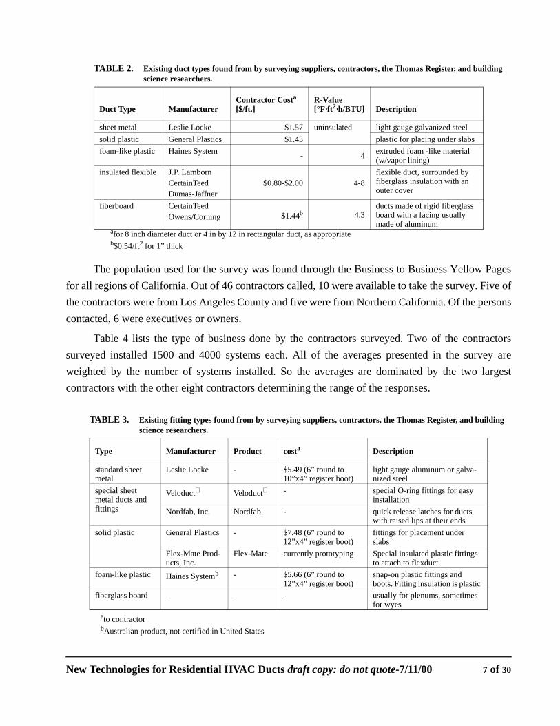
TABLE 2. Existing duct types found from by surveying suppliers, contractors, the Thomas Register, and building science researchers.
Duct Type ManufacturerContractor Costa
[$/ft.] R-Value [°F·ft2·h/BTU] Description
sheet metal Leslie Locke $1.57 uninsulated light gauge galvanized steelsolid plastic General Plastics $1.43 plastic for placing under slabsfoam-like plastic Haines System - 4 extruded foam -like material
(w/vapor lining)insulated flexible J.P. Lamborn
CertainTeedDumas-Jaffner
$0.80-$2.00 4-8flexible duct, surrounded by fiberglass insulation with an outer cover
fiberboard CertainTeedOwens/Corning $1.44b 4.3
ducts made of rigid fiberglass board with a facing usually made of aluminum
afor 8 inch diameter duct or 4 in by 12 in rectangular duct, as appropriateb$0.54/ft2 for 1” thick
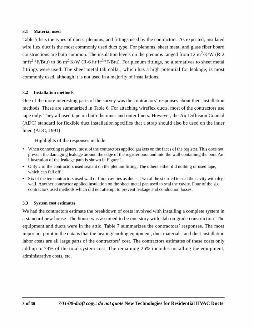
TABLE 3. Existing fitting types found from by surveying suppliers, contractors, the Thomas Register, and building science researchers.
Type Manufacturer Product costa
ato contractor
Description
standard sheet metal
Leslie Locke - $5.49 (6” round to 10”x4” register boot)
light gauge aluminum or galva-nized steel
special sheet metal ducts and fittings
Veloduct Veloduct - special O-ring fittings for easy installation
Nordfab, Inc. Nordfab - quick release latches for ducts with raised lips at their ends
solid plastic General Plastics - $7.48 (6” round to 12”x4” register boot)
fittings for placement under slabs
Flex-Mate Prod-ucts, Inc.
Flex-Mate currently prototyping Special insulated plastic fittings to attach to flexduct
foam-like plastic Haines Systemb
bAustralian product, not certified in United States
- $5.66 (6” round to 12”x4” register boot)
snap-on plastic fittings and boots. Fitting insulation is plastic
fiberglass board - - - usually for plenums, sometimes for wyes
New Technologies for Residential HVAC Ducts draft copy: do not quote-7/11/00 7 of 30
3.1 Material used
Table 5 lists the types of ducts, plenums, and fittings used by the contractors. As expected, insulatedwire flex duct is the most commonly used duct type. For plenums, sheet metal and glass fiber boardconstructions are both common. The insulation levels on the plenums ranged from 12 m2·K/W (R-2hr·ft2·°F/Btu) to 36 m2·K/W (R-6 hr·ft2·°F/Btu). For plenum fittings, no alternatives to sheet metalfittings were used. The sheet metal tab collar, which has a high potential for leakage, is mostcommonly used, although it is not used in a majority of installations.
3.2 Installation methods
One of the more interesting parts of the survey was the contractors’ responses about their installationmethods. These are summarized in Table 6. For attaching wireflex ducts, most of the contractors usetape only. They all used tape on both the inner and outer liners. However, the Air Diffusion Council(ADC) standard for flexible duct installation specifies that a strap should also be used on the innerliner. (ADC, 1991)
Highlights of the responses include:
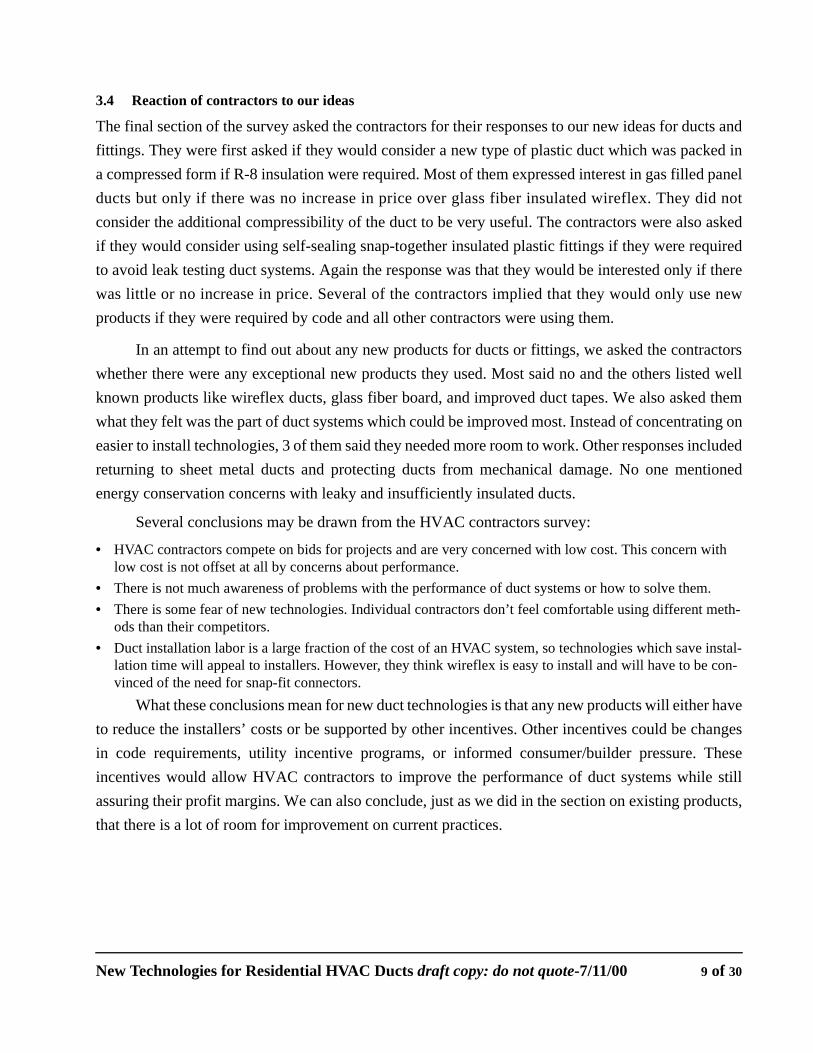
• When connecting registers, most of the contractors applied gaskets on the faces of the register. This does not prevent the damaging leakage around the edge of the register boot and into the wall containing the boot An illustration of the leakage path is shown in Figure 1.
• Only 2 of the contractors used sealant on the plenum fitting. The others either did nothing or used tape, which can fall off.
• Six of the ten contractors used wall or floor cavities as ducts. Two of the six tried to seal the cavity with dry-wall. Another contractor applied insulation on the sheet metal pan used to seal the cavity. Four of the six contractors used methods which did not attempt to prevent leakage and conduction losses.
3.3 System cost estimates
We had the contractors estimate the breakdown of costs involved with installing a complete system ina standard new house. The house was assumed to be one story with slab on grade construction. Theequipment and ducts were in the attic. Table 7 summarizes the contractors’ responses. The mostimportant point in the data is that the heating/cooling equipment, duct materials, and duct installationlabor costs are all large parts of the contractors’ cost. The contractors estimates of these costs onlyadd up to 74% of the total system cost. The remaining 26% includes installing the equipment,administrative costs, etc.
8 of 30 7/11/00-draft copy: do not quote New Technologies for Residential HVAC Ducts
3.4 Reaction of contractors to our ideas
The final section of the survey asked the contractors for their responses to our new ideas for ducts andfittings. They were first asked if they would consider a new type of plastic duct which was packed ina compressed form if R-8 insulation were required. Most of them expressed interest in gas filled panelducts but only if there was no increase in price over glass fiber insulated wireflex. They did notconsider the additional compressibility of the duct to be very useful. The contractors were also askedif they would consider using self-sealing snap-together insulated plastic fittings if they were requiredto avoid leak testing duct systems. Again the response was that they would be interested only if therewas little or no increase in price. Several of the contractors implied that they would only use newproducts if they were required by code and all other contractors were using them.
In an attempt to find out about any new products for ducts or fittings, we asked the contractorswhether there were any exceptional new products they used. Most said no and the others listed wellknown products like wireflex ducts, glass fiber board, and improved duct tapes. We also asked themwhat they felt was the part of duct systems which could be improved most. Instead of concentrating oneasier to install technologies, 3 of them said they needed more room to work. Other responses includedreturning to sheet metal ducts and protecting ducts from mechanical damage. No one mentionedenergy conservation concerns with leaky and insufficiently insulated ducts.
Several conclusions may be drawn from the HVAC contractors survey:
• HVAC contractors compete on bids for projects and are very concerned with low cost. This concern with low cost is not offset at all by concerns about performance.
• There is not much awareness of problems with the performance of duct systems or how to solve them.• There is some fear of new technologies. Individual contractors don’t feel comfortable using different meth-
ods than their competitors.• Duct installation labor is a large fraction of the cost of an HVAC system, so technologies which save instal-
lation time will appeal to installers. However, they think wireflex is easy to install and will have to be con-vinced of the need for snap-fit connectors.
What these conclusions mean for new duct technologies is that any new products will either haveto reduce the installers’ costs or be supported by other incentives. Other incentives could be changesin code requirements, utility incentive programs, or informed consumer/builder pressure. Theseincentives would allow HVAC contractors to improve the performance of duct systems while stillassuring their profit margins. We can also conclude, just as we did in the section on existing products,that there is a lot of room for improvement on current practices.
New Technologies for Residential HVAC Ducts draft copy: do not quote-7/11/00 9 of 30
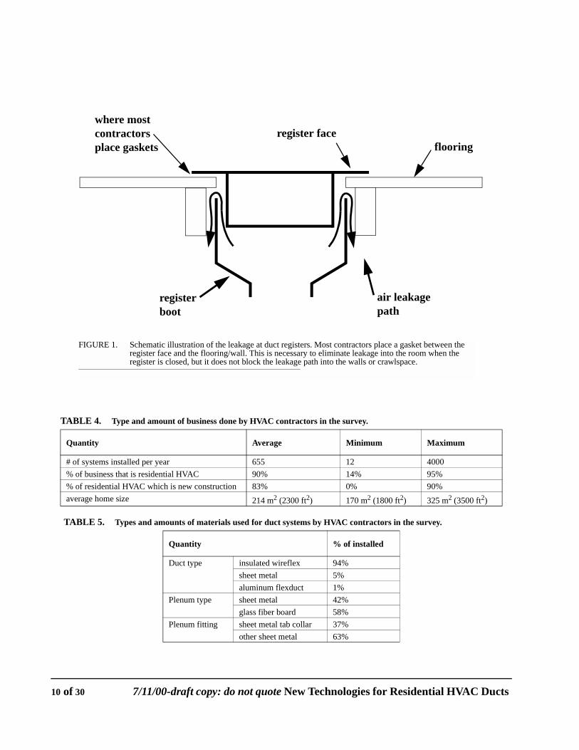
TABLE 4. Type and amount of business done by HVAC contractors in the survey.
Quantity Average Minimum Maximum
# of systems installed per year 655 12 4000% of business that is residential HVAC 90% 14% 95%% of residential HVAC which is new construction 83% 0% 90%average home size 214 m2 (2300 ft2) 170 m2 (1800 ft2) 325 m2 (3500 ft2)
TABLE 5. Types and amounts of materials used for duct systems by HVAC contractors in the survey.
Quantity % of installed
Duct type insulated wireflex 94%sheet metal 5%aluminum flexduct 1%
Plenum type sheet metal 42%glass fiber board 58%
Plenum fitting sheet metal tab collar 37%other sheet metal 63%
FIGURE 1. Schematic illustration of the leakage at duct registers. Most contractors place a gasket between the register face and the flooring/wall. This is necessary to eliminate leakage into the room when the register is closed, but it does not block the leakage path into the walls or crawlspace.
flooringregister face
where mostcontractors place gaskets
air leakagepath
registerboot
10 of 30 7/11/00-draft copy: do not quote New Technologies for Residential HVAC Ducts
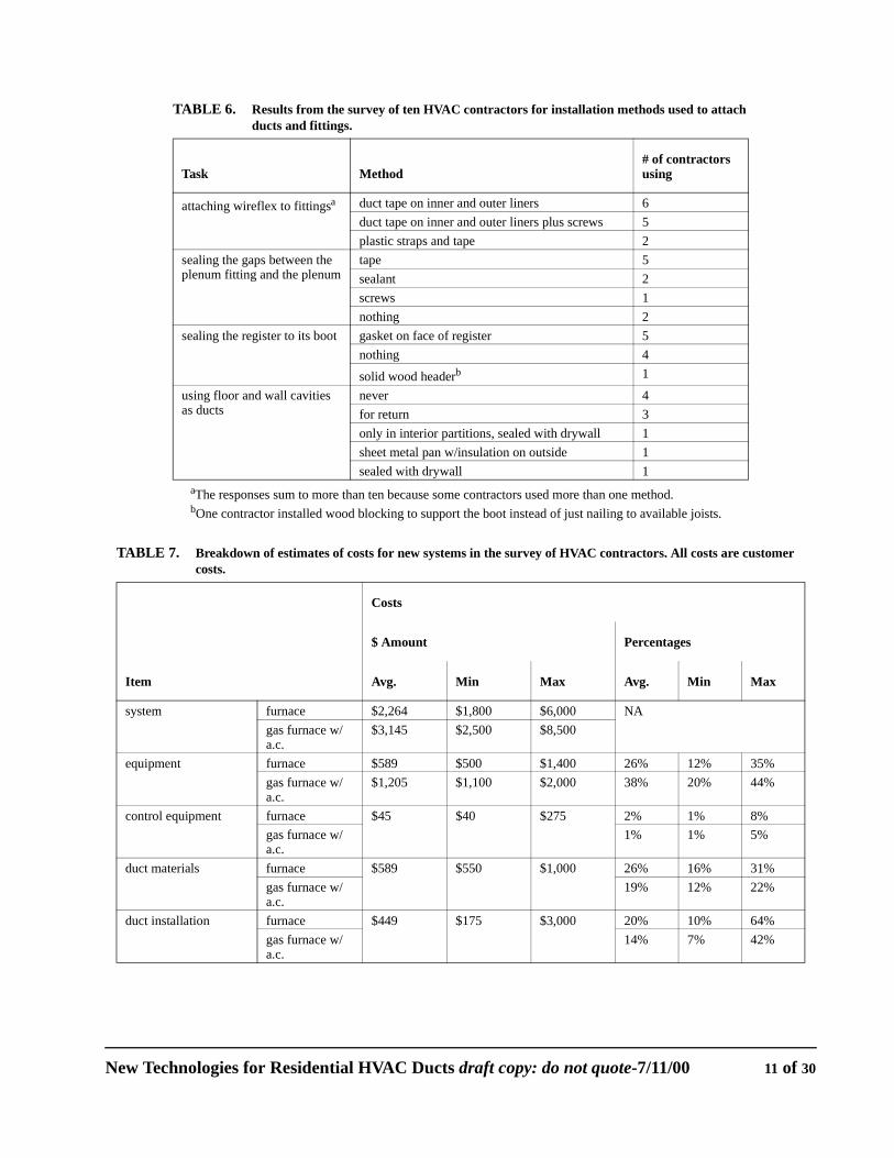
TABLE 6. Results from the survey of ten HVAC contractors for installation methods used to attach ducts and fittings.
Task Method# of contractors using
attaching wireflex to fittingsa duct tape on inner and outer liners 6duct tape on inner and outer liners plus screws 5plastic straps and tape 2
sealing the gaps between the plenum fitting and the plenum
tape 5sealant 2screws 1nothing 2
sealing the register to its boot gasket on face of register 5nothing 4
solid wood headerb 1
using floor and wall cavities as ducts
never 4for return 3only in interior partitions, sealed with drywall 1sheet metal pan w/insulation on outside 1sealed with drywall 1
aThe responses sum to more than ten because some contractors used more than one method.bOne contractor installed wood blocking to support the boot instead of just nailing to available joists.
TABLE 7. Breakdown of estimates of costs for new systems in the survey of HVAC contractors. All costs are customer costs.
Item
Costs
$ Amount Percentages
Avg. Min Max Avg. Min Max
system furnace $2,264 $1,800 $6,000 NAgas furnace w/ a.c.
$3,145 $2,500 $8,500
equipment furnace $589 $500 $1,400 26% 12% 35%gas furnace w/ a.c.
$1,205 $1,100 $2,000 38% 20% 44%
control equipment furnace $45 $40 $275 2% 1% 8%gas furnace w/ a.c.
1% 1% 5%
duct materials furnace $589 $550 $1,000 26% 16% 31%gas furnace w/ a.c.
19% 12% 22%
duct installation furnace $449 $175 $3,000 20% 10% 64%gas furnace w/ a.c.
14% 7% 42%
New Technologies for Residential HVAC Ducts draft copy: do not quote-7/11/00 11 of 30
4.0 Potential New Designs and Technologies
In this section we will consider new designs for ducts and fittings. The economic and building codetests for these products are considered in the following two sections.
When considering new approaches to problems, the first step is to determine goals. Whatproperties are desirable in a new duct system? Ideally, a system would have:
• no leaks• insulation at all points• low costs for installation and materials• durability of the sealing and insulation
In order to insure that these goals are met, it is necessary that the system:
• require little fabrication on site (to reduce labor costs)• have seals made by snapping parts together (to reduce labor costs and be foolproof)• have mechanical, rather than adhesive, seals (for durability)
One vision of a “perfect” system is flexible ducts with universal connectors on their ends thatsnap into fittings and plenums. Excep for mounting register boots to studs or joists and installing theheating/cooling equipment, system installation would consist of snapping parts together. If the snap fitconnection was reversible, then this “perfect” system would also be easy to expand or reconfigure.
There are many options besides the “perfect” system. These include:
• Requiring that all fittings be covered by insulation and that wireflex be attached with a nylon strap on the inner liner, as specified by the Air Diffusion Council (ADC, 1991). This would eliminate the problem of duct tape failing and reduce leakage losses. It would also increase installation time and make technologies which offer simpler installation more attractive even with higher material costs.
• Require that all fittings, including registers and plenum connections, have gaskets which insure a tight seal will be made between fittings. This would reduce leakage in a durable and foolproof manner while still allowing wireflex duct and fittings very similar to those currently in use.
• Require that snap-in fittings be used for all connections, including ducts to fittings. This would insure that the duct system is connected properly.
• Require that fittings have an approved method of attaching wireflex duct which is integral to the fittings. An example will be shown below.
In the following sections we separately consider new designs for insulation based on GFP technology,ducts made of the GFP insulation, and easier-to-install fittings.
4.1 Potential designs for new duct insulation
We focused on using gas filled panel (GFP) technology developed in another CIEE project (seeGriffith et al, 1992). Griffith et al. developed this technology for use as appliance and buildinginsulation and consequently chose designs which resulted in a rigid product that did not compress.
12 of 30 7/11/00-draft copy: do not quote New Technologies for Residential HVAC Ducts
The idea for GFPs was to produce a superior insulation using plastics and existing food packagingtechnology. Heat transfer through the insulation is reduced by eliminating convection and radiationheat transfer. Convection is reduced by having small cell sizes. Radiation is reduced by using lowemissivity coatings on layers between cells.
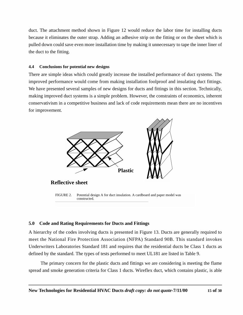
Our design method was to construct models of the insulation and then critique them for ease ofmanufacturing, compressibility, etc. New models were then made until we had produced several withgood qualities. Figures 2-7 are drawings of the five most promising designs for duct insulation, whichwe have designated with letters A through E. In Table 8, estimates are presented of the properties, bothgood and bad, of the 5 designs.
All of the models seem appropriate for use as duct insulation. Design E seems particularlyappropriate for a compressible duct design because it will open irreversibly when released.
4.2 Potential Designs for Ducts
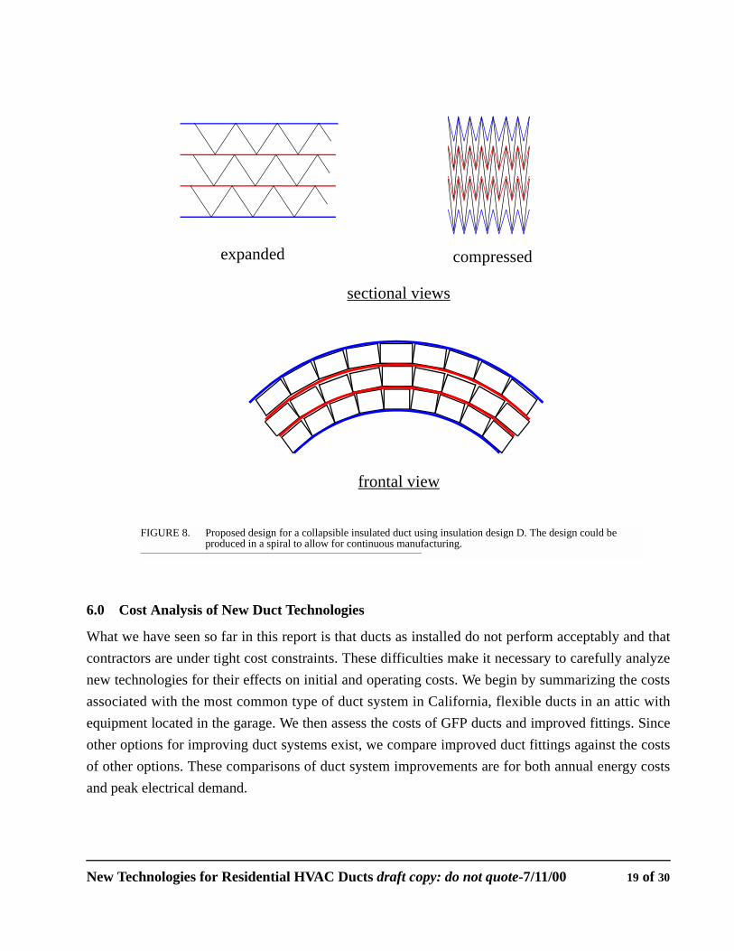
All of the designs for duct insulation in Section 4.1 could be turned into ducts. Designs A-D areparticularly appropriate to rectangular ducts while design E is appropriate for a circular duct. Sinceround ducts will have lower conduction losses and less material required for a given cross sectionalarea, we elected to construct a model of a round duct using design E. A schematic diagram of themodel is given in Figure 7. The model was constructed with a thick inner layer of plastic (actually a 2liter soft drink bottle). The insulation was made with plastic and the sheet on the outside of the ductwas metalized polyester. The model could be folded in half and compressed to reduce its volume by afactor of 17. Another possible round duct, which could be made continuously in a spiral is shown inFigure 8.
For square ducts, any of the insulation designs A through D could be used to produce collapsibleinsulated ducts. None of these designs would be appropriate for return ducts without some internalbracing to prevent collapsing under pressure. As presently configured, they are therefore limited to thesupply side of the duct system.
4.3 Potential designs for fittings
All of the connections in residential duct systems are candidates for improvement. The particularconnections considered here are: connections of duct to fitting, connections of plenum fittings toplenums, and connections from register to register boot. All of the ideas presented below assume thatinsulation will be integrated with the fitting. This will both save labor and insure that the duct systemis properly insulated.
New Technologies for Residential HVAC Ducts draft copy: do not quote-7/11/00 13 of 30
4.3.1 Register to boot connectionsThe HVAC contractor survey results showed that it is not common knowledge within the industry thatair leaks around the edge of the register boot and into the wall or floor. A simple gasket which wouldstop this is shown in Figure 9. Other possible gasket or seal options would be on the outside of theregister boot, or to have lips on the boot which extend between the flooring (sheet rock in a wall) andthe joists (studs). However, these other solutions require either more labor or placement of the seal ina location where the distance between the two surfaces is variable.
One reason that sheet metal registers and boots don’t fit tightly is that the boots are often bentduring installation. Tougher plastic fittings would eliminate this problem and allow closer tolerances.This would ensure leak-free connections of registers.
The ultimate solution for register to boot connections would be a matched register and bootwhich snap together. This could easily be integrated into an industry standard for registers, just as thereare currently standard sizes for registers and boots.
4.3.2 Plenum fittingsThe plenum is another point where improvements can be made on existing methods. The mostcommonly used fittings are tab collars. A diagram of a tab collar is shown in Figure 10. As can beseen in the figure, this type of fitting inherently requires sealing, but in our survey most contractorsused only tape for sealing. Other fittings which are commonly used are better than the tab collar forsealing but we did not find any which did not rely on tape or sealant to eliminate leaks.
There are several options for improved duct plenum fittings. Ideally, the fittings would beattached to the plenum in a factory and be durably sealed. Short of that, fittings which create sealsmechanically could be installed in the field. A simple option, which is used by at least one contractorin California, is to use a gasket between a bead on the fitting and the plenum. This is shown in Figure11. Some more complicated ideas are shown in the Appendix.
4.3.3 Fitting to duct connectionsConnecting the fitting to the duct is the most labor intensive part of assembling duct systems. The“perfect” duct system mentioned above would have connectors on the ends of ducts which snaptogether. In this case, connecting the duct system would consist of walking the ends of the duct fromone connection to another. The type of connector could be taken from existing connectors used in thetoy, automotive, or other industries which currently use plastic snap-together connectors.
One drawback to the “perfect” system is that it is not possible to cut the ducts. Contractors docut wireflex duct in the field and would be resistant to the idea of precut ducts. Because of this, it isworthwhile to consider improved attachment methods for flexduct which do not require fittings on the
14 of 30 7/11/00-draft copy: do not quote New Technologies for Residential HVAC Ducts
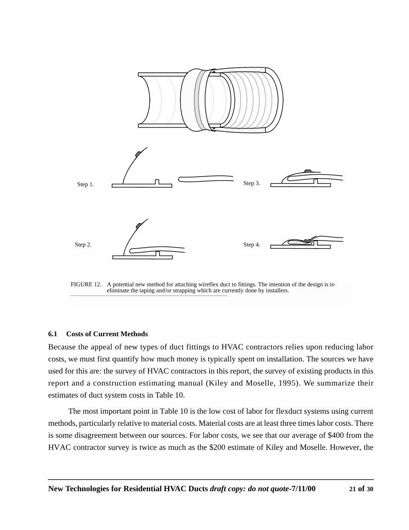
duct. The attachment method shown in Figure 12 would reduce the labor time for installing ductsbecause it eliminates the outer strap. Adding an adhesive strip on the fitting or on the sheet which ispulled down could save even more installation time by making it unnecessary to tape the inner liner ofthe duct to the fitting.
4.4 Conclusions for potential new designs
There are simple ideas which could greatly increase the installed performance of duct systems. Theimproved performance would come from making installation foolproof and insulating duct fittings.We have presented several samples of new designs for ducts and fittings in this section. Technically,making improved duct systems is a simple problem. However, the constraints of economics, inherentconservativism in a competitive business and lack of code requirements mean there are no incentivesfor improvement.
5.0 Code and Rating Requirements for Ducts and Fittings
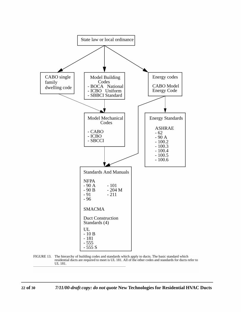
A hierarchy of the codes involving ducts is presented in Figure 13. Ducts are generally required tomeet the National Fire Protection Association (NFPA) Standard 90B. This standard invokesUnderwriters Laboratories Standard 181 and requires that the residential ducts be Class 1 ducts asdefined by the standard. The types of tests performed to meet UL181 are listed in Table 9.
The primary concern for the plastic ducts and fittings we are considering is meeting the flamespread and smoke generation criteria for Class 1 ducts. Wireflex duct, which contains plastic, is able
Reflective sheet
Plastic
FIGURE 2. Potential design A for duct insulation. A cardboard and paper model was constructed.
New Technologies for Residential HVAC Ducts draft copy: do not quote-7/11/00 15 of 30
to meet the standards because there is so little plastic that the quantity of smoke generated is below thelimit set by the standard. Another concern is the flame penetration test. A sample of the duct materialmust be able to support a weight when it is placed over a burner. Wireflex duct is able to do this becauseof the mat of fiberglass insulation wrapped around it. It costs approximately $2000 to have a laboratoryperform the flame penetration, smoke generation and flame spread tests.
Reflective sheetPlastic
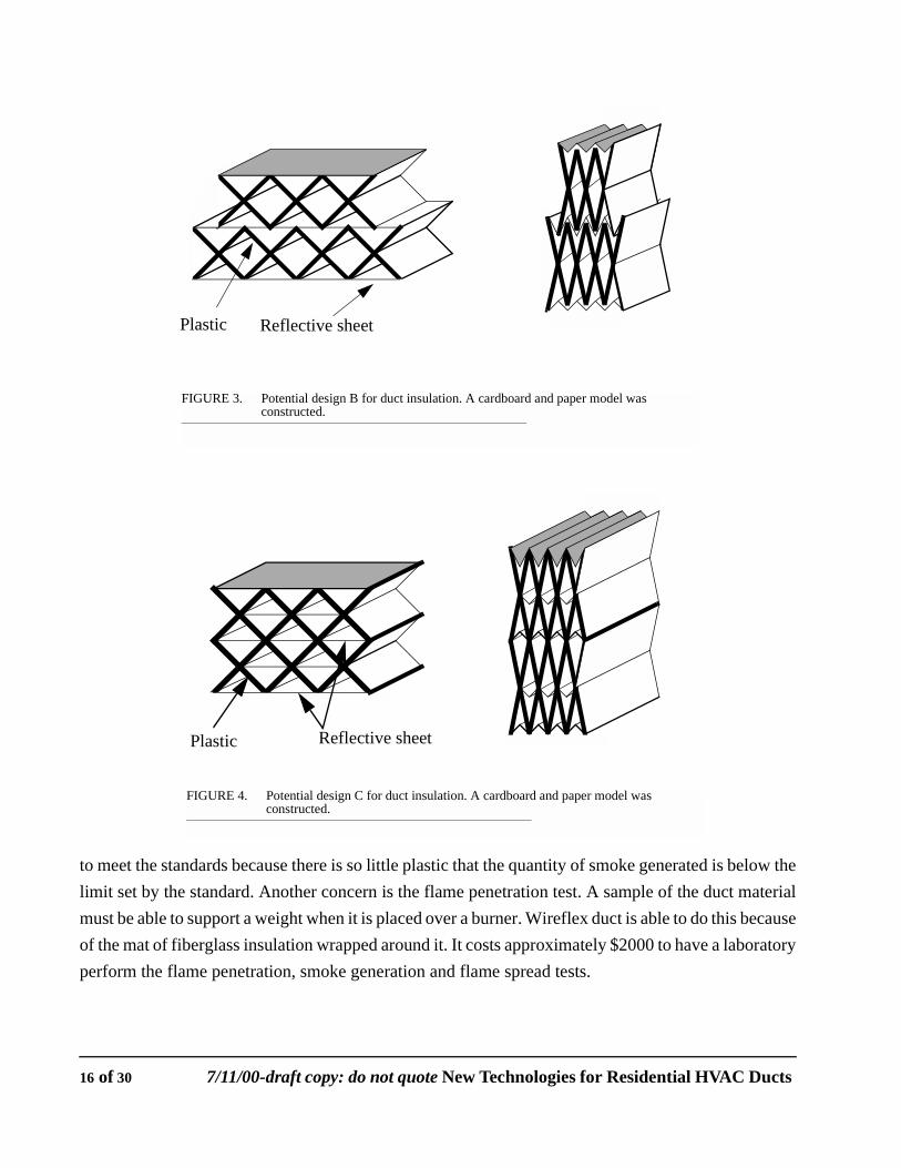
FIGURE 3. Potential design B for duct insulation. A cardboard and paper model was constructed.
Plastic Reflective sheet
FIGURE 4. Potential design C for duct insulation. A cardboard and paper model was constructed.
16 of 30 7/11/00-draft copy: do not quote New Technologies for Residential HVAC Ducts
Another non-economic hurdle which must be overcome by any new fitting or duct products isresistance to change by installers. Several of the contractors in the telephone survey implied that theywould only make bids on jobs using the same types of materials as their competitors. It was alsomentioned that they would only do the minimum necessary to meet local building codes because ofcost constraints. These difficulties will have to be overcome by either utility rebate programs orchanges in building codes.
Reflective sheetPlastic
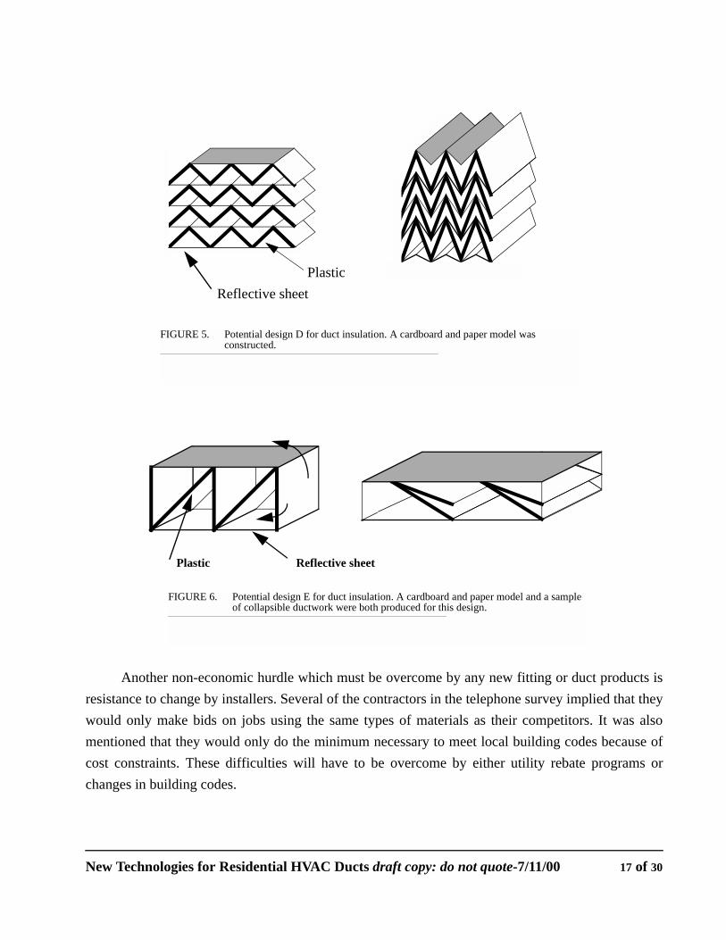
FIGURE 5. Potential design D for duct insulation. A cardboard and paper model was constructed.
Reflective sheetPlastic
FIGURE 6. Potential design E for duct insulation. A cardboard and paper model and a sample of collapsible ductwork were both produced for this design.
New Technologies for Residential HVAC Ducts draft copy: do not quote-7/11/00 17 of 30
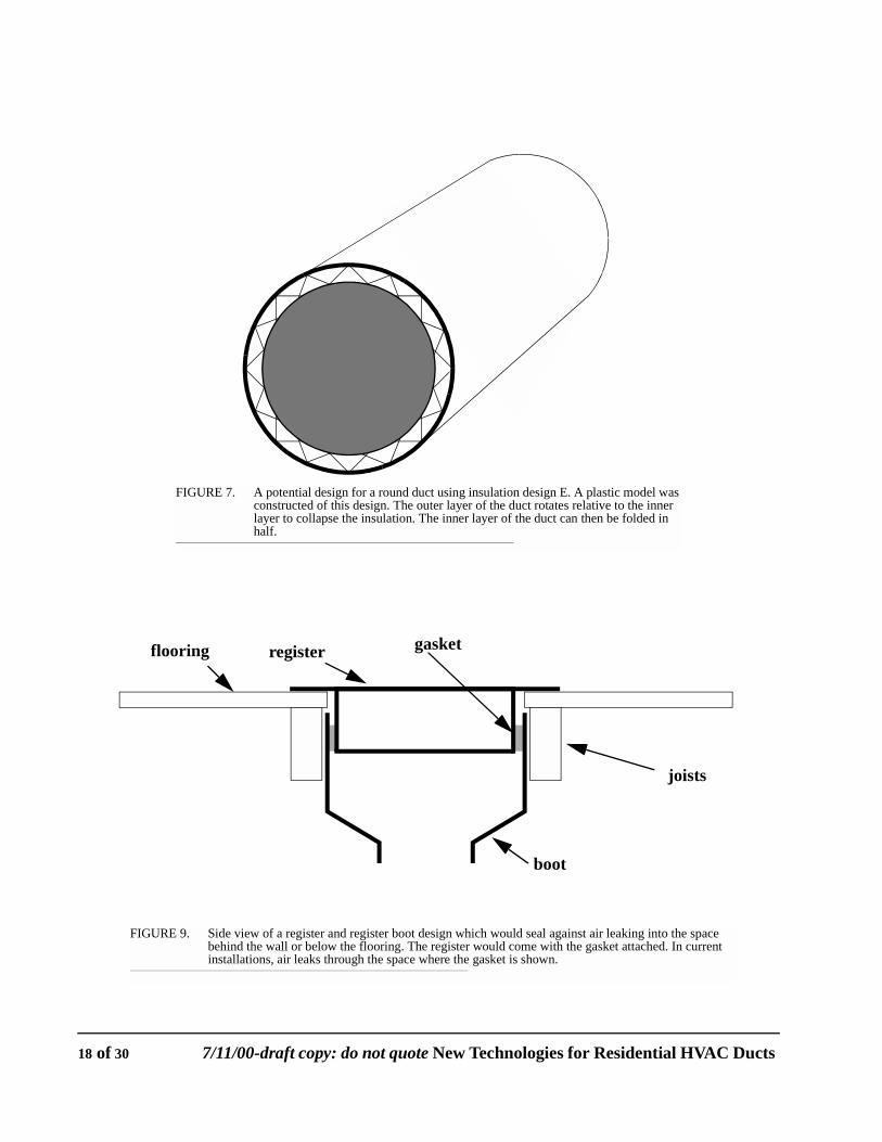
FIGURE 7. A potential design for a round duct using insulation design E. A plastic model was constructed of this design. The outer layer of the duct rotates relative to the inner layer to collapse the insulation. The inner layer of the duct can then be folded in half.
FIGURE 9. Side view of a register and register boot design which would seal against air leaking into the space behind the wall or below the flooring. The register would come with the gasket attached. In current installations, air leaks through the space where the gasket is shown.
register gasket
boot
joists
flooring
18 of 30 7/11/00-draft copy: do not quote New Technologies for Residential HVAC Ducts
6.0 Cost Analysis of New Duct Technologies
What we have seen so far in this report is that ducts as installed do not perform acceptably and thatcontractors are under tight cost constraints. These difficulties make it necessary to carefully analyzenew technologies for their effects on initial and operating costs. We begin by summarizing the costsassociated with the most common type of duct system in California, flexible ducts in an attic withequipment located in the garage. We then assess the costs of GFP ducts and improved fittings. Sinceother options for improving duct systems exist, we compare improved duct fittings against the costsof other options. These comparisons of duct system improvements are for both annual energy costsand peak electrical demand.
FIGURE 8. Proposed design for a collapsible insulated duct using insulation design D. The design could be produced in a spiral to allow for continuous manufacturing.
sectional views
frontal view
expanded compressed
New Technologies for Residential HVAC Ducts draft copy: do not quote-7/11/00 19 of 30
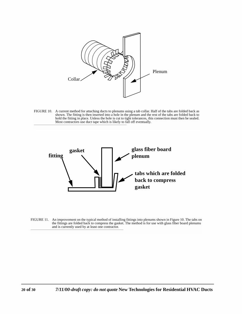
FIGURE 10. A current method for attaching ducts to plenums using a tab collar. Half of the tabs are folded back as shown. The fitting is then inserted into a hole in the plenum and the rest of the tabs are folded back to hold the fitting in place. Unless the hole is cut to tight tolerances, this connection must then be sealed. Most contractors use duct tape which is likely to fall off eventually.
PlenumCollar
fittingglass fiber boardgasket
tabs which are foldedback to compressgasket
plenum
FIGURE 11. An improvement on the typical method of installing fittings into plenums shown in Figure 10. The tabs on the fittings are folded back to compress the gasket. The method is for use with glass fiber board plenums and is currently used by at least one contractor.
20 of 30 7/11/00-draft copy: do not quote New Technologies for Residential HVAC Ducts
6.1 Costs of Current Methods
Because the appeal of new types of duct fittings to HVAC contractors relies upon reducing laborcosts, we must first quantify how much money is typically spent on installation. The sources we haveused for this are: the survey of HVAC contractors in this report, the survey of existing products in thisreport and a construction estimating manual (Kiley and Moselle, 1995). We summarize theirestimates of duct system costs in Table 10.
The most important point in Table 10 is the low cost of labor for flexduct systems using currentmethods, particularly relative to material costs. Material costs are at least three times labor costs. Thereis some disagreement between our sources. For labor costs, we see that our average of $400 from theHVAC contractor survey is twice as much as the $200 estimate of Kiley and Moselle. However, the
FIGURE 12. A potential new method for attaching wireflex duct to fittings. The intention of the design is to eliminate the taping and/or strapping which are currently done by installers.
Step 1.
Step 2.
Step 3.
Step 4.
New Technologies for Residential HVAC Ducts draft copy: do not quote-7/11/00 21 of 30
State law or local ordinance
CABO single Model Building Codes
- BOCA National- ICBO Uniform- SBBCI Standard
Energy codes
CABO ModelEnergy Code
Model Mechanical Codes
- CABO- ICBO- SBCCI
Energy Standards
ASHRAE- 62- 90 A- 100.2- 100.3- 100.4- 100.5- 100.6
Standards And Manuals
NFPA- 90 A- 90 B- 91- 96
- 101- 204 M- 211
SMACMA
Duct Construction Standards (4)UL- 10 B- 181- 555- 555 S
FIGURE 13. The hierarchy of building codes and standards which apply to ducts. The basic standard which residential ducts are required to meet is UL 181. All of the other codes and standards for ducts refer to UL 181.
familydwelling code
22 of 30 7/11/00-draft copy: do not quote New Technologies for Residential HVAC Ducts
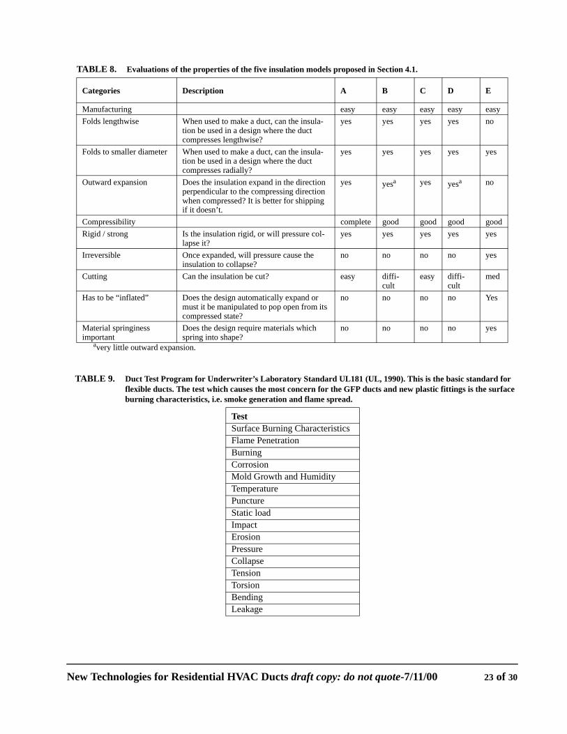
TABLE 8. Evaluations of the properties of the five insulation models proposed in Section 4.1.
Categories Description A B C D E
Manufacturing easy easy easy easy easyFolds lengthwise When used to make a duct, can the insula-
tion be used in a design where the duct compresses lengthwise?
yes yes yes yes no
Folds to smaller diameter When used to make a duct, can the insula-tion be used in a design where the duct compresses radially?
yes yes yes yes yes
Outward expansion Does the insulation expand in the direction perpendicular to the compressing direction when compressed? It is better for shipping if it doesn’t.
yes yesa yes yesa no
Compressibility complete good good good goodRigid / strong Is the insulation rigid, or will pressure col-
lapse it?yes yes yes yes yes
Irreversible Once expanded, will pressure cause the insulation to collapse?
no no no no yes
Cutting Can the insulation be cut? easy diffi-cult
easy diffi-cult
med
Has to be “inflated” Does the design automatically expand or must it be manipulated to pop open from its compressed state?
no no no no Yes
Material springiness important
Does the design require materials which spring into shape?
no no no no yes
avery little outward expansion.
TABLE 9. Duct Test Program for Underwriter’s Laboratory Standard UL181 (UL, 1990). This is the basic standard for flexible ducts. The test which causes the most concern for the GFP ducts and new plastic fittings is the surface burning characteristics, i.e. smoke generation and flame spread.
TestSurface Burning CharacteristicsFlame PenetrationBurningCorrosionMold Growth and HumidityTemperaturePunctureStatic loadImpactErosionPressureCollapseTensionTorsionBendingLeakage
New Technologies for Residential HVAC Ducts draft copy: do not quote-7/11/00 23 of 30
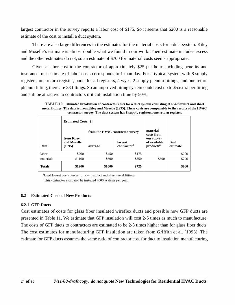
largest contractor in the survey reports a labor cost of $175. So it seems that $200 is a reasonableestimate of the cost to install a duct system.
There are also large differences in the estimates for the material costs for a duct system. Kileyand Moselle’s estimate is almost double what we found in our work. Their estimate includes excessand the other estimates do not, so an estimate of $700 for material costs seems appropriate.
Given a labor cost to the contractor of approximately $25 per hour, including benefits andinsurance, our estimate of labor costs corresponds to 1 man day. For a typical system with 8 supplyregisters, one return register, boots for all registers, 4 wyes, 2 supply plenum fittings, and one returnplenum fitting, there are 23 fittings. So an improved fitting system could cost up to $5 extra per fittingand still be attractive to contractors if it cut installation time by 50%.
6.2 Estimated Costs of New Products
6.2.1 GFP DuctsCost estimates of costs for glass fiber insulated wireflex ducts and possible new GFP ducts arepresented in Table 11. We estimate that GFP insulation will cost 2-5 times as much to manufacture.The costs of GFP ducts to contractors are estimated to be 2-3 times higher than for glass fiber ducts.The cost estimates for manufacturing GFP insulation are taken from Griffith et al. (1993). Theestimate for GFP ducts assumes the same ratio of contractor cost for duct to insulation manufacturing
TABLE 10. Estimated breakdown of contractor costs for a duct system consisting of R-4 flexduct and sheet metal fittings. The data is from Kiley and Moselle (1995). These costs are comparable to the results of the HVAC
contractor survey. The duct system has 8 supply registers, one return register.
Estimated Costs [$]
material costs from our survey of available productsa
aUsed lowest cost sources for R-4 flexduct and sheet metal fittings.
Best estimate
from Kiley and Moselle (1995)
from the HVAC contractor survey
Item averagelargest contractorb
bThis contractor estimated he installed 4000 systems per year.
labor $200 $450 $175 $200materials $1100 $600 $550 $600 $700
Totals $1300 $1000 $725 $900
24 of 30 7/11/00-draft copy: do not quote New Technologies for Residential HVAC Ducts
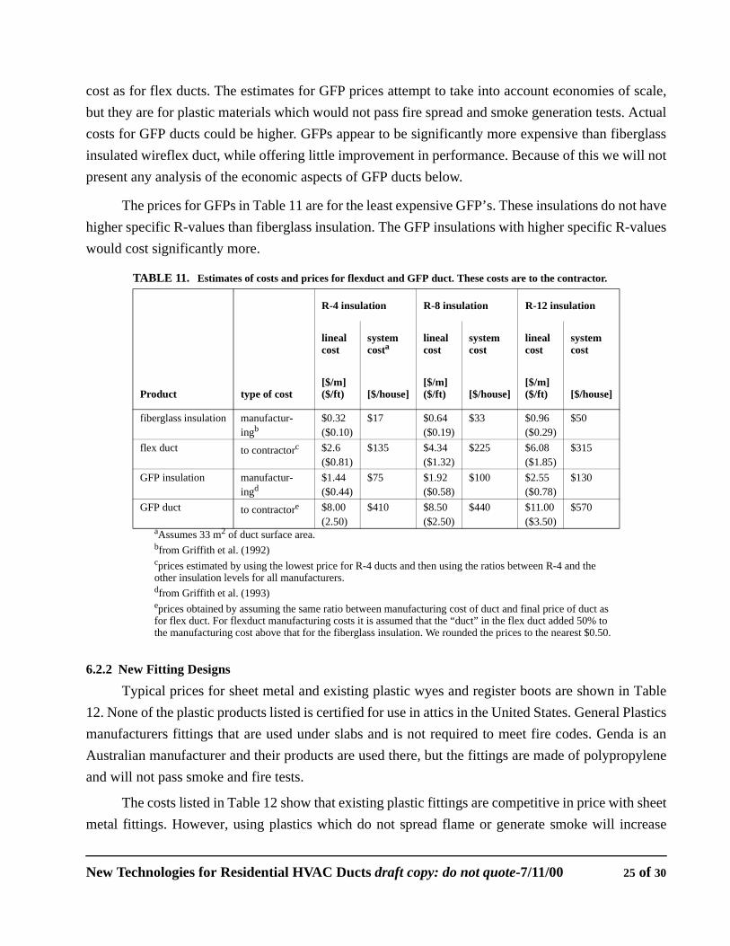
cost as for flex ducts. The estimates for GFP prices attempt to take into account economies of scale,but they are for plastic materials which would not pass fire spread and smoke generation tests. Actualcosts for GFP ducts could be higher. GFPs appear to be significantly more expensive than fiberglassinsulated wireflex duct, while offering little improvement in performance. Because of this we will notpresent any analysis of the economic aspects of GFP ducts below.
The prices for GFPs in Table 11 are for the least expensive GFP’s. These insulations do not havehigher specific R-values than fiberglass insulation. The GFP insulations with higher specific R-valueswould cost significantly more.
6.2.2 New Fitting Designs
Typical prices for sheet metal and existing plastic wyes and register boots are shown in Table12. None of the plastic products listed is certified for use in attics in the United States. General Plasticsmanufacturers fittings that are used under slabs and is not required to meet fire codes. Genda is anAustralian manufacturer and their products are used there, but the fittings are made of polypropyleneand will not pass smoke and fire tests.
The costs listed in Table 12 show that existing plastic fittings are competitive in price with sheetmetal fittings. However, using plastics which do not spread flame or generate smoke will increase
TABLE 11. Estimates of costs and prices for flexduct and GFP duct. These costs are to the contractor.
Product type of cost
R-4 insulation R-8 insulation R-12 insulation
linealcost
systemcosta
linealcost
systemcost
linealcost
systemcost
[$/m]($/ft) [$/house]
[$/m]($/ft) [$/house]
[$/m]($/ft) [$/house]
fiberglass insulation manufactur-ingb
$0.32($0.10)
$17 $0.64($0.19)
$33 $0.96($0.29)
$50
flex duct to contractorc $2.6 ($0.81)
$135 $4.34($1.32)
$225 $6.08($1.85)
$315
GFP insulation manufactur-ingd
$1.44($0.44)
$75 $1.92($0.58)
$100 $2.55($0.78)
$130
GFP duct to contractore $8.00(2.50)
$410 $8.50($2.50)
$440 $11.00($3.50)
$570
aAssumes 33 m2 of duct surface area.bfrom Griffith et al. (1992)cprices estimated by using the lowest price for R-4 ducts and then using the ratios between R-4 and the other insulation levels for all manufacturers.dfrom Griffith et al. (1993)eprices obtained by assuming the same ratio between manufacturing cost of duct and final price of duct as for flex duct. For flexduct manufacturing costs it is assumed that the “duct” in the flex duct added 50% to the manufacturing cost above that for the fiberglass insulation. We rounded the prices to the nearest $0.50.
New Technologies for Residential HVAC Ducts draft copy: do not quote-7/11/00 25 of 30
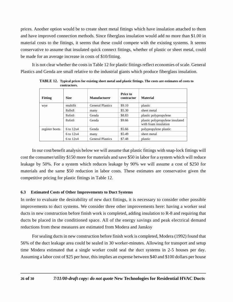
prices. Another option would be to create sheet metal fittings which have insulation attached to themand have improved connection methods. Since fiberglass insulation would add no more than $1.00 inmaterial costs to the fittings, it seems that these could compete with the existing systems. It seemsconservative to assume that insulated quick connect fittings, whether of plastic or sheet metal, couldbe made for an average increase in costs of $10/fitting.
It is not clear whether the costs in Table 12 for plastic fittings reflect economies of scale. GeneralPlastics and Genda are small relative to the industrial giants which produce fiberglass insulation.
In our cost/benefit analysis below we will assume that plastic fittings with snap-lock fittings willcost the consumer/utility $150 more for materials and save $50 in labor for a system which will reduceleakage by 50%. For a system which reduces leakage by 90% we will assume a cost of $250 formaterials and the same $50 reduction in labor costs. These estimates are conservative given thecompetitive pricing for plastic fittings in Table 12.
6.3 Estimated Costs of Other Improvements to Duct Systems
In order to evaluate the desirability of new duct fittings, it is necessary to consider other possibleimprovements to duct systems. We consider three other improvements here: having a worker sealducts in new construction before finish work is completed, adding insulation to R-8 and requiring thatducts be placed in the conditioned space. All of the energy savings and peak electrical demandreductions from these measures are estimated from Modera and Jansksy
For sealing ducts in new construction before finish work is completed, Modera (1992) found that56% of the duct leakage area could be sealed in 30 worker-minutes. Allowing for transport and setuptime Modera estimated that a single worker could seal the duct systems in 2-5 houses per day.Assuming a labor cost of $25 per hour, this implies an expense between $40 and $100 dollars per house
TABLE 12. Typical prices for existing sheet metal and plastic fittings. The costs are estimates of costs to contractors.
Fitting Size ManufacturerPrice to contractor Material
wye multifit General Plastics $9.10 plastic8x8x8 many $5.30 sheet metal8x6x6 Genda $8.83 plastic polypropylene8x6x6 Genda $9.66 plastic polypropylene insulated
with foam insulationregister boots 6 to 12x4 Genda $5.66 polypropylene plastic
6 to 12x4 many $5.49 sheet metal6 to 12x4 General Plastics $7.48 plastic
26 of 30 7/11/00-draft copy: do not quote New Technologies for Residential HVAC Ducts
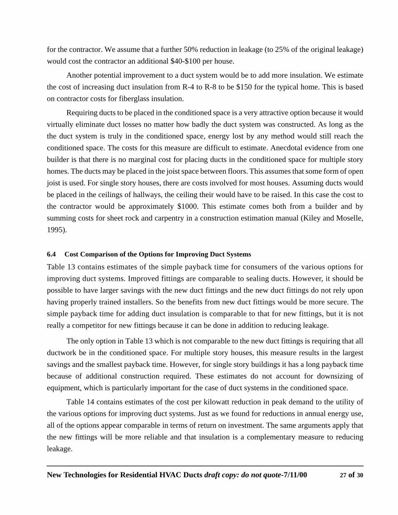
for the contractor. We assume that a further 50% reduction in leakage (to 25% of the original leakage)would cost the contractor an additional $40-$100 per house.
Another potential improvement to a duct system would be to add more insulation. We estimatethe cost of increasing duct insulation from R-4 to R-8 to be $150 for the typical home. This is basedon contractor costs for fiberglass insulation.
Requiring ducts to be placed in the conditioned space is a very attractive option because it wouldvirtually eliminate duct losses no matter how badly the duct system was constructed. As long as thethe duct system is truly in the conditioned space, energy lost by any method would still reach theconditioned space. The costs for this measure are difficult to estimate. Anecdotal evidence from onebuilder is that there is no marginal cost for placing ducts in the conditioned space for multiple storyhomes. The ducts may be placed in the joist space between floors. This assumes that some form of openjoist is used. For single story houses, there are costs involved for most houses. Assuming ducts wouldbe placed in the ceilings of hallways, the ceiling their would have to be raised. In this case the cost tothe contractor would be approximately $1000. This estimate comes both from a builder and bysumming costs for sheet rock and carpentry in a construction estimation manual (Kiley and Moselle,1995).
6.4 Cost Comparison of the Options for Improving Duct Systems
Table 13 contains estimates of the simple payback time for consumers of the various options forimproving duct systems. Improved fittings are comparable to sealing ducts. However, it should bepossible to have larger savings with the new duct fittings and the new duct fittings do not rely uponhaving properly trained installers. So the benefits from new duct fittings would be more secure. Thesimple payback time for adding duct insulation is comparable to that for new fittings, but it is notreally a competitor for new fittings because it can be done in addition to reducing leakage.
The only option in Table 13 which is not comparable to the new duct fittings is requiring that allductwork be in the conditioned space. For multiple story houses, this measure results in the largestsavings and the smallest payback time. However, for single story buildings it has a long payback timebecause of additional construction required. These estimates do not account for downsizing ofequipment, which is particularly important for the case of duct systems in the conditioned space.
Table 14 contains estimates of the cost per kilowatt reduction in peak demand to the utility ofthe various options for improving duct systems. Just as we found for reductions in annual energy use,all of the options appear comparable in terms of return on investment. The same arguments apply thatthe new fittings will be more reliable and that insulation is a complementary measure to reducingleakage.
New Technologies for Residential HVAC Ducts draft copy: do not quote-7/11/00 27 of 30
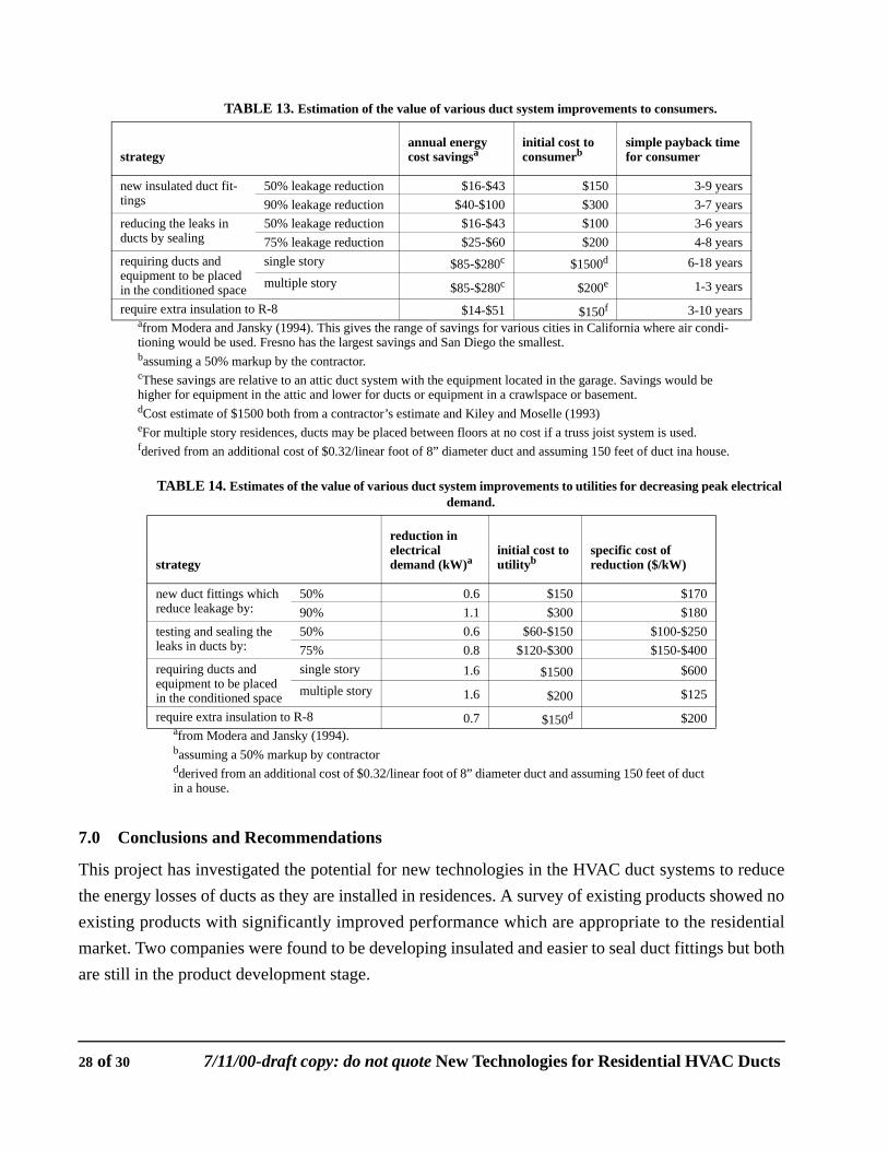
7.0 Conclusions and Recommendations
This project has investigated the potential for new technologies in the HVAC duct systems to reducethe energy losses of ducts as they are installed in residences. A survey of existing products showed noexisting products with significantly improved performance which are appropriate to the residentialmarket. Two companies were found to be developing insulated and easier to seal duct fittings but bothare still in the product development stage.
TABLE 13. Estimation of the value of various duct system improvements to consumers.
strategyannual energy cost savingsa
initial cost to consumerb
simple payback time for consumer
new insulated duct fit-tings
50% leakage reduction $16-$43 $150 3-9 years90% leakage reduction $40-$100 $300 3-7 years
reducing the leaks in ducts by sealing
50% leakage reduction $16-$43 $100 3-6 years75% leakage reduction $25-$60 $200 4-8 years
requiring ducts and equipment to be placed in the conditioned space
single story $85-$280c $1500d 6-18 yearsmultiple story $85-$280c $200e 1-3 years
require extra insulation to R-8 $14-$51 $150f 3-10 yearsafrom Modera and Jansky (1994). This gives the range of savings for various cities in California where air condi-tioning would be used. Fresno has the largest savings and San Diego the smallest.bassuming a 50% markup by the contractor.cThese savings are relative to an attic duct system with the equipment located in the garage. Savings would be higher for equipment in the attic and lower for ducts or equipment in a crawlspace or basement.dCost estimate of $1500 both from a contractor’s estimate and Kiley and Moselle (1993)eFor multiple story residences, ducts may be placed between floors at no cost if a truss joist system is used.fderived from an additional cost of $0.32/linear foot of 8” diameter duct and assuming 150 feet of duct ina house.
TABLE 14. Estimates of the value of various duct system improvements to utilities for decreasing peak electrical demand.
strategy
reduction in electrical demand (kW)a
initial cost to utilityb
specific cost of reduction ($/kW)
new duct fittings which reduce leakage by:
50% 0.6 $150 $17090% 1.1 $300 $180
testing and sealing the leaks in ducts by:
50% 0.6 $60-$150 $100-$25075% 0.8 $120-$300 $150-$400
requiring ducts and equipment to be placed in the conditioned space
single story 1.6 $1500 $600multiple story 1.6 $200 $125
require extra insulation to R-8 0.7 $150d $200afrom Modera and Jansky (1994).bassuming a 50% markup by contractordderived from an additional cost of $0.32/linear foot of 8” diameter duct and assuming 150 feet of duct in a house.
28 of 30 7/11/00-draft copy: do not quote New Technologies for Residential HVAC Ducts
A telephone survey of HVAC contractors was performed and revealed that installation labor andduct materials represent significant percentages of contractors’ costs. The contractors’ reactions topotential new products showed a willingness to consider new products but not at higher costs. Thecontractors were found to use installation methods which did not ensure proper sealing at fittings andto not realize the faults in these methods.
Several designs for insulation and ducts using GFP technology were created and evaluated.Economic calculations showed that GFP ducts would be significantly more expensive than glass fiberinsulated wireflex duct even before considering the costs of fire resistant plastics. Consequently, thedevelopment of ducts based on GFP technology does not seem worth further research.
The value of new duct fittings which would improve sealing of duct systems was comparedagainst other options for improving duct performance. New duct fittings show promise relative to thesealing ducts with existing methods. The one option which could potentially be much more valuablethan the new duct fittings is requiring ducts to be placed within the conditioned space.
8.0 References
Air Diffusion Council (1991), Flexible Duct Performance and Installation Standards, 2nd Ed., One Illinois Center, Suite 200, 111 East Wacker Drive, Chicago, Illinois 60601.
Cummings, J. B., J. J. Tooley, Jr., and R. Dunsmore. (1990). "Impacts of Duct Leakage on Infiltra-tion Rates, Space Conditioning Energy Use, and Peak Electrical Demand in Florida Homes." In Proceedings of ACEEE Summer Study, Pacific Grove, California, August 1990. American Council for an Energy Efficient Economy, Washington, D.C.
Davis , B.E., and M.-R. Roberson. (1993). "Using the "Pressure-Pan" Technique to Prioritize Duct Sealing Efforts: A Study of 18 Arkansas Homes" Energy and Buildings 20(1):57-64.
Griffith, B.T., Arasteh, D., and Selkowitz, S. (1992), High-Performance, Non-CFC-Based Thermal Insulation: Gas Filled Panels, California Institute for Energy Efficiency Research Report Series 2, CIEE, Lawrence Berkeley Laboratory, Berkeley, CA 94720.
Griffith, B., Turler, D., and Arasteh, D. (1993), Optimizing the Conductivity and Cost of Gas-Filled Panel Thermal Insulations, 22nd International Thermal Conductivity Conference, Arizona State University, November 7-10, 1993.
Kiley, M.D., and Moselle, W.M., ed. (1993), 1993 National Construction Estimator, 41st Ed., Craftsman Book Company, Carlsbad, CA.
Modera, M.P., Dickerhoff, D.J., Jansky R.E., and Smith, B.V. (1991), Improving the Energy Effi-ciency of Residential Air Distribution Systems in California - Final Report: Phase I, Lawrence Berkeley Laboratory Report, LBL-30886.
Modera, M.P. (1992), Final Report: New Construction Duct Leakage Diagnostic, Report to Southern California Edison and California Institute for Energy Efficiency, Lawrence Berkeley Labora-tory Internal Document.
New Technologies for Residential HVAC Ducts draft copy: do not quote-7/11/00 29 of 30
Modera, M. P. (1993). "Characterizing the Performance of Residential Air Distribution Systems." Energy and Buildings, 20(1):65-75. LBL-32532, Lawrence Berkeley Laboratory, Berkeley, California.
Modera, M. P., and D. A. Jump. (1995). "Field Measurements of the Interactions Between Heat Pumps and Duct Systems in Residential Buildings." In Proceedings of ASME International Solar Energy Conference, March, 1995. LBL-36047, Lawrence Berkeley Laboratory, Berke-ley, California.
NFPA (1989a). NFPA 90A, Standard for the Installation of Air Conditioning and Ventilating Sys-tems. 1989 Edition. National Fire Protection Association, Batterymarch Park, Quincy, MA 02269.
NFPA (1989b). NFPA 90B, Standard for the Installation of Warm Air Heating and Air Conditioning Systems, 1989 Edition. National Fire Protection Association, Batterymarch Park, Quincy, MA 02269.
Parker, D. S. (1989). "Evidence of Increased Levels of Space Heat Consumption and Air Leakage Associated with Forced Air Heating Systems in Houses in the Pacific Northwest." ASHRAE Trans.96:2.
Parker, D., P. Fairey, and L. Gu. (1993). "Simulation of the Effects of Duct Leakage and Heat Trans-fer on Residential Space-Cooling Energy Use." Energy and Buildings 20(2):97-114.
Proctor, J. P., and R. K. Pernick. (1992). "Getting it Right the Second Time: Measured Savings and Peak Reduction from Duct and Appliance Repairs." In Proceedings of ACEEE Summer Study, Pacific Grove, California, August 1992. American Council for an Energy Efficient Economy, Washington, D.C.
Treidler, E.B. and Modera, M.P., (1994). ‘‘Thermal Performance of Residential Duct Systems in Basements’’, ASHRAE Trans. 102(I) , Lawrence Berkeley Laboratory Report, LBL-33962.
U.L (1990). Factory Made Air Ducts and Air Connectors - UL 181, Underwriters Laboratories Inc., 333 Pfingston Road, Northbrook, Illinois 60062-2096.
30 of 30 7/11/00-draft copy: do not quote New Technologies for Residential HVAC Ducts