New Intelligence to Make OILER INSPECTIO...
10
Includes the 2013 Code Changes and Updates with Recommendations from Section 7 Effective January 1, 2014 COURTESY OF 16633 Foltz Parkway • Strongsville, OH USA • Ph: (440) 572-1500 • Fax: (440) 238-8828 • www.clark-reliance.com • [email protected] BOILER INSPECTION GUIDELINES FOR DRUM LEVEL INSTRUMENTATION Per Section I of the ASME Code
Transcript of New Intelligence to Make OILER INSPECTIO...

BOILER INSPECTION GUIDELINES FOR DRUM LEVEL INSTRUMENTATION
Per Section I of the ASME Code
COURTESY OF
Includes the 2013 Code Changes and Updates with Recommendations from Section 7
Effective January 1, 2014
COURTESY OF
16633 Foltz Parkway • Strongsville, OH USA • Ph: (440) 572-1500 • Fax: (440) 238-8828 • www.clark-reliance.com • [email protected]
BOILER INSPECTION GUIDELINES FOR DRUM LEVEL INSTRUMENTATION
Per Section I of the ASME Code
COURTESY OF
Includes the 2013 Code Changes and Updates with Recommendations from Section 7
Effective January 1, 2014
16633 FOLTZ INDUSTRIAL PARKWAY • STRONGSVILLE, OHIO 44149 U.S.A.PHONE +1 (440) 572-1500 • FAX +1 (440) [email protected] • www.clark-reliance.com
Designing & Manufacturing Boiler Level Control Systems since 1884,Clark-Reliance has become the most recognized and trusted namein boiler-trim controls and operation. That position has beenaccomplished by the continued commitment to excellence in qualityproduct performance and customer service. These values are corecompetencies at Clark-Reliance.
From introducing the first alarm watercolumn to the new microprocessor basedElectro-Eye-Hye® 2000, Clark-Reliancecontinues to lead the industry in boilercontrol safety, performance, and newproduct development. These innovationsare also available to modernize yourexisting level control systems,and improve reliability.
Introduced conductivity probetechnology to the Boiler Industry in 1959
Industry Leader with Drum Levelinstrumentation specified by majorcontractors, OEM’s and users
Complete line of products to 3000 PSI
Over 100 years of manufacturingexperience
Knowledge, Corporate Stability, Quality Service
Active Members of
leading the industry with the most completeline of innovative products and solutions
Agency Approvals
Clark-Reliance® designs and develops product specifications consistentwith the customer’s use for that product, and ensures that all products
and services conform to their established quality specifications.
For the latest product and application solutions, visit clark-reliance.com CLA-384 (REV. 4/11)
RELIANCE BOILER INSTRUMENTATION Instrumentation and Controls Group
BOILER INSTRUMENTATION
1
• Operator exposure to hazardous areas is minimized…unnecessary “nuisance” repair trips are eliminated.
• Longer probe and valve life… blowdowns are performed only when necessary, reducing wear.
• Pinpoints the failure of any module or peripheral in the system to simplify repair.
The system’s intelligence can
distinguish “dirty” probes from
probes that need to be replaced.
Also, the Eye-Hye SmartLevel
system eliminates the need for
frequent blowdowns. Now, blow-
downs can be performed when
the blue indicator is illuminated
(the probes need cleaning) or for
scheduled cleaning of the
connecting piping.
New Intelligence to Make Maintenance Safer & Easier
• Reliable indication promotes optimum quality steam to the turbine or your process
• Provides an optimized system for heat rate efficiency.
• Remote indicators at multiple locations provide operators information at a glance and save stair climbing, especially on HRSG applications
By notifying operators with unique LED indication that the probes need
to be cleaned, the new Eye-Hye
system can help provide the
most reliable, most accurate water
level for your boiler. Not only is
safety enhanced, but turbine and
generation efficiency are optimized.
New Intelligence to Improve Steam Efficiency
Where’s your water? For over
53 years, Eye-Hye® Indicators
have provided remote indication
of boiler water level, trusted
by operators of thousands of
boilers worldwide.
The all new Eye-Hye® SmartLevel™
Boiler Indication System adds patent
pending technology to intelligently monitor
the condition of its probes which sense
water level in the boiler’s steam drum.
When the probes require cleaning to
remove residue and mineral build-up to
maintain their accuracy, the system’s
smart technology unambiguously
notifies the control room or other
remote locations that a probe column
blowdown (cleaning) is necessary.
If the blue light on the indicator is
illuminated, a blowdown is needed.
Boiler Level Indication System
21687 CR Eye-Hye 8pg Broch.indd 2 8/12/13 2:19 PM
BOILER INSPECTION GUIDELINES FOR DRUM LEVEL INSTRUMENTATION
Per Section I of the ASME Code
COURTESY OF
Includes the 2013 Code Changes and Updates with Recommendations from Section 7
Effective January 1, 2014

ASME SECTION I WATER GAGE REQUIREMENTS
UNDER 400 PSIG At Least 1 Direct Reading Gage Glass
Must be “In-Service” at all times
400 PSIG and ABOVE 2 Direct Reading Gage Glasses
OR 1 Direct Reading Gage Glass and
2 Indirect (Remote) Level Indicators
Figure 1
Note: When the gage glass is not continuously visible to the operator, two Remote (Indirect) Reading Gages are used to meet Section I requirements, the Direct Reading Gage Glass may be valved-off (only when operating above 400 PSI), but must be maintained in serviceable condition. The two Remote Level Indicators must operate independently and be continuously displayed.
GAGE VISIBILITY
GOOD PRACTICE IS TO LOCATE ALL ALARMS AND CUTOUTS WITHIN WATER GAGE GLASS VISIBILITY
COURTESY OF
16633 Foltz Parkway • Strongsville, OH USA • Ph: (440) 572-1500 • Fax: (440) 238-8828 • www.clark-reliance.com • [email protected]

WATER COLUMNS
• 1” NPS minimum vessel connections
• ¾” NPS minimum drain connection
• The steam connection may come out of the top of the vessel (See Connection # 4 on Figure 1)
• The line for the steam connection from the vessel to the water column should be level or slope downward from the drum to the water column (#3)
• The line for the water connection from the vessel to the water column should be level or upward from the vessel to the water column (#2)
• Water columns are defined as “Standard Pressure Parts” or Standard Welded Parts” in Subsection PG-11. Therefore, a Manufacturers Data report or Code Stamp is not required.
• Water columns are not permitted to be constructed from austenitic stainless steel
WATER GAGE VALVES • ½” NPS (Min.) connection to the water column • The Shutoff valves between the drum and the water column must be OS&Y, of through-flow design and orientation. • Install chain operators for operating from the floor or platform for safe means of operation • Must show position as open or closed, and have lock open capabilities
• Valves must have an unrestricted ¼” drain opening GAGE GLASS • Upper visibility to be no higher than lower edge of the steam connection to the drum (#6) • Lower visibility to be no lower than the upper edge of the water connection to the drum (#5) • The lowest visible part of the gage glass (#1) must be at least 2” above the lowest permissible water level (Level A) • Transparent or tubular glass gage glasses that rely on observing the steam-water interface and have multiple sections, must have a minimum of 1” overlap of the visible portions. • Internal lateral structural supports (webs) in a transparent gage glass that obstruct the viewing of the level are prohibited.
• Ported type water gage glasses must be fitted with proper illumination to provide visual discrimination between water and steam.
Gage Cocks (Try Cocks) • Not required (Since 1991) • If used, must be minimum ½” NPS to the water column.

REMOTE LEVEL INDICATOR • ¾” NPS minimum vessel connections • When used as a water column, the vessel connections must be 1” NPS minimum. • ½” NPS minimum drain connection • When used as a water column, the drain connection must be ¾” NPS minimum. • When the two remote level indicators are used at 400 PSIG and above, the remaining gage glass may be shut off, but must be maintained in the serviceable condition. • The display of the two indirect indicators must be continuously visible in the operators control area. • Conductivity Probe Level Indication Systems meet Section I requirements for Indirect (Remote) Level Indicators. See Figure 2.
MAGNETIC WATER LEVEL GAGE • Considered an Indirect level indicator because the actual water line can not be viewed • Does not replace the Code required direct reading gage glass • Limited use to 900 PSI • Switches or accessories for control purposes are prohibited • Can not be used as a water column for the attachment of water gage glasses or other Code required instruments. • Indication scale must comply to PG-60 requirements regarding gage glass placement limitations for the viewing range • ¾” NPS minimum vessel connections • Can be fitted with a 4-20 mA transmitter for remote indication. • Material of construction may include certain types of stainless steel (refer to PG-12.3) • ½” NPS minimum drain connections
Figure 2
COURTESY OF
16633 Foltz Parkway • Strongsville, OH USA • Ph: (440) 572-1500 • Fax: (440) 238-8828 • www.clark-reliance.com • [email protected]
MAXIMUM PRESSURE LIMITS FOR THREADED CONNECTIONS : ¾” to 3” NPS (DN) & PSI (MPa) 3” (80) = 400 PSI (3) 1-1/2” (40) = 900 PSI (6) ¾” (20) & smaller = 1500 PSI (10) 2-1/2” (65) = 500 PSI (3.5) 1-1/4” (32) = 1000 PSI (7) 2” (50) = 600 PSI (4) 1” (25) = 1200 PSI(8)
COURTESY OF
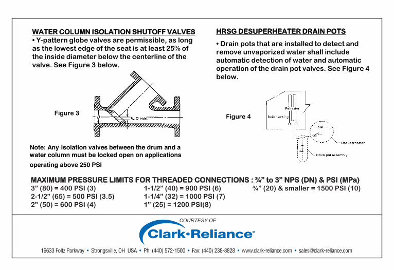
WATER COLUMN ISOLATION SHUTOFF VALVES • Y-pattern globe valves are permissible, as long as the lowest edge of the seat is at least 25% of the inside diameter below the centerline of the valve. See Figure 3 below.
Figure 3
HRSG DESUPERHEATER DRAIN POTS
• Drain pots that are installed to detect and remove unvaporized water shall include automatic detection of water and automatic operation of the drain pot valves. See Figure 4 below.
Figure 4
Note: Any isolation valves between the drum and a water column must be locked open on applications operating above 250 PSI
MAXIMUM PRESSURE LIMITS FOR THREADED CONNECTIONS : ¾” to 3” NPS (DN) & PSI (MPa) 3” (80) = 400 PSI (3) 1-1/2” (40) = 900 PSI (6) ¾” (20) & smaller = 1500 PSI (10) 2-1/2” (65) = 500 PSI (3.5) 1-1/4” (32) = 1000 PSI (7) 2” (50) = 600 PSI (4) 1” (25) = 1200 PSI(8)
COURTESY OF
16633 Foltz Parkway • Strongsville, OH USA • Ph: (440) 572-1500 • Fax: (440) 238-8828 • www.clark-reliance.com • [email protected]

COURTESY OF
16633 Foltz Parkway • Strongsville, OH USA • Ph: (440) 572-1500 • Fax: (440) 238-8828 • www.clark-reliance.com • [email protected]
COURTESY OF
COMMON NON-COMPLIANT DRUM LEVEL EQUIPMENT ARRANGEMENTS
Magnetic Gages being used as direct reading gages. Magnetic Gages are permitted as a local indirect gage or as a remote level indicator when used with a 4-20mA transmitter to a control area indicator. A Magnetic Level Gage can not replace the Code required direct reading gage glass.
When the over 400 PSI Code option arrangement is used (two independent indicators for one of the gage glasses), the two indirect indicators must be continuously visible in the operators control area and the gage valves may be isolated. Viewing the boiler level on a plant operation control system computer screen does not qualify as a continuously visible indicator unless it is always on the screen. If keystrokes or mouse clicks are required to view the indirect indicator, it does not meet the Code requirements, as an indirect indicator.
When the over 400 PSI Code Option Arrangement is used, the existing gage glasses must be able to be brought into service without further action other than opening the isolation valves, closing the drain valve, and powering on illuminators. Gage glasses that can not be turned on without repairs do not meet ASME Code requirements.
Bi-color ported type water gages must be fitted with proper illumination to provide visual discrimination between water and steam. If not, the gage glass is not in Code compliance.
Not having two independent indirect reading gages when the gage glass image is not directly visible in the operators control area or transmitted to the operators control area, by means of a camera, fiber optic system, or mirrors.
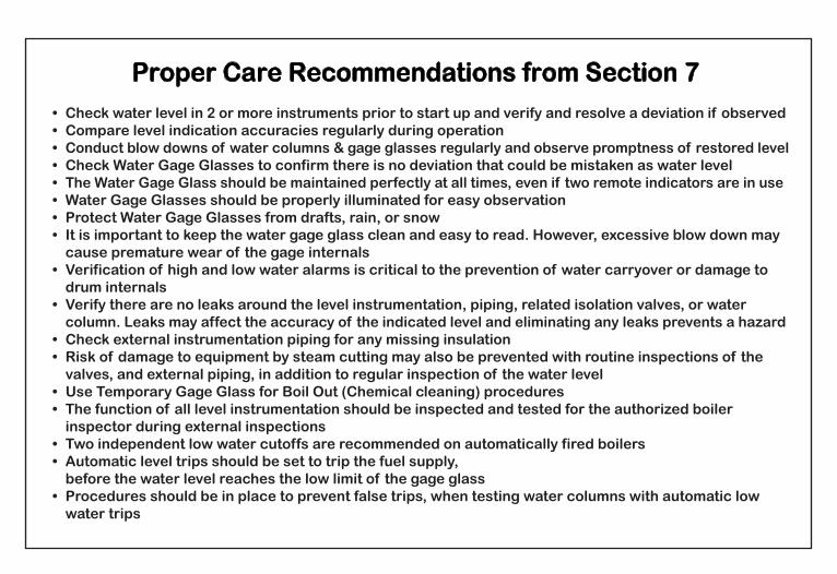
Proper Care Recommendations from Section 7
• Check water level in two or more instruments prior to start up and verify when a deviation isobserved
• Check Water Gage Glasses to confirm there is no dirt or contamination that could be mistaken as water level
• Water Gages should be properly illuminated for easy observation• It is important to keep the water gage glass clean and easy to read. However, excessive blow
down may cause premature wear of the gage internals• Verification of high and low water alarms is critical to the prevention of carryover or damage to
drum internals• Verify there are no leaks around the level instrumentation, piping, related isolation valves, or
water column. Leaks may affect the accuracy of the indicated level and eliminating any leaks willhelp to prevent a hazard
• Check external instrumentation piping for any missing insulation• Risk of damage to equipment by steam cutting may also be prevented with routine inspections of
the valves, and external piping, in addition to regular inspection of the water level.• Use Temporary Gage Glass for Boil Out (chemical cleaning) procedures.
• Check water level in 2 or more instruments prior to start up and verify and resolve a deviation if observed• Compare level indication accuracies regularly during operation• Conduct blow downs of water columns & gage glasses regularly and observe promptness of restored level• Check Water Gage Glasses to confirm there is no deviation that could be mistaken as water level• The Water Gage Glass should be maintained perfectly at all times, even if two remote indicators are in use• Water Gage Glasses should be properly illuminated for easy observation• Protect Water Gage Glasses from drafts, rain, or snow• It is important to keep the water gage glass clean and easy to read. However, excessive blow down may cause premature wear of the gage internals• Verification of high and low water alarms is critical to the prevention of water carryover or damage to drum internals• Verify there are no leaks around the level instrumentation, piping, related isolation valves, or water column. Leaks may affect the accuracy of the indicated level and eliminating any leaks prevents a hazard• Check external instrumentation piping for any missing insulation• Risk of damage to equipment by steam cutting may also be prevented with routine inspections of the valves, and external piping, in addition to regular inspection of the water level• Use Temporary Gage Glass for Boil Out (Chemical cleaning) procedures• The function of all level instrumentation should be inspected and tested for the authorized boiler inspector during external inspections• Two independent low water cutoffs are recommended on automatically fired boilers• Automatic level trips should be set to trip the fuel supply, before the water level reaches the low limit of the gage glass• Procedures should be in place to prevent false trips, when testing water columns with automatic low water trips

COURTESY OF
16633 Foltz Parkway • Strongsville, OH USA • Ph: (440) 572-1500 • Fax: (440) 238-8828 • www.clark-reliance.com • [email protected]
COURTESY OF
GOOD PRACTICE RECOMMENDATIONS
The following are not required by ASME Code, but are recommended for safe operation:
1. Chain Operators should always be installed to provide a safe means of operating gage glass isolation valves under normal conditions and in the event of glass leakage.
2. A conductivity probe system combined with a 4-20 mA level transmitter, or, two conductivity probe systems provide the best reliability due to the redundancy of probe systems. The use of two or three differential pressure transmitters (redundant devices) is not recommended due to the likelihood of simultaneous common mode failure, due to environmental variations (especially freeze-up) or loss of device sensing leg primes.
3. Trip and alarm points are within the visible range of the gage glass for visual verification.
4. Freeze protection for outdoor applications should be provided to prevent damage to the level instrumentation devices.
5. Transparent water gage glass illumination should be provided to give optimum viewing of the drum level for the operator, especially in low lit areas and when a transparent gage glass is elevated above the viewing platform.
6. Exposed piping to the gage glass or level instrument, especially the upper steam piping, should be insulated to minimize risk and level density error due to excessive cooling and condensate formation.
7.
Note: Plant (owner) policies and procedures may exceed Code minimum requirements with the number of level indicating instruments to be installed, which may prevent a violation if any single instrument is out of service for maintenance.

COURTESY OF
16633 Foltz Parkway • Strongsville, OH USA • Ph: (440) 572-1500 • Fax: (440) 238-8828 • www.clark-reliance.com • [email protected]
COURTESY OF
GOOD PRACTICE RECOMMENDATIONS for Inspection, Testing, and Servicing
The following are not required by ASME Code, but are recommended for safe operation:
1. Water Gage Glasses, Water Columns, and Remote Level Indicators:
a. Visual Inspection and Blow Down should be conducted on routine basis to verify cleanliness for easy reading of the level “ready discrimination” between steam and water.
Also, to remove any sediment from collecting in the piping or valves.
b. Visual inspection of all external instrumentation should be conducted on a monthly basis including piping, isolation valves, drain valves, and lighting accessories.
c. Annual Servicing of Water Gage glasses is recommended. Follow the OEM instructions.
Semi-annual servicing is recommended for severe service applications with poor water quality or high-pressure applications > 1500 PSIG (10 MPa)
2. Low Water Cutouts:
a. Testing should to be conducted on a daily basis. Actual plant policies may dictate more or less frequency. In any case, the maximum interval should not exceed one week.
b. Annual servicing of low water cutouts is highly recommended. Disassemble the cutout switch assembly, examine conductivity probes or the float mechanism for contamination or wear. Replace any suspect components. Follow the OEM instructions.
d. When freeze protection is not installed on level instruments, and the equipment is not inservice or is isolated, it should be drained and free of water if freezing temperatures areexpected in order to prevent damage.

COURTESY OF
For questions, consult your local Boiler Inspector, Insurance Carrier, or a Reliance Applications Engineer.
CONTROL ROOM INDICATOR CONTROL ROOM
INDICATOR
LEVEL INDICATION SYSTEM WITH CONDUCTIVITY PROBES
LEVEL INDICATION SYSTEM WITH
CONDUCTIVITY PROBES
BI-COLOR DIRECT READING GAGE GLASS WITH ILLUMINATION (viewing hood not shown)
Typical Code Compliant installation for pressures
over 400 PSIG
CLA-009 01/14 CLA-009 01/14
COURTESY OF
16633 Foltz Parkway • Strongsville, OH USA • Ph: (440) 572-1500 • Fax: (440) 238-8828 • www.clark-reliance.com • [email protected]
COURTESY OF
16633 Foltz Parkway • Strongsville, OH USA • Ph: (440) 572-1500 • Fax: (440) 238-8828 • www.clark-reliance.com • [email protected]
COURTESY OF
16633 Foltz Parkway • Strongsville, OH USA • Ph: (440) 572-1500 • Fax: (440) 238-8828 • www.clark-reliance.com • [email protected]