New foundations in Japan and recent pile researches in … Taiwan(KIMURA).pdf · behavior of pile...
54
New foundations in Japan and recent pile researches in Kyoto University Kyoto University Makoto Kimura [email protected]
Transcript of New foundations in Japan and recent pile researches in … Taiwan(KIMURA).pdf · behavior of pile...

New foundations in Japan and recent pile researches
in Kyoto University
Kyoto University Makoto [email protected]

Contents
・ Japanese design ideas of roadbridge foundations
・ New pile foundation in Japan
・ Investigation of mechanical behavior of pile group
(・ A seismic reinforcement methodfor an existing pile )

Seismic design for pier and foundation
橋脚
フーチング
杭
軟弱地盤
硬い地盤
路線直角方向から見た図 路線方向から見た図
No foundati
on failure
(杭)基礎
earthquake force for design
Horizontal bearing capacity on pier
Horizontal bearing capacity on foundation
<
Earthquake force for design<Basic idea
for seismic designearthquake force for design

橋脚の水平耐力
基礎の水平耐力
設計想定地震力
Needs of seismic reinforcement for existing foundations
Stiffness of pier
Reinforcement for existing foundations
Horizontal bearing capacity on foundation
<
Earthquake force for design< Increase
After Kobe earthquake
Reinforcement of pier
Reinforcement of foundation
Pandora’s boxAdvancement of numerical methodCombined calculation for upper structure and foundation

e
HV
M
MH
R MH
R MH
R
HV
M
MH
R MH
R MH
R
?
Why do we design a footing?
Pile
? ?
Footing

JACKET FOUNDATION WITH INCLINED PILES
Jacket structure
Pier
Steel pile
Stuff substratum
Soft soil layer
Offshore pile foundations for roads
Not so heavy
Jacket steel pile foundationwith inclined piles
Jacket leg
Steel pile
Ballast tank

AXIAL LOAD DISTRIBUTION(STATIC)
-6
-4
-2
0
2
4
6
No.1 No.2 No.3 No.4
Axi
al fo
rce
(MN
)
TypeA : Analysis (at 6.61s)TypeA : Test (at 6.30s)TypeB : Analysis (at 6.59s)TypeB : Test (at 6.17s)
Inertial force
1 2 3 4
Inertial force
1 2 3 4
Type A
Type B
Inertial force of a superstructure
Com
pres
sion
(+
)Te
nsio
n (-
)

PILE FOUNDATION AND CAISSON FOUNDATION
(Unit:m)
<Remarks> C.G.:Center of gravity
Pile foundation
Elastic beam Plastic beam
C.G. of superstructure
Rubber bearing
Pier
Superstructure
33.3
8.0
0.9
Elastic beam 5.0
G.L.-39.4
25
Caisson
C.G. of superstructure
18.8
Rubber bearing
14.5
8.0
2.25
9.4C.G. of jacket structure
C.G. of tank
Pier
A A0.4
20° 20°
Inclined pile Vertical pile
Superstructure
Substructure
Elastic solid elementAc
AscAsDS1
Ds2
Caisson foundation

RESPONSE FOR ACCELERATION AND DISPLACEMENT
-8.0
-4.0
0.0
4.0
8.0
0 2 4 6 8 10 12Time (sec)
Acc
eler
atio
n (m
/s2 ) Pile foundationCaisson foundation
-2.0
-1.0
0.0
1.0
2.0
0 2 4 6 8 10 12Time (sec)
Disp
lace
men
t (m
) Pile foundationCaisson foundation
-8.0
-4.0
0.0
4.0
8.0
0 2 4 6 8 10 12Time (sec)
Acc
eler
atio
n (m
/s2 )
Acceleration Displacement
-0.2
-0.1
0.0
0.1
0.2
0 2 4 6 8 10 12Time (sec)
Disp
lace
men
t (m
)
Upper structure
Foundation
Upper structure
Foundation

My new pile foundations
10

NEW STRUCTUREHanshin Expressway

Cost analysis
Pile group Integrated column by multiple steel pipes
1.00 1.18 0.82 1.00 0.65

KY
O
OT
UNIVERSITY
FO
U N D E D 18 9 7
KY
O
OT
UNIVERSITY
FO
U N D E D 18 9 7
Shaking table test and numerical simulation on seismic performance of a bridge column integrated by multiple steel pipes with directly-connected piles
Koichi Isobe (Hokkaido University) H. Sugiyama, M. Shinohara, H. Kobayashi (Hanshin Expressway)
Y. Sawamura, Y. Mitsuyoshi, M. Kimura (Kyoto University)
14

KY
O
OT
UNIVERSITY
FO
U N D E D 18 9 7
KY
O
OT
UNIVERSITY
FO
U N D E D 18 9 7
Development of “Integrated column by multiple steel pipes” (2004)
A bridge column integrated by 4 steel pipes and multiple shear panels interconnecting the pipes has been proposed.
It is designed based on damage control concept, in which the vertical load is supported by the steel pipes and the lateral load is adjunctively supported by shear links.
Shear panels are made of low yield stress steel and have hysteretic energy dissipation properties.
It intends to lead seismic damage into shear panels and enables early recovery by replacing only panels.
Introduction
15

KY
O
OT
UNIVERSITY
FO
U N D E D 18 9 7
KY
O
OT
UNIVERSITY
FO
U N D E D 18 9 7
Development of “Integrated column by multiple steel pipes” (2004)
Budget-pleasing prefabricated material (ready-made spiral steel pipes) are used.
Anchor frame is NOT necessary unlike a conventional steel pier structure.
Reduce 30% of construction cost
Reduce construction time
Rapid transportation open
Introduction
16
NO Anchor frame

KY
O
OT
UNIVERSITY
FO
U N D E D 18 9 7
KY
O
OT
UNIVERSITY
FO
U N D E D 18 9 717
IntroductionProposal of “Steel pipe pile foundation” for integrated column
Each pipe of the column is supported by a directly connected steel pile without a footing
Maybe rational & reasonable foundation structure for “A bridge column integrated column by multiple steel pipes”
Not impair the ability of the integrated column structure
Reduce inertia force and sectional force at the connected area between piles and column
Reduce the cost of footing and the number of piles
Can employ the pile foundation in narrow construction conditions
ConventionalGP foundationwith Footing
Way-outDirectly connected
without Footing
Energydissipation
Footing3 x 3piles
2 x 2piles

KY
O
OT
UNIVERSITY
FO
U N D E D 18 9 7
KY
O
OT
UNIVERSITY
FO
U N D E D 18 9 718
Purpose of StudyShaking table test and Numerical simulation To compare the both seismic performance (footing type
vs footing-less type) Axial force acting at pile heads Lateral displacement at a pier top and pile heads Cross sectional force acting in a bridge column and
piles To confirm the yield order of the member for the
proposed structure To check the behavior of the proposed structure in
liquefiable sand To identify the structural issues of the proposed type To cross-check analytical model by simulating the model
tests

KY
O
OT
UNIVERSITY
FO
U N D E D 18 9 7
KY
O
OT
UNIVERSITY
FO
U N D E D 18 9 719
Outline of Shaking table testShaking table and Large-scale rigid box with tempered glass
Public Works Research Institute in Tsukuba Large-scale 3-dimensional shaking table Table size: 8m x 8m Box size: 4m (W) x 1m (L) x 2m (H) See the ground through the tempered glass
4m 2m
1m

KY
O
OT
UNIVERSITY
FO
U N D E D 18 9 7
KY
O
OT
UNIVERSITY
FO
U N D E D 18 9 720
Outline of Shaking table testDetail of the model used in the tests
Shear panels
Underground beamFooting type Footing-less

KY
O
OT
UNIVERSITY
FO
U N D E D 18 9 7
KY
O
OT
UNIVERSITY
FO
U N D E D 18 9 721
Outline of Shaking table testFooting type (conventional) Footing-less type (way-out)
Natural periodIn air: 0.236(sec)In sand: 0.361(sec)
Natural periodIn air: 0.578(sec)In sand: 0.544(sec)
long-period structure

KY
O
OT
UNIVERSITY
FO
U N D E D 18 9 7
KY
O
OT
UNIVERSITY
FO
U N D E D 18 9 722
Outline of Shaking table testDry sand (Case-1-S) Liquefiable sand (Case-2-S)

KY
O
OT
UNIVERSITY
FO
U N D E D 18 9 7
KY
O
OT
UNIVERSITY
FO
U N D E D 18 9 723
Outline of Shaking table testTest cases
Footing type Footing-less typeDry sand Case-1F (D-F) Case-1S (D-S)Liquefiable sand Case-2F (L-F) Case-2S (L-S)

KY
O
OT
UNIVERSITY
FO
U N D E D 18 9 7
KY
O
OT
UNIVERSITY
FO
U N D E D 18 9 724
Outline of Shaking table test
Footing type Footing-less type

KY
O
OT
UNIVERSITY
FO
U N D E D 18 9 7
KY
O
OT
UNIVERSITY
FO
U N D E D 18 9 7
目標値 計測値
Step 1 1.92 m/sec2 2.0 m/sec2
ステップ最大入力加速度
Case-2 (Liquefiable sand)Case-1 (Dry sand)
Case-2
-6-4-20246
0 5 10 15 20Acc
eler
atio
n [m
/sec
2 ]
Time [sec]-6-4-20246
0 5 10 15 20Acc
eler
atio
n [m
/sec2 ]
Time [sec]
Case-1 Step8
Outline of Shaking table test
目標値 計測値
Step 1 0.5 m/sec2 0.62 m/sec2
Step 2 1.0 m/sec2 0.94 m/sec2
Step 3 1.5 m/sec2 1.45 m/sec2
Step 4 2.0 m/sec2 2.01 m/sec2
Step 5 2.5 m/sec2 2.47 m/sec2
Step 6 3.0 m/sec2 3.07 m/sec2
Step 7 3.5 m/sec2 3.63 m/sec2
Step 8 5.0 m/sec2 5.25 m/sec2
加振ステップ最大入力加速度
Loading step Loading stepInput accelerationInput acceleration
Obs.Target Obs. Target
25

KY
O
OT
UNIVERSITY
FO
U N D E D 18 9 7
KY
O
OT
UNIVERSITY
FO
U N D E D 18 9 7
(1) Dry sand
26

KY
O
OT
UNIVERSITY
FO
U N D E D 18 9 7
KY
O
OT
UNIVERSITY
FO
U N D E D 18 9 7
-6
-4
-2
0
2
4
6
-60 -40 -20 0 20 40 60
Res
pons
e ac
cele
ratio
n at
pie
r top
[m/s
ec2 ]
Lateral displacement at pier top [mm]
27
Results of Shaking table test Dry sandResponse acceleration vs lateral displacement @ pier top
Lateral disp. @ pier top (mm)
Input wave acc.(1) 0.5 m/s2
(2) 1.0 m/s2
(3) 1.5 m/s2
(4) 2.0 m/s2
(5) 2.5 m/s2
(6) 3.0 m/s2
(7) 3.5 m/s2
(8) 5.0 m/s2
Resp
onse
acc
. @ p
ier
top
(gal
)
The stiffness of Case-1-F (D-F) is bigger than that of Case-1-S (D-S).
Case-1-F yields at earlier stage than Case-1-S. Response acceleration and lateral displacement for Case-1-
F increase rapidly and brittle deformation is observed.

KY
O
OT
UNIVERSITY
FO
U N D E D 18 9 7
KY
O
OT
UNIVERSITY
FO
U N D E D 18 9 7
Results of Shaking table testStrain on the structure at Step 2
-3000 -2000 -1000 0 1000 2000 3000-2
-1.5
-1
-0.5
0
0.5
1
1.5
Hei
ght [
m]
-2
-1.5
-1
-0.5
0
0.5
1
1.5
-3000 -2000 -1000 0 1000 2000 3000
Hei
ght [
m]
29

KY
O
OT
UNIVERSITY
FO
U N D E D 18 9 7
KY
O
OT
UNIVERSITY
FO
U N D E D 18 9 7
-3000 -2000 -1000 0 1000 2000 3000-2
-1.5
-1
-0.5
0
0.5
1
1.5
Hei
ght [
m]
-2
-1.5
-1
-0.5
0
0.5
1
1.5
-3000 -2000 -1000 0 1000 2000 3000
Hei
ght [
m]
Results of Shaking table testStrain on the structure at Step 3
30

KY
O
OT
UNIVERSITY
FO
U N D E D 18 9 7
KY
O
OT
UNIVERSITY
FO
U N D E D 18 9 7
Results of Shaking table testDamage process of the member
32
The proposed substructure (Case-1-S) have advantages of strain reduction of column by strain descentralization at footing point.
It has high seismic performance and high toughness if the conditions are right in view of the fact that the main member (columns and piles) holds a large residual strength after yielding of the shear panels.
加振No. (最大入力加速度) 上段 中段 下段 柱 杭 上段 中段 下段 柱 杭
第1加振 (0.5 m/sec2)第2加振 (1.0 m/sec2)第3加振 (1.5 m/sec2)第4加振 (2.0 m/sec2)第5加振 (2.5 m/sec2)第6加振 (3.0 m/sec2)第7加振 (3.5 m/sec2)第8加振 (5.0 m/sec2)
フーチングを有する杭基礎 (Case-1-F) 杭基礎一体型 (Case-1-S)
せん断パネル 鋼管 せん断パネル地中梁
鋼管

KY
O
OT
UNIVERSITY
FO
U N D E D 18 9 7
KY
O
OT
UNIVERSITY
FO
U N D E D 18 9 7
(2) Liquefiable sand
33

KY
O
OT
UNIVERSITY
FO
U N D E D 18 9 7
KY
O
OT
UNIVERSITY
FO
U N D E D 18 9 734
Results of Shaking table testExcess pore water pressure
0.00.20.40.60.81.01.2
0 5 10 15 20 25
PS-0.2PS-1.0
Time (sec)EP
WP
ratio
0.00.20.40.60.81.01.2
0 5 10 15 20 25
PF-0.2PF-1.0
Time (sec)
EPW
P ra
tio
Case-2F (L-F) Case-2S (L-S)
The excess pore water pressure ratio of PF-0.2 & PS-0.2 sharply increasesafter the shaking and reaches 1 at around 5 seconds. This indicates that theground is fully liquefied.
KY
O
OT
UNIVERSITY
FO
U N D E D 18 9 7
KY
O
OT
UNIVERSITY
FO
U N D E D 18 9 735
-60-40-20
0204060
0 5 10 15 20 25
L-FL-S
Late
ral d
ispl
acem
ent (
mm
)
Time (sec)
-60-40-20
0204060
0 5 10 15 20 25
L-FL-S
Late
ral d
ispl
acem
ent (
mm
)
Time (sec)
-8-6-4-202468
0 5 10 15 20 25
L-FL-S
Resp
onse
acc
eler
atio
n (m
/s2 )
Time (sec)Pier top Pile head
Pier top
L-F L-S
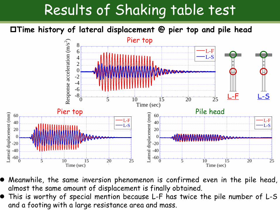
Meanwhile, the same inversion phenomenon is confirmed even in the pile head,almost the same amount of displacement is finally obtained.
This is worthy of special mention because L-F has twice the pile number of L-Sand a footing with a large resistance area and mass.
Results of Shaking table testTime history of lateral displacement @ pier top and pile head

Results of Shaking table testStrain of the structure
36
Case-2F (L-F) Case-2S (L-S)
The maximum strain in the whole structure generates at the column base for L-Fand on the pile for L-S.
The max. strain in column base for L-F has been over yield strain (2000 µ). The max. strain in the pile for L-S has not exceeded the yield strain.

KY
O
OT
UNIVERSITY
FO
U N D E D 18 9 7
KY
O
OT
UNIVERSITY
FO
U N D E D 18 9 7
Summary for model tests
Based on the fact that the main members such as the columns and piles yield after the shear panels (secondary member) yield, the proposed structure has a damage control performance by energy absorption due to plastic deformation of the shear panels.
In particular, S-type has high seismic performance because the main member (columns and piles) holds a large residual strength even after yielding of the shear panels.
37
KY
O
OT
UNIVERSITY
FO
U N D E D 18 9 7
KY
O
OT
UNIVERSITY
FO
U N D E D 18 9 7
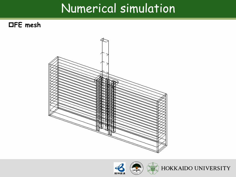
Numerical simulationFE mesh

5.1 Objectives of lateral loading test
1. To investigate bearing capacity and failure level of practical LNG tank foundation
⇒ No one check the practical LNG tank foundation after long time service
2. To investigate mechanical behavior ofthe largest scale group pile foundation
⇒ Pile group efficiency e = f( pile spacing L / d, number of pile, etc.)
The largest in-situ ultimate lateral loading test in Japan 3×3
L
~ In-situ lateral loading test of 63 group pile foundation ~
41/23
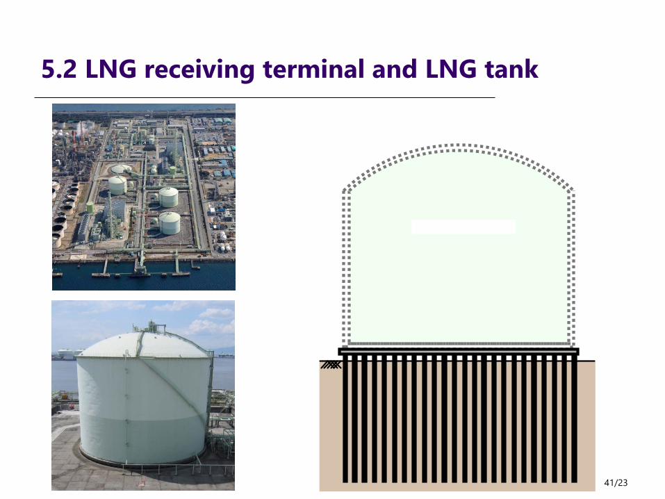
5.2 LNG receiving terminal and LNG tank

5.3 Experimental condition
496 of steel pipe pile
demolished after40 years service
LNG tank
48 m Reaction piles
7×9 group pile
5000 kN jack
Slab
6000
Steel pipe pileφ 406.4Thickness 12.7
800
Protective concrete
Unit (mm)
800
⇒Prediction FEM analysisto decide max. load

5.3 Experimental conditions
43/19
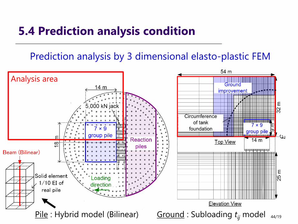
5.4 Prediction analysis condition
44/19
Prediction analysis by 3 dimensional elasto-plastic FEM
Analysis area
Pile : Hybrid model (Bilinear) Ground : Subloading tij model

5.4 Prediction analysis model
45/23

5.5 Results ~Load-displacement~
46/19
0
4000
8000
12000
16000
20000
24000
28000
32000
36000
40000
0 20 40 60 80 100 120 140 160 180 200 220 240 260 280

5.5 Results ~deformation of group pile~

5.5 Results ~Load share of each pile~
49/19

The Composite-Pile Method (Patent No.5077857 )
Should not be fundamentally reinforced even if seismic piles in soft ground and liquefied ground .Development of new technologies improve the unsuitable soil .Cost reduction, Workability is good. Pile format does not change

Liquefaction phenomena is nationwide challengesAn urgent measures are necessary.
Collapse of the buildingdue to liquefaction
The 2011 off the Pacific coast of Tohoku EQ
Liquefaction phenomena: 9700 places in Tohoku andCapital Area
Needs of seismic reinforcement for existing foundations
Design criteria revision, liquefaction phenomenon
Assuming a large-scale earthquake, improvement of design seismic force and anti-seismic strength for new bridges is required
Niigata EQ of 1964

例 )RC巻立て
P
δO
基礎の荷重変位関係
×
×
PyP
PyF
×
補強後の橋脚躯体の荷重変位関係
FPy :橋脚基礎の降伏耐力PPy :橋脚躯体の降伏耐力
Even if the super- and sub-structure were reinforced, thereis a possibility that the entire bridge would collapse in casethe whole seismic energy affects on the existing foundation.
Needs of seismic reinforcement for existing foundationsAn increase in the seismic load to the foundation due to seismic reinforcement for the superstructure of bridges
Bridge pier reinforcement works and collapse-prevention devices are designed on thepremise that the pile foundation satisfies a certain horizontal load bearing capacity.
Concrete jacketing method
Seismic reinforced bridge pier
Original foundation
Lateral load
Lateral disp.
FPy: Yield resistance of foundationPPy: Yield resistance of bridge pier

Proposition:How to deal with the existing pile foundation of bridges?
As-needed repairs and seismic reinforcement
1. Frequent occurrence of large-scale earthquake (twice in a quarter of acentury)
*The Southern Hyogo prefecture EQ in 1995*The 2011 off the Pacific coast of Tohoku EQ*Occurrence of Nankai Trough EQ is assumed
2. Aging bridges that have been cross-linked during the high-growth periodin Japan >> It is important to prolong their life. The total number is700,000 bridges.
3. Basic Act for National Resilience Contributing to Preventing andMitigating Disasters for Developing Resilience in the Lives of the Citizenry.Disaster Prevention and Mitigation is a national policy.
A seismic reinforcement method for an existing pile foundation in soft ground and liquefiable ground

Procedure for evaluating the seismic safety of existing bridge foundations

The Composite-Pile Method (Patent No.5077857 )
Should not be fundamentally reinforced even if seismic piles in soft ground and liquefied ground .Development of new technologies improve the unsuitable soil .Cost reduction, Workability is good. Pile format does not change

56/16

57/16

0
10
20
30
40
50
0 1 2 3 4 5 6 7 8
ボアホールカメラ調査による杭損傷の累積点数
橋脚基数
Damage to the pile in the soft ground and
liquefied ground
Needs of seismic reinforcement for existing foundations
Plastic deformation caused by the earthquake disaster
The Southern Hyogo prefecture EQ in 1995The 2011 off the Pacific coast of Tohoku EQ
Cracks generated in piles
No.
of b
ridge
pie
r
Cumulative No. of pile damage found by the bore-hole camera investigation
Based on the reports of restoration for foundation structures of Kobe line #3 by Hanshin Expressway