New Expansion Locating Pin - · PDF fileZero clearance between reference hole by expansion...
12
New Model VRC Model VRA Line-up from pin diameter φ 3mm!! Durability of ten million cycles!! ※ when using VRA Locating repeatability 3 μm!! Zero clearance between reference hole by expansion locating pin!! Expansion Locating Pin
-
Upload
truongcong -
Category
Documents
-
view
247 -
download
1
Transcript of New Expansion Locating Pin - · PDF fileZero clearance between reference hole by expansion...

http://www.kosmek.co.jp
JQA-QMA10823KOSMEK HEAD OFFICE
Printed in JapanCAT.NO.VRA001-01-02 2013. 05 First 2Ry
HEAD OFFICE
BRANCH OFFICE (U.S.A.)
THAILAND REPRESENTATIVE OFFICE
1-5, 2-Chome, Murotani, Nishi-ku, Kobe 651-2241TEL.+81-78-991-5115 FAX.+81-78-991-8787
KOSMEK (U.S.A.) LTD.1441 Branding Avenue, Suite 110, Downers Grove, IL 60515 USATEL.+1-630-241-3465 FAX.+1-630-241-3834
67 Soi 58, RAMA 9 Rd., Suanluang, Suanluang, Bangkok 10250TEL.+66-2-715-3450 FAX.+66-2-715-3453
● FOR FURTHER INFORMATION ON UNLISTED SPECIFICATIONS AND SIZES, PLEASE CALL US.
● SPECIFICATIONS IN THIS LEAFLET ARE SUBJECT TO CHANGE WITHOUT NOTICE.
New
Model VRCModel VRA
Line-up from pin diameter φ3mm!!
Durabil ity of ten mil l ion cycles! ! ※ when using VRA
Locating repeatabil ity 3 μm!!
Zero clearance between reference hole by expansion locating pin!!
Expansion Locating Pin

When releasing the clearance between pin and reference hole is big enough for smooth loading / unloading and conveyanceautomation.
Expansion locating pin expands and the clearance between pin and reference hole become zero which leads to locate withhigh accuracy.Also locking from the inside of the hole leads to zero backlash.
Locating repeatability: 3μm
Locate with high accuracy by expanding pin
General locating pin
Locating accuracy of general locating pin depends on clearancebetween pin and reference hole. Also it leads to inaccuracy of work and construction.
Quality improvementCost reduction
Improvement in expansion locating pin allows high accurateprocessing / cost reduction in alignment equipments
Outstanding loading-unloading functioncan reduce loading-unloading errors.
Productivityimprovement
After
Improvement in locating accuracy leads to cost reduction in accuracy-alignment equipments for computer vision and improve operation of manual systems.
Cost reduction in accuracy-alignment equipmentsAfter
Optimum clearance for loading / unloadingAfter
Before
Locating accuracy and loading / unloading efficiency
Improving locating accuracy of general locating pin causesinefficiency in loading / unloading. It is impossible to manage both high locating accuracy and loading / unloading efficiency.
Before
WorkpieceZero clearance
When expanded
Improvement in locating accuracy
Cost reduction inaligning equipments
Workpiece
When releasing
due to the clearance
Small clearance leads to damage
BacklashWorkpiece
Enough clearance
Effects of introducing Action description Application sampleEffects of introducing Model No. Indication Specifications External dimensions Cautions
Model VRAModel VRC
Zero clearance between reference hole by expansion locating pin!!
Durabil ity of ten mil l ion cycles! ! ※ when using VRA
Locating repeatabil ity 3 μm
Expansion locating pin
PAT. P.
1 2
Before After
General locating pinUnstable locating accuracy (depends on clearance)
Difficulty of loading/unloading
Backlash due to the clearance
Expansion locating pinStable locating accuracy by zero clearance
When released:Easily loaded/unloaded
When expanded:Strong holding force by zero clearance
Backlashdue to the clearance
Workpiece
When released (workpiece is loaded / unloaded) When expanded (work is located)
expands
Workpiece
Air pressure
Zero clearanceEnough clearance
Wobbling
Backlash No Backlash
Workpiece Workpiece
Cut pin
Datum pin
Diamond-shaped pin
Round pin

3 4
動作説明 使用事例Expansion locating pin model VRA/VRC
Action description Application sample
<Releasing by air supply>Release action (pin diameter reduced) isprocessed by air supply.
Contacts with 3 points on holeFor locating
Contacts with 2 points on holeFor one direction locating
Workpiece Workpiece
General locating pin consists of round pin and diamond-shaped pin.
ALike general locating pin, D: datum pin (equivalent to round pin) contacts with 3 points on hole for reference locating.
C: cut pin ( equivalent to diamond-shaped pin) contacts with 2 points on hole for one direction locating.
When loading / unloading (when releasing)
Release air pressure ON<Expanding by built-in spring>When air pressure is OFF, the diameter of pin expands by the built-in spring and locatesthe workpiece.
When locating (When expanding)
Release air pressure OFF
Air pressureON
Gripper
Workpiece
Loading / unloading
Built-in spring
For picking and placing function with robot or transfer system※ Please check the gripper expanding force
For locating workpiece For pal let changeover
For locating pal let of table robot
Enough clearance when pin diameter compressedIdeal for loading/unloading automation
VR□-D:Datum pin VR□-C:Cut pin
indicates the locating direct ion (gr ipper part)indicates the locating direct ion ( f ixat ion locating part)
enough clearance
Action descriptionAction description Application sampleApplication sampleEffects of introducing Model No. Indication Specifications External dimensions Cautions

5 6
Expansion locating pin model VRA/VRC
Model No. indication Specif ication
21 43
VRA 040 0 - D
2
※Able to select withstanding extract force VRC : (High gripping force) only when select ing the hole diameter040 :φ4H10 mm2
1
Workpiece hole diameter
030 : φ3H10 mm
040※ : φ4H10 mm
050 : φ5H10 mm
060 : φ6H10 mm
1 Withstanding extract force
VRA : StandardVRC※ : High gripping force
D : Datum (For locating)
C : Cut (For one direct ion locating)
D C
3 Design No.
0 : Revis ion number of product
4 Function
+ 0.040 0
+ 0.040 0
+ 0.048 0
+ 0.048 0
+ 0.048 0
+ 0.048 0
+ 0.048 0
+ 0.048 0
+ 0.048 0
Workpiece hole diameter mm
Stroke mm
Locating repeatabi l i ty mm
Gripper expansion force ※1 N
Workpiece holding force (Reference)※2 N
Allowable thrust load ※3 N
Cyl inder capacity cm3
Max. operat ing pressure MPa
Min. operat ing pressure MPa
Operating temperature ℃
Usable f luid
Mass g
Model No.
when compressed mm
When expanded mm
Expansion & release
diameter dimension
VRA0300-□ VRA0400-□ VRA0500-□ VRA0600-□ VRC0400-□
φ3H10 φ4H10 φ5H10 φ6H10 φ4H10
Less thanφ2.94 Less thanφ3.94 Less thanφ4.94 Less thanφ5.94 Less thanφ3.94
More thanφ3.06 More thanφ4.06 More thanφ5.06 More thanφ6.06 More thanφ4.06
(0 .9)
0 .003
0 .3
0 ~ 70
Dry air
3 .7 3 .9 5 .6 5 .8 18
Standard High gripping force
4 ~ 7 7 ~ 13 23 ~ 30
1.0 1 .8 5 .0
10 18 100
0.03 0 .05 0.07
0 .5 1 .0
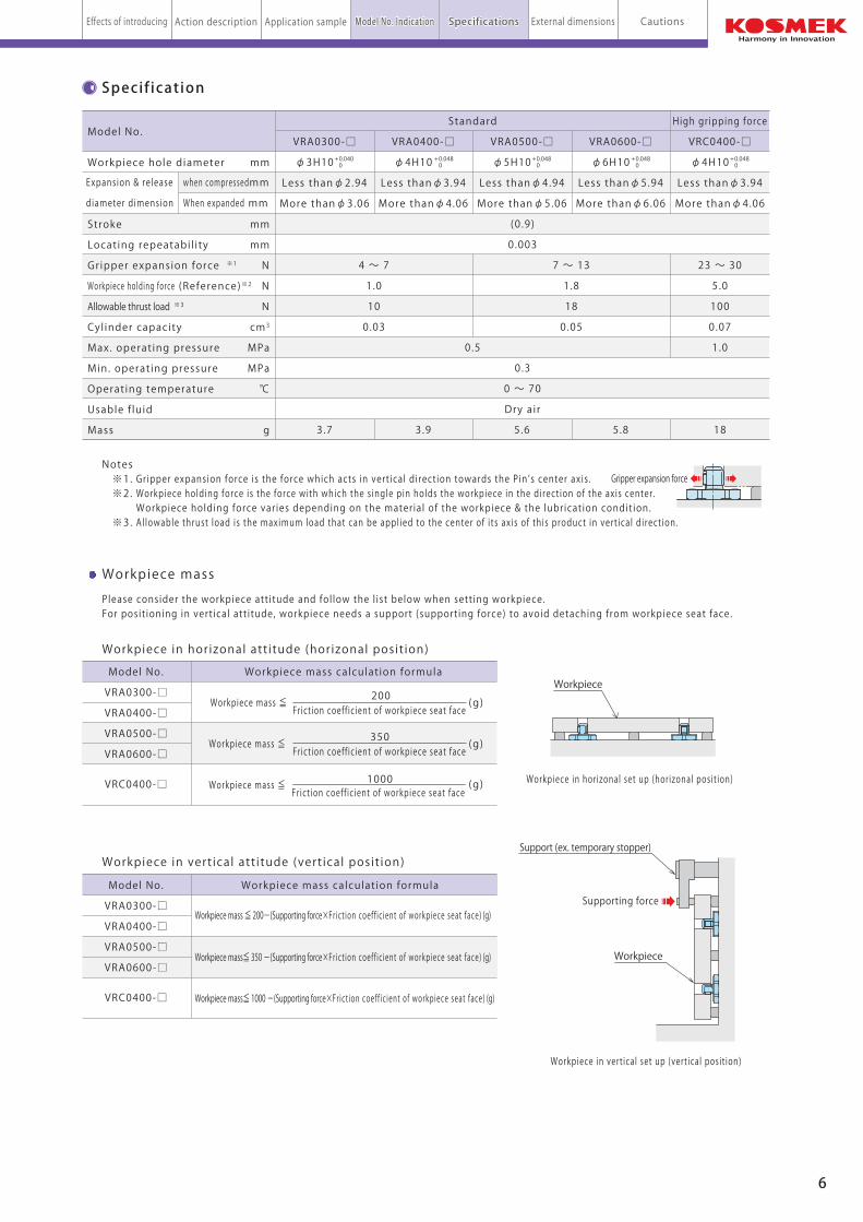
Workpiece mass calculat ion formula
Workpiece in horizonal att i tude (horizonal posit ion)
Workpiece in vert ical att i tude (vert ical posit ion)
Workpiece in horizonal set up (horizonal posit ion)
Workpiece in vert ical set up (vert ical posit ion)
Workpiece mass
Workpiece mass ≦ (g)200
Frict ion coeff ic ient of workpiece seat face
(g)Workpiece mass ≦350
Frict ion coeff ic ient of workpiece seat face
(g)Workpiece mass ≦ 1000Frict ion coeff ic ient of workpiece seat face
Please consider the workpiece att i tude and fol low the l ist below when sett ing workpiece. For posit ioning in vert ical att i tude, workpiece needs a support (support ing force) to avoid detaching from workpiece seat face.
Model No.
VRA0300-□
VRA0400-□
VRA0500-□
VRA0600-□
VRC0400-□
Workpiece mass calculat ion formula
Workpiece mass ≦ 200-(Supporting force×Frict ion coeff ic ient of workpiece seat face) (g)
Workpiece mass≦ 350 -(Supporting force×Frict ion coeff ic ient of workpiece seat face) (g)
Workpiece mass≦ 1000 -(Supporting force×Frict ion coeff ic ient of workpiece seat face) (g)
Model No.
VRA0300-□
VRA0400-□
VRA0500-□
VRA0600-□
VRC0400-□
Notes ※1. Gripper expansion force is the force which acts in vert ical direct ion towards the Pin’s center axis . ※2. Workpiece holding force is the force with which the s ingle pin holds the workpiece in the direct ion of the axis center . Workpiece holding force var ies depending on the material of the workpiece & the lubricat ion condit ion. ※3. Al lowable thrust load is the maximum load that can be appl ied to the center of i ts axis of this product in vert ical direct ion.
Workpiece Workpiece
contacts with 3 work holes contacts with 2 work holes
Supporting force
Support (ex. temporary stopper)
Workpiece
Gripper expansion force
Workpiece
形式表示 仕様Action description Application sampleEffects of introducing Model No. IndicationModel No. Indication SpecificationsSpecifications External dimensions Cautions
5 6
Expansion locating pin model VRA/VRC
Model No. indication Specif ication
21 43
VRA 040 0 - D
2
※Able to select withstanding extract force VRC : (High gripping force) only when select ing the hole diameter040 :φ4H10 mm2
1
Workpiece hole diameter
030 : φ3H10 mm
040※ : φ4H10 mm
050 : φ5H10 mm
060 : φ6H10 mm
1 Withstanding extract force
VRA : StandardVRC※ : High gripping force
D : Datum (For locating)
C : Cut (For one direct ion locating)
D C
3 Design No.
0 : Revis ion number of product
4 Function
+ 0.040 0
+ 0.040 0
+ 0.048 0
+ 0.048 0
+ 0.048 0
+ 0.048 0
+ 0.048 0
+ 0.048 0
+ 0.048 0
Workpiece hole diameter mm
Stroke mm
Locating repeatabi l i ty mm
Gripper expansion force ※1 N
Workpiece holding force (Reference)※2 N
Allowable thrust load ※3 N
Cyl inder capacity cm3
Max. operat ing pressure MPa
Min. operat ing pressure MPa
Operating temperature ℃
Usable f luid
Mass g
Model No.
when compressed mm
When expanded mm
Expansion & release
diameter dimension
VRA0300-□ VRA0400-□ VRA0500-□ VRA0600-□ VRC0400-□
φ3H10 φ4H10 φ5H10 φ6H10 φ4H10
Less thanφ2.94 Less thanφ3.94 Less thanφ4.94 Less thanφ5.94 Less thanφ3.94
More thanφ3.06 More thanφ4.06 More thanφ5.06 More thanφ6.06 More thanφ4.06
(0 .9)
0 .003
0 .3
0 ~ 70
Dry air
3 .7 3 .9 5 .6 5 .8 18
Standard High gripping force
4 ~ 7 7 ~ 13 23 ~ 30
1.0 1 .8 5 .0
10 18 100
0.03 0 .05 0.07
0 .5 1 .0
Workpiece mass calculat ion formula
Workpiece in horizonal att i tude (horizonal posit ion)
Workpiece in vert ical att i tude (vert ical posit ion)
Workpiece in horizonal set up (horizonal posit ion)
Workpiece in vert ical set up (vert ical posit ion)
Workpiece mass
Workpiece mass ≦ (g)200
Frict ion coeff ic ient of workpiece seat face
(g)Workpiece mass ≦350
Frict ion coeff ic ient of workpiece seat face
(g)Workpiece mass ≦ 1000Frict ion coeff ic ient of workpiece seat face
Please consider the workpiece att i tude and fol low the l ist below when sett ing workpiece. For posit ioning in vert ical att i tude, workpiece needs a support (support ing force) to avoid detaching from workpiece seat face.
Model No.
VRA0300-□
VRA0400-□
VRA0500-□
VRA0600-□
VRC0400-□
Workpiece mass calculat ion formula
Workpiece mass ≦ 200-(Supporting force×Frict ion coeff ic ient of workpiece seat face) (g)
Workpiece mass≦ 350 -(Supporting force×Frict ion coeff ic ient of workpiece seat face) (g)
Workpiece mass≦ 1000 -(Supporting force×Frict ion coeff ic ient of workpiece seat face) (g)
Model No.
VRA0300-□
VRA0400-□
VRA0500-□
VRA0600-□
VRC0400-□
Notes ※1. Gripper expansion force is the force which acts in vert ical direct ion towards the Pin’s center axis . ※2. Workpiece holding force is the force with which the s ingle pin holds the workpiece in the direct ion of the axis center . Workpiece holding force var ies depending on the material of the workpiece & the lubricat ion condit ion. ※3. Al lowable thrust load is the maximum load that can be appl ied to the center of i ts axis of this product in vert ical direct ion.
Workpiece Workpiece
contacts with 3 work holes contacts with 2 work holes
Supporting force
Support (ex. temporary stopper)
Workpiece
Gripper expansion force
Workpiece
形式表示 仕様Action description Application sampleEffects of introducing Model No. IndicationModel No. Indication SpecificationsSpecifications External dimensions Cautions

7 8
Expansion locating pin model VRA/VRC
External dimensions
Instal l ing phase※4 and pitch tolerance※5
※5
Machine dimensions of mounting area External dimensions and machine dimensions of mounting area
φL
E thread
φD p7
φK
(φAE)※2
E thread
6.3S
6 .3S
Release air port※3
(one part needed)
φD H7
φAG ※3
Less thanφAF
φC
Hexagon B
A
GF
4.5
3.5
Stroke
0.5~1
(Recommended clearance)
JH
Hole diameter
Gripper part(Refer to the detai l of expansion area)
Workpiece
Seat※2
Grease s lot※1
Seating surface
O-r ing ( Included)
P.C.D. M
※ The figure shows released status of VR□-C (Pin compressed).
2-φN※4
(Location orientation hole)
Gripper part
45°
30°
AA
0.4
More than AB
AC(AD)※2
(mm)
VRA0300-□ VRA0400-□ VRA0500-□ VRA0600-□ VRC0400-□
φ3H10 φ4H10 φ5H10 φ6H10 φ4H10
Less thanφ2.94 Less thanφ3.94 Less thanφ4.94 Less thanφ5.94 Less thanφ3.94
More thanφ3.06 More thanφ4.06 More thanφ5.06 More thanφ6.06 More thanφ4.06
(0 .9)
2 3 4 5 3
Standard High gripping force
13.5 15.5 20
10 12 14
11 13.5 15.5
10.4 12.4 15.4
10.4 12.4 15.4
M10×0.75 M12×1 M15×1
7 8 .5 11.5
6 .5 7 8 .5
1 1 1 .8
2 2 .5 4
8 .6 10.3 13.7
5 .6 7 .5 8
1 1 1 .5
2 .2 2 .6 3 .5
5 .3 6 .5 8
7±0.05 8 .5±0.05 11.5
2 .5 ~ 3 3 ~ 3.5 4 .5 ~ 5
19 22 24
1 1 2
2 3 3
SS8.5 (made by NOK) S10 (made by NOK) S12.5 (made by NOK)
Workpiece hole diameter
When compressed
When expanded
Stroke
A
B
C
D p7
D H7
E
F
G
H
J
K
L
M
N
AA
AB
AC
AD
AE
AF
AG
O-r ing
Model No.
Expansion & release
diameter dimension
+ 0.040 0
+ 0.036+ 0.018
+ 0.018 0
+ 0.036+ 0.018
+ 0.018 0
+ 0.036+ 0.018
+ 0.018 0
+ 0.048 0
+ 0.048 0
+ 0.048 0
+ 0.048 0
※Expansion area detail
VR□-D(For locating)
VR□-C(For one direct ion locating)
indicates gripper part.indicates fixation locating part.
Vertical
Mounting pitch tolerance less than ±0.02Workpiece hole pitch accuracy less than ±0.02
VR□-D(For locating)
VR□-C(For one direct ion locating)
indicates the locating direct ion (gr ipper part)indicates the locating direct ion ( f ixat ion locating part)
Notes ※4. The direct ion of mounting pin is very important to make a best performance. Please make adjustment to the mounting direct ion of pin using the locating or ientat ion hole, before t ightening the body whole way to the mounting area. ※5. The pitch tolerance for cyl inder and the pitch accuracy of workpiece hole should be within ±0.02mm. I f the pitch accuracy of workpiece holes is not going to be within ±0.02mm, please make the workpiece hole of VR□-C(for one direct ion locating) be s lot . The width of the object should be within the workpiece hole diameter H10 dimensions.
Notes ※1. When mounting this product , please apply grease in the greasing s lot & t ighten it with the hexagon socket . ※2. This product has no seat surface towards the center of i ts axis . P lease prepare the seat separately or machine the mounting area. Keep it in mind that there are the recommended clearance:0.5~1mm and the mounting tool dimension. ※3. Please machine release air port within the range of .
外形寸法Action description Application sampleEffects of introducing Model No. Indication Specifications External dimensionsExternal dimensions Cautions

7 8
Expansion locating pin model VRA/VRC
External dimensions
Instal l ing phase※4 and distance accuracy※5
※5
Machine dimensions of mounting area External dimensions and machine dimensions of mounting area
φL
E thread
φD p7
φK
(φAE)※2
E thread
6.3S
6 .3S
Release air port※3
(one part needed)
φD H7
φAG ※3
Less thanφAF
φC
Hexagon B
A
GF
4.5
3.5
Stroke
0.5~1
(Recommended clearance)
JH
Hole diameter
Gripper part(Refer to the detai l of expansion area)
Workpiece
Seat※2
Grease s lot※1
Seating surface
O-r ing ( Included)
P.C.D. M
※ The figure shows released status of VR□-C (Pin compressed).
2-φN※4
(Location orientation hole)
Gripper part
45°
30°
AA
0.4
More than AB
AC(AD)※2
(mm)
VRA0300-□ VRA0400-□ VRA0500-□ VRA0600-□ VRC0400-□
φ3H10 φ4H10 φ5H10 φ6H10 φ4H10
Less thanφ2.94 Less thanφ3.94 Less thanφ4.94 Less thanφ5.94 Less thanφ3.94
More thanφ3.06 More thanφ4.06 More thanφ5.06 More thanφ6.06 More thanφ4.06
(0 .9)
2 3 4 5 3
Standard High gripping force
13.5 15.5 20
10 12 14
11 13.5 15.5
10.4 12.4 15.4
10.4 12.4 15.4
M10×0.75 M12×1 M15×1
7 8 .5 11.5
6 .5 7 8 .5
1 1 1 .8
2 2 .5 4
8 .6 10.3 13.7
5 .6 7 .5 8
1 1 1 .5
2 .2 2 .6 3 .5
5 .3 6 .5 8
7±0.05 8 .5±0.05 11.5
2 .5 ~ 3 3 ~ 3.5 4 .5 ~ 5
19 22 24
1 1 2
2 3 3
SS8.5 (made by NOK) S10 (made by NOK) S12.5 (made by NOK)
Workpiece hole diameter
When compressed
When expanded
Stroke
A
B
C
D p7
D H7
E
F
G
H
J
K
L
M
N
AA
AB
AC
AD
AE
AF
AG
O-r ing
Model No.
Expansion & release
diameter dimension
+ 0.040 0
+ 0.036+ 0.018
+ 0.018 0
+ 0.036+ 0.018
+ 0.018 0
+ 0.036+ 0.018
+ 0.018 0
+ 0.048 0
+ 0.048 0
+ 0.048 0
+ 0.048 0
※Expansion area detail
VR□-D(For locating)
VR□-C(For one direct ion locating)
indicates gripper part.indicates fixation locating part.
Vertical
Distance accuracy of each mounting hole better than ±0.02
Distance accuracy of each workpiece holebetter than ±0.02
VR□-D(For locating)
VR□-C(For one direct ion locating)
indicates the locating direct ion (gr ipper part)indicates the locating direct ion ( f ixat ion locating part)
Notes ※4. The direct ion of mounting pin is very important to make a best performance. Please make adjustment to the mounting direct ion of pin using the locating or ientat ion hole, before t ightening the body whole way to the mounting area. ※5. The distance accuracy of each mounting hole and each workpiece hole should be better than ±0.02mm. I f the distance accuracy of each workpiece hole is not going to be better than ±0.02mm, please make the workpiece hole of VR□-C(for one direct ion locating) be s lot . The width of the object should be within the workpiece hole diameter H10 dimensions.
Notes ※1. When mounting this product , please apply grease in the greasing s lot & t ighten it with the hexagon socket . ※2. This product has no seat surface towards the center of i ts axis . P lease prepare the seat separately or machine the mounting area. Keep it in mind that there are the recommended clearance:0.5~1mm and the mounting tool dimension. ※3. Please machine release air port within the range of .
外形寸法Action description Application sampleEffects of introducing Model No. Indication Specifications External dimensionsExternal dimensions Cautions

9 10
注意事項Expansion locating pin Cautions model VRA/VRC
Cautions
● Notes for design
1)Check the specifications
● This product compresses the pin by supplying air which allows
loading and unloading workpiece. When the air supply is shut
off and release the supplied air, it locates workpiece with
the internal spring. Use it with the combination of the expansion
pin for locating (-D) and one direction locating (-C).
The combination of (-D) and (-D), or (-C) and (-C) does not
satisfy the specification. When gripping only one workpiece hole
to convey lightweight work, use the expansion pin for locating (-D).
2) Please do not use under the environment where the product is
exposed to cutting chips and quenching liquid
3) The pitch tolerance for cyl inder and workpiece hole
pitch accuracy ● The pitch tolerance for cyl inder and the workpiece hole pitch
accuracy should be within ±0.02mm. I f the workpiece hole pitch
accuracy is not going to be within ±0.02mm, please make
the workpiece hole (-C) be s lot .
Tightening torque (N・m)
3.2
4.0
25
Thread s ize (mm)
M10×0.75
M12×1
M15×1
Model . NoVRA0300VRA0400VRA0500VRA0600
VRC0400
4)The reference surface towards the Pin’ s center axis.
● This product has no reference surface towards the center of its axis.
Please keep in mind the recommended clearance (0 .5~1)
and tool dimensions for mounting, and apply embedding
processing or prepare the seat separately for the proper center axis.
5)Mounting/removing workpiece (pallet)
● If needed, please apply a guide pin (rough guide) separately
to avoid increasing the force which exceeds allowable thrust
load when mounting/ removing workpiece (pallet).
5)Clamp mounting direction (phase)
● The mounting direction (phase) is important for high accurate locating.
Gripper part as a reference, please follow the figure below.
Adjustment procedure of mounting direction
① At mounting status, measure the
angle from the first direction of
gripper part to the desired direction.
② Loosen 1/4 of the hexagon part.
③ Use the location orientation hole
to rotate only the body of pin by
the angle measured in ①.
④ Tighten the hexagon part with
a prescribed torque wrench.
● Notes on installation
1)Check the fluid to use.
●Be sure to use clean air run through an air filter.
2)Disposal before piping.
● The pipeline, piping connector and fixture circuits should be
cleaned by thorough flushing.
The dust and cutting chips in the circuit may lead to fluid
leakage and malfunctioning.
● There is no filter provided with this product to prevent foreign
materials and contaminants from gett ing into the air c i rcuit .
3)Applying seal tape. (When using seal tape for piping)
● No seal tape need for thread part of expansion locating pin.
● Wrap with tape 1 to 2 times following the screwing direction.
● Pieces of sealing tape can lead to air leaks and malfunction.
● In order to prevent a foreign substance from going into the
product during piping work, it should be carefully cleaned
before work is started.
4)Mounting/ Removing cylinder
● When mounting cylinder, please apply grease to grease slot to
prevent burning.
Tighten the body with a torque wrench as shown in
the table below.
(Please do not tighten with an excessive torque wrench.)
1)It should be handled by qualified personnel.
● The hydraulic machine/air compressor should be handled and
maintained by qualified personnel.
2)Do not handle or remove the machine unless the safety is ensured.
① The machine and equipment can only be inspected or prepared
when it is confirmed that the preventative devices are in place.
② Before the machine is removed, make sure that the above-mentioned
safety measures are in place. Shut off the air of hydraulic source
and make sure no pressure exists in the hydraulic and air circuit.
③ After stopping the machine, do not remove until the temperature
cools down.
④ Make sure there is no abnormality in the bolts and respective parts
before restart ing the machine or equipment.
3) Do not touch workpieces (pallets) or cylinder while they are working.
Otherwise, your hands may be injured due to clinching.
4)Do not disassemble or modify it.
● If the equipment is taken apart or modified,
the warranty will be void even within the warranty period.
● Note on handling
① If the stipulated maintenance and inspection are not carried out.
② If the product is used while it is not suitable for use based on
the operator’ s judgement, resulting in defect.
③ If it is used or handled in inappropriate way by the operator.
(Including damage caused by the misconduct of the third party.)
④ If the defect is caused by reasons other than our responsibility.
⑤ If repair or modifications are carried out by anyone other than Kosmek,
or without our approval and confirmation, it will void warranty.
⑥ Other caused by natural disasters or calamities not attributable to
our company.
⑦ Parts expenses or replacement expenses due to parts consumption
and deterioration.
(Such as rubber, plastic, seal material and some electric components.)
Damages excluding from direct result of a product defect shall be
excluded from the warranty.
1)Warranty Period
● The product warranty period is 18months from shipment from
our factory or 12 months from initial use, whichever is earlier.
2)Warranty Scope
● If the product is damaged or malfunctions during the warranty
period due to faulty design, materials or workmanship, we will
replace or repair the defective part at our expense.
Defects or failures caused by the following are not covered.
● Warranty
3)Regularly make a tightening inspection to ensure proper use.
4) Regularly make an inspection that the supply air pressure level is
within the range of specification.
5)Make sure there is smooth action and no abnormal noise.
● Especially when it is restarted after left unused for a long preiod,
make sure it can be operated correctly.
6)The products should be stored in the cool and dark place
without direct sunshine and moisture.
7)Please contact us for overhaul and repair.
1)Removal of the machine and shut off of pressure source.
● Before the machine is removed, make sure that the above-mentioned safety
measures are in place. Shut off the air of hydraulic source and make sure
no pressure exists in the air circuit.
● Make sure there is no abnormality in the bolts and respective parts
before restarting.
2)Regularly clean the area around the machine.
● Continuous use with dirt on components will lead to locating
functions not work properly, leaking and malfunction.
When it does not work properly by cleaning only outside, it may
have contaminations of foreign substances to the machine inside and
damage to the internal part. In that case, please contact us for
overhaul (cleaning and replacing of internal parts).
Since it is a high-accuracy machine, when overhaul is conducted
by anyone other than Kosmek, the warranty will be void even
within the warranty period.
● Maintenance and Inspection
vertical
VR□-D(For locating)
VR□-C(For one direct ion locating)
indicates the locating direct ion (gr ipper part) .indicates the locating direct ion ( f ixat ion locating part) .
0.5~1
(Recommended
clearance)
seat
Reference surface towardsthe Pin’s center axis
Workpiece (pallet)
外形寸法Action description Application sampleEffects of introducing Model No. Indication Specifications External dimensions CautionsCautions
Reference surface towardsthe Pin’s center axis

http://www.kosmek.co.jp
JQA-QMA10823KOSMEK HEAD OFFICE
Printed in JapanCAT.NO.VRA001-01-02 2013. 05 First 2Ry
HEAD OFFICE
BRANCH OFFICE (U.S.A.)
THAILAND REPRESENTATIVE OFFICE
1-5, 2-Chome, Murotani, Nishi-ku, Kobe 651-2241TEL.+81-78-991-5115 FAX.+81-78-991-8787
KOSMEK (U.S.A.) LTD.1441 Branding Avenue, Suite 110, Downers Grove, IL 60515 USATEL.+1-630-241-3465 FAX.+1-630-241-3834
67 Soi 58, RAMA 9 Rd., Suanluang, Suanluang, Bangkok 10250TEL.+66-2-715-3450 FAX.+66-2-715-3453
● FOR FURTHER INFORMATION ON UNLISTED SPECIFICATIONS AND SIZES, PLEASE CALL US.
● SPECIFICATIONS IN THIS LEAFLET ARE SUBJECT TO CHANGE WITHOUT NOTICE.
New
Model VRCModel VRA
Line-up from pin diameter φ3mm!!
Durabil ity of ten mil l ion cycles! ! ※ when using VRA
Locating repeatabil ity 3 μm!!
Zero clearance between reference hole by expansion locating pin!!
Expansion Locating Pin