NEW CROSS HEAT NETWORK: DESIGN STUDY
107
November 2015 NEW CROSS HEAT NETWORK: DESIGN STUDY LB Lewisham 3514033A-BEL Final
Transcript of NEW CROSS HEAT NETWORK: DESIGN STUDY
November 2015
NEW CROSS HEAT NETWORK:
DESIGN STUDY
LB Lewisham
3514033A-BELFinal


New Cross Heat Network:Design study
3514033A-BEL
Prepared forLB Lewisham
Prepared byParsons Brinckerhoff
www.pbworld.com


Report Title : New Cross Heat Network: Design study
PIMS Number :
Report Status : Final
Job No : 3514033A-BEL
Date : November 2015
DOCUMENT HISTORY AND STATUS
Document control
Prepared by Thomas Mills Checked by(technical) Dominic Bowers
Approved by Dominic Bowers Checked by(quality assurance) Dominic Bowers
Revision details
Version Date Pagesaffected Comments
1.0 September2015 All
2.0 November2015 All Updated for LBL, HNDU and Goldsmiths comments


New Cross Heat Network: Design study
New Cross Heat Network: Design study Prepared by Parsons BrinckerhoffNovember 2015 for LB Lewisham
- 7 -
CONTENTSPage
ABBREVIATIONS 9
Executive Summary 11
INTRODUCTION 14
1 INTRODUCTION 151.1 Background 151.2 Report structure 15
DESIGN 16
2 DESIGN 172.1 Network length 172.2 Typical route sections 172.3 Goldsmiths interface – Education Building 192.4 Goldsmiths interface – 1 St James’ 222.5 Pipe sizing 222.6 Expansion and stress reduction 252.7 Project class 30
FUTURE CONNECTION SPECIFICATION 32
3 FUTURE CONNECTION INTERFACE SPECIFICATION 33
SECTION ANALYSIS AND INSTALLATION METHODOLOGY 34
4 SECTION ANALYSIS AND INSTALLATION METHODOLOGY 354.1 SELCHP 354.2 Waste Reception Centre and Landmann Way 374.3 Surrey Canal Road 384.4 Junction of Surrey Canal Road and Trundley’s Road 404.5 Trundley’s Road / Folkestone Gardens 414.6 Sanford Street 434.7 Fordham Park 444.8 Clifton Rise / Batavia Road / Goodwood Road 454.9 New Cross Road 464.10 St James’s Road / Goldsmiths campus 484.11 Site compound and storage 49
INTERFACES AND ENABLING WORKS 50
5 INTERFACES AND ENABLING WORKS 515.1 Pipe network interface register 515.2 Section 50 License register 535.3 Enabling works 53
SITES OF ENGINEERING DIFFICULTY 56
6 SITES OF ENGINEERING DIFFICULTY 57
New Cross Heat Network: Design study
New Cross Heat Network: Design study Prepared by Parsons BrinckerhoffNovember 2015 for LB Lewisham
- 8 -
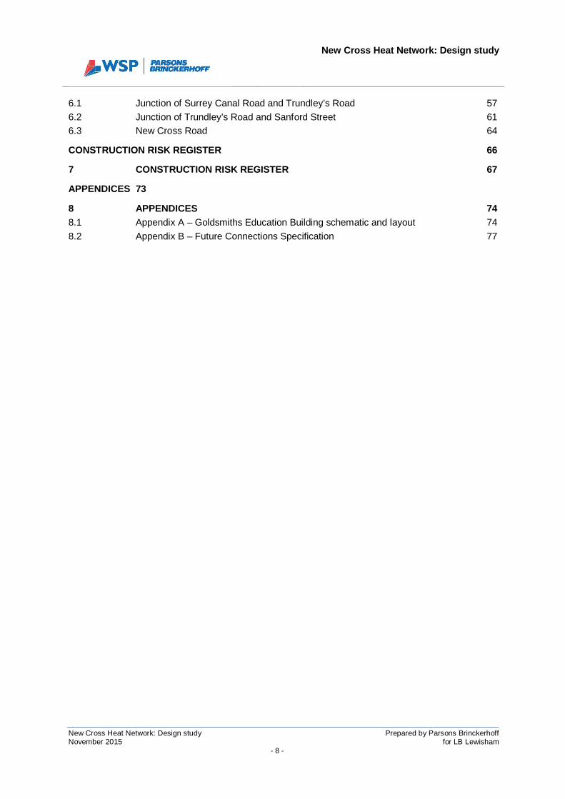
6.1 Junction of Surrey Canal Road and Trundley’s Road 576.2 Junction of Trundley’s Road and Sanford Street 616.3 New Cross Road 64
CONSTRUCTION RISK REGISTER 66
7 CONSTRUCTION RISK REGISTER 67
APPENDICES 73
8 APPENDICES 748.1 Appendix A – Goldsmiths Education Building schematic and layout 748.2 Appendix B – Future Connections Specification 77

New Cross Heat Network: Design study
New Cross Heat Network: Design study Prepared by Parsons BrinckerhoffNovember 2015 for LB Lewisham
- 9 -
ABBREVIATIONS
°C degrees celsius
CHP Combined Heat and Power (engine)
DECC Department of Energy Climate Change
DE Decentralised Energy
DHW Domestic Hot Water
DH District Heating
EHV Extra High Voltage
EfW Energy from Waste
GW Gigawatts
GWh Gigawatt-hour
GPR Ground Penetrating Radar
HIU Heat Interface Unit
HV High Voltage
IP Intermediate Pressure
kW Kilowatts
kWh Kilowatt-hour
LP Low Pressure
LV Low Voltage
LBL London Borough of Lewisham
m metres
m/s metres per second
mm millimetres
MPa Megapascals
MW Megawatts
MWh Megawatt-hour
NDT Non-Destructive Testing
SGN Southern Gas Networks
SCR Surrey Canal Road
SELCHP South East London Combined Heat and Power
SH Space Heating
TfL Transport for London
WRC Landmann Way Waste Reception Centre
WSP | PB WSP | Parsons Brinckerhoff

New Cross Heat Network: Design study
New Cross Heat Network: Design study Prepared by Parsons BrinckerhoffNovember 2015 for LB Lewisham
- 11 -
EXECUTIVE SUMMARY
This sheet is intended as a summary only
Key high level information determined in this study is presented below.
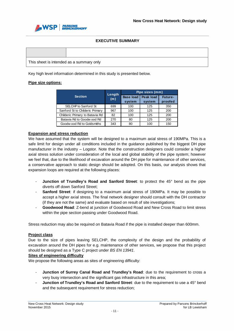
Pipe size options:
Expansion and stress reductionWe have assumed that the system will be designed to a maximum axial stress of 190MPa. This is asafe limit for design under all conditions included in the guidance published by the biggest DH pipemanufacturer in the industry – Logstor. Note that the construction designers could consider a higheraxial stress solution under consideration of the local and global stability of the pipe system; howeverwe feel that, due to the likelihood of excavation around the DH pipe for maintenance of other services,a conservative approach to static design should be adopted. On this basis, our analysis shows thatexpansion loops are required at the following places:
- Junction of Trundley’s Road and Sanford Street: to protect the 45° bend as the pipediverts off down Sanford Street;
- Sanford Street: if designing to a maximum axial stress of 190MPa. It may be possible toaccept a higher axial stress. The final network designer should consult with the DH contractor(if they are not the same) and evaluate based on result of site investigations;
- Goodwood Road: Z-bend at junction of Goodwood Road and New Cross Road to limit stresswithin the pipe section passing under Goodwood Road.
Stress reduction may also be required on Batavia Road if the pipe is installed deeper than 600mm.
Project classDue to the size of pipes leaving SELCHP, the complexity of the design and the probability ofexcavation around the DH pipes for e.g. maintenance of other services, we propose that this projectshould be designed as a Type C project under BS EN 13941.Sites of engineering difficultyWe propose the following areas as sites of engineering difficulty:
- Junction of Surrey Canal Road and Trundley’s Road: due to the requirement to cross avery busy intersection and the significant gas infrastructure in this area;
- Junction of Trundley’s Road and Sanford Street: due to the requirement to use a 45° bendand the subsequent requirement for stress reduction;
Base loadsystem
Peak loadsystem
Future-proofed
SELCHP to Sanford St 699 100 125 350Sanford St to Childeric Primary 967 100 125 200Childeric Primary to Batavia Rd 82 100 125 200Batavia Rd to Goodw ood Rd 270 80 125 200Goodw ood Rd to Goldsmiths 343 80 100 150
Pipe sizes (mm)Section Length
(m)
New Cross Heat Network: Design study
New Cross Heat Network: Design study Prepared by Parsons BrinckerhoffNovember 2015 for LB Lewisham
- 12 -
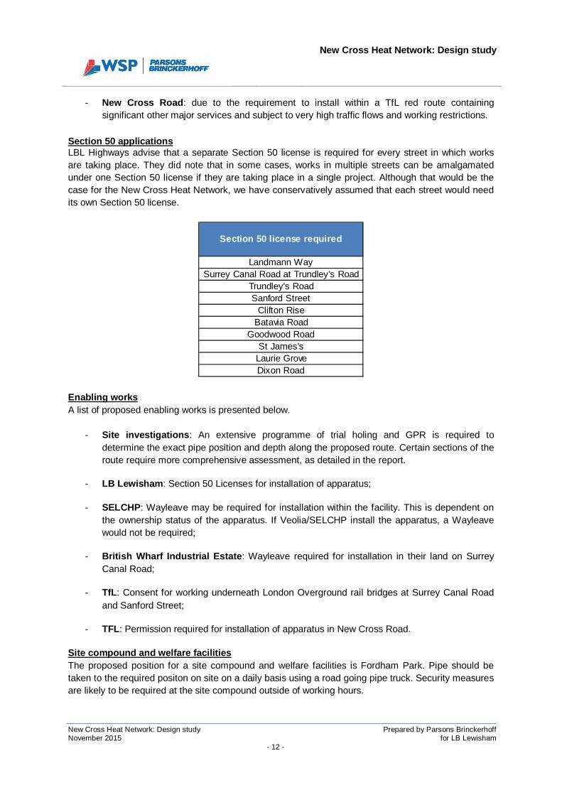
- New Cross Road: due to the requirement to install within a TfL red route containingsignificant other major services and subject to very high traffic flows and working restrictions.
Section 50 applicationsLBL Highways advise that a separate Section 50 license is required for every street in which worksare taking place. They did note that in some cases, works in multiple streets can be amalgamatedunder one Section 50 license if they are taking place in a single project. Although that would be thecase for the New Cross Heat Network, we have conservatively assumed that each street would needits own Section 50 license.
Enabling worksA list of proposed enabling works is presented below.
- Site investigations: An extensive programme of trial holing and GPR is required todetermine the exact pipe position and depth along the proposed route. Certain sections of theroute require more comprehensive assessment, as detailed in the report.
- LB Lewisham: Section 50 Licenses for installation of apparatus;
- SELCHP: Wayleave may be required for installation within the facility. This is dependent onthe ownership status of the apparatus. If Veolia/SELCHP install the apparatus, a Wayleavewould not be required;
- British Wharf Industrial Estate: Wayleave required for installation in their land on SurreyCanal Road;
- TfL: Consent for working underneath London Overground rail bridges at Surrey Canal Roadand Sanford Street;
- TFL: Permission required for installation of apparatus in New Cross Road.
Site compound and welfare facilitiesThe proposed position for a site compound and welfare facilities is Fordham Park. Pipe should betaken to the required positon on site on a daily basis using a road going pipe truck. Security measuresare likely to be required at the site compound outside of working hours.
Section 50 license required
Landmann WaySurrey Canal Road at Trundley's Road
Trundley's RoadSanford Street
Clifton RiseBatavia Road
Goodwood RoadSt James's
Laurie GroveDixon Road

New Cross Heat Network: Design study
New Cross Heat Network: Design study Prepared by Parsons BrinckerhoffNovember 2015 for LB Lewisham
- 13 -
Other itemsThe following are also provided in the report:
1) Construction risk register;2) Section analysis and methodology3) Pipe network interface register4) Trench dimensions for different pipe sizes5) Typical trench sections6) Future connections specification

New Cross Heat Network: Design study
New Cross Heat Network: Design study Prepared by Parsons BrinckerhoffNovember 2015 for LB Lewisham
- 14 -
SECTION 1
INTRODUCTION
New Cross Heat Network: Design study
New Cross Heat Network: Design study Prepared by Parsons BrinckerhoffNovember 2015 for LB Lewisham
- 15 -
1 INTRODUCTION
1.1 Background
1.1.1 WSP | Parsons Brinckerhoff was appointed by the London Borough of Lewisham (LBLhereafter) to undertake a feasibility study for a heat network supplying Goldsmiths, Universityof London (Goldsmiths hereafter) with heat from the SELCHP waste incineration plant. Thewider assessment consists of four elements:
Element A: A route optimisation study to determine the most effective route betweenSELCHP and Goldsmith’s College;
Element B: A network expansion assessment to identify opportunities to establish additionalconnections to the network;
Element C: A design study to identify the technical requirements of the heat network, allowinglikely costs to be calculated;
Element D: A governance and delivery options study for the heat network.
1.1.2 This report represents the output for Element C. Elements A and B have already been issuedand Element D will be delivered in a separate report.
1.2 Report structure
1.2.1 This report progresses the design of the preferred route between SELCHP and Goldsmithsidentified in the Element A report. Pipe sizes have been calculated for the Element D reportand have been used to inform routing and static design calculations included in this report.
1.2.2 Pipes have been sized for the expanded network identified in the Element B report andinclude options for both peak and base load supply. They have also been future-proofed foradditional unknown load.
1.2.3 The report assesses key design elements, including the interfaces at Goldsmiths, pipe stressand expansion, and sites of engineering difficulty. A future connection specification is includedfor pre-existing buildings and new build heat customers; and a section by section analysis andpipe interface register summarise the key logistical considerations for each section of theproposed route. A construction risk register is also included.

New Cross Heat Network: Design study
New Cross Heat Network: Design study Prepared by Parsons BrinckerhoffNovember 2015 for LB Lewisham
- 16 -
SECTION 2
DESIGN

New Cross Heat Network: Design study
New Cross Heat Network: Design study Prepared by Parsons BrinckerhoffNovember 2015 for LB Lewisham
- 17 -
2 DESIGN
2.1 Network length
2.1.1 The as-installed network length will differ from the design network length as there willundoubtedly be small variations arising from conditions once the ground is excavated.
2.1.2 Section 5.3 recommends a programme of ground penetrating radar and trial holes toestablish the exact position of existing services in key areas of the network. Once thiswork has been undertaken, for-construction design can be completed, allowing amore accurate assessment of network length to be undertaken.
2.1.3 In the absence of site investigation data, we have measured the network length basedon the preferred route, as discussed in the section analysis presented in Section 4;and on the design for sites of engineering difficulty presented in Section 6.
2.1.4 The preferred network, as proposed, is 2,361 metres in length.
2.2 Typical route sections
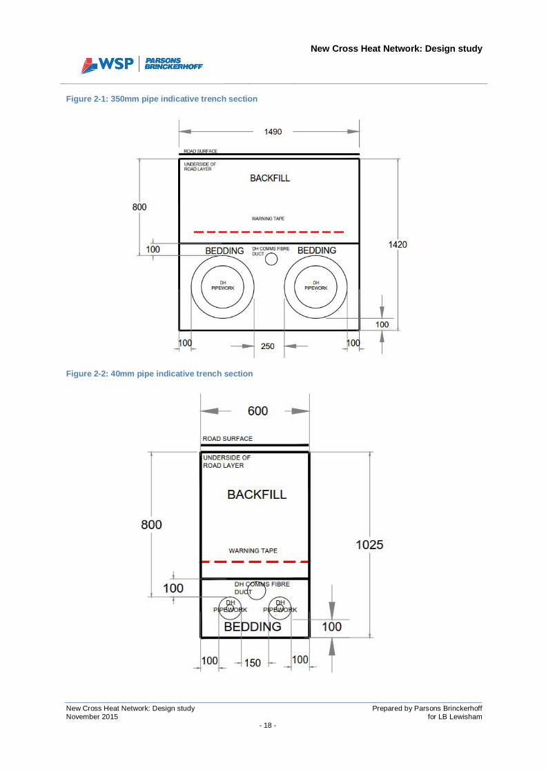
2.2.1 Trench cross sections will vary across the network according to the size of the pipeand the position and size of existing services. A summary of typical trench dimensionsfor different pipe sizes is presented in Table 2-1.
Table 2-1: Typical trench dimensions for different pipe diameters
NB: Assumes pipe insulation Series 2; cover to crown of pipe = 800mm
2.2.2 Trench cross sections for 40mm and 350mm pipe are presented by way of example inFigure 2-1 and Figure 2-2.
Pipe diameter(mm)
Trenchwidth(mm)
Trenchdepth(mm)
40 600 102550 630 104065 670 106080 710 1080
100 800 1125125 950 1150150 1010 1180200 1160 1255250 1350 1350300 1450 1400350 1490 1420
New Cross Heat Network: Design study
New Cross Heat Network: Design study Prepared by Parsons BrinckerhoffNovember 2015 for LB Lewisham
- 18 -
Figure 2-1: 350mm pipe indicative trench section
Figure 2-2: 40mm pipe indicative trench section
New Cross Heat Network: Design study
New Cross Heat Network: Design study Prepared by Parsons BrinckerhoffNovember 2015 for LB Lewisham
- 19 -
2.3 Goldsmiths interface – Education Building
2.3.1 Goldsmiths’ ambition is that all of the heat load on their campus DH networks will beserved from either the new 1 St James’ energy centre or the existing EducationBuilding energy centre. As such, only two points of connection to the DH network willbe required.
2.3.2 The Education Building is, at the time of writing, undergoing a boiler replacementprogramme that includes stripping out asbestos contaminated pipework. We visitedthe site prior to the boiler replacement programme and Goldsmiths subsequentlyprovided schematic and layout drawings for the plant room (post-installation of newboilers). The schematic and layout drawings have been developed by AECOM andare included in Appendix A of this report.
2.3.3 AECOM’s schematic (MEP_100) shows two 200mm blanked DH connections on theexisting boiler return pipework and also one on each of the new flow and returnheaders that are being installed as part of the boiler replacement programme. Thereare, therefore, two options for connecting a DH substation to the existing EducationBuilding system. It is noted that AECOM’s layout drawing (MEP_101) does not showspace for a heat interface / substation for the incoming DH network. Followingconsultation with Goldsmiths, they confirmed that space is being allowed for a heatinterface in the Oil Store, which is adjacent to the Education Building plant room.
2.3.4 It should also be noted that the 200mm blanked connections that have been left arebased on a supply from SELCHP of approximately 5.5MW (as stated on drawingMEP_100). The assumptions behind this sizing are not clear; however we believe thatit is based on a future configuration of load distribution and buildings connected to thecampus heat network at Goldsmiths. We have downloaded gas consumption data forthe Education Building plant room for the period 2013 to 2015 and the peak halfhourly gas consumption through this period was 467kWh. Note that this is not theinstantaneous peak; rather the maximum consumption over a half hour period.
2.3.5 Goldsmiths have advised that their intention is for other buildings to be connected toan expanded campus heat network in the future and it is upon this basis that our loadassessment has been undertaken. We have been advised by Goldsmiths as to whichof their existing buildings will be connected to the campus heat network and, from theexisting boiler gas consumption data, we have assessed the connected loadassociated with this future scenario. This assessment, which is detailed further in theElement B report and takes account of future changes in campus building stock,concludes that the maximum hourly heat load for buildings that will be connected tothe DH network would be 2MW over an hour. This assessment is based on half hourlykWh demands, so the peak instantaneous load in the connected buildings will behigher; however it makes little sense to size the SELCHP connections to meetinstantaneous peak demand when there are existing boilers with sufficient resilienceto do that job (the new 1 St James’ building will also have its own boiler plant).
2.3.6 Based on our assessment and the information provided by Goldsmiths with regard totheir future intentions for internal heat networks, a 2MW supply from SELCHP wouldbe enough to serve almost all of the connected heat load which, based on gas
New Cross Heat Network: Design study
New Cross Heat Network: Design study Prepared by Parsons BrinckerhoffNovember 2015 for LB Lewisham
- 20 -
consumption data between 2012 and 2015, is in the region of 3.9GWh. The ElementD report will assess the commercial viability of reducing the connection sizes to abaseload only supply. This should be considered, given the cost of installing DHinfrastructure and the issues identified in the Element A report around the number ofexisting services along the proposed route.
2.3.7 It is not possible at this stage to determine the distribution of the future connectedload across the two Goldsmiths interfaces (Education Building and 1 St James’). Wehave therefore assumed an equal split, thus requiring an interface of 1MW at each ofthe two substations. Possibly lower if a baseload supply is determined to be moreeconomically advantageous in the Element D report.
2.3.8 Goldsmiths have also stated their intention to undertake measures in their buildingstock to lower return temperatures. Their existing systems are 82/71°C flow andreturn however; as stated in the Element A report, we have assumed that their returntemperatures will come down to around 60°C, providing a primary return temperatureto the DH network of 65°C.
2.3.9 Based on the 2MW peak supply distributed across two substations of 1MW each; anda primary return temperature of 65°C (with a supply temperature from SELCHP of110°C), we conclude that 80mm connections would be appropriate for each of thesubstations at 1 St James’ and the Education Building. This is based on thetemperature and load inputs just described and a maximum allowable pressure lossof 200 pascals per metre. Pressure loss and velocity limits are used to ensure theflow of water in the pipe does not cause excessive wear to the pipework and does notlead to excessive pumping energy requirements.
2.3.10 With regard to the positioning of the blanked connections in the Education Building,the two on the existing boiler return pipework are appropriate for supplying heat fromSELCHP to the plant room. We have concluded that the DH connection will not besized for peak instantaneous demand, so it is important to design the DH interface forconditions where the flow rate on the Goldsmiths circuit exceeds the flow rate acrossthe DH heat exchanger. We have shown a high level interface design in Figure 2-3.
2.3.11 We have not seen the controls strategy for AECOM’s design; however, based on theschematic, we note that it shows a pump on every secondary circuit coming off thenew boiler header as well as a shunt pump (P2) onto the header. It is unclear whatpump P2 controls to; however it may be possible to remove the pumps on the twonon-weather compensated circuits (pump P8 for the Rutherford Building; and pumpP11 for the link to the main site boiler house) and allow pump P2 to control to adifferential pressure across DPV11 on PHE3 in the old oil store. A minimum flowbypass would also be required to limit the flow around the new 200mm headers whenthe pump is at reduced output. These potential modifications are shown on Figure2-3.
1 DPV1 is not currently installed. It would be necessary to install it in order to control the pump P2 on differentialpressure.

New Cross Heat Network: Design study
New Cross Heat Network: Design study Prepared by Parsons BrinckerhoffNovember 2015 for LB Lewisham
- 21 -
Figure 2-3: Education Building DH interface and possible secondary system modifications (adapted from AECOM drawing 60312517-MEP-100)
New Cross Heat Network: Design study
New Cross Heat Network: Design study Prepared by Parsons BrinckerhoffNovember 2015 for LB Lewisham
- 22 -
2.3.12 The DH substation would then controls as follows:
- P14 controls to maintain a zero delta T (plus margin) at TS2 minus TS1;
- CV1 controls to maintain specified flow temperature at TS3 – nominally 82°C.
2.4 Goldsmiths interface – 1 St James’
2.4.1 1 St James’ is part of the future campus development proposals for Goldsmiths. Assuch, it has not been constructed and therefore the interface with the New Cross HeatNetwork can be included as part of the M&E proposals for the energy centre that willbe located within it.
2.4.2 The timeline for construction of 1 St James’ is 2015 to 2018, as detailed in theGoldsmiths Master Plan (John McAslan & Partners, 2014).
2.4.3 Given that there are not yet any proposals for the design of the energy centre, it isproposed that the M&E designers for the project follow the guidance set out in theNew Connection Specification referred to in Section 3 and presented in Appendix B.
2.5 Pipe sizing
2.5.1 It is important to note that there are implications if DH pipe is oversized. Low flowrates in large diameter pipes can lead to significant heat losses as the system waterspends a long time in transit between the heat source (SELCHP) and the customer.This is particularly an issue in the summer months, when heat load is low. Minimumflow rates can be achieved with a bypass arrangement at the furthest load(Goldsmiths); however this would mean increased pumping energy to maintain asuitable flow rate.
2.5.2 Similarly, under-sizing of the pipework means increased frictional losses andtherefore greater pumping energy requirement. It is important, therefore, that thedetailed system design ensures adequate capacity in the pipe for the required loadconditions without unnecessarily reducing the efficiency of the connection toGoldsmiths.
2.5.3 A balance must be struck between ensuring sufficient capacity within the pipe forfuture load scenarios, and optimising the operational performance of the scheme withregard to pumping energy and heat losses. We therefore recommend that pipe sizingis revisited as the scheme is further defined with regard to loads other thanGoldsmiths that may connect in the future. The following is taken from theCIBSE/ADE UK Heat Networks Code of Practice:
In both new build and retrofit schemes there are significant uncertainties in how theheat demands may develop over time and there will be a need to make a judgementregarding the potential for expansion. In practice some oversizing is not a majoreconomic penalty as the pumping energy will be lower. Similarly, within the pressureconstraints of the system, it will be possible to supply more heat than the originaldesign through the same network by increasing pump pressures and operating
New Cross Heat Network: Design study
New Cross Heat Network: Design study Prepared by Parsons BrinckerhoffNovember 2015 for LB Lewisham
- 23 -
energy. This means that most networks if conservatively designed will haveconsiderable flexibility in the heat demands that can be economically supplied.
2.5.4 For the purposes of this analysis, LBL requested that we evaluate the pipe sizing onthe basis of Goldsmiths supply with the addition of a number of loads adjacent to thepipework linking Goldsmiths and SELCHP. They are:
- Childeric Primary school
- Batavia Road
- Goodwood Road
- Bond House
2.5.5 It has previously been stated that two heat supply options will be assessed economicviability:
1) Peak load supply: SELCHP meets peak demand at Goldsmiths and additionalloads identified above. Back-up boilers are located at each customer site for whenheat from SELCHP is unavailable;
2) Base load supply: Pipes are sized to meet base load demand at Goldsmiths andthe loads identified above. Back-up boilers are located at each customer site forwhen demand rises above the base load connection or heat from SELCHP isunavailable.
2.5.6 Pipes sized for the two scenarios above would not be sufficient to supply the otherloads identified in the Element B study, e.g. Convoys Wharf and Surrey CanalTriangle.
2.5.7 A third pipe sizing scenario has therefore been assessed, wherein the pipes are sizedfor a future-proofed network, serving not only the loads in the peak and base loadscenarios identified above, but the whole preferred expanded network identified in theElement B study, as follows:

New Cross Heat Network: Design study
New Cross Heat Network: Design study Prepared by Parsons BrinckerhoffNovember 2015 for LB Lewisham
- 24 -
Table 2-2: Expanded network loads
2.5.8 It is noted that the design specification included in the ITT documentation states thatpipes should be at specified diameters at key points along the network, as follows:
- SELCHP to the junction of Surrey Canal Road and Trundley’s Road – 350mm.- Junction of Trundley’s Road and Sanford Street – 200mm
2.5.9 We have undertaken our own assessment of pipe sizing for the preferred expandednetwork option and can confirm that the sizes put forward in the ITT document areappropriate for the expanded network identified in Element B with some additionalfuture proofing.
2.5.10 The pipe sizes required for each of the scenarios described above – base load; peakload and future-proofed – are presented below.
Table 2-3: Pipe sizes: base load, peak load and future-roofed networks
2.5.11 Note that pipe sizing for the future-proofed scenario should be revisited as thescheme’s engagement with potential additional connections such as Convoys Wharf
Name Type
Goldsmiths - 1 St James' Existing
Goldsmiths - Education Building Existing
Batavia Road New development
Surrey Canal Triangle Future development
Convoys Wharf Future development
Goodwood Road Future development
Bond House Future development
Achilles Street Council housing
Arklow Road Future development
The Wharves Deptford Future development
Grinstead Road/Neptune's Wharf Future development
Childeric Primary School Existing
Deptford Green School Existing
Base loadsystem
Peak loadsystem
Future-proofed
SELCHP to Sanford St 699 100 125 350Sanford St to Childeric Primary 967 100 125 200Childeric Primary to Batavia Rd 82 100 125 200Batavia Rd to Goodw ood Rd 270 80 125 200Goodw ood Rd to Goldsmiths 343 80 100 150
Pipe sizes (mm)Section Length
(m)
New Cross Heat Network: Design study
New Cross Heat Network: Design study Prepared by Parsons BrinckerhoffNovember 2015 for LB Lewisham
- 25 -
progresses and more is learned about the developments. Note the following from theCIBSE/ADE UK Heat Networks Code of Practice.
For new buildings the heat demand estimates should be produced by the appointedbuilding services designer although the Heat Network designer may have valuableadvice to offer based on previous experience. It is vital that a consensus is reached atthis stage to avoid the potential for significantly oversizing or undersizing the network.
2.5.12 Furthermore, as the structuring of the network delivery is further defined (see ElementD report), the scheme design should take account of the owner’s intentions for thelong-term expansion of the scheme. It may be that a private sector owner may notwish to expand the scheme in line with the expanded network identified in Element B.If this is the case, the pipe sizes should be re-evaluated to avoid long-term issues withefficiency, as described in Section 2.5.1.
2.6 Expansion and stress reduction
2.6.1 There are multiple factors that affect expansion and the requirement for stressreduction in a district heating pipe and it is important that a detailed design process,including full static calculations for expansion and stress analysis, precedes theproject construction phase.
2.6.2 Based on the routing proposed in this feasibility study and the condition of the heatavailable from SELCHP, it is possible to undertake a preliminary assessment of thelikely stress characteristics and expansion on the network.
2.6.3 Expansion in buried DH mains is limited by the friction force applied to the pipe fromthe soil above it. Limiting expansion in this way means the pipe is under axial stressas the soil prevents the free expansion of the pipe.
2.6.4 In calculating stress and expansion, the depth of soil cover, the length and diameterof the pipe section, the temperature of the water and the insulation thickness are thedetermining factors. Expansion is greatest on long sections of straight pipe, i.e. wherethere is the greatest distance between expansion ends.
2.6.5 In determining the requirement for stress reduction, there are multiple options. Wherepipes are 300mm in diameter or below and the design temperature differential2 doesnot exceed 130°C, the designer may choose not to use any stress reduction. This isacceptable under certain conditions, but can put the system at risk of buckling ifexcavation around the installed pipe (e.g. for maintenance of other nearby services)causes it to expand further as friction material (which limits expansion) is removed.
Another, more conservative approach is to design an L190 system. This is whereaxial stresses in the pipe are never allowed to exceed 190 MPa.
2.6.6 If the design requires stress reduction, there are three ways of achieving it.
2 The design temperature differential is defined as the maximum flow temperature and the cold fill temperature(assuming there is no preheating of the pipe), i.e. before the water is heated for the first time. The cold filltemperature in the UK is typically take to be between 8°C and 10°C.
New Cross Heat Network: Design study
New Cross Heat Network: Design study Prepared by Parsons BrinckerhoffNovember 2015 for LB Lewisham
- 26 -
1) By adding bends to take up the expansion and therefore reduce the axial stress:Typically this is done with U-loops – also known as expansion loops. Thisapproach is expensive and requires space for the U-loop to be installed. It alsoincreases the frictional losses in the pipework;
2) Expansion compensators: These are fittings that take up the initial expansionwithin a pipe as the water is heated for the first time. Once the water is up totemperature, the expanded compensator is permanently secured and becomespart of the main pipe. The disadvantage to this approach is that it only worksonce;
3) Pre-stressing: This is where the pipe is pre-heated to take up some of theexpansion before it is buried. This is expensive as it requires electricity to heat thepipe and also requires long sections of trench to be left open at any one time.
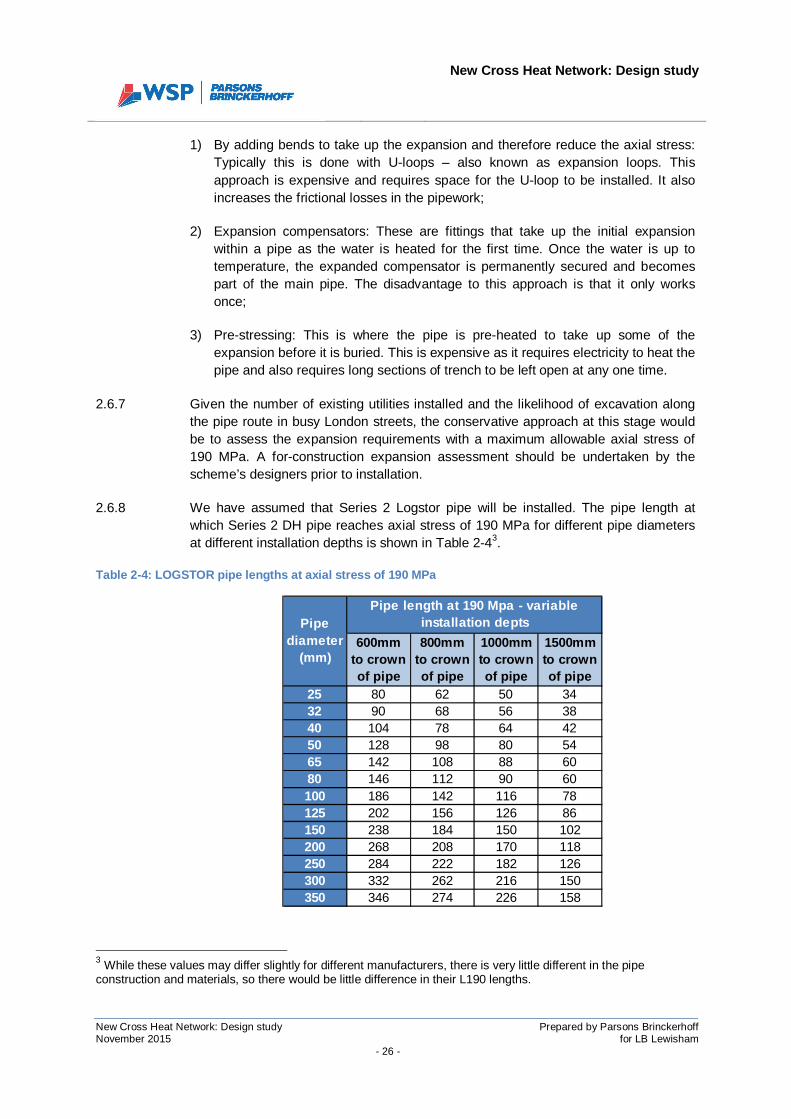
2.6.7 Given the number of existing utilities installed and the likelihood of excavation alongthe pipe route in busy London streets, the conservative approach at this stage wouldbe to assess the expansion requirements with a maximum allowable axial stress of190 MPa. A for-construction expansion assessment should be undertaken by thescheme’s designers prior to installation.
2.6.8 We have assumed that Series 2 Logstor pipe will be installed. The pipe length atwhich Series 2 DH pipe reaches axial stress of 190 MPa for different pipe diametersat different installation depths is shown in Table 2-43.
Table 2-4: LOGSTOR pipe lengths at axial stress of 190 MPa
3 While these values may differ slightly for different manufacturers, there is very little different in the pipeconstruction and materials, so there would be little difference in their L190 lengths.
600mmto crownof pipe
800mmto crownof pipe
1000mmto crownof pipe
1500mmto crownof pipe
25 80 62 50 3432 90 68 56 3840 104 78 64 4250 128 98 80 5465 142 108 88 6080 146 112 90 60100 186 142 116 78125 202 156 126 86150 238 184 150 102200 268 208 170 118250 284 222 182 126300 332 262 216 150350 346 274 226 158
Pipediameter
(mm)
Pipe length at 190 Mpa - variableinstallation depts
New Cross Heat Network: Design study
New Cross Heat Network: Design study Prepared by Parsons BrinckerhoffNovember 2015 for LB Lewisham
- 27 -
2.6.9 Note that the position at which axial stress reaches 190MPa in a straight pipe run isindependent of temperature. The temperature differential affects the maximum axialstress level that could be reached in a pipe, for example if the temperature differentialis 50°C, the maximum axial stress level that could be reached in any length of pipe is125MPa.If the temperature differential was 100°C, the maximum axial stress level thatcould be reached in any length of pipe is 250MPa. The point at which these stresslevel are reached is a product of the pipe diameter and the force applied by the soilabove only – not the temperature.
2.6.10 It can be seen from the L190 data table (Table 2-4) that the shallower the pipe isburied, the longer it can be before it reaches an axial stress of 190 MPa. As describedearlier, the reason for this is because the soil applies a friction force to the pipe,restricting its free expansion and increasing the axial stress level. Therefore, althoughexpansion increases when pipe is installed at shallower depth, axial stress is reduced.
Surrey Canal Road
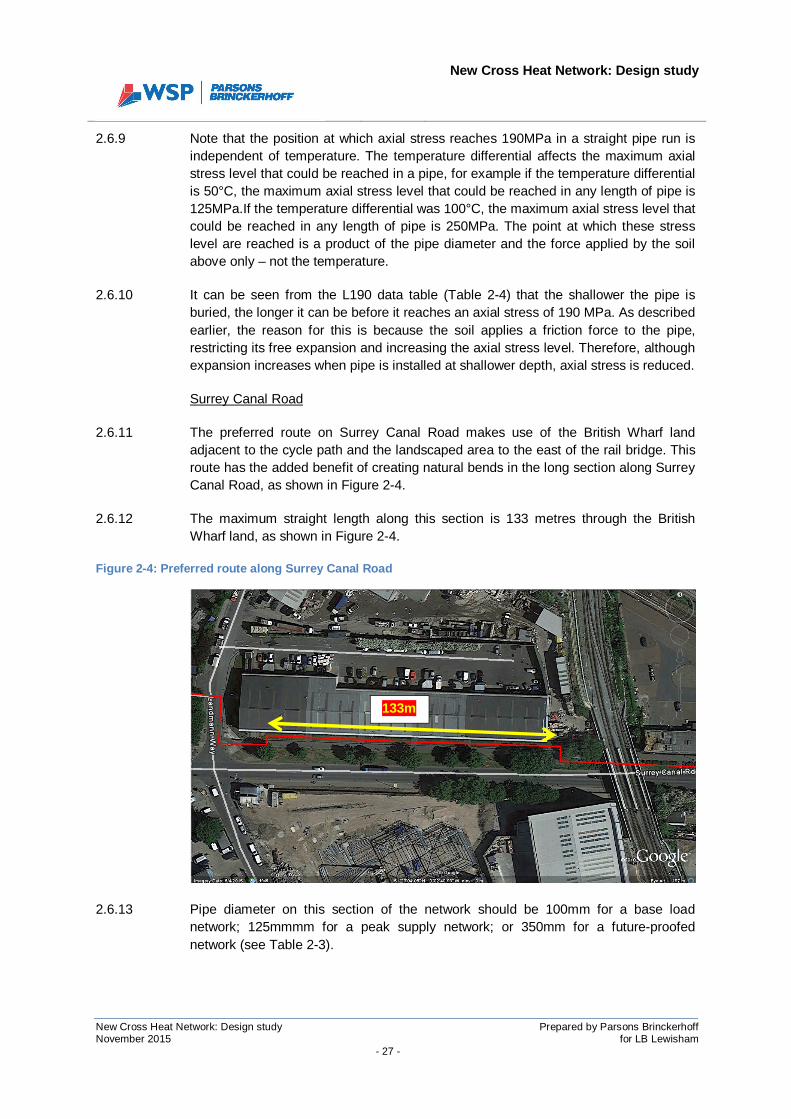
2.6.11 The preferred route on Surrey Canal Road makes use of the British Wharf landadjacent to the cycle path and the landscaped area to the east of the rail bridge. Thisroute has the added benefit of creating natural bends in the long section along SurreyCanal Road, as shown in Figure 2-4.
2.6.12 The maximum straight length along this section is 133 metres through the BritishWharf land, as shown in Figure 2-4.
Figure 2-4: Preferred route along Surrey Canal Road
2.6.13 Pipe diameter on this section of the network should be 100mm for a base loadnetwork; 125mmmm for a peak supply network; or 350mm for a future-proofednetwork (see Table 2-3).
133m
New Cross Heat Network: Design study
New Cross Heat Network: Design study Prepared by Parsons BrinckerhoffNovember 2015 for LB Lewisham
- 28 -
2.6.14 Referencing the maximum pipe lengths for 190MPa maximum axial stress in Table2-4, it confirms that stress reduction measures would not be required on Surrey CanalRoad unless the pipe is installed deeper than 800mm to the crown of the pipe. Theproposed route is to install through the soft dig British Wharf land, so it is unlikely thatthe pipe would need to be installed deeper than 800mm.
Trundley’s Road
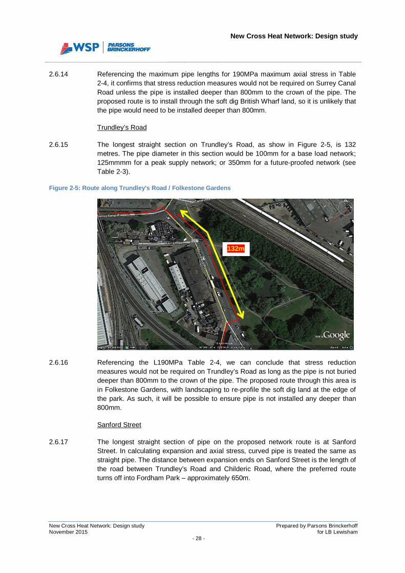
2.6.15 The longest straight section on Trundley’s Road, as show in Figure 2-5, is 132metres. The pipe diameter in this section would be 100mm for a base load network;125mmmm for a peak supply network; or 350mm for a future-proofed network (seeTable 2-3).
Figure 2-5: Route along Trundley's Road / Folkestone Gardens
2.6.16 Referencing the L190MPa Table 2-4, we can conclude that stress reductionmeasures would not be required on Trundley’s Road as long as the pipe is not burieddeeper than 800mm to the crown of the pipe. The proposed route through this area isin Folkestone Gardens, with landscaping to re-profile the soft dig land at the edge ofthe park. As such, it will be possible to ensure pipe is not installed any deeper than800mm.
Sanford Street
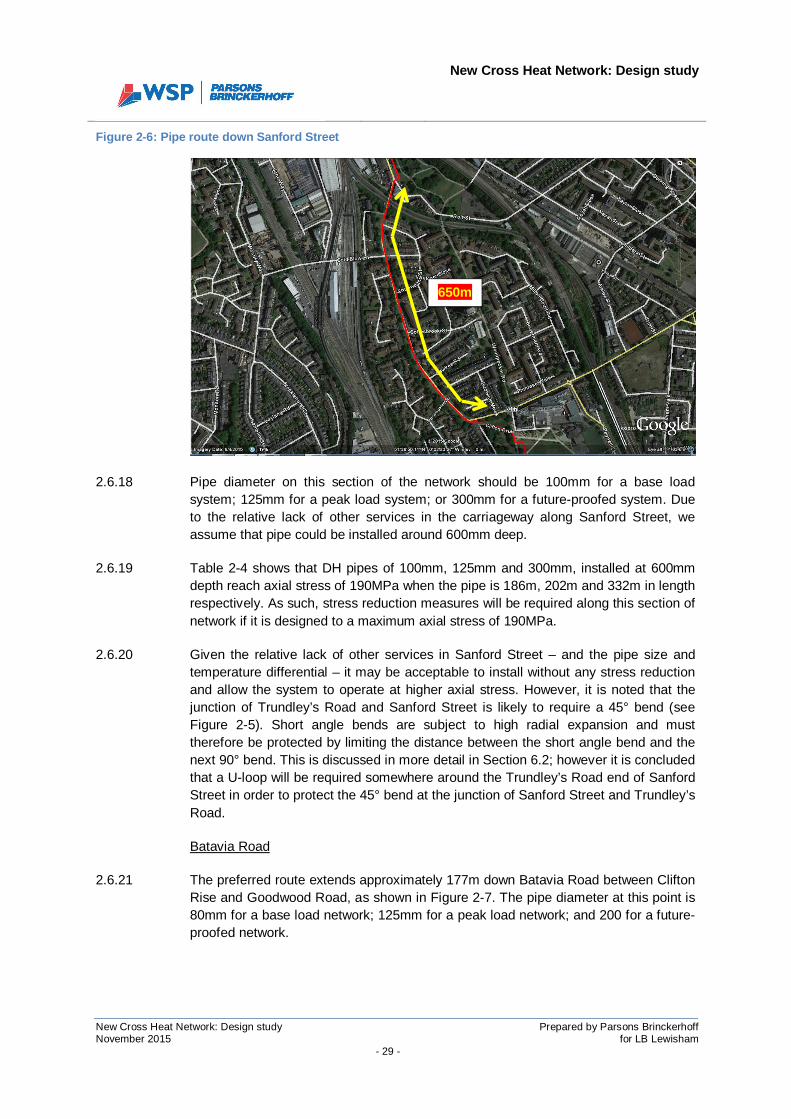
2.6.17 The longest straight section of pipe on the proposed network route is at SanfordStreet. In calculating expansion and axial stress, curved pipe is treated the same asstraight pipe. The distance between expansion ends on Sanford Street is the length ofthe road between Trundley’s Road and Childeric Road, where the preferred routeturns off into Fordham Park – approximately 650m.
132m
New Cross Heat Network: Design study
New Cross Heat Network: Design study Prepared by Parsons BrinckerhoffNovember 2015 for LB Lewisham
- 29 -
Figure 2-6: Pipe route down Sanford Street
2.6.18 Pipe diameter on this section of the network should be 100mm for a base loadsystem; 125mm for a peak load system; or 300mm for a future-proofed system. Dueto the relative lack of other services in the carriageway along Sanford Street, weassume that pipe could be installed around 600mm deep.
2.6.19 Table 2-4 shows that DH pipes of 100mm, 125mm and 300mm, installed at 600mmdepth reach axial stress of 190MPa when the pipe is 186m, 202m and 332m in lengthrespectively. As such, stress reduction measures will be required along this section ofnetwork if it is designed to a maximum axial stress of 190MPa.
2.6.20 Given the relative lack of other services in Sanford Street – and the pipe size andtemperature differential – it may be acceptable to install without any stress reductionand allow the system to operate at higher axial stress. However, it is noted that thejunction of Trundley’s Road and Sanford Street is likely to require a 45° bend (seeFigure 2-5). Short angle bends are subject to high radial expansion and musttherefore be protected by limiting the distance between the short angle bend and thenext 90° bend. This is discussed in more detail in Section 6.2; however it is concludedthat a U-loop will be required somewhere around the Trundley’s Road end of SanfordStreet in order to protect the 45° bend at the junction of Sanford Street and Trundley’sRoad.
Batavia Road
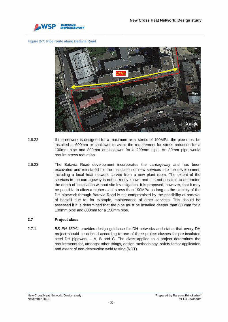
2.6.21 The preferred route extends approximately 177m down Batavia Road between CliftonRise and Goodwood Road, as shown in Figure 2-7. The pipe diameter at this point is80mm for a base load network; 125mm for a peak load network; and 200 for a future-proofed network.
650m
New Cross Heat Network: Design study
New Cross Heat Network: Design study Prepared by Parsons BrinckerhoffNovember 2015 for LB Lewisham
- 30 -
Figure 2-7: Pipe route along Batavia Road
2.6.22 If the network is designed for a maximum axial stress of 190MPa, the pipe must beinstalled at 600mm or shallower to avoid the requirement for stress reduction for a100mm pipe and 800mm or shallower for a 200mm pipe. An 80mm pipe wouldrequire stress reduction.
2.6.23 The Batavia Road development incorporates the carriageway and has beenexcavated and reinstated for the installation of new services into the development,including a local heat network served from a new plant room. The extent of theservices in the carriageway is not currently known and it is not possible to determinethe depth of installation without site investigation. It is proposed, however, that it maybe possible to allow a higher axial stress than 190MPa as long as the stability of theDH pipework through Batavia Road is not compromised by the possibility of removalof backfill due to, for example, maintenance of other services. This should beassessed if it is determined that the pipe must be installed deeper than 600mm for a100mm pipe and 800mm for a 150mm pipe.
2.7 Project class
2.7.1 BS EN 13941 provides design guidance for DH networks and states that every DHproject should be defined according to one of three project classes for pre-insulatedsteel DH pipework – A, B and C. The class applied to a project determines therequirements for, amongst other things, design methodology, safety factor applicationand extent of non-destructive weld testing (NDT).
177m
New Cross Heat Network: Design study
New Cross Heat Network: Design study Prepared by Parsons BrinckerhoffNovember 2015 for LB Lewisham
- 31 -
2.7.2 Class C projects are the most onerous in terms of design requirement and aregenerally defined as projects with large diameter pipes (>300mm) with a designtemperature differential of more than 130°C4 .
2.7.3 Class B projects are generally projects involving pipe sizes up to and including300mm and with a temperature differential of between 86°C and 130°C. Class Aprojects are for the same pipe size range as class B projects but with a temperaturedifferential up to 85°C.
2.7.4 There are factors that mean a system could be defined as class C even if pipe sizesdo not exceed 300mm and the temperature differential does not exceed 130°C.Examples of those conditions are:
- Where there is a likelihood of excavation along or across the pipe route. Soilapplies a friction force to buried pipework, limiting the expansion. Where this soilis removed, the pipe is free to expand, increasing the risk of buckling in thatsection.
- Where the network design is very complex, e.g. involving small angle bends(<90°).
- Where there is very little soil cover – particularly in sections where there is curvedpipe.
2.7.5 Heat supply from SELCHP would be at a maximum of 110°C, as confirmed bySELCHP. With a cold fill temperature of 10°C, the temperature differential on thenetwork would not exceed 130°C.
2.7.6 Pipe sizes have been assessed in Section 2.5 of this report and it has beenconcluded that the diameter of the pipe outside SELCHP could exceed 300mm. It isalso clear that there are sections of the network where there are a significant numberof other services in the vicinity. As such, the probability of there being excavationaround the pipework, once installed, is considered to be quite high. We thereforepropose that this project should be considered a Type C project as per BS EN 13941.
4 The temperature differential referred to here is the differential between the flow temperature and the cold filltemperature in the DH pipework.

New Cross Heat Network: Design study
New Cross Heat Network: Design study Prepared by Parsons BrinckerhoffNovember 2015 for LB Lewisham
- 32 -
SECTION 3
FUTURE CONNECTION SPECIFICATION

New Cross Heat Network: Design study
New Cross Heat Network: Design study Prepared by Parsons BrinckerhoffNovember 2015 for LB Lewisham
- 33 -
3 FUTURE CONNECTION INTERFACE SPECIFICATION
3.1.1 A future connection specification for both pre-existing and new build additions to theDH network is presented in Appendix B.

New Cross Heat Network: Design study
New Cross Heat Network: Design study Prepared by Parsons BrinckerhoffNovember 2015 for LB Lewisham
- 34 -
SECTION 4
SECTION ANALYSIS AND INSTALLATIONMETHODOLOGY
New Cross Heat Network: Design study
New Cross Heat Network: Design study Prepared by Parsons BrinckerhoffNovember 2015 for LB Lewisham
- 35 -
4 SECTION ANALYSIS AND INSTALLATION METHODOLOGY
4.1 SELCHP
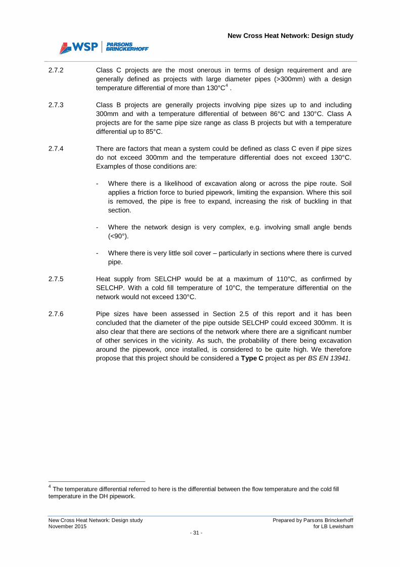
4.1.1 The pipe route within the SELCHP facility has been determined by Veolia and is asdescribed in the Element A report and shown above. The pipe will be installed aboveground within the facility boundary and will be supported from multiple structures,including the curved access ramp from which waste vehicles access the facility. Thistype of installation will require bespoke design and it is recommended that one of thepipe manufacturers is engaged to assist in this design process.
Overall length of section: 175m
Length of hard dig: 0m
Length of soft dig: 0m
Length above ground: 175m
Key issues:
· Wayleave required for installation in SELCHP Ltd land, unless SELCHP ownthe pipework;
· Installation must not affect daily operations within the facility (access oftrucks);
· Greater expansion due to installation above ground (not restrained by frictionfrom soil);
· Bespoke design for bracketry supporting the pipe under the access ramp(see Figure 4-1);
· Consideration of anchoring and implications on supporting structures;
· Working at height as pipe is supported by structures at high level;
· Mechanical protection of the exposed pipework may be required.

New Cross Heat Network: Design study
New Cross Heat Network: Design study Prepared by Parsons BrinckerhoffNovember 2015 for LB Lewisham
- 36 -
Figure 4-1: Example of supporting bracket for DH pipe
4.1.2 Proposed methodology:
· In discussion with Veolia, they advised that they would appoint a competentcontractor to undertake the works within their site. As such, depending on thedelivery structure, the contractor delivering the wider DH network may berequired to interface at a demarcation point at the SELCHP boundary with theSELCHP appointed contractor;
· If required, a short shutdown period could be arranged for the existing DHnetwork; however this would be a short period and would most likely be in thesummer;
· Veolia would liaise with the contractor with regards storage and workingconditions within their site.
New Cross Heat Network: Design study
New Cross Heat Network: Design study Prepared by Parsons BrinckerhoffNovember 2015 for LB Lewisham
- 37 -
4.2 Waste Reception Centre and Landmann Way
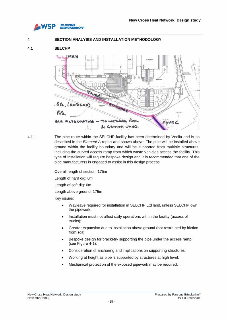
4.2.1 SELCHP’s original proposal was for the pipe to be installed straight through theLandmann Way Waste Reception Centre (WRC). The Element A report identified thatthis approach would require installation through more of the new cycle route andwould therefore be more expensive. It was confirmed with LBL waste andenvironment officers that the route could pass through the middle of the WRC and outonto Landmann Way as long as provision could be made for alternative wastedisposal during the installation period. They also noted that the pipe installationshould not affect the two ponds in the WRC.
Overall length of section: 95m
Length of hard dig: 95m
Length of soft dig: 0m
4.2.2 Key issues:
· Access for refuse vehicles using SELCHP must be maintained;
· Access to British Wharf industrial estate and other businesses on LandmannWay must be maintained;
· Temporary closing of WRC means alternative must be provided until itreopens;
· Ponds within WRC boundary to be unaffected by works;
· Pipe to cross line of existing services on Landmann Way.
4.2.3 Proposed methodology:
· Pre-tender for contractor, consult SELCHP with regard to scheduling of worksand maintaining access to SELCHP during works;
New Cross Heat Network: Design study
New Cross Heat Network: Design study Prepared by Parsons BrinckerhoffNovember 2015 for LB Lewisham
- 38 -
· Liaise with British Wharf and other business owners to advise of worksschedule and discuss provision for access;
· Advance notice signs for closure of WRC and works on Landmann Way.Allow sufficient lead time;
· Night-time working when crossing Landmann Way to minimise disruption;
· Use road plates over trenches as necessary to allow continued access toSELCHP during daytime.
4.3 Surrey Canal Road
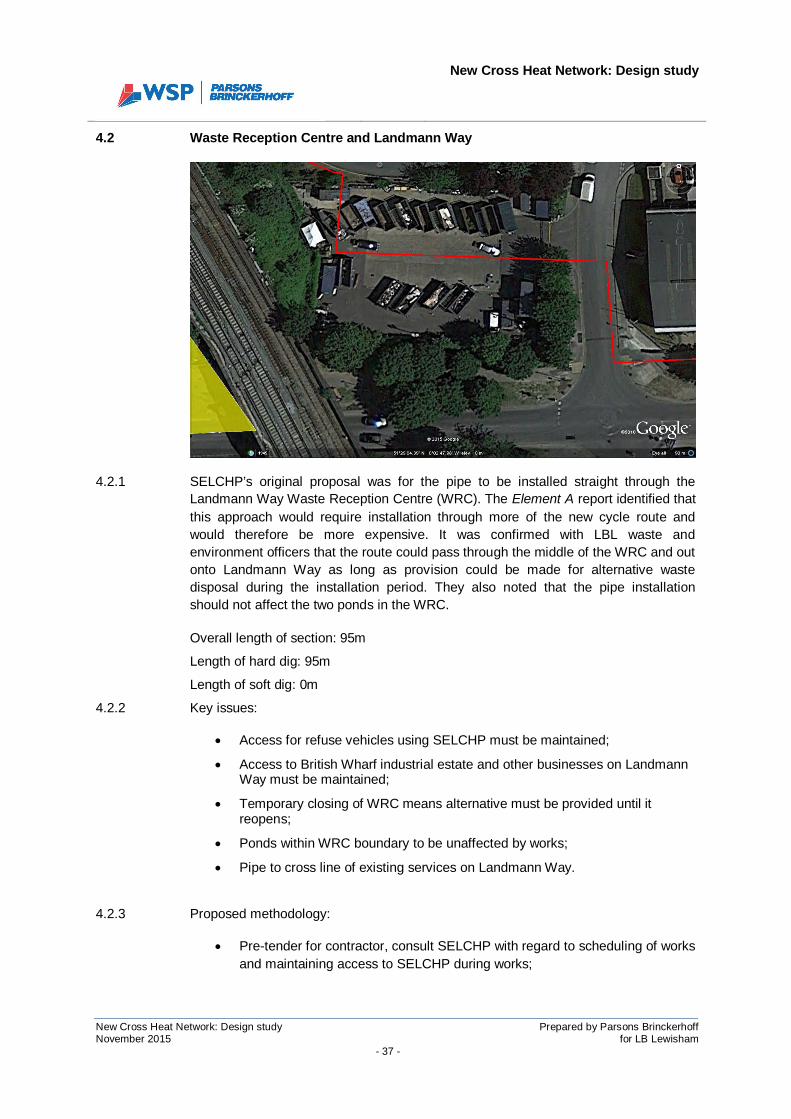
4.3.1 Following the issue of the Element A report, a risk workshop was held with LBLdepartmental officers to discuss some of the issues around key sections of theproposed route. Two options had been identified as potentially viable for installation inSurrey Canal Road: installation in the south side footway; or installation in the BritishWharf soft dig land, moving into the landscaped area between the cycle path and thecarriageway. Of the two options, it was concluded that the south side footway wouldnot be viable due to the impact on traffic flows from the working area, which wouldencroach onto the road. The soft dig land adjacent to the cycle path is thereforepreferred on the basis that it minimises the impact on the carriageway, which is amajor route through the area. This area requires a wayleave from British Wharf, whoown the soft dig land. If this cannot be arranged, it may be necessary to install in thecycle path, although this should be avoided if at all possible.
4.3.2 Key information:
Overall length of section: 280m
Length of hard dig: 60m
Length of soft dig: 220m

New Cross Heat Network: Design study
New Cross Heat Network: Design study Prepared by Parsons BrinckerhoffNovember 2015 for LB Lewisham
- 39 -
4.3.3 Key issues:
· It will be necessary to dig up a short section of cycle path before moving intoBritish Wharf land. Multiple existing services including EHV electricity cableare present within the cycle path;
· Wayleave required for installation in British Wharf land;
· Consent required from TfL for works under rail bridge. They may also requirean asset protection agreement;
· Working area will encroach onto the cycle path;
· Necessary to cross the cycle path to move into landscaped area under thebridge;
· Crossing cycle path will mean passing under multiple existing services. Handdig only;
· Diversions required for cycle path closure. Notice required;
· Reinstatement of cycle path with bonded gravel to full width of path whereexcavated;
· Risk of material falling onto the road during excavation of landscaped areaunder rail bridge;
· Re-landscaping of area under rail bridge to be agreed with LBL.
4.3.4 Proposed methodology:
· Secure consent from TfL for working underneath the railway bridge (seeElement A Transport Infrastructure Impact Assessment report);
· Advance notice signs indicating duration of works and cycle route diversion;
· GPR and trial hole as required along proposed route to identify services. Usethe GPR to identify pinch points and position trial holes;
· Important to determine depth of existing services under cycle path at the pointwhere the DH pipe will cross from British Wharf land into the landscaped areabetween the carriageway and the cycle path. This site investigation may havebeen done in advance as part of a detailed route proving exercise;
· Excavate along c. 15m of cycle path using mechanical and hand dig asrequired until pipe can turn 90° into British Wharf land;
· Mechanical soft dig trenching in British Wharf land;
· Cross cycle path at appropriate depth to pass underneath existing utilities andinto landscaped area adjacent to carriageway;
· Shoring for landscaped area under rail bridge before excavating and installingpipework;
New Cross Heat Network: Design study
New Cross Heat Network: Design study Prepared by Parsons BrinckerhoffNovember 2015 for LB Lewisham
- 40 -
· Reinstate landscaping to agreed design;
· Continue to junction with Trundley’s Road.
4.4 Junction of Surrey Canal Road and Trundley’s Road
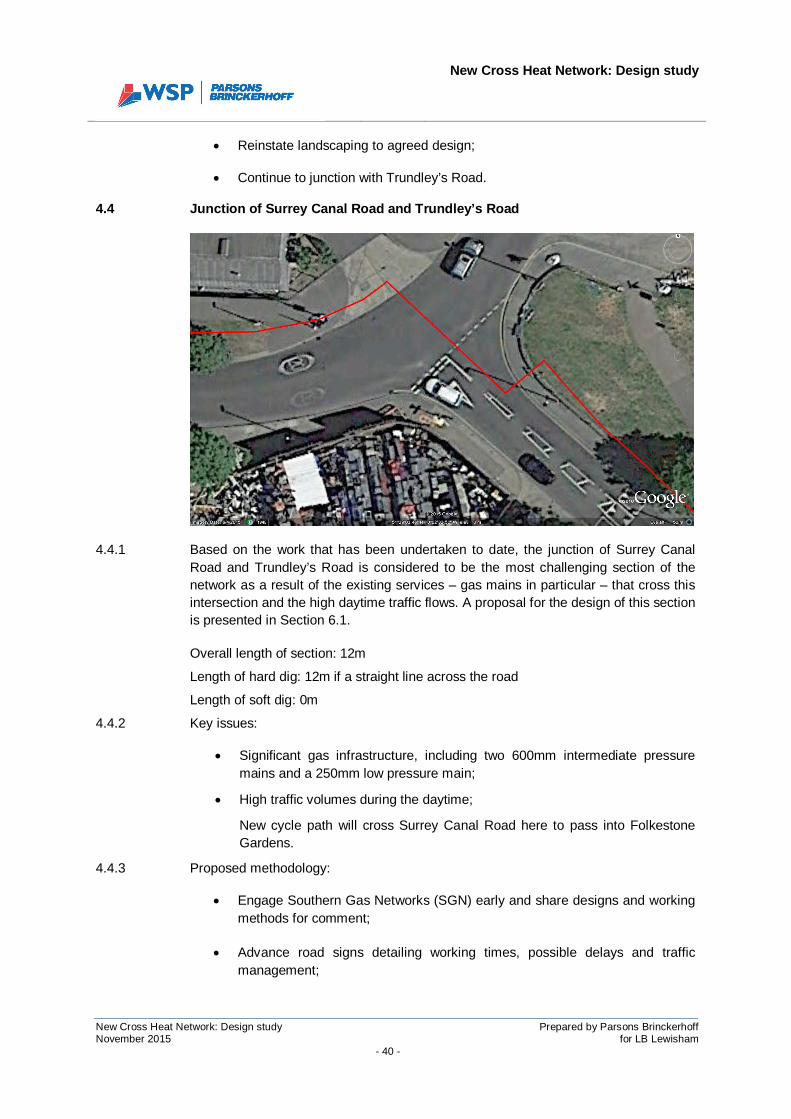
4.4.1 Based on the work that has been undertaken to date, the junction of Surrey CanalRoad and Trundley’s Road is considered to be the most challenging section of thenetwork as a result of the existing services – gas mains in particular – that cross thisintersection and the high daytime traffic flows. A proposal for the design of this sectionis presented in Section 6.1.
Overall length of section: 12m
Length of hard dig: 12m if a straight line across the road
Length of soft dig: 0m
4.4.2 Key issues:
· Significant gas infrastructure, including two 600mm intermediate pressuremains and a 250mm low pressure main;
· High traffic volumes during the daytime;
New cycle path will cross Surrey Canal Road here to pass into FolkestoneGardens.
4.4.3 Proposed methodology:
· Engage Southern Gas Networks (SGN) early and share designs and workingmethods for comment;
· Advance road signs detailing working times, possible delays and trafficmanagement;
New Cross Heat Network: Design study
New Cross Heat Network: Design study Prepared by Parsons BrinckerhoffNovember 2015 for LB Lewisham
- 41 -
· Inform Southern Gas Networks of working dates so that they can witnessexcavation in the vicinity of intermediate pressure mains;
· Undertake night time trial holing, with traffic management and/or diversions,to try and find a route through existing services. Consider working over twoconsecutive nights to maintain one way traffic flows. Works should seek tofind a route across the junction and into Folkestone Gardens;
· Use night time working with traffic management and/or diversions to minimisedisruption to traffic during installation;
· Road plates can be used to allow traffic flows through the day time;
Depending on the installation depth, steel plates or a concrete raft may berequired to protect the pipe from vertical loading due to traffic flows acrossSurrey Canal Road.
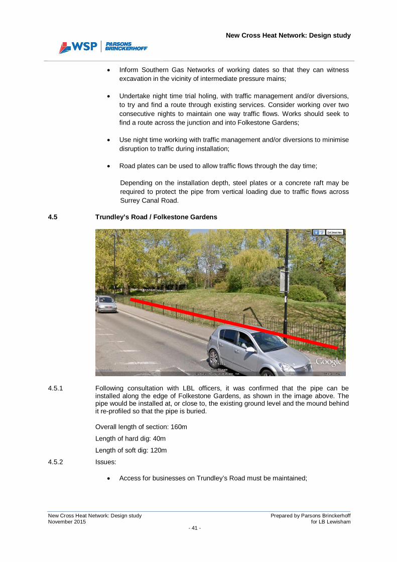
4.5 Trundley’s Road / Folkestone Gardens
4.5.1 Following consultation with LBL officers, it was confirmed that the pipe can beinstalled along the edge of Folkestone Gardens, as shown in the image above. Thepipe would be installed at, or close to, the existing ground level and the mound behindit re-profiled so that the pipe is buried.
Overall length of section: 160m
Length of hard dig: 40m
Length of soft dig: 120m
4.5.2 Issues:
· Access for businesses on Trundley’s Road must be maintained;

New Cross Heat Network: Design study
New Cross Heat Network: Design study Prepared by Parsons BrinckerhoffNovember 2015 for LB Lewisham
- 42 -
· Getting from the junction of Trundley’s Road and Surrey Canal Road intoFolkestone Gardens (significant gas infrastructure in the area);
· Agree landscaping design with LBL Parks officers.
· Pipe must cross Trundley’s Road to divert down Sanford Street.
4.5.3 Proposed methodology:
· Liaise with Trundley’s Road business owners to advise of works scheduleand discuss provision for access;
· Advance notice signs detailing work dates in Folkestone Gardens;
· Advance notice signs for works in junction of Trundley’s Road and SanfordStreet;
· Inform Southern Gas Networks of working dates so that they can witnessexcavation in the vicinity of intermediate pressure main in FolkestoneGardens and Trundley’s Road;
· Trial holes to determine route through existing services from junction ofSurrey Canal Road and Trundley’s Road into Folkestone Gardens (seeSection 6.1);
· Hard dig – mechanical and hand dig as required – to install from junction ofSurrey Canal Road and Trundley’s Road into Folkestone Gardens;
· Soft dig / installation along outer edge of Folkestone Gardens. Reinstate tolandscaping design agreed with LBL Parks officers;
· Hard dig across Trundley’s Road towards Sanford Street. Cross the line ofintermediate pressure gas main, which appears to be at c. 2m depth to crown(based on SGN drawing).
New Cross Heat Network: Design study
New Cross Heat Network: Design study Prepared by Parsons BrinckerhoffNovember 2015 for LB Lewisham
- 43 -
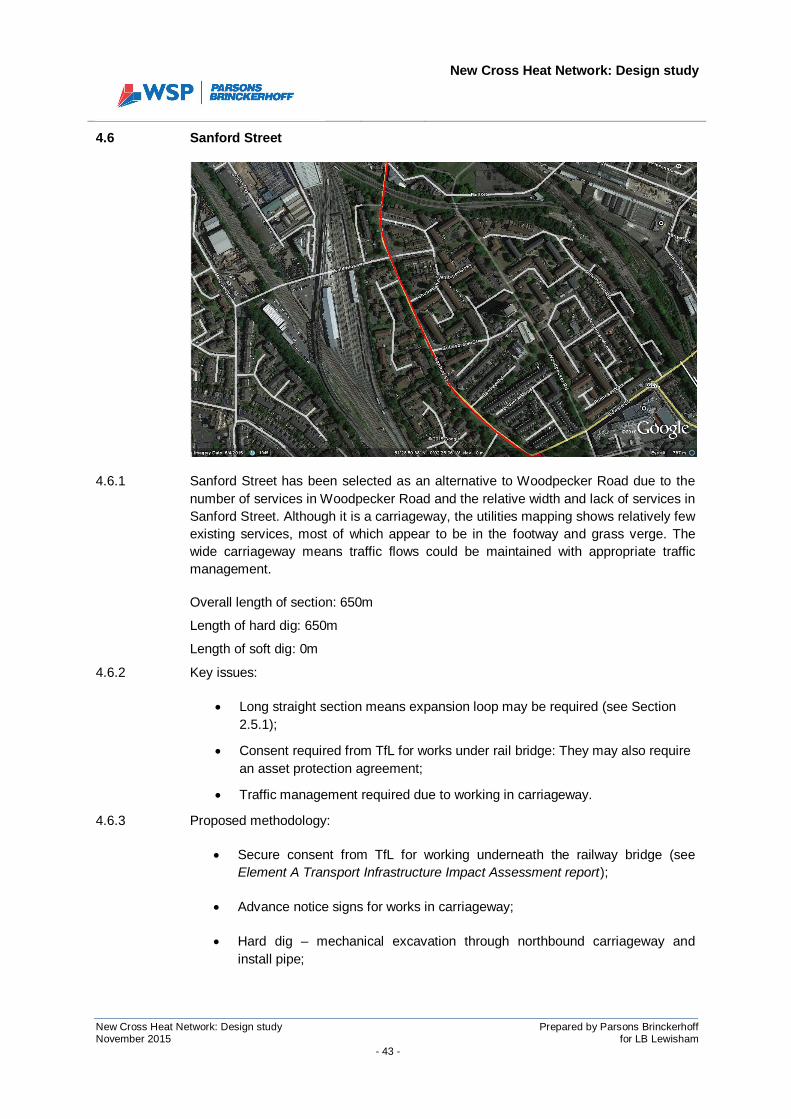
4.6 Sanford Street
4.6.1 Sanford Street has been selected as an alternative to Woodpecker Road due to thenumber of services in Woodpecker Road and the relative width and lack of services inSanford Street. Although it is a carriageway, the utilities mapping shows relatively fewexisting services, most of which appear to be in the footway and grass verge. Thewide carriageway means traffic flows could be maintained with appropriate trafficmanagement.
Overall length of section: 650m
Length of hard dig: 650m
Length of soft dig: 0m
4.6.2 Key issues:
· Long straight section means expansion loop may be required (see Section2.5.1);
· Consent required from TfL for works under rail bridge: They may also requirean asset protection agreement;
· Traffic management required due to working in carriageway.
4.6.3 Proposed methodology:
· Secure consent from TfL for working underneath the railway bridge (seeElement A Transport Infrastructure Impact Assessment report);
· Advance notice signs for works in carriageway;
· Hard dig – mechanical excavation through northbound carriageway andinstall pipe;
New Cross Heat Network: Design study
New Cross Heat Network: Design study Prepared by Parsons BrinckerhoffNovember 2015 for LB Lewisham
- 44 -
· Trench excavation, pipe installation and backfill/reinstatement to beundertaken sequentially through sections of carriageway;
· Traffic management to follow sections as described above;
· See Section 2.5.1 and Section 6.2 for discussion around requirement for, andposition of, expansion loops.
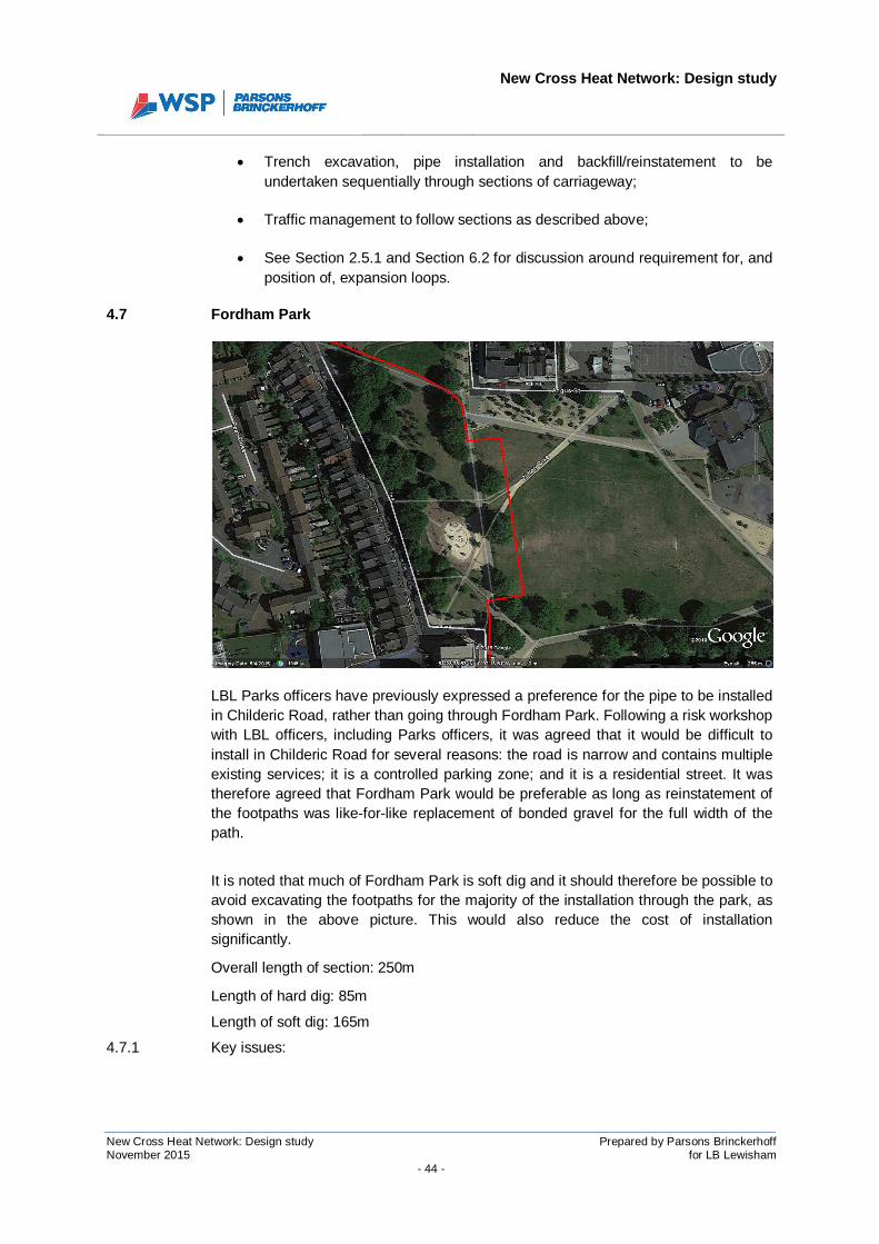
4.7 Fordham Park
LBL Parks officers have previously expressed a preference for the pipe to be installedin Childeric Road, rather than going through Fordham Park. Following a risk workshopwith LBL officers, including Parks officers, it was agreed that it would be difficult toinstall in Childeric Road for several reasons: the road is narrow and contains multipleexisting services; it is a controlled parking zone; and it is a residential street. It wastherefore agreed that Fordham Park would be preferable as long as reinstatement ofthe footpaths was like-for-like replacement of bonded gravel for the full width of thepath.
It is noted that much of Fordham Park is soft dig and it should therefore be possible toavoid excavating the footpaths for the majority of the installation through the park, asshown in the above picture. This would also reduce the cost of installationsignificantly.
Overall length of section: 250m
Length of hard dig: 85m
Length of soft dig: 165m
4.7.1 Key issues:
New Cross Heat Network: Design study
New Cross Heat Network: Design study Prepared by Parsons BrinckerhoffNovember 2015 for LB Lewisham
- 45 -
· Ensure any excavated footpath is reinstated with bonded gravel to the fullwidth of the path;
· Ensure any excavated soft dig area is reinstated as agreed with LBL Parksofficers;
· Impact on people using the park.
4.7.2 Proposed methodology
· Advance notice signs detailing work dates in Fordham Park;
· Where excavation is taking place in, or adjacent to, a footpath, close thefootpath altogether in the interests of public safety;
· Route through park from junction of Childeric Road and Sanford Street in thenorth-west corner through to Clifton Rise in south-west corner, as shown inpreceding image.
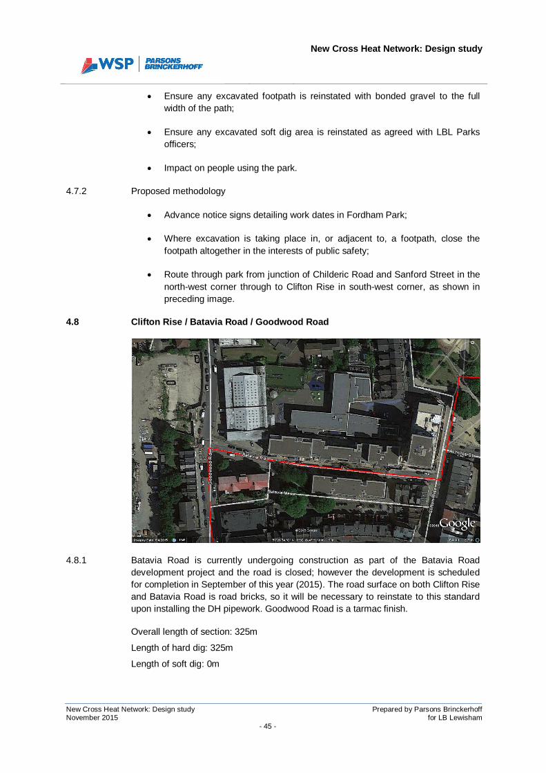
4.8 Clifton Rise / Batavia Road / Goodwood Road
4.8.1 Batavia Road is currently undergoing construction as part of the Batavia Roaddevelopment project and the road is closed; however the development is scheduledfor completion in September of this year (2015). The road surface on both Clifton Riseand Batavia Road is road bricks, so it will be necessary to reinstate to this standardupon installing the DH pipework. Goodwood Road is a tarmac finish.
Overall length of section: 325m
Length of hard dig: 325m
Length of soft dig: 0m
New Cross Heat Network: Design study
New Cross Heat Network: Design study Prepared by Parsons BrinckerhoffNovember 2015 for LB Lewisham
- 46 -
4.8.2 Key issues:
· Reinstatement of road bricks on Clifton Rise and Batavia Road;
· Impact on businesses on Clifton Rise and residents on Goodwood Road;
· Proximity of residential property – potential noise issue.
4.8.3 Proposed methodology
· Advance warning signs notifying of dates for works;
· Liaison with Choice Cars taxi rank on the corner of Clifton Rise and BataviaRoad to ensure they are aware of the works, which will have a potentialimpact on their taxis;
· Road closure on Clifton Rise from the junction with Batavia Road, northtowards Fordham Park;
· Sequential excavation, installation and reinstatement along the proposedroute;
· Ensure road bricks are lifted without damaging where possible, retained andreused upon reinstatement;
· Reopen Clifton Rise as soon as installation is complete in this section.
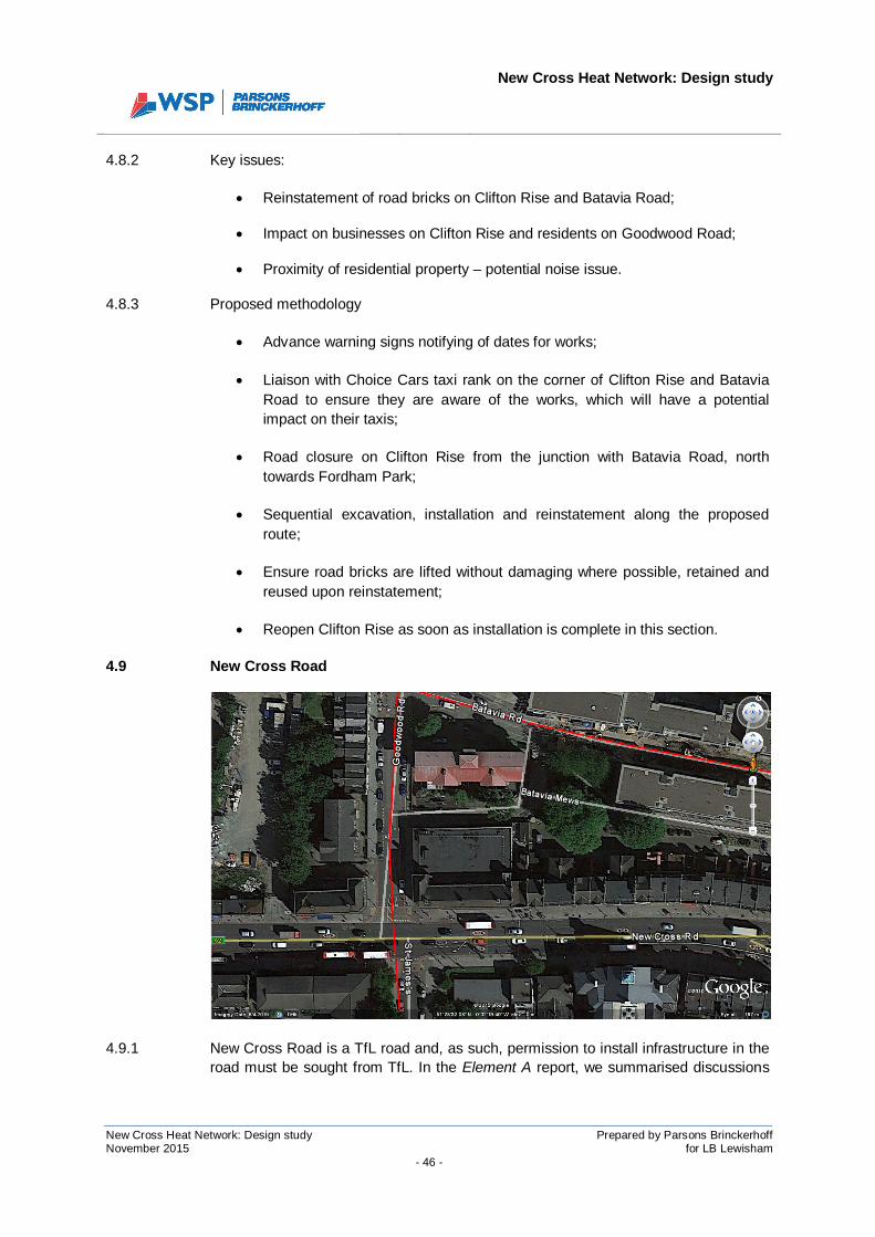
4.9 New Cross Road
4.9.1 New Cross Road is a TfL road and, as such, permission to install infrastructure in theroad must be sought from TfL. In the Element A report, we summarised discussions
New Cross Heat Network: Design study
New Cross Heat Network: Design study Prepared by Parsons BrinckerhoffNovember 2015 for LB Lewisham
- 47 -
with TfL, in which they confirmed their requirements for allowing works to proceed onred routes. The point at which the DH route crosses New Cross Road was movedfollowing the Element A investigation due to difficulties in crossing at the originallyproposed location – namely a central trief kerb that would make maintaining two-waytraffic flows more difficult; and the position of Goldsmiths connection points on theother side of New Cross Road.
Overall length of section: 12m
Length of hard dig: 12m
Length of soft dig: 0m
4.9.2 Key issues:
· Two-way traffic flows to be maintained at all times;
· Night working required to minimise duration of works in the road;
· Multiple services cross the line of the DH pipe, although most of them appearto be in the footpaths rather than the carriageway;
· Lane rental fees apply for working within specified hours (as detailed inElement A report).
4.9.3 Proposed methodology
· Liaison with TfL to agree TM and installation methodologies and timing ofworks;
· Advance warning signs notifying of dates for works;
· Undertake pre-installation GPR (see Section 5.3.) to confirm extent ofservices in the carriageway. If necessary, undertake pre-installation trialholing in carriageway (sequentially, maintaining two way traffic flows). Trialholes will be required in the footways on either side of the crossing toestablish the depth of services;
· Number of welds / pipe sections increased to enable sequential crossing ofthe road whilst maintaining two-way traffic flows;
· During installation, use of road plates to maintain traffic flows as necessary.
New Cross Heat Network: Design study
New Cross Heat Network: Design study Prepared by Parsons BrinckerhoffNovember 2015 for LB Lewisham
- 48 -
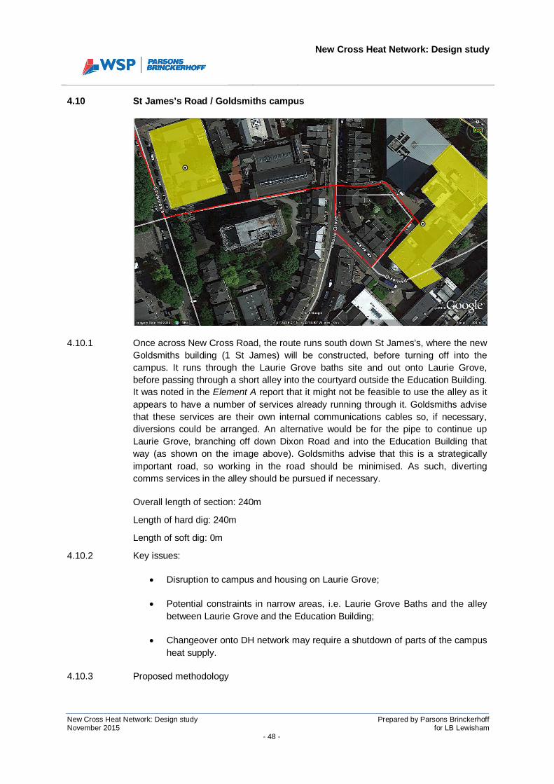
4.10 St James’s Road / Goldsmiths campus
4.10.1 Once across New Cross Road, the route runs south down St James’s, where the newGoldsmiths building (1 St James) will be constructed, before turning off into thecampus. It runs through the Laurie Grove baths site and out onto Laurie Grove,before passing through a short alley into the courtyard outside the Education Building.It was noted in the Element A report that it might not be feasible to use the alley as itappears to have a number of services already running through it. Goldsmiths advisethat these services are their own internal communications cables so, if necessary,diversions could be arranged. An alternative would be for the pipe to continue upLaurie Grove, branching off down Dixon Road and into the Education Building thatway (as shown on the image above). Goldsmiths advise that this is a strategicallyimportant road, so working in the road should be minimised. As such, divertingcomms services in the alley should be pursued if necessary.
Overall length of section: 240m
Length of hard dig: 240m
Length of soft dig: 0m
4.10.2 Key issues:
· Disruption to campus and housing on Laurie Grove;
· Potential constraints in narrow areas, i.e. Laurie Grove Baths and the alleybetween Laurie Grove and the Education Building;
· Changeover onto DH network may require a shutdown of parts of the campusheat supply.
4.10.3 Proposed methodology

New Cross Heat Network: Design study
New Cross Heat Network: Design study Prepared by Parsons BrinckerhoffNovember 2015 for LB Lewisham
- 49 -
· Liaison with Goldsmiths to agree programme and working requirements oncampus;
· Trial holing at pinch points, i.e. alley between Laurie Grove and the EducationBuilding; and the route through Laurie Grove Baths.
· Trenching and installation of pipework using hard dig techniques along theroute identified through trial holing process.
· Substations to be installed without disruption to Goldsmiths’ heating systems.Final changeover to DH integration over weekend to minimise down time.
4.11 Site compound and storage
4.11.1 It is important that the appointed contractor is given adequate space for the provisionof welfare facilities and the storage of materials for the duration of the project. Giventhe extent of the network, it is likely that storage would ideally be located in differentplaces as the works progress along the route.
4.11.2 There are areas of the proposed route that are sensitive to the impact on traffic flows(e.g. junction of Surrey Canal Road and Trundley’s Road); cyclists and pedestrians(e.g. Surrey Canal cycle path); parks (e.g. Folkestone Gardens, Fordham Park);business access (e.g. SELCHP). As such, it is important that these sensitivities areconsidered when planning the logistics of getting pipe to the various areas of the site.
4.11.3 We discussed options for storage and movement of pipes with a DH contractor. Theirfeeling was that it would be preferable to store pipe in a central storage area ofapproximately 30m x 30m and to then taken the pipes and fittings to the workfaceeach day using a road going pipe truck,
4.11.4 The obvious places for a 30m x 30m space within the vicinity of the site are the twopublic parks – Folkestone Gardens and Fordham Park. Of the two, Fordham Park islarger, flatter and more open. As such, this would be the preferred position for a pipestorage and site welfare facilities.
4.11.5 It is noted that security around the area may be an issue and, as such, it will benecessary to provide a security guard to watch the site compound and storage areaovernight.
New Cross Heat Network: Design study
New Cross Heat Network: Design study Prepared by Parsons BrinckerhoffNovember 2015 for LB Lewisham
- 50 -
SECTION 5
INTERFACES AND ENABLING WORKS

New Cross Heat Network: Design study
New Cross Heat Network: Design study Prepared by Parsons BrinckerhoffNovember 2015 for LB Lewisham
- 51 -
5 INTERFACES AND ENABLING WORKS
5.1 Pipe network interface register
5.1.1 A pipe network interface register is provided in Figure 5-1.

New Cross Heat Network: Design study
New Cross Heat Network: Design study Prepared by Parsons BrinckerhoffNovember 2015 for LB Lewisham
- 52 -
Figure 5-1: Pipe network interface register
Existing utility interfacesLand Owners (other thanLBL adopted highway or
public space)Wayleaves required Affected businesses Others
SELCHP N/A SELCHP Ltd Dependent on asset ow nership SELCHP Ltd N/AInteroute - comms
SGN - LP gasUKPN - pow erBT - comms
Thames Water - w aterBT - comms
Instalcom - commsInteroute - comms
National Grid - HV pow erSGN - LP & IP gas
UKPN - LV, HV & EHV pow erSSE - comms
Thames Water - sew ers & w aterVigin Media - comms
Zayo - commsBT - comms
Instalcom - commsInteroute - commsSGN - LP & IP gas
UKPN - LV, HV pow erSSE - comms
Thames Water - sew ers & w aterVirgin Media - comms
Zayo - commsEU Netw orks - comms
BT - commsInstalcom - commsInteroute - comms
UKPN - LV, HV pow erSSE - comms
Thames Water - sew ers & w aterVigin Media - comms
Zayo - commsUKPN - LV pow er
BT - commsSGN - LP & IP gas
Thames Water - sew ers (deep)BT - comms
Thames Water - sew ers & w aterVirgin Media - comms
SGN - LP gasUKPN - LV pow erSGN - LP & IP gas
BT - commsUKPN - LV pow er
Thames Water - sew ers & w aterVirgin Media - comms
BT - commsThames Water - sew ers & w ater
Virgin Media - commsSGN - LP gas
UKPN - LV pow erSGN - LP & IP gas
BT - commsThames Water - sew ers & w ater
UKPN - LV pow erVirgin Media - comms
Thames Water - sew ers & w aterBT - comms
SGN - LP gasUKPN - LV pow er
Virgin Media - commsGoldsmiths comms netw ork
Goldsmiths campus Goldsmiths, University ofLondon
Goldsmiths, University ofLondon
Goldsmiths, University ofLondon
Works programme to be coordinated w ithGoldsmiths to minimise disruption
TfL to approve access and methodology.Strict w orking time limitations.
St James's N/A N/A Goldsmiths, University ofLondon
N/A
New Cross Road TfL N/A N/A
Goodw ood Road N/A N/A N/A N/A
Public space. Works methodology andreinstatement to be agreed w ith LBL
Parks Department
Clifton Rise/BataviaRoad
N/A N/A Choice CarsClifton Rise and Batavia Road both road
bricks. Reinstatement to currentstandard.
Fordham Park N/A N/A N/A
Sanford Street N/A N/A N/A Possible Asset Protection Agreementw ith Netw ork Rail for installation under
the rail bridge.
Surrey Canal Road British Wharf Industrial Estate British Wharf Industrial Estate
British Wharf Industrial Est.
SELCHP Ltd.
Waste Reception Centre
Juno Way Trading Estate
Relandscaping of soft dig area under railbridge. Requires agreement w ith LBL.
Installation in cycle path to be agreedw ith LBL Cycle Programme team.Specific reinstatement standards.
Possible Asset Protection Agreementw ith Netw ork Rail for installation under
the rail bridge.
Trundleys Road N/A N/A
DD Scrap MetalSE8 Test Centre
Transw eldSlade Green Plating
Albany Waste ManagementEuropean Taste Restaurant
Route along perimeter of FolkestoneGradens to be agreed w ith LBL Parks
department. Relandscaping design mustalso be agreed.
INTERFACES
Network section
Landmann Way N/A N/A
British Wharf Industrial Est.
SELCHP Ltd.
Waste Reception Centre
N/A
New Cross Heat Network: Design study
New Cross Heat Network: Design study Prepared by Parsons BrinckerhoffNovember 2015 for LB Lewisham
- 53 -
5.2 Section 50 License register
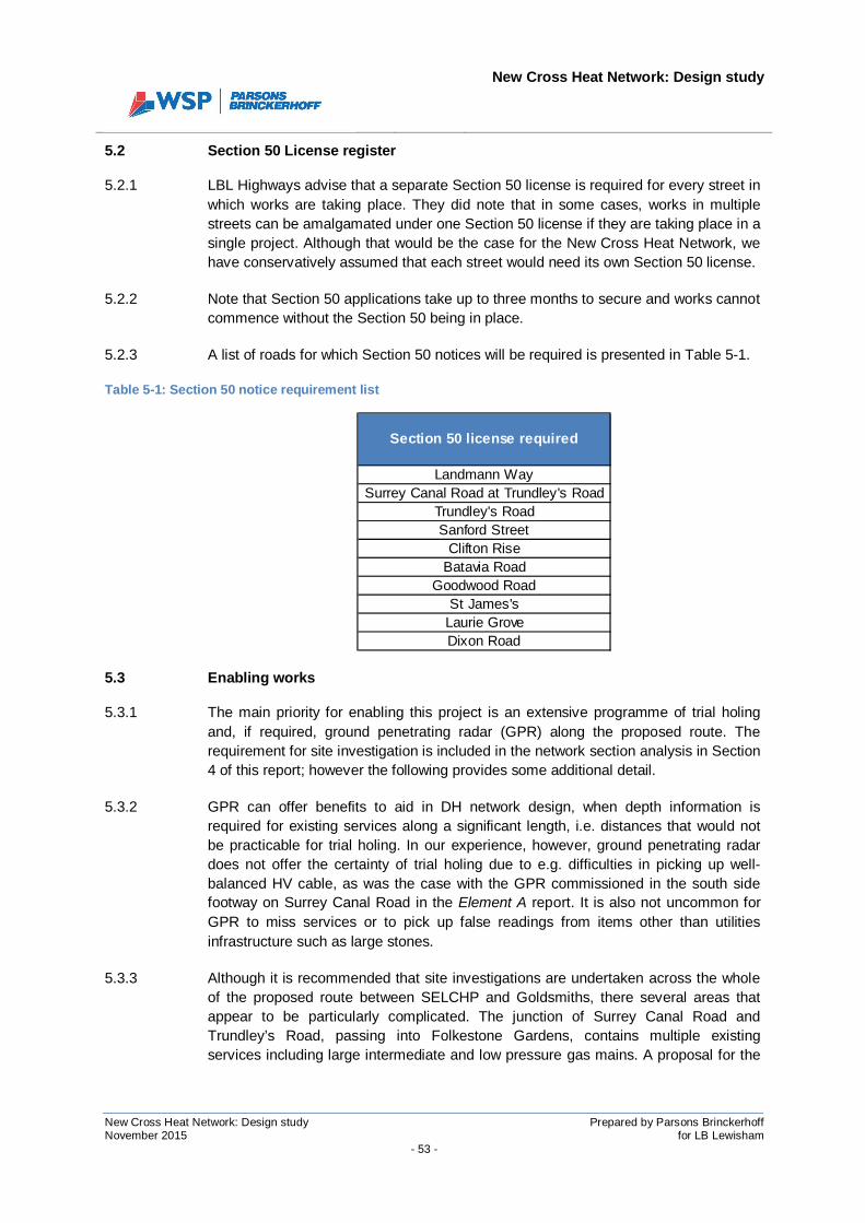
5.2.1 LBL Highways advise that a separate Section 50 license is required for every street inwhich works are taking place. They did note that in some cases, works in multiplestreets can be amalgamated under one Section 50 license if they are taking place in asingle project. Although that would be the case for the New Cross Heat Network, wehave conservatively assumed that each street would need its own Section 50 license.
5.2.2 Note that Section 50 applications take up to three months to secure and works cannotcommence without the Section 50 being in place.
5.2.3 A list of roads for which Section 50 notices will be required is presented in Table 5-1.
Table 5-1: Section 50 notice requirement list
5.3 Enabling works
5.3.1 The main priority for enabling this project is an extensive programme of trial holingand, if required, ground penetrating radar (GPR) along the proposed route. Therequirement for site investigation is included in the network section analysis in Section4 of this report; however the following provides some additional detail.
5.3.2 GPR can offer benefits to aid in DH network design, when depth information isrequired for existing services along a significant length, i.e. distances that would notbe practicable for trial holing. In our experience, however, ground penetrating radardoes not offer the certainty of trial holing due to e.g. difficulties in picking up well-balanced HV cable, as was the case with the GPR commissioned in the south sidefootway on Surrey Canal Road in the Element A report. It is also not uncommon forGPR to miss services or to pick up false readings from items other than utilitiesinfrastructure such as large stones.
5.3.3 Although it is recommended that site investigations are undertaken across the wholeof the proposed route between SELCHP and Goldsmiths, there several areas thatappear to be particularly complicated. The junction of Surrey Canal Road andTrundley’s Road, passing into Folkestone Gardens, contains multiple existingservices including large intermediate and low pressure gas mains. A proposal for the
Section 50 license required
Landmann WaySurrey Canal Road at Trundley's Road
Trundley's RoadSanford Street
Clifton RiseBatavia Road
Goodwood RoadSt James's
Laurie GroveDixon Road
New Cross Heat Network: Design study
New Cross Heat Network: Design study Prepared by Parsons BrinckerhoffNovember 2015 for LB Lewisham
- 54 -
design through this section is offered in Section 6.1; however it is not possible todevelop a final design without site investigation to establish the exact position anddepth of existing services. This junction is very sensitive to traffic disruption due to thesignificant industrial and commercial facilities nearby, including SELCHP, so it isimportant that the site investigations are planned to minimise disruption and areagreed/coordinated with LBL’s Streetworks team.
5.3.4 The junction of Trundley’s Road and Sanford Street is also heavily congested withexisting services, including an intermediate pressure gas main. The proposed route isfor the pipe to turn 90° out of Folkestone Gardens into the Trundley’s Roadcarriageway (across the line of the intermediate pressure gas main) and then turn 45°down Sanford Street (see Figure 2-5). The point at which the pipe turns down SanfordStreet depends on the exact location of other services in the carriageway. As such,this must be confirmed with trial holes before the depth and line of the DH pipeworkcan be confirmed.
5.3.5 Trail holing across New Cross Road to establish a line and depth for the pipe willentail the closure of lanes on a TfL red route. The utilities mapping sourced for thepurposes of this study (included in the Element A information pack) suggests thatmost of the services running along New Cross Road are in the footways. The trunksewer running along the carriageway is indicated at over 11m deep on the ThamesWater mapping, so would not affect the DH pipe installation. It is thereforerecommended that GPR is used initially to establish whether there are any otherservices in the carriageway. If not, it may possible to proceed with installation withouttrial holing the carriageway. Note that trial holes will be required in the footways onboth sides of the crossing to establish the depth of the services running through thefootway and therefore the depth at which the DH should cross the carriageway.
5.3.6 Other than site investigations, there are several other key enabling works are tosecure the necessary permissions from the various owners of land along the route.They are:
· LB Lewisham: Section 50 Licenses for installation of apparatus;
· SELCHP: Wayleave may be required for installation within the facility. This isdependent on the ownership status of the apparatus. If Veolia/SELCHP install theapparatus, a Wayleave would not be required;
· British Wharf Industrial Estate: Wayleave required for installation in their landon Surrey Canal Road;
· TfL: Consent for working underneath London Overground rail bridges at SurreyCanal Road and Sanford Street;
· TFL: Permission required for installation of apparatus in New Cross Road;
· Goldsmiths, University of London: Wayleave required for installation in theircampus.

New Cross Heat Network: Design study
New Cross Heat Network: Design study Prepared by Parsons BrinckerhoffNovember 2015 for LB Lewisham
- 55 -
New Cross Heat Network: Design study
New Cross Heat Network: Design study Prepared by Parsons BrinckerhoffNovember 2015 for LB Lewisham
- 56 -
SECTION 6
SITES OF ENGINEERING DIFFICULTY
New Cross Heat Network: Design study
New Cross Heat Network: Design study Prepared by Parsons BrinckerhoffNovember 2015 for LB Lewisham
- 57 -
6 SITES OF ENGINEERING DIFFICULTY
6.1 Junction of Surrey Canal Road and Trundley’s Road
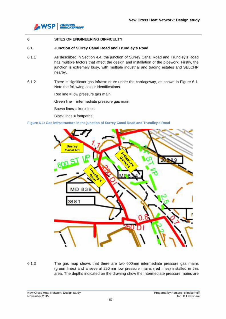
6.1.1 As described in Section 4.4, the junction of Surrey Canal Road and Trundley’s Roadhas multiple factors that affect the design and installation of the pipework. Firstly, thejunction is extremely busy, with multiple industrial and trading estates and SELCHPnearby.
6.1.2 There is significant gas infrastructure under the carriageway, as shown in Figure 6-1.Note the following colour identifications.
Red line = low pressure gas main
Green line = intermediate pressure gas main
Brown lines = kerb lines
Black lines = footpaths
Figure 6-1: Gas infrastructure in the junction of Surrey Canal Road and Trundley's Road
6.1.3 The gas map shows that there are two 600mm intermediate pressure gas mains(green lines) and a several 250mm low pressure mains (red lines) installed in thisarea. The depths indicated on the drawing show the intermediate pressure mains are
SurreyCanal Rd

New Cross Heat Network: Design study
New Cross Heat Network: Design study Prepared by Parsons BrinckerhoffNovember 2015 for LB Lewisham
- 58 -
between 2.2m and 2.5m and the low pressure mains are above, crossing SurreyCanal Road at approximately 1.1m deep. This is the depth to the crown of the pipe.
6.1.4 Discussion with Southern Gas Networks confirmed that a minimum clearance of 1.5times the diameter of the pipe must be maintained from intermediate pressure gasmains. As such, there should be at least 900mm clearance between the DH pipe andthe gas mains.
6.1.5 DH pipework has maximum depths at which they can be installed. This depth varieswith pipe diameter and insulation thickness, as shown in Table 6-1.
Table 6-1: LOGSTOR Series 2 maximum installation depth
6.1.6 The Element D study concludes that pipe sizes across Trundley’s Road would be300mm for a peak load supply network and 200mm for a base load supply network.
6.1.7 The data table shows that for pipes between 200mm and 300mm in diameter, themaximum installation depth is 2.75m. If the intermediate pressure gas main isinstalled at approximately 2.5m to the crown of the pipe, the invert level of the pipe(the bottom of it) would be over 3m deep. As such, it is concluded that the DH mainscould not be installed below the intermediate pressure gas mains at this point.
6.1.8 The DH pipe should therefore be installed above both the intermediate and lowpressure gas mains. The gas drawing shows the low pressure gas main atapproximately 1.1m to the crown of the pipe through this area. It is therefore proposedthat the DH main should be installed with the invert level no deeper than 850mm,allowing a minimum of 250mm5 clearance to the low pressure gas main below.
6.1.9 It is not possible to determine the exact depth of installation without trial holes. Thereare other services running through this area, including a 100mm water main; however
5 250mm is the minimum clearance required by Southern Gas Networks for installing infrastructure across theline of a low pressure gas main.
DIAMax
depth(m)
25 1.5032 1.5040 1.7550 2.0065 2.2580 2.25100 2.25125 2.50150 2.50200 2.75250 2.75300 2.75350 3.00
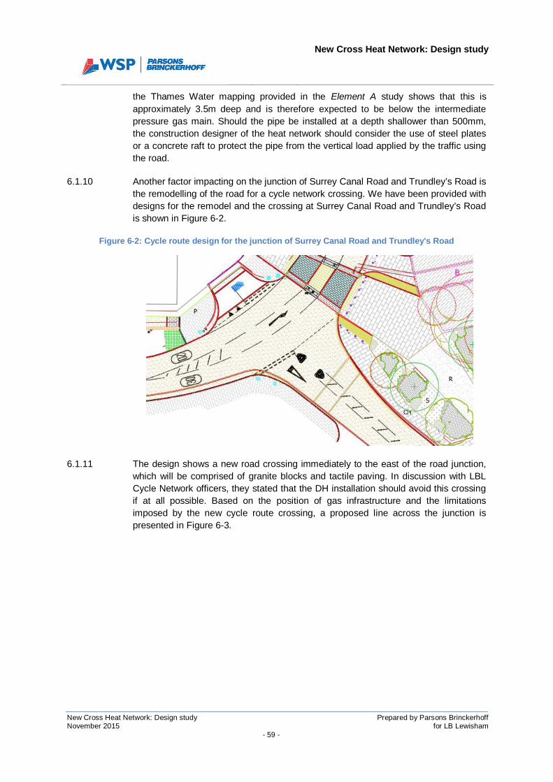
New Cross Heat Network: Design study
New Cross Heat Network: Design study Prepared by Parsons BrinckerhoffNovember 2015 for LB Lewisham
- 59 -
the Thames Water mapping provided in the Element A study shows that this isapproximately 3.5m deep and is therefore expected to be below the intermediatepressure gas main. Should the pipe be installed at a depth shallower than 500mm,the construction designer of the heat network should consider the use of steel platesor a concrete raft to protect the pipe from the vertical load applied by the traffic usingthe road.
6.1.10 Another factor impacting on the junction of Surrey Canal Road and Trundley’s Road isthe remodelling of the road for a cycle network crossing. We have been provided withdesigns for the remodel and the crossing at Surrey Canal Road and Trundley’s Roadis shown in Figure 6-2.
Figure 6-2: Cycle route design for the junction of Surrey Canal Road and Trundley's Road
6.1.11 The design shows a new road crossing immediately to the east of the road junction,which will be comprised of granite blocks and tactile paving. In discussion with LBLCycle Network officers, they stated that the DH installation should avoid this crossingif at all possible. Based on the position of gas infrastructure and the limitationsimposed by the new cycle route crossing, a proposed line across the junction ispresented in Figure 6-3.
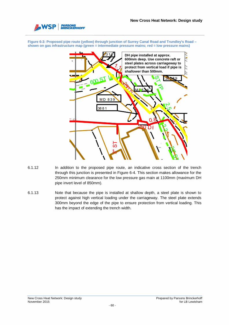
New Cross Heat Network: Design study
New Cross Heat Network: Design study Prepared by Parsons BrinckerhoffNovember 2015 for LB Lewisham
- 60 -
Figure 6-3: Proposed pipe route (yellow) through junction of Surrey Canal Road and Trundley's Road –shown on gas infrastructure map (green = intermediate pressure mains; red = low pressure mains)
6.1.12 In addition to the proposed pipe route, an indicative cross section of the trenchthrough this junction is presented in Figure 6-4. This section makes allowance for the250mm minimum clearance for the low pressure gas main at 1100mm (maximum DHpipe invert level of 850mm).
6.1.13 Note that because the pipe is installed at shallow depth, a steel plate is shown toprotect against high vertical loading under the carriageway. The steel plate extends300mm beyond the edge of the pipe to ensure protection from vertical loading. Thishas the impact of extending the trench width.
DH pipe installed at approx.600mm deep. Use concrete raft orsteel plates across carriageway toprotect from vertical load if pipe isshallower than 500mm.
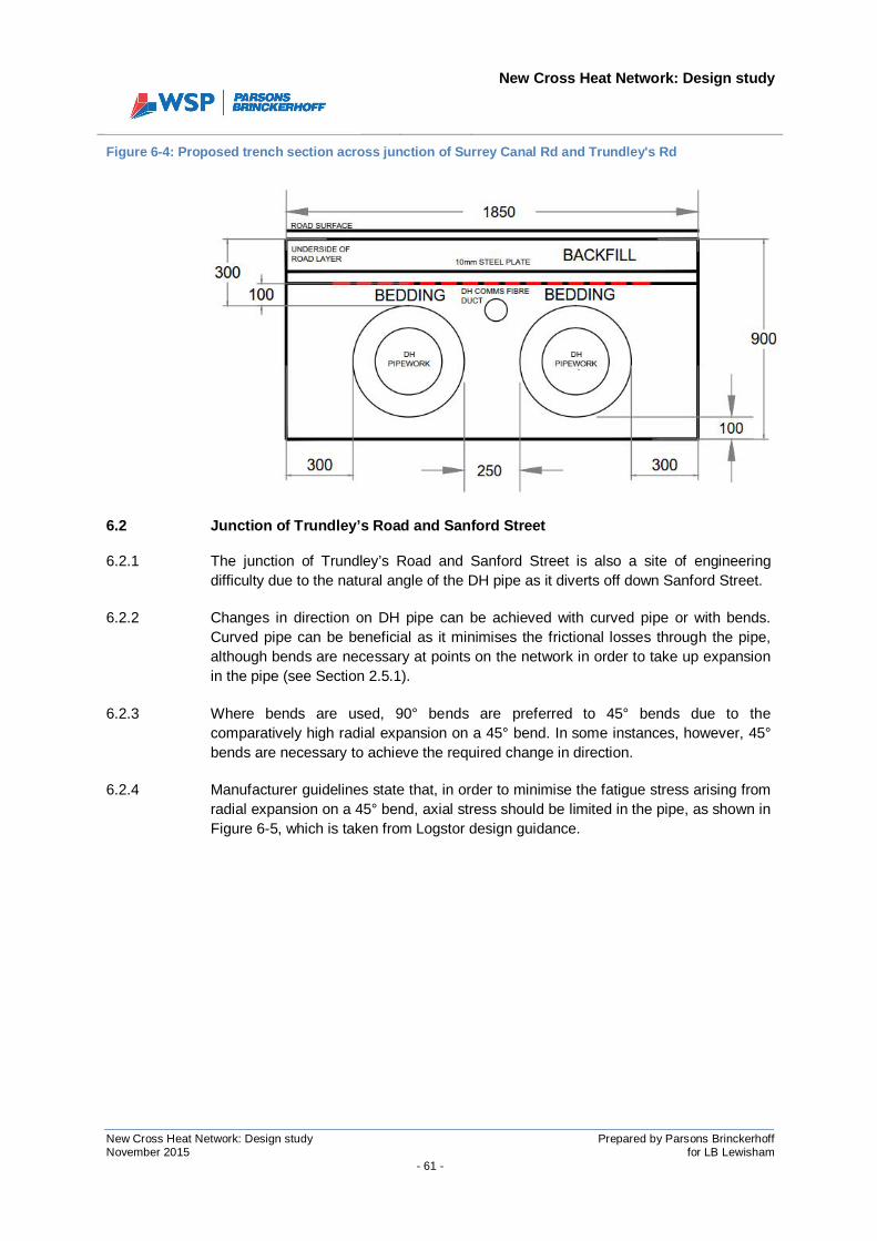
New Cross Heat Network: Design study
New Cross Heat Network: Design study Prepared by Parsons BrinckerhoffNovember 2015 for LB Lewisham
- 61 -
Figure 6-4: Proposed trench section across junction of Surrey Canal Rd and Trundley's Rd
6.2 Junction of Trundley’s Road and Sanford Street
6.2.1 The junction of Trundley’s Road and Sanford Street is also a site of engineeringdifficulty due to the natural angle of the DH pipe as it diverts off down Sanford Street.
6.2.2 Changes in direction on DH pipe can be achieved with curved pipe or with bends.Curved pipe can be beneficial as it minimises the frictional losses through the pipe,although bends are necessary at points on the network in order to take up expansionin the pipe (see Section 2.5.1).
6.2.3 Where bends are used, 90° bends are preferred to 45° bends due to thecomparatively high radial expansion on a 45° bend. In some instances, however, 45°bends are necessary to achieve the required change in direction.
6.2.4 Manufacturer guidelines state that, in order to minimise the fatigue stress arising fromradial expansion on a 45° bend, axial stress should be limited in the pipe, as shown inFigure 6-5, which is taken from Logstor design guidance.
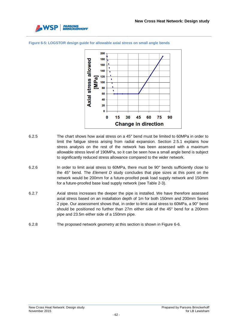
New Cross Heat Network: Design study
New Cross Heat Network: Design study Prepared by Parsons BrinckerhoffNovember 2015 for LB Lewisham
- 62 -
Figure 6-5: LOGSTOR design guide for allowable axial stress on small angle bends
6.2.5 The chart shows how axial stress on a 45° bend must be limited to 60MPa in order tolimit the fatigue stress arising from radial expansion. Section 2.5.1 explains howstress analysis on the rest of the network has been assessed with a maximumallowable stress level of 190MPa, so it can be seen how a small angle bend is subjectto significantly reduced stress allowance compared to the wider network.
6.2.6 In order to limit axial stress to 60MPa, there must be 90° bends sufficiently close tothe 45° bend. The Element D study concludes that pipe sizes at this point on thenetwork would be 200mm for a future-proofed peak load supply network and 150mmfor a future-proofed base load supply network (see Table 2-3).
6.2.7 Axial stress increases the deeper the pipe is installed. We have therefore assessedaxial stress based on an installation depth of 1m for both 150mm and 200mm Series2 pipe. Our assessment shows that, in order to limit axial stress to 60MPa, a 90° bendshould be positioned no further than 27m either side of the 45° bend for a 200mmpipe and 23.5m either side of a 150mm pipe.
6.2.8 The proposed network geometry at this section is shown in Figure 6-6.
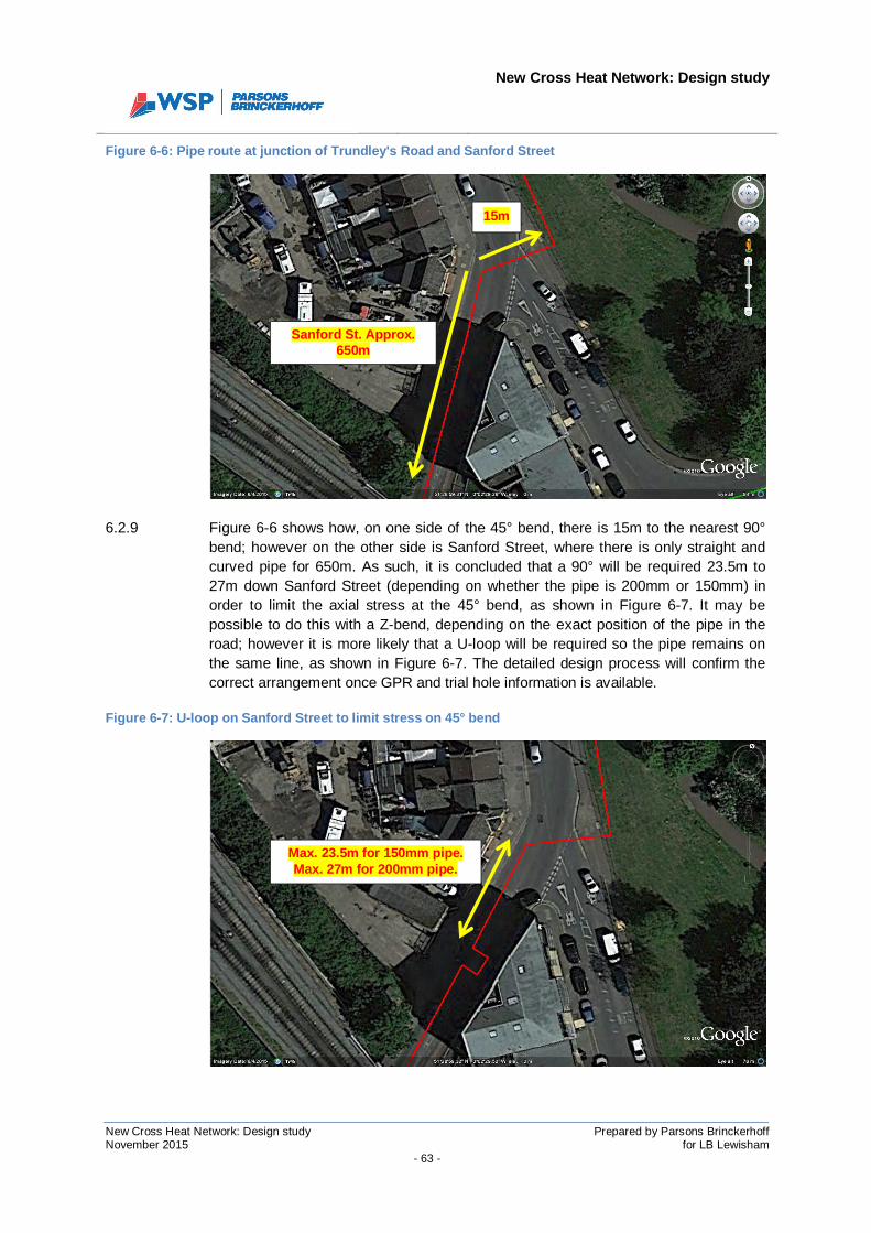
New Cross Heat Network: Design study
New Cross Heat Network: Design study Prepared by Parsons BrinckerhoffNovember 2015 for LB Lewisham
- 63 -
Figure 6-6: Pipe route at junction of Trundley's Road and Sanford Street
6.2.9 Figure 6-6 shows how, on one side of the 45° bend, there is 15m to the nearest 90°bend; however on the other side is Sanford Street, where there is only straight andcurved pipe for 650m. As such, it is concluded that a 90° will be required 23.5m to27m down Sanford Street (depending on whether the pipe is 200mm or 150mm) inorder to limit the axial stress at the 45° bend, as shown in Figure 6-7. It may bepossible to do this with a Z-bend, depending on the exact position of the pipe in theroad; however it is more likely that a U-loop will be required so the pipe remains onthe same line, as shown in Figure 6-7. The detailed design process will confirm thecorrect arrangement once GPR and trial hole information is available.
Figure 6-7: U-loop on Sanford Street to limit stress on 45° bend
15m
Sanford St. Approx.650m
Max. 23.5m for 150mm pipe.Max. 27m for 200mm pipe.
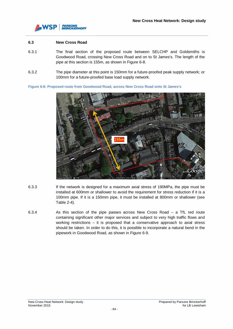
New Cross Heat Network: Design study
New Cross Heat Network: Design study Prepared by Parsons BrinckerhoffNovember 2015 for LB Lewisham
- 64 -
6.3 New Cross Road
6.3.1 The final section of the proposed route between SELCHP and Goldsmiths isGoodwood Road, crossing New Cross Road and on to St James’s. The length of thepipe at this section is 155m, as shown in Figure 6-8.
6.3.2 The pipe diameter at this point is 150mm for a future-proofed peak supply network; or100mm for a future-proofed base load supply network.
Figure 6-8: Proposed route from Goodwood Road, across New Cross Road onto St James's
6.3.3 If the network is designed for a maximum axial stress of 190MPa, the pipe must beinstalled at 600mm or shallower to avoid the requirement for stress reduction if it is a100mm pipe. If it is a 150mm pipe, it must be installed at 800mm or shallower (seeTable 2-4).
6.3.4 As this section of the pipe passes across New Cross Road – a TfL red routecontaining significant other major services and subject to very high traffic flows andworking restrictions – it is proposed that a conservative approach to axial stressshould be taken. In order to do this, it is possible to incorporate a natural bend in thepipework in Goodwood Road, as shown in Figure 6-9.
155m
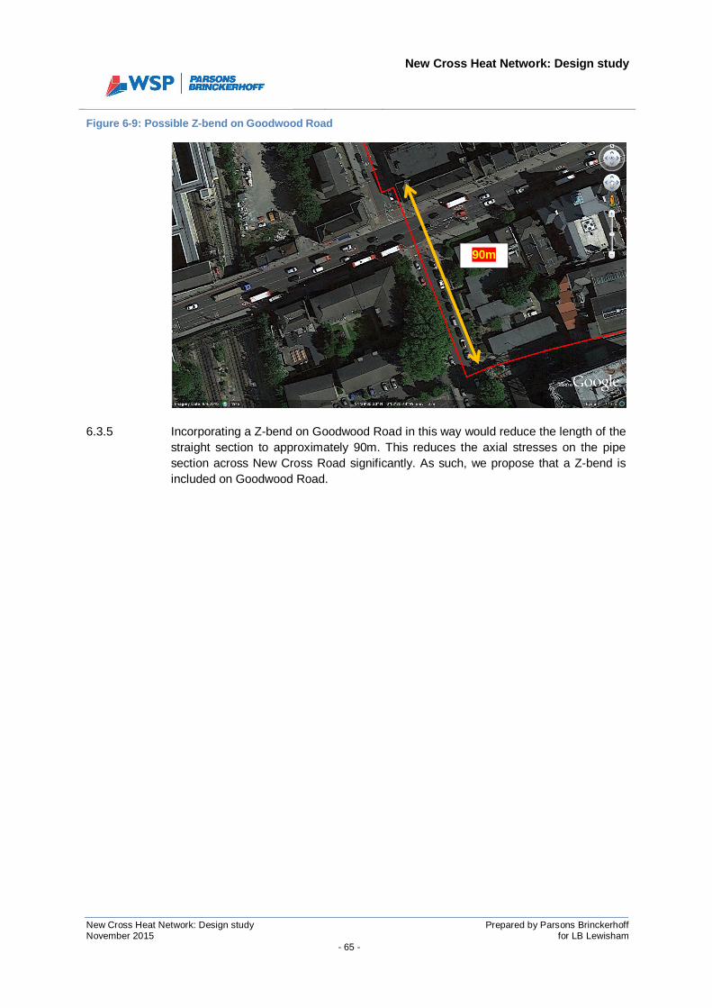
New Cross Heat Network: Design study
New Cross Heat Network: Design study Prepared by Parsons BrinckerhoffNovember 2015 for LB Lewisham
- 65 -
Figure 6-9: Possible Z-bend on Goodwood Road
6.3.5 Incorporating a Z-bend on Goodwood Road in this way would reduce the length of thestraight section to approximately 90m. This reduces the axial stresses on the pipesection across New Cross Road significantly. As such, we propose that a Z-bend isincluded on Goodwood Road.
90m

New Cross Heat Network: Design study
New Cross Heat Network: Design study Prepared by Parsons BrinckerhoffNovember 2015 for LB Lewisham
- 66 -
SECTION 7
CONSTRUCTION RISK REGISTER

New Cross Heat Network: Design study
New Cross Heat Network: Design study Prepared by Parsons BrinckerhoffNovember 2015 for LB Lewisham
- 67 -
7 CONSTRUCTION RISK REGISTER
7.1.1 A construction risk register, detailing the hazards and the proposing mitigationmeasures is presented in the following pages.
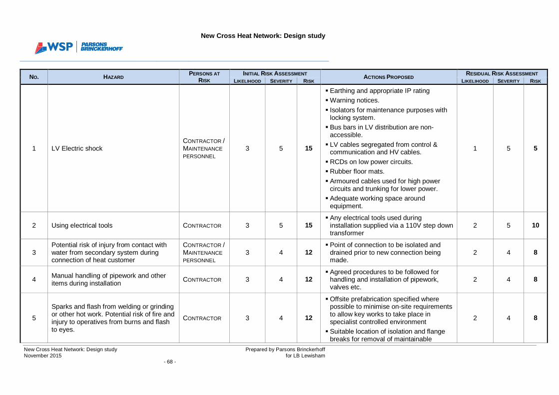
New Cross Heat Network: Design study
New Cross Heat Network: Design study Prepared by Parsons BrinckerhoffNovember 2015 for LB Lewisham
- 68 -
NO. HAZARDPERSONS AT
RISKINITIAL RISK ASSESSMENT ACTIONS PROPOSED
RESIDUAL RISK ASSESSMENTLIKELIHOOD SEVERITY RISK LIKELIHOOD SEVERITY RISK
1 LV Electric shockCONTRACTOR /MAINTENANCEPERSONNEL
3 5 15
§ Earthing and appropriate IP rating§ Warning notices.§ Isolators for maintenance purposes with
locking system.§ Bus bars in LV distribution are non-
accessible.§ LV cables segregated from control &
communication and HV cables.§ RCDs on low power circuits.§ Rubber floor mats.§ Armoured cables used for high power
circuits and trunking for lower power.§ Adequate working space around
equipment.
1 5 5
2 Using electrical tools CONTRACTOR 3 5 15§ Any electrical tools used during
installation supplied via a 110V step downtransformer
2 5 10
3Potential risk of injury from contact withwater from secondary system duringconnection of heat customer
CONTRACTOR /MAINTENANCEPERSONNEL
3 4 12§ Point of connection to be isolated and
drained prior to new connection beingmade.
2 4 8
4 Manual handling of pipework and otheritems during installation CONTRACTOR 3 4 12
§ Agreed procedures to be followed forhandling and installation of pipework,valves etc.
2 4 8
5
Sparks and flash from welding or grindingor other hot work. Potential risk of fire andinjury to operatives from burns and flashto eyes.
CONTRACTOR 3 4 12
§ Offsite prefabrication specified wherepossible to minimise on-site requirementsto allow key works to take place inspecialist controlled environment§ Suitable location of isolation and flange
breaks for removal of maintainable
2 4 8
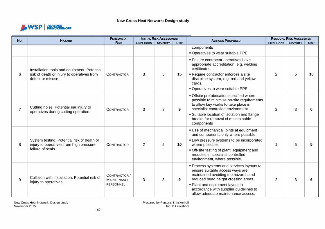
New Cross Heat Network: Design study
New Cross Heat Network: Design study Prepared by Parsons BrinckerhoffNovember 2015 for LB Lewisham
- 69 -
NO. HAZARDPERSONS AT
RISKINITIAL RISK ASSESSMENT ACTIONS PROPOSED
RESIDUAL RISK ASSESSMENTLIKELIHOOD SEVERITY RISK LIKELIHOOD SEVERITY RISK
components§ Operatives to wear suitable PPE
6Installation tools and equipment. Potentialrisk of death or injury to operatives fromdefect or misuse.
CONTRACTOR 3 5 15
§ Ensure contractor operatives haveappropriate accreditation, e.g. weldingcertificates.§ Require contractor enforces a site
discipline system, e.g. red and yellowcards.§ Operatives to wear suitable PPE
2 5 10
7 Cutting noise. Potential ear injury tooperatives during cutting operation. CONTRACTOR 3 3 9
§ Offsite prefabrication specified wherepossible to minimise on-site requirementsto allow key works to take place inspecialist controlled environment.§ Suitable location of isolation and flange
breaks for removal of maintainablecomponents
2 3 6
8System testing. Potential risk of death orinjury to operatives from high pressurefailure of seals.
CONTRACTOR 2 5 10
§ Use of mechanical joints at equipmentand components only where possible.§ Low pressure systems to be incorporated
where possible.§ Off-site testing of plant, equipment and
modules in specialist controlledenvironment, where possible.
1 5 5
9 Collision with installation. Potential risk ofinjury to operatives.
CONTRACTOR /MAINTENANCEPERSONNEL
3 3 9
§ Process systems and services layouts toensure suitable access ways aremaintained avoiding trip hazards andreduced head height crossing areas.§ Plant and equipment layout in
accordance with supplier guidelines toallow adequate maintenance access.
2 3 6
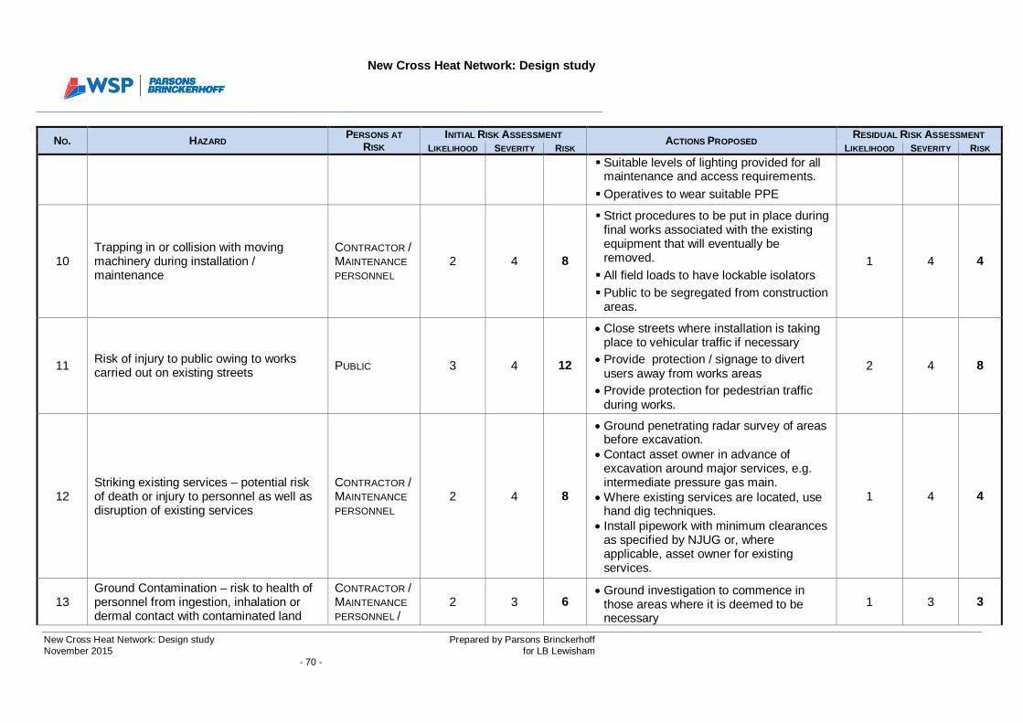
New Cross Heat Network: Design study
New Cross Heat Network: Design study Prepared by Parsons BrinckerhoffNovember 2015 for LB Lewisham
- 70 -
NO. HAZARDPERSONS AT
RISKINITIAL RISK ASSESSMENT ACTIONS PROPOSED
RESIDUAL RISK ASSESSMENTLIKELIHOOD SEVERITY RISK LIKELIHOOD SEVERITY RISK
§ Suitable levels of lighting provided for allmaintenance and access requirements.§ Operatives to wear suitable PPE
10Trapping in or collision with movingmachinery during installation /maintenance
CONTRACTOR /MAINTENANCEPERSONNEL
2 4 8
§ Strict procedures to be put in place duringfinal works associated with the existingequipment that will eventually beremoved.§ All field loads to have lockable isolators§ Public to be segregated from construction
areas.
1 4 4
11 Risk of injury to public owing to workscarried out on existing streets PUBLIC 3 4 12
· Close streets where installation is takingplace to vehicular traffic if necessary
· Provide protection / signage to divertusers away from works areas
· Provide protection for pedestrian trafficduring works.
2 4 8
12Striking existing services – potential riskof death or injury to personnel as well asdisruption of existing services
CONTRACTOR /MAINTENANCEPERSONNEL
2 4 8
· Ground penetrating radar survey of areasbefore excavation.
· Contact asset owner in advance ofexcavation around major services, e.g.intermediate pressure gas main.
· Where existing services are located, usehand dig techniques.
· Install pipework with minimum clearancesas specified by NJUG or, whereapplicable, asset owner for existingservices.
1 4 4
13Ground Contamination – risk to health ofpersonnel from ingestion, inhalation ordermal contact with contaminated land
CONTRACTOR /MAINTENANCEPERSONNEL /
2 3 6· Ground investigation to commence in
those areas where it is deemed to benecessary
1 3 3
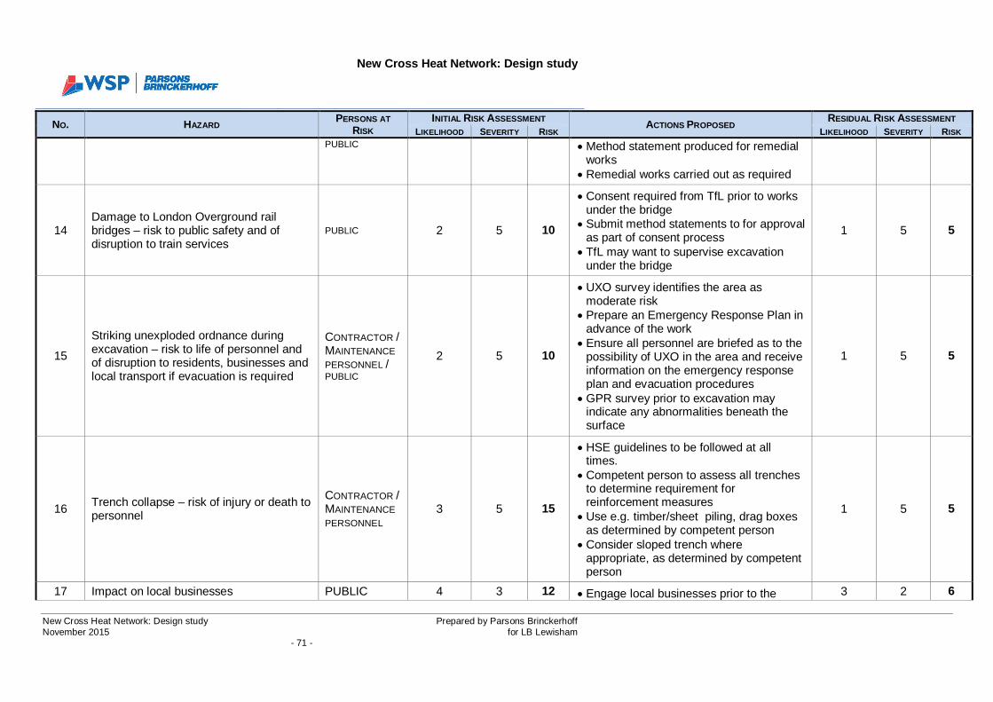
New Cross Heat Network: Design study
New Cross Heat Network: Design study Prepared by Parsons BrinckerhoffNovember 2015 for LB Lewisham
- 71 -
NO. HAZARDPERSONS AT
RISKINITIAL RISK ASSESSMENT ACTIONS PROPOSED
RESIDUAL RISK ASSESSMENTLIKELIHOOD SEVERITY RISK LIKELIHOOD SEVERITY RISK
PUBLIC · Method statement produced for remedialworks
· Remedial works carried out as required
14Damage to London Overground railbridges – risk to public safety and ofdisruption to train services
PUBLIC 2 5 10
· Consent required from TfL prior to worksunder the bridge
· Submit method statements to for approvalas part of consent process
· TfL may want to supervise excavationunder the bridge
1 5 5
15
Striking unexploded ordnance duringexcavation – risk to life of personnel andof disruption to residents, businesses andlocal transport if evacuation is required
CONTRACTOR /MAINTENANCEPERSONNEL /PUBLIC
2 5 10
· UXO survey identifies the area asmoderate risk
· Prepare an Emergency Response Plan inadvance of the work
· Ensure all personnel are briefed as to thepossibility of UXO in the area and receiveinformation on the emergency responseplan and evacuation procedures
· GPR survey prior to excavation mayindicate any abnormalities beneath thesurface
1 5 5
16 Trench collapse – risk of injury or death topersonnel
CONTRACTOR /MAINTENANCEPERSONNEL
3 5 15
· HSE guidelines to be followed at alltimes.
· Competent person to assess all trenchesto determine requirement forreinforcement measures
· Use e.g. timber/sheet piling, drag boxesas determined by competent person
· Consider sloped trench whereappropriate, as determined by competentperson
1 5 5
17 Impact on local businesses PUBLIC 4 3 12 · Engage local businesses prior to the 3 2 6
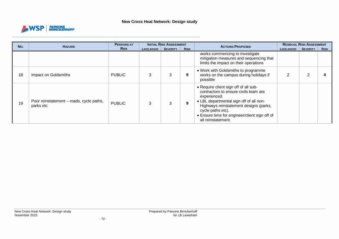
New Cross Heat Network: Design study
New Cross Heat Network: Design study Prepared by Parsons BrinckerhoffNovember 2015 for LB Lewisham
- 72 -
NO. HAZARDPERSONS AT
RISKINITIAL RISK ASSESSMENT ACTIONS PROPOSED
RESIDUAL RISK ASSESSMENTLIKELIHOOD SEVERITY RISK LIKELIHOOD SEVERITY RISK
works commencing to investigatemitigation measures and sequencing thatlimits the impact on their operations
18 Impact on Goldsmiths PUBLIC 3 3 9· Work with Goldsmiths to programme
works on the campus during holidays ifpossible
2 2 4
19 Poor reinstatement – roads, cycle paths,parks etc PUBLIC 3 3 9
· Require client sign off of all sub-contractors to ensure civils team areexperienced.
· LBL departmental sign off of all non-Highways reinstatement designs (parks,cycle paths etc).
· Ensure time for engineer/client sign off ofall reinstatement.

New Cross Heat Network: Design study
New Cross Heat Network: Design study Prepared by Parsons BrinckerhoffNovember 2015 for LB Lewisham
- 73 -
SECTION 8
APPENDICES

New Cross Heat Network: Design study
New Cross Heat Network: Design study Prepared by Parsons BrinckerhoffNovember 2015 for LB Lewisham
- 74 -
8 APPENDICES
8.1 Appendix A – Goldsmiths Education Building schematic and layout
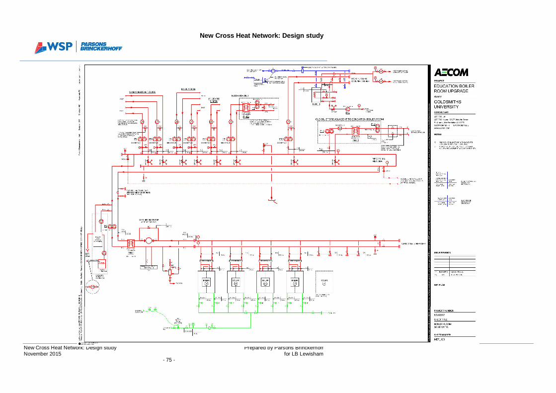
New Cross Heat Network: Design study
New Cross Heat Network: Design study Prepared by Parsons BrinckerhoffNovember 2015 for LB Lewisham
- 75 -
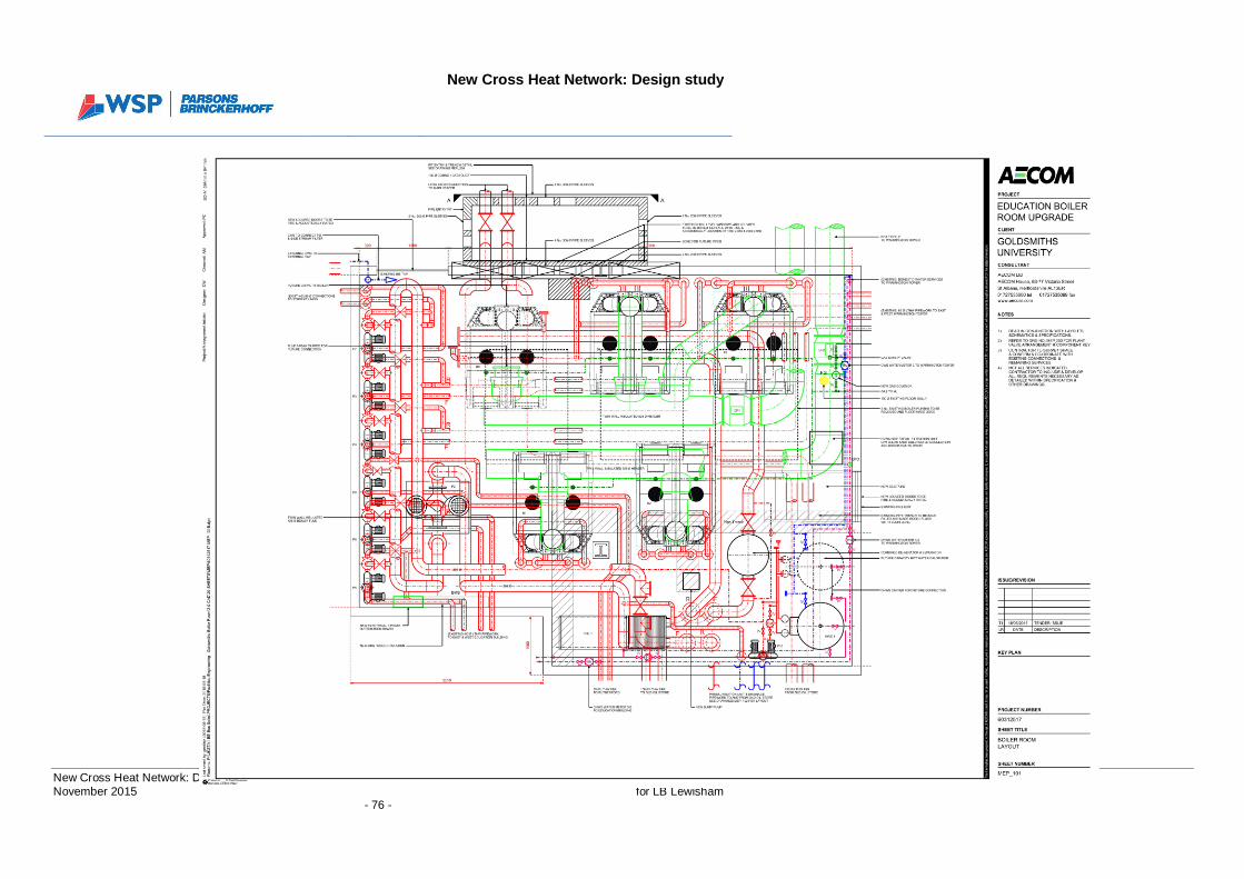
New Cross Heat Network: Design study
New Cross Heat Network: Design study Prepared by Parsons BrinckerhoffNovember 2015 for LB Lewisham
- 76 -

New Cross Heat Network: Design study
New Cross Heat Network: Design study Prepared by Parsons BrinckerhoffNovember 2015 for LB Lewisham
- 77 -
8.2 Appendix B – Future Connections Specification

New Cross Heat Network: Design study
New Cross Heat Network: Design study Prepared by Parsons BrinckerhoffNovember 2015 for LB Lewisham
- 78 -

November 2015
NEW CROSS HEAT NETWORK: NEWCONNECTIONS SPECIFICATION
London Borough of Lewisham
[3513044A-BEL]
Final


New Cross Heat Network: NewConnections Specification
3514033A-BEL
Prepared forLondon Borough of Lewisham
Prepared byWSP | Parsons Brinckerhoff
www.pbworld.com

New Cross Heat Network: NewConnections Specification
New Cross Heat Network - Future connections specification Prepared by WSP | Parsons BrinckerhoffNovember 2015 for London Borough of Lewisham
- 5 -
CONTENTSPage
1 INTRODUCTION 7
2 THE PRIMARY NETWORK 8
3 SECONDARY NETWORKS 93.1 Return temperatures 113.2 General operating requirements 12
4 SECONDARY SYSTEM DESIGN 134.1 General operating philosophy 13
5 EXISTING BUILDINGS 195.1 Constant Temperature (CT), variable volume 205.2 Constant Temperature (CT), constant volume 205.3 Variable Temperature (VT), Constant Volume 225.4 Variable Temperature (VT), Variable Volume 235.5 Centralised HWS Supply 235.6 Other System Types 245.7 Residential Systems 245.8 DH Substation Interface Configuration 25
6 PHYSICAL REQUIREMENT FOR INCORPORATING THE DH SUBSTATION 276.1 Provision for future connection of DH substation 276.2 Plant layouts 286.3 Minimum Plant Room Equipment Requirements 28

New Cross Heat Network: NewConnections Specification
New Cross Heat Network - Future connections specification Prepared by WSP | Parsons BrinckerhoffNovember 2015 for London Borough of Lewisham
- 7 -
1 INTRODUCTION
This document describes the hot water and space heating design strategies to be considered in allbuildings which are to be connected to a district heating network.
This document is compliant with the guidelines set out in the CIBSE Heat Networks Code of Practicefor the UK.
The ideal design philosophy for a district heating network is based on constant operational flow andreturn temperatures and variable flow rate, to suit the annual fluctuations in customer demand. Thefollowing guidelines are provided to suit this operational philosophy.
The following terminology will be used to describe the various sub-systems that are dealt with in thisdocument:
System definitions
· LTHW stands for Low Temperature Hot Water supply.
· DHW refers to Domestic Hot Water supply.
· DH stands for District Heating.
· HWS refers to Hot Water Service supply (i.e. non-domestic hot water)
· SELCHP stands for South East London Combined Heat and Power.
· DP stands for Differential Pressure.
· CT stands for Constant Temperature.
· VT stands for Variable Temperature.
· The primary network refers to the primary distribution system that connects SELCHP toeach individual building or development.
· District Heating Substation located in the developer plant room is the physical (andcontractual) delineation between the primary and secondary networks.
· The secondary networks are the local networks within each building or development thatsupply hot water to the end user.
· HIU stands for Heat Interface Unit.

New Cross Heat Network: NewConnections Specification
New Cross Heat Network - Future connections specification Prepared by WSP | Parsons BrinckerhoffNovember 2015 for London Borough of Lewisham
- 8 -
2 THE PRIMARY NETWORK
The primary New Cross Heat Network will be a variable flow rate system that is controlled by theindividual instantaneous heating demands of the connected buildings. A constant temperaturedifferential is imposed on the primary circuit irrespective of the demand requirement, with the returntemperature kept as low as possible to maximise the thermal efficiency of the network, and tominimise pumping costs.
To meet these requirements, it is essential that the primary and secondary networks are compatible intheir design. The main purpose of this document is to provide guidance on the design of thesecondary circuits, i.e. the heating systems within connected buildings, so that the primary networkcan operate at its optimum efficiency.

New Cross Heat Network: NewConnections Specification
New Cross Heat Network - Future connections specification Prepared by WSP | Parsons BrinckerhoffNovember 2015 for London Borough of Lewisham
- 9 -
3 SECONDARY NETWORKS
A heat exchanger substation shall form the hydraulic interface between the primary district heatingnetwork and the new connection’s secondary system(s). The advantage of using a heat exchanger isthat it provides hydraulic separation of the two circuits, creating a contractual demarcation andeliminating the risk of contamination to the primary system from the customer secondary systems andvice versa.
The substation shall be located in a plant room within the connected development/building. Toachieve compatibility with the primary network, it is important that these substations are designed,installed and operated to a common set of rules that are described in the next section.
Within new-build residential connections, the secondary system generally supplies heat to tertiaryLTHW and DHW systems located in individual residential units via a Heat Interface Unit (HIU). Theseunits can be thought of as scaled-down version of the heat substations, and are comparable in size toa modern domestic condensing boiler. However, unlike the large substations, which are designed forspecific buildings, the HIU is generally an off-the-shelf item that is selected to meet the required loadspecifications. These HIUs are essential to the efficient operation of a DH network and it is noted thatthe market does not currently benefit from a quality standard, which means there is a lot of variation inthe efficiency and quality of the available units.
It is essential that the interface between the primary and secondary networks has a common set offeatures. The following drawing gives a typical schematic indication for the connection requirements atthe interface between the primary DH circuit and the relevant building secondary systems. It shouldbe noted that this drawing is for guidance and information only and each connection should be co-ordinated as required with the end user for final design and installation requirements.
The drawing indicates two heat exchanger units operating in parallel; however, depending on therequired load of the individual connection, along with any specific resilience requirement, thesubstation may incorporate single or multiple parallel heat exchangers, or a level of standby. Subjectto this final required configuration, the controls can vary to suit each requirement type.
The physical requirements for the incorporation of the heat exchange substation in the developerplant rooms are detailed in Section 6 below.
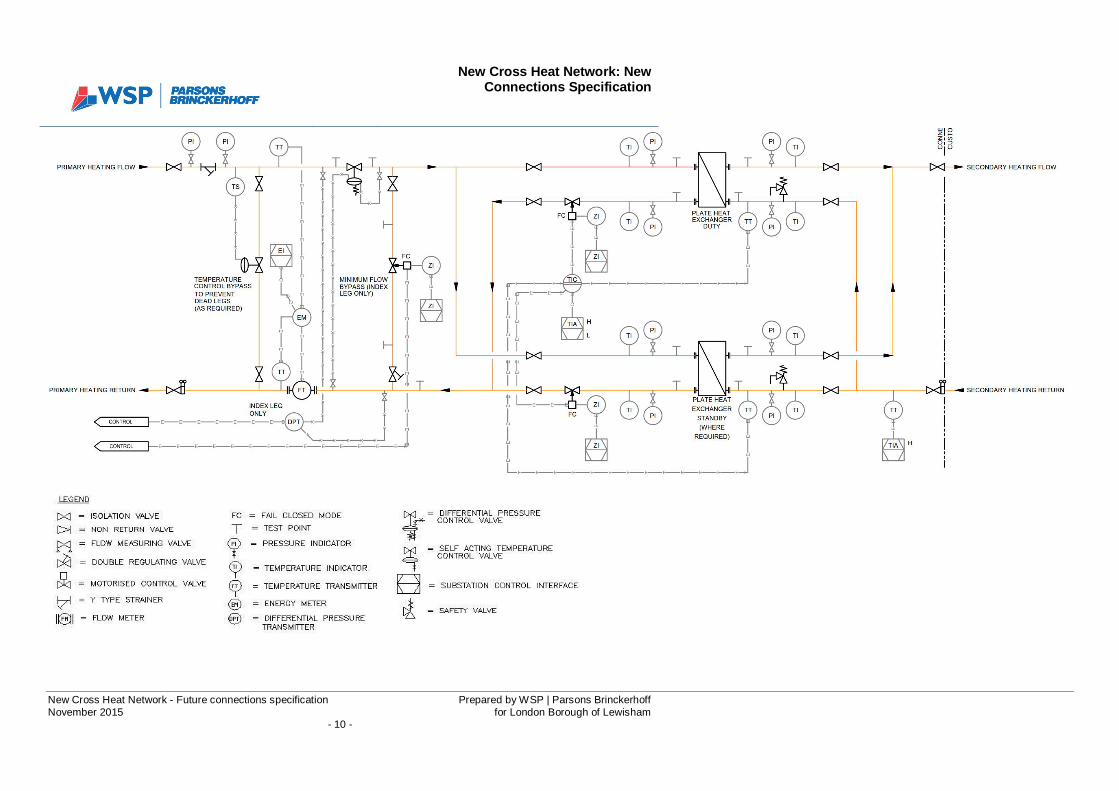
New Cross Heat Network: NewConnections Specification
New Cross Heat Network - Future connections specification Prepared by WSP | Parsons BrinckerhoffNovember 2015 for London Borough of Lewisham
- 10 -
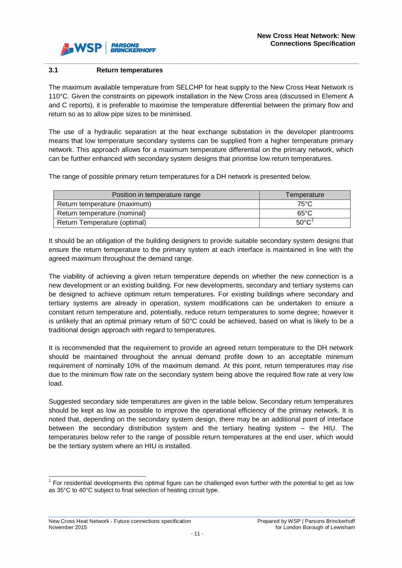
New Cross Heat Network: NewConnections Specification
New Cross Heat Network - Future connections specification Prepared by WSP | Parsons BrinckerhoffNovember 2015 for London Borough of Lewisham
- 11 -
3.1 Return temperatures
The maximum available temperature from SELCHP for heat supply to the New Cross Heat Network is110°C. Given the constraints on pipework installation in the New Cross area (discussed in Element Aand C reports), it is preferable to maximise the temperature differential between the primary flow andreturn so as to allow pipe sizes to be minimised.
The use of a hydraulic separation at the heat exchange substation in the developer plantroomsmeans that low temperature secondary systems can be supplied from a higher temperature primarynetwork. This approach allows for a maximum temperature differential on the primary network, whichcan be further enhanced with secondary system designs that prioritise low return temperatures.
The range of possible primary return temperatures for a DH network is presented below.
Position in temperature range TemperatureReturn temperature (maximum) 75°CReturn temperature (nominal) 65°CReturn Temperature (optimal) 50°C1
It should be an obligation of the building designers to provide suitable secondary system designs thatensure the return temperature to the primary system at each interface is maintained in line with theagreed maximum throughout the demand range.
The viability of achieving a given return temperature depends on whether the new connection is anew development or an existing building. For new developments, secondary and tertiary systems canbe designed to achieve optimum return temperatures. For existing buildings where secondary andtertiary systems are already in operation, system modifications can be undertaken to ensure aconstant return temperature and, potentially, reduce return temperatures to some degree; however itis unlikely that an optimal primary return of 50°C could be achieved, based on what is likely to be atraditional design approach with regard to temperatures.
It is recommended that the requirement to provide an agreed return temperature to the DH networkshould be maintained throughout the annual demand profile down to an acceptable minimumrequirement of nominally 10% of the maximum demand. At this point, return temperatures may risedue to the minimum flow rate on the secondary system being above the required flow rate at very lowload.
Suggested secondary side temperatures are given in the table below. Secondary return temperaturesshould be kept as low as possible to improve the operational efficiency of the primary network. It isnoted that, depending on the secondary system design, there may be an additional point of interfacebetween the secondary distribution system and the tertiary heating system – the HIU. Thetemperatures below refer to the range of possible return temperatures at the end user, which wouldbe the tertiary system where an HIU is installed.
1 For residential developments this optimal figure can be challenged even further with the potential to get as lowas 35°C to 40°C subject to final selection of heating circuit type.
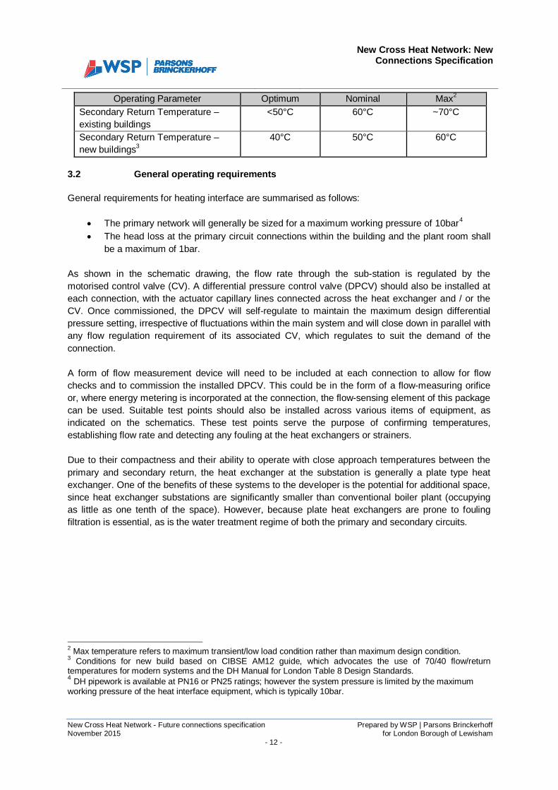
New Cross Heat Network: NewConnections Specification
New Cross Heat Network - Future connections specification Prepared by WSP | Parsons BrinckerhoffNovember 2015 for London Borough of Lewisham
- 12 -
Operating Parameter Optimum Nominal Max2
Secondary Return Temperature –existing buildings
<50°C 60°C ~70°C
Secondary Return Temperature –new buildings3
40°C 50°C 60°C
3.2 General operating requirements
General requirements for heating interface are summarised as follows:
· The primary network will generally be sized for a maximum working pressure of 10bar4
· The head loss at the primary circuit connections within the building and the plant room shallbe a maximum of 1bar.
As shown in the schematic drawing, the flow rate through the sub-station is regulated by themotorised control valve (CV). A differential pressure control valve (DPCV) should also be installed ateach connection, with the actuator capillary lines connected across the heat exchanger and / or theCV. Once commissioned, the DPCV will self-regulate to maintain the maximum design differentialpressure setting, irrespective of fluctuations within the main system and will close down in parallel withany flow regulation requirement of its associated CV, which regulates to suit the demand of theconnection.
A form of flow measurement device will need to be included at each connection to allow for flowchecks and to commission the installed DPCV. This could be in the form of a flow-measuring orificeor, where energy metering is incorporated at the connection, the flow-sensing element of this packagecan be used. Suitable test points should also be installed across various items of equipment, asindicated on the schematics. These test points serve the purpose of confirming temperatures,establishing flow rate and detecting any fouling at the heat exchangers or strainers.
Due to their compactness and their ability to operate with close approach temperatures between theprimary and secondary return, the heat exchanger at the substation is generally a plate type heatexchanger. One of the benefits of these systems to the developer is the potential for additional space,since heat exchanger substations are significantly smaller than conventional boiler plant (occupyingas little as one tenth of the space). However, because plate heat exchangers are prone to foulingfiltration is essential, as is the water treatment regime of both the primary and secondary circuits.
2 Max temperature refers to maximum transient/low load condition rather than maximum design condition.3 Conditions for new build based on CIBSE AM12 guide, which advocates the use of 70/40 flow/returntemperatures for modern systems and the DH Manual for London Table 8 Design Standards.4 DH pipework is available at PN16 or PN25 ratings; however the system pressure is limited by the maximumworking pressure of the heat interface equipment, which is typically 10bar.

New Cross Heat Network: NewConnections Specification
New Cross Heat Network - Future connections specification Prepared by WSP | Parsons BrinckerhoffNovember 2015 for London Borough of Lewisham
- 13 -
4 SECONDARY SYSTEM DESIGN
4.1 General operating philosophy
Secondary systems shall be designed based on constant operating temperatures and variable flowrate criteria to ensure full compatibility with the primary supply systems. The following drawingindicates the basic concept of variable speed pumping and two-port control strategy.
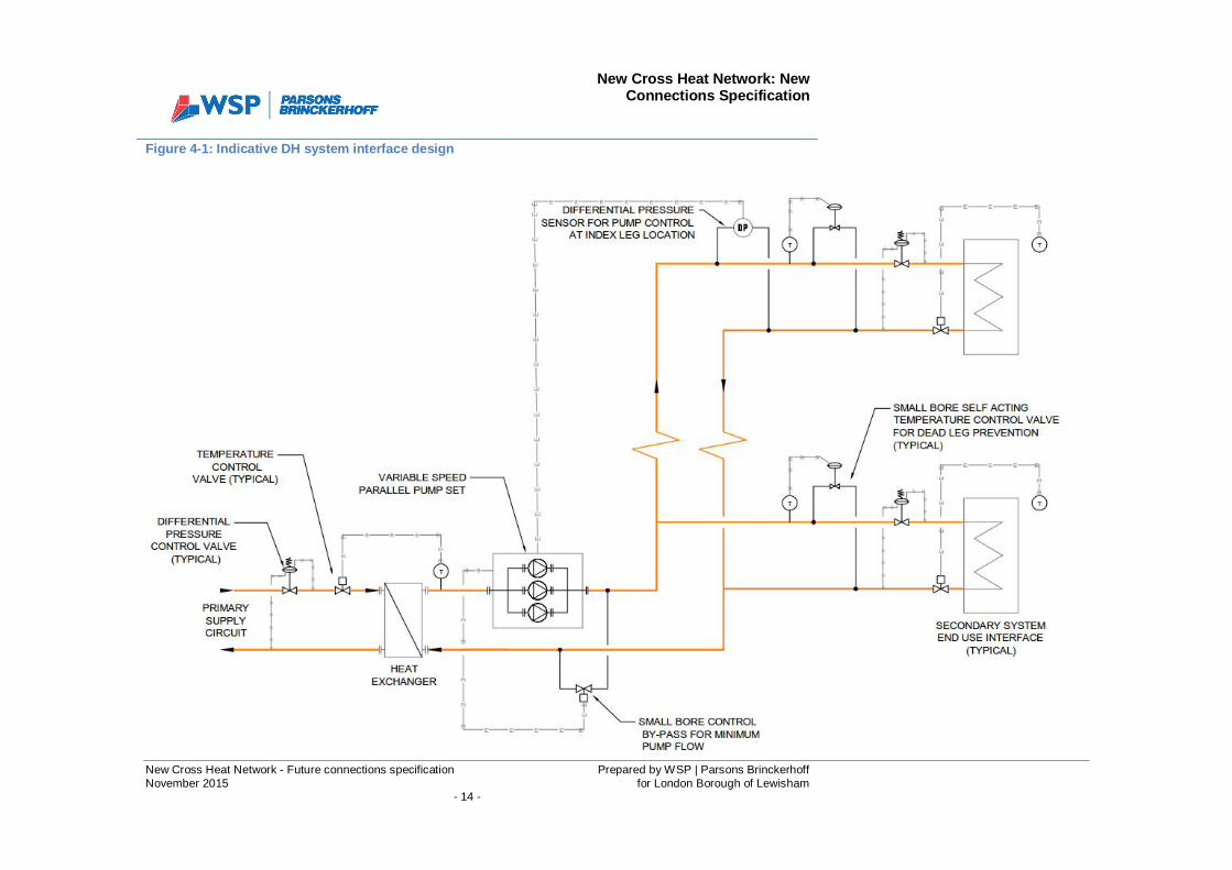
New Cross Heat Network: NewConnections Specification
New Cross Heat Network - Future connections specification Prepared by WSP | Parsons BrinckerhoffNovember 2015 for London Borough of Lewisham
- 14 -
Figure 4-1: Indicative DH system interface design
New Cross Heat Network: NewConnections Specification
New Cross Heat Network - Future connections specification Prepared by WSP | Parsons BrinckerhoffNovember 2015 for London Borough of Lewisham
- 15 -
The required terminal load is used to regulate the control valve opening, ensuring that the pump iskept at the optimum operation point for the overall circuit. This keeps the electrical consumption of thepump to a minimum and maintains a maximum temperature differential between the flow and thereturn.
It is recommended that the pump speed regulation is controlled through differential pressuremeasured at the secondary circuit index run, as shown in Figure 4-1. This is normally the most distantload and ensures an accurate and close tolerance reaction to changes in the system demandparameters, as valves open and close.
It is not correct to control a variable flow circuit with the overall system differential pressure at thepumps, which is seen in practice on many installations, as a set point DP for peak will be significantlydifferent to the requirement at minimum demand. The only suitable alternative to an index leg control,for example where no controls network is available to a residential scheme, is to utilise a specialistpackaged intelligent pumping system that is available from certain pump suppliers. This works on acommissioned setting for peak and minimum demand. Based on a matrix of absorbed power for theparticular pumps being used, the system knows where the pumps need to be on their speed curve.The only downside to this solution is it is initially based on theoretical figures and needs to be checked/ re-commissioned as necessary based on actual parameters once known. It also requires adjustmentif further connections are added where the system dynamics will change.
Due to the possibility that, at times of very low load, the required system flow rate may be exceededby the minimum possible flow rate at the pumps’ minimum speed setting, it is necessary to install asmall bore control bypass arrangement so that the pumps can maintain minimum flow, as shown inFigure 4-1. The bypass control valve should be set to open when the single smallest pump reaches itsminimum speed and the differential pressure set point continues to rise.
It is also recommended that any final connection heat interface, that is prone to a long length ofpotential dead leg, is fitted with a small bore self-acting temperature control valve to maintain asuitable level of heat close to the connection when the control valve is closed, such that when heat isrequired, the reaction time to provide a suitable temperature is negligible. This is also as shown inFigure 4-1 and described further in Section 4.1.2 below. Depending on the reaction times requiredthese can alternatively be located on the end of main headers to cover multiple connections.
The temperature differential in the secondary distribution networks must be kept as high as possibleto ensure efficient operation of the DH network. The temperature differential at the primary /secondary interface will depend on the design of the internal building services. Therefore, all internalsystems must ensure compatible design that maintains optimum differential temperature at theinterface during all demand scenarios.
Key considerations for the design of building internal systems are as follows:
· Selecting low temperature operating systems such as underfloor heating to significantlyreduce return temperature.
· Where underfloor heating is not acceptable or feasible, low flow rate radiator circuits forbuildings, complete with thermostatic control, should be adopted. Radiator circuits can be
New Cross Heat Network: NewConnections Specification
New Cross Heat Network - Future connections specification Prepared by WSP | Parsons BrinckerhoffNovember 2015 for London Borough of Lewisham
- 16 -
designed to operate satisfactorily down to as low as 40°C-30°C without compromising theability of the system to deliver the required level of heat, given the new build requirements forfabric loss. This is as opposed to the traditional 82°C / 71°C approach. Quite often, boilerplant, pipework and radiators are oversized and therefore the modified conditions can beapplied to existing systems without any loss of performance in the heating system (seeSection 5).
· Compensated control to provide a variable temperature (VT) circuit to radiator and similarheat emitters will then optimise return temperatures further as the ambient temperaturemoves away from the winter peak requirements.
· Lower system operating temperatures ((i.e. below the traditional 82°C flow temperature) canalso be applied to constant temperature (CT) type circuits serving air handling unit (AHU) andfan coil unit (FCU) connections.
· In line with the sections covered below, the fundamental solution should involve a variableflow rate system in line with demand profile to ensure constant temperature differentialoperation to absolute minimum demand scenario.
· Ensuring minimum return temperature from hot water service connections, whether storage orinstantaneous. This can be as low as 25°C during high draw off times (see Section 4.1.5).
· Instantaneous hot water generation should be considered.
4.1.1 Two-port Control Valves and Variable Speed Pumping
The use of two port control valves and variable flow operation in constant temperature systemapplications is fundamental in ensuring that the unnecessary return of supply water temperature backto the heat exchanger is avoided. The use of variable speed pumps, in conjunction with differentialpressure control valves for system balance, provides an efficient method of delivering only the energythat is needed and, when combined with parallel pumping (see Section 4.1.4), provides the requiredturn down of the system to maintain optimum return temperatures throughout the annual demandprofiles.
4.1.2 “Dead leg” control
Bypass arrangements should be kept to an absolute minimum. They will be necessary during lowdemand periods when the supply temperature on the primary and secondary network deterioratesdue to control valves remaining closed for a period of time. If flow by-passes are not controlledproperly, the system loses efficiency because even at peak times, there is a continual mix betweenthe flow and return streams. To overcome this, self-acting temperature control by-passes should beinstalled at the end of main branch legs or at any remote equipment connections. These should beadjusted so that they open within a predetermined tolerance of the design flow temperature set point.This will allow a small constant flow to occur during low demand periods, to prevent the occurrence of“dead legs”.
It should be noted that short “dead legs” are perfectly acceptable on large-scale two port controlsystems and that as long as there is a main system branch, in reasonably close proximity, which is

New Cross Heat Network: NewConnections Specification
New Cross Heat Network - Future connections specification Prepared by WSP | Parsons BrinckerhoffNovember 2015 for London Borough of Lewisham
- 17 -
maintained at the design flow temperature, there is no need to install these bypasses over and abovewhere they are absolutely necessary. The actual size of the by-pass and self-acting valve, whereessential, should be kept to the smallest bore that will allow the flow rate required to maintain the“dead leg” at a minimum designated temperature (this figure should be less than the design operatingtemperature for example, the setting on a 60°C circuit could be 50-55°C.
4.1.3 Circuit Mixing
Wherever possible, water returning from one heating circuit at a high temperature should beconsidered for use in a second circuit. However, it is appreciated that this is not always possible sinceone circuit may demand energy at a different time to another.
4.1.4 Pump Selection Methodology
It is recommended that the required pumps are installed in parallel within the flow circuit just after theheat exchanger, as shown in the following drawing. Differential pressure control is then incorporatedin each sub-circuit after the pump, to provide system balance during all demand scenarios and flow /pressure fluctuations. The number of pumps selected will depend on the maximum and minimum flowrates at which the system will operate throughout the year and the characteristics of the inverter of thevariable speed pump.
For connections where the difference between the annual maximum and minimum demands is lessonerous than others, a single duty pump may have sufficient turndown capacity to meet the requiredoperation throughout the year. For most connections the difference in loads throughout the year issignificant and therefore, to be able to meet the required return temperature at all times, the use ofparallel pumping should be adopted. Again dependant on the flow rate differences between theannual maximum and minimum demands, this can mean two 50% units, three 33% units and/or theincorporation of a low load (jockey) pump.
The minimum flow requirements described above should be based on the minimum speedrequirement for a single pump in the parallel set up. Note that minimum flow for the pump is notnecessarily in line with the minimum inverter setting and the pump may be allowed to ramp up itscurve at this speed before final prevention of dead head is required.
Pump selection should seek to maintain a degree of resilience is case of pump failure ormaintenance; for example three pumps at 50 percent of the peak requirement in a duty/duty/standbyarrangement.
4.1.5 Hot Water Supply
The generation of hot water services (HWS) is generally supplied from the customer secondary sidesystem and should be designed such that the mix of return temperatures from this and the otherheating circuits will provide the overall required return temperature. Consideration needs to be givento pump control where this is a dedicated circuit at the times when no demand is required otherwisethe return temperature will rise from this connection.
The most efficient solution for return temperature and annual pumping savings is to connect the HWSas a separate primary interface with the DH supply. Subject to individual customer resiliencerequirements for HWS supply, consideration should be given to an instantaneous approach. Thisprovides the benefit of not only space reduction, heat loss reduction from standing water and the
New Cross Heat Network: NewConnections Specification
New Cross Heat Network - Future connections specification Prepared by WSP | Parsons BrinckerhoffNovember 2015 for London Borough of Lewisham
- 18 -
reduction of the risk of infection from Legionella, but will also benefit in providing a minimum returntemperature where the cold feed is connected directly to the heat exchanger. Packaged HWSsubstations that are fully compatible with a DH connection are widely available as both instantaneousor with a required level of storage.
The DHW supply for all residential units shall ideally be generated locally via a Hydraulic InterfaceUnit (HIU). The HIU shall typically be a wall mounted packaged unit comprising 2No heat exchangers(1No for heating, 1No for DHW), a heating circulation pump, control devices and heat metering forbilling purposes.
4.1.6 BMS
Exchange of BMS data should be provided as required to ensure ongoing operational compatibilitybetween the district heating primary and the secondary circuits. The Energy Centre will continuallymonitor the flow and return temperatures on both the primary and secondary sides of the substationinterface, as well as the primary flow rate, primary valve position(s), instantaneous energyconsumption and cumulative energy consumption for billing. The provision of these signals will allowfor full diagnosis of the interface performance and where any compatibility issues may arise. Note thatfurther control signals may need to be provided by the secondary system subject to the finalcomplexity of the substation connection.
An electrical enclosure and control panel would be installed to house control devices and thecommunication system link to the energy centre. This will be capable of transmitting the data obtainedfrom the installation, as described above, as well as alarms and receiving control inputs.
4.1.7 Metering
Energy meters measure the volume flow rates as well as the flow and return temperatures to providean accurate record of energy usage. The preferred flow meter element technology is an ultrasonic orsimilar full pipe bore type device that should be to a minimum Class 2 in accordance with theMeasuring Instruments Directive. These solid state devices are less susceptible to deposits in thewater because they contain no moving parts. Furthermore they require very little maintenance and areaccurate even with very low flow rates, although it is essential that selection is based on both themaximum and minimum operating requirements.
Metering is generally installed to record energy delivered on the primary side circuit for reasons ofdemarcation; however check meters can be installed as required on the secondary side. The energymetering system must include a flow meter, two temperature sensors and a stand-alone integratorunit complete with battery backup. No energy metering should be carried out within the main BMSlogic.
Note that metering must be compliant with the Heat Networks (Metering and Billing) Regulations(2014). A summary of the Regulations is presented in the Element D report.
New Cross Heat Network: NewConnections Specification
New Cross Heat Network - Future connections specification Prepared by WSP | Parsons BrinckerhoffNovember 2015 for London Borough of Lewisham
- 19 -
5 EXISTING BUILDINGS
Existing buildings should not be connected to a DH network without first ensuring they are to asuitable level of compatibility and will not detriment individual operation or efficiency of the primarysupply system. For example, if the accumulation of higher return temperatures is permitted this canlead to an overall return temperature above the minimum required for the operation of a CHP engineA lowering of the overall system temperature differential will also impact on the potential level ofenergy within in a thermal storage facility, the efficiency of the annual DH pumping regime and the DHpipe sizing / ability to provide further customers.
Many existing buildings have the legacy of the traditional approach to heating design with three-portcontrol in particular being a significant problem on the constant temperature (CT) type systems. Thesystem design temperatures are historically 82°C flow and 71°C return; however in reality, thesetemperatures are significantly higher than 71°C for the majority of the year due to the three-port by-pass arrangement. Even at peak times the temperature is higher based on the fact that a three-portsolution is based on a balanced flow for the full connected load, when the actual peak has asignificant level of diversity that is effectively being by-passed.
Most traditional existing building designs also incorporate weather compensated VT heating systemssupplying radiators or other similar perimeter type circuits. With this type of circuit, the flowtemperature is varied incrementally according to the external ambient temperature by three-portcontrol blending the lower temperature return with the flow. These systems are more compatible withDH networks because they can provide lower return temperatures for a significant proportion of theyear. They tend to operate on a constant flow basis, but more recently TRVs or zonal thermostatcontrol has been introduced whereby flow is regulated and the pump can reduce in speed based onthe change in the system differential pressure.
It is important, therefore, that potential new connections to existing buildings are properly assessedfor their level of compatibility by determining which of the following they include:
· Constant temperature, variable volume circuits· Constant temperature, constant volume circuits· Variable temperature, constant volume circuits (weather compensated)· Variable temperature, variable volume circuits (weather compensated)· Centralised HWS supply· Other system types· Residential systems
Once the type of system(s) installed within a given connection has been determined, and prior toexamining potential methods of enhancement where necessary, it is also beneficial to assess theexisting operating performance by consulting trended temperature and energy data where available. Ifthis information is not available or it is not possible to set up, then consideration should be given to aperiod of monitoring using portable temperature sensors and meters where appropriate.
Once the level of compatibility has been established, the areas where the operation may causedetriment to the DH operation need to be identified and enhancements reviewed in line with thepotential solutions described in high level in the following sections. Note that many of these solutions
New Cross Heat Network: NewConnections Specification
New Cross Heat Network - Future connections specification Prepared by WSP | Parsons BrinckerhoffNovember 2015 for London Borough of Lewisham
- 20 -
may also make economic sense, regardless of whether the building is connecting to a DH scheme,based on heat loss and / or annual pumping savings. It should also be noted that these potentialsolutions only deal with enhancements that, although not optimum for DH connection, will ensurecompatibility in a cost effective manner and without requiring total replacement of systems unless theywere life expired (refer then to new system designs).
5.1 Constant Temperature (CT), variable volume
Where an existing building already operates a CT secondary system with two-port control and inverterdriven pumps, this is generally an ideal connection for a DH network. Generally the approach on theolder type building would be for a traditional 82°C / 71°C temperature operation, but some newerbuildings may have incorporated a better design with lower returns or overall temperatures, forexample 80°C / 60°C or even 70°C / 50°C. It would still be advisable to assess the existing operationto ensure the temperature parameters are in line with design requirements. Particularly for olderbuildings with the traditional approach to temperature, it would also be beneficial to consider whetherthe secondary / tertiary systems have been oversized, which is often the case, whereby there ispotential to lower the operating temperatures without detriment to the operation. This can generally beassessed by reviewing control valve positions through the peak times (ideally trended from BMS) tosee if they are ever required to be fully open. If not, it is possible that proportionally (ensuring suitablemargins) the temperature of the system could be reduced i.e. it could be a 72°C / 61°C as opposed tothe existing 82°C / 71°C. Another method is to gradually reduce the flow temperature set point duringthe winter months and assess what level it can be dropped to before any connections arecompromised. Another investigation would be the number of pumps installed and any benefit both inrectifying any minimum flow by-pass for return temperature to the DH connection and in reducingannual building operation costs associated with pumping. The simple addition of a jockey pump tomaintain the base loads for a large proportion of the year and allow turndown to minimum demandscenarios could have significant effect on pumping costs and ensure constant return temperature tothe DH.
In short, although these are generally a suitable type of system for connection to a DH system, areview should still be carried out to confirm the potential for any enhancements that would furtherbenefit the efficiency of both the building system and the DH operation.
5.2 Constant Temperature (CT), constant volume
As described above, this is the least compatible building secondary system configuration for a DHnetwork connection as it produces fluctuating return temperatures based on the control of the heatingdemand. This is due to the traditional approach for CT circuits of utilising three-port control valves witha constant flow rate around the system, regardless of the demand. Again, the approach on the oldertype building would be for a traditional 82°C / 71°C temperature operation. As individual heatingconnections require less demand, the three-port control solution modulates to by-pass to provide amix of flow and return temperatures. As stated, given no diversity control and a flow rate to suit theoverall connected load, even at peak winter demand periods, there would be a large proportion of by-pass and the return temperature is very rarely seen close to the design 71°C. Over design/sizing ofthe overall circuit will only exacerbate this more. This type of system will use significantly morepumping power than the variable volume system and regardless of DH connection, modification wouldbe recommended to reduce annual operating costs. The following enhancement and modificationproposals focus on ensuring a connection to a DH system would be possible as opposed to the
New Cross Heat Network: NewConnections Specification
New Cross Heat Network - Future connections specification Prepared by WSP | Parsons BrinckerhoffNovember 2015 for London Borough of Lewisham
- 21 -
secondary system operation; however, they would all generally provide varying degrees of efficiencyand thus operational cost savings. All, or a combination of them, would need to be assessed on alifecycle basis to confirm viability. It is very rare that a constant volume circuit can be connected to aDH system without some form of detriment to the operation and therefore the following potentialenhancements / modifications should be reviewed on an individual and cumulative basis to determineif there is a cost effective solution:
1) If the system is at, or very close to, end of life then there is commercial scope to replace themajority of pumping equipment and control components with a new solution in line with theoptimum variable flow system described under Section 4.1 above. If wider replacement ispossible, for example AHU upgrades, then a full review of design operating temperaturescould also be considered.
2) A low cost, quick fix option is to evaluate whether there is suitable over design in the existingsystem for the potential to lower the operating temperature without detriment to the operation.This can generally be assessed by reviewing control valve positions through the peak times(ideally trended from BMS) to see if they are ever required to be fully open. If not, it ispossible that proportionally (ensuring suitable margins) the temperature of the system couldbe reduced i.e. it could be a 72°C / 61°C as opposed to the existing 82°C / 71°C. Anothermethod is to gradually reduce the flow temperature set point during the winter months andassess what level it can be dropped to before any connections are compromised. This wouldensure that even with a three-port by-pass control operation the return temperature is unlikelyto reach levels that could create serious issue for the DH supply. It would not provide anysignificant efficiency benefit to the building system, other than heat loss savings, although itcould also be considered along with the more detailed modification potentials below.
3) Assessment of the overall payback on efficiency may confirm that it is viable to modify theexisting three-port control arrangement to a variable volume two-port system, based onannual savings in pumping energy and this would provide the optimum solution for a DHconnection. The modification of the three-port control devices at the system terminal units canbe considered in one of two ways.
i. Physically isolate the three-port by-pass, such that it operates as a two portas it closes to the load. Checks would need to be made to actuators toassess their differential pressure operating limits and these may need to beupgraded if necessary. Differential pressure control valves would also needto be installed across the system connections.
ii. Change the three-port control valve at each connection with a replacementtwo-port control valve. Again, differential pressure control valves would alsoneed to be installed across the system connections, although there is analternative in the market where the control valve and DPCV are combined asa single device.
Note that on both of these solutions the control at the terminal would remain as existing. Thesystem pumps would also need to be checked for compatibility with maximum and minimumdemand turndown with an inverter fitted if they do not already include for one, or fullreplacement of the pump sets with optimum variable speed selections. An easy win to provide
New Cross Heat Network: NewConnections Specification
New Cross Heat Network - Future connections specification Prepared by WSP | Parsons BrinckerhoffNovember 2015 for London Borough of Lewisham
- 22 -
minimum turndown efficiency, can be to consider the incorporation of a variable speed jockeypump to operate under a controlled regime with the modified larger existing pumps. Anymodification to variable volume control would also require the inclusion of DP sensor controland minimum flow control for the pumps, along with dead leg control, all as described inSection 4.1 above.
Where multiple fan coil units are included within an existing CT circuit, it may not be costeffective to modify each individual unit and thus they may need to remain under a separatelypumped constant volume regime, with careful assessment of what the final mixed return tothe DH would be when combined with the rest of the circuit which has been modified tovariable volume. If this is the case, then consideration should also be given to theincorporation of compensation on the FCU circuit to lower the operating temperatures for thevast majority of the year.
If CT circuits can be modified to two-port, variable volume control it is also worth investigatingwhether it is possible to widen the operating differential temperature, which will provide furtherefficiency benefits with regard to pumping on both the building and DH systems. This can bedone by increasing the CT system flow temperature. For example, a standard AHU coildesigned for 82°C / 71°C will have a mean temperature of 76.5°C. If you raise the flowtemperature to say 85°C and maintain the mean temperature by reducing the flow rate, thereturn temperature from the coil will drop to 68°C with no detriment to the capacity. If theindividual coil is over sized then there is scope to reduce the mean temperature and lower thereturn temperatures further. Under this regime it is generally best to install new two-portvalves suitably sized for the reduced flow rate requirements.
Any works associated with the modification of equipment and components on existing constantvolume circuits to provide the compatibility required with a DH connection can be extensive and thus itis imperative that detailed specification of requirements, along with full capital costing and paybackanalysis is carried out to ensure overall viability.
5.3 Variable Temperature (VT), Constant Volume
VT systems incorporate weather compensated control to change the set point of the system flowtemperature based on the external ambient temperature. Older systems, again, are traditionallydesigned to operate at 82°C / 71°C at the peak external ambient temperature, with the 82°C reducedas the temperature rises. The older systems will rely fully on the compensation control to prevent overheating of the spaces and thus operate at a constant flow around the radiators or other perimeter typeheat emitters. Some may include zonal shutdowns, or will have been retro fitted with TRVs at the heatemitters in which case they will operate more in line with the VT system type described in Section 5.4below. Subject to the ideal balancing of the circuits, the operational differential temperature shouldgenerally stay constant through the annual demand profile and thus will reduce proportionally as thecompensated flow set point is changed. For the vast majority of the year, this will therefore provide thepotential for good return temperatures to a DH network.
To fully confirm the suitability for connection to a DH network, it is important to assess the operation ofthe various VT circuits and confirm that these return temperatures are suitable, particularly duringpeak external temperature periods. This can be done through analysis of existing trended data or
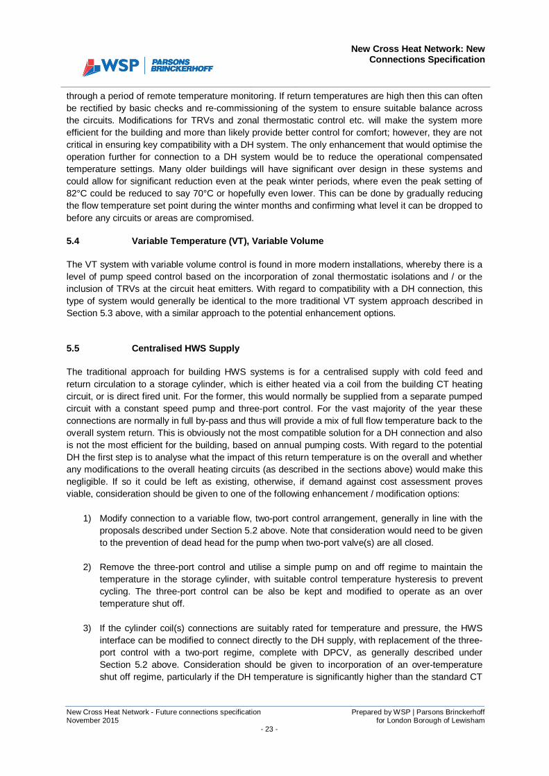
New Cross Heat Network: NewConnections Specification
New Cross Heat Network - Future connections specification Prepared by WSP | Parsons BrinckerhoffNovember 2015 for London Borough of Lewisham
- 23 -
through a period of remote temperature monitoring. If return temperatures are high then this can oftenbe rectified by basic checks and re-commissioning of the system to ensure suitable balance acrossthe circuits. Modifications for TRVs and zonal thermostatic control etc. will make the system moreefficient for the building and more than likely provide better control for comfort; however, they are notcritical in ensuring key compatibility with a DH system. The only enhancement that would optimise theoperation further for connection to a DH system would be to reduce the operational compensatedtemperature settings. Many older buildings will have significant over design in these systems andcould allow for significant reduction even at the peak winter periods, where even the peak setting of82°C could be reduced to say 70°C or hopefully even lower. This can be done by gradually reducingthe flow temperature set point during the winter months and confirming what level it can be dropped tobefore any circuits or areas are compromised.
5.4 Variable Temperature (VT), Variable Volume
The VT system with variable volume control is found in more modern installations, whereby there is alevel of pump speed control based on the incorporation of zonal thermostatic isolations and / or theinclusion of TRVs at the circuit heat emitters. With regard to compatibility with a DH connection, thistype of system would generally be identical to the more traditional VT system approach described inSection 5.3 above, with a similar approach to the potential enhancement options.
5.5 Centralised HWS Supply
The traditional approach for building HWS systems is for a centralised supply with cold feed andreturn circulation to a storage cylinder, which is either heated via a coil from the building CT heatingcircuit, or is direct fired unit. For the former, this would normally be supplied from a separate pumpedcircuit with a constant speed pump and three-port control. For the vast majority of the year theseconnections are normally in full by-pass and thus will provide a mix of full flow temperature back to theoverall system return. This is obviously not the most compatible solution for a DH connection and alsois not the most efficient for the building, based on annual pumping costs. With regard to the potentialDH the first step is to analyse what the impact of this return temperature is on the overall and whetherany modifications to the overall heating circuits (as described in the sections above) would make thisnegligible. If so it could be left as existing, otherwise, if demand against cost assessment provesviable, consideration should be given to one of the following enhancement / modification options:
1) Modify connection to a variable flow, two-port control arrangement, generally in line with theproposals described under Section 5.2 above. Note that consideration would need to be givento the prevention of dead head for the pump when two-port valve(s) are all closed.
2) Remove the three-port control and utilise a simple pump on and off regime to maintain thetemperature in the storage cylinder, with suitable control temperature hysteresis to preventcycling. The three-port control can be also be kept and modified to operate as an overtemperature shut off.
3) If the cylinder coil(s) connections are suitably rated for temperature and pressure, the HWSinterface can be modified to connect directly to the DH supply, with replacement of the three-port control with a two-port regime, complete with DPCV, as generally described underSection 5.2 above. Consideration should be given to incorporation of an over-temperatureshut off regime, particularly if the DH temperature is significantly higher than the standard CT
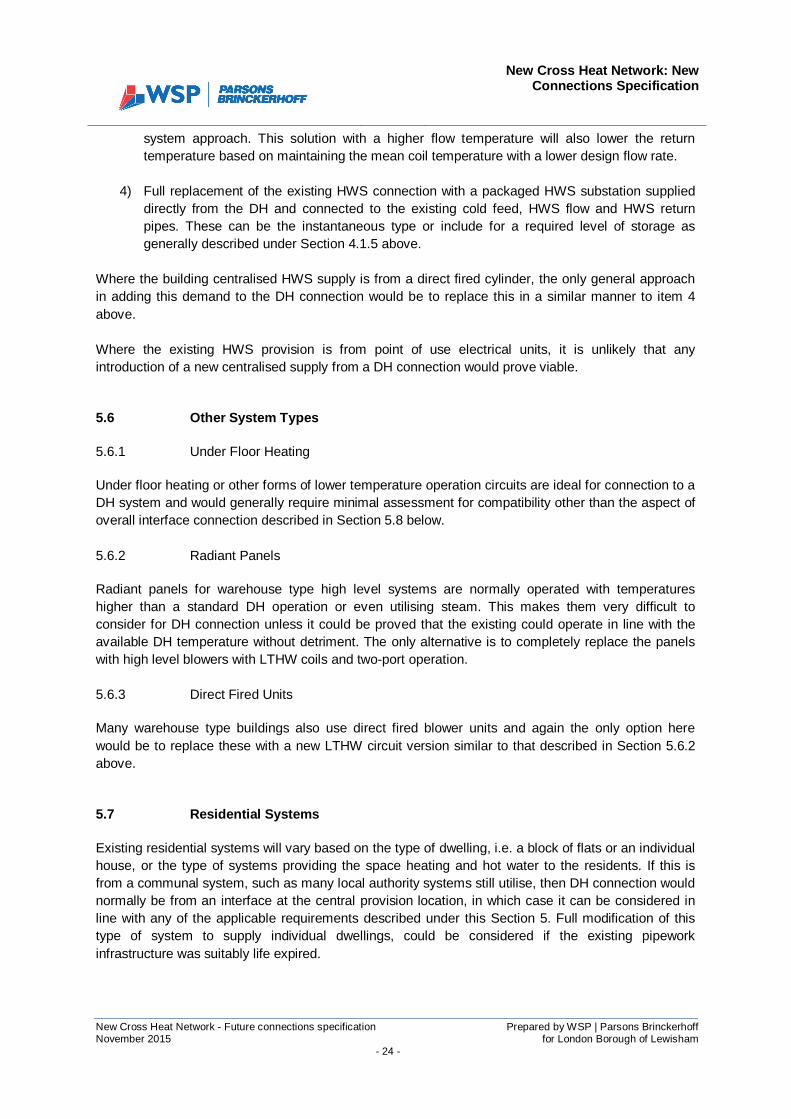
New Cross Heat Network: NewConnections Specification
New Cross Heat Network - Future connections specification Prepared by WSP | Parsons BrinckerhoffNovember 2015 for London Borough of Lewisham
- 24 -
system approach. This solution with a higher flow temperature will also lower the returntemperature based on maintaining the mean coil temperature with a lower design flow rate.
4) Full replacement of the existing HWS connection with a packaged HWS substation supplieddirectly from the DH and connected to the existing cold feed, HWS flow and HWS returnpipes. These can be the instantaneous type or include for a required level of storage asgenerally described under Section 4.1.5 above.
Where the building centralised HWS supply is from a direct fired cylinder, the only general approachin adding this demand to the DH connection would be to replace this in a similar manner to item 4above.
Where the existing HWS provision is from point of use electrical units, it is unlikely that anyintroduction of a new centralised supply from a DH connection would prove viable.
5.6 Other System Types
5.6.1 Under Floor Heating
Under floor heating or other forms of lower temperature operation circuits are ideal for connection to aDH system and would generally require minimal assessment for compatibility other than the aspect ofoverall interface connection described in Section 5.8 below.
5.6.2 Radiant Panels
Radiant panels for warehouse type high level systems are normally operated with temperatureshigher than a standard DH operation or even utilising steam. This makes them very difficult toconsider for DH connection unless it could be proved that the existing could operate in line with theavailable DH temperature without detriment. The only alternative is to completely replace the panelswith high level blowers with LTHW coils and two-port operation.
5.6.3 Direct Fired Units
Many warehouse type buildings also use direct fired blower units and again the only option herewould be to replace these with a new LTHW circuit version similar to that described in Section 5.6.2above.
5.7 Residential Systems
Existing residential systems will vary based on the type of dwelling, i.e. a block of flats or an individualhouse, or the type of systems providing the space heating and hot water to the residents. If this isfrom a communal system, such as many local authority systems still utilise, then DH connection wouldnormally be from an interface at the central provision location, in which case it can be considered inline with any of the applicable requirements described under this Section 5. Full modification of thistype of system to supply individual dwellings, could be considered if the existing pipeworkinfrastructure was suitably life expired.
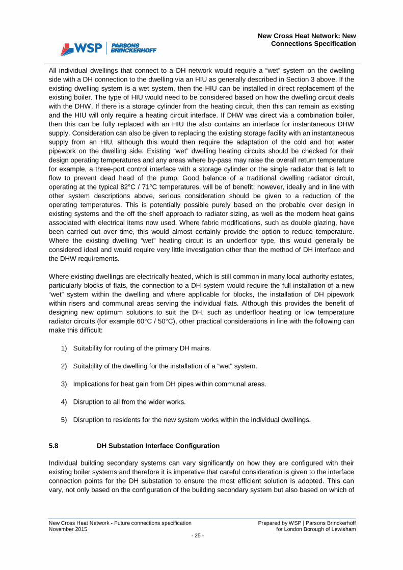
New Cross Heat Network: NewConnections Specification
New Cross Heat Network - Future connections specification Prepared by WSP | Parsons BrinckerhoffNovember 2015 for London Borough of Lewisham
- 25 -
All individual dwellings that connect to a DH network would require a “wet” system on the dwellingside with a DH connection to the dwelling via an HIU as generally described in Section 3 above. If theexisting dwelling system is a wet system, then the HIU can be installed in direct replacement of theexisting boiler. The type of HIU would need to be considered based on how the dwelling circuit dealswith the DHW. If there is a storage cylinder from the heating circuit, then this can remain as existingand the HIU will only require a heating circuit interface. If DHW was direct via a combination boiler,then this can be fully replaced with an HIU the also contains an interface for instantaneous DHWsupply. Consideration can also be given to replacing the existing storage facility with an instantaneoussupply from an HIU, although this would then require the adaptation of the cold and hot waterpipework on the dwelling side. Existing “wet” dwelling heating circuits should be checked for theirdesign operating temperatures and any areas where by-pass may raise the overall return temperaturefor example, a three-port control interface with a storage cylinder or the single radiator that is left toflow to prevent dead head of the pump. Good balance of a traditional dwelling radiator circuit,operating at the typical 82°C / 71°C temperatures, will be of benefit; however, ideally and in line withother system descriptions above, serious consideration should be given to a reduction of theoperating temperatures. This is potentially possible purely based on the probable over design inexisting systems and the off the shelf approach to radiator sizing, as well as the modern heat gainsassociated with electrical items now used. Where fabric modifications, such as double glazing, havebeen carried out over time, this would almost certainly provide the option to reduce temperature.Where the existing dwelling “wet” heating circuit is an underfloor type, this would generally beconsidered ideal and would require very little investigation other than the method of DH interface andthe DHW requirements.
Where existing dwellings are electrically heated, which is still common in many local authority estates,particularly blocks of flats, the connection to a DH system would require the full installation of a new“wet” system within the dwelling and where applicable for blocks, the installation of DH pipeworkwithin risers and communal areas serving the individual flats. Although this provides the benefit ofdesigning new optimum solutions to suit the DH, such as underfloor heating or low temperatureradiator circuits (for example 60°C / 50°C), other practical considerations in line with the following canmake this difficult:
1) Suitability for routing of the primary DH mains.
2) Suitability of the dwelling for the installation of a “wet” system.
3) Implications for heat gain from DH pipes within communal areas.
4) Disruption to all from the wider works.
5) Disruption to residents for the new system works within the individual dwellings.
5.8 DH Substation Interface Configuration
Individual building secondary systems can vary significantly on how they are configured with theirexisting boiler systems and therefore it is imperative that careful consideration is given to the interfaceconnection points for the DH substation to ensure the most efficient solution is adopted. This canvary, not only based on the configuration of the building secondary system but also based on which of
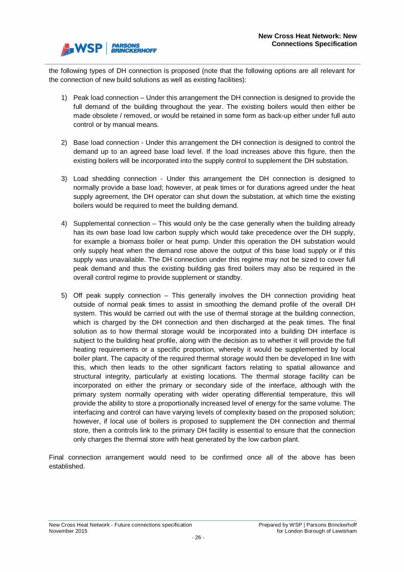
New Cross Heat Network: NewConnections Specification
New Cross Heat Network - Future connections specification Prepared by WSP | Parsons BrinckerhoffNovember 2015 for London Borough of Lewisham
- 26 -
the following types of DH connection is proposed (note that the following options are all relevant forthe connection of new build solutions as well as existing facilities):
1) Peak load connection – Under this arrangement the DH connection is designed to provide thefull demand of the building throughout the year. The existing boilers would then either bemade obsolete / removed, or would be retained in some form as back-up either under full autocontrol or by manual means.
2) Base load connection - Under this arrangement the DH connection is designed to control thedemand up to an agreed base load level. If the load increases above this figure, then theexisting boilers will be incorporated into the supply control to supplement the DH substation.
3) Load shedding connection - Under this arrangement the DH connection is designed tonormally provide a base load; however, at peak times or for durations agreed under the heatsupply agreement, the DH operator can shut down the substation, at which time the existingboilers would be required to meet the building demand.
4) Supplemental connection – This would only be the case generally when the building alreadyhas its own base load low carbon supply which would take precedence over the DH supply,for example a biomass boiler or heat pump. Under this operation the DH substation wouldonly supply heat when the demand rose above the output of this base load supply or if thissupply was unavailable. The DH connection under this regime may not be sized to cover fullpeak demand and thus the existing building gas fired boilers may also be required in theoverall control regime to provide supplement or standby.
5) Off peak supply connection – This generally involves the DH connection providing heatoutside of normal peak times to assist in smoothing the demand profile of the overall DHsystem. This would be carried out with the use of thermal storage at the building connection,which is charged by the DH connection and then discharged at the peak times. The finalsolution as to how thermal storage would be incorporated into a building DH interface issubject to the building heat profile, along with the decision as to whether it will provide the fullheating requirements or a specific proportion, whereby it would be supplemented by localboiler plant. The capacity of the required thermal storage would then be developed in line withthis, which then leads to the other significant factors relating to spatial allowance andstructural integrity, particularly at existing locations. The thermal storage facility can beincorporated on either the primary or secondary side of the interface, although with theprimary system normally operating with wider operating differential temperature, this willprovide the ability to store a proportionally increased level of energy for the same volume. Theinterfacing and control can have varying levels of complexity based on the proposed solution;however, if local use of boilers is proposed to supplement the DH connection and thermalstore, then a controls link to the primary DH facility is essential to ensure that the connectiononly charges the thermal store with heat generated by the low carbon plant.
Final connection arrangement would need to be confirmed once all of the above has beenestablished.

New Cross Heat Network: NewConnections Specification
New Cross Heat Network - Future connections specification Prepared by WSP | Parsons BrinckerhoffNovember 2015 for London Borough of Lewisham
- 27 -
6 PHYSICAL REQUIREMENT FOR INCORPORATING THE DH SUBSTATION
6.1 Provision for future connection of DH substation
The sketch below illustrates the requirement for providing:a) A means of bringing the primary heating mains into the development or building plantroom
from the street.b) Space allocation for the heat exchange substations in the development heating plantroom.c) Provision for the physical interface between the DH heating substation and the development
heating system.d) Provision for mains power supply for the DH substation.e) Provision for a controls interface with the building heating systems and the DH substation.f) As described in Section 5.8 above, there is potential to incorporate thermal storage at the
customer interface; however, subject to operational requirements and the final designsolutions to suit, this can be incorporated in a number of ways and is thus not included withinthe following sketch.
Developmentboilers
Spaceallocation forESCo Heatexchange
substation(s)
Secondary Flow
Secondary Return
header
header
Primary Flow
Primary Return
Provision to allowprimary network toentre development
plant room from thestreet
Provision to allowconnection of
secondary systemto heat substation
Provision for controls connection to ESCO substation
Provision for power supply to ESCO substation
Developmentheating plantroom

New Cross Heat Network: NewConnections Specification
New Cross Heat Network - Future connections specification Prepared by WSP | Parsons BrinckerhoffNovember 2015 for London Borough of Lewisham
- 28 -
6.2 Plant layouts
DH substations should be supplied as single packaged units to suit the required demands. Dependingon the level of demand, the units may consist of more than one heat exchanger up to as many asthree exchangers for larger loads. The following table provides indicative spacing requirements,based on a single supplier assessment, for a number of standard heating loads:
ESCo District Heating Substation (primary:/ secondary interface)
Output (kW) 250 500 800 1,000 1,500 2,000 3,000
Number of Heat Exchangers 1 1 1 2 2 2 2
Length (mm) 1,500 2,250 2,250 2,750 2,750 3,000 3,000
Width (mm) 500 750 750 1,500 1,500 1,500 1,500
Height (mm) 2,000 2,500 2,500 2,500 2,500 2,500 2,500
Approximate Dry Weight (kg) 725 1,050 1,300 1,725 1,800 1,925 2,000
The following should be noted regarding the above dimensional data:
· As stated, these are provisional sizes and should therefore be updated during the design andprocurement process, when full supplier data and drawings can be provided.
· The figures indicated are the packaged skid dimensions only and therefore an allowance of1m should be incorporated all around the skid to facilitate access and maintenancerequirements.
· The larger packages with more than one exchanger may provide difficulty in delivery andbuilding access, therefore, it is envisaged that the skids could be broken down into sectionsbased on the number of exchangers. This should be clearly indicated on supplier details.
· Note that should thermal storage be recommended as part of the DH interface, suitable spaceallocation will need to be provided, along with structural analysis for the potential significantassociated weight.
6.3 Minimum Plant Room Equipment Requirements
The following describes the typical requirements at the building plant areas where the substations areto be located. Ideally this will consist of a lockable independent plant room; however, incorporationwithin general plant areas is possible although suitable procedures on demarcations would need to beestablished. The following table provides a list of requirements, although it should be noted that if theconnection is located in a shared general plant room then some of the items may be covered underthe provision for the overall plant area.

New Cross Heat Network: NewConnections Specification
New Cross Heat Network - Future connections specification Prepared by WSP | Parsons BrinckerhoffNovember 2015 for London Borough of Lewisham
- 29 -
ITEM SPECIFICATION REQUIREMENT
ROOM ILLUMINATION
ELECTRICAL CONNECTION (for maintenance)
ELECTRICAL SUPPLY(Control box)
WATER SUPPLY
WATER DISCHARGE
CONCRETE STANDS
VENTILATION
HEALTH & SAFETY
LAYOUT & DIMENSIONS
Minimum light level: 150 lux.
III 380 V to earth / 32 A5.
220 V AC (+/- 5%)50 Hz (+/- 3%)Thermo-magnetic protection recommended 16A curve C (the box incorporates a thermo-magnetic protection of 10 A curve C in thesupply).
DN 25.
Provide wastewater discharge line in the plantroom and a sump to collect condensation fromheat exchangers.
Provide concrete stands for heat exchangersand pumps (if present).
Mechanical and continuous, with a minimum ofthree air changes per hour.
Plan showing evacuation route in case of fire,located in a visible place.The plant room should not have elements of riskto health and safety (sharp metallic objects,holes in roof or floor without protection, …)
As described for the relevant packagedsubstation unit.
5 If an electrical connection is available in a general plant area, it is assumed that access would be providedduring any maintenance works. It is not considered that an outlet would be provided where an individualsubstation plant room is proposed. In such cases it would be envisaged that the nearest available point would bemade available following co-ordination with the individual building operator.