New Couplings - elesa-ganter.com
32
Couplings New
Transcript of New Couplings - elesa-ganter.com

CouplingsNew

ELESA and GANTER models all rights reserved in accordance with the law.Always mention the source when reproducing our drawings.2
CouplingsGeneral notes
INTRODUCTION
Couplings create connections between drive shafts and driven shafts in order to transmit rotary motion and torque. For example, they are used to combine the shafts of motors and transmissions into a single drive unit.
Alongside the primary purpose of transmitting torque, couplings also carry out other important tasks: - Compensating for shaft offsets and misalignments - Absorbing runout errors and axial motions - Damping vibrations and shocks
Couplings are used in a very wide range of applications. The spectrum ranges from simple drives to complex control, regulation and measurement applications.
MISALIGNMENT AND RUNOUT TOLERANCES
Like all mechanical parts, shafts are subjected to manufacturing and assembly tolerances that generally cannot be entirely eliminated even with extensive technical measures.
If these deviations are not taken into account in the design, the result can be vibrations, running noises, and wear or damage to the shafts and their bearings.
Suitable couplings not only are able to effectively compensate for misalignment and runout errors, they also greatly simplify the assembly process, thereby reducing the overall labor required.
Shaft misalignment and runout errors can vary in nature and should always be taken into consideration when selecting the appropriate coupling.
Error type Misalignment diagram
LateralThe axes of the shafts are in fact parallel, but they are offset laterally and do not line up.
AngularThe axes of the shafts do not lie in the same plane; they meet at a certain angle.
AxialThe shafts move axially along the axis of rotation.
RunoutThe shafts move radially out of the center of the axis of rotation.

ELESA and GANTER models all rights reserved in accordance with the law.Always mention the source when reproducing our drawings. 3
CouplingsGeneral notes
AREAS OF APPLICATION - CLASSES - COUPLING TYPES
The applications of couplings can generally be divided into two classes.
Motion control Torque and power transmission
For torque and power transmission, the focus lies on pure transmission of force. This requires couplings that can with-stand high torques and heavy loads while functioning reliably in harsh conditions.
Typical applications are: Conveyor systems, pumps and agitators, packaging machines, etc.
For motion control applications, the rotational movement is transmitted with very high precision and accuracy. This requires a coupling type with a high torsional stiffness and zero backlash in the direction of rotation.
Typical applications are: Servo or stepper motors for linear axes, industrial robots, test benches, etc.
Two coupling types are available for each of the application classes described above.
Bellows couplings and beam couplings Elastomer jaw couplings and oldham couplings
Elastomer jaw couplings are designed for high torque trans- mission and can be used in all manner of applications.
Oldham couplings transmit less torque but can compensate for higher shaft misalignments.
Bellows couplings offer high torsional stiffness. This makes them excellent for precise and controlled movements. Beam couplings have lower torsional stiffness compared with bellows couplings, but they can compensate for higher shaft misalignments.
ELESA and GANTER models all rights reserved in accordance with the law.Always mention the source when reproducing our drawings.4
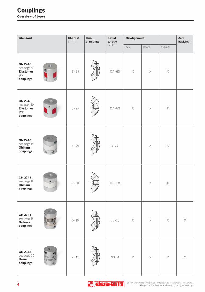
Standard Shaft Øin mm
Hub clamping
Rated torquein Nm
Misalignment Zero backlash
axial lateral angular
GN 2240 see page 6 Elastomer jaw couplings
3 - 25 0.7 - 60 X X X
GN 2241 see page 10 Elastomer jaw couplings
3 - 25 0.7 - 60 X X X
GN 2242 see page 14 Oldham couplings
4 - 20 1 - 28 X X
GN 2243 see page 16 Oldham couplings
2 - 20 0.5 - 28 X X
GN 2244 see page 18 Bellows couplings
5 - 19 1.5 - 10 X X X X
GN 2246 see page 20 Beam couplings
4 - 12 0.3 - 4 X X X X
CouplingsOverview of types

ELESA and GANTER models all rights reserved in accordance with the law.Always mention the source when reproducing our drawings. 5
Standard Shaft Øin mm
Hub clamping
Rated torquein Nm
Misalignment Zero backlash
axial lateral angular
GN 2240 see page 6 Elastomer jaw couplings
3 - 25 0.7 - 60 X X X
GN 2241 see page 10 Elastomer jaw couplings
3 - 25 0.7 - 60 X X X
GN 2242 see page 14 Oldham couplings
4 - 20 1 - 28 X X
GN 2243 see page 16 Oldham couplings
2 - 20 0.5 - 28 X X
GN 2244 see page 18 Bellows couplings
5 - 19 1.5 - 10 X X X X
GN 2246 see page 20 Beam couplings
4 - 12 0.3 - 4 X X X X
Standard Suitable for use with Application examples Special features
Servo motors
Stepper motors
Universal motors
GN 2240 see page 6 Elastomer jaw couplings
X X X
- Hydraulic pumps - Packaging machines - Industrial robots - Fans - Agitators
- High torques - Fast and simple plug-in assembly
GN 2241 see page 10 Elastomer jaw couplings
X X X
GN 2242 see page 14 Oldham couplings
X X
- Conveyor systems - Packaging machines - Positioning drives - Pumps
- High torques - High lateral misalignment compensation
- Fast and simple plug-in assembly
GN 2243 see page 16 Oldham couplings
X X
GN 2244 see page 18 Bellows couplings
X X
- Rotary encoders - Position measuring systems
- Test benches - Industrial robots - Spindle drives
- Precise angle and torque transmission
- High torsional stiffness
GN 2246 see page 20 Beam couplings
X
- Confectionery machines
- Industrial robots - CAT scanners - Position measuring systems
- Precise angle and torque transmission
- Manufactured from a single piece
- High torsional stiffness
Overview of typesCouplings

ELESA and GANTER models all rights reserved in accordance with the law.Always mention the source when reproducing our drawings.6
GN 2240 RoHS
Elastomer jaw couplingswith clamping hub
SPECIFICATIONBore codes - Type B: without keyway - Type K: with keyway (from d1 = 30)
Hub Aluminum AL anodized, natural colorCoupling spider Polyurethane (TPU) temperature resistant up to 60 °CHardness 80 Shore A, blue BS 92 Shore A, white WS 98 Shore A, red RSSocket cap screws DIN 912 Steel, blackened
Temperature range: -20 °C up to +60 °C
INFORMATIONElastomer jaw couplings GN 2240 can transmit very high torques while compensating for shaft misalignments and runout tolerances. They are preferred in applications where the focus lies on pure torque and power transmission.The choice of three coupling spiders with different hardness values allows the properties of the coupling to be optimally matched to the specific requirements. The clamping hubs and simple plug-in installation make jaw couplings very easy to assemble.With the bore code K, the keyway is always integrated into both bores d2 and d3.
ACCESSORY - Coupling spiders GN 2240.1 (see page 13)
TECHNICAL INFORMATION - Keyway P9 DIN 6885 (see main catalogue page A16) - ISO-Fundamental Tolerances (see main catalogue page A21) - Elastomer characteristics (see main catalogue page A32)
ELESA and GANTER models all rights reserved in accordance with the law.Always mention the source when reproducing our drawings. 7
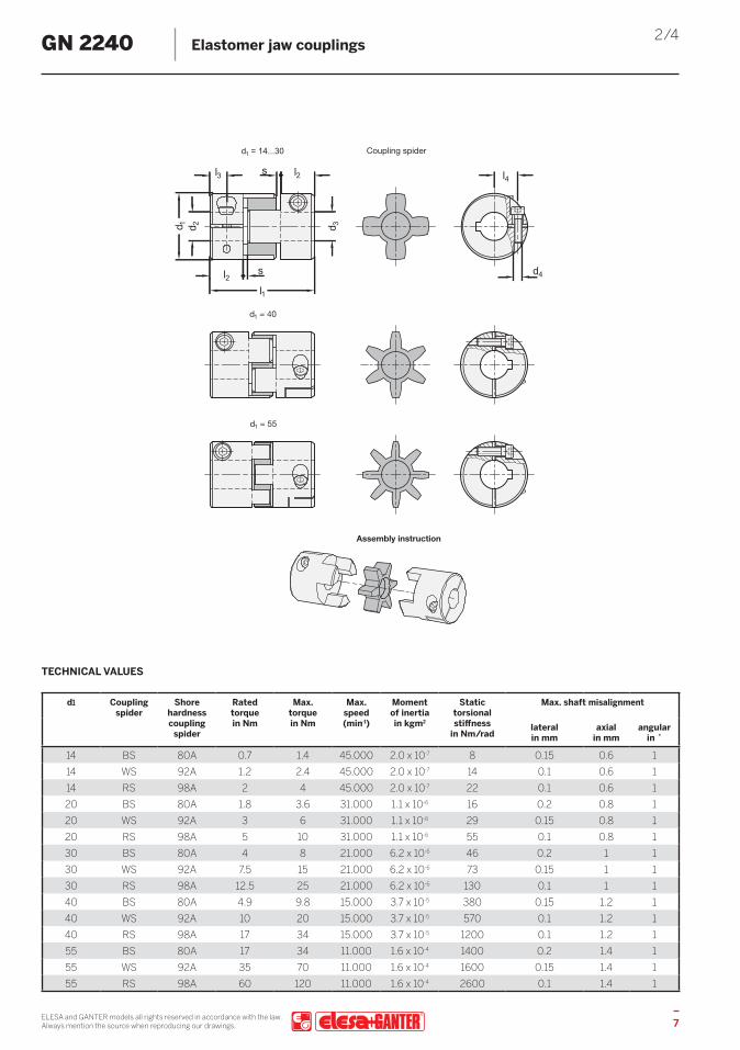
2/4GN 2240 Elastomer jaw couplings
d1 Coupling spider
Shore hardness coupling
spider
Rated torque in Nm
Max. torque in Nm
Max. speed (min-1)
Moment of inertia in kgm2
Static torsional stiffness
in Nm/rad
Max. shaft misalignment
lateral in mm
axial in mm
angular in ˚
14 BS 80A 0.7 1.4 45.000 2.0 x 10⁻⁷ 8 0.15 0.6 114 WS 92A 1.2 2.4 45.000 2.0 x 10⁻⁷ 14 0.1 0.6 114 RS 98A 2 4 45.000 2.0 x 10⁻⁷ 22 0.1 0.6 120 BS 80A 1.8 3.6 31.000 1.1 x 10⁻⁶ 16 0.2 0.8 120 WS 92A 3 6 31.000 1.1 x 10⁻⁶ 29 0.15 0.8 120 RS 98A 5 10 31.000 1.1 x 10⁻⁶ 55 0.1 0.8 130 BS 80A 4 8 21.000 6.2 x 10⁻⁶ 46 0.2 1 130 WS 92A 7.5 15 21.000 6.2 x 10⁻⁶ 73 0.15 1 130 RS 98A 12.5 25 21.000 6.2 x 10⁻⁶ 130 0.1 1 140 BS 80A 4.9 9.8 15.000 3.7 x 10⁻⁵ 380 0.15 1.2 140 WS 92A 10 20 15.000 3.7 x 10⁻⁵ 570 0.1 1.2 140 RS 98A 17 34 15.000 3.7 x 10⁻⁵ 1200 0.1 1.2 155 BS 80A 17 34 11.000 1.6 x 10⁻⁴ 1400 0.2 1.4 155 WS 92A 35 70 11.000 1.6 x 10⁻⁴ 1600 0.15 1.4 155 RS 98A 60 120 11.000 1.6 x 10⁻⁴ 2600 0.1 1.4 1
TECHNICAL VALUES
ELESA and GANTER models all rights reserved in accordance with the law.Always mention the source when reproducing our drawings.8
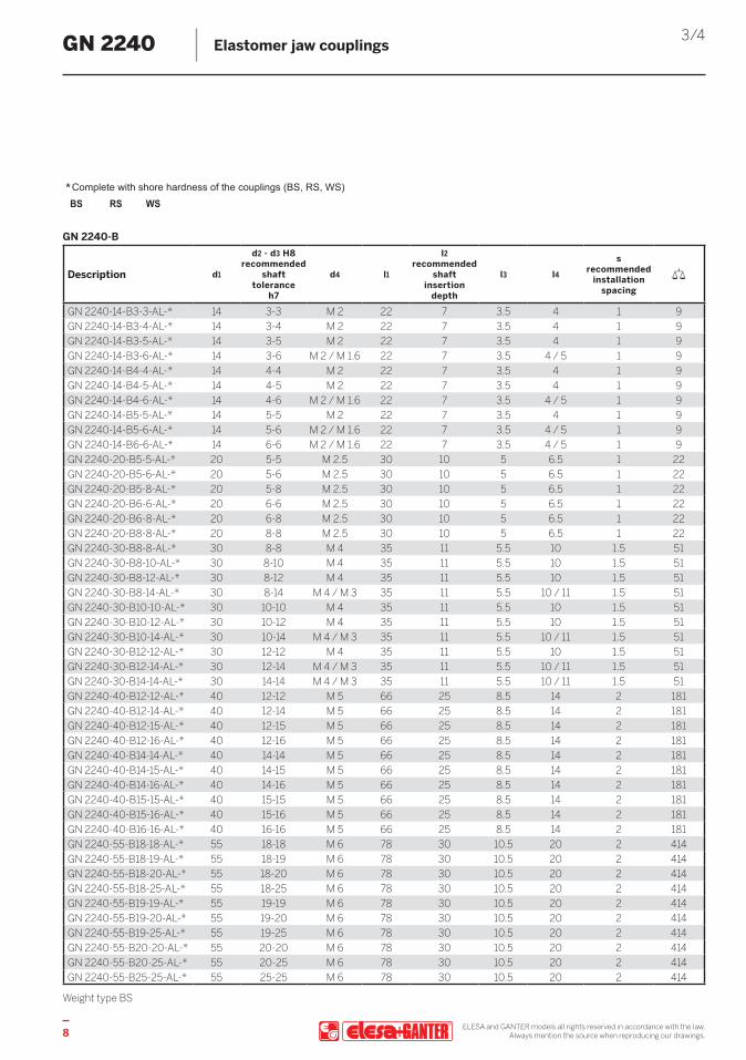
3/4GN 2240 Elastomer jaw couplings
w
Complete with shore hardness of the couplings (BS, RS, WS)*BS RS WS
GN 2240-B
Description d1
d2 - d3 H8 recommended
shaft tolerance
h7
d4 l1
l2 recommended
shaft insertion
depth
l3 l4
s recommended
installation spacing
GN 2240-14-B3-3-AL-* 14 3-3 M 2 22 7 3.5 4 1 9GN 2240-14-B3-4-AL-* 14 3-4 M 2 22 7 3.5 4 1 9GN 2240-14-B3-5-AL-* 14 3-5 M 2 22 7 3.5 4 1 9GN 2240-14-B3-6-AL-* 14 3-6 M 2 / M 1.6 22 7 3.5 4 / 5 1 9GN 2240-14-B4-4-AL-* 14 4-4 M 2 22 7 3.5 4 1 9GN 2240-14-B4-5-AL-* 14 4-5 M 2 22 7 3.5 4 1 9GN 2240-14-B4-6-AL-* 14 4-6 M 2 / M 1.6 22 7 3.5 4 / 5 1 9GN 2240-14-B5-5-AL-* 14 5-5 M 2 22 7 3.5 4 1 9GN 2240-14-B5-6-AL-* 14 5-6 M 2 / M 1.6 22 7 3.5 4 / 5 1 9GN 2240-14-B6-6-AL-* 14 6-6 M 2 / M 1.6 22 7 3.5 4 / 5 1 9GN 2240-20-B5-5-AL-* 20 5-5 M 2.5 30 10 5 6.5 1 22GN 2240-20-B5-6-AL-* 20 5-6 M 2.5 30 10 5 6.5 1 22GN 2240-20-B5-8-AL-* 20 5-8 M 2.5 30 10 5 6.5 1 22GN 2240-20-B6-6-AL-* 20 6-6 M 2.5 30 10 5 6.5 1 22GN 2240-20-B6-8-AL-* 20 6-8 M 2.5 30 10 5 6.5 1 22GN 2240-20-B8-8-AL-* 20 8-8 M 2.5 30 10 5 6.5 1 22GN 2240-30-B8-8-AL-* 30 8-8 M 4 35 11 5.5 10 1.5 51GN 2240-30-B8-10-AL-* 30 8-10 M 4 35 11 5.5 10 1.5 51GN 2240-30-B8-12-AL-* 30 8-12 M 4 35 11 5.5 10 1.5 51GN 2240-30-B8-14-AL-* 30 8-14 M 4 / M 3 35 11 5.5 10 / 11 1.5 51GN 2240-30-B10-10-AL-* 30 10-10 M 4 35 11 5.5 10 1.5 51GN 2240-30-B10-12-AL-* 30 10-12 M 4 35 11 5.5 10 1.5 51GN 2240-30-B10-14-AL-* 30 10-14 M 4 / M 3 35 11 5.5 10 / 11 1.5 51GN 2240-30-B12-12-AL-* 30 12-12 M 4 35 11 5.5 10 1.5 51GN 2240-30-B12-14-AL-* 30 12-14 M 4 / M 3 35 11 5.5 10 / 11 1.5 51GN 2240-30-B14-14-AL-* 30 14-14 M 4 / M 3 35 11 5.5 10 / 11 1.5 51GN 2240-40-B12-12-AL-* 40 12-12 M 5 66 25 8.5 14 2 181GN 2240-40-B12-14-AL-* 40 12-14 M 5 66 25 8.5 14 2 181GN 2240-40-B12-15-AL-* 40 12-15 M 5 66 25 8.5 14 2 181GN 2240-40-B12-16-AL-* 40 12-16 M 5 66 25 8.5 14 2 181GN 2240-40-B14-14-AL-* 40 14-14 M 5 66 25 8.5 14 2 181GN 2240-40-B14-15-AL-* 40 14-15 M 5 66 25 8.5 14 2 181GN 2240-40-B14-16-AL-* 40 14-16 M 5 66 25 8.5 14 2 181GN 2240-40-B15-15-AL-* 40 15-15 M 5 66 25 8.5 14 2 181GN 2240-40-B15-16-AL-* 40 15-16 M 5 66 25 8.5 14 2 181GN 2240-40-B16-16-AL-* 40 16-16 M 5 66 25 8.5 14 2 181GN 2240-55-B18-18-AL-* 55 18-18 M 6 78 30 10.5 20 2 414GN 2240-55-B18-19-AL-* 55 18-19 M 6 78 30 10.5 20 2 414GN 2240-55-B18-20-AL-* 55 18-20 M 6 78 30 10.5 20 2 414GN 2240-55-B18-25-AL-* 55 18-25 M 6 78 30 10.5 20 2 414GN 2240-55-B19-19-AL-* 55 19-19 M 6 78 30 10.5 20 2 414GN 2240-55-B19-20-AL-* 55 19-20 M 6 78 30 10.5 20 2 414GN 2240-55-B19-25-AL-* 55 19-25 M 6 78 30 10.5 20 2 414GN 2240-55-B20-20-AL-* 55 20-20 M 6 78 30 10.5 20 2 414GN 2240-55-B20-25-AL-* 55 20-25 M 6 78 30 10.5 20 2 414GN 2240-55-B25-25-AL-* 55 25-25 M 6 78 30 10.5 20 2 414
Weight type BS

ELESA and GANTER models all rights reserved in accordance with the law.Always mention the source when reproducing our drawings. 9
4/4GN 2240 Elastomer jaw couplings
Complete with shore hardness of the couplings (BS, RS, WS)*BS RS WS
GN 2240-K
Description d1
d2 - d3 H8 recommended
shaft tolerance
h7
d4 l1
l2 recommended
shaft insertion
depth
l3 l4
s recommended
installation spacing
GN 2240-30-K8-8-AL-* 30 8-8 M 4 35 11 5.5 10 1.5 51GN 2240-30-K8-10-AL-* 30 8-10 M 4 35 11 5.5 10 1.5 51GN 2240-30-K8-12-AL-* 30 8-12 M 4 35 11 5.5 10 1.5 51GN 2240-30-K8-14-AL-* 30 8-14 M 4 / M 3 35 11 5.5 10 / 11 1.5 51GN 2240-30-K10-10-AL-* 30 10-10 M 4 35 11 5.5 10 1.5 51GN 2240-30-K10-12-AL-* 30 10-12 M 4 35 11 5.5 10 1.5 51GN 2240-30-K10-14-AL-* 30 10-14 M 4 / M 3 35 11 5.5 10 / 11 1.5 51GN 2240-30-K12-12-AL-* 30 12-12 M 4 35 11 5.5 10 1.5 51GN 2240-30-K12-14-AL-* 30 12-14 M 4 / M 3 35 11 5.5 10 / 11 1.5 51GN 2240-30-K14-14-AL-* 30 14-14 M 4 / M 3 35 11 5.5 10 / 11 1.5 51GN 2240-40-K12-12-AL-* 40 12-12 M 5 66 25 8.5 14 2 181GN 2240-40-K12-14-AL-* 40 12-14 M 5 66 25 8.5 14 2 181GN 2240-40-K12-15-AL-* 40 12-15 M 5 66 25 8.5 14 2 181GN 2240-40-K12-16-AL-* 40 12-16 M 5 66 25 8.5 14 2 181GN 2240-40-K14-14-AL-* 40 14-14 M 5 66 25 8.5 14 2 181GN 2240-40-K14-15-AL-* 40 14-15 M 5 66 25 8.5 14 2 181GN 2240-40-K14-16-AL-* 40 14-16 M 5 66 25 8.5 14 2 181GN 2240-40-K15-15-AL-* 40 15-15 M 5 66 25 8.5 14 2 181GN 2240-40-K15-16-AL-* 40 15-16 M 5 66 25 8.5 14 2 181GN 2240-40-K16-16-AL-* 40 16-16 M 5 66 25 8.5 14 2 181GN 2240-55-K18-18-AL-* 55 18-18 M 6 78 30 10.5 20 2 414GN 2240-55-K18-19-AL-* 55 18-19 M 6 78 30 10.5 20 2 414GN 2240-55-K18-20-AL-* 55 18-20 M 6 78 30 10.5 20 2 414GN 2240-55-K18-25-AL-* 55 18-25 M 6 78 30 10.5 20 2 414GN 2240-55-K19-19-AL-* 55 19-19 M 6 78 30 10.5 20 2 414GN 2240-55-K19-20-AL-* 55 19-20 M 6 78 30 10.5 20 2 414GN 2240-55-K19-25-AL-* 55 19-25 M 6 78 30 10.5 20 2 414GN 2240-55-K20-20-AL-* 55 20-20 M 6 78 30 10.5 20 2 414GN 2240-55-K20-25-AL-* 55 20-25 M 6 78 30 10.5 20 2 414GN 2240-55-K25-25-AL-* 55 25-25 M 6 78 30 10.5 20 2 414
Weight type BS

ELESA and GANTER models all rights reserved in accordance with the law.Always mention the source when reproducing our drawings.10
GN 2241 RoHS
Elastomer jaw couplingswith grub screw
SPECIFICATIONBore codes - Type B: without keyway - Type K: with keyway (from d1 = 30)
HubAluminum ALanodized, natural colorCoupling spiderPolyurethane (TPU)temperature resistant up to 60 °CHardness80 Shore A, blue BS92 Shore A, white WS98 Shore A, red RSGrub screws
- Steel, blackened - for d2 / d3 ≤ 4, one grub screw - for d2 / d3 > 4, two grub screws
Temperature range: -20 °C up to +60 °C
INFORMATIONElastomer jaw couplings GN 2241 can transmit very high torques while compensating for shaft misalignments and runout tolerances. They are preferred in applications where the focus lies on pure torque and power transmission. The choice of three coupling spiders with different hardness values allows the properties of the coupling to be optimally matched to the specific requirements. The use of grub screws for clamping and the simple plug-in installation make jaw couplings very easy to assemble. With the bore code K, the keyway is always integrated into both bores d2 and d3.
ACCESSORY - Coupling spiders GN 2240.1 (see page 13)
TECHNICAL INFORMATION - Keyway P9 DIN 6885 (see main catalogue page A16) - ISO-Fundamental Tolerances (see main catalogue page A21) - Elastomer characteristics (see main catalogue page A32)
d1 Coupling spider
Shore hardness coupling
spider
Rated torque in Nm
Max. torque in Nm
Max. speed (min-1)
Moment of inertia in kgm2
Static torsional stiffness
in Nm/rad
Max. shaft misalignment
lateral in mm
axial in mm
angular in ˚
14 BS 80A 0.7 1.4 45.000 2.0 x 10⁻⁷ 8 0.15 0.6 114 WS 92A 1.2 2.4 45.000 2.0 x 10⁻⁷ 14 0.1 0.6 114 RS 98A 2 4 45.000 2.0 x 10⁻⁷ 22 0.1 0.6 120 BS 80A 1.8 3.6 31.000 1.1 x 10⁻⁶ 16 0.2 0.8 120 WS 92A 3 6 31.000 1.1 x 10⁻⁶ 29 0.15 0.8 120 RS 98A 5 10 31.000 1.1 x 10⁻⁶ 55 0.1 0.8 130 BS 80A 4 8 21.000 6.2 x 10⁻⁶ 46 0.2 1 130 WS 92A 7.5 15 21.000 6.2 x 10⁻⁶ 73 0.15 1 130 RS 98A 12.5 25 21.000 6.2 x 10⁻⁶ 130 0.1 1 140 BS 80A 4.9 9.8 15.000 3.7 x 10⁻⁵ 380 0.15 1.2 140 WS 92A 10 20 15.000 3.7 x 10⁻⁵ 570 0.1 1.2 140 RS 98A 17 34 15.000 3.7 x 10⁻⁵ 1200 0.1 1.2 155 BS 80A 17 34 11.000 1.6 x 10⁻⁴ 1400 0.2 1.4 155 WS 92A 35 70 11.000 1.6 x 10⁻⁴ 1600 0.15 1.4 155 RS 98A 60 120 11.000 1.6 x 10⁻⁴ 2600 0.1 1.4 1
TECHNICAL VALUES
ELESA and GANTER models all rights reserved in accordance with the law.Always mention the source when reproducing our drawings. 11
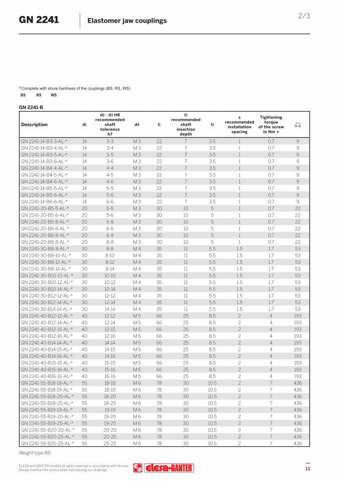
2/3GN 2241 Elastomer jaw couplings
Complete with shore hardness of the couplings (BS, RS, WS)*BS RS WS
GN 2241-B
Description d1
d2 - d3 H8 recommended
shaft tolerance
h7
d4 l1
l2 recommended
shaftinsertion
depth
l3
s recommended
installationspacing
Tightening torque
of the screw in Nm ≈
GN 2241-14-B3-3-AL-* 14 3-3 M 3 22 7 3.5 1 0.7 9GN 2241-14-B3-4-AL-* 14 3-4 M 3 22 7 3.5 1 0.7 9GN 2241-14-B3-5-AL-* 14 3-5 M 3 22 7 3.5 1 0.7 9GN 2241-14-B3-6-AL-* 14 3-6 M 3 22 7 3.5 1 0.7 9GN 2241-14-B4-4-AL-* 14 4-4 M 3 22 7 3.5 1 0.7 9GN 2241-14-B4-5-AL-* 14 4-5 M 3 22 7 3.5 1 0.7 9GN 2241-14-B4-6-AL-* 14 4-6 M 3 22 7 3.5 1 0.7 9GN 2241-14-B5-5-AL-* 14 5-5 M 3 22 7 3.5 1 0.7 9GN 2241-14-B5-6-AL-* 14 5-6 M 3 22 7 3.5 1 0.7 9GN 2241-14-B6-6-AL-* 14 6-6 M 3 22 7 3.5 1 0.7 9GN 2241-20-B5-5-AL-* 20 5-5 M 3 30 10 5 1 0.7 22GN 2241-20-B5-6-AL-* 20 5-6 M 3 30 10 5 1 0.7 22GN 2241-20-B5-8-AL-* 20 5-8 M 3 30 10 5 1 0.7 22GN 2241-20-B6-6-AL-* 20 6-6 M 3 30 10 5 1 0.7 22GN 2241-20-B6-8-AL-* 20 6-8 M 3 30 10 5 1 0.7 22GN 2241-20-B8-8-AL-* 20 8-8 M 3 30 10 5 1 0.7 22GN 2241-30-B8-8-AL-* 30 8-8 M 4 35 11 5.5 1.5 1.7 53GN 2241-30-B8-10-AL-* 30 8-10 M 4 35 11 5.5 1.5 1.7 53GN 2241-30-B8-12-AL-* 30 8-12 M 4 35 11 5.5 1.5 1.7 53GN 2241-30-B8-14-AL-* 30 8-14 M 4 35 11 5.5 1.5 1.7 53GN 2241-30-B10-10-AL-* 30 10-10 M 4 35 11 5.5 1.5 1.7 53GN 2241-30-B10-12-AL-* 30 10-12 M 4 35 11 5.5 1.5 1.7 53GN 2241-30-B10-14-AL-* 30 10-14 M 4 35 11 5.5 1.5 1.7 53GN 2241-30-B12-12-AL-* 30 12-12 M 4 35 11 5.5 1.5 1.7 53GN 2241-30-B12-14-AL-* 30 12-14 M 4 35 11 5.5 1.5 1.7 53GN 2241-30-B14-14-AL-* 30 14-14 M 4 35 11 5.5 1.5 1.7 53GN 2241-40-B12-12-AL-* 40 12-12 M 5 66 25 8.5 2 4 193GN 2241-40-B12-14-AL-* 40 12-14 M 5 66 25 8.5 2 4 193GN 2241-40-B12-15-AL-* 40 12-15 M 5 66 25 8.5 2 4 193GN 2241-40-B12-16-AL-* 40 12-16 M 5 66 25 8.5 2 4 193GN 2241-40-B14-14-AL-* 40 14-14 M 5 66 25 8.5 2 4 193GN 2241-40-B14-15-AL-* 40 14-15 M 5 66 25 8.5 2 4 193GN 2241-40-B14-16-AL-* 40 14-16 M 5 66 25 8.5 2 4 193GN 2241-40-B15-15-AL-* 40 15-15 M 5 66 25 8.5 2 4 193GN 2241-40-B15-16-AL-* 40 15-16 M 5 66 25 8.5 2 4 193GN 2241-40-B16-16-AL-* 40 16-16 M 5 66 25 8.5 2 4 193GN 2241-55-B18-18-AL-* 55 18-18 M 6 78 30 10.5 2 7 436GN 2241-55-B18-19-AL-* 55 18-19 M 6 78 30 10.5 2 7 436GN 2241-55-B18-20-AL-* 55 18-20 M 6 78 30 10.5 2 7 436GN 2241-55-B18-25-AL-* 55 18-25 M 6 78 30 10.5 2 7 436GN 2241-55-B19-19-AL-* 55 19-19 M 6 78 30 10.5 2 7 436GN 2241-55-B19-20-AL-* 55 19-20 M 6 78 30 10.5 2 7 436GN 2241-55-B19-25-AL-* 55 19-25 M 6 78 30 10.5 2 7 436GN 2241-55-B20-20-AL-* 55 20-20 M 6 78 30 10.5 2 7 436GN 2241-55-B20-25-AL-* 55 20-25 M 6 78 30 10.5 2 7 436GN 2241-55-B25-25-AL-* 55 25-25 M 6 78 30 10.5 2 7 436
Weight type BS

ELESA and GANTER models all rights reserved in accordance with the law.Always mention the source when reproducing our drawings.12
3/3GN 2241 Elastomer jaw couplings
Complete with shore hardness of the couplings (BS, RS, WS)*BS RS WS
GN 2241-K
Description d1
d2 - d3 H8 recommended
shaft tolerance
h7
d4 l1
l2 recommended
shaftinsertion
depth
l3
s recommended
installationspacing
Tightening torque
of the screw in Nm ≈
GN 2241-30-K8-8-AL-* 30 8-8 M 4 35 11 5.5 1.5 1.7 53GN 2241-30-K8-10-AL-* 30 8-10 M 4 35 11 5.5 1.5 1.7 53GN 2241-30-K8-12-AL-* 30 8-12 M 4 35 11 5.5 1.5 1.7 53GN 2241-30-K8-14-AL-* 30 8-14 M 4 35 11 5.5 1.5 1.7 53GN 2241-30-K10-10-AL-* 30 10-10 M 4 35 11 5.5 1.5 1.7 53GN 2241-30-K10-12-AL-* 30 10-12 M 4 35 11 5.5 1.5 1.7 53GN 2241-30-K10-14-AL-* 30 10-14 M 4 35 11 5.5 1.5 1.7 53GN 2241-30-K12-12-AL-* 30 12-12 M 4 35 11 5.5 1.5 1.7 53GN 2241-30-K12-14-AL-* 30 12-14 M 4 35 11 5.5 1.5 1.7 53GN 2241-30-K14-14-AL-* 30 14-14 M 4 35 11 5.5 1.5 1.7 53GN 2241-40-K12-12-AL-* 40 12-12 M 5 66 25 8.5 2 4 193GN 2241-40-K12-14-AL-* 40 12-14 M 5 66 25 8.5 2 4 193GN 2241-40-K12-15-AL-* 40 12-15 M 5 66 25 8.5 2 4 193GN 2241-40-K12-16-AL-* 40 12-16 M 5 66 25 8.5 2 4 193GN 2241-40-K14-14-AL-* 40 14-14 M 5 66 25 8.5 2 4 193GN 2241-40-K14-15-AL-* 40 14-15 M 5 66 25 8.5 2 4 193GN 2241-40-K14-16-AL-* 40 14-16 M 5 66 25 8.5 2 4 193GN 2241-40-K15-15-AL-* 40 15-15 M 5 66 25 8.5 2 4 193GN 2241-40-K15-16-AL-* 40 15-16 M 5 66 25 8.5 2 4 193GN 2241-40-K16-16-AL-* 40 16-16 M 5 66 25 8.5 2 4 193GN 2241-55-K18-18-AL-* 55 18-18 M 6 78 30 10.5 2 7 436GN 2241-55-K18-19-AL-* 55 18-19 M 6 78 30 10.5 2 7 436GN 2241-55-K18-20-AL-* 55 18-20 M 6 78 30 10.5 2 7 436GN 2241-55-K18-25-AL-* 55 18-25 M 6 78 30 10.5 2 7 436GN 2241-55-K19-19-AL-* 55 19-19 M 6 78 30 10.5 2 7 436GN 2241-55-K19-20-AL-* 55 19-20 M 6 78 30 10.5 2 7 436GN 2241-55-K19-25-AL-* 55 19-25 M 6 78 30 10.5 2 7 436GN 2241-55-K20-20-AL-* 55 20-20 M 6 78 30 10.5 2 7 436GN 2241-55-K20-25-AL-* 55 20-25 M 6 78 30 10.5 2 7 436GN 2241-55-K25-25-AL-* 55 25-25 M 6 78 30 10.5 2 7 436
Weight type BS

ELESA and GANTER models all rights reserved in accordance with the law.Always mention the source when reproducing our drawings. 13
GN 2240.1 RoHS
Coupling spidersfor GN 2240 / GN 2241
SPECIFICATIONPolyurethane (TPU)temperature resistant up to 60 °CHardness80 Shore A, blue BS92 Shore A, white WS98 Shore A, red RS
INFORMATIONCoupling spiders GN 2240.1 are intended as replacement parts or for adjusting elastomer jaw couplings GN 2240 (see page 6) / GN 2241 (see page 10). The choice of three coupling spiders with different hardness values allows the properties of the coupling to be optimally matched to the specific requirements.
TECHNICAL INFORMATION - Elastomer characteristics (see main catalogue page A32)
GN 2240.1
Descriptiond0
Coupling Ø GN 2240 / GN 2241
d1 b Number of teeth
GN 2240.1-14-BS 14 14 6 4 1GN 2240.1-14-RS 14 14 6 4 1GN 2240.1-14-WS 14 14 6 4 1GN 2240.1-20-BS 20 20 8 4 2GN 2240.1-20-RS 20 20 8 4 2GN 2240.1-20-WS 20 20 8 4 2GN 2240.1-30-BS 30 30 10 4 5GN 2240.1-30-RS 30 30 10 4 5GN 2240.1-30-WS 30 30 10 4 5GN 2240.1-40-BS 40 40 12 6 7GN 2240.1-40-RS 40 40 12 6 7GN 2240.1-40-WS 40 40 12 6 7GN 2240.1-55-BS 55 55 14 8 18GN 2240.1-55-RS 55 55 14 8 18GN 2240.1-55-WS 55 55 14 8 18

GN 2242 RoHS
Oldham couplingswith clamping hub
SPECIFICATIONBore codes - Type B: without keyway - Type K: with keyway (from d1 = 20)
Hub Aluminum ALanodized, natural colorSpacer Plastic (Polyacetal POM) KUtemperature resistant up to 80 °CSocket cap screws DIN 912Steel, blackenedTemperature range: -20 °C up to +80 °C
INFORMATIONOldham couplings GN 2242 can compensate for large lateral shaft misalignments while transmitting high torques. As a result, they are used in applications with a focus on pure torque and power transmission associated with high lateral shaft misalignments.The clamping hubs and simple plug-in installation make oldham couplings very easy to assemble. They are suitable for a diverse range of applications and are used in general machine construction in packaging machines and pumps.With the bore code K, the keyway is always integrated into both bores d2 and d3.
TECHNICAL INFORMATION - Keyway P9 DIN 6885 (see main catalogue page A16) - ISO-Fundamental Tolerances (see main catalogue page A21) - Plastic characteristics (see main catalogue page A2)
d1 Rated torque in Nm*
Max. torque in Nm
Max. speed (min-1)
Moment of inertia in kgm2
Static torsional stiffness
in Nm/rad
Max. shaft misalignment
lateral in mm angular in ˚
12 1 2 52.000 6.6 x 10⁻⁸ 60 1 315 1.6 3.2 42.000 1.7 x 10⁻⁷ 80 1 320 3.2 6.4 31.000 8.0 x 10⁻⁷ 120 1.2 330 15 30 21.000 5.2 x 10⁻⁶ 530 2 338 28 56 16.000 1.5 x 10⁻⁵ 1500 2.5 3
TECHNICAL VALUES
*Load fluctuations are not taken into account
ELESA and GANTER models all rights reserved in accordance with the law.Always mention the source when reproducing our drawings.14
GN 2242 RoHS
Oldham couplingswith clamping hub
SPECIFICATIONBore codes - Type B: without keyway - Type K: with keyway (from d1 = 20)
Hub Aluminum ALanodized, natural colorSpacer Plastic (Polyacetal POM) KUtemperature resistant up to 80 °CSocket cap screws DIN 912Steel, blackenedTemperature range: -20 °C up to +80 °C
INFORMATIONOldham couplings GN 2242 can compensate for large lateral shaft misalignments while transmitting high torques. As a result, they are used in applications with a focus on pure torque and power transmission associated with high lateral shaft misalignments.The clamping hubs and simple plug-in installation make oldham couplings very easy to assemble. They are suitable for a diverse range of applications and are used in general machine construction in packaging machines and pumps.With the bore code K, the keyway is always integrated into both bores d2 and d3.
TECHNICAL INFORMATION - Keyway P9 DIN 6885 (see main catalogue page A16) - ISO-Fundamental Tolerances (see main catalogue page A21) - Plastic characteristics (see main catalogue page A2)
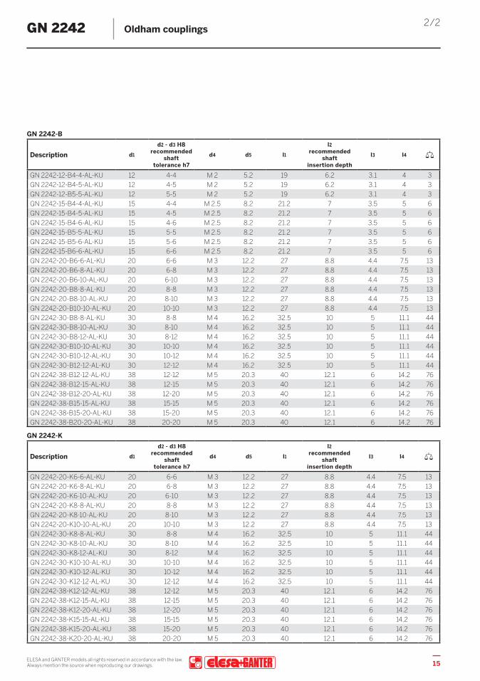
2/2GN 2242 Oldham couplings
w
GN 2242-B
Description d1
d2 - d3 H8 recommended
shaft tolerance h7
d4 d5 l1
l2 recommended
shaftinsertion depth
l3 l4
GN 2242-12-B4-4-AL-KU 12 4-4 M 2 5.2 19 6.2 3.1 4 3GN 2242-12-B4-5-AL-KU 12 4-5 M 2 5.2 19 6.2 3.1 4 3GN 2242-12-B5-5-AL-KU 12 5-5 M 2 5.2 19 6.2 3.1 4 3GN 2242-15-B4-4-AL-KU 15 4-4 M 2.5 8.2 21.2 7 3.5 5 6GN 2242-15-B4-5-AL-KU 15 4-5 M 2.5 8.2 21.2 7 3.5 5 6GN 2242-15-B4-6-AL-KU 15 4-6 M 2.5 8.2 21.2 7 3.5 5 6GN 2242-15-B5-5-AL-KU 15 5-5 M 2.5 8.2 21.2 7 3.5 5 6GN 2242-15-B5-6-AL-KU 15 5-6 M 2.5 8.2 21.2 7 3.5 5 6GN 2242-15-B6-6-AL-KU 15 6-6 M 2.5 8.2 21.2 7 3.5 5 6GN 2242-20-B6-6-AL-KU 20 6-6 M 3 12.2 27 8.8 4.4 7.5 13GN 2242-20-B6-8-AL-KU 20 6-8 M 3 12.2 27 8.8 4.4 7.5 13GN 2242-20-B6-10-AL-KU 20 6-10 M 3 12.2 27 8.8 4.4 7.5 13GN 2242-20-B8-8-AL-KU 20 8-8 M 3 12.2 27 8.8 4.4 7.5 13GN 2242-20-B8-10-AL-KU 20 8-10 M 3 12.2 27 8.8 4.4 7.5 13GN 2242-20-B10-10-AL-KU 20 10-10 M 3 12.2 27 8.8 4.4 7.5 13GN 2242-30-B8-8-AL-KU 30 8-8 M 4 16.2 32.5 10 5 11.1 44GN 2242-30-B8-10-AL-KU 30 8-10 M 4 16.2 32.5 10 5 11.1 44GN 2242-30-B8-12-AL-KU 30 8-12 M 4 16.2 32.5 10 5 11.1 44GN 2242-30-B10-10-AL-KU 30 10-10 M 4 16.2 32.5 10 5 11.1 44GN 2242-30-B10-12-AL-KU 30 10-12 M 4 16.2 32.5 10 5 11.1 44GN 2242-30-B12-12-AL-KU 30 12-12 M 4 16.2 32.5 10 5 11.1 44GN 2242-38-B12-12-AL-KU 38 12-12 M 5 20.3 40 12.1 6 14.2 76GN 2242-38-B12-15-AL-KU 38 12-15 M 5 20.3 40 12.1 6 14.2 76GN 2242-38-B12-20-AL-KU 38 12-20 M 5 20.3 40 12.1 6 14.2 76GN 2242-38-B15-15-AL-KU 38 15-15 M 5 20.3 40 12.1 6 14.2 76GN 2242-38-B15-20-AL-KU 38 15-20 M 5 20.3 40 12.1 6 14.2 76GN 2242-38-B20-20-AL-KU 38 20-20 M 5 20.3 40 12.1 6 14.2 76
GN 2242-K
Description d1
d2 - d3 H8 recommended
shaft tolerance h7
d4 d5 l1
l2 recommended
shaftinsertion depth
l3 l4
GN 2242-20-K6-6-AL-KU 20 6-6 M 3 12.2 27 8.8 4.4 7.5 13GN 2242-20-K6-8-AL-KU 20 6-8 M 3 12.2 27 8.8 4.4 7.5 13GN 2242-20-K6-10-AL-KU 20 6-10 M 3 12.2 27 8.8 4.4 7.5 13GN 2242-20-K8-8-AL-KU 20 8-8 M 3 12.2 27 8.8 4.4 7.5 13GN 2242-20-K8-10-AL-KU 20 8-10 M 3 12.2 27 8.8 4.4 7.5 13GN 2242-20-K10-10-AL-KU 20 10-10 M 3 12.2 27 8.8 4.4 7.5 13GN 2242-30-K8-8-AL-KU 30 8-8 M 4 16.2 32.5 10 5 11.1 44GN 2242-30-K8-10-AL-KU 30 8-10 M 4 16.2 32.5 10 5 11.1 44GN 2242-30-K8-12-AL-KU 30 8-12 M 4 16.2 32.5 10 5 11.1 44GN 2242-30-K10-10-AL-KU 30 10-10 M 4 16.2 32.5 10 5 11.1 44GN 2242-30-K10-12-AL-KU 30 10-12 M 4 16.2 32.5 10 5 11.1 44GN 2242-30-K12-12-AL-KU 30 12-12 M 4 16.2 32.5 10 5 11.1 44GN 2242-38-K12-12-AL-KU 38 12-12 M 5 20.3 40 12.1 6 14.2 76GN 2242-38-K12-15-AL-KU 38 12-15 M 5 20.3 40 12.1 6 14.2 76GN 2242-38-K12-20-AL-KU 38 12-20 M 5 20.3 40 12.1 6 14.2 76GN 2242-38-K15-15-AL-KU 38 15-15 M 5 20.3 40 12.1 6 14.2 76GN 2242-38-K15-20-AL-KU 38 15-20 M 5 20.3 40 12.1 6 14.2 76GN 2242-38-K20-20-AL-KU 38 20-20 M 5 20.3 40 12.1 6 14.2 76
ELESA and GANTER models all rights reserved in accordance with the law.Always mention the source when reproducing our drawings. 15
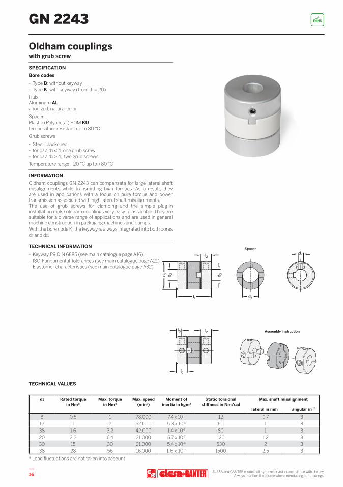
GN 2243 RoHS
GN 2243GN 2243
d1 Rated torque in Nm*
Max. torque in Nm*
Max. speed (min-1)
Moment of inertia in kgm2
Static torsional stiffness in Nm/rad
Max. shaft misalignment
lateral in mm angular in ˚
8 0.5 1 78.000 7.4 x 10⁻⁹ 12 0.7 312 1 2 52.000 5.3 x 10⁻⁸ 60 1 338 1.6 3.2 42.000 1.4 x 10⁻⁷ 80 1 320 3.2 6.4 31.000 5.7 x 10⁻⁷ 120 1.2 330 15 30 21.000 5.4 x 10⁻⁶ 530 2 338 28 56 16.000 1.6 x 10⁻⁵ 1500 2.5 3
* Load fluctuations are not taken into account
TECHNICAL VALUES
Oldham couplingswith grub screw
SPECIFICATIONBore codes - Type B: without keyway - Type K: with keyway (from d1 = 20)
HubAluminum ALanodized, natural colorSpacer Plastic (Polyacetal) POM KU temperature resistant up to 80 °CGrub screws
- Steel, blackened - for d2 / d3 ≤ 4, one grub screw - for d2 / d3 > 4, two grub screws
Temperature range: -20 °C up to +80 °C
INFORMATIONOldham couplings GN 2243 can compensate for large lateral shaft misalignments while transmitting high torques. As a result, they are used in applications with a focus on pure torque and power transmission associated with high lateral shaft misalignments.The use of grub screws for clamping and the simple plug-in installation make oldham couplings very easy to assemble. They are suitable for a diverse range of applications and are used in general machine construction in packaging machines and pumps.With the bore code K, the keyway is always integrated into both bores d2 and d3.
TECHNICAL INFORMATION - Keyway P9 DIN 6885 (see main catalogue page A16) - ISO-Fundamental Tolerances (see main catalogue page A21) - Elastomer characteristics (see main catalogue page A32)
ELESA and GANTER models all rights reserved in accordance with the law.Always mention the source when reproducing our drawings.16
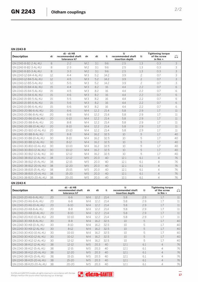
2/2GN 2243 Oldham couplings
GN 2243-B
Description d1d2 - d3 H8
recommended shaft tolerance h7
d4 d5 l1l2
recommended shaft insertion depth
l3Tightening torque
of the screw in Nm ≈
GN 2243-8-B2-2-AL-KU 8 2-2 M 2 3.1 9.6 2.5 1.3 0.3 3GN 2243-8-B2-3-AL-KU 8 2-3 M 2 3.1 9.6 2.5 1.3 0.3 3GN 2243-8-B3-3-AL-KU 8 3-3 M 2 3.1 9.6 2.5 1.3 0.3 3GN 2243-12-B4-4-AL-KU 12 4-4 M 3 5.2 14.2 3.9 2 0.7 3GN 2243-12-B4-5-AL-KU 12 4-5 M 3 5.2 14.2 3.9 2 0.7 3GN 2243-12-B5-5-AL-KU 12 5-5 M 3 5.2 14.2 3.9 2 0.7 3GN 2243-15-B4-4-AL-KU 15 4-4 M 3 8.2 16 4.4 2.2 0.7 6GN 2243-15-B4-5-AL-KU 15 4-5 M 3 8.2 16 4.4 2.2 0.7 6GN 2243-15-B4-6-AL-KU 15 4-6 M 3 8.2 16 4.4 2.2 0.7 6GN 2243-15-B5-5-AL-KU 15 5-5 M 3 8.2 16 4.4 2.2 0.7 6GN 2243-15-B5-6-AL-KU 15 5-6 M 3 8.2 16 4.4 2.2 0.7 6GN 2243-15-B6-6-AL-KU 15 6-6 M 3 8.2 16 4.4 2.2 0.7 6GN 2243-20-B6-6-AL-KU 20 6-6 M 4 12.2 21.4 5.8 2.9 1.7 11GN 2243-20-B6-8-AL-KU 20 6-8 M 4 12.2 21.4 5.8 2.9 1.7 11GN 2243-20-B6-10-AL-KU 20 6-10 M 4 12.2 21.4 5.8 2.9 1.7 11GN 2243-20-B8-8-AL-KU 20 8-8 M 4 12.2 21.4 5.8 2.9 1.7 11GN 2243-20-B8-10-AL-KU 20 8-10 M 4 12.2 21.4 5.8 2.9 1.7 11GN 2243-20-B10-10-AL-KU 20 10-10 M 4 12.2 21.4 5.8 2.9 1.7 11GN 2243-30-B8-8-AL-KU 30 8-8 M 4 16.2 32.5 10 5 1.7 40GN 2243-30-B8-10-AL-KU 30 8-10 M 4 16.2 32.5 10 5 1.7 40GN 2243-30-B8-12-AL-KU 30 8-12 M 4 16.2 32.5 10 5 1.7 40GN 2243-30-B10-10-AL-KU 30 10-10 M 4 16.2 32.5 10 5 1.7 40GN 2243-30-B10-12-AL-KU 30 10-12 M 4 16.2 32.5 10 5 1.7 40GN 2243-30-B12-12-AL-KU 30 12-12 M 4 16.2 32.5 10 5 1.7 40GN 2243-38-B12-12-AL-KU 38 12-12 M 5 20.3 40 12.1 6.1 4 76GN 2243-38-B12-15-AL-KU 38 12-15 M 5 20.3 40 12.1 6.1 4 76GN 2243-38-B12-20-AL-KU 38 12-20 M 5 20.3 40 12.1 6.1 4 76GN 2243-38-B15-15-AL-KU 38 15-15 M 5 20.3 40 12.1 6.1 4 76GN 2243-38-B15-20-AL-KU 38 15-20 M 5 20.3 40 12.1 6.1 4 76GN 2243-38-B20-20-AL-KU 38 20-20 M 5 20.3 40 12.1 6.1 4 76
GN 2243-K
Description d1d2 - d3 H8
recommended shaft tolerance h7
d4 d5 l1l2
recommended shaft insertion depth
l3Tightening torque
of the screw in Nm ≈
GN 2243-20-K6-6-AL-KU 20 6-6 M 4 12.2 21.4 5.8 2.9 1.7 11GN 2243-20-K6-8-AL-KU 20 6-8 M 4 12.2 21.4 5.8 2.9 1.7 11GN 2243-20-K6-10-AL-KU 20 6-10 M 4 12.2 21.4 5.8 2.9 1.7 11GN 2243-20-K8-8-AL-KU 20 8-8 M 4 12.2 21.4 5.8 2.9 1.7 11GN 2243-20-K8-10-AL-KU 20 8-10 M 4 12.2 21.4 5.8 2.9 1.7 11GN 2243-20-K10-10-AL-KU 20 10-10 M 4 12.2 21.4 5.8 2.9 1.7 11GN 2243-30-K8-8-AL-KU 30 8-8 M 4 16.2 32.5 10 5 1.7 40GN 2243-30-K8-10-AL-KU 30 8-10 M 4 16.2 32.5 10 5 1.7 40GN 2243-30-K8-12-AL-KU 30 8-12 M 4 16.2 32.5 10 5 1.7 40GN 2243-30-K10-10-AL-KU 30 10-10 M 4 16.2 32.5 10 5 1.7 40GN 2243-30-K10-12-AL-KU 30 10-12 M 4 16.2 32.5 10 5 1.7 40GN 2243-30-K12-12-AL-KU 30 12-12 M 4 16.2 32.5 10 5 1.7 40GN 2243-38-K12-12-AL-KU 38 12-12 M 5 20.3 40 12.1 6.1 4 76GN 2243-38-K12-15-AL-KU 38 12-15 M 5 20.3 40 12.1 6.1 4 76GN 2243-38-K12-20-AL-KU 38 12-20 M 5 20.3 40 12.1 6.1 4 76GN 2243-38-K15-15-AL-KU 38 15-15 M 5 20.3 40 12.1 6.1 4 76GN 2243-38-K15-20-AL-KU 38 15-20 M 5 20.3 40 12.1 6.1 4 76GN 2243-38-K20-20-AL-KU 38 20-20 M 5 20.3 40 12.1 6.1 4 76
GN 2243
ELESA and GANTER models all rights reserved in accordance with the law.Always mention the source when reproducing our drawings. 17

GN 2244 RoHS
Bellows couplingswith clamping hub
SPECIFICATIONBore codeType B: without keywayHubAluminum ALanodized, natural colorBellowsStainless Steel AISI 304 NISocket cap screws DIN 912Steel, blackenedCrimp ringBrassTemperature resistant up to 120 °C
INFORMATIONBellows couplings GN 2244 transmit angle positions and torques with extreme precision and zero backlash. The metal bellows also reliably compensates for shaft misalignments and runout tolerances. The clamping hubs make bellows couplings very easy to install.They are used in applications where precise position and movement transmission is required, such as in the servo drive systems of machine tools and in industrial robots.
TECHNICAL INFORMATION - ISO-Fundamental Tolerances (see main catalogue page A21) - Stainless Steel characteristics (see main catalogue page A26)
ON REQUEST- Bore with keyway
ELESA and GANTER models all rights reserved in accordance with the law.Always mention the source when reproducing our drawings.18

2/2
Description d1d2 - d3 H8
recommended shaft tolerance h7
d4 l1l2
recommended shaft insertion depth
l3 l4Tightening torque
of the screw in Nm ≈
GN 2244-19-B5-5-AL-NI 19 5-5 M 2 30 10.5 3 6.8 0.5 16GN 2244-19-B5-6-AL-NI 19 5-6 M 2 30 10.5 3 6.8 0.5 16GN 2244-19-B5-8-AL-NI 19 5-8 M 2 30 10.5 3 6.8 0.5 16GN 2244-19-B6-6-AL-NI 19 6-6 M 2 30 10.5 3 6.8 0.5 16GN 2244-19-B6-8-AL-NI 19 6-8 M 2 30 10.5 3 6.8 0.5 16GN 2244-19-B8-8-AL-NI 19 8-8 M 2 30 10.5 3 6.8 0.5 16GN 2244-27-B6-6-AL-NI 27 6-6 M 2.5 35 12.5 3.5 10.3 0.9 32GN 2244-27-B6-8-AL-NI 27 6-8 M 2.5 35 12.5 3.5 10.3 0.9 32GN 2244-27-B6-10-AL-NI 27 6-10 M 2.5 35 12.5 3.5 10.3 0.9 32GN 2244-27-B8-8-AL-NI 27 8-8 M 2.5 35 12.5 3.5 10.3 0.9 32GN 2244-27-B8-10-AL-NI 27 8-10 M 2.5 35 12.5 3.5 10.3 0.9 32GN 2244-27-B10-10-AL-NI 27 10-10 M 2.5 35 12.5 3.5 10.3 0.9 32GN 2244-32-B10-10-AL-NI 32 10-10 M 3 46 15.5 4.3 12 1.5 68GN 2244-32-B10-12-AL-NI 32 10-12 M 3 46 15.5 4.3 12 1.5 68GN 2244-32-B10-14-AL-NI 32 10-14 M 3 46 15.5 4.3 12 1.5 68GN 2244-32-B12-12-AL-NI 32 12-12 M 3 46 15.5 4.3 12 1.5 68GN 2244-32-B12-14-AL-NI 32 12-14 M 3 46 15.5 4.3 12 1.5 68GN 2244-32-B14-14-AL-NI 32 14-14 M 3 46 15.5 4.3 12 1.5 68GN 2244-40-B12-12-AL-NI 40 12-12 M 4 51 16 5 15 3.5 110GN 2244-40-B12-15-AL-NI 40 12-15 M 4 51 16 5 15 3.5 110GN 2244-40-B12-19-AL-NI 40 12-19 M 4 51 16 5 15 3.5 110GN 2244-40-B15-15-AL-NI 40 15-15 M 4 51 16 5 15 3.5 110GN 2244-40-B15-19-AL-NI 40 15-19 M 4 51 16 5 15 3.5 110GN 2244-40-B19-19-AL-NI 40 19-19 M 4 51 16 5 15 3.5 110
TECHNICAL VALUES
d1 Rated torque in Nm
Max. speed (min-1)
Moment of inertia in kgm2
Static torsionalstiffness in
Nm/rad
Max. shaft misalignment
lateral in mm axial in mm angular in˚
19 1.5 33.000 8.6 x 10⁻⁷ 170 0.15 ± 0.5 1.527 2.3 23.000 3.6 x 10⁻⁶ 800 0.15 ± 0.5 1.532 4.5 19.000 1.1 x 10⁻⁶ 1600 0.2 ± 0.7 1.540 10 15.000 2.8 x 10⁻⁵ 2700 0.2 ± 1 1.5
www
GN 2244 Bellows couplings
ELESA and GANTER models all rights reserved in accordance with the law.Always mention the source when reproducing our drawings. 19

GN 2246 STAINLESSSTEEL
INOX
RoHS
Beam couplingsAluminum / Stainless Steel, with clamping hub
SPECIFICATIONBore codeType B: without keywayVersion in Aluminum AL - anodized, natural color - temperature resistant up to 150 °C - Socket cap screws DIN 912, Steel blackened
Version in Stainless Steel NI - AISI 303 - temperature resistant up to 200 °C - Socket cap screws DIN 912, Stainless Steel AISI 304 Cu
INFORMATIONBeam couplings GN 2246 transmit angle positions and torques with extreme precision and no backlash. They are manufactured of a single piece and offer high torsional stiffness thanks to the alternating slits. The clamping hubs make beam couplings very easy to assemble.They are used in applications where precise position and movement transmission is required, such as in the drive systems of position measuring systems and in test benches.The Stainless Steel version can also be used in environments requiring high corrosion resistance, such as in medical technology (CAT scanners) and food-processing equipment (confectionary machines).
TECHNICAL INFORMATION - ISO-Fundamental Tolerances (see main catalogue page A21) - Stainless Steel characteristics (see main catalogue page A26)
ON REQUEST - Bore with keyway
Version in Aluminumd1 Rated torque
in NmMax. speed
(min-1)Moment of
inertia in kgm2Static torsional
stiffness in Nm/rad
Max. shaft misalignment
lateral in mm axial in mm angular in ˚
12 0.4 52.000 7.8 x 10⁻⁸ 45 0.1 ± 0.3 216 0.5 39.000 3.4 x 10⁻⁷ 80 0.1 ± 0.4 220 1 31.000 9.1 x 10⁻⁷ 170 0.1 ± 0.4 225 2 25.000 2.6 x 10⁻⁶ 380 0.15 ± 0.4 232 4 19.000 9.7 x 10⁻⁶ 500 0.15 ± 0.5 2
Version in Stainless Steeld1 Rated torque
in NmMax. speed
(min-1)Moment of
inertia in kgm2Static torsional
stiffness in Nm/rad
Max. shaft misalignment
lateral in mm axial in mm angular in ˚
12 0.3 52.000 2.2 x 10⁻⁷ 64 0.1 ± 0.2 216 0.5 39.000 9.0 x 10⁻⁷ 85 0.1 ± 0.3 220 1 31.000 2.5 x 10⁻⁶ 250 0.1 ± 0.3 225 2 25.000 7.1 x 10⁻⁶ 330 0.15 ± 0.4 232 3.5 19.000 2.7 x 10⁻⁵ 850 0.15 ± 0.5 2
TECHNICAL VALUES
ELESA and GANTER models all rights reserved in accordance with the law.Always mention the source when reproducing our drawings.20

2/2GN 2246 Beam couplings
GN 2246-AL
Description d1d2 - d3 H8
recommended shaft tolerance h7
d4 l1l2
recommended shaft insertion depth
l3 l4Tightening torque
of the screw in Nm ≈
GN 2246-12-B4-4-AL 12 4-4 M 2 18.5 5 2.5 4 0.5 4GN 2246-12-B4-5-AL 12 4-5 M 2 18.5 5 2.5 4 0.5 4GN 2246-12-B5-5-AL 12 5-5 M 2 18.5 5 2.5 4 0.5 4GN 2246-16-B5-5-AL 16 5-5 M 2.5 23 6.5 3.25 5 1 9GN 2246-16-B5-6-AL 16 5-6 M 2.5 23 6.5 3.25 5 1 9GN 2246-16-B6-6-AL 16 6-6 M 2.5 23 6.5 3.25 5 1 9GN 2246-20-B5-5-AL 20 5-5 M 2.5 26 7.5 3.75 6.5 1 16GN 2246-20-B5-6-AL 20 5-6 M 2.5 26 7.5 3.75 6.5 1 16GN 2246-20-B5-8-AL 20 5-8 M 2.5 26 7.5 3.75 6.5 1 16GN 2246-20-B6-6-AL 20 6-6 M 2.5 26 7.5 3.75 6.5 1 16GN 2246-20-B6-8-AL 20 6-8 M 2.5 26 7.5 3.75 6.5 1 16GN 2246-20-B8-8-AL 20 8-8 M 2.5 26 7.5 3.75 6.5 1 16GN 2246-25-B6-6-AL 25 6-6 M 3 31 8.5 4.25 9 1.5 28GN 2246-25-B6-8-AL 25 6-8 M 3 31 8.5 4.25 9 1.5 28GN 2246-25-B6-10-AL 25 6-10 M 3 31 8.5 4.25 9 1.5 28GN 2246-25-B8-8-AL 25 8-8 M 3 31 8.5 4.25 9 1.5 28GN 2246-25-B8-10-AL 25 8-10 M 3 31 8.5 4.25 9 1.5 28GN 2246-25-B10-10-AL 25 10-10 M 3 31 8.5 4.25 9 1.5 28GN 2246-32-B10-10-AL 32 10-10 M 4 41 12 6 11 2.5 64GN 2246-32-B10-12-AL 32 10-12 M 4 41 12 6 11 2.5 64GN 2246-32-B12-12-AL 32 12-12 M 4 41 12 6 11 2.5 64
STAINLESS STEELGN 2246-NI
Description d1
d2 - d3 H8 recommended shaft
tolerance h7
d4 l1l2
recommended shaft insertion depth
l3 l4Tightening torque
of the screw in Nm ≈
GN 2246-12-B4-4-NI 12 4-4 M 2 18.5 5 2.5 4 0.5 10GN 2246-12-B4-5-NI 12 4-5 M 2 18.5 5 2.5 4 0.5 10GN 2246-12-B5-5-NI 12 5-5 M 2 18.5 5 2.5 4 0.5 10GN 2246-16-B5-5-NI 16 5-5 M 2.5 23 6.5 3.25 5 1 25GN 2246-16-B5-6-NI 16 5-6 M 2.5 23 6.5 3.25 5 1 25GN 2246-16-B6-6-NI 16 6-6 M 2.5 23 6.5 3.25 5 1 25GN 2246-20-B5-5-NI 20 5-5 M 2.5 26 7.5 3.75 6.5 1 43GN 2246-20-B5-6-NI 20 5-6 M 2.5 26 7.5 3.75 6.5 1 43GN 2246-20-B5-8-NI 20 5-8 M 2.5 26 7.5 3.75 6.5 1 43GN 2246-20-B6-6-NI 20 6-6 M 2.5 26 7.5 3.75 6.5 1 43GN 2246-20-B6-8-NI 20 6-8 M 2.5 26 7.5 3.75 6.5 1 43GN 2246-20-B8-8-NI 20 8-8 M 2.5 26 7.5 3.75 6.5 1 43GN 2246-25-B6-6-NI 25 6-6 M 3 31 8.5 4.25 9 1.5 78GN 2246-25-B6-8-NI 25 6-8 M 3 31 8.5 4.25 9 1.5 78GN 2246-25-B6-10-NI 25 6-10 M 3 31 8.5 4.25 9 1.5 78GN 2246-25-B8-8-NI 25 8-8 M 3 31 8.5 4.25 9 1.5 78GN 2246-25-B8-10-NI 25 8-10 M 3 31 8.5 4.25 9 1.5 78GN 2246-25-B10-10-NI 25 10-10 M 3 31 8.5 4.25 9 1.5 78GN 2246-32-B10-10-NI 32 10-10 M 4 41 12 6 11 2.5 170GN 2246-32-B10-12-NI 32 10-12 M 4 41 12 6 11 2.5 170GN 2246-32-B12-12-NI 32 12-12 M 4 41 12 6 11 2.5 170
ELESA and GANTER models all rights reserved in accordance with the law.Always mention the source when reproducing our drawings. 21

SHAFT-HUB FASTENING
Clamping hub
The fastening with clamping hubs is entirely non-positive by reducing the slit height using socket head screws.
In this type, the coupling hub is fastened simply and securely with a high clamping force, without damaging the surface of the shafts.
Grub screw
When used for fastening, grub screws are inserted radially to create a positive and non-positive connection to the shaft surface.
Alignment holes bored into the mounting diameter allow the coupling hub to be positioned precisely. At the same time, this prevents damage to the clamping point.
Combination with keyway
The combination of grub screw or clamping hub fastening with feather keys prevents slipping due to torque while ensuring precise angular positioning of the shafts.
This type of fastening also provides for maximum torque trans- mission.
The right type of fastening must be selected to ensure simple and reliable mounting of the coupling hub on the shaft. The following shaft-hub fastening types are available:
CouplingsAssembly instructions
SHAFT INSERTION DEPTH
For correct fastening of the coupling hubs, the shaft must be installed according to the recommended shaft insertion depth l2. The shaft insertion depth l2 is specified in the standard sheet of the respective coupling.
If the insertion depth is too low, the shaft could slip out of the coupling, or the clamping hub could break. If the shaft is inserted too far, this can cause interference within the coupling, leading to damage.
22 ELESA and GANTER models all rights reserved in accordance with the law.Always mention the source when reproducing our drawings.

ALIGNMENT ADJUSTMENT
CouplingsAssembly instructions
Like all mechanical parts, shafts are subjected to manufacturing and assembly tolerances that generally cannot be entirely eliminated even with extensive technical measures. Couplings can compensate for the resulting misalignments while still ensuring transmission of the necessary torque. However, if the misalignments exceed the permissible values, this results in vibrations that can quickly shorten the service life of the coupling. The actual shaft misalignment may, therefore, never be larger than the specified permissible values.
The permissible shaft misalignment values given in the standard sheet take into account only the lateral, angular or axial misalignment. In the event of combined misalignments consisting of two or more errors, each permissible value is reduced to half the value specified in the standard sheet.
In general, it is recommended to limit misalignments to no more than one third of the permissible value in the standard sheet. This is because shaft misalignment occurs not only during assembly. It often develops during operation as the result of vibrations, thermal expansion or bearing wear.
lateral angular - symmetrical
angular - asymmetrical lateral and angular
axial (axial motion) runout
23ELESA and GANTER models all rights reserved in accordance with the law.Always mention the source when reproducing our drawings.

RATED TORQUE
The torque that the coupling can transmit continuously. This value allows for load fluctuations during operation so that rated torque compensation is not required when selecting the couplings (excluding Oldham types). Select a coupling such that the load torque generated during continuous operation does not exceed the rated torque.
MAXIMUM TORQUE
ROTATIONAL SPEED
The torque that the coupling can transmit momentarily.
MOMENT OF INERTIA (ROTATING MASS)
CouplingsTechnical information / Definition of terms
The maximum rotational speed of the coupling was calculated based on a peripheral speed of 33 m/s. Tests have confirmed that the coupling will not sustain damage at this speed.
This indicates the coupling’s resistance to rotation around its own axis. The lower the moment of inertia, the less load torque is required for starting and stopping the motor.
STATIC TORSIONAL STIFFNESS
The static torsional stiffness indicates the number of degrees by which a coupling twists depending on the introduced torque. Torsional stiffness is generally indicated as torque per unit of arc (Nm/rad). To simplify the design process, the torsional stiffness can also be converted to degrees per Nm.Where:2π rad = 360° →
Example: Coupling with a torsional stiffness of 500 Nm/rad =
SLIP TORQUE
Slip torque refers to the torque at which the shaft begins to slip out of the clamping hub. This presumes that the clamping hub was installed at the specified screw tightening torque.
The slip torque values given in the table were derived from experimental testing. They are based on a shaft tolerance of h7, a shaft hardness of 34 to 40 HRC and the screw tightening torque for the clamping hub given in the table.
The load torque must be less than the slip torque for which the coupling is designed. It is also necessary to take into account that the slip torques given in the table are lower than the indicated maximum torque values. If no slip torque is specified, then the maximum torque can be achieved.
Because the slip torque changes due to operating conditions, the suitability of the selected coupling should be tested under real conditions.
1 rad = 360° = 180° ≈ 57.3° 2π π
500 Nm → Reciprocal 57.3° ≈ 0.1146° 57.3° 500 Nm 1 Nm
GN 2240
d1 d2/ d3Slip torque
in Nm ≈Tightening torque of the screw
in Nm ≈14 3 0.8 0.5
14 4 1.4 0.5
14 5 2.1 0.514 6 1.3 0.2520 5 4.9 1
20 6 6.4 1
20 8 9.4 1
30 8 9.3 3.5
30 10 14.6 3.5
24 ELESA and GANTER models all rights reserved in accordance with the law.Always mention the source when reproducing our drawings.

CouplingsTechnical information / Definition of terms
GN 2240
d1 d2/ d3Slip torque
in Nm ≈Tightening torque of the screw
in Nm ≈
30 12 20 3.5
30 14 15.3 1.5
40 12 31.7 840 14 38.5 840 15 - 8
40 16 - 8
55 18 85 13
55 19 91.5 13
55 20 98 13
55 25 130 13
GN 2242
d1 d2/ d3Slip torque
in Nm ≈Tightening torque of the screw
in Nm ≈
12 4 1.9 0.5
12 5 2.4 0.5
15 4 2.3 115 5 3.5 115 6 4.8 1
20 6 4.2 1.5
20 8 5.7 1.5
20 10 - 1.5
30 8 7.5 2.5
30 10 13.9 2.5
30 12 17.2 2.5
38 12 20.2 4
38 15 30 4
38 20 38.8 4
GN 2246
d1 d2/ d3Slip torque
in Nm ≈Tightening torque of the screw
in Nm ≈
12 4 - 0.5
12 5 - 0.5
16 5 - 116 6 - 120 5 - 1
20 6 - 1
20 8 - 1
25 6 0.7 1.5
25 8 1.7 1.5
25 10 - 1.5
32 10 2.7 2.5
32 12 - 2.5
25ELESA and GANTER models all rights reserved in accordance with the law.Always mention the source when reproducing our drawings.
CouplingsTechnical information / Definition of terms
TEMPERATURE CORRECTION FACTORS
If the ambient temperature is greater than 30 °C, the rated torque and the maximum torque must be adjusted using the temperature correction factors.
Ambient temperature Temperature correction factor for GN 2240 / GN 2241 for GN 2242 / GN 2243
-20 °C up to +30 °C 1 1+30 °C up to +40 °C 0.8 0.8
+40 °C up to +60 °C 0.7 0.7+60 °C up to +80 °C - 0.55
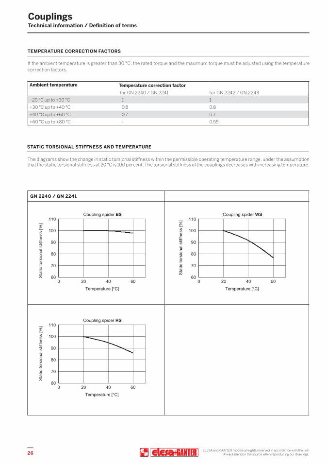
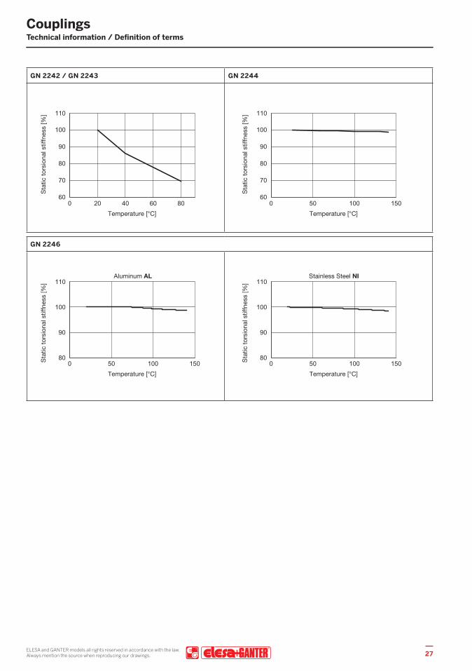
STATIC TORSIONAL STIFFNESS AND TEMPERATURE
The diagrams show the change in static torsional stiffness within the permissible operating temperature range, under the assumption that the static torsional stiffness at 20 °C is 100 percent. The torsional stiffness of the couplings decreases with increasing temperature.
GN 2240 / GN 2241
26 ELESA and GANTER models all rights reserved in accordance with the law.Always mention the source when reproducing our drawings.
CouplingsTechnical information / Definition of terms
GN 2242 / GN 2243 GN 2244
GN 2246
27ELESA and GANTER models all rights reserved in accordance with the law.Always mention the source when reproducing our drawings.

CouplingsTechnical information / Definition of terms
RESTORING FORCE - ECCENTRICITY
When the shaft ends are installed in eccentric arrangements, the coupling constantly attempts to return to its neutral position. The resulting force is referred to as restoring force.
If the couplings are installed with the lowest possible eccentricity, the resulting restoring forces are lower. This also reduces the force acting on the shaft bearing.
GN 2240 / GN 2241
GN 2242 / GN 2243 GN 2244
28 ELESA and GANTER models all rights reserved in accordance with the law.Always mention the source when reproducing our drawings.
CouplingsTechnical information / Definition of terms
GN 2246
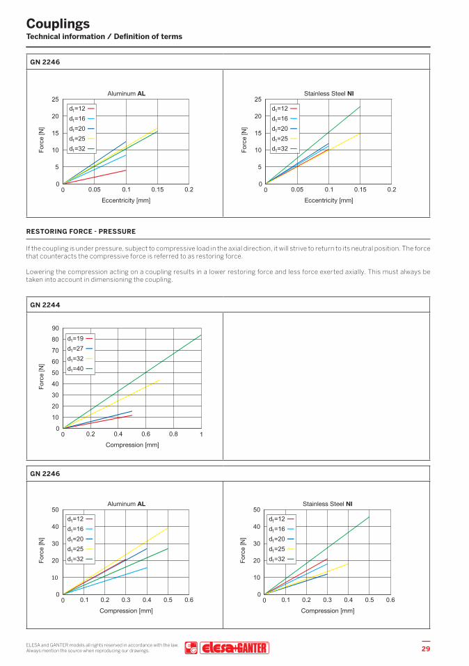
RESTORING FORCE - PRESSURE
If the coupling is under pressure, subject to compressive load in the axial direction, it will strive to return to its neutral position. The force that counteracts the compressive force is referred to as restoring force.
Lowering the compression acting on a coupling results in a lower restoring force and less force exerted axially. This must always be taken into account in dimensioning the coupling.
GN 2244
GN 2246
29ELESA and GANTER models all rights reserved in accordance with the law.Always mention the source when reproducing our drawings.
ELESA and GANTER models all rights reserved in accordance with the law.Always mention the source when reproducing our drawings.30
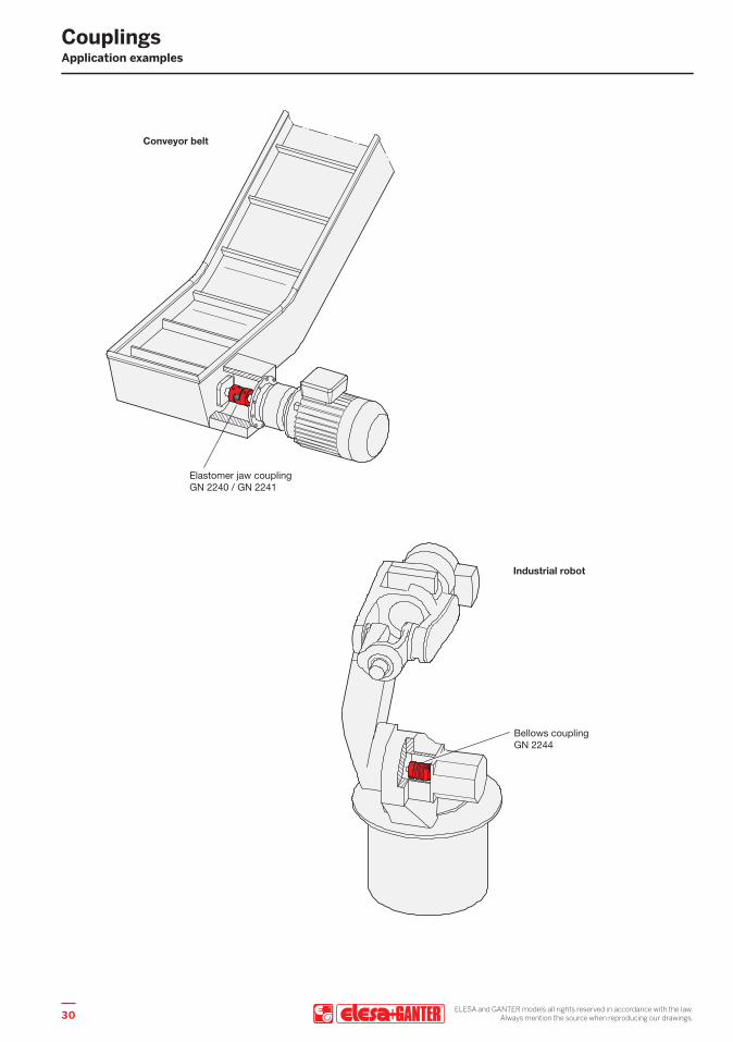
CouplingsApplication examples

COPYRIGHT © 2021 Elesa S.p.A and OTTO GANTER GmbH & Co. KG All rights reserved. No part of this catalogue can be reproduced in whole or in part without prior written permission from Elesa S.p.A or OTTO GANTER GmbH & Co. KG

Find out more on elesa-ganter.com
SP-E
G-E
NG
-04.
21-C
OU
PL
ELESA S.p.A.Via Pompei 2920900 Monza (MB) Italy
+39 039 28 [email protected]
OTTO GANTER GmbH & Co.KGTriberger Straße 378120 Furtwangen Germany
+49 7723 65 07 [email protected]