
New Assessment/Test Method for Automated Driving (NATM ...
46
Submitted by the IWG on VMAD Informal document GRVA-09-07 9 th GRVA, 1-5 February 2021 Provisional agenda item 4(b) (Based on working paper VMAD-16-03-rev.2) New Assessment/Test Method for Automated Driving (NATM) Master Document (Final Draft) 1. Background 1.1 During the 178 th session of the United Nations Economic Commission for Europe (UNECE)’s World Forum for Harmonization of Vehicle Regulations (WP.29), the Framework document on automated/autonomous vehicles (WP.29/2019/34/Rev.2) was adopted and the Terms of Reference (ToR) (WP.29/1147/Annex VI) for the Informal Working Group on Validation Methods for Automated Driving (VMAD) were developed. 1.2 The Framework document included the action item of a ‘new assessment/test method for automated driving’ (NATM) for consideration during the 183 rd (March 2021) session of WP.29. 1.3 Consistent with the Framework document, the ToR outlines that VMAD’s mandate under the Working Party on Automated/Autonomous and Connected Vehicles (GRVA) is to develop assessments methods, including scenarios, to validate the safety of automated systems based on a multi-pillar approach including audit, simulation/virtual testing, test track, and real-world testing. 1.4 During the development of this work, the ToR outlines that VMAD should: Pursue this work in line with the following principles/elements described in the WP.29 Framework Document on Autonomous Vehicles: d. Object event detection and response (assessment): The automated/autonomous vehicles shall be able to detect and respond to object/events that may be reasonably expected in the operational design domain (ODD); and f. Validation for system safety: vehicle manufacturers should demonstrate a robust design and validation process based on a system-engineering approach with the goal of designing automated driving systems (ADS) free of unreasonable risks and ensuring compliance with road traffic regulation and the principles listed in this document. Design validation methods should include a hazard analysis and safety risk assessment for ADS, for the object event detection and response (OEDR), but also for the overall vehicle design into which it is being integrated and when applicable, for the broader transportation ecosystem. Design and validation methods should demonstrate the behavioural competencies an automated/autonomous vehicle would be expected to perform during a
Transcript of New Assessment/Test Method for Automated Driving (NATM ...

Submitted by the IWG on VMAD
Informal document GRVA-09-07 9th GRVA, 1-5 February 2021 Provisional agenda item 4(b) (Based on working paper VMAD-16-03-rev.2)
New Assessment/Test Method for Automated Driving (NATM)
Master Document (Final Draft)
1. Background
1.1 During the 178th session of the United Nations Economic Commission for Europe (UNECE)’s World Forum for Harmonization of Vehicle Regulations (WP.29), the Framework document on automated/autonomous vehicles (WP.29/2019/34/Rev.2) was adopted and the Terms of Reference (ToR) (WP.29/1147/Annex VI) for the Informal Working Group on Validation Methods for Automated Driving (VMAD) were developed.
1.2 The Framework document included the action item of a ‘new assessment/test method for automated driving’ (NATM) for consideration during the 183rd (March 2021) session of WP.29.
1.3 Consistent with the Framework document, the ToR outlines that VMAD’s mandate under the Working Party on Automated/Autonomous and Connected Vehicles (GRVA) is to develop assessments methods, including scenarios, to validate the safety of automated systems based on a multi-pillar approach including audit, simulation/virtual testing, test track, and real-world testing.
1.4 During the development of this work, the ToR outlines that VMAD should: Pursue this work in line with the following principles/elements described in the
WP.29 Framework Document on Autonomous Vehicles: d. Object event detection and response (assessment): The
automated/autonomous vehicles shall be able to detect and respond to object/events that may be reasonably expected in the operational design domain (ODD); and
f. Validation for system safety: vehicle manufacturers should demonstrate a robust design and validation process based on a system-engineering approach with the goal of designing automated driving systems (ADS) free of unreasonable risks and ensuring compliance with road traffic regulation and the principles listed in this document. Design validation methods should include a hazard analysis and safety risk assessment for ADS, for the object event detection and response (OEDR), but also for the overall vehicle design into which it is being integrated and when applicable, for the broader transportation ecosystem. Design and validation methods should demonstrate the behavioural competencies an automated/autonomous vehicle would be expected to perform during a

2
normal operation, the performance during crash avoidance situations and the performance of fall back strategies. Test approaches may include a combination of simulation, test track and on road testing.
Take account of the developments of other subsidiary Working Parties (GRs) of WP.29 and their IWGs and work in full cooperation with them; and,
Consider existing data, research and technical standards (e.g. SAE, ISO) available during the development of its action items.
2. Purpose and Scope
2.1 In order for the international community to maximize the potential safety benefits of ADS, a safety validation framework that can be adopted by Contracting Parties of both the 1958 and the 1998 UN vehicle regulations agreements must be established. The NATM developed by VMAD aims to provide clear direction for validating the safety of an ADS in a manner that is repeatable, objective and evidence-based, while remaining technology neutral and flexible enough to foster ongoing innovation by the automotive industry.
2.2 This document consolidates the work accomplished by VMAD to date to develop the NATM. It provides a clear overview of the NATM and its constituent pillars. This document also serves to promote coordination between VMAD and the work of the GRVA Informal Working Group on Functional Requirements for Automated Vehicles (FRAV). This coordination will ensure that the NATM also addresses the validation of compliance of an ADS to common safety requirements to be developed by FRAV.
2.3 Given the substantial technical work that is still needed to operationalize the NATM in practice, this version of the Master Document provides a high level framework for the NATM, outlining: Scope and general overviews of the scenario catalogue and each of the pillars
(simulation/virtual testing, test track, and real-world testing, audit/assessment and in-use monitoring); and,
Overall process of the NATM (e.g., how the components of the NATM (i.e., the scenarios catalogue and pillars) operate together, producing an efficient, comprehensive, and cohesive process).
2.4 Going forward, this document will be further developed and regularly updated and informed by the outcomes of future VMAD sessions.
2.5 As VMAD continues to develop the elements of the NATM and FRAV continues to develop safety requirements for ADS, this document will be updated to incorporate this work. Detailed technical documents will be outlined in an index of supporting reference materials, located at the end of this document, as these are developed by VMAD.
3
2.6 Subject to direction from GRVA and WP.29, once the NATM has reached a state of maturity to inform evaluation criteria (based on performance requirements specified by the IWG FRAV), it is anticipated that this document (and any supporting resources developed by VMAD) will be used to help inform validation process guidelines and/or regulations/requirements that align with the needs of both 1958 and 1998 Agreement parties (subject to approval by WP.29).
3. Definitions
3.1 The introduction of ADS and related technologies has resulted in a proliferation of new technical terms and concepts. To ensure consistency, a glossary of terms and definitions used in the NATM Master Document is attached at Annex 1. This glossary will be further developed and updated on an ongoing basis as the Master document and any supporting technical documents are developed. Where applicable, VMAD will ensure these terms are consistent with those adopted by WP.29, GRVA, and other GRVA Informal Working Groups, including definitions agreed upon by FRAV.
4. Applying a Multi-pillar Approach to the NATM
4.1 The purpose of the NATM is to provide a framework for assessing an ADS and its ability to demonstrate safe behaviour when operating in the real world.
4.2 Validating these capabilities is a highly complex task which cannot be done comprehensively nor effectively through one validation methodology alone. As a result, VMAD has proposed that the NATM adopt a multi-pillar approach for the validation of ADS, composed of a scenarios catalogue and five validation methodologies (pillars) each of which is explored in greater detail in subsequent sections of this document: A scenario catalogue, consisting of descriptions of real-world driving situations
that may occur during a given trip, will be a tool used by the NATM-pillars to validate the safety of an ADS.
Simulation/virtual Testing which uses different types of simulation toolchains to assess the compliance of an ADS with the safety requirements on a wide range of virtual scenarios including some which would be extremely difficult if not impossible to test in real-world settings.
Track testing uses a closed-access testing ground with various scenario elements to test the capabilities and functioning of an ADS;
Real world testing uses public roads to test and evaluate the performance of ADS related to its capacity to drive in real traffic conditions;
Audit/assessment procedures which establish how manufacturers will be required to demonstrate to safety authorities using documentation, their simulation, test-track, and/or real-world testing of the capabilities of an ADS. The audit will validate that hazards and risks relevant for the system have been

4
identified and that a consistent safety-by-design concept has been put in place. The audit will also verify that robust processes/mechanisms/strategies (i.e., safety management system) that are in place to ensure the ADS meets the relevant safety requirements throughout the vehicle lifecycle. It shall also assess the complementarity between the different pillars of the assessment and the overall scenario coverage; and finally,
In-service monitoring and reporting addresses the in-service safety of the ADS after its placing on the market. It relies on the collection of fleet data in the field to assess whether the ADS continues to be safe when operated on the road. This data collection can also be used to fuel the common scenario database with new scenarios from the field and to allow the whole ADS community to learn from major ADS accidents/incidents.

5
5. Scenarios Catalogue 5.1 Why should scenario-based testing be included in the NATM? In order to
maximize the potential safety of AVs, a robust safety validation framework shall be established. Such a framework shall provide clear direction for assessing safety requirements of AVs in a repeatable, objective, evidence-based and technology neutral manner.
5.2 At this relatively early stage in the development of AVs, much of the existing literature that assesses the current state of AV development uses metrics such as miles/kilometers travelled in real-world test situations with the absence of a collision, a legal infraction, or a disengagement by the vehicle’s ADS.
5.3 Simple metrics such as kilometers travelled without a collision, legal infraction, or disengagement can be helpful for informing public dialogue about the general progress being made to develop AVs. Such measurements on their own however, do not provide sufficient evidence to the international regulatory community that an AV will be able to safely navigate the vast array of different situations a vehicle could reasonably be expected to encounter.
5.4 In fact, some observers have suggested that an AV would have to drive billions of miles in the real-world to experience an adequate number of situations without an incident to prove that it has a significantly better safety performance than a human driver (Kalra & Paddock, 2016). Safety validation through such testing would not be cost and time effective, nor would it be feasible to replicate the testing later on. As validation of AV in various traffic situations is needed, therefore different traffic scenarios shall be considered.
5.5 A scenario-based approach helps to systematically organize safety validation activities in an efficient, objective, repeatable, and scalable manner and is a critical part of the NATM for ensuring a holistic and dense coverage of traffic situations.
5.6 Scenarios-based validation consists of reproducing specific real-world situations that exercise and challenge the capabilities of an ADS-equipped vehicle to operate safely.
5.7 What is a traffic scenario? A scenario is a description of one or more real-world driving situations that may occur during a given trip[1]. SG1 will design scenarios for use under the NATM pillars. A scenario can involve many elements, such as roadway layout, types of road users, objects exhibiting static or diverse dynamic behaviours, and diverse environmental conditions (among other factors). [1] A trip is a traversal of an entire travel pathway by a vehicle from the point of origin to a destination.
5.8 As previously noted, the use of scenarios can be applied to different testing methodologies, such as virtual/simulation, test track, and real-world testing. Together these methodologies provide a multifaceted testing architecture, with each methodology possessing specific strengths and weaknesses. Therefore, some scenarios may be more appropriately tested using certain test methodologies over others.

6
5.9 Going forward, VMAD will establish a catalogue of scenarios that should be considered to validate, using the NATM pillars, each safety requirement – given by FRAV - for an ADS, considering that it is ideal that scenarios (neutral to vehicle technology) comprehensively reflect the situation on world-wide public roads. In addition, scenarios shall not be limited to scenarios that are deemed preventable by the ADS. This work will be accomplished in consultation with VMAD subgroups.
5.10 [Reserved (issue about scenarios not covered by scenario catalogue)] 5.11 Identifying Scenarios: Scenario-based validation methods must include an adequate
representation/coverage of relevant, critical, and complex scenarios to effectively validate an ADS. There are a number of approaches for identifying scenarios to validate the safety of an AV. For example, scenarios can be identified based on: analyzing human driver behaviour, including evaluating naturalistic driving data; analyzing collision data, such as law enforcement and insurance companies’
crash databases; analyzing traffic patterns in specific ODD (e.g., by recording and analyzing road
user behaviour at intersections); analyzing data collected from ADS’ sensors (e.g., accelerometer, camera, radar,
and global positioning systems); Using specially configured measurement vehicle, onsite monitoring equipment,
drone measurements, etc. for collecting various traffic data (including other road users);
Knowledge/experience acquired during ADS development; Synthetically generated scenarios from key parameter variations; and Engineered scenarios based on functional safety requirements and safety of
intended functionality. 5.12 Continued collection of real-world data is important for identifying unexpected
scenarios – scenarios that may be uniquely challenging to that vehicle’s specific ADS.
5.13 Once a wide range of scenarios has been identified, specific requirements can be tested and validated by virtual, test track, and real-world test validation methods.
5.14 Classifying Scenarios: The amount of information that is included in a scenario can be extensive. For example, the description of a scenario could contain information specifying a wide range of different actions, characteristics and elements, such as objects (e.g., vehicles, pedestrians), roadways, and environments, as well as pre-planned courses of action and major events that should occur during the scenario. Therefore, it is critical that a standardized and structured language for describing scenarios is established so that AV stakeholders understand the intention of a scenario, each other’s objectives, and the capabilities of an ADS.
5.15 One approach that researchers have established for developing a standardized and structured language for describing scenarios, which also incorporates different levels

7
of abstraction/detail, is classifying scenarios according to three categories: functional, logical, and concrete scenarios. Functional Scenario: Scenarios with the highest level of abstraction, outlining
the core concept of the scenario, such as a basic description of the ego vehicle’s actions; the interactions of the ego vehicle with other road users and objects; roadway geometry; and other elements that compose the scenario (e.g. environmental conditions etc.). This approach uses accessible language to describe the situation and its corresponding elements.
Logical Scenario: Building off the elements identified within the functional scenario, developers generate a logical scenario by selecting value ranges or probability distributions for each element within a scenario (e.g., the possible width of a lane in meters). The logical scenario description covers all elements and technical requirements necessary to implement a system that solves these scenarios.
Concrete Scenarios: Concrete scenarios are established by selecting specific values for each element. This step ensures that a specific test scenario is reproducible. In addition, for each logical scenario with continuous ranges, any number of concrete scenarios can be developed, helping to ensure a vehicle is exposed to a wide variety of situations.
Refer to Figure 1 for examples of functional, logical and concrete scenarios.
Figure 1. Examples of a scenario during different stages of its development (Pegasus, 2018).
5.16 Scenario Elements: Traffic scenarios are derived by combining a number of
relevant elements, taken from disjunct layers describing the scenario space systematically.

8
5.17 Functional scenarios for divided highway application are described in Annex 2. This document should be regarded as “live document”, meaning that the document should be updated based on the continuous discussion and the document is not the final version.
6 Simulation/Virtual Testing 6.1 Common terms. The following terms are used throughout this section.
‘Abstraction’ is the process of selecting the essential aspects of a source system or referent system to be represented in a model or simulation, while ignoring those aspects not relevant. Any modelling abstraction carries with it the assumption that should not significantly affect the intended uses of the simulation tool.
‘Closed Loop Testing’ means a virtual environment that does take the actions of the element-in-the loop into account. Simulated objects respond to the actions of the system (e.g. system interacting with a traffic model).
‘Deterministic’ is a term describing a system whose time evolution can be predicted exactly and a given set of input stimuli will always produce the same output.
‘Driver-In-the-Loop’ (DIL) is typically conducted in a driving simulator used for testing the human–automation interaction design. DIL has components for the driver to operate and communicate with the virtual environment.
‘Hardware-In-the-Loop’ (HIL) involves the final hardware of a specific vehicle sub-system running the final software with input and output connected to a simulation environment to perform virtual testing. HIL testing provides a way of replicating sensors, actuators and mechanical components in a way that connects all the I/O of the Electronic Control Units (ECU) being tested, long before the final system is integrated.
‘Model’ is a description or representation of a system, entity, phenomenon, or process.
‘Model calibration’ is the process of adjusting numerical or modelling parameters in the model to improve agreement with a referent.
‘Model Parameter’ are numerical values used to support characterizing a system functionality. A model parameter has a value that cannot be observed directly in the real world but that must be inferred from data collected in the real world (in the model calibration phase).
‘Model-In-the-Loop’ (MIL) is an approach which allows quick algorithmic development without involving dedicated hardware. Usually, this level of development involves high-level abstraction software frameworks running on general-purpose computing systems.

9
‘Open Loop Testing’ means a virtual environment that does not take the actions of the element-in-the loop into account (e.g. system interacting with a recorded traffic situation).
‘Probabilistic’ is a term pertaining to non-deterministic events, the outcomes of which are described by a measure of likelihood.
‘Proving Ground or test-track’ is a physical testing facility closed to the traffic where the performance of an ADS can be investigated on the real vehicle. Traffic agents can be introduced via sensor stimulation or via dummy devices positioned on the track.
‘Sensor Stimulation’ is a technique whereby artificially generated signals are provided to the element under testing in order to trigger it to produce the result required for verification of the real world, training, maintenance, or for research and development.
‘Simulation’ is the imitation of the operation of a real world process or system over time.
‘Simulation model’ is a model whose input variables vary over time. ‘Simulation toolchain’ is a combination of simulation tools that are used to
support the validation of an ADS. ‘Software-In-the-Loop’ (SIL) is where the implementation of the developed
model will be evaluated on general-purpose computing systems. This step can use a complete software implementation very close to the final one. SIL testing is used to describe a test methodology, where executable code such as algorithms (or even an entire controller strategy), is tested within a modelling environment that can help prove or test the software.
‘Stochastic’ means a process involving or containing a random variable or variables. Pertaining to chance or probability.
‘Validation of the simulation model’ is the process of determining the degree to which a simulation model is an accurate representation of the real world from the perspective of the intended uses of the tool.
‘Vehicle -In-the-Loop’ (VIL) is a fusion environment of a real testing vehicle in the real-world and a virtual environment. It can reflect vehicle dynamics at the same level as the real-world and it can be operated on a vehicle test bed or on a test track.
‘Verification of the simulation model’ is the process of determining the extent to which a simulation model or a virtual testing tool is compliant with its requirements and specifications as detailed in its conceptual models, mathematical models, or other constructs.
‘Virtual testing’ is the process of testing a system using one or more simulation models.
6.2 Introduction.

10
Simulation provides powerful tools to assess the performance of an ADS under diverse and complex conditions which are prohibitive for conventional physical testing. Powered by simulation models, virtual testing plays a vital role in ensuring comprehensive assessment of an ADS. The major role virtual testing will play in the development and validation of ADS justifies its inclusion as a principal pillar of the NATM.
While robust virtual test methods are available and widely used, the task of the NATM is to verify the possibility to produce reliable evidence of ADS safety performance in the physical world. Therefore, this section of the Master Document explains virtual testing tools and methods and complementarity of this pillar with the other testing methods.
6.3 Virtual testing and simulation in ADS development and validation. Virtual testing can be used in different phases of the ADS development and validation. Virtual testing can be used to explore in a comprehensive and cost-effective way an ADS (or of part of it) in a wide range of traffic scenarios across different ODDs and for a variety of additional purposes. Relying on simulation, virtual testing is particularly indicated to test the ADS under safety critical scenarios that would be difficult and/or unsafe to reproduce on test tracks or public roads.
6.4 Virtual testing includes replacing one or more physical elements characterized in a scenario-based test by a simulation model. The goal of such virtualization is to resemble, to a sufficient extent, the original physical elements. For automotive applications, virtual testing can be used to reproduce the driving environment and the objects operating therein that interact with either the entire system (e.g. a full vehicle with tires and ADS functions), a subsystem (e.g. an actuator or a hardware controller), or a component (e.g. a sensor).
6.5 Through this approach, an assessor can get confidence about the ADS based on the virtual tests and validation that was performed by the developer in an agile, controllable, predictable, repeatable, and efficient manner.
6.6 The simulation toolchain used for virtual testing may result in the combination of different approaches. In particular, tests can be performed: entirely inside a computer (referred to as Model or Software in the Loop testing,
MIL/SIL), with the model of the elements involved (e.g. a simple representation of the control logic of an ADS) interacting in a simulated environment; and/or
with a sensor, a subsystem, or the whole vehicle interacting with a virtual environment (Hardware or Vehicle in the Loop testing, HIL/VIL). For VIL testing, the vehicle can either be in:
• a laboratory where the vehicle would be standing still or moving on a chassis dynamometer or powertrain test bed and be connected to the environment model by wire or by direct stimulation of its sensors; or
• a proving ground where the vehicle would be connected to an environment model and would interact with virtual objects by physically moving on the test-track.

11
With a subsystem interacting with a real driver (Driver in the Loop testing, DIL). 6.7 The interaction between the system under the test and the environment can either be
an open- or closed-loop. Open-loop virtual tests (also referred to as software or hardware reprocessing,
shadow mode, etc.) could be done through a variety of methods, such as the ADS interacting with virtual situations collected from the real world. In this case, virtual objects’ actions are data-driven only and the information is not self-corrected based on feedback from the output. Because the open-loop controller may vary due to external disturbances without the ADS and/or the assessor being aware, the applicability of open-loop tests in the ADS validation may be limited.
Closed-loop virtual tests includes a feedback loop that continuously sends information from the closed-loop controller to the ADS. Within these test systems, the behaviour of the digital objects could react in different ways depending on the action of the system under test.
6.8 Selecting an open- or closed-loop test could depend on factors such as the objectives of the virtual testing activity and the status of development of the system under test. For ADS validation it is expected that mainly closed-loop virtual testing will be considered.
6.9 Strengths and Weaknesses of the Pillar The flexibility of the pillar makes it a standard test method in vehicle design and validation in general. For ADS’, given the impossibility to test the vehicle behaviour in real life in all possible situations and for any change in its driving logic, virtual testing becomes an indispensable tool to verify the capability of the automated system to deal with a wide variety of possible traffic scenarios. In addition, virtual testing can be extremely beneficial to replace real world and proving ground testing concerning safety-critical traffic scenarios.
6.10 Furthermore, virtual tests used for ADS validation can achieve different objectives, depending on the overall validation strategy and the accuracy of the underlying simulation models: Provide qualitative confidence in the safety of the full system. Contribute directly to statistical confidence in the safety of the full system
(caveats apply). Provide qualitative or statistical confidence in the performance of specific
subsystems or components. Discover challenging scenarios to test in the real world (e.g. real-world tests and
track tests described in chapter 7 and 8 of this document). 6.11 In contrast to all its potential benefits, a limitation of this approach is in its intrinsic
limited fidelity. As models can only provide a coarse representation of the reality, the suitability of a model to satisfactorily replace the real world for validating the safety of ADSs has to be carefully assessed. Therefore, the validation of the simulation models used in virtual testing is essential to determine the transferability and reliability of the results compared to real-world performance.

12
6.12 An approach for assessing the accuracy of a virtual testing toolchain is to compare the ADS’ performance within a virtual test with its performance in the real world when executing the same scenario. Given the high number of scenarios that virtual testing can perform compared to track test, the validation will likely need to be performed on a smaller but still sufficiently representative subsection of the relevant scenarios in order to substantiate any extrapolation beyond the scenarios used for the validation.
6.13 Table 1 summarizes the main strengths and weaknesses of the virtual testing as part of the demonstration of the safety level by the manufacturer.
Table 1. Strengths and Weaknesses of the Virtual Testing Pillar.
Strengths Weaknesses • Controllability – Virtual testing affords an unmatched
ability to control many aspects of a test. • Agility – Virtual tests allows for system changes to be
revaluated immediately. • Efficiency – In MIL and SIL, virtual tests can be
accelerated faster than real-time so that many tests can be run concurrently in a relatively short amount of time.
• Cost effectiveness at test execution – In spite of the investments required to develop, validate and maintain a virtual testing toolchain, the running costs connected to its use are considerably lower than those required by physical testing.
• Wide scenario coverage – Compared to other testing methods, virtual testing allows a wider exploration of safety-critical scenarios. By properly combining the experiments parameters it can for example reduce the space of the known unknowns and to the extent possible that of the unknown unknowns (including the effect of system failures).
• Data gathering and analysis - Virtual testing offers a convenient and error-free platform for data gathering and analysis of the ADS performance. Once Qualified, that data can serve as a significant contribution for assessing the risk from the ADS.
• Repeatability and replicability – Simulation affords the re-execution of the same virtual test without deviations due to stochastic phenomena. Faults in the functioning of the ADS can thus be identically replicated at any moment.
• Lower environmental fidelity/reliability – It is difficult, and likely impossible for models to completely reproduce the environment, responses, as well as the behaviour of the vehicle, other road users etc. in the real world. Also the validation process cannot prove the validity of the simulation across all possible scenarios.
• Risk of over-reliance. Without proper consideration of models’ intrinsic limitations, a risk exists to put too much emphasis on virtual testing results without sufficient proof of their validity by physical testing.
• Expensive software life-cycle. The availability of a simulation model to execute virtual testing requires covering certain aspects of the software life-cycle which can be costly and time-consuming

13
6.14 Maturity of the Pillar Virtual testing is a constantly evolving test method. While it
is in many ways mature and used commonly for design and development processes, the real-world reliability and validity of each embodiment of the tool still needs to be determined. Although virtual testing can be used both in the ADS development and validation process by the manufacturer and in the ADS certification process by the authority, it can be considered a mature option only as a tool used for the vehicle manufacturer. Further work is needed to define the requirements for using virtual testing in the certification process. Topics to be addressed are for instance the validation requirements. It needs to be proven, indeed, that the simulation toolchain used for virtual testing is an accurate representation of the real system for the purpose of the experimentation.
6.15 Another area of research for the future application of virtual testing in ADS certification is the possibility for authorities to host and maintain a validated and standardized simulation environment where manufacturer can “plug” the system to be validated (either in the form of a physical system or of a model/software) to show its compliance to the safety requirements defined by the legislation.
6.16 Since this is currently the subject of research and standardization activities, in the short term virtual testing can only be allowed by simulation toolchains developed and maintained by vehicle manufacturers or ADS developers. Since their design depends on the validation and verification strategies implemented by the manufacturer, they should not be subject to regulation or standardization but rather explained and documented by the ADS/vehicle manufacturer and the basis for its verification and validation reviewed during the certification process. For this reason, it is envisioned that documentation and data provided by the manufacturer should be harmonized.
6.17 Interaction between Virtual Testing and the other Test Methods. Virtual testing will have strong relationships with all the pillars of the NATM. In particular: Virtual testing expands the scope of physical testing to account for the diversity
of traffic. The strength of virtual testing lies in its capacity to cost-effectively assess performance across ranges of variables and arrays of scenarios. Virtual testing enables results of limited physical tests to be supplemented by verifiable data covering variations on the physical test scenario. Virtual testing enables coverage of safety-critical scenarios at their logical abstraction levels, confirming that an ADS will perform as intended across the parameter ranges. These advantages reduce the burden on physical tests (offsetting their weaknesses) to improve the efficiency of the overall assessment across the pillars. Virtual testing can also be effectively used to identify and cover edge cases and other low-probability scenarios to increase confidence on their performances.
Virtual testing can play an important role in the development of performance requirements and traffic scenarios. Virtual testing also enables assessment of ADS performance boundaries, enabling precision of limits between collision avoidance and crash mitigation. Through methods of randomization and compositions, virtual testing enables the developer or the assessor to challenge

14
the ADS with unexpected, unplanned scenarios, and thus increases the confidence in the performance of the ADS when challenged with low probability events.
Virtual testing will be a key element in the audit assessment. Results of virtual testing carried out both during vehicle development and in the verification and validation phase will represent an important element to be subject to audit. Manufacturers will need to provide evidence and documentation about how the virtual testing is carried out and how the underlying simulation toolchain has been validated.
Real-world tests can aid in the generation of realistic simulation models and in establishing their accuracy:
6.17...1 Real-world data for vehicle and component model validation: vehicle data and data measured via vehicle sensors are important sources for quantifying and arguing model accuracy (e.g. vehicle dynamics or sensor models).
6.17...2 Real-world data for traffic modelling: the generation of novel scenarios requires realistic road user behaviour for the simulation environment to remain meaningful and representative.
Virtual testing can play an important role in responding to concerns identified through in-use monitoring of ADS performance. Virtual testing provides speed and flexibility in analysing real-world events to verify ADS performance against such events and, if necessary, support modifications to improve performance. Scenario descriptions can be shared and integrated rapidly into virtual testing regimes worldwide. The various types of virtual testing, including HIL methods that come close to matching physical testing, ensure robust and rapid responses.
6.18 Use of the pillar to assess ADS safety requirements. Virtual testing using a validated simulation toolchain can be used to assess the ADS’ compliance with the safety requirements. Considering the categories of safety requirements currently being considered, virtual testing seems particularly relevant for assessing requirements related to: ADS should drive safely and ADS should manage safety critical situations. These
are the requirements where virtual testing can play the most prominent role. MIL/SIL, HIL and VIL virtual testing can all be used to assess these requirements at different stages of vehicle verification and validation.
ADS should interact safely with the user. DIL virtual testing can be helpful to support the assessment of this category of safety requirement by analysing the interaction between the driver and the ADS in a safe and controlled environment.
ADS should safely manage failure modes and ADS should ensure a safe operational state. The use of virtual testing in these two categories is also very promising but would probably require further research work. SIL virtual testing could include simulated failures and maintenance requests. HIL and VIL virtual testing could be used to assess how the system would react to the occurrence of a real malfunctioning induced to the real system.

15
7 Track Testing 7.1 Track testing occurs on a closed-access testing ground that uses real obstacles and
obstacle surrogates (e.g. vehicle crash targets, etc.) to assess the safety requirements of an ADS (e.g., human factors, safety system). This testing approach allows for the physical vehicles to be tested through a limited set of realistic scenarios (based on the test track’s geometries, dimensions, size, and the ODD) to evaluate either sub-systems or the fully assembled system. These external inputs and conditions can be controlled or measured during a test. In addition to this test method providing a higher level of environmental fidelity than simulation, it provides an opportunity to test the vehicle with less danger than what is likely posed within real-world tests. However, operating on test tracks can be resource-intensive, therefore testing on a test track will be based on selected known critical scenarios. Refer to Table 2. below for more information regarding the respective strengths and weaknesses of this testing methodology.
7.2 Track testing may be more suitable for assessing the ADS capabilities in a discrete number of nominal scenarios and critical scenarios. The same tests could be used to verify the performance of the vehicles regarding human factors or fallback in these scenarios. Table 2. Strengths and Weaknesses of the Track Test Pillar
Strengths Weaknesses • Controllability – Track testing allows for control over many of the test elements, including certain aspects of the ODD. • Fidelity – Track testing involves functional, physical ADS-equipped vehicles and lifelike obstacles and environmental conditions. •Reproducibility– Track testing scenarios can be replicated in different locations by different testing entities • Repeatability – Track testing allows for multiple iterations of tests to be run in the same fashion, with the same inputs and initial conditions. • Efficiency – Compared to real-world testing, closed-course testing can accelerate exposure to known rare events or safety critical scenarios by setting them up as explicitly designed test
• Significant time –Track testing can take a significant amount of time to set up and execute. • Costly – Track testing may require a substantial number of personnel and specialized test equipment (e.g., obstacle objects, measurement devices, safety driver). • Limited variability – Track testing facility infrastructure and conditions may be difficult to modify to account for a wide variety of test elements (e.g., ODD conditions). They are restricted to their geometries, dimensions, size and ODD limitations such as weather conditions, time of day, number and type of other traffic agents. • Safety risks – Track testing with physical vehicles and real obstacles presents a

16
scenarios. Road testing by contrast could be an inefficient way to test less co manifesting by chance. • Track testing can be used to validate the quality of the simulation toolchain by comparing an ADS’ performance within a simulation test with its performance on a test track when executing the same scenario.
potentially uncertain and hazardous environment for the test participants (e.g., safety driver and experiment observers). • Representativeness even with its increased fidelity. Whilst things like pedestrians can be included, these won’t typically be real people due to safety reasons and the clutter or real-world environments cannot be replicated.
7.3 Why include this pillar in the NATM? As per paragraph 7.3 as well as the strengths and limitation table, there are a number of reasons for including track testing in the NATM. For instance, track testing can be used to assess the performance of ADS in nominal and critical scenarios. Track testing can also provide a higher level of environmental fidelity than simulation. Unlike real-world testing, track testing can accelerate exposure to known rare events or safety critical scenarios.
7.4 Maturity of the pillar Although track testing is a mature process which is used to assess safety requirements for some existing technologies, testing of ADS vehicles is fairly new and may need to be further refined. For instance, it may be difficult to develop specific ODD elements, such as rain, fog, and snow to reliably test how an ADS interacts with these environmental elements.
7.5 How the pillar interacts with other pillars? The information generated during the track-test could also be used to validate the virtual tests by comparing an ADS’ performance within a virtual test with its performance on a test track when executing the same scenario. For instance, track testing can be used to validate the quality/reliability of the virtual toolchain by comparing an ADS’ performance within a virtual test with its performance on a test track when executing the same scenarios.
8 Real-world Testing 8.1 Real-world testing uses public roads to test the capabilities and compliance with
safety requirements (e.g., human factors, safety system) of a vehicle with an automated driving system (ADS) in real-world traffic.
8.2 This testing method can expose the ADS to a wide variety of real-world conditions related to an ODD. There are various approaches to real-world testing. For example, tests can be done within a specific ODD (e.g., highway driving) with a safety driver who is monitoring/ensuring the ADS is functioning safely.
8.3 Real world testing could be used to assess aspects of the ADS performance related to its capability to drive in real traffic conditions, e.g. smooth driving, capability to deal

17
with dense traffic, interaction with other road users, maintaining flow of traffic, being considerate and courteous to other vehicles.
8.4 Real world testing could also be used to assess part of the ADS performance at some ODD boundaries (nominal and complex scenarios), i.e. is the system triggering transition demands to the driver when it is supposed to (e.g. end of the ODD, weather conditions). The same testing could be used to confirm the performances related to human factors under these conditions.
8.5 Finally, on road testing could be used to detect issues that may not be well captured by track tests and simulation, such as perception quality limitation (e.g. due to light conditions, rain, etc.).
8.6 Although it may not be possible to encounter all traffic scenarios during a real-world test, the likelihood of covering specific complex scenarios could be increased by selecting a specific type of ODD (e.g., highway) and examining when and where specific elements (e.g., high- or low-density traffic) typically occur.
8.7 Specific infractions identified during real-world testing may be later reviewed/assessed by evaluating the information/data using virtual, track and real-world testing. In addition, real-world testing data can be collected to identify and record new traffic scenarios and improve the environmental validity of track and virtual testing methodologies in the future.
8.8 Refer to Table 3 below for more information regarding the respective strengths and weaknesses of this testing method.

18
Table 3. Strengths and Weaknesses of the Real World Test Pillar
Strengths Weaknesses • High environmental validity – allows for validation of the vehicle in its intended ODD(s) and the diverse conditions these may present. • Can be used to test scenarios elements, such as weather and infrastructure (e.g., bridges, tunnels), that are unavailable through track testing • Real-world testing may be used to validate the simulation and track-testing by comparing an ADS’ performance within a simulation and track test with its performance on in a real-world environment when executing the same scenario. • Can be used to assess aspects of the ADS performance related to its interaction with other road users, e.g. maintaining flow of traffic, being considerate and courteous to other vehicles. • Model, single software, and toolchain validation
• Restricted controllability – Public-road scenarios afford a limited amount of control over ODD conditions. • Restricted reproducibility – Public-road scenarios are difficult to replicate exactly in different locations. • Restricted repeatability – Public-road scenarios are difficult to repeat exactly over multiple iterations. • Limited scalability – Public-road scenarios may not scale up sufficiently. • Costly but not as costly as track testing – Requires a number of resources and is time-consuming • Potential impact on traffic and safety authorities • New competencies may need to be developed by authorities • Safety risks: on-road testing could subject test personnel and the public to significant risks of unsafe behavior.
8.9 Why include this pillar in the NATM? Real world testing provides an opportunity
to validate the safety of the ADS within its true operating environment, as set out in greater detail in paragraphs 8.3, 8.4, and 8.5.
8.10 Maturity of the pillar Real-world testing is regularly conducted to assess the performance of human drivers. However, testing of ADS performance may pose some new challenges for this test methodology. Experiences could be drawn from other motor vehicle-related real-world testing schemes, such as real driving emissions (RDE) testing and market surveillance.
8.11 How the pillar interacts with other pillars Real-world testing may be used to validate if portions of a virtual and/or track-testing environment were modelled properly by comparing an ADS’ performance within a simulation and track test with its performance on in a real-world environment when executing the same test scenario.
8.12 It can also be used to identify new traffic scenarios for track and virtual testing, allowing for the identification of edge cases and other unknown hazard vulnerabilities that could challenge the ADS. The information gathered from real

19
world testing can also be used in the hazard and risk analysis and design of the ADS systems.
9. Audit 9.1 The purpose of the audit pillar is to assess/demonstrate that the:
Manufacturer has the right processes to ensure operational and functional safety during the vehicle lifecycle, and
Vehicle design is safe by design and this design is sufficiently validated before market introduction. The validation should be confirmed by in use monitoring.
9.2 The manufacturer will be required to demonstrate that: 1. robust processes are in place to ensure safety throughout the vehicle
lifecycle (development phase, production, but also operation on the road and decommissioning). It shall include taking the right measures to monitor the vehicle in the field and to take the right action when necessary;
2. hazard and risks relevant for the system have been identified and a consistent safety-by-design concept has been put in place to mitigate these risks; and
3. the risk assessment and the safety- by-design concept have been validated by the manufacturer through testing showing before the vehicle is placed on the market that the vehicle meets the safety requirements and in particular is free of unreasonable safety risks to the broader transport ecosystem in particular the driver, passengers and other road users.
9.3 Why should the Audit pillar be included in the NATM?
9.4 On the basis of the evidence provided by the manufacturer and the targeted tests, authorities will be able to audit and check whether the processes, the risk assessment, the design and the validation of the manufacturer are robust enough with regard functional and operational safety.
9.5 As such, these elements: risk assessments, safety- by-design concept, and validation tests can be used to demonstrate the ADS’ overall safety in a far more robust manner than a limited number of physical/virtual tests on their own.
9.6 Strengths and weaknesses of the audit pillar Risk analysis, safety-by-design concepts as well verification/validation test methods are standard development methods used in the automotive industry for years to ensure functional safety of electronic system (fail safe). It is expected that similar methods will be followed by manufacturers to minimize unsafe and unknown scenarios for ADSs in a systematic manner (operational safety beyond failures).

20
9.7 Regarding the safety assessment, the tools under this pillar will provide a more robust demonstration on the ADS safety (coverage) than a few test runs. The manufacturer’s safety case will be reinforced if it is assessed by an independent auditor and confirmed by targeted physical or virtual tests. Test runs will in particular be needed to demonstrate that the vehicle exhibits minimum performances for standard manoeuvres (e.g. normal lane keeping, lane change), key critical scenarios (e.g. emergency braking) and in traffic conditions (e.g. smooth integration in the traffic). It remains to be decided at this stage whether these tests shall be standardized across manufacturers for some defined situations or shall be tailored to the results of the risk assessment/design of the ADS or both.
9.8 Maturity of the Audit Pillar. The audit pillar is already used for a long time in UN Regulations (e.g. UN regulation 79 on steering, UN regulation 13 on braking and UN regulation 152 on AEBS). VMAD also proposed an updated audit pillar for the regulation on automated lane keeping systems in line with the concepts described above. The new UN regulation on cybersecurity also uses audits.
9.9 Risk analysis, verification/validation and safety management systems is a well-established practice in the industry (ISO 26262 on Industry functional safety). There is on-going work to cover new risks raised by ADAS/ADS such as operational safety (ISO/PAS 21448, BSI PAS 1880:2020, BSI PAS 1881-2020 and UL 4600). Similar standardization work exists for cybersecurity (ISO/SAE DIS 21434).
9.10 It should be noted that the publication of voluntary safety assessment reports documented by the manufacturer are also currently encouraged in some contracting parties (e.g. United States and Canada).
10 In-service monitoring and reporting 10.1 The in-service monitoring and reporting pillar addresses the in-service safety of
automated vehicles after market introduction. In practice, the application of the other pillars of the NATM will assess whether the ADS is reasonably safe for market introduction whereas the in-service monitoring and reporting will gather additional evidence from the field operation to demonstrate that that the ADS continues to be safe when operated on the road. This pillar addresses the dynamic nature of road transportation to ensure attention to and continuous improvement of road safety through the use of ADS.
10.2 The pillar consists in the collection of relevant data during AVs operation.
10.3 The three main purposes of in-service monitoring and reporting is to use retrospective analysis of data from manufacturers and other relevant sources to:

21
demonstrate that the initial safety assessment (residual risk) in the audit phase before the market introduction is confirmed in the field overtime (“safety confirmation”).
to fuel the common scenario database with important new scenarios that may happen with automated vehicles in the field (“scenario generation”) and
to derive safety recommendations for the whole community by sharing learnings derived from key safety accidents/ incidents to allow the whole community to learn from operational feedback, fostering continuous improvement of both technology and legislation (“safety recommendations”).
The obligation to have “real-time monitoring” (self-checks/ on board diagnostics) of the performance of ADs subsystems by the manufacturer is not part of this pillar but is part of the safety requirements. However, some reporting mechanisms on the performance of ADS subsystems overtime could be part of the first bullet above, and contribute to the predictive monitoring of safety performance degradation. The processes put in place by the manufacturer to manage safety during in use (e.g. to manage changes in the traffic rules and in the infrastructure) fall outside this pillar and are assessed with the audit pillar. This pillar focuses on the type of data to be monitored and reported.
10.4 Why should this pillar be included in the NATM?
10.5 Whatever safety evaluation is done before market introduction, the actual level of safety will only be confirmed once a sufficient number of vehicles is in the field and once they are subjected to a sufficient range of traffic and environmental conditions. It is therefore essential that a feedback loop (fleet monitoring) is in place to confirm the safety by design concept and the validation carried out by the manufacturer before market introduction. The operational experience feedback from in-use monitoring will allow ex-post evaluation of regulatory requirements and validation methods, providing indications on gaps and needs for review.
10.6 New scenarios and new risks might be introduced by AVs on the market. Therefore, the In -Use Monitoring pillar could be used to generate new scenarios in the common scenario database to cover these new safety risks.
10.7 Finally, in the early phase of market introduction of ADS, it is essential that the whole community learns from crashes involving AVs in order to quickly react and lead to safety developments and subsequent prevention of that crash scenario for all other ADS.
10.8 Strengths and weaknesses of the pillar:
10.9 Data from the field will be the most realistic way to assess the safety performance of an ADS over a wide range of real driving traffic and environmental conditions.

22
10.10 Data from the field are also instrumental to ensure that the scenario database is updated with the latest scenarios in particular those deriving from the increasing use of ADS.
10.11 Regarding safety recommendations, learning from in-service data is a central component to the safety potential of ADSs. Lessons learned from a crash involving ADSs could lead to safety developments and subsequent prevention of that crash scenario in other ADS. Feedback from the operational experience is recognized as best practice for safety management in the automotive sector as well as in other transport sectors (e.g. already in place in aviation, railway and maritime sectors). Field operation data can also provide evidence of the positive impact of ADs on road safety.
10.12 Limitations might derive from the quantity of data to be handled (too much data is as problematic as too little data), availability of tools for automatic scenario generation, and identification of responsibility handlers. Therefore, the outcome shall be a proportionate, efficient and uniform system.
10.13 Methods to verify the reliability of collected data should be developed. The data collected should be comparable amongst manufacturers. It will create challenges on which data and how these data are collected and reported (definition of suitable reporting criteria). Time-wise, another challenge is the development of the in-service safety monitoring framework in a timely manner in order to serve AVs market deployment. Data privacy should also be taken into account. A standardized format for communication of information will be needed to allow processing by authorities in a standard manner and that any outcomes are easily shareable or open for analysis by other authorities. Different type of data may be needed depending on the purpose of the data collection.
10.14 Processes for reporting the operational feedback from AVs should be developed for the automotive sector taking into account the higher number of monitored vehicles and events to be recorded.
10.15 Maturity of the Pillar
10.16 In-service monitoring and reporting is standard practice in the industry to develop and improve driver assistant systems (see ISO 26262 and SOTIF1). It was introduced as part of the audit of the new ALKS regulation. Starting from this requirement, additional elements should be developed in order to establish a more comprehensive approach for information sharing. In-service monitoring and reporting has already been implemented for many years as part of EU emissions regulations. In-use reporting was established in
1 Safety of the intended function: ISO/PAS 21448,

23
1966 in the USA and formalized into a comprehensive safety reporting system under US law in 2000.
10.17 The development of new traffic scenarios on the basis of traffic data has already started from the manufacturers’ side, through post-processing of recorded data elements and images (tools for complete automatic scenario generation are not available yet).
10.18 Operational Accident/incident analysis is a well-established practice in some vehicle safety regimes, e.g. through the analysis of data from event data recorders (EDRs) from conventional vehicles which are collecting relevant information in certain crash situations 2. No standard data elements are currently defined for ADS crash/near missed-investigation: entities engaging in testing or deployment are encouraged to voluntarily collect data associated with crashes 3. Because it is first time the concept of in-service-monitoring is introduced into the automotive safety sector and vehicles are usually used by normal citizens (different from air or rail sector), feasibility, such as how to collect data, which data (e.g. including or not if the ADs caused the circumstances that resulted in near-miss-crash), would be important view points and it should be well discussed.
10.19 Mechanisms for operational feedback to improve common knowledge are already in place for decades in other transport sectors (see ECCAIRS portal). Existing systems for reporting of safety concerns in the automotive sector have also been developed over decades of experience. A first step would be to investigate the suitability of such tools for ADs too. However, the main effort would still remain in defining common reporting criteria and developing a common repository. According to mechanisms already in place in other sectors (e.g. see Figure 2), in-service data recorded related to safety-relevant events (i.e. accidents, near-miss events, abnormal functioning etc.) are processed by manufacturers/operators and then an accident report (what happened) by manufacturers/operators is delivered to the National authority. National authorities are then responsible to perform the accident analysis (why did it happened), derive safety recommendations (how could this be avoided), and evaluate the possible impact on existing legislation. National information is then recorded into (1) a Central Repository of Occurrences and (2) a Central Repository of Safety Recommendations. Access to data recorded into the Central Repository is subject to strict rules and mainly limited to competent Authorities. Safety recommendations are shared internationally according to the guiding principle that transport safety is of
2 See 49 CFR Part 563, Event Data Recorders. www.gpo.gov/fdsys/pkg/CFR-2016-title49-vol6/xml/CFR-2016-title49-vol6-part563.xml
3 NHTSA Voluntary Guidance, https://www.nhtsa.gov/sites/nhtsa.dot.gov/files/documents/13069a-ads2.0_090617_v9a_tag.pdf

24
global concern and its improvement should not be limited by geographical or organizational borders. Privacy is ensured at all levels. Another option could be for the measured data to be directly communicated to the authorities, who will then be in charge of collection, storage and post-processing of the information.
Figure 2 – Reporting events – flow of information
10.20 There is some link with the Informal Working Group that is already working on data recording requirements for conventional and automated vehicles (DSSAD/EDR IWG4) in particular regarding accident analysis. However in-service monitoring as part of the ADS assessment method has a different purpose (i.e. confirming the safety assessment, fueling the scenario database, detailed analysis of accidents/incidents) than EDR/DSSAD (accident reconstruction and liability in case of road traffic offense).
4 DSSAD/EDR https://wiki.unece.org/pages/viewpage.action?pageId=87621709

25
11 NATM Pillars/Element Interaction
11.1 The goal of the NATM is to assess the safety of an ADS in a manner that is as repeatable, objective and evidence-based as possible, whilst remaining technology neutral and flexible enough to foster ongoing innovation in the automotive industry.
11.2 The overall purpose of the NATM is to assess, based on the safety requirements, whether the ADS is able to cope with the occurrences that may be encountered in the real world. In particular by looking at scenarios linked to road users behaviour/environmental conditions in traffic scenarios but also scenarios linked to driver behaviour (e.g. HMI) and ADS failures.
11.3 As previously noted, the multi-pillar approach recognizes that the safety of an ADS cannot be reliably assessed/validated using only one of the pillars. Each of the aforementioned testing methodologies possesses its own strengths and limitations, such as differing levels of environmental control, environmental fidelity, and scalability.
11.4 A single assessment or test method may not be enough to assess whether the ADS is able to cope with all occurrences that may be encountered in the real world.
11.5 For instance, while real-world testing provides a high degree of environmental fidelity, a scenario-based testing methodology using only real-world testing could be costly, time-consuming, difficult to replicate, and pose safety risks. Consequently, track testing may be more appropriate methods to run higher risk scenarios without exposing other road users to potential harm. Further, test scenarios can also be more easily replicated in a closed track environment compared to the real-world. That said, test track scenarios can be potentially difficult to develop and implement, especially if there are numerous or complex scenarios, involving a variety of scenario elements.
11.6 Simulation/virtual testing, by contrast, can be more scalable, cost-effective, safe, and efficient compared to track or real-world testing, allowing a test administrator to safely and easily create a wide range of scenarios including complex scenarios where a diverse range of elements are examined. However, simulations may have lower fidelity than the other methodologies. Simulation software may also vary in quality and tests could be difficult to replicate across different simulation platforms.
11.7 In-service monitoring and reporting can confirm the pre-deployment safety assessment and fill the gaps between safety validation through virtual/physical testing and real-life conditions. Evaluation of in-service performance will also serve to update the scenario database with new scenarios deriving from increasing deployment of driving automation. Finally, the feedback from operational experience can support ex-post evaluation of regulatory requirements.

26
11.8 In addition to the respective strengths and weakness of each test pillar, the nature of the safety requirements being assessed will also inform what pillars are used.
11.9 For instance: the most appropriate method to assess an ADS’s overall system safety prior to market introduction may be the audit pillar, using a systematic approach to perform a risk analysis. The audit could include information such as safety by design confirmed validation outputs as well as analysis of data collected in the field by the manufacturer.
11.10 Virtual testing may be more suitable when there is a need to vary test parameters and a large number of tests need to be carried out to support efficient scenario coverage (e.g., for path planning and control, or assessing perception quality with pre-recorded sensor data).
11.11 Track tests may be best suited for when the performance of an ADS can be assessed in a discrete number of physical tests, and the assessment would benefit from higher levels of fidelity (e.g., for HMI or fall back, critical traffic situations).
11.12 Real-world testing may be more suitable where the scenario may not be precisely represented virtually or on a test track (e.g., interactions with other road-users and perception quality may be assessed through real world evaluation).
11.13 In-service monitoring and reporting of field data represents the best way to confirm the safety performance of an ADS in the field after market introduction over a wide variety of real driving traffic and environmental conditions.
11.14 Given these considerations, the sequence and composition of test pillars used to assess each safety requirement may vary. While some testing might follow a logical sequence from simulation to track and then to real world testing, there may be deviations depending on the specific safety requirement being tested.
11.15 It is therefore necessary for the NATM pillars to be used together to produce an efficient, comprehensive, and cohesive process, considering their strengths and limitations. The methods should complement one another, avoiding excessive overlaps or redundancy to ensure an efficient and effective validation strategy.
11.16 As previously noted, the NATM pillars not only include the three aforementioned test methods but also an aggregated analysis (e.g., an audit/assessment /in service monitoring/reporting pillar). Whereas the test methods will assess the safety of the ADS, the audit/assessment pillar will serve to assess the safety of the ADS as well as the robustness of organizational processes/strategies. Elements of the audit are:
Assessment of the robustness of safety management system, Assessment of the (identified) hazards and risks for the system, Assessment of the Verification strategy (e.g. verification plan and matrix)
that describe the validation strategy and the integrated use of the pillars to achieve the adequate coverage

27
Assessment of the level of compliance with requirements achieved through an integrated use of all pillars, including consistency between the outcomes of one pillar as input for another pillar (forward and backward) and adequate use of scenarios. This level of compliance concerns both new vehicles as vehicles in use.
The audit/assessment phase also incorporate results from the Simulation, Track test and Real-World tests carried out by the manufacturer.
11.17 Figure 3 provides a diagram that outlines how the pillars, scenarios, and safety requirements (developed by FRAV) will interact. Further examination of each of these elements follows in the subsequent sections of this document.

28
Figure 3. Relationship between VMAD Pillars, Scenarios and FRAV Safety Requirements
12 VMAD NATM- FRAV Integration
This section will be further developed, regularly updated, and informed by the outcomes of future VMAD and FRAV sessions. The purpose of this section is to establish the links between the different pillars of the NATM and the safety requirements developed by FRAV, as outlined in Common Safety Requirements for Autonomous Vehicles document developed by FRAV (FRAV-05). As the safety requirements and technical aspects of each of the pillars are further developed, each of these sections will be updated to include additional detail. To provide further context, this section will also include examples of how the NATM pillars can be applied to certain functional capabilities of an ADS (e.g., highway driving) based on the established safety requirements.
Annex 1 – Glossary of Terms and Definitions (Draft only)
‘Complex Scenarios’ means a traffic scenario containing one or more situations that involve a large number of other road users, unlikely road infrastructure, or abnormal geographic/environmental conditions.
‘Critical Scenarios’ means a traffic scenario containing a situation in which the ADS needs to perform an emergency maneuver in order to avoid/mitigate a potential collision, or react to a system failure.
‘Edge Case’ is a rare situation that still requires specific design attention for it to be dealt with by the AV in a reasonable and safe way. The quantification of “rare” is relative, and generally refers to situations or conditions that will occur often enough in a full-scale deployed fleet to be a problem but may have not been captured in the design process. Edge cases can be individual unexpected events, such as the appearance of a unique road sign or an unexpected animal type on a highway
‘Nominal Scenarios’ means a traffic scenario containing situations that reflect regular and non-critical driving maneuvers.
‘Test case specification’ are the detailed specifications of what must be done by the tester to prepare for the test.
‘Test methods’ is a structured approach to consistently derive knowledge about the ADS by means for executing tests, e.g. virtual testing in simulated environments, physical, structured testing in controlled test facility environments, and real world on-road conditions. ‘Traffic scenario’ (or scenario for short) is a sequence or combination of situations used to assess the safety requirements for an ADS. Scenarios include a DDT or sequence of DDTs. Scenarios can also involve a wide range of elements, such as some or all portions of the DDT; different roadway layouts; different types of road users and objects exhibiting static or diverse dynamic behaviours; and, diverse environmental conditions (among many other factors).

30
Annex 2 – Functional Scenarios for divided highway application
Contents 1. Introduction .................................................................................................................................. 30
2. Inputs to this proposal: ................................................................................................................. 30
3. Building blocks of functional scenarios ......................................................................................... 31
4. Coverage ....................................................................................................................................... 31
5. Symbols used in this document: ................................................................................................... 32
6. A list of possible scenarios for L3 Highway Chauffeur ADS ........................................................... 32
1. Nominal driving (Perform lane keeping) ................................................................................... 34
1-1. Nominal driving (Perform lane keeping) ............................................................................ 34
2. Interaction with other vehicles/objects .................................................................................... 35
2-1. Perform lane change .............................................................................................................. 36
2-2. Critical (Emergency) braking scenarios during lane keeping ............................................. 37
3. Detect and response to traffic rules and road furniture .......................................................... 41
4. Country specific road geometry ................................................................................................ 44
5. Unusual situation ....................................................................................................................... 45
References ............................................................................................................................................ 45
1. Introduction This text is a synthesis of different recent elaborations of traffic scenarios, with the designated purpose to create a functional scenario list for L3 highway chauffeur automated system testing and type approval process. ODD range: highways with up to 130 km/h and lane changes allowed.
2. Inputs to this proposal: • Present UN ALKS regulation (R157) [1] • The Netherlands (TNO) Scenario Categories V1.7 [2] • SAFE (Fortellix) scenario library [3] • Japan Crash scenarios [4]

31
• China functional scenario proposal (CATARC)[5] • JRC own elaborations [6] • Germany (IGLAD) catalogue of conflict types [7]
Inputs provided by JP, NL, SAFE, CN have submitted for consideration and discussion during the VMAD SG1 meeting held on 10 December, proposal from DE submitted on 16 December 2020.
3. Building blocks of functional scenarios Functional scenarios can cover several aspects (e.g. road geometry at different abstraction levels, ego-vehicle behavior, moving/stable objects).
Additional aspects that are not covered by functional scenarios (e.g. speeds, accelerations, positions, environmental conditions, failures, miscommunications, road geometries at more detailed levels) should be covered by logical scenario.
Since classification of aspects to functional and logical scenarios (i.e. “which aspects should be considered in functional scenarios” and “which aspects should be considered in logical scenarios”) has not yet been discussed and agreed, the classification in this document is initial version and will be updated through discussion.
4. Coverage Since collisions always occur with other vehicles/objects (assuming that they can operate properly when there are no other vehicles/objects), and 24 functional scenarios in the figure described in “2. Interaction with other vehicles” can cover all interactions between other vehicles/objects and ego vehicle, the scenarios can cover collision with other vehicles/objects appropriately.
As described in paragraph 3., factors not covered in the proposed functional scenarios (e.g. initial speed of ego vehicle, size, initial position, initial speed, acceleration of other vehicles/objects), perception factor (e.g. weather, brightness, blind spot, false positive factor, blinkers of other vehicles) and vehicle stability factors (e.g. curve, slope, road surface μ, wind, etc.) can be described with parameters in logical scenarios.
Functional scenarios should be added anytime if SG1 and VMAD-IWG discussed and agreed.

32
5. Symbols used in this document: ICON DESCRIPTION
Ego vehicle
Lead vehicle
Other vehicles part of the scenario
Impassable object on intended path
Passable object on intended path
6. A list of possible scenarios for L3 Highway Chauffeur ADS
Input matrix from VMAD-SG1 participants:
Scenario family Sub-scenario Japan crash
scenarios
The Netherlands
(TNO)
SAFE scenario library
China functional scenarios
Conflict Type
1. Nominal driving
1-1. Perform lane keeping
a. Driving straight X X X X
b. Manoeuvring a bend X X X X
2. Interaction with other vehicles/objects
2-1. Perform lane change
a. Ego vehicle performing lane change with vehicle behind
X X X
b. Merging at highway entry X X X X
c. Merging at lane end X X X
d. Merging into an occupied lane X X X
2-2.Critical (Emergency) braking scenarios during lane keeping
e. Impassable object on intended path
X X X X
f. Passable object on intended path X X X X
g. Lead vehicle braking X X X X X
h. Approaching slower/stopped LV
X X X X X
i. Cut-in in front of the ego vehicle
X X X X X
j. Cut-out in front of the ego vehicle
X X X X X

33
k. Detect and respond to swerving vehicles
X X X X
3. Detect and response to traffic rules and road furniture
a. Speed limit sign X X
b. Signal lights X X
c. Drive through tunnel X
d. Toll X
e. Conventional obstacles X X
4.Country specific road geometry a. Intercepter X
5. Unusual situation a. Wrong way driver (oncoming)
X X
Notes to the inputs from VMAD SG1 members:
• China (CATARC): This is a list cut from a general catalogue describing different ODDs, like “General road”, “City expressway” or “The highway” and their test items, like “speed limit sign”, “lane line”, “toll station”, etc. The functional scenarios proposed below in this document are much more generic than the ones proposed by China, so they form a subset of this list. For example China proposal: “toll station” on the road or “conventional obstacles” can be in line with “impassable object on intended path” from this scenario list.
• The Netherlands (TNO): a very thorough scenario catalogue containing much more scenarios than needed for the highway use case. Terminology and descriptions worked out fully. Scenarios can be created using a combination of tags from the different layers.
• Japan: crash scenarios, scenarios only containing interaction with other vehicles. They describe different road geometries and possible other vehicle positions around ego. All other parameters considered as features (acceleration – deceleration, lane change – lane keeping, etc.).
• SAFE: a list of scenarios sometimes with very concrete examples, sometimes more generic approach. There is a different scenario for passing by slowly moving vehicles in the adjacent lane and a different one for passing by standing vehicles, but handles LV following as one scenario.
• Conflict Type: a list of “conflict types” used i.a. by accident investigators to sort scenarios, leading to accidents on road to different groups. These conflict types can be sorted into conflicts with or without influence of other road user. Uses different symbols than other documents for the description of a scenario or situation (mainly different kinds of arrows). Separates left and right hand traffic. Contains 251 scenario types, structured in seven larger types of conflicts, like: “longitudinal traffic” or “pedestrian crossing the road”.
Note: “emphasized scenario parameters” and “tested parameters” in this paragraph are some examples of parameters. Other parameters may be essential for the validation testing.

34
Nominal driving (Perform lane keeping) 1-1. Nominal driving (Perform lane keeping)
Note: lane keeping is addressed in current UN-Regulation for ALKS No. 157 up to 60 km/h. As a functional scenario, lane keeping can be sorted into two groups depending on road geometry. It can also be sorted into more groups depends on the lane that the vehicle is in: center, side, middle, etc.
Driving straight i. Without LV
ii. With LV iii. With other vehicles in adjacent lanes (moving or stopped)
Figure 1. Schematic representation of driving straight
General description:
The ego vehicle is driving on a straight road. The aim of this scenario is to test the lane keeping ability of the vehicle under normal or demanding conditions and parameters [1,2,4].
Emphasized scenario parameters: ego speed demand (road rules), lane width, LV speed profile (if present), layout and speed profile of other vehicles (if present).
Tested parameters: deviation from lane centre (nominal value and distribution), deviation from desired speed, obeying to speed changes, temporal modifications, distance between ego and LV (if present), reaction to other vehicles…
Manoeuvring a bend (right curve and left curve) iv. Without LV v. With LV
vi. With other vehicles in adjacent lanes (moving or stopped)

35
Figure 2. Schematic representation of manoeuvring a bend
General description:
The ego vehicle is driving on a curved road. The aim of this scenario is to test if the vehicle is able to handle the road curvatures specified as part of the ODD [1,2,4].
Emphasized scenario parameters: ego speed demand (road rules), lane width, LV speed profile (if present), layout and speed profile of other vehicles (if present).
Tested parameters: deviation from lane centre (nominal value and distribution), deviation from desired speed, obeying to speed changes, temporal modifications, distance between ego and LV (if present), distance to other vehicles…
Interaction with other vehicles/objects The 24 scenarios below can cover the interaction with other vehicles driving in the same direction on the same or adjacent lanes. The main examples of these scenarios can be described as a. to k in this paragraph.

36
2-1. Perform lane change Note: LC scenarios are complicated by the fact that the ADS cannot be forced to make a lane change. In addition, lane change functionality and principles shall be defined in a later stage (like technical requirements, definitions, activation criteria, indication of lane change, etc.).
Lane changes can be grouped based on the number of vehicles in the target lane. If there is enough space to execute the lane change, there is no need to cooperate with other vehicles. If the target lane is occupied by other traffic participants, than the ego vehicle has to adapt to the other participants and perform merging.
Ego vehicle performing lane change with vehicle behind
Figure 3. Schematic representation of a lane change
General description:

37
In an adjacent lane, another vehicle is driving in the same direction as the ego vehicle. The intention of the ego vehicle is, to perform a lane change to the lane in which the other player is driving [1,3].
Emphasized scenario parameters: time of lane change, ego speed demand (road rules), lane width, LV speed profile (if present), layout and speed profile of other vehicles (if present).
Tested parameters: deviation from lane centres (nominal value, overshoot), time of lane change (lateral velocity of ego), distance between ego and LV (if present), distance to other vehicles…
Merging at highway entry Merging at lane end Merging into an occupied lane
Figure 4. Schematic representation of merging
General description: Other vehicles occupy the lane adjacent to the ego lane. The ego vehicle intends to perform a lane change to the lane in which the other vehicles are driving [1-4]. According to road geometry, speed, number and layout of other vehicles, the difficulty of the scenario changes.
Emphasized scenario parameters: road layout, layout and speed profile of other vehicles (if present), ego speed (road rules), lane width…
Tested parameters: distance to other vehicles, time of lane change (lateral velocity of ego),…
2-2. Critical (Emergency) braking scenarios during lane keeping Note: In this family of scenarios a couple critical functional scenarios are present. It can be noticed in the input matrix of SG1 as well, these are scenarios that nearly every participant highlighted in the input documents.
Impassable object on intended path (Including other cars and VRUs)

38
Figure 5. Schematic representation of an impassable object
General description: The ego vehicle is driving on a road with an impassable object in the ego lane. The objective of the ego vehicle is to continue driving straight. The ego vehicle needs to react [1,2]. Depending on the velocity of the ego vehicle, the severity of the scenario is changing.
Emphasized scenario parameters: road layout (visibility of the object on the path), layout and speed profile of other vehicles (if present), ego velocity.
Tested parameters: reaction of ego (lane change/braking), distance to object, lateral velocity of ego (if changing lane)…
Passable object on intended path (e.g. manhole lid)
Figure 6. Schematic representation of a passable object
General description: The ego vehicle is driving on a road with a passable object in the ego lane, e.g., a manhole lid or a small branch. The objective of the ego vehicle is to continue driving straight. The ego vehicle needs to react [1,4]. Depending on the velocity of the ego vehicle, the difficulty of the scenario is changing.
Emphasized scenario parameters: road layout (visibility of the object on the path), layout and speed profile of other vehicles (if present), ego velocity.
Tested parameters: reaction of ego (false positive, lane change/braking), distance to object, lateral velocity of ego (if changing lane)…

39
Lead vehicle braking
Figure 7. Schematic representation of lead vehicle braking
General description: The ego vehicle is following a LV. The LV brakes, the ego vehicle has to adapt its speed in order to stay at a safe distance from the lead vehicle [1-4].
Emphasized scenario parameters: ego velocity (road rules), LV speed profile (deceleration), layout and speed profile of other vehicles (if present).
Tested parameters: distance between ego and LV, reaction to other vehicles in adjacent lanes…
Approaching slower/stopped LV
Figure 8. Schematic representation of approaching stopped lead vehicle
General description: LV is driving in front of the ego vehicle at a slower speed. The ego vehicle might brake or perform a lane change to avoid a collision [1-4]. According to the speed of the LV and ego vehicle, the severity of this scenario can be assessed.
Emphasized scenario parameters: ego velocity (road rules), LV speed profile (deceleration), layout and speed profile of other vehicles (if present).
Tested parameters: distance between ego and LV, reaction to other vehicles in adjacent lanes…
Cut-in in front of the ego vehicle

40
Figure 9. Schematic representation of cut-in
General description: Another vehicle is driving in the same direction as the ego vehicle in an adjacent lane. The other vehicle makes a lane change, such that is becomes the LV from the ego vehicle’s perspective [1-4]. Depending on the distance and lateral velocity of the LV, the severity of the cut-in manoeuvre changes.
Emphasized scenario parameters: LV lateral speed, distance to LV, ego velocity, lane width, layout and speed profile of other vehicles (if present).
Tested parameters: distance between ego and LV, distance to other vehicles…
Cut-out in front of the ego vehicle i. Cut-out to highway exit
ii. Cut-out on highway lanes
Figure 10. Schematic representation of cut-out
General description: LV is driving in the same direction as the ego vehicle in front of the ego vehicle. The LV makes a lane change, such that it will no longer be the ego vehicle’s LV [1-4]. In order to test the behaviour of the ego vehicle, an obstacle is present in the ego lane in front of the ego vehicle. Depending on the velocity of the ego vehicle and the lateral velocity of the LV, the difficulty of this scenario changes.

41
Emphasized scenario parameters: LV lateral speed, distance to LV, ego velocity, lane width, layout and speed profile of other vehicles (if present).
Tested parameters: distance between ego and obstacle, distance to other vehicles…
Detect and respond to swerving vehicles
Figure 12. Schematic representation of a swerving vehicle
General description: Another vehicle is driving in the same direction as the ego vehicle in an adjacent lane. The other vehicle swerves towards the ego vehicle’s lane [1-3].
Emphasized scenario parameters: lateral speed of other vehicle, ego velocity, lane width, layout and speed profile of other vehicles (if present).
Tested parameters: distance between ego and swerving vehicle, distance to other vehicles…
Detect and response to traffic rules and road furniture Note: These scenarios are implicitly present in nearly every document, but sometimes are treated as special road furniture. It should be considered that these scenarios can be occurred simultaneously with other scenarios. It should be also noted that traffic rules are different from different countries or regions.
Speed limit sign This scenario challenges the DUT to respond appropriately to speed limit changes by decelerating when entering a lower speed zone and accelerating when entering a higher speed zone. In the example shown below, the speed limit decreases from 80kph to 60kph.

42
Figure 12-1 dut_speed_limit_change scenario
Environmental requirements: A road that has at least one change in the speed limit.
DUT behavior: The DUT drives on the road, presumably adapting its speed to the changing limitations.
DUT merge at lane end
Signal lights The test road consists of at least two lanes. The signal lights are set above the road, and the signal
lights of adjacent lanes are kept in green state.
Figure3 Testing scenario diagram for expressway signal lights
Drive through tunnel

43
Figure 11. Schematic representation of driving through tunnel
General description: The ego vehicle is driving through a tunnel (lack of GPS signals and natural light) [4]. The vehicle needs to adapt to the quickly changing light parameters and lack of global positioning. Depending on the speed of the ego vehicle, the difference between the light conditions outside and inside the tunnel and the length of the tunnel, the difficulty of the scenario is changing.
Emphasized scenario parameters: ego velocity, light conditions.
Tested parameters: ego lateral and longitudinal velocity, deviation to lane centre…
Toll The test road is a long straight road with at least one lane. A toll station is set on this section, and
toll station signs, speed limit signs and speed bumps are set in front of the toll station. This is shown in Figure 6.
Figure 6 Schematic diagram of the test scenario of driving in and out of a toll station
Conventional obstacles The test road is a long straight road containing at least two lanes, and the middle lane line is a white
dashed line. Within the lanes, conical traffic signs and traffic markings are placed according to the traffic control requirements of the road maintenance operation. This is shown in Figure 7.

44
Figure 7 Diagram of a conventional obstacle course.
Country specific road geometry Note: This scenario is only applicable for limited countries or regions. Therefore, application of this scenario can be unnecessary depends on the target market of the ADS.
Intercepter For the DUT, junctions present a challenge due to the increased likelihood of conflicts with other actors.
In this scenario, the DUT traverses an intersection simultaneously with another car - the interceptor. This scenario tests the DUT’s behavior when on a collision course with another car in an intersection, possibly with signs, signals, or traffic lights. The DUT should be able to safely maneuver through the intersection and avoid or mitigate a collision.
Environmental requirements: A junction with at least three ways. It may or may not be controlled (i.e. have yield sign, traffic lights, etc.).
DUT behavior: The DUT traverses the junction in any direction (left, right or straight).
Other actors' behavior: Another car approaches the same junction, from a different direction and traverses the junction such that its trajectory intersects with the DUT’s trajectory.
Figure 3-1 Interceptor scenario
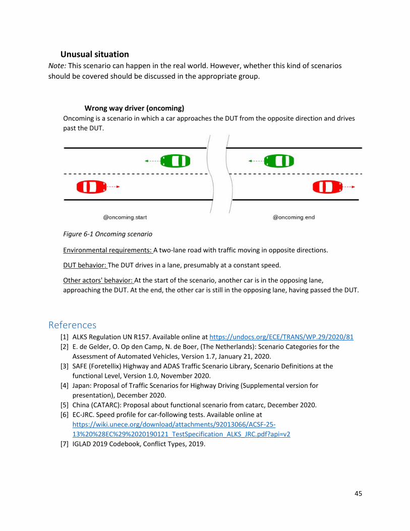
45
Unusual situation Note: This scenario can happen in the real world. However, whether this kind of scenarios should be covered should be discussed in the appropriate group.
Wrong way driver (oncoming) Oncoming is a scenario in which a car approaches the DUT from the opposite direction and drives past the DUT.
Figure 6-1 Oncoming scenario
Environmental requirements: A two-lane road with traffic moving in opposite directions.
DUT behavior: The DUT drives in a lane, presumably at a constant speed.
Other actors' behavior: At the start of the scenario, another car is in the opposing lane, approaching the DUT. At the end, the other car is still in the opposing lane, having passed the DUT.
References [1] ALKS Regulation UN R157. Available online at https://undocs.org/ECE/TRANS/WP.29/2020/81 [2] E. de Gelder, O. Op den Camp, N. de Boer, (The Netherlands): Scenario Categories for the
Assessment of Automated Vehicles, Version 1.7, January 21, 2020. [3] SAFE (Foretellix) Highway and ADAS Traffic Scenario Library, Scenario Definitions at the
functional Level, Version 1.0, November 2020. [4] Japan: Proposal of Traffic Scenarios for Highway Driving (Supplemental version for
presentation), December 2020. [5] China (CATARC): Proposal about functional scenario from catarc, December 2020. [6] EC-JRC. Speed profile for car-following tests. Available online at
https://wiki.unece.org/download/attachments/92013066/ACSF-25-13%20%28EC%29%2020190121_TestSpecification_ALKS_JRC.pdf?api=v2
[7] IGLAD 2019 Codebook, Conflict Types, 2019.

46


![SIP Automated Driving System › evt › workshop2019 › file › OP › OP...Automated driving on Development/ general roads [L2] demonstration Large-scale field test Automated driving](https://static.fdocuments.net/doc/165x107/5f145f25c22f5208253f8f90/sip-automated-driving-system-a-evt-a-workshop2019-a-file-a-op-a-op.jpg)