NEW ALBANY AND FLOYD COUNTY SANITARY …cityofnewalbany.com/images/NAFC design_manual_2012.pdfNEW...
303
NEW ALBANY AND FLOYD COUNTY SANITARY SEWER AND S TORMWATER DESIGN MANUAL DECEMBER 2012
Transcript of NEW ALBANY AND FLOYD COUNTY SANITARY …cityofnewalbany.com/images/NAFC design_manual_2012.pdfNEW...

NEW ALBANY AND FLOYD COUN TY
SANITARY SEWER AND S TORMWATER DES IGN MANUAL
D E C E M B E R 2 0 1 2

NEW ALBANY AND FLOYD COUNTY STORMWATER AND SANITARY SEWER DESIGN MANUAL
TABLE OF CONTENTS
CHAPTER TITLE
1 INTRODUCTION
2 GENERAL INFORMATION
3 GENERAL PLANNING INFORMATION
4 CADD STANDARDS
5 FINAL RECORD DRAWINGS
6 SURVEYING
7 EASEMENTS
8 EROSION PREVENTION AND SEDIMENT CONTROL
9 GEOTECHNICAL
10 STORMWATER FACILITIES DESIGN
11 PRIVATE DEVELOPMENT DRAINAGE PLAN SUBMITTAL REQUIREMENTS
12 SANITARY SEWER SYSTEMS
13 DEVELOPMENT SANITARY SEWER CONSTRUCTION
14 PUMP STATIONS
15 ODOR CONTROL
APPENDIX TITLE
A STANDARD DETAILS
B CRITERIA FOR PRECAST STRUCTURES
C CITY OF NEW ALBANY TECHNICAL SPECIFICATIONS FOR LIFT STATIONS

TABLE OF CONTENTS
CHAPTER 1 INTRODUCTION
NUMBER SECTION PAGE 1.1 PURPOSE OF THE DESIGN MANUAL 1-1 1.2 DESCRIPTION AND USE OF THE DESIGN MANUAL 1-1 1.3 STRUCTURE OF THE DESIGN MANUAL 1-1 1.4 DIGITAL VERSION OF DESIGN MANUAL 1-2 1.5 UPDATES TO THE DESIGN MANUAL 1-2

1-1
CHAPTER 1 INTRODUCTION
1.1 PURPOSE OF THE DESIGN MANUAL
This Design Manual is a guide for the planning and design of stormwater systems, erosion control structures, and associated activities for New Albany and Floyd County. In addition, the design manual addresses sanitary sewers and small sanitary pump stations for New Albany. The guidelines and general design procedures in this manual are approved by the New Albany Stormwater Board, the New Albany Sewer Board and the Floyd County Stormwater Board. The contents of this design manual are based on the Louisville MSD design manual dated August, 2009. The Louisville MSD design manual was edited as necessary to fit New Albany and Floyd County’s needs. This Manual: A. Enumerates design standards that have been authorized by New Albany and Floyd
County to facilitate compliance with local, state and federal regulations. B. Identifies submittal requirements and procedures for the review of infrastructure
projects within the respective service areas. C. Serves as a reference document for professional consultants in the design of
infrastructure projects within the respective service areas.
1.2 DESCRIPTION AND USE OF THE DESIGN MANUAL
The Manual identifies a single set of standards, submittal requirements and approval procedures to be used in the planning and design of projects within the respective service areas. This Manual is not intended to serve as a step-by-step design methodology nor can this Manual address every situation which may arise. The application of sound engineering/surveying principles and judgment combined with the information contained herein are necessary to complete the planning, design, and preparation of related construction documents for stormwater and sanitary sewer projects. Approval of plans by New Albany or Floyd County shall not relieve the designer or developer from required compliance with the provisions of this manual unless a written variance is received from New Albany or Floyd County.
1.3 STRUCTURE OF THE DESIGN MANUAL
The Manual contains 15 chapters. A general table of contents is found at the beginning of the Manual. To facilitate use of the Manual, a detailed table of contents can be found at the

1-2
beginning of each chapter for text and exhibits. The Manual is structured as follows: A. Chapters 2 and 3 describe general planning and design approach, required submittals
and approval procedures. B. Chapters 4 through 7 detail standards regarding drafting construction drawings, record
drawings, surveying and easement documents. C. Chapters 8 and 9 describe standards for performing geotechnical explorations and the
design of erosion control structures. D. Chapters 10 and 11 cover the design of stormwater systems and the submittal
requirements for private development drainage in New Albany and Floyd County. E. Chapters 12 through 15 relate to the specific design of sanitary sewers, small sanitary
pump stations, and odor control, and discuss the submittal requirements for private development sanitary sewer construction for the City of New Albany.
1.4 DIGITAL VERSION OF DESIGN MANUAL
A digital version of the design manual is located at the following websites: New Albany Stormwater: http://www.newalbanystormwater.org New Albany Wastewater: http://www.cityofnewalbany.com (select the wastewater department page) Floyd County: http://www.floydcounty.in.gov/county%20offices/stormwater.htm Floyd County Soil and Water Conservation District: http://www.floydswcd.org Printable PDF versions of the respective chapters are available for download at these websites.
1.5 UPDATES TO THE DESIGN MANUAL
The Manual is intended to be a dynamic document. As design criteria and technology evolve, the Manual will require revisions and improvements. As changes are made, updates will be posted to the website version. It will be the designer’s responsibility to stay updated on the manual.

TABLE OF CONTENTS
CHAPTER 2 GENERAL INFORMATION
NUMBER SECTION PAGE 2.1 PURPOSE 2-1 2.2 DESIGN APPROACH 2-1 2.3 NEW ALBANY PRIVATE DEVELOPMENT REVIEW PROCESS 2-3 2.4 FLOYD COUNTY PRIVATE DEVELOPMENT REVIEW 2-3 PROCESS 2.5 STORMWATER QUALITY MANAGEMENT PERMIT (SWQMP) 2-3 2.6 UTILITIES/AGENCY COORDINATION 2-4 2.7 OPINIONS OF COST (FOR CAPTIAL IMPROVEMENT 2-4 PROJECTS) 2.8 PERMIT REQUIREMENTS 2-4
CHAPTER 2 GENERAL INFORMATION
EXHIBITS
EXHIBIT TITLE PAGE
2-1 NEW ALBANY UTILITIES AND AGENCIES 2-6
2-1 FLOYD COUNTY UTILITIES AND AGENCIES 2-7
2-2 REQUIRED PERMITS FOR DRAINAGE PROJECTS 2-8
2-2 REQUIRED PERMITS FOR PUMP STATIONS/STRUCTURES PROJECTS
2-9
2-2 REQUIRED PERMITS FOR SANITARY SERWER AND FORCEMAIN PROJECTS
2-10

2-1
CHAPTER 2 GENERAL INFORMATION
2.1 PURPOSE This chapter:
A. Provides an overview of the planning and design approach relating to sanitary and storm water sewers and their appurtenant facilities.
B. Summarizes the processes for submittal, review and approval of construction
documents for private development projects in New Albany and Floyd County. C. Provides information relating to area utility and external agency coordination. D. Provides direction relating to the preparation of opinions of capital, operation, and
maintenance costs.
2.2 DESIGN APPROACH
Proposed construction or expansion of sanitary sewer or stormwater facilities shall be in compliance with the following: A. New Albany Wastewater:
1. New Albany Comprehensive Plan Year 2020 (HNTB, 1999).
2. Capacity Assurance Plan (CAP).
3. New Albany Code of Ordinances Chapter 51: Sewers.
4. Sewer Capacity Credit Requirements.
5. Indiana Administrative Code 327 IAC 3.
6. This New Albany and Floyd County Stormwater and Sanitary Sewer Design
Manual.
B. New Albany Stormwater:
1. New Albany Comprehensive Plan Year 2020 (HNTB, 1999).
2. Stormwater Master Plan (Stantec 2010).
3. New Albany Code of Ordinances Chapter 56: Stormwater Management.
4. New Albany Code of Ordinances Chapter 154: Subdivision.

2-2
5. Indiana Administrative Code 327 IAC 15-5 (Rule 5).
6. The Indiana Storm Water Quality Manual by Indiana Department of
Environmental Management (IDEM).
7. Best Management Practices Stormwater Management Manual for Southern Indiana by Southern Indiana Stormwater Advisory Committee (SISWAC).
8. This New Albany and Floyd County Stormwater and Sanitary Sewer Design Manual.
C. Floyd County Stormwater:
1. Floyd County Ordinance Regulating Construction Site Runoff and Post-Construction Stormwater Management.
2. Floyd County Illicit Discharge Ordinance.
3. Indiana Administrative Code 327 IAC 15-5 (Rule 5).
4. The Indiana Storm Water Quality Manual by Indiana Department of Environmental Management (IDEM).
5. Best Management Practices Stormwater Management Manual for Southern Indiana by Southern Indiana Stormwater Advisory Committee (SISWAC).
6. This New Albany and Floyd County Stormwater and Sanitary Sewer Design Manual.
Any person, company, corporation, or other entity proposing to develop land or to install new or replacement sanitary sewer or stormwater facilities in New Albany or Floyd County must prepare planning and design documents in accordance with the standards and requirements of this Manual and the Indiana Administrative Code (IAC) for review and approval by New Albany or Floyd County. Planning and Construction Documents must be prepared and signed by both a Professional Engineer and Land Surveyor (where applicable per IC 25-21.5-1-7), currently licensed in the State of Indiana. The service level of proposed facilities should be in accordance with standards referenced in these documents. The Design Engineer shall refer to Chapter 10 Stormwater Facilities Design of this design manual for design standards regarding stormwater facilities in New Albany or Floyd County. For sanitary sewer and pump station design standards in New Albany, the Design Engineer shall refer to Chapter 12 Sanitary Sewer Systems, Chapter 14 Pump Stations, and Chapter 15 Odor Control.

2-3
2.3 NEW ALBANY PRIVATE DEVELOPMENT REVIEW PROCESS
An applicant proposing to develop or redevelop land in the City of New Albany shall refer to the Code of Ordinance for the City of New Albany for a description of the review processes and required submittals as well as coordinate their efforts with the New Albany Planning Department and Building Officials. Refer to New Albany’s Zoning Ordinance (Chapter 156 of the Code of Ordinances for the City of New Albany) for a description of the review processes for an Improvement Location Permit, a Planned Unit Development District (PUDD), Conditional Use and Special Exception approvals, etc. See New Albany’s Subdivision Control Ordinance (Chapter 154 of the Code of Ordinances for the City of New Albany) for the review process for developers requesting the approval of a plat for the subdivision of land. The New Albany Stormwater and Wastewater Departments shall be involved during the preliminary and secondary review processes. Refer to Chapter 11 of this design manual for the New Albany Stormwater Department’s submittal requirements for reviewing private development drainage projects. See Chapter 13 of this design manual for the New Albany Wastewater Department’s submittal requirements for reviewing private development sanitary sewer projects.
2.4 FLOYD COUNTY PRIVATE DEVELOPMENT REVIEW PROCESS
An applicant proposing to develop or redevelop land in Floyd County shall refer to Floyd County’s Zoning and Subdivision Control Ordinances for a description of the review processes and required submittals as well as coordinate their efforts with the Planning Department and Building Officials. Refer to Floyd County’s Zoning Ordinance for a description of the review processes for an Improvement Location Permit, a Planned Unit Development District (PUDD), Conditional Use and Special Exceptions approvals, etc. See the Floyd County Subdivision Control Ordinance for the requirements regarding subdivision approval. The Floyd County Stormwater Department shall be involved during the preliminary and secondary review processes. Refer to Chapter 11 of this design manual for the Floyd County Stormwater Department’s submittal requirements for reviewing private development drainage projects.
2.5 STORMWATER QUALITY MANAGEMENT PERMIT (SWQMP)
A stormwater quality management permit (SWQMP) shall be obtained for all development or redevelopment activities in New Albany or Floyd County that result in the disturbance of one or more acres of land, including land disturbing activities on individual lots of less than one acre that are part of a larger common plan of development or sale. The SWQMP application and fee shall be submitted to the Auditor’s office located in the City-County Building. Once construction plans are complete for a development requiring a SWQMP, the developer shall submit the Notice of Intent (NOI), a Perimeter Control Plan (PCP), a Stormwater Pollution Prevention Plan (SWPPP), and a Post-Construction Stormwater Pollution Prevention Plan to the Floyd County Soil and Water Conservation District (SWCD) for review. These items must be approved by the Floyd County SWCD prior to breaking ground or disturbing soil. For information on the SWQMP process and submittal and inspection requirements, refer to the New Albany Stormwater Management Ordinance (Chapter 56 of the Code of Ordinances for the City of New Albany) or the Floyd County Ordinance Regulating Construction Site

2-4
Runoff and Post-Construction Stormwater Management.
2.6 UTILITIES/AGENCY COORDINATION The Design Engineer and/or Developer shall coordinate the design of all sanitary sewer and stormwater facilities with all utilities and external agencies actively involved in the provision of service in New Albany or Floyd County. For example, the involvement of external agencies may include: A. The design of new sanitary sewer facilities or an expansion to existing facilities
requires the approval of the Indiana Department of Environmental Management (IDEM).
B. Construction within regulated streams and regulatory floodplains requires the approval
of and permit by IDEM and the U.S. Army Corps of Engineers. C. Construction in a floodway requires a permit issued by the Indiana Department of
Natural Resources. D. Work within federal and state highway rights-of-ways requires approval and/or a
permit by the Indiana Department of Transportation (INDOT). Contact shall be made with such agencies prior to the final design submittal to New Albany or Floyd County. New Albany or Floyd County should be given a copy of all correspondence with utilities and external agencies. A partial listing of utilities and agencies is included in Exhibit 2-1.
2.7 OPINIONS OF COST (FOR CAPITAL IMPROVEMENT PROJECTS) Opinions of probable cost shall be based on the best professional judgement of the Design Engineer. The Design Engineer should use recent bid tabulations, and information from suppliers and contractors in formulating opinions of cost. Opinions of capital cost shall be in the Construction Specification Institute (CSI) format and shall be grouped by category. Opinions of capital cost should include a construction contingency, allocations for planning and design, and a cost for necessary land, easement, or right-of-way acquisition. The amount or percentage of these contingencies and allocations are dependent upon project specifics and the stage of project development. Opinions of operation and maintenance cost shall include costs for labor, utilities, maintenance and repair. Energy efficiency shall be considered in the design.
2.8 PERMIT REQUIREMENTS A summary of requirements for permits is shown as Exhibit 2-2. The Exhibit contains individual lists for drainage projects, pump station/structural projects, and sanitary sewer and force main projects. The list should not be considered all-inclusive, and the designer will need to confirm all permit requirements as a part of the preliminary scope of the project. The following is a brief summary of the major permits that impact projects in the New Albany and Floyd County service area. Some commonly required permits include:

2-5
A. Section 404 - Nationwide Permit No. 12 of 33 CFR Part 330 from the U.S. Army Corps of Engineers. Conditions of this permit may require a Water Quality Certification from IDEM (see Item B below). A permit is required for discharges of soil, sand, gravel or dredged material into waters of the U.S. Design Engineers must inquire from the U.S. Army Corps of Engineers if a certain stream requires this permit.
B. Section 401 - Application for Water Quality Certification from IDEM must be issued or waived before a federal permit under Section 404 is granted (Item A above). Section 401 of the Clean Water Act requires certification from the state that the discharge of the dredge or fill material will not violate the water quality standards of the state.
C. Sanitary Sewer Construction Permit administered by IDEM. Indiana Administrative
Code 327 IAC 3 requires that a construction permit must be obtained before construction can begin for a new or expanded wastewater treatment plant, a new sanitary sewer, pump station, or force main.
D. Construction/Land Disturbance Storm Water Permitting (327 IAC 15-5, Rule 5)
administered by IDEM. This is a general permit program that targets construction activities that result in land disturbance of one acre or more. 327 IAC 15-5 is designed to reduce pollutants, principally sediment, that are a result of soil erosion and other activities associated with land-disturbing activities.

2-1NEW ALBANY UTILITIES AND AGENCIES
DECEMBER 2012
Indiana-American Water2423 Middle RoadJeffersonville, IN 47130812-218-1500
Silver Creek Water Corporation8104 County Line RoadSellersburg, IN 47172812-246-2889
Edwardsville Water Corporation545 Maplewood BlvdGeorgetown, IN 47122812-948-0900
Borden Tri-County Regional Water District1791 West Water StreetBorden, IN 47106812-967-2226
Floyds Knobs Water Company4781 Paoli Pike #1Floyds Knobs, IN 47119812-923-9040
Vectren GasP.O. Box 209Evansville, IN 47702-0209812-491-4000800-227-1376
Duke Energy1110 Clifty Dr.Madison, IN 47250812-265-4217
Clark County REMC7810 State Road 60PO Box 411Sellersburg, IN 47172812-246-3316
Harrison REMCPO Box 5171165 Old Forest RoadCorydon, IN 47112812-738-4115
AT&T510 E. Spring St.New Albany, IN 47150812-948-7181
Insight Cable1608 Vance AvenueNew Albany, IN 47150502-357-4400
INDOT- Seymour District185 Agrico LaneSeymour, IN 47274877-305-7611
IDEM100 N. Senate AveIndianapolis, IN 46204-2251317-232-8603
New Albany-Floyd County Consolidated School Corporation2813 Grant Line RoadNew Albany, IN 47150812-949-4200
New Albany Planning & Zoning311 Hauss Square, Room 329New Albany, IN 47150-3586812-948-5333
New Albany Building Department311 Hauss Square, Room 329New Albany, IN 47150-3586812-948-5333
New Albany Stormwater Department2113 Grant Line RoadNew Albany, IN 47150-3586812-945-1989
New Albany Wastewater Department38 W 10th StreetNew Albany, IN 47150812-948-5320
2-6

2-1FLOYD COUNTY UTILITIES AND AGENCIES
DECEMBER 2012
Indiana-American Water2423 Middle RoadJeffersonville, IN 47130812-218-1500
Silver Creek Water Corporation8104 County Line RoadSellersburg, IN 47172812-246-2889
Edwardsville Water Corporation545 Maplewood BlvdGeorgetown, IN 47122812-948-0900
Floyds Knobs Water Company4781 Paoli Pike #1Floyds Knobs, IN 47119812-923-9040
Borden Tri-County Regional Water District1791 West Water StreetBorden, IN 47106812-967-2226
Greenville Water Utility9706 Clark St.Greenville, IN 47124812-923-9821
Ramsey Water Company415 Highway 64 NWPO Box 245Ramsey, IN 47166812-347-2551
Georgetown UtilitiesGeorgetown Public Works Department1070 Copperfield DriveGeorgetown, IN 47122812-951-3800
Elizabeth Water Company8128 Hurricane Street SEElizabeth, IN 47117812-969-2025
Vectren GasP.O. Box 209Evansville, IN 47702-0209812-491-4000800-227-1376
Duke Energy1110 Clifty Dr.Madison, IN 47250812-265-4217
Clark County REMC7810 State Road 60PO Box 411Sellersburg, IN 47172812-246-3316
Harrison REMCPO Box 5171165 Old Forest RoadCorydon, IN 47112812-738-4115
Insight Cable1608 Vance AvenueNew Albany, IN 47150502-357-4400
AT&T510 E. Spring St.New Albany, IN 47150812-948-7181
IDEM100 N. Senate AveIndianapolis, IN 46204-2251317-232-8603
INDOT- Seymour District185 Agrico LaneSeymour, IN 47274877-305-7611
New Albany-Floyd County Consolidated School Corporation2813 Grant Line RoadNew Albany, IN 47150812-949-4200
New Albany Wastewater Department38 W 10th StreetNew Albany, IN 47150812-948-5320
Floyd County Stormwater DepartmentPine View Government Center2524 Corydon Pike, Suite 201New Albany, IN 47150812-949-5446
Floyd County Plan CommissionPine View Government Center2524 Corydon Pike, Suite 203New Albany, IN 47150812-948-5440
Floyd County Soil & Water Conservation DepartmentPine View Government Center2524 Corydon Pike, Suite 103New Albany, IN 47150812-945-9936
Floyd County CommissionersPine View Government Center2524 Corydon Pike, Suite 204New Albany, IN 47150812-948-5466
2-7

EFFECTIVE DATE:
EXHIBIT 2-2 PAGE 1 REQUIRED PERMITS
DECEMBER 2012
FOR DRAINAGE PROJECTS
SUBMITTED APPROVED PERMIT REQUIRED SUBMITTALS AGENCY WHEN REQUIRED
Section 404- Nationwide Permit No. 12 of 33 CFR Part 330 Application, drawings Army Corps of Engineers
For discharges of soil, sand, gravel, or dredged material into a regulated stream. May require IDEM Water Quality Certification.
Section 401, Clean Water Act- Water Quality Certification
Application, location map, drawings, cross sections, site photos
Indiana Department of Environmental Management
When a project is planned in Indiana that will impact a wetland, stream, river, lake, or other Water of the U.S. A Section 401
WQC is a required component of a federal permit and must be issued before a federal permit or license can be granted.
Construction in a FloodwayApplication, location map, site map, drawings,
photosIndiana Department of
Natural Resources For excavation, fill, or construction in a floodway.
Construction/Land Disturbance Storm Water Permitting (327 IAC 15-5, Rule 5)
Notice of Intent, proof of publication, application fee, construction plan review approval
Indiana Department of Environmental Management
General permit that targets construction activities that result in land disturbance of one acre or more.
Encroachment Permit Application, drawingsIndiana Department of
Transportation When encroaching on state right-of-way
Encroachment Permit DrawingsNew Albany Street
Department When encroaching on city right-of-way
Encroachment Permit DrawingsFloyd County Highway
Department When encroaching on county right-of-way
Lane Closure Approval DrawingsNew Albany Board of Public
Works When necessary to close lanes of traffic in New Albany
Lane Closure Approval DrawingsFloyd County
Commissioners When necessary to close lanes of traffic in Floyd County
New Albany Improvement Location PermitSee New Albany Zoning Ordinance (Chapter
156) for required submittalsNew Albany Plan
Commission
For all newly erected, constructed, reconstructed, extended, structurally altered or moved structures and for changes in land,
building, or structure use in New Albany.
New Albany Subdivision ApprovalSee New Albany Subdivision Control Ordinance
(Chapter 154) for required submittalsNew Albany Plan
Commission For a proposed subdivision in New AlbanyNew Albany Planned Unit Development
District (PUDD) ApprovalSee New Albany Zoning Ordinance (Chapter
156) for required submittalsNew Albany Plan
Commission For a Planned Unit Development District in New Albany
New Albany Stormwater Board Approval
See Chapter 10 (for capital improvement projects) or Chapter 11 (for private
development) of this Design Manual for submittal requirements
New Albany Stormwater Board For all land development or drainage projects in New Albany
New Albany Stormwater Quality Management Permit (SWQMP)
SWQMP Application, Notice of Intent (NOI), Perimeter Control Plan (PCP), Stormwater Pollution Prevention Plan (SWPPP), Post-
Construction SWPPP, construction plans, etc.Floyd County Soil and
Water Conservation District
All development or redevelopment activities in New Albany that result in the disturbance of one or more acres of land, including
land disturbing activities on individual lots of less than one acre as part of a larger common plan of development or sale.
Floyd County Improvement Location Permit
See the Floyd County Zoning Ordinance for submittal requirements
Floyd County Building Commissioner
For all newly erected, constructed, reconstructed, extended, structurally altered or moved structures and for changes in land,
building, or structure use in Floyd County
Floyd County Subdivision ApprovalSee the Floyd County Subdivision Control
Ordinance for submittal requirementsFloyd County Plan
Commission For a proposed subdivision in Floyd CountyFloyd County Planned Unit Development
District (PUDD) ApprovalSee the Floyd County Zoning Ordinance for
submittal requirementsFloyd County Plan
Commission For a Planned Unit Development District in Floyd County
Floyd County Stormwater Board Approval
See Chapter 10 (for capital improvement projects) or Chapter 11 (for private
development) of this Design Manual for submittal requirements
Floyd County Stormwater Board For all land development or drainage projects in Floyd County
Floyd County Storm Water Quality Management Permit (SWQMP)
SWQMP Application, Notice of Intent (NOI), Perimeter Control Plan (PCP), Stormwater Pollution Prevention Plan (SWPPP), Post-
Construction SWPPP, construction plans, etc.Floyd County Soil and
Water Conservation District
All development or redevelopment activities in Floyd County that result in the disturbance of one or more acres of land, including
land disturbing activities on individual lots of less than one acre as part of a larger common plan of development or sale.
REQUIRED PERMITS FOR DRAINAGE PROJECTS
2-8

EXHIBIT 2-2 PAGE 2REQUIRED PERMITS FOR PUMP STATIONS /STRUCTURES PROJECTS
EFFECTIVE DATE: DECEMBER 2012
SUBMITTED APPROVED PERMIT REQUIRED SUBMITTALS AGENCY WHEN REQUIRED
Section 404- Nationwide Permit No. 12 of 33 CFR Part 330 Application, drawings Army Corps of Engineers
For discharges of soil, sand, gravel, or dredged material into a regulated stream. May require IDEM Water Quality
Certification.
Section 401, Clean Water Act- Water Quality Certification
Application, location map, drawings, cross sections, site photos
Indiana Department of Environmental Management
When a project is planned in Indiana that will impact a wetland, stream, river, lake, or other Water of the U.S. A Section 401 WQC is a required component of a federal
permit and must be issued before a federal permit or license can be granted.
Construction in a FloodwayApplication, location map, site map,
drawings, photosIndiana Department of Natural
Resources For excavation, fill, or construction in a floodway.
Sanitary Sewer Construction Permit
Application, drawings, specifications, Capacity Certification/Allocation Letter from Utility, design summary, affected parties list
Indiana Department of Environmental Management For construction of sanitary sewer and lift stations
Construction/Land Disturbance Storm Water Permitting (327 IAC 15-5, Rule 5)
Notice of Intent, proof of publication, application fee, construction plan review
approvalIndiana Department of
Environmental ManagementGeneral permit that targets construction activities that
result in land disturbance of one acre or more.
Encroachment Permit Application, drawingsIndiana Department of
Transportation When encroaching on state right-of-way
Encroachment Permit DrawingsNew Albany Street
Department When encroaching on city right-of-way
Encroachment Permit DrawingsFloyd County Highway
Department When encroaching on county right-of-way
Lane Closure Approval DrawingsNew Albany Board of Public
Works When necessary to close lanes of traffic in New Albany
New Albany Improvement Location PermitSee New Albany Zoning Ordinance (Chapter
156) for required submittals New Albany Plan Commission
For all newly erected, constructed, reconstructed, extended, structurally altered or moved structures and for changes in land, building, or structure use in New Albany.
New Albany Subdivision Approval
See New Albany Subdivision Control Ordinance (Chapter 154) for required
submittals New Albany Plan Commission For a proposed subdivision in New AlbanyNew Albany Planned Unit Development
District (PUDD) ApprovalSee New Albany Zoning Ordinance (Chapter
156) for required submittals New Albany Plan Commission For a Planned Unit Development District in New Albany
New Albany Sanitary Sewer Board Approval
See Chapters 12, 14, and 15 (for capital improvement projects) or Chapter 13 (for
private development) of this Design Manual for submittal requirements
New Albany Sanitary Sewer Board
For all land development or capital improvement sanitary sewer projects in New Albany
Sewer Credit Approval Application, Calculations, Site PlanNew Albany Sanitary Sewer
Board/ IDEM
For all sanitary sewer projects in New Albany. Sewer credits must be secured prior to design approval and
connection to the sewer system.
New Albany Stormwater Quality Management Permit (SWQMP)
SWQMP Application, Notice of Intent (NOI), Perimeter Control Plan (PCP), Stormwater Pollution Prevention Plan (SWPPP), Post-Construction SWPPP, construction plans,
etc.Floyd County Soil and Water
Conservation District
All development or redevelopment activities in New Albany that result in the disturbance of one or more acres
of land, including land disturbing activities on individual lots of less than one acre as part of a larger common plan
of development or sale.
The City of New Albany Building PermitApplication, Property Survey, Site Plan,
Assessor's PlatNew Albany Building
Commission For any project with a building in New AlbanyRequest for Final Inspection & Certificate
of Occupancy ApplicationNew Albany Building
Commission
REQUIRED PERMITS FOR PUMP STATIONS/STRUCTURES PROJECTS
2-9

EFFECTIVE DATE:
DECEMBER 2012
EXHIBIT 2-2 PAGE 3REQUIRED PERMITS FOR SANITARY SEWER ANDFORCEMAIN PROJECTS
SUBMITTED APPROVED PERMIT REQUIRED SUBMITTALS AGENCY WHEN REQUIRED
Section 404- Nationwide Permit No. 12 of 33 CFR Part 330 Application, drawings Army Corps of Engineers
For discharges of soil, sand, gravel, or dredged material into a regulated stream. May require IDEM Water Quality
Certification.
Section 401, Clean Water Act- Water Quality Certification
Application, location map, drawings, cross sections, site photos
Indiana Department of Environmental Management
When a project is planned in Indiana that will impact a wetland, stream, river, lake, or other Water of the U.S. A Section 401 WQC is a required component of a federal permit and must be issued before a federal permit or
license can be granted.
Construction in a FloodwayApplication, location map, site map,
drawings, photosIndiana Department of Natural
Resources For excavation, fill, or construction in a floodway.
Sanitary Sewer Construction Permit
Application, drawings, specifications, Capacity Certification/Allocation Letter from Utility, design summary, affected
parties listIndiana Department of
Environmental Management For construction of sanitary sewer and lift stations
Construction/Land Disturbance Storm Water Permitting (327 IAC 15-5, Rule 5)
Notice of Intent, proof of publication, application fee, construction plan review
approvalIndiana Department of
Environmental ManagementGeneral permit that targets construction activities that
result in land disturbance of one acre or more.
Encroachment Permit Application, drawingsIndiana Department of
Transportation When encroaching on state right-of-way
Encroachment Permit DrawingsNew Albany Street
Department When encroaching on city right-of-way
Encroachment Permit DrawingsFloyd County Highway
Department When encroaching on county right-of-way
Lane Closure Approval DrawingsNew Albany Board of Public
Works When necessary to close lanes of traffic in New Albany
New Albany Subdivision Approval
See New Albany Subdivision Control Ordinance (Chapter 154) for required
submittals New Albany Plan Commission For a proposed subdivision in New AlbanyNew Albany Planned Unit Development
District (PUDD) ApprovalSee New Albany Zoning Ordinance
(Chapter 156) for required submittals New Albany Plan Commission For a Planned Unit Development District in New Albany
New Albany Sanitary Sewer Board Approval
See Chapters 12, 14, and 15 (for capital improvement projects) or Chapter 13
(for private development) of this Design Manual
New Albany Sanitary Sewer Board
For all land development or capital improvement sanitary sewer projects in New Albany
Sewer Credit Approval Application, Calculations, Site PlanNew Albany Sanitary Sewer
Board/ IDEM
For all sanitary sewer projects in New Albany. Sewer credits must be secured prior to design approval and
connection to the sewer system.
New Albany Stormwater Quality Management Permit (SWQMP)
SWQMP Application, Notice of Intent (NOI), Perimeter Control Plan (PCP), Stormwater Pollution Prevention Plan (SWPPP), Post-Construction SWPPP,
construction plans, etc.Floyd County Soil and Water
Conservation District
All development or redevelopment activities in New Albany that result in the disturbance of one or more acres
of land, including land disturbing activities on individual lots of less than one acre as part of a larger common plan
of development or sale.
REQUIRED PERMITS FOR SANITARY SEWER AND FORCE MAIN PROJECTS
2-10

TABLE OF CONTENTS
CHAPTER 3 GENERAL PLANNING INFORMATION
NUMBER SECTION PAGE
3.1 PURPOSE 3-1
3.2 PLANNING APPROACH 3-1
3.3 NEW ALBANY CAPACITY ASSURANCE PLAN (CAP) 3-1
3.4 NEW ALBANY COMPREHENSIVE PLAN YEAR 2020 3-1
3.5 NEW ALBANY STORMWATER MASTER PLAN 3-2
3.6 FLOYD COUNTY COMPREHENSIVE LAND USE PLAN UPDATE
3-2
3.7 REGIONAL FACILITIES 3-2

3-1
CHAPTER 3 GENERAL PLANNING INFORMATION
3.1 PURPOSE This chapter:
A. Identifies the sources of planning and design information for development of sanitary sewer and stormwater drainage infrastructure in the respective service areas.
B. Identifies the goals of New Albany’s Capacity Assurance Plan, Comprehensive Plan Year 2020, and the Stormwater Master Plan.
C. Identifies the goals of Floyd County’s Comprehensive Land Use Plan. 3.2 PLANNING APPROACH
New Albany and Floyd County's regional approach for the planning, design, construction, operation and maintenance of sanitary sewer and stormwater facilities is structured to ensure a level of service that protects the general health, safety, and welfare of the citizens of the respective service areas. This approach will also further efforts to satisfy local, state and federal regulations as they relate to water quality. New Albany and Floyd County planning documents, including the New Albany Comprehensive Plan, the New Albany Capacity Assurance Plan, the New Albany Stormwater Master Plan, and Floyd County’s Comprehensive Land Use Plan provide the framework for planning and design of sanitary sewer and stormwater facilities in the service area. The Design Engineer should use these documents for planning and as reference documents for the development of sanitary sewer and stormwater facilities.
3.3 NEW ALBANY CAPACITY ASSURANCE PLAN (CAP)
The New Albany Capacity Assurance Plan (CAP) (2001) and amendments identify improvements needed within the wastewater collection and treatment system to comply with the Consent Decree agreement between the City of New Albany, and the Environmental Protection Agency (EPA).
3.4 NEW ALBANY COMPREHENSIVE PLAN YEAR 2020
The New Albany Comprehensive Plan was updated in 1999 by HNTB and is a planning document that projects the physical, social, and economic growth and redevelopment that will occur in New Albany up to year 2020. The document discusses existing demographic, economic, and land use trends and projects future land use trends and market opportunities and the corresponding impacts the growth will have upon City services, facilities, utilities, parks, recreational facilities, and transportation.

3-2
3.5 NEW ALBANY STORMWATER MASTER PLAN
The goal of the 2010 New Albany Stormwater Master Plan is to provide a regional approach to develop a consistent level of drainage service and maintain or improve water quality across the City. The plan identifies and prioritizes stormwater improvement projects for the City to address existing drainage issues and to avoid future drainage issues.
3.6 FLOYD COUNTY COMPREHENSIVE LAND USE PLAN UPDATE
The Floyd County Comprehensive Plan was updated in 2005 in order to understand the present land development conditions and trends in Floyd County and to adjust the community’s land development goals and objectives accordingly.
3.7 REGIONAL FACILITIES
New Albany and Floyd County realize that in some cases regional facilities are more appropriate, cost effective, and assure proper operation and maintenance compared to on-site detention facilities. The requirement to build or participate in the cost of regional facilities shall be determined concurrently with the review by New Albany or Floyd County of the developer’s proposed development plans and by an analysis of the development’s impact on the general community. This impact includes watershed, other development, existing service facilities, and its conformance with existing master plans.

TABLE OF CONTENTS
CHAPTER 4 CADD STANDARDS
NUMBER SECTION PAGE
4.1 GENERAL 4-1
4.2 CADD STRUCTURE 4-1
4.2.1 CADD Environment 4-1
4.2.2 Submittal of Final Plans 4-3
4.3 STANDAND AND TYPICAL DRAWINGS 4-4
4.3.1 Definitions 4-4
4.3.2 Title Sheet Requirements 4-5
4.3.3 Title Block Requirements 4-6
4.3.4 Plan Index Sheet Requirements 4-6
4.3.5 Special Details 4-6 4.3.6 Drawing Number Convention (Projects using 4-6 Multiple Disciplines)
4.4 PLAN, PROFILE, AND CROSS-SECTION FORMAT 4-7
4.4.1 General Criteria 4-7
4.4.2 Plan View 4-8
4.4.3 Profile View 4-10
4.4.4 Cross Section 4-12
4.4.5 General Notes 4-13
4.4.6 Certification 4-13

TABLE OF CONTENTS (cont.)
CHAPTER 4 CADD STANDARDS
NUMBER SECTION PAGE
4.4.6.1 Surveyor’s Certification 4-13 4.4.6.2 Basement Elevation Certification (Sanitary 4-14 Projects Only) 4.4.6.3 Professional Engineer Certification 4-14

CHAPTER 4
CADD STANDARDS EXHIBITS
EXHIBIT TITLE PAGE
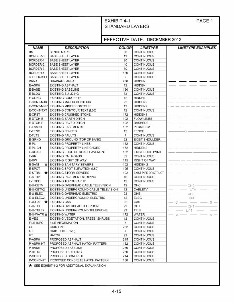
4-1 STANDARD LAYERS 4-15
4-2 STANDARD LINETYPE AND MISCELLANEOUS FEATURES 4-17
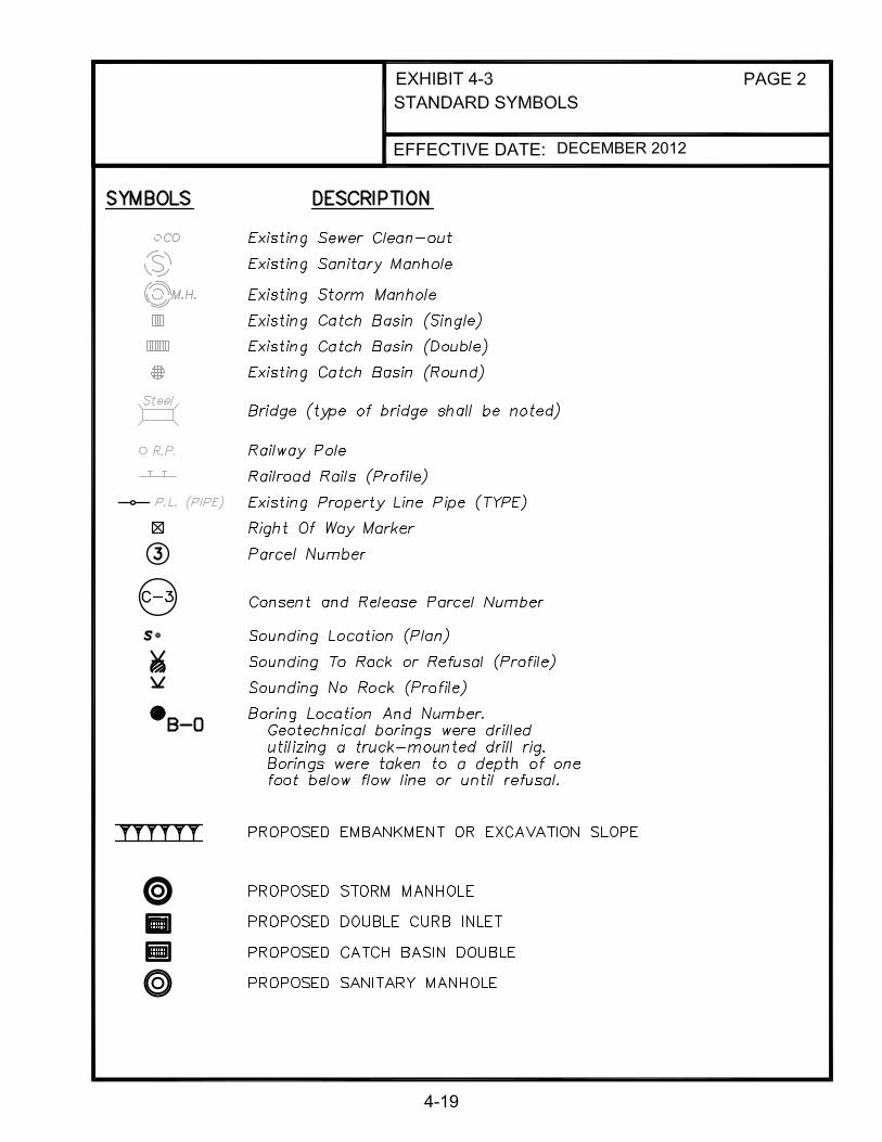
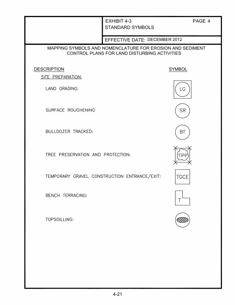
4-3 STANDARD SYMBOLS 4-18
4-4 PEN SIZE ASSIGNMENTS 4-26
4-5 STANDARD ABBREVIATIONS 4-27
4-6 STANDARD BORDER 4-28
4-7 STANDARD TITLE BLOCKS 4-29
4-8 STANDARD TITLE SHEET 4-30
4-9 SAMPLE PLAN INDEX SHEET 4-31
4-10 SAMPLE DRAINAGE MAP (SANITARY COLLECTOR SYSTEM)
4-32
4-11 SAMPLE DRAINAGE MAP (STORM COLLECTOR SYSTEM) 4-33
4-12 HORIZONTAL & VERTICAL CONTROL MAP 4-34
4-13 SAMPLE PLAN SHEET 4-35
4-14 SAMPLE PROFILE SHEET 4-36
4-15 SAMPLE CROSS SECTION 4-37
4-16 PROPERTY ACQUISITION SUMMARY SHEET 4-38

4-1
CHAPTER 4 CADD STANDARDS
4.1 GENERAL
New Albany and Floyd County has adopted CADD standards to provide consistency with respect to plan and document development and for compatibility with respect to the sharing of data and document storage. New Albany and Floyd County operate in the AutoCAD environment. Emphasis has been placed on developing standards that are in line with current industry procedures, but can be easily adapted to change with industry advancements. Development plans for sanitary sewer and stormwater construction shall be prepared in a neat and professional manner and shall conform to the standards detailed in this chapter. It is important that information be presented in such a manner that it will be legible when the plans are scanned, reproduced, or reduced. The following section presents the standards that shall be adhered to on all New Albany and Floyd County Capital Improvement projects and Private Development plans. The standard Layer Names, Colors, Text Heights, Line Weights, Standard Symbols, and Standard Abbreviations are shown in Exhibits 4-1 through 4-5 at the end of this chapter.
4.2 CADD STRUCTURE
4.2.1 CADD Environment
A. The electronic files will be shared and referenced by many different individuals. Therefore, this chapter outlines the minimum standards, conventions, and formats necessary to ensure a usable electronic file data set to all users.
B. It must be stressed that while the CADD Standards are to be applied to the
deliverable files for design plans, they should not be used to restrict the user’s options or workflows during plan development. Interim drawings for public meetings, reviews, etc. may deviate from the suggested workflows and standards if needed for particular display or presentation requirements.
C. All drawings shall be in AutoCAD format, compatible with the current version that New Albany and Floyd County are running. The project manager should check with New Albany and Floyd County for version information before any CADD work begins.
D. In addition to hard copy drawings, all final drawings are to be submitted in AutoCAD and pdf formats per the requirements of this chapter.
E. Model space shall be used for all drafting. Paper space may be used for borders, viewports, and plotting. Modelspace contains the model at “real life” size. Printing is from paperspace at 1:1 scale for full-size prints.

4-2
Scales The appropriate scales for original plans are 1" = 50' horizontal with vertical scale of 1" = 5' and 1" = 20' horizontal with vertical scale of 1" = 2'. Other scales may be allowed with prior approval of New Albany or Floyd County for the purpose of clarity. A graphic scale is required. In addition, crossings of state highways may require additional sheets at different scales. Coordination between New Albany or Floyd County and INDOT will be necessary. AutoCAD Template File An AutoCad template will be created to incorporate the standards as described in this chapter. This file will contain the standard layers, linetypes, fonts, and symbols (blocks), and can be downloaded from the New Albany and Floyd County websites listed in Chapter 1, section 1.4 of this design manual. Standard Layers and Line Types The standard New Albany and Floyd County layers are presented in Exhibit 4-1. All drawing elements shall be placed on one of these layers. The color and line style attributes for all drawing elements shall be set to “By Layer”. Custom Linestyles are also shown in Exhibits 4-1 and 4-2. Standard Symbols and Abbreviations The standard symbols are presented in Exhibit 4-3 and standard abbreviations are presented in Exhibit 4-5. Pen Size Assignments The chart in Exhibit 4-4 shows the relationship between colors and pen sizes (weights). Screening For screening options - See Exhibit 4-4. The intent is for existing features (topography, etc.) to be screened. Standard Sheets The standard sheet size is 24” x 36” for all sanitary and stormwater projects. The sheets are presented in Exhibit 4-6 and the standard title block is presented in Exhibit 4-7. Text Fonts, Sizes, and Weights All fonts, sizes, and weights will be preset attributes in the New Albany and Floyd County template drawing file. The standard font style on New Albany and Floyd County projects is “simplex.shx”.

4-3
The text heights used are synonymous with the Leroy Scale of hand drafting. The following chart shows the height for each text style used. In general, Upper and Lower Case shall be used to denote existing text and UPPER case shall be used to denote proposed text.
TEXT STYLE HEIGHT (inches) Notes
L60 0.06 For existing text on plats where space is limited. (Upper & Lower Case)
L80 0.08 All existing text. (Upper & Lower Case)
L100 0.10 For Proposed Item Annotation where space is limited (UPPER CASE)
L120 0.12 For Proposed Item Annotation / Construction Notes. (UPPER CASE)
L140 0.14 For Note Titles & Other Misc. Labels (UPPER CASE)
L175 0.175 Misc. Titles / Labels (UPPER CASE)
L200 0.20 Misc. Titles / Labels (UPPER CASE)
4.2.2 Submittal of Final Plans
General A. Every sheet in the final plan set shall have a corresponding AutoCAD and pdf
file. That is, one AutoCAD file and one pdf file per plan sheet. A one to one relationship between the design file content and the plotted sheets shall be maintained.
B. No external references shall be allowed for the final submittal. Paper space shall be used to represent the actual sheet at a 1:1 scale. All sanitary and storm projects performed for New Albany and Floyd County shall be submitted digitally per the requirements of section 4.2.1.

4-4
C. All mapping features and all design features in plan view located in model space of the CAD drawings shall maintain their true coordinate location values. Please reference Chapter 6, “Surveying” for additional details on coordinate systems. Detail sheets do not have to be shown in true coordinate location.
D. A one-to-one relationship between the design file content and the plotted sheets shall be maintained. i.e., there is no “hidden” information that is turned “off” or “frozen” to make the final plot.
File Naming
At the completion of the plans, the CADD files are to be delivered with the following naming sequence:
AAAAA-SBBB.dwg.
Where:
AAAAA = Project Number.
BBB = sheet number. Use zeroes as necessary.
The “S” stands for sheet(s) and it is not to be changed.
Example: The digital AutoCAD file for Sheet 47 of Project Number 12345 would be named as follows: 12345_S047.dwg.
The files shall be stored in a parent folder named for the Project Number and name of the project and be delivered to New Albany or Floyd County on a CD or DVD media format.
A final set of plans shall be printed on 24”x36” paper. This set of plans shall be stamped, signed and dated by the professional engineer of record.
4.3 STANDARD AND TYPICAL DRAWINGS
4.3.1 Definitions
A. Standard Drawings - Details that indicate the acceptable procedure, dimensions, or timetable for a particular facet of construction. The details are not to be modified and can be made a part of the plan set by referencing the respective drawing number on the front Title Sheet. New Albany and Floyd County have adopted standard drawings issued by Louisville MSD and are included in Appendix A of this Design Manual. If changes are made to a particular standard drawing for a project, the detail ceases to be a standard drawing and becomes a special detail. The special detail will then need to conform to the requirements of Section 4.3.5.

4-5
B. Special Details - There are numerous exhibits and design aids found in other chapters of this manual. The details will vary from project to project. Use of the details is encouraged; however, the detail, in its final form, will need to conform to the requirements of Section 4.3.5.
C. Typical Drawings - Examples of typical sheets illustrating the format and
information required on New Albany and Floyd County contract plans are provided as reference. The respective sheets and exhibit numbers are listed below.
Exhibit Title
4-8 Sample Title Sheet 4-9 Sample Plan Index Sheet 4-10 Sample Drainage Map (Sanitary Collector System) 4-11 Sample Drainage Map (Storm Collector System) 4-12 Sample Horizontal and Vertical Control Map 4-13 Sample Plan Sheet 4-14 Sample Profile Sheet 4-15 Sample Cross Section Sheet 4-16 Sample Property Acquisition Summary Sheet
4.3.2 Title Sheet Requirements
A Sample Title Sheet can be found on Exhibit 4-8. For each project, the title sheet shall have at least the minimum information listed on it:
A. Project No. B. Name of Project C. Index of Drawings D. Name and Address of Engineer E. Design Segment Designation (where applicable) F. Sheet____of____ G. For sanitary interceptor and major storm sewer contracts, the proposed sewers
for which the plans are drawn shall be shown. The stations at the extremities of the project shall be shown and identified with leaders and arrows. For example: BEGIN PROJECT MC-1, STA. 5+42.00 and END PROJECT MC-1, STA. 10+51.03.
H. To notify the Contractor of the procedure required for the location of utilities
prior to construction, the following note should be placed on the Title Sheet.

4-6
"NOTE: CAUTION EXISTING UTILITIES” “THE INFORMATION SHOWN ON THESE DRAWINGS CONCERNING TYPE AND LOCATION OF UNDERGROUND UTILITIES IS NOT GUARANTEED TO BE ACCURATE OR ALL-INCLUSIVE. LOCATION, SIZE, AND MATERIAL SHOWN ON UTILITIES ARE FROM AVAILABLE RECORDS SUPPLIED BY THE RESPECTIVE UTILITY COMPANY. INDIANA 811-CALL BEFORE YOU DIG MUST BE NOTIFIED 2 BUSINESS DAYS PRIOR TO ANY EXCAVATION FOR VERIFICATION OF LOCATION, SIZE AND MATERIAL, DIAL 811 or 1-800-382-5544.
I. Other Agency’s Standard Drawings pertaining to project (INDOT, etc.) with standard drawing number and description.
J. Revision Block with date & comments. 4.3.3 Title Block Requirements
All sheets included in the plans, except the Title Sheet and the Standard Drawings, shall contain a title block, which conforms to the sample shown in the Exhibit 4-7. Information in the Title Block should include the project title indicating sanitary or drainage plans, what type of sheet, and the specific information on the sheet.
4.3.4 Plan Index Sheet Requirements
A Plan Index Sheet shall be prepared to identify the location of the work shown on each Plan Sheet. A Sample Plan Index Sheet is shown on Exhibit 4-9. The Plan Index Sheet shall include a reference to the location of the profile for the sewer lines on each plan sheet if the profile is on a separate sheet. For most projects, the Plan Index Sheet may be shown on the Project Map, which is located on the Title Sheet.
4.3.5 Special Details
The Design Engineer should show any proposed construction that is not covered by the Standard Drawings as a detail on a Special Detail sheet. The detail should clearly and accurately depict the proposed construction. Junction chambers, special pipe bedding, railroad crossings, pump stations, select erosion control measures, and modifications to any of the Standard Drawings are typical examples of items that may require a Special Detail.
4.3.6 Drawing Number Convention (Projects using Multiple Disciplines)
The drawing number shall consist of two parts: The 1st part is the letter corresponding to the discipline. The second part is the numerical page number in that subset.
4-7
List of Discipline General (G) Civil/Site (C) Process (D) Structure (S) Architectural (A) Mechanical/HVAC (M) Electrical (E) Instrumentation & Control (I) Examples: G-1, G-2, S-1, S-2, etc.
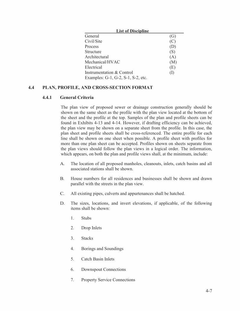
4.4 PLAN, PROFILE, AND CROSS-SECTION FORMAT
4.4.1 General Criteria
The plan view of proposed sewer or drainage construction generally should be shown on the same sheet as the profile with the plan view located at the bottom of the sheet and the profile at the top. Samples of the plan and profile sheets can be found in Exhibits 4-13 and 4-14. However, if drafting efficiency can be achieved, the plan view may be shown on a separate sheet from the profile. In this case, the plan sheet and profile sheets shall be cross-referenced. The entire profile for each line shall be shown on one sheet when possible. A profile sheet with profiles for more than one plan sheet can be accepted. Profiles shown on sheets separate from the plan views should follow the plan views in a logical order. The information, which appears, on both the plan and profile views shall, at the minimum, include:
A. The location of all proposed manholes, cleanouts, inlets, catch basins and all
associated stations shall be shown.
B. House numbers for all residences and businesses shall be shown and drawn parallel with the streets in the plan view.
C. All existing pipes, culverts and appurtenances shall be hatched.
D. The sizes, locations, and invert elevations, if applicable, of the following
items shall be shown:
1. Stubs 2. Drop Inlets 3. Stacks 4. Borings and Soundings 5. Catch Basin Inlets 6. Downspout Connections 7. Property Service Connections
4-8
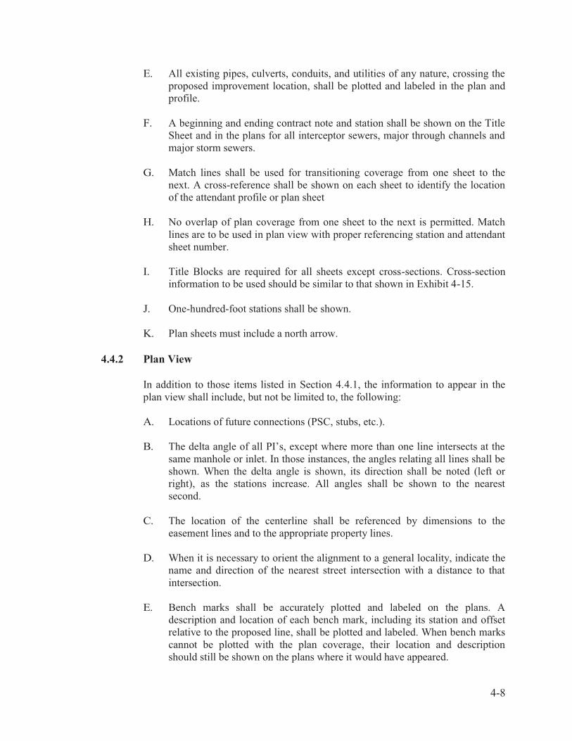
E. All existing pipes, culverts, conduits, and utilities of any nature, crossing the proposed improvement location, shall be plotted and labeled in the plan and profile.
F. A beginning and ending contract note and station shall be shown on the Title Sheet and in the plans for all interceptor sewers, major through channels and major storm sewers.
G. Match lines shall be used for transitioning coverage from one sheet to the next. A cross-reference shall be shown on each sheet to identify the location of the attendant profile or plan sheet
H. No overlap of plan coverage from one sheet to the next is permitted. Match lines are to be used in plan view with proper referencing station and attendant sheet number.
I. Title Blocks are required for all sheets except cross-sections. Cross-section information to be used should be similar to that shown in Exhibit 4-15.
J. One-hundred-foot stations shall be shown.
K. Plan sheets must include a north arrow. 4.4.2 Plan View
In addition to those items listed in Section 4.4.1, the information to appear in the plan view shall include, but not be limited to, the following: A. Locations of future connections (PSC, stubs, etc.). B. The delta angle of all PI’s, except where more than one line intersects at the
same manhole or inlet. In those instances, the angles relating all lines shall be shown. When the delta angle is shown, its direction shall be noted (left or right), as the stations increase. All angles shall be shown to the nearest second.
C. The location of the centerline shall be referenced by dimensions to the
easement lines and to the appropriate property lines. D. When it is necessary to orient the alignment to a general locality, indicate the
name and direction of the nearest street intersection with a distance to that intersection.
E. Bench marks shall be accurately plotted and labeled on the plans. A
description and location of each bench mark, including its station and offset relative to the proposed line, shall be plotted and labeled. When bench marks cannot be plotted with the plan coverage, their location and description should still be shown on the plans where it would have appeared.

4-9
F. The precise location of all soundings and borings. G. Houses, fences and drives shall be shown for a minimum of 50 feet beyond
the right-of-way or to the fronts of the houses for lines located in the street or rights-of-way. Trees, steps, walks and other topographic features shall be shown to the extent that they may be pertinent to the improvement location or construction. These items must be field located. Trees shall be shown with a designation of size and type with the dripline depicted graphically.
H. Property lines, lot lines, easement lines and other boundary lines shall be
shown a minimum of 75 feet beyond any proposed or existing right-of-way. In instances where additional information might be required, the limit shall be extended.
I. Property Service Connection symbols for sanitary sewers, as shown in
Exhibit 4-3 shall be shown near the lot line where service is expected to be required. For consistency, the symbol should be shown approximately 20 feet behind the property line. If a specific location for the connection needs to be shown, an arrow shall be added to the symbol indicating the desired location of service and a note shall be shown in the area indicating the station of the proposed Property Service Connection.
J. Generally, only the outside lines of a pipe shall be shown on the plans.
However, a thin centerline shall be shown within these outside lines where any of the following conditions exist:
1. A distance is shown from a point or line to the centerline of the pipe. 2. The delta angle is shown. 3. The angle of intersection is shown.
Pipes larger than 24 inches in diameter should be drawn to scale to depict the true impact limits.
K. Existing ditches with a bottom width of 4 feet or less should be drawn using
the centerline of the ditch. If the ditches and channels have a bottom width greater than 4 feet, each side of the ditch should be drawn and its width be noted. Where ditch paving exists, the width of the paved area shall be shown.
L. Existing and proposed sewers, their direction of flow, size, and material shall
be shown. The Deed Book and Page Number shall be shown for existing Sewer or Drainage Easements, which are impacted by sewer construction.
M. All water lines, gas lines, oil lines, electric and telephone conduits, fiber optic
cables, and any other underground or overhead utilities shall be shown with the size or primary voltage and ownership identified.
N. All existing or proposed sewers, manholes and catch basins.

4-10
O. When sanitary sewers are to be in existing streets, the front dimension and bearing, if possible, of each lot shall be shown. When sanitary sewers are to be placed in easements or rights-of-way, property line dimensions adjacent to the proposed sewer construction shall be shown.
P. Highways, street names, alleys, or major streams and ditches shall be shown.
The width and type of all surfaces shall be indicated. Q. Street right-of-way widths shall be shown adjacent to and after the street
name. For example: ROBIN ROAD (50' R/W) or ROBIN ROAD (R/W varies) - if the width is not uniform.
R. The name of all baselines shall be shown. The pipe size and direction of flow
shall be noted on all pipes, above the pipe and between all manholes. S. The general notes and a legend of the standard symbols used throughout the
plans shall be shown on the Plan Index Sheet or on the first plan sheet if the plan index is shown on the Title Sheet.
T. Stations shall be shown above each 100-foot station on 50-scale and 20- scale
plans and above each 500-foot station on 100-scale plans. For example: 1+00, 5+00, etc. All horizontal curve data shall be shown on the plans, if applicable.
U. The phrase, "Do Not Disturb", shall be used to indicate existing conditions or
facilities, which are to remain in place during construction. The phrase or abbreviation, "DND", shall be shown adjacent to all such items on the plans. If used, "DND" must be shown and defined in the legend. Likewise "DNR", "Do Not Remove", may be used to indicate existing conditions or facilities which are to remain in place during construction but which some level of disturbance is anticipated. The size and type of items, which are within the construction area, must be clearly identified. This information is critical to assist in the easement acquisition process.
V. The resurfacing limits will be shown for all projects receiving final
resurfacing. W. Where applicable, add the following: storm sewer pipe and PSC charts.
4.4.3 Profile View
In addition to those items listed in Section 4.4.1, the information to appear in the profile view shall include the following as a minimum: A. Stations and grid elevations shall be shown. . The grid shall be set up on a 2-
inch square basis. The vertical scale for 50-scale plans shall be 1" = 5' and for 20-scale plans shall be 1" = 2'.
B. The limits, by station, shall be shown for all concrete caps, cradles and
encasements, tunnels, and bored segments.

4-11
C. When a line located in an easement crosses a public right-of-way, the limits of that right-of-way, including its width, shall be shown.
D. Information relative to whether the line will be constructed in an easement, right-of-way, or existing New Albany or Floyd County property shall be shown directly above the profile grid.
E. The type of backfill used, when not identified in the general notes, shall be placed directly above the profile grid with a leader and arrow defining the limits of each type of backfill.
F. The ASTM or AASHTO designation (whichever applies) and pipe classification shall be shown below the pipe profile.
G. The pipe size, grade, and distance between the centerline of the manholes shall be indicated between all manholes. This information shall be parallel to and shown above smaller pipes; however, on pipes of sufficient diameter, this information should be placed inside the pipe. Grades shall be shown as a percent, i.e., 0.50%.
H. Invert elevations shall be shown to the nearest hundredth of a foot and at the following locations:
1. All breaks in the grade.
2. Breaks necessary for profile continuation onto another sheet.
3. Centerline of standard manholes with continuous grade. Other conduits critical to the pipe gradient.
4. Intersecting pipe.
5. All locations necessary to substantiate the profile grade.
6. Both pipe invert edges when there is a drop or slant inlet.
7. Other conditions shown on the typical drawings.
8. Each catch basin or surface inlet connection.
9. Labeled similar to: IE 479.48.
I. Manholes shall be identified by station, line and manhole number. Proposed
manhole rim elevations shall be shown to the nearest tenth (Rim El. 424.9±) in earth areas and to the nearest hundredth in paved areas. Surface inlet grates shall also be shown to the nearest hundredth (Gr. El. 418.76).

4-12
J. The water surface elevations of ponding and/or 100-year flooding areas shall be shown.
K. Borings indicating depths and type of soils encountered shall be shown if not shown on a separate soils sheet.
L. The results of all soundings shall be shown using the proper symbol.
M. The vertical height of manhole collars shall be shown.
N. The flow line of all ditches having impact on sewer depth or location which are deeper than one foot shall be plotted and labeled as flowline ditch, left or right. On large channels, it may be necessary to show left and right tops of bank.
O. Existing ground profile including street grades or other improvements shall be shown as dashed lines. Proposed ground profile, including any proposed street grades or improvements, shall be shown as a solid line. See Exhibit 4-1.
P. If basements exist, the basement floor elevation shall be shown for sanitary plans. For houses without basements, the first floor elevations shall be shown. When an existing basement floor elevation absolutely cannot be obtained, a first floor elevation shall be obtained and a basement elevation estimated. When the basement elevation is estimated, this fact shall be duly noted in the profile by using the word "Assumed" adjacent to the elevation. House numbers or lot numbers shall be indicated on the profile along with elevations indicated above.
Q. In order to show on which side of the sewer a house is located, houses on the left (when facing up station) shall be drawn using a solid line, and houses on the right (when facing up station) shall be drawn using a dashed line as shown in Exhibit 4-2.
R. Any stacks to be shown on the profile, such as for interceptor sewers, shall be shown solid on the left side and dashed on the right side and should be labeled pipe size stack and left or right.
S. Any underground telephone conduit, water lines, gas lines, etc. shall be shown when crossing proposed New Albany or Floyd County facilities.
4.4.4 Cross Sections
The information to be shown on cross-sections shall be, but not limited to, the following:
A. Horizontal and vertical scales shall be equal. Generally a scale of 1" = 5' shall
be used; however, 1" = 10' may be used in special circumstances. Any other scale to be used requires prior approval of the Project Manager.

4-13
B. Pre-printed colored grid sheets shall not be used because they cannot be scanned on computer for record.
C. Cross-sections shall be required for all proposed ditch projects as well as
roadway or alley construction. D. Cross-sections should show the existing and proposed ground lines, utilities,
fences, structures, property lines, easement lines, and right-of-way lines. E. Cross-sections shall be shown looking up station and shall be placed on the
sheet progressing from bottom of sheet for lower station to top of sheet for higher station and left to right if more than one row of cross-sections is presented on one sheet.
F. Cross-sections shall generally be on even 50-foot stations along the
improvement centerline or baseline. G. If cross-sections are required on a project, pipe crossings may be shown on a
cross-section rather than creating a separate profile for each pipe crossing. H. Half-sections shall be shown for all driveways and a minimum of one half-
section between driveways. I. All water lines, gas lines, telephone conduit, and others shall be shown in the
cross-section. J. Existing ground shall be shown as dashed lines and proposed grade shall be
shown with solid lines.
4.4.5 General Notes General Notes are notes common to the complete set of plans and shall be shown on the first plan sheet, if space permits, or Title Sheet, if necessary. The type of backfill, pipe material and classification may be shown in the General Notes if the majority of the pipes on a particular project have these items in common. Additionally, a Legend shall be shown on the first plan sheet, which defines the standard symbols used in the plans.
4.4.6 Certification
4.4.6.1 Surveyor’s Certification
The following certification paragraph and signature is to be placed on all sanitary and drainage projects. This note will need to be adjusted if survey procedures deviate from the language as shown.

4-14
CERTIFICATION
I hereby certify that the topography for this plan was located under my supervision, and that the property lines shown hereon were obtained from recorded deeds or plats, and that only the property corners noted as monumented were located in the field. Surveyor’s Signature, L.S. # and Date
4.4.6.2 Basement Elevation Certification (Sanitary Projects Only) The registered Land Surveyor shall place the following certification on the preliminary plan cover sheet, or other appropriate location, prior to the request for a field review. The certification should also be placed on the first plan sheet or other appropriate location in the final plans prior to their submission to New Albany for approval.
CERTIFICATION
I hereby certify that the houses shown on these plans, which have basement facilities controlling the elevation of the sanitary sewer, have been entered and controlling elevations determined under my supervision, and that these elevations are correct to the best of my knowledge and belief.
Surveyor’s Signature, L.S. # and Date
NOTE: ON SANITARY PROJECTS THE CERTIFICATIONS CAN BE COMBINED AS A SINGLE NOTE IF APPLICABLE.
4.4.6.3 Professional Engineer Certification
Plans and specifications shall be prepared by or under the personal supervision of a professional engineer, registered pursuant to IC 25-31-1. Final Plans and specifications submitted to New Albany and Floyd County as well as applicable regulatory agencies shall be certified and sealed by a professional engineer. Registered land surveyors may prepare and certify plans for sanitary sewer extensions and storm drainage only as provided in IC 25-21.5-1-7.
DECEMBER 2012
4-15

DECEMBER 2012
4-16

DECEMBER 2012
4-17

DECEMBER 2012
4-18
a
DECEMBER 2012
4-19
a
a

DECEMBER 2012
3
4-20
All stacks must conform to therequirements of section 12.14of the New Albany and Floyd CountyStormwater and Sanitary SewerDesign Manual.
Denotes 6" siamese property serviceconnection (not permitted).
4
DECEMBER 2012
4-21

5
DECEMBER 2012
4-22

6
DECEMBER 2012
4-23

7
DECEMBER 2012
4-24

8
DECEMBER 2012
4-25

PEN SIZE COLOR COLOR RANGE 1
COLOR RANGE 2
COLOR RANGE 3
COLOR RANGE 4
0.18mm 1, 9, 250 10-19 90-99 170-1790.25mm 2, 251 20-29 100-109 180-1890.30mm 3, 252 30-39 110-119 190-1990.35mm 4, 253 40-49 120-129 200-209 160-1690.50mm 5, 254 50-59 130-139 210-2190.60mm 6, 255 60-69 140-149 220-2290.70mm 7 70-79 150-159 230-2390.90mm 8 80-89 240-249
COLOR PLOTS12-172 40% of black
182 6% of black192-242 40% of black
188 2% of black16 30% of black
All pens in the following ranges ending with the number 2 except "2" will plot shaded as follow
STANDARD ASSIGNMENTS
SHADING
DECEMBER 2012
4-26

DECEMBER 2012
4-27
CCCC
Top of Grate Elevation

DECEMBER 2012
4-28
a a

DECEMBER 2012
4-29

DECEMBER 2012
4-30

DECEMBER 2012
4-31

DECEMBER 2012
4-32

DECEMBER 2012
4-33

DECEMER 2012
4-34

DECEMBER 2012
4-35

DECEMBER 2012
4-36

DECEMBER 2012
4-37

DECEMBER 2012
4-38
*PR
OP
ER
TYA
DD
RE
SS
PA
RC
EL
NO
.S
HE
ET
NO
.
SO
UR
CE
OF
TITL
EO
WN
ER
TOTA
LA
RE
AS
EW
ER
AN
DD
RA
INE
SM
'TTE
MP
CO
NS
TE
AS
EM
EN
TR
EM
AR
KS
PE
RM
AN
EN
TE
AS
EM
EN
T
AC
AC
AC
SQ
.FT.
SQ
.FT.
SQ
.FT.
PR
OP
ER
TYA
CQ
UIS
ITIO
NS
UM
MA
RY
*Sho
uld
the
prop
erty
addr
ess
diffe
rfro
mth
eow
ner's
mai
ling
addr
ess
plac
eth
eow
ner's
mai
ling
addr
ess
inth
ere
mar
ksco
lum
n.

TABLE OF CONTENTS
CHAPTER 5 FINAL RECORD DRAWINGS
NUMBER SECTION PAGE
5.1 PURPOSE 5-1
5.2 GENERAL 5-1
5.3 PROCESS 5-2
5.4 DRAWING INFORMATION 5-2
5.5 AS-BUILT ITEMS 5-2
5.5.1 Alignment Changes 5-3
5.5.1.1 Changes in Location 5-3
5.5.1.2 Changes in Elevation 5-3
5.5.2 Structure Changes 5-4
5.5.2.1 General 5-4
5.5.2.2 Pump Stations 5-4
5.5.3 Miscellaneous Changes 5-4
5.5.3.1 Property Service Connections 5-4
5.5.3.2 Changes in Lot or Unit Designations 5-4
5.5.4 General 5-5

5-1
CHAPTER 5 FINAL RECORD DRAWINGS
5.1 PURPOSE This chapter establishes the procedures that must be followed by Design Engineers, Land Surveyors, Contractors, and Developers concerning Final Record Drawings to ensure that all proposed sanitary sewer and stormwater drainage plans correctly depict the facilities as constructed. The final record drawings are the “Bid Plans” that have been revised to identify changes that occurred during construction. This chapter applies to capital improvement and private development projects in New Albany and Floyd County.
5.2 GENERAL The Final Record Drawings shall be prepared by the project design engineer/consultant, based on record information provided by the contractor. At the completion of the project, the contractor will be responsible for providing New Albany or Floyd County and the design engineer/consultant with a set of “Red Line Drawings” and “As-Built Survey Information”. The information will be incorporated into the “Bid Plans” design AutoCAD files by the project design engineer/consultant to become the “Final Record Drawings” file. The Final Record Drawings are then saved in AutoCAD and PDF formats, with the file name format in accordance with the requirements of Chapter 4. The file will contain a “FRD” reference, differentiating it from the original “bid plans” file. In addition to submitting the Final Record Drawings in AutoCAD and PDF formats, the project design engineer/consultant shall submit two hard copies of the Final Record Drawings to New Albany or Floyd County. Note - On private development projects, the project owner will be responsible for preparing the Final Record Drawings, subject to the same above requirements. A. Construction Field Changes Major deviations from the approved construction plans as a result of unexpected field conditions will require documentation and approval by New Albany or Floyd County and the project design engineer/consultant prior to execution of the changes. It shall be up to the New Albany or Floyd County inspector to determine if the deviation is minor and can be resolved on-site or if the deviation requires additional review and approval. If the inspector decides that the deviation needs to be reviewed by New Albany or Floyd County and/or the design engineer, then the contractor shall submit four (4) copies of the marked-up (red line) plans showing the proposed revisions. Upon acceptance of the changes, New Albany or Floyd County will mark the red line drawings approved, sign and date the approval and send the red line drawings to the construction site via the inspector. One copy will be for the contractor, one copy for the inspector, one copy for the design engineer/consultant, and one copy for New Albany or Floyd County’s file. In the event that an inspector is not assigned to a project, then the contractor shall submit red line drawings for all deviations that occur from the construction plans.

5-2
B. Red Line Drawings
As the project progresses, the Contractor shall maintain a record of all deviations in location or elevation of any installation from that shown on the Plans. The information will be compiled in a red-lined format on a copy of the Bid Plans. At the completion of the project the information is submitted to New Albany or Floyd County and the project design engineer/consultant. The information should be recorded in a clear and concise format, allowing for an easy transfer of information.
C. As-Built Survey Information
The Contractor’s Licensed Professional Land Surveyor will be responsible for “as-builting” the items listed below. The survey information shall be compiled in an electronic file, compatible with the *.dwg format. Location and elevations shall be tied to the project survey control.
5.3 PROCESS
On New Albany or Floyd County projects, the noted as-built information will be provided to New Albany or Floyd County as soon as possible after completion of the project. Final payment to the contractor will not occur until the as-built information is provided.
On private development projects, final project acceptance will not occur until the completed Final Record Drawings are reviewed by New Albany or Floyd County's inspector for verification of information. Once verified, the plans are returned to New Albany or Floyd County for final review and acceptance. If the plans are accepted they become Final Record Drawings. If they are rejected the above process is repeated until accepted.
Reference is made to Chapter 4 for a detailed explanation of the documentation requirements. The as-built information is assigned to a specific layer within the drawing file. Predetermined font and pen sizes have also been established.
5.4 DRAWING INFORMATION
Where constructed information differs from the bid information, the plans will reflect a line through the bid information and show the corrected information near the crossed-out original data. Original information shall under no circumstances be removed from the original plans. No red line markings will be accepted. A check mark should be placed beside the original plan information, which has been verified to be correct as constructed. New Albany and Floyd County will not accept Final Record Drawings that have color ink other than black or have plan information overlayed on aerial photos.
5.5 AS-BUILT ITEMS
The following construction items, at a minimum, should be reviewed and verified to produce the Final Record Drawings:

5-3
5.5.1 Alignment Changes
5.5.1.1 Changes in Location
A. Manholes
B. Catch Basins or Surface Inlets
C. Headwalls
D. Retaining Walls
E. Slope Protection
F. Channel Linings
G. Pump Station Wet Wells
H. Pump Station Valve Vaults
I. Air Release Valves
J. Property Service Cleanouts
K. Detention Basins
5.5.1.2 Changes in Elevation To the nearest hundredth.
A. Inverts
B. Rims
C. Surface Inlet Grates
D. Paved Ditches
To the nearest tenth.
A. Turf Ditches B. Miscellaneous Structures C. Detention Basins

5-4
5.5.2 Structure Changes
5.5.2.1 General
A. Manhole collar sizes B. All revisions in pipe sizes, lengths, slopes, and angles C. Identify pipe material if different from the plans
5.5.2.2 Pump Stations
A. All revisions in pipe sizes B. All revisions to electrical controls C. All revisions to exhaust and ventilation systems D. Pump modifications E. Changes in elevation for inverts and level controls F. Equipment layout modifications G. Building modifications
5.5.3 Miscellaneous Changes
5.5.3.1 Property Service Connections
A. Size B. Length C. Depth at R/W or Property Line D. Sewer Station E. End Location, if the PSC is not perpendicular to the sewer
5.5.3.2 Changes in Lot or Unit Designations
A. Lot Numbers B. Tract Numbers C. Apartment Unit Designations D. Condominium Unit Designations E. Patio Home Designations

5-5
5.5.4 General
A. Any unverified data shall show +/- thereby indicating that information has not been verified.
B. The following stamp will be inserted into each plan sheet after all as-built
information has been added.
Final Record Drawing By ___________________ Date ________ Contractor ____________________________________ Engineer Record Drawings have been prepared based on information provided by the Contractor in accordance with the specifications.

TABLE OF CONTENTS
CHAPTER 6 SURVEYING
NUMBER SECTION PAGE
6.1 PURPOSE 6-1
6.2 GENERAL 6-1
6.2.1 Conduct 6-1
6.2.2 Right of Entry 6-1
6.3 HORIZONTAL AND VERTICAL CONTROL 6-2
6.3.1 General 6-2
6.3.2 Datum 6-2
6.3.3 Placement 6-2
6.3.4 Monuments 6-2
6.3.5 Project Control and Bench Marks 6-3
6.3.6 Survey Control Point References 6-3
6.3.7 Vandalized Survey Project Points and Bench Marks 6-3
6.3.8 Horizontal and Vertical Control Review 6-3
6.3.9 Horizontal and Vertical Control Map 6-4
6.3.9.1 Horizontal Information 6-4
6.3.9.2 Vertical Information 6-4
6.3.10 Guidelines 6-4

TABLE OF CONTENTS (cont.)
CHAPTER 6 SURVEYING
NUMBER SECTION PAGE
6.4 DEGREE OF ACCURACY 6-4
6.4.1 General 6-4
6.4.2 Accuracy Criteria 6-5
6.4.2.1 Sanitary Interceptor or Through Drainage System 6-5
6.4.2.2 Sanitary Collector or Local Drainage Systems 6-5
6.5 FIELD PROFILE AND TOPOGRAPHY 6-5
6.5.1 Field Profile Requirements 6-5
6.5.2 Sanitary Service Connection Survey 6-5
6.5.3 Topographic Requirements 6-6
6.5.4 Survey Information Needed for Trees 6-7
6.6 SPECIAL SURVEYS 6-7
6.6.1 Property Surveys 6-7
6.6.2 Utility Surveys 6-7
6.6.3 Railroad and Highway Surveys 6-8
6.6.3.1 Railroads 6-8
6.6.3.2 Highways 6-8
6.7 STAKING SANITARY SEWER AND THROUGH DRAINAGE 6-9 SYSTEM CENTERLINES
6.7.1 Preliminary Centerlines 6-9

TABLE OF CONTENTS (cont.)
CHAPTER 6 SURVEYING
NUMBER SECTION PAGE
6.7.2 Final Centerlines 6-9
6.7.2.1 Staking 6-9
6.7.2.2 Monuments 6-9
6.7.2.3 Centerline Verification 6-10
6.7.2.4 Acceptance 6-10
6.8 CERTIFICATION NOTES 6-10
CHAPTER 6 SURVEYING
EXHIBITS
EXHIBIT TITLE PAGE
6-1 SERVICE CONECTION SURVEY FORM 6-11

6-1
CHAPTER 6 SURVEYING
6.1 PURPOSE
This chapter describes the various field surveys for design, construction and approvals required for capital projects. Private development requiring approval and/or acceptance of constructed facilities shall also follow these guidelines. Project engineers and field survey crew chiefs should familiarize themselves with this and all other chapters of this Design Manual prior to the start-up of any field survey effort. Familiarity with this Manual will enable the field survey crew to obtain the necessary field information for design and construction and also minimize the occurrence of improper activities.
6.2 GENERAL
6.2.1 Conduct
The survey crews shall conduct themselves properly, both on the project and in the surrounding community. Survey vehicles should be adequately identified with their corresponding firm name. Their work should be explained to the property owners and to the public, as necessary, but the survey crew should carefully refrain from outlining any plans or policies, which might be misconstrued. If approached, the survey crew should not convey any project specific information to the property owners. The property owner should be referred to the Stormwater or Sewer Utility Manager for answers to project specific questions. The crew must be courteous at all times when talking with the public and the crew members must maintain a written record of the names of owners or residents with whom they converse. During these conversations, the survey crews should inquire about the location of survey corners or monuments located on the owner's property.
6.2.2 Right of Entry
When it is obvious that the survey work will require entry onto private property, the owner shall be contacted, the survey work described, and permission to enter obtained. No project specific information should be conveyed to the property owner. Efforts to contact property owners shall include telephone calls, letters and a door hanger for those who are not at home. It should be explained in the notice that field inspection and soils investigation personnel might require entry from time to time during the course of the project. In the event that the owner does not grant permission and it is evident that the survey work will be delayed, the Stormwater or Sewer Utility Manager should be immediately notified in writing. It is the responsibility of the Stormwater or Sewer Utility Manager to take action to obtain legal right of entry.

6-2
6.3 HORIZONTAL AND VERTICAL CONTROL
6.3.1 General
Existing horizontal and vertical control monuments in the area of the survey shall be referenced for all centerlines, and/or baselines, and level circuits. These monuments or benchmarks shall be shown and identified on the plans. Trees are not to be used for surveying purposes except in remote areas where there is no other practical alternative. No spikes or nails are to be driven into a tree as described previously. Trees shall not be "blazed" under any circumstances, and only water-based paint may be used if it is necessary to mark a tree.
6.3.2 Datum
All control shall be related to existing monuments that have been published by NGS or the State Plane Coordinate System and must reference the appropriate datum as indicated below: A. Horizontal control shall be referenced to the Indiana State Plane Coordinate
System, East Zone 1983 (NAD83). B. Vertical control shall be referenced to the North American Vertical Datum
1988 (NAVD 88). 6.3.3 Placement
All horizontal control shall be located within the easement or public right-of-way whenever possible. Each monument should be placed to avoid movement caused by construction or other activities. Every horizontal control marker that is not being specifically set for individual project control points should be set at maximum intervals of one-half mile on all projects. A vertical control marker that is not being specifically set for individual project control points should be placed similarly to horizontal control marker at maximum intervals of one-quarter mile.
6.3.4 Monuments
All horizontal and vertical control markers shall be of ferrous materials a minimum of 2 inch diameter with an X stamped in the center and SURVEY MARK stamped above the X and DO NOT DISTURB stamped below the X.

6-3
6.3.5 Project Control and Bench Marks
Project horizontal control shall be as described in this chapter. Project vertical control (bench marks) shall be established at a maximum interval of 500 feet and must maintain a minimum distance of 25 feet from the improvement centerline. Each bench mark should be placed to avoid movement caused by construction or other activities. All bench marks must conform to specifications for quality as referenced in Federal Geodetic Data Committee (FGDC) endorsed standards FGDC-STD007.4. Sidewalks, steps (unless massive), small concrete slabs and similar structures are not acceptable. Each project must contain at least one bench mark, which conforms to Federal Geodetic Data Committee (FGDC) endorsed standards FGDC-STD-007.4.
6.3.6 Survey Control Point References
With the advent of GPS and the coordinate control capabilities of most survey equipment, field references for horizontal survey control points are no longer required. All bench marks are to be field located and shall be referenced to the centerline of the sewer by station, and offset. In addition, other field references, such as addresses, etc., should be referenced in field notes, plans, and any other pertinent documents submitted. If a spike in a power pole is used as a benchmark, the field notes, plan sheets, and the horizontal and vertical control sheet shall list the power pole number.
6.3.7 Vandalized Survey Project Points and Bench Marks
It is not the responsibility of New Albany or Floyd County for any damage done to project centerline control points and bench marks until after the final plans, contract documents, and field notes with proper references have been accepted. Any damage done to those points up to that time will be repaired or replaced by the Land Surveyor at the Land Surveyor's expense. It is advised that these points are accurately field referenced at the earliest possible time.
6.3.8 Horizontal and Vertical Control Review
New Albany and Floyd County retains the right to request any corresponding field notes either digital or hard copies that pertain to the horizontal and vertical control for the project together with horizontal and vertical closure statements for their review. The control data sheets shall be submitted for each newly set horizontal and vertical control monument.
6-4
6.3.9 Horizontal and Vertical Control Map
A horizontal and vertical control map is required for all sanitary sewer surveys and major storm drainage projects. This map shall be prepared on a standard plan sheet and shall be included in the final plans. The final horizontal and vertical control map shall include final stations, station equations, all curve data, and the final location and description of bench marks. In addition, the following information shall be shown. 6.3.9.1 Horizontal Information
A. Coordinate ties with adjacent projects.
B. Final coordinates of all horizontal control points, PI’s, beginning and ending
stations.
C. All bearings, coordinates, angles and point designations on baselines in the design segment.
D. Source of horizontal datum. (List the bearing and distance of the control line, and the deflection angle of the proposed centerline.)
6.3.9.2 Vertical Information A. New bench marks - their designations, locations, description and elevation. B. Existing Vertical Control Monuments - their designations, elevation and
location. C. Source of vertical datum. (If a spike in a power pole is used for a bench mark,
list the power pole number and the height of the spike above the ground, and house number(s) of adjacent homes.
6.3.10 Guidelines
Horizontal and vertical control shall be established according to the guidelines defined by these publications:
A. Federal Geodetic Data Committee (FGDC) endorsed standards FGDC-STD-
003, FGDC-STD-007.1 through FGDC-STD-007.4 or the current Federal Geodetic Data Committee standards.
6.4 DEGREE OF ACCURACY
6.4.1 General
The instruments used shall meet the specifications indicated in these guidelines or in following sections. All instruments shall be certified to National Institute of

6-5
Standards and Technology (NIST) standards and manufacturer's specifications. NIST, the instrument manufacturer, or a certified instrument repairs facility must perform the certification. All instruments should be serviced regularly by a certified repair facility and checked at a National Geodetic Survey baseline. EDM instruments should be calibrated by a certified repair facility annually. Field notes of all calibration checks can be requested by New Albany or Floyd County. Instrumentation for second order leveling as defined by the Federal Geodetic Control Subcommittee (FGCS) of the FGDC shall be used for any projects requiring second order, class II specifications.
6.4.2 Accuracy Criteria
6.4.2.1 Sanitary Interceptor or Through Drainage System
Horizontal surveys will adhere to Second Order, Class II specifications, except that the error of closure shall equal or exceed 1:50,000. Vertical control will adhere to Second Order, Class II specifications.
6.4.2.2 Sanitary Collector or Local Drainage Systems Horizontal surveys will adhere to Third Order, Class I specifications, except the adjustments being made by either the Least Squares or Compass Rule Method. Vertical control will adhere to Third Order specifications, except the error of closure will be equal to or exceed Second Order, Class II requirements.
6.5 FIELD PROFILE AND TOPOGRAPHY
6.5.1 Field Profile Requirements
Profile elevations shall be determined along sanitary sewer or through drainage system centerlines at 25-foot intervals, where possible, or at 50-foot intervals on paved streets, and at all necessary intermediate breaks. Profiles shall delineate existing structures, roads, streams, etc. Elevations shall be established to the nearest one-tenth of a foot on natural terrain and to one-hundredth of a foot on artificial surfaces. Cross-sections shall be taken at critical locations when it is necessary to determine what effect open cuts or trenching might have on other facilities such as structures, utilities, pavements, fences, trees, or landscaping. Roadside ditches within 30 feet, parallel to the sewer, and greater than 1.5 feet in depth shall be shown in profile with the sewer. These ditches and other elevations critical to design and/or construction must be shown on the plans.

6-6
6.5.2 Sanitary Service Connection Survey
A sanitary service connection survey shall be made along each street to properly determine the controlling elevations for design of a particular sanitary sewer line. The form found in Exhibit 6-1 shall be used in accomplishing this survey. The following information shall be shown on the form for each unit surveyed: A. Type of structure.
B. Basement facilities present.
C. Size, type and location of service line.
D. Elevation of the lowest possible living area floor.
E. Any additional information that may be required for design of the sanitary
sewer line.
All elevations should be determined by actual field measurements; however, if a unit cannot be entered, an estimated lowest living area floor elevation shall be made from a known elevation from some other point on the unit. In this case, the elevation must be clearly marked as being estimated. Should an estimated elevation control or have the potential to control the vertical elevation of the sewer, New Albany or Floyd County shall arrange provision for entry and actual determination of the service elevation. The completed forms shall be submitted along with the preliminary plans for review. They need not be included in the final plan submission but shall be included with the as built drawings submitted at the conclusion of the project.
6.5.3 Topographic Requirements
The following information shall be obtained in the field:
A. All topography critical to the design of the improvement shall be located and recorded in the field notes.
B. Topography generated from aerial photography shall be identified and field
checked for any errors or omissions. Omitted topography shall be located by field survey and appropriately recorded. This work is the specific responsibility of the Engineer or Land Surveyor, even though the aerial photography may have been provided from other sources. All topography within the project construction limits and/or easements and rights-of-way shall be field located.
6-7
6.5.4 Survey Information Needed for Trees
A. Species of Tree (Use the Audubon Society Field Guide to North American Trees, Eastern Region).
B. Size (DBH - Diameter at Breast Height).
C. Dripline (Diameter).
D. Encroachment Allowed within the Dripline.
E. Location: 1. All trees 6 inches in diameter or greater within the temporary or
permanent easement shall be located and the species given within 30-feet of the centerline for pipe projects or 15 feet outside the top of slope for ditches.
2. All trees less than 6 inches in diameter shall be located and species given, when within an existing or proposed sewer and drainage easement.
3. When trees are grouped together, at a very close interval, locate the approximate center of the grouping and list the most dominant species of the group.
6.6 SPECIAL SURVEYS
6.6.1 Property Surveys
Where the relationship of the improvement location and adjacent property line is critical, the location of existing property lines and other boundaries shall be established by a property survey sufficient to define the easement. Property lines, boundary lines, easements, etc. shall be referenced by stations and offsets from the centerline or baseline to the nearest one-hundredth of one foot, by measurement of the angles at the PI with the centerline, and by other means of comparable accuracy. Surveys shall ascertain the names of owners, lessees or tenants, sources of title and date of acquisition and shall be verified from the appropriate New Albany or Floyd County records.
6.6.2 Utility Surveys
All publicly and privately-owned surface and subsurface utilities affected by the proposed improvement shall be located and identified by field survey and by use of maps supplied by the utilities. Locations, elevations, and other pertinent data as may be required for possible relocation or adjustment shall be secured for all such utilities to the limits of information currently available. Overhead power lines near the intended improvement alignment, or those which may be a construction hazard,

6-8
should be shown on the plans using the proper symbol and labeled with their primary voltage.
6.6.3 Railroad and Highway Surveys
When the centerline of improvements crosses a railroad or highway, all existing and proposed railroad tracks, roadways, and affected structures shall be tied to the improvement centerline. The topography shall be provided on either side of the proposed crossing to the extent required by the affected reviewing agency. An attempt to contact the railroad owners shall be made prior to the survey work in the railroad R/W. Typical information shall include, but not be limited to, the following sections. 6.6.3.1 Railroads A. Top of rails - 300 feet minimum in either direction locate horizontally and
vertically at 50-foot intervals. B. Angle between centerline of tracks and centerline of improvement. C. Name and address of railroad company. D. Location of railroad right-of-way and easements (source of record where
possible). E. Horizontal and vertical information relative to transmission lines, such as
telephone or electric. F. Stations on the centerline of each track. G. Mile post locations, measured from centerline crossing.
6.6.3.2 Highways
A. Station on centerline of highway and each edge of pavement, or front face of
curb, as may be appropriate.
B. Angle between highway centerline and centerline of improvement.
C. Location of highway rights-of-way and easements (source of record where possible).
D. Location of any crossings, parallel utilities, or drainage structures, which may be in conflict with the improvement construction.
E. Number and width of lanes and the type and condition of the surface.

6-9
6.7 STAKING SANITARY SEWER AND THROUGH DRAINAGE SYSTEM CENTERLINES
6.7.1 Preliminary Centerlines
Improvement centerlines shall be staked for a preliminary field review by using highly visible temporary markers. These markers shall be placed on the centerline at convenient locations, such as fence lines, streets, and borders of timber areas. Intermediate markers shall be placed as necessary to maintain continuous visibility. Plastic flagging shall be used on the markers to increase their visibility. Approximate stations and line designation shall be placed on the markers. The method of designating the centerline in urban areas may be modified as required to provide the information previously noted, including the use of paint on streets. Final staking of improvement lines and the assignment of final line designations before a preliminary field review is not encouraged. These requirements are subject to revision by New Albany/Floyd County to suit specific projects.
6.7.2 Final Centerlines
6.7.2.1 Staking Prior to acceptance of the final plans, the centerline shall be staked at PI's and as needed to maintain line of sight for purposes of easement acquisition, bidding, field reviews, etc. Stations and line designation shall be clearly marked with an indelible marker on 1" x 2" x 18" (minimum) flat stake adjacent to the PI. Guard stakes of 1" x 1" x 48" (minimum), marked "Centerline Sewer" shall be provided at all PI's, manholes, structures, and other control points. Stake markings shall include the designation of the sewer, such as Line "A” and the station of the point for which the guard stake is provided. Points in pavement areas shall be identified by painting the necessary information adjacent to the permanently located point. PK nails or spikes are to be used for final centerline staking. Where necessary, offset stakes shall be utilized to identify points in streets, highways, and railroads.
6.7.2.2 Monuments Iron pins shall be placed at all PI's and POT's necessary to establish the centerline, beginning and ending stations of the contract, and at those points specifically requested by New Albany/Floyd County. These points shall be field referenced, per this design manual specifications, so they may be located or reestablished at a later date. Iron pins shall be placed at all other manhole locations but do not need to be field referenced. Iron pins shall be made of or contain ferrous material and be a minimum of 30 inches in length and 5/8 inches in diameter. In lieu of iron pins, railroad spikes, 6 inches minimum length, or PK nails shall be used in bituminous pavements and a scribed cross ("X") shall be used on concrete surfaces.

6-10
6.7.2.3 Centerline Verification The Design Consultant shall verify the improvement alignment by obtaining field angles and distances along all segments of the improvement centerline. This shall include tying the final centerline alignment by traverse into the control baseline. The alignment shown on the Horizontal and Vertical Control Map shall be the final approved alignment.
6.7.2.4 Acceptance The Design Consultant shall verify, in writing, that the alignment shown on the final construction plans has been located correctly in the field. This shall include returning to the field and verifying that all permanent points are intact and reestablishing all damaged or missing points. This must be accomplished before New Albany/Floyd County will accept the original drawings, contract documents, and authorize final payment to the Design Engineer.
6.8 CERTIFICATION NOTES
Example Surveyor Certification notes can be found in Section 4.4.6.1. A certification note, placed on the project title sheet, is required for all projects and should reflect the specific type of survey performed.
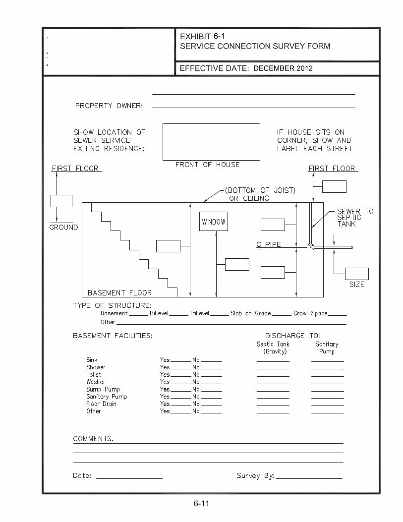
6-1
DECEMBER 2012
6-11

TABLE OF CONTENTS
CHAPTER 7 EASEMENTS
NUMBER SECTION PAGE
7.1 PURPOSE 7-1
7.2 EXISTING EASEMENTS 7-1
7.3 DEFINITIONS 7-1
7.3.1 Fee Simple Title 7-1
7.3.2 Sanitary Sewer and Drainage Easement 7-1
7.3.3 Temporary Construction Easement 7-2
7.3.4 Access Easement 7-2
7.4 EASEMENT WIDTHS 7-3
7.5 CONSTRUCTION PLAN REQUIREMENTS 7-3
7.5.1 General 7-3
7.5.2 Easement Description Criteria 7-4
7.6 EASEMENT PLAT CRITERIA 7-4
7.6.1 General 7-4
7.6.2 Plat Information 7-5
7.6.3 Property Service Connection Easement 7-5
7.6.4 Easements on Railroad Rights-of-Way 7-6
7.6.5 Certificates 7-6
7.6.6 Submission 7-6
TABLE OF CONTENTS (cont.)
CHAPTER 7 EASEMENTS
NUMBER SECTION PAGE
7.7 PROPERTY ACQUISITION SUMMARY SHEET 7-7
7.7.1 Parcel Number 7-7
7.7.2 Owner’s Name 7-7
7.7.3 Property Address 7-7
7.7.4 Plan Sheet Number 7-7
7.7.5 Source Title 7-8
7.7.6 Total Area of Tract 7-8
7.7.7 Area of Easements 7-8
7.7.8 Permanent Easement 7-9

CHAPTER 7 EASEMENTS
EXHIBITS
EXHIBIT TITLE PAGE
7-1 SAMPLE SANITARY SEWER AND DRAINAGE EASEMENT PLAT 7-9
7-2 SAMPLE RELEASE OF EASEMENT PLAT 7-10
7-3 SAMPLE EASEMENT ENCROACHMENT PLAT 7-11
7-4 SAMPLE CONSENT AND RELEASE FORM (FLOYD COUNTY) 7-12
7-4 SAMPLE CONSENT AND RELEASE FORM (NEW ALBANY) 7-13
7-5 EASEMENT PLAT CHECKLIST 7-14

7-1
CHAPTER 7 EASEMENTS
7.1 PURPOSE
All public sanitary sewers, storm drains, and open channels must be constructed in public rights-of-way, easements or on publicly owned properties. No approval will be given for construction or improvement of any public sewer, storm drain, or channel without provision of suitable permanent easement or right-of-way. The developer on private development projects will be responsible for acquiring all easements. Document recording will be the responsibility of the developer.
7.2 EXISTING EASEMENTS
Each existing easement to be used shall be shown on the plans submitted for review and approval. The information shown on the plans shall include the Deed Book and Page Number, or Instrument Number, of the recorded easement. All restrictive clauses as to the use of the easements, i.e., for utility purposes, drainage, sanitary sewers, etc., shall be noted on the plan adjacent to the pertinent easement. Construction of sanitary sewers or drainage systems will not be permitted in existing exclusive gas, electric, water, or telephone easements unless a Sanitary Sewer and Drainage Easement is acquired overlapping the existing easement with approval of the affected agency.
Existing drainage easements generally do not provide for the construction of sanitary sewers. In order to use these easements for sanitary sewer construction a new easement will be required to convert the existing Drainage Easement into a Sanitary Sewer and Drainage Easement. Construction plans and easement plats shall be prepared accordingly and the proposed new easement should be shown in the same manner as an entirely new easement.
7.3 DEFINITIONS The following terms define the methods under which New Albany/Floyd County will acquire interest in property for the purpose of constructing, operating, and maintaining wastewater pumping, drainage facilities and sanitary sewers: 7.3.1 Fee Simple Title
For the purpose of constructing major aboveground structures, New Albany/Floyd County will normally acquire all rights to the required property in fee simple and permanently retain ownership. This generally refers to large pumping stations, and major detention basins.
7.3.2 Sanitary Sewer and Drainage Easement
For the purpose of constructing facilities (sanitary sewers, storm drainage systems, etc.), New Albany/Floyd County will acquire the right to construct facilities within the limits of easements. They will have the right to operate and maintain those

7-2
facilities within the same limits and also have reasonable ingress and egress over each affected property to the easements for construction, operation, maintenance and reconstruction. These easements are permanent in nature and are referred to as Sanitary Sewer and Drainage Easement. Crossings between Sanitary Sewer and Drainage Easements, and Utility Easements, are acceptable. The limits of Sanitary Sewer and Drainage Easements shall be set for permanent structures. Existing structures shall not be within the easement area, unless the sewer construction actually requires the removal of such buildings or structures. A property owner generally is restricted from constructing any facility within the limits of the easement that might interfere with the maintenance and operation of the facility.
7.3.3 Temporary Construction Easement
A temporary construction easement will be required adjacent to all new Sanitary Sewer and Drainage Easements when necessary for construction operations. Temporary construction easements shall be required for structure removal, access roads, stockpiling, and other construction activities when necessary. Structure removal includes the removal of treatment plants, pump stations, etc. Sufficient area shall be supplied for movement of equipment and materials to accomplish the intended activity within the Temporary Construction Easement. If at all possible, Temporary Construction Easements will not be acquired on adjacent private property when the proposed facility lies within a dedicated right-of-way or an existing Sanitary Sewer and Drainage Easement. Only under certain unusual conditions will a Temporary Construction Easement be acquired from a parcel if a new permanent easement is not being acquired from that same parcel. Accordingly, no plats shall be prepared showing Temporary Construction Easements only. "Consent and Release" may be used in lieu of temporary easement. Temporary Construction Easement lines may be drawn through permanent structures; however, the Contract Documents shall contain language, which clearly indicates that all such permanent structures shall not be disturbed during construction. After the project is completed and the property is restored to its prior condition, all rights to the property are relinquished.
7.3.4 Access Easement
All Sanitary Sewer and Drainage Easements must have access to a public right of way. If there is no access from a public right of way, a permanent access easement will be required. The access easement will allow the City Ingress/Egress from a public right of way to the Sanitary Sewer and Drainage Easements. The maximum distance between access easements is 400 linear feet. No fences shall be constructed in an access easement. The access easement shall be labeled as a Sanitary Sewer and Drainage Easements.

7-3
7.4 EASEMENT WIDTHS
Whenever possible, the total easement width, permanent and temporary, should be sufficient to permit the contractor to have flexibility in the method of construction. Widths of Sanitary Sewer and Drainage Easements and Temporary Construction Easements using trench construction are tabulated below. In no case shall these guidelines be a substitute for sound engineering judgment. Access Easements in New Albany shall be a minimum 12’. Access Easements in Floyd County shall be a minimum 15’.
Table 1. Minimum Easement Widths
Size of Pipe Sanitary Sewer and Drainage* Temporary Total
Minimum 15' 20' on each side 55'
24" - 48" 20' 20' on each side 60'
54" and larger 30' 25' on each side 80'
* Unless otherwise approved by New Albany/Floyd County
7.5 CONSTRUCTION PLAN REQUIREMENTS
7.5.1 General
Construction plans shall be prepared in a manner, which will show clearly, and correctly, the information necessary for the acquisition of each parcel of land required. They must accurately show the location of each parcel and its relationship with surrounding areas. The alignment, as shown on the construction plans and easement plats, must agree with the alignment staked in the field. The information shown must be authentic and thoroughly checked since it will become legal evidence regarding the parcels of land required. The plans shall carry appropriate certifications and seals indicating that the surveying has been accomplished under the supervision of a Land Surveyor registered with the State of Indiana. They shall also meet the Minimum Standards of Practice for Land Surveying in Indiana and the following guidelines: A. An effort should be made to parallel property lines with the facility when
topographic features permit.
B. Easements shall be referenced to property corners and/or known landmarks to the degree that they can be accurately reestablished prior to construction.
C. In residential areas, all topographic features, such as trees, shrubs, sheds, etc., located within the easements shall be properly identified on the plans. When
7-4
undeveloped wooded areas are encountered, only those trees of unusual size or nature need to be specifically identified on the plans. Any items within these easements, which are definitely not to be disturbed during the construction, shall be clearly noted "Do Not Disturb" (DND). Items, which remain, but which must be disturbed for construction shall be noted "Do Not Remove" (DNR).
7.5.2 Easement Description Criteria
The construction plans shall show the following information for each parcel from which easements are to be acquired: A. Property owner's name of record and address on the Property Acquisition
Summary Sheet. B. Subdivision name and plat number. C. Existing rights-of-way and easements. D. Existing Sanitary Sewer and Drainage Easements, their Deed Book, Page
Number. E. Property lines with label. F. Parcel numbers. In addition, the Deed Book and Page Number, or Instrument Number, for the new easement shall be added to the plans when the information is made available by New Albany/Floyd County.
7.6 EASEMENT PLAT CRITERIA
7.6.1 General
A. Sanitary Sewer and Drainage Easements Easement plats shall be prepared for each property having a Sanitary Sewer and Drainage Easement or other type of acquisition. The phrase "Sanitary Sewer and Drainage Easement" shall be used on all plats and acquisition documents. All plats shall have the title block in the lower right corner of the plat and the Land Surveyor's Certification and Seal in the lower left corner. No other format should be submitted and none will be accepted. Permanent easement on all plats is to be hatched for clarity. Temporary easements are not to have hatching, cross-hatching, or shading. A sample “Easement Plat” is shown in Exhibit 7-1.

7-5
B. Release of Existing Easements
Any release of easement is to have its own plat and the area of easement to be released is to be crosshatched. No plat containing both easement dedication and release of easement will be accepted. New Albany/Floyd County must approve the release of easement and the applicable fees must be paid. All other requirements of easement plats shall apply to easement release plats. A sample “Release of Easement Plat” is shown on Exhibit 7-2. The easement release (“Quitclaim”) requirements and procedures are found on the New Albany or Floyd County web page.
C. Encroachment Plats
On occasion a permanent structure is found to be, or required to be, encroaching upon an existing easement. In such situations, an easement encroachment plat must be prepared and recorded. A sample “Easement Encroachment Plat” is shown on Exhibit 7-3.
Easement plats should contain sufficient information to enable a Land Surveyor to locate and stake the easements in the field.
D. Consent and Release
In order for work to be done on a property with no easement, the property owner must sign a Consent and Release Form. A sample “Consent and Release Form” is shown in Exhibit 7-4.
7.6.2 Plat Information
The “Easement Plat Checklist” indicates the plat requirements and should be referenced prior to all submittals. It is located in Exhibit 7-6, and can be found at www.floydcounty.in.gov/county%20offices/stormwater.htm and www.newalbanystormwater.org.
7.6.3 Property Service Connection Easement
Occasionally, a Sanitary Sewer may be located such that the permanent easement does not extend to the property line of an adjacent property to be served with a proposed property service connection.
In these instances, a 15’ Sanitary Sewer and Drainage Easement shall be provided from the proposed service facility easement to the property line at the most likely location of the property service connection. Sufficient Temporary Construction Easement shall also be depicted.
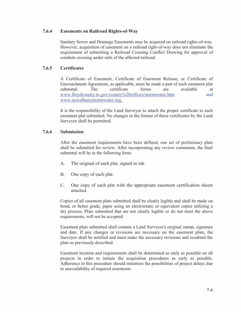
7-6
7.6.4 Easements on Railroad Rights-of-Way
Sanitary Sewer and Drainage Easements may be acquired on railroad rights-of-way. However, acquisition of easement on a railroad right-of-way does not eliminate the requirement of submitting a Railroad Crossing Conflict Drawing for approval of conduits crossing under rails of the affected railroad.
7.6.5 Certificates
A Certificate of Easement, Certificate of Easement Release, or Certificate of Encroachment Agreement, as applicable, must be made a part of each easement plat submittal. The certificate forms are available at www.floydcounty.in.gov/county%20offices/stormwater.htm and www.newalbanystormwater.org. It is the responsibility of the Land Surveyor to attach the proper certificate to each easement plat submitted. No changes in the format of these certificates by the Land Surveyor shall be permitted.
7.6.6 Submission
After the easement requirements have been defined, one set of preliminary plats shall be submitted for review. After incorporating any review comments, the final submittal will be in the following form: A. The original of each plat, signed in ink.
B. One copy of each plat.
C. One copy of each plat with the appropriate easement certification sheets
attached. Copies of all easement plats submitted shall be clearly legible and shall be made on bond, or better grade, paper using an electrostatic or equivalent copier utilizing a dry process. Plats submitted that are not clearly legible or do not meet the above requirements, will not be accepted.
Easement plats submitted shall contain a Land Surveyor's original stamp, signature and date. If any changes or revisions are necessary on the easement plats, the Surveyor shall be notified and must make the necessary revisions and resubmit the plats as previously described.
Easement location and requirements shall be determined as early as possible on all projects in order to initiate the acquisition procedures as early as possible. Adherence to this procedure should minimize the possibilities of project delays due to unavailability of required easements.

7-7
7.7 PROPERTY ACQUISITION SUMMARY SHEET
Property data shall be shown on the Property Acquisition Summary Sheet, as well as on the construction plan sheet and easement plat. However, a separate Property Acquisition Summary Sheet will not be required if a project has five parcels or less. In such instances, the property acquisition information in the same format may be placed on the Plan Sheet Index, on the first plan sheet if adequate space is available, or be included in the plan index on the cover sheet. An example of the layout for the Property Acquisition Summary Sheet is shown in Chapter 4 on Exhibit 4-16. The Property Acquisition Summary Sheet shall show the following data for each parcel required for right-of-way purposes: 7.7.1 Parcel Number
Parcel numbers shall be assigned to each parcel of property to be acquired and shown on the plans. Parcel number 1 shall be assigned to the first parcel, and the remaining parcels shall be numbered consecutively from the beginning to the end of the project. Parcel numbers shall not be assigned to publicly-owned rights-of-way. Parcel numbers assigned to each tract shall not be changed after submission of the final easement plats. If it is then determined that acquisition from any parcel will not be required, that number shall be removed from the plans and the notation "NOT USED" shall be placed in the owner's block on the Property Acquisition Summary Sheet.
7.7.2 Owner's Name
The name of the current owner of the property and address, at the time of the preparation of the plans, shall be shown. Final changes to the Property Acquisition Summary Sheet will be made when the property is being acquired.
7.7.3 Property Address
The address of the property served shall be shown. Should the owner's mailing address differ from that of the property, the owner's mailing address should be shown in the remark’s column.
7.7.4 Plan Sheet Number
The sheet number is the number assigned to the plan sheet on which the particular parcel is shown. Some parcels, of course, will appear on more than one plan sheet and all sheet numbers must be included.
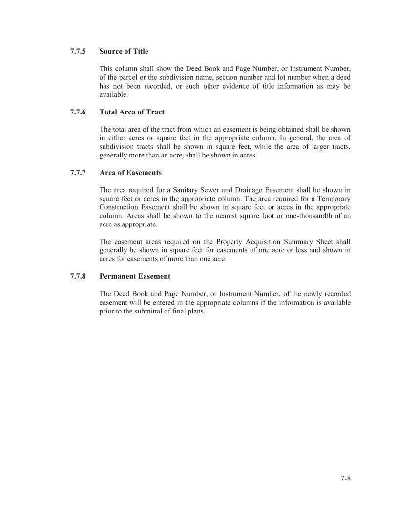
7-8
7.7.5 Source of Title
This column shall show the Deed Book and Page Number, or Instrument Number, of the parcel or the subdivision name, section number and lot number when a deed has not been recorded, or such other evidence of title information as may be available.
7.7.6 Total Area of Tract
The total area of the tract from which an easement is being obtained shall be shown in either acres or square feet in the appropriate column. In general, the area of subdivision tracts shall be shown in square feet, while the area of larger tracts, generally more than an acre, shall be shown in acres.
7.7.7 Area of Easements
The area required for a Sanitary Sewer and Drainage Easement shall be shown in square feet or acres in the appropriate column. The area required for a Temporary Construction Easement shall be shown in square feet or acres in the appropriate column. Areas shall be shown to the nearest square foot or one-thousandth of an acre as appropriate.
The easement areas required on the Property Acquisition Summary Sheet shall generally be shown in square feet for easements of one acre or less and shown in acres for easements of more than one acre.
7.7.8 Permanent Easement
The Deed Book and Page Number, or Instrument Number, of the newly recorded easement will be entered in the appropriate columns if the information is available prior to the submittal of final plans.

Floyd County Court.
NEW ALBANY, IN 47150
NEW ALBANY, IN 47150
7-1
DECEMBER 2012
SAMPLE SANTIARY SEWER & DRAINAGE
7-9

Floyd County Court.
NEW ALBANY, IN 47150
NEW ALBANY, IN 47150
NEW ALBANY, IN 47150
DECEMBER 2012
7-10

Floyd County Court.
NEW ALBANY, IN 47150
NEW ALBANY, IN 47150
DECEMBER 2012
7-11

CONSENT AND RELEASE
This Consent and release made and entered into this day of , 20 , by and between , parties of the first part, and
Floyd County WHEREAS, Floyd County deems it necessary to perform the following work in order
to improve the storm drainage for the following described property, and
WHEREAS, the parties of the first part, being the owners of said property and desirous of having said work performed.
Address of Property:
Description of Work:
NOW THEREFORE, in consideration of the benefits accruing to said property, the parties of the first part hereby consent and agree that Floyd County. its agents, employees and assigns may enter ant come upon the above described property for the purpose of performing the work as described above and further expressly agree that the parties of the first part will assert no claim whatsoever, of any kind or type, against Floyd County, its agents, employees or assigns by reason of the performing of said work, but by these presents shall be forever barred except that Floyd County shall be liable for any damage to persons or property which results from its acts or omissions during the course of the project as it is performed on party of the first part's property and which occurs during such performance.
IN TESTIMONY WHEREOF, witness the signatures of the parties this day of , 20 . PROPERTY OWNERS Party of the First Part Party of the First Part BY: Floyd County
(Provide one copy for property owner and one copy for Floyd County files
EXHIBIT 7-4 SAMPLE CONSENT AND RELEASE FORM
EFFECTIVE DATE:
7-13
DECEMBER 2012
7-12
xxxxx

CONSENT AND RELEASE
This Consent and release made and entered into this day of , 20 , by and between , parties of the first part, and
New Albany WHEREAS, New Albany deems it necessary to perform the following work in order
to improve the storm drainage for the following described property, and
WHEREAS, the parties of the first part, being the owners of said property and desirous of having said work performed.
Address of Property:
Description of Work:
NOW THEREFORE, in consideration of the benefits accruing to said property, the parties of the first part hereby consent and agree that New Albany. its agents, employees and assigns may enter ant come upon the above described property for the purpose of performing the work as described above and further expressly agree that the parties of the first part will assert no claim whatsoever, of any kind or type, against New Albany, its agents, employees or assigns by reason of the performing of said work, but by these presents shall be forever barred except that New Albany shall be liable for any damage to persons or property which results from its acts or omissions during the course of the project as it is performed on party of the first part's property and which occurs during such performance.
IN TESTIMONY WHEREOF, witness the signatures of the parties this day of , 20 . PROPERTY OWNERS Party of the First Part Party of the First Part BY: New Albany
(Provide one copy for property owner and one copy for New Albany files
EXHIBIT 7-4 SAMPLE CONSENT AND RELEASE FORM
EFFECTIVE DATE:
7-13
DECEMBER 2012
7-13
ccc

DECEMBER 2012
Esmtchecklist.doe
Easement Plat Checklist
Using guidelines set forth in the New Albany/Floyd County Design Manual all easement plats must clearly provide the following:
1. A plat of the parent tract with bearing and length of each line shown and labeled (meas.) if measured in the field, (deed) if taken from deed, (plat) if taken from plat, or (calc.) if calculated. Curve lines must be labeled with enough curve data to define the curve.
2. Delineation of the new permanent easement with the bearing and length of each line (angle at each P.I. may replace bearing). Curved lines are to be labeled with curve data sufficient to define the curve.
3. Delineation of the temporary construction easement (if any).
4. Area of permanent easement to be acquired.
5. Area of temporary easement to be acquired.
6. Reference of at least one corner of the permanent easement to a corner of the present tract. More may be required in some instance.
7. Description of any monuments and notation.
8. Names of property owners and record sources of each property adjoining the new permanent easement.
9. Name of roads and width of R/W.
10. North point or reference meridian and its basis.
11. Location map of sufficient detail to locate the parcel being surveyed. Include a separate north point.
12. Parcel number to be shown within the parent tract.
13. Permanent easement to be hatched. Easement releases must be cross-hatched.
14. Limits of the permanent easement are to be clearly identified and labeled "Sanitary sewer and Drainage easement" and width to be labeled.
15. Limits of the temporary construction easement are to be clearly identified and labeled "temporary construction easement" and width to be labeled.
16. Show all existing easements with identification and record source.
17. Graphic and written scale.
18. Statement that the unadjusted error of closure meets or exceeds governing authorities.
19. Indicate method of survey where applicable: i.e. random traverse, direct-on-line, parallel offsets etc.
20. Dated signature and seal of the PLS responsible for the survey.
21. Record source of the parent property.
22. Title block containing the following:� Title of the survey� Address of the property� Address of the property owner� Name and address of the PLS or the surveying firm� Parcel number� Record number� Tax block and lot number� Date
EXHIBIT 7-5EASEMENT PLAT CHECKLIST
7-14

TABLE OF CONTENTS
CHAPTER 8 EROSION PREVENTION AND SEDIMENT CONTROL
NUMBER SECTION PAGE
8.1 PURPOSE OF THIS CHAPTER 8-1
8.2 OVERVIEW OF EPSC REQUIREMENTS 8-1
8.3 SENSITIVE FEATURE IDENTIFICATIONS 8-1
8.4 EPSC PLAN DEVELOPMENT STANDARDS 8-2
8.5 EROSION PREVENTION MEASURES 8-3
8.6 TEMPORARY SEDIMENT CONTROL MEASURES 8-4
8.7 RUNOFF CONTROL AND CONVEYANCE MEASURES 8-4
8.8 CONSTRUCTION DEWATERING 8-4

8-1
CHAPTER 8 EROSION PREVENTION AND SEDIMENT CONTROL
8.1 PURPOSE OF THIS CHAPTER This chapter of the Design Manual provides the user with guidance to meet the Erosion Prevention and Sediment Control (EPSC) requirements for New Albany and Floyd County. The information contained in this chapter, including the application forms, and checklists are available in digital format and can be downloaded from http://www.floydcounty.in.gov/county%20offices/stormwater.htm or http://www.newalbanystormwater.org/. This chapter also establishes requirements to be used when preparing plans for minimizing soil erosion and sedimentation during and after construction of any land development, improvement or retrofit project.
8.2 OVERVIEW OF EPSC REQUIREMENTS An EPSC plan must be developed by the developer/engineer and approved by New Albany or Floyd County for land disturbing activities. An Improvement Location Permit should also be obtained prior to initiating land disturbing activities, in New Albany, in excess of one acre or situated closer than 50 feet to a Sensitive Feature, or require a building permit. Guidelines on how to select and design EPSC Best Management Practices (BMPs) for specific construction activities have been developed by IDEM and the Southern Indiana Stormwater Advisory Committee (SWAC). The BMPs can be found in the Indiana Storm Water Quality Manual at http://www.in.gov/idem/4899.htm and the Best Management Practices Stormwater Management Manual for Southern Indiana at http://www.siswac.org/lib/man_BMP_200910009.pdf. The detailed EPSC plan shall contain the information required by the EPSC Detailed Construction Plan Checklist. When Sensitive Features are identified, a narrative description of how the delineated Sensitive Features will be protected during the proposed land-disturbing activity must be included on the plans. Submit the EPSC Detailed Construction Plan Checklist with the detailed EPSC plans to New Albany Stormwater Board or Floyd County Stormwater Department for review and approval.
8.3 SENSITIVE FEATURE IDENTIFICATION
Sensitive Features include land containing any one the following features:
A. Wetlands.
B. Stream corridors.
C. Karst features.
D. Steep Slopes and Highly Erodible Lands.
E. Lakes and Impoundments.

8-2
8.4 EPSC PLAN DEVELOPMENT STANDARDS
EPSC plans shall be developed to achieve the standards in the Indiana Storm Water Quality Manual and the Best Management Practices Stormwater Management Manual for Southern Indiana. The design storm event associated with this level of control is the 10-year, 24-hour SCS Type II storm event. NRCS procedures should be used to determine runoff amounts. Each EPSC Plan must delineate the following elements:
A. All Sensitive Features.
B. Potential sources of sediment that may potentially leave the site.
C. The location of all BMPs.
D. Installation and maintenance requirements of BMPs.
E. The sequencing of construction activities to be utilized on the project.
The following site management practices shall be utilized on the plans when feasible:
A. Minimize site disturbance to preserve and maintain existing vegetative cover.
B. Limit the number of temporary access points to the site.
C. Phase and sequence construction activities.
D. Locate temporary and permanent soil disposal areas, haul roads, and construction
staging areas to minimize erosion, sediment transport, and disturbance to existing vegetation.
Detailed EPSC plans shall comply with the following standards and review criteria:
A. Sediment Tracking Control - Stabilized construction entrances shall be located and utilized at all points of ingress/egress on a construction site in accordance with the Indiana Storm Water Quality Manual and the Best Management Practices Stormwater Management Manual for Southern Indiana.
B. Construction Dewatering Operations - Whenever construction dewatering operations are required on a site, they shall be conducted according to the Indiana Storm Water Quality Manual and the Best Management Practices Stormwater Management Manual for Southern Indiana.
C. Crossings of waterways during construction shall be minimized. Encroachment into stream buffers, riparian areas, and wetlands shall be avoided.
D. Topsoil shall be stockpiled and protected from erosion or dispersal both during and after site grading operations.

8-3
E. Temporary Stabilization Measures - Where construction or land disturbance activity will or has temporarily ceased on any portion of a site, temporary site stabilization measures shall be installed in accordance with the Indiana Storm Water Quality Manual and the Best Management Practices Stormwater Management Manual for Southern Indiana.
F. Final Stabilization - Final Stabilization of the site shall be required within 14 calendar days of construction completion.
G. Temporary Structural Controls installed during construction shall be designed to accomplish maximum stabilization and control of erosion and sedimentation, and shall be installed, maintained, and removed according to the Indiana Storm Water Quality Manual and the Best Management Practices Stormwater Management Manual for Southern Indiana. All temporary structural controls shall function as designed when controlling the peak runoff resulting from the storm event identified in this Section.
H. All Permanent Structural Controls including drainage facilities such as channels, storm sewer inlets, and detention basins, shall be designed according to the standards set forth in this Design Manual.
8.5 EROSION PREVENTION MEASURES
Erosion prevention measures shall be used during and after construction site preparation in order to safely convey clean water to storm drains or adequate watercourses. One or more measures should be utilized as appropriate during the project's construction phase. Such measures may include but are not limited to: phasing and construction sequencing, surface roughening, temporary seeding, mulching, matting, and geotextile blankets. Each of these measures is discussed in the Indiana Stormwater Quality Manual developed by the IDEM, and the Best Management Practices Stormwater Management Manual for Southern Indiana developed by the SWAC. In addition to site-specific erosion control measures, the grading plan should include the following general measures as a minimum: A. Cuts or fills should not be so close to property lines as to endanger adjoining property
without adequately protecting such properties against erosion, sedimentation, slippage, settlement, subsidence, or other damages.
B. Subsurface drainage should be provided in areas having a high water table to intercept seepage that would affect slope stability, bearing strength or create undesirable wetness.
C. No fill shall be placed where it can slide or wash onto another property.
D. Fill shall not be placed adjacent to channel banks where it can create bank failure, reduce the capacity of the stream, or result in downstream sediment deposition.
E. All borrow and disposal areas should be included as part of the grading plan.

8-4
F. Adequate channels and floodways should be provided to safely convey increased runoff from the developed area to an adequate outlet without causing significant channel erosion, degradation, or increased off-site flooding.
G. The site should be graded to direct flows to appropriate controls. 8.6 TEMPORARY SEDIMENT CONTROL MEASURES
New Albany/Floyd County emphasizes erosion prevention in EPSC plans. However, there are always instances where erosion cannot be prevented. For these situations, temporary sediment controls must be implemented to control the migration of eroded sediment off site. Temporary sediment control measures, in the Indiana Stormwater Quality Manual developed by the IDEM, and the Best Management Practices Stormwater Management Manual for Southern Indiana developed by the SWAC, are to be followed. One or more of the measures should be utilized as appropriate during the project’s construction phase.
8.7 RUNOFF CONTROL AND CONVEYANCE MEASURES
Runoff control and conveyance measures, in the Indiana Stormwater Quality Manual developed by the IDEM, and the Best Management Practices Stormwater Management Manual for Southern Indiana developed by the SWAC, are to be followed.
8.8 CONSTRUCTION DEWATERING
Construction dewatering measures, in the Indiana Stormwater Quality Manual developed by the IDEM, and the Best Management Practices Stormwater Management Manual for Southern Indiana developed by the SWAC, are to be followed.

TABLE OF CONTENTS
CHAPTER 9 GEOTECHNICAL
NUMBER SECTION PAGE
9.1 PURPOSE 9-1
9.2 GENERAL 9-1
9.2.1 Right of Entry 9-1
9.2.2 Protection of Underground Structures and Utilities 9-2 9.2.3 Erosion Prevention and Sediment Control/Ground Restoration 9-2
9.3 DRILLING AND SAMPLING 9-3
9.3.1 Methods and Equipment 9-3 9.3.2 Location, Frequency and Depth Requirements for 9-3 Soundings and Borings
9.4 LABORATORY ANALYSES 9-4
9.5 REPORT DEVELOPMENT AND DRAFTING 9-4
CHAPTER 9 GEOTECHNICAL
EXHIBITS
EXHIBIT TITLE PAGE
9-1 GEOTECHNICAL LEGEND SHEET 9-6

9-1
CHAPTER 9 GEOTECHNICAL
9.1 PURPOSE
This section establishes the minimum standards for performing geotechnical explorations on New Albany/Floyd County projects. Geotechnical explorations are required on all New Albany/Floyd County projects, unless otherwise directed by New Albany/Floyd County. Reasons for performing geotechnical explorations include, but are not limited to, the following: A. To establish the bedrock depth along the alignment of proposed sewers or at the
location of proposed structures. B. To determine the subsurface profile and properties (texture, moisture content, density,
shear strength, compressibility, etc.) of soil and bedrock materials. This information is needed for the design of below grade structures, (wetwells, junction structures, tanks, etc.) building foundations, sheeting and bracing systems, retaining walls, stable channel slopes, pavements, and embankments.
C. Additionally, this information is necessary when unsuitable foundation conditions are
at the trench subgrade level or when unstable trench wall conditions are anticipated. D. To investigate the subsurface conditions at tunnel or boring and jacking sites. The
composition and nature of materials at underground crossings is needed to establish the conditions to be encountered (soft ground, hard ground, or mixed face tunneling) and the appropriate construction method.
E. To provide information regarding groundwater so that the contractor can plan for an
adequate dewatering system. F. To determine pavement section makeup, layer thickness and condition.
9.2 GENERAL 9.2.1 Right of Entry
When the geotechnical exploration work will require entry onto private property, the property owner shall be contacted, the work described, and permission to enter obtained. Efforts to contact property owners shall include telephone calls and the leaving of letters for those who are not at home. In some instances, New Albany/Floyd County may deem it necessary to issue a letter of introduction and identification (on New Albany/Floyd County letterhead), which the geotechnical field party will provide to the owner. In the event that the owner does not grant permission, and it is evident that the geotechnical work will be delayed, New Albany/Floyd County should be notified, in writing, immediately. It is the responsibility of New Albany/Floyd County to take whatever course of action is deemed necessary to obtain the legal right of entry in accordance with state statutes.

9-2
9.2.2 Protection of Underground Structures and Utilities
Prior to drilling and sampling in public rights-of-way and easements, Indiana811 shall be called at 811 or 1-800-382-5544 and requested to mark the locations of existing underground facilities. At least 3-business days notice is required for service. Indiana811 confirmation numbers should be documented so that a record for the request is available. Drilling should not begin until clearance has been provided or notification that all underground utility lines are marked has been received. On private property, Indiana811 may not maintain records. It then becomes necessary to employ the property owner's assistance and knowledge of service lines, underground storage tanks, septic tank facilities and/or use visible surface features, such as meter vaults, shut-off valves, etc., to estimate the locations of underground facilities. Borings should be offset accordingly, if necessary, to avoid any conflicting utilities. If there is any reason to believe that an underground facility exists in an area to be drilled, and its location cannot be determined with reasonable accuracy, then that boring should not be advanced.
9.2.3 Erosion Prevention and Sediment Control/Ground Restoration
All efforts should be extended to avoid rutting, especially in residential areas. Ruts should be repaired with leveling the area with topsoil and seeding or sodding as required by New Albany/Floyd County or as agreed upon with the property owner. When using a truck-mounted drill rig, efforts should be made to access boring locations without crossing streams. In the event that crossing a stream is necessary to access a critical boring location, a ford in the stream, which is regularly used by the property owner, should be used after receiving approval from the property owner and New Albany/Floyd County. Any rutting should be repaired with seeding and sodding as described above. Dozer roads cut to permit access to boring and sounding locations should be leveled and seeded and strawed immediately following completion of the work. Upon completion, borings should be completely backfilled from the bottom to the ground surface, using excavated cuttings. Reversed auger rotation or down pressure on the drill tools should be used to achieve compaction. In sodded areas, the sod should first be carefully cut, lifted from the boring site, and set aside. After backfilling, the sod should be replaced over the boring and tamped. Asphalt cold patch or concrete should be used to repair borings in pavements. When drilling around sinkholes or at a site with the potential to drain storm water directly into a water feature (including streams, lakes or impoundments, or along steep slopes), special care should be taken to place all auger cuttings back into the hole. If excess cuttings remain, they should be removed from the site.

9-3
9.3 DRILLING AND SAMPLING
9.3.1 Methods and Equipment
Unless otherwise authorized by New Albany/Floyd County, power equipment shall be utilized to obtain geotechnical data. In most cases, this will involve a truck or skid-mounted soils drilling rig equipped with continuous flight mechanical augers. In some instances it may be advantageous to use an air track rock drill if only rock soundings are being performed. In areas where drilling rig access is restricted with steep slopes, heavy woods, soft ground, or where the rock surface is known to be shallow with reasonable assurance (for example, next to a rock bottom stream), New Albany/Floyd County may permit the use of manually driven sounding rods or hand augers. In general, all soil test borings shall be performed in accordance with ASTM D 1586 "Standard Method for Penetration Test and Split Barrel Sampling of Soils". Split-barrel samples shall be taken at five-foot depth intervals and at changes in strata. When undisturbed samples in clay soils are required (for example, when shear strength determinations are needed), samples should be obtained in accordance with ASTM D 1587 "Standard Practice for Thin-Walled Tube Sampling of Soils". Observation wells should be installed in completed soil borings whenever groundwater is encountered during the drilling process. Casing should be of 1-inch diameter field slotted PVC pipe. Water table readings should be obtained from observation wells no sooner than seven days from completion of the boring. Rock core drilling shall be performed in accordance with ASTM D 2113 "Standard Practice for Diamond Core Drilling for Site Investigation", except when wire line drilling is permitted. The diameter of the rock core shall not be less than 2-1/8 inches.
9.3.2 Location, Frequency and Depth Requirements for Soundings and Borings
Rock soundings should be performed at intervals of 50 feet where rock is encountered and 100 feet where rock is not encountered along the proposed alignment of collector and interceptor sewers, manholes, pump stations, and underground structures. The soundings should be advanced to a maximum depth, which corresponds to one foot below the invert elevation or to auger refusal, whichever occurs first. The requirements for rock soundings may be waived by New Albany or Floyd County in areas of New Albany or Floyd County where the bedrock surface is known to be deeper than excavation depths. The requirements for soil test borings will be evaluated by New Albany/Floyd County on a project-by project basis. In general, soil test borings will be required for sewers located in areas with deep, potentially unstable soils or where high groundwater may be expected. When required, soil test borings should be drilled at approximate intervals of 500 feet and should be terminated 4 feet below the invert

9-4
elevation or at auger refusal, whichever occurs first. If bedrock occurs higher than the invert elevation, then rock core drilling should extend the boring to 2 feet below the invert elevation. Whenever possible, the boring plan should be developed to position test borings at locations of special interest. For example, test borings should be sited at the deepest excavation or where the open trench may affect existing buildings or major utilities. Borings should be drilled at the access pits or shafts of tunnels. If access is available, intermediate borings along the tunnel alignment should be advanced at 100-foot intervals. For pump stations, the number of borings needed may vary based on the number and layout of the individual facilities, but at a minimum borings will be advanced at the wet well and valve vault.
9.4 LABORATORY ANALYSES
Representative split-barrel samples should be analyzed for Atterberg limits, (ASTM D 4318) particle size distribution (ASTM D 422), specific gravity (ASTM D 854) and moisture content (ASTM D 2216). The samples should then be classified in accordance with ASTM D 2487 "Test Method for Classification of Soils for Engineering Purposes".
Representative samples of soil materials, which are to be placed and compacted to controlled moisture-density conditions, should be subjected to Standard Proctor moisture-density tests (ASTM D 698) to determine the maximum dry density and optimum moisture content. Additionally, for any projects requiring pavement design, representative samples of proposed subgrade soils should be subjected to laboratory California Bearing Ratio tests (ASTM D 1883) to provide design CBR values.
When shear strength parameters are required for geotechnical analyses, these parameters should be determined as follows. The shear strength for non-cohesive materials (sand and sand-gravel mixtures) should be measured in accordance with ASTM D 3080 "Standard Test Method for Direct Shear Test of Soils under Consolidated-Drained Conditions". The undrained shear strength for cohesive soils (clays) should be measured in accordance with ASTM D 2166 "Standard Test Method for Unconfined Compressive Strength of Cohesive Soil". The drained shear strength for cohesive soils should be measured in accordance with ASTM D 4767 "Standard Test Method for Consolidated-Undrained Triaxial Compression Test on Cohesive Soils."
9.5 REPORT DEVELOPMENT AND DRAFTING
Reports of geotechnical explorations should include discussions on the project, general site conditions, site geology, scope of work, results of the exploration, and conclusions and recommendations relative to the proposed design and construction. More specifically, the site description should include discussions of the site topography, site drainage characteristics, any existing improvements, proposed improvements, etc. Descriptions of the site geology should include underlying soil types and rock formations. Other geologic features such as faults or susceptibility to sinkholes should also be included. A description of the scope of work should also be provided and should include a complete description of the drilling, sampling, and laboratory analysis programs. The results of the exploration should include

9-5
descriptions of soil types, depths, the presence and depth of any groundwater, etc. Descriptions of rock cores should note the presence of joints, voids, mudseams, recovery ratios and rock quality designation values. References to site locations should also be included. In addition, any engineering analysis performed (slope stability, settlement, etc.) should be discussed. Finally, the conclusions and recommendations relative to design and construction from a geotechnical standpoint should be included. When submitting the results of rock line soundings, the depth intervals of any rock remnants or hard clay soils encountered above the top of rock should be reported. Geotechnical exploration data, including boring locations, graphical boring logs, sounding symbols, penetration test blowcounts, unconfined compressive strengths, natural moisture contents, groundwater elevations, top of rock elevations, etc., should be placed on the plan and profile drawings by the Design Engineer. The drawings should reflect the difference between soundings performed with mechanical augers and soundings performed with manually driven sounding rods. For intervals that have been sounded by mechanical augers and by manually driven soundings rods, report both sets of data. The elevations of any rock remnants or hard clay soils encountered above the top of rock should also be noted on the drawings. Refer to the New Albany/Floyd County Geotechnical Legend Sheet, Exhibit 9-1, for the appropriate symbols. New Albany/Floyd County drafting standards as outlined in Chapter 4 should be followed.

9-1
DECEMBER 2012
PLA
NS
PREP
AR
EDA
ND
SUB
MIT
TED
BY:
CO
NST
RU
CTE
DB
Y:
FIN
AL
REC
OR
DD
RA
WIN
GB
Y:C
OM
PAN
YN
AM
ED
ATE
SIG
NA
TUR
ED
ATE
FIN
AL
REC
OR
DD
RA
WIN
G
CO
MPA
NY
NA
ME
9-6
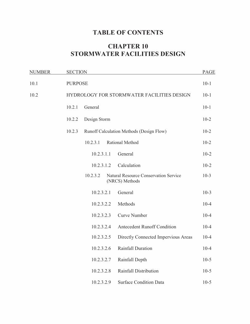
TABLE OF CONTENTS
CHAPTER 10 STORMWATER FACILITIES DESIGN
NUMBER SECTION PAGE
10.1 PURPOSE 10-1
10.2 HYDROLOGY FOR STORMWATER FACILITIES DESIGN 10-1
10.2.1 General 10-1
10.2.2 Design Storm 10-2
10.2.3 Runoff Calculation Methods (Design Flow) 10-2
10.2.3.1 Rational Method 10-2
10.2.3.1.1 General 10-2
10.2.3.1.2 Calculation 10-2
10.2.3.2 Natural Resource Conservation Service 10-3 (NRCS) Methods
10.2.3.2.1 General 10-3
10.2.3.2.2 Methods 10-4
10.2.3.2.3 Curve Number 10-4
10.2.3.2.4 Antecedent Runoff Condition 10-4
10.2.3.2.5 Directly Connected Impervious Areas 10-4 10.2.3.2.6 Rainfall Duration 10-4 10.2.3.2.7 Rainfall Depth 10-5 10.2.3.2.8 Rainfall Distribution 10-5 10.2.3.2.9 Surface Condition Data 10-5

TABLE OF CONTENTS (cont.)
CHAPTER 10 STORMWATER FACILITIES DESIGN
NUMBER SECTION PAGE
10.3 HYDRAULICS FOR STORMWATER FACILITIES DESIGN 10-5
10.3.1 General Guidelines 10-5
10.3.1.1 Design Flows 10-5
10.3.1.2 Allowable Pipe Materials 10-6
10.3.1.3 Roughness Coefficients “n” 10-6
10.3.1.4 General Pipe Design Requirements 10-6
10.3.2 Storm Sewers 10-7
10.3.2.1 Design Methodology/Design Storm 10-7
10.3.3 Culverts 10-7
10.3.3.1 Design Methodology/Design Storm 10-7
10.3.3.2 Maximum Allowable Headwater 10-7
10.3.3.3 General 10-8
10.3.4 Trenchless Pipe Installation 10-8
10.3.5 Conventional Channels and Ditches 10-8
10.3.5.1 Design Methodology/Design Storm 10-8
10.3.5.2 General 10-10
10.3.5.3 Channel Design Procedure 10-10
10.3.6 Natural Channel Design Procedures 10-12

TABLE OF CONTENTS (cont.)
CHAPTER 10 STORMWATER FACILITIES DESIGN
NUMBER SECTION PAGE
10.3.6.1 Design Methodology 10-12
10.3.6.2 Design Discharge 10-12
10.3.6.3 Design Submittals 10-12
10.3.6.4 Channel Stabilization Methods 10-13
10.3.6.5 Aquatic Habitat Enhancements 10-13
10.3.6.6 Riparian Corridor Enhancements 10-13
10.3.7 Surface Inlets and Gutter Spreads 10-13
10.3.7.1 Design Storm 10-14
10.3.7.2 Design Methodology 10-14
10.3.7.3 Maximum Flow Spread on Pavement 10-14
10.3.7.4 General 10-14
10.3.8 Detention Basins 10-15
10.3.8.1 Detention Basin Design 10-15
10.3.8.2 Basin Discharge 10-16
10.3.8.3 Parking Lot Surface Storage 10-18
10.3.8.4 Other Alternatives 10-18
10.3.9 Sinkholes 10-18
10.3.9.1 General 10-18
10.3.9.2 Design 10-18

TABLE OF CONTENTS (cont.)
CHAPTER 10 STORMWATER FACILITIES DESIGN
NUMBER SECTION PAGE
10.4 HYDROLOGIC AND HYDRAULIC MODELING STANDARDS 10-19
10.4.1 Software Selection 10-19
10.4.2 Hydrologic Modeling 10-20
10.4.2.1 Basin Parameters 10-20 10.4.2.2 Meteorological Parameters 10-21
10.4.2.3 Control Specifications 10-22
10.4.3 Hydraulic Modeling 10-22
10.4.3.1 Study Limits 10-22 10.4.3.2 Cross Sectional Geometry 10-22 10.4.3.3 Structures 10-24 10.4.3.4 Steady Flow and Boundary Conditions 10-24 10.4.3.5 HEC-RAS Methodology 10-25
10.4.4 Submittals 10-25
10.4.4.1 The Floodplain/Floodway Report Details 10-25
10.4.4.2 Watershed Analysis Mapping 10-26
10.4.4.3 Transmittal Medium 10-26

CHAPTER 10 STORMWATER FACILITIES DESIGN
EXHIBITS
EXHIBIT TITLE PAGE
10-1 HYDROLOCIC METHOD SELECTION FLOWCHART 10-27
10-2 RAINFALL INTENSITY - DURATION CURVES 10-28
10-3 RAINFALL FOR FLOYD COUNTY 10-29
10-4 HYDROLOGIC SOIL GROUPS 10-30
10-5 RATIONAL METHOD RUNOFF COEFFICIENTS 10-31
10-6 RUNOFF CURVE NUMBERS FOR URBAN AREAS 10-33
10-7 MANNING ROUGHNESS COEFFICIENTS, (n) 10-38

10-1
CHAPTER 10 STORMWATER FACILITIES DESIGN
10.1 PURPOSE
This chapter establishes the minimum standards for the planning and design of drainage systems and stormwater management facilities. The criteria in this section shall apply to all drainage facility design in both the local and through drainage systems except where facilities have significant and immediate impact upon State or Federal property or highways. In those cases, the most restrictive of State, Federal or these standards shall govern.
Stormwater design information may be retrieved from the Floyd County web page at http://www.floydcounty.in.gov/county%20offices/stormwater.htm or the New Albany web page at http://www.newalbanystormwater.org/.
10.2 HYDROLOGY FOR STORMWATER FACILITIES DESIGN
10.2.1 General
This section describes the recommended procedures for calculating the runoff generated from a project site. Correct utilization of these procedures should result in the best available estimation of existing and projected runoff. The procedure will also provide the consistency of results necessary when applied to project sites throughout New Albany and Floyd County. It is assumed that practicing Engineers involved with preparing drainage plans have adequate knowledge of the recommended procedures. There is, therefore, no attempt in this Design Manual to provide step-by-step calculation methodologies. The runoff calculation procedures to be utilized depend upon the size of the proposed development or project as follows:
A. If the total tributary area to an existing or proposed stormwater facility on the
project site is 50 acres or less, and no storage design is required, the method of runoff calculation shall be the Rational Method.
B. If the total project drainage area is greater than 50 acres, or storage design is required, a discharge hydrograph must be calculated using the NRCS method or another method that has been approved.
C. The Rational Method may be used to design through drainage channels if the drainage area of the channel is 50 acres or less; otherwise, the channel shall be designed by NRCS runoff calculation methodology or another method that has been approved. Note: See Exhibit 10-1 for guidance in selecting the appropriate method.

10-2
10.2.2 Design Storm The selection of a design storm is the basis for all runoff calculations and facility design for a project site. The facility specific requirements and associated check frequencies are found in Section 10.3.7. Localized restrictions may be placed on some areas, based upon existing drainage problems or flooding frequency. The elevation of the 100-year, 24-hour pre- and post-development discharge shall be checked for all drainage system designs to assure conformance with the guidelines of the FEMA Program. The elevation for the 100-year, 24-hour post-development discharge shall be conveyed within the limits of the proposed easement.
10.2.3 Runoff Calculation Methods (Design Flow)
10.2.3.1 Rational Method 10.2.3.1.1 General The Rational Method is the recommended runoff calculation procedure for project sites where: A. The total drainage area is 50 acres or less. B. Detention/Storage design is not required. 10.2.3.1.2 Calculation A. The Rational Method shall be performed as follows:
Q = C x I x A
Where: Q = Peak runoff (cu. ft. per sec.) C = Runoff coefficient I = Rainfall intensity (inches/hour) A = Contributing area (acres)
B. Rainfall Intensity-Duration Curves, Exhibit 10-2, shall be utilized in the Rational Method to determine rainfall depths and storm intensities.
C. The time of concentration (duration), Tc, shall be determined by calculating the time for a particle of water to travel from the most hydrological remote point of the project area to the point of interest. Acceptable methods to derive time of concentration are the TR-55 (Technical Release - 55, available from the NRCS) and the Kinematic Wave method. The minimum Tc shall not be less than 10 minutes to any given inlet or analysis point. Manning’s Equation should be used to estimate any in-pipe or channel travel.

10-3
D. The runoff coefficient, C, must represent a composite of the surface condition tributary to the point under consideration. To determine the appropriate C-Factor, the hydrologic soil group and land use for each surface condition must be obtained. Hydrologic soil group descriptions can be found in Exhibit 10-4. Exhibit 10-5 then combines this information with surface slope to provide the correct C-Factor for that area. The C-Factors given may be used directly when the drainage area is homogeneous. When it is not, an appropriately weighted C-Factor must be determined. For areas where no hydrologic soil group information can be obtained, the C-Factor shall be the values for soil group C. If the project site conditions differ significantly from those used as the basis for the C-Factor figures, the Design Engineer must develop a specific composite C-Factor for the area. To determine the composite C-Factor for the entire project site, a weighted average must be calculated based upon the percentage of the areas with different C-Factors. The Design Engineer shall select or calculate runoff coefficients, which reflect actual proposed designs. For subdivisions, the Design Engineer shall accommodate the maximum imperviousness permitted under land use guidelines.
E. To calculate flow rates in series, i.e., in ditch or storm sewer design, the C*A term shall be summed for all contributing drainage areas. The intensity shall be selected from the time of concentration to that point. The Tc selected shall be the larger of: 1) Tc for the subject inlet or analysis point based on overland flow to said inlet/analysis point, or 2) the Tc from the previous in-line inlet or analysis point plus the travel time from the previous inlet or analysis point.
10.2.3.2 Natural Resource Conservation Service (NRCS) Methods 10.2.3.2.1 General The NRCS Methods are required for runoff calculation procedures for project sites where: A. The total project drainage area is greater than 50 acres or;
B. Detention/Storage design is required and the site is larger than one acre.
When these project conditions exist, the Design Engineer shall confer with New Albany or Floyd County to determine if there is a hydrologic model available for the area. If a model exists, site calculations must be performed and correlated with this data. If models do not exist, the Design Engineer must use the NRCS Methodology to develop a hydrologic model.

10-4
10.2.3.2.2 Methods The NRCS Methods also include the TR-20 and TR-55 Methods. Detailed descriptions, example calculations, and worksheets for these methods are available in: A. Project Formulation - Hydrology, Technical Release No. 20 User's Manual; B. Urban Hydrology for Small Watersheds, Technical Release No. 55; and C. A Guide to Hydrologic Analysis Using NRCS Methods. 10.2.3.2.3 Curve Number The Curve Number (CN) is similar to the Rational Method C-Factor in that it is based on the surface conditions of the project site. The correct CN can be determined from Exhibit 10-6. Maps depicting the NRCS Hydrologic Soil Groups, Existing Land Use, and Projected Land Use for each watershed are available through the NRCS. This information may be used to determine the appropriate surface condition factors for use in runoff calculations as described in this Section. 10.2.3.2.4 Antecedent Runoff Condition The index of runoff potential before a storm event is termed the Antecedent Runoff Condition (ARC). The ARC is an attempt to account for the variation in CN at a particular site for various storm conditions. The CNs in Exhibit 10-6 are for average ARC, which are used primarily for design applications. Please refer to the NRCS National Engineering Handbook, Section 4 - Hydrology (NEH-4, NRCS) for a detailed discussion of storm to storm variations and upper and lower CN limits. Adjustments to the ARC will normally be involved only in calibration. 10.2.3.2.5 Directly Connected Impervious Areas Directly connected impervious areas shall be considered where applicable in NRCS runoff calculations. The Design Engineer shall select or calculate runoff coefficients, which reflect actual proposed designs. For subdivisions, the Design Engineer shall accommodate the maximum imperviousness permitted under land use guidelines. 10.2.3.2.6 Rainfall Duration The minimum design storm duration for planning and design is the NRCS Method, and will utilize the NRCS Type II 24-hour rainfall distribution. Critical storm analysis shall be performed when warranted.

10-5
10.2.3.2.7 Rainfall Depth Exhibit 10-3 shall be utilized to determine total rainfall depths for New Albany and Floyd County for use by the NRCS methods. These values are derived from NOAA Atlas 14, Volume 2, Version 3, Revised 2006, published by the U.S. Department of Commerce, National Oceanic and Atmospheric Administration, and National Weather Service. 10.2.3.2.8 Rainfall Distribution Synthetic rainfall distributions shall be used for design storm generation. When critical storm analyses are not required, the distributions shall match the NRCS Type II curve as published in NRCS Technical Report 55, with 5-minute time steps. In some cases New Albany or Floyd County may require a critical storm analysis to determine the rainfall duration and distribution that produces the worst runoff conditions for a specific site. Since the NRCS Type II distribution represents a 24-hour duration storm only, it is not applicable to the critical storm analysis. This analysis will be based on dimensionless Huff Distributions as presented in Rainfall Frequency Atlas of the Midwest by Floyd Huff and James Angel, Midwestern Climate Center, NOAA, and the Illinois State Water Survey, A Division of the Illinois Department of Energy and Natural Resources. 10.2.3.2.9 Surface Condition Data Maps depicting the NRCS Hydrologic Soil Groups, Existing Land Use, and Projected Land Use for each watershed in New Albany and Floyd County are available through the NRCS Web Soil Survey at http://websoilsurvey.nrcs.usda.gov/app/HomePage.htm. This information may be used to determine the appropriate surface condition factors for use in runoff calculations as described in this Section.
10.3 HYDRAULICS FOR STORMWATER FACILITIES DESIGN
This section contains the technical criteria required for the design of stormwater facilities. The Design Engineer must make adequate reference to other chapters of this manual for additional design guidelines.
10.3.1 General Guidelines
10.3.1.1 Design Flows A. Design flows must be calculated by the appropriate method described in
Section 10.2. At a minimum, the facility must have the capacity to transport the 10-year, 24-hour post-development discharge, except in retrofit projects (with approval from the New Albany Stormwater Board or Floyd County Stormwater Department). The water surface profile and through system

10-6
capacity shall be checked for the 100-year, 24-hour post-development discharge. All systems must be capable of passing the 100-year, 24-hour design flow within the drainage easement. Additional facility-specific requirements are found in following portions of this Section.
10.3.1.2 Allowable Pipe Materials
A. Pipe material will be selected from the products identified in the Louisville MSD Standard Specifications. CMP is not allowed.
10.3.1.3 Roughness Coefficients “n” (See Exhibit 10-7)
A. Concrete Pipe: 0.012
B. Plastic (Smooth Interior Wall): 0.011
C. Sod: 0.030
D. Placed Riprap: 0.030
E. Dumped Riprap: 0.035
F. Gabions: 0.028
G. Coefficients for other approved materials shall be source documented for review.
10.3.1.4 General Pipe Design Requirements
A. Minimum velocity shall be 2 feet per second at design flow or 3 feet per second at full flow; whichever requires the greater slope.
B. Minimum pipe size shall be 12 inches unless otherwise approved by New Albany or Floyd County.
C. Maximum manhole spacing 1. Less than 18" diameter- 400' 2. 18" to 30" diameter- 500' 3. 33" and greater diameter- 600'
D. All pipes are to have headwalls. Design of headwalls shall consider traffic safety.
E. Stubs for storm sewers when required shall be 1 foot long measured from the outside of the manhole or surface inlet for PVC and PE pipe or one length of pipe for concrete pipe.

10-7
F. Submerged pipes are not desirable, but may be approved on a case-by-case basis.
10.3.2 Storm Sewers
10.3.2.1 Design Methodology/Design Storm All storm sewer systems will be designed for the 10-year, 24-hour storm. The 100-year, 24-hour storm discharge elevation must be checked to ensure the system does not surcharge out of any inlets and/or manholes. Manning's Equation is recommended to calculate pipe flow and velocity. The storm sewer hydraulic grade line shall be at least 1.0 foot below the ground surface or building drain elevation, whichever is lower, at all points for the 10-year, 24-hour design event. For the 100-year, 24-hour event, the hydraulic grade line may not rise higher than the ground line or building drain elevation, whichever is lower. Losses at all inlets, junction structures and bends are to be considered. Pipes on grades greater than or equal to 20% shall have anchors at each pipe joint. The Design Engineer shall check to ensure that all pipes have sufficient cover and that all structures, inlets and manholes have sufficient dimension to receive pipes, bells, frames, and grates.
10.3.3 Culverts
10.3.3.1 Design Method/Design Storm A method as described in the INDOT Design Manual Chapter 203 Hydraulics and Drainage Design, along with the maximum allowable headwater and general requirements below, shall be used to design culverts. The design method utilized must be submitted for review. 10.3.3.2 Maximum Allowable Headwater The most stringent requirement of the following will apply: A. Cul-de-sacs, alleys, local streets, and collectors: Use the subgrade elevation of
the adjacent roadway for the 10-year, 24-hour discharge.
B. Major and minor arterials: Use 12-inches below the shoulder elevation of the adjacent roadway for the 100-year discharge.
C. Headwater for the 10-year, 24-hour discharge shall not exceed 1.2 times the structure rise except as specifically approved on a case-by-case basis. For pipes 30” in diameter and larger, the headwater shall not exceed 1.0 times the structure rise except as specifically approved on a case-by-case basis.
D. If a culvert has a drainage area greater than one square mile or is in a regulated floodplain the 100-year, 24-hour storm headwater depth shall not be greater than 1.0 times the structure rise except as specifically approved on a case-by-case basis.

10-8
10.3.3.3 General A. Downstream channel must receive appropriate protection or energy
dissipation if the design outlet discharge would cause erosive conditions. B. Traffic safety must be considered in the design of culvert end treatments. This
may include extending the culvert beyond the right-of-way limits, installing catch basins to intercept roadside swales, and installing guardrails. Designs must conform to meet the requirements of the agency responsible for road maintenance and safety.
10.3.4 Trenchless Pipe Installation
Trenchless pipe installation for storm sewers and culverts is described in Chapter 12 of this manual.
10.3.5 Conventional Channels and Ditches This section describes the technical criteria necessary to design stormwater channels and ditches using conventional design procedures. These procedures shall be applied to roadside and rear yard ditches and highly urbanized channels. Where possible, all waters of the state (especially in undisturbed areas) shall be designed using Natural Channel Design techniques as described in Section 10.3.6. This criterion represents minimum requirements. Justification shall be submitted for review and approval in cases where different slopes or other protective measures are recommended. 10.3.5.1 Design Methodology/Design Storm Manning's Equation is recommended, except in cases where backwater conditions are significant. All calculations must be submitted for review. Software programs utilized must be approved. A. Design Storm
1. Channels and ditches shall be capable of conveying the 10-year, 24-hour storm flow within their banks. Through drainage systems shall be designed to collect and transport the onsite post-development rate and the offsite existing rate of runoff for the 100-year, 24-hour design storm. In all cases, the 100-year, 24-hour discharge elevation must be checked to ensure that adjacent structures do not suffer flood damage.
2. All systems must be capable of passing the 100-year, 24-hour design
flow within the drainage easement.
B. Channel Criteria The Minimum Channel Slope shall be 0.5%, except in special cases such as retrofit projects or major channels.

10-9
C. Maximum Side Slope 1. Earth 3:1 (when depth < 8.0 feet) 4:1 (when depth > 8.0 feet) 2:1 (may be allowed on case-by-case basis) 2. Riprap and Aggregate 1.5:1 3. Concrete 1:1 4. No maintenance ground cover 2:1 5. Bioengineered systems on various slopes
D. Channel Depth Channels created for new residential subdivisions shall not have a design depth of greater than 2.0’, unless otherwise approved.
E. Channel Lining 1. Channel slope 0.5% or less - Concrete. Evaluate the use of a low flow
channel. 2. Channel Slope between 0.5% and 2.0% - Concrete low flow channel
with durable lining for the remainder of the protected section. 3. Channel Slope greater than 2.0% - Natural vegetation, geosynthetic turf
reinforcement, Rip Rap or concrete based on shear stress requirements. 4. If the design parameters are beyond the limits of natural vegetation,
then a non-degradable durable material must be used. Durable channel lining is required to the depth of the 10-year, 24-hour storm. Durable channel lining may be low maintenance ground cover, sod, soil bioengineered systems, turf reinforcement mats or concrete. Rip-Rap, Aggregate Channel Lining and Gabion Baskets are to be limited to areas immediately downstream of an outlet pipe to reduce velocities and erosion potential. The use of these materials shall be a last alternative and approved on a case by case basis.
5. Trapezoidal or rectangular paved channels shall have bottom slopes no
less than 1:12 sloping either to the center or to one side of the channel to provide self cleaning.
6. Channel and channel lining design shall consider the effects of open
channel junctions, curved alignment, obstructions, transitions, constrictions, changes in slope and other characteristics including the effects of subcritical and supercritical flow.

10-10
10.3.5.2 General
A. Roadside ditches on retrofit projects, which have less than a 4 foot shoulder, shall not exceed 1'-6" in depth, measured from the edge of pavement.
B. Roadside ditches and channels must have a minimum 4 foot shoulder from
the edge of the pavement to the top of the bank.
C. Roadside ditches and channels in through systems must have a minimum 8-foot shoulder from the edge of the pavement to the top of the bank.
D. In areas where new sidewalks are proposed to cross swales, ditches, or
channels, a culvert meeting design storm requirements must be installed extending past the sidewalk sufficiently to allow a maximum 4:1 slope.
E. Ditches and channels adjacent to state highways may require more stringent
criteria. The Design Engineer must obtain the criteria from the INDOT.
F. Cutoff walls shall be placed at the beginning and end of all paved channels.
G. Utilities and their facilities should not be located within or interfere with swales, ditches, detention/retention facilities, stormwater quality treatment devices and facilities, manholes, pipes or landscaping such as trees and bushes.
10.3.5.3 Channel Design Procedure
A. The method of designing channels and ditches as presented agrees with
Hydraulic Engineering Circular HEC-15 that is based on the tractive force theory. The calculated shear stress resulting from flow in a channel is compared to the maximum permissible shear stress for the channel lining selected. If the shear force induced by the flowing water equals or exceeds the permissible shear stress of the lining, failure may occur and a more resilient lining must be proposed. This concept allows for calculation of the maximum discharge a channel can carry by equating the calculated and permissible shear1. The procedure is applicable to channels of uniform cross section and constant bottom slope.
The suggested step-by-step design procedure is shown below. Additional information is taken from the Federal Highway Administration’s HYDRAIN software documentation manual. Other procedures and references may be utilized by the design engineer. However, it will be the design engineers responsibility to satisfy all design requirements.
B. The design procedure as shown assumes steady uniform flow with the energy
slope equal to the bed slope and flow calculated using Manning’s equation. For conditions other than these, the designer should consult other references; one of which is HEC-11, which focuses on natural channels with irregular cross sections, varying bottom slopes, and flows exceeding 50 cfs.

10-11
The maximum shear stress on the side slopes is always less than or equal to that on the channel bottom and does not limit the design of a single, rigid, vegetative, gabion, or temporary lining, but may affect the design of composite linings1. The designer is alerted to this situation and should consult the previously noted references.
C. Design Procedure
1. Determine Drainage Area Contributing to the Channel. 2. Select Channel Cross Section- Side Slopes & Bottom Width 3. Determine Channel Longitudinal Grade 4. Calculate Design Flow - Adjust channel cross-section and grade as
necessary for capacity. 5. Select Channel Lining
a. Determine maximum permissible shear stress (τp) for the
selected lining. See Table 8-11 in the Stream Restoration Design National Engineering Handbook at http://www.nae.usace.army.mil/reg/nrrbs/chapters/Chapter-08.pdf for a summary list of various protection measures or the manufacturer’s recommendations for specific Turf Reinforcement products.
b. Estimate flow depth in the channel. c. Determine Manning “n” for selected lining and depth of flow. d. Calculate flow using Manning’s equation and the estimated
flow depth. e. If calculated flow varies from design flow, repeat steps (b)
and (d) until flows agree. f. Calculate actual shear stress(τd)
τd =γdn s,
Where:
τd = actual shear stress 1b/ft2 γ= specific weight of water 62.4 lbf/ft3 dn = flow depth in ft. s = energy slope (bed slope); ft/ft
1Federal Highway Administration’s HYDRAIN Software Documentation (GKY and Associates, Inc.)

10-12
g. If τd < τp, the lining selected is acceptable. If τd> τp, consider the following: � Select a lining with a higher permissible shear stress � Decrease slope � Increase the channel width and/or flatten side slopes
10.3.6 Natural Channel Design Procedures
This section describes Natural Channel Design procedures to be utilized where possible for the design of streams especially along waters of the state and in undisturbed areas. It should be noted that Natural Channel Design techniques promote enhanced stormwater quality and aquatic habitat over conventionally designed channels and ditches and is the preferred method for the design of streams.
10.3.6.1 Design Methodology
Streams designed using natural channel design techniques shall emulate naturally formed streams. The design shall be based upon measurements from reference reaches in similar physiographical regions exhibiting similar characteristics to the desired stream. The designed stream shall exhibit characteristics consistent with stream types expected to occur within the given valley type. Both the pre-existing stream type and the designed stream shall be classified in accordance with the Rosgen Stream Classification system2.
10.3.6.2 Design Discharge
Streams designed using Natural Channel Design techniques shall include a bankfull channel design based on the bankfull discharge (also commonly referred to as the channel forming event). It approximates a 1.5-year storm event and can range between a 0.8 to 2.0-year storm event. The bankfull discharge used for design shall be determined based on field bankfull indicators and shall be checked against regional curves developed from gauged streams within the same physiographical region as the stream to be designed. Where flooding of nearby structures may occur, the floodplain area adjacent to the bankfull channel shall be designed to convey a 100-year, 24-hour storm event. 10.3.6.3 Design Submittals All parameters/information used for the basis of design shall be submitted for review. Where an existing stream is present, the design submittal shall include calculations for the proposed channel as well as measurements from the existing channel. Information submitted shall include reference reach data and location of reference reaches.
2Applied River Morphology (Dave Rosgen, 1994).

10-13
As a minimum, the following design parameters/information shall be included in the design submittal: longitudinal profile; cross sectional geometry for pool, riffle and cross-over reaches; stream type; drainage area; bankfull width; mean bankfull depth; bankfull cross sectional area; bankfull discharge; mean bankfull velocity; maximum bankfull depth; width to depth ratio; width of flood prone area; entrenchment ratio; ratio of pool depth to mean bankfull depth; ratio of pool width to mean bankfull width; average riffle, pool, run and glide slope; average water surface slope; valley slope; meander length; belt width; radius of curvature; ratio of meander length to bankfull width; ratio of radius of curvature to bankfull width; meander width ratio; sinuosity; pool to pool spacing; ratio of pool to pool spacing to bankfull width; D50 of bed materials; D84 of material which will be transported during a bankfull event; critical dimensionless shear stresses; minimum mean bankfull depth calculated using dimensionless shear stress equations. 10.3.6.4 Channel Stabilization Methods Methods to be utilized to stabilize channel banks below the bankfull depth should be included within the design submittal. The use of rock should be limited to areas exhibiting shear stresses above allowable shear stresses for vegetation. The use of native vegetation and soil bioengineering treatments is the preferred method to stabilize channel banks. 10.3.6.5 Aquatic Habitat Enhancements The use of aquatic habitat enhancements should be included where possible and consistent with stream types. Enhancements may include a variety of structures consistent with stream types such as woody material, rock or wood overhangs, rock vanes, cross vanes, W-weirs, J-hook weirs, stream gravel/boulders, etc. Details for all structures shall be included with the design submittal. In most instances, it is not necessary to extend any in-stream structures or bank revetments above the bankfull depth. 10.3.6.6 Riparian Corridor Enhancements Where practical, the design shall include enhancements to the riparian corridor on either side of the reconstructed stream. Riparian corridor enhancements shall include native plantings consistent with anticipated inundation periods. Submittals shall include a description of existing vegetation within the riparian corridor as well as proposed plantings and frequency schedules.
10.3.7 Surface Inlets and Gutter Spreads
This section describes the technical criteria necessary to design surface inlets/catch basins. Please reference HEC 12, Drainage of Highway Pavements for more in depth discussions and procedures.

10-14
10.3.7.1 Design Storm Curb inlets and gutter spreads shall be designed for a storm intensity of 4 inches per hour. All other stormwater inlets shall be designed for the 10-year, 24-hour storm return period. 10.3.7.2 Design Methodology The design methodology utilized shall be those presented in HEC 12, Drainage of Highway Pavements or the INDOT Design Manual. 10.3.7.3 Maximum Flow Spread on Pavement Maximum flow spreads on pavement shall be as follows: A. Cul-de-sacs, Alleys, and Local Streets - 6 feet; 8 feet with 2 foot wide
concrete curb and gutter. B. County Through Roads - 4 feet; 6 feet with 2 foot wide concrete curb and
gutter. Flow spread is measured from the face of curb. The minimum slope for gutters shall be 0.50%. In addition, the flow depth at any location along the curb shall not exceed 4 inches. 10.3.7.4 General A. Inlets shall be placed immediately upstream of pedestrian walkways and
intersections and designed to intercept as close to 100% of the flow as possible.
B. Inlets placed at locations other than that described above shall be placed at
locations that prevent the allowable spread or depth at curb criteria from being exceeded. Vane grates shall be used at all inlet locations.
C. Inlets at sags in curb and gutter applications shall receive careful design to
prevent violation of the gutter spread requirements above. In addition, it is good engineering practice to place flanking inlets on each side of the low point inlet when in a depressed area that has no outlet except through the system. This is illustrated in the figure shown below.
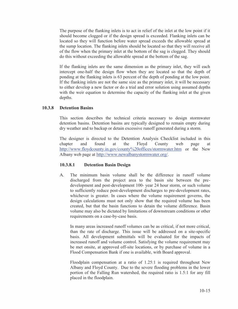
10-15
The purpose of the flanking inlets is to act in relief of the inlet at the low point if it should become clogged or if the design spread is exceeded. Flanking inlets can be located so they will function before water spread exceeds the allowable spread at the sump location. The flanking inlets should be located so that they will receive all of the flow when the primary inlet at the bottom of the sag is clogged. They should do this without exceeding the allowable spread at the bottom of the sag. If the flanking inlets are the same dimension as the primary inlet, they will each intercept one-half the design flow when they are located so that the depth of ponding at the flanking inlets is 63 percent of the depth of ponding at the low point. If the flanking inlets are not the same size as the primary inlet, it will be necessary to either develop a new factor or do a trial and error solution using assumed depths with the weir equation to determine the capacity of the flanking inlet at the given depths.
10.3.8 Detention Basins This section describes the technical criteria necessary to design stormwater detention basins. Detention basins are typically designed to remain empty during dry weather and to backup or detain excessive runoff generated during a storm. The designer is directed to the Detention Analysis Checklist included in this chapter and found at the Floyd County web page at http://www.floydcounty.in.gov/county%20offices/stormwater.htm or the New Albany web page at http://www.newalbanystormwater.org/. 10.3.8.1 Detention Basin Design A. The minimum basin volume shall be the difference in runoff volume
discharged from the project area to the basin site between the pre-development and post-development 100- year 24 hour storm, or such volume to sufficiently reduce post-development discharges to pre-development rates, whichever is greater. In cases where the volume requirement governs, the design calculations must not only show that the required volume has been created, but that the basin functions to detain the volume difference. Basin volume may also be dictated by limitations of downstream conditions or other requirements on a case-by-case basis.
In many areas increased runoff volumes can be as critical, if not more critical, than the rate of discharge. This issue will be addressed on a site-specific basis. All development submittals will be evaluated for the impacts of increased runoff and volume control. Satisfying the volume requirement may be met onsite, at approved off-site locations, or by purchase of volume in a Flood Compensation Bank if one is available, with Board approval.
Floodplain compensation at a ratio of 1.25:1 is required throughout New Albany and Floyd County. Due to the severe flooding problems in the lower portion of the Falling Run watershed, the required ratio is 1.5:1 for any fill placed in the floodplain.
10-16
In the Falling Run watershed, the volume of increased runoff must be mitigated at a ratio of 1.5:1.
If the basin is to be located directly on a portion of the through drainage system, volume calculations must also consider the total system flow reaching the basin. If the basin is to be constructed on a solid or intermittent stream, it must be beneficial to the stream corridor or the public.
Detention Basins for private development projects shall not be constructed in the Floodway. They may be constructed in the Floodplain with Board approval. Capital Project Detention Basins are constructed to compensate for additional flow from existing development. Some Capital Project Detention Basins must be built in the Floodplain or Floodway to accomplish their goals.
B. Maximum basin side slopes shall be 3:1, unless retaining walls are provided. C. Low flow channels may be grass if the channel grade is between 2.0% and
4.0%. D. Basin design must include maintenance accessibility and responsibility. E. Requirements of Dam Safety Laws shall be observed. F. The Design Engineer shall address provisions for anti-seep collars, extended
detention basins, wet ponds, soil bioengineering, baffles, outlet protection and length to width ratios.
G. The minimum length to width ratio of detention basins shall be 3:1. Inlets
(pipes or ditches) shall be no closer to the outlet than the midpoint of the basin.
H. No sanitary sewer manholes shall be located within the detention basin. I. Detention basins in Single Family Developments are to be placed in a lot
recorded as “Open Spaces”. All other detention basins must be completely within a recorded Easement.
J. Retention basins (permanent pool basins or wet basins) shall have a minimum depth of 5’.
10.3.8.2 Basin Discharge
A. Discharge control structures shall be multi-stage and capable of limiting 2, 10, and 100-year, 24-hour post-development discharges to pre-development peak discharge rates or downstream system capacity, whichever is less, and shall be constructed of concrete or approved alternate. Orifices smaller than 12” shall take precautions to avoid clogging. See example shown on the next page.

10-17
PLAN VIEW
SECTION A-A SECTION B-B
A A
B
B
B. The emergency spillway shall be sized to accommodate a flow equal to the design overflow of the 100-year, 24-hour storm post-development discharge, assuming all other outlets are completely blocked, without overtopping the dam. Discharge must be conveyed to a public outlet of sufficient capacity. Erosion protection must be provided for the spillway and receiving stream and energy dissipation must be employed.
C. The dam elevation shall not be less than one foot above the 100-year, 24-hour storm storage and overflow elevation.
D. Appropriate downstream channel protection must be installed and the basin outlet pipe must be placed no closer than 15’ from an adjacent property line.
E. Storage, discharge, and routing calculations for the 2, 10, and 100-year, 24-hour discharges must be submitted for review and have a Professional Engineer’s stamp and signature.
F. The top of dam shall be at least one foot below the lowest opening of any structure adjacent to and upstream of the dam.
G. Detention basins shall be fully discharged, or return to normal pool elevation in the case of wet basins, within 36 hours after the storm event unless specifically approved.
H. The detention basin shall be the first item of construction and must be designed to function as a sediment basin through the construction period. The basin design must be checked for capacity due to additional runoff generated by disturbed site conditions. The detention basin may be designed with over-excavation to account for planned sedimentation during construction. Excess sedimentation shall be removed and disposed of properly to establish design capacity of the detention basin.

10-18
10.3.8.3 Parking Lot Surface Storage
A. Parking lot storage involves shallow ponding in a specifically graded area of a parking lot. The major disadvantage is the inconvenience to users during the ponding function. Clogging of the flow control device and icy conditions can be maintenance and safety problems. This method is intended to control the runoff directly from the parking area and is not appropriate for storing large volumes.
B. The general design requirements are: 1. Maximum water depth: 8 inches 2. Maximum surface grade: 5.0% 3. Minimum surface grade: 1.0%
10.3.8.4 Other Alternatives A. The use of Underground Detention must be approved by New
Albany/Floyd County. Underground Detention and oversized piping shall be bonded for the full construction cost, have a pre-treatment device and be tele-inspected before bond release.
B. Vegetated recessed islands, bio-swales or micro-detention are acceptable
alternatives in appropriate soil conditions and will be approved on a case-by-case basis.
10.3.9 Sinkholes
10.3.9.1 General A sinkhole is any closed depression in a limestone region formed by the removal of water, surfacial soil, rock or other material that is connected to a cavern or underground passage. The sinkhole drainage area shall include any area that contributes surface water directly to the sinkhole. The use of sinkholes as stormwater management facilities is not permitted, unless there are no other cost-effective alternatives. The use of sinkholes must be submitted for approval. 10.3.9.2 Design Specific design considerations for the use of sinkholes, when permitted, include but are not limited to: A. The sinkhole shall have the volume to store a 100-year, 24-hour NRCS storm
with a no outlet condition.

10-19
B. Capacity of the sinkhole, including a hydrogeologic study along with dye test results.
C. Protection measures for the sinkhole inlet.
D. Trash barriers.
E. Detention requirements.
F. An alternate means of surface water disposal in the event of sinkhole failure.
G. Restriction of development in floodplain areas adjacent to the sinkhole.
H. Review of construction methods and staging.
I. The design of sinkhole structures must be supervised by a Geotechnical Engineer, licensed in Indiana. The engineer shall also inspect and certify the construction of the sinkhole structure and certify the ability of the sinkhole to accept anticipated flows without flooding or causing property damage in the case of failure.
J. Any structural failures must be fully documented and a Geotechnical Engineer, licensed in the Indiana, must supervise design of, inspect and certify construction of repairs.
10.4 HYDROLOGIC AND HYDRAULIC MODELING STANDARDS
Development of uniform modeling standards is a means by which New Albany and Floyd County can regulate the quality of the floodplain models. Successful floodplain management requires that the hydrologic and hydraulic floodplain models be updated as changes in watersheds occur. These changes include those resulting from continued development in the watershed, as well as from physical changes in the drainage system. As the watersheds evolve over time, the modeling standards provide guidance on how changes should be incorporated into the models. The implementation of a comprehensive set of modeling standards promotes consistency in floodplain modeling, standardizes review efforts, and provides a means to educate the engineering/development community. The following modeling guidelines are consistent with current engineering standards of practice not necessarily to the exclusion of other sound and technically supported procedures. If an alternative modeling method is proposed, a licensed professional engineer shall justify the use of any methods other than those described below in writing prior to the model submittal and review process.
10.4.1 Software Selection
HEC-1 and HEC-HMS are the recommended programs for rainfall/runoff hydrologic simulations requiring hydrograph analysis at one or more points along a stream. HEC-2 and HEC-RAS are the recommended programs for open channel

10-20
flow or floodplain calculations excluding streams with extremely low or high gradient. The most current versions of these software packages are available from the Hydrologic Engineering Center’s website at www.hec.usace.army.mil.
Caution should be used when converting from one version to another (for example HEC-2 to HEC-RAS) to make sure that the original intent of the model is understood. Changes to be made for the newer model should work properly and should be fully documented. The HEC manuals offer guidance for conversions to the newer versions of their software. Other software may be accepted for floodplain analysis if approved by FEMA for National Flood Insurance Program (NFIP) usage. A list of accepted models may be found at www.fema.gov. Civil site analysis, local detention basin design, water quality analysis, natural channel design, and interior drainage system design may be performed with models not on FEMA’s approved NFIP list if approved by New Albany or Floyd County prior to use, on a case by case basis.
10.4.2 Hydrologic Modeling
The following methods and/or parameters shall be used for single event hydrologic analyses for streams and/or detention basin calculations. 10.4.2.1 Basin Parameters
A. Subbasin Delineation. Depending on the size and location of the watershed
being analyzed, and the extents of previous modeling attempts, tributary boundaries may need to be redefined or subdivided. Drainage areas must be delineated using mapping with 2 foot contours available in New Albany and parts of Floyd County. In areas where watersheds extend into other counties and 2 foot contour data is not available, supplement the topographic data with 7-1/2 Minute USGS Topographic Quadrangles. Subbasin size in developable watershed areas should be 50 to 200 acres. Areas that are not expected to develop due to land use or zoning criteria can have larger subbasin areas based on natural drainage patterns.
B. Loss Rate. The NRCS Runoff Curve Number (CN) Method, as described in
TR-55 (NRCS 1986) and NEH-4 (NRCS 1985), shall be used to estimate runoff from design storms. Continuous simulations, if necessary, may use other loss rate methodology where applicable.
C. Transform. Rainfall excess shall be transformed into runoff using the NRCS
Unit Hydrograph approach.
D. Base Flow. Unless modeling the Ohio River, base flow may be ignored during floodplain analyses.
E. Time of Concentration (Tc). The time of concentration shall be calculated for
each subbasin using the combined travel times for sheet flow, shallow concentrated flow, and open channel flow in accordance with TR-55 (NRCS 1986).

10-21
F. Antecedent Runoff Conditions (ARC). Average ARC shall be used in all cases except for model calibration.
G. Infiltration. Runoff infiltration will be calculated using the NRCS Runoff Curve Number (CN) Method, as discussed above. CN’s should be developed for both the “existing watershed conditions” (EX) and the “fully developed watershed conditions” (FD) and analyzed separately. EX CN’s shall be estimated using NRCS Web Soil Survey (located at http://websoilsurvey.nrcs.usda.gov/app/HomePage.htm) data for hydrologic soil groups, land cover type and treatment, hydrologic condition, and percentage of impervious area (connected or unconnected). Impervious area calculations should include buildings, roads, and miscellaneous transportation such as sidewalks and driveways. FD CN’s shall be estimated using soils data, existing zoning regulations, and Exhibit 10-6 with maximum impervious area limitations to CN values.
H. Channel Routing. Hydrograph routing through a subbasin or along a reach of stream shall use either the Modified Puls (low gradient) or Muskingum-Cunge (moderate to high gradient) routing techniques. Muskingum-Cunge 8-point cross sections are recommended for natural channels. Routing results in the hydrologic model must correlate with the hydraulic model for the same reach.
I. Reservoir Routing. Reservoir routing may be used for modeling storage effects at bridges or culverts, or may be used for detention facility analysis. In either case, the routing method shall use an elevation-volume-outflow relationship developed by the engineer with consideration of backwater effects on the outlet hydraulics. The initial conditions of reservoir elements shall be controlled by normal dry-weather water surface elevations. Documentation of methods used to derive the hydraulic response and storage capacity of structures associated with reservoir routing should accompany the submittal.
10.4.2.2 Meteorological Parameters A. Rainfall Duration. All models used for hydraulics analysis shall use 24-hour
duration design storms.
B. Total Rainfall Depth. Rainfall depths associated with various annual exceedence probabilities are referenced from NOAA Atlas 14 Precipitation-Frequency Atlas of the United States, Volume 2 Version 3.0, Revised 2006. Exhibit 10-3 contains a table with various rainfall amounts for storm events. The 24-hour duration rainfall values used for analysis are as follows:
� 2-year 3.1 inches � 10-year 4.4 inches � 100-year 6.8 inches

10-22
C. Temporal Distribution. The NRCS Type II rainfall distribution (5-minute increment) will be used for design storm definition in New Albany and Floyd County.
D. Spatial Distribution. Design storms shall be applied uniformly and simultaneously to subbasins of the hydrologic simulation.
10.4.2.3 Control Specifications
A. Calculation Time Step. There are five-minute (or less) calculation steps required for hydrologic modeling.
B. Simulation Length. Hydrologic models must simulate the 24-hour design storm and describe watershed response until all elements are within 5% of their initial discharge conditions.
10.4.3 Hydraulic Modeling
Water surface profile modeling is required for analyzing impacts to waters of the state and intermittent streams. The one-dimensional, steady flow calculations performed by HEC-RAS are suitable for most watershed conditions. 10.4.3.1 Study Limits The hydraulic study shall extend upstream and downstream of the impacted reach to a point that the modified profile converges with the existing condition profile for the same event. When creating new models, verify the modeling extent with New Albany or Floyd County prior to starting the project. 10.4.3.2 Cross Sectional Geometry A. Width. The minimum width is set by extending the left and right ends of the
cross section to one foot above the 100 year floodplain elevation.
B. Spacing. Cross section locations shall be based on sound engineering judgment. Higher density is required at tributary locations, slope changes, roughness changes, valley morphology changes, and at bridges or other structures. In general, cross section locations should be based on the riffle spacing of the stream being studied. Pool cross sections may be necessary for geomorphic channel design, but are not required for floodplain determination. Cross section spacing on any stream in New Albany and Floyd County should not exceed 500 feet (excluding the Ohio River).
C. Number of Data Points. A minimum of seven data points is required to describe each cross section. The maximum number of data points is limited by software constraints.
D. Source of Geometry Data. Elevation data in the active channel shall be

10-23
collected with field survey and tied to the North American Vertical Datum of 1988 (NAVD 88) . The cross section geometry shall have the density of points necessary to accurately quantify the area under bankfull elevation and the location of the stream thalweg. Two foot contour mapping may be used to supplement cross section data in the floodplain (overbanks). A licensed Land Surveyor or Professional Engineer must document the accuracy of survey information at cross sections and Structures.
E. Bank Stations. Bank stations in natural cross sections shall be placed at the geomorphic bankfull elevation. Variations in roughness values shall be included for the channel bed, left and right banks, and left and right floodplains.
F. Reach Lengths. The distances measured between cross sections at similar points are called reach lengths. HEC-RAS uses this information to compute discharge-weighted reach overbank segments. Floodplain models should use the distance measured along the stream thalweg for the centerline reach length. Left and right overbank reach lengths should be estimated as the center of mass of the floodplain discharge.
G. Roughness Values. Channel and floodplain roughness values significantly influence model accuracy. Roughness values should be reflective of the natural variations in the bed materials and overbank vegetation. Consistent with models developed in the past, Manning’s n should be used to describe frictional energy losses. There are a variety of methods available for calculating Manning’s n from particle size distributions of channel materials (USDA, Rosgen, and others). Listed below are some additional references available that have photographs of reaches with measured values. A listing and description of roughness values with photographs should be included in the documentation of the model development. References:
Open-Channel Hydraulics, Chow, 1959 Roughness Characteristics of Natural Channels, Barnes, Harry H., USGS, 1967 Roughness Characteristics of New Zealand Rivers, Hicks and Mason, 1991 Stream Corridor Restoration Principles, Practices, and Processes, USDA, 1998 The Reference Reach Field Book, Rosgen, 1998
H. Expansion and Contraction Coefficients. Subcritical flow contraction and expansion coefficients are used to estimate energy losses caused by abrupt changes in the flowing cross sectional area. Typical losses occur upstream and downstream of bridge or culvert crossings and flow through a narrower portion of the valley. Where contraction and expansion losses are expected to occur, contraction coefficients should vary between 0.1 and 0.3, expansion coefficients should vary between 0.3 and 0.5. FEMA requires documentation of loss coefficients higher than these ranges.

10-24
I. Ineffective Flow Areas. Effective flow, in one-dimensional modeling, is the portion of the flow traveling in the downstream direction. Portions of the cross section that are occupied by water but not flowing in the downstream direction are described as ineffective flow areas and should be specified. A definition of ineffective flow areas should be justified in the report. Ineffective flow areas in urban watersheds must reflect current development. It is typical to have ineffective flow areas upstream and downstream of bridges.
J. Levees. The use of the levee option in HEC-RAS must be used to describe a levee in accordance with FEMA regulations and justified for NFIP use. Use of the levee option in the hydraulic model for other reasons than the description of a legitimate flood control measure must be approved in advance.
10.4.3.3 Structures A. Required Structures. Bridges, culverts, significant pedways and other stream
crossings shall be included in the hydraulic model. The geometry of the obstruction shall be surveyed and related to NAVD 88. Normal stream debris should be reflected in the reach’s roughness values.
B. Analysis Methods. Refer to Hydraulic Reference Manual Version 2.0 or higher (HEC). The selected method is at the discretion of the engineer but must be documented in the report.
10.4.3.4 Steady Flow and Boundary Conditions
A. Frequency of Flow Data. The hydrologic model must be sufficiently subdivided to provide flow change locations along the study reach. New flow data shall be added to the hydraulic model when the flow rate changes by +10%.
B. Upstream or Downstream Boundary Conditions. Hydraulic models shall be
connected by junctions or downstream boundary conditions representing larger streams. Normal depth is used to represent the upstream or downstream boundary condition, or starting water surface, when the study reach is sufficiently remote from streams with existing models. If the study reach can be extended to a modeled reach then either a junction shall be used or the downstream boundary of the new reach shall be set at the water surface elevation of the larger tributary modeled with the same storm event. This conservative “simultaneous peak” approach is used for regulatory models to define the worst possible case of floodplain inundation. A minimum of ten cross sections should be placed between the boundary conditions and the study reach.
C. Internal Boundaries (Junctions). Where possible, newly modeled tributaries
will be connected to larger streams with junctions. Under most floodplain

10-25
modeling conditions the energy losses occurring at locations where streams come together can be calculated with the Energy Equation option in HEC-RAS. The reach distance across junctions should be minimized to reduce errors when using this option.
10.4.3.5 HEC-RAS Methodology A. Friction Slope. Use the HEC-RAS Average Conveyance Method.
B. Calculation Tolerances. Use the HEC-RAS Defaults.
C. Conveyance Method. The suggested method, for consistency, is to use the
HEC-RAS default, which calculates conveyance in areas defined by changes in Manning’s “n” values only.
D. Floodway Methodology. Floodway determinations are required for waters of the state or intermittent streams. The floodway is determined by using the encroachment options available in HEC-RAS. The floodway boundaries are established by encroaching into the floodplain, producing equal loss in conveyance from both sides of the channel until the water surface has risen 1.0 foot. Floodway determination shall include consideration of expansion and contraction losses at bridges and valley nick points. For additional guidelines refer to HEC-RAS and Floodway Determination Using Computer Program HEC-2, TD-5, USACE, 1988.
10.4.4 Submittals
10.4.4.1 The Floodplain/Floodway Report Details The report shall be submitted to the New Albany Stormwater Board or the Floyd County Stormwater Department and include the following: A. Discussion of the reasons for development or modifications of floodplain
models and the standards or assumptions made. The report shall be a bound document including a cover letter signed by a licensed professional engineer.
B. Include a table defining the changes to the floodplain and the floodway limits containing the information provided in HEC-RAS with the standard table “Encroachment 1”. HEC-RAS results shall be submitted for the existing, or effective model, if available, the corrected effective model showing additional geometry information from the study reach, and the proposed model.
C. Tables of the watershed and basin parameters, i.e. time of concentrations, curve numbers for existing and fully developed conditions and watershed areas.
D. Photographs of representative reaches and all bridges or culverts in the hydraulic model.

10-26
E. A table of HEC-HMS elements that correspond to flow change locations in HEC-RAS including junction name, cross section name, and the floodplain discharge.
F. Water surface profiles for all events modeled.
G. Typical cross sections showing water surface elevations and encroachment limits.
H. Hardcopies of existing HEC data files used to generate the updated models.
I. A hardcopy summary of HEC-HMS results (standard output table).
J. Digital versions of models prepared for the analysis. 10.4.4.2 Watershed Analysis Mapping A. Mapping shall include soils, land use, zoning, streams, buildings, roads,
existing and proposed floodplain/floodway boundaries, hydraulic cross sections and study reach limits, at a minimum. The standard scale for paper maps is 1” = 400’ or less using 2-ft contours. Encroachment stations shown on final mapping shall be represented in the final model runs.
B. Digital copies of cross section or subbasin modifications are required. Submittals may be as ESRI shapefiles or *.DXF files referenced to the Indiana State Plane Coordinate System, East Zone 1983 (NAD83).
10.4.4.3 Transmittal Medium All digital materials, including HEC models, ESRI shapefiles, *.DXF files, digital photographs, H&H modeling parameters, etc. should accompany submittals on a CD or DVD bound into the report.

DECEMBER 2012
10-27

DECEMBER 2012
10-28

DECEMBER 2012
RAINFALL FOR FLOYD COUNTY(INCHES)
Rainfall data taken from NOAA's National Weather Service HydrometeorlogicalDesign Studies Center Precipitation Frequency Data Service (PFDS).
10-29
0.94 1.12 1.36 1.54 1.78 1.96 2.15
1.14 1.38 1.71 1.97 2.31 2.59 2.87
1.38 1.66 2.06 2.39 2.84 3.21 3.60
1.49 1.79 2.23 2.59 3.09 3.52 3.96
1.83 2.19 2.72 3.16 3.79 4.32 4.88
2.16 2.59 3.21 3.72 4.44 5.04 5.68
2.56 3.07 3.81 4.43 5.31 6.05 6.84
3.06 3.67 4.54 5.25 6.27 7.11 8.00
3.47 4.15 5.10 5.87 6.94 7.82 8.75
4.12 4.91 5.99 6.89 8.16 9.22 10.3
xxxxx
xxxxxxx

DECEMBER 2012
10-30

DECEMBER 2012
(C-factor)
10-31

DECEMBER 2012
(C-factor)
10-32

DECEMBER 2012
(CN)
10-33

DECEMBER 2012
(CN)
10-34

EFFECTIVE DATE: DECEMBER 2012
(CN)
10-35
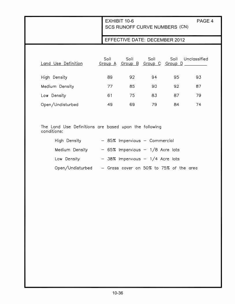
DECEMBER 2012
(CN)
10-36

DECEMBER 2012
CN
10-37

DECEMBER 2012
10-38

DECEMBER 2012
10-39

DECEMBER 2012
10-40

EFFECTIVE DATE: DECEMBER 2012
10-41

DECEMBER 2012
10-42

TABLE OF CONTENTS
CHAPTER 11 PRIVATE DEVELOPMENT DRAINAGE PLAN SUBMITTAL REQUIREMENTS
NUMBER SECTION PAGE
11.1 PURPOSE 11-1 11.2 NEW ALBANY STORMWATER BOARD/FLOYD COUNTY 11-1 STORMWATER DEPARMENT REVIEW
11.2.1 Preliminary Review 11-1
11.2.2 Final Review 11-2
11.2.3 Construction Phase 11-3
11.3 MINIMUM CONSTRUCTION PLAN SUBMITTAL STANDARDS 11-5
11.3.1 Subdivision Plans 11-5
11.3.1.1 Cover Sheet 11-5
11.3.1.2 Composite Drainage Plan 11-5
11.3.1.3 Grading and EPSC Plan 11-6
11.3.1.4 Plan and Profile (Road) Sheets 11-7
11.3.1.5 Storm Drainage Profiles 11-7
11.3.1.6 Standard Detail Sheet 11-8
11.3.1.7 Additional Submittal Items 11-8
11.3.1.8 Submittal 11-9
11.3.2 All Other Development Plans (Sites, etc.) 11-9

TABLE OF CONTENTS (cont.)
CHAPTER 11 PRIVATE DEVELOPMENT DRAINAGE PLAN SUBMITTAL REQUIREMENTS
NUMBER SECTION PAGE
11.3.2.1 Existing Topography Plan 11-9
11.3.2.2 Proposed Development and Grading Plan 11-9
11.4 INSPECTION OF SUBDIVISION CONSTRUCTION 11-10
11.4.1 General 11-10 11.4.2 Inspector Assignment 11-10
11.5 FEES 11-10
11.5.1 Plan Review Fees 11-10
11.5.2 Stormwater Fees 11-11
11.5.2.1 Regional Facility Fee 11-11
11.5.3 Compensation Fees 11-11

11-1
CHAPTER 11 PRIVATE DEVELOPMENT DRAINAGE PLAN SUBMITTAL REQUIREMENTS
11.1 PURPOSE
This chapter establishes the submittal requirements to the New Albany Stormwater Board and the Floyd County Stormwater Department for private development storm sewer projects. This chapter also summarizes the processes required by the City of New Albany and Floyd County for approving a private development project. See Chapter 13 “Development Sanitary Sewer Construction” for the New Albany Sewer Board approval process and submittal requirements for private development sanitary sewer projects. Storm sewer systems should be designed in accordance with the applicable provisions of this and other chapters of the New Albany/Floyd County Design Manual.
11.2 NEW ALBANY STORMWATER BOARD/FLOYD COUNTY STORMWATER DEPARTMENT REVIEW
The drainage facilities for a proposed development in New Albany must be reviewed and approved by the New Albany Stormwater Board. The drainage facilities for a proposed development in Floyd County must be reviewed and approved by the Floyd County Stormwater Department. The applicant shall meet with the Stormwater Board or Stormwater Department during the planning phase of development to discuss the feasibility of the storm sewer design before creating final construction plans. 11.2.1 Preliminary Review
A meeting should be arranged with the developer and the New Albany Stormwater Board or Floyd County Stormwater Department to discuss a preliminary plan and if sufficient downstream capacity is available. A preliminary plan shall be submitted on a 24” x 36” drawing identifying the limits of the project. The preliminary plan should generally show a location map, the lot layout with topography, drainage areas in each segment, proposed storm sewer alignment, proposed detention basin location with preliminary volume calculations, the existing storm sewer, and the discharge points. The Stormwater Board/Stormwater Department will review the submittal, primarily examining the development for the following:
A. Potential impacts to upstream, downstream, and adjacent properties.
B. Adequacy of drainage system outlet.
C. Public outlet for drainage.
D. Floodplain impact.
E. Erosion Prevention and Sediment Control.

11-2
F. Adherence to any applicable drainage master plan criteria.
In New Albany or Floyd County the developer should consult with the New Albany Stormwater Board or the Floyd County Stormwater Department prior to submitting preliminary plans. The purpose is to confirm adherence to applicable drainage criteria and insure the downstream drainage system has adequate capacity.
11.2.2 Final Review
Final plans shall include the following items:
A. Drainage Construction Plans and Specs
Two copies of the final drainage plans shall be submitted on 24”x36” size sheets as well as one digital copy containing both AutoCad and PDF file formats. One hard copy and one digital copy of the storm sewer specifications shall also be submitted. A Professional Engineer and/or Professional Land Surveyor (where applicable per IC 25-21.5-1-7) licensed in the State of Indiana shall seal, sign, and date each sheet of the drainage plans. A Professional Land Surveyor, licensed in the State of Indiana, shall seal, sign, and date any sheets with Boundaries shown. Drafting standards shall be according to Chapter 4 “CADD Standards” of this design manual.
The use of the standard details located in Appendix A of this manual is required. Nonstandard details and deviations from the standard details must be shown within the plan set. Deviations from the standard details must be approved by New Albany or Floyd County.
B. Drainage Calculations
The drainage design calculations shall be as described in Chapter 10 “Stormwater Facilities Design” of this design manual and shall be included in the final submittal. New Albany or Floyd County may require improvements to downstream facilities in order to accommodate the flow from the proposed development.
C. Approval by IDEM (if required)
For developments requiring IDEM approval, a copy of the permit and permit approval letter shall be submitted to the New Albany Stormwater Board or Floyd County Stormwater Department.
D. Correspondence with other Utilities
Documentation must be provided showing that potential conflicts with existing utilities have been addressed to the satisfaction of the utility company. New Albany or Floyd County must be copied on all letters and transmittals to and from the various utility companies.

11-3
E. Other Permits
Documentation must be provided showing that all applicable permits have been obtained for the construction of the project, such as encroachment permits, railroad crossing permits, and New Albany/Floyd County shall be copied on all letters and transmittals to and from the various regulatory agencies.
F. Easement Plats (if required)
Two copies of any sewer and drainage easement plats required for the proposed development shall be included with the final submission of documents. Easement Plats shall be recorded prior to construction approval.
G. Record Plat
A copy of the record plat for the development must be submitted in order for New Albany or Floyd County to determine whether or not additional sewer and drainage easements will be required. The Developer shall record the Record Plat.
H. Erosion Prevention and Sediment Control (EPSC) Plan
The developer must submit a plan for erosion prevention and sediment control (EPSC) as part of their plan set. The EPSC plan must include the actual depths and locations of all control measures. The EPSC plan must be stamped and sealed by an Indiana licensed Professional Engineer or Professional Land Surveyor (where applicable per IC 25-21.5-1-7). See Chapter 8 “Erosion Prevention and Sediment Control” for EPSC measures.
11.2.3 Construction Phase
The New Albany Stormwater Board or Floyd County Stormwater Department will issue an approval letter after all final design submittal requirements are provided and deemed satisfactory. This letter is the notice to proceed, and construction of the storm sewer must commence within one year of approval.
A. Bonds
New Albany requires that a Performance Bond be posted covering the cost of sewer facilities construction during construction. New Albany will require that a Maintenance Bond be posted in the amount calculated by New Albany ($5,000.00 minimum plus $50 per LF under roads and $25 per LF outside of pavement). After the project has been accepted by New Albany, a one-year warranty period begins. If there are no problems with the facilities after one year, New Albany will release the bonds.
B. Accepted Bid Proposal
New Albany requires that the lump sum cost for the construction of the sanitary sewers be submitted. The lump sum amount shall be the same as the amount shown on the Performance Bond.

11-4
C. Drainage Facilities Contract
The developer agrees to construct the project according to the plans and specifications and to furnish record drawings once the job is finished. In the case that New Albany/Floyd County desire to take ownership of the facilities a Drainage Facilities Contract will be prepared by New Albany or Floyd County. This document is the legal agreement between the developer and New Albany/Floyd County regarding the construction of drainage facilities. It conveys the drainage facilities to New Albany/Floyd County upon completion and acceptance by New Albany/Floyd County.
D. Inspector
The New Albany Stormwater Board or Floyd County Stormwater Department will provide part-time inspection as-needed for the construction of all drainage systems. Construction of storm sewers shall not begin in a development until an inspector has been assigned to the construction site. New Albany or Floyd County requires a three (3) working day advanced notice to schedule an inspector for a project.
E. Construction Field Changes
Final approved construction plans bearing the Engineer's original seal, signature, and date are required prior to beginning storm drainage construction Deviations from approved construction plans as a result of unexpected field conditions will require documentation and approval by the New Albany Stormwater Board or Floyd County Stormwater Department. To obtain this approval, the contractor shall submit three (3) copies of the marked-up REDLINE plans showing the proposed revisions. Upon acceptance of the changes, the New Albany Stormwater Board or Floyd County Stormwater Department will mark the REDLINE drawings approved, sign and date the approval and send the REDLINES to the construction site via the inspector. One copy will be for the contractor, one copy for the inspector and one copy for the New Albany Stormwater Board or Floyd County Stormwater Department file.
F. Close-Out Procedures
After completion of the storm sewer installation, and appropriate restoration of the disturbed area has been completed in accordance with the Erosion Prevention and Sediment Control Plan, and all other close out criteria are met, the New Albany Stormwater Board or Floyd County Stormwater Department will accept the storm sewers as complete.
G. Record Plans
At the completion of construction, final record (as-built) drawings of the construction plans bearing the Land Surveyor's and/or Professional Engineer’s original seal, signature, and date, and incorporating all approved changes shall be submitted to the New Albany Stormwater Board or Floyd County Stormwater

11-5
Department. Final record drawings shall be prepared in accordance with Chapter 5 “Final Record Drawings” of this manual. The developer shall submit one hard copy of the final record drawings and one electronic copy containing both AutoCAD and PDF file formats. New Albany’s or Floyd County’s inspector will coordinate and check the work prior to submitting the record drawings to the New Albany Stormwater Board or Floyd County Stormwater Department. Record plans shall be sent to the following address:
New Albany Stormwater Department
2113 Grant Line Road New Albany, IN 47150
Phone Number: (812) 945-1989 or
Floyd County Stormwater Department Pine View Government Center 2524 Corydon Pike, Suite #201
New Albany, IN 47150 Phone Number: (812) 945-9936
11.3 MINIMUM CONSTRUCTION PLAN SUBMITTAL STANDARDS
11.3.1 Subdivision Plans Subdivision Plans for the development of more than four (4) lots require dedication of roadways for access. All plans must be submitted on 24” x 36” inch sheets. 11.3.1.1 Cover Sheet A. Location Map with the site outlined. B. Title Block: Title of Subdivision, name and address of developer; name,
address and email address of Engineer; date of preparation; revision dates. C. Index of Sheets and Legend. D. Engineer’s and Land Surveyor's seals, signatures, and dates. E. Utility Notes. 11.3.1.2 Composite Drainage Plan
A. Topography Minimum Scale 1" = 100' with existing and proposed contours at 2-foot intervals, NAVD 88 datum. Contours to extend a minimum of 50 feet beyond property lines.

11-6
B. Proposed Development Street rights-of-way, street names, street centerline stationing, lot lines, lot numbers, property boundary, existing drainage structures, proposed drainage structures (labeled by number or other designation) and easements with widths shown. C Hydrologic Data Designate pre-development and post-development drainage areas (in acres) to individual inlets, and off-site drainage areas (acres), which generate through drainage. D. Pipe Chart Pipe number, drainage area, coefficient of runoff (c), time of concentration, intensity, discharge (Q), size, length, slope, capacity, velocity, and headwater depth for both the 10-year and 100-year flows. E. 100-year FEMA floodplain and floodway, if applicable, with flood elevations noted. F. Identification of outlet system. 11.3.1.3 Grading and Erosion Prevention and Sediment Control Plan
A. Existing and Proposed Contours.
B. Erosion Prevention and Sediment Measures (Reference Chapter 8 and EPSC Checklist).
C. Proposed Development Street rights-of-way, street names, street centerline stationing, lot lines, lot numbers, property boundary, existing drainage structures, proposed drainage structures (labeled by number or other designation) and easements. D. Grading Plan may be combined with Composite Drainage Plan provided the
plan remains legible.
E. Areas of slope greater than or equal to 30% shall be identified.
F. Stream Buffers if applicable.
G. Limits of disturbance and number of acres disturbed.

11-7
11.3.1.4 Plan and Profile (Road) Sheets
Plan View
A. Catch Basins Line and station number (structure number), grate type and elevation, and invert elevation. B. Pipe Designation Length, size, type, slope, pipe number.
C. Headwalls
Type, invert elevation. D. Ditches and Swales Type, stations.
E. Easements Type, size, existing easements labeled with deed book and page numbers or instrument number.
F. Utilities
Existing and proposed (including sanitary sewers.)
G. Other drainage structures to be labeled accordingly.
Profile View
A. Storm lines and structures to be shown on road profiles.
B. Utility and sanitary sewer crossings.
11.3.1.5 Storm Drainage Profiles (pipes, ditches, box culverts)
A. Catch Basins
Station or number, type, grate type and elevation, invert elevation, and headwater elevation (10 and 100 year).
B. Pipes
Length, size, type, class, grade, line number if applicable, HGL (10 and 100 year).

11-8
C. Ditches
1. Type 2. Grade 3. Flow line elevation at grade changes 4. Design Depth 5. Mannings “n” 6. Slope 7. 10 and 100 year discharge depths 8. Channel Shear Stress
D. Headwalls
Type and invert elevation.
E. Existing and proposed ground surfaces.
11.3.1.6 Standard Detail Sheet
Refer to Appendix A in this Design Manual for Standard Details. Any detail not covered in the appendix must be approved by the New Albany Stormwater Board or Floyd County Stormwater Department.
11.3.1.7 Additional Submittal Items
A. Quantities - Detailed breakdown of all items, related to storm drainage construction needed to determine the amount of the subdivision bond.
B. Approved Preliminary Plan - including sanitary sewer layout.
C. Clearing and Grading Plan - required if site clearing and grading is to precede approval.
D. Detention Basin Calculations - if applicable and in accordance with the
provisions of Chapters 10 and 11 of this design manual.
E. Highway Encroachment Permit - (if applicable) from the Indiana Department of Transportation.
F. Section 404 Permit - (if applicable) from the U.S. Army Corps of Engineers.
G. Section 401 Water Quality Certification Permit - (if applicable) from the Indiana Department of Environmental Management.
H. Application for Culverts and Stream Crossings Permit - from the Indiana
Department of Environmental Management.
I. Other required permits not identified here.

11-9
11.3.1.8 Submittal
Two sets of 24” x 36” construction plans and specifications are to be submitted for initial review.
11.3.2 All Other Development Plans (Site, etc.)
11.3.2.1 Existing Topography Plan
This plan shall conform to Chapter 4 of this design manual with the following additional data: A. Spot elevations at critical points. B. 100-year FEMA floodplain and floodway, if applicable, with flood
elevations noted. C. Off-site drainage area in acres, which generate through drainage.
11.3.2.2 Proposed Development and Grading Plan
This plan may be combined with the plan described in paragraph 11.3.2.1 if existing features can still be discerned. This plan shall include the following additional data: A. Revised hydrologic data, runoff calculations, and detention basin design, if
applicable. B. Hydraulic data, such as pipe charts and ditch data on profiles, showing
quantity of flow, velocities, and degree of protection. C. Erosion prevention and sediment control measures and details. D. Show public outlet and evaluate capacity of downstream facilities. E. Proposed easements for through drainage, detention facilities, and/or offsite
increase in runoff. F. Note specific conflicts with other utilities. G. Written explanation of any proposed deviation from policies, standards, or
design criteria and any supplemental data that would aid the understanding of the proposed plan work.
H. The stamp of a professional engineer licensed in Indiana shall be affixed to
the plan when the proposed facilities affect public drainage, downstream properties, floodplains or detention.

11-10
11.4 INSPECTION OF SUBDIVISION CONSTRUCTION 11.4.1 General
New Albany or Floyd County will provide on-site inspection for the construction of public drainage systems in public rights-of-way or public easements. Drainage construction may begin following approval of the construction plans and issuance of all permits as described in Chapter 2.
11.4.2 Inspector Assignment
Construction of drainage structures and pipes shall not begin in a development until an inspector has been assigned to the construction site by New Albany or Floyd County. In certain situations, which will be identified during construction plan review, full-time inspection may be required. In the event that inspection personnel are not available to provide the level of inspection necessitated by a contractor's schedule, the owner may retain (at the owner's expense) an independent inspector working under the direct supervision of a professional engineer. The independent inspector will be required to certify that the materials and methods of construction are in compliance with the approved plans. Arrangements for owner-provided inspection including schedule and level of effort must be approved in advance. Three working days notice is required to schedule an inspector for a project. To schedule an inspector, please contact New Albany or Floyd County at:
New Albany Stormwater Department
2113 Grant Line Road New Albany, IN 47150
Phone Number: (812) 945-1989 or
Floyd County Stormwater Department Pine View Government Center 2524 Corydon Pike, Suite #201
New Albany, IN 47150 Phone Number: (812) 945-9936
11.5 FEES
11.5.1 Plan Review Fees
Plan review is done by an independent consultant under contract to New Albany. The developer will pay plan review fees directly to this consultant. All fees must be paid prior to approval of the plans. The fee is a flat rate, which includes the review of the original submittal and one (1) resubmittal. If additional submittals are needed, the developer will be billed for time and expense. Additional fees may be required for large sites or with extensive review of hydrologic and hydraulic modeling. Floyd County plan reviews are conducted by county staff.

11-11
11.5.2 Stormwater Fees
11.5.2.1 Regional Facility Fee
This is a stormwater impact fee, paid by the developer on sites where New Albany or Floyd County has determined on-site detention will not be required. This fee allows the developer to pay a proportionate share of the cost of constructing Regional Stormwater Detention Facilities.
11.5.3 Compensation Fees
Fees are applicable to sites in floodprone watersheds where runoff volume compensation is required.

TABLE OF CONTENTS
CHAPTER 12 SANITARY SEWER SYSTEMS
NUMBER SECTION PAGE 12.1 PURPOSE 12-1 12.2 BASIC ELEMENTS 12-1 12.3 GENERAL LOCATION CRITERIA 12-1 12.4 HORIZONTAL ALIGNMENT CRITERIA 12-2
12.4.1 General 12-2 12.4.2 Sewers Located under Pavement 12-3 12.4.3 Stationing 12-3 12.4.4 Sewer Designations 12-3
12.5 VERTICAL ALIGNMENT CRITERIA 12-3
12.5.1 Sewer Depths 12-3 12.5.2 Sewer Gradients 12-4 12.5.3 Flooding and Ponding Areas 12-4 12.5.4 Minimum Water Main Clearances 12-5
12.5.4.1 Horizontal Clearance 12-5 12.5.4.2 Vertical Clearance 12-5
12.6 GENERAL PROCEDURES 12-5 12.7 DRAINAGE MAP REQUIREMENTS 12-5 12.8 DESIGN FLOW CRITERIA 12-6
12.8.1 Collector Sewers 12-6 12.8.2 Interceptor Sewers 12-6

TABLE OF CONTENTS (cont.)
CHAPTER 12 SANITARY SEWER SYSTEMS
NUMBER SECTION PAGE 12.8.3 Design Flows 12-7
12.8.3.1 Residential Service Connections 12-7 12.8.3.2 Commercial Service Connections 12-8 12.8.3.3 Future Development 12-8
12.9 HYDRAULIC DESIGN CRITERIA 12-9
12.9.1 General 12-9 12.9.2 Hydraulic Grade Line 12-9 12.9.3 Velocity 12-9 12.9.4 Minimum Slopes 12-10 12.9.5 Sewer Size Changes 12-10
12.10 HYDRAULIC COMPUTATIONS 12-10 12.11 SEWER PIPE 12-10
12.11.1 Minimum Diameter 12-10 12.11.2 Pipe Material 12-11 12.11.3 Pipe Bedding and Encasement 12-15 12.11.4 Backfill of Trench Excavations 12-17 12.11.5 Leakage Testing for Sanitary Sewers 12-21 12.11.6 Loading Calculations 12-22
12.12 MANHOLES 12-22
12.12.1 Manhole Locations 12-22

TABLE OF CONTENTS (cont.)
CHAPTER 12 SANITARY SEWER SYSTEMS
NUMBER SECTION PAGE 12.12.2 Maximum Manhole Spacing 12-23 12.12.3 Diameter 12-23 12.12.4 Watertight 12-23 12.12.5 Drop Inlets 12-24 12.12.6 Manhole Collars 12-24 12.12.7 Manhole Numbering 12-24 12.12.8 Chimney Seals 12-24 12.12.9 Manhole Barrel Joints 12-24 12.12.10 Manhole Frame and Collar Connections 12-24 12.12.11 Manhole Personnel and Equipment Access 12-25 12.12.12 Manhole Testing 12-25
12.13 STUBS 12-25 12.14 PROPERTY SERVICE CONNECTIONS 12-25 12.15 FLOATATION 12-26 12.16 ANCHORS 12-26 12.17 CONCRETE ENCASEMENTS 12-27 12.18 TRENCHLESS PIPE INSTALLATION 12-27 12.19 RAILROAD CROSSINGS 12-29
12.19.1 Criteria 12-29 12.19.2 Railroad Conflict Drawings 12-30

TABLE OF CONTENTS (cont.)
CHAPTER 12 SANITARY SEWER SYSTEMS
NUMBER SECTION PAGE
12.20 HIGHWAY CROSSING 12-30 12.21 CREEK, STREAM OR DITCH CROSSINGS 12-31

CHAPTER 12
SANITARY SEWER SYSTEMS
EXHIBITS
EXHIBIT TITLE PAGE
12-1 COMPUTATIONS FOR SANITARY SEWER DESIGN 12-32
12-2 UNDEVELOPED AREA WASTEWATER FLOWS 12-33
12-3 MINIMUM ALLOWABLE SLOPES 12-34
12-4 HYDRAULIC ELEMENTS OF CIRCULAR SEWERS 12-35
12-5 PIPE FLOW CHART FULL (6” - 54”) 12-36
12-5 PIPE FLOW CHART FULL (21” - 144”) 12-37
12-6 TYPLICAL SERVICE CONNECTIONS 12-38
12-7 RAILROAD CONFLICT DRAWING 12-39
12-7 RAILROAD CONFLICT DRAWING 12-40
12-1
CHAPTER 12 SANITARY SEWER SYSTEMS
12.1 PURPOSE
This chapter establishes the minimum standards and technical design criteria for sanitary sewer systems in the New Albany service area for Capital Improvement and development projects. Adherence to these standards will expedite review and approval of plans. Hydraulic design presented herein represents acceptable procedures not necessarily to the exclusion of other sound and technically supported design procedures. Any departure from these design requirements should be brought to the attention of New Albany before submission of plans for approval and should be justified and documented. Sanitary sewer plan preparation for private development must also conform to Chapter 13 requirements and in all cases plan development shall conform to the Chapter 8 EPSC requirements. The City of New Albany is currently under a sewer tap-on ban imposed by the Indiana Department of Environmental Management (IDEM). Sanitary sewer credits must be secured from the New Albany Sewer Board and IDEM prior to design approval and connection to the sewer system.
12.2 BASIC ELEMENTS
The design of sanitary sewers basically consists of the determination of the following: A. The location of the horizontal alignment, which most efficiently provides service to
existing and potential users.
B. The vertical restrictions on establishing the sewer alignment including: depths required to serve users, minimum cover, elevations of other sewers in the system, conflicts with other underground facilities, solid rock considerations, and maintaining the required hydraulic gradients.
C. The design flow generated by the existing and future users, which must be transported by the sewer.
D. The pipe size, pipe material, bedding and method of construction required.
E. The necessary appurtenances and special structures required. 12.3 GENERAL LOCATION CRITERIA
Sewers shall be located using sound engineering judgment to determine the most cost-effective and environmentally sensitive alignment that best serves the needs of the entire tributary area. Additionally, it is imperative that all alternatives worthy of consideration receive maximum and equal consideration with regard to environmental impact. The costs and acquisition time for easements can be significant; therefore, sewers should be located within existing easements and rights-of-way whenever feasible and practical.

12-2
When selecting the sewer alignment, consideration should be given to the following general location criteria: A. Elevation requirements necessary to provide appropriate service with due consideration
of sanitary facilities in basements. B. For protection of environmentally sensitive areas and constraints such as creeks,
wetlands, trees, protected habitats, etc.
C. Existing utilities, railroads, highways, and overhead facilities.
D. Location of other existing and proposed sewerage and stormwater facilities.
E. Property values, easement needs and potential damages to the affected properties.
F. Existing and proposed high water elevations, including high water for appropriate design periods.
G. Anticipated extension of existing streets and the potential for the development of contiguous areas.
H. Continuity with adjacent design segments.
I. Maintenance of traffic.
J. Availability of materials.
K. Foundation conditions.
L. Construction cost.
The location of proposed sanitary sewers should also comply with the Indiana Administrative Code 327 IAC 3 Rule 6 “Technical Standards for Sanitary Collection Systems”, Sections 9 and 10.
12.4 HORIZONTAL ALIGNMENT CRITERIA
12.4.1 General
All sewers shall be constructed with a straight alignment between manholes. Sewers shall be located in yards in a sanitary sewer and drainage easement adjacent to the road right-of-way and shall be at least 10 feet from the water main. The manholes shall be completely outside the pavement and not partially in the pavement, unless approved by the Sewer Board. The centerline of the manhole shall be a minimum distance of 3 feet from the edge of pavement, and a minimum distance of 5 feet inside the sanitary sewer and drainage easement.

12-3
12.4.2 Sewers Located under Pavement (Subject to Approval by Sewer Board)
Construction of sewers under pavement will be subject to approval by the Sewer Board. If circumstances require the sewer to be located under the roadway, the sewer shall be located in the traffic lane on the opposite side of the street and at least 10 feet away from the water main with the centerline of the sewer to be a minimum of 5 feet from the edge of pavement. Every effort shall be made to place the entire manhole frame and cover entirely within the pavement. In areas where this location will conflict with gas and water valves or other utilities, the sewer location shall be adjusted to avoid these conflicts. Consideration of other factors, such as the width of the pavement, depth of rock, and possible conflict with other utilities, will still be required so the sewer can be built without modification during construction. In areas where concrete pavement is encountered, consideration shall be given to placing the sewer in a location whereby one edge of the pavement to be removed would coincide with existing construction joints, which are generally in the centerline of the streets. This procedure would require that only one side of the pavement would have to be sawed for removal. In areas where lots slope abruptly away from the street, consideration shall be given to locating the sewer near the property line on the low side.
12.4.3 Stationing
All sewer stations shall increase upstream. Every effort shall be made to begin the stationing of a sewer with Station 0+00.00 at the downstream end. When an existing sewer is to be extended, the stationing should be continued from the end of the existing sewer whenever possible. The PI stations and deflection angles or interior angles shall be shown on the plans at all changes in alignment.
12.4.4 Sewer Designations
The designation of the first sewer in a collection system shall be LINE "A". The next sewer upstream contributing to LINE "A" shall be designated LINE "B", and the station of LINE "B" at this point shall be Station 0+00.00. This method shall continue throughout the collection system and subsequent sewers shall be assigned appropriate designations by ascending letters. Lines beyond LINE "Z" shall continue with double letter designations starting with LINE "AA", "AB", etc. For very short segments not extending beyond one manhole, designations such as LINE "B-1" will be allowed.
12.5 VERTICAL ALIGNMENT CRITERIA
12.5.1 Sewer Depths
Sanitary sewers shall have a minimum cover of 4 feet in easements and a minimum cover of 5 feet in rights-of-way. Specific exceptions to these minimum requirements may be made with prior approval by New Albany.

12-4
In developed areas, the criteria, discussed in Section 12.8.3, should be used to establish the flow line of the sewer unless otherwise directed by New Albany. The "Service Connection Survey" form, found on Exhibit 6-1, should be used when determining the controlling elevations of a sanitary sewer line. In instances where only a few houses on a sanitary sewer have existing basement facilities, the impact on the entire system shall be considered prior to providing gravity basement service. Additionally, in areas having substantial amounts of solid rock, consideration shall be given to the omission of basement service. This omission must be approved in writing by New Albany.
In establishing the elevation of the proposed sanitary sewer, the elevations of existing and proposed interceptor sewers and the elevations of inflow pipes to existing pump stations and wastewater treatment plants and all other utilities shall be considered.
A minimum cover of 2 feet shall generally be maintained when crossing under existing streams, existing ditches, and existing or proposed channel improvements and storm sewers, provided the sanitary sewer line is encased in concrete (or capped if approved by New Albany). With respect to streams, restoration of the channel invert will conform to the applicable standard drawings (EC-01-01, EC-02-01, or EC-03-01) located in Appendix A.
The sanitary sewer elevation necessary to serve the entire tributary area shall be considered in establishing the upstream flow line of any sanitary sewer segment including the area beyond the boundary of a design section.
A separate parallel sanitary collector sewer shall be considered in lieu of individual property service connections into the interceptor sewer in areas where the sanitary interceptor sewer reaches excessive depths. The collector sewer, at a higher elevation, should end in a drop manhole or vertical stacks into the interceptor sewer. A cost-effectiveness study shall be submitted to New Albany for review and approval.
12.5.2 Sewer Gradients
All sewer gradients shall be referenced to the North American Vertical Datum of 1988. When connecting into or extending existing sewer facilities that were constructed using another datum, an elevation equation should be shown on the plans. The hydraulic criteria, established in Section 12.9, should be used to determine sewer flow line elevations in manhole structures.
12.5.3 Flooding and Ponding Areas
In general, the top of sanitary manhole elevations shall be a minimum of 2 feet above existing, proposed, or projected 100-year high water elevations. However, when this minimum elevation causes the manhole to be above the natural ground creating obstructive mounds, the top of the manhole elevation shall be lowered to the natural ground elevation and a watertight manhole lid and frame shall be specified.

12-5
12.5.4 Minimum Water Main Clearances
The following minimum clearances between the sewer and existing or proposed water mains shall be used in establishing the sewer alignment:
12.5.4.1 Horizontal Clearance
The horizontal clearance shall be 10 feet minimum per the Indiana Administrative Code 327 IAC 3-6-9 “Separation of collection systems from water mains and drinking water wells.” Where this is not possible, the Design Engineer should reference 327 IAC 3-6-9 for exceptions.
12.5.4.2 Vertical Clearance
The vertical clearance shall be at least 18 inches per the Indiana Administrative Code 327 IAC 3-6-9 “Separation of collection systems from water mains and drinking water wells.” The sewer shall be located below the water main. Should it become necessary for the sewer to cross over the water main, special precautions and exfiltration testing of the sewer will be required. Such cases shall require written approval by New Albany and IDEM.
12.6 GENERAL PROCEDURES
The design flow for each segment of the sewer system shall be determined as follows:
A. Prepare a Drainage Map, which defines the area’s tributary to each element of the
sewer.
B. Examine each area to determine its potential land use. C. Determine the average daily flow. D. Determine the design or peak flow based upon the average daily flow and the peaking
factor.
12.7 DRAINAGE MAP REQUIREMENTS
A Drainage Map shall be prepared showing the actual area to be served by the proposed project, the location of the sewers, the portion of the project area tributary to each individual sewer element, and any points of inflow which contribute additional flow from adjacent areas. The Drainage Map shall be prepared on a standard size sheet at an appropriate scale to show the entire project and adjacent future contributing areas. Two or more sheets may be used for large-scale projects. A sample Drainage Map is shown on Exhibit 4-10. The purpose of the Drainage Map is to graphically depict the basis for the design flow calculations. The Drainage Map and design calculations shall be presented for review with submittal of the preliminary and construction plans. The minimum specific information required includes the following:

12-6
A. A key map showing the general location of the project area, including any areas not within the project area that contribute to the proposed system.
B. A general layout of the proposed system with the drainage area tributary to each major element of the system defined.
C. The basis for determining the number of existing and future users and the average daily flow for each drainage area: i.e., the number of single-family or multi-family dwelling units; type and size of existing commercial, industrial and institutional users; and the number of acres of undeveloped land by zoning classification.
D. A zoning designation, such as R1, for each drainage area.
E. A designation for each sewer line.
F. A numbering system for manholes, which shall be added to the computation sheets. Contact Sewer Department at Ph. 948-5320 for manhole numbers.
G. All proposed sewer sizes.
H. The location of estimated or actual flow entering the proposed system from outside areas, developed or undeveloped. These areas are to be shown in their entirety on the Drainage Map and shall include the same types of information required for the proposed service area.
I. An adequate number of spot elevations must be obtained in areas of undeveloped land to show the natural drainage of the area if necessary.
J. An indication of the existing system's ability to receive the proposed flow with sufficient capacity.
12.8 DESIGN FLOW CRITERIA
12.8.1 Collector Sewers
Collector sewers are primarily installed to receive wastewater directly from property service connections. A major change in land use within a tributary area can have a significant impact on the collector system's ability to transport the necessary flow. Collector sewers should be designed to transport the peak daily flow (at 2/3 pipe full), which might be expected during their service life. The design flows should be calculated as described in Section 12.8.3.
12.8.2 Interceptor Sewers
An interceptor sewer is a principal sewer to which collector sewers are tributary. All interceptor sewers should be designed for peak daily flow (flowing 2/3 full) unless otherwise directed by New Albany.

12-7
For a major industrial water user or for undeveloped industrial land in the tributary area, New Albany will generally specify the estimated average daily flow. Otherwise, a flow of 10 persons per acre shall be assumed for all industrially zoned land (see Exhibit 12-2), except in areas where specific reliable information is available to more correctly analyze the anticipated flows.
12.8.3 Design Flows
The average daily flow and peak daily flow rates used in the design of a collector and interceptor sewer shall be equal to any upstream flows (if applicable) plus the flow from proposed service connections and any future flow from potential land development. Design flows for residential and commercial services shall be estimated in accordance with the Indiana Administrative Code 327 IAC 3-6-11 “Design flow rate requirements for collection systems and water pollution treatment/control facilities” and as described in Sections 12.8.3.1 and 12.8.3.2 hereinafter. Determining design flows for undeveloped land that could discharge into the proposed sewer in the future is described in Section 12.8.3.3.
12.8.3.1 Residential Service Connections
A general average daily flow rate value can be used to determine the average daily flows for residential service connections. The following equation shall be used to calculate average and peak daily flow rates for residential services: ADF = General Average x PRSC PDF = ADF x PF Where: ADF = Average daily flow rate expressed as gallons per residential service connection per day. General Average = General average daily flow rate value in accordance with the following: 1 bedroom apartment = 200 gpd/unit 2 bedroom apartment = 300 gpd/unit Single-family home = 310 gpd/unit PRSC = Proposed number of residential service connections. PDF = Peak daily flow rate expressed as gallons per residential service connection per day. PF = Peak daily factor = 18 + √P 4 + √P Where P = population in thousands. If the population is unknown, a peaking factor of 4 shall be used.
12-8
12.8.3.2 Commercial Service Connections
To determine the average daily flow and peak daily flow rates for service connections other than residential, the number of service connections can be multiplied by the applicable flow calculation factor listed in Table 11-1 of the Indiana Administrative Code 327 IAC 3-6-11 “Design flow rate requirements for collection systems and water pollution treatment/control facilities”. The following equation can be used to calculate the average and peak flow rates:
ADF = FCF x PSC PDF = ADF x PF Where: ADF = Average daily flow rate expressed as gallons per service connection per day. FCF = Flow calculation factors as listed in Table 11-1 of 327 IAC 3-6-11 expressed as gallons per day. PSC = Proposed number of service connections. PDF = Peak daily flow rate expressed as gallons per service connection per day. PF = Peak daily factor = 18 + √P 4 + √P Where P = population in thousands.
If the population is unknown, a peaking factor of 4 shall be used.
12.8.3.3 Future Development
An estimate of the average daily flow and peak daily flow rates for future development shall be made by multiplying the average daily flow per acre listed in Exhibit 12-2 for the applicable zoning district by the number of acres of undeveloped land. For zoning districts that allow single family and multi-family dwellings and it is unknown which type of development will occur in the future, then the higher of the two flows shall be selected for that zoning district. The following equation shall be used to calculate the average and peak flow rates: ADF = Average Flow x Acreage PDF = ADF x PF
Where: ADF = Average daily flow rate expressed as gallons per day. Average Flow = Average daily flow rate as listed in Exhibit 12-2 in gallons per acre per day.

12-9
Acreage = Acres of undeveloped land per zoning district. PDF = Peak daily flow rate expressed as gallons per day. PF = Peak daily factor = 18 + √P 4 + √P Where P = population in thousands. If the population is unknown, a peaking factor of 4 shall be used.
12.9 HYDRAULIC DESIGN CRITERIA
12.9.1 General
Manning's Equation shall be used to determine proper pipe size and slope to transport the design flow. Design shall be for two-thirds (2/3) pipe flow at saturation conditions with the following characteristics: A. Roughness coefficient – n = 0.013 (Sanitary Sewers Only)
B. Minimum velocity – v = 2 feet/second
C. Minimum pipe size – D = 8 inches
D. Minimum allowable slopes = (See Exhibit 12-3)
Saturation conditions are defined as the maximum projected population for the watershed based on present zoning.
12.9.2 Hydraulic Grade Line
The hydraulic grade line should not rise above the crown of the sewer pipe. When critical, the hydraulic grade line shall be computed to show its elevation at manholes, transition structures, and junction points of flow in pipes and provide for the losses and the differences in elevation. If velocity entering a manhole is above critical, the hydraulic grade line must be computed to ensure that no service connections are surcharged. The pipe exiting the manhole must be adjusted in elevation to ensure that the energy gradient remains level across the manhole.
12.9.3 Velocity
All sanitary sewers shall be designed to carry the design flow at a minimum velocity of 2.0 ft/s (Reference paragraph 12.9.4 for exceptions). The maximum allowable design velocity shall be 15 ft/s based on the design flow. When severe topographic or unusual conditions require a design velocity greater than 15 ft/s, the hydraulic design and pipe material must be approved in writing by New Albany.

12-10
12.9.4 Minimum Slopes
The minimum allowable slopes will be as required to obtain the minimum velocity as required in Section 12.9.3. In no case shall the slopes be less than those identified in Exhibit 12-3 (stubs shall have a minimum slope of 0.005 ft/ft).
Note: For 8” pipe the minimum slope is 0.007 ft/ft (based upon pipe at one-fourth full depth) in cases where the minimum required velocity, at design flow, cannot be achieved at a lesser slope.
12.9.5 Sewer Size Changes
Sewer size changes shall only take place within a manhole or junction box structure. To ensure that the energy gradient is maintained, use the following:
A. Pipes 24" in Diameter or Smaller
1. When increasing the sewer size by 6 inches or less, crown elevations
shall match at the centerline of the manhole.
2. When increasing the sewer size by more than 6 inches, the springlines of the smaller and larger sewer shall match at the centerline of the manhole. However, if the hydraulic design calculations show unacceptable losses resulting in a surcharge condition, the Design Engineer may match crown elevations at the centerline of the manhole by raising the elevation of the smaller sewer.
B. Pipes 27" in Diameter or Larger
Manholes or junctions involving sewers 27 inches or larger shall first be designed by matching the crown elevation at the centerline of the structure. The hydraulic grade line shall then be determined. If the Hydraulic Grade Line (HGL) shows a surcharging condition, the downstream pipe may be lowered as needed.
12.10 HYDRAULIC COMPUTATIONS
Exhibit 12-1 is a sample computation sheet for designing interceptor and collector sewers. The procedure used in completing this form can be found at the bottom of the Exhibit. This computation sheet, or similar form, shall be submitted with the plans for review. A copy of the computation sheet can be downloaded from the New Albany website: www.cityofnewalbany.com.
12.11 SEWER PIPE
12.11.1 Minimum Diameter
The minimum allowable inside diameter for sewer pipe, other than property service connections, shall be 8 inches. All property service connections shall have a

12-11
minimum inside diameter of 6 inches; commercial or industrial connections shall be individually considered with the minimum size of 6 inches.
12.11.2 Pipe Material
Pipe material will be selected from the following products. Alternate products can be specified by the designer, but prior approval from New Albany will be required. Designers will indicate the pipe material and pipe class on the plans. Approved products from the design manual that are not advantageous for a particular project and not allowed will need to be identified in the Contract (must be approved by New Albany).
A. Concrete Pipe: Reinforced concrete pipe shall meet the requirements of
ASTM C76, Standard Specification for Reinforced Concrete Culvert, Storm Drain and Sewer Pipe. Unless shown otherwise on the Plans or required by the Contract, Class III, Wall B or thicker pipe shall be used. For circular pipe sizes 12-inch through 24-inch diameter, nonreinforced concrete pipe meeting ASTM C14, Class 3 can be used where reinforced concrete pipe Class III is allowed.
Cement used in the manufacture of reinforced concrete pipe shall meet the requirements of ASTM C 150, Standard Specification for Portland Cement, for Type II cement. All reinforcing cages shall be circular; elliptical reinforcement shall not be permitted unless shown on the Plans or allowed by New Albany. Joints shall be sealed with Type A - rubber compression or confined O-ring or other New Albany approved gaskets. Joints shall meet the requirements of ASTM C 443-05A, Standard Specification for Joints for Concrete Pipe and Manholes, Using Rubber Gaskets. Unless otherwise directed by New Albany, T-branch and Y-branch fittings shall be manufactured at the pre-cast plant and supplied to the Project site as single units. When field-fabricated branches are permitted, the openings in the pipe shall be properly cast at the time of manufacture.
B. Ductile Iron Pipe and Fittings: Ductile iron pipe shall meet the
requirements of ANSI/AWWA C151/A21.51, Ductile Iron Pipe, and Centrifugally Cast in Metal Molds or Sand-Lined Molds for Water or Other Liquids. Unless shown otherwise on the Plans or in the Contract, the thickness class shall be determined based on a working pressure of 150 psi, in accordance with ANSI/AWWA C150/A21.50, Thickness Design for Ductile Iron Pipe. Flanged joint ductile iron fittings shall meet the requirements of ANSI/AWWA C110/A21.10, Ductile Iron and Gray Iron Fittings, 3 inch through 48 inch for Water and Other Liquids. At a minimum, Class 250 fittings with class 53 wall thickness shall be used.

12-12
Mechanical, push on and other such joints shall meet the requirements for ductile iron fittings, ANSI/AWWA C153/A21.53. Where these short bodied compact fittings are to be fitted to aged existing cast iron pipe of larger diameter than specified in A21 standards, mechanical joint sleeves or bell-and-spigot sleeves shall provide transition. All pipe and fittings shall be cement-lined in accordance with ANSI/AWWA C104/A21.4, Cement-Mortar Lining for Ductile Iron and Gray Iron Pipe and Fittings, or polyurethane lined over concrete or ductile iron or gray iron pipe and fittings. The polyurethane lining shall be an ASTM Type V, chemical cure, 100% solids, elastomeric and aromatic with no sand fillers or extenders added. It shall be capable of being spray applied to 50 mils nominal thickness in a single application. Minimum lining thickness shall be 40 mils. The polyurethane lining shall be a seamless flexible membrane that is corrosion, abrasion, and impact resistant; with a Shore ”D” hardness of 60 to 65 at 78ºF (25.5ºC); a tensile strength of 2,878 psi and elongation of 52% per ASTM D-412; shall be resistant to abrasion as measured by a weight loss of no more than 42 mgs. per ASTM D-1044; and shall have a water vapor transmission rate (WVTR) of no more than 0.016 grams per 100 square inches (254 cm2) per 24 hours (75 mils DFT @ 73ºF (22.7ºC), 100% RH, per ASTM F-1249-90). Unless otherwise noted on the plans or in the specifications, all pipes shall be cement lined. Lining thickness per ANSI/AWWA C-104/A21.4 shall be 1/16 in. (min.) for 3 through 12 in. pipe, 3/32 in. for 14 in. through 24 in. pipe, and 1/8 in. for 30 through 54 in. pipe. Joints shall be push-on rubber gasket types which meet the requirements of ANSI/AWWA C111/A21.11, Rubber Gasket Joints for Ductile Iron and Gray Iron Pressure Pipe and Fittings. When flanged joints are required, they shall meet the requirements of ANSI/AWWA C115/A21.15, Flanged Ductile Iron and Gray Iron Pipe with Threaded Flanges. Mechanical flanged restrained joints may be used when approved by New Albany. All flanged and mechanical joints for ductile iron pipe and fittings shall be made with stainless steel nuts, bolts, etc.
C. Polyvinyl Chloride (PVC) Pipe and Fittings: Unless shown otherwise on the Plans, in the Contract, or stipulated by New Albany, the Contractor may, at his option, use any of the following types of PVC pipe:
1. PVC pipe meeting the requirements of ASTM D 3034, Standard
Specification for Type PSM Poly (Vinyl Chloride)(PVC) Sewer Pipe and Fittings. At a minimum, SDR 35 pipe shall be used.
2. PVC pipe meeting the requirements of ASTM F 679, Standard
Specification for (Polyvinyl Chloride) (PVC) Large Diameter Plastic Gravity Sewer Pipe and Fittings. At a minimum, SDR 35 shall be used.
12-13
3. PVC pipe meeting the requirements of ASTM F 789, Standard Specification for Type PS46 (Polyvinyl Chloride) (PVC) Plastic Gravity Flow Sewer Pipe and Fittings.
4. PVC pipe meeting the requirements of ASTM D 1785, Standard
Specification for (Polyvinyl Chloride) (PVC) Plastic Pipe, Schedules 40, 80 and 120. Fittings shall meet the requirements of ASTM D 2466, Standard 4 Specification for (Polyvinyl Chloride) (PVC) Plastic Pipe Fittings.
Polyvinyl Chloride (PVC) Pipe shall be installed in accordance with these Specifications and ASTM Standards for "Underground Installation of Flexible Thermoplastic Sewer Pipe", D2321 requiring a minimum trench width of not less than the greater of either the pipe outside diameter plus 16 inches or the pipe outside diameter times 1.25 plus 12 inches. Joints for PVC pipe meeting the requirements of ASTM D 3034, ASTM F 679, and ASTM F 789 shall be gasket, bell and spigot, push-on types which meet the requirements of ASTM D 3212, Standard Specification for Joints for Drain and Sewer Plastic Pipes Using Flexible Elastomeric Seals. Gaskets shall meet the requirements of ASTM F 477, Standard Specification for Elastomeric Seals (Gaskets) for Joining Plastic Pipe. Fusible PVC pipe for gravity sewer service shall meet the requirements of ASTM D3034, ASTM F679, or ASTM D1785 for standard dimensions, as applicable. Fusible PVC pipe shall be extruded with plain ends. The ends shall be square to the pipe and free of any bevel or chamfer. There shall be no bell or gasket of any kind incorporated into the pipe. Fusible PVC pipe lengths shall be assembled in the field with butt-fused joints. The fusion technician shall follow the pipe supplier’s guidelines for this procedure. The fusion technician shall have the current qualification credentials for the pipe size being fused, as documented by the pipe supplier. The fusible PVC pipe shall be installed in a manner so as not to exceed the recommended bending radius guidelines and the maximum safe pulling force established by the pipe supplier.
D. Polyethylene Pipe and Fittings: Polyethylene pipe shall meet the
requirements of ASTM F 714, Standard Specification for Polyethylene (PE) Plastic Pipe (DR-PR) Based on Outside Diameter. The pipe shall be manufactured from material which meets the requirements of ASTM D 1248, Standard Specification for Polyethylene Plastics Molding and Extrusion Materials for Type III, Class C, Category 5, Grade P34 High Density Polyethylene (pipe designation PE 3608). Pipe made from these resins must have a long-term strength rating of 1,600 psi or more. Polyethylene pipe shall not be delivered to the site until New Albany has provided approval for the pipe class to be used.

12-14
Polyethylene pipe shall be installed in accordance with these Specifications and ASTM Standards for "Underground Installation of Flexible Thermoplastic Sewer Pipe", D2321. Joints between plain end pipes and fittings shall be made by butt fusion using procedures that are in accordance with ASTM F2620 by a person who is a manufacturer’s certified thermojointer.
E. Polypropylene (PP) Pipe and Fittings:
1. Polypropylene pipe up to 30 inches in diameter shall meet the
requirements of ASTM F2736 “Standard Specification for 6 inches to 30 inches Polypropylene Corrugated Single Wall Pipe and Double Wall Pipe.” The pipe shall have a smooth interior with annular exterior corrugations and a minimum pipe stiffness of 46 psi when tested in accordance with ASTM D2412 “Standard Test Method for Determination of External Loading Characteristics of Plastic Pipe by Parallel-Plate Loading.” The polypropylene compound for pipe and fitting production shall be an impact modified copolymer meeting the material requirements of ASTM F2736, Section 4.
Pipe shall be joined with a gasketed integral bell and spigot joint meeting the requirements of ASTM F2736. Pipe shall be watertight according to the requirements of ASTM D3212 “Standard Specification for Joints for Drain and Sewer Plastic Pipes Using Flexible Elastomeric Seals.” Spigot shall have two gaskets meeting the requirements of ASTM F477 “Standard Specification for Elastomeric Seals (Gaskets) for Joining Plastic Pipe” and the bell shall be reinforced with a polymer composite band installed by the manufacturer. Fittings shall conform to ASTM F2736. Bell and spigot connections shall utilize a spun-on, welded or integral bell and spigot with gaskets meeting ASTM F477. Service connections using polypropylene pipe up to 30 inches in diameter shall consist of a PVC hub, rubber sleeve and stainless steel band (INSERTA TEE or equal). Connection shall be a compression fit into the cored wall of a mainline pipe. Hub shall be made from heavy-duty PVC material. Stainless steel clamping assembly shall be made from minimum 301 grade steel. Rubber sleeve and gasket shall meet the requirements of ASTM F477. Gaskets shall be installed by the manufacturer. The water-based solution provided by the manufacturer shall be used during assembly.
2. Polypropylene pipe 30 inches to 60 inches in diameter shall meet the requirements of ASTM F2764 “Standard Specification for 30 to 60 in. Polypropylene (PP) Triple Wall Pipe and Fittings for Non-Pressure Sanitary Sewer Applications.” The pipe shall have smooth interior and exterior surfaces with annular inner corrugations. The pipe shall have a minimum pipe stiffness of 46 psi when tested in accordance with ASTM D2412 “Standard Test Method for Determination of External

12-15
Loading Characteristics of Plastic Pipe by Parallel-Plate Loading.” The polypropylene compound for pipe and fitting production shall be an impact modified copolymer meeting the material requirements of ASTM F2764.
Pipe shall be joined with a gasketed integral bell and spigot joint
meeting the requirements of ASTM F2764. Pipe shall be watertight according to the requirements of ASTM D3212 “Standard Specification for Joints for Drain and Sewer Plastic Pipes Using Flexible Elastomeric Seals.” Spigot shall have two gaskets meeting the requirements of ASTM F477 “Standard Specification for Elastomeric Seals (Gaskets) for Joining Plastic Pipe” and the bell shall be reinforced with a polymer composite band installed by the manufacturer. Fittings shall conform to ASTM F2764. Bell and spigot connections shall utilize a spun-on, welded or integral bell and spigot with gaskets meeting ASTM F477.
3. Installation of polypropylene pipe shall be in accordance with ASTM
D2321 “Standard Practice for Underground Installation of Thermoplastic Pipe for Sewers and Other Gravity-Flow Applications” and manufacturer recommended installation guidelines.
12.11.3 Pipe Bedding and Encasement
Pipe bedding and encasement shall be of crushed stone or concrete and shall be installed as specified herein and as shown on the Plans, or as directed by New Albany. See Standard Drawings GC-01-01, GC-02-01, GC-03-01, and GC-04-01 in Appendix A for details regarding pipe bedding and encasement. Concrete used in encasements, caps, and cradles shall be Class B Concrete that has a minimum 28-day compressive strength of 2,500 psi, a minimum slump of 3 inches and a maximum slump of 5 inches.
A. Crushed Stone Cradle: Crushed stone cradle shall mean the placement of
crushed stone from the subgrade level (6 inches below the outside of the pipe) up to the springline of the pipe. The crushed stone shall be deposited in the trench to grade, allowing for the thickness of the pipe wall. Bell holes shall be dug to relieve the bells of all concentrated loads and to provide uniform support throughout the pipe section. For larger pipes, the crushed stone shall be shoveled and shovel-sliced beneath the haunches of the pipe to assure uniform support. Unless shown otherwise on the Plans or directed by New Albany, the following types of pipes shall be supported on a crushed stone cradle. 1. Concrete Pipe 2. Ductile Iron Pipe
B. Soil Bedding/Cradle: For concrete pipe installed outside the roadway right-of-way with 9 feet of cover or less, the crushed stone cradle can be eliminated

12-16
and replaced with job excavated native soil material. The earth trench bottom foundation should be scarified for the middle third of the pipe O.D. or at the Contractors option a minimum thickness of granular bedding can be provided. For rock foundations provide a standard 6-inch thick granular bedding.
C. Crushed Stone Encasement: Crushed stone encasement shall mean the
placement of additional crushed stone above the crushed stone cradle to a level at least 6 inches above the outside top of the pipe and leveled off between the trench walls. The additional stone shall be placed in such manner to prevent damage to the pipe. Unless shown otherwise on the Plans or directed by New Albany, the following types of pipe shall be encased in crushed stone.
1. Polyvinyl Chloride Pipe
2. Polyethylene Pipe
3. Polypropylene Pipe
D. Concrete Cradle: Where a concrete cradle is required as additional support
for a sanitary sewer pipe, or if a sanitary sewer pipe will have less than 2 feet of vertical clearance above an existing or proposed storm drain or utility conduit, a concrete cradle shall be installed. The length of the concrete cradle shall be as shown on the Plans or 2 feet beyond the outside edge of the underlying storm drain or utility conduit. The pipe shall be laid to line and grade, and shall be supported on concrete blocks, bricks or saddles set to prevent both vertical and lateral movement of the pipe. The use of wooden blocks will not be permitted. Concrete shall be placed around the pipe up to the springline of the pipe. Proper bracing shall be provided to prevent displacement or flotation of the sewer pipe during placing of concrete.
E. Concrete Cap: The length of the concrete cap shall either be as shown on
the plans; or 2 feet beyond the outside edge of the storm drain or utility conduit; or 2 feet beyond the point where the sewer pipe attains 30 inches of cover in an easement; or 4 feet of cover in a right-of way or surfaces subject to vehicular traffic, or as directed by New Albany. The sewer pipe shall be laid and supported on a crushed stone cradle, and concrete shall be placed around the pipe and at least 6 inches above the top of the pipe for the full trench width. Proper bracing shall be provided to prevent displacement or flotation of the sewer pipe during placing of the concrete.
F. Concrete Encasement: Where shown on the Plans or where conditions exist
requiring additional pipe protection (stream crossings, ditch crossings, shallow trench or poor soil conditions), pipes shall be encased in concrete, as determined by New Albany. The length of the concrete encasement shall be at least 2 feet beyond the point where additional pipe protection is required, as shown on the Plans, or as directed by New Albany. The sanitary sewer pipe shall be laid and supported as required for a concrete cradle, and concrete shall be placed around the pipe 6 inches either side of it and up to at least 6

12-17
inches over the top of the pipe. Proper bracing of the pipe shall be provided to prevent movement or flotation of the sewer pipe during placing of concrete. In rock-bottom streams, the encasement shall extend from 6 inches below the pipe up to the original rock level. Encasement shall be required when crossing a blue line stream and shall extend to 5 feet beyond the top of bank on each side of said stream. Concrete encasement is required for plastic pipe with less than 4 feet of cover in easements and less than 5 feet of cover in street rights-of-way. Unless otherwise directed by New Albany, a 4-inch PVC drain pipe shall be placed in the trench next to the carrier pipe and shall extend through the concrete encasement and 5 feet into the crushed stone encasement on both sides. The drain pipe shall be open on both ends. This will allow unimpeded flow of any groundwater in the sewer trench.
12.11.4 Backfill of Trench Excavations
Backfilling of trenches shall be accomplished as soon as possible after the pipe is placed. The Contractor shall have the option of using flushed and jetted or compacted backfill materials. The Contractor shall notify New Albany 24 hours in advance of all flushing and jetting and/or mechanical compaction options.
A. Within Limits of Existing or Proposed Paved Surfaces: At the Contractor's
option, with prior approval by New Albany, backfill within the limits of existing or proposed paved surfaces shall consist of: Type I-A Backfill - sand, flushed and jetted, Type I-B Backfill - sand, combination flushed and jetted and mechanically compacted, or Type III Backfill - selected excavated material and/or approved borrow material - mechanically compacted. In special cases and with the approval of New Albany, the Contractor may utilize Type I-A sand backfill -flushed and jetted in the lower portion of the excavation and Type III backfill selected excavated materials - mechanically compacted in the upper portion of the excavation.
1. Sand - Flushed and Jetted (Type I-A). After the trench has been
completely backfilled with sand, the backfill shall be densified by thoroughly flushing and jetting with water, beginning at the downstream end of the trench and proceeding upstream. Water to be used for flushing and jetting shall be supplied through hoses and pipes having a minimum diameter of 2 inches. The jet pipe shall have a minimum diameter of 1-1/2 inches. Jet pipes used to penetrate the backfill material shall be equipped with a shut-off valve and be of sufficient length to completely penetrate the sand backfill. The jet pipe shall be inserted into the sand backfill at a maximum spacing along the trench of 6 feet and the spacing shall be staggered along the trench area. The jet pipe shall penetrate the sand backfill to within 12 inches of the crushed stone encasement. Care shall be exercised to prevent the jet pipe from penetrating the crushed stone encasement. When the depth of the trench exceeds the length of the jet pipe the flushing and jetting shall be completed in lifts. The pipe shall remain in place until water is observed rising above the backfill throughout the full width of the

12-18
trench and over a length of the trench equal to one-half the distance between adjacent jet installations. If this condition is not observed within a reasonable period, the Contractor shall increase the water flow or provide additional jet pipes. If the Contractor fails to flush and jet the sand backfill in accordance with the Specifications, the sand backfill shall be excavated and replaced with properly flushed and jetted sand backfill or material compacted in accordance with paragraph 3, at no additional cost to New Albany.
The Contractor shall provide all piping, fittings, etc., necessary to deliver the water to the site and shall arrange with the water company, if applicable, for making the necessary taps and metering. All expenses incurred for installing the pipe and hose, together with the cost of the water, shall be borne by the Contractor. Following flushing and jetting and prior to pavement construction, the surface of the sand subgrade shall be thoroughly compacted following the procedures described in paragraph 2.
2. Sand, Combination Flushed and Jetted, and Mechanically Compacted (Type I-B). The trench shall be completely backfilled with sand, and the backfill shall be densified by thoroughly flushing and jetting with water. Flushing and jetting procedures shall be in accordance with paragraph 1 above. Next, the sand backfill shall be removed to a depth of 3 feet below the pavement surface and stockpiled for later mechanical compaction. The exposed surface shall then be thoroughly compacted. The remainder of the trench shall be backfilled in two lifts of sand (approximately 12-inches thick) up to the pavement subgrade level with each lift being thoroughly compacted. For compaction, the Contractor shall supply a vibratory plate compactor or smooth drum vibratory roller capable of compacting sands to a minimum effective depth of 16-inches. The Contractor shall submit the manufacturer’s equipment specifications for proof of this required effective compaction depth. The required number of passes of the roller or plate shall be established at the beginning of compaction operations for the Project by taking nuclear density tests to monitor the density increase with increased passes of the roller or plate. The required number of passes shall be set when no further increase in sand backfill density is measured.
3. Earth Materials - Compacted (Type III-A). Selected excavated materials
or approved borrow materials containing no rock fragments with a maximum dimension larger than 4 inches shall be carefully deposited in uniform, horizontal layers, not exceeding 6 inches in compacted depth, in a zone located from the top of the cradle or encasement up to a horizontal plane located 2 feet above the exterior top of the pipe. Prior to compaction, each layer shall be level and evenly distributed on both sides of the pipe so as to not disturb, displace or damage the pipe. Each layer shall be thoroughly compacted to a minimum of 95 percent of the standard Proctor density, at moisture content between plus 2 percent

12-19
and minus 4 percent of the optimum moisture content, as determined by ASTM D 698, utilizing mechanical compaction. Each layer shall be properly compacted before the next succeeding layer is placed. Any lift of fill which pumps under the weight of the compaction equipment shall be rejected, regardless of the field density test results.
The remainder of the trench from the horizontal plane located 2 feet above the pipe up to the ground surface or top of the existing subgrade shall be backfilled with selected excavated materials containing no rock fragments with a maximum dimension larger than 4 inches, or approved borrow materials. The backfill shall be placed in uniform horizontal layers not exceeding 12 inches in compacted depth. Each layer shall be thoroughly compacted to a minimum of 95 percent of the standard Proctor density and a moisture content between plus 2 percent and minus 4 percent of the optimum moisture content, as determined by ASTM D 698, utilizing mechanical compaction methods. Each layer shall be properly compacted before the next succeeding layer is placed. Any lift of fill which pumps under the weight of the compaction equipment shall be rejected, regardless of the field density test results.
4. Combination Sand (Type I-A) and Earth Backfill (Type III-A). In
trench situations where the lower trench dimensions limit the use of mechanical compaction equipment, the existing site conditions limit the effectiveness of the mechanical compaction methods, or where additional backfill material is required to replace unsuitable excavated materials, the Contractor may utilize flushed and jetted sand backfill in the lower portion of the trench and mechanically compacted earth material in the upper portion of the trench with prior approval of New Albany. The sand backfill operations shall extend from the top of the cradle or encasement up to a point where mechanical compaction can be properly accomplished in accordance with paragraph 1. The mechanical compaction operations shall extend from the top of the sand backfill up to the ground surface or top of the existing subgrade in accordance with paragraph 3.
5. No. 57 Crushed Stone - Compacted. With prior approval from New
Albany, No. 57 crushed stone may be used as trench backfill within paved areas. The stone shall be carefully deposited in uniform, horizontal layers not exceeding 12 to 24 inches in compacted depth, depending on the type and size of compaction equipment used. The initial lift(s) of stone immediately above the pipe shall be level and evenly distributed on both sides of the pipe. Each layer shall be thoroughly compacted by making a minimum of two passes using a vibratory plate compactor or smooth drum vibratory roller capable of compacting clean stone to a minimum effective depth of the lift thickness selected. The Contractor shall submit the manufacturer’s

12-20
equipment specifications for proof of this required effective compaction depth.
B. Outside Limits of Existing or Proposed Paved Surfaces. At the
Contractor's option, trench backfill outside the limits of existing or proposed paved surfaces shall consist of earth materials (selected excavated or approved borrow materials) which are flushed and jetted or compacted. The upper one foot of the earth backfill shall be essentially free from rock, gravel or other hard, durable fragments.
1. Earth Materials - Flushed and Jetted (Type II Backfill). The lower
portion of the trench backfill extending from the top of the cradle or encasement to a horizontal plane located 2 feet above the exterior top of the pipe shall contain no rock or rock fragments with a maximum dimension larger than 1 inch. The remainder of the trench shall be backfilled with selected excavated materials or approved borrow materials containing no rock fragments larger than 1 cubic foot. After the trench has been completely backfilled with selected excavated material or approved borrow material, the backfill shall be densified by thoroughly flushing and jetting with water, beginning at the downstream end of the trench and proceeding upstream. The backfill shall be thoroughly and uniformly sluiced and flooded by introducing water at the top of the trench and by inserting the jet pipe into the backfill at intervals as specified above along the trench. This process shall be continued until the backfill is completely saturated and no further settlement is observed. Hoses, jet pipes and the maximum depth of insertion shall be as specified above. After the backfill in the trench has substantially dried and completed any additional settlement, any settlement below the finish grade shall be refilled with additional earth, and compacted in accordance with paragraph 2 below.
2. Mechanical Compaction of Earth Materials (Type III-B). Selected
excavated materials or approved borrow materials, containing no rock or rock fragments with a maximum dimension larger than 3 inches, shall be carefully deposited in uniform, horizontal layers, not exceeding 6 inches in compacted depth, in a zone located from the top of the cradle or encasement up to a horizontal plane located 2 feet above the exterior top of the pipe. Prior to compaction, each layer shall be leveled and evenly distributed on both sides of the pipe so as not to disturb, displace or damage the pipe. Each layer shall be thoroughly compacted to a minimum of 85 percent of the Standard Proctor density before the next succeeding layer is placed. Any lift of fill which pumps under the weight of the compaction equipment shall be rejected, regardless of the field density test results. The remainder of the trench from the horizontal plane located 2 feet above the top of the pipe up to the ground surface shall be backfilled with selected excavated materials or approved borrow material containing no rock fragments larger than 1 cubic foot. The material shall be placed in uniform horizontal layers not exceeding 12 inches in compacted depth. Each layer shall be compacted

12-21
with a dozer or other heavy, earth-moving equipment traveling back and forth over the material until no further settlement is observed.
12.11.5 Leakage Testing for Sanitary Sewers
Testing shall not be scheduled until at least 24 hours after verbal contact is made with the project inspector. The Contractor shall perform leakage tests on sanitary sewer pipes to ensure that installed pipes are not subject to excessive infiltration or exfiltration. Sanitary sewer pipes installed in areas where other underground facilities will be constructed subsequent to the sanitary sewer shall be tested twice; at the completion of the sanitary sewer installation, and following the installation of the other underground facilities. All leakage testing must be performed in the presence of a representative of New Albany. No leakage testing shall be performed prior to jetting. When conducting any leakage test, the Contractor shall provide all meters, weirs, gages, water, equipment and personnel necessary to perform the test as specified. New Albany shall provide the inspection personnel, stopwatch, recording forms and calculations to demonstrate if the test passed or failed. If a pipe installation fails to pass the requirements as specified herein, the Contractor shall repair or replace all defective materials or Workmanship, and conduct additional leakage tests necessary to demonstrate that the repaired section meets the leakage requirements, at no additional cost to New Albany. If requested by New Albany the Contractor shall submit in writing a method of repair, and must be approved by New Albany before repair can begin. A. Low-Pressure Air Tests: When conducting a low-pressure air test, the
Contractor shall securely install and brace all plugs prior to pressurizing the pipe. Personnel shall not be allowed to enter manholes when the sewer pipe is pressurized. Low-pressure air tests shall be conducted in accordance with the following:
1. Reinforced Concrete Pipe - ASTM C 924, Recommended Practice for
Testing Concrete Pipe Sewer Lines by Low-Pressure Test Method. 2. Polyvinyl Chloride Pipe (PVC), - UNI-B-6 Recommended Practice for
Low-Pressure Air Testing of Installed Sewer Pipe. The "half-time" testing method will be accepted for these pipes only if the section of pipe being tested has a zero drop in pressure for half the test time specified for the pipe's length to diameter ratio.
3. Polyethylene Pipe (HDPE), Polypropylene pipe (PP) - ASTM F1417
“Standard Practice for Installation Acceptance of Plastic Non-pressure Sewer Lines Using Low-Pressure Air”
B. Infiltration/Exfiltration Tests for Concrete Pipe: Reinforced concrete pipe
may be tested for direct infiltration or exfiltration in lieu of performing low-

12-22
pressure air tests. Tests shall be performed in accordance with ASTM C 969, Standard Practice for Infiltration and Exfiltration Acceptance Testing of Installed Precast Concrete Pipe Lines, except that the allowable rate of infiltration or exfiltration shall be 150 gallons per 24 hours per inch diameter per mile of pipe. Regardless of the leakage test results, any spurting or gushing streams of water entering the sewer or manhole shall be sealed at no additional cost to New Albany.
C. Deflection Tests for Sanitary Sewers: The Contractor shall test all thermoplastic main line pipe by use of a calibrated mandrel, or other device approved by New Albany, to ensure that no pipe deflection has occurred greater than 5 percent of the inside diameter of the pipe. Pipe shall be fully backfilled and compacted at least 30 days prior to testing. The Contractor shall test the entire length of the sewer installed. Any pipe section exhibiting greater than 5 percent deflection shall be replaced and retested, at no additional cost to New Albany. Should the test fail, New Albany will require a second deflection test 30 days after the pipe is modified, backfilled and compacted at the Contractor’s expense. Deflection testing shall be performed at the time of the first or final air test. If conditions warrant, the inspector may request additional tests to be performed after final restoration. NOTE: When failure of the second air test requires repair of the main line sewer, an additional deflection test shall be required.
12.11.6 Loading Calculations
All sewers shall be designed to prevent damage from superimposed loads during and after construction. Proper allowance for loads on sewers shall be made, based on trench width and depth. When standard strength sewer pipe is not sufficient, extra strength pipe or special construction methods shall be specified. Live and dead loads shall be determined for all sewers and calculations submitted to New Albany for review. Dead load, live load and impact loading requirements must be met in the selection of pipe materials and installation methods.
12.12 MANHOLES
12.12.1 Manhole Locations
Manholes shall be required at the following locations: A. Changes in sewer grades or alignment. B. Sewer junctions. C. Where required, not to exceed the maximum manhole spacing.

12-23
D. Changes in sewer diameters.
E. The location of the terminal manhole in each sewer line should be based on many factors including manhole spacing, driveway locations, the position of improvements on the lots being served, and the location of temporary sanitary facilities, such as septic tanks. A definitive single policy cannot be established for all circumstances, although the sewer line would normally terminate in the vicinity of the downstream property line.
F. Where vertical stacks connect to large (>48 inches) sewers an additional manhole or cleanout (if connecting sewer is 6 inches) shall be required approximately 5 feet from the stack.
12.12.2 Maximum Manhole Spacing
Size of Sewer Distance 8" to 15" diameter 400' 18" to 30" diameter 500' Over 30” diameter 600'
When certain conditions warrant, such as the elimination of a manhole, the manhole spacing can be exceeded with the approval of New Albany and IDEM.
12.12.3 Diameter
For new construction, the minimum diameter of manholes shall be 48 inches, although larger diameters are necessary in special instances, such as acute angle considerations with pipe diameters greater than 24 inches. The minimum elevation drop across new manholes and larger diameter manholes shall be 0.1 feet for changes in pipe direction greater than 45 degrees. All manholes must be checked to ensure that sufficient wall is supplied between pipe openings to meet all precast manhole criteria. See Appendix B. Replacement manholes for existing sewers shall have a minimum diameter of 60”. For sewers of sufficient depth, a 60” diameter (minimum) base section may be installed to a distance of 84” (minimum) above the pipe invert with a cone section above the base which transitions to a 48” diameter (minimum) riser. The intention of this requirement is to provide space for relining equipment and personnel in order to reline the existing sewer mains as necessary.
12.12.4 Watertight
Watertight manholes and covers are to be used where the manhole is located within the 100 year floodplain.

12-24
12.12.5 Drop Inlets
A vertical or slanting drop inlet shall be provided for a sewer entering a manhole at an elevation higher than the sewer leaving the manhole. A drop inlet will not be allowed for elevation differences less than 2 feet.
12.12.6 Manhole Collars
A 6-inch collar shall be used when it is certain the manhole rim will not be lowered in the future and a 12-inch or greater collar when lowering is anticipated.
12.12.7 Manhole Numbering
All newly constructed public or private manholes will be assigned identification numbers. The manhole number shall start with the Basin number followed by the next available sequential number. For example, manholes in Basin 16 shall be named 16-1, 16-2, etc. Contact the Sewer Department at Ph. 948-5320 for applicable Basin number and the next available manhole number. The assigned number for the respective manhole will be shown on both the plan and profile sheets as part of the structure note. During construction it is the responsibility of the contractor to stamp the number into the structure rim.
12.12.8 Chimney Seals
Internal, mechanical chimney seals are required on all new New Albany manholes. Chemical chimney seals are to be used only for rehabilitation and only in non-paved areas.
12.12.9 Manhole Barrel Joints
Joint sealant materials shall be of the sizes recommended by the manufacturer to provide watertight seals between precast manhole sections. When requested, the Contractor shall furnish information showing that the sizes of the joint sealants being supplied meet the manufacturer's recommendations. Joints between precast sections shall be sealed in a two-way fashion consisting of a Type B sealant and an exterior joint wrap. The Type B sealant consists of a preformed flexible butyl rubber sealant in conformance with ASTM C990-06 - Joints for Concrete Pipe Manholes, and Precast Box Sections Using Preformed Flexible Joint Sealant. The exterior joint wrap shall consist of a six-inch wide strip of polyolefin covered with butyl mastic joint sealant, or a hydrophilic sealant having a 50% expansion factor and being capable of withstanding 25 PSI of pressure. The exterior joint wrap shall be in accordance with ASTM C877-08 Standard Specification for External Sealing Bands for Concrete Pipe, Manholes, and Precast Box Sections.
12.12.10 Manhole Frame and Collar Connections
All standard manhole frames shall be bolted to the collar with two 1-inch diameter anchor bolts positioned 180 degrees apart and all watertight manhole frames shall

12-25
be bolted to the collar with four 1-inch diameter anchor bolts positioned 90 degrees apart.
12.12.11 Manhole Personnel and Equipment Access
Personnel access is required at manholes sufficient for New Albany maintenance crews to enter the area. A waiver is required in the event access cannot be provided.
12.12.12 Manhole Testing
All new manholes shall be subject to vacuum testing in accordance with ASTM C1244. Vacuum testing shall be conducted in the presence of the New Albany inspector after chimney seal installation. Manholes that do not pass the vacuum test shall be repaired and retested at no cost to New Albany.
12.13 STUBS
Generally, stubs shall be provided in cul-de-sacs, at points of possible future extension, and at the terminus of the sewer line, unless otherwise directed by New Albany. Stubs shall be one foot long measured from outside of manhole barrel for PVC, DI, PP, or PE pipe or one pipe length for concrete pipe. The allowable length for cul-de-sac stubs is 20 feet without specific approval from New Albany.
12.14 PROPERTY SERVICE CONNECTIONS A. The property service connection (PSC) is the section of pipe between the R/W or
easement line and the mainline sewer. Standard symbols and general notes pertaining to the size, type and length of "Y" or "T" branches and property service connections are shown on Exhibit 4-3 and shall be used on the plans. The standard connection for single-family residences will be 6 inches; commercial or industrial connections shall be individually considered with the minimum size being 6 inches. Green metallic “locater” tape labeled “SEWER” must be installed above the PSC at a depth of not more than 30 inches. The location of the PSC shall be approved by the New Albany inspector. See the standard detail SP-01-01 Property Service Connection.
B. A minimum slope of 1.00% (1/8”/ft.) for property service connections shall be used for
determining design elevations. However, in all cases, the invert elevation of the property service connection at the easement or property line shall be equal to or higher than the crown of the sewer. The depth of the property service connection at the R/W line will conform to Exhibit 12-6 and shall be at least 3’ deep.
C. The minimum slope for the house connection (service line from the property line to the
house) will be 1.0% (1/8”/ft.). The house connection line shall be laid at a uniform grade and in as straight alignment as possible. The house connection line shall not be laid parallel to or within three feet of any bearing wall.

12-26
D. Stacks shall be used when they are more economical than the typical property service connection. Stacks shall also be used in areas where the depths of the mainline sewer, existing utilities, or other obstructions are located at elevations that prevent the use of the typical property service connections. As a rule of thumb, two guidelines must be satisfied for a stack to be used. The receiving sewer must have a minimum cover of 12 feet and the length of stack (measured vertically) must be at least 3 feet. An additional requirement is to provide the minimum 3 feet of fall between the top of stack and house discharge point as indicated on Exhibit 12-6. Example (assume level ground) - if a receiving sewer has 12 feet of cover and the discharge point at the house is 7 feet below ground, a stack would not be used; however, if the discharge depth was 6 feet or less, a stack would be required. Obviously field conditions may dictate deviations. See standard details SS-01-01 Stack Connection to 30” or Smaller Pipe and SS-02-01 Stack Connection to 30” or Larger Pipe.
E. For property services that connect to deep sewer (deeper than 10 feet) and for near
vertical (within 30 degrees of vertical) lateral risers, install a vertical riser adapter with flange (Plastic Treads Model No. G-986 or equal) between the bottom fitting and the vertical riser section to prevent settlement of the lateral riser and to prevent possible damage to the bottom fitting joint.
F. Each PSC must have a Two-Way Cleanout installed just inside the R/W or easement line. A one-way cleanout shall also be installed within ten feet of the exterior wall and shall be installed to open in the direction of the flow. If a grease interceptor is installed outside the building, then a cleanout shall be installed in both sewer lines that exit the building. Cleanout locations shall be approved by the New Albany inspector. Cleanouts shall be a minimum of 6 inches. See standard details SC-01-02 One Way Cleanout and SC-02-02 Two Way Cleanout.
G. Property service connections that are 6 inches in diameter may be jacked without a
casing.
H. Jointless pipe shall be used for new or rehabilitated PSCs. VCP shall not be used for new or rehabilitated PSCs.
12.15 FLOATATION
All sewers and sewer structures to be constructed where high groundwater conditions exist or where flooding of the trench is anticipated shall be designed to prevent floatation or excessive pipe flexing.
12.16 ANCHORS
When sewer slopes of 20 percent or greater are encountered, the sewer shall be securely anchored by using concrete anchors or other specially designed anchoring devices to prevent slippage. The design and method used shall be approved by New Albany.
Sewer slopes greater than 40 percent require approval by New Albany.

12-27
12.17 CONCRETE ENCASEMENTS
Concrete encasement shall extend a minimum length of 2 feet beyond the point where a 4-foot depth of cover is reached or to a point 5 feet beyond the tops of banks when crossing a ditch or stream. Concrete encasements shall be used when it is necessary to prevent floatation, when crossing streams, ditches or existing storm drains. They shall also be used where soil conditions may indicate the possibility of heavy erosion, where crossing over utilities with less than 2-feet of clearance, or in areas where the sewer has less than the required cover. The minimum length of the concrete encasement shall be 2 feet beyond the outside diameter of the storm drain or utility conduit.
12.18 TRENCHLESS PIPE INSTALLATION - DESIGN AND CONSTRUCTION REQUIREMENTS
When open cutting is not permitted, the design plans will identify an appropriate pipe installation method and required information for the contractor to bid the project. The engineer will design the trenchless pipe installation using one of the following methods:
� Tunneling
� Boring and Jacking
� Horizontal Directional Drilling
� Pipe Bursting
The contractor will have the option to offer a different method of trenchless pipe installation than the one proposed on the plans, subject to approval and acceptance by New Albany. When an alternate method is proposed by the contractor he will be responsible for the final design calculations. A plan of operation and list of proposed materials will be submitted for New Albany approval. Structural calculations will be required for all components. Items include: casing and carrier pipe, tunnel liner plates, the working pits, sheeting and shoring, electrical facilities, ventilation, and communications. All design calculations and plans must be signed and sealed and submitted by a professional engineer licensed in the State of Indiana. The contractor will also need to coordinate their excavations beforehand with Indiana 811- Call Before you Dig.
The following criteria shall be followed whenever a trenchless pipe installation is used. Any deviation from this criterion will require prior approval from New Albany. A. Tunneling
1. Tunnels shall be constructed using steel liner plates.
2. The tunnel liner shall have a minimum outside diameter of 48 inches.
3. The carrier pipe shall be installed at least 4 inches above the invert of the liner, and there shall be a minimum distance of 8 inches between the top of the carrier pipe and the top of the tunnel liner.

12-28
4. Tunnel liner plates and joints shall be of leak proof construction, capable of withstanding E80 loading for railroads and H25 loading for roadways.
5. Liner plates shall have minimum yield strength of 28,000 psi.
6. It will not be necessary to use a protective coating or cathodic protection on tunnel liners, casing or sewer pipes.
7. The space between tunnel liner plates and carrier pipe shall be filled with grout or with pneumatic backstowed pea gravel or No. 9 crushed stone.
B. Boring/Jacking
1. In boring excavation, the carrier pipe shall be encased in a steel casing pipe of
sufficient size to provide clearance for the proper installation of the sewer pipe. The minimum inside diameter of the casing pipe shall be as follows:
Carrier Pipe Nominal Diameter (Inches)
4 6 8 10 12 14 15 16 18 20 21 24 27 30 33 36
Casing Pipe Nominal Diameter (Inches)
10 12 16 18 20 24 24 30 30 30 36 36 42 48 50 50
2. All casing pipe must have a minimum thickness of 3/8-inch unless otherwise
determined by designer.
3. Steel casing pipe shall have minimum yield strength of 35,000 psi.
4. Casing spacers shall be used to centrally position the carrier pipe inside the casing pipe. Casing spacers shall be installed a maximum of eight (8) feet apart along the length of the carrier pipe within the casing pipe, within two (2) feet of each side of a pipe joint, and the rest evenly spaced. Casing spacers shall be bolt-on style with a shell made in two (2) sections of heavy T-304 stainless steel or solid polyethylene (to be used with PVC pipe only).
5. If spacers are not used then the entire void between the carrier pipe and the casing pipe shall be filled with grout or with pneumatic backstowed pea gravel or No. 9 crushed stone. Any void space outside the casing pipe shall be pressure-filled with cement grout. Cement grout for filling the voids between the carrier and casing pipe shall be a mixture suitable for grouting and shall be approved by New Albany prior to its use.
6. At each end of the casing pipe, the carrier pipe shall be sealed with casing end seals or grout. The seal shall extend a minimum of 12 inches in each direction from the end of the casing pipe. The wrap-around end seals shall be made of a waterproof flexible coal tar membrane reinforced with fiberglass, or synthetic

12-29
rubber in which the two exposed edges shall be adhesively bonded forming a watertight seal. The ends of the wrap shall be sealed on the casing and carrier pipe by stainless steel bands.
C. Horizontal Directional Drilling
1. Horizontal Drilling is used to install 2 inch to 30 inch diameter pipes in segments
up to 1,000 feet.
2. Completed in three phases: boring of pilot hole, enlarging of hole by reaming, and pulling of pipe through enlarged hole.
D. Pipe Bursting
1. Pipe Bursting is used to replace existing lines that have defects that cannot be
rehabilitated by normal rehabilitation methods.
2. A static, hydraulic, or pneumatic pipe bursting tool with an expander is launched through the old pipe, fragmenting it and compacting the old pipe fragment into the surrounding soil, creating a path for the new pipe.
12.19 RAILROAD CROSSINGS
12.19.1 Criteria
The following criteria shall be strictly adhered to when the planning for sewer construction affects railroad rights-of-way and facilities (railroad companies may specify more stringent requirements): A. Sewers shall cross tracks at an angle as close to 90 degrees as practical, but
preferably never less than 45 degrees. Sewers shall not be placed under railroad bridges where there is a likelihood of restricting the required waterway area of the bridge or where there is a possibility of endangering the foundations.
B. Sewer lines crossing under railroad tracks and rights-of-way shall be constructed using one of the trenchless methods outlined above and as permitted by the railroad company.
C. Sewers under railroad tracks and across railroad rights-of-way shall extend to a point, a minimum distance of 25 feet from the centerline of the outside track or the right-of-way line, whichever occurs first.
D. Sewer lines laid longitudinally along railroad rights-of-way shall be located as far as practical from any tracks or other important structures. If located within 25 feet of the centerline of any track or should there be danger of damage from leakage to any bridge, building, or other important structure, the sewer shall be encased or shall be of a special design as approved by New Albany and the affected railroad.

12-30
E. When placed along railroad rights-of-way, the top of the pipe shall have a minimum cover of 4 feet.
F. Trenchless sewer installations under railroad tracks and across railroad rights-of-way shall be no less than 4 feet deep measured from the bottom of the rail to the top of the sewer installation at its nearest point. The top of the installation shall not be above the invert of existing or proposed ditches.
12.19.2 Railroad Conflict Drawings
Railroad conflict drawings shall conform to the following criteria: A. Railroad conflict drawings, as shown in Exhibit 12-7, shall be prepared on
8.5" x 11" sheets. The plan and profile may be placed on one or more sheets as dictated by the scale. The record number of the plan and/or profile sheet that shows the conflict shall be added to the conflict drawing.
B. Drawings shall be prepared to scale showing the relationship between the proposed sewer and the railroad, angle of crossing, location of utilities, original survey station of the railroad (when available), right-of-way lines, topography, and general layout. The profile established from a field survey shall show the sewer in relation to the actual ground and tracks. The limits of installation by station, sewer line soundings and borings, and all other pertinent information shall be shown on the drawing.
C. Railroad conflict drawings shall be submitted along with a complete questionnaire, which shall be furnished by the railroad company.
12.20 HIGHWAY CROSSING
Sewer pipe installations constructed under State, County, or City maintained roadways, will need to conform to the design requirements of the respective governing agency. One of the designer’s first tasks will be to determine if open cutting will be allowed. Construction shall meet the following requirements (more stringent criteria may be required on a project specific basis): A. Sewers shall cross the roadways at an angle as close to 90 degrees as practical, but
preferably never less than 45 degrees. Sewers shall not be placed under roadway bridges where there is a likelihood of restricting the required area of the bridge or where there is a possibility of endangering the foundations.
B. Sewer lines crossing under highways and rights-of-way shall be constructed using
one of the trenchless methods outlined above and as permitted by the governing agency.
C. Sewer installations under roadways shall have a minimum depth of 3 feet from the
surface elevation to the top of the installation. The top of the installation shall not be

12-31
above the invert of existing or proposed ditches. D. Sewer installations under roadways shall extend a minimum of 10 feet outside the
existing paving, as measured at right angles to the roadway, or to the toe of the slope when the roadway is on fill and the toe of slope exceeds 10 feet outside the existing paving. Installations should likewise extend to the top of slope furthest from the roadway on ditches if the top of slope is greater than 10 feet from the edge of pavement.
E. Sewer lines laid in a longitudinal direction on highway rights-of-way shall be located a
sufficient distance from the edge of the pavement to allow adequate working room and to provide maximum safety to the motorist when the roadway is to remain open to traffic. Those sewer lines within the roadway right-of-way, but not located under paved areas, shall have no less than 5 feet of cover.
F. Metallic tape shall be laid in the trench above the pipe from the edge of pavement to the
right-of-way line or from the end of the tunnel to the right-of-way line on all crossings of State highways.
12.21 CREEK, STREAM OR DITCH CROSSINGS
Sanitary sewer pipes for crossing a creek, stream or ditch shall be a jointless pipe and shall be encased in concrete as required in Section 12.17 Concrete Encasements and Section 12.11.3, paragraph F. Concrete Encasement.

12-1
Projec
t Nam
eSh
eetof
Comp
uted B
yCh
ecked
ByPro
ject N
o.Da
te
12
45
67
89
1011
1213
1415
1617
18
From
To
Sta.
Sta.
GPD
GPD
MGD
c.f.s
LFft/f
tin.
c.f.s
f.p.s
Ratio
d/DRa
tiof.p
.s
Col. 1
Draina
ge Ar
ea De
signa
tionCo
l. 2Se
wer L
ine De
signa
tionCo
l. 3Ma
nhole
Desig
nation
by St
ation
Col. 4
Avera
ge Da
ily Flo
w (Ga
llons p
er da
y)Co
l. 5Pe
ak Fa
ctor
Col. 6
Total
Sewa
ge Fl
ow in
gallon
s per
day (
Col. 4
x Col.
5)Co
l. 7To
tal Se
wage
Flow
in Mil
lion ga
llons p
er da
y (Co
l. 6 div
ided b
y 1,00
0,000
)Co
l. 8De
sign F
low (C
ol. 7 x
1.54
72 cfs
/MGD)
Col. 9
Leng
th of
Pipe m
easur
ed fro
m cen
terline
of Ma
nhole
to ce
nterlin
e of M
anho
leCo
l. 10
Desig
n Slop
eCo
l. 11
Pipe S
izeCo
l. 12
"Q" F
ullCo
l. 13
"V" Fu
llCo
l. 14
Desig
n "Q"
to "Q
" Full
ratio (
Col. 8
divide
d by C
ol. 12
)Co
l. 15
Ratio
of pip
e diam
eter (D
) to De
sign F
low De
pth (d
) in fe
et (Ex
hibit 1
2-4)
Col. 1
6De
sign "
V" Fu
ll to "V
" Full
Ratio
(Exhib
it 12-4
)Co
l. 17
Desig
n Velo
city (C
ol. 13
x Col.
16)
Col. 1
8Dif
feren
ce in I
nvert E
levatio
ns
Rema
rks
Drain. Area Designation
Manh
ole
Upper End
Design "Q" "Q" Full
Lower End
Design "V" "V" Full
Design "V"
Drop
"Q" Full
Invert
Eleva
tion o
f Sew
er
Length
Design Flow "Q" (Peak Flow)
Size
COMP
UTAT
IONSF
ORSA
NITAR
YSE
WERD
ESIGN
ENGIN
EER
3
Locat
ion
Average Daily Flow
Peak Factor
Sewer Line Designation
Design Flow Depth Ratio
Total Sewage Flow (Peak Flow)
Slope
"V" Full
DECEMBER 2012
12-32

12-2
Min Lot Size perDwelling Unit1 Dwelling Units
Zoning District Description ft2 (acre) per Acre Per Unit Per Acre Cap/Day Acre/Day
AR Agricultural Residential 18,000 (.41) 2 4 8 100 800
R1 Suburban Residential 12,000 (.275) 3.6 4 14.5 100 1,450
R2 Urban Residential 7,200 (.165) 6.1 4 24.4 100 2,440
R3 Single-Family (Med Density) 6,000 (.14) 7.1 4 28.4 100 2,840
R3 Multi-Family (Med Density) 3,600 (.08) 12.5 4 50 100 5,000
R4 Single-Family (High Density) 6,000 (.14) 7.1 4 28.4 100 2,840
R4 Multi-Family (High Density) 1,800 (.04) 25 3 75 100 7,500
R5 Multi-Family (High Rise) 900 (.02) 50 3 150 100 15,000
RN-1 Neighborhood Residential Single-Family 4,800 (.11) 9.1 4 36.4 100 3,640
RN-1 Neighborhood Residential Multi-Family 3,000 (.07) 14.3 3 42.9 100 4,290
RN-2 Neighborhood Residential-2 Single-Family 3,600 (.08) 12.5 4 50 100 5,000
RN-2 Neighborhood Residential-2 Multi-Family 2,400 (.06) 16.67 3 50 100 5,000
Zoning District Equivalent Population/ AcreAverage
Gal/Cap/DayAverage
Gal/Acre/Day
Commercial 20 100 2,000
Industrial2 10 100 1,000
Non-Developable Land 1 100 100
1. Minimum lot sizes per dwelling unit are from Tables IIa and IIb in the New Albany Code of Ordinances, Chapter 156 Zoning Code2. This figure may be adjusted by New Albany if a major industrial user is anticipated
Population Average Gal/
DECEMBER 2012
12-33

12-3
*If 2.0 fps can not be achieved with the design flow,the minimum slope will be 0.0070. ft/ft
DECEMBER 2012
12-34
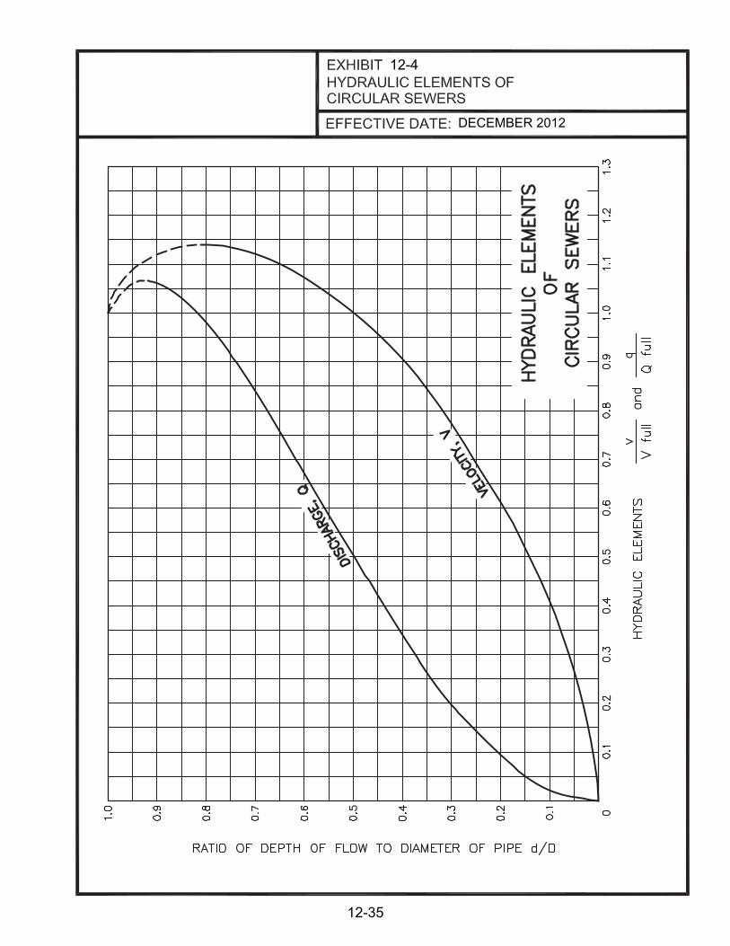
12-4
DECEMBER 2012
12-35

12-5
DECEMBER 2012
12-36

12-5
DECEMBER 2012
12-37

12-6
1/8" (1
%)
12.1
4.b
DECEMBER 2012
12-38

12-7
DECEMBER 2012
12-39

12-7
DECEMBER 2012
12-40

TABLE OF CONTENTS
CHAPTER 13 DEVELOPMENT SANITARY SEWER CONSTRUCTION
NUMBER SECTION PAGE
13.1 PURPOSE 13-1
13.2 NEW ALBANY SEWER BOARD REVIEW 13-1
CHAPTER 13
DEVELOPMENT SANITARY SEWER CONTRUCTION EXHIBITS
EXHIBIT TITLE PAGE 13-1 SUBMITTALS FOR PRIVATE DEVELOPMENT 13-6 SANITARY SEWER REVIEW 13-2 APPLICATION FOR SEWER CREDITS 13-7 13-3 MINIMUM REQUIREMENTS CHECKLIST FOR 13-8 SANITARY SEWER CONSTRUCTION PLANS
13-4 PROPERTY SERVICE CONNECTION INLET SHEET 13-9

13-1
CHAPTER 13 DEVELOPMENT SANITARY SEWER CONSTRUCTION
13.1 PURPOSE
This chapter establishes the submittal requirements to the New Albany Sewer Board for private development sanitary sewer projects. See Chapter 11 “Private Development Drainage” for the New Albany Stormwater Board and Floyd County Stormwater Department approval processes and submittal requirements for private development drainage projects. Sanitary sewer systems should be designed in accordance with the applicable provisions of this and other chapters of the New Albany Design Manual. Adherence to these procedures will facilitate timely review and approval for construction.
13.2 NEW ALBANY SEWER BOARD REVIEW
The sanitary sewer facilities for a proposed development in New Albany must be reviewed and approved by the New Albany Sewer Board. The applicant shall meet with the Sewer Board during the planning phase of development to discuss the feasibility of the sanitary sewer design and to ensure the availability of sewer credits before creating final construction plans. Refer to Exhibit 13-1 for a checklist of submittals required for the New Albany Sewer Board review process for development projects. For connection of a new single-family residence, sewer credits are not required but the location of the sewer tap must be approved by the Sewer Utility. For all other developments, the Sewer Board review process and submittal requirements are discussed below.
A. Preliminary Review For new developments connecting to the public sewer (other than single-family residences), a meeting should be arranged by the developer with the New Albany Sewer Board to discuss a proposed sewer plan and if sufficient sewer credits are available. A preliminary plan shall be submitted identifying the limits of the project. The preliminary plan should generally show a location map, the lot layout, proposed sewer alignment, existing sanitary sewer, and the number of customer service connections. If the proposed sewer includes a pump station then a concept plan, as described in Chapter 14 of this design manual, shall be submitted with the preliminary submittal. The preliminary submittal shall also include an Application for Sewer Credits and the proposed development’s flow projections to show how the amount of sanitary sewer credits was determined. The Application for Sewer Credits is located in Exhibit 13-2 and on the New Albany website: www.cityofnewalbany.com under the wastewater department page. Sanitary sewer credits must be secured from the Indiana Department of Environmental Management (IDEM) and the New Albany Sewer Board prior to design approval and connection to the sewer system. B. Final Review After receiving preliminary approval and receiving the necessary sewer credits, the final submission to the New Albany Sewer Board for approval of sanitary sewer facilities shall include the following items:

13-2
1. Sanitary Sewer Construction Plans and Specs
One copy of the final sewer plans shall be submitted on 24”x36” size sheets as well as one digital copy containing both AutoCad and PDF file formats. One hard copy and one digital copy of the sanitary sewer specifications shall also be submitted. A Professional Engineer and/or Professional Land Surveyor (where applicable per IC 25-21.5-1-7) that is licensed in the State of Indiana shall seal, sign, and date each sheet of the sewer plans. A Professional Land Surveyor, licensed in the State of Indiana, shall seal, sign, and date any sheets with Boundaries shown. Drafting standards shall be according to Chapter 4 “CADD Standards” of this design manual. Plan requirements for the respective sheets are identified on the Minimum Requirements Checklist for Sanitary Sewer Construction Plans in Exhibit 13-3. The sanitary sewer plans and specifications shall be in accordance with the Indiana Administrative Code 327 IAC 3, this design manual, and the New Albany Standard Specifications for Lift Stations (if applicable). The information for all connections must be shown on a Property Service Connection Inlet Sheet. A copy of the sheet should be placed in the plans for construction and record drawings. An example sheet can be found in Exhibit 13-4. The use of New Albany’s standard details is required. The standard details are located in Appendix A of this design manual. Nonstandard details and deviations from the standard details will need to be shown within the plan set. Deviations from the standard details must be approved by the New Albany Sewer Board. 2. Flow Projections and Calculations
The flow projections and sewer design calculations shall be as described in Chapter 12 “Sanitary Sewer Systems” of this design manual and included in the final submittal. New Albany may require improvements to downstream facilities in order to accommodate the flow from the proposed development. If the proposed sanitary sewer design includes a pump station, the design calculations for initial and ultimate flow conditions, as described in Chapter 14 “Pump Stations” of this design manual, shall be included in the final submittal. The pump station design shall be in accordance with Chapter 14 of this design manual and the New Albany Technical Specification for Lift Stations found in Appendix C of this manual. Odor control calculations shall also be submitted with the pump station design in order to determine if odor control measures are needed (see Chapter 15 “Odor Control” of this design manual).
3. Approval by IDEM (if required)
For developments requiring a sewer extension to New Albany’s sewer system, a Sanitary Sewer Construction Permit issued by IDEM must be obtained showing that the sanitary sewer design is in accordance with Indiana Administrative Code 327 IAC 3. A copy of the permit and permit approval letter shall be submitted to the New Albany Sewer Board.

13-3
4. Correspondence with other Utilities
Documentation must be provided showing that potential conflicts with the sanitary sewer and existing utilities have been addressed to the satisfaction of the utility company. New Albany must be copied on all letters and transmittals to and from the various utility companies.
5. Other Permits
Documentation must be provided showing that all applicable permits have been obtained for the construction of the sanitary sewer, such as encroachment permits, railroad crossing permits, stream crossing permits, etc. New Albany must be copied on all letters and transmittals to and from the various regulatory agencies. 6. Easement Plats (if required)
Two copies of any sewer and drainage easement plats required for the proposed development shall be included with the final submission of documents.
7. Record Plat
A copy of the record plat for the development must be submitted in order for New Albany to determine whether or not additional sewer and drainage easements will be required. Before the New Albany Sewer Department will allow sanitary sewers to be accepted and put into service, all public sewers must be in public rights of way or in a public easement. 8. Erosion Prevention and Sediment Control (EPSC) Plan
The developer must submit a plan for erosion prevention and sediment control (EPSC). The EPSC plan must include the actual depths and locations of all control measures. The EPSC plan must be stamped and sealed by an Indiana licensed Professional Engineer or Professional Land Surveyor (where applicable per IC 25-21.5-1-7). See Chapter 8 “Erosion Prevention and Sediment Control” for EPSC measures.
C. Construction Phase The New Albany Sewer Department will issue an approval letter after all final design submittal requirements are provided and deemed satisfactory. Construction of the sanitary sewer must commence within one year of approval.
1. Bonds
New Albany requires that a Performance Bond be posted covering the cost of sewer facilities construction during construction. New Albany will require that a Maintenance Bond be posted in the amount calculated by New Albany ($5,000.00 minimum plus $50 per LF under roads and $25 per LF outside of pavement). After the project has been accepted by New Albany, a one-year warranty period begins. If there are no problems with the facilities after one year, New Albany will release the bonds.

13-4
2. Accepted Bid Proposal
New Albany requires that the lump sum cost for the construction of the sanitary sewers be submitted. The lump sum amount shall be the same as the amount shown on the Performance Bond.
3. Wastewater Facilities Contract
This document is the legal agreement between the developer and New Albany regarding the construction of sanitary sewerage facilities. It conveys the sewerage facilities to New Albany, upon completion and acceptance by New Albany. The developer agrees to construct the project according to the plans and specifications and to furnish record drawings once the job is finished. New Albany agrees to inspect the work, and to accept ownership of the facilities, along with operation and maintenance responsibilities, once they are completed according to plans and specifications.
4. Inspector
The New Albany Sewer Department will provide part-time inspection as-needed for the construction of all sanitary sewer systems. Construction of sewers shall not begin in a development until an inspector has been assigned to the construction site. New Albany requires 3 working days advanced notice to schedule an inspector for a project.
5. Construction Field Changes
Deviations from approved construction plans as a result of unexpected field conditions will require documentation and approval by the New Albany Sewer Board. To obtain this approval, the contractor shall submit three (3) copies of the marked-up (REDLINE) plans showing the proposed revisions. Upon acceptance of the changes, the New Albany Sewer Board will mark the REDLINE drawings approved, sign and date the approval and send the REDLINES to the construction site via the inspector. One copy will be for the contractor, one copy for the inspector and one copy for the New Albany Sewer Board file.
6. Close-Out Procedures
After completion of the sewer installation, the Contractor, in accordance with Chapter 12 “Sanitary Sewer Systems” of this design manual, shall conduct a low-pressure air test and deflection test (for flexible pipe) of all sewer lines and vacuum test all manholes. The Contractor shall notify the New Albany Sewer Department 48 hours before testing. After all tests have passed and appropriate restoration of the disturbed area has been completed in accordance with the Erosion Prevention and Sediment Control Plan, and all other close out criteria are met, the New Albany Sewer Board will accept the sewers and release the lines for connections. 7. Record Plans
At the completion of construction, final record (as-built) drawings of the construction plans bearing the Land Surveyor's and/or Professional Engineer’s original seal,

13-5
signature, and date, and incorporating all approved changes shall be submitted to the New Albany Sewer Board. Final record drawings shall be prepared in accordance with Chapter 5 “Final Record Drawings” of this manual. Information regarding the property service connections (PSC) shall be shown on the record drawings. This information includes the location of the PSC in relation to the sewer along with the length, size, and depth of the PSC. The developer shall submit one hard copy of the final record drawings and one electronic copy containing both AutoCAD and PDF file formats. New Albany’s inspector will coordinate and check the work prior to submitting the record drawings to the New Albany Sewer Board. The as-builts must be completed and approved before the New Albany Sewer Board will make the sewers available for connection. Record plans shall be sent to the following address:
New Albany WWTP 38 West 10th Street
New Albany, IN 47150 Phone Number: (812) 948-5320

13-1
DECEMBER 2012
SUBMITTALS FOR PRIVATE DEVELOPMENTSANITARY SEWER REVIEW
Preliminary Plan
Concept Plan (for Pump Stations)
Flow Projections
Application for Sewer Credits/ Sewer Credit Approval
Sanitary Sewer Construction Plans and Specs- Hard Copy
Sanitary Sewer Construction Plans and Specs- Electronic Copy
Flow Projections
Design Calculations
IDEM Sanitary Sewer Construction Permit
Correspondence with other Utilities
Other Necessary Permits
Easement Plats
Record Plat
Erosion Prevention and Sediment Control Plan
Performance Bond
Maintenance Bond
Accepted Bid Proposal
Wastewater Facilities Contract
Record Drawings
New Albany Sewer Board
Preliminary Review
Construction
Final Review
Submittals for Private Development Sanitary Sewer Review
13-6

13-2
DECEMBER 2012
APPLICATION FOR SEWER CREDITS
Date of Application:
Name of Applicant:
Applicant Address:
Telephone: ( )
Project Name:
Project Location:
(address or description)
Description of Project:
(include phases & timing)
Estimated date when project is fully complete:
Total credits needed for project: (attach flow projections and calculations)
Credits needed for the next 3 years:
Anticipated construction start date once credits are granted:(i.e. complete project design, obtain IDEM construction permit, etc.)
Estimate of sanitary sewer connections for the project in: Year 1:
Year 2:
Year 3:
New Albany Sewer BoardApplication for Sewer Credits
13-7

DECEMBER 2012
MINIMUM REQUIREMENTS CHECKLISTFOR SANITARY SEWER CONSTRUCTION PLANS
13-3
13-8
(New Albany Use Only)
(NAVD 88)
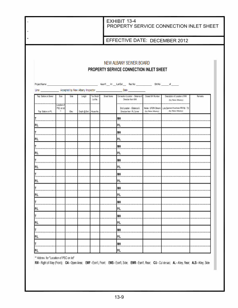
DECEMBER 2012
PROPERTY SERVICE CONNECTION INLET SHEET13-4
13-9
(by New Albany)
(by New Albany)
(by New Albany)

TABLE OF CONTENTS
CHAPTER 14 PUMP STATIONS
NUMBER SECTION PAGE
14.1 PURPOSE 14-1
14.2 SUBMITTAL REQUIREMENTS 14-1
14.2.1 Concept Plan Submittals 14-1
14.2.2 Final Design Submittals 14-4
14.3 DESIGN APPROACH 14-5
14.3.1 Compliance with Capacity Assurance Plan 14-5
14.3.2 Approvals 14-5
14.3.3 Service Level 14-5
14.3.4 Cost-Effectiveness Analysis 14-5
14.4 DESIGN CRITERIA 14-6
14.4.1 Definitions 14-6
14.4.2 General 14-7
14.4.3 Process 14-8
14.4.3.1 Wetwell 14-8
14.4.3.2 Force Main 14-9
14.4.3.3 System Head Curve 14-11
14.4.3.4 Buoyancy 14-12
14.4.3.5 Force Main Pressure and Water Hammer 14-13 Calculations

TABLE OF CONTENTS (cont.)
CHAPTER 14 PUMP STATIONS
NUMBER SECTION PAGE 14.4.3.6 Odor Control 14-15
14.5 ELECTRICAL 14-15
14.5.1 General 14-15
14.5.2 Applicable Standards or Codes 14-15
14.5.3 Pump Control 14-16
14.5.3.1 Automatic Operational Sequence 14-16
14.5.3.2 Control Setpoints/Elevations 14-17
14.5.3.3 Level Measurement/Detection 14-17
14.5.3.4 Control Panel Interface 14-18
14.5.3.5 PLC Monitoring 14-19
14.5.3.6 Pump Controls Interlock 14-20
14.5.4 Alarm System 14-20
14.5.4.1 Station Local Alarms 14-20
14.5.4.2 Dialer 14-21
14.5.4.3 Battery Back-up 14-21
14.5.5 Pump Station Electrical Criteria 14-22
14.5.5.1 General 14-22
14.5.5.2 Emergency Power 14-24
14.5.5.3 Site Lighting 14-25

TABLE OF CONTENTS (cont.)
CHAPTER 14 PUMP STATIONS
NUMBER SECTION PAGE
14.6 OPINIONS OF COST 14-25
14.6.1 Opinions of Capital Cost 14-25
14.6.2 Opinions of Operation and Maintenance Cost 14-25

14-1
CHAPTER 14 PUMP STATIONS
14.1 PURPOSE
This chapter: A. Identifies the planning and design approach to be used for small pump stations (defined
as those less than 700 gpm peak flow and/or up to 80 feet TDH). Pump stations outside of this criteria will be considered on a case-by-case basis.
B. Defines specific criteria for the design of small, sanitary pump stations and their
associated force mains. C. Delineates submittal requirements required by New Albany for review and approval of
small pump stations. D. Delineates requirements for opinions of construction and operating costs. E. Pump stations must satisfy the regulations of agencies having jurisdiction. Pump
stations, at a minimum, shall conform to this document, the City of New Albany Technical Specification for Lift Stations (see Appendix C), the regulations of the Indiana Department of Environmental Management (IDEM) and the Indiana Administrative Code 327 IAC 3.
14.2 SUBMITTAL REQUIREMENTS
The Design Engineer shall submit the Concept Plan and Final Design submittals to the New Albany wastewater utility manager for review and approval. Approval by New Albany will be required prior to authorization of any succeeding design phase.
14.2.1 Concept Plan Submittals
The purpose of a Concept Plan is to provide New Albany with preliminary design data for proposed facilities (gravity sewers, pump stations, force mains). The Concept Plan is used to justify alternatives recommended for providing sanitary sewer service.
Concept Plan submittals relating to pump stations shall include the following elements.
A. Project Background
1. Narrative description of the proposed service and drainage areas that can be served by the proposed facility.

14-2
2. Description and reference to any Facilities Plan and/or Capacity Assurance Plan requirements that relate to the proposed service area (on-site area to which service will be provided) and drainage areas (off-site areas that can be served with the proposed facilities).
3. Topographic map showing the boundaries of the proposed service and drainage areas.
B. Existing Environment
1. Existing land use for the proposed service area, adjacent areas, and
drainage areas, delineating project area or development site.
2. Existing hydrology, land features, floodplains, geological characteristics, surface conditions, subsoil conditions, and water table details.
C. Existing Collection System
1. Current sanitary sewer and stormwater collection system maps for the
proposed service area, drainage area, and surrounding area.
2. Details of existing system to which a proposed gravity sewer or force main may connect. Capacity of existing sewer system to receive flow from force main or future gravity sewer if temporary pump station is installed.
3. Locations of streets, alleys, unusual obstructions, required rights-of-ways, and all similar data that may help to define the physical features of a proposed sewer project.
D. Future Conditions
1. Designated land use for the proposed service area, drainage area, and
surrounding area. 2. Population and flow projections for the proposed service area and
drainage area. 3. Types of development, i.e., residential, commercial, or industrial. 4. Location of future roads, parks, industrial areas, subdivisions, etc.,
which may affect the routing and location of sewers and force mains. 5. Construction phasing to accommodate proposed development.

14-3
E. Pump Station Justification
In many cases, pump stations are unavoidable and necessary to provide service to a new area. The need for a sanitary pump station must be justified according to one or more of the following criteria. Compliance with one or more of the following criteria does not relieve the designer from the requirement to evaluate alternatives if portions of the service area do not satisfy these conditions: 1. The pump station is recommended in an approved Facilities Plan and/or
Capacity Assurance Plan; or
2. The elevation of a proposed service area is too low to be served by existing or future on-site or off-site gravity sewers; or
3. Interceptor sewers, planned by New Albany, are not in place; or 4. The proposed sanitary pump station has been determined to be a cost-
effective alternative to an on-site or off-site gravity sewer. To justify a pump station using these criteria, alternatives must be developed and evaluated as described in the following two sections.
F. Development of Alternatives
The following are minimum alternatives to be considered when a cost-effectiveness study is required as part of the pump station justification.
1. Gravity Sewer to Existing Collection System:
Provide description and preliminary drawings to illustrate existing facilities, proposed facilities, and connection.
2. Interim Solutions:
Temporary pump stations that provide service until permanent interceptors or other facilities are constructed.
3. Other Possible Solutions:
a. Consolidation with other pump stations.
b. Address sewer connections that are not cost-effective due to site conditions or not possible due to elevation differences, individually.
c. Grinder pumps for individual homes or small clusters of homes.

14-4
4. Pump Station Construction: Provide description and preliminary drawings to illustrate existing facilities, proposed facilities, and connection.
G. Evaluation of Alternatives
The alternatives shall be evaluated based on a cost-effectiveness analysis outlined in Section 14.3.4. The analysis shall be performed on each alternative and include both economic and non-economic factors.
14.2.2 Final Design Submittals
Final design submittals relating to pump stations shall include the following elements:
A. New Albany standard specifications modified to specific project needs with
additional diagrams and technical data as necessary to construct the proposed installation.
B. Flow projections and calculations.
C. Wetwell calculations.
D. Force main calculations.
E. Pump curves/system curves in feet of total dynamic head versus flow in gallons per minute with the following labels: Pump Curve; Single Pump Operation Curve; Two-Pump Operation Curve; Three-Pump Operation Curve (if applicable); Design Point(s); shut-off head; and Operating Point(s) and Operating Envelope.
F. Total hydraulic efficiency at operating point(s).
G. Pump cycle time.
H. Valve configuration.
I. Pump on-off setting calculations.
J. Buoyancy calculations.
K. Force main pressure, water hammer, and cyclic fatigue calculations.
L. Determinations for air release, air/vacuum, and/or sewage combination air valves.
M. Odor control calculations and/or assumptions.

14-5
N. Electrical calculations and/or power requirements (refer to Section 14.5 for specific requirements).
O. Opinions of capital and operation and maintenance costs. Energy efficiency is to be considered in the design.
P. Site plans showing details of pump station, wet well, valve vault, site access, landscaping (if applicable), and electrical utility pole or service rack location.
14.3 DESIGN APPROACH
14.3.1 Compliance with Capacity Assurance Plan and/or Facilities Plan
Proposed construction or expansion of sanitary pump stations shall be in compliance with Capacity Assurance Plan and/or Facilities Plan.
14.3.2 Approvals
Prior to construction or expansion of a sanitary pump station, the design documents must receive the approval of the following agencies and be signed and sealed by a Professional Engineer currently registered in the State of Indiana: A. New Albany Sewer Board B. Indiana Department of Environmental Management (IDEM) C. Others as needed (USACE, health department, INDOT, etc.)
14.3.3 Service Level
Guidelines presented in this Design Manual govern the planning and design of small pump stations defined as follows: A. Range in size up to 700 gallons per minute (peak flow) and/or up to 80
feet of total dynamic head. B. Proposed construction or expansion of sanitary pump stations exceeding
the stated ranges will be considered by the New Albany Sewer Board on an individual basis.
14.3.4 Cost-Effectiveness Analysis
The cost-effectiveness comparison analysis between a pump station and gravity sewer shall include both economic and non-economic factors. A. Economic Factors The economic portion of the cost-effectiveness analysis shall use a present worth

14-6
calculation that considers capital costs, operation and maintenance costs, and salvage values. Capital costs shall include opinions of construction cost as outlined in Section 14.6, engineering costs based on recognized fee curves and costs for acquisition of properties, easements and rights-of-way, including legal costs. Operation and maintenance costs shall include opinions of cost for labor, utilities, maintenance and repair of facilities. Salvage values shall be developed on straight-line depreciation. Life cycle costs should be considered over a 20-year period. Unless otherwise directed by the New Albany Sewer Board, a discount rate equal to that required by IDEM should be used to calculate the present worth value of each alternative.
B. Non-Economic Factors
1. Environmental Impact: The short-term and long-term impacts of the
alternative on the environment.
2. Reliability: A measure of how dependable the alternative performs over time.
3. Operability: The ease with which the alternative operates over time. 4. Constructability: The ease with which an alternative can be constructed
and phased into operation. 5. Resistance to vandalism. 6. Aesthetics and comments on neighborhood/property owner acceptance.
14.4 DESIGN CRITERIA
14.4.1 Definitions
A. Design Average Daily Flow: Refer to Chapter 12 Section 12.8.3.
B. Peak Flow: Design Average Daily Flow x peaking factor (per 327 IAC 3-6-11 and Chapter 12 Section 12.8.3).
C. Initial Average Flow: Average Flow estimated from the Initial population.
D. Initial Peak Flow: Initial Average Flow x peaking factor.
E. 20-Yr. Average Flow: Average Flow estimated from the 20-yr. population projection.
F. 20-Yr. Peak Flow: 20-yr. Average Flow x peaking factor.

14-7
G. Ultimate Average Flow: Average flow estimated from the Ultimate population projection.
H. Ultimate population is defined as the population halfway between 20-year population and watershed saturation population.
I. Ultimate Peak Flow: Ultimate Average Flow x peaking factor.
J. Watershed Saturation Population: The maximum projected population for the watershed based on present zoning.
K. Emergency Response Storage Volume: Ultimate Average Flow x 120 min. 14.4.2 General
Flow projections for developed and undeveloped areas that are used to design pump stations shall be as defined in Chapter 12. Flow projections should be prepared by the Design Engineer and submitted to the New Albany Sewer Board for approval.
Pump station peaking factors should be the same as sanitary sewer peaking factors, which includes anticipated wet-weather flows. Pump stations shall be of the wetwell type utilizing submersible pumps. With prior approval, pump stations with average minimum flow between 0.25 MGD and 1 MGD, may be designed as wet well/dry pit type. They shall operate automatically under normal conditions, but be capable of manual control. Pump stations shall be planned and designed to include provisions for ease of future elimination. Precast concrete or cast-in place concrete wetwells are acceptable. All pump stations with an average daily flow greater than 50,000 gallons per day shall have a mechanical building on site for mechanical storage and to house electrical equipment. The building shall be designed so that it will not detract from the appearance of the surrounding vicinity. See the New Albany Technical Specifications for Lift Stations (located in Appendix C) for the mechanical building specifications. The tops of the pump station wet well and valve vault shall be designed to an elevation at least 2 feet above the 100-year flood elevation or the pump station wet well and valve vault shall be flood proofed to provide maximum protection against flooding while still permitting operation. The pump controls must also be located 2 feet above the 100-year flood. Pumps shall be sized such that the pumping capacity, with the largest pump out of service, will handle the peak design flow condition. All plug and check valves shall be installed horizontally in shallow concrete valve vaults next to the wetwells. There must be sufficient vertical clearance in the valve vault for the combination air and vacuum relief valve. The arrangement shall

14-8
provide for easy access to the equipment to facilitate maintenance. Valve vaults are confined spaces; therefore, they require adequate means for ingress and egress, including OSHA approved ladders and access hatches of sufficient size. If the pump station is provided with potable water service, the service line shall have a backflow preventer and/or a pressure vacuum breaker ASSE #1020 or a reduced pressure zone ASSE #1013 installed to prevent possible cross connections to the potable water supply. The service line shall be installed in compliance with the applicable water company regulations. Each pump station shall be accessible via a bituminous or concrete access road with a minimum width of 12 feet to accommodate maintenance truck traffic. If the station is located on a dead-end street, a paved turn area shall be provided. Road construction shall meet current New Albany street specifications. Pavement shall be one inch INDOT HMA surface over two inches INDOT HMA binder over nine inches INDOT 73 DGA. All thickness refers to compacted thickness. The design of the access road must also allow for a Vac-con truck to have access to the wet well for cleaning and be able to support the weight of the vehicle. Fencing and seeding/sodding of the pump station site shall be per New Albany’s Technical Specification for Lift Stations and will be reviewed on a case-by-case basis.
To ensure uniformity and system compatibility, New Albany has prepared a standard specification for a typical pump station (see Appendix C). The Design Engineer should use the information that is provided herein to customize these documents in order for the installation to meet the specific project needs. The Design Engineer shall be responsible for the design of the system. Any deviations from the standard specification must be approved by the New Albany Sewer Department.
14.4.3 Process
14.4.3.1 Wetwell
Wetwells shall be designed for the ultimate peak flow. The cycle of operation for each pump shall not be less than 15 minutes and the maximum detention time in the wetwell shall average no more than 30 minutes. The wetwell volume for optimum operation shall be computed as follows:
V = (φq)/4
Where: V = Required operating capacity in gallons (from the lead pump on
elevation to the pumps off elevation)

14-9
φ = Minimum time of one pumping cycle in minutes, from start to start. Ideally 0 = 15 minutes (maximum 30 minutes; minimum 12 minutes)
q = Pump capacity in gallons per minute (use ultimate peak flow)
Detention times for both initial average flow and ultimate average flow conditions shall be computed.
Wetwell volume shall be based on a maximum draw down depth of 4 feet between the lead pump on elevation and the pumps off elevation. The design of the pump station shall incorporate a minimum two-hour emergency response storage volume based on ultimate average flow conditions as stipulated under Section 14.4.1. The required volume must be provided in the wetwell and/or a separate, self-draining surge tank between the high wetwell alarm elevation and the invert elevation of the lowest influent gravity sewer. The two-hour emergency response storage volume may be waived by New Albany if two sources of electric service are provided or there is an emergency generator permanently installed at the pump station. Unless specifically prevented by site conditions, the Design Engineer shall layout the collection system and pump station such that the top of the wetwell or nearest upstream manhole is at least two feet below the lowest building floor elevation receiving sewer service. In the event that emergency response measures are overburdened, this will provide a point of relief to prevent backups into homes and the adverse impacts on public health and property damage. The Design Engineer shall identify the location and characteristics of the overflow relief point on the Drawings. Avoid dropping influent flows into wetwells by installing a drop pipe connection on the wetwell interior or exterior to eliminate air entrainment. The wetwell shall be considered as a Class 1, Division 1 hazardous location. Rail packages shall be non-sparking. Further wetwell sizing constraints are detailed in Section 14.5.3, Pump Control. A manhole shall be located within ten (10) feet of the wet well on the influent line. The influent line shall be constructed of Ductile Iron pipe. This manhole shall provide provisions for bypass pumping. A plug valve shall be placed in the influent line to the lift station. This valve will be used to isolate the wet well.
14.4.3.2 Force Main Force mains shall be designed for ultimate peak flow conditions and checked for initial and ultimate peak flow conditions to insure the velocity ranges. Force mains shall be ductile iron conforming to AWWA C151, PVC conforming to AWWA C-900 Class 150 (minimum), or HDPE conforming to ASTM F714. Force main fittings shall be ductile iron mechanical joints rated for a minimum of 150 psi. Refer to the New Albany Technical Specification for Lift Stations in Appendix C for force main requirements.

14-10
Sewage combination air valves shall be provided at all high points in the force main. Long horizontal runs and increases in slope may require air/vacuum and/or air release valves, realizing that air release valves are for pockets of air accumulated during operation and air/vacuum valves are to exhaust or admit air during filling or draining the force main. Cleanouts shall be provided at all low points and at additional critical locations. The Design Engineer shall consider and review with New Albany the location of all air release valves, air/vacuum valves, sewage combination air valves and cleanouts. The Engineer shall provide an economic analysis comparing the installation of air release and air/vacuum release valves against the installation of deeper force main piping. The economic analysis shall take into account the installation and maintenance costs associated with the air release and air/vacuum release valves. Air release and air/vacuum release valves shall be specifically designed for wastewater service and be sized per the manufacturer’s recommendations. The air and vacuum release valves will be contained in a vault and vented above ground. A manually controlled isolation valve shall be installed between the force main and the air release or air/vacuum release valves. Joint restraints or concrete thrust blocks shall be installed at bends. An analysis must be made to determine if a joint restraint is required either upstream or downstream of the bend. For slopes of 20 percent and greater, anchors shall be provided at each joint (at a minimum). A flexible through-wall connector shall be used at pipe penetrations through structures to allow for differential settlement.
Force main design criteria shall be as follows:
A. Minimum Pipe Size
1. 4-inch I.D. for wastewater pumps
2. 2-inch I.D. for grinder pumps
B. Design Pipe Roughness Coefficient (C)
1. PVC C = 120 and 150
2. Lined Ductile Iron C = 120
3. HDPE C = 120
C. Velocity (V) Range
1. V = 2.0 to 5.0 feet per second (fps) for wastewater pumps 2. V = 3.0 to 5.0 fps for grinder pumps

14-11
Note: A maximum velocity of 6.0 fps is allowable with a present worth economic calculation that considers capital and operating costs in order to justify any increase above 5.0 fps.
14.4.3.3 System Head Curve The pump/system curve calculation may be performed utilizing any acceptable hydraulic equation. The system head curve is a plot of the flow through a pipe system against the head losses as a result of friction losses, minor losses, and elevation differences in the pipe system. Selection of pump size shall be based on static head and total dynamic head. The design operating point is at the intersection of the pump curve and the system curve. Also, the pump should be selected such that the shut-off head exceeds the pumping head at peak Q. Static head or static pressure (hs) shall be based on the average elevation of lead pump on/off: hs = (Elevation of highest point in force main) - (Average elevation of lead pump on/off) Minor losses through fittings and valves shall be computed by multiplying the velocity head by the minor loss coefficient: hm = K*(V2/2g) Where:
K = Minor loss coefficient V = Velocity (feet per second) G = Acceleration of gravity = 32.2 (feet per second squared)
Friction losses (hf) in the force main can be computed according to the Hazen-Williams formula as follows: hf = (10.44) (L) (q) 1.85˗ / [(C) 1.85 (d) 4.8655] Where:
L = Length of pipe (feet) q = Flow rate (gallons per minute) C = Hazen-Williams friction loss coefficient d = Pipe diameter (inches)

14-12
Compute total dynamic head as follows: TDH = Static Lift + Friction Loss + Minor Loss = hs + hf + hm The TDH shall be calculated for the design roughness coefficient as stated in Section 14.4.3.2. All applicable system curves shall be plotted on the pump curve submitted. The operating point for the selected pump shall be in the range of initial peak flow to ultimate peak flow as determined by the Design Engineer. The pump efficiency at the operating point should be within the acceptable operating range of 60 to 120% of the capacity at the best efficiency point. The selected pump must be approved by the New Albany Sewer Department. The pump efficiency shall be included in the final design submittal. Grinder pump efficiencies may be obtained from the manufacturer. During pump selection, the system should be checked for low static head conditions (i.e., full wetwell condition) and high static head conditions. The minimum and maximum head curves shall be plotted on the pump curve. This check is performed to insure that in no case will the pump be required to operate outside its normal operating range. Such an occurrence could result in overloading of the motor and eventual pump failure. The motors shall be sized to be non-overloading over the entire pump curve. When pump stations are proposed to discharge into gravity sewers, the capacity of the gravity sewer receiving the discharge shall be checked to determine the impact on the sewer capacity. When pump stations are proposed to discharge into existing force mains, an analysis of the existing pump station shall be performed to evaluate the impact of the additional flow in the existing force main and its effect on the existing pump(s) performance. The Design Engineer should check initial and ultimate flow conditions to see if the existing pump capacity is compromised. Conditions should be verified when the existing pump station is pumping and when it is not pumping (on and off). An analysis of the potential for reverse flow through the existing pumps shall be included. If the capacity is reduced, a recommended upgrade to this station should also be presented in conjunction with the proposed pump station design. Approval of systems that discharge into force mains will be evaluated on a case-by-case basis. 14.4.3.4 Buoyancy
Buoyancy shall be analyzed on the wetwell and valve vault to determine whether additional methods of restraint are necessary. Mechanical equipment, water weight, and other temporary loads shall not be included in the analysis. A safety factor of 1.5 (minimum) is required.

14-13
Buoyancy Force shall be computed as follows: Buoyancy Force = (Displaced Volume) x (Unit Weight of Water)
Opposing Force shall be computed as follows:
Opposing Force = Weight of Barrel + Weight of Bottom Slab + Weight of Top Slab + Net Weight of Saturated Soil over Bottom Slab Extension + Any Additional Restraints (Do not include electrical/mechanical components).
Factor of Safety is computed as follows:
Factor of Safety = Opposing Force > 1.5 Buoyant Force
14.4.3.5 Force Main Pressure and Water Hammer Calculations
From the Uni-Bell Handbook of PVC Pipe, Design and Construction, 1986, water hammer is an increase in pressure in a pipe caused by a sudden change in velocity. The velocity change usually results from the closing of a valve. The maximum surge pressure encountered is a function of wave velocity (a) as follows: a = 4660/(1 + (kd/Et))1/2 Where:
a = Wave velocity k = Fluid bulk modulus, 300,000 pounds per square inch (psi) for water d = Pipe ID, (inches) E = Modulus of elasticity of pipe
400,000 psi for PVC pipe 24,000,000 psi for ductile iron pipe
t = Wall thickness (inches)
OR
a = 4660 / ((1 + (k/E) (DR-2))1/2
Where: DR = (O.D. (inches)) ÷ (wall thickness (inches)) DR = Dimension Ratio

14-14
The maximum surge pressure (P) is computed as follows:
P = aV 2.31 g
Where:
V = Maximum change in velocity (velocity goes to 0 feet per second) g = Acceleration due to gravity (32.2 feet per second-squared) P = Pressure surge (pounds per square inch)
Total pressure is computed as: Total Pressure = Maximum Surge Pressure + Static Pressure
= P + hs
Total pressure must be less than the rated pressure of the pipe (rated pressure including surge allowance). Cyclic Surge (Fatigue) Analysis is determined (for PVC force mains only) as follows:
A. Estimate the number of pump cycles for the proposed system using a design
life of 80 years (use 4 cycles per hour and a safety factor of 2.5).
B. Calculate the peak hoop stress (S) using Vinson's formula.
C = (5.05 x 10²¹) S-4.906
Where: C = Average number of cycles to failure
S = Peak hoop stress (pounds per square inch)
C. Determine Total System Pressure (PT)
PT = Maximum Surge Pressure + Static Pressure
D. Use International Standards Organization (ISO) formula to determine
minimum dimension ratio.
DRrequired = (2S/PT) + 1
Where: DR = Dimension Ratio
S = Peak Hoop Stress
PT = Total System Pressure

14-15
The calculated DR value must be greater than the DR of the selected pipe. Force main pressure and water hammer calculations for ductile iron pipe shall be based upon AWWA Standards C150/A21.15-91, “American National Standard for the Thickness Design of Ductile Iron Pipe.” Calculations for polyethylene pipe shall be based upon AWWA Standards C906 “Standard for Polyethylene Pressure Pipe and Fittings.”
14.4.3.6 Odor Control
The Design Engineer shall consider the need for odor control if detention time in either the wetwell or the force main, based on the average flow, exceeds 45 minutes. Refer to Chapter 15, Odor Control, for specific requirements.
14.5 ELECTRICAL
14.5.1 General
This section provides guidelines for the design and preparation of plans and specifications as related to small sanitary pump station power, control, and telemetry systems. All electrical documents must be signed and sealed by a Professional Electrical Engineer currently registered in the State of Indiana. All concepts and designs are to strike a balance between function, initial cost, operational cost, and ease of maintenance. Generally accepted designs, materials, and methods are to be used throughout the project. The Design Engineer shall utilize these as a template for completing design. If, however, the Design Engineer identifies an opportunity to take advantage of an innovative design approach, the Design Engineer is to present the proposal in writing to New Albany for evaluation.
14.5.2 Applicable Standards or Codes
All systems, designs and procedures are to meet or exceed the requirements of the latest issue of the following codes or standards:
Indiana Building Code IBC National Electric Code NEC Underwriters Laboratories, Inc. UL Factory Mutual FM National Fire Protection Association NFPA National Electrical Manufacturers Association NEMA

14-16
Occupational Safety and Health Administration OSHA Indiana Occupational Safety and Health Administration IOSHA
Design should relate to the following specific requirements:
A. NFPA 37 Standard for the Installation and Use of Stationary Combustion
Engines and Gas Turbines B. NFPA 110 Standard for Emergency and Standby Power Systems C. NFPA 820 Standard for Fire Protection in Wastewater Treatment and
Collection Facilities.
14.5.3 Pump Control
14.5.3.1 Automatic Operational Sequence A programmable logic controller (PLC) shall be used for the primary control of the submersible pumps. The PLC shall operate the submersible pumps and shall perform automatic alternation and duplexing for two pumps (or triplexing for three pumps, where applicable). The PLC shall alternate the lead pump once the wetwell level has been pumped down to the stop setpoint (elevation). PLC’s shall be Allen-Bradley Micrologix 1000 or Square D Modicon TSX Momentum with the required discrete/analog inputs/outputs. A minimum of 10% spare inputs/outputs shall be provided. Float switches shall be provided as a secondary control of the submersible pumps in the event of failure of the PLC. A total of four backup float switches are required: low wetwell level, pumps stop, pumps start, and high wetwell level. The float controls shall sequentially start and stop all pumps via relay logic and time delay relays. The controls will operate completely independent of the PLC. Upon activation of the backup start float, both pumps shall automatically start, via time delays to prevent simultaneous starting, and operate in a similar fashion to that of the PLC. When the wetwell level falls below the backup stop level float, both pumps will de-energize and the PLC will take control of the pumps. A step control or variable level scheme shall be used for the pump control. These schemes shall establish the following sequence of operations: A. Constant Speed Pumps - The lead pump shall start when the wetwell volume
from the pumps "off setpoint/elevation" to the lead pump "start setpoint/elevation" is equal to the volume derived in Section 14.4.3.1. The minimum separation between these elevations shall be 12 inches. If the influent sewage flow into the wetwell is greater than the capacity of one pump, the second and, if applicable, third pumps shall start at ascending, separate levels (start elevations). They then continue to run until the liquid level in the wetwell is pumped down to a predetermined level (stop elevation) for all pumps.

14-17
B. Variable speed pumps will be considered on a case-by-case basis.
14.5.3.2 Control Setpoints/Elevations The PLC shall stop all pumps when the wetwell level is equal to the minimum level recommended by the manufacturer of the proposed pumps plus 24 inches, and a minimum of 12 inches below the PLC controls lead start setpoint. The increment in levels between the PLC control multi-pump start points shall be a minimum of 12 inches. The backup low wetwell level float shall be located 12 inches below the backup stop float. The backup stop float shall be 12 inches below the PLC stop setpoint. The backup start float shall be 12 inches above the PLC lag pump start setpoint. The PLC high wetwell level alarm shall be at or lower than the invert of the lowest influent pipe and at least 12 inches above the backup float start elevation. The local high wetwell level alarm float shall be a minimum of 12 inches above the PLC high level setpoint.
14.5.3.3 Level Measurement/Detection An ultrasonic level transmitter with submersible, Class I, Division 1 ultrasonic level transducer shall be the preferred method of level measurement and shall be incorporated into the pump station operation. The ultrasonic level transmitter/transducer shall be Milltronics HydroRanger transmitter/Milltronics XPS transducer. Proper placement of the transducer is critical to ensure foreign objects (piping, float cables, etc.) do not encroach on the transducer beam angle. The transmitter shall be installed within the pump control panel or rack mounted adjacent to the pump control panel. Where located adjacent to the pump control panel, a sun shade shall be provided to protect the transmitter. The transducer shall be flange mounted to the top slab of the wetwell. This arrangement will allow the Owner to remove the transducer as needed for cleaning and maintenance. Float switches shall provide back-up pump control and high wetwell level monitoring in the event of PLC failure. The float switches shall be free hanging and suspended by weighted cables. The cables shall be of sufficient length to be installed without splicing. Float cables and pump power/control cables shall be supported from stainless steel level sensor holders via stainless steel strain relief cable grips. The level sensor holder shall be located near the wetwell hatch opening to allow easy access for removal of cables. Intrinsically safe relays shall be installed within the pump control panel for termination of float switches. Float cables shall be provided with Class I, Division 2 sealing connectors where cables enter the pump control panel. Level detection systems that require maintenance personnel to enter the wetwell to repair or replace components are unacceptable.

14-18
14.5.3.4 Control Panel Interface
A graphic touchscreen “human-machine interface” terminal (HMI) shall be provided for indicating status and alarms, and for input from the operator for various control functions. Exceptions are the inclusion of hard-wired Hand-Off-Automatic (H-O-A) selector switches, noted below, and a reset pushbutton for each pump to allow manual operation of the pumps and resetting of motor starter faults without the HMI or PLC. The H-O-A selector switch shall be provided for each pump and shall be mounted on the dead front of the control panel. In the Hand position the selected pump(s) shall operate continuously until switched to the Off position. In the Automatic position the selected pump(s) shall operate as described above via the ultrasonic level transducer. Hand operation shall not require the PLC to be functional. A total of three elapsed time meters shall be provided on the dead front of the control panel: one elapsed time meter for each pump and one elapsed time meter for simultaneous pump operation. The run time for each pump shall be displayed on an accumulative type elapsed meter that is non-resettable showing run time in one-tenth hour increments. A separate ammeter shall be provided on the dead front of the control panel for monitoring the running amperage of each pump motor, Phase A. A Lead Pump 1 / Lead Pump 2 / Automatic Lead Pump Alternate selector switch shall be provided to select a specific lead pump or for automatic alternation of the lead pump. A “Test-Auto” test switch shall also be mounted on the control enclosure for testing all alarm lights. The following indicating lights shall be provided on the control panel:
A. Pump Run - indicating light for each pump (labeled as Pump “X” Run). The
indicating light shall be lit when the corresponding pump is running. B. Seal/Failure - indicating light for each pump (labeled as Pump “X”
Seal/Failure). C. Motor High Temperature - indicating light for each pump (labeled as Pump
“X” Motor High Temperature). All switches, indicating lights, push buttons, and ammeters mounted on the pump control panel shall have engraved plastic legend nameplates (white with black letters) – secured with screws – indicating its function.

14-19
14.5.3.5 PLC Monitoring The PLC shall be configured to monitor the following conditions:
A. Pump No.1 Running.
B. Pump No.2 Running.
C. Pump No.1 Seal Leak.
D. Pump No.2 Seal Leak
E. Pump No.1 Motor High Temperature.
F. Pump No.2 Motor High Temperature.
G. Pump No.1 Motor Overload.
H. Pump No.2 Motor Overload.
I. Pump No.1 Lead (via selector switch position).
J. Pump No.2 Lead (via selector switch position).
K. Automatic Pump Alternation (via selector switch position).
L. Pump No.1 In-Auto Position.
M. Pump No.2 In-Auto Position.
N. Pump No.1 In-Hand Position.
O. Pump No.2 In-Hand Position.
P. Pump(s) Off Level (via transducer).
Q. Lead Pump Start Level (via transducer).
R. Lag Pump Start Level (via transducer).
S. High Wetwell Level (via transducer or float).
T. Low Wetwell Level (via transducer or float).
U. Low Temperature (outdoor systems only).
V. Loss-of-phase, phase reversal, or under voltage.

14-20
14.5.3.6 Pump Controls Interlock The following alarms shall automatically de-energize the respective pump(s): A. Motor High Temperature (de-energize respective pump).
B. Motor Overload (de-energize respective pump).
C. Seal Leakage (de-energize respective pump).
D. Low Wetwell Level (de-energize all pumps).
E. Starter Fault (from reduced voltage solid-state starter on soft started pump
motors).
F. Loss-of-phase, phase reversal, or under voltage (de-energize all pumps).
Seal leakage and over-temperature shall be latched in the PLC program until manually reset via “soft buttons” on the HMI on the control panel door. When the backup level controls are energized, motor high temperature and seal failure shall de-energize the pump, however, the pump will be re-enabled if either interlock self-resets, i.e., the motor cools down. Electrical overload relays and soft starters shall be provided with a reset pushbutton on the inner door of the control panel, independent of the PLC or HMI controls. Loss-of-phase, phase reversal or under voltage condition shall de-energize all pumps in any mode of control. The monitor for these conditions shall reset automatically once the problem parameter falls within its appropriate range. If, upon reset of the monitor, the control system calls for more than one pump, the additional pump(s) shall be energized after a time delay(s) in both the PLC logic or the backup control system relay logic to reduce motor inrush current on the electrical service or the generator.
14.5.4 Alarm System
14.5.4.1 Station Local Alarms The station shall be provided with a local alarm system powered from the main control panel and powered via an uninterruptible power supply (UPS). The following shall initiate the local alarm.
A. High wetwell level (via transducer or local float)
B. Low wetwell level (via transducer or local float)
C. Power failure
These alarms should annunciate locally via a red flashing light. The light shall

14-21
remain on during alarm condition and shall de-energize automatically once the alarm condition has cleared. All control system alarms shall automatically reset when the alarm condition has cleared. An adjustable 0-15 minute time delay relay shall be activated and timed-out prior to transmitting the high wetwell level condition to the dialer. 14.5.4.2 Dialer
Each station shall be equipped with a RACO dialer monitoring system, 16 channel minimum, which will dial out and notify the operator in the event that an alarm has been activated at the pump station. The dialer shall be compatible with all other pump station dialers currently installed within the system. The dialer shall be provided with a surge suppressor and properly ground to the grounding electrode system provided at the station. The dialer shall be self-contained in a NEMA 4X, stainless steel enclosure and located adjacent to the pump control panel. The dialer shall be powered from the pump control panel. The following signals shall be provided as inputs to the dialer: A. Pump No. 1 Motor Overtemperature. B. Pump No. 2 Motor Overtemperature. C. Pump No. 1 Motor Overload. D. Pump No. 2 Motor Overload. E. Pump No. 1 Seal leakage. F. Pump No. 2 Seal leakage. G. High wet well level alarm (via transducer or float). H. Low wet well alarm (via transducer or float). I. Low temperature (outdoor systems only). J. Power failure. 14.5.4.3 Battery Back-up Equipment within the pump control panel shall be designed to operate on 24Vdc. A back-up battery power supply with charger shall be provided to allow operation of the PLC and dialer upon loss of 120-volt power. The battery shall be sufficiently sized to provide a minimum of 6 hours operation.
14-22
14.5.5 Pump Station Electrical Criteria
14.5.5.1 General
All pumping stations shall be wired in strict accordance with the latest edition of the National Electric Code. Pumps and equipment shall normally be designed to operate from a 230/460 volt, three-phase power source. All stations shall be powered by a 480-volt, 3-phase, 4-wire wye primary, or a 480-volt, 3-phase, 3-wire delta primary. Engineer shall coordinate incoming electrical service with the local utility company. All stations powered by 480-volts primary shall have a minimum 7.5 KVA single-phase, 480-volt to 120/240-volt, transformer provided for power station controls and miscellaneous equipment (dialer, receptacles, station lights, etc.). Single-phase to three-phase converters will not be allowed. Single-phase service will be considered by New Albany on a case-by-case basis. Where approved, single-phase pump stations shall have capacitor start-induction run motors. A control power transformer will not be required to facilitate auxiliary equipment when 240/120-volt delivery is available from the utility. All motor starters and controls shall be located in a shop-assembled control cabinet, located above the 100-year flood elevation. All conductors shall be insulated, stranded, copper wire, rated at 600 volts.
Pump control cabinets shall be stainless steel or aluminum, NEMA 4X enclosure, suitable for outdoor installation or type NEMA 12 for inside use within the mechanical building as appropriate. Each cabinet shall be equipped with a locking hasp, staple, and three-point latching handle to provide watertight and tamper-proof service and shall be mounted on a wet well electrical rack/pedestal. Each cabinet shall have a hinged inner door, containing all operator control devices, and must be appropriately sized for the application. All indoor located panel enclosures shall be painted with an epoxy-based enamel coating. Pump control cabinet shall be dead front with all operators’ devices, including HMI, accessible without opening the enclosure door (via lockable switch compartment). All relays, timers, terminal strips, etc., shall be mounted to a subpanel inside the enclosure. All wiring must be stranded and sized to be protected by a 20A/1P circuit breaker, or as required by control panel manufacturer. Supplemental overcurrent protection may be used in lieu of oversized wiring. The pump control panel shall be provided with a metal data pocket on interior of the control panel door. Elementary control schematics and connection diagrams showing the spatial relationship of components and wiring shall be furnished and stored in data pocket. Sleeve type wire markers or other “permanent” type markers shall be installed on

14-23
all wires, keynoted back to the elementary schematic or the connection diagram, and all terminals identified.
Motor starters shall be NEMA-rated magnetic type with a 120 volt control coil, and three ambient-compensated thermal overload relays for three-phase and single phase services with a minimum size of NEMA-1. Reduced-voltage starters shall be provided for motors rated 25 HP or larger, unless more stringent requirements are mandated by the local utility company. Reduced-voltage starters, where required, shall utilize solid-state motor starters with bypass contactors. The solid-state starters shall be used to start and stop the pumps with the bypass contactor utilized for full speed operation. Consult with local utility for motor starting requirements.
All circuit breakers utilized for submersible pumps shall be ground-fault interrupter type.
A surge protection device shall be provided for the pump control panel.
The pump control panel shall be supplied with a thermostatically controlled 120-volt heater sized to maintain panel internal temperature at a minimum 55 �F and shall include a low temperature switch, set at 40 �F, within the enclosure to alarm failure of heater.
A minimum of one (1) 120-volt, 15-amp receptacle, and one (1) 120-volt, 15-amp GFI duplex receptacle shall be mounted in the control enclosure. An internal panel light, with switch, shall be installed in the electrical enclosure.
An externally mounted NEMA 3R red-flashing globe-type alarm light, with a lexan-type cover and wire shield shall be installed on the outside of the mechanical building, where applicable, visible from the road. The light shall be activated upon a High or Low wetwell level and a normal utility power failure.
Separate pedestal mounted stainless steel (or aluminum) NEMA 4X enclosures shall be provided to facilitate the junction of cords from Class I, Division 1, Group D wet well components with permanent wiring to non-hazardous control panel (starters, PLC, etc.). The junction box shall be mounted a minimum of 36 inches above the wet well top slab. The pedestal shall provide an air gap between the wet well and junction box. The pedestal shall be vented and hinged to allow operator access to cabling within the pedestal. One, two (2) inch diameter aluminum, rigid galvanized steel, or PVC-coated rigid steel conduit per pump must be installed from this junction box to the pumps. The conduit, and all connections, must be sealed at both ends with manufacturer-approved watertight seals, or silicone.
Sun shields shall be provided at all exterior pump control panels. Shield shall be fabricated from minimum 10-gauge aluminum, and shall be designed, fabricated, installed, and supported to fully cover and shade the top, sides, and back of the enclosure, from direct exposure to sunlight. Sun shields shall not be attached directly to the enclosure by drilling holes through, or welding studs to, the enclosure surfaces, and shall be designed and mounted to provide a minimum 1-inch air gap all around the enclosure for air circulation and heat dissipation.

14-24
At a minimum, the following key issues must be addressed in the design with calculations and/or NEC references to verify such:
A. Service size.
B. Feeder/service conductor size.
C. Ground conductor size.
D. Feeder/service disconnect size.
E. Branch circuit conductor size.
F. Branch circuit type of protection.
G. Branch circuit over-current protection rating.
H. Motor controllers size and overload protection rating.
I. Pump control system transformer over-current protection.
J. Available fault current.
K. Feeder/service over-current protection.
L. Ground fault protection.
The service conductors, main circuit breaker, transfer switch, and starter branch circuit conductors, must be sized so that the full capacity of the motor starters may be utilized in the future.
14.5.5.2 Emergency Power A City approved generator hook-up is required for emergency power outage. The switching unit must be type specified by New Albany to prevent feedback and meet all electrical codes for safe operations and to be standardized with existing stations. A fused double-throw safety switch shall be provided and rated for use as service entrance equipment and shall be housed in a stainless steel, NEMA 4X enclosure. The double-throw safety switch may be installed at the service riser pole or rack-mounted, along with the generator receptacle noted below, adjacent to the service riser pole. Please note that the fused double-throw disconnect switch has a long lead time. A Crouse-Hinds Arktite Model AR2042, 200-amp, 600VAC / 250VDC, 3-wire, 4-pole (reversed service), body grounded, receptacle shall be installed on the emergency side of the double-throw safety switch for connection to the Owner’s portable generator.

14-25
14.5.5.3 Site Lighting An area light shall be installed to illuminate the area, including the pump station wetwell, vault, and control panel. The light shall be installed with a dusk-dawn sensor, and an on-off weatherproof switch, to override the dusk-dawn sensor. The light shall be installed a minimum of 10 feet above the ground or high enough to illuminate the entire lift station area. The light shall be a 1000-watt metal halide. Smaller wattage fixtures may be allowed if point-by-point foot-candle levels are demonstrated, and provide a minimum of 2 foot-candles (maintained level) throughout the entire lift station area.
14.6 OPINIONS OF COST
Opinions of probable cost shall be based on the best professional opinions of the Design Engineer. The Design Engineer should use recent bid tabulations, and information from suppliers and contractors in formulating the opinions of cost. The opinion of cost shall take into consideration capital cost and the cost of operation and maintenance.
14.6.1 Opinions of Capital Cost
Opinions of capital cost shall be grouped by category.
Opinions of capital cost shall include a construction contingency of 10% and should include a cost for necessary land, easement, or right-of-way acquisition.
14.6.2 Opinions of Operation and Maintenance Cost
Opinions of operation and maintenance cost shall include costs for labor, utilities, maintenance and repair. Energy efficiency is to be considered in the design.

15-1
TABLE OF CONTENTS
CHAPTER 15 ODOR CONTROL
NUMBER SECTION PAGE 15.1 ODOR CONTROL JUSTIFICATION 15-1 15.2 ODOR CONTROL DESIGN PROCESS 15-1
CHAPTER 15 EXHIBITS
EXHIBIT TITLE PAGE 15-1 ODOR CONTROL SYSTEM DESIGN CRITERIA FORM 15-2

15-1
CHAPTER 15 ODOR CONTROL
15.1 ODOR CONTROL JUSTIFICATION
The design engineer shall review the potential need for odor control, evaluate odor control options, and make recommendations in the Concept Plan submittal. New Albany will review the information and consider the need for odor control on a case by case basis according to the following criteria:
A. The history of odor complaints in the vicinity. If New Albany has received odor
complaints within 100 yards of the proposed facility within the previous year, odor control may be required.
B. The potential that the facility has to create an off-site odor nuisance. If the facility is fed by upstream pumping stations, if it has collection sewers that have low velocities (<2 ft/sec) and/or long detention times (>6 hours) or if it is expected to receive heavy industrial flow, odor control may be required. On-site odor control will also be required if the wetwell or force main has an average detention time in excess of 45 minutes and may be required with lesser detention times if other conditions warrant it.
C. The proximity of proposed facilities to existing and future homes, businesses and roads. If a home or business is located within 150 feet of the facility, or is expected to be within this distance, odor control facilities may be required.
D. The design calculations performed by the project engineer indicate that odor control
is needed. Refer to Exhibit 15-1 “Odor Control System Design Criteria Form”. 15.2 ODOR CONTROL DESIGN PROCESS
If New Albany determines that odor control is required for the proposed facility the design engineer shall refer to Chapter 16 “Odor Control” in the Louisville and Jefferson County MSD Design Manual for submittal requirements and design criteria. The Louisville and Jefferson County MSD Design Manual can be found online at the following web address: http://www.msdlouky.org/insidemsd/standard-drawings.htm
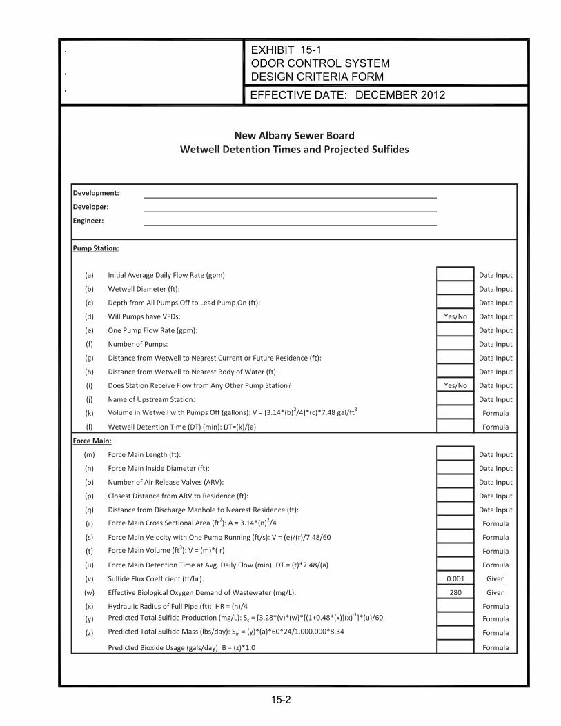
15-1
DECEMBER 2012
Development:
Developer:
Engineer:
Pump Station:
(a) Initial Average Daily Flow Rate (gpm) Data Input
(b) Wetwell Diameter (ft): Data Input
(c) Depth from All Pumps Off to Lead Pump On (ft): Data Input
(d) Will Pumps have VFDs: Yes/No Data Input
(e) One Pump Flow Rate (gpm): Data Input
(f) Number of Pumps: Data Input
(g) Distance from Wetwell to Nearest Current or Future Residence (ft): Data Input
(h) Distance from Wetwell to Nearest Body of Water (ft): Data Input
(i) Does Station Receive Flow from Any Other Pump Station? Yes/No Data Input
(j) Name of Upstream Station: Data Input
(k) Volume in Wetwell with Pumps Off (gallons): V = [3.14*(b)2/4]*(c)*7.48 gal/ft3 Formula
(l) Wetwell Detention Time (DT) (min): DT=(k)/(a) Formula
Force Main:
(m) Force Main Length (ft): Data Input
(n) Force Main Inside Diameter (ft): Data Input
(o) Number of Air Release Valves (ARV): Data Input
(p) Closest Distance from ARV to Residence (ft): Data Input
(q) Distance from Discharge Manhole to Nearest Residence (ft): Data Input
(r) Force Main Cross Sectional Area (ft2): A = 3.14*(n)2/4 Formula
(s) Force Main Velocity with One Pump Running (ft/s): V = (e)/(r)/7.48/60 Formula
(t) Force Main Volume (ft3): V = (m)*( r) Formula
(u) Force Main Detention Time at Avg. Daily Flow (min): DT = (t)*7.48/(a) Formula
(v) Sulfide Flux Coefficient (ft/hr): 0.001 Given
(w) Effective Biological Oxygen Demand of Wastewater (mg/L): 280 Given
(x) Hydraulic Radius of Full Pipe (ft): HR = (n)/4 Formula
(y) Predicted Total Sulfide Production (mg/L): Sc = [3.28*(v)*(w)*[(1+0.48*(x)](x)-1]*(u)/60 Formula
(z) Predicted Total Sulfide Mass (lbs/day): Sm = (y)*(a)*60*24/1,000,000*8.34 Formula
Predicted Bioxide Usage (gals/day): B = (z)*1.0 Formula
New Albany Sewer BoardWetwell Detention Times and Projected Sulfides
15-2

Appendix A
Standard Details

DE
CE
MB
ER
2012
*Thi
s is
a d
etai
l fro
m M
SD
Sta
ndar
d D
raw
ings
dat
ed 9
-30-
09.
this
isa
test
tode
lete
this
sect
ion
inits
entir
ety.

DE
CE
MB
ER
2012
*Thi
s is
a d
etai
l fro
m M
SD
Sta
ndar
d D
raw
ings
dat
ed 9
-30-
09.
this
isan
othe
rtes
tto
dele
teth
isin
entir
ely
pipe
shal
lbe

DE
CE
MB
ER
2012
*Thi
s is
a d
etai
l fro
m M
SD
Sta
ndar
d D
raw
ings
dat
ed 9
-30-
09.
dele
ting
this
asw
ell

DE
CE
MB
ER
2012
*Thi
s is
a d
etai
l fro
m M
SD
Sta
ndar
d D
raw
ings
dat
ed 9
-30-
09.
this
isbe
ing
dele
ted
asw
ell.

DE
CE
MB
ER
2012
*Thi
s is
a d
etai
l fro
m M
SD
Sta
ndar
d D
raw
ings
dat
ed 9
-30-
09.
DG
-02.

DE
CE
MB
ER
2012
*Thi
s is
a d
etai
l fro
m M
SD
Sta
ndar
d D
raw
ings
dat
ed 9
-30-
09.
DG
-04.
5.D
esig
nfo
rHS
-20
load
ing.

DE
CE
MB
ER
2012
*Thi
s is
a d
etai
l fro
m M
SD
Sta
ndar
d D
raw
ings
dat
ed 9
-30-
09.

DE
CE
MB
ER
2012
*Thi
s is
a d
etai
l fro
m M
SD
Sta
ndar
d D
raw
ings
dat
ed 9
-30-
09.

DE
CE
MB
ER
2012
*Thi
s is
a d
etai
l fro
m M
SD
Sta
ndar
d D
raw
ings
dat
ed 9
-30-
09.

DE
CE
MB
ER
2012
*Thi
s is
a d
etai
l fro
m M
SD
Sta
ndar
d D
raw
ings
dat
ed 9
-30-
09.

DE
CE
MB
ER
2012
*Thi
s is
a d
etai
l fro
m M
SD
Sta
ndar
d D
raw
ings
dat
ed 9
-30-
09.

DE
CE
MB
ER
2012
*Thi
s is
a d
etai
l fro
m M
SD
Sta
ndar
d D
raw
ings
dat
ed 9
-30-
09.

DE
CE
MB
ER
2012
*Thi
s is
a d
etai
l fro
m M
SD
Sta
ndar
d D
raw
ings
dat
ed 9
-30-
09.

DE
CE
MB
ER
2012
*Thi
s is
a d
etai
l fro
m M
SD
Sta
ndar
d D
raw
ings
dat
ed 9
-30-
09.
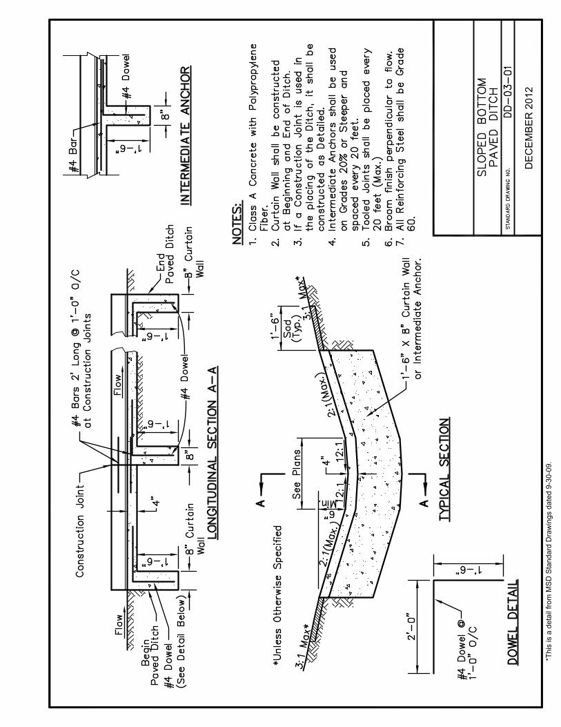
DE
CE
MB
ER
2012
*Thi
s is
a d
etai
l fro
m M
SD
Sta
ndar
d D
raw
ings
dat
ed 9
-30-
09.

DE
CE
MB
ER
2012
*Thi
s is
a d
etai
l fro
m M
SD
Sta
ndar
d D
raw
ings
dat
ed 9
-30-
09.

DE
CE
MB
ER
2012
*Thi
s is
a d
etai
l fro
m M
SD
Sta
ndar
d D
raw
ings
dat
ed 9
-30-
09.

*Thi
s is
a d
etai
l fro
m M
SD
Sta
ndar
d D
raw
ings
dat
ed 9
-30-
09.
DE
CE
MB
ER
2012

*Thi
s is
a d
etai
l fro
m M
SD
Sta
ndar
d D
raw
ings
dat
ed 9
-30-
09.
DE
CE
MB
ER
2012

*Thi
s is
a d
etai
l fro
m M
SD
Sta
ndar
d D
raw
ings
dat
ed 9
-30-
09.
DE
CE
MB
ER
2012
5.Si
ames
eC
onne
ctio
nsar
eno
tper
mitt
ed.
6.D
etec
tabl
em
arki
ngta
pesh
allb
ein
stal
led.
indi
vidu
al
Sia
mes
eC
onne
ctio
n(N
otP
erm
itted
)
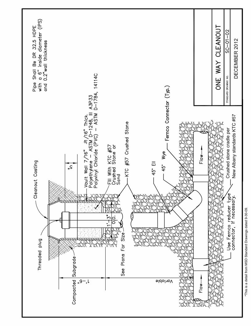
DE
CE
MB
ER
2012
*Thi
s is
a d
etai
l fro
m M
SD
Sta
ndar
d D
raw
ings
dat
ed 9
-30-
09.
Cru
shed
ston
ecr
adle
per
New
Alb
any
stan
dard
sK
TC#5
7

DE
CE
MB
ER
2012
*Thi
s is
a d
etai
l fro
m M
SD
Sta
ndar
d D
raw
ings
dat
ed 9
-30-
09.
xxxCru
shed
ston
ecr
adle
per
New
Alb
any
stan
dard
sK
TC#5
7

DE
CE
MB
ER
2012
*Thi
s is
a d
etai
l fro
m M
SD
Sta
ndar
d D
raw
ings
dat
ed 9
-30-
09.
cc
x
x
x

DE
CE
MB
ER
2012
*Thi
s is
a d
etai
l fro
m M
SD
Sta
ndar
d D
raw
ings
dat
ed 9
-30-
09.
Not
used
.
Not
used
.
Not
used
.
Bac
kfill
acco
rdin
gto
New
Alb
any
Stan
dard
Spec
ifica
tions
.
Inte
rnal
mec
hani
calC
him
ney
seal
sar
ere
quire
don
allN
ewA
lban
ym
anho
les.
Che
mic
albo
ndin
gfo
rchi
mne
yse
als
isto
beus
edon
lyfo
rre
habi
litat
ion
and
only
inno
n-pa
ved
area
s.A
tam
inim
um,t
hese
alw
illex
tend
from
apo
int3
inch
esab
ove
the
base
ofth
em
anho
lefr
ame,
toa
poin
t3in
ches
belo
wth
eto
pof
the
conc
rete
cone
orto
psl
ab.
Ifgr
ade
adju
stm
ents
colla
rsar
eus
ed,t
hese
alhe
ight
will
incr
ease
prop
ortio
nally
toth
eco
llarh
eigh
t.

DE
CE
MB
ER
2012
*Thi
s is
a d
etai
l fro
m M
SD
Sta
ndar
d D
raw
ings
dat
ed 9
-30-
09.
z
zx
z
z
z

DE
CE
MB
ER
2012
*Thi
s is
a d
etai
l fro
m M
SD
Sta
ndar
d D
raw
ings
dat
ed 9
-30-
09.
Not
used
.
Not
used
.
Bac
kfill
acco
rdin
gto
New
Alb
any
Stan
dard
Spec
ifica
tions
.
Chi
mne
yse
als,
eith
erin
tern
ally
mec
hani
calo
rche
mic
al,w
illbe
requ
ired
onal
lnew
New
Alb
any
man
hole
s.A
tam
inim
um,t
hese
alw
illex
tend
from
apo
int3
inch
esab
ove
the
base
ofth
em
anho
lefr
ame,
toa
poin
t3in
ches
belo
wth
eto
pof
the
conc
rete
cone
orto
psl
ab.
Ifgr
ade
adju
stm
ents
colla
rsar
eus
ed,t
hese
alhe
ight
will
incr
ease
prop
ortio
nally
toth
eco
llarh
eigh
t.
Not
used
.

DE
CE
MB
ER
2012
*Thi
s is
a d
etai
l fro
m M
SD
Sta
ndar
d D
raw
ings
dat
ed 9
-30-
09.
z
z
z
x

DE
CE
MB
ER
2012
*Thi
s is
a d
etai
l fro
m M
SD
Sta
ndar
d D
raw
ings
dat
ed 9
-30-
09.
Not
used
.
Not
used
.
Not
used
.
Not
used
.
Bac
kfill
acco
rdin
gto
New
Alb
any
Stan
dard
Spec
ifica
tions
.

DE
CE
MB
ER
2012
*Thi
s is
a d
etai
l fro
m M
SD
Sta
ndar
d D
raw
ings
dat
ed 9
-30-
09.

DE
CE
MB
ER
2012
*Thi
s is
a d
etai
l fro
m M
SD
Sta
ndar
d D
raw
ings
dat
ed 9
-30-
09.

DE
CE
MB
ER
2012
*Thi
s is
a d
etai
l fro
m M
SD
Sta
ndar
d D
raw
ings
dat
ed 9
-30-
09.

DE
CE
MB
ER
2012
*Thi
s is
a d
etai
l fro
m M
SD
Sta
ndar
d D
raw
ings
dat
ed 9
-30-
09.

DE
CE
MB
ER
2012
*Thi
s is
a d
etai
l fro
m M
SD
Sta
ndar
d D
raw
ings
dat
ed 9
-30-
09.

DE
CE
MB
ER
2012
*Thi
s is
a d
etai
l fro
m M
SD
Sta
ndar
d D
raw
ings
dat
ed 9
-30-
09.

DE
CE
MB
ER
2012
*Thi
s is
a d
etai
l fro
m M
SD
Sta
ndar
d D
raw
ings
dat
ed 9
-30-
09.

DE
CE
MB
ER
2012
*Thi
s is
a d
etai
l fro
m M
SD
Sta
ndar
d D
raw
ings
dat
ed 9
-30-
09.

Appendix B
Criteria for Precast Structures

APPENDIX B
CRITERIA FOR PRECAST STRUCTURES
1. Any use of precast structures must be so noted on the plans, including a typical detail for each type of structure for the project.
2. Structures which require specially designed footings, cut-off walls, etc., will not be allowed as precast.
3. Openings in precast structures for pipes shall be the outside diameter of the pipe plus maximum of 6 inches. In order to use non-shrink grout, the opening shall be the outside diameter of pipe plus 3 inches. (Outside diameter of pipe plus 4 1/2 inches is permissible when tapered hole forms are utilized.)
4. For precast structures (other than those with knockout panels), the opening around the pipe shall either be filled with non-shrink grout for the wall thickness of the structure or the pipe shall be encased with a minimum 6-inch collar of concrete from the inside face of the wall to 1’-0” outside the outer face of the wall. The pipe shall be adequately supported to prevent settling while the grout or the concrete encasement is setting up. The inside face of the structure walls shall be finished with a trowel and wet brush finish.
5. For circular structures, the following applies as to the maximum inside diameter (or horizontal dimension) of pipe to be used with a given size of manhole.
Diameter of Structure Maximum Size of Pipe*
4’-0” 24 inches 5’-0” 36 inches 6’-0” 48 inches
*Outside diameter may be considered on a case-by-case basis for flexible pipe.
6. For circular structures, the minimum distance allowed between precast holes for the pipes shall be 12 inches.
7. For circular structures and rectangular structures (other than those with knockout panels), the minimum vertical distance from the holes for the pipes to the top of the structure wall shall be 4 inches. If this vertical distance is less than 12 inches, then additional reinforcing steel shall be furnished for this section. The top slab must be designed for HS-20 loading.

8. For precast structures with knockout panels, holes for the pipe shall not be cut into the structural members (i.e., top beams and corner columns) and non-shrink grout shall not be allowed to be placed around the pipes. The pipes shall be encased with concrete a minimum 6-inch collar around the outside of pipe or a minimum of 3 inches beyond the hole knocked in the wall, whichever is greater. Also, the concrete encasement shall extend from the inside face of the wall to 1’-0” outside the outer face of the wall.
9. Precast structures with knockout panels shall not be used with more than 2 feet of earth cover unless load calculations are supplied.
10. For rectangular structures where pipe will be installed in adjacent walls (other than those with knockout panels), at least 6 inches of wall (measured from the interior corner)is required on each side of the pipe beyond the precast opening for the pipe. This rule is not applicable for structures which have pipe installed in opposite walls or where one outlet pipe is utilized.
11. A wash is required in the bottom of catch basins to provide positive drainage (sloped toward outlet).

Appendix C
New Albany Lift Station Specifications

1
City of New Albany Sewer Utility
TECHNICAL SPECIFICATIONS FOR LIFT STATIONS
Revised 12-20-21
In addition to those recommended standards specified by the latest revision of the “Recommended Standards for Sewage Works” (Ten State Standards), the following minimum standards for wastewater lift station design and installation; have been adopted by the City of New Albany Sewer Utility. All wastewater lift stations shall be of the submersible type. With prior approval, lift stations, with average minimum flow between 0.25 MGD and one (1) MGD, may be designed as wet well/dry pump pit type. Lift stations larger than one (1) MGD will require extensive pre-design discussions. A. Submersible type wastewater lift station minimum specifications: 1. Wet Well
a. Circular wet well(s) shall be fabricated of pre-cast reinforced concrete base sections,
riser sections, and flat slab tops. Base sections, riser sections, and flat slab tops shall conform to the requirements of ASTM Specifications C478, latest revision. Joints between pre-cast sections shall be sealed with two (2) rings of flexible butyl rubber sealant. Concrete wet wells shall be coated outside with an approved bituminous seal coating. Interior Joints shall be sealed with high strength non-shrink grout. All inlet and outlet pipes through the wet well wall shall be through a cast-in-place opening and provided with a resilient seal. Wet well top slab to be located above 100-year flood elevation or flood-proof hatch to be installed.
b. The wet well base shall be placed on at least twelve (12) inches of leveled and compacted KYDOT #57 crushed limestone.
c. The wet well access hatches shall have aluminum frames and doors with hinged
double doors, locking provisions and self-opening shocks. The door shall be ¼” thick aluminum floor plate reinforced to 300 PSF live load. Hinges and all hardware shall be of stainless steel. Bumper blocks shall be placed to block vehicles from driving onto or across the wet well hatches. Access hatch drainage channel to be drained to daylight.
d. The wet well shall be designed large enough to allow at least twelve (12) minutes
elapsed time between successive equipment starts during average flow conditions, and small enough to prevent the wastewater from going septic. Engineer shall submit all computations used to size wet well, including depth of wet well and to determine pump size(s).
e. Except as requested by the Utility, the wet well floor shall have a fillet at the inner base
wall of the wet well to prevent the accumulation of solids.

2
f. Wet well shall have a minimum inside diameter of six (6) feet and a minimum depth of
six (6) feet from the bottom to the invert of the lowest incoming pipe. In addition, the highest “alarm level” float shall be at least one (1) foot below the lowest incoming pipe and the lowest “pump off” float shall be set at the top of the pump for complete submersion of the pump. Floats shall be placed in a location that is readily accessible for pulling and cleaning needs.
g. Due to the six (6) feet depth, fall protection must be provided in way of OSHA approved
anchor points of at least 2 or more.
h. A diverting shield or baffle may be required on the influent flow piping / made of stainless steel or an approved material.
2. Valve Vault
a. A rectangular valve vault shall be installed on the discharge piping for ease of
accessibility and maintenance of the check and plug valves. It shall be designed so that no part of a valve or pipefitting flange is closer than twelve (12) inches to a wall, floor or ceiling to allow easy maintenance access. Valve vault top slab to be located above 100-year flood elevation or flood-proof hatch to be installed.
b. The valve vault shall be constructed in accordance with the specifications for wet well
construction. The valve vault shall be a rectangular pre-cast or cast-in-place concrete structure with minimum inside diameter of 6’ x 6’. The discharge piping shall be at least three (3) feet below finished grade of the area. The valve vault base shall be placed on at least six (6) inches of leveled and compacted KYDOT #57 crushed limestone. The valve vault shall not be placed on unstable (uncompacted) fill due to over-excavation of the lift station area. All inlet and exit piping through the wall of the valve vault shall be through cast-in-place openings provided with a resilient seal. A drainpipe shall be placed in the valve vault with the discharge end placed in the wet well. An approved backflow device shall be placed on the end of the drainpipe in the wet well.
c. The valve vault shall be coated on the outside with an approved bituminous seal
coating.
d. A hinged single hatch with locking provisions, access hatch assembly shall be installed on the top of the valve vault. The hatch, frame, and accessories shall be constructed of aluminum with stainless steel hardware and fasteners, having a minimum opening of 30” X 30”. The hatch shall be rated at 300 PSF live load. The hatch shall open away from the electrical control panel/junction box. Access hatch drainage channel to be drained to daylight.
3. Pumps, Motors and Seals
The following manufactures are preferred:
� Flygt � Hydromatic

3
� Myers
Other manufacturers may be accepted on a case-by-case basis. All pump documentation shall be submitted for approval, prior to ordering equipment, to the City of New Albany / Wastewater Treatment Plant Manager.
4. Valves, Discharge Piping, and Force Main
a. Discharge piping shall be ductile iron pipe with flanged ductile iron fittings, and long radius elbows. Preferred ( wye ) after check valves to reduce friction loss.
b. Valves and piping shall be a minimum 4-inch in size. Piping shall be designed to
minimize station head loss yet maintain the cleaning velocity of at least two (2) fps. All discharge piping shall be of the same size as the force main, (increase to this size at pump discharge).
c. A swing-type check valve and plug valve shall be installed in the discharge line of each
pump and located in the valve vault. Plug valves shall conform to AWWA C504-80 and rated for 150 psi. Matco check valves shall conform to AWWA C1111, be rated at 150 psi, and shall have a spring-loaded external lever arm or weighted. The plug valves shall be Dezurik, eccentric type installed outlet side (after) the check valves. The connection of the piping after the valves will be made utilizing a wye connection. Design engineer shall include provision for a “slow-closing” check valve when conditions require such a valve.
d. An emergency pump auxiliary connection shall be provided on all lift stations. This
connection will allow the bypass pumping of the wet well in emergency conditions. The pipe shall extend out of the ground one (1) foot to connect a pump hose. The connection end of the pipe shall be four (4) inch with a four (4) inch female cam lock fitting or quick connect unless the design horse power of the pump is above sixty (60) HP then a six (6) inch connection and female cam lock is required.
e. Ductile iron Class 51 and 52 pipe for use in force mains sized four (4) inches and
larger shall be constructed per ANSI Specification A21-51-1976 covering thickness design of ductile iron pipe, and AWWA Specification C151-76 covering overall specifications and requirements for ductile iron pipe.
f. PVC C-900 Class 150 pipe for use in force mains four (4) inches and larger shall be
constructed per AWWA Specification C-900-89. All PVC force mains shall be laid with a 12 gauge shielded copper tracing wire and tape placed on the top of the pipe. The wire must be accessible at the valve vault, discharge manhole, air relief valve manholes, and at access boxes when the distance between the above structures exceeds 1000 feet.
g. Force main fittings shall be 150 psi (minimum) ductile iron mechanical joints. Fittings
and piping shall be restrained per AWWA specifications using Meg-a-lug restrainer glands and blocking.
h. Apco or Val-matic ( Determined by City ) automatically operating combination air and
vacuum relief valves shall be placed at all high points on the force main. They shall be

4
placed in minimum 48” diameter manholes for ease in access and maintenance. The air relief valves shall be of stainless steel construction or cast with stainless internal parts.
i. Force mains shall be hydrostatically tested for leakage at 150 % of maximum
operating pressure.
j. Discharge piping to have stainless steel liquid filled gauges ( P.S.I.) located in valve box and attached with ¾ inch NPT taps with 316 stainless steel nipples and bronze ball shut off valve or stainless. These should be located before the check valves.
5. Guide Rails
a. Guide rails for the pumps shall be a minimum two (2)-inch stainless steel pipe. A
stainless steel lifting chain with a safety factor of five (5) shall be provided with each pump.
6. Electrical
a. For electrical requirements see Section 14.5 in Chapter 14-Pump Stations of the New
Albany and Floyd County Stormwater and Sanitary Sewer Design Manual.
7. Mechanical Building
a. All lift stations designed with an average daily flow in excess of fifty thousand (50,000) gallons per day shall have erected a block building with brick veneer on the outside. This building will serve as the lift station site for mechanical storage, and to house the electrical equipment. Fluorescent enclosed light fixtures ( if out side in shelter, will require cold weather ballast. The building must have a minimum ceiling height of 8’0”, and have 8’0” by 8’0” minimum outside dimensions. The inside dimension shall be a minimum of 6’0” by 6’0”. The interior of the building shall be painted with light colored masonry paint. The truss roof of the mechanical building shall be constructed with asphalt shingles with a pitch sufficient to allow water to run off the roof. The building must be securely anchored to a minimum 6-inch thick poured-in-place concrete reinforced slab. The surface of the slab shall be slightly above surrounding area.
b. The building shall be designed so that it will not detract from the appearance of the
surrounding vicinity.
c. A 42” wide (minimum) x 7’ hollow metal door in a steel frame with 2 finish coats of paint must be installed with a 2’ x 2’ louver for ventilation, and an aluminum threshold. The door must have a hasp for padlocking provisions.
8. Site Requirements
a. The contractor shall be responsible for developing a lawn around the lift station by
sodding or by seeding with Kentucky 31 variety clear tag grass seed. All banks shall be no steeper than 3 to 1 slope. Gravel or asphalt in fenced area.

5
b. A bituminous or concrete paved road (minimum 12’0” width) shall be built to the station, which will accommodate maintenance truck traffic. If the station is located on a dead-end street, a paved turn area shall be provided. Road construction shall meet current New Albany street specifications. Pavement shall be one (1) inch INDOT HMA surface over two (2) inches INDOT HMA binder over nine (9) inches INDOT 73 DGA. All thickness refers to compacted thickness. It must also allow for Vac-con truck to have access to wet well for cleaning and support weight of vehicle.
c. A four (4)-foot by four (4)-foot concrete slab, sloping away from the building, shall be
provided at the entrance to the building.
d. All aboveground structures, hatch openings, valve vaults, wet wells and driveways shall be designed so that they are inherently protected from a 100-year flood event. Wet well top slabs, valve vault top slabs, and access hatches shall be located above the 100-year flood elevation or flood-proof access hatches shall be provided.
e. Shelter structure with steel posts will be required for smaller stations with shingled
roofing and drip edge / vinyl siding and a light system consisting of fixtures to illuminate control panels. Lightning Rods for protection when applicable.
f. The City may require hoist or crane system for larger Stations.
g. Fencing will be either chain link vinyl coated or cedar plank with 20 ft gates / may
require barbed wire / this will be determined by the City depending on location of the purposed lift station to be attractive in some areas or for security reasons. Attached to fencing will be emergency phone numbers and name of station along with warning signs and address.
h. The site shall have city water hose bib (non–freeze) with garden hose connection and a
backflow preventer (heated or insulated).
9. Miscellaneous
a. A minimum three (3)-inch ductile iron pipe wet well vent shall be installed, with a 180-degree bend with a stainless steel screen.
b. All hardware and fastener items located either inside or directly connected to the wet
well and valve vault shall be of stainless steel construction.
c. Pumps shall have a five (5) year warranty provided by the manufacturer. The warranty shall be as follows. 18 months full coverage of pump, 19-36 months 75% coverage, 37-48 months 50% coverage and 49-60 months 25% coverage. The developer or the pump manufacturer can provide this warranty. A certificate of warranty shall be supplied with the pumps. The developer shall warrant all equipment, materials, and workmanship in the installation against defects or failures of any kind for a period of one (1) year from the date the Utility accepts the lift station for operation and maintenance.
d. At project completion the following documents will be provided to the New Albany
Sewer Utility prior to City acceptance of the Lift Station: 1) two sets of as-built
6
drawings (24”x 36”), 2) an Autocad file containing the as-built drawings, 3) a PDF file containing the as-built drawings, 4) a PDF file containing the project specifications, and 5) a PDF file containing the shop drawings. Four paper (4) copies of the operation and maintenance manuals shall be provided at this time along with the certificate of warranty, and two paper copies of all shop drawing submittals and documents.
e. A manhole shall be located within ten (10) feet of the wet well on the influent line. The
influent line shall be constructed of AWWA C 150 Class 52 (min.) Ductile Iron pipe. This manhole shall provide provisions for bypass pumping. A plug valve shall be placed in the influent line to the liftstation. This valve will be used to isolate the wet well.
f. Two sets of preliminary plans and specifications for the lift station layout and structures
shall be submitted for review and approval to the New Albany Sewer Utility prior to completion of final plans and specifications. See design manual Chapter 14 for more information.
g. Certified pump curves shall be supplied with each installed pump. All pumps shall
have stainless steel nameplates securely attached. Pump motors shall be non-overloading at all points on the pump curve. The contractor, pump supplier and contractor’s electrical subcontractor shall perform field operation tests, when all construction is complete, to show that all items are working properly and meeting design specifications. A complete written report, containing the above, shall be submitted to the City.