New Advances and Applications Using X-Ray … Fluorescence Analyzers for Alloy Testing ... elements...
4
New Advances and Applications Using X-Ray Fluorescence Analyzers for Alloy Testing Abstract For more than 40 years, positive material identification (PMI) of alloys has been performed using standalone, portable, and more recently, handheld x-ray fluorescence (XRF) spectrometers. These portable spectrometers, using a focused beam of x-rays to excite key elements found in the alloy sample, produce a resultant spectrum and a digital readout of elemental concentrations. The concentrations of key elements provide industrial inspectors with the ability to verify alloy grades in critical applications, thus avoiding possible catastrophic incidents where an incorrect alloy could have been used by mistake. The latest handheld alloy analyzers incorporate major technological advances allowing for greater accuracy, precision, and lower limits of detection for a wider range of elements. These advances illustrate how new industry problems facing inspection engineers today can now be addressed by handheld XRF. Several difficult applications will be discussed such as flow accelerated corrosion (FAC) in refinery HF Alkylation units due to chromium, copper and nickel content, and (FAC) in power generating stations due to chromium levels and carbon steel failure due to low silicon content. Introduction History has taught us that we should trust, but verify! Verification of alloys to ensure they are composed of the correct alloying elements has been the realm of handheld x-ray fluorescence for the past four decades. Industries ranging from petrochemical, aerospace and fabrication (which are mission critical for the correct material), to contract testing services, metals recycling applications and many more have employed portable XRF for alloy verification for over 40 years. The use of these tools assures users that the composition of the metal they purchase, fabricate, verify, install, or recycle is alloyed as expected. Since the late 1960s, the portable XRF market has seen several generations of increasingly sophisticated alloy analyzers become commercially available to perform this crucial task. Each generation adds new capabilities, increased speed and greater ease of use. Today, nearly all alloys are tested and identified for correct alloying content with these powerful handheld tools. Fig. 1 Seventh generation alloy analyzer, the Thermo Scientific Niton XL3t, circa 2009 The Latest Developments Unlike the limited quantity, hand-built and, often, highly application specific portable, two-piece, analyzers of decades past, today’s one-piece handheld XRF analyzers are built in volume with modern assembly technologies and are designed on a common platform to allow a wide range of uses. The latest alloy analyzers are readily adapted, with software and calibration options, to a wide range of other materials analysis applications. Expanded alloy application examples are the addition of precious metals and electronic alloy calibrations to the base alloy model, as well as precious metals in catalytic converters. Fig. 2 A handheld XRF being used to inspect piping systems in a refinery. Examples of other types of analysis are environmental and toxic materials testing applications, which can be further added to the basic or expanded alloy analyzer. With user software upgrades now feasible electronically, the longer a modern XRF tool is used, the more it can evolve and the better it can perform. Joey Cheverie - 1
Transcript of New Advances and Applications Using X-Ray … Fluorescence Analyzers for Alloy Testing ... elements...

New Advances and Applications Using X-Ray Fluorescence Analyzers for Alloy Testing Abstract For more than 40 years, positive material identification (PMI) of alloys has been performed using standalone, portable, and more recently, handheld x-ray fluorescence (XRF) spectrometers. These portable spectrometers, using a focused beam of x-rays to excite key elements found in the alloy sample, produce a resultant spectrum and a digital readout of elemental concentrations. The concentrations of key elements provide industrial inspectors with the ability to verify alloy grades in critical applications, thus avoiding possible catastrophic incidents where an incorrect alloy could have been used by mistake. The latest handheld alloy analyzers incorporate major technological advances allowing for greater accuracy, precision, and lower limits of detection for a wider range of elements. These advances illustrate how new industry problems facing inspection engineers today can now be addressed by handheld XRF. Several difficult applications will be discussed such as flow accelerated corrosion (FAC) in refinery HF Alkylation units due to chromium, copper and nickel content, and (FAC) in power generating stations due to chromium levels and carbon steel failure due to low silicon content. Introduction History has taught us that we should trust, but verify! Verification of alloys to ensure they are composed of the correct alloying elements has been the realm of handheld x-ray fluorescence for the past four decades. Industries ranging from petrochemical, aerospace and fabrication (which are mission critical for the correct material), to contract testing services, metals recycling applications and many more have employed portable XRF for alloy verification for over 40 years. The use of these tools assures users that the composition of the metal they purchase, fabricate, verify, install, or recycle is alloyed as expected. Since the late 1960s, the portable XRF market has seen several generations of increasingly sophisticated alloy analyzers become commercially available to perform this crucial task. Each generation adds new capabilities, increased speed and greater ease of use. Today, nearly all alloys are tested and identified for correct alloying content with these powerful handheld tools.
Fig. 1 Seventh generation alloy analyzer, the Thermo Scientific Niton XL3t, circa 2009
The Latest Developments Unlike the limited quantity, hand-built and, often, highly application specific portable, two-piece, analyzers of decades past, today’s one-piece handheld XRF analyzers are built in volume with modern assembly technologies and are designed on a common platform to allow a wide range of uses. The latest alloy analyzers are readily adapted, with software and calibration options, to a wide range of other materials analysis applications. Expanded alloy application examples are the addition of precious metals and electronic alloy calibrations to the base alloy model, as well as precious metals in catalytic converters.
Fig. 2 A handheld XRF being used to inspect piping systems in a refinery.
Examples of other types of analysis are environmental and toxic materials testing applications, which can be further added to the basic or expanded alloy analyzer. With user software upgrades now feasible electronically, the longer a modern XRF tool is used, the more it can evolve and the better it can perform.
Joey Cheverie - 1
In the very latest handheld XRF alloy analyzers, the most significant technology advancements are:
• Further miniaturization and field hardening
• Improved ergonomics
• Doubling of the speed of alloy and metals testing
• Enhanced performance for difficult (nearly twin) alloy separations
• Increased sensitivity for tramp & trace elements in alloys
How the XRF Works
Fig. 3 Functional Diagram of HHXRF
A handheld XRF consists of a source of x-rays (radioisotope or electronic x-ray tube) that generates a beam of primary x-rays. This beam shines into the sample to be analyzed and generates a spectrum of characteristic fluorescence radiation from atoms of the elements in the sample. These characteristic x-rays are detected by a solid state detector and their electromagnetic energies are converted to electrical pulses. These pulses then are sorted into element channels in a Digital Signal Processor. From here the counts from each element are sent to the microprocessor. The microprocessor contains the algorithms to perform the calculations for computing the percentage of each element from the count rate data. The element’s symbols and their concentrations are then sent to the display (see Fig. 4) and data storage, or via data transfer software to be logged in a microcomputer, laptop or PC in spreadsheet or word processor format. Entered sample names (via on-board keypad or optional bar code reader) and full spectral data for every measurement are stored along with the
complete sample analysis information. All data is encrypted in accordance with US Federal Regulation 21CFR Part 111.
Fig.4 Example readout for SS 316
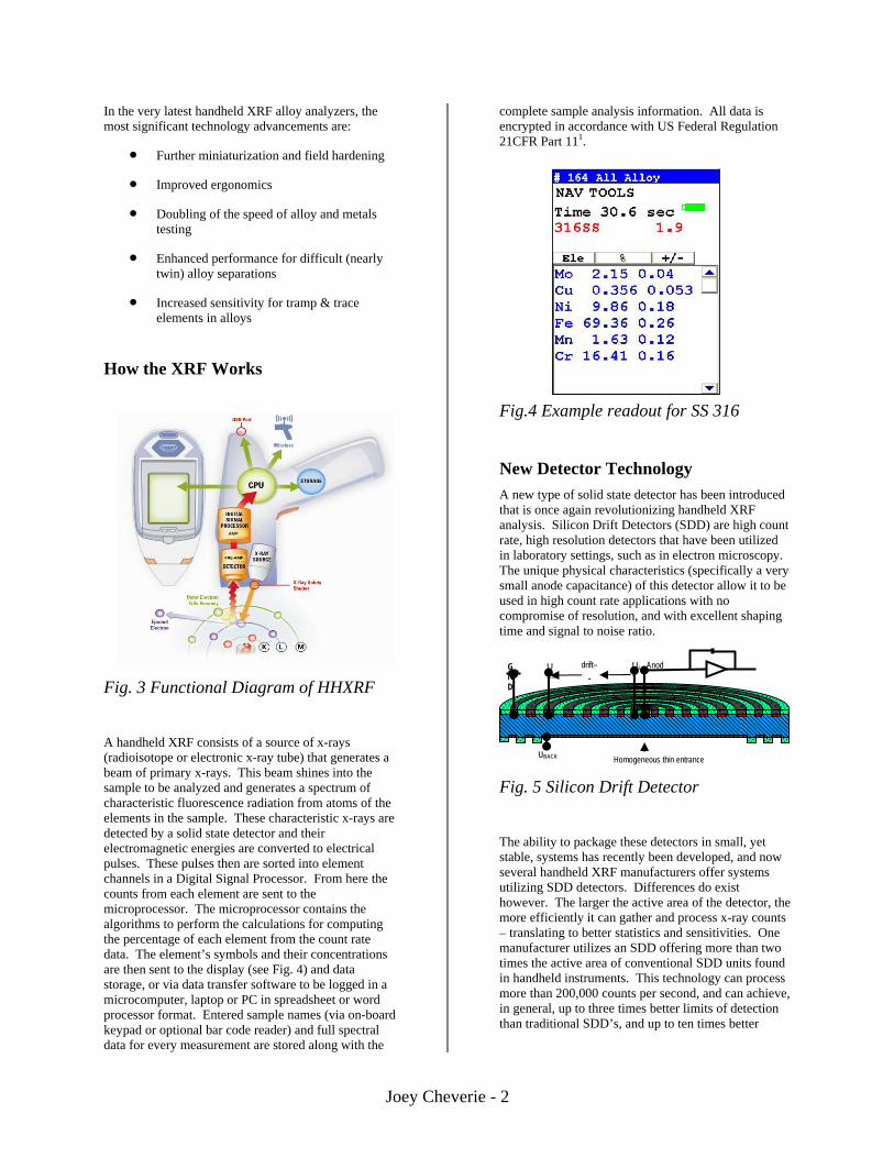
New Detector Technology A new type of solid state detector has been introduced that is once again revolutionizing handheld XRF analysis. Silicon Drift Detectors (SDD) are high count rate, high resolution detectors that have been utilized in laboratory settings, such as in electron microscopy. The unique physical characteristics (specifically a very small anode capacitance) of this detector allow it to be used in high count rate applications with no compromise of resolution, and with excellent shaping time and signal to noise ratio.
Fig. 5 Silicon Drift Detector
The ability to package these detectors in small, yet stable, systems has recently been developed, and now several handheld XRF manufacturers offer systems utilizing SDD detectors. Differences do exist however. The larger the active area of the detector, the more efficiently it can gather and process x-ray counts – translating to better statistics and sensitivities. One manufacturer utilizes an SDD offering more than two times the active area of conventional SDD units found in handheld instruments. This technology can process more than 200,000 counts per second, and can achieve, in general, up to three times better limits of detection than traditional SDD’s, and up to ten times better
GND
UOR
UIR
UBACK Homogeneous thin entrance
-drift– Anod
Joey Cheverie - 2

sensitivities over conventional Si PiN detector based instruments.
Of course, in order to take advantage of this high-capacity detector, the XRF analyzer must have the ability to generate a sufficient number of fluorescent x-ray events from a sample, and position the detector to collect as many as possible. Enter the 50kV x-ray tube.
The recent introduction of a miniature 50kV gold-anode x-ray tube has led the way in x-ray tube developments. Excitation intensity is exponentially proportional to the excitation voltage. Utilization of a 50kV tube has improved precision two-fold over comparable 40kV tube systems.
As a result, the new XRF analyzers utilizing large area SDD technology have as much as a ten-fold increase in performance over conventional Si-PiN based systems. In addition, they have the distinct ability to provide analysis of light element content such as silicon, aluminum, sulfur and phosphorus – without the need for helium purging or vacuum, something that was considered impossible as recently as a year ago.
This greatly increases the ease of performing PMI on newer alloys found in high sulfur processing environments such as ZeCor®, where the 6% silicon would otherwise require measurement with a helium-purged XRF analyzer or optical emission spectroscopy. It also introduces new PMI applications which require extreme sensitivity, such as the prevention of flow accelerated corrosion in HF alkylation units. Residual element analysis can now be performed with a level of confidence once only garnered in the laboratory.
In short, technology continues to improve, and if we have learned anything, it is not to underestimate what the future might bring. Of course the real beauty of what these new generations of XRF instruments deliver is that the user need not have an understanding of the science behind them in order to benefit from their use. And that benefit can’t be understated.
Spot Collimation and Camera Technology Similar to a chain, a process system is only as strong as its weakest link. The use of proper filler materials, and the ability to obtain proper weld dilution rates while joining two pieces of a process system together are as critical to the integrity of the pressure envelope as are the base materials (pipes, valves, etc…) themselves. Up to now, clip-on “weld masks” have been available for XRF analyzers that narrow the instruments field of view, permitting these measurements. While easy to use, they made it difficult to confirm that individual measurements completely isolated the filler material from the base metal.
Figure 6 Isolation of a weld bead for analysis.
Recent advances to certain handheld XRF analyzers incorporate a spot collimation and CCD camera features to isolate and analyze welds. These systems incorporate a miniature CCD camera and sample imaging software that helps the user properly position the instrument in the correct location for every measurement. At the completion of each measurement, it stores a digital picture of the sample along with the analytical results. Additionally, the analyzer x-ray beam can be collimated to analyze a highly focused spot. The user can easily select a spot size appropriate for each measurement - functioning similar to an internal weld mask. While measuring base materials, the user selects the larger 8 mm diameter measurement area; when analyzing welds, a simple software switch reduces the measurement area to a smaller 3 mm diameter. The analyzer superimposes a “bull’s-eye” on the camera display to ensure proper placement on the sample.
Increased Sensitivity For tramp and trace levels of elemental contaminants, sensitivity is a critical issue. The latest breakthroughs that have improved limits of detection (LOD) for certain residual and / or tramp elements (e.g.; Cr, Mn, Sn, Cu, and Pb) are:
• 50 kV, 2W miniature x-ray tube (having 20% more output than a typical handheld XRF)
• Optimized x-ray path geometry along with “on the fly” optimization of measurement parameters
Joey Cheverie - 3

• New large area SDD’s for faster measurements, greater sensitivity, better precision, and improved LOD.
TIME 2s per filter
3s per filter
5s per filter
10s per filter
Element Fe Base Fe Base Fe Base Fe Base
Sn 0.055 0.045 0.030 0.020
Nb 0.0065 0.0055 0.0040 0.0025
Cu 0.045 0.035 0.028 0.018
Ni 0.090 0.070 0.053 0.040
P 0.500 0.200 0.13 0.083
Si 1.250 0.500 0.300 0.190
Fig. 7 3-sigma LOD’s Iron Base, Various Analysis Times, all units % wt.
The LOD‘s shown in the above chart, Fig. 7, are typically two-fold better in the LOD values than previous XRF analyzer generations.
The analyzer can now determine previously immeasurable (outside the lab) levels of trace and tramp elements. Such contaminants can poison products, or make them unusable for certain applications. For example, specifications on carbon steel piping for HF Alkylation units set a maximum concentration of 2000 ppm for the sum of residual elements Cu, Cr, and Ni. Values greater than this level have been shown to promote preferential corrosion that can lead to catastrophic failure. Other examples include, monitoring Si content at trace levels at (>0.1%) in hot sulfidation corrosion applications in Petrochemical markets and similarly Flow-accelerated corrosion (FAC) in Nuclear plants where Cr content greater than 0.1% in carbon steel piping drastically improves the corrosion rate. Many types of low concentration contaminants can now be identified using handheld XRF before the alloy is installed or the operation is seriously impacted.
Conclusion The latest improvements in hand-held alloy analyzers for alloy testing have resulted in smaller, faster and near-lab performance in a 3 pound (1.3 kg), field-hardened package. Geometry optimization, “on the fly” parameter optimization, combined with detector improvements and faster electronics, provide faster testing, more sensitive trace and tramp element determination, the ability to quantify fractional percent alloying elements, and extremely rapid, high-precision, and accurate major element determination. Many previously difficult alloys determinations can now be performed without the need for lab testing. The essential power and reach of a lab XRF spectrometer is now available for use in harsh field environments.
Authors Joey Cheverie, Vice President NITON Analyzer Division – Alloy Elemental Controls Ltd. 3230 Wharton Way Mississauga, On, Canada, L4X 2C1 [email protected] James R. Pasmore, Director, Key Accounts Thermo Scientific Niton Analyzers Thermo Fisher Scientific 62256 Nels Anderson Rd, Suite 6 Bend, OR, USA, 97701 [email protected]
Joey Cheverie - 4