Neurosky Eeg Brainwave Chip and Board Tgam1
10
TGAM1 Spec Sheet March 24, 2010
-
Upload
sandeepjichoudhary9165 -
Category
Documents
-
view
450 -
download
8
Transcript of Neurosky Eeg Brainwave Chip and Board Tgam1
TGAM1 Spec SheetMarch 24, 2010
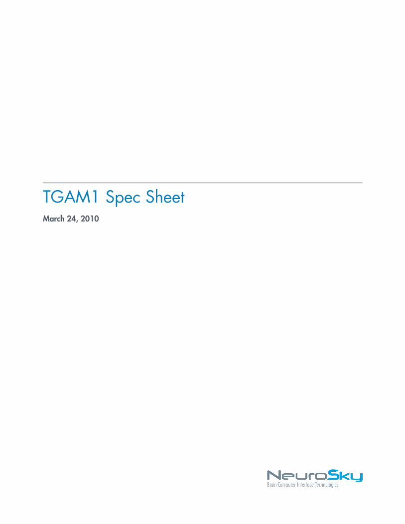
e NeuroSky product families consist of hardware andsoftware components for simple integration of this bio-sensor technology into consumer and industrial end-applications.All products are designed andmanufactured tomeet exactingconsumer speci cations for quality, pricing, and featuresets. NeuroSky sets itself apart by providing building-block component solutions that offer friendly synergieswith related and complementary technological solutions.
NOWARRANTIES: THEDOCUMENTATIONPROVIDEDIS "AS IS"WITHOUTANYEXPRESSOR IMPLIEDWARRANTYOFANYKINDINCLUDINGWARRANTIESOFMERCHANTABIL-ITY,NONINFRINGEMENTOF INTELLECTUALPROPERTY,INCLUDINGPATENTS,COPYRIGHTSOROTHERWISE,OR FITNESS FOR ANY PARTICULAR PURPOSE. IN NOEVENTSHALLNEUROSKYOR ITS SUPPLIERSBELIABLEFORANYDAMAGESWHATSOEVER (INCLUDING,WITHOUTLIMITATION,DAMAGESFORLOSSOFPROFITS, BUSINESSINTERRUPTION,COSTOFREPLACEMENTGOODSORLOSSOFORDAMAGETOINFORMATION)ARISINGOUTOFTHEUSEOFOR INABILITYTOUSETHEDOCUMENTA-TIONPROVIDED,EVEN IFNEUROSKYHASBEENADVISEDOF THE POSSIBILITY OF SUCHDAMAGES. , SOME OFTHE ABOVE LIMITATIONS MAY NOT APPLY TO YOUBECAUSESOMEJURISDICTIONSPROHIBITTHEEXCLUSIONORLIMITATIONOFLIABILITYFORCONSEQUENTIALOR INCIDENTAL DAMAGES.
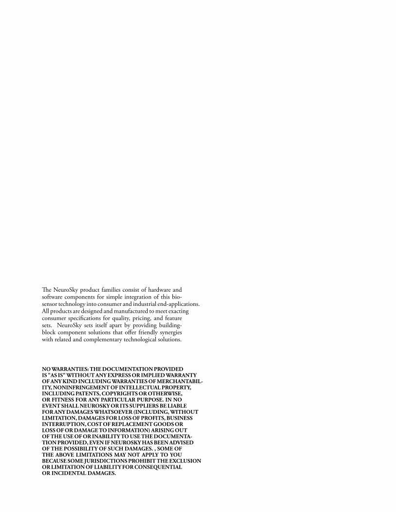
Contents
Technical Speci cations 4General . . . . . . . . . . . . . . . . . . . . . . . . . . . . . . . . . . . . . . . . . . . . . 4I/0 Pins . . . . . . . . . . . . . . . . . . . . . . . . . . . . . . . . . . . . . . . . . . . . . 5
Serial Communication 6inkGear CODE . . . . . . . . . . . . . . . . . . . . . . . . . . . . . . . . . . . . . . . 6Command Bytes . . . . . . . . . . . . . . . . . . . . . . . . . . . . . . . . . . . . . . . . 6
Con gurable Default Settings 7
Mechanical Drawing 10
March 24, 2010 | © 2009 NeuroSky, Inc. All Rights Reserved.3

Chapter 1
Technical Specifications
General
Classi cation Speci cation NotesProduct Family inkGear-AM A = ASIC,M =ModuleModel Number TGAM1Revision Number 2.3Module Dimension (Max) 27.9mm x 15.2mm x 2.5mm 1.10in x 0.60in x
0.10in(L x W x H)
Module Weight (Max) 130mg 0.0045 ouncesOperating Voltage 2.97V ~ 3.63V Stuff Option*
SP6200 3.0~6.0VMAX1595 1.8~5.5V
Max Input Voltage Noise 10mV Peak to PeakMax Power Consumption 15mA @ 3.3VESD Protection 4kV Contact Discharge
8kV Air DischargeTested at EEG, REF,GND
Output Interface Standard UART(Serial) TX, RX, VCC(+),GND(-)
Output Baud Rate 1200, 9600, 57600 Default set with stuffoption
#EEG Channels 1 3 contacts (EEG, REF,GND)
* Check with NeuroSky Sales for price addition.
March 24, 2010 | © 2009 NeuroSky, Inc. All Rights Reserved.4
Chapter 1 – Technical Specifications
I/0 Pins
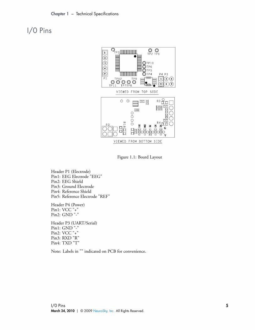
Figure 1.1: Board Layout
Header P1 (Electrode)Pin1: EEG Electrode "EEG"Pin2: EEG ShieldPin3: Ground ElectrodePin4: Reference ShieldPin5: Reference Electrode "REF"
Header P4 (Power)Pin1: VCC "+"Pin2: GND "-"
Header P3 (UART/Serial)Pin1: GND "-"Pin2: VCC "+"Pin3: RXD "R"Pin4: TXD "T"
Note: Labels in "" indicated on PCB for convenience.
I/0 PinsMarch 24, 2010 | © 2009 NeuroSky, Inc. All Rights Reserved.
5
Chapter 2
Serial Communication
is section only outlines parts that are different from the standard inkGear API1. Please refer tothe inkGear API and Reference Manual for more details.
ThinkGear CODE
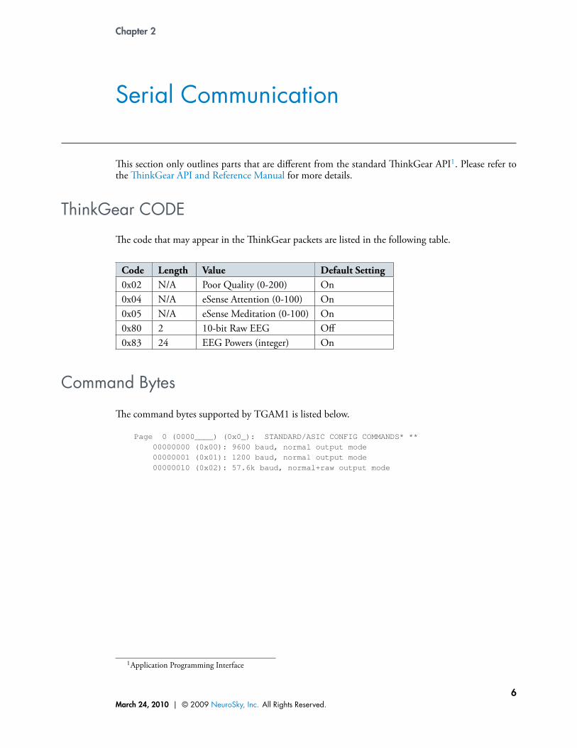
e code that may appear in the inkGear packets are listed in the following table.
Code Length Value Default Setting0x02 N/A Poor Quality (0-200) On0x04 N/A eSense Attention (0-100) On0x05 N/A eSense Meditation (0-100) On0x80 2 10-bit Raw EEG Off0x83 24 EEG Powers (integer) On
Command Bytes
e command bytes supported by TGAM1 is listed below.
Page 0 (0000____) (0x0_): STANDARD/ASIC CONFIG COMMANDS* **00000000 (0x00): 9600 baud, normal output mode00000001 (0x01): 1200 baud, normal output mode00000010 (0x02): 57.6k baud, normal+raw output mode
1Application Programming Interface
March 24, 2010 | © 2009 NeuroSky, Inc. All Rights Reserved.6
Chapter 3
Configurable Default Settings
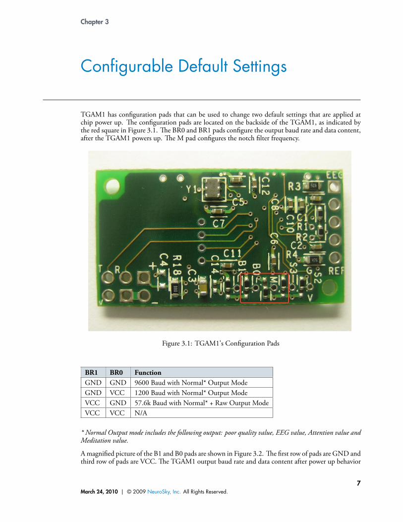
TGAM1 has con guration pads that can be used to change two default settings that are applied atchip power up. e con guration pads are located on the backside of the TGAM1, as indicated bythe red square in Figure 3.1. e BR0 and BR1 pads con gure the output baud rate and data content,after the TGAM1 powers up. e M pad con gures the notch lter frequency.
Figure 3.1: TGAM1's Con guration Pads
BR1 BR0 FunctionGND GND 9600 Baud with Normal* Output ModeGND VCC 1200 Baud with Normal* Output ModeVCC GND 57.6k Baud with Normal* + Raw Output ModeVCC VCC N/A
* Normal Output mode includes the following output: poor quality value, EEG value, Attention value andMeditation value.
Amagni ed picture of the B1 and B0 pads are shown in Figure 3.2. e rst row of pads are GND andthird row of pads are VCC. e TGAM1 output baud rate and data content after power up behavior
March 24, 2010 | © 2009 NeuroSky, Inc. All Rights Reserved.7

Chapter 3 – Configurable Default Settings
depends on the pad setting as described in table above. For example, the stuff option in the modulein Figure 3.1 has both BR1 and BR0 tie to GND pads for a 9600 baud with Normal Output Mode.
Figure 3.2: B0 and B1 pads
e baud rate can also be con gured after the module is powered up by sending commands throughthe UART interface. e commands are listed in the table below. When the module is reset, the baudrate setting will revert back to the default set by BR0 and BR1.
Command Function0x00 9600 Baud with Normal* Output Mode0x01 1200 Baud with Normal* Output Mode0x02 57.6k Baud with Normal* + Raw Output Mode
* Normal Output mode includes the following output: poor quality value, EEG value, Attention value andMeditation value.
Figure 3.3: M pad
As mentioned earlier, TGAM1’s notch lter frequency can be con gured with the M con guration
March 24, 2010 | © 2009 NeuroSky, Inc. All Rights Reserved.8
Chapter 3 – Configurable Default Settings
pads. It is used to select either 50Hz or 60Hz to reduce the AC noise speci c to a targeted market. Asindicated in Figure 3.3, the top pad is GND and bottom pad is VCC. Tie the M pad to VCC pad toselect 60Hz, and to GND pad to select 50Hz notch ltering frequency.
Unlike the BR0, BR1 con guration, there is no equivalent software con guration for the M con g-uration. e most common stuff option for these con guration pads are illustrated in Figure 3.1,con guring the TGAM1 for 9600 Baud, normal output and 60Hz notch ltering frequency. Forother stuffing options, contact NeuroSky Sales to get the correct ordering code.
March 24, 2010 | © 2009 NeuroSky, Inc. All Rights Reserved.9
Chapter 4
Mechanical Drawing
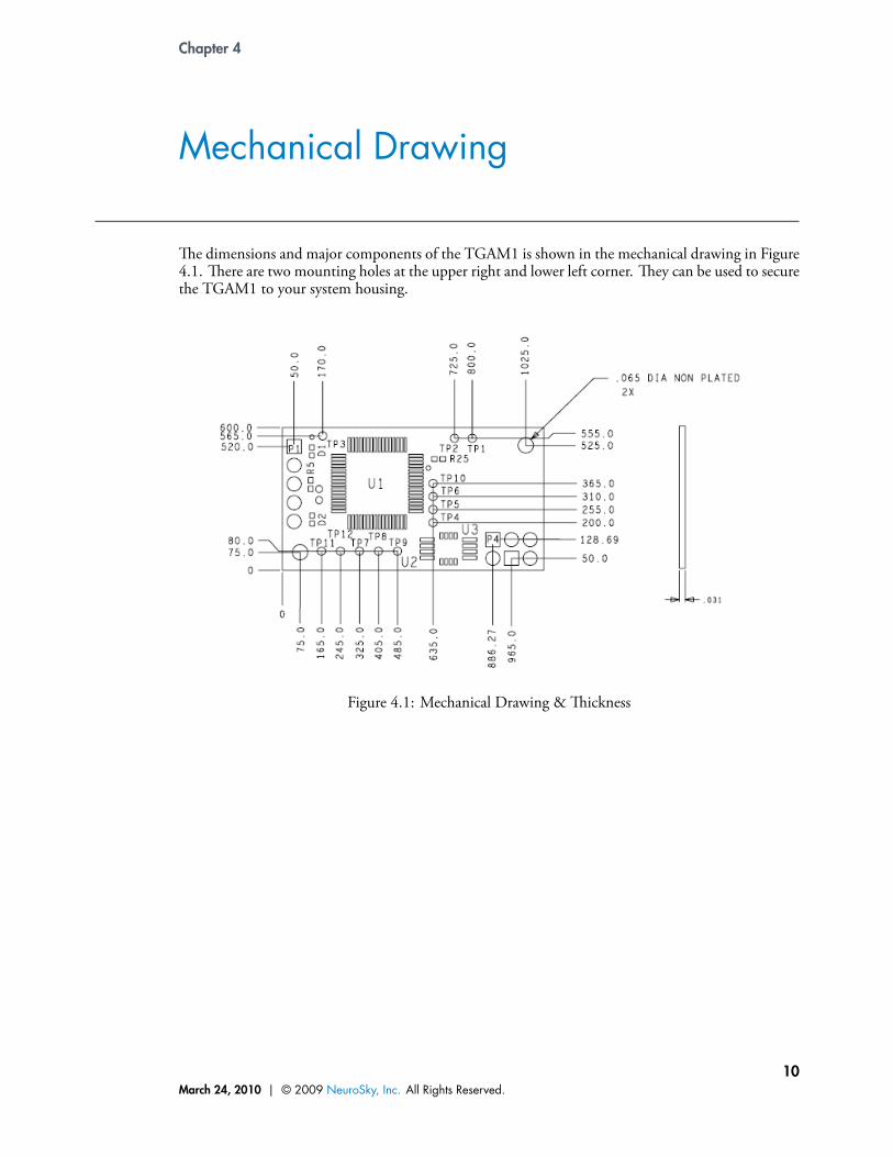
e dimensions and major components of the TGAM1 is shown in the mechanical drawing in Figure4.1. ere are two mounting holes at the upper right and lower left corner. ey can be used to securethe TGAM1 to your system housing.
Figure 4.1: Mechanical Drawing &ickness
March 24, 2010 | © 2009 NeuroSky, Inc. All Rights Reserved.10