Neuro-Developmental Engineering: towards early diagnosis ... · ˇ ˆ˙˝ 0 Neuro-Developmental...
30
Neuro-Developmental Engineering: towards early diagnosis of neuro-developmental disorders 1 Domenico Campolo, Fabrizio Taffoni, Giuseppina Schiavone, Domenico Formica, Eugenio Guglielmelli and Flavio Keller Università Campus Bio-Medico 00128 Roma - Italy 1 School of Mechanical & Aerospace Engineering Nanyang Technological University 639798 Singapore 1. Introduction Neuro-Developmental Engineering (NDE) is a new and emerging interdisciplinary research area at the intersection of developmental neuroscience and bioengineering aiming at provid- ing new methods and tools for: i ) understanding neuro-biological mechanisms of human brain development; ii ) quantitative analysis and modeling of human behavior during neuro- development; iii ) assessment of neuro-developmental milestones achieved by humans from birth onwards. Main application fields of NDE are: - New clinical protocols and standards for early diagnosis, functional evaluation and therapeutic treatments of neuro- developmental disorders; - New generations of educational, interactive toys which can provide adequate stimuli and guidance for supporting the physiological neuro-development process This technology is expected to be also useful in the long term for developing new tools, e.g. toys, which can sustain, in ecological scenarios, the regular development of motor and cogni- tive abilities of the child, based on a rigorous scientific approach. The long term goal is establishing standards against which development of infants at risk for neuro-developmental disorders, particularly autism, can be measured, with the aim of detecting early signs of disturbed development. 1.1 Sensori-Motor Integration Deficits in Neurodevelopmental Disorders Neurodevelopmental disorders such as ASD, ADHD, Tourette syndrome and others are char- acterized by a genetic basis. In this case behavioral analysis, or behavioral phenotyping, will be instrumental for the analysis of the roles of genes in behavior (Gerlai 2002). Autism is a behavioral disorder, with onset in childhood, which is characterized by deficits in three basic domains: social interaction, language and communication, and pattern of interests. There is no doubt that autism has a strong genetic component, and that biological disease mechanisms leading to autism are already active during foetal development and/or infancy,
Transcript of Neuro-Developmental Engineering: towards early diagnosis ... · ˇ ˆ˙˝ 0 Neuro-Developmental...
������������� ���� �� ���� �������������������� �������� ������������ ������������ ���
0
Neuro-Developmental Engineering: towards earlydiagnosis of neuro-developmental disorders
1Domenico Campolo, Fabrizio Taffoni, Giuseppina Schiavone,Domenico Formica, Eugenio Guglielmelli and Flavio Keller
Università Campus Bio-Medico00128 Roma - Italy
1School of Mechanical & Aerospace EngineeringNanyang Technological University
639798 Singapore
1. Introduction
Neuro-Developmental Engineering (NDE) is a new and emerging interdisciplinary researcharea at the intersection of developmental neuroscience and bioengineering aiming at provid-ing new methods and tools for: i) understanding neuro-biological mechanisms of humanbrain development; ii) quantitative analysis and modeling of human behavior during neuro-development; iii) assessment of neuro-developmental milestones achieved by humans frombirth onwards.Main application fields of NDE are:
- New clinical protocols and standards for early diagnosis, functional evaluation andtherapeutic treatments of neuro- developmental disorders;
- New generations of educational, interactive toys which can provide adequate stimuliand guidance for supporting the physiological neuro-development process
This technology is expected to be also useful in the long term for developing new tools, e.g.toys, which can sustain, in ecological scenarios, the regular development of motor and cogni-tive abilities of the child, based on a rigorous scientific approach.The long term goal is establishing standards against which development of infants at riskfor neuro-developmental disorders, particularly autism, can be measured, with the aim ofdetecting early signs of disturbed development.
1.1 Sensori-Motor Integration Deficits in Neurodevelopmental DisordersNeurodevelopmental disorders such as ASD, ADHD, Tourette syndrome and others are char-acterized by a genetic basis. In this case behavioral analysis, or behavioral phenotyping, willbe instrumental for the analysis of the roles of genes in behavior (Gerlai 2002).Autism is a behavioral disorder, with onset in childhood, which is characterized by deficits inthree basic domains: social interaction, language and communication, and pattern of interests.There is no doubt that autism has a strong genetic component, and that biological diseasemechanisms leading to autism are already active during foetal development and/or infancy,
��
����������� ���� �(���������� �� ���� ����
as demonstrated, for example, by the abnormal pattern of brain growth during late foetal andearly postnatal life (see (Keller and Persico 2003), for a review). Autism is usually diagnosedat the age of 3 years, in many cases after a period of seemingly normal neurological andbehavioral development. The diagnosis of autism is purely clinical, there are no laboratorytests to confirm or disprove the diagnosis. It has been recognized that, although typical autismis not associated with major neurological deficits, autism has characteristic manifestations inthe perceptual and motor domains.Deficits in the perceptual domain include altered processing and recognition of socially relevantinformation from peopleŠs faces (see (Grelotti et al. 2003), for a review), deficits in percep-tion of motion cues (Milne et al. 2002), (Spencer et al. 2000), (Bertone et al. 2003), (Takeraeet al. 2004), difficulty in disengaging attention (Landry and Bryson 2004) and alterations ofauditory processing (Courchesne et al. 1984), (Boddaert et al. 2004). Studies based on analy-sis of home-made movies suggest that an impairment of spontaneous attention toward socialstimuli is present already at 20 months (Swettenham et al. 1998), and possibly also as early asduring the first 6 months of life (Maestro et al. 2002). Furthermore, an autism-like syndrome isfrequently observed in congenitally blind children (Hobson and Bishop 2003). Taken together,these observations suggest that at least some individuals with autism are characterized by anearly deficit of ‘low-level’ perceptual processing, which jeopardizes their ability to develophigher-level capacities, such as language and interpersonal skills.Motor impairments in autism include deficits in postural reflexes (Minshew et al. 2004),(Schmitz et al. 2003), (Molloy et al. 2003), repetitive, stereotyped movements and awkwardpatterns of object manipulation, lack of purposeful exploratory movements (see e.g. (Pierceand Courchesne 2001)), gaze abnormalities (Sweeney et al. 2004), unusual gait pattern (Hallettet al. 1993), and alterations of movement planning and execution, which express themselvesas ‘hyper- dexterity’ (Rinehart et al. 2001), (Mari et al. 2003). Motor abnormalities may beobserved retrospectively in infants who later develop the autistic syndrome, on the basis ofhome-made movies made during the first year of life (Teitelbaum et al. 1998), (Teitelbaum etal. 2004). These clinical observations are consistent with a large body of evidence of subtlestructural and functional abnormalities of cortical and subcortical neural systems involvedin movement planning and execution, such as the prefrontal cortex, the basal ganglia and thecerebellum (see (Keller and Persico 2003), for a review).
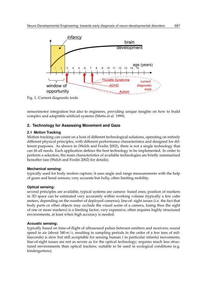
1.2 Ecological ApproachThe diagnosis of ASD is currently made at 3 years of age; Attention-Deficit Hyperactivity Dis-order (ADHD) is always considered as an alternative diagnosis of “high functioning” autism;Tourette syndrome is diagnosed at age 7 or later. ASD is therefore a natural candidate fordemonstrating the validity of novel approaches to early diagnosis. As shown in Fig. 1, in-fancy, i.e. the first 2-3 years of life before language development, represents an importanttemporal window for an early diagnosis of ASD.The goal of our approach is twofold. On one hand, guided by neuroscientists, we developtechnological platforms and methods to extract more information on perceptual and intersub-jective capacities of human infants than is currently possible; this information could be laterused for early diagnosis of developmental disorders. On the other hand, infancy providesus with an important window of opportunity to capture the mechanisms behind sensorimo-tor integration as these are just developing. Moreover, neurodevelopmental disorders are animportant benchmark to highlight failures within such mechanism. Such a knowledge canbe useful to neuroscientists to better understand the human brain functions involved in the
������������� ���� �� ���� �������������������� �������� ������������ ������������ ��)
������������������������ ������������������������������������������������� ������������� ������������
������
���
��� �� �������
�������
���� �������������
�������������������������
��������� ��!���
Fig. 1. Current diagnostic tools
sensorimotor integration but also to engineers, providing unique insights on how to buildcomplex and adaptable artificial systems (Metta et al. 1999).
2. Technology for Assessing Movement and Gaze
2.1 Motion TrackingMotion tracking can count on a host of different technological solutions, operating on entirelydifferent physical principles, with different performance characteristics and designed for dif-ferent purposes. As shown in (Welch and Foxlin 2002), there is not a single technology thatcan fit all needs. Each application defines the best technology to be implemented. In order toperform a selection, the main characteristics of available technologies are briefly summarizedhereafter (see (Welch and Foxlin 2002) for details).
Mechanical sensing:typically used for body motion capture; it uses angle and range measurements with the helpof gears and bend sensors; very accurate but bulky, often limiting mobility.
Optical sensing:several principles are available, typical systems are camera- based ones; position of markersin 3D space can be estimated very accurately within working volume (typically a few cubemeters, depending on the number of deployed cameras); line-of- sight issues (i.e. the fact thatbody parts or other objects may occlude the visual scene of a camera, losing thus the sightof one or more markers) is a limiting factor; very expensive; often requires highly structuredenvironments, at least when high accuracy is needed.
Acoustic sensing:typically based on time-of-flight of ultrasound pulses between emitters and receivers; soundspeed in air (about 340 m/s, resulting in sampling periods in the order of a few tens of mil-liseconds) is slow but still acceptable for sensing human ( in particular infants) movements;line-of-sight issues are not as severe as for the optical technology; requires much less struc-tured environments than optical trackers; suitable to be used in ecological conditions (e.g.kindergartens).

����������� ���� �(���������� �� ���� ����
(Geo)Magnetic sensing:a first method is based on electromagnetic coupling between a source and several trackers;main drawbacks are that signal decays as 1/d3 (where d is the source-tracker distance) andis affected by the geomagnetic field; these devices are quite expensive and require a certainamount of structuring of the environment. A second method is electronic compassing; esti-mates heading and solely relies on the geomagnetic field, i.e. it does not require any artificialsource and is therefore sourceless; measurements can be altered by ferromagnetic influence ofsurrounding objects.
Inertial sensing:highly miniaturized accelerometers and gyroscopes are used to sense, respectively, acceler-ation (comprising the gravitational field) and angular velocity; used as inclinometers, ac-celerometers can sense the gravity vector, i.e. the ‘vertical’ direction, in this sense they arealso sourceless.
��!���������� �"�������
�������
�����������
���#������ �!�
"��
�����!������"���� ���"�
�"����"�����
����"� �����
$������ %��!������" &���"� '"����" (�")���"�
���
����
����
���"#����""���"�
��
���
�
���*��*��)�����
���"�������������!���
��
�
�
��
�
�
�
�
�
�
�
�
� �
� � �
�
�
�
���� � ��� �� �������� � ��������������
���"#����+��,������"����
Fig. 2. Selection chart of different motion tracking technologies
In Fig. 2, a selection chart for the different available technologies is provided. For each avail-able technology (columns) its suitability with respect to the performance characteristics ofinterest (rows) is indicated. Since our main purpose is developing technological tools that areeither wearable by infants or embeddable into toys, the highest priority is given to technolo-gies which are unobtrusive. This directly leads us to discard solutions involving mechanicaltrackers.The second element considered for selection are the line-of-sight issues, since we are going todeal with infants, it is extremely difficult to perform experiments with technologies that arelimited by the line of sight, a peculiarity of the optical technology which is only suitable to

������������� ���� �� ���� �������������������� �������� ������������ ������������ ��*
experiments with collaborative subjects who are somehow willing to ‘act’ in front of a cam-era. Line-of-sight issues are much less severe for the acoustic technology which is thus stillappealing for movements analysis in infants.The third element of the selection criterion is performance with respect to tracking accuracy.Here a distinction is made between tracking positions and tracking orientations. Measure-ment principles such as the time-of-flight (typically deployed in acoustic measurements) orcamera-based tracking are inherently suitable to measure the distance of points (markers) andthe origin of the measurement system (e.g. the source of acoustic waves or a camera etc...).Orientations can be inferred indirectly by estimating distances between two or more mark-ers and the source of measurement. The larger the distance between two markers, the betterthe estimation of orientation. As dimensions shrink, as in the case of infants, accuracy ofindirect orientation measurements also decreases (e.g. accurate tracking of the orientationof an infant’s wrist can be problematic even without considering line-of-sight issues). Othertechnologies allow a direct measurement of orientations (for example inertial sensors usedas inclinometers can sense deviations from the vertical axis while magnetic sensors used ascompasses can sense deviations from the horizontal geomagnetic north direction) without re-quiring the positioning of multiple markers.As long as orientation is concerned, inertial and magnetic technologies appear to be very ap-pealing since: are highly unobtrusive due the availability of miniaturized off-the-shelf devices;do not suffer from line-of-sight issues; can provide high accuracy in orientation tracking aresourceless: do not require any structuring of the environment; have virtually unlimited work-ing volume; are low-cost.The bottom half of Fig. 2 shows, for each technology, the main limiting factors to a correctoperation. Besides temperature, which affects any electrical device and that can be compen-sated in most of the cases, the real limiting factor for the magnetic technology is the presenceof ferromagnetic materials. Common ferromagnetic objects such as iron parts of doors, chairs,tables etc... can produce local distortions of the geomagnetic field, causing thus errors in theestimations of orientations. As discussed in (Kemp et al. 1998), some care should be taken,when conducting experiments, to avoid large ferromagnetic objects in the surroundings. Wefound that this can be easily done in environments such as day-cares where, for safety reasons,all metals are usually avoided and typical materials used with children are wood, rubber andplastic.
2.2 Gaze TrackingDevices for measuring eye movements are commonly referred to as ‘eye trackers’. In generalthere are two types of techniques for monitoring eye movement (Young and Sheena 1975):
- ‘eye-in-head’ measurement: the sensing device is fixed on the head and therefore theeye position is measured in craniotopic coordinates;
- ‘point of regard’ or gaze: the sensors are located in the external environment and theeye position is measured in spatial coordinates.
These two kind of measurements are coincident when the head is kept in a fixed position.When the head is free to move, measurement of the head orientation is also required to de-rive gaze from craniotopic coordinates. Eye tracking methodologies can be classified in fourcategories:
1. Magnetic Induction Method (Search Coil)
2. Electro-Oculography (EOG)

����������� ���� �(���������� �� ���� ��*+
3. Photoelectric Methods: Infra-Red (IR) Oculography
4. Video-Oculography (VOG)
Each methodology is characterized by parameters such as range of measurement, sensitivity,linearity, accuracy, discomfort for the subject, interference with the field of view of the subject,tolerance to head movement.
Magnetic Induction Method (Search Coil):The search coil technique has become the accepted standard for the measurement of 3D eyemovement. This technique is based on the fact that a magnetic field induces a voltage in a coil(search coil) which is attached to the eye. The induced voltage has amplitude proportional tothe sine of the angle between the coil axis and the magnetic field direction. The magnetic fieldis provide by coils mounted at the sides of a cubic frame. The dimensions of the sides of theframe can vary from few tens of centimeters to few meters, allowing to measure also othermovements (i.e. eye-hand coordination). Robinson (Robinson 1963) was the first to apply thistechnique, using a coil secured to the eye by suction. Nowadays the search coil is embeddedin a scleral contact lens. The lens is subject to slippage if the lens covers only the cornea. Eyemovement is measured in absolute spatial coordinates. Head orientation can also be measuredwith a search coil mounted on the forehead, and orientation and movement of the eye withinthe head can be calculated from the orientation of the head and of the eye with respect tothe magnetic field (Haslwanter 1995). Currently a number of different search coil systems arecommercially available (e.g. by Skalar Instruments, C-N-C Engineering, Remmel Labs, etc.).Although the scleral search coil is the most precise eye movement measurement method (veryhigh temporal and spatial resolution can be obtained with accuracy to about 5-10 arc-secondsover a limited range of about 5 deg), it is also the most intrusive method. Insertion of the lensrequires care and practice and wearing the lens causes discomfort and risk of corneal abrasionor lead breakage. The requirements to stay in the center of the magnetic field precludes theuse of search coils during many natural activities. Thus, this technique is mostly used forresearch purposes, it is not suitable for clinical routine.
Electro-Oculography:First applications of electro-oculography are dated back to the ‘30s and are currently widelyused both for clinical and research purposes. It relies on measurement of electrical potentialdifferences between the cornea and the retina, discovered by DuBois-Reymond in 1849. Skinelectrodes are positioned around the eye. The measured potential difference is proportional tothe sine of the rotation angle of the eye. For small rotation the proportionality is almost linear;it decreases for higher angles of rotation (Byford 1963). The recorded potentials are in therange 15-200 μV, with nominal sensitivities of order of 20 μV/deg of eye movement. The eyemovement is measured in craniotopic coordinates and head movement during recording doesnot affect the measurement. The discomfort for the subject is limited and the measurementrange is wide both for horizontal movements (±70 deg) and for vertical movements (±30 deg),even if the sensitivity decreases for lateral position of the eye. The most important advantageof this methodology is the possibility of recording eye movement with closed eyes, which isrelevant requirement during some experimental protocol (e.g.. during sleeping phases). Themain drawback of this technique are related to the nature of the potential recorded and tothe artifacts due to the electrodes properties. As concern the potential, the resting corneo-retinic potential (usually of the order of 0.4-1 mV) can be affected by lighting conditions ofthe environment and by the psycho-physical condition of the subject. The artifacts at the

������������� ���� �� ���� �������������������� �������� ������������ ������������ �*,
level of the skin electrodes relies on the contact resistance electrode-skin, on the oxidation andpolarization of the electrodes.
Infra-Red Oculography:Infra-red (IR) oculography is based on the recording of the light reflected by the eye whenit is lighted with IR light beam. Since IR light is not visible, it does not interfere with thesubject vision, moreover the IR detectors are not influenced by environmental lighting con-ditions. There are three categories of Infra-red (IR) oculography which use respectively: thecorneal reflection, the Purkinje images and the track of the limb. Due to the construction ofthe eye, when a beam of IR light points to it, four reflections are formed on the eye, calledPurkinje images (Cornsweet and Crane 1973): the first on the front surface of the cornea andit is called corneal reflection, the second image on rear surface of the cornea, the third on thefront surface of the lens and the fourth on the rear surface of the lens. By detecting the cornealreflection and the pupil center and by using an appropriate calibration procedure, it is possi-ble to measure the Point of Regard (gaze) on a planar surface on which calibration points arepositioned. Two points of reference on the eye are needed to separate eye movements fromhead movements. The positional difference between the pupil center and corneal reflectionchanges with pure eye rotation, but remains relatively constant with minor head movements.The corneal reflection moves in the opposite direction of the eye respect to the pupil center.In other cases both the first and the fourth Purkinje images (Dual-Purkinje images eye track-ers are detected. Both reflections move together through exactly the same distance upon eyetranslation but they move through different distances upon eye rotation. The third methodbased on photoelectric principle relies on the track of the limb (scleral-iris edge) of the eye bymeasuring the amount of scattered light. Most photoelectric systems must be mounted closeto the eyes (i.e. EL-MAR tracking device), so they may restrict the field of view, moreover fastmovements of the head can cause slippage of the device on the head leading to mis-alignmentof the eye respect to the IR emitter and detector. There exist also external device and a supportfor keeping the head fixed is needed (i.e. Tobii eye tracker). The range of measurement of thephotoelectric eye tracker is not higher then ±30 deg in the horizontal plane and ±20 deg inthe vertical plane.
Video-Oculography:Video systems for measuring ocular movements are based on the analysis of images recordedby cameras. This technique, introduced in the ‘80s, quickly improved in terms of perfor-mances and reliability thanks to the technological development of digital cameras and com-puter powerful. The Video Oculography (VOG) provides directly a digital output. Severalalgorithms are available for the pupil detection in an image frame and pupil centroid coor-dinates extraction, nevertheless environmental lighting conditions can affect the automaticdetection (Eizenman et al. 1984) (Landau 1987). Thus, IR light is used together with videorecording, so that the pupil appears brighter. This technique is called Pupil Center/CornealReflection (PC/CR) because the IR light produces also the Purkinje images, mentioned before.As in IR Oculography, also VOG can be realized both as wearable device (DiScenna 1995) andprovides measurements in craniotopic coordinates or external device and provides measure-ments in spatial coordinates. Head-mounted system (i.e. EyeLink) can be worn without toomuch discomfort. High resolution and high frame rate CCD and CMOS cameras are used.Reduced dimensions and weight of the actual cameras allow to position them in such a waythat they interfere as less as possible with the field of view of the subject (Babcock and Pelz

����������� ���� �(���������� �� ���� ��*-
2004), (Pelz et al. 2000). The measurement range for VOG systems can exceed ±30 deg inhorizontal plane and ±20 deg in the vertical plane; eye tracking can be executed both on-lineand off-line. The drawback is that these systems have a low acquisition rate, in general 50-60Hz, not suitable for recording fast eye movement such as saccadic movements, but sufficesfor smooth pursuit eye movements. External camera systems can go up to 1000-1250 Hz andhave an accuracy of 0.01 deg. External camera are generally positioned under the screen of acomputer, used for calibration and for specific visual stimuli. Head movements are toleratedif the eye is kept in the field of view of the camera. There are devices which include systemsof pursuit of the subject and the camera orients automatically so that the eye of the subject isalways in its field of view.In Table 1 the relevant parameters of the eye tracking techniques presented are summarized.
3. Instrumented Toys and Wearable Devices
Virtually any toy, tool or piece of garment used by children could be a good candidate to hostall sorts of technology and ‘see what comes out’ when the child wears it or plays with it.Our approach is based on a closed-loop dialogue between neuroscientists and bioengineers. Inthe following, two platforms are presented which specifically address two domains of interestin child’s development: spatial cognition and social behavior.For both platforms, functional specifications are derived from protocols of experiments of in-terest for neuroscientists. The aim is twofold. On one side we wish to provide neuroscientistswith novel technological platforms for the unobtrusive and ecological assessment of behav-ioral development in infants. On the other side, these platforms should enable/facilitate thetransition from research to clinical practice.
3.1 Assessing Spatial Cognition SkillsBy the end of the first year of life, infants start to pile-up blocks, put lids on cans and insert ob-jects into apertures. Through these activities, the child learns to plan actions that involve morethan one item. The ability to solve such problems reflects the child’s spatial, perceptual andmotor development. In particular, the representational ability to imagine objects in differentpositions and orientations must be in place before various objects can be fit into apertures.Recent studies by Ornkloo and von Hofsten (Ornkloo and von Hofsten 2007) show develop-mental curves, based on statistical rates of success of object-fitting tasks, relative to childrenaged 14-26 months old.Specifically, the tasks consisted of inserting cylinders with different cross-sections into a boxwith similar holes on its lid, see Fig. 3 (top). All the objects had similar dimensions, 1 mmsmaller than the apertures. Different cross-sections were used whose circumference was ap-proximately the same but varied with respect to the number of possibilities they fit into acorresponding aperture, as also reported in Fig. 3 (bottom).Based on visual inspection of video recordings, the data analysis consisted (among otherthings) in assessing horizontal and vertical pre-adjustments. In particular, the outcome wasyes/no (i.e. successful or unsuccessful) based on the alignment errors between the object andthe box. Both the vertical error (angular misalignment between the longitudinal axis of the ob-ject and verticality) and the horizontal error (angular misalignment between the orientationsof the cross- section and the aperture) were estimated (from the videos). Results showed thatsuccessful solution was associated with appropriate preadjustments before the hand arrivedwith the block to the aperture; in particular it has been proved that the preadjustments can beconsidered appropriate for misalignments lower than 30 deg.

������������� ���� �� ���� �������������������� �������� ������������ ������������ �*.
Search coil Electro- Infra-Red VideoOculography Oculography Oculography
MeasurementTypology
Absolute spatialcoordinate
Craniotopiccoordinates
Head-mounted:craniotopiccoordinates;
Head-mounted:craniotopiccoordinates;
External device:spatialcoordinates
External device:spatialcoordinates
Range ofmeasurement
±90 deg for all3D space
±70 deg inhorizontal plane
±30 deg inhorizontal plane
±30 deg inhorizontal plane
±30 deg invertical plane
±20 deg invertical plane
±20 deg invertical plane
TemporalResolution
linked to A/Dconversion,500-1000Hz(depends onsoftware andhardwareinstrumentation)
linked to A/Dconversion,500-1000Hz(depends onsoftware andhardwareinstrumentation)
linked to A/Dconversion,500-1000Hz(depends onsoftware andhardwareinstrumentation)
Depends oncamera framerate: from 30Hzto 1000-1250Hz
Spatialresolution
0.01 deg 1-1.5 deg 0.1 deg 0.1 deg
Discomfort High Limited Limited LimitedInterferencewith thesubject fieldof view
None None Head-mounteddevice caninterfere with thefield of view
Head-mounteddevice caninterfere with thefield of view
Tolerance toheadmovement
- Head has to bein the center ofthe magneticfield
Not affected byhead movement
External device:low tolerance tohead movements
- Headmovements aretolerated wheneye is kept in thefield of view ofthe camera;
- Additionalsearch coil on theforehead
- Additionalsensors allow tore-orientate thecamera
Other Notes - limitedrecording timeand risk ofcorneal abrasionor lead breakage
- Measurementwith closed eyes(during sleeping)
- Not suitablewhen the subjectwears glasses orcontact lens
- lens slippage - Skin electrodesartifacts- Restingcorneo-retinalpotentialvariability
Table 1. Comparison of different gaze tracking technologies
3.1.1 Block-Box PlatformInspired by such experiments and based on our previous experience with sensorized toys(Campolo et al. 2007), we developed a sensorized core, shown in Fig. 4 (top), for the cylindrical

����������� ���� �(���������� �� ���� ��*/
��#
��������� �"#
��-
��
��� � � � � �Fig. 3. Block-box experimental scenario (top). Different cross- sections (bottom) for the cylin-drical blocks and the relative number of insertion possibilities (‘inf’ means infinite), readaptedfrom (Ornkloo and von Hofsten 2007)
objects with various cross-sections, shown in Fig. 4 (bottom).In particular, we found that from an ecological perspective, the sourceless estimation of ob-jects orientation via inertial and magnetic sensors is especially suited to this application. Ac-celerometers can in fact be used to measure tilt while magnetometers can be used as compassto measure horizontal misalignments. Gyroscopes are required to compensate for non-staticeffects. Further details on the filter used to estimate orientation from the sensors raw data isdescribed in (Campolo et al. 2008).
Fig. 4. Kinematics sensing unit (top left). Bluetooth transmitting unit (top right). Examples ofassemblies of electronics and batteries for shells with different cross-section (bottom).

������������� ���� �� ���� �������������������� �������� ������������ ������������ �*�
By considering the requirements of the experimental setup and protocol of the above men-tioned study (Ornkloo and von Hofsten 2007), the functional specifications of the block-boxplatform can be resumed as follows:
• the device (electronic core and power supply) should be embeddable in solids withdifferent shapes with a “grasping size” less than 5 cm;
• the sensor unit should consist of sourceless sensors for orientation tracking;
• the transmission unit should assure a bi-directional wireless communication to a remoteworkstation few meters far from the experimental scenario;
• the batteries should provide power supply for at least 2 hours of continuous use;
• the overall weight of the toy should not exceed the 50-60 grams.
According with these specifications, the block-box sensorized toys have been designed tobe as compact and light as possible. In particular, the platform mainly consists of a com-pact (17.8mm × 17.8mm × 10.2mm), micro-fabricated 9-axis inertial-magnetic sensor (modelMAG02-1200S050 from Memsense Inc.). The device is designed to sense ±2g accelerations,±1200 deg/sec angular rates, ±1 Gauss magnetic fields, all within a 50 Hz bandwidth. Thesensors are coupled with a multi-channel, 12 bits AD converter (model MAX1238 from MaximInc.) which can retransmit converted data over a 4-wires I2C bus. For our application, wesample each of the 9 channels at 100 Samples/sec rate. Such data are collected and rearrangedin a specific message format by a microcontroller (PIC16F876A from Microchip TechnologyInc.) and then retransmitted via a bluetooth module (Parani-ESD200 from Sena TechnologiesInc.). Finally, two 3.6V Li-Ion Rechargeable batteries (LIR3048 from Powerstream Inc.) areused in series, in order to guarantee approximately two hours of autonomous operation. Datatransmitted over the bluetooth interface are collected by a nearby PC, for later data analysis.Fig. 5 represents the overall architecture of the block-box platform. As it can be noted, wedecided to arrange the different components into two separate electronic boards (a sensorboard and a transmission board), which are connected through the I2C bus. This solutionmakes the system modular, allowing us to easily change the sensor unit or put together severalsensors that share the same bus.In Fig. 6 the electronic CAD designs (left) and the real pictures (right) of the sensor (top) andthe transmission (bottom) boards are shown. Fig. 7 reports the overall aspect of the electroniccore of the Block-Box platform with the actual dimensions.
3.1.2 In-Field Calibration of Inertial-Magnetic SensorsMagnetometers are meant to sense the geomagnetic field and provide its components[bx, by, bz]T along the x, y and z axes of the sensing device itself (such axes move with themoving frame). Similarly, the accelerometers are meant, in static conditions, to read out thecomponents of the gravitational field [gx, gy, gz]T along the same axes.Calibration of such sensors is straightforward when one can reliably count on precision align-ment procedures, e.g. in a laboratory setting. In (Campolo et al. 2006), a procedure for in-field calibration of magnetometric sensors was presented which does not rely on previousknowledge of magnitude and direction of the geomagnetic field and which does not requireaccurately predefined orientation sequences. Such a method can be applied to accelerometersas well and is especially suited for clinical applications. The procedure relies on the fact thegeomagnetic (or gravitational) field has constant components in the fixed frame. As the orien-tation of the sensors vary, the components in the moving frame also vary but the magnitude

����������� ���� �(���������� �� ���� ��*�
Fig. 5. Block-Box Platform architecture.
of the field keeps constant, i.e. the components are bound to lie on a sphere. Readouts fromnon-calibrated sensors are therefore bound to lie on an ellipsoid, see (Campolo et al. 2006) fordetails. Via the least-square method it is possible to robustly estimate the centroid and semi-axes length of the ellipsoid which coincide with the calibration parameters (gain and offsetsfor each axis).Based on this method, a calibration protocol was devised to provide a sufficient number ofmeasurements for the algorithm to robustly converge. The instrumented toy (of whatevershape) is secured inside a wooden box, shaped as a parallelepiped, so that the toy does notmove as the box is displaced around.
Magnetometers:as in Fig. 8-a, the box is placed on a table and an approximately 360 deg rotation (no need tobe accurate) is performed by keeping one face of the box always parallel and in contact withthe table. The same procedure is repeated for four different faces.
Accelerometers:as in Fig. 8-b, the box is placed on a table and smoothly (i.e. avoiding shocks) tilted by 90 degalong one edge, this is repeated four times1 until the box returns in the initial position. Thewhole procedure is repeated with a different initial position.
Gyroscopes:the procedure is similar to the one deployed for the accelerometers.
1 Each time on a different edge: once a 90 deg rotation is performed along one edge, the next edge is thenon-consecutive one which also makes contact with the table.

������������� ���� �� ���� �������������������� �������� ������������ ������������ �*)
Fig. 6. The electronic CAD designs (left) and the real pictures (right) of the sensor (top) andthe transmission (bottom) boards.
Measurements derived from a calibration sequence are shown in Fig. 8-c and Fig. 8-d, respec-tively for the magnetometers and for the accelerometers. The least-squares algorithm is thenused to derive the best fitting ellipsoids (one for the magnetometers and one for the accelerom-eters) whose surfaces contain the two sets of measurements.As previously mentioned, since the geomagnetic field is constant, its components in the mov-ing frame are bound to lie on the calibrating ellipsoid, not only during the calibration se-quences but for every possible movement. For this reason, also movements performed duringthe regular use of the toy, i.e. when the infants plays with it, can be used for updating thecalibration parameters, or at least for an on-line check. Similar procedures apply to accelerom-eters, paying attention to consider only the quasi-static movements, i.e. when accelerationsof the movement itself are negligible with respect to gravity. Details about ‘in-use’ calibrationcan be found in (Lotters et al. 1998).

����������� ���� �(���������� �� ���� ��*�
Fig. 7. Electronic core of the Block-Box platform with the actual dimensions.
3.2 Assessing Spontaneous MovementsInfants show a large variety of spontaneous movement patterns. Such movements are calledspontaneous to tell them apart from reflex movements because they are endogenously gener-ated by infantsŠ nervous system without any external sensory input.While reflexive movements allow a detailed study of a stable, quantitative relationship be-tween sensory input and reflexive motor output, spontaneous motility could be regarded asthe expression of spontaneous neural activity, so it is an excellent marker of neural dysfunc-tion caused by brain impairments during the first year of life (Prechtl and General 2001).Among several spontaneous motor patterns, movements that appear to be more effectivefor functional assessment of infantsŠ nervous systems are complex sequential movementsof arms, legs, neck, and trunk called General Movements (GMs): they are characterized byrotations along the axis of the limbs and slight changes in the direction of movements (see(Einspieler et al. 2005) for a review).If the nervous system is impaired, GMs change their quality or even disappear: they lose theircomplex character and involve a reduced number of limbs in monotonous sequences; theyappear to be rigid and less smooth because generated by the almost simultaneous contractionof all limb and trunk muscles. Such alterations are considered to be highly predictive for laterneurological impairments like Cerebral Palsy (CP).During the assessment phase, infants with bare arms and legs are videotaped in supine posi-tion. The duration of the recording depends on the age of the infant: to collect at least threeGMs, 1 h recording is necessary with pre-term infants while 10 minutes are enough from termage onward. The same infant is videotaped at different ages: from 2 to 3 recordings duringthe pre-term period; one recording at term or early post-term age or both, and at least onerecording between 9 and 15 weeks post-term. After each recording session, a trained clinicianreviews the videotape looking for GMs sequences that are copied onto an assessment tape.The observed GM and the week of development are reported on a table called individual

������������� ���� �� ���� �������������������� �������� ������������ ������������ �**
a) b)
0�10�2
0�3
00�0
40�1
40�0
40
56�7585
9�758
5:�758
��
�
�
4�
4���
4�
4���
56�7585
9�758
5:�758
c) d)Fig. 8. Calibration sequences for magnetometers (a) and accelerometers (b). Plots of the mea-surements (i.e. voltages Vx, Vy and Vz from the triaxial sensors) derived from the calibrationsequences for the magnetometers (c) and the accelerometers (d).
developmental trajectory. Such table is used to assess the risk of developing lateral neurolog-ical impairments. 11 studies on 358 infants assessed by 90 observers revealed an inter-raterreliability between 89% and 93% (Einspieler et al. 2005).
Wrist and Ankle Movement Sensor (WAMS)GMs assessment protocol collects qualitative information on motor behavior of infants dur-ing their first year of life. In order to match the individual developmental trajectory withsome quantitative objective information we proposed a magneto-inertial wearable device forecological behavioral analysis of infants’ motor behavior called Wrist and Ankle MovementSensor (WAMS) (Taffoni et al. 2008). Such a device, which allows gathering objective infor-mation such as the angle of rotation along the axis of the limb, its velocity, smoothness, accel-eration etc., could improve the predictive validity of GMs, thus reducing the inter-observerdisagreement.Because the target is assessing infants’ movement, it is important to reduce size and weightof the device as much as possible. Although there are several commercial solutions, they areoften exceedingly large and bulky. According to anthropometric data, the maximal linearlength of a wearable device should not exceed 2.5 cm and should not weight more than 20grams.In order to estimate a proper scale range of the sensor, preliminary quantitative experimentshave been conducted. A three-cameras (500 Hz) motion capture system was used (Qualysis

����������� ���� �(���������� �� ���� �)++
Motion Capture Systems Inc., SWE) to obtain position-time data from both arms of infants andevaluate frequency and dynamic content of their spontaneous movements. Three reflectivemarkers were placed on the head and two on both hands. In Fig. 9-A data from one-week-oldinfant are shown.
.�/�.�/�
��/�
��/�
�/��/
�
�/�
�/�
�/
0�1!23 1!2
4�1!
2
5'67���)�5'67 ���58'7���)�58'7 ���58'7���
Fig. 9. Representative data relative to head-hands kinematics of a one week old infant
Probability Density Function (PDF) of several sets of experimental data was computed to es-timate the dynamic range for the accelerometer sensors, showing that a ±2g range would besufficient to capture infants’ kinematics. As for the magnetometers, since only the geomag-netic field (about 0.6 gauss) needs to be measured, the full measurement range should be inthe order of ±1 Gauss. Saturation of gyroscopes would result in a problematic loss of trackingand therefore, given several commercially available gyroscopes with full scale ranging from±150 deg/s to ±1200 deg/s, the maximum scale range (±1200 deg/s) was selected.In line with such specification a sampling frequency of 250 Hz was selected. This frequencyis between the sampling frequency of other magneto-inertial commercially available systems(typically 100 Hz) and the frequency of the optical devices (up to 500 Hz).A preliminary analysis of commercial magneto-inertial sensors currently available high-lighted a triaxial magnetometer, accelerometer and gyroscope analogue sensor from Mem-sense (MAG02-1200S050) that matches the technical requirements previously defined. Al-though there are several highly miniaturized components available off the shelf, we have cho-sen to use a microfabricated device integrating all the required sensing capability for two mainreasons: 1) a more efficient packaging; 2) a more reliable axis orientation. Not orthogonal sen-sible axes directly translate in errors during orientation tracking. In order to simultaneously

������������� ���� �� ���� �������������������� �������� ������������ ������������ )+,
collect data from both arms and legs we propose a Body Area Network (BAN) of four sensors:two for arms and two for legs. Unlike common BAN (Jovanov et al. 2005) we chose to usea wired configuration in order to reduce the weight of each sensor: wired communication al-lows not to include the battery onboard, and therefore to reduce the weight. For such reasonseach sensing unit is provided with a low power, 12-channels, 12 bits AD Converters with anI2C compatible two wires serial interface. In this way only 4 wires are required: 2 for data and2 for supply, which is in a remote master station. In this station a microcontroller PIC16F876Acollects data from each WAMS (identified by a unique address) and retransmits via RS232 toa PC where such data are stored. The electronic board is embedded into a soft silicon rub-ber structure used both for electrical passivation and for comfortable contact with the infant’sskin. A Velcro strap is used to fix such sensors to the infant’s limbs. Figure 10 shows the firstWAMS prototype: total weight less then 14 grams and volume within 2.5 × 2.5 × 1.5 cm3.
�"!Fig. 10. Typical experimental scenario. (A). Example of use on a 3 months old baby (B). FirstWAMS prototype (C).
3.3 Assessing Social AttentionPoor sensorimotor integration has long been addressed as a cause of motor and social prob-lems in developmental disorders such as ASD (Trevarthen and Daniel 2005). Failure in orient-ing towards occurring social stimuli (e.g. facial expressions, speech, gesture) represents oneof the earliest and most basic social impairments in autism and may contribute to the later-emerging social and communicative impairments (Dawson et al. 2004). Early social exchangesrequire rapid shifting of attention between different stimuli. Impairments in social orientingcan alter the developmental pathway of young children by depriving them of appropriatesocial stimulation (Mundy and Neal 2001).

����������� ���� �(���������� �� ���� �)+-
Fig. 11. Social situation.
A social protocol to study the response of a child to social stimuli was devised by G. Stenberg(Dept of Psychology, University of Uppsala, Sweden). As shown in Fig. 11 (top), a childsits at a table observing two adults sitting approximately 45 deg left and right. The adultsubjects engage in a conversation while alternatively positioning blocks in front of the child.Observing the video-recordings, the psychologist would then take note (frame by frame) ofwhen the child looks at the adult subjects, when at the blocks, whether the child can anticipatethe ‘next move’ of an adult subject (based on the clues provided in the conversation). Indeeda lengthy process, requiring hours to rate a few minutes of an experiment.
3.3.1 Audio-Visuo-Vestibular Cap platformEarly diagnosis is also based on the possibility of screening a large number of children andautomatic, or at least semi-automatic, methods would be very valuable.To this end, we developed the multimodal Audio-Visuo-Vestibular Cap (AVVC) platform,shown in Fig. 12, specifically devised to assess sensorimotor integration in social orientingbehaviors in very young children, from 6 to 24 months of age. In particular it allows monitor-ing the child’s gaze and facial expressions, monitoring the head kinematics, localize in soundstimuli with respect to the child.
3.3.1.1 Gaze and facial expressionsin the current version, a lightweight eye-cam (1/4” CMOS sensor, 640 × 480 resolution, 30frames/sec) is mounted on the beak of the cap monitors. A mini-objective (model RE-025S,2.5 mm focal length, 84 deg diagonal field-of-view, 57 deg vertically and 71 deg horizontally)is used to keep the face of the child on focus. This provides still images of the face, indepen-dently of the head movements, and in particular allows monitoring the gaze.

������������� ���� �� ���� �������������������� �������� ������������ ������������ )+.
!������*������� �����
���*"�!
������� ������!�
Fig. 12. Audio-Video-Vestibular-Cap (AVVC).
3.3.1.2 Head kinematicsis monitored via a commercial magnetic-inertial sensor (MTx-28A33G25 device from XSensInc.; static orientation accuracy < 1deg; bandwidth 40Hz; sampling rate 100Hz). Similarly tothe human vestibular system, the inertial sensors can be used to estimate tilt with respect togravity as well as angular velocity of the head. Furthermore, the magnetic sensors, used as acompass, can determine the amount of head rotation on the horizontal plane.
3.3.1.3 Direction of sound stimuliis an important clue in social behavior. Humans localize sound in space via interaural timedifferences (ITD) and intensity level differences (ILD), over various frequency ranges (Blauert1997). To this end, we use a pair of microphones (MKE 2-ew Gold, Levalier, sampled in stereoaudio quality at 44.2kHz) mounted on the cap in correspondence of the ears of the child. TheITD of sound arrival at the two microphones can be estimated based on the generalized cross-correlation algorithm (Rucci and Wray 1999).
3.3.2 Ecological Calibration of the Binaural Microphones for the AVVCAn ITD/angle relationship is required to determine the angular position of a sound sourcewith respect to the head once the ITD is estimated. Typical calibration procedures involverelative positioning of a sound source with respect to a pair of binaural microphones. Forvarious angular positions, the relative ITDs are estimated and the ITD/angle relationship isthus experimentally determined.For the AVVC platform this is a challenging task as calibration can only be done after the childwears the cap, mainly for two reasons: i) the ITD also depends on how the sound propagatesthrough the head of the child, therefore the cap must be worn; ii) the cap is manually fit

����������� ���� �(���������� �� ���� �)+/
onto the child’s head and this procedure is neither accurate or repeatable, i.e. a calibration isrequired every time the child wears the cap.
��-�����������"�
���'99:
Fig. 13. Ecological calibration protocol for the binaural microphones of the AVVC platform.
An ecological calibration protocol was specifically devised to cope with these issues and con-sidering that children are non-cooperative subjects (especially in the case of children withASD). As shown in Fig. 13, an experimenter is sitting still in front of the child (already wear-ing the AVVC with the binaural microphones to be calibrated) and keeps talking, acting thusas a fixed sound source. Another experimenter (not talking) uses a colored toy to capture thechild’s attention. As the toy is moved around (see dashed line in the), the head of the child,who keeps looking at the toy, spans a wide range of orientations. It is worth noting that theposition of the toy is not relevant, its only purpose is inducing the child to orient the head indifferent directions.The magneto-inertial device, also mounted on the cap and fixed with respect to the binauralmicrophones, keeps track of the orientation of the head. In Fig. 14 the head orientation (indegrees) is plotted against the ITD (in milliseconds). The relationship is well fitted to a line(R2 = 0.98). The slope of the fitting line is related to the physics of sound localization via ITDcues while the offset of the fitting line is mainly depended on how the cap is fit onto the child’shead, which varies from trial to trial.Clearly, the whole procedure relies on the hypothesis of ‘fixed sound source’. Although theexperimenter sitting in front of the child is instructed to remain still as much as possible whiletalking, the child’s head is unconstrained and therefore free to translate while orienting to-wards the moving toy. These factors affect both resolution and accuracy. Nevertheless, pre-liminary in-field tests, presented in the next section, show how when used in combinationwith an experimental protocol it can still be used for data segmentation.
3.3.3 Calibration Procedure for the AVVC eye trackerDuring calibration procedure movements of the pupil in pixels are transformed to eye positionin degrees. Eye-tracking systems calibration usually consists of looking at several markers ona screen in order to collect enough data to modify the parameter of an adjustable model,often while keeping the head still. Also, this kind of calibration cannot be easily performed

������������� ���� �� ���� �������������������� �������� ������������ ������������ )+�
.�/� .�/� .�/� .�/� � �/� �/� �/�.��
.��
.��
.��
�
��
��
��
��
$;7�1!2
)���
�����
����
����
1���
2
Fig. 14. Calibration curve for the binaural microphones. Fitting values: slope = 150 deg/ms;offset = 11 deg; R2=0.98.
when the users are very young children. We propose a new calibration procedure, inspiredby the vestibulo-ocular reflex (VOR) which allows generating compensatory eye movementsin response to head motion as sensed by the vestibular organs in the inner ear.When the head rotates about any axis (horizontal, vertical, or torsional) distant visual imagesare stabilized by rotating the eyes about the same axis, but in opposite direction (Crawfordand Vilis 1991). The gain of the VOR (the ratio of eye angular velocity d
dt ψe to head angularvelocity d
dt ψh) is typically around -1 when the eyes are focused on a distant target.During our calibration procedure, the child is asked to rotate the head to the left and to theright while keeping looking at the caregiver who is sitting in front of him. Head rotationmovements are recorded at a frequency of 100 Hz by the magneto-inertial sensor mountedon the top of the cap. Given the relation between head and eye angular velocities, the headazimuth (ψh) correlates with the coordinates2 of the pupil in the horizontal plane. Linearfitting can be applied to the calibration curve (see Fig. 15) to extract gain and offset. This allowsexpressing the eye orientation in degrees rather than in (normalized) pixels, as in Fig. 16
4. In-Field Testing
In this section preliminary experimental data relative to in-field testings of both the block-box and the AVVC platforms are presented. Such tests are significant as they prove usabilityof the proposed platforms in unstructured environments. In particular, the two platforms
2 Coordinates of the pupil are derived from images and are typically in pixels, i.e. depend on factorssuch as resolution of the camera and its distance from the pupil. To avoid dealing with zooming factors,distances in pixels are normalized with respect to physiological features such as the width of the eye.

����������� ���� �(���������� �� ���� �)+�
� �/� �/� �/� �/� �.��
.��
.��
�
��
��
��
6��!� �+���<�-� ����5���+���� �< ���
5��
��'
+�!
��)�
1���
2
Fig. 15. Head-eye calibration curve: raw data (dots) and fitted line (solid) with R2 > 0.90.
� � � � ��.��
.��
�
��
��
58'7
'��
��1�
��2
� � � � ��
.��
.��
�
��
��
808
� � � � ��
.��
�
��
9�
�"���
�1���
,2
;�!��12� � � � ��
.��
�
��
;�!��12Fig. 16. Head and eye orientation and angular velocity as acquired during a calibration pro-cedure.

������������� ���� �� ���� �������������������� �������� ������������ ������������ )+)
were tested (separately) at our local day-care with typically-developing children aged 12-24months. The experiments followed the two protocols described in Sec. 3.1 and in Sec. 3.3.Although tested separately, the two platforms could also be used in the same experiment orin conjunction with other devices. In fact, in every experiment, one or more video cameras arealso present for recording purposes. A key aspect of multimodal assessment is synchroniza-tion among all devices. During the experiments we routinely performed simple actions suchas ‘tapping’ on a switch button in order to trigger contemporaneous physical events, e.g. aflashing light, a buzzing sound, or a touch event. Each sensor present on the scene records theoccurrence of at least one such physical triggers (e.g. cameras would capture flashing lights,microphones would capture buzzing sounds, accelerometers would capture ‘tapping’). Dur-ing off-line data pre-processing, the occurrence of such triggering events was then used as atime-stamp to synchronize movie files, with sound files, with kinematic data etc...
4.1 Experiments with the AVVC platformTo study sensorimotor coordination during attentional tasks, we need to correlate informationcoded relatively to different references: the operating space, the head, and the ears. A fixedsound source would appear as moving from the perspective of binaural localization unlessthe head of the child is held still. Since the child’s head cannot be constrained, being able tosense the orientation of the head is crucial.In particular, with reference to the experiment described in Sec. 3.3, the following relationholds:
sound-in-space = sound-in-head + head-in-space
where sound-in-head represents the direction of the sound stimulus with respect to the (mov-ing) frame of the subjects’s head, sound-in-space is the direction of sound stimulus in the(fixed) frame of the operating space (i.e. the coordinate frame in which the social protocol isplanned), and head-in-space is the orientation of the head in the (fixed) frame of the operatingspace.Sound-in-head can be estimated via binaural algorithms while head-in-space can be estimatedvia the inertial-magnetic device, therefore sound-in-space can be reconstructed by addingsuch two estimates.
�� �� � �� �� �� �� ��
���
.��
�
��
���
��!��1�"2
.���
.��
�
��
���
� �/�
<7=��������"��1���2)����������������1���2
������������
������������
Fig. 17. Plots relative to the AVVC measurements
The data relative to a specific trial are reported in Fig. 17 which plots the head orientation ofthe child (solid line) as well as the direction of the sound stimuli in the operating space, i.e.sound-in-space (dots). The (fixed) angular position of the two experimenters in Fig. 11 canbe identified by the clouds of dots. On the right side of Fig. 17 the distribution (PDF) of such

����������� ���� �(���������� �� ���� �)+�
dots is shown, the two peaks are relative to the angular position of the experimenters. Thisinformation can be used as a spatial filter, i.e. all dots far away from the two peaks can beignored (despite all the care taken, day-cares remain noisy environments).From Fig. 17 we can easily tell, at every time, which experimenter is talking and towardswhom the child’s head is oriented.Note that the head never fully reaches either of the angular positions of the speakers. Thereason is that orienting behaviors also involve eye rotations which should be added to thehead orientation. This was confirmed by visual inspection of pictures taken by the eye-cam(e.g. see the details of a child’s eyes in Fig. 12). Automatic detection of gaze is still work-in-progress.
4.2 Experiments with the Block-Box platformThe block-box prototype described in Sec. 3.1.1 was tested with several typically-developingchildren at our local day-care. Representative snapshots from one particular trial are shownin Fig. 18 in which the sensorized core was embedded into a cube. In the sequence of snap-shots, the child (18 months old) first reaches for the cube with his right hand, than adjusts theorientation of cube with both hands and then successfully inserts the cube into the hole, aftersome final adjustment and pushing.In the work of Ornkloo and von Hofsten (Ornkloo and von Hofsten 2007), two video camerasmonitored the experiment providing respectively a top and a side view. From the videos, afterdetermining the frame during which the object came into contact with the box, both verticaland horizontal alignment of the object with the aperture were evaluated from the specificframe, with a goniometer. Accuracy of the methods highly depends on the quality of thevideos. As stated in the paper, the vertical and horizontal alignments were judged by twocoders who disagreed on 31 out of 302 cases.In our experiments, the raw data derived from the inertial-magnetic sensors were first fedinto a complementary filter (Campolo et al. 2008) to derive the sequence of orientations ofthe cube (100 per second, for clarity only few are reported in the middle of Fig 18). Once theorientation of the cube is known, the vertical angular error (i.e. tilt with respect to gravity)and the horizontal angular error (i.e. misalignment between the horizontal projection of thecross-section axes of the object and the axes of the aperture) can be determined at any time,as shown in Fig. 18 (bottom). The time of contact with the box is determined by the peaks ofacceleration produced by the shock and distinctively sensed by the accelerometers (2-3 timeslarger than g).In the bottom plot of Fig. 18, the first 4 seconds are relative to the in-air manipulation of theblock. Approximately at time t = 4s, the first impact with box occurs (detected by the ac-celerometers), since at this time both errors are below 30 deg, the pre-adjustment would beconsidered correct according to (Ornkloo and von Hofsten 2007). In the remaining 7 seconds,the child tries to insert the cube and only slightly before time t = 11s both vertical and hor-izontal alignment errors drop to zero and the cube can be successfully inserted. As a finalnote, the exact time of dropping of the cube can also be determined from the accelerometersbecause for a body in free fall acceleration always drops to zero.
5. Conclusion
Although developmental milestones of children are largely described in literature, quantita-tive normative databases of sensorimotor integration skills in relation to increasingly complex

������������� ���� �� ���� �������������������� �������� ������������ ������������ )+*
� � � � � � � � �� ���
��
��
��
��
��
��
;� ���<�
�����������
�
�
�=>�?=�;���@>>=>A�>;�����@>>=>
� � � � � � � � �� ���
�
�
;� ���<�
������>�;�=�����
��><;��=�;��; B�<�>;�=�
���� !"#
$
% &
'
�$
(
)* +�,-.�/0 1* �,/��23,4�5/
6
)
1
7
7 * 8/"�94�5/
Fig. 18. Experiments with the block-box. Vertical and horizontal alignment errors (top). Re-constructed orientation vs. time (middle). Sequence of snapshots (bottom).
tasks are still lacking. On one hand this would extend the current knowledge on developmen-tal mechanisms, with an impact on Developmental Sciences as well as on Robotics. On theother hand, it would allow early diagnosis of neurodevelopmental disorders such as Autism,with a major impact on society.For this, technology plays a crucial role. Virtually any toy, tool or piece of garment used bychildren could host all sorts of technology. Our approach is based on a closed loop dialoguebetween neuroscientists and bioengineers. The functional specifications for the proposed plat-

����������� ���� �(���������� �� ���� �),+
forms are derived from experimental protocols devised by neuroscientists. The selection of thetechnology strictly followed ecological requirements.In this paper we present three technological platforms, an instrumented toys, a lightweightbracelet and a wearable cap, specifically devised to assess the development of social attentionand spatial cognition in infants.Deficits in social attention and abnormal social behavior are among the most typical traits ofpeople with Autism. After a child is diagnosed with Autism, i.e. after the 3 years of age,parents retrospectively report failure to use gaze to regulate behavior and to engage in socialgames of infancy (Landry and Bryson 2004). Assessing social behaviors is per se challenging,due to the multitude of variables to take into account: multi modality is a must.To this end, we developed the AVVC wearable device aiming at multimodal assessment ofgaze and head kinematics in response to sound stimuli. Calibration procedures were alsodesigned which would be appropriate to unstructured environments, appearing as a game tothe child. Based on a protocol specifically devised to monitor the response of a child to socialstimuli, experiments with the AVVC platform were carried out at a local day-care. Theseexperiments proved that our approach to objective, quantitative and ecological assessment ofsocial behavior is viable. Experimental results also show that, when combined with a structureprotocol, semi-automatic segmentation of data is possible.For spatial cognition, the scientific focus is on the ability of a child to mentally rotate an objectin order to fit the appropriate hole. The experimental protocol is devised to assess the verticaland horizontal pre-adjustments of the block (with various levels of difficulty in relation to thedifferent cross-sections) at the time of contact with the box. The ‘traditional’ methods rely onthe (time-consuming) manual scoring of videos, frame-by-frame.The block-box platform embeds magnetic-inertial sensors. The time of contact can be au-tomatically determined from the large acceleration peaks due to the mechanical shock (i.e.when the block hits the box). For that specific time frame vertical and horizontal alignmentsare also available via the orientation reconstructed from the raw data ( e.g. see values in Fig. 18for t = 4s).In fact, we can reconstruct the orientation at any time. Meaning that pre-adjustment kinematicscan be assessed during the whole approaching trajectory. The studies of Mari et al. (Mari et al.2003) have shown that children with ASD typically have difficulties in activating concurrentmotor programs such as reaching for an object and pre- shaping the hand for grasping it. Weexpect similar findings to hold also for the block-box task, where reaching and pre-adjustmentare concurrent motor programs.In their study, Mari et al., used stereo-photogrammetry, assessing the pre-shaping of the handvia reflective markers on the index finger and the thumb. Although valuable for research,such a method is hardly applicable to clinical practice for screening purposes. The block-boxplatform is suitable to work in day-cares, or in the office of a pediatrician. In this way a largenumber of children may actually be objectively monitored.
Acknowledgement
This work was supported by a grant from the European Union, FP6-NEST/Adventure Pro-gramme, contract no. 015636.

������������� ���� �� ���� �������������������� �������� ������������ ������������ ),,
6. References
[1] Babcock J. and Pelz J (2004) Building a lightweight eye-tracking headgear, in ACM Eyetracking research and applications symposium, San Antonio, TX, USA, 109-114
[2] Bertone A, Mottron L, Jelenic P, Faubert J. (2003) Motion perception in autism: a “com-plex” issue, J Cogn Neurosci 15: 218-225.
[3] Blauert J (1997) Spatial Hearing, revised ed. Cambridge, MA: MIT Press[4] Boddaert N, Chabane N, Belin P, Bourgeois M, Royer V, Barthelemy C, Mouren-Simeoni
MC, Philippe A, Brunelle F, Samson Y, Zilbovicius M (2004) Perception of complexsounds in autism: abnormal auditory cortical processing in children. Am J Psychiatry161:2117-2120.
[5] Byford G.H. (1963) Non-linear relations between the corneo-retinal potential and hori-zontal eye movements, J. Physiol. (London), 168, 14P-15P
[6] Campolo D, Fabris M, Cavallo G, Accoto D, Keller F, Guglielmelli E (2006) A Novel Proce-dure for In-field Calibration of Sourceless Inertial/Magnetic Orientation Tracking Wear-able Devices, in Proc. of the first IEEE / RAS-EMBS Intl Conf. on Biomedical Robotics andBiomechatronics (BIOROB), pp.471-476, Pisa, Italy, Feb 20-22.
[7] Campolo D, Maini ES, Patane’ F, Laschi C, Dario P, Keller F, Guglielmelli E (2007) De-sign of a Sensorized Ball for Ecological Behavioral Analysis of Infants, IEEE InternationalConference on Robotics and Automation (ICRA), Pasadena, California, USA, pp. 1318-1323
[8] D. Campolo, L. Schenato, L. Pi, X. Deng, E. Guglielmelli (2009) Attitude Estimation ofa Biologically Inspired Robotic Housefly via Multimodal Sensor Fusion, RSJ AdvancedRobotics Journal 23:955-977
[9] Cornsweet T. N. and Crane H.D. (1973) Accurate two-dimensional eye tracker using firstand fourth Purkinje images, J. Opt. Sc. Am., 63, 921-928
[10] Courchesne E, Kilman BA, Galambos R, Lincoln AJ (1984) Autism: processing of novelauditory information assessed by event- related brain potentials. Electroencephalogr ClinNeurophysiol 59:238-248.
[11] Crawford JD, Vilis T (1991) Axes of eye rotation and Listing’s law during rotations of thehead. Journal of Neurophysiology, 65(3), 407-423
[12] Dawson G, Toth K, Abbott R, Osterling J, Munson J, Estes A, Liaw J (2004) Early SocialAttention Impairments in Autism: Social Orienting, Joint Attention, and Attention toDistress, Developmental Psychology, 40:271-283
[13] DiScenna A. O., Das V., Zivotofsky A. Z., Seidman S. H., Leigh R. J.(1995) Evaluation ofa video tracking device for measurement of horizontal and vertical eye rotations duringlocomotion, Journal of Neuroscience Methods, 58, 89-94
[14] Einspieler C. , Prechtl H. F. R. (2005), PrechtlŠs Assessment of General Movements: ADiagnostic Tool for the Functional Assessment of the Young Nervous System, MentalRetardation and Developmental Disabilities Research Reviews, 11:61-67.
[15] Eizenman M., Frecker R. C., and Hallet P.E. (1984) Precise non-contacting measurementof eye movements using corneal reflex, Vis. Res., 24:167-174
[16] Gerlai R (2002) Phenomics: fiction or the future?, in Trends Neurosci., 25:506-9[17] Grelotti DJ, Gauthier I, Schultz RT (2003) Social interest and the development of cortical
face specialization: what autism teaches us about face processing. Dev Psychobiol 40:213-225.
[18] Hallett M, Lebiedowska MK, Thomas SL, Stanhope SJ, Denckla MB, Rumsey J (1993)Locomotion of autistic adults. Arch Neurol 50:1304-1308

����������� ���� �(���������� �� ���� �),-
[19] Haslwanter T. (1995) Mathematics of three-dimensional eye rotations, Vision Res., 42,1053-1061
[20] Hobson RP, Bishop M (2003) The pathogenesis of autism: insights from congenital blind-ness. Philos Trans R Soc Lond B Biol Sci., 358:335-344.
[21] Jovanov E., Milenkovic A., Otto C., de Groen P. C. (2005), A wireless body area networkof intelligent motion sensors for computer assisted physical rehabilitation, J. Neuroengi-neering Rehabil., 2:6doi:10.1186/1743-0003-2-6.
[22] Keller F, Persico AM (2003) The neurobiological context of autism, Mol. Neurobiol.. 28:1-22[23] Kemp B, Janssen AJMW, van der Kamp B (1998) Body position can be monitored in 3D
using miniature accelerometers and earth-magnetic field sensors, Electroencephalographyand Clinical Neurophysiology, 109:484-488
[24] Landau U. M. (1987) Estimation of a circular arc centre and its radius, Comput. Vis Graph.Image Process., 38:317-326
[25] Landry R, Bryson SE (2004) Impaired disengagement of attention in young children withautism, J Child Psychol Psychiatry, 45: 1115-22.
[26] Lotters JC, Schipper J, Veltink PH, Olthuis W, Bergveld P (1998) Procedure for in-usecalibration of triaxial accelerometers in medical applications, Sensors and Actuators A,68:221-228
[27] Maestro S, Muratori F, Cavallaro MC, Pei F, Stern D, Golse B, Palacio-Espasa F (2002)Attentional skills during the first 6 months of age in autism spectrum disorder. J AmAcad Child Adolesc Psychiatry, 41:1239-1245.
[28] Mari M, Castiello U, Marks D, Marraffa C, Prior M (2003) The reach-to-grasp movementin children with autism spectrum disorder, Philos Trans R Soc Lond B Biol Sci., 358:393-403
[29] Metta G, Sandini G, Konczak J (1999) A developmental approach to visually-guidedreaching in artificial systems, Neural Networks, 12:1413-1427
[30] Milne E, Swettenham J, Hansen P, Campbell R, Jeffries H, Plaisted K (2002) High motioncoherence thresholds in children with autism. J Child Psychol Psychiatry 43:255-263.
[31] Minshew NJ, Sung K, Jones BL, Furman JM (2004) Underdevelopment of the posturalcontrol system in autism, Neurology, 63:2056-2061
[32] Molloy CA, Dietrich KN, Bhattacharya A (2003) Postural stability in children with autismspectrum disorder, J Autism Dev Disord, 33:643-652
[33] Mundy P, Neal R (2001) Neural plasticity, joint attention and a transactional social-orienting model of autism. In L. Glidden (Ed.), International review of research in mentalreterdation, Vol. 23, Autism (pp. 139-168), New York: Accademic Press
[34] Ornkloo H, von Hofsten C (2007) Fitting objects into holes: on the development of spatialcognition skills, Dev Psychol., 43:404-16
[35] Pelz J., Canosa R., Babcock J., Kucharczyk D., Silver A., and Konno D. (2000) Portableeyetracking: Astudy of eye movements, in Proceedings of SPIE, Human Vision and Elec-tronic Imaging, San Jose, CA, USA, 566-582
[36] Pierce K, Courchesne E (2001) Evidence for a cerebellar role in reduced exploration andstereotyped behavior in autism, Biol Psychiatry, 49:655-664
[37] Prechtl H. F. R. General (2001), Movement assessment as a method of developmentalneurology: new paradigms and their consequences, Developmental Medicine & Child Neu-rology, 43: 836-842.

������������� ���� �� ���� �������������������� �������� ������������ ������������ ),.
[38] Rinehart NJ, Bradshaw JL, Brereton AV, Tonge BJ (2001) Movement preparation in high-functioning autism and Asperger disorder: a serial choice reaction time task involvingmotor reprogramming, J Autism Dev Disord, 31:79-88
[39] Robinson D. A. (1963) A method for measuring eye movement using a scleral search coilin a magnetic field, IEEE Trans. Biom. Eng., 10, 137-145
[40] Rucci M, Wray J (1999) Binaural cross-correlation and auditory localization in barn owl:a theoretical study, Neural Networks, 12:31-42
[41] Schmitz C, Martineau J, Barthelemy C, Assaiante C (2003) Motor control and childrenwith autism: deficit of anticipatory function?, Neurosci. Lett., 348:17-20
[42] Spencer J, O’Brien J, Riggs K, Braddick O, Atkinson J, Wattam- Bell J (2000) Motion pro-cessing in autism: evidence for a dorsal stream deficiency, Neuroreport, 11:2765-2767.
[43] Sweeney JA, Takarae Y, Macmillan C, Luna B, Minshew NJ (2004) Eye movements inneurodevelopmental disorders, Curr Opin Neurol., 17:37-42
[44] Swettenham J, Baron-Cohen S, Charman T, Cox A, Baird G, Drew A, Rees L, WheelwrightS (1998) The frequency and distribution of spontaneous attention shifts between socialand nonsocial stimuli in autistic, typically developing, and nonautistic developmentallydelayed infants. J Child Psychol Psychiatry 39:747-753.
[45] Takarae Y, Minshew NJ, Luna B, Krisky CM, Sweeney JA (2004) Pursuit eye movementdeficits in autism, Brain 127:2584-2594
[46] Taffoni F, Campolo D, Delafield-Butt J, Keller F, Guglielmelli E, (2008) Design and assem-bling of a magneto-inertial wearable device for ecological behavioral analysis of infants,IEEE/RSJ International Conference on Intelligent Robots and Systems (IROS), Nice, France,pp. 3832-3837.
[47] Teitelbaum P, Teitelbaum O, Nye J, Fryman J, and Maurer RG (1998) Movement analysisin infancy may be useful for early diagnosis of autism, Proc Natl Acad Sci USA, 95: 13982-13987
[48] Teitelbaum O, Benton T, Shah PK, Prince A, Kelly JL, Teitelbaum P (2004) Eshkol-Wachman movement notation in diagnosis: the early detection of Asperger’s syndrome,Proc Natl Acad Sci USA 101:11909-11914
[49] Trevarthen C, Daniel S, (2005) Disorganized rhythm and synchrony: Early signs of autismand Rett syndrome, Brain and Development, 27:25-34
[50] Young L., Sheena D. (1975) Survey of eye movement recoding methods. Behavior researchmethods & instrumentation, 7(5), 397-429
[51] Welch G, Foxlin E (2002) Motion Tracking: No Silver Bullet, but a Respectable Arsenal,IEEE Computer Graphics and Applications, 22:24-38

����������� ���� �(���������� �� ���� �),/