
Networking in Virtual Infrastructure and Future Internet
36
NCHC Jen-Wei Hu Networking in Virtual Infrastructure and Future Internet
Transcript of Networking in Virtual Infrastructure and Future Internet
NCHC Jen-Wei
Hu
Networking in Virtual Infrastructure and Future
Internet
Overview
Virtualization
Networking in Virtualization
Future Internet
2
Hardware virtualization
Hardware virtualization techniques
Enable you to run concurrently multiple operating systems on a host computer.
Provide isolated execution environments for each virtual machine.
3
Classification of Hypervisors
Virtual Machine Monitor (VMM)
Essentially, hypervisors could be classified into two types according to the resident position of host machine.
Type I hypervisor
Type II hypervisor
4
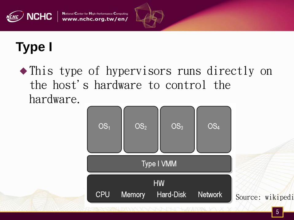
Type I
This type of hypervisors runs directly on the host's hardware to control the hardware.
Source: wikipedi
5
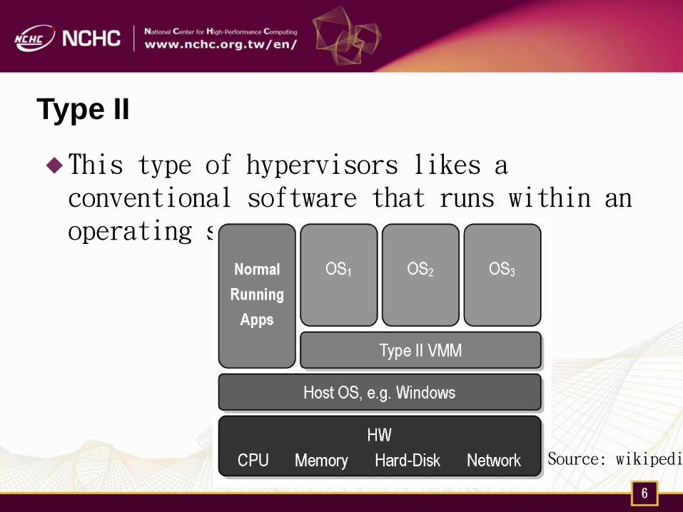
Type II
This type of hypervisors likes a conventional software that runs within an operating system environment.
Source: wikipedi
6
Networking in Virtualization
Compare to CPU, network virtualization has lagged behind.
Networking is important because a single server will host 40 or more VMs in the near future.
8
Popular Networking Modes in VMM
Internal/Host-only networking
Bridged networking
Network Address Translation (NAT)
9
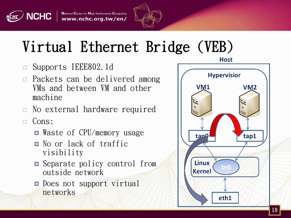
Virtual Ethernet Bridge (VEB)
Supports IEEE802.1d
Packets can be delivered among VMs and between VM and other machine
No external hardware required
Cons:
Waste of CPU/memory usage
No or lack of traffic visibility
Separate policy control from outside network
Does not support virtual networks
10
Open vSwitch
Open source software that well suited to function as a virtual switch in VM environments
Visibility into inter-VM communication via NetFlow, sFlow, SPAN and RSPAN
Standard 802.1Q VLAN model with trunking
Kernel-based forwarding
Support for OpenFlow
Compatibility layer for the Linux bridging code
11
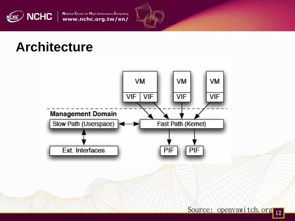
Architecture
Source: openvswitch.org 12
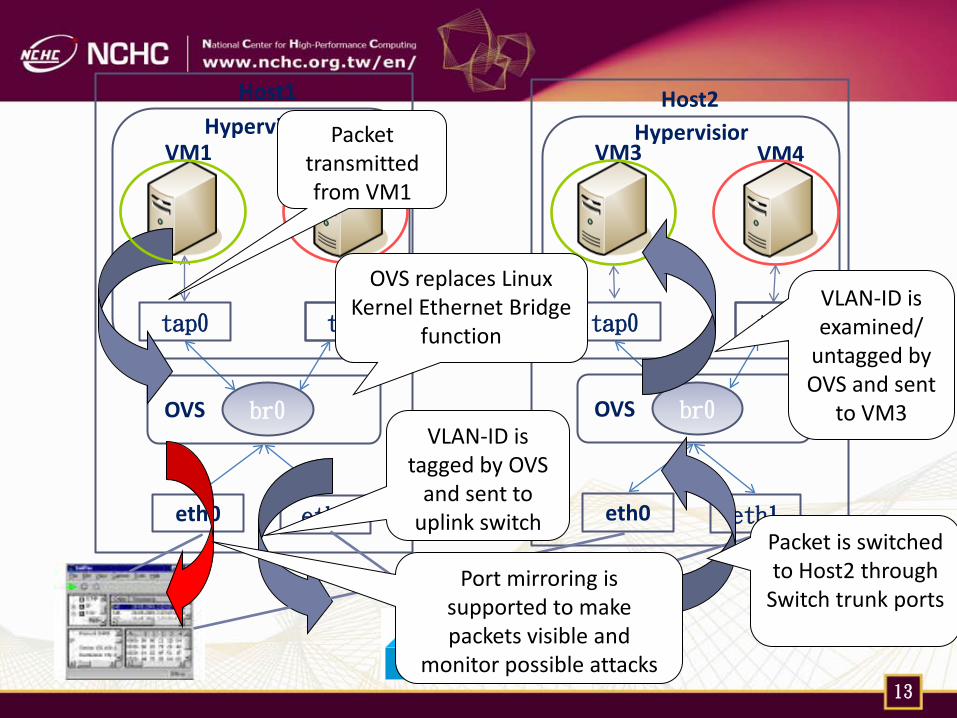
eth1
tap0 tap1
VM2
br0 OVS
VM1
Host1
Hypervisior
eth0 eth1
tap0 tap1
VM4
br0 OVS
VM3
Host2 Hypervisior
eth0
OVS replaces Linux Kernel Ethernet Bridge
function
Packet transmitted from VM1
VLAN-ID is tagged by OVS
and sent to uplink switch
Packet is switched to Host2 through
Switch trunk ports
VLAN-ID is examined/
untagged by OVS and sent
to VM3
Port mirroring is supported to make packets visible and
monitor possible attacks 13
Separation of Network Configuration
Configurations of network is now divided into two parts
Physical network devices that managed by network team
Software virtual switches is configured by server team
Possible inconsistence of network and server configurations may cause errors and is very hard to troubleshooting/maintenance.
14
Hardware Edge Virtual Bridging (EVB)
Two ongoing IEEE standards are working on physical virtual switching environments.
IEEE 802.1Qbg VEPA (Virtual Ethernet Port Aggregation)
lead by HP (HP, IBM, Extreme, Brocade, Juniper ...)
IEEE 802.1Qbh Bridge Port Extension / VN-Tag
proposed by Cisco
15
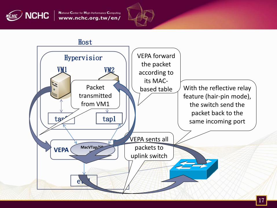
IEEE 802.1Qbg/ VEPA
Minor software update from VEB to VEPA is required in order to force packets transmitted to uplink switches.
SR-IOV NICs can also support VEPA with minor update.
Switches firmware should also be upgraded to support reflective relay (hair-pin mode).
Leverage existing hardware
No changes to existing frame formats
QoS, ACL, and monitoring functions remains the same at physical switches layer
16
eth1
tap0 tap1
VM2
MacVTap/SR-IOV VEPA
VM1
Host
Hypervisior
Packet transmitted from VM1
VEPA sents all packets to
uplink switch
With the reflective relay feature (hair-pin mode),
the switch send the packet back to the
same incoming port
VEPA forward the packet
according to its MAC-
based table
17
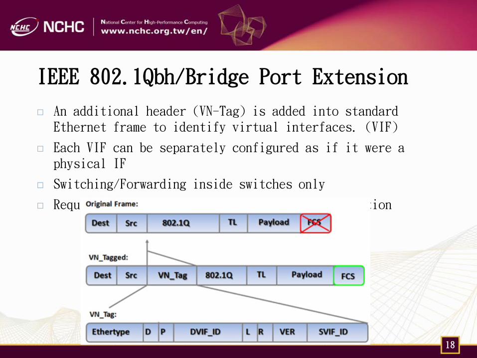
IEEE 802.1Qbh/Bridge Port Extension
An additional header (VN-Tag) is added into standard Ethernet frame to identify virtual interfaces. (VIF)
Each VIF can be separately configured as if it were a physical IF
Switching/Forwarding inside switches only
Requires significant software/hardware modification
18
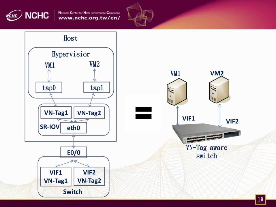
tap0 tap1
VM2
SR-IOV
VM1
Host
Hypervisior
eth0
VN-Tag1 VN-Tag2
E0/0
VIF1 VN-Tag1
VIF2 VN-Tag2
Switch
VM1 VM2
VIF1 VIF2
19
VN-Tag aware switch
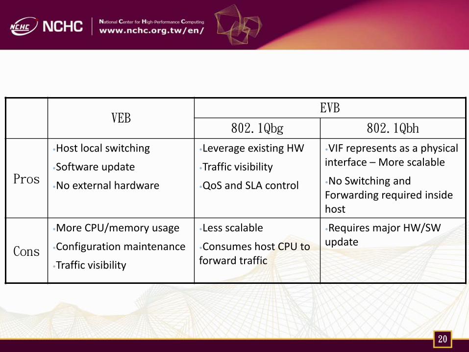
VEB EVB
802.1Qbg 802.1Qbh
Pros
•Host local switching
•Software update
•No external hardware
•Leverage existing HW
•Traffic visibility
•QoS and SLA control
•VIF represents as a physical interface – More scalable
•No Switching and Forwarding required inside host
Cons
•More CPU/memory usage
•Configuration maintenance
•Traffic visibility
•Less scalable
•Consumes host CPU to forward traffic
•Requires major HW/SW update
20
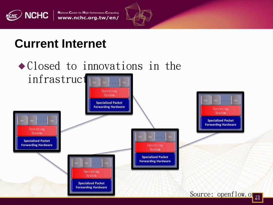
Current Internet
Closed to innovations in the infrastructure
21 Source: openflow.org
Future Internet
To solve some limitations in current Internet
Scalability
Security
QoS
Virtualization
Future Internet is a summarizing term for worldwide research activities dedicated to the further development of the original Internet. (From Wiki)
22
Future Internet Testbed
For innovations and researches in Future Internet, the testbed requires some advanced concepts:
Programmability
Virtualization
End-to-end slice
23
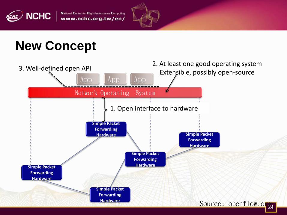
New Concept
24
1. Open interface to hardware
3. Well-defined open API 2. At least one good operating system
Extensible, possibly open-source
Source: openflow.org
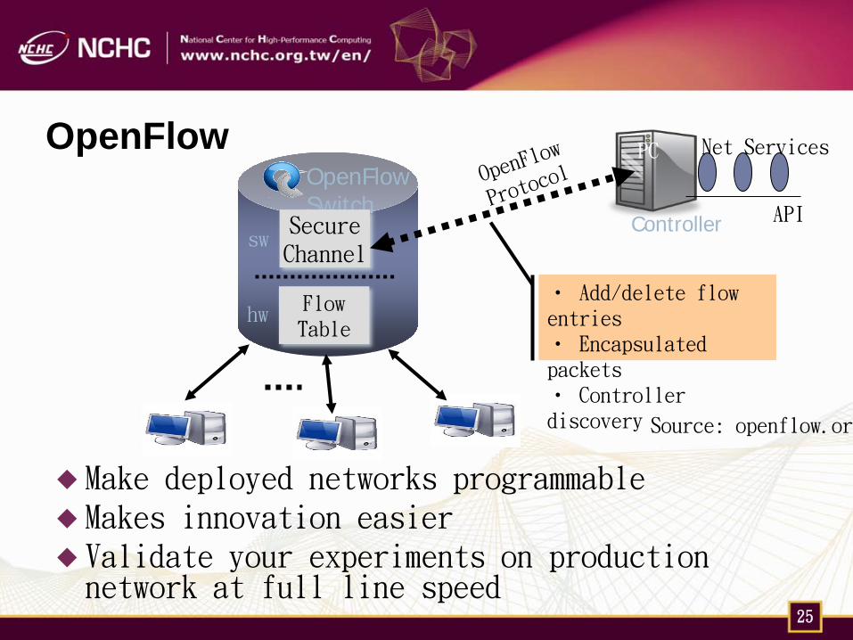
OpenFlow
Make deployed networks programmable Makes innovation easier Validate your experiments on production network at full line speed
25
Controller
OpenFlow Switch
Flow Table
Secure Channel
PC
hw
sw
• Add/delete flow entries • Encapsulated packets • Controller discovery
API
Net Services
Source: openflow.org
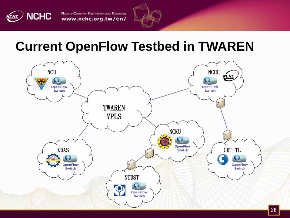
Current OpenFlow Testbed in TWAREN
26
TWAREN VPLS
KUAS
OpenFlow Switch
NCKU
OpenFlow Switch CHT-TL
OpenFlow Switch
NCU
OpenFlow Switch
NCHC
OpenFlow Switch
NTUST
OpenFlow Switch

TWAREN International Circuit
27

iGENI-Taiwan Integrated Research Network
28 Source: iCAIR
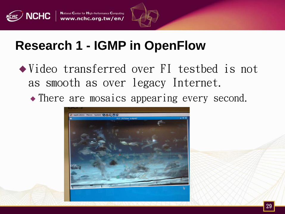
Research 1 - IGMP in OpenFlow
Video transferred over FI testbed is not as smooth as over legacy Internet.
There are mosaics appearing every second.
29
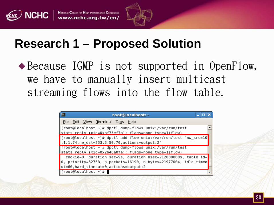
Research 1 – Proposed Solution
Because IGMP is not supported in OpenFlow, we have to manually insert multicast streaming flows into the flow table.
30
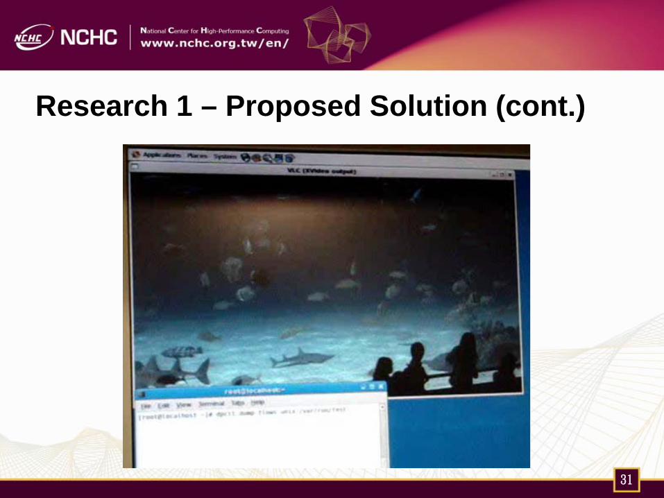
Research 1 – Proposed Solution (cont.)
31
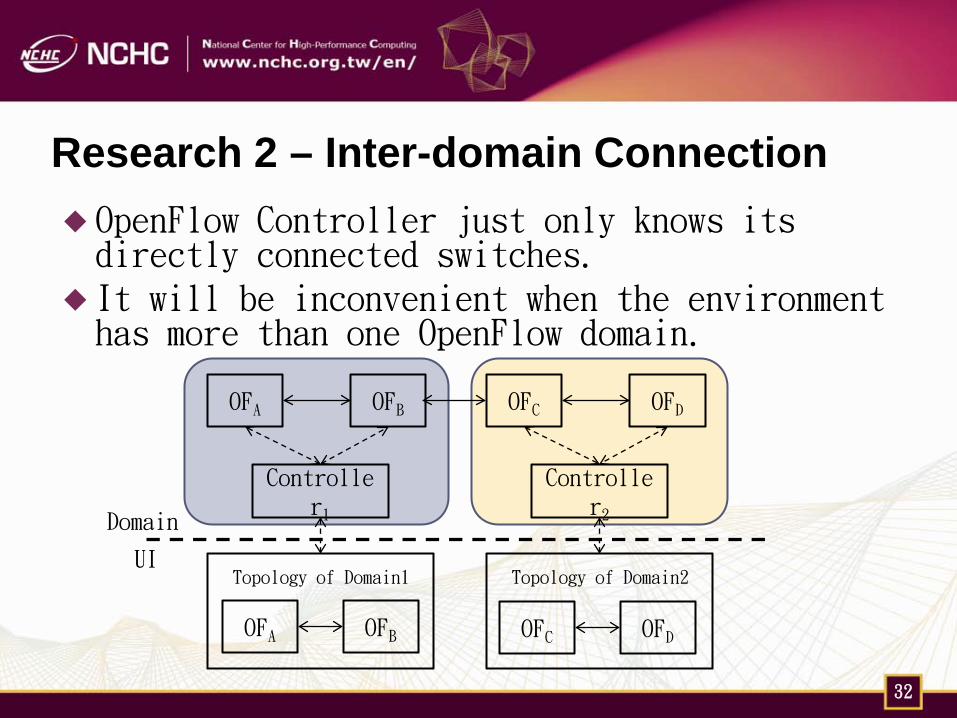
Research 2 – Inter-domain Connection OpenFlow Controller just only knows its directly connected switches.
It will be inconvenient when the environment has more than one OpenFlow domain.
32
Controller1
OFA OFB OFC OFD
OFA OFB
Topology of Domain1
Controller2
OFC OFD
Topology of Domain2 UI
Domain
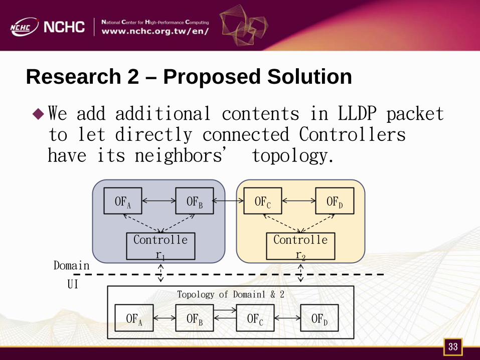
Research 2 – Proposed Solution We add additional contents in LLDP packet to let directly connected Controllers have its neighbors’ topology.
33
Controller1
OFA OFB OFC OFD
Controller2
OFA OFB OFC OFD
UI
Domain
Topology of Domain1 & 2
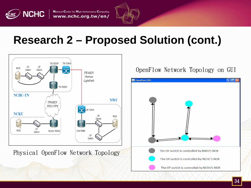
Research 2 – Proposed Solution (cont.)
34
Physical OpenFlow Network Topology
OpenFlow Network Topology on GUI
Conclusions
Networking is an important part of Cloud.
OpenFlow is an API, but it makes the network programmable and implements innovation easier.
The combination of OpenFlow switches and virtual switches will be an interested develop/research area for control and management the next-generated network.
35
Thank you
36


