Network Basiccs.tju.edu.cn/faculty/zenghua/LabPractice/NETWORK... · Web view... it performs a...
85
Network Basic Students Lab Manual Lab Set 1 (Prepare and Practice at student’s own PC ) Lab 1.1 TCP/IP Configuration and Useful Commands Objective Become familiar with the basic network knowledge of a PC computer system Identify PC connections including network attachment Examine the internal PC network configuration Use some commands to find out information about the PC network Background Knowing the PC network is a basic thing when troubleshooting. This knowledge is also the first step to success in the networking field. This lab assumes the use of any version of Windows. This is a non-destructive lab and can be done on any machine without concern of changing the system configuration. In the following instructions, students should perform the lab with Windows 2000/XP. Step 1 Connect into the Internet Establish and verify connectivity to the Internet. This ensures the computer has an IP address. Step 2 Gather TCP/IP configuration information Use the Start menu to open the Command Prompt, an MS-DOS-like window. Press Start>Run as, type cmd and press the Enter key. The following figure shows the Command screen. Type ipconfig and press the Enter key. The spelling of ipconfig is critical while case is not. It is short for IP Configuration.
Transcript of Network Basiccs.tju.edu.cn/faculty/zenghua/LabPractice/NETWORK... · Web view... it performs a...

Network Basic Students Lab Manual
Lab Set 1 (Prepare and Practice at student’s own PC )Lab 1.1 TCP/IP Configuration and Useful Commands
ObjectiveBecome familiar with the basic network knowledge of a PC computer systemIdentify PC connections including network attachmentExamine the internal PC network configurationUse some commands to find out information about the PC network
BackgroundKnowing the PC network is a basic thing when troubleshooting. This knowledge is also the
first step to success in the networking field.This lab assumes the use of any version of Windows. This is a non-destructive lab and can be
done on any machine without concern of changing the system configuration.In the following instructions, students should perform the lab with Windows 2000/XP.
Step 1 Connect into the InternetEstablish and verify connectivity to the Internet. This ensures the computer has an IP address.
Step 2 Gather TCP/IP configuration informationUse the Start menu to open the Command Prompt, an MS-DOS-like window. Press
Start>Run as, type cmd and press the Enter key.The following figure shows the Command screen. Type ipconfig and press the Enter key. The
spelling of ipconfig is critical while case is not. It is short for IP Configuration.
This first screen shows the IP address, subnet mask, and default gateway. The IP address and the default gateway should be in the same network or subnet, otherwise this host would not be able to communicate outside the network. In the figure the subnet mask tells us that the first three octets must be the same to be in the same network.Step 3 Record the following TCP/IP information for this computer
IP address:

Subnet Mask: Default Gateway:
Step 4 Compare the TCP/IP configuration of this computer to others on the LANIf this computer is on a LAN, compare the information of several machines.Are there any similarities?What is similar about the IP addresses?What is similar about the default gateway?The IP addresses should share the same network portion. All machines in the LAN should
share the same default gateway.Step 5 Check additional TCP/IP configuration information
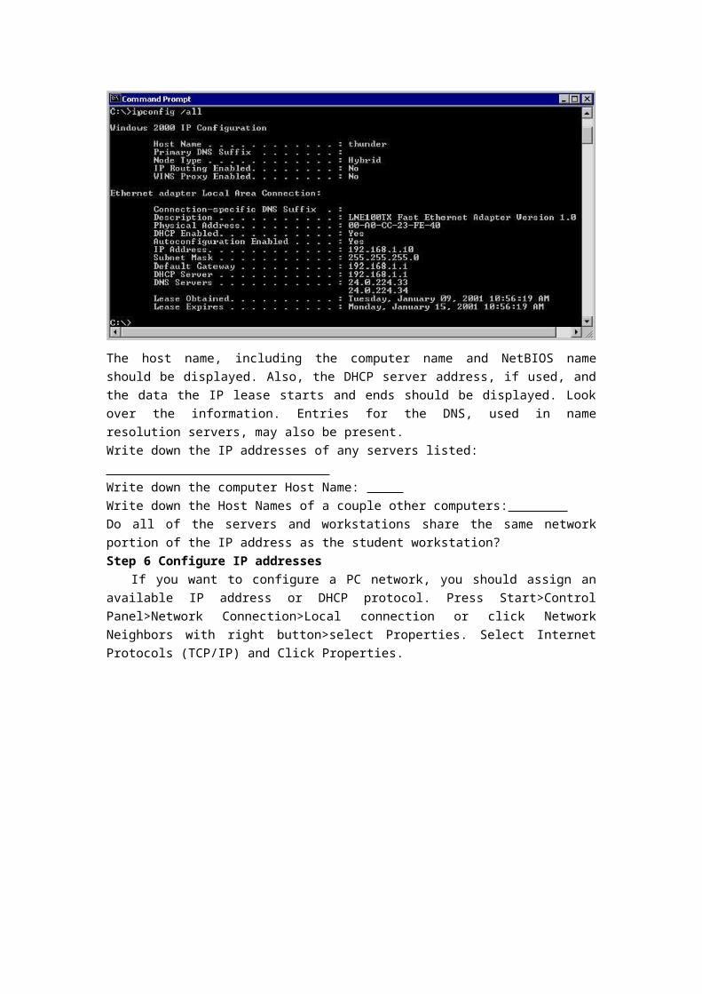
To see detailed information, type ipconfig /all and press Enter. The figure shows the detailed IP configuration screen.
The host name, including the computer name and NetBIOS name should be displayed. Also, the DHCP server address, if used, and the data the IP lease starts and ends should be displayed. Look over the information. Entries for the DNS, used in name resolution servers, may also be present.Write down the IP addresses of any servers listed: Write down the computer Host Name: Write down the Host Names of a couple other computers: Do all of the servers and workstations share the same network portion of the IP address as the student workstation? Step 6 Configure IP addresses
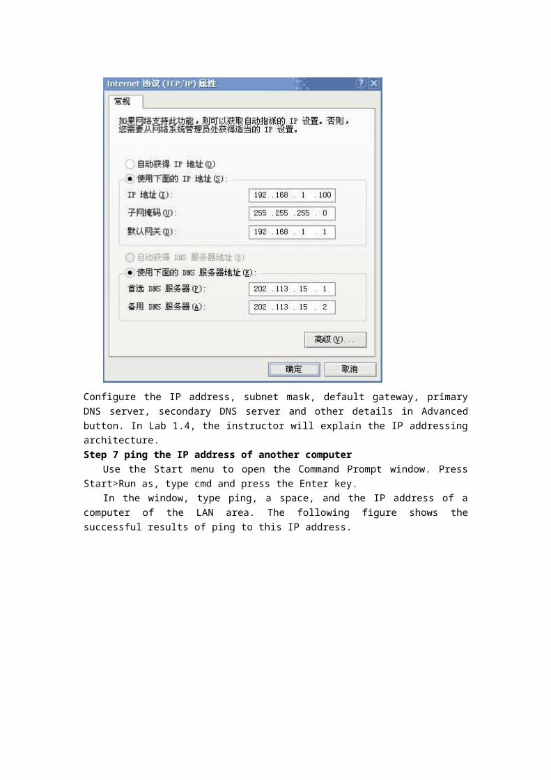
If you want to configure a PC network, you should assign an available IP address or DHCP protocol. Press Start>Control Panel>Network Connection>Local connection or click Network Neighbors with right button>select Properties. Select Internet Protocols (TCP/IP) and Click Properties.
Configure the IP address, subnet mask, default gateway, primary DNS server, secondary DNS server and other details in Advanced button. In Lab 1.4, the instructor will explain the IP addressing architecture.Step 7 ping the IP address of another computer
Use the Start menu to open the Command Prompt window. Press Start>Run as, type cmd and press the Enter key.
In the window, type ping, a space, and the IP address of a computer of the LAN area. The following figure shows the successful results of ping to this IP address.
Ping uses the ICMP echo request and echo reply feature to test physical connectivity. Since ping reports on four attempts, it gives an indication of the reliability of the connection. Look over the results and verify that the ping was successful. Is the ping successful? If not, perform appropriate troubleshooting.
If a second networked computer is available, try to ping the IP address of that machine.Step 8 ping the IP address of the default gateway
Try to ping the IP address of the default gateway. If the ping is successful, it means there is physical connectivity to the router on the local network and probably the rest of the world.Step 9 ping the IP address of a DHCP or DNS server
The same to last one.Step 10 ping the Loopback IP address of this computer
Type the following command: ping 127.0.0.1The 127.0.0.0 network is reserved for loopback testing. If the ping is successful, then TCP/IP
is properly installed and functioning on this computer.If you uninstalled the network adapter driver, the ping will be unsuccessful.
Step 11 ping the hostname of another computerTry to ping the hostname of the computer that was recorded in the previous lab. The figure
shows the successful result of the ping the hostname.
Look over the results. Notice that the first line of output shows the host name, m450 in the example, followed by the IP address. This means the computer was able to resolve the host name to an IP address. Without name resolution, the ping would have failed because TCP/IP only understands valid IP addresses, not names.
If the ping was successful, it means that connectivity and discovery of IP addresses can be done with only a hostname. In fact, this is how many early networks communicated. If successful, then ping a hostname also shows that there is probably a WINS server working on the network. WINS servers or a local “Imhosts” file resolve computer host names to IP addresses. If the ping fails, then chances are there is no NetBIOS name to IP addresses resolution running.Step 12 ping Cisco Website www.cisco.com

The first output line shows the Fully Qualified Domain Name(FQDN) followed by the IP address. A DNS server somewhere in the network was able to resolve the name to an IP address. DNS servers resolve domain names, not hostnames, to IP addresses.
Without this name resolution, the ping would have failed because TCP/IP only understands valid IP address. It would not be possible to use the web browser without this name resolution.
Notice that the DNS server was able to resolve the name to an IP address, but there is no response. All TJU routers are configured to ignore ping requests. This is a frequently implemented security measure.Step 13 Trace the route to the Cisco web site
Type tracert www.cisco.com and press Enter.
tracert is TCP/IP abbreviation for trace route. The preceding figure shows the successful result when running tracert from Bavaria in Germany. The first output line shows the FQDN followed by the IP address. Therefore, a DNS server was able to resolve the name to an IP address. Then there are listings of all routers the tracert requests had to pass through to get to the destination.
tracert uses the same echo request and replies as the ping command but in a slightly different way. Observe that tracert actually contacted each router three times. Compare the results to determine the consistency of the route. Notice in the above example that there were relatively long delays after router 11 and 13, possibly due to congestion. The main thing is that there seems to be

relatively consistent connectivity.Each router represents a point where one network connects to another network and the packet
was forwarded through.Step 14 Trace other IP addresses or domain names and a local host name or IP address
Try using the tracert command with other IP addresses, domain names, local host name, local IP address.Step 15 Close the screen
Close the screen when finished examining network settings.This concludes the lab.

Lab 1.2 Basic PC/Network Troubleshooting Processes
ObjectiveLearn the proper sequence for troubleshooting computer and network problems.Become familiar with the more common hardware and software problems.Given a basic problem situation, be able to troubleshoot and resolve the problem.
BackgroundThe ability to effectively troubleshoot computer related problems is an important skill. The
process of identifying the problem and solving it requires a systematic step-by-step approach. This lab will introduce some basic hardware and software related problems to solve. This lab will assist in becoming more familiar with PC components and the software. The process of solving a problem is fairly straightforward. Some of the suggestions here are more than what will be required to solve basic hardware and software problems. They will help provide a framework and guidelines when more complex problems arise. A list of sample problems to be introduced is provided in the instructor’s version of the lab.
The Eight Basic Steps for PC and Network Troubleshooting ProcessStep 1 Define the problem
Describe what is happening or not happening using proper terminology. For example: The PC cannot get to the Internet, or the PC cannot print.Step 2 Gather the facts
Observe the symptoms and try to characterize or identify the source of the problem:Is it hardware related, check for lights and noises. Is it software related, are there errors on screen?Does the problem affect this computer or user only. or are others also impacted?Does it affect this software only, or more than one application?Is this the first time the problem has happened or has it happened before?Was anything on the PC changed recently?Get the opinions of others who may have more experience.Check web sites and troubleshooting knowledge databases.
Step 3 Consider the possibilitiesUse the facts gathered. Identify one or more possible causes and potential solutions. Rank
solutions in order of the most likely to the least likely cause.Step 4 Create an action plan
Develop a plan that involves the single most likely solution. The other options can be tried if the original solution fails. Consider the following in the development of a plan:
Check the simplest possible causes first. Is the power turned on or plugged in?Verify hardware first then software.If it is a network problem start at Layer 1 of the OSI model and work up the Layers. Studies show the majority of problems occur at Layer 1.Can substitution be used to isolate the problem? If the monitor does not work it could be the monitor, video adapter or cables. Try another monitor to see if it corrects the problem.

Step 5 Implement the planMake the change(s) from the plan to test the first possible solution.
Step 6 Observe the resultsIf the problem is solved, go on to document the solution. Double check to make sure
everything still works.If the problem is not resolved restore the changes and return to the plan to try the next
solution. If this change is not reversed, it will be unclear whether the problem was a later change or the combination of two changes.Step 7 Document the results
Always document the results to assist in solving similar problems. Documentation also helps to develop a documentation history for each device. If part of the devices are going to be replaced it might be nice to know if any are frequent sources of trouble or if they have recently been reconditioned.Step 8 Introduce problems and troubleshoot
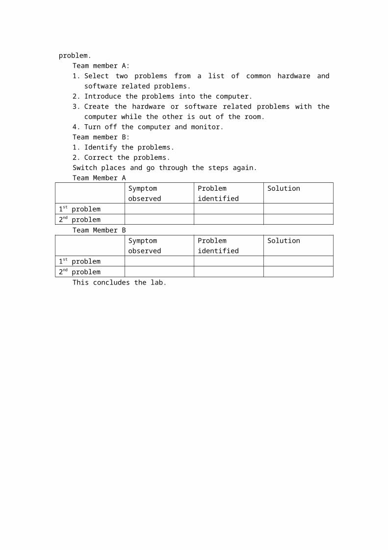
Work in teams of two. The desired goal will be to run one of the videos or movies from the on-line curriculum or the CD. Each team member solving the problem should fill in the table based on the symptoms observed, problems identified, and solutions to the problem.
Team member A:1. Select two problems from a list of common hardware and software related problems.2. Introduce the problems into the computer.3. Create the hardware or software related problems with the computer while the other is
out of the room.4. Turn off the computer and monitor.Team member B:1. Identify the problems.2. Correct the problems.Switch places and go through the steps again.Team Member A
Symptom observed Problem identified Solution1st problem2nd problem
Team Member BSymptom observed Problem identified Solution
1st problem2nd problem
This concludes the lab.

Lab 1.4 IP Addressing and Basic Subnetting
Objective Name the five different classes of IP addressesDescribe the characteristics and use of the different IP address classesIdentify the class of an IP address based on the network numberDetermine which part, or octet, of an IP address is the network ID and which part is the host IDIdentify valid and invalid IP host addresses based on the rules of IP addressingDefine the range of addresses and default subnet mask for each classHow to identify reasons to use a subnet maskWhat given requirements determine the subnet mask, number of subnets, and hosts per subnetWhat needs to be understood about useable subnets and useable numbers of hostsHow to identify valid and invalid IP host addresses based on a network number and subnet mask
Background / PreparationThis lab exercise helps develop an understanding of IP addresses and how TCP/IP networks
operate. It is primarily a written lab exercise. However, it would be worthwhile to review some real network IP addresses using the command line utilities ipconfig for Windows NT/2000/XP. IP addresses are used to uniquely identify individual TCP/IP networks and hosts, such as computers and printers, on those networks in order for devices to communicate. Workstations and servers on a TCP/IP network are called hosts and each has a unique IP address. This address is referred to as its host address. TCP/IP is the most widely used protocol in the world. The Internet or World Wide Web only uses IP addressing. In order for a host to access the Internet, it must have an IP address.In this basic form, the IP address has two parts:
A network addressA host address
The network portion of the IP address is assigned to a company or organization by the Internet Network Information Center(InterNIC). Routers use the IP address to move data packets between networks. IP addresses are 32 bits long according to the current version IPv4 and are divided into 4 octets of 8 bits each. They operate ate the network layer(Layer 3) of the Open System Interconnection(OSI) model, which is the Internet layer of the TCP/IP model. IP addresses are assigned in the following ways:
Statically – manually, by a network administratorDynamically – automatically, by a Dynamic Host Configuration Protocol(DHCP) server
The IP address of a workstation, or host is a logical address, meaning it can be changed. The Media Access Control(MAC) address of the workstation is a 48-bit physical address. This address is burned into the network interface card(NIC) and cannot change unless the NIC is replaced. The combination of the logical IP address and the physical MAC address helps route packets to their proper destination.There are five different classes of IP addresses, and depending on the class, the network and host part of the address will use a different number of bits. In this lab, different classes of IP addresses will be worked with and to help become familiar with the characteristics of each. The understanding of IP addresses is critical to the understanding of TCP/IP and internetworks in general. The following resources are required:
PC workstation with Windows 9x/NT/2000/XP installedAccess to the Windows Calculator
This lab also focuses on the basics of IP subnet masks and their use with TCP/IP networks. The subnet mask can be used to split up an existing network into subnetworks, or subnets. Some of the primary reasons for subnetting are the following:
Reduce the size of the broadcast domains, which creates smaller networks with less trafficAllow LANs in different geographical locations to communicate through routersProvide improved security by separating one LAN from another
Routers separate subnets, and determine when a packet can go from one subnet to another. Each router a packet goes through is considered a hop. Subnet masks help workstations, servers, and routers in an IP network determine if the destination host for the packet they want to send is on their own network or another network. This lab reviews the default subnet mask and then focuses on custom subnet masks. Custom subnet masks use more bits than the default subnet masks by borrowing these bits from the host portion of the IP address. This creates a three-part address:
The original network addressThe subnet address made up of the bits borrowedThe host address made up of the bits left after borrowing some for subnets
Step 1 Review IP address classes and their characteristicsAddress classesThere are five classes of IP addresses, A through E. Only the first three classes are used
commercially. A Class A network address is discussed in the table to get started. The first column is the class of IP address. The second column is the first octet, which must fall within the range shown for a given class of addresses. The Class A address must start with a number between 1 and 126. The first bit of a Class A address is always a zero, meaning the High Order Bit(HOB) or the 128 bit cannot be used. 127 is reserved for loopback testing. The first octet alone defines the network ID for a Class A network address.
Default subnet maskThe default subnet mask uses all binary ones, decimal 255, to mask the first 8 bits of the
Class A address. The default subnet mask helps routers and hosts determine if the destination host is on this network or another one. Because there are only 126 Class A networks, the remaining 24 bits, or 3 octets, can be used for hosts. Each Class A network can have 224, or over 16 million hosts. It is common to subdivide the network into smaller grouping called subnets by using a custom subnet mask, which is discussed in the next lab.
Network and host addressThe network or host portion of the address cannot be all ones or all zeros. As an example, the
Class A address of 118.0.0.5 is a valid IP address. The network portion, or first 8 bits, which are equal to 118, is not all zero and the host portion, or last 24 bits, is not all zeros or all ones. If the host portion were all zeros, it would be the network address itself. If the host portion were all ones, it would be a broadcast for the network address. The value of any octet can never be greater than decimal 255 or binary 11111111.Class 1st Octet
Decimal Range
1st Octet High Order
Network/Host ID (N=Network,
Default Subnet Mask
Number of Networks
Hosts per Network (Usable

Bits H=Host) Addresses)A 1-126* 0 N.H.H.H 255.0.0.0 126(27 -
2)16,777,214 (224 - 2)
B 128-191 10 N.N.H.H 255.255.0.0 16,382 (214 - 2)
65,534 (216 - 2)
C 192-223 110 N.N.N.H 255.255.255.0 2,097,150(221 - 2)
254(28 - 2)
D 224-239 1110 Reserved for MulticastingE 240-254 11110 Experimental; used for researchNote: Class A address 127 cannot be used and is reserved for loopback and diagnostic functions.
Step 2 Determine basic IP addressingUse the IP address chart and your knowledge of IP address classes to answer the following
questions:1. What is the decimal and binary range of the first octet of all possible Class B IP address?
Decimal: From: To: Binary: From: To:
2. Which octet(s) represent the network portion of a Class C IP address?3. Which octet(s) represent the host portion of a Class A IP address?4. What is the maximum number of useable hosts with a Class C network address?5. How many Class B networks are there?6. How many hosts can each Class B network have?7. How many octets are there in an IP address? How many bits per octet?
Step 3 Determine the host and network portions of the IP addressWith the following IP host addresses, indicate the following:
Class of each addressNetwork address or IDHost portionBroadcast address for this networkDefault subnet mask
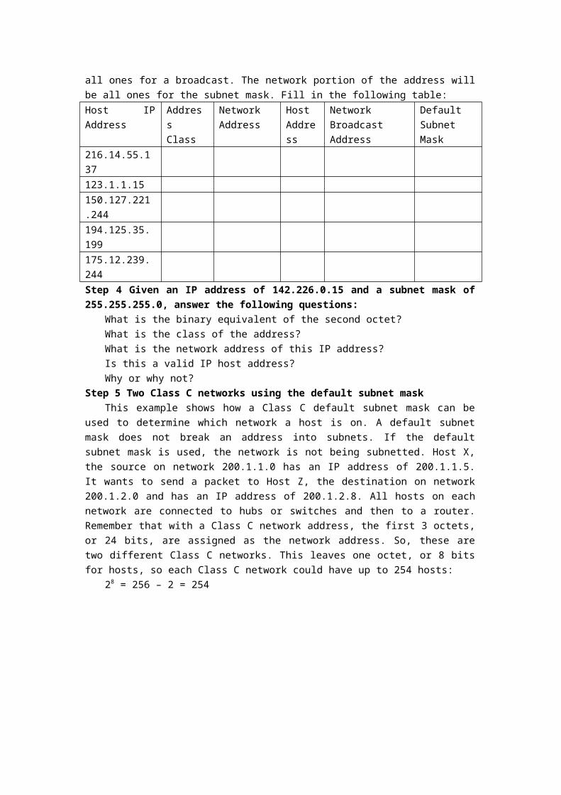
The host portion will be all zeros for the network ID. Enter just the octets that make up the host. The host portion will be all ones for a broadcast. The network portion of the address will be all ones for the subnet mask. Fill in the following table:Host IP Address Address
ClassNetwork Address
Host Address
Network Broadcast Address
Default Subnet Mask
216.14.55.137123.1.1.15150.127.221.244194.125.35.199175.12.239.244Step 4 Given an IP address of 142.226.0.15 and a subnet mask of 255.255.255.0, answer the following questions:
What is the binary equivalent of the second octet?What is the class of the address?

What is the network address of this IP address?Is this a valid IP host address?Why or why not?
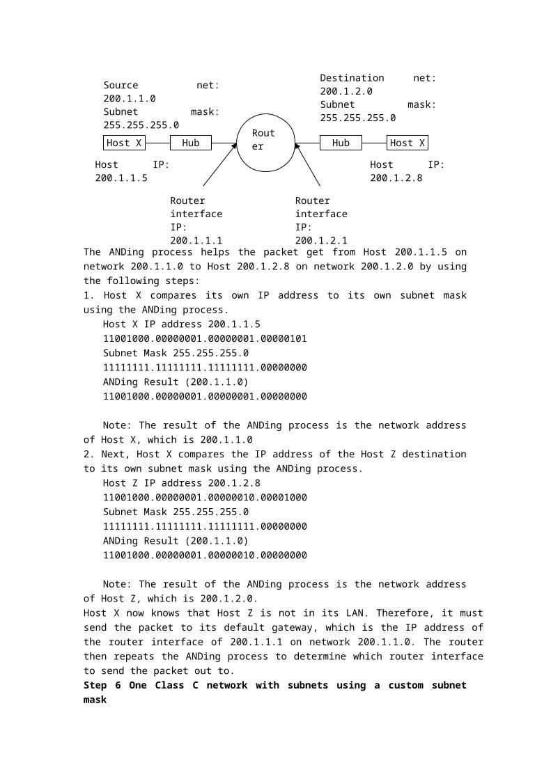
Step 5 Two Class C networks using the default subnet maskThis example shows how a Class C default subnet mask can be used to determine which
network a host is on. A default subnet mask does not break an address into subnets. If the default subnet mask is used, the network is not being subnetted. Host X, the source on network 200.1.1.0 has an IP address of 200.1.1.5. It wants to send a packet to Host Z, the destination on network 200.1.2.0 and has an IP address of 200.1.2.8. All hosts on each network are connected to hubs or switches and then to a router. Remember that with a Class C network address, the first 3 octets, or 24 bits, are assigned as the network address. So, these are two different Class C networks. This leaves one octet, or 8 bits for hosts, so each Class C network could have up to 254 hosts:
28 = 256 – 2 = 254
The ANDing process helps the packet get from Host 200.1.1.5 on network 200.1.1.0 to Host 200.1.2.8 on network 200.1.2.0 by using the following steps:1. Host X compares its own IP address to its own subnet mask using the ANDing process.
Host X IP address 200.1.1.5 11001000.00000001.00000001.00000101Subnet Mask 255.255.255.0 11111111.11111111.11111111.00000000ANDing Result (200.1.1.0) 11001000.00000001.00000001.00000000
Note: The result of the ANDing process is the network address of Host X, which is 200.1.1.02. Next, Host X compares the IP address of the Host Z destination to its own subnet mask using the ANDing process.
Host Z IP address 200.1.2.8 11001000.00000001.00000010.00001000Subnet Mask 255.255.255.0 11111111.11111111.11111111.00000000ANDing Result (200.1.1.0) 11001000.00000001.00000010.00000000
Note: The result of the ANDing process is the network address of Host Z, which is 200.1.2.0.Host X now knows that Host Z is not in its LAN. Therefore, it must send the packet to its default gateway, which is the IP address of the router interface of 200.1.1.1 on network 200.1.1.0. The router then repeats the ANDing process to determine which router interface to send the packet out to.Step 6 One Class C network with subnets using a custom subnet mask
Host X HubRouter
Hub Host X
Source net: 200.1.1.0Subnet mask: 255.255.255.0
Destination net: 200.1.2.0Subnet mask: 255.255.255.0
Router interfaceIP: 200.1.1.1
Router interfaceIP: 200.1.2.1
Host IP: 200.1.1.5 Host IP: 200.1.2.8

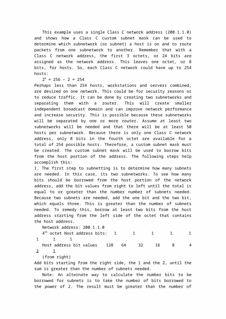
This example uses a single Class C network address (200.1.1.0) and shows how a Class C custom subnet mask can be used to determine which subnetwork (or subnet) a host is on and to route packets from one subnetwork to another. Remember that with a Class C network address, the first 3 octets, or 24 bits are assigned as the network address. This leaves one octet, or 8 bits, for hosts. So, each Class C network could have up to 254 hosts:
28 = 256 – 2 = 254Perhaps less than 254 hosts, workstations and servers combined, are desired on one network. This could be for security reasons or to reduce traffic. It can be done by creating two subnetworks and separating them with a router. This will create smaller independent broadcast domain and can improve network performance and increase security. This is possible because these subnetworks will be separated by one or more router. Assume at least two subnetworks will be needed and that there will be at least 50 hosts per subnetwork. Because there is only one Class C network address, only 8 bits in the fourth octet are available for a total of 254 possible hosts. Therefore, a custom subnet mask must be created. The custom subnet mask will be used to borrow bits from the host portion of the address. The following steps help accomplish this:1. The first step to subnetting is to determine how many subnets are needed. In this case, its two subnetworks. To see how many bits should be borrowed from the host portion of the network address, add the bit values from right to left until the total is equal to or greater than the number number of subnets needed. Because two subnets are needed, add the one bit and the two bit, which equals three. This is greater than the number of subnets needed. To remedy this, borrow at least two bits from the host address starting from the left side of the octet that contains the host address.
Network address: 200.1.1.04th octet Host address bits: 1 1 1 1 1 1 1 1Host address bit values 128 64 32 16 8 4 2 1(from right)
Add bits starting from the right side, the 1 and the 2, until the sum is greater than the number of subnets needed.
Note: An alternate way to calculate the number bits to be borrowed for subnets is to take the number of bits borrowed to the power of 2. The result must be greater than the number of subnets needed. As an example if 2 bits are borrowed the calculation is two to the second power, which equal four. Since the number of subnets needed is two this should be adequate.2. After we know many bits to borrow, we take them from the left side of the host address, the 4 th
octet. Every bit borrowed from the host address bit leaves fewer bits for the hosts. Even though the number of subnets is increased, the number of hosts per subnet is decreased. Because two bits need to be borrowed from the left side, that new value must be shown in the subnet mask. The existing default subnet mask was 255.255.255.0 and the new custom subnet mask is 255.255.255.192. The 192 results from adding the first two bits from the left, 128 + 64 = 192. These bits now become 1s and are part of the overall subnet mask. This leaves 6 bits for host IP addresses of 26 = 64 hosts per subnet.
4th Octet borrowed bits for subnet: 1 1 0 0 0 0 0 0Subnet bit values: (from left side) 128 64 32 16 8 4 2 1
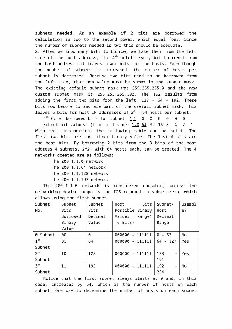
With this information, the following table can be built. The first two bits are the subnet binary value. The last 6 bits are the host bits. By borrowing 2 bits from the 8 bits of the host address 4 subnets, 2^2, with 64 hosts each, can be created. The 4 networks created are as follows:

The 200.1.1.0 networkThe 200.1.1.64 networkThe 200.1.1.128 networkThe 200.1.1.192 network
The 200.1.1.0 network is considered unusable, unless the networking device supports the IOS command ip subnet-zero, which allows using the first subnet.Subnet No. Subnet Bits
Borrowed Binary Value
Subnet Bits Decimal Value
Host Bits Possible Binary Values (Range) (6 Bits)
Subnet/Host Decimal Range
Useable?
0 Subnet 00 0 000000 – 111111 0 – 63 No1st Subnet 01 64 000000 – 111111 64 – 127 Yes2nd Subnet 10 128 000000 – 111111 128 – 191 Yes3rd Subnet 11 192 000000 – 111111 192 – 254 No
Notice that the first subnet always starts at 0 and, in this case, increases by 64, which is the number of hosts on each subnet. One way to determine the number of hosts on each subnet or the start of each subnet is to take the remaining host bits to the power of 2. Because we borrowed two of the 8 bits for subnets and have 6 bits left, the number of hosts per subnet is 2 6 or 64. Another way to figure the number of hosts per subnet or the increment from one subnet to the next is to subtract the subnet mask value in decimal, 192 in the fourth octet, from 256, which is the maximum number of possible combinations of 8 bits. This equals 64. This means start at 0 for the first network and add 64 for each additional subnetwork. For example, if the second subnet is used, the 200.1.1.64 network cannot be used for a host ID since the network ID of the 64 subnet has all zeros in the host portion.
Another common way to represent a subnet mask, is the use of the “slash/number” (/#) where the # following the slash is the number of bits used in the mask (network and subnet combined). As an example, a Class C network address such as 200.1.1.0 with a standard subnet mask (255.255.255.0) would be written as 200.1.10/24, indicating that 24 bits are used for the mask. The same network, when subnetted by using two host bits for subnets, would be written as 200.1.1.0/26. This indicates that 24 bits are used for the network and 2 bits for the subnet. This would represent a custom subnet mask of 255.255.255.192 in dotted decimal format.
A Class A network of 10.0.0.0 with a standard mask (255.0.0.0) would be written as 10.0.0.0/8. If 8 bits (the next octet) were being used for subnets it would be written as 10.0.0.0/16. This would represent a custom subnet mask of 255.255.0.0 in dotted decimal format. The “slash” number after the network number is an abbreviated method of indicating the subnet mask being used.Step 7 Use the following information and the previous examples to answer the following subnet-related questions
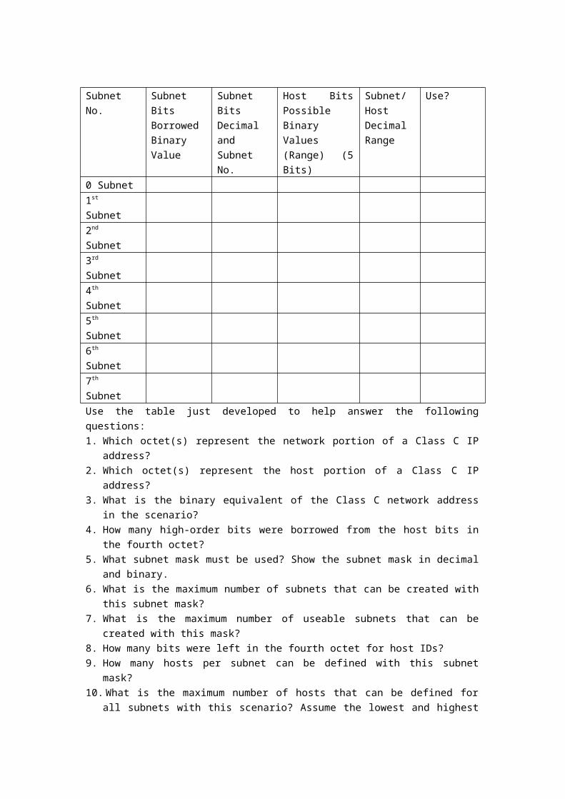
A company has applied for and received a Class C network address of 197.15.22.0. The physical network is to be divided into 4 subnets, which will be interconnected by routers. At least 25 hosts will be needed per subnet. A Class C custom subnet mask needs to be used and a router is needed between the subnets to route packets from the one subnet to another. Determine the number of bits that need to be borrowed from the host portion of the network address and the number of bits that will be left for host addresses.
Note: There will be 8 possible subnets, of which 6 can be used.Fill in the following table and answer the following questions:
Subnet No. Subnet Bits Borrowed Binary Value
Subnet Bits Decimal and Subnet No.
Host Bits Possible Binary Values (Range) (5 Bits)
Subnet/Host Decimal Range
Use?
0 Subnet1st Subnet2nd Subnet3rd Subnet4th Subnet5th Subnet6th Subnet7th SubnetUse the table just developed to help answer the following questions:1. Which octet(s) represent the network portion of a Class C IP address?2. Which octet(s) represent the host portion of a Class C IP address?3. What is the binary equivalent of the Class C network address in the scenario?4. How many high-order bits were borrowed from the host bits in the fourth octet?5. What subnet mask must be used? Show the subnet mask in decimal and binary.6. What is the maximum number of subnets that can be created with this subnet mask?7. What is the maximum number of useable subnets that can be created with this mask?8. How many bits were left in the fourth octet for host IDs?9. How many hosts per subnet can be defined with this subnet mask?10. What is the maximum number of hosts that can be defined for all subnets with this scenario?
Assume the lowest and highest subnet numbers and the lowest and highest host ID on each subnet cannot be used.
11. Is 197.15.22.63 a valid host IP address with this scenario?12. Why or why not?13. Is 197.15.22.160 a valid host IP address with this scenario?14. Why or why not?15. Host A has an IP address of 197.15.22.126. Host B has an IP address of 197.15.22.129. Are
these hosts on the same subnet? Why?
Lab Set 2Lab 2.1 Router Knowledge (Demo at Lab, 2-3 hours)
Objective Understand the physical layer components of a router.Describes techniques for physically connecting the various router interfaces.Connect a PC to a router using a console or rollover cableIdentify and locate the proper cables to connect the router and PC to a hub or switch.Use the cables to connect the router and PC to the hub or switch.Identify and locate the proper cables to interconnect the routers.
Background/Preparation
Step 1 Describe The External Connections On A RouterThe figure shows some of the external connectors on a 2600 router.
This segment will describe the three basic types of connections on a router, which are LAN interfaces, WAN interfaces, and management ports.
LAN interfaces allow routers to connect to the LAN media. This is usually some form of Ethernet. However, it could be some other LAN technology such as Token Ring or FDDI.
WANs provide connections through a service provider to a distant site or to the Internet. These may be serial connections or any number of other WAN interfaces. With some types of WAN interfaces, an external device such as a CSU is required to connect the router to the local connection of the service provider. With other types of WAN connections, the router may be directly connected to the service provider.
The function of management ports is different from the other connections. The LAN and WAN connections provide network connections through which packets are forwarded. The management port provides a text-based connection for the configuration and troubleshooting of the router. The common management interfaces are the console and auxiliary ports. These are EIA-232 asynchronous serial ports. They are connected to a communications port on a computer. The computer must run a terminal emulation program to provide a text-based session with the router. Through this session the network administrator can manage the device.
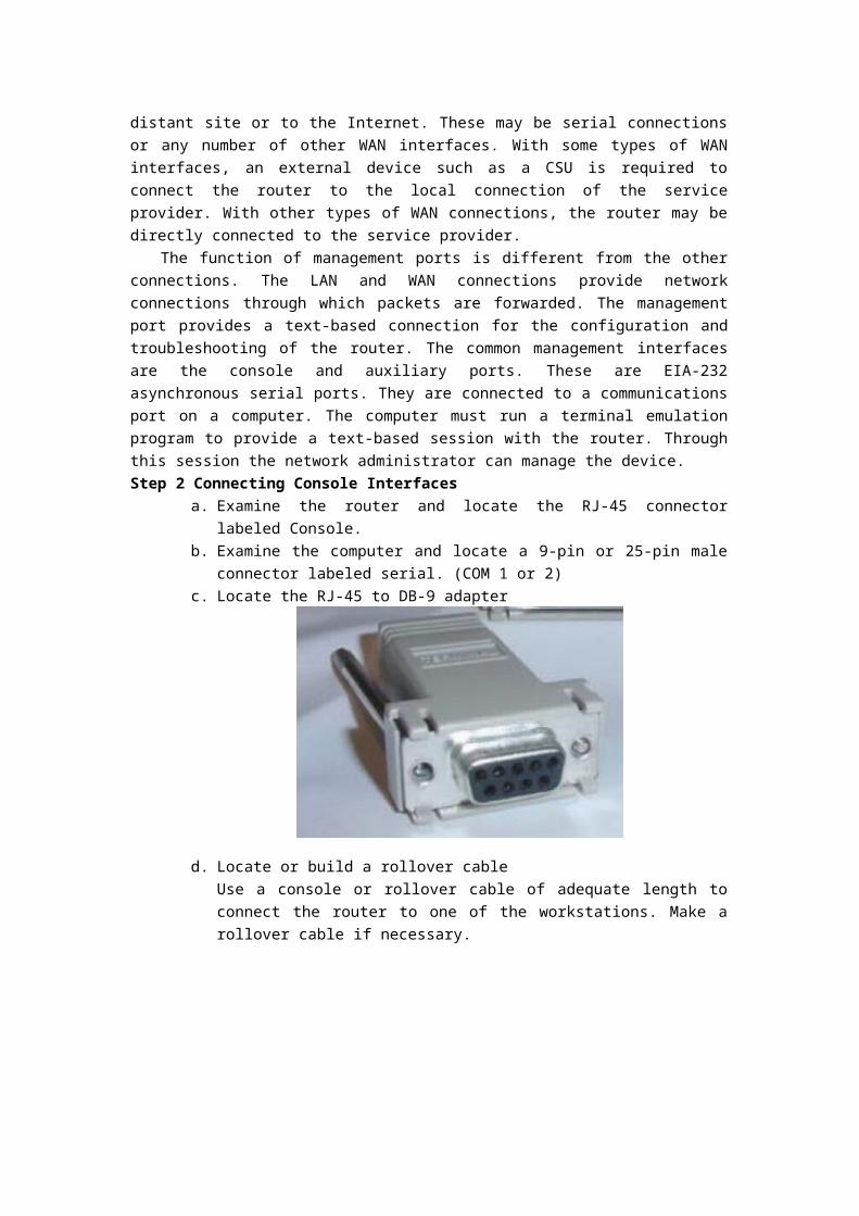
Step 2 Connecting Console Interfacesa. Examine the router and locate the RJ-45 connector labeled Console.b. Examine the computer and locate a 9-pin or 25-pin male connector labeled serial.
(COM 1 or 2)c. Locate the RJ-45 to DB-9 adapter
d. Locate or build a rollover cableUse a console or rollover cable of adequate length to connect the router to one of the workstations. Make a rollover cable if necessary.
e. Connect the console or rollover cable to the router console port, an RJ-45 connector. Next, connect the other end of the console or rollover cable to the RJ-45 to DB-9 or RJ-45 to DB-25 adapter depending on the available PC serial port. Finally attach the adapter to a PC serial port, either DB-9 or DB-25, depending on the computer.
Step 3 Connecting Router LAN Interfacesa. Examine the router.b. What is the model number of the router?(Cisco xxxx)c. Locate one or more RJ-45 connectors on the router labeled 10/100 Ethernet on the 2500
series or 10/100 Fast Ethernet on the 2600 series. This identifier may vary depending on the type of router used. A 2500 series router will have an AUI DB-15 Ethernet port labeled AUI 0. These will require a 10BaseT transceiver to connect to the RJ-45 cable.
d. Identify the Ethernet ports shown that could be used for connecting the routers.e. The connection between the router and the hub will be accomplished using a Category 5
straight-through patch cable. Locate a patch cable that is long enough to reach from the
router to the hub. Be sure to examine the cable ends carefully and select only straight-through cables.
f. Use a cable to connect the Ethernet interface that uses the 0 designation on the router to a port on the hub or switch. Also, use the 10BaswT AUI transceiver for the 2500 series.
g. The computer(s) will also connect to the hub using a straight through patch cable. Run Category 5 patch cables from each PC to where the switch or hub is located. Connect one end of these cables to the RJ-45 connector on the computer NIC and connect the other end to a port on the hub or switch. Be sure to examine the cable ends carefully and select only straight through cables.
h. Plug in and turn on the routers, computers, and hub or switch.i. To verify the router connections, insure that the link light on the router interface and the
hub/switch interface are both lit.j. To verify the computer connections, insure that the link light on the NIC and the hub
interface are both lit.Step 4 Connecting WAN Interfaces
a. Examine the router.b. What is the model number of the router?c. What is the model number of the second router?d. How many serial ports are there on each router that could be used for connecting the
routers?e. Inspect the serial cables available in the lab. Depending on what type of router and/or
serial card used, the router may have different connectors. The two most common types are the DB-60 and the smart serial connectors.
f. Since this lab will not be connected to a live leased line, one of the routers will need to provide the clocking for the circuit. This is normally provided to each of the routers by the service provider. To provide this clocking signal in the lab, one of the routers will need a DCE cable instead of the DTE cable used on the other router.
In this lab, the connection between routers uses one DCE cable and one DTE cable. The DCE-DTE connection between routers is referred to as a null serial cable. This lab will use one V.35 DCE cable and one V.35 DTE cable to simulate the WAN connection.
The V.35 DCE connector is usually a female V.35 (34-pin) connector. The DTE cable has a male V.35 connector. The cables are also labeled as DCE or DTE on the router end of the cable.
g. After having indicated the cables required to interconnect the router locate them in the equipment inventory.
h. The DTE and DCE V.35 cables must now be joined together. Holding one of the V.35 ends in each hand examine the pins and sockets as well as the threaded connectors. Note that there is only one proper way for the cables to fit together. Align the pins on the male cable with the sockets on the female cable and gently couple them. Very little effort should be required to accomplish this. When they are joined, turn the thumbscrews clockwise and secure the connectors.
i. Before making the connection to one of the routers, examine the connector on the router and the cable. Note that the connectors are tapered to help prevent improper connection. Holding the connector in one hand, orient the cable and router connecters so that the tapers match. Now push the cable connector partially into the router connector. It

probably will not go on all the way as the threaded connectors need to be tightened in order for the cable to be inserted completely. While holding the cable in one hand and gently pushing the cable toward the router, turn one of the thumbscrews clockwise, 3 or 4 rounds to start the screws. Now turn the other thumbscrew clockwise, 3 or 4 rounds to get it started. At this point the cable should be attached enough enabling the use of both hands to advance each thumbscrew at the same rate until the cable is fully inserted. Do not over-tighten these connectors.
This concludes the lab.
Lab 2.2 Router Basic Configuration
Objective Become familiar with the Cisco IOS software.Become familiar with the CLI environment.Configure HyperTerminal to establish a console session with the router.Understand the initial process of a router bootup.Identify the three distinct operating environments or modes of the Cisco IOS devices.
BackgroundAs with a computer, a router or switch cannot function without an operating system. Cisco
IOS is the embedded software architecture in all of the Cisco routers and is also the operating system of the Catalyst switches. It provides the following network services: basic routing and switching functions, reliable and secure access to networked resources, and network scalability.
HyperTerminal is a simple Windows-based terminal emulation program that can be used to connect to the console port on the router. A PC with HyperTerminal provides a keyboard and monitor for the router. Connecting to the console port with a rollover cable and using HyperTerminal is the most basic way to access a router for checking or changing its configuration.Step 1 Introduce the CLI Environment
Command-line interface (CLI) is typically accessed through a console session. A console uses a low speed serial connection directly from a computer or terminal to the console connection on the router. A CLI session can also be accessed remotely through a dialup connection using a modem connected to the router AUX port. A third method of accessing a CLI session is to Telnet to the router which interface must be configured with an IP address.
The Cisco CLI uses a hierarchical structure. This structure requires entry into different modes to accomplish particular tasks. This will be introduced in the next labs.
The IOS provides a command interpreter service known as the command executive (EXEC). After each command is entered, the EXEC validates and executes the command.
As a security feature the Cisco IOS software separates the EXEC sessions into two access levels. The following are the features of the user EXEC mode and privileged EXEC mode:
The user EXEC mode allows only a limited number of basic monitoring commands. This is often referred to as a view only mode. The user EXEC level does not allow any commands that might change the configuration of the router. The user EXEC mode can be identified by the > prompt.
The privileged EXEC mode provides access to all router commands. This mode can be configured to require a password. For added protection, it can also be configured to require a user ID. This allows only authorized users to access the router. Configuration and management commands require that the network administrator be at the privileged EXEC level. Global configuration mode and all other more specific configuration modes can only be reached from the privileged EXEC mode. The privileged EXEC mode can be identified by the # prompt.
Step 2 Establishing a Console Session with HyperTerminala. Connect a rollover cable to the console port on the router and the other end to the PC
with a DB-9 or DB-25 adapter to the COM 1 port. This should be completed prior to

powering on any devices.b. Turn on the computer and router.c. From the Windows taskbar, locate the HyperTerminal program: Start > Programs >
Accessories > Communications > Hyper Terminald. At the “Connection Description” popup, enter a name in the connection Name: field and
select OK.
e. At the “Connect To” popup, use the drop down arrow in the Connect using: field to select COM 1 and select OK.
f. At the “COM1 Properties” popup, use the drop down arrows to select:Bits per second: 9600Data bits: 8Parity: NoneStop bits: 1Flow control: None
Then select OK.

g. When the HyperTerminal session window comes up, turn on the router. If the router is already on, press the Enter key. There should be a response from the router.If there is, then the connection has been successfully completed. If there is no connection, troubleshoot as necessary. For example, verify that the router has power. Check the connection to the COM1 port on the PC and the console port on the router. If there is still no connection, ask the instructor for assistance.
h. To end the console session from a HyperTerminal session, select:File > Exit
i. When the HyperTerminal disconnect warning popup appears, select Yes.j. The computer will then ask if the session is to be saved. Select Yes or No as you like.k. Close HyperTerminal.l. Shut down the router.
Step 3 Starting a RouterThis segment will explain the startup process for Cisco routers.A router initializes by loading the bootstrap, the operating system, and a configuration file. If
the router cannot find a configuration file, it enters setup mode. Upon completion of the setup mode, a backup copy of the configuration file may be saved to NVRAM.
The goal of the startup routines for Cisco IOS software is to start the router operations. To do this, the startup routines must accomplish the following:
Verify that the router hardware is tested and functional.Find and load the Cisco IOS software.Find and apply the startup configuration file or enter the setup mode.
When a Cisco router powers up, it performs a power-on self test (POST). During this self test, the router executes diagnostics from ROM on all hardware modules. These diagnostics verify the basic operation of the CPU, memory, and network interface ports. After verifying the hardware functions, the router proceeds with software initialization.
After the POST, the following events occur as the router initializes:1. The generic bootstrap loader in ROM executes. A bootstrap is a simple set of
instructions that tests hardware and initializes the IOS for operation.
2. The IOS can be found in several places. The boot field of the configuration register determines the location that is used to load the IOS. If the boot field indicates a flash or network load, boot system commands in the configuration file indicate the exact name and location of the image.
3. The operating system image is loaded. When the IOS is loaded and operational, a listing of the available hardware and software components is sent to the console terminal screen.
4. The configuration file saved in NVRAM is loaded into main memory and executed one line at a time. The configuration commands start routing processes, supply addresses for interfaces, and define other operating characteristics of the router.
5. If no valid configuration file exists in NVRAM, the operating system searches for an available TFTP server. If no TFTP server is found, the setup dialog is initiated.
During the initial router bootup, there are a lot of information and messages that are displayed. This information will vary, depending on the interfaces in the router and the Cisco IOS release.
Setup mode is not intended to be used to enter complex protocol features in a router. The purpose of the setup mode is to permit administrators to install a basic configuration for routers when a configuration cannot be obtained from another source.
In the setup mode, default answers appear in square brackets [ ] following the question. Press the Enter key to use these defaults. During the setup process, Ctrl-C can be pressed at any time to terminate the process. When Ctrl-C is used to terminate setup, all interfaces are administratively shut down.
When the configuration process is completed in setup mode, the following options will be displayed:
[0] Go to the IOS command prompt without saving this config.[1] Return back to the setup without saving this config.[2] Save this configuration to nvram and exit. Enter your selection [2]:After the startup processes, router can do its work which was configured by the administrator.

Lab 2.3 Basic commands
Objective Identify basic router modes of user EXEC and privileged EXEC.Use commands to enter specific modes.Become familiar with the basic commands for each mode.Configure a password for console login, Telnet sessions, and secret password
BackgroundAny router that meets the interface requirements may be used. Possible routers include 800,
1600, 1700, 2500, 2600 routers, or a combination. Refer to the chart at the end of the lab to correctly identify the interface identifiers to be used based on the equipment in the lab. The configuration output used in this lab is produced from 2501 series routers. Any other router used may produce slightly different output. The following steps are intended to be executed on each router unless specifically instructed otherwise.
Start a HyperTerminal session as performed in the Establishing a HyperTerminal session lab.Note: Go to the erase and reload instructions at the end of this lab. Perform those steps
before continuing with this lab.The show commands are the most important information-gathering commands available for
the router. show running-config (or show run) is probably the single most valuable command to
help determine the current status of a router, because it displays the active configuration file running in RAM.
show startup-config (or show start) displays the backup configuration file that is stored in non-volatile RAM (NVRAM). This is the file that will be used to configure the router when it is first started or rebooted with the reload command. All the detailed router interface setting are contained in this file.
show flash is used to view the available flash memory and the amount used. Flash is where IOS file or image is stored.
show arp displays the routers address resolution table. show interfaces displays statistics for all interfaces configured on the router. show protocols displays global and interface-specific status of configured Layer 3
protocols, such as IP and IPX.Step 1 Login to the router in user EXEC mode
a. Connect to the router and login.b. What prompt did the router display?c. What does this prompt mean?
Step 2 Login to the router in privileged EXEC modea. Enter enable at the user mode prompt.
Router > enableb. If prompted for a password, enter the password class.c. What prompt did the router display?d. What does this prompt mean?
Step 3 Enter global configuration mode

a. Enter configure terminal at the privilege mode prompt.Router# configure terminal
b. What prompt did the router display?c. What does this prompt mean?
Step 4 Enter router configuration modea. Enter router rip at the global configuration mode.
Router(config)# router ripb. What prompt did the router display?c. What does this prompt mean?
Step 5 Exit from router mode and go into interface configuration modea. Enter exit at the prompt to return to global configuration mode.
Router (config-router)# exitb. Enter interface serial 0 at the global configuration mode prompt.
Router (config)# interface serial 0c. What prompt did the router display?d. What does this prompt mean?e. Enter exit at the prompt to return to global configuration mode.
Router (config-router)# exitStep 6 Assign a name to the router
a. Router (config)# hostname GODb. What prompt did the router display?c. What does this prompt mean?d. What change has occurred in the prompt?
Step 7 Exit the routera. Enter exit at the prompt to close out of the router.
GOD (config)# exitb. From the privileged EXEC mode, type exit to logoff.
Step 8 Configure the console passwordGOD(config)# line console 0GOD(config-line)# password ciscoGOD(config-line)# loginGOD(config-line)# exitGOD(config)#
Step 9 Configure the Telnet passwordGOD(config)#line vty 0 4GOD(config-line)#password ciscoGOD(config-line)#loginGOD(config-line)#exitGOD(config)#
Step 10 Configure the enable password and the enable secret passworda. Configure the enable password on the router.
GOD(config)#enable password ciscoGOD(config)#exit
b. Return to the user EXEC mode by entering the disable command:

GOD#disablec. Enter the privileged EXEC mode again. This time a prompt for a password will show.
Enter cisco but the characters will not be seen on the line.GOD>enablePassword:
d. Configure the enable secret password.GOD(config)#enable secret classGOD(config)#exit
e. Return to the user EXEC mode by entering the disable command:GOD#disable
f. Enter the privileged EXEC mode again. A prompt for a password will show. Enter cisco. The characters will not be seen on the line. If it fails, continue until the bad secrets message is displayed.GOD>enablePassword:Password:Password:% Bad secrets
g. Enter the privileged EXEC mode again. A prompt for a password will show. Enter class. The characters will not be displayed on the line:GOD>enablePassword:GOD#
Note: The enable secret password takes precedence over the enable password. So once an enable secret password is entered the enable password no longer is accepted.
h. Show the routers running-configurationGOD#show running-configIs there an encrypted password?Are there any other password?Are any of the other passwords encrypted?
Step 11 Enter the help commanda. Enter the help command by typing ? at the router prompt. The router responds with all
commands available in user mode.b. What did the router reply with?c. Are all router commands available at the current prompt?d. Enter the help command by typing ? at anywhere. The router responds with all
commands available in the current prompt. When you forget the format of any command, you can type ? following the command.
Step 12 Display IOS version and other important informationa. Enter the show version command. The router will return information about the IOS that
is running in RAM.b. What is the IOS version?c. What is the name of the system image (IOS) file?
d. Where was the router IOS image booted from?e. What type of processor (CPU) and how much RAM does this router have?f. How many Ethernet interfaces does this router have? How many serial interfaces?g. The router backup configuration file is stored in non-volatile random access memory
(NVRAM). How much NVRAM does this router have?h. The router operating system (IOS) is stored in Flash memory. How much Flash memory
does this router have?i. What is the configuration register set to?
Step 13 Display the time and date for the routerEnter the show clock command. What information is displayed?
Step 14 Display a cached list of host names and addressesEnter the show hosts command. What information is displayed with show hosts?
Step 15 Display users who are connected to the routerEnter the show users command. What information is displayed with show users?
Step 16 Show the command bufferEnter the show history command. What information is displayed with show history?
Step 17 Enter privileged EXEC modea. From user EXEC mode, enter privileged EXEC mode using the enable command.b. Enter the enable password class. (If required)
Step 18 Show information about the active configuration fileEnter show running-config (or show run) at the router prompt. What important information is
displayed with show run?Step 19 Show information about the backup configuration file
Enter show startup-config (or show start) at the router prompt. What important information is displayed with show start, and where is this information kept?Step 20 Display statistics for all interfaces configured on the router
a. Enter show interfaces at the router prompt.b. Find the following information for interface Ethernet 0:
1. What is MTU? Message Transfer Unit, the size in bytes_of the largest packet to be created by the interface.
2. What is rely? The reliability of the interface.3. What is load? The level of utilization of the interface.
c. Find the following information for interface Serial 0:1. What is the IP address and subnet mask?2. What data link layer encapsulation is being used?
Step 21 Display the protocols configured on the routerEnter show protocols at the router prompt. What important information is displayed?
Step 22 Configuring Message-of-the-Day (MOTD)a. Enter Global Configuration modeb. Enter banner motd ? at the router prompt.c. Choose the text for the MOTD. The login banner should be a warning not to attempt
login unless authorized. In the following space, enter an appropriate warning banner. The message can contain any printable character, other than the delimiting character, as well as spaces and carriage returns.

d. Enter the desired banner message. From the global configuration mode enter banner motd # message #. The “#” signs are used as delimiters and the “message” is the banner message chosen in the previous step.
e. Test the MOTD display. Exit the console session. Reenter the router to display the message-of-the-day. This is done by pressing the Enter key. This will display the message entered into the configuration.
Upon completion of the previous steps, logoff by typing exit. Turn the router off.

Lab Set 3 (Students do at lab by themselves, 2-3 hours)Lab 3.1 Connecting Network
ObjectiveConfigure an Ethernet interface on the router with an IP address and a subnet mask.Choose a description for an interface and use interface configuration mode to enter that
description.Configure a serial interface on each of two routers so they can communicate.Use Cisco Discovery Protocol (CDP) commands to get information about neighboring
network devices.Establish a Telnet connection to a remote router.Suspend and reestablish a Telnet session.Display active Telnet sessions.Disconnect a Telnet session.Use the ping command to verify that the network layer between source and destination is
working properly.Use the traceroute Cisco IOS command and use the tracert MS-DOS command from source
to destination router. Verify that the network layer between source, destination, and each router along the way is working properly.
Background/PreparationIn this lab, students configure interfaces on the router with IP addresses and subnet masks.CDP discovers and shows information about directly connected Cisco devices, including
routers and switches. CDP is a Cisco proprietary protocol that runs at the data link layer of the OSI model. The data link layer is Layer 2 of the OSI model. This allows devices that may be running different network Layer 3 protocols, such as IP or IPX, to learn about each other. CDP begins automatically upon a device system startup. CDP may be enabled globally using the cdp run command. It may be enabled on any interface as required using the cdp enable command. CDP is enabled on all interfaces by default. Using the command show cdp interface gathers the information that CDP uses for its advertisement and discovery frame transmission. Use show cdp neighbors and show cdp neighbors detail to display the CDP updates received on the local router.
This lab also focuses on the Telnet (remote terminal) utility to access routers remotely. Telnet is used to connect from a local router to another remote router in order to simulate being at the console on the remote router. The local router acts as a Telnet client and the remote router acts as a Telnet server. Telnet is a good testing or troubleshooting tool since it is an application layer utility. A successful Telnet demonstrates that the entire TCP/IP protocol stack on both the client and server are functioning properly. Telnet from the workstation as a client into any router with IP connectivity on the network. In addition, Telnet into an Ethernet switch if an IP address has been assigned.
It is often desirable to have Telnet sessions to multiple routers simultaneously in order to check and compare configuration information. This lab contains the ability to Telnet to multiple routers, suspend those sessions, and switch between the active sessions. A list of active

connections can also be displayed in the process.The traceroute command, abbreviated as trace, is an excellent utility for troubleshooting the
path that a packet takes through an internetwork of routers. It can help to isolate problem links and routers along the way. The traceroute command uses ICMP packets and the error message generated by routers when the packet exceeds its Time-To-Live (TTL). The Windows version of this command is tracert.
Start a HyperTerminal session as performed in the Establishing a HyperTerminal session lab.Note: Perform erase and reload steps on all routers in this lab assignment before continuing.
Step 1 Configuring an Ethernet InterfaceRouter Designation
Router Name
Router Type
E0 Address Subnet mask Enable secret Password
Enable/VTY/Console passwords
Router 1 GOD 192.168.14.1 255.255.255.0 class ciscoa. Configure the Ethernet 0 interface
GOD(config)#interface fastEthernet 0GOD(config-if)#ip address 192.168.14.1 255.255.255.0GOD(config-if)#no shutdownGOD(config-if)#exitGOD (config)#exit
b. Display the Ethernet 0 configuration informationGOD#show interface ethernet 0Note: This will show the details of the Ethernet interface. List at least three details discovered by issuing this command. Ethernet0 is up. Line protocol is down. Internet address is 192.168.14.1. Encapsulation ARPA To what OSI layer is the “Encapsulation” referring?
Step 2 Configure serial interface Serial 0Router Designation
Router Name
Router Type
Serial 0 Address
Subnet mask Enable secret Password
Enable/VTY/Console passwords
Router 1 GOD DCE 192.168.15.1 255.255.255.0 class ciscoRouter 2 BHM DTE 192.168.15.2 255.255.255.0 class cisco
a. From global configuration mode, configure serial interface Serial 0 on Router GOD. Refer to Interface Summary.
GOD(config)#interface serial 0GOD(config-if)#ip address 192.168.15.1 255.255.255.0GOD(config-if)#clock rate 2000000GOD(config-if)#no shutdownGOD(config-if)#exitGOD(config)#exit
Note: Once the interface configuration mode is entered, note the IP address of the interface.

Enter the subnet mask. Enter the clock rate only on the DCE side of the device. The command no shutdown turns on the interface. The command shutdown turns the interface off.
b. Save the running configuration to the startup configuration at the privileged EXEC mode:
GOD#copy running-config startup-configNote: Save the running configuration for the next time that the router is restarted. The router can be restarted either by a software reload command or a power shutdown. The running configuration will be lost if the running configuration is not saved. The router uses the startup configuration when the router is started.
c. Display information about Serial interface 0 on GOD Enter the command show interface serial 0 on GOD.
GOD#show interface serial 0This will show the details of interface serial 0.
List at least three details discovered by issuing this command. Serial 0 is down. Line protocol is down. Internet address is 192.168.15.1/24. Encapsulation HDLC To what OSI layer is the “Encapsulation” referring? If the Serial interface was configured, why did the show interface serial 0 say that
the interface is down?d. From the global configuration mode, configure serial interface Serial 0 on Router BHM.
Refer to interface chart.BHM(config)#interface serial 0BHM(config-if)#ip address 192.168.15.2 255.255.255.0BHM(config-if)#no shutdownBHM(config-if)#exitBHM(config)#exit
e. Save the running configuration to the startup configuration at the privileged EXEC mode:
BHM#copy running-config startup-configf. Display information about Serial interface 0 on BHM
Enter the command show interface serial 0 on BHM. Refer to interface chart.BHM#show interface serial 0
This will show the details of interface serial 0. List at least three details discovered by issuing this command. Serial 0 is up, line protocol is up. Internet address is 192.168.15.2/24. Encapsulation HDLC What is the difference in the Line and Protocol status recorded on GOD earlier?
Why?g. Verify that the serial connection is functioning
ping the serial interface of the other router.BHM#ping 192.168.15.1GOD#ping 192.168.15.2

From GOD, ping the BHM router serial interface. Does the ping work? From BHM, ping the GOD router serial interface. Does the ping work? If the answer is no for either question, troubleshoot the router configurations to
find the error. Then ping the interfaces again until the answer to both questions is yes.
Step 3 Display the CDP updates received on the local routera. Display the values of the CDP timers, the interface status, and encapsulation used
Enter show cdp interface command at the router prompt. How often is the router sending CDP packets? What is the holdtime value? Global CDP settings can be seen using the show cdp command by itself. What information is not shown in the show cdp command?
b. Display the CDP updates received on the local router.Enter show cdp neighbors command at the router prompt for both routers. Collect
information about them, including Device and Port ID, Local Interface, Hold Time, Capability, Platform and so on.c. Display details about CDP updates received on the local router
Enter show cdp neighbors detail from the router prompt.d. Observe CDP packets being sent and received on the router
Enter the debug cdp packets command from the privileged EXEC mode.What is the output? (Wait for at least two minutes)After observing the output enter the undebug all command to stop debugging activity.
e. Observe CDP packet traffic Enter the following commands at the privileged EXEC mode prompt and record the
results. GOD#show cdp traffic GOD#clear cdp counters GOD#show cdp traffic
Step 4 Establishing, Verifying, Suspending and Disconnecting a Telnet Connectiona. Configure the routers
If there are any difficulties configuring hostname or passwords, refer to the Configuring Router Passwords lab. If there are any difficulties configuring interfaces or the routing protocol, refer to the Configuring Host Tables lab.
Verify the configurations of the routers by performing a show running-config on each router. If not correct, fix any configuration errors, and verify.
b. Login to Router 1 and verify the connection to Router 2 Login to the GOD router in user mode. Verify the connection between the two routers. Ping the serial 0 interface of the
BHM router. If the ping is not successful, return back and troubleshoot the configuration.
c. Use help with the telnet commandEnter telnet ? at either the user EXEC or the privileged EXEC router prompt. What did the router reply with?
d. Telnet to a remote router

Enter telnet router-name if IP host tables were configured. Otherwise, enter telnet ip address at the router prompt to connect to a remote router. What prompt did the router display?
e. Look at the interfaces on the remote router. Enter show interface at the router prompt.f. Display the protocols on the remote router. Enter show protocols at the router prompt.g. Enter privileged EXEC mode. Enter enable at the command prompt. Enter the password
class.h. Look at the running configuration. Enter show running-config at the remote router
prompt.i. Look at the saved configuration. Enter show startup-config at the router prompt.j. Look at the neighbor configuration. Enter show cdp neighbors command at the router
prompt.k. Suspend the current Telnet session
Enter Ctrl+Shift+6 followed by the x key.This only suspends the session and returns to the previous router. It does not disconnect from this router.
What prompt did the router display? l. Resume a Telnet session
Press the Enter key at the router prompt. The router will respond with:[Resuming connection 1 to 192.168.15.2 ... ]
Press the Enter key.This will resume the Telnet session that was previously suspended in Step k.
What prompt did the router display? m. Another method to Resume a Telnet session
Enter show sessions at the command prompt. Resume the previously suspended Telnet session
Type resume 1 and the number of the session that is to be resumed followed by the Enter key at the router prompt. The router will respond with:[Resuming connection 1 to 192.168.X.X ... ]Press the Enter key.This will resume a Telnet session that was previously suspended, too.
n. Close a Telnet session Enter the command exit while in a Telnet session.
This will terminate the Telnet session. What prompt did the router display?Note: To disconnect from a suspended Telnet session, type disconnect and press Enter.
Step 5 Use the ping commanda. Enter ping xxx.xxx.xxx.xxx where xxx.xxx.xxx.xxx is the previous listed IP address.b. Examine the results of the ping command
The exclamation point (!) indicate successful ping.The period (.) indicate ping timeout.The ping command test for Layer 3 connectivity.
c. Perform an extended pingEnter into the privileged EXEC mode. Type enable and then the password class.
Type ping and press Enter. Fill out the rest of the prompts.Step 6 Use the traceroute command
a. Enter traceroute ip xxx.xxx.xxx.xxx where xxx.xxx.xxx.xxx is the IP address of the target destination.Note: Use one of the end routers and trace IP to the other end host. The router will
respond with:GOD#traceroute 192.168.16.2Type escape sequence to abort.Tracing the route to 192.168.16.21 BHM (192.168.15.2) 16 msec 16 msec 16 msec2 192.168.16.2 16 msec 16 msec 12 msecGOD#If the output is not successful, check the router and host configurations.
Upon completion of the previous steps, logoff by typing exit. Turn the router off.
Lab 3.2 Static Routing
ObjectiveConfigure static routes and default routes between routers to allow data transfer between
routers without the use of dynamic routing protocols.
Background/PreparationRouting is the process that a router uses to forward packets toward the destination network. A
router makes decisions based upon the destination IP address of a packet. All devices along the way use the destination IP address to send the packet in the right direction to reach its destination. To make the correct decisions, routers must learn how to reach remote networks. When routers use dynamic routing, this information is learned from other routers. When static routing is used, a network administrator configures information about remote networks manually.
Since static routes are configured manually, network administrators must add and delete static routes to reflect any network topology changes. In a large network, the manual maintenance of routing tables could require a lot of administrative time. On small networks with few possible changes, static routes require very little maintenance. Static routing is not as scalable as dynamic routing because of the extra administrative requirements. Even in large networks, static routes that are intended to accomplish a specific purpose are often configured in conjunction with a dynamic routing protocol.
Start a HyperTerminal session as performed in the Establishing a HyperTerminal session lab.Note: Perform erase and reload steps on all routers in this lab assignment before continuing.
Router Designation
Router Name
Ethernet 0 address
Interface Type Serial 0
Serial 0 Address
Subnet mask all addresses
Enable secret Password
Enable/VTY/Console passwords
Router 1 GOD 192.168.14.1 DCE 192.168.15.1 255.255.255.0 class ciscoRouter 2 BHM 192.168.16.1 DTE 192.168.15.2 255.255.255.0 class ciscoStep 1 Configure both routers
Enter the global configuration mode and configure the hostname as shown in the chart. Then configure the console, virtual terminal, and enable passwords. If there are any difficulties, refer to the Configuring router passwords lab. Configure interfaces and IP host tables. If there are any difficulties, refer to the Configuring Interfaces lab. Do not configure a routing protocol.Step 2 Configure the workstations
Configure the workstations with the proper IP address, subnet mask, and default gateway.a. The configuration for the host connected to the GOD Router is:
IP Address 192.168.14.2IP subnet mask 255.255.255.0Default gateway 192.168.14.1
b. The configuration for the host connected to the BHM Router is:IP Address 192.168.16.2IP subnet mask 255.255.255.0Default gateway 192.168.16.1
c. Check connectivity between the workstations using ping. From the workstation attached to the GOD router, ping the workstation attached to the BHM router.
d. Was the ping successful?e. Why did the ping fail? The hosts cannot ping to a network that there is no record of in
the routing table.Step 3 Check interface status
a. Check the interfaces on both routers with the command show ip interface brief.b. Are all the necessary interfaces up?
Step 4 Check the routing table entriesa. Using the command show ip route, view the IP routing table for GOD.
GOD>show ip routeb. Use the command show ip route, view the IP routing table for BHM.
BHM>show ip routec. Are all of the routes needed in the routing tables?d. "Based on the output from the show ip route command on the GOD and BHM routers,
can a host on network 192.168.16.0 connect to a host on network 192.168.14.0?" If a route is not in the routers to which the host is connected, the host cannot reach the
destination host.Step 5 Adding static routes
a. How can this situation be changed so that the hosts can ping each other? Add static routes to each router or run a routing protocol.
b. In global configuration mode, add a static route on Router1 to network 192.168.16.0 and on Router2 to network 192.168.14.0.GOD(config)#ip route 192.168.16.0 255.255.255.0 192.168.15.2BHM(config)#ip route 192.168.14.0 255.255.255.0 192.168.15.1Note: There are two commands for configuring Static Routing.
Router(config)#ip route x.x.x.x x.x.x.x x.x.x.xcommand destination net subnet mask next-hop address
Router(config)#ip route x.x.x.x x.x.x.x s0command destination net subnet mask outgoing Interface
c. Static routes are needed to show the routers that there are networks beyond what they are connected. So a static route is needed on both routers.
Step 6 Verify the new routesa. Use the command show ip route, view the IP routing table for GOD.
GOD>show ip routeb. Using the command show ip route, view the IP routing table for BHM.
BHM>show ip route

c. Are all of the routes needed in the routing tables?d. Can a host on subnet 192.168.16.0 see a host on network 192.168.14.0?
Step 7 ping host to host againa. Check connectivity between the workstations using ping. From the workstation attached
to the GOD router, ping the workstation attached to the BHM router.b. If the ping was not successful, check routing table to make sure static routes are entered
correctly.Step 8 Configuring default route forwarding instead of Static Routing
a. Delete the Static Routing on both routers by adding no beyond the original commands.GOD(config)#no ip route 192.168.16.0 255.255.255.0 192.168.15.2BHM(config)#no ip route 192.168.14.0 255.255.255.0 192.168.15.1
b. Verify the routesGOD>show ip routeBHM>show ip route
c. Can a host on subnet 192.168.16.0 see a host on network 192.168.14.0?d. Adding a default routing
GOD(config)#ip route 0.0.0.0 0.0.0.0 192.168.15.2BHM(config)#ip route 0.0.0.0 0.0.0.0 192.168.15.1Note: The 0.0.0.0 mask, when logically ANDed to the destination IP address of the
packet to be routed, will always yield the network 0.0.0.0. If the packet does not match a more specific route in the routing table, it will be routed to the 0.0.0.0 network.e. Verify the routes
GOD>show ip routeBHM>show ip route
f. What’s different between Static Routing and Default Routing?Upon completion of the previous steps, logoff by typing exit. Turn the router off.

Lab 3.4 Dynamic Routing
ObjectiveBecome familiar with the Dynamic Routing protocols.Configure the RIP dynamic routing protocol on routers.
Background/PreparationAn autonomous system (AS) is a collection of networks under a common administration that
share a common routing strategy. To the outside world, an AS is viewed as a single entity.The goal of a routing protocol is to build and maintain a routing table. This table contains the
learned networks and associated ports for those networks. Routers use routing protocols to manage information received from other routers and its interfaces, as well as manually configured routes.
The routing protocol learns all available routes, places the best routes into the routing table, and removes routes when they are no longer valid. The router uses the information in the routing table to forward routed protocol packets.
The routing algorithm is fundamental to dynamic routing. Whenever the topology of a network changes because of growth, reconfiguration, or failure, the network knowledgebase must also change. The network knowledgebase needs to reflect an accurate view of the new topology.
Most routing algorithms can be classified into one of two categories: Distance vector Link-state
The distance vector routing approach determines the direction, or vector, and distance to any link in an internetwork. The link-state approach recreates the exact topology of an entire internetwork.
Start a HyperTerminal session as performed in the Establishing a HyperTerminal session lab.Note: Perform erase and reload steps on all routers in this lab assignment before continuing.
Step 1 Configure the routersRouter Designation
Router Name
Ethernet 0 address
Interface Type Serial 0
Serial 0 Address
Subnet mask all addresses
Enable secret Password
Enable/VTY/Console passwords
Router 1 GOD 172.16.0.1 DCE 172.17.0.1 255.255.0.0 class ciscoRouter 2 BHM 172.18.0.1 DTE 172.17.0.2 255.255.0.0 class cisco
From the global configuration mode, configure the hostname as shown in the chart. Then configure the console, virtual terminal, and enable passwords. If there is a problem doing this,

refer to the configuring router passwords lab. Next, configure the interfaces according to the chart. Refer to the Configuring Interfaces lab for assistance.Step 2 Check the routing table entries
Using the command show ip route, view the IP routing table for GOD and BHM.GOD>show ip routeBHM>show ip route
Step 3 Configure the routing protocol on the GOD router and BHM routera. From the global configuration mode, enter the following:
GOD(config)#router ripGOD(config-router)#network 172.16.0.0GOD(config-router)#network 172.17.0.0GOD(config-router)#exitGOD(config)#exitGOD#copy running-config startup-config
b. From the global configuration mode, enter the following:BHM(config)#router ripBHM(config-router)#network 172.16.0.0BHM(config-router)#network 172.17.0.0BHM(config-router)#exitBHM(config)#exitBHM#copy running-config startup-config
Step 4 Configure the hosts with the proper IP address, subnet mask and default gatewayStep 5 Verify that the internetwork is functioning by pinging the Ethernet interface of the other router
a. From the host attached to GOD, is it possible to ping the BHM router Ethernet interface?b. From the host attached to BHM, is it possible to ping the GOD router Ethernet interface?c. If the answer is no for either question, troubleshoot the router configurations to find the
error. Then do the pings again until the answer to both questions is yes.Step 6 Show the routing tables for each router
From the enable or privileged EXEC mode, examine the routing table entries using the show ip route command on each router.Step 7 Show the RIP routing table entries for each router
a. Enter show ip route ripb. What is the administrative distance?
Step 8 Make sure that routing updates are being senta. Type the command debug ip rip at the privileged EXEC mode prompt. Wait for at least
45 seconds.b. Was there any output from the debug command?c. What did the output show ?d. To turn off specific debug commands type the no option, for example no debug ip rip
events. To turn off all debug commands type undebug all.Step 9 Stop routing updates from GOD to BHM
a. On the console session for the GOD router, enter global configuration mode and then enter router configuration mode by entering the command router rip. Enter the command
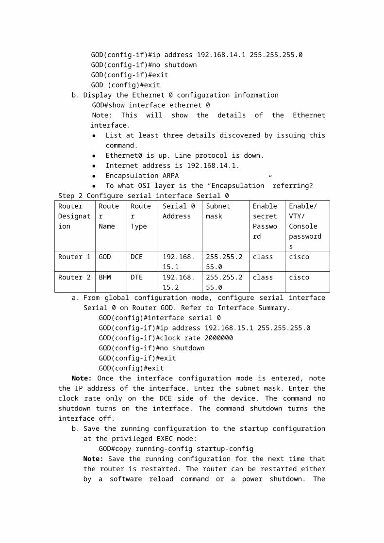
passive-interface serial 0. This will prevent the GOD router from advertising its routes to the BHM router.
b. To confirm this, use the debug ip rip events command on the GOD router. Verify from the output that the router is not sending updates out the interface to the BHM router.
c. Disable the debug output with the no debug all command.d. Also from the BHM router, issue the show ip route to verify that the route to the GOD
LAN has been removed.e. Attempt to ping from the computers in GOD to the computers in BHM. What is the
response?f. Confirm that the BHM router is still sending update to GOD. To do this, use the debug ip
rip events command on the BHM router. Verify from the output that the router is sending updates out the interface to the GOD router.
g. Disable the debug output with the no debug all command.h. Restore the routing updates from GOD to BHM by entering no passive-interface serial
0.i. Exit to the privileged EXEC mode. Wait for at least 45 seconds. Check the routing tables
by entering show ip route command. Make sure that routing updates are being sent by typing debug ip rip events and no debug all command.
Step 10 Perform erase and reload steps on all routersStep 11 Configure the routersRouter Designation
Router Name
Ethernet 0 address
Interface Type Serial 0
Serial 0 Address
Subnet mask all addresses
Enable secret Password
Enable/VTY/Console passwords
Router 1 GOD 192.168.20.1 DCE 192.168.22.1 255.255.255.0 class ciscoRouter 2 BHM 192.168.25.1 DTE 192.168.22.2 255.255.255.0 class cisco
From the global configuration mode, configure the hostname as shown in the chart. Then configure the console, virtual terminal, and enable passwords. If there is a problem doing this, refer to the configuring router passwords lab. Next, configure the interfaces according to the chart. Refer to the Configuring Interfaces lab for assistance.Step 12 Configure the routing protocol on the GOD router and BHM router
a. Configure IGRP using AS 101 on GOD. Go to the proper command mode and enter the following:GOD(config)#router igrp 101GOD(config-router)#network 192.168.22.0GOD(config-router)#network 192.168.20.0GOD(config-router)#exitGOD(config)#exitGOD#copy running-config startup-config
b. Configure IGRP using AS 101 on BHM. Go to the proper command mode and enter the following:BHM(config)#router igrp 101BHM(config-router)#network 192.168.25.0BHM(config-router)#network 192.168.22.0

BHM(config-router)#exitBHM(config)#exitBHM#copy running-config startup-config
Step 13 Configure the hosts with the proper IP address, subnet mask and default gatewayStep 14 Verify that the internetwork is functioning by pinging the Ethernet interface of the other router
a. From the host attached to GOD, is it possible to ping the BHM router Ethernet interface?b. From the host attached to BHM, is it possible to ping the GOD router Ethernet interface?c. If the answer is no for either question, troubleshoot the router configurations to find the
error. Then do the pings again until the answer to both questions is yes.Step 15 Show the routing tables for each router
From the enable or privileged EXEC mode, examine the routing table entries using the show ip route command on each router.Step 16 Verify IGRP routing updates
a. Type debug ip igrp events on the GOD router at the privileged exec mode.b. Are routing updates being displayed?c. Where are the updates being sent to?d. Where are the updates being received from?e. Turn off debugging.
Step 17 Analyze specific routesa. Type show ip route 192.168.25.0 on the GOD router at the privileged exec modeb. What is the total delay for this route?c. What is the minimum bandwidth?d. What is the Reliability of this route?e. What is the minimum MTU size for this route?f. Type show ip route 192.168.25.1 on the BHM router at the privileged EXEC mode.g. What is the total delay for this route? h. What is the minimum bandwidth?i. What is the Reliability of this route?j. What is the minimum MTU size for this route?
Step 18 Load Balancing Across Multiple Paths with RIPAdd a new serial line to connect the routers. Erase the configuration file and reload the
routers.
Router Router Name
Ethernet 0 address
Interface Type
Serial 0 Address
Serial 1 Address
Subnet mask all addresses
Enable secret
Enable/VTY/Console
Serial 0 Password passwordsRouter 1 GOD 192.168.14.1 DCE 192.168.15.1 192.168.13.1 255.255.255.0 class ciscoRouter 2 BHM 192.168.16.1 DTE 192.168.15.2 192.168.13.2 255.255.255.0 class cisco
Step 19 Configure the hostname and passwords on the routersOn the routers, enter the global configuration mode and configure the hostname as shown in
the chart. Then configure the console, virtual terminal, and enable passwords. If there are problems doing this, refer to the Configuring Router Passwords lab. Next configure the interfaces and routing according to the chart. If there are problems doing this, refer to the Configuring Interfaces lab and the Configuring RIP lab. Make sure to copy the running-config to the startup-config on each router so the configuration will not be lost if the router is powercycled.Step 20 Configure the hosts with the proper IP address, subnet mask and default gateway
Test the configuration by pinging all interfaces from each host. If the pinging is not successful troubleshoot the configuration.Step 21 Check Basic Routing Configuration
a. Enter show ip protocol command on each router.b. In the configuration, is "Routing protocol is RIP" displayed?c. Enter the command show ip route on both routers. List how the route is connected
(directly, RIP), the IP address and via through what network. There should be four routes in each table.
Step 22 Make sure that the router load balance is on a per-packet basisa. Configure the router to load balance on a per-packet basis. Both serial interfaces must
use process switching. Process switching forces the router to look in the routing table for the destination network of each routed packet. In contrast, fast-switching, which is the default, stores the initial table lookup in a high-speed cache and uses the information to route packets to the same destination.
b. Enable process switching on both serial interfaces:GOD(config-if)# no ip route-cacheBHM(config-if)# no ip route-cache
c. Verify that fast switching is disabled by using the show ip interface command.d. Was fast switching disabled? Yes
Step 23 Verify per-packet load balancinga. Because there are two routes to the destination network, half the packets will be sent
along one path, and half will travel over the other. The path selection alternates with each packet received.
b. Observe this process by using the debug ip packet command on the GOD.c. Send 30 ping packets across the network from the host attached to BHM router to the
host attached to the GOD router. This can be done with the ping 192.168.16.2 – n 30 command on the host. As the pings are responded to the router generates IP packet information. Stop the debug by using the command undebug all on the GOD router.
d. Examine and record part of the debug output.e. What is the evidence of load balancing in the output?
Step 24 Verify per-destination load balancinga. After verifying per-packet load balancing, configure the router to use per-destination
load balancing. Both serial interfaces must use fast switching so that the route-cache can be used after the initial table lookup.
b. Use the command:GOD(config-if)#ip route-cache.
c. Use the show ip interface to verify that fast switching is enabled.d. Is fast switching enabled? e. The routing table is consulted only once per destination, therefore, packets that are part
of a packet train to a specific host will all follow the same path. Only when a second destination forces another table lookup or when the cached entry expires will the alternate path be used. Use the debug ip packet command and ping across the network. Note which serial interface the packet was sent out on.
f. Examine and record part of the debug output. Which serial interface was the packet sent out on?
Step 25 Load Balancing Across Multiple Paths with IGRPThe same environment to the Step 18. Erase the configuration file and reload the routers.
Step 26 Configure the hostname and passwords on the routersOn the routers, enter the global configuration mode and configure the hostname as shown in
the chart. Then configure the console, virtual terminal, and enable passwords. If there are problems doing this, refer to the Configuring Router Passwords lab. Next configure the interfaces and routing according to the chart. If there are problems doing this, refer to the Configuring Interfaces lab and the Configuring IGRP lab. Make sure to copy the running-config to the startup-config on each router so the configuration will not be lost if the router is powercycled.Step 27 Configure bandwidth on the GOD router interfaces
a. In order to make unequal cost load balancing to work, it is necessary need to establish different metrics for the IGRP routes. This is done with the bandwidth command. The serial 0 interface will be set to a bandwidth of 56K and the serial 1 interface will be set to a value of 384K. The route-cache must also be turned off for load balancing. Both serial interfaces must use process switching. Process switching forces the router to look in the routing table for the destination network of each routed packet. In contrast fast-switching, which is the default, stores the initial table lookup in a high-speed cache and uses the info to route packets to the same destination.Enter the following statements on the GOD router:
GOD(config)#interface serial 0/0GOD(config-if)#bandwidth 56GOD(config-if)#no ip route-cacheGOD(config-if)#interface serial 0/1GOD(config-if)#bandwidth 384GOD(config-if)#no ip route-cache
b. Because the IGRP metric includes bandwidth in its calculation, bandwidth must be manually configured on the serial interfaces in order to ensure accuracy. For the purposes of this lab, the alternative paths to network 192.168.16.0 from the GOD router are not of unequal cost until the appropriate bandwidths are set.
c. Use the show interface command output to verify the correct bandwidth settings and the show ip interface command to ensure that fast switching is disabled.

d. Can the bandwidth of Ethernet interfaces be set manually?Step 28 Configure the hosts with the proper IP address, subnet mask and default gateway
Test the configuration by pinging all interfaces from each host. If the pinging is not successful, troubleshoot the configuration.Step 29 Use the variance command to configure unequal-cost load balancing
a. The variance value determines whether IGRP will accept unequal-cost routes. An IGRP router will only accept routes equal to the local best metric for the destination multiplied by the variance value. So if the local best metric of an IGRP router for a network is 10476, and the variance is 3, the router will accept unequal-cost routes with any metric up to 31428 or 10,476 x 3. This is as long as the advertising router is closer to the destination. An IGRP router accepts only up to four paths to the same network.Note: An alternate route is added to the route table only if the next-hop router in that path is closer to the destination (has a lower metric value) than the current route.
b. By default, IGRP variance is set to 1, which means that only routes that are exactly 1 times the local best metric are installed. Therefore, a variance of 1 disables unequal-cost load balancing.
c. Configure the GOD router to enable unequal-cost load balancing using the following commands:
GOD(config)#router igrp 101GOD(config-router)#variance 10
d. According to the help feature, what is the maximum variance value?e. Check the GOD routing table. It should have two routes to network 192.168.16.0 with
unequal metrics.f. What is the IGRP metric for the route to 192.168.16.0 through serial 0? g. What is the IGRP metric for the route to 192.168.16.0 through serial 1?
Step 30 Check Basic Routing Configurationa. Enter show ip protocol command on each router.b. Enter the command show ip route on both routers. List how the route is connected
(directly, IGRP), the IP address and via through what network. There should be four routes in each table.
Step 31 Verify per-packet load balancinga. Because there are two routes to the destination network, half the packets will be sent
along one path, and half will travel over the other. The path selection alternates with each packet received.
b. Observe this process by using the debug ip packet command on the GOD router.c. Send a 30 ping packets across the network from the host attached to BHM router to the
host attached to the GOD router. This can be done with the with the ping 192.168.14.2 – n 30 command on the host. As the pings are responded to, the router outputs IP packet information. Stop the debug after the pings by using the command undebug all.
d. Examine and record part of the debug output.e. What is the evidence of load balancing in the output?
Step 32 Verify per-destination load balancinga. After verifying per-packet load balancing, configure the router to use per-destination
load balancing. Both serial interfaces must use fast switching so that the route-cache can

be used after the initial table lookup.b. Use the command ip route-cache on both serial interfaces of the GOD router.c. Use the show ip interface to verify that fast switching is enabled.d. Is fast switching enabled? The routing table is consulted only once per destination.
Therefore, packets that are part of a packet train to a specific host will all follow the same path. Only when a second destination forces another table lookup or when the cached entry expires will the alternate path be used.
e. Use the debug ip packet command and ping across the network. Note which serial interface the packet was sent out on.
f. Examine and record part of the debug output.g. Which serial interface was the packet sent out on?
Upon completion of the previous steps, logoff by typing exit. Turn the router off.
Some Basic and Useful Troubleshooting Commandsa. Make sure the physical connections are all right.b. Ping command can test the Layer 3 connection.c. Telnet command can test the Layer 7 connection.d. Traceroute command can test the Layer 3 connection.e. Show command can gather some important information. For example, show ip route,
show ip protocol, show interfaces, show running-configf. Debug command can receive the real-time information from the console screen.

Lab Set 4 (Students do it at their own PC by RouterSim
software)
P.S. The command will be differ from the real switches, but
the switching work mode will be familiar.Lab 4.1 Basic Configuration of switch
ObjectiveInvestigate the default configuration of a 2900 series switch.Create a basic switch configuration.Manage the switch MAC table.Create and verify a basic switch configuration.Configure port security on individual FastEthernet ports.Backup the switch IOS to a TFTP server and then restore it.Backup the switch startup configuration file to a TFTP server and then restore it.Change passwords and use the password recovery procedure.Upgrade the IOS and HTML files from a file supplied by the instructor.
Background/Preparation
Switch Designation Switch Name Enable Secret Password
Enable, VTY and Console Password
Switch 1 ALSwitch class ciscoCable a network similar to the one in the diagram. The configuration output used in this lab is
produced from a 2950 series switch. Any other switch used may produce different output. The following steps are to be executed on each switch unless specifically instructed otherwise. Instructions are also provided for the 1900 Series switch, which initially displays a User Interface Menu. Select the “Command Line” option from the menu to perform the steps for this lab.
Start a HyperTerminal session as performed in the Establishing a HyperTerminal session lab.Note: Perform erase and reload steps on all routers in this lab assignment before continuing.
General Configuration Tips Using the question mark (?) and arrow keys to help enter commands. Each command mode restricts the set of available commands. If there is difficulty entering a
command, check the prompt and then enter the question mark (?) for a list of available commands. The problem might be a wrong command mode or using the wrong syntax.
To disable a feature, enter the keyword no before the command, for example, no ip address.

Save the configuration changes to NVRAM so that the changes are not lost if there is a system reload or power outage.
Step 1 Enter privileged modea. Privileged mode gives access to all the switch commands. Many of the privileged
commands configure operating parameters. Therefore, privileged access should be password-protected to prevent unauthorized use. The privileged command set includes those commands contained in user EXEC mode, as well as the configure command through which access to the remaining command modes are gained.
Switch>enableSwitch#
b. Notice the prompt changed in the configuration to reflect privileged EXEC mode.Step 2 Examine the current switch configuration (1900: perform a, b and k)
a. Examine the current running configuration file.Switch#show running-config
b. How many Ethernet or Fast Ethernet interfaces does the switch have?c. What is the range of values shown for the VTY lines?d. Examine the current contents of NVRAM as follows:
Switch#show startup-config%% Non-volatile configuration memory is not present
e. Why does the switch give this response?f. Issue the following to show the current IP address of the switch.
Switch#show interface VLAN 1g. Is there an IP address set on the switch?h. What is the MAC address of this virtual switch interface?i. Is this interface up?j. The IP properties of the interface can be shown by entering following the command:
Switch#show ip interface VLAN 1k. The following commands will provide the switch IP address information for the 1900:
#show ipStep 3 Display IOS information
a. Examine the following version information that the switch reports.Switch#show version
b. What is the IOS version that the switch is running?c. What is the system image file name?d. What is the base MAC address of this switch?e. Is the switch running enterprise edition software? (1900 series)f. Is the switch running Enhanced Image software, indicated by the letters "EA" in the IOS
file name? (2950 series)Step 4 Examine the Fast Ethernet interfaces
a. Examine the default properties of the Fast Ethernet interfaces. As an example examine the properties of the fourth interface:1900:
#show interface fastethernet 0/26 (Note: this is a trunk port)Or

#show interface ethernet 0/4 (Note: this is an access port)2950:
#show interface fastethernet 0/4 (Note: this can be a trunk or access port)Or#show interface gigabitethernet 0/1 (Note: this can be a trunk or access port)
b. Is the interface up or down?c. What event would make an interface go up?d. What is the MAC address of the interface?e. What is the speed and duplex setting of the interface?
Step 5 Examine VLAN informationa. Examine the following default VLAN settings of the Switch
Switch>show vlanb. What is the name of VLAN 1?c. Which ports are in this VLAN?d. Is VLAN 1 active?e. What type of VLAN is the default VLAN?
Step 6 Examine Flash memory (1900: Skip)a. Issue one of the following to examine the contents of the flash directory
Switch#dir flash:orSwitch#show flash
b. Name the files and directories found?Step 7 Examine the startup configuration file
a. To see the contents of the startup configuration file, type the show startup-config command in privileged EXEC mode as follows:Switch#show startup-config
b. The switch responds with:Non-volatile configuration memory is not present
c. Why does this message appear?d. Copy the following configuration to NVRAM.
Note: This step ensures any changes made will be available to the switch if there is a reload or the power goes off.
Switch#copy running-config startup-configDestination filename [startup-config]?Building configuration...[OK]Switch#
e. Issue the following to show the contents of NVRAM.Switch#show startup-config
f. What is displayed now?Step 8 Assign a name to the switch
a. Enter enable and then the configuration mode. The configuration mode allows the management of the switch. Enter ALSwitch, the name this switch will be referred to in the following:

Switch#configure terminalEnter the configuration commands, one for each line. End by pressing Ctrl-Z.Switch(config)#hostname ALSwitchALSwitch(config)#exit
b. Notice the prompt changed in the configuration to reflect its new name. Type exit or press Ctrl-Z to go back into privileged mode.
Step 9 Examine the current running configurationa. Exam the current configuration that follows to verify that there is no configuration
except for the hostname:ALSwitch#show running-config
b. Are there any passwords set on the lines? (Note: There are no VTY lines on the 1900.)c. What does the configuration show as the hostname of this switch?
Step 10 Set the access passwords (1900: Skip)Enter config-line mode for the console. Set the password on this line as cisco for login.
Configure the vty lines 0 to 15 with the password cisco as follows:ALSwitch#configure terminalEnter the configuration commands, one for each line. End by pressing Ctrl-Z.ALSwitch(config)#line con 0ALSwitch(config-line)#password ciscoALSwitch(config-line)#loginALSwitch(config-line)#line vty 0 15ALSwitch(config-line)#password ciscoALSwitch(config-line)#loginALSwitch(config-line)#exit
Step 11 Set the command mode passwordsa. Set the enable password to cisco and the enable secret password to class as follows:
2950:ALSwitch(config)#enable password ciscoALSwitch(config)#enable secret class
1900:ALSwitch(config)#enable password level 15 ciscoALSwitch(config)#enable secret class
b. Which password takes precedence, the enable password or enable secret password?Step 12 Configure the layer 3 access to the switch
a. Set the IP address of the switch to 192.168.1.2 with a subnet mask of 255.255.255.0 as follows:Note: This is done on the internal virtual interface VLAN 1.
ALSwitch(config)#interface VLAN 1ALSwitch(config-if)#ip address 192.168.1.2 255.255.255.0ALSwitch(config-if)#exit
1900:ALSwitch(config)#ip address 192.168.1.2 255.255.255.0ALSwitch(config)#exit
b. Set the default gateway for the switch and the default management VLAN to 192.168.1.1

as follows:ALSwitch(config)#ip default-gateway 192.168.1.1ALSwitch(config)#exit
1900:ALSwitch(config)#ip default-gateway 192.168.1.1ALSwitch(config)#exit
Step 13 Verify the management LANs settings (1900: Skip)Note to instructor: if 1900 is used, please skip to the next step.a. Verify the interface settings on VLAN 1 as follows:
ALSwitch#show interface VLAN 1b. What is the bandwidth on this interface?c. What are the VLAN states:d. Enable the virtual interface using the no shutdown command
ALSwitch(config)#interface VLAN 1ALSwitch(config-if)#no shutdownALSwitch(config-if)#exit
e. What is the queuing strategy?Step 14 Save the configuration
a. The basic configuration of the switch has just been completed. Back up the running configuration file to NVRAM as follows:
Note: This will ensure that the changes made will not be lost if the system is rebooted or loses power.
ALSwitch#copy running-config startup-configDestination filename [startup-config]?[Enter]Building configuration...[OK]ALSwitch#
1900:b. The configuration is automatically saved to NVRAM within approximately one minute
of entering a command. To save the configuration to a TFTP server, enter the following:ALSwitch#copy nvram tftp://tftp server ip add/destination_filename
c. Configuration upload is successfully completed.Step 15 Examine the startup configuration file (1900: Skip)
a. To see the configuration that is stored in NVRAM, type show startup-config from the privileged EXEC (enable mode).ALSwitch#show startup-config
b. What is displayed?c. Are all the changes that were entered recorded in the file?
Step 16 Record the MAC addresses of the hosta. Determine and record the layer 2 addresses of the PC network interface cards.
If running Windows 98, check by using Start > Run > winipcfg, then click on More info.If running Windows 2000, check by using Start > Run > cmd > ipconfig /all.
b. PC1: c. PC4:

Step 17 Determine the MAC addresses that the switch has learneda. To determine the MAC addresses the switch has learned, use the show mac-address-table
command as follows at the privileged EXEC mode prompt:ALSwitch#show mac-address-table
b. How many dynamic addresses are there?c. How many total MAC addresses are there?d. How many addresses have been user defined?e. Do the MAC addresses match the host MAC addresses?
Step 18 Determine the show MAC table optionsa. To determine the options the show mac-address-table command has use the ? option as
follows:ALSwitch#show mac-address-table ?How many options are available for the show mac-address-table command?
b. Show only the MAC addresses from the table that were learned dynamically.c. How many are there?
Step 19 Clear the MAC address tableTo remove the existing MAC addresses use the clear mac-address-table command from the
privileged EXEC mode prompt as follows:ALSwitch#clear mac-address-table dynamic
Step 20 Determine the show MAC table optionsa. To determine the options the mac-address-table command has use the ? option as
follows:ALSwitch(config)#mac-address-table ?
b. How many options are available for the mac-address-table command?c. There is an option to set a static MAC address in the table. Under what circumstances
would this option be utilized?Step 22 Setup a static MAC address
Setup a static MAC address on Fast Ethernet interface 0/4 as follows:Note: Use the address that was recorded for PC4. The MAC address is used in the example
statement only.ALSwitch(config)#mac-address-table static 00e0.2917.1884 interface fastethernet 0/4 vlan 12900:
ALSwitch(config)#mac-address-table static 00e0.2917.1884 fastethernet 0/4 vlan 11900:
ALSwitch(config)#mac-address-table permanent 00e0.2917.1884 ethernet 0/4Step 23 Verify the results
a. Enter the following to verify the mac–address table entries.ALSwitch#show mac-address-table
b. How many total MAC addresses are there now?c. How many static addresses are there?d. Under what circumstances can other static or dynamic learning of addresses occur on
switchport 4?Step 24 Remove the static MAC entry
The static mac-address-table entry may need to be reversed. To do this, enter the

configuration mode and reverse the command by putting a no in front of the entire old command string as follows:
Note: The MAC address 00e0.2917.1884 is used in the example statement only, use the MAC address that was recorded for the host on port 0/4.ALSwitch(config)#no mac-address-table static 00e0.2917.1884 interface fastethernet 0/4 vlan 1
2900:ALSwitch(config)#no mac-address-table static 00e0.2917.1884 fastEthernet 0/4 vlan 1
1900:ALSwitch(config)#no mac-address-table permanent 00e0.2917.1884 ethernet 0/4
Step 25 Verify the resultsa. Enter the following to verify that the static MAC address was cleared:
ALSwitch#show mac-address-table staticb. How many total static MAC addresses are there now?
Step 26 List port security optionsa. Determine the options for setting port security on interface FastEthernet 0/4.
1900:ALSwitch(config)#interface ethernet 0/4ALSwitch(config-if)#port secure ?max-mac-count Maximum number of addresses allowed on the port<cr>
2950:ALSwitch(config-if)#switchport port-security ?aging Port-security aging commandsmac-address Secure mac addressmaximum Max secure addrsviolation Security Violation Mode<cr>
b. To allow the switchport FastEthernet 0/4 to accept only one device enter port security as follows:
ALSwitch(config-if)#switchport mode accessALSwitch(config-if)#switchport port-securityALSwitch(config-if)#switchport port-security mac-address sticky
1900:ALSwitch(config-if)#port secure
Step 27 Verify the resultsa. Enter the following to verify the mac–address table entries:
ALSwitch#show mac-address-tableb. How are the address types listed for the two MAC addresses?c. Show port security settings.
ALSwitch#show port-security1900:
ALSwitch#show mac-address-table securityStep 28 Show the running configuration file
a. Are there statements that directly reflect the security implementation in the listing of the

running configuration?b. What do those statements mean?
Step 29 Limit the number of hosts per porta. On interface FastEthernet 0/4 set the port security maximum MAC count to 1 as follows:
1900:ALSwitch(config)#interface Ethernet 0/4ALSwitch(config-if)#port secure max-mac-count 1
2950:ALSwitch(config-if)#switchport port-security maximum 1
b. Disconnect the PC attached to FastEthernet 0/4. Connect to the port on the PC that has been given the IP address 192.168.1.7. This PC has not yet been attached to the switch. It may be necessary to ping the switch address 192.168.1.2 to generate some traffic.
c. Record any observations.Step 30 Configure the port to shut down if there is a security violation
a. It has been decided that in the event of a security violation the interface should be shut down.Enter the following to make the port security action to shutdown:2950:
ALSwitch(config-if)#switchport port-security violation shutdown2900XL:
ALSwitch(config-if)#port security action shutdown1900:
The default action upon address violation is “suspend”b. What other action options are available with port security?c. If necessary, ping the switch address 192.168.1.2 from the PC 192.168.1.7. This PC is
now connected to interface FastEthernet 0/4. This ensures that there is traffic from the PC to the switch.
d. Record any observations.Step 31 Show port 0/4 configuration information
a. To see the configuration information for just FastEthernet port 0/4, type show interface fastethernet 0/4, as follows, at the Privileged EXEC mode prompt:
ALSwitch#show interface fastethernet 0/41900:
ALSwitch#show interface ethernet 0/4b. What is the state of this interface?
1900:ALSwitch#show interface ethernet 0/4
c. What is the state of this interface?Step 32 Reactivate the port
a. If a security violation occurs and the port is shut down, use the no shutdown command to reactivate it.
b. Try reactivating this port a few times by switching between the original port 0/4 host and the new one. Plug in the original host, type the no shutdown command on the interface and ping using the DOS window. The ping will have to be repeated multiple times or use
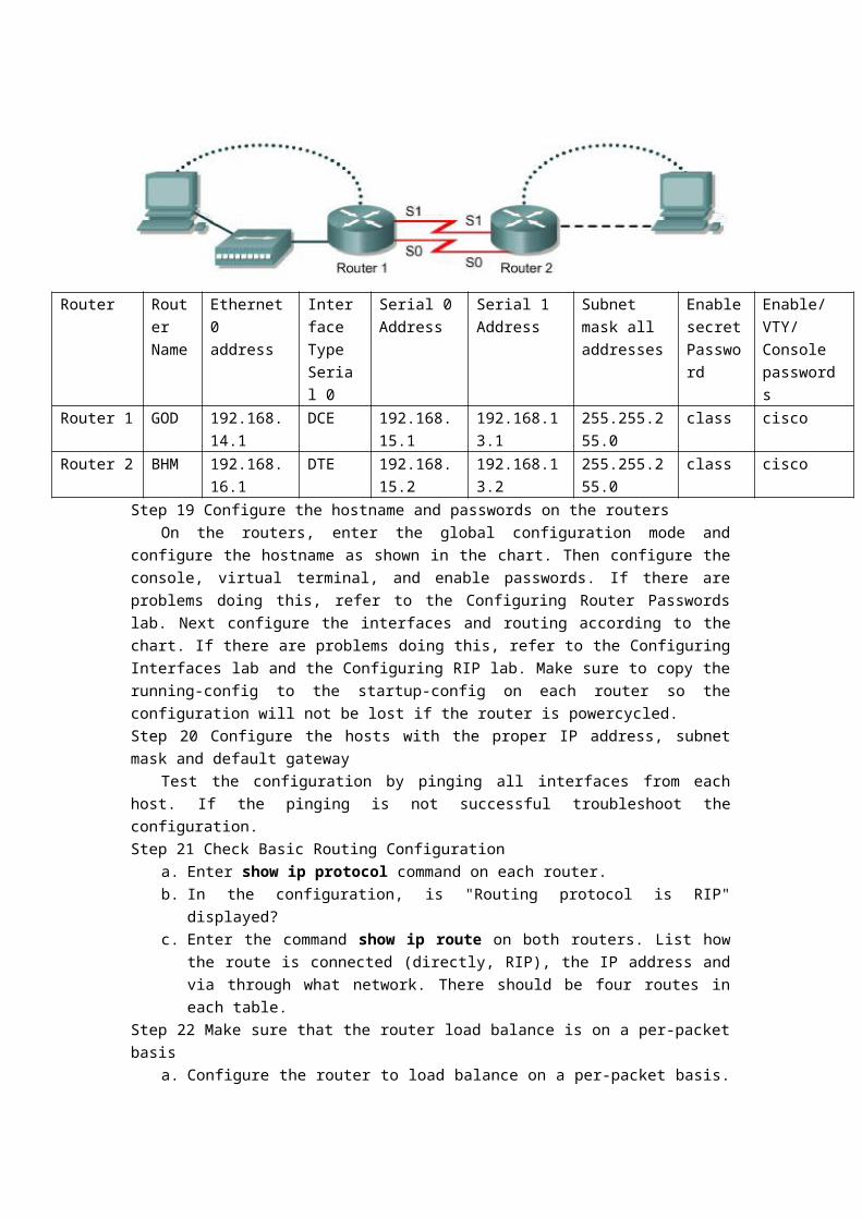
the ping 192.168.1.2 –n 200 command. This will set the number of ping packets to 200 instead of 4. Then switch hosts and try again.
Step 33 Move hosta. Take the PC that had previously been connected to Fast Ethernet 0/4 and reconnect it to
Fast Ethernet 0/8. The PC has been moved to a new location. This could be to another VLAN but in this instance all switch ports are in VLAN 1 and network 192.168.1.0.
b. From this PC on Fast Ethernet 0/8, ping 192.168.1.2 –n 50c. Was the ping successful?d. Why or why not?e. Enter the following to show the mac-address-table.
ALSwitch#show mac-address-tablef. Record observations about the show output.
Step 34 Clear MAC tablea. Enter the following to clear the mac-address-table:
Note: This will unlock the MAC addresses from security and allow a new address to be registered.
ALSwitch#clear mac-address-table dynamicb. From the PC on the Fast Ethernet 0/8, ping 192.168.1.2 –n 50.c. Was the ping successful?d. If not troubleshoot as necessary.
Step 35 Change security settingsa. Enter the following to show the mac-address-table:
ALSwitch#show mac-address-tableb. Notice that Fast Ethernet 0/4 is secure. However, that security should be applied to the
machine on port 0/8, as this is the machine that was moved from port 0/4. Remove port security from interface Fast Ethernet 0/4 as follows:
ALSwitch(config)#interface fastethernet 0/4ALSwitch(config-if)#no switchport port-security mac-address sticky 0008.744d.8ee2
ALSwitch(config-if)#shutdownALSwitch(config-if)#no shutdown
1900:ALSwitch(config)#interface ethernet 0/4ALSwitch(config-if)#no port secure
c. Apply port security with a max-mac-count of 1 to interface Fast Ethernet 0/8 as follows:ALSwitch(config)#interface fastethernet 0/8ALSwitch(config-if)#switchport mode accessALSwitch(config-if)#switchport port-security mac-address stickyALSwitch(config-if)#switchport port-security maximum 1
1900:ALSwitch(config)#interface ethernet 0/8ALSwitch(config-if)#port secure max-mac-count 1
d. Enter the following to clear the mac-address-table.Note: Clearing individual entries could have also been done.
ALSwitch#clear mac-address-table

Step 36 Verify the resultsa. Verify that the mac-address-table has been cleared.
ALSwitch#show mac-address-tableb. Can all PCs still successfully ping each other?c. If not troubleshoot the switch and PCs.
Step 37 Starting and configuring the Cisco TFTP servera. The TFTP server may not be like the one that is used in this classroom. Please check with
the instructor for the operating instructions for the TFTP server used in place of the Cisco TFTP server.
b. Once the TFTP server is running and shows the correct address configuration on the workstation, copy the IOS file to the switch.
Step 38 Copying IOS to the TFTP server (1900: Skip)a. Verify that the TFTP server is running and that it can be pinged from the switch.b. What is the IP address of the TFTP server?c. From the console session, enter show flash.d. What is the name and length of the Cisco IOS image stored in flash?e. What attributes can be identified from the codes in the Cisco IOS filename?f. From the console session in the Privileged EXEC mode, enter the copy flash tftp
command. At the prompt enter the IP address of the TFTP server.g. 1900: (download only)
Step 39 Verify the transfer to the TFTP servera. Verify the transfer to the TFTP server by checking the log file.b. Verify the flash image size in the TFTP server directory. To locate it click on View >
Options. This will show the TFTP server root directory. It should be similar to the following, unless the default directories were changed.
C:\Program Files\Cisco Systems\Cisco TFTP Serverc. Locate this directory using the File Manager and look at the detail listing of the file. The
file length in the show flash command should be the same file size as the file stored on the TFTP server. If the file sizes are not identical in size, check with the instructor.
Step 40 Copying IOS from the TFTP servera. Now that the IOS is backed up, the image must be tested and the IOS must be restored to
the switch. Verify again that the TFTP server is running, sharing a network with the switch and can be reached by pinging the TFTP server IP address.
b. Record the IP address of the TFTP server. c. Now start the actual copying, from the privileged EXEC prompt.
Note: It is important that this process is not interrupted.d. The switch may prompt for an overwrite flash. Will the image fit in available flash?e. What is the size of the file being loaded?f. What happened on the switch console screen as the file was being downloaded?g. Was the verification successful?h. Was the whole operation successful?
Step 41 Upgrading Catalyst 1900 Firmware with a TFTP Servera. Select option “F” to go to the Firmware Configuration menu from the main menu.b. Copy the switch firmware file to the TFTP server.

c. Select option “S” from the Firmware Configuration menu and enter the IP address of the server where the switch upgrade file is located.
d. Select option “F” from the Firmware Configuration menu and enter the name of the firmware upgrade file.
e. Select '”T” from the Firmware Configuration menu to initiate the upgrade.f. Verify the upgrade is in progress by checking the Upgrade status section of the Firmware
Configuration menu. If the upgrade is in progress, the field reads "in-progress".g. When the transfer is complete, the switch resets automatically and executes the newly
downloaded firmware.Caution: During the transfer of the upgrade file, the switch might not respond to
commands for as long as 1 minute. This is normal and correct. The firmware could be corrupted if the transfer is interrupted by turning the switch off and on.
Step 42 Test the restored IOS imageVerify that the switch image is correct. To do this, cycle the switch power and observe the
startup process to confirm that there were no flash errors. If there are none then the IOS on the switch should have started correctly. Also to further verify IOS image in flash, issue the show version command which will show output similar to the following:
System image file is "flash:c2950-c3h2s-mz.120-5.3.WC.1.bin"Step 43 Copying the startup configuration file to TFTP server
a. Verify that the TFTP server is running and that it can be pinged from the switch.b. What is the IP address of the TFTP server? c. From the console session, enter show flash.
2900:dir flash:
1900:(command not available)
d. What is the name and length of the startup configuration image stored in flash?e. From the console session in the Privileged EXEC mode, enter the copy running-config
startup-config command, to make sure that the running configuration file is saved to the startup configuration file. Then type the copy startup-config tftp command. At the prompt enter the IP address of the TFTP server as follows:
ALSwitch#copy running-config startup-configDestination filename [startup-config]?[enter]Building configuration...[OK]ALSwitch#copy start tftpAddress or name of remote host []? 192.168.1.3Destination filename [alswitch-confg]?[enter]!!744 bytes copied in 1.60 secs (744 bytes/sec)ALSwitch#
1900:ALSwitch#copy nvram tftp://192.168.1.3/alswitch-config
Configuration upload is successfully completed

Step 44 Verify the transfer to the TFTP servera. Verify the transfer to the TFTP server by checking the log file.b. Verify the flash image size in the TFTP server directory. To locate it click on View >
Options. This will show the TFTP server root directory. The output should be similar to the following, unless the default directories were changed:
C:\Program Files\Cisco Systems\Cisco TFTP Serverc. Locate this directory using the File Manager and look at the detail listing of the file. The
file length in the show flash command should be the same file size as the file stored on the TFTP server. If the file sizes are not identical in size, check with the instructor.
Step 45 Restore the startup configuration file from the TFTP servera. To restore the startup configuration file, first the switch must be erased. Then reconfigure
the switch with just the VLAN 1 IP address of 192.168.1.2 255.255.255.0. Finally type the command copy tftp startup-config at the Privileged EXEC mode prompt as shown in the following:
Switch#copy tftp startup-configAddress or name of remote host []? 192.168.1.10Source filename []? alswitch-confgDestination filename [startup-config]? Accessingtftp://192.168.1.10/alswitch-confg...Loading alswitch-confg .from 192.168.1.10 (via Vlan1): ![OK - 1622 bytes][OK]1622 bytes copied in 22.796 secs (71 bytes/sec)Switch#
Note: It is important that this process is not interrupted.Was the operation successful?1900:
ALSwitch#copy tftp://192.168.1.3/alswitch-config nvramTFTP successfully downloaded configuration file
Step 46 Test the restored startup configuration image (Not supported on the 1900)Verify that the switch image is correct. To do this, cycle the switch power and observe the
switch prompt. If it has returned to the name that was assigned to it in the original configuration, the restoration is complete. Type the command show startup-config to see the restored configuration.Step 47 Reset the console password
a. Have a classmate change the console and VTY passwords on the switch. Save the changes to the startup-config file and reload the switch.
b. Now without knowing the passwords, try to gain access to the switch.Step 47 Recover access to the switch (2900XL is essentially the same)
a. Make sure that a PC is connected to the console port and a HyperTerminal window is open.
b. Turn the switch off. Turn it back on while holding down the “MODE” button on the front of the switch at the same time that the switch is powered on. Release the “MODE” button after the STAT LED goes out.

c. The following output should be displayed:C2950 Boot Loader (C2950-HBOOT-M) Version 12.1(11r)EA1, RELEASESOFTWARE (fc1)Compiled Mon 22-Jul-02 18:57 by antoninoWS-C2950-24 starting...Base ethernet MAC Address: 00:0a:b7:72:2b:40Xmodem file system is available.The system has been interrupted prior to initializing the flash files system. The
following commands will initialize the flash files system, and finish loading the operating system software:
flash_initload_helperboot
d. To initialize the file system and finish loading the operating system enter the following commands:
flash_initload_helperdir flash:
Note: Do not forget to type the colon (:) after the word “flash” in the command dir flash:. e. Type rename flash:config.text flash:config.old to rename the configuration file. This
file contains the password definition.Step 48 Restart the system
a. Type boot to boot the system.b. Enter N at the following prompt to start the Setup program:
Continue with the configuration dialog? [yes/no] : Nc. Type rename flash:config.old flash:config.text to rename the configuration file with its
original name at the Privileged EXEC mode prompt.d. Copy the configuration file into memory as follows:
Switch#copy flash:config.text system:running-configSource filename [config.text]?[enter]Destination filename [running-config][enter]
e. The configuration file is now reloaded. Change the old unknown passwords as follows:ALSwitch#configure terminalALSwitch(config)#no enable secretSwitch(config)#enable secret classALSwitch(config)#line console 0ALSwitch(config-line)#password ciscoALSwitch(config-line)#exitALSwitch(config)#line vty 0 15ALSwitch(config-line)#password ciscoALSwitch(config-line)#exitALSwitch(config)#exitALSwitch#copy running-config startup-config

Destination filename [startup-config]?[enter]Building configuration...[OK]ALSwitch#
f. Power cycle the switch and verify that the passwords are now functional. If not, repeat the procedure.
Step 49 Procedure for the 1900 and 2800 switchesa. Check the boot firmware version number from the Systems Engineering menu. To access
the Systems Engineering menu, follow the procedure below:1. Disconnect the power cord from the rear panel.2. Press and hold the Mode button on the front panel.3. Power-cycle the switch.4. Release the Mode button one or two seconds after LED above port 1x goes off
or when the diagnostic console is displayed.Cisco Systems Diagnostic ConsoleCopyright(c) Cisco Systems, Inc. 1999All rights reserved.Ethernet Address: 00-E0-1E-7E-B4-40-------------------------------------------------Press Enter to continue.
5. Press Enter to display the Diagnostic Console - Systems Engineering menu.The following Systems Engineering menu will display:
Diagnostic Console - Systems EngineeringOperation firmware version: 8.00.00 Status: validBoot firmware version: 3.02[C] Continue with standard system start up[U] Upgrade operation firmware (XMODEM)[S] System Debug InterfaceEnter Selection:
6. The bold letters above show the Boot firmware version.b. Clearing the Password (Firmware Version 1.10 and Later).
To clear the password, follow the steps below:1. Power-cycle the switch.
After POST completes, the following prompt displays:Do you wish to clear the passwords? [Y]es or [N]o:
Note: The student will have ten seconds to respond. If a response is not made within that time, the Management Console Logon screen displays. This waiting period cannot be changed.2. Enter [Y]es to delete the existing password from Nonvolatile RAM (NVRAM).
Note: If you type [N]o, the existing password remains valid.3. Assign a password from the switch management interfaces (management console
or Command Line Interface (CLI)).c. Viewing the Password (firmware versions between 1.10 and 3.02). For firmware versions
between 1.10 and 3.02, students can view the password they are trying to recover

(instead of clearing it as described in the previous section).1. Access the diagnostic console.
i. Press and hold the Mode button.ii. Power-cycle the switch.
iii. Release the Mode button one or two seconds after LED above port 1x goes off or the diagnostics console is displayed.
The following logon screen will appear:-------------------------------------------------Cisco Systems Diagnostic ConsoleCopyright(c) Cisco Systems, Inc. 1999All rights reserved.Ethernet Address: 00-E0-1E-7E-B4-40-------------------------------------------------
iv. Press Enter to continue.2. Press Enter and select the [S] option on the Diagnostic Console - Systems
Engineering menu, and then select the [V] option on the Diagnostic Console - System Debug Interface menu to display the management console password.
3. To change the password, select the [M] option on the Console Settings menu.d. Password recovery for Firmware Version 1.09 and Earlier.
Note: If the shipping date is before June 1997, gather the information listed in this section, and contact the Cisco Technical Assistance Center (TAC) for password recovery.
Note: This section is also applicable for those Catalyst 2800 switches that do not have the Mode button in their front panel.
To recover a password, follow the steps below:1. Contact the Cisco TAC for the factory-installed password.2. Provide the serial number and/or Media Access Control (MAC) address of the
switch. The serial number is usually located on the back of the unit. To obtain the MAC address, remove the cover and read the Ethernet address of the Programmable Read-Only Memory (PROM).
Step 50 Exit the switchType exit to leave the switch welcome screen as follows:
Switch#exitOnce the steps are complete, logoff by typing exit, and turn all the devices off. Then remove andstore the cables and adapter.

Lab 4.2 VLAN
ObjectiveCreate two VLANs, name them and assign member ports to them.Test functionality by moving a workstation from one VLAN to another.Remove an interface from a VLAN and Delete a VLANCreate an 802.1q trunk line between the two switches to allow communication between
paired VLANs.Configure the VTP protocol to establish Server and client switches.Create an 802.1q trunk line between the switch and router to allow communication between
VLANs.
Background/PreparationAn important feature of Ethernet switching is the ability to create virtual LANs (VLANs). A
VLAN is a logical group of network stations and devices. VLANs can be grouped by job functions or departments, regardless of physical location of users. Traffic between VLANs is restricted. Switches and bridges forward unicast, multicast, and broadcast traffic only on LAN segments that serve the VLAN to which the traffic belongs. In other words, devices on a VLAN only communicate with devices that are on the same VLAN. Routers provide connectivity between different VLANs.
VLANs increase overall network performance by logically grouping users and resources together. Businesses often use VLANs as a way of ensuring that a particular set of users are logically grouped regardless of the physical location. Organizations use VLANs to group users in the same department together. For example, users in the Marketing department are placed in the Marketing VLAN, while users in the Engineering Department are placed in the Engineering VLAN.
VLANs can enhance scalability, security, and network management. Routers in VLAN topologies provide broadcast filtering, security, and traffic flow management.
A VLAN comprises a switched network that is logically segmented. Each switch port can be assigned to a VLAN. Ports assigned to the same VLAN share broadcasts. Ports that do not belong to that VLAN do not share these broadcasts. This improves network performance because unnecessary broadcasts are reduced.
Static membership VLANs are called port-based and port-centric membership VLANs. As a device enters the network, it automatically assumes the VLAN membership of the port to which it is attached.
Users attached to the same shared segment, share the bandwidth of that segment. Each additional user attached to the shared medium means less bandwidth and deterioration of network performance. VLANs offer more bandwidth to users than a hub-based Ethernet shared network. The default VLAN for every port in the switch is the management VLAN. The management VLAN is always VLAN 1 and may not be deleted. At least one port must be assigned to VLAN 1 in order to manage the switch. All other ports on the switch may be reassigned to alternate VLANs.
Dynamic membership VLANs are created through network management software. CiscoWorks 2000 or CiscoWorks for Switched Internetworks is used to create Dynamic VLANs.
Dynamic VLANs allow for membership based on the MAC address of the device connected to the switch port. As a device enters the network, the switch that it is connected to queries a database on the VLAN Configuration Server for VLAN membership.
A trunk is a physical and logical connection between two switches across which network traffic travels. It is a single transmission channel between two points. The two points are usually switching centers.
In a switched network, a trunk is a point-to-point link that supports several VLANs. The purpose of a trunk is to conserve ports when a link between two devices that implement VLANs is created. Figure illustrates two VLANs shared across switches Sa and Sb. Each switch uses two physical links so that each port carries traffic for a single VLAN. This is a simple way to implement inter-switch VLAN communication, but it does not scale well.
Trunking protocols were developed to effectively manage the transfer of frames from different VLANs on a single physical line. The trunking protocols establish agreement for the distribution of frames to the associated ports at both ends of the trunk. Frame tagging has been adopted as the standard trunking mechanism by the IEEE.The two most common tagging schemes for Ethernet segments are ISL and 802.1Q.
VLAN Trunking Protocol (VTP) was created by Cisco to solve operational problems in a switched network with VLANs. It is a Cisco proprietary protocol.
The role of VTP is to maintain VLAN configuration consistency across a common network administration domain. VTP is a messaging protocol that uses Layer 2 trunk frames to add, delete, and rename VLANs on a single domain. VTP also allows for centralized changes that are communicated to all other switches in the network.
VTP switches operate in one of three modes: Server Client Transparent VTP servers can create, modify, and delete VLAN and VLAN configuration parameters for
the entire domain. VTP servers save VLAN configuration information in the switch NVRAM. VTP servers send VTP messages out to all trunk ports.
VTP clients cannot create, modify, or delete VLAN information. This mode is useful for switches that lack the memory to store large tables of VLAN information. The only role of VTP clients is to process VLAN changes and send VTP messages out all trunk ports.
When a host in one broadcast domain wishes to communicate with a host in another broadcast domain, a router must be involved. Logical connectivity involves a single connection, or trunk, from the switch to the router. That trunk can support multiple VLANs. This topology is called a router on a stick because there is a single connection to the router. However, there are multiple logical connections between the router and the switch.
Start a HyperTerminal session as performed in the Establishing a HyperTerminal session lab.Note: Perform erase and reload steps on all routers in this lab assignment before continuing.

Switch Designation
Switch Name
Enable Secret Password
Enable, VTY and Console Password
VLAN 1 IP Address/Subnet Mask
Default Gateway IP Address
Switch 1 Switch_A class cisco 192.168.1.2/24 192.168.1.1Step 1 Configure the switch
Configure the hostname, access and command mode passwords, as well as the management LAN settings. These values are shown in the chart. If problems occur while performing this configuration, refer to the Basic Switch Configuration lab.Step 2 Configure the hosts attached to the switch
Configure the host to use the same subnet for the address, mask, and default gateway as on the switch.Step 3 Verify connectivity
a. To verify that the host and switch are correctly configured, ping the switch from the host.b. Was the ping successful?c. If the answer is no, troubleshoot the host and switch configurations.
Step 4 Show the IOS versiona. It is very important to know the version of the operating system. Differences between
versions may change how commands are entered. Type the show version command at the User EXEC or Privileged EXEC mode prompt as follows:Switch_A#show version
b. What version of the switch IOS is displayed?c. Does this switch have standard edition or Enterprise edition software?d. What is the Firmware or IOS Version running on this switch?
Step 5 Display the VLAN interface informationa. On Switch_A, type the command show vlan at the Privileged EXEC prompt as follows:
Switch_A#show vlan1900:
Switch_A#show vlan-membershipb. Which ports belong to the default VLAN?c. How many VLANs are set up by default on the switch?d. What does the VLAN 1003 represent?e. How many ports are in the 1003 VLAN?
Step 6 Create and name two VLANsEnter the following commands to create and name two VLANs:
Switch_A#vlan databaseSwitch_A(vlan)#vlan 2 name VLAN2Switch_A(vlan)#vlan 3 name VLAN3Switch_A(vlan)#exit
1900:Switch_A#configure terminalSwitch_A(config)#vlan 2 name VLAN2Switch_A(config)#vlan 3 name VLAN3
Step 7 Display the VLAN interface information
a. On Switch_A, type the command show vlan at the Privileged EXEC prompt as follows:Switch_A#show vlan
b. Are there new VLANs in the listing?1900:
Switch_A#show vlan-membershipc. Do they have any ports assigned to them yet?
Step 8 Assign ports to VLAN 2Assigning ports to VLANs must be done from the interface mode. Enter the following
commands to add port 2 to VLAN 2:Switch_A#configure terminalSwitch_A(config)#interface fastethernet 0/2Switch_A(config-if)#switchport mode accessSwitch_A(config-if)#switchport access vlan 2Switch_A(config-if)#end
1900:Switch_A#config terminalSwitch_A(config)#interface Ethernet 0/2Switch_A(config-if)#vlan static 2Switch_A(config)#end
Step 9 Display the VLAN interface informationa. On Switch_A, type the command show vlan at the Privileged EXEC prompt as follows:
Switch_A#show vlan1900:
Switch_A#show vlan-membershipb. Is port 2 assigned to VLAN 2?c. Is the port still listed in the default VLAN?
Step 10 Assign a port to VLAN 3Assigning ports to VLANs must be done from the interface mode. Enter the following
commands to add port 3 to VLAN3Switch_A#configure terminalSwitch_A(config)#interface fastethernet 0/3Switch_A(config-if)#switchport mode accessSwitch_A(config-if)#switchport access vlan 3Switch_A(config-if)#end
1900:Switch_A#config terminalSwitch_A(config)#interface Ethernet 0/3Switch_A(config)#vlan static 3Switch_A(config)#end
Step 11 Look at the VLAN interface informationa. On Switch_A, type the command show vlan at the Privileged EXEC prompt as follows:
Switch_A#show vlan1900:
Switch_A#show vlan-membership

b. Is port 3 assigned to VLAN 3?c. Is the port still listed in the default VLAN?
Step 12 Look at only VLAN2 informationa. Instead of displaying all of the VLANs type the show vlan id 2 command at the
Privileged EXEC mode prompt as follows:Switch_A#show vlan id 2
1900:Switch_A#show vlan 2
b. Does this command supply any more information than the show VLAN command?Step 13 Look at only VLAN2 information with a different command (1900: Omit this step)
a. Instead of displaying all of the VLANs type the show vlan name VLAN2 command at the Privileged EXEC mode prompt.
Switch_A#show vlan name VLAN2b. Does this command supply any more information than the show VLAN command?
Step 14 Delete a Host from a VLANTo remove a host from a VLAN, use the no form of the switchport commands in the port
interface configuration mode.Switch_A#configure terminalSwitch_A(config)#interface fastethernet 0/2Switch_A(config-if)#no switchport access vlan 2
1900:Switch_A#configure terminalSwitch_A(config)#interface Ethernet 0/2Switch_A(config-if)#no vlan-membership 2Switch_A(config-if)#end
Step 15 Display the VLAN Interface Informationa. On Switch_A, type the command show vlan at the Privileged EXEC prompt.
Switch_A#show vlanb. Is port 0/2 removed from VLAN 2?
Step 16 Delete a VLANTo remove an entire VLAN, enter the VLAN database mode and use the negative form of the
command.Switch_A#vlan databaseSwitch_A(vlan)#no vlan 3Deleting VLAN 3Switch_A(vlan)#exit
1900:Switch_A#configure terminalSwitch_A(config)#interface ethernet 0/3Switch_A(config-if)#no vlan 3Switch_A(config-if)#exit
Step 17 Display the VLAN Interface Informationa. On Switch_A, type the command show vlan at the Privileged EXEC prompt.
Switch_A#show vlan
b. Is VLAN 3 removed?c. What happened to the ports that were released from VLAN 3?
Step 18 Delete VLAN 1a. Try to delete VLAN 1, which is the default VLAN, the same way that you deleted VLAN
3.Switch_A#vlan databaseSwitch_A(vlan)#no vlan 1A default VLAN may not be deleted.Switch_A(vlan)#exit
1900:Switch_A#configure terminalSwitch_A(config)#no vlan 1Switch_A(config)#no vlan 1
^% Invalid input detected at '^' marker.Switch_A(config)#exit
b. The default VLAN cannot be deleted.