Network Management for Operational Technology in ...1 Cisco Systems, Inc. Network Management for...
38
1 Cisco Systems, Inc. www.cisco.com Network Management for Operational Technology in Connected Factory Architectures Preface This Cisco Reference Design discusses the use of Cisco's Industrial Network Director (IND) application for monitoring industrial network assets and discovering automation devices within the context of the Connected Factory solution. Cisco IND provides critical visibility to operations teams that need to understand what is happening in the network in order to maximize productivity and minimize downtime. Intended Audience This document is written for people interested in learning more details about the capabilities of Cisco IND and how it can help local operations teams easily and successfully monitor their network assets and automation equipment. Document Objective and Scope This Cisco Reference Design provides a brief review of the larger Cisco Connected Factory solution and then describes in more detail the Cisco IND. This document outlines what is possible with the Cisco IND application, review some key use cases, and cover best practices, caveats, and recommendations. Organization This document includes the following main sections: System Overview, page 2 System Architecture, page 2 Network Topology, page 4 System Components, page 4 System Functional Considerations, page 5 Functional Description, page 7 Example Use Cases, page 23 Caveats, page 33 Related Documentation, page 33 Configuration Required for Device Discovery and Monitoring, page 34
Transcript of Network Management for Operational Technology in ...1 Cisco Systems, Inc. Network Management for...
Network Management for Operational Technology in Connected Factory Architectures
PrefaceThis Cisco Reference Design discusses the use of Cisco's Industrial Network Director (IND) application for monitoring industrial network assets and discovering automation devices within the context of the Connected Factory solution. Cisco IND provides critical visibility to operations teams that need to understand what is happening in the network in order to maximize productivity and minimize downtime.
Intended AudienceThis document is written for people interested in learning more details about the capabilities of Cisco IND and how it can help local operations teams easily and successfully monitor their network assets and automation equipment.
Document Objective and ScopeThis Cisco Reference Design provides a brief review of the larger Cisco Connected Factory solution and then describes in more detail the Cisco IND. This document outlines what is possible with the Cisco IND application, review some key use cases, and cover best practices, caveats, and recommendations.
Organization This document includes the following main sections:
System Overview, page 2
System Architecture, page 2
Network Topology, page 4
System Components, page 4
System Functional Considerations, page 5
Functional Description, page 7
Example Use Cases, page 23
Caveats, page 33
Related Documentation, page 33
Configuration Required for Device Discovery and Monitoring, page 34
1
Cisco Systems, Inc. www.cisco.com
Network Management for Operational Technology in Connected Factory Architectures
System Overview
Glossary, page 37
System OverviewThe manufacturing plant floor is becoming more advanced and connected than ever before. With the move toward a converged Ethernet-based architecture, operations teams are increasingly faced with additional responsibilities as their domain starts to overlap with that of network and IT engineers. Cisco recognizes this evolution and wants the industrial network to provide increased productivity and not be just another hurdle for operations teams to overcome. An easy-to-use, lightweight, and intelligent platform is needed that presents network information in the context of automation equipment. Cisco IND is designed from the ground up to address these concerns and provide a simple, easy-to-use, and robust view of the plant floor network for operations departments. Additionally, Cisco IND provides visibility to the automation network so that local plant technicians can quickly identify how and where automation devices are connected to the network in the event that an issue arises. The primary goal of Cisco IND is to make the operations teams self-sufficient in managing the plant network, thereby reducing downtime and ultimately keeping costs low and productivity high.
Cisco IND provides monitoring for not only the industrial network assets (such as switches), but also includes the ability to discover automation equipment such as programmable logic controllers (PLCs), human machine interfaces (HMIs), etc. in an easy-to-understand way that does not require years of networking experience. Operations personnel are able to view the network and how the automation assets are leveraging it at a high level. When there is an issue, the operations team can drill down to specific devices and connections, allowing them to resolve many issues themselves without having to constantly get network engineers involved to troubleshoot. If a more complex problem arises, the operations team is able to quickly locate the affected devices in the network and provide precise information to escalation teams to more quickly resolve the issue.
Cisco IND works in conjunction with the larger Cisco Connected Factory solution to provide a converged, next-generation network that provides maximum visibility, availability, flexibility, and security to industrial and enterprise equipment.
System ArchitectureThe Connected Factory architecture is designed from the ground up to leverage Cisco's industry-leading networking expertise and extend it to the factory floor where industrial machines, controls, and other devices require maximum resiliency, extremely low latency, compliance with industry standards, and ease of use for operations personnel. The architecture connects the plant-floor network with the existing enterprise network, while lthe industrial DMZ protects mission critical data and machinery. This solution is designed to be easily scalable and repeatable so it can be easily deployed to a wide variety of manufacturing applications.
Purdue Model for Control HierarchyThe Connected Factory solution employs the commonly used industry-standard Purdue Model for Control Hierarchy (reference ISBN 1-55617-265-6) to divide the plant into a logical framework, as shown in Figure 1.
2
Network Management for Operational Technology in Connected Factory Architectures
System Architecture
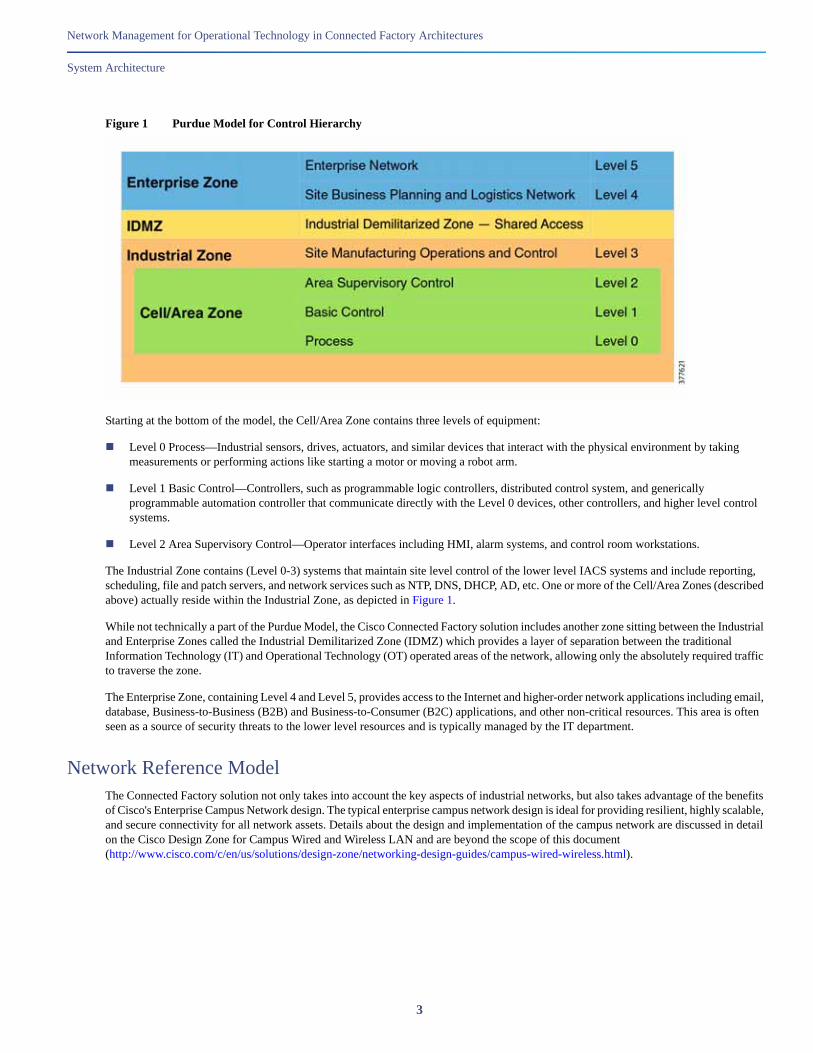
Figure 1 Purdue Model for Control Hierarchy
Starting at the bottom of the model, the Cell/Area Zone contains three levels of equipment:
Level 0 Process—Industrial sensors, drives, actuators, and similar devices that interact with the physical environment by taking measurements or performing actions like starting a motor or moving a robot arm.
Level 1 Basic Control—Controllers, such as programmable logic controllers, distributed control system, and generically programmable automation controller that communicate directly with the Level 0 devices, other controllers, and higher level control systems.
Level 2 Area Supervisory Control—Operator interfaces including HMI, alarm systems, and control room workstations.
The Industrial Zone contains (Level 0-3) systems that maintain site level control of the lower level IACS systems and include reporting, scheduling, file and patch servers, and network services such as NTP, DNS, DHCP, AD, etc. One or more of the Cell/Area Zones (described above) actually reside within the Industrial Zone, as depicted in Figure 1.
While not technically a part of the Purdue Model, the Cisco Connected Factory solution includes another zone sitting between the Industrial and Enterprise Zones called the Industrial Demilitarized Zone (IDMZ) which provides a layer of separation between the traditional Information Technology (IT) and Operational Technology (OT) operated areas of the network, allowing only the absolutely required traffic to traverse the zone.
The Enterprise Zone, containing Level 4 and Level 5, provides access to the Internet and higher-order network applications including email, database, Business-to-Business (B2B) and Business-to-Consumer (B2C) applications, and other non-critical resources. This area is often seen as a source of security threats to the lower level resources and is typically managed by the IT department.
Network Reference ModelThe Connected Factory solution not only takes into account the key aspects of industrial networks, but also takes advantage of the benefits of Cisco's Enterprise Campus Network design. The typical enterprise campus network design is ideal for providing resilient, highly scalable, and secure connectivity for all network assets. Details about the design and implementation of the campus network are discussed in detail on the Cisco Design Zone for Campus Wired and Wireless LAN and are beyond the scope of this document (http://www.cisco.com/c/en/us/solutions/design-zone/networking-design-guides/campus-wired-wireless.html).
3
Network Management for Operational Technology in Connected Factory Architectures
Network Topology
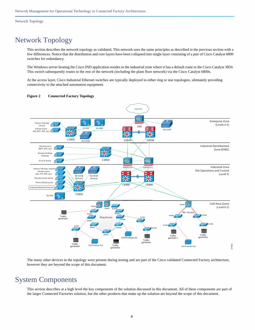
Network TopologyThis section describes the network topology as validated. This network uses the same principles as described in the previous section with a few differences. Notice that the distribution and core layers have been collapsed into single layer consisting of a pair of Cisco Catalyst 6800 switches for redundancy.
The Windows server hosting the Cisco IND application resides in the industrial zone where it has a default route to the Cisco Catalyst 3850. This switch subsequently routes to the rest of the network (including the plant floor network) via the Cisco Catalyst 6800s.
At the access layer, Cisco Industrial Ethernet switches are typically deployed in either ring or star topologies, ultimately providing connectivity to the attached automation equipment.
Figure 2 Connected Factory Topology
The many other devices in the topology were present during testing and are part of the Cisco validated Connected Factory architecture, however they are beyond the scope of this document.
System ComponentsThis section describes at a high level the key components of the solution discussed in this document. All of these components are part of the larger Connected Factories solution, but the other products that make up the solution are beyond the scope of this document.
Ring Access
IES
IES
IES
IES
IES
WLC5508 C4500C4500 4444
ASA
Internet
IXIA 1600T Traffic Generator / Performance Analyzer
10/100
VGA
MouseK/B
Factory Talk App. Servers
Traffic generator
5555C3850
C6880C6880
C3850
Industrial Demilitarized Zone (IDMZ)
Enterprise Zone(Levels 4-5)
Industrial ZoneSite Operations and Control
(Level 3)
Cell/Area Zones(Level 0-2)
C3850
ISE PAN ISE MNT
Infrastructure(AD, FTP, NTP, etc)
WLC5508 (primary)
WLC5508 (backup)W(
WLrr
W(p
WLC5508ISSSSSEEEEEEEEEEEEEEE PPPPPPPPPPPPPPPPAAAAAAAAAAAAAAAANNNNNNNNNNNNNNNNNNNN
Factory Talk App. Servers
Infrastructure(AD, MFT, NTP, etc)
PI-to-PI Server
Remote Desktop Gateway
Infrastructure(MFT, NTP, etc)
Remote Access Server
C0
ASA5525-X ASA5525-X
Prime Infrastructure
IES
IESIES
IXIA 1600T Traffic Generator / Performance Analyzer
Sync in
Sync Out
10/100
VGA
MouseK/B
PORTS INREAR PANEL
Traffic generatorIXIA 1600T Traffic Generator / Performance Analyzer
Sync in
Sync Out
10/100
VGA
MouseK/B
PORTS INREAR PANEL
Traffic generator
IES
Star Access
IES
IESIES
IXIA 1600T Traffic Generator / Performance Analyzer
Sync in
Sync Out
10/100
VGA
MouseK/B
PORTS INREAR PANEL
Traffic generator
IXIA 1600T Traffic Generator / Performance Analyzer
Sync in
Sync Out
10/100
VGA
MouseK/B
PORTS INREAR PANEL
Traffic generator
rSSSSSSta eess
ISE PSN
Industrial Network Director
IXIA 1600T Traffic Generator / Performance Analyzer
Sync in
Sync Out
10/100
VGA
MouseK/B
PORTS INREAR PANEL
Traffic generator
r
3778
23
IE1000
IE4000
IE5000
IE2000
IE1000
IE1000
IE1000
IE4000
IE4000
IE2000
IE2000IE5000IE5000
IE3000
IE3000
IE4000
IE4000
IE1000
CIP/Profinet I/O
CIP/Profinet PLCCIP/Profinet PLC
4

Network Management for Operational Technology in Connected Factory Architectures
System Functional Considerations
Cisco Industrial Network DirectorCisco IND provides operations teams with an easily-integrated system delivering increased operator and technician productivity through streamlined network monitoring and rapid troubleshooting. Cisco IND is part of a comprehensive IoT solution from Cisco:
Easy-to-adopt network management system purpose-built for industrial applications that leverages the full capabilities of the Cisco Industrial Ethernet product family to make the network accessible to non-IT operations personnel.
Creates a dynamic integrated topology of automation and networking assets using industrial protocol (CIP, PROFINET) discovery to provide a common framework for plant floor and plant IT personnel to monitor and troubleshoot the network and quickly recover from unplanned downtime. This CIP and PROFINET discovery also allows Cisco IND to display details of the connected industrial devices (such as PLCs).
Rich APIs allow for easy integration of network information into existing industrial asset management systems and allow customers and system integrators to build dashboards customized to meet specific monitoring and accounting needs.
Cisco Industrial Ethernet SwitchesCisco Industrial Ethernet Switches are designed from the ground up for the demanding environments and requirements of industrial networks and are fully tested and validated in IACS environments for the top protocols in use today, including Ethernet IP, PROFINET, and CC-Link. Building on the years of class leading experience in enterprise switching, these industrial-focused switches add additional software features as well as ruggedized hardware to deliver resilient, low-latency, high speed performance. Cisco Industrial Ethernet Switches are available in a range of models, each with a variety of port configurations and sizes, including Cisco IE1000, Cisco IE2000, Cisco IE3000, Cisco IE4000, Cisco IE4010, and Cisco IE5000. Some of the highlighted features of the switches include (not all features are available on all models):
Industry-leading security including SUDI, ACT2, FIPS 140-2, Trustsec, and SGT/SGACL
Port speeds ranging from 100 Mbps to 10 Gbps (copper and fiber available)
DIN rail mount
DC power supplies
Alarm relays
Industrial PoE and PoE+
Netflow Lite
Support for industrial protocols including CIP, EtherNet I/P, and Profinet
Redundancy features including REP, PRP, MRP, EtherChannel, and Flex Links
Horizontal stacking
System Functional ConsiderationsThis section describes the system functional considerations that should be examined prior to implementing Cisco IND in a production environment. It is important to ensure that proper system resources are allocated to hosting the Cisco IND application and that all of the required protocols are permitted across the network between the user, Cisco IND, and the network assets it is monitoring.
System Requirements for Cisco INDThe following list includes the minimum system requirements for installing the Cisco IND application. For additional details, refer to the official release notes and installation guide.
5

Network Management for Operational Technology in Connected Factory Architectures
System Functional Considerations
Windows OS (English only)—Windows 7 Enterprise or Profession with SP2, Windows 10
Browser—Chrome Version 50.0.2661.102 or later, Firefox Version 46.01 or later
CPU—Dual core 2.4 GHz
RAM—8 GB
Storage— 50 GB
The actual hardware platform used is not mandated by Cisco. In the solution test environment, Cisco IND (and the host Windows OS) were installed as a VMware ESXi virtual machine running on Cisco UCS C-Series hardware.
Supported Devices in Cisco INDCisco IND supports the following devices as of version 1.1.1-49 with device pack version 1.1.0:
Cisco IE1000
Cisco IE2000
Cisco IE2000U
Cisco IE3000
Cisco IE3010
Cisco IE4000
Cisco IE4010
Cisco IE5000
Cisco CGS2520
Rockwell Automation/Allen-Bradley Stratix 8000/8300
Rockwell Automation/Allen-Bradley Stratix 5700
Rockwell Automation/Allen-Bradley Stratix 5410
Rockwell Automation/Allen-Bradley Stratix 5400
Rockwell Automation/Allen-Bradley Stratix 2500
In addition to these supported devices, Cisco IND can also monitor automation equipment that communicates with CIP or PROFINET industrial protocols. Other devices can be identified using SNMP including access points, wireless LAN controllers, firewalls, routers, and servers.
Device Packs, available for download at Cisco.com, allow Cisco IND to easily support additional industrial networking product IDs (PIDs) as they become available. Cisco IND Device Packs can only be installed with the Cisco IND application that has a matching version number and the release number must be the same or greater than the Cisco IND release number.
Network ConsiderationsCisco IND can be installed on a server in the industrial zone with tightly restricted access to other areas of the network. It is recommended to use only secure protocols (such as HTTPS and SSH) when possible to protect critical data. If required, Cisco IND is lightweight enough to be installed on a ruggedized laptop that resides within a zone on a plant floor, as long as it meets the system requirements.
6

Network Management for Operational Technology in Connected Factory Architectures
Functional Description
The Cisco IND application requires Layer 3 connectivity to all of the network assets and automation clients that it is tasked with discovering and monitoring. This means that all devices that need to be discovered and monitored should have an IP address assigned that is routable and able to reach the Cisco IND server.
If there is a firewall located between the Windows server hosting Cisco IND and the monitored devices, the firewall must be be configured to allow the following protocols and ports through both inbound and outbound: TCP ports 5432, 8088, 8443, 443, 80, 21, and 50000-50050.
In order to use the Cisco Active Advisor integration, the client computer which is accessing the Cisco IND web interface also needs to have Internet access to be able to upload network inventory data.
Depending on technical and business requirements, direct access to the Internet for Cisco Smart Licensing may not be available. In this situation, Cisco Software Manager Satellite can be positioned in the IDMZ between the IND server and the Cisco cloud to facilitate license management on premise.
Functional DescriptionCisco IND provides an easy-to-use interface designed especially for operations staff to be able to get a clear picture of their plant floor network and attached automation endpoints. This section describes the intuitive application's major functions and capabilities, but does not go into detail about every available feature and option. The goal is to present a clear depiction of what is possible with Cisco IND. For additional information, refer to the official product documentation available at http://www.cisco.com/go/ind.
User InterfaceCisco IND is primarily accessed through an intuitive web-based GUI. Upon logging into Cisco IND, the Dashboard is displayed, as described in Dashboard, page 8. At the top of the screen, basic navigation buttons allow the user to access the Operate and Settings categories and their sub-categories:
Operate
— Alarms
— Asset Discovery
— Audit Trails
— Dashboard
— Inventory
— Tasks
— Topology
Settings
— Access Profiles
— Active Sessions
— Alarm Settings
— Backup
— Device Pack
— Group Management
— Licenses
7
Network Management for Operational Technology in Connected Factory Architectures
Functional Description
— Password Policies
— System Settings
— User Accounts
— User Roles
Also at the top of the screen is a count of the total number of active alarms, which also links to the Alarm page. This is visible from every screen in Cisco IND so the user can quickly respond to new alarms no matter where they are in the user interface.
A help link is also available at the top of each screen that gives access to the following functions:
Help (link to online manual)
Guided tours (explained in Guided Tours, page 9)
Download logs
API Tool
DashboardThe Dashboard view is displayed when users first log in to the Cisco IND web interface. It can also be accessed from anywhere in the user interface by clicking the Cisco Industrial Network Director logo at the top left of the screen or by navigating to Operate > Dashboard.
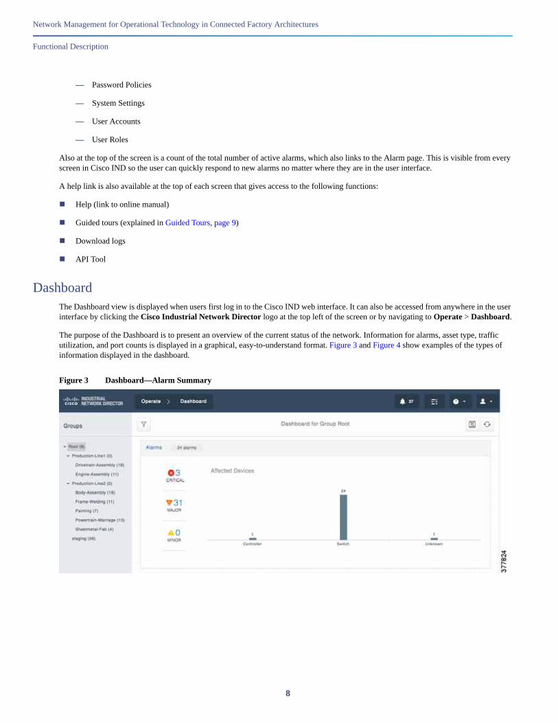
The purpose of the Dashboard is to present an overview of the current status of the network. Information for alarms, asset type, traffic utilization, and port counts is displayed in a graphical, easy-to-understand format. Figure 3 and Figure 4 show examples of the types of information displayed in the dashboard.
Figure 3 Dashboard—Alarm Summary
8

Network Management for Operational Technology in Connected Factory Architectures
Functional Description
Figure 4 Dashboard—Asset Summary
The layout and order of the information displayed can be easily rearranged with a simple click-and-drag interface so that the most important information can be displayed at the top of the page.
On the left side of the Dashboard screen you can see a tree structure for Groups of devices. The concept of groups is used throughout Cisco IND, as you will see later. This functionality allows the administrator to group together devices on any criteria they choose, however grouping devices based on physical location is most common and recommended. Once the devices are grouped together (either during Asset Discovery or subsequently in the Settings > Group Management screen), various Cisco IND functions can filter information so only the most relevant device information is displayed and the user is not overloaded with extraneous data. In Figure 3 and Figure 4, you can see that different groups have been selected; in the Alarm summary display, the Root group is shown. The Root group is the default group under which all sub-groups and devices are contained. Selecting this group allows you to see information from all devices that Cisco IND knows about. Figure 4, which shows Asset information, shows information for only the “Drivetrain-Assembly” group, which is a subgroup of “Production-Line-1”. In this case, “Drivetrain-Assembly” contains fourteen supported devices and one client device.
Guided ToursCisco IND is meant to be easily accessible and usable by operations. It can often be daunting navigating through a new application, trying to figure out how to perform even the simplest tasks. Cisco IND includes a feature called Guided Tours to help new and inexperienced users step through the main features of the application.
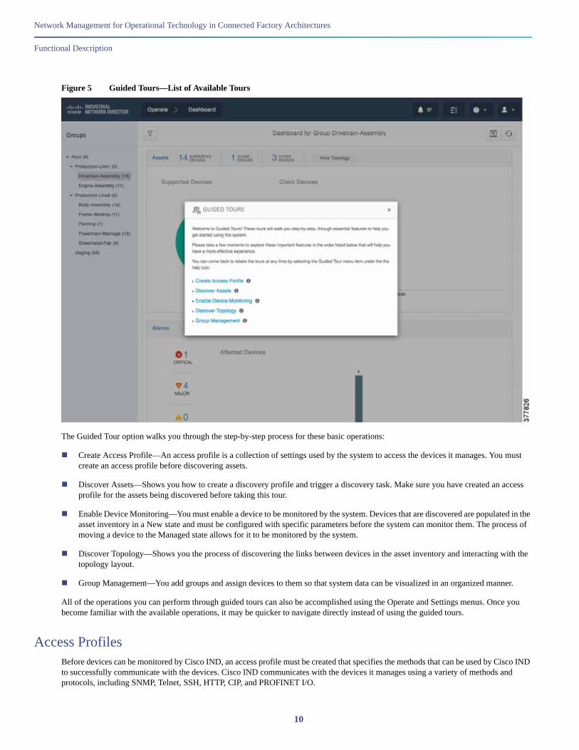
To access Guided Tours, click the ? button at the top of any screen in Cisco IND to display the pop-up window shown in Figure 5 with links to each of the available tours.
9
Network Management for Operational Technology in Connected Factory Architectures
Functional Description
Figure 5 Guided Tours—List of Available Tours
The Guided Tour option walks you through the step-by-step process for these basic operations:
Create Access Profile—An access profile is a collection of settings used by the system to access the devices it manages. You must create an access profile before discovering assets.
Discover Assets—Shows you how to create a discovery profile and trigger a discovery task. Make sure you have created an access profile for the assets being discovered before taking this tour.
Enable Device Monitoring—You must enable a device to be monitored by the system. Devices that are discovered are populated in the asset inventory in a New state and must be configured with specific parameters before the system can monitor them. The process of moving a device to the Managed state allows for it to be monitored by the system.
Discover Topology—Shows you the process of discovering the links between devices in the asset inventory and interacting with the topology layout.
Group Management—You add groups and assign devices to them so that system data can be visualized in an organized manner.
All of the operations you can perform through guided tours can also be accomplished using the Operate and Settings menus. Once you become familiar with the available operations, it may be quicker to navigate directly instead of using the guided tours.
Access ProfilesBefore devices can be monitored by Cisco IND, an access profile must be created that specifies the methods that can be used by Cisco IND to successfully communicate with the devices. Cisco IND communicates with the devices it manages using a variety of methods and protocols, including SNMP, Telnet, SSH, HTTP, CIP, and PROFINET I/O.
10

Network Management for Operational Technology in Connected Factory Architectures
Functional Description
To create an access profile, navigate to Settings > Access Profiles. From this page you can add a new profile or edit an existing one. The fields on this page are used to specify the type of protocol(s) Cisco IND should use to reach the devices to be managed, as well as items such as the login credentials or SNMP community string. All devices that will be added using this access profile should be pre-configured to allow communication with the specified protocols and credentials.
Figure 6 Access Profile Configuration
In Figure 6, you can see the various options available to be configured. Setting the slider at the top to Advanced allows you to specify the Access Mechanism (either Telnet or SSH), as well as the port number to use.
A single Access Profile can be used by any number or type of devices that share a common access mechanism and credentials. The Access Profile is referenced when creating the Discovery Profile, described in the next section.
Asset DiscoveryIn order for Cisco IND to monitor network switches and automation equipment, the assets must first be discovered. This discovery process is initiated by first creating Discovery Profiles (accessed by navigating to Operate > Asset Discovery). The asset discovery process uses one of two Discovery Mechanisms:
Link Layer—Specify a starting IPv4 address. Cisco IND connects this device and attempts to discover connected devices up to the specified number of hops away by examining the MAC and ARP tables on the switches.
IP Scan—Specify a range of IPv4 addresses by stating the Start and End IP, as well as the Netmask for the range.
11

Network Management for Operational Technology in Connected Factory Architectures
Functional Description
Each Discovery Profile also requires reference to an Access Profile.
Figure 7 Asset Discovery Profile with IP Scan
Each Discovery Profile also has the option to add all devices discovered with the profile to a specific group that has been created. By default, all devices are added to the Root group unless another one is specified. Devices can be moved between groups later if desired using the Settings > Group Management screen.
Prior to proceeding to the next step, the target devices need to be configured with some basic settings in order to successfully communicate with Cisco IND. Refer to Configuration Required for Device Discovery and Monitoring, page 34 for the required configuration per device type.
Once a Discovery Profile has been created, the next step is to initiate a Scan. From the main Operate > Asset Discovery screen, click the Scan Now button beside the desired Discovery Profile in the table. This causes Cisco IND to attempt to discover all devices reachable within the range of IPv4 addresses or the link layer hop count defined in the profile. The scanning process can take some time depending on the scope of addresses it tries to scan. The status of the scan can be checked in the Tasks screen (discussed in Tasks, page 14).
Once the scan has completed successfully, all discovered devices are displayed on the Operate > Inventory screen.
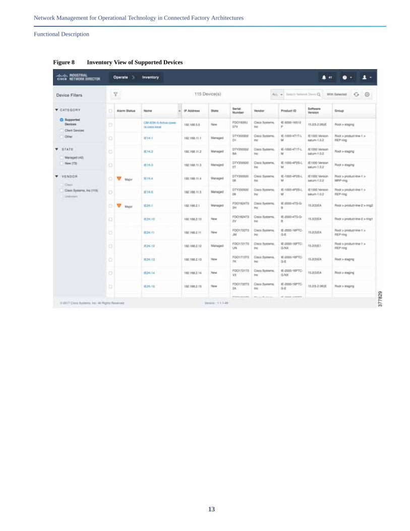
In Figure 8 and Figure 9, you can see examples of both Supported Devices, such as Cisco Industrial Ethernet switches, as well as Client devices, such as CIP and PROFINET controllers. Note the different types of information shown for different device types, as well as the ability to filter and sort the information as required.
12
Network Management for Operational Technology in Connected Factory Architectures
Functional Description
Figure 8 Inventory View of Supported Devices
13

Network Management for Operational Technology in Connected Factory Architectures
Functional Description
Figure 9 Inventory View of Client Devices
Notice in Figure 8, which shows the Supported Devices inventory, that some devices are listed as New and some are listed as Managed. When devices are first discovered and added to the inventory, they are considered New. In order for Cisco IND to be able to fully monitor the devices, additional configuration on the devices is required. Refer to Configuration Required for Device Discovery and Monitoring, page 34 for the full configuration required per device type. After the prerequisite configuration is applied to the monitored devices, they are ready to be moved to a Managed state in Cisco IND. Once in a Managed state, all available information can be viewed in Cisco IND. This New/Managed concept and terminology only applies to Supported Devices, not to Client devices.
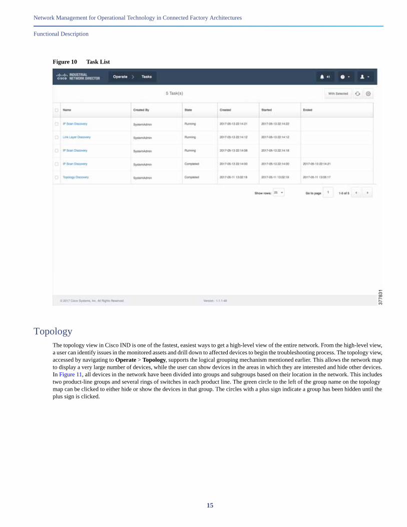
TasksUser operations initiated in Cisco IND are recorded in the Operate > Tasks table, which is useful for troubleshooting as well as checking the status of operations involving large numbers of devices as they may take some time to complete. In a multi-user environment, the tasks page is also beneficial for monitoring who is doing what. In the event that an operation fails, such as moving a discovered device to a Managed state, the tasks page is a quick way to see details about why the operation failed so the user can troubleshoot the issue.
14
Network Management for Operational Technology in Connected Factory Architectures
Functional Description
Figure 10 Task List
TopologyThe topology view in Cisco IND is one of the fastest, easiest ways to get a high-level view of the entire network. From the high-level view, a user can identify issues in the monitored assets and drill down to affected devices to begin the troubleshooting process. The topology view, accessed by navigating to Operate > Topology, supports the logical grouping mechanism mentioned earlier. This allows the network map to display a very large number of devices, while the user can show devices in the areas in which they are interested and hide other devices. In Figure 11, all devices in the network have been divided into groups and subgroups based on their location in the network. This includes two product-line groups and several rings of switches in each product line. The green circle to the left of the group name on the topology map can be clicked to either hide or show the devices in that group. The circles with a plus sign indicate a group has been hidden until the plus sign is clicked.
15

Network Management for Operational Technology in Connected Factory Architectures
Functional Description
Figure 11 Topology View—Device Groups
Hovering the mouse cursor over a group causes the devices in that group to be highlighted in green so you can easily see their relative location.
16

Network Management for Operational Technology in Connected Factory Architectures
Functional Description
Figure 12 Topology View—Device Group Highlighted
The topology view displays all devices in the inventory. At any time, the Discover Topology button at the top of the screen can be clicked to force Cisco IND to query all devices in order to build the topology view. Connected links between devices are discovered using primarily LLDP, but Cisco IND also looks at the MAC table on switches to determine which device is connected to which interface. Device connectivity shown on the topology view is supported for inter-switch links, as well as connections between switches and client devices (such as CIP and PROFINET automation equipment). Additionally, Cisco IND can display topology information for unsupported devices discovered via SNMP.
Once devices and connections have been discovered and displayed in the topology view, the individual devices and groups of devices can be manually repositioned with a simple click-and-drag of the mouse. This is helpful to arrange devices in a logical topology, such as a ring, star, or bus. After manually rearranging the device layout, click the disk icon at the top right of the screen to save the layout.
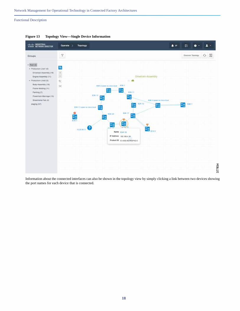
Figure 13, Figure 14, and Figure 15 give some examples of the types of information that is accessible through the topology view. In the first example, the topology view has been manually zoomed into the “Drivetrain-Assembly” using the plus/minus buttons on the left and dragging the graph area with the mouse. Alternatively a group or subgroup can be selected in the hierarchy on the left part of the screen to automatically zoom into the view for that group. Once the topology for the “Drivetrain-Assembly” network is displayed, a single device can be selected (in this case a Cisco IE4000 switch named “IE4K-18”) and some basic information about the switch is displayed. Clicking the name of the switch in blue takes you to the inventory page for the device, which displays all available information.
17
Network Management for Operational Technology in Connected Factory Architectures
Functional Description
Figure 13 Topology View—Single Device Information
Information about the connected interfaces can also be shown in the topology view by simply clicking a link between two devices showing the port names for each device that is connected.
18
Network Management for Operational Technology in Connected Factory Architectures
Functional Description
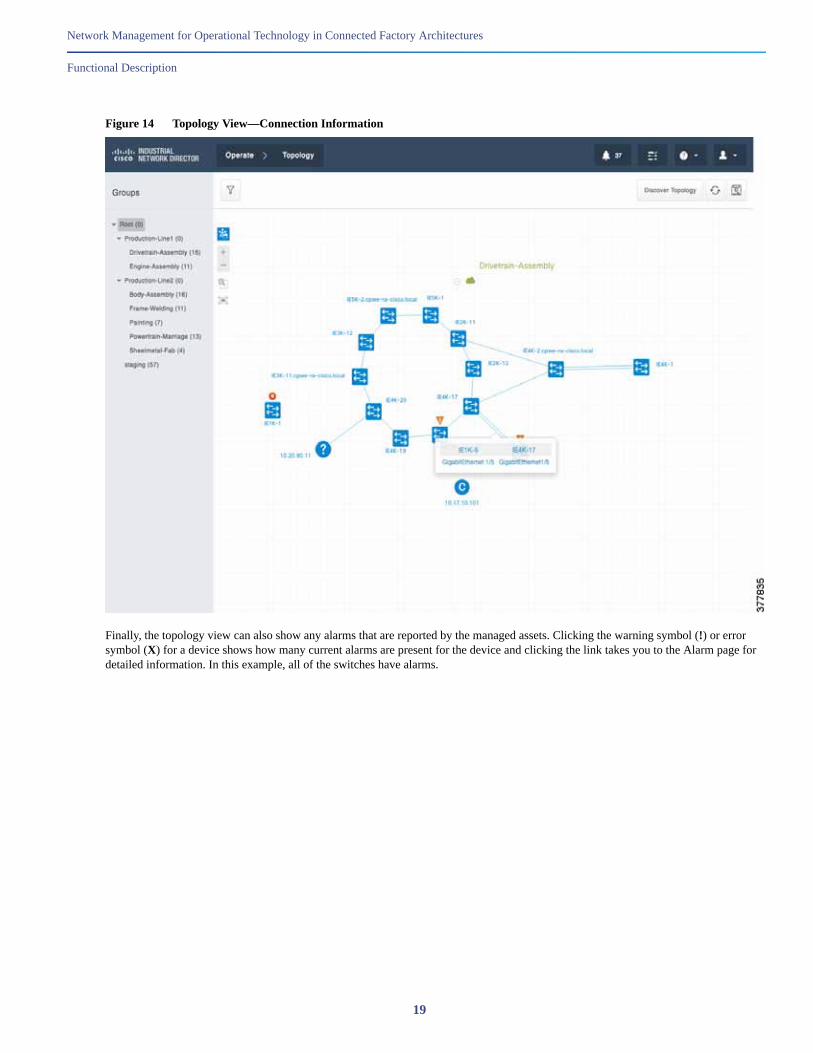
Figure 14 Topology View—Connection Information
Finally, the topology view can also show any alarms that are reported by the managed assets. Clicking the warning symbol (!) or error symbol (X) for a device shows how many current alarms are present for the device and clicking the link takes you to the Alarm page for detailed information. In this example, all of the switches have alarms.
19

Network Management for Operational Technology in Connected Factory Architectures
Functional Description
Figure 15 Topology View—Device Alarm
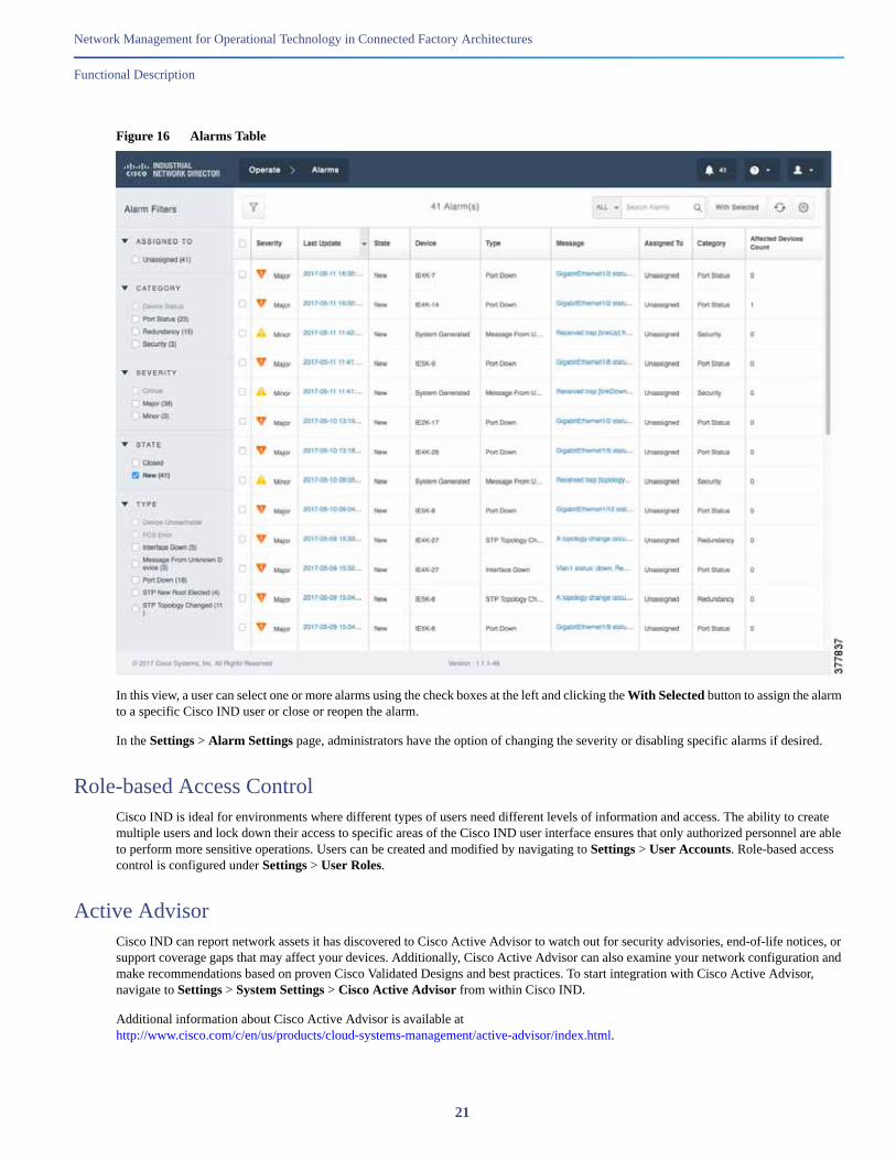
AlarmsCisco IND provides a rich alarm monitoring interface to centralize issue reporting for all managed assets. Network assets are configured to send SNMP traps to the Cisco IND server which displays them in a table that can be filtered and sorted as required. Cisco IND users are alerted to alarms from many different places in the user interface, as mentioned previously. Wherever the alarms are initially presented, they ultimately link back to the main Alarms page, which is accessed by navigating to Operate > Alarms. Figure 16 shows the Alarms page which lists 41 alarms that have been reported. You can see examples of the types of information that is available, including timestamps, device name, severity, status, alarm message, and the number of devices affected by a specific alarm.
20
Network Management for Operational Technology in Connected Factory Architectures
Functional Description
Figure 16 Alarms Table
In this view, a user can select one or more alarms using the check boxes at the left and clicking the With Selected button to assign the alarm to a specific Cisco IND user or close or reopen the alarm.
In the Settings > Alarm Settings page, administrators have the option of changing the severity or disabling specific alarms if desired.
Role-based Access ControlCisco IND is ideal for environments where different types of users need different levels of information and access. The ability to create multiple users and lock down their access to specific areas of the Cisco IND user interface ensures that only authorized personnel are able to perform more sensitive operations. Users can be created and modified by navigating to Settings > User Accounts. Role-based access control is configured under Settings > User Roles.
Active AdvisorCisco IND can report network assets it has discovered to Cisco Active Advisor to watch out for security advisories, end-of-life notices, or support coverage gaps that may affect your devices. Additionally, Cisco Active Advisor can also examine your network configuration and make recommendations based on proven Cisco Validated Designs and best practices. To start integration with Cisco Active Advisor, navigate to Settings > System Settings > Cisco Active Advisor from within Cisco IND.
Additional information about Cisco Active Advisor is available at http://www.cisco.com/c/en/us/products/cloud-systems-management/active-advisor/index.html.
21

Network Management for Operational Technology in Connected Factory Architectures
Functional Description
APICisco IND includes a comprehensive RESTful API allowing it to easily integrate with existing industrial asset management tools, automation applications, and control systems. An intuitive API Tool is included with Cisco IND to help system integrators and developers rapidly learn and adopt the API. To access the API tool, log in to the Cisco IND GUI, click the ? button at the top, and select API Tool from the drop-down menu. This displays a web page that lists the available options and allows users to test various calls to check the resulting output given the desired input.
Figure 17 API Tool
LicensingCisco IND supports two licensing models, traditional licensing and smart software licensing, both of which are per-device and term subscription based. Traditional licensing requires the user upload a license file which defines the maximum number of devices that Cisco IND can monitor. Smart software licensing is a cloud-based model where you only pay for licensing for the exact number of devices you need to monitor.
22
Network Management for Operational Technology in Connected Factory Architectures
Example Use Cases
Example Use CasesThis section lists just a few of the possible use cases where Cisco IND can assist operations personnel in maximizing productivity and minimizing costs and downtime.
Adding New Switches and Viewing DetailsIn this use case, the user uses Cisco IND to discover several new switches that have been physically added to the network and then verifies the health and connectivity of the switches.
Prior to discovering the switches in Cisco IND, the switches have been physically installed, connected, and configured using a console connection. The switches each contain a set of basic configuration lines that allow the switches to be discovered by Cisco IND:
snmp-server community cisco ro
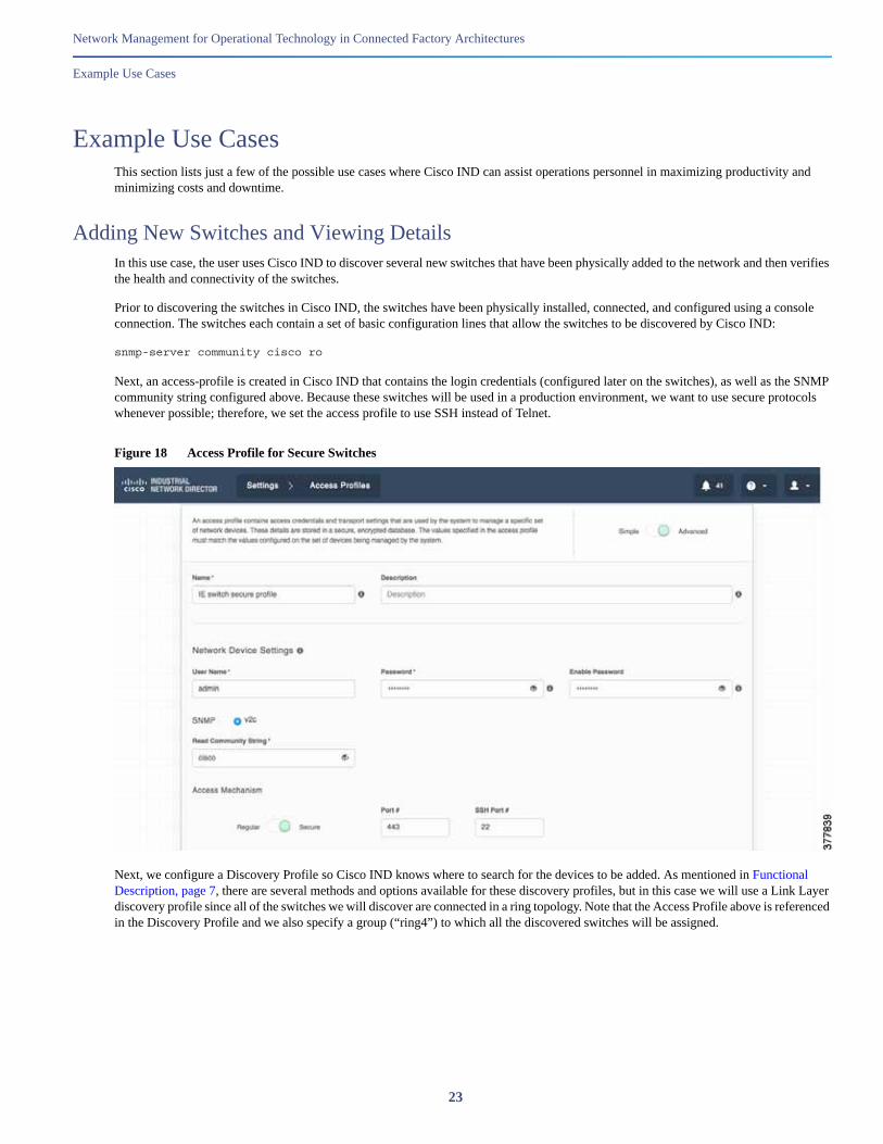
Next, an access-profile is created in Cisco IND that contains the login credentials (configured later on the switches), as well as the SNMP community string configured above. Because these switches will be used in a production environment, we want to use secure protocols whenever possible; therefore, we set the access profile to use SSH instead of Telnet.
Figure 18 Access Profile for Secure Switches
Next, we configure a Discovery Profile so Cisco IND knows where to search for the devices to be added. As mentioned in Functional Description, page 7, there are several methods and options available for these discovery profiles, but in this case we will use a Link Layer discovery profile since all of the switches we will discover are connected in a ring topology. Note that the Access Profile above is referenced in the Discovery Profile and we also specify a group (“ring4”) to which all the discovered switches will be assigned.
23

Network Management for Operational Technology in Connected Factory Architectures
Example Use Cases
Figure 19 Discovery Profile for New Switches
Next, back on the Asset Discovery page, we initiate the discovery process by clicking the Scan Now button beside the new profile. At this point the status of the discovery process can be monitored on the Tasks page, which you should periodically check until the task is complete. Once complete, view the Details pop-up as shown in Figure 20.
24

Network Management for Operational Technology in Connected Factory Architectures
Example Use Cases
Figure 20 Discovery Task Results
Notice that four new Cisco IE4000 switches were successfully discovered. Messages about failed discoveries can be ignored as these are devices Cisco IND already knows about or, in the case of the “Unable to resolve” messages, they refer to devices connected to the switches without IP addresses on that VLAN (which we do not want to manage). At this point the four switches are added to the inventory in a New state. In order to transition to a Managed state, additional configuration is required on the switches so that Cisco IND can log in to the switches via SSH and retrieve additional metrics and information. The following configuration is applied to the switches out-of-band. Make sure the configuration matches that specified in the access profile (credentials, methods, and ports).
username admin privilege 15 password 0 s3cur3p4ssw0rdaaa new-modelaaa authentication login default localaaa authorization exec default local ip http secure-serverip http authentication aaa login-authentication defaultip http secure-ciphersuite aes-256-cbc-sha line vty 0 4exec-timeout 0 0login authentication defaulttransport input alltransport output allline vty 5 15exec-timeout 0 0login authentication defaulttransport input alltransport output all
The final step in adding the devices to Cisco IND is to move them to a Managed state, which is done by checking the box beside each new switch in the Inventory screen, then clicking With Selected and choosing Change State of 4 Device(s) to: Managed. When you do this, a pop-up window is displayed warning that Cisco IND will download additional configurations to the switches.
25

Network Management for Operational Technology in Connected Factory Architectures
Example Use Cases
Figure 21 Move New Switches to Managed State
There is a hyperlink in the pop-up where you can preview the configuration that will be downloaded to each switch, adding additional functionality for Cisco IND to monitor metrics and receive alarms. This configuration is also shown in Configuration Required for Device Discovery and Monitoring, page 34.
After the switches successfully move to a Managed state, click the device in the Inventory to view additional details. The device overview shows critical health metrics for the switch including CPU and memory utilization, temperature, flash usage, power supply status, and bandwidth utilization. Other information about the switch including serial number, MAC address, software version, uptime, and product ID (PID) are also included for reference. There is also a graphical view of the physical switch including port and alarm status.
26
Network Management for Operational Technology in Connected Factory Architectures
Example Use Cases
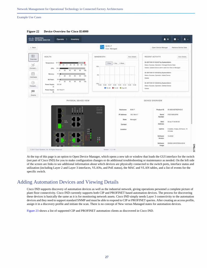
Figure 22 Device Overview for Cisco IE4000
At the top of this page is an option to Open Device Manager, which opens a new tab or window that loads the GUI interface for the switch (not part of Cisco IND) for you to make configuration changes or do additional troubleshooting or maintenance as needed. On the left side of the screen are links to see additional information about which devices are physically connected to the switch ports, interface status and utilization (including Layer 2 and Layer 3 interfaces, VLANs, and PoE status), the MAC and VLAN tables, and a list of events for the specific switch.
Adding Automation Devices and Viewing DetailsCisco IND supports discovery of automation devices as well as the industrial network, giving operations personnel a complete picture of plant floor connectivity. Cisco IND currently supports both CIP and PROFINET based automation devices. The process for discovering these devices is basically the same as it is for monitoring network assets. Cisco IND simply needs Layer 3 connectivity to the automation devices and they need to support standard SNMP and must be able to respond to CIP or PROFINET queries. After creating an access profile, assign it in a discovery profile and initiate the scan. There is no concept of New versus Managed states for automation devices.
Figure 23 shows a list of supported CIP and PROFINET automation clients as discovered in Cisco IND.
27

Network Management for Operational Technology in Connected Factory Architectures
Example Use Cases
Figure 23 Inventory of Discovered Automation Clients
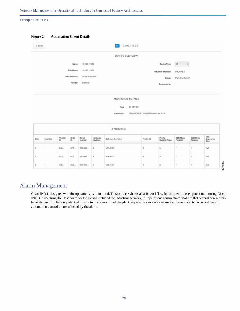
Zooming in on one of the automation devices shows more details including the IP and MAC addresses, serial numbers, and other details for each of the three modules in this Siemens chassis.
28
Network Management for Operational Technology in Connected Factory Architectures
Example Use Cases
Figure 24 Automation Client Details
Alarm ManagementCisco IND is designed with the operations team in mind. This use case shows a basic workflow for an operations engineer monitoring Cisco IND. On checking the Dashboard for the overall status of the industrial network, the operations administrator notices that several new alarms have shown up. There is potential impact to the operation of the plant, especially since we can see that several switches as well as an automation controller are affected by the alarm.
29
Network Management for Operational Technology in Connected Factory Architectures
Example Use Cases
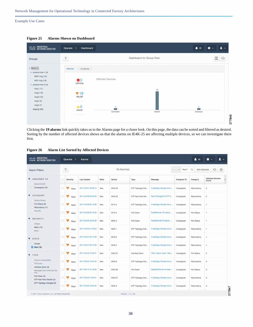
Figure 25 Alarms Shown on Dashboard
Clicking the 19 alarms link quickly takes us to the Alarms page for a closer look. On this page, the data can be sorted and filtered as desired. Sorting by the number of affected devices shows us that the alarms on IE4K-25 are affecting multiple devices, so we can investigate there first.
Figure 26 Alarm List Sorted by Affected Devices
30
Network Management for Operational Technology in Connected Factory Architectures
Example Use Cases
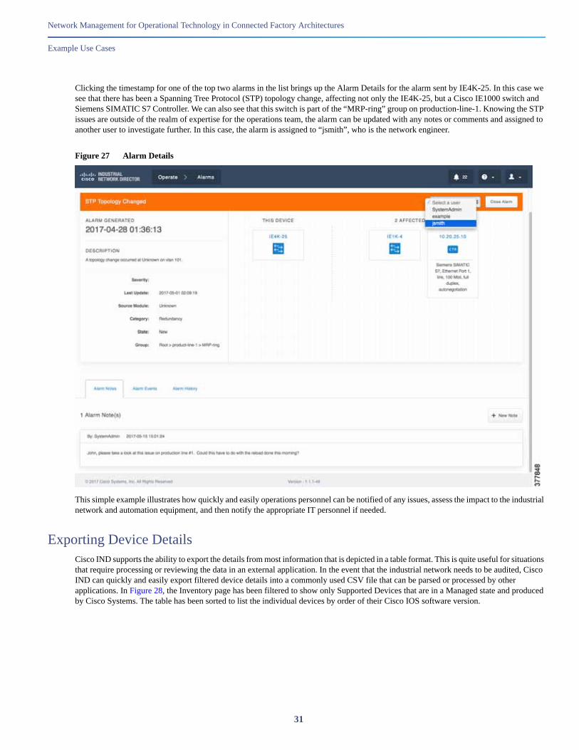
Clicking the timestamp for one of the top two alarms in the list brings up the Alarm Details for the alarm sent by IE4K-25. In this case we see that there has been a Spanning Tree Protocol (STP) topology change, affecting not only the IE4K-25, but a Cisco IE1000 switch and Siemens SIMATIC S7 Controller. We can also see that this switch is part of the “MRP-ring” group on production-line-1. Knowing the STP issues are outside of the realm of expertise for the operations team, the alarm can be updated with any notes or comments and assigned to another user to investigate further. In this case, the alarm is assigned to “jsmith”, who is the network engineer.
Figure 27 Alarm Details
This simple example illustrates how quickly and easily operations personnel can be notified of any issues, assess the impact to the industrial network and automation equipment, and then notify the appropriate IT personnel if needed.
Exporting Device DetailsCisco IND supports the ability to export the details from most information that is depicted in a table format. This is quite useful for situations that require processing or reviewing the data in an external application. In the event that the industrial network needs to be audited, Cisco IND can quickly and easily export filtered device details into a commonly used CSV file that can be parsed or processed by other applications. In Figure 28, the Inventory page has been filtered to show only Supported Devices that are in a Managed state and produced by Cisco Systems. The table has been sorted to list the individual devices by order of their Cisco IOS software version.
31

Network Management for Operational Technology in Connected Factory Architectures
Example Use Cases
Figure 28 Export Inventory List to CSV
The resulting CSV can be opened with a text editor or spreadsheet application and subsequently included in a report, for example.
32

Network Management for Operational Technology in Connected Factory Architectures
Caveats
Figure 29 CSV File Containing Device Details
CaveatsThe following unresolved caveats were identified in solution testing. These issues have been reported and are expected to be resolved in future software revisions. Additional outstanding caveats are documented in the official product release notes.
Topology connectivity of client devices is not working with Port-Security configured on the switchport.
Topology display will not show two Cisco IE1000s connected to each other unless the ports are on the management VLAN.
Related Documentation http://www.cisco.com/go/ind
33
Network Management for Operational Technology in Connected Factory Architectures
Configuration Required for Device Discovery and Monitoring
http://www.cisco.com/c/en/us/td/docs/switches/ind/release_notes/rn-iot-ind-1-1.html
http://www.cisco.com/c/en/us/td/docs/switches/ind/install/IND_1-1_install.html
http://www.cisco.com/c/en/us/products/switches/industrial-ethernet-switches/index.html
http://www.cisco.com/c/en/us/solutions/enterprise/design-zone-industry-solutions/index.html
http://www.ab.com/en/epub/catalogs/12762/2181376/214372/9142990/
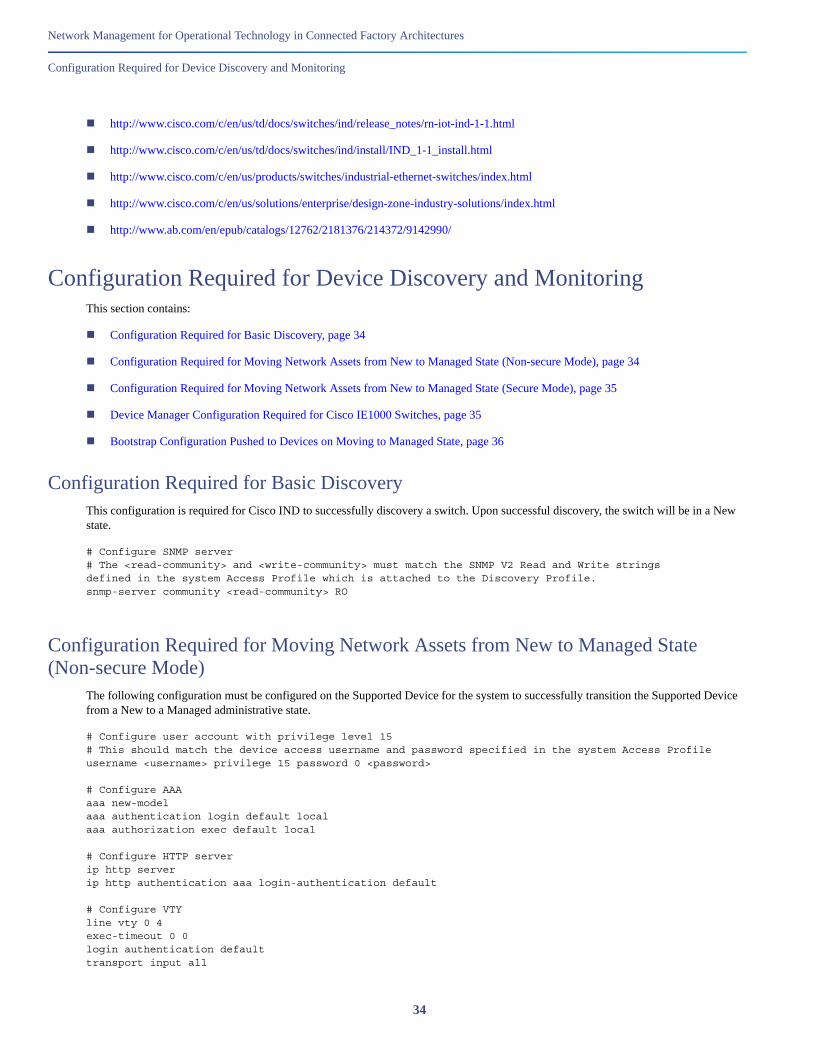
Configuration Required for Device Discovery and MonitoringThis section contains:
Configuration Required for Basic Discovery, page 34
Configuration Required for Moving Network Assets from New to Managed State (Non-secure Mode), page 34
Configuration Required for Moving Network Assets from New to Managed State (Secure Mode), page 35
Device Manager Configuration Required for Cisco IE1000 Switches, page 35
Bootstrap Configuration Pushed to Devices on Moving to Managed State, page 36
Configuration Required for Basic DiscoveryThis configuration is required for Cisco IND to successfully discovery a switch. Upon successful discovery, the switch will be in a New state.
# Configure SNMP server# The <read-community> and <write-community> must match the SNMP V2 Read and Write stringsdefined in the system Access Profile which is attached to the Discovery Profile.snmp-server community <read-community> RO
Configuration Required for Moving Network Assets from New to Managed State (Non-secure Mode)
The following configuration must be configured on the Supported Device for the system to successfully transition the Supported Device from a New to a Managed administrative state.
# Configure user account with privilege level 15# This should match the device access username and password specified in the system Access Profileusername <username> privilege 15 password 0 <password> # Configure AAAaaa new-modelaaa authentication login default localaaa authorization exec default local # Configure HTTP serverip http serverip http authentication aaa login-authentication default # Configure VTYline vty 0 4exec-timeout 0 0login authentication defaulttransport input all
34

Network Management for Operational Technology in Connected Factory Architectures
Configuration Required for Device Discovery and Monitoring
transport output allline vty 5 15exec-timeout 0 0login authentication defaulttransport input alltransport output all
Configuration Required for Moving Network Assets from New to Managed State (Secure Mode)
The following configuration must be configured on the Supported Device for the system to successfully transition the Supported Device from a New to a Managed administrative state in Secure mode.
# Configure user account with privilege level 15# This should match the device access username & password specified in the system AccessProfileusername <username> privilege 15 password 0 <password> # Configure AAAaaa new-modelaaa authentication login default localaaa authorization exec default local # Configure HTTPS serverip http secure-serverip http authentication aaa login-authentication defaultip http secure-ciphersuite aes-256-cbc-sha # Configure VTYline vty 0 4exec-timeout 0 0login authentication defaulttransport input alltransport output allline vty 5 15exec-timeout 0 0login authentication defaulttransport input alltransport output all
Device Manager Configuration Required for Cisco IE1000 SwitchesThe following configuration must be performed manually on Cisco IE1000 switches via the Device Manager GUI prior to discovering with Cisco IND.
1. Log in to the Cisco IE1000 Device Manager.
2. Leave the username field blank and enter cisco as the password.
3. Choose Admin > Users.
4. Create Device Access User and use the same in Access Profile on Cisco IND.
5. Configure SNMP community string for Read Only (ro):
a. Choose Configure > SNMP. Click OK in the pop-up windows to confirm enabling SNMP.
b. Check the check box to enable SNMP Mode globally. Click Submit.
35
Network Management for Operational Technology in Connected Factory Architectures
Configuration Required for Device Discovery and Monitoring
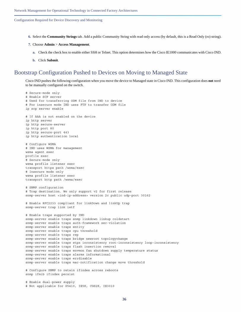
6. Select the Community Strings tab. Add a public Community String with read only access (by default, this is a Read Only (ro) string).
7. Choose Admin > Access Management.
a. Check the check box to enable either SSH or Telnet. This option determines how the Cisco IE1000 communicates with Cisco IND.
b. Click Submit.
Bootstrap Configuration Pushed to Devices on Moving to Managed StateCisco IND pushes the following configuration when you move the device to Managed state in Cisco IND. This configuration does not need to be manually configured on the switch.
# Secure-mode only# Enable SCP server# Used for transferring ODM file from IND to device# For insecure mode IND uses FTP to transfer ODM fileip scp server enable
# If AAA is not enabled on the device ip http server ip http secure-serverip http port 80 ip http secure-port 443 ip http authentication local
# Configure WSMA# IND uses WSMA for managementwsma agent execprofile exec# Secure-mode onlywsma profile listener exectransport https path /wsma/exec# Insecure mode onlywsma profile listener exectransport http path /wsma/exec
# SNMP configuration# Trap destination. We only support v2 for first releasesnmp-server host <ind-ip-address> version 2c public udp-port 30162
# Enable RFC2233 compliant for linkDown and linkUp trapsnmp-server trap link ietf
# Enable traps supported by INDsnmp-server enable traps snmp linkdown linkup coldstartsnmp-server enable traps auth-framework sec-violationsnmp-server enable traps entitysnmp-server enable traps cpu thresholdsnmp-server enable traps repsnmp-server enable traps bridge newroot topologychangesnmp-server enable traps stpx inconsistency root-inconsistency loop-inconsistencysnmp-server enable traps flash insertion removalsnmp-server enable traps envmon fan shutdown supply temperature statussnmp-server enable traps alarms informationalsnmp-server enable traps errdisablesnmp-server enable traps mac-notification change move threshold
# Configure SNMP to retain ifindex across rebootssnmp ifmib ifindex persist
# Enable dual-power supply# Not applicable for S5410, IE5K, CGS2K, IE3010
36
Network Management for Operational Technology in Connected Factory Architectures
Glossary
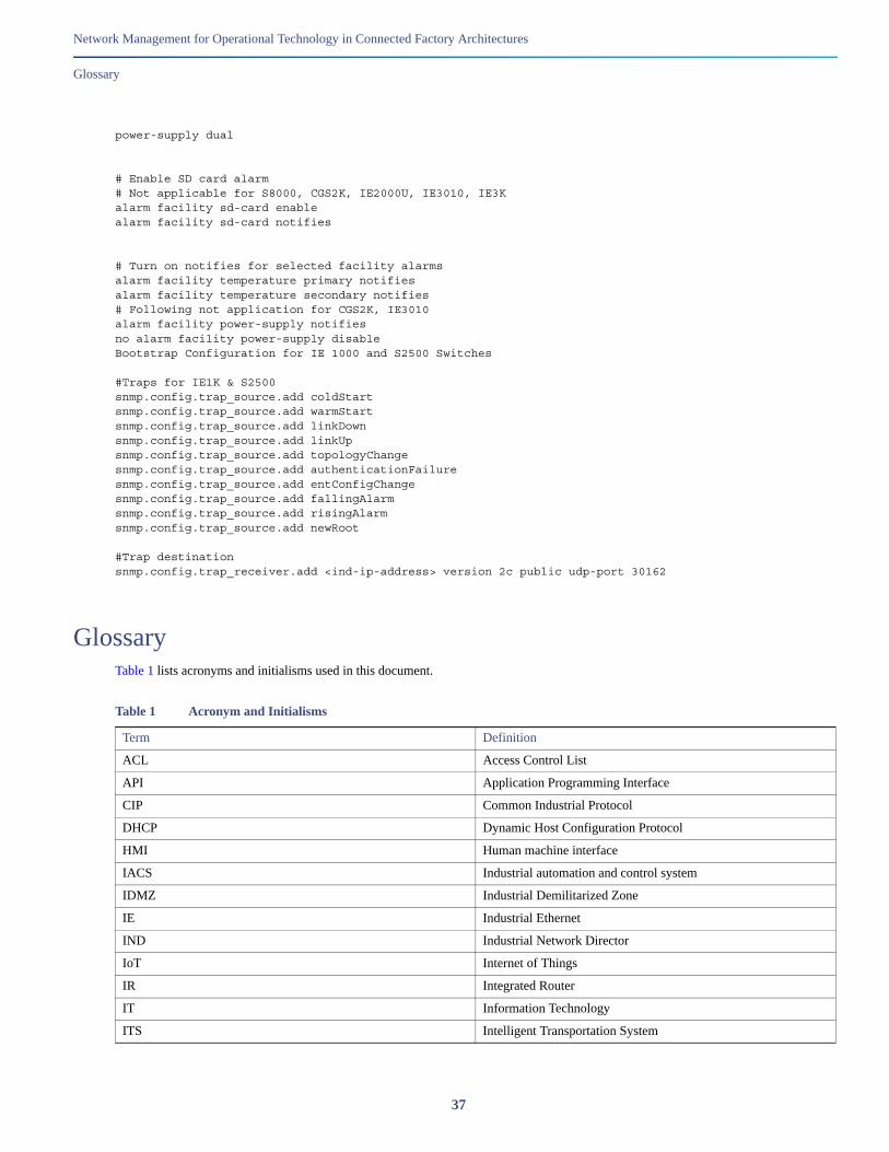
power-supply dual
# Enable SD card alarm# Not applicable for S8000, CGS2K, IE2000U, IE3010, IE3Kalarm facility sd-card enablealarm facility sd-card notifies
# Turn on notifies for selected facility alarmsalarm facility temperature primary notifiesalarm facility temperature secondary notifies# Following not application for CGS2K, IE3010alarm facility power-supply notifiesno alarm facility power-supply disableBootstrap Configuration for IE 1000 and S2500 Switches
#Traps for IE1K & S2500snmp.config.trap_source.add coldStartsnmp.config.trap_source.add warmStart snmp.config.trap_source.add linkDownsnmp.config.trap_source.add linkUpsnmp.config.trap_source.add topologyChangesnmp.config.trap_source.add authenticationFailuresnmp.config.trap_source.add entConfigChangesnmp.config.trap_source.add fallingAlarmsnmp.config.trap_source.add risingAlarmsnmp.config.trap_source.add newRoot
#Trap destinationsnmp.config.trap_receiver.add <ind-ip-address> version 2c public udp-port 30162
GlossaryTable 1 lists acronyms and initialisms used in this document.
Table 1 Acronym and Initialisms
Term Definition
ACL Access Control List
API Application Programming Interface
CIP Common Industrial Protocol
DHCP Dynamic Host Configuration Protocol
HMI Human machine interface
IACS Industrial automation and control system
IDMZ Industrial Demilitarized Zone
IE Industrial Ethernet
IND Industrial Network Director
IoT Internet of Things
IR Integrated Router
IT Information Technology
ITS Intelligent Transportation System
37
Network Management for Operational Technology in Connected Factory Architectures
Glossary
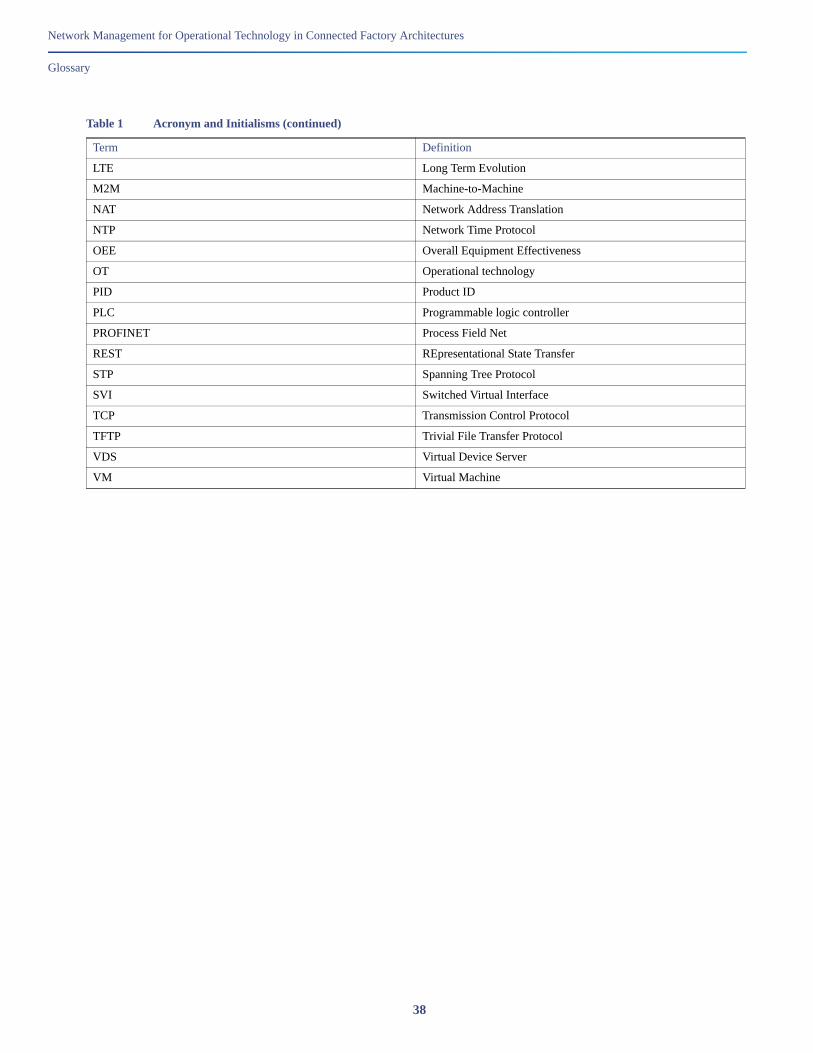
LTE Long Term Evolution
M2M Machine-to-Machine
NAT Network Address Translation
NTP Network Time Protocol
OEE Overall Equipment Effectiveness
OT Operational technology
PID Product ID
PLC Programmable logic controller
PROFINET Process Field Net
REST REpresentational State Transfer
STP Spanning Tree Protocol
SVI Switched Virtual Interface
TCP Transmission Control Protocol
TFTP Trivial File Transfer Protocol
VDS Virtual Device Server
VM Virtual Machine
Table 1 Acronym and Initialisms (continued)
Term Definition
38