Network Layer and Link State Routing Computer Networks Computer NetworksA15.
57
Network Layer and Link State Routing Computer Networks A15
-
Upload
joseph-neal -
Category
Documents
-
view
234 -
download
2
Transcript of Network Layer and Link State Routing Computer Networks Computer NetworksA15.

Network Layerand
Link State Routing
Network Layerand
Link State Routing
Computer NetworksA15
Network Layer OutlineNetwork Layer Outline IP Issues
– Fragmentation, addressing, subnets DHCP Network Address Translation (NAT)
Link State Routing– Reliable Flooding– Dikjstra’s Algorithm
Hierarchical Routing RIP, OSPF, BGP
Computer Networks Network Layer 2

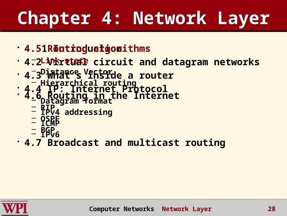
Chapter 4: Network LayerChapter 4: Network Layer 4. 1 Introduction 4.2 Virtual circuit and datagram networks 4.3 What’s inside a router 4.4 IP: Internet Protocol
– Datagram format– IPv4 addressing– ICMP– IPv6
4.5 Routing algorithms– Link state– Distance Vector– Hierarchical routing
4.6 Routing in the Internet– RIP– OSPF– BGP
4.7 Broadcast and multicast routing
Computer Networks Network Layer 3
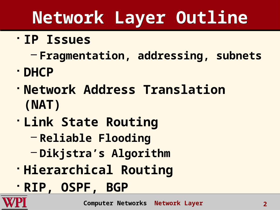
IP Datagram FormatIP Datagram Format
ver length
32 bits
data (variable length,typically a TCP
or UDP segment)
16-bit identifier
header checksum
time tolive
32 bit source IP address
IP protocol versionnumber
header length (bytes)
max numberremaining hops
(decremented at
each router)
forfragmentation/reassembly
total datagram
length (bytes)
upper layer protocolto deliver payload to
head.len
type ofservice
“type” of data flgsfragment
offsetupper layer
32 bit destination IP address
Options (if any) E.g. timestamp,record routetaken, specifylist of routers to visit.
how much overhead with
TCP? 20 bytes of TCP 20 bytes of IP = 40 bytes +
app layer overhead 4 Computer Networks Network Layer
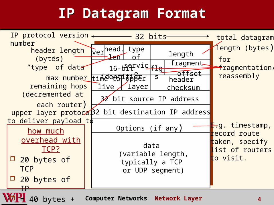
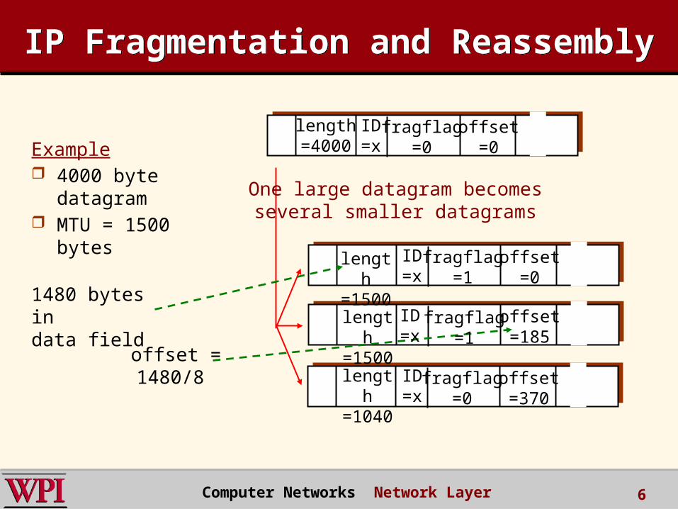
IP Fragmentation & ReassemblyIP Fragmentation & Reassembly
network links have MTU (max.transfer size) - largest possible link-level frame.
– different link types, different MTUs
large IP datagram divided (“fragmented”) within net
– one datagram becomes several datagrams
– “reassembled” only at final destination
– IP header bits used to identify, order related fragments
fragmentation: in: one large datagramout: 3 smaller datagrams
reassembly
Computer Networks Network Layer 5
IP Fragmentation and Reassembly
IP Fragmentation and Reassembly
ID=x
offset=0
fragflag=0
length=4000
ID=x
offset=0
fragflag=1
offset=185
offset=370
fragflag=0
length
=1040
One large datagram becomesseveral smaller datagrams
Example 4000 byte
datagram MTU = 1500
bytes
1480 bytes in
data fieldoffset =1480/8
fragflag=1
length
=1500
length
=1500 ID
=x
ID=x
Computer Networks Network Layer 6
Chapter 4: Network LayerChapter 4: Network Layer 4. 1 Introduction 4.2 Virtual circuit and datagram networks 4.3 What’s inside a router 4.4 IP: Internet Protocol
– Datagram format– IPv4 addressing– ICMP– IPv6
4.5 Routing algorithms– Link state– Distance Vector– Hierarchical routing
4.6 Routing in the Internet– RIP– OSPF– BGP
4.7 Broadcast and multicast routing
Computer Networks Network Layer 7
IP Addressing: IntroductionIP Addressing: Introduction
IP address: 32-bit identifier for host, router interface
interface: connection between host/router and physical link
– router’s typically have multiple interfaces
– host typically has one interface
– IP addresses associated with each interface
223.1.1.1
223.1.1.2
223.1.1.3
223.1.1.4 223.1.2.9
223.1.2.2
223.1.2.1
223.1.3.2223.1.3.1
223.1.3.27
223.1.1.1 = 11011111 00000001 00000001 00000001
223 1 11
Computer Networks Network Layer 8
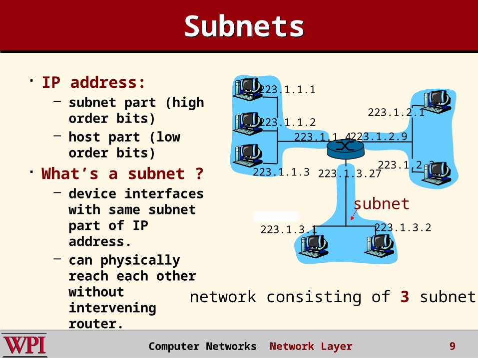
SubnetsSubnets
IP address: – subnet part (high
order bits)– host part (low order
bits) What’s a subnet ?
– device interfaces with same subnet part of IP address.
– can physically reach each other without intervening router.
223.1.1.1
223.1.1.2
223.1.1.3
223.1.1.4 223.1.2.9
223.1.2.2
223.1.2.1
223.1.3.2223.1.3.1
223.1.3.27
network consisting of 3 subnets
subnet
Computer Networks Network Layer 9

SubnetsSubnets223.1.1.0/24
223.1.2.0/24
223.1.3.0/24
Recipe To determine the
subnets, detach each interface from its host or router, creating islands of isolated networks. Each isolated network is called a subnet.
Subnet mask: /24 :: defined by the leftmost 24 bits.
Computer Networks Network Layer 10
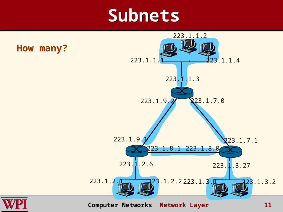
SubnetsSubnets
How many?223.1.1.1
223.1.1.3
223.1.1.4
223.1.2.2223.1.2.1
223.1.2.6
223.1.3.2223.1.3.1
223.1.3.27
223.1.1.2
223.1.7.0
223.1.7.1223.1.8.0223.1.8.1
223.1.9.1
223.1.9.2
Computer Networks Network Layer 11
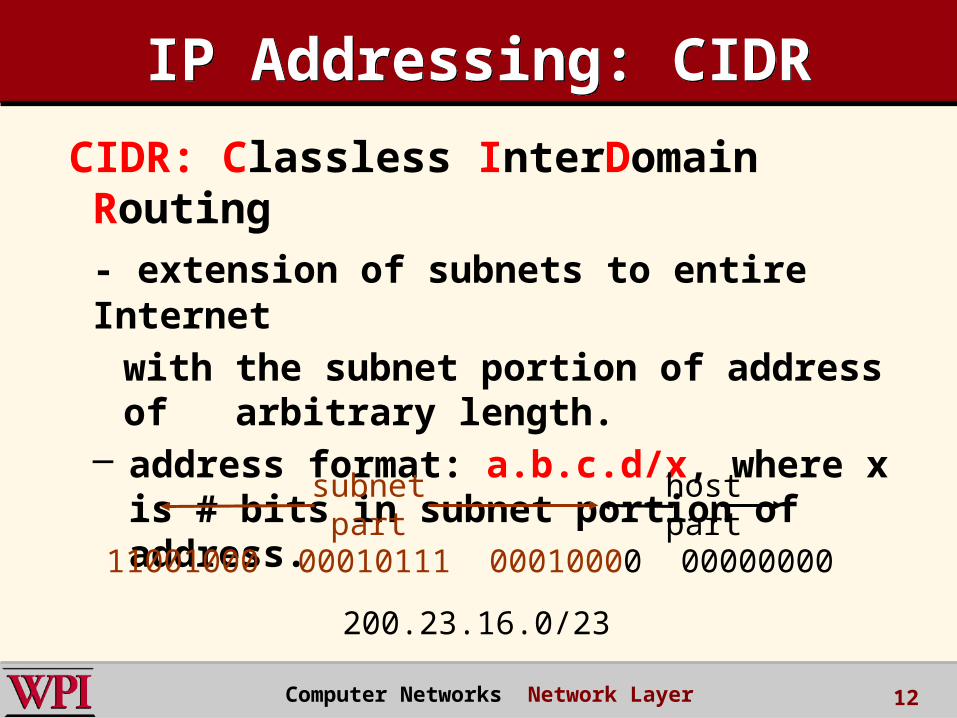
IP Addressing: CIDRIP Addressing: CIDR
CIDR: Classless InterDomain Routing- extension of subnets to entire Internet
with the subnet portion of address of arbitrary length.
– address format: a.b.c.d/x, where x is # bits in subnet portion of address.
11001000 00010111 00010000 00000000
subnetpart
hostpart
200.23.16.0/23
Computer Networks Network Layer 12

IP Addresses: How to Get One?IP Addresses: How to Get One?
Q: How does a host get IP address?
hard-coded by system admin in a file.– Windows: control-panel->network-
>configuration->tcp/ip->properties– UNIX: /etc/rc.config
DHCP: Dynamic Host Configuration Protocol: dynamically get address from a server.– A “plug-and-play” protocol Computer Networks Network Layer 13
DHCP: Dynamic Host Configuration Protocol
DHCP: Dynamic Host Configuration Protocol
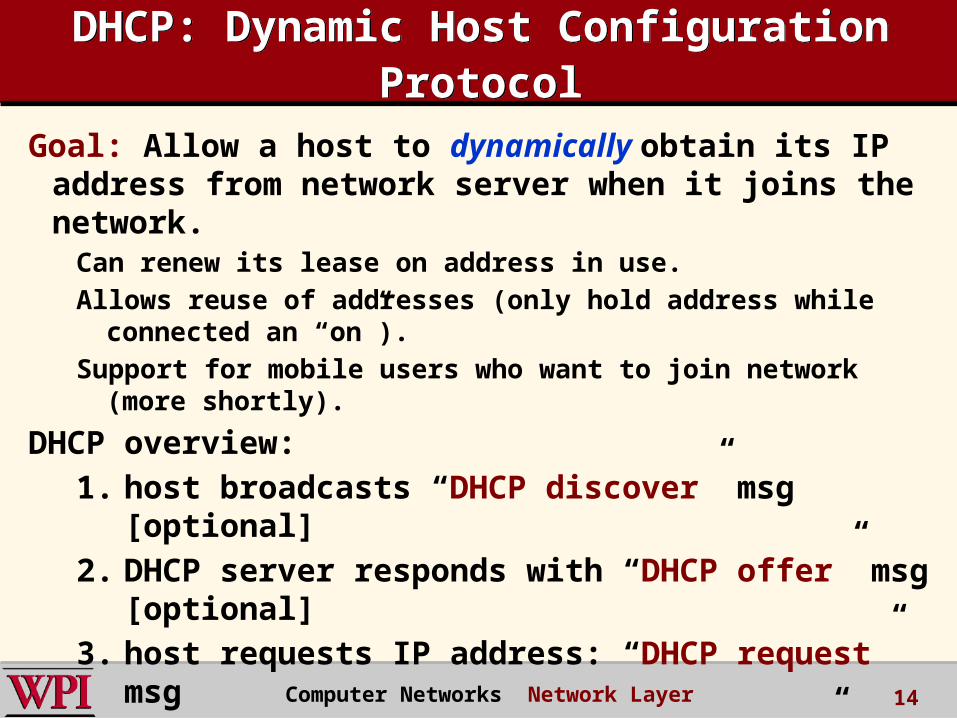
Goal: Allow a host to dynamically obtain its IP address from network server when it joins the network.
Can renew its lease on address in use.
Allows reuse of addresses (only hold address while connected an “on”).
Support for mobile users who want to join network (more shortly).
DHCP overview:1. host broadcasts “DHCP discover” msg [optional]
2. DHCP server responds with “DHCP offer” msg [optional]
3. host requests IP address: “DHCP request” msg
4. DHCP server sends address: “DHCP ack” msg
Computer Networks Network Layer 14
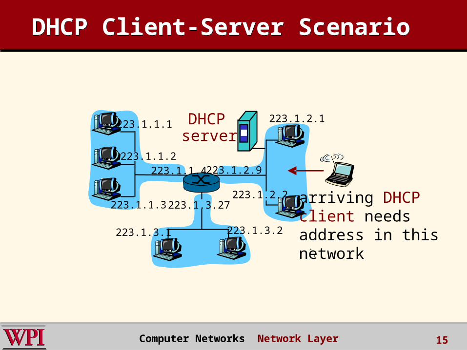
DHCP Client-Server ScenarioDHCP Client-Server Scenario
223.1.1.1
223.1.1.2
223.1.1.3
223.1.1.4 223.1.2.9
223.1.2.2
223.1.2.1
223.1.3.2223.1.3.1
223.1.3.27
A
BE
DHCP server
arriving DHCP client needsaddress in thisnetwork
Computer Networks Network Layer 15
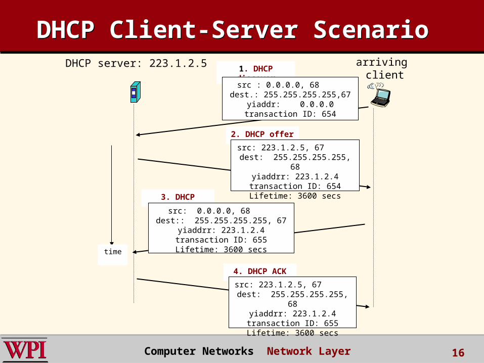
DHCP Client-Server ScenarioDHCP Client-Server ScenarioDHCP server: 223.1.2.5 arriving
client
time
1. DHCP discover
src : 0.0.0.0, 68 dest.: 255.255.255.255,67
yiaddr: 0.0.0.0transaction ID: 654
2. DHCP offer
src: 223.1.2.5, 67 dest: 255.255.255.255, 68
yiaddrr: 223.1.2.4transaction ID: 654Lifetime: 3600 secs
3. DHCP request
src: 0.0.0.0, 68 dest:: 255.255.255.255, 67
yiaddrr: 223.1.2.4transaction ID: 655Lifetime: 3600 secs
4. DHCP ACK
src: 223.1.2.5, 67 dest: 255.255.255.255, 68
yiaddrr: 223.1.2.4transaction ID: 655Lifetime: 3600 secs
Computer Networks Network Layer 16
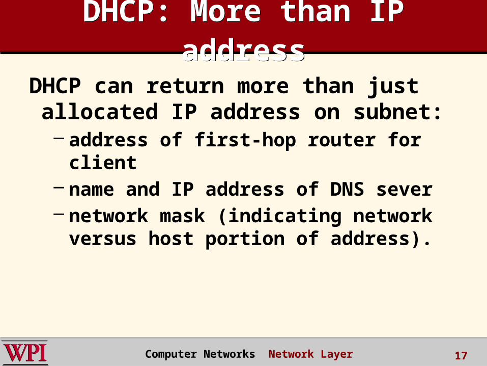
DHCP: More than IP address
DHCP: More than IP address
DHCP can return more than just allocated IP address on subnet:– address of first-hop router for client– name and IP address of DNS sever– network mask (indicating network versus
host portion of address).
Computer Networks Network Layer 17
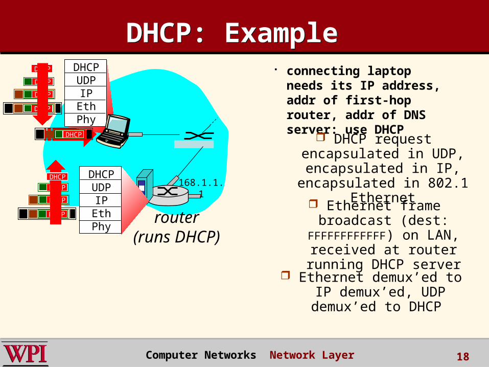
DHCP: ExampleDHCP: Example connecting laptop
needs its IP address, addr of first-hop router, addr of DNS server: use DHCP
router(runs DHCP)
DHCPUDP
IPEthPhy
DHCP
DHCP
DHCP
DHCP
DHCP
DHCPUDP
IPEthPhy
DHCP
DHCP
DHCP
DHCPDHCP
DHCP request encapsulated in UDP, encapsulated in IP,
encapsulated in 802.1 Ethernet Ethernet frame broadcast
(dest: FFFFFFFFFFFF) on LAN, received at router running
DHCP server
Ethernet demux’ed to IP demux’ed, UDP
demux’ed to DHCP
168.1.1.1
Computer Networks Network Layer 18
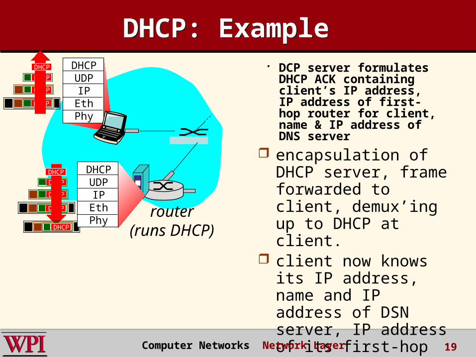
DCP server formulates DHCP ACK containing client’s IP address, IP address of first-hop router for client, name & IP address of DNS server
router(runs DHCP)
DHCPUDP
IPEthPhy
DHCP
DHCP
DHCP
DHCP
DHCPUDP
IPEthPhy
DHCP
DHCP
DHCP
DHCP
DHCP
encapsulation of DHCP server, frame forwarded to client, demux’ing up to DHCP at client.
client now knows its IP address, name and IP address of DSN server, IP address of its first-hop router.
DHCP: ExampleDHCP: Example
Computer Networks Network Layer 19
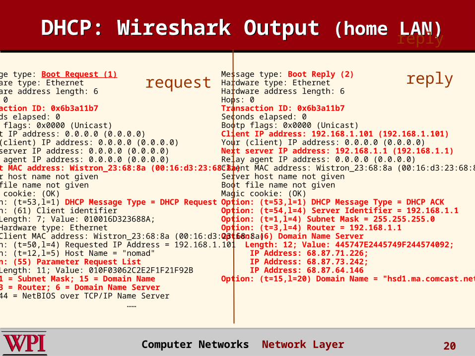
DHCP: Wireshark Output (home LAN)DHCP: Wireshark Output (home LAN)
Message type: Boot Reply (2)Hardware type: EthernetHardware address length: 6Hops: 0Transaction ID: 0x6b3a11b7Seconds elapsed: 0Bootp flags: 0x0000 (Unicast)Client IP address: 192.168.1.101 (192.168.1.101)Your (client) IP address: 0.0.0.0 (0.0.0.0)Next server IP address: 192.168.1.1 (192.168.1.1)Relay agent IP address: 0.0.0.0 (0.0.0.0)Client MAC address: Wistron_23:68:8a (00:16:d3:23:68:8a)Server host name not givenBoot file name not givenMagic cookie: (OK)Option: (t=53,l=1) DHCP Message Type = DHCP ACKOption: (t=54,l=4) Server Identifier = 192.168.1.1Option: (t=1,l=4) Subnet Mask = 255.255.255.0Option: (t=3,l=4) Router = 192.168.1.1Option: (6) Domain Name Server Length: 12; Value: 445747E2445749F244574092; IP Address: 68.87.71.226; IP Address: 68.87.73.242; IP Address: 68.87.64.146Option: (t=15,l=20) Domain Name = "hsd1.ma.comcast.net."
reply
Message type: Boot Request (1)Hardware type: EthernetHardware address length: 6Hops: 0Transaction ID: 0x6b3a11b7Seconds elapsed: 0Bootp flags: 0x0000 (Unicast)Client IP address: 0.0.0.0 (0.0.0.0)Your (client) IP address: 0.0.0.0 (0.0.0.0)Next server IP address: 0.0.0.0 (0.0.0.0)Relay agent IP address: 0.0.0.0 (0.0.0.0)Client MAC address: Wistron_23:68:8a (00:16:d3:23:68:8a)Server host name not givenBoot file name not givenMagic cookie: (OK)Option: (t=53,l=1) DHCP Message Type = DHCP RequestOption: (61) Client identifier Length: 7; Value: 010016D323688A; Hardware type: Ethernet Client MAC address: Wistron_23:68:8a (00:16:d3:23:68:8a)Option: (t=50,l=4) Requested IP Address = 192.168.1.101Option: (t=12,l=5) Host Name = "nomad"Option: (55) Parameter Request List Length: 11; Value: 010F03062C2E2F1F21F92B 1 = Subnet Mask; 15 = Domain Name 3 = Router; 6 = Domain Name Server 44 = NetBIOS over TCP/IP Name Server
……
request reply
Computer Networks Network Layer 20
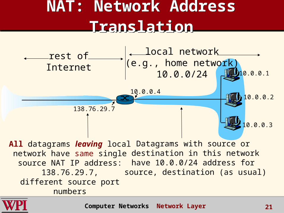
NAT: Network Address Translation
NAT: Network Address Translation
10.0.0.1
10.0.0.2
10.0.0.3
10.0.0.4
138.76.29.7
local network(e.g., home network)
10.0.0/24
rest ofInternet
Datagrams with source or destination in this networkhave 10.0.0/24 address for
source, destination (as usual)
All datagrams leaving localnetwork have same single source
NAT IP address: 138.76.29.7,different source port numbers
Computer Networks Network Layer 21
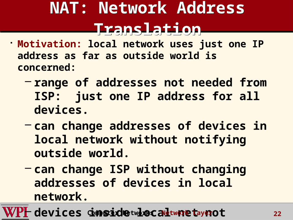
Motivation: local network uses just one IP address as far as outside world is concerned:– range of addresses not needed from ISP:
just one IP address for all devices.– can change addresses of devices in local
network without notifying outside world.– can change ISP without changing addresses
of devices in local network.– devices inside local net not explicitly
addressable, visible by outside world (a security plus).
NAT: Network Address Translation
NAT: Network Address Translation
Computer Networks Network Layer 22
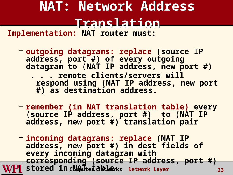
Implementation: NAT router must:
– outgoing datagrams: replace (source IP address, port #) of every outgoing datagram to (NAT IP address, new port #)
. . . remote clients/servers will respond using (NAT IP address, new port #) as destination address.
– remember (in NAT translation table) every (source IP address, port #) to (NAT IP address, new port #) translation pair
– incoming datagrams: replace (NAT IP address, new port #) in dest fields of every incoming datagram with corresponding (source IP address, port #) stored in NAT table.
NAT: Network Address Translation
NAT: Network Address Translation
Computer Networks Network Layer 23
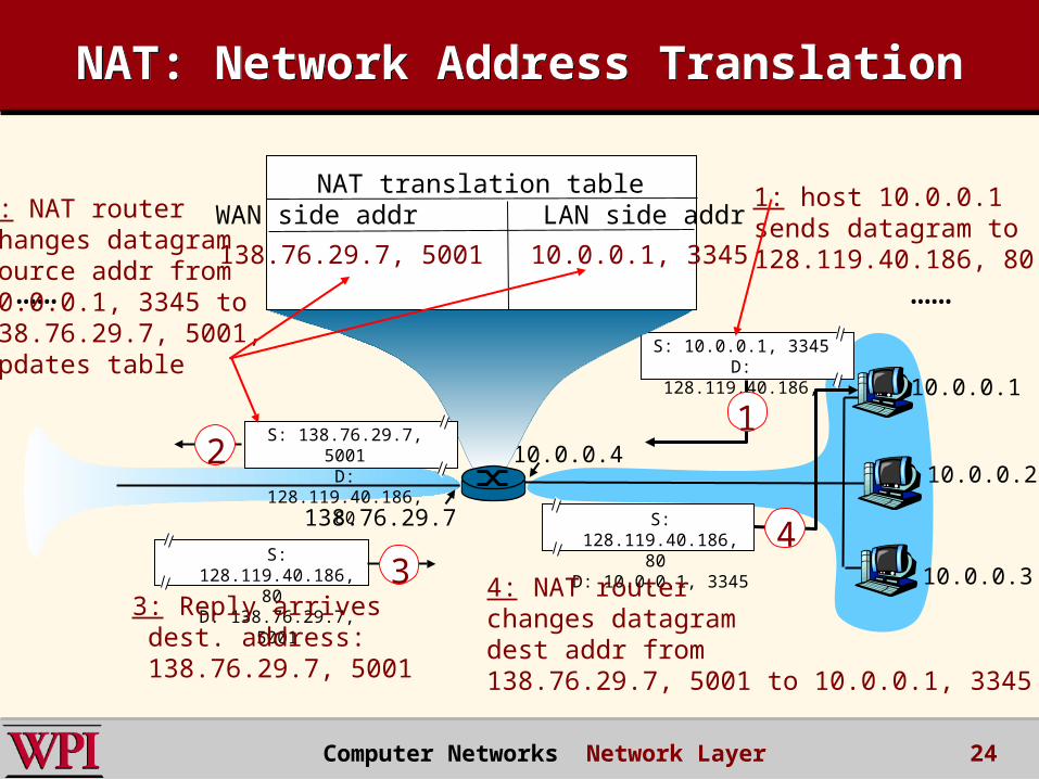
NAT: Network Address TranslationNAT: Network Address Translation
10.0.0.1
10.0.0.2
10.0.0.3
S: 10.0.0.1, 3345D: 128.119.40.186,
80
110.0.0.4
138.76.29.7
1: host 10.0.0.1 sends datagram to 128.119.40.186, 80
NAT translation tableWAN side addr LAN side addr
138.76.29.7, 5001 10.0.0.1, 3345
…… ……
S: 128.119.40.186, 80
D: 10.0.0.1, 33454
S: 138.76.29.7, 5001
D: 128.119.40.186, 80
2
2: NAT routerchanges datagramsource addr from10.0.0.1, 3345 to138.76.29.7, 5001,updates table
S: 128.119.40.186, 80
D: 138.76.29.7, 5001
33: Reply arrives dest. address: 138.76.29.7, 5001
4: NAT routerchanges datagramdest addr from138.76.29.7, 5001 to 10.0.0.1, 3345
Computer Networks Network Layer 24
Computer Networks Network Layer
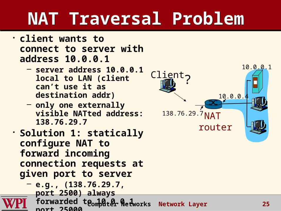
NAT Traversal ProblemNAT Traversal Problem client wants to connect
to server with address 10.0.0.1
– server address 10.0.0.1 local to LAN (client can’t use it as destination addr)
– only one externally visible NATted address: 138.76.29.7
Solution 1: statically configure NAT to forward incoming connection requests at given port to server
– e.g., (138.76.29.7, port 2500) always forwarded to 10.0.0.1 port 25000
10.0.0.1
10.0.0.4
NAT router
138.76.29.7
Client ?
25
Computer Networks Network Layer
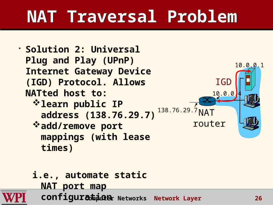
NAT Traversal ProblemNAT Traversal Problem
Solution 2: Universal Plug and Play (UPnP) Internet Gateway Device (IGD) Protocol. Allows NATted host to:
learn public IP address (138.76.29.7)
add/remove port mappings (with lease times)
i.e., automate static NAT port map configuration
10.0.0.1
10.0.0.4
NAT router
138.76.29.7
IGD
26
Computer Networks Network Layer
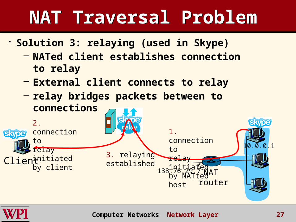
NAT Traversal ProblemNAT Traversal Problem Solution 3: relaying (used in Skype)
– NATed client establishes connection to relay– External client connects to relay– relay bridges packets between to connections
138.76.29.7Client
10.0.0.1
NAT router
1. connection torelay initiatedby NATted host
2. connection torelay initiatedby client
3. relaying established
27
Chapter 4: Network LayerChapter 4: Network Layer 4. 1 Introduction 4.2 Virtual circuit and datagram networks 4.3 What’s inside a router 4.4 IP: Internet Protocol
– Datagram format– IPv4 addressing– ICMP– IPv6
4.5 Routing algorithms– Link state– Distance Vector– Hierarchical routing
4.6 Routing in the Internet– RIP– OSPF– BGP
4.7 Broadcast and multicast routing
Computer Networks Network Layer 28
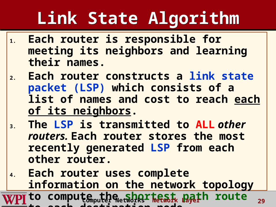
Link State AlgorithmLink State Algorithm1. Each router is responsible for meeting
its neighbors and learning their names.
2. Each router constructs a link state packet (LSP) which consists of a list of names and cost to reach each of its neighbors.
3. The LSP is transmitted to ALL other routers. Each router stores the most recently generated LSP from each other router.
4. Each router uses complete information on the network topology to compute the shortest path route to each destination node.
Computer Networks Network Layer 29

Figure 4.18 Reliable LSP FloodingFigure 4.18 Reliable LSP Flooding
(a)
X A
C B D
(b)
X A
C B D
(c)
X A
C B D
(d)
X A
C B D
P&D slide
Reliable Flooding
Computer Networks Network Layer 30
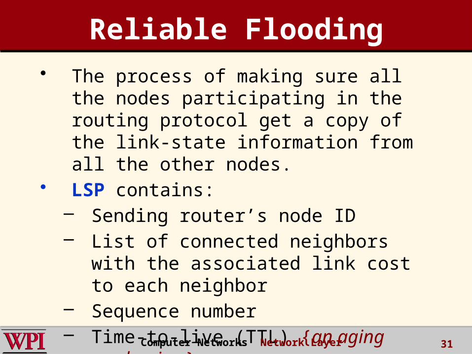
Reliable Flooding• The process of making sure all the
nodes participating in the routing protocol get a copy of the link-state information from all the other nodes.
• LSP contains:– Sending router’s node ID– List of connected neighbors with the
associated link cost to each neighbor– Sequence number– Time-to-live (TTL) {an aging
mechanism} Computer Networks Network Layer 31
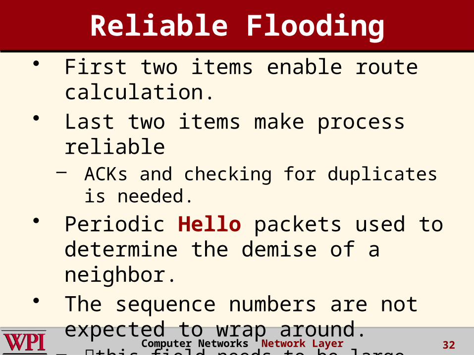
• First two items enable route calculation.
• Last two items make process reliable
– ACKs and checking for duplicates is needed.
• Periodic Hello packets used to determine the demise of a neighbor.
• The sequence numbers are not expected to wrap around.
– this field needs to be large (64 bits) !!
Reliable Flooding
Computer Networks Network Layer 32
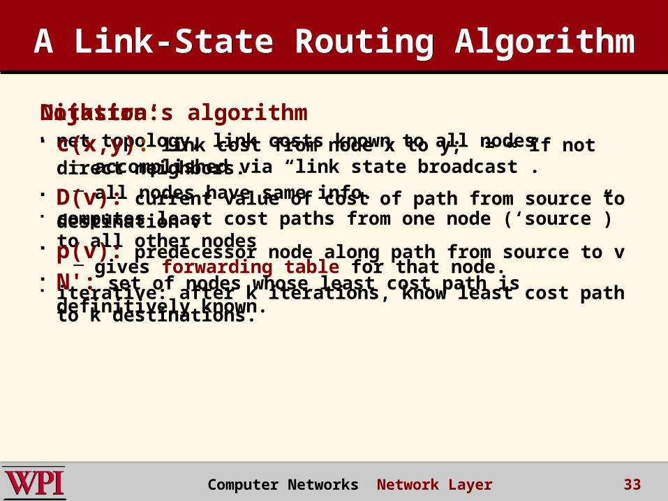
A Link-State Routing AlgorithmA Link-State Routing Algorithm
Dijkstra’s algorithm net topology, link costs known to all nodes
– accomplished via “link state broadcast”. – all nodes have same info.
computes least cost paths from one node (‘source”) to all other nodes
– gives forwarding table for that node. iterative: after k iterations, know least cost path to k
destinations.
Notation: c(x,y): link cost from node x to y; = ∞ if not direct
neighbors. D(v): current value of cost of path from source to
destination v p(v): predecessor node along path from source to v N': set of nodes whose least cost path is definitively
known.
Computer Networks Network Layer 33
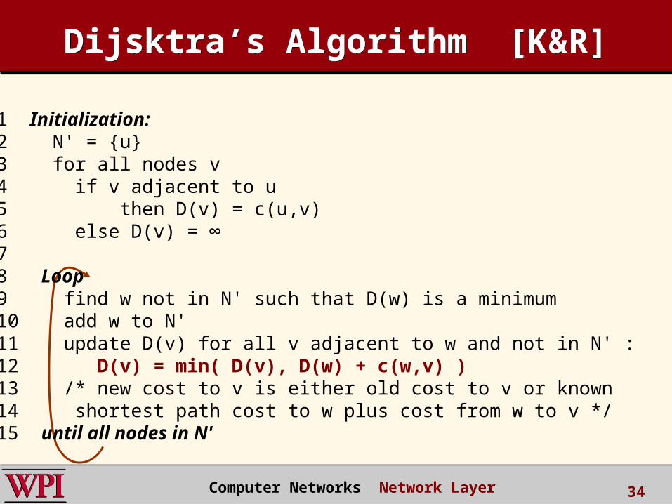
Dijsktra’s Algorithm [K&R]Dijsktra’s Algorithm [K&R]
1 Initialization: 2 N' = {u} 3 for all nodes v 4 if v adjacent to u 5 then D(v) = c(u,v) 6 else D(v) = ∞ 7 8 Loop 9 find w not in N' such that D(w) is a minimum 10 add w to N' 11 update D(v) for all v adjacent to w and not in N' : 12 D(v) = min( D(v), D(w) + c(w,v) ) 13 /* new cost to v is either old cost to v or known 14 shortest path cost to w plus cost from w to v */ 15 until all nodes in N'
Computer Networks Network Layer 34
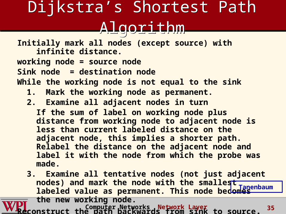
Dijkstra’s Shortest Path Algorithm
Dijkstra’s Shortest Path Algorithm
Initially mark all nodes (except source) with infinite distance.
working node = source nodeSink node = destination nodeWhile the working node is not equal to the sink 1. Mark the working node as permanent. 2. Examine all adjacent nodes in turn
If the sum of label on working node plus distance from working node to adjacent node is less than current labeled distance on the adjacent node, this implies a shorter path. Relabel the distance on the adjacent node and label it with the node from which the probe was made.
3. Examine all tentative nodes (not just adjacent nodes) and mark the node with the smallest labeled value as permanent. This node becomes the new working node.
Reconstruct the path backwards from sink to source. Computer Networks Network Layer 35
Tanenbaum
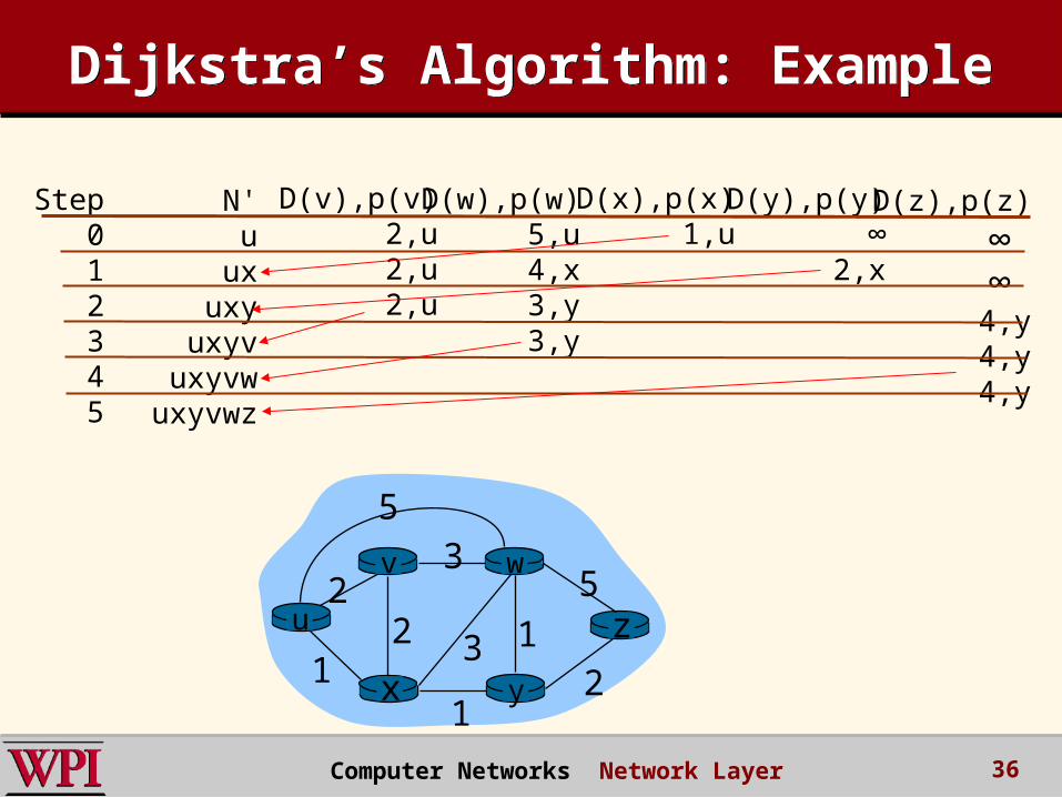
Dijkstra’s Algorithm: ExampleDijkstra’s Algorithm: Example
Step012345
N'u
uxuxy
uxyvuxyvw
uxyvwz
D(v),p(v)2,u2,u2,u
D(w),p(w)5,u4,x3,y3,y
D(x),p(x)1,u
D(y),p(y)∞
2,x
D(z),p(z)
∞ ∞ 4,y4,y4,y
u
yx
wv
z2
21
3
1
12
53
5
Computer Networks Network Layer 36
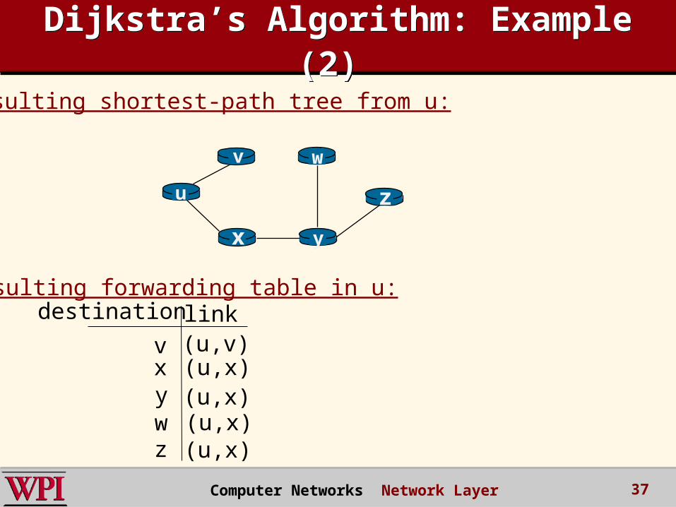
Dijkstra’s Algorithm: Example (2)
Dijkstra’s Algorithm: Example (2)
u
yx
wv
z
Resulting shortest-path tree from u:
vxywz
(u,v)(u,x)(u,x)(u,x)(u,x)
destination linkResulting forwarding table in u:
Computer Networks Network Layer 37
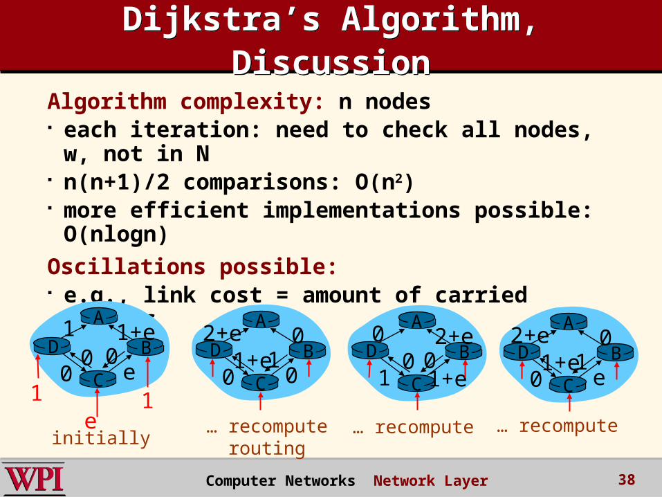
Dijkstra’s Algorithm, DiscussionDijkstra’s Algorithm, Discussion
Algorithm complexity: n nodes each iteration: need to check all nodes, w,
not in N n(n+1)/2 comparisons: O(n2) more efficient implementations possible:
O(nlogn)
Oscillations possible: e.g., link cost = amount of carried traffic
A
D
C
B1 1+e
e0
e1 1
0 0
A
D
C
B2+e 0
001+e1
A
D
C
B0 2+e
1+e10 0
A
D
C
B2+e 0
e01+e1
initially… recompute
routing… recompute … recompute
Computer Networks Network Layer 38

Chapter 4: Network LayerChapter 4: Network Layer 4. 1 Introduction 4.2 Virtual circuit and datagram networks 4.3 What’s inside a router 4.4 IP: Internet Protocol
– Datagram format– IPv4 addressing– ICMP– IPv6
4.5 Routing algorithms– Link state– Distance Vector– Hierarchical routing
4.6 Routing in the Internet– RIP– OSPF– BGP
4.7 Broadcast and multicast routing
Computer Networks Network Layer 39
Hierarchical RoutingHierarchical Routing
scale: with 200 million destinations:
can’t store all destinations in routing tables!
routing table exchange would swamp links!
administrative autonomy
internet = network of networks
each network admin may want to control routing in its own network
Our routing study thus far – an idealization
all routers identical network “flat” … not true in practice
Computer Networks Network Layer 40
Hierarchical RoutingHierarchical Routing
aggregate routers into regions, “autonomous systems” (AS)
routers in same AS run same routing protocol
– “intra-AS” routing protocol
– routers in different AS can run different intra-AS routing protocol
Gateway router Direct link to router
in another AS
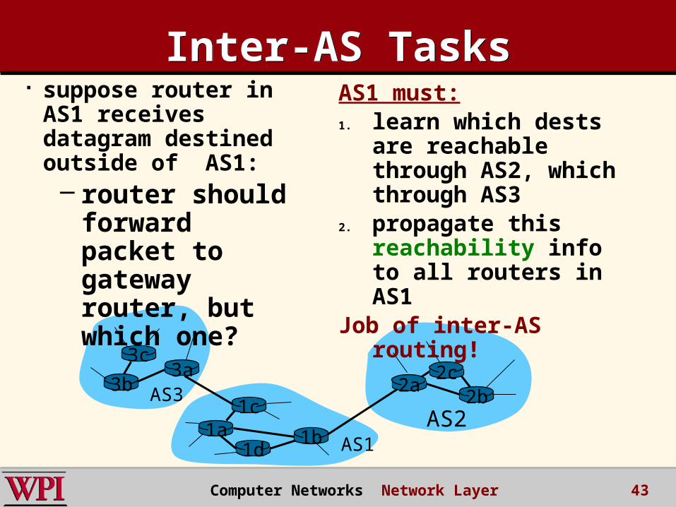
Computer Networks Network Layer 41
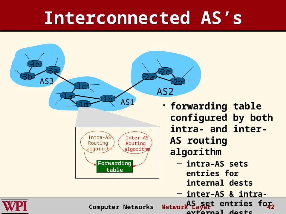
3b
1d
3a
1c2aAS3
AS1AS21a
2c2b
1b
Intra-ASRouting algorithm
Inter-ASRouting algorithm
Forwardingtable
3c
Interconnected AS’sInterconnected AS’s
forwarding table configured by both intra- and inter-AS routing algorithm
– intra-AS sets entries for internal dests
– inter-AS & intra-AS set entries for external dests
Computer Networks Network Layer 42
3b
1d
3a
1c2aAS3
AS1AS21a
2c2b
1b
3c
Inter-AS TasksInter-AS Tasks suppose router in
AS1 receives datagram destined outside of AS1:– router should
forward packet to gateway router, but which one?
AS1 must:1. learn which dests
are reachable through AS2, which through AS3
2. propagate this reachability info to all routers in AS1
Job of inter-AS routing!
Computer Networks Network Layer 43
Chapter 4: Network LayerChapter 4: Network Layer 4. 1 Introduction 4.2 Virtual circuit and datagram networks 4.3 What’s inside a router 4.4 IP: Internet Protocol
– Datagram format– IPv4 addressing– ICMP– IPv6
4.5 Routing algorithms– Link state– Distance Vector– Hierarchical routing
4.6 Routing in the Internet– RIP– OSPF– BGP
4.7 Broadcast and multicast routing
Computer Networks Network Layer 44
Intra-AS RoutingIntra-AS Routing
also known as Interior Gateway Protocols (IGP)
most common Intra-AS routing protocols:
– RIP: Routing Information Protocol
– OSPF: Open Shortest Path First
– IGRP: Interior Gateway Routing Protocol (Cisco proprietary)
Computer Networks Network Layer 45

Chapter 4: Network LayerChapter 4: Network Layer 4. 1 Introduction 4.2 Virtual circuit and datagram networks 4.3 What’s inside a router 4.4 IP: Internet Protocol
– Datagram format– IPv4 addressing– ICMP– IPv6
4.5 Routing algorithms– Link state– Distance Vector– Hierarchical routing
4.6 Routing in the Internet– RIP– OSPF– BGP
4.7 Broadcast and multicast routing
Computer Networks Network Layer 46
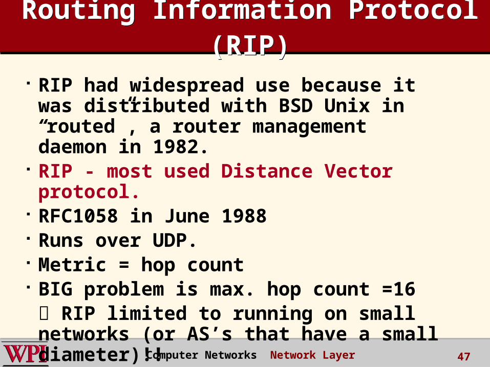
Routing Information Protocol (RIP)
Routing Information Protocol (RIP)
RIP had widespread use because it was distributed with BSD Unix in “routed”, a router management daemon in 1982.
RIP - most used Distance Vector protocol.
RFC1058 in June 1988 Runs over UDP. Metric = hop count BIG problem is max. hop count =16 RIP limited to running on small networks (or AS’s that have a small diameter)!! Computer Networks Network Layer 47
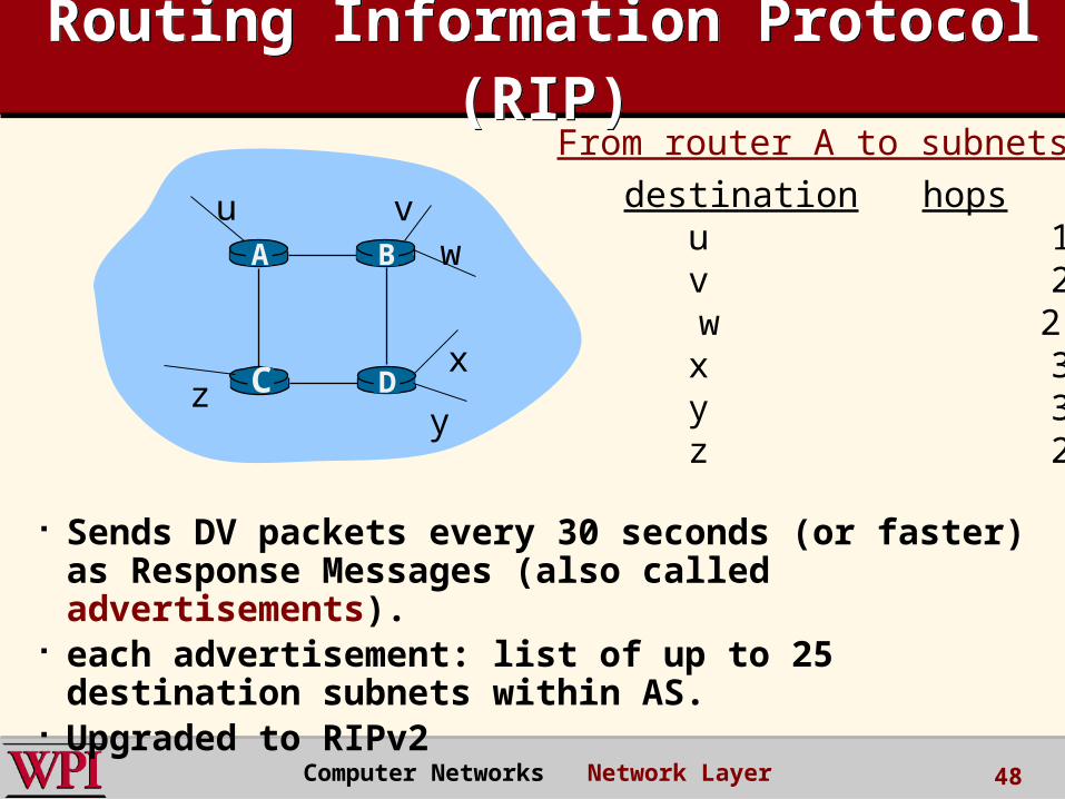
Routing Information Protocol (RIP)
Routing Information Protocol (RIP)
Sends DV packets every 30 seconds (or faster) as Response Messages (also called advertisements).
each advertisement: list of up to 25 destination subnets within AS.
Upgraded to RIPv2
DC
BA
u vw
x
yz
destination hops u 1 v 2 w 2 x 3 y 3 z 2
From router A to subnets:
Computer Networks Network Layer 48
Figure 4.17 RIP Packet FormatFigure 4.17 RIP Packet Format
Address of net 2
Distance to net 2
Command Must be zero
Family of net 2 Address of net 2
Family of net 1 Address of net 1
Address of net 1
Distance to net 1
Version
0 8 16 31
(network_address,distance)
pairs
P&D slide
RIP PacketsRIP Packets
Computer Networks Network Layer 49
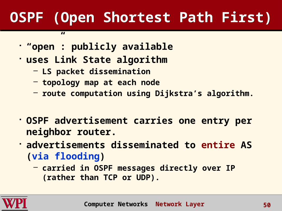
OSPF (Open Shortest Path First)OSPF (Open Shortest Path First)
“open”: publicly available uses Link State algorithm
– LS packet dissemination– topology map at each node– route computation using Dijkstra’s algorithm.
OSPF advertisement carries one entry per neighbor router.
advertisements disseminated to entire AS (via flooding)
– carried in OSPF messages directly over IP (rather than TCP or UDP).
Computer Networks Network Layer 50
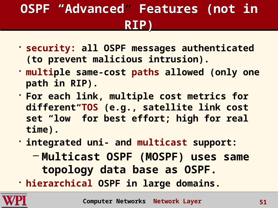
OSPF “Advanced” Features (not in RIP)
OSPF “Advanced” Features (not in RIP)
security: all OSPF messages authenticated (to prevent malicious intrusion).
multiple same-cost paths allowed (only one path in RIP).
For each link, multiple cost metrics for different TOS (e.g., satellite link cost set “low” for best effort; high for real time).
integrated uni- and multicast support: – Multicast OSPF (MOSPF) uses same
topology data base as OSPF. hierarchical OSPF in large domains.
Computer Networks Network Layer 51
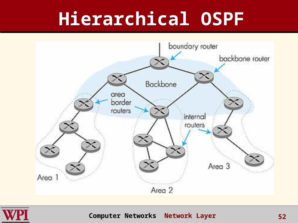
Hierarchical OSPFHierarchical OSPF
Computer Networks Network Layer 52
Hierarchical OSPFHierarchical OSPF two-level hierarchy: local area, backbone.
– Link-State Advertisements (LSAs) only in area
– each node has detailed area topology; only knows direction (shortest path) to nets in other areas.
area border routers: “summarize” distances to nets in own area, advertise to other Area Border routers.
backbone routers: run OSPF routing limited to backbone.
boundary routers: connect to other AS’s.
Computer Networks Network Layer 53
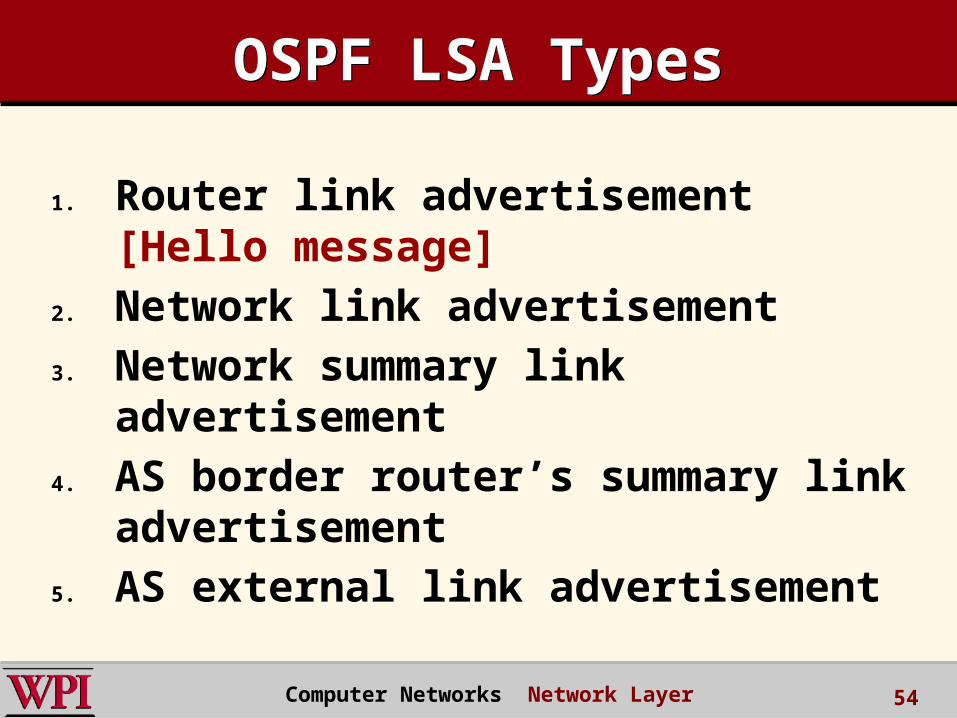
OSPF LSA TypesOSPF LSA Types
1. Router link advertisement [Hello message]
2. Network link advertisement3. Network summary link
advertisement4. AS border router’s summary link
advertisement5. AS external link advertisement
Computer Networks Network Layer 54

Chapter 4: Network LayerChapter 4: Network Layer 4. 1 Introduction 4.2 Virtual circuit and datagram networks 4.3 What’s inside a router 4.4 IP: Internet Protocol
– Datagram format– IPv4 addressing– ICMP– IPv6
4.5 Routing algorithms– Link state– Distance Vector– Hierarchical routing
4.6 Routing in the Internet– RIP– OSPF– BGP
4.7 Broadcast and multicast routing
Computer Networks Network Layer 55
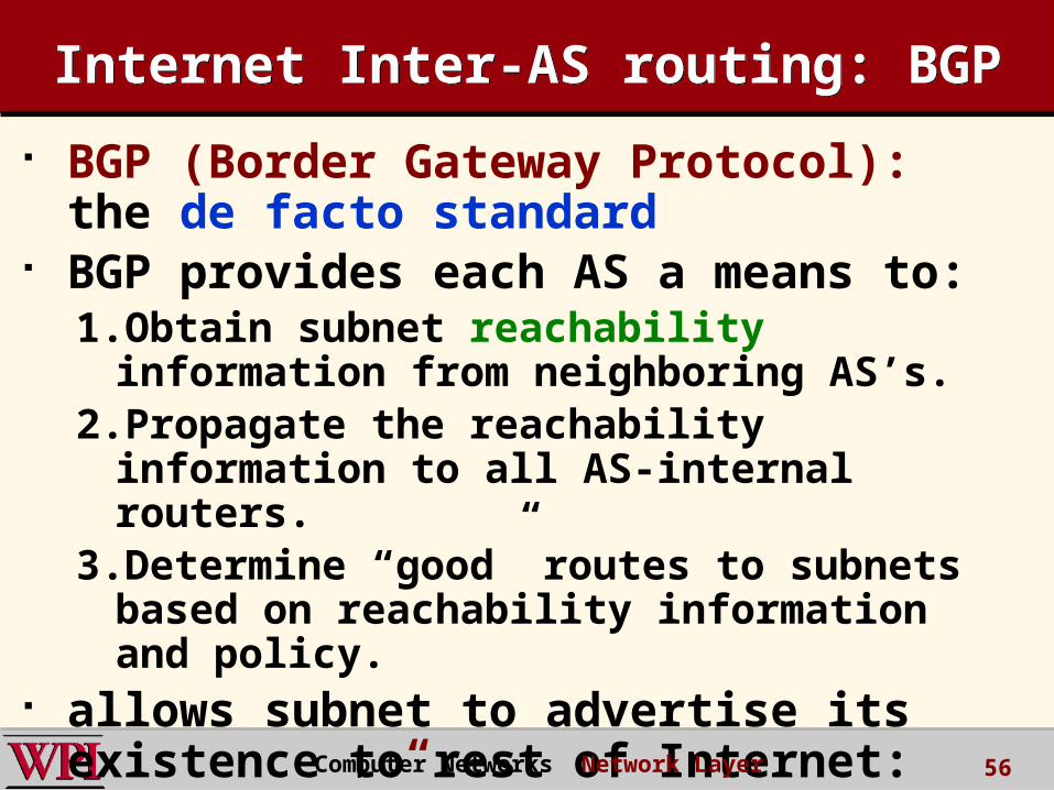
Internet Inter-AS routing: BGPInternet Inter-AS routing: BGP
BGP (Border Gateway Protocol): the de facto standard
BGP provides each AS a means to:1.Obtain subnet reachability information from
neighboring AS’s.2.Propagate the reachability information to all
AS-internal routers.3.Determine “good” routes to subnets based
on reachability information and policy. allows subnet to advertise its
existence to rest of Internet: “I am here!”
Computer Networks Network Layer 56

Network Layer SummaryNetwork Layer Summary IP Issues
– Fragmentation, addressing, subnets DHCP Network Address Translation (NAT)
Link State Routing– Reliable Flooding– Dikjstra’s Algorithm
Hierarchical Routing RIP, OSPF, BGP
Computer Networks Network Layer 57