NetSOLO CLASSIC - Bass United
52
NetSOLO ® CLASSIC NETWORK EMERGENCY VOICE EVACUATION SYSTEM Copyright © 2004 All Rights Reserved Published in U.S.A. Part No. 9000-0565 Revision A 16 Southwest Park, Westwood, MA 02090 USA TEL: (781) 471-3000 FAX: (781) 471-3099
Transcript of NetSOLO CLASSIC - Bass United

NetSOLO® CLASSIC
NETWORK EMERGENCY VOICE EVACUATION SYSTEM
Copyright © 2004 All Rights Reserved Published in U.S.A. Part No. 9000-0565 Revision A
16 Southwest Park, Westwood, MA 02090 USA TEL: (781) 471-3000 FAX: (781) 471-3099


16 Southwest Park, Westwood, MA 02090 USA TEL: (781) 471-3000 FAX: (781) 471-3099
9000-0565 Rev. A
II
IMPORTANT INFORMATION This manual is designed for use by factory trained installers and operators of the Fire Control Instruments, Inc. (FCI) NetSOLO® Classic Emergency Voice Evacuation and Fire Alarm Control system. All illustrations, functional descriptions, operating and installation procedures, and other relevant information are contained in this manual. The contents of this manual are important, and the manual must be kept with the system at all times. If building ownership is changed, this manual, including any testing and maintenance information, must be passed along to the new owner(s). The NetSOLO® Classic panel is part of a system. Manuals and instructions for other devices forming part of the system should be kept together. Purchasers who install this system for use by others must leave the instructions with the user. A copy of these instructions is included with each product and is available from the manufacturer. This equipment is Listed by various listing agencies for use in emergency evacuation and fire alarm systems. Use only components that are compatible with this FCI system. The installation MUST be in accordance with the instructions in this manual. Therefore:
• DO NOT deviate from the procedures described in this manual. • DO NOT assume any details not shown in this manual. • DO NOT modify any electrical or mechanical features. • DO comply with all codes and standards set forth by the Authority Having Jurisdiction
The term “Authority Having Jurisdiction” has become a standard term in the fire alarm industry. An acceptable definition of “Authority Having Jurisdiction” is: Fire alarm systems installed in the USA fall under the jurisdiction of some authority. In some areas, this may be a local fire department; in other areas, it may be a building inspector, insurance firm, etc. Different authorities may have their own local requirements for the way the fire alarm system is installed and used. Most local authorities based their requirements on the NFPA (National Fire Protection Association) codes, but there may be important differences. You must install this system in the way in which the Authority Having Jurisdiction requires. If you do not know which authority has jurisdiction in your area, contact your local fire department or building inspector for guidance. It is important that you tell users to be aware of any requirements defined by the Authority Having Jurisdiction. The installation MUST be in accordance with the following standards:
• National Fire Alarm Code (NFPA 72) • National Electrical Code (NFPA 70) • Life Safety Code (NFPA 101)
WARNING: Touching components, which are improperly installed, applied or operated, could be hazardous and possibly fatal. Short circuits could cause arcing that could result in molten metal injuries. Therefore, only qualified technicians familiar
with electrical hazards should perform checkout procedures. Safety glasses should be worn, and test equipment used for voltage measurements should be designed for this purpose and be in good working order. ENVIRONMENTAL CONSIDERATIONS It is important that this equipment be operated within its specifications
Recommended operating temperature range: 60 to 80° F (15 to 27° C) Absolute maximum operating temperature range: 32 to 120° F (0 to 49° C) Operating humidity: not to exceed 85%,
non-condensing at 90° F (32° C) Operating this equipment within the recommended temperature range will extend the useful life of the system standby batteries.
!

16 Southwest Park, Westwood, MA 02090 USA TEL: (781) 471-3000 FAX: (781) 471-3099
9000-0565 Rev. A
III
INSTALLATION CONSIDERATIONS Check that you have all the equipment you need to complete the installation. Follow the field wiring diagrams and installation notes in this manual. Install the equipment in a clean, dry environment (minimal dust). Avoid installing the equipment where vibrations will occur. Remove all electronic assemblies prior to drilling, filing, reaming, or punching the enclosure. When possible, make all cable entries from the side, being careful to separate the power limited conductors form the non-power limited conductors. Before making modifications, verify that they will not interfere with battery, transformer, and printed circuit board location. Do not over tighten screw terminals. Over tightening may damage threads, resulting in reduced terminal contact pressure and difficulty with screw terminal removal. Disconnect all sources of power before servicing, removing, or inserting any circuit board. Control unit and associated equipment may be damaged by removing and/or inserting cards, sub-assemblies, or interconnecting cables while the unit is energized. WIRING CONSIDERATIONS This fire alarm control panel contains power-limited circuits. You cannot connect external sources of power to these circuits without invalidating their approval. Verify that wiring sizes are adequate for all initiating device and notification appliance circuits. Most devices cannot tolerate more than a 10% drop from the specified voltage. The installer must ensure that the wiring and devices installed in the system meet the current National Electrical Code, NFPA 70, and all applicable state and local building code requirements. Use the conductor size and type required by local codes. (See NFPA 70, Article 760). Wiring resistance must not be more than that shown on the field wiring diagrams. To reduce errors and help in servicing the system, all conductors should be labeled or otherwise coded and logged at installation to identify circuit assignment and polarity. If the conductors are logged with a code, keep the log that explains the code with the manual, so that it is available to other people working on the panel. Like all solid state electronic devices, this system may operate erratically or be damaged when subjected to lightning induced transients. Although no system is completely immune to lightning transients and interference, proper grounding will reduce susceptibility. FCI does not recommend the use of overhead or outside aerial wiring due to the increased susceptibility to nearby lightning strikes. Consult with the FCI Technical Support Department if any problems are anticipated or encountered. To prevent the spread of fire, use proper patching materials to areas where system wiring passes through fire-rated walls or floors. SURVIVABILITY Per the National Fire Alarm Code, NFPA 72, all circuits necessary for the operation of the notification appliances shall be protected until they enter the evacuation signaling zone that they serve. Any of the following methods shall be considered acceptable as meeting these requirements:
(1) A 2-hour rated cable or cable system (2) A 2-hour rated enclosure (3) Performance alternatives approved by Authority Having Jurisdiction
MAINTENANCE To keep your fire alarm system in excellent working order, ongoing maintenance is required per the manufacturer’s recommendations and UL and NFPA Standards, and applicable state and local codes. At a minimum, the requirements of Chapter 7 of NFPA, the National Fire Alarm Code, shall be followed. A preventative maintenance agreement should be arranged through the manufacturer’s local representative. Though smoke detectors are designed for long life, they may fail at any time. Any smoke detector, fire alarm system, or any component of that system shall be repaired or replaced immediately.

16 Southwest Park, Westwood, MA 02090 USA TEL: (781) 471-3000 FAX: (781) 471-3099
9000-0565 Rev. A
IV
SYSTEM RE-ACCEPTANCE TEST To ensure proper system operation, this product must be tested in accordance with NFPA 72, Chapter 7. Re-acceptance testing is required after any modification, repair, or adjustment to system hardware, wiring, or programming. All components, circuits, or system operations known to be affected by a change must be 100% tested. In addition, to ensure that other operations are not inadvertently affected, at least 10% of initiating devices that are not directly affected by the change, up to a maximum of 50 devices, must also be tested and proper system operation verified. Equipment used in the system may not be technically compatible with the control panel. It is essential to use only equipment Listed for service with the control panel. OTHER CONSIDERATIONS The equipment was tested according to EC directive 89/336/EEC for Class A equipment and was verified to the limits and methods of EN 55022. FCC WARNING: This equipment generates, uses, and can radiate radio frequency energy and, if not installed and used in accordance with this instruction manual, may cause interference to radio communications. It has been tested and found to comply with the limits for Class A computing devices pursuant to Subpart B of Part 15 of FCC Rules, which is designed to provide reasonable protection against such interference when operated in a commercial environment. Operation of this equipment in a residential area is likely to cause interference, in which case the user will be required to correct the interference at his own expense. If these instructions are not clear, or if additional information or clarification is needed, please consult your local authorized Fire Control Instruments, Inc. distributor. Because of design changes and product improvements, the information in this manual will be subject to change without notice. FCI reserves the right to change hardware and/or software design, which may subsequently affect the contents of this manual. FCI assumes no responsibility for any errors that may appear in this manual. Neither this manual nor any part of it may be reproduced without the advance written permission of Fire Control Instruments, Inc. LIMITATIONS OF FIRE ALARM SYSTEMS FCI recommends that smoke and/or heat detectors be located throughout the protected premises following the recommendations of the current edition of the National Fire Protection Association Standard 72, the National Fire Alarm Code (NFPA 72), manufacturer’s recommendations, State and local codes, and the recommendations contained in the Guide for the Proper Use of System Smoke Detectors, which is made available at no charge to all installing dealers. A study by the Federal Emergency Management Agency (an agency of the United States government) indicated that smoke detectors may not go into alarm or give early warning in as many as 35% of all fires. While fire alarm systems are designed to provide warning against fire, they do not guarantee warning or protection against fire. Any alarm system is subject to compromise or failure to warn for a variety of reasons. For example:
• Particles of combustion or “smoke” from a developing fire may not reach the sensing chambers of a smoke detector because:
- Barriers such as closed or partially closed doors, walls, or chimneys may inhibit air flow. - Smoke particles may become “cold” and stratify, and may not reach the ceiling or upper walls where detectors are located.
- Smoke particles may be blown away from detectors by air outlets. - Smoke particles may be drawn into air returns before reaching the detector.
In general, smoke detectors on one level of a structure cannot be expected to sense fires developing on another level.
• The amount of “smoke” present may be insufficient to alarm smoke detectors. Smoke detectors are designed to alarm at various levels of smoke density. If such density levels are not created by a developing fire at the location of detectors, the detectors will not go into alarm.

16 Southwest Park, Westwood, MA 02090 USA TEL: (781) 471-3000 FAX: (781) 471-3099
9000-0565 Rev. A
V
• Smoke detectors, even when working properly, have sensing limitations. Detectors that have photoelectronic sensing chambers tend to detect smoldering fires earlier than flaming fires, which have little visible smoke. Detectors that have ionization-type sensing chambers tend to detect fast flaming fires earlier than smoldering fires. Because fires develop in different ways and are often unpredictable in their growth, neither type of detector is necessarily best and a given type of detector may not provide adequate warning of a fire.
• Smoke detectors are subject to unwanted or nuisance alarms. For example, a smoke detector located in or near a kitchen may go into nuisance alarm during normal operation of kitchen appliances. In addition, dusty or steamy environments may cause a smoke detector to alarm unnecessarily. If the location of a smoke detector causes an abundance of unwanted or nuisance alarms, do not disconnect the smoke detector; call a professional to analyze the situation and recommend a solution.
• Smoke detectors cannot be expected to provide adequate warning of a fires caused by arson, children playing with matches (especially in bedrooms), smoking in bed, violent explosions (caused by escaping gas, improper storage of flammable materials, etc.).
• Heat detectors do not sense particles of combustion and are designed to alarm only when heat on their sensors increase at a predetermined rate or reaches a predetermined level. Heat detectors are designed to protect property, not life.
• Warning devices (including horns, sirens, bells, and speakers) may not alert people or awaken sleepers who are located on the other side of closed or partially open doors. A warning device that activates on a different floor or level of a dwelling or structure is less likely to awaken or alert people. Even persons who are awake may not notice the warning if the alarm is muffled by noise from a stereo, radio, air conditioner or other appliance, or by passing traffic. Audible warning devices may not alert the hearing-impaired (strobes or other devices should be provided to warn these people). Any warning device may fail to alert people with a disability, deep sleepers, people who have recently used alcohol or drugs, or people on medication or sleeping pills.
Please note that:
1) Strobes can, under certain circumstances, cause seizures in people with conditions such as epilepsy.
2) Studies have shown that certain people, even when they hear a fire alarm signal, do not respond or comprehend the meaning of the signal. It is the property owner’s responsibility to conduct fire drills and other training exercises to make people aware of the fire alarm signals and instruct on the proper reaction to alarm signals.
3) In rare instances, the sounding of a warning device can cause temporary or permanent hearing loss.
• Telephone lines needed to transmit alarm signals from a premises to a central station may be out of service or temporarily out of service. For added protection against telephone line failure, backup radio transmission systems are recommended.
• System components, though designed to last many years, can fail at any time. As a precautionary measure, it is recommended that smoke detectors be checked, maintained, and replaced per manufacturer’s recommendations.
• System components will not work without electrical power. If system batteries are not serviced or replaced regularly, they may not provide adequate standby when AC power fails.
• Environments with high air velocity or that are dusty or dirty require more frequent maintenance.
In general, fire alarm systems and devices will not work without power and will not function properly unless they are maintained and tested regularly. While installing a fire alarm system may make the owner eligible for a lower insurance rate, a fire alarm system is not a substitute for insurance. Property owners should continue to act prudently in protecting the premises and the people on the premises and should properly insure life and property and buy sufficient amounts of liability insurance to meet their needs.

16 Southwest Park, Westwood, MA 02090 USA TEL: (781) 471-3000 FAX: (781) 471-3099 9000-565 Rev. A
1 of 46
Table of Contents Important Information I 1.0 General Description 3
1.1 NetSOLO® Equipment 4 1.1.1 7100 Fire Alarm Control Panel 4 1.1.2 INI-7100 UTP, Intelligent Network Interface, Unshielded, Twisted Pair 4 1.1.3 INI-7100 FO, Intelligent Network Interface, Fiber Optic 4 1.2 NetSOLO Classic Equipment 5 1.2.1 INCC-C, Intelligent Network Command Center 5 1.3 NetSOLO Classic Sub-assemblies 5 1.3.1 INI-VGE Series, Intelligent Network Interface- Voice Gateway 5 1.3.2 ASM-16 Addressable Switch Sub-assembly 5
1.3.3 AA-100 Amplifier 6 1.3.4 AA-120 Amplifier 6 1.3.5 INCC-E Command Center Enclosure 6 1.3.6 INCC-Exp Command Center Expansion Enclosure 6
1.3.7 CAB Amplifier Enclosures 6 1.3.8 ANU-48 Remote LED Driver Sub-assembly 6 1.3.9 LCD Display Annunciator Sub-assembly (NGA) 6
2.0 Installation 7
2.1 Location 7 2.2 Unpacking 7 2.3 INCC-E (Single Back Box Application) 8 2.4 INCC-E (Multiple Back Box Application) 9 2.5 NetSOLO® INCC-C Intelligent Network Command Center Assembly 10 2.5.1 INI-VGE Intelligent Network Interface 10 2.5.2 INCC Inner Door 11 2.5.3 ASM-16 Addressable Switch Sub-assembly 12 2.5.4 ANU-48 Remote LED Driver Sub-assembly 13
2.2.5 NGA Remote LED Driver Sub-assembly 13 2.5.6 AA-100, AA-120 Amplifiers 13 2.5.7 DR-C4B, DR-D4B Amplifier Cabinets 13
2.5.8 Voice Paging Microphone Assembly 16 2.5.9 Fire Fighter's Intercom Handset Assembly 17
3.0 Wiring 18 3.1 Power Connections 18 7100 /Battery Calculation Chart 20 3.1.2 INI-7100 Intelligent Network Interface 21 3.1.3 INI-7100 Addressing 23 3.2 Intelligent Network Interface, Voice Gateway (INI-VGE) 23 3.2.1 Power Connections (INCC-C) 24 3.2.2 NetSOLO® Classic Network Connections 28
3.2.3 INI-VGE Signaling Line Circuit 30 3.2.4 Fire Fighter Intercom Riser Connections 31 3.2.5 Connections to Remote ASM-16s 32 3.2.6 Earth Ground Connection (INCC-C 32
3.2.7 INI-VGE Addressing 33

16 Southwest Park, Westwood, MA 02090 USA TEL: (781) 471-3000 FAX: (781) 471-3099 9000-0565 Rev. A
Page 2 of 46
Table of Contents (Continued)
3.3 Power Amplifiers 34 3.3.1 Primary and secondary power requirements 35 3.3.2 Amplifier Connections 36 3.3.3 Adjusting Audio Gain Level 37
3.3.4 LEDs 38 3.3.5 Selecting the Default Backup Tone 38 3.3.6 Backup Amplifier 39
3.4 Speaker Circuit connections 40 3.4.1 Speaker Switching 40 3.4.2 Speaker Wire 42
4.0 System Operation 43 4.1 7100 LED Indicators 43 4.2 7100 Switches 44 4.3 System Reset 44 4.4 Acknowledge Alarm Events 44 4.5 Silence System Outputs 45 4.6 Trouble / Supervisory Off-Normal Acknowledge 45
5.0 Transient Over-voltage Protection 46 5.1 Routing of Power-Limited Field Wiring Circuits 46

16 Southwest Park, Westwood, MA 02090 USA TEL: (781) 471-3000 FAX: (781) 471-3099 9000-0565 Rev. A
Page 3 of 46
1.0 General Description
The NetSOLO® Classic Emergency Voice Evacuation System is a peer-to-peer, self-regenerating, token ring passing network consisting of two (2) to sixty four (64) nodes. The NetSOLO® Classic system is of modular design. This allows a wide range of configurations from three basic assemblies to form an integrated, distributed fire alarm system with bulk audio evacuation and fire command capability. The network communication conveys all fire alarm, audio evacuation, voice paging, and fire fighter communications over a single pair of wires or fiber optic cable. Wire can be run up to 3,000 feet between each node while fiber optic cable can tolerate up to 8 dB loss between each node. A node can consist of:
• A Model 7100 Series Fire Alarm Control Panel equipped with Intelligent Network
Interface Sub-assemblies that accommodate unshielded, twisted wire (INI-7100 UTP) or fiber optic cable (INI-7100 FO).
• An Intelligent Network Command Center (INCC-C) comprised of up to four (4) Intelligent Network Interface -Voice Gateway (INI-VGE) sub-assemblies, one (1) to six (6) fully programmable Addressable Switch Sub-assemblies (ASM-16), a microphone for paging, and a telephone handset for fire fighter communications.
• Four voice channels, each equipped with up to twenty (20) Series AA-100 or AA-120 amplifiers,
• The NetSOLO® Classic Emergency Voice Evacuation System has been designed and
tested to comply with:
• NFPA 13- Installation of Sprinkler Systems • NFPA 72- National Fire Alarm Code:
- Central Fire Alarm Station Alarms (Model 7100-2D) - Local Fire Alarm Systems - Auxiliary Fire Alarm Systems - Remote Station Fire Alarm Systems (Model 7100-2D) - Proprietary Fire Alarms Systems (Model 7100-2D)
• NFPA 70- National Electrical Code • NFPA 101- Life Safety Code • Americans with Disabilities Act (ADA) • UL Std 864 :
- Automatic Fire Detector Alarm - Manual Fire Alarm - Supervisory - Automatic Smoke Alarm, non-coded and master-coded operation - Releasing Device Service
• CSFM (pending) • NYC-MEA (pending)

16 Southwest Park, Westwood, MA 02090 USA TEL: (781) 471-3000 FAX: (781) 471-3099 9000-0565 Rev. A
Page 4 of 46
1.1 NetSOLO® Equipment
1.1.1 7100 Fire Alarm Control Panel The 7100 Series analog, addressable fire alarm control panel provides such standard features as: • Two (2) Class B, Style 4 Signaling Line Circuits (SLC) • Two (2) Class B, Style Y Notification Appliance Circuits (NAC) • Alarm and Trouble Form “C” dry contacts • Accommodates 99 FCI Approved, UL Listed compatible analog, addressable
sensors per SLC (394 total per 7100 system) • Accommodates 98 FCI Approved, UL Listed compatible addressable monitor and
control modules per SLC (196 total per 7100 system) • 80-character alphanumeric display with key switch protected system access
functions and system diagnostic LEDs • 500 event, non-volatile history log • Resettable and non-resettable external power outputs rated 1A @ 24 VDC • Alarm Verification and Positive Alarm Sequence • Multi-level Alarm Processing • NAC coding • Programmable Trouble Reminder • Integral RS-232 Port • Power Limited Circuits In addition, optional features include: • Class A Optional Module (CAOM) with Disconnect Switches for System NACs
and SLCs • Digital Alarm Communicator Transmitter (DACT) built in to Model FC7100-2D • Municipal Circuit Optional Module (MCOM) • LCD-7100 Remote 80-character alphanumeric display (up to 5 per 7100 FACP) • LDM-7100 LED Display Driver providing 33 outputs (up to 5 per 7100 FACP)
Each 7100 fire alarm control panel converts into a NetSOLO® network node by the addition of an INI-7100 UTP or INI-7100 FO per 1.1.2 or 1.1.3 below.
1.1.2 INI-7100 UTP, Intelligent Network Interface, Unshielded, Twisted Pair NetSOLO® Network interface to the 7100 FACP using copper wire network terminations only. It occupies one node on the NetSOLO® Broadband network.
OR
1.1.3 INI-7100 FO, Intelligent Network Interface, Fiber Optic
NetSOLO® Network interface to the 7100 FACP using either fiber optic cable or copper wire network terminations. It occupies one node on the NetSOLO® Broadband network.

16 Southwest Park, Westwood, MA 02090 USA TEL: (781) 471-3000 FAX: (781) 471-3099 9000-0565 Rev. A
Page 5 of 46
1.2 NetSOLO® Classic Equipment 1.2.1 Intelligent Network Command Center (INCC-C)
The Command and Control Center is comprised of one INI-VGE, one or more ASM-16 programmable switch sub-assemblies, ANU-48 remote LED Driver subassemblies, or an NGA Network LCD annunciator. Optional assemblies are a system voice paging microphone and fire fighter's handset. NOTE: A NetSOLO® voice evacuation system can have multiple command centers each occupying one node on the network. These can serve as remote command centers duplicating the functions of a main command center or as independent command centers for their location.
1.3 NetSOLO® Classic Sub-assemblies
1.3.1 Intelligent Network Interface- Voice Gateway, (INI-VGE) The Intelligent Network Interface- Voice Gateway sub-assembly is available for fiber optic/copper wire combination. This sub-assembly is the NetSOLO® Network interface for the Voice Evacuation Command Center (INCC-C). It accommodates either unshielded twisted pair wire or fiber-optic cable. The INI-VGE-UTP is available for unshielded twisted pair use only. Installed in the INCC-C command center, it: • Provides connection to the system's microphone and fire fighter's handset • Monitors and controls up to six (6) ASM-16, NGA, or ANU-48 sub-assemblies for a
total of 256 fully programmable control switches. • Has one Style 4 (Class B) signal line circuit with a capacity of up to 16 AOM-TEL
(fire fighter comm. circuit) sub-assemblies. • Occupies one node on the NetSOLO® network. • Each INI-VGE is capable of commanding up to twenty (20) AA-100 or AA-120
amplifiers. • Has one Style 4 (Class B) signal line circuit with a capacity of up to 16 AOM-TEL
(fire fighter comm. circuit) and 32 AOM-MUX or AOM-2S (dual-channel) speaker circuit sub-assemblies.
• Provides one fire fighter communications riser. • Stores up to sixteen (16) customizable digital tones/messages with a combined,
total length of three minutes.
1.3.2 Addressable Switch Sub-assembly (ASM-16) The ASM-16 is a configurable switch input sub-assembly with 16 switches and 48 status LEDs. Each switch address is fully programmable to serve as: • A Voice Evacuation Speaker Circuit control switch • A Fire Fighter Communication Circuit control switch • An Auxiliary Control Circuit switch • A status indicating LED, red, green, and yellow

16 Southwest Park, Westwood, MA 02090 USA TEL: (781) 471-3000 FAX: (781) 471-3099 9000-0565 Rev. A
Page 6 of 46
1.3.3 Amplifier-100 Watt (AA-100) The AA-100 is a 100-watt switching audio output amplifier, with two standard outputs of 25 or 70.7 Vrms. Only one of the two outputs may be used in an installation. It has one (1) fully supervised speaker circuit wired style Y (Class B) or Style Z (Class A) capable of supplying up to 100 watts of power maximum. The amplifier contains its own power supply, battery transfer control, amplifier supervision and back-up amplifier transfer control.
1.3.4 Amplifier-120 Watt (AA-120) The AA-120 is a 120-watt switching audio output amplifier, with one standard output of 25 Vrms. It has one (1) fully supervised speaker circuit wired Style Y (Class B) or Style Z (Class A) capable of supplying up to 120 watts of power maximum. The amplifier contains its own power supply, battery transfer control, amplifier supervision and back-up amplifier transfer control.
1.3.5 Command Center Enclosure (INCC-E) This enclosure houses the INI-VGE, Fire Fighter Telephone, Emergency Microphone, and up to three (3) ASM-16/ANU-48 Sub-assemblies.
1.3.6 Command Center Expander Enclosure (INCC-Ex) This enclosure can be interconnected with others to provide added capacity for larger applications. It can accommodate up to six (6) ASM-16 or ANU-48 sub-assemblies.
1.3.7 Amplifier Enclosure (DRC4B, DRD4B) These enclosures house the AA-100 and AA-120 amplifiers. They are available in two (C4), or four (D4) tiers, with one amplifier occupying one tier.
1.3.8 Remote LED Driver Sub-assembly (ANU-48) This sub-assembly provides output for up to 48 remote LEDs. It mounts in the INCC enclosure or in a remote UL Listed annunciator.
1.3.9 LCD Display Annunciator Sub-assembly (NGA) This sub-assembly mounts in the INCC enclosure and provides an LCD display of system events, together with system status indicating LEDs and touch-screen switches for Alarm Acknowledge, Trouble Acknowledge, Signal Silence and System Reset.

16 Southwest Park, Westwood, MA 02090 USA TEL: (781) 471-3000 FAX: (781) 471-3099 9000-0565 Rev. A
Page 7 of 46
2.0 Installation
2.1 Location
All components of the NetSOLO® system should be located per the following requirements: • The INCC-C Command Center must be mounted close-nippled to the 7100
control panel that supplies it with its 24 VDC operating voltage. • Installations are to be indoors only, protected from rain, water, and rapid
changes in temperature that could cause condensation. Equipment must be securely mounted on rigid, permanent walls
• Temperature shall not exceed the range of 32 - 120° F (0 - 49° C) • Operating humidity not to exceed with 85% non-condensing at 90o F (32o C) • There should be adequate space around the installation to allow easy access
for operation and servicing. • All NetSOLO® assemblies and components are to be located in conformance to
local and national codes. • All installation field wiring shall be in conformance to local and national codes.
2.2 Unpacking
All components of the NetSOLO® are shipped disassembled. Remove all sub-assemblies and accessories from their shipping carton to access the enclosure. Remove and inspect the enclosure for shipping damage. Inspect all electronic sub-assemblies for damage without removing them from their anti-static protective bags. If any pieces are found damaged, notify the shipping carrier immediately. Report missing components to FCI Customer Service.

16 Southwest Park, Westwood, MA 02090 USA TEL: (781) 471-3000 FAX: (781) 471-3099 9000-0565 Rev. A
Page 8 of 46
2.3 INCC-E Back Box (Single Back Box Application)
A) Prepare the mounting site by pre-drilling for fasteners as needed using the dimensions shown in Figure 2-1 below. Mounting hardware should be #10 to ¼" in diameter. Fasteners must be anchored into solid materials unless backed by studs or equivalent support. Mountings to concrete walls should be backed by plywood to insulate the equipment from possible condensation.
B) The keyhole-shaped mounting holes at the top of the enclosure allow the fastener head to pass through. Insert the fasteners halfway and hang the back box on them. Install the two bottom fasteners. Tighten all four fasteners to complete the installation.
Refer to the Installation Instructions for this enclosure, P/N 9000-0547
FIG. 2-1 NetSOLO® Back Box Dimensions
16 Southwest Park, Westwood, MA 02090 USA TEL: (781) 471-3000 FAX: (781) 471-3099 9000-0565 Rev. A
Page 9 of 46
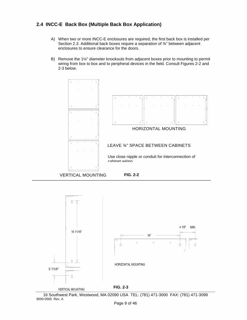
2.4 INCC-E Back Box (Multiple Back Box Application)
A) When two or more INCC-E enclosures are required, the first back box is installed per Section 2.3. Additional back boxes require a separation of ¾" between adjacent enclosures to ensure clearance for the doors.
B) Remove the 1¼" diameter knockouts from adjacent boxes prior to mounting to permit wiring from box to box and to peripheral devices in the field. Consult Figures 2-2 and 2-3 below.
3 7/16"
HORIZONTAL MOUNTING
VERTICAL MOUNTING
LEAVE ¾" SPACE BETWEEN CABINETS
FIG. 2-2
FIG. 2-3
Use close nipple or conduit for interconnection of cabinet wiring

16 Southwest Park, Westwood, MA 02090 USA TEL: (781) 471-3000 FAX: (781) 471-3099 9000-0565 Rev. A
Page 10 of 46
!IMPORTANT! This sub-assembly is a static sensitive electronic device. To minimize the possibility of damage, always use a grounded wrist strap
2.5 NetSOLO® Broadband Intelligent Network Command Center Assembly (INCC-C)
General The INCC-C Intelligent Network Command Center uses a modular approach. Consequently, the contents of an INCC-C assembly will vary depending upon the project's specific requirements. It occupies one node on the NetSOLO network. At a minimum, an INCC-C assembly must include one INI-VGE sub-assembly, one ASM-16 switch sub-assembly, one NetSOLO® back box, one INCC inner door, and one INCC outer full-Plexiglas door. The standard INCC inner door provides six bays to accommodate up to six ASM-16, NGA, or ANU-48 sub-assemblies. Each INI-VGE can support up to 6 ASM-16, NGA, or ANU-48 sub-assemblies. The additional sub-assemblies can be mounted in extra NetSOLO® back boxes. Unused bays can be covered with blank faceplates. An optional voice-paging microphone assembly occupies one standard bay in place of an ASM-16. An optional fire fighter's telephone handset assembly occupies two standard bays and requires the use of the INCC-T inner door, which combines two bays to accommodate the telephone assembly. See Figure 2-4 below.
2.5.1 Intelligent Network Interface (INI-VGE Series)
Unpack the INI-VGE sub-assembly from its shipping carton and remove it from its anti-static bag. Locate the six mounting standoffs at the top center of the INCC-E back box. Use the six screws provided to secure the sub-assembly to the back box at each corner, top center, and bottom center. Orient the sub-assembly so that the component side is facing up, the four ST fiber optic cables are positioned to the lower left, and the four 4-pin terminal blocks run down the right side of the board. Refer to the Installation Instructions for this sub-assembly, P/N 9000-0549.
Fig. 2-4 Typical INCC-C Command Center

16 Southwest Park, Westwood, MA 02090 USA TEL: (781) 471-3000 FAX: (781) 471-3099 9000-0565 Rev. A
Page 11 of 46
2.5.2 Inner Door (INCC)
Unpack the INCC Inner Door from its shipping carton. The INCC Inner Door is used with the ASM-16/NGA/ANU-48 sub-assemblies and the microphone. The INCC-T Inner Door is used when the system's configuration includes a fire fighter's telephone assembly. Locate the two hinge pins in the upper and lower left corners of the INCC-E back box. Place the nylon spacer provided over the lower left-hand hinge pin. Orient the door so that the two captured thumb screws and cam lock hole are to the right, and the two hinge pin mounting holes are to the left. Slide the upper hinge pin of the INCC-E through the upper hinge pin mounting hole. Continue to lift the door until it clears the INCC-E lower hinge pin. Swing the door in until the lower hinge pin mounting hole is aligned with the INCC-E lower hinge pin. Allow the door to drop down over the INCC-E lower hinge pin to complete the installation. See Figure 2-5 below. Once the sub-assemblies, the Microphone assembly, and Fire Fighter's Handset assembly are mounted to the back of the Inner Door, use the thumb screws to the right to secure the whole assembly to the INCC-E back box. Refer to the Installation Instructions for this enclosure, P/N 9000-0546.
Fig. 2-5

16 Southwest Park, Westwood, MA 02090 USA TEL: (781) 471-3000 FAX: (781) 471-3099 9000-0565 Rev. A
Page 12 of 46
!!
!
2.5.3 Addressable Switch Sub-assembly (ASM-16)
Unpack the ASM-16 sub-assembly from its shipping carton. For new installations, temporarily remove the INCC Inner Door from the INCC-E back box and place it face down on a flat surface. We recommend that the switch label be prepared and inserted between the ASM-16 face plate overlay and the back plate at this time. Any subsequent alterations to the switch labels will require the ASM-16 be removed from the Inner Door assembly to gain access to the label. Place the ASM-16 assembly in position in the desired location in the Inner Door. Fasten the assembly in place by installing a Kep nut over the mounting studs located at each corner. Do not tighten the nuts until all adjacent assemblies have been set in place. Refer to the Installation Instructions for this sub-assembly, P/N 9000-0550. Plug the RS-485 interconnect ribbon cable into the INI-VGE sub-assembly Connector J3. Plug the other end into J2 of the first ASM-16. Continue the RS-485 bus between each additional ASM-16 as needed. Extend the RS-485 bus as needed to sub-assemblies in adjoining expansion cabinets by wiring between Terminal Block TB1 from the last ASM-16 sub-assembly in the first cabinet and Terminal Block TB1 in the first ASM-16 sub-assembly in the next cabinet.
Fig. 2-6 (Rear View)
IMPORTANT! This sub-assembly is a static sensitive electronic device. To minimize the possibility of damage, always use a grounded wrist strap or maintain contact with ground while handling this equipment.
16 Southwest Park, Westwood, MA 02090 USA TEL: (781) 471-3000 FAX: (781) 471-3099 9000-0565 Rev. A
Page 13 of 46
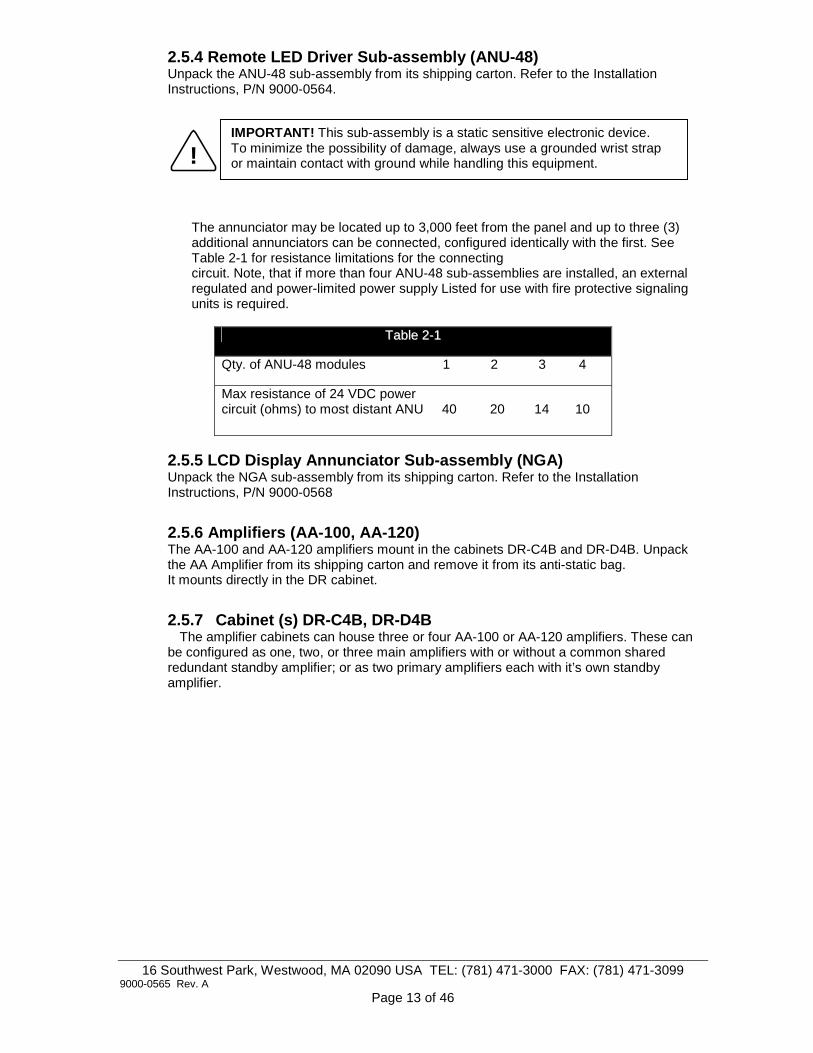
2.5.4 Remote LED Driver Sub-assembly (ANU-48) Unpack the ANU-48 sub-assembly from its shipping carton. Refer to the Installation Instructions, P/N 9000-0564.
!
The annunciator may be located up to 3,000 feet from the panel and up to three (3) additional annunciators can be connected, configured identically with the first. See Table 2-1 for resistance limitations for the connecting circuit. Note, that if more than four ANU-48 sub-assemblies are installed, an external regulated and power-limited power supply Listed for use with fire protective signaling units is required.
TTaabbllee 22--11
Qty. of ANU-48 modules 1 2 3 4
Max resistance of 24 VDC power circuit (ohms) to most distant ANU 40 20 14 10
2.5.5 LCD Display Annunciator Sub-assembly (NGA) Unpack the NGA sub-assembly from its shipping carton. Refer to the Installation Instructions, P/N 9000-0568
2.5.6 Amplifiers (AA-100, AA-120) The AA-100 and AA-120 amplifiers mount in the cabinets DR-C4B and DR-D4B. Unpack the AA Amplifier from its shipping carton and remove it from its anti-static bag. It mounts directly in the DR cabinet.
2.5.7 Cabinet (s) DR-C4B, DR-D4B The amplifier cabinets can house three or four AA-100 or AA-120 amplifiers. These can
be configured as one, two, or three main amplifiers with or without a common shared redundant standby amplifier; or as two primary amplifiers each with it’s own standby amplifier.
IMPORTANT! This sub-assembly is a static sensitive electronic device. To minimize the possibility of damage, always use a grounded wrist strap or maintain contact with ground while handling this equipment.

16 Southwest Park, Westwood, MA 02090 USA TEL: (781) 471-3000 FAX: (781) 471-3099 9000-0565 Rev. A
Page 14 of 46
Fig. 2-7 Cabinet DR-C4B
16 Southwest Park, Westwood, MA 02090 USA TEL: (781) 471-3000 FAX: (781) 471-3099 9000-0565 Rev. A
Page 15 of 46
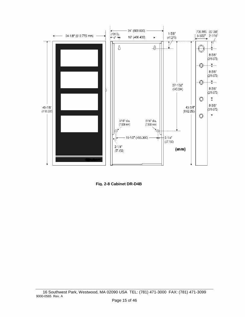
Fig. 2-8 Cabinet DR-D4B

16 Southwest Park, Westwood, MA 02090 USA TEL: (781) 471-3000 FAX: (781) 471-3099 9000-0565 Rev. A
Page 16 of 46
Remove jumpers from INI-VGEConnector J15
INI-VGE
Microphone Cable
Gray jumper
2.5.8 Voice Paging Microphone Assembly (Optional) Unpack the pre-assembled Voice Paging Microphone assembly from its shipping carton. For new installations, temporarily remove the INCC Inner Door from the INCC-E back box and place it face down on a flat surface. The Microphone assembly occupies one bay of the inner door. Place the Microphone assembly in position in the desired location in the inner door. Fasten the assembly in place by installing a Kep nut over the mounting studs located at each corner. Do not tighten the nuts until all adjacent assemblies have been set in place. Remove the jumpers that are installed on the INI-VGE J15 header. Connect the six-pin connector of the coiled cord to J15 on the INI-VGE, labeled "Microphone". Be sure to orient the connector so the gray jumper spans the top two pins on the INI-VGE J15 (Pins 6 and 5 counting from the top down). See Figure 2-9 below for details.
Fig. 2-9

16 Southwest Park, Westwood, MA 02090 USA TEL: (781) 471-3000 FAX: (781) 471-3099 9000-0565 Rev. A
Page 17 of 46
2.5.9 Fire Fighter's Intercom Handset Assembly (Optional) Unpack the handset assembly from its shipping carton. Be sure to use the INCC-T Inner Door to accommodate the assembly. For new installations, temporarily remove the Inner Door from the INCC-E back box and place it face down on a flat surface. The handset assembly occupies two bays of the Inner Door. Place the handset assembly in position on the Inner Door. Fasten the assembly in place by installing a Kep nut over the mounting studs located at each corner. Do not tighten the nuts until all adjacent assemblies have been set in place. Plug the pre-assembled four-pin terminal block that terminates the phone cable into the INI-VGE TB5. Remove INI-VGE jumper W5 to enable local handset connection. See Figure 2-10
Fig. 2-10
NOTE: When the INI-VGE terminal block TB5 is connected to a local handset, it cannot be used as a phone riser connected to remote AOM-TELs.
Remove Jumper W5 toenable local handset
connection
TelephoneCable
INI-VGE
16 Southwest Park, Westwood, MA 02090 USA TEL: (781) 471-3000 FAX: (781) 471-3099 9000-0565 Rev. A
Page 18 of 46
3.0 Wiring
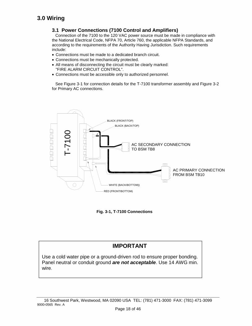
3.1 Power Connections (7100 Control and Amplifiers) Connection of the 7100 to the 120 VAC power source must be made in compliance with the National Electrical Code, NFPA 70, Article 760, the applicable NFPA Standards, and according to the requirements of the Authority Having Jurisdiction. Such requirements include: • Connections must be made to a dedicated branch circuit. • Connections must be mechanically protected. • All means of disconnecting the circuit must be clearly marked:
"FIRE ALARM CIRCUIT CONTROL". • Connections must be accessible only to authorized personnel. See Figure 3-1 for connection details for the T-7100 transformer assembly and Figure 3-2 for Primary AC connections.
Fig. 3-1, T-7100 Connections
T-7
100
AC SECONDARY CONNECTIONTO BSM TB8
AC PRIMARY CONNECTIONFROM BSM TB10
BLACK (FRONT/TOP)
BLACK (BACK/TOP)
WHITE (BACK/BOTTOM))
RED (FRONT/BOTTOM)
IMPORTANT
Use a cold water pipe or a ground-driven rod to ensure proper bonding. Panel neutral or conduit ground are not acceptable. Use 14 AWG min. wire.

16 Southwest Park, Westwood, MA 02090 USA TEL: (781) 471-3000 FAX: (781) 471-3099 9000-0565 Rev. A
Page 19 of 46
F2
ALA
RM
DR
Y C
ON
TA
CT
CO
MM
ON
5
TB2
TB2
5
GND/GRN
HOT120 VAC, 60 Hz
NEUTRALGROUND
TB
6X
FM
R
TB10HOT/BLK
TB8
F1
BSM
BATTERY (-)
BATTERY (+)
NO
T U
SE
D
TR
AN
SF
ER
RE
LAY
CO
NT
RO
L
ALA
RM
DR
Y C
ON
TA
CT
N/C
NA
C #
2 , C
LAS
S B
, ST
YLE
Y (
EO
L=47
K)
NA
C #
1 , C
LAS
S B
, ST
YLE
Y (
EO
L= 4
7K)
TB1
TB7
34
(-) (+)
TB7
4
J10
SW1
TB1
3 2 1 8 7 6
8 7 5
12
(-) (+)
8 7 6
DA
CT
LINE
1 RIN
G IN
(FR
OM
ST
RE
ET
)
DA
CT
LINE
1 TIP
IN (F
RO
M S
TR
EE
T)
SILENCESIGNAL
System Silenced
ACKNOWLEDGE
System Trouble
Supervisory
NEUT/WHT
TB
6
SilencedNAC #1
ALARM
AC Power ON
ALARM
J8
1 2
Ground Fault
SYSTEM
LAMP TESTRESET/
SilencedNAC #2
ACKNOWLEDGETROUBLE
Power Fault
OK
BKSP/EDIT
MENU/BACK
DA
CT
LINE
2 TIP
OU
T (T
O P
HO
NE
)
DA
CT
LINE
2 RIN
G IN
(FR
OM
ST
RE
ET
)
DA
CT
LINE
2 TIP
IN (F
RO
M S
TR
EE
T)
DA
CT
LINE
2 RIN
G O
UT
(TO
PH
ON
E)
DA
CT
LINE
1 TIP
OU
T (T
O P
HO
NE
)
DA
CT
RIN
G O
UT
(TO
PH
ON
E)
8
TB9
3 4 5 6
41 2 3 65 7
7 8
W3TB9
D25
W4
D26
>
WXY9
MNO6
DEF3
<
PRS7
0_.,
TUV8
GHI
-QZ
4
1
JKL5
ABC2
J5
TB4
EA
RT
H G
RO
UN
D
SY
ST
EM
CO
MM
ON
(-)
SLC
#1
, CLA
SS
B, S
TY
LE 4
SLC
#2
, CLA
SS
B, S
TY
LE 4
(71
00-2
ON
LY)
ALA
RM
DR
Y C
ON
TA
CT
N/O
TR
OU
BLE
DR
Y C
ON
TA
CT
N/C
TR
OU
BLE
DR
Y C
ON
TA
CT
CO
MM
ON
TR
OU
BLE
DR
Y C
ON
TA
CT
N/O
(+)
TB3
3
TB4
2
J1
TB3
34 2
2
ON
1
41 3
RSTLED7
2 1
RECLED1
4 3
24 3 41
(-)
J4
1
TB1
4
TB5
3 2
4
1
W3
GRN
1
RX
1
SUPRV
W1
TX
1
2 1
(+)(-)
4 3
NO
T U
SE
D
CO
M A
(to
LC
D-7
100
TB
1-1)
CO
M B
(to
LC
D-7
100
TB
1-2)
NO
N-R
ES
ET
TA
BLE
B+
, 24
VD
C @
0.2
5A
RE
SE
TT
AB
LE B
+, 2
4 V
DC
@ 0
.25
A
TB5
2
J2
W1
RS232
P2
J3
12 34 1
Fig. 3-2, 7100 Wire Connections
2 amp. @ 120VAC,

16 Southwest Park, Westwood, MA 02090 USA TEL: (781) 471-3000 FAX: (781) 471-3099 9000-0565 Rev. A
Page 20 of 46
Table 3-1 7100 Control Standby Battery Calculation Chart Qty
Sub-assembly
Description
Supv. Current
Alarm Current
Total Supv. Current
Total Alarm Current
7100-2 Analog/Addressable Control Panel 0.065 0.085 7100-2D Analog/Addressable Control Panel w/DACT 0.085 0.105 CAOM Class A Optional Module 0.001 0.001 MCOM Municipal Circuit Optional Module 0.001 0.001 LCD-7100 Remote Serial Ann., LCD Display 0.050 0.075 LDM-7100 Remote LED Driver Module 0.035 0.200* INI-7100 UTP Intelligent Network Interface, Copper Wire 0.040 0.040 INI-7100 FO Intelligent Network Interface, Fiber Optic 0.040 0.040 Addressable Modules: Analog Addressable Sensors: Notification Appliances: --- --- --- --- --- --- Auxiliary Power Devices: Misc. Devices: TOTALS: A Total supervisory current B Enter number of standby hours required** C Multiply Line A by hours in Line B D Total alarm current E Enter alarm sounding period in hours (5 minutes = 0.084 Hrs.) F Multiply Line D by Line E G Add Line C & Line F H Multiply Line G by 1.2 to arrive at Total Ampere/Hours required*** NOTE: * With all LEDs and optional sounder energized ** 24 hrs for NFPA 72 Protected Premises or Central station signaling, 60 hrs for Auxiliary or Remote Supervising Station Fire Alarm Systems. Factory Mutual requires 90 Hrs standby for deluge/pre-action systems with 15 minute alarm period. *** Use next size battery with capacity greater than required. (Use only FCI Model B-7R, B-17R, or B-31R batteries)

16 Southwest Park, Westwood, MA 02090 USA TEL: (781) 471-3000 FAX: (781) 471-3099 9000-0565 Rev. A
Page 21 of 46
3.1.2 Intelligent Network Interface (INI-7100) The 7100 BSM Basic System Sub-assembly must be equipped with either an INI-7100 UTP or an INI-7100 FO sub-assembly in order to act as a node on the NetSOLO® Classic Network.
A) INI-7100 UTP The INI-7100 UTP provides terminal block connections for a twisted, unshielded pair of wires. Figure 3-3 illustrates typical wiring between nodes. Note the maximum distance of 3,000 feet between each node. Consult Table 3-2 for specific wiring connections.
Table 3-2 Wiring Schedule: INI-7100 UTP INI-7100 TB1-1 (Com 1B) to: Next INI-7100 TB1-3 (Com 2A) or Network Node INI-7100 TB1-2 (Com 1A) to: Next INI-7100 TB1-4 (Com 2B) or Network Node Use non-shielded, twisted pair- 16-18 AWG, 3,000 ft. max. between nodes
Fig. 3-3
4 3 2 1 34 12
Style 7 Network
3,000 ft. Between Nodes
CHANNEL 2 CHANNEL 1
TB1
INI-7100-UTP
CHANNEL 2
TB1
NEXT NODE
CHANNEL 1COM 1B
COM 1A
PREVIOUS NODE
1TB1 4 3 2
CHANNEL 2
COM 2ACOM 2B
CHANNEL 1

16 Southwest Park, Westwood, MA 02090 USA TEL: (781) 471-3000 FAX: (781) 471-3099 9000-0565 Rev. A
Page 22 of 46
B) INI-7100 FO The INI-7100 FO adds four (4) standard ST connectors for fiber optic cable while retaining the ability to accommodate copper wire. Connecting the INI-7100 sub-assemblies in consecutive order of addressing allows the fastest network communication. No star configurations or T-tapping on the NetSOLO® network is permitted. Figure 3-4 illustrates a typical fiber optic network. Consult Table 3-3 for specific fiber optic cable connections between nodes.
Table 3-3 Fiber Optic Connections: INI-7100 FO INI-7100 Connector J1 (TX1) to Next INI-7100 Connector J7 (RX2) or Network Node INI-7100 Connector J4 (RX1) to Next INI-7100 Connector J6 (TX2) or Network Node Fiber optic cable specifications: Up to 200 microns (optimized for 62.5 / 125 microns), Standard ST Connectors Up to 8 dB loss max. between nodes
The INI-7100 FO can accommodate both fiber optic cable connections and copper wire as shown above. This is useful for applications where the NetSOLO® network covers multiple buildings. NetSOLO® wiring within a building can be run on copper wire. Connections between buildings can be run on fiber optic cable for best protection against transients and ground fault conditions. See Figure 3-5 for an example of a network using both types of connections.
INI-7100-FO INI-7100-FO INI-7100-FO
J7
RX2
J6
CHANNEL 2
TX2
INI-7100-FO
TB14 3 2 1
J4CHANNEL 1
J1
TX1RX1
J7
RX2
J6
CHANNEL 2
TB14 3 2 1
J4
RX1
CHANNEL 1J1
TX1TX2
J7
RX2
CHANNEL 2
J6
TX2
TB14 3 2 1
RX1 TX1
J4 J1CHANNEL 1
Style 7 Network
10 dB Loss Max. Between Nodes
Fig. 3-4
NOTICE: The use of fiber optic cable is not permitted in New York City
Fig. 3-5
Previous Node (if any)
Second Node Next Node First Node

16 Southwest Park, Westwood, MA 02090 USA TEL: (781) 471-3000 FAX: (781) 471-3099 9000-0565 Rev. A
Page 23 of 46
3.1.3 INI-7100 Addressing INI-7100 Switch SW-1 is an 8-position DIP switch used to address each sub-assembly in the network. Each position is set to ON to represent a binary zero or OFF to equal a binary One. Do not duplicate addresses. Fastest network communication is achieved when nodes are addressed in consecutive order. For ease of installation, set the INI-7100 to its network address before mounting it in the 7100 NetSOLO® cabinet. Table 3-4 illustrates the switch settings for all addresses. (NOTE: SW-1 is oriented upside down when the unit is installed in the 7100 NetSOLO® assembly).
Table 3-4
on
= 1
on
= 2
on
= 3
on
= 4
on
= 5
on
= 6
on
= 7
on
= 8
on
= 9
on
= 10
on
= 11
on
= 12
on
= 13
on
= 14
on
= 15
on
= 16
on
= 17
on
= 18
on
= 19
on
= 20
on
= 21
on
= 22
on
= 23
on
= 24
on
= 25
on
= 26
on
= 27
on
= 28
on
= 29
on
= 30
on
= 31
on
= 32
on
= 33
on
= 34
on
= 35
on
= 36
on
= 37
on
= 38
on
= 39
on
= 40
on
= 41
on
= 42
on
= 43
on
= 44
on
= 45
on
= 46
on
= 47
on
= 48
on
= 49
on
= 50
on
= 51
on
= 52
on
= 53
on
= 54
on
= 55
on
= 56
on
= 57
on
=58
on
= 59
on
= 60
on
= 61
on
= 62
on
= 63
on
= 64
on
1248163264
= ON (up)
= OFF (down)

16 Southwest Park, Westwood, MA 02090 USA TEL: (781) 471-3000 FAX: (781) 471-3099 9000-0565 Rev. A
Page 24 of 46
IF F IR E F IG H T E R H A N D S E T C O N N E C T E D T OT B 5 , U S E O F T B 5 A S A P H O N E R IS E R T OA O M -T E L s IS N O T A V A IL A B L E
IN I-V G C S L C S U P P O R T S : 1 6 A O M -T E L M O D U L E S
(F IR E F IG H T E R T E L E P H O N E C K T S )
T o A A A M P L IF IE RT e rm s P 3 -1 , P 3 -2 * *
S IG N A L IN G L IN E C IR C U IT ( + )S IG N A L IN G L IN E C IR C U IT ( - )
N e tS O L O ® C O N N E C T IO N S u s in g W IR E(U N S H IE L D E D , T W IS T E D P A IR )C O M 2 A (T O N E X T N O D E C O M 1 A T E R M IN A L )
C O M 2 B (T O N E X T N O D E C O M 1 B T E R M IN A L )
C O M 1 B (F R O M P R E V IO U S N O D E C O M 2 B T E R M IN A L )C O M 1 A (F R O M P R E V IO U S N O D E C O M 2 A T E R M IN A L )
N e tS O L O ® C O N N E C T IO N S u s in g F IB E R O P T IC C A B L E(S T A N D A R D S T C O N N E C T O R S )
F R O M P R E V IO U S N O D E T X 1 C O N N E C T O R
F R O M P R E V IO U S N O D E R X 1 C O N N E C T O R
T O N E X T N O D E T X 2 C O N N E C T O R
T O N E X T N O D E R X 2 C O N N E C T O R
C H A N N E L 2
C H A N N E L 1
{
R X 2
T X 2
R X 1
T X 1 {
F R O M 7 1 0 0 P A N E L IN C C O N L Y
C O N N E C T T O1 s t L O C A L A S M -1 6 C O N N E C T O R J 2
(IN S A M E C A B IN E T )
C O N N E C T T O1 s t R E M O T E A S M -1 6 T E R M IN A L B L O C K T B 1(IN R E M O T E C A B IN E T )
F IR E F IG H T E R T E L E P H O N E C A B L E
M IC R O P H O N E C A B L E
G R A Y J U M P E R
{2 4 V D C + INC O M M O N ( - ) IN
C O M M O N ( - ) O U T2 4 V D C + O U T
NOTE: Remove INI-VGE jumper W5 to enable Phone Riser connection to AOM-TELs
3.2 Intelligent Network Interface, Voice Gateway (INI-VGE) The INI-VGE is the network interface sub-assembly for the INCC-C NetSOLO® Voice Command Center. In the INCC, this sub-assembly connects to the NetSOLO® system microphone and Fire Fighter Telephone handset, and supervises and controls up to six ANU-48, NGA, or ASM-16 sub-assemblies. Figure 3-6 shows all connections available on the INI-VGE and their functions. NOTE: J2, J5, J6 and J8 are omitted on the INI-VGE-UTP.
Connect a ground wire from the 7100 BSM TB6 ground terminal and the INI-VGE TB3 Terminal 1. The INI-VGE also has one signaling line circuit (SLC) wired Style 4 (Class "B") only. This SLC supports up to 16 AOM-TEL Fire Fighter Intercom circuits and up to 32 AOM-MUX/AOM-2S dual-channel speaker circuits. ** Connection to AA Amplifiers must be in same room, close-nippled or in rigid conduit, not to exceed 20 feet in length. 3.2.1 INI-VGE Series Power Connections The INI-VGE serving as the network interface and control unit of an INCC-C Command Center connects to its operating power via Terminal Block TB2. See Figure 3-6
Table 3-9 INI-VGE Power Connections TB2-1 +24 VDC IN - from power supply TB2-2 Common ( - ) IN - from power supply TB2-3 +24 VDC OUT TB2-4 Common ( - ) OUT
Fig. 3-6, Typical Connections to INI-VGE

16 Southwest Park, Westwood, MA 02090 USA TEL: (781) 471-3000 FAX: (781) 471-3099 9000-0565 Rev. A
Page 25 of 46
Table 3-5 NetSOLO® INI-VGE Power Consumption Calculation Chart
Qty Sub-
assembly Description Supv. Current
Alarm Current
Total Supv. Current
Total Alarm Current
INI-VGE Intelligent Network Voice Gateway- Command Center 0.150 A 0.150 A
ASM-16 Addressable Switch Sub-assembly 0.011 A † 0.011 A ‡
ANU-48 Remote LED Driver 0.011 A † 0.011 A‡ NGA LCD Annunciator
0.200 A* 0.200 A
Microphone Paging Microphone 0.001 A 0.001 A Telephone Fire Fighter's
Telephone Handset 0.020 A 0.020 A
AOM-TEL Addressable Output Module- Telephone 0.002 A 0.0065 A
AOM-MUX Addressable Output Module- Multiplex 0.004 A 0.0065 A
AOM-2S Addressable Output Module 0.0003 A 0.0003 A
Total:
NOTE: The total supervisory and alarm currents determined above must be added to the standby battery calculations for the power supply providing the operating voltage to the INCC-C. Typically this is a 7100 fire alarm control panel. † Add 0.003 A for each LED that is programmed to be lit for trouble or supervisory off-normal conditions ‡ Add 0.003 A for each LED that is programmed to be lit for alarm conditions * * During power failure, supervisory current is 0.045 A, alarm current is 0.200 A. (Back lighting is extinguished during power failure and operates only in alarm).

16 Southwest Park, Westwood, MA 02090 USA TEL: (781) 471-3000 FAX: (781) 471-3099 9000-0565 Rev. A
Page 26 of 46
Table 3-6 NetSOLO® INI-VGE Series Field Wiring Connections Terminal Block 1- NetSOLO® Network connection- using unshielded, twisted pair TB1-1 NetSOLO® COM 1A connection TB1-2 NetSOLO® COM 1B connection TB1-3 NetSOLO® COM 2A connection TB1-4 NetSOLO® COM 2B connection Terminal Block 2- External Power Connection (INI-VGE) TB2-1 24 VDC ( + ) power input from external power supply TB2-2 Negative ( - ) power input from external power supply TB2-3 ( + ) Power Out terminal- wiring terminal only, not a source of power TB2-4 ( - ) Power Out terminal- wiring terminal only, not a source of power TB3-1 Earth Ground Terminal Block 4- Power Amplifier and Signaling Line Circuit Connections TB4-1 Connect to AA-100 or AA-120 Amplifier P3 Term. 1** TB4-2 Connect to AA-100 or AA-120 Amplifier P3 Term. 2** TB4-3 Signaling Line Circuit ( + ), Style 4, Class "B" TB4-4 Signaling Line Circuit ( - ), Style 4, Class "B" Terminal Block 5- Fire Fighter Handset or Fire Fighter Phone riser connection (INI-VGE) TB5-1 Fire Fighter Phone ( - ):
Plugs into local Fire Fighter Handset- INI-VGE Phone riser field wire connection to AOM-TEL Term 3
TB5-2 Fire Fighter Phone ( + ): Plugs into local Fire Fighter Handset- INI-VGE Phone riser field wire connection to AOM-TEL Term 4
TB5-3 Ground: Plugs into local Fire Fighter Handset- INI-VGE Phone Riser field wire connection to Shield Drain wire
TB5-4 Phone Off Hook: Plugs into local Fire Fighter Handset- INI-VGE
Terminal Block 6- RS485 Remote Comm. Connection to ASM-16 in Separate Cabinet- INCC only TB6-1 + 24 VDC Supply - connects to remote ASM-16 TB1-3 TB6-2 RS-485 COM B - connects to remote ASM-16 TB1-2 TB6-3 RS-485 COM A - connects to remote ASM-16 TB1-1 TB6-4 System Common ( - ) connects to remote ASM-16 TB1-4

16 Southwest Park, Westwood, MA 02090 USA TEL: (781) 471-3000 FAX: (781) 471-3099 9000-0565 Rev. A
Page 27 of 46
Table 3-7 NetSOLO® INI-VGE Series Jumpers & Cable Connections J1- "E" FNCTNS/RESET Factory use J2- Fiber Optic ST Channel 1 TX1 Connects to next node RX2 ST connector J3- RS 485 Local Connects to 1st Local ASM-16 Connector J2- INCC only J4- SDA/SCL Factory use J5- Fiber Optic ST Channel 1 RX1 Connects to next node TX2 ST connector J6- Fiber Optic ST Channel 2 TX2 Connects form previous node RX1 connector J7- Repeater Factory use J8- Fiber Optic ST Channel 2 RX2 Connects from previous node TX1 connector J15- Microphone Connectors to microphone cable- INCC only J16- Signals In/Out Factory use W1- GFI IN for ground fault indication W2- Termination Factory Use, must be IN W3- EGND IN to enable earth ground reference circuit W4- Config Factory Use, must be installed W5- Handset Enable OUT to enable Local Fire Fighter Handset connection
IN to enable Phone Riser connection to AOM-TELs
**NOTE: Connection must be in same room, close-nippled or in rigid conduit, not to exceed 20 feet. Table 3-8 NetSOLO® INI-VGE Indicating & Diagnostic LEDs LED 1- REC The sub-assembly is receiving network data LED 3- MRC MRC LED 4- DUP DUP LED 5- TX The sub-assembly is transmitting network data LED 6- RX1 The sub-assembly is receiving network data on Channel 1 LED 7- RX2 The sub-assembly is receiving network data on Channel 2 LED 8- RST RST LED 9- DG DG

16 Southwest Park, Westwood, MA 02090 USA TEL: (781) 471-3000 FAX: (781) 471-3099 9000-0565 Rev. A
Page 28 of 46
NetSOLO® CONNECTIONS using FIBER OPTIC CABLE (STANDARD ST CONNECTORS)
FROM PREVIOUS NODE TX1 CONNECTOR
FROM PREVIOUS NODE RX1 CONNECTOR
TO NEXT NODE TX2 CONNECTOR
TO NEXT NODE RX2 CONNECTOR
CHANNEL 2
CHANNEL 1
{TX1
RX2
TX2
RX1 {
COM 1A (FROM PREVIOUS NODE COM 2A TERMINAL)COM 1B (FROM PREVIOUS NODE COM 2B TERMINAL)
COM 2B (TO NEXT NODE COM 1B TERMINAL)COM 2A (TO NEXT NODE COM 1A TERMINAL)
NetSOLO® CONNECTIONS using WIRE(UNSHIELDED, TWISTED PAIR)
3.2.2 NetSOLO® Classic Network Connections
The INI-VGE can be connected to the NetSOLO® using an unshielded, twisted pair of wires, fiber optic cable, or a combination of the two.
Table 3-10 NetSOLO® Network Wire Terminations TB1-1 COM 1A To next node's TB1-3 (COM 2A) TB1-2 COM 1B To next node's TB1-4 (COM 2B) TB1-3 COM 2A From previous node's TB1-1 (COM 1A) TB1-4 COM 2B From previous node's TB1-2 (COM 1B)
Use 16-18 AWG unshielded, twisted pair up to 3000 feet (915 m) between nodes
Table 3-11 NetSOLO® Network Fiber Optic Cable Connections (INI-VGE Only) ST Connector J2 Channel 1 TX1 To next node's ST Connector J8 (RX2) ST Connector J5 Channel 1 RX1 To next node's ST Connector J6 (TX2) ST Connector J6 Channel 2 TX2 From previous node's ST Connector J5 (RX1) ST Connector J8 Channel 2 RX2 From previous node's ST Connector J2 (TX1)
Fiber optic cable: up to 200 microns (optimized for 62.5/ 125 microns) Up to 8 dB loss max. between nodes NOTICE: The use of fiber optic cable is not permitted in New York City
NOTE: Connectors J2, J5, J6 and J8 are omitted on the INI-VGE-UTP
Figure 3-8

16 Southwest Park, Westwood, MA 02090 USA TEL: (781) 471-3000 FAX: (781) 471-3099 9000-0565 Rev. A
Page 29 of 46
Figure 3-9
3000 Feet max.
8 dB Loss max.
TO NEXT NODE RX2 CONNECTOR
TO NEXT NODE TX2 CONNECTOR
FROM PREVIOUS NODE RX1 CONNECTOR
FROM PREVIOUS NODE TX1 CONNECTOR
COM 1A (FROM PREVIOUS NODE COM 2A TERMINAL) COM 1B (FROM PREVIOUS NODE COM 2B TERMINAL) COM 2B (TO NEXT NODE COM 1B TERMINAL) COM 2A (TO NEXT NODE COM 1A TERMINAL)
TX2
RX1
TX1
RX2
NetSOLO® CONNECTIONS using WIRE (UNSHIELDED, TWISTED PAIR)
NetSOLO® CONNECTIONS using FIBER OPTIC CABLE (STANDARD ST CONNECTORS)
TX1
{ TX2
RX2
RX1 { CHANNEL
1
CHANNEL 2
Figure 3-9

16 Southwest Park, Westwood, MA 02090 USA TEL: (781) 471-3000 FAX: (781) 471-3099 9000-0565 Rev. A
Page 30 of 46
3.2.3 INI-VGE Signaling Line Circuit This sub-assembly, provides one Style 4 (Class B) Signaling Line Circuit (SLC). Up to 16 AOM-TEL Fire Fighter Intercom circuits and 32 AOM-MUX/AOM-2S Dual-Channel Speaker circuits can be connected to this SLC.
} NOT USED
}
SLC ( + )SLC ( - )
STYLE 4(CLASS "B")
ONLY
AOM-MUX/AOM-2S
AOM-TEL
INI-VG SLC SUPPORTS: 32 AOM-MUX/AOM-2S MODULES (DUAL CHANNEL SPKR. CKTS. &
16 AOM-TEL MODULES (FIRE FIGHTER TELEPHONE CKTS)
Fig. 3-10 INI-VGE Signaling Line Circuit Specifications: 24 VDC nominal, power-limited and supervised 40 ohms max. wire resistance 0.5 uF max. circuit capacitance 0.070 amp max. current Use twisted unshielded wire, 18 AWG min.

16 Southwest Park, Westwood, MA 02090 USA TEL: (781) 471-3000 FAX: (781) 471-3099 9000-0565 Rev. A
Page 31 of 46
3.2.4 INI-VGE Fire Fighter Intercom Riser Connections This sub-assembly provides a phone riser circuit on Terminal Block TB5, Terminals 3 & 4 that connect to AOM-TEL/AOM-2S Fire Fighter Phone circuit Terminals 3 & 4. Up to 16 AOM-TEL/AOM-2s can be connected to each INI-VGE phone riser. The INI-VGE uses Terminal Block TB5 Terminals 1 & 2 to connect to the main Fire Fighter handset located in the INCC cabinet.
Fig. 3-11
1k
22 uF (Red)
(Blue)
1k
22 uF (Red)
(Blue)
4 9
5 6 7 3 2 1 0
8
4 9
5 6 7 3 2 1 0
8
AOM-TEL
4 9
5 6 7 3 2 1 0
8
4 9
5 6 7 3 2 1 0
8
AOM-TEL TB-4
4 3 2 1
(SLC -) (SLC +)
TB-5 4 3 2 1
3.9K
3.9K
Supervisory AOM-TEL
Supervises telephone line to floor AOM-TEL. Also creates a Class “A” phone riser 0
1 2 3 4 5
6 7 8 9
5 6 7 8 9 0
1 2 3 4
RC Filter
INI-VGE Signaling Line Circuit provides one Style 4 (SLC) that can support up to 16 AOM-TEL modules. The first one is used for supervision of the audio riser.
INI-VGE Signaling line Circuit Specifications
IMPORTANT: Install an RC Filter, P/N 1120-0810, in each warden station or telephone jack being monitored by the AOM-TEL. Refer to FCI Publication 9000-0405, Figure 2-33, for wiring detail s.
Phone Riser Specifications 24 VDC (open circuit) Current 0.237 amp. max. 0.750 amp. (short) 40 ohms max. line resistance 0.5uF max. circuit capacitance
Use twisted, shielded pair, 18 AWG.
24 VDC nominal, power-limited, supervised 40 ohms max. wire resistance 0.5 uF max. circuit capacitance 0.070 A max. current
Use twisted, unshielded wire, 18 AWG

16 Southwest Park, Westwood, MA 02090 USA TEL: (781) 471-3000 FAX: (781) 471-3099 9000-0565 Rev. A
Page 32 of 46
3.2.5 INI-VGE Connections to Remote ASM-16 Sub-assemblies An INI-VGE installed in an INCC-C Command Center assembly can support up to 16 ASM-16 programmable switch sub-assemblies. The INCC-C cabinet has space for up to six ASM-16 sub-assemblies (three if a microphone and fire fighter handset are included). INI-VGE TB6 provides a hardwire connection between the INI-VGE and any ASM-16 mounted in a different cabinet. ASM-16s mounted in the same cabinet as the INI-VGE can be connected directly by a ribbon cable (see Section 2.5.3).
Table 3-12 INI-VGE to Remote ASM-16s TB6-1 (+ 24 VDC) 1st Remote ASM-16 TB1-3 TB6-2 (RS-485 COM B) 1st Remote ASM-16 TB1-2 TB6-3 (RS-485 COM A) 1st Remote ASM-16 TB1-1 TB6-4 (Common) 1st Remote ASM-16 TB1-4
3.2.6 INI-VGE Earth Ground Connection
Connect INI-VGE TB3 to earth ground for full protection against transient voltages and power surges and to conform to the National Electric Code, NFPA 70, Article 760.
TO 1st REMOTE ASM-16 TB1-2 (RS-485 COM B)TO 1st REMOTE ASM-16 TB1-1 (RS-485 COM A)
TO 1st REMOTE ASM-16 TB1-3 (+ 24 VDC)
TO 1st REMOTE ASM-16 TB1-4 (Common)
CONNECT TO 1st REMOTE ASM-16 TERMINAL BLOCK TB1 (IN EACH REMOTE CABINET)INCC ONLY
Fig. 3-12
IMPORTANT Use a cold water pipe or a ground-driven rod to ensure proper bonding. Panel neutral or conduit ground are not acceptable. Use 14 AWG min. wire.

16 Southwest Park, Westwood, MA 02090 USA TEL: (781) 471-3000 FAX: (781) 471-3099 9000-0565 Rev. A
Page 33 of 46
3.2.7 INI-VGE Series Addressing Use INI-VGE DIP Switch SW-1 to set the address the sub-assembly will occupy on the NetSOLO® network. Do not duplicate addresses with other sub-assemblies on the network. For fastest communication between nodes, set the addresses in consecutive order.
on
= 1
on
= 2
on
= 3
on
= 4
on
= 5
on
= 6
on
= 7
on
= 8
on
= 9
on
= 10
on
= 11
on
= 12
on
= 13
on
= 14
on
= 15
on
= 16
on
= 17
on
= 18
on
= 19
on
= 20
on
= 21
on
= 22
on
= 23
on
= 24
on
= 25
on
= 26
on
= 27
on
= 28
on
= 29
on
= 30
on
= 31
on
= 32
on
= 33
on
= 34
on
= 35
on
= 36
on
= 37
on
= 38
on
= 39
on
= 40
on
= 41
on
= 42
on
= 43
on
= 44
on
= 45
on
= 46
on
= 47
on
= 48
on
= 49
on
= 50
on
= 51
on
= 52
on
= 53
on
= 54
on
= 55
on
= 56
on
= 57
on
=58
on
= 59
on
= 60
on
= 61
on
= 62
on
= 63
on
= 64
on
1248163264
Table 3-13

16 Southwest Park, Westwood, MA 02090 USA TEL: (781) 471-3000 FAX: (781) 471-3099 9000-0565 Rev. A
Page 34 of 46
3.3 AA-100 and AA-120 Power Amplifiers
A) AA-100 Audio Amplifier The AA-100 audio amplifier provides up to 100 watts of power. Two outputs are provided, one at 70.7 VRMS and the other at 25 VRMS. The power taken from these outputs combined must not exceed 100 watts total. A four-wire high level output/return circuit must be employed. Cut R-100 to enable output wiring supervision in the AA-100. Use only the 70.7 V output, which must be supervised. B) AA-120 Audio Amplifier The AA-120audio amplifier provides up to 120 watts of power. Use only the 70.7 V output. The power taken from this output must not exceed 120 watts total. A four-wire high-level output/return circuit must be employed when output wiring supervision is required. Cut R-100 to enable output wiring supervision in the AA-120. C) Trouble Contacts Trouble contacts on the amplifiers close to report problems with audio input wiring, brown out, batteries, output wiring, or the amplifier itself. Trouble contact wiring must not leave the cabinet, and is monitored via an AMM series input monitoring module. D) Backup Amplifiers Only an AA-120 may be used as a backup amplifier for one or more AA-100 and AA-120 amplifiers. In the event of an amplifier failure, backup amplifier switching is automatic. When one backup amplifier is serving multiple primary amplifiers, only one primary amplifier failure will be supported. Individual LEDs signal each source of trouble to aid in troubleshooting. The supervision of the backup amplifier output is done through the four-wire return circuit on the backup amplifier. The high-level backup input on the AA-100 or AA-120 must be 25 VRMS only. Use output wiring supervision whenever high-level audio amplifier output leaves the cabinet. E) Cabinet Mounting The AA-100 and AA-120 mount directly in the DR series cabinets, one amplifier per tier. Primary (AC) and secondary (24V battery) power source connections must be made to each amplifier. Some external listed means of charging the batteries (such as a CHG-120 charger) must be used.

16 Southwest Park, Westwood, MA 02090 USA TEL: (781) 471-3000 FAX: (781) 471-3099 9000-0565 Rev. A
Page 35 of 46
3.3.1 Primary and Secondary Power requirements for the AA-100 and AA-120 Audio Amplifiers Primary power required for the AA-100, and AA-120 Amplifiers is 120VAC. Secondary power (24 VDC battery) connections must be made at the designated terminals shown in Figure 3-13. Secondary power may be obtained from any source of 24 VDC that is Listed for fire alarm signaling and has sufficient alarm and standby capacity (, etc.). Use Table 3-14 to calculate amplifier secondary (battery) power requirements.
Table 3-14 AA-100/AA-120 Amplifier Standby Battery Calculation Chart Qty
Sub-assembly
Description
Supv. Current
Alarm Current
Total Supv. Current
Total Alarm Current
AA-100 AA-100 Primary amplifier 0.050 A 7.3 A AA-120 AA-120 Primary amplifier 0.050 A 7.3 A AA-120 AA-120 Back up amplifier 0.050 A 0.30 A Additional current consuming devices
powered from the power supply
TOTALS: A Total supervisory current B Enter number of standby hours required 24 C Multiply Line A by hours in Line B D Total alarm current E Enter alarm sounding period in hours ** (0.25 hr) F Multiply Line D by Line E G Add Line C & Line F H Multiply Line G by 1.2 to arrive at total ampere/hours required*** NOTE: For Emergency Voice/Alarm Communication service, the system shall be capable of operating for 24 hours under a maximum normal load and then operating during an alarm condition for a period of 2 hours. Fifteen (15) minutes of evacuation alarm operation at maximum alarm load shall be considered the equivalent of 2 hours of alarm operation. Use next size battery with capacity greater than required. Maximum alarm current from 31 AH batteries must not exceed 9A. Maximum alarm current from 55AH batteries must not exceed 20A.

16 Southwest Park, Westwood, MA 02090 USA TEL: (781) 471-3000 FAX: (781) 471-3099 9000-0565 Rev. A
Page 36 of 46
3.3.2 Amplifier Connections
Note: The low-level input and high-level output "P" connectors are primarily for in-cabinet applications where the wiring to or from the amplifier remains in the same cabinet. For "multiple-cabinet" applications, hardwire the systems using terminal blocks P3 and P8. When more than one cabinet is required, cabinets must be mounted adjacent to each other and all interconnecting wiring must be installed in conduit. Note: Cut resistor R100 to enable high-level audio output wiring supervision. Output supervision is always required in the AA-100. This option is only required in the AA-120 when output wiring leaves the cabinet. Note: If the amplifier is being used in stand-alone mode (no connection to an INI-VGE) where the backup tone generator is being used, R107 must be cut to prevent the amplifier from generating a trouble condition. The amplifier will indicate trouble within 90 seconds. See Figure 3-13.
Figure 3-13 Amplifier Connections – Upper and lower Boards
NOTE: Connections between amplifiers are supervised against opens, shorts and grounds. However, all these conditions will be displayed as “Power amp. short.”

16 Southwest Park, Westwood, MA 02090 USA TEL: (781) 471-3000 FAX: (781) 471-3099 9000-0565 Rev. A
Page 37 of 46
3.3.3. Adjusting Audio Gain Level A multi-position rotary switch allows the installer to adjust the gain of the audio output signal to compensate for audio line losses. After correct adjustment, the audio amplifier will produce its maximum rated output power. See Figure 3-14 To adjust: After complete installation of all amplifiers and associated circuitry, with the low-level audio input to the amplifier set for normal standby, use a small slotted screwdriver to position the rotary switch until the NORMAL LEVEL LED is lit and the INCORRECT LEVEL LED is off. At this point, the audio gain is properly adjusted. NOTE: Ensure that a 470-ohm impedance matching resistor has been installed on the last amplifier (P3 Terminals 1 and 2). Failure to do so will result in calibration difficulty. Figure 3-14
Figure 3-13 “Stand Alone” Operation

16 Southwest Park, Westwood, MA 02090 USA TEL: (781) 471-3000 FAX: (781) 471-3099 9000-0565 Rev. A
Page 38 of 46
3.3.4 LEDs
3.3.5 Selecting the Default Backup Tone Use SW1, located in the lower right-hand corner of the amplifier circuit board, to select Hi/Lo or Slow Whoop as the default backup tone. The backup tone will start automatically if low-level audio input to the amplifier is lost or when the amplifier has been configured for stand-alone operation.

16 Southwest Park, Westwood, MA 02090 USA TEL: (781) 471-3000 FAX: (781) 471-3099 9000-0565 Rev. A
Page 39 of 46
3.3.6 Backup Amplifier An AA-120 Amplifier can be used to backup one or more amplifiers. In the event of an amplifier failure, backup amplifier switching is automatic.
Figure 3-15

16 Southwest Park, Westwood, MA 02090 USA TEL: (781) 471-3000 FAX: (781) 471-3099 9000-0565 Rev. A
Page 40 of 46
3.4 Speaker Circuit Connections 3.4.1 Speaker Switching The amplified signal from each audio amplifier must be connected to a control module, which will switch the signal to a speaker circuit when necessary. Following are drawings (Figures 3-16 through 3-19) illustrating the wiring configurations for the AA-100, and AA-120 audio amplifiers.
AOM-2S
AA-100 Upper Board
only)
)
)
AOM-2S
AA-100 Upper Board
AA-100A High LevelAudio Out 70.7 V)
Figure 3-17 Speaker Switching Configuration for the AA-100 (Class B) with AOM-2S (Style Z)
Figure 3-16 Speaker Switching Configuration for the AA-100 (Class B) with AOM-2S (Style Y)

16 Southwest Park, Westwood, MA 02090 USA TEL: (781) 471-3000 FAX: (781) 471-3099 9000-0565 Rev. A
Page 41 of 46
AOM-2S
AOM-2S
AA-120 Upper Board
AOM-2S
)
AA-120 Upper Board
Figure 3-18 Speaker Switching Configuration for the AA-120 (Class B) with AOM-2S (Style Y)
Figure 3-19 Speaker Switching Configuration for the AA-120 (Class B) with AOM-2S (Style Z)

16 Southwest Park, Westwood, MA 02090 USA TEL: (781) 471-3000 FAX: (781) 471-3099 9000-0565 Rev. A
Page 42 of 46
3.4.2 Speaker Wire Use twisted, SHIELDED pair, 18 AWG. Minimum. Make sure the shield is run continuously through the speaker circuits with no segments of the shield left floating. Do not tie the shield to conduit or junction boxes in the field. Terminate the drain wire back at the panel's location to system negative. Style Z circuits do not require an end-of-line resistor. This is included on the AA amplifier.
The following table may be used as a guide to determine the wire requirements for each speaker circuit.
Table 3-18 AA Series Amplifier Speaker Circuit Wiring Requirements Circuit Length in Feet (Meters) Watts 10 ft. (3
m) 25 ft. (7.6 m)
50 ft. (15.25 m)
100 ft. (30.5 m)
250 ft. (76 m)
500 ft. (152.5 m)
1000 ft. (305 m)
100 18 18 18 16 14 10 N/A AWG 120 18 18 18 18 16 14 10 AWG
N/A = Not Allowed NOTE: Use, twisted, SHIELDED wire
NOTE: Strobe notification appliances should be connected to the notification appliance circuits of the associated 7100 control or SNAC supplementary panel.

16 Southwest Park, Westwood, MA 02090 USA TEL: (781) 471-3000 FAX: (781) 471-3099 9000-0565 Rev. A
Page 43 of 46
4.0 System Operation 4.1 7100 LED Indicators
The 7100 NetSOLO® Basic System Sub-assembly (BSM) provides system status LED indicators as well as an alphanumeric display.
Table 4-1 7100 NetSOLO® LEDs Designation Description AC Power ON (Green) Lights to indicate presence of 120 VAC input
Alarm (Red) Lights when system is in Alarm, flashes until Alarm is acknowledged
Supervisory (Yellow) Lights when system is in Supervisory Off-Normal, flashes until Off-Normal is acknowledged
System Trouble (Yellow) Lights to indicate System Trouble condition, flashes until System Trouble is acknowledged
Power Fault (Yellow) Lights during a LOW or NO Battery Fault condition Ground Fault (Yellow) Lights to indicate a Ground Fault condition NAC 1 Silenced (Yellow) Lights to indicate that NAC circuits has been silenced with
Signal Silence switch (if programmed to be silenceable) NAC 2 Silenced (Yellow) Lights to indicate that NAC circuits has been silenced with
Signal Silence switch (if programmed to be silenceable) System Silenced (Yellow) Lights when a System Silence has been performed
OK
BKSP/EDIT
MENU/BACK
SilencedNAC #1
ACKNOWLEDGE
AC Power ON
LAMP TEST
SYSTEM
SilencedNAC #2
SILENCESIGNAL
System Silenced
RESET/
ACKNOWLEDGETROUBLE
Power Fault
ALARM
Supervisory
ALARM System Trouble Ground Fault
<
7PRS
>_.,0
WXY8
TUV9
1
GHI4
-QZ32
MNOJKL5 6
DEFABC
J5
Fig. 4-1
NOTE: The evacuation system is programmed to provide a xxxx KHz default evacuation tone.

16 Southwest Park, Westwood, MA 02090 USA TEL: (781) 471-3000 FAX: (781) 471-3099 9000-0565 Rev. A
Page 44 of 46
4.2 7100 Switches These switches are used to control and operate the 7100 NetSOLO® fire alarm control panel. Access to these keys is enabled by unlocking the key switch. The switches are normally disabled and do not function until the key switch is set to the unlocked position.
Table 4-2 7100 NetSOLO® Switches Designation Description Alarm Acknowledge Silences the panel's audible sounder. Press once for each alarm event
to be acknowledged Trouble Acknowledge Silences the panel's audible sounder. Press once for each trouble or
supervisory off-normal condition to be acknowledged Signal Silence Press to silence all system outputs programmed as silenceable. Press
again to resound silenced outputs. Outputs will resound automatically upon subsequent system events.
Lamp Test / Reset Press to perform Lamp test on all 7100 BSM LEDs. Press and HOLD for five seconds to reset system
Menu / Back Used in system front panel programming. Press once to initiate Program Mode. Once in Program Mode, switch acts as a "Back" function to exit Program Function screens
BKSP / Edit Used in Front Panel programming as prompted by Display OK Used in Front Panel programming as an "Enter" switch Alphanumeric Keys These 12 keys are used to select specific point addresses for
programming purposes PK-625 Key Switch This switch locks and unlocks access to all switches on the
7100 NetSOLO® Panel
4.3 System Reset 1) Turn the key switch to the “Unlock” position to open access to the system
controls. 2) Press and HOLD the System Reset / Lamp Test switch for five seconds until
the alphanumeric display shows "Resetting…" 3) Release the System Reset / Lamp Test Switch.
4.4 Acknowledge Alarm Events 1) Turn the key switch to the “Unlock” position to open access to the system
controls. 2) Press the Alarm Acknowledge Switch once to silence the audible sounder.
The flashing red Alarm indicating LED will light steadily.
NOTE: The 7100 NetSOLO® is designed to acknowledge one alarm event at a time. Repeat this process for every alarm event on the system.

16 Southwest Park, Westwood, MA 02090 USA TEL: (781) 471-3000 FAX: (781) 471-3099 9000-0565 Rev. A
Page 45 of 46
4.5 Silence System Outputs 1) Turn the key switch to the “Unlock” position to open access to the system
controls. 2) Press the Signal Silence Switch ONCE to silence all outputs programmed to be
silenceable.
NOTE: The Signal Silence Switch functions as a toggle on / toggle off switch. Be sure to observe the status of the System Silence indicating LED. • If it is OFF, pressing the System Silence switch will SILENCE • If it is ON, pressing the System Silence switch will UNSILENCE
Subsequent alarm event will re-sound already silenced system outputs. Press the System Silence Switch again to silence.
4.6 Trouble / Supervisory Off-Normal Acknowledge 1) Turn the key switch to the “Unlock” position to open access to the system
controls. 2) Press the Trouble Acknowledge Switch to silence the audible sounder.
The flashing yellow Trouble indicating LED will light steadily
NOTE: Subsequent trouble and off-normal events will re-sound the audible sounder. Press the Trouble Acknowledge Switch again to acknowledge new events.

16 Southwest Park, Westwood, MA 02090 USA TEL: (781) 471-3000 FAX: (781) 471-3099 9000-0565 Rev. A
Page 46 of 46
Section 5.0: Transient Overvoltage Protection
5.1 Routing Of Power-Limited Field Wiring Circuits UL Standard 864, (Control Units for Fire Protective Signaling Systems), requires that a minimum of ¼ inch separation be maintained between power-limited circuits and non power-limited circuits. The control unit is designed so the required separation between these circuits (power-limited vs. non power-limited) is maintained at the field wiring terminals. In order to fully comply with the intent of these requirements, however, the minimum ¼ inch separation must also be maintained between the field wiring conductors of power-limited circuits and non power-limited circuits. This may be accomplished by routing the field wiring as shown in the following diagram. Unless otherwise indicated on the unit, all field wiring circuits are power-limited except:
AC power circuit Standby battery circuit Power supply output Municipal box (auxiliary) circuit
INI-VG SIGNALING LINE CIRCUIT
(POWER-LIMITED)
INI-VG NetSOLO® CONNECTIONS(POWER-LIMITED)
120 VAC CONNECTION to Amplifiers
(NON POWER-LIMITED)
FIRE FIGHTER INTERCOM WIRING
(POWER-LIMITED)
BATTERY CONNECTION
(NON POWER-LIMITED)
24VDC POWER to AMPLIFIERs
(NON POWER-LIMITED)
POWER-LIMITED WIRINGvia this Conduit
NON-POWER-LIMITED WIRINGvia this Conduit
POWER-LIMITED WIRING via this Conduit
POWER-LIMITED WIRING via this Conduit
NOTE: Route all field wiring to maintain a minimum of 1/4 inch separation between power-limited and non power-limited circuit types. Additional conduit connections may be made in the respective power-limited and non power- limited areas of the enclosure if needed to maintain this required minimum separation.
Fig. 5-1