NETLIST PROCESSING FOR CUSTOM VLSI VIA … PROCESSING FOR CUSTOM VLSI VIA PATTERN MATCHING ... The...
105
COMPUTER SYSTEMS LABORATORY ELECTRICAL ENGINEERING DEPARTMENT STANFORD UNIVERSITY, STANFORD, CA 94305 NETLIST PROCESSING FOR CUSTOM VLSI VIA PATTERN MATCHING Thomas Stephen Chanak Technical Report No. CSL-TR-95-681 November 1995 This research was supported by the ARPA, under contract DABT 63-94-C-0054
Transcript of NETLIST PROCESSING FOR CUSTOM VLSI VIA … PROCESSING FOR CUSTOM VLSI VIA PATTERN MATCHING ... The...

COMPUTER SYSTEMS LABORATORY
ELECTRICAL ENGINEERING DEPARTMENTSTANFORD UNIVERSITY, STANFORD, CA 94305
NETLIST PROCESSING FOR CUSTOM VLSIVIA PATTERN MATCHING
Thomas Stephen Chanak
Technical Report No. CSL-TR-95-681
November 1995
This research was supported by the ARPA, under contract DABT 63-94-C-0054


i
NETLIST PROCESSING FOR CUSTOM VLSI VIA PATTERN MATCHING
Thomas Stephen Chanak
Technical Report: CSL-TR-95-681
November 1995
Computer Systems LaboratoryDepartments of Electrical Engineering and Computer Science
Stanford UniversityStanford, CA [email protected]
Abstract:
A vast array of CAD tools are available to support the design of integrated circuits. Unfortunately, tool development lags advances in technology and design methodology - the newest, most aggressive custom chips confront design issues that were not anticipated by the currently available set of tools. When existing tools cannot fill a custom design’s needs, a new tool must be developed, often in a hurry. This situation arises fairly often, and many of the tools created use, or imply, some method of netlist pattern recognition. If the pattern-oriented facet of these tools could be isolated and unified among a variety of tools, custom tool writ-ers would have a useful building block to start with when confronted with the urgent need for a new tool.
Starting with the UNIX pattern-matching, text-processing tool awk as a model, a pattern-action netlist pro-cessing environment was built to test the concept of writing CAD tools by specifying patterns and actions. After implementing a wide variety of netlist processing applications, the refined pattern-action system proved to be a useful and fast way to implement new tools. Previous work in this area had reached the same conclusion, demonstrating the usefulness of pattern recognition for electrical rules checking, simulation, database conversion, and more. Our experiments identified a software building block, the “pattern object”, that can construct the operators proposed in other works while maintaining flexibility in the face of changing requirements through the decoupling of global control from a pattern matching engine.
The implicit computation of subgraph isomorphism common to pattern matching systems was thought to be a potential runtime performance issue. Our experience contradicts this concern. VLSI netlists tend to be sparse enough that runtimes do not grow unreasonably when a sensible amount of care is taken. Difficulties with the verification of pattern based tools, not performance, present the greatest obstacle to pattern match-ing tools.
Pattern objects that modify netlists raise the prospect of order dependencies and subtle interactions among patterns, and this interaction is what causes the most difficult verification problems. To combat this problem, a technique that considers an application’s entire set of pattern objects and a specific target netlist together can perform analyses that expose otherwise subtle errors. This technique, along with debugging tools built specifically for pattern objects and netlists, allows the construction of trustworthy applications.
Key Words and Phrases: CAD, Electrical Rules

ii
Copyright by Thomas Stephen Chanak 1995
All Rights Reserved

iii
Acknowledgements
A number of people made helpful contributions during my time at Stanford. My advisor,
Professor Mark Horowitz, in addition to providing his guidance and insight, never failed
to provide the resources and opportunities I needed to pursue this work. I am especially
grateful to him for providing access to his contacts throughout the chip design community,
including the people at Digital Equipment Corporation who provided large examples and
large machines to run them on, and especially Ed Hudson, who deserves a great deal of
credit for leading me toward a rewarding research topic.
I am also indebted to my associate advisor, Professor Teresa Meng, and to Professor Bruce
Wooley for reading this thesis and to Professors Oyekunle Olukuton and Stephen Boyd for
serving on my oral examination committee.
My peers in CIS and CSL collectively formed as large a portion of my overall experience
as any other. John Maneatis has helped, listened, and exhorted so many times in so many
circumstances that I cannot imagine how things might have been without him. “Birdie”
Amrutur and Russell Kao bravely and graciously served as guinea pigs at times when my
work was still taking shape. I would also like to name Don Ramsey, Drew Wingard,
Arturo Salz, Clem Portmann, Stefanos Sidiropoulos, Marc Loinaz, Phil Lacroute, and
Mike Smith; these are the people who maintained the culture in which I learned so much.
This research was supported by ARPA under contract number DABT63-94-C-0054.
My love to Sylvia, Emily, and Matthew; may we continue on a long adventure together.

iv
v
Table of Contents
Acknowledgements. . . . . . . . . . . . . . . . . . . . . . . . . . . . . . . . . . . . . . . . . . . . . . . . iii
Table of Contents . . . . . . . . . . . . . . . . . . . . . . . . . . . . . . . . . . . . . . . . . . . . . . . . . . v
List of Tables . . . . . . . . . . . . . . . . . . . . . . . . . . . . . . . . . . . . . . . . . . . . . . . . . . . . vii
List of Figures. . . . . . . . . . . . . . . . . . . . . . . . . . . . . . . . . . . . . . . . . . . . . . . . . . . . ix
Chapter 1 Introduction. . . . . . . . . . . . . . . . . . . . . . . . . . . . . . . . . . . . . . . . . . . . . . . . . 1
1.1. Motivation . . . . . . . . . . . . . . . . . . . . . . . . . . . . . . . . . . . . . . . . 11.2. Commonality in Custom Tools . . . . . . . . . . . . . . . . . . . . . . . . 31.3. A Concrete Example . . . . . . . . . . . . . . . . . . . . . . . . . . . . . . . . 41.4. Using Patterns to Process Netlists . . . . . . . . . . . . . . . . . . . . . . 5
Chapter 2 The Role of Pattern-Based Processing . . . . . . . . . . . . . . . . . . . . . . . . . . . . 7
2.1. Netlist Processing via Text Processing . . . . . . . . . . . . . . . . . . 72.2. Hardwired Code. . . . . . . . . . . . . . . . . . . . . . . . . . . . . . . . . . . 102.3. Netlist-Specific Implementation Methods . . . . . . . . . . . . . . . 112.4. Netlist Parsing . . . . . . . . . . . . . . . . . . . . . . . . . . . . . . . . . . . . 142.5. Choosing a Paradigm for a Pattern-Oriented Tool . . . . . . . . 15
Chapter 3 Pattern Objects . . . . . . . . . . . . . . . . . . . . . . . . . . . . . . . . . . . . . . . . . . . . . 17
3.1. Pattern and Action Specification . . . . . . . . . . . . . . . . . . . . . . 173.2. The Subgraph Pattern/Action Object . . . . . . . . . . . . . . . . . . . 213.3. The Use of Pattern Objects . . . . . . . . . . . . . . . . . . . . . . . . . . 253.4. Netlist-Specific Pattern Extraction . . . . . . . . . . . . . . . . . . . . 283.5. Summary . . . . . . . . . . . . . . . . . . . . . . . . . . . . . . . . . . . . . . . . 30
Chapter 4 Matching Algorithms and Matching Performance . . . . . . . . . . . . . . . . . . 33
4.1. Subgraph Isomorphism . . . . . . . . . . . . . . . . . . . . . . . . . . . . . 344.2. Algorithms for Subgraph Isomorphisms . . . . . . . . . . . . . . . . 374.3. Relative Performance. . . . . . . . . . . . . . . . . . . . . . . . . . . . . . . 474.4. Summary . . . . . . . . . . . . . . . . . . . . . . . . . . . . . . . . . . . . . . . . 49
vi
Chapter 5 Debugging and Verifying Pattern-Based Applications . . . . . . . . . . . . . . 51
5.1. Measures To Counter Routine Bugs . . . . . . . . . . . . . . . . . . . 525.2. Detecting Unintended Pattern Interaction . . . . . . . . . . . . . . . 585.3. Summary . . . . . . . . . . . . . . . . . . . . . . . . . . . . . . . . . . . . . . . . 67
Chapter 6 Conclusions. . . . . . . . . . . . . . . . . . . . . . . . . . . . . . . . . . . . . . . . . . . . . . . . 69
Appendix A A Pattern Object Implementation’s Reference Manual . . . . . . . . . . . . . . 71
A.1. Pattern-Based Applications. . . . . . . . . . . . . . . . . . . . . . . . . . 71A.2. Overall Design of the System . . . . . . . . . . . . . . . . . . . . . . . . 72A.3. Netlist Infrastructure . . . . . . . . . . . . . . . . . . . . . . . . . . . . . . . 73
A.3.1 Data Types and Representation . . . . . . . . . . . . . . . 74A.3.2 Library Routines . . . . . . . . . . . . . . . . . . . . . . . . . . . 76
A.4. Writing Patterns . . . . . . . . . . . . . . . . . . . . . . . . . . . . . . . . . . 79A.4.1 Pattern Specification . . . . . . . . . . . . . . . . . . . . . . . . 79A.4.1 Pattern Generation . . . . . . . . . . . . . . . . . . . . . . . . . 81
A.5. A Full Example . . . . . . . . . . . . . . . . . . . . . . . . . . . . . . . . . . . 82
Appendix B Practical Advice for Building a Pattern Object Environment. . . . . . . . . . 87
References. . . . . . . . . . . . . . . . . . . . . . . . . . . . . . . . . . . . . . . . . . . . . . . . . . . . . . . 89

vii
List of Tables
Table 4-1 . Adjacent Edge Counts per Vertex, Sorted . . . . . . . . . . . . . . . . . . . . . 35
Table 4-2 . Fanout Statistics for Four Netlists . . . . . . . . . . . . . . . . . . . . . . . . . . . 37
Table 4-3 . Three-Input Nand Search Profile . . . . . . . . . . . . . . . . . . . . . . . . . . . . 44
Table 5-1 . Search Statistics for a Buggy Pattern . . . . . . . . . . . . . . . . . . . . . . . . . 55

viii

ix
List of Figures
Figure 1-1 . An “AWK for Circuits” Script to Replace Sense Amplifiers with In-verters . . . . . . . . . . . . . . . . . . . . . . . . . . . . . . . . . . . . . . . . . . . . . . . 5
Figure 2-1 . Transistor stack folding often does not lead to a stack of parallel tran-sistors . . . . . . . . . . . . . . . . . . . . . . . . . . . . . . . . . . . . . . . . . . . . . . 14
Figure 3-1 . Alternation Illustrated with a Complementary Pass Gate . . . . . . . . . 19
Figure 3-2 . Closure illustrated with an inverter. . . . . . . . . . . . . . . . . . . . . . . . . . 19
Figure 3-4 . Invoking a Pattern Object . . . . . . . . . . . . . . . . . . . . . . . . . . . . . . . . . 22
Figure 3-3 . A Pattern to Find Static Latches and Remove the Weak Feedback . 23
Figure 3-5 . A Netlist Containing a Staticizing Inverter. . . . . . . . . . . . . . . . . . . . 24
Figure 3-6 . Two Multiple-match cases . . . . . . . . . . . . . . . . . . . . . . . . . . . . . . . . 25
Figure 3-7 . A Pattern Implementing Alternation to Constrain Context . . . . . . . 26
Figure 3-8 . Multiple Inverter Configurations via Recursion . . . . . . . . . . . . . . . . 27
Figure 3-9 . Pattern to Traverse a Channel-Connected Subgraph (Forever!) . . . . 28
Figure 3-10 . Patterns to Find the Width of the Widest Ripple-carry Adder in a Netlist . . . . . . . . . . . . . . . . . . . . . . . . . . . . . . . . . . . . . . . . . . . . . . 28
Figure 3-11 . The Family of Latches Used in MIPS-X . . . . . . . . . . . . . . . . . . . . 30
Figure 3-12 . Pattern Declarations to Recognize a Latch Family . . . . . . . . . . . . . 31
Figure 4-1 . Four graphs, two of which are alike . . . . . . . . . . . . . . . . . . . . . . . . . 35
Figure 4-2 . Context obscures local isomorphism invariants . . . . . . . . . . . . . . . . 36
Figure 4-3 . Histogram of Device Fanout . . . . . . . . . . . . . . . . . . . . . . . . . . . . . . . 38
Figure 4-4 . Continued Histogram . . . . . . . . . . . . . . . . . . . . . . . . . . . . . . . . . . . . 38
Figure 4-5 . General Brute-Force Algorithm . . . . . . . . . . . . . . . . . . . . . . . . . . . . 39
Figure 4-6 . Static search order for an Inverter. . . . . . . . . . . . . . . . . . . . . . . . . . . 40
x
Figure 4-7 . Inverter-searching code. . . . . . . . . . . . . . . . . . . . . . . . . . . . . . . . . . . 41
Figure 4-8 . Better Inverter-searching code . . . . . . . . . . . . . . . . . . . . . . . . . . . . . 42
Figure 4-9 . Choosing Search Order in Light of Context . . . . . . . . . . . . . . . . . . . 43
Figure 4-10 . Two search-orders for a 3-input nand gate . . . . . . . . . . . . . . . . . . . 45
Figure 4-11 . Matching Time versus Pattern Size . . . . . . . . . . . . . . . . . . . . . . . . 46
Figure 4-12 . A Ten-Input Nor Pattern . . . . . . . . . . . . . . . . . . . . . . . . . . . . . . . . . 48
Figure 4-13 . A Ten-Input Nor Near Miss . . . . . . . . . . . . . . . . . . . . . . . . . . . . . . 48
Figure 4-14 . Another Ten-Input Nor Near Miss . . . . . . . . . . . . . . . . . . . . . . . . . 48
Figure 4-15 . Runtime components for a sample application . . . . . . . . . . . . . . . . 50
Figure 5-1 . A Typographic Exchange can Completely Alter a Pattern . . . . . . . . 52
Figure 5-2 . A Buggy Nand-Gate Pattern . . . . . . . . . . . . . . . . . . . . . . . . . . . . . . . 55
Figure 5-3 . Browser Display Before Teasing . . . . . . . . . . . . . . . . . . . . . . . . . . . 57
Figure 5-4 . Browser Display After Teasing. . . . . . . . . . . . . . . . . . . . . . . . . . . . . 57
Figure 5-5 . A simple pattern conflict. . . . . . . . . . . . . . . . . . . . . . . . . . . . . . . . . . 59
Figure 5-6 . Latch Cell and Similar Memory Cells . . . . . . . . . . . . . . . . . . . . . . . 60
Figure 5-7 . Example of a Contextual H-Constraint . . . . . . . . . . . . . . . . . . . . . . . 62
Figure 5-8 . Examples of D-Constraints with Inverters . . . . . . . . . . . . . . . . . . . . 63
Figure A-1 . A Preprocessor-Based Development Environment . . . . . . . . . . . . . 73
Figure A-2 . A Sample Pattern Specification . . . . . . . . . . . . . . . . . . . . . . . . . . . . 81
Figure A-3 . Preprocessor Output for nand_check . . . . . . . . . . . . . . . . . . . . . . . . 82
Figure A-4 . The procedure toggleDataRead() . . . . . . . . . . . . . . . . . . . . . . . . . . . 83
Figure A-5 . Signature Topology of a Domino Gate . . . . . . . . . . . . . . . . . . . . . . 84
Figure A-6 . Domino Gate Pattern . . . . . . . . . . . . . . . . . . . . . . . . . . . . . . . . . . . . 84

xi
Figure A-7 . A Tree-following pattern . . . . . . . . . . . . . . . . . . . . . . . . . . . . . . . . . 85
Figure A-8 . The Main Application File, “tcount.c”. . . . . . . . . . . . . . . . . . . . . . . 86
Figure A-9 . A Shell Session for “tcount” . . . . . . . . . . . . . . . . . . . . . . . . . . . . . . 86

xii

1
Chapter 1
Introduction
1.1. Motivation
The expense and complexity of modern VLSI designs inevitably lead to the involvement
of computer assistance in the design process. Device models and numerical methods yield
circuit simulation tools like SPICE. Graph-comparison algorithms perform layout-versus-
schematic verification and geometric algorithms check technological design rules on
lithography masks. Optimization techniques like simulated annealing can be applied to
nearly any problem for which one can formulate a figure of merit. Tools like these contrib-
ute to most any chip design, from high volume memories to small research projects.
Fast product cycles have generated a lot of pressure toward reducing design cost, espe-
cially for low-volume designs or enormously complex ones. CAD tools for, among other
things, automatic physical placement and routing, synthesis of gate implementations from
logical specifications, and generation of test patterns can all reduce the cost of design in
both time and designer effort. Most of these advances come about through a similar pro-
cess: First, make assumptions and/or apply restrictions and/or stylize the form of the result
to abstract the problem into a tractable form. Then, optimize the abstraction within the
limits of computational feasibility. Especially in the realm of digital design, there are
many opportunities to abstract and automate the integrated circuit design process.
The process of abstracting design problems, stylizing the solution space, and optimizing
can be taken a long way. Silicon compilers attempt to generate optimal, correct-by-con-
struction mask geometry starting with specifications as abstract as programming lan-
guages. If high-quality test vectors and a formal proof of correctness emerge as a
2
by-product, all the better. The ultimate goal for an entire branch of integrated circuit CAD
research is complete, turn-key design automation.
Complete design automation makes sense when the design cost matters above all else,
either in terms of time or money, but design cost does not dominate all chip designs. There
are still high-volume chips whose designs push the edge of technology in order to meet
aggressive performance specifications. While large parts of these chips might be hand-
crafted by expert designers, those designers still need tools of various kinds in order to
manage the complexity of large, modern chips. At the same time, significant portions of
these designs will not push the technological envelope, and therefore make good targets
for design automation.
Unfortunately, the same hand-crafting that advances the state of the art and allows unprec-
edented performance will invariably invalidate one or more of the pyramid of assumptions
and abstractions that hold a monolithic design automation system like a silicon compiler
together. Even when portions of a custom design could be automated in isolation, some
advanced tools depend on seeing entire designs in order to validate any guarantees they
make. In the end, custom chip designers have to give up on aggressive design automation,
or at the least coerce their design and their tools to work together in some patchwork fash-
ion.
So, must designers write their own design-automating tools to work within each new cus-
tom chip’s unique parameters? It would seem ridiculous to reproduce the software engi-
neering effort behind something as sophisticated as a silicon compiler prior to each new
chip design, as the effort to produce a silicon compiler is perhaps greater than that needed
to design a custom chip, worthwhile only when amortized over many designs. It turns out,
however, that custom design teams do indeed produce a new tool set for each new design.
The task is not quite as daunting as it seems for two reasons.
• A tool that worked perfectly well on a prior design may no longer function because a
new design contains departures from that tool’s underlying methodological assump-
tions. One can often salvage the use of such a tool. The new design’s

3
assumption-breaking exceptional situations may be sparse enough or may appear in
narrow enough contexts that they can be “doctored” in an ad hoc fashion, allowing the
tool to proceed as before. As little as a shell script or a PERL program can perform the
required fix up duty.
• More importantly, the CAD problems faced by custom designers are easier than the
ones faced by writers of general-purpose CAD tools. They are easier because the
designers can operate on both the tools and the design. CAD opportunities are the
result of simplifications, abstractions, and constraints, and designers of custom chips
have the ultimate ability to impose constraints and policies on their own designs. Tools
in this role do not have to solve general cases, they only need to solve the specific
instances of problems.
The writers of tools for custom designs might benefit if there were some middle ground
between patching together semi-workable tools and building new ones from scratch. If
there were some powerful building blocks to start with, which still left the abstraction/
assumption/policy decisions open, tool writers could both create new tools and glue
together existing ones more easily. The key would be to choose building blocks which
strike good balances between providing power and saddling the tool writer with implicit
policy decisions. This thesis proposes one such tool based on topological pattern match-
ing.
1.2. Commonality in Custom Tools
At one point or another almost all chip designs will be represented in terms of a network
of discrete transistors and passive devices, a schematic diagram of sorts which, when in a
computer-amenable format, is called a netlist. Many of the CAD tools designed or modi-
fied for use on custom designs operate primarily on device netlists.
A survey of netlist processing tools like simulators, rule checkers, and database converters
shows that many of these tools contain a common component. Netlist processing tools fre-
quently need to isolate exceptional subcircuits, classify subcircuits, or search for certain
circuit configurations, all based on their local topologies, in order to direct their

4
computations. A useful method for describing and manipulating subcircuits according to
their topologies would be a good starting place for many new tools.
The building block proposed by this thesis is a method for specifying and implementing
computations on netlists, especially device netlists. The specification technique can be
described as a graph analog to the UNIX tool awk.[7] Just as awk searches for matches of
regular expressions, and executes a code fragment wherever matches are found, this sys-
tem processes netlists by specifying subcircuit topologies along with code to run when-
ever the corresponding subcircuits are found.
1.3. A Concrete Example
A sample application illustrates how a pattern capability might be used in practice. This
example will assume that the pattern-oriented building block is provided in the form of an
“AWK for Circuits” tool that reads a script of pattern-action pairs an applies them to a
netlist.
Many designers will perform a whole-chip simulation in order to verify proper function
and interconnection of the completed design at the topmost level. With larger designs,
simulators will operate on digital abstractions of signals rather than with voltage and cur-
rent waveforms in order to run fast enough. Unfortunately, nominally digital designs can
contain analog components. An example of an analog circuit in a “wholly” digital chip
would be a sense amplifier.
A fast, digital simulator like IRSIM [17] or COSMOS [18] cannot correctly model the
functional behavior of some sense amplifiers, let alone their performance. Since top-level
simulations typically address functional behavior only as a check on proper module inter-
connection, IRSIM could perform that functional check if sense amplifiers were replaced
for the duration of the simulation with functionally equivalent substitute circuits. With
performance parameters like timing set aside, an inverter makes a functional replacement
for a sense amplifier, and IRSIM can model inverters.

5
With all sense amplifiers temporarily replaced with inverters IRSIM can run the whole-
chip functional simulation, but the designer could make a mistake in performing the sub-
stitutions. The potential for errors of this kind cannot be dismissed because they are very
similar in nature to the module misconnections that the whole-chip simulation guards
against in the first place. The substitution has to be completely automated to be trusted.
An “AWK for Circuits” tool could easily implement automatic substitution. A script file
like in Figure 1-1 with a pattern-action declaration directs the tool to look for the pattern,
that is, subcircuits with topology the same as the description of a sense amplifier in the
declaration, and for each matching subcircuit in the chip to run the declaration’s corre-
sponding action, a fragment of code whose function in this case is to remove the sense
amplifier transistors from the netlist and insert inverter transistors in their place.
1.4. Using Patterns to Process Netlists
Existing methods capable of quickly producing a variety of tools span a spectrum from
unix shell tools like awk or perl to engines which can reconstruct netlist hierarchy bottom-
up. Chapter 2 examines each of these systems for strengths and weaknesses as platforms
for building new, custom netlist processing tools. Of these methods, one closely resem-
bling the hypothetical “AWK for Circuits” shows the greatest potential as a tool building
platform given some redesign to improve its versatility.
begin pattern
nfet1 CLK nn GNDnfet2 bit nn bit_bpload bit Vdd ... etc.
end pattern
begin action
delete n1, n2, pload, etc.insert ninv bit_b GND outinsert p
end action
Figure 1-1. An “AWK for Circuits” Script to Replace Sense Amplifiers with Inverters
The pattern,a netlist describinga sense amplifier
The action, whichremoves the senseamplifier devicesand substitutes aninverter
6
The phrase “AWK for Circuits” begins to describe a tool-building platform, but the exact
mechanics of specifying topologies and the semantics of an awk-like pattern-action decla-
rations carry a number of implications. Chapter 3 addresses the various options and issues
on the way to developing a software abstraction called a pattern object. Pattern objects
represent building blocks that unify the topological processing components of many cus-
tom tools and allow the easy development and maintenance of new netlist-processing
applications.
Pattern-action declarations and their corresponding pattern objects will imply a matching
computation between the pattern and part of a netlist. Previous efforts in this area have
raised the concern that the matching process might be a difficult computational problem.
An investigation of matching performance has largely erased this concern. While the
matching problem is theoretically difficult in the general case, VLSI netlists have struc-
tural properties which can be exploited to make the matching process much easier. Chap-
ter 4 outlines the circumstances that could lead to poor matching performance and present
matching techniques that reliably run quickly.
Lack of performance or the unwillingness of tool writers to “write patterns” might be sug-
gested as the primary drawbacks to pattern-based processing, but the forerunners of this
work have not seen wider acceptance for a different reason: Chapter 5 discusses how, in
the presence of netlist-modifying pattern objects, pattern-based applications can be espe-
cially challenging to verify. To gain confidence in such applications, methods have been
developed which can examine sets of patterns and specific netlists in order to expose the
combinations of patterns and netlists which can lead to the most difficult bugs.
7
Chapter 2
The Role of Pattern-Based Processing
When given a new problem to solve, developers have used a number of techniques to
implement new netlist processing tools. This chapter focuses on those methods which pro-
vide the flexibility needed to adapt to changes in underlying technologies or methods. Of
these, the simplest method merely applies text-processing tools to ASCII representations
of netlists. Text-tool-based applications, though easy to construct and use, generally can-
not address the connective structure in a netlist and therefore have a limited application
domain. Faced with more demanding tasks, custom designers either move on to formal,
declarative systems which are purposefully geared toward netlists or even resort to custom
programming in order to implement solutions. An exploration of the strengths and weak-
nesses of each method will identify the most promising among them, a pattern-matching
method which subsequent chapters will refine and elaborate.
Examples from two problem domains will illustrate the capabilities and weaknesses of
each tool-building method throughout the discussion. In one application, an extracted-
from-layout netlist will require modification prior to comparison with a reference sche-
matic. A second application area will consist of “sanity checks”, automatic analyses of
netlists for gross design errors. Sanity checkers will process device netlists in order to
detect and report the existence of particular errors.
2.1. Netlist Processing via Text Processing
Some simple netlist CAD problems have an especially easy solution. When a device
netlist is in “human-readable” form, some ASCII representation perhaps, a number of
flexible tools designed for text processing can be applied to netlists. UNIX shell tools like

8
grep, sed, awk, sort, uniq, and so on can accomplish many useful computations when run
on flat netlists.
The Berkeley “sim” format for CMOS device netlists provides a good example of a file
format that text processing tools can manipulate usefully. In a “sim” file, each line of text
represents one device: a transistor, a resistor, or a capacitor. The first letter in each line
identifies the type of a device, capacitor versus resistor verses pfet versus nfet, and the fol-
lowing fields list the netlist names that the corresponding device terminals are connected
to.
Turning to the sample applications, either grep or awk could help to prepare an extracted
device netlist for comparison to a schematic netlist. During chip layout, contact-program-
mable cells, parasitic-matching replicas, and even vanity artwork (initials/logos) can cre-
ate degenerate devices or nets which do not logically belong to the design and therefore
should not participate in the LVS check. Many of these degenerate nets and devices can be
identified through superficial examination of an ASCII netlist file. For example, devices
that have their source and drain terminals shorted together will have identical net names in
the corresponding fields in the netlist, so a simple awk program can filter these out. As an
additional example, grep could easily screen out nfets with their gates grounded or pfets
with their gates tied to Vdd.
In the sanity-checking domain, several checks can also be done the same way. Some
design styles disallow pfets channels connected to Vss or nfet channels connected to Vdd.
Either condition would be easy to detect with awk. Transistors with non-minimum length
or transistors that short the power rails together could be caught by grep.
Direct application of text-based utilities solves the easiest problems, but the utility of text-
based tools increases as additional information is encoded into net and device names. Self-
imposed net naming policies can increase the amount of information available to tools that
examine netlists a line at a time. Naming conventions that encode signal information like
signalling levels or clock phases, if used universally, enable text-based systems to do addi-
tional useful things. The naming policy can be implemented manually by designers or by

9
the tools they use. For instance, the LVS preparation and sanity checking applications
could both make use of the name-inheritance system in the circuit extractor in magic.
Because the magic layout extractor generates net names in a consistent way, text-based
tools can detect floating nets in a design. Nets without explicit user labels are assigned
synthetic names which are easy to distinguish from user net names. If a designer explicitly
labels every net in their design, then “floating” nets (like those in a logo which should be
excluded from LVS, or ones that indicate wells which lack contacts) can be detected in
two stages: First, wherever a transistor is connected to a net with a synthetic name, either
the designer forgot to label that net or the net is not fully connected - perhaps a contact is
missing. Once the design has been updated so that no transistors connect to synthetically
named nets, any remaining synthetic names (connected to capacitors) will indicate float-
ing nets.
The magic name inheritance system also adds information to user-labeled nets. The
extraction is hierarchical, so if a net is labeled in a cell toward the bottom of the hierarchy
the net’s name includes that label and the “path” of cell instance names that leads from the
top-of-the-hierarchy cell to the labeling cell. If the same net is labeled in multiple cells, the
shortest, topmost-level label takes precedence. This naming behavior allows a useful san-
ity check when routing Vdd and GND throughout a design. If every cell labels Vdd and
GND, and the chip has its power grid fully connected, the only net names containing the
strings “Vdd” and “GND” should be Vdd and GND. The occurrence of a net named
“Vdd” or “Vss” with a pathname points to a cell instance which was not connected prop-
erly. Grep can easily find these occurrences.
Preparation of an extracted netlist for LVS has another requirement that pushes the use of
text-based tools to the limit. Because of the layout practice of transistor folding, a single
transistor in a schematic can be implemented with several parallel transistors in a layout.
Before an LVS run, parallel transistors in the extracted netlist should be combined into a
single device. Even identifying parallel transistors is tough because each pair of parallel
transistors will be described with two different lines of text in two different places in the

10
netlist file. The solution may not be straightforward, but the unix tools are up to the task in
the hands of a creative user.
One possible solution to the parallel transistor problem begins with the observation that
lexically sorting a “.sim” file almost accomplishes the task of grouping parallel transistors
together. All that is needed is a canonical method for assigning source and drain terminals.
With the shell tool sort as the primary component, detection of parallel transistors could be
accomplished with the following steps:
• Awk can examine the source and drain fields of each transistor, swapping them if nec-
essary to put them in ascending lexical order. At the same time, coordinate and size
fields can be suppressed.
• Sort can now arrange the netlist file so that parallel transistors occupy consecutive
lines. With coordinates and dimensions suppressed, and source and drain terminals
assigned canonically, parallel transistors will actually be identical lines.
• Uniq can now remove, or awk can now remove and combine, the parallel transistors.
While the reduction of parallel transistors does not sound like a difficult problem, some
significant creativity, brainstorming and debugging were required to produce the above
solution. This limitation of these solutions arises primarily from the fact that the text-ori-
ented tools do not “understand” the connectivity that the net names in a “.sim” file imply.
Even the associative array capability of awk cannot straightforwardly represent and
manipulate graphs. The unix shell tools are versatile and easy to work with, but their
inability to address connectivity limits what they can accomplish when applied to netlists.
2.2. Hardwired Code
Reducing parallel transistors pushes text-based tools to the limit, but the same problem
poses little challenge to someone willing to write a small program in a programming lan-
guage like C. Nothing exceeds the flexibility of custom programming, as all alternative
implementation techniques are ultimately implemented with custom programs themselves.
Weighing against the flexibility is the problem of starting with absolutely nothing. Other

11
implementation techniques offer infrastructure or capabilities that can be leveraged to pro-
duce useful tools with less effort.
The LVS application that requires the reduction of parallel transistors demonstrates the
extra work that involved with programming from scratch. The heart of the program, which
searches for pairs of parallel transistors and combines them, consists of no more than two
nested loops. Before writing these loops, though, a programmer will have to implement a
data structure that can represent the netlist and its connections. The program will also need
code to parse the input netlist and write out the modified netlist. By the time the program
is finished the payload accounts for a small fraction of the overall amount of code.
To reduce the overhead of custom programming, developers will often attempt to reuse
code from some previous application. When done in an undisciplined way, this approach
sacrifices flexibility in a practical sense by creating brittle code. A better alternative might
be a software system which provides infrastructure and functionality designed for modular
use in the first place. Some such systems will be described in the next section.
2.3. Netlist-Specific Implementation Methods
To implement tools without starting from scratch, researchers have proposed retargetable
tools designed specifically for netlists. These tools seek to provide versatile netlist pro-
cessing primitives that an end user can assemble into various applications.
Pelz [6] provides one example of a netlist tool-building tool. This system is designed as
an interpreter which can execute script-like programs. The programs’ statements can
invoke various processing primitives on “variables” representing abstract data structures.
Sets rather than graphs constitute the principle data type of the variables manipulated by
this particular interpreter. At the beginning of execution certain sets like “all devices” and
“all nets” are implicitly defined, and the script can then generate new sets by applying the
interpreter’s built in primitive operations. These operations include classic set operations
like union, intersection, and complement. The interpreter can also iterate over elements of
a set, or reduce (count the elements of) sets.

12
The most important set-building primitives are the two that address the connectivity of the
input netlist, CONNECT and HULL. CONNECT generates the set of nets/devices that are
adjacent to a given device/net via any of a given set of terminal types. HULL is an iterat-
ing generalization of CONNECT which can generate transitive closures. Clever use of
CONNECT and HULL can implement several useful graph traversing computations on a
netlist. As the interpreter’s author designed it specifically for ERC applications, there are
many examples from the ERC domain which can demonstrate the utility of the interpreter
and its primitives.
Error-checking applications built with the Pelz interpreter are usually designed to produce
an “error” set as their output; if that set is empty the netlist passes the check. As an exam-
ple, consider building the subset of “nets used as inputs to a gate that do not have a path
through pfet channels to Vdd” in a CMOS design. A script with the following steps can
perform the task:
• A HULL operator narrowed to pfet source and drain terminals is invoked on the net
Vdd, generating the set “P2V”, all nets connected by pfet channels to Vdd.
• The set “P2V” can be complemented, yielding “NP2V”, the set of nets NOT con-
nected by pfet channels to Vdd. None of these should be connected to transistor gate
terminals.
• Iterating over all of the nets in “NP2V”, the CONNECT operator can generate the set
of devices adjacent to each net via gate terminals. Any devices that exist represent vio-
lations of the “outputs must have a p-channel path to Vdd” rule. Whenever this set is
non-empty, the net used to generate it can be included in the error set.
The interpreter’s set operators have enough versatility to implement the path-to-Vdd
check and checks like “no asynchronous loops in a gate netlist” or “all scan chains have
the same length”, but the LVS parallel transistor example catches the system short. There
is no way to construct the set of transistors that are in parallel with other transistors. In
fact, the interpreter primitives are poorly suited to any task involving the recognition of
subcircuits (like logic gates or latches) by topology alone.
13
An example of another tool-building system that fares better on recognition problems
would be DIALOG. DIALOG [1][2] is a tool designed to implement expert systems that
critique designs, in other words, electrical rules checkers. DIALOG contains an compo-
nent called LEXTOC, a search engine which can find matches of a pattern topology in a
netlist. This pattern matcher would have many applications in itself, but the DIALOG sys-
tem goes a step further. Production rules in DIALOG knowledge bases are written as pairs
of LEXTOC patterns and DIALOG primitive calls. This pattern-and-action inference
engine could be thought of as “AWK for Circuits”.
Parallel transistor reduction is an easy problem in DIALOG. One LEXTOC pattern speci-
fying two parallel transistors and a corresponding action which reduces those transistors
will cause the DIALOG engine to combine parallel transistors throughout the network.
The expressive power of DIALOG increases the level of complexity of the problems that
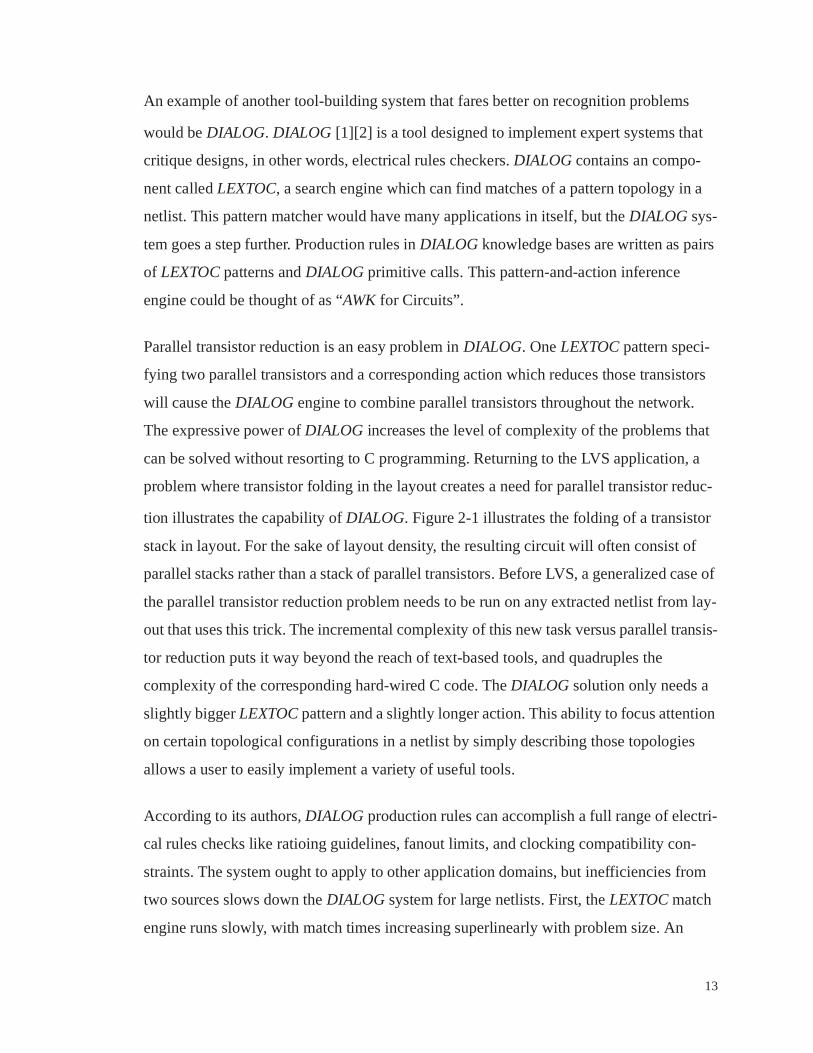
can be solved without resorting to C programming. Returning to the LVS application, a
problem where transistor folding in the layout creates a need for parallel transistor reduc-
tion illustrates the capability of DIALOG. Figure 2-1 illustrates the folding of a transistor
stack in layout. For the sake of layout density, the resulting circuit will often consist of
parallel stacks rather than a stack of parallel transistors. Before LVS, a generalized case of
the parallel transistor reduction problem needs to be run on any extracted netlist from lay-
out that uses this trick. The incremental complexity of this new task versus parallel transis-
tor reduction puts it way beyond the reach of text-based tools, and quadruples the
complexity of the corresponding hard-wired C code. The DIALOG solution only needs a
slightly bigger LEXTOC pattern and a slightly longer action. This ability to focus attention
on certain topological configurations in a netlist by simply describing those topologies
allows a user to easily implement a variety of useful tools.
According to its authors, DIALOG production rules can accomplish a full range of electri-
cal rules checks like ratioing guidelines, fanout limits, and clocking compatibility con-
straints. The system ought to apply to other application domains, but inefficiencies from
two sources slows down the DIALOG system for large netlists. First, the LEXTOC match
engine runs slowly, with match times increasing superlinearly with problem size. An

14
improved implementation, LEXCAL [1], increases the practical circuit size but does not
change the asymptotic behavior, so again circuits above a certain size will be impractical.
The DIALOG system also has inordinate memory requirements, largely in order to imple-
ment its parallel semantics - in DIALOG, all matching instances must be found and
tracked before any actions are executed. These parallel semantics are required not by the
application domain but merely by LEXTOC’s default, implicit global control flow.
2.4. Netlist Parsing
It may be possible to go even further than DIALOG/LEXTOC in terms of describing and
searching for topological configurations in a netlist. Rather than examining netlist topol-
ogy piecemeal, perhaps the best approach is to parse a netlist in its entirety. If the hierar-
chical cell compositions that constitute a netlist can be reconstructed bottom-up from a flat
design netlist, then tools might address the netlist in the form of a parse tree instead of a
graph.
AAAAAAAAAAAAAAAAAAAAAAAAAAAAAAAAAAAAAAAAAAAAAAAAAAAAAAAAAAAAAAAAAAAA
AAAAAAAAAAAAAAAAAAAAAAAAAAAAAAAAAAAAAAAAAAAAAAAAAAAAAAAAAAAAAAAAAAAA
AAAAAAAAAAAAAAAAAAAAAAAAAAAAAAAAAAAAAAAAAAAAAAAAAAAAAAAAAAAAAAAAAAAAAAAAAAAAAAAAAAAAAAAAAAAAAAAAAAAA
AAAAAAAAAAAAAAAAAAAAAAAAAAAAAAAAAAAAAAAAAAAAAAAAAAAAAAAAAAAAAAAAAAAAAAAAAAAAAAAAAAAAAAAAAAAAAAAAAAAA
AAAAAAAAAAAAAAAAAAAAAAAAAAAAAAAAAAAAAAAAAAAAAAAAAAAAAAAAAAAAAAAAAAAAAAAAAAAAAAAAAAAAAAAAAAAAAAAAAAAA
AAAAAAAAAAAAAAAAAAAAAAAAAAAAAAAAAAAAAAAAAAAAAAAAAAAAAAAAAAAAAAAAAAAAAAAAAAAAAAAAAAAAAAAAAAAAAAAAAAAA
AAAAAAAAAAAAAAAAAAAAAAAAAAAAAAAAAAAAAAAAAAAAAAAAAAAAAAAAAAAAAAAAAAAAAAAAAAAAAAAAAAAAAAAAAAAAAAAAAAAA
AAAAAAAAAAAAAAAAAAAAAAAAAAAAAAAAAAAAAAAAAAAAAAAAAAAAAAAAAAAAAAAAAAAAAAAAAAAAAAAAAAAAAAAAAAAAAAAAAAAA
AAAAAAAAAAAAAAAAAAAAAAAAAAAAAAAAAAAAAAAAAAAAAAAAAAAAAAAAAAAAAAAAAAAAAAAAAAAA
AAAAAAAAAAAAAAAAAAAAAAAAAAAAAAAAAAAAAAAAAAAAAAAAAAAAAAAAAAAAAAAAAAAAAAAAAAAA
AAAAAAAAAAAAAAAAAAAAAAAAAAAAAAAAAAAAAAAAAAAAAAAAAAAAAAAAAAAAAAAAAAAAAAAAAAAA
Figure 2-1. Transistor stack folding often does not lead to a stack of parallel transistors

15
GRASP [15] is a tool designed to parse entire netlists. A user of GRASP writes a graph
grammar which describes the set of legal circuits for a particular design methodology.
GRASP can then determine whether some netlist conforms to the methodology by
attempting to parse it with the grammar. GRASP itself attempts no more than recognition
of “correct” netlists, but the ability to parse, to reconstruct hierarchy bottom-up in one
automatic step would be a wonderful starting place for building new tools.
While promising in concept, GRASP lacks flexibility in a subtle way. GRASP grammars,
like yacc grammars, are specified with mutually recursive production rules. Yacc requires
grammars in the set LR(1) [20] in order to parse efficiently with a shift-reduce algorithm,
and GRASP has an analogous restriction. While the GRASP authors were able to write a
suitable grammar for recognizing a “CMOS 2-phase” methodology, rather an ambitious
undertaking, not all reasonable methodologies will have a corresponding “fast” grammar.
Furthermore, the question of whether some particular graph grammar can be parsed effi-
ciently is not easy to answer by inspection. Therefore, users of a grammar-based tool
development system might easily encounter an application where a suitable grammar is
rendered unsuitable by the slightest of changes.
2.5. Choosing a Paradigm for a Pattern-Oriented Tool
Text-based tools like grep, awk, and the rest of the unix suite provide a good model for a
tool-constructing system by providing versatile primitive operations in well-partitioned
modules. By themselves these tools can usefully manipulate netlists, but their design does
not really address netlist connectivity. New modular tools, designed in the same spirit as
the unix suite but specifically geared toward netlists, would allow rapid implementations
of tools that would otherwise require the more burdensome task of writing custom pro-
grams.
The core of the DIALOG/LEXTOC system might be described loosely as an “AWK for
Circuits”. Of all of the systems described so far, this one appears to be a step in the right
direction. The DIALOG system as it stands has some minor disadvantages as a retargeta-
ble tool-building platform: its action language is geared toward ERC applications, and its

16
implementation is slow. None of these are insurmountable problems. DIALOG’s biggest
shortcoming as a building block is that its functionality is not packaged in the most useful
way. If the basic concept underlying DIALOG were refined in order to place a pattern-
action paradigm in a versatile, modular, efficient package, the result would allow the rapid
development of new netlist processing tools. Such a system will be developed in the next
chapter.

17
Chapter 3
Pattern Objects
A system like “Awk for Circuits” or the DIALOG engine holds great promise as the foun-
dation for new netlist processing tools. To maximize the potential for tool building, the
basic pattern/action functionality of these tools should be made available in a useful form.
The new capability should uniformly and concisely express useful computations. It should
also provide this functionality in an open-ended way which does not make too many
implicit assumptions about the nature of future tools. This chapter will identify a software
entity that can accomplish all of these things, the pattern object.
One could choose a number of ways to design a tool which, loosely stated, “takes a list of
patterns (subcircuits) with actions (code fragments) and executes the actions wherever it
finds the corresponding patterns in some big netlist.” The exact method of specifying the
patterns and actions will establish the tool’s flexibility, ease of use, and the expressiveness
of its input language. The semantics of applying the patterns and actions to a netlist must
also resolve potential ambiguous cases. This chapter will examine some possible specifi-
cation techniques for pattern objects and choose one which makes an adaptable and flexi-
ble building block. That choice will turn out not to be an “Awk for Circuits” but rather a
lower-level software object which can be used to implement awk-like tools, parsers, and
other functions all with the same basic component.
3.1. Pattern and Action Specification
If the goal is to build a pattern-based tool development system, the first issue to address is
also the most important one: how should topological patterns be specified? The answer to
this question will influence every aspect of a pattern-based system and the applications
built with it. UNIX tools like awk, grep, sed, lex, and yacc use patterns in their
18
specifications and also achieve great versatility, so perhaps their lexical pattern specifica-
tion techniques can inspire a graph analog. Awk, sed, grep, and lex in particular use regular
expressions to search for matches in a text stream. Regular expressions provide a nice way
to specify useful pattern spaces, and the computation required for the implied searching
and matching is straightforward.
“Regular expressions” for graphs, (GREs), might be invented by analogy to the usual lex-
ical regular expression (LRE). The atomic GRE objects can be devices or nets, instead of
the symbols from an alphabet for an LRE. In an LRE, juxtaposition in the expression
implies sequence. In other words, symbols and their matches must appear in the same
order. Graph adjacency would be the analogous concept for GREs. A textual description
of the GRE would therefore look like a netlist.
With the components described so far, LREs can specify literal strings, and GREs can
specify subgraphs. A single regular expression will match exactly one string or subgraph.
The utility of LREs comes in part from their ability to specify whole families, or “lan-
guages”, of strings. This power of regular expressions lies in two additional operators, the
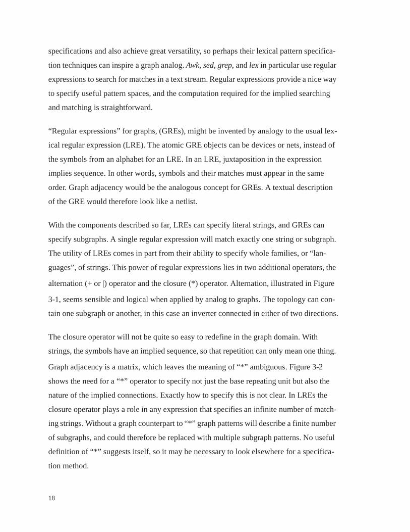
alternation (+ or |) operator and the closure (*) operator. Alternation, illustrated in Figure
3-1, seems sensible and logical when applied by analog to graphs. The topology can con-
tain one subgraph or another, in this case an inverter connected in either of two directions.
The closure operator will not be quite so easy to redefine in the graph domain. With
strings, the symbols have an implied sequence, so that repetition can only mean one thing.
Graph adjacency is a matrix, which leaves the meaning of “*” ambiguous. Figure 3-2
shows the need for a “*” operator to specify not just the base repeating unit but also the
nature of the implied connections. Exactly how to specify this is not clear. In LREs the
closure operator plays a role in any expression that specifies an infinite number of match-
ing strings. Without a graph counterpart to “*” graph patterns will describe a finite number
of subgraphs, and could therefore be replaced with multiple subgraph patterns. No useful
definition of “*” suggests itself, so it may be necessary to look elsewhere for a specifica-
tion method.

19
Regular expressions represent just one specification model that might extend to the graph
domain. The UNIX tool yacc provides an example of another. Instead of regular expres-
sions with their alternation and closure operators, yacc operates on grammars, sets of BNF
production rules which hierarchically define the desired “language”. GRASP, for instance,
uses the graph analog of this idea to parse netlists according to a graph grammar.
A graph grammar can describe an infinite numbers of subgraphs, which could lead to con-
cise, expressive declarations. A few production rules can define infinite families of topol-
ogies. Between simple subgraphs and graph grammars, grammars certainly have a greater
+
Figure 3-1. Alternation Illustrated with a Complementary Pass Gate
Pattern Matches
or
Pattern Matches?
* or
or
Figure 3-2. Closure illustrated with an inverter
20
ability to describe topology. Pattern objects could potentially use either method for
describing patterns. While grammars initially appear to be the better choice, there are
more factors than topological expressiveness to consider.
A pattern-based system modeled after the paradigm of yacc, awk or DIALOG will have to
specify actions as well as topological patterns. In pattern/action systems the pattern topol-
ogy descriptions and corresponding action descriptions have an intimate relationship. Just
as awk’s C-based action language has extensions to access a matched line of text and its
components, a netlist action language will require some way for the action code to access
the particular devices and nets that some corresponding pattern has matched.
For subgraph patterns the pattern description language will be a netlist. The usual method
for specifying a netlist involves naming the nets and devices and then describing any con-
nections by referencing those names. When the netlist has a match, the nets and devices
from the matching subcircuit can be bound to variables with the same names as the nets
and devices in the pattern netlist. Actions written in a programming language could then
reference and manipulate the components of a matched subcircuit by naming the corre-
sponding bound variables.
For graph-grammar patterns the pattern description language has just one netlist for each
production rule, but the matching subcircuit will be one of a possibly infinite family of
parse trees. Instead of the access to variables with one-to-one binding as in the subgraph
case, actions for graph-grammar patterns would have to iterate or recurse over a parse tree
to access the matching subcircuit’s nets and devices.
Graph grammars might make for easier descriptions of a pattern’s topology, but the corre-
sponding actions will be much more difficult to write. This factor tips the balance toward
simple subgraphs, and along with some practical shortcomings of graph grammars
described earlier in Chapter 2 caused the adoption of simple subgraphs as the basis for the
pattern object. The later development of netlist-specific pattern extraction (Section 3.4.)
vindicated this choice.
21
3.2. The Subgraph Pattern/Action Object
With the pattern specification method settled, the next topic will be the pattern and
action’s semantics. So far, any discussion of how a pattern-and-action system works has
tacitly assumed semantics similar to awk. In other words, just as awk scans an entire text
file looking for pattern matches that invoke their respective matches, netlist pattern/action
systems presumably scan an entire netlist for matching subcircuits, invoking the corre-
sponding actions for each match found. This section describes another model where the
outer control flow is made explicit. These semantics, simpler than those of awk, also turn
out to be more flexible and capable, and at the same time less ambiguous.
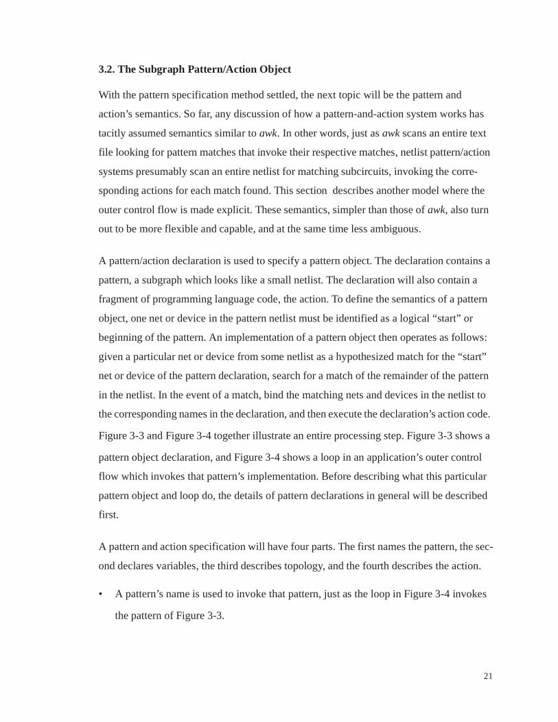
A pattern/action declaration is used to specify a pattern object. The declaration contains a
pattern, a subgraph which looks like a small netlist. The declaration will also contain a
fragment of programming language code, the action. To define the semantics of a pattern
object, one net or device in the pattern netlist must be identified as a logical “start” or
beginning of the pattern. An implementation of a pattern object then operates as follows:
given a particular net or device from some netlist as a hypothesized match for the “start”
net or device of the pattern declaration, search for a match of the remainder of the pattern
in the netlist. In the event of a match, bind the matching nets and devices in the netlist to
the corresponding names in the declaration, and then execute the declaration’s action code.
Figure 3-3 and Figure 3-4 together illustrate an entire processing step. Figure 3-3 shows a
pattern object declaration, and Figure 3-4 shows a loop in an application’s outer control
flow which invokes that pattern’s implementation. Before describing what this particular
pattern object and loop do, the details of pattern declarations in general will be described
first.
A pattern and action specification will have four parts. The first names the pattern, the sec-
ond declares variables, the third describes topology, and the fourth describes the action.
• A pattern’s name is used to invoke that pattern, just as the loop in Figure 3-4 invokes
the pattern of Figure 3-3.
22
• The variable declaration section assigns names to the nets and devices of the pattern.
The names are used in the topology section to describe the pattern’s interconnection.
Several keywords can precede a net or device name. The keyword “start” indicates the
that pattern’s logical start point. The keyword “local” applied to a net name asserts that
any matching net from the netlist can have no adjacent devices other than the ones
specified in the pattern. The keyword “literal” asserts that the matching net or device
must be literally the one named. The pattern in Figure 3-3 uses “literal” to indicate that
net variables “Vdd” and “GND” can only match the actual Vdd and GND nets in the
netlist.
• The topology description is a netlist, written in terms of the names in the declaration
section. The netlist is a list of devices, with each device naming its terminals and net
connections.
• The action is a code fragment in a general-purpose programming language, C, which
can access the matches to the pattern variables by naming those variables. Once the
action completes, the search will continue unless the action contains an explicit
“return” statement.
Figure 3-3 shows a specification for a pattern and action which identifies weak-feedback
staticized latches and removes the feedback. The pattern specifies a four-transistor net-
work that represents a loop of two inverters. The pattern and action make the assumption
that of the two inverters in a symmetric configuration, the one made of weaker devices is
the staticizing inverter.
In this pattern the device N1 is the declared start device, so the loop in Figure 3-4 simply
proposes every device in the netlist as a potential match for N1. When a candidate for N1
leads to a match, the action code executes. Note that the action can access properties of
matched devices by naming the corresponding variable, i.e. “N2.width” refers to the width
for (d = /* all devices in the netlist */)static_latch(d, Vdd, GND);
Figure 3-4. Invoking a Pattern Object

23
of the device in the netlist that matched N2. This action compares the widths of the N1 and
N2 matches in case the match is encountered in reverse before deleting the feedback
devices.
Why explicitly write loops like Figure 3-4? Such decoupling of pattern recognition from
outer control flow will turn out to have numerous advantages. Among these advantages,
separation of the pattern object from the control flow that invokes that pattern object
resolves some ambiguities in the “Awk for Circuits” semantics. Multiple patterns each of
which matches multiple subcircuits could all have their actions run concurrently, but
netlist-modifying actions would lead to questions about what happens first or which action
has priority in a conflict. An outer loop invoking the pattern object explicitly serializes and
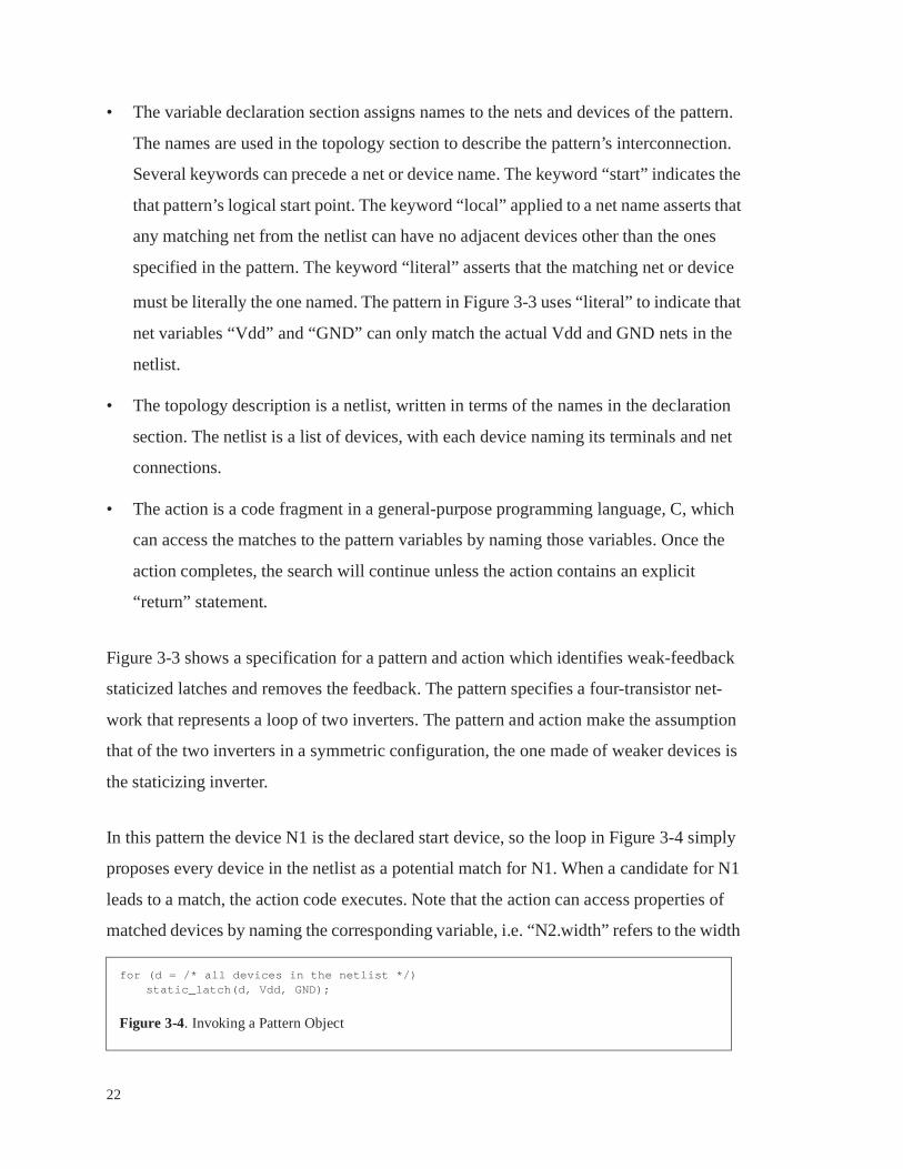
orders the matches and action executions. For example, if the pattern object specified in
Figure 3-3 were invoked on every transistor in the netlist of Figure 3-5, the action could
possibly execute beginning with either M9 or M10.1 In either case the opposite inverter is
1. This is a bug - the conditions should be <, not <=. The way the pattern is, it would match SRAM cells!
pattern static_latch
start device N1device N2,P1,P2net in,outliteral net Vdd, GND
topology
((N1 nfet) ((gate in)(srcdrn out)(srcdrn GND)))((P1 pfet) ((gate in)(srcdrn out)(srcdrn Vdd)))((N2 nfet) ((gate out)(srcdrn in)(srcdrn GND)))((P2 pfet) ((gate out)(srcdrn in)(srcdrn Vdd)))
action{
if ((N1.width>=N2.width)&&(P1.width>=P2.width) {delete_device(N2);delete_device(P2);num_static_latches++;
}return;
}end_action
Figure 3-3. A Pattern to Find Static Latches and Remove the Weak Feedback
in out
N1
P1
N2(weak)
P2(weak)
24
deleted, so that the match can only occur once, so that the variable num_static_latches will
not increment by two despite the fact that the netlist begins with two complete matches.
Another explicit control flow option resolves a further semantic ambiguity. A pattern
object runs its action if a topological match is found given the start nets/devices. A “start”
net might actually border multiple, independent matching subcircuits in a netlist. Even
without multiple complete matches, due to symmetry, “start” nets and devices can both
lead to multiple possible matches with the symmetric portion in different permutations.
Figure 3-6 shows examples of both situations. In practice, two policies find a lot of use:
find and run the action on all matches, or find and run the action on only the first match
encountered. Since both policies are useful, either can be selected per pattern.
Explicit control flow resolves these potentially ambiguous cases, which is certainly some-
thing which needs attention, but there are more reasons to decouple the control flow from
the pattern matches. The ability to make explicit choices, such as how to handle multiple
matches, increases the flexibility of the pattern capability. The next section demonstrate
some of the other possibilities that exist when the user explicitly manages control flow.
Figure 3-5. A Netlist Containing a Staticizing Inverter
M1
M2
M3 M4
M5
M6
M7
M8, W=10
M9, W=10
M10, W=10
M11, W=10
M12
M13

25
3.3. The Use of Pattern Objects
Figure 3-4 illustrates how an application can use a pattern object to implement the “AWK
for Circuits” notion of applying an action to every instance of a subcircuit in a netlist. A
loop or an iterating function simply invokes the pattern once for each net or device in the
entire subject netlist. This exhaustive “pass” is just one of many constructs that can be
built with pattern objects.
So far pattern objects have been invoked from an application’s outer control loops, but the
application and the pattern action’s code fragment can use the same programming lan-
guage. Patterns can invoke patterns just as applications do in their outer loops. The ability
of a pattern to call another pattern or even itself opens the door to a variety of useful com-
putations.
Pattern Circuit: 2 matches Circuit: 6 matches
Start Device
Pattern Circuit: n matches
Start Net
Figure 3-6. Two Multiple-match cases
Device and/or Net start: Symmetry
Net start: Duplication

26
Consider the transmission gate of Figure 3-1, where the companion inverter could be
present in either polarity. To count the transmission gates in a circuit, but only the ones
accompanied by a companion inverter, one might write two patterns as in Figure 3-7. The
calls in the pass-gate pattern’s action implement alternation, as a means of constraining the
allowable contexts for pass gates in this application.
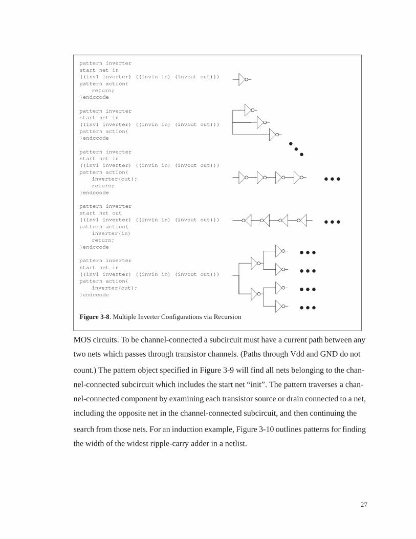
In Figure 3-8 pattern object recursion is used to traverse several configurations of invert-
ers, depending on the presence of a recursive call, the presence of a “return”, and specified
interconnections. Pattern recursion in various forms can implement depth-first traversal,
induction, or even elementary recursive-descent parsing. Implicit in these recursive pat-
terns are the specifications of connection that the regular-expression “*” operator failed to
capture. Recursive pattern objects along with their invoking control flow can therefore
manipulate infinite families of topologies without infinite specifications.
For an example of depth-first traversal, Figure 3-9 shows a single pattern containing a sin-
gle device which can search for “channel-connected” subcircuits, a useful analysis unit for
pattern is_inverter returns “int” default “0”
start net instart net outstart lit net v Vddstart lit net g GND
((nfet1 nfet) ((gate in) (srcdrn out) (srcdrn g)))((pfet1 pfet) ((gate in) (srcdrn out) (srcdrn v)))
pattern action{return 1;
}endccode
pattern count_passgate
start dev pfet1start lit net v Vddstart lit net g GND
((nfet1 nfet) ((gate in1) (srcdrn a) (srcdrn b)))((pfet1 pfet) ((gate in2) (srcdrn a) (srcdrn b)))
pattern action{if (is_inverter(in1, in2, Vdd, GND)||is_inverter(in2, in1, Vdd, GND))
pass_gate_count++;return;
}endccode
Figure 3-7. A Pattern Implementing Alternation to Constrain Context
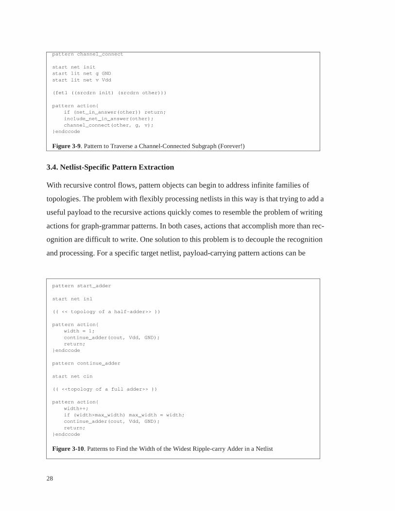
27
MOS circuits. To be channel-connected a subcircuit must have a current path between any
two nets which passes through transistor channels. (Paths through Vdd and GND do not
count.) The pattern object specified in Figure 3-9 will find all nets belonging to the chan-
nel-connected subcircuit which includes the start net “init”. The pattern traverses a chan-
nel-connected component by examining each transistor source or drain connected to a net,
including the opposite net in the channel-connected subcircuit, and then continuing the
search from those nets. For an induction example, Figure 3-10 outlines patterns for finding
the width of the widest ripple-carry adder in a netlist.
pattern inverterstart net in((inv1 inverter) ((invin in) (invout out)))pattern action{
return;}endccode
pattern inverterstart net in((inv1 inverter) ((invin in) (invout out)))pattern action{}endccode
pattern inverterstart net in((inv1 inverter) ((invin in) (invout out)))pattern action{
inverter(out);return;
}endccode
pattern inverterstart net out((inv1 inverter) ((invin in) (invout out)))pattern action{
inverter(in)return;
}endccode
pattern inverterstart net in((inv1 inverter) ((invin in) (invout out)))pattern action{
inverter(out);}endccode
Figure 3-8. Multiple Inverter Configurations via Recursion
28
3.4. Netlist-Specific Pattern Extraction
With recursive control flows, pattern objects can begin to address infinite families of
topologies. The problem with flexibly processing netlists in this way is that trying to add a
useful payload to the recursive actions quickly comes to resemble the problem of writing
actions for graph-grammar patterns. In both cases, actions that accomplish more than rec-
ognition are difficult to write. One solution to this problem is to decouple the recognition
and processing. For a specific target netlist, payload-carrying pattern actions can be
pattern channel_connect
start net initstart lit net g GNDstart lit net v Vdd
(fet1 ((srcdrn init) (srcdrn other)))
pattern action{if (net_in_answer(other)) return;include_net_in_answer(other);channel_connect(other, g, v);
}endccode
Figure 3-9. Pattern to Traverse a Channel-Connected Subgraph (Forever!)
pattern start_adder
start net in1
(( << topology of a half-adder>> ))
pattern action{width = 1;continue_adder(cout, Vdd, GND);return;
}endccode
pattern continue_adder
start net cin
(( <<topology of a full adder>> ))
pattern action{width++;if (width>max_width) max_width = width;continue_adder(cout, Vdd, GND);return;
}endccode
Figure 3-10. Patterns to Find the Width of the Widest Ripple-carry Adder in a Netlist
29
produced from recognition-only patterns semi-automatically. The process contains the fol-
lowing steps:
• Write a graph grammar or a set of recursive pattern objects that recognizes an infinite
number of topologies.
• Run the recognizing pattern on the target netlist. The output will be a series of netlists,
one for each match found.
• Use a graph-comparing algorithm like Gemini to reduce the list of netlists found to a
list of the distinct netlist topologies found.
• Transform the list of distinct netlists into a list of pattern declarations, each ready for a
payload action to be inserted manually.
The process can be illustrated with the basic latch cell used throughout the RISC micro-
processor MIPS-X. Figure 3-11 shows two variations of the basic cell, and also how a
multiplexor is often merged with the basic cell. Not only might there be multiple pass tran-
sistors to implement the mux, but there is also a possibility that one or more of the mux
inputs will be a constant, Vdd or GND. Each of these variations counts as a different
topology, because the base cell already contains Vdd and GND. The topologies are dis-
tinct, and so perhaps are the appropriate payload actions for a given application.
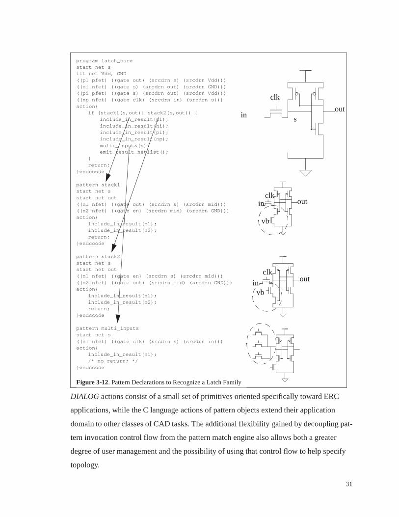
The pattern set in Figure 3-12 can recognize all of the latches in the family illustrated in
Figure 3-11. Four patterns work together: the first matches the core of the latch, the next
two identify one of the two transistor stack permutations, and the last matches possible
multiple inputs. These patterns recognized 1083 latches in the MIPS-X design. Of these,
there were 18 different topologies - one, two, and three input latches, with the multiple
input types occurring with various combinations of inputs tied together or to Vdd or to
GND. The number of distinct latch topologies is certainly small enough that writing
actions for each one by hand is not too much to ask of a tool developer.
With pattern extraction, grammar-like pattern expressiveness can be combined with
straightforward action writing. To achieve this combination, attention must focus on a

30
single netlist, and unfortunately the process is only semi-automatic. These drawbacks do
not prevent the pattern extraction procedure from being useful. In addition to the latch-
family application just described, this procedure has helped with the reverse engineering
of unfamiliar netlists and has helped to track down errors through many different netlists
and applications.
3.5. Summary
The basic DIALOG engine comes close to providing a reasonable platform for tool devel-
opment, but the pattern object offers the same capability in a more versatile package.
Figure 3-11. The Family of Latches Used in MIPS-X
InOut
Vbias
The Basic Latch
Phi
Out
Vbias
In1
In2
In3
Q1
Q2
Q3
Including a Mux (Two or more Inputs)
Out
Vbias
In
“1”
“0”
Q1
Q2
Q3
Constant Inputs
InOut
Vbias
The Basic Latch (Variation)
Phi
31
DIALOG actions consist of a small set of primitives oriented specifically toward ERC
applications, while the C language actions of pattern objects extend their application
domain to other classes of CAD tasks. The additional flexibility gained by decoupling pat-
tern invocation control flow from the pattern match engine also allows both a greater
degree of user management and the possibility of using that control flow to help specify
topology.
program latch_corestart net slit net Vdd, GND((p1 pfet) ((gate out) (srcdrn s) (srcdrn Vdd)))((ni nfet) ((gate s) (srcdrn out) (srcdrn GND)))((pi pfet) ((gate s) (srcdrn out) (srcdrn Vdd)))((np nfet) ((gate clk) (srcdrn in) (srcdrn s)))action{
if (stack1(s,out)||stack2(s,out)) {include_in_result(p1);include_in_result(ni);include_in_result(pi);include_in_result(np);multi_inputs(s);emit_result_netlist();
}return;
}endccode
pattern stack1start net sstart net out((n1 nfet) ((gate out) (srcdrn s) (srcdrn mid)))((n2 nfet) ((gate en) (srcdrn mid) (srcdrn GND)))action{
include_in_result(n1);include_in_result(n2);return;
}endccode
pattern stack2start net sstart net out((n1 nfet) ((gate en) (srcdrn s) (srcdrn mid)))((n2 nfet) ((gate out) (srcdrn mid) (srcdrn GND)))action{
include_in_result(n1);include_in_result(n2);return;
}endccode
pattern multi_inputsstart net s((n1 nfet) ((gate clk) (srcdrn s) (srcdrn in)))action{
include_in_result(n1);/* no return; */
}endccode
Figure 3-12. Pattern Declarations to Recognize a Latch Family
inout
clk
s
in out
vb
clk
in out
vb
clk

32
On top of a restricted set of action primitives and the limitations of its backward-chaining
global control flow, DIALOG suffered from the poor performance of LEXTOC. Perfor-
mance can be a critical parameter, as designers working on multi-million transistor
designs have little use for an implementation technique that produces slow applications.
While this shortcoming may account for the fact that DIALOG has not seen widespread
use, the next chapter will demonstrate that pattern object implementations exist which can
run fast enough to discount performance as a limitation of pattern-based tool development.
33
Chapter 4
Matching Algorithms and Matching Performance
The previous chapter established a formalism for specifying netlist operations with pat-
terns and actions. Underlying any implementation that can execute pattern/action netlist
operations is the ability to search for matches of a topological pattern in some larger
netlist.
To find matches of some pattern in a graph is to solve the theoretical problem of subgraph
isomorphism, a problem which is known to be computationally expensive in the general
case.[11] This potential for long runtimes has lead Pelz [6] to explore the range of tools
can be built with operations less powerful than pattern matching, lead the DIALOG [1]
authors to implement compiled pattern matchers, and lead Ohlrich [11] to produce sophis-
ticated subgraph isomorphism algorithms for Subgemini.
Fortunately, VLSI netlists have properties, sparsity especially, that render the matching
problem easier than in the worst case. As a consequence, typical Subgemini runtimes grow
linearly with the size of the subject netlist, rather than exponentially.[11]
Despite the sparse nature of device netlists, initial experiences with a preliminary pattern
matcher saw matching runtimes varying by factors of over a thousand for the very same
netlist and pattern, depending on subtleties in the direction in which the search proceeded.
With such a span of performance at stake it appeared necessary to write or “tune” patterns
with performance continually in mind. The need to be mindful of search difficulty while
writing patterns threatened to counteract the benefits of using patterns. Fortunately, less
naive matching algorithms consistently perform well on typical netlists and patterns with-
out requiring user direction or imposing unreasonable restrictions.

34
This chapter will begin by illustrating the difficulty of graph comparison in general, and
then show how the problem simplifies for typical VLSI device netlists. Finally, the use of
heuristics or the subgemini algorithm will be discussed as a means of releasing pattern
writers from the responsibility of performance tuning.
4.1. Subgraph Isomorphism
What is so difficult about finding matches of some smaller graph in a larger graph? A first
step toward appreciating the theoretical difficulty of subgraph isomorphism would be to
look at the simpler problem of graph isomorphism. Computing graph isomorphism
amounts to comparing two graphs to determine whether they are instances of the same
graph or not. Figure 4-1 shows four small graphs, only two of which are the same (isomor-
phic). On as small of an example as this, superficial inspection fails to make an easy deter-
mination of isomorphism. As graphs grow, comparison will usually involve systematic
trial and error, as even the simpler problem of graph isomorphism is computationally hard.
The number of hypothetical assignments between the components of two graphs under
comparison grows factorially with the size of the graphs, and the test of each hypothesized
match is a complex task in itself.
Comparing graphs might require exponential time in the most general case, but some algo-
rithms run faster in the average case. Many successful graph isomorphism algorithms
exploit local graph properties called isomorphism invariants. For instance, for a vertex of
one graph to correspond to a given vertex in another, both vertices must have the same
number of incident edges. Table 4-1 shows the edge-adjacency counts for the vertices in
the graphs of Figure 4-1 sorted in increasing order. A glance at this list can instantly rule
out graphs A and D as matches for either one another or graphs B or C. Adjacency counts
like these are cheap to compute and can help a great deal toward quickly showing that dif-
ferent graphs do not match.
Turning back to the initial problem of subgraph isomorphism, the matching problem is
confounded further still. A matching subgraph, in context, will likely have incident edges
or vertices from the surrounding graph which do not belong to the subgraph, as illustrated

35
in Figure 4-2. Before a subgraph matching problem resembles a graph matching problem,
it must be determined which of the edges and vertices in a graph form a candidate for a
matching subgraph. Without this determination local isomorphism invariants are difficult
to find and use. What was already a computationally difficult problem, graph isomor-
phism, has only been made worse when generalized to subgraph isomorphism.
Figure 4-1. Four graphs, two of which are alike
Graph A Graph B
Graph C Graph D
Table 4-1. Adjacent Edge Counts per Vertex, Sorted
Graph A Graph B Graph C Graph D2 2 2 2
3 2 2 2
3 3 3 3
3 3 3 3
3 4 4 3
4 4 4 5

36
A search for subcircuits in a netlist constitutes a subgraph isomorphism problem. Fortu-
nately, subcircuit matches can be found in large VLSI netlists reasonably quickly despite
the innate difficulty of the general problem. Characteristics of both typical patterns and
typical VLSI netlists simplify the problem enormously:
• Many practical patterns will contain nets which are “local” to that pattern - matches of
this pattern are expected to appear in the netlist exactly as they appear in the pattern,
with no additional adjacent devices. In these cases a useful local isomorphism invari-
ant has been made available.
• Netlists are bipartite graphs, with nets and devices as vertices and terminal connec-
tions as arcs. The usual VLSI devices, transistors, resistors, capacitors, and so forth,
have a fixed, small number of terminals, never more than four. This property con-
strains the perplexity of VLSI graphs.
• Devices and terminal connections are both labeled, for instance, “nfet”, “pfet”, “npn”,
“resistor”, “gate”, “emitter”, “source”, “drain”, and so on.
• While a net can potentially have enormous numbers of adjacent devices, there are usu-
ally few such nets, and those nets are easily identified, “special” nets: power rails,
clocks, and biases, for instance. In most device netlists, non-“special” nets have a
Pattern Graph with Matching Subgraph
UnmatchedEdges
UnmatchedVertex
Figure 4-2. Context obscures local isomorphism invariants
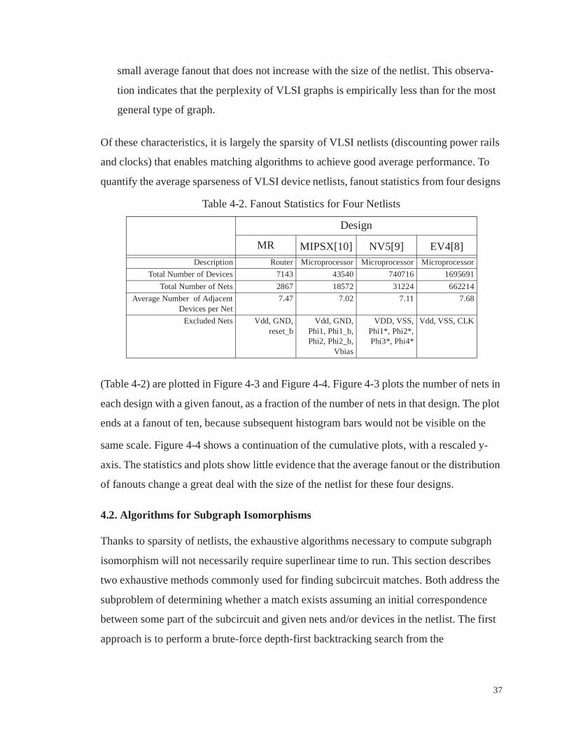
37
small average fanout that does not increase with the size of the netlist. This observa-
tion indicates that the perplexity of VLSI graphs is empirically less than for the most
general type of graph.
Of these characteristics, it is largely the sparsity of VLSI netlists (discounting power rails
and clocks) that enables matching algorithms to achieve good average performance. To
quantify the average sparseness of VLSI device netlists, fanout statistics from four designs
(Table 4-2) are plotted in Figure 4-3 and Figure 4-4. Figure 4-3 plots the number of nets in
each design with a given fanout, as a fraction of the number of nets in that design. The plot
ends at a fanout of ten, because subsequent histogram bars would not be visible on the
same scale. Figure 4-4 shows a continuation of the cumulative plots, with a rescaled y-
axis. The statistics and plots show little evidence that the average fanout or the distribution
of fanouts change a great deal with the size of the netlist for these four designs.
4.2. Algorithms for Subgraph Isomorphisms
Thanks to sparsity of netlists, the exhaustive algorithms necessary to compute subgraph
isomorphism will not necessarily require superlinear time to run. This section describes
two exhaustive methods commonly used for finding subcircuit matches. Both address the
subproblem of determining whether a match exists assuming an initial correspondence
between some part of the subcircuit and given nets and/or devices in the netlist. The first
approach is to perform a brute-force depth-first backtracking search from the
Table 4-2. Fanout Statistics for Four Netlists
Design
MR MIPSX[10] NV5[9] EV4[8]Description Router Microprocessor Microprocessor Microprocessor
Total Number of Devices 7143 43540 740716 1695691
Total Number of Nets 2867 18572 31224 662214
Average Number of AdjacentDevices per Net
7.47 7.02 7.11 7.68
Excluded Nets Vdd, GND,reset_b
Vdd, GND,Phi1, Phi1_b,Phi2, Phi2_b,
Vbias
VDD, VSS,Phi1*, Phi2*,Phi3*, Phi4*
Vdd, VSS, CLK

38
AAAA
AAAAAAAAAAAAAAAAAAAAAAAAAAAAAA
AAAAAAAAAAAAAAA
AAAAAAAAAAAAAAAAAA
AAAAAAAAAAAAAAAAAAAAAAAAAAAAAAAAAAAAAAAAAAAAAAAAAAAAAAAAAAAAAAAAAAAAAAAAAAAAAAAAAAAAAAA
AAAAAAAA
AAAAAA
AAAAAA
AAAA
AAAA
AAAAAA
AAAAAAAAAAAAAAAAAAAAAAAAAA
AAAAAAAAAAAAAA
AAAAAAAAAAAAAAAAAAAA
AAAAAAAAAAAAAAAAAAAAAAAAAAAAAA
AAAAAAAAAAAAAAAAAAAAA
AAAAAA
AAAAAAAAA
AAAAAA
AAAAAA
AAAA
AAAA
AAAAAAAAAAAAAAAAAAAAAAAAAAAAAAAAAAAAAAAAAAAAAAAA
AAAAAAAAAAAA
AAAAAAAAAAAAAAAAAA
AAAAAAAAAAAAAAAAAAAAAAAAAAAAAAAAAAAAAAAAAAAAAAAAAAA
AAAAAAAAAAAAAAAAAA
AAAAAA
AAAA
AAAA
AAAAAA
AAAA
AAAAAAAAAAAAAAAAAAAAAAAAAAAAAAAAAAAAAAAAAA
AAAA
AAAAAAAAAAAAAAAA
AAAAAA
AAAAAAAAAAAAAAAAAAAAAAAAAAAAAAAAAAAAAAAAAAAAAAAA
AAAAAA
AAAAAAAAAAAAAAA
AAAA
AAAA
Net Fanout Histogram
0
0.1
0.2
0.3
0.4
0.5
0.6
0.7
0.8
0.9
1
0 1 2 3 4 5 6 7 8 9 10
Number of Adjacent Devices
Fra
ctio
n of
Tot
al N
ets
AAAAAAAA
AAEV4
AAAAAAAA
AANV5
AAAAAAAA
AAMIPSX
AAAAAAAA
AAMR
EV4
NV5
MIPSX
MR
Figure 4-3. Histogram of Device Fanout
Net Fanout Histogram (Continuation of Cum ulative Fraction)
0.9
0.91
0.92
0.93
0.94
0.95
0.96
0.97
0.98
0.99
1
15 20 25 30 35 40 45 50
Number of Adjacent Devices
Fra
ctio
n of
Tot
al N
ets
EV4
NV5
MIPSX
MR
Figure 4-4. Continued Histogram

39
hypothesized starting point onward. The second is the elegant algorithm in subgemini
which progresses depth-first by iteratively applying a hashing function.
Backtracking Depth-First Search
A pattern/subcircuit can be thought of as a list of variables, some for nets and some for
devices, to be filled in with corresponding nets and devices in the netlist. A backtracking
search begins with one of those variables bound to a specific candidate from the netlist.
After running, either the remaining variables are bound to netlist objects such that those
objects match the pattern in topology, or the lack of such a match is indicated.
Figure 4-5 shows the general algorithm in pseudo-code. Line 2, which is executed once
per variable to be matched, arbitrarily chooses an unmatched variable to search for and
also an already-matched adjacent variable to search from. The algorithm searches exhaus-
tively regardless of the variable order or choices of neighbors, but both will impact perfor-
mance, and may also effect which of potentially multiple matches will be found first.
For the sake of illustration, suppose that the pattern is a CMOS inverter, and that a vari-
able-matching order and choices of neighbors have been chosen a priori. Figure 4-6
shows the search order superimposed on an inverter schematic. Each pair of a variable to
be matched and its previously-matched neighbor indicate an arc on the pattern’s adjacency
graph. The arcs from all such pairs form a tree in the adjacency graph. Arcs in the pattern
1 while (not all variables are bound) {2 select an unbound variable, u, adjacent in the pattern to a bound variable, b3 for (all objects, o, adjacent in the netlist to the object bound to b) {4 if (o is already bound to a variable) skip to next o5 for (all bound variables, a, adjacent to u) {6 if (the object bound to a is not adjacent to the object bound to u)7 skip to next o8 }9 bind o to u10 proceed to next u11 }12 return failure13 }14 return success
Figure 4-5. General Brute-Force Algorithm

40
adjacency graph not in the tree, called back edges, require checks (by the loop, lines 5-8,
Figure 4-5) to verify matching topology.
The DIALOG authors proposed the generation of pattern matching code specific to a pat-
tern with LEXCAL, for performance reasons. Such code typically consists of nested loops,
for the variable searches, intertwined with topology checks for back edges. A given search
order establishes the loop nesting order, and dictates where the back-edge checks occur.
Neglecting distinctions among device types and terminal types, code for the inverter of
Figure 4-6 is shown in Figure 4-7.
Examination of the multiply nested loops of the inverter-specific code of Figure 4-7 shows
the danger to runtimes when a net has high fanout. Suppose that the first candidate chosen
for net variable “O” happens to be Gnd in the actual netlist. Keeping in mind that we don’t
distinguish between nfets and pfets in this example, every device connected to Gnd makes
a reasonable candidate for “P”! The soonest each candidate for “P” can be eliminated as a
hypothesis is two loops beyond, where “I” may fail to be adjacent to “P”. If “search-
inverter” is called on every device in the netlist, the loops from “I” inward might have to
execute O((number of devices on Gnd)2) times.
Figure 4-6. Static search order for an Inverter
V
G
I O
P
N
V
G
I O
P
N 1
2
3
3
4
5
I O

41
This inverter example has just demonstrated how a fairly innocent pattern can take longer
than it ought to to run. Given the basic algorithm, there is only one degree of freedom
available to avoid problems of this kind. The order in which variables are matched must be
chosen in order to minimize the chance of explosive runtimes. Search order optimization
will now be discussed as a method for improving runtimes.
The most important search ordering issue involves nets like Vdd and Gnd, whose fanout
grows with netlist size. Patterns should either accept such nets as additional inputs when
they are expected as a part of the pattern, or exclude them as special cases when they are
not. This special treatment does not merely reduce the number of hypotheses examined.
The promiscuous nature of such nets in typical VLSI transform them from a liability to a
pervasive search-pruning asset.
To look again at the nested loops of Figure 4-7, it would appear that even small average
fanouts would multiply to large runtimes given a large pattern and therefore deeply nested
loops. Such is not necessarily the case, and the reason involves the premature termination
search-inverter(N)for (O=nets adjacent to N) {
for (P=devices adjacent to O) {if (P==N) continue;for (I=nets adjacent to N) {
if (I==O) continue;for (X=nets adjacent to I) {
if (X==N) continue;if (X==P) break;
}if (X!=P) continue;for (G=nets adjacent to N) {
if (G==O) continue;if (G==I) continue;for (V=nets adjacent to P) {
if (V==O) continue;if (V==I) continue;if (V==G) continue;return SUCCESS;
}}
}}
}return FAILURE;
}
Figure 4-7. Inverter-searching code
Arc 1
Arc 2
Arc 3
Back-edge 3
Arc 4
Arc 5

42
of loops. The code in Figure 4-7 omits some constraints that help a great deal in practice.
The inverter pattern specifies not just topology but the types of the devices and the names
of the terminals interconnecting the devices and the nets. Figure 4-8 shows the same code
including these very constraints. The more important constraint, however, is the back
edge, the check that “I” is adjacent to “P”. Empirically, back-edge checks prune the
search more effectively than any other form of constraint for sparse graphs like circuits.
The pattern writer can provide helpful constraints as well. A pattern might declare a net
“local” to the pattern, meaning that this net, in its context in the netlist, has only the neigh-
bors specified in the pattern. The corresponding constraint prunes effectively and is cheap
to check. The pattern writer can also help with contextual constraints or application-spe-
cific constraints. In our inverter example, a pattern writer might require that the output net
has no srcdrn terminals adjacent to it, aside from the two in the inverter.
search-inverter(N)if (N is not an nfet) return FAILURE;for (O=nets adjacent to N via a srcdrn) {
for (P=devices adjacent to O via a srcdrn) {if (P is not a pfet) continue;for (I=nets adjacent to N via a gate) {
if (I==O) continue;for (X=devices adjacent to I via a gate) {
if (X==N) continue;if (X==P) break;
}if (X!=P) continue;for (G=nets adjacent to N via a srcdrn) {
if (G==O) continue;if (G==I) continue;for (V=nets adjacent to P via a srcdrn) {
if (V==O) continue;if (V==I) continue;if (V==G) continue;return SUCCESS;
}}
}}
}return FAILURE;
}
Figure 4-8. Better Inverter-searching code

43
While the average fanout of a net is not large, it is not constant. The search can avoid iter-
ating over some of the above-average-fanout nets if it can choose which variables to pro-
ceed with in view of the fanouts of nets already matched. Consider the parallel transistor
pattern of Figure 4-9. Due to the pattern’s symmetry, the search can proceed with either of
the srcdrn terminals. If the search code examines the fanout of both candidates and pro-
ceeds with the one with smaller fanout, it is likely to run faster.
A set of heuristics for ordering searches has worked well in practical use. The heuristics
involve no more than greedily choosing variables one at a time such that each imposes a
maximal estimated constraint on the search. An adaptive matcher can even utilize fanout
information to improve its choices on the fly, but the heuristic guidelines based on pattern
topology alone have produced excellent static search orders in practice. The next variable
to match is chosen based on the following rules, in decreasing priority:
• Never begin an arc at a net designated by the pattern as high-fanout, like GND
• The “local” net or device with the highest number of matched neighbors (back-edges)
and lowest number of unmatched neighbors
• non-local nets, again maximizing back-edge count (or with the smallest fanout in the
netlist context, if that information is available)
• the presence of a “custom” user constraint
Pattern Context
Figure 4-9. Choosing Search Order in Light of Context
Start
Ordering Choices
Choose This Not This
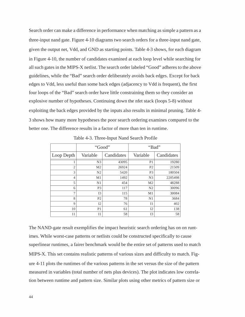
44
Search order can make a difference in performance when matching as simple a pattern as a
three-input nand gate. Figure 4-10 diagrams two search orders for a three-input nand gate,
given the output net, Vdd, and GND as starting points. Table 4-3 shows, for each diagram
in Figure 4-10, the number of candidates examined at each loop level while searching for
all such gates in the MIPS-X netlist. The search order labeled “Good” adheres to the above
guidelines, while the “Bad” search order deliberately avoids back edges. Except for back
edges to Vdd, less useful than some back edges (adjacency to Vdd is frequent), the first
four loops of the “Bad” search order have little constraining them so they consider an
explosive number of hypotheses. Continuing down the nfet stack (loops 5-8) without
exploiting the back edges provided by the inputs also results in minimal pruning. Table 4-
3 shows how many more hypotheses the poor search ordering examines compared to the
better one. The difference results in a factor of more than ten in runtime.
The NAND-gate result exemplifies the impact heuristic search ordering has on on runt-
imes. While worst-case patterns or netlists could be constructed specifically to cause
superlinear runtimes, a fairer benchmark would be the entire set of patterns used to match
MIPS-X. This set contains realistic patterns of various sizes and difficulty to match. Fig-
ure 4-11 plots the runtimes of the various patterns in the set versus the size of the pattern
measured in variables (total number of nets plus devices). The plot indicates low correla-
tion between runtime and pattern size. Similar plots using other metrics of pattern size or
Table 4-3. Three-Input Nand Search Profile
“Good” “Bad”
Loop Depth Variable Candidates Variable Candidates1 N3 43095 P1 19280
2 M2 26924 P2 21509
3 N2 5420 P3 180504
4 M1 1492 N3 2205498
5 N1 454 M2 48288
6 P3 117 N2 30096
7 I3 115 M1 30084
8 P2 78 N1 3684
9 I2 76 I1 402
10 P1 61 I2 138
11 I1 58 I3 58

45
difficulty look much the same. By contrast, the time to run the whole pattern set with heu-
ristic search ordering is about a half hour, while an attempt to run the same set with the
heuristics inverted to make “poor” choices had to be abandoned after not finishing in a
week.
Heuristic search ordering works well in practice, and the nature of the heuristic rules
allows them to be implemented automatically and transparently. Pattern writers can there-
fore specify patterns without concerning themselves with search order or performance. A
pattern that takes a long time to run in spite of the heuristics usually indicates one of two
V
G
P1P2
P3
N1
N2
M2
I2
I3
M1
N3
I1
O
V
P1P2
P3
N1
N2
M2
I2
I3
M1
N3
I1
O
Figure 4-10. Two search-orders for a 3-input nand gate
"Good”
“Bad”
1
2
3
4
5
6
7
8
9
10
11
5
6
7 8
9
10
11
1
2
34
5
6
7
89
10
11
9
10
11
8
23
4
G
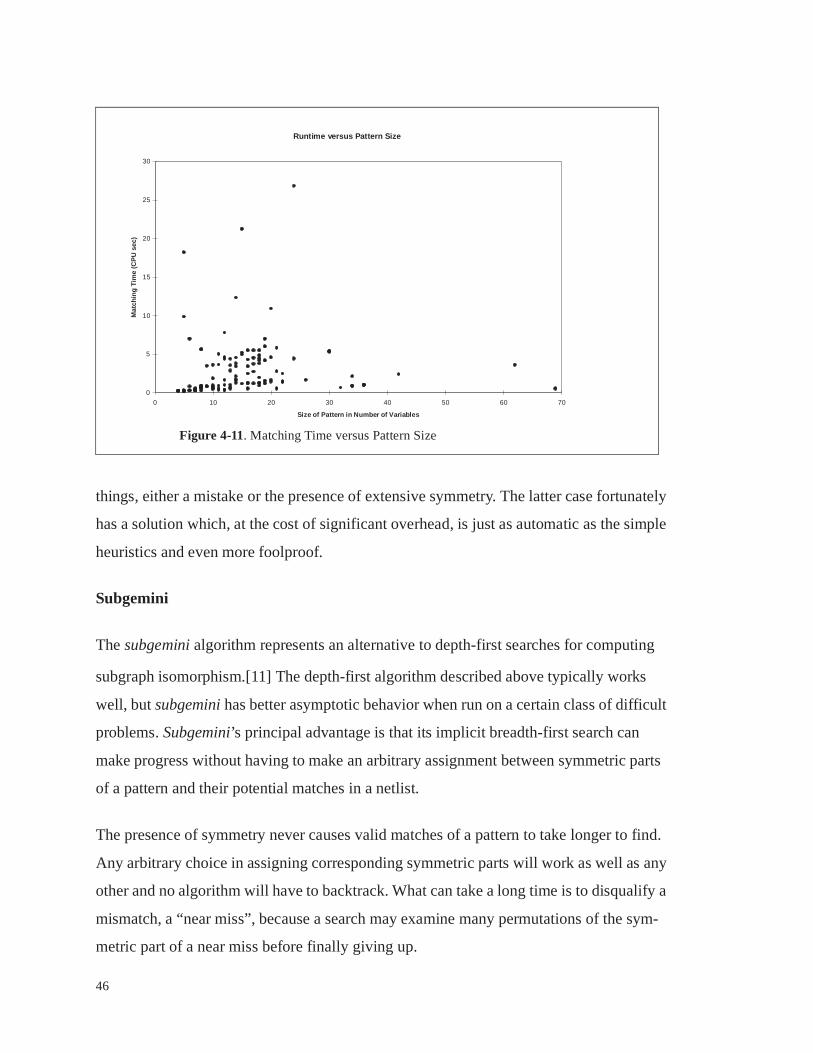
46
things, either a mistake or the presence of extensive symmetry. The latter case fortunately
has a solution which, at the cost of significant overhead, is just as automatic as the simple
heuristics and even more foolproof.
Subgemini
The subgemini algorithm represents an alternative to depth-first searches for computing
subgraph isomorphism.[11] The depth-first algorithm described above typically works
well, but subgemini has better asymptotic behavior when run on a certain class of difficult
problems. Subgemini’s principal advantage is that its implicit breadth-first search can
make progress without having to make an arbitrary assignment between symmetric parts
of a pattern and their potential matches in a netlist.
The presence of symmetry never causes valid matches of a pattern to take longer to find.
Any arbitrary choice in assigning corresponding symmetric parts will work as well as any
other and no algorithm will have to backtrack. What can take a long time is to disqualify a
mismatch, a “near miss”, because a search may examine many permutations of the sym-
metric part of a near miss before finally giving up.
Runtime v ersus Pattern Size
0
5
10
15
20
25
30
0 10 20 30 40 50 60 70
Size of Pattern in Number of Variables
Mat
chin
g T
ime
(CP
U s
ec)
Figure 4-11. Matching Time versus Pattern Size

47
The pattern of Figure 4-12 and the netlist portions in Figure 4-13 and Figure 4-14 illustrate
the advantage of the subgemini algorithm in the face of such symmetry. A depth-first
search which matches all of the parallel transistors M0-9 before attempting to match Mp
will have a problem when it encounters the subcircuit of Figure 4-13 in a netlist. In a fruit-
less effort to match Mp with Mn, the algorithm will exhaustively permute the assignments
for M0 through M9. If the search order tries to match M0 and Mp before M1-9, a netlist
like Figure 4-14 will cause the depth-first search to examine all permutations of Ma-e and
then of Mf-j in the vain hope that nets N3 and N4 are one and the same. No single depth-
first search order will always perform well for Figure 4-12 in the presence of both circuits,
Figure 4-13 and Figure 4-14.
The subgemini algorithm can determine a mismatch in either of the near miss cases with
just a few labeling iterations. Before choosing an assignment for matches of M0-9, sub-
gemini can establish the correspondence between N1 and N2, N3, or N4, and can further-
more differentiate between viable candidates for M0-9 and candidates for Mn or Mp.
The worst case for subgemini involves patterns and netlists which contain nested symme-
tries. Such situations can require subgemini to backtrack after selecting arbitrary matches
for symmetric patterns. Its breadth-first behavior then degrades to depth-first, and expo-
nential runtimes become possible. Fortunately, these configurations rarely occur in VLSI
netlists, and require far more transistors and nets to construct than there are in most pat-
terns.
4.3. Relative Performance
Given a spectrum of algorithmic options and implementation techniques which achieve
various levels of performance, it makes sense to compare search times to the computation
times for other facets of a pattern object-based application. In addition to searching for
pattern matches, applications need to read and write netlists and execute pattern’s actions.
The time required to read a netlist from a file into memory cannot be neglected. A large
netlist can require several minutes. For most patterns, the time required to search for that

48
Figure 4-12. A Ten-Input Nor Pattern
Figure 4-13. A Ten-Input Nor Near Miss
Figure 4-14. Another Ten-Input Nor Near Miss
N1 Mp
Mn
M1 M2 M3 M5 M6 M8 M9M0 M7
N2
N3 N4
Ma Mb Mc Md Me Mf Mg Mh Mi Mj
Start Device

49
pattern everywhere in a netlist is less than the time required to read that same netlist in the
first place. The netlist used in Figure 4-11 requires 60 seconds to read, yet the most diffi-
cult pattern required half that time to check everywhere in the netlist. Using the fastest of a
number of match engine implementations,1 most patterns from that same test set required
less than two seconds to check everywhere in that same netlist. In light of these relative
execution times, any application with just a few pattern sweeps can be dominated by
netlist I/O.
An application involving a large number of patterns can amortize the cost of netlist I/O,
but the number of successful matches will still increase as the number of patterns
increases. Each match implies an action execution, and pattern actions, even the usual
simple ones, take time to execute. When an action modifies the netlist’s representation in
memory via insertions and especially deletions, its execution time will approach the time
required by the corresponding search. Actions that perform file I/O, output to a log file for
instance, can easily take longer to execute than their corresponding pattern searches. A
profiling study done with pixie approximated the components of runtime attributable to
searching versus executing actions in an example application. In this application, each pat-
tern match has its transistors deleted and has the bounding box of those transistors’ coordi-
nates written to a file. The application includes over a hundred pattern sweeps amortizing
a single reading of the netlist from a file. The chart in Figure 4-15 shows that, at least for
this application, further improvements in search times would quickly reach diminishing
returns for overall application performance.
4.4. Summary
With a choice between fast, simple heuristics and the slower but even more robust sub-
gemini algorithm, pattern writers should never be in a position where they have to tune or
tweak their patterns for performance’s sake. A theoretically difficult problem turns out not
to appear in its full complexity when the graph is a VLSI device netlist and the patterns
sizes are typical of the ones used to construct most applications.
1. The implementation with the preprocessor which generates compilable pattern-specific proce-dures, described in Appendix A.

50
Given the breakdown in execution time between pattern searches, action execution, and
I/O in a typical pattern-based application, optimizations to search times beyond those
already achieved will only result in modest performance gains. Despite the attention given
to execution time by previous authors, performance is not an obstacle to pattern-based
application writing.
Runtime Components
Pattern Search Time47%
Netlist Read Time11%
Action Execution Time42%
Figure 4-15. Runtime components for a sample application

51
Chapter 5
Debugging and Verifying Pattern-Based Applications
Previous chapters have demonstrated that pattern matching techniques are both useful and
computationally practical. This chapter describes the largest drawback to tools built with
patterns, which is determining whether the patterns and actions were indeed performing
the intended computation, completely and correctly. Unless tool developers can gain some
assurance that pattern objects are behaving appropriately, they will not use them to build
important tools.
Problems with the debugging and verification of pattern-based applications fall into two
broad categories. Many problems are of the sort that plague any software - typographic
errors, erroneous specifications, and mistaken assumptions that inevitably lead to bad
results. While some new tools have aided in the debugging of problems of this kind, this
category of problems will occur with or without the use of pattern objects.
The other problem class threatens the viability of pattern-based tool writing. These prob-
lems are characterized by pattern actions which modify the subject netlist in a way that
can affect whether subsequent pattern objects activate. The possible interactions among
multiple patterns include subtle and non-intuitive cases. Compounding the problem, the
subject netlists can be too large to supervise in detail, so that any errors introduced via a
pattern interaction mechanism might be difficult to detect.
This chapter first addresses the former class of bugs, the problems typical of all software
development. Visualization and profiling tools along with the automatic generation of pat-
terns are discussed as methods for reducing errors of this kind. Attention then shifts to the
second class of problems, the situation where patterns interact in unanticipated ways. A
solution to this problem will be critical if pattern techniques are to find serious use. Tactics

52
like complete pattern coverage and tools for netlist-specific analysis of pattern sets are
shown to provide enough protection against dangerous pattern interactions that applica-
tion writers can proceed safely with pattern objects.
5.1. Measures To Counter Routine Bugs
Some user mistakes will always be difficult to eliminate, whether patterns happen to be
involved or not. Something like a typographic error or a botched cut-copy-modify editing
job in an input file will cause wrong answers. Figure 5-1 illustrates an error of this kind.
One way to avoid this type of error is to not produce patterns manually. Patterns specifica-
tions are intended to be easy for a person to write by hand, but they also happen to be
straightforward enough that pattern-writing programs are also easy to write. This section
a ~a
a ~a
b ~b
b~b
a ~a
a ~a
b ~b
b~b
Desired Exclusive-Or Gate Not an Exclusive-Or Gate at All
(n1 ((gate ~b) (srcdrn GND) (srcdrn mid1)))(n1 ((gate ~b) (srcdrn GND) (srcdrn mid1)))(n2 ((gate a) (srcdrn out) (srcdrn mid1)))(n2 ((gate a) (srcdrn out) (srcdrn mid1)))(n3 ((gate b) (srcdrn GND) (srcdrn mid2)))(n3 ((gate b) (srcdrn GND) (srcdrn mid2)))(n4 ((gate ~a) (srcdrn out) (srcdrn mid2)))(n4 ((gate ~a) (srcdrn out) (srcdrn mid3)))(p1 ((gate a) (srcdrn Vdd) (srcdrn mid3)))(p1 ((gate a) (srcdrn Vdd) (srcdrn mid2)))(p2 ((gate b) (srcdrn out) (srcdrn mid3)))(p2 ((gate b) (srcdrn out) (srcdrn mid3)))(p3 ((gate ~a) (srcdrn Vdd) (srcdrn mid4)))(p3 ((gate ~a) (srcdrn Vdd) (srcdrn mid4)))(p4 ((gate ~b) (srcdrn out) (srcdrn mid4)))(p4 ((gate ~b) (srcdrn out) (srcdrn mid4)))
Figure 5-1. A Typographic Exchange can Completely Alter a Pattern

53
will begin by discussing the use of pattern-generating programs, and then discuss an envi-
ronment and tools for general debugging of pattern-based applications.
Automatic Pattern Generation
At times there will be an opportunity to automate the writing of patterns. Developers will
seize such opportunities merely to save the effort of writing a set of patterns manually, but
automatically generated patterns also improve an application’s reliability. In particular,
such patterns are much less likely to contain bugs of the kind illustrated in Figure 5-1.
Once a set of pattern topologies have been constructed by an automatic tool, the tool
writer can manually add actions appropriate for the current application, or yet another pro-
gram may synthesize the appropriate actions from the same input that the pattern topolo-
gies were derived from. The output pattern specifications ought to be “correct by
construction”. Experience with pattern generating tools indicates that their output is
indeed relatively error-free.
One example of an especially successful pattern generator is a program that was written to
accept factored Boolean expressions as input and produce patterns for the corresponding
logic gates as output. The generator’s user can select one of a number of technologies and
circuit styles. For instance, an expression like “A nor B” as input to the generator can yield
the topology for the corresponding logic gate in static CMOS, precharged CMOS, bipolar
ECL, or a number of these circuit families’ differential variants.
To use the gate-generating tool, an application author writes factored Boolean equations
for the desired gates, uses the generator to turn them into pattern specifications, and then
uses those pattern specifications to produce pattern objects for the final application. With
pattern definitions as an intermediate step, this process can take advantage of the infra-
structure developed for pattern objects, especially debugging environments and the perfor-
mance-enhancing techniques from the previous chapter.
Pattern generators have proven their worth in use, but the first attempt to write one is not
always bug-free. Furthermore, manually-written patterns are still required for many
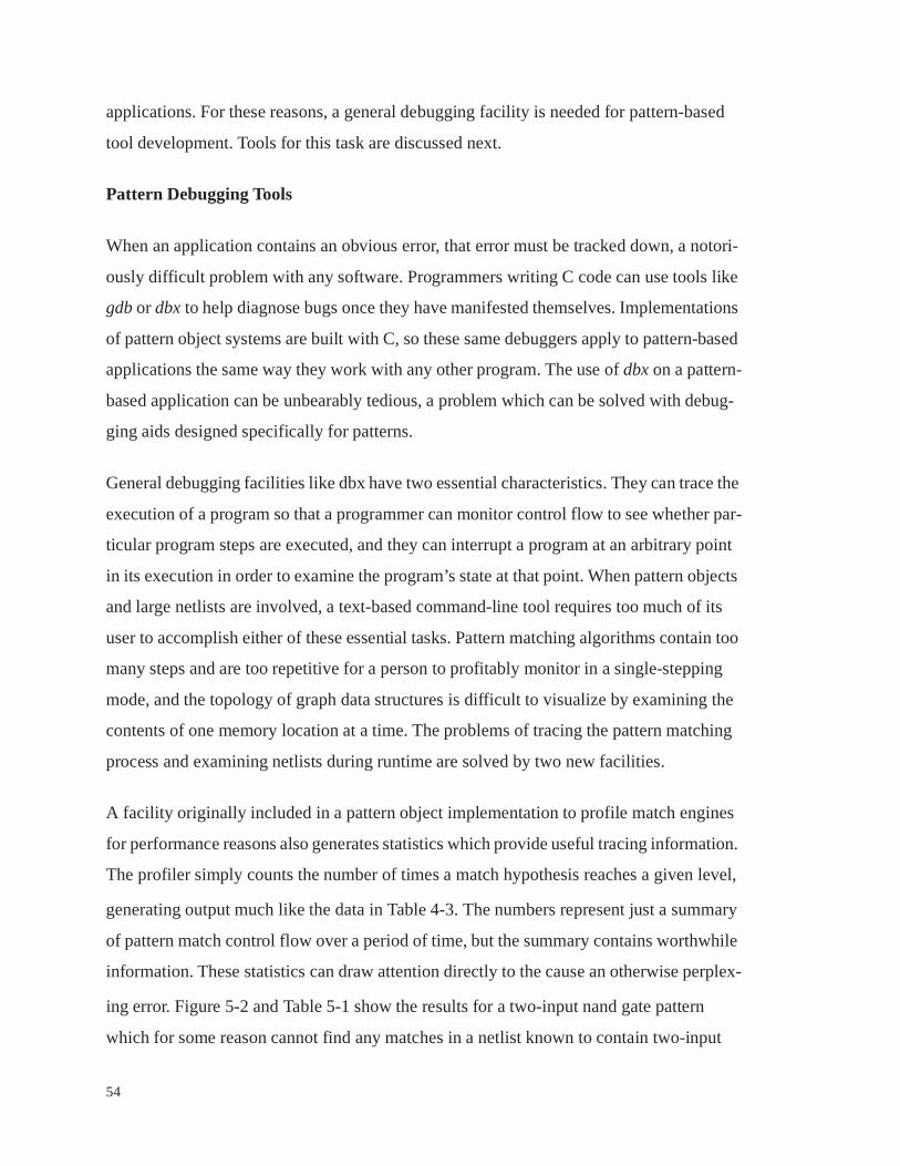
54
applications. For these reasons, a general debugging facility is needed for pattern-based
tool development. Tools for this task are discussed next.
Pattern Debugging Tools
When an application contains an obvious error, that error must be tracked down, a notori-
ously difficult problem with any software. Programmers writing C code can use tools like
gdb or dbx to help diagnose bugs once they have manifested themselves. Implementations
of pattern object systems are built with C, so these same debuggers apply to pattern-based
applications the same way they work with any other program. The use of dbx on a pattern-
based application can be unbearably tedious, a problem which can be solved with debug-
ging aids designed specifically for patterns.
General debugging facilities like dbx have two essential characteristics. They can trace the
execution of a program so that a programmer can monitor control flow to see whether par-
ticular program steps are executed, and they can interrupt a program at an arbitrary point
in its execution in order to examine the program’s state at that point. When pattern objects
and large netlists are involved, a text-based command-line tool requires too much of its
user to accomplish either of these essential tasks. Pattern matching algorithms contain too
many steps and are too repetitive for a person to profitably monitor in a single-stepping
mode, and the topology of graph data structures is difficult to visualize by examining the
contents of one memory location at a time. The problems of tracing the pattern matching
process and examining netlists during runtime are solved by two new facilities.
A facility originally included in a pattern object implementation to profile match engines
for performance reasons also generates statistics which provide useful tracing information.
The profiler simply counts the number of times a match hypothesis reaches a given level,
generating output much like the data in Table 4-3. The numbers represent just a summary
of pattern match control flow over a period of time, but the summary contains worthwhile
information. These statistics can draw attention directly to the cause an otherwise perplex-
ing error. Figure 5-2 and Table 5-1 show the results for a two-input nand gate pattern
which for some reason cannot find any matches in a netlist known to contain two-input
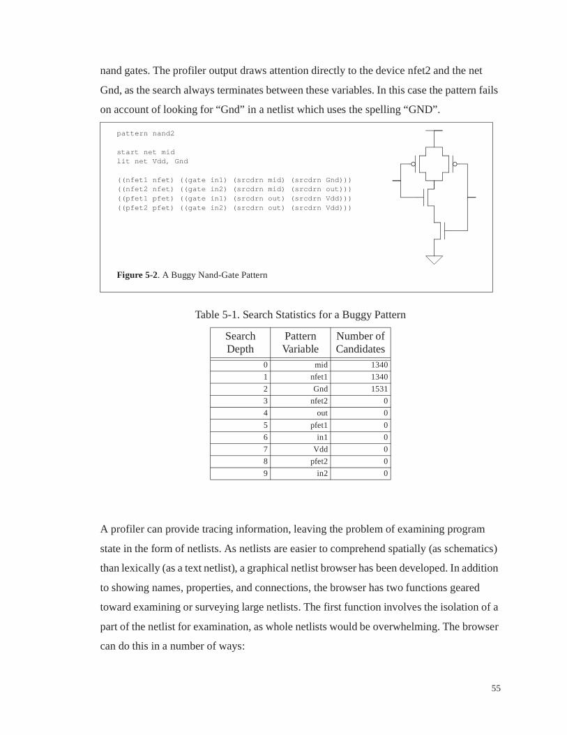
55
nand gates. The profiler output draws attention directly to the device nfet2 and the net
Gnd, as the search always terminates between these variables. In this case the pattern fails
on account of looking for “Gnd” in a netlist which uses the spelling “GND”.
A profiler can provide tracing information, leaving the problem of examining program
state in the form of netlists. As netlists are easier to comprehend spatially (as schematics)
than lexically (as a text netlist), a graphical netlist browser has been developed. In addition
to showing names, properties, and connections, the browser has two functions geared
toward examining or surveying large netlists. The first function involves the isolation of a
part of the netlist for examination, as whole netlists would be overwhelming. The browser
can do this in a number of ways:
pattern nand2
start net midlit net Vdd, Gnd
((nfet1 nfet) ((gate in1) (srcdrn mid) (srcdrn Gnd)))((nfet2 nfet) ((gate in2) (srcdrn mid) (srcdrn out)))((pfet1 pfet) ((gate in1) (srcdrn out) (srcdrn Vdd)))((pfet2 pfet) ((gate in2) (srcdrn out) (srcdrn Vdd)))
Figure 5-2. A Buggy Nand-Gate Pattern
Table 5-1. Search Statistics for a Buggy Pattern
Search Depth
Pattern Variable
Number of Candidates
0 mid 1340
1 nfet1 1340
2 Gnd 1531
3 nfet2 0
4 out 0
5 pfet1 0
6 in1 0
7 Vdd 0
8 pfet2 0
9 in2 0

56
• Particular nets or devices can be searched for by name, like “CLK” or “*/Vdd” or
“ex/rg/5_1014_798#” in order to put under examination
• The Nth match of a particular pattern specification can be isolated for examination.
• Neighbors of any net or device already under examination, which the browser will list
on request, can be included in the examination.
• Extensions of “neighbor inclusion” can select, for example, “the channel-connected
component including this net/transistor” for examination.
Once some portion of a netlist has been selected for examination, another netlist-oriented
function of the browser is used to make the structure of this subnetlist more clear to a per-
son. The netlist devices or some subset of them are drawn on the screen in arbitrary loca-
tions, and circular symbols representing nets are drawn near each’s “center of mass” with
lines drawn to show their connections. When the user moves a net or device symbol with a
mouse, the connections remain updated. The user can tease a netlist until its structure is
more clear, for instance transforming Figure 5-3 to the equivalent netlist of Figure 5-4.
The process could be called a manual netlist-to-schematic tool, which enables someone to
examine structures in a human-comprehensible form even when that form is not already
encoded into the netlist.
Now that the structure of the subnetlist is clearer, the name and property information avail-
able by clicking on nets and devices is of much more use. In practice this browsing capa-
bility of the debugger has served to reverse-engineer unfamiliar designs, make clear why
some part of a netlist was problematic for some application, or even to double-check pat-
tern specification topologies by reading in pattern specifications as if they were netlists.
The profiling and debugging capabilities described here proved invaluable during the
development of pattern-based applications. The existence of a problem can declare itself
in numerous ways, but finding the underlying cause will usually involve careful examina-
tion of the application and its netlist during the execution of the application. Debugging
tools, massive instrumentation of applications (printfs everywhere), or some similar mea-
sure will inevitably become necessary. The tools just described are indispensable, but with

57
pattern-based applications the more serious verification problem involves errors which do
not make themselves obvious. Tools that can diagnose a known error are a good thing, but
Figure 5-3. Browser Display Before Teasing
Figure 5-4. Browser Display After Teasing
Vdd
Vdd
Gnd
Gnd

58
a way to expose the existence of previously undetected, subtle bugs is even more critical.
These error-exposing methods are discussed next.
5.2. Detecting Unintended Pattern Interaction
The most dangerous application errors are the kind whose presence is not obvious. Unfor-
tunately, pattern-oriented methods by their nature introduce a mechanism which can all
too easily bring about undetected bugs. An example of this mechanism is illustrated in
Figure 5-5. In this example a pattern had been written in the past which recognized an
nfet-pass-transistor latch and removed the level-restoring pfet for the sake of an analysis
which does not allow for level restorers. The pattern-based tool worked well, encouraging
its developer to use this tool as a starting point for a new task. Now, someone wants to
count the number of one-input latches in a design versus the number of two-input latches,
all while maintaining the previous function of removing restorers. Two patterns to simul-
taneously count and fix up latches are written as in Figure 5-5. Now the problem develops:
every two-input latch contains an instance of a single-input latch.1 If the single-input pat-
tern is run throughout the netlist first, it will match in too many places, and by deleting
restorers, prevent the two-input version from ever matching. The two-input pattern should
be run first. If it is, the application works - unless the restorer-removal feature is deleted at
some point in the future. In that case, the single-input pattern will again erroneously match
two-input latches, and the user has no reason to think the resulting answer is incorrect.
The conflict in the above example was fairly easy to anticipate. A subtler example of an
undesired, unanticipated interaction came about while writing patterns to match circuits in
the MIPS-X microprocessor. The cache “valid” bits use a five transistor memory cell,
shown in Figure 5-6. The basic latch cell used throughout MIPS-X, also in Figure 5-6, has
the same topology as the memory cell. The essential difference between the two is that the
storage net in the memory cell will never have additional connections to it, while the cor-
responding net in the latch, the output, always will.
1. Actually, each contains two instances.
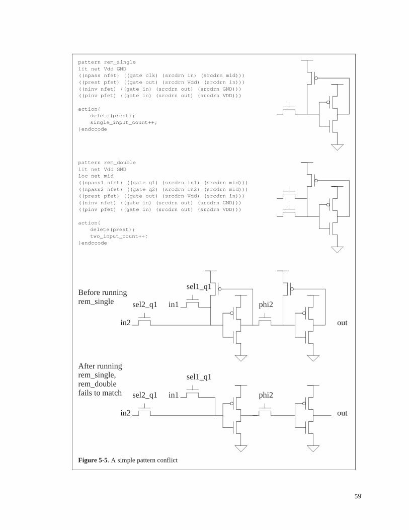
59
pattern rem_singlelit net Vdd GND((npass nfet) ((gate clk) (srcdrn in) (srcdrn mid)))((prest pfet) ((gate out) (srcdrn Vdd) (srcdrn in)))((ninv nfet) ((gate in) (srcdrn out) (srcdrn GND)))((pinv pfet) ((gate in) (srcdrn out) (srcdrn VDD)))
action{delete(prest);single_input_count++;
}endccode
pattern rem_doublelit net Vdd GNDloc net mid((npass1 nfet) ((gate q1) (srcdrn in1) (srcdrn mid)))((npass2 nfet) ((gate q2) (srcdrn in2) (srcdrn mid)))((prest pfet) ((gate out) (srcdrn Vdd) (srcdrn in)))((ninv nfet) ((gate in) (srcdrn out) (srcdrn GND)))((pinv pfet) ((gate in) (srcdrn out) (srcdrn VDD)))
action{delete(prest);two_input_count++;
}endccode
in1
in2
sel1_q1
sel2_q1 phi2
out
in1
in2
sel1_q1
sel2_q1 phi2
out
Figure 5-5. A simple pattern conflict
Before runningrem_single
After runningrem_single,rem_doublefails to match

60
A pattern object that deletes five-transistor cells was run throughout the netlist, deleting
enough transistors to make all subsequent pattern objects run noticeably faster. Unfortu-
nately, in an unused bit on the processor status word register, the layout contains a latch
whose output goes nowhere. That latch was matched as a memory cell by the five-transis-
tor pattern object.
Misidentification of an unused latch might be ignored in some situations but in this case a
further interaction made the mistake important. Pattern objects that replaced latch circuits
with abstract “latch” devices never had their chance to run, and so later pattern objects that
would have matched circuitry at the latch’s input failed to match because they required a
latch as context. The error was discovered because of the unmatched devices near the
input of the latch. If not for these unmatched devices, the only indication of a problem was
the strange total number of memory cells, 513 rather than 512.
Pattern ordering conflicts like the ones just described can occur whenever patterns’
actions modify the target netlist. Netlist changes by one pattern’s action can prevent a
future match from succeeding, or even enable some later pattern to match which ought to
have failed. Many applications deliberately exploit interaction among patterns in order to
Clear
InOut
Vbias
bit
Figure 5-6. Latch Cell and Similar Memory Cells

61
do their job, but subtle, unanticipated forms of interaction among patterns pose a danger.
Large netlists can contain enough cases and enough variety in pattern matches’ contexts
that an application writer may fail to anticipate the potential for some patterns to interact.
Again, because the netlist is so large, that interaction could also easily go unnoticed.
While one could prevent all interaction by forbidding modifications to the netlist, such a
policy is too restrictive. Some applications exist specifically to modify netlists in some
way, but even applications that do not output a changed netlist still need to make use of
netlist modifications. Most of the applications that deliberately interact patterns do so in
order to resolve the differences among similar structures with multiple matching steps.
When a pattern is targeted for a particular type of circuit, but the topology of that circuit
can be mistaken for some other circuit in some contexts, it may be possible to resolve the
difference with the use of additional patterns. Previous patterns’ results typically help to
resolve ambiguities in one of two ways: either they add discriminating contextual infor-
mation or they remove obfuscating contextual information. An example of the first case is
in Figure 5-7. An application needs to identify dynamic latches of the sort pictured in the
figure. Unfortunately, an identical-looking topology also plays the role of bus driver,
depending on context. A differentiating criterion would be the fact that the latch univer-
sally appears with exactly one inverter on its output, while bus drivers connect to a bus
which includes connections to multiple drivers and receivers. Suppose that previous pat-
terns have identified and marked all instances of inverters in the netlist. In this case a more
discriminating latch pattern could then include the inverter at the output1 in addition to the
latch’s original four transistors in its specification. The netlist-modifying behavior of one
pattern has therefore helped a subsequent pattern to determine proper context. This type of
constraint, where, for instance, a “widget” pattern looks for the presence of a previously
matched “widget driver”, will be referred to as an H-constraint.2 H-constraints exploit pre-
vious patterns’ matches by specifying their inclusion in later matches.
1. The new latch pattern could simply be enlarged to include the inverter’s transistors, obviating the need for a separate matching step in this case. It will soon be shown, though, that matching inverters is in itself no trivial matter.
2. “H” for hierarchy - one abstract device includes another in its description

62
The other common way in which netlist-modifying patterns resolve contextual ambigu-
ities works more indirectly. Consider the topology of a CMOS inverter in some netlist
context. If the output net has only the two drain terminals (from the inverter’s own two
transistors) connected to it, and nothing else but transistor gates, then without doubt the
subcircuit is an inverter. Unfortunately, there are many circuits which look like an inverter
with additional transistor channels connected to the output that are not inverters at all, and
still more where a genuine inverter is followed by perhaps a latch or pass-transistor logic.
One way to resolve the difference is to wait until other patterns have accounted for all of
the transistor sources and drains connected to the output of the inverter candidate. Figure
5-8 show the process pictorially. The disambiguating information generated when a pat-
tern waits for previous patterns to account for all mysterious neighbors before committing
will be referred to as a D-constraint.1
1. “D” for default.
Latch or Bus Driver? Latch in Context Bus Driver in Context
Figure 5-7. Example of a Contextual H-Constraint

63
Interaction Analysis
Patterns that interact through netlist modifications are needed for multi-step disambigua-
tion, yet interacting patterns represent the greatest danger when trying to produce correct
applications. Interaction analysis is a procedure designed to detect harmful pattern interac-
tions while preserving the ability to disambiguate matches in multiple steps. The analysis
described here examines an application’s entire set of patterns as a whole, along with a
specific target netlist, in order to provide feedback on the existence of both benevolent and
malevolent pattern interactions.
To make the analysis of interacting patterns approachable, topology modifications by pat-
terns’ actions will be restricted to a single, blanket operation. This operation will remove
all of the transistors and local nets of the matched pattern from the netlist, and insert a new
Figure 5-8. Examples of D-Constraints with Inverters
Pass Gate
Mux
Latch
Latch
Match
No Match
Mux
Latch
!

64
device named after the pattern into the netlist in their place, with a new terminal corre-
sponding to each non-local, non-literal net. Devices specifically marked “context” in the
pattern can be excluded from what will be called the abstract operation. The restriction of
netlist modifications to abstract does not unnecessarily limit the use of pattern interaction
for contextual disambiguation. In fact, abstract represents the most natural method for
implementing both H-constraints and D-constraints. Actions are restricted to abstract
operations simply to make the analysis of interactions more tractable.
With the abstract operation defined, a pattern-based application along with a specific
netlist can now be analyzed for interactions among patterns. The analysis proceeds in four
steps:
• First, the set of patterns for an application has its actions removed and replaced with an
abstract operation. If the application has other payloads for the pattern’s actions, they
can be set aside until after the analysis is complete.
• Next the abstracting patterns are run on the target netlist. This run uses modified
semantics for the abstract operation in order to generate pattern interaction feedback.
At first the application’s pattern order will be arbitrary except where H-constraints are
needed, but the order can be iteratively refined as dictated by feedback from the analy-
sis tool.
• The run continues with each pattern attempted one additional time.
• Finally, when warnings from the interaction analysis have been addressed or elimi-
nated, the original application actions can be resubstituted so that the application does
its original job once more.
The analysis tool is implemented with a modified match engine and a temporary change in
the semantics of the abstract operation. When abstracting, the new engine will insert the
new device, but instead of deleting the pattern’s devices, it will mark them as “used” and
note to which pattern they belong. When searching, the new engine ignores “used”
devices for purposes of deciding whether or not to abstract, but it notes their presence dur-
ing searches in order to detect two interesting cases.
65
In the case where a match is found, but peripheral “used” devices in the match context
would have foiled the match had they not been “used”, (because of a “local” constraint,)
the patterns to which those those “used” devices belong are patterns which provide a nec-
essary D-constraint for the current pattern. Feedback of this type does not indicate a cur-
rent problem, but rather a potential problem if the pattern order is changed in certain ways.
Any time a match is not found by the modified match engine, the search is reinitiated with
“used” devices treated as if they were not “used”. In cases where a match is now possible,
the “used” devices in the match belong to patterns which interact with the current pattern.
Each report of this kind should be investigated. A case may be harmless but it will often
indicate that the pattern order should be changed, or that one of the interacting patterns is
underconstrained.
Both types of feedback are used in an iterative process where pattern definitions are modi-
fied (in order to make them more narrowly defined) and the pattern invocation order is
adjusted until all problems have been eliminated. Some patterns will generate a minimum
of problems. For instance, a pattern whose name never appears in either of the lists of
feedback does not interact at all with the other patterns. These patterns can be called
“safe”. Other, non-“safe” patterns might be involved in an large number of interactions.
Inverters are notorious both for requiring D-constraints to match, and for being required as
H-constraints. In some cases patterns like an inverter pattern may require multiple slots in
the pattern invocation schedule.
Complete Coverage
The analysis procedure just described will not necessarily find all cases of pattern interac-
tion in a netlist. Since some applications absolutely cannot tolerate the possibility of an
unnoticed error, a stronger analysis is required. This requirement can be met with the
above analysis method in conjunction with one additional measure: the application’s pat-
tern set must cover, or account for, every transistor in the subject netlist.
66
Complete matching removes the two mechanisms that would allow a problematic situa-
tion to go unreported by interaction analysis. First, interaction analysis feedback always
results from two or more patterns which involve the same devices. If some particular
devices could either be matched by one particular pattern or dropped on the floor, the anal-
ysis would be silent in either case. When a pattern set covers the netlist entirely, every
device belongs to at least one pattern, so that every ambiguity involves multiple patterns
and therefore appears in the analysis’ output. With at least two patterns involved in every
ambiguous case, a failure to report an interaction would require that a pattern failed to
match where it should have.
The interaction analysis process preserves all of the original netlist devices and topology
throughout its run, so a pattern that ought to match would fail to match only if a D-con-
straint or H-constraint were missing. Since the analysis process also preserves all new
devices created by previous patterns’ abstract operations, all of the abstract devices
needed to satisfy D- or H-constraints should be present by the end of a covering set of pat-
terns. In order for a device that would rightfully complete a D- or H-constraint to be miss-
ing, some other pattern would have to account for the missing pattern’s transistors,
necessarily causing feedback of some kind earlier during that missing pattern’s execution.
Summarizing, if a set of abstracting patterns is run with the interaction analysis semantics,
and the process ends with every original device in the original netlist matched by some
pattern, then no pattern interaction can be present without the interaction analysis process
generating feedback at some point. Unfortunately, analytic feedback involving a particular
pattern throws doubt on that pattern and every pattern after it in the overall pattern order.
To gain any benefit from interaction analysis, it must be practical to to write patterns in
such a way that feedback is either eliminated or reduced in volume to the point where a
human can sign off on the remaining ambiguities.
To assess the sparsity of interaction analysis feedback in a practical situation, an interac-
tion-analyzing matcher was used in a total-coverage trial on the MIPS-X microprocessor.
Completely covering the processor (excluding I-cache) with gate-sized patterns required
126 unique patterns. The set of patterns was written and refined, with individual patterns

67
being included, excluded, or shuffled in execution order, until all of the 43458 transistors
were accounted for. Of the 126 patterns, 50 generated warnings from the analysis, but
refinements in the pattern set reduced this number to 32 and left the remaining 94 patterns
“safe”.
The remaining 32 interaction classes consisted mainly of cases where, for instance, the
matching of a memory cell prevented the later matching of its two constituent inverters.
Most of these cases where easy to sign off because the number of instances of a particular
interaction would correspond exactly to the number of overall matches of one of the inter-
action’s constituent patterns. For example, there were 1024 instances of inverter-memory
cell interaction, and 512 memory cells total, a predictable and dismissable result. In addi-
tion to the easily dismissed feedback, the analysis also reported the ambiguity of Figure 5-
6, a true error. This case and four other small regions of the entire netlist needed careful
examination before all of the analysis feedback for the entire netlist and pattern set was
accounted for.
5.3. Summary
Since all software systems can suffer from misspecification, an environment for building
applications with pattern objects needs to provide debugging tools designed especially for
patterns and netlists. Debuggers help to diagnose know bugs, but one must also expose the
very existence of bugs. The debugging challenge for pattern-based applications lies not in
making individual patterns do their respective jobs, but rather in preventing patterns from
silently interfering with one another.
Patterns must interact for legitimate reasons, especially for the purpose of establishing
context and disambiguating similar topologies. When a limited, abstract operation can
achieve the desired interaction, undesired interaction can be analyzed for given an entire
set of abstracting pattern objects and a specific netlist. If the set of patterns accounts for
every transistor in the specific netlist, no unanticipated interaction can pass through the
analysis without the generation of a warning.

68
Interaction analysis furnishes a practical safeguard against undesired, unanticipated pat-
tern interaction only if the resulting feedback is sparse enough for hand evaluation. The
MIPS-X matching experiment demonstrated that realistic pattern sets can be designed to
reduce the amount of warning feedback to manageable levels - out of 43458 transistors,
126 patterns, and 9203 pattern matches, five netlist contexts required human examination.
The success of this experiment suggests that abstract-based applications can be made
extremely trustworthy in practical situations.
69
Chapter 6
Conclusions
A search for a versatile, tool-constructing building block resulted in the pattern object, a
software abstraction for specifying and implementing netlist processing steps. A system
which implements pattern objects has been used in turn to implement a variety of netlist
CAD tools, helping to preprocess, parse, and transform netlists. Both by themselves and in
conjunction with a larger software system, pattern objects have consistently expedited the
implementation of new tools and produced tools which are easier to maintain or modify.
Pattern object performance could be an obstacle for pattern-based applications running on
large netlists. Earlier work in this area suffered from matching algorithms whose execu-
tion time grew more than linearly with both netlist and pattern size, making pattern-based
tools impractical for the very designs that could use their help the most: multi-million
device custom microprocessors. The observation that a small number of nets have the
largest impact on run times leads to both heuristic depth-first and subgemini-style algo-
rithms whose run times tend not to grow faster than netlist size in practice. Matchers have
been developed which can find all instances of a logic-gate-sized pattern in a netlist in less
time than was required to read that netlist into memory in the first place.
Pattern objects do not lack for performance or applicability to problems. The most serious
obstacle to pattern use is the difficulty of producing bug-free applications. Pattern-based
applications have potential for errors wherever pattern actions manipulate a subject
netlist’s topology. The procedure outlined in this thesis can detect the possibility of dan-
gerous pattern interaction in specific netlists with sets of parsing pattern objects. This pro-
cedure includes the development and tuning of a set of patterns which can account for
every transistor in a subject netlist, a substantial undertaking. For some applications the

70
reassurances provided by interaction analysis are well worth the extra work involved. The
trade-off is left to the developer, who can choose a level of comfort and effort appropriate
for the task at hand.
With improved matching algorithms and a procedure which can prevent pattern interac-
tion errors, the pattern-and-action methods which have shown promise in the past now
represent a good option for the production of netlist processing tools. So long as designers
push design methodologies to their limits and device netlists are a relevant part of those
methodologies, pattern-based tools can help to provide quick, pragmatic CAD solutions.

71
Appendix A
A Pattern Object Implementation’s Reference Manual
This reference manual describes in detail the use of a system implementing pattern
objects, software abstractions which provide netlist manipulation specified by patterns.
A.1. Pattern-Based Applications
Especially when working with transistor netlists, a lot of the work in many CAD tasks
involves finding, matching, or classifying parts of a netlist topologically. “Hard-wiring”
recognition for certain circuit types into a tool is tedious and error-prone, and leads to
tools which are difficult to maintain.
A better way to manipulate topology is suggested by the text-processing program awk. A
user of awk can selectively process lines in a text file by filtering them with a regular
expression. Multiple filters, or regular expressions, are allowed, and each regular expres-
sion has its own associated “action”. Actions are code fragments in an interpreted C-like
language which constitute the payload for the overall application. With this pattern-action
paradigm awk can undertake a great variety of computations without the user ever needing
to write a meticulous, hard-wired parser.
The basic awk idea can work in the netlist domain. Patterns, instead of being regular
expressions, can be small netlists specifying subgraphs. Input files, instead of being lines
of text, can be device netlists. To specify computations, C “actions” can be paired with
each “pattern” topology. The entire mechanism provides a convenient and powerful capa-
bility for tools in many application domains:
• Many Electrical Rules checks are easily encoded into a pattern-action specification

72
• Pattern-action mechanisms can provide a “front-end” for tools that have topological
parsing requirements, decoupling the parts of the tool and making it easier to maintain.
• Patterns and actions can implement pre- and post-processing steps which “glue”
nearly compatible tools together by fixing up sparse problems
• Reverse engineering and other post-design analyses can make good use of patterns and
actions.
In any of their application domains, pattern-based tools work especially well in emergency
situations, because they use a nearly universal design representation (flat device netlists)
and because they can work bottom-up. These properties reduce the dependency of a pat-
tern-based tool on any other tools in a design flow, allowing a developer to respond to a
CAD challenge even where the CAD environment has broken down.
A.2. Overall Design of the System
Applications developed in this pattern object environment are C programs like any other,
except that parts of the program that need to match or search for a particular subcircuit can
be described with a declarative specification. These specifications, patterns, might consti-
tute the entire application, a small part of the overall application, or anywhere between.
Figure A-1 illustrates the overall design of the application development environment. The
environment provides netlist manipulation infrastructure in the form of an object library,
and a preprocessor which can transform pattern-action specifications into C procedures.
The application author provides pattern definitions, and also the outer loop of the applica-
tion, including “main()”. The C compiler can then compile and link all of the components
together into an executable.
The application author begins by writing “main()” in order to establish the overall control
flow of the application. Provided library routines can read and write netlists in a variety of
file formats, and iterate pattern invocations over all of a netlist’s devices or nets. Global
variables can accumulate results or allow communication among processing steps.

73
When the user writes pattern specifications for this system, the action portion can also uti-
lize a number of the routines provided in the library. These routines allow access to and
transformation of nets, devices, and their properties. For example, library routines exist to
make terminal connections, to delete nets or devices, or to examine user-defined proper-
ties like “width” of particular devices or nets.
A.3. Netlist Infrastructure
The development environment provides library routines and header files which describe
and implement the abstract types needed to represent and manipulate netlists. User code,
main(){read_netlist();invoke_patterns();write_netlist();}
User ApplicationPattern Definitions
pattern foostart net inliteral net Vdd((n1 nfet) ((gate in....
Library Routines
typedef struct .... net;read_netlist(){fopen(.....
Preprocessor Output
foo(in)net *in;{for (n1=nets adjacent to in.....
Preprocessor
CC
Complete Application
Figure A-1. A Preprocessor-Based Development Environment

74
pattern action code, and preprocessor-generated pattern matching code can all make use of
this infrastructure in order to read, write, and change netlists.
A.3.1 Data Types and Representation
Names: DictEnt
One of the development environment’s fundamental data types exists more to save space
than to model netlists. Netlists representations can consume a great deal of memory, yet
the efficiency of applications will depend on entire netlists residing in physical memory
without swapping. Strings for net and device instance names, terminal names, type names,
and so forth would consume a great deal of memory if they were stored for each use. The
pattern environment, preprocessor, and library support a single name space. Each distinct
string, as it is encountered in whatever context, is placed or found in a hash table and
referred to thereafter by a pointer to its hash table entry. The type of this pointer is DictEnt
* , and two functions are provided:
void DictInit();
Initializes the global name space.
DictEnt *dictLookup(char *)
Returns the entry for the given string, creating an entry if necessary.
Strings entered into the global name space can be compared merely by comparing their
pointers, but if an application needs the characters in the string associated with a given
DictEnt it can access it directly through the string field:
DictEnt *foo;printf(“%s\n”, foo->string);
Devices, Nets, and Terminals: NLObj, NLObjLst
Devices in a netlist contain instance names, type names, and a list of terminal connections,
as do nets. Due to this symmetry, nets and devices have the same type, NLObj, and context

75
determines whether an NLObj refers to a net or device. Nets (devices) contain a linked-list
of adjacent devices (nets), each reference a NLObjLst which contains the name of the con-
necting terminal type:
typedef struct {DictEnt *instName; /* instance name, ie “Gnd”*/DictEnt *typeName; /* type name, ie “nfet”*/NLObjLst *adj; /* neighnors */
} NLObj;
typedef struct {DictEnt *tname; /* terminal name, ie “gate”*/NLObj *obj; /* neighboring NLObj */NLObjLst *next; /* link to next */
} NLObjLst;
As an example, to list the names of the devices whose gates are connected to GND:
DictEnt *gate = dictLookup(“gate”);extern NLObj *GND;for (NLObjLst *n = GND->adj; n; n = n->next)
if (n->tname==gate)printf(“%s\n”, n->obj->instName->string);
Device and Net Properties: IProp, FProp, PProp
Each NLObj also has a linked property list. The property name is a DictEnt *, and the
property value is a union including int, double, and void *. The typed value of a property
can be accessed with the getProp-based macros IProp, FProp, and PProp. Each of these
macros will cause the creation of a zero-valued property if no property by the same name
is already attached to the NLObj. The macros can all be used as either lvalues or rvalues:
NLObj *device;DictEnt *width;
if (FProp(width, device) == FProp(width, device2));
FProp(width, device) *= 2.0;

76
Properties exist so that applications can annotate netlists during their execution. Pointer-
valued properties, though, are not supported by any library netlist I/O routines.
Netlists: hashTable, NetList
An entire netlist consists of a set of nets and a set of devices, with each net listing its adja-
cent devices with NLObjLst entries, and each device listing its adjacent nets the same way.
The set of devices and the set of nets are each represented as a hash table, keyed by the
instName field. For this reason all nets and all devices must have distinct instance names,
even though a lot of applications will not care about instance names for devices.
typedef struct {hashTable *nettable;hashTable *devicetable;
} NetList;
A.3.2 Library Routines
A number of routines are provided for the manipulation of netlists, either by pattern’s
actions or by main().
getObj, findObj
The routines getObj and findObj look up a device or net in its corresponding NetList table.
If there is no match, getObj will create one, while findObj will return NULL.
NLObj *findObj(DictEnt *, hashTable *);NLObj *getObj(DictEnt *, hashTable *);
NetList *netlist;if (!findObj(dictLookup(“GND”), netlist->nettable))
printf(“Must use VSS\n”);NLObj *mydevice = getObj(dictLookup(“my_inst_name”),
netlist->devicetable);

77
nlConnect
The routine nlConnect is used to update net and device adjacent-lists in order to represent
a new connection:
void nlConnect(NLObj *device, DictEnt *termtype,NLObj *net);
nlDisConnect
The opposite operation is provided by nlDisConnect, which will print an error if the corre-
sponding connection does not exist.
void nlDisConnect(NLObj *device, DictEnt *termtype,NLObj *net);
nlRemDev
The deletion of a device is accomplished with nlRemDev. Before removing the device
from the netlist’s hash table, nlRemDev calls nlDisConnect on all of the device’s connec-
tions.
void nlRemDev(NetList *netlist, NLObj *device);
nlRemNet
A net with no connections can be deleted with nlRemNet. If the net has any adjacent
devices, nlRemNet does nothing.
void nlRemNet(NetList *netlist, NLObj *net);
isAdj
The function isAdj tests whether a given net and device are adjacent via a terminal of a
given type. Preprocessor-generated code uses this function to test back-edges.
int isAdj(DictEnt *termtype, NLObj *net, *device);

78
iterateNets, iterateDevices
Applications often need to apply an operation either to all nets in a netlist or to all devices
in a netlist. The iterators iterateNets and iterateDevices are provided for this purpose. The
arguments are a netlist, and a pointer to a procedure whose argument is an NLObj *.
void iterateNets(NetList *netlist,void *proc(NLObj *net));
void iterateDevices(NetList *netlist,void *proc(NLObj *device));
These procedures are especially useful as a means to apply a single-start-variable pattern
procedure to an entire netlist.
simRead, simWrite, genReadB, genWriteB
Two sets of routines are provided to read and write netlists. One set uses the Berkeley
“.sim” format, while the other uses a binary format which is faster to read and write and
handles all user-defined properties which are not pointers.
NetList *simRead(char *filename);void simWrite(NetList *netlist, FILE *outfile);NetList *genReadB(char *filename);void genWriteB(NetList *netlist, FILE *outfile);
The “.sim” format routines simRead and simWrite define and use the following device
type names, terminal types, and device and net properties:
• nfet, for n-channel transistors. (device type)
• pfet, for p-channel transistors. (device type)
• gate, a p- or n-channel gate terminal. (terminal type)
• srcdrn, for both the source and drain terminals of p- or n-channel transistors. (terminal
type)
• capacitance, the lumped capacitance of a net to GND in fF. (property)
• l, the length of a transistor in microns. (property)
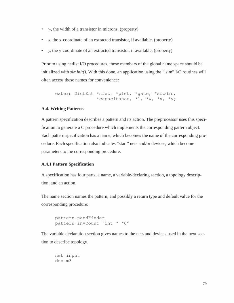
79
• w, the width of a transistor in microns. (property)
• x, the x-coordinate of an extracted transistor, if available. (property)
• y, the y-coordinate of an extracted transistor, if available. (property)
Prior to using netlist I/O procedures, these members of the global name space should be
initialized with simInit(). With this done, an application using the “.sim” I/O routines will
often access these names for convenience:
extern DictEnt *nfet, *pfet, *gate, *srcdrn,*capacitance, *l, *w, *x, *y;
A.4. Writing Patterns
A pattern specification describes a pattern and its action. The preprocessor uses this speci-
fication to generate a C procedure which implements the corresponding pattern object.
Each pattern specification has a name, which becomes the name of the corresponding pro-
cedure. Each specification also indicates “start” nets and/or devices, which become
parameters to the corresponding procedure.
A.4.1 Pattern Specification
A specification has four parts, a name, a variable-declaring section, a topology descrip-
tion, and an action.
The name section names the pattern, and possibly a return type and default value for the
corresponding procedure:
pattern nandFinderpattern invCount “int “ “0”
The variable declaration section gives names to the nets and devices used in the next sec-
tion to describe topology.
net inputdev m3

80
These net and device placeholders can be created implicitly by the topology specification,
so this section is used primarily to add special annotations to specific pattern nets or
devices. The annotations are indicated with the keywords start, local, and literal.
start dev m13local net instackliteral net gnd GNDstart local (srcdrn) net output
Nets and devices marked start indicate the logical start point for pattern matches. Hypoth-
eses for start variables, taken from some netlist, are passed to the generated procedure as
arguments.
Nets marked local can only match nets in a netlist with exactly the same context as in the
pattern; no additional, unmatched adjacent devices are allowed. Nets on the boundaries of
a pattern will not be local, but internal nets might be. The local constraint can be confined
to addressing connections via a particular terminal type.
Nets marked literal can only match the indicated net. For instance, “literal net gnd GND”
asserts that the variable gnd matches only the netlist net with instance name GND. Since
the match is already made, such nets could be marked start instead, but literal also indi-
cates expected high fanout as a performance-improving hint, and helps to create single-
start-variable patterns for iterateDevices and iterateNets. With this implementation, the
variable name and the instance name should be different to avoid a name-space collision
in the resulting C procedure.
The topology specification section is a simple netlist format. The netlist lists the pattern’s
devices, with each device listing its connections to nets via terminals. A device entry can
specify a particular device type if desired.
(M1 ((gate in) (srcdrn out) (srcdrn gnd)))((M2 pfet) ((gate in) (srcdrn out) (srcdrn vdd)))((M3 npn) ((base VBias) (collector out) (emitter Vee)))

81
Finally, pattern specifications include an action. The keywords ccode{ and }endccode
delimit a fragment of code which is inserted verbatim into the innermost condition of the
generated procedure’s search code. Actions can include any legal C statements. Matches
for the net and device names from the topology description are available for manipulation
in the action, as C variables of type NLObj *. Because the action is in the innermost loop
of an exhaustive search, the C keyword return can be used by an action to terminate that
search after a successful match.
An example pattern using most features of the specification language is in Figure A-2. The
specification describes a pattern object which returns a “1” if called with a net which cor-
responds to the middle stack net of a static nand gate, or a zero otherwise.
A.4.1 Pattern Generation
The pattern preprocessor is implemented in two stages. The first examines the pattern and
attempts to choose a variable-matching order based on performance-maximizing heuris-
tics. The second stage actually produces the C code, mostly nested for loops and ifs. This
partitioned design allows substituted second stages to generate code for infrastructure
implementations other that the one described here, or to generate instrumented code.
Pattern specification files are assumed to have the file suffix “.pat”, which are read by the
program order to produce files with the suffix “.sop”. Files in “.sop” format are suitable
pattern nand_check “int” “0”
start local net middlelocal (srcdrn) net outliteral net vdd Vddliteral net gnd GND
((nfet1 nfet) ((gate in1) (srcdrn middle) (srcdrn out)))((nfet2 nfet) ((gate in2) (srcdrn middle) (srcdrn gnd)))((pfet1 pfet) ((gate in1) (srcdrn out) (srcdrn vdd)))((pfet2 pfet) ((gate in2) (srcdrn out) (srcdrn vdd)))
pattern ccode{
return 1; /* This is the entire action */
}endccode
Figure A-2. A Sample Pattern Specification

82
input for backend, which produces C code. The files with the C code have the suffix “.inc”
and are suitable for insertion into an application “.c” file via #include.
Figure A-3 illustrates the output of the preprocessor for the specification of Figure A-2.
The structure of this code is typical, with nested loops and conditions which, if satisfiable,
cause the execution of the inserted action code.
A.5. A Full Example
An example application will serve to illustrate all of the components of the development
system. In this example, the goal will be to measure the toggle frequency of the outputs of
all of the precharged gates in a two-phase design. In other words, per 100 clock transi-
tions, how many transitions does the average precharged gate make?
This application needs a source of information beyond the device netlist of the design.
Assume that a switch-level simulator has been instrumented to accumulate toggle counts
on all nets in the design for some representative input vectors. The output of the simulator
int nand_check(middle)NLObj *middle;{
if (!(middle->adjCount==2)) return 0;for (/* nfet2 = all nfets on middle via srcdrn*/)for (/* gnd = all nets on nfet2 via srcdrn*/) {if ((gnd!=middle)&&(gnd->instName==GND)) {for (/*nfet1 = all nfets on middle via srcdrn*/) {if (nfet1 != nfet2) {for (/*out = all devices on nfet1 via srcdrn*/) {if ((out!=middle)&&(out!=gnd)&&(devTermCount(srcdrn, out)==3)) {for (/*pfet1 = all pfets on out via srcdrn*/) {if ((pfet1!=nfet1)&&(pfet1!=nfet2)) {for (/*in1 = all nets on pfet1 via gate */) {if ((in1!=middle)&&(in1!=gnd)&&(in1!=out)&&isAdj(in1, gate, nfet1)) {for (/*vdd = all nets on pfet1 via gate */) {if ((vdd!=middle)&&(vdd!=gnd)&&(vdd!=out)&&(vdd!=in1)&&(vdd->instName==Vdd){for (/*pfet2 = all pfets on out via srcdrn*/) {if ((pfet2!=pfet1)&&(pfet2!=nfet1)&&(pfet2==nfet2)) {for (/*in2 = all nets on pfet2 via srcdrn*/) {if ((in2!=in1)&&(in2!=vdd)&&(in2!=out)&&
(in2!=gnd)&&(in2!=middle)&&isAdj(in2, gate, nfet2)) {
return 1; /* This is the entire action */
}}}}}}}}}}}}}}}}}return 0;
}
Figure A-3. Preprocessor Output for nand_check

83
is a file which lists each net name followed by its toggle count. The application will need
to add the information in this file to the netlist once the netlist has been read in. The proce-
dure toggleDataRead(), in Figure A-4, accomplishes this.
After reading the netlist and the supplementary toggle count data, precharged gates must
be identified. A pattern for each type of precharged gate could be written, but this applica-
tion will take a short-cut with the following assumptions:
• The design is two-phased, with global inputs Phi1 and Phi2.
• Clocks and derived clocks are used only by clock buffers (inverters), pass-gate latches,
and precharged gates.
• All precharged gates are domino.
• All parallel transistors have been reduced.
Given these assumptions, all precharged gates will contain the three-transistor topology
illustrated in Figure A-5. A pattern which recognizes this topology and accumulates the
associated statistics is shown by Figure A-6. The application is not quite complete,
because the pattern relies on nets in the Phi1 and Phi2 clock trees having the property
isaclock set.
The isaclock property should be set for Phi1, Phi2, and every net in the tree of inverters
rooted at those nets. A single pattern can accomplish this task via recursion, as shown in
toggleDataRead(char *filename){
FILE *infile; char netstring[MAXSIZE]; int count; NLObj *net;if (!(infile=fopen(filename, “r”)))
error(“Cannot Read Toggle Data %s”, filename);while (!feof(infile)) {
fscanf(“%s %d”, netstring, &count);net = findObj(dictLookup(netstring), netlist->nettable);if (!net) error(“read data for nonexistent net %s”, netstring);IProp(togglecount, net) = count;
}fclose(infile);
}
Figure A-4. The procedure toggleDataRead()
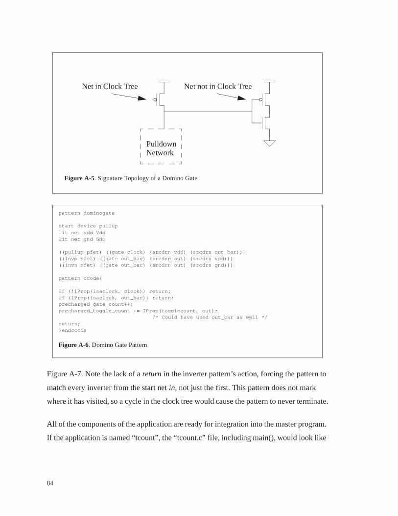
84
Figure A-7. Note the lack of a return in the inverter pattern’s action, forcing the pattern to
match every inverter from the start net in, not just the first. This pattern does not mark
where it has visited, so a cycle in the clock tree would cause the pattern to never terminate.
All of the components of the application are ready for integration into the master program.
If the application is named “tcount”, the “tcount.c” file, including main(), would look like
PulldownNetwork
Net in Clock Tree Net not in Clock Tree
Figure A-5. Signature Topology of a Domino Gate
pattern dominogate
start device pulluplit net vdd Vddlit net gnd GND
((pullup pfet) ((gate clock) (srcdrn vdd) (srcdrn out_bar)))((invp pfet) ((gate out_bar) (srcdrn out) (srcdrn vdd)))((invn nfet) ((gate out_bar) (srcdrn out) (srcdrn gnd)))
pattern ccode{
if (!IProp(isaclock, clock)) return;if (IProp(isaclock, out_bar)) return;precharged_gate_count++;precharged_toggle_count += IProp(togglecount, out);
/* Could have used out_bar as well */return;}endccode
Figure A-6. Domino Gate Pattern

85
Figure A-8. The patterns from Figure A-6 and Figure A-7 would be in a companion file,
“tcount.pat”. Building the application would involve the following steps:
• Preprocess “tcount.pat” into “tcount.sop” and then “tcount.inc”:
order tcountbackend tcount
• Compile the application and link with “libnet.a”
cc -o tcount tcount.c -lnet
The application is now ready to run. A sample shell session is illustrated by Figure A-9.
pattern followTree
start net inlit net vdd Vddlit net gnd GND
((n1 nfet) ((gate in) (srcdrn out) (srcdrn GND)))((p1 pfet) ((gate in) (srcdrn out) (srcdrn vdd)))
pattern ccode{
IProp(isaclock, in) = 1;IProp(isaclock, out) = 1;followtree(out);
}endccode
Figure A-7. A Tree-following pattern

86
#include <stdio.h>#include <netlist.h>
dictEnt *togglecount = dictLookup(“togglecount”);dictEnt *isaclock = dictLookup(“isaclock”);
NetList *netlist;int precharged_gate_count = 0, precharged_toggle_count =0;
void toggleDataRead(){
/* see Figure A-4 */}
/* include preprocessed patterns */#include “tcount.inc”
main(argc, argv)int argc;char *argv[];{
if (argc!=3) error(“Usage: tcount <.sim file> <toggle file>\n”);dictInit();simInit();netlist = simRead(argv[1]);toggleDataRead(argv[2]);followTree(getObj(dictLookup(“Phi1”), netlist->nettable));followtree(getObj(dictLookup(“Phi2”), netlist->nettable));iterateDevices(netlist, dominogate);printf(“Precharged Toggle Ratio = %lf\n”,
precharged_toggle_count / (double) precharged_gate_count /(double)IProp(togglecount,getObj(dictLookup(“Phi1”),netlist->nettable));
}
Figure A-8. The Main Application File, “tcount.c”
% lsnetlist.sim simout.tog tcount.c tcount.pat% order tcount% lsnetlist.sim simout.tog tcount.c tcount.pat tcount.sop% backend tcount% lsnetlist.sim simout.tog tcount.c tcount.inc tcount.pat tcount.sop% cc -o tcount -I$net -L$net tcount.c -lnet% lsnetlist.sim simout.tog tcount* tcount.c tcount.inc tcount.pat tcount.sop% tcount netlist.sim simout.togPrecharged Toggle Ratio = 0.5% echo “Just what I expected, netlist.sim is supposed to be fully differential”Just what I expected, netlist.sim is supposed to be fully differential%
Figure A-9. A Shell Session for “tcount”
87
Appendix B
Practical Advice for Building a Pattern Object Environment
A pattern object capability is fairly easy to build. A fully functional, first-cut implementa-
tion of an “AWK for Circuits” required less than 3000 lines of C code. If match engines,
netlist support infrastructure, and debugging support tools already exist, a developer in a
custom design environment is in a good position to quickly fill new tool needs. The
research underlying this thesis included the development of several versions of pattern
environments and their application to realistic problems on some large netlists. The over-
all experience has resulted in some practical suggestions for anyone who wishes to build a
pattern capability:
• Build on top of a real, general-purpose programming language. Both C and LISP (in
DIALOG) appear to work well. Especially for pattern actions, the open-endedness of a
real language is invaluable, and at the same time nobody really wants to learn a new
language just to use a new tool. Depending on the match engine implementation, the
compiler can even do the hard work.
• Match engine implementations can be either interpreters or preprocessors that lead to
compiled pattern-specific procedures. Compiled implementations have a performance
advantage, but during tool development and debugging an interpreting matcher allows
for a more interactive situation with faster response to changes. The best solution is to
provide both implementations, each with the same input language. The interpreter can
be used until the system is stable, and then the patterns can be “compiled”.
• A pattern/netlist debugging tool like the one described in Chapter 5 is extremely valu-
able. Tcl/Tk [19] provides a good starting point for developing the browsing compo-
nent of the debugger. Include a profiling, interpreting match engine in the debugger.

88
The debugger used in this work can be compiled into any pattern-based application,
which has proven to be a very worthwhile capability.
• Pattern-based applications operate primarily on flat device netlists, which for some
designs can be quite large. Applications performed best when an entire netlist’s repre-
sentation fit in a workstation’s physical memory. Large designs required well-endowed
workstations, with up to half of a gigabyte of RAM consumed for the largest of the
designs examined. A netlist representation specially tuned for space efficiency for the
special case of three-terminal, undistinguished devices would improve runtimes for
large transistor netlists indirectly by improving memory hierarchy performance.

89
References
[1] H. J. DeMan, I. Bolsens, E. vanden Meersch and J. van Cleynebreugel, “Dialog: an
Expert Debugging System for MOS VLSI Design”, IEEE Transactions on CAD,
Vol. CAD-4, No. 3, 303-311, July 1985.
[2] H. DeMan, I. Bolsens and E. Vanden Meersch, “An Expert System for Logical and
Electrical Debugging of MOS VLSI Networks”, Proc. International Conference
on Computer Aided Design, 203-205, 1984.
[3] R. L. Spickelmier and A. R. Newton, “Critic: A Knowledge-Based Program for
Critiquing Circuit Designs”, Int. Conf. on on Computer Design, VLSI in Comput-
ers, 324-327, 1988.
[4] J. Wenin, J. Verhasselt, M. Van Camp, J. Leonard and P. Guebels, “Rule-Based
VLSI Verification System Constrained by Layout Parasitics”, Proc. 26th Design
Automation Conference, 662-667, 1989.
[5] S. Bergquist and R. Sparkes, “QCritic: A Rule-Based Analyzer for Bipolar Circuit
Designs”, Proc. of the CICC, 617-620, 1986.
[6] G. Pelz, “An Interpreter for General Netlist Design Rule Checking”, Proc. 29th
Design Automation Conference, 305-310, 1992.
[7] A. Aho, “The AWK Programming Language”, Addison-Wesley, 1988
[8] D. Dobberpuhl, “A 200-Mhz, 64-bit, Dual-Issue CMOS Microprocessor”, IEEE
Journal of Solid State Circuits, Vol. 17, No. 11, 1555-1567, November 1992.
90
[9] M. Uhler, “High Performance Single Chip VAX Microprocessor”, 37th IEEE
International Computer Conference, February 1992
[10] M. Horowitz, P. Chow, D. Stark, R. Simoni, A. Salz, S. Przybylski, J. Hennessy, G.
Gulak, A. Agarwal and J. Acken, “MIPS-X: A 20-MIPS Peak, 32-bit Microproces-
sor with On-Chip Cache”, IEEE Journal of Solid State Circuits, Vol. SC-22, No. 5,
October 1987, 790-799.
[11] Miles Ohlrich, Carl Ebeling, Eka Ginting and Lisa Sather, “Subgemini: Identifying
SubCircuits using a Fast Subgraph Isomorphism Algorithm”, Proc. 30th Design
Automation Conference, 31-37, 1993.
[12] C. Ebeling and O. Zajicek, “Validating VLSI Circuit Layout by Wirelist Compari-
son”, Proc. IEEE International Conference on Computer Aided Design, 172-173,
1983.
[13] C. Ebeling, “GeminiII: A Second Generation Layout Validation Tool”, Proc. IEEE
International Conference on Computer Aided Design, 322-325, 1988.
[14] A. Kolodny, R. Friedman and T. Ben-Tzur, “Rule-Based Static Debugger and Sim-
ulation Compiler for VLSI Schematics”, Proc. IEEE International Conference on
Computer Aided Design, 150-152, 1985.
[15] C. Bamji and J. Allen, “GRASP: A Grammar-Based Schematic Parser”, Proc. 26th
Design Automation Conference, 448-453, 1989.
[16] B. Grundmann, “XREF/Coupling: Capacitive Coupling Error Checker”, IEEE
International Conference on Computer Aided Design, 1990.
[17] A. Salz and M. Horowitz, “IRSIM: An Incremental MOS Switch-Level Simula-
tor”, Proc. 26th Design Automation Conference, 173-178, 1989.

91
[18] R. Bryant, D. Beatty, K. Brace, K. Cho and T. Scheffler, “COSMOS: A Compiled
Simulator for MOS Circuits”, Proc. 24th Design Automation Conference, 9-16,
1987.
[19] J. Ousterhout, “Tcl and the Tk Toolkit”, Addison-Wesley, 1993
[20] A. Aho and J. Ullman, “Principles of Compiler Design”, Addison-Wesley, 1985.