
NetGuardian 832A/864A G5 Web Browser
134
USER MANUAL NetGuardian 832A/864A G5 Web Browser March 6, 2020 D-UM-NETG5.12101 Firmware Version v.5.6D Visit our website at www.dpstelecom.com for the latest PDF manual and FAQs.
Transcript of NetGuardian 832A/864A G5 Web Browser

USER MANUAL
NetGuardian 832A/864A G5 Web Browser
March 6, 2020 D-UM-NETG5.12101 Firmware Version v.5.6D
Visit our website at www.dpstelecom.com for the latest PDF manual and FAQs.

© 2020 DPS Telecom
This document contains proprietary information which is protected by copyright. All rights are reserved. No part ofthis document may be photocopied without prior written consent of DPS Telecom.
All software and manuals are copyrighted by DPS Telecom. Said software and manuals may not be reproduced,copied, transmitted or used to make a derivative work, by either mechanical, electronic or any other means in wholeor in part, without prior written consent from DPS Telecom, except as required by United States copyright laws.
The material in this manual is for information purposes and is subject to change without notice. DPS Telecom shallnot be liable for errors contained herein or consequential damages in connection with the furnishing, performance, oruse of this manual.
Notice
Revision History
March 6, 2020
December 11, 2019
November 15, 2019
October 21, 2019
March 5, 2019
August 2, 2018
May 18, 2018
September 6, 2017
December 7, 2016
May 20, 2016
April 30, 2015
January 26, 2015
October 17, 2014
November 25, 2013
November 19, 2013
October 21, 2013
July 25, 2013
...
October 6, 2011
Minor Updates
Updated Entering System Settings Section
Added support for Air Flow Sensors
Updated Appendix A
Added support for static routes.
Added Analog Delta alarm
Added Enhanced Mode for "Filter IPA"
Added Trap Listening Port details to Setting up SNMP section
STMP Email Updates
Added Making Relays Exclusive
DSCP Screenshot Updates
System Alarms Display Map
Added advanced controls option and updated Derived Controls to includeconstant operator.
Added Configure DNP3
Added Configuring DSCP Devices and MonitoringDSCP Devices sections
Added DSCP to "Data Port Types"
Added Source Address to "SettingUp SNMPv1 or v2c" section
...
Added support for T1/E1 WAN Top Board
ContentsVisit our website at www.dpstelecom.com for the latest PDF manual and FAQs
Overview1 1
Introduction1.1 1
Potential Problems using Web Interface in a Secure Proxy Network1.2 1
What's New in NetGuardian G51.3 2
Unit Configuration2 3
Logging on to the NetGuardian2.1 3
Using RADIUS Authentication (Available as of Firmware v5.0I)2.2 4
Entering System Settings2.3 5
Changing the Logon Password2.4 7
Logon Profiles and Access Rights2.4.1 8
Security Dial-Back2.4.2 9
Configuring Port Parameters2.5 10
Ethernet Ports2.5.1 10
Using the Base URL Field2.5.1.1 12
T1/E1 WAN Configuration2.5.1.2 13
Setting Up SNMPv1, v2c or v32.5.2 14
Filter IPA Config and Operation2.5.3 17
Changing Craft Port Communication Settings2.5.4 20
Configuring Modem Port Settings2.5.5 21
Configuring Data Ports 1 - 92.5.6 22
Data Port Types2.5.6.1 24
Defining SPS8 Ports2.5.6.2 26
Defining NTCP Ports2.5.6.3 27
Direct and Indirect Proxy Connections2.5.6.4 28
Setting Up Notification Methods2.6 29
Alpha Numeric Pager Setup2.6.1 30
SNPP Notification Setup2.6.2 30
Numeric Pager Setup2.6.3 30
Text Paging Setup2.6.4 31
Email Notification Setup2.6.5 31
SMTP POP3 Authentication Support2.6.5.1 32
SNMPv1 Notification Setup2.6.6 33
SNMPv3 Notification Setup2.6.7 33
TCP Paging Setup2.6.8 34
Num17 Pager Setup2.6.9 35

Echo Notification Setup2.6.10 35
Defining Point Groups2.7 36
Configuring Base Discrete Alarms2.8 37
Event Qualification Timers2.9 38
Setting System Alarm Notifications2.10 40
Variable Bindings2.11 41
SNMP Alarms2.12 42
Configure the Accumulation Timer2.13 43
Configuring Ping Targets2.14 44
Analog Sensors2.15 45
Integrated Temperature and Battery Sensor (Optional)2.15.1 46
D-Wire Sensors (Optional)2.15.2 48
Analog Polarity Override2.15.3 49
Analog Delta2.15.4 49
Configuring the Control Relays2.16 52
Advanced Controls Build Option2.16.1 52
Activating Relays from an Alarm Point's Change of Status2.16.2 53
Echoing alarm points to relays2.16.2.1 53
Oring echoed alarm points2.16.2.2 53
Making Control Relays exclusive from each other2.16.2.3 54
Derived Control Relays and Virtual Alarming2.16.3 54
Relay Operating Modes2.16.4 55
Echoed Mode2.16.4.1 55
ORed Mode2.16.4.2 55
Normal Mode2.16.4.3 55
Override Default Relay Momentary Time Using Event Qualification2.16.5 56
Setting System Timers2.17 57
Setting the System Date and Time2.18 59
Network Time Protocol Support2.18.1 60
Configuring DSCP Devices2.19 60
Configuring PPP Modes2.20 63
Cellular2.20.1 64
Dial Up2.20.2 65
Building Access Controller2.21 67
Entry/Exit Logging2.21.1 68
In-Facility Broadcast2.21.2 68
Exit Mode2.21.2.1 69
Camera Settings2.22 69

Alarm Sync2.23 70
Saving Changes or Resetting Factory Defaults2.24 70
Rebooting the NetGuardian2.25 71
Monitoring Your NetGuardian3 71
Alarm Summary Window3.1 72
Monitoring Base Alarms3.2 72
Monitoring Ping Targets3.3 73
Monitoring SNMP Alarms3.4 73
Monitoring Analogs3.5 74
Monitoring DSCP Devices3.6 74
Monitoring System Alarms3.7 75
Operating Controls3.8 75
Event Logging3.9 76
Monitoring Data Port Activity3.10 77
Monitoring Switch Status3.11 78
Monitoring Camera Activity3.12 78
Pan-and-tilt Camera Controls3.12.1 79
Monitoring Multiple Cameras3.12.2 79
Appendixes4 80
Appendix A — Display Mapping4.1 80
System Alarms Display Map4.1.1 85
Appendix B — SNMP Manager Functions4.2 90
Appendix C — SNMP Granular Trap Packets4.3 93
Appendix D — ASCII Conversion4.4 95
Appendix E - RADIUS Dictionday File (Available on Resource Disk)4.5 96
Appendix F - DNP3 Configuration / Interoperability Guide4.6 97
Appendix G - Modbus Registers4.7 105
Frequently Asked Questions5 121
General FAQs5.1 121
SNMP FAQs5.2 123
Pager FAQs5.3 124
Technical Support6 125
End User License Agreement7 126
1
Overview1
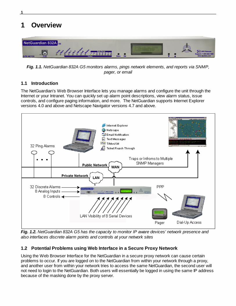
Fig. 1.1. NetGuardian 832A G5 monitors alarms, pings network elements, and reports via SNMP,pager, or email
Introduction1.1
The NetGuardian's Web Browser Interface lets you manage alarms and configure the unit through theInternet or your Intranet. You can quickly set up alarm point descriptions, view alarm status, issuecontrols, and configure paging information, and more. The NetGuardian supports Internet Explorerversions 4.0 and above and Netscape Navigator versions 4.7 and above.
Fig. 1.2. NetGuardian 832A G5 has the capacity to monitor IP aware devices' network presence andalso interfaces discrete alarm points and controls at your network sites
Potential Problems using Web Interface in a Secure Proxy Network1.2
Using the Web Browser Interface for the NetGuardian in a secure proxy network can cause certainproblems to occur. If you are logged on to the NetGuardian from within your network through a proxy,and another user from within your network tries to access the same NetGuardian, the second user willnot need to login to the NetGuardian. Both users will essentially be logged in using the same IP addressbecause of the masking done by the proxy server.

2
What's New in NetGuardian G51.3
The NetGuardian G5 series adds these new features:
SNMP v2c Support and Robust Message DeliveryNetGuardian G5 supports SNMP v2c, and the SNMP INFORM command, which permits robust deliveryof alarm notification to your SNMP manager.
Alarm Point GroupingEach NetGuardian Alarm point can be assigned to one of eight groups, which are identified with a user-defined label. Some of the ways you can use Alarm Point Grouping include:
Alarm Severity Levels: Configure the NetGuardian to indicate assigned alarmsecurity levels like Critical, Major, Minor and Status in avariable binding within the SNMP TRAP or INFORMmessage — so alarms can be sorted by severity even ifyour SNMP manager doesn't support severity levels.
Two Sets of Alarm Severity Levels: With 8 alarm groups to work with, you can easily createtwo different sets of severity levels. For example, you couldseparate power alarms (rated from Critical to Status) fromenvironmental alarms (also rated Critical to Status).
Custom Virtual Alarms: Create virtual alarms based on easy formulas like Allsecurity alarms or Critical power alarms.
Flexible Custom Derived Controls: NetGuardian G5 lets you create Derived Controls formulasbased on Alarm Point Groups.
Granular Pager and Email Notification: Selectively assign alarm points to specific pager and emailnotification recipients. The NetGuardian can be configuredto send pager notifications only for Critical or Major alarms— or you can send power alarms to repair technicians andintrusion alarms to a security guard.
Global Support for Dual SNMP ManagersNetGuardian G5 supports sending all SNMP TRAP and INFORM notifications to two global SNMPmanagers. This makes it easier to configure a secondary SNMP manager and frees up yourNetGuardian configuration for additional notification devices and more flexible alarm reporting. You caneasily send an alarm to your primary SNMP manager at the NOC; to a secondary backup SNMPmanager at another location; to the pager of the on-call technician; and the email in-box of thetechnician's supervisor.
Ping Devices with SNMPv1 GETNetGuardian G5 allows the use of SNMPv1 GETs to verify connectivity to a device. This re-uses the pingtarget functionality and allows an option between ICMP ping and SNMP ping. The SNMP ping will be anSNMPv1 GET against common MIB variables; sysDescr, SysObjectID, or SysUpTime. No special OIDentry is required.
Filter or Reset the NetGuardian Event LogThe NetGuardian Event Log has been enhanced to support new NetGuardian G5 features:
• You can filter Event Log entries by Alarm Point Group, to see only the alarms you want. • You can reset the Event Log, to clear old alarms from the display.
3
• You can reset the Event Log by Alarm Point Group; for example, clear power alarms while retainingintruder alarms.
Alarm Sync Makes Turnup and Testing EasyNetGuardian G5 also provides a new command to re-synchronize all alarms. This command clears allalarms, so that a new notification is sent for all standing alarms. You can easily test alarm connectionsduring turnup without rebooting the NetGuardian unit.
Unit Configuration2
Logging on to the NetGuardian2.1
For Web Interface functionality, the unit must first be configured with some basic network information. Ifthis step has not been done, refer to the NetGuardian User Manual for initial software configurationsetup.
1. To connect to the NetGuardian from your Web browser, you must know its IP address or domainname if it has been registered with your internal DNS. Enter it in the address bar of your Webbrowser. It may be helpful to bookmark the logon page to simplify access.
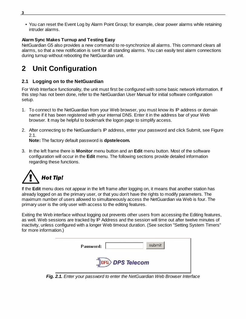
2. After connecting to the NetGuardian's IP address, enter your password and click Submit, see Figure2.1.Note: The factory default password is dpstelecom.
3. In the left frame there is Monitor menu button and an Edit menu button. Most of the software
configuration will occur in the Edit menu. The following sections provide detailed informationregarding these functions.
! Hot Tip!
If the Edit menu does not appear in the left frame after logging on, it means that another station hasalready logged on as the primary user, or that you don't have the rights to modify parameters. Themaximum number of users allowed to simultaneously access the NetGuardian via Web is four. Theprimary user is the only user with access to the editing features.
Exiting the Web interface without logging out prevents other users from accessing the Editing features,as well. Web sessions are tracked by IP Address and the session will time out after twelve minutes ofinactivity, unless configured with a longer Web timeout duration. (See section "Setting System Timers"for more information.)
Fig. 2.1. Enter your password to enter the NetGuardian Web Browser Interface
4
Using RADIUS Authentication (Available as of Firmware v5.0I)2.2
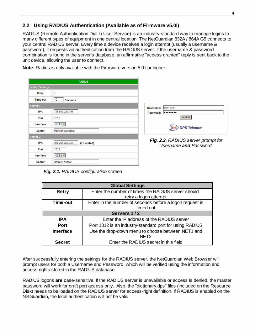
RADIUS (Remote Authentication Dial In User Service) is an industry-standard way to manage logins tomany different types of equipment in one central location. The NetGuardian 832A / 864A G5 connects toyour central RADIUS server. Every time a device receives a login attempt (usually a username &password), it requests an authentication from the RADIUS server. If the username & passwordcombination is found in the server's database, an affirmative "access granted" reply is sent back to the unit device, allowing the user to connect.
Note: Radius is only available with the Firmware version 5.0 I or higher.
Fig. 2.1. RADIUS configuration screen
Fig. 2.2. RADIUS server prompt forUsername and Password.
Global Settings
Retry Enter the number of times the RADIUS server should retry a logon attempt
Time-out Enter in the number of seconds before a logon request istimed out
Servers 1 / 2
IPA Enter the IP address of the RADIUS server
Port Port 1812 is an industry-standard port for using RADIUS
Interface Use the drop-down menu to choose between NET1 andNET2
Secret Enter the RADIUS secret in this field
After successfully entering the settings for the RADIUS server, the NetGuardian Web Browser willprompt users for both a Username and Password, which will be verified using the information andaccess rights stored in the RADIUS database.
RADIUS logons are case-sensitive. If the RADIUS server is unavailable or access is denied, the masterpassword will work for craft port access only. Also, the "dictionary.dps" files (included on the ResourceDisk) needs to be loaded on the RADIUS server for access-right definition. If RADIUS is enabled on theNetGuardian, the local authentication will not be valid.
5
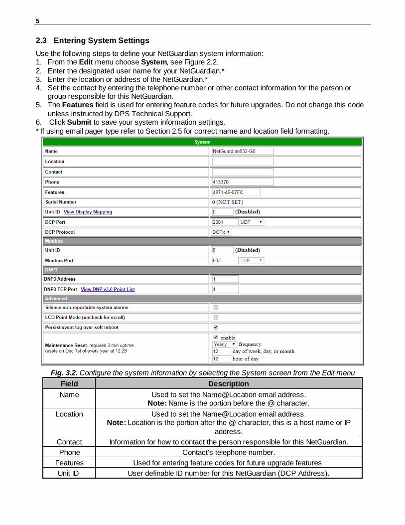
Entering System Settings2.3
Use the following steps to define your NetGuardian system information:1. From the Edit menu choose System, see Figure 2.2.2. Enter the designated user name for your NetGuardian.*3. Enter the location or address of the NetGuardian.*4. Set the contact by entering the telephone number or other contact information for the person or
group responsible for this NetGuardian.5. The Features field is used for entering feature codes for future upgrades. Do not change this code
unless instructed by DPS Technical Support.6. Click Submit to save your system information settings.* If using email pager type refer to Section 2.5 for correct name and location field formatting.
Fig. 3.2. Configure the system information by selecting the System screen from the Edit menu
Field Description
Name Used to set the Name@Location email address.Note: Name is the portion before the @ character.
Location Used to set the Name@Location email address.Note: Location is the portion after the @ character, this is a host name or IP
address.
Contact Information for how to contact the person responsible for this NetGuardian.
Phone Contact's telephone number.
Features Used for entering feature codes for future upgrade features.
Unit ID User definable ID number for this NetGuardian (DCP Address).

6
DCP Port Enter the DCP Port for this NetGuardian. (1-8 serial otherwise UDP/IP Port) Note: DCPe added to the list of DCP protocols.
DCP Protocol Choose between DCPx, DCPf, or DCPe.
Get History Select the Download button to download the logs for all D-Wire sensors (Onlyavailable with the D-Wire top board hardware build option).
Erase History Check this box to erase all logs for each D-Wire sensor. (Only available with theD-Wire top board hardware build option).
Modbus Unit ID User definable ID number for the Modbus feature. Value can range from 1-255 (0= Disabled)
Modbus Port Modbus port for this NetGuardian.
Silence non-reportable
system alarms
Check the box to silence alarms not applicable to your configuration. Example:This NetGuardian is not setup to send SNMP traps. Check this box to avoidreceiving a failure notification for system alarm 13 (SNMP Trap not sent).
LCD PointMode
Check this box to have the front panel LCD operate in "Point Mode". In this mode,only the points in alarm are displayed on the screen, instead of the full alarm
descriptions. Point numbers for discrete alarms, analog threshold crossings, andlatched relays will appear on the LCD. See hardware manual for details.
DNP Address This is the DNP3 polling address of the NetGuardian. This value can range from 0-
65519.
DNP TCP Port This option allows you to select the port for DNP3 polling over LAN. Set to "0" todisable DNP3
Persist eventlog over soft
reboot
Check to save the event log over a soft reboot.
Enable If this is checked, the NetGuardian will reboot itself 29 minutes after the scheduledhour. At the top of the hour of the scheduled reset, the NetGuardian will show a
warning on the web interface and display the countdown until the reset in minutes.System alarms will be saved across the reset. If “Persist event log over soft
reboot” is checked, the event log will be saved across the reset as well.
Frequency How often you would like the unit to perform a maintenance reset. You can selectYearly, Monthly, Weekly, and Daily.
Day of week,day, or month
Select on which weekday, day, or month to reset. This setting is relative to thefrequency option. If Frequency is set to monthly, the NetGuardian will skip monthson which the reset date is not valid for the month. For example, if the reset day is31, it will not activate the reset in September or February. This field is not used
when frequency is set to Daily.
Hour of day Which hour of the day you would like the NetGuardian to perform the maintenancereset. The reset will be perform 29 minutes after the top of hour.
Table 3.A. System fields

7
Changing the Logon Password2.4
The password can be configured from the Edit menu > Logon screen > Master Password section.The minimum password length is four characters; however, DPS recommends setting the minimumpassword length to at least five characters. You can also configure security logon profiles to individualaccess rights and security dial-back functions in the Logon Profile screen. (See section for dial-backand logon profile configuration information.)
The factory default password is dpstelecom. DPS Telecom strongly recommends that thedefault password be changed.
Use the following steps to change the logon password:1. From the Edit menu select Logon.2. Enter the minimum password length you wish to set.3. Enter your new password in the Password and Confirm Password fields.4. Click the Submit Data button.
Fig. 2.3. Configure the password parameters from the Login screen
8
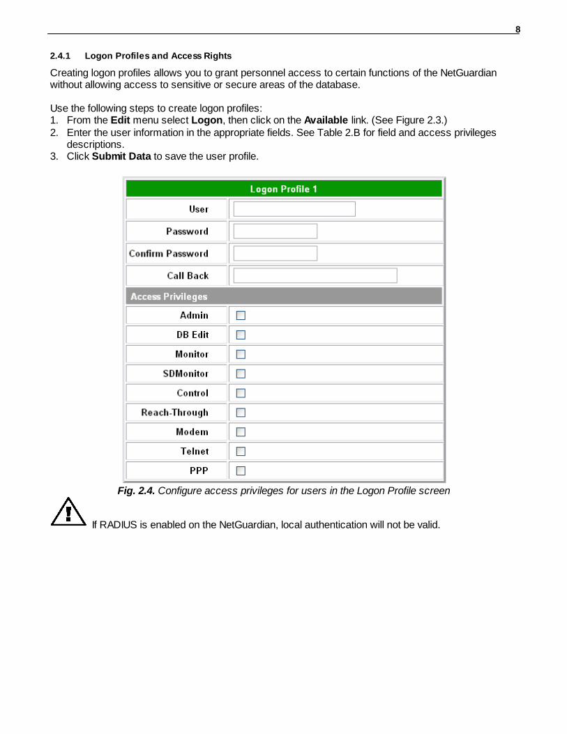
2.4.1 Logon Profiles and Access Rights
Creating logon profiles allows you to grant personnel access to certain functions of the NetGuardianwithout allowing access to sensitive or secure areas of the database.
Use the following steps to create logon profiles:1. From the Edit menu select Logon, then click on the Available link. (See Figure 2.3.)2. Enter the user information in the appropriate fields. See Table 2.B for field and access privileges
descriptions.3. Click Submit Data to save the user profile.
Fig. 2.4. Configure access privileges for users in the Logon Profile screen
If RADIUS is enabled on the NetGuardian, local authentication will not be valid.
9
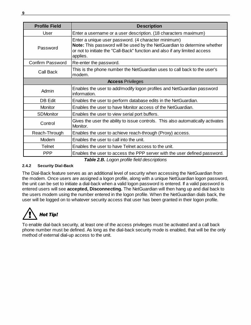
Profile Field Description
User Enter a username or a user description. (18 characters maximum)
Password
Enter a unique user password. (4 character minimum)Note: This password will be used by the NetGuardian to determine whetheror not to initiate the "Call-Back" function and also if any limited accessapplies.
Confirm Password Re-enter the password.
Call BackThis is the phone number the NetGuardian uses to call back to the user'smodem.
Access Privileges
AdminEnables the user to add/modify logon profiles and NetGuardian passwordinformation.
DB Edit Enables the user to perform database edits in the NetGuardian.
Monitor Enables the user to have Monitor access of the NetGuardian.
SDMonitor Enables the user to view serial port buffers.
ControlGives the user the ability to issue controls. This also automatically activatesMonitor.
Reach-Through Enables the user to achieve reach-through (Proxy) access.
Modem Enables the user to call into the unit.
Telnet Enables the user to have Telnet access to the unit.
PPP Enables the user to access the PPP server with the user defined password.
Table 2.B. Logon profile field descriptions
2.4.2 Security Dial-Back
The Dial-Back feature serves as an additional level of security when accessing the NetGuardian fromthe modem. Once users are assigned a logon profile, along with a unique NetGuardian logon password,the unit can be set to initiate a dial-back when a valid logon password is entered. If a valid password isentered users will see accepted, Disconnecting. The NetGuardian will then hang up and dial back tothe users modem using the number entered in the logon profile. When the NetGuardian dials back, theuser will be logged on to whatever security access that user has been granted in their logon profile.
! Hot Tip!
To enable dial-back security, at least one of the access privileges must be activated and a call backphone number must be defined. As long as the dial-back security mode is enabled, that will be the onlymethod of external dial-up access to the unit.
10
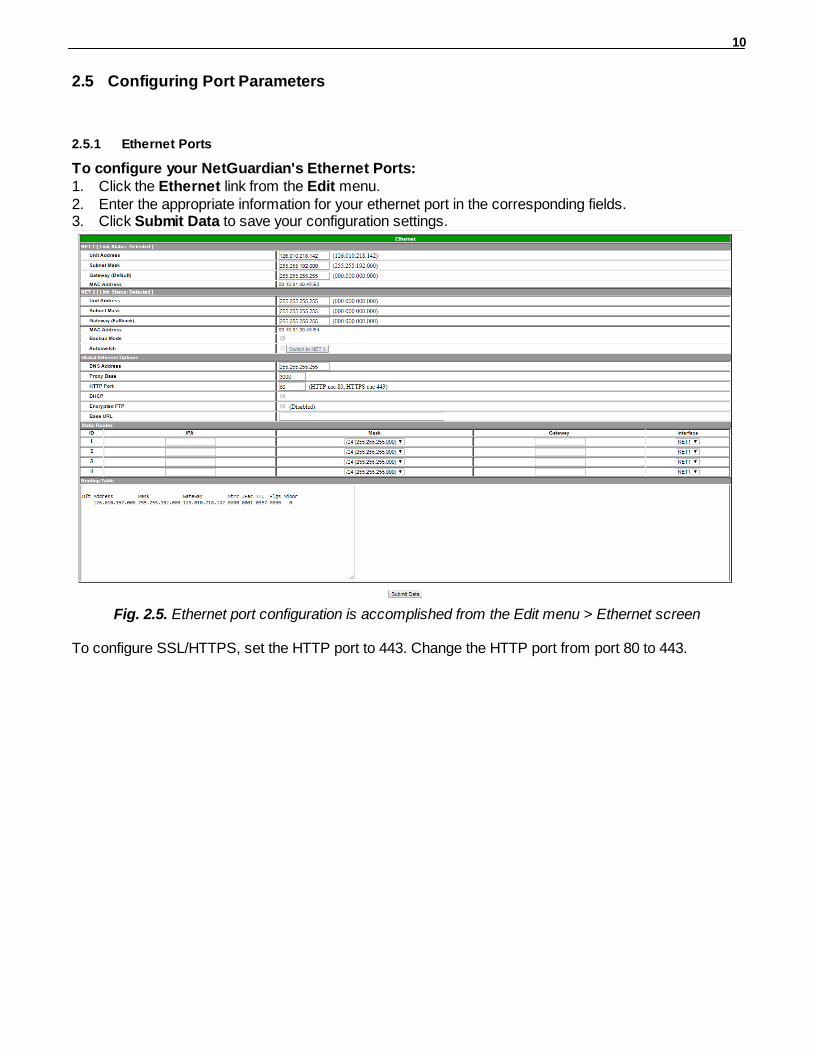
Configuring Port Parameters2.5
2.5.1 Ethernet Ports
To configure your NetGuardian's Ethernet Ports:1. Click the Ethernet link from the Edit menu.2. Enter the appropriate information for your ethernet port in the corresponding fields.3. Click Submit Data to save your configuration settings.
Fig. 2.5. Ethernet port configuration is accomplished from the Edit menu > Ethernet screen
To configure SSL/HTTPS, set the HTTP port to 443. Change the HTTP port from port 80 to 443.
11
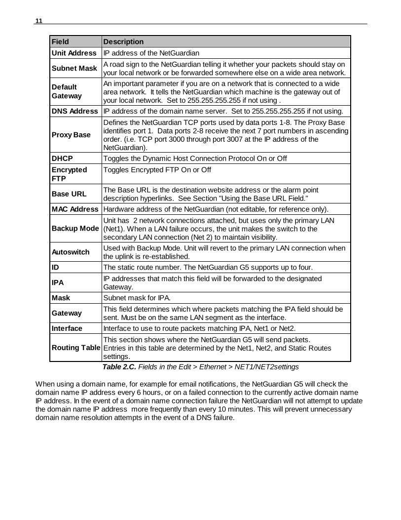
Field Description
Unit Address IP address of the NetGuardian
Subnet MaskA road sign to the NetGuardian telling it whether your packets should stay onyour local network or be forwarded somewhere else on a wide area network.
DefaultGateway
An important parameter if you are on a network that is connected to a widearea network. It tells the NetGuardian which machine is the gateway out ofyour local network. Set to 255.255.255.255 if not using .
DNS Address IP address of the domain name server. Set to 255.255.255.255 if not using.
Proxy Base
Defines the NetGuardian TCP ports used by data ports 1-8. The Proxy Baseidentifies port 1. Data ports 2-8 receive the next 7 port numbers in ascendingorder. (i.e. TCP port 3000 through port 3007 at the IP address of theNetGuardian).
DHCP Toggles the Dynamic Host Connection Protocol On or Off
EncryptedFTP
Toggles Encrypted FTP On or Off
Base URLThe Base URL is the destination website address or the alarm pointdescription hyperlinks. See Section "Using the Base URL Field."
MAC Address Hardware address of the NetGuardian (not editable, for reference only).
Backup ModeUnit has 2 network connections attached, but uses only the primary LAN(Net1). When a LAN failure occurs, the unit makes the switch to thesecondary LAN connection (Net 2) to maintain visibility.
AutoswitchUsed with Backup Mode. Unit will revert to the primary LAN connection whenthe uplink is re-established.
ID The static route number. The NetGuardian G5 supports up to four.
IPAIP addresses that match this field will be forwarded to the designatedGateway.
Mask Subnet mask for IPA.
GatewayThis field determines which where packets matching the IPA field should besent. Must be on the same LAN segment as the interface.
Interface Interface to use to route packets matching IPA, Net1 or Net2.
Routing TableThis section shows where the NetGuardian G5 will send packets.Entries in this table are determined by the Net1, Net2, and Static Routessettings.
Table 2.C. Fields in the Edit > Ethernet > NET1/NET2settings
When using a domain name, for example for email notifications, the NetGuardian G5 will check thedomain name IP address every 6 hours, or on a failed connection to the currently active domain nameIP address. In the event of a domain name connection failure the NetGuardian will not attempt to updatethe domain name IP address more frequently than every 10 minutes. This will prevent unnecessarydomain name resolution attempts in the event of a DNS failure.
12
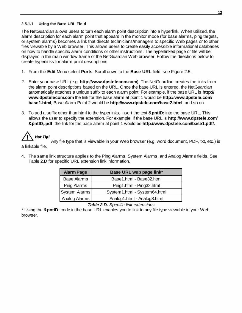
2.5.1.1 Using the Base URL Field
The NetGuardian allows users to turn each alarm point description into a hyperlink. When utilized, thealarm description for each alarm point that appears in the monitor mode (for base alarms, ping targets,or system alarms) becomes a link that directs technicians/managers to specific Web pages or to otherfiles viewable by a Web browser. This allows users to create easily accessible informational databaseson how to handle specific alarm conditions or other instructions. The hyperlinked page or file will bedisplayed in the main window frame of the NetGuardian Web browser. Follow the directions below tocreate hyperlinks for alarm point descriptions.
1. From the Edit Menu select Ports. Scroll down to the Base URL field, see Figure 2.5.
2. Enter your base URL (e.g. http://www.dpstelecom.com). The NetGuardian creates the links fromthe alarm point descriptions based on the URL. Once the base URL is entered, the NetGuardianautomatically attaches a unique suffix to each alarm point. For example, if the base URL is http://www.dpstelecom.com the link for the base alarm at point 1 would be http://www.dpstele.com/base1.html, Base Alarm Point 2 would be http://www.dpstele.com/base2.html, and so on.
3. To add a suffix other than html to the hyperlinks, insert the text &pntID; into the base URL. Thisallows the user to specify the extension. For example, if the base URL is http://www.dpstele.com/&pntID;.pdf, the link for the base alarm at point 1 would be http://www.dpstele.com/base1.pdf/.
! Hot Tip! Any file type that is viewable in your Web browser (e.g. word document, PDF, txt, etc.) is
a linkable file.
4. The same link structure applies to the Ping Alarms, System Alarms, and Analog Alarms fields. SeeTable 2.D for specific URL extension link information.
Alarm Page Base URL web page link*
Base Alarms Base1.html - Base32.html
Ping Alarms Ping1.html - Ping32.html
System Alarms System1.html - System64.html
Analog Alarms Analog1.html - Analog8.html
Table 2.D. Specific link extensions* Using the &pntID; code in the base URL enables you to link to any file type viewable in your Webbrowser.
13
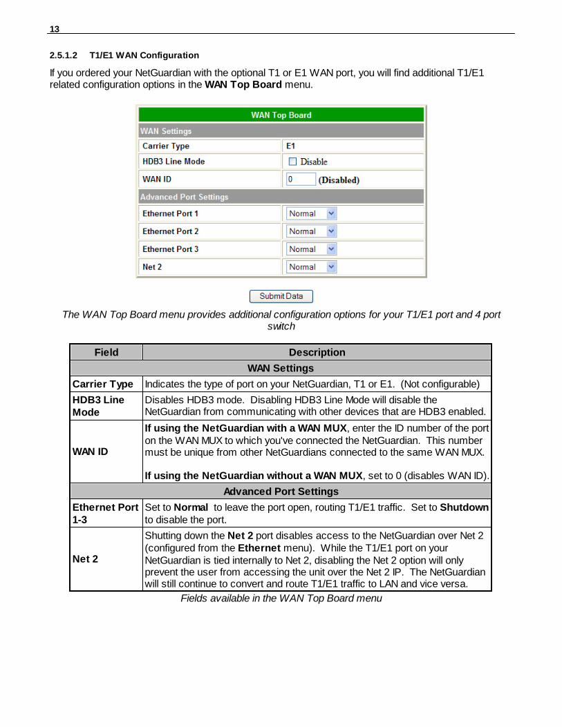
2.5.1.2 T1/E1 WAN Configuration
If you ordered your NetGuardian with the optional T1 or E1 WAN port, you will find additional T1/E1related configuration options in the WAN Top Board menu.
The WAN Top Board menu provides additional configuration options for your T1/E1 port and 4 portswitch
Field Description
WAN Settings
Carrier Type Indicates the type of port on your NetGuardian, T1 or E1. (Not configurable)
HDB3 LineMode
Disables HDB3 mode. Disabling HDB3 Line Mode will disable theNetGuardian from communicating with other devices that are HDB3 enabled.
WAN ID
If using the NetGuardian with a WAN MUX, enter the ID number of the porton the WAN MUX to which you've connected the NetGuardian. This numbermust be unique from other NetGuardians connected to the same WAN MUX.
If using the NetGuardian without a WAN MUX, set to 0 (disables WAN ID).
Advanced Port Settings
Ethernet Port1-3
Set to Normal to leave the port open, routing T1/E1 traffic. Set to Shutdownto disable the port.
Net 2
Shutting down the Net 2 port disables access to the NetGuardian over Net 2(configured from the Ethernet menu). While the T1/E1 port on yourNetGuardian is tied internally to Net 2, disabling the Net 2 option will onlyprevent the user from accessing the unit over the Net 2 IP. The NetGuardianwill still continue to convert and route T1/E1 traffic to LAN and vice versa.
Fields available in the WAN Top Board menu
14
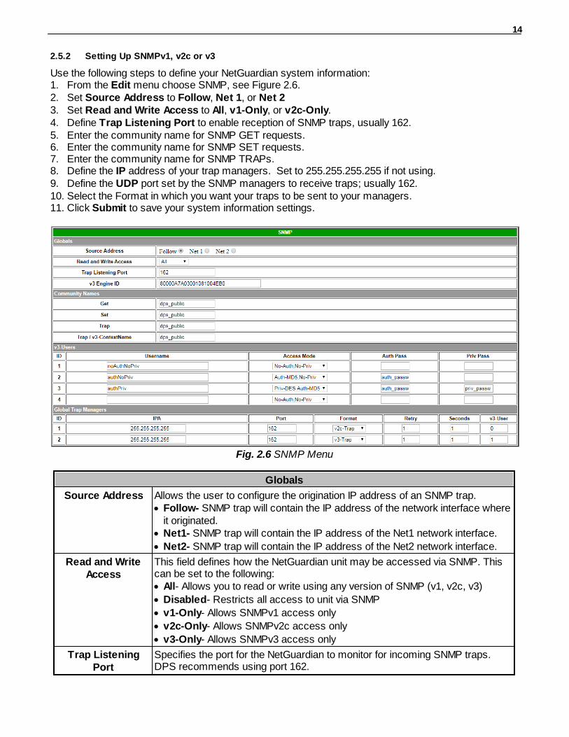
2.5.2 Setting Up SNMPv1, v2c or v3
Use the following steps to define your NetGuardian system information:1. From the Edit menu choose SNMP, see Figure 2.6.2. Set Source Address to Follow, Net 1, or Net 23. Set Read and Write Access to All, v1-Only, or v2c-Only.4. Define Trap Listening Port to enable reception of SNMP traps, usually 162.5. Enter the community name for SNMP GET requests.6. Enter the community name for SNMP SET requests.7. Enter the community name for SNMP TRAPs.8. Define the IP address of your trap managers. Set to 255.255.255.255 if not using.9. Define the UDP port set by the SNMP managers to receive traps; usually 162.10. Select the Format in which you want your traps to be sent to your managers.11. Click Submit to save your system information settings.
Fig. 2.6 SNMP Menu
Globals
Source Address Allows the user to configure the origination IP address of an SNMP trap.· Follow- SNMP trap will contain the IP address of the network interface where
it originated.· Net1- SNMP trap will contain the IP address of the Net1 network interface.
· Net2- SNMP trap will contain the IP address of the Net2 network interface.
Read and WriteAccess
This field defines how the NetGuardian unit may be accessed via SNMP. Thiscan be set to the following:· All- Allows you to read or write using any version of SNMP (v1, v2c, v3)
· Disabled- Restricts all access to unit via SNMP
· v1-Only- Allows SNMPv1 access only
· v2c-Only- Allows SNMPv2c access only
· v3-Only- Allows SNMPv3 access only
Trap ListeningPort
Specifies the port for the NetGuardian to monitor for incoming SNMP traps.DPS recommends using port 162.
15
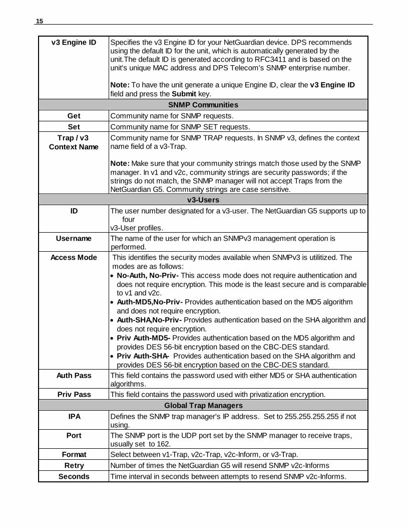
v3 Engine ID Specifies the v3 Engine ID for your NetGuardian device. DPS recommendsusing the default ID for the unit, which is automatically generated by theunit.The default ID is generated according to RFC3411 and is based on theunit's unique MAC address and DPS Telecom's SNMP enterprise number.
Note: To have the unit generate a unique Engine ID, clear the v3 Engine IDfield and press the Submit key.
SNMP Communities
Get Community name for SNMP requests.
Set Community name for SNMP SET requests.
Trap / v3 Context Name
Community name for SNMP TRAP requests. In SNMP v3, defines the contextname field of a v3-Trap.
Note: Make sure that your community strings match those used by the SNMPmanager. In v1 and v2c, community strings are security passwords; if thestrings do not match, the SNMP manager will not accept Traps from theNetGuardian G5. Community strings are case sensitive.
v3-Users
ID The user number designated for a v3-user. The NetGuardian G5 supports up tofour
v3-User profiles.
Username The name of the user for which an SNMPv3 management operation isperformed.
Access Mode This identifies the security modes available when SNMPv3 is utilitized. Themodes are as follows:
· No-Auth, No-Priv- This access mode does not require authentication anddoes not require encryption. This mode is the least secure and is comparableto v1 and v2c.
· Auth-MD5,No-Priv- Provides authentication based on the MD5 algorithmand does not require encryption.
· Auth-SHA,No-Priv- Provides authentication based on the SHA algorithm anddoes not require encryption.
· Priv Auth-MD5- Provides authentication based on the MD5 algorithm andprovides DES 56-bit encryption based on the CBC-DES standard.
· Priv Auth-SHA- Provides authentication based on the SHA algorithm andprovides DES 56-bit encryption based on the CBC-DES standard.
Auth Pass This field contains the password used with either MD5 or SHA authentication algorithms.
Priv Pass This field contains the password used with privatization encryption.
Global Trap Managers
IPA Defines the SNMP trap manager's IP address. Set to 255.255.255.255 if notusing.
Port The SNMP port is the UDP port set by the SNMP manager to receive traps,usually set to 162.
Format Select between v1-Trap, v2c-Trap, v2c-Inform, or v3-Trap.
Retry Number of times the NetGuardian G5 will resend SNMP v2c-Informs
Seconds Time interval in seconds between attempts to resend SNMP v2c-Informs.

16
v3-Users Association to the v3-User Table is made to specify the username, securitymode, and passwords that should be used for sending a v3-Trap.
Table 2.E. Fields in the Edit > SNMP settings
Note: If you are using SNMPv3, any changes to the Engine ID or passwords will require a reboot. Atbootup,you may experience a slight delay while the authorization and privatization keys update.

17
2.5.3 Filter IPA Config and Operation
The Filter IPA table allows you to increase the NetGuardian's network security by allowing or blockingpackets from specified IP addresses. Addresses which appear in the table will be processed by theNetGuardian. Defined IP addresses associated with network cameras or the network time server areautomatically processed and will not be filtered out by this feature. Broadcast packets of255.255.255.255 and ARP requests for the NetGuardian IP address are also not filtered.
1. From the Edit menu select Filter IPA.2. A warning prompt will appear, see Figure 2.7. Click OK to continue, or Exit to cancel.
Fig. 2.7. Filter IPA warning prompt
3. Once enabled only the IP addresses in the table will be allowed access to the NetGuardian.4. Select to Enable IPA Table.5. Choose an IPA Filter Mode: Standard or Enhanced. If you change the IPA Filter Mode, click the
"Submit Data" button before continuing to display the correct menu for your chosen mode. Proceedto either the "Standard" or "Enhanced" section below for your chosen mode.
"Standard" IPA Filter ModeThe Standard IPA Filter Mode includes a basic whitelist/blacklist by IP address.
Configuring your IP whitelist/blacklist in "Standard" IPA Filter Mode
1. Choose "Whitelist" or "Blacklist" to decide whether ONLY the listed IP addresses can connect to theNetGuardian (Whitelist) or the listed IP addresses are blocked by the NetGuardian (Blacklist).
2. Enter up to 12 IP addresses.3. Click "Submit Data" to save your Whitelist/Blacklist (be careful not to lock yourself out of the
NetGuardian).
18
! Hot Tip!
Entering a zero in any of the octet fields will declare that part of the octet to be a wildcard.
WARNING: "Filter IPA" is incompatible with networks that assign IP addresses. You may use thewildcard field to open an entire subnet.
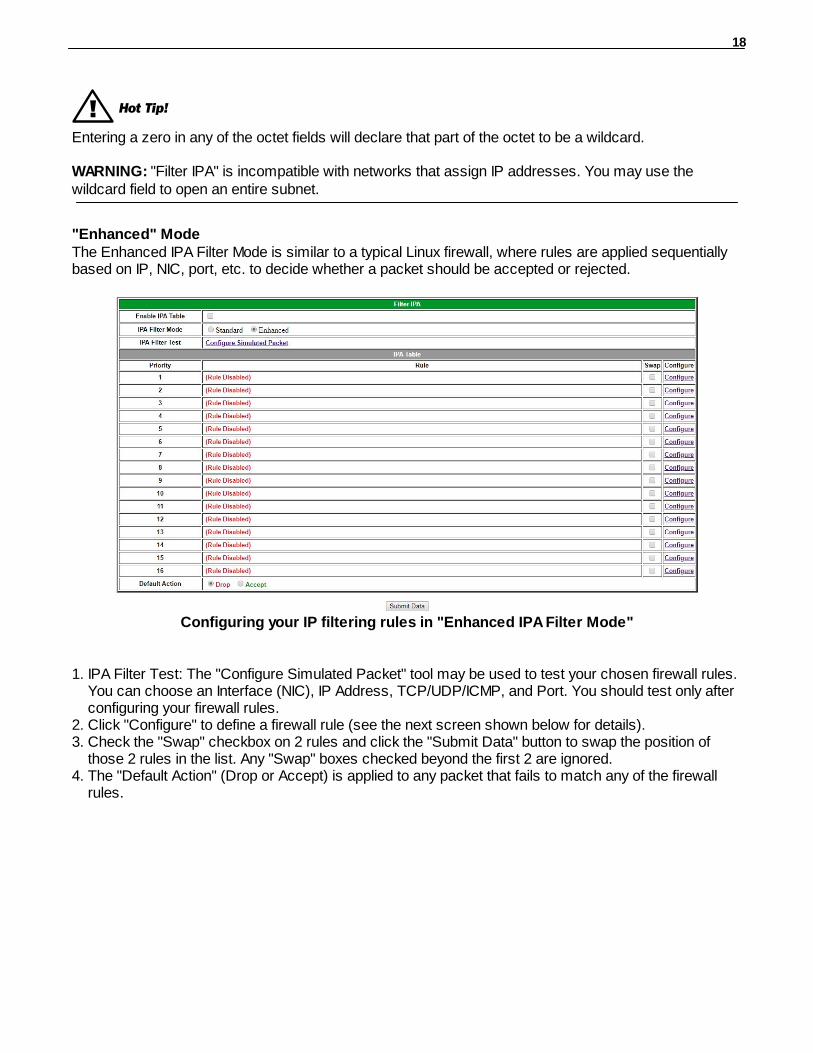
"Enhanced" ModeThe Enhanced IPA Filter Mode is similar to a typical Linux firewall, where rules are applied sequentiallybased on IP, NIC, port, etc. to decide whether a packet should be accepted or rejected.
Configuring your IP filtering rules in "Enhanced IPA Filter Mode"
1. IPA Filter Test: The "Configure Simulated Packet" tool may be used to test your chosen firewall rules.You can choose an Interface (NIC), IP Address, TCP/UDP/ICMP, and Port. You should test only afterconfiguring your firewall rules.
2. Click "Configure" to define a firewall rule (see the next screen shown below for details).3. Check the "Swap" checkbox on 2 rules and click the "Submit Data" button to swap the position of
those 2 rules in the list. Any "Swap" boxes checked beyond the first 2 are ignored.4. The "Default Action" (Drop or Accept) is applied to any packet that fails to match any of the firewall
rules.
19
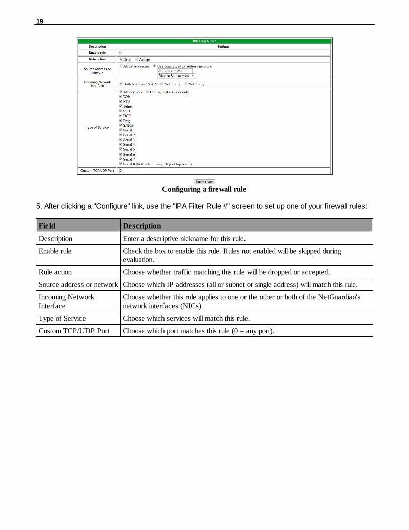
Configuring a firewall rule
5. After clicking a "Configure" link, use the "IPA Filter Rule #" screen to set up one of your firewall rules:
Field Description
Description Enter a descriptive nickname for this rule.
Enable rule Check the box to enable this rule. Rules not enabled will be skipped duringevaluation.
Rule action Choose whether traffic matching this rule will be dropped or accepted.
Source address or network Choose which IP addresses (all or subnet or single address) will match this rule.
Incoming NetworkInterface
Choose whether this rule applies to one or the other or both of the NetGuardian'snetwork interfaces (NICs).
Type of Service Choose which services will match this rule.
Custom TCP/UDP Port Choose which port matches this rule (0 = any port).

20
2.5.4 Changing Craft Port Communication Settings
Use the following steps to change the craft port communication settings:1. From the Edit menu > Ports screen, scroll down to the Craft section, see figure below.2. You can set the baud rate for the craft port to 300, 600, 1200, 2400, 4800, 9600, 19200, 38400,
57600, 115200. (Default Baud is 9600)3. Under the Wfmt (word format) field, select the appropriate data bits, parity, and stop bits setting to
match your terminal emulation software or device connected to the NetGuardian craft port. (Defaultdesignation is 8,N,1)
4. Click Submit Data to save the craft port settings.
Fig. 2.9. Configure the front panel craft port parameters from the Ports screen

21
2.5.5 Configuring Modem Port Settings
Use the following steps to configure the modem port settings. Default for these fields is blank.1. From the Edit menu > Ports screen, scroll to the Modem section, see Figure 2.10.2. In the Ring Count field enter the number of rings before answering. (Default = 1)3. The Dial Init and the Answer Init fields can be used if any other modem initialization settings need
to be set. For example, the modem can be set to ignore the dial-tone by entering a character code ineither the Answer Init (into the NetGuardian) or the Dial Init (out from the NetGuardian).
4. Click Submit Data to save your modem port settings.
Fig. 2.10. Change the modem settings from the Edit menu > Ports screen
Command Description
A Answer command
Bn Select communications standard
D
Dial
P Pulse dial
T Tone dial
R Connect as answering modem
W Wait for dial tone
, Pause for the duration of S8
@ Wait for silence
! Switch hook flash
; Return to the command state
En Command echo
Hn Switch hook control
In Modem identification
Ln Speaker volume
Mn Speaker activity
On Online
Qn Responses
Sr? Interrogate register
Sr=n Set register value
Vn Result codes
Xn Result code set
Z Reset
Modem commands may vary. Seeyour modem user manual forcommands specific to your modem.
If you set the ring count to 0, theNetGuardian will still be able to dialout for notifications, but will NEVERanswer an incoming call.
Table 2.F. Standard modem commands (Hayes)
22
2.5.6 Configuring Data Ports 1 - 9
Data port settings can be configured in the Edit menu > Ports screen.
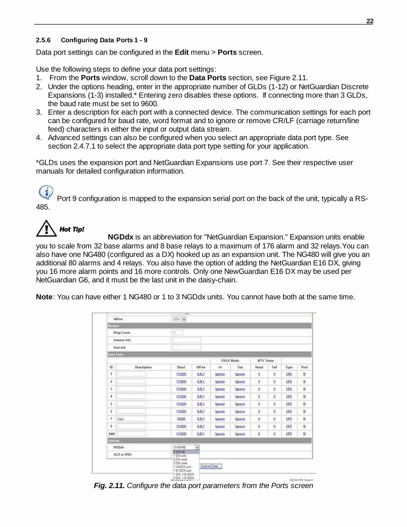
Use the following steps to define your data port settings:1. From the Ports window, scroll down to the Data Ports section, see Figure 2.11.2. Under the options heading, enter in the appropriate number of GLDs (1-12) or NetGuardian Discrete
Expansions (1-3) installed.* Entering zero disables these options. If connecting more than 3 GLDs,the baud rate must be set to 9600.
3. Enter a description for each port with a connected device. The communication settings for each portcan be configured for baud rate, word format and to ignore or remove CR/LF (carriage return/linefeed) characters in either the input or output data stream.
4. Advanced settings can also be configured when you select an appropriate data port type. Seesection 2.4.7.1 to select the appropriate data port type setting for your application.
*GLDs uses the expansion port and NetGuardian Expansions use port 7. See their respective usermanuals for detailed configuration information.
Port 9 configuration is mapped to the expansion serial port on the back of the unit, typically a RS-485.
! Hot Tip!NGDdx is an abbreviation for "NetGuardian Expansion." Expansion units enable
you to scale from 32 base alarms and 8 base relays to a maximum of 176 alarm and 32 relays.You canalso have one NG480 (configured as a DX) hooked up as an expansion unit. The NG480 will give you anadditional 80 alarms and 4 relays. You also have the option of adding the NetGuardian E16 DX, givingyou 16 more alarm points and 16 more controls. Only one NewGuardian E16 DX may be used perNetGuardian G6, and it must be the last unit in the daisy-chain.
Note: You can have either 1 NG480 or 1 to 3 NGDdx units. You cannot have both at the same time.
Fig. 2.11. Configure the data port parameters from the Ports screen

23
! Hot Tip!NGDdxk is the expansion type to choose when using a 216 G3 as an expansion.
The 216 expansion provides an additional 16 alarms, 2 controls and 8 analogs. When the port isassigned with this type, base control 1 will be used to support the keying of a radio to transmitcommunication between the NetGuardian G5 and the 216 expansion. By selecting the number of 216expansion units from the NGDdx options dropdown menu, the NetGuardian G5 will configure port 1 forpolling this type of expansion. The NetGuardian G5 will poll the 216 expansion units on the DCP PollTimer interval and will process asynchronous reporting of a COS alarm from the expansion units.
Note: You can have up to 8 216DX expansion units.
Fig. 2.11. Configure the data port parameters from the Ports screen
24
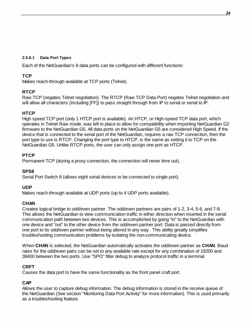
2.5.6.1 Data Port Types
Each of the NetGuardian's 8 data ports can be configured with different functions:
TCPMakes reach-through available at TCP ports (Telnet).
RTCPRaw TCP (negates Telnet negotiation). The RTCP (Raw TCP Data Port) negates Telnet negotiation andwill allow all characters (including [FF]) to pass straight through from IP to serial or serial to IP.
HTCPHigh speed TCP port (only 1 HTCP port is available). An HTCP, or High-speed TCP data port, whichoperates in Telnet Raw mode, was left in place to allow for compatibility when importing NetGuardian G2firmware to the NetGuardian G5. All data ports on the NetGuardian G5 are considered High Speed. If thedevice that is connected to the serial port of the NetGuardian, requires a raw TCP connection, then theport type to use is RTCP. Changing the port type to HTCP, is the same as setting it to TCP on theNetGuardian G5. Unlike RTCP ports, the user can only assign one port as HTCP.
PTCPPermanent TCP (during a proxy connection, the connection will never time out).
SPS8Serial Port Switch 8 (allows eight serial devices to be connected to single port).
UDPMakes reach-through available at UDP ports (up to 4 UDP ports available).
CHANCreates logical bridge to odd/even partner. The odd/even partners are pairs of 1-2, 3-4, 5-6, and 7-8.This allows the NetGuardian to view communication traffic in either direction when inserted in the serialcommunication path between two devices. This is accomplished by going "in" to the NetGuardian withone device and "out" to the other device from the odd/even partner port. Data is passed directly fromone port to its odd/even partner without being altered in any way. This ability greatly simplifiestroubleshooting communication problems by isolating the non-communicating device.
When CHAN is selected, the NetGuardian automatically activates the odd/even partner as CHAN. Baudrates for the odd/even pairs can be set to any available rate except for any combination of 19200 and38400 between the two ports. Use "SPO" filter debug to analyze protocol traffic in a terminal.
CRFTCauses the data port to have the same functionality as the front panel craft port.
CAPAllows the user to capture debug information. The debug information is stored in the receive queue ofthe NetGuardian (See section "Monitoring Data Port Activity" for more information). This is used primarilyas a troubleshooting feature.
25
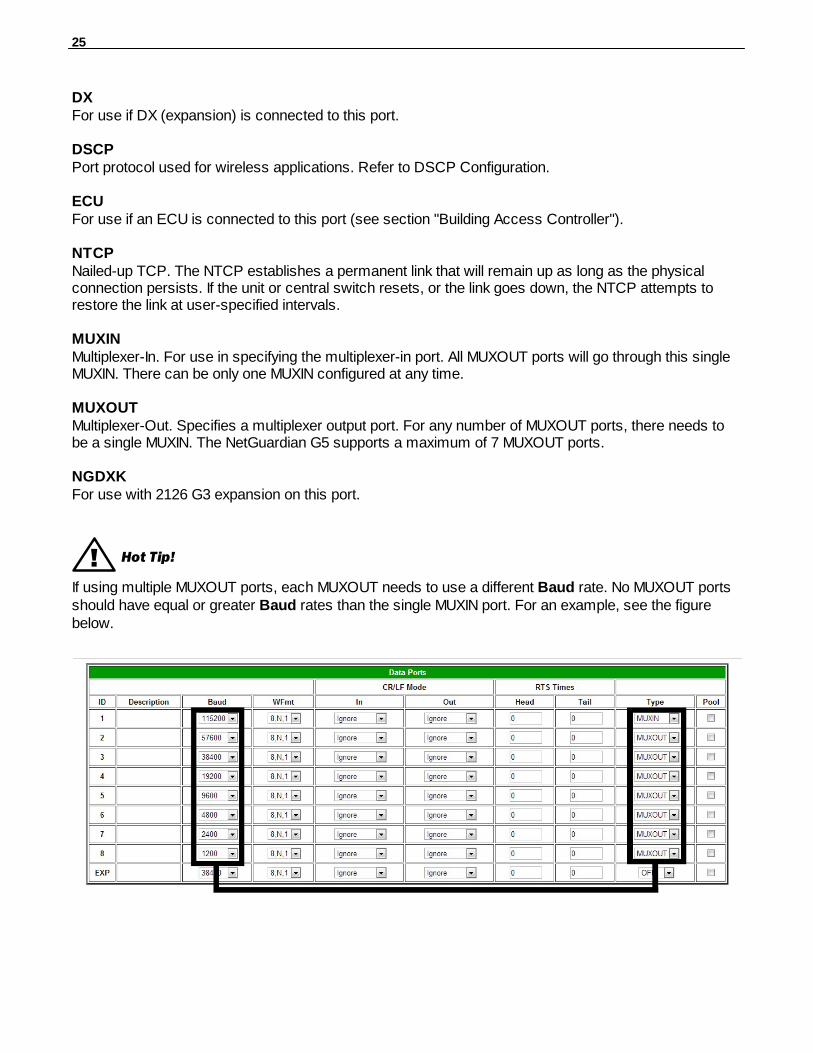
DXFor use if DX (expansion) is connected to this port.
DSCPPort protocol used for wireless applications. Refer to DSCP Configuration.
ECUFor use if an ECU is connected to this port (see section "Building Access Controller").
NTCPNailed-up TCP. The NTCP establishes a permanent link that will remain up as long as the physicalconnection persists. If the unit or central switch resets, or the link goes down, the NTCP attempts torestore the link at user-specified intervals.
MUXINMultiplexer-In. For use in specifying the multiplexer-in port. All MUXOUT ports will go through this singleMUXIN. There can be only one MUXIN configured at any time.
MUXOUTMultiplexer-Out. Specifies a multiplexer output port. For any number of MUXOUT ports, there needs tobe a single MUXIN. The NetGuardian G5 supports a maximum of 7 MUXOUT ports.
NGDXKFor use with 2126 G3 expansion on this port.
! Hot Tip!
If using multiple MUXOUT ports, each MUXOUT needs to use a different Baud rate. No MUXOUT portsshould have equal or greater Baud rates than the single MUXIN port. For an example, see the figurebelow.
26
2.5.6.2 Defining SPS8 Ports
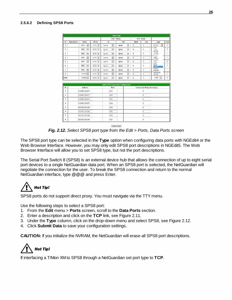
Fig. 2.12. Select SPS8 port type from the Edit > Ports, Data Ports screen
The SPS8 port type can be selected in the Type option when configuring data ports with NGEdit4 or theWeb Browser Interface. However, you may only edit SPS8 port descriptions in NGEdit5. The WebBrowser Interface will allow you to set SPS8 type, but not the port descriptions.
The Serial Port Switch 8 (SPS8) is an external device hub that allows the connection of up to eight serialport devices to a single NetGuardian data port. When an SPS8 port is selected, the NetGuardian willnegotiate the connection for the user. To break the SPS8 connection and return to the normalNetGuardian interface, type @@@ and press Enter.
! Hot Tip!
SPS8 ports do not support direct proxy. You must navigate via the TTY menu.
Use the following steps to select a SPS8 port:1. From the Edit menu > Ports screen, scroll to the Data Ports section.2. Enter a description and click on the TCP link, see Figure 2.11.3. Under the Type column, click on the drop-down menu and select SPS8, see Figure 2.12.4. Click Submit Data to save your configuration settings.
CAUTION: If you initialize the NVRAM, the NetGuardian will erase all SPS8 port descriptions.
! Hot Tip!
If interfacing a T/Mon XM to SPS8 through a NetGuardian set port type to TCP.
27
2.5.6.3 Defining NTCP Ports
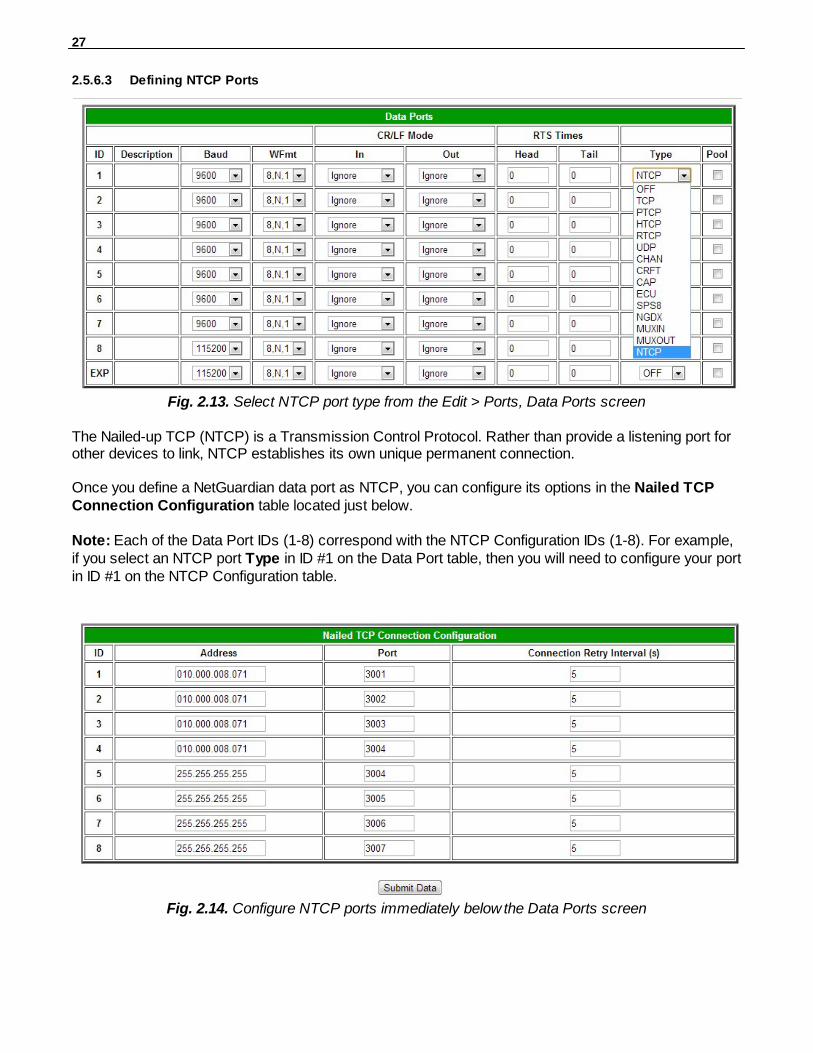
Fig. 2.13. Select NTCP port type from the Edit > Ports, Data Ports screen
The Nailed-up TCP (NTCP) is a Transmission Control Protocol. Rather than provide a listening port forother devices to link, NTCP establishes its own unique permanent connection.
Once you define a NetGuardian data port as NTCP, you can configure its options in the Nailed TCPConnection Configuration table located just below.
Note: Each of the Data Port IDs (1-8) correspond with the NTCP Configuration IDs (1-8). For example,if you select an NTCP port Type in ID #1 on the Data Port table, then you will need to configure your portin ID #1 on the NTCP Configuration table.
Fig. 2.14. Configure NTCP ports immediately below the Data Ports screen
28
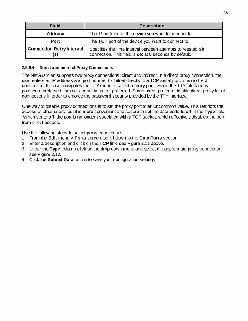
Field Description
Address The IP address of the device you want to connect to.
Port The TCP port of the device you want to connect to.
Connection Retry Interval(s)
Specifies the time interval between attempts to reestablishconnection. This field is set at 5 seconds by default.
2.5.6.4 Direct and Indirect Proxy Connections
The NetGuardian supports two proxy connections, direct and indirect. In a direct proxy connection, theuser enters an IP address and port number to Telnet directly to a TCP serial port. In an indirectconnection, the user navigates the TTY menu to select a proxy port. Since the TTY interface ispassword protected, indirect connections are preferred. Some users prefer to disable direct proxy for allconnections in order to enforce the password security provided by the TTY interface.
One way to disable proxy connections is to set the proxy port to an uncommon value. This restricts theaccess of other users, but it is more convenient and secure to set the data ports to off in the Type field. When set to off, the port is no longer associated with a TCP socket, which effectively disables the portfrom direct access.
Use the following steps to select proxy connections:1. From the Edit menu > Ports screen, scroll down to the Data Ports section. 2. Enter a description and click on the TCP link, see Figure 2.11 above.3. Under the Type column click on the drop-down menu and select the appropriate proxy connection,
see Figure 2.13.4. Click the Submit Data button to save your configuration settings.
29
Setting Up Notification Methods2.6
The Edit menu > Pagers screen allows you to configure several alarm notification methods in additionto pagers. Each notification method is defined as a pager type in this screen. To define a pager as theprimary or secondary notification of alarm conditions, select the pager in the appropriate alarm pointprovisioning screens. Refer to Section 2.9, "Configuring Base Discrete Alarms," and Section 2.9,"Setting System Alarm Notifications," for more information.
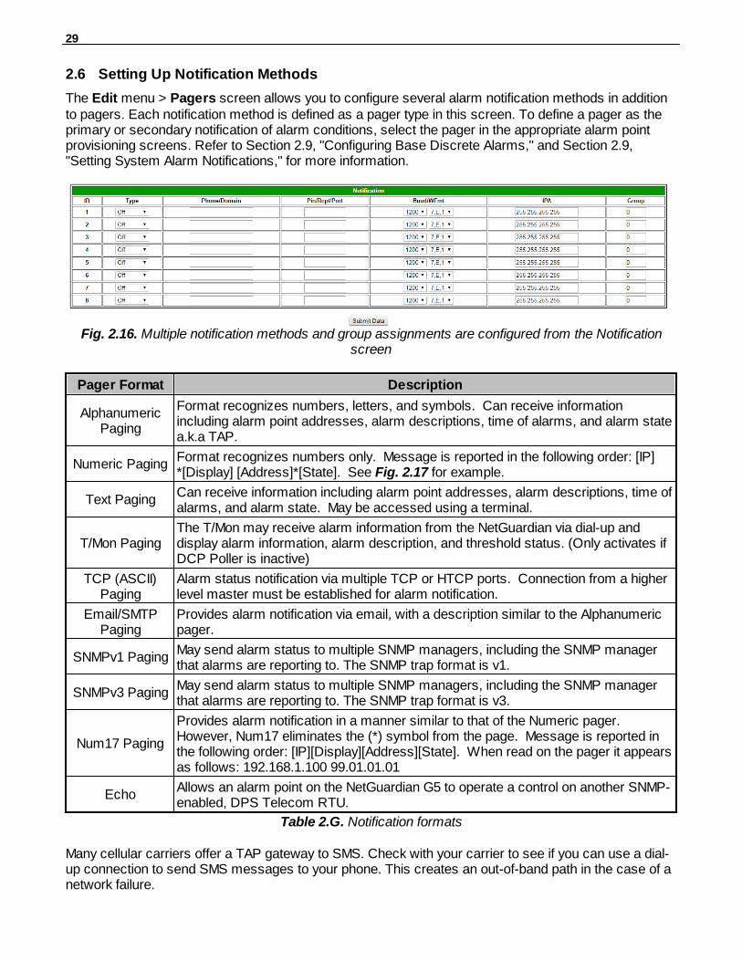
Fig. 2.16. Multiple notification methods and group assignments are configured from the Notificationscreen
Pager Format Description
AlphanumericPaging
Format recognizes numbers, letters, and symbols. Can receive informationincluding alarm point addresses, alarm descriptions, time of alarms, and alarm statea.k.a TAP.
Numeric PagingFormat recognizes numbers only. Message is reported in the following order: [IP]*[Display] [Address]*[State]. See Fig. 2.17 for example.
Text PagingCan receive information including alarm point addresses, alarm descriptions, time ofalarms, and alarm state. May be accessed using a terminal.
T/Mon PagingThe T/Mon may receive alarm information from the NetGuardian via dial-up anddisplay alarm information, alarm description, and threshold status. (Only activates ifDCP Poller is inactive)
TCP (ASCII)Paging
Alarm status notification via multiple TCP or HTCP ports. Connection from a higherlevel master must be established for alarm notification.
Email/SMTPPaging
Provides alarm notification via email, with a description similar to the Alphanumericpager.
SNMPv1 PagingMay send alarm status to multiple SNMP managers, including the SNMP managerthat alarms are reporting to. The SNMP trap format is v1.
SNMPv3 PagingMay send alarm status to multiple SNMP managers, including the SNMP managerthat alarms are reporting to. The SNMP trap format is v3.
Num17 Paging
Provides alarm notification in a manner similar to that of the Numeric pager. However, Num17 eliminates the (*) symbol from the page. Message is reported inthe following order: [IP][Display][Address][State]. When read on the pager it appearsas follows: 192.168.1.100 99.01.01.01
EchoAllows an alarm point on the NetGuardian G5 to operate a control on another SNMP-enabled, DPS Telecom RTU.
Table 2.G. Notification formats
Many cellular carriers offer a TAP gateway to SMS. Check with your carrier to see if you can use a dial-up connection to send SMS messages to your phone. This creates an out-of-band path in the case of anetwork failure.
30
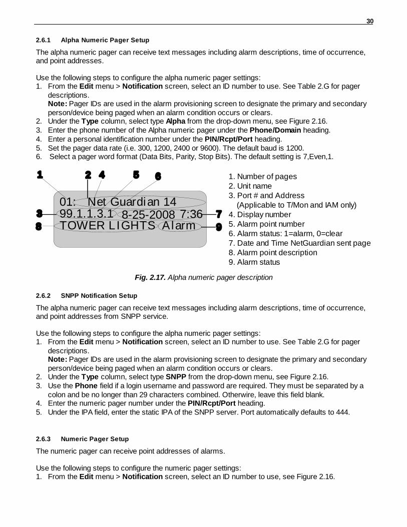
2.6.1 Alpha Numeric Pager Setup
The alpha numeric pager can receive text messages including alarm descriptions, time of occurrence,and point addresses.
Use the following steps to configure the alpha numeric pager settings:1. From the Edit menu > Notification screen, select an ID number to use. See Table 2.G for pager
descriptions.Note: Pager IDs are used in the alarm provisioning screen to designate the primary and secondaryperson/device being paged when an alarm condition occurs or clears.
2. Under the Type column, select type Alpha from the drop-down menu, see Figure 2.16.3. Enter the phone number of the Alpha numeric pager under the Phone/Domain heading.4. Enter a personal identification number under the PIN/Rcpt/Port heading.5. Set the pager data rate (i.e. 300, 1200, 2400 or 9600). The default baud is 1200.6. Select a pager word format (Data Bits, Parity, Stop Bits). The default setting is 7,Even,1.
1. Number of pages2. Unit name3. Port # and Address (Applicable to T/Mon and IAM only)4. Display number5. Alarm point number6. Alarm status: 1=alarm, 0=clear7. Date and Time NetGuardian sent page8. Alarm point description9. Alarm status
01: Net Guardian 1499.1.1.3.1TOWER LIGHTS Alarm
7:368-25-2008
1 2
3
5 6
7
8 9
4
Fig. 2.17. Alpha numeric pager description
2.6.2 SNPP Notification Setup
The alpha numeric pager can receive text messages including alarm descriptions, time of occurrence,and point addresses from SNPP service.
Use the following steps to configure the alpha numeric pager settings:1. From the Edit menu > Notification screen, select an ID number to use. See Table 2.G for pager
descriptions.Note: Pager IDs are used in the alarm provisioning screen to designate the primary and secondaryperson/device being paged when an alarm condition occurs or clears.
2. Under the Type column, select type SNPP from the drop-down menu, see Figure 2.16.3. Use the Phone field if a login username and password are required. They must be separated by a
colon and be no longer than 29 characters combined. Otherwire, leave this field blank.4. Enter the numeric pager number under the PIN/Rcpt/Port heading.5. Under the IPA field, enter the static IPA of the SNPP server. Port automatically defaults to 444.
2.6.3 Numeric Pager Setup
The numeric pager can receive point addresses of alarms.
Use the following steps to configure the numeric pager settings:1. From the Edit menu > Notification screen, select an ID number to use, see Figure 2.16.
31
Note: Pager IDs are used in the alarm provisioning screen to designate the primary and secondaryperson/device being paged when an alarm condition occurs or clears.
2. Under the Type column select Numeric from the drop-down menu, see Figure 2.16.3. Enter the phone number of the numeric pager under the Phone/Domain heading, followed by 7
commas (e.g. 555-1212,,,,,,,). Placing a comma after the phone number initiates a two secondpause (per comma). This allows enough time for the pager to answer before the NetGuardian sendsthe alarm information.
The Baud/Wfmt and IPA fields are not used from numeric pager types.
2.6.4 Text Paging Setup
Text pages can receive information including the point addresses of alarms, the alarm description, timeof the alarm, and state (alarm or clear). The text pages may be viewed using a terminal such asHyperTerminal.
Use the following steps to configure the text paging settings:1. From the Edit menu > Notification screen, select an ID number to use, refer to Figure 2.16.
Note: Pager IDs are used in the alarm provisioning screen to designate the primary and secondaryperson/device being paged when an alarm condition occurs or clears.
2. Under the Type column select Text from the drop-down menu, see Figure 2.16.3. Enter the phone number of the text paging device under the Phone/Domain heading.4. Set the pager data rate (i.e. 300, 1200, 2400 or 9600). The default baud is 1,200.5. Select a pager word format (e.g Data bits: 7 or 8, Parity: none (N), even (E) or odd (O), and Stop
Bits: 1). The default setting is 7, Even,1.
To set up text paging from T/Mon see the T/Mon user manual.
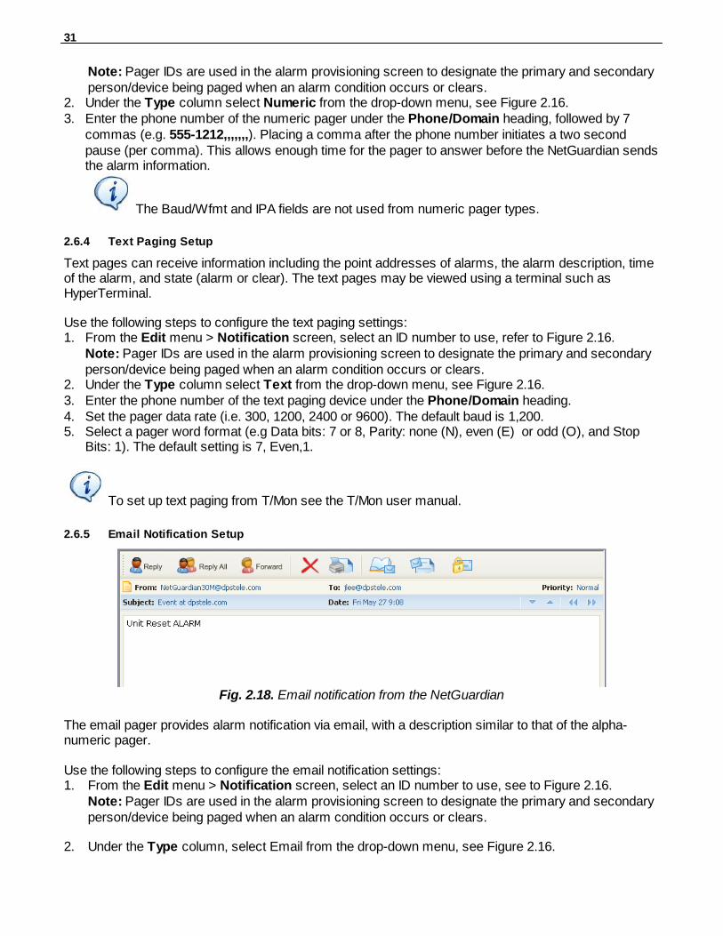
2.6.5 Email Notification Setup
Fig. 2.18. Email notification from the NetGuardian
The email pager provides alarm notification via email, with a description similar to that of the alpha-numeric pager.
Use the following steps to configure the email notification settings:1. From the Edit menu > Notification screen, select an ID number to use, see to Figure 2.16.
Note: Pager IDs are used in the alarm provisioning screen to designate the primary and secondaryperson/device being paged when an alarm condition occurs or clears.
2. Under the Type column, select Email from the drop-down menu, see Figure 2.16.
32
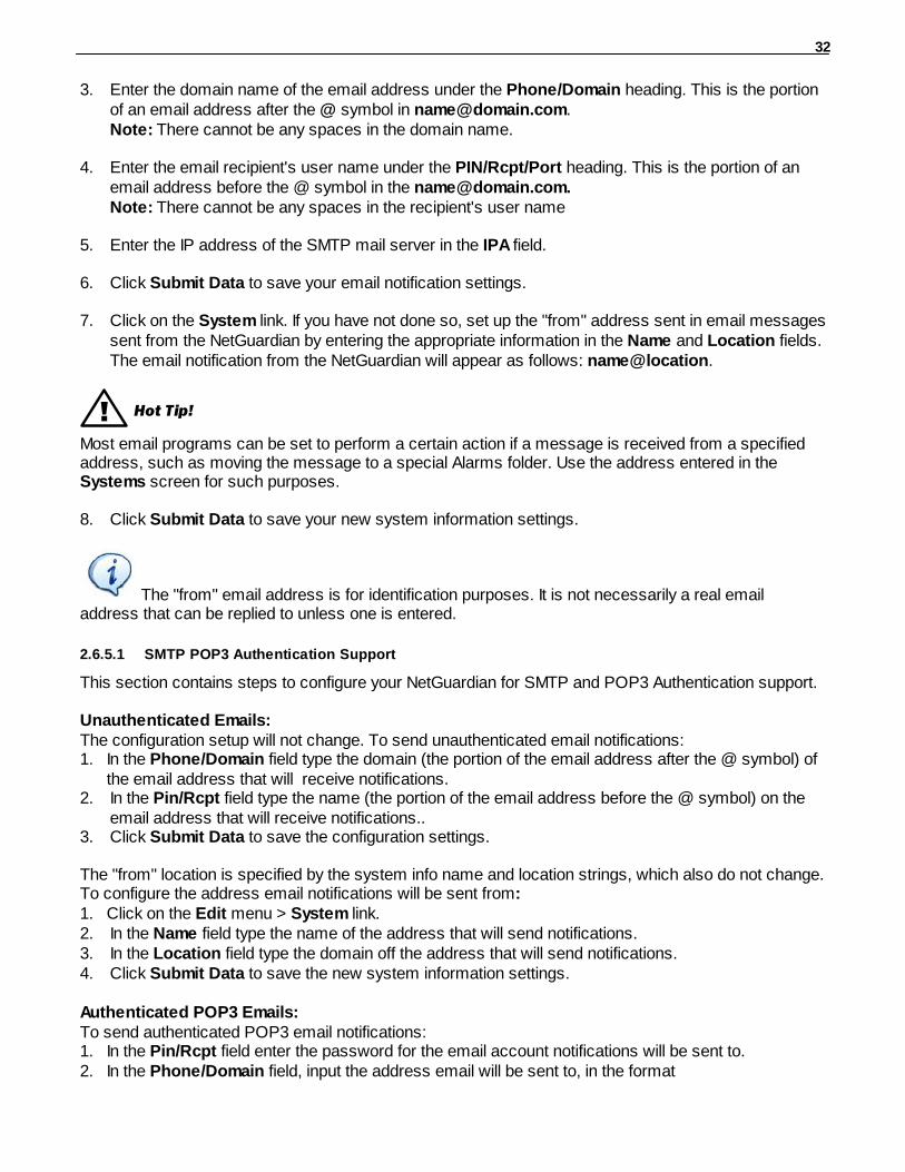
3. Enter the domain name of the email address under the Phone/Domain heading. This is the portionof an email address after the @ symbol in [email protected]: There cannot be any spaces in the domain name.
4. Enter the email recipient's user name under the PIN/Rcpt/Port heading. This is the portion of anemail address before the @ symbol in the [email protected]. Note: There cannot be any spaces in the recipient's user name
5. Enter the IP address of the SMTP mail server in the IPA field.
6. Click Submit Data to save your email notification settings.
7. Click on the System link. If you have not done so, set up the "from" address sent in email messagessent from the NetGuardian by entering the appropriate information in the Name and Location fields.The email notification from the NetGuardian will appear as follows: name@location.
! Hot Tip!
Most email programs can be set to perform a certain action if a message is received from a specifiedaddress, such as moving the message to a special Alarms folder. Use the address entered in the Systems screen for such purposes.
8. Click Submit Data to save your new system information settings.
The "from" email address is for identification purposes. It is not necessarily a real emailaddress that can be replied to unless one is entered.
2.6.5.1 SMTP POP3 Authentication Support
This section contains steps to configure your NetGuardian for SMTP and POP3 Authentication support.
Unauthenticated Emails:The configuration setup will not change. To send unauthenticated email notifications:1. In the Phone/Domain field type the domain (the portion of the email address after the @ symbol) of
the email address that will receive notifications.2. In the Pin/Rcpt field type the name (the portion of the email address before the @ symbol) on the
email address that will receive notifications..3. Click Submit Data to save the configuration settings.
The "from" location is specified by the system info name and location strings, which also do not change.To configure the address email notifications will be sent from:1. Click on the Edit menu > System link.2. In the Name field type the name of the address that will send notifications.3. In the Location field type the domain off the address that will send notifications.4. Click Submit Data to save the new system information settings.
Authenticated POP3 Emails:To send authenticated POP3 email notifications:1. In the Pin/Rcpt field enter the password for the email account notifications will be sent to.2. In the Phone/Domain field, input the address email will be sent to, in the format
33
"[email protected]" for POP before SMTP authentication.3. Click Submit Data to save your changes.4. Click on the Edit menu > System link.5. In the Name field type the name of the address you want to receive notifications from the
NetGuardian (the part of the email address coming before the @ symbol - [email protected]).6. In the Location field type the domain of the address you want to receive notifications from the
NetGuardian (this is the part of the address coming after the @ symbol - [email protected]).7. Click Submit Data to save the new system information settings.
Authenticated SMTP Emails:To send authenticated SMTP email notifications: 1. In the Pin/Rcpt field enter the password for the email acount that notifications willl be sent to. 2. In the Phone/Domain field, input the address email will be sent to, in the format
"user:yourdomain.com" (Note the ':' in place of '@').3. Click Submit Data too save your changes.4. Click on the Edit menu > System link. 5. In the Name field, type the name of the address that you want to receive notifications from the
NetGuardian (the part of the email address coming before the @ symbol - [email protected]).6. In the Location field type the domain of the address you want to receive notifications from the
NetGuardian (this is the part of the address coming after the @ symbol - [email protected]).
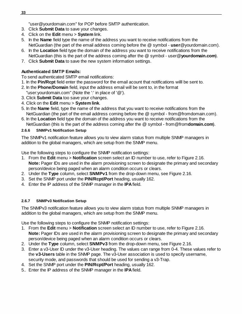
2.6.6 SNMPv1 Notification Setup
The SNMPv1 notification feature allows you to view alarm status from multiple SNMP managers inaddition to the global managers, which are setup from the SNMP menu.
Use the following steps to configure the SNMP notification settings:1. From the Edit menu > Notification screen select an ID number to use, refer to Figure 2.16.
Note: Pager IDs are used in the alarm provisioning screen to designate the primary and secondaryperson/device being paged when an alarm condition occurs or clears.
2. Under the Type column, select SNMPv1 from the drop-down menu, see Figure 2.16.3. Set the SNMP port under the PIN/Rcpt/Port heading, usually 162.4. Enter the IP address of the SNMP manager in the IPA field.
2.6.7 SNMPv3 Notification Setup
The SNMPv3 notification feature allows you to view alarm status from multiple SNMP managers inaddition to the global managers, which are setup from the SNMP menu.
Use the following steps to configure the SNMP notification settings:1. From the Edit menu > Notification screen select an ID number to use, refer to Figure 2.16.
Note: Pager IDs are used in the alarm provisioning screen to designate the primary and secondaryperson/device being paged when an alarm condition occurs or clears.
2. Under the Type column, select SNMPv3 from the drop-down menu, see Figure 2.16.3. Enter a v3-User ID under the v3-User heading. The values can range from 0-4. These values refer to
the v3-Users table in the SNMP page. The v3-User association is used to specify username,security mode, and passwords that should be used for sending a v3-Trap.
4. Set the SNMP port under the PIN/Rcpt/Port heading, usually 162.5.. Enter the IP address of the SNMP manager in the IPA field.
34
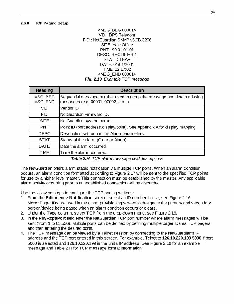
2.6.8 TCP Paging Setup
<MSG_BEG 00001>VID : DPS Telecom
FID : NetGuardian SNMP v5.0B.3206SITE: Yale OfficePNT : 99.01.01.01
DESC: RECTIFIER 1STAT: CLEAR
DATE: 01/01/2001TIME: 12:17:02
<MSG_END 00001>Fig. 2.19. Example TCP message
Heading Description
MSG_BEGMSG_END
Sequential message number used to group the message and detect missingmessages (e.g. 00001, 00002, etc...).
VID Vendor ID
FID NetGuardian Firmware ID.
SITE NetGuardian system name.
PNT Point ID (port.address.display.point). See Appendix A for display mapping.
DESC Description set forth in the Alarm parameters.
STAT Status of the alarm (Clear or Alarm).
DATE Date the alarm occurred.
TIME Time the alarm occurred.
Table 2.H. TCP alarm message field descriptions
The NetGuardian offers alarm status notification via multiple TCP ports. When an alarm conditionoccurs, an alarm condition formatted according to Figure 2.17 will be sent to the specified TCP pointsfor use by a higher level master. This connection must be established by the master. Any applicablealarm activity occurring prior to an established connection will be discarded.
Use the following steps to configure the TCP paging settings:1. From the Edit menu> Notification screen, select an ID number to use, see Figure 2.16.
Note: Pager IDs are used in the alarm provisioning screen to designate the primary and secondaryperson/device being paged when an alarm condition occurs or clears.
2. Under the Type column, select TCP from the drop-down menu, see Figure 2.16.3. In the Pin/Rcpt/Port field enter the NetGuardian TCP port number where alarm messages will be
sent (from 1 to 65,536). Multiple ports can be defined by defining multiple pager IDs as TCP pagersand then entering the desired ports.
4. The TCP message can be viewed by a Telnet session by connecting to the NetGuardian's IPaddress and the TCP port entered in this screen. For example, Telnet to 126.10.220.199 5000 if port5000 is selected and 126.10.220.199 is the unit's IP address. See Figure 2.19 for an examplemessage and Table 2.H for TCP message format information.

35
2.6.9 Num17 Pager Setup
The Num17 Pager can receive point addresses of alarms. It is quite similar to the Numeric Pagingformat in the way it receives and reports alarms. However, on certain pager systems the symbol * willcause a freeze or other undesirable situations. Num17 eliminates the * symbol from the pages itreceives and reports alarms as a 17-digit series of numbers.
Use the following steps to configure Num17 Pager settings:1. From the Edit menu > Notification screen select an ID number to use, refer to Figure 2.16.
Note: Pager IDs are used in the alarm provisioning screen to designate the primary and secondaryperson/device being paged when an alarm condition occurs or clears.
2. Under the Type column select Num17 from the drop-down menu, see Figure 2.16.
3. Enter the phone number of the numeric pager under the Phone heading, followed by commas (forexample 555-1212,,,,,,,). Placing a comma after the phone number initiates a two second pause percomma. This allows enough time for the pager to answer before the NetGuardian sends the alarminformation. The Baud/Wfmt and IPA fields are not used from Num17 pager types.
4. Click Submit Data to save the configuration settings.
2.6.10 Echo Notification Setup
As of firmware 5.0K and above. An Echo notification type enables an alarm point on the NetGuardian G5to operate a control on another SNMP remote from DPS.
1. From the Notification devices tab, choose Echo as the notification Type.
2. Enter the Community Set Name in the Phone/Domain field.
3. Enter the Relay Point Reference in the Pin/Pcpt/Port field. This is entered as:[Port].[Address].[Display].[Relay Point] NOTE: The Port will always be 99, and the address is always 1. Therefore,your entries will always begin with 99.1.
4. The Baud/WFmt and Group fields will not be used.
5. Under IPA, enter in the IP address of the SNMP-enabled, DPS remote you are setting up to operateits relay.
NOTE: If more than one point is mapped to Echo notification, the OR'ed logic is applied.

36
Defining Point Groups2.7
Each NetGuardian Alarm point can be assigned to one of eight groups, which are identified with a user-defined label. Once the point groups are defined, the Point Group IDs can be used to group base andsystem alarms, see section "Configuring Base Discrete Alarms."
Use the following steps to define alarm messages for alarm point groups:1. To define the point groups, select Point Group from the Edit menu.2. Then enter the appropriate descriptions in the Description, When Set and When Clear fields for
each point group.3. Click Submit Data to save the point group settings.
Fig. 2.20. Define the Alarm and Clear messages for up to eight different point groups
37
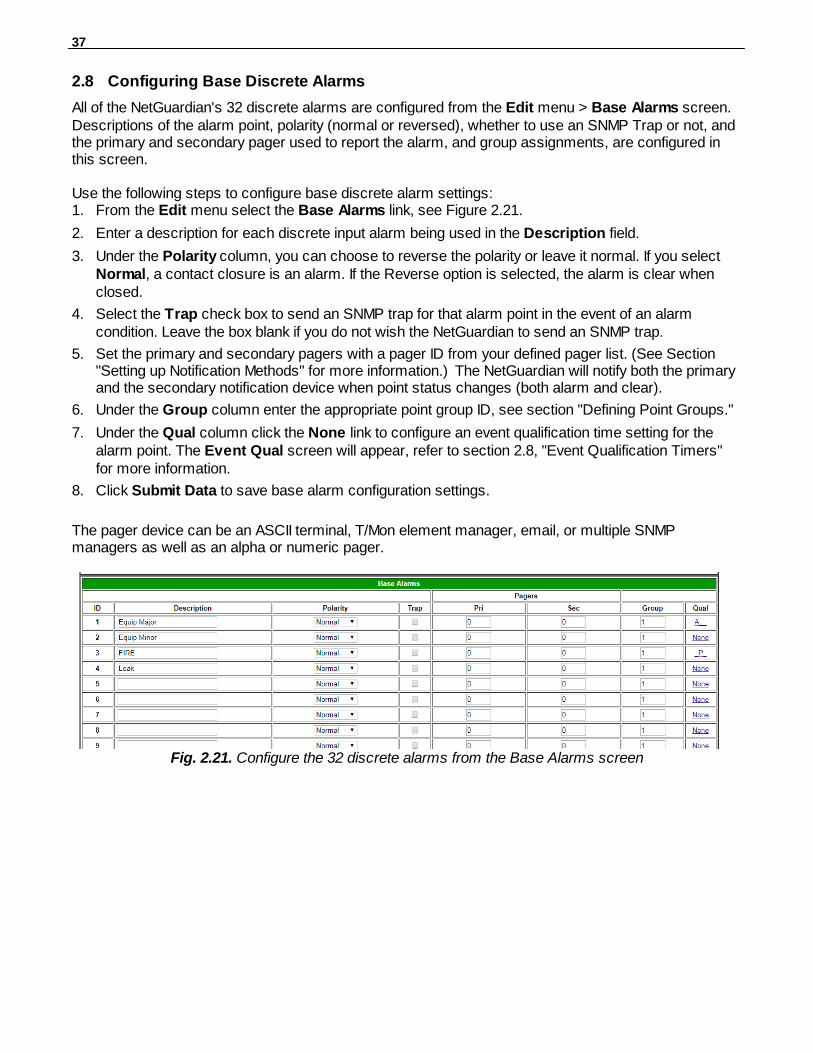
Configuring Base Discrete Alarms2.8
All of the NetGuardian's 32 discrete alarms are configured from the Edit menu > Base Alarms screen.Descriptions of the alarm point, polarity (normal or reversed), whether to use an SNMP Trap or not, andthe primary and secondary pager used to report the alarm, and group assignments, are configured inthis screen.
Use the following steps to configure base discrete alarm settings:1. From the Edit menu select the Base Alarms link, see Figure 2.21.
2. Enter a description for each discrete input alarm being used in the Description field.
3. Under the Polarity column, you can choose to reverse the polarity or leave it normal. If you selectNormal, a contact closure is an alarm. If the Reverse option is selected, the alarm is clear whenclosed.
4. Select the Trap check box to send an SNMP trap for that alarm point in the event of an alarmcondition. Leave the box blank if you do not wish the NetGuardian to send an SNMP trap.
5. Set the primary and secondary pagers with a pager ID from your defined pager list. (See Section"Setting up Notification Methods" for more information.) The NetGuardian will notify both the primaryand the secondary notification device when point status changes (both alarm and clear).
6. Under the Group column enter the appropriate point group ID, see section "Defining Point Groups."
7. Under the Qual column click the None link to configure an event qualification time setting for thealarm point. The Event Qual screen will appear, refer to section 2.8, "Event Qualification Timers"for more information.
8. Click Submit Data to save base alarm configuration settings.
The pager device can be an ASCII terminal, T/Mon element manager, email, or multiple SNMPmanagers as well as an alpha or numeric pager.
Fig. 2.21. Configure the 32 discrete alarms from the Base Alarms screen
38
Event Qualification Timers2.9
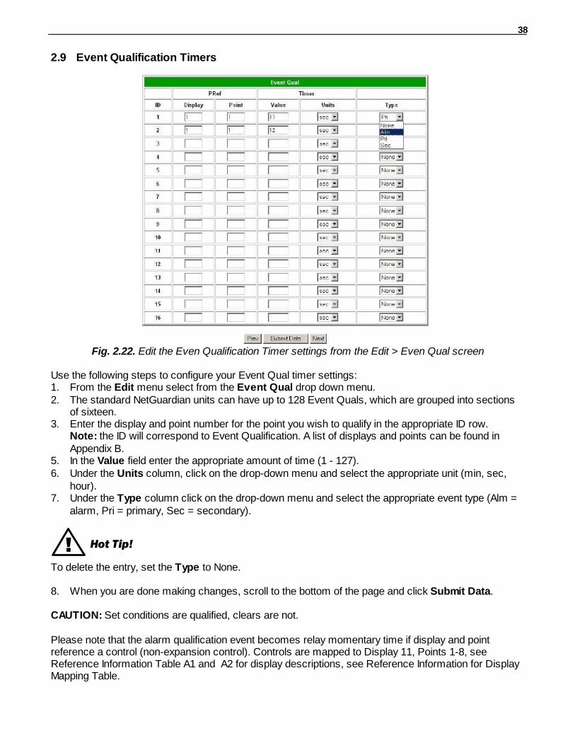
Fig. 2.22. Edit the Even Qualification Timer settings from the Edit > Even Qual screen
Use the following steps to configure your Event Qual timer settings:1. From the Edit menu select from the Event Qual drop down menu. 2. The standard NetGuardian units can have up to 128 Event Quals, which are grouped into sections
of sixteen.3. Enter the display and point number for the point you wish to qualify in the appropriate ID row.
Note: the ID will correspond to Event Qualification. A list of displays and points can be found inAppendix B.
5. In the Value field enter the appropriate amount of time (1 - 127).6. Under the Units column, click on the drop-down menu and select the appropriate unit (min, sec,
hour).7. Under the Type column click on the drop-down menu and select the appropriate event type (Alm =
alarm, Pri = primary, Sec = secondary).
! Hot Tip!
To delete the entry, set the Type to None.
8. When you are done making changes, scroll to the bottom of the page and click Submit Data.
CAUTION: Set conditions are qualified, clears are not.
Please note that the alarm qualification event becomes relay momentary time if display and pointreference a control (non-expansion control). Controls are mapped to Display 11, Points 1-8, seeReference Information Table A1 and A2 for display descriptions, see Reference Information for DisplayMapping Table.

39
Also, you must set the Type field first, before attempting to edit other data for each ID. To setup EventQualification Timers, follow the instructions below:
1. Choose the Event Qual tab from the menu selections2. Enter the ID of the Event qual you would like to modify, 3. Then input the Type, Display, Point, Value
and Timer units for each ID. Where Display is 1 - 16, Point is the qualifying alarm point. The Timervalue can be set in units of seconds, minutes or hour units. The Type options are Alarm, PrimaryPager, Secondary Pager, or None. Please note, if you select None from the Type menu, your entrywill be deleted.
3. Click the Save button.
40
Setting System Alarm Notifications2.10
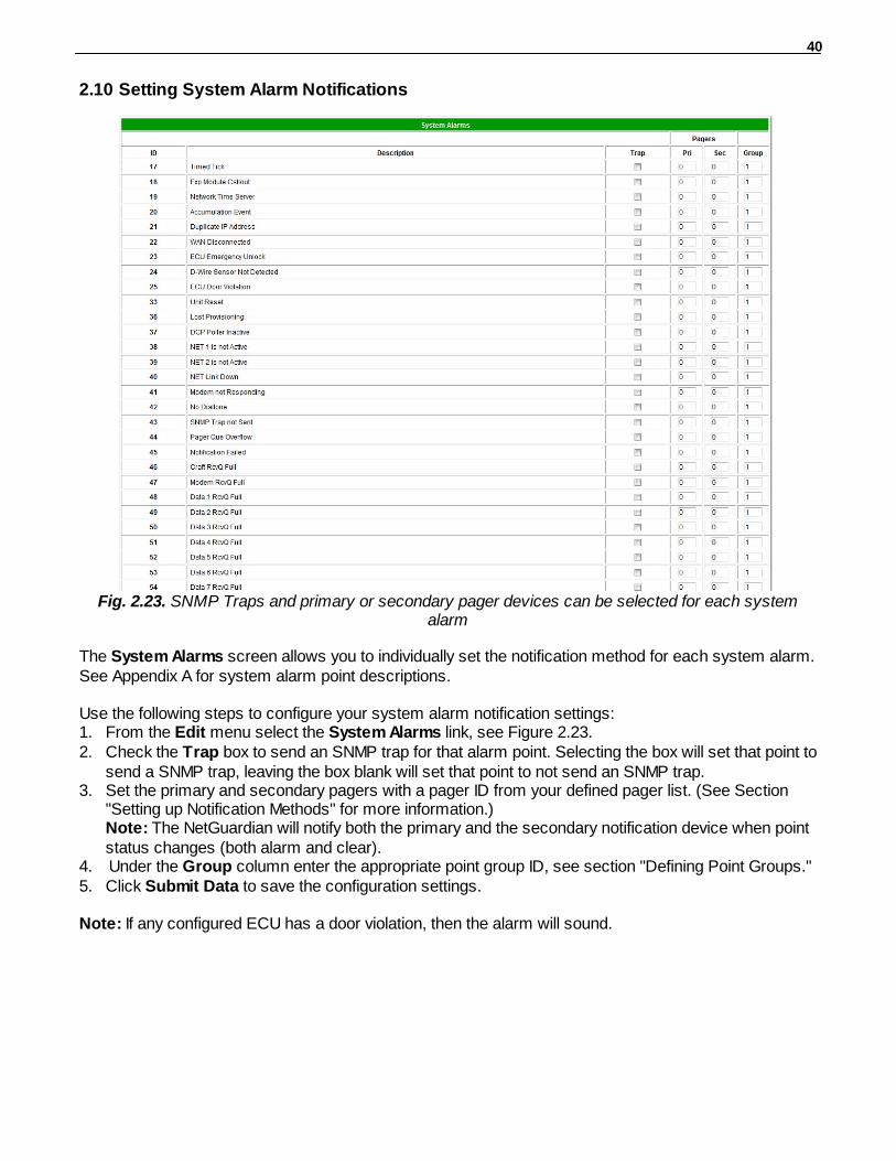
Fig. 2.23. SNMP Traps and primary or secondary pager devices can be selected for each systemalarm
The System Alarms screen allows you to individually set the notification method for each system alarm.See Appendix A for system alarm point descriptions.
Use the following steps to configure your system alarm notification settings:1. From the Edit menu select the System Alarms link, see Figure 2.23.2. Check the Trap box to send an SNMP trap for that alarm point. Selecting the box will set that point to
send a SNMP trap, leaving the box blank will set that point to not send an SNMP trap. 3. Set the primary and secondary pagers with a pager ID from your defined pager list. (See Section
"Setting up Notification Methods" for more information.)Note: The NetGuardian will notify both the primary and the secondary notification device when pointstatus changes (both alarm and clear).
4. Under the Group column enter the appropriate point group ID, see section "Defining Point Groups."5. Click Submit Data to save the configuration settings.
Note: If any configured ECU has a door violation, then the alarm will sound.
41
Variable Bindings2.11
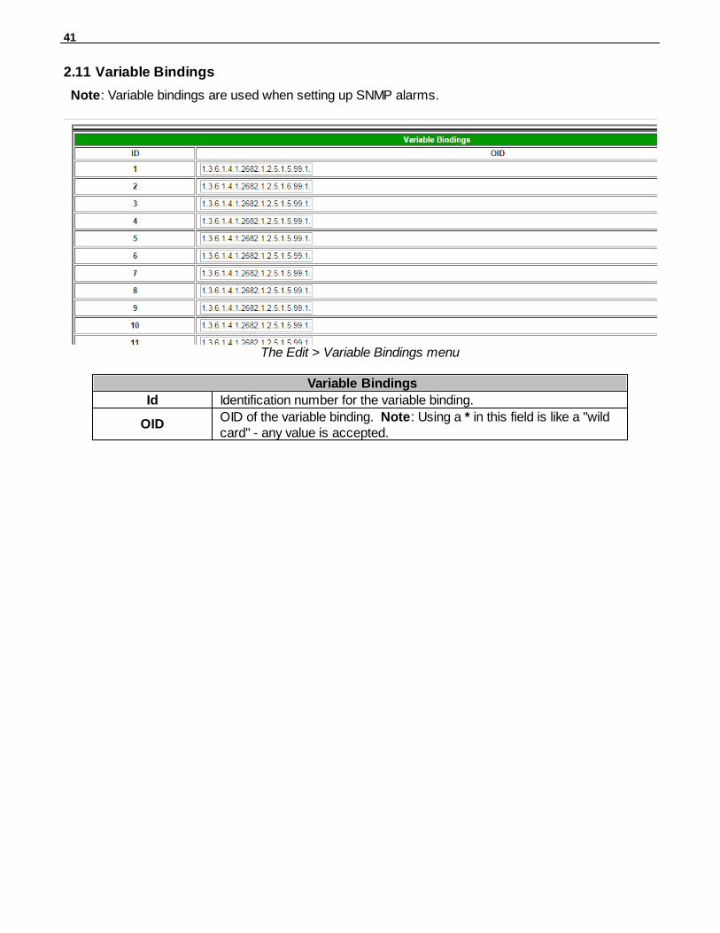
Note: Variable bindings are used when setting up SNMP alarms.
The Edit > Variable Bindings menu
Variable Bindings
Id Identification number for the variable binding.
OIDOID of the variable binding. Note: Using a * in this field is like a "wildcard" - any value is accepted.
42
SNMP Alarms2.12
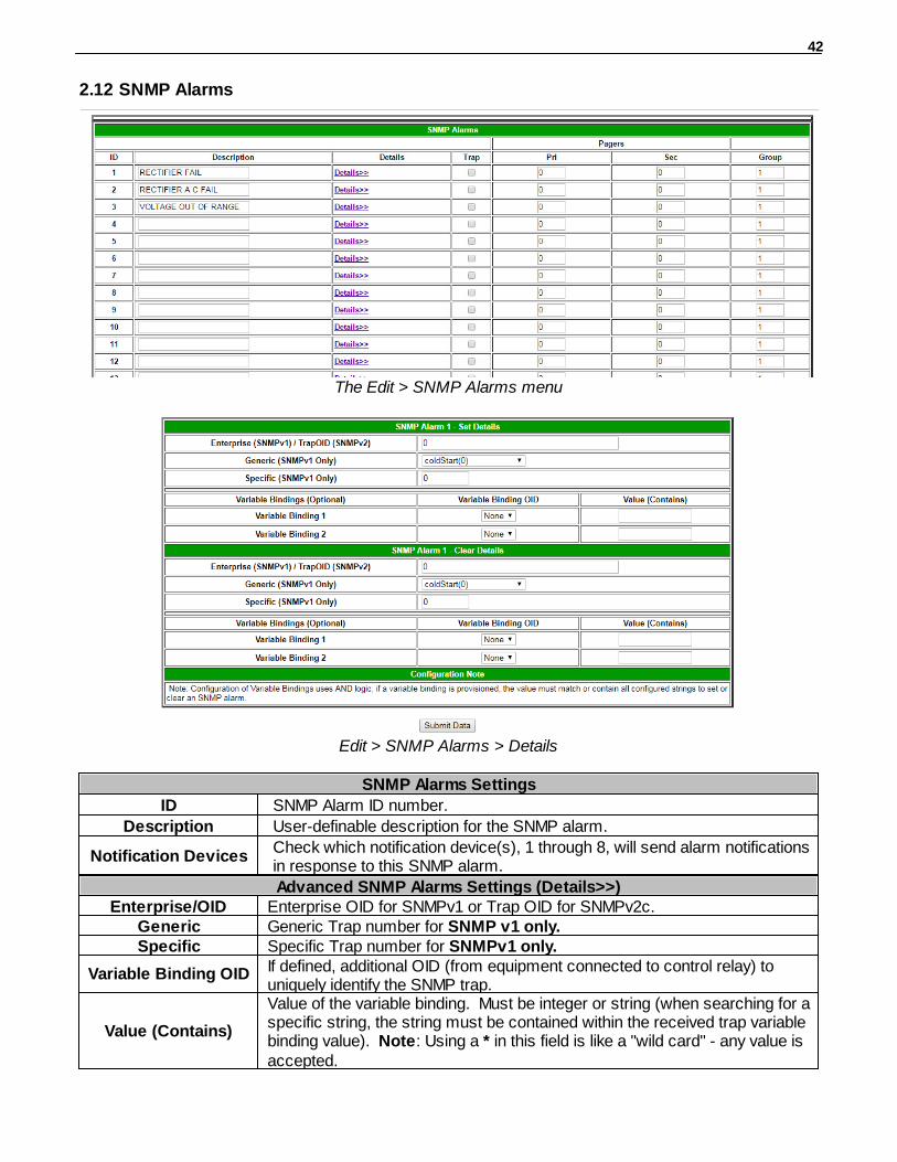
The Edit > SNMP Alarms menu
Edit > SNMP Alarms > Details
SNMP Alarms Settings
ID SNMP Alarm ID number.
Description User-definable description for the SNMP alarm.
Notification DevicesCheck which notification device(s), 1 through 8, will send alarm notificationsin response to this SNMP alarm.
Advanced SNMP Alarms Settings (Details>>)Enterprise/OID Enterprise OID for SNMPv1 or Trap OID for SNMPv2c.
Generic Generic Trap number for SNMP v1 only.Specific Specific Trap number for SNMPv1 only.
Variable Binding OID If defined, additional OID (from equipment connected to control relay) touniquely identify the SNMP trap.
Value (Contains)
Value of the variable binding. Must be integer or string (when searching for aspecific string, the string must be contained within the received trap variablebinding value). Note: Using a * in this field is like a "wild card" - any value isaccepted.
43
Configure the Accumulation Timer2.13
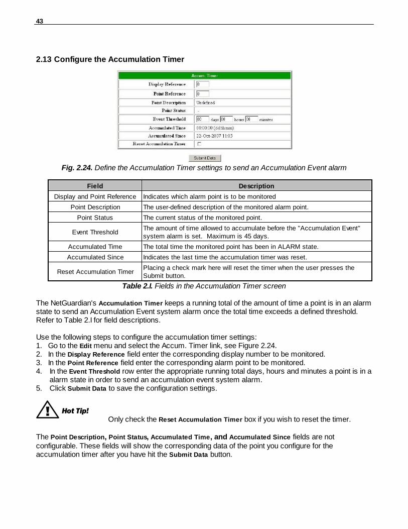
Fig. 2.24. Define the Accumulation Timer settings to send an Accumulation Event alarm
Field Description
Display and Point Reference Indicates which alarm point is to be monitored
Point Description The user-defined description of the monitored alarm point.
Point Status The current status of the monitored point.
Event ThresholdThe amount of time allowed to accumulate before the "Accumulation Event"system alarm is set. Maximum is 45 days.
Accumulated Time The total time the monitored point has been in ALARM state.
Accumulated Since Indicates the last time the accumulation timer was reset.
Reset Accumulation TimerPlacing a check mark here will reset the timer when the user presses theSubmit button.
Table 2.I. Fields in the Accumulation Timer screen
The NetGuardian's Accumulation Timer keeps a running total of the amount of time a point is in an alarmstate to send an Accumulation Event system alarm once the total time exceeds a defined threshold.Refer to Table 2.I for field descriptions.
Use the following steps to configure the accumulation timer settings:1. Go to the Edit menu and select the Accum. Timer link, see Figure 2.24.2. In the Display Reference field enter the corresponding display number to be monitored.3. In the Point Reference field enter the corresponding alarm point to be monitored.4. In the Event Threshold row enter the appropriate running total days, hours and minutes a point is in a
alarm state in order to send an accumulation event system alarm.5. Click Submit Data to save the configuration settings.
! Hot Tip!Only check the Reset Accumulation Timer box if you wish to reset the timer.
The Point Description, Point Status, Accumulated Time, and Accumulated Since fields are notconfigurable. These fields will show the corresponding data of the point you configure for theaccumulation timer after you have hit the Submit Data button.
44
Configuring Ping Targets2.14
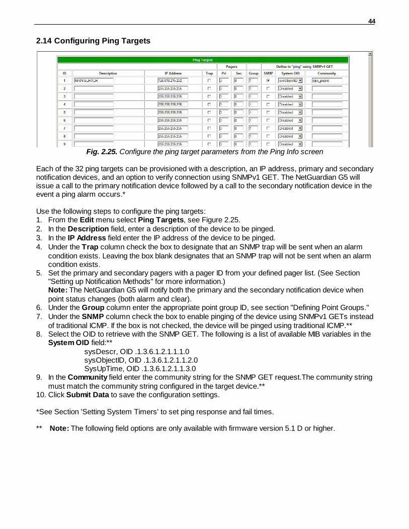
Fig. 2.25. Configure the ping target parameters from the Ping Info screen
Each of the 32 ping targets can be provisioned with a description, an IP address, primary and secondarynotification devices, and an option to verify connection using SNMPv1 GET. The NetGuardian G5 willissue a call to the primary notification device followed by a call to the secondary notification device in theevent a ping alarm occurs.*
Use the following steps to configure the ping targets:1. From the Edit menu select Ping Targets, see Figure 2.25.2. In the Description field, enter a description of the device to be pinged.3. In the IP Address field enter the IP address of the device to be pinged.4. Under the Trap column check the box to designate that an SNMP trap will be sent when an alarm
condition exists. Leaving the box blank designates that an SNMP trap will not be sent when an alarmcondition exists.
5. Set the primary and secondary pagers with a pager ID from your defined pager list. (See Section"Setting up Notification Methods" for more information.)Note: The NetGuardian G5 will notify both the primary and the secondary notification device whenpoint status changes (both alarm and clear).
6. Under the Group column enter the appropriate point group ID, see section "Defining Point Groups."7. Under the SNMP column check the box to enable pinging of the device using SNMPv1 GETs instead
of traditional ICMP. If the box is not checked, the device will be pinged using traditional ICMP.**8. Select the OID to retrieve with the SNMP GET. The following is a list of available MIB variables in the
System OID field:**sysDescr, OID .1.3.6.1.2.1.1.1.0sysObjectID, OID .1.3.6.1.2.1.1.2.0SysUpTime, OID .1.3.6.1.2.1.1.3.0
9. In the Community field enter the community string for the SNMP GET request.The community stringmust match the community string configured in the target device.**
10. Click Submit Data to save the configuration settings.
*See Section 'Setting System Timers' to set ping response and fail times.
** Note: The following field options are only available with firmware version 5.1 D or higher.
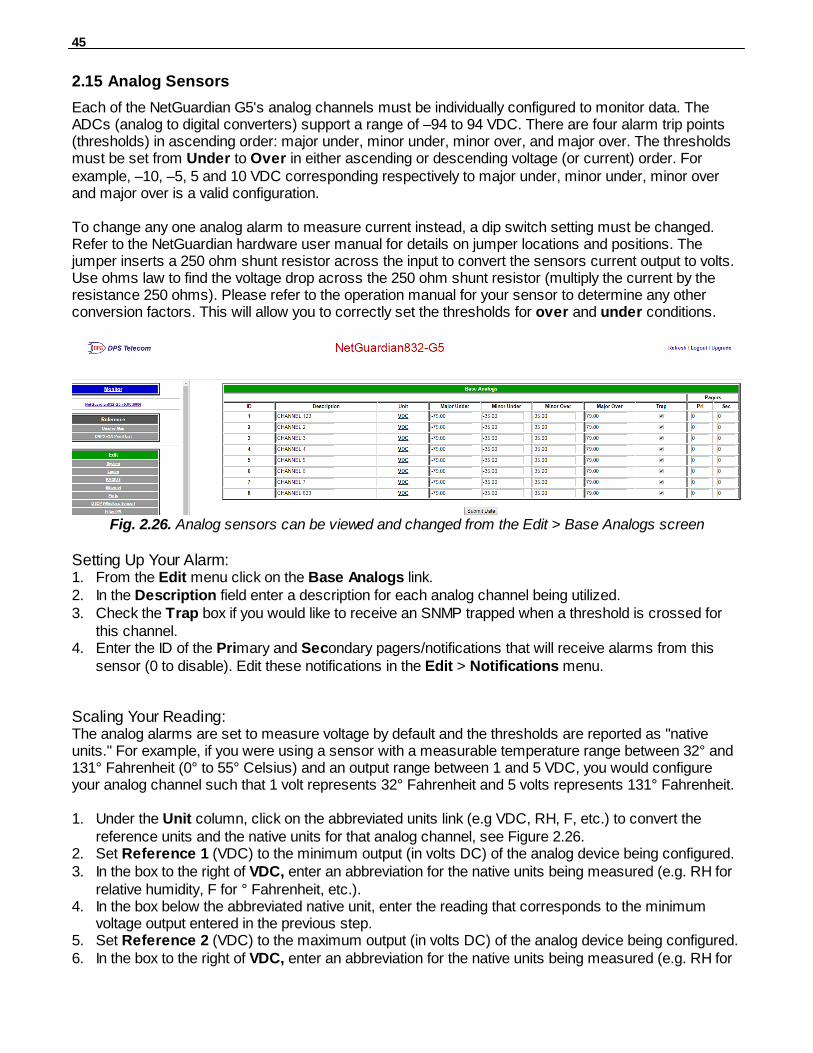
45
Analog Sensors2.15
Each of the NetGuardian G5's analog channels must be individually configured to monitor data. TheADCs (analog to digital converters) support a range of –94 to 94 VDC. There are four alarm trip points(thresholds) in ascending order: major under, minor under, minor over, and major over. The thresholdsmust be set from Under to Over in either ascending or descending voltage (or current) order. Forexample, –10, –5, 5 and 10 VDC corresponding respectively to major under, minor under, minor overand major over is a valid configuration.
To change any one analog alarm to measure current instead, a dip switch setting must be changed.Refer to the NetGuardian hardware user manual for details on jumper locations and positions. Thejumper inserts a 250 ohm shunt resistor across the input to convert the sensors current output to volts.Use ohms law to find the voltage drop across the 250 ohm shunt resistor (multiply the current by theresistance 250 ohms). Please refer to the operation manual for your sensor to determine any otherconversion factors. This will allow you to correctly set the thresholds for over and under conditions.
Fig. 2.26. Analog sensors can be viewed and changed from the Edit > Base Analogs screen
Setting Up Your Alarm:1. From the Edit menu click on the Base Analogs link.2. In the Description field enter a description for each analog channel being utilized.3. Check the Trap box if you would like to receive an SNMP trapped when a threshold is crossed for
this channel.4. Enter the ID of the Primary and Secondary pagers/notifications that will receive alarms from this
sensor (0 to disable). Edit these notifications in the Edit > Notifications menu.
Scaling Your Reading:The analog alarms are set to measure voltage by default and the thresholds are reported as "nativeunits." For example, if you were using a sensor with a measurable temperature range between 32° and131° Fahrenheit (0° to 55° Celsius) and an output range between 1 and 5 VDC, you would configureyour analog channel such that 1 volt represents 32° Fahrenheit and 5 volts represents 131° Fahrenheit.
1. Under the Unit column, click on the abbreviated units link (e.g VDC, RH, F, etc.) to convert thereference units and the native units for that analog channel, see Figure 2.26.
2. Set Reference 1 (VDC) to the minimum output (in volts DC) of the analog device being configured.3. In the box to the right of VDC, enter an abbreviation for the native units being measured (e.g. RH for
relative humidity, F for ° Fahrenheit, etc.).4. In the box below the abbreviated native unit, enter the reading that corresponds to the minimum
voltage output entered in the previous step.5. Set Reference 2 (VDC) to the maximum output (in volts DC) of the analog device being configured.6. In the box to the right of VDC, enter an abbreviation for the native units being measured (e.g. RH for
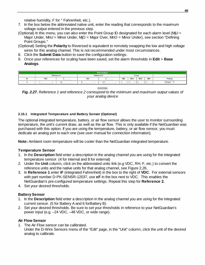
46
relative humidity, F for ° Fahrenheit, etc.).7. In the box below the abbreviated native unit, enter the reading that corresponds to the maximum
voltage output entered in the previous step.(Optional) In this menu, you can also enter the Point Group ID designated for each alarm level (MjU =
Major Under, MnU = Minor Under, MjO = Major Over, MnO = Minor Under), see section "DefiningPoint Groups."
(Optional) Setting the Polarity to Reversed is equivalent to remotely swapping the low and high voltagewires for this analog channel. This is not recommended under most circumstances.
8. Click the Submit Data button to save the configuration settings.9. Once your references for scaling have been saved, set the alarm thresholds in Edit > Base
Analogs.
Fig. 2.27. Reference 1 and reference 2 correspond to the minimum and maximum output values ofyour analog device
2.15.1 Integrated Temperature and Battery Sensor (Optional)
The optional integrated temperature, battery, or air flow sensor allows the user to monitor surroundingtemperature, the unit's current draw, as well as the air flow. This is only available if the NetGuardian waspurchased with this option. If you are using the temperature, battery, or air flow sensor, you mustdedicate an analog port to each one (see user manual for connection information).
Note: Ambient room temperature will be cooler than the NetGuardian integrated temperature.
Temperature Sensor1. In the Description field enter a description in the analog channel you are using for the integrated
temperature sensor. (4 for internal and 8 for external)2. Under the Unit column, click on the abbreviated units link (e.g VDC, RH, F, etc.) to convert the
reference units and the native units for that analog channel, see Figure 2.26.3. In Reference 1 enter iF (integrated Fahrenheit) in the box to the right of VDC. For external sensors
with part number D-PK-SENSR-12037, use eF in the box next to VDC. This enables theNetGuardian's pre-configured temperature settings. Repeat this step for Reference 2.
4. Set your desired thresholds.
Battery Sensor1. In the Description field enter a description in the analog channel you are using for the integrated
current sensor. (5 for Battery A and 6 forBattery B) 2. Set your desired thresholds. Be sure to set your thresholds in reference to your NetGuardian's
power input (e.g. –24 VDC, –48 VDC, or wide range).
Air Flow Sensor1. The Air Flow sensor can be calibrated.
Under the D-Wire Sensors menu of the "Edit" page, in the "Unit" column, click the unit of the desiredanalog to calibrate.
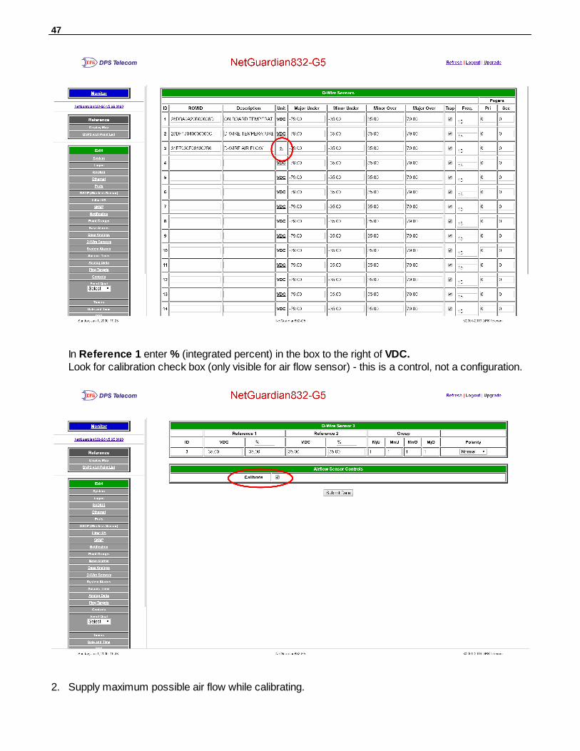
47
In Reference 1 enter % (integrated percent) in the box to the right of VDC.Look for calibration check box (only visible for air flow sensor) - this is a control, not a configuration.
2. Supply maximum possible air flow while calibrating.

48
You can view the calibration progress in the D-Wire Sensors Monitor page.
The first part of the calibration should display the qual percentage, followed by the calibrationpercentage.Once calibration finishes, same air flow should result in 100%.
2.15.2 D-Wire Sensors (Optional)
Fig. 2.28. D-Wire Sensors menu
If this NetGuardian G5 has support for D-Wire sensors, a link will appear in the Edit menu sidebar. Theinterface will resemble the Edit > Base Analogs menu, but with two new columns: ROMID and Freq.Any detected or configured sensor will automatically fill out a ROMID cell. The color of each cell willsignify its configuration status: If the ROMID cell is yellow, the sensor is detected but is not yetconfigured. If the cell is red, then the sensor is configured but has not been detected, and the "D-WireSensor Not Detected" System Alarm will set. The "Unit" field will automatically be configured uponsubmission, no changes should be made to this field for D-Wire sensors. The Freq. columndetermines how often (in minutes) the unit logs each sensor to a .csv file.
Note: The page must be submitted in order to configure the detected ROMID(s). It may take up to oneminute for a newly attached sensor to register in the Edit or Monitor interface.

49
2.15.3 Analog Polarity Override
iF : integrated temperature sensor in fahrenheit or iC for celsius oV+ : override polarity VDC to positiveoV- : override polarity VDC to negative
If you have a positive powered NetGuardian, you may want to use this feature if you are using theinternal battery sensor. The Web Browser Interface will override oV+ and oV- tags and show VDC. Soyou won't have to view an uncommon looking tag while in monitor mode.
Analog Accuracy:+/- 1% of analog range.
Analog Step Sizes
Input Voltage Range Resolution (Step Size)
0-5 V .0015 V
5-14 V .0038 V
14-30 V .0081 V
30-70 V .0182 V
70-90 V .0231 V
Table 2.J. Analog step sizes
2.15.4 Analog Delta
Sometimes, simply checking the alarm threshold values of your analog sensors is not enough. TheAnalog Delta feature allows you to define a discrete alarm to be triggered when your analog valuechanges too quickly, even if it does not reach an alarm threshold. For example, if temperature orpressure begins rapidly changing, which can cause damage to sensitive equipment.
In the Edit > Analog Delta menu, you can define a time period and maximum acceptable delta that willlet your NetGuardian know how quickly a value is allowed to change, and how often to check for achange.
Field DescriptionAnalog Type What kind of analog sensor is being monitored (Base,
expansion, D-wire).
Analog Number
Which analog channel of the above type is being monitored. Ex. "Base Analogs" and "1" would correspond to the first baseanalog in Edit > Base Analogs. "D-Wire Sensors" and "4" would
50
correspond to the fourth D-wire sensor field in Edit > D-WireSensors (which may not be the fourth node in the daisy chain, ifany previous node uses more than one field).
Acceptable Delta
The maximum amount that the analog reading can change withinthe given time period, in either direction, before the Analog Deltaalarm is triggered.
Note: The difference measured is computed from the scaledreading of the analog channel, not the raw voltage difference.See "Analog Sensors" for more info on linear scaling usingReference 1 and Reference 2.
Time Period How often the NetGuardian checks the analog value for achange.
Alarm Display/Point
Which discrete point on the Display Map that the Analog Deltaalarm will use. (Defaults to Display 2 Point 32, or the last PingTarget field.)
Note: This alarm should only be mapped to Displays 1 and 2,which correspond to Base Alarms and Ping Targets,respectively. If your NetGuardian is an 832A instead of a 864A,Display 1 Points 33-64 will be unavailable. Do not map theAnalog Delta alarm to a ping target or discrete alarm that isalready in use.

51
Once the Analog Delta alarm is set to a valid configuration, the Current Stats and Previous Alarmmonitoring menus will appear underneath, in blue. Current Stats will show the most recent deltacalculation, and Previous Alarm will show the most recent delta that was large enough to trigger thealarm.
A delta is calculated that exceeds the defined maximum.
The information from that delta is stored under the Previous Alarm header.

52
Configuring the Control Relays2.16
Fig. 2.29. Configure controls in the Edit menu > Controls screen
The Relays of the NetGuardian G5 can be identified and configured using the Edit menu > Controlsscreen. A description can be entered for each of the relays. You can also designate whether or not tosend SNMP Traps when a relay is actuated. Relays are normally open (N/O) by default. A circuit boardjumper can be changed for each control to make it normally closed (N/C). Refer to the NetGuardian usermanual for PCB settings and jumper positions.
1. From the Edit menu, select the Controls link, see figure above.2. In the Description field enter a description for each control/relay being used.3. Set the Energize State to either Normal or Inverted. Selecting Normal sets the relay's normal
electrical state to De-energized. Selecting Inverted sets the relay's normal electrical state toEnergized.
4. Check the Trap box to send an SNMP trap for that alarm point. Selecting the box will set that pointto send a SNMP trap, leaving the box blank will set that point to not send an SNMP trap.
5. Under the Group column enter the appropriate point group ID, see section "Defining Point Groups."6. Click Submit Data to save the configuration settings.
! Hot Tip!
The Energize State is different than the normal state of the physical contact closure position of eachrelay, which is determined by circuit board jumpers. This gives you the added benefit of being able tomonitor the wire. In the event of a power failure, the relay would de-energize back to it's normal physicalcontact closure set by the circuit board jumper for that relay. Check your jumper settings and relayconnections before setting to Normal or Inverted. Refer to the NetGuardian manual for jumper settingsand relay connection options.
4. Check the Trap box designate an SNMP trap when a control point operates.5. Click Submit Data to save the configuration settings.
2.16.1 Advanced Controls Build Option
When encountering the Edit Controls interface with the Advanced Controls build option, you'll see anadditional checkbox below the main window titled 'Enable Advanced Features'. These advancedfeatures control the timing for a generator and are used to charge the batteries. To configure advancedcontrols settings, select this checkbox.

53
NOTE: Selecting the 'Enable Advanced Features' checkbox will occupy control relay slots #1 and #2.
Edit Controls > Enable Advanced Features
Monitoring Trigger This selects which severity level will cause Control #1 to latch and startthe generator. The Battery Monitoring feature monitors analog channels 5and/or 6 (Battery A and B).
Generator Warm-Up Time Determines how long the generator will run before Control #2 latches,initiating the battery charging. Can be configured in seconds, minutes orhours, within a range of 1 - 120.
Battery Charge Time Determines how long the batteries will charge until Control #2 releases.Can be configured in seconds, minutes or hours, within a range of 1 - 120.
Generator Cooldown Time Determines how long the generator will cooldown until Control #1releases. Can be configured in seconds, minutes or hours, within a rangeof 1 - 120.
Once you have configured your settings, press the 'Submit Data' button. In order for the changes totake effect, you will need to reboot your NetGuardian 832/864 G5 device.
2.16.2 Activating Relays from an Alarm Point's Change of Status
The NetGuardian allows the user to echo an alarm point state to activate a relay. Any of theNetGuardian's discrete alarms, system alarms, ping alarms, or analog alarms may be echoed toactivate a relay in the event that alarm is triggered. However, a relay set to echo an alarm point cannotbe manually activated. To allow the relay to be manually activated while still maintaining its echoedstatus, the relay point must be set to ORed.
2.16.2.1 Echoing alarm points to relays
In the Description field (see Figure 2.29) enter the display, alarm point, a dash (-), and the descriptionof the alarm you wish to echo. For example, if echoing discrete alarm 8, enter 01.08-your alarmdescription. (The display and alarm point are formatted as DD.PP, where DD = the display number andPP = the point number or GX where X is the group number) See Appendix A for a complete list ofdisplay and point numbers.
2.16.2.2 Oring echoed alarm points
In the Description field enter the display, alarm point, an under bar (_), and the description of the alarmyou wish to set to ORed. For example, if ORing discrete alarm 8, enter 01.08_your alarm description.The display and alarm point are formatted as DD.PP, where DD = the display number and PP = thepoint number or GX where X is the group number) See Appendix A for a complete list of display andpoint numbers.
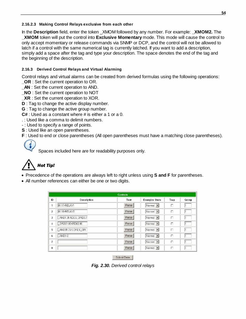
54
2.16.2.3 Making Control Relays exclusive from each other
In the Description field, enter the token _XMOM followed by any number. For example: _XMOM2. The_XMOM token will put the control into Exclusive Momentary mode. This mode will cause the control toonly accept momentary or release commands via SNMP or DCP, and the control will not be allowed tolatch if a control with the same numerical tag is currently latched. If you want to add a description,simply add a space after the tag and type your description. The space denotes the end of the tag andthe beginning of the description.
2.16.3 Derived Control Relays and Virtual Alarming
Control relays and virtual alarms can be created from derived formulas using the following operations:_OR : Set the current operation to OR._AN : Set the current operation to AND._NO : Set the current operation to NOT_XR : Set the current operation to XOR.D : Tag to change the active display number.G : Tag to change the active group number.C# : Used as a constant where # is either a 1 or a 0.. : Used like a comma to delimit numbers.- : Used to specify a range of points.S : Used like an open parentheses.F : Used to end or close parentheses (All open parentheses must have a matching close parentheses).
Spaces included here are for readability purposes only.
! Hot Tip!
· Precedence of the operations are always left to right unless using S and F for parentheses.
· All number references can either be one or two digits.
Fig. 2.30. Derived control relays
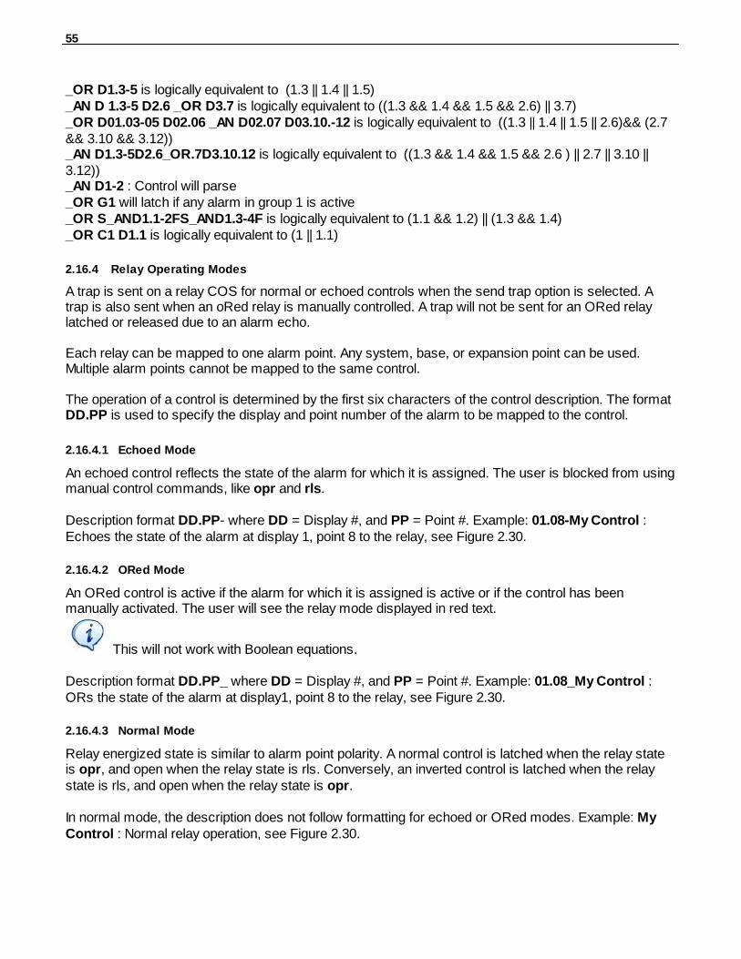
55
_OR D1.3-5 is logically equivalent to (1.3 || 1.4 || 1.5)_AN D 1.3-5 D2.6 _OR D3.7 is logically equivalent to ((1.3 && 1.4 && 1.5 && 2.6) || 3.7)_OR D01.03-05 D02.06 _AN D02.07 D03.10.-12 is logically equivalent to ((1.3 || 1.4 || 1.5 || 2.6)&& (2.7&& 3.10 && 3.12))_AN D1.3-5D2.6_OR.7D3.10.12 is logically equivalent to ((1.3 && 1.4 && 1.5 && 2.6 ) || 2.7 || 3.10 ||3.12))_AN D1-2 : Control will parse_OR G1 will latch if any alarm in group 1 is active_OR S_AND1.1-2FS_AND1.3-4F is logically equivalent to (1.1 && 1.2) || (1.3 && 1.4)_OR C1 D1.1 is logically equivalent to (1 || 1.1)
2.16.4 Relay Operating Modes
A trap is sent on a relay COS for normal or echoed controls when the send trap option is selected. Atrap is also sent when an oRed relay is manually controlled. A trap will not be sent for an ORed relaylatched or released due to an alarm echo.
Each relay can be mapped to one alarm point. Any system, base, or expansion point can be used.Multiple alarm points cannot be mapped to the same control.
The operation of a control is determined by the first six characters of the control description. The formatDD.PP is used to specify the display and point number of the alarm to be mapped to the control.
2.16.4.1 Echoed Mode
An echoed control reflects the state of the alarm for which it is assigned. The user is blocked from usingmanual control commands, like opr and rls.
Description format DD.PP- where DD = Display #, and PP = Point #. Example: 01.08-My Control :Echoes the state of the alarm at display 1, point 8 to the relay, see Figure 2.30.
2.16.4.2 ORed Mode
An ORed control is active if the alarm for which it is assigned is active or if the control has beenmanually activated. The user will see the relay mode displayed in red text.
This will not work with Boolean equations.
Description format DD.PP_ where DD = Display #, and PP = Point #. Example: 01.08_My Control :ORs the state of the alarm at display1, point 8 to the relay, see Figure 2.30.
2.16.4.3 Normal Mode
Relay energized state is similar to alarm point polarity. A normal control is latched when the relay stateis opr, and open when the relay state is rls. Conversely, an inverted control is latched when the relaystate is rls, and open when the relay state is opr.
In normal mode, the description does not follow formatting for echoed or ORed modes. Example: MyControl : Normal relay operation, see Figure 2.30.
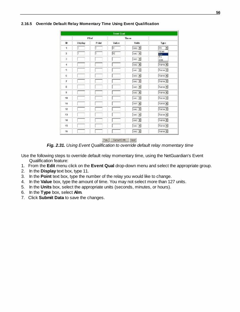
56
2.16.5 Override Default Relay Momentary Time Using Event Qualification
Fig. 2.31. Using Event Qualification to override default relay momentary time
Use the following steps to override default relay momentary time, using the NetGuardian's EventQualification feature:
1. From the Edit menu click on the Event Qual drop-down menu and select the appropriate group.2. In the Display text box, type 11.3. In the Point text box, type the number of the relay you would like to change.4. In the Value box, type the amount of time. You may not select more than 127 units.5. In the Units box, select the appropriate units (seconds, minutes, or hours).6. In the Type box, select Alm.7. Click Submit Data to save the changes.

57
Setting System Timers2.17
Fig. 2.32. When a target fails to respond to a ping within the fail time period, a fault is declared
Ping Cycle Period
Ping Fail Time
Min.
FailureDeclared
OK
OK
OK
Fail
Fail
Fai
l
Fai
l
Fai
l F
ail
21 3 4 5 7 6 8 9Min.
0 1 2 3 4 5
Fig. 2.33. Default timer settings
The NetGuardian's System Timers allow you to control the rate of your pinging activity, time of speakersounding, inactivity time for data ports, and discrete alarm detect time. Ping timer settings allow you tobalance network traffic against alarm response times. Although you can change the values from theirdefault settings, it is recommended that you use either the default settings or plan your settings so thatthere is no conflict among the timers. Specifically, the FAIL time should be set to several times theCYCLE time to allow multiple PINGs before a FAIL is declared. Likewise, the CYCLE time should be setto several times the wait time.
! Hot Tip!The smaller the CYCLE number, the sooner you will find out about failures;
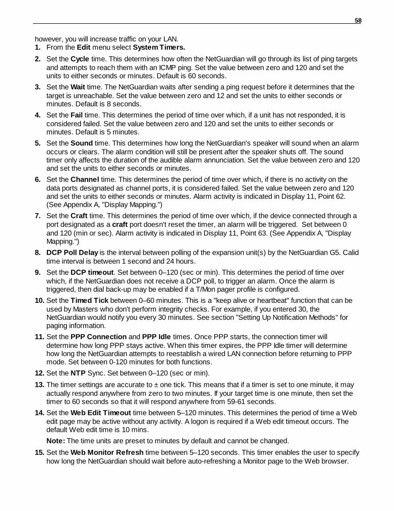
58
however, you will increase traffic on your LAN.1. From the Edit menu select System Timers.
2. Set the Cycle time. This determines how often the NetGuardian will go through its list of ping targetsand attempts to reach them with an ICMP ping. Set the value between zero and 120 and set theunits to either seconds or minutes. Default is 60 seconds.
3. Set the Wait time. The NetGuardian waits after sending a ping request before it determines that thetarget is unreachable. Set the value between zero and 12 and set the units to either seconds orminutes. Default is 8 seconds.
4. Set the Fail time. This determines the period of time over which, if a unit has not responded, it isconsidered failed. Set the value between zero and 120 and set the units to either seconds orminutes. Default is 5 minutes.
5. Set the Sound time. This determines how long the NetGuardian's speaker will sound when an alarmoccurs or clears. The alarm condition will still be present after the speaker shuts off. The soundtimer only affects the duration of the audible alarm annunciation. Set the value between zero and 120and set the units to either seconds or minutes.
6. Set the Channel time. This determines the period of time over which, if there is no activity on thedata ports designated as channel ports, it is considered failed. Set the value between zero and 120and set the units to either seconds or minutes. Alarm activity is indicated in Display 11, Point 62.(See Appendix A, "Display Mapping.")
7. Set the Craft time. This determines the period of time over which, if the device connected through aport designated as a craft port doesn't reset the timer, an alarm will be triggered. Set between 0and 120 (min or sec). Alarm activity is indicated in Display 11, Point 63. (See Appendix A, "DisplayMapping.")
8. DCP Poll Delay is the interval between polling of the expansion unit(s) by the NetGuardian G5. Calidtime interval is between 1 second and 24 hours.
9. Set the DCP timeout. Set between 0–120 (sec or min). This determines the period of time overwhich, if the NetGuardian does not receive a DCP poll, to trigger an alarm. Once the alarm istriggered, then dial back-up may be enabled if a T/Mon pager profile is configured.
10. Set the Timed Tick between 0–60 minutes. This is a "keep alive or heartbeat" function that can beused by Masters who don't perform integrity checks. For example, if you entered 30, theNetGuardian would notify you every 30 minutes. See section "Setting Up Notification Methods" forpaging information.
11. Set the PPP Connection and PPP Idle times. Once PPP starts, the connection timer willdetermine how long PPP stays active. When this timer expires, the PPP Idle timer will determinehow long the NetGuardian attempts to reestablish a wired LAN connection before returning to PPPmode. Set between 0-120 minutes for both functions.
12. Set the NTP Sync. Set between 0–120 (sec or min).
13. The timer settings are accurate to ± one tick. This means that if a timer is set to one minute, it mayactually respond anywhere from zero to two minutes. If your target time is one minute, then set thetimer to 60 seconds so that it will respond anywhere from 59-61 seconds.
14. Set the Web Edit Timeout time between 5–120 minutes. This determines the period of time a Webedit page may be active without any activity. A logon is required if a Web edit timeout occurs. Thedefault Web edit time is 10 mins.
Note: The time units are preset to minutes by default and cannot be changed.
15. Set the Web Monitor Refresh time between 5–120 seconds. This timer enables the user to specifyhow long the NetGuardian should wait before auto-refreshing a Monitor page to the Web browser.

59
The default Web monitor refresh time is 60 seconds.
Note: The time units are preset to seconds by default and cannot be changed.
16. Set the LCD Delay time between 1–60 seconds. This timer is used when you have set the LCD to"Point Mode." This time is how long you want the alarm to be displayed on the front panel LCDscreen. The default is 2 seconds.
17. Set the LCD Scroll speed between 100 to 1000 milliseconds. This timer is used to configure howmuch time passes for the LCD to continue scrolling. The default is 600 milliseconds.
Setting the System Date and Time2.18
Fig. 2.34. The current date and time can be entered from the Date and Time screen or from an SNMPmanager
The date is entered in the mm/dd/yyyy format and the time is entered in the hh:mm:ss format.
! Hot Tip!
The date and time can also be set from an SNMP manager.
Use the following steps to manually set the system's time and date:1. From the Edit menu, select Date and Time, see Figure 2.34.2. Enter the appropriate date, the day of the week, and time.3. Click Submit Data to save the data and time settings.
The date and time will need resetting following a power failure or reboot unless yourNetGuardian is equipped with the real-time clock option or network time is enabled. (See the section2.15.1 for instructions on setting the network time configuration.)

60
2.18.1 Network Time Protocol Support
Fig. 2.35. Configure the Network Time Protocol feature in the Date and Time screen
1. From the Edit menu select Date and Time.2. Click on the Time Zone drop-down menu and select the appropriate time zone.3. Put a check next to Observe DST if you are in an area that observes daylight saving.4. You may also change the server IP Address that the NetGuardian syncs with by entering a the
appropriate IP address in the Time Server IPA field.5. If you do not want your NetGuardian to sync with an NTP server, simply set the Time Server IPA to
255.255.255.255.Note: If Time Server IPA is set to 255.255.255.255, you will be able to manually adjust the date andtime.
6. Click Submit Data to save the date and time settings.
Configuring DSCP Devices2.19
Note:
If configuring the Wireless Propane Sensor please reference the How to configure on theNetGuardian G5 Web Interface section in the "Wireless Propane Monitoring" user manual.If configuring the Wireless Extender for Propane Sensor please reference the How to configureon the NetGuardian G5 Web Interface section in the "Wireless Extender for Propane Sensor"user manual.
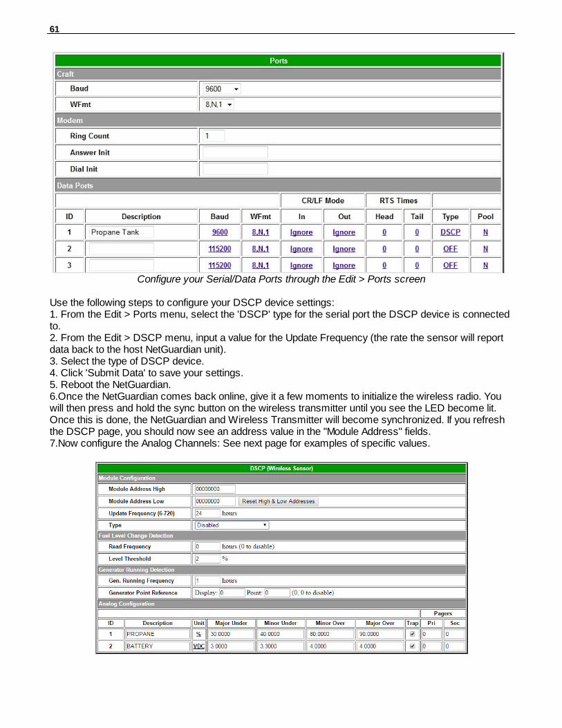
61
Configure your Serial/Data Ports through the Edit > Ports screen
Use the following steps to configure your DSCP device settings:1. From the Edit > Ports menu, select the 'DSCP' type for the serial port the DSCP device is connectedto. 2. From the Edit > DSCP menu, input a value for the Update Frequency (the rate the sensor will reportdata back to the host NetGuardian unit).3. Select the type of DSCP device.4. Click 'Submit Data' to save your settings.5. Reboot the NetGuardian.6.Once the NetGuardian comes back online, give it a few moments to initialize the wireless radio. Youwill then press and hold the sync button on the wireless transmitter until you see the LED become lit.Once this is done, the NetGuardian and Wireless Transmitter will become synchronized. If you refreshthe DSCP page, you should now see an address value in the "Module Address" fields.7.Now configure the Analog Channels: See next page for examples of specific values.
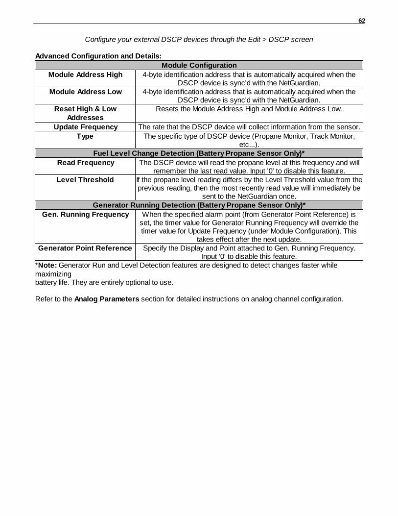
62
Configure your external DSCP devices through the Edit > DSCP screen
Advanced Configuration and Details:
Module Configuration
Module Address High 4-byte identification address that is automatically acquired when theDSCP device is sync'd with the NetGuardian.
Module Address Low 4-byte identification address that is automatically acquired when theDSCP device is sync'd with the NetGuardian.
Reset High & LowAddresses
Resets the Module Address High and Module Address Low.
Update Frequency The rate that the DSCP device will collect information from the sensor.
Type The specific type of DSCP device (Propane Monitor, Track Monitor,etc...).
Fuel Level Change Detection (Battery Propane Sensor Only)*
Read Frequency The DSCP device will read the propane level at this frequency and willremember the last read value. Input '0' to disable this feature.
Level Threshold If the propane level reading differs by the Level Threshold value from theprevious reading, then the most recently read value will immediately be
sent to the NetGuardian once.Generator Running Detection (Battery Propane Sensor Only)*
Gen. Running Frequency When the specified alarm point (from Generator Point Reference) isset, the timer value for Generator Running Frequency will override thetimer value for Update Frequency (under Module Configuration). This
takes effect after the next update.Generator Point Reference Specify the Display and Point attached to Gen. Running Frequency.
Input '0' to disable this feature.*Note: Generator Run and Level Detection features are designed to detect changes faster whilemaximizingbattery life. They are entirely optional to use.
Refer to the Analog Parameters section for detailed instructions on analog channel configuration.
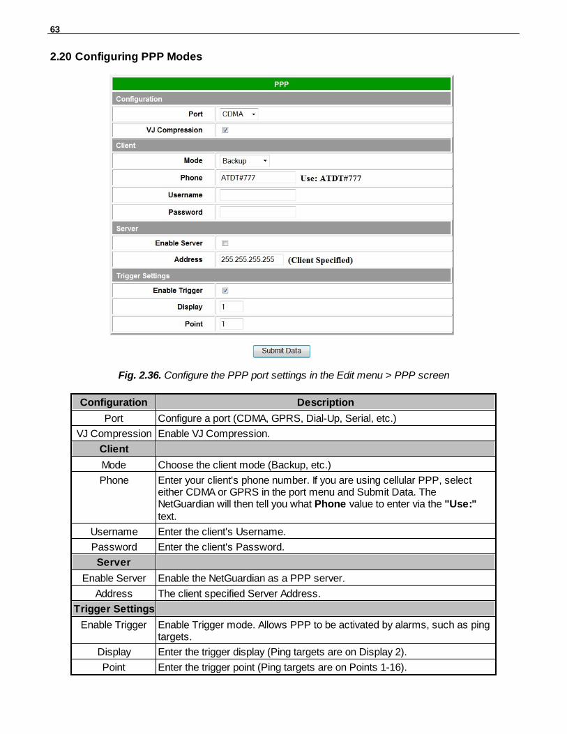
63
Configuring PPP Modes2.20
Fig. 2.36. Configure the PPP port settings in the Edit menu > PPP screen
Configuration Description
Port Configure a port (CDMA, GPRS, Dial-Up, Serial, etc.)
VJ Compression Enable VJ Compression.
Client
Mode Choose the client mode (Backup, etc.)
Phone Enter your client's phone number. If you are using cellular PPP, selecteither CDMA or GPRS in the port menu and Submit Data. TheNetGuardian will then tell you what Phone value to enter via the "Use:"text.
Username Enter the client's Username.
Password Enter the client's Password.
Server
Enable Server Enable the NetGuardian as a PPP server.
Address The client specified Server Address.
Trigger Settings
Enable Trigger Enable Trigger mode. Allows PPP to be activated by alarms, such as pingtargets.
Display Enter the trigger display (Ping targets are on Display 2).
Point Enter the trigger point (Ping targets are on Points 1-16).
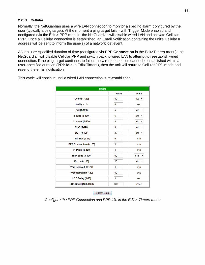
64
2.20.1 Cellular
Normally, the NetGuardian uses a wire LAN connection to monitor a specific alarm configured by theuser (typically a ping target). At the moment a ping target fails - with Trigger Mode enabled andconfigured (via the Edit > PPP menu) - the NetGuardian will disable wired LAN and activate CellularPPP. Once a Cellular connection is established, an Email Notification containing the unit's Cellular IPaddress will be sent to inform the user(s) of a network lost event.
After a user-specified duration of time (configured via PPP Connection in the Edit>Timers menu), theNetGuardian will disable Cellular PPP and switch back to wired LAN to attempt to reestablish wiredconnection. If the ping target continues to fail or the wired connection cannot be established within auser-specified duration (PPP Idle in Edit>Timers), then the unit will return to Cellular PPP mode andresend the email notification.
This cycle will continue until a wired LAN connection is re-established.
Configure the PPP Connection and PPP Idle in the Edit > Timers menu
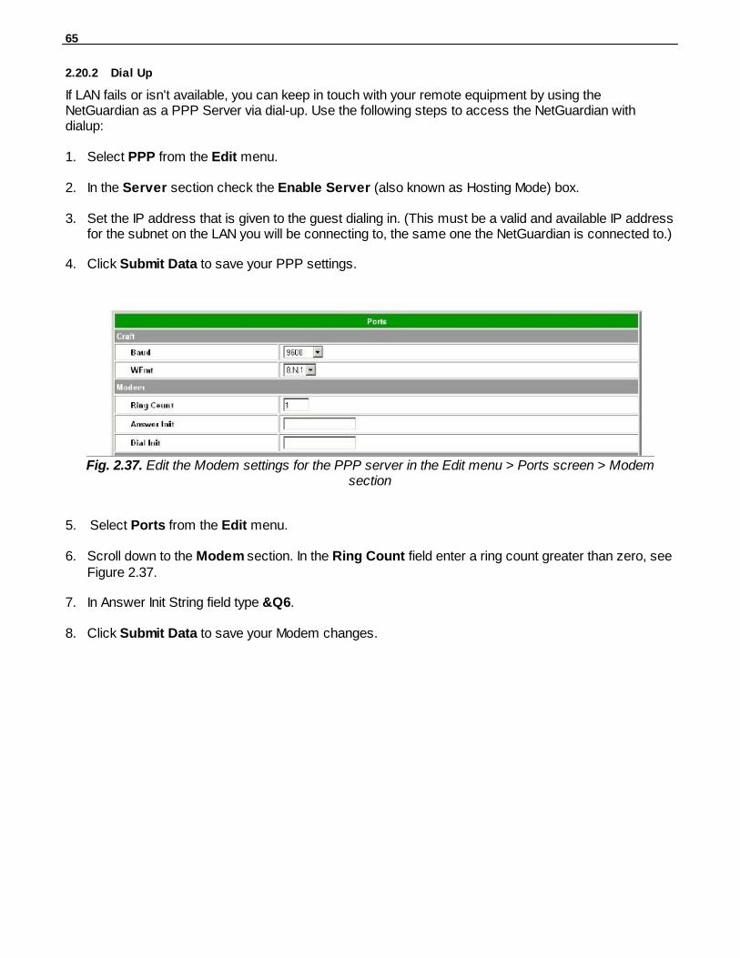
65
2.20.2 Dial Up
If LAN fails or isn't available, you can keep in touch with your remote equipment by using theNetGuardian as a PPP Server via dial-up. Use the following steps to access the NetGuardian withdialup:
1. Select PPP from the Edit menu.
2. In the Server section check the Enable Server (also known as Hosting Mode) box.
3. Set the IP address that is given to the guest dialing in. (This must be a valid and available IP addressfor the subnet on the LAN you will be connecting to, the same one the NetGuardian is connected to.)
4. Click Submit Data to save your PPP settings.
Fig. 2.37. Edit the Modem settings for the PPP server in the Edit menu > Ports screen > Modemsection
5. Select Ports from the Edit menu.
6. Scroll down to the Modem section. In the Ring Count field enter a ring count greater than zero, seeFigure 2.37.
7. In Answer Init String field type &Q6.
8. Click Submit Data to save your Modem changes.
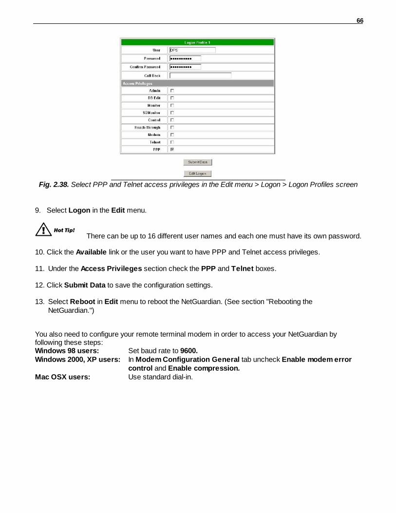
66
Fig. 2.38. Select PPP and Telnet access privileges in the Edit menu > Logon > Logon Profiles screen
9. Select Logon in the Edit menu.
! Hot Tip! There can be up to 16 different user names and each one must have its own password.
10. Click the Available link or the user you want to have PPP and Telnet access privileges.
11. Under the Access Privileges section check the PPP and Telnet boxes.
12. Click Submit Data to save the configuration settings.
13. Select Reboot in Edit menu to reboot the NetGuardian. (See section "Rebooting theNetGuardian.")
You also need to configure your remote terminal modem in order to access your NetGuardian byfollowing these steps:Windows 98 users: Set baud rate to 9600.Windows 2000, XP users: In Modem Configuration General tab uncheck Enable modem error
control and Enable compression.Mac OSX users: Use standard dial-in.

67
Building Access Controller2.21
Fig. 2.39 Configure building access from the BAC Option
The Building Access Controller (BAC) option is only available if the BAC is installed on the NetGuardian(See the BAC 32 User Manual for more information).
The BAC can function in a number of different operational modes. However, for basic functionality, theuser only has to enter the BAC Unit ID. The BAC Unit ID is the BAC's DCP address. It must match theexpansion address databased in T/Mon.
Field Description (Configuration) Dependencies
BAC Unit IDThe BAC's DCP Address. The BAC Unit ID must match the
expansion address databased in T/Mon. This field isessential to BAC Operation.
DirectionEnabled
Check to enable both entry and exit logging at a site. Forkeypad users, Direction will require users to enter a 1 toenter or 4 to exit immediately following their password. For
example, if the password is 4541600, and direction isenabled, users need to type in 45416001# to enter, or
45416004# to exit.
ECU in Dual ProxyMode
Latch on exit Allows users to unlock doors from the "inside" proxy reader/keypad when Direction is enabled.
Direction Enabled
EmergencyUnlock
Enabling this mode will unlock all doors if the defined gasand fire alarm occur. Both alarms have to be active in orderfor the NetGuardian to issue the unlock command. Doors
are re-locked only after the gas alarm has cleared.
ECU G3 V3.0D orabove
In FacilityBroadcast
Disables door violations upon a successful building accesslogin for a period of sixty minutes (configurable via the
BACTL web interface), allowing the user to unlock multipledoors with a single access request. For more information
see your Building Access 32 manual. In-Facility UDP
PortThe port used for In-Facility Broadcasts
In-FacilityBroadcast
In-Facility SendCount
The number of times, 1-3, the NetGuardian will send the In-Facility Broadcast
In-FacilityBroadcast
In-Facility For in facility broadcasts, this option creates a port to accept In-Facility
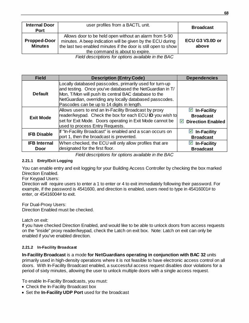
68
Internal DoorPort
user profiles from a BACTL unit.Broadcast
Propped-DoorMinutes
Allows door to be held open without an alarm from 5-90minutes. A beep indication will be given by the ECU during
the last two enabled minutes if the door is still open to showthe command is about to expire.
ECU G3 V3.0D orabove
Field descriptions for options available in the BAC
Field Description (Entry Code) Dependencies
Default
Locally databased passcodes, primarily used for turn-upand testing. Once you've databased the NetGuardian in T/Mon, T/Mon will push its central BAC database to theNetGuardian, overriding any locally databased passcodes. Pascodes can be up to 14 digits in length.
Exit Mode
Allows users to end an In-Facility Broadcast by proxyreader/keypad. Check the box for each ECU ID you wish toset for Exit Mode. Doors operating in Exit Mode cannot beused to process Entry Requests.
In-FacilityBroadcast
Direction Enabled
IFB DisableIf "In-Facility Broadcast" is enabled and a scan occurs onport 1, then the broadcast is prevented.
In-FacilityBroadcast
IFB InternalDoor
When checked, the ECU will only allow profiles that aredesignated for the first floor.
In-FacilityBroadcast
Field descriptions for options available in the BAC
2.21.1 Entry/Exit Logging
You can enable entry and exit logging for your Building Access Controller by checking the box markedDirection Enabled. For Keypad Users: Direction will require users to enter a 1 to enter or 4 to exit immediately following their password. Forexample, if the password is 4541600, and direction is enabled, users need to type in 45416001# toenter, or 45416004# to exit.
For Dual-Proxy Users:Direction Enabled must be checked.
Latch on exit: If you have checked Direction Enabled, and would like to be able to unlock doors from access requestson the "inside" proxy reader/keypad, check the Latch on exit box. Note: Latch on exit can only beenabled if you've enabled direction.
2.21.2 In-Facility Broadcast
In-Facility Broadcast is a mode for NetGuardians operating in conjunction with BAC 32 unitsprimarily used in high-density operations where it is not feasible to have electronic access control on alldoors. With In-Facility Broadcast enabled, a successful access request disables door violations for aperiod of sixty minutes, allowing the user to unlock multiple doors with a single access request.
To enable In-Facility Broadcasts, you must:· Check the In-Facility Broadcast box
· Set the In-Facility UDP Port used for the broadcast
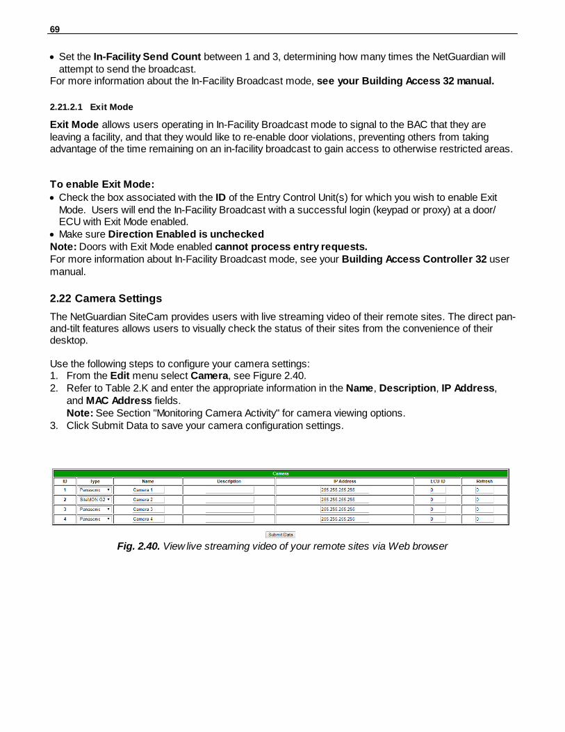
69
· Set the In-Facility Send Count between 1 and 3, determining how many times the NetGuardian willattempt to send the broadcast.
For more information about the In-Facility Broadcast mode, see your Building Access 32 manual.
2.21.2.1 Exit Mode
Exit Mode allows users operating in In-Facility Broadcast mode to signal to the BAC that they areleaving a facility, and that they would like to re-enable door violations, preventing others from takingadvantage of the time remaining on an in-facility broadcast to gain access to otherwise restricted areas.
To enable Exit Mode:
· Check the box associated with the ID of the Entry Control Unit(s) for which you wish to enable ExitMode. Users will end the In-Facility Broadcast with a successful login (keypad or proxy) at a door/ECU with Exit Mode enabled.
· Make sure Direction Enabled is uncheckedNote: Doors with Exit Mode enabled cannot process entry requests.For more information about In-Facility Broadcast mode, see your Building Access Controller 32 usermanual.
Camera Settings2.22
The NetGuardian SiteCam provides users with live streaming video of their remote sites. The direct pan-and-tilt features allows users to visually check the status of their sites from the convenience of theirdesktop.
Use the following steps to configure your camera settings: 1. From the Edit menu select Camera, see Figure 2.40.2. Refer to Table 2.K and enter the appropriate information in the Name, Description, IP Address,
and MAC Address fields.Note: See Section "Monitoring Camera Activity" for camera viewing options.
3. Click Submit Data to save your camera configuration settings.
Fig. 2.40. View live streaming video of your remote sites via Web browser

70
Camera Field Description
Name Enter the name of the camera.
Description Enter a description of the camera.
IP AddressEnter the IP Address of the camera (not the NetGuardian). The NetGuardianwill provision this in the camera. The unit will also send the NetGuardiansubnet and gateway information.
MAC Address Enter the hardware address of the camera (not the NetGuardian).
RefreshEnter the refresh time. This determines the amount of time (in seconds) thatelapses before the image will be updated. Entering 0 will causeuninterrupted, live streaming video (bandwidth rated at 146 kB per second).
Table 2.K. Camera field descriptions
Camera Internet SettingsIn order to perform the pan-and-tilt functions of the camera, your Web browser must be set to check fornewer versions of stored pages at every visit to the page.
The directions for checking for newer versions of stored pages may vary depending on whatversion of Windows you are running. The instructions below are relevant to Internet Explorer 5.5 and 6.0only.
1. With the Web browser open (Internet Explorer version 5.5 or later), click on Tools and selectInternet Options from the drop-down menu.
2. Click on the Settings button under the Temporary Internet files heading.3. Click on the Every visit to the page button and click Ok.
Alarm Sync2.23
Clicking on the Alarm Sync link from the Edit menu will re-synchronize all of the NetGuardian alarms. This command clears all alarms, so that a new notification is sent for all standing alarms. You caneasily test alarm connections during turnup without rebooting the NetGuardian unit. A warning promptwill appear, click Ok to continue or Cancel to exit without resynchronizing your alarms, see Figure 2.41.
Fig. 2.41. Click Ok to re-synchronize the NetGuardian alarms or Cancel to exit
Saving Changes or Resetting Factory Defaults2.24
Your NetGuardian G5 comes equipped with Non Volatile RAM (NVRAM), which enables the retention ofdata in the event of power loss. This section allows you to write and initialize the NVRAM.
Some changes require a reboot of the NetGuardian to take effect, see Section "Rebooting the
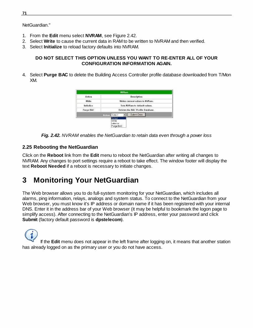
71
NetGuardian."
1. From the Edit menu select NVRAM, see Figure 2.42.2. Select Write to cause the current data in RAM to be written to NVRAM and then verified. 3. Select Initialize to reload factory defaults into NVRAM.
DO NOT SELECT THIS OPTION UNLESS YOU WANT TO RE-ENTER ALL OF YOURCONFIGURATION INFORMATION AGAIN.
4. Select Purge BAC to delete the Building Access Controller profile database downloaded from T/MonXM.
Fig. 2.42. NVRAM enables the NetGuardian to retain data even through a power loss
Rebooting the NetGuardian2.25
Click on the Reboot link from the Edit menu to reboot the NetGuardian after writing all changes toNVRAM. Any changes to port settings require a reboot to take effect. The window footer will display thetext Reboot Needed if a reboot is necessary to initiate changes.
Monitoring Your NetGuardian3
The Web browser allows you to do full-system monitoring for your NetGuardian, which includes allalarms, ping information, relays, analogs and system status. To connect to the NetGuardian from yourWeb browser, you must know it's IP address or domain name if it has been registered with your internalDNS. Enter it in the address bar of your Web browser (it may be helpful to bookmark the logon page tosimplify access). After connecting to the NetGuardian's IP address, enter your password and click Submit (factory default password is dpstelecom).
If the Edit menu does not appear in the left frame after logging on, it means that another stationhas already logged on as the primary user or you do not have access.
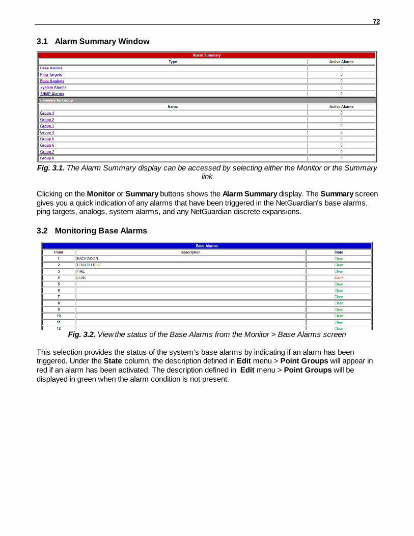
72
Alarm Summary Window3.1
Fig. 3.1. The Alarm Summary display can be accessed by selecting either the Monitor or the Summarylink
Clicking on the Monitor or Summary buttons shows the Alarm Summary display. The Summary screengives you a quick indication of any alarms that have been triggered in the NetGuardian's base alarms,ping targets, analogs, system alarms, and any NetGuardian discrete expansions.
Monitoring Base Alarms3.2
Fig. 3.2. View the status of the Base Alarms from the Monitor > Base Alarms screen
This selection provides the status of the system's base alarms by indicating if an alarm has beentriggered. Under the State column, the description defined in Edit menu > Point Groups will appear inred if an alarm has been activated. The description defined in Edit menu > Point Groups will bedisplayed in green when the alarm condition is not present.
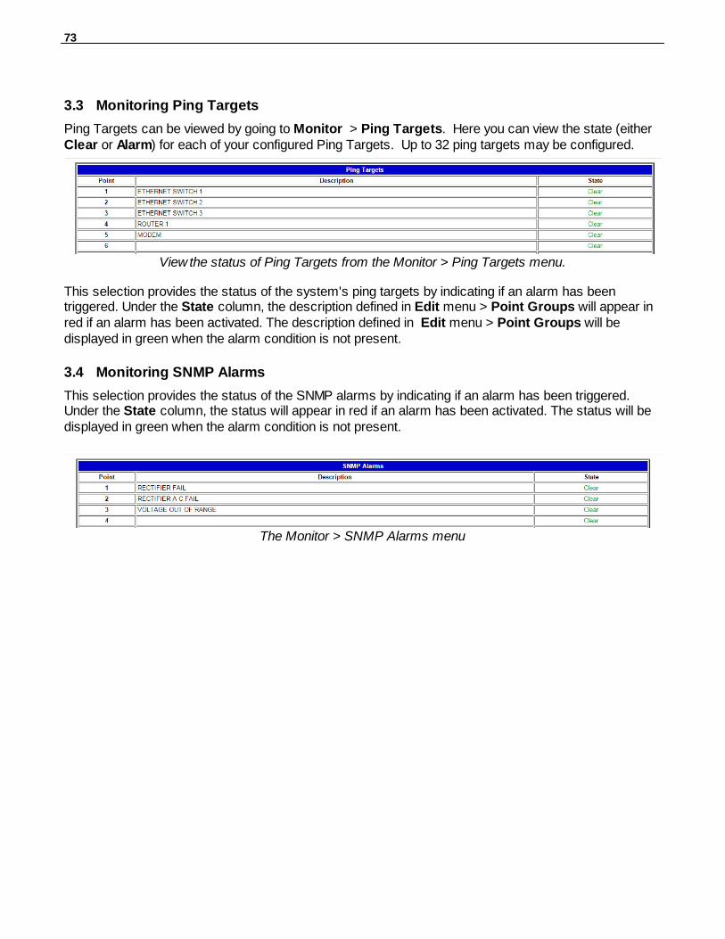
73
Monitoring Ping Targets3.3
Ping Targets can be viewed by going to Monitor > Ping Targets. Here you can view the state (eitherClear or Alarm) for each of your configured Ping Targets. Up to 32 ping targets may be configured.
View the status of Ping Targets from the Monitor > Ping Targets menu.
This selection provides the status of the system's ping targets by indicating if an alarm has beentriggered. Under the State column, the description defined in Edit menu > Point Groups will appear inred if an alarm has been activated. The description defined in Edit menu > Point Groups will bedisplayed in green when the alarm condition is not present.
Monitoring SNMP Alarms3.4
This selection provides the status of the SNMP alarms by indicating if an alarm has been triggered.Under the State column, the status will appear in red if an alarm has been activated. The status will bedisplayed in green when the alarm condition is not present.
The Monitor > SNMP Alarms menu
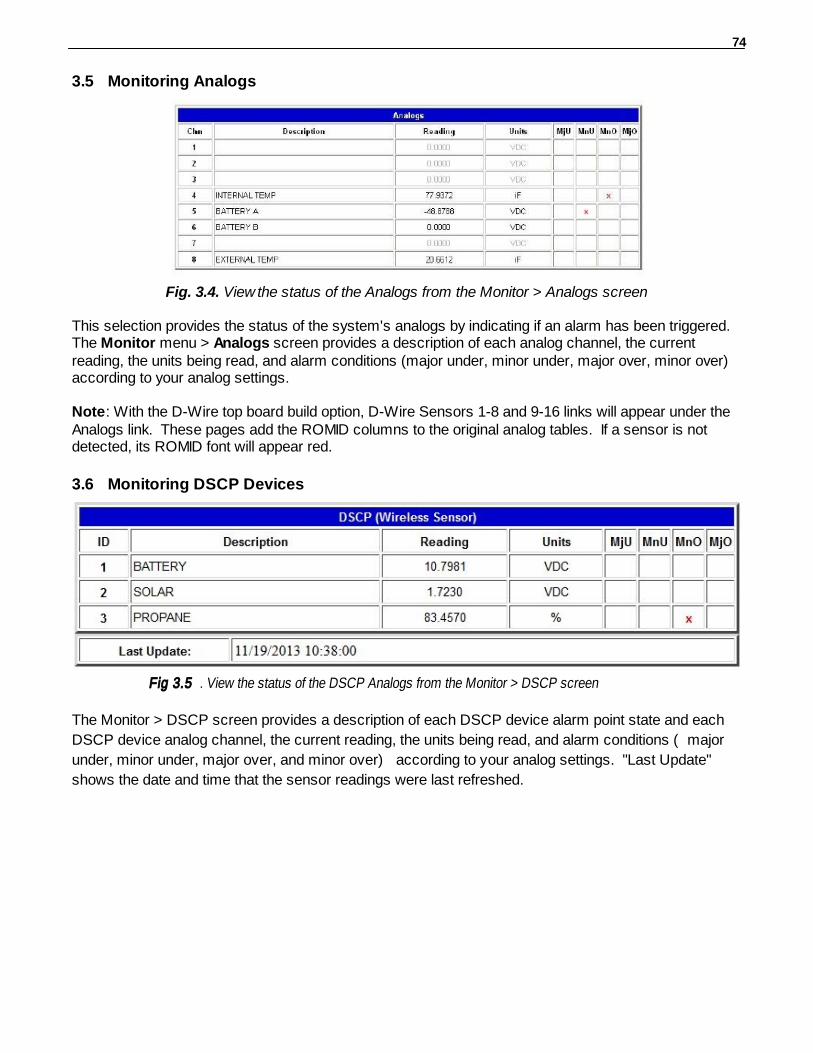
74
Monitoring Analogs3.5
Fig. 3.4. View the status of the Analogs from the Monitor > Analogs screen
This selection provides the status of the system's analogs by indicating if an alarm has been triggered.The Monitor menu > Analogs screen provides a description of each analog channel, the currentreading, the units being read, and alarm conditions (major under, minor under, major over, minor over)according to your analog settings.
Note: With the D-Wire top board build option, D-Wire Sensors 1-8 and 9-16 links will appear under theAnalogs link. These pages add the ROMID columns to the original analog tables. If a sensor is notdetected, its ROMID font will appear red.
Monitoring DSCP Devices3.6
Fig 3.5 . View the status of the DSCP Analogs from the Monitor > DSCP screen
The Monitor > DSCP screen provides a description of each DSCP device alarm point state and each
DSCP device analog channel, the current reading, the units being read, and alarm conditions (major
under, minor under, major over, and minor over) according to your analog settings. "Last Update"
shows the date and time that the sensor readings were last refreshed.

75
Monitoring System Alarms3.7
Fig.3.6. View the status of the System Alarms from the Monitor > System Alarms screen
This selection provides the status of the system alarms by indicating if an alarm has been triggered.Under the State column, the description defined in Edit menu > Point Groups will appear in red if analarm has been activated. The description defined in Edit menu > Point Groups will be displayed ingreen when the alarm condition is not present. (Refer to Appendix A for system alarm trap numbers.)
Operating Controls3.8
Fig. 3.7. Issue controls from the Monitor > Controls screen
Use the following rules to operate controls:1. Select Controls from the Monitor menu. 2. Under the State field, choose a command (Opr - operate, Rls - release, or Mom - momentary). 3. Click Submit Data to issue the control.
The control relay's normal state - open or closed - is determined by a PCB jumper. Operating a controlthus changes the normal state of the relay (energizes it) until it is released (de-energized). Themomentary command energizes the relay for approximately one second before it is released again. Usethe event qualifiers to extend the momentary period.
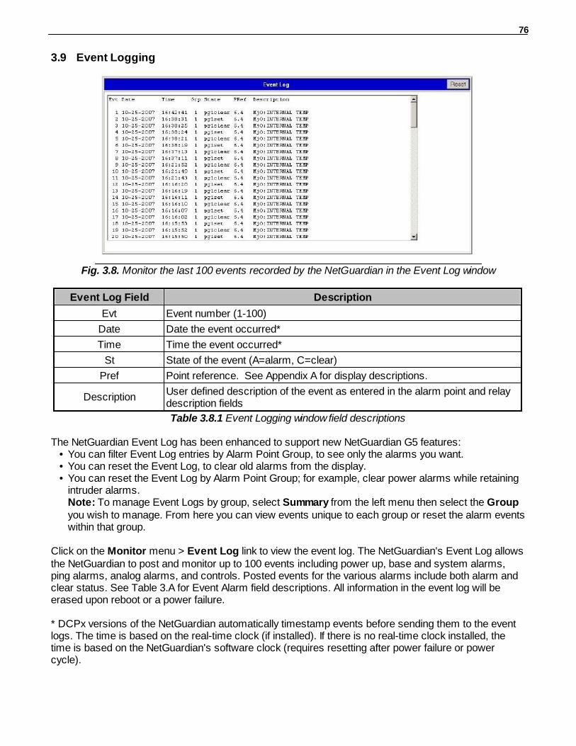
76
Event Logging3.9
Fig. 3.8. Monitor the last 100 events recorded by the NetGuardian in the Event Log window
Event Log Field Description
Evt Event number (1-100)
Date Date the event occurred*
Time Time the event occurred*
St State of the event (A=alarm, C=clear)
Pref Point reference. See Appendix A for display descriptions.
DescriptionUser defined description of the event as entered in the alarm point and relaydescription fields
Table 3.8.1 Event Logging window field descriptions
The NetGuardian Event Log has been enhanced to support new NetGuardian G5 features:• You can filter Event Log entries by Alarm Point Group, to see only the alarms you want. • You can reset the Event Log, to clear old alarms from the display. • You can reset the Event Log by Alarm Point Group; for example, clear power alarms while retaining
intruder alarms.Note: To manage Event Logs by group, select Summary from the left menu then select the Groupyou wish to manage. From here you can view events unique to each group or reset the alarm eventswithin that group.
Click on the Monitor menu > Event Log link to view the event log. The NetGuardian's Event Log allowsthe NetGuardian to post and monitor up to 100 events including power up, base and system alarms,ping alarms, analog alarms, and controls. Posted events for the various alarms include both alarm andclear status. See Table 3.A for Event Alarm field descriptions. All information in the event log will beerased upon reboot or a power failure.
* DCPx versions of the NetGuardian automatically timestamp events before sending them to the eventlogs. The time is based on the real-time clock (if installed). If there is no real-time clock installed, thetime is based on the NetGuardian's software clock (requires resetting after power failure or powercycle).
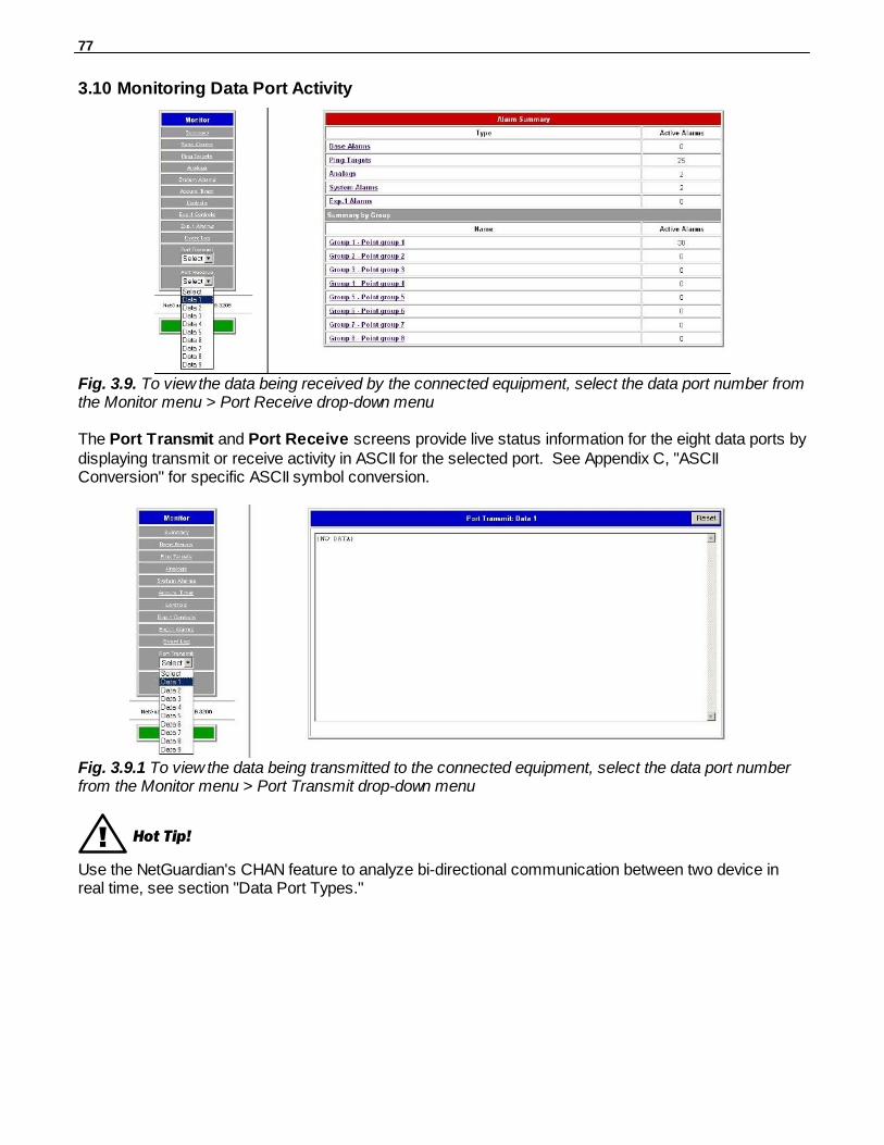
77
Monitoring Data Port Activity3.10
Fig. 3.9. To view the data being received by the connected equipment, select the data port number fromthe Monitor menu > Port Receive drop-down menu
The Port Transmit and Port Receive screens provide live status information for the eight data ports bydisplaying transmit or receive activity in ASCII for the selected port. See Appendix C, "ASCIIConversion" for specific ASCII symbol conversion.
Fig. 3.9.1 To view the data being transmitted to the connected equipment, select the data port numberfrom the Monitor menu > Port Transmit drop-down menu
! Hot Tip!
Use the NetGuardian's CHAN feature to analyze bi-directional communication between two device inreal time, see section "Data Port Types."

78
Monitoring Switch Status3.11
Fig. 3.10 The Monitor > Switch Status Menu.
If you ordered your NetGuardian G5 with the optional Fiber top board, you will see the Switch Statusoption in the Monitor Menu. From here, you'll keep tabs on Link Status, Speed, and Packets from boththe 10/100/1000 Base Switch and SFP Fiber ports.
Monitoring Camera Activity3.12
Fig. 3.10. Monitor live streaming video via the NetGuardian's Web browser
Select the Site Camera drop-down menu from the Monitor menu to view activity from the site camera.Bandwidth usage in live streaming mode is rated at 146 kB per second.
The NetGuardian only sends the camera data when a user is monitoring the image.

79
3.12.1 Pan-and-tilt Camera Controls
Control left-right and up-down viewing options via the Pan/Tilt options. Clicking on the image will makethat the new center point.
In order to have pan-and-tilt controls, your Internetsettings must be set to check for newer versions ofstored pages every visit to the page, see section"Camera Internet Settings."
The preset number controls allow you to tilt to thefour corners of the screen (1-4). To alter the screensize click on the Program link . To adjust thebrightness, click on the – to darken the imagescreen or + to brighten it. Click on STD to return tothe default settings.
Fig. 3.11. Use the arrow buttons to use thepan-and-tilt features of the NetGuardian
SiteCAM
3.12.2 Monitoring Multiple Cameras
Fig. 3.12 View up to 4 multiple cameras.
You can monitor multiple cameras at one time by clicking the Multiple link. To view individual screensyou may select the site camera under the Monitor menu > Camera drop-down menu or click on thetitle of the screen you wish to view individually. To configure your multiple camera settings, click on theSetup-Multiple link, see Figure 3.13.

80
Fig. 3.13 Enter the IP Address or Host Name of each camera, and title your camera
Before you can setup multiple camera views, you will need to set up your camera for "live streaming."See your camera user manual to configure your camera for live streaming. You may only use up to 15alphanumeric characters to name your camera. Once you have finished click the Save button.
Appendixes4
Appendix A — Display Mapping4.1
Port Address Display Points Description Set Clear
99 1 1 1-32 Discrete Alarms 1-32 8001-8032
9001-9032
99 1 1 33-64 Discrete Alarms 33-64 (864A)Unused (832A)
8033-8064
9033-9064
99 1 2 1-32 Ping Table 8065-8096
9065-9096
99 1 3 1-32 Analog Channel 1** 8129-8133
9129-9133
99 1 4 1-32 Analog Channel 2** 8193-8197
9193-9197
99 1 5 1-32 Analog Channel 3** 8257-8261
9257-9261
99 1 6 1-32 Analog Channel 4** 8321-8325
9321-9325
99 1 7 1-32 Analog Channel 5** 8385-8389
9385-9389
99 1 8 1-32 Analog Channel 6** 8449- 9449-9453
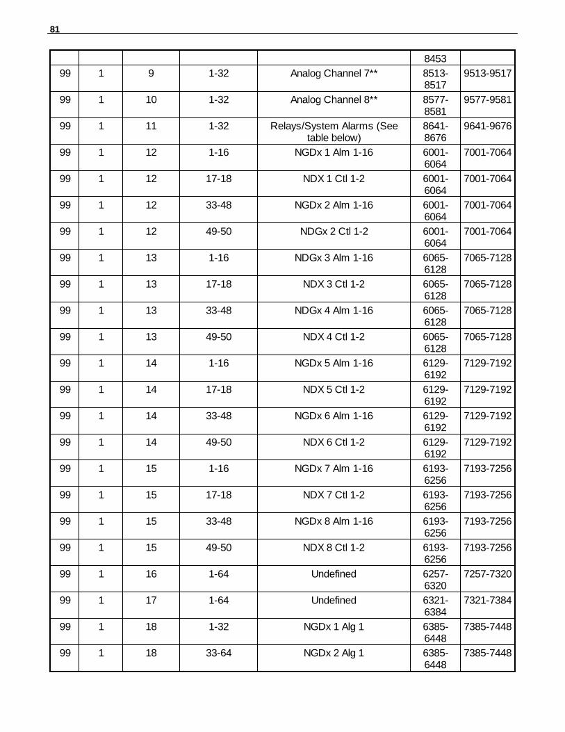
81
8453
99 1 9 1-32 Analog Channel 7** 8513-8517
9513-9517
99 1 10 1-32 Analog Channel 8** 8577-8581
9577-9581
99 1 11 1-32 Relays/System Alarms (Seetable below)
8641-8676
9641-9676
99 1 12 1-16 NGDx 1 Alm 1-16 6001-6064
7001-7064
99 1 12 17-18 NDX 1 Ctl 1-2 6001-6064
7001-7064
99 1 12 33-48 NGDx 2 Alm 1-16 6001-6064
7001-7064
99 1 12 49-50 NDGx 2 Ctl 1-2 6001-6064
7001-7064
99 1 13 1-16 NDGx 3 Alm 1-16 6065-6128
7065-7128
99 1 13 17-18 NDX 3 Ctl 1-2 6065-6128
7065-7128
99 1 13 33-48 NDGx 4 Alm 1-16 6065-6128
7065-7128
99 1 13 49-50 NDX 4 Ctl 1-2 6065-6128
7065-7128
99 1 14 1-16 NGDx 5 Alm 1-16 6129-6192
7129-7192
99 1 14 17-18 NDX 5 Ctl 1-2 6129-6192
7129-7192
99 1 14 33-48 NGDx 6 Alm 1-16 6129-6192
7129-7192
99 1 14 49-50 NDX 6 Ctl 1-2 6129-6192
7129-7192
99 1 15 1-16 NGDx 7 Alm 1-16 6193-6256
7193-7256
99 1 15 17-18 NDX 7 Ctl 1-2 6193-6256
7193-7256
99 1 15 33-48 NGDx 8 Alm 1-16 6193-6256
7193-7256
99 1 15 49-50 NDX 8 Ctl 1-2 6193-6256
7193-7256
99 1 16 1-64 Undefined 6257-6320
7257-7320
99 1 17 1-64 Undefined 6321-6384
7321-7384
99 1 18 1-32 NGDx 1 Alg 1 6385-6448
7385-7448
99 1 18 33-64 NGDx 2 Alg 1 6385-6448
7385-7448

82
99 1 19 1-32 NGDx 3 Alg 1 6449-6512
7449-7512
99 1 19 33-64 NGDx 4 Alg 1 6449-6512
7449-7512
99 1 20 1-32 NGDx 5 Alg 1 6513-6576
7513-7576
99 1 20 33-64 NGDx 6 Alg 1 6513-6576
7513-7576
99 1 21 1-32 NGDx 7 Alg 1 6577-6640
7577-7640
99 1 21 33-64 NGDx 8 Alg 1 6577-6640
7577-7640
99 1 22 1-32 NGDx 1 Alg 2 6641-6704
7641-7704
99 1 22 33-64 NGDx 2 Alg 2 6641-6704
7641-7704
99 1 23 1-32 NGDx 3 Alg 2 6705-6768
7705-7768
99 1 23 33-64 NGDx 4 Alg 2 6705-6768
7705-7768
99 1 24 1-32 NGDx 5 Alg 2 6769-6832
7769-7832
99 1 24 33-64 NGDx 6 Alg 2 6769-6832
7769-7832
99 1 25 1-32 NGDx 7 Alg 2 6833-6896
7833-7896
99 1 25 33-64 NGDx 8 Alg 2 6833-6896
7833-7896
99 1 26 1-32 NGDx 1 Alg 3 6897-6960
7897-7960
99 1 26 33-64 NGDx 2 Alg 3 6897-6960
7897-7960
99 1 27 1-32 NGDx 3 Alg 3 6961-7024
7961-8024
99 1 27 33-64 NGDx 4 Alg 3 6961-7024
7961-8024
99 1 28 1-32 NGDx 5 Alg 3 7025-7088
8025-8088
99 1 28 33-64 NGDx 6 Alg 3 7025-7088
8025-8088
99 1 29 1-32 NGDx 7 Alg 3 7089-7152
8089-8152
99 1 29 33-64 NGDx 8 Alg 3 7089-7152
8089-8152
Table A.1. Display descriptions and SNMP Trap numbers for the NetGuardian
* The TRAP number ranges shown correspond to the point range of each display. For example, theSNMP Trap "Set" number for alarm 1 (in Display 1) is 8001, "Set" for alarm 2 is 8002, "Set" for alarm 3
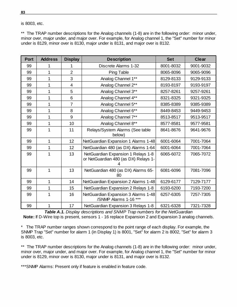
83
is 8003, etc.
** The TRAP number descriptions for the Analog channels (1-8) are in the following order: minor under,minor over, major under, and major over. For example, for Analog channel 1, the "Set" number for minorunder is 8129, minor over is 8130, major under is 8131, and major over is 8132.
Port Address Display Description Set Clear
99 1 1 Discrete Alarms 1-32 8001-8032 9001-9032
99 1 2 Ping Table 8065-8096 9065-9096
99 1 3 Analog Channel 1** 8129-8133 9129-9133
99 1 4 Analog Channel 2** 8193-8197 9193-9197
99 1 5 Analog Channel 3** 8257-8261 9257-9261
99 1 6 Analog Channel 4** 8321-8325 9321-9325
99 1 7 Analog Channel 5** 8385-8389 9385-9389
99 1 8 Analog Channel 6** 8449-8453 9449-9453
99 1 9 Analog Channel 7** 8513-8517 9513-9517
99 1 10 Analog Channel 8** 8577-8581 9577-9581
99 1 11 Relays/System Alarms (See tablebelow)
8641-8676 9641-9676
99 1 12 NetGuardian Expansion 1 Alarms 1-48 6001-6064 7001-7064
99 1 12 NetGuardian 480 (as DX) Alarms 1-64 6001-6064 7001-7064
99 1 13 NetGuardian Expansion 1 Relays 1-8or NetGuardian 480 (as DX) Relays 1-
4
6065-6072 7065-7072
99 1 13 NetGuardian 480 (as DX) Alarms 65-80
6081-6096 7081-7096
99 1 14 NetGuardian Expansion 2 Alarms 1-48 6129-6177 7129-7177
99 1 15 NetGuardian Expansion 2 Relays 1-8 6193-6200 7193-7200
99 1 16 NetGuardian Expansion 3 Alarms 1-48/SNMP Alarms 1-16 ***
6257-6305 7257-7305
99 1 17 NetGuardian Expansion 3 Relays 1-8 6321-6328 7321-7328
Table A.1. Display descriptions and SNMP Trap numbers for the NetGuardianNote: If D-Wire top is present, sensors 1 - 16 replace Expansion 2 and Expansion 3 analog channels.
* The TRAP number ranges shown correspond to the point range of each display. For example, theSNMP Trap "Set" number for alarm 1 (in Display 1) is 8001, "Set" for alarm 2 is 8002, "Set" for alarm 3is 8003, etc.
** The TRAP number descriptions for the Analog channels (1-8) are in the following order: minor under,minor over, major under, and major over. For example, for Analog channel 1, the "Set" number for minorunder is 8129, minor over is 8130, major under is 8131, and major over is 8132.
***SNMP Alarms: Present only if feature is enabled in feature code.

84
SNMP Trap #s
Points Description Set Clear
1-16 Relays 1-16 8641-8656 9641-9656
17 Timed Tick 8657 9657
18 Exp. Module Callout 8658 9658
19 Network Time Server 8659 9659
20 Accumulation Event 8660 9660
21 Duplicate IP Address 8661 9661
22 T1/E1 Error 8662 9662
23 ECU Emergency Unlock 8663 9663
24 D-Wire Sensor Not Detected 8664 9664
25 ECU Door Violation 8665 9665
26 Maintenance Mode 8666 9666
27 DSCP Timeout 8667 9667
28 Wireless Sensor Power Fault 8668 9668
29 Wireless Sensor Power Low 8669 9669
30 Wireless Sensor Update 8670 9670
32 Modbus Poll Inactive 8672 9672
33 Unit Reset 8673 9673
34 PPP Backup Mode 8674 9674
35 Server Restore 8675 9675
36 Lost Provisioning 8676 9676
37 DCP Poller Inactive 8677 9677
38 NET1 not active 8678 9678
39 NET2 not active 8679 9679
40 NET Link Down 8680 9680
41 Modem not responding 8681 9681
42 No Dial Tone 8682 9682
43 SNMP Trap not Sent 8683 9683
44 Pager Que Overflow 8684 9684
45 Notification failed 8685 9685
46 Craft RcvQ full 8686 9686
47 Modem RcvQ full 8687 9687
48 Data 1 RcvQ full 8688 9688
49 Data 2 RcvQ full 8689 9689
50 Data 3 RcvQ full 8690 9690
51 Data 4 RcvQ full 8691 9691
52 Data 5 RcvQ full 8692 9692
53 Data 6 RcvQ full 8693 9693
54 Data 7 RcvQ full 8694 9694
55 Data 8 RcvQ full 8695 9695
56 NetGuardian DX 1 fail 8696 9696
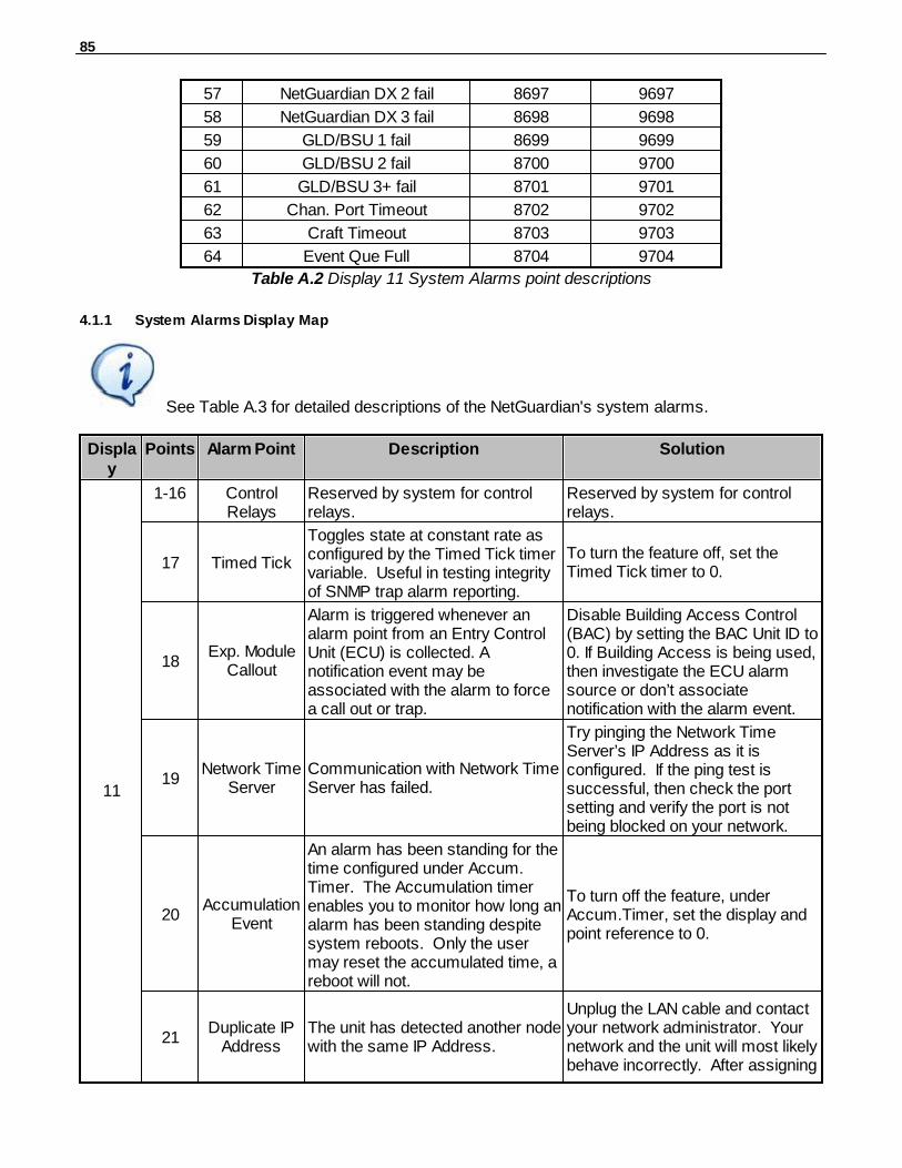
85
57 NetGuardian DX 2 fail 8697 9697
58 NetGuardian DX 3 fail 8698 9698
59 GLD/BSU 1 fail 8699 9699
60 GLD/BSU 2 fail 8700 9700
61 GLD/BSU 3+ fail 8701 9701
62 Chan. Port Timeout 8702 9702
63 Craft Timeout 8703 9703
64 Event Que Full 8704 9704
Table A.2 Display 11 System Alarms point descriptions
4.1.1 System Alarms Display Map
See Table A.3 for detailed descriptions of the NetGuardian's system alarms.
Display
Points
Alarm Point Description Solution
11
1-16 ControlRelays
Reserved by system for controlrelays.
Reserved by system for controlrelays.
17 Timed Tick
Toggles state at constant rate asconfigured by the Timed Tick timervariable. Useful in testing integrityof SNMP trap alarm reporting.
To turn the feature off, set theTimed Tick timer to 0.
18Exp. Module
Callout
Alarm is triggered whenever analarm point from an Entry ControlUnit (ECU) is collected. Anotification event may beassociated with the alarm to forcea call out or trap.
Disable Building Access Control(BAC) by setting the BAC Unit ID to0. If Building Access is being used,then investigate the ECU alarmsource or don’t associatenotification with the alarm event.
19Network Time
ServerCommunication with Network TimeServer has failed.
Try pinging the Network TimeServer’s IP Address as it isconfigured. If the ping test issuccessful, then check the portsetting and verify the port is notbeing blocked on your network.
20Accumulation
Event
An alarm has been standing for thetime configured under Accum.Timer. The Accumulation timerenables you to monitor how long analarm has been standing despitesystem reboots. Only the usermay reset the accumulated time, areboot will not.
To turn off the feature, underAccum.Timer, set the display andpoint reference to 0.
21Duplicate IP
AddressThe unit has detected another nodewith the same IP Address.
Unplug the LAN cable and contactyour network administrator. Yournetwork and the unit will most likelybehave incorrectly. After assigning

86
a correct IP Address, reboot theunit to clear the System alarm.
22 T1/E1 ErrorWAN connection not detected. Loss of signal, or loss of frame.
Check the back of the unit andconfirm WAN cable is connectedand WAN LED is solid green.
23ECU
EmergencyUnlock
Set when both user-defined fireand gas alarms occur.
Will clear when fire and gas alarmsclear. Feature can also bedisabled if "Emergency UnlockEnabled" is unchecked from theweb or NGEdit G5 interfaces.
24D-Wire
Sensor NotDetected
A configured D-Wire Sensor is notdetected.
Check G5 D-Wire port and D-WireSensor and confirm cable isplugged in. Also make sure thatconfigured ROM ID's match the D-Wire Sensors plugged in.
25ECU DoorViolation
Door sensor has detectedunauthorized entry.
Verify integrity of door sensor. Thisalarm is to alert of unauthorizedaccess.
26Maintenance
Mode
Maintenance mode is currentlyactive for the server shutdownfeature
Maintenance mode will timeoutaccording t othe amount specifiedby the user in teh NGEdit "ServerShutdown" tab.
27DSCP
Timeout
The unit has not received a signalfrom the DSCP Poller after acertain period of time.
Check configuration of DSCPPoller. Check battery power. Makesure signal is not physicallyobstructed.
28WirelessSensor
Power Fault
Power to DSCP unit is shorting orcannot provide enough currentcausing a fault with the sensorpower.
Check sensor wiring for any faultyconnections or shortened cables.
29 WirelessSensor
Power Low
DSCP unit is not providing enoughpower to the sensors.
Check sensor wiring for any faultyconnections or shortened cables.
30 WirelessSensorUpdate
This unit has received a sensorreading update from a wirelessdevice.
This alarm is normal and is used tolog wireless activity.
32 Modbus PollInactive
The unit has not seen a poll fromthe master for the time specified bythe setting.
Timeout is set to 90 seconds. Ifdevice has not seen a poll for 90seconds, alarm will activate.
33 Power Up
The unit has just come-online. Theset alarm condition is followedimmediately by a clear alarmcondition.
Seeing this alarm is normal if theunit is powering up.
34 PPP BackupMode
The unit's Backup PPP mode iscurrently in use.
PPP Backup mode comes onwhen the ethernet link goes down.Check the ethernet for connectivity.
35 ServerRestore
Manual Server Shutdown/Restoreprocess is in progress.
Server shutdown is active whenManual Shutdown/Restore is inprogress.Wait for shutdown/
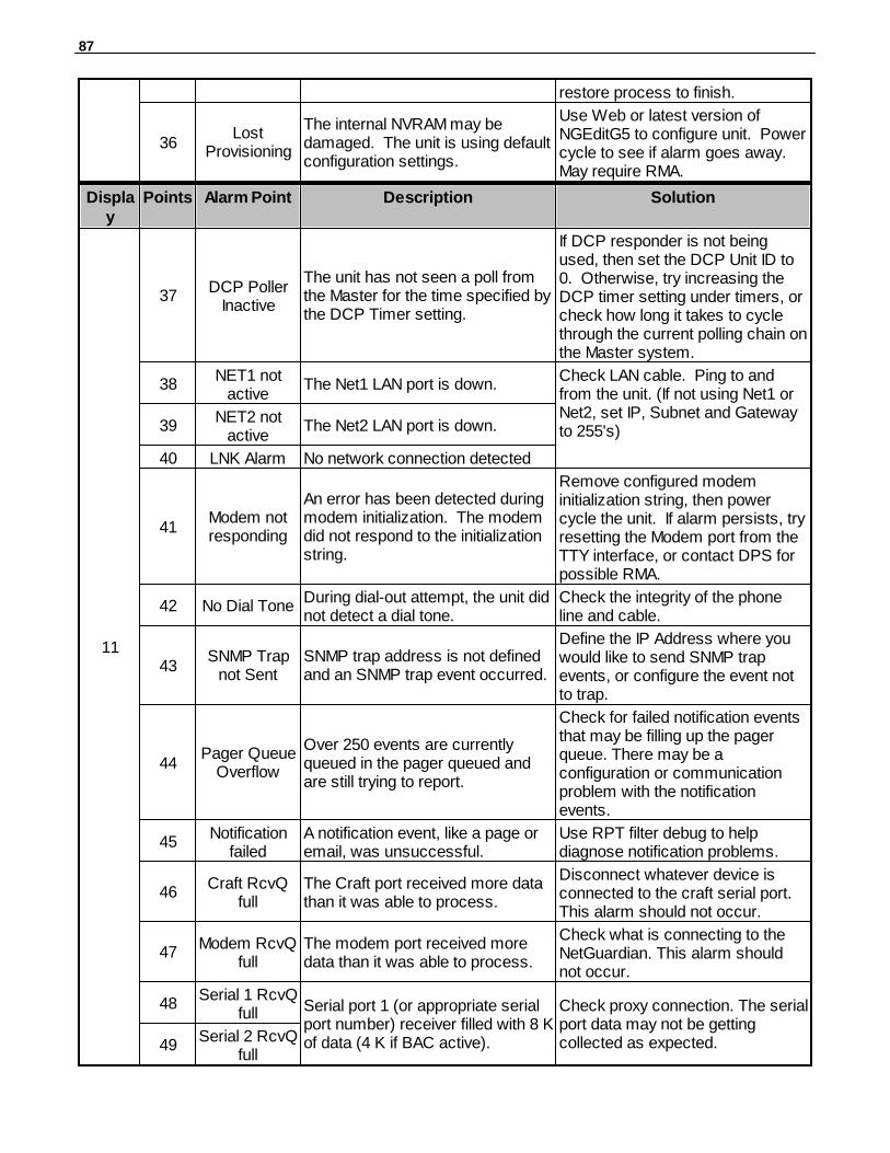
87
restore process to finish.
36Lost
Provisioning
The internal NVRAM may bedamaged. The unit is using defaultconfiguration settings.
Use Web or latest version ofNGEditG5 to configure unit. Powercycle to see if alarm goes away. May require RMA.
Display
Points Alarm Point Description Solution
11
37DCP Poller
Inactive
The unit has not seen a poll fromthe Master for the time specified bythe DCP Timer setting.
If DCP responder is not beingused, then set the DCP Unit ID to0. Otherwise, try increasing theDCP timer setting under timers, orcheck how long it takes to cyclethrough the current polling chain onthe Master system.
38NET1 not
activeThe Net1 LAN port is down.
Check LAN cable. Ping to andfrom the unit. (If not using Net1 orNet2, set IP, Subnet and Gatewayto 255's)39
NET2 notactive
The Net2 LAN port is down.
40 LNK Alarm No network connection detected
41Modem notresponding
An error has been detected duringmodem initialization. The modemdid not respond to the initializationstring.
Remove configured modeminitialization string, then powercycle the unit. If alarm persists, tryresetting the Modem port from theTTY interface, or contact DPS forpossible RMA.
42 No Dial ToneDuring dial-out attempt, the unit didnot detect a dial tone.
Check the integrity of the phoneline and cable.
43SNMP Trap
not SentSNMP trap address is not definedand an SNMP trap event occurred.
Define the IP Address where youwould like to send SNMP trapevents, or configure the event notto trap.
44Pager Queue
Overflow
Over 250 events are currentlyqueued in the pager queued andare still trying to report.
Check for failed notification eventsthat may be filling up the pagerqueue. There may be aconfiguration or communicationproblem with the notificationevents.
45Notification
failedA notification event, like a page oremail, was unsuccessful.
Use RPT filter debug to helpdiagnose notification problems.
46Craft RcvQ
fullThe Craft port received more datathan it was able to process.
Disconnect whatever device isconnected to the craft serial port.This alarm should not occur.
47Modem RcvQ
fullThe modem port received moredata than it was able to process.
Check what is connecting to theNetGuardian. This alarm shouldnot occur.
48Serial 1 RcvQ
full Serial port 1 (or appropriate serialport number) receiver filled with 8 Kof data (4 K if BAC active).
Check proxy connection. The serialport data may not be gettingcollected as expected.49
Serial 2 RcvQfull
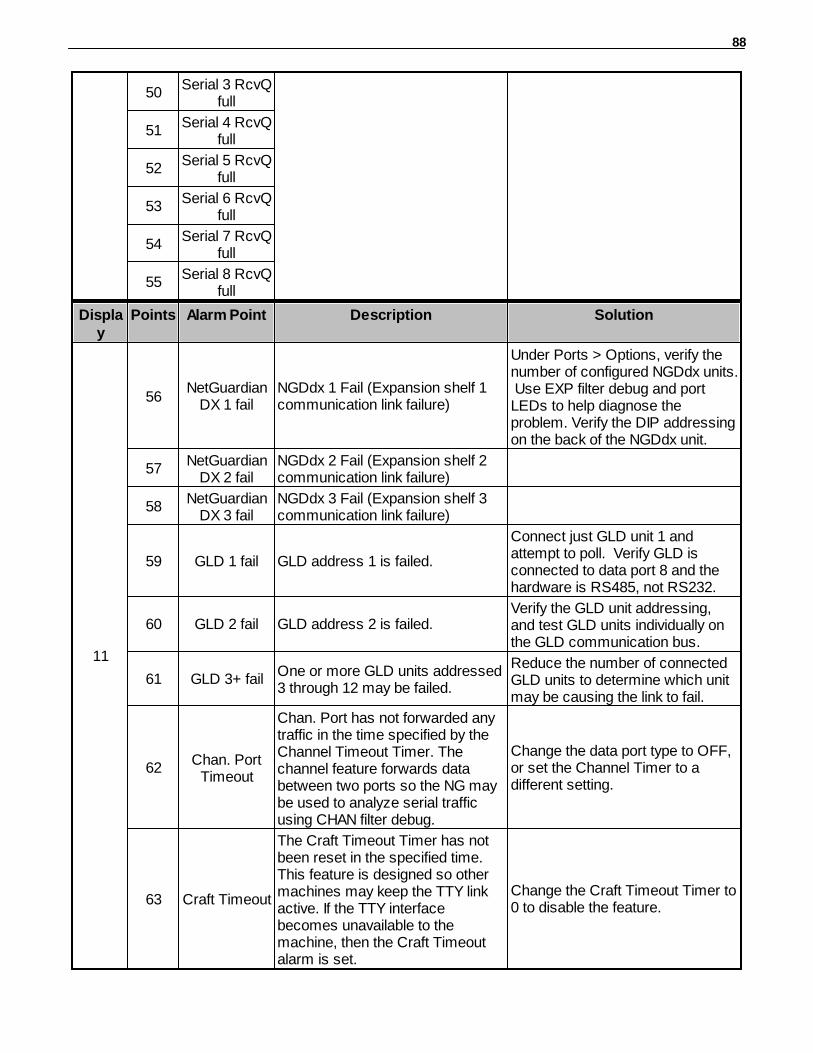
88
50Serial 3 RcvQ
full
51Serial 4 RcvQ
full
52Serial 5 RcvQ
full
53Serial 6 RcvQ
full
54Serial 7 RcvQ
full
55Serial 8 RcvQ
full
Display
Points Alarm Point Description Solution
11
56NetGuardian
DX 1 failNGDdx 1 Fail (Expansion shelf 1communication link failure)
Under Ports > Options, verify thenumber of configured NGDdx units. Use EXP filter debug and portLEDs to help diagnose theproblem. Verify the DIP addressingon the back of the NGDdx unit.
57NetGuardian
DX 2 failNGDdx 2 Fail (Expansion shelf 2communication link failure)
58NetGuardian
DX 3 failNGDdx 3 Fail (Expansion shelf 3communication link failure)
59 GLD 1 fail GLD address 1 is failed.
Connect just GLD unit 1 andattempt to poll. Verify GLD isconnected to data port 8 and thehardware is RS485, not RS232.
60 GLD 2 fail GLD address 2 is failed.Verify the GLD unit addressing,and test GLD units individually onthe GLD communication bus.
61 GLD 3+ failOne or more GLD units addressed3 through 12 may be failed.
Reduce the number of connectedGLD units to determine which unitmay be causing the link to fail.
62Chan. Port
Timeout
Chan. Port has not forwarded anytraffic in the time specified by theChannel Timeout Timer. Thechannel feature forwards databetween two ports so the NG maybe used to analyze serial trafficusing CHAN filter debug.
Change the data port type to OFF,or set the Channel Timer to adifferent setting.
63 Craft Timeout
The Craft Timeout Timer has notbeen reset in the specified time. This feature is designed so othermachines may keep the TTY linkactive. If the TTY interfacebecomes unavailable to themachine, then the Craft Timeoutalarm is set.
Change the Craft Timeout Timer to0 to disable the feature.

89
64Event Que
FullThe Event Que is filled with morethan 500 uncollected events.
Enable DCP timestamp polling onthe master so events are collected,or reboot the system to clear thealarm.
Table A.3 System Alarms Descriptions

90
Appendix B — SNMP Manager Functions4.2
The SNMP Manager allows the user to view alarm status, set date/time, issue controls, and perform aresync. The display and tables below outline the MIB object identifiers. Table B.1 begins with dpsRTU;however, the MIB object identifier tree has several levels above it. The full English name is as follows:root.iso.org.dod.internet.private.enterprises.dps-Inc.dpsAlarmControl.dpsRTU. Therefore, dpsRTU's fullobject identifier is 1.3.6.1.4.1.2682.1.4. Each level beyond dpsRTU adds another object identifyingnumber. For example, the object identifier of the Display portion of the Control Grid is1.3.6.1.4.1.2682.1.4.3.3 because the object identifier of dpsRTU is 1.3.6.1.4.1.2682.1.4 + the ControlGrid (.3) + the Display (.3).
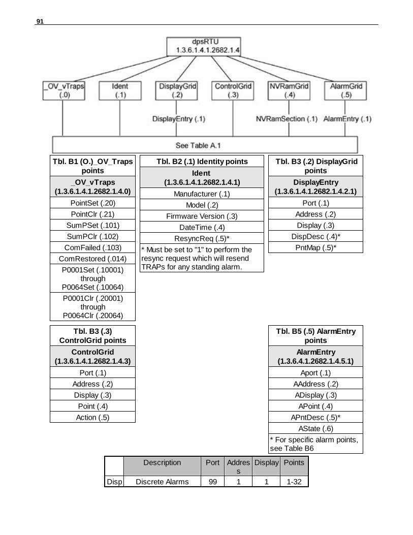
91
Tbl. B1 (O.)_OV_Trapspoints
_OV_vTraps(1.3.6.1.4.1.2682.1.4.0)
PointSet (.20)
PointClr (.21)
SumPSet (.101)
SumPClr (.102)
ComFailed (.103)
ComRestored (.014)
P0001Set (.10001)through
P0064Set (.10064)
P0001Clr (.20001)through
P0064Clr (.20064)
Tbl. B2 (.1) Identity points
Ident (1.3.6.1.4.1.2682.1.4.1)
Manufacturer (.1)
Model (.2)
Firmware Version (.3)
DateTime (.4)
ResyncReq (.5)*
* Must be set to "1" to perform theresync request which will resendTRAPs for any standing alarm.
Tbl. B3 (.2) DisplayGridpoints
DisplayEntry(1.3.6.1.4.1.2682.1.4.2.1)
Port (.1)
Address (.2)
Display (.3)
DispDesc (.4)*
PntMap (.5)*
Tbl. B3 (.3)ControlGrid points
ControlGrid(1.3.6.1.4.1.2682.1.4.3)
Port (.1)
Address (.2)
Display (.3)
Point (.4)
Action (.5)
Tbl. B5 (.5) AlarmEntrypoints
AlarmEntry(1.3.6.4.1.2682.1.4.5.1)
Aport (.1)
AAddress (.2)
ADisplay (.3)
APoint (.4)
APntDesc (.5)*
AState (.6)
* For specific alarm points,see Table B6
Description Port Address
Display Points
Disp1
Discrete Alarms 99 1 1 1-32
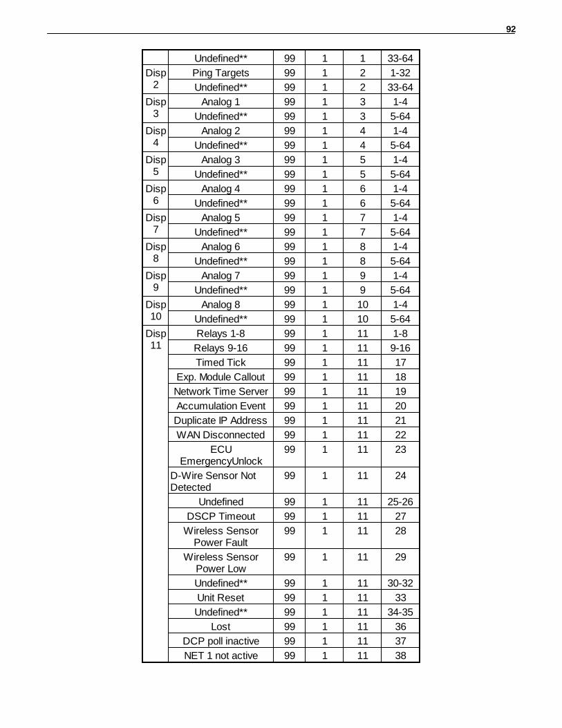
92
Undefined** 99 1 1 33-64
Disp2
Ping Targets 99 1 2 1-32
Undefined** 99 1 2 33-64
Disp3
Analog 1 99 1 3 1-4
Undefined** 99 1 3 5-64
Disp4
Analog 2 99 1 4 1-4
Undefined** 99 1 4 5-64
Disp5
Analog 3 99 1 5 1-4
Undefined** 99 1 5 5-64
Disp6
Analog 4 99 1 6 1-4
Undefined** 99 1 6 5-64
Disp7
Analog 5 99 1 7 1-4
Undefined** 99 1 7 5-64
Disp8
Analog 6 99 1 8 1-4
Undefined** 99 1 8 5-64
Disp9
Analog 7 99 1 9 1-4
Undefined** 99 1 9 5-64
Disp10
Analog 8 99 1 10 1-4
Undefined** 99 1 10 5-64
Disp11
Relays 1-8 99 1 11 1-8
Relays 9-16 99 1 11 9-16
Timed Tick 99 1 11 17
Exp. Module Callout 99 1 11 18
Network Time Server 99 1 11 19
Accumulation Event 99 1 11 20
Duplicate IP Address 99 1 11 21
WAN Disconnected 99 1 11 22
ECUEmergencyUnlock
99 1 11 23
D-Wire Sensor NotDetected
99 1 11 24
Undefined 99 1 11 25-26
DSCP Timeout 99 1 11 27
Wireless SensorPower Fault
99 1 11 28
Wireless SensorPower Low
99 1 11 29
Undefined** 99 1 11 30-32
Unit Reset 99 1 11 33
Undefined** 99 1 11 34-35
Lost 99 1 11 36
DCP poll inactive 99 1 11 37
NET 1 not active 99 1 11 38
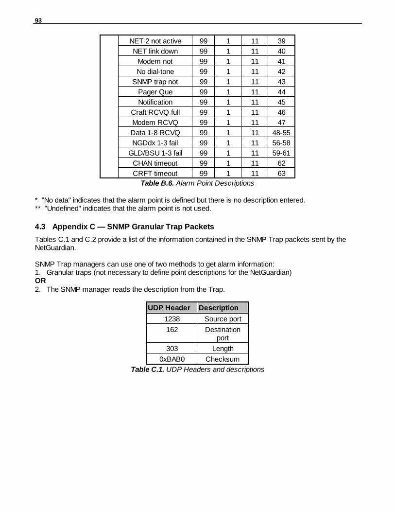
93
NET 2 not active 99 1 11 39
NET link down 99 1 11 40
Modem not 99 1 11 41
No dial-tone 99 1 11 42
SNMP trap not 99 1 11 43
Pager Que 99 1 11 44
Notification 99 1 11 45
Craft RCVQ full 99 1 11 46
Modem RCVQ 99 1 11 47
Data 1-8 RCVQ 99 1 11 48-55
NGDdx 1-3 fail 99 1 11 56-58
GLD/BSU 1-3 fail 99 1 11 59-61
CHAN timeout 99 1 11 62
CRFT timeout 99 1 11 63
Table B.6. Alarm Point Descriptions
* "No data" indicates that the alarm point is defined but there is no description entered.** "Undefined" indicates that the alarm point is not used.
Appendix C — SNMP Granular Trap Packets4.3
Tables C.1 and C.2 provide a list of the information contained in the SNMP Trap packets sent by theNetGuardian.
SNMP Trap managers can use one of two methods to get alarm information: 1. Granular traps (not necessary to define point descriptions for the NetGuardian)OR2. The SNMP manager reads the description from the Trap.
UDP Header Description
1238 Source port
162 Destinationport
303 Length
0xBAB0 Checksum
Table C.1. UDP Headers and descriptions
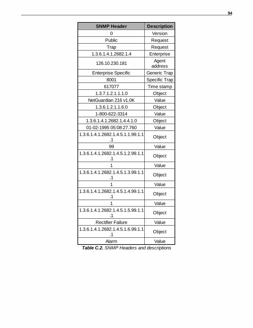
94
SNMP Header Description
0 Version
Public Request
Trap Request
1.3.6.1.4.1.2682.1.4 Enterprise
126.10.230.181Agent
address
Enterprise Specific Generic Trap
8001 Specific Trap
617077 Time stamp
1.3.7.1.2.1.1.1.0 Object
NetGuardian 216 v1.0K Value
1.3.6.1.2.1.1.6.0 Object
1-800-622-3314 Value
1.3.6.1.4.1.2682.1.4.4.1.0 Object
01-02-1995 05:08:27.760 Value
1.3.6.1.4.1.2682.1.4.5.1.1.99.1.1.1
Object
99 Value
1.3.6.1.4.1.2682.1.4.5.1.2.99.1.1.1
Object
1 Value
1.3.6.1.4.1.2682.1.4.5.1.3.99.1.1.1
Object
1 Value
1.3.6.1.4.1.2682.1.4.5.1.4.99.1.1.1
Object
1 Value
1.3.6.1.4.1.2682.1.4.5.1.5.99.1.1.1
Object
Rectifier Failure Value
1.3.6.1.4.1.2682.1.4.5.1.6.99.1.1.1
Object
Alarm Value
Table C.2. SNMP Headers and descriptions
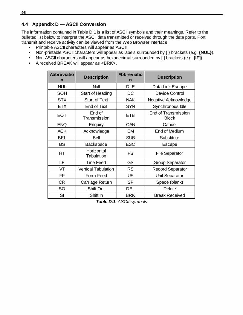
95
Appendix D — ASCII Conversion4.4
The information contained in Table D.1 is a list of ASCII symbols and their meanings. Refer to thebulleted list below to interpret the ASCII data transmitted or received through the data ports. Porttransmit and receive activity can be viewed from the Web Browser Interface.
• Printable ASCII characters will appear as ASCII.• Non-printable ASCII characters will appear as labels surrounded by { } brackets (e.g. {NUL}).• Non-ASCII characters will appear as hexadecimal surrounded by [ ] brackets (e.g. [IF]).• A received BREAK will appear as <BRK>.
Abbreviation
DescriptionAbbreviatio
nDescription
NUL Null DLE Data Link Escape
SOH Start of Heading DC Device Control
STX Start of Text NAK Negative Acknowledge
ETX End of Text SYN Synchronous Idle
EOTEnd of
TransmissionETB
End of TransmissionBlock
ENQ Enquiry CAN Cancel
ACK Acknowledge EM End of Medium
BEL Bell SUB Substitute
BS Backspace ESC Escape
HTHorizontalTabulation
FS File Separator
LF Line Feed GS Group Separator
VT Vertical Tabulation RS Record Separator
FF Form Feed US Unit Separator
CR Carriage Return SP Space (blank)
SO Shift Out DEL Delete
SI Shift In BRK Break Received
Table D.1. ASCII symbols
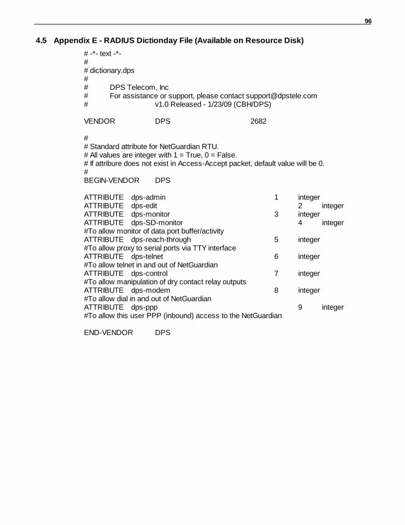
96
Appendix E - RADIUS Dictionday File (Available on Resource Disk)4.5
# -*- text -*-## dictionary.dps## DPS Telecom, Inc# For assistance or support, please contact [email protected]# v1.0 Released - 1/23/09 (CBH/DPS)
VENDOR DPS 2682
## Standard attribute for NetGuardian RTU.# All values are integer with 1 = True, 0 = False.# If attribure does not exist in Access-Accept packet, default value will be 0.#BEGIN-VENDOR DPS
ATTRIBUTE dps-admin 1 integerATTRIBUTE dps-edit 2 integerATTRIBUTE dps-monitor 3 integerATTRIBUTE dps-SD-monitor 4 integer#To allow monitor of data port buffer/activityATTRIBUTE dps-reach-through 5 integer#To allow proxy to serial ports via TTY interfaceATTRIBUTE dps-telnet 6 integer#To allow telnet in and out of NetGuardianATTRIBUTE dps-control 7 integer#To allow manipulation of dry contact relay outputsATTRIBUTE dps-modem 8 integer#To allow dial in and out of NetGuardianATTRIBUTE dps-ppp 9 integer#To allow this user PPP (inbound) access to the NetGuardian
END-VENDOR DPS
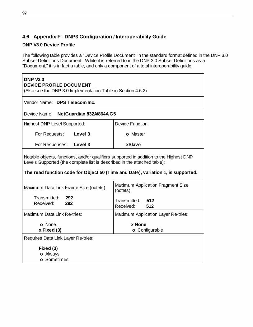
97
Appendix F - DNP3 Configuration / Interoperability Guide4.6
DNP V3.0 Device Profile
The following table provides a "Device Profile Document" in the standard format defined in the DNP 3.0Subset Definitions Document. While it is referred to in the DNP 3.0 Subset Definitions as a"Document," it is in fact a table, and only a component of a total interoperability guide.
DNP V3.0DEVICE PROFILE DOCUMENT(Also see the DNP 3.0 Implementation Table in Section 4.6.2)
Vendor Name: DPS Telecom Inc.
Device Name: NetGuardian 832A/864A G5
Highest DNP Level Supported:
For Requests: Level 3
For Responses: Level 3
Device Function:
o Master
xSlave
Notable objects, functions, and/or qualifiers supported in addition to the Highest DNPLevels Supported (the complete list is described in the attached table):
The read function code for Object 50 (Time and Date), variation 1, is supported.
Maximum Data Link Frame Size (octets):
Transmitted: 292 Received: 292
Maximum Application Fragment Size(octets):
Transmitted: 512Received: 512
Maximum Data Link Re-tries:
o None x Fixed (3)
Maximum Application Layer Re-tries:
x None o Configurable
Requires Data Link Layer Re-tries:
Fixed (3) o Always o Sometimes
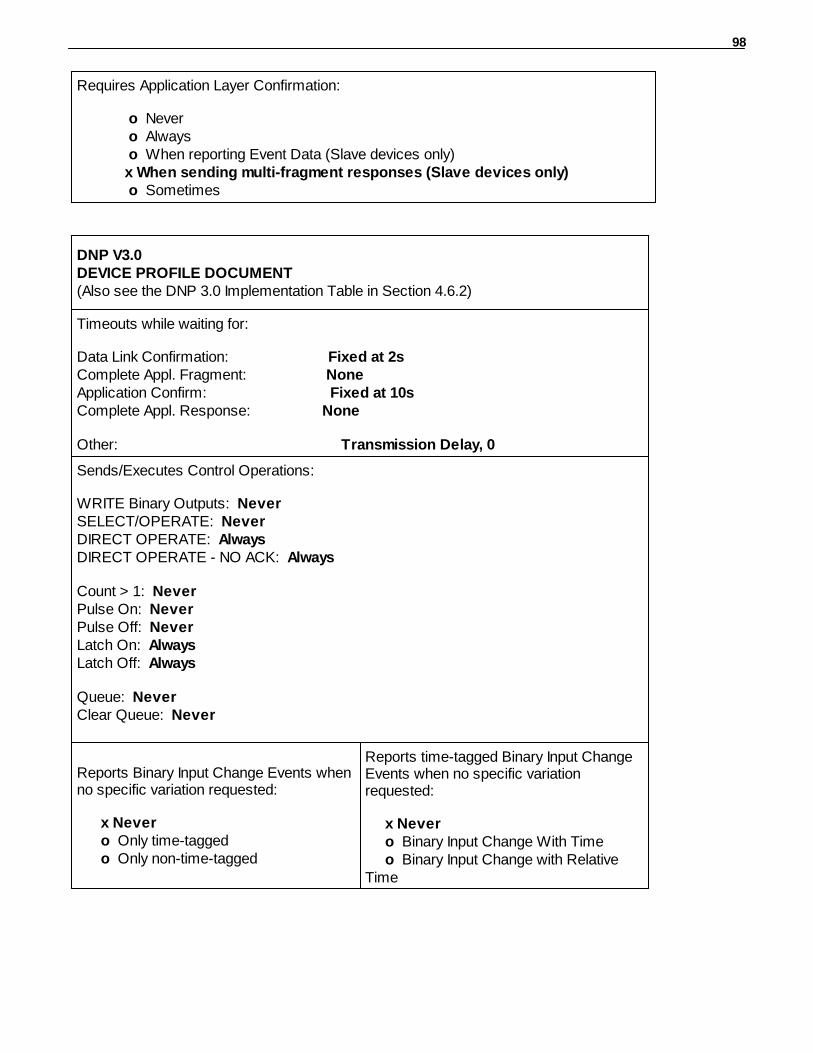
98
Requires Application Layer Confirmation:
o Never o Always o When reporting Event Data (Slave devices only) x When sending multi-fragment responses (Slave devices only) o Sometimes
DNP V3.0DEVICE PROFILE DOCUMENT(Also see the DNP 3.0 Implementation Table in Section 4.6.2)
Timeouts while waiting for:
Data Link Confirmation: Fixed at 2sComplete Appl. Fragment: None Application Confirm: Fixed at 10sComplete Appl. Response: None
Other: Transmission Delay, 0
Sends/Executes Control Operations:
WRITE Binary Outputs: Never SELECT/OPERATE: Never DIRECT OPERATE: Always DIRECT OPERATE - NO ACK: Always
Count > 1: Never Pulse On: Never Pulse Off: Never Latch On: AlwaysLatch Off: Always
Queue: NeverClear Queue: Never
Reports Binary Input Change Events whenno specific variation requested:
x Never o Only time-tagged o Only non-time-tagged
Reports time-tagged Binary Input ChangeEvents when no specific variationrequested:
x Never o Binary Input Change With Time o Binary Input Change with RelativeTime
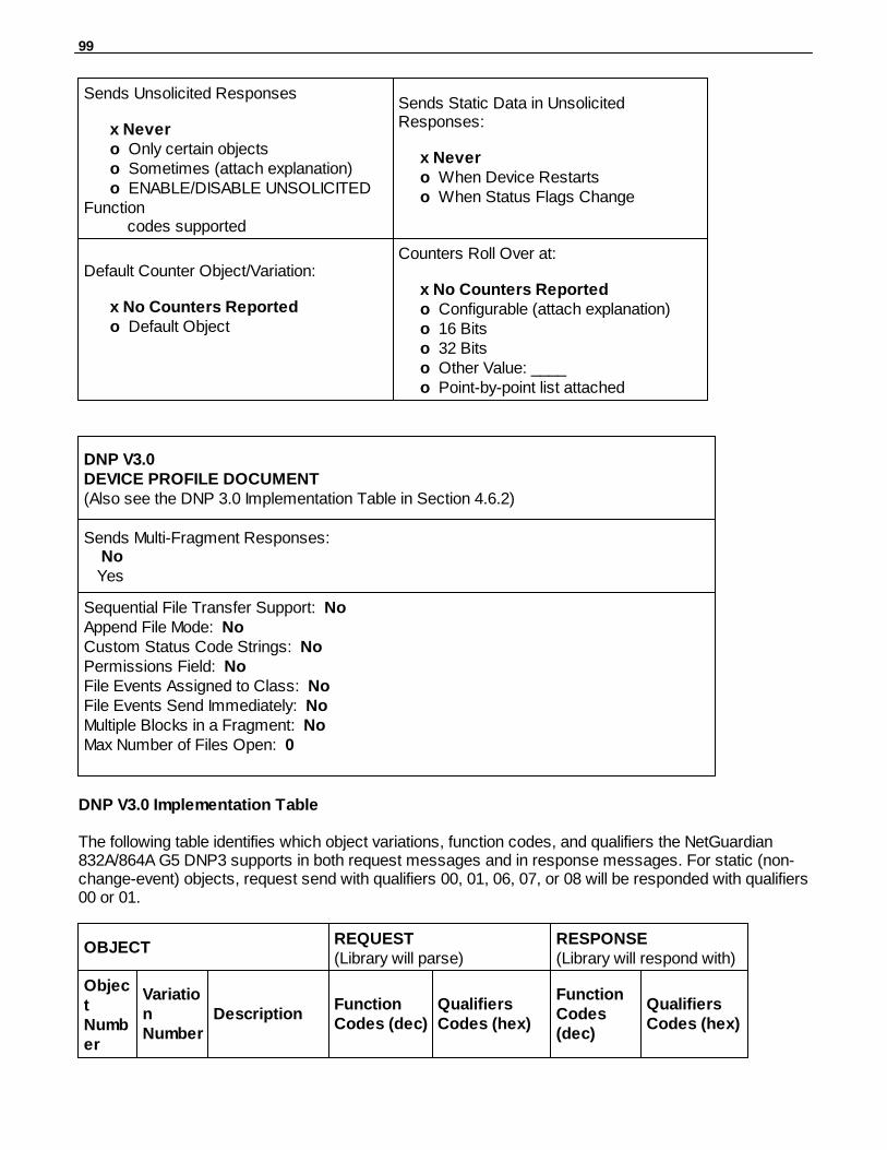
99
Sends Unsolicited Responses
x Never o Only certain objects o Sometimes (attach explanation) o ENABLE/DISABLE UNSOLICITEDFunction codes supported
Sends Static Data in UnsolicitedResponses:
x Never o When Device Restarts o When Status Flags Change
Default Counter Object/Variation:
x No Counters Reported o Default Object
Counters Roll Over at:
x No Counters Reported o Configurable (attach explanation) o 16 Bits o 32 Bits o Other Value: ____ o Point-by-point list attached
DNP V3.0DEVICE PROFILE DOCUMENT(Also see the DNP 3.0 Implementation Table in Section 4.6.2)
Sends Multi-Fragment Responses: No Yes
Sequential File Transfer Support: NoAppend File Mode: NoCustom Status Code Strings: NoPermissions Field: NoFile Events Assigned to Class: NoFile Events Send Immediately: NoMultiple Blocks in a Fragment: NoMax Number of Files Open: 0
DNP V3.0 Implementation Table
The following table identifies which object variations, function codes, and qualifiers the NetGuardian832A/864A G5 DNP3 supports in both request messages and in response messages. For static (non-change-event) objects, request send with qualifiers 00, 01, 06, 07, or 08 will be responded with qualifiers00 or 01.
OBJECTREQUEST(Library will parse)
RESPONSE(Library will respond with)
ObjectNumber
VariationNumber
DescriptionFunctionCodes (dec)
QualifiersCodes (hex)
FunctionCodes(dec)
QualifiersCodes (hex)
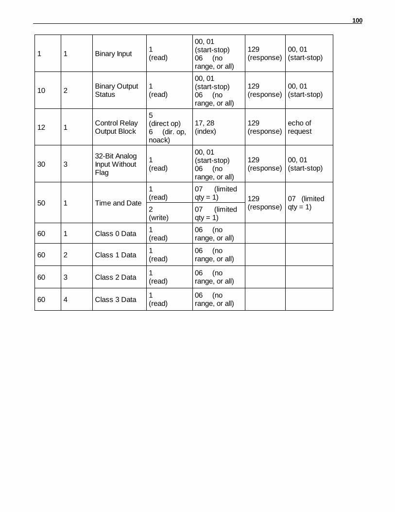
100
1 1 Binary Input1 (read)
00, 01 (start-stop)06 (norange, or all)
129 (response)
00, 01 (start-stop)
10 2Binary OutputStatus
1 (read)
00, 01 (start-stop)06 (norange, or all)
129 (response)
00, 01 (start-stop)
12 1Control RelayOutput Block
5 (direct op)6 (dir. op,noack)
17, 28 (index)
129 (response)
echo ofrequest
30 332-Bit AnalogInput WithoutFlag
1 (read)
00, 01 (start-stop)06 (norange, or all)
129 (response)
00, 01 (start-stop)
50 1 Time and Date
1 (read)
07 (limitedqty = 1) 129
(response)07 (limitedqty = 1)2
(write)07 (limitedqty = 1)
60 1 Class 0 Data1 (read)
06 (norange, or all)
60 2 Class 1 Data1 (read)
06 (norange, or all)
60 3 Class 2 Data1 (read)
06 (norange, or all)
60 4 Class 3 Data1 (read)
06 (norange, or all)

101
DNP V3.0 Point List
The tables below identify all the default data points provided by the NetGuardian 832A/864A G5 DNP3.
Binary Input Points
Binary Input PointsStatic Variation: Obj 01 Var 01 - Binary Input w/o statusRequest function codes supported: 1 (read)
PointIndex
Description Class
0-63 Discrete Alarms 1 - 64 1
64-95 Ping Targets 1
96-127 Unused 1
128 Timed Tick 1
129 Exp. Module Callout 1
130 Network Time Server 1
131 Accumulation Event 1
132 Duplicate IP Address 1
133 WAN Disconnected 1
134 ECU Emergency Unlock 1
135 D-Wire sensor not detected 1
136 ECU Door Violation 1
137 Maintenance Mode 1
138 DSCP timeout 1
139 Wireless Sensor Power Fault 1
140 Wireless Sensor Power Low 1
141 Unused 1
142 Unused 1
143 Unused 1
144 Unit Reset 1
145 PPP Backup Mode 1
146 Unused 1
147 Lost Provisioning 1
148 DCP Poller Inactive 1
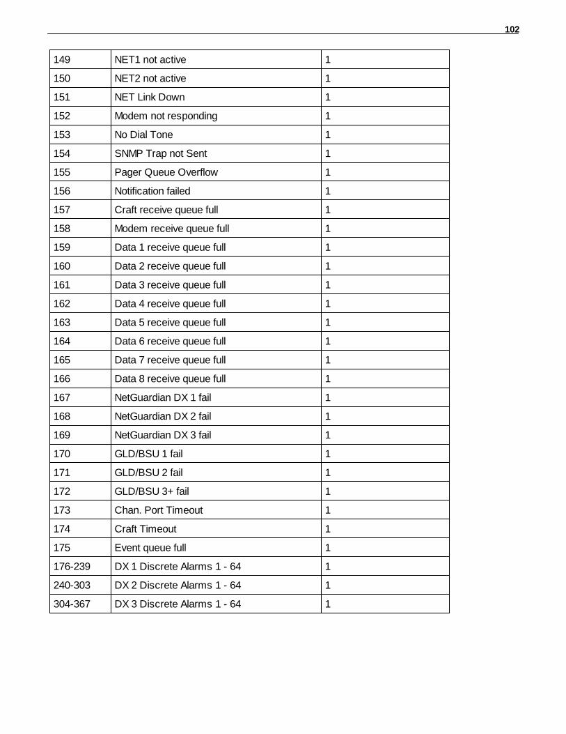
102
149 NET1 not active 1
150 NET2 not active 1
151 NET Link Down 1
152 Modem not responding 1
153 No Dial Tone 1
154 SNMP Trap not Sent 1
155 Pager Queue Overflow 1
156 Notification failed 1
157 Craft receive queue full 1
158 Modem receive queue full 1
159 Data 1 receive queue full 1
160 Data 2 receive queue full 1
161 Data 3 receive queue full 1
162 Data 4 receive queue full 1
163 Data 5 receive queue full 1
164 Data 6 receive queue full 1
165 Data 7 receive queue full 1
166 Data 8 receive queue full 1
167 NetGuardian DX 1 fail 1
168 NetGuardian DX 2 fail 1
169 NetGuardian DX 3 fail 1
170 GLD/BSU 1 fail 1
171 GLD/BSU 2 fail 1
172 GLD/BSU 3+ fail 1
173 Chan. Port Timeout 1
174 Craft Timeout 1
175 Event queue full 1
176-239 DX 1 Discrete Alarms 1 - 64 1
240-303 DX 2 Discrete Alarms 1 - 64 1
304-367 DX 3 Discrete Alarms 1 - 64 1
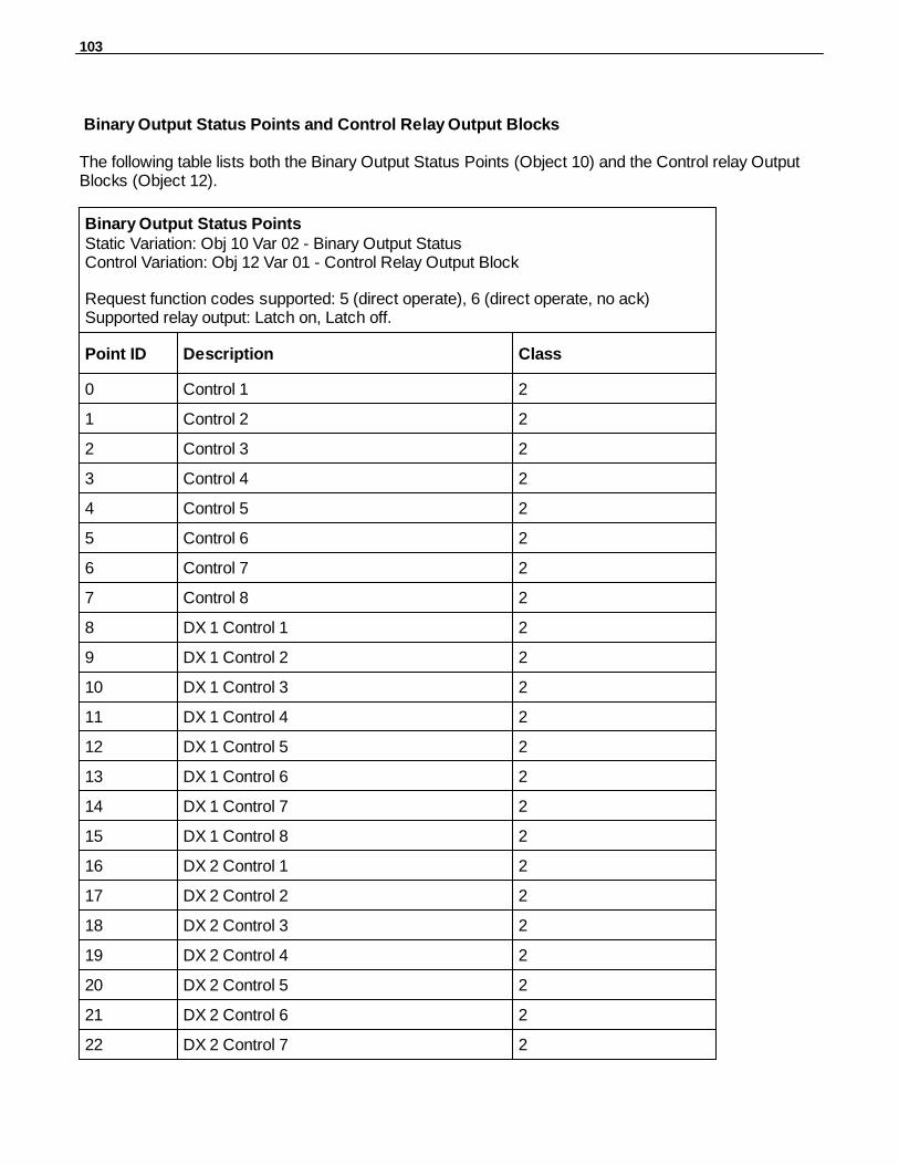
103
Binary Output Status Points and Control Relay Output Blocks
The following table lists both the Binary Output Status Points (Object 10) and the Control relay OutputBlocks (Object 12).
Binary Output Status PointsStatic Variation: Obj 10 Var 02 - Binary Output StatusControl Variation: Obj 12 Var 01 - Control Relay Output Block
Request function codes supported: 5 (direct operate), 6 (direct operate, no ack)Supported relay output: Latch on, Latch off.
Point ID Description Class
0 Control 1 2
1 Control 2 2
2 Control 3 2
3 Control 4 2
4 Control 5 2
5 Control 6 2
6 Control 7 2
7 Control 8 2
8 DX 1 Control 1 2
9 DX 1 Control 2 2
10 DX 1 Control 3 2
11 DX 1 Control 4 2
12 DX 1 Control 5 2
13 DX 1 Control 6 2
14 DX 1 Control 7 2
15 DX 1 Control 8 2
16 DX 2 Control 1 2
17 DX 2 Control 2 2
18 DX 2 Control 3 2
19 DX 2 Control 4 2
20 DX 2 Control 5 2
21 DX 2 Control 6 2
22 DX 2 Control 7 2

104
23 DX 2 Control 8 2
24 DX 3 Control 1 2
25 DX 3 Control 2 2
26 DX 3 Control 3 2
27 DX 3 Control 4 2
28 DX 3 Control 5 2
29 DX 3 Control 6 2
30 DX 3 Control 7 2
31 DX 3 Control 8 2
Analog Inputs
The following table lists Analog Inputs (Object 30). It is important to note that Analog Inputs, AnalogOutput Control Blocks, and Analog Output Statuses are transmitted through DNP as singed numbers.
Analog InputsStatic Variation: Obj 30 Var 03 - 32-Bit analog w/o flagRequest function codes supported: 1 (read)
Point ID Description Default Unit Class
0 Analog Channel 1 Voltage (VDC) 3
1 Analog Channel 2 Voltage (VDC) 3
2 Analog Channel 3 Voltage (VDC) 3
3 Analog Channel 4 Voltage (VDC) 3
4 Analog Channel 5 Voltage (VDC) 3
5 Analog Channel 6 Voltage (VDC) 3
6 Analog Channel 7 Voltage (VDC) 3
7 Analog Channel 8 Voltage (VDC) 3
8 DX 1 Analog Channel 1 Voltage (VDC) 3
9 DX 1 Analog Channel 2 Voltage (VDC) 3
10 DX 1 Analog Channel 3 Voltage (VDC) 3
11 DX 1 Analog Channel 4 Voltage (VDC) 3
12 DX 1 Analog Channel 5 Voltage (VDC) 3
13 DX 1 Analog Channel 6 Voltage (VDC) 3
14 DX 1 Analog Channel 7 Voltage (VDC) 3
15 DX 1 Analog Channel 8 Voltage (VDC) 3
16 DX 2 Analog Channel 1 Voltage (VDC) 3
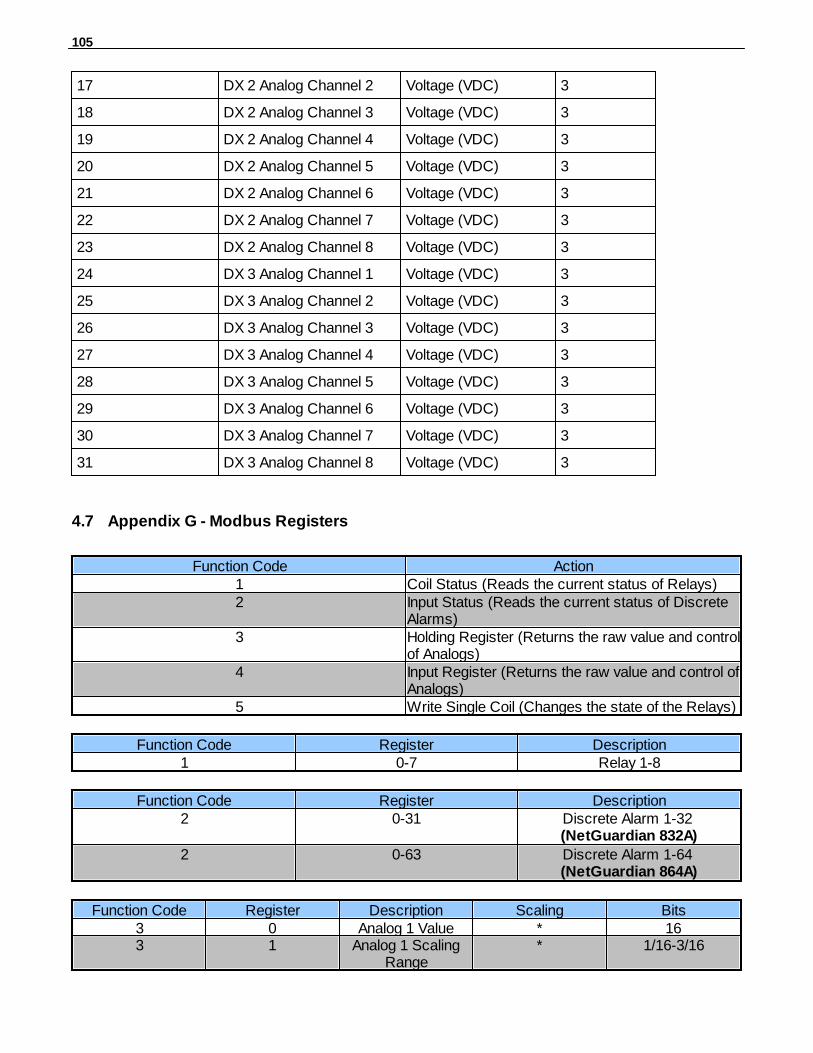
105
17 DX 2 Analog Channel 2 Voltage (VDC) 3
18 DX 2 Analog Channel 3 Voltage (VDC) 3
19 DX 2 Analog Channel 4 Voltage (VDC) 3
20 DX 2 Analog Channel 5 Voltage (VDC) 3
21 DX 2 Analog Channel 6 Voltage (VDC) 3
22 DX 2 Analog Channel 7 Voltage (VDC) 3
23 DX 2 Analog Channel 8 Voltage (VDC) 3
24 DX 3 Analog Channel 1 Voltage (VDC) 3
25 DX 3 Analog Channel 2 Voltage (VDC) 3
26 DX 3 Analog Channel 3 Voltage (VDC) 3
27 DX 3 Analog Channel 4 Voltage (VDC) 3
28 DX 3 Analog Channel 5 Voltage (VDC) 3
29 DX 3 Analog Channel 6 Voltage (VDC) 3
30 DX 3 Analog Channel 7 Voltage (VDC) 3
31 DX 3 Analog Channel 8 Voltage (VDC) 3
Appendix G - Modbus Registers4.7
Function Code Action1 Coil Status (Reads the current status of Relays)2 Input Status (Reads the current status of Discrete
Alarms)3 Holding Register (Returns the raw value and control
of Analogs)4 Input Register (Returns the raw value and control of
Analogs)5 Write Single Coil (Changes the state of the Relays)
Function Code Register Description1 0-7 Relay 1-8
Function Code Register Description2 0-31 Discrete Alarm 1-32
(NetGuardian 832A)
2 0-63 Discrete Alarm 1-64 (NetGuardian 864A)
Function Code Register Description Scaling Bits3 0 Analog 1 Value * 163 1 Analog 1 Scaling
Range* 1/16-3/16

106
Function Code Register Description Scaling Bits3 1 Analog 1 Sign * 7/163 2 Analog 2 Value * 163 3 Analog 2 Scaling
Range* 1/16-3/16
3 3 Analog 2 Sign * 7/163 4 Analog 3 Value * 163 5 Analog 3 Scaling
Range* 1/16-3/16
3 5 Analog 3 Sign * 7/163 6 Analog 4 Value * 163 7 Analog 4 Scaling
Range* 1/16-3/16
3 7 Analog 4 Sign * 7/163 8 Analog 5 Value * 163 9 Analog 5 Scaling
Range* 1/16-3/16
3 9 Analog Sign * 7/163 10 Analog 6 Value * 163 11 Analog 6 Scaling
Range* 1/16-3/16
3 11 Analog 6 Sign * 7/163 12 Analog 7 Value * 163 13 Analog 7 Scaling
Range* 1/16-3/16
3 13 Analog 7 Sign * 7/163 14 Analog 8 Value * 163 15 Analog 8 Scaling
Range* 1/16-3/16
3 15 Analog 8 Sign * 7/16* See Scaling Range Table Below
Function Code Register Description Scaling Bits4 0 Analog 1 Value * 164 1 Analog 1 Scaling
Range* 1/16-3/16
4 1 Analog 1 Sign * 7/164 2 Analog 2 Value * 164 3 Analog 2 Scaling
Range* 1/16-3/16
4 3 Analog 2 Sign * 7/164 4 Analog 3 Value * 164 5 Analog 3 Scaling
Range* 1/16-3/16
4 5 Analog 3 Sign * 7/164 6 Analog 4 Value * 164 7 Analog 4 Scaling
Range* 1/16-3/16
4 7 Analog 4 Sign * 7/164 8 Analog 5 Value * 164 9 Analog 5 Scaling
Range* 1/16-3/16

107
Function Code Register Description Scaling Bits4 9 Analog 5 Sign * 7/164 10 Analog 6 Value * 164 11 Analog 6 Scaling
Range* 1/16-3/16
4 11 Analog 6 Sign * 7/164 12 Analog 7 Value * 164 13 Analog 7 Scaling
Range* 1/16-3/16
4 13 Analog 7 Sign * 7/164 14 Analog 8 Value * 164 15 Analog 8 Scaling
Range* 1/16-3/16
4 15 Analog 8 Sign * 7/16* See Scaling Range Table Below
Function Code Register Description5 0-7 Relay 1-8
Function Code Register Description2 1200-1215 NetGuardian E16 DX Expansion 1
Alarm 1-161 1300-1315 NetGuardian E16 DX Expansion 1
Relay 1-162 1400-1415 NetGuardian E16 DX Expansion 2
Alarm 1-161 1500-1515 NetGuardian E16 DX Expansion 2
Relay 1-162 1600-1615 NetGuardian E16 DX Expansion 3
Alarm 1-161 1700-1715 NetGuardian E16 DX Expansion 3
Relay 1-16
Function Code Register Description5 1300-1315 NetGuardian E16 DX Expansion 1
Relay 1-165 1500-1515 NetGuardian E16 DX Expansion 2
Relay 1-165 1700-1715 NetGuardian E16 DX Expansion 3
Relay 1-16
Function Code Register Description2 1200-1263 NetGuardian 480 (as DX) Alarm 1-
642 1316-1331 NetGuardian 480 (as DX) Alarm
65-801 1300-1303 NetGuardian 480 (as DX) Relay 1-
4
Function Code Register Description5 0-7 NetGuardian 480 (as DX) Relay 1-

108
Function Code Register Description4
Function Code Register Description2 1200-1247 NetGuardian DX48 Expansion 1
Alarm 1-481 1300-1307 NetGuardian DX48 Expansion 1
Relay 1-82 1400-1447 NetGuardian DX48 Expansion 2
Alarm 1-481 1500-1507 NetGuardian DX48 Expansion 2
Relay 1-82 1600-1647 NetGuardian DX48 Expansion 3
Alarm 1-481 1700-1707 NetGuardian DX48 Expansion 3
Relay 1-8
Function Code Register Description5 1300-1315 NetGuardian DX48 Expansion 1
Relay 1-85 1500-1515 NetGuardian DX48 Expansion 2
Relay 1-85 1700-1715 NetGuardian DX48 Expansion 3
Relay 1-8
Function Code Register Description2 1200-1231 NetGuardian 832A (as DX)
Expansion 1 Alarm 1-321 1300-1307 NetGuardian 832A (as DX)
Expansion 1 Relay 1-82 1400-1431 NetGuardian 832A (as DX)
Expansion 2 Alarm 1-321 1500-1507 NetGuardian 832A (as DX)
Expansion 1 Relay 1-82 1600-1631 NetGuardian 832A (as DX)
Expansion 3 Alarm 1-321 1700-1707 NetGuardian 832A (as DX)
Expansion 1 Relay 1-8
Function Code Register Description2 1200-1263 NetGuardian 864A (as DX)
Expansion 1 Alarm 1-641 1300-1307 NetGuardian 864A (as DX)
Expansion 1 Relay 1-82 1400-1463 NetGuardian 864A (as DX)
Expansion 2 Alarm 1-641 1500-1507 NetGuardian 864A (as DX)
Expansion 1 Relay 1-82 1600-1663 NetGuardian 864A (as DX)
Expansion 3 Alarm 1-641 1700-1707 NetGuardian 864A (as DX)
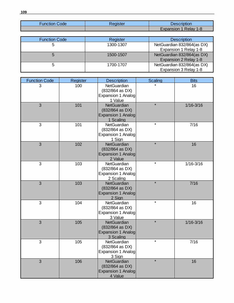
109
Function Code Register DescriptionExpansion 1 Relay 1-8
Function Code Register Description5 1300-1307 NetGuardian 832/864(as DX)
Expansion 1 Relay 1-85 1500-1507 NetGuardian 832/864(as DX)
Expansion 2 Relay 1-85 1700-1707 NetGuardian 832/864(as DX)
Expansion 3 Relay 1-8
Function Code Register Description Scaling Bits3 100 NetGuardian
(832/864 as DX)Expansion 1 Analog
1 Value
* 16
3 101 NetGuardian(832/864 as DX)
Expansion 1 Analog1 Scaling
* 1/16-3/16
3 101 NetGuardian(832/864 as DX)
Expansion 1 Analog1 Sign
* 7/16
3 102 NetGuardian(832/864 as DX)
Expansion 1 Analog2 Value
* 16
3 103 NetGuardian(832/864 as DX)
Expansion 1 Analog2 Scaling
* 1/16-3/16
3 103 NetGuardian(832/864 as DX)
Expansion 1 Analog2 Sign
* 7/16
3 104 NetGuardian(832/864 as DX)
Expansion 1 Analog3 Value
* 16
3 105 NetGuardian(832/864 as DX)
Expansion 1 Analog3 Scaling
* 1/16-3/16
3 105 NetGuardian(832/864 as DX)
Expansion 1 Analog3 Sign
* 7/16
3 106 NetGuardian(832/864 as DX)
Expansion 1 Analog4 Value
* 16
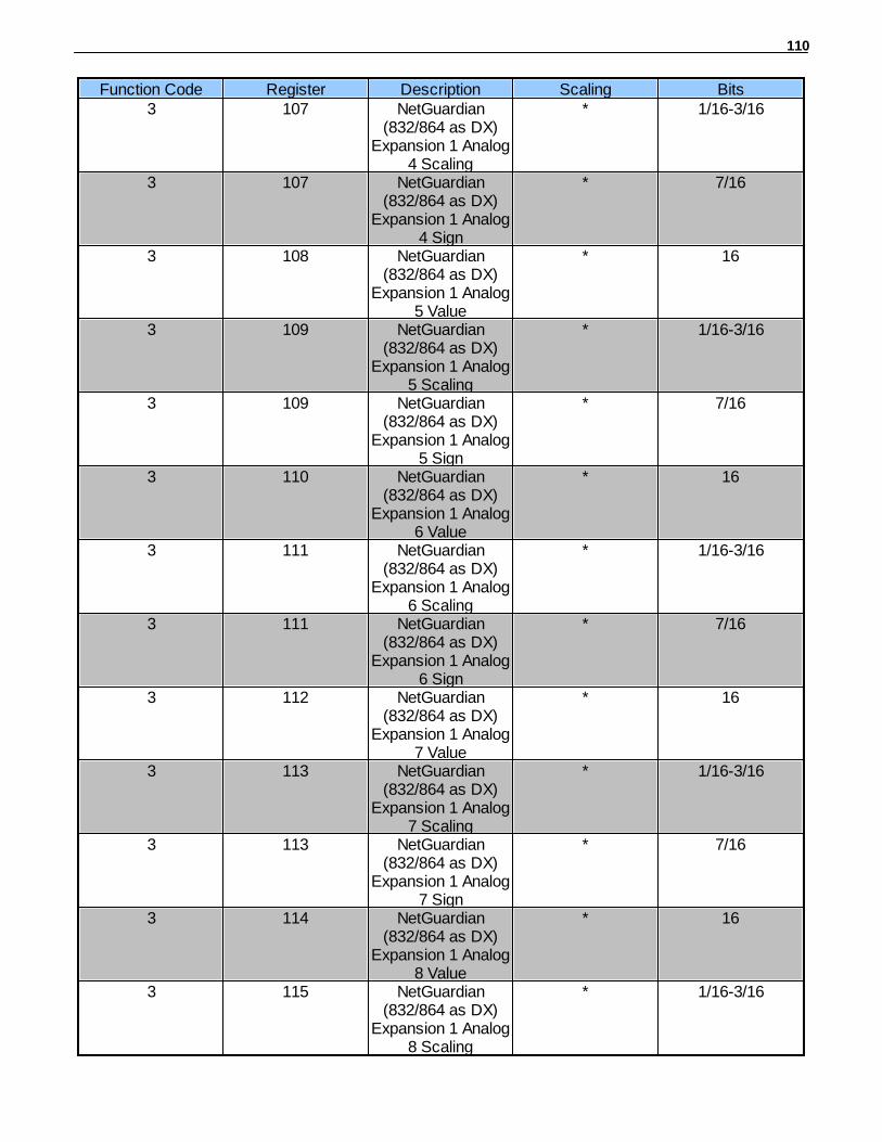
110
Function Code Register Description Scaling Bits3 107 NetGuardian
(832/864 as DX)Expansion 1 Analog
4 Scaling
* 1/16-3/16
3 107 NetGuardian(832/864 as DX)
Expansion 1 Analog4 Sign
* 7/16
3 108 NetGuardian(832/864 as DX)
Expansion 1 Analog5 Value
* 16
3 109 NetGuardian(832/864 as DX)
Expansion 1 Analog5 Scaling
* 1/16-3/16
3 109 NetGuardian(832/864 as DX)
Expansion 1 Analog5 Sign
* 7/16
3 110 NetGuardian(832/864 as DX)
Expansion 1 Analog6 Value
* 16
3 111 NetGuardian(832/864 as DX)
Expansion 1 Analog6 Scaling
* 1/16-3/16
3 111 NetGuardian(832/864 as DX)
Expansion 1 Analog6 Sign
* 7/16
3 112 NetGuardian(832/864 as DX)
Expansion 1 Analog7 Value
* 16
3 113 NetGuardian(832/864 as DX)
Expansion 1 Analog7 Scaling
* 1/16-3/16
3 113 NetGuardian(832/864 as DX)
Expansion 1 Analog7 Sign
* 7/16
3 114 NetGuardian(832/864 as DX)
Expansion 1 Analog8 Value
* 16
3 115 NetGuardian(832/864 as DX)
Expansion 1 Analog8 Scaling
* 1/16-3/16
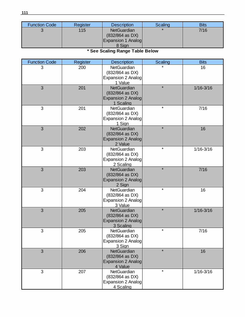
111
Function Code Register Description Scaling Bits3 115 NetGuardian
(832/864 as DX)Expansion 1 Analog
8 Sign
* 7/16
* See Scaling Range Table Below
Function Code Register Description Scaling Bits3 200 NetGuardian
(832/864 as DX)Expansion 2 Analog
1 Value
* 16
3 201 NetGuardian(832/864 as DX)
Expansion 2 Analog1 Scaling
* 1/16-3/16
3 201 NetGuardian(832/864 as DX)
Expansion 2 Analog1 Sign
* 7/16
3 202 NetGuardian(832/864 as DX)
Expansion 2 Analog2 Value
* 16
3 203 NetGuardian(832/864 as DX)
Expansion 2 Analog2 Scaling
* 1/16-3/16
3 203 NetGuardian(832/864 as DX)
Expansion 2 Analog2 Sign
* 7/16
3 204 NetGuardian(832/864 as DX)
Expansion 2 Analog3 Value
* 16
3 205 NetGuardian(832/864 as DX)
Expansion 2 Analog3 Scaling
* 1/16-3/16
3 205 NetGuardian(832/864 as DX)
Expansion 2 Analog3 Sign
* 7/16
3 206 NetGuardian(832/864 as DX)
Expansion 2 Analog4 Value
* 16
3 207 NetGuardian(832/864 as DX)
Expansion 2 Analog4 Scaling
* 1/16-3/16

112
Function Code Register Description Scaling Bits3 207 NetGuardian
(832/864 as DX)Expansion 2 Analog
4 Sign
* 7/16
3 208 NetGuardian(832/864 as DX)
Expansion 2 Analog5 Value
* 16
3 209 NetGuardian(832/864 as DX)
Expansion 2 Analog5 Scaling
* 1/16-3/16
3 209 NetGuardian(832/864 as DX)
Expansion 2 Analog5 Sign
* 7/16
3 210 NetGuardian(832/864 as DX)
Expansion 2 Analog6 Value
* 16
3 211 NetGuardian(832/864 as DX)
Expansion 2 Analog6 Scaling
* 1/16-3/16
3 211 NetGuardian(832/864 as DX)
Expansion 2 Analog6 Sign
* 7/16
3 212 NetGuardian(832/864 as DX)
Expansion 2 Analog7 Value
* 16
3 213 NetGuardian(832/864 as DX)
Expansion 2 Analog7 Scaling
* 1/16-3/16
3 213 NetGuardian(832/864 as DX)
Expansion 2 Analog7 Sign
* 7/16
3 214 NetGuardian(832/864 as DX)
Expansion 2 Analog8 Value
* 16
3 215 NetGuardian(832/864 as DX)
Expansion 2 Analog8 Scaling
* 1/16-3/16
3 215 NetGuardian(832/864 as DX)
Expansion 2 Analog8 Sign
* 7/16

113
* See Scaling Range Table Below
Function Code Register Description Scaling Bits3 300 NetGuardian
(832/864 as DX)Expansion 3 Analog
1 Value
* 16
3 301 NetGuardian(832/864 as DX)
Expansion 3 Analog1 Scaling
* 1/16-3/16
3 301 NetGuardian(832/864 as DX)
Expansion 3 Analog1 Sign
* 7/16
3 302 NetGuardian(832/864 as DX)
Expansion 3 Analog2 Value
* 16
3 303 NetGuardian(832/864 as DX)
Expansion 3 Analog2 Scaling
* 1/16-3/16
3 303 NetGuardian(832/864 as DX)
Expansion 3 Analog2 Sign
* 7/16
3 304 NetGuardian(832/864 as DX)
Expansion 3 Analog3 Value
* 16
3 305 NetGuardian(832/864 as DX)
Expansion 3 Analog3 Scaling
* 1/16-3/16
3 305 NetGuardian(832/864 as DX)
Expansion 3 Analog3 Sign
* 7/16
3 306 NetGuardian(832/864 as DX)
Expansion 3 Analog4 Value
* 16
3 307 NetGuardian(832/864 as DX)
Expansion 3 Analog4 Scaling
* 1/16-3/16
3 307 NetGuardian(832/864 as DX)
Expansion 3 Analog4 Sign
* 7/16
3 308 NetGuardian(832/864 as DX)
* 16

114
Function Code Register Description Scaling BitsExpansion 3 Analog
5 Value3 309 NetGuardian
(832/864 as DX)Expansion 3 Analog
5 Scaling
* 1/16-3/16
3 309 NetGuardian(832/864 as DX)
Expansion 3 Analog5 Sign
* 7/16
3 310 NetGuardian(832/864 as DX)
Expansion 3 Analog6 Value
* 16
3 311 NetGuardian(832/864 as DX)
Expansion 3 Analog6 Scaling
* 1/16-3/16
3 311 NetGuardian(832/864 as DX)
Expansion 3 Analog6 Sign
* 7/16
3 312 NetGuardian(832/864 as DX)
Expansion 3 Analog7 Value
* 16
3 313 NetGuardian(832/864 as DX)
Expansion 3 Analog7 Scaling
* 1/16-3/16
3 313 NetGuardian(832/864 as DX)
Expansion 3 Analog7 Sign
* 7/16
3 314 NetGuardian(832/864 as DX)
Expansion 3 Analog8 Value
* 16
3 315 NetGuardian(832/864 as DX)
Expansion 3 Analog8 Scaling
* 1/16-3/16
3 315 NetGuardian(832/864 as DX)
Expansion 3 Analog8 Sign
* 7/16
* See Scaling Range Table Below
Function Code Register Description Scaling Bits4 100 NetGuardian
(832/864 as DX)* 16
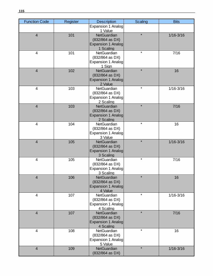
115
Function Code Register Description Scaling BitsExpansion 1 Analog
1 Value4 101 NetGuardian
(832/864 as DX)Expansion 1 Analog
1 Scaling
* 1/16-3/16
4 101 NetGuardian(832/864 as DX)
Expansion 1 Analog1 Sign
* 7/16
4 102 NetGuardian(832/864 as DX)
Expansion 1 Analog2 Value
* 16
4 103 NetGuardian(832/864 as DX)
Expansion 1 Analog2 Scaling
* 1/16-3/16
4 103 NetGuardian(832/864 as DX)
Expansion 1 Analog2 Scaling
* 7/16
4 104 NetGuardian(832/864 as DX)
Expansion 1 Analog3 Value
* 16
4 105 NetGuardian(832/864 as DX)
Expansion 1 Analog3 Scaling
* 1/16-3/16
4 105 NetGuardian(832/864 as DX)
Expansion 1 Analog3 Scaling
* 7/16
4 106 NetGuardian(832/864 as DX)
Expansion 1 Analog4 Value
* 16
4 107 NetGuardian(832/864 as DX)
Expansion 1 Analog4 Scaling
* 1/16-3/16
4 107 NetGuardian(832/864 as DX)
Expansion 1 Analog4 Scaling
* 7/16
4 108 NetGuardian(832/864 as DX)
Expansion 1 Analog5 Value
* 16
4 109 NetGuardian(832/864 as DX)
* 1/16-3/16

116
Function Code Register Description Scaling BitsExpansion 1 Analog
5 Scaling4 109 NetGuardian
(832/864 as DX)Expansion 1 Analog
5 Scaling
* 7/16
4 110 NetGuardian(832/864 as DX)
Expansion 1 Analog6 Value
* 16
4 111 NetGuardian(832/864 as DX)
Expansion 1 Analog6 Scaling
* 1/16-3/16
4 111 NetGuardian(832/864 as DX)
Expansion 1 Analog6 Scaling
* 7/16
4 112 NetGuardian(832/864 as DX)
Expansion 1 Analog7 Value
* 16
4 113 NetGuardian(832/864 as DX)
Expansion 1 Analog7 Scaling
* 1/16-3/16
4 113 NetGuardian(832/864 as DX)
Expansion 1 Analog7 Scaling
* 7/16
4 114 NetGuardian(832/864 as DX)
Expansion 1 Analog8 Value
* 16
4 115 NetGuardian(832/864 as DX)
Expansion 1 Analog8 Scaling
* 1/16-3/16
4 115 NetGuardian(832/864 as DX)
Expansion 1 Analog8 Scaling
* 7/16
* See Scaling Range Table Below
Function Code Register Description Scaling Bits4 200 NetGuardian
(832/864 as DX)Expansion 2 Analog
1 Value
* 16
4 201 NetGuardian(832/864 as DX)
* 1/16-3/16

117
Function Code Register Description Scaling BitsExpansion 2 Analog
1 Scaling4 201 NetGuardian
(832/864 as DX)Expansion 2 Analog
1 Sign
* 7/16
4 202 NetGuardian(832/864 as DX)
Expansion 2 Analog2 Value
* 16
4 203 NetGuardian(832/864 as DX)
Expansion 2 Analog2 Scaling
* 1/16-3/16
4 203 NetGuardian(832/864 as DX)
Expansion 2 Analog2 Sign
* 7/16
4 204 NetGuardian(832/864 as DX)
Expansion 2 Analog3 Value
* 16
4 205 NetGuardian(832/864 as DX)
Expansion 2 Analog3 Scaling
* 1/16-3/16
4 205 NetGuardian(832/864 as DX)
Expansion 2 Analog3 Sign
* 7/16
4 206 NetGuardian(832/864 as DX)
Expansion 2 Analog4 Value
* 16
4 207 NetGuardian(832/864 as DX)
Expansion 2 Analog4 Scaling
* 1/16-3/16
4 207 NetGuardian(832/864 as DX)
Expansion 2 Analog4 Sign
* 7/16
4 208 NetGuardian(832/864 as DX)
Expansion 2 Analog5 Value
* 16
4 209 NetGuardian(832/864 as DX)
Expansion 2 Analog5 Scaling
* 1/16-3/16
4 209 NetGuardian(832/864 as DX)
* 7/16
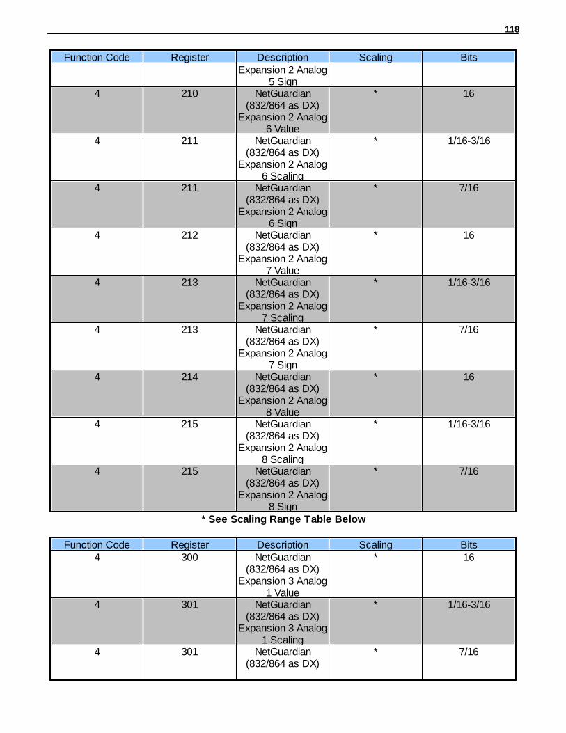
118
Function Code Register Description Scaling BitsExpansion 2 Analog
5 Sign4 210 NetGuardian
(832/864 as DX)Expansion 2 Analog
6 Value
* 16
4 211 NetGuardian(832/864 as DX)
Expansion 2 Analog6 Scaling
* 1/16-3/16
4 211 NetGuardian(832/864 as DX)
Expansion 2 Analog6 Sign
* 7/16
4 212 NetGuardian(832/864 as DX)
Expansion 2 Analog7 Value
* 16
4 213 NetGuardian(832/864 as DX)
Expansion 2 Analog7 Scaling
* 1/16-3/16
4 213 NetGuardian(832/864 as DX)
Expansion 2 Analog7 Sign
* 7/16
4 214 NetGuardian(832/864 as DX)
Expansion 2 Analog8 Value
* 16
4 215 NetGuardian(832/864 as DX)
Expansion 2 Analog8 Scaling
* 1/16-3/16
4 215 NetGuardian(832/864 as DX)
Expansion 2 Analog8 Sign
* 7/16
* See Scaling Range Table Below
Function Code Register Description Scaling Bits4 300 NetGuardian
(832/864 as DX)Expansion 3 Analog
1 Value
* 16
4 301 NetGuardian(832/864 as DX)
Expansion 3 Analog1 Scaling
* 1/16-3/16
4 301 NetGuardian(832/864 as DX)
* 7/16
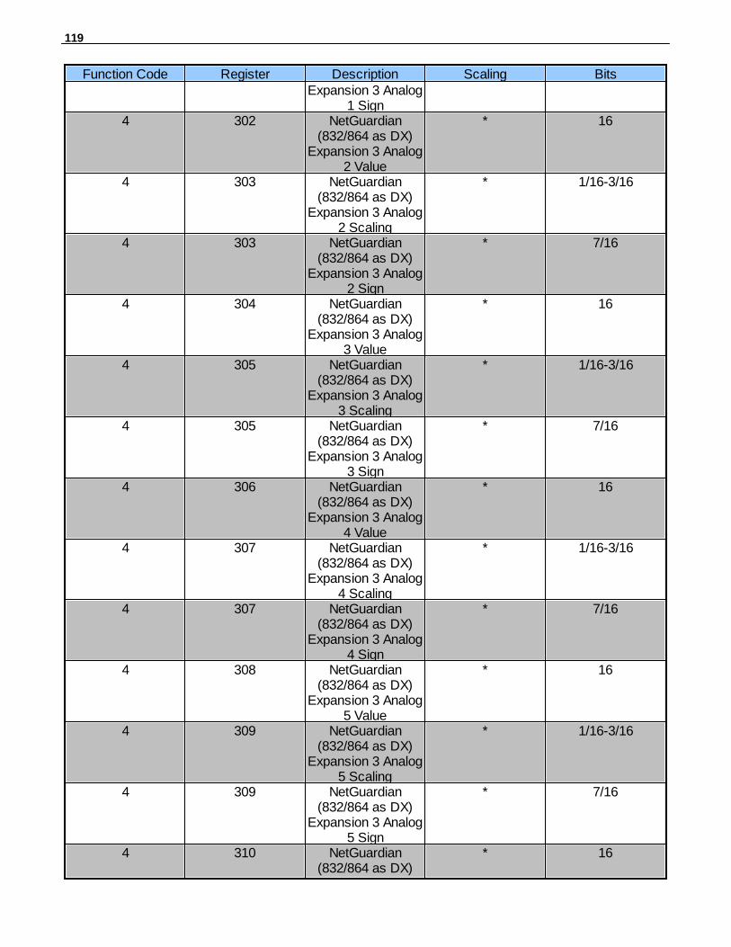
119
Function Code Register Description Scaling BitsExpansion 3 Analog
1 Sign4 302 NetGuardian
(832/864 as DX)Expansion 3 Analog
2 Value
* 16
4 303 NetGuardian(832/864 as DX)
Expansion 3 Analog2 Scaling
* 1/16-3/16
4 303 NetGuardian(832/864 as DX)
Expansion 3 Analog2 Sign
* 7/16
4 304 NetGuardian(832/864 as DX)
Expansion 3 Analog3 Value
* 16
4 305 NetGuardian(832/864 as DX)
Expansion 3 Analog3 Scaling
* 1/16-3/16
4 305 NetGuardian(832/864 as DX)
Expansion 3 Analog3 Sign
* 7/16
4 306 NetGuardian(832/864 as DX)
Expansion 3 Analog4 Value
* 16
4 307 NetGuardian(832/864 as DX)
Expansion 3 Analog4 Scaling
* 1/16-3/16
4 307 NetGuardian(832/864 as DX)
Expansion 3 Analog4 Sign
* 7/16
4 308 NetGuardian(832/864 as DX)
Expansion 3 Analog5 Value
* 16
4 309 NetGuardian(832/864 as DX)
Expansion 3 Analog5 Scaling
* 1/16-3/16
4 309 NetGuardian(832/864 as DX)
Expansion 3 Analog5 Sign
* 7/16
4 310 NetGuardian(832/864 as DX)
* 16

120
Function Code Register Description Scaling BitsExpansion 3 Analog
6 Value4 311 NetGuardian
(832/864 as DX)Expansion 3 Analog
6 Scaling
* 1/16-3/16
4 311 NetGuardian(832/864 as DX)
Expansion 3 Analog6 Sign
* 7/16
4 312 NetGuardian(832/864 as DX)
Expansion 3 Analog7 Value
* 16
4 313 NetGuardian(832/864 as DX)
Expansion 3 Analog7 Scaling
* 1/16-3/16
4 313 NetGuardian(832/864 as DX)
Expansion 3 Analog7 Sign
* 7/16
4 314 NetGuardian(832/864 as DX)
Expansion 3 Analog8 Value
* 16
4 315 NetGuardian(832/864 as DX)
Expansion 3 Analog8 Scaling
* 1/16-3/16
4 315 NetGuardian(832/864 as DX)
Expansion 3 Analog8 Sign
* 7/16
* See Scaling Range Table Below
Scaling Range TableScaling Range Scaling Value*
0 0.0015228211 0.0038636782 0.0080983983 0.018197654 0.02306719
*Get correct Scaling Value by using corresponding Scaling Range
Example 1: Modbus Response:
Analog 1 Value: [08][72] = 2162Analog 1 Scaling Range: 2 = 0.008098398Analog 1 Sign = 0
121
Scaled Value:2162 * 0.008098398 = 17.5087(if Analog Sign = 1 then multiply by -1)Scaled Value = 17.5087
Example 2:Modbus Response:
Analog 1 Value: [0A][47] = 2631Analog 1 Scaling Range: 3 = 0.01819765Analog 1 Sign = 1
Scaled Value:2631 * 0.01819765 = 47.8780(if Analog Sign = 1 then multiply by -1)Scaled Value = 47.8780 * -1Scaled Value = -47.8780
Frequently Asked Questions5
Here are answers to some common questions from NetGuardian users. The latest FAQs can be foundon the NetGuardian support web page, http://www.dpstelecom.com.
If you have a question about the NetGuardian, please call us at (559) 454-1600 or e-mail us [email protected]
General FAQs5.1
Q. How do I Telnet to the NetGuardian?A. You must use Port 2002 to connect to the NetGuardian. Configure your Telnet client to connect
using TCP/IP (not Telnet, or any other port options). For connection information, enter the IPaddress of the NetGuardian and Port 2002. For example, to connect to the NetGuardian using thestandard Windows Telnet client, click Start, click Run, and type Telnet <NetGuardian IP address>2002.
Q. How can I back up the current configuration of my NetGuardian?A. There are two ways. NGEdit can read the configuration of your NetGuardian and save the
configuration to your PC's hard disk or a flash drive. With NGEdit you can also make changes to theconfiguration file and write the changed configuration to the NetGuardian's NVRAM. The other way isto use File Transfer Protocol (FTP). You can use FTP to read configuration files from or write files tothe NetGuardian's NVRAM, but you can't use FTP to edit configuration files.
Q. Can I use my NetGuardian as a proxy server to access TTY interfaces on my third-partyserial equipment?
A. You can use Data Ports 1–8, located on the back of the NetGuardian, to connect to serial devices,as long as your devices support RS-232. To make a proxy connection, you must define the correctTCP port for each serial port. To define TCP ports, you must first connect directly to theNetGuardian through its IP address. Once you have connected to the NetGuardian, you can definethe TCP ports through the NetGuardian's TTY or Web Browser Interface configuration interfaces.
Q. What do the terms alarm point, display, port, and address mean?A. These terms define the exact location of a network alarm, from the most specific (an individual

122
alarm point) to the most general (an entire monitored device). An alarm point is a numberrepresenting an actual contact closure that is activated when an alarm condition occurs. Forexample, an alarm point might represent a low oil sensor in a generator or a open/closed sensor in adoor. A display is a logical group of 64 alarm points. A port is traditionally the actual physical serialport through which the monitoring device collects data. The address is a number representing themonitored device. The terms port and address have been extended to refer to logical, or virtual,ports and addresses. For example, the NetGuardian reports internal alarms on Port 99, address 1.
Q. What characteristics of an alarm point can I configure through software? For instance, can Iconfigure Point 4 to sense an active-low (normally closed) signal, or Point 5 to sense a levelor edge?
A. The NetGuardian alarm points are level sensed and can be software-configured to generate analarm on either a high (normally open) or low (normally closed) level.
Q. When I connect to the NetGuardian through the craft port on the front panel it eitherdoesn't work right or it doesn't work at all. What's going on?
A. Make sure your using the right COM port settings. The standard settings for the craft port are 9600baud, 8 bits, no parity, and 1 stop bit. Flow control must be set to none. Flow control normallydefaults to hardware in most terminal programs, and this will not work correctly with theNetGuardian.
Q. I just changed the port settings for one of my data ports, but the changes did not seem totake effect even after I wrote the NVRAM.
A. In order for data port and craft port changes (including changes to the baud rate and word format) totake effect, the NetGuardian must be rebooted. Whenever you make changes, remember to writethem to the NetGuardian's NVRAM so they will be saved when the unit is rebooted.
Q. How do I get my NetGuardian on the network?A. Before the NetGuardian will work on your LAN, the unit address (IP address), the subnet mask, and
the default gateway must be set. A sample configuration could look like this:unit address: 192.168.1.100subnet mask: 255.255.255.0Default Gateway: 192.168.1.1
Always remember to save your changes by writing to the NVRAM. Any modifications of theNetGuardian's IP configuration will also require a reboot.
Q. Does the PPP allow upload of new firmware over PPP?A. The NetGuardian supports all PPP upload capabilities with the exception of firmware.
Q. I'm using HyperTerminal to connect to the NetGuardian through the craft port, but the unitwon't accept input when I get to the first level menu.
A. Make sure you turn off all handshaking in HyperTerminal.
Q. I can't change the craft port baud rate.A. Once you select a higher baud rate, you must set your terminal emulation to that new baud rate and
enter the DPSCFG and press Enter escape sequence. The craft port interprets a break key as anoverride to 9600 baud. At slower baud rates, normal keys can appear as a break.
Q. The LAN line LED is green on my NetGuardian, but I can't poll it from my T/MonXM master.A. Some routers will not forward to an IP address until the MAC address has been registered with the
router. You need to enter the IP address of your T/MonXM system or your gateway in the ping table.
123
SNMP FAQs5.2
Q. Which version of SNMP is supported by the SNMP agent on the NetGuardian?A. SNMP v1, v2C, and v3 on the NetGuardian G5 series.
Q. How do I configure the NetGuardian to send traps to an SNMP manager? Is there a separateMIB for the NetGuardian? How many SNMP managers can the agent send traps to? And howdo I set the IP address of the SNMP manager and the community string to be used whensending traps?
A. The NetGuardian begins sending traps as soon as the SNMP managers are defined. TheNetGuardian MIB is included on the NetGuardian Resource CD. The MIB should be compiled on yourSNMP manager. (Note: MIB versions may change in the future.) The unit supports a main SNMPmanager, which is configured by entering its IP address in the trap address field of Ethernet PortSetup. You can also configure up to eight secondary SNMP managers, which is configured byselecting the secondary SNMP managers as pager recipients. Community strings are configuredglobally for all SNMP managers. To configure the community strings, choose System from the Editmenu, and enter appropriate values in the Get, Set, and Trap fields.
Q. Does the NetGuardian support MIB-2 and/or any other standard MIBs?A. The NetGuardian supports the bulk of MIB-2.
Q. Does the NetGuardian SNMP agent support both NetGuardian and T/MonXM variables?A. The NetGuardian SNMP agent manages an embedded MIB that supports only the NetGuardian's
RTU variables. The T/MonXM variables are included in the distributed MIB only to provide SNMPmanagers with a single MIB for all DPS Telecom products.
Q. How many traps are triggered when a single point is set or cleared? The MIB defines trapslike major alarm set/cleared, RTU point set, and a lot of granular traps, which could implythat more than one trap is sent when a change of state occurs on one point.
A. Generally, a single change of state generates a single trap, but there are two exception to this rule. Exception 1: the first alarm in an all clear condition generates an additional summary point set trap.Exception 2: the final clear alarm that triggers an all clear condition generates an additional summarypoint clear trap.
Q. What does point map mean?A. A point map is a single MIB leaf that presents the current status of a 64-alarm-point display in an
ASCII-readable form, where a "."represents a clear and an "x" represents an alarm.
Q. The NetGuardian manual talks about eight control relay outputs. How do I control thesefrom my SNMP manager?
A. The control relays are operated by issuing the appropriate set commands, which are contained inthe DPS Telecom MIB. For more information about the set commands, see Reference Information,Display Mapping, in any of the NetGuardian software configuration guides.
Q. How can I associate descriptive information with a point for the RTU granular traps?A. The NetGuardian alarm point descriptions are individually defined using the Web Browser Interface,
TTY, or NGEdit configuration interfaces.
Q. My SNMP traps aren't getting through. What should I try?A. Try these three steps:
1. Make sure that the trap address (IP address of the SNMP manager) is defined. (If youchanged the trap address, make sure you saved the change to NVRAM and rebooted.)

124
2. Make sure all alarm points are configured to send SNMP traps.3. Make sure the NetGuardian and the SNMP manager are both on the network. Use the
NetGuardian's ping command to ping the SNMP manager.
Pager FAQs5.3
Q. Why won't my alpha pager work?A. To configure the NetGuardian to send alarm notifications to an alpha pager, enter the data phone
number for your pager in the Phone Number field. This phone number should connect to your pagerservices modem. Then enter the PIN for your pager in the PIN/Rcpt/Port field. You don't need toenter anything in any of the other fields. If you still don't receive pages, try setting the Dial Modem Initstring to ATS37=9. This will limit the NetGuardian's connection speed.
Q. Numeric pages don't come in or are cut off in the middle of the message. What's wrong?A. You need to set a delay between the time the NetGuardian dials your pager number and the time the
NetGuardian begins sending the page message. You can set the delay in the Pager Number field,where you enter your pager number. First enter the pager number, then enter some commasdirectly after the number. Each comma represents a two-second delay. So, for example, if youwanted an eight-second delay, you would enter 555-1212,,,, in the Pager Number field.
Q. What do I need to do to set up email notifications?A. You need to assign the NetGuardian an email address and list the addresses of email recipients.
Let's explain some terminology. An email address consists of two parts, the user name (everythingbefore the @ sign) and the domain (everything after the @ sign). To assign the NetGuardian anemail address, choose System from the Edit menu. Enter the NetGuardian's user name in theName field (it can't include any spaces) and the domain in the Location field. For example, if thesystem configuration reads:
Name: netguardianLocation: proactive.com
Then email notifications from the NetGuardian will be sent from the [email protected] next step is to list the email recipients. Choose Pagers from the Edit menu. For each emailrecipient, enter his or her email domain in the Phone/Domain field and his or her user name in thePIN/Rcpt/Port field. You must also enter the IP address of an SNMP server in the IPA field.

125
Technical Support6
DPS Telecom products are backed by our courteous, friendly Technical Support representatives, whowill give you the best in fast and accurate customer service. To help us help you better, please take thefollowing steps before calling Technical Support:
1. Check the DPS Telecom website.You will find answers to many common questions on the DPS Telecom website, at http://www.dpstelecom.com/support/. Look here first for a fast solution to your problem.
2. Prepare relevant information.
Having important information about your DPS Telecom product in hand when you call will greatlyreduce the time it takes to answer your questions. If you do not have all of the information when youcall, our Technical Support representatives can assist you in gathering it. Please write the informationdown for easy access. Please have your user manual and hardware serial number ready.
3. Have access to troubled equipment.Please be at or near your equipment when you call DPS Telecom Technical Support. This will help ussolve your problem more efficiently.
4. Call during Customer Support hours. Customer support hours are Monday through Friday, from 7A.M. to 6 P.M., Pacific time. The DPS Telecom Technical Support phone number is (559) 454-1600.
Emergency Assistance: Emergency assistance is available 24 hours a day, 7 days a week. Foremergency assistance after hours, allow the phone to ring until it is answered with a paging message.You will be asked to enter your phone number. An on-call technical support representative will returnyour call as soon as possible.

126
End User License Agreement7
All Software and firmware used in, for, or in connection with the Product, parts, subsystems, orderivatives thereof,in whatever form, including, without limitation, source code, object code and microcode, including anycomputerprograms and any documentation relating to or describing such Software is furnished to the End Useronly under anon-exclusive perpetual license solely for End User's use with the Product.
The Software may not be copied or modified, in whole or in part, for any purpose whatsoever. TheSoftware may notbe reverse engineered, compiled, or disassembled. No title to or ownership of the Software or any of itsparts istransferred to the End User. Title to all patents, copyrights, trade secrets, and any other applicable rightsshallremain with the DPS Telecom.
DPS Telecom's warranty and limitation on its liability for the Software is as described in the warrantyinformationprovided to End User in the Product Manual.End User shall indemnify DPS Telecom and hold it harmless for and against any and all claims,damages, losses,costs, expenses, obligations, liabilities, fees and costs and all amounts paid in settlement of any claim,action orsuit which may be asserted against DPS Telecom which arise out of or are related to the non-fulfillmentof anycovenant or obligation of End User in connection with this Agreement.
This Agreement shall be construed and enforced in accordance with the laws of the State of California,withoutregard to choice of law principles and excluding the provisions of the UN Convention on Contracts fortheInternational Sale of Goods. Any dispute arising out of the Agreement shall be commenced andmaintained only inFresno County, California. In the event suit is brought or an attorney is retained by any party to thisAgreement toseek interpretation or construction of any term or provision of this Agreement, to enforce the terms ofthisAgreement, to collect any money due, or to obtain any money damages or equitable relief for breach, theprevailingparty shall be entitled to recover, in addition to any other available remedy, reimbursement forreasonable attorneys'fees, court costs, costs of investigation, and other related expenses.

127

WarrantyDPS Telecom warrants, to the original purchaser only, that its products a) substantially conform to DPS' publishedspecifications and b) are substantially free from defects in material and workmanship. This warranty expires two years from thedate of product delivery with respect to hardware and ninety days from the date of product delivery with respect to software.If the purchaser discovers within these periods a failure of the product to substantially conform to the specifications or thatthe product is not substantially free from defects in material and workmanship, the purchaser must promply notify DPS. Withinreasonable time after notification, DPS will endeavor to correct any substantial non-conformance with the specifications orsubstantial defects in material and workmanship, with new or used replacement parts. All warranty service will be performed atthe company's office in Fresno, California, at no charge to the purchaser, other than the cost of shipping to and from DPS,which shall be the responsiblity of the purchaser. If DPS is unable to repair the product to conform to the warranty, DPS willprovide at its option one of the following: a replacement product or a refund of the purchase price for the non-conformingproduct. These remedies are the purchaser's only remedies for breach of warranty. Prior to initial use the purchaser shall havedetermined the suitability of the product for its intended use. DPS does not warrant a) any product, components or parts notmanufactured by DPS, b) defects caused by the purchaser's failure to provide a suitable installation environment for theproduct, c) damage caused by use of the product for purposes other than those for which it was designed, d) damage causedby disasters such as fire, flood, wind or lightning unless and to the extent that the product specification provides forresistance to a defined disaster, e) damage caused by unauthorized attachments or modifications, f) damage during shipmentfrom the purchaser to DPS, or g) any abuse or misuse by the purchaser.
THE FOREGOING WARRANTIES ARE IN LIEU OF ALL OTHER WARRANTIES, EXPRESS OR IMPLIED, INCLUDING BUTNOT LIMITED TO THE IMPLIED WARRANTIES OF MERCHANTABILITY AND FITNESS FOR A PARTICULARPURPOSE.
In no event will DPS be liable for any special, incidental, or consequential damages based on breach of warranty, breach ofcontract, negligence, strict tort, or any other legal theory. Damages that DPS will not be responsible for include but are notlimited to, loss of profits; loss of savings or revenue; loss of use of the product or any associated equipment; cost of capital;cost of any substitute equipment, facilities or services; downtime; claims of third parties including customers; and injury toproperty.
The purchaser shall fill out the requested information on the Product Warranty Card and mail the card to DPS. This cardprovides information that helps DPS make product improvements and develop new products.
For an additional fee DPS may, at its option, make available by written agreement only an extended warranty providing anadditional period of time for the applicability of the standard warranty.
Technical SupportIf a purchaser believes that a product is not operating in substantial conformance with DPS' published specifications or thereappear to be defects in material and workmanship, the purchaser should contact our technical support representatives. If theproblem cannot be corrected over the telephone and the product and problem are covered by the warranty, the technicalsupport representative will authorize the return of the product for service and provide shipping information. If the product isout of warranty, repair charges will be quoted. All non-warranty repairs receive a 90-day warranty.

(800) 622-3314 • www.DpsTelecom.com • 4955 E. Yale Avenue, Fresno, California 93727
Free Tech Support is Only a Click Away
Free Tech Support in Your Email: The Protocol Alarm Monitoring Ezine
The Protocol Alarm Monitoring Ezine is your free emailtech support alert, delivered directly to your in-boxevery two weeks. Every issue has news you can useright away:
Free Tech Support on the Web: MyDPS
MyDPS is your personalized, members-only online resource.Registering for MyDPS is fast, free, and gives you exclusiveaccess to:
• Firmware and software downloads and upgrades• Product manuals• Product datasheets• Exclusive user forms
Expert tips on using your alarm monitoringequipment — advanced techniques that will saveyou hours of work
Educational White Papers deliver fast informaltutorials on SNMP, ASCII processing, TL1 andother alarm monitoring technologies
New product and upgrade announcements keepyou up to date with the latest technology
Exclusive access to special offers for DPSTelecom Factory Training, product upgrade offersand discounts
To get your free subscription to The Protocol register online at
•
•
•
•
Need help with your alarm monitoring? DPS Information Services are ready toserve you … in your email or over the Web!
www.DpsTelecom.com
www.TheProtocol.com/register
www.DpsTelecom.com/register
Register for MyDPS online at


![MARSHALL MIX DESIGN METHOD FOR ASPHALTIC ... 832a February 22, 2013 (28 Pages) MARSHALL MIX DESIGN METHOD FOR ASPHALTIC CONCRETE (ASPHALT-RUBBER) [AR-AC] (An Arizona Method) 1. SCOPE](https://static.fdocuments.net/doc/165x107/5aa5df047f8b9ab4788dc1c1/marshall-mix-design-method-for-asphaltic-832a-february-22-2013-28-pages-marshall.jpg)


