
NetApp NFS & SRM 4.0 Setup Guide
45
Proven Practice: NetApp® & VMware© vCenter SRM 4.0 Setup Guide for NFS® VMware® vCenter Site Recovery Manager 4.0 & Network Appliance® Simulator Setup Guide for NFS Replications Cormac Hogan VMware Global Support Services September 2009 Rev A Page 1 of 45
-
Upload
syed-mohamed -
Category
Documents
-
view
2.495 -
download
1
Transcript of NetApp NFS & SRM 4.0 Setup Guide

Proven Practice: NetApp® & VMware© vCenter SRM 4.0 Setup Guide for NFS®
VMware® vCenterSite Recovery Manager 4.0
& Network Appliance® Simulator
Setup Guide for NFS Replications
Cormac HoganVMware Global Support Services
September 2009Rev A
Page 1 of 45

Proven Practice: NetApp® & VMware© vCenter SRM 4.0 Setup Guide for NFS®
Introduction .......................................................................... 3 Requirements ........................................................................ 3 Disclaimer ............................................................................. 3 1. NetApp Simulator Network Configuration .......................... 4 2. NetApp Simulator Storage Configuration ......................... 10 3. NetApp Simulator NFS Configuration ............................... 16
Part A: Protected Site Setup ................................................. 16 Part B: Recovery Site Setup ................................................. 22
4. Storage Replication Adapter (SRA) Installation .............. 27 5. Array Managers Configuration ......................................... 29 6. Create Protection Group .................................................. 35 7. Create Recovery Plan ....................................................... 37 8. Test the Recovery Plan .................................................... 40 Trademarks ........................................................................ 45 Summary ............................................................................. 45 About the Author ................................................................. 45
Page 2 of 45

Proven Practice: NetApp® & VMware© vCenter SRM 4.0 Setup Guide for NFS®
IntroductionOne of the new features of VMware® vCenter Site Recovery Manager 4.0 is the introduction of support for NFS®. This proven practice will use the Network Appliance® (NetApp) simulator from NETAPP to demonstrate how to configure this new feature.
The NetApp simulator is a great Site Recovery Manager learning tool. In this document, you will be guided through the configuration steps to use SRM 4.0 with vSphere 4.0 and NetApp. The replication in this example will be done using NFS volumes.
This setup guide uses a NetApp simulator. However the steps can be used standard NetApp storage arrays.
The NetApp simulator runs in an Ubuntu Linux VM. The simulator (which is configured to run inside of the Ubuntu Linux VM) will have its own IP address as it runs a web based managed interface called FilerView. This same IP is used for storage connectivity, e.g. iSCSI or NFS.
Warning: The simulator is provided by NetApp on the understanding that it is only used for testing and training purposes. NetApp does not support use of the simulator in production environments.
RequirementsYou will require a minimum of two ESX servers running ESX 4.0, one at your production site and one at your recovery site. Various deployment methods can be used. Discussion on how to do this is beyond the scope of this document. You will also need a VMkernel network interface configured on the ESX server to access the NFS shares on the NetApp appliances.
This guide also assumes that you have vCenter 4.0 servers at both the production and recovery sites. Again, discussions on vCenter deployments are beyond the scope of this document.
The NetApp appliance VM will require two IP addresses. Therefore you will require a total of 4 IP addresses for the two appliances (2 IP addresses each).
These simulators require that the vSwitch to which the appliance VM is attached is placed in promiscuous mode.
DisclaimerThis guide is by no means comprehensive. It is literally a step-by-step guide to get the NetApp Simulator to a point where it can be used with VMware vCenter Site Recovery Manager for POC, demonstrations and training purposes. For production deployments, you are urged to refer to the detailed documentation provided by both NetApp and VMware. You use this proven practice at your discretion. VMware and the author do not guarantee any results from the use of this proven practice. This proven practice is provided on an as-is basis and is for demonstration purposes only.
Page 3 of 45

Proven Practice: NetApp® & VMware© vCenter SRM 4.0 Setup Guide for NFS®
1. NetApp Simulator Network Configuration
These steps are only necessary if you are using the simulator. If you are not using the simulator, skip to part 2. The steps here must be carried out on both the protected and recovery simulator.
This guide assumes the NetApp simulator has already been deployed as a VM on ESX servers at both the protected and recovery sites. It also assumes that you have root access to the appliance.
Step 1: Logon to the Ubuntu Linux VM which will run the simulator. Once you have logged on, open a terminal session from the Applications -> Accessories > Terminal pull down window.
Step 2: Become super user by typing the command sudo su – to become superuser. Run a df command. You should notice that the simulator has a file system layout as follows. The simulator setup files and storage are typically located in /sim. This /sim is a mount-point for approximately 20GB of storage, but this is configurable.
Page 4 of 45

Proven Practice: NetApp® & VMware© vCenter SRM 4.0 Setup Guide for NFS®
Step 3: Run an ifconfig –a command. Take note of which network interface is being used by the Ubuntu OS. In this case it is eth3. You will need this reference later.
Step 4: If you currently do not have an IP address displayed in the ifconfig -a, you can assign it either a static IP or pick one up via DHCP. Note however that the Ubuntu OS does not need an IP address for the simulator to function. to setup an IP, Go to System > Administration > Network:
Step 5: Provide administrator privileges, and in the Connections tab, select Wired connection, and click Properties:
Page 5 of 45

Proven Practice: NetApp® & VMware© vCenter SRM 4.0 Setup Guide for NFS®
Step 6: Unselect ‘Enable roaming mode’ and in the Connection Settings, in the Configuration drop down, choose between a Static IP or DHCP. If choosing DHCP, simply click OK. If Static is chosen, populate the IP address, subnet Mask & Gateway address field before clicking OK.
Step 7: Re-run an ifconfig –a command. If there is no change in the IP address, use the ifdown -a and ifup –a commands to force an update. Your Ubuntu OS should now have a network interface configured.
Step 8: Change directory to /sim. Run the command setup.sh.
At the point where is asks ‘Which network interface should the simulator use?’, select the same interface as appeared in the ifconfig output above, in this example, eth3.
If the script fails with the error:
Loading defaults. Run with -i option to ignore defaults-t has an invalid network interface of eth2. Use ifconfig to see what interfaces you have
Rerun the script with the –i <interface> option, e.g. setup.sh –i eth3
Note that the first question is regarding Regeneration MAC address. You should answer yes if running multiple simulators on the same network to ensure that each simulator has its own unique MAC address.
Another question which appears during the install is regarding the simulator’s network interface - Which network interface should the simulator use? [eth2]: If the interface is not correct, input the correct one, such as eth3.
Note also that this is where you can add additional disks to your simulator. By default a simulator has 3 disks, all placed in the default aggregate, aggr0. If you do create more disks, you can use FilerView (UI) or the command line (CLI) to add the new disks to aggr0 or you can create a new aggregate to add them to. We will do this later in the setup.
Page 6 of 45

Proven Practice: NetApp® & VMware© vCenter SRM 4.0 Setup Guide for NFS®
In this setup, we will give the simulator an additional 10 disks (of size 1GB each so it is important to select option ‘f’) as below:
root@student-desktop:/sim# ./setup.sh Script version 20 (25/Jan/2007)Loading defaults. Run with -i option to ignore defaultscat: .ontapversion: No such file or directory./setup.sh: line 777: [: -lt: unary operator expected./setup.sh: line 778: [: -lt: unary operator expected./setup.sh: line 780: [: -ge: unary operator expectedPlease ensure the simulator is not running.Regenerate MAC address? [no]: Use DHCP on first boot? [yes]: Ask for floppy boot? [no]: Your default simulator network interface is already configured to eth3.Which network interface should the simulator use? [eth3]: Your system has 386MB of free memory. The smallest simulator memory you should choose is 58MB. The maximum simulator memory is 346MB.The recommended memory is 128MB.How much memory would you like the simulator to use? [128]: Create a new log for each session? [no]: Overwrite the single log each time? [yes]: Your simulator has 3 disk(s). How many more would you like to add? [0]: 10The following disk types are available in MB: Real (Usable) a - 43 ( 14) b - 62 ( 30) c - 78 ( 45) d - 129 ( 90) e - 535 (450) f - 1024 (900)
If you are unsure choose the default option aWhat disk size would you like to use? [f]: Disk adapter to put disks on? [0]: Adding 10 additional disk(s)../setup.sh: line 1009: [: -lt: unary operator expectedComplete. Run /sim/runsim.sh to start the simulator.
Step 9: Next we start the simulator. Change directory to /sim. Run the command runsim.sh.
root@student-desktop:/sim# ./runsim.sh runsim.sh script version Script version 20 (25/Jan/2007)This session is logged in /sim/sessionlogs/log
NetApp Release 7.2.1: Sun Dec 10 00:23:08 PST 2006Copyright (c) 1992-2006 Network Appliance, Inc.Starting boot on Fri Nov 14 13:47:51 GMT 2008Fri Nov 14 13:47:55 GMT [diskown.isEnabled:info]: software ownership has been enabled for this systemFri Nov 14 13:48:01 GMT [fmmbx_instanceWorke:info]: normal mailbox instance on local sideFri Nov 14 13:48:01 GMT [fmmb.current.lock.disk:info]: Disk v4.16 is a local HA mailbox disk.Fri Nov 14 13:48:02 GMT [raid.cksum.replay.summary:info]: Replayed 0 checksum blocks.Fri Nov 14 13:48:02 GMT [raid.stripe.replay.summary:info]: Replayed 0 stripes.Fri Nov 14 13:48:03 GMT [wafl.maxdirsize.boot.notice:warning]: aggr0: This volume's maxdirsize (2621KB) is higher than the default (1310KB). There may be a performance penalty when doing operations on large directories.Fri Nov 14 13:48:07 GMT [wafl.vol.guarantee.fail:error]: Space for volume vol0 is NOT guaranteedFri Nov 14 13:48:07 GMT [wafl.maxdirsize.boot.notice:warning]: vol0: This volume's maxdirsize (2621KB) is higher than the default (1310KB). There may be a performance penalty when doing operations on large directories.Fri Nov 14 13:48:10 GMT [rc:notice]: The system was down for 1993 secondsFri Nov 14 13:48:19 GMT [dfu.firmwareUpToDate:info]: Firmware is up-to-date on all disk drivesadd net default: gateway 10.21.71.254
Page 7 of 45

Proven Practice: NetApp® & VMware© vCenter SRM 4.0 Setup Guide for NFS®
Fri Nov 14 13:48:19 GMT [sfu.firmwareUpToDate:info]: Firmware is up-to-date on all disk shelves.Fri Nov 14 13:48:19 GMT [iscsi.service.startup:info]: iSCSI service startupFri Nov 14 13:48:21 GMT [mgr.boot.disk_done:info]: NetApp Release 7.2.1 boot complete. Last disk update written at Fri Nov 14 13:14:54 GMT 2008Fri Nov 14 13:48:21 GMT [mgr.boot.reason_ok:notice]: System rebooted after a halt command.CIFS local server is running.Fri Nov 14 13:48:22 GMT [sfu.firmwareUpToDate:info]: Firmware is up-to-date on all disk shelves.
Data ONTAP (netapp-sima.csl.vmware.com)login: Fri Nov 14 13:48:24 GMT last message repeated 11 timesFri Nov 14 13:48:24 GMT [iscsi.notice:notice]: ISCSI: New session from initiator iqn.1998-01.com.vmware:cs-pse-d01-0f123b6a at IP addr 10.21.71.120Fri Nov 14 13:48:24 GMT [sfu.firmwareUpToDate:info]: Firmware is up-to-date on all disk shelves.Fri Nov 14 13:48:24 GMT last message repeated 5 timesFri Nov 14 13:49:12 GMT [nbt.nbns.registrationComplete:info]: NBT: All CIFS name registrations have completed for the local server.
Step 10: Determine IP address of simulator (this is not the IP of your Ubuntu OS)
Once the simulator has started, you will be prompted for a login and password. Login to the simulator. It is running NetApp’s ONTAP® Operating System. Once you login, run the command ifconfig –a to get the IP address used by the simulator, e.g.
netapp-sima> ifconfig -ans0: flags=848043<UP,BROADCAST,RUNNING,MULTICAST> mtu 1500 inet 10.21.69.235 netmask 0xfffffc00 broadcast 10.21.71.255 ether 00:50:56:0f:5b:ab (Linux AF_PACKET socket)ns1: flags=808042<BROADCAST,RUNNING,MULTICAST> mtu 1500 ether 00:50:56:10:5b:ab (Linux AF_PACKET socket)lo: flags=1948049<UP,LOOPBACK,RUNNING,MULTICAST,TCPCKSUM> mtu 9188 inet 127.0.0.1 netmask 0xff000000 broadcast 127.0.0.1netapp-sima>
Step 11: In this example, I already have an IP address associated with my simulator, but you will need to modify this when setting it up the simulator for the first time. To change this value, run the command setup when logged into the simulator. You will need to enter an IP address for interface ns0 along with the appropriate netmask and gateway.
netapp-simb> setupThe setup command will rewrite the /etc/rc, /etc/exports,/etc/hosts, /etc/hosts.equiv, /etc/dgateways, /etc/nsswitch.conf,and /etc/resolv.conf files, saving the original contents ofthese files in .bak files (e.g. /etc/exports.bak).Are you sure you want to continue? [yes] NetApp Release 7.2.1: Sun Dec 10 00:23:08 PST 2006 System ID: 0099921696 (netapp-simb) System Serial Number: 987654-32-0 (netapp-simb) Model Name: Simulator Processors: 1 slot 0: NetApp Virtual SCSI Host Adapter v0 13 Disks: 10.5GB 1 shelf with LRC slot 1: NetApp Virtual SCSI Host Adapter v1 slot 2: NetApp Virtual SCSI Host Adapter v2 slot 3: NetApp Virtual SCSI Host Adapter v3 slot 4: NetApp Virtual SCSI Host Adapter v4 13 Disks: 10.5GB 1 shelf with LRC slot 5: NetApp Virtual SCSI Host Adapter v5 slot 6: NetApp Virtual SCSI Host Adapter v6 slot 7: NetApp Virtual SCSI Host Adapter v7
Page 8 of 45
Proven Practice: NetApp® & VMware© vCenter SRM 4.0 Setup Guide for NFS®
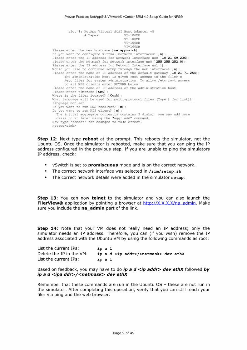
slot 8: NetApp Virtual SCSI Host Adapter v8 4 Tapes: VT-100MB VT-100MB VT-100MB VT-100MB Please enter the new hostname [netapp-simb]: Do you want to configure virtual network interfaces? [n]: Please enter the IP address for Network Interface ns0 [10.21.69.236]: Please enter the netmask for Network Interface ns0 [255.255.252.0]: Please enter the IP address for Network Interface ns1 []: Would you like to continue setup through the web interface? [n]: Please enter the name or IP address of the default gateway [10.21.71.254]: The administration host is given root access to the filer's /etc files for system administration. To allow /etc root access to all NFS clients enter RETURN below.Please enter the name or IP address of the administration host: Please enter timezone [GMT]: Where is the filer located? [Cork]: What language will be used for multi-protocol files (Type ? for list)?:language not setDo you want to run DNS resolver? [n]: Do you want to run NIS client? [n]: The initial aggregate currently contains 3 disks; you may add more disks to it later using the "aggr add" command.Now type 'reboot' for changes to take effect.netapp-simb>
Step 12: Next type reboot at the prompt. This reboots the simulator, not the Ubuntu OS. Once the simulator is rebooted, make sure that you can ping the IP address configured in the previous step. If you are unable to ping the simulators IP address, check:
• vSwitch is set to promiscuous mode and is on the correct network.• The correct network interface was selected in /sim/setup.sh• The correct network details were added in the simulator setup.
Step 13: You can now telnet to the simulator and you can also launch the FilerView® application by pointing a browser at http://X.X.X.X/na_admin. Make sure you include the na_admin part of the link.
Step 14: Note that your VM does not really need an IP address; only the simulator needs an IP address. Therefore, you can (if you wish) remove the IP address associated with the Ubuntu VM by using the following commands as root:
List the current IPs: ip a lDelete the IP in the VM: ip a d <ip addr>/<netmask> dev ethXList the current IPs: ip a l
Based on feedback, you may have to do ip a d <ip addr> dev ethX followed by ip a d <ipa ddr>/<netmask> dev ethX
Remember that these commands are run in the Ubuntu OS – these are not run in the simulator. After completing this operation, verify that you can still reach your filer via ping and the web browser.
Page 9 of 45
Proven Practice: NetApp® & VMware© vCenter SRM 4.0 Setup Guide for NFS®
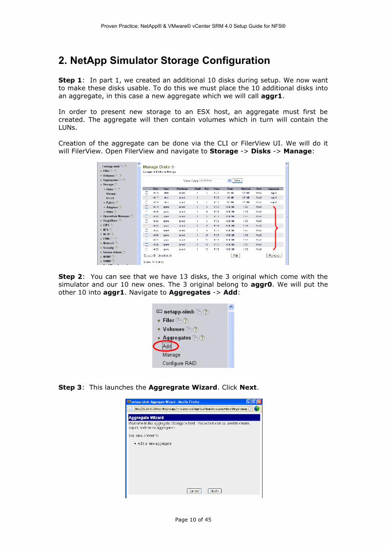
2. NetApp Simulator Storage Configuration
Step 1: In part 1, we created an additional 10 disks during setup. We now want to make these disks usable. To do this we must place the 10 additional disks into an aggregate, in this case a new aggregate which we will call aggr1.
In order to present new storage to an ESX host, an aggregate must first be created. The aggregate will then contain volumes which in turn will contain the LUNs.
Creation of the aggregate can be done via the CLI or FilerView UI. We will do it will FilerView. Open FilerView and navigate to Storage -> Disks -> Manage:
Step 2: You can see that we have 13 disks, the 3 original which come with the simulator and our 10 new ones. The 3 original belong to aggr0. We will put the other 10 into aggr1. Navigate to Aggregates -> Add:
Step 3: This launches the Aggregrate Wizard. Click Next.
Page 10 of 45

Proven Practice: NetApp® & VMware© vCenter SRM 4.0 Setup Guide for NFS®
Step 4: Accept the defaults in the Aggregate Parameters screen, leaving the name as aggr1:
Step 5: Accept the default RAID Group Size (16) in the RAID Parameters screen:
Step 6: Accept the default (Automatic) in the Disk Selection Method screen:
Page 11 of 45
Proven Practice: NetApp® & VMware© vCenter SRM 4.0 Setup Guide for NFS®
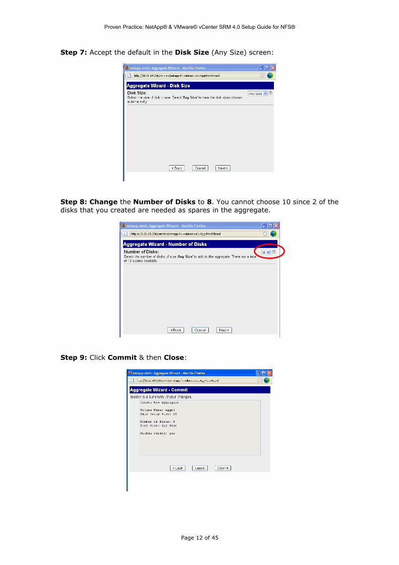
Step 7: Accept the default in the Disk Size (Any Size) screen:
Step 8: Change the Number of Disks to 8. You cannot choose 10 since 2 of the disks that you created are needed as spares in the aggregate.
Step 9: Click Commit & then Close:
Page 12 of 45

Proven Practice: NetApp® & VMware© vCenter SRM 4.0 Setup Guide for NFS®
Step 10: Agg1 has now been created to cater for this. Click Aggregates, and then Manage to view it.
Step 11: Next create a volume called vol2 in the newly created Aggregate aggr1 which will hold a LUN which will be presented to the ESX. From the Volumes item, select Manage to view the current volume.
Step 12: Create a new volume by clicking on Volumes -> Add to create a new volume. This launches the Volume Wizard. Click Next:
Page 13 of 45
Proven Practice: NetApp® & VMware© vCenter SRM 4.0 Setup Guide for NFS®
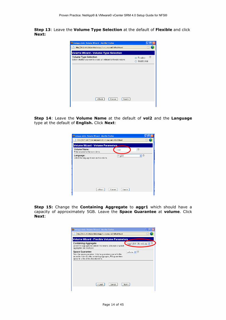
Step 13: Leave the Volume Type Selection at the default of Flexible and click Next:
Step 14: Leave the Volume Name at the default of vol2 and the Language type at the default of English. Click Next:
Step 15: Change the Containing Aggregate to aggr1 which should have a capacity of approximately 5GB. Leave the Space Guarantee at volume. Click Next:
Page 14 of 45
Proven Practice: NetApp® & VMware© vCenter SRM 4.0 Setup Guide for NFS®
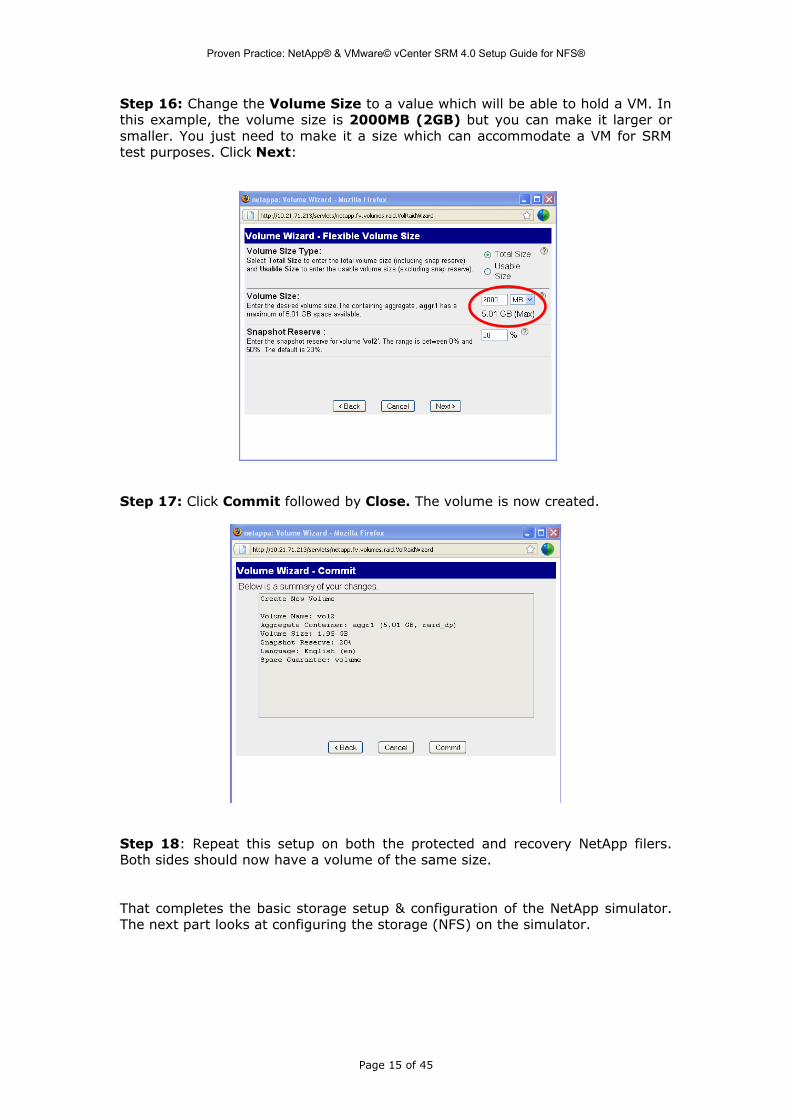
Step 16: Change the Volume Size to a value which will be able to hold a VM. In this example, the volume size is 2000MB (2GB) but you can make it larger or smaller. You just need to make it a size which can accommodate a VM for SRM test purposes. Click Next:
Step 17: Click Commit followed by Close. The volume is now created.
Step 18: Repeat this setup on both the protected and recovery NetApp filers. Both sides should now have a volume of the same size.
That completes the basic storage setup & configuration of the NetApp simulator. The next part looks at configuring the storage (NFS) on the simulator.
Page 15 of 45

Proven Practice: NetApp® & VMware© vCenter SRM 4.0 Setup Guide for NFS®
3. NetApp Simulator NFS Configuration
Part A: Protected Site Setup
Step 1: Verify the state of the new volume by selecting the Volumes -> Manage View.
In this particular example, my volume (vol2) is 1600MB in size. Yours may be different depending on how you configured it in the previous section.
Step 2: We now need to export this volume as an NFS share. Note that NetApp’s Storage Replication Adapter (SRA) require a persistent export of the NFS share where you must specify the root IP address and RW IP address of any ESX server that will mount the share.
You can do this from the UI or you can log into the appliance via telnet and run the exportfs command. In this example I am granting the ESX server (which has a VMkernel IP address of 10.21.64.34) access to a volume on my NetApp:
srm-protect> exportfs -p rw=10.21.64.34,root=10.21.64.34 /vol/vol2srm-protect> exportfs/vol/vol0/home -sec=sys,rw,nosuid/vol/vol0 -sec=sys,rw,anon=0,nosuid/vol/vol1 -sec=sys,rw,nosuid/vol/vol2 -sec=sys,rw=10.21.66.121,root=10.21.66.121srm-protect>
Step 3: If you decide to do this via the UI, go to NFS > Manage Exports:
Page 16 of 45

Proven Practice: NetApp® & VMware© vCenter SRM 4.0 Setup Guide for NFS®
Step 4: Note that vol2 currently has RW access to all hosts, and no root access defined. We must change this in order for the ESX to be able to deploy VMs on this share, and also to allow the NetApp SRA to discover the LUNs. Click on the /vol/vol2 link to launch the NFS Export Wizard.
Step 5: In the Export Options window, the Read-Write Access and Security check boxes are already selected. You will need to also select the Root Access check box as shown here. Then click Next:
Step 6: Leave the Export Path at the default setting:
Step 7: In the Read-Write Hosts window, click on Add to explicitly add a RW host. If you leave this window with just the All Hosts check box selected, the NetApp SRA will not discover these exports. You must add each individual ESX involved in SRM.
Page 17 of 45

Proven Practice: NetApp® & VMware© vCenter SRM 4.0 Setup Guide for NFS®
Step 8: Populate the Host to Add with the (VMkernel) IP address:
In this case I wish to export the NFS share to an ESX host with the VMkernel (IP storage) IP address of 10.21.67.114.
Step 9: The Read-Write Hosts window should now include my VMkernel IP address. Click Next to move to the Root Hosts window:
Step 10: Populate the Root Hosts exactly the same way as the Read-Write Hosts by clicking on the Add button. This should again be the VMkernel/IP Storage IP address. When this is populated, click Next:
Page 18 of 45
Proven Practice: NetApp® & VMware© vCenter SRM 4.0 Setup Guide for NFS®
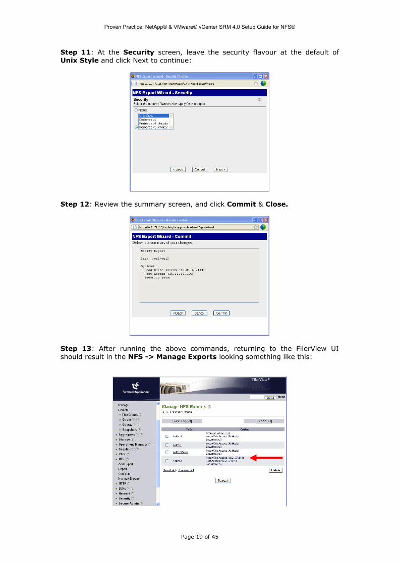
Step 11: At the Security screen, leave the security flavour at the default of Unix Style and click Next to continue:
Step 12: Review the summary screen, and click Commit & Close.
Step 13: After running the above commands, returning to the FilerView UI should result in the NFS -> Manage Exports looking something like this:
Page 19 of 45

Proven Practice: NetApp® & VMware© vCenter SRM 4.0 Setup Guide for NFS®
Step 14: To prepare for replication, you need to ensure that your protected filer and your recovery filer know about each other. You could use IP addresses, but you can also use hostnames for the filers. If you decide to use hostnames, you should populate the hosts file on the protected filer with an entry for the recovery filer. This can be done thru the UI via Network -> Manage Hosts File.
Step 15: Use the buttons below the host file window to insert new entries and apply the changes. Click on the window, and then select Insert. This launches a window to allow you to create a new /etc/hosts line:
Step 16: Once populated with an IP number and official host name, click OK on the ‘create a new /etc/hosts line’ window followed by Apply on the Manage Hosts File screen.
Page 20 of 45

Proven Practice: NetApp® & VMware© vCenter SRM 4.0 Setup Guide for NFS®
Step 17: Another step to setup replication is to allow Remote Access between the protected and recovery filers. This is done in the SnapMirror -> Remote Access -> Manage view.
Click on the Add Remote Access Entry. Here you can choose to either allow the remote filer to access individual volumes or all volumes. In this example, I am allowing the recovery filer to access all volumes on the protected filer:
Step 18: At this point, before we start the replication, it would be a good idea to mount the share on the protected ESX, and deploy a Virtual Machine to the share before we start replicating. This will mean that when we do start replication, the virtual machine files will also be replicated to the recovery site array. Here is an example.
That completes the protected filer setup. We will next turn our attention to the recovery filer setup.
Page 21 of 45
Proven Practice: NetApp® & VMware© vCenter SRM 4.0 Setup Guide for NFS®
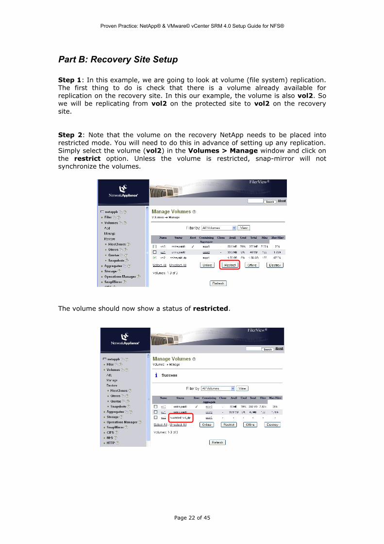
Part B: Recovery Site Setup
Step 1: In this example, we are going to look at volume (file system) replication. The first thing to do is check that there is a volume already available for replication on the recovery site. In this our example, the volume is also vol2. So we will be replicating from vol2 on the protected site to vol2 on the recovery site.
Step 2: Note that the volume on the recovery NetApp needs to be placed into restricted mode. You will need to do this in advance of setting up any replication. Simply select the volume (vol2) in the Volumes > Manage window and click on the restrict option. Unless the volume is restricted, snap-mirror will not synchronize the volumes.
The volume should now show a status of restricted.
Page 22 of 45

Proven Practice: NetApp® & VMware© vCenter SRM 4.0 Setup Guide for NFS®
Step 3: To prepare for replication, I need to ensure that my protected filer and my recovery filer know about each other. Therefore I need to populate the hosts file on the recovery filer with an entry for the protected filer. This can be done thru the UI via Network -> Manage Hosts File. This is exactly the same as the step we carried out on the protected filer. Click Apply once the entry is added.
Step 4: Another step to setup replication is to allow Remote Access between the protected and recovery filers. This is done in the SnapMirror -> Remote Access -> Manage view. Here you can choose to either allow the remote filer to access individual volumes or all volumes. In this example, I am allowing the protected filer (called netappa) to access all volumes on the protected filer:
Page 23 of 45

Proven Practice: NetApp® & VMware© vCenter SRM 4.0 Setup Guide for NFS®
Step 5: Now we setup a snapmirror replication to replicate from protected vol2 on the protected filer to recovery vol4 on the recovery filer. This is done on the recovery site filer via Snapmirror -> Add. Populate the destination volume (vol2), the source filer (netappa) & the source volume (vol2). The remaining items can stay at their defaults. It should look like this screen shot here. Click Add at the bottom of the page to add the snapmirror entry.
Step 6: Once the relationship between protected and recovery filers has been added, you need to initialize the replication. This is done by going to Snapmirror -> Manage -> Advanced.
Page 24 of 45
Proven Practice: NetApp® & VMware© vCenter SRM 4.0 Setup Guide for NFS®
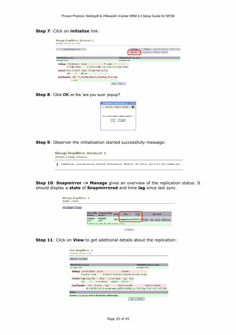
Step 7: Click on initialize link:
Step 8: Click OK on the ‘are you sure’ popup?
Step 9: Observer the initialization started successfully message:
Step 10: Snapmirror -> Manage gives an overview of the replication status. It should display a state of Snapmirrored and time lag since last sync.
Step 11: Click on View to get additional details about the replication:
Page 25 of 45

Proven Practice: NetApp® & VMware© vCenter SRM 4.0 Setup Guide for NFS®
If you have difficulty getting the replication to work, examine the SnapMirror -> Log -> Report view for any errors. If you are logged into the filer via telnet, you may also see some useful errors displayed. Most of the time, the issues are to do with resolving the hostnames of the simulators or the recovery site volume not being restricted.
Page 26 of 45

Proven Practice: NetApp® & VMware© vCenter SRM 4.0 Setup Guide for NFS®
4. Storage Replication Adapter (SRA) Installation
Note that the NetApp SRA for NAS is different to the NetApp SRA for iSCSI & FC. Ensure that you install the version required for NAS replication.
Step 1: Launch the NetApp SRA for NAS Installation and click Next on the Welcome screen.
Step 2: Accept the EULA and click Next
Step 3: Supply User Name/Organization information or accept the defaults and click Next
Page 27 of 45

Proven Practice: NetApp® & VMware© vCenter SRM 4.0 Setup Guide for NFS®
Step 4: Select Complete installation and click Next.
Step 5: Click Install:
Step 6: Click Finish
This would be an opportune time to read the README file, the Install & Admin Guide and the Release Notes which accompany the NetApp SRA.
Page 28 of 45

Proven Practice: NetApp® & VMware© vCenter SRM 4.0 Setup Guide for NFS®
5. Array Managers Configuration
The NAS adapter from NetApp provides an additional field called NFS IP Ad-dresses in the Array Managers Configuration wizard. You can use the NFS IP Ad-dresses field to enter the IP addresses of the storage controller that are used to serve NFS from that controller to the ESX hosts. If the controller uses multiple IP addresses to serve NFS data, these IP addresses are entered in the NFS IP Addresses field and are separated by commas. If the IP addresses are not entered then the disaster recovery NAS adapter returns all available IP ad-dress of the storage controller
Step 1: Click on the SRM icon within vCenter. The assumption is that the Protected and Recovery site connection/pairing & Inventory Mappings has already been configured.
Step 2: Click on the Configure link next to Array Managers in the Protection Setup. This will launch the Configure Array Managers window. Click on the Add button to add the protected array first.
Page 29 of 45

Proven Practice: NetApp® & VMware© vCenter SRM 4.0 Setup Guide for NFS®
Step 3: Populate the protected array details. Make sure to select the NetApp Data ONTAP NAS storage system in case there are multiple SRA managers available. Click the Connect button.
Note that the NFS IP field can be used to choose a particular network interface to communicate between the ESX and the filer if the filer has multiple network interfaces, some of which cannot be reached by the ESX.
Step 4: If the array is discovered successfully, the Array ID and model will populate. Ensure that the Array ID check box is selected, and then click OK.
Page 30 of 45

Proven Practice: NetApp® & VMware© vCenter SRM 4.0 Setup Guide for NFS®
Note – the NetApp NAS SRA will only discover persistently exported volumes. If they are not persistently exported, the following error will appear during the Array Managers configuration:
If the array discovery fails, check that your volume is exported correctly from the protected array:
[2009-06-22 10:38:41.184 02772 verbose 'SysCommandLineWin32'] Starting process: "C:\\Program Files\\VMware\\VMware vCenter Site Recovery Manager\\external\\perl-5.8.8\\bin\\perl.exe" "C:/Program Files/VMware/VMware vCenter Site Recovery Manager/scripts/SAN/ONTAP_NAS/command.pl"[2009-06-22 10:38:41.778 02772 trivia 'PrimarySanProvider'] discoverLuns's output:<Response>[#1] Discover Luns Started [#1] Collecting NFS export information [#1] Skipping this path /vol/vol0 since there are no r/w rules [#1] Skipping this path /vol/vol1 since there are no r/w rules [#1] Skipping this path /vol/vol2 since there are no r/w rules [#1] Skipping this path /vol/vol0/home since there are no r/w rules [#1] Skipping this path /vol/vol3 since there are no r/w rules [#1] Could not find any exported NFS [#1] Discover Luns completed with errors [#1] </Response>[2009-06-22 10:38:41.778 02772 info 'PrimarySanProvider'] discoverLuns exited with exit code 0[2009-06-22 10:38:41.778 02772 trivia 'PrimarySanProvider'] 'discoverLuns' returned <?xml version="1.0" encoding="UTF-8"?>[#1] <Response>[#1] <ReturnCode>4</ReturnCode>[#1] </Response>[#1] [2009-06-22 10:38:41.778 02772 info 'PrimarySanProvider'] Return code for discoverLuns: 4
srm-protect> exportfs -p rw=10.21.66.121,root=10.21.66.121 /vol/vol3srm-protect> exportfs/vol/vol0/home -sec=sys,rw,nosuid/vol/vol0 -sec=sys,rw,anon=0,nosuid/vol/vol1 -sec=sys,rw,nosuid/vol/vol2 -sec=sys,rw,nosuid/vol/vol3 -sec=sys,rw=10.21.66.121,root=10.21.66.121srm-protect>
[2009-06-22 10:57:28.106 03900 verbose 'SysCommandLineWin32'] Starting process: "C:\\Program Files\\VMware\\VMware vCenter Site Recovery Manager\\external\\perl-5.8.8\\bin\\perl.exe" "C:/Program Files/VMware/VMware vCenter Site Recovery Manager/scripts/SAN/ONTAP_NAS/command.pl"[2009-06-22 10:57:28.747 03900 trivia 'PrimarySanProvider'] discoverLuns's output:<Response>[#1] Discover Luns Started [#1] Collecting NFS export information [#1] Skipping this path /vol/vol0/home since there are no r/w rules [#1] Skipping this path /vol/vol0 since there are no r/w rules [#1] Skipping this path /vol/vol1 since there are no r/w rules [#1] Skipping this path /vol/vol2 since there are no r/w rules [#1] adding nfs export path=/vol/vol3 [#1] Collecting list of replicated exports [#1] vol3 has a volume replica /vol/vol3 [#1] Discover Luns completed successfully [#1] </Response>
Page 31 of 45

Proven Practice: NetApp® & VMware© vCenter SRM 4.0 Setup Guide for NFS®
[2009-06-22 10:57:28.747 03900 info 'PrimarySanProvider'] discoverLuns exited with exit code 0[2009-06-22 10:57:28.747 03900 trivia 'PrimarySanProvider'] 'discoverLuns' returned <?xml version="1.0" encoding="UTF-8"?>[#1] <Response>[#1] <LunList arrayId="srm-protect_NAS">[#1] <Lun id="/vol/vol3" nfsName="/vol/vol3">[#1] <Peer>[#1] <ArrayKey>srm-recovery_NAS</ArrayKey>[#1] <ReplicaLunKey>/vol/vol3</ReplicaLunKey>[#1] </Peer>[#1] </Lun>[#1] </LunList>[#1] <ReturnCode>0</ReturnCode>[#1] </Response>
Step 5: The protected array is now discovered successfully. The peer array involved in replications may also be observed at this point. Click Next to move onto the screen to populate information about the recovery array:
Step 6: At this point, we have not added our recovery array, but this screen does show you the state of other recovery arrays. Note that the green check mark in the replicated array pairs indicates a valid in-sync replication between peer arrays. The NetApp does not yet have one as we haven’t provided recovery array details. Click Add to populate array information for the recovery array:
Page 32 of 45

Proven Practice: NetApp® & VMware© vCenter SRM 4.0 Setup Guide for NFS®
Step 7: Populate the recovery array details. Again, ensure that you select the NetApp Data ONTAP NAS storage system in case there are multiple SRA managers available. Click the Connect button.
Step 8: If the array is discovered successfully, the Array ID and model will populate. Again, ensure that this is selected and click OK.
Page 33 of 45

Proven Practice: NetApp® & VMware© vCenter SRM 4.0 Setup Guide for NFS®
Step 8: The recovery array is now discovered successfully. Click OK to move onto the replicated LUN discovery. If replication is in-place & in-sync between the local and remote filers, then a green check box should be observed for our filers in the Replicated Array Pairs.
Step 9: If replication is working correctly, and there is a Virtual Machine on the share at the protect site, then the LUN discovery should successfully find the replicated volume. Click Next to verify.
In this case the protected /vol/vol2 is replicated to recovery /vol/vol2.
Page 34 of 45

Proven Practice: NetApp® & VMware© vCenter SRM 4.0 Setup Guide for NFS®
6. Create Protection GroupWe are now ready to start building our recovery plan. The first step is to create a protection group which includes all VMs and their respective datastores which we wish to protect.
Step 1: On the protected site, select Protection Groups, and then click on Create Protection Group.
Step 2: Enter the name of the Protection Group and the Description:
Step 3: Select the Datastore Group corresponding to your protection side array. In this case it is called NetApp_217_NAS. You will then be given a list of VMs which are on the selected datastore group.
Page 35 of 45

Proven Practice: NetApp® & VMware© vCenter SRM 4.0 Setup Guide for NFS®
Step 4: Select a placeholder on the recovery site of where to place the VM configuration files. These placeholder VMs do not consume much space, and are replaced by the VMs which appear on the replicated LUN in the event of a failover or test failover. Click Finish.
Step 5: When the Protection Group is created, move on to creation the associated recovery plan.
Page 36 of 45

Proven Practice: NetApp® & VMware© vCenter SRM 4.0 Setup Guide for NFS®
7. Create Recovery Plan
Step 1: Move to the recovery side vCenter, select Site Recovery icon, and then select Recovery Plans. Click on Create Recovery Plan.
Step 2: Give your Recovery Plan a name. Here I called it RP_N1_NAS.
Step 3: Select the Protection Group that you want to recover. In this example, I select the Protection Group called PG_N1_NAS that I created earlier.
Page 37 of 45

Proven Practice: NetApp® & VMware© vCenter SRM 4.0 Setup Guide for NFS®
Step 4: Modify the timeout value for recovery steps if desired. I have changed the values from 600 to 60 for test purposes. However making such a change in a production environment is not advisable as it could lead to your recovery plan failing.
Step 5: Determine which network to use during tests. Leaving the test network at Auto will means that the VMs will not come up on a bubble network and will not impact the still running VMs on the protected site. You do not need to modify this from the default for the purpose of our tests.
Step 6: Suspend VMs during recovery steps if desired. You do not need to modify this from the default for the purpose of our tests.
Page 38 of 45
Proven Practice: NetApp® & VMware© vCenter SRM 4.0 Setup Guide for NFS®
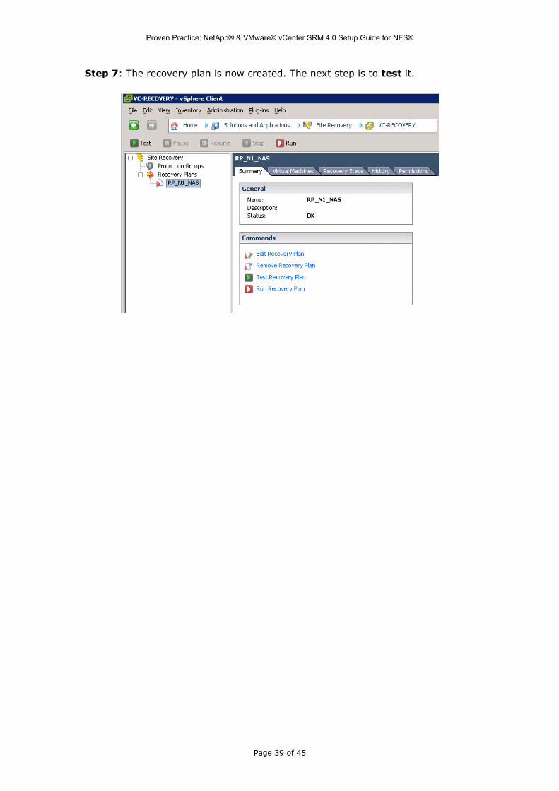
Step 7: The recovery plan is now created. The next step is to test it.
Page 39 of 45
Proven Practice: NetApp® & VMware© vCenter SRM 4.0 Setup Guide for NFS®
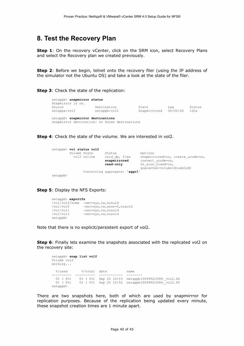
8. Test the Recovery Plan
Step 1: On the recovery vCenter, click on the SRM icon, select Recovery Plans and select the Recovery plan we created previously.
Step 2: Before we begin, telnet onto the recovery filer (using the IP address of the simulator not the Ubuntu OS) and take a look at the state of the filer.
Step 3: Check the state of the replication:
netappb> snapmirror statusSnapmirror is on.Source Destination State Lag Statusnetappa:vol2 netappb:vol2 Snapmirrored 00:00:06 Idle
netappb> snapmirror destinationssnapmirror destination: no known destinations
Step 4: Check the state of the volume. We are interested in vol2.
netappb> vol status vol2 Volume State Status Options vol2 online raid_dp, flex snapmirrored=on, create_ucode=on, snapmirrored convert_ucode=on, read-only fs_size_fixed=on, guarantee=volume(disabled) Containing aggregate: 'aggr1'netappb>
Step 5: Display the NFS Exports:
netappb> exportfs/vol/vol0/home -sec=sys,rw,nosuid/vol/vol0 -sec=sys,rw,anon=0,nosuid/vol/vol1 -sec=sys,rw,nosuid/vol/vol2 -sec=sys,rw,nosuidnetappb>
Note that there is no explicit/persistent export of vol2.
Step 6: Finally lets examine the snapshots associated with the replicated vol2 on the recovery site:
netappb> snap list vol2Volume vol2working...
%/used %/total date name---------- ---------- ------------ -------- 0% ( 0%) 0% ( 0%) Sep 25 10:53 netappb(0099921696)_vol2.46 0% ( 0%) 0% ( 0%) Sep 25 10:52 netappb(0099921696)_vol2.45netappb>
There are two snapshots here, both of which are used by snapmirrror for replication purposes. Because of the replication being updated every minute, these snapshot creation times are 1 minute apart.
Page 40 of 45
Proven Practice: NetApp® & VMware© vCenter SRM 4.0 Setup Guide for NFS®
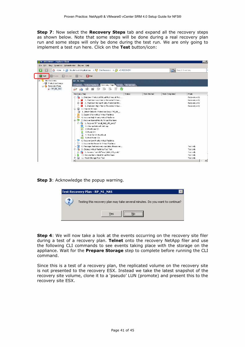
Step 7: Now select the Recovery Steps tab and expand all the recovery steps as shown below. Note that some steps will be done during a real recovery plan run and some steps will only be done during the test run. We are only going to implement a test run here. Click on the Test button/icon:
Step 3: Acknowledge the popup warning.
Step 4: We will now take a look at the events occurring on the recovery site filer during a test of a recovery plan. Telnet onto the recovery NetApp filer and use the following CLI commands to see events taking place with the storage on the appliance. Wait for the Prepare Storage step to complete before running the CLI command.
Since this is a test of a recovery plan, the replicated volume on the recovery site is not presented to the recovery ESX. Instead we take the latest snapshot of the recovery site volume, clone it to a ‘pseudo’ LUN (promote) and present this to the recovery site ESX.
Page 41 of 45
Proven Practice: NetApp® & VMware© vCenter SRM 4.0 Setup Guide for NFS®
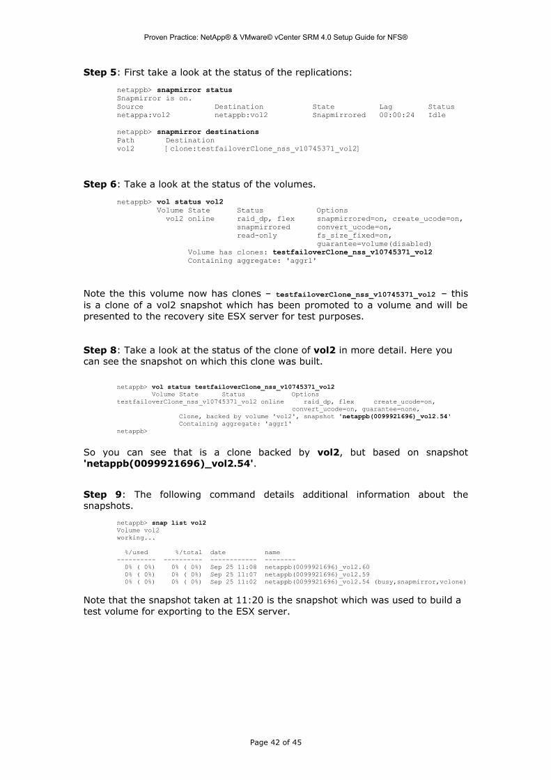
Step 5: First take a look at the status of the replications:
netappb> snapmirror statusSnapmirror is on.Source Destination State Lag Statusnetappa:vol2 netappb:vol2 Snapmirrored 00:00:24 Idle
netappb> snapmirror destinationsPath Destinationvol2 [clone:testfailoverClone_nss_v10745371_vol2]
Step 6: Take a look at the status of the volumes.
netappb> vol status vol2 Volume State Status Options vol2 online raid_dp, flex snapmirrored=on, create_ucode=on, snapmirrored convert_ucode=on, read-only fs_size_fixed=on, guarantee=volume(disabled) Volume has clones: testfailoverClone_nss_v10745371_vol2 Containing aggregate: 'aggr1'
Note the this volume now has clones – testfailoverClone_nss_v10745371_vol2 – this is a clone of a vol2 snapshot which has been promoted to a volume and will be presented to the recovery site ESX server for test purposes.
Step 8: Take a look at the status of the clone of vol2 in more detail. Here you can see the snapshot on which this clone was built.
netappb> vol status testfailoverClone_nss_v10745371_vol2 Volume State Status OptionstestfailoverClone_nss_v10745371_vol2 online raid_dp, flex create_ucode=on, convert_ucode=on, guarantee=none, Clone, backed by volume 'vol2', snapshot 'netappb(0099921696)_vol2.54' Containing aggregate: 'aggr1'netappb>
So you can see that is a clone backed by vol2, but based on snapshot 'netappb(0099921696)_vol2.54'.
Step 9: The following command details additional information about the snapshots.
netappb> snap list vol2Volume vol2working...
%/used %/total date name---------- ---------- ------------ -------- 0% ( 0%) 0% ( 0%) Sep 25 11:08 netappb(0099921696)_vol2.60 0% ( 0%) 0% ( 0%) Sep 25 11:07 netappb(0099921696)_vol2.59 0% ( 0%) 0% ( 0%) Sep 25 11:02 netappb(0099921696)_vol2.54 (busy,snapmirror,vclone)
Note that the snapshot taken at 11:20 is the snapshot which was used to build a test volume for exporting to the ESX server.
Page 42 of 45

Proven Practice: NetApp® & VMware© vCenter SRM 4.0 Setup Guide for NFS®
Step 10: Before we started this test, there were no volumes export to the recovery site ESX from the recovery filer. Now that we have run the test plan, we see that there is a volume exported to the VMkernel IP address of the recovery ESX. This is all handled by the NetApp SRA.
netappb> exportfs/vol/testfailoverClone_nss_v10745371_vol2 -sec=sys,rw=10.21.67.115,root=10.21.67.115/vol/vol0/home -sec=sys,rw,nosuid/vol/vol0 -sec=sys,rw,anon=0,nosuid/vol/vol1 -sec=sys,rw,nosuid/vol/vol2 -sec=sys,rw,nosuidnetappb>
Step 11: you may also observe the following messages displayed on the recovery filer (ONTAP) during a test failover run:
Fri Sep 25 11:02:49 GMT [app.log.info:info]: SRMB: Disaster Recovery NAS Adapter Storage Replication Adapter 1.4: (1) Test-Failover-start Event: Disaster Recovery NAS Adapter executed Test-Failover-start operation successfully from OS major version = 5 ,minor version = 2 ,package = Service Pack 2 and build = 3790
Step 12: Confirm successful test failover
Step 13: Click the Continue link to end the test failover. Again, using the CLI on the NetApp appliance, verify various events and operations from a storage perspective. Wait for the Reset Storage Post Test step to complete first.
Messages on the recovery filer will appear similar to the following:
Fri Sep 25 11:12:59 GMT [wafl.vvol.offline:info]: Volume 'testfailoverClone_nss_v10745371_vol2' has been set temporarily offlineFri Sep 25 11:13:01 GMT [app.log.info:info]: SRMB: Disaster Recovery NAS Adapter Storage Replication Adapter 1.4: (3) Test-Failover-stop Event: Disaster Recovery NAS Adapter executed Test-Failover-stop operation successfully from OS major version = 5 ,minor version = 2 ,package = Service Pack 2 and build = 3790
Page 43 of 45

Proven Practice: NetApp® & VMware© vCenter SRM 4.0 Setup Guide for NFS®
Step 14: If the test failover operation is successfully stopped, you should notice that the cloned volume is no longer exported to the recovery ESX server from the recovery filer:
netappb> exportfs/vol/vol0/home -sec=sys,rw,nosuid/vol/vol0 -sec=sys,rw,anon=0,nosuid/vol/vol1 -sec=sys,rw,nosuid/vol/vol2 -sec=sys,rw,nosuid
Step 15: If the test failover operation is successfully stopped, you should notice that the cloned volume no longer exists on the recovery filer:
netappb> vol status vol2 Volume State Status Options vol2 online raid_dp, flex snapmirrored=on, create_ucode=on, snapmirrored convert_ucode=on, read-only fs_size_fixed=on, guarantee=volume(disabled) Containing aggregate: 'aggr1'
That completes the setup for Site Recovery Manager with replicated NetApp NAS devices.
Page 44 of 45

Proven Practice: NetApp® & VMware© vCenter SRM 4.0 Setup Guide for NFS®
Trademarks © 2009 VMware, Inc. All rights reserved. Protected by one or more U.S. Patent Nos. 6,397,242, 6,496,847, 6,704,925, 6,711,672, 6,725,289, 6,735,601, 6,785,886, 6,789,156, 6,795,966, 6,880,022, 6,944,699, 6,961,806, 6,961,941, 7,069,413, 7,082,598, 7,089,377, 7,111,086, 7,111,145, 7,117,481, 7,149,843, 7,155,558, 7,222,221, 7,260,815, 7,260,820, 7,269,683, 7,275,136, 7,277,998, 7,277,999, 7,278,030, 7,281,102, 7,290,253, 7,356,679, 7,409,487, 7,412,492, 7,412,702, 7,424,710, 7,428,636, 7,433,951, 7,434,002, and 7,447,854; patents pending.
VMware, the VMware “boxes” logo and design, Virtual SMP, and VMotion are registered trademarks or trademarks of VMware, Inc. in the United States and/or other jurisdictions.
All other marks and names mentioned herein may be trademarks of their respective companies.
Summary
As stated in the introduction, the point of this proven practice is to take the reader through the steps of setting up replication between a pair NetApp simulator volumes which are exported as NFS shares to VMare ESX servers, and then configure VMware vCenter Site Recovery Manager so that a test failover can be initiated.
The main purpose of this document is to assist in setting up such a configuration for demo and training purposes, or Proof-Of-Concept purposes. While it may be of some assistance with deploying a production environment, further reading is essential to determine best practices.
About the Author
Cormac Hogan is a Staff Technical Course Developer for VMware Global Support Services (GSS) based out of Cork, Ireland. He develops and delivers training for the GSS Technical Support Engineers within VMware, primarily on storage and storage related topics.
Page 45 of 45


