
Nepal Doorsanchar Company Limited - Nepal...
299
Tender Document for Second Floor Extension of Quarter Building at Nepal Telecom, Regional Directorate, Attariya, Kailali (Tender No NDCL/RD-Attariya/CIVIL/075/76-01) Nepal Doorsanchar Company Limited (Nepal Telecom) Bidding Document for Procurement of works Second Floor Extension of Quarter Building at Attariya, Kailali Tender No. NDCL/RD-Attariya/CIVIL/075/76-01 Issued on: Bid Document issued to: Office Name : Nepal Telecom, Regional Directorate Office Address: Attariya, Kailali
Transcript of Nepal Doorsanchar Company Limited - Nepal...
Tender Document for Second Floor Extension of Quarter Building at Nepal Telecom, Regional Directorate, Attariya, Kailali (Tender No NDCL/RD-Attariya/CIVIL/075/76-01)
Nepal Doorsanchar Company Limited
(Nepal Telecom)
Bidding Document for
Procurement of works
Second Floor Extension of Quarter Building
at
Attariya, Kailali
Tender No. NDCL/RD-Attariya/CIVIL/075/76-01
Issued on:
Bid Document issued to:
Office Name : Nepal Telecom, Regional Directorate
Office Address: Attariya, Kailali

Tender Document for Second Floor Extension of Quarter Building at Nepal Telecom, Regional Directorate, Attariya, Kailali (Tender No NDCL/RD-Attariya/CIVIL/075/76-01)
Table of Contents
Part - I Bidding Procedures ............................................................................................. ….5
Section - I Instructions to Bidders ……………………………………………………………...6
Section - II Bid Data Sheet…………………………………………………………………..29
Section - III Evaluation and Eligibility Criteria…………………………….……………….32
Section – IV Bidding Forms………………………………………………………………....39
Part - II Requirements.......................................................................................................….43
Section - V Works Requirements ………………………………………………………..….44
Section - VI Bill of Quantities…………………………………………………………….....45
Part - III Conditions of Contract and Contract Forms ......................................... …76
Section - VII General Conditions of Contract……………………………………………….77
Section - VIII Special Conditions of Contract…………………………………………….....99
Section - IX Contract Forms …………………………………………………………… … 104.
Annex-1
Annex-2
Tender Document for Second Floor Extension of Quarter Building at Nepal Telecom, Regional Directorate, Attariya, Kailali (Tender No NDCL/RD-Attariya/CIVIL/075/76-01)
g]kfn 6]lnsd IF]qLo lgb]{zgfno cQ/Lof s}nfnL
af]nkq cfXjfgsf] ;"rgf k|yd k6s k|sflzt ldlt @)&^÷)#÷)@
o; lgb]{zgfnodf tkl;n adf]lhdsf] lgdf{0f sfo{ af]nkq k|s[ofjf6 u/fpg' kg]{ ePsf]n] g]kfn ;/sf/jf6 Ohfht k|fKt of]Uo OR5's lgdf{0f Joj;foLx?jf6 cfkm\gf] kmd{ / sDkgL btf{ k|df0f kq , :yfoL n]vf gDa/, d"No clea[åL s/ btf{ / cf=j=)&$÷&% sf] cfo s/ r'Qmf k|df0fkqsf] k|dfl0ft k|ltlnlk ;+nUg u/L lgDg zt{x? / af]nkq kmf/fdsf] zt{x?sf] clwgdf /xL lgdf{0f sfo{sf] af]nkq cfx\jfg ul/Psf] 5 .
zt{x?M != OR5's af]nkqbftfx?n] lkmtf{ gx'g] u/L k|lt kmf/fd tf]lsPsf] /sd ?= !),))).)) (dxz'n sfp06/ ;do leq) a'emfO{
lgj]bg ;lxt of] ;"rgf k|yd k6s k|sflzt ePsf] ldltn] #) cf}+ lbgsf] sfof{no ;do leq o; lgb]{zgfnoaf6 af]nkq k'l:tsf vl/b ul/ #! cf}+ lbg, lbgsf] !@:)) ah];Dd o;} lgb]{zgfnosf] btf{ zfvfdf bflvnf ug{ ;lsg]5 . /Ltk"j{s gePsf] / tf]lsPsf] ldlt tyf ;do eGbf kl5 k|fKt x'g cfPsf] jf s'g} zt{ /flv k]z ePsf] af]nkq pk/ s'g} sf/jfxL ul/g] 5}g .
@= af]nkq kmf/fd btf{ ubf{ vfd aflx/ g]kfn 6]lnsd, IF]=lg= cQl/of, s}nfnL nfO{ ;Daf]wg ul/ lgdf{0f sfo{sf] lja/0f :ki6 pNn]v ug'{ kg]{5 .
#= OR5's of]Uo af]nkqbftfx?n] o; lgb]{zgfnoaf6 cfjZos hfgsf/L xfl;n ug]{ jf af]nkq k'l:tsf x]g{ ;Sg]5g\ . o; ;DaGwdf s'g} s'/f a'em\g'k/]df kmf]g g+= )(!%%)*(& df ;Dks{ ug{ ;lsg] 5 .
$= k|fKt ePsf af]nkqx?, af]nkq bflvnf ug]{ clGtd lbgsf] @M)) ah] o; lgb]{zgfnodf s'g} jf ;a} af]nkqbftfx? jf lghsf] k|ltlglwx?sf] pkl:yltdf vf]lng] 5 . lghx?sf] pkl:ylt gePdf klg af]nkq vf]Ng afwf k'Ug] 5}g .
%= af]nkq k]z ubf{ af]nkq;fy hdfgt jfktsf] tklzndf pNn]lvt /sd o; sDkgLsf] wgu9L l:yt a}+s ckm sf7df08f}+ ln=df /x]sf] a}+s vftf g+= )^)^))))))%^ df hDdf u/]sf] ;Ssn a}+s ef}r/ jf g]kfn /fi6« a}+sjf6 dfGotf k|fKt æsÆ >]0fLsf] jfl0fHo a}+s x?dWo]jf6 af]nkq btf{ ug{] clGtd ldltn] 3l6df !@) lbg Dofb /x]sf] o; sDkgLsf] gfddf hf/L ul/Psf] ;Ssn a}+s hdfgL kq (Bid Security) clgjfo{ ;+nUg x'g' kg]{ 5 .
^= b/efpmkq v/Lb ug]{, bflvnf ug]{ / vf]Ng] clGtd lbg labf kg{ uPsf]] v08df To;sf] nuQ} sfof{no vf]n]sf] lbg ;f]lx ;dodf af]nkq v/Lb ug{, bflvnf ug{ / vf]Ng ;lsg] 5 .
&= Ps AolQm, kmd{ jf ;+:yfsf] gfddf vl/b u/]sf] af]nkq kmf/fd csf]{ AolQm, kmd{ jf ;+:yfsf] gfd af6 bflvnf ug{ kfOg]
5}g .
*= af]nkqbftfn] cfjZos 7fg]df a]nkq bflvnf ug{' cufj} :jo+ cfjZos k|aGw ul/ lgdf{0f:ynsf] lgl/If0f ug{ ;Sg]5g .
(= of] ;"rgf g]kfn 6l]nsdsf] j]a;fO6 www.ntc.net.np df klg x]g{ ;lsg] 5 ;fy} g]kfn 6]lnsdsf] E-Procurement Website ,http//eproc.ntc.net.np dfkm{t e-bidding k|s[ofaf6 klg af]nkq btf{ ug{ ;lsg]5 .
!)= af]nkq cfx\jfgsf] la:t[t ;"rgf af]nkq k'l:tsfdf ;dfa]; ul/Psf] 5 . af]nkq d"NofÍg ;f]xL la:t[t ;"rgf adf]lhd x'g]5 .
!!= af]nkq :jLs[t ug]{, gug]{ jf cf+l;s ?kdf :jLs[t ug]{ ;Dk'0f{ clwsf/ o; lgb]{zgfnodf lglxt /xg] 5 . !@= lgdf{0f sfo{sf] ljj/0f lgDgfg';f/ /x]sf] 5 .
l;=g+= ;"rgf g+= lgdf{0f sfo{sf] ljj/0f af]nkq b:t'/ ?= w/f}6L /sd ?= Aff]nkq vl/b tyf btf{ ug]{ clGtd ldlt
! NDCL/RD-Attariya/CIVIL/075/76-01
Second Floor Extension of
Quarter Building at
Attariya, Kailali !),))).)) #,)),))).))
@)&^÷)#÷#! @)&^÷)$÷)!

4
Tender Document for Second Floor Extension of Quarter Building at Nepal Telecom, Regional Directorate, Attariya, Kailali (Tender No NDCL/RD-Attariya/CIVIL/075/76-01)
Abbreviations
BD ... .................................. Bidding Document
BDF ... ........................... .. Bidding Forms
BDS ... ........................... .. Bid Data Sheet
BOQ................................ . Bill of Quantities
COF ... .......................... . Contract Forms
ELI ... ........................... ... Eligibility
EQC ... ........................... .. Evaluation and Qualification Criteria
EXP ... .......................... .. Experience
FIN ... ........................... ... Financial
GCC .............................. .. General Conditions of Contract
GoN ... ........................... .. Government of Nepal
ICC ... ............................. . International Chamber of Commerce
IFB ……………………… Invitation for Bids
ITB ... .............................. . Instructions to Bidders
JV ... ............................. .. Joint Venture
LIT ............................... ... Litigation
NCB... ............................. . National Competitive Bidding
NT …………………………Nepal Telecom
PAN ... .......................... .. Permanent Account Number
PPA ... .......................... .. Public Procurement Act
PPMO... .......................... . Public Procurement Monitoring Office
PPR ... .......................... .. Public Procurement Regulations
PL ... .................................. Profit & Loss
SBD ... ........................... .. Standard Bidding Document
SCC ... .......................... .. Special Conditions of Contract
TS ... .................................. Technical Specifications
VAT ... ........................... .. Value Added Tax
WRQ ... ........................ ... Works Requirements

5
Tender Document for Second Floor Extension of Quarter Building at Nepal Telecom, Regional Directorate, Attariya, Kailali (Tender No NDCL/RD-Attariya/CIVIL/075/76-01)
Part - I
BIDDING PROCEDURES
6
Tender Document for Second Floor Extension of Quarter Building at Nepal Telecom, Regional Directorate, Attariya, Kailali (Tender No NDCL/RD-Attariya/CIVIL/075/76-01)
SECTION - I
Instructions to Bidders
A. General
1. Scope of Bid 1.1 In connection with the Invitation for Bids indicated in the Bid Data
Sheet (BDS), the Employer, as indicated in the BDS, issues this
Bidding Document for the procurement of Works as specified in
Section V (Works Requirements). The name, identification, and
number of Contracts of the National Competitive Bidding (NCB) are
provided in the BDS.
1.2 Throughout this Bidding Document:
(a) the term “in writing” means communicated in written form and
delivered against receipt;
(b) except where the context requires otherwise, words
indicating the singular also include the plural and words
indicating the plural also include the singular; and
(c) “day” means calendar day, ‘month’ means calendar month.
2. Source of Funds 2.1 In accordance with its annual program and budget, approved by the
employer, the implementing agency indicated in the BDS plans to
apply a portion of the allocated budget from its own source of fund,
to eligible payments under the contract(s) for which this Bidding
Document is issued.
3. Fraud and Corruption
3.1 Nepal Telecom (NT) requires that the Procuring Entities as well as
bidders, suppliers and contractors, shall adhere to the highest
standard of ethics during the procurement and execution of such
contracts. In this context, the Employer;
(a) defines, for the purposes of this provision, the terms set forth below as follows:
(i) “corrupt practice” means the offering, giving, receiving, or soliciting, directly or indirectly, anything of value to influence improperly the actions of another party;
(ii) “fraudulent practice” means any act or omission, including a misrepresentation, that knowingly or recklessly misleads, or attempts to mislead, a party to obtain a financial or other benefit or to avoid an obligation;
(iii) “coercive practice” means impairing or harming, or threatening to impair or harm, directly or indirectly, any party or the property of the party to influence improperly the actions of a party;
(iv) “collusive practice” means an arrangement between two or
7
Tender Document for Second Floor Extension of Quarter Building at Nepal Telecom, Regional Directorate, Attariya, Kailali (Tender No NDCL/RD-Attariya/CIVIL/075/76-01)
more parties designed to achieve an improper purpose, including influencing improperly the actions of another party.
(iv) “obstructive practice” means:
(aa) deliberately destroying, falsifying, altering or concealing of evidence material to the investigation or making false statements to investigators in order to materially impede a investigation into allegations of a corrupt, fraudulent, coercive or collusive practice; and/or threatening, harassing or intimidating any party to prevent it from disclosing its knowledge of matters relevant to the investigation or from pursuing the investigation; or
(bb) acts intended to materially impede the exercise of the employer’s inspection and audit rights provided for under sub-clause 3.5 below.
(b) will reject bid(s) if it determines that the bidder has, directly or through an agent, engaged in corrupt, fraudulent, collusive, coercive, or obstructive practices in competing for the contract in question;
3.2 The Bidder shall not carry out or cause to carry out the following acts with an intention to influence the implementation of the procurement process or the procurement agreement :
(a) give or propose improper inducement directly or
indirectly,
(b) distortion or misrepresentation of facts,
(c) engaging in corrupt or fraudulent practice or involving in
such act,
(d) interference in participation of other competing bidders,
(e) coercion or threatening directly or indirectly to cause harm
to the person or the property of any person to be involved in
the procurement proceedings,
(f) collusive practice among bidders before or after submission of bids for distribution of works among bidders or fixing
artificial/uncompetitive bid price with an intention to deprive the Employer the benefit of open competitive bid price,
(g) Contacting the Employer with an intention to influence the
Employer with regards to the bids or interference of any kind
in examination and evaluation of the bids during the period from
the time of opening of the bids until the notification of award of
contract.
3.3 PPMO, on the recommendation of the Procuring Entity may blacklist a Bidder for a period of one (1) to three (3) years for its conduct including on the following grounds and seriousness of the act committed by the bidder:
(a) if convicted by a court of law in a criminal offence which
disqualifies the Bidder from participating in the contract,
(b) if it is established that the contract agreement signed by the
8
Tender Document for Second Floor Extension of Quarter Building at Nepal Telecom, Regional Directorate, Attariya, Kailali (Tender No NDCL/RD-Attariya/CIVIL/075/76-01)
Bidder was based on false or misrepresentation of Bidder’s
qualification information,
(c) if it at any time determines that the firm has, directly or through
an agent, engaged in corrupt, fraudulent, collusive, coercive,
or obstructive practices in competing for, or in executing, a
GoN/DP-financed contract.
3.4 A bidder declared blacklisted and ineligible by the GoN, Public Procurement Monitoring Office (PPMO) and the employer, shall be ineligible to bid for a contract during the period of time determined by the GoN, PPMO.
3.5 The Contractor shall permit the employer to inspect the
Contractor’s accounts and records relating to the performance of the
Contractor and to have them audited by auditors appointed by the
employer, if so required by the employer.
4. Eligible Bidders 4.1 A Bidder may be a natural person, private entity, or government - owned entity—subject to ITB 4.5—or any combination of them in the form of a Joint Venture (JV) under an existing agreement, or with the intent to constitute a legally-enforceable joint venture. In the case of a JV:
(a) all partners shall be jointly and severally liable for the execution of the Contract in accordance with the Contract terms. Maximum number of JV shall be as specified in the BDS. The qualification requirement of the parties to the JV shall be as specified in Section III Evaluation and Qualification Criteria, and
(b) the JV shall nominate a Representative who shall have the authority to conduct all business for and on behalf of any and all the parties of the JV during the bidding process and, in the event the JV is awarded the Contract, during Contract execution.
4.2 A Bidder, and all parties constituting the Bidder, shall have the
nationality of any country or eligible countries mentioned in the
BDS. A Bidder shall be deemed to have the nationality of a country if
the Bidder is a citizen or is constituted, or incorporated, and operates
in conformity with the provisions of the laws of that country. This
criterion shall also apply to the determination of the nationality of
proposed sub Contractors or suppliers for any part of the Contract
including related services.
4.3 A Bidder shall not have a conflict of interest. A Bidder found to have
a conflict of interest shall be disqualified. A Bidder may be considered
to be in a conflict of interest with one or more parties in this bidding
process, if:
(a) they have controlling partners in common; or
(b) they receive or have received any direct or indirect subsidy from any of them; or

9
Tender Document for Second Floor Extension of Quarter Building at Nepal Telecom, Regional Directorate, Attariya, Kailali (Tender No NDCL/RD-Attariya/CIVIL/075/76-01)
(c) they have the same legal representative for purposes of this bid;
or
(d) they have a relationship with each other, directly or through
common third parties, that puts them in a position to have
access to information about or influence on the Bid of
another Bidder, or influence the decisions of the Employer
regarding this bidding process; or
(e) a Bidder participates in more than one bid in this bidding
process either individually or as a partner in a joint venture.
Participation by a Bidder in more than one Bid will result in the
disqualification of all Bids in which the party is involved. However,
this does not limit the inclusion of the same sub Contractor in
more than one bid; or
(f) a Bidder or any of its affiliates participated as a consultant in the
preparation of the design or technical specifications of the
Contract that is the subject of the Bid; or
(g) a Bidder or any of its affiliates has been hired (or is proposed to be
hired) by the Employer as Engineer for the Contract.
4.4 A firm that is under a declaration of ineligibility in accordance with
ITB 3, at the date of the deadline for bid submission or thereafter,
shall be disqualified.
4.5 Enterprises owned by Government shall be eligible only if they can establish that they are legally and financially autonomous and operate under commercial law, and that they are not a dependent agency of the GoN.
4.6 Bidders shall provide such evidence of their continued eligibility satisfactory to the Employer, as the Employer shall reasonably request.
4.7 In case a prequalification process has been conducted prior to the bidding process, this bidding is open only to prequalified Bidders.
4.8 The bidder shall meet the eligibility criteria specified in section III (Evaluation and Qualification Criteria) of bid document.

10
Tender Document for Second Floor Extension of Quarter Building at Nepal Telecom, Regional Directorate, Attariya, Kailali (Tender No NDCL/RD-Attariya/CIVIL/075/76-01)
5. Eligible Materials, Equipment and Services
5.1 The materials, equipment and services to be supplied under the Contract shall have their origin in any source countries as defined in ITB 4.2 above and all expenditures under the Contract will be limited to such materials, equipment, and services. At the Employer’s request, Bidders may be required to provide evidence of the origin of materials, equipment and services.
5.2 For purposes of ITB 5.1 above, “origin” means the place where the materials and equipment are mined, grown, produced or manufactured, and from which the services are provided. Materials and equipment are produced when, through manufacturing, processing, or substantial or major assembling of components, a commercially recognized product results that differs substantially in its basic characteristics or in purpose or utility from its components.
B. Contents of Bidding Documents
6. Sections of Bidding Document
6.1 The Bidding Document consist of Parts I, II, and III, which include all the Sections indicated below, and should be read in conjunction with any Addenda issued in accordance with ITB 8.
PART I Bidding Procedures
Section I Instructions to Bidders (ITB)
Section II Bid Data Sheet (BDS)
Section III Evaluation and Qualification Criteria (EQC)
Section IV Bidding Forms (BDF)
PART II Requirements
Section V Works Requirements (WRQ)
Section VI Bill of Quantities (BOQ) PART III Conditions of Contract and Contract Forms
Section VII General Conditions of Contract (GCC)
Section VIII Special Conditions of Contract (SCC)
Section IX Contract Forms (COF)
6.2 The Invitation for Bids issued by the Employer is not part of the Bidding Document.
6.3 The Employer is not responsible for the completeness of the Bidding Document and their Addenda, if they were not obtained directly from the source stated by the Employer in the Invitation for Bids.
6.4 The Bidder is expected to examine all instructions, forms, terms, and specifications in the Bidding Document. Failure to furnish all information or documentation required by the Bidding Document may result in the rejection of the bid.
7. Clarification of Bidding Document, Site Visit, Pre-Bid Meeting
7.1 A prospective Bidder requiring any clarification of the Bidding
Document shall contact the Employer in writing at the Employer’s
address indicated in BDS or raise any question or curiosity during
the pre-bid meeting if provided for in accordance with ITB 7.4.
11
Tender Document for Second Floor Extension of Quarter Building at Nepal Telecom, Regional Directorate, Attariya, Kailali (Tender No NDCL/RD-Attariya/CIVIL/075/76-01)
The Employer shall be required to make available as soon as
possible the answer to such question or curiosity in writing to
any request for clarification, provided that such request is
received as mentioned in ITB 7.5. The Employer shall forward
copies of its response to all Bidders who have acquired the Bidding
Document in accordance with ITB 6.3, including
a description of the inquiry but without identifying its source.
Should the Employer deem it necessary to amend the Bidding
Document as a result of a request for clarification, it shall do so
following the procedure under ITB 8 and ITB 22.2.
7.2 The Bidder is encouraged to visit and examine the Site of
Works and its surroundings and obtain for itself, on its own risk and
responsibility, all information that may be necessary for preparing
the bid and entering into a Contract for construction of the Works. The
costs of visiting the Site shall be at the Bidder’s own expense.
7.3 The Bidder and any of its personnel or agents will be granted
permission by the Employer to enter upon its premises and
lands for the purpose of such visit, but only upon the express
condition that the Bidder, its personnel, and agents will release and
indemnify the Employer and its personnel and agents from and
against all liability in respect thereof, and will be responsible for death
or personal injury, loss of or damage to property, and any other loss,
damage, costs, and expenses incurred as a result of the inspection.
7.4 The Bidder’s designated representative is invited to attend a pre-
bid meeting, if provided for in the BDS. The purpose of the meeting
will be to clarify issues and to answer questions on any matter that
may be raised at that stage.
7.5 The Bidder is requested, as far as possible, to submit any
questions in writing, to reach the Employer as mentioned in BDS.

12
Tender Document for Second Floor Extension of Quarter Building at Nepal Telecom, Regional Directorate, Attariya, Kailali (Tender No NDCL/RD-Attariya/CIVIL/075/76-01)
7.6 Minutes of the pre-bid meeting, including the text of the questions raised, without identifying the source, and the responses given, together with any responses prepared after the meeting, will be transmitted promptly to all Bidders who have acquired the Bidding Document in accordance with ITB 6.3. Any modification to the Bidding Document that may become necessary as a result of the pre-bid meeting shall be made by the Employer exclusively through the issue of an addendum pursuant to ITB 8 and not through the minutes of the pre-bid meeting.
7.7 Non attendance at the pre-bid meeting will not be a cause for disqualification of a Bidder.
8. Amendment of Bidding Document
8.1 At any time prior to the deadline for submission of bids, the
Employer may amend the Bidding Document by issuing agenda.
8.2 Any addendum issued shall be part of the Bidding Document and shall be communicated in writing to all who have obtained the Bidding Document from the Employer in accordance with ITB 6.3.
8.3 To give prospective Bidders reasonable time in which to take an addendum into account in preparing their bids, the Employer may, at its discretion, extend the deadline for the submission of bids, pursuant to ITB 22.2
C. Preparation of Bids
9. Cost of Bidding 9.1 The Bidder shall bear all costs associated with the preparation and submission of its Bid, and the Employer shall in no case be responsible or liable for those costs, regardless of the conduct or outcome of the bidding process.
10. Language of Bid 10.1 The Bid, as well as all correspondence and documents relating to
the bid exchanged by the Bidder and the Employer, shall be
written in the language specified in the BDS. Supporting
documents and printed literature that are part of the Bid may be in
another language provided they are accompanied by an accurate
translation of the relevant passages in the language specified in the
BDS, in which case, for purposes of interpretation of the Bid, such
translation shall govern.
11. Documents Comprising the Bid
11.1 The Bid shall comprise the following:
(a) Letter of Bid;
(b) completed Schedules, in accordance with ITB 12 and 14, or as
stipulated in the BDS;
(c) Bid Security, in accordance with ITB 19;
(d) alternative bids, at Bidder’s option and if permissible, in accordance with ITB 13;
(e) written confirmation authorizing the signatory of the Bid to commit the Bidder, in accordance with ITB 20.2;
13
Tender Document for Second Floor Extension of Quarter Building at Nepal Telecom, Regional Directorate, Attariya, Kailali (Tender No NDCL/RD-Attariya/CIVIL/075/76-01)
(f) documentary evidence in accordance with ITB 17 establishing the Bidder’s qualifications to perform the Contract;
(g) Technical Proposal in accordance with ITB 16;
(h) In the case of a bid submitted by a JV, the JV agreement, or letter of intent to enter into a JV including a draft agreement, indicating at least the parts of the Works to be executed by the respective partners; and
(i) Any other document required in the BDS.
12. Letter of Bid and Schedules
12.1 The Letter of Bid, Schedules, and all documents listed under ITB 11, shall be prepared using the relevant forms in Section 4 (Bidding Forms), if so provided. The forms must be completed without any alterations to the text, and no substitutes shall be accepted. All blank spaces shall be filled in with the information requested.
13. Alternative Bids NA
14. Bid Prices and Discounts
14.1 The prices and discounts quoted by the Bidder in the Letter of Bid and in the Schedules shall conform to the requirements specified below.
14.2 The Bidder shall submit a bid for the whole of the works
described in ITB 1.1 by filling in prices for all items of the
Works, as identified in Section IV (Bidding Forms). In case of Unit
Rate Contracts, the Bidder shall fill in rates and prices for all items
of the Works described in the Bill of Quantities. Items against which
no rate or price is entered by the Bidder will not be paid for by the
Employer when executed and shall be deemed covered by the
rates for other items and prices in the Bill of Quantities.
14.3 The price to be quoted in the Letter of Bid shall be the total price of
the Bid, excluding any discounts offered.
14.4 Unconditional discounts, if any, and the methodology for their
application shall be quoted in the Letter of Bid, in accordance with
ITB 12.1.
14.6 Unless otherwise provided in the BDS and the Conditions of
Contract, the prices quoted by the Bidder shall be fixed. If the
prices quoted by the Bidder are subject to adjustment during the
performance of the Contract in accordance with the provisions of the
Conditions of Contract, the Bidder shall furnish the indices and
weightings for the price adjustment formulae in the Table of
Adjustment Data in Section IV (Bidding Forms) and the
Employer may require the Bidder to justify its proposed indices and
weightings.
14.7 The bidder is subject to local taxes such as VAT, social charges or
income taxes on nonresident international personnel, and also
duties, fees, levies on amounts payable by the employer under the

14
Tender Document for Second Floor Extension of Quarter Building at Nepal Telecom, Regional Directorate, Attariya, Kailali (Tender No NDCL/RD-Attariya/CIVIL/075/76-01)
Contract.
All duties, taxes, and other levies payable by the Contractor under
the Contract, or for any other cause, as of the date 30 days prior
to the deadline for submission of bids, shall be included in the
rates and prices and the total bid price submitted by the Bidder.
15. Currency of Bid
and Payment
15.1 The currency of the bid and payment shall be in Nepalese
Rupees.
16. Documents
Comprising the
Technical
Proposal
16.1 The Bidder shall furnish a Technical Proposal including a
statement of work methods, equipment, personnel, schedule
and any other information as stipulated in Section IV (Bidding
Forms), in sufficient detail to demonstrate the adequacy of
the Bidders’ proposal to meet the work requirements and the
completion time.
17. Documents
Establishing the
Qualifications of
the Bidder
17.1 To establish its qualifications to perform the Contract in
accordance with Section III (Evaluation and Qualification Criteria)
the Bidder shall provide the information requested in the
corresponding information sheets included in Section IV
(Bidding Forms).
18. Period of
Validity of Bids
18.1 Bids shall remain valid for the period specified in the BDS after the
bid submission deadline date prescribed by the Employer. A bid
valid for a shorter period shall be rejected by the Employer as
nonresponsive.
18.2 In exceptional circumstances, prior to the expiration of the bid
validity period, the Employer may request Bidders to extend
the period of validity of their Bids. The request and the responses
shall be made in writing. If a bid security is requested in accordance
with ITB 19, it shall also be extended 30 days beyond the
deadline of the extended validity period. A Bidder may refuse the
request without forfeiting its bid security. A Bidder granting the
request shall not be required or permitted to modify its Bid.
19. Bid Security 19.1 The Bidder shall furnish as part of its bid, in original form, a bid
security as specified in the BDS. In case of e-submission of bid, the
Bidder shall upload scanned copy of Bid security letter at the time of
electronic submission of the bid. The Bidder accepts that the scanned
copy of the Bid security shall, for all purposes, be equal to the original.
The details of original Bid Security and the scanned copy submitted with
e-bid should be the same otherwise the bid shall be non-responsive.
15
Tender Document for Second Floor Extension of Quarter Building at Nepal Telecom, Regional Directorate, Attariya, Kailali (Tender No NDCL/RD-Attariya/CIVIL/075/76-01)
19.2 The bid security shall be, at the Bidder’s option, in any of the
following forms:
(a) an unconditional bank guarantee from "A" class commercial
bank or;
(b) a cash deposit voucher in the Employer's Account as
specified in BDS.
In the case of a bank guarantee, the bid security shall be submitted
either using the Bid Security Form included in Section IV (Bidding
Forms) or in another Form acceptable to the employer. The form must
include the complete name of the Bidder. The bid security shall be valid
for minimum thirty (30) days beyond the original validity period of the
bid, or beyond any period of extension if requested under ITB 18.2.
19.3 The bid security issued by any foreign Bank outside Nepal must
be counter guaranteed by an "A" class commercial Bank in
Nepal.
19.4 Any bid not accompanied by an enforceable and substantially
compliant bid security shall be rejected by the Employer as
nonresponsive. In case of e- Submission, if the scanned copy of an
acceptable Bid Security letter is not uploaded with the electronic
Bid then Bid shall be rejected.
19.5 The bid security of unsuccessful Bidders shall be returned within
three days, once the successful bidder has furnished the required
performance security and signed the Contract Agreement
pursuant to ITB 38.1and 39.1.
19.6 The bid security shall be forfeited if:
(a) a Bidder requests for withdrawal or modification of its bid as against of ITB clause 24.3 during the period of bid validity specified by the Bidder on the Letter of Bid, except as provided in ITB 18.2
(b) a bidder does not accept the correction of arithmetical errors
pursuant to clause 31.1 ;
(c) a bidder changes the prices or substance of the bid while
providing
information pursuant to clause 27.1;
(d) a bidder involves in fraud and corruption pursuant to clause
3.1;
(e) the successful Bidder fails to:
(i) furnish a performance security in accordance with ITB
38.1; or
(ii) sign the Contract in accordance with ITB 39.1
19.7 The Bid Security of a JV shall be in the name of the JV that
16
Tender Document for Second Floor Extension of Quarter Building at Nepal Telecom, Regional Directorate, Attariya, Kailali (Tender No NDCL/RD-Attariya/CIVIL/075/76-01)
submits the bid. If the JV has not been legally constituted at the
time of bidding, the Bid Security shall be in the names of all
future partners as named in the letter of intent mentioned in ITB
4.1.
20. Format and
Signing of Bid
20.1 The Bidder shall prepare one original of the documents
comprising the bid as described in ITB 11 and clearly mark it
ORIGINAL”. In addition, the Bidder shall submit copies of the bid in
the number specified in the BDS, and clearly mark each of them
“COPY.” In the event of any discrepancy between the original and
the copies, the original shall prevail.
In case of e-submission of bid, the Bidder shall submit his bid
electronically in PDF or web forms files as specified in ITB Clause
21.1(b), If a Bidder submits both the electronic bid and a bid in hard
copy within the bid submission deadline, then the submitted Bids shall
be accepted for evaluation provided that the facts and figures in hard
copy confirm to those in electronic bid. If there is any major discrepancy
in fact and figures in the electronic bid and bid in hard copy, it shall be
treated as two separate bids from one Bidder and both the Bids shall
be disqualified, as per ITB Clause 4.3 (e).
20.2 The original and all copies of the bid shall be typed or written in
indelible ink and shall be signed by a person duly authorized to
sign on behalf of the Bidder. This authorization shall consist of a
written confirmation as specified in the BDS and shall be
attached to the bid. The name and position held by each person
signing the authorization must be typed or printed below the
signature. All pages of the bid, except for un amended printed
literature, shall be signed or initialed by the person signing the
bid.
20.3 Any amendments such as interlineations, erasures, or overwriting
shall be valid only if they are signed or initialed by the person
signing the bid.
D. Submission and Opening of Bids
21. Sealing and Marking of Bids
21.1 Bidders may always submit their bids by mail or by hand or by courier. When so specified in the BDS, bidders shall have the option of submitting their bids electronically. Procedures for submission, sealing and marking are as follows:
(a) Bidders submitting bids by mail, by hand or by courier
i. Bidders shall enclose the original and each copy of the Bid, including alternative bids, if permitted in accordance with ITB 13, in separate sealed envelopes, duly marking the envelopes as
“ORIGINAL”, “ALTERNATIVE” and “COPY.” These envelopes
17
Tender Document for Second Floor Extension of Quarter Building at Nepal Telecom, Regional Directorate, Attariya, Kailali (Tender No NDCL/RD-Attariya/CIVIL/075/76-01)
containing the original and the copies shall then be enclosed in one single envelope.
ii. The inner and outer envelopes shall:
(aa) bear the name and address of the Bidder;
(bb) be addressed to the Employer as provided in BDS 22.1;
(cc) bear the specific identification of this bidding process indicated in BDS 1.1; and
(dd) bear a warning not to open before the time and date for bid opening.
iii. If all envelopes are not sealed and marked as required, the Employer will assume no responsibility for the misplacement or premature opening of the bid.
(b) Bidders submitting bids electronically
Bidders shall follow the electronic bid submission procedures specified below:
i. For e-submission, the bidder is required to register in the NT portal http://www.eproc.ntc.net.np for downloading and submitting the bid electronically.
ii. Interested bidders may either purchase the bidding documents from the employer's office as specified in the invitation for bid (IFB) or bidders registered in the portal of eproc may download the bidding document from http://www.eproc.ntc.net.np after login. If bidders choose to download the bidding document and submit the bid electronically, then the cost of the bidding document shall be deposited as specified in IFB. In addition, electronic scanned copy (.pdf format) of the bank deposit voucher/cash receipt should also be submitted along with the electronic bid files.
The bidder shall then prepare/fill the documents and forms included in the issued bid documents or the downloaded bid documents from the e-proc portal of the employer eproc.ntc.net.np. as applicable. The required documents and forms shall be prepared in PDF form and/or shall be filled in the web forms in the e-proc system as specified below.
S. N.
Document Requirement Remarks
1 Letter of Bid Mandatory PDF/Web Forms
2 Bid Security (Bank Guarantee)
Mandatory PDF
3 Company registration Mandatory PDF
18
Tender Document for Second Floor Extension of Quarter Building at Nepal Telecom, Regional Directorate, Attariya, Kailali (Tender No NDCL/RD-Attariya/CIVIL/075/76-01)
4 VAT registration Mandatory PDF
5 Tax clearances certificate or evidence of tax return submission
Mandatory PDF
6 Power of Attorney of Bid signatory
Mandatory PDF
7 Declaration Letter NA NA
8 Bank Voucher for cost of bid document
Mandatory PDF
9 Joint venture agreement Mandatory Mandatory in case of
JV Bids Only
10 Qualification Information
Mandatory Web Forms (Experience,
Turnover, etc.)
11 Applicable Price Adjustment Table
If applicable Non-submission of figures of Price Adjustment by the bidder shall not be considered for Price Adjustment
12 Completed BOQ Mandatory Web Forms
13 SPC for Nepal Telecom ongoing/completed projects of more than 10 Km.
Mandatory PDF
Note:
a) The documents specified as “Mandatory” should be included
in e-submission and non submission of the documents shall
be considered as non-responsive bid.
b) Bidders (all partners in case of JV) should verify/update their profile documents as appropriate for the specific bid before submitting their bid electronically.
iv) The Bidder shall then upload the PDF bid files and submit the complete bid online through e-proc portal of NT http://www.eproc.ntc.net.np within the specified date and time.
v) Bidders are advised to download the bid submission report to ensure that all the documents/ files are up to date and complete.
vi) The Bidder / Bid shall meet the following requirements and conditions for e-submission of bids;
aa) The e-submitted bids must be readable through open
19
Tender Document for Second Floor Extension of Quarter Building at Nepal Telecom, Regional Directorate, Attariya, Kailali (Tender No NDCL/RD-Attariya/CIVIL/075/76-01)
standards interfaces. Unreadable and or partially submitted bid files (not complying as per ITB Clause 21.1(d) shall be considered incomplete and rejected for further bid evaluation.
bb) In addition to electronically submitted PDF files/web forms, the Bidder shall be required to submit original bid security letter/ documents and clarifications as specified in ITB Clause 27. If a bidder does not submit the original Bid security letter and requested documents and or clarifications within the specified time limit then the bid shall not be considered for further evaluation.
cc) If major discrepancy is found between the electronically submitted PDF bid files and the documents/ clarifications provided by the Bidder as per ITB Clause 27.3, then the bid shall not be considered for further evaluation.
dd) The facility for submission of bid electronically through e-submission is to promote transparency, non-discrimination, equality of access, and open competition in the bidding process. The Bidders are fully responsible to use the e- submission facility properly in e proc portal of NT - http://www.eproc.ntc.net.np as per specified procedures and in no case the Employer shall be held liable for Bidder's inability to use this facility.
ee) When a bidder submits electronic bid through the e-proc portal of the employer, it is assumed that the bidder has prepared the bid by studying and examining the complete set of the Bidding documents including specifications, drawings and conditions of contract.
ff) Bidders who submit electronic bid should deposit the bidding document fee as specified in IFB and upload the scan copy (in pdf format) of the deposit voucher at the time of bid submission. The deposited amount shall be verified by the Employer during the bid evaluation process. The submitted Bid shall be non-responsive and shall not be evaluated if the cost for bidding document is not deposited as specified in the IFB.
22. Deadline for Submission of Bids
22.1 Bids must be received by the Employer at the address and no later than the date and time indicated in the BDS.
In case of e-submission, the standard time for e-submission is Nepalese
Standard Time as set out in the server. The e-procurement system will accept the e-submission of bid from the date of publishing of notice and will automatically not allow the e-submission of bid after the deadline for submission of bid.
22.2 The Employer may, at its discretion, extend the deadline for the submission of bids by amending the Bidding Document in accordance with ITB 8, in which case all rights and obligations of the Employer and Bidders previously subject to the deadline
20
Tender Document for Second Floor Extension of Quarter Building at Nepal Telecom, Regional Directorate, Attariya, Kailali (Tender No NDCL/RD-Attariya/CIVIL/075/76-01)
shall thereafter be subject to the deadline as extended.
23. Late Bids 23.1 The Employer shall not consider any bid that arrives after the deadline for submission of bids, in accordance with ITB 22. Any bid received by the Employer after the deadline for submission of bids shall be declared late, rejected, and returned unopened to the Bidder.
24. Withdrawal, and
Modification of
Bids
24.1 A Bidder may withdraw, or modify its bid after it has been submitted either in hard copy or by e-submission. Procedures for withdrawal or modification of submitted bids are as follows:
(i) Bids submitted in hard Copy
a) Bidders may withdraw or modify its bids by sending a written notice in a sealed envelope, duly signed by an authorized representative, and shall include a copy of the authorization in accordance with ITB 20.2 before 24 hours prior to the last deadline of submission of bid. The corresponding modification of the bid must accompany the respective written notice. All notices must be:
(aa) prepared and submitted in accordance with ITB 20 and ITB 21, and in addition, the respective envelopes shall be clearly marked “WITHDRAWAL”, “MODIFICATION;” and
(bb) received by the Employer 24 hours prior to the deadline prescribed for submission of bids, in accordance with ITB 22.
ii) E-submitted bids.
a) Bidder may submit modification or withdrawal prior to the deadline prescribed for submission of bids through e-GP system by using the forms and instructions provided by the system. Once a Bid is withdrawn, bidder shall not be able to submit another bid for the same bid.
b) Withdrawal and modification of bids through hard copy shall not be considered in case of e-submitted bids
24.2 Bids requested to be withdrawn in accordance with ITB 24.1 shall be returned unopened to the Bidders after completion of the bid opening.
24.3 In case of bids submitted in hardcopy no bid shall be withdrawn or modified in the interval between 24 hours prior time of the deadline for submission of bids and the expiration of the period of bid validity specified by the Bidder on the Letter of Bid or any extension thereof.
In case of e-submitted bids no bids shall be withdrawn or modified in the interval between deadline for submission of bids and the expiration of the period of bid validity specified by the Bidder on the Letter of Bid or any extension thereof.

21
Tender Document for Second Floor Extension of Quarter Building at Nepal Telecom, Regional Directorate, Attariya, Kailali (Tender No NDCL/RD-Attariya/CIVIL/075/76-01)
25. Bid Opening 25.1 The Employer shall open the bids in public at the address, date
and time specified in the BDS in the presence of Bidders`
designated representatives and anyone who choose to attend.
25.2 The Employer shall download the e-submitted bid files. The e-
procurement system allows the Employer to download the e-
submitted bid files (report) only after bid opening date and time
after login simultaneously by at least two members of the Bid
opening committee.
25.3 Electronically submitted bid shall be opened at first in the same
time and date as specified above. Electronic Bids shall be
opened one by one and read out. The e-submitted bids must be
readable through open standards interfaces. Unreadable and or
partially submitted bid files shall be considered incomplete.
25.4 Thereafter, envelopes marked “WITHDRAWAL” shall be opened and read out and the envelope with the corresponding bid shall not be opened, but returned to the Bidder. No bid withdrawal shall be Permitted unless the corresponding withdrawal notice contains a valid authorization to request the withdrawal and is read out at bid opening. Next, envelopes marked “MODIFICATION” shall be opened and read out with the corresponding bid. No bid modification shall be permitted unless the corresponding modification notice contains a valid authorization to request the modification and is read out at bid opening. Only envelopes that are opened and read out at bid opening shall be considered further.
25.5 All other envelopes shall be opened one at a time, reading
out: the name of the Bidder; the Bid Price(s), including any
discounts and alternative bids and indicating whether there is a
modification; the presence of a bid security and any other details
as the Employer may consider appropriate. Only discounts and
alternative offers read out at bid opening shall be considered for
evaluation.
No bid shall be rejected at bid opening except for late bids, in
accordance with ITB 23.1.
25.6 The Employer shall prepare a record of the bid opening that shall
include, as a minimum: the name of the Bidder and whether there
is a withdrawal, or modification; the Bid Price, per Contract if
applicable, including any discounts and alternative offers; and
the presence or absence of a bid security. The Bidders’
representatives who are present shall be requested to sign the
record. The omission of a Bidder’s signature on the record shall
not invalidate the contents and effect of the record.
22
Tender Document for Second Floor Extension of Quarter Building at Nepal Telecom, Regional Directorate, Attariya, Kailali (Tender No NDCL/RD-Attariya/CIVIL/075/76-01)
E. Evaluation and Comparison of Bids
26. Confidentiality 26.1 Information relating to the examination, evaluation, comparison, and post-qualification of bids and recommendation of Contract award, shall not be disclosed to Bidders or any other persons not officially concerned with such process until information on Contract award is communicated to all Bidders.
26.2 Any attempt by a Bidder to influence the Employer
in the evaluation of the bids or Contract award decisions
may result in the rejection of its bid.
26.3 Notwithstanding ITB 26.2, from the time of bid opening to
the time of Contract award, if any Bidder wishes to
contact the Employer on any matter related to the
bidding process, it may do so in writing.
27. Clarification of Bids
27.1 To assist in the examination, evaluation, and
comparison of the bids, and qualification of the
Bidders, the Employer may, at its discretion, ask any
Bidder for a clarification of its bid. Any clarification
submitted by a Bidder that is not in response to a
request by the Employer shall not be considered. The
Employer’s request for clarification and the response
shall be in writing. No change in the prices or substance
of the bid shall be sought, offered, or permitted, except to
confirm the correction of arithmetic errors discovered by
the Employer in the evaluation of the bids, in accordance
with ITB 31. In case of e-submission of bid, upon
notification from the employer, the bidder shall also submit
the original of documents comprising the bid as per ITB
11.1 for verification of submitted documents for
acceptance of the e-submitted bid.
27.2 If a Bidder does not provide clarifications of its bid by
the date and time set in the Employer’s request for
clarification, its bid may be rejected.
28. Deviations, Reservations, and Omissions
28.1 During the evaluation of bids, the following definitions apply:
(a) “Deviation” is a departure from the requirements specified in the Bidding Document;
(b) “Reservation” is the setting of limiting conditions or withholding from complete acceptance of the requirements specified in the Bidding Document; and
(c) “Omission” is the failure to submit part or all of the information or documentation required in the Bidding Document.
23
Tender Document for Second Floor Extension of Quarter Building at Nepal Telecom, Regional Directorate, Attariya, Kailali (Tender No NDCL/RD-Attariya/CIVIL/075/76-01)
29. Determination of
Responsiveness
29.1 The Employer’s determination of a bid’s responsiveness is to be based on the contents of the bid itself, as defined in ITB11.
29.2 A substantially responsive bid is one that meets the requirements of the Bidding Document without material deviation, reservation, or omission. A material deviation, reservation, or omission is one that,
(a) if accepted, would:
(i) affect in any substantial way the scope, quality, or performance of the Works specified in the Contract;
or
(ii) limit in any substantial way, inconsistent with the Bidding Document, the Employer’s rights or the Bidder’s obligations under the proposed Contract; or
(b) if rectified, would unfairly affect the competitive position of other Bidders presenting substantially responsive bids.
29.3 The Employer shall examine the technical aspects of the bid submitted in accordance with ITB 16, Technical Proposal, in particular, to confirm that all requirements of Section V (Works Requirements) have been met without any material deviation, reservation or omission.
29.4 If a bid is not substantially responsive to the requirements of
the Bidding Document, it shall be rejected by the Employer and
may not subsequently be made responsive by correction of the
material deviation, reservation, or omission.
30. Nonconformities,
Errors, and
Omissions
30.1 Provided that a bid is substantially responsive, the Employer may waive any non-conformities in the bid.
30.2 Provided that a bid is substantially responsive, the Employer may request that the Bidder submit the necessary information or documentation, within a reasonable period of time, to rectify nonmaterial nonconformities in the bid related to documentation requirements. Requesting information or documentation on such nonconformities shall not be related to any aspect of the price of the bid. Failure of the Bidder to comply with the request may result in the rejection of its bid.
30.3 Provided that a bid is substantially responsive, the Employer shall rectify quantifiable nonmaterial nonconformities related to the Bid Price. To this effect, the Bid Price may be adjusted, for comparison purposes only, to reflect the price of a missing or non-conforming item or component. The adjustment shall be made using the methods indicated in Section III (Evaluation and Qualification Criteria).
24
Tender Document for Second Floor Extension of Quarter Building at Nepal Telecom, Regional Directorate, Attariya, Kailali (Tender No NDCL/RD-Attariya/CIVIL/075/76-01)
30.4 If minor discrepancies are found such as in technical specification, description, feature which does not make the bid to be rejected, then the cost, which is calculated to the extent possible due to such differences, shall be included while evaluating the bid.
30.5 If the value of such non-conformities is found to be more than fifteen percent of the quoted amount of the bidder on account of minor discrepancies pursuant to ITB 30.4, such bid shall be considered ineffective in substance and shall not be involved in evaluation.
31. Correction of Arithmetical Errors
31.1 Provided that the bid is substantially responsive, the Employer shall correct arithmetical errors on the following basis:
(a) only for unit price Contracts, if there is a discrepancy between the unit price and the total price that is obtained by multiplying the unit price and quantity, the unit price shall prevail and the total price shall be corrected, unless in the opinion of the Employer there is an obvious misplacement of the decimal point in the unit price, in which case the total price as quoted shall govern and the unit price shall be corrected;
(b) if there is an error in a total corresponding to the addition or
subtraction of subtotals, the subtotals shall prevail and the
total shall be corrected; and
(c) if there is a discrepancy between words and figures, the
amount in words shall prevail, unless the amount expressed in
words is related to an arithmetic error, in which case the
amount in figures shall prevail subject to (a) and (b) above.
31.2 If the Bidder that submitted the lowest evaluated bid does not
accept the correction of errors, its bid shall be disqualified and its
bid security shall be forfeited.
32. Evaluation of Bids
32.1 The Employer shall use the criteria and methodologies listed in
this Clause. No other evaluation criteria or methodologies shall be
permitted.
32.2 To evaluate a bid, the Employer shall consider the following:
(a) the bid price, excluding Value Added Tax , Provisional Sums, and the provision, if any, for contingencies in the Summary Bill of Quantities, for Unit Rate Contracts, or Schedule of Prices for lump sum Contracts, but including Day work items, where priced competitively;
(b) price adjustment for correction of arithmetic errors in accordance with ITB 31.1;
(c) price adjustment due to discounts offered in accordance with ITB 14.4;
(d) adjustment for nonconformities in accordance with ITB

25
Tender Document for Second Floor Extension of Quarter Building at Nepal Telecom, Regional Directorate, Attariya, Kailali (Tender No NDCL/RD-Attariya/CIVIL/075/76-01)
30.3;
(e) application of all the evaluation factors indicated in Section III (Evaluation and Qualification Criteria);
32.3 The estimated effect of the price adjustment provisions of the Conditions of Contract, applied over the period of execution of the Contract, shall not be taken into account in bid evaluation.
32.4 If this Bidding Document allows Bidders to quote separate prices for different Contracts, and to award multiple Contracts to a single Bidder, the methodology to determine the lowest evaluated price of the Contract combinations, including any discounts offered in the Letter of Bid, is specified in Section III (Evaluation and Qualification Criteria).
32.5 In case of special evaluation in civil works, if the bid for an Unit
Rate Contract, which results in the lowest Evaluated Bid Price, is
seriously unbalanced, front loaded or substantially below
updated estimates in the opinion of the Employer, the
Employer may require the Bidder to produce detailed price
analysis for any or all items of the Bill of Quantities, to demonstrate
the internal consistency of those prices with the construction
methods and schedule proposed. After evaluation of the price
analysis, taking into consideration the schedule of estimated
Contract payments, the Employer may require that the amount of
the performance security be increased at the expense of the
Bidder as mentioned in BDS to protect the Employer against
financial loss in the event of default of the successful Bidder
under the Contract.
32.6 In case of e-submission bids, the Employer evaluates the bid on the basis of the information in the electronically submitted bid files. If the Bidder cannot substantiate or provide evidence to establish the information provided in e-submitted bid through documents/ clarifications as per ITB Clause 27.1, the bid shall not be considered for further evaluation.
33. Comparison of Bids
33.1 The Employer shall compare all substantially responsive bids in accordance with ITB 32.2 to determine the lowest evaluated bid.
34. Qualification of the Bidder
34.1 The Employer shall determine to its satisfaction whether the Bidder that is selected as having submitted the lowest evaluated and substantially responsive bid meets the qualifying criteria specified in Section III (Evaluation and Qualification Criteria).
34.2 The determination shall be based upon an examination of the documentary evidence of the Bidder’s qualifications submitted by the Bidder, pursuant to ITB 17.1.
34.3 An affirmative determination of qualification shall be a prerequisite for award of the Contract to the Bidder. A
26
Tender Document for Second Floor Extension of Quarter Building at Nepal Telecom, Regional Directorate, Attariya, Kailali (Tender No NDCL/RD-Attariya/CIVIL/075/76-01)
negative determination shall result in disqualification of the bid, in which event the Employer shall proceed to the next lowest evaluated bid to make a similar determination of that Bidder’s qualifications to perform satisfactorily.
35. Employer’s Right to Accept Any Bid, and to Reject Any or All Bids
35.1 The Employer reserves the right to accept or reject any bid, and to annul the bidding process and reject all bids at any time prior to Contract award, without thereby incurring any liability to Bidders. In case of annulment, all bids submitted and specifically, bid securities, shall be promptly returned to the Bidders.
F. Award of Contract
36. Award Criteria
36.1 The Employer shall award the Contract to the Bidder whose offer has been determined to be the lowest evaluated bid and is substantially responsive to the Bidding Document, provided further that the Bidder is determined to be qualified to perform the Contract satisfactorily.
37. Letter of Intent to Award the Contract/Notification of Award
37.1 The Employer shall notify the concerned Bidder whose bid has been selected in accordance with ITB 36.1 within seven days of the selection of the bid, in writing that the Employer has intention to accept its bid and the information regarding the name, address and amount of selected bidder shall be given to all other bidders who submitted the bid.
37.2 If no bidder submits an application pursuant to ITB 40 within a period of seven days of the notice provided under ITB 37.1, the Employer shall, accept the bid selected in accordance with ITB 36.1 and Letter of Acceptance shall be communicated to the selected bidder prior to the expiration of period of Bid validity, to furnish the performance security and sign the contract within fifteen days.
38. Performance Security
38.1 Within Fifteen (15) days of the receipt of Letter of Acceptance from the Employer, the successful Bidder shall furnish the performance security as under mentioned from A class Commercial Bank in accordance with the conditions of Contract using Sample Form for the Performance Security included in Section IX (Contract Forms), or another form acceptable to the Employer. The performance security issued by any foreign Bank outside Nepal must be counter guaranteed by an "A" class commercial Bank in Nepal.
i) If bid price of the bidder selected for acceptance is up to 15 (fifteen) percent below the approved cost estimate, the performance security amount shall be 5 (five) percent of the bid price.
ii) For the bid price of the bidder selected for acceptance is more than 15 (fifteen) percent below of the cost estimate, the performance security amount shall be determined as follows:
27
Tender Document for Second Floor Extension of Quarter Building at Nepal Telecom, Regional Directorate, Attariya, Kailali (Tender No NDCL/RD-Attariya/CIVIL/075/76-01)
Performance Security Amount = [(0.85 x Cost Estimate - Bid Price) x 0.5] + 5% of Bid Price.
The Bid Price and Cost Estimate shall be inclusive of Value Added Tax. The Bid Price and Cost Estimate shall be inclusive of Value Added Tax
38.2 Failure of the successful Bidder to submit the above-mentioned
Performance Security or to sign the Contract Agreement shall
constitute sufficient grounds for the annulment of the award and
forfeiture of the bid security. In that event the Employer may
award the Contract to the next lowest evaluated Bidder whose
offer is substantially responsive and is determined by the
Employer to be qualified to perform the Contract satisfactorily.
The process shall be repeated according to ITB 37.
39. Signing of
Contract
39.1 The Employer and the successful Bidder shall sign the Contract Agreement within the period as stated ITB 38.1.
39.2 At the same time, the Employer shall affix a public notice on the
result of the award on its notice board and make arrangement for
causing such notice to be affixed on the notice board also of the
District Development Committee, District Administration Office and
District Treasury and Controller Office. The Employer may make
arrangements to post the notice into its website, if it has; and if it
does not have, into the website of the Public Procurement
Monitoring Office, identifying the bid and lot numbers and the
following information: (i) the result of evaluation of bid; (ii) date of
publication of notice inviting bids; (iii) name of newspaper; (iv)
reference number of notice; (v) item of procurement; (vi) name
and address of bidder making contract and (viii) contract price
39.3 Within thirty (30) days from the date of issuance of notification
pursuant to ITB 37.1 unsuccessful bidders may request in writing
to the Employer for a debriefing seeking explanations on the
grounds on which their bids were not selected. The Employer
shall promptly respond in writing to any unsuccessful Bidder
who, requests for debriefing.
39.4 If the bidder whose bid is accepted fails to sign the contract as
stated ITB 39.1, the Public Procurement Monitoring Office shall
blacklist the bidder on recommendation of the Public Entity.
40. Complaint and
Review
40.1 If a Bidder is dissatisfied with the Procurement proceedings or the decision made by the Employer in the intention to award the Contract, it may file an application to the Chief of the Public Entity within Seven (7) days of providing the notice under ITB 37.1 by the Public Entity, for review of the proceedings stating the factual and legal grounds.
40.2 Late application filed after the deadline pursuant to ITB 40.1
shall not be processed.

28
Tender Document for Second Floor Extension of Quarter Building at Nepal Telecom, Regional Directorate, Attariya, Kailali (Tender No NDCL/RD-Attariya/CIVIL/075/76-01)
40.3 The chief of Public Entity shall, within five (5) days after
receiving the application, give its decision with reasons, in
writing pursuant to ITB 40.1:
(a) whether to suspend the procurement proceeding and indicate
the procedure to be adopted for further proceedings; or
(b) to reject the application.
The decision of the chief of Public Entity shall be final for the
Bid amount up to the value as stated in 40.4.
40.4 If the Bidder is not satisfied with the decision of the Public Entity in
accordance with ITB 40.3, is not given within five (5) days of receipt
of application pursuant to ITB 40.1, it can, within seven (7) days
of receipt of such decision, file an application to the Review
Committee of the GoN, stating the reason of its disagreement on
the decision of the chief of Public Entity and furnishing the relevant
documents, provided that its Bid amount is more than Rupees
Twenty Million (Rs. 20,000,000). The application may be sent by
hand, by post, by courier, or by electronic media at the risk of the
Bidder itself.
40.5 Late application filed after the deadline pursuant to ITB 40.4
shall not be processed.
40.6 Within three (3) days of the receipt of application from the
Bidder, pursuant to ITB 40.4, the Review Committee shall
notify the concerning Public Entity to furnish its procurement
proceedings, pursuant to ITB 40.3.
40.7 Within three (3) days of receipt of the notification pursuant to
ITB 40.6, the Public Entity shall furnish the copy of the related
documents to the Review Committee.
40.8 The Review Committee, after inquiring from the Bidder and the Public Entity, if needed, shall give its decision within one (1) month of the receipt of the application filed by the Bidder, pursuant to ITB 40.4.
40.9 The Bidder, filing application pursuant to ITB 40.4, shall have to furnish a cash amount or Bank guarantee from "A" class commercial bank equivalent to zero point five percent (0.5%) of its quoted Bid amount with the validity period of at least ninety (90) days from the date of the filing of application pursuant to ITB 40.4.
40.10 If the claim made by the Bidder pursuant to ITB 40.4 is justified, the Review Committee shall have to return the security deposit to the applicant, pursuant to ITB 40.9, within seven (7) days of such decision made.
29
Tender Document for Second Floor Extension of Quarter Building at Nepal Telecom, Regional Directorate, Attariya, Kailali (Tender No NDCL/RD-Attariya/CIVIL/075/76-01)
SECTION - II
Bid Data Sheet This section consists of provisions that are specific to each procurement and supplement the information or requirements included in Section I Instructions to Bidders.
A. General
ITB 1.1 The name of the Project : Second Floor Extension of Quarter Building , NTRD, Attariya
ITB 1.1 The Employer : Nepal Telecom, Regional Directorate, Attariya
ITB 1.1 The identification number of the bidding process :
NDCL/RD-Attariya/CIVIL/075/76-01
ITB 2.1 Source of Fund: Nepal Telecom
The implementing agency : Nepal Telecom
ITB 4.1 a Eligible bidder: Domestic bidder registered in Nepal
ITB 4.2 Eligible countries: Nepal
B. Bidding Document
ITB 7.1 For clarification purposes only, the Employer’s address is:
Attention: Director, NTRD, Attariya
Address: Nepal Telecom, Regional Directorate, Attariya
Country: Nepal
Telephone: : 091-550897
Facsimile number: 091-550222
Electronic mail address:
Request for clarification should be received by the employer no later than: 10 days prior to the deadline of submission of bids
ITB 7.4 A Pre-Bid meeting shall take place. It will be held at the following date, time and place.
Date: 21st day of issue of notice.
Time: 1:00 PM
Place: Nepal Telecom, Regional Directorate, Attariya
ITB 7.5 Time for request: Requests for clarification should be received by the Employer no later than: 10 days prior to the deadline for submission of bids.
C. Preparation of Bids
ITB 10.1 The language of the bid : English
30
Tender Document for Second Floor Extension of Quarter Building at Nepal Telecom, Regional Directorate, Attariya, Kailali (Tender No NDCL/RD-Attariya/CIVIL/075/76-01)
ITB 11.1 (b) In accordance with ITB 12 and ITB 14, the following schedules shall be submitted with the bid, including the priced Bill of Quantities for Unit Rate Contracts: Construction schedule
ITB 11.1 (i) The Bidder shall submit with its bid the following additional documents:
Satisfactory Performance Certificate (SPC) for Nepal Telecom ongoing / completed if any
ITB 13.1 Alternative bids “shall not be” permitted.
ITB 13.2 Alternative times for completion “shall not be” permitted.
ITB 13.4 Alternative technical solutions shall be permitted for the following parts of the Works: N/A
ITB 14.5 The prices quoted by the Bidder “shall not be” subject to price adjustment.
ITB 14.6 The prices quoted by the Bidder “shall not be” subject to adjustment during the performance of the Contract.
ITB 14.5 The date for all duties, taxes, and other levies payable by the Contractor under the contract or for any other cause, as of the date 30 days prior to the deadline for submission of bids
ITB 18.1 The bid validity period shall be: 90 days after the deadline for bid submission.
ITB 19.1
The Bidder shall furnish a bid security; from "A" class commercial bank with a minimum of Rs. 3,00,000.00
ITB 19.2 (b)
Account Name: NTCL Deposit (Contractor) Dhangadhi
Bank Name: Bank of Kathmandu Ltd., Branch Office Dhangadhi
Bank Address: Dhangadhi, Kailali
Account Number: 060600000056
ITB 20.2 The written confirmation of authorization to sign on behalf of the Bidder shall
indicate:
(a) The name and description of the documentation required to
demonstrate the authority of the signatory to sign the Bid such as a
Power of Attorney; and
(b) In the case of Bids submitted by an existing or intended JV, an
undertaking signed by all parties (i) stating that all parties shall
be jointly and severally liable, and (ii) nominating a
Representative who shall have the authority to conduct all
business for and on behalf of any and all the parties of the JV
during the bidding process and, in the event the JV is awarded the
Contract, during contract execution.
31
Tender Document for Second Floor Extension of Quarter Building at Nepal Telecom, Regional Directorate, Attariya, Kailali (Tender No NDCL/RD-Attariya/CIVIL/075/76-01)
D. Submission and Opening of Bids
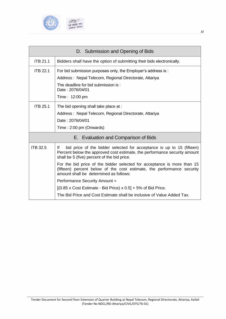
ITB 21.1 Bidders shall have the option of submitting their bids electronically.
ITB 22.1 For bid submission purposes only, the Employer’s address is :
Address : Nepal Telecom, Regional Directorate, Attariya
The deadline for bid submission is : Date : 2076/04/01
Time : 12:00 pm
ITB 25.1 The bid opening shall take place at :
Address : Nepal Telecom, Regional Directorate, Attariya
Date : 2076/04/01
Time : 2:00 pm (Onwards)
E. Evaluation and Comparison of Bids
ITB 32.5 If bid price of the bidder selected for acceptance is up to 15 (fifteen) Percent below the approved cost estimate, the performance security amount shall be 5 (five) percent of the bid price.
For the bid price of the bidder selected for acceptance is more than 15 (fifteen) percent below of the cost estimate, the performance security amount shall be determined as follows:
Performance Security Amount =
[(0.85 x Cost Estimate - Bid Price) x 0.5] + 5% of Bid Price.
The Bid Price and Cost Estimate shall be inclusive of Value Added Tax.

32
Tender Document for Second Floor Extension of Quarter Building at Nepal Telecom, Regional Directorate, Attariya, Kailali (Tender No NDCL/RD-Attariya/CIVIL/075/76-01)
SECTION - III
Evaluation and Qualification Criteria
This Section contains all the criteria that the Employer shall use to evaluate bids and qualify
Bidders by post-qualification exercise. The employer requires bidders to be qualified by meeting
predefined, precise minimum requirements. The method sets pass-fail criteria, which, if not met
by the bidder, results in disqualification. In accordance with ITB 32 and ITB 34, no other
methods, criteria and factors shall be used. The Bidder shall provide all the information
requested in the forms included in Section IV (Bidding Forms).
Table of Criteria
1. Evaluation
1.1 Quantifiable Nonconformities, Errors and Omissions
2. Qualification
2.1 Eligibility
2.1.1 Conflict of Interest
2.1.2 Government-owned Entity
2.1.3 Other Eligibility
2.2 Pending Litigation
2.2.1 Pending Litigation
2.3 Financial Situation
2.3.1 Historical Financial Performance
2.3.2 Average Annual Construction Turnover
2.4 Experience
2.4.1 General Construction Experience
2.4.2 Specific Construction Experience
(a) Contracts of Similar Size and Nature
2.5 Personnel
2.6 Equipment
1. Evaluation In addition to the criteria listed in ITB 32.2 (a) – (e) the following criteria shall apply:
1.1 Quantifiable Nonconformities, Errors and Omissions
The evaluated amount of quantifiable nonconformities, errors and/or omissions shall
be determined by ascertaining the price of such effect on an equal basis by adjusting the same
to the quoted price of the bid. A bid having minor deviations and having no material deviation to
cause any serious effect upon the scope, quality, characteristics, terms and conditions,
performance or any other requirements stated in the bidding documents and acceptable to
the Employer can be considered to be substantially responsive.
2. Qualification
2.1 Eligibility

33
Tender Document for Second Floor Extension of Quarter Building at Nepal Telecom, Regional Directorate, Attariya, Kailali (Tender No NDCL/RD-Attariya/CIVIL/075/76-01)
Criteria Compliance Requirements Documents
Requirement Single
Entity
Joint Venture
Submission Requirements
All Partners
Combined
Each
Partner
Lead
Partner
2.1.1 Conflict of Interest
No conflicts of interest in accordance with ITB Sub-Clause 4.3.
must meet requirement
must meet requirement
must meet requirement
not applicable
Letter of Bid
2.1.2 Government-owned Entity
Bidder required to meet conditions of ITB Sub-Clause 4.5.
must meet requirement
must meet requirement
must meet requirement
not applicable
Forms ELI - 1, ELI - 2, with attachments
2.1.3 Other Eligibility
Firm Registration Certificate
must meet requirement
not applicable
must meet requirement
not applicable
Document attachment
Business Registration Certificate
must meet requirement
not applicable
must meet requirement
not applicable
Document
attachment
VAT and PAN Registration certificate (only for domestic bidders)
must meet requirement
not applicable
must meet requirement
not applicable
Document
attachment
Tax Clearance Certificate for the last Fiscal Year.
must meet requirement
not applicable
must meet requirement
not applicable
Document attachment
Satisfactory performance certificate (SPC) for Nepal Telecom ongoing/completed projects if the bidder has completed /ongoing projects in Nepal Telecom.
must meet requirement
not
applicable
must meet
requirement not
applicable Document attachment

34
Tender Document for Second Floor Extension of Quarter Building at Nepal Telecom, Regional Directorate, Attariya, Kailali (Tender No NDCL/RD-Attariya/CIVIL/075/76-01)
2.2 Pending Litigation
Criteria Compliance Requirements Documents
Requirement Single
Entity
Joint Venture
Submission Requirements All Partners
Combined
Each
Partner
Lead
Partner
2.1.1 Pending Litigation
All pending litigation shall be treated as resolved against the Bidder and so shall in total not represent more than 50 percent of the Bidder's net worth.
must meet requirement by itself or as partner to past or existing JV
not applicable must meet requirement by itself or as partner to past or existing JV
not applicable
Form LIT - 1
2.3 Financial Situation
Criteria Compliance Requirements Documents
Requirement Single
Entity
Joint Venture Submission
Requirements All Partners
Combined Each Partner
Lead
Partner
2.3.1 Historical Financial Performance
bmission of audited
balance sheets and
income statements, for
the last 7 years to
demonstrate the
current soundness of
the applicant’s
financial position. As a
minimum, a Bidder’s
net worth calculated
as the difference
between total assets
and total liabilities
should be positive
Must
meet
requirem
ent
Not applicable Must meet
requirement
Not
applicable
Form FIN-1
with
attachments
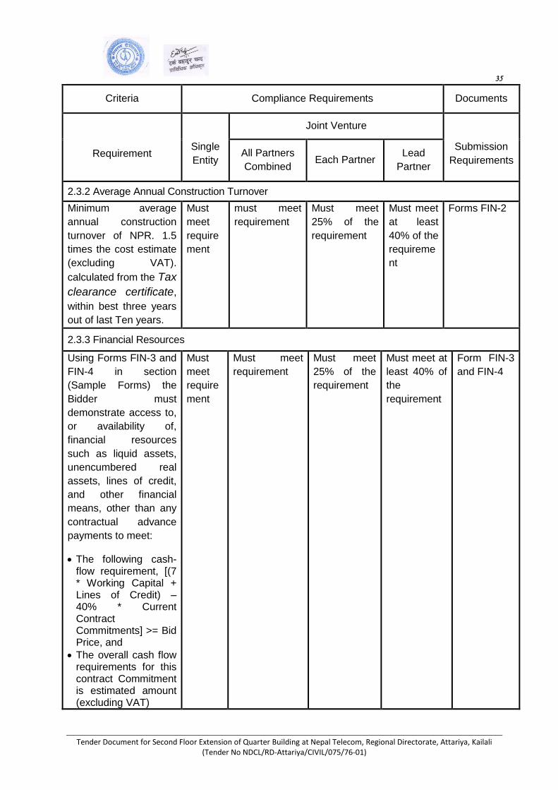
35
Tender Document for Second Floor Extension of Quarter Building at Nepal Telecom, Regional Directorate, Attariya, Kailali (Tender No NDCL/RD-Attariya/CIVIL/075/76-01)
Criteria Compliance Requirements Documents
Requirement
Single
Entity
Joint Venture
Submission
Requirements All Partners
Combined Each Partner
Lead
Partner
2.3.2 Average Annual Construction Turnover
Minimum average
annual construction
turnover of NPR. 1.5
times the cost estimate
(excluding VAT).
calculated from the Tax
clearance certificate,
within best three years
out of last Ten years.
Must
meet
require
ment
must meet
requirement
Must meet
25% of the
requirement
Must meet
at least
40% of the
requireme
nt
Forms FIN-2
2.3.3 Financial Resources
Using Forms FIN-3 and
FIN-4 in section
(Sample Forms) the
Bidder must
demonstrate access to,
or availability of,
financial resources
such as liquid assets,
unencumbered real
assets, lines of credit,
and other financial
means, other than any
contractual advance
payments to meet:
The following cash-flow requirement, [(7 * Working Capital + Lines of Credit) – 40% * Current Contract Commitments] >= Bid Price, and
The overall cash flow requirements for this contract Commitment is estimated amount (excluding VAT)
Must
meet
require
ment
Must meet
requirement
Must meet
25% of the
requirement
Must meet at
least 40% of
the
requirement
Form FIN-3
and FIN-4
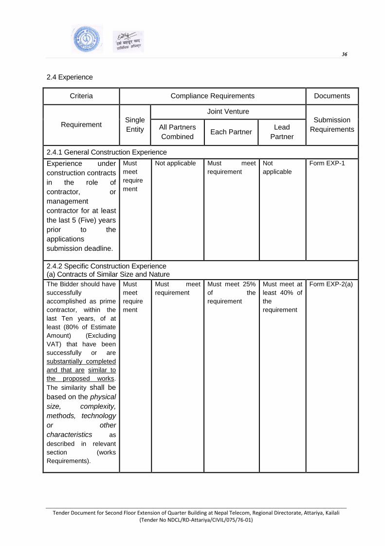
36
Tender Document for Second Floor Extension of Quarter Building at Nepal Telecom, Regional Directorate, Attariya, Kailali (Tender No NDCL/RD-Attariya/CIVIL/075/76-01)
2.4 Experience
Criteria Compliance Requirements Documents
Requirement Single
Entity
Joint Venture
Submission
Requirements All Partners
Combined Each Partner
Lead
Partner
2.4.1 General Construction Experience
Experience under
construction contracts
in the role of
contractor, or
management
contractor for at least
the last 5 (Five) years
prior to the
applications
submission deadline.
Must
meet
require
ment
Not applicable Must meet
requirement
Not
applicable
Form EXP-1
2.4.2 Specific Construction Experience (a) Contracts of Similar Size and Nature
The Bidder should have
successfully
accomplished as prime
contractor, within the
last Ten years, of at
least (80% of Estimate
Amount) (Excluding
VAT) that have been
successfully or are
substantially completed
and that are similar to
the proposed works.
The similarity shall be
based on the physical
size, complexity,
methods, technology
or other
characteristics as
described in relevant
section (works
Requirements).
Must
meet
require
ment
Must meet
requirement
Must meet 25%
of the
requirement
Must meet at
least 40% of
the
requirement
Form EXP-2(a)
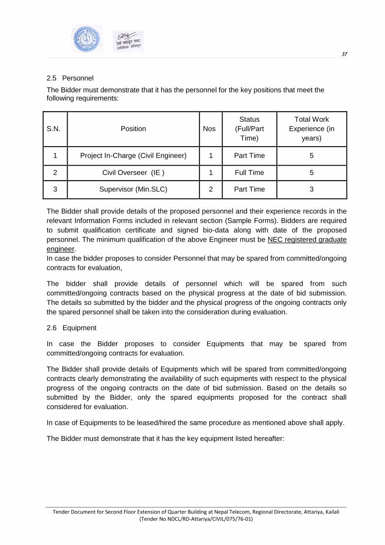
37
Tender Document for Second Floor Extension of Quarter Building at Nepal Telecom, Regional Directorate, Attariya, Kailali (Tender No NDCL/RD-Attariya/CIVIL/075/76-01)
2.5 Personnel
The Bidder must demonstrate that it has the personnel for the key positions that meet the following requirements:
S.N. Position Nos
Status
(Full/Part
Time)
Total Work
Experience (in
years)
1 Project In-Charge (Civil Engineer) 1 Part Time 5
2 Civil Overseer (IE ) 1 Full Time 5
3 Supervisor (Min.SLC) 2 Part Time 3
The Bidder shall provide details of the proposed personnel and their experience records in the
relevant Information Forms included in relevant section (Sample Forms). Bidders are required
to submit qualification certificate and signed bio-data along with date of the proposed
personnel. The minimum qualification of the above Engineer must be NEC registered graduate
engineer.
In case the bidder proposes to consider Personnel that may be spared from committed/ongoing
contracts for evaluation,
The bidder shall provide details of personnel which will be spared from such
committed/ongoing contracts based on the physical progress at the date of bid submission.
The details so submitted by the bidder and the physical progress of the ongoing contracts only
the spared personnel shall be taken into the consideration during evaluation.
2.6 Equipment
In case the Bidder proposes to consider Equipments that may be spared from
committed/ongoing contracts for evaluation.
The Bidder shall provide details of Equipments which will be spared from committed/ongoing
contracts clearly demonstrating the availability of such equipments with respect to the physical
progress of the ongoing contracts on the date of bid submission. Based on the details so
submitted by the Bidder, only the spared equipments proposed for the contract shall
considered for evaluation.
In case of Equipments to be leased/hired the same procedure as mentioned above shall apply.
The Bidder must demonstrate that it has the key equipment listed hereafter:
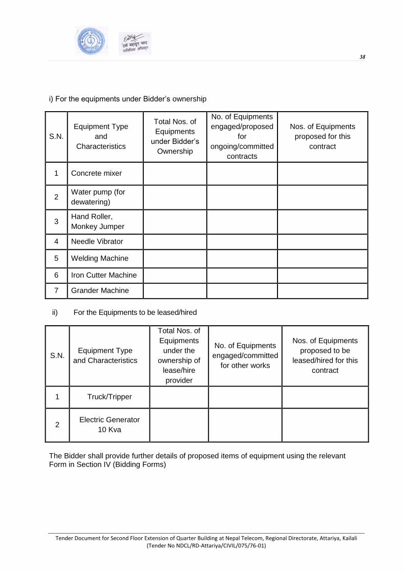
38
Tender Document for Second Floor Extension of Quarter Building at Nepal Telecom, Regional Directorate, Attariya, Kailali (Tender No NDCL/RD-Attariya/CIVIL/075/76-01)
i) For the equipments under Bidder’s ownership
S.N.
Equipment Type
and
Characteristics
Total Nos. of
Equipments
under Bidder’s
Ownership
No. of Equipments
engaged/proposed
for
ongoing/committed
contracts
Nos. of Equipments
proposed for this
contract
1 Concrete mixer
2 Water pump (for
dewatering)
3 Hand Roller,
Monkey Jumper
4 Needle Vibrator
5 Welding Machine
6 Iron Cutter Machine
7 Grander Machine
ii) For the Equipments to be leased/hired
S.N. Equipment Type
and Characteristics
Total Nos. of
Equipments
under the
ownership of
lease/hire
provider
No. of Equipments
engaged/committed
for other works
Nos. of Equipments
proposed to be
leased/hired for this
contract
1 Truck/Tripper
2 Electric Generator
10 Kva
The Bidder shall provide further details of proposed items of equipment using the relevant Form in Section IV (Bidding Forms)

39
Tender Document for Second Floor Extension of Quarter Building at Nepal Telecom, Regional Directorate, Attariya, Kailali (Tender No NDCL/RD-Attariya/CIVIL/075/76-01)
SECTION - IV
Bidding Forms

40
Tender Document for Second Floor Extension of Quarter Building at Nepal Telecom, Regional Directorate, Attariya, Kailali (Tender No NDCL/RD-Attariya/CIVIL/075/76-01)
Letter of Bid
The Bidder must accomplish the Letter of Bid in its letterhead clearly showing the Bidder’s complete name and address.
Date: .........................................................
Name of the contract: .........................................................
Invitation for Bid No.: .......................................................
To: ……………………………………………………………………………………………………….....
We, the undersigned, declare that:
(a) We have examined and have no reservations to the Bidding Documents, including Addenda issued in accordance with Instructions to Bidders (ITB) Clause 8;
(b) We offer to execute in conformity with the Bidding Documents the following Works:
(c) The total price of our Bid, excluding any discounts offered in item (d) below is:
(d) The discounts offered and the methodology for their application are:
(e) Our bid shall be valid for a period of [insert validity period as specified in ITB 18.1] days
from the date fixed for the bid submission deadline in accordance with the Bidding
Documents, and it shall remain binding upon us and may be accepted at any time before the
expiration of that period;
(f) If our bid is accepted, we commit to obtain a performance security in accordance with the
Bidding Document;
(g) Our firm, including any subcontractors or suppliers for any part of the Contract, have
nationalities from eligible countries or any countries [insert the nationality of the Bidder,
including that of all parties that comprise the Bidder if the Bidder is a consortium or
association, and the nationality of each Subcontractor and Supplier];
(h) We, including any subcontractors or suppliers for any part of the contract, do not have any
conflict of interest in accordance with ITB 4.3;
(i) We are not participating, as a Bidder or as a subcontractor, in more than one bid in this
bidding process in accordance with ITB 4.3, other than alternative offers submitted in
accordance with ITB 13;
(j) Our firm, its affiliates or subsidiaries, including any Subcontractors or Suppliers for any part of the contract, has not been declared ineligible, under the Employer’s country laws or official regulations or by an act of compliance with a decision of the United Nations Security Council;

41
Tender Document for Second Floor Extension of Quarter Building at Nepal Telecom, Regional Directorate, Attariya, Kailali (Tender No NDCL/RD-Attariya/CIVIL/075/76-01)
(k) We are not a government owned entity.
(l) We understand that this bid, together with your written acceptance thereof included in your notification of award, shall constitute a binding contract between us, until a formal contract is prepared and executed;
(m) We declare that, we have not been black listed as per ITB 3.4 and no conflict of interest in the
proposed procurement proceedings and we have not been punished for an offense relating to
the concerned profession or business.
(n) We understand that you are not bound to accept the lowest evaluated bid or any other bid
that you may receive; and
(o) If awarded the contract, the person named below shall act as Contractor’s Representative:
(p) We agree to permit the Employer or its representative to inspect our accounts and records and
other documents relating to the bid submission and to have them audited by auditors
appointed by the Employer.
Name: .................................................................................................
In the capacity of .............................................................................
Signed …………………………………………………………...
Duly authorized to sign the Bid for and on behalf of …………
Date …………………………………………………………....
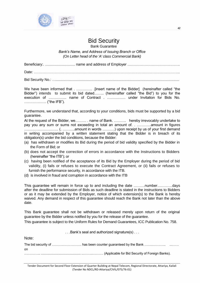
42
Tender Document for Second Floor Extension of Quarter Building at Nepal Telecom, Regional Directorate, Attariya, Kailali (Tender No NDCL/RD-Attariya/CIVIL/075/76-01)
Bid Security Bank Guarantee
Bank’s Name, and Address of Issuing Branch or Office
(On Letter head of the 'A' class Commercial Bank)
Beneficiary:. .............................. name and address of Employer …………………………………….
Date: ………………………………………………………………………………………………………...
Bid Security No.: …............................................................................................................................
We have been informed that . …………. .[insert name of the Bidder] (hereinafter called “the Bidder”) intends to submit its bid dated…….. (hereinafter called “the Bid”) to you for the execution of …………... name of Contract . …………… under Invitation for Bids No. ……………… (“the IFB”).
Furthermore, we understand that, according to your conditions, bids must be supported by a bid guarantee.
At the request of the Bidder, we……… . name of Bank. ………. hereby irrevocably undertake to pay you any sum or sums not exceeding in total an amount of. . ………...amount in figures ………………………. (. ……….amount in words ……….) upon receipt by us of your first demand in writing accompanied by a written statement stating that the Bidder is in breach of its obligation(s) under the bid conditions, because the Bidder:
(a) has withdrawn or modifies its Bid during the period of bid validity specified by the Bidder in
the Form of Bid; or
(b) does not accept the correction of errors in accordance with the Instructions to Bidders
(hereinafter “the ITB”); or
(c) having been notified of the acceptance of its Bid by the Employer during the period of bid
validity, (i) fails or refuses to execute the Contract Agreement, or (ii) fails or refuses to
furnish the performance security, in accordance with the ITB.
(d) is involved in fraud and corruption in accordance with the ITB
This guarantee will remain in force up to and including the date ………number…………days after the deadline for submission of Bids as such deadline is stated in the instructions to Bidders or as it may be extended by the Employer, notice of which extension(s) to the Bank is hereby waived. Any demand in respect of this guarantee should reach the Bank not later than the above date.
This Bank guarantee shall not be withdrawn or released merely upon return of the original
guarantee by the Bidder unless notified by you for the release of the guarantee.
This guarantee is subject to the Uniform Rules for Demand Guarantees, ICC Publication No. 758.
. . .Bank’s seal and authorized signature(s) . . .
Note:
The bid security of ………..……………. has been counter guaranteed by the Bank ……..………... ...……
on
…………... ............................................. ...……..………. (Applicable for Bid Security of Foreign Banks).
43
Tender Document for Second Floor Extension of Quarter Building at Nepal Telecom, Regional Directorate, Attariya, Kailali (Tender No NDCL/RD-Attariya/CIVIL/075/76-01)
Part - II
REQUIREMENTS
44
Tender Document for Second Floor Extension of Quarter Building at Nepal Telecom, Regional Directorate, Attariya, Kailali (Tender No NDCL/RD-Attariya/CIVIL/075/76-01)
SECTION - V
Works Requirements This Section contains the Specification, the Drawings, and supplementary information
that describe the Works to be procured.
The Specifications of work is attached in Annex-1
The Drawings are attached in Annex-2

45
Tender Document for Second Floor Extension of Quarter Building at Nepal Telecom, Regional Directorate, Attariya, Kailali (Tender No NDCL/RD-Attariya/CIVIL/075/76-01)
SECTION - VI
Bill of Quantities

46 46
Tender Document for Second Floor Extension of Quarter Building at Nepal Telecom, Regional Directorate, Attariya, Kailali (Tender No NDCL/RD-Attariya/CIVIL/075/76-01)
Nepal Telecom, Regional Directorate
Attariya, Kailali
Bill of Quantities
PROJECT: Second Floor Extension of Quarter Building LOCATION: NTRD, Attariya
S.No Description of work Total Quantity Unit
Rate per unit (In NRs) Amount
(In NRs)
In Figure
Remarks
In Figure In Word
A CIVIL WORKS
1 EARTHWORK EXCAVATION
Earth work excavation in gravel and
boulder mixed soil & disposal of
excavated materials to outside site
limit as per drawing, specification and
approval of Engineer
270.75 Cu.M
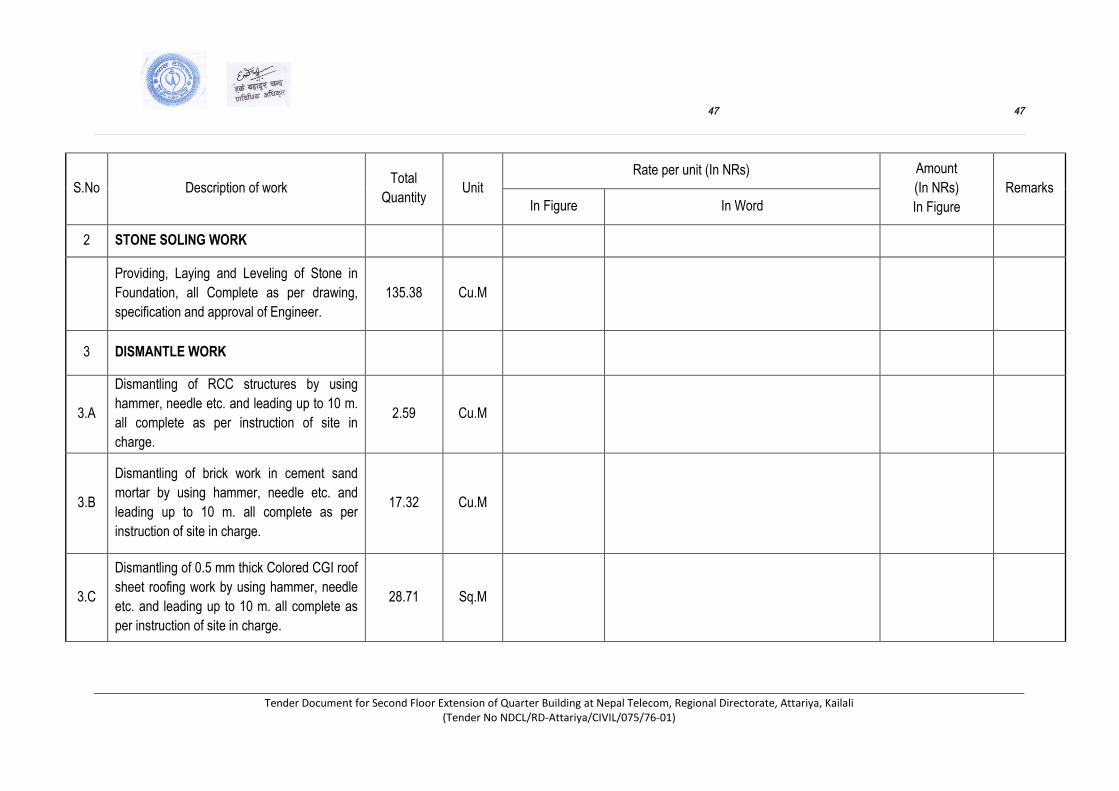
47 47
Tender Document for Second Floor Extension of Quarter Building at Nepal Telecom, Regional Directorate, Attariya, Kailali (Tender No NDCL/RD-Attariya/CIVIL/075/76-01)
S.No Description of work Total
Quantity Unit
Rate per unit (In NRs) Amount
(In NRs)
In Figure
Remarks
In Figure In Word
2 STONE SOLING WORK
Providing, Laying and Leveling of Stone in
Foundation, all Complete as per drawing,
specification and approval of Engineer.
135.38 Cu.M
3 DISMANTLE WORK
3.A
Dismantling of RCC structures by using
hammer, needle etc. and leading up to 10 m.
all complete as per instruction of site in
charge.
2.59 Cu.M
3.B
Dismantling of brick work in cement sand
mortar by using hammer, needle etc. and
leading up to 10 m. all complete as per
instruction of site in charge.
17.32 Cu.M
3.C
Dismantling of 0.5 mm thick Colored CGI roof
sheet roofing work by using hammer, needle
etc. and leading up to 10 m. all complete as
per instruction of site in charge.
28.71 Sq.M
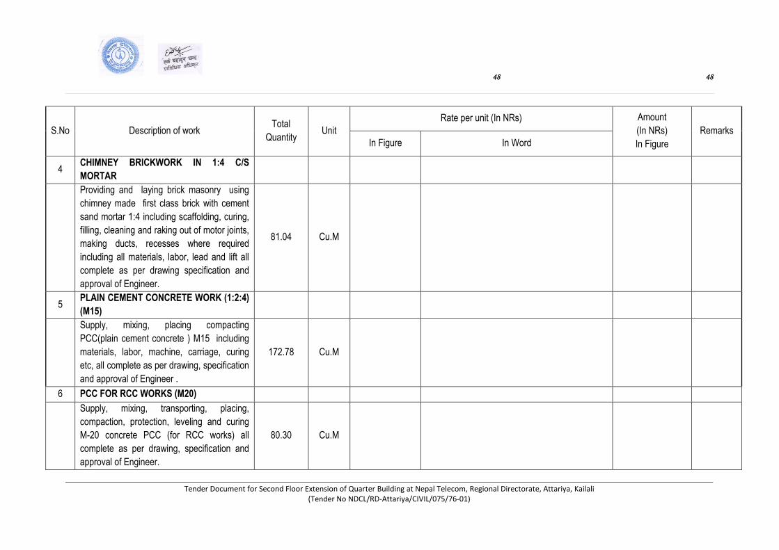
48 48
Tender Document for Second Floor Extension of Quarter Building at Nepal Telecom, Regional Directorate, Attariya, Kailali (Tender No NDCL/RD-Attariya/CIVIL/075/76-01)
S.No Description of work Total
Quantity Unit
Rate per unit (In NRs) Amount
(In NRs)
In Figure
Remarks
In Figure In Word
4 CHIMNEY BRICKWORK IN 1:4 C/S
MORTAR
Providing and laying brick masonry using
chimney made first class brick with cement
sand mortar 1:4 including scaffolding, curing,
filling, cleaning and raking out of motor joints,
making ducts, recesses where required
including all materials, labor, lead and lift all
complete as per drawing specification and
approval of Engineer.
81.04 Cu.M
5 PLAIN CEMENT CONCRETE WORK (1:2:4)
(M15)
Supply, mixing, placing compacting
PCC(plain cement concrete ) M15 including
materials, labor, machine, carriage, curing
etc, all complete as per drawing, specification
and approval of Engineer .
172.78 Cu.M
6 PCC FOR RCC WORKS (M20)
Supply, mixing, transporting, placing,
compaction, protection, leveling and curing
M-20 concrete PCC (for RCC works) all
complete as per drawing, specification and
approval of Engineer.
80.30 Cu.M
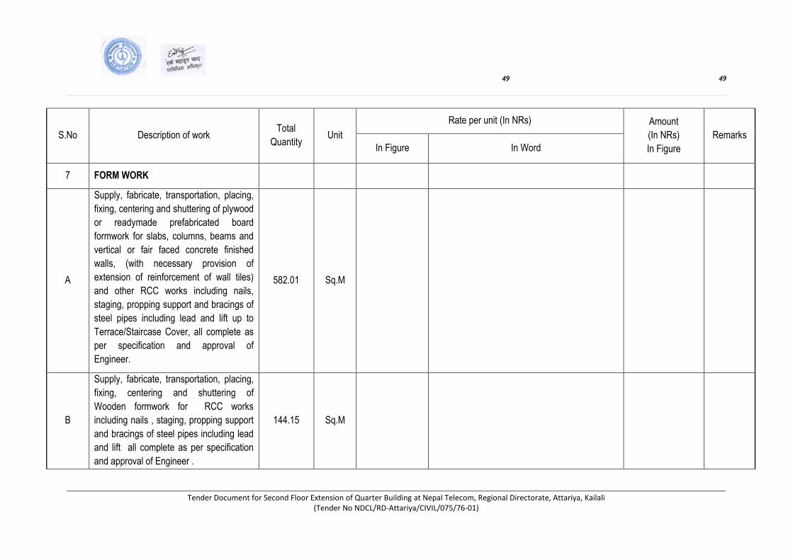
49 49
Tender Document for Second Floor Extension of Quarter Building at Nepal Telecom, Regional Directorate, Attariya, Kailali (Tender No NDCL/RD-Attariya/CIVIL/075/76-01)
S.No Description of work Total
Quantity Unit
Rate per unit (In NRs) Amount
(In NRs)
In Figure
Remarks
In Figure In Word
7 FORM WORK
A
Supply, fabricate, transportation, placing,
fixing, centering and shuttering of plywood
or readymade prefabricated board
formwork for slabs, columns, beams and
vertical or fair faced concrete finished
walls, (with necessary provision of
extension of reinforcement of wall tiles)
and other RCC works including nails,
staging, propping support and bracings of
steel pipes including lead and lift up to
Terrace/Staircase Cover, all complete as
per specification and approval of
Engineer.
582.01 Sq.M
B
Supply, fabricate, transportation, placing,
fixing, centering and shuttering of
Wooden formwork for RCC works
including nails , staging, propping support
and bracings of steel pipes including lead
and lift all complete as per specification
and approval of Engineer .
144.15 Sq.M
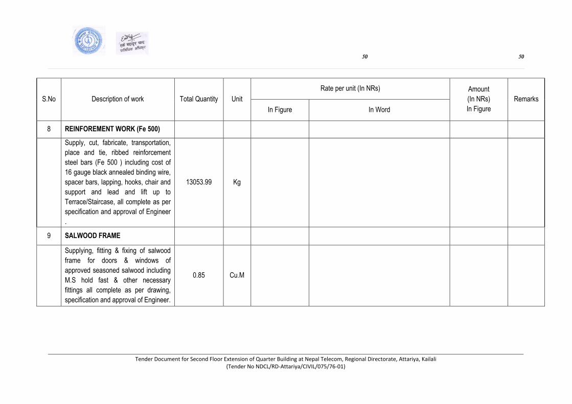
50 50
Tender Document for Second Floor Extension of Quarter Building at Nepal Telecom, Regional Directorate, Attariya, Kailali (Tender No NDCL/RD-Attariya/CIVIL/075/76-01)
S.No Description of work Total Quantity Unit
Rate per unit (In NRs) Amount
(In NRs)
In Figure
Remarks
In Figure In Word
8 REINFOREMENT WORK (Fe 500)
Supply, cut, fabricate, transportation,
place and tie, ribbed reinforcement
steel bars (Fe 500 ) including cost of
16 gauge black annealed binding wire,
spacer bars, lapping, hooks, chair and
support and lead and lift up to
Terrace/Staircase, all complete as per
specification and approval of Engineer
.
13053.99 Kg
9 SALWOOD FRAME
Supplying, fitting & fixing of salwood
frame for doors & windows of
approved seasoned salwood including
M.S hold fast & other necessary
fittings all complete as per drawing,
specification and approval of Engineer.
0.85 Cu.M

51 51
Tender Document for Second Floor Extension of Quarter Building at Nepal Telecom, Regional Directorate, Attariya, Kailali (Tender No NDCL/RD-Attariya/CIVIL/075/76-01)
S.No Description of work Total Quantity Unit Rate per unit (In NRs) Amount
(In NRs)
In Figure
Remarks
In Figure In Word
10 38 MM THICK PANELED DOOR
SHUTTER
Supply and fixing of 38 mm thick
paneled door shutter with 38 x 100
mm thick salwood Frame including
hinges, tower bolts, door blocking set,
aldrop with steel screws, handle and
mortice lock and all complete as per
drawing and specification & approval
of Engineer.
18.40 Sq.M
11 FLUSH DOOR SHUTTERS WITH
TEAK PLY
Supply and fixing flush door shutter
with 38x100mm size framed salwood
flush door shutter with 12mm plywood
including hinges, tower bolts, door
blocking set, aldrop with steel screws,
handle and mortice lock and all
complete as per drawing and
specification & approval of Engineer.
12.57 Sq.M
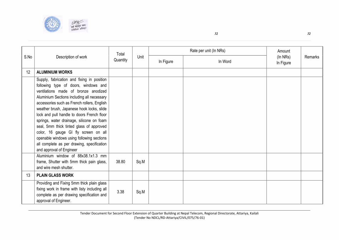
52 52
Tender Document for Second Floor Extension of Quarter Building at Nepal Telecom, Regional Directorate, Attariya, Kailali (Tender No NDCL/RD-Attariya/CIVIL/075/76-01)
S.No Description of work Total
Quantity Unit
Rate per unit (In NRs) Amount
(In NRs)
In Figure
Remarks In Figure In Word
12 ALUMINIUM WORKS
Supply, fabrication and fixing in position
following type of doors, windows and
ventilations made of bronze anodized
Aluminium Sections including all necessary
accessories such as French rollers, English
weather brush, Japanese hook locks, slide
lock and pull handle to doors French floor
springs, water drainage, silicone on foam
seal, 5mm thick tinted glass of approved
color, 16 gauge GI fly screen on all
openable windows using following sections
all complete as per drawing, specification
and approval of Engineer
Aluminium window of 88x38.1x1.3 mm
frame, Shutter with 5mm thick pain glass,
and wire mesh shutter.
38.80 Sq.M
13 PLAIN GLASS WORK
Providing and Fixing 5mm thick plain glass
fixing work in frame with listy including all
complete as per drawing specification and
approval of Engineer.
3.38 Sq.M

53 53
Tender Document for Second Floor Extension of Quarter Building at Nepal Telecom, Regional Directorate, Attariya, Kailali (Tender No NDCL/RD-Attariya/CIVIL/075/76-01)
S.No Description of work Total
Quantity Unit
Rate per unit (In NRs) Amount
(In NRs)
In Figure
Remarks
In Figure In Word
14 12.5 MM PLASTERING WORK 1:3 C/S
Ratio
Supply laying & fixing 1:3 plaster in Ceiling
including supply of materials, labor, mixing,
leveling, curing & scaffolding etc all
complete as per drawing, specification and
approval of the Engineer
283.54 Sq.M
15 20 MM THICK PANI PATI
Supply, laying & fixing 20 mm thick cement
sand Panipati (1:4) on Side of projection
including materials, labor, curing etc all
complete as per drawing, specification and
approval of the Engineer.
219.10 R.M
16 12.5 MM PLASTERING WORK 1:4 C/S
Ratio
Supplying, laying & fixing 1:4 plaster in
wall, column, beam including supply of
materials, labor, mixing, leveling, curing &
scaffolding etc all complete as per
drawing, specification and approval of the
Engineer
1021.82 Sq.M

54 54
Tender Document for Second Floor Extension of Quarter Building at Nepal Telecom, Regional Directorate, Attariya, Kailali (Tender No NDCL/RD-Attariya/CIVIL/075/76-01)
S.No Description of work Total Quantity Unit Rate per unit (In NRs) Amount
(In NRs)
In Figure
Remarks
In Figure In Word
17 ROOFING TILE CARVING WORK
Roofing Tile Carving work by Cement
mortar (1:4) work on sloped roof all
complete as per drawing, specification
and approval of Engineer.
51.39 Cu.M
18 SCREEDING WORK.
Supply, mixing, laying and compacting
20 to 25mm thick cement sand screed
(1:4) on floors including materials,
labor, curing etc all complete as per
drawing, specification and approval of
the Engineer
492.12 Sq.M
19 PUNNING WORKS
Supply, mixing and placing of 3mm
thick cement sand punning 1:1 over
screed, trowel finished in perfect line
and level including materials, labor,
curing, caring etc all complete as per
drawing, specification and approval of
the Engineer
492.12 Sq.M

55 55
Tender Document for Second Floor Extension of Quarter Building at Nepal Telecom, Regional Directorate, Attariya, Kailali (Tender No NDCL/RD-Attariya/CIVIL/075/76-01)
S.No Description of work Total Quantity Unit
Rate per unit (In NRs) Amount
(In NRs)
In Figure
Remarks
In Figure In Word
20 MOSAIC TILE FLOORING WORK
Supply, mixing and placing of 25mm
thick Mosaic Tile flooring work in 19
mm thick cement mortar (1:2) with
polishing in floors all complete as per
drawing, specification and approval of
the Engineer.
33.96 Sq.M
21 MARBLE FLOORING WORK.
Supply, mixing and placing of available
approved thickness of marble finished
in perfect line and level on 1:2 CM of
selected quality , color, shade, type
and size in patterns including cutting,
adjusting, rebates and drilling holes
bracket, dowel pins anchoring;
including grinding, rubbing and
polishing all complete as per drawing,
specification and approval of the
Engineer.
10.17 Sq.M

56 56
Tender Document for Second Floor Extension of Quarter Building at Nepal Telecom, Regional Directorate, Attariya, Kailali (Tender No NDCL/RD-Attariya/CIVIL/075/76-01)
S.No Description of work Total
Quantity Unit
Rate per unit (In NRs) Amount
(In NRs)
In Figure
Remarks In Figure In Word
22 FLOOR AND WALL TILES
Supplying, laying and fixing non slip floor porcelain tiles
on roof, on toilet floor and glazed tiles on toilet walls of
approved quality, size, color and pattern including base
plaster, fitting and grunting of joints in approved color,
quality, size and pattern all complete as per drawing,
specification and approval of the Engineer
140.23 Sq.M
23 WASHABLE DISTEMPER PAINTING WORKS
Supply and applying one coat of primer and 2 or more
coat of distemper paint of high quality over plastered
surface of wall including supply of materials, labour
cleaning the surface, preparation of the base , painting &
curing etc, all complete as per drawing, specification
and approval of the Engineer.
2117.17 Sq.M
24 WEATHER COAT(APEX) PAINTING WORKS
Supply and applying one coat of primer and 2 or more
coats of Apex (Weather) paint of high quality over
plastered surface of wall including supply of materials,
labour cleaning the surface, preparation of the base ,
painting & curing etc, all complete as per drawing,
specification and approval of the Engineer.
1437.54 Sq.M
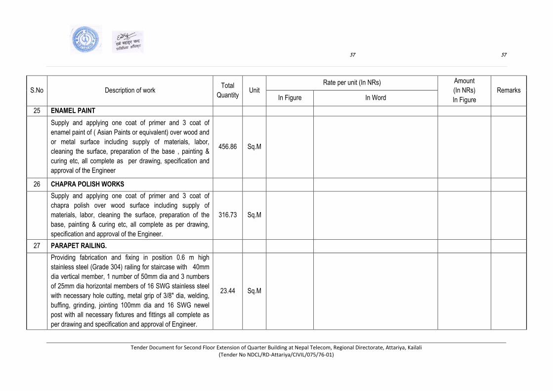
57 57
Tender Document for Second Floor Extension of Quarter Building at Nepal Telecom, Regional Directorate, Attariya, Kailali (Tender No NDCL/RD-Attariya/CIVIL/075/76-01)
S.No Description of work Total
Quantity Unit
Rate per unit (In NRs) Amount
(In NRs)
In Figure
Remarks In Figure In Word
25 ENAMEL PAINT
Supply and applying one coat of primer and 3 coat of
enamel paint of ( Asian Paints or equivalent) over wood and
or metal surface including supply of materials, labor,
cleaning the surface, preparation of the base , painting &
curing etc, all complete as per drawing, specification and
approval of the Engineer
456.86 Sq.M
26 CHAPRA POLISH WORKS
Supply and applying one coat of primer and 3 coat of
chapra polish over wood surface including supply of
materials, labor, cleaning the surface, preparation of the
base, painting & curing etc, all complete as per drawing,
specification and approval of the Engineer.
316.73
Sq.M
27 PARAPET RAILING.
Providing fabrication and fixing in position 0.6 m high
stainless steel (Grade 304) railing for staircase with 40mm
dia vertical member, 1 number of 50mm dia and 3 numbers
of 25mm dia horizontal members of 16 SWG stainless steel
with necessary hole cutting, metal grip of 3/8" dia, welding,
buffing, grinding, jointing 100mm dia and 16 SWG newel
post with all necessary fixtures and fittings all complete as
per drawing and specification and approval of Engineer.
23.44 Sq.M
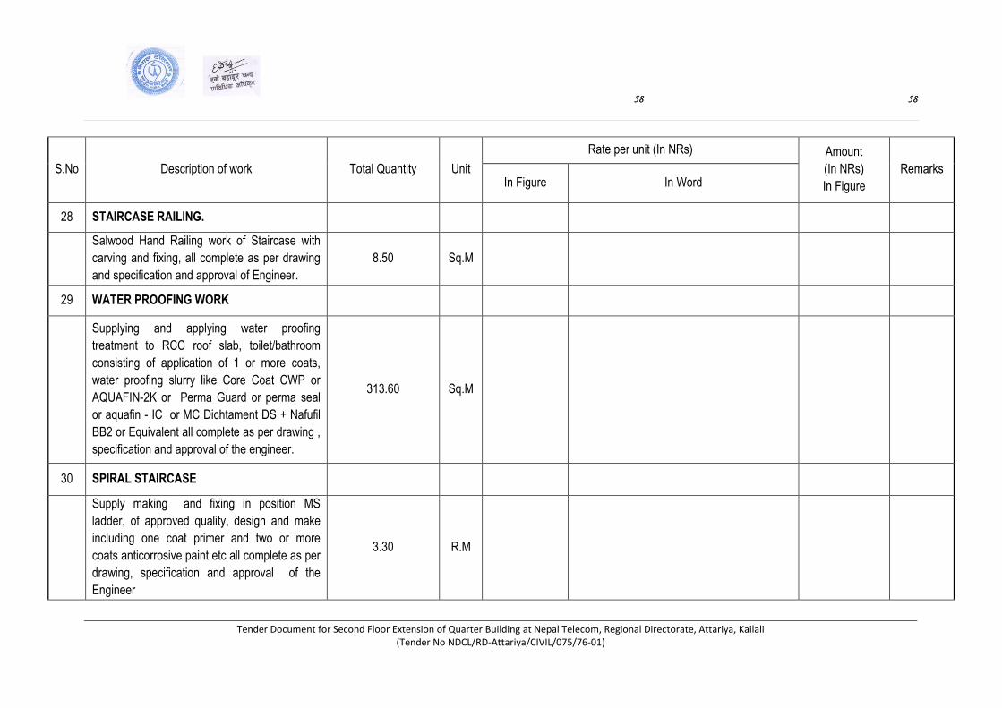
58 58
Tender Document for Second Floor Extension of Quarter Building at Nepal Telecom, Regional Directorate, Attariya, Kailali (Tender No NDCL/RD-Attariya/CIVIL/075/76-01)
S.No Description of work Total Quantity Unit
Rate per unit (In NRs) Amount
(In NRs)
In Figure
Remarks In Figure In Word
28 STAIRCASE RAILING.
Salwood Hand Railing work of Staircase with
carving and fixing, all complete as per drawing
and specification and approval of Engineer.
8.50 Sq.M
29 WATER PROOFING WORK
Supplying and applying water proofing
treatment to RCC roof slab, toilet/bathroom
consisting of application of 1 or more coats,
water proofing slurry like Core Coat CWP or
AQUAFIN-2K or Perma Guard or perma seal
or aquafin - IC or MC Dichtament DS + Nafufil
BB2 or Equivalent all complete as per drawing ,
specification and approval of the engineer.
313.60
Sq.M
30 SPIRAL STAIRCASE
Supply making and fixing in position MS
ladder, of approved quality, design and make
including one coat primer and two or more
coats anticorrosive paint etc all complete as per
drawing, specification and approval of the
Engineer
3.30 R.M
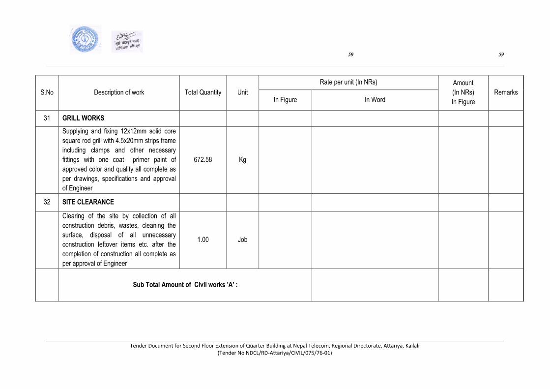
59 59
Tender Document for Second Floor Extension of Quarter Building at Nepal Telecom, Regional Directorate, Attariya, Kailali (Tender No NDCL/RD-Attariya/CIVIL/075/76-01)
S.No Description of work Total Quantity Unit
Rate per unit (In NRs) Amount
(In NRs)
In Figure
Remarks In Figure In Word
31 GRILL WORKS
Supplying and fixing 12x12mm solid core
square rod grill with 4.5x20mm strips frame
including clamps and other necessary
fittings with one coat primer paint of
approved color and quality all complete as
per drawings, specifications and approval
of Engineer
672.58 Kg
32 SITE CLEARANCE
Clearing of the site by collection of all
construction debris, wastes, cleaning the
surface, disposal of all unnecessary
construction leftover items etc. after the
completion of construction all complete as
per approval of Engineer
1.00 Job
Sub Total Amount of Civil works 'A' :
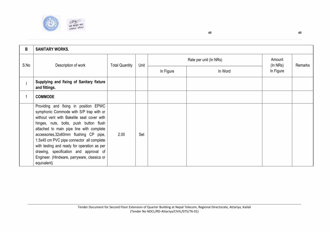
60 60
Tender Document for Second Floor Extension of Quarter Building at Nepal Telecom, Regional Directorate, Attariya, Kailali (Tender No NDCL/RD-Attariya/CIVIL/075/76-01)
B SANITARY WORKS.
S.No Description of work Total Quantity Unit
Rate per unit (In NRs) Amount
(In NRs)
In Figure
Remarks
In Figure In Word
I Supplying and fixing of Sanitary fixture
and fittings.
1 COMMODE
Providing and fixing in position EPWC
symphonic Commode with S/P trap with or
without vent with Bakelite seat cover with
hinges, nuts, bolts, push button flush
attached to main pipe line with complete
accessories,32x60mm flushing CP pipe,
1.5x45 cm PVC pipe connector all complete
with testing and ready for operation as per
drawing, specification and approval of
Engineer. (Hindware, parryware, classica or
equivalent)
2.00 Set

61 61
Tender Document for Second Floor Extension of Quarter Building at Nepal Telecom, Regional Directorate, Attariya, Kailali (Tender No NDCL/RD-Attariya/CIVIL/075/76-01)
S.No Description of work Total
Quantity Unit
Rate per unit (In NRs) Amount
(In NRs)
In Figure
Remarks In Figure In Word
2 WASH BASIN
Providing and fixing in position white earthen ware single
hole hand wash basins including 15mm CP Faucet ,
32mm CP waste couplin with plug and CP chain and ring
32mm PVC bottle trap (MALPINE -UK or equivalent) with
tail and pieces, 15mm CP approved angle cocks with
460mm long PVC reinforced connector pipes (Italian
make) with both end coupling joints etc. all complete with
testing and ready for operation as per drawing,
specification and approval of Engineer.
20" x 16" size porcelain clay white glazed wash basin
(Hind ware, parry ware, classica or equivalent) 2.00 Set
3 KITCHEN SINKS
Providing and fixing in position stainless steel (16 SWG)
kitchen sink with or without drain board including 15mm
dia. Single lever swivel type bench mounted pillar cock
with 57mm dia fixing flange and clear height 300mm,
40mm dia. PVC bottle trap (MALPINE -UK or equivalent)
with tail pieces, 40 mm dia waste coupling, all complete
with necessary accessories as per drawing ,
specification and approval of Engineer.
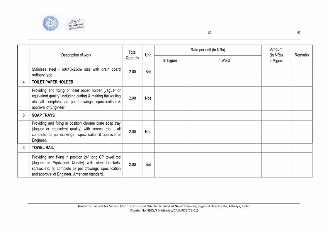
62 62
Tender Document for Second Floor Extension of Quarter Building at Nepal Telecom, Regional Directorate, Attariya, Kailali (Tender No NDCL/RD-Attariya/CIVIL/075/76-01)
Description of work Total
Quantity Unit
Rate per unit (In NRs) Amount
(In NRs)
In Figure
Remarks
In Figure In Word
Stainless steel - 60x45x25cm size with drain board
ordinary type. 2.00 Set
4 TOILET PAPER HOLDER
Providing and fixing of toilet paper holder (Jaguar or
equivalent quality) including cutting & making the walling
etc, all complete, as per drawings, specification &
approval of Engineer.
2.00 Nos
5 SOAP TRAYS
Providing and fixing in position chrome plate soap tray
(Jaguar or equivalent quality) with screws etc. , all
complete, as per drawings, specification & approval of
Engineer.
2.00 Nos
6 TOWEL RAIL
Providing and fixing in position 24" long CP towel rod
(Jaguar or Equivalent Quality) with steel brackets,
screws etc, all complete as per drawings, specification
and approval of Engineer. American standard.
2.00
Set
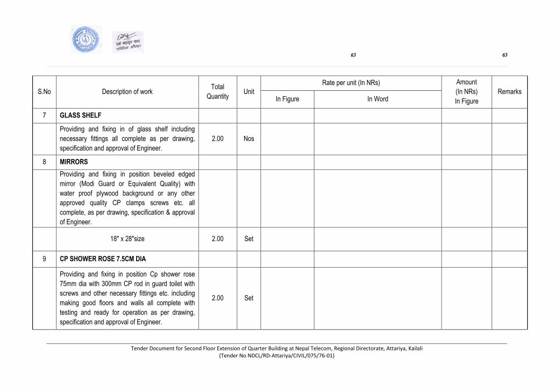
63 63
Tender Document for Second Floor Extension of Quarter Building at Nepal Telecom, Regional Directorate, Attariya, Kailali (Tender No NDCL/RD-Attariya/CIVIL/075/76-01)
S.No Description of work Total
Quantity Unit
Rate per unit (In NRs) Amount
(In NRs)
In Figure
Remarks In Figure In Word
7 GLASS SHELF
Providing and fixing in of glass shelf including
necessary fittings all complete as per drawing,
specification and approval of Engineer.
2.00 Nos
8 MIRRORS
Providing and fixing in position beveled edged
mirror (Modi Guard or Equivalent Quality) with
water proof plywood background or any other
approved quality CP clamps screws etc. all
complete, as per drawing, specification & approval
of Engineer.
18" x 28"size 2.00 Set
9 CP SHOWER ROSE 7.5CM DIA
Providing and fixing in position Cp shower rose
75mm dia with 300mm CP rod in guard toilet with
screws and other necessary fittings etc. including
making good floors and walls all complete with
testing and ready for operation as per drawing,
specification and approval of Engineer.
2.00 Set
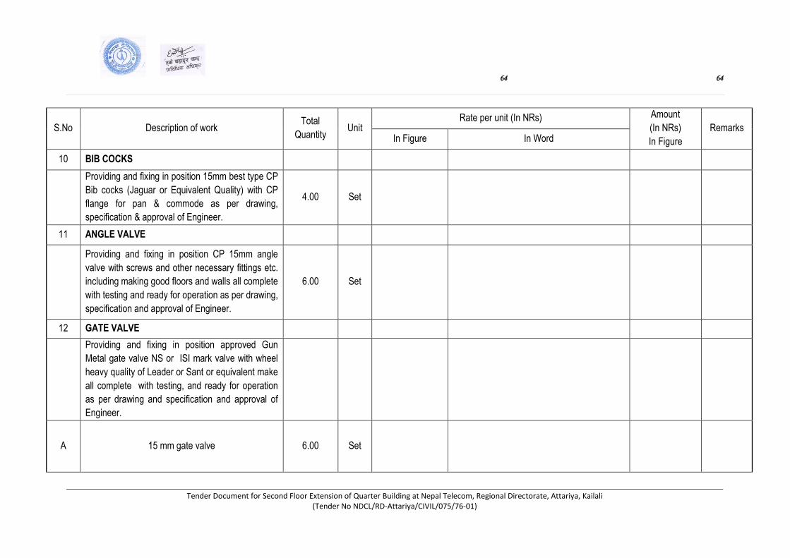
64 64
Tender Document for Second Floor Extension of Quarter Building at Nepal Telecom, Regional Directorate, Attariya, Kailali (Tender No NDCL/RD-Attariya/CIVIL/075/76-01)
S.No Description of work Total
Quantity Unit
Rate per unit (In NRs) Amount
(In NRs)
In Figure
Remarks In Figure In Word
10 BIB COCKS
Providing and fixing in position 15mm best type CP
Bib cocks (Jaguar or Equivalent Quality) with CP
flange for pan & commode as per drawing,
specification & approval of Engineer.
4.00 Set
11 ANGLE VALVE
Providing and fixing in position CP 15mm angle
valve with screws and other necessary fittings etc.
including making good floors and walls all complete
with testing and ready for operation as per drawing,
specification and approval of Engineer.
6.00 Set
12 GATE VALVE
Providing and fixing in position approved Gun
Metal gate valve NS or ISI mark valve with wheel
heavy quality of Leader or Sant or equivalent make
all complete with testing, and ready for operation
as per drawing and specification and approval of
Engineer.
A 15 mm gate valve 6.00 Set

65 65
Tender Document for Second Floor Extension of Quarter Building at Nepal Telecom, Regional Directorate, Attariya, Kailali (Tender No NDCL/RD-Attariya/CIVIL/075/76-01)
S.No Description of work Total
Quantity Unit
Rate per unit (In NRs) Amount
(In NRs)
In Figure
Remarks
In Figure In Word
B 25 mm gate valve 4.00 Set
13 GRATTING
Providing and fixing of 100 mm dia PVC grating
including cutting and making good the walls and
floors etc., all complete as per drawings,
specification and approval of Engineer.
4.00 Set
14 FLOOR TRAPS
Providing and fixing PVC floor trap of 110 mm dia
OD inlet and 75 mm dia OD outlet with 110mm dia
stainless steel grating of heavy type including
cutting and making good the walls and floors etc.,
all complete as per drawings, specification and
approval of Engineer.
8.00 Set
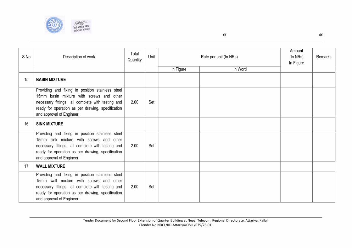
66 66
Tender Document for Second Floor Extension of Quarter Building at Nepal Telecom, Regional Directorate, Attariya, Kailali (Tender No NDCL/RD-Attariya/CIVIL/075/76-01)
S.No Description of work Total
Quantity Unit Rate per unit (In NRs)
Amount
(In NRs)
In Figure
Remarks
In Figure In Word
15 BASIN MIXTURE
Providing and fixing in position stainless steel
15mm basin mixture with screws and other
necessary fittings all complete with testing and
ready for operation as per drawing, specification
and approval of Engineer.
2.00 Set
16 SINK MIXTURE
Providing and fixing in position stainless steel
15mm sink mixture with screws and other
necessary fittings all complete with testing and
ready for operation as per drawing, specification
and approval of Engineer.
2.00 Set
17 WALL MIXTURE
Providing and fixing in position stainless steel
15mm wall mixture with screws and other
necessary fittings all complete with testing and
ready for operation as per drawing, specification
and approval of Engineer.
2.00 Set
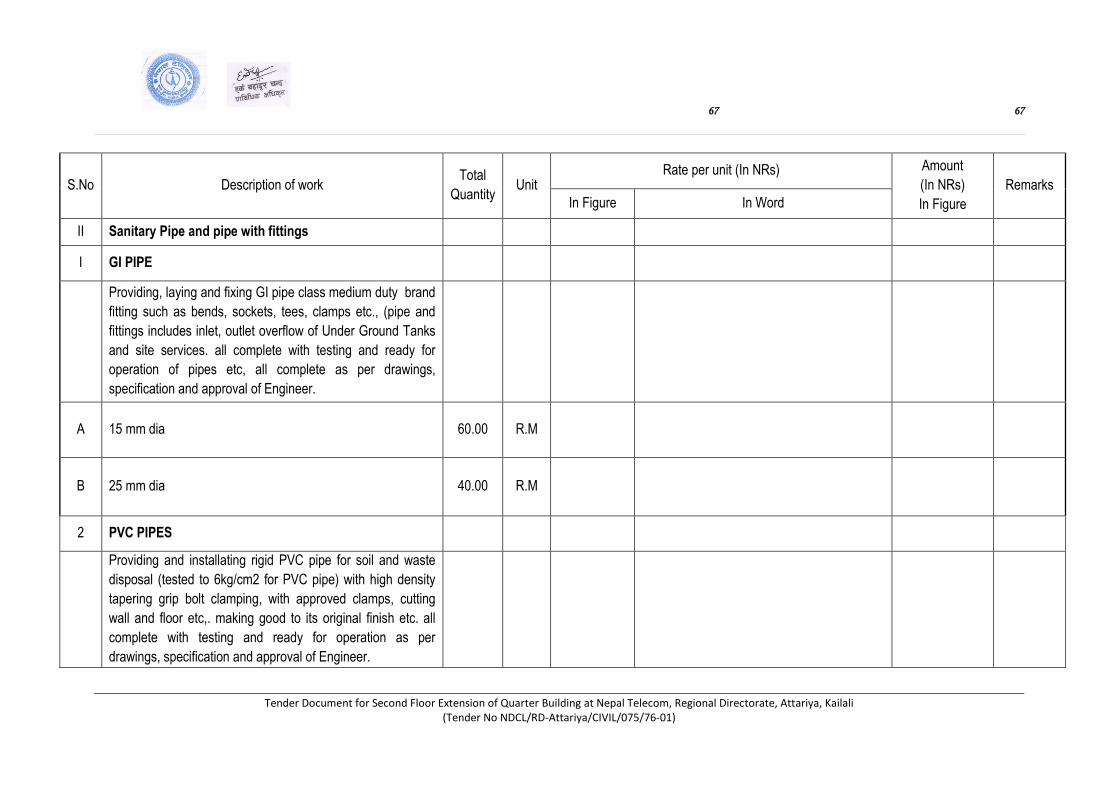
67 67
Tender Document for Second Floor Extension of Quarter Building at Nepal Telecom, Regional Directorate, Attariya, Kailali (Tender No NDCL/RD-Attariya/CIVIL/075/76-01)
S.No Description of work Total
Quantity Unit
Rate per unit (In NRs) Amount
(In NRs)
In Figure
Remarks
In Figure In Word
II Sanitary Pipe and pipe with fittings
I GI PIPE
Providing, laying and fixing GI pipe class medium duty brand
fitting such as bends, sockets, tees, clamps etc., (pipe and
fittings includes inlet, outlet overflow of Under Ground Tanks
and site services. all complete with testing and ready for
operation of pipes etc, all complete as per drawings,
specification and approval of Engineer.
A 15 mm dia 60.00 R.M
B 25 mm dia 40.00 R.M
2 PVC PIPES
Providing and installating rigid PVC pipe for soil and waste
disposal (tested to 6kg/cm2 for PVC pipe) with high density
tapering grip bolt clamping, with approved clamps, cutting
wall and floor etc,. making good to its original finish etc. all
complete with testing and ready for operation as per
drawings, specification and approval of Engineer.
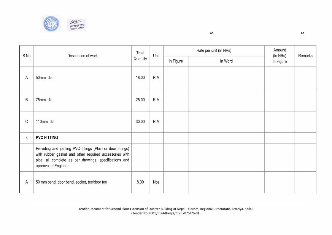
68 68
Tender Document for Second Floor Extension of Quarter Building at Nepal Telecom, Regional Directorate, Attariya, Kailali (Tender No NDCL/RD-Attariya/CIVIL/075/76-01)
S.No Description of work Total
Quantity Unit
Rate per unit (In NRs) Amount
(In NRs)
In Figure
Remarks
In Figure In Word
A 50mm dia 18.00 R.M
B 75mm dia 25.00 R.M
C 110mm dia 30.00 R.M
3 PVC FITTING
Providing and jointing PVC fittings (Plain or door fittings)
with rubber gasket and other required accessories with
pipe, all complete as per drawings, specifications and
approval of Engineer
A 50 mm bend, door bend, socket, tee/door tee 8.00 Nos
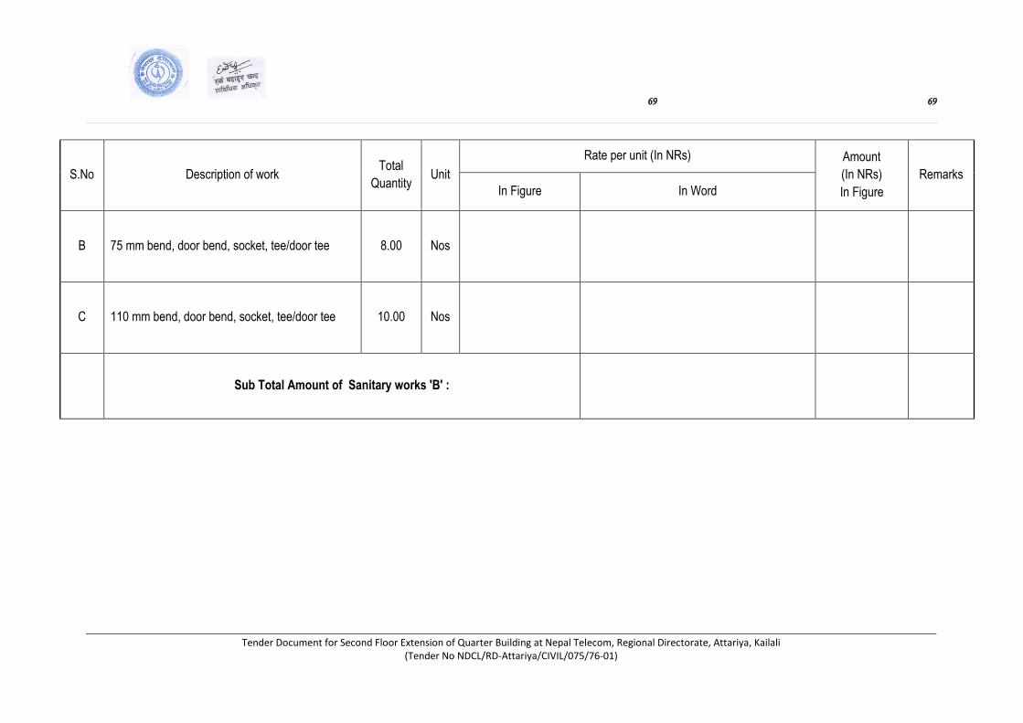
69 69
Tender Document for Second Floor Extension of Quarter Building at Nepal Telecom, Regional Directorate, Attariya, Kailali (Tender No NDCL/RD-Attariya/CIVIL/075/76-01)
S.No Description of work Total
Quantity Unit
Rate per unit (In NRs) Amount
(In NRs)
In Figure
Remarks
In Figure In Word
B 75 mm bend, door bend, socket, tee/door tee 8.00 Nos
C 110 mm bend, door bend, socket, tee/door tee 10.00 Nos
Sub Total Amount of Sanitary works 'B' :

70 70
Tender Document for Second Floor Extension of Quarter Building at Nepal Telecom, Regional Directorate, Attariya, Kailali (Tender No NDCL/RD-Attariya/CIVIL/075/76-01)
C ELECTRIFICATION WORKS
S.No Description of work Total
Quantity Unit
Rate per unit (In NRs) Amount
(In NRs)
In Figure
Remarks In Figure In Word
1
Supplying and installing of Standard company
10 way recessed type double lock distribution
box of metal sheet with following rated MCBs
(a) 25A DP MCB - 1 Pc (b) 6A SP MCB -4 Pcs
and (c) 16A SP MCB -4 Pcs as per Drawing,
Specification and Instructions all complete.
1.00 Set
2
Supplying and installing of Standard company
1x40 Watt Opalite with Acrylic Difuser (TSC
19/136) fluorescent lamp set with electronic
choke, switch, celling rose, celling
fixingmaterials as per Drawing, Specification
and Instructions all complete.
8.00 Set
3
Supplying and installing of Standard company
decorative type dome light 8" heavy carrier
with switch, 11 Watt CFL bulb, celling rose and
all necessary fixing and connecting materials
as per Drawing, Specification and Instructions
all complete.
17.00 Set

71 71
Tender Document for Second Floor Extension of Quarter Building at Nepal Telecom, Regional Directorate, Attariya, Kailali (Tender No NDCL/RD-Attariya/CIVIL/075/76-01)
S.No Description of work Total
Quantity Unit
Rate per unit (In NRs) Amount
(In NRs)
In Figure
Remarks
In Figure In Word
4
Supplying and installing of Standard company
decorative type wall bracket/bulk head lamp with
switch, 11 Watt CFL bulb, celling rose and all
necessary fixing and connecting materials as per
Drawing, Specification and Instructions all
complete.
18.00 Set
5
Supplying and installing of Standard company 9"
Exhaust fan with regulator, control switch,
hanging tubes and chains and all necessary
fixing, insulating and materials as per Drawing,
Specification and Instructions all complete.
4.00 Set
6
Supplying and installing of Standard company 48"
swing ceilling fan with regulator, control
switch,ceilling rose, hanging tubes and chains and
all necessary fixing, insulating and materials as
per Drawing, Specification and Instructions all
complete.
9.00 Set
7
Supplying and installing 6/16 Amp S/Socket with
safety shutter F with switch and indicator in
suitable GI Shtte metal box with all necessary
fixing andconnecting materials as per Drawing,
Specification and Instructions all complete.
24.00 Set

72 72
Tender Document for Second Floor Extension of Quarter Building at Nepal Telecom, Regional Directorate, Attariya, Kailali (Tender No NDCL/RD-Attariya/CIVIL/075/76-01)
S.No Description of work Total
Quantity Unit
Rate per unit (In NRs) Amount
(In NRs)
In Figure
Remarks
In Figure In Word
8
Wirinig of fluorescent lamps, dome lights, wall
brackets and fan points with 2x3/20 SWG copper
cable in suitable concealed PVC conduit including
junction boxes, necessary fixing and connecting
materials as per Drawing and instruction all
complete.
56.00 Points
9
Wirinig of 5/15 Amp multi-pin power socket with
2x7/20 + 3/22 SWG copper cable (Green) in
suitable concealed PVC conduit including junction
boxes, necessary fixing and connecting materials
as per Drawing and instruction all complete.
24.00 Points
10
Supplying and Wirinig 7/18 SWG copper cable in
suitable concealed PVC conduit from main DP
MCB to DB2 as per Drawing and instruction all
complete.
20.00 Meter
11
Supplying and installing standard company
Telephone outlet socket and wirinig of telephone
points from telephone junction box to each pionts
separately with indoor teleohone wire ( 0.5 mm2 )
in suitable concealed PVC conduit including
necessary fixing and connecting materials as per
drawing,
8.00 Points
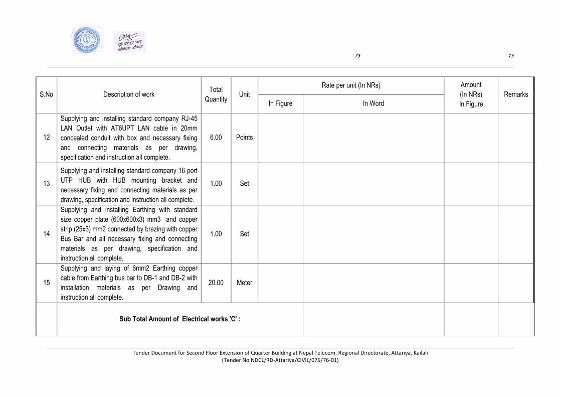
73 73
Tender Document for Second Floor Extension of Quarter Building at Nepal Telecom, Regional Directorate, Attariya, Kailali (Tender No NDCL/RD-Attariya/CIVIL/075/76-01)
S.No Description of work Total
Quantity Unit
Rate per unit (In NRs) Amount
(In NRs)
In Figure
Remarks
In Figure In Word
12
Supplying and installing standard company RJ-45
LAN Outlet with AT6UPT LAN cable in 20mm
concealed conduit with box and necessary fixing
and connecting materials as per drawing,
specification and instruction all complete.
6.00 Points
13
Supplying and installing standard company 16 port
UTP HUB with HUB mounting bracket and
necessary fixing and connecting materials as per
drawing, specification and instruction all complete.
1.00 Set
14
Supplying and installing Earthing with standard
size copper plate (600x600x3) mm3 and copper
strip (25x3) mm2 connected by brazing with copper
Bus Bar and all necessary fixing and connecting
materials as per drawing, specification and
instruction all complete.
1.00 Set
15
Supplying and laying of 6mm2 Earthing copper
cable from Earthing bus bar to DB-1 and DB-2 with
installation materials as per Drawing and
instruction all complete.
20.00 Meter
Sub Total Amount of Electrical works 'C' :
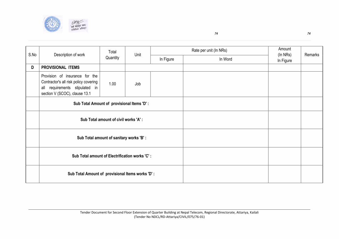
74 74
Tender Document for Second Floor Extension of Quarter Building at Nepal Telecom, Regional Directorate, Attariya, Kailali (Tender No NDCL/RD-Attariya/CIVIL/075/76-01)
S.No Description of work Total
Quantity Unit
Rate per unit (In NRs) Amount
(In NRs)
In Figure
Remarks In Figure In Word
D PROVISIONAL ITEMS
Provision of insurance for the
Contractor's all risk policy covering
all requirements stipulated in
section V (SCOC), clause 13.1
1.00 Job
Sub Total Amount of provisional Items 'D' :
Sub Total amount of civil works 'A' :
Sub Total amount of sanitary works 'B' :
Sub Total amount of Electrification works 'C' :
Sub Total Amount of provisional Items works 'D' :
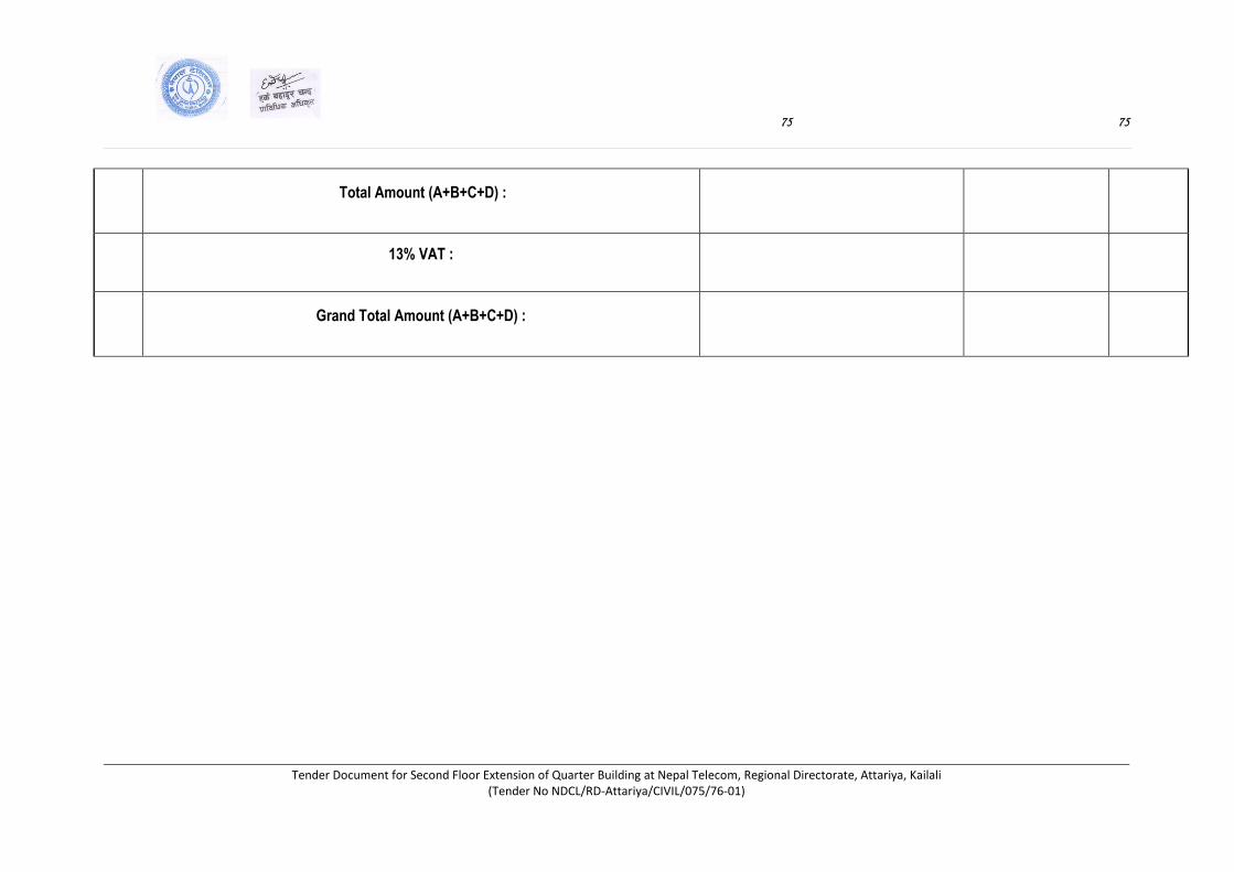
75 75
Tender Document for Second Floor Extension of Quarter Building at Nepal Telecom, Regional Directorate, Attariya, Kailali (Tender No NDCL/RD-Attariya/CIVIL/075/76-01)
Total Amount (A+B+C+D) :
13% VAT :
Grand Total Amount (A+B+C+D) :

76 76
Tender Document for Second Floor Extension of Quarter Building at Nepal Telecom, Regional Directorate, Attariya, Kailali (Tender No NDCL/RD-Attariya/CIVIL/075/76-01)
Part - III
CONDITIONS OF CONTRACT
AND CONTRACT FORMS
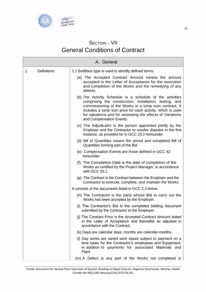
77 77
Tender Document for Second Floor Extension of Quarter Building at Nepal Telecom, Regional Directorate, Attariya, Kailali (Tender No NDCL/RD-Attariya/CIVIL/075/76-01)
SECTION - VII
General Conditions of Contract
A. General
1. Definitions 1.1 Boldface type is used to identify defined terms.
(a) The Accepted Contract Amount means the amount accepted in the Letter of Acceptance for the execution and completion of the Works and the remedying of any defects.
(b) The Activity Schedule is a schedule of the activities comprising the construction, installation, testing, and commissioning of the Works in a lump sum contract. It includes a lump sum price for each activity, which is used for valuations and for assessing the effects of Variations and Compensation Events.
(c) The Adjudicator is the person appointed jointly by the Employer and the Contractor to resolve disputes in the first instance, as provided for in GCC 23.2 hereunder.
(d) Bill of Quantities means the priced and completed Bill of Quantities forming part of the Bid.
(e) Compensation Events are those defined in GCC 42 hereunder.
(f) The Completion Date is the date of completion of the Works as certified by the Project Manager, in accordance with GCC 53.1.
(g) The Contract is the Contract between the Employer and the Contractor to execute, complete, and maintain the Works.
It consists of the documents listed in GCC 2.3 below.
(h) The Contractor is the party whose Bid to carry out the Works has been accepted by the Employer.
(i) The Contractor’s Bid is the completed bidding document submitted by the Contractor to the Employer.
(j) The Contract Price is the Accepted Contract Amount stated in the Letter of Acceptance and thereafter as adjusted in accordance with the Contract.
(k) Days are calendar days; months are calendar-months.
(l) Day works are varied work inputs subject to payment on a time basis for the Contractor’s employees and Equipment, in addition to payments for associated Materials and Plant.
(m) A Defect is any part of the Works not completed in

78 78
Tender Document for Second Floor Extension of Quarter Building at Nepal Telecom, Regional Directorate, Attariya, Kailali (Tender No NDCL/RD-Attariya/CIVIL/075/76-01)
accordance with the Contract.
(n) The Defects Liability Certificate is the certificate issued by Project Manager upon correction of defects by the Contractor.
(o) The Defects Liability Period is the period calculated from
the Completion Date where the Contractor remains responsible for remedying defects.
(p) Drawings include calculations and other information
provided or approved by the Project Manager for the
execution of the Contract.
(q) The Employer is the party who employs the Contractor to
carry out the Works, as specified in the SCC.
(r) Equipment is the Contractor’s machinery and vehicles
brought temporarily to the Site to construct the Works.
(s) Force Majeure means an exceptional event or circumstance:
which is beyond a Party's control; which such Party could
not reasonably have provided against before entering into
the Contract; which, having arisen, such Party could not
reasonably have avoided or overcome; and, which is not
substantially attributable to the other Party.
(t) The Initial Contract Price is the Contract Price listed in the Employer’s Letter of Acceptance.
(u) The Intended Completion Date is the date on which it is
intended that the Contractor shall complete the Works.
The Intended Completion Date is specified in the SCC.
The Intended Completion Date may be revised only by
the Project Manager by issuing an extension of time or an
acceleration order.
(v) Letter of Acceptance means the formal acceptance by the
Employer of the Bid and denotes the formation of the
contract at the date of acceptance.
(w) Materials are all supplies, including consumables, used by
the Contractor for incorporation in the Works.
(x) Party means the Employer or the Contractor, as the context
requires.
(y) SCC means Special Conditions of Contract
(z) Plant is any integral part of the Works that shall have a
mechanical, electrical, chemical, or biological function.
(aa) The Project Manager is the person named in the SCC (or

79 79
Tender Document for Second Floor Extension of Quarter Building at Nepal Telecom, Regional Directorate, Attariya, Kailali (Tender No NDCL/RD-Attariya/CIVIL/075/76-01)
any other competent person appointed by the Employer
and notified to the Contractor, to act in replacement of the
Project Manager) who is responsible for supervising the
execution of the Works and administering the Contract.
(bb) Retention Money means the aggregate of all monies
retained by the Employer pursuant to GCC 46.1.
(cc) The Site is the area defined as such in the SCC.
(dd) Site Investigation Reports are those that were included in
the bidding documents and are factual and interpretative
reports about the surface and subsurface conditions at the
Site.
(ee) Specification means the Specification of the Works
included in the Contract and any modification or addition
made or approved by the Project Manager.
(ff) The Start Date is given in the SCC. It is the latest date
when the Contractor shall commence execution of the
Works. It does not necessarily coincide with any of the
Site Possession Dates.
(gg) A Subcontractor is a person or corporate body who has a
Contract with the Contractor to carry out a part of the work
in the Contract, which includes work on the Site.
(hh) Temporary Works are works designed, constructed,
installed, and removed by the Contractor that are needed
for construction or installation of the Works.
(ii) A Variation is an instruction given by the Project Manager
which varies the Works.
(jj) The Works are what the Contract requires the Contractor to
construct, install, and turn over to the Employer, as defined
in the SCC.
2. Interpretation 2.1 In interpreting these GCC, singular also means plural, male also means female or neuter, and the other way around. Headings have no significance. Words have their normal meaning under the language of the Contract unless specifically defined. The Project Manager shall provide instructions clarifying queries about these GCC.
2.2 If sectional completion is specified in the SCC, references
in the GCC to the Works, the Completion Date, and the
Intended Completion Date apply to any Section of the Works
(other than references to the Completion Date and Intended

80 80
Tender Document for Second Floor Extension of Quarter Building at Nepal Telecom, Regional Directorate, Attariya, Kailali (Tender No NDCL/RD-Attariya/CIVIL/075/76-01)
Completion Date for the whole of the Works).
2.3 The documents forming the Contract shall be interpreted in
the following order of priority:
(a) Contract Agreement,
(b) Letter of Acceptance,
(c) Contractor’s Bid,
(d) Special Conditions of Contract,
(e) General Conditions of Contract,
(f) Specifications,
(g) Drawings,
(h) Bill of Quantities (or Schedules of Prices for lump sum contracts), and
(i) Any other document listed in the SCC as forming part of the Contract.
3. Language and Law 3.1 The language of the Contract and the law governing the Contract are stated in the SCC.
1. Project Manager's Decisions
4.1 Except where otherwise specifically stated, the Project Manager shall decide contractual matters between the Employer and the Contractor in the role representing the Employer.
2. Delegation 5.1 The Project Manager may delegate any of his duties and responsibilities to other people, except to the Adjudicator, after notifying the Contractor, and may cancel any delegation after notifying the Contractor.
3. Communications 6.1 Communications between parties that are referred to in the Conditions shall be effective only when in writing. A notice shall be effective only when it is delivered.
4. Subcontracting 7.1 The Contractor may subcontract with the approval of the Project Manager, but may not assign the Contract without the approval of the Employer in writing. Subcontracting shall not alter the Contractor’s obligations.
5. Other Contractors 8.1 The Contractor shall cooperate and share the Site with other contractors, public authorities, utilities, and the Employer between the dates given in the Schedule of Other Contractors, as referred to in the SCC. The Contractor shall also provide facilities and services for them as described in the Schedule. The Employer may modify the Schedule of Other Contractors, and shall notify the Contractor of any such
81 81
Tender Document for Second Floor Extension of Quarter Building at Nepal Telecom, Regional Directorate, Attariya, Kailali (Tender No NDCL/RD-Attariya/CIVIL/075/76-01)
modification
6. Personnel and Equipment
9.1 The Contractor shall employ the key personnel and use the
equipment identified in its Bid to carry out the Works, or
other personnel and equipment approved by the Project
Manager. The Project Manager shall approve any proposed
replacement of key personnel and equipment only if their
relevant qualifications or characteristics are substantially
equal to or better than those proposed in the Bid.
9.2 If the Project Manager asks the Contractor to remove a person who is a member of the Contractor’s staff or work force, stating the reasons, the Contractor shall ensure that the person leaves the Site within seven days and has no further connection with the work in the Contract.
7. Employer’s and Contractor's Risk
10.1 The Employer carries the risks which this Contract states are Employer’s risks, and the Contractor carries the risks which this Contract states are Contractor’s risks.
11. Employer’s Risks
11.1 From the Start Date until the Defects Liability Certificate
has been issued, the following are Employer’s risks:
(a) The risk of personal injury, death, or loss of or damage
to property (excluding the Works, Plant, Materials, and Equipment), which are due to
(i) use or occupation of the Site by the Works or for the purpose of the Works, which is the unavoidable result of the Works or
(ii) negligence, breach of statutory duty, or interference with any legal right by the Employer or by any person employed by or contracted to him except the Contractor.
(b) The risk of damage to the Works, Plant, Materials, and Equipment to the extent that it is due to a fault of the Employer or in the Employer’s design, or due to war or radioactive contamination directly affecting the country where the Works are to be executed.
11.2 From the Completion Date until the Defects Liability Certificate has been issued, the risk of loss of or damage to the Works, Plant, and Materials is an Employer’s risk except loss or damage due to
(a) a Defect which existed on the Completion Date,
(b) an event occurring before the Completion Date, which was not itself an Employer’s risk, or
82 82
Tender Document for Second Floor Extension of Quarter Building at Nepal Telecom, Regional Directorate, Attariya, Kailali (Tender No NDCL/RD-Attariya/CIVIL/075/76-01)
(c) the activities of the Contractor on the Site after the Completion Date.
12. Contractor’s Risks
12.1 From the Starting Date until the Defects Liability Certificate has been issued, the risks of personal injury, death, and loss of or damage to property (including, without limitation, the Works, Plant, Materials, and Equipment) which are not Employer’s risks are Contractor’s risks.
13. Insurance 13.1 The Contractor shall provide insurance in the joint names of the Employer and the Contractor from the Start Date to the end of the Defects Liability Period, in the amounts and deductibles stated in the SCC for the following events which are due to the Contractor’s risks:
(a) loss of or damage to the Works, Plant, and Materials;
(b) loss of or damage to Equipment;
(c) loss of or damage to property (except the Works, Plant,
Materials, and Equipment) in connection with the
Contract; and
(d) Personal injury or death.
13.2 Policies and certificates for insurance shall be delivered by
the Contractor to the Project Manager for the Project
Manager’s approval before the Start Date. All such
insurance shall provide for compensation to be payable in
the proportions of Nepalese Rupees required to rectify the
loss or damage incurred.
13.3 If the Contractor does not provide any of the policies
and certificates required, the Employer may affect the
insurance which the Contractor should have provided and
recover the premiums the Employer has paid from
payments otherwise due to the Contractor or, if no payment
is due, the payment of the premiums shall be a debt due.
13.4 Alterations to the terms of insurance shall not be made
without the approval of the Project Manager.
13.5 Both parties shall comply with any conditions of the insurance
policies.
14. Site Investigation Reports
14.1 The Contractor, in preparing the Bid, shall rely on any Site Investigation Reports referred to in the SCC, supplemented by any information available to the Bidder.
15. Contractor to Construct the Works
15.1 The Contractor shall construct and install the Works in accordance with the Specifications and Drawings.
83 83
Tender Document for Second Floor Extension of Quarter Building at Nepal Telecom, Regional Directorate, Attariya, Kailali (Tender No NDCL/RD-Attariya/CIVIL/075/76-01)
16. The Works to Be Completed within intended Completion Date
16.1 The Contractor may commence execution of the Works on the Start Date and shall carry out the Works in accordance with the Program submitted by the Contractor, as updated with the approval of the Project Manager, and complete them within the intended Completion Date.
17. Design by contractor and Approval by the Project Manager
17.1 The contractor shall be responsible for the design of permanent works as specified in SCC.
17.2 Contractor shall be responsible for design of the Temporary Works. The Contractor shall submit Specifications and Drawings showing the proposed Temporary Works to the Project Manager, for his approval.
17.3 All Drawings prepared by the Contractor for the execution of the temporary or permanent Works, shall be subject to prior approval by the Project Manager before their use.
17.4 The Project Manager’s approval shall not alter the Contractor’s responsibility for design of temporary works.
18. Safety, Security and Protection of the Environment
18.1 The Contractor shall, throughout the execution, and completion of the works and remedying of any defects therein:
a. Have full regard for the safety of all persons entitled to be upon the site and keep the site (so as the same is under his control) and the works (so far as the same are not completed or occupied by the Employer) in an orderly state appropriate to the avoidance of danger to such persons.
b. Provide and maintain at his own cost all lights, guards, fencing, warning signs and watching, when necessary or required by the Project Manager or by any duly constituted authority, for the protection of the Works of for the safety and convenience of the public or others.
c. Take all reasonable steps to protect the environment on and off the site and to avoid damage or nuisance to persons
or to property of the public or others resulting from pollution, noise or other causes arising as a consequence of his methods of operation.
d. Ensure that any cut or fill slopes are planted in grass or other plant cover as soon as possible to protect them from erosion.
e. Any spoil or material removed from drains shall be disposed off to designated stable tipping areas as directed by the Project Manager.
84 84
Tender Document for Second Floor Extension of Quarter Building at Nepal Telecom, Regional Directorate, Attariya, Kailali (Tender No NDCL/RD-Attariya/CIVIL/075/76-01)
f. Shall not use fuel wood as a means of heating during the processing or preparation of any materials forming part of the works.
g. The Project Manager shall have the power to disallow any working practice or activity of the Contractor or direct that such practices or activities be modified should the Project Manager consider, on the advice of the relevant Government Departments, that the practices or activities will be harmful to wildlife.
h. Provide on the Site such life saving apparatus as may be appropriate and an adequate and easily accessible first aid outfit or such outfits as may be required by any government ordinance, factory act, etc., subsequently published and amended from time to time.
19. Discoveries 19.1 Anything of historical or other interest or of significant value unexpectedly discovered on the Site shall be the property of the Employer. The Contractor shall notify the Project Manager of such discoveries and carry out the Project Manager’s instructions for dealing with them.
20. Possession of the
Site
20.1 The Employer shall give possession of all parts of the Site to the Contractor. If possession of a part is not given by the date stated in the SCC, the Employer shall be deemed to have delayed the start of the relevant activities, and this shall be a Compensation Event.
21. Access to the Site 21.1 The Contractor shall allow the Project Manager and any person authorized by the Project Manager access to the Site and to any place where work in connection with the Contract is being carried out or is intended to be carried out.
22. Instructions, Inspections and Audits
22.1 The Contractor shall carry out all instructions of the Project Manager which comply with the applicable laws where the Site is located.
22.2 The Contractor shall permit the employer and/or persons
appointed by the employer to inspect the Site and/or the
accounts and records of the Contractor and its sub-
contractors relating to the performance of the Contract, and
to have such accounts and records audited by auditors
appointed by the employer if required by the employer. The
Contractor’s attention is drawn to Sub-Clause 58.2 which
provides, inter alia, that acts intended to materially impede
the exercise of the employer’s inspection and audit rights
provided for under this Sub-Clause constitute a obstructive

85 85
Tender Document for Second Floor Extension of Quarter Building at Nepal Telecom, Regional Directorate, Attariya, Kailali (Tender No NDCL/RD-Attariya/CIVIL/075/76-01)
practice subject to contract termination.
23. Dispute Settlement
23.1 The Employer and the Contractor shall attempt to settle amicably by direct negotiation any disagreement or dispute arising between them under or in connection with the Contract.
23.2 Any dispute between the Parties as to matters arising pursuant to this Contract which cannot be settled amicably within thirty (30) days after receipt by one Party of the other Party’s request for such amicable settlement may be referred to the Arbitration within 30 days after the expiration of amicable settlement period.
24. Appointment of the Adjudicator Members
NA
25 Procedures for Disputes
25.1 NA
25.2 NA
25.3 NA
25.4 In case of arbitration, the arbitration shall be conducted in
accordance with the arbitration procedures published by
the Nepal Council of Arbitration (NEPCA) at the place given
in the SCC.
B. Time Control
26. Program 26.1 Within the time stated in the SCC, after the date of the Letter of Acceptance, the Contractor shall submit to the Project Manager for approval a Program showing the general methods, arrangements, order, and timing for all the activities in the Works. In the case of a lump sum contract, the activities in the Program shall be consistent with those in the Activity Schedule.
26.2 An update of the Program shall be a program showing the
actual progress achieved on each activity and the effect of the
progress achieved on the timing of the remaining work,
including any changes to the sequence of the activities.
26.3 The Contractor shall submit to the Project Manager for approval an updated Program at intervals no longer than the period stated in the SCC. If the Contractor does not submit an updated Program within this period, the Project Manager may withhold the amount stated in the SCC from the next payment certificate and continue to withhold this amount until the next payment after the date on which the overdue Program has been submitted. In the case of a lump sum contract, the Contractor shall Provide an updated Activity Schedule within 15 days of being instructed to by the Project

86 86
Tender Document for Second Floor Extension of Quarter Building at Nepal Telecom, Regional Directorate, Attariya, Kailali (Tender No NDCL/RD-Attariya/CIVIL/075/76-01)
Manager.
26.4 The Project Manager’s approval of the Program shall not alter the Contractor’s obligations. The Contractor may revise the Program and submit it to the Project Manager again at any time. A revised Program shall show the effect of Variations and Compensation Events.
27. Extension of
the Intended
Completion Date
27.1 The Project Manager shall extend the Intended Completion Date if a Compensation Event occurs or a Variation is issued which makes it impossible for Completion to be achieved by the Intended Completion Date without the Contractor taking steps to accelerate the remaining work, which would cause the Contractor to incur additional cost.
27.2 The Project Manager shall decide whether and by how much to extend the Intended Completion Date within 21 days of the Contractor asking the Project Manager for a decision upon the effect of a Compensation Event or Variation and submitting full supporting information at least 7 days prior to the intended completion date. If the Contractor has failed to give early warning of a delay or has failed to cooperate in dealing with a delay, the delay by this failure shall not be considered in assessing the new Intended Completion Date.
28. Acceleration 28.1 When the Employer wants the Contractor to finish before the Intended Completion Date, the Project Manager shall obtain priced proposals for achieving the necessary acceleration from the Contractor. If the Employer accepts these proposals, the Intended Completion Date shall be adjusted accordingly and confirmed by both the Employer and the Contractor.
28.2 If the Contractor’s priced proposals for acceleration are
accepted by the Employer, they are incorporated in the
Contract Price and treated as a Variation.
29. Delays Ordered by the Project Manager
29.1 The Project Manager may instruct the Contractor to delay the start or progress of any activity within the Works.
30. Management Meetings
30.1 Either the Project Manager or the Contractor may require the other to attend a management meeting. The business of a management meeting shall be to review the plans for remaining work and to deal with matters raised in accordance with the early warning procedure.
30.2 The Project Manager shall record the business of management meetings and provide copies of the record to those attending the meeting and to the Employer. The responsibility of the parties for actions to be taken shall be decided by the Project Manager either at the
87 87
Tender Document for Second Floor Extension of Quarter Building at Nepal Telecom, Regional Directorate, Attariya, Kailali (Tender No NDCL/RD-Attariya/CIVIL/075/76-01)
management meeting or after the management meeting and stated in writing to all who attended the meeting.
31. Early Warning 31.1 The Contractor shall warn the Project Manager at the earliest opportunity of specific likely future events or circumstances that may adversely affect the quality of the work, increase the Contract Price, or delay the execution of the Works. The Project Manager may require the Contractor to provide an estimate of the expected effect of the future event or circumstance on the Contract Price and Completion Date. The estimate shall be provided by the Contractor as soon as reasonably possible.
31.2 The Contractor shall cooperate with the Project Manager in making and considering proposals for how the effect of such an event or circumstance can be avoided
or reduced by anyone involved in the work and in carrying out any resulting instruction of the Project Manager.
C. Quality Control
32. Identifying Defects
32.1 The Project Manager shall check the Contractor’s work and notify the Contractor of any Defects that are found. Such checking shall not affect the Contractor’s responsibilities. The Project Manager may instruct the Contractor to search for a Defect and to uncover and test any work that the Project Manager considers may have a Defect.
33. Tests 33.1 If the Project Manager instructs the Contractor to carry out a test not specified in the Specification to check whether any work has a Defect and the test shows that it does, the Contractor shall pay for the test and any samples. If there is no Defect, the test shall be a Compensation Event.
34. Correction of Defects
34.1 The Project Manager shall give notice to the Contractor of any Defects before the end of the Defects Liability Period, which begins at Completion, and is defined in the SCC. The Defects Liability Period shall be extended for as long as Defects remain to be corrected.
34.2 Every time notice of a Defect is given, the Contractor shall correct the notified Defect within the length of time specified by the Project Manager’s notice.
35. Uncorrected Defects 35.1 If the Contractor has not corrected a Defect within the time specified in the Project Manager’s notice, the Project Manager shall assess the cost of having the Defect corrected, and the Contractor shall pay this amount.

88 88
Tender Document for Second Floor Extension of Quarter Building at Nepal Telecom, Regional Directorate, Attariya, Kailali (Tender No NDCL/RD-Attariya/CIVIL/075/76-01)
D. Cost Control
36. Contract Price 36.1 In the case of a Unit Rate contract, the Bill of Quantities shall contain priced items for the Works to be performed by the Contractor. The Bill of Quantities is used to calculate the Contract Price. The Contractor will be paid for the quantity of the work accomplished at the rate in the Bill of Quantities for each item.
37. Changes in the Contract Price
37.1 In the case of an Unit Rate contract:
(a) The Contractor shall not be allowed to change any unit rates even if the final quantities of the work done differ from the quantities in the Bill of Quantities
(b) The Project Manager shall not adjust rates from changes in quantities.
(c) If requested by the Project Manager, the Contractor shall provide the Project Manager with a detailed cost breakdown of any rate in the Bill of Quantities.
38. Variations 38.1 All Variations shall be included in updated Programs produced by the Contractor.
38.2 The Contractor shall provide the Project Manager with a quotation for carrying out the Variation when requested to do so by the Project Manager. The Project Manager shall assess the quotation, which shall be given within seven (7) days of the request or within any longer period stated by the Project Manager and before the Variation is ordered.
38.3 If the Contractor’s quotation is unreasonable, the Project Manager may order the Variation and make a change to the Contract Price, which shall be based on the Project Manager’s own forecast of the effects of the Variation on the Contractor’s costs.
38.4 If the Project Manager decides that the urgency of varying the work would prevent a quotation being given and considered without delaying the work, no quotation shall be given and the Variation shall be treated as a Compensation Event.
38.5 The Contractor shall not be entitled to additional payment for costs that could have been avoided by giving early warning.
38.6 In the case of an Unit Rate contract, if the work in the Variation corresponds to an item description in the Bill of Quantities and if, in the opinion of the Project Manager, the timing of its execution do not cause the cost per unit of quantity to change, the rate in the Bill of Quantities shall be
89 89
Tender Document for Second Floor Extension of Quarter Building at Nepal Telecom, Regional Directorate, Attariya, Kailali (Tender No NDCL/RD-Attariya/CIVIL/075/76-01)
used to calculate the value of the Variation. If the cost per unit of quantity changes, or if the nature or timing of the work in the Variation does not correspond with items in the Bill of Quantities, the quotation by the Contractor shall be in the form of new rates for the relevant items of work. But the assessment shall be based on the following :
If the contract value is ‘a’ % less than the estimated amount, then the rate of item which is not included in BOQ ("Extra Item") will be ‘a’ % less than the estimated unit rate of that item defined by Nepal Telecom. If the contract amount is ‘b’ % above than the estimated amount, then the unit rate of item which is not included in BOQ will not in any case be more than the estimated unit rate of that item defined by Nepal Telecom.
39. Cash Flow Forecasts 39.1 When the Program, or, in the case of a lump sum contract, the Activity Schedule, is updated, the Contractor shall provide the Project Manager with an updated cash flow forecast.
40. Payment Certificates 40.1 The Contractor shall submit to the Project Manager monthly statements of the estimated value of the work executed less the cumulative amount certified previously.
40.2 The Project Manager shall check the Contractor’s monthly
statement and certify the amount to be paid to the Contractor
within 30 days of submission by contractor.
40.3 The value of work executed shall be determined by the Project Manager.
40.4 The value of work executed shall comprise:
the value of the quantities of work in the Bill of Quantities
that have been completed; or
40.5 The value of work executed shall include the valuation of
Variations and Compensation Events.
40.6 The Project Manager may exclude any item certified in a previous certificate or reduce the proportion of any item previously certified in any certificate in the light of later information.
41. Payments 41.1 Payments shall be adjusted for deductions for retention. The Employer shall pay the Contractor the amounts certified by the Project Manager within 30 days of the date of each certificate. If the Employer makes a late payment, the Contractor shall be paid interest as indicated in the SCC on the late payment in the next payment. Interest shall be
90 90
Tender Document for Second Floor Extension of Quarter Building at Nepal Telecom, Regional Directorate, Attariya, Kailali (Tender No NDCL/RD-Attariya/CIVIL/075/76-01)
calculated from the date by which the payment should have been made up to the date when the late payment is made.
41.2 If an amount certified is increased in a later certificate or
as a result of an award by the Adjudicator or an Arbitrator,
the Contractor shall be paid interest upon the delayed
payment as set out in this clause. Interest shall be
calculated from the date upon which the increased amount
would have been certified in the absence of dispute.
41.3 Items of the Works for which no rate or price has been entered
in BOQ shall not be paid for by the Employer and shall be
deemed covered by other rates and prices in the Contract.
42. Compensation Events
42.1 The following and as specified in the SCC shall be Compensation Events:
(a) The Employer does not give access to a part of the Site by the Site Possession Date pursuant to GCC 20.1.
(b) The Employer modifies the Schedule of Other Contractors
in a way that affects the work of the Contractor under the
Contract.
(c) The Project Manager orders a delay or does not
issue Drawings, Specifications, or instructions required
for execution of the Works on time.
(d) The Project Manager instructs the Contractor to uncover or to carry out additional tests upon work, which is then found to have no Defects.
(e) The Project Manager unreasonably does not approve a subcontract to be let.
(f) Ground conditions are substantially more adverse than could reasonably have been assumed before issuance of the Letter of Acceptance from the information issued to bidders (including the Site Investigation Reports), from information available publicly and from a visual inspection of the Site.
(g) The Project Manager gives an instruction for dealing with an unforeseen condition, caused by the Employer, or additional work required for safety or other reasons.
(h) Other contractors, public authorities, utilities, or the Employer does not work within the dates and other constraints stated in the Contract, and they cause delay or extra cost to the Contractor.
(i) The advance payment is delayed.
(j) The effects on the Contractor of any of the Employer’s

91 91
Tender Document for Second Floor Extension of Quarter Building at Nepal Telecom, Regional Directorate, Attariya, Kailali (Tender No NDCL/RD-Attariya/CIVIL/075/76-01)
Risks.
(k) The Project Manager unreasonably delays issuing a Certificate of Completion.
(l) Force majeure events as determined by the Project
Manager.
42.2 If a Compensation Event would cause additional cost or
would prevent the work being completed before the
Intended Completion Date, the Contract Price shall be
increased and/or the Intended Completion Date shall be
extended. The Project Manager shall decide whether and
by how much the Contract Price shall be increased and
whether and by how much the Intended Completion Date
shall be extended.
42.3 As soon as information demonstrating effect of each Compensation Event upon the Contractor’s forecast cost has been provided by the Contractor, it shall be assessed by the Project Manager, and the Contract Price shall be adjusted accordingly. If the Contractor’s forecast is deemed unreasonable, the Project Manager shall adjust the Contract Price based on the Project Manager’s own forecast. The Project Manager shall assume that the Contractor shall react competently and promptly to the event.
42.4 The Contractor shall not be entitled to compensation to the extent that the Employer’s interests are adversely affected by the Contractor’s not having given early warning or not having cooperated with the Project Manager.
43. Tax 43.1 The Project Manager shall adjust the Contract Price if taxes, duties, and other levies are changed between the date 30 days before the submission of bids for the Contract and the date of the last Completion certificate. The adjustment shall be the change in the amount of tax payable by the Contractor, provided such changes are not already reflected in the Contract Price or are a result of GCC 45.
44. Currency 44.1 The currency of Contracts shall be Nepalese Rupees.
45. Price Adjustment
45.1 Prices shall be adjusted for fluctuations in the cost of inputs only if provided for in the SCC. If so provided, the amounts certified in each payment certificate, before deducting for
92 92
Tender Document for Second Floor Extension of Quarter Building at Nepal Telecom, Regional Directorate, Attariya, Kailali (Tender No NDCL/RD-Attariya/CIVIL/075/76-01)
Advance Payment, shall be adjusted by applying the respective price adjustment factor to the payment amounts due.
45.2 Adjustment Formulate1: "The adjustment to the Interim Payment Certificates in respect of changes in cost and legislation shall be determined from separate formulae for each of the types of construction work to be performed and Plant to be supplied. The formulae will be of the following general type:
45.3 The Price Adjustment amount shall be limited to a maximum of the initial Contract Amount as specified in the SCC.
45.4 The Price Adjustment provision shall not be applicable for delayed period if the contract is not completed in time due to the delay caused by the contractor or the contract is a Lump sum Contract or a Fixed Budget Contract.
46. Retention 46.1 The Employer shall retain from each payment due to
the Contractor the proportion stated in the SCC until
Completion of the whole of the Works.
46.2 Upon the issue of a Defects Liability Certificate by the Project
Manager, in accordance with GCC 55.1, half the total
amount retained shall be repaid to the Contractor and half
when the Contractor has submitted the Tax evidence
document issued by the concerned Internal Revenue
Office that the contractor has submitted his Income Returns
. On completion of the whole works, the Contractor may
substitute retention money with an “on demand” bank
guarantee.
47. Liquidated Damages 47.1 The Contractor shall pay liquidated damages to the Employer
at the rate per day stated in the SCC for each day that the
Completion Date is later than the Intended Completion Date.
The total amount of liquidated damages shall not exceed the
amount defined in the SCC. The Employer may deduct
liquidated damages from payments due to the Contractor.
Payment of liquidated damages shall not affect the

93 93
Tender Document for Second Floor Extension of Quarter Building at Nepal Telecom, Regional Directorate, Attariya, Kailali (Tender No NDCL/RD-Attariya/CIVIL/075/76-01)
Contractor’s liabilities.
47.2 If the Intended Completion Date is extended after liquidated
damages have been paid, the Project Manager shall correct
any overpayment of liquidated damages by the Contractor by
adjusting the next payment certificate. The Contractor shall be
paid interest on the overpayment, calculated from the date
of payment to the date of repayment, at the rates specified in
GCC.41
48. Bonus NA
49. Advance Payment
49.1 The Employer shall make advance payment to the
Contractor of the amounts stated in the SCC by the date
stated in the SCC, against provision by the Contractor of
an unconditional bank guarantee from 'A' class commercial
Bank in a form and by a bank acceptable to the Employer in
amounts equal to the advance payment. The guarantee
shall remain effective until the advance payment has been
repaid, but the amount of the guarantee shall be
progressively reduced by the amounts repaid by the
Contractor. Interest shall not be charged on the advance
payment.
49.2 The Contractor is to use the advance payment only to pay for Equipment, Plant, Materials, and mobilization expenses required specifically for execution of the Contract. The Contractor shall demonstrate that advance payment has been used in this way by supplying copies of invoices or other documents to the Project Manager.
49.3 The advance payment shall be repaid by deducting proportionate amounts, as stated in SCC, from payments otherwise due Contractor, following the schedule of completed percentages of the Works on a payment basis. No account shall be taken of the advance payment or its repayment in assessing valuations of work done, Variations, price adjustments, Compensation Events, Bonuses, or Liquidated Damages.
50. Securities 50.1 The Performance Security as defined in SCC shall be provided to the Employer no later than the date specified in the Letter of Acceptance and shall be issued in an amount specified in the SCC, by a ‘A’ class commercial bank acceptable to the Employer, and denominated in Nepalese Rupees. The Performance Security shall be valid until a date 30 days from the date of issue of the Defect Liability Certificate in the case of a bank guarantee.
94 94
Tender Document for Second Floor Extension of Quarter Building at Nepal Telecom, Regional Directorate, Attariya, Kailali (Tender No NDCL/RD-Attariya/CIVIL/075/76-01)
50.2 The performance security issued by any foreign Bank outside Nepal must be counter guaranteed by an "A" class commercial Bank in Nepal.
51. Day works NA
52. Cost of Repairs 52.1 Loss or damage to the Works or Materials to be incorporated in the Works between the Start Date and the end of the Defects Correction periods shall be remedied by the Contractor at the Contractor’s cost if the loss or damage arises from the Contractor’s acts or omissions.
E. Finishing the Contract
53. Completion 53.1 The Contractor shall request the Project Manager to issue a certificate of Completion of the Works, and the Project Manager shall do so upon deciding that the work is completed.
54. Taking Over 54.1 The Employer shall take over the Site and the Works within seven days of the Project Manager’s issuing a certificate of Completion.
55. Final Account 55.1 The Contractor shall supply the Project Manager with a detailed account of the total amount that the Contractor considers payable under the Contract before the end of the Defects Liability Period. The Project Manager shall issue a Defects Liability Certificate and certify any final payment that is due to the Contractor within 60 days of receiving the Contractor’s account if it is correct and complete. If it is not, the Project Manager shall issue within 60 days a schedule that states the scope of the corrections or additions that are necessary. If the Final Account is still unsatisfactory after it has been resubmitted, the Project Manager shall decide on the amount payable to the Contractor and issue a payment certificate.
56. Operating and Maintenance Manuals
56.1 If “as built” Drawings and/or operating and maintenance manuals are required, the Contractor shall supply them by the dates stated in the SCC.
57. Termination 57.1 In no case, the Contractor shall terminate the Contract unilaterally without duly notifying the Employer.
57.2 The Employer may terminate the Contract at any time if the contractor;
a. does not commence the work as per the Contract,
b. abandons the work without completing,

95 95
Tender Document for Second Floor Extension of Quarter Building at Nepal Telecom, Regional Directorate, Attariya, Kailali (Tender No NDCL/RD-Attariya/CIVIL/075/76-01)
c. fails to achieve progress as per the Contract.
57.3 The Employer or the Contractor may terminate the Contract
if the other party causes a fundamental breach of the
Contract.
57.4 Fundamental breaches of Contract shall include, but shall not be limited to, the following :
(a) The Contractor uses the advance payment for matters other than the contractual obligations,
(b) The Contractor stops work for 30 days when no stoppage of work is shown on the current Program and the stoppage has not been authorized by the Project Manager;
(c) The Project Manager instructs the Contractor to delay the progress of the Works, and the instruction is not withdrawn within 30 days;
(d) The Employer or the Contractor is made bankrupt or goes into liquidation other than for a reconstruction or amalgamation.
(e) a payment certified by the Project Manager is not paid by
the Employer to the Contractor within 90 days of the date of
the Project Manager’s certificate;
(f) the Project Manager gives Notice that failure to correct a
particular Defect is a fundamental breach of Contract and
the Contractor fails to correct it within a reasonable period
of time determined by the Project Manager;
(g) the Contractor does not maintain a Security, which is
required; and
(h) the Contractor has delayed the completion of the Works
by the number of days for which the maximum amount of
liquidated damages can be paid, as defined in the SCC.
(i) If the Contractor, in the judgment of the Employer has
engaged in corrupt or fraudulent practices in competing for
or in executing the Contract, pursuant to GCC 58.1.
57.5 When either party to the Contract gives notice of a breach
of Contract to the Project Manager for a cause other than
those listed under GCC 57.2 above, the Project Manager
shall decide whether the breach is fundamental or not.
Notwithstanding the above, the Employer may terminate the
Contract for convenience.
57.6 Notwithstanding the above, the Employer may terminate
the Contract for convenience.

96 96
Tender Document for Second Floor Extension of Quarter Building at Nepal Telecom, Regional Directorate, Attariya, Kailali (Tender No NDCL/RD-Attariya/CIVIL/075/76-01)
57.7 If the Contract is terminated, the Contractor shall stop
work immediately, make the Site safe and secure, and leave
the Site as soon as reasonably possible.
58. Fraud and Corruption 58.1 If the Employer determines that the Contractor has engaged in corrupt, fraudulent, collusive, coercive or obstructive practices, in competing for or in executing the Contract, then the Employer may, after giving 15 days notice to the Contractor, terminate the Contractor's employment under the Contract and expel him from the Site.
58.2 Should any employee of the Contractor be determined to have engaged in corrupt, fraudulent, collusive, coercive, or obstructive practice during the execution of the Works, then that employee shall be removed in accordance with Clause 9.
For the purposes of this Sub-Clause;
(i) “corrupt practice” is the offering, giving, receiving or soliciting, directly or indirectly, of anything of value to influence improperly the actions of another party.
(ii) “fraudulent practice”5 is any act or omission, including a misrepresentation, that knowingly or recklessly misleads, or attempts to mislead, a party to obtain a financial or other benefit or to avoid an obligation;
(iii) “collusive practice”6 is an arrangement between two or more parties designed to achieve an improper purpose, including to influence improperly the
actions of another party;
(iv) “coercive practice”7 is impairing or harming, or threatening to impair or harm, directly or indirectly, any party or the property of the party to influence improperly the actions of a party;
(v) “obstructive practice” is
(aa) deliberately destroying, falsifying, altering or concealing of evidence material to the investigation or making false statements to investigators in order to materially impede a investigation into allegations of a corrupt, fraudulent, coercive or collusive practice; and/or threatening, harassing or intimidating any party to prevent it from disclosing its knowledge of matters relevant to the investigation or from pursuing the investigation; or
(bb) acts intended to materially impede the exercise of the GON’s/DP’s inspection and audit rights provided for under Sub-Clause 22.2.

97 97
Tender Document for Second Floor Extension of Quarter Building at Nepal Telecom, Regional Directorate, Attariya, Kailali (Tender No NDCL/RD-Attariya/CIVIL/075/76-01)
59. Black Listing 59.1 Without prejudice to any other rights of the Employer under this Contract, GoN, Public Procurement Monitoring Office (PPMO) and the employer, on the recommendation of procuring entity, may blacklist a Bidder for its conduct for a period of one (1) to three (3) years on the following grounds and seriousness of the act committed by the bidder.
(a) if it is established that the Contractor has committed substantial defect in implementation of the contract or has not substantially fulfilled its obligations under the contract or the completed work is not of the specified quality as per the contract.
60. Payment upon Termination
60.1 If the Contract is terminated because of a fundamental breach of Contract by the Contractor, the Project Manager shall issue a certificate for the value of the work done and Materials ordered less advance payments received up to the date of the issue of the certificate and less the percentage to apply to the value of the work not completed, as indicated in the SCC. Additional Liquidated Damages shall not apply. If the total amount due to the Employer exceeds any payment due to the Contractor, the difference shall be a debt payable to the Employer.
60.2 If the Contract is terminated because of fundamental breach of Contract or for any other fault by the Contractor, the performance security shall be forfeited by the Employer.
In such case, amount to complete the remaining works as per the Contract shall be recovered from the Contractor as Government dues.
61. Property 61.1 All Materials on the Site, Plant, Equipment, Temporary Works, and Works shall be deemed to be the property of the Employer if the Contract is terminated because of the Contractor’s default.
62. Release from Performance
62.1 If the Contract is frustrated by the outbreak of war or by any other event entirely outside the control of either the Employer or the Contractor, the Project Manager shall certify that the Contract has been frustrated. The Contractor shall make the Site safe and stop work as quickly as possible after receiving this certificate and shall be paid for all work carried out before receiving it and for any work carried out afterwards to which a commitment was made.
63. Project Manager’s Duties and Authorities
64.1 The Project Manager’s duties and authorities are restricted to the extent as stated in the SCC.
64. Local Taxation 66.1 The prices tendered by the Contractor shall include all taxes
98 98
Tender Document for Second Floor Extension of Quarter Building at Nepal Telecom, Regional Directorate, Attariya, Kailali (Tender No NDCL/RD-Attariya/CIVIL/075/76-01)
that may be levied in accordance to the laws and regulations in being in Nepal on the date 30 days prior to the closing date for submissions of Bids on the Contractor’s equipment, plant and materials acquired for the purpose of the Contract and on the services performed under the Contract. Nothing in the Contract shall relieve the Contractor from his responsibility to pay any tax that may be levied in Nepal on profits made by him in respect of the Contract.
65. Value Added Tax 67.1 The Contract is not exempted from value added tax. An amount specified in the schedule of taxes shall be paid by the Contractor in the concerned VAT office within time frame specified in VAT regulation.
99 99
Tender Document for Second Floor Extension of Quarter Building at Nepal Telecom, Regional Directorate, Attariya, Kailali (Tender No NDCL/RD-Attariya/CIVIL/075/76-01)
SECTION - VIII
Special Conditions of Contract
100 100
Tender Document for Second Floor Extension of Quarter Building at Nepal Telecom, Regional Directorate, Attariya, Kailali (Tender No NDCL/RD-Attariya/CIVIL/075/76-01)
Special Conditions of Contract
A. General
GCC 1.1 (q) The Employer is Nepal Telecom, Regional Directorate, Attariya
GCC 1.1 (u) The Intended Completion Date for the whole of the Works shall be 9 (Nine) months from the date of site possession/layout.
GCCs 1.1
(aa) & 4.1
The Project Manager is Director, NTRD, Attariya
GCC 1.1 (cc) The Site is located at NTRD, Attariya.
GCC 1.1 (jj) The Works consist of The Works consist of Extension of Frame structured of Second Floor (Existing Ground and First Floor) with water supply , sanitation and electrification system & Platform Construction.
GCC 3.1 The language of the contract is ENGLISH
The law that applies to the Contract is the law of NEPAL
GCC 8.1 Schedule of other contractors: NA
GCC 13.1 The minimum insurance amounts and deductible shall be :
(a) for the Works, Plant and Materials: 110%
(b) For loss or damage to Equipment: 110%.
(c) for loss or damage to property (except the Works, Plant, Materials, and Equipment) in connection with Contract 110%
(d) for personal injury or death(per person for 10 persons with unlimited number of occurrences of the people):
(i) of the Contractor’s employees that specified in the Labour Act of Nepal
(ii) of other people (including Employers staffs & Engineer staff): 10 Lakhs
The maximum deductible shall be:
(a) for the Works, Plant and Materials: NPR 15,00,000.00
(b) for loss or damage to equipment: NPR 50,000.00
(c) for loss or damage to property( except the works, plant, materials and equipment) in connection with contracts: NPR
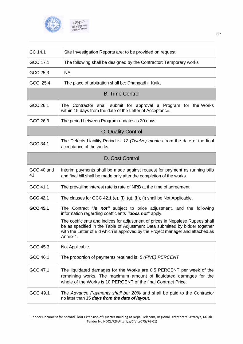
101 101
Tender Document for Second Floor Extension of Quarter Building at Nepal Telecom, Regional Directorate, Attariya, Kailali (Tender No NDCL/RD-Attariya/CIVIL/075/76-01)
CC 14.1 Site Investigation Reports are: to be provided on request
GCC 17.1 The following shall be designed by the Contractor: Temporary works
GCC 25.3 NA
GCC 25.4 The place of arbitration shall be: Dhangadhi, Kailali
B. Time Control
GCC 26.1 The Contractor shall submit for approval a Program for the Works within 15 days from the date of the Letter of Acceptance.
GCC 26.3 The period between Program updates is 30 days.
C. Quality Control
GCC 34.1 The Defects Liability Period is: 12 (Twelve) months from the date of the final
acceptance of the works.
D. Cost Control
GCC 40 and 41
Interim payments shall be made against request for payment as running bills
and final bill shall be made only after the completion of the works.
GCC 41.1 The prevailing interest rate is rate of NRB at the time of agreement.
GCC 42.1 The clauses for GCC 42.1 (e), (f), (g), (h), (i) shall be Not Applicable.
GCC 45.1 The Contract “is not” subject to price adjustment, and the following information regarding coefficients “does not” apply.
The coefficients and indices for adjustment of prices in Nepalese Rupees shall be as specified in the Table of Adjustment Data submitted by bidder together with the Letter of Bid which is approved by the Project manager and attached as Annex-1.
GCC 45.3 Not Applicable.
GCC 46.1 The proportion of payments retained is: 5 (FIVE) PERCENT
GCC 47.1 The liquidated damages for the Works are 0.5 PERCENT per week of the
remaining works. The maximum amount of liquidated damages for the
whole of the Works is 10 PERCENT of the final Contract Price.
GCC 49.1 The Advance Payments shall be: 20% and shall be paid to the Contractor no later than 15 days from the date of layout.

102 102
Tender Document for Second Floor Extension of Quarter Building at Nepal Telecom, Regional Directorate, Attariya, Kailali (Tender No NDCL/RD-Attariya/CIVIL/075/76-01)
GCC 50.1 Performance Security amount shall be as follow:
i) If bid price of the bidder selected for acceptance is up to 15 (fifteen) Percent below the approved cost estimate, the performance security amount shall be 5 (five) percent of the bid price.
ii) For the bid price of the bidder selected for acceptance is more than 15 (fifteen) percent below of the cost estimate, the performance security amount shall be determined as follows: Performance Security Amount = [(0.85 x Cost Estimate - Bid Price) x 0.5] + 5%of Bid Price.
The Bid Price and Cost Estimate shall be inclusive of Value Added Tax.
E. Finishing the Contract
GCC 60.1 The percentage to apply to the value of the works not completed, representing the Employer’s additional cost for completing the works is 80 %.
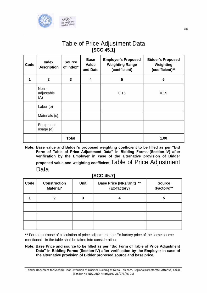
103 103
Tender Document for Second Floor Extension of Quarter Building at Nepal Telecom, Regional Directorate, Attariya, Kailali (Tender No NDCL/RD-Attariya/CIVIL/075/76-01)
Table of Price Adjustment Data [SCC 45.1]
Code Index
Description
Source
of Index*
Base
Value
and Date
Employer's Proposed
Weighting Range
(coefficient)
Bidder's Proposed
Weighting
(coefficient)**
1 2 3 4 5 6
Non - adjustable (A)
0.15 0.15
Labor (b)
Materials (c)
Equipment usage (d)
Total 1.00
Note: Base value and Bidder’s proposed weighting coefficient to be filled as per “Bid Form of Table of Price Adjustment Data” in Bidding Forms (Section-IV) after verification by the Employer in case of the alternative provision of Bidder
proposed value and weighting coefficient.Table of Price Adjustment Data
[SCC 45.7]
Code Construction
Material*
Unit Base Price (NRs/Unit) **
(Ex-factory)
Source
(Factory)**
1 2 3 4 5
** For the purpose of calculation of price adjustment, the Ex-factory price of the same source
mentioned in the table shall be taken into consideration.
Note: Base Price and source to be filled as per “Bid Form of Table of Price Adjustment Data” in Bidding Forms (Section-IV) after verification by the Employer in case of the alternative provision of Bidder proposed source and base price.

104 104
Tender Document for Second Floor Extension of Quarter Building at Nepal Telecom, Regional Directorate, Attariya, Kailali (Tender No NDCL/RD-Attariya/CIVIL/075/76-01)
SECTION - IX
Contract Forms

105 105
Tender Document for Second Floor Extension of Quarter Building at Nepal Telecom, Regional Directorate, Attariya, Kailali (Tender No NDCL/RD-Attariya/CIVIL/075/76-01)
Letter of Intent
[on letterhead paper of the Employer]
Date: ... …………………
To: .............................................name and address of the Contractor............................................
Subject: ......................... Issuance of letter of intent to award the contract....................................
This is to notify you that, it is our intention to award the contract ... ................................. .[insert
date] ............................for execution of the ... ................................................................... . [insert
name of the contract and identification number, as given in the Contract Data/SCC] to you as
your bid price ............................................ [insert amount in figures and words in Nepalese
Rupees] as corrected and modified in accordance with the Instructions to Bidders is hereby
selected as substantially responsive lowest evaluated bid.
Authorized Signature: ………………………………
Name: ... …………………………………………….
Title: ……………………………………………….
CC:
[Insert name and address of all other Bidders, who submitted the bid]
Notes on Letter of Intent :
The issuance of Letter of Intent is the information of the selection of the bid of the successful bidder
by the Employer and for providing information to other unsuccessful bidders who participated in the
bid as regards to the outcome of the procurement process. This standard form of Letter of Intent to
Award should be filled in and sent to the successful Bidder only after evaluation and selection of
substantially responsible lowest evaluated bid.

106 106
Tender Document for Second Floor Extension of Quarter Building at Nepal Telecom, Regional Directorate, Attariya, Kailali (Tender No NDCL/RD-Attariya/CIVIL/075/76-01)
Letter of Acceptance [on letterhead paper of the Employer]
Date: ……………………..
To:…………………………..... name and address of the Contractor …………………………….....
Subject: ........................................................ . Notification of Award
This is to notify that your Bid dated ................................date …………………………..for execution of the……………………..name of the contract and identification number, as given in the Contract Data/SCC ……………………... for the Contract price of Nepalese Rupees [insert amount in figures and words in Nepalese Rupees], as corrected in accordance with the Instructions to Bidders is hereby accepted in accordance with the Instruction to Bidders.
You are hereby instructed to contact this office to sign the formal contract agreement within
15 days with Performance Security as specified in the SCC consisting of a Bank Guarantee
in the format included in Section IX (Contract Forms) of this Bidding Document.
The Employer shall forfeit the bid security, in case you fail to furnish the Performance Security
and to sign the contract within specified period.
Authorized Signature: …………………………………...
Name and Title of Signatory: ……………………………

107 107
Tender Document for Second Floor Extension of Quarter Building at Nepal Telecom, Regional Directorate, Attariya, Kailali (Tender No NDCL/RD-Attariya/CIVIL/075/76-01)
Contract Agreement
THIS AGREEMENT made the ....................................day of …………………………..
between…………………………. name of the Employer …………………………(hereinafter
“the Employer”), of the one part, and ……………………………name of the Contractor
………………………………(hereinafter “the Contractor”), of the other part:
WHEREAS the Employer desires that the Works known as ……………………….... name of
the Contract ..............................should be executed by the Contractor, and has accepted a
Bid by the Contractor for the execution and completion of these Works and the remedying of
any defects in the sum of NRs …..........…..[insert amount of contract price in words and
figures including taxes] (hereinafter “the Contract Price”).
The Employer and the Contractor agree as follows:
1. In this Agreement words and expressions shall have the same meanings as are respectively assigned to them in the Contract documents referred to.
2. The following documents shall be deemed to form and be read and construed as part of this Agreement. (a) the Letter of Acceptance; (b) the Letter of Bid; (c) the Addenda Nos ................................... insert addenda numbers if any ………………… (d) the Special Conditions of Contract; (e) the General Conditions of Contract; (f) Bills of Quantities (BOQ); (g) the Specification; (h) the Drawings; (i) the Activity Schedules; and (j) Table of Price Adjustment Data (k) ............................................. ..[Specify if there are any other document ]
3. In consideration of the payments to be made by the Employer to the Contractor as indicated in this Agreement, the Contractor hereby covenants with the Employer to execute the Works and to remedy defects therein in conformity in all respects with the provisions of the Contract.
4. The Employer hereby covenants to pay the Contractor in consideration of the execution and completion of the Works and the remedying of defects therein, the Contract Price or such other sum as may become payable under the provisions of the Contract at the times and in the manner prescribed by the Contract.
IN WITNESS whereof the parties hereto have caused this Agreement to be executed in accordance with the laws of Nepal on the day, month and year indicated above. Signed by …………………………. for and on behalf the Contractor in the presence of Witness, Name Signature, Address, Date Signed by………………………….. for and on behalf of the Employer in the presence of Witness, Name, Signature, Address, Date
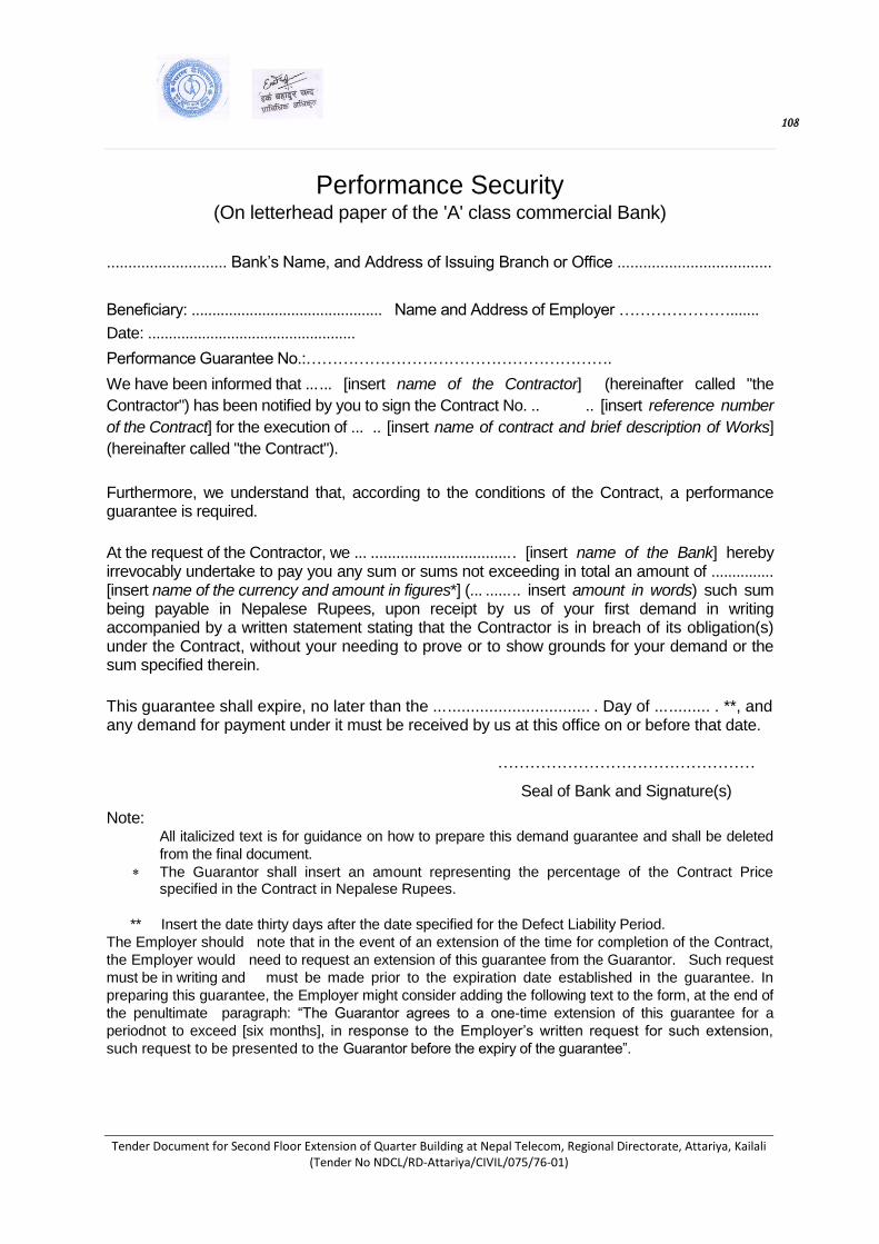
108 108
Tender Document for Second Floor Extension of Quarter Building at Nepal Telecom, Regional Directorate, Attariya, Kailali (Tender No NDCL/RD-Attariya/CIVIL/075/76-01)
Performance Security (On letterhead paper of the 'A' class commercial Bank)
............................ Bank’s Name, and Address of Issuing Branch or Office ....................................
Beneficiary: .............................................. Name and Address of Employer ………………….......
Date: ..................................................
Performance Guarantee No.:………………………………………………….
We have been informed that ... ... [insert name of the Contractor] (hereinafter called "the
Contractor") has been notified by you to sign the Contract No. .. .. [insert reference number
of the Contract] for the execution of ... .. [insert name of contract and brief description of Works]
(hereinafter called "the Contract").
Furthermore, we understand that, according to the conditions of the Contract, a performance guarantee is required.
At the request of the Contractor, we ... ................................. . [insert name of the Bank] hereby irrevocably undertake to pay you any sum or sums not exceeding in total an amount of ............... [insert name of the currency and amount in figures*] (... ...... .. insert amount in words) such sum being payable in Nepalese Rupees, upon receipt by us of your first demand in writing accompanied by a written statement stating that the Contractor is in breach of its obligation(s) under the Contract, without your needing to prove or to show grounds for your demand or the sum specified therein.
This guarantee shall expire, no later than the ... ............................... . Day of ... ......... . **, and any demand for payment under it must be received by us at this office on or before that date.
…………………………………………
Seal of Bank and Signature(s)
Note: All italicized text is for guidance on how to prepare this demand guarantee and shall be deleted
from the final document.
The Guarantor shall insert an amount representing the percentage of the Contract Price specified in the Contract in Nepalese Rupees.
** Insert the date thirty days after the date specified for the Defect Liability Period.
The Employer should note that in the event of an extension of the time for completion of the Contract,
the Employer would need to request an extension of this guarantee from the Guarantor. Such request
must be in writing and must be made prior to the expiration date established in the guarantee. In
preparing this guarantee, the Employer might consider adding the following text to the form, at the end of
the penultimate paragraph: “The Guarantor agrees to a one-time extension of this guarantee for a
periodnot to exceed [six months], in response to the Employer’s written request for such extension,
such request to be presented to the Guarantor before the expiry of the guarantee”.
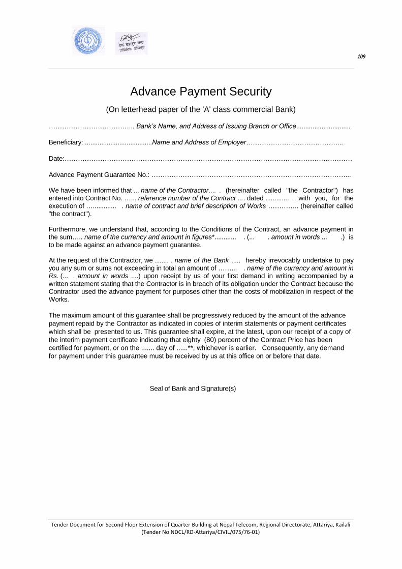
109 109
Tender Document for Second Floor Extension of Quarter Building at Nepal Telecom, Regional Directorate, Attariya, Kailali (Tender No NDCL/RD-Attariya/CIVIL/075/76-01)
Advance Payment Security
(On letterhead paper of the 'A' class commercial Bank)
………………………………... Bank’s Name, and Address of Issuing Branch or Office..............................
Beneficiary: .....................................Name and Address of Employer……………………………………..
Date:…………………………………………………………………………………………………………………
Advance Payment Guarantee No.: ……………………………………………………………………………... We have been informed that ... name of the Contractor.... . (hereinafter called "the Contractor") has entered into Contract No. …... reference number of the Contract ... . dated ............. . with you, for the execution of …............. . name of contract and brief description of Works ………….. (hereinafter called "the contract"). Furthermore, we understand that, according to the Conditions of the Contract, an advance payment in the sum….. name of the currency and amount in figures*............ . (... . amount in words ... .) is to be made against an advance payment guarantee. At the request of the Contractor, we ….... . name of the Bank ..... hereby irrevocably undertake to pay you any sum or sums not exceeding in total an amount of ……... . name of the currency and amount in Rs. (... . amount in words ....) upon receipt by us of your first demand in writing accompanied by a written statement stating that the Contractor is in breach of its obligation under the Contract because the Contractor used the advance payment for purposes other than the costs of mobilization in respect of the Works.
The maximum amount of this guarantee shall be progressively reduced by the amount of the advance
payment repaid by the Contractor as indicated in copies of interim statements or payment certificates
which shall be presented to us. This guarantee shall expire, at the latest, upon our receipt of a copy of
the interim payment certificate indicating that eighty (80) percent of the Contract Price has been
certified for payment, or on the ....... day of ......**, whichever is earlier. Consequently, any demand
for payment under this guarantee must be received by us at this office on or before that date.
Seal of Bank and Signature(s)

110 110
Tender Document for Second Floor Extension of Quarter Building at Nepal Telecom, Regional Directorate, Attariya, Kailali (Tender No NDCL/RD-Attariya/CIVIL/075/76-01)

Tender Document for Second Floor Extension of Quarter Building at Nepal Telecom, Regional Directorate, Attariya, Kailali (Tender No NDCL/RD-Attariya/CIVIL/075/76-01)
Annex-1
Specifications of Building Construction (Civil) Works
1. General
The Work shall be carried out according to these Specifications whether specifically mentioned
elsewhere or not. No extra in any form will be paid unless it is definitely stated as an item in the Bill
of Quantities.
Whenever the Specifications are not given or when the Specifications are ambiguous, the relevant
Nepal Standards or Indian Standards and further amendments will be considered as final and
binding.
All Works shall be carried out simultaneously with electrical, plumbing, sanitary and other services and in co-operation with the Contractors of the above services. The Work shall be carried on till it is completed satisfactorily along with the completion of other essential services. The building Contractor shall keep the other Contractors informed of the proposed program of Work, well in advance, so that the building Work is not hindered. The Contractor shall further cooperate with other Contractors in respect of any facility required by them e.g. making holes in shuttering for sanitary, pipes, electric conduits, fan hook etc. However, no extra payment shall be admissible for such reasonable assistance and facilities afforded to other Contractors and the building Contractors shall be deemed to have taken these factors into consideration while quoting the rates.
The Work shall be related to the drawings which the Contractor is presumed to have studied.
Nothing extra will be paid for any item because of its shape, location or other difficult
circumstances, even if the schedule makes no distinction, as long as the item is shown in the
drawings.
The sources of materials stated in the Specifications are those from which materials are generally
available. However, materials not conforming to Specifications shall be rejected even if they come
from the stated sources. The Contractor should satisfy himself that sufficient quantity of materials
of acceptable Specification is available form the stated or other sources.
The requirements of Specifications shall be fulfilled by the Contractor without extra charges i.e. the
item rates quoted shall be deemed to have taken these Specifications into account.
These are requirements the Contractor shall fulfil after the issue of Letter of Acceptance but before
the Date of Commencement.
1.1 Definitions General:
Acceptable/Approved (Approval) - Acceptable to/approved by the Engineer. Agreed - Agreed in writing. As detailed - As detailed on the drawings. Authorized/ordered/rejected - Authorized/ordered/rejected by the Engineer. Designated - Shown on the drawings or otherwise specified by the Engineer or, in relation
to an item scheduled in the bid documents, descriptive of an item to be priced by a bidder.
Indicated - Indicated in or reasonably to be inferred from the contract, or indicated in
Detailed Specifications Of Building Works (Civil) Page 1

writing by the Engineer.
Instructed/directed/permitted -Instructed/directed/ permitted by the Engineer. Satisfactory - Capable of fulfilling or having fulfilled the intended function. Service - Any pipeline, cable, duct etc. for conveying or transmitting any fluid or other
matter. Submitted - Submitted with the tender or submitted to the Engineer, as appropriate.
Tolerances:
Deviation - The difference between the actual (i.e., measured) size or position and the specified size or position.
Permissible deviation - The specified limit(s) of deviation. Tolerance - The range between the limits within which a size or position must lie.
Measurement and Payment: Bill/schedule - The bill/schedule of quantities. Billed/scheduled rate - The unit rate or price entered in the bill/schedule at which the
Contractor undertakes to execute the particular work or to provide the required material, article or service, or to do any or all of these things, as set out in the item concerned.
Billed/scheduled - Listed in the bill/schedule of quantities. Fixed charge - A charge for work that is executed without reference to time. Method-related charge - The sum for an item inserted in the bill by the Contractor when
tendering, to cover items of work relating to his intended method of executing the Works.
Time-related charge - A charge for work the cost of which, to the Employer, is varied in proportion to the length of time taken to execute the particular item scheduled.
Value-related charge - A charge that is directly proportional to the value of the contract.
1.2 Contractor’s Office & Accommodation
Various works defined under this item are for the provision and maintenance of the Contractor's office, camps, stores, equipment yard, and workshops. The structure of the buildings shall be
adequate, rainproof, spacious, airy and hygienic with proper lighting and toilet facilities. The area shall be kept neat and clean. Any garbage or sewage shall be disposed at a location and in a
manner approved by the Engineer. Space allocated for storage of various materials such as cement, reinforcement steel, and petroleum products etc. shall be clearly separated to avoid contamination. Petroleum products shall be stored and handled in a way that avoids contamination of ground
water. Workshops shall be installed with oil and grease traps for the same purpose.
Written information shall be given to and approval taken from the Engineer regarding proper
establishment and maintenance of such camps. Failure in compliance with Engineer's instructions
in respect of overall standard will lead to reduction or withholding of any payment due to the
Contractor.
The Contractor shall provide at his own expense adequate temporary accommodation and toilet
facilities for his Workmen and keep the same in good conditions. This may `be done to suit Site
conditions with the approval of Project Engineer. The above mentioned temporary structures shall
be removed on the completion of Works at Contractor's own cost. All materials shall belong to the
Contractor.
The Contractor shall make his own arrangement for the supply of electric power and lighting as
Page 2 Detailed Specifications Of Building Works (Civil)
required for construction purpose.
The Contractor shall make his own arrangement for all internal and external telephones and other
communication means deemed necessary for the Works.
The Contractor shall make his own arrangement for office equipment and other consumable for his
use for the Works.
1.3 Office for Engineer
The contractor shall provide and maintain offices for the use of the Engineer and his staff if
provided in the contract
1.4 Safety Measures
The Contractor shall be responsible for safety of all workmen and other persons entering the Works and shall at his own expense; where not stated otherwise take all measures, subject to the Engineer's approval, necessary to ensure their safety. Such measures shall include but not be limited to:
Provision of safety and emergency regulations for fire, gas, and electric shock prevention,
together with rescue operation plan Safe control of flowing water
Provision and maintenance of suitable lighting to provide adequate illumination at place of work with appropriate spares and standby unit
Provision and maintenance of safe, sound slings, pulleys, ropes, and other lifting device
Provision of safe access to any part of the works.
Provision of notices in local dialect temporarily or permanently during construction at locations likely to be used by the public. Placement of such notices shall depend on the existence of the nature of work in the vicinity. These notices shall be in addition to any other statutory requirements demanded of the Contractor
The Contractor shall submit a proposal with detailed safety and emergency measures for the
Engineer's approval. When the proposal has been approved, English and Nepali version of the
regulations shall be made available to all of his Employees and the Engineer.
The Contractor shall ensure that all his Employees are fully conversant with the regulations,
emergency and rescue procedures etc. and shall enforce a rule that will instantly dismiss any
employee committing a serious breach of such regulations.
1.5 Notice Boards
The Contractor shall erect notice boards (1.2 m x 1.8 m) at the site giving details of the Contract in
the format and wordings directed by the Engineer. These boards shall be erected within 14 days
after the Contractor has been given the Possession of Site The Contractor shall not erect any advertisement sign board on or along the work. The board shall
be removed by the Contractor by the end of the Defects Liability Period.
Detailed Specifications Of Building Works (Civil) Page 3

2. Temporary Facilities:
2.1 Provision of Temporary Services
When the rehabilitation or replacement of existing public utilities requires their temporary
disconnection, the Contractor shall provide the affected users with temporary services in at least the same standard as the original services. For water supply he may install temporary lines or
arrange for regular supply by tankers. When forced to disconnect existing sewers the Contractor shall install temporary pipes of adequate size to carry off sewage from any private sewer facilities cut off by construction work. Connections to temporary pipes shall be made immediately by the
Contractor upon cutting off the existing facility. No sewage shall be allowed to flow from any severed facility upon the ground surface or into trench excavation. Pipes used in temporary
sewers may be plastic or approved flexible material.
Upon completion of work the Contractor shall replace all severed connections and restore to
operating order the existing sanitary facilities. The Contractor without approval of the Engineer
shall operate no valve or other controls in public service facilities. All users affected by such
operation shall be notified by the Contractor at least one hour before the operation and advised of
the probable time when service will be restored.
2.2 Protection of Adjoining Property
The Contractor shall control the movement of his crews and equipment on right-of-way including access routes approved by the Engineer so as to minimize damage to crops and property and
shall endeavour to avoid marring the lands. Ruts and scars shall be obliterated and damage to land shall be corrected and the land shall be restored as closely as possible to its original conditions before final taking-over of the Works. The Contractor shall be responsible directly to the Employer for any excessive or avoidable damage to crops or lands resulting from his operations whether on lands adjacent to right-of-way
or on approved access road and deductions will be made from payment due to the Contractor to
cover the amount of such excessive or avoidable damage as determined by the Engineer.
2.3 Reinstatement upon Completion
Temporary facilities shall be provided by the Contractor, only for as long as required after which he
shall dismantle and remove the same from their place of use as speedily as possible. The
Contractor in his yard shall safely store re-usable components. The place of use shall be cleared
and reinstated immediately to at least the condition existing before the temporary facilities were
provided to the satisfaction of the Engineer.
2.4 Measurement and Payment
Unless otherwise provided in the contract, no separate measurement and/or payment shall be
made for all materials and works required under this clause. All costs in connection with the work
specified herein shall be considered to be included with other related items of the work in the BOQ
All provision of temporary services shall be covered by a provisional sum in the BOQ. The lump
sum amounts indicated in BOQ shall be paid in pro-rata basis by dividing the total amounts by
contract period in months. These payments will be incorporated in the interim certificates for
payment.
Page 4 Detailed Specifications Of Building Works (Civil)

2.5 Publicly And Privately Owned Services If any privately owned service for water, electricity, drainage, etc., passing through the site
is affected by the works, the Contractor shall provide a satisfactory alternative service in
full working order to the satisfaction of the owner of the services and of the Engineer before terminating the existing service.
Drawing and scheduling the affected services like water pipes, sewers, cables, etc. owned by various authorities including Public Undertakings and Local Authorities included in the contract documents shall be verified by the Contractor for the accuracy of the information prior to the commencement of any work.
Notwithstanding the fact that the information on affected services may not be exhaustive, the final position of these services within the works shall be supposed to have been indicated based on the information furnished by different bodies and to the extent the bodies are familiar with the final position. The Contractor must also allow for any effect of these services and alternations upon the works and for arranging regular meetings with the various bodies at the commencement of the contract and throughout the period of the works in order to maintain the required co-ordination. During the period of the works, the Contractor shall agree if the public utility bodies vary their decisions in the execution of their proposals in terms of program and construction, provided that, in the opinion of the Engineer, the Contractor has received reasonable notice thereof before the relevant alterations are put in hand.
No clearance or alterations to the utility shall be carried out unless ordered by the Engineer.
Any services affected by the works shall be restored immediately by the Contractor who must also take all measures reasonably required by the various bodies to protect their services and property during the progress of the works.
The Contractor may be required to carry out the removal or shifting of certain services/utilities on specific orders from the Engineer for which payment shall be made to him. Such works shall be taken up by the Contractor only after obtaining clearance from the Engineer and ensuring adequate safety measures.
2.6 Insurance of works Insurance of Works
o The Contractor shall take out Insurance for the Works from approved agency/institution staff if provided in the contract
o Payments made to the agency/institution and stamp charges/duties incurred if any, by the contractor in compliance of the above work shall be paid from Provisional Sum included for the item in the BOQ after submission of the insurance document to the satisfaction of the Engineer.
Third Party Insuranceo The Contractor shall take out Third Party Insurance from an approved
agency/institution staff if provided in the contract o Payments made to the agency/institution and stamp charges/duties incurred if
any, by the Contractor in compliance of the above work shall be paid from the Provisional Sum included for the item in the BOQ after submission of the documents to the satisfaction of the Engineer.
Insurance of Contractor's Workmen and Employeeso The Contractor shall insure against such liability as stipulated in Conditions of
o The cost for works under this Sub-Clause shall be covered by the Contractor's
overhead included in unit rates of other items in the BOQ. Detailed Specifications Of Building Works (Civil) Page 5
2.7 Environmental Protection Works
The environment has been defined to mean surrounding area including human and natural
resources to be affected by execution and after completion of works. The Contractor shall take all precautions for safeguarding the environment during the course of the construction of the works. He shall abide by all prevalent laws, rules and regulations governing pollution and environmental protection. The Contractor shall prohibit employees from unauthorized use of explosives, poaching wildlife
and cutting trees. The Contractor shall be responsible for the action of his employees.
The Contractor is expected to arrange and execute the Works in such a way that existing
environmental conditions are not deteriorated. Borrow pits and dumping sites used by the
contractor shall be reinstated at his own cost by grass and/or tree plantation.
Written instruction/approval must be given to seek from the Engineer regarding protection and
reinstatement of environment throughout the Contract period. Failure in compliance with
Engineer's instructions in respect of overall standard will lead to reduction or withhold of payment.
Further, any serious deterioration in the environment including pollution attributable to Contractor
as determined by the Engineer, may result in deduction of actual expenditures incurred in their
reinstatement done through separate agency, from any money due to the Contractor.
Environmental protection works, among others, shall also include the following:
2.8 Borrow/Quarry Sites
The Engineer shall have the power to disallow the method of construction and/or the use of any
borrow/quarry area, if in his opinion, the stability and safety of the works or any adjacent structure
is endangered, or there is undue interference with the natural or artificial drainage, or the method
or use of the area will promote undue erosion. All areas susceptible to erosion shall be protected as soon as possible either by temporary or
permanent drainage works. All necessary measures shall be taken to prevent concentration of
surface water and to avoid erosion and scouring of slopes and other areas. Any newly formed channels shall be backfilled.
Borrows/quarries shall be located away from the population centres, drinking water intakes,
cultivable lands and drainage systems. The cutting of trees shall be minimized. Temporary ditches
and/or settling basins shall be dug to prevent erosion. The undesirable ponding of water shall be
prevented through temporary drains discharging to natural drainage channels.
Earthworks operations shall be strictly limited to the areas to be occupied by the permanent works
and approved borrow areas and quarries unless otherwise permitted by the Engineer. Due provision shall be made for temporary drainage. Erosion and/or instability and/or sediment
deposition arising from earthwork operations not in accordance with the Specifications shall be made good immediately by the Contractor. The Contractor shall obtain the permission of the Engineer before opening up any borrows pits or
quarries. Such borrow pits and quarries may be prohibited or restricted in dimensions and depth
by the Engineer where:
(i) They might affect the stability or safety of the works or adjacent property; (ii) They might interfere with natural or artificial drainage or irrigation;
Page 6 Detailed Specifications Of Building Works (Civil)
(iii) They may be environmentally unsuitable.
The Contractor shall not purchase or receive any borrow materials from private individuals unless
the source of such materials has been approved by the Engineer. At least 14 days before he
intends to commence opening up any approved borrow pit or quarry, the Contractor shall submit to
the Engineer his intended method of working and restoration. These shall include but not be
limited to:
2.9 Disposal of Spoil and Construction Waste
Materials in excess of the requirements for permanent works and unsuitable materials shall be
disposed off in locations and in the manner as agreed with the Engineer. The locations of disposal sites shall be such as not to promote instability, destruction of properties and public service
systems. Exposed areas of such disposal sites shall be suitably dressed and be planted with suitable vegetation. The Contractor shall plan his works in such a way that there is no spillage of POL products to the
surface or sub-surface water.
2.10 Provision and Maintenance of Camps, Offices, Stores, Equipment Yards
Various works defined under this item are related to provision and maintenance of camps for work
person and employees, Contractor's site offices, stores equipment yards and workshops. These
camps must be adequate, rain-proof, spacious, airy and hygienic with proper lighting and materials
storage facilities. The area shall be kept neat and clean. Space allocated for storage of materials such as cement, gabion wire, reinforcing wire etc. shall in general be damp-free, rain-proof and away from petroleum products storage. Permission may be granted by the Engineer to erect suitable camps within the right of way free of
charge, if such establishments do not cause obstructions to traffic, nuisance to works execution
and adverse effect to the environment.
Written information must be given to and approval be taken from the Engineer regarding proper
establishment and maintenance of such camps. Failure in compliance with Engineer's instruction
in respect of overall standard will lead to reduction or with holding of payment.
2.11 Provision and Maintenance of Toilets
Provision of toilets for labour and employees shall be made to avoid public nuisance as well as
pollution of water courses and air. The Contractor shall construct suitable septic tanks and/or soak
pits along with room of pit-type latrines. Sufficient water must be provided and maintained in the
toilets. Proper methods of sanitation and hygiene should be employed during the whole project
duration.
2.12 Provision of Potable Water
The Contractor shall supply potable water along with commencement of work to Contractor's staff
and work person both at camps and construction-sites. This arrangement shall be enforced to
avoid proliferation and generation of various water borne diseases. The Contractor shall inform the Engineer regarding sources, installation and operation of supply of
potable water within a week after the supply is commenced.
Detailed Specifications Of Building Works (Civil) Page 7
2.13 Provision of First Aid/Medical Facilities
Provision of first aid/medical facilities shall be made along with commencement of work to provide
quick medical service to injured/sick work person, and employees. Services shall also include on-
the-way service and other arrangements required for taking them to the nearest hospital in case of
emergency.
The scope of work shall include service of at least one part-time experienced health worker/health
assistant with a minimum of once a week full time site visit as work assignment. The Contractor
shall also supply and provide adequate medicines and facilities required for standard first aid.
The Contractor shall inform the Engineer regarding the medical facility within a week after its
establishment and operation.
2.14 Hazardous Materials
The Contractor shall not store hazardous materials near water surfaces. The Contractor shall provide protective clothing or appliances when it is necessary to use some hazardous substances.
High concentration of airborne dust resulting in deposition and damage to crops and water resources shall be avoided. The Contractor shall take every precaution to control excessive noise
resulting in disruption to wildlife and human population. Only controlled explosives methods shall be applied and used in construction works.
2.15 Reinstatement of Environment
The Contractor shall arrange and execute works as well as related activities in such a way that
environmental conditions are reinstated. He may be required to carry out filling, removal and
disposal works along with plantation of grass and trees as directed by the Engineer at his own
costs at identified locations to reinstate environment.
Written instruction/approval shall be given by/sought from the Engineer regarding reinstatement of
environment both during and after completion of works and up to the end of Defects Liability
Period.
Measurement and Payment
No separate measurement and payment shall be made for the works described in this Clause.
2.16 Survey And Setting Out During the period of Commencement of works the Contractor shall survey the construction
area and confirm the levels. He shall immediately notify the Engineer of any discrepancies and shall agree with the Engineer any amended values to be used during the contract,
including replacements for any stations missing from the original stations. The Contractor shall check, replace and supplement as necessary the station points and
agree any revised or additional station details with the Engineer.
All stations and reference points shall be clearly marked and protected to the satisfaction of the Engineer.
The Contractor shall establish working Bench Marks tied with reference stations soon after taking possession of the site. The coordinates and the elevations of the reference stations shall be obtained from the Engineer. The working Bench Marks shall be near all major/medium structure sites. Regular checking of these Bench Marks shall be made and
Page 8 Detailed Specifications Of Building Works (Civil)
adjustments, if any, got agreed with the Engineer and recorded. The Contractor shall be responsible for the accurate establishment of the centrelines
based on the Drawing and data supplied. The centrelines shall be accurately referenced in a manner satisfactory to the Engineer. A schedule of reference dimensions shall be prepared and supplied by the Contractor to the Engineer.
The existing profile and cross-sections shall be taken jointly by the Engineer and the Contractor. These shall form the basis for the measurements and payments. If in the opinion of the Engineer, design modifications of the centrelines and/or grade are advisable, the Engineer shall issue detailed instructions to the Contractor and the Contractor shall perform modifications in the field, as required, and modify the levels on the cross-sections accordingly.
2.18 As-Built Drawings Such approved Working Drawings as have been selected by the Engineer shall be correctly modified for inclusion in the As-Built Drawings incorporating such variations to the Works as have been ordered and executed. Such drawings shall show the actual arrangement of all structures and items of equipment installed under the Contract. The Contractor shall submit 1 (one) reproducible copy and 3 (three) prints of all As-Built Drawings clearly named as such to the Engineer for approval before applying for the Taking-Over Certificate for the respective Section of the Works.
During the course of the Works, the Contractor shall maintain a fully detailed record of all changes
from the approval to facilitate easy and accurate preparation of the As-Built Drawing. Irrespective
of the other contractual prerequisites no Section of the Works will be considered substantially
completed until the Engineer has approved the respective As-Built Drawings.
2.19 Photographs The Contractor shall supply negatives and un-mounted positive colour prints of photographs, of such portions of the works in progress and completed, as may be directed by the Engineer. The negatives and prints shall not be retouched. The negative of each photograph shall be the property of the Employer and shall be delivered to the Engineer with prints. No prints from these negatives shall be supplied to anyone without the written permission of the Engineer.
2.20 Supply Of Video Records
The work consists of taking video film of important activities of the work as directed by the
Engineer during the contract and editing them to a video film of playing time between 30 minutes
and 180 minutes as directed by the Engineer. It shall contain narration of activities in English
and/or Nepali by a competent narrator. The edition of the video film and the script shall be
approved by the Engineer. The video records shall be of acceptable quality and the film shall be
capable of producing colour pictures.
Measurement
The measurement for this item shall be by number of sets of edited master records supplied each with four copies thereof. Payment
The contract unit rate shall include all expenses for making video films with the help of a
professionally competent photographer, editing, narration and supplying the final edited master
record along with four copies thereof.
Detailed Specifications Of Building Works (Civil) Page 9

3. Notes About Measurement And Payment
3.1 Measurement
Unless specified, all measurements shall be based on “Principals of Measurement (Int.) for works
of constructions." The tolerances specified in these Specifications are for evaluation of accuracies
only based on which the work shall be accepted or rejected. However, the measurement of the
work performed within the limits of tolerances shall be the measurement of actual work done in
place, if their dimensions are less than what have been specified or instructed by the Engineer. If
the actual work done in place is more than what has been specified or instructed by the Engineer, but within the limit of tolerances, the measurement shall be the measurement of the work what has
been specified or instructed by the Engineer.
3.2 Payment
Unless specified in the contract, the contract unit rates and/or prices for items as set out in the Bill
of Quantities are the full and the final compensation to the Contractor for: Supply of all materials necessary to complete the item as per relevant specifications; Use of materials, labours, tools, equipment, machines and other resources as per need;
All handling, packing charges and transportation;
Cost of supervision, quality assurance, temporary and ancillary works;
Site commissioning;
Maintenance and making good;
All duties and obligations as set out in the contract
general works such as setting out, clearance of site before setting out and after completion of works
the preparation of detailed work program
providing samples of various materials proposed to be used
the detailed Design and Drawing of temporary works
testing of materials
any other details as required by the contract
cost of all operations like storing, erection, moving into final position, etc. necessary to complete and protect the work till handing over to the Employer;
the cost for safeguarding the environment
All incidental costs, not covered under above stated.
Where the Bill of Quantities does not include the items mentioned in this Section, no separate
payment shall be made for such works. The costs in connection with the execution of the works
specified herein shall be considered to be included in the related items of other works specified in
the Bill of Quantities or shall be considered to be incidental to the works specified. Items specified
in this Section and included in the Bill of Quantities shall be paid at the contract unit rates as
agreed and shown in the Bill of Quantities.
3.3 National Specifications
Certain Specifications issued by various national or other widely recognized bodies are referred to
in these Specifications. Such Specifications shall be defined and referred to as National
Specifications.
Page 10 Detailed Specifications Of Building Works (Civil)

The Contractor may propose that the materials and workmanship be defined in accordance with
the requirements of other equivalent National Specifications and he may execute the works in
accordance with such National Specifications as may be approved by the Engineer. A copy of the
National Specification, together with its translation into the English language if the National
Specification is in another language, shall be submitted to the Engineer along with the request for
its adoption.
In referring to National Specifications, the following abbreviations are used: NS Nepal Bureau of Standards and Metrology
IS Indian Standards
ASTM American Society of Testing and Materials
BS British Standards
BSCP British Standard Code of Practice
ISO International Organization for Standardization
EN European Norm
NFP French Norm
Along with the commencement of the contract, the Contractor shall provide in his site office at
least one complete set of all National Specifications referred to in these Specifications, if they are
for the Sections applicable to the works. This set shall be made available for use by the Engineer.
3.4 Equivalency of Standards
Wherever reference is made in these Specifications to specific standards and codes to be met by the materials, plant, and other supplies to be furnished, and work to be performed or tested, the provisions of latest current edition or revision of relevant standards and codes in effect shall apply. Other authoritative standards which ensure a substantially equal or higher performance than the specified*,-standards and codes shall be accepted subject to the Engineer's prior review and approval. Differences between the standards specified and the proposed alternative standards shall be fully described by the Contractor and submitted to the Engineer at least 28 days prior to the date when the Contractor desires the Engineer's approval. In the event that the Engineer determines that such proposed deviations do not ensure substantially performance, the Contractor shall comply with the standards and codes specified. No payment shall be made for adoption of higher standards.
3.5 Units of Measurement, Abbreviations and Terminology:
Units of Measurement
The Symbols for units of measurement are used in these Specifications as they are given below.
M micron = m x 10-6
mm millimetre
m meter
km kilometre
sq. mm. or mm2 square millimetre
sq.m. or m2 square meter
sq. km. or km2 square kilometre
Detailed Specifications Of Building Works (Civil) Page 11

ha hectare
cu. m. or m3 cubic meter
lit or I litre
rad radian
°C degrees Celsius
kg kilogram
g gram = kgx10-3
mg milligram = kg x 10-6
mg/l milligram per litre Symbols of other units, if not covered above,
t ton = kg x 103
shall be as per SI system set out in ISO 31/1.
kg/m3 kilogram per cubic meter
Abbreviations
t/m3 ton per cubic meter
N Newton The following abbreviations are used in these
N/m2 Newton per square meter Specifications.
Lin. m Linear meter
Max Maximum
Min Minimum
ACV Aggregate Crushing Value
BOQ Bill of Quantities
CR Crushing Ratio
dia Diameter
hr Hour
LS Linear Shrinkage
MC Moisture Content
MDD Maximum Dry Density
min Minute
no Number (units), as in 6 no.
No Number (order) as in No 6
OMC Optimum Moisture Content
OPC Ordinary Portland Cement
PI Plasticity Index
PL Plastic Limit
PM Plasticity Modulus (PI x % passing 0.425 mm sieve)
POL Petrol, Oil & Lubricant
ROW Right of Way
SE Sand Equivalent
sec Second
SG Specific Gravity
SI International Standard Units of Measurements
Page 12 Detailed Specifications Of Building Works (Civil)
SSS Sodium Sulphate Soundness test, loss on 5 cycles
STV
Standard Tar Viscosity
TS Tensile Strength
UC Uniformity Coefficient
UCS Unconfined Compressive Strength
VIM Voids in Mix
w/c Water cement ratio
wt Weight
% Percent
Terminology
The term "the Specifications" shall be construed as the Standard Specification and the Special
Specification all together.
6. Program
The Contractor shall provide all information needed for fulfilment of the program and required in
accordance with the Conditions of Contract including the sequence in which he intends to work
including implementation of quality assurance plan. If the Contractor requests a change in the
sequence and such change is approved by the Engineer, the Contractor shall have no claim as
per the Conditions of Contract for delay arising from such revisions to the program.
The program for the construction and completion of the works shall be established using CPM/PERT techniques or equivalent. The program shall be detailed enough to give, in addition to construction activities, detailed network activities for the submission and approval of materials, procurement of critical materials and equipment, fabrication of special products/equipments if any and their installation and testing, and for all activities of the Engineer that are likely to affect the progress of work. The Contractor shall update all activities in accordance with the Conditions of Contract on the basis of the decision taken at the periodic site review meetings or as directed by the Engineer. The program shall also include the Contractor's general requirements for any road closures to be agreed in principle with the Engineer. Such agreement shall not relieve the Contractor of his
responsibility to obtain specific approval for each closure or series of closures. Any proposal for
night working shall also be stated in the program.
Detailed Specifications Of Building Works (Civil) Page 13

7. QUALITY CONTROL
7.1 Scope
This Section covers the Quality Control System and procedures, Quality Assurance Plan, program
of tests, trials, and general procedures for acceptance as well as Laboratory arrangements and
related facilities which are required for the selection and control of the quality of materials and
workmanship.
7.2 Contractor Responsible For the Quality of the Works
All materials incorporated and all workmanship performed shall be strictly in conformity with the
requirements of the Specifications and the Contractor shall be responsible for the quality of the
works in the entire construction within the contract.
The Contractor shall provide, use and maintain on the Site, throughout the period of execution of
the contract, a Laboratory with adequate Laboratory equipment operated by competent staff for
carrying out tests required for the selection and control of the quality of materials and for the
control of workmanship in accordance with these Specifications. The list of Laboratory equipment
to be procured and Laboratory facilities to be provided shall be this specification. The Contractor
shall assume that tests shall be required on all materials to be used in the works and on all
finished works or part of works.
7.3 Quality Control System
The Quality Control System comprises the methods, procedures and organization for the Quality
Control of the works. The Contractor shall implement the Quality Control System in the following
sequences:
a) Compliant testing for materials including Laboratory trials, b) Compliant testing for methods and equipment prior to the commencement of the work,
including site trials or trials sections, c) Control testing during construction, d) Acceptant testing on completed works or parts of the works.
The Contractor shall carry out all necessary tests and shall report to the Engineer the results of
such tests before submitting materials and/or finished works or part of works to the Engineer for
approval in accordance with this Specification. In certain circumstances, tests may be carried out
at the place of manufacture as per the Conditions of Contracts. For satisfying himself about the quality of the works, quality control tests shall be conducted by the
Engineer himself or by any other agencies deemed fit by the Engineer. Additional tests may also
be conducted where in the opinion of the Engineer such tests are needed.
Before commencement of the work, the Contractor shall demonstrate a trial run of all construction
equipment for establishing their capability to achieve the laid down Specifications and tolerances
to the satisfaction of the Engineer.
The supply, testing and monitoring shall be in compliance with a Quality Assurance Plan and the
provisions in the contract.
Page 14 Detailed Specifications Of Building Works (Civil)

7.4 Quality Assurance Plan
The Contractor shall submit to the Engineer for his approval, the Quality Assurance Plan (QAP)
which shall be based on the detailed Program of the Works. The Quality Assurance Plan shall
include the following:
(1) The Quality Control Schedule Comprising of: a) The recapitulative test schedule and testing program detailing the list of tests for
compliance, Laboratory trials, site trials and trials Sections, construction control tests and their frequencies, tests for acceptance of the completed works with their dates.
b) Recapitulative list of "critical" acceptance testing procedures, for equipment or parts of the works which corresponds to the tasks on the Critical Path according to the construction Program.
c) Estimate of the number of tests to be carried out, list and number of appropriate equipment to conduct them, list of tests to be conducted outside the site Laboratory , if any, identification of the outside Laboratory where proposed to carry out the test.
d) List of staff assigned to the Laboratory, their position and responsibilities in the
quality control procedures, their qualification and experience, general description
and detailed organization of the Laboratory activities.
(2) The list of sources of materials and/or of manufactured articles, their main characteristics,
their identification mode as provided by the supplier when required; the program of supply
and procurement of material and/or manufactured articles in accordance with the
Program.
(3) The list of tests and quality control procedures to be implemented by the Sub-contractors,
if any, pointing out the "critical" acceptance testing procedures relating to the Sub-
contracted works, which correspond to the tasks on the Critical Path included in the Sub-
contracted works. The Contractor shall implement the Quality Control in compliance with the approved QAP.
The Engineer's approval of the QAP shall not relieve the Contractor from his responsibility of the quality of the Works as per the Conditions of Contract and these Specifications nor
shall the Engineer's approval of the QAP exempt the Contractor of any procedure to inform the Engineer in writing or request for the Engineer's approval or re-approval as specified in the Conditions of Contract and/or in these Specifications
The Contractor shall monitor and update the QAP on the basis of the decisions taken at
the periodic review meetings or as directed by the Engineer and in accordance with the
program of the works and the Conditions of Contract.
7.5 Testing Procedures And Set Of Tests
For ensuring the quality of the work, the materials and the workmanship shall be subjected to
testing in accordance with procedures, sets of tests and frequencies as specified in respective Sections of these Specifications. The specified testing frequencies are not restrictive. The Engineer shall direct for the tests to be carried out as frequently as deemed necessary that the
materials and workmanship comply with their Specifications. Where no specific testing procedure is mentioned in the Specifications, the tests shall be carried
out as per the prevalent accepted engineering practice or directions of the Engineer. Detailed Specifications Of Building Works (Civil) Page 15

7.6 Laboratory Trials To Confirm Compliance With Specifications
Concrete
Laboratory trials for concrete mixes shall be carried out by the Contractor to demonstrate that the
composition of the mixes proposed for the concrete meets the requirements of the Specifications.
The compositions of concrete mixes which meet the specified requirements and are accepted by
the Engineer shall be then used in the site trials carried out.
7.6. Site Trials Or Trials Sections
7.6.1 Concrete
Site trials for concrete mixes shall be carried out by the Contractor to demonstrate the suitability of
his mixing equipment. During the site trials, compliance with the Specifications for weighing
equipment, storage of ingredients, means of transport for concrete, placing, compaction and
curing shall be checked by the Engineer.
During the site trial a full scale sequence including placing and compaction of concrete shall be
carried out on a part of the works which will represent particular difficulties due to the presence of
reinforcement, obstructions or others.
The Contractor shall allow in his program for conducting the site trials and for carrying out the
appropriate tests, including the time required to obtain compressive strength test results at 28
days. The Contractor shall inform in writing the Engineer at least two weeks before the date he
proposes to use the concrete mixes in the site trials with all relevant data including the trial
program, the results of the Laboratory trial tests for the proposed concrete mixes and compliance
tests results of all constituents i.e. cement, aggregates, water and admixtures, if any.
7.6.2. Other Works and Equipment
Site trials for Pre-stressed Concrete Works, Painting of Structural Steelwork etc. are detailed in the
relevant Sections of these Specifications.
Approval of the Engineer to a set of data recorded in a site trial shall not relieve the Contractor of
his responsibilities to comply with the requirements of these Specifications
7.6.3. Control Testing During Construction
Quality Control procedure are detailed in the relevant Sections of these Specifications
7.6.4. Acceptance Tests For Completed Works Or Part Of Works
Acceptance tests for other works and equipment are detailed in the relevant Sections of these
Specifications.
7.6.5. Recapitulative Schedule Of Tests
The tests to be carried out and their frequency for the quality control of the works are detailed in
the relevant Sections of these Specifications.
The following Table recapitulates the testing schedule for the main types of works.
Page 16 Detailed Specifications Of Building Works (Civil)
7.6.6. Testing Schedule
Part or Tests Frequency
component of
the works Concrete cement: acceptance tests: Conservative samples for Materials each supply and not less than
Control tests: chemical composition physical every 200t or part of it. properties testing in case of non
compliance of the mixes or aggregates: storage on site for longer than 1 acceptance tests: month
Control tests: each delivery and every 100 t or Grading part of it for fine aggregate and Silt & clay content 250 t or part of it for coarse
Organic impurities aggregate Chloride content, sulphate content, Alkali As frequently as required. reactivity
water, admixtures Concrete • lab. Trials • site trials • early works: every 6 m3 of control tests compressive strength each class. When compliance is established: every 20 m3 or
part of it.
Reinforcement:
Brickworks for quality of bricks as required structures quality of cement and sand
Materials mortar control tests compressive strength of
mortar every 10 m3of brick work or
part of it. Masonry for quality of cement and sand as required
structures control tests compressive strength of every 10m3 of masonry of part of materials mortar it Mortar dismantling of masonry (1 m_1 m) every 30m3 of masonry or part of
it
7.07. Contractor's Laboratory
(1) Laboratory Building
The Contractor shall on his own make provide and maintain a site Laboratory. Such Laboratory shall have a minimum total area of 60 m2 appropriately partitioned to house various Laboratory instruments/equipment, office, store, and toilet. It shall have adequate
electrical connections (power plugs, switches) necessary to operate the equipment in the Laboratory.The Laboratory shall either be any existing building at site, rented and modified
to suit the purpose or shall be a shed constructed of GI sheets and pipes/angles. The floor of the Laboratory shall however be of 100 mm M15/20 concrete and the minimum height
2.7 m. The Contractor shall submit the design of the GI shed for approval of the Engineer prior to its construction.
Detailed Specifications Of Building Works (Civil) Page 17
Alternatively, it may also be constructed from shipping containers modified suitably to the
Engineer's satisfaction for the purpose.
This Laboratory shall be part of the Temporary Works and will be the property of the
Contractor on completion of the Works.
(2) Measurement
Measurement for the provision of site Laboratory will be on a monthly basis.
(3) Payment
Payment for work will be made on the basis of contract unit price indicated in the BOQ.
Payment for the works shall be full and final compensation for all material, labour, and
equipment (including land rent if any) to complete the works as specified.
7.08. Laboratory Equipment at Site
The equipment for the site Laboratory and field control tests shall be provided, installed, operated
and maintained by the Contractor. The equipment, material, chemical reagents may also be used
by the Engineer to conduct tests according to his Quality Check Plan. Testing frequency (both
Laboratory and field control) shall be developed in the Quality Assurance Plan of the Contractor
and Quality Check Plan of the Engineer. After the completion of the Works, the Laboratory
equipment shall become the property of the Contractor. Laboratory and field control equipment
anticipated for the Works are listed in following Tables.
Measurement and Payment
Measurement and Payments for the work will be made in relevant monthly statement on the basis
of lump sum price quoted in the BOQ. It shall be paid in the following manner:
- 50% after installation of the equipment in the site Laboratory to the satisfaction of the
Engineer and
- the remaining 50% after 80% completion of the Works.
7.9. Laboratory Equipment/Field Control Testing Apparatus For Cement Masonry And
Concrete Works
S.No. Designation Quantity
1. Slump Cone with Base and Graduated Tamping Rod 2 Sets
2. Heavy Duty Concrete Cube Moulds, 150 mm cubes, with Base 12 Sets 3. Concrete Cube Crushing (set) Machine with Spherically Seated Block 1 Set
and Platens for Mortar Test
4. Mortar Flow Apparatus with Cone 2 Sets
5. Vicat Apparatus 1 Set
6. Standard Sieves for Aggregate 2 Sets
7. Electric Oven 1 Set
7.10. Sampling and Testing of Material away From Site
Some tests on construction material shall be conducted periodically off the site at reputable
institutions in Kathmandu as directed by the Engineer.
The frequency of tests shall be developed in the Quality Assurance Plan that shall also prescribe
test results and reporting formats. However, some details on the tests are listed tentatively below.
Page 18 Detailed Specifications Of Building Works (Civil)

7.11 List Of Tests To Be Conducted Off-Site Tests (Locations subject to the approval of the Engineer)
S.No. Description of Tests 1. UTM Tensile Test for Re-bar 2. Zinc Coating and Tensile test of GI wire 3. Los Angeles Abrasion Test for Aggregate 4. UTM tensile Test for Anchor Bar 5. Specific Gravity of Aggregates
The tests listed above are subject to the Contractor's Quality Assurance Plan approved by the
Engineer. The Engineer shall also determine the number of tests while executing the Works.
The Contractor shall keep records of all tests in a format approved by the Engineer. Two copies of
any test results shall be forwarded to the Engineer.
Measurement
Measurement of work under this Clause shall be in number of tests fully executed to the
satisfaction of the Engineer.
7.12. Payment
Payment will be made from the Provisional Sum set aside for the purpose and shall be full and
final compensation for all material, labour, and equipment to complete the works as specified.
7.13. Survey and Setting
All traverse stations and reference points shall be clearly marked and protected to the satisfaction
of the Engineer.
The Contractor shall provide the Engineer with all necessary assistance for checking the setting
out, agreement of levels and any other survey or measurement which the Engineer needs to carry
out in connection with the Works during the entire period of Contract. Such assistance shall
include:
- Provision of suitably qualified surveyors to work under the direction of the Engineer as
required.
- Provision of all necessary support for these surveyors including assistants, chainmen, labour, survey equipment (thedolite, levels, etc.), hand tools, pegs, and other incidental material.
The survey equipment shall be of the quality approved by the Engineer.
7.14 Use of the Contractor's Temporary Works
Unless otherwise specified under the Contract, the Contractor shall allow the Employer, the
Engineer or the Nominated Subcontractor the use of temporary access, crossings and other
Temporary Works at site insofar that such use is related with the Works.
Detailed Specifications Of Building Works (Civil) Page 19
7.15. Day work
Day work shall mean provisional sum payable to the Contractor for works executed on a daily or
hourly basis as instructed in writing by the Engineer. This item is categorized in three groups
namely: (i) Labour (ii) Equipment (iii) Material
The Engineer however shall have the right to obtain further information on the rates and if
appropriate to negotiate changes in the rates or demand new prices for additional equipment,
staff, or material before or after the award of the Contract. The Engineer shall have the right to calculate new prices for Day work on the basis of rate
analysis.
The hourly or daily rates of labour or equipment and the unit price for material submitted by the
Contractor shall deem to cover all expenses and shall be inclusive of overhead, taxes, and profit.
Non-working hours or idle time/down time of labour and equipment respectively shall not be
considered for payment.
7.16 Reports
The Contractor shall prepare and submit four copies of Progress Report on a monthly basis. The
Reports shall highlight the targeted and achieved progress, problems at site, and brief description
of the claims during the month and the Engineer's response, and other information relevant to the
Project. It shall be supplemented with necessary charts, tables, data, and at least 36 photographs.
On completion of the Works, the Contractor shall prepare and submit a Completion Report that
shall deal comprehensively on all aspects covered in the Monthly Report. Additional information
such as improvement in construction methods/techniques, lessons learnt from the Project,
important considerations for maintenance, etc. should also be highlighted.
7.17. Site Diary
The Contractor shall keep Site Diaries wherein full details of the work carried out during each day
shall be fully recorded. The diaries shall be available for inspection by the Engineer any time
during normal office hours. The Site Diaries shall include: - Weather Conditions, rainfall/snowfall, and river water level - Description, quantity, and location of work performed - Shifts and working hours - Number and category of workers working at site - Plant in use and idle, or broken down - Test carried out and results - Inspection carried out by the Engineer - Site instructions - Visitors - Accidents
7.18 Measurement and Payment
The cost for these works shall be covered by the Contractor's overhead included in unit rates of
other items in the BOQ.
Page 20 Detailed Specifications Of Building Works (Civil)
8. MATERIALS AND TESTING OF MATERIALS
8.1 Quality Of Materials
The materials supplied and used in the works shall comply with the requirements of these
Specifications. They shall be new, except as provided elsewhere in the contract or permitted by
the Engineer in writing. The materials shall be manufactured, handled and used skilfully to ensure
completed works to comply with the contract.
8.2. Sources Of Materials
The use of any one kind or class of material from more than one source is prohibited, except by
written permission of the Engineer. Such permission, if granted, shall set forth the conditions under
which the change may be made. The sources or kinds of material shall not be changed without
written permission of the Engineer. If the product of any source proves unacceptable, the
Contractor shall make necessary arrangements for the supply of acceptable material. Any claims
for compensation associated with such arrangements or changes shall not be considered, unless
the source of the unacceptable material is designated in the contract as a source of material.
When any manufactured product, either new or used, is to be furnished by the Employer, the
location at which such material shall be delivered to the Contractor shall be designated in the
contract. In such cases, the Contractor shall haul the materials from the designated delivery point
to the point of use. The compensation for such hauling shall be included in the contract unit rate
for placing the materials in the finished work.
8.3. Inspection And Acceptance Of Materials
Final inspection and acceptance of materials shall be made only at the site of the work. The
Engineer reserves the right to sample, inspect, and test the materials throughout the duration of
the works and to reject any materials which are found to be unsatisfactory.
A preliminary inspection of materials may be made at the source for the convenience and
accommodation of the Contractor, but the presence of a representative of the Engineer shall not
relieve the Contractor of the responsibility of furnishing materials complying with their
Specifications.
The representative of the Engineer shall have free entry at all times to those parts of any plant
which concern production of the materials ordered.
8.4 Materials And Manufactured Articles
(1) Order for Materials and Manufactured Articles
The Contractor shall, before placing any order for materials and manufactured articles for
incorporation in the Works, submit to the Engineer the names of the firms from whom he
proposes to obtain such materials and manufactured articles, giving for each firm a
description of the materials and manufactured articles to be supplied, their origin, the
manufacturer's specification, quality, weight, strength and other relevant details. The
Contractor shall submit the samples of such materials and manufactured articles when
Detailed Specifications Of Building Works (Civil) Page 21

requested by the Engineer and when appropriate, manufacturer's certificates of recent test
carried out on similar materials and manufactured articles shall also be submitted.
(2) Storage
All materials and manufactured articles shall be stored on site in a manner acceptable to
the Engineer. The Contractor shall carefully protect all work, materials and manufactured
articles from the weather and vermin.
(3) Test Certificates
When instructed by the Engineer, the Contractor shall submit to him all Test Certificates
from the suppliers/manufacturers of the materials and/or manufactured articles to be used
for the contract. Such certificates shall certify that the materials and/or manufactured
articles concerned have been tested in accordance with the requirements of these
Specifications. All Test results shall be enclosed along with such certificates. The
Contractor shall provide adequate means of identifying the materials and/or manufactured
articles delivered on the site with the corresponding certificates.
8.5. Defective Materials
All materials not conforming to the requirements of the contract shall be rejected whether in place
or not. They shall be removed immediately from the site unless otherwise permitted by the
Engineer. Even after rectification of the defects no rejected material shall be used in the work
unless approved by the Engineer in writing. Upon failure of the Contractor to comply promptly with
any order of the Engineer given under this Clause, the Engineer shall have authority to cause the
removal and replacement of rejected material and to deduct the cost thereof from any monies due
to the Contractor.
8.6. Trade Names And Alternatives
For convenience in designation in the contract, certain articles or materials to be incorporated in
the work may be designated under a trade name or the name of a manufacturer and his catalogue
information. The use of an alternative article or material which is of equal or better quality and of
the required characteristics for the purpose intended shall be permitted, subject to the following
requirements:
(1) The proof as to the quality and suitability of alternatives shall be submitted by the
Contractor. He shall also furnish all information necessary as required by the Engineer.
The Engineer shall be the sole judge as to the quality and suitability of alternative articles
or materials and his decision shall be the final and binding upon the Contractor.
(2) Whenever the specifications permit the substitution of a similar or equivalent material or
article, no tests or action relating to the approval of such substitute material shall be made
until the request for substitution is made in writing by the Contractor accompanied by
complete data as to the equality of the material or article proposed. Such request shall be
made well in advance to permit approval without delaying the work.
8.7. Foreign Materials
Materials which are manufactured, produced or fabricated outside Nepal shall be delivered at a
Page 22 Detailed Specifications Of Building Works (Civil)

point in Nepal as specified in the contract where they shall be retained for a sufficient time to
permit inspection, sampling, and testing. The Contractor shall not be entitled to an extension of
time for acts or events occurring outside Nepal and it shall be the Contractor's responsibility to
deliver materials obtained from outside Nepal to the point of delivery in Nepal. The Contractor
shall supply the facilities and arrange for testing required at his own cost. All testing by the
Contractor shall be subject to witnessing by the Engineer.
The Contractor shall furnish to the Engineer a "Certificate of Compliance" with the specifications from the manufacturer, producer or fabricator of foreign material where required. In addition, certified mill test reports clearly identifiable to the lot of material shall be furnished where required in these Specifications or otherwise requested by the Engineer. Where structural materials requiring mill test reports are obtained from foreign manufacturers, such materials shall be furnished only from those foreign manufacturers who have previously established, to the satisfaction of the Engineer, the sufficiency of their in-plant quality control, as deemed necessary by the Engineer or his representative, to give satisfactory assurance of their ability to furnish material uniformly and consistently in conformance with their Specifications. At the option of the Engineer, such sufficiency shall be established whether by submission of detailed written proof thereof or through in-plant inspection by the Engineer or his representative.
If the welding of steel for structural steel members or the casting and pre-stressing of pre-cast pre-
stressed concrete members is to be performed outside of Nepal, the following requirements shall
apply:
(1) Such fabrication shall be performed only within the plants and by fabricators who have
previously established, to the satisfaction of the Engineer, that they have the experience,
knowledge, trained manpower, quality control, equipment and other facilities required to
produce the quality and quantity of the work required. At the option of the Engineer,
prequalification of the plant and fabricator shall be established either by the submission of
detailed written proof thereof or through in-plant inspection by the Engineer or his
representative, or both.
(2) The Contractor shall make written application to the Engineer for approval for such foreign
fabrication at the earliest possible time and in no case later than 60 calendar days in
advance of the planned start of fabrication. The application shall list the specific units or
portion of a work which shall be fabricated outside of Nepal.
(3) The Contractor shall advise the Engineer, in writing, at least 20 calendar days in advance
of the actual start of any such foreign fabrication.
(4) All documents pertaining to the contract, including but not limited to, correspondence,
tender documents, working drawings and data shall be written in the English/Nepali
language and all numerical data shall use the metric system of units of measurement.
8.8. Definition of General Types of Materials
The following definitions shall apply to materials in this Section and other relevant Sections.
(1) "Topsoil" shall mean the top layer of soil that can support vegetation. It shall include all turf
acceptable for turfing. (2) "Suitable Material" shall comprise all that is acceptable in accordance with the contract for
Detailed Specifications Of Building Works (Civil) Page 23
use in the works {and which is capable of being compacted to form a stable fill having side
slopes as indicated in the Drawing. The material used in fill (except rock fill) shall not contain
rock fragments with dimensions of more than 75 mm.}
(3) "Unsuitable Material" shall mean other than suitable material and shall include:
(a) Material from swamps, marshes or bogs; (b) Peat, logs, stumps, perishable material, organic clays; (c) Material susceptible to spontaneous combustion; (d) Material in a frozen condition; (e) Clay of liquid limit exceeding 70 and/or plasticity index exceeding 45. Materials stated above in d), if otherwise suitable shall be classified suitable when
unfrozen.
(4) "Well Graded Granular Material" consisting of gravel and/or sand shall conform to relevant
Clause.
(5) "Rock fall", coarse alluvial material shall be loose soils such as moraines, debris, or
alluvial material containing large blocks or large boulders. Individual blocks or boulders of
hard materials greater than 0.3m3 each in volume, shall be classified as hard material.
(6) "Hard Material" shall mean any material which conform to the requirements of relevant
Sub-clause.
8.9. Sieves
IS sieves shall be used for all tests. Based on IS-460 the standard sieves series shall be as
follows:
125; 90; 75; 63; 50; 45; 40; 37.5; 31.5; 25; 22.4; 20; 19; 16; 12.5; 11.2; 10; 9.5; 8; 6.3 ;5.6; 4.75; 4.00; 2.8; 2.36; 2; 1.7; 1.4; 1.18; 1; 0.85; 0.71; 0.6; 0.5; 0.425; 0.400; 0.300; 0.250; 0.212; 0.180; 0.150; 0.125; 0.090; 0.075 mm.
8.10. Soils And Gravels
8.10.1. Sampling and Samples
Sampling of soils and gravels shall be carried out as specified or as directed by the Engineer. Samples shall be prepared for testing as indicated in IS 2720 part I, except that: a) The mass (in g) of a sample required for sieve analysis is about 400D, D being the maximum
particle size (mm). b) Sample containing particles larger than 19 mm size shall be prepared for compaction and CBR
tests as described hereunder, provided the proportion in weight of such particles is less than
30% :
An adequate quantity of representative material shall be sieved over the 50 mm and 19 mm sieve. The material passing the 50 mm sieve and retained on the 19 mm sieve shall be weighed and
replaced with an equal mass of material passing the 19 mm sieve and retained on the 4.75 mm
sieve. The material for replacement shall be taken from the remaining portion of the main sample. When preparing gravel samples, the aggregations of particles shall be broken with a wooden or
rubber hammer or pestle. Care shall be taken that no individual particles are crushed in the
operation.
Page 24 Detailed Specifications Of Building Works (Civil)

8.10.2. Standard Methods of Testing
Tests on soils and gravels shall be performed in accordance with the standard methods given in Table below:
Tests Procedures Applicable to Disturbed/Undistributed Samples of Soils and Gravels
Tests Test procedure
Determination of:
i) Moisture Content IS 2720 Part 2 (Oven-drying method) ii) Liquid Limit IS 2720 Part 5 (Cone Penetrometer or by
Casagrande Apparatus)
iii) Plastic Limit IS 2720 Part 5
iv) Plasticity Index IS 2720 Part 5
v) Linear Shrinkage IS 2720 Part 20 vi) Specific Gravity of IS 2720 Part 3
Particles
vii) Particle Size Distribution IS 2720 Part 4
viii) Organic Matter Content IS 2720 Part 22 '
ix) Total Sulphate Content IS 2720 Part 27
x) pH Value IS 2720 Part 26 (Electrometric Method)
xi) Mica Content - Manual mineralogical counting
xii) Density-Moisture Content IS 2720 Part 7 relationship (2.5 kg
rammer)
xiii) Density-Moisture Content IS 2720 Part 8
relationship (4.9 kg
rammer)
xiv) California Bearing Ratio IS 2720 Part 16 xv) Sand Equivalent IS 2720 Part 37 (Mechanical Shaker or Manual
Shaker method)
xvi) Field Dry Density IS 2720 Part 28/Part 29 xvii) Unconfined compression IS2720 Part 10
test
xviii) Consolidation test IS2720 Part 15
xix) Direct shear test 1S2720 Part 13
xx) Triaxial test IS2720 Part 11,12
xxi) Hydrometer analysis IS 2720 Part 4
xxii) Vane shear test IS 2720 Part 30
Detailed Specifications Of Building Works (Civil) Page 25

It is further specified that:
a) Wherever in the text of these Specifications and the Special Specification the term "x% of the MDD (IS 2720 Part 27 or IS 2720 Part 28) is used it shall mean that a standard of compaction
shall be achieved such that the dry density of the compacted material is x% of the maximum
dry density determined from the respective tests mentioned in Table 6.4. Samples for the
compaction tests shall be taken before compaction of the layers begins unless in the opinion
of the Engineer the compactive effort proposed or applied by the Contractor is such that the material characteristics have changed in which case the samples for the tests shall be taken
after all compaction is complete.
b) Compaction tests: when the material is susceptible to crushing during compaction, a separate
and new sample shall be used in the determination of each point on the moisture/density
curve.
c) The dry density of material placed in the works shall be determined by the Sand Replacement
Method unless the Engineer directs to use a nuclear method or other method. In the case of
nuclear method, tests shall be done at least at the same frequency required when using the
Sand Replacement Method, but at each nuclear densometer test location the average of three
readings taken at positions rotated by 90° shall be used. A check/comparison test using the
Sand Replacement Method shall be carried out at 10 test interval.
Initial calibration of the nuclear density testing equipment shall be done by carrying out at least fifty
tests in parallel with the Sand Replacement Method for each different material encountered. The
check tests shall be used to update the initial calibration of the nuclear density testing equipment.
8.11. Stone, Aggregate, Sand And Fillers
(1) Sampling and Preparation of Samples
Sampling shall be carried out as per ASTM-D75 and the samples shall be prepared in
accordance with IS 2386 or according to sampling procedures specified for the Standard
Methods of testing given in following Table.'
(2) Standards Methods of Testing
Tests on stone, aggregate, sand and filler shall be performed in accordance with the
standard procedures given in the following tables. Tests Procedures Applicable to Stone Aggregate and Fillers'
Tests Test Procedure
Determination of:
i) Particle Size Distribution IS 2386 Parti
(Gradation)
ii) Clay, Silt, Dust in Aggregates IS 2386 Part 2
iii) Flakiness index IS 2386 Part
iv) Specific Gravity IS 2386 Part 3
v) Moisture Content IS 2386 Part 3
vi) Bulk Density, Voids & Bulking IS 2386 Part 3
Page 26 Detailed Specifications Of Building Works (Civil)
vii) Soluble Chloride Content BS812 Part 117
viii) Mica Content Manual mineralogical counting
ix) Water Absorption 1S2386 Part 3
x) Crushing Ratio Manual counting weighing &
xi) Los Angeles Abrasion IS 2386 Part 4
xii) AIV - ACV IS 2386 Part 4
xiii) Polished Stone Value IS 2386 Part 4
xiv) Degradability Test NFP94-067
xv) Sodium Sulphate Soundness IS 2386 Part 5
xvi) Alkali Aggregate Reactivity IS 2386 Part 7
Test
xvii) Deleterious Substances IS 2386 Part 2
xviii) Sand Equivalent IS 2720 Part 37
xix) Crushing Strength of stone IS 2386 Part 4
8.12. Cement
Ordinary and High Strength Portland Cement (OPC and HSPC), Portland Slag Cement (PSC),
Portland Pozzolana Cement (PPC) shall be sampled according to IS 3535 and tested according to
IS 4031.
Chemical and physical requirements for Ordinary Portland Cement, High Strength Portland
Cement, Portland Slag Cement and Portland Pozzolana Cement shall be in accordance with IS
269, IS 8112, IS 12269, IS 455, IS 1489 respectively.
The requirements on their physical characteristics shall be:
8.12.1. Requirements on the Physical Characteristics of Cement
S.N. Physical characteristics OPC/PSC HSPC Test Procedure
i) Fineness, m2/kg: (by Blaine's Air Permeability 225 225 IS-4031 Part 2
method)
ii) Setting Time:
IS 4031 Part 5
(a) Minimum Initial Setting Time (minutes) 45 45
(b) Maximum Final Setting Time (minutes) 600 600
iii) Soundness by Lechatelier method, mm, maximum 10 10 IS 4031 Part 3
iv) Compressive Strength: IS 4031 Part 6
Detailed Specifications Of Building Works (Civil) Page 27
Minimum Average Compressive Strength of three
mortar cube(N/mm2)
(a) 3 days 22 27
(b) 7 days 29 37
(c) 28 days 43 53
8.13. Lime
Limes shall be sampled and tested in accordance with BS 890 and shall comply with all
requirements specified therein.
Lime for treatment shall be Hydrated Calcium Lime or Quicklime and, unless otherwise specified,
shall comply with the requirements given in Table below:
8.13.1. Requirements of Lime for Treatment
S. No. Characteristics Hydrated lime Quicklime
i) Fineness Residue on 0.212 mm sieve - 1% 10% 10% Maximum Residue on 0.075 mm sieve – 50%
Maximum
>i) Chemical requirements Free lime content 50% 60% 5% - Minimum Hydrated lime content -
Maximum
8.13.2. Lime Treated Materials
(1) Sampling Sampling and preparation of samples of lime treated material shall be carried out as specified or as instructed by the Engineer except that: Samples containing particles larger than 19 mm shall be prepared for compaction and
CBR tests. (The fraction coarser than 19 mm shall be replaced by an equal weight of
material passing through 19mm sieve and retained on 4.75 sieves).
(2) Standard Methods of Testing The tests on lime treated materials shall be performed in accordance with the Standard
methods:
Additional Tests Procedures Applicable to Lime Treated Materials
Tests Test Procedure
Determination of:
(i) Unconfined Compressive Strength (UCS) BS1924-Part2
(ii) Effect of immersion on UCS BS 1924 -Part 2
(iii) Lime Content BS 1924-Part 2
Page 28 Detailed Specifications Of Building Works (Civil)

8.14. Concrete
Sampling and testing on concrete shall be carried out in accordance with the standard methods
given:.
8.14.1. Tests Procedures Applicable to Concrete
S.No. Tests Test Procedures
Determination of:
(i) Air contents of fresh concrete BS 1881-106
(ii) Density of hardened concrete BS 1881-114
(iii) Compressive strength of concrete cubes BS 1881-116
(iv) Tensile splitting strength BS 1881-117
(v) Flexural strength BS 1881-118
(vi) Compressive strength of concrete cores BS 1881-120
(vii) Water absorption BS 1881-122
(viii) Mixing and sampling fresh concrete in laboratory BS 1881-125
(ix) Normal curing of test specimens (20° C method) BS 1881-111
(x) Accelerated curing of test specimens BS 1881-112
(xi) Making test cubes from fresh concrete BS 1881-108
8.14.2. Non-destructive Tests Applicable to Concrete
S.No. Tests References to Test
Procedures
(i) Method of testing hardened concrete for other than BS 1881-5
strength (ii) Guide to the use of non destructive methods of test for BS 1881-201
hardened concrete (iii) Recommendation for surface hardened testing by rebound BS 1881-202
hammer (iv) Recommendation for measurement of velocity of ultrasonic BS 1881-203
pulses in concrete (v) Recommendation on the use of electromagnetic cover BS 1881-204
meters (vi) Recommendation for the assessment of concrete Strength BS 1881-207
by near to surface tests.
The test specimens shall be cured at a temperature of 27°C ± 2°C. Water to be used in concrete
shall be tested as specified in BS 3148.
The total chloride content, expressed as chloride ion, arising from all ingredients in a mix including
cement, water and admixtures shall not exceed the following limits, expressed as a percentage of
the weight of cement in the mix :-
Detailed Specifications Of Building Works (Civil) Page 29

For pre-stressed concrete, steam cured concrete or concrete containing sulphate resisting or
super-sulphated cement : 0.1 per cent
For any other reinforced concrete : 0.4 per cent
The total sulphate content expressed as SO3 of all the ingredients in a mix including cement,
water and admixtures shall not exceed 0.4 per cent by weight of the aggregates or 4.0 per cent of
the weight of the cement in the mix, whichever is the lesser.
8.15. Reinforcing Steel
All reinforcement for use in the Works shall be tested in a Laboratory acceptable to the Engineer
and two copies of each test certificate shall be supplied to the Engineer. The sampling and
frequency of testing shall be as set out in the NS 84-2042 and NS 191-2045. In addition to the
testing requirements described above, the Contractor shall carry out additional testing as
instructed by the Engineer.
8.15.1. Testing Of Welds
(1) The tests shall be carried out by the methods described in BS 709. The following
requirements shall also be met with. (a) General
In any respect the test results of welded joints shall not be inferior to the British Standard
test requirements for the parent material.
(b) Procedure Trials
(i) Tensile and Bend Test Should any one of the weld joint pieces selected for transverse tensile and transverse and longitudinal bend test fail to comply with the requirements applicable
to the parent metal of the joint, 2 additional test pieces shall be taken from the joint material represented by the test. Both the test pieces shall comply with the requirements in order to qualify for the acceptance.
(ii) Charpy V-notch Tests
Should the average impact value obtained from any set of 3 Charpy V-notch tests
on specimens fail to comply with the requirements, 3 additional test pieces from the
same sample shall be tested. The average of the 6 test results shall comply with the
test requirements in order to qualify for acceptance.
(iii) Revised Procedures In the event of failure to meet the requirements, the Contractor shall carry out further
trials, using revised procedures, and further tests to the satisfaction of the Engineer.
(c) Production Tests
(i) Tensile and Bend Tests Should any one of the weld joint test pieces selected for transverse tensile and
transverse bend tests fail to comply with the test requirements applicable to parent
metal of the joint represented by the test, additional specimens shall be taken from the
same production test plates and the test shall be repeated. Should any of Page 30 Detailed Specifications Of Building Works (Civil)

the additional tests fail to comply with the requirements, the joint shall be rejected.
(ii) Charpy V-notch Tests Should the average impact value obtained from any set of 3 Charpy V-notch specimens selected fail to comply with the test requirements, 3 additional test
pieces from the same production test plates shall be tested. Should the average
of the 6 results fail to comply with the test requirements the joint shall be rejected.
(iii) Re-welding and Re-Testing In the event of failure to meet the test requirements the welded joint represented
by the tests shall be completely cut out. The joint shall then be re-welded and the
test repeated.
(iv)Non-destructive Testing A method of non-destructive testing agreed with the Engineer shall be used for the
examination of butt welds in tension members.
8.16. Paints For Structural Steelwork
The Contractor shall submit the proposal to the Engineer about the paint system to be used in the
Works.
The system shall be defined at least by the following information, supported by the paint
manufacturer's data sheets: Type of system, composition of each component, Minimum thickness of each coat,
Drying time at 10°C and 20°C within a range a relevant hygrometric conditions, including handling conditions, minimum and maximum time of overlap,
Type of painting method and thinner content, (airless spray, brush, roller etc.)
Thinner type,
Blending ratio,
Maximum time limit of use, by 75% of relative humidity and for a relevant range of temperature and hygrometric conditions,
Ripening time for a relevant range of temperatures and at least for 20°C and 30°C.
Weather conditions constraint for painting and drying, including minimum and maximum ambient temperature and temperature of surfaces to be painted.
8.17. Bricks
Bricks shall conform to NS-1-2035 with the exceptions specified
8.18. Mortar
Mortar shall comply with relevant Sub-clause.
8.19. Reinforced Concrete Pipes
Reinforced concrete pipes shall comply with the requirements of NS 80-2042/IS 458:1988.
Detailed Specifications Of Building Works (Civil) Page 31
8.20. Geo textiles
Geo textiles used shall be made of polyethylene or polypropylene or polyester or similar fibres,
either woven or non-woven. Unless otherwise shown on the Drawing, the geo textiles shall:
a) sustain a load of not less than 10 kN/m at break and have a minimum failure strain of 10
percent when determined in accordance with BS: 6906 or shall have a grab tensile
strength more than 0.4 kN/m and grab elongation corresponding to this limit in accordance
with ASTM D4632.
b) have apparent opening size as shown on the Drawing. If no size is shown on the Drawing,
then the apparent size shall be 0.1 mm.
c) allow water to flow through it at right angles to its principal plane, in either direction at a
rate of not less than 50 liters/sq.m./sec. under a constant head of 100 mm, determined in
accordance with BS: 6906 (Part 3) or ASTM D4491, unless otherwise shown on the
Drawing. The flow rate determined in the test shall be corrected to that applicable to a
temperature of 15°C using data on variation in viscosity of water with temperature
d) have a minimum puncture resistance of 200 N when determined in accordance with ASTM
D 4833.
e) have a minimum tear resistance of 350 N when determined in accordance with ASTM D
4533. Geo textiles used for drilled sub-surface drains shall be as specified
Page 32 Detailed Specifications Of Building Works (Civil)
9. CONCRETE WORK
9.1. Definitions
Structural concrete is any class of concrete which is used in reinforced, pre-stressed or un-
reinforced concrete construction which is subject to stress.
Non-structural concrete is composed of materials complying with the Specification but for which no
strength requirements are specified and which is used only for filling voids, blinding foundations
and similar purposes where it is not subjected to significant stress.
A pour refers to the operation of placing concrete into any mould, bay or formwork, etc. and also to
the volume which has to be filled. Pours in vertical succession are referred to as lifts.
9.2. Materials For Concrete
(1) General
The Contractor shall submit to the Engineer full details of all materials which he proposes
to use for making concrete. No concrete shall be placed in the works until the Engineer
has approved the materials of which it is composed. Approved materials shall not
thereafter be altered or substituted by other materials without the consent of the Engineer.
(2) Cement
Cement shall be free flowing and free of lumps. It shall be supplied in the manufacturer's
sealed unbroken bags or in bulk. Bagged cement shall be transported in vehicles provided
with effective means of ensuring that it is protected from the weather. Bulk cement shall be transported in vehicles or in containers built and equipped for the
purpose.
Cement in bags shall be stored in a suitable weatherproof structure of which the interior
shall be dry and well ventilated at all times. The floor shall be raised above the
surrounding ground level not less than 30cm and shall be so constructed that no moisture
rises through it.
Each delivery of cement in bags shall be stacked together in one place. The bags shall be
closely stacked so as to reduce air circulation with min gap of 500mm from outside wall. If
pallets are used, they shall be constructed so that bags are not damaged during handling
and stacking. Stack of cement bags shall not exceed 8 bags in height. Different types of
cement in bags shall be clearly distinguished by visible markings and shall be stored in
separate stacks.
Cement from broken bags shall not be used in the works. Cement in bags shall be used in
the order in which it is delivered. Bulk cement shall be stored in weather proof silos which shall bear a clear indication of the type of cement contained in them. Different types of cement shall not be mixed in the same silo. The Contractor shall provide sufficient storage capacity on site to ensure that his
Detailed Specifications Of Building Works (Civil) Page 33

anticipated program of work is not interrupted due to lack of cement. Cement which has become hardened or lumpy or fails to comply with the Specification in
any way shall be removed from the Site.
All cement for any one structure shall be from the same source as far as possible. All cement used in the works shall be tested by the manufacturer. The manufacturer shall
provide the results of tests as given in following tables for each supply and for the last six
months of his production. The Contractor shall supply two copies of each certificate to the
Engineer.
9.2.2.1. Test Results For Chemical Composition Of Cement
Compounds Mean Min Max. Standard
% deviation
Lime CaO
Silica SiO2
Alumina AI2O3
Iron Oxide Fe2O3
Magnesia MgO
Sulphur So3
Trioxide Soda, Na2O,K2O
Potash
9.2.2.2. Test Results for Physical Properties of Cement
Characteristics Requirements Nominal Mean Min Max St.
Dev.
Fineness, M2/KG : (by 225
Blaine's
Air Permeability Method)
Minimum Setting time (initial), 45
min
Maximum Setting time (final), 600
min
Soundness (by. Le Chatelie 10
method) mm, maximum
Minimum Average
Compressive
Strength of three mortar
cubes, (N/mm2)
3 days 27*
7 days 37*
28 days 53*
*denotes the requirements of High Strength Portland cement.
Each set of tests carried out by the manufacturer on samples taken from cement which is
subsequently delivered to site shall relate to no more than one day's output of each
cement plant.
Page 34 Detailed Specifications Of Building Works (Civil)
The Contractor shall constitute, from each delivery and each type of cement and not less
than one samples for every 200 tons or part of it, representative samples to be tested
when instructed by the Engineer in a laboratory acceptable to him, in case of the concrete
mixes do not comply with the requirements of this Specification.
Cement which is stored on site for longer than one month shall be tested in such
laboratory for every 200 tons or part thereof and at monthly intervals thereafter.
The Contractor shall keep full records of all data relevant to the manufacture, delivery;
testing and the cement used in the works and shall provide the Engineer with two copies
thereof.
(3) Fine Aggregate
Fine aggregate shall be clean hard and durable and shall be natural sand, crushed gravel
sand or crushed rock sand complying with IS 383. AH the material shall pass through a
4.75 mm IS sieve and the grading shall be in accordance with IS 383. In order to achieve
an acceptable grading, it may be necessary to blend materials from more than one
source. The deviation from the initial fineness modulus shall be no more than ± 0.30 for
ordinary concrete and ± 0.20 for high quality concrete.
However, in respect of the presence of deleterious materials the fine aggregate shall not
contain iron pyrites, iron oxides, mica, shale, coal or other laminar soft or porous materials
or organic matter unless the Contractor can show by comparative tests on finished
concrete as per the direction of the Engineer, that the presence of such materials does not
affect the properties of the concrete.
(4) Coarse Aggregate
Coarse aggregate shall be clean hard and durable crushed rock, crushed gravel or natural
gravel corresponding to the following classes:
Class A: Aggregate shall consist of crushed igneous or quartzite rock from an approved
source.
Class B: Aggregate shall consist of crushed quarry rock other than Class A from an
approved source.
Class C: Aggregate shall consist of natural or partly crushed gravel, pebbles obtained
from an approved gravel deposit. It may contain a quantity of material obtained
from crushing the oversize stone in the deposit provided such material is
uniformly mixed with the natural uncrushed particles.
Class D: Aggregate shall consist entirely of crushed gravel. The crushed gravel shall be
produced from material retained on a standard sieve having an opening at least
twice as large as the maximum size of aggregate particle specified.
Class E: Aggregate shall consist of an artificial mixture of any of the above classes of
aggregate the. The use of Class E aggregate and the relative proportions of the
constituent materials shall be approved by the Engineer.
Detailed Specifications Of Building Works (Civil) Page 35

Coarse aggregate shall be supplied in the nominal size called for in the contract and shall
be of the grading as single sized aggregate or graded aggregate of nominal size 40 mm,
20 mm, 12.5 mm and 10 mm in accordance with IS 383.
Other properties shall be as set out below:
Flakiness Index: When tested in accordance with IS 2386 Part 1, the Flakiness Index of
the coarse aggregate shall be as set out hereunder:
For ordinary concrete : not more than 25
For high quality concrete : not more than 15
If the Flakiness Index of the coarse aggregate varies by more than five units from the
average value of the aggregate used in the approved trial mix, then a new set of trial
mixes shall be carried out if the workability of the mixes has been adversely affected by such variation.
Water Absorption: The aggregate shall not have water absorption of more than 2 per
cent when tested as set out in IS 2386 Part 3.
Los Angeles Abrasion (LAA): The aggregate shall have LAA not more than 45% for
ordinary concrete, and not more than 35% for high quality concrete, when tested in
accordance with IS 2386 Part 4.
Aggregate Crushing Value (ACV): The aggregate shall have ACV not more than 30% for
pavement structure and not more than 45% for other structure when tested in accordance
with IS 2386 Part 4.
Alkali Aggregate Reactivity: The aggregate shall comply with IS 383/3.2 notes when
tested in accordance with IS 2386 Part 7.
(5) Testing Aggregates (a) Acceptance Testing The Contractor shall deliver to the Engineer samples containing not less than 50 kg of any aggregate which he proposed to use in the works and shall supply such further samples as the Engineer may require. Each sample shall be clearly labelled to show its origin and
shall be accompanied by all information called for in IS 2386 Part 1 to 8. Tests to determine compliance of the aggregates shall be carried out by the Contractor in a laboratory acceptable to the
Engineer, if the tested materials fail to comply with the Specification, further tests shall be
made in the presence of the Contractor and the Engineer. Acceptance of the material shall
be based on the results of such tests.
All the materials shall be accepted if the results of not less than three consecutive sets of
test executed in accordance with IS 2386 (Part 1-8) show compliance.
b) Compliance Testing/Process Control Testing
The Contractor shall carry out routine testing of aggregates for compliance with the
Specification during the period that concrete is being produced for the works. The tests set
out below shall be performed on aggregates from each separate source on the basis of
one set of tests for each day on which aggregates are delivered to site provided that the
set of tests shall represent not more than 100 tons of fine aggregate and not more than
Page 36 Detailed Specifications Of Building Works (Civil)
250 tons of coarse aggregate, and provided also that the aggregates are of uniform
quality. Grading : Silt, Clay Contents and Organic Impurities:
IS 2386 Part 1 IS 2386 Part 2
If the aggregate from any source is variable, the frequency of testing shall be increased as
instructed by the Engineer.
In addition to the above routine tests, the Contractor shall carry out the following tests at
the stated frequencies:
Chloride Content: As frequently as may be required to ensure that the proportion of
chlorides in the aggregates does not exceed the limit stated in the Specification. Sulphate
Content and Alkali Aggregate Reactivity; As frequently as may be required according to
the variability of sulphate content and alkali reactivity assessed from the laboratory tests
carried out during the concrete mix design.
(6) Delivery and Storage of Aggregates
Aggregates shall be delivered to site in clean and suitable vehicles. Different type or sizes
of aggregates shall not be delivered in one vehicle.
Each type or size of aggregate shall be stored in a separate bin or compartment having a
base such that the contamination of aggregate is prevented. Dividing walls between bins
shall be substantial and continuous so that no mixing of types or sizes occurs.
The storage of aggregates shall be arranged in such a way that drying out in hot weather
is prevented in order to avoid sudden fluctuations in water content. Storage of fine
aggregates shall be arranged in such way that they can drain sufficiently before use in
order to prevent fluctuations in water content of the concrete.
(7) Water for Concrete and Mortar Water shall be clean and free from harmful matter and shall comply with the requirements
of IS 456.
Brackish water containing more than 1000 ppm chloride ion or 2000 ppm sulphate ion
shall not be used for mixing or curing concrete. The Contractor shall carry out tests in compliance with IS 456 to establish compliance with
Specifications.
(8) Admixtures
(a) General
The use of admixtures in concrete may be required under the contract to promote special
properties in the finished concrete or may be proposed by the Contractor to assist him in
compliance with the Specification. In all cases the Contractor shall submit to the Engineer full details of the admixture he
proposes to use and the manner in which he proposes to add it in the mix. The information
provided shall include:
Detailed Specifications Of Building Works (Civil) Page 37
(i) The typical dosage, the method of dosing, and the detrimental effects of an excess or
deficiency in the dosage.
(ii) The chemical names of the main active ingredients in the admixture.
(iii) Whether or not the admixture contains chlorides, and if so the chloride ion content
expressed as a percentage by weight of admixture.
(iv) Whether the admixture leads to the entrainment of air when used at the
manufacturer's recommended dosage, and if so the extent to which it does so.
(v) Details of previous uses of the admixture in Nepal.
The chloride ion content of any admixture shall not exceed 1 per cent by weight of the
admixture nor 0.02 per cent by weight of the cement in the mix.
Admixtures shall not be mixed together without the consent of the Engineer.
Calcium chloride or admixtures containing calcium chloride shall not be used in pre-
stressed concrete.
Admixtures may be supplied as liquid or as powder. They shall be stored in sealed and
undamaged containers in a dry, cool place. Admixtures shall be dispensed in liquid form
and dispensers shall be of sufficient capacity to measure at one time the full quantity
required for each batch.
(b) Workability Agents
Workability agents shall comply with BS 5075 and shall not have any adverse effect on
the properties of the concrete.
9.3. The Design Of Concrete Mixes
(1) Classes of Concrete
The classes of structural concrete to be used in the works shall be as shown on the
Drawing and designated in following Table, in which the class designation includes two
figures. The figures indicates the characteristic strength Fck at 28 days expressed in MPa
(N/mm2 ) and the second figure is the maximal nominal size of aggregate in the mix
expressed in millimetres. Letter M in the class designation stands for Mix, letters SM stand
for Special Mix.
Consistence of the mix, assessed through the Slump Test where the slump is measured in
millimetres, is designated as follows:
S: Stiff consistence, for slump < 40
P: Plastic consistence, for slump > 40 and < 90
VP: Very Plastic consistence, for slump >90 and < 150
F: Flowing consistence for slump > 150
Page 38 Detailed Specifications Of Building Works (Civil)
9.3.1.1. Concrete Classes and Strength
Characteri
Trial mixes Early works test cubes
Minimal Any one
stic Maximum
Target result Average of 3
Classes of
Type of Strength Nominal Size
Consistence Strength (aver, of 3 consecutive
concrete uses (fck) of Aggregate fd=1.1fck cubes) results
MPa (mm)
MPa MPa MPa (N/mm2)
(N/mm2)
(N/mm2) (N/mm2)
M 10/75 S Ordinary 10 75 11 10 14
M 10/40 S Ordinary 10 40 11 10 14
M 15/20 S Ordinary 15 20 16.5 15 19
M 15/40 S Ordinary 15 40 16.5 15 19
M 20/20 S Ordinary 20 20 22 20 24
M 20/40 S Ordinary 20 40 22 20 24
M 25/20 S Ordinary 25 20 27.5 25 29
M 25/40 S Ordinary 25 40 27.5 25 29
(2) Design of Proposed Mixes
Concrete mixes shall comply with relevant Clause. The Contractor shall design all the concrete mixes called for in the Drawing using the
ingredients which have been approved by the Engineer in compliance with the following
requirements:
(a) The aggregate portion shall be well graded from the nominal maximum size of
stone down to the 150 micron size.
(b) The cement content shall be such to achieve the strength called for but in any
case not less than the minimum necessary as shown in following Tables
(c) The workability shall be consistent with ease of placing and proper compaction
having regard to the presence of reinforcement and other obstructions.
(d) The water/cement ratio shall be the minimum consistent with adequate workability
but in any case not greater than 0.5 for classes of concrete from M20 to M50
taking due account of any water contained in the aggregates. The Contractor shall
take into account that this requirement may in certain cases require the inclusion
of a workability agent in the mix.
9.3.2.1. Minimum Cement Content Classes of Minimum cement content in kg per m concrete of compacted
concrete Moderate Intermediate Severe exposure
exposure exposure
M15/40, M15/20 150 200 225
M20/40, M20/20 250 300 325
M25/20, M25/40 300 325 350
Note: The minimum cement contents shown in the above table are required in order to achieve
impermeability and durability. In order to meet the strength requirements in the
Specification higher contents may be required.
Detailed Specifications Of Building Works (Civil) Page 39
The categories applicable to the works are based on the factors listed hereunder: Moderate exposure : Surface sheltered from severe rain, buried concrete. Intermediate exposure : Surface exposed to severe rain; alternate wetting and drying;
traffic; corrosive fumes; heavy condensation. Severe exposure : Surface exposed to water having a pH of 4.5 or less,
groundwater containing sulphate.
(3) Laboratory Trial Mixes For each mix of concrete for which the Contractor has proposed a design, he shall prepare the number of concrete batches specified hereunder: Nominal composition : 3 separate batches
Modified compositions, the quantities of other constituents being unchanged: Water : +10% 1 batch
Water : -10% 1 batch
Cement : +15% 1 batch
Cement : -15% 1 batch
Samples shall be taken from each batch and the following action taken, all in accordance
with BS 1881:
(a) The slump of the concrete shall be determined.
(b) Six tests cubes shall be cast from each batch. In the case of concrete having a
maximum aggregate size of 20 mm, 150 mm cubes shall be used. In the case of
concrete containing lager aggregate, 200 mm cubes shall be used and in addition
any pieces of aggregate retained on a 50 mm IS sieve shall be removed from the
mixed concrete before casting the cubes.
(c) The density of all the cubes shall be determined before the strength tests are
carried out.
(d) All faces shall be perpendicular to each other.
(e) Three cubes from each batch shall be tested for compressive strength at seven
days and the remaining three at 28 days.
For "Smaller Contracts works", the following compositions are suggested as a starting basis for the Laboratory trials for one m3 of concrete:
Concrete Characteristic Cement Total Fine aggr./ Water Workability
Class Strength N/mm (kg) aggregates Total Aggr. (max)
(kg) (%) (lit.)
M 15/40-1 15 250 300 1900 35-45 160 Stiff- M 15/20 20 1875 35-45 165- Plastic
M 20/20 170 Stiff
A "result" being the average strength of the three cubes from one batch, the average of the three
results from tests at 28 days for the nominal composition shall not be less than the Minimal Target
Strength shown in the Table. One result from the modified compositions shall not be less than the nominal strength as shown
on Table above.
(4) Site Trials
At least six weeks before commencing placement of concrete in the permanent works, site
trials shall be prepared for each class of concrete specified.
Page 40 Detailed Specifications Of Building Works (Civil)

For each mix of concrete for which the Contractor has proposed a design and successfully
tested in Laboratory , he shall prepare three separate batches specified hereunder using
the materials which have been approved for use in the works and the mixing plant which
he proposes to use for the works. The volume of each batch shall be the capacity of the
concrete mixer proposed for full production.
Samples shall be taken from each batch and the action taken. The average of the three
results of tests at 28 days shall not be less than the Minimal Target Strength.
The Contractor shall also carry out tests to determine the drying shrinkage of the concrete
unless otherwise directed by the Engineer.
Based on the results of the tests on the Laboratory trial and site trial mixes, the Contractor
shall submit full details of his proposals for mix design to the Engineer, including the type
and source of each ingredient, and the results of the tests on the trial mixes.
If the Engineer does not agree to a proposed concrete mix for any reason, the Contractor
shall amend his proposals and carry out further trial mixes. No mix shall be used in the
works without the written consent of the Engineer.
(5) Quality Control of Concrete Production
(a) Sampling For each class of concrete in production at each plant for use in the works, samples of concrete shall be taken at the point of mixing or of deposition as instructed by the
Engineer, all in accordance with the sampling procedures described in BS 1881 and with the further requirements set out below.
Six 150 mm or 200 mm cubes as appropriate shall be made from each sample and shall
be cured and tested in accordance with BS 1881 three at seven days and the other three
at 28 days. Where information samples are required, such as for post-tensioning
operations, three additional cubes shall be made.
The minimum frequency of sampling of concrete of each grade shall be as following: For 1-5 m3 quantity of work - 1 no. of sample
For 5-20 m3 quantity of work - 2 no. of sample
For 20 m3 and more quantity of work - 3 no. of sample plus one additional for
each 20m3 or part thereof. At least one sample shall be taken from each shifts of work.
Until compliance with the Specification has been established the frequency of sampling
shall be three times that stated above and not less than 3 samples/day for each class of
concrete in production at each plant or such lower frequency as may be instructed by the
Engineer.
(b) Testing (i) The slump of the concrete shall be determined for each batch from which samples
are taken and in addition for other batches at the point of production and deposition or at the frequency instructed by the Engineer. The slump of concrete in any batch
shall not differ from the value established by the trial mixes by more than 25 mm or one third of the value whichever is the less.
(ii) The air content of air entrained concrete in any batch shall be within 1.5 times of the
required value and the average value of four consecutive measurements shall be
within the required value expressed as a percentage of the volume of freshly mixed
Detailed Specifications Of Building Works (Civil) Page 41
concrete.
(iii) Early Works: Until such time as sufficient test results are available to apply the
method of control described in (iv) below, the compressive strength of the concrete
at 28 days shall be such that no single result (average of 3 cubes) is less than the characteristic strength fck as shown in Table under the Heading "early works test cubes" and also that the average of three consecutive results is not less than fck +4 as shown in Table under the same heading. The 7-day cube result may be used as an early strength indicator, at the discretion
of the Engineer.
(iv) When at least 20 consecutive results on tested batches are available for any class
of concrete mixed in any one plant, no single result shall be less than fck +4
(N/mm2) and also the average of any group of three consecutive results shall not be
less than fck+4 (N/mm2).
In addition the Coefficient of Variation shall be less than the figure given below:
Number of batches Maximum coefficient of variation
Ordinary concrete High quality concrete
After 20 tested batches After 18% 15%
50 tested batches 15% 12%
Where the Coefficient of Variation = (Standard Deviation of the results/Average
value of the result)
(v) Failure to comply with Requirements:
If any one result in a group of three consecutive results is less than fck-4
(N/mm_), but the other results of group satisfy the strength requirement, then
only the batch from which the failed result was obtained shall be deemed not
to comply with the Specification.
If the average strength of the group is less than the strength requirement then
all the batches between those represented by the first and the last result shall
be deemed not to comply with the Specification, and the Contractor shall
immediately adjust the production procedure or the mix design subject to the
agreement of the Engineer to restore compliance with the Specification.
The Contractor shall take necessary action to remedy concrete which does
not comply with this Specification. Such action may include but not necessarily confined to the following : Increasing the frequency of sampling until control is again established. Carrying out non destructive testing such as ultrasonic measurements,
load tests or other appropriate methods, Cutting test cores from the concrete and testing in accordance with BS
1881
Carrying out strengthening or other remedial work to the concrete where possible or appropriate.
Removing the concrete.
Accepting as sub standard
Page 42 Detailed Specifications Of Building Works (Civil)
10. WOOD WORK
10.1. Quality:
Generally the timber shall be Sal wood unless otherwise stated of the best quality obtained from
an approved saw mill. Timber for carpentry shall be straight and free from twist, sapwood, shakes,
dead and loose knots, worm holes, other holes, signs of decay and other defects, and seasoned
and shall comply with the requirements of IS 883-1994 All the timber shall be seasoned and free
from decay, harmful fungi and insect attacks and from any other damage of harmful nature which
will affect the strength, durability, appearance or its usefulness for the purpose for which it is
required. The minimum compressive strength of the timber shall be 70 kg/cm2.
10.2. Kind:
The timber shall be best quality timber as specified in the item. The samples of the approved
timber to be used shall be deposited in the office of Engineer for the purpose of comparison.
Colour:
The Colour shall be uniform as far as possible, the darkness of colour amongst colour species of
timber being generally a sign of strength and durability. Moisture:
The natural moisture content of any untreated timber delivered to site shall not exceed those as recommended by IS 287-1993. All timber shall be seasoned to moisture content of not more than
22% for frames and 15% for shutter. The contractor’s price must include for any kiln drying that may be necessary to achieve these figures
Stacking:
As soon as the foundation of building are laid all necessary timber, scantling shall be brought to
the site and stacked as laid down in IS 401 - 1967 till required. All timber of assembled woodwork
shall be protected from the weather and stored in such a way as to prevent attack by termites,
insects or decay fungi for which temporary shed shall be built. All timber shall be stored at least
750mm above ground level or more, if deemed necessary and individual members shall be
separated by strips so that air may circulate around all four sides.
Timber for the work shall not be brought to the site of work until the sample and approved by the
Engineer who may reject the defective timber/timber works. Any effort like plugging, painting,
using any adhesive or resinous material to hide defect shall render the pieces, rejectable by the Engineer. Timber presented for inspection shall clean and free from dust, mud, paint or other
material, which may conceal the defects. Cut-off ends for protection can be done after inspection
with raw linseed oil or any other materials approved by the Engineer. No timber be painted, tarred
or oiled primed without the previous permission of the Engineer.
10.3. Sawing:
All beams and scantling shall be sawed straight lines, planes and of uniform thickness with full
measurement from end to end and shall be swan along grain and under no condition beams,
rafters, wall plates, blocks etc. shall be sawed across grain. They shall be sawn with such
sufficient margin as to secure specified dimensions, lines and planes after being brought and
Detailed Specifications Of Building Works (Civil) Page 43
dressed.
All wood work except door/window frames or ceiling shall be painted with two coats of creosote
confirming to IS 218 1952. Any timber rejected shall at once be removed from the site. The
contractor shall be responsible up to the end of the maintenance period for executing at his own
cost all work necessary to eradicate insect attack of timber which becomes evident, including the
replacement of timber attached or suspected of being attacked, not with standing that the timber
concerned may have already been inspected and passed as fit to use before.
10.4. Hardware
Hardware shall consist of bolts, with the necessary nuts and washers, timber connectors, drift
pins, dowels, nails, screw nails, coach bolts, spikes and other metal fasteners. They shall be
galvanized or un-galvanized as specified. Bolts, nuts and washers shall be mild steel and comply
with IS 1363-1992. Drift Pins and dowels shall be mild steel. Nails shall comply with IS 723-1972.
Screw nails and screws shall comply with IS 451-1972/IS 2585-1968. Coach bolts shall comply
with IS 2609-1972. Spikes and other metal fastenings shall be of mild steel.
10.5. Holdfast
All panels except where specified in the drawing shall be fitted with frames having steel double
breasted butt hinges. Window frames shall have three 7.5cm / 2.00 mm thick hinges on each
panel whereas the size of hinges for door panels shall be as follows:
Width of panels (up to 75cm) : 10cm double breasted butt hinge, 2.00mm thick, 3 nos. Width of panels exceeding 75cm : 12.5cm double breasts butt hinges, 2.25mm thick, 3 nos.
Following shall be the size of the screw:
For 7.5cm hinges : 25mm long No. 8
For 10cm hinges : 30mm long No. 9
For 12.5cm hinges : 45mm long No. 10
Above No. refers to Nettlefolds or equivalent screws only.
Doors shall be fitted with double-action automatic hydraulic door closers wherever instructed.
10.6. Tower Bolt
All tower bolts shall be of aluminium with bolt casted monolithic with the handle. Following shall be
size of the tower bolt. Windows Panels 15cm top and bottom
Door 15cm top
15cm bottom (wherever necessary)
All screws shall be of Nettlefold or equivalent suitable lengths and diameter.
10.7. Handles
All doors shall be provided with handle on both sides and all windows with handles on the inner
side only. Door handled shall be minimum 15cm clear inside and window handle 10cm clear.
All doors shall be fitted with mortise lock of heavy quality, preferably of aluminium.
Page 44 Detailed Specifications Of Building Works (Civil)

Note
A sample of hardware (tower bolts, handles, hinges, catch and allotrope and screws) will be
displayed at the site at Project Engineer's office as the sample of desired quality and design. The
Contractor shall submit samples of hardware in writing to Project Engineer for approval.
10.8. Construction
When ventilator is provided above the door, full length, of the vertical post shall be provided. Joints
in the frame vertical style or horizontal rail shall not be allowed .The unrelated edges of the frame
in the opening shall be rounded or beaded uniformly.
The rebate and the plaster key grooves shall be provided as shown in the drawing. Vertical part of
the frame shall be embedded at least 30 mm in the masonry or concrete or flooring. Hold fasts
shall be provide as specified and any adjustment of spacing necessary shall be erected in position
and held in plumb with proper supports from both sides and built in masonry as it is being built.
The Work shall be as per the drawing .the timber shall be properly planned wrought and dressed
in a workmanship manner.
All joinery work shall be securely mortised and tenoned and glued with best quality waterproof
glue. All sections and dimensions are to be as shown on drawings. For all joinery work, use of
nails shall not be permitted. Wood screws of appropriate size and of approved make shall be used.
Wherever practicable, means of fastening the various parts together shall be concealed. All work
(both carpentry and joinery) shall be to the dimensions shown on the drawings.
The rate of woodwork shall include the cost of all sawing, planning, joining, bolts, nails, spikes,
keys wedges, pins, screw etc. necessary for the framing and fixing. Joints and portions inserted in
masonry or floor shall be allowed for in the measurement. Plugging in of holes for hold fasts shall
be done in neat manner. Any defects observed after installation shall be rejected. Sample of
workmanship shall be submitted for approval.
10.9. Timber Preservation
When described in the contract or shown on the Drawing timber shall be treated with preservative
in accordance with the Indian Standard Code of Practice for the preservation of timber IS 401-
1982.
10.10. Insect Damage
All timber shall be free from live barer beetle or other insect attack when brought upon the Site.
The Contractor shall be responsible to the end of the maintenance period for executing at his own
cost all Work necessary to eradicate insect attack of timber which becomes evident, including the
replacement of timber attached or suspected of being attacked, not with standing that the timber
concerned may have already been inspected and passed as fit for use.
10.11. Seasoning of Timber
All timber shall be seasoned to a moisture content of not more than 22% for carpentry and 15% for
joinery. The Contractor's price must include for any kiln drying that may be necessary to achieve
these figures.
Detailed Specifications Of Building Works (Civil) Page 45

10.12. Inspection and Testing
The Project Engineer shall be given facilities for inspection of all works in progress whether in
Workshop or on Site. All timber as it arrives on the Site and not approved by them must be
removed forthwith, failing which the Employer, with the advise of the Project Engineer, may
arrange for the removal of the rejects and impose of them as they may consider advisable at the
Contractor's expenses.
Notwithstanding approval having been given as above, any timber incorporated in the Works found to
be in any way defective before the expiry of the maintenance period shall be removed and renewed at
the Contractor's expense. The Contractor is to allow for testing or prototypes of special construction
units and the Project Engineer shall be at liberty to select any samples they may require for the purpose
of testing i.e. for moisture content, or identification of species, strength, etc.
Where timbers need to be extended into a wall, they shall be thoroughly "Brush Treated" with a
wood preservative approved by the Project Engineer, and as much clear air space maintained
around the timber where it adjoins the wall as possible.
10.13. Clearing Up
The Contractor is to clear out and destroy or remove all cut and shavings and other wood waste
from all parts of the building and the Site generally, as the work progress and at the conclusion of
the work.
10.14. Galvanizing
When described in the contract or shown on the Drawing, all hardware shall be galvanized in
accordance with the Indian Standard Recommended Practice for Hot-Dip Galvanizing of Iron
10.15. Carpentry and Joinery
10.15.1. Carpentry
All carpentry shall be executed with workmanship of the best quality. Scantlings and boarding shall
be accurately sawn and shall be of uniform width and thickness throughout. All carpenter's work
shall be left with sawn surface except where particularly specified to be wrought.
All carpenter's work shall be accurately set out in strict accordance with the drawings and shall be
framed together and securely fixed in best possible manner with properly made joints. All
necessary brads, nails and screws, etc. shall be provided as directed and approved.
Actual dimensions of scantlings for carpentry shall not vary from the specified dimensions by more
than 3mm in deficiency or excess but must be uniform throughout. Boards 25mm thick or less
shall hold up to the specified sizes. All timbers shall be as long as possible and practicable, in
order to eliminate joints.
10.15.2. Joinery
Generally all joiner's work shall be accurately set out on boards to full size for the information and
guidance of the artisans before commencing the respective works, with all joints, iron work and
Page 46 Detailed Specifications Of Building Works (Civil)

other works connected therewith fully delineated. Such setting out must be submitted to the
Project Engineer and approved before such respective works are commenced.
All jointer's work shall be cut out and framed together as soon after the commencement of the
building as is practicable, but is not to be wedged up or glued until the building is ready for fixing
same. Any portions that warp wind or develop shakes or other defects within twelve months after
completion of the works shall be removed and new fixed in their place on Contractor's own
expense.
All work shall be properly mortised, tennoned, housed, shouldered, dovetailed, notched, wedged,
pinned, braided, etc., as directed and to the satisfaction of the Project Engineer and all properly
glued up with the best quality approved glue.
Joints in joinery must be as specified or detailed, and so designed and secured as to resist or
compensate for any stresses to which they may be subjected. All nails, springs, etc. are to be
punched and puttied. Loose joints are to be made where provision must be made for shrinkage,
glued joints where shrinkage need not be considered and where sealed joints are required. Glue
for load-bearing joints or where there is damp conditions must be of the resin type. For non-load-
bearing joints or where dry conditions may be guaranteed casein or organic glues may be used.
Where Joinery work is specified to be built in, it shall be the responsibility of the contractor to
ensure that the joinery works are set to plumb and true and shall not be damaged or displaced by
subsequent operations. The contractor shall also provide and secure suitable anchors or other
fixings as per drawings and details.
All exposed surfaces of joinery Work shall be wrought and all arises "eased-off" by planning and
sand papering to an approved finish suitable to the specified treatment.
Dimensions
Joinery shall hold up to the specified sizes and as measured.
10.15.3. Fixing Joinery
All beads, fillets and small members shall be fixed with round or oval brads on nails on nails well
punched in and stopped. All large members shall be fixed with screws; the heads let in and
palliated to match the grain. Unless otherwise specified, plugs of external work shall be of
hardwood, plugs for internal work may be of softwood. Holes for plugging must be made with a
proper drilling tool and the holes completely filled with the plugging material.
Unless otherwise specified all skirting, window, grounds and backings for same, fillets etc. shall be
plugged at intervals not exceeding 60cm.
10.15.4. Budding Joiner
All door and window frames, sills, wooden bars etc., which are fixed to brickwork, concrete by
means of grounds, lugs, etc., shall be bedded solid in mortar as previously described and pointed
with a recessed joint 6mm deep to the approval of the Project Engineer.
Plywood’s, Blackboards, Chipboards etc., shall be of a standard quality. They shall be bonded with
synthetic resin or "interior" type unless otherwise stated. Where stated to be "exterior" type, they
shall be weatherproof. All exposed edges of blackboard and clipboard shall be lipped with
hardwood as described below.
Samples of all such materials and their source of manufacture must be approved by the Project
Engineer before used in the works.
Detailed Specifications Of Building Works (Civil) Page 47

10.16. Plastic Sheeting
Shall be approved laminated sheeting 1.5mm thick, securely fixed by means of Aerodux 185
adhesive, and in colours approved by the Project Engineer.
10.17. Ironmongery
All locks and Ironmongery shall be fixed with screws, etc., to match. Before the woodwork is
painted, handles shall be removed, carefully stored and re-fixed after completion of painting and
locks oiled and left in perfect working order.
Prices for fixing locks must include for organizing master-keying systems if required and all keys
shall be labeled with door references marked on approved labels before handling the Project
Engineer on completion.
10.18. Protection of Work
The contractor shall be responsible for the temporary doors and closing in openings necessary for
the protection of the work during progress. He shall also provide and maintain any other temporary
covering required for the protection of finished woodwork that may be damaged during the
progress of the work if left unprotected.
Page 48 Detailed Specifications Of Building Works (Civil)
11. DETAILED SPECIFICATIONS OF BUILDING WORKS (CIVIL)
item Particulars Detailed Specification
11. A. Site Preparation Works
All material from site clearance shall be the property of the
Employer and depending on its nature shall, as directed by the
Engineer, be either
a. Stockpiled for future reuse.
b. disposed by controlled burning.
c disposed by tipping or side casting with all lift within 30m.
Topsoil, referred to in this Clause shall mean the top 100 mm layer
of soil with roots and organic matter, which is capable of vegetation
support.
Measurement
Clearing and grubbing executed as per this Specification shall be
measured in square meter.
General Cutting trees including removal of stumps and their roots and
backfilling to required compaction shall be measured in number. For
this purpose girth shall be measured at a height 1 meter above
ground.
Cutting of trees up to 300 mm girth including removal of stumps and
roots and backfilling of holes with compaction shall not be
measured separately.
Payment
Clearing and grubbing and cutting trees shall be paid at their
respective contract unit rates which shall be the full and the final
compensation to the Contractor. The contract unit rate for cutting of
trees of girth above 300 mm shall also include handling, salvaging,
piling and disposing off the cleared materials with all leads and lifts. The Contractor shall take the necessary precautions to prevent
damage to structures and other private or public property. If
necessary, trees shall be cut in sections from the top downwards.
The branches of trees to be left standing shall be trimmed so as not
to intrude into a space of 7 m above the roadway.
Such individual trees as the Engineer may designate and mark in
white paint shall be left standing and uninjured. In order to minimize
damage to trees that are to be left standing, trees shall be felled
towards the centre of the area being cleared, if so required by the
A1 Tree cutting Engineer.
Permission for cutting trees must be obtained from the competent
authority that may require that trees be numbered, measured and
marked in the presence of officials from that authority. Cutting of
such trees shall then be carried out by the Contractor and the
timber stored at designated locations within the Right of Way.
Felling and cutting of trees on the site and pilling them off the site
shall conform to the requirements of the competent authority.
All tree trunks and branches in excess of 150 mm in diameter shall
be cleaned off, secondary branches cut into suitable length and
Detailed Specifications Of Building Works (Civil) Page 49
stacked at sites indicated by the Engineer. Such timber shall not be
used by the Contractor for any purpose and shall remain the
property of the Employer.
All timber except such timber as can be used and all brush, stumps,
roots, rotten wood and other refuse from the clearing and grubbing
operations shall be completely removed from within the Right of
Way.
Where directed by the Engineer, the area covered by anthills shall
be treated, after excavation and before backfilling of cavities, with
an approved ant control chemical.
In the site all trees up to 300 mm girth, stumps and roots shall be
removed to a depth of not less than 900 mm below the finished
Removal of
level and a minimum of 500 mm below the original ground level
A2 whichever is lower.
roots
Except in borrow areas the cavities resulting from the grubbing shall
be backfilled with approved material and compacted to a density not
less than the density of the surrounding ground.
Clearing shall consist of the cutting, removing and disposal of all
trees, bushes, shrubs, grass, weeds, other vegetation, anthills,
rubbish, fences, top organic soil not exceeding 150 mm in thickness
and all other objectionable material, resulting from the clearing and
grubbing. It shall also include the removal and disposal of structures
A3 Site cleaning that obtrude, encroach upon or otherwise obstruct the work.
The moving of a certain amount of soil or gravel material may be
inherent to or unavoidable during the process of clearing and no
extra payment shall be made for this. Clearing shall include the
removal of all rocks and boulders of up to 0.15 m3 in size exposed
or lying on the surface.
Conservation of Top Soil
Where suitable topsoil exists within the limits of the area to be
cleared and grubbed, the Contractor shall, if ordered by the
Engineer, remove the topsoil together with any grass and other
suitable vegetation. If not used immediately, the topsoil shall be
transported and deposited in stockpiles for later use.
Conservation of Flora
Where provided for in the contract, certain designated flora
encountered in the road reserve and borrow areas shall be carefully
protected by the Contractor. In his tendered rate for Site Clearance,
Surface
he shall include for the careful removal and planting of the flora in a
A4 protected and fenced-off area and, on completion of the road, for
dressing
the replanting of the flora in suitable positions in the road reserve in
accordance with the Engineer's instructions.
Execution of Work
Stumps, embedded logs, roots and all other vegetation growth and
accumulated rubbish of whatsoever nature and all other
objectionable material shall be completely removed to a specified
depth.
Normally the portions of the road reserve that fall within the limits of
the road prism, as well as certain borrow areas shall be cleared
and/or grubbed. Where the road reserve is to remain unfenced, the
full width of the road reserve shall be cleared and/or grubbed except
Page 50 Detailed Specifications Of Building Works (Civil)
for such trees designated by the Engineer to be left standing and
uninjured. The Contractor shall mark the boundaries of the area for clearing and grubbing and seek the approval of the Engineer before commencement of the work. The Engineer shall designate in detail the exact areas to be cleared and grubbed and the time at which it shall be done. Disposal of Material Material obtained from clearing and grubbing shall be disposed off in borrow pits or other suitable places and be covered up with soil or gravel as directed by the Engineer. The burning of combustible material shall not, normally, be permitted and may only be done with the prior written approval of the Engineer. Where fences have to be taken down, fencing wire shall be neatly wound into reels and all such wire, together with all fence posts and other serviceable material from structures, etc., shall be stacked at sites indicated by the Engineer. Re-clearing of Vegetation
When portions of the road reserve, borrow or other areas have been cleared in accordance with the Specifications, but in the course of time, vegetation grows again during construction, the Engineer may, if he considers it necessary, order that the area be re-cleared.
Before the bottom layer of the embankment is made, the Contractor shall grub up and remove any vegetation that may in the meantime have grown on the surfaces previously cleared and grubbed. Such re-clearing of areas previously cleared includes the removal and disposal of grass, shrubs and other vegetation in the same manner as for the first clearing operation. No separate payment shall be made for re-clearing of vegetation. The area from where the grass roots are to be obtained shall be specified by the Engineer-in-Charge at the time of execution of the work and no royalty shall be charged on this account from the contractor. The soil shall be suitably moistened and then the operation of planting grass shall be commenced. The grass shall be dibbled at 10 cm, 7.5 cm, 5 cm apart in any direction or other spacing as described in the item. Dead grass and weeded shall not be planted. The contractor shall be responsible for watering and maintenance of levels and the lawn for 30 days or till the grass forms a thick lawn A5
Turfing
free from weeded and fit for moving whichever is later. Generally planting in other direction at 15 cm, 10 cm, spacing is done in the case of large open spaces, at 7.5 cm spacing in residential lawn and at 5cm spacing for Tennis Court and sports ground lawn.
During the maintenance period, any irregularities arising in ground levels due to watering or due to trampling by labour, or due to cattle straying thereon, shall be constantly made up to the proper levels with earth as available or brought from outside as necessary, Constant watch shall be maintained to ensure that dead patches are replanted and weeds are removed.
Detailed Specifications Of Building Works (Civil) Page 51
Measurements
Length, breadth of the lawn grassed shall be measured and the
area shall be calculated in sqm. correct to two places of decimal.
Rate
The rate shall include of all the labour and material involved in all
the operations described above.
In ordinary soil, including refilling earth after mixing with oil cake,
manure and watering. Holes of circular shape in ordinary soil shall
be excavated to the dimensions described in the items and
excavate soil broken to clods of size not exceeding 75 mm in any
direction, shall be stacked outside the hole, stones, brick bats,
unsuitable earth and other rubbish, all roots and other undesirable
growth met with during excavation shall be separated out and
unserviceable material removed from the size as directed. Useful
material, if any, shall be stacked properly and separately. Good
earth in quantities as required to replace such discarded stuff shall
be brought and stacked at site by the contractor.
The tree holes shall be manured with powdered Neam/castor oil
cake at the specified rate along with farm yard manure over sludge
shall be uniformly mixed with the excavated soil after the manure
has been broken down to powder, (size of particle not be exceeded
Tree planting 6 mm in any direction) in the specified proportion, the mixture shall
A6 inclusive tree be filled in to the hole up to the level of adjoining ground and then
guards profusely watered and enable the soil to subside the refilled soil
shall then be dressed evenly with its surface about 50 to 75 mm
below the adjoining ground level or as directed by the Engineer-in-
charge.
Tree Guard
The tree guard shall be 450 mm in diameter and 1 meter high
above ground level and 25 cm in below ground level. The tree
guard shall be framed of 4 nos. 20 x 3 mm MS. Flat welded to
50x50 wire mesh. The entire tree guard shall be given two coats of
synthetic enamel paint of approved brand and manufacturer of
required shade brand and manufacturer of required shade over a
priming coat of ready mixed steel primer of approved brand and
manufacturer.
Measurement : The tree guard shall be enumerated.
Rate: The rate shall include the cost of all the labour and material
involved in all the operations described above.
The job includes the activities like soil investigation works, bore hole
of required depth including mobilization and demobilization of
Soil
drilling machines (Rotary or percussion), Field test (SPT, Field
A7 density test,vane shear test), lab test (consolidation, direct shear
Investigation
test, unconfined compression test, chemical test ,specific gravity
test, seive analysis, moisture content, atterbergs limits tests etc.)
and preparation of soil analysis report
11. B. Soil and Sand Works
Foundation trench shall be dug to the exact width and depth and
B1, B7 Excavation levels as indicated in the drawings or to such lesser or greater
extent as the Engineer may advice. Sides of trenches shall be
Page 52 Detailed Specifications Of Building Works (Civil)
vertical. In case the soil does not permit vertical sides, the Contractor shall protect side with timber shoring. Excavated earth shall not be placed within 1.5 meter of the edge of the trench. The Project Engineer may direct the Contractor to place excavated earth at a particular site up to 30 meter away from the building. The bottom of the trench shall be perfectly levelled both longitudinally and transversely. The bed shall be lightly watered and well-rammed. Excess digging if done through mistake shall be filled with 1:4:8 concrete. Water, if any accumulated in the trench, shall be bailed out and all necessary precaution taken to prevent surface water from entering the trench. Soft and defective spot in the trench shall be dug out and removed and filled with concrete or materials prescribed by the Project Engineer. If rocks or boulders are found during excavation, they should be removed and the bed trench shall be levelled and made hard by consolidating the earth, at no extra cost. Above mentioned items or any variation thereof from the Bills of Quantities shall be measured and valued by the Engineer as a variation. After the completion of foundation masonry, the remaining portion of the trench not filled by masonry shall be filled up with earth in layers of 15cm, watered and well-rammed. Such filling shall be free from rubbish, refuse matters and clods, surplus earth, if any shall be removed and site shall be levelled and dressed. Trenches shall be measured as per drawings and rate shall be for complete Work including trench filling, for 30 meter lead and 1.5 meter lift including all tools and plants required for the completion of the work, removal of boulders, side shoring, pumping, and filling in voids by mass concrete (1:4:8). No excavation or foundation work shall be filled in or covered up before the inspection and approval of the Project Engineer. The starting level for excavation shall be deemed to be ground level or such level as may be specified by the Project Engineer, before the commencement of the Work. Measurement Measurement of all works will be made in m³. Measurement for payment under the contract will be limited to the lines, grades, slopes and dimensions shown on the Drawings or as determined by the Engineer as the work proceeds on the basis of his evaluation of the soil/rock characteristics and site-conditions set forth in the Clause. All required and accepted excavation shall be measured from its original position. The volume shall be determined in cubic meters by average area method to be computed from the original and final cross-sections of the completed works as per the drawings or as directed by the Engineer. Where it is not practicable to use the above method of measurement, the Engineer may use volumetric method or any other method that in his opinion is best suited for accurate assessment. Any over-excavation shall be reinstated at the risk and cost of the Contractor as directed by the Engineer. Payment
Detailed Specifications Of Building Works (Civil) Page 53
Payment for work under these clauses will be made on the basis of
contract unit price indicated in the BOQ.
The payment will be full and final compensation for all material,
labour, and equipment to complete the works as specified.
This work is related to all types of structures that require filling with
specified material in the remaining volume or space of excavation
left unoccupied by any permanent construction.
Activities involved are collection and transportation of suitable
material from local borrow pits or hill side excavation, placing the
specified backfill material in layers, removal of foreign material if
any, watering, compacting to required density, lines and levels as
indicated in the drawings or as directed by the Engineer.
Compaction shall proceed after the Contractor together with the
Engineer identify the optimum thickness of each layer of suitable
material, its optimum moisture content, and the corresponding
number of passes required for a roller to arrive at the corresponding
OMC. Prior to the start of works, the contractor shall prepare a trial
stretch to establish the above parameters and shall repeat it as
often as necessary due to change in layer thickness, borrow pits,
and /or change in equipment. The Contractor may use the Standard
Specifications for Roads and Bridge Works of GON, MWOT, DOR
as guide for the above purpose.
Backfill, classified according to their nature, are presented in the
following Sub-Clauses.
Backfill in Plinth of Building and Parking
This work shall consist of filling for construction of embankment for
plinth of building, road works and parking area and includes
B2,B3 Backfill
furnishing, placing, watering, compacting and shaping suitable
B5,B6 material obtained from approved sources in accordance to lines,
levels, grades, dimensions shown on the Drawings and or as
required by the Engineer. Fill material used shall not exceed 150
mm and 75 mm within the 300 mm and 150 mm of formation level
respectively. Fill material shall not have organic content value
exceeding 5% and soaked CBR value less than 6% unless
otherwise approved by the Engineer.
Activities involved shall be preparation of surface, scarifying, supply,
and laying of suitable material in layers. Except where material is
laid close to the formation level, each layer shall not exceed 300
mm in thickness before compaction. Each layer of material shall
then be watered and compacted to 95% dry density at optimum
moisture content. Testing shall be carried out by sand cone using
relevant BS or ASTM Standards.
The top level of such fill executed shall be regarded as the
formation level.
Common Backfill In Structures
Common backfill includes stacked suitable material recovered from
excavations or material transported from outside. This may include
granular material passing through 75 mm sieve or sandy soil. The
backfill material shall be spread uniformly in layers, levelled,
watered and then compacted to 95% of its optimum density in
layers not exceeding 200 mm for buildings works and 250 mm for
others. Compaction may be done manually or with mechanical
Page 54 Detailed Specifications Of Building Works (Civil)
means. Manual compaction in each layer will be done using 2 to 5
kg rammers made of cast-iron or wood. Mechanical compaction
shall be executed with either plate compactors, earth rammers, depending on site conditions. Compaction tests shall be conducted with sand cones using relevant BS or ASTM standards. Transportation And Handling Of Excess Disposable Material This work will be required in connection with transportation of materials from demolition works (unless otherwise specified) and excess suitable or unsuitable material from excavation. Transport will include all distance beyond the initial lead (30m unless otherwise specified) for safe disposal as specified by the Engineer. Activities involved will be supply of necessary means of transport, loading, and transportation safely without damage/loss, unloading and levelling properly at disposal sites. The disposed materials shall be laid in layers mechanically or manually compacted to the satisfaction of the Engineer. The excess material shall be disposed manually with or without equipment like wheelbarrows or by trucks depending on the location of disposal sites. Measurement Measurement will be based first in m³ of loose volume of accepted works with 35% deduction for voids for all leads indicated in the BOQ. The measurement will be made at the disposal site. Payment Payment for work under this Clause will be made on the basis of contract unit price indicated in the BOQ. The payment will be full
and final compensation for all material, labour, and equipment to
complete the works as specified. 11. C. Masonry Works
Mortar
Mortar shall comply with IS 2250-1981; Code of Practice for
preparation and use of masonry mortar. The mortar used in work
shall have the strength not less than 5 N/mm2 or 7.5 N/mm2 at 28
days as specified.
However, if provided in the Contract, cement and sand may also be
mixed in specified proportions. Cement shall be proportioned only
by weight, by taking its unit weight as 1.44 ton per cubic meter and
sand shall be proportioned by volume after making due allowance
General
for bulking.
Mixing
The mixing shall be done in a mechanical mixer unless hand-mixing
is permitted by the Engineer. If hand-mixing is allowed, the
operation shall be carried out on a clear watertight platform. in the
required proportion cement and sand shall be first mixed dry to
obtain an uniform colour. Then required quantity of water shall be
added and the mortar shall be mixed to produce workable
consistency. The mortar shall be mixed for at least three minutes
after addition of water in the case of mechanical mixing. In the case
of hand mixing, the mortal shall be hoed back and forth for about 10
Detailed Specifications Of Building Works (Civil) Page 55
minutes after addition of water in order to obtain uniform
consistency. Only that quantity of mortar shall be mixed at a time which can be used completely before it becomes unworkable. Any mortar that has become unworkable due to loss of water before elapsing the initial setting time of cement shall be rewet to make it workable and shall be used in the works. On no account mortar shall be used after elapsing the initial setting time of cement. Soaking Of Bricks
Bricks shall be soaked in water for a minimum period of one hour before use. When bricks are soaked they shall be removed from the tank sufficiently in advance so that at the time of laying they are skin dry. Such soaked bricks shall be stacked on a clean place where they are not spoilt by dirt, earth, etc. Laying Brickwork
The brick shall be built in English bond with upwards facing frog in case of 230mm thick brickwork (for chimney made and fair faced machine made bricks both). The brick shall be built in running stretcher bond with upwards facing frog in case of half brick wall (for chimney made, traditional dachi appa brickwork and machine made both). Each brick shall be set with bed and vertical joints filled thoroughly with mortar. Selected bricks shall be used for the exposed brickwork as specified under 7.1.2. The walls shall be taken up truly plumb. All courses shall be laid truly horizontal and vertical joints shall be truly vertical. Vertical joints in alternate course shall come directly over the other. The thickness of brick courses shall be kept uniform and for this purpose wooden straight edge with graduation giving thickness of each brick course including joint shall be used. Necessary tools comprising of wooden straight edge, masons sprit level, square, foot rule, plumb, line and pins etc. shall be frequently and fully used by the masons to ensure that the walls are taken up true to plumb, line and levels. Both the faces of walls of thickness greater than 23cm shall be kept in proper plane. All the connected brickwork shall be carried up nearly at one level and no partition of work shall be raised more than one meter above the rest of the work. Any dislodged brick shall be removed and reset in fresh mortar. Before commencing any brickwork, the Contractor shall confer with other trades to ensure that all pipes, conduits, drains, sleeves, bolts, hangers, or any other materials necessary to be installed in the brickwork at the time it is built, have been fixed or provided for. Joints
Bricks shall be laid that all joints are full of mortar. The thickness of joints shall be not more than 10mm. The face joints shall be raked to a minimum depth of 7mm by a raking tool during the progress of the work when the mortar is still green, so as to provide proper key for the plaster or pointing to be done. Where plastering pointing is not to be done, the joints shall be struck flush and finished at the time of laying. The face of brickwork shall be kept cleaned and mortar dropping removed.
Jointing With Existing Structures
Page 56 Detailed Specifications Of Building Works (Civil)

When fresh masonry is to be placed against existing surface of
structures, the surface shall be cleaned of all loose materials,
roughened and wetted as directed by the Engineer so as to effect a good bond with the new work. Openings
Openings in brickwork for air conditioning ducts, exhaust fans, grills
pipes etc. shall be provided at the time of laying brickwork without
any extra cost.
After installation of piping, conduits, grills, etc. all openings left
around pipes, conduits, grills etc. shall be checked and caulked with
cement mortar to render the whole work vermin proof and tidily
finished.
The rates quoted are deemed to be inclusive of closing such pre determined openings including erection and dismantling of scaffolding if required, the placing of inserts, collars, grills etc. to be paid separately under respective items. Curing
Green work shall be protected from rain by suitable covering. Masonry work in cement mortar shall be kept constantly moist on all faces for a minimum period of seven days. The top of the masonry work shall be left flooded with water so as not to disturb or washout the green mortar. During hot weather, all finished or partly completed work shall be covered or wetted in such a manner as to prevent rapid drying of the brick work. Scaffolding
The scaffolding shall be sound and strong to withstand all loads likely to come upon it. The holes which provide resting space for horizontal members shall not be left in masonry under one meter in width or immediately near the skew backs of arches. The holes left in the masonry work for supporting the scaffolding shall be filled and made good. Condition Of Equipment All equipment used for mixing or transporting mortar and bricks shall be clean and free from set mortar, dirt or other injurious foreign substances. Walling Building: Bricks shall be wetted before being laid and the top of walling where left off shall be wetted before re-commencing building. Walls to be kept wet three days after building. Bricks shall be well buttered with mortar before being laid and the brickwork carried up evenly course so that no part is allowed to be carried up more than 90cm higher at any time than any other part. Cavity Walling Building
The two layer of half brick wall with half brick cavity is cavity walling
of the building. Bricks shall be wetted before being laid and the top of walling where left off shall be wetted before re-commencing building. Each left brick wall shall be connected by 10G GI links
made as per design at every five course vertically and at the 60cm
Detailed Specifications Of Building Works (Civil) Page 57
spacing horizontally or as per drawing. The two courses below sill
will be solid wall. One or both half brick wall will be laid in fair face in
stretcher bond. The walls are to be kept wet three days after
building. Bricks shall be well buttered with mortar before being laid and the brickwork carried up evenly course-by-course so that no part is allowed to be carried up more than 90cm higher at any time than any other part. Setting out Walling
The contractor shall provide proper setting - out rods and set out all work on it for corners, openings, heights, etc. And shall build the walls and piers etc. To the width, depth and height indicated on the drawings and as directed and approved by the Engineer in-charge. Bonding Walls
Load bearing brickwork generally shall be of Quota bond (nominal thickness 350mm) and reinforced as shown on the detailed drawings. One brick walls (nominal thickness 230mm) shall be in English bond and half brick walls (nominal thickness 115mm) in Stretcher bond. No broken bricks or bats shall be used unless required to from bond. All propounds, quoins, reveals and other angles of walls shall be built strictly true and square. Cement &sand shall be as before specified. Lime shall be freshly burnt lime slaked at least one month before being used by drenching with water, well broken up and mixed and the slurry passed through a 3mm mesh screen to remove all lumps and impurities. Filling for Brick work
Where brickwork cavities are specified to contain reinforcing bars they shall be filled with concrete mix as previously described. The filling shall be placed and consolidated in section not exceeding 90cm in height. Cavities that are to be filled shall be kept free of all mortar dropping. Brick Lintels
Lintels over doors and under openings except where in concrete, shall be formed in brick work by reinforcing the three concrete immediately above the opening with steel wire reinforcement projecting 45cm at either end of the opening and the rates are to include for any necessary centring. Putlog Holes
All putlog holes shall be not less than one course deep and carefully filled with bricks cut to fit size of opening with beds and joints filled with mortar well tamped in after scaffolding is removed. Keeping Clean
The contractor shall allow in his rates for keeping the fair-faced brickwork free from mortar at all times and for cleaning the work at completion. Construction Joints between Walls
Where Construction joints indicated on the drawings should be filled
by 25*100m flexible jute carpet coated with bitumen and covered by 16G galvanized steel sheet in exposed faces. All the construction
debris shall be removed before placing it.
Page 58 Detailed Specifications Of Building Works (Civil)

Reinforced Brickwork All brickwork shall be reinforced with Torsteel or equivalent reinforcement both horizontally and vertically, as per drawing and instruction of engineer. The reinforcement cleaned of rust and loose flakes with a wire brush, shall be embedded thoroughly in cement mortar at every fourth course. It shall be cast in or securely fixed to adjoining columns or walls, in a manner approved by the Engineer.
Jointing
In jointing, the face joints of the mortar shall be worked out while still
green to give a finished surface flush with the face of the brick-work.
The faces of brick-work shall be cleaned to remove any splashes of
mortar during the course of raising the brick-work.
The measurement of brickwork both 230mm (above 230mm, if any)
and 115mm thick shall be the product of the length, height and
thickness i.e. in cubic meter for chimney made and fair faced
machine made brickwork.
Deduction for doors, windows and other openings including lintels
shall be made to arrive at the net quantity of work. Nothing shall be
paid extra for forming such openings. However, no deductions shall
be made for areas less than 0.1 sqm. overall, bearing of lintels,
beams, girders and hold fasts blocks but nothing extra like form
work shall be paid for embedding these. Similarly, no deductions
shall be made for chimney flue left in the walls, but nothing extra
shall be allowed for rendering for flue openings as specified. Unless
otherwise specified nothing extra shall be admissible for cutting
shape other than straight or any cutting necessary for shaping the
walls to the structural design. Rate shall be inclusive of all
necessary scaffolding, watering, cutting of bricks, curing, vertical &
horizontal reinforcement within brickwork, materials and labour.
Bricks shall be of uniform deep red or copper colour, thoroughly
burnt without being vitrified, regular in shape and size and shall
have sharp and square sides and edges and parallel faces to
ensure uniformity in the thickness of the courses of brickwork.
The Brick shall be first class machine made bricks of quality
Machine made approved by the Engineer and free from grit and other impurities
C1 Bricks such as lime, iron and other deleterious salts, conforming NS 1
2035/ IS code (latest revision). These shall be well-burnt, sound,
and hard with sharp edges and shall emit ringing sound when struck
with a mallet. These shall be of uniform size.
The size of the bricks shall be 24.0cm x 11.2cm x 5.7cm unless
otherwise specified, with a tolerance of ± 3mm in each direction.
The compressive strength should be more than 3.5N/mm².
The Brick shall be first class chimney made bricks of quality
approved by the Engineer and free from grit and other impurities
Chimney made
such as lime, iron and other deleterious salts, conforming NS 1
C2 2035 / IS code (latest revision). These shall be well burnt, sound,
Bricks and hard with sharp edges and shall emit ringing sound when struck
with a mallet. These shall be of uniform size.
The size of the bricks shall be 22.9cm x 11.2cm x 5.5cm unless
otherwise specified, with a tolerance of ± 3mm in each direction.
Detailed Specifications Of Building Works (Civil) Page 59
The compressive strength should be 3.5N/mm². The bricks shall be
provided with frogs Dachi Bricks
The Brick shall be machine pressed chimney made traditional bricks of first class quality approved by the Engineer and free from grit and other impurities such as lime, iron and other deleterious salts, conforming to NS 1 2035. These shall be well burnt, sound, and hard with sharp edges and shall emit ringing sound when struck with a mallet. These shall be of uniform size. The size of the bricks shall be 21.8cm x 10.0cm x 5.6cm (dachi appa sano) unless otherwise specified, with a tolerance of ± 2mm in each direction. The compressive strength should be more than 3.5N/mm². Samples
Samples of each type of brick taken at random from the load shall be deposited with the Engineer for his approval before being used in the work. All subsequent deliveries shall be up to the standard of the sample approved. Mix Proportion
For dachi appa brickwork of 108mm thick, the mortar mix shall be in a proportion of 1:4 i.e. consisting of one part cement and 4 parts sand and finished with surkhi pointing. Laying Brickwork
All brick shall be built in Stretcher bond. Each brick shall be set with bed and vertical joints filled thoroughly with mortar finished in Surkhi pointing. Selected bricks shall be used for the exposed brickwork.
C3 Ornamental The walls shall be taken up truly plumb. All courses shall be laid Brick
Works truly horizontal and vertical joints shall be truly vertical. Vertical joints in alternate course shall come directly over the other. The thickness of brick courses shall be kept uniform
and for this purpose wooden straight edge with graduation giving thickness of each brick course including blade joint (thin joints) shall be used. Necessary tools comprising of
wooden straight edge, masons sprit level, square, foot rule, plumb, line and pins etc. shall be frequently and fully used by the masons to ensure that the walls are taken up true
to plumb, line and levels. Both the faces of walls of thickness greater than 23cm shall be kept in proper plane. All the connected brickwork shall be carried up nearly at one level and no partition of work shall be raised more than one meter above the rest of the work. Any dislodged brick shall be removed and reset in fresh mortar. Before commencing any brickwork, the Contractor shall confer with other trades to ensure that all pipes, reinforcement bars, conduits, drains, sleeves, bolts, hangers, or any other materials necessary to be installed in the brickwork at the time it is built, have been fixed or provided for. Surkhi Pointing Bricks shall be laid such that all joints are filled properly with surkhi pointing. The gap in the joints shall be not more than 1mm and properly pointed during the progress of the work. The face of brickwork shall be kept cleaned and mortar dropping removed. Putlog Holes
Page 60 Detailed Specifications Of Building Works (Civil)

The putlog holes (if inevitable for scaffolding), which provide resting space for horizontal members shall not be left in masonry under one metre in width or immediately near the skewbacks of arches. The holes left in the masonry work for supporting the scaffolding shall be filled with bricks filled with mortar to fit the size of opening with proper beds and joints. Measurements
The measurement of traditional dachi appa work in wall shall be the product of the length x height i.e. in square meter. The measurement of decorative and ornamental traditional
brickwork in wall shall be measured in running meter.
Deduction for doors, windows and other openings including lintels shall be made to arrive at the net quantity of work. Nothing shall be paid extra for forming such openings. However, no deductions shall be made for areas less than 0.1 sqm overall, bearing of lintels, beams, girders and hold fasts blocks but nothing extra like form work shall be paid for embedding these. Similarly, no deductions shall be made for chimney flue left in the walls, but nothing extra shall be allowed for rendering for flue openings as specified. Unless otherwise specified nothing extra shall be admissible for cutting shape other than straight or any cutting necessary for shaping the walls to the structural design. Rate shall be inclusive of all necessary scaffolding, watering, cutting of bricks, curing, vertical & horizontal reinforcement within brickwork, materials and labour Payment The brick works, plastering and pointing shall be paid at their respective contract unit rate which shall be the full and the final compensation to the Contractor as per Clause 112 to complete the work as per these Specifications.
Rat Trap Bond is one of
the brick bonding
construction techniques
in the walling system. In
this type of brick bond
techniques, the bricks
are laid on edge with 1:6
cement mortar as
shown in the figure.
C4
Rat Trap Bond Consumption of brick in
Brick Masonry Rat Trap Bond is reduced by 25-30 % (depending on the thickness
of brick). Due to this reduction in number of bricks, the consumption
of cement mortar is also reduced to 55% (45% cement and 50%
sand is saved as compared to normal English Bond and Flemish
Bond brick wall). The bond acts as a good thermal insulator due to
cavity in between. Plastering on the outer wall may not require due
to the attractive appearance.
CO2 emission in Rat trap bond in 1m3 brick work is 820/27.5 x 2.2=
65.5 kg of CO2 against 1236/27.5 x 2.2 = 99 kg of CO2 in normal
English Bond. General masonry specifications apply.
Detailed Specifications Of Building Works (Civil) Page 61

C6, C7, Stone Masonry
C8, C9 Works
The stones to be used shall be durable and angular in shape. If boulders are used they shall be broken into angular pieces. The stones shall be sound, hard, and free from iron bands, spots, sand holes, flaws, shakes, cracks or other defects. The stone shall not absorb water more than 5 per cent. The specific gravity of the stone shall not be less than 2.50. Except otherwise described in the contract, the length of any stone shall not exceed three times its height. The breadth of the stone on the bed shall not be less than 150 mm nor greater than 3/4 the thickness of the wall. At least 85% of the stones used in masonry, except those used for chinking as chips or spalls of stones shall have individual volumes of more that 0.01 m3 The chips or spalls used including voids in the dry stone masonry shall not be more than 20% of the stone masonry by volume. In case of mortared masonry the total volume of mortar and spalls taken together shall not be more than 30% of the mortared masonry. Representative samples of the stones intended for use in the works shall be submitted to the Engineer for prior approval. Further representative samples shall be submitted for approval whenever there is a change in the type or strength of the rock that the Contractor intends to use in masonry work. Mortar
Mortar for masonry shall conform to provisions under brick works. Construction
The method of construction described herein shall hold good in all Clauses of this Section, wherever applicable. General Construction shall be carried out in accordance with I.S. 1597-1992, Code of Practice for construction of stone masonry, Part 1 Rubble stone masonry or Part 2 Ashlar Masonry as appropriate. All stratified stone possessing bedding planes shall be laid with its natural bed as nearly as possible at right angles to the direction of load. In the case of arch rings, the natural bed shall be radial. Facework groins shall be built to a height not exceeding one meter in advance of the main body of the work and adjacent walling stepped down on either side. Masonry face work between the groins shall then be built to a height not exceeding 500 mm above the backing which shall then be brought up level with the completed facework. At no time shall the backing be built up higher than the facework. Except for dry rubble walling, all joints (gaps) shall be sufficiently
thick to prevent stone to stone contact and the gaps shall be
completely filled with mortar. Stones shall be clean and sufficiently
wetted before laying to prevent absorption of water from mortar.
Placing loose mortar on the course and pouring water upon it to fill the gaps in stones shall not be allowed. Mortar shall be fluid, mixed thoroughly and then poured in the joints. No dry or hollow space shall be left anywhere in the masonry and each stone shall have all its faces completely covered with mortar of the thickness as specified for joints. The bed which is to receive the stone shall be cleaned, wetted and
covered with a layer of fresh mortar. All stones shall be laid full in
Page 62 Detailed Specifications Of Building Works (Civil)

mortar both in bed and vertical joints and settled carefully in place with a wooden mallet immediately after placement and solidly embedded in mortar before it has set. Clean and wet chips and spalls shall be wedged into the mortar joints and bed whenever necessary to avoid thick joints or bed of mortar. When the foundation masonry is laid directly on rock, the bedding face of the stones of the first course shall be dressed to fit into rock snugly when pressed down in the mortar bedding over the rock. For masonry works over rock, a levelling course of M15/40 or M15/20 concrete 100mm thickness shall be laid over rock and then stone masonry work shall be laid without foundation concrete block. In case, any stone already set in mortar is disturbed or the joints broken, it shall be taken out without disturbing the adjoining stones and joints. Dry mortar and stones thoroughly cleaned from the joints and the stones shall be reset in fresh mortar. Sliding one stone on top of another which is freshly laid shall not be allowed. Shaping and dressing of stone shall be done before it is laid in the work. Dressing and hammering of the laid stones which will loosen the masonry shall not be allowed. Building up face wall tied with occasional through stones and filling up the middle with stones spalls and chips or dry packing shall not be allowed. Vertical joints shall be staggered. Distance between the nearer vertical joints of upper layer and lower layer in coursed rubble masonry shall not be less than half the height of the course. Masonry in a structure between two expansion joints shall be carried up nearly at one uniform level throughout but when breaks are unavoidable the masonry shall be raked in sufficiently long steps to facilitate jointing of old and new work. The stepping of raking shall not be more than 45 degrees with the horizontal. Masonry shall not be laid when the air temperature in the shade is less than 3°C. Newly laid masonry shall be protected from the harmful effects of weather. Ashlar
All stones shall be dressed to accurate planes on the beds and joints and they shall be fair and neatly or fine tooled on the face unless otherwise described in the contract. Block-In-Course
Beds and joints shall be squared and dressed for a distance of at least 220 mm from the exposed face. Bond stones shall form at least one sixth of the area of the exposed face and shall extend at least 900 mm into the wall or for the full thickness of the wall if the latter is less than 900 mm. Unless described in the contract as tooled or drafted, the exposed face of all stones shall be blocked and left rough. Arises shall be dressed square at all beds and joints. Square Rubble-Coursed Or Broken Courses
All stones shall be truly squared and dressed for a distance at least 120 mm from the face of the wall. Bond stones shall be provided at the rate of at least one to every 0.8 m2 of exposed face and shall
measure not less than 150 mm x 150 mm on the face and not less than 450 mm in length or the full thickness of the wall, whichever is
Detailed Specifications Of Building Works (Civil) Page 63

the less. Vertical joints in any layer shall be broken in the next layer
and the horizontal lapping of the stones shall not be less than 100
mm. Random Rubble - Coursed Or Uncoursed
All stones shall be carefully set with a bond stone provided at the rate of at least one to every 0.9 m2 of exposed face. Bond stones shall measure not less than 150 mm x 150 mm on the exposed face and not less than 450 mm in length or the full thickness of the wall, whichever is the less. Dry Random Rubble
Dry random rubble masonry shall be constructed generally to the requirements of coursed random rubble masonry but with the omission of mortar. All stones shall be carefully shaped to obtain as close a fit as possible at all beds and joints, any interstices between the stones being filled with selected stone spalls. The stones in courses shall be laid perpendicular to the batter face. The exposed tops or capings of dry rubble structures shall be formed as shown on the Drawing. Composite Random Rubble
Materials for composite random rubble shall comply with relevant Clauses. The dry stone insets shall be constructed when the level of the surrounding mortared masonry surround has reached the top of the dry stone inset. Test And Standard Of Acceptance
Before laying any mortar, the Contractor shall make six sets of mortar test cubes from each source of sand to demonstrate the compliance of the mix to the specified strength. Each set shall comprise six cubes, three to be tested at 7 days and the other to be tested at 28 days. During construction, the Contractor shall make and test mortar cubes at the rate of three cubes for every 10 m3 of masonry to assess the strength subject to a minimum of 3 cubes samples for a days work. Testing of cubes shall be in accordance with IS 2250. The stones shall be tested for the water absorption as per IS: 1124 and it shall not be more than 5 percent. The stones shall also be tested for Specification gravity and it shall not be less than 2.65. Sand shall be tested as directed by the Engineer. At least 3 set of tests for stone and sand shall be conducted for every source. About one square meter (1mx1m) measured in front face of the completed stone masonry in every 200 sq.m or part of it shall be dismantled during the process of construction up to complete depth and the aggregate volume of the stones having volume more than 0.01m3 shall be obtained by the method of displacement of water to find the volume of spalls and mortars in the case of mortared masonry and the volume of spalls and voids in the case of dry masonry. The dismantling shall be made in such a manner that the quality of the surrounding work is least affected. While dismantling, the tightness of the joints shall also be compared with the thickness of joints as specified for assessment of the quality of work. If the volume of spalls and mortars is more than the specified volume and/or the joints are not filled completely with mortar, then the entire work which the sample and test represent shall be rejected.
Page 64 Detailed Specifications Of Building Works (Civil)

The dismantled portion shall be made good by the Contractor at his
own cost after completion of the test.
Measurement
Stone masonry shall be measured in cubic meters. The pointing
shall be measured in sq.m.
Payment
The stone masonry shall be paid at the respective contract unit
prices which shall be the full and the final compensation to the
Contractor
Stone filling shall be done as stone masonry works in general but
with the omission of mortar. All stones shall be carefully shaped to
C10
Stone Filling obtain as close a fit as possible at all beds and joints, any
Works interstices between the stones being filled with selected stone
spalls. The stones in courses shall be laid perpendicular to the
batter face.
Glass blocks: Solid or hollow Glass blocks of 190mm x 190mm x
80mm or size as specified and of approved color and shape and
shall be used. Blocks shall be made from structural glass annealed
to withstand rigorous use of material. The bricks shall be impervious
to grease, chemicals, moisture and shall not change its color with
age.
Mortar:
1 part Portland Cement, 1 part lime, and 4-1/2 to 6 times parts of
fine sand passing No. 20 sieve and free of iron compounds to avoid
stains; add integral type waterproofed to increase waterproof
qualities of the mortar. Mortar shall be mixed drier than normal and
only an amount that will be used in 1/2 to 1 hour. Glass block will
not absorb water the same as brick. Re-tempered mortar shall not
be use in any case.
Installation
Surfaces shall be cleaned thoroughly prior to installation.
C11 Glass Block Glass block panels shall be installed into four side prepared
opening, shall never be made to carry loads other than their own
weight. Glass blocks shall not be tapped with steel tools.
Glass block panels shall never be freestanding. Masonry with glass
blocks more than 30 mm high, every horizontal joint should be
reinforced with galvanized expanded metal strips. Blocks masonry
shall not exceed 9m2 (vertical dimension not to exceed 3m)
Uniform joint width of 1/4 inch (6 mm) plus or minus 1/8 inch (3
mm). shall be maintained with maximum variation from plane of unit
to next unit - 1/32 inch (.80 mm) and maximum variation of panel
from plane - 1/16 inch (1.6 mm).When mortar has set, pack backer
rod in jamb and head channels. Recess to allow for sealant.
The construction shall be so executed that there is complete
freedom of movement of the panel within the inframing members.
Provision for expansion shall be made along the jambs and the
head of each panel and there shall be proper anchorage of panel at
head, sill and jamb.
Detailed Specifications Of Building Works (Civil) Page 65

Cleaning Remove excess mortar from glass surfaces with a damp cloth before set occurs. The glass block wall shall be left clean and unblemished condition. The residue of cement on the glass surface let from mortar/ tiling grout shall be removed by use of proprietary cement stain remover. Hydrofluoric acid or derivatives must not be used. No scratch marks of blades shall be seen in the glass surface.
Protection Protect installed products shall be protected until completion of project. Damaged products shall be Touched-up, repaired or replaced before Substantial Completion Measurement/ payment Measurement shall be in square meter for specified thickness of
masonryor nos of glass blocks as specified in the BOQ. Rate shall
include materials, mixing, laying, finishing, and labour etc., all complete.
11. D. Concrete Works
Mixing Concrete Before any batching, mixing, transporting, placing, compacting and finishing and curing the concrete ordered or delivered to site, the Contractor shall submit to the Engineer full details including Drawing of all the plant which he proposes to use and the arrangements he proposes to make. Concrete for the works shall be batched and mixed in one or more plants or concrete mixer unless the Engineer agrees to some other arrangement. If concrete mixers are used, there shall be sufficient number of mixtures including stand by mixers. Batching and mixing plants shall be complying with the requirements of IS 1791 and capable of producing a uniform distribution of the ingredients throughout the mass. Truck mixers shall comply with the requirements of IS 4925 and shall only be used with the prior approval of the Engineer. If the plant proposed by the Contractor does not fall
D1-D8 General within the scope of IS 1791 it shall have been tested in accordance with IS 4634 and shall have a mixing performance within the limits of IS 1791.
All mixing operations shall be under the control of an experienced supervisor. The aggregate storage bins shall be provided with drainage facilities arranged so that the drainage water is not discharged to the weigh hoppers. Each bin shall be drawn down at least once per week and any accumulations of mud or silt shall be removed. If bulk cement is used, the scale and weight hopper for cement shall be distinct from the scale and weight hopper for aggregates. Cement and aggregates shall be batched by weight. Water may be measured by weight or volume. The weighing and water dispensing mechanisms shall be maintained
in good order. Their accuracy shall be maintained within the
tolerances described in IS 1791 and not more than plus or minus one
Page 66 Detailed Specifications Of Building Works (Civil)
percent, and checked against accurate weights and volumes when
required by the Engineer. The weights of cement and of each size of aggregate and the weight or volume of water as indicated by the mechanism employed shall be within a tolerance of plus or minus three per cent of the respective weight per batch agreed by the Engineer. The Contractor shall provide standard test weights at least equivalent to the maximum working load used on the most heavily loaded scale and other auxiliary equipment required for checking the satisfactory operation of each scale or measuring device. Tests shall be made by the Contractor in the presence of the Engineer during the site trials described in Sub-clause 604 (4) and then at intervals to be determined by the Engineer but not less than once per three months. The Contractor shall furnish the Engineer with copies of the complete results of all check tests and shall make any adjustments, repairs or replacements necessary to ensure satisfactory performance. The nominal drum or pan capacity of the mixer shall not be exceeded. The turning speed and the mixing time shall be as recommended by the manufacturer, but in addition, when water is the last ingredient to be added, mixing shall continue for at least one minute after all the water has been added to the drum or the pan. The blades of pan mixers shall be maintained within the tolerances specified by the manufacturer of the mixer and the blades shall be replaced when it is no longer possible to maintain the tolerances by adjustment. Mixers shall be fitted with an automatic recorder registering the number of batches discharged. The water to be added to the mix shall be reduced by the amount of free water contained in the coarse and fine aggregates. This amount shall be determined by the Contractor by a method agreed by the Engineer immediately before mixing begins each day and thereafter at least once per hour and for each delivery of aggregates during concreting. When the correct quantity of water, determined as set out in the Specification, has been added to the mix, no further water shall be added, either during mixing or subsequently. Mixers which have been out of use for more than 30 minutes shall be thoroughly cleaned before any fresh concrete is mixed. Mixers shall be cleaned out before changing to another type of cement. Transportation Of Concrete
The concrete shall be discharged from the mixer and transported to the works by means which shall prevent adulteration, segregation or loss of ingredients, and shall ensure that the concrete is of the required workability at the point and time of placing. The loss of slump between discharge from the mixer and placing shall be within the tolerances. The capacity of the means of transport shall not be less than the full volume of a batch. The time elapsing between mixing transporting placing and
compaction altogether of a batch of concrete shall not be longer than
the initial setting time of the concrete. If the placing of any batch of
Detailed Specifications Of Building Works (Civil) Page 67
concrete is delayed beyond this period, the concrete shall not be
placed in the works. Placing Of Concrete
Consent for Placing
Concrete shall not be placed until the Engineer's consent has been given in writing. The Contractor shall give the Engineer at least two full working day notice of his intention to place concrete. If concrete placing is not commenced within 24 hours of the Engineer's consent the Contractor shall again request consent as specified above. Preparation of Surface to Receive Concrete
Excavated surfaces on which concrete is to be deposited shall be prepared as set out in relevant Section Existing concrete surfaces shall be prepared before deposition of further concrete they shall be clean, hard and sound and shall be wet but without any free-standing water. Any flow of water into an excavation shall be diverted through proper side drains to a sump or be removed by other suitable method which will prevent washing away the freshly deposited concrete or any of its constituents. Any under drain constructed for this purpose shall be completely grouted up when they are no longer required by a method agreed by the Engineer.
Unless otherwise instructed by the Engineer surfaces against which concrete is to be placed shall receive prior coating of cement slurry or mortar mixed in the proportions similar to those of the fines portion in the concrete to be placed. The mortar shall be kept ahead of the concrete. The mortar shall be placed into all parts of the excavated surface and shall not be less than 5 mm thick. If any fissures have been cleaned out they shall be filled with mortar or with concrete as instructed by the Engineer. The amount of mortar placed at one time shall be limited so that it does not dry out or set before being covered with concrete. Placing Procedures
The concrete shall be deposited as nearly as possible in its final position. It shall be placed so as to avoid segregation of the concrete and displacement of the reinforcement, other embedded items or formwork. It shall be brought up in layers approximately parallel to the construction joint planes and not exceeding 300 mm in compacted thickness unless otherwise permitted or directed by the Engineer, but the layers shall not be thinner than four times the maximum nominal size of aggregate. When placing on a nearly horizontal surface, placing shall start at the lower end of the surface to avoid de-compaction of concrete. Layers shall not be placed so that they form feather edges nor shall they be placed on a previous layer which has taken its initial set. In order to comply with this requirement, another layer may be started before initial set of the preceding layer. All the concrete in a single bay or pour shall be placed as a
continuous operation. It shall be carefully worked round all
obstructions, irregularities in the foundations and the like so that all
parts are completely full of compacted concrete with no segregation or
Page 68 Detailed Specifications Of Building Works (Civil)
honey combing. It shall also be carefully worked round and between water stops, reinforcement, embedded steelwork and similar items which protrude above the surface of the completed pour. All work shall be completed on each batch of concrete before its initial set commences and thereafter the concrete shall not be disturbed before it has set hard. No concrete that has partially hardened during transit shall be used in the works and the transport of concrete from the mixer to the point of placing shall be such that this requirement can be complied with. Concrete shall not be placed during rain which is sufficiently heavy or prolonged to wash mortar from coarse aggregate on the exposed faces of fresh concrete. Means shall be provided to remove any water accumulating on the surface of the placed concrete. Concrete shall not be deposited into such accumulations of water. In dry weather, covers shall be provided for all fresh concrete surfaces which are not being worked on. Water shall not be added to concrete for any reason. When concrete is discharged from the place above its final deposition, segregation shall be prevented by the use of chutes, down pipes, trunking, baffles or other appropriate devices. Forms for walls shall be provided with openings or other devices that will permit the concrete to be placed in a manner that will prevent segregation and accumulations of hardened concrete on the formwork or reinforcement above the level of the placed concrete. When it is necessary to place concrete under water the Contractor shall submit to the Engineer his proposals for the method and equipment to be employed. The concrete shall be deposited either by bottom- discharging watertight containers or through funnel-shaped tremies which are kept continuously full with concrete in order to reduce to a minimum the contact of the concrete with the water. Special care shall be taken to avoid segregation. If the level of concrete in a tremie pipe is allowed to fall to such extent that the water enters the pipe, the latter shall be removed from the pour and filled with concrete before being again lowered into the placing position. During and after concreting under water, pumping or de-watering in the immediate vicinity shall be suspended if there is any danger that such work will disturb the freshly placed concrete. Interruptions to Placing
If the concrete placing is interrupted for any reason and the duration of the interruption cannot be forecast or is likely to be prolonged, the Contractor shall immediately take the necessary action to form a construction joint so as to eliminate as far as possible feather edges and sloping top surfaces and shall thoroughly compact the concrete. All work on the concrete shall be completed before elapse of initial setting time and it shall not thereafter be disturbed until it is hard enough to resist damage. Plant and materials to comply with this requirement shall be readily available at all time during concrete placing. Before concreting is resumed after such an interruption the Contractor
shall cut out and remedy all damaged or un-compacted concrete,
Detailed Specifications Of Building Works (Civil) Page 69

feather edges or any undesirable features and shall leave a clean
sound surface against which the fresh concrete may be placed.
If it becomes possible to resume concrete placing without
contravening the Specification and the Engineer consents to resumption, the new concrete shall be thoroughly worked in and
compacted against the existing concrete so as to eliminate any cold joints. In case of long interruption concrete shall be resumed as directed by Engineer. Dimensions of Pours
Unless otherwise agreed by the Engineer, pours shall not be more than two meters high and shall as far as possible have a uniform thickness over the plan area of the pour. Concrete shall be placed to the full planned height of all pours except in the circumstances described. The Contractor shall plan the dimensions and sequence of pours in such a way that cracking of the concrete does not take place due to thermal or shrinkage stresses. Placing Sequence
The Contractor shall arrange that the intervals between successive lifts of concrete in one Section of the works are of equal duration. This duration shall not be less than three days or not more than seven days under temperate weather conditions unless otherwise agreed by the Engineer. Where required by the Engineer to limit the opening of construction joints due to shrinkage, concrete shall not be placed against adjacent concrete which is less than 21 days old. Contraction gaps in concrete shall be of the widths and in the locations as shown on the Drawing and they shall not be filled until the full time interval shown on the Drawing has elapsed. Compaction Of Concrete
Concrete shall be fully compacted throughout the full extent of the placed layer. It shall be thoroughly worked against the formwork and around any reinforcement and other embedded item, without displacing them. Care shall be taken at arises or other confined spaces. Successive layers of the same pour shall be thoroughly worked together. Concrete shall be compacted with the assistance of mechanical immersion vibrators, unless the Engineer agrees another method. Immersion and surface vibrators shall operate at a frequency of between 70 and 200 hertz. The Contractor shall ensure that vibrators are operated at pressures and voltages not less than those recommended by the manufacturer in order that the compactive effort is not reduced. A sufficient number of vibrators shall be operated to enable the entire quantity of concrete being placed to be vibrated for the necessary period and, in addition, stand-by vibrators shall be available for instant use at each place where concrete is being placed. Vibration shall be continued at each point until the concrete ceases to
contract, air bubbles have ceased to appear, and a thin layer of mortar has appeared on the surface. Vibrators shall not be used to
move concrete laterally and shall be withdrawn slowly to prevent the
Page 70 Detailed Specifications Of Building Works (Civil)
formation of voids.
The vibrators shall be inserted vertically into the concrete to penetrate the layer underneath at regular spacing which shall not exceed the
distance from the vibrator over which vibration is visibly effective and
some extent of vibration is overlapped. Vibration shall not be applied by way of reinforcement nor shall the vibrators be allowed to touch reinforcement, sheathing ducts or other embedded items. Coarse Aggregate
As per item (4) page 31 Fine Aggregate
As per item (3) page 31 Cement As per item (2) page 30
Water
As per item (7) page 33 Tests
Regular Slump test should be carried out to control the addition of water and to maintain required consistency. Curing Of Concrete
General Concrete shall be protected during the first stage of hardening from loss of moisture and from the development of temperatures differentials within the concrete sufficient to cause cracking. The methods used for curing shall not cause damage of any kind to the concrete. Curing shall be continued for as long as may be necessary to achieve the above objectives but not less than seven days or until the concrete is covered by successive construction whichever is the shorter period. The above objectives shall be dealt with but nothing shall prevent both objectives being achieved by a single method where circumstances permit. The curing process shall commence as soon as the concrete is hard enough to resist damage from the process. In the case of large areas or continuous pours, it shall commence on the completed Section of the pour before the rest of the pour is finished. Loss of Moisture
Exposed concrete surfaces shall be closely covered with impermeable sheeting, properly secured to prevent its removal by wind and the development of air spaces beneath it. Joints in the sheeting shall be lapped by at least 300 mm. If it is not possible to use impermeable sheeting, the Contractor shall keep the exposed surfaces continuously wet by means of water spray or by covering with a water absorbent material which shall be kept wet, unless this method conflicts with provisions of relevant Sub-clause. Water used for curing shall be of the same quality as that used for
mixing.
Detailed Specifications Of Building Works (Civil) Page 71
Formed surfaces may be cured by retaining the formwork in place for
the required curing period. If instructed by the Engineer, the Contractor shall, in addition to the curing provisions set out above provide a suitable form of shading to prevent the direct rays of the sun reaching the concrete surfaces for at least the first four days of the curing period. Limitation of Temperature Differentials
The Contractor shall limit the development of temperature differentials in concrete after placing by any means appropriate to the circumstances including the following: Limiting concrete temperatures at placing); Use of low heat cement for mass concreting, subject to the agreement of the Engineer; Leaving formwork in place during the curing period. Steel forms shall be suitably insulated on the outside; Preventing rapid dissipation of heat from surfaces by shielding from wind. Protection Of Fresh Concrete
Freshly placed concrete shall be protected from rainfall and from water running over the surface until it is sufficiently hard to resist damage from these causes. Concrete placed in the works shall not be subjected to any loading including traffic until it has attained at least its characteristic strength. Concreting In Hot Weather
General The Contractor shall prevent damage to concrete arising from exposure to extreme temperatures, and shall maintain in good working order all plant and equipment required for this purpose. In the event that conditions become such that even with the use of equipment the requirements cannot be met, concrete placing shall immediately cease until such time as the requirements can again be met. Concrete Placing in Hot Weather
During hot weather the Contractor shall take all measures necessary to ensure that the temperature of concrete at the time of placing in the works does not exceed 30°C and that the concrete does not lose any moisture during transporting and placing. Such measures may include but are not necessarily limited to the following:- Shielding aggregates from direct sunshine. Use of a mist water spray on aggregates. Sun shields on mixing plants and transporting equipment. Surfaces in which concrete is to be placed shall be shielded from direct sunshine and surfaces shall be thoroughly wetted to reduce absorption of water from the concrete placed on or against them. After concrete has been placed, the selected curing process shall be commenced as soon as possible. If any interval occurs between completion of placing and start of curing, the concrete shall be closely covered during the interval with polythene sheet to prevent loss of moisture. Construction Joints
Whenever concrete is to be bonded to other concrete which has
Page 72 Detailed Specifications Of Building Works (Civil)
hardened, the surface of contact between the Sections shall be
deemed a construction joint. Where construction joints are shown in the Drawing, the Contractor shall form such joints in such positions. The location of joints which the Contractor requires to make for the purpose of construction shall be subject to the approval of the Engineer. Construction joints shall be in vertical or horizontal planes except in sloping slabs where they shall be normal to the exposed surface or elsewhere where the Drawing requires a different arrangement. Construction joints shall be arranged as to reduce to a minimum the effects of shrinkage in the concrete after placing, and shall be placed in the most advantageous positions with regard to stresses in the structures and the desirability of staggering joints. Feather edges of concrete at joints shall be avoided. Any feather edges which may have formed where reinforcing bars project through a joint shall be cut back until sound concrete has been reached. The intersections of horizontal and near horizontal joints and exposed faces of concrete shall appear as straight lines produced by use of a guide strip fixed to the formwork at the top of the concrete lift, or by other means acceptable to the Engineer. Construction joints formed as free surfaces shall not exceed a slope of 20 per cent from the horizontal. The surface of the fresh concrete in horizontal or near horizontal joints shall be thoroughly cleaned and roughened by means of high pressure water, and air jets or wire brush, when the concrete is hard enough to withstand the treatment without the leaching of cement. The surface of vertical or near vertical joints shall be similarly treated if circumstances permit the removal of formwork at a suitable time. Where concrete has become too hard for the above treatment to be successful, the surface whether formed or free shall be thoroughly scrabbled by mechanical means, manually or wet sand blasted and then washed with clean water. The indentations produced by scrabbling shall not be less than 10 mm deep and shall be away from the finished face by 40mm. If instructed by the Engineer the surface of the concrete shall be thoroughly brushed with a thin layer of mortar composed of one part of cement to two parts of sand by weight immediately prior to the deposition of fresh concrete. The mortar shall be kept just ahead of the fresh concrete being placed and the fresh layer of concrete shall be thoroughly and systematically vibrated to full depth to ensure complete bond with the adjacent layer. No mortar or concrete shall be placed until the joint has been inspected and approved by the Engineer. Records Of Concrete Placing
Records of the details of every pour of concrete placed in the works shall be kept by the Contractor in a form agreed by the Engineer. These records shall include class of concrete, location of pour, date and duration of pour, ambient temperature and concrete temperature at time of placing and all relevant meteorological information such as rain, wind etc., moisture contents of the aggregates, details of mixes,
Detailed Specifications Of Building Works (Civil) Page 73
batch numbers, cement batch number, results of all tests undertaken,
part of the structure and place where test cube samples are taken
from. The Contractor shall supply to the Engineer four copies of these records each week covering work carried out the preceding week. In addition he shall supply to the Engineer monthly histograms of all 28 day cubes strength results together with cumulative and monthly standard deviations, Coefficient of Variation, and any other information which the Engineer may require concerning the concrete placed in the works. No Fines Concrete
No Fines concrete (NF concrete) is intended for use where a porous concrete is required and shall only be used where shown on the Drawing or instructed by the Engineer. The mix shall consist of Ordinary Portland cement and aggregate complying with this Specification. The aggregate size shall be 40 mm to 10 mm only. The weight of cement mixed with 0.3 cubic meters of aggregate shall not be less than 50 kg. The quantity of water shall not exceed that required to produce a smooth cement paste which will coat evenly the whole of the aggregate. Hand Mixed Concrete
Concrete for structural purposes shall not be mixed by hand. Where non structural concrete is required, hand mixing may be carried out subject to approval of the Engineer. For making hand mixed concrete, cement, sand and aggregate shall be batched separately by volume or by weight as applicable.Mixing shall be done in masonary platform or sheet iron tray. Then cement and sand shall be mixed dry to uniform colour. The aggregate shall be stacked in a proper shape upon which cement sand mix shall be spread and whole mix shall be turned up and down to have uniform mix of all ingredients. Then water shall be added and shall be mixed to uniform consistency. For hand mixed concrete the specified quantities of cement shall be increased by 10% and not more than 0.25 cubic meters shall be mixed at one time. During windy weather precautions shall be taken to prevent cement from being blown away in the process of gauging and mixing. Early Loading
No load shall be applied to any part of a structure until the specified curing period has expired, and thereafter loading shall be allowed after approval by the Engineer. The Engineer's decision shall be based on the type of load to be applied, the age of concrete, the magnitude of stress induced and the propping of the structure. No structure shall be opened to traffic until test cubes have attained the specified minimum 28 days strength
Measurement Concrete
Concrete laid in place as specified in the Drawing or directed by the
Engineer shall be measured in cubic meter separately for each class. No deduction shall be made in the measurement for: bolt holes, pockets, box outs an cast in components provided that the
volume of each is less than 0.15 cubic meters; Page 74 Detailed Specifications Of Building Works (Civil)

mortar beds, fillets, drips, rebates, recesses, grooves, chamfers and
the like of 100 mm total width or less;
reinforcement
Blinding Concrete/Non Structural Concrete
Blinding concrete laid in place shall be measured in cubic meter. No
deduction shall be made for openings provided that the area of each
is less than 0.5 square meters. Blinding concrete over hard material
shall be measured as the volume used provided that the maximum
thickness of 150 mm allowed for over break is not exceeded.
Admixtures, Workability and Hardening Agents
Measurement of these items shall be carried out as specified in the
contract.
Concrete
Every class of concrete shall be paid as per respective contract unit
rate. The respective rate shall also include the cost of:
Admixtures and workability agents including submission of details
unless specified.
Class of UF1,2 or 3 surface finish.
Laying to sloping surfaces not exceeding 15° from the horizontal and
to falls.
Formwork to lean concrete.
Placing and compacting against excavated surfaces where required
including any additional concrete to fill over break and working space.
Complying with the requirements of Clauses 2001 to 2013,1806 and
1807.
Admixtures, Workability and Hardening Agents
Payment shall be made at contract unit rate which shall be the full and
the final compensation to the Contractor for all specified in the
contract.
Non-structural concrete (NS concrete) shall be used only for non
structural purposes where shown on the Drawing.
NS concrete shall be compound of ordinary Portland cement and
aggregates complying with this Specification.
The weight of cement mixed with 0.3 cubic meters of combined
Non- aggregate shall not be less than 50 kg. The mix shall be proportioned
D1
structural by weight or by volume. The maximum aggregate size shall be 40 mm
Concrete nominal.
The concrete shall be mixed by machine or by hand to a uniform
colour and consistency before placing. The quantity of water used
shall not exceed that required to produce a concrete with sufficient
workability to be placed and compacted where required.
The concrete shall be compacted by hand towels or rammers or by
mechanical vibration.
Reinforcement as plain bars and deformed bars and steel fabric shall
comply with the following Indian Standards.
Reinforcemen IS 1786 for high strength deformed steel bars and wires.
D9 t IS 1566 for steel mesh fabric.
IS 432 mild steel and medium tensile steel bars.
All reinforcement shall be from an approved manufacturer and, if
required by the Engineer, the Contractor shall submit the ISI
Detailed Specifications Of Building Works (Civil) Page 75

certification mark or other test certificate from the manufacturer
acceptable to the Engineer. The Contractor shall furnish all
information as manufacturer's certificate, invoice, and other relevant
details to ensure the quality of steel. The reinforcements shall have no crack, scale or rust or foreign particles that will destroy or reduce the bond. The bars shall be accurately bent and formed to the dimension indicated in the Drawings. The Contractor shall prepare bending schedules for each structure and calculate the weight of the reinforcement. The schedule of bars and the calculations shall be submitted to the Engineer for approval. Binding wire used to bind reinforcements shall be annealed galvanized binding wire of 20 gauges. The sampling and frequency of testing shall be as set out in the NS 84-2042 and NS 191-2045. All reinforcement not complying with the Specification shall be removed from site. Storage of Reinforcement All reinforcement shall be delivered to site either in straight lengths or cut and bent. No reinforcement shall be accepted in long lengths which have been transported bent over double. Any reinforcement which is likely to remain in storage for a long period shall be protected from the weather so as to avoid corrosion and pitting. All reinforcement which has become corroded or pitted to an extent which, in the opinion of the Engineer, will affect its properties shall either be removed from site or may be tested for compliance with the appropriate Indian Standard at the Contractor expense. Reinforcement shall be stored at least 150mm above the ground on a clean area free of mud and dirt and sorted out according to category, quality and diameter. Bending Reinforcement Unless otherwise shown on the Drawing, bending and cutting shall comply with IS 2502. The Contractor shall satisfy himself as to the accuracy of any bar bending schedules supplied and shall be responsible for cutting, bending, and fixing the reinforcement in accordance with the Drawing. Bars shall be bent mechanically using appropriate bar benders. Bars shall be bent cold by the application of slow steady pressure. At temperatures below 5°C the rate of bending shall be reduced if necessary to prevent fracture in the steel. Bending reinforcement inside the forms shall not be permitted except for mild steel bars of diameter less or equal to 12 mm, when it is absolutely necessary. After bending, bars shall be securely tied together in bundles or groups and legibly labelled as set out in IS 2502. Fixing Reinforcement Reinforcement shall be thoroughly cleaned. All dirt, scale, loose rust, oil and other contaminants shall be removed before placing it in position. If the reinforcement is contaminated with concrete from previous operations, it shall be cleaned before concreting in that Section. Reinforcement shall be securely placed and fixed in position as
shown in the drawing or directed by the Engineer. Page 76 Detailed Specifications Of Building Works (Civil)
Unless otherwise agreed by the Engineer, all intersecting bars shall be either tied together with not less than 1.6 mm diameter soft
annealed iron wire and the end of the wire turned into the body of the concrete, or shall be secured with a wire clip of a type agreed by the
Engineer. Spacer blocks shall be used for ensuring that the correct cover is maintained on the reinforcement. Blocks shall be as small as practicable and of a shape agreed by the Engineer. They shall be made of mortar mixed in the proportions of one part of cement to two parts of sand by weight. Wires cast into the block for tying in to the reinforcement shall have not less than 1.6 mm diameter and shall be soft annealed iron. Alternatively another type of spacer block may be used subject to the Engineer's approval. All reinforcement shall be checked of shape, size, diameter and number where necessary. Reinforcement shall be rigidly fixed so that it remains intact during placing of concrete. Any fixers Made to the formwork shall not remain within the space to be occupied by the concrete being placed. No splices shall be made in the reinforcement except where shown on the Drawing or agreed by the Engineer. Splice lengths shall be as shown on the Drawing or directed by the Engineer. Reinforcement shall not be welded except where required by the contract or agreed by the Engineer. If welding is employed, all welded splices shall be full penetration butt welds complying with the procedures set out in IS 2751 or IS 9417 as applicable. Mechanical splices shall not be used unless the Engineer agrees otherwise. Acceptance for welded or mechanical splices of approved design shall be based on qualification tests to be carried out by the Contractor: prior to start of the work. Construction control testing as instructed by the Engineer shall be also carried out. The Contractor shall ensure that reinforcement left exposed in the works shall not suffer distortion, displacement or other damage. When it is necessary to bend protruding reinforcement aside temporarily, the radius of the bend shall not be less than four times the bar diameter for mild steel bars or six times the bar diameter for high yield bars. Such bends shall be carefully straightened without leaving residual kinks or damaging the concrete round them before concrete placing. In no circumstances heating and bending of high yield bars shall be permitted. Bars complying with IS 1786 or other high tensile bars shall not be bent after placing in the works. The reinforcement shall be paid at contract unit rate. The rate shall also include compensation for the cost of providing, cutting to length, cleaning, spacer blocks, waste incurred by cutting, welding, fixing the reinforcement in position including the provision of wire or other material for supporting and tying the reinforcement in place, bending reinforcement aside temporarily, and straightening, placing and compacting concrete around reinforcementand. Exact length of laps, bending, hooking, and provision and fixing of chairs of atleast 12 mm dia shall be separately measured for payment.
Detailed Specifications Of Building Works (Civil) Page 77
Formworks As per E1-E13
Fabric Reinforcement
The fabric reinforcement shall be paid at contract unit rate which shall
be also inclusive of compensation for wastage and laps. 11. E. Formworks and Waling
Form works shall include all temporary or permanent forms required
for forming the concrete together with all temporary construction for
their support. Form works shall be designed and erected by the Contractor so that concrete can be properly placed and compacted in a manner that the hardened concrete conforms to the required shape, position, and level subject to the specified tolerances and standards of finish. It shall be assembled with adequate nails and /or nuts and bolts. It shall consist of wooden boards, sheet metals, and any other suitable material that prevent loss of grout when the concrete is vibrated. Special care shall be taken to maintain the stability of the form works and the tightness of the joints particularly during concrete vibrating operations. The formworks shall be as specified in the BOQ with adequate ribs for the beam, column and slabs. The Engineer shall approve the material and position of any ties passing through the concrete. The whole or part of the tie shall be capable of being removed such that any remaining part shall be embedded in the concrete by at least the specified thickness for reinforcement cover. Any holes formed by removal of ties shall be filled with concrete or mortar of approved composition. Form works at top shall be provided where the slope of the formed
E1-E13 surface exceeds one in four.
Before each concrete operation commences, form works shall be cleaned of all rubbish and other foreign particles. Concrete operations shall not commence until the erected form works has been inspected and approved. The Contractor shall give at least 48 hours notice for such inspection. On rejection for any reason, the Engineer shall require another 48 hours to inspect the rectified errors. The inside surface of forms shall be coated with an approved material to prevent the adhesion of concrete. Such material shall be applied strictly in accordance with the manufacturer's instructions and shall not come in contact with the reinforcement or anchors. Construction of Formwork
Joints in formwork for exposed faces shall, unless otherwise specified,
be evenly spaced and horizontal or vertical and shall be continuous in
a regular pattern.
All joints in formwork shall be water tight. Where reinforcement
projects through formwork, the form shall fit closely round the bars.
Formwork shall be so designed that it may be easily removed from the
work without damage to the faces of the concrete. It shall also
incorporate provisions for making minor adjustments in position, if
required, to ensure the correct location of concrete faces. Due
allowance shall be made in the position of all formwork for movement
Page 78 Detailed Specifications Of Building Works (Civil)
and settlement under the weight of fresh concrete. Surfaces at slopes less than 20° may be formed by screeding. Surfaces at slopes between 20° and 30° shall generally be formed if the Contractor can demonstrate to the satisfaction of the Engineer that such slopes can be screeded with the use of special screed boards to hold the concrete in place during vibration.
Horizontal or inclined formwork to the upper surface of concrete shall
be adequately secured against uplift due to the pressure of fresh
concrete. Formwork shall also be tied down or otherwise secured against floating within the body of the concrete.
The internal and external angles on concrete surfaces shall be formed with fillets and chamfers of the sizes shown on the Drawing unless otherwise instructed by the Engineer. Supports for formwork may be bolted to previously placed concrete provided the type of bolt used is acceptable to the Engineer. If metal ties through the concrete are used in conjunction with bolts, the metal left in shall not be close to the face of the concrete by less than 50mm. Formwork shall not be re-used after it has suffered damage which is sufficient to impair the finished surfaces of the concrete. Where circumstances prevent easy access within the form, temporary openings shall be provided through the formwork for cleaning and inspection. Shear keys of the size and shape as indicated on the Drawing shall be provided in all construction joints. Where pre-cast concrete elements are specified for use as permanent formwork, or proposed by the Contractor and agreed by the Engineer, they shall comply with the requirements of formwork as specified in the Specifications in respect of surface finish, strength and rigidity. Such elements shall be set true to line and level within the tolerances prescribed for the appropriate class of finish and fixed so that they cannot move when concrete is placed against them. Preparation of Formwork
Before any reinforcement is placed into position within formwork, the latter shall be thoroughly cleaned and then dressed with a release agent. The agent shall be either suitable oil incorporating a wetting agent, an emulsion of water suspended in oil or low viscosity oil containing chemical agents. The Contractor shall not use an emulsion of oil suspended in water nor any release agent which causes staining or discolouration of the concrete, air holes on the concrete surface, or retards the set of the concrete or affects the strength of concrete. In order to avoid colour differences on adjacent concret surfaces, only one type of release agent shall be used in any one section of the works. In cases where it is necessary to fix reinforcement before placing formwork, all surface preparation of formwork shall be carried out
before it is placed into position. The Contractor shall not allow reinforcement or pre-stressing tendons to be contaminated with
formwork release agent.
Detailed Specifications Of Building Works (Civil) Page 79
Before placing concrete all dirt, construction debris and other foreign matter shall be removed completely from within the placing area. Before concrete placing commences, all wedges and other adjusting devices shall be secured against movement during concrete placing and the Contractor shall maintain a watch on the formwork during placing to ensure that no movement occurs. If any movement noticed, the formwork shall be set right immediately. Removal of Formwork
The Contractor shall give 24 hours notice of his intentions to strike any form works. Forms shall be removed without shock vibrations or other damage to the concrete. Formwork shall be carefully removed without shock or disturbance to the concrete. No formwork shall be removed until the concrete has gained sufficient strength to withstand any stresses safely to which it may thereby be subjected. The minimum periods which shall elapse between completion of placing concrete and removal of forms are given in Table and apply to
ambient temperatures higher than 10°C. At lower temperatures or if cement other than ordinary Portland are involved, the Engineer may
instruct longer periods.
Alternatively, formwork may be removed when the concrete has
attained the strength set out in Table provided that the attained strength is determined by making test cubes and curing them under
the same conditions as the concrete to which they refer. Compliance with these requirements shall not relieve the Contractor of his obligation to delay removal of formwork until the removal can be completed without damage to the concrete. If the Contractor wishes to strip formwork from the underside of arches, beams and slabs before the expiry of the period for supports set out above, it shall be designed so that it can be removed without disturbing the supports. The Contractor shall not remove supports temporarily for the purpose of stripping formwork and subsequently replace them. As soon as the formwork has been removed, bolt holes in concrete faces other than construction joints which are not required for subsequent operations shall be completely filled with mortar sufficiently dry to prevent any slumping at the face. The morr shall be mixed in the same proportions as the fine aggregate and cement in the surrounding concrete and with the same materials and shall be finished flush with the face of the concrete. After removal of the formwork, the date of casting of concrete shall be marked on the surface of related concrete by water proof paint/marker for estimation of curing time. Minimum Time for Form works
Normal Cold Strength to
Form work Weather Weather be attained
(days) (days) 1.Vertical or near vertical 24 hours 0.2 fck
faces of mass concrete 2. Beam sides, walls and 48 hours 1.5: 0.3 fck
Page 80 Detailed Specifications Of Building Works (Civil)
unloaded columns 3. Sofits of slabs and
beams :
Spans up to 3m 4 days 7 days fck
Spans over 3m to 6m 11 days 17 days fck
Measurement Except as stated below, formwork shall be measured in square meter of formwork actually in contact with the finished face of the concrete. No deduction shall be made in the measurement for openings, pipes, ducts and the like, provided that the area of each is less than 0.50 square meters. Unless otherwise stated, if the volume or area of concrete has not been deducted when measuring the concrete, formwork to form box or the void shall not be measured. Formwork required for lean concrete, to form construction joints and shear keys for future concrete and other construction surfaces shall not be measured and the costs shall be included in the rates for other work. Formwork to contraction and expansion joints shall be measured in square meter on one face only. The rates shall include for the costs stated below and for forming recesses for sealant and channels for grout. The measurement of formwork is inclusive of the measurement for formwork finished surface, shoring, staging, scaffolding and other accessories required for erection and removal of the formwork. Payment The formwork shall be paid as per the contract unit rate. The rates for formwork shall include the cost of submission of details, transportation and use of all materials for formwork, erection including provision of supports, fillets and chamfers 75 mm and less in width, bolts, ties, fixings, cutting to waste, drilling or notching the formwork for reinforcement where required, working around pipes, ducts, conduits and waterstops, temporary openings, cleaning, dressing, removal of formwork, filling bolt holes and any remedial work including all incidental works required to complete the work as per Specification. The payment for unformed surfaces of concrete shall be deemed
included in the contract unit rate of the relevant concrete. 11. F. Roofing Works
The corrugated iron sheet shall be of the specified gauge. A 24 B.G. sheet shall weigh 5.4kg/m2. The sheet shall be free from rust and the zinc covering at the time of fixing shall be on perfect condition. Each sheet shall have 10 corrugations 75mm wide and 19mm deep with overall flat width of 800mm, referred to as 24 B.G. 10/3 sheets. Each sheet shall be laid on wooden or steel purling with an end
F1 – F6 CGI sheet overlap of 150mm minimum or as per drawing and side overlap of two and half corrugations. The sheet shall be joined together with galvanized hook-bolts of L type of 8mm diameter, with bitumen and limpet washers. L hook shall be fixed at 300mm interval along bearer and 600mm along edge. Each bolt shall have “limpet” dome washer in addition to bitumen washer.
Wind ties of 40mm x 6mm flat iron shall be fixed at the eaves ends of
Detailed Specifications Of Building Works (Civil) Page 81
the sheets fixing the same with purling by L hook bolts at 1200mm
centre to centre distance.
Ridge and hips shall be covered by special ridges and shall be bolted
with 300mm lap on either side so as to prevent the rain driving under
it.
Holes in sheets shall be made on the ground; the sheets shall be
placed on trestles and holes punched in the ridge of corrugations from
below upward. Unnecessary holes made on the roof shall be rejected
in total.
Measurement
Measurement of all the works will be made in m2 of works as
specified.
Payment
Payment for work will be made on the basis of contract unit price
indicated in the BOQ.
The payment will be full and final compensation for all material,
labour, and equipment to complete the works as specified.
Gutter shall be fabricated from plain G.S. Sheets of thickness as
specified in the item. Eaves gutters shall be of the shape and section
specified in the description of the item. The overall width of the sheet
referred to therein shall mean the peripheral width of the gutter
including the rounded edges. The longitudinal edges shall be turned
back to the extent of 12 mm and beaten to form a rounded edge. The
ends of the sheets at junctions of pieces shall be hooked into each
other and beaten flush to avoid leakage.
Gutter shall be laid with a minimum slope of 1 in 120.
Gutter shall be supported on and fixed to M.S. flat iron brackets bent
F7, F8
Gutters to shape and fixed to the requisite slope. The maximum spacing of
brackets shall be 1.20 metres.
The gutter shall be fixed to the brackets with 2 Nos. G.I. bolts and
nuts 6 mm dia, each fitted with a pair of G.I. and bitumen washers.
The connecting bolts shall be above the water line of the gutters. For
connection to down take pipes, a proper drop end or funnel shaped
connecting piece shall be made out of G.S. sheet of the same
thickness as the gutter and riverted to the gutter, the other end tailing
into the socket of the rain-water pipe. Wherever necessary stop ends,
angles etc., should be provided.
The gutters when fixed shall be true to line and slope and shall be
leakproof.
A good slate should be hard, tough and durable, of rough texture,
ring bell-like when struck, not split when holed or dressed, practically
non-absorbent and of a satisfactory colour. Those which feel greasy
are generally of inferior quality and may show white patches or marc
site (iron pyrites) decay readily, especially if subjected to a smoky
atmosphere; patches of lime also adversely affect durability.
F9 Slate When left immersed in water to half its height for twelve hours, the
water line on the slate should not be more than 3mm above the level
of water in the vessel. In slates of poor quality, the water is readily
absorbed and rises several inches up the slates; such slates are
easily destroyed by frost action (due to the absorbed water freezing
and disintegrating the slate). If a dry slate is kept in water which is
kept boiling for forty-eight hours, its increase in weight should not
Page 82 Detailed Specifications Of Building Works (Civil)

exceed 0.3 percent, and if a specimen of slate is immersed for ten
days in solution of sulphuric acid it should not show any signs of
flaking or softening.
In the event of the lack of quality control for the slate quarrying, the
Engineer In-charge shall reserve the right to reject whole or a portion
of the slates brought to the site form previously approved quarry site.
Only the selected pieces shall be allowed to remain at site, the rest
shall have to be removed immediately as ordered.
Preparation for Laying
The slates shall be hand tool punched 30cm x 45cm and other
required sizes and the thickness is maintained to a uniform size of
6mm (approximately). The slates shall be fixed with Copper or CP
steel nails. The use of GI nails will not be permitted.
Workmanship:
Same as to the specification of ceramic tile work and as per drawing,
and instruction of the engineer, all complete.
Measurement:
It shall be measured in Sqm. of the work.
Roofing tiles are to be clay tile from Harisiddhi Brick Factory or
equivalent locally made tile. The clay tile single lap inter-locking at
head and side and with ridge tiles etc. to match. They are to be
uniform in size, shape and colour and free from twist and other
defects, in every respect equal to samples to be deposited with and
approved by the Engineer In-charge. Each tile are hooked by 16g GI
strap to eaves board (fascia) and in verges too. Before laying tile the
gutter should be fixed.
Replaced cracked or damaged tiles and clean down and leave roofs
F10 Clay Tile
watertight on completion.
Measurement
Measurement of works will be made in m2 of plan area of works as
specified for the width not less than 250mm.
Measurement of works for in vertical plane will be made in linear
length of m of works as specified for the width less than 250mm.
Payment
Payment for work will be made on the basis of contract unit price
indicated in the BOQ.
The payment will be full and final compensation for all material,
labour, and equipment to complete the works as specified.
The clay ridge cover fitting to the clay tiles shall be used. These
covers shall be laid in 1:4 Cement sand mortar over the tile.
Measurement
Measurement of works will be made in m of linear length of works as
specified for the width not less than 250mm.
F11 Clay ridge
Measurement of works for in vertical plane will be made in linear
length of m of works as specified for the width less than 250mm.
Payment
Payment for work will be made on the basis of contract unit price
indicated in the BOQ.
The payment will be full and final compensation for all material,
labour, and equipment to complete the works as specified.
Detailed Specifications Of Building Works (Civil) Page 83
Fibre glass reinforced roofing shall be 4 mm thick of required
colour/size, design and drawing as approved. The roof shall have smooth gradual slope curvature for easy drainage of water & shall be factory manufactured as per design & directions of Engineer-in-Charge.
Material
(1) Glass Fibre (chopped strand mat)
(2) Unsaturated Polyester Resin
The F.R.P. roof laminate shall be water and chemical resistant and
shall have very high transit strength to weight ratio and high modulus
of elasticity, good textile processing and excellent fiber reinforcement
properties. The laminate shall have low coefficient of thermal
F14,F15 Fiber Glass expansion and a high thermal conductivity and high dielectric
constants. The F.R.P. laminate shall be diversionally stable, shall
have moisture and corrosion resistance.
Tolerance
Tolerance of + 10 mm in overall size of FRP is permissible.
Finish
The F.R.P. laminate to be finished with polyurathene based or
equivalent paint as final coat or gloss or mat followed by clear lacquer
coat to get the shine of required shade.
Measurement and Rate
The measurement shall be made in square metre. The rate includes
cost of all the materials, labour scaffolding, fittings & fixing upto all
heights etc. involved in operations described above.
All wood work shall be planed neatly and truly finished to the exact
dimensions. All joints shall be neat and tight, truly and accurately
fitted. Wall plates, purlins and rafter shall be painted with 2 costs of
creosote conforming IS 218 1952.
F19
- Timber
All beams shall be bedded on (1:2:4) RCC beds of 10cm x 7.5cm x
4.5cm dimension with a minimum of 15cm bearing or as specified in
F21 the drawing. All portion of timber in contact with masonry shall have
6mm gap sides. All beams shall rest on bearing.
Measurement of wood work shall be in volumes for the finished work,
including fixing, sawing, planning, joining, nails, screws etc. Wooden
blocks/joints wherever specified may be measured in number.
11. G. Door and Windows
The contractor is to clear out and destroy or remove all cut and
shavings and other wood waste from all parts of the building and the
site generally, as the work progress and at the conclusion of the work.
Carpentry:
All carpentry shall be executed with workmanship of the best quality.
Scantling and boarding shall be accurately sawn and shall be of
G1
Wooden uniform width and thickness throughout. All carpenter’s work shall be
frames left with sawn surface except where particularly specified to be
wrought.
All carpenter’s work shall be accurately set out in strict accordance
with the drawings and shall be framed together and securely fixed in
best possible manner with properly made joints. All necessary brads,
sheet metal screws, etc. shall be provided as directed and approved.
Joinery:
Page 84 Detailed Specifications Of Building Works (Civil)
All joints shall be accurately set out on boards to full size for the information and guidance of the artisans before commencing the respective works, with all joints, iron work and other works connected therewith fully delineated. Such setting out must be submitted to the Engineer In-charge and approved before such respective works are commenced. All jointer’s work shall be cut out and framed together as soon after the commencement of the building as is practicable, but is not to be wedged up or glued until the building is ready for fixing same. Any portions that warp, wind or develop shakes or other defects within six months after completion of the works shall be removed and new fixed in their place on contractor’s own expense. All work shall be properly mortises, tenons, house, shouldered, dovetailed, notched, wedged, pinned, braided, etc., as directed and to the satisfaction of the consultants and all properly glued up with the best quality approved glue. Joints in joinery must be as specified or detailed, and so designed and secured as to resist or compensate for any stresses to which they may be subjected. All nails, springs, etc. are to be punched and puttied. Loose joints are to be made where provision must be made for shrinkage, glued joints where shrinkage need not be considered and where sealed joints are required. Glue for load-bearing joints or where conditions may be damp must be damp must be of the resin type. For non-load-bearing joints or conditions may be guaranteed casein or organic glues may be used. All exposed surfaces of joinery work shall be wrought and all arise “eased-off” by plaining and sand papering to an approved finish suitable to the specified treatment. Dimensions: Joinery shall hold up to the specified sizes and as measure. Fixing Joinery: All beads, fillets and small members shall be fixed with round or oval brads on nails well punched in and stopped. All large members shall be fixed with brass screws, the heads let in and palette to match the grain. Unless otherwise specified, plugs of external work shall be of hardwood; plugs for internal work may be of softwood. Holes for plugging must be made with a proper drilling tool and the holes completely filled with the plugging material. Unless otherwise specified all skirting, window, grounds and backings for same, fillets etc., shall be plugged at intervals not exceeding 600mm. Bedding Joinery: All door and window frames, sills, wooden bars etc., which are fixed to brickwork, concrete by means of grounds, lugs, etc., shall be bedded solid in mortar as previously described and pointed with a recessed joint 6mm deep to the approval of the Engineer In-charge. Plywood, Block boards, Chipboards and MDF board, shall be bonded
with synthetic resin of “interior” type and sheet metal screws unless
otherwise stated for the doors. Where stated to be “exterior” type, they
shall be weatherproof.
Detailed Specifications Of Building Works (Civil) Page 85

All exposed edges of block board and chipboard shall be lipped with
hardwood as described below.
Samples of all such materials and their source of manufacture must
be approved by the Engineer In-charge before used in the works.
Inspection and Testing
The Engineer In-charge shall be given facilities for inspection of all
works in progress whether in workshop or on site. All timber as it
arrives on the site and not approved by them must be removed
forthwith, failing which the Employer, with the advise of the Engineer
In-charge, may arrange for the removal of the rejects and impose of
them as they may consider advisable at the contractor’s expenses.
Notwithstanding approval having been given as above, any timber
incorporated in the works found to be in any way defective before the
expiry of the maintenance period shall be removed and renewed at
the contractor’s expense. The contractor is to allow for testing or
prototypes of special construction units and the Engineer In-charge
shall be at liberty to select any samples they may require for the
purpose of testing i.e. for moisture content, or identification of species,
strength, etc.
Where timbers need to be extended into a wall, they shall be
thoroughly “Brush Treated” with a wood preservative approved by the
Engineer In-charge, and as much clear air space maintained around
the timber where it adjoins the wall as possible.
Measurement
Measurement of works will be made in m³ of works as specified.
Payment
Payment for work will be made on the basis of contract unit price
indicated in the BOQ.
The payment will be full and final compensation for all material,
labour, and equipment to complete the works as specified.
The window shutters may be fully panelled, fully glazed, partly glazed
and partly panelled, battened or Venetian as specified. Styles and
panels shall be neatly planed and truly finished to exact dimensions.
Styles and rails shall be framed properly and accurately with mortise
and tenon joints and fixed with bamboo pins as per drawing. Glue
shall be applied at al joints before clamping and fixing with bamboo
pins. Panels shall be of one piece without any joints and shall be
housed with 12.5mm insertion into rails and styles.
Panels shall be of thickness as specified in the drawing. All rails
G2
Panelled above 100mm in width shall have double tenon. No tenon shall
shutters exceed 6mm the thickness of the member. In case of swing door,
swing door hung in lace shall not be rebated together. It shall be fitted
with vision panels.
Measurement
Measurement of works will be made in m2 of works as specified.
Payment
Payment for work will be made on the basis of contract unit price
indicated in the BOQ.
The payment will be full and final compensation for all material,
labour, and equipment to complete the works as specified.
G3 – G6, Glazed, Ply, Shutter or frame shall be as described in Panelled doors.
G8 – G14 Teak, GI Putty: Putty for glazing in wood frames shall be composed of pure
Page 86 Detailed Specifications Of Building Works (Civil)
Sheet and linseed oil and whiting powder free from grittiness. Wiremesh Wooden beads All wooden beads shall be from hard wood fitted
Shutters against the glass. Wooden beads shall be bedded against the rebate and secured by 12.5mm glass nails fixed at 75mm apart. The rebate depth shall be 12.5mm Wooden beads shall not project beyond the rebate. All glass panes shall have edge-clearance, when fitted of 1.5mm all round. Beads shall be painted with approved paint before fixing glass pane. Hinges/ handles/bolts/scrwes: The window shutters shall have minimum of two-piece 100mm steel hinges with steel screws, one aluminium handle and two pieces of 150mm tower bolts of super brand or equivalent with steel screws. The timber louvers shall be 12 mm. thick of the size and fixing as shown in the Drawing. Vertical slats if required shall be provided as per instruction of the Engineer. Construction Procedure
The window shutters may be fully panelled, fully glazed, partly glazed and partly panelled, battened or Venetian as specified. Styles and panels shall be neatly planed and truly finished to exact dimensions. Styles and rails shall be framed properly and accurately with mortise and tenon joints and fixed with bamboo pins as per drawing. Glue shall be applied at al joints before clamping and fixing with bamboo pins. Panels shall be of one piece without any joints and shall be housed with 12.5mm insertion into rails and styles. Panels shall be of thickness as specified in the drawing. All rails above 100mm in width shall have double tenon. No tenon shall exceed 6mm the thickness of the member. In case of swing door, swing door hung in lace shall not be rebated together. It shall be fitted with vision panels. Rebates of metal frames receiving glass shall be prepared and treated with primer for putty prior to glazing and putty shall be primed ten days after glazing (See Painting). Glass louvers shall have ground edges and be fixed in accordance with the instruction of the louver frame manufacturer. Mirrors shall be 4mm S.G. silvered plate glass or Swan brand with polished edges, and shall be drilled for and fixed with four chromium plated screws with detachable dome heads. On completion remove all broken, scratched or cracked panes and replace with new to the satisfaction of the Engineer In-charge. Clean inside and out with approved cleaner. On no account shall scraping with glass clean windows. Solid core shutters
Wooden solid core of lightwood with 4mm Teak plywood in both sides glued and lipped with mould salwood of sample approved by project engineer. The tolerances for the overall size are +-3mm +-1mm in thickness. Where described as “External Quality” flushes doors are to be finished
with weatherproof plywood as before described and the Engineer In-
charge must approve sample doors before the doors are completed.
The door shutters are polished with clear chapra polish and painted
Detailed Specifications Of Building Works (Civil) Page 87

with two coats of touch wood polish.
The doors shall be sticked with moulding of approved design in the
shape as shown in the drawing.
The Door shutters shall have minimum of three pieces of 150mm
brass hinges with brass screws, one IPSA Mortise lock of heavy duty
or equivalent, two pieces of 150mm brass tower bolts of good quality
with brass screws, 75 mm doorstopper.
Construction Procedure
The window shutters may be fully panelled, fully glazed, partly glazed
and partly panelled, battened or Venetian as specified. Styles and
panels shall be neatly planed and truly finished to exact dimensions.
Styles and rails shall be framed properly and accurately with mortise
and tenon joints and fixed with bamboo pins as per drawing. Glue
shall be applied at al joints before clamping and fixing with bamboo
pins. Panels shall be of one piece without any joints and shall be
housed with 12.5mm insertion into rails and styles.
Panels shall be of thickness as specified in the drawing. All rails
above 100mm in width shall have double tenon. No tenon shall
exceed 6mm the thickness of the member. In case of swing door,
swing door hung in lace shall not be rebated together. It shall be fitted
with vision panels.
Measurement
Measurement of works will be made in m2 of works as specified.
Payment
Payment for work will be made on the basis of contract unit price
indicated in the BOQ.
The payment will be full and final compensation for all material,
labour, and equipment to complete the works as specified.
Measurement
Measurement of works will be made in m2 of works as specified.
Payment
Payment for work will be made on the basis of contract unit price
indicated in the BOQ. The payment will be full and final compensation
for all material, labour, and equipment to complete the works as
specified.
NB:These specifications may be adopted for other type of shutters viz
plywood, teak, GI sheet flush doors etc as well. For such items
replace glass with relevant material as specified.
MS roding in As specified and instructed by the Engineer-in-Charge and detailed
G7 window
working drawings, if any.
frames
For shutter, the thickness of 38mm salwood panel shall be used for
carving and decorative works, unless otherwise mentioned. The
section size of door frame for decorative door shall be 75mm x
125mm section or 100mmx100mm or equivalent to this section or as
Carved approved by the engineer
wooden door Construction Procedure
and windows The carving of the doors and windows should be refined aesthetically
with reflection carving craftsmanship as approved by Architect
For the main decorative carved door shutter, the shutter shall be fitted
1 nos. of 300mm brass aldrop, 2 nos. 200mm brass door handle, 4
nos. of 250mm tower bolt, 6 nos. 25x25x125mm brass hinges, nails,
Page 88 Detailed Specifications Of Building Works (Civil)

screws, with at least three coats of chapra polish, or as per drawing
and instruction of engineer, all complete.
Measurement
Measurement of works will be made in m2 of works as specified.
The measurement of door frames inclusive of carved wooden door
shutters shall be done only once in Sqm. The quantity shall be derived
by multiplying full length and full breadth of the door frames inclusive
of door shutter.
The rate shall include both salwood door frame and door shutter
works with paints in square meter of length and breadth of door size.
Payment
Payment for work will be made on the basis of contract unit price
indicated in the BOQ. The payment will be full and final compensation
for all material, labour, and equipment to complete the works as
specified.
Mica As specified and instructed by the Engineer-in-Charge and detailed
G15, G16 lamination
working drawings, if any.
works
These shall be fabricated from 15 micron natural or colour anodized
Aluminium profiles conforming to IS: 733-1983. The glazing glass
shall be clear IAG float glass or equivalent without any distortion.
The window shall be made out of extruded aluminium section (Al. Mg.
Si.) and shall conform to IS – 63400, AA-6063 unless otherwise
directed. Aluminium sections shall be anodized and the anodic film
shall be 12-15 microns. The colours shall be as directed. The 2-3
tracks on outer frame of standard size otherwise directed shall be
fixed in the position by using heavy duty plastic grips with necessary
plugs and fillers. All the sliding shutters shall be provided with two ball
bearing rollers and ratting pieces/guides one each at the top and
bottom, weather strips all around. Openable window shall be double
weather stripped, one strip shall be provided in outer frame and outer
shall be in the shutter frame. The hinges or stay hinges of openable
Aluminium window shall be strong. Pin of the hinges shall be of non-corroding
G17 – doors and materials, preferably nylon/steel. All the joints shall be mechanically
G20 windows fixed. All the window shutter shall be provided with special locking
arrangement. Glass shall be fixed in the shutter by means of rubber
gaskets.
Construction Procedures
The sliding window frames are of two-track design and the shutters
are to be jointed by special cleats for extra strength. Rollers mounted
on ball bearings are to be fitted to obtain smooth operation. The
sliding shutters shall have provisions for grooves for weather strips to
exclude wind, water or dust ingress. The shutters are glazed with
4mm thick approved quality and clear transparent glass using gaskets
of ethylene- propylene or PVC (EPDM/ PVC). The doorframe shall be
made of aluminium extrusion as per design. The ventilator frames with
fixed glass shall be of same dimension as the sliding two-track frame.
The frames and shutters are to be fabricated by using the crimping
method of corner jointing. Corners of frames are to be miter cut on
high speed TCT saw machines to give burr free corners. Sturdy
Detailed Specifications Of Building Works (Civil) Page 89
corner cleats should hold the frames with only a hairline corner joint
visible and the frames should be square/ rectangular and free from
distortions. The frames shall be firmly secured to the walls in line and
level. Only aluminium screws shall be used for joining and no welding
will be allowed. The joint between the frame and the plaster on walls,
sill and lintel beam shall be filled with silicon sealant. The aluminium
windows/ ventilators/ doors shall be free from scratches and other
visible defects.
The frames are fixed to the wall with plastic grips and steel screws of
suitable colour.
Standard Sizes, Tolerances and Designations
The overall sizes of aluminium doors, windows and ventilators are
derived after allowing 1.25 mm clearances on all the four sides for the
purpose of fitting the doors, windows and ventilators into modular
openings.
Tolerances
The sizes for doors, windows and ventilators frames shall not vary by
more than ±1.5 mm.
Glass Panes
Glass panes shall weigh at least 7.5 kg/m2 and shall be free from
flaws, specks or bubbles. All panes shall have properly squared
corners and straight edges.
Stainless Steel Friction Stay
The stainless steel friction stays of make approved by the Engineer-
in-Charge shall be used.
Lockable Handles
The lockable handle shall be of make approved by the Engineer-in-
Charge and of required colour to match the colour of powder coated
/anodized aluminium window sections.
Tubular Handle
The tubular handle bar shall be aluminium polyester powder coated
minimum 50 micron to the required colour/anodized AC 15. Outer dia
of tube shall be 32 mm, tube thickness 3.0 mm and centre to centre
length 2115 mm + 5 mm.
Measurement
Measurement of works will be made in m2 of works as specified.
Rate
Rate shall include full and final compensation for all material, labour,
and equipment to complete the works as specified.
Polyvinyl chloride Resin suspension grade is the basic raw material
for forming PVC compound. PVC resin then is mixed with chemicals
like Calcium, Stearate, Hydrocarbon Wax, Titanium Dioxide, Calcium
Carbonate, and Acrylic processing aids. Further, additives like impact
modifiers, pigments, epoxy plasticizer, UV stabilizer, lubricants,
UPVC doors
chemical blowing agent etc. are added. The purpose of adding the
G21 chemicals and additives is to impart cellular structure, strength,
and windows
surface finish, colour and resistance to fading by light rays. These
chemicals are mixed in the desired proportion and shall be used in the
formulation of PVC material and for free and smooth extrusion of PVC
profiles.
The Upvc work as scheduled and detailed shall be fabricated as per
the Drawings. Fabricated Upvc work covered by this specification
Page 90 Detailed Specifications Of Building Works (Civil)
shall be supplied and installed by the well-known local Upvc
fabricators or manufacturer as approved by the Engineer. Before placing any orders the Contractor shall state the name of the window manufacturer he has selected from the list of approved manufacturers. The nominated manufacturer shall not be changed without prior approval of the Engineer. Manufacture
Upvc work shall be fabricated in accordance with the standard Manufacturer manual and as per the Drawings showing jointing details, hardware and extrusion profiles. It will be the Upvc fabricator's responsibility to ensure that all fabricated Upvc work is carried out in accordance with the Drawings. The frame and the rebate shall be a monolithic unit. All the members shall be free of stains and any damage. If any damage or defects during delivery or after fitting in position are found, the defects shall be rectified immediately or replaced at the Contractor’s expense. The Contractor shall attach all necessary product and quality specification along with the quotation. All the frames and shutters shall be of the same color. The fly mesh net: if applicable, shall be stainless steel jali (fly mesh net) or as approved by the A/E. The jali shall be fitted neatly and cleanly in the shutter and shall be tight and plain throughout the shutter. Any damage during fitting or delivery will not be accepted. The Contractor shall replace the fly mesh immediately at no additional cost if the fly mesh is found to be damaged after fitting and fixing in position. The contractor shall verify the exact dimension at site before fabrication. In the event of any changes, the Contractor shall be timely informed by the Upvc contractor (in the event of third party supply) at the time of masonry works. Any demolition and/or re-masonry work due to the lack of co-ordination between the Upvc contractor and the civil contractor will be the responsibility of the Contractor and it is incumbent on the Contractor to co-ordinate, as appropriate, with the UPVC. Workshop Drawings
The contractor shall arrange for the preparation of complete workshop drawings of all fabricated Upvc work and shall submit same to the Engineer for approval. Flashing
All flashings required to be built in as the work proceeds shall be supplied by the Contractor and built in by the trade concerned. All other flashings as detailed on the Drawings shall be supplied and fixed in position by the fabricator. Hardware Fittings
Hinges, handles, knobs, locks, ball catchers, bolts, door stoppers, door closers, door spring adjustable shelf fittings and other hardware fittings for doors and windows shall be of the best quality and of the specified make and approved by the Engineer. The size number, make etc. shall be as per the hardware schedules as shown on drawings or BOQ. Measurements
Detailed Specifications Of Building Works (Civil) Page 91
It shall be done in square meter of the area done. Rate
Rate shall be for all labour and materials, accessories, all complete. 11. H. Flooring Works
Materials: Cement: Portland cement as per specification under “Concrete Work” Aggregate of 12mm nominal gauge shall be properly gauged. Sieving may be insisted upon in which case the contractor shall provide/ supply necessary sieves and labour at his own cost. Sand shall be clean inner bed. Grain distribution shall be same as described under ‘Plastering’.
Proportion:
The concrete shall be either 1:2:4 mix or 1:4:8 mix or as specified in
the drawing. All mix shall be batched by volume except cement, which
shall be proportioned by weight and as specified.
Mixing:
Mixing shall be done on a watertight platform. Material shall be dry
mixed after accurately gauging different materials in wooden boxes.
The dry mixture shall be turned over thrice (at least) till the colour is
uniform and then twice while wet. Water shall be added gradually and
no more than necessary to sufficiently wet the materials. Only that
much concrete shall be mixed which can be used within half an hour.
Each stock of dry mix shall not be larger than consuming one bag of
cement. In case of machine mixing IS. Code shall be strictly followed
and the mixing done under the supervision of the site In-charge.
Preparation of Sub-grade
Concrete
The sub-grade shall be cleared of all loose earth, rubbish, and other
H1 foreign matter. If necessary the sub-grade shall be cleaned with wire
flooring
brushes. Cleaned sub-grade shall then be wetted with water
thoroughly, but no water pool shall be allowed. Necessary slope shall
be given in the sub-grade itself. If the sub-grade is of lean concrete
the flooring shall be commenced within 48 hours.
Placing
Concrete shall be laid in horizontal layers and gently rammed.
Finishing
It shall be compacted first with wood float. The blows shall be fairly
heavy but as consolidation takes place, light rapid strokes shall be
given. Beating shall continue till all hollows in concrete are filled with
mortar paste. Then the surface shall be trawled till the moisture
disappears. The surface shall be checked with straight edge. The
surface must be uniform in colour. Immediately after trawling, well-
mixed neat cement slurry mixed integrally with hardening liquid 2
litres. to 50kg of cement shall be sprinkled in a uniform layer at the
rate of 2.2 kg. per sq.m. The cement slurry shall be trawled smooth
with a steel float several times till approved finish is achieved. The
surface shall be without the float marks or air holes. Sample of
workmanship shall be got to approved prior to work.
Curing
Curing shall not be commenced until the top layer has hardened.
Hardened concrete shall be kept wet for 15 days. Covering with empty
cement gunnies shall be avoided, as the colour is likely to be
Page 92 Detailed Specifications Of Building Works (Civil)
bleached with the remnants of cement matter from the
bags Measurement It shall be measured in square meter for specified thickness measured from wall to wall exclusive of any finishing or as per instructions of Engineer. Unless otherwise stated in the schedule of quantities, nothing extra shall be admissible for small areas and corners and work in any shape. No deductions shall however, be made for protruding or independent columns occurring in the floors, door frames embedded in floor or any other part out when the area does not exceed 0.1 m2 for each. However nothing extra shall be allowed for the cutting involved at such places. Marble Chips: Marble chips shall be of 3 mm gauge having maximum size 3mm and minimum size of 1.5 mm and shall be of good quality. The color shall be as per the instruction of engineer or drawings. Sample of marble stone to be used shall be submitted to the Project manager and his approval should be taken before the bulk purchase. All the marble chips supplied shall conform to the approved sample in all respect. Proportion and Mixing
Base course
For cement concrete base course, All mix (as per specified proportion) shall be batched by volume except cement, which shall be proportioned by weight and as specified. Mixing shall be done on a watertight platform. Material shall be dry mixed after accurately gauging different materials in wooden boxes. The dry mixture shall be turned over thrice (at least) till the color is uniform and then twice while wet. Water shall be added gradually and no more than necessary to sufficiently wet the materials. Only that much concrete
Mosaic/ shall be mixed which can be used within half an hour. Each stock of H2 – H5 Terrazzo Tile dry mix shall not be larger than consuming one bag of cement. In
Flooring case of machine mixing IS. Code shall be strictly followed and the mixing done under the supervision of the site In-charge. For cement sand Base Course: 1 part cement; 2 parts sand and mixing shall be done as per specification for mortar mixing of brick masonry work
Top course:
The marble chips and cement shall be mixed by measuring with boxes to have the required proportion firsed dry mixed, and then thoroughly mixed by adding water gradually to have a uniform plastic mix. Within two hours of laying of the bottom layer of cement concrete, the upper layer of marble chips and cement shall be laid, and the surface tamped lightly and finished perfectly level with straight edge float and trowel. After about 2 hours of laying, the surface shall be covered with wet bags and kept wet and left undisturbed for two days. The surface shall then be cut or ground by rubbing with sand stone blocks and all the cement in the surface removed. A neat cement wash shall then be given in the surface and left undisturbed for six days and then the surface shall be ground (or rubbed) with carborundum stones of different grades starting with coarse one and
Detailed Specifications Of Building Works (Civil) Page 93
successively with finer ones, and the rubbing continued until the entire
surface shows a uniform granular appearance. The surface should be
kept wet during all these days. After final rubbing the surface shall be
thoroughly cleaned by washing with soap water and then with clean
water.
Laying
The base shall be made rough and watered and given a cement wash
and then the mortar shall be laid in 20 mm. thick layers as per
instruction of Engineer. After laying mortar, it should be levelled with
wooden floats. Proper slope for draining wash water shall be provided
as per instruction of the Engineer. And over this, marble stone should
be laid; the joints should not be more than 3 mm. The joints should be
painted with white cement slurry.
Curing
After about two hours of laying, the surface shall be covered with wet
bags and kept wet and left undisturbed for two days.
Finish
Finally, when the surface is absolutely dry, oxalic acid powder shall be
rubbed well on the surface with grinding machine with water, and this
operation shall be repeated until the surface becomes perfectly
smooth and glossy. The surface shall be rubbed with wax to give a
glazing surface. White cement or color cement shall be used in joint to
have the required color as per specified or as per instruction of
Engineer. Care shall be taken that the floor is not left slippery and that
ordinary wax is not used under any circumstances
If required by the Engineer, the grinding and polishing shall be done
by grinding machine in 3 operations, first grinding with machine fitted
with coarse Carborundum stone, second grinding with medium grade
Carborundum stone and final grinding with fine grade Carborundum
stone.
Measurement
Measurement shall be in square meter of exact length and breadth
(length and height in dado) of the floor.
Rate
Rate shall include materials, mixing, laying, curing, finishing, grinding,
polishing and labor etc., all complete.
Tiles: The tile material for Glazed/Non-glazed Vitrified Porcelain
(Granite Viglacera-Vietnam, Portebello- Brazil or equivalent make) /
Glazed/Non-glazed Ceramic tiles (Somany, Kajaria or equivalent
make), shall confirm to IS:777 (respective IS standards) or Equivalent
approved by the Engineer
The tiles shall be of approved colour, size and shape or as shown in
the drawings. and shall be laid to the pattern approved by the
H6, H25, Tiling
Engineer. The tiles shall be of uniform colour, true to size and shape
H29, H39 and free from cracks, twists, uneven edges, crazing and other defects.
The size and thickness of the tiles shall be as specified. The
contractor shall submit samples of tile for selection and approval by
the Engineer In-charge and all tiles delivered to the site shall conform
to the approved samples with regard to size, quality, texture and
colour.
Mixing:
Mixing shall be done as per specification for mortar mixing of brick
Page 94 Detailed Specifications Of Building Works (Civil)

masonry work Preparation of Surface and installation
Wall surfaces shall be brushed cleaned and wetted. Prior to installing any tile, the Contractor shall inspect surface and conditions in areas to receive tile work and shall notify the Engineer of any serious defects or conditions that will interfere with or prevent a satisfactory tile installation and shall coordinate with other traders of work. Approximately 12 mm thick level and plumb, scratch coat of cement mortar 1:4 or as specified by site engineer shall be applied. The scratch coat shall be moist cured for at least 24 hours before application of floating coat. Before applying floating coat the scratch coat shall be thoroughly wetted. The floating coat, plastic mix of neat cement of approximately 3 mm thickness shall be applied even with screeds to true plane. Floating coat shall be applied over areas no larger than can be covered with tile while the mortar is still plastic (half set). Glazed tile shall be soaked, completely immersed in clean water at least 30 minutes and drained. Individual tile that exhibits drying along edges shall be allowed to remain on the backs of tile at the time of setting. Tiles shall be installed by applying a skin coat of a plastic mix of neat cement to backs of tile and firmly pressing tile into the floating coat to true plane and position. White cement shall be used for the skin coat where white joints are required. During the process of setting tiles, continuous horizontal and vertical cuts every 40cm to 60 cm shall be made through the floating coat while plastic, using the point of a trowel turned edge wise, Care shall be taken to prevent cutting into the scratch coat. Where full size tile cannot be laid, it shall be cut (sawn) to required size and edges rubbed smooth to ensure a true and straight joint. All tile work finishing shall be adequately protected from damage during the progress of construction and any damage shall be repaired to the satisfaction of the Engineer at the Contractor's expense. Joints in Tile Work
Joints in tile work shall be accurately aligned with horizontal joints level and vertical joints plumb. Joints shall be maintained uniformly wide by aligning spacer lugs on tile edges if tiles are so manufactured or by use of wetted strings. Tile Layout Tiles shall be laid out in such a way that no tile less than half size occurs. Where tile must be cut at edges or penetrated the cut edges shall be carefully filed and neatly ground. Chipped, cracked or broken tile shall not be used and all defective work shall be replaced and repaired to the satisfaction of the Engineer at the Contractor's expense. Grouting the Tile Joints
After tiles have been set firm and strings removed, the tiles shall be
dampened and joints grouted full with a plastic mix of neat cement by
trowel, brush or finger application. Unless otherwise directed, grout
shall be white cement. During grouting all excess grout shall be
Detailed Specifications Of Building Works (Civil) Page 95

cleaned off the tile surface with damp cloth sponges
The finished floor surface shall be true to required levels.
All tile work finishing shall be adequately protected from damage
during the progress of construction till completion and any damage
shall be repaired to the satisfaction of the Engineer at the Contractor's
expense. Upon completion prior to final inspection and acceptance,
the Contractor shall clean all tile work. Acids or agents liable to
damage the work shall be avoided. If tile surface show mass
scratches, crack or other imperfections, which cannot be removed by
cleaning; the Contractor shall remove the defective material and
replace with new material at no additional expense. Sample of
workmanship and tile grout proposed (silicone) shall be approved
prior to execution of work.
Measurement
The measurement shall be in square meters of the work done
including the setting mortar. The rate shall be for the material and
labour, all complete.
Flag stone of specified thickness shall be of uniform colour free from
cracks and other defects. Each of the four edges shall be trimmed to
four straight lines with right angle to other edge unless otherwise
stated. The size of the flagstone shall be of uniform in width of 45cm
and the variable length not less than 30cm. Thickness of the slab shall
not exceed more than 50mm nor be less than 30mm.
Laying
Stone slab of specified thickness shall be laid on sand bed or 1:4
cement sand bed as specified by engineer. Joints shall be kept as thin
as possible and shall not exceed 6mm and all the joints are pointed
with 1:1 Cement sand mortar unless specified otherwise by engineer.
Flag Stone
Laying shall start from one side in the slope as indicated in drawing or
H7 – H10 instruction. Under no circumstances shall the contractor insert small
paving stone chips underneath the slab to raise its level to desired level. After
the slabs of stone are laid, the mortar in the joints shall be raked to a
depth of 12.5mm to 20mm. Joints flush pointed with 1:1 cement sand
mortar. Special care shall be taken to protect the floor from walking
over it before it is completely dry or in any event not earlier than 3
days.
Sample of floor stone shall be produced before site In-charge for
approval and the contractor shall procure only those stone slabs that
clearly and definitely confirm with the approved sample. At any case,
the procured slabs shall be exhibited before using as floor slab.
Measurement
It shall be measured in square meter for specified thickness.
Telia tiles are to be uniform in size, shape and colour and free from
twist and other defects, in every respect equal to samples to be
deposited with and approved by the Engineer In-charge.
Measurement
H11
Telia brick Measurement of works will be made in m2 of plan area of works.
pavement Payment
Payment for work will be made on the basis of contract unit price
indicated in the BOQ. The payment will be full and final compensation
for all material, labour, and equipment to complete the works as
specified.
Page 96 Detailed Specifications Of Building Works (Civil)

The flat brick soling shall be made in foundation and floor. The brick
laying/ soling shall be done over the 5cm sand filling in line and level
Flat Brick
Each brick shall be laid separately and tamped firmly in place in the
H12, sand bed. Joints between bricks shall be filled with dry sand. On
Soling
H15a completion the surface shall be true to line and level with no part
deviating from true line and level by more than 20mm. No mud on
sand filling shall be allowed when level is not maintained in
excavation.
The Brick on Edge brick soling shall be made in foundation and floor.
The brick laying/ soling shall be done over the 5cm sand filling in line
H13,
and level Each brick shall be laid separately and tamped firmly in
Brick On place in the sand bed. Joints between bricks shall be filled with dry
H15b,
Edge Soling sand. On completion the surface shall be true to line and level with no
H17
part deviating from true line and level by more than 20mm. No mud on
sand filling shall be allowed when level is not maintained in
excavation.
Providing and laying 12mm thick wooden parquet flooring of natural
wild shishum, including Chapra polishing to smooth finished floor
surfaces as per drawing, specification and direction of engineer, all
complete, in m².
Material
The wooden parquet flooring shall be of natural wild shishum in
standard size (e.g. minimum size of 70mm x 280mm x 12mm or
50mm x 300mm x 12mm parquet tile) or equivalent as approved by
the Engineer. The moisture content shall be not more than 8%.
Laying
(These wooden tiles are laid over the dust and grease free cement
surface floor. The floor is adequately spread with adhesive and tiles
are laid. The joints of one tile to other tile should +-. 05mm.)
The wild shishum wooden parquet flooring shall be provided on neatly
H14, H38 Parqueting finished and levelled IPS flooring. The tiles shall be laid over standard
base of wood, using parquet adhesive in pattern approved by the
Engineer. The smoothly finished surface shall be sandpapered, and
finely finished with chapra polish as approved.Over these surface two
coats of transparent lacquer paints are applied.
The Contractor shall submit sample of material for approval of the
Engineer. The Contractor shall also erect a sample panel of 900mm x
900mm or larger size for his approval of the finished workmanship
prior to commencement of the work.
Measurement
It shall be measured from wall to wall of actual work done in square
meters, which shall include skirting works also.
Rate
Rate shall include all material, laying, finishing, skirting and labour
etc., all complete.
H16, H18 Stone soling Refer to dry stone masonry
Sand filling in floor shall be done with proper ramming in 23mm
H19 Sand filling layers, after sprinkling with water and consolidating. Sand shall be
free from rubbish, organic materials etc. Particular care shall be
Detailed Specifications Of Building Works (Civil) Page 97
exercised not to dump sand in space between foundation trench and
inside face of the masonry.
Measurement shall be in cu.m. of consolidated actual Work.
Brickbat boulders shall be hard, tough, sound and durable. No
brickbat shall be more than 5cm. Boulders shall be laid in their natural
Brickbat bed. Smaller size boulders/pebbles shall be used to fill up gaps
Filling between boulders in order to form uniform well-knitted floor structure.
Measurement shall be in cubic meter of actual length, breadth and
depth.
H20
Neat cement Refer to plaster works, exclude sand.
punning
The seasoned and aldrin treated Timber Planks of finished size of
450mm x65mm x15mm of specified hardwood or as directed by the
consultant shall be used and laid in approved type of pattern over
levelled cement punned surfaces and fixed to the floor with Dendrite
glue or water repellent Glue and each tile is screwed to ground with
H21
Wooden two nos. sheet metal screws and grip. At the edges, of floor the plank
planking should have minimum of 8mm gap for the expansion and contraction.
The top surface shall be finished in perfect line and level.
The planks shall be painted with chapra paints as per the
specifications and finished with 2 coats of Polyurethane paints as
wearing coat. The texture of the floors shall be in mat or as instructed
by the Project In-charge.
The cement concrete interlocking tiles of approved shape size and
color shall be provided in cement sand mortar. These shall be either
pre-cast concrete blocks or cast-in-situ concrete. Cement sand mortar
used for bedding and joint shall be in 1:4 ratio.
Laying
The tiles shall be laid on either concrete or compacted sand-gravel as
indicated in the Drawing.
In the case of cement sand base , it shall be 1 part cement; 4 parts
sand and mixing shall be done as per specification for mortar mixing
of brick masonry work laid to the dimensions, lines and levels shown
in the Drawing and well compacted by ramming or other means.
Before laying the foundation of lean concrete, the base shall be
Concrete
leveled and slightly watered to make it damp.
In the case of sand gravel it shall consist of a material approved by
H22, H23 interlocking
the Engineer. The tiles shall then be laid out and bedded on 12 mm
tiles
thick cement sand mortar of 1:4 ratios. The gaps between the
block/slabs shall not be more than 12 mm and shall be filled with 1:4
cement sand mortar.
Tests and Standard of Acceptance
Concrete shall be tested in accordance with specification for concrete
and shall meet the specified criteria. All tiles shall be laid true to the
lines and levels shown on the Drawing or as instructed by the
Engineer.
Measurement
The work shall be measured in square meter of the area. Concrete
and/or sand-gravel foundation shall be measured in cubic meters.
Excavation for foundation shall not be measured. It is deemed
included in the measurement of the tiles.
Page 98 Detailed Specifications Of Building Works (Civil)
Payment
The tiles measured as above shall be paid at the contract unit rate
which shall be the full and the final compensation to the Contractor.
Concrete and/or sand-gravel foundation shall be paid for separately,
as provided under respective Sections of these Specifications.
The plaster of Paris shall be of semi – hydrate variety calcium
sulphate. Its fineness shall be such that when sieved through a sieve
of IS sieve designation 3.35mm for 5 minutes, after drying the residue
left on it shall be not more than 1% by weight. It shall not be too quick
setting. Initial setting time shall not be less than 13 minutes.
Preparation of Surface
Projecting burrs of mortar formed during existing cement plaster shall
be removed. The surface shall be scrubbed clean with wire brushes.
In addition the plastered surface shall be pock marked with pointed
tool, at spacing of not more than 4cm centers and depth of pocks to
be approx. 3mm deep. This is to ensure a proper key for the plaster.
H24
Plaster of The surface shall be cleaned of oil and grease marks etc.
Paris works Application
The material shall be mixed with water to a workable consistency.
Plaster of Paris shall be applied directly on the wall plasters in suitable
size panels and finished t a smooth surface by a steel trowels. The
plaster shall be applied in such a manner that it fully fills the gaps the
thickness over the plastered surface is as specified in the description
of the item. The finished surface shall be smooth and true to plane,
slopes or curves as required.
Measurement
Measurement shall be in square meter of area of application. Rate
shall include materials, mixing, laying, curing, finishing and labour etc.
all complete.
H25 Clay tiling Refer to glazed tiling works
Materials
Cement: Portland cement (white as well) as per specification under
“Concrete Work”
Sand: As per specification under “Concrete Work”
Granite: Granite shall be of good quality, 16 ± 2mm thick, having
smooth, hard polished surface, regular in shape, size and of uniform
thickness, of good appearance, and of sharp and square edges. It
shall be free from cracks and other defects. The color and size shall
Granite
be as per the instruction of the engineer and drawing. Sample of
H26 granite stone to be used shall be submitted to the engineer and his
flooring
approval should be taken before the bulk purchase. All the granite
stone supplied shall conform to the approved sample in all respect.
Proportion
Base Course: 1 part cement; 2 parts sand and mixing shall be done
as per specification for mortar mixing of brick masonry work
Dressing
Each granite stone slab shall be machine cut to required size and
shape as specified in the drawings. All angles and edges of the
granite slabs shall be true and square and free from chippings and the
Detailed Specifications Of Building Works (Civil) Page 99

surface shall be true and plane. The thickness of the stone shall be as
specified in the drawings. No tolerance shall be allowed for thickness.
The granite slabs shall be mirror polished. All granite stones shall be
brought pre-polished to the site. The contractor shall prepare samples
and obtain approval of the Engineers before proceeding with the work.
The contractor shall ensure that no chisel marks are visible on the
surface of the stone before fixing. Stones with chisel marks or broken
edges shall be rejected.
Laying
The base shall be made rough and watered and given a cement wash
and then the mortar shall be laid in 19-20 mm. thick layers as per
instruction of Engineer. After laying mortar, it should be leveled with
wooden floats. Proper slope for draining wash water shall be provided
as per instruction of the Engineer. And over this, granite stone should
be laid; the joints should not be more than 1.5 mm. The joints should
be painted with approved colored cement slurry.
Curing
After about 2 hours of laying, the surface shall be covered with wet
bags and kept wet and left undisturbed for 2 days.
Finish
Finally, when the surface is absolutely dry, the surface shall be
rubbed with wax to give a glazing surface, as per instruction of
Engineer. Care shall be taken that the floor is not left slippery and that
ordinary wax is not used under any circumstances
Measurement
Measurement shall be in square meter of exact length and breadth of
the floor. Rate shall include materials, mixing, laying, curing, finishing
and labor etc. all complete.
Providing and laying of pre-cast Anti-slip (300X 300) cement tile of
approved pattern in Ramp and other specified area in cement mortar
1:4 (1 Cement : 4 Sand) and pointing the joints with cement mortar of
same color as of cement tile all complete.
The Pre-cast cement tile shall conform to relevant standard of NS and
IS of latest revision. The surface shall be cleaned of all dust particles
and impurities that affect cement mortar.
Anti-slip Proportion
H27
Precast Base Course: 1 part cement; 4 parts sand and mixing shall be done
Cement Tile as per specification for mortar mixing of brick masonry work
Installation
The tile shall be laid in cement mortar having 20mm thickness
minimum. All the joints shall be finished as per the drawing and
instruction of the Engineer. A sample of workmanship shall be
approved prior to execution of work.
Measurement:
It shall be measured in square meter of the area covered including
materials and labor complete.
The tiles shall be of vitreous ware and free from deleterious
Acid or alkali
substances. The iron oxide content allowable in the raw material shall
H31
not exceed two percent. The tiles shall be vitrified at the temperature
resistant tiles of 11000C and above and shall be kept unglazed. The finished, tile,
when fractured shall appear fine grained in texture, dense and
homogenous. The tiles shall be sound, true to shape, flat and free
Page 100 Detailed Specifications Of Building Works (Civil)
from flows and manufacturing defects affecting their utility. The tiles
shall be of required colour. Dimensions and Tolerances
Ceramic unglazed vitreous acid-resistant tiles shall be made in three sizes namely 98.5 X 98.5 mm, 148.5 X 148.5 mm and 198.5 X 198.5 mm. They shall be available in the following thickness: 25, 20 and 15 mm. The depth of the grooves on the underside of the tile shall not exceed 3 mm. Tolerance on length, breadth and thickness of tiles shall be + 2 percent. Shape The tiles shall be square shaped. Half tiles rectangular in shape shall also be available. Half tiles for use with full tiles shall have dimensions which shall be such as to make two half tiles, when joined together, match with the dimension of full tile. The shape of tiles other than square shall be as agreed to between the purchaser and the manufacturer. Marking Tiles shall be legibly marked on the back with the name of the manufacturer or his trade mark, manufacturer’s batch number and year of manufacture. Each tile may also be marked with the standard certification mark. Preparation of Surface and Laying The cement used to be acid and or alkali resistant cement and cement mortar to be used to be acid and or Alkali resistant mortar. Thickness of bedding of mortar for flooring to be 10 mm or specified on the item and for dado/skirting to be 12 mm or specified on item. Rate The rate for flooring shall include the cost of all materials and labour involved in all the operations described above. Providing and laying plain, textured, coloured vinyl Tiles with color and patterns as indicated or as approved by site engineer/ Architect, including compatible adhesive over previously prepared substrate, with polyurethane surface treatment as per drawing and design requirement. Materials
Vinyl Sheet :
As specified in BOQ.or as per site engineers approval. Contractor shall submit manufacturer’s technical data for flooring and accessory.
Vinyl sheet Welding Thread:
H32 flooring Vinyl thread or rod shall be used as produced by the manufacturer of sheet vinyl flooring and intended for heat sealing of joints. Color shall match field of sheet vinyl floor covering unless otherwise specified by engineer
Adhesive: Only Manufacturer approved adhesive as compatible to the tiles, as approved by site engineer/architect shall be used. Manufacturer approved adhesives shall be submitted to site engineer/ Architect for approval. Preparation of Surface and Installation
Subfloor surface shall be solid, dry, smooth and free from cracks,
Detailed Specifications Of Building Works (Civil) Page 101
holes, ridges, or coatings preventing adhesive bond and other defects
impairing performance or appearance. Slab substrates shall be dry
and free of curing compounds, sealers, hardeners and other materials
that may interfere with adhesive bond. Coatings from subfloor
surfaces that would prevent adhesive bond, including curing
compounds incompatible with flooring adhesives, paints, oils, waxes
and sealers shall be removed.Adhesion and dryness characteristics
shall be determined by performing bond and moisture tests
recommended by flooring manufacturer.
Cementitious leveling and patching compounds as recommended by
site Engineer shall be used for filling small cracks, holes and
depressions and leveling subfloors. This contractor shall be
responsible for leveling new or existing floors whose surface varies up
to 5/16”. Site engineer shall be notified in writing where substrate
varies more than above before proceeding with the work. Gypsum
based leveling compounds shall not be accepted.
Flooring and accessories shall be installed only after other finishing
operations, including painting, have been completed. Flooring shall
not be installed over concrete slabs until the latter have been cured
and are sufficiently dry to achieve bond with adhesive. Any
unsatisfactory work shall be informed to site engineer.
Flooring work shall not be commenced until the subfloor surfaces are
satisfactory and approved by site engineer. Installation shall be
carried out as per manufacturer's instruction after approval from site
engineersThe finished floor surface shall be true to required levels.
All flooring work finishing shall be adequately protected from damage
during the progress of construction and any damage shall be repaired
to the satisfaction of the Engineer at the Contractor's expense. Upon
completion prior to final inspection and acceptance, the Contractor
shall clean all work. Agents liable to damage the work shall be
avoided. If surface show mass scratches, crack or other
imperfections, which cannot be removed by cleaning; the Contractor
shall remove the defective material and replace with new material at
no additional expense. Sample of workmanship and tile grout
proposed (silicone) shall be approved prior to execution of work.
Marble stone: Marble shall be of good quality having smooth, hard
surface, regular in shape, size and of uniform thickness, of good
appearance, and of sharp and square edges. It shall be free from
cracks and other defects. Marble stone of uniform size with more than
45cm and the minimum length of 1200mm to fit in the counter and
floor, may be from Godavari Marble factory (polished of minimum size
600mmx600mm) or Rajasthani (Indian) Marble equivalent conforming
H33 – Marble
to IS 1130 – latest Revision or BS specification or as approved by the
engineer. No small marble will be allowed except in the thin wall or
H37 flooring
skirting or the edges or unless specified by engineer. The marble
must be backed with the nylon grip net. . The marble shall be of
minimum thickness of 20mm. The colour shall be as per the
instruction of engineer or drawings. Sample of marble stone to be
used shall be submitted to the Project manager and his approval
should be taken before the bulk purchase. All the marble stone
supplied shall conform to the approved sample in all respect.
Proportion
Page 102 Detailed Specifications Of Building Works (Civil)
Base Course: 1 part cement; 2 parts sand and mixing shall be done
as per specification for mortar mixing of brick masonry work Dressing
Each marble stone slab shall be machine cut to required size and shape as specified in the drawing and as instructed by engineer. All angles and edges of the marble slabs shall be true and square and free from chippings and the surface shall be true and plane. The thickness of the stone shall be as specified in the drawing. No tolerance shall be allowed for thickness. For flooring, the marble slabs shall be machine cut with good finish at edges and corners. The contractor shall ensure that no chisel marks are visible on the surface of the stone before fixing. Marbles with chisel marks or broken edges shall be rejected. Laying
The base shall be made rough and watered and given a cement wash and then the mortar shall be laid in 20 mm. thick layers as per instruction of Engineer. After laying mortar, it should be levelled with wooden floats. Proper slope for draining wash water shall be provided as per instruction of the Engineer. And over this, marble stone should be laid; the joints should not be more than 3 mm. The joints should be painted with white cement slurry. Curing
After about two hours of laying, the surface shall be covered with wet bags and kept wet and left undisturbed for two days. Finish
Finally, when the surface is absolutely dry, oxalic acid powder shall be rubbed well on the surface with grinding machine with water, and this operation shall be repeated until the surface becomes perfectly smooth and glossy. The surface shall be rubbed with wax to give a glazing surface. White cement or colour cement shall be used in joint to have the required colour as per specified or as per instruction of Engineer. Care shall be taken that the floor is not left slippery and that ordinary wax is not used under any circumstances If required by the Engineer, the grinding and polishing shall be done by grinding machine in 3 operations, first grinding with machine fitted with coarse Carborundum stone, second grinding with medium grade Carborundum stone and final grinding with fine grade Carborundum stone.
Measurement
Measurement shall be in square meter of exact length and breadth
(length and height in dado) of the floor. Rate shall include materials,
mixing, laying, curing, finishing, grinding, polishing and labour etc., all
complete.
25mm thick crazy marble flooring consisting of 19mm thick cement
Cast in situ
mortar (1:2) with cement sand, and 6mm thick top course (1:1) with
white or color cement with marble chips mixed with marble pieces
crazy marble
H33a including mixing, laying, grinding and polishing to smooth finished
flooring
glazed floor surface, all complete, in m².
Materials
Cement: Portland cement (white as well) as per specification under
Detailed Specifications Of Building Works (Civil) Page 103
“Concrete Work” Sand as per specification under “Concrete Work” Aggregate : hard and tough (granite stone) of 12mm gauge, well graded, clean and free from dust and dirt. Marble Chips: of 3mm gauge, having maximum size 3mm and minimum size or 1.5mm. Marble chips for terrazzo flooring shall be dry, dust free, sharp and hard. Marble Pieces: 19mm thick of size 200mm to 300mm dimension
Proportion
Base Course: 19mm thick cement mortar of 1:2. Upper Course: 6mm thick Marble chips and cement of specified (white or other) (1:1) 1 part marble chips; 1 part cement mixed with approved size & shape of marble pieces Mixing
Cement concrete shall be prepared by mixing the ingredients dry by measuring with boxes to have the required proportion. First cement and sand shall be mixed dry and this dry mix shall be mixed with stone chips dry and then mixed by adding water slowly and gradually and mixed thoroughly to have a uniform mix. The marble chips and cement shall be mixed by measuring with boxes to have the required proportion, first dry mixed, and then thoroughly mixed by adding water gradually to have a uniform plastic mix. Laying
The base shall be made rough and watered and given a cement wash and then the cement sand mortar of 1:2 shall be laid in 19mm thick layers in panels of 90 CM x 90 CM or as per instruction of Engineer. Panels shall be bounded by glass dividing strips 6mm thick and 25mm deep. After laying, the mortar shall be compacted by beating and tamping and leveled with wooden floats. Proper slope for draining wash water shall be provided as per instruction on the Engineer. Within 2 hours of laying of the bottom layer of cement mortar with pieces of marbles, the upper layer of marble chips and cement shall be laid, and the surface tamped lightly and finished perfectly level with straight edge float and trowel. Additional aggregates may be spread on the finished surface while compacting or rolling so that the final surface is covered with chips to extent of about 70% of the exposed area. Curing
After about 2 hours of laying, the surface shall be covered with wet bags and kept wet and left undisturbed for 2 days. Finish
The surface shall be ground by rubbing with sand stone blocks and all the cement in the surface removed. A neat cement wash shall then be given in the surface and left undisturbed for 6 days and the surface shall be ground with carborundum stones of different grades starting with coarse one and successively with finer ones, and rubbing shall be continued until the entire surface shows a uniform granular appearance. The surface should be kept wet during all these days. After final rubbing, the surface shall be thoroughly cleaned by washing with soft soap water and then with clean water. Finally, when the surface is absolutely dry, oxalic acid powder shall be
Page 104 Detailed Specifications Of Building Works (Civil)

rubbed well on the surface with pieces of felt with a few drops of water, and this operation shall be repeated until the surface becomes perfectly smooth and glossy. The surface shall be rubbed with wax to give a glazing surface. White cement or colored cement shall be used to have the required color as per specified or as per instruction of the Engineer. If required by the Engineer, the grinding shall be done by grinding machine in at least three operations, first grinding with machine fitted with coarse carborundum stone, second grinding with medium grade carborundum stone, and final grinding with fine grade carborundum stone. Measurement Measurement shall be in square meter of exact length and breadth of
the floor or length and height in dado. Rate shall include all materials,
mixing, laying, curing, grinding, finishing, polishing and labour etc. all
complete. 11. I. Plaster, Punning and Pointing Works
I1 – I7, General
I13 - I16 Plaster Works
Plastering shall be started from top and worked down. All putlog holes shall be properly filled in advance of the plastering as the scaffolding is being taken down. Wooden screeds 75 mm wide and of the thickness of the plaster shall be fixed vertically 2.5 to 4 meters apart to act as gauges and guides in applying the plaster. The mortar shall be laid on the wall between the screeds using the plaster's float and pressing the mortar so that the raked joints are properly filled. The plaster shall then be finished off with a wooden straight edge reaching across the screeds. The straight edge shall be worked on the screeds with a small upward and sideways motion 50 mm or 75 mm at a time. Finally, the surface shall be finished off with a plaster's wooden float. Metal floats shall not be used. When recommencing the plastering beyond the work suspended earlier the edges of the old plaster shall be scraped, cleaned and wetted before plaster is applied to the adjacent areas. No portion of the surface shall be left out in a condition to be patched up later on. The plaster shall be finished to a true and plumb surface and to the proper degree of smoothness as required by the Engineer. The average thickness of plaster shall not be less than the specified thickness. The minimum Thickness over any portion of the surface shall not be less than the specified thickness minus 3 mm. Any cracks which appear in the surface and all portions, which sound hollow when tapped, or are found to be soft or otherwise defective, shall be cut out in rectangular shape and re-done as directed by the Engineer. The surface to be plastered shall be brushed clean mortar joints of brick masonry or hollow concrete walls or any other surface to be plastered shall be raked to a depth of approximately 12mm, and the surface brushed down with a stiff brush and thoroughly wetted. The surface shall be free of all dust, loose materials, grease etc. The mortar shall be first dry mixed, by measuring with boxes to
Detailed Specifications Of Building Works (Civil) Page 105
required proportion, and then water added slowly and gradually and
mixed thoroughly to uniform consistency. The thickness of the plaster shall not be less than 12 mm not more than 20mm. In case of plaster thicker than 20mm, it shall be built by two or more coats each coat not exceeding 12mm in thickness. Cement shall be as specified above. Sand shall be as before specified but shall be graded to a suitable fineness in accordance with the nature of the plaster, etc., in order to obtain the finish required. Lime for plastering shall be as before described in clause 414 and slaked and run at least four weeks before use. All other mixes shall be constructed in a like manner. Moist curing shall be accomplished by keeping the plaster uniformly damp by suitable means. Moist curing shall start during application and continue for not less than 7 days. Hacking
Prices of all paving and plastering etc. shall include for hacking concrete ceilings, beams, floors etc., by approved means and for raking out joints of walls 12mm deep to form a proper key. Plastering on walls generally shall be taken to include flush faces of lintels etc., in same. Surfaces to be paved or plastered must be brushed clean and well wetted before each coat is applied. All cement plaster shall be kept continually damp in the interval between application of coats and for seven days after application of the final coat. Dubbing out where required shall be composed of similar material to that following. Partially or wholly set material will not be allowed to be used or re-mixed. Samples
The Contractor shall prepare sample square meter of the plastering and paving as directed until the quality, texture and finish required is obtained and approved by the Project Engineer after which all plastering or paving executed shall conform with the respective approved sample. No payment shall be accounted for such sampling. Finish
Care shall be taken to insure that finished plaster surfaces shall be plumb, square, straight and true to line. Generally all screeds and paving shall be finished smooth, even and truly level (unless specifically required to falls and currents, etc.), and paving shall be steel troweled or floated. Rendering and plastering shall be finished plumb, square, smooth and even. All surfaces to be plastered shall be thoroughly wetted before any plastering is commenced and the Contractor shall allow in his prices for dusting external angles with neat cement to give additional strength. No plastering will be allowed to take place until all chases for service have been cut, services installed and chases made good. On no account may finished plaster surface be chased and made good. All Work shall be to approval and any not complying with the above
shall be hacked away and replaced, as directed, and at the Page 106 Detailed Specifications Of Building Works (Civil)

Contractor's expense.
Arises and Angles in Plastering
All arises shall be clean and sharp or slightly rounded as directed
including neatly forming miters.
All making good shall be cut out to a rectangular shape, the edges
undercut to form dovetail key and finished flush with face of
surrounding plaster. All cracks, blisters and other defects must be cut
out made good and the whole of the paving and plastering Work left
perfect on completion.
Screeds shall be in cement and sand (1:4) and rates shall include for
thoroughly hacking, cleaning and soaking the receiving structure in
water. No creed shall be laid on a dry structure in any circumstances.
Where changes of floor finish occur they shall be divided by strips as
specified.
The Contractor's special attention is drawn to the fact that all screeds,
immediately after the initial set has taken place, will be required to be
continuously covered in water by the sand trap or other approved
method for at least 10 days. Any screed panel that is found to be dry
before the end of this period shall be removed at the discretion of the
Project Engineer.
Waterproofed external rendering shall consist of minimum 12mm
cement and sand (1:4) rendering at the rate of 2.05 litre to 41 kgs of
cement all in accordance with the manufacturer's instructions and
finished perfectly true and even with a wood float.
External Plastering and Rendering:
Waterproofed External Plaster or Rendering work shall consist of
minimum 12.5mm to 16mm as detailed in the Bill of Quantity with
cement/ sand ratio 1:3 or 1:4 at the rate of 1/2 gallon to 90 lbs of
cement all in accordance with the manufacturer’s instructions and
finished perfectly true and even with a wood float.
Internal Plastering and Rendering:
Internal Plastering or Rendering shall consist of minimum 12.5mm to
16mm as detailed in the Bill of Quantities with cement/ sand ration
1:3, 4 finished perfectly true and even with a wood float.
For pointing, the mortar shall be filled and pressed into the raked out
joints, before giving the required finish. The pointing shall then be
finished to proper type given on the Drawing. If type of pointing is not
mentioned on the Drawing the same shall be ruled pointing. For ruled
pointing after the mortar has been filled and pressed into the joints
General
and finished off level with the edges of the bricks, it shall while still
green be ruled along the centre with a half round tool of such width as
I8 – I12 Pointing
may be specified by the Engineer. The superfluous mortar shall then
Works
be cut off from the edges of the lines and the surface of the masonry
shall also be cleaned of all mortar.
Where external faces of the mortared masonry work will be backfilled
or otherwise permanently covered up, the mortared joint shall be
finished flush to the faces of the adjacent stonework.
Where mortared masonry faces will remain exposed, the mortar joints
Detailed Specifications Of Building Works (Civil) Page 107
shall be pointed to a consistent style as shown on the Drawing. Pointing shall be carried out using mortar 1:3 by volume of cement and sand or as shown on the Drawing. The mortar shall be filled and pressed into the raked out joints before giving the required finish. The pointing, if not otherwise mentioned, shall be ruled type for which it shall, while masonry work is still green, be ruled along the centre with half round tools of such width as may be specified by the engineer. The excess mortar shall,then, be taken off from the edges of the lines and shall not be unnecessarily plastered over the exposed stone works. The thickness of the joints shall not be less than 3mm for Ashlar masonry. Before applying the punning and pointing, the base surface shall be cleaned, any dust or loose particles removed and thoroughly wetted. The surface shall be free of all dust, loose materials, grease etc. The average thickness of the punning and pointing work shall not be less than 3 mm. The pattern shall be as per instruction of the Engineer or as shown in the drawings. The mortar shall be first dry mixed, by measuring with boxes to required proportion, and then water added slowly and gradually and mixed thoroughly to uniform consistency. The coat shall be finished by rubbing with a steel trowel and any depression shall be filled in and rubbed to shining surface. Cement shall be as specified above. Sand shall be as before specified but shall be graded to a suitable fineness in accordance with the nature of the plaster, etc., in order to obtain the finish required. All other mixes shall be constructed in a like manner. Moist curing shall be accomplished by keeping the plaster uniformly damp by suitable means. Moist curing shall start during application and continue for not less than 7 days. Measurement Measurement of works will be made in m2 of works as specified. Payment Payment for work will be made on the basis of contract unit price indicated in the BOQ. The payment will be full and final compensation for all material,
labour, and equipment to complete the works as specified. 11. J. Paint Works
All materials shall be delivered on site intact in the original drums or
tins and shall be mixed and applied strictly in accordance with the manufacturer’s instructions and to the approval of the Engineer. All cement paints and washable distemper shall be applied by brush; emulsion paints shall be applied by means of a brush then rolled. All enamel paints are applied by brush or sprayed, and bitumen and
J1 – J29 bituminous base aluminium paints are applied by brush. Before application of any paint, adjoining surfaces shall be covered by cloth,
General or paper and wherever paints stains it shall be removed before leaving the work in same day. The only addition, which will be allowed to be made locally will be
liquid thinners supplied or recommended by the manufacturers and
none shall be, thinned more than approved by the Engineer.
Page 108 Detailed Specifications Of Building Works (Civil)
Preparation and priming of surfaces: Concrete and Cement rendered surfaces shall be smooth and free from defects and shall be allowed to dry out thoroughly. Surfaces shall be thoroughly brushed down and left free from all efflorescence, dirt and dust. All such surfaces, which are to be finished with oil or enamel paint, shall be primed with two coats of alkali resisting primer. Plaster surfaces shall be perfectly smooth and free from defect. All such surfaces shall be allowed to dry for a minimum period of four weeks. Surfaces shall be stopped with approved plaster compound, rubbed down flush, thoroughly brushed down and left free from all efflorescence, dirt and dust. Fair-faced surfaces shall be dry, brushed down and free from dust or dirt and shall be treated with an approved alkali resisting primer (for plastic emulsion). Metal work generally shall be thoroughly wire brushed to remove all scale, rust, and through sand papering shall be done before any painting is done. Where severe rust exists, the special anti-rust primer must be used. After painting it shall be stored in covered shed and 60cm above ground. Shop primed surfaces shall have bare places touched up with an approved metal primer. Un-primed surfaces shall be given one coat of primer as last. Galvanized surfaces, which are thoroughly weathered, shall be, brushed down with white spirit, washed down and given one coat of zinc chromate primer. Bituminous-coated surfaces shall be given as isolating coat of shellac knotting followed by an approved metal primer. Woodwork generally shall be rubbed down, given one coat shellac knotting, one coat wood self knotting primer, and all cracks, nail holes, defects, and uneven surfaces, etc., stopped and faces up with hard stopping rubbed down flush. Before oiling woodwork all stains must be removed and uniform colour obtained and filled. COLOURS AND PRIMING: The priming undercoats and finishing coats shall each be of differing tints and the priming and undercoats shall be of the correct types and tints to suit the respective finishing coats in accordance with the following instructions. All finishing coats shall be of colours and tints selected by the Engineer. The paintwork shall have and uniform finish and all paint for external work shall be exterior quality only. Rubbing Down: Each coat of paint shall be properly dried and shall be well rubbed down with fine glass paper before the next coat is applied. The paintwork shall be finished smooth and free from brush marks. Samples Cards of all paints, etc., shall be submitted to and samples prepared for approval of the Engineer before laying on and such samples, when approved, shall become the standard for work. Program: The contractor shall so arrange his program of work that all other
Detailed Specifications Of Building Works (Civil) Page 109

Trades are completed and away from the area to be painted when the
painting begins. Ironmongery, Protection and Cleaning Up: All ironmongery shall be removed from joinery before painting is commenced and shall be cleaned and renovated of necessary and re-fixed after completion painting. Cover up all floors, etc., with non-resinous sawdust or other approved covering when executing and all painting decorating work. Paint splashes, spots and stains shall be removed from floors, woodwork, etc., and damaged surface touched up and the whole of the work left clean upon completion. Materials: All paint materials of specified brand shall be obtained from the manufacturer or authorized dealer. All sealers, primers and undercoating are to be obtained from the makers of the finishing materials and are to be in accordance with their recommendation for the particular finish required. Knot Sealer: For use on knots and resinous portions of woodwork. Stopping and Filling composed of parts putty to one part of stiff white lead. Lacquer:
Approved polyurethane eggshell clear lacquer applied in accordance
with the manufacturer’s instructions. Polish shall be an approved brand of wax polish. Oil shall be best quality linseed oil. Filler for polished or oiled surfaces to be Beeswax filler. Wood Preservative: All wood work, as specified or instructed shall, be treated after cutting and preparation but before assembly or fixing with three coats of solution consisting of one part if Atlas “A” wood preservative brown grade to three parts of water. The solution is to the brushed in all faces of all timbers unless exposed to view and painted. This is applicable in the wood frame contact with masonry and roof purling, batten and counter rafter. The contractor shall note that this solution is HIGHLY POISONOUS and shall take all necessary precautions and instruct his workmen accordingly. Paint Application: Painting Items as described hereafter shall comprise the following, and shall all include for preparing and priming surfaces as above described: - Cement Paint : Apply two coats. Plastic Emulsion : Apply a minimum of three coats, using a thinning medium or water only if and as recommended by the manufacturer. An approved plaster primer tinted to match may be substituted for the
first coat. Paint : Apply two undercoats and one finishing coat of enamel gloss
oil paint. Flat oil paint : Apply two coats of flat oil paint, using thinning medium
in accordance with the manufacturer’s instructions.
Page 110 Detailed Specifications Of Building Works (Civil)
Oil : Apply two coats of linseed oil. Wax Polish : Apply a minimum of two coats to approval. Lacquer : Apply three coats of Polythene lacquer as described, to
approval. Prime : Prepare and prime only before fixing.
(a) Length shall be measured at the centre of the girth.
(b) Moulded cornices and coves shall be given in square metres the area being arrived at by multiplying length by the girth.
(c) Flat or weathered top to cornices when exceeding 15 cm in width shall not be included in the girth but measured with the general plaster work.
(d) Cornices which are curved in their length shall be measured separately.
If the old Paint of existing surface is firm and sound, it shall be
cleaned of grease, smoke etc. The surface shall then be rubbed down with sand paper and dusted. Rusty patches shall be cleaned up and touched with synthetic enamel paint. If the old Paint is blistered and flaked, it shall be completely removed.
Measurement:
Measurement shall be in square meters of the actual covered area of the paints. Nothing extra shall be allowed for painting any rough surface. The rate shall include for specified coats inclusive of
materials, labour, scaffolding all complete. For whitewashing, wherever scaffolding is necessary, it shall be
erected on double supports tied together by horizontal pieces, over which scaffolding planks shall be fixed. No ballies, bamboos or planks
shall rest on or touch the surface which is being white washed. For all exposed brick work or tile work, double scaffolding having two sets of vertical supports shall be provided. The supports shall be sound and
strong, tied together with horizontal pieces over which scaffolding planks shall be fixed. Where ladders are used, pieces of old gunny bags shall be tied on their tops to avoid damage or scratches to walls. For white washing the ceiling, proper stage scaffolding shall be erected.
Preparation of Surface
J1, J2, White wash Before new work is white washed, the surface shall be thoroughly J13 brushed free from mortar droppings an foreign matter. In case of old work, all loose particles and scales shall be scrapped off and holes in
plaster as well as patches of less than 50 cm area shall be filled up with mortar of the same mix. Where so specifically
ordered by the Engineer-in-Charge, the entire surface of old white
wash shall be thoroughly removed by scrapping. Where efflorescence is observed the deposits should be brushed clean and washed. The surface shall then be allowed to dry for atleast 48 hours before white washing is done.
Preparation of Lime Wash
The lime wash shall be prepared from fresh stone white lime. The lime shall be thoroughly slaked on the spot, mixed and stirred with
sufficient water to make a thin cream. This shall be allowed to stand
Detailed Specifications Of Building Works (Civil) Page 111

for a period of 24 hours and then shall be screened through a clean
coarse cloth. 40 gm of gum dissolved in hot water, shall be added to each 10 cubic dicimetre of the cream. The approximate quantity of
water to be added in making the cream will be 5 litres of water to one kg of lime. Indigo (Neel) upto 3 gm per kg of lime dissolved in water, shall then be added and stirred well. Water shall then be added at the rate of about 5 litres per kg. of lime to produce a milky solution. Application
The white wash shall be applied with moonj brushes to the specified number of coats. The operation for each coat shall consist of a stroke of the brush given from the top downwards, another from the bottom upwards over the first stroke, and similarly one stroke horizontally from the right and another from the left before it dries. Each coat shall be allowed to dry before the next one is applied. Further each coat shall be inspected and approved by the Engineer-in-Charge before the subsequent coat is applied. No portion of the surface shall be left out initially to be patched up later on. For new work, three or more coats shall be applied till the surface presents a smooth and uniform finish through which the plaster does not show. The finished dry surface shall not show any signs of cracking and peeling nor shall it come off readily on the hand when rubbed. For old work, after the surface has been prepared, a coat of white wash shall be applied over the patches and repairs. Then a single coat or two or more coats of white wash as stipulated in the description of the item shall be applied over the entire surface. The white washed surface should present a uniform finish through which the plaster patches do not appear. The washing on ceiling should be done prior to that on walls. Protective Measures
Doors, windows, floors, articles of furniture etc. and such other parts of the building not to be white washed, shall be protected from being splashed upon. Splashings and droppings, if any shall be removed by the contractor at his own cost and the surfaces cleaned. Damages if any to furniture or fittings and fixtures shall be recoverable from the contractor. Measurements
Length and breadth shall be measured and area shall be calculated in sqm. Measurements for Jambs, Soffits and Fills etc. for openings shall be as described in plaster. Cornices and other such wall or ceiling features, shall be measured along the girth and included in the measurements. The number of coats of each treatment shall be stated. The item shall include removing nails, making good holes, cracks, patches etc. not exceeding 50 sq. cm. each with material similar in composition to the surface to be prepared. Rate
The rate shall include all material and labour involved in all the
operations described above. Page 112 Detailed Specifications Of Building Works (Civil)

Washable distemper of required colour as approved by the Engineer
shall be used, conform to IS: 427-latest revision. Before application of
the distemper the shade shall be approved by the Engineer. The paint
(SKK-Japanese, Nerolac, Berger or equivalent) shall be water based
washable distemper as per NS, IS specification. Only fresh distemper
shall be used, hard or set shall not be used.
Preparation of Paint
The washable distemper powder shall be stirred slowly in clean water
using 0.6 litre of water per kg of distemper or as specified by the
manufacturer. Warm water shall preferably be used. It shall be
allowed to stand for at least 30 minutes (or if practicable over night)
before used. The mixture shall be well stirred before and during use to
maintain an even consistency.
Distemper shall not be mixed in larger quantity than is actually
required for one day’s work.
Preparation of Surface
Before new work is distempered, the surface shall be thoroughly
brushed free from mortar dropping and other foreign matter and sand
papered smooth. New plaster surfaces shall be allowed to washable
for at least six weeks before applying distemper.
Pitting in plaster shall be made good with plaster of Paris mixed with
the colour to be used. The surface shall then be rubbed down again
with fine grade sandpaper and made smooth. A coat of distemper
shall be applied over the patches. The patched surface shall be
J3 Distemper allowed to washable thoroughly before the regular coat of distemper is
works applied.
Application
For new work, the treatment shall consist of a priming coat of whiting
followed by the application of two or more coats of distemper till the
surface shows and even colour. For each coat, the entire surface shall
be coated with the mixture uniformly with proper distemper brushes in
horizontal strokes followed immediately by vertical ones, which
together shall constitute one coat.
The subsequent coats shall be applied only after the previous coat
has dried. The finished surface shall be even and uniform and shall
show no brush marks.
Enough distemper shall be mixed to finish one room at a time. The
application of a coat in each room shall be finished in one operation
and no work shall be started in any room, which cannot be completed
the same day. After each day work, the brushes shall be washed in
hot water and hung down to washable. Old brushes, which are dirty or
caked with distemper, shall not be used.
On plastered, POP surface (paint shall be prepared with sand
papering), putting, and two coats of primer. The paint is applied in two
coats of washable distemper with roller or brush. The surface should
be properly cleaned and treated with water based primer as per
manufacturer’s specifications. Rectification of defects in plaster/POP
with broken edges should be done by using a proper colour putty,
paste as per manufactures specifications.
The surface on which paint is applied shall become hard washable in
Detailed Specifications Of Building Works (Civil) Page 113

16 hours. The necessary single / multistage scaffoldings required for
the work shall be provided as detailed out under coatings. The
equipment, roller or brush used on the work should be immediately
washed with water to facilitate future use.
Measurement
Measurement shall be in square meters of the actual covered area of
the paints. Nothing extra shall be allowed for painting any rough
surface e.g. external sand - faced plaster or work in short width or
surface in any shape. The rate shall include for two or more coats
inclusive of materials, labour, scaffolding all complete.
Cement paint of required colour shall be of ready mixed type in
sealed container of approved brand (Snowcem India Ltd., or
equivalent brand or manufacture)r conforming to IS: 5410 - latest
revision, approved by the engineer in sealed tins, shall be used.
Before application of the cement paint the shade shall be approved
the Engineer. It shall be procured either in 50 kg. Container or 25 kg.
Container. All such container shall have unbroken seal with
manufacturer’s name and trade marks as well as a description of
contents all clearly marked. Such paint shall be mixed and applied
strictly in accordance with the manufacturer’s instructions and with the
approval of site In-charge. All materials shall be stored in dry place.
Preparation of Paint
Only fresh cement paint shall be used, hard or set paint shall not be
used. The container shall be made loose by rolling and shaking the
container before opening. Cement paint shall be mixed with water in
two stages.
First a paste shall be prepared by mixing 2 parts of cement paint
powder with one part of water by volume and immediately this shall be
thinned by adding another part of water to have uniform solution of
Water proof
consistency of paints. Care shall be taken to add the cement paint
gradually to the water and not vice versa.
J4 cement paint
The second stage shall comprise of adding further one part of water to
works the mix and stirring thoroughly to obtain a liquid of workable and
uniform consistency. In all cases the manufacturer’s instructions shall
be followed meticulously.
Cement paint shall be mixed in such quantities as can be used up
within an hour of its mixing as otherwise the mixture will set and
thicken affecting flow and finish. The lids of cement paint shall be kept
tightly closed when not in use, as by exposure to atmosphere the
cement paint rapidly becomes air set due to its hygroscopic qualities.
Preparation of Surface
Before application of paint all dust and foreign materials shall be
removed from the surface by use of wire brush. All holes, cracks and
abrasion shall be fill with plaster of Paris, properly prepared and
applied and smoothed off to match adjoining surfaces. Any loose or
uneven areas or any major cracks or defects in the concrete or plaster
back ground shall be cut out and made good and the repairs allowed
to dry thoroughly. Any efflorescence shall be removed by dry brushing
The surface shall be allowed to run off.
Application
The fresh mixed paint shall be frequently stirred during application
and no mixture (paint) shall be used after an hour of mixing. A vertical
Page 114 Detailed Specifications Of Building Works (Civil)
stroke with another horizontal stroke shall be termed one coat. Paint
solution shall be applied to the surface with hair brushed/roller in a
number of coats to get uniform finish. After the first coat of the paint
has hardened, it shall be cured with water at least for 24 hours before
the second coat is applied. Similarly required number of coats shall
be given to get an even and uniform shade. It shall be kept damp at
least for seven days. Sample of workmanship shall be approved by
the Engineer prior to commencement of work.
The final painted surface shall exhibit uniform and good finished
appearance. Measurement shall being square meter of actual covered
area. No extra shall be allowed for scaffolding, curing and painting
corners, plaster strips etc.
Measurement / Payment
Measurement shall be in square meters of the actual covered area of
the paint. Nothing extra shall be allowed for painting any rough
surface e.g. external sand - faced plaster or work in short width or
surface in any shape. The rate shall include for two or more coats
inclusive of materials, labour, scaffolding all complete.
The primer and paint shall be of approved quality and of approved
manufacture like Asian Paints, Nerolac, Jensolin, Berger British Paints
India Ltd., Johnson and Nicholson, India or equivalent brand approved
by the Engineer. These materials shall be ready mixed and in sealed
tins with manufacturer’s name, colour and instruction clearly painted
in the container.
Preparation of Surface
All surfaces to be painted shall be planed and thoroughly sand
papered, first by using No. 120 sandpaper. Ordinary putting shall fill
up nail holes, cracks or other in equalities. Putting shall be made up of
2 parts of best quality whiting (absolutely dead stone lime) 1 part if
white lead mixed together in linseed oil and kneaded (3 oz. of linseed
oil to 1 lb. of whiting).
A primer coat shall be locally applied in holes, cracks etc. before putty
is applied. The putty/paste fillers shall be of approved quality and
J5 a, J15
Enamel Paints manufacture and shall be applied to the surface with a knife or other
– J17 sharp edged tools after the priming coat as well as after each
undercoat. After the surface is dry, it shall be sand paper by using No.
60 sandpaper.
Surface so prepared shall be painted with one coat of primer. The
primed surface when dry shall be sand papered by using No. 100
sand paper.
The primed surface so prepared shall be painted with one coat of
selected enamel using bristle brush and not horsehair ones. The paint
shall be applied in thinnest possible layers with parallel strokes
Care shall be taken to ensure the surface being free from dust or
other foreign material before priming or enamelling the surface. No
paint shall splash on the floor, wall jambs, sill or other part of the
building.
Application
On Wood work
After preparing and after the priming coat has been applied a topcoat
Detailed Specifications Of Building Works (Civil) Page 115
shall be applied. The primed surface so prepared shall be painted with one coat of selected enamel using bristle brush and not horsehair ones. The paint shall be applied in thinnest possible layers with parallel strokes. Another coat shall be applied after the previous coat is dry. Care should be taken that dust or other foreign materials do not settle or otherwise disfigure the various coats. The same brand of materials will be used for various coats. The paint shall be used and applied as per manufacture's printed instruction. The paints shall be applied with bristle brushes and not horse hair ones. The paints shall be applied in the thinnest possible layers with parallel drawings, no flowing down shall be allowed. Painting to false ceiling and acoustic materials such as thermo Cole, perforated acoustic tile, soft board etc. shall be done by spray painting only. The Engineer prior to commencement of work shall approve sample of workmanship. On metal surface
The paint shall be continuously stirred in the container so that its consistency is kept uniform throughout. The painting shall be laid on evenly smoothly by means of crossing and laying - off. The crossing and laying off consists of covering the area with paint, brushing the surface hard for the first time and then brushing alternatively in opposite directions, two or three times and then finally brushing lightly in a direction at right angles to the same. In this process no brush marks shall be left after the laying – off if finished. The full process of crossing and laying - off will constitute one coat. Where so stipulated, the painting shall be carried out using spray machines suited for the nature and location of the work to be carried out. Only skilled and experienced workmen shall be employed for this class of work. Paints used shall be brought to the requisite consistency by adding suitable thinner. Spraying shall be carried out only in dry conditions. No exterior painting shall be done in damp foggy or rainy weather. Surface to be painted shall be clean, dry, smooth, and adequately protected from dampness. Each coat shall be applied in sufficient quantity to obtain complete coverage, shall be well brushed and evenly worked out over the entire surface and into all corners, angles and crevices allowed to thoroughly dry. Second coat shall be of suitable shade to match final colour, and shall be approved by the Engineer before final coat is started. Allow at least 48 hours drying time between coats for interior and 7 days for exterior work, and if in the judgement of the Engineer more time is required it shall be allowed. Finished surfaces shall be protected from dampness and dust until completely dry. Finished work shall be uniform, of approved colour, smooth and free for runs, sags, defective brushing and clogging. Make edges of paints adjoining other materials of colours sharp and clean, without overlapping. Finish: The painted surfaces shall present uniform appearance and semi – glass finish free from steaks, blisters etc. Measurement Measurement shall be in square meters of the actual covered area. Nothing extra shall be allowed for painting any rough surface e.g.
Page 116 Detailed Specifications Of Building Works (Civil)
external sand - faced plaster or work in short width or surface in any
shape. The measurement shall be as follows:
Description of Measurement Overlapping Factor
Work Method
Panelled or 1.5 for each side
Framed
Ledged & 1(1/8) for each side.
Battened
Flush 1 for each side.
Fully glazed or Measured flat (not 0.5 for each side.
gauged girthed) end of frame
Part panelled and 1 for each side.
to frame.
part
Fully ventilated or 1.5 for each side.
Louvered
Boarding with 1.5 for each side.
covered fillet and
match boarding
Tile & slate Measured flat (no 3/4 for overall
battening deduction for open
Trellis or Jaffri spaces) 1 for Painting all over
Gates and open The height shall be 1 for Painting all over
palisade fencing taken from the lower
including standard end of the palisade
braces, rails, stays up to the top of the
palisade but not to
the standards if they
are higher.
Carved or Measured flat 1.5 for each face.
enriched work
Corrugated sheet. Measured flat 114% of flat area
The rate shall include for specified coats inclusive of materials, labour,
scaffolding, all complete
On the plastered/POP surface, paint shall be prepared with sand
papering, putting, and two coats of primer. The paint is applied in two
coats of acrylic emulsion with roller or spray. The surface should be
properly cleaned and treated with water based primer as per
manufacturer’s specifications. Rectification of defects in plaster, POP
with broken edges should be done by using a proper colour putty,
J5 b, Emulsion paste as per manufactures specifications.
J18, J19 Paints The surface on which paint is applied shall become hard dry in 12
hours. The necessary single / multistage scaffoldings required for the
work shall be provided as detailed out under coatings. The equipment,
rollers or spray used on the work should be immediately washed with
water to facilitate future use. After the first coat of the paint has
hardened, the second coat is applied as instructed by the engineer.
Similarly required number of coats shall be given to get an even and
Detailed Specifications Of Building Works (Civil) Page 117

uniform shade.
Chapra (french Wood) polish is prepared from the chapra mixed with
spirit. Two layers of resin is applied by the smooth cotton clothes and
dried.
Preparation of Surface
Before application of Chapra polish, the timber surfaces shall be
thoroughly sand papered to obtain smooth surfaces and all the dust
are removed from the surfaces. A coat of primer of chalk power mixed
with resin or readymade approved putty is applied and sand papered
to fill in the voids and joints.
J10 Chapra paint
Preparation & Application
The Chapra polish shall be made by mixing Chapra granules, thinner
and spirit. The chapra must completely dissolve in the spirit. Over the
primed surfaces, the Chapra polish of approved quality shall be
applied with smooth cotton cloth with firm rubbing and spread evenly.
The cloth shall be of good quality and perfectly cleaned.
Chapra wood finish shall be reapplied at least three times, after
sandpapering with finer sand paper to get the final finish & best result.
Measurement
The measurement shall be in square metres of the finished work. The
rate shall include all the materials and labour, all complete.
J11, J12, Red Lead Red Lead primer paint shall be of approved brand. The lead content in
J22, J23 Primer the paint shall be less than 60% by weight. The site in charge shall
examine the paints before seal is broken
J24, J25 Plastic felt
J27 Japanees
Refer to general provisions above and the manufacturer's technical
Texture paint
specification brochures
Heritage Wall
J28 Surface
Texture
Prevention of the termite from reaching the super-structure of the
building and its contents can be achieved by creating a chemical
barrier between the ground, from where the termites come and other
contents of the building which may form food for the termites. This is
achieved by treating the soil beneath the building and around the
foundation with a suitable insecticide.
Materials
Chemicals: Any one of the following chemicals in water emulsion to
achieve the percentage concentration specified against each chemical
J29
Anti Termite shall be used:
Treatment (i) Chlorphriphos emulsifiable concentrate of 20%
(ii) Lindane emulsifiable concentrate of 20%
To achieve the specified percentage of concentration, Chemical
should be diluted with water in required quantity before it is used.
Graduated containers shall be used for dilution of chemical with water
in the required proportion to achieve the desired percentage of
concentration. .
Safety Precautions : Chemical used for antitermite treatment are
insecticides with a persistent action and are highly poisonous. This
chemical can have an adverse effect upon health when absorbed
Page 118 Detailed Specifications Of Building Works (Civil)
through the skin, inhaled as vapours or spray mists or swallowed. The containers having emulsifiable concentrates shall be clearly labeled and kept securely closed in stores so that children or pet cannot get at them. Storage and mixing of concentrates shall not be done near any fire source or flame. Persons carrying out chemical soil treatments should familiarize themselves and exercise due care when handling the chemicals whether in concentrated or in diluted form. After handling the concentrates or dilute emulsion, worker shall wash themselves with soap and water and wear clean clothing especially before eating and smoking. In the event of severe contamination, clothing shall be removed at once and the skin washed with soap and water. If chemical has splashed into the eyes, they shall be flushed with plenty of soap and water and immediate medical attention shall be sought. The use of chemical shall be avoided where there is any risk of wells or other water supplies becoming contaminated. Treatment Treatment along outside of foundations: The soil in contact with the external wall of the building shall be treated with chemical emulsion at the rate of 7.5 litres per square metre of vertical surface of the sub-structure to a depth of 300 mm. To facilitate this treatment, a shallow channel shall be excavated along and close to the wall face. The chemical emulsion shall be directed towards the wall at 1.75 litres per running metre of the channel. Rodding with 12 mm diameter mild steel rods at 150 mm apart shall be done in the channel. If necessary, for uniform dispersal of the chemical to 300 mm depth from the ground level. The balance chemical of 0.5 litre per running metre shall then be used to treat the backfill earth as it is returned to the channel directing the spray towards the wall surface. If there is a concrete or masonry apron around the building, approximately 12 mm diameter holes shall be drilled as close as possible to the plinth wall about 300 mm apart, deep enough to reach the soil below and the chemical emulsion pumped into these holes to soak the soil below at the rate of 2.25 litres per linear metre. In soils which do not allow percolation of chemicals to desired depth, the uniform disposal of the chemical to a depth of 300 mm shall be obtained by suitably modifying the mode of treatment depending on site condition. In case of RCC foundations the soil (backfill) in contact with the column sides and plinth beams along with external perimeter of the building shall be treated with chemical emulsion at the rate of 7.5 litres/sqm. of the vertical surface of the structure. To facilitate this treatment, trenches shall be excavated equal to the width of the shovel exposing the sides of the column and plinth beams upto a depth of 300 mm or upto the bottom of the plinth beams, if this level is less than 300 mm. The chemical emulsion shall be sprayed on the backfill earth as it is returned into the trench directing the spray against the concrete surface of the beam or column as the case may be. Treatment of Soil under Floors : The points where the termites are
likely to seek entry through the floor are the cracks at the following
Detailed Specifications Of Building Works (Civil) Page 119
locations: (a) At the junction of the floor and walls as result of shrinkage of the concrete; (b) On the floor surface owing to construction defects; (c) At construction joints in a concrete floor, cracks in sections; and (d) Expansion joints in the floor. Chemical treatment shall be provided in the plinth area of ground floor of the structure, wherever such cracks are noticed by drilling 12 mm holes at the junction of floor and walls along the cracks on the floor and along the construction and expansion joints at the interval of 300
mm to reach the soil below. Chemical emulsion shall be squirted into these holes using a hand operated pressure pump to soak the soil below until refusal or upto a maximum of one litre per hole. The holes shall then be sealed properly with cement mortar 1:2 (1 cement: 2 coarse sand) finished to match the existing floors. The cement mortar applied shall be cured for at least 10 days as per instruction of Engineer-in-charge. Treatment of Voids in Masonry : The movement of termites through the masonry wall may be arrested by drilling holes in masonry wall at plilnth level and squirting chemical emulsions into the holes to soak the masonry. The holes shall be drilled at an angle of 45 degree from both sides of the plinth wall at 300 mm intervals and emulsion squirted through these holes to soak the masonry using a hand operated pump. This treatment shall also be extended to internal walls having foundations in the soil. Holes shall also be drilled at wall corners and where door and window frames are embedded in the masonry or floor at ground. Emulsion shall be squirted through the holes till refusal or to a maximum of one litre per hole. Care shall be taken to seal the holes after the treatment. Treatment at Points of Contact of Wood Work : The wood work which has already been damaged beyond repairs by termites shall be replaced. The new timber shall be dipped or liberally brushed at least twice with chemical in oil or kerosene. All existing wood work in the building which is in contact with the floor or walls and which is infested by termites, shall be treated by spraying at the points of contacts with the adjoining masonry with the chemical emulsion by drilling 6 mm holes at a dowonward angle of about 45 degree at junction of wood work and masonry and squirting chemical emulsion into these holes till refusal or to a maximum of half a litre per hole. The treated holes shall then be sealed. Infested wood work in chaukhats, shelves, joints, purlins etc., in contact with the floor or the walls shall be provided with protective treatment by drilling holes of about 3 mm diameter with a downward slant to the core of the wood work on the inconspicuous surface of the frame. These holes should be at least 150 mm centre to centre and should cover in entire frame work. Chemicals shall be liberally infused in these holes. If the wood is not protected by paint or varnish two coats of the chemicals shall be given on all the surfaces and crevices adjoining the masonry. Measurement Measurement shall be in square meter of applied surface of total plinth area, flat measurement only and Rate
Page 120 Detailed Specifications Of Building Works (Civil)
Rate shall be inclusive of all labor and materials.
11. K. Damp Proof Works The damp proof course shall consist of cement, sand/stone aggregate mixed with 2% of Accoproof, Impermo or Cement seal by weight of cement and painted with two coal tar paint over it. Damp proof Course will be provided to all walls, which do not have tie beam above ground level as per the details of the working drawing. Water Proofing Compound
Integral cement water proofing compound conforming to IS 2645 and of approved brand and manufacture, enlisted by the Engineer-in-Charge from time to time shall be used. The contractor shall bring the materials to the site in their original packing. The containers will be opened and the material mixed with dry cement in the proportion by weight, recommended by the manufacturers or as specifically described in the description of the item. Care shall be taken in mixing, to see that the water proofing material gets well and integrally mixed with the cement and does not run out separately when water is added. Cement shall be fresh Portland cement. Sand shall be clean course of 5mm size and down free from mica and clay. Stone aggregate shall be hard and tough of 12.mm size well graded and free from dust and dirt. Water proofing compound other than Accoproof, Impermo or Cement seal may be used after obtaining permission from the site-in– charge regarding the acceptability of the compound and quantity required for desired result.
K1, K2 Concrete DPC Cement shall be thoroughly mixed with required 2%by weight of waterproofing compound, and then mixed dry with the required
volume of sand to make a proportion of 1:2. The cement sand mix shall then be thoroughly mixed dry with stone aggregate to maintain required proportion. Clean water shall then be mixed gradually to give a plastic mix of required consistency. The mixing shall be done by turning at least three times to give uniform and homogeneous concrete. All the mixing shall be done in an impervious masonry platform. Before lying concrete, the level of the surface of the plinth shall be checked longitudinally and transversely. All joints shall be racked and surfaces moisten by pouring clean water on it. The inside of the formwork shall be covered with polyethylene sheet so as to make water- tight joint between the formwork and the concrete. Concrete shall be laid uniformly by tamping to make dense concrete, leveled both transversely and longitudinally. The damp proof course shall be laid continuously except across doorways. Construction joints if unavoidable shall be given at the site of doors or wall opening. Such joints shall be sloped, and such sloped surface shall be applied with neat cement wash before starting concerning on following days. Hardened concrete shall be cured for 15 days. Shuttering may be removed after 72 hours. Two coats of hot coal tar shall be applied on the cured cement
concrete. The first coat shall be applied at 1.5 Kg. per sq. and the
paint shall be blinded immediately with coarse sand and the surface is Detailed Specifications Of Building Works (Civil) Page 121
tamped lightly. Second coat of hot coal tar shall be applied at the rate
of 1 Kg. per sq. uniformly over the surface. Such surface shall be
immediately blinded with coarse sand and tamped lightly. Lay over the
full width of the walls and at the height shown on the drawings a
mortar screed of sufficient thickness to form a level surface and cover
the screed with two coats of hot bitumen.
Measurement
Measurement of works will be made in m³ of works as specified.
Payment
Payment for work will be made on the basis of contract unit price
indicated in the BOQ. The payment will be full and final compensation
for all material, labour, and equipment to complete the works.
K3 Bitumen Paint Refer tarfelt works below
K4
Polythene To be approved by the Engineer-in-Charge
Sheet
Prior to the laying of the roofing materials on the slope or flat roofs,
one layer of finished underlay shall be provided on thin news paper
sheets. The underlay shall work as the false ceiling for the room as
well as shall act as the water-sealing agent to the room. This is
achieved through the following:
Waterproof and Termite resistant Plywood:
Kit Plywood of Phenol Bonded, hot pressed and termite resistant
special plywood with manufacturer’s guarantee towards their reliability
to the specifications, of the kind, as per the Indian Standards. The
sizes and the thickness shall be as per the detail designs and as
specified in the bill of quantities. Samples of the materials and their
manufacturer’s warranty card shall be submitted for Project In-
charges approval.
Tarfelting and Bitumen Paints:
Tar felt: Shalimar Tar felt or equivalent shall be according to IS. Tar
felt supplied should be packed in rolls with IS Certification mark. Tar
felt shall be free from visible external defects, such as holes, oil
K5 – K6 Tarfelt
patches, ragged or untrue edges, breaks, cracks, tears,
protuberances and indentations. Unless otherwise stated, tar felt
supplied shall be in widths of 90 cm and 100cm and generally in
lengths of 10m and 20m. The sample should be submitted to the
Engineer In-charge before bulk purchase, and should be approved by
him.
Bitumen Mastic: Shall be of approved quality conforming to IS: 3037-
1965. This shall be supplied in sealed tins with IS Certification mark.
Laying: The felt shall be laid in lengths at right angles to the direction
of the run off gradient, with paper or plastic barrier between tar felt
and concrete, commencing at the lowest level and working up to the
crest such that the overlaps of the adjacent layers of felt offers the
minimum obstruction to the flow of water. In the next layer, mastic
asphalt or bitumen is spread, and tar felt is laid. The tar felt laid should
be in three layers.
The bitumen mastic (binding material) shall be prepared by heating to
the correct working temperature and conveyed to the point of work in
a bucket or pouring can. Each coat of each bay shall be spread
evenly and uniformly by means of a float to the recommended
Page 122 Detailed Specifications Of Building Works (Civil)
thickness, on to the previously prepared surface, the isolating
membrane or the preceding coat. Each coat of bitumen mastic shall
be followed, without delay by the
succeeding, since exposure to contamination (by dust or dirt)
might impair adhesion and cause blistering. The finished floor shall
not sound hollow when tapped with wooden mallet.
The tar felt before laying shall be first cut to the required lengths,
cleaned of dusting materials and laid out flat on roof. Each length of
felt prepared for laying shall be laid in position and rolled up for a
distance of half of its length. The hot binding material shall be poured
on to the roof across the full width. In case of rolled felt, the felt is
steadily rolled out and pressed down. The excess bonding material is
squeezed out at the ends and is removed as the laying spreads.
When the first half of the strip of felt has been bonded to the roof, the
other half shall be rolled up and then unrolled on to the hot bonding
material in the same way. Minimum overlap at the ends and the sides
of strips of felt shall not be less than 15cm. All overlaps shall be firmly
bonded with hot bitumen. The laying of second layer of felt shall be so
arranged that the joints be staggered with those of the layer beneath
it.
Measurement
Measurement of all the works will be made in m2 of works as
specified.
Payment
Payment for work will be made on the basis of contract unit price
indicated in the BOQ. The payment will be full and final compensation
for all material, labour, and equipment to complete the works as
specified. Providing and applying of two component acrylic polymer modified
cementations flexible membrane system (Perma guard, Aquafin 2K/M
or equivalent) as approved by engineer, on RCC rooftop, basements,
terraces and sunken slabs etc including injection system (pressure
grouting) on water leakage area and new & old concreting joint where
necessary and filling Perma bond SBR modified mortar or equivalent on junction between floor and parapet wall area with “V” shape groove
Elastometric cutting as specified by the site engineer all complete:
K7 water Measurement / Payment
Proofing Measurement shall be in square meter of exact length and breadth.
Rate shall include materials, mixing, laying, curing, finishing and
labour etc., all complete.
Note: The installation specifications for the approved material if
different, the manufacturers specification shall be followed after site
engineer’s approval. Technical specification from manufacturer and
the warranty provision/document shall be submitted to the site
engineer before approval by the contractor. Semi flexible Providing and applying 2 coat waterproofing coating system for
polymer protecting concrete and masonry on RCC roof top, basements slabs,
K8 coating terrace and sunken slabs area over the entire surface including
system surface preparation, pipe lines and other joints
2 coat shall be applied by brush at the ratio of 1:2 (Perma Bond AR /
Detailed Specifications Of Building Works (Civil) Page 123
Shield liquid/ tapecrete P 151 and fresh grey cement powder) or as
approved by site engineer according to respective manufacturers
specification Materials: Approved polymer materials from manufacturer (Tapecret P 151, Perma Bond AR/ Perma Shield or equivalent) as approved by site engineer shall be applied. Technical specification from manufacturer and the warranty provision / document shall be submitted to the site engineer by the contractor. Mixing:- The polymer shall be mixed with neat cement in the ratio of 2 part cement: 1 part polymer by weight. The mixture has to be stirred thoroughly until no air bubbles remain in the mix. Any lump found in the mix should be removed. Surface preparation: The surface shall be cleaned to remove all dust, foreign matters, loose materials and any deposits of contamination which could affect the bond between the surface and the waterproofing coating. By scarifying, grinding, water blasting, sand blasting, acid washing or other approved method. New flat surface like sub base concrete shall be made reasonably smooth so as not to impede the application of the waterproofing coating and to avoid sharp projection. All concrete shall be thoroughly pre-wetted for at least prior to th application of the coating by pouring water on flat surface or by vigorously spraying water on vertical/ inclined surfaces. Depressions shall be filled and levelled after engineers approval Application:- The mix shall be applied in 2 coats by brush on rendered and / or prepared surface. First coat should be allowed to stir dry for 5-6 hours. The coatings shall be applied in uniform thickness to horizontal and vertical surfaces. The surface should be made wet before application in case of porous structure. Curing and Protection
The surface after application shall be kept moist for a period of 2-3 days. Curing shall be started as soon as the chemical has hardened sufficiently so as not to be damaged by a fine water spray. After application of final coat, initial air drying shall be done for 2-6 hours. During this period no water is to be used for curing. In case of high temperature and low humidity combined with high wind condition, the coating shall be covered with polythene sheet to avoid rapid drying of the coating. After maximum period of 6 hours of the final application, moist curing shall be done for next 24 hours by way of spraying water on the coating. During the period at no point of time should the coating be left completely dry or submerged in water. During the first 12 hours of curing, the work shall be protected from abrasion, rain, and other adverse conditions. After moist curing, the coating shall be allowed to air dry for 3 days before submersion in water if required for use. The finished coat shall be tough, hard-wearing surface with
waterproofing and shall allow trapped vapour to escape preventing Page 124 Detailed Specifications Of Building Works (Civil)
peeling and blister formation.
Measurement / Payment
Measurement shall be in square meter of exact length and breadth.
Rate shall include materials, mixing, laying, curing, finishing and
labour etc., all complete.
Providing and applying powder or liquid waterproofing compound
(Perma Trik/ Perma Plast-o-proof or equivalent) as approved by
engineer as integral part of concreting system or plaster as specified
by the site engineer all complete:
Mixing:-
The compound shall be mixed with cement in the ratio as specified in
BOQ or as instructed by site engineer.
Liquid compound:
Integral water
(Perma plast-o- proof or equivalent): 100 ml per 50 bags of cement)
Powder form:
proofing (Perma Trik or equivalent) 500 gm per 50 kg bag of cement)
treatment
The mixture shall be thoroughly mixed. Application, curing and
system:
protection shall comply with the concreting or plastering works under
respective specification.
Note: The installation specifications for the approved material if
different, manufacturer’s specification shall be followed after site
engineers approval. Technical specification from manufacturer and
the warranty provision/document shall be submitted before approval
to the site engineer by the contractor.
Measurement / Payment
Measurement shall be as specified in BOQ .
Rate shall include material and labour cost.
11. L. Maintenance and Dismantling Works
The Contractor shall dismantle any cement masonry works as
indicated in the Drawings or as ordered by the Engineer. The resulting
material shall be the property of the Employer and all suitable
materials shall be stockpiled for reuse purposes within a lead of 30 m
as directed by the Engineer. Unsuitable material shall be disposed off
L1, L2, Dismantling
as directed by the Engineer.
Cement masonry dismantling shall include use of labour and proper
L14, L15, Masonry
equipment, transporting, stockpiling and all incidental and provisions
L16 Works
necessary to complete the work.
The Contractor shall dismantle any dry stone masonry wall as
indicated in the drawings or as instructed by the Engineer. The
resulting material shall remain the property of the Employer and all
suitable material shall be stockpiled for reuse purposes within a lead
of 30 m as directed by the Engineer.
The Contractor shall dismantle any plain or reinforced concrete works
as indicated in the Drawings or as ordered by the Engineer. The
Dismantling resulting material shall remain the property of the Employer and all
L3, L4 Concrete suitable materials shall be stockpiled for reuse purposes within a lead
Works of 30 meter. Unsuitable material shall be disposed off as directed by
the Engineer.
Concrete/reinforced concrete dismantling shall include use of labour
Detailed Specifications Of Building Works (Civil) Page 125
and proper equipment, transporting, stockpiling and all incidental and
provisions necessary to complete the work.
The Contractor shall dismantle any wood works as indicated in the
drawings or as instructed by the Engineer. The resulting material shall
L17 Wood works remain the property of the Employer and all suitable material shall be
stockpiled for reuse purposes within a lead of 30 m as directed by the
Engineer.
The Contractor shall dismantle any steel works as indicated in the
Fence, Post,
drawings or as instructed by the Engineer. The resulting material shall
L19 remain the property of the Employer and all suitable material shall be
steel works
stockpiled for reuse purposes within a lead of 30 m as directed by the
Engineer
Minor Crack:
Providing and applying water proof mortar (Perma bond SBR mortar
or equivalent.) on the RCC slab minor crack making “v” shaped
groove cutting and polymer coating of 1 feet wide area from groove all
complete.
Major crack:
Providing and filling seal (Perma poly seal or equivalent) on the RCC
Crack
slab major crack with making “V” shaped groove cutting with primer
coat all complete.
Treatments:
Note: The installation specifications for the approved material if
different, manufacturers' specification shall be followed after site
engineer’s approval. Technical specification from manufacturer and
the warranty provision/document shall be submitted to the site
engineer before approval by the contractor.
Measurement / Payment
Measurement shall be in running meter of exact length. Rate shall
include materials, mixing, laying, curing, finishing, and labour etc., all
complete
Injection/Pres Providing and applying pressure grouting by injection system with
sure Grouting mixing integral waterproofing compound (Perma grout - 500, Aquafin -
treatment IB2….. or equivalent) as approved by engineer with fresh cement
slurry on RCC basement slab, Water tank and RCC Shear wall area,
including providing and filling Perma bond SBR modified mortar or
equivalent on junction between concrete construction joint with “V”
shape groove cutting including 15 mm dia pipe inserts at 1 x 1 m
centre to centre as specified by the site engineer all complete:
Application:
Application shall be as per manufacturer's specification after approval
by site engineer. Technical specification from manufacturer, the
warranty provision and document shall be submitted to the site
engineer by the contractor. Any flaws and defects shall be repaired at
contractor cost and shall be submitted in clean flaw less condition.
Measurement / Payment
Measurement shall be in square meter of exact length and breadth.
Rate
Rate shall include materials, mixing, laying, curing, finishing and
labour etc., all complete.
11. M. Metal, Fence and railing Works
Page 126 Detailed Specifications Of Building Works (Civil)

The Mild steel (MS) products including collapsible gates are fabricated
from the Mild Steel flat, angle and channels conforming to the BS 15
or equivalent. The welding shall be butt-welding. The grips are of
plastic or metal. The screws shall be steel screws.
The product is primed with two coats of red lead primer.
Fabrication of
Measurement
M1- M5, The work shall be measured in m² of opening in vertical plan or in unit
MS Members weight as specified in the Bill of Quantity.
Payment
Payment for the work will be made on the basis of contract unit price
indicated in the BOQ. The payment will be full and final compensation
for all material, labour, and equipment to complete the works as
specified.
These shall consist of MS laths 1.25mm thick and 80mm wide laths
or as specified. The laths shall be machine rolled and straightened
with an effective bridge depth of 16mm and shall be interlocked
together throughout their entire length and jointed together at the end
with end locks. These shall be mounted on specially designed pipe
shaft. Each lath section shall be continuous single strip piece without
any joint.
The springs shall be coiled type. The spring shall be manufactured
from high tensile spring steel wire or strip of adequate strength to
balance the shutters in all positions. The spring pipe shaft etc. shall be
supported on strong mild steel brackets.
Guide Channel
The guide channels shall be of mild steel deep channel section and of
rolled, pressed or built up (fabricated) construction. The thickness of
the sheet used shall not be less than 3.15mm.
The minimum depths for guide channels shall be as follows:
Clear width of shutter Depth of Guide Channel.
Rolling
Up to 3.5m 60mm
M6 3.5m and above 75mm
Shutter
The gap between the two legs of the guide channel shall be sufficient
to allow the free movement of the curtain and at the same time - close
enough to prevent the rattling of the curtain due to wind.
Each guide channel shall be provided with a minimum of three fixing
elates or supports for attachment to the walls or column by means of
bolts or screws. The spacing of cleats shall not exceed 0.75m.
Alternatively, the guide channels may also be provided with suitable
dowels, hooks or pins for embedding in the walls.
The guide channels shall be attached to the jambs, plumb and true,
either in the overlapping fashion, projecting fashion or embedded in
grooves, depending on the method of fixing.
The cover of shaft, spring etc. shall be of the same material as that of
lath.
Fixing
Brackets shall be fixed on the lintel or under the lintel as specified with
rawl plugs, and screws bolts etc. the shaft along with the spring shall
then be fixed on the brackets.
Detailed Specifications Of Building Works (Civil) Page 127
The lath portion (shutter) shall be laid on ground and the side guide
channels shall be bound with it with ropes etc. the shutter shall then
be placed in position and top fixed with pipe shaft with bolts and nuts.
The sides guide channels and the cover and frame shall then be fixed
to the walls through the plate welded to the guides. These plates and
bracket shall be fixed by means of steel screws bolts, and rawl plugs
drilled in the wall. The plates and screws bolts shall be concealed in
plaster to make their location invisible. Fixing shall be done accurately
in a workman like manner that the operation of the shutter is easy and
smooth.
Painting
All surfaces are to be painted with primer coat and minimum two coats of enamel paints as per specification, after drying and thoroughly
cleaned to remove all loose scale and loose rust. Surfaces not in
contact but inaccessible after shop assembling, shall receive the full-
specified protective treatment before assembling.
Measurement & Rate
The measurement shall be done in height multiplied by width of the
shutter, i.e. in Sqm. No extra will be paid for like shutter cover box,
edges, etc. The rate shall be inclusive of labor, material, all complete. The Mild steel gates are fabricated from the Mild Steel flat, angle and
channels conforming to the BS 15 or equivalent. The welding shall be
butt-welding conforming relevant clause of this specification
The grips are of plastic or metal. The screws shall be steel screws.
The gate shall of steel sheet conforming to BS 15 or equivalent of
20G.
The gate is primed with two coats of red lead primer.
The gate is painted with two coat of enamel of bituminous aluminium
M8 MS Gate paint to get uniform painted surfaces.
Measurement
The above work shall be measured in m² of opening in vertical plan
completed as specified.
Payment
Payment for the work will be made on the basis of contract unit price
indicated in the BOQ. The payment will be full and final compensation
for all material, labour, and equipment to complete the works as
specified. The barbed wire fences shall be two-strand galvanized barbed wire
(Minimum of 100gm/m2) over the Mild steel wires of required diameter should be used for fencing. The Mild Steel should conform BS 15 or
equivalent. The concrete in concrete post shall conform to the design
drawings.
Construction Procedures
M10, The concrete posts are erected over the foundation. The barbed wire
M12, Fence Works is tightened to the post in the hooks. A tension not exceeding 400
M13 kg/m2 is applied while erecting the wires in layers as per the design.
At the end diagonal bracing shall be made.
Testing and Inspection
The erected fencing shall deform any post and wires shall be straight
with out sagging.
Measurement
The above work shall be measured in m² of fence in vertical plan
Page 128 Detailed Specifications Of Building Works (Civil)
above the foundation completed as specified.
Payment
Payment for the work will be made on the basis of contract unit price
indicated in the BOQ. The payment will be full and final compensation
for all material, labour, and equipment to complete the works as
specified.
Tubes shall be designated by their nominal bore. These shall be light,
medium or heavy as specified depending upon the wall thickness.
Tubes shall be clean finished and reasonably free from scale. They
shall be free from cracks, surface flaws, laminations and other
defects. The ends shall be cut clean and square with axis of tube,
unless otherwise specified.
Wall thickness of tubes used for construction exposed to weather
shall be not less than 4 mm and for construction not exposed to
weather it shall be not less than 3.2 mm where structures are not
readily accessible for maintenance, the minimum thickness shall be 5
mm.
Fabrication
The component parts of the structure shall be assembled in such a
manner that they are neither twisted nor otherwise damaged and be
so prepared that the specified cambers, if any, are, maintained. The
tubular steel work shall be painted with one coat of approved steel
primer after fabrication. All fabrication and welding is to be done in an
approved workshop.
Straightening : All material before being assembled shall be
straightened, if necessary, unless required to be of curvilinear form
Black Pipe
and shall be free from twist.
Bolting : Washers shall be specially shaped where necessary, or
M11 Tubular Truss
other means, used to give the nuts and the heads of bolts a
satisfactory bearing. In all cases, where the full area of the bolts is to
be developed, the threaded portion of the bolt shall
not be within the thickness of the parts bolted together and washers of
appropriate thickness shall be provided to allow the nuts to be
completely tightened.
Welding : Where welding is adopted, it shall be as specified.
Caps and Bases for Columns : The ends of all the tubes, for
columns transmitting loads through the ends, should be true and
square to the axis of the tubes and should be provided with a cap or
base accurately fitted to the end of the tube and screwed, welded or
shrunk on. The cap or base plate should be true and square to the
axis of the column.
Sealing of Tubes : When the end of a tube is not automatically
sealed by virtue of its connection be welding to another member the
end shall be properly and completely sealed. Before sealing, the
inside of the tubes should be dry and free from loose scale.
Flatened Ends : In tubular construction the ends of tubes may be
flattened or otherwise formed to provide for welded. Riveted or bolted
connections provide that the methods adopted for such flattening do
not injure the material. The change of sections shall be gradual.
Hoisting and Erection
Detailed Specifications Of Building Works (Civil) Page 129
Tubular trusses shall be hoisted and erected in position carefully, without damage to themselves, other structure, equipment and injury to workman. The method of hoisting and erection proposed to be adopted shall be got approved from the Engineer-in-charge. The contractor shall however be fully responsible, for the work being carried out in a safe and proper manner without unduly stressing the various members. Proper equipment such as derricks, lifting tackles, winches, ropes etc. shall be used. Measurements
The work as fixed in place shall be measured in running metres correct to a centimeter on their weights calculated on the basis of standard tables correct to the nearest kilogram unless otherwise specified. Weight of cleats, brackets, packing pieces bolts nuts, washers distance pieces separators diapharam gussests, fish plates, etc. shall not be measured separately. No deduction shall be made for skew cuts. Rate
The rate shall include the cost of labour and materials involved in all
the operations described above including application of one coat of
approved steel primer, i.e. red oxide zinc chrome primer.
11. N. Ceiling, Wall Panelling and Partition Works
The material for installing false ceiling system shall be made of appropriate board with flexural strength not less than 485 N cross directional and 175 N machine directional, with hardness at core, end and edge not less than 65 N, with capacity to withstand breaking load not less than 556 N in longitudinal direction and not less than 275 N in transverse direction. The thermal resistance value "R" shall be not less than 0.45, with fire propagation index "I" not less than 2.1. It shall be fixed to the underside of the suspended grid comprising properly placed at maximum distance 457mm c/c frame. Connecting clip and softie cleat using standard screw and proper metal grip, as per drawing, manufacturers' specification, and instruction of engineer, all complete. Finish
General The ceiling boards free of damages are fixed to the framing in perfect line and level. The joints are sealed with plaster of Paris and non-woven paper tapes with out forming any bubble the joints shall be finished flush to make the ceiling in one piece. The finished surface shall be smooth and true to plane and curved as required. Once laying of ceiling is completed the dust and floors are cleaned for the painting works. Measurement It shall be measured flat in square meter of the actual area covered. Payment Payment for work will be made on the basis of contract unit price indicated in the BOQ. The payment will be full and final compensation for all material, labour, and equipment to complete the works as specified.
N10 N11 Gypsum 9.5 mm-12mm thick (or as specified) Gypsum board tiles of 610 x 610
Board mm size ( or as per design) conforming to IS 2095: 1982 & 2542-
Page 130 Detailed Specifications Of Building Works (Civil)
1981. The tiles shall be plain, textured or designed with design
patterns as per drawings or approved by site engineer. The suspenders are galvanized mild steel straps of 28G and
horizontal and transverse members are galvanized mild steel channel
of 16 G. Construction Procedures
Frame Work The frame work shall be of zinc coated mild steel or galvanized iron (G.I. framing) and shall consist of 45 mm sq. or 50 x50 mm square tubes of 18G as main runners as specified in the item at specified spacing welded together with 45 mm x 45 mm zinc coated Gypsteel branded channels, or 50 x 50 mm G.I. channels of 18G as runners at specified spacing. The above frame shall be suspended from existing RCC slab with adjustable 25 x 4 mm mild steel flats welded at top to reinforcement bars, including exposing the reinforcement bars and making good the damages with cement mortar as specified in the item and drawings. Expanded Metal Expanded metal shall be fixed with the long way of the mesh across the supports. The strands in the various sheets shall all slope in one direction, in vertical work they shall also slope inwards and downwards from the plaster face. To ensure continuity of key at the fixing points small round rods, V-shaped ribs or strips of hardwood shall be fixed on the face of the supports. All sheets shall be lapped not less that 25-mm at the sides and ends, overlaps shall not occur only at supports. Sides of the sheets shall be wired together with galvanized wire of not less than 18 SWG, at every 75 mm between supports. Cut ends of wire used for fastening etc. shall be bent inwards and not towards the plaster finishing coat. The expanded metal shall be secured to supports by means of galvanized staples at intervals of not more that 100-mm. It shall be secured to steelwork by wire or clips. The fixing centres should normally be not greater than 350 mm for mesh weighing 1.2 kg/sq.m. of 10 or 6 mm mesh. Care shall be taken to ensure that the anti corrosion treatment is in good condition after fixing. Gypboard or Boral plaster board
The material for installing false ceiling system shall be made of gypsum board with ISO 9002 and ISO 14000 certification, with minimum thickness of 12.5mm (maximum variation in thickness +0.4mm or –0.4mm), with minimum density of 677 kg/cum, with flexural strength not less than 485 N cross directional and 175 N machine directional, with hardness at core, end and edge not less than 65 N, with capacity to withstand breaking load not less than 556 N in longitudinal direction and not less than 275 N in transverse direction. The thermal resistance value "R" shall be not less than 0.45, with fire propagation index "I" not less than 2.1. It shall be fixed to the underside of the suspended grid comprising properly galvanised 0.5mm thick 80mm x 26mm ceiling section to be placed at maximum distance 457mm c/c, 0.5mm thick 20mm x 45mm x 30mm channel
Detailed Specifications Of Building Works (Civil) Page 131
along the wall, 0.9mm thick 15mm x 45mm intermediate channel to be
placed at maximum distance of 122mm c/c, 0.5mm thick 25mm x
25mm ceiling angle to be placed at maximum distance connecting clip
and 22mm x 37mm softie cleat to be fixed at RCC ceiling by using
standard screw and proper metal grip, as per drawing, manufacturers'
specification, and instruction of engineer, all complete.
Finish
The ceiling boards free of damages are fixed to the framing in perfect
line and level. The joints are sealed with plaster of Paris and non-
woven paper tapes with out forming any bubble the joints shall be
finished flush to make the ceiling in one piece. The finished surface
shall be smooth and true to plane and curved as required.
Once laying of ceiling is completed the dust and floors are cleaned for
the painting works.
Measurement
It shall be measured flat in square meter of the actual area covered.
Payment
Payment for work will be made on the basis of contract unit price
indicated in the BOQ. The payment will be full and final compensation
for all material, labour, and equipment to complete the works as
specified.
The Armstrong fine fissures board of size 600 x 600 x 16 mm or 600 x
1200 x 16 mm size shall be used. The Boards shall have texture and
design pattern.
The suspenders must conform to Armstrong standard grid. Horizontal
and transverse members are galvanized mild steel channel.
Construction Procedures
The Armstrong ceilings are suspended from the concrete ceilings, and
or truss and purling by steel hangers to suspend the horizontal steel
channels. The horizontal members are screwed with steel screws and
grip in the wall. The suspenders are clamped to the truss and purling
with steel screws. After the framing is completed the engineer in
N13
Armstrong charge shall check the framing before allowing fixing the ceiling
Board boards.
The Armstrong fine fissures boards free of damages are fixed to the
framing in perfect line and level.
Once laying of ceiling is completed the dust and floors are cleaned.
Measurement
Measurement of all the works will be made in m2 of works as
specified.
Payment
Payment for work will be made on the basis of contract unit price
indicated in the BOQ.
The payment will be full and final compensation for all material, labor,
and equipment to complete the works as specified.
This panelling shall be decorative or non-decorative (Paintable) type
as per design and thickness specified by the Engineer-in-Charge
Sisam wood
The ornamental wood work shall be painted on the back with priming
N19 coat of approved wood primer before fixing the same to the grounds
wall panelling
with screws, which shall be sunk into the wood work and their tops
covered with putty. The ornamental work shall be made true and
accurate to the dimensions shown in the working drawings. The fixing
Page 132 Detailed Specifications Of Building Works (Civil)
shall be done true to lines and levels. The planks for wall lining shall
be tongued and grooved, unless otherwise specified.
Measurements
Wall panelling shall be measured in square metre nearest to two
places of decimal.
Rate
The rate includes the cost of materials and labour required for all the
operation described above.
Providing and fixing the prefabricated concrete panel of 50mm to
75mm thickness with tongue groove joint on metal channel with all
accessories, for interior and exterior walls for dry construction.
Application:
Panels precasted as solid reinforced precast concrete (flat panels),
or as reinforced concrete ribbed panels with a thin exterior shell of
specified thickness as approved by the site engineer shall be used.
75 mm thick panels shall be used for the external wall and 50 mm
thick panels for internal partition walls shall be used or as specified in
the design. Engineering and energy performance documentation of
the material shall be submitted to the site engineer for approval.
N20 – Prefab Panel Standard panels (2.4 m x 0.6 m, 2.7 m x 0.6 m, 3 m x 0.6 m) shall be
laid in the metal channels as per manufacturers’ specification with
N23
approval of site engineer to
Protection
Protect installed products shall be protected until completion of
project.
Damaged products shall be touched-up, repaired or replaced before
Substantial Completion
Measurement:
It shall be done in exact square meter of the area done after
deducting the openings.
Rate
Rate shall be for all the works including all Connections, bracing,
reinforcement, labor and materials.
UPVC
Refer UPVC door and windows
N24, N25 partition
board
N26, N27 Aluminium Refer Aluminium door and windows
partition
11. O. Road Works / P. Gabion Works
Refer to Detailed Specification of relative departmental documents
Detailed Specifications Of Building Works (Civil) Page 133
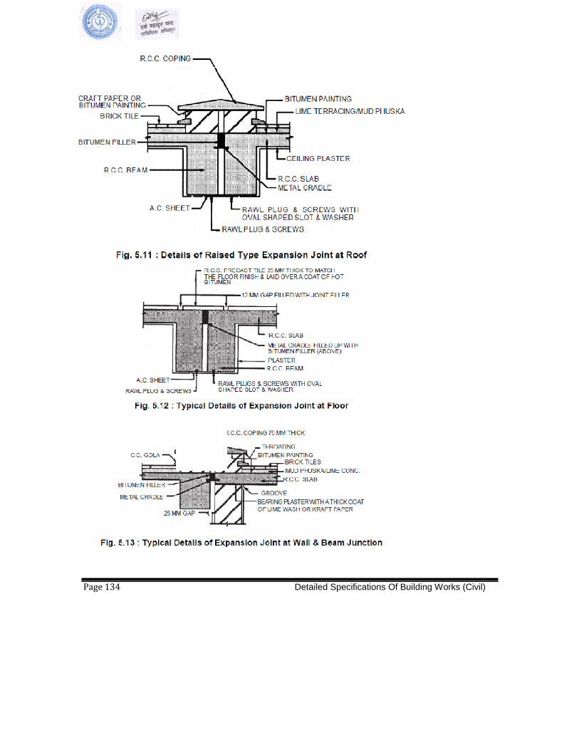
Page 134 Detailed Specifications Of Building Works (Civil)
LIST OF APPROVED MAKES (Example only) ____________________________________________________________________________________
Sl.No. MATERIALS MANUFACTURERS
_______________________________________________________________________________________ 1. Doors & Windows fixtures/ Fittings: Everite, Hardima, Earl Bihari 2. Door Closer / Floor spring : Doorking, Everite, Hardwyn, Amar Darmy.
3. Aluminium Sections. : Indal , Bhoruka, Hindalco, Jindal
4. Clear Glass/ Clear Float Glass :Modi, Gujrat Guardian, Tata, Saint Gobain(SG)
Toughened Glass
5. Laminates : Formica, Decolam, Century, Marino, National, Green Ply
6. Synthetic Enamel Paints : Berger (Luxol gold), Asian(Apcolite), ICI
Dulux (Gloss), Nerolac (Full gloss hard drying)
7. Oil Bound Distemper : Asian (Tractor), Berger (Bison), Nerolac
(Super Acrylic).
8. Cement Paint : Snowcem Plus, Berger (Durocem Extra),
Nerolac (Nerocem with titanium),.
9. Plastic Emulsion Paint : ICI, Asian, Nerolac
10. Other Paints/Primers : ICI Dulux, Asian, Berger, Nerolac
11. Cement : OPC 43 grade conforming to BIS-8112 and approval of Engineer
12. Reinforcement Steel : TMT steel conforming to BIS-1786 and approval of source by
Engineer
13. Glass Mosaic Tiles : Italia, Bizzaza. Pallidio
14. Back-up Rod. : Supreme Industries or equivalent
15. M.S. Pipe : Jindal Hisar, Prakash-Surya, BST, Kalinga
16. Polysulphide sealant. : Pidilite, Fosroc, Choskey, Chematal Rai
17. Polycarbonate Sheets : GE Plastics or approved equivalent
18. Metal Fire Check Doors :Navair, Shakti-met, Godrej, Pacific Fire Control,
Promat 19. Gyspum Board System : India Gypsum, Laffarge, Boral 20. Sunken Portion Treatment : Choksey, Roffe, Krytone,Sika
21. Admixtures for concrete. : Cico, Vam Organics, Roffe, Pidilite
22. Epoxy Paint. : Nerolac, Shalimar or approved equivalent.
23. Ceramic Tiles : Johnson, Somany, Kajaria, Spartek, Nitco, Orient
24. Pre-Laminated Particle Board : Novopan, Greenlam, Kitlam,Bhutan Board.
25. Flush Door Shutters. : Century, Kitply, Novapan, GIC Goyal, Green Ply
26. Silicon Treatment : GE-Silicon, Pidilite, Choksey, Wacker, Forsoc
27. Glazed Tiles : Bell, Somany, Johnson, Kajaria, Cera.
28. PVC Water Stops : Supreme, Fixopan or approved equivalent
29. White Cement. : Birla White, J.K.
30. Powder Coating Material Pure
Polyester. : Jotun , Berger, Goodlass Nerolac
31. Masking Tapes : Suncontrol , Wonder Polymer.
32. Stainless Steel Screws For
Fabrication and fixing of Windows.: Kundan , Puja , Atul.
33. Proposed Treatment on MS Brackets. : Galvanised Brackets As per IS:4759-1996 610
gms./sqm.(microns) 80-90 34. Dash Fasteners./Anchor bolts : Hilti, Fischer, Bosch.
35. Stainless Steel Bolts, Washers Nuts. : Kundan, Puja, Atul.
Detailed Specifications Of Building Works (Civil) Page 135

36. Stainless Steel Pressure Plate Screws. : Kundan, Puja, Atul.
37. Stainless Steel Friction Stay. : Securistyle, Earl Bihari.
38. E.P.D.M. Gaskets. : Anand Reddiplex, Enviro Seals
39. Weather Silicon. : Dow Corning, Wacker, GE
40. Structural Silicon at butt joints : - Do -
41. PVC continous fillet for periphery
packing of Glazings /Structural glazings.: Roop, Anand, Forex Plastic.
42. Floor Springs. : Doorking, Opel.
43. Aluminium Cleat arrangement for
Glazings. : Deco or approved equivalent
44. Water proofing / Injection Grouting : Overseas Water Proofing Corporation
45. 6mm thick Reflective Glass : Glaverbel, Glavermas, Saint Gobain.
46. Door Locks. : ACME, Godrej, Harrison
47. Door Seal – Woolpile Weather Strip : Anand -Reddiplex.
48. Aluminium Grill : Decogrille and approved Equivalent
49. Vitrified Porcelene Tiles: : Restile (Granamite- Atena), Naveen, Bell-Ceramics,
Kajaria, Somani
50. Carpets : Hollitex, Standard, Mohawk
51. Aluminium Cladding sheets : Alstrong , Alpolic, Alucobond,
52. Aluminium Die-cast handles : Giesse, Securistyle, Alu-alpha
& two point locking kit
53. Stainless steel D-handles : D-line, Giesse, Dorma
54. Auditorium Chairs : Penworker, Suri Cine chairs, Godrej
55. Woollen Fabric for Auditorium : ESSMA, Raymonds
56. Stainless Steel Pipes/Flats : 304 Grade
57. Structural Steel : Conforming to BIS 2062 and approval by Engineer
58. Ready Mix Concrete : L&T,ACC,BIRLA,AHLCON
59. Antistatic Epoxy Floor : Fosrock, Beck, Famaflor, STP
60. SBS bitumen based Self adhesive
membrane Material : Grace-Bituthene CP1.5, Texsa-Texself 1.5
61. Acoustic Mineral Fibre : USG-Radar, Armstrong, 21st Century, Acostyle
62. APP modified Bitumen water
proofing membrane : Lloyds, STP, Bitumat
63. Hand made ceramic tiles : Raja Tiles, Saraswathi
64. Curtain wall : Specialised Agency to be Approved by Engineer
65. Fire Panic bar : Briton, Monarch, Von-Duprin
66 Ply board : Greenply, Kitply, Century
67 PVC Doors : Rajshri or approved equivalent
Note : Wherever makes have not been specified for certain items, the same shall be as per National
Standard and as per approval of Engineer
Page 136 Detailed Specifications Of Building Works (Civil)

Sanitary Works
Page 137 Detailed Specifications of Sanitary Works
SPECIFICATIONS (WATER SUPPLY AND SANITARY INSTALLATION)
(A). General Instructions to the Contractor
1. General Notes
(i) All items of Works given in this schedule of quantities shall be executed in strict accordance with the relevant drawings and Specifications read in conjunction with the appropriate I.S.I. codes.
(ii) The quantities given in this schedule are provisional. The
Contractor will be paid for the actual quantity of Works executed as measured at Site. The Project Engineer reserves the right to increase or decrease any of the quantities or to totally omit any item or Works. Any claims by the Contractor on these accounts will not be entertained.
(iii) The suppliers have to supply the materials as quoted in respective
Specifications. Some brand names have been listed below for the general guidance of the Contractor. These brand names are used herein merely in describe the nature of the desired materials and not used to endorse or indicate a preference for a particular product or manufacture. Goods which have similar characteristics and provide performance and quality at least equivalent to those specified and conforming its ISI standards are acceptable.
Porcelain Clay Sanitary - Hindustan Sanitary
Wares Wares, Parrywares or
Equivalent.
Pump - Crompton or Kirloshar Equivalent
HDPE Pipe - N.S. 40/041, Nepothene
Or equipment
Cisterns - Hindusthan
- Parrywere
Chromium Plated (C.P.) - Ego brand, BMT or Fittings (Fancy Type)
Chromium Plated (C.P.) - Blue star or nova
Fittings (Ordinary Types) Jauqure, Hindustan
Cast Iron Pipes - D.N. Singha, T.D.
Surekha
Galvanized Iron (G.I.) - HIPCO or equipment
Page 138 Detailed Specifications of Sanitary Works
Pipes 'S' branch
Galvanized Iron Fitting - 'R' brand, Fittings
Looking Mirror - Hindustan or Pearls
Gun Metal Fittings -"GG" or "Leader" makes
or equivalent.
Shoner rule -nova, dugar, news the
Equivalence
Flush Valve - Blue Star, Jacguar, Ess- Ess or Equivalent
Push Valve - Jal, Viking or equivalent.
PVC Pipe - Panchakanya or Equivalent.
PVC Fitting - Prince, Supreme or Equivalent.
2. Extent Agreement
The Works under the Agreement shall comprise the delivery, installation and testing at Site, as per Bill of Quantities drawings of pipes, valves, and appurtenance etc. Required for water supply and sanitary Works
Quality: All materials should conform to qualitative standards as dictated by I. S. codes.
Suitability of Goods: The pipes, valves, appurtenances shall be suitable for use without significant corrosion in transport water.
3. Interpretation of Terms Where the words "selected”, "as directed", "as required", words of similar meaning, are used in the Bills of Quantities. It is to be understood that the selection, direction or requirements of the Project Engineer are intended. Similarly, the words "approved", "satisfactory", or other synonyms, shall mean "approved by" or "satisfactory to" the Project Engineer and the Project Engineer's approval must first be obtained before the materials ordered or the Works to which the words refer are put in hand.
Wherever the words "necessary', "proper" or words of similar meaning are used in the Bills of Quantities with respect to the extent, conduct or character of Works described, it is to be understood that they shall mean that the said Works shall be executed to the extent, must be conducted in a manner or be of a character which is "necessary" or "proper" in the opinion of the Project Engineer.
4. Position of Sanitary Fixtures, Runs, Pipes
Page 139 Detailed Specifications of Sanitary Works
(i) The recommended positions of the sanitary fixtures, runs of all piping etc. as shown in the layout drawing will be adhered to as far as possible or as far as practicable.
(ii) Should there be any discrepancy or incomplete description,
ambiguity or omission in the drawings and other documents, whether original or supplementary forming the Agreement, completion or maintenance of the installation, the Contractor shall immediately on discovering the same, draw the attention of the Project Engineer to this.
(iii) Prior to the installation of all fittings, pumps, traps, etc. The
finial position shall be ascertained from the Project Engineer. 5. Completion Tests
After completion of the Works, the Contractor shall notify to the Project Engineer (in writing) about the completion of the Works within seven days from the date of this notification, the Project Engineer or his representative shall remain present at the time of carrying out the tests by the Contractor.
All Works shall be tested in sections 100 Lbs as required, before being covered up to the satisfaction of the Project Engineer.
The Contractor shall include for providing all necessary appliances and labour for these tests.
All water service pipe Works shall be flushed through with a disinfectant at the expense of the Contractor, upon completion of installation.
All drainage pipe Works shall be robbed through before laying and upon completion of installation to ensure cleanliness.
6. Sample
The Contractor shall submit samples of accessories and apart from its proposes to use in the installation if asked from the Project Engineer for approval to ensure greater accuracy when setting out pipe Works and to enable practical dimensions of fittings to be obtained on Site.
Drawing and samples shall be submitted by the Contractor as the Specifications shall not be departed from without written instructions from the Project Engineer.
7. Proprietary of Materials
Where proprietary of materials are specified hereafter, the Contractor may propose the use of similar materials of other manufacture but of equal quality for approval by the Project Engineer. Should the price of alternate materials proposed be lower in price, the Contractor shall a revise schedule of price for the particular item along with his proposal for the use of alternate material in lieu of the one specified.
All materials and goods, where specified to be obtained from a particular
Page 140 Detailed Specifications of Sanitary Works

manufacturer or supplier, are to be used or fixed strictly in accordance with their instructions.
8. Brand Names
Whenever and wherever brand names are used it is merely to describe the nature of the desired materials and not used to endorse or indicate a preference for a particular product or manufacture. Goods which have similar characteristics and provide performance and quality at least equal to those specified and conforming to I.S. standards are acceptable.
9. Packaging
The Contractor is to provide special packaging according to standard practices to project materials or parts of materials from damage, and his rates will be deemed to include for all such protection.
10. Specified Materials
The source of materials stated in the Specifications are those from which materials are generally available. However, materials not conforming Specifications shall be rejected even if they come from the stated sources. The Contractor should satisfy himself that sufficient quantity of material of acceptable Specification is available from the stated or other sources.
11. Standards
All materials, Workmanship and components shall where applicable and unless otherwise stated in the Agreement comply with either. Indian standard or code practice current on the date firm for receipt of tenders. The Indian Standards referred to here are:
Indian Standards (I.S.)
Published by Bureau of Indian Standard, India.
Should there be any discrepancy or incomplete description, ambiguity or omission in the drawings and other documents, whether original or supplementary forming the Agreement, completion or maintenance of the installation, the Contractor shall immediately on discovering the same draw the attention of the Project Engineer to this.
The Works shall be carried out according to these Specification whether specifically mentioned elsewhere or not. No extra in any form will be paid unless it is definitely stated as it is in the Bill of Quantities.
Whenever the Specifications are not given or when the Specification is ambiguous, the relevant Indian standards or British Standards and further amendments will be considered as final and binding.
12. Quantities
The Works shall be related to the drawings which the Agreement is presumed to have studied. Nothing extra will be paid for any items
Page 141 Detailed Specifications of Sanitary Works

because of its shape, locations or other difficult circumstances, even if the schedule makes no distinction, as long as the item is shown in the drawings.
The quantities given in this schedule are provisional. The Contractor will be paid for the actual quantity of Works executed as measured at Site and priced at the rates in the schedule. The Project Engineer reserves the right to increase or decrease any of the quantities or to totally omit any item or Works. Any claim by the Contractor on these accounts will not be entertained.
13. Office Accommodation and W.C.
The Contractor shall provide at his own expenses adequate temporary accommodation and toilet facilities for his Workmen and keep the same in good order. This may be done to suit Site conditions with the approval of the Project Engineer. The above mentioned temporary structures shall be removed on the completion of Works at Contractor's own cost. All materials shall belong to the Contractor.
14. Sign Board
A sign board of specified size shall be placed at Site. 15. Drawing, Instructions, Measurements
All the Works shall be done according to the drawings and instructions of the Project Engineer and the Contractor shall arrange to test materials and/or portions of the Works at his own cost in order to prove their soundness and sufficiency. If after any such test, and in the opinion of the Project Engineer, any Works or position of Works is found to be defective or unsound, the Contractor shall pull down and re-execute the same at his own cost. Defective materials shall be removed from the Site.
16. Trees
No trees, saplings shall be removed/cut without prior permission of the Project Engineer. If may tree has to be cut, this shall form an extra item. For the purpose of the Specification, a tree shall be defined as growth whose circumferences of the trunk at 30cm (1'-0") from the base is not less than 90cm (c'-0").
17. Measuring materials
Materials requiring measuring shall be measured separately in boxes of appropriate sized before being mixed.
18. Measuring Materials
All trenches, walls newly laid, concrete or other Works requiring protection from weather or accidental injury shall be protected by means of tarpaulin or in any other way so as to keep the Works immune from damage. Nothing extra shall be paid for on this matter.
Page 142 Detailed Specifications of Sanitary Works
19. Leaves Clean
On completion, all Works must be cleaned down, rubbish removed and the Works and land cleared of rubbish, surplus materials, debris and other accumulations and everything left in a clean and orderly conditions.
20. Provisional Items
All provisional items in the schedule shall be carried out at the discretion of the Project Engineer, and may or may not form part of the Agreement. In case the Agreement. In case the provisional items are carried out by the Contractor, the rates shall be settled as for extra items as stated in the Conditions of Agreement.
21. Storage
Safe, dry and proper storage shall be provided for all materials particularly cement. For cement storage capacity should be equal to at least one fourth the total quantity to be used but may not exceed 200 tonne (i.e. 4000 bags). If silo is installed at the Site of Works the Project Engineer may reduce the capacity storage.
22. Test of Materials
The Contractor shall at his own cost arrange and carry out the tests of materials to be used in the Works or any other tests as deemed necessary by the Project Engineer.
23. Maintenance
The completed installation, inclusive of piping, fixtures, pumps, tanks etc. shall not be finally taken over and acceptance certificate issued to the Contractor until the expiry of the defects liability period of 6 month. During the period, the Contractor shall be liable for:
(i) The replacement of any defective part that may develop in goods of
his own manufacture of supplied by him at his own expense.
(ii) Bringing to the notice of the Project Engineer any defect arising in materials supplied by the owner and replacing them, thus rectifying the defects at the expense of the owner. Until finally taken over, the Contractor shall have the right of entry to the premble at his own risk and expense, for maintaining the installation in proper order.
24. Accessories
The Contractor has to supply and install all necessary accessories such as eccentric increases, non-return value, service value and delivery pipes etc. Delivery pipes shall extend beyond the structure, and connection to main delivery has to be made.
Details of pump and accessories within the pump house are not shown and shall be according to manufacturer's instructions.
25. Excavation for Pipe Lines
Page 143 Detailed Specifications of Sanitary Works
In excavating trenches for pipe lines, slight rails shall be erected, before excavation is commenced, at every 100 meters and at all change of direction or gradient. The sight rail shall consist of a board, not less than 10 centimeters deep, with the top edge planed true and straight. This shall be supported by a stout wooden post at each end, and its top edge accurately fixed to a definite and, as far as practicable, uniform height above the level of the pipe to be laid. The centre line of the pipe shall be denoted on each rail thereon, and the rail on one side of the centre line painted rail, and on the other side white. The depth of the excavation and the level of the pipe invert shall be checked by means of boning rods of appropriate length. The boning rods used are to be accurately made to the various lengths required, the lower and being provided with a shoe of sufficient projection to rest on the centre of the invert of the last pipe laid.
The excavation shall be carried out to the lines and levels shown on the plans or as ordered by the Project Engineer, and shall be deep enough to permit a minimum cover as specified hereunder.
Pipe Minimum Cover in mm
Normal Ground
Cast Iron - 750
Galvanised Iron - 600
The Contractor shall be responsible for and shall at his own cost, make up all subsidence or slips whether arising from its nature of the materials in embankments, from the nature of the ground or from any cause whatsoever. The Contractor shall, his own expense keep the whole of the Working Site dry and from water and construct such temporary water courses and drain as may be surface of the Works. The Contractor shall include in his rates the cost of providing all tools, machinery and all temporary Works such as staging, struts, shoring, planks and poling boards and their removal on the completion of the Works and the cost of pumping and trenches. Whenever pumping is necessary, the whole Works shall be executed as quickly as possible, due care being taken to avoid excessive pumping, which may cause settlement of surrounding land and property.
Any trench or excavation which may have been taken to a great depth than necessary shall be filled into the required level with suitable material approved by the Project Engineer and rammed solid with watering at the Contractor's expense.
Special care shall be taken provide a solid even bed for the barrel of the pipe, and the floor of the trench shall be properly shaped to receive the gocke it and the barrels of the pipes. Where lock is met within the trenches, the excavation shall be taken to a depth of 15 csm of selected filling (approved by the Project Engineer) placed on the rock and consolidated to form a firm even bed for the pipe where required, socket
Page 144 Detailed Specifications of Sanitary Works

holes shall be cut in the rock. In narrow trenches, socket holes shall be cut in the rock. In narrow trenches, the width of the excavation shall be increased. the sides of trenches shall be allowed a slope not exceeding 1 to 12, the width at the bottom being at least 30 cms wider than the socket of the pipe, so as to allow room for ramming the refilled materials under and at the sides of the pipe.
26. Re-filling
No refilling shall be carried out until the construction Works has been tested and approved. The re-filling on the top and around the sewers shall be done with great care and in such a manner as will obtain the greatest amount of compactness and solidity possible. For that purpose, the earth shall be laid and rammed in regular layers not more than 230mm (9") thick up to the surface and also watered and rammed at each layer. The top soil shall be carefully replaced to match the existing.
Page 145 Detailed Specifications of Sanitary Works

27. Testing of Pipes Lines Cast Iron and G.I. Pipes
After each section of the pipeline has been laid and jointed and anchorage's built in for the bends, the pipeline shall be tested in lengths of 2 kilometers or less as directed by the Project Engineer, by and at the expense of the Contractor. Before testing, the trench shall be partially backfield except at the oinits. the accessories nodded viz. Test pump, pressure gauge, end pieces including connecting valves and piping etc., for carrying cut the hydraulic tests shall be provided by the Contractor's. The Contractor shall provide the supply of necessary labour and water for testing at his expense, the cost of this shall be included in the unit rate for lying and jointing of pipes. The pipes and joints found to be defective during the test shall be replaced and or reduce by the Contractor and the related labour cost be met by the Contractor.
The two tests that shall be carried out are -
(i) Pressure test a pressure of at least double the maximum Working pressure, pipes and joints shall be absolutely watertight under the test.
(ii) Leakage test (to be conducted after the satisfactory completion of
the pressure test) at a pressure to be specified by the Project Engineer for a duration of two hours. Unless otherwise specified the leakage test pressure shall be the lower or ½ times the maximum static pressure that will be experienced by the pressure after installation.
Where any section of the main is provided with concrete thrust blocks or anchorages, the pressure test shall not be made until at least five days have elapsed after the concrete was caste.
The procedure to be followed are as follows:
(i) Pressure Test:
- Each valved section of the pipe shall be slowly filled with water and all air shall be expelled from the pipe through hydrants and blow-offs. If these are not available are not available at high places, necessary tapping may be made at points or highest elevation before the test is made and plugs inserted after the tests have been completed.
- If the trench has been partially back-filled the specified
pressure based on the elevation of the lowest point of the line or section under test and corrected to the elevation of the test guage, shall be applied by means of a pump connected to the poi in a manner satisfactory to the Project Engineer. The duration of the test shall not be less than 24 cm.
- All exposed pipes, fittings, valves and joints should be
Page 146 Detailed Specifications of Sanitary Works
carefully examined. Any cracked or defective pipe, fitting and value discovered in consequence of this pressure test shall be removed and replaced by sound material and the test shall to repeat. All joints showing visible leaks shall also be recalled or redone until tight.
(ii) Leakage Test:
- Leakage is defined as the quantity of water to be supplied into the newly laid pipe, or any valve section thereof, necessary to maintain the specified leakage test pressure.
The pipe installation will not be accepted until the leakage is less than the number of
cm3
/h as determined by the formula-
q1 = N D P
3.3
Where,
q1 = the allowable leakage in cm3
/h.
N = number of joints in the length of the pipeline.
D = diameter in mm, and
p = the average test pressure during the leakage
Test in kg kg. /cm2
28. Testing of Elevated Tank for Wetertightness
When the construction of the elevated tank is completed it shall be tested for water tightness as follow:
The tank shall be filled with water gradually as directed by the Project Engineer, to overflow level and after allowing four days for the water to be thoroughly absorbed by the walls, the walls shall be again brought up to the overflow level and left undisturbed for 7 days. At the end of this period, there should be no serious diminution in water level and no signs of leaks weep from the tank walls or bottoms. In the event of any serious diminution, the Contractor shall empty the tank and carry out at his own cost such repairs or alternations as required to stop any leak, weep or other cause of loss of water and thereafter repeat the test till the tank is certified as watertight by the Project Engineer.
All water, labour, materials, and plant necessary to carry out the tests and repairs shall be supplied by the Contractor at his own cost.
29. Checking of Reservoir for water tightness
After the construction of the reservoir is completed, and before back filling of any earthen embankment, unless otherwise verified, it shall be tested for water tightness as directed by the Project Engineer. The following tests
Page 147 Detailed Specifications of Sanitary Works
shall be carried out from the Contractor under the direction and supervision of the Project Engineer. Each compartment of the reservoir shall be filled with water gradually as directed by the Project Engineer up to the level of the top of the partition of wall (if after allowing four days for the water to be thoroughly absorbed by the walls, water level shall again be brought up to the level of the top of the partition wall (if any) and shall left undisturbed for seven days. If any diminution in water level is noticed other than attributable to evaporation, the Contractor shall report the matter in writing to the Project Engineer and seek his assistance and instructions in determining the cause of the loss of water. The Contractor shall thereafter marked to effect any repair or alteration required to stop any cause of loss of water and thereafter repeat the process again and again, if required, until the reservoir is complete watertight and satisfactory by the Project Engineer.
Any labour, materials and plant necessary to effect the above checking and testing shall be supplied by the Contractor at his own cost.
Any tests and similar action shall be taken to determine water tightness of the reservoir up to its top water level.
The Contractor shall be solely responsible for the water tightness and any remedial measures necessary.
Page 148 Detailed Specifications of Sanitary Works

30. Disaffection of Reservoirs and pipe lines
(i) Reservoirs: The internal surfaces of the reservoir and external Surfaces of all pipes and fittings within the reservoir shall be thoroughly cleaned and if necessary scrubbed to remove all obvious contamination matter and the water from the operations removed by squeezes and drained out through the washout main.
The reservoir shall then be filled with water containing an approved hypochlorite or liquid chlorine solution such quantity and such strength as will result in a concentration of free chlorine of not less than 10 PPM or as otherwise directed by the Project Engineer. This chlorinated water shall be allowed to remain the reservoir for a minimum period of 24 hours as directed by the Project Engineer. Then flushed out.
The reservoir shall be refilled with treated water and the sample shall be taken for bacteriological analysis accordance with the instruction of the Project Engineer. If the result of the analysis is unsatisfactory, the sterilizing process and refilling and sampling shall repeated until the analysis is satisfactory.
(ii) Pipe Lines:- After the pipe lines have been filled and flushed out to
remove all debris and contaminant matter, it shall be filled with chlorinated water of strength as prescribed disinfecting of reservoir and pipe line, and left to stand for 24 hours or such process as directed by the Project Engineer. Then the pipe line shall be flushed out and refilled with treated water if subsequent analysis is reveals contamination, the sterilizing process shall be repeated to the complete satisfaction of the Project Engineer.
(B) Detail (Item) Specification:
1. Sanitary fixtures & Accessories
All sanitary wares and fittings shall be first class quality white glazed vitreous china ceramic conforming to is 774, is 2256 and approved by the Project Engineer.
1.1 Water Closed (W.C.)
(a) European pattern W.C. commode and flush valve or cistern.
These shall be of white glazed vitreous china first class quality, double or single trap symphonic water closet suite as specified in the Bill of Quantities, P or S Trap flushing cistern or flush valve as specified conforming to Indian standard Specification. The commode and flushing cistern shall be free from cracks, blisters and shall have smooth surface.
Fixing :- W.C. commode shall be fixed to floor with CP brass screws or by means of 75mm long 6.5mm dia counter sunk bolts and nuts imbeded in floor concrete or as per the instruction of the Project Engineer. The base of pedestal of the commode
Page 149 Detailed Specifications of Sanitary Works
shall be filled with white cement mixed with pigment to match the shade of floor or as directed by the Project Engineer. Following measure shall be adopted for fixing the W.C. commode
(i) The central axis of the commode shall be perpendicular to the finished face of wall.
(ii) The outlet of the commode shall be centrally placed in the rubber
gasket of the HDPE pipe C.I. pipe as per drawing or as directed by the Project Engineer and shall have not leakage.
(iii) The distance between centre line of outlet of W.C. commode and
finished wall face shall be as adjusted as to rest squarely against the finished wall face.
(iv) Seat and lid: This shall be of ISI marked solid of heavy duty quality
and fitted exactly on the rim of the W.C. Commode with C.P. brass hinges, rubber buffers and C.P. brass nuts.
Indian Pattern W.C. pan flush valve or flushing cistern:
(i) Indian Pan: These shall be of white glazed vitreous china of first
class quality Indian pattern squatting pans (500mm size) of open rim with back inlet type with two numbers of white glazed ceramic
1st
class quality non-skid type foot treads and ceramic P or S traps. The pans, foot treads or rests etc. shall be free from cracks, blisters and shall have smooth surface.
(ii) Orissa pan These shall be of white glazed vitreous china 1st
class
quality orissa pattern squatting pans with integral foot treads (580mm size) of box rim with back inlet type including ceramic P or S traps and complete accessories. The pan etc. shall be free from cracks, blisters and shall have smooth surface.
(iii) Fitting: The W.C. pan Indian or orissa shall be laid on floor slope towards the pan in a Workman like manner, being taken not to damage the W.C. pan, etc, in the process of fixing. If damaged in any way, it shall be replaced at no cost of the employer. The pans, etc should be fixed on a proper base of cement concrete (1:2:4) mix (1 part cement : 2 parts sand :4 parts stone balls: of 20mm nominal size) taking care that the cushion is uniform and even without having any hollows between the concrete base W.C. pans etc. Joint between the W.C. pan and finished floor shall be neatly done and no hair cracks shall be visible. Joint between the outlet of W.C. pan and ceramic p or S trap shall be made with near cement, yarn, linseed oil, white lead and water proofing compound and made leak-proof. The outlet of the ceramic traps shall be centrally placed in the rubber gasket of the socket of the HDPE pipe or cast iron pipe as special or as directed by the Project Engineer and shall have no leakage.
Page 150 Detailed Specifications of Sanitary Works

Flushing Cistern: The flushing cistern shall be white glazed vitreous china of low level as specified in the Bill of Quantities with complete accessories. The fixing of cistern shall be as specified clause NO. 1.5.
1.2 Wash Basins
These shall be white glazed vitreous china of first class quality with single or double tap hole as specified in the Bill of Quantities. These shall be free from cracks, crazes, and blister and shall have smooth surface.
Fixing: The basin shall be supported on brackets s per as manufacturers instruction and/or on vitreous China pedestal as directed by the Project Engineer. There shall not be any gap between top edge of the basin and finished face of wall.
C.P. Basin Mixer: - This shall be 15 mm size of C.P. brass central hole basin mixer with fancy knob heads for hot and stop cocks and castled central spout.
1.3 Sinks Sinks and its accessories shall be of required size in white glazed vitreous china or stainless steel, as specified in the Bill of Quantities with overflow. Each sink shall have one 32mm C.P. brass trap with cleaning eye, union, nuts, etc. Sinks shall be supported on C.I. or M. S. brackets of heavy type.
Where required, counter top sinks shall be fixed in tables or counters by mean of 40 x 5mm flat screwed to the table. Counter top sinks shall have 40mm C.P. brass waste with chain and plug 40mm C.P. brass trap with cleaning eye, and union. One C.P. or aluminium bending 25mm wide shall be fixed to cover to joint between sinks and table as called for as the Bill of Quantities.
1.4 Urinals These shall be white glazed vitreous china of first class quality flat back type (430mm size) with integrated overflow. The urinals shall be free from cracks, blisters and shall have smooth surface.
Fixing: Urinals shall be fixed on the wall with the help of C.P. brass screws as per the manufacturers and/or directed by the Project Engineer. There shall not be any gap between the back edge of the urinal and finished face of the wall.
1.5 Flushing Cistern The flushing cisterns shall be manually operated or automatic, high level or low level s specified in the Bill of Quantities. The cistern may be cast iron or porcelain s specified in the Bill of Quantities and shall have a removable cover which shall fit closely on it and be screwed against displacement. In the case of high level cisterns, the outlet shall be of 32 mm nominal bore and in the case of low level cistern, the outlet shall be 40mm nominal bore, The discharge rate of the cistern be about 10 liters in 3 seconds when connected to an appropriate flush pipe, and there shall have to operate with minimum height of 30cm between the top of the pan and the underside of the cistern. The body thickness of a cast iron cistern shall not at any place, be less than 0.5cm.
Page 151 Detailed Specifications of Sanitary Works

The body of a pressed steel cistern shall be of seamless or welded construction of thickness not less than. 1.6mm and shall be porcelain enameled or otherwise protected against corrosion. . All Working parts shall be designed to operate smoothly cape efficiently. The symphonic action of a flushing cistern shall be capable of being rapidly brought into action by the operating lever, but shall not self-syphon or leak.
Fixing of flushing cistern: The cistern shall be fixed on C.I. or R.S. cantilever which shall be firmly embed in the wall in cement mortar (1:4) or fixed by using wooden plugs and screws as directed by the Project Engineer. The outlet of flush pipe from the cistern shall be connected to the pan by means of cement or putty joint. The flush pipe shall be fixed to wall by using holder butt clamps.
1.6 Water Tanks Water tank shall be made of G.I. sheet or high density polythene tank as shown on the drown and specified in the Bill of Quantities. Tank shall be fabricated from new G.I. sheets of 14 gauge or as directed by the Project Engineer. Thanks with length upto 1800mm shall be provided with one manhole cover, and of grater length than 1800mm shall be provided with two manhole covers. Manhole covers shall be of G. I. sheet with locking arrangement as per drawing or as directed by the Project Engineer.
G. I. water tank shall provide inlets, outlets, scour and overflow pipes, sockets for float level switches and inter connections if required. Overflow pipes shall be provided with a mosquito proof brass grating. Scour pipe of size as specified by the Project Engineer shall be provided with a bend and pipe piece and plug terminating outside the tank wall. Ball cocks used for tanks shall be high or low pressure ball cocks with brass lever rods and polythene ball floats. The ball floats shall conform to Indian standard which shall be hammer tested. C.I. water tank or polethene tank shall be fixed in position ass shown on drawing or as directed by the Project Engineer.
1.7 Pipes and fittings (Heavy duty cast iron ( H.C.I. ) pipes ( Hume pipe, HDPE or PVC Pipe )
1.7.1 General Requirements:
All pipe Works to be installed under buildings should be heavy class cast -iron soil pipes. No double socket connectors shall be used on the drawings installation without prior permission of the Project Engineer.
Unless detailed otherwise on drawings, all branches from ground floor soil fittings discharging direct to drain shall not drop vertically beneath the fitting to a greater depth than 1400mm. the minimum depth allowed is 100mm below ground level.
All drainage branches shall be extended to a distance of 1200mm beyond the building, in cast Iron drain.
Page 152 Detailed Specifications of Sanitary Works
The Contractor shall check the invert levels of existing drains, sewers and manholes before laying any new drain or sewer, and shall notify the Project Engineer immediately the declared invert levels are found to be inaccurate. The Contractor shall also check the routes and levels of other services to ensure that the routes of the new drains or sewer do not clash.
The drains shall be laid in straight lines and to even grade to the levels shown. Connecting drains from fittings etc. not be laid to a gradient of not less than 40, unless specified otherwise. No. pipes shall be joined together before being laid. All internal soil and waste pipes above 50mm diameter shall be installed in cast iron/HDPE/PVC pipe. All internal waste pipes 50mm diameter and below shall be installed in galvanized mild steel/HDPD/PVC pipe. All pipes shall be at a fall sufficient to achieve a self-cleansing velocity. All overflows shall terminate with splay cut ends, in position indicated on drawings.
All pipe Works terminating at roof level shall be fitted with ventilating cowl.
1.7.2 Cast iron pipes /PVC pipe/ HDP and accessories:
(i) C.I. and fittings : Soil, waste vent pipe
All cast iron pipes and fittings shall be according to the relevant I.S.I. Specifications subject to approve of the Project Engineer, free from fawl and the inside should be clean and smooth. The access doors of fittings shall be of proper design provided with (1/8") rubber insertion. The spigot and shall abut the shoulder of the shoulder of the socket end and leave no angular space in between. The pipes shall be bitumen painted smooth inside, and outside shall be painted with 3 coats of anti-corrosive paint as directed by the Project Engineer.
The pipes shall be of the longest length available and shall conform to the weights and dimensions conforming to IS: 1536-1967.
(ii) Preparation of Pipes: - All pipes shall be inspected both internally
and externally before being put up in position for jointing or lowering into the trenches. They shall be internally brushed throughout (except in the case of pipes in coils) to remove any soil, but in such a manner that internal coating of pies shall not be scratched or injured in any way. The inside of the sockets and the outside of spigots shall be carefully accumulation or obstruction.
After clearing and cleaning the pipes and assembling or placing them
alongside the trench, ready for lowering, the lengths shall be lowered
into trenches after being approved by the Project Engineer.
Page 153 Detailed Specifications of Sanitary Works
(iii) Laying and jointing of cast iron pipes:- The pipes shall be laid in position, the socket ends of all pipes facing uphill, irrespective of
the direction of the flow of water. Any deviation of less than 111/40
in any plane shall usually be effected by laying the straight pipes to a float curve, of such radius that the deflections at joints shall not
exceed 2 1/20
.
After placing a length of pipe in the trench, the spigot end shall be centered in the socket and the pipe forced home and aligned to gradient. The pipe shall be secured in place with approved backfill material tamped under it except at the socket. Pipes and fittings which do not allow a sufficient and uniform space for joints shall be removed and replaced with pipe and fittings of proper dimension to ensure such uniform space. At times when pipe laying is not in progress, the open ends of the pipe shall be closed by a waters plug or other means approved by the Project Engineer.
The IS code of practice for laying of cast iron pipes (IS No. 3114-1965) gives in detail methods of laying cast iron pipes below ground level. It also includes handling and jointing of pipes, hydrostatic tests, back fillings, restoration and maintenance of surfaces and these shall be followed where applicable.
Table 1, in the above code also gives the quantity of lead and spun yarn for different size of pipes.
Cast iron pipes may also be joined by means of flange cast on. The jointing material used between flanges pies shall be compressed fibber board or rubber (see No. 638-1955)- Specification for rubber and insertion jointing) of thickness between 1.5mm and 3mm.
Tighten joints shall be used strictly in accordance will the manufacturer's instructions.
Concrete thrust or anchor blocks suitably designed shall be provided wherever necessary to transit hydro pressure. Where the hydraulic thrust is in an upward direction, anchor blocks of sufficient weight shall be provided to which pipes shall be secured with steel straps.
(iv) Lead caulked joints: Whenever pipes are required to be jointed by
lead the pipes when laid in position for jointing shall be examined for line and level and the space left in the socket after the yarn has been inserted shall be filled in by pouring in molten lead. The lead shall be filled at one pouring. The lead used shall be soft and free from any admixture.
(v) Bracket and hangers: All Cast iron stacks shall be securely fixed
with wrought iron pipe rings and extension pieces in mild steel tube, out to length required and splayed and built into the structure.
Page 154 Detailed Specifications of Sanitary Works
Table of fixing for piping
Material Pipe size Horizontal Max vertical Max.
Cast iron- 50mm 2750mm 2750mm
100mm dia. 2750mm 2750mm
The method of joined shall be with well tarrel gasket and molten lead conforming to IS: 782-1966, caulked tightly home into socket in accordance to IS: 3114-1965. Care should be taken to ensure that no jointing material projects inside the bore of the pipe.
(i) Floor traps: These shall be of self-cleansing pattern conforming to IS: 2556 (XII) - 1973
1.7.3 Testing of C.I. pipes and fittings:
All Soil and waste pipes shall be tested to detect any leakage etc. in accordance to IS: 5329-1969.
1.7.4 Measurements: C.I. pipes shall be measured along the centre line of pipes and fittings in running meter between socket of pipes or corresponding C.I. fittings. Floor traps shall be measured by the number. The original C.I. grating shall be kept in it place and nothing extra shall be paid for it. Floor traps shall be with or without vents and nothing extra shall be payable on this account. All C.I. specials shall be paid by the numbers.
1.8 C.I. pipes & fittings
1.8.1 C.I. pipes: The pipes and fittings shall be galvanized mild steel, mediums (class B) conforming to IS: 1239. Fittings shall comply with IS: 1897 or equivalent. The method of jointing shall be by B.S.P. pipe threads on pipe and fittings, painted with jointing compound and fine hemp. Care should be taken remove any internal burr to pipe before joint is made. Any exposed thread shall be painted to prevent corrosion. All joints should be cleaned afterwards. Where water pipes do not fall below sewer lines, they should be laid at min. dept or 610mm below ground level, if otherwise not stated.
The wall thickness and weight of medium (Class C) pipes in kg/m shall be as below.
Weight of Dimensions of pipes Dimension galvanized
pipe in
outside diameter
mild steel
Thicknes
Kg/m
Maximum
Minimum s
Sockets
Min.
Screwed
socket
mm
mm
mm
outside dia.
Approx.
mm dia. mm
1.23 21.80 21.00 2.65 27.00 37.00
Page 155 Detailed Specifications of Sanitary Works
1.59 27.30 26.50 2.65 32.50 39.00
2.46 34.20 33.30 3.25 39.50 46.00
3.17 42.90 42.00 3.25 49.00 51.00
3.65 48.80 47.90 3.25 56.00 51.00
5.17 60.80 59.70 3.65 68.00 60.00
6.63 76.60 75.30 3.65 84.00 69.00
8.64 89.50 88.00 4.05 98.00 75.00
12.40 115.00 113.10 4.50 124.00 87.00
1.8.2 Backsets & Hangers:
All services shall be securely fixed galvanized iron built in pattern holderbats or two
piece rings, extension piece and screw to wall back plate.
Pipe Horizontal Vertical
15mm (1/2") - 185mm (6') 244mm (8')
20mm (3/4") - 244mm (8') 3050mm (10')
25mm (1") - 244mm (8') 3050mm (10')
32 mm (11/4
") - 2750mm (9') 3050 mm (10') 40mm (11/2") - 3050 mm (10') 3660mm (12')
50mm (2") - 3050 mm (10') 3660mm (12')
2.3.3 Testing : All G. I. water supply pipe will be tested in accordance to IS: 2065-1972 and with minimum 100 IB/………
2.2.4 Laying & fixing of G. I. pipes:
Screwed galvanized pipes shall be jointed with screwed socket joints, using screwed fittings. Care shall be taken to removed any burr from the ends of pipes. After screwing white lead and fine hemp shall be applied while tightening. Compound containing red lead shall not be used to prevent danger of contamination of the water. Any thread exposed after joints shall be painted or in the use of underground piping thickly coated with three coats of anti-corrosive paint to prevent corrosion. All G. I. pipes shall be concealed.
In addition to the sectional testing of water supply piping, the Contractor shall test the entire installation on complete of the job to the satisfaction of
Page 156 Detailed Specifications of Sanitary Works
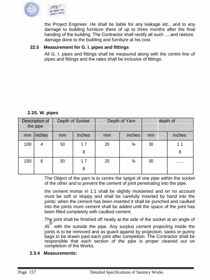
the Project Engineer. He shall be liable for any leakage etc., and to any damage to building furniture there of up to three months after the final handing of the building. The Contractor shall rectify all such ….and restore damage done to the building and furniture at his cost.
22.5 Measurement for G. I. pipes and fittings
All G. I. pipes and fittings shall be measured along with the centre line of pipes and fittings and the rates shall be inclusive of fittings.
2.3 S. W. pipes
Description of Depth of Socket Depth of Yarn depth of
the pipe
mm inches mm inches mm inches mm inches
100 4 50 1 7 20 ¾ 30 1 1
8 8
150 6 50 1 7 20 ¾ 30 …..
8
The Object of the yarn is to centre the spigot of one pipe within the socket of the other and to prevent the cement of joint penetrating into the pipe.
the cement mortar in 1:1 shall be slightly moistened and on no account must be soft or sloppy and shall be carefully inserted by hand into the joints: when the cement has been inserted it shall be punched and caulked into the joints more cement shall be added until the space of the joint has been filled completely with caulked cement.
The joint shall be finished off neatly at the side of the socket at an angle of
450
with the outside the pipe. Any surplus cement projecting inside the joints is to be removed and as guard against by projection, sacks or gunny bags to be drawn past each joint after completion. The Contractor shall be responsible that each section of the pipe is proper cleaned out on completion of the Works.
2.3.4 Measurements:
Page 157 Detailed Specifications of Sanitary Works

All S.W. pipes shall be measured along the centre line of pipes and fittings in running metre between socket to socket of pipes or corresponding PVC fittings. All PVC specials shall be paid by the numbers.
2. Traps/Joins/Special
2.1C.I. floor trap/PVC Floor traps shall be cast iron, or PVC deep seal with an effective seal of 300mm. All waste pipes shall be discharged over the trap. The trap and waste pipes shall be set in cement concert blocks firmly supported on the structural floor. The blocks shall be in (1:2:4) and extended 37mm below finished floor level. Contractor shall provide all necessary shuttering ad centering for the blocks. Floor traps shall be of self-cleansing pattern conforming to IS: 2556 (XII) -1973. It shall be symphonic type of size 110/63mm or as directed by the Project Engineer.
2.2 C.I. fittings (Specials)/PVC Specials, All cast iron & PVC fittings (Specials) shall be according to the relevant I.S.I. Specifications subject to approval of the Project Engineer, free from flaw and the interior should be clean and smooth. The fittings shall be bitumen painted smooth inside and outside shall be painted with 3 coast of anticorrosive pain as directed by the Project Engineer.
the PVC fittings shall be PVC conforming to of class as specified.
Cocks
All cocks shall be 15mm size of chromium plated with fancy knob head. This shall be ego brand, Blue Star or equivalent Jaquar, ARK, and Best quality, All cocks shall be installed as directed by the Project Engineer. Gate Valves/Ball Vatre
Sluice valves shall be of the taper faced wedge gate type on regulated by spindles of inside screw non-rising type. the valves shall open by movement of hand wheel single lever or the key and bar in an anti clockwise direction. The direction of opening shall be marked on each valve and on hand wheel fitted. Material, manufacture, dimensions and tests of gate valves shall be in accordance with IS; 778-1964 or other approved standards as specified in the Bill of Quantities. All valves shall have the nominal size and maximum Working pressure or class cast or stamped on the body of the valve.
Water meters Water meters shall be of the domestic type, inferential and semi-positive water meter conforming to IS; 779- 1961.Installatin of the meter shall conform to IS: 2401-1963. Foot valves and strainers
The Indian standard Specification No. 4038-1967 covers the requirements for flanged and screwed -end foot valves of both swing and life type for use with centrifugal
Page 158 Detailed Specifications of Sanitary Works
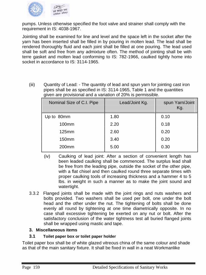
pumps. Unless otherwise specified the foot valve and strainer shall comply with the requirement in IS: 4038-1967.
Jointing shall be examined for line and level and the space left in the socket after the yarn has been inserted shall be filled in by pouring in molten lead. The lead shall be rendered thoroughly fluid and each joint shall be filled at one pouring. The lead used shall be soft and free from any admixture often. The method of jointing shall be with terre gasket and molten lead conforming to IS: 782-1966, caulked tightly home into socket in accordance to IS: 3114-1965.
(iii) Quantity of Lead: - The quantity of lead and spun yarn for jointing cast iron pipes shall be as specified in IS: 3114-1965, Table 1 and the quantities given are provisional and a variation of 20% is permissible.
Nominal Size of C.I. Pipe Lead/Joint Kg.
spun Yarn/Joint
Kg.
Up to 80mm 1.80 0.10
100mm 2.20 0.18
125mm 2.60 0.20
150mm 3.40 0.20
200mm 5.00 0.30
(iv) Caulking of lead joint: After a section of convenient length has been leaded caulking shall be commenced. The surplus lead shall be free from the leading pipe, outside the socket of the other pipe, with a flat chisel and then caulked round three separate times with proper caulking tools of increasing thickness and a hammer 4 to 5 lbs. in weight in such a manner as to make the joint sound and watertight.
3.3.2 Flanged joints shall be made with the joint rings and nuts washers and
bolts provided. Two washers shall be used per bolt, one under the bolt head and the other under the nut. The tightening of bolts shall be done evenly all round by tightening at one time diametrically opposite. In no case shall excessive tightening be exerted on any nut or bolt. After the satisfactory conclusion of the water tightness test all buried flanged joints shall be wrapped using mastic and tape.
3. Miscellaneous items
3.1 Toilet paper box or toilet paper holder
Toilet paper box shall be of white glazed vitreous china of the same colour and shade as that of the main sanitary fixture. It shall be fixed in wall in a neat Workmanlike
Page 159 Detailed Specifications of Sanitary Works

manner. Recess in walls, where required, shall be provided. It shall be fix with C.P. brass screws, where required.
3.2 Soap tray or soap dish Soap tray or soap dish shall be of white glazed vitreous China of the same colour and shade as that of the main fixtures. Soap tray shall be fixed in wall in a neat Workmanlike manner. Recess in walls, where required, shall be provided. It shall be fixed with C.P. brass screws, where required.
3.3 Towel Rod Towel rod shall be heavy type of C.P. brass with two brackets. The size of the rod shall be s specified on the drawing or Bill of Quantities. The brackets shall be firmly fastened by means of C.P. brass screws to wooden plugs or fawl plugs firmly embedded in the wall.
Page 160 Detailed Specifications of Sanitary Works

3.4 Glass Shelf Glass shelf unit shall be of glass of best quality with edges rounded off and shall be free from flaws specks or bubbles. The size of the glass shelf shall 500mm x 125mm unless otherwise specified of thickness not less than 6mm. The glass shelf shall have C.P. brass guard rail resting on rubber washers on the glass plate and C.P. brass brackets which shall be fixed with C.P. brass screws to wooden plugs fixed by fawl plugs firmly embedded in the wall.
3.5 Mirror Mirrors shall be of approved make 5.5mm thick. All edged shall be rounded off. Mirrors shall be fixed on a backing of 6 mm thick commercial board backing and fixed to wall with brass chromium plated screws and washers. Mirrors shall be of beveled or beveled edge of sizes as specified in the Bill of Quantities.
3.6 Shower rose All materials and fittings used in construction shall conform to the latest editions of the relevant Indian standard. The shower rose shall be of heavy chromium plated. The size of the shower rose shall be 100mm or as specified in the bill of quantity when measured across the diameter and the inlet connection shall be 15mm size The shower rose shall be round or octagonal as directed by the Project Engineer and shall have 145 holes with a variation up to10 . The diameter of each hole in the shower rose shall be 1.2mm with a variation upto 10. The inside of the shower rose shall be uniform and smooth in order to ensure free flow of water. A Stop cock of specified size shall be provided to control the inlet supply of water to shower rose. The stop cock shall be heavy chromium plated or as specified in the bill of quantity or as directed by the Project Engineer. The shower rose shall be fitted with
the 15mm dia. G.I. pipe with a 900
bend at top. The height of the rose when fitted shall be 120cm from the floor.
3.7 C.P Grating Floor and urinal traps shall be provided with chromium plated grating, with rim of approved design and shape. Minimum thickness shall be 3mm.
3.8 C.P. Fittings All C.P. fittings, additional bib cocks, shall be of the best quality heavy pattern of approved make.
All C.P. fittings shall be fixed in a Works man like manner and shall not carry tool marks and scratches.
4C/ Anti clockwise top- provided with steel with grating approval by Project
Engineer. PVC Pipe waste soil and vent pipe line heaving Polly chloride (in PVC) pipes and fittings confirming to NS or ISR of approved make of the following sizes in PVC cement solvent and or gasket joints in chiding clean, outs, cutting the pipes to the acquired
Page 161 Detailed Specifications of Sanitary Works
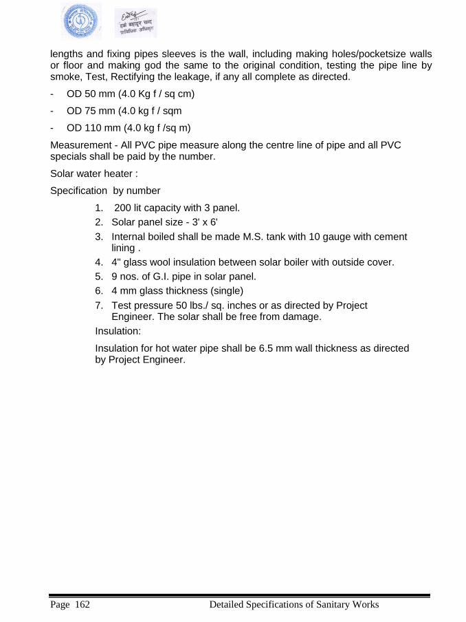
lengths and fixing pipes sleeves is the wall, including making holes/pocketsize walls or floor and making god the same to the original condition, testing the pipe line by smoke, Test, Rectifying the leakage, if any all complete as directed.
- OD 50 mm (4.0 Kg f / sq cm) - OD 75 mm (4.0 kg f / sqm - OD 110 mm (4.0 kg f /sq m) Measurement - All PVC pipe measure along the centre line of pipe and all PVC specials shall be paid by the number.
Solar water heater :
Specification by number
1. 200 lit capacity with 3 panel. 2. Solar panel size - 3' x 6'
3. Internal boiled shall be made M.S. tank with 10 gauge with cement
lining . 4. 4" glass wool insulation between solar boiler with outside cover. 5. 9 nos. of G.I. pipe in solar panel. 6. 4 mm glass thickness (single)
7. Test pressure 50 lbs./ sq. inches or as directed by Project
Engineer. The solar shall be free from damage.
Insulation:
Insulation for hot water pipe shall be 6.5 mm wall thickness as directed by Project Engineer.
Page 162 Detailed Specifications of Sanitary Works
Electrical Works
Page 163 Detailed Specifications of Electrical Works

ELECTRICAL SPECIFICAITON 1. ELECTRICAL INSTALLATION WORKS
GENERAL
The following specifications will apply under all circumstances to the equipment to be installed against this Agreement and it is to be ensured that the Developer, shall obtain for himself at his own expense and on his own responsibility all the information which may be necessary for purpose of making the tender and for entering into a Agreement keeping in view the specifications detained hereunder, drawing, and designing of the electrical installation and inspection of Site.
The rates shall include for the cost of material erection, commissioning, labor, supervision, tools, plant, transport, all taxes, contingencies, breakage, wastage, sundries, scaffolding, maintenance of wiring for one year etc. i.e. they should be for an item complete in all respect.
Workmanship and good appearance of the installation shall be of equal importance with its electrical and mechanical efficiency, and all portions of the work shall be so laid out and installed that the Work as a whole is of uniform quality and shall present a neat and mechanical appearance in a manner meeting the approval of the Project Engineer. The Developer shall verify in the field all measurements necessary for the electrical Work and shall assume responsibility for their accuracy.
Materials which are defective or damaged during the progress of Work shall be replaced or repaired in an approved manner at the expense of the Developer. The installation shall comply with all applicable laws and ordinances and with the requirements of the B.S. or Indian Codes and as specified herein or shown in the Drawings. The progress of the electrical work shall be carried out so as to conform the progress of the Work of the other trade and the entire installation shall be completed as soon as the condition of the building with permit.
All cutting, drilling, channelling, patching, etc., required for installation of electrical shall be carried out in a manner approved by the Project Engineer. Any deferring of finish, planning, woodwork, metal work, masonry, concrete or other material, resulting from the performance of the Work shall be replaced or repaired at no expense to the owner and to the satisfaction of the Project Engineer.
SITE CONDITION
The equipment materials to be erected and commissioned should be suitable for the Site conditions. It is estimated that the maximum temperature at Site will be 40o C.
SCOPE OF WORKS
Provide all labor, materials, equipments, transportation and operation and tests necessary for and incidental to the completion and operation of the complete Electrical System, Protection and Telephone as required and as specified herein or shown on the Drawing.
Page 164 Detailed Specifications of Electrical Works

a) Complete Electrical Installation including underground line, disconnect switches etc. as detailed in the Bill of Quantities.
b) Complete Lighting and Power Wiring Systems and Earthing Systems c) Lighting and Power Panel Boards, Switchboards. d) Lighting Fixtures, Switches, Outlets, Conduits, etc
e) Excavation rock fill, cutting and patching main Work and contain Work,
sleeves, inserts, anchor, etc. as required for proper installation in accordance with the requirements, drawings and specifications.
f) Provide for installation of other miscellaneous electrical wiring required for all
plumbing, electronic and mechanical equipment, complete as shown on the Drawings and as specified herein.
g) Complete protection system.
h) Complete telephone internal and external cable network, plug in outlets and distribution panels.
i) Installation of diesel generator set and transformers including all protection
system. j) Installation and testing of motor control panels to be used for pumps.
k) Where the Electrical Work is associated with the Work of others, the Developer shall
confer with the persons affected, and shall furnish them with necessary information, drawings, dimensions etc. and shall coordinate the electrical work with the Work of other trades to ensure a satisfactory installation, in accordance with the Drawings and Specification and with the highest standards of trade practices based on IS Codes of Practices.
STANDARDS
The installation shall generally be carried out in conformity with the 'Indian Code of Practice' for electrical wiring and fitting in building and for the electrical equipment on buildings. All materials and equipment to be supplied should conform to the relevant Indian Standard Specification. Where no specification is available for any materials or equipment, it shall be governed by specific approval of the Project Engineer.
1.05 I.S. Specifications
The following Indian Standard Specifications will apply to the equipment and the
Agreement :
(a) Low tension air circuit breakers : IS 2516 -1965 Part I Selection I.
(b) Switch fuse units on cubicle switch boards: IS 4047 - 1967
(c) Switch fuse units on Industrial Boards etc.
(d) Switch gear bus bars : IS 375 - 1963
(e) H.R.C. fuse link : IS 2208 - 1963
(f) Distribution fuse boards : IS 2675 - 1966
Page 165 Detailed Specifications of Electrical Works
(g) Enclosures for low voltage switch gear : IS 2147 - 1962
(h) PVC Cables : IS 1554 - 1964
(i) Tubular fluorescent lamps forgeneral lighting service : IS 2418 - 1965 (j) Tungsten filament lamps forgeneral service: IS 418 - 1963 (k) Ceiling fans : IS 374 - 1966
(l) Flood lights : IS 1947 - 1961
(m) Flame proof electrical lighting fittings : IS 2206 - 1962(Part I ) (n) Industrial light fittings with metal reflectors : IS 17 - 1961 (o) Water tight electric light fittings : IS 3553 - 1968
(p) Switch socket outlets : IS 4615- 1968
(q) Three pin plug and socket outlets : IS 1293 - 1967 (r) Switches for domestic and similar purpose: IS 3854 - 1966
CODES OF PRACTICES Earthing : IS 3043 - 1966
Electrical wiring installation : IS 732 - 1963
Switchgear : IS 3072 - 1965(Part I )
Lighting Protection : IS 2309 - 1960.
Materials All materials and equipment shall be new and shall be in accordance with the standards as established by the Indian Standard Institute or the requirements of the B.S. Where materials or equipment are specified or shown on the Drawings by name of manufacturers, they shall be used. Equipment or material of other manufacturers may be considered for use if equal quality appearance, and electrical and mechanical characteristics and approved by the Project Engineer.
Power Supply The power supply system is alternating current 3 phase with neutral at a frequency of 50 cycles per second and 400/230V. Distribution Transformer This specification covers 11/04 KV, 315 KVA copper wound distribution transformer to be used in 11/04 KV Sub-station. The transformer is to be for out door tropical climate and shall conform to latest TEC 76 BS 171 IS 2026 standards and shall conform to the following particulars. (A) Rating:
1. Rated primary voltage 11 KV
2. Maximum primary voltage 12 KV
3. Rated secondary voltage 400 V
4. Connection DY - with star point brought out
Page 166 Detailed Specifications of Electrical Works

5. Tapping and voltage regulation:- Full output tapping to be provided on H.V. winding for No load rated voltage variation of + 2.5, 5
and 7.5% adjustment by manually operated
off load tap changing switch.
6. H.V. terminals:- 3 no. of solid bushing with terminal connectors.
7. L.T. terminals:- Cable ended type suitable for 2 no. of
3 1/2 corex 240 sq mm PVC insulated steel
armored aluminum Conductor cable.
Main Power Control Panel Board
(a) Main power control panel shall be made of folded steel sheet 2.5 mm thick with thrust protection and anticorrosion painting. They shall be installed in the substation/electric room as shown on the drawings.
The low voltage distribution switchboard serving to control and protect the L.V. outgoing distribution boards shall be manufactured and tested in accordance with the provisions of I.S. and the relevant. It shall be provided with a pressure resistant two-wing door and a detachable plate of structural material in the cable termination space.
(b) Busbars
Each L.V. panel shall comprise five busbars: three for the phases, one for the neutral and one for potential equalization (ground). Busbars shall be made of hard drawn high conductivity electrolytic copper according to Indian standard. They shall be air insulated, of dimensions and short circuit rating as shown on the drawings.
(c) Moulded Case Circuit-Breakers
The moulded case circuit-breakers shall be manufactured according to IEC 157 or equivalent and shall have the following characteristics.
- Rated voltage : 400 V
- Nominal current rating : 400 A, 250A, 40 A, 60 A, 100 A as shown on the drawings
- Nominal frequency : 50 Hz
- Breaking capacity (rms) : 30 KA for 250 A and 10 KA for
100 a current rating
- Number of poles : 3
- Total break-time : 20 ms
The switch disconnectors shall consist of a fully enclosed housing fabricated from non-tracking, heat resistant insulating material, accommodating the silver plated fixed and movable contacts.
The movable contacts shall be driven by a robust switching mechanism with quick
Page 167 Detailed Specifications of Electrical Works

make-and-break operation. Handle complete with position indication shall be provided, the protection class, shall be according to IS. (d) Ammeters:
Ammeters shall be of 96 X 96 mm size with quadrant scale, scaled according to the corresponding current transformer rating and shall have the following characteristics:
- Mechanism : Moving iron
- Tolerance : Class 1.5
- Maximum current : 5A
- Frequency range : 15 to 65 Hz
- Scale graduation : Starting at about one fifth of full scale value.
- Overload capacity : 1.2 times continuously, 50
times for
sec., 4 times for 2 or 3
min, 2 times for about 10 min.
Ammeters shall be connected through current transformers.
Page 168
Works
Detailed Specifications of Electrical
(e) Voltmeters
Voltmeters shall be of 96 X 96 mm size with quadrant scale, scaled 0 500 V with built-in series to the rear of the indicator, having the following characteristics:
- Mechanism : Moving coil
- Tolerance : Class 1.5
- Frequency range : 15-65 Hz
- Scale graduation : Starting at about one fifth of full scale
value.
- Overload capacity : 2 times for 1 min The measuring of voltage for each phase shall be affected through one five-way voltmeter selector switch. (f) Miscellaneous
Before dispatching from the factory, all components of the main low voltage distribution switchboard shall be subjected to the routine tests specified in relevant Indian Standards, or equivalent.
Furthermore certificates issued by a testing organization selected by the Project Engineer shall be submit to the Project Engineer by the Developer proving that the types of the components to be supplied have passed the type tests prescribed in the relevant British Standard or equivalent.
Prior to ordering the relevant equipment the Developer shall submit to the Project Engineer for approval information and data stated in the relevant British Standard or equivalent as regards the components for the distribution board.
(g) L.V. Cable Distribution Cabinets The low-voltage cable distribution cabinets (feeder pillars)shall have the following characteristics:
Power supply system: Three-base and neutral solidly earthen, 400/230 V,
50 Hz.
Busbars: Three for the phases, one for the neutral and one potential equalization bulbar.
Types and equipment as shown on the drawings.
Installation: Outdoors on recast concrete base.
Each cabinet shall consist of a supporting frame of which sheet-steel housing covers are secured and a saddle shaped roof. All housing parts shall be hot dip galvanized.
M.C.B. Distribution Boards 1. This section comprises of surface/recess type Distribution Boards
complete with required miniature circuit breakers (MCB). 2. These Distribution Boards with enclosures, bus bars, neutral links, and
Page 169 Detailed Specifications of Electrical Works
earth links, shall be of the original manufacturers only as indicated in the approved lists.
3. The D.Bs' shall be duly connected with the wire way ducting or conducts to
make it electrically and mechanically continuous with the help or sockets bushes, or flange plates, as desired by the Project Engineer.
4. All D.B.'s shall be required to be connected with incoming sub-main cable
and outgoing circuit wiring with Dowel's or approved equivalent crimping lugs for wires of 6 sq. mm. or bigger sizes cables lugs shall be crimped with proper tools at Site. Rates quoted by the Developer shall include the connections in the D.B.'s.
5. D.B.'s shall be fixed on the walls/or flush with wall (recessed) in approved manner and damage to wall made good as per original.
6. Damage to the original paint to the D.B.'s if any, shall be made good
as desired by the Project Engineer.
7. D.B.'s shall be dust and vermin proof. These shall have hinged cover and MCB's shall not be open able without opening these covers. Phase barrier and shrouding sheets shall also be provided in D.B. The D.B. shall be fabricated of 14 SWG CRCA sheet steel and shall be stove enamel painted.
8. Blank spaces (spares) shall be covered with blanking plate.
9. The breaker shall have quick break trip free mechanism with thermal over
load and magnetic short circuit tripping devices. The mechanism shall be such that the circuit can not be held closed against a fault. The thermal items shall prevent reclosing of a circuit when a fault or over load persist.
10. The contact shall be silver tungsten or other suitable material to give long
contact file. Multiple unit shall have common inter tripping mechanism.
11. Miniature Circuit breakers in the panels shall have phase sequence numbering. The phase to which each single pole branch is connected shall be clearly indicated and so arranged that any three adjacent branches are connected to phase RY and B respectively and the same relationship of phase sequence is maintained.
12. Each MCB shall have fault current of 9 KA for 5 A and 15 A load at 220 V
supply system. 13. Circuit Diagrams of each D.B. shall be stuck to over cover of the D.B.
which shall clearly identify circuit number and connected load points.
14. Approved M.C.B. Distribution Board names are: LV Cable
Single core, four core, or five core, as shown on the drawing, copper conductor,
PVC insulated, PVC sheathed, single wire armored and PVC served, 0.6/1 KV
rated cables shall be used in the low voltage distribution system. The cable
Page 170 Detailed Specifications of Electrical Works
shall comply with IS or equivalent and have the following technical characteristics. Number of cores: 4 or 5 for three phase systems 2 or 3 core for single-phase systems. Rated voltage: 0.6/1 KV Neutral of distribution system solidly earthen. Cross-section of copper conductors as shown on the drawings. Cable shall
o
withstand a continuous copper temperature of 75 C. The Cable
shall consist of: Shaped standard copper conductors PVC insulation Layer of extruded PVC Galvanized steel wire armor. The conductors shall be stranded with successive layers of plain annealed wires, drawn from electrolytic copper of high conductivity meeting the requirements of BS 6360. In the stranding and shaping process, each conductor shall be prespiralled to the lay of the finished cable, so the cores will automatically bed in their correct relative position when laid up. Conductors shall have smooth contour, free from sharp edges or projections, which could damage the insulation or cause high local electrical stresses. Number and diameter of wires shall be according to IS. The cables shall be sheathed over the laid-up cores by a layer of extruded PVC complying with IS or equivalent. The amour shall consist of a single layer of galvanized steelwires complying with IS or equivalent. The diameter of the amour wire shall be in accordance with IS.
HV Cables Three or single core 12.7/22 KV Earthen Aluminum conductor, screened, XLPE Insulated Armored Shielded and PVC Sheathed cables conforming to IS 7098 (Part II) amended upto date shall be used in the High voltage system from overhead line to the sub-station installed distribution transformer. Other physical characteristics of the HV cables shall be in conformity to the LV cables. HV cables shall be laid in underground into a separate high density polytene pipes or ducting.
Cable Laying Laid Underground: Where cables are laid underground they shall be laid in a trench 0.9l mm deep from the general ground level. The problem of the trench shall be levelled and the cable shall be laid on a 7.62 cm bedding of fine chemically inert, sand. Mechanical protection shall be given with single layer of well burnt bricks on sides with concrete tiles on top, the inside cavity being filled with sand so that at least a 5.08 cm layer of sand remains on top of the cable. The concrete tiles shall be interlocking type with the word "DANGER" impressed on top. Back filling shall be done with well rammed and watered earth. Cast from cable markers shall be placed so as to be visible on the surface at suitable
Page 171 Detailed Specifications of Electrical Works
intervals and at every bend. Wherever cables run through or enter the building, crosses road or drain, CI sleeves pipes of approved diameter shall be provided. The rates quoted shall include trenching, giving protection, sleeving and clamping, including supply of all materials as specified above. Wherever cables are to run along wall surface of either the building or electrical duct or on the ceiling, these shall be fixed with clients. Clients shall consist of moulded insulated materials divided in two halves flat steel of suitable approved section. The securing shall be by means of studs and nuts with lockouts and washers. For PVC armored cables, aluminum or GI claw type clamps may be used. The raises quoted shall include supply and installation of all fixing materials specified above. Laid in ready trench: This will mean laying of cable in ready prepared trenches directly on trench floor. Minimum bending radius shall be twelve times the overall cable diameter in case of APLSTS cables and six times for PVC armored cables if not otherwise recommended by the Project Engineer. The lengths of cables given in the schedule of quantities are only approximate. The successful Developer is required to measure out the actual lengths needed before laying. Straight though joints will not generally be permitted. Jointing: Cable jointing shall be carried out by skilled jointuress with expert supervision. The Developer shall use the best jointing materials and the necessary cable compound and all jointing, sweating, basting, wiping and filling in of compound shall be done in an approved manner. In case of aluminum conductor cable special care should be taken for its marked difference from copper conductor cable. For PVC cable standard compression type tinned brass glands shall be
used. Wiring System (a) Concealed Point wiring shall consist of branch wiring for final
subdistribution board together with the controlling switch (or push) as far as and including the ceiling rose or any other approved terminations or socket outlet. In case of more than one light point controlled by the same switch, the wiring upto the ceiling rose or any other approved terminations of the first light point including the switch shall be considered as a primary point, loop wiring from light to light shall be considered as a secondary point and the distinguishing rate shall be quoted.
(b) A three pin socket outlet point shall include the earth continuity base copper
conductor cable of 2-5 sq. mm from the earth pin to the terminal or bus at the final distribution center.
Wiring shall be done in "looping system" and phase or live conductor shall be
looped at switch box and neutral conductor can be looped from light, fan, or socket outlets. i) In estimating the current to be carried out by any conductor, incandescent lamps, shall be rated at 100 watts, the ceiling fans shall be
Page 172 Detailed Specifications of Electrical Works
rated at 80 watts, table fans and ordinary socket points at 60 watts, fluorescent lamps of 4 ft at 50 watts and 2 ft at 25 watts and power socket outlet at 1000 watts, unless the actual values are specified. ii) Lights fans, and socket outlet may be Worked on a common circuit. Such sub-circuits shall not have more than a total of 8 points of lights, fans and sockets outlets. The load of such circuits shall be restricted to 800 watts. The number of socket outlets shall not be more than two per circuit. As regards power sub-circuits, the outlet shall be provided according to the load design for these circuits, but in no case shall these be more than two outlets on each circuit. Rates: The rates for wiring light, fan and all plug points given in the schedule of Work attached with the tender, shall be irrespective of the length of points. Circuit wires of these points shall also from part of the point rate. The conductor for final sub-circuit for points shall have a nominal cross section area not less than 2.5 sq. mm. (Copper conductor for light and fan circuit and 4 sq. mm for power sub-circuit in case of general light and power wiring.
(a) The Developer shall prepare fabrication and detailed working drawings
and obtain the approval. All Work shall be carried out only on approval of these drawings. However, approval of the drawings does not relieve the Developer of his responsibility to meet with the intent of the specification. The Developer shall also submit complete layout drawings on completion of the work. The rate quoted by the Developer shall be inclusive of this Work. These drawings must give the following information. Runs of PVC conduits and number of wires contained in circuits and size of wires for point wiring.
(b) Location of all distribution boards, main switches, junction and pull
boxes and fuses; Complete schematic diagram of the installation;
(c) Location of earthing stations. The virtual completion certificate will not be issued till the drawings are submitted. Position of Lighting, Distribution Boards and Switch Gears
(d) Should there by any discrepancy or incomplete description ambiguity or
omission in the drawings and other documents, whether original or supplementary forming the Agreement, the Developer shall immediately on discovering the same, draw attention of the Project Engineer.
(e) Before commencement of Work, the exact final position of all points switch
boxes and the distribution boards shall be ascertained by the Developer from the Project Engineer.
Sampling:
The Developer shall submit 2 sets of samples of accessories and apparatus, he propose to use in the installation, to the Project Engineer for approval. Drawings or samples, as required shall be submitted by the Developer and this specification shall not be departed from without any written instructions from the Project
Page 173 Detailed Specifications of Electrical Works
Engineer. The verbal approval given by the Project Engineer to any drawings or samples submitted by the Developer shall in noway exonerate the Developers from their liability to carry out the Work in accordance with the terms of the Agreement. Earthing
Earth Installation: The entire electrical network shall be solidly and effectively earthen vigorously following the methods as per I.S. 3043 - 1966. The Site for earth stations shall be selected as close to the sub-station or switch room as possible. The Site so selected shall have to be moist with a tendency to remain water-logged even during the driest season of the year. Such places can be located near the drain outlet from the main building. The earth pit shall be one meter square and 2 m deep 1 m x 1 m x 6 mm electrolytically pure copper plate shall be used as earth electrode which shall be laid vertically from the base of the pit. The earth lead from the electrode shall be (25X3) mm in copper strip or 6.No S.W.G. copper conductor as specifies which has to be brazed with the electrode to sustain flow of heavy current without effecting the brazing during heavy fault conditions. In order to improve the conductivity of the soil, common salt and charcoal shall be used to required quantity to cover the electrode before refilling the pit. The earth resistance then shall have to be measured and it must remain as close as one ohm. If this value is not reached the other pits shall have to be dug and be repeated the similar process and connect the earth stations in parallel till the required value of the earth resistance is obtained. Following separate and independent earthing installations shall be completed in the entire electric system of the project Site referred herein: (a) Generator Earthing : two points (Grids) (b) Transformer Earthing : two points (Grids) (c) H-pole structure & lighting arrestor earthing : 2 points
(d) Main power control panel earthing : 1 point (e) Lighting protection ring eartling : 1\4 to 6 points Detail Working drawings be prepared and approval of the Project Engineer to be obtained prior to commencing the Earthing Installation (Grids) system.
Testing of Installation
Insulation Resistance
i) The insulation resistance shall be measured by applying between earth and the whole system
of conductors or Any section thereof with all fuses in places an all switches closed, and except in
earthen concentric wiring and all lamps in position or both poles of the installation otherwise
electrically connected together, a direct current pressure of less than twice the
working pressure provided that it need not exceed 500 volts for medium voltage circuits.
Where the supply is derived from the 3 wire (A.C. or D.C.) or a poly phase system, the neutral
Page 174 Detailed Specifications of Electrical Works

pole of which is connected to earth either direct or through added resistance, the working
pressure shall be deemed to be that which is main trained between the outer or phase
conductor and the neutral.
ii) The insulation resistance measured as above shall be not less than 50 divided by the number of points on the circuit provided that the whole installation shall not be required to have an insulation resistance greater than one megaohm.
iii) Control rheostats, heating and power appliances and electric signs may, if
required, be disconnected from the circuit during the test, but in that event the insulation resistance between the code or frame work, and all live parts of each rheostat, appliances and sign, shall be not less than that specified in the relevant Indian Standard Specification or where there is no such specification shall be not less than half a megohm.
iv) The insulation resistance shall also be measured between all conductors
connected to one pole or phase conductor of the supply and all the conductors connected to the middle wire or the neutral or to the other pole or phase conductors of the supply and its valve shall be not less than that specified in sub-clause (ii).
On completion of an electric installation (or an extension to an installation) a certificate shall be furnished by the Developer counter signed by the certified supervisor under whose direct supervision, the installation was carried out. This certificate shall be in the prescribed from as required by the local Electric Supply Authorities.
(b) Testing of Earth Continuity Path
The earth continuity conductor including metal conduits and metallic envelopes of cables in all
cases shall be tested for electric continuity and the electrical resistance of the same along with
the earthling lead but excluding any added resistance or earth leakage circuit breaker
measured from the connection with the earth electrode to any point in the earth continuity
conductor in the completed installation shall not exceed one ohm.
(c) Testing of Polarity of Non-linked Single Pole Switches
i) In a 2 wire installation of test shall be made to verify that all non-linked single pole switches have been fitted in the same conductor throughout and such conductor shall be labelled or marked for connected to an outer or phase conductor or to the non-earthen conductor of the supply.
ii) In a three wire or a four wire installation, a test shall be made to verify that every
non-linked single pole switches fitted in a conductor which is labelled or marked
Page 175 Detailed Specifications of Electrical Works

for connection to one of the outer or phase conductor or the supply. The Developer shall be responsible for providing the necessary instruments and subsidiary earth for carrying out the test. The earth continuity tests shall comply with the IS specifications as may be applicable. Should the above tests not comply with the limits laid down, the Developer shall rectify the faults until the required results are obtained.
Lightning Protection System
The Developer shall be responsible for the supply and installation of the complete lighting protection system, which may be carried out by a specialists sub-Developer approved or specified by the Project Engineer. The installation shall consist of air networks connected to water tower top and down conductors, and finally, terminated to earth electrodes, via. suitable test points, all in accordance with the details as indicated on the drawings. Conductors shall consist of 25x3 mm. soft annealed copper strips. Air Termination Network: Air termination shall consist of a system of horizontal conductors insulated in accordance with the Indian Standard Code 2309:1969 Practice for the Protection of Buildings and allied structures against lighting/B.S. Code of Practice CP: 326:1965. All exposed metal work and roof structures, forming part of the structure to be protected shall be bonded to the net work by conductors of the appropriate cross section. Down Conductors: From the air terminations 25x3 mm. down conductors shall be installed and fixed to the structure as indicated on the drawings. The conductors shall follow the most direct route to the earth rod or earth network. Test clamp'sconnecting down conductors to the earth system shall be fixed to the water tower structure at between 450 mm and 2 M .above ground level. Joints in down conductors shall not be permitted and provision shall be made for expansion and contraction of conductors. Special care being taken in the fixing of support to allow for movement. Earthing Arrangement Earth tables of 25x3 mm minimum size shall be connected to the down tapes at the test clamps and routed to the earth rods as indicated on the drawings. The tapes shall be hurried at not less than 0.5 meters below ground. The arrangements shall conform with earthing section of this specifications. Test Clamps: Test clamps shall be manufactured from phosphor bronze, admiralty brass or approved equivalent with two fixing holes suitably counter sunk to receive No. 8 screws. Copper bonding tapes shall be tinned prior to bolting to test clamps and
Page 176 Detailed Specifications of Electrical Works

connected surfaces of all tapes shall be treated with an approved petroleum jelly or grease. Tape conductors shall be fixed to flat roof surfaces by means of suitable felt pads, fused to the bitumen felt covering or asphalt, alternative fixing arrangements may be used subject to the approval of the Project Engineer. Where tape conductor are fixed to walls or structural work they shall be fixed by means of distance type saddles or hold fasts, as detailed. They shall be not less than 19 mm wide by 3 mm thick of phosphor bronze, admiralty brass or hard drawn copper for copper taped, and aluminum for hard drawn copper for copper tapes, and aluminum for aluminum tapes, and galvanized for galvanized iron tapes.
Conductors shall be supported by saddles at the following spacing: (a) Vertical runs at 0.75 mm center; (b) Horizontal runs on horizontal surfaces at 0.6 m
centers; (c) Horizontal runs on vertical surface at 0.6 m centers.
All fixing screws shall be brass and the minimum size used shall be 31 mm * 8 mm. Round headed screws shall be used generally but where necessary counter sunk screws shall be used. Joints and Bends : Joints will not normally be permitted, but where specified or approved, they shall conform to IS: All bonds shall conform to earthing sections of this specifications. In case of G.I. strips joints shall be welded and protected from corrosion.
Testing: All systems shall be tested in accordance with I.S. code of Practice for lighting protection, as well as I.S. Code of Practice for earthling. The resistance from any point of the system to earth shall not exceed to ohms. The resistance of each metallic conducting path, including all joints shall not exceed the calculated resistance of the tape itself by more than six percent. In addition, the resistance from the earth electrode to the nearest test clamps shall not exceed 0.2 ohms. Stand by Diesel Generating Set Stand by diesel generating set of 415 Volts, three phase four wire 50 Hz rating shall be used by the Developer for installation and commissioning and load run test. Following scope of works will be covered up in this section:
(a) Installation of D.G. set on its mounting pad in the substation. Handling, lifting, anchoring setting the foundation pads, bolts will be completed by the Developer. Civil part i.e. floor costing will be done by the civil Developer.
Page 177 Detailed Specifications of Electrical Works
(b) Installation of Day Service Tank AME panel or change over switches etc. (c) Power and control cables laying and terminations. (d) Fuel, lubricating, cleaning and other related Works. (e) Test run and Load run for a duration of minimum of 6 hours to 10 hours her appurtenant services required of the complete installation, testing and commissioning in accordance with relevantdrawings and meeting the requirements of the specifications and relevant I.S. Specifications including the fees for inspection together with the liabilities and obligations as detailed in the general conditions of Agreement.
2. Prices shall remain firm and free from variation due to rise and fall in the cost materials and labor or anyother price variation whatsoever whether during the stipulated period of execution or during extended period of completion if any, except direct statutory, increase by the act of Govt. or local Bodies.
3. Item rates shall remain valid for any variations in the estimated quantities
given in the schedule of qualities. In order to facilitate the technical scrutiny of various quotations, the tender must supply with their quotations detailed technical particulars, make, catalogues and erection drawings for various items under different parts specified in the schedule of quantities.
4. The power supply shall be 3 phase, 4 wire, 415/240 volts A.C. and
frequency of 50 cycles, per second. All consuming devices shall be suitable for the voltage and frequency mentioned above.
5 The drawings and specifications lay down minimum standard of equipment
and workmanship and deviations, if any, shall be clearly set down in Annexure-I. In the absence of any deviations, it will be deemed that the tender is fully satisfied with the intents of the specifications and drawings and their compliance with the statutory and fire insurance provisions including local codes. Where the drawings and specifications conflict, the more stringent shall apply.
6 All equipment and the installation shall be tested as specified and a test
certificate in the prescribed from as required by the local supply authorities shall be furnished.
7 The entire installation shall be guaranteed against defective material or
workmanship for a period of 12 months from the date the installation has been certified by the Project Engineer and taken over by the owner. During the guarantee period, all the defects shall be rectified by the Developer, free of cost.
8 The successful tender shall submit the drawings for all the HT/LT boards
to the Project Engineer for approval. The approval of these drawings will be general and will not absolve the Developer of the responsibility of the
Page 178 Detailed Specifications of Electrical Works
correctness of these drawings. At least 6 copies of the approved drawings shall be supplied to the Project Engineer for their distribution to various agencies at Site at no cost to the Project Engineer.
9 The successful Developer shall arrange water and power
connections required for the Work at his own cost. The Developer shall also instal tested meters at his own cost. The Developer shall pay the actual consumption at the supply company/agency rates.
10 The tenders must see the Site conditions and take all the aforesaid
and foregoing factors while quoting the rates, as no extra will be allowed on any ground arising out of or relating to the aforesaid and foregoing.
11 The successful Developer shall include in his rates for painting with
3 coats of synthetic enamel paint to match the surroundings or as directed by the Project Engineer for all down rod hangers pertaining, to light fixtures fans etc.
12 he Developer shall supply completion drawings of the entire
installation on a tracing cloth showing the complete wiring diagram as executed at Site drawn to scale approved by the Project Engineer after the completion of Work but before completion certificate is given by the Project Engineer.
13 The Developer must include in their rates any fees to Govt.
and arrange all sanction from the electrical inspector. 14 After laying and jointing the cables shall be subject to necessary
tests as stipulated in IS No. 5959 (Part -I), 1970. 15. The materials of the 1st preference shall be used and
the Developer may excuse himself of not doing so only, if the required range, as per tender specifications, is not manufactured by the particular manufacturer. The evidence of such case shall be supported by a letter from the respective manufacturer. All samples of all electric fittings an other accessories shall be approved by the Project Engineer prior to their installation.
16. 16 In case where this specification and the description in the Schedule of Quantities differ, the Work shall be carried out, as detailed in the schedule of quantities.
17. No alternation whatsoever is to be made to the text or quantities of
this schedule of quantities, unless such alteration is authorities in writing by the Architects. Any such alteration or additions shall,
Page 179 Detailed Specifications of Electrical Works
unless authorize in writing, be disregarded when tender documents are considered.
18. Any error in description or in quantity or omission of items from the
Agreement shall not vitiate this Agreement but shall be corrected and demand to be a variation required by Project Engineer. All measurements shall be taken in accordance with the Indian Standard Electrical Installation in Buildings Method of Measurements of IS: 5808:1770, unless otherwise specified.
Page 180 Detailed Specifications of Electrical Works

Tender Document for Second Floor Extension of Quarter Building at Nepal Telecom, Regional Directorate, Attariya, Kailali (Tender No NDCL/RD-Attariya/CIVIL/075/76-01)
Annex-2
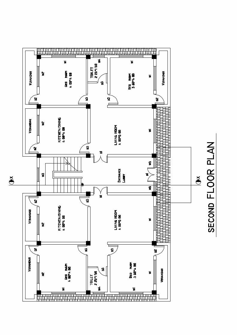


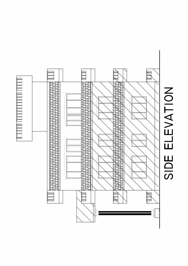


![Volume 17, Issue 4 No. 100 Nepal Telecom (Nepal ... · PDF fileVolume 17, Issue 4 No. 100 Nepal Telecom (Nepal Doorsanchar Co.Ltd.) Monthly, Kartik 2074 (November 2017) g]kfn b /;~rf](https://static.fdocuments.net/doc/165x107/5a9e53c27f8b9aee4a8d0546/volume-17-issue-4-no-100-nepal-telecom-nepal-17-issue-4-no-100-nepal-telecom.jpg)