NEMA offer Motor starters - Steven...
116
NEMA offer Motor starters Power applications Catalog March 2004 Courtesy of Steven Engineering, Inc.-230 Ryan Way, South San Francisco, CA 94080-6370-Main Office: (650) 588-9200-Outside Local Area: (800) 258-9200-www.stevenengineering.com
Transcript of NEMA offer Motor starters - Steven...

NEMA offerMotor startersPower applications Catalog
March
2004
Courtesy of Steven Engineering, Inc.-230 Ryan Way, South San Francisco, CA 94080-6370-Main Office: (650) 588-9200-Outside Local Area: (800) 258-9200-www.stevenengineering.com

Courtesy of Steven Engineering, Inc.-230 Ryan Way, South San Francisco, CA 94080-6370-Main Office: (650) 588-9200-Outside Local Area: (800) 258-9200-www.stevenengineering.com

General contents 0
Courtesy of Steven Engineering, Inc.-230 Ryan Way, South San Francisco, CA
NEMA offerMotor startersPower applications
1 – NEMA Rated Type S Contactors and Starters
2 – NEMA Rated Type S Combination Starters
3 – Solid State Overload Relays
4 – Definite Purpose Contactors
5 – Lighting Contactors
6 – Manual Starters and Switches
7 – Accessories
8 – Services
94080-6370-Main Office: (650) 588-9200-Outside Local Area: (800) 258-9200-www.stevenengineering.com

1/0Courtesy of Steven Engineering, Inc.-230 Ryan Way, South San Francisco
, CA 94080-6370-Main Office: (650) 588-9200-Outside Local Area: (800) 258-9200-www.stevenengineering.com
Contents
Courtesy of Steven Engineering, Inc.-230 Ryan Way, South San Francisco, CA
1 - NEMA Rated Type S Contactors and Starters
1
Selection guide . . . . . . . . . . . . . . . . . . . . . . . . . . . . . . . . . . . . . . . . . . . . . page 1/2b Contactors and starters
v General, characteristics . . . . . . . . . . . . . . . . . . . . . . . . . . . . . . . . . . . . page 1/4
b Contactors Class 8502
v References . . . . . . . . . . . . . . . . . . . . . . . . . . . . . . . . . . . . . . . . . . . . . page 1/6
b Reversing contactors Class 8702
v References . . . . . . . . . . . . . . . . . . . . . . . . . . . . . . . . . . . . . . . . . . . . . page 1/7
b Starters Class 8536
v References . . . . . . . . . . . . . . . . . . . . . . . . . . . . . . . . . . . . . . . . . . . . . page 1/8
b Reversing starters Class 8736
v References . . . . . . . . . . . . . . . . . . . . . . . . . . . . . . . . . . . . . . . . . . . . . page 1/9
b Contactors and starters
v Variants-Motor Logic® . . . . . . . . . . . . . . . . . . . . . . . . . . . . . . . . . . . . page 1/10
v Variants-Motor Logic Plus . . . . . . . . . . . . . . . . . . . . . . . . . . . . . . . . . page 1/11
v Variants . . . . . . . . . . . . . . . . . . . . . . . . . . . . . . . . . . . . . . . . . . . . . . . page 1/12
v Dimensions . . . . . . . . . . . . . . . . . . . . . . . . . . . . . . . . . . . . . . . . . . . . page 1/14
1/1 94080-6370-Main Office: (650) 588-9200-Outside Local Area: (800) 258-9200-www.stevenengineering.com
1
Courtesy
Selection guide 0 NEMA Rated Type S Contactors and Starters 0
Contactors and starters
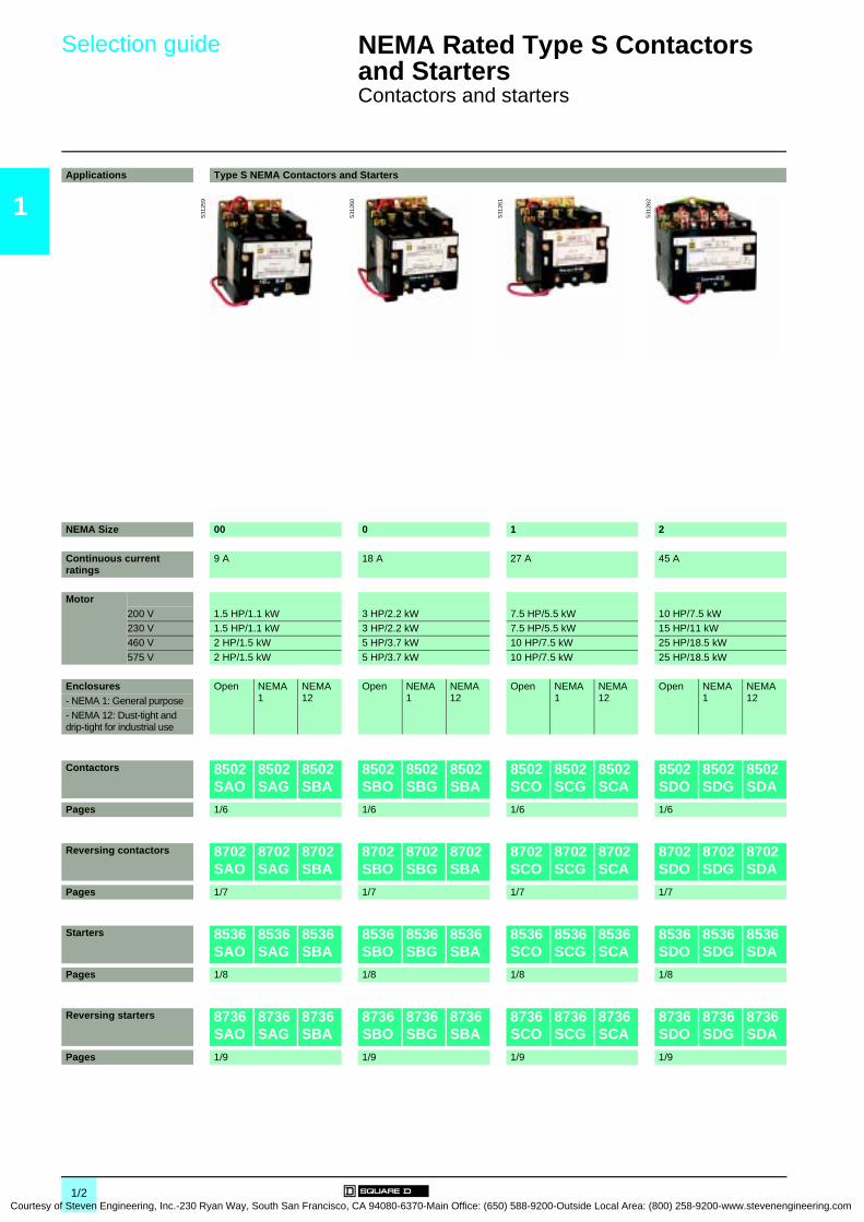
Applications Type S NEMA Contactors and Starters
NEMA Size 00 0 1 2
Continuous current ratings
9 A 18 A 27 A 45 A
Motor200 V 1.5 HP/1.1 kW 3 HP/2.2 kW 7.5 HP/5.5 kW 10 HP/7.5 kW230 V 1.5 HP/1.1 kW 3 HP/2.2 kW 7.5 HP/5.5 kW 15 HP/11 kW460 V 2 HP/1.5 kW 5 HP/3.7 kW 10 HP/7.5 kW 25 HP/18.5 kW
575 V 2 HP/1.5 kW 5 HP/3.7 kW 10 HP/7.5 kW 25 HP/18.5 kW
Enclosures Open NEMA 1
NEMA 12
Open NEMA 1
NEMA 12
Open NEMA 1
NEMA 12
Open NEMA 1
NEMA 12- NEMA 1: General purpose
- NEMA 12: Dust-tight and drip-tight for industrial use
Contactors 8502 SAO
8502 SAG
8502 SBA
8502 SBO
8502 SBG
8502 SBA
8502 SCO
8502 SCG
8502 SCA
8502 SDO
8502 SDG
8502 SDA
Pages 1/6 1/6 1/6 1/6
Reversing contactors 8702 SAO
8702 SAG
8702 SBA
8702 SBO
8702 SBG
8702 SBA
8702 SCO
8702 SCG
8702 SCA
8702 SDO
8702 SDG
8702 SDA
Pages 1/7 1/7 1/7 1/7
Starters 8536 SAO
8536 SAG
8536 SBA
8536 SBO
8536 SBG
8536 SBA
8536 SCO
8536 SCG
8536 SCA
8536 SDO
8536 SDG
8536 SDA
Pages 1/8 1/8 1/8 1/8
Reversing starters 8736 SAO
8736 SAG
8736 SBA
8736 SBO
8736 SBG
8736 SBA
8736 SCO
8736 SCG
8736 SCA
8736 SDO
8736 SDG
8736 SDA
Pages 1/9 1/9 1/9 1/9
5312
59
5312
60
5312
61
5312
62
1/2 of Steven Engineering, Inc.-230 Ryan Way, South San Francisco, CA 94080-6370-Main Office: (650) 588-9200-Outside Local Area: (800) 258-9200-www.stevenengineering.com

Courtesy of S
0
1
Type S NEMA Contactors and Starters3 4 5 6 7
90 A 135 A 270 A 540 A 810 A
25 HP/18.5 kW 40 HP/30 kW 75 HP/55 kW 150 HP/110 kW –30 HP/22 kW 50 HP/37 kW 100 HP/75 kW 200 HP/150 kW 300 HP/220 kW50 HP/37 kW 100 HP/75 kW 200 HP/150 kW 400 HP/300 kW 600 HP/450 kW
50 HP/37 kW 100 HP/75 kW 200 HP/150 kW 400 HP/300 kW 600 HP/450 kW
Open NEMA 1
NEMA 12
Open NEMA 1
NEMA 12
Open NEMA 1
NEMA 12
Open NEMA 1
NEMA 12
Open NEMA 1
NEMA 12
8502 SEO
8502 SEG
8502 SEA
8502 SFO
8502 SFG
8502 SFA
8502 SGO
8502 SGG
8502 SGA
8502 SHO
8502 SHG
8502 SHA
8502 SJO
8502 SJG
8502 SJA
1/6 1/6 1/6 1/6 1/6
8702 SEO
8702 SEG
8702 SEA
8702 SFO
8702 SFG
8702 SFA
8702 SGO
8702 SGG
8702 SGA
8702 SHO
8702 SHG
8702 SHA
8702 SJO
8702 SJG
8702 SJA
1/7 1/7 1/7 1/7 1/7
8536 SEO
8536 SEG
8536 SEA
8536 SFO
8536 SFG
8536 SFA
8536 SGO
8536 SGG
8536 SGA
8536 SHO
8536 SHG
8536 SHA
8536 SJO
8536 SJG
8536 SJA
1/8 1/8 1/8 1/8 1/8
8736 SEO
8736 SEG
8736 SEA
8736 SFO
8736 SFG
8736 SFA
8736 SGO
8736 SGG
8736 SGA
8736 SHO
8736 SHG
8736 SHA
8736 SJO
8736 SJG
8736 SJA
1/9 1/9 1/9 1/9 1/9
5312
63
5312
64
5312
65
5312
66
5312
66
1/3teven Engineering, Inc.-230 Ryan Way, South San Francisco, CA 94080-6370-Main Office: (650) 588-9200-Outside Local Area: (800) 258-9200-www.stevenengineering.com
1
Courtesy
General,characteristics 0
NEMA Rated Type S Contactors and Starters 0
Contactors and starters
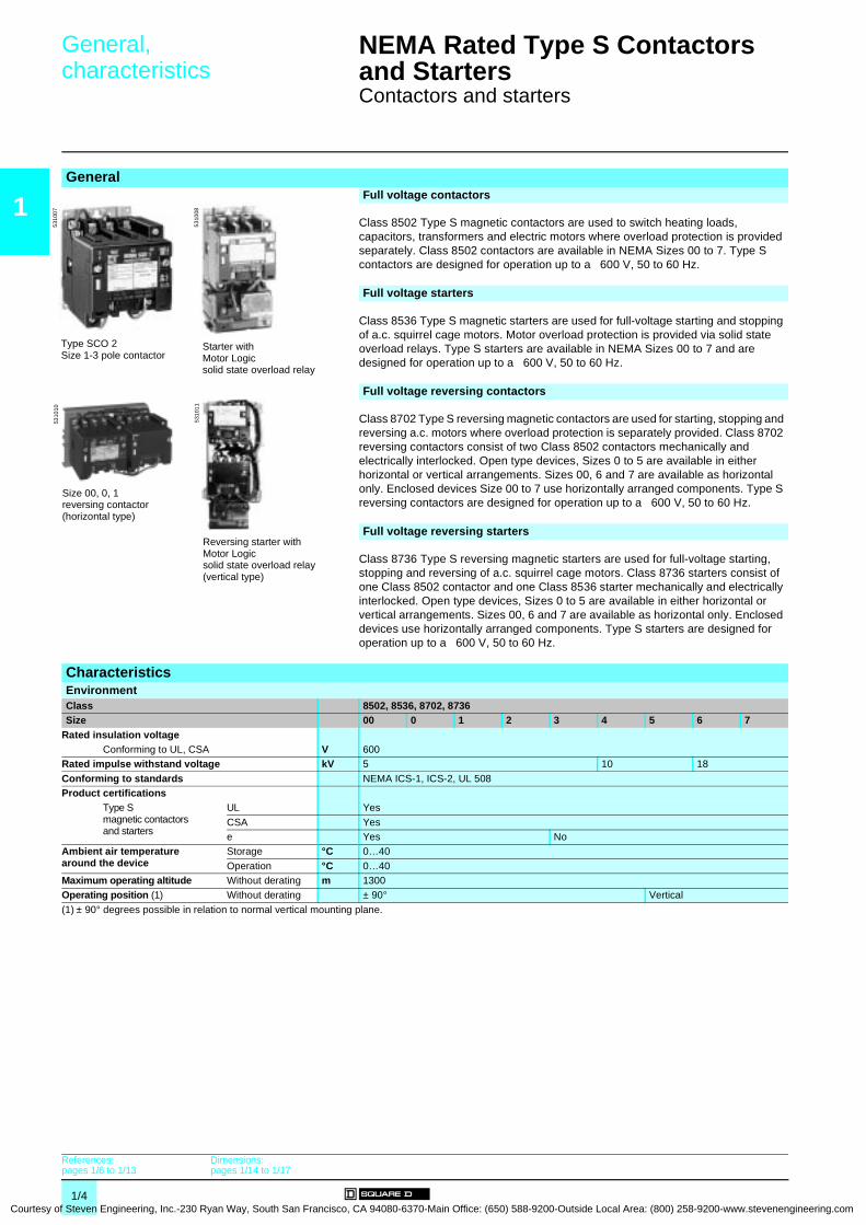
GeneralFull voltage contactors
Class 8502 Type S magnetic contactors are used to switch heating loads, capacitors, transformers and electric motors where overload protection is provided separately. Class 8502 contactors are available in NEMA Sizes 00 to 7. Type S contactors are designed for operation up to a 600 V, 50 to 60 Hz.
Full voltage starters
Class 8536 Type S magnetic starters are used for full-voltage starting and stopping of a.c. squirrel cage motors. Motor overload protection is provided via solid state overload relays. Type S starters are available in NEMA Sizes 00 to 7 and are designed for operation up to a 600 V, 50 to 60 Hz.
Full voltage reversing contactors
Class 8702 Type S reversing magnetic contactors are used for starting, stopping and reversing a.c. motors where overload protection is separately provided. Class 8702 reversing contactors consist of two Class 8502 contactors mechanically and electrically interlocked. Open type devices, Sizes 0 to 5 are available in either horizontal or vertical arrangements. Sizes 00, 6 and 7 are available as horizontal only. Enclosed devices Size 00 to 7 use horizontally arranged components. Type S reversing contactors are designed for operation up to a 600 V, 50 to 60 Hz.
Full voltage reversing starters
Class 8736 Type S reversing magnetic starters are used for full-voltage starting, stopping and reversing of a.c. squirrel cage motors. Class 8736 starters consist of one Class 8502 contactor and one Class 8536 starter mechanically and electrically interlocked. Open type devices, Sizes 0 to 5 are available in either horizontal or vertical arrangements. Sizes 00, 6 and 7 are available as horizontal only. Enclosed devices use horizontally arranged components. Type S starters are designed for operation up to a 600 V, 50 to 60 Hz.
CharacteristicsEnvironmentClass 8502, 8536, 8702, 8736Size 00 0 1 2 3 4 5 6 7
Rated insulation voltage Conforming to UL, CSA V 600Rated impulse withstand voltage kV 5 10 18
Conforming to standards NEMA ICS-1, ICS-2, UL 508Product certifications
Type Smagnetic contactors and starters
UL Yes
CSA Yese Yes No
Ambient air temperature around the device
Storage °C 0…40
Operation °C 0…40Maximum operating altitude Without derating m 1300Operating position (1) Without derating ± 90° Vertical
(1) ± 90° degrees possible in relation to normal vertical mounting plane.
Type SCO 2Size 1-3 pole contactor
5310
07
Starter withMotor Logicsolid state overload relay
5310
08
Size 00, 0, 1reversing contactor(horizontal type)
5310
10
Reversing starter with Motor Logicsolid state overload relay(vertical type)
5310
11
References:pages 1/6 to 1/13
Dimensions:pages 1/14 to 1/17
1/4 of Steven Engineering, Inc.-230 Ryan Way, South San Francisco, CA 94080-6370-Main Office: (650) 588-9200-Outside Local Area: (800) 258-9200-www.stevenengineering.com

Courtesy of S
Characteristics (continued) 0 NEMA Rated Type S Contactors and Starters 0
Contactors and starters
1
Characteristics (continued)Pole characteristicsClass 8502, 8536, 8702, 8736Size 00 0 1 2 3 4 5 6 7
Number of poles 3-pole devices 3
Rated operational voltage Up to V 600Frequency limits Of the operational current Hz 50/60Conventional rated thermal current A 9 18 27 45 90 135 270 540 810
Rated making capacity At 600 V 10 x rated currentRated breaking capacity At 600 V 10 x rated currentPermissible short time rating
Service limit current A 11 21 32 52 104 156 311 621 932
a.c. control circuit characteristicsClass 8502, 8536, 8702, 8736Size 00 0 1 2 3 4 5 6 7
Rated control circuit voltage V 600Average consumption 50 Hz Inrush VA N/A 232 232 296 676 1260 1300 1495 (1) –
Sealed VA N/A 26 26 36 47 89 14 56 (1) –
Average consumption 60 Hz Inrush VA 165 245 245 311 700 1185 1300 1780 (1) 1960 (1)Sealed VA 33 27 27 37 46 85 14 48 (1) 59 (1)
Heat dissipation 50/60Hz 50 Hz W N/A 7.7 7.7 12 15 23.4 13 27 –
60 Hz W 6 7.8 7.8 14 14 22 13 32 36Operating time (2) Closing "C" ms 9.1 -23.2 8.4 -20.1 8.4 -20.1 14.6 -27.6 17.3 -32.3 13.0-43.9 40 -60 57.0-74.0 43.8
Opening "O" ms 5.29 -15.9 2.4 -15.9 2.4 -15.9 16.3 -22.8 9.6 -18.7 11.2 -21.7 50 -75 28.3 -31.8 54.3
Mechanical life In millions of op. cycles 6 10 10 10 5 3 2 1.5 0.5Maximum operating rate (3) In op. cycles per hour 9000 9000 9000 5400 4500 4500 180 180 180
Power circuit connections (connection via lug) Type of lug Screw clamp terminal Box lug Parallel groove
Wire sizes (Min./max.) Solid or stranded copper wire (AWG)
#14-#8 #14-#8 #14-#8 #14-#4 #14-#1/0 #8-250kcmil
#4-500kcmil
1 or 2, 250-500kcmil per phase
1 to 4, 250-500kcmil per phase
Control circuit connections (connection via lug) Type of lug Screw clamp terminal
Wire sizes (Min./max.) Solid or stranded copper wire (AWG)
#16-#12
(1) Size 6 and 7 have a d.c. coil. The values shown are for the a.c. input to the d.c. power supply that provides power to the coil.(2) The closing time "C" is measured from the moment that the coil supply is switched on to the initial contact of the main poles. The opening time "O" is measured
from the moment that the coil supply is switched off to the moment that the main poles separate.(3) Operating cycles are without a load (mechanical life).
References:pages 1/6 to 1/13
Dimensions:pages 1/14 to 1/17
1/5teven Engineering, Inc.-230 Ryan Way, South San Francisco, CA 94080-6370-Main Office: (650) 588-9200-Outside Local Area: (800) 258-9200-www.stevenengineering.com
1
Courtesy
References 0 NEMA Rated Type S Contactors and Starters 0
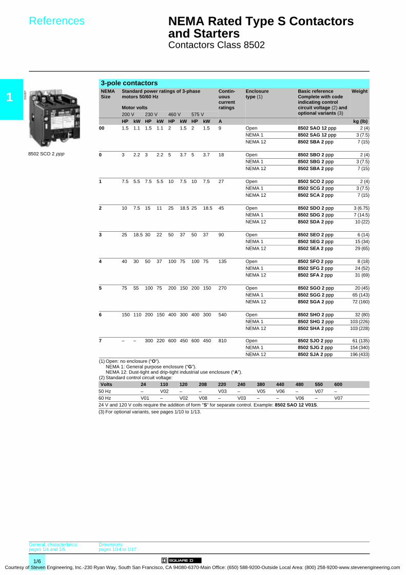
Contactors Class 8502
3-pole contactorsNEMA Size
Standard power ratings of 3-phase motors 50/60 Hz
Motor volts
Contin-uous current ratings
Enclosuretype (1)
Basic referenceComplete with code indicating control circuit voltage (2) and optional variants (3)
Weight
200 V 230 V 460 V 575 V
HP kW HP kW HP kW HP kW A kg (lb)00 1.5 1.1 1.5 1.1 2 1.5 2 1.5 9 Open 8502 SAO 12 ppp 2 (4)
NEMA 1 8502 SAG 12 ppp 3 (7.5)
NEMA 12 8502 SBA 2 ppp 7 (15)
0 3 2.2 3 2.2 5 3.7 5 3.7 18 Open 8502 SBO 2 ppp 2 (4)NEMA 1 8502 SBG 2 ppp 3 (7.5)
NEMA 12 8502 SBA 2 ppp 7 (15)
1 7.5 5.5 7.5 5.5 10 7.5 10 7.5 27 Open 8502 SCO 2 ppp 2 (4)NEMA 1 8502 SCG 2 ppp 3 (7.5)
NEMA 12 8502 SCA 2 ppp 7 (15)
2 10 7.5 15 11 25 18.5 25 18.5 45 Open 8502 SDO 2 ppp 3 (6.75)NEMA 1 8502 SDG 2 ppp 7 (14.5)
NEMA 12 8502 SDA 2 ppp 10 (22)
3 25 18.5 30 22 50 37 50 37 90 Open 8502 SEO 2 ppp 6 (14)NEMA 1 8502 SEG 2 ppp 15 (34)
NEMA 12 8502 SEA 2 ppp 29 (65)
4 40 30 50 37 100 75 100 75 135 Open 8502 SFO 2 ppp 8 (18)
NEMA 1 8502 SFG 2 ppp 24 (52)NEMA 12 8502 SFA 2 ppp 31 (69)
5 75 55 100 75 200 150 200 150 270 Open 8502 SGO 2 ppp 20 (45)
NEMA 1 8502 SGG 2 ppp 65 (143)NEMA 12 8502 SGA 2 ppp 72 (160)
6 150 110 200 150 400 300 400 300 540 Open 8502 SHO 2 ppp 32 (80)
NEMA 1 8502 SHG 2 ppp 103 (226)NEMA 12 8502 SHA 2 ppp 103 (228)
7 – – 300 220 600 450 600 450 810 Open 8502 SJO 2 ppp 61 (135)NEMA 1 8502 SJG 2 ppp 154 (340)
NEMA 12 8502 SJA 2 ppp 196 (433)(1) Open: no enclosure (“O”).
NEMA 1: General purpose enclosure (“G”).NEMA 12: Dust-tight and drip-tight industrial use enclosure (“A”).
(2) Standard control circuit voltage:Volts 24 110 120 208 220 240 380 440 480 550 600
50 Hz – V02 – – V03 – V05 V06 – V07 –60 Hz V01 – V02 V08 – V03 – – V06 – V0724 V and 120 V coils require the addition of form "S" for separate control. Example: 8502 SAO 12 V01S.
(3) For optional variants, see pages 1/10 to 1/13.
8502 SCO 2 ppp
5310
07
General, characteristics:pages 1/4 and 1/5
Dimensions:pages 1/14 to 1/17
1/6 of Steven Engineering, Inc.-230 Ryan Way, South San Francisco, CA 94080-6370-Main Office: (650) 588-9200-Outside Local Area: (800) 258-9200-www.stevenengineering.com

Courtesy of S
References 0 NEMA Rated Type S Contactors and Starters 0
Reversing contactors Class 8702
1
3-pole reversing contactorsNEMA SizeStandard power ratings of 3-phase motors 50/60 Hz
Motor volts
Contin-uous current ratings
Enclosuretype (1)
Basic referenceComplete with code indicating control circuit voltage (2) and optional variants (3)
Weight
200 V 230 V 460 V 575 V
HP kW HP kW HP kW HP kW A kg (lb)00 1.5 1.1 1.5 1.1 2 1.5 2 1.5 9 Open/Horizontal Type 8702 SAO 4 ppp 5 (12)
NEMA 1 8702 SAG 4 ppp 7 (16)
NEMA 12 8702 SBA 4 ppp 10 (23)
0 3 2.2 3 2.2 5 3.7 5 3.7 18 Open/Vertical Type 8702 SBO 12 ppp 5 (12)Open/Horizontal Type 8702 SBO 4 ppp 5 (12)
NEMA 1 8702 SBG 4 ppp 7 (16)NEMA 12 8702 SBA 4 ppp 10 (23)
1 7.5 5.5 7.5 5.5 10 7.5 10 7.5 27 Open/Vertical Type 8702 SCO 7 ppp 5 (12)
Open/Horizontal Type 8702 SCO 8 ppp 5 (12)NEMA 1 8702 SCG 8 ppp 7 (16)NEMA 12 8702 SCA 4 ppp 10 (23)
2 10 7.5 15 11 25 18.5 25 18.5 45 Open/Vertical Type 8702 SDO 1 ppp 7 (16)Open/Horizontal Type 8702 SDO 2 ppp 7 (16)NEMA 1 8702 SDG 2 ppp 11 (24)
NEMA 12 8702 SDA 1 ppp 14 (31)
3 25 18.5 30 22 50 37 50 37 90 Open/Vertical Type 8702 SEO 1 ppp 15 (35)Open/Horizontal Type 8702 SEO 2 ppp 15 (35)
NEMA 1 8702 SEG 2 ppp 43 (95)NEMA 12 8702 SEA 1 ppp 44 (96)
4 40 30 50 37 100 75 100 75 135 Open/Vertical Type 8702 SFO 1 ppp 20 (45)Open/Horizontal Type 8702 SFO 3 ppp 20 (45)NEMA 1 8702 SFG 3 ppp 43 (95)
NEMA 12 8702 SFA 1 ppp 44 (96)
5 75 55 100 75 200 150 200 150 270 Open/Vertical Type 8702 SGO 1 ppp 44 (98)Open/Horizontal Type 8702 SGO 3 ppp 44 (98)
NEMA 1 8702 SGG 3 ppp 135 (298)NEMA 12 8702 SGA 1 ppp 137 (302)
6 150 110 200 150 400 300 400 300 540 Open/Horizontal Type 8702 SHO 1 ppp 88 (195)
NEMA 1 8702 SHG 1 ppp 181 (400)NEMA 12 8702 SHA 1 ppp 222 (490)
7 – – 300 220 600 450 600 450 810 Open/Horizontal Type 8702 SJO 1 ppp 141 (310)NEMA 1 8702 SJG 1 ppp 233 (514)
NEMA 12 8702 SJA 1 ppp 275 (607)(1) Open: no enclosure (“O”).
NEMA 1: General purpose enclosure (“G”).NEMA 12: Dust-tight and drip-tight industrial use enclosure (“A”).
(2) Standard control circuit voltage:Volts 24 110 120 208 220 240 380 440 480 550 600
50 Hz – V02 – – V03 – V05 V06 – V07 –60 Hz V01 – V02 V08 – V03 – – V06 – V0724 V and 120 V coils require the addition of form "S" for separate control. Example: 8702 SAO 4 V01S.
(3) For optional variants, see pages 1/10 to 1/13.
8702 SAO 4 ppp(horizontal type)
5310
10
General, characteristics:pages 1/4 and 1/5
Dimensions:pages 1/14 to 1/17
1/7teven Engineering, Inc.-230 Ryan Way, South San Francisco, CA 94080-6370-Main Office: (650) 588-9200-Outside Local Area: (800) 258-9200-www.stevenengineering.com

1
Courtesy
References 0 NEMA Rated Type S Contactors and Starters 0
Starters Class 8536
3-pole startersNEMA Size
Standard power ratings of 3-phase motors 50/60 Hz
Motor volts
Contin-uous current ratings
Enclosure type (1)
Basic referenceComplete with code indicating control circuit voltage (2) and optional variants (3) and “H” code (4)
Weight
200 V 230 V 460 V 575 VHP kW HP kW HP kW HP kW A kg (lb)
00 1.5 1.1 1.5 1.1 2 1.5 2 1.5 9 Open 8536 SAO 12 (2) (3) (4) 2 (4)NEMA 1 8536 SAG 12 (2) (3) (4) 3 (8)NEMA 12 8536 SBA 2 (2) (3) (4) 7 (16)
0 3 2.2 3 2.2 5 3.7 5 3.7 18 Open 8536 SBO 2 (2) (3) (4) 2 (4)NEMA 1 8536 SBG 2 (2) (3) (4) 4 (8)NEMA 12 8536 SBA 2 (2) (3) (4) 7 (16)
1 7.5 5.5 7.5 5.5 10 7.5 10 7.5 27 Open 8536 SCO 3 (2) (3) (4) 2 (4)NEMA 1 8536 SCG 3 (2) (3) (4) 3 (8)NEMA 12 8536 SCA 3 (2) (3) (4) 7 (16)
2 10 7.5 15 11 25 18.5 25 18.5 45 Open 8536 SDO 1 (2) (3) (4) 3 (6.75)NEMA 1 8536 SDG 1 (2) (3) (4) 7 15.5)NEMA 12 8536 SDA 1 (2) (3) (4) 10 (23)
3 25 18.5 30 22 50 37 50 37 90 Open 8536 SEO 1 (2) (3) (4) 6 (14)NEMA 1 8536 SEG 1 (2) (3) (4) 17 (37)NEMA 12 8536 SEA 1 (2) (3) (4) 31 (68)
4 40 30 50 37 100 75 100 75 135 Open 8536 SFO 1 (2) (3) (4) 8 (18)NEMA 1 8536 SFG 1 (2) (3) (4) 25 (56)
NEMA 12 8536 SFA 1 (2) (3) (4) 33 (73)
5 75 55 100 75 200 150 200 150 270 Open 8536 SGO 1 (2) (3) (4) 20 (45)NEMA 1 8536 SGG 1 (2) (3) (4) 73 (160)
NEMA 12 8536 SGA 1 (2) (3) (4) 80 (177)
6 150 110 200 150 400 300 400 300 540 Open 8536 SHO 2 (2) (3) (4) 32 (80)NEMA 1 8536 SHG 2 (2) (3) (4) 105 (231)
NEMA 12 8536 SHA 2 (2) (3) (4) 106 (233)
7 – – 300 220 600 450 600 450 810 Open 8536 SJO 2 (2) (3) (4) 61 (135)NEMA 1 8536 SJG 2 (2) (3) (4) 130 (287)NEMA 12 8536 SJA 2 (2) (3) (4) 140 (309)
(1) Open: no enclosure (“O”).NEMA 1: General purpose enclosure (“G”).NEMA 12: Dust-tight and drip-tight industrial use enclosure (“A”).
(2) Standard control circuit voltage:Volts 24 110 120 208 220 240 380 440 480 550 600
50 Hz – V02 – – V03 – V05 V06 – V07 –
60 Hz V01 – V02 V08 – V03 – – V06 – V0724 V and 120 V coils require the addition of form "S" for separate control. Example: 8536 SAO 12 V01 H10S.(3) For optional variants, see pages 1/10 to 1/13. (4) To complete the "H" code for solid state overload relays, see page 1/10.
8536 SAO 12 V02 H20
5310
08
General, characteristics:pages 1/4 and 1/5
Dimensions:pages 1/14 to 1/17
1/8 of Steven Engineering, Inc.-230 Ryan Way, South San Francisco, CA 94080-6370-Main Office: (650) 588-9200-Outside Local Area: (800) 258-9200-www.stevenengineering.com
Courtesy of S
References 0 NEMA Rated Type S Contactors and Starters 0
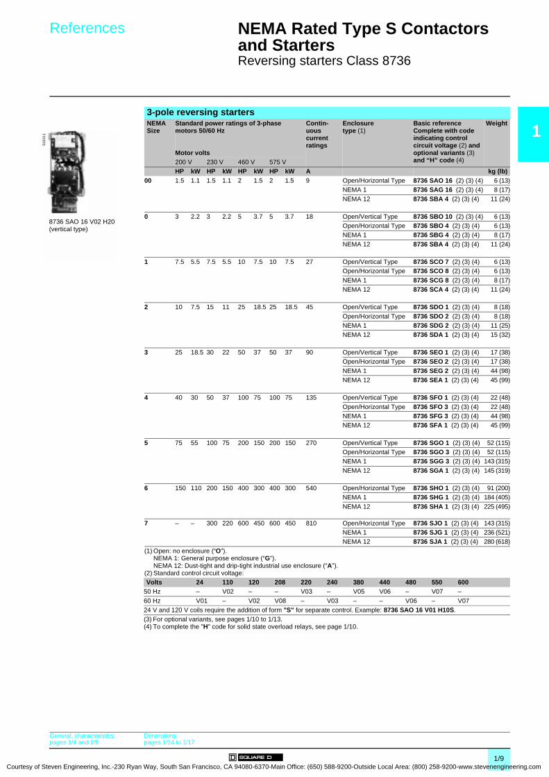
Reversing starters Class 8736
1
3-pole reversing startersNEMA SizeStandard power ratings of 3-phase motors 50/60 Hz
Motor volts
Contin-uous current ratings
Enclosure type (1)
Basic referenceComplete with code indicating control circuit voltage (2) and optional variants (3) and “H” code (4)
Weight
200 V 230 V 460 V 575 VHP kW HP kW HP kW HP kW A kg (lb)
00 1.5 1.1 1.5 1.1 2 1.5 2 1.5 9 Open/Horizontal Type 8736 SAO 16 (2) (3) (4) 6 (13)NEMA 1 8736 SAG 16 (2) (3) (4) 8 (17)NEMA 12 8736 SBA 4 (2) (3) (4) 11 (24)
0 3 2.2 3 2.2 5 3.7 5 3.7 18 Open/Vertical Type 8736 SBO 10 (2) (3) (4) 6 (13)Open/Horizontal Type 8736 SBO 4 (2) (3) (4) 6 (13)NEMA 1 8736 SBG 4 (2) (3) (4) 8 (17)
NEMA 12 8736 SBA 4 (2) (3) (4) 11 (24)
1 7.5 5.5 7.5 5.5 10 7.5 10 7.5 27 Open/Vertical Type 8736 SCO 7 (2) (3) (4) 6 (13)Open/Horizontal Type 8736 SCO 8 (2) (3) (4) 6 (13)
NEMA 1 8736 SCG 8 (2) (3) (4) 8 (17)NEMA 12 8736 SCA 4 (2) (3) (4) 11 (24)
2 10 7.5 15 11 25 18.5 25 18.5 45 Open/Vertical Type 8736 SDO 1 (2) (3) (4) 8 (18)
Open/Horizontal Type 8736 SDO 2 (2) (3) (4) 8 (18)NEMA 1 8736 SDG 2 (2) (3) (4) 11 (25)NEMA 12 8736 SDA 1 (2) (3) (4) 15 (32)
3 25 18.5 30 22 50 37 50 37 90 Open/Vertical Type 8736 SEO 1 (2) (3) (4) 17 (38)Open/Horizontal Type 8736 SEO 2 (2) (3) (4) 17 (38)
NEMA 1 8736 SEG 2 (2) (3) (4) 44 (98)NEMA 12 8736 SEA 1 (2) (3) (4) 45 (99)
4 40 30 50 37 100 75 100 75 135 Open/Vertical Type 8736 SFO 1 (2) (3) (4) 22 (48)
Open/Horizontal Type 8736 SFO 3 (2) (3) (4) 22 (48)NEMA 1 8736 SFG 3 (2) (3) (4) 44 (98)NEMA 12 8736 SFA 1 (2) (3) (4) 45 (99)
5 75 55 100 75 200 150 200 150 270 Open/Vertical Type 8736 SGO 1 (2) (3) (4) 52 (115)Open/Horizontal Type 8736 SGO 3 (2) (3) (4) 52 (115)NEMA 1 8736 SGG 3 (2) (3) (4) 143 (315)
NEMA 12 8736 SGA 1 (2) (3) (4) 145 (319)
6 150 110 200 150 400 300 400 300 540 Open/Horizontal Type 8736 SHO 1 (2) (3) (4) 91 (200)NEMA 1 8736 SHG 1 (2) (3) (4) 184 (405)
NEMA 12 8736 SHA 1 (2) (3) (4) 225 (495)
7 – – 300 220 600 450 600 450 810 Open/Horizontal Type 8736 SJO 1 (2) (3) (4) 143 (315)NEMA 1 8736 SJG 1 (2) (3) (4) 236 (521)NEMA 12 8736 SJA 1 (2) (3) (4) 280 (618)
(1) Open: no enclosure (“O”).NEMA 1: General purpose enclosure (“G”).NEMA 12: Dust-tight and drip-tight industrial use enclosure (“A”).
(2) Standard control circuit voltage:Volts 24 110 120 208 220 240 380 440 480 550 600
50 Hz – V02 – – V03 – V05 V06 – V07 –
60 Hz V01 – V02 V08 – V03 – – V06 – V0724 V and 120 V coils require the addition of form "S" for separate control. Example: 8736 SAO 16 V01 H10S.(3) For optional variants, see pages 1/10 to 1/13. (4) To complete the "H" code for solid state overload relays, see page 1/10.
8736 SAO 16 V02 H20(vertical type)
5310
11
General, characteristics:pages 1/4 and 1/5
Dimensions:pages 1/14 to 1/17
1/9teven Engineering, Inc.-230 Ryan Way, South San Francisco, CA 94080-6370-Main Office: (650) 588-9200-Outside Local Area: (800) 258-9200-www.stevenengineering.com
1
Courtesy
References, associations 0
NEMA Rated Type S Contactors and Starters 0
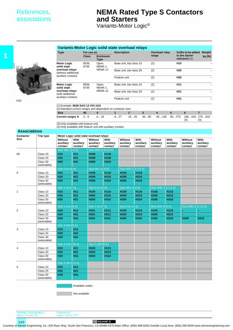
Variants-Motor Logic®
Variants-Motor Logic solid state overload relaysType For use on Description Overload relay
rangeSuffix to be added to the starter reference (1)
WeightClass Enclosure
Typekg (lb)
Motor Logic solid state overload relays(without additional auxiliary contact)
8536, 8736
Open, NEMA 1, NEMA 12
Base unit, trip class 10 (2) H10 –
Base unit, trip class 20 (2) H20 –
Feature unit (2) H30 –
Motor Logic solid state overload relays(with additional auxiliary contact)
8536, 8736
Open, NEMA 1, NEMA 12
Base unit, trip class 10 (2) H11 –
Base unit, trip class 20 (2) H21 –
Feature unit (2) H31 –
(1) Example: 8536 SAO 12 V01 H10.(2) Standard current ranges and dependent on contactor size: Size 00 0 1 2 3 4 5 6 7
Current ranges A 3…9 6…18 9…27 15…45 30…90 40…135 90…270 180…540 (3)
270…810 (4)
(3) Only available with feature unit.(4) Only available with feature unit with auxiliary contact.
AssociationsContactorSize
Trip type Motor Logic solid state overload relaysWithout auxiliary contact
With auxiliary contact
Without auxiliary contact
With auxiliary contact
Without auxiliary contact
With auxiliary contact
Without auxiliary contact
With auxiliary contact
Without auxiliary contact
With auxiliary contact
Size 00C (3-9 A) Size 00B (1.5-4.5 A)
00 Class 10 H10 H11 H108 H118Class 20 H20 H21 H208 H218Class 30 (selectable)
H30 H31 H308 H318
Size 0 (6-18 A) Size 00C (3-9 A) Size 00B (1.5-4.5 A)
0 Class 10 H10 H11 H109 H119 H108 H118Class 20 H20 H21 H209 H219 H208 H218Class 30 (selectable)
H30 H31 H309 H319 H308 H318
Size 1 (9-27 A) Size 0 (6-18 A) Size 00C (3-9 A) Size 00B (1.5-4.5 A)
1 Class 10 H10 H11 H100 H110 H109 H119 H108 H118Class 20 H20 H21 H200 H210 H209 H219 H208 H218Class 30 (selectable)
H30 H31 H300 H310 H309 H319 H308 H318
Size 2 (15-45 A) Size 1 (9-27 A) Size 0 (6-18 A) Size 00C (3-9 A) Size 00B (1.5-4.5 A)
2 Class 10 H10 H11 H101 H111 H100 H110 H109 H119 – –Class 20 H20 H21 H201 H211 H200 H210 H209 H219 – –Class 30 (selectable)
H30 H31 H301 H311 H300 H310 H309 H319 H308 H318
Size 3 (30-90 A)
3 Class 10 H10 H11Class 20 H20 H21Class 30 (selectable)
H30 H31
Size 4 (45-135 A) Size 3 (30-90 A)
4 Class 10 H10 H11 H103 H113Class 20 H20 H21 H203 H213Class 30 (selectable)
H30 H31 H303 H313
Size 5 (90-270 A)
5 Class 10 H10 H11Class 20 H20 H21Class 30 (selectable)
H30 H31
Available codes
Not available
H10
5311
23
General, characteristics:pages 1/4 and 1/5
Dimensions:pages 1/14 to 1/17
1/10 of Steven Engineering, Inc.-230 Ryan Way, South San Francisco, CA 94080-6370-Main Office: (650) 588-9200-Outside Local Area: (800) 258-9200-www.stevenengineering.com

Courtesy of S
References (continued) 0 NEMA Rated Type S Contactors and Starters 0
Variants-Motor Logic Plus
1
(1) Example: 8536 SAO 12 V01 B20S.
Variants-Motor Logic Plus solid state overload relaysDescription For use on Motor Logic
Plus current ranges
Factory modification Suffix to be added to the starter reference (1)
WeightClass/Enclosure type
A kg (lb)Motor Logic Plus solid state overload relays
8536, 8736Open type
0.5…2.3 No modification for 200-480 V B20 –
Add communication module for 200-480 V B22 –No modification for 600 V B24 –Add communication module for 600 V B26 –
2…9 No modification for 200-480 V B30 –Add communication module for 200-480 V B32 –No modification for 600 V B34 –
Add communication module for 600 V B36 –6…27 No modification for 200-480 V B40 –
Add communication module for 200-480 V B42 –
No modification for 600 V B44 –Add communication module for 600 V B46 –
10…45 No modification for 200-480 V B50 –
Add communication module for 200-480 V B52 –No modification for 600 V B54 –Add communication module for 600 V B56 –
20…90 No modification for 200-480 V B60 –Add communication module for 200-480 V B62 –No modification for 600 V B64 –
Add communication module for 600 V B66 –60…135 No modification for 200-480 V B70 –
Add communication module for 200-480 V B72 –No modification for 600 V B74 –Add communication module for 600 V B76 –
120…270 No modification for 200-480 V B80 –Add communication module for 200-480 V B82 –No modification for 600 V B84 –
Add communication module for 600 V B86 –240…540 No modification for 200-480 V B90 –
Add communication module for 200-480 V B92 –
No modification for 600 V B94 –Add communication module for 600 V B96 –
B20
5312
02
General, characteristics:pages 1/4 and 1/5
Dimensions:pages 1/14 to 1/17
1/11teven Engineering, Inc.-230 Ryan Way, South San Francisco, CA 94080-6370-Main Office: (650) 588-9200-Outside Local Area: (800) 258-9200-www.stevenengineering.com

1
Courtesy
References 0 NEMA Rated Type S Contactors and Starters 0
Variants
Variants-OperatorsDescription For use on Colour/Marking Suffix to be added
to the contactor or starter reference (1)
WeightClass Enclosure
typekg (lb)
Push buttons 8502, 8536 NEMA 1, 12 "Start-Stop" A –
8702, 8736 NEMA 1, 12 "Forward-Reverse-Stop" A1 –"High-Low-Stop" A2 –
Pilot lightswithout operating interlock(2)
8502, 8536, 8702, 8736
NEMA 1 Red P1 –
Green P2 –Amber P3 –Clear P4 –
Push-to-test pilot lightswithout operating interlock(2)
8502, 8536, 8702, 8736
NEMA 12 Red P21 –Green P22 –Amber P23 –
Clear P24 –Yellow P25 –
LED pilot lights 8502, 8536, 8702, 8736
NEMA 1 Red P51 –
Green P52 –Yellow P55 –
Special wiring 8502, 8536, 8702, 8736
NEMA 1 Red/"Off" P71 –
Green/"On" P72 –Selector switches 8502, 8536,
8702, 8736NEMA 1,NEMA 12
"Hand-Off-Auto" C –
8702, 8736 NEMA 1,NEMA 12
"On-Off" C6 –"Forward-Off-Reverse" C14 –
"Forward-Reverse" C20 –
Variants-TransformersDescription For use on Functions Suffix to be added
to the contactor or starter reference (1)
WeightClass Enclosure
typekg (lb)
Separate control circuit 8502, 8536,8702, 8736
NEMA 1, 12 Specify voltage and frequency S –
Fused control circuitwithout transformer
8502, 8536,8702, 8736
NEMA 1, 12 One fuse F –Two fuses F4 –
Control circuit transformersstandard capacity (50/60 Hz) (3)
8502, 8536,8702, 8736
NEMA 1, 12 Fuses: 2 (primary), 0 (secondary) F4T (4) –Fuses: 1 (primary), 1 (secondary) (5) FF1T –Fuses: 2 (primary), 1 (secondary) FF4T –
Fuses: 1 (primary), 2 (secondary) (5) F1F10T –Fuses: 2 (primary), 2 (secondary) F4F10T –
Additional capacity(50/60 Hz) Two fuses in primary (3)
8502, 8536,8702, 8736
NEMA 1, 12 100 VA additional capacity F4T11 (6) –
200 VA additional capacity F4T12 (6) –
Additional capacity(50/60 Hz) Two fuses in primary and one fuse in secondary (3)
8502, 8536,8702, 8736
NEMA 1, 12 100 VA additional capacity FF4T11 –
(1) Example: 8536 SAG 12 V01 A P1 P2. All suffix are listed in alphanumeric order after the voltage code.(2) Unless otherwise requested, the standard practice is to wire the red pilot light to indicate that the device is energized. No
additional auxiliary contact is required. Also, standard practice is to wire the green pilot light to indicate that the device is de-energized. An additional normally closed auxiliary contact is required; please consult your Regional Sales Office.
(3) Control circuit transformer selection table:
Primary-secondary 120-12 (7)
120-24 (8)
208-120 240-24 (8)
240-120 277-120 480-24 (8)
480-120 480-240 600-120
60 Hz V88 V89 V84 V82 V80 V85 V83 V81 V87 V86Example: 8536 SAG 12 V81 F4T A P1 P2.(4) Not available with 24 V secondary on Size 3. Select appropriate transformer with secondary fuse protection. See transformer
selection table.(5) Single phase with one leg earthed or earthed 3-phase applications only.(6) Not available with 24 V secondary. Select appropriate transformer with secondary fuse protection. See transformer selection
table for 24 V secondary restrictions.(7) 12 V coils are not available on Sizes 3-7.(8) 24 V coils are not available on Sizes 4-7.
General, characteristics:pages 1/4 and 1/5
Dimensions:pages 1/14 to 1/17
1/12 of Steven Engineering, Inc.-230 Ryan Way, South San Francisco, CA 94080-6370-Main Office: (650) 588-9200-Outside Local Area: (800) 258-9200-www.stevenengineering.com
Courtesy of S
References (continued) 0 NEMA Rated Type S Contactors and Starters 0
Variants
1
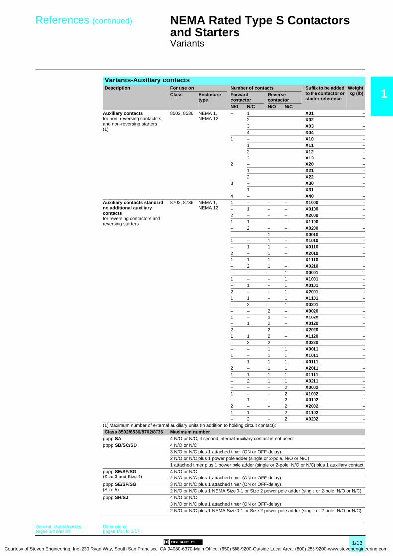
Variants-Auxiliary contactsDescription For use on Number of contacts Suffix to be addedto the contactor or starter reference
Weightkg (lb)Class Enclosure
typeForward contactor
Reverse contactor
N/O N/C N/O N/CAuxiliary contactsfor non–reversing contactors and non-reversing starters (1)
8502, 8536 NEMA 1, NEMA 12
– 1 X01 –2 X02 –3 X03 –4 X04 –
1 – X10 –1 X11 –2 X12 –3 X13 –
2 – X20 –1 X21 –2 X22 –
3 – X30 –1 X31 –
4 – X40 –Auxiliary contacts standard no additional auxiliary contactsfor reversing contactors and reversing starters
8702, 8736 NEMA 1, NEMA 12
1 – – – X1000 –– 1 – – X0100 –2 – – – X2000 –1 1 – – X1100 –– 2 – – X0200 –– – 1 – X0010 –1 – 1 – X1010 –– 1 1 – X0110 –2 – 1 – X2010 –1 1 1 – X1110 –– 2 1 – X0210 –– – – 1 X0001 –1 – – 1 X1001 –– 1 – 1 X0101 –2 – – 1 X2001 –1 1 – 1 X1101 –– 2 – 1 X0201 –– – 2 – X0020 –1 – 2 – X1020 –– 1 2 – X0120 –2 – 2 – X2020 –1 1 2 – X1120 –– 2 2 – X0220 –– – 1 1 X0011 –1 – 1 1 X10¹¹ –– 1 1 1 X0111 –2 – 1 1 X2011 –1 1 1 1 X1111 –– 2 1 1 X0211 –– – – 2 X0002 –1 – – 2 X1002 –– 1 – 2 X0102 –2 – – 2 X2002 –1 1 – 2 X1102 –– 2 – 2 X0202 –
(1) Maximum number of external auxiliary units (in addition to holding circuit contact):Class 8502/8536/8702/8736 Maximum numberpppp SA 4 N/O or N/C, if second internal auxiliary contact is not usedpppp SB/SC/SD 4 N/O or N/C
3 N/O or N/C plus 1 attached timer (ON or OFF-delay)2 N/O or N/C plus 1 power pole adder (single or 2-pole, N/O or N/C)1 attached timer plus 1 power pole adder (single or 2-pole, N/O or N/C) plus 1 auxiliary contact
pppp SE/SF/SG(Size 3 and Size 4)
4 N/O or N/C2 N/O or N/C plus 1 attached timer (ON or OFF-delay)
pppp SE/SF/SG(Size 5)
3 N/O or N/C plus 1 attached timer (ON or OFF-delay)2 N/O or N/C plus 1 NEMA Size 0-1 or Size 2 power pole adder (single or 2-pole, N/O or N/C)
pppp SH/SJ 4 N/O or N/C3 N/O or N/C plus 1 attached timer (ON or OFF-delay)2 N/O or N/C plus 1 NEMA Size 0-1 or Size 2 power pole adder (single or 2-pole, N/O or N/C)
General, characteristics:pages 1/4 and 1/5
Dimensions:pages 1/14 to 1/17
1/13teven Engineering, Inc.-230 Ryan Way, South San Francisco, CA 94080-6370-Main Office: (650) 588-9200-Outside Local Area: (800) 258-9200-www.stevenengineering.com
1
Courtesy
Dimensions 0
NEMA Rated Type S Contactors and Starters 0
Contactors and starters
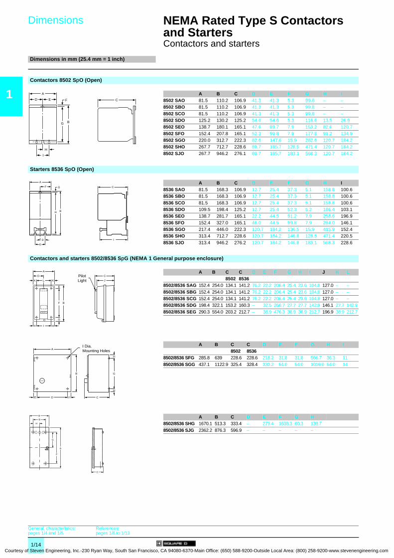
Dimensions in mm (25.4 mm = 1 inch)
Contactors 8502 SpO (Open)
A B C D E F G H I8502 SAO 81.5 110.2 106.9 41.3 41.3 5.3 99.8 – –8502 SBO 81.5 110.2 106.9 41.3 41.3 5.3 99.8 – –
8502 SCO 81.5 110.2 106.9 41.3 41.3 5.3 99.8 – –8502 SDO 125.2 130.2 125.2 54.6 54.6 5.3 116.6 13.5 26.98502 SEO 138.7 180.1 165.1 47.6 89.7 7.9 153.2 82.6 120.7
8502 SFO 152.4 207.8 165.1 52.3 99.8 7.9 177.8 91.2 134.98502 SGO 220.0 312.7 222.3 82.6 147.6 15.9 282.6 120.7 184.28502 SHO 267.7 712.7 228.6 89.7 185.7 128.5 471.4 120.7 184.2
8502 SJO 267.7 946.2 276.1 89.7 185.7 183.1 568.3 120.7 184.2
Starters 8536 SpO (Open)
A B C D E F G H I8536 SAO 81.5 168.3 106.9 12.7 25.4 37.3 5.1 158.8 100.68536 SBO 81.5 168.3 106.9 12.7 25.4 37.3 5.1 158.8 100.6
8536 SCO 81.5 168.3 106.9 12.7 25.4 37.3 5.1 158.8 100.68536 SDO 109.5 198.4 125.2 12.7 25.4 52.3 5.2 186.4 103.18536 SEO 138.7 281.7 165.1 22.2 44.5 91.2 7.9 258.6 196.9
8536 SFO 152.4 327.0 165.1 46.0 44.5 99.8 7.9 284.0 146.18536 SGO 217.4 446.0 222.3 120.7 184.2 136.5 15.9 415.9 152.48536 SHO 313.4 712.7 228.6 120.7 184.2 146.8 128.5 471.4 220.5
8536 SJO 313.4 946.2 276.2 120.7 184.2 146.8 183.1 568.3 228.6
Contactors and starters 8502/8536 SpG (NEMA 1 General purpose enclosure)
A B C C D E F G H I J K L8502 8536
8502/8536 SAG 152.4 254.0 134.1 141.2 76.2 22.2 206.4 25.4 23.6 104.8 127.0 – –
8502/8536 SBG 152.4 254.0 134.1 141.2 76.2 22.2 206.4 25.4 23.6 104.8 127.0 – –8502/8536 SCG 152.4 254.0 134.1 141.2 76.2 22.2 206.4 25.4 23.6 104.8 127.0 – –8502/8536 SDG 198.4 322.1 153.2 160.3 – 32.5 266.7 27.7 27.7 142.9 146.1 27.7 142.9
8502/8536 SEG 290.3 554.0 203.2 212.7 – 38.9 476.3 38.9 38.9 212.7 196.9 38.9 212.7
A B C C D E F G H I8502 8536
8502/8536 SFG 285.8 639 228.6 228.6 218.2 31.8 31.8 566.7 36.3 11
8502/8536 SGG 437.1 1122.9 325.4 328.4 330.2 54.0 54.0 1016.0 54.0 14
A B C D E F G H8502/8536 SHG 1670.1 513.3 333.4 – 279.4 1638.3 60.3 139.7
8502/8536 SJG 2362.2 876.3 596.9 – – – – –
A
B
C
I
H
E F
G
D
A
B
C
E
D
F G
H
I
RESET
RESET
H
F
G
E
K
D
KL
IH
B
C
J
A
PilotLight
RESET
A
B
H
H
CFDE
G
I Dia.Mounting Holes
H
B
E
G
A
F
C
General, characteristics:pages 1/4 and 1/5
References:pages 1/6 to 1/13
1/14 of Steven Engineering, Inc.-230 Ryan Way, South San Francisco, CA 94080-6370-Main Office: (650) 588-9200-Outside Local Area: (800) 258-9200-www.stevenengineering.com
Courtesy of S
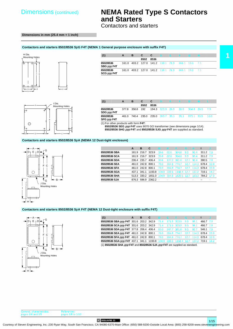
Dimensions (continued)
0
NEMA Rated Type S Contactors and Starters 0
Contactors and starters
Dimensions in mm (25.4 mm = 1 inch)
1
Contactors and starters 8502/8536 SpG F4T (NEMA 1 General purpose enclosure with suffix F4T)(1) A B C C D E F G H8502 8536
8502/8536 SBG ppp F4T
161.0 403.2 127.0 141.2 118.1 21.3 365.1 19.1 7.1
8502/8536 SCG ppp F4T
161.0 403.2 127.0 141.2 118.1 21.3 365.1 19.1 7.1
(1) A B C C D E F G H I8502 8536
8502/8536 SDG ppp F4T
377.8 358.8 192 194.3 323.9 26.9 26.9 304.8 26.9 7.9
8502/8536 SFG ppp F4T
461.0 740.4 235.0 235.0 393.7 35.1 35.1 673.1 33.5 10.9
(1) For other products with form F4T:8502/8536 SEG ppp F4T uses 9070 GO transformer (see dimensions page 1/14).8502/8536 SHG ppp F4T and 8502/8536 SJG ppp F4T are supplied as standard.
Contactors and starters 8502/8536 SpA (NEMA 12 Dust-tight enclosure)
A B C D E F G H I J8502/8536 SBA 161.9 216.7 323.9 39.6 82.6 304.8 9.5 90.4 311.2 7.98502/8536 SCA 161.9 216.7 323.9 39.6 82.6 304.8 9.5 90.4 311.2 7.9
8502/8536 SDA 206.4 235.7 406.4 39.6 127.0 381.0 12.7 90.4 390.5 7.98502/8536 SEA 461.0 242.8 800.1 78.0 304.8 774.7 12.7 114.3 678.4 10.98502/8536 SFA 461.0 242.8 800.1 78.0 304.8 774.7 12.7 114.3 678.4 10.9
8502/8536 SGA 437.1 341.1 1193.8 104.8 228.6 1168.4 12.7 137.2 719.1 14.28502/8536 SHA 513.3 330.2 1651.0 104.8 304.8 1625.6 12.7 163.3 784.2 17.38502/8536 SJA 876.3 596.9 2362.2 – – – – – – –
Contactors and starters 8502/8536 SpA F4T (NEMA 12 Dust-tight enclosure with suffix F4T)
(1) A B C D E F G H I J8502/8536 SBA ppp F4T 301.6 203.2 342.9 71.4 171.5 323.9 9.5 99.1 466.7 7.9
8502/8536 SCA ppp F4T 301.6 203.2 342.9 71.4 171.5 323.9 9.5 99.1 466.7 7.98502/8536 SDA ppp F4T 377.8 206.4 406.4 65.0 247.7 381.0 9.5 92.7 546.1 7.98502/8536 SEA ppp F4T 461.0 242.8 800.1 78.0 304.8 774.7 12.7 114.3 678.4 10.9
8502/8536 SFA ppp F4T 461.0 242.8 800.1 78.0 304.8 774.7 12.7 114.3 678.4 10.98502/8536 SGA ppp F4T 437.1 341.1 1193.8 104.8 228.6 1168.4 12.7 137.2 719.1 14.2(1) 8502/8536 SHA ppp F4T and 8502/8536 SJA ppp F4T are supplied as standard.
F
G
B
ED CA
H Dia.Mounting Holes
RESET
A
B
H
H
CFDE
G
I Dia.Mounting Holes
F
G
GDD E
C
B
A
I
H
J Dia.Mounting Holes
F
G
GDD E
C
B
A
I
H
J Dia.Mounting Holes
General, characteristics:pages 1/4 and 1/5
References:pages 1/6 to 1/13
1/15teven Engineering, Inc.-230 Ryan Way, South San Francisco, CA 94080-6370-Main Office: (650) 588-9200-Outside Local Area: (800) 258-9200-www.stevenengineering.com

1
Courtesy
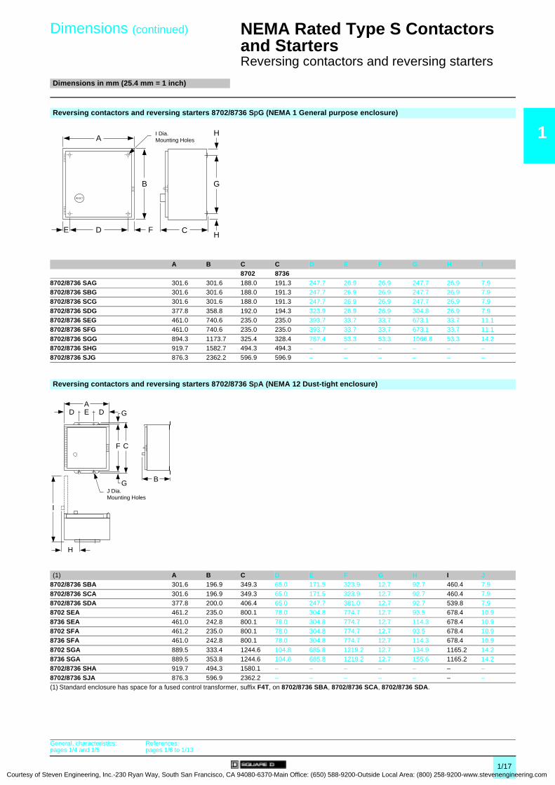
Dimensions0
NEMA Rated Type S Contactors and Starters 0
Reversing contactors and reversing starters
Dimensions in mm (25.4 mm = 1 inch)
Reversing contactors and reversing starters 8702 SpO/8736 SJO (Open)
Reference/Mounting (1) A B C D E F G H I J K8702 SAO/Horizontal 181.0 127.0 134.9 – – 86.4 11.7 110.2 4.6 139.7 22.9
8702 SBO/Horizontal 181.0 127.0 134.9 – – 86.4 11.7 110.2 4.6 139.7 22.98702 SBO/Vertical 138.7 233.9 134.9 127.8 5.3 – 15.5 203.2 15.5 127.8 5.38702 SCO/Horizontal 181.0 127.0 134.9 – – 86.4 11.7 110.2 4.6 139.7 22.9
8702 SCO/Vertical 138.7 233.9 134.9 127.8 5.3 – 15.5 203.2 15.5 127.8 5.38702 SDO/Horizontal 228.6 174.6 153.2 – – 114.3 9.5 142.9 6.4 152.4 38.18702 SDO/Vertical 171.5 288.9 153.2 158.8 6.4 – 12.7 263.5 12.7 158.8 6.4
8702 SEO/Horizontal 322.8 202.2 177.8 298.5 12.2 – 12.2 177.8 12.2 298.5 12.28702 SEO/Vertical 182.9 482.6 177.8 158.8 12.2 – 25.7 431.8 24.9 158.8 12.28702 SFO/Horizontal 362.0 296.7 177.8 336.6 12.7 – 12.7 203.2 46.7 336.6 12.7
8702 SFO/Vertical 202.2 607.1 177.8 177.8 12.2 – 46.0 514.4 30.0 177.8 12.28702 SGO/Horizontal 490.5 411.0 238.1 457.2 16.5 – 26.2 355.6 29.2 457.2 16.58702 SGO/Vertical 273.1 864.6 238.1 241.3 15.9 – 31.8 812.8 29.2 241.3 15.9
8702 SHO/Horizontal 568.3 712.2 241.6 457.2 15.9 – 97.2 538.0 77.0 457.2 19.48702 SJO/Horizontal 616.0 946.2 350.8 501.7 38.4 – – 762.0 – – –
8736 SJO/Horizontal 616.0 946.2 350.8 501.7 38.4 – – 762.0 – – –(1) Vertical type design differs from that shown on the corresponding NEMA size horizontal type figure, but dimensions listed apply to that figure.
Reversing contactors and reversing starters 8736 SpO (Open)
Reference/Mounting (1) A B C D E F G H I J K L M8736 SAO/Horizontal 181.0 175.3 134.9 – – 86.4 11.9 110.2 157.7 115.1 128.5 16.7 –8736 SBO/Horizontal 181.0 175.3 134.9 – – 86.4 11.9 110.2 157.7 115.1 128.5 16.7 –8736 SBO/Vertical 138.9 292.4 134.9 127.8 5.3 – 15.5 203.2 271.8 63.8 128.5 5.3 127.8
8736 SCO/Horizontal 181.0 175.3 134.9 – – 86.4 11.9 110.2 157.7 115.1 128.5 16.7 –8736 SCO/Vertical 138.9 292.4 134.9 127.8 5.3 – 15.5 203.2 271.8 63.8 128.5 5.3 127.88736 SDO/Horizontal 228.6 215.9 153.2 – – 114.3 9.5 142.9 190.5 127.0 131.0 38.1 –
8736 SDO/Vertical 171.5 342.4 153.2 158.8 6.4 – 19.8 263.5 329.2 79.4 131.0 6.4 152.48736 SEO/Horizontal 322.8 297.4 177.8 298.5 12.2 12.2 273.1 273.1 298.5 158.8 12.2 298.58736 SEO/Vertical 185.7 565.2 177.8 158.8 12.2 – 25.7 527.1 – 158.8 158.8 12.2 158.8
8736 SFO/Horizontal 362.0 370.6 177.8 336.6 12.7 – 46.7 311.2 311.2 336.6 158.8 12.7 336.68736 SFO/Vertical 202.2 662.4 177.8 177.8 12.2 46.7 622.3 – 102.6 158.8 12.2 177.88736 SGO/Horizontal 490.5 530.9 238.1 457.2 16.5 32.5 482.6 482.6 457.2 168.3 15.9 457.2
8736 SGO/Vertical 273.1 994.4 238.1 241.3 16.5 – 32.5 946.2 946.2 241.3 168.3 15.9 241.38736 SHO/Horizontal 568.3 712.2 241.6 457.2 17.3 – 97.2 538.0 77.0 457.2 19.4 – –(1) Vertical type design differs from that shown on the corresponding NEMA size horizontal type figure, but dimensions listed apply to that figure.
A
G
I
H B
J K
D E
F C
A
H
F
C
L KM
J
D
E G
RESET
I
B
General, characteristics:pages 1/4 and 1/5
References:pages 1/6 to 1/13
1/16 of Steven Engineering, Inc.-230 Ryan Way, South San Francisco, CA 94080-6370-Main Office: (650) 588-9200-Outside Local Area: (800) 258-9200-www.stevenengineering.com
Courtesy of S
Dimensions (continued)
0
NEMA Rated Type S Contactors and Starters 0
Reversing contactors and reversing starters
Dimensions in mm (25.4 mm = 1 inch)
1
Reversing contactors and reversing starters 8702/8736 SpG (NEMA 1 General purpose enclosure)A B C C D E F G H I8702 8736
8702/8736 SAG 301.6 301.6 188.0 191.3 247.7 26.9 26.9 247.7 26.9 7.98702/8736 SBG 301.6 301.6 188.0 191.3 247.7 26.9 26.9 247.7 26.9 7.98702/8736 SCG 301.6 301.6 188.0 191.3 247.7 26.9 26.9 247.7 26.9 7.9
8702/8736 SDG 377.8 358.8 192.0 194.3 323.9 26.9 26.9 304.8 26.9 7.98702/8736 SEG 461.0 740.6 235.0 235.0 393.7 33.7 33.7 673.1 33.7 11.18702/8736 SFG 461.0 740.6 235.0 235.0 393.7 33.7 33.7 673.1 33.7 11.1
8702/8736 SGG 894.3 1173.7 325.4 328.4 787.4 53.3 53.3 1066.8 53.3 14.28702/8736 SHG 919.7 1582.7 494.3 494.3 – – – – – –8702/8736 SJG 876.3 2362.2 596.9 596.9 – – – – – –
Reversing contactors and reversing starters 8702/8736 SpA (NEMA 12 Dust-tight enclosure)
(1) A B C D E F G H I J8702/8736 SBA 301.6 196.9 349.3 65.0 171.5 323.9 12.7 92.7 460.4 7.9
8702/8736 SCA 301.6 196.9 349.3 65.0 171.5 323.9 12.7 92.7 460.4 7.98702/8736 SDA 377.8 200.0 406.4 65.0 247.7 381.0 12.7 92.7 539.8 7.98702 SEA 461.2 235.0 800.1 78.0 304.8 774.7 12.7 93.5 678.4 10.9
8736 SEA 461.0 242.8 800.1 78.0 304.8 774.7 12.7 114.3 678.4 10.98702 SFA 461.2 235.0 800.1 78.0 304.8 774.7 12.7 93.5 678.4 10.98736 SFA 461.0 242.8 800.1 78.0 304.8 774.7 12.7 114.3 678.4 10.9
8702 SGA 889.5 333.4 1244.6 104.8 685.8 1219.2 12.7 134.9 1165.2 14.28736 SGA 889.5 353.8 1244.6 104.8 685.8 1219.2 12.7 155.6 1165.2 14.28702/8736 SHA 919.7 494.3 1580.1 – – – – – – –
8702/8736 SJA 876.3 596.9 2362.2 – – – – – – –(1) Standard enclosure has space for a fused control transformer, suffix F4T, on 8702/8736 SBA, 8702/8736 SCA, 8702/8736 SDA.
RESET
A
B
H
HCFDE
G
I Dia.Mounting Holes
F
G
GDD E
C
B
A
I
H
J Dia.Mounting Holes
General, characteristics:pages 1/4 and 1/5
References:pages 1/6 to 1/13
1/17teven Engineering, Inc.-230 Ryan Way, South San Francisco, CA 94080-6370-Main Office: (650) 588-9200-Outside Local Area: (800) 258-9200-www.stevenengineering.com

2/0Courtesy of Steven Engineering, Inc.-230 Ryan Way, South San Francisco
, CA 94080-6370-Main Office: (650) 588-9200-Outside Local Area: (800) 258-9200-www.stevenengineering.com
Contents
Courtesy of Steven Engineering, Inc.-230 Ryan Way, South San Francisco, CA
2 - NEMA Rated Type S Combination Starters
2
Selection guide . . . . . . . . . . . . . . . . . . . . . . . . . . . . . . . . . . . . . . . . . . . . . page 2/2
b Disconnect switch starters and circuit-breaker starters
v General, characteristics . . . . . . . . . . . . . . . . . . . . . . . . . . . . . . . . . . . . page 2/4
b Fusible disconnect switch starters Class 8538
with Class H fuse clips and with solid state overload relays
v References . . . . . . . . . . . . . . . . . . . . . . . . . . . . . . . . . . . . . . . . . . . . . page 2/6
b Fusible disconnect switch starters Class 8538
with Class R fuse clips
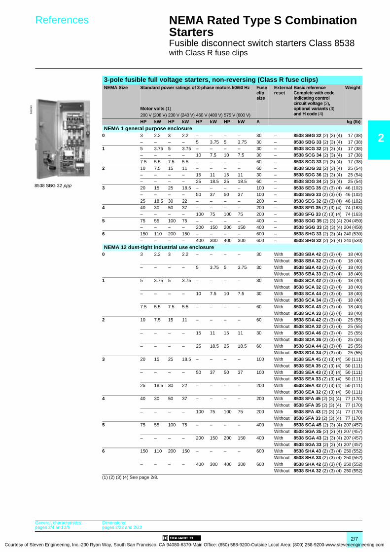
v References . . . . . . . . . . . . . . . . . . . . . . . . . . . . . . . . . . . . . . . . . . . . . page 2/7
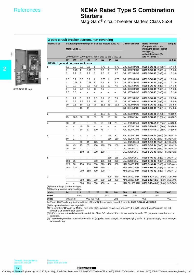
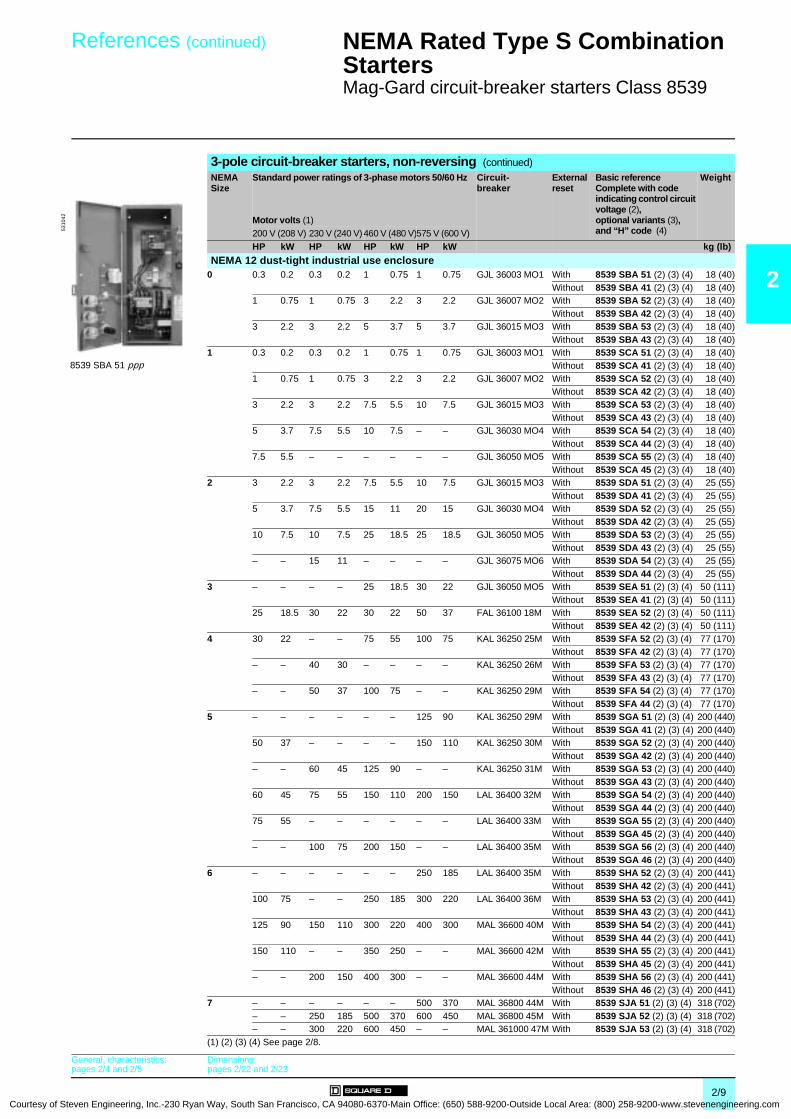
b Mag-Gard® circuit-breaker starters Class 8539
v References . . . . . . . . . . . . . . . . . . . . . . . . . . . . . . . . . . . . . . . . . . . . . page 2/8
b Thermal-magnetic circuit-breaker starters Class 8539
v References . . . . . . . . . . . . . . . . . . . . . . . . . . . . . . . . . . . . . . . . . . . . page 2/10
b Non-fusible disconnect switch starters Class 8538
v References . . . . . . . . . . . . . . . . . . . . . . . . . . . . . . . . . . . . . . . . . . . . page 2/12
b Fusible disconnect switch starters Class 8538
with Class H fuse clips
v References . . . . . . . . . . . . . . . . . . . . . . . . . . . . . . . . . . . . . . . . . . . . page 2/13
b Fusible disconnect switch starters Class 8538
(Class R fuse clips) with solid state overload relays
v Associations. . . . . . . . . . . . . . . . . . . . . . . . . . . . . . . . . . . . . . . . . . . . page 2/14
b Fusible disconnect switch starters Class 8538
with solid state overload relays
v Associations. . . . . . . . . . . . . . . . . . . . . . . . . . . . . . . . . . . . . . . . . . . . page 2/15
b Mag-Gard circuit-breaker starters Class 8539
with solid state overload relays
v Associations. . . . . . . . . . . . . . . . . . . . . . . . . . . . . . . . . . . . . . . . . . . . page 2/16
b Thermal magnetic circuit-breaker starters
with solid state overload relays
v Associations. . . . . . . . . . . . . . . . . . . . . . . . . . . . . . . . . . . . . . . . . . . . page 2/18
b Accessories
v Characteristics . . . . . . . . . . . . . . . . . . . . . . . . . . . . . . . . . . . . . . . . . . page 2/20
v References . . . . . . . . . . . . . . . . . . . . . . . . . . . . . . . . . . . . . . . . . . . . page 2/21
b Disconnect switch starters and circuit-breaker starters
v Dimensions . . . . . . . . . . . . . . . . . . . . . . . . . . . . . . . . . . . . . . . . . . . . page 2/22
2/1 94080-6370-Main Office: (650) 588-9200-Outside Local Area: (800) 258-9200-www.stevenengineering.com

2
Courtesy
Selection guide 0 NEMA Rated Type S Combination Starters 0
Disconnect switch starters and circuit-breaker starters
Applications Type S NEMA combination starters
NEMA Size 0 1 2
Standard motor power ratings 50/60 Hz(1) 200 V (208 V) 3 HP/2.2 kW 7.5 HP/5.5 kW 10 HP/7.5 kW
230 V (240 V) 3 HP/2.2 kW 7.5 HP/5.5 kW 15 HP/11 kW
460 V (480 V) 5 HP/3.75 kW 10 HP/7.5 kW 25 HP/18.5 kW575 V (500 V) 5 HP/3.75 kW 10 HP/7.5 kW 25 HP/18.5 kW
Motor voltage (starter voltage)
Enclosures NEMA 1 NEMA 12 NEMA 1 NEMA 12 NEMA 1 NEMA 12
- NEMA 1: General purpose
- NEMA 12: Dust-tight for industrial use
Fusible disconnect switch starters Class H fuse clips
8538 SBG 1p
8538 SBA pp
8538 SCG 1p
8538 SCA pp
8538 SDG 1p
8538 SDA pp
Pages 2/6 2/6 2/6
Fusible disconnect switch starters Class R fuse clips
8538 SBG 3 p
8538 SBA pp
8538 SCG 3 p
8538 SCA pp
8538 SDG 3 p
8538 SDA pp
Pages 2/7 2/7 2/7
Non-fusible disconnect switch starters
8538 SBG 11
8538 SBA p1
8538 SCG 11
8538 SCA p1
8538 SDG 11
8538 SDA p1
Pages 2/12 2/12 2/12
Circuit-breaker starters 8539 SBG 4p
8539 SBA pp
8539 SCG 4p
8539 SCA pp
8539 SDG 4p
8539 SDA pp
Pages 2/8 and 2/9 2/8 and 2/9 2/8 and 2/9
Thermal-magnetic circuit-breaker starters
8539 SBG p
8539 SBA pp
8539 SCG p
8539 SCA pp
8539 SDG p
8539 SDA pp
Pages 2/10 and 2/11 2/10 and 2/11 2/10 and 2/11
(1) For circuit-breaker starters and thermal-magnetic circuit-breaker starters, see pages 2/8 to 2/11.
5311
20
5311
19
2/2 of Steven Engineering, Inc.-230 Ryan Way, South San Francisco, CA 94080-6370-Main Office: (650) 588-9200-Outside Local Area: (800) 258-9200-www.stevenengineering.com
Courtesy of S
0
2
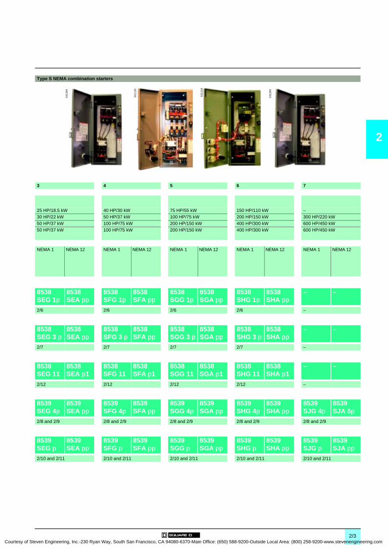
Type S NEMA combination starters
3 4 5 6 7
25 HP/18.5 kW 40 HP/30 kW 75 HP/55 kW 150 HP/110 kW –30 HP/22 kW 50 HP/37 kW 100 HP/75 kW 200 HP/150 kW 300 HP/220 kW
50 HP/37 kW 100 HP/75 kW 200 HP/150 kW 400 HP/300 kW 600 HP/450 kW50 HP/37 kW 100 HP/75 kW 200 HP/150 kW 400 HP/300 kW 600 HP/450 kW
NEMA 1 NEMA 12 NEMA 1 NEMA 12 NEMA 1 NEMA 12 NEMA 1 NEMA 12 NEMA 1 NEMA 12
8538 SEG 1p
8538 SEA pp
8538 SFG 1p
8538 SFA pp
8538 SGG 1p
8538 SGA pp
8538 SHG 1p
8538 SHA pp
– –
2/6 2/6 2/6 2/6 –
8538 SEG 3 p
8538 SEA pp
8538 SFG 3 p
8538 SFA pp
8538 SGG 3 p
8538 SGA pp
8538 SHG 3 p
8538 SHA pp
– –
2/7 2/7 2/7 2/7 –
8538 SEG 11
8538 SEA p1
8538 SFG 11
8538 SFA p1
8538 SGG 11
8538 SGA p1
8538 SHG 11
8538 SHA p1
– –
2/12 2/12 2/12 2/12 –
8539 SEG 4p
8539 SEA pp
8539 SFG 4p
8539 SFA pp
8539 SGG 4p
8539 SGA pp
8539 SHG 4p
8539 SHA pp
8539 SJG 4p
8539 SJA 5p
2/8 and 2/9 2/8 and 2/9 2/8 and 2/9 2/8 and 2/9 2/8 and 2/9
8539 SEG p
8539 SEA pp
8539 SFG p
8539 SFA pp
8539 SGG p
8539 SGA pp
8539 SHG p
8539 SHA pp
8539 SJG p
8539 SJA pp
2/10 and 2/11 2/10 and 2/11 2/10 and 2/11 2/10 and 2/11 2/10 and 2/11
5312
69
5311
20
5311
19
5312
69
2/3teven Engineering, Inc.-230 Ryan Way, South San Francisco, CA 94080-6370-Main Office: (650) 588-9200-Outside Local Area: (800) 258-9200-www.stevenengineering.com

2
Courtesy
General,characteristics 0
NEMA Rated Type S Combination Starters 0
Disconnect switch startersCircuit-breaker starters
GeneralClass 8538 and 8539 Type S combination starters combine the requirements of motor overload and short-circuit protection into one package.These starters are manufactured in accordance with NEMA standards and are UL listed. They are designed to operate up to a 600 V maximum, 50 to 60 Hz, and are available with solid state overload relays.Square D is one of the leaders in North America and Europe in providing starters that are verified by UL to comply with IEC 947-4-1 and Type 2 coordination. This means that the components of a motor branch circuit protective device (fuses and circuit-breaker), contactor and overload relay will be suitable for further use following a short-circuit fault allowing for replacement of components during normal scheduled maintenance. Class 8538 Type S combination starters, Sizes 0-5, with fusible disconnect switches, meet Type 2 performance criteria.
Disconnect switch startersFeatures:b Interchangeable fuse clips, straight through wiring, solid earth bar, space for a fused control transformer, provisions for adding disconnect switch electrical interlock, handle mechanism/door closing mechanism.
Switch type combination starters are available with fusible or non-fusible disconnect switches in NEMA Sizes 0-6. The switch itself is constructed of a moulded, insulated material that delivers arc-quenching performance similar to that of high voltage switch-gear. Visible blade construction confirms safety and proper performance at a glance. Many industries have standardized on this feature. Sizes 0-2, non-fusible assemblies can be field converted to fusible designs easily and quickly. Factory built fusible units will accept the industry standard Class H or R fuses. The various units have specific UL listed short circuit withstand ratings that range from 5000 to 100 000 A. Specific ratings are influenced by many components including the size of the disconnect switch and the type of fuses used with the switch. Circuit-breaker starters
Features:b Handle mechanism, door closing mechanism.
Options:b Factory installed auxiliary switch (provides remote indication of an open or tripped breaker), factory supplied alarm switch (actuates bell alarms or warning light when breaker is tripped).
Square D provides both a thermal-magnetic circuit-breaker and a motor circuit protector in NEMA Sizes 0-7 for applications requiring a breaker-type combination starter. The most widely used over-current protection devices are thermal-magnetic circuit-breakers. Mag-Gard® motor circuit protectors are similar in construction, but provide only short circuit protection. When Mag-Gard devices are used with motor starters, the adjustable instantaneous trip provides maximum motor protection based on specific amperage and application. Type S combination starters using thermal-magnetic breakers carry a UL listed short circuit withstand rating from 5000 to 30 000 A. If a Mag-Gard Type GJL breaker is used, withstand ratings increase to 100 000 A. Specific ratings and listings may vary depending on the specific combination of components used in the assembly.
CharacteristicsEnvironmentClass 8538 8539Size 0 1 2 3 4 5 6 0 1 2 3 4 5 6 7
Rated insulation voltage Conforming to UL, CSA V 600 600Rated impulse withstand voltage
Class H or Class K fuses kV 5 10 18 –
Class R fuses kV 100 –ITE circuit-breaker (FAL, KAL, LAL, MAL) kV – 10ITE circuit-breaker (GJL) kV – 65 –
INST circuit-breaker (FAL, KAL, LAL, MAL) kV – 22 (1) 22 30 (3)INST circuit-breaker (GJL) kV – 100 (2) –
Product certifications UL, CSA
(1) 22 kV rating for 0-480 V. 10 kV rating for 600 V.(2) 100 kV rating for 0-480 V. 10 kV rating for 600 V.(3) 30 kV rating for 0-480 V. 22 kV rating for 600 V.
Fusible disconnect switch combination starter
5310
43
Circuit-breaker combination starter
5310
42
References:pages 2/6 to 2/21
Dimensions:pages 2/22 and 2/23
2/4 of Steven Engineering, Inc.-230 Ryan Way, South San Francisco, CA 94080-6370-Main Office: (650) 588-9200-Outside Local Area: (800) 258-9200-www.stevenengineering.com

Courtesy of S
Characteristics (continued) 0 NEMA Rated Type S Combination Starters 0
Disconnect switch startersCircuit-breaker starters
2
Electrical characteristicsUL listed short circuit ratingsSize 0 1 2 3 4 5 6 7Disconnect switch starters 8538 SpG 1p/SpA
NEMA fuse class Class H
Enclosure (1) Standard –Available Ampere RMS symmetrical A 5000 10 000 18 000 –Disconnect switch starters 8538 SpG 3p/SpA
NEMA fuse class Class REnclosure (1) Standard –Available Ampere RMS symmetrical A 100 000 –
Circuit-breaker starters 8539 SpG 4p/SpAEnclosure (1) StandardAvailable Ampere RMS symmetrical A With GJL
circuit-breaker:100 000 (voltage 0-480 V)10 000 (voltage 481-600 V)
With GJL circuit-breaker: 100 000 (voltage 0-480 V)10 000 (voltage 481-600 V)22 000 (8539 SGG 4p S8 and 8539 SDA pp S8)
22 000 30 000(voltage 0-480 V)22 000(voltage 481-600 V)
Thermal-magnetic circuit-breaker starters 8538 SpG p/SpAEnclosure (1) StandardAvailable Ampere RMS symmetrical A 5000 10 000 18 000 30 000
(voltage 0-480 V) 22 000 (voltage 481-600 V)
Mag-Gard trip rangeCircuit-breaker GJL/FAL/KAL/LAL/MAL ppppp Mpp
Trip range/suffix number A M01 = 9-33 25M = 625-1250 35M = 1750-3500M02 = 21-77 26M = 750-1500 36M = 2000-4000M03 = 45-165 29M = 875-1750 40M = 2500-5000
M04 = 90-330 30M = 1000-2000 42M = 3000-6000M05 = 150-550 31M = 1125-2250 44M = 3500-7000M06 = 225-825 32M = 1250-2500
18M = 300-1100 33M = 1500-3000
TerminalsSize 0 1 2 3 4 5 6 7Type Line terminals on disconnect switch
Type of lug Box lugWire size min.-max.
Switch #14-1/0 Cu/Al #6-300 MCM Cu/Al One #4-500 MCM Cu – –
Circuit-breaker
#14-#4 Cu (2)#12-#4 Al or #14-#1/0 Cu#12-#1/0 Al#14-#1 Cu/#8-#1/0 Al (GJL Breaker)
#14-#1/0 Cu or #12-#1/0 Al#14-#1 Cu/#8-#1/0 Al (GJL Breaker)
#14-#2 Cu#10-#2 Al (FA Brkr)#4-300 MCM Cu/Al (KA Breaker) #14-#1 Cu/#8-#1/0 Al (GJL Breaker)
#14-#1/0 Cu#12-#1/0 Al (LA Brkr)#4-300 MCM Cu/Al (KA Breaker)
#4-300 MCM Cu/Al (KA Breaker)x1 #1-600 MCM orx2 #1-250 MCM Cu/Al (LA Breaker)
x1 #1-600 MCM or x2 #1-250 MCM Cu/Al (LA Breaker) orx3 #3/0-500 MCM Cu/Al (MA Breaker)
x3 #3/0-500 MCM Cu/Al
Type Power terminals on magnetic starterType of lug Screw
clamp terminal
Box lug Parallel groove
Wire Size min.-max.
#14-#8 Cu #14-#4 Cu #14-#0 Cu #8-250 MCM Cu #4-500 MCM Cu 250-500 MCM Cu (3)
250-500 MCM Cu
Per terminal
1 or 2 1 1 or 2 1-4
Type Control terminals on magnetic starterType of lug Screw clamp terminalWire Size
min.-max.
#16-#12 Cu #16-#12 Cu (4) #16-#12 Cu
Per terminal
2
(1) Standard enclosure includes non-oversize NEMA 1 and 12.(2) Use on FAL circuit-breakers rated 25 A or less.(3) Order Class 9999 Type SAL-16 parts kit to convert power terminals to accept wire sizes 1/0-300 MCM.(4) Terminal block range limited to #16-#14.
References:pages 2/6 to 2/21
Dimensions:pages 2/22 and 2/23
2/5teven Engineering, Inc.-230 Ryan Way, South San Francisco, CA 94080-6370-Main Office: (650) 588-9200-Outside Local Area: (800) 258-9200-www.stevenengineering.com

2
Courtesy
References 0 NEMA Rated Type S Combination Starters 0
Fusible disconnect switch starters Class 8538 with Class H fuse clips and solid state overload relays
3-pole fusible full voltage starters, non-reversing (Class H fuse clips)NEMA Size Standard power ratings of 3-phase motors 50/60 Hz
Motor volts (1)
Fuse clip size
External reset
Basic referenceComplete with code indicating control circuit voltage (2), optional variants (3) and H code (4)
Weight
200 V (208 V) 230 V (240 V) 460 V (480 V) 575 V (600 V)HP kW HP kW HP kW HP kW A kg (lb)
NEMA 1 general purpose enclosure0 3 2.2 3 2.2 – – – – 30 – 8538 SBG 12 (2) (3) (4) 17 (38)
– – – – 5 3.75 5 3.75 30 – 8538 SBG 13 (2) (3) (4) 17 (38)1 5 3.75 5 3.75 – – – – 30 – 8538 SCG 12 (2) (3) (4) 17 (38)
– – – – 10 7.5 10 7.5 30 – 8538 SCG 14 (2) (3) (4) 17 (38)
7.5 5.5 7.5 5.5 – – – – 60 – 8538 SCG 13 (2) (3) (4) 17 (38)2 10 7.5 15 11 – – – – 60 – 8538 SDG 12 (2) (3) (4) 25 (54)
– – – – 15 11 15 11 30 – 8538 SDG 16 (2) (3) (4) 25 (54)
– – – – 25 18.5 25 18.5 60 – 8538 SDG 14 (2) (3) (4) 25 (54)3 20 15 25 18.5 – – – – 100 – 8538 SEG 15 (2) (3) (4) 46 (102)
– – – – 50 37 50 37 100 – 8538 SEG 13 (2) (3) (4) 46 (102)
25 18.5 30 22 – – – – 200 – 8538 SEG 12 (2) (3) (4) 46 (102)4 40 30 50 37 – – – – 200 – 8538 SFG 15 (2) (3) (4) 74 (163)
– – – – 100 75 100 75 200 – 8538 SFG 13 (2) (3) (4) 74 (163)
5 75 55 100 75 – – – – 400 – 8538 SGG 15 (2) (3) (4) 204 (450)– – – – 200 150 200 150 400 – 8538 SGG 13 (2) (3) (4) 204 (450)
6 150 110 200 150 – – – – 600 – 8538 SHG 13 (2) (3) (4) 240 (530)
– – – – 400 300 400 300 600 – 8538 SHG 12 (2) (3) (4) 240 (530)
NEMA 12 dust-tight industrial use enclosure0 3 2.2 3 2.2 – – – – 30 With 8538 SBA 22 (2) (3) (4) 18 (40)
Without 8538 SBA 12 (2) (3) (4) 18 (40)
– – – – 5 3.75 5 3.75 30 With 8538 SBA 23 (2) (3) (4) 18 (40)Without 8538 SBA 13 (2) (3) (4) 18 (40)
1 5 3.75 5 3.75 – – – – 30 With 8538 SCA 22 (2) (3) (4) 18 (40)
Without 8538 SCA 12 (2) (3) (4) 18 (40)– – – – 10 7.5 10 7.5 30 With 8538 SCA 24 (2) (3) (4) 18 (40)
Without 8538 SCA 14 (2) (3) (4) 18 (40)
7.5 5.5 7.5 5.5 – – – – 60 With 8538 SCA 23 (2) (3) (4) 18 (40)Without 8538 SCA 13 (2) (3) (4) 18 (40)
2 10 7.5 15 11 – – – – 60 With 8538 SDA 22 (2) (3) (4) 25 (55)
Without 8538 SDA 12 (2) (3) (4) 25 (55)– – – – 15 11 15 11 30 With 8538 SDA 26 (2) (3) (4) 25 (55)
Without 8538 SDA 16 (2) (3) (4) 25 (55)
– – – – 25 18.5 25 18.5 60 With 8538 SDA 24 (2) (3) (4) 25 (55)Without 8538 SDA 14 (2) (3) (4) 25 (55)
3 20 15 25 18.5 – – – – 100 With 8538 SEA 25 (2) (3) (4) 50 (111)
Without 8538 SEA 15 (2) (3) (4) 50 (111)– – – – 50 37 50 37 100 With 8538 SEA 23 (2) (3) (4) 50 (111)
Without 8538 SEA 13 (2) (3) (4) 50 (111)
25 18.5 30 22 – – – – 200 With 8538 SEA 22 (2) (3) (4) 50 (111)Without 8538 SEA 12 (2) (3) (4) 50 (111)
4 40 30 50 37 – – – – 200 With 8538 SFA 25 (2) (3) (4) 77 (170)
Without 8538 SFA 15 (2) (3) (4) 77 (170)– – – – 100 75 100 75 200 With 8538 SFA 23 (2) (3) (4) 77 (170)
Without 8538 SFA 13 (2) (3) (4) 77 (170)
5 75 55 100 75 – – – – 400 With 8538 SGA 25 (2) (3) (4) 207 (457)Without 8538 SGA 15 (2) (3) (4) 207 (457)
– – – – 200 150 200 150 400 With 8538 SGA 23 (2) (3) (4) 207 (457)
Without 8538 SGA 13 (2) (3) (4) 207 (457)6 150 110 200 150 – – – – 600 With 8538 SHA 23 (2) (3) (4) 250 (552)
Without 8538 SHA 13 (2) (3) (4) 250 (552)
– – – – 400 300 400 300 600 With 8538 SHA 22 (2) (3) (4) 250 (552)Without 8538 SHA 12 (2) (3) (4) 250 (552)
(1) (2) (3) (4) See page 2/8.
8538 SBG 12 ppp
5310
43
General, characteristics:pages 2/4 and 2/5
Dimensions:pages 2/22 and 2/23
2/6 of Steven Engineering, Inc.-230 Ryan Way, South San Francisco, CA 94080-6370-Main Office: (650) 588-9200-Outside Local Area: (800) 258-9200-www.stevenengineering.com
Courtesy of S
References 0 NEMA Rated Type S Combination Starters 0
Fusible disconnect switch starters Class 8538 with Class R fuse clips
2
3-pole fusible full voltage starters, non-reversing (Class R fuse clips) NEMA Size Standard power ratings of 3-phase motors 50/60 Hz
Motor volts (1)
Fuse clip size
External reset
Basic referenceComplete with code indicating control circuit voltage (2), optional variants (3) and H code (4)
Weight
200 V (208 V) 230 V (240 V) 460 V (480 V) 575 V (600 V)HP kW HP kW HP kW HP kW A kg (lb)
NEMA 1 general purpose enclosure0 3 2.2 3 2.2 – – – – 30 – 8538 SBG 32 (2) (3) (4) 17 (38)
– – – – 5 3.75 5 3.75 30 – 8538 SBG 33 (2) (3) (4) 17 (38)1 5 3.75 5 3.75 – – – – 30 – 8538 SCG 32 (2) (3) (4) 17 (38)
– – – – 10 7.5 10 7.5 30 – 8538 SCG 34 (2) (3) (4) 17 (38)
7.5 5.5 7.5 5.5 – – – – 60 – 8538 SCG 33 (2) (3) (4) 17 (38)2 10 7.5 15 11 – – – – 60 – 8538 SDG 32 (2) (3) (4) 25 (54)
– – – – 15 11 15 11 30 – 8538 SDG 36 (2) (3) (4) 25 (54)
– – – – 25 18.5 25 18.5 60 – 8538 SDG 34 (2) (3) (4) 25 (54)3 20 15 25 18.5 – – – – 100 – 8538 SEG 35 (2) (3) (4) 46 (102)
– – – – 50 37 50 37 100 – 8538 SEG 33 (2) (3) (4) 46 (102)
25 18.5 30 22 – – – – 200 – 8538 SEG 32 (2) (3) (4) 46 (102)4 40 30 50 37 – – – – 200 – 8538 SFG 35 (2) (3) (4) 74 (163)
– – – – 100 75 100 75 200 – 8538 SFG 33 (2) (3) (4) 74 (163)
5 75 55 100 75 – – – – 400 – 8538 SGG 35 (2) (3) (4) 204 (450)– – – – 200 150 200 150 400 – 8538 SGG 33 (2) (3) (4) 204 (450)
6 150 110 200 150 – – – – 600 – 8538 SHG 33 (2) (3) (4) 240 (530)
– – – – 400 300 400 300 600 – 8538 SHG 32 (2) (3) (4) 240 (530)
NEMA 12 dust-tight industrial use enclosure0 3 2.2 3 2.2 – – – – 30 With 8538 SBA 42 (2) (3) (4) 18 (40)
Without 8538 SBA 32 (2) (3) (4) 18 (40)
– – – – 5 3.75 5 3.75 30 With 8538 SBA 43 (2) (3) (4) 18 (40)Without 8538 SBA 33 (2) (3) (4) 18 (40)
1 5 3.75 5 3.75 – – – – 30 With 8538 SCA 42 (2) (3) (4) 18 (40)
Without 8538 SCA 32 (2) (3) (4) 18 (40)– – – – 10 7.5 10 7.5 30 With 8538 SCA 44 (2) (3) (4) 18 (40)
Without 8538 SCA 34 (2) (3) (4) 18 (40)
7.5 5.5 7.5 5.5 – – – – 60 With 8538 SCA 43 (2) (3) (4) 18 (40)Without 8538 SCA 33 (2) (3) (4) 18 (40)
2 10 7.5 15 11 – – – – 60 With 8538 SDA 42 (2) (3) (4) 25 (55)
Without 8538 SDA 32 (2) (3) (4) 25 (55)– – – – 15 11 15 11 30 With 8538 SDA 46 (2) (3) (4) 25 (55)
Without 8538 SDA 36 (2) (3) (4) 25 (55)
– – – – 25 18.5 25 18.5 60 With 8538 SDA 44 (2) (3) (4) 25 (55)Without 8538 SDA 34 (2) (3) (4) 25 (55)
3 20 15 25 18.5 – – – – 100 With 8538 SEA 45 (2) (3) (4) 50 (111)
Without 8538 SEA 35 (2) (3) (4) 50 (111)– – – – 50 37 50 37 100 With 8538 SEA 43 (2) (3) (4) 50 (111)
Without 8538 SEA 33 (2) (3) (4) 50 (111)
25 18.5 30 22 – – – – 200 With 8538 SEA 42 (2) (3) (4) 50 (111)Without 8538 SEA 32 (2) (3) (4) 50 (111)
4 40 30 50 37 – – – – 200 With 8538 SFA 45 (2) (3) (4) 77 (170)
Without 8538 SFA 35 (2) (3) (4) 77 (170)– – – – 100 75 100 75 200 With 8538 SFA 43 (2) (3) (4) 77 (170)
Without 8538 SFA 33 (2) (3) (4) 77 (170)
5 75 55 100 75 – – – – 400 With 8538 SGA 45 (2) (3) (4) 207 (457)Without 8538 SGA 35 (2) (3) (4) 207 (457)
– – – – 200 150 200 150 400 With 8538 SGA 43 (2) (3) (4) 207 (457)
Without 8538 SGA 33 (2) (3) (4) 207 (457)6 150 110 200 150 – – – – 600 With 8538 SHA 43 (2) (3) (4) 250 (552)
Without 8538 SHA 33 (2) (3) (4) 250 (552)
– – – – 400 300 400 300 600 With 8538 SHA 42 (2) (3) (4) 250 (552)Without 8538 SHA 32 (2) (3) (4) 250 (552)
(1) (2) (3) (4) See page 2/8.
8538 SBG 32 ppp
5310
43
General, characteristics:pages 2/4 and 2/5
Dimensions:pages 2/22 and 2/23
2/7teven Engineering, Inc.-230 Ryan Way, South San Francisco, CA 94080-6370-Main Office: (650) 588-9200-Outside Local Area: (800) 258-9200-www.stevenengineering.com
2
Courtesy
References 0 NEMA Rated Type S Combination Starters 0
Mag-Gard® circuit-breaker starters Class 8539
3-pole circuit breaker starters, non-reversing NEMA Size Standard power ratings of 3-phase motors 50/60 Hz
Motor volts (1)
Circuit-breaker Basic referenceComplete with code indicating control circuit voltage (2), optional variants (3) and “H” code (4)
Weight
200 V (208 V) 230 V (240 V) 460 V (480 V) 575 V (600 V)
HP kW HP kW HP kW HP kW kg (lb)
NEMA 1 general purpose enclosure0 0.3 0.2 0.3 0.2 1 0.75 1 0.75 GJL 36003 MO1 8539 SBG 41 (2) (3) (4) 17 (38)
1 0.75 1 0.75 3 2.2 3 2.2 GJL 36007 MO2 8539 SBG 42 (2) (3) (4) 17 (38)3 2.2 3 2.2 5 3.7 5 3.7 GJL 36015 MO3 8539 SBG 43 (2) (3) (4) 17 (38)
1 0.3 0.2 0.3 0.2 1 0.75 1 0.75 GJL 36003 MO1 8539 SCG 41 (2) (3) (4) 17 (38)
1 0.75 1 0.75 3 2.2 3 2.2 GJL 36007 MO2 8539 SCG 42 (2) (3) (4) 17 (38)3 2.2 3 2.2 7.5 5.5 10 7.5 GJL 36015 MO3 8539 SCG 43 (2) (3) (4) 17 (38)5 3.7 7.5 5.5 10 7.5 – – GJL 36030 MO4 8539 SCG 44 (2) (3) (4) 17 (38)
7.5 5.5 – – – – – – GJL 36050 MO5 8539 SCG 45 (2) (3) (4) 17 (38)
2 3 2.2 3 2.2 7.5 5.5 10 7.5 GJL 36015 MO3 8539 SDG 41 (2) (3) (4) 25 (54)5 3.7 7.5 5.5 15 11 20 15 GJL 36030 MO4 8539 SDG 42 (2) (3) (4) 25 (54)10 7.5 10 7.5 25 18.5 25 18.5 GJL 36050 MO5 8539 SDG 43 (2) (3) (4) 25 (54)
– – 15 11 – – – – GJL 36075 MO6 8539 SDG 44 (2) (3) (4) 25 (54)
3 – – – – 25 18.5 30 22 GJL 36050 MO5 8539 SEG 41 (2) (3) (4) 46 (102)25 18.5 30 22 30 22 50 37 FAL 36100 18M 8539 SEG 42 (2) (3) (4) 46 (102)
4 30 22 – – 75 55 100 75 KAL 36250 25M 8539 SFG 42 (2) (3) (4) 74 (163)
– – 40 30 – – – – KAL 36250 26M 8539 SFG 43 (2) (3) (4) 74 (163)– – 50 37 100 75 – – KAL 36250 29M 8539 SFG 44 (2) (3) (4) 74 (163)
5 – – – – – – 125 90 KAL 36250 29M 8539 SGG 41 (2) (3) (4) 191 (420)50 37 – – – – 150 110 KAL 36250 30M 8539 SGG 42 (2) (3) (4) 191 (420)
– – 60 45 125 90 – – KAL 36250 31M 8539 SGG 43 (2) (3) (4) 191 (420)60 45 75 55 150 110 200 150 LAL 36400 32M 8539 SGG 44 (2) (3) (4) 191 (420)75 55 – – – – – – LAL 36400 33M 8539 SGG 45 (2) (3) (4) 191 (420)
– – 100 75 200 150 – – LAL 36400 35M 8539 SGG 46 (2) (3) (4) 191 (420)
6 – – – – – – 250 185 LAL 36400 35M 8539 SHG 42 (2) (3) (4) 200 (441)100 75 – – 250 185 300 220 LAL 36400 36M 8539 SHG 43 (2) (3) (4) 200 (441)125 90 150 110 300 220 400 300 MAL 36600 40M 8539 SHG 44 (2) (3) (4) 200 (441)
150 110 – – 350 250 – – MAL 36600 42M 8539 SHG 45 (2) (3) (4) 200 (441)– – 200 150 400 300 – – MAL 36600 44M 8539 SHG 46 (2) (3) (4) 200 (441)
7 – – – – – – 500 370 MAL 36800 44M 8539 SJG 41 (2) (3) (4) 318 (702)– – 250 185 500 370 600 450 MAL 36800 45M 8539 SJG 42 (2) (3) (4) 318 (702)
– – 300 220 600 450 – – MAL 361000 47M 8539 SJG 43 (2) (3) (4) 318 (702)(1) Motor voltage (starter voltage).(2) Standard control circuit voltage:Volts 24 110 120 208 220 240 380 440 480 550 600
50 Hz – V02 – – V03 – V05 V06 – V07 –
60 Hz V01 (5) (6) – V02 (5) V08 – V03 – – V06 – V0724 V and 120 V coils require the addition of form “S” for separate control. Example: 8559 SCG 41 V02 H10S.(3) For optional variants, see page 2/21. (4) To complete “H” code for Motor Logic solid state overload relays, see pages 2/13 to 2/19. Motor Logic Plus units are not
available on combination starters.(5) 24 V coils are not available on Sizes 4-6. On Sizes 0-3, where 24 V coils are available, suffix “S” (separate control) must be
specified.(6) These voltage codes must include suffix “S” (supplied at no charge). When specifying suffix “S”, please supply motor voltage
when ordering.
8539 SBG 41 ppp
5310
42
General, characteristics:pages 2/4 and 2/5
Dimensions:pages 2/22 and 2/23
2/8 of Steven Engineering, Inc.-230 Ryan Way, South San Francisco, CA 94080-6370-Main Office: (650) 588-9200-Outside Local Area: (800) 258-9200-www.stevenengineering.com
Courtesy of S
References (continued) 0 NEMA Rated Type S Combination Starters 0
Mag-Gard circuit-breaker starters Class 8539
2
3-pole circuit-breaker starters, non-reversing (continued)NEMA Size
Standard power ratings of 3-phase motors 50/60 Hz
Motor volts (1)
Circuit- breaker
External reset
Basic referenceComplete with code indicating control circuit voltage (2), optional variants (3), and “H” code (4)
Weight
200 V (208 V) 230 V (240 V)460 V (480 V)575 V (600 V)HP kW HP kW HP kW HP kW kg (lb)
NEMA 12 dust-tight industrial use enclosure0 0.3 0.2 0.3 0.2 1 0.75 1 0.75 GJL 36003 MO1 With 8539 SBA 51 (2) (3) (4) 18 (40)
Without 8539 SBA 41 (2) (3) (4) 18 (40)1 0.75 1 0.75 3 2.2 3 2.2 GJL 36007 MO2 With 8539 SBA 52 (2) (3) (4) 18 (40)
Without 8539 SBA 42 (2) (3) (4) 18 (40)3 2.2 3 2.2 5 3.7 5 3.7 GJL 36015 MO3 With 8539 SBA 53 (2) (3) (4) 18 (40)
Without 8539 SBA 43 (2) (3) (4) 18 (40)1 0.3 0.2 0.3 0.2 1 0.75 1 0.75 GJL 36003 MO1 With 8539 SCA 51 (2) (3) (4) 18 (40)
Without 8539 SCA 41 (2) (3) (4) 18 (40)1 0.75 1 0.75 3 2.2 3 2.2 GJL 36007 MO2 With 8539 SCA 52 (2) (3) (4) 18 (40)
Without 8539 SCA 42 (2) (3) (4) 18 (40)3 2.2 3 2.2 7.5 5.5 10 7.5 GJL 36015 MO3 With 8539 SCA 53 (2) (3) (4) 18 (40)
Without 8539 SCA 43 (2) (3) (4) 18 (40)5 3.7 7.5 5.5 10 7.5 – – GJL 36030 MO4 With 8539 SCA 54 (2) (3) (4) 18 (40)
Without 8539 SCA 44 (2) (3) (4) 18 (40)7.5 5.5 – – – – – – GJL 36050 MO5 With 8539 SCA 55 (2) (3) (4) 18 (40)
Without 8539 SCA 45 (2) (3) (4) 18 (40)2 3 2.2 3 2.2 7.5 5.5 10 7.5 GJL 36015 MO3 With 8539 SDA 51 (2) (3) (4) 25 (55)
Without 8539 SDA 41 (2) (3) (4) 25 (55)5 3.7 7.5 5.5 15 11 20 15 GJL 36030 MO4 With 8539 SDA 52 (2) (3) (4) 25 (55)
Without 8539 SDA 42 (2) (3) (4) 25 (55)10 7.5 10 7.5 25 18.5 25 18.5 GJL 36050 MO5 With 8539 SDA 53 (2) (3) (4) 25 (55)
Without 8539 SDA 43 (2) (3) (4) 25 (55)– – 15 11 – – – – GJL 36075 MO6 With 8539 SDA 54 (2) (3) (4) 25 (55)
Without 8539 SDA 44 (2) (3) (4) 25 (55)3 – – – – 25 18.5 30 22 GJL 36050 MO5 With 8539 SEA 51 (2) (3) (4) 50 (111)
Without 8539 SEA 41 (2) (3) (4) 50 (111)25 18.5 30 22 30 22 50 37 FAL 36100 18M With 8539 SEA 52 (2) (3) (4) 50 (111)
Without 8539 SEA 42 (2) (3) (4) 50 (111)4 30 22 – – 75 55 100 75 KAL 36250 25M With 8539 SFA 52 (2) (3) (4) 77 (170)
Without 8539 SFA 42 (2) (3) (4) 77 (170)– – 40 30 – – – – KAL 36250 26M With 8539 SFA 53 (2) (3) (4) 77 (170)
Without 8539 SFA 43 (2) (3) (4) 77 (170)– – 50 37 100 75 – – KAL 36250 29M With 8539 SFA 54 (2) (3) (4) 77 (170)
Without 8539 SFA 44 (2) (3) (4) 77 (170)5 – – – – – – 125 90 KAL 36250 29M With 8539 SGA 51 (2) (3) (4) 200 (440)
Without 8539 SGA 41 (2) (3) (4) 200 (440)50 37 – – – – 150 110 KAL 36250 30M With 8539 SGA 52 (2) (3) (4) 200 (440)
Without 8539 SGA 42 (2) (3) (4) 200 (440)– – 60 45 125 90 – – KAL 36250 31M With 8539 SGA 53 (2) (3) (4) 200 (440)
Without 8539 SGA 43 (2) (3) (4) 200 (440)60 45 75 55 150 110 200 150 LAL 36400 32M With 8539 SGA 54 (2) (3) (4) 200 (440)
Without 8539 SGA 44 (2) (3) (4) 200 (440)75 55 – – – – – – LAL 36400 33M With 8539 SGA 55 (2) (3) (4) 200 (440)
Without 8539 SGA 45 (2) (3) (4) 200 (440)– – 100 75 200 150 – – LAL 36400 35M With 8539 SGA 56 (2) (3) (4) 200 (440)
Without 8539 SGA 46 (2) (3) (4) 200 (440)6 – – – – – – 250 185 LAL 36400 35M With 8539 SHA 52 (2) (3) (4) 200 (441)
Without 8539 SHA 42 (2) (3) (4) 200 (441)100 75 – – 250 185 300 220 LAL 36400 36M With 8539 SHA 53 (2) (3) (4) 200 (441)
Without 8539 SHA 43 (2) (3) (4) 200 (441)125 90 150 110 300 220 400 300 MAL 36600 40M With 8539 SHA 54 (2) (3) (4) 200 (441)
Without 8539 SHA 44 (2) (3) (4) 200 (441)150 110 – – 350 250 – – MAL 36600 42M With 8539 SHA 55 (2) (3) (4) 200 (441)
Without 8539 SHA 45 (2) (3) (4) 200 (441)– – 200 150 400 300 – – MAL 36600 44M With 8539 SHA 56 (2) (3) (4) 200 (441)
Without 8539 SHA 46 (2) (3) (4) 200 (441)7 – – – – – – 500 370 MAL 36800 44M With 8539 SJA 51 (2) (3) (4) 318 (702)
– – 250 185 500 370 600 450 MAL 36800 45M With 8539 SJA 52 (2) (3) (4) 318 (702)– – 300 220 600 450 – – MAL 361000 47M With 8539 SJA 53 (2) (3) (4) 318 (702)
(1) (2) (3) (4) See page 2/8.
8539 SBA 51 ppp
5310
42
General, characteristics:pages 2/4 and 2/5
Dimensions:pages 2/22 and 2/23
2/9teven Engineering, Inc.-230 Ryan Way, South San Francisco, CA 94080-6370-Main Office: (650) 588-9200-Outside Local Area: (800) 258-9200-www.stevenengineering.com

2
Courtesy
References 0 NEMA Rated Type S Combination Starters 0
Thermal-magnetic circuit-breaker starters Class 8539
3-pole thermal-magnetic circuit-breaker starters, non-reversingNEMA Size
Standard power ratings of 3-phase motors 50/60 Hz
Motor volts (1)
Circuit- breaker
External reset
Basic referenceComplete with code indicating control circuit voltage (2), optional variants (3) and “H” code (4)
Weight
200 V (208 V) 230 V (240 V)460 V (480 V)575 V (600 V) Type RatingHP kW HP kW HP kW HP kW A kg (lb)
NEMA 1 general purpose enclosure0 2 1.5 2 1.5 – – – – FAL 15 – 8539 SBG 1 (2) (3) (4) 17 (38)
– – – – 5 3.7 5 3.7 FAL 15 – 8539 SBG 2 (2) (3) (4) 17 (38)3 2.2 3 2.2 – – – – FAL 20 – 8539 SBG 3 (2) (3) (4) 17 (38)
1 5 3.7 – – – – – – FAL 35 – 8539 SCG 5 (2) (3) (4) 17 (38)7.5 5.5 – – – – – – FAL 50 – 8539 SCG 2 (2) (3) (4) 17 (38)– – 5 3.7 – – – – FAL 30 – 8539 SCG 1 (2) (3) (4) 17 (38)– – 7.5 5.5 – – – – FAL 45 – 8539 SCG 6 (2) (3) (4) 17 (38)– – – – 7.5 5.5 10 7.5 FAL 20 – 8539 SCG 3 (2) (3) (4) 17 (38)– – – – 10 7.5 – – FAL 25 – 8539 SCG 7 (2) (3) (4) 17 (38)– – – – – – 7.5 5.5 FAL 15 – 8539 SCG 8 (2) (3) (4) 17 (38)
2 10 7.5 10 7.5 – – – – FAL 60 – 8539 SDG 1 (2) (3) (4) 25 (54)– – 15 11 – – – – FAL 80 – 8539 SDG 7 (2) (3) (4) 25 (54)– – – – 7.5 5.5 – – FAL 20 – 8539 SDG 3 (2) (3) (4) 25 (54)– – – – 20 15 25 18.5 FAL 60 – 8539 SDG 4 (2) (3) (4) 25 (54)– – – – 25 18.5 – – FAL 70 – 8539 SDG 5 (2) (3) (4) 25 (54)– – – – – – 15 11 FAL 35 – 8539 SDG 8 (2) (3) (4) 25 (54)– – – – – – 20 15 FAL 45 – 8539 SDG 9 (2) (3) (4) 25 (54)
3 15 11 20 15 40 30 50 37 FAL 90 – 8539 SEG 3 (2) (3) (4) 46 (102)20 15 25 18.5 50 37 – – FAL 100 – 8539 SEG 1 (2) (3) (4) 46 (102)25 18.5 30 22 – – – – KAL 110 – 8539 SEG 5 (2) (3) (4) 46 (102)– – – – 30 22 40 30 FAL 80 – 8539 SEG 6 (2) (3) (4) 46 (102)– – – – – – 30 22 FAL 60 – 8539 SEG 4 (2) (3) (4) 46 (102)
4 30 22 – – 75 55 – – KAL 125 – 8539 SFG 3 (2) (3) (4) 74 (163)40 30 50 37 100 75 – – KAL 200 – 8539 SFG 4 (2) (3) (4) 74 (163)– – 40 30 – – 100 75 KAL 150 – 8539 SFG 1 (2) (3) (4) 74 (163)– – – – 60 45 75 55 KAL 110 – 8539 SFG 5 (2) (3) (4) 74 (163)– – – – – – 60 45 FAL 100 – 8539 SFG 6 (2) (3) (4) 74 (163)
5 50 37 – – – – 150 110 LAL 200 – 8539 SGG 6 (2) (3) (4) 191 (420)60 45 75 55 150 110 200 150 LAL 250 – 8539 SGG 1 (2) (3) (4) 191 (420)75 55 – – – – – – LAL 300 – 8539 SGG 4 (2) (3) (4) 191 (420)– – 60 45 125 90 – – LAL 225 – 8539 SGG 3 (2) (3) (4) 191 (420)– – 100 75 200 150 – – LAL 350 – 8539 SGG 2 (2) (3) (4) 191 (420)– – – – – – 125 90 KAL 200 – 8539 SGG 7 (2) (3) (4) 191 (420)
6 100 75 125 90 250 185 300 220 MAL 450 – 8539 SHG 4 (2) (3) (4) 220 (486)125 90 150 110 300 220 400 300 MAL 600 – 8539 SHG 3 (2) (3) (4) 220 (486)150 110 – – 350 250 – – MAL 600 – 8539 SHG 5 (2) (3) (4) 220 (486)– – 200 150 400 300 – – MAL 800 – 8539 SHG 7 (2) (3) (4) 220 (486)– – – – – – 250 185 MAL 250 – 8539 SHG 6 (2) (3) (4) 220 (486)– – – – – – 350 250 MAL 500 – 8539 SHG 2 (2) (3) (4) 220 (486)
7 – – 250 185 500 370 600 450 MAL 900 – 8539 SJG 2 (2) (3) (4) 320 (706)– – 300 220 600 450 – – MAL 1000 – 8539 SJG 3 (2) (3) (4) 320 (706)– – – – – – 500 370 MAL 800 – 8539 SJG 1 (2) (3) (4) 320 (706)
NEMA 12 dust-tight industrial use enclosure0 2 1.5 2 1.5 – – – – FAL 15 With 8539 SBA 11 (2) (3) (4) 18 (40)
Without 8539 SBA 1 (2) (3) (4) 18 (40)– – – – 5 3.7 5 3.7 FAL 15 With 8539 SBA 12 (2) (3) (4) 18 (40)
Without 8539 SBA 2 (2) (3) (4) 18 (40)3 2.2 3 2.2 – – – – FAL 20 With 8539 SBA 13 (2) (3) (4) 18 (40)
Without 8539 SBA 13 (2) (3) (4) 18 (40)1 5 3.7 – – – – – – FAL 35 With 8539 SCA 15 (2) (3) (4) 18 (40)
Without 8539 SCA 5 (2) (3) (4) 18 (40)7.5 5.5 – – – – – – FAL 50 With 8539 SCA 12 (2) (3) (4) 18 (40)
Without 8539 SCA 2 (2) (3) (4) 18 (40)– – 5 3.7 – – – – FAL 30 With 8539 SCA 11 (2) (3) (4) 18 (40)
Without 8539 SCA 1 (2) (3) (4) 18 (40)– – 7.5 5.5 – – – – FAL 45 With 8539 SCA 16 (2) (3) (4) 18 (40)
Without 8539 SCA 6 (2) (3) (4) 18 (40)– – – – 7.5 5.5 10 7.5 FAL 20 With 8539 SCA 13 (2) (3) (4) 18 (40)
Without 8539 SCA 3 (2) (3) (4) 18 (40)– – – – 10 7.5 – – FAL 25 With 8539 SCA 17 (2) (3) (4) 18 (40)
Without 8539 SCA 7 (2) (3) (4) 18 (40)– – – – – – 7.5 5.5 FAL 15 With 8539 SCA 18 (2) (3) (4) 18 (40)
Without 8539 SCA 8 (2) (3) (4) 18 (40)(1) (2) (3) (4) See page 2/8.
8539 SBG 1 ppp
5310
42
General, characteristics:pages 2/4 and 2/5
Dimensions:pages 2/22 and 2/23
2/10 of Steven Engineering, Inc.-230 Ryan Way, South San Francisco, CA 94080-6370-Main Office: (650) 588-9200-Outside Local Area: (800) 258-9200-www.stevenengineering.com
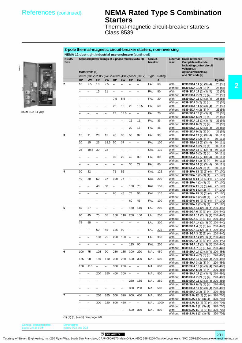
Courtesy of S
References (continued) 0 NEMA Rated Type S Combination Starters 0
Thermal-magnetic circuit-breaker starters Class 8539
2
3-pole thermal-magnetic circuit-breaker starters, non-reversing NEMA 12 dust-tight industrial use enclosure (continued)NEMA Size
Standard power ratings of 3-phase motors 50/60 Hz
Motor volts (1)
Circuit- breaker
External reset
Basic referenceComplete with code indicating control circuit voltage (2), optional variants (3) and “H” code (4)
Weight
200 V (208 V) 230 V (240 V) 460 V (480 V)575 V (600 V) Type RatingHP kW HP kW HP kW HP kW A kg (lb)
2 10 7.5 10 7.5 – – – – FAL 60 With 8539 SDA 11 (2) (3) (4) 25 (55)Without 8539 SDA 1 (2) (3) (4) 25 (55)
– – 15 11 – – – – FAL 80 With 8539 SDA 17 (2) (3) (4) 25 (55)Without 8539 SDA 7 (2) (3) (4) 25 (55)
– – – – 7.5 5.5 – – FAL 20 With 8539 SDA 13 (2) (3) (4) 25 (55)Without 8539 SDA 3 (2) (3) (4) 25 (55)
– – – – 20 15 25 18.5 FAL 60 With 8539 SDA 14 (2) (3) (4) 25 (55)Without 8539 SDA 4 (2) (3) (4) 25 (55)
– – – – 25 18.5 – – FAL 70 With 8539 SDA 15 (2) (3) (4) 25 (55)Without 8539 SDA 5 (2) (3) (4) 25 (55)
– – – – – – 15 11 FAL 35 With 8539 SDA 18 (2) (3) (4) 25 (55)Without 8539 SDA 8 (2) (3) (4) 25 (55)
– – – – – – 20 15 FAL 45 With 8539 SDA 19 (2) (3) (4) 25 (55)Without 8539 SDA 9 (2) (3) (4) 25 (55)
3 15 11 20 15 40 30 50 37 FAL 90 With 8539 SEA 13 (2) (3) (4) 50 (111)Without 8539 SEA 3 (2) (3) (4) 50 (111)
20 15 25 18.5 50 37 – – FAL 100 With 8539 SEA 11 (2) (3) (4) 50 (111)Without 8539 SEA 1 (2) (3) (4) 50 (111)
25 18.5 30 22 – – – – KAL 110 With 8539 SEA 15 (2) (3) (4) 50 (111)Without 8539 SEA 5 (2) (3) (4) 50 (111)
– – – – 30 22 40 30 FAL 80 With 8539 SEA 16 (2) (3) (4) 50 (111)Without 8539 SEA 6 (2) (3) (4) 50 (111)
– – – – – – 30 22 FAL 60 With 8539 SEA 14 (2) (3) (4) 50 (111)Without 8539 SEA 4 (2) (3) (4) 50 (111)
4 30 22 – – 75 55 – – KAL 125 With 8539 SFA 13 (2) (3) (4) 77 (170)Without 8539 SFA 3 (2) (3) (4) 77 (170)
40 30 50 37 100 75 – – KAL 200 With 8539 SFA 14 (2) (3) (4) 77 (170)Without 8539 SFA 4 (2) (3) (4) 77 (170)
– – 40 30 – – 100 75 KAL 150 With 8539 SFA 11 (2) (3) (4) 77 (170)Without 8539 SFA 1 (2) (3) (4) 77 (170)
– – – – 60 45 75 55 KAL 110 With 8539 SFA 15 (2) (3) (4) 77 (170)Without 8539 SFA 5 (2) (3) (4) 77 (170)
– – – – – – 60 45 FAL 100 With 8539 SFA 16 (2) (3) (4) 77 (170)Without 8539 SFA 6 (2) (3) (4) 77 (170)
5 50 37 – – – – 150 110 LAL 200 With 8539 SGA 16 (2) (3) (4) 200 (440)Without 8539 SGA 6 (2) (3) (4) 200 (440)
60 45 75 55 150 110 200 150 LAL 250 With 8539 SGA 11 (2) (3) (4) 200 (440)Without 8539 SGA 1 (2) (3) (4) 200 (440)
75 55 – – – – – – LAL 300 With 8539 SGA 14 (2) (3) (4) 200 (440)Without 8539 SGA 4 (2) (3) (4) 200 (440)
– – 60 45 125 90 – – LAL 225 With 8539 SGA 13 (2) (3) (4) 200 (440)Without 8539 SGA 3 (2) (3) (4) 200 (440)
– – 100 75 200 150 – – LAL 350 With 8539 SGA 12 (2) (3) (4) 200 (440)Without 8539 SGA 2 (2) (3) (4) 200 (440)
– – – – – – 125 90 KAL 200 With 8539 SGA 17 (2) (3) (4) 200 (440)Without 8539 SGA 7 (2) (3) (4) 200 (440)
6 100 75 125 90 250 185 300 220 MAL 450 With 8539 SHA 14 (2) (3) (4) 220 (486)Without 8539 SHA 4 (2) (3) (4) 220 (486)
125 90 150 110 300 220 400 300 MAL 600 With 8539 SHA 13 (2) (3) (4) 220 (486)Without 8539 SHA 3 (2) (3) (4) 220 (486)
150 110 – – 350 250 – – MAL 600 With 8539 SHA 15 (2) (3) (4) 220 (486)Without 8539 SHA 5 (2) (3) (4) 220 (486)
– – 200 150 400 300 – – MAL 800 With 8539 SHA 17 (2) (3) (4) 220 (486)Without 8539 SHA 7 (2) (3) (4) 220 (486)
– – – – – – 250 185 MAL 250 With 8539 SHA 16 (2) (3) (4) 220 (486)Without 8539 SHA 6 (2) (3) (4) 220 (486)
– – – – – – 350 250 MAL 500 With 8539 SHA 12 (2) (3) (4) 220 (486)Without 8539 SHA 2 (2) (3) (4) 220 (486)
7 – – 250 185 500 370 600 450 MAL 900 With 8539 SJA 12 (2) (3) (4) 320 (706)Without 8539 SJA 2 (2) (3) (4) 320 (706)
– – 300 220 600 450 – – MAL 1000 With 8539 SJA 13 (2) (3) (4) 320 (706)Without 8539 SJA 3 (2) (3) (4) 320 (706)
– – – – – – 500 370 MAL 800 With 8539 SJA 11 (2) (3) (4) 320 (706)Without 8539 SJA 1 (2) (3) (4) 320 (706)
(1) (2) (3) (4) (5) See page 2/8.
8539 SDA 11 ppp
5310
42
General, characteristics:pages 2/4 and 2/5
Dimensions:pages 2/22 and 2/23
2/11teven Engineering, Inc.-230 Ryan Way, South San Francisco, CA 94080-6370-Main Office: (650) 588-9200-Outside Local Area: (800) 258-9200-www.stevenengineering.com

2
Courtesy
References 0 NEMA Rated Type S Combination Starters 0
Non-fusible disconnect switch starters Class 8538
3-pole non-fusible full voltage starters, non-reversing NEMA Size Standard power ratings of 3-phase motors 50/60 Hz
Motor volts (1)
External reset Basic reference Complete with code indicating control circuit voltage (2), optional variants (3) and “H” code (4)
Weight
200 V (208 V) 230 V (240 V) 460 V (480 V) 575 V (600 V)HP kW HP kW HP kW HP kW kg (lb)
NEMA 1 general purpose enclosure0 3 2.2 3 2.2 5 3.75 5 3.75 – 8538 SBG 11 (2) (3) (4) 17 (38)
1 7.5 5.5 7.5 5.5 10 7.5 10 7.5 – 8538 SCG 11 (2) (3) (4) 17 (38)2 10 7.5 15 11 25 18.5 25 18.5 – 8538 SDG 11 (2) (3) (4) 25 (54)3 25 18.5 30 22 50 37 50 37 – 8538 SEG 11 (2) (3) (4) 46 (102)
4 40 30 50 37 100 75 100 75 – 8538 SFG 11 (2) (3) (4) 74 (163)5 75 55 100 75 200 150 200 150 – 8538 SGG 11 (2) (3) (4) 204 (450)6 150 110 200 150 400 300 400 300 – 8538 SHG 11 (2) (3) (4) –
NEMA 12 dust-tight industrial use enclosure0 3 2.2 3 2.2 5 3.75 5 3.75 With 8538 SBA 21 (2) (3) (4) 18 (40)
Without 8538 SBA 11 (2) (3) (4) 18 (40)
1 7.5 5.5 7.5 5.5 10 7.5 10 7.5 With 8538 SCA 21 (2) (3) (4) 18 (40)Without 8538 SCA 11 (2) (3) (4) 18 (40)
2 10 7.5 15 11 25 18.5 25 18.5 With 8538 SDA 21 (2) (3) (4) 25 (55)
Without 8538 SDA 11 (2) (3) (4) 25 (55)3 25 18.5 30 22 50 37 50 37 With 8538 SEA 21 (2) (3) (4) 50 (111)
Without 8538 SEA 11 (2) (3) (4) 50 (111)
4 40 30 50 37 100 75 100 75 With 8538 SFA 21 (2) (3) (4) 77 (170)Without 8538 SFA 11 (2) (3) (4) 77 (170)
5 75 55 100 75 200 150 200 150 With 8538 SGA 21 (2) (3) (4) 200 (441)Without 8538 SGA 11 (2) (3) (4) 200 (441)
6 150 110 200 150 400 300 400 300 With 8538 SHA 21 (2) (3) (4) 200 (441)
Without 8538 SHA 11 (2) (3) (4) 200 (441)
(1) Motor voltage (starter voltage).(2) Standard control circuit voltage:
Volts 24 110 120 208 220 240 380 440 480 550 60050 Hz – V02 – – V03 – V05 V06 – V07 –60 Hz V01 (5) (6) – V02 (5) V08 – V03 – – V06 – V07
24 V and 120 V coils require the addition of form “S” for separate control. Example: 8538 SCA 21 V03 H10S.(3) For optional variants, see page 2/21. (4) To complete “H” code for Motor Logic solid state overload relays, see pages 2/13 to 2/19. Motor Logic Plus units are not
available on combination starters.(5) 24 V coils are not available on Sizes 4-6. On Sizes 0-3, where 24 V coils are available, suffix “S” (separate control) must be specified.(6) These voltage codes must include suffix “S” (supplied at no charge). When specifying suffix “S”, please supply motor voltage when ordering.
8538 SBG 11 ppp
5312
68
General, characteristics:pages 2/4 and 2/5
Dimensions:pages 2/22 and 2/23
2/12 of Steven Engineering, Inc.-230 Ryan Way, South San Francisco, CA 94080-6370-Main Office: (650) 588-9200-Outside Local Area: (800) 258-9200-www.stevenengineering.com
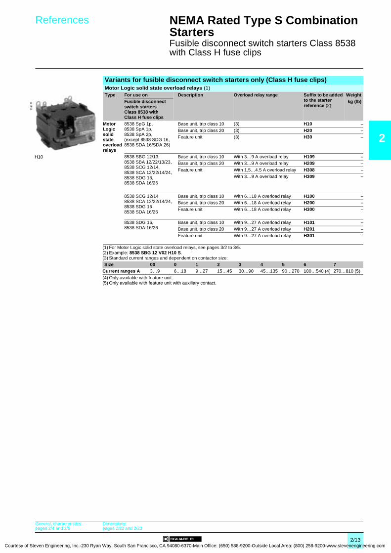
Courtesy of S
References 0 NEMA Rated Type S Combination Starters 0
Fusible disconnect switch starters Class 8538 with Class H fuse clips
2
Variants for fusible disconnect switch starters only (Class H fuse clips)Motor Logic solid state overload relays (1)Type For use on Description Overload relay range Suffix to be added
to the starter reference (2)
WeightFusible disconnect switch starters Class 8538 with Class H fuse clips
kg (lb)
Motor Logic solid state overload relays
8538 SpG 1p,8538 SpA 1p,8538 SpA 2p,(except 8538 SDG 16, 8538 SDA 16/SDA 26)
Base unit, trip class 10 (3) H10 –
Base unit, trip class 20 (3) H20 –Feature unit (3) H30 –
8538 SBG 12/13, 8538 SBA 12/22/13/23,8538 SCG 12/14,8538 SCA 12/22/14/24,8538 SDG 16,8538 SDA 16/26
Base unit, trip class 10 With 3…9 A overload relay H109 –Base unit, trip class 20 With 3…9 A overload relay H209 –
Feature unit With 1.5…4.5 A overload relay H308 –With 3…9 A overload relay H309 –
8538 SCG 12/148538 SCA 12/22/14/24,8538 SDG 168538 SDA 16/26
Base unit, trip class 10 With 6…18 A overload relay H100 –Base unit, trip class 20 With 6…18 A overload relay H200 –
Feature unit With 6…18 A overload relay H300 –
8538 SDG 16,8538 SDA 16/26
Base unit, trip class 10 With 9…27 A overload relay H101 –
Base unit, trip class 20 With 9…27 A overload relay H201 –Feature unit With 9…27 A overload relay H301 –
(1) For Motor Logic solid state overload relays, see pages 3/2 to 3/5.(2) Example: 8538 SBG 12 V02 H10 S.(3) Standard current ranges and dependent on contactor size:Size 00 0 1 2 3 4 5 6 7
Current ranges A 3…9 6…18 9…27 15…45 30…90 45…135 90…270 180…540 (4) 270…810 (5)
(4) Only available with feature unit.(5) Only available with feature unit with auxiliary contact.
H10
5311
23
General, characteristics:pages 2/4 and 2/5
Dimensions:pages 2/22 and 2/23
2/13teven Engineering, Inc.-230 Ryan Way, South San Francisco, CA 94080-6370-Main Office: (650) 588-9200-Outside Local Area: (800) 258-9200-www.stevenengineering.com

2
Courtesy
Associations 0 NEMA Rated Type S Combination Starters 0
Fusible disconnect switch starters Class 8538 (Class R fuse clips) with solid state overload relays
AssociationsRatings For use on Motor Logic solid state overload relaysMotor voltage
NEMASize
Class 10 Class 20 Class 30 (selectable)8538 – 3-9 A 6-18 A 9-27 A – 3-9 A 6-18 A 9-27 A – 1.5-4.5 A 3-9 A 6-18 A 9-27 A
200 V 0 SBG 32, SBA 42/32 H10 H109 H20 H209 H30 H308 H3091 SCG 32, SCA 42/32 H10 H109 H100 H20 H209 H200 H30 H308 H309 H300
SCG 33, SCA 43/33 H10 H20 H302 SDG 32, SDA 42/32 H10 H20 H303 SEG 35, SEA 45/35 H10 H20 H30
SEG 32, SEA 42/32 H10 H20 H304 SFG 35, SFA 45/35 H10 H20 H305 SGG 35, SGA 45/35 H10 H20 H306 SHG 33, SHA 43/33 H10 H20 H30
230 V 0 SBG 32, SBA 42/32 H10 H109 H20 H209 H30 H308 H3091 SCG 32, SCA 42/32 H10 H109 H100 H20 H209 H200 H30 H308 H309 H300
SCG 33, SCA 43/33 H10 H20 H302 SDG 32, SDA 42/32 H10 H20 H303 SEG 35, SEA 45/35 H10 H20 H30
SEG 32, SEA 42/32 H10 H20 H304 SFG 35, SFA 45/35 H10 H20 H305 SGG 35, SGA 45/35 H10 H20 H306 SHG 33, SHA 43/33 H10 H20 H30
460 V 0 SBG 33, SBA 43/33 H10 H109 H20 H209 H30 H308 H3091 SCG 34, SCA 44/34 H10 H109 H100 H20 H209 H200 H30 H308 H309 H3002 SDG 36, SDA 46/36 H109 H100 H101 H209 H200 H201 H308 H309 H300 H3013 SDG 34, SDA 44/34 H10 H20 H30
SEG 33, SEA 43/33 H10 H20 H304 SFG 33, SFA 43/33 H10 H20 H305 SGG 33, SGA 43/33 H10 H20 H306 SHG 32, SHA 42/32 H10 H20 H30
575 V 0 SBG 33, SBA 43/33 H10 H109 H20 H209 H30 H308 H3091 SCG 34, SCA 44/34 H10 H109 H100 H20 H209 H200 H30 H308 H309 H3002 SDG 36, SDA 46/36 H109 H100 H101 H209 H200 H201 H308 H309 H300 H3013 SDG 34, SDA 44/34 H10 H20 H30
SEG 33, SEA 43/33 H10 H20 H304 SFG 33, SFA 43/33 H10 H20 H305 SGG 33, SGA 43/33 H10 H20 H306 SHG 32, SHA 42/32 H10 H20 H30
Available codes
Not available
General, characteristics:pages 2/4 and 2/5
Dimensions:pages 2/22 and 2/23
2/14 of Steven Engineering, Inc.-230 Ryan Way, South San Francisco, CA 94080-6370-Main Office: (650) 588-9200-Outside Local Area: (800) 258-9200-www.stevenengineering.com

Courtesy of S
Associations 0 NEMA Rated Type S Combination Starters 0
Non-fusible disconnect switch starters Class 8538 with solid state overload relays
2
AssociationsRatings For use on Motor Logic solid state overload relaysMotor voltage
NEMASize
Class 10 Class 20 Class 30 (selectable)8538 – 3-9 A 6-18 A – 3-9 A 6-18 A – 1.5-4.5 A 3-9 A 6-18 A
200 V 0 SBG 11, SBA 21/11 H10 H109 H20 H209 H30 H308 H3091 SCG 11, SCA 21/11 H10 H109 H100 H20 H209 H200 H30 H308 H309 H3002 SDG 11, SDA 21/11 H10 H20 H303 SEG 11, SEA 21/11 H10 H20 H304 SFG 11, SFA 21/11 H10 H20 H305 SGG 11, SGA 21/11 H10 H20 H306 SHG 11, SHA 21/11 H10 H20 H30
230 V 0 SBG 11, SBA 21/11 H10 H109 H20 H209 H30 H308 H3091 SCG 11, SCA 21/11 H10 H109 H100 H20 H209 H200 H30 H308 H309 H3002 SDG 11, SDA 21/11 H10 H20 H303 SEG 11, SEA 21/11 H10 H20 H304 SFG 11, SFA 21/11 H10 H20 H305 SGG 11, SGA 21/11 H10 H20 H306 SHG 11, SHA 21/11 H10 H20 H30
460 V 0 SBG 11, SBA 21/11 H10 H109 H20 H209 H30 H308 H3091 SCG 11, SCA 21/11 H10 H109 H100 H20 H209 H200 H30 H308 H309 H3002 SDG 11, SDA 21/11 H10 H20 H303 SEG 11, SEA 21/11 H10 H20 H304 SFG 11, SFA 21/11 H10 H20 H305 SGG 11, SGA 21/11 H10 H20 H306 SHG 11, SHA 21/11 H10 H20 H30
575 V 0 SBG 11, SBA 21/11 H10 H109 H20 H209 H30 H308 H3091 SCG 11, SCA 21/11 H10 H109 H100 H20 H209 H200 H30 H308 H309 H3002 SDG 11, SDA 21/11 H10 H20 H303 SEG 11, SEA 21/11 H10 H20 H304 SFG 11, SFA 21/11 H10 H20 H305 SGG 11, SGA 21/11 H10 H20 H306 SHG 11, SHA 21/11 H10 H20 H30
Available codes
Not available
General, characteristics:pages 2/4 and 2/5
Dimensions:pages 2/22 and 2/23
2/15teven Engineering, Inc.-230 Ryan Way, South San Francisco, CA 94080-6370-Main Office: (650) 588-9200-Outside Local Area: (800) 258-9200-www.stevenengineering.com

2
Courtesy
Associations 0 NEMA Rated Type S Combination Starters 0
Mag-Gard circuit-breaker starters Class 8539 with solid state overload relays
AssociationsRatings For use on Motor Logic solid state overload relaysMotor voltage
NEMASize
Class 10 Class 20 Class 30 (selectable)8539 – 3-9 A 6-18 A 9-27 A – 3-9 A 6-18 A 9-27 A – 1.5-4.5 A 3-9 A 6-18 A 9-27 A
200 V 0 SBG 41, SBA 51/41 H308SBG 42, SBA 52/42 H109 H209 H308 H309SBG 43, SBA 53/43 H109 H209 H309
1 SCG 41, SCA 51/41 H308SCG 42, SCA 52/42 H109 H209 H308 H309SCG 43, SCA 53/43 H100 H200 H300SCG 44, SCA 54/44 H10 H20 H30SCG 45, SCA 55/45 H10 H20 H30
2 SDG 41, SDA 51/41 H100 H200 H300SDG 42, SDA 52/42 H101 H201 H301SDG 43, SDA 53/43 H10 H20 H30
3 SEG 42, SEA 52/42 H10 H20 H304 SFG 42, SFA 52/42 H10 H20 H30
SFG 43, SFA 53/43 H10 H20 H305 SGG 42, SGA 52/42 H10 H20 H30
SGG 44, SGA 54/44 H10 H20 H30SGG 45, SGA 55/45 H10 H20 H30
6 SHG 43, SHA 53/43 H10 H20 H30SHG 44, SHA 54/44 H10 H20 H30SHG 45, SHA 55/45 H10 H20 H30
230 V 0 SBG 41, SBA 51/41 H308SBG 42, SBA 52/42 H109 H209 H308 H309SBG 43, SBA 53/43 H109 H209 H309
1 SCG 41, SCA 51/41 H308SCG 42, SCA 52/42 H109 H209 H308 H309SCG 43, SCA 53/43 H100 H200 H300SCG 44, SCA 54/44 H10 H20 H30
2 SDG 41, SDA 51/41 H100 H200 H300SDG 42, SDA 52/42 H101 H201 H301SDG 43, SDA 53/43 H10 H20 H30SDG 44, SDA 54/44 H10 H20 H30
3 SEG 42, SEA 52/42 H10 H20 H304 SFG 43, SFA 53/43 H10 H20 H30
SFG 44, SFA 54/44 H10 H20 H305 SGG 43, SGA 53/43 H10 H20 H30
SGG 44, SGA 54/44 H10 H20 H30SGG 46, SGA 56/46 H10 H20 H30
6 SHG 44, SHA 54/44 H10 H20 H30SHG 46, SHA 56/46 H10 H20 H30
7 SJG 42, SJA 52 H10 H20 H30SJG 43, SJA 53 H10 H20 H30
Available codes
Not available
General, characteristics:pages 2/4 and 2/5
Dimensions:pages 2/22 and 2/23
2/16 of Steven Engineering, Inc.-230 Ryan Way, South San Francisco, CA 94080-6370-Main Office: (650) 588-9200-Outside Local Area: (800) 258-9200-www.stevenengineering.com

Courtesy of S
Associations (continued) 0 NEMA Rated Type S Combination Starters 0
Mag-Gard circuit-breaker starters Class 8539 with solid state overload relays
2
Associations (continued)Ratings For use on Motor Logic solid state overload relaysMotor voltage
NEMASize
Class 10 Class 20 Class 30 (selectable)8539 – 3-9 A 6-18 A 9-27 A – 3-9 A 6-18 A 9-27 A – 1.5-4.5 A 3-9 A 6-18 A 9-27 A
460 V 0 SBG 41, SBA 51/41 H308SBG 42, SBA 52/42 H109 H209 H308 H309SBG 43, SBA 53/43 H109 H209 H309
1 SCG 41, SCA 51/41 H308SCG 42, SCA 52/42 H109 H209 H308 H309SCG 43, SCA 53/43 H100 H200 H300SCG 44, SCA 54/44 H10 H20 H30
2 SDG 41, SDA 51/41 H100 H200 H300SDG 42, SDA 52/42 H101 H201 H301SDG 43, SDA 53/43 H10 H20 H30
3 SEG 41, SEA 51/41 H10 H20 H30SEG 42, SEA 52/42 H10 H20 H30
4 SFG 42, SFA 52/42 H10 H20 H30SFG 44, SFA 54/44 H10 H20 H30
5 SGG 43, SGA 53/43 H10 H20 H30SGG 44, SGA 54/44 H10 H20 H30SGG 46, SGA 56/46 H10 H20 H30
6 SHG 43, SHA 53/43 H10 H20 H30SHG 44, SHA 54/44 H10 H20 H30SHG 45, SHA 55/45 H10 H20 H30SHG 46, SHA 56/46 H10 H20 H30
7 SJG 42, SJA 52 H10 H20 H30SJG 43, SJA 53 H10 H20 H30
575 V 0 SBG 41, SBA 51/41 H308SBG 42, SBA 52/42 H109 H209 H308 H309SBG 43, SBA 53/43 H109 H209 H309
1 SCG 41, SCA 51/41 H308SCG 42, SCA 52/42 H109 H209 H308 H309SCG 43, SCA 53/43 H100 H200 H300
2 SDG 41, SDA 51/41 H100 H200 H300SDG 42, SDA 52/42 H101 H201 H301SDG 43, SDA 53/43 H10 H20 H30
3 SEG 41, SEA 51/41 H10 H20 H30SEG 42, SEA 52/42 H10 H20 H30
4 SFG 42, SFA 52/42 H10 H20 H305 SGG 41, SGA 51/41 H10 H20 H30
SGG 42, SGA 52/42 H10 H20 H30SGG 44, SGA 54/44 H10 H20 H30
6 SHG 42, SHA 52/42 H10 H20 H30SHG 43, SHA 53/43 H10 H20 H30SHG 44, SHA 54/44 H10 H20 H30
7 SJG 41, SJA 51 H10 H20 H30SJG 42, SJA 52 H10 H20 H30
Available codes
Not available
General, characteristics:pages 2/4 and 2/5
Dimensions:pages 2/22 and 2/23
2/17teven Engineering, Inc.-230 Ryan Way, South San Francisco, CA 94080-6370-Main Office: (650) 588-9200-Outside Local Area: (800) 258-9200-www.stevenengineering.com

2
Courtesy
Associations 0 NEMA Rated Type S Combination Starters 0
Thermal magnetic circuit-breaker starters with solid state overload relays
AssociationsRatings For use on Motor Logic solid state overload relaysMotor voltage
NEMASize
Class 10 Class 20 Class 30 (selectable)8539 – 3-9 A 6-18 A – 3-9 A 6-18 A – 1.5-4.5 A 3-9 A 6-18 A
200 V 0 SBG 1, SBA 11/1 H109 H209 H308 H309SBG 3, SBA 13/3 H10 H20 H30
1 SCG 5, SCA 15/5 H10 H20 H30SCG 2, SCA 12/2 H10 H20 H30
2 SDG 1, SDA 11/1 H10 H20 H303 SEG 3, SEA 13/3 H10 H20 H30
SEG 1, SEA 11/1 H10 H20 H30SEG 5, SEA 15/5 H10 H20 H30
4 SFG 3, SFA 13/3 H10 H20 H30SFG 4, SFA 14/4 H10 H20 H30
5 SGG 6, SGA 16/6 H10 H20 H30SGG 1, SGA 11/1 H10 H20 H30SGG 4, SGA 14/4 H10 H20 H30
6 SHG 4, SHA 14/4 H10 H20 H30SHG 3, SHA 13/3 H10 H20 H30SHG 5, SHA 15/5 H10 H20 H30
230 V 0 SBG 1, SBA 11/1 H109 H209 H308 H309SBG 3, SBA 13/3 H10 H20 H30
1 SCG 1, SCA 11/1 H10 H20 H30SCG 6, SCA 16/6 H10 H20 H30
2 SDG 1, SDA 11/1 H10 H20 H30SDG 7, SDA 17/7 H10 H20 H30
3 SEG 3, SEA 13/3 H10 H20 H30SEG 1, SEA 11/1 H10 H20 H30SEG 5, SEA 15/5 H10 H20 H30
4 SFG 1, SFA 11/1 H10 H20 H30SFG 4, SFA 14/4 H10 H20 H30
5 SGG 3, SGA 13/3 H10 H20 H30SGG 1, SGA 11/1 H10 H20 H30SGG 2, SGA 12/2 H10 H20 H30
6 SHG 4, SHA 14/4 H10 H20 H30SHG 3, SHA 13/3 H10 H20 H30SHG 7, SHA 17/7 H10 H20 H30
7 SJG 2, SJA 12 H10 H20 H30SJG 3, SJA 13 H10 H20 H30
Available codes
Not available
General, characteristics:pages 2/4 and 2/5
Dimensions:pages 2/22 and 2/23
2/18 of Steven Engineering, Inc.-230 Ryan Way, South San Francisco, CA 94080-6370-Main Office: (650) 588-9200-Outside Local Area: (800) 258-9200-www.stevenengineering.com

Courtesy of S
Associations (continued) 0 NEMA Rated Type S Combination Starters 0
Thermal magnetic circuit-breaker starters with solid state overload relays
2
Associations (continued)Ratings For use on Motor Logic solid state overload relaysMotor voltage
NEMASize
Class 10 Class 20 Class 30 (selectable)8539 – 3-9 A 6-18 A – 3-9 A 6-18 A – 1.5-4.5 A 3-9 A 6-18 A
460 V 0 SBG 2, SBA 12/2 H109 H209 H308 H3091 SCG 3, SCA 13/3 H100 H200 H300
SCG 7, SCA 17/7 H100 H200 H3002 SDG 3, SDA 13/3 H10 H20 H30
SDG 4, SDA 14/4 H10 H20 H30SDG 5, SDA 15/5 H10 H20 H30
3 SEG 6, SEA 16/6 H10 H20 H30SEG 3, SEA 13/3 H10 H20 H30SEG 1, SEA 11/1 H10 H20 H30
4 SFG 5, SFA 15/5 H10 H20 H30SFG 3, SFA 13/3 H10 H20 H30SFG 4, SFA 14/4 H10 H20 H30
5 SGG 3, SGA 13/3 H10 H20 H30SGG 1, SGA 11/1 H10 H20 H30SGG 2, SGA 12/2 H10 H20 H30
6 SHG 4, SHA 14/4 H10 H20 H30SHG 3, SHA 13/3 H10 H20 H30SHG 5, SHA 15/5 H10 H20 H30SHG 7, SHA 17/7 H10 H20 H30
7 SJG 2, SJA 12 H10 H20 H30SJG 3, SJA 13 H10 H20 H30
575 V 0 SBG 2, SBA 12/2 H109 H209 H308 H3091 SCG 8, SCA 18/8 H100 H200 H300
SCG 3, SCA 13/3 H100 H200 H3002 SDG 8, SDA 18/8 H10 H20 H30
SDG 9, SDA 19/9 H10 H20 H30SDG 4, SDA 14/4 H10 H20 H30
3 SEG 4, SEA 14/4 H10 H20 H30SEG 6, SEA 16/6 H10 H20 H30SEG 3, SEA 13/3 H10 H20 H30
4 SFG 6, SFA 16/6 H10 H20 H30SFG 5, SFA 15/5 H10 H20 H30SFG 1, SFA 11/1 H10 H20 H30
5 SGG 7, SGA 17/7 H10 H20 H30SGG 6, SGA 16/6 H10 H20 H30SGG 1, SGA 11/1 H10 H20 H30
6 SHG 6, SHA 16/6 H10 H20 H30SHG 4, SHA 14/4 H10 H20 H30SHG 2, SHA 12/2 H10 H20 H30SHG 3, SHA 13/3 H10 H20 H20
7 SJG 1, SJA 11 H10 H20 H30SJG 2, SJA 12 H10 H20 H30
Available codes
Not available
General, characteristics:pages 2/4 and 2/5
Dimensions:pages 2/22 and 2/23
2/19teven Engineering, Inc.-230 Ryan Way, South San Francisco, CA 94080-6370-Main Office: (650) 588-9200-Outside Local Area: (800) 258-9200-www.stevenengineering.com
2
Courtesy
Characteristics 0 NEMA Rated Type S Combination Starters 0
Accessories
CharacteristicsClass 9999Type Single-pole electrical interlocks
Electrical ratingsMaximum current
Make Break Continuous carrying current
50/60 Hz a 120 V A 40 15 15a 240 V A 20 10 15a 480 V A 10 8 15
a 600 V A 8 6 15Class 9999Type 2-pole electrical interlocks
Electrical ratingsMaximum current
Make Break Continuous carrying current
50/60 Hz a 120 V A 30 3 10VA 3450 345 –
a 240 V A 15 1.5 10
VA 3450 345 –a 480 V A 7.5 0.75 10
VA 3450 345 –
a 600 V A 6 0.6 10VA 3450 345 –
General, characteristics:pages 2/4 and 2/5
Dimensions:pages 2/22 and 2/23
2/20 of Steven Engineering, Inc.-230 Ryan Way, South San Francisco, CA 94080-6370-Main Office: (650) 588-9200-Outside Local Area: (800) 258-9200-www.stevenengineering.com
Courtesy of S
References 0 NEMA Rated Type S Combination Starters 0
Accessories
2
VariantsType For use on Description Suffix to be added
to the starter reference (1)
Weightkg (lb)
Interlocks Disconnect switch starters 8538 Spp or circuit-breaker starters 8539 Spp
Single-pole Y74 –
2-pole Y75 –
Control transformers
Disconnect switch starters 8538 Spp or circuit-breaker starters 8539 Spp
Standard capacity F4T –50 VA additional capacity F4T10 –
100 VA additional capacity F4T11 –200 VA additional capacity F4T12 –
InterlocksType For use on Description Reference Weight
kg (lb)Class Type (2)Interlocks 8538 SB, SC, SD
(Series B) (3)Single-pole 9999 R6 –
2-pole 9999 R7 –SD(Series C)
Single-pole 9999 R43 –2-pole 9999 R44 –
SB, SC(Series C)
Single-pole 9999 R45 –2-pole 9999 R46 –
SE, SF(Series A)
Single-pole 9999 R8 –
2-pole 9999 R9 –SE(Series B and C)
Single-pole 9999 R41 –2-pole 9999 R42 –
SF(Series B and C)
Single-pole 9999 R39 –2-pole 9999 R40 –
SG Single-pole 9999 R35 –2-pole 9999 R36 –
SBA, SCA, SBG,SCG (Series D)
Single-pole 9999 TC11 –
2-pole 9999 TC21 –SBAS8, SCAS8,SBGS8, SCGS8(Series D),SDA, SDA (3),SDG, SDG (3)(Series D),SEA, SEG(Series D)
Single-pole 9999 TC10 –2-pole 9999 TC20 –
8539 SB, SC, SD, SE,SF, SG (4)
Single-pole 9999 R26 –2-pole 9999 R27 –
(1) Example: 8538 SBG 12 V01 Y74.(2) Series A, B, C and D are product versions.(3) Class 8538 type numbers ending in suffix "S8".(4) No interlocks available, when used with the GJL circuit-breaker.
General, characteristics:pages 2/4 and 2/5
Dimensions:pages 2/22 and 2/23
2/21teven Engineering, Inc.-230 Ryan Way, South San Francisco, CA 94080-6370-Main Office: (650) 588-9200-Outside Local Area: (800) 258-9200-www.stevenengineering.com

2
Courtesy
Dimensions 0
NEMA Rated Type S Combination Starters 0
Disconnect switch starters Circuit-breaker starters
Dimensions in mm (25.4 mm = 1 inch)
Combination starters 8538 SpGA B C D E F G H I
8538 SBG 175.3 469.9 175.3 165.1 0 88.9 86.4 175.3 101.68538 SCG 175.3 469.9 175.3 165.1 0 88.9 86.4 175.3 101.68538 SDG 200.7 558.8 190.5 177.8 78.7 121.9 0 195.6 152.4
8538 SEG 304.8 749.3 228.6 195.6 0 142.2 162.6 327.7 134.68538 SFG 330.2 990.6 279.4 292.1 0 177.8 152.4 330.2 228.68538 SGG (1) 439.4 1498.6 342.9 635.0 0 274.3 165.1 520.7 –
8538 SHG 812.8 2082.8 812.8 1016.0 0 330.2 482.6 889.0 –(1) Combination starter does not contain a full size panel. No usable panel space is available.
Available space for field requirements
Combination starters 8539 SpGA B C D E F G H
8539 SBG 175.3 469.9 165.1 200.7 0 88.9 86.4 175.38539 SCG 175.3 469.9 165.1 200.7 0 88.9 86.4 175.3
8539 SDG 200.7 558.8 165.1 162.6 78.7 121.9 0 195.68539 SEG + FAL (1) 304.8 749.3 165.1 215.9 0 142.2 162.6 327.78539 SEG + KAL (1) 304.8 749.3 172.7 266.7 0 142.2 162.6 327.7
8539 SFG 330.2 990.6 172.7 317.5 0 177.8 152.4 330.28539 SGG + KAL (1) (2) 439.4 1498.6 172.7 584.2 0 274.3 165.1 520.78539 SGG + LAL (1) (2) 439.4 1498.6 228.6 622.3 0 274.3 165.1 520.7
8539 SHG + LAL (1) 812.8 2082.8 228.6 647.7 0 330.2 482.6 889.08539 SHG + MAL (1) 812.8 2082.8 317.5 1028.7 0 330.2 482.6 889.0(1) Circuit-breaker.(2) Combination starter does not contain a full size panel. No usable panel space is available.
Available space for field requirements
C
GFE
A
H
D
B
I
DisconnectSwitch
FuseBase
Starter
C
GFE
A
H
D
B
Starter
Breaker
General, characteristics:pages 2/4 and 2/5
References:pages 2/6 to 2/21
2/22 of Steven Engineering, Inc.-230 Ryan Way, South San Francisco, CA 94080-6370-Main Office: (650) 588-9200-Outside Local Area: (800) 258-9200-www.stevenengineering.com

Courtesy of S
Dimensions (continued)
0
NEMA Rated Type S Combination Starters 0
Disconnect switch starters Circuit-breaker starters
Dimensions in mm (25.4 mm = 1 inch)
2
Combination starters 8538/8539 SBG to SDG (NEMA 1 enclosure)A B C D E F G H I J
8538/8539 SBG 241.3 571.5 211.8 161.9 520.7 372.1 46.0 42.7 76.2 58.78538/8539 SCG 241.3 571.5 211.8 161.9 520.7 372.1 46.0 42.7 76.2 58.78538/8539 SDG 266.7 660.4 243.6 187.3 609.6 429.3 54.0 50.8 101.6 25.4
K L M N O W X Y8538/8539 SBG 26.9 82.6 55.4 31.8 22.2 12.7-19.1 12.7-19.1 12.78538/8539 SCG 26.9 82.6 55.4 31.8 22.2 12.7-19.1 12.7-19.1 12.7
8538/8539 SDG 26.9 82.6 55.4 31.8 22.2 25.4-31.8 12.7-19.2 12.7
Combination starters 8538/8539 SEG to SJG (NEMA 1 enclosure)A B C D E F G H J K
8538 SEG 387.4 1066.8 269.0 235.0 76.2 576.8 1041.4 12.7 71.6 89.78539 SEG 387.4 1066.8 269.0 235.0 76.2 576.8 1041.4 12.7 71.6 89.78538/8539 SFG 406.4 1333.5 267.5 254.0 76.2 600.7 1308.1 12.7 71.6 89.7
8538 SGG 508.0 1981.2 393.7 304.8 101.6 746.8 1955.8 12.7 89.2 114.68539 SGG 508.0 1676.4 348.2 304.8 101.6 746.8 1651.0 12.7 89.2 114.68538/8539 SHG 914.4 2286.0 534.2 – – 1050.9 – – – –
8539 SJG 863.6 533.4 2286.0 – – 1257.3 – – – –L M N O W X Y
8538 SEG 127.0 68.1 136.5 32.5 25.4-31.8 12.7-19.2 12.7
8539 SEG 127.0 68.1 136.5 32.5 50.8-63.5 12.7-19.3 12.78538/8539 SFG 127.0 68.1 136.5 32.5 63.5 12.7-19.4 12.78538 SGG 235.0 80.8 – – 12.7-19.1 76.2 –
8539 SGG 127.0 80.8 – – 12.7-19.2 76.2 –8538/8539 SHG 127.0 – – – – – –8539 SJG 127.0 – – – – – –
Combination starters 8538/8539 SpA (NEMA 12 enclosure)A B C D E F G H I J
8538/8539 SBA 241.3 211.8 609.6 82.6 63.5 114.3 596.9 15.0 112.5 363.58538/8539 SCA 241.3 211.8 609.6 82.6 63.5 114.3 596.9 15.0 112.5 363.5
8538/8539 SDA 266.7 243.6 704.9 82.6 63.5 139.7 685.8 9.5 104.8 420.68538/8539 SEA 387.4 269.0 1066.8 127.0 76.2 235.0 1041.4 12.7 128.5 566.78538 SFA 406.4 267.5 1333.5 127.0 76.2 254.0 1308.1 12.7 106.2 583.2
8539 SFA 406.4 267.5 1333.5 127.0 76.2 254.0 1308.1 12.7 131.6 583.28538 SGA 508.0 348.2 1981.2 235.0 101.6 304.8 1955.8 12.7 197.6 746.88539 SGA 508.0 348.2 1676.4 127.0 101.6 304.8 1651.0 12.7 197.6 696.0
8538/8539 SHA 914.4 431.8 2286.0 127.0 – – – – – 1203.38539 SJA 863.6 533.4 2286.0 127.0 – – – – – 1257.3
Combination starters 8538/8539 SpG pp S8 and 8538/8539 SpA pp S8 (NEMA 12 enclosure)A B C D E L
8538/8539 SpG pp S8 381.0 730.3 243.6 295.3 666.8 82.6
8538/8539 SpA pp S8 381.0 787.4 278.4 228.6 768.4 82.6(2) 0.31/8 dia. mounting holes.
(1) 0.31 in. (8 mm) dia. mounting holes for Sizes 0, 1, and 2, 0.44 in. (11 mm) dia. mounting holes for Sizes 3 and 4 , 0.56 in. (14 mm) dia. mounting holes located on 14 external flanges for Size 5.
YO
N
C
E B
KMD
A
Y
(1)
F
W X W
G
JH
I
L
Cover Open 90°
DA
E HL C
P
O
Y
BG
Y
J
NM
K
W X W
F
(1)
Cover Open 90°
B
C
FA
(1)
J
I
DE
G
H
C
E B
D
A
(2)
L
General, characteristics:pages 2/4 and 2/5
References:pages 2/6 to 2/21
2/23teven Engineering, Inc.-230 Ryan Way, South San Francisco, CA 94080-6370-Main Office: (650) 588-9200-Outside Local Area: (800) 258-9200-www.stevenengineering.com

3/0Courtesy of Steven Engineering, Inc.-230 Ryan Way, South San Francisco
3 -
, CA 94080-6370-Main Office: (650) 588-9200-Outside Local Area: (800) 258-9200-www.stevenengineering.com

Contents
Courtesy of Steven Engineering, Inc.-230 Ryan Way, South San Francisco, CA
3 - Solid State Overload Relays
3
b Motor Logic base unit
v General, description. . . . . . . . . . . . . . . . . . . . . . . . . . . . . . . . . . . . . . . page 3/2
v Characteristics . . . . . . . . . . . . . . . . . . . . . . . . . . . . . . . . . . . . . . . . . . . page 3/3
v References . . . . . . . . . . . . . . . . . . . . . . . . . . . . . . . . . . . . . . . . . . . . . page 3/4
v Dimensions . . . . . . . . . . . . . . . . . . . . . . . . . . . . . . . . . . . . . . . . . . . . . page 3/6
b Motor Logic feature unit
v General, description. . . . . . . . . . . . . . . . . . . . . . . . . . . . . . . . . . . . . . . page 3/2
v Characteristics . . . . . . . . . . . . . . . . . . . . . . . . . . . . . . . . . . . . . . . . . . . page 3/3
v References . . . . . . . . . . . . . . . . . . . . . . . . . . . . . . . . . . . . . . . . . . . . . page 3/4
v Dimensions . . . . . . . . . . . . . . . . . . . . . . . . . . . . . . . . . . . . . . . . . . . . . page 3/6
b Motor Logic Plus programmable unit
v General, description. . . . . . . . . . . . . . . . . . . . . . . . . . . . . . . . . . . . . . . page 3/2
v Characteristics . . . . . . . . . . . . . . . . . . . . . . . . . . . . . . . . . . . . . . . . . . . page 3/3
v References . . . . . . . . . . . . . . . . . . . . . . . . . . . . . . . . . . . . . . . . . . . . . page 3/5
v Dimensions . . . . . . . . . . . . . . . . . . . . . . . . . . . . . . . . . . . . . . . . . . . . . page 3/7
3/1 94080-6370-Main Office: (650) 588-9200-Outside Local Area: (800) 258-9200-www.stevenengineering.com
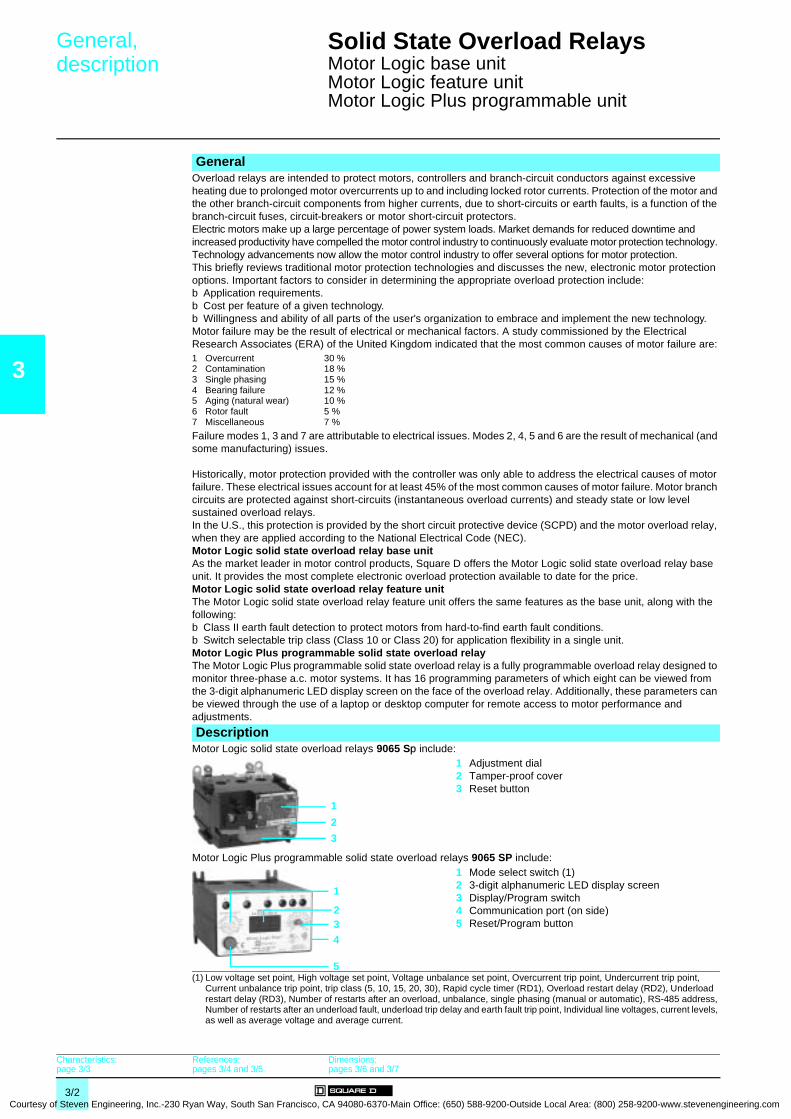
3
Courtesy
General,description 0
Solid State Overload Relays 0
Motor Logic base unitMotor Logic feature unitMotor Logic Plus programmable unit
GeneralOverload relays are intended to protect motors, controllers and branch-circuit conductors against excessive heating due to prolonged motor overcurrents up to and including locked rotor currents. Protection of the motor and the other branch-circuit components from higher currents, due to short-circuits or earth faults, is a function of the branch-circuit fuses, circuit-breakers or motor short-circuit protectors.Electric motors make up a large percentage of power system loads. Market demands for reduced downtime and increased productivity have compelled the motor control industry to continuously evaluate motor protection technology. Technology advancements now allow the motor control industry to offer several options for motor protection.This briefly reviews traditional motor protection technologies and discusses the new, electronic motor protection options. Important factors to consider in determining the appropriate overload protection include:b Application requirements.b Cost per feature of a given technology.b Willingness and ability of all parts of the user's organization to embrace and implement the new technology.Motor failure may be the result of electrical or mechanical factors. A study commissioned by the Electrical Research Associates (ERA) of the United Kingdom indicated that the most common causes of motor failure are:1 Overcurrent2 Contamination3 Single phasing4 Bearing failure5 Aging (natural wear)6 Rotor fault7 Miscellaneous
30 %18 %15 %12 %10 %5 %7 %
Failure modes 1, 3 and 7 are attributable to electrical issues. Modes 2, 4, 5 and 6 are the result of mechanical (and some manufacturing) issues.
Historically, motor protection provided with the controller was only able to address the electrical causes of motor failure. These electrical issues account for at least 45% of the most common causes of motor failure. Motor branch circuits are protected against short-circuits (instantaneous overload currents) and steady state or low level sustained overload relays.In the U.S., this protection is provided by the short circuit protective device (SCPD) and the motor overload relay, when they are applied according to the National Electrical Code (NEC).Motor Logic solid state overload relay base unitAs the market leader in motor control products, Square D offers the Motor Logic solid state overload relay base unit. It provides the most complete electronic overload protection available to date for the price.Motor Logic solid state overload relay feature unitThe Motor Logic solid state overload relay feature unit offers the same features as the base unit, along with the following:b Class II earth fault detection to protect motors from hard-to-find earth fault conditions.b Switch selectable trip class (Class 10 or Class 20) for application flexibility in a single unit.Motor Logic Plus programmable solid state overload relayThe Motor Logic Plus programmable solid state overload relay is a fully programmable overload relay designed to monitor three-phase a.c. motor systems. It has 16 programming parameters of which eight can be viewed from the 3-digit alphanumeric LED display screen on the face of the overload relay. Additionally, these parameters can be viewed through the use of a laptop or desktop computer for remote access to motor performance and adjustments.
DescriptionMotor Logic solid state overload relays 9065 Sp include:
1 Adjustment dial2 Tamper-proof cover3 Reset button
Motor Logic Plus programmable solid state overload relays 9065 SP include:1 Mode select switch (1)2 3-digit alphanumeric LED display screen3 Display/Program switch4 Communication port (on side)5 Reset/Program button
(1) Low voltage set point, High voltage set point, Voltage unbalance set point, Overcurrent trip point, Undercurrent trip point, Current unbalance trip point, trip class (5, 10, 15, 20, 30), Rapid cycle timer (RD1), Overload restart delay (RD2), Underload restart delay (RD3), Number of restarts after an overload, unbalance, single phasing (manual or automatic), RS-485 address, Number of restarts after an underload fault, underload trip delay and earth fault trip point, Individual line voltages, current levels, as well as average voltage and average current.
1
2
3
1
234
5
Characteristics:page 3/3
References:pages 3/4 and 3/5
Dimensions:pages 3/6 and 3/7
3/2 of Steven Engineering, Inc.-230 Ryan Way, South San Francisco, CA 94080-6370-Main Office: (650) 588-9200-Outside Local Area: (800) 258-9200-www.stevenengineering.com

Courtesy of S
Characteristics 0 Solid State Overload Relays 0
Motor Logic base unitMotor Logic feature unitMotor Logic Plus programmable unit
3
Tripping curves Average operating time related to multiples of the current setting
EnvironmentConforming to standards UL 508, NEMA ICS-2, IEC 60947-4-1Product certifications UL Listed, CSA certified, e marked
Ambient air temperaturearound the device
Storage °C - 40...+ 80Operation °C - 25…+ 70
Electrical characteristicsMotor Logic solid state overload relays
Class 9065Type SpB SpC Sp 0 Sp 1 Sp 2 Sp 3 Sp 4 Sp 5 ST 620 ST 720Current ranges A 1.5…4.5 3…9 6…18 9…27 15…45 30…90 45…135 90…270 180…540 270…810Withstand rating (stand alone) A 5000 RMS symmetrical, 600 V 10 000 RMS symmetrical, 600 V
Rated insulation voltage a V 600Control voltage Self-poweredFrequency limits Hz 48…62
Trip contact ratings A600/P300Repeat trip time accuracy ± 2 %Power wire connection Through hole device # 14-4
AWG# 14-1/0 AWG
# 8-250 MCM
# 4-500 MCM
250-500 MCM(1 or 2 per phase)
250-500 MCM(1 to 4 per phase)
Control wire # 16-12 AWG (two per terminal)Lug kit power wire # 14-8 AWG # 14-4
AWG# 14-1/0 AWG
# 8-250 MCM
N/A N/A N/A
DIN adapter 35 mm DIN rail, 7.5 mm track depth
Motor Logic Plus programmable solid state overload relaysClass 9065Type SPBp SPCp SP 1p SP 2p SP 3p SP 4p SP 5p SP 6p
Current ranges A 0.5…2.3 2…9 6…27 10…45 20…90 60…135 120…270 240…540Withstand rating (stand alone) A 100 000 (RMS symmetrical, 600 V) UL
10 000 (RMS symmetrical, 600 V) CSARated insulation voltage a V 600
Control voltage 3-phase, 50/60 Hz a V 200 to 480, 500 to 600Frequency limits Hz 48...66Trip contact ratings B300
Repeat trip time accuracy Voltage ± 0.5 % of nominal voltageCurrent ± 1 % (50 % min to 120 % max overcurrent)
Screen 3-digit alphanumeric LED display screen
Programming parameters 16Power wire connection Through-hole deviceControl wire # 12-22 AWG (two per terminal)
Lug kit power wire # 1/0-14 AWG
10000.0
1000.0
100.0
10.0
1.01.0 10.0
21
1
10
100
1000
10000
0 100 200 300 400 500 600 700 800 900 1000
12
Time (s)
x current setting
1 Class 102 Class 20
Time (s)
1 Class 102 Class 20
Motor Logic units Motor Logic Plus unit
% of OC setting
General, description:page 3/2
References:pages 3/4 and 3/5
Dimensions:pages 3/6 and 3/7
3/3teven Engineering, Inc.-230 Ryan Way, South San Francisco, CA 94080-6370-Main Office: (650) 588-9200-Outside Local Area: (800) 258-9200-www.stevenengineering.com
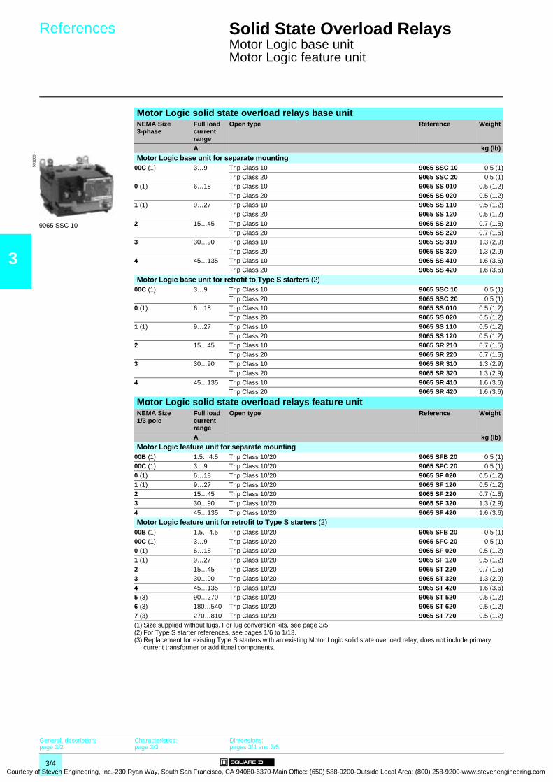
3
Courtesy
References 0 Solid State Overload Relays 0
Motor Logic base unitMotor Logic feature unit
Motor Logic solid state overload relays base unitNEMA Size3-phase
Full loadcurrent range
Open type Reference Weight
A kg (lb)
Motor Logic base unit for separate mounting00C (1) 3…9 Trip Class 10 9065 SSC 10 0.5 (1)
Trip Class 20 9065 SSC 20 0.5 (1)0 (1) 6…18 Trip Class 10 9065 SS 010 0.5 (1.2)
Trip Class 20 9065 SS 020 0.5 (1.2)1 (1) 9…27 Trip Class 10 9065 SS 110 0.5 (1.2)
Trip Class 20 9065 SS 120 0.5 (1.2)
2 15…45 Trip Class 10 9065 SS 210 0.7 (1.5)Trip Class 20 9065 SS 220 0.7 (1.5)
3 30…90 Trip Class 10 9065 SS 310 1.3 (2.9)
Trip Class 20 9065 SS 320 1.3 (2.9)4 45…135 Trip Class 10 9065 SS 410 1.6 (3.6)
Trip Class 20 9065 SS 420 1.6 (3.6)
Motor Logic base unit for retrofit to Type S starters (2)00C (1) 3…9 Trip Class 10 9065 SSC 10 0.5 (1)
Trip Class 20 9065 SSC 20 0.5 (1)0 (1) 6…18 Trip Class 10 9065 SS 010 0.5 (1.2)
Trip Class 20 9065 SS 020 0.5 (1.2)
1 (1) 9…27 Trip Class 10 9065 SS 110 0.5 (1.2)Trip Class 20 9065 SS 120 0.5 (1.2)
2 15…45 Trip Class 10 9065 SR 210 0.7 (1.5)
Trip Class 20 9065 SR 220 0.7 (1.5)3 30…90 Trip Class 10 9065 SR 310 1.3 (2.9)
Trip Class 20 9065 SR 320 1.3 (2.9)4 45…135 Trip Class 10 9065 SR 410 1.6 (3.6)
Trip Class 20 9065 SR 420 1.6 (3.6)
Motor Logic solid state overload relays feature unitNEMA Size1/3-pole
Full loadcurrent range
Open type Reference Weight
A kg (lb)
Motor Logic feature unit for separate mounting00B (1) 1.5…4.5 Trip Class 10/20 9065 SFB 20 0.5 (1)00C (1) 3…9 Trip Class 10/20 9065 SFC 20 0.5 (1)0 (1) 6…18 Trip Class 10/20 9065 SF 020 0.5 (1.2)
1 (1) 9…27 Trip Class 10/20 9065 SF 120 0.5 (1.2)2 15…45 Trip Class 10/20 9065 SF 220 0.7 (1.5)3 30…90 Trip Class 10/20 9065 SF 320 1.3 (2.9)
4 45…135 Trip Class 10/20 9065 SF 420 1.6 (3.6)
Motor Logic feature unit for retrofit to Type S starters (2)00B (1) 1.5…4.5 Trip Class 10/20 9065 SFB 20 0.5 (1)00C (1) 3…9 Trip Class 10/20 9065 SFC 20 0.5 (1)0 (1) 6…18 Trip Class 10/20 9065 SF 020 0.5 (1.2)
1 (1) 9…27 Trip Class 10/20 9065 SF 120 0.5 (1.2)2 15…45 Trip Class 10/20 9065 ST 220 0.7 (1.5)3 30…90 Trip Class 10/20 9065 ST 320 1.3 (2.9)
4 45…135 Trip Class 10/20 9065 ST 420 1.6 (3.6)5 (3) 90…270 Trip Class 10/20 9065 ST 520 0.5 (1.2)6 (3) 180…540 Trip Class 10/20 9065 ST 620 0.5 (1.2)
7 (3) 270…810 Trip Class 10/20 9065 ST 720 0.5 (1.2)(1) Size supplied without lugs. For lug conversion kits, see page 3/5.(2) For Type S starter references, see pages 1/6 to 1/13.(3) Replacement for existing Type S starters with an existing Motor Logic solid state overload relay, does not include primary
current transformer or additional components.
5312
03
9065 SSC 10
General, description:page 3/2
Characteristics:page 3/3
Dimensions:pages 3/4 and 3/5
3/4 of Steven Engineering, Inc.-230 Ryan Way, South San Francisco, CA 94080-6370-Main Office: (650) 588-9200-Outside Local Area: (800) 258-9200-www.stevenengineering.com

Courtesy of S
References 0 Solid State Overload Relays 0
Motor Logic Plus programmable unit
3
Motor Logic Plus programmable solid state overload relaysNEMA Size3-phase
Productdescriptioncurrent range
Voltage Reference Weight
A V kg (lb)00 0.5…2.3 200…480 9065 SPB 4 1 (3)
600 9065 SPB 6 1 (3)
0 2…9 200…480 9065 SPC 4 1 (3)600 9065 SPC 6 1 (3)
1 6…27 200…480 9065 SP 14 1 (3)
600 9065 SP 16 1 (3)2 10…45 200…480 9065 SP 24 1 (3)
600 9065 SP 26 1 (3)
3 20…90 200…480 9065 SP 34 1 (3)600 9065 SP 36 1 (3)
4 (1) 60…135 200…480 9065 SP 44 1 (3)
600 9065 SP 46 1 (3)5 (2) 120…270 200…480 9065 SP 54 1 (3)
600 9065 SP 56 1 (3)
6 (3) 240…540 200…480 9065 SP 64 1 (3)600 9065 SP 66 1 (3)
Variants (for Type S starters)Description Current range Factory modification Reference Weight
A kg (lb)Motor Logic Plus programmable solid state overload relays (to order with starter reference) (4)
0.5…2.3 No modification for 200…480 V B20 –
Add communication module for 200…480 V B22 –No modification for 600 V B24 –
Add communication module for 600 V B26 –2…9 No modification for 200…480 V B30 –
Add communication module for 200…480 V B32 –
No modification for 600 V B34 –Add communication module for 600 V B36 –
6…27 No modification for 200…480 V B40 –
Add communication module for 200…480 V B42 –No modification for 600 V B44 –Add communication module for 600 V B46 –
10…45 No modification for 200…480 V B50 –Add communication module for 200…480 V B52 –No modification for 600 V B54 –
Add communication module for 600 V B56 –20…90 No modification for 200…480 V B60 –
Add communication module for 200…480 V B62 –
No modification for 600 V B64 –Add communication module for 600 V B66 –
60…135 No modification for 200…480 V B70 –
Add communication module for 200…480 V B72 –No modification for 600 V B74 –Add communication module for 600 V B76 –
120…270 No modification for 200…480 V B80 –Add communication module for 200…480 V B82 –No modification for 600 V B84 –
Add communication module for 600 V B86 –240…540 No modification for 200…480 V B90 –
Add communication module for 200…480 V B92 –
No modification for 600 V B94 –Add communication module for 600 V B96 –
KitsType Kit description For use on Reference Weight
kg (lb)Lug-lug kit For separate mounting 9065 Sp (Sizes 00C/0/1 only) 9999 LLO –Lug-extender kit For retrofit to existing Type S
starters9065 Sp (Sizes 00C/0/1 only) 9999 LBO –
(1) Size 4 requires the use of external current transformer. Ratio of 150: 5 recommended.(2) Size 5 requires the use of external current transformer. Ratio of 300: 5 recommended.(3) Size 6 requires the use of external current transformer. Ratio of 600: 5 recommended.(4) For Type S Open style starter references, see pages 1/6 to 1/13.
5312
02
9065 SPB 4
General, description:page 3/2
Characteristics:page 3/3
Dimensions:pages 3/4 and 3/5
3/5teven Engineering, Inc.-230 Ryan Way, South San Francisco, CA 94080-6370-Main Office: (650) 588-9200-Outside Local Area: (800) 258-9200-www.stevenengineering.com

3
Courtesy
Dimensions 0
Solid State Overload Relays 0
Motor Logic base unitMotor Logic feature unit
Dimensions are inchmm------------
Motor Logic solid state overload relays9065 SpB/SpC 9065 SS 2p0/SR 2p0/SF 220/ST 220
(1) 2 holes. 2 slots for 8-32 mounting screws.
9065 SS 3p0/SR 3p0/SF 320/ST 320 9065 SS 4p0/SR 4p0/SF 420/ST 420
RESET
ResetTravel
.246
3.9099
2.2357
.318
.277 .28
7
1.0025
1.5940
3.2683
.369
.8923
2.6968
2.8171
(1)
RESET
4.28109
3.9199
ResetTravel
.246
0.0000
2.1956
3.5189
3.2482
1.7043
1.8447
1.2431
1.2431
RESET
.308
1.0827
1.5038
3.2583
4.74120
5.32135
.297
4.45113
4.16106
5.02128
3.80975.33
135
.3810 1.57
40
2.9675 3.56
902.26
57
1.5740
.328
ResetTravel
.246
.318
RESET
ResetTravel
1.5038
3.2583
4.74120
5.32135
.297
.308
1.0827
5.33135
.3810
1.5740
2.9675
3.5690
2.2657
1.5740
4.53115
4.16106
5.92150
3.8097
.328
.246
.318
General, description:page 3/2
Characteristics:page 3/3
References:pages 3/4 and 3/5
3/6 of Steven Engineering, Inc.-230 Ryan Way, South San Francisco, CA 94080-6370-Main Office: (650) 588-9200-Outside Local Area: (800) 258-9200-www.stevenengineering.com

Courtesy of S
Dimensions (continued)
0
Solid State Overload Relays 0
Motor Logic base unitMotor Logic feature unit Motor Logic Plus programmable unit Dimensions are inch
mm------------
3
Motor Logic solid state overload relays (continued)
9065 ST 520
Motor Logic Plus programmable solid state overload relays9065 SPB/SPC/SP
(1) Optional communication module.
COM
COM
COM 1 2 3
RESET
86
86
MeterLogic®
200
160120
80220
270
2.2557
7.38187
7.75197
5.88149
8.25210
1.1830
2.20(55,9)
2.14(54,4)
200–480 V~50/60 Hz
CONTACT RATINGNEMA B300
5.05(128)
3.85 (97,8)4.37 (111)
3.60 (91,4)
ø 0.65 (16,5)4.70(119)
1.20(30,5)
(1)
7 lb-in (0,8 N m) 96 95 98
™ ®
55)
TC RUN
RESET/PROGRAM
#RU/ADDR
RD2RD1
CUBUCOC
MULTVUBHVLV
GFUCTD#RFRD3
Motor Logic Plus3.0
(77,
2.65(67,3)
2.03(51,6)
0.70(17,8)
0.25(6,35) 0.34
(8,64)
2.28(57,9)
0.20(5,08)
3.10 (78,7)
L1 L2 L3 NO NCC
DISPLAY / PROGRAM9065 SPC42.0-9.0 A, SER. B
MODE SELECT
LISTEDIND. CONT. EQ.
786X
MADE IN USAHECHO EN EUA
FABRIQUE AUX E.U.
L1–L2L2–L3
L3–L1
AV
G
AVG
AB
CVO
LTAG
E CURRE
NT
AA 0149SUITABLE 5 kA RMS
600 VAC MAX
General, description:page 3/2
Characteristics:page 3/3
References:pages 3/4 and 3/5
3/7teven Engineering, Inc.-230 Ryan Way, South San Francisco, CA 94080-6370-Main Office: (650) 588-9200-Outside Local Area: (800) 258-9200-www.stevenengineering.com

4/0Courtesy of Steven Engineering, Inc.-230 Ryan Way, South San Francisco
4 -
, CA 94080-6370-Main Office: (650) 588-9200-Outside Local Area: (800) 258-9200-www.stevenengineering.com

Contents 0
Courtesy of Steven Engineering, Inc.-230 Ryan Way, South San Francisco, CA
4 - Definite Purpose Contactors
4
b Types DP and DPA Class 8910
v General . . . . . . . . . . . . . . . . . . . . . . . . . . . . . . . . . . . . . . . . . . . . . . . . page 4/2
v Characteristics . . . . . . . . . . . . . . . . . . . . . . . . . . . . . . . . . . . . . . . . . . . page 4/3
v References . . . . . . . . . . . . . . . . . . . . . . . . . . . . . . . . . . . . . . . . . . . . . page 4/4
v Accessories . . . . . . . . . . . . . . . . . . . . . . . . . . . . . . . . . . . . . . . . . . . . . page 4/6
v Dimensions . . . . . . . . . . . . . . . . . . . . . . . . . . . . . . . . . . . . . . . . . . . . . page 4/8
4/1 94080-6370-Main Office: (650) 588-9200-Outside Local Area: (800) 258-9200-www.stevenengineering.com
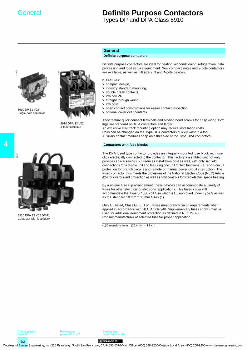
4
Courtesy
General 0 Definite Purpose Contactors 0
Types DP and DPA Class 8910
(1) Dimensions in mm (25.4 mm = 1 inch).
GeneralDefinite purpose contactors
Definite purpose contactors are ideal for heating, air conditioning, refrigeration, data processing and food service equipment. New compact single and 2-pole contactors are available, as well as full size 2, 3 and 4-pole devices. b Features:v compact design,v industry standard mounting,v double break contacts,v low coil VA,v straight through wiring,v low cost,v open contact constructions for easier contact inspection,v optional cover over contacts. They feature quick connect terminals and binding head screws for easy wiring. Box lugs are standard on 40 A contactors and larger. An exclusive DIN track mounting option may reduce installation costs. Coils can be changed on the Type DPA contactors quickly without a tool. Auxiliary contact modules snap on either side of the Type DPA contactors.
Contactors with fuse blocks
The DPA fused type contactor provides an integrally mounted fuse block with fuse clips electrically connected to the contactor. This factory assembled unit not only provides space savings but reduces installation cost as well, with only six field connections for a 3-pole unit and featuring one unit for two functions, i.e., short-circuit protection for branch circuits and remote or manual power circuit interruption. The fused contactor thus meets the provisions of the National Electric Code (NEC) Article 424 for overcurrent protection as well as limit controls for fixed electric space heating. By a unique fuse clip arrangement, these devices can accommodate a variety of fuses for other electrical or electronic applications. This fused cover will accommodate the Type SC 300 volt fuse which is UL approved under Type G as well as the standard 10 mm x 38 mm fuses (1).
Only UL listed, Class G, K, H or J fuses meet branch circuit requirements when applied in accordance with NEC Article 240. Supplementary fuses shown may be used for additional equipment protection as defined in NEC 240-30. Consult manufacturer of selected fuse for proper application.
8910 DPA 33 V023-pole contactor
5311
25
8910 DP 31 V02Single-pole contactor
5311
24
8910 DPA 23 V02 DFM1Contactor with fuse block
5312
57
Characteristics:page 4/3
References:pages 4/4 to 4/7
Dimensions:pages 4/8 and 4/9
4/2 of Steven Engineering, Inc.-230 Ryan Way, South San Francisco, CA 94080-6370-Main Office: (650) 588-9200-Outside Local Area: (800) 258-9200-www.stevenengineering.com

Courtesy of S
Characteristics 0 Definite Purpose Contactors 0
Types DP and DPA Class 8910
4
CharacteristicsClass 8910Type DP
11/12DP21/22
DP31/32
DP41/42
DPA12/13/14
DPA22/23/24
DPA32/33/34
DPA42/43/44
DPA52/53
DPA62/63
DPA72/73
DPA92/93
DPA122/123
EnvironmentRated insulation voltage Conforming to UL, CSA V 600Rated impulse withstand voltage kV 5
Conforming to standardsNEMA ICS-1, ICS-2 YesUL 508 Yes
Product certificationsUL YesCSA Yes
e YesAmbient air temperature around the device - 30…
Storage °C 0…65 + 65
Operation °C 0…65 0…40Operating position
Without derating Vertical
Pole characteristicsNumber of poles 1P/2P 2P/3P/4P 2P/3P
Rated operational voltageUp to V 600
Frequency limitsOf the operational current Hz 50/60
Conventional thermal current (FLA) A 20 25 30 40 20 25 30 40 50 60 70 90 120
Rated making capacity (LRA)At 240 V A – 120 150 180 240 300 360 450 540 720At 277 V A 100 125 150 200 –
At 480 V A 100 125 150 150/200
100 125 150 200 250 300 375 450 600
At 600 V A 80 100 120 150/160
80 100 120 160 200 240 300 360 480
Resistive ratingAt 600 V A 30/30 30/35 40/40 50/50 25 35 40 50 62 75 94 120
a.c. control circuit characteristicsRated control circuit voltage V 600 24/
600Average consumption 60Hz
Inrush VA 30 56 (1) 109 214 700
Sealed VA 6 6 (1) 10 19 46Heat dissipation 60 Hz
Sealed W 2.5 2.7 (2) 3.3 7.5 14
Mechanical durability (3)In thousands of operating cycles 500
Power circuit connectionsType of termination Binding head
screwScrew clamp terminal
Box lug
Binding head screw Box lug
Wire sizes (Min./max.) (4) #14-#8 #14-#6
#14-#8 #14-#6
#14-#2 #14-#1/0
Control circuit connectionsType of termination .250" Quick connect .250" Quick connect/binding head screw Screw
clamp terminal
Wire sizes (Min./max.) (4) #16-#12(1) 4-pole has 109 VA inrush, 10 VA sealed.(2) 4-pole Watts are 3.3.(3) Operating cycles are without a load (mechanical durability).(4) Solid or stranded copper wire (AWG).
External auxiliary contactsType 9999 D10/D01/D11/D20/SX6/SX7/SX8/SX9/SX10
Voltage a V 120 or lessMaking current a A 60 (35% power factor)Breaking current a A 6 (35% power factor)
Continuous current A 10
General:page 4/2
References:pages 4/4 to 4/7
Dimensions:pages 4/8 and 4/9
4/3teven Engineering, Inc.-230 Ryan Way, South San Francisco, CA 94080-6370-Main Office: (650) 588-9200-Outside Local Area: (800) 258-9200-www.stevenengineering.com
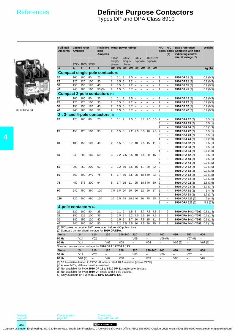
4
Courtesy
References 0 Definite Purpose Contactors 0
Types DP and DPA Class 8910
Full load Amperes
Locked rotor Amperes
Resistive load Amperes
Motor power ratings N/O poles
N/C poles (1)
Basic reference Complete with code indicating control circuit voltage (2)
Weight
115V single-phase
230V single-phase
230V 3-phase
460/575V3-phase
277V 480V 575VA A A A A HP kW HP kW HP kW HP kW kg (lb)
Compact single-pole contactors20 100 100 80 25 1 1.1 2 1.5 – – – – 1 – 8910 DP 11 (2) 0.2 (0.5)25 125 125 100 30 2 1.5 3 2.2 – – – – 1 – 8910 DP 21 (2) 0.2 (0.5)30 150 150 120 40 2 1.5 3 2.2 – – – – 1 – 8910 DP 31 (2) 0.2 (0.5)
40 240 200 160 50 (3) 2 1.5 5 3.7 – – – – 1 – 8910 DP 41 (2) 0.2 (0.5)
Compact 2-pole contactors (4)
20 100 100 80 30 1 1.1 2 1.5 – – – – 2 – 8910 DP 12 (2) 0.2 (0.5)
25 125 125 100 35 2 1.5 3 2.2 – – – – 2 – 8910 DP 22 (2) 0.2 (0.5)30 150 150 120 40 2 1.5 5 3.7 – – – – 2 – 8910 DP 32 (2) 0.2 (0.5)40 240 200 160 50 2 1.5 5 3.7 – – – – 2 8910 DP 42 (2) 0.2 (0.5)
2-, 3- and 4-pole contactors (4)
20 120 100 80 25 1 1.1 2 1.5 5 3.7 7.5 5.5 2 – 8910 DPA 12 (2) 0.5 (1)3 – 8910 DPA 13 (2) 0.5 (1)
4 – 8910 DPA 14 (2) 0.6 (1.3)25 150 125 100 35 2 1.5 3 2.2 7.5 5.5 10 7.5 2 – 8910 DPA 22 (2) 0.5 (1)
3 – 8910 DPA 23 (2) 0.5 (1)
4 – 8910 DPA 24 (2) 0.6 (1.3)30 180 150 120 40 2 1.5 5 3.7 10 7.5 15 11 2 – 8910 DPA 32 (2) 0.5 (1)
3 – 8910 DPA 33 (2) 0.5 (1)
4 – 8910 DPA 34 (2) 0.6 (1.3)40 240 200 160 50 3 2.2 7.5 5.5 10 7.5 20 15 2 – 8910 DPA 42 (2) 0.5 (1)
3 – 8910 DPA 43 (2) 0.5 (1)4 – 8910 DPA 44 (2) 0.7 (1.5)
50 300 250 200 62 3 2.2 10 7.5 15 11 30 22 2 – 8910 DPA 52 (2) 0.7 (1.5)
3 – 8910 DPA 53 (2) 0.7 (1.5)60 360 300 240 75 5 3.7 10 7.5 25 18.5 30 22 2 – 8910 DPA 62 (2) 0.7 (1.5)
3 – 8910 DPA 63 (2) 0.7 (1.5)
75 450 375 300 94 5 3.7 15 11 25 18.5 40 30 2 – 8910 DPA 72 (2) 1.6 (3.5)3 – 8910 DPA 73 (2) 1.7 (3.7)
90 540 450 360 120 7.5 5.5 20 15 30 22 50 37 2 – 8910 DPA 92 (2) 1.4 (3)
3 – 8910 DPA 93 (2) 1.7 (3.7)120 720 600 480 120 10 7.5 25 18.5 40 30 75 55 2 – 8910 DPA 122 (2) 2 (4.4)
3 – 8910 DPA 123 (2) 5.9 (13)
4-pole contactors (4)
20 120 100 80 25 1 1.1 2 1.5 5 3.7 7.5 5.5 2 2 8910 DPA 14 (2) Y392 0.6 (1.3)25 150 125 100 35 2 1.5 3 2.2 7.5 5.5 10 7.5 2 2 8910 DPA 24 (2) Y392 0.6 (1.3)
30 180 150 120 40 2 1.5 5 3.7 10 7.5 15 11 2 2 8910 DPA 34 (2) Y392 0.6 (1.3)40 240 200 160 50 3 2.2 7.5 5.5 10 7.5 20 15 2 2 8910 DPA 44 (2) Y392 0.7 (1.5)(1) N/C poles on outside. N/C poles open before N/O poles close.(2) Standard control circuit voltage for 8910 DP/DPA:Volts 24 110 120 208-240 220 277 440 480 550 600
50 Hz V14 V02 – – V09 – V06 (5) – V07 (6) –60 Hz V14 – V02 V09 – V04 – V06 (5) – V07 (6)Standard control circuit voltage for 8910 DPA 122/DPA 123:
Volts 24 110 120 208 220 230-240 440 480 550 60050 Hz V12 V02 – – V03 – V06 – V07 –60 Hz V01 (7) – V02 V08 – V03 – V06 – V07
(3) 50 A resistive limited to 277V. All others rated 40 A resistive (above 277V).(4) Above 240V, all lines must be switched.(5) Not available for Type 8910 DP 11 to 8910 DP 31 single-pole devices.(6) Not available for Type 8910 DP single and 2-pole devices.(7) Only available on Types 8910 DPA 122/DPA 123.
8910 DPA 33
5311
25
General:page 4/2
Characteristics:page 4/3
Dimensions:pages 4/8 and 4/9
4/4 of Steven Engineering, Inc.-230 Ryan Way, South San Francisco, CA 94080-6370-Main Office: (650) 588-9200-Outside Local Area: (800) 258-9200-www.stevenengineering.com

Courtesy of S
References 0 Definite Purpose Contactors 0
Types DP and DPA Class 8910
4
Contactors with fuse blocks (1)Contactors Fuse Suffix to be added
to the contactor reference (3)
WeightRating Maximum
rating voltage
Dimen-sions(2)
Class
A V mm kg (lb)8910 DPA 13/23/33/43 3 600 10 x 38 CC (3) DFC1 0.35 (0.8)
60 480 10 x 57 G (3) DFG1 0.35 (0.8)
30 480 10 x 41 G (3) DFG2 0.35 (0.8)
30 250 14 x 51 H or K (3) DFH1 0.35 (0.8)
60 250 20 x 76 H or K (3) DFH2 0.35 (0.8)
30 600 20 x 57 J (3) DFJ1 0.40 (0.9)
60 600 26 x 60 J (3) DFJ2 0.40 (0.9)
30 600 10 x 38 M (3) DFM1 0.40 (0.9)
30 250 14 x 51 R (3) DFR1 0.35 (0.8)
60 250 20 x 76 R (3) DFR2 0.35 (0.8)
30 300 14 x 22 T (3) DFT1 0.35 (0.8)
60 300 14 x 22 T (3) DFT2 0.35 (0.8)
30 600 14 x 22 T (3) DFT3 0.40 (0.9)
60 600 25 x 39 T (3) DFT4 0.40 (0.9)
(1) For dimensions, see page 4/9.(2) Dimensions in mm (25.4 mm = 1 inch).(3) 8910 DPA 13 or 23 or 33 or 43 plus standard control circuit voltage:Volts 24 110 120 208-240 220 277 440 480 550 60050 Hz V14 V02 – – V09 – V06 – V07 –
60 Hz V14 – V02 V09 – V04 – V06 – V07Example: 8910 DPA 33 V02 DFG1.
8910 DPA 23 V02 DFM1
5312
57
General:page 4/2
Characteristics:page 4/3
Dimensions:pages 4/8 and 4/9
4/5teven Engineering, Inc.-230 Ryan Way, South San Francisco, CA 94080-6370-Main Office: (650) 588-9200-Outside Local Area: (800) 258-9200-www.stevenengineering.com
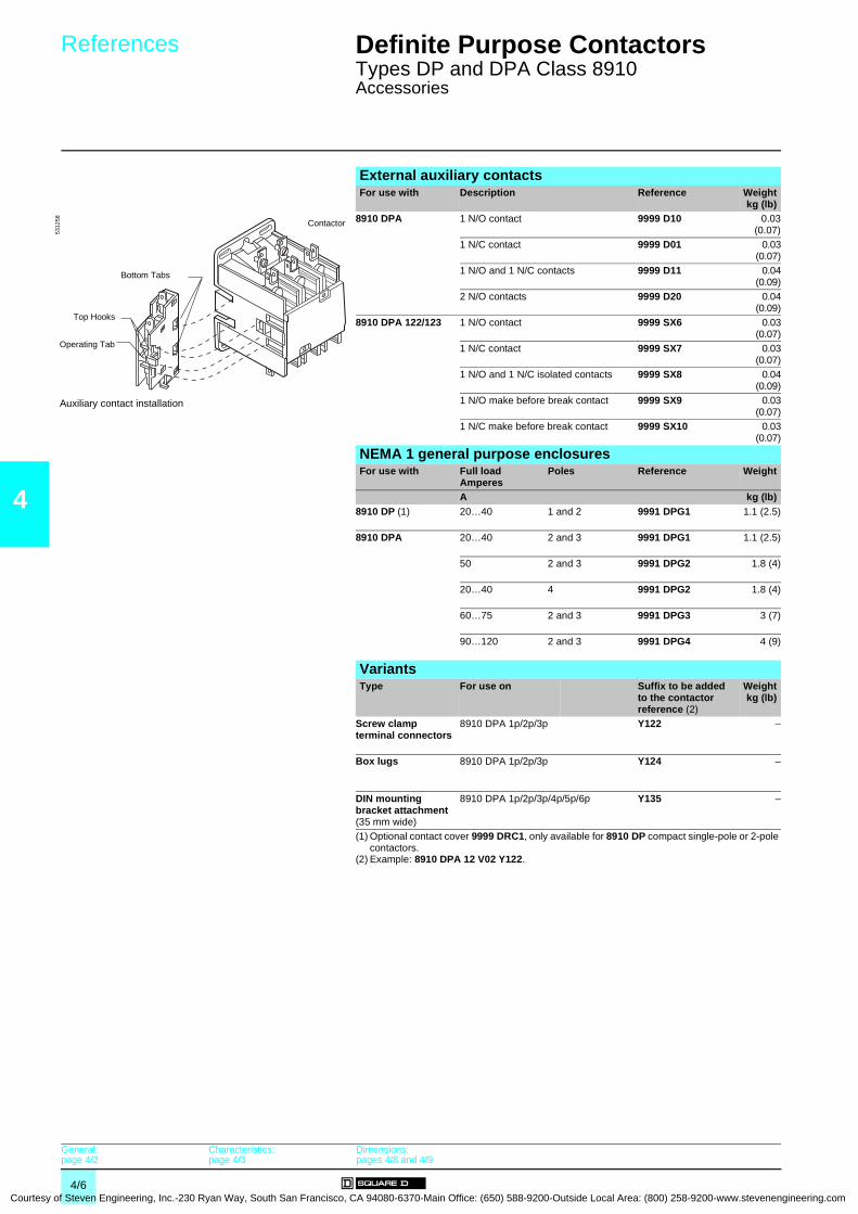
4
Courtesy
References 0 Definite Purpose Contactors 0
Types DP and DPA Class 8910Accessories
External auxiliary contactsFor use with Description Reference Weight
kg (lb)8910 DPA 1 N/O contact 9999 D10 0.03
(0.07)1 N/C contact 9999 D01 0.03
(0.07)1 N/O and 1 N/C contacts 9999 D11 0.04
(0.09)2 N/O contacts 9999 D20 0.04
(0.09)8910 DPA 122/123 1 N/O contact 9999 SX6 0.03
(0.07)1 N/C contact 9999 SX7 0.03
(0.07)1 N/O and 1 N/C isolated contacts 9999 SX8 0.04
(0.09)1 N/O make before break contact 9999 SX9 0.03
(0.07)1 N/C make before break contact 9999 SX10 0.03
(0.07)
NEMA 1 general purpose enclosuresFor use with Full load
AmperesPoles Reference Weight
A kg (lb)8910 DP (1) 20…40 1 and 2 9991 DPG1 1.1 (2.5)
8910 DPA 20…40 2 and 3 9991 DPG1 1.1 (2.5)
50 2 and 3 9991 DPG2 1.8 (4)
20…40 4 9991 DPG2 1.8 (4)
60…75 2 and 3 9991 DPG3 3 (7)
90…120 2 and 3 9991 DPG4 4 (9)
VariantsType For use on Suffix to be added
to the contactor reference (2)
Weightkg (lb)
Screw clamp terminal connectors
8910 DPA 1p/2p/3p Y122 –
Box lugs 8910 DPA 1p/2p/3p Y124 –
DIN mounting bracket attachment (35 mm wide)
8910 DPA 1p/2p/3p/4p/5p/6p Y135 –
(1) Optional contact cover 9999 DRC1, only available for 8910 DP compact single-pole or 2-pole contactors.
(2) Example: 8910 DPA 12 V02 Y122.
Auxiliary contact installation
5312
58
Bottom Tabs
Top Hooks
Operating Tab
Contactor
General:page 4/2
Characteristics:page 4/3
Dimensions:pages 4/8 and 4/9
4/6 of Steven Engineering, Inc.-230 Ryan Way, South San Francisco, CA 94080-6370-Main Office: (650) 588-9200-Outside Local Area: (800) 258-9200-www.stevenengineering.com

Courtesy of S
References (continued) 0 Definite Purpose Contactors 0
Types DP and DPA Class 8910Accessories
4
Replacement coilsType For use on Poles Average
consumption (60 Hz)
Basic referenceComplete with code indicating control circuit voltage (1)
Weight
Inrush SealedVA VA kg (lb)
Replacement coils
8910 DPA 1p/2p/3p/4p 2 and 3 56 6 9998 DA1 ppp –
8910 DPA p4 4 109 10 9998 DA2 ppp –
8910 DPA 5p/6p 2 and 3 109 10 9998 DA2 ppp –
8910 DPA 7p/9p 2 and 3 214 19 9998 DA3 ppp –
Replacement parts kitsType Kit description For use on Reference Weight
kg (lb)Replacement parts kits
Contains the necessary movable and stationary contacts, contact springs and additional hardware for one pole
8910 DPA 1p 9998 DRC1 –
8910 DPA 2p 9998 DRC2 –
8910 DPA 3p 9998 DRC3 –
8910 DPA 4p 9998 DRC4 –
8910 DPA 5p 9998 DRC5 –
8910 DPA 6p 9998 DRC6 –
8910 DPA 7p 9998 DRC7 –
8910 DPA 9p 9998 DRC9 –
8910 DPA 12p 9998 DRC12 –
Miscellaneous partsType For use on Reference Weight
kg (lb)DIN mounting adaptor plate
8910 DPA 9999 DMB1 –
(1) Standard control circuit voltage:
Volts 24 110 120 208-240 220 277 440 480 550 60050 Hz V14 V02 – – V09 – V06 – V07 –60 Hz V14 – V02 V09 – V04 – V06 – V07
Example: 9998 DA1 V02.
General:page 4/2
Characteristics:page 4/3
Dimensions:pages 4/8 and 4/9
4/7teven Engineering, Inc.-230 Ryan Way, South San Francisco, CA 94080-6370-Main Office: (650) 588-9200-Outside Local Area: (800) 258-9200-www.stevenengineering.com

4
Courtesy
Dimensions 0
Definite Purpose Contactors 0
Types DP and DPA Class 8910
Dimensions are inchmm------------
8910 DP 11/21/31/41 (single-pole) 8910 DP 12/22/32/42 (2-pole)
(1) Provisions for #10 or M5 mounting screws. (1) Provisions for #10 or M5 mounting screws.8910 DPA 12/13/22/23/32/33/42/43 (2 and 3-pole/20-40 A) 8910 DPA 14/24/34/44 (4-pole/20-40 A)
(1) Provisions for #10 or M5 mounting screws. (1) Provisions for #10 or M5 mounting screws.8910 DPA 5p/6p (2 and 3-pole/50-60 A) 8910 DPA 7p/9p (2 and 3-pole/75-90 A)
(1) Provisions for #10 or M5 mounting screws. (1) Provisions for #10 or M5 mounting screws.
2.8773
3.2984
1.6342
2.3159
.8321
.277
2.1655
1.6342
2.2257
(1)
2.8773
3.2984
1.6342
2.3159
.8321
.277
2.1655
1.6342
2.2257
(1)
2.5064
2.0051
1.5038
.5013
(1)
3.1279
.256
.256
3.2583
4.00102 3.75
95
3.1781
2.2557
.4612
.8121
3.2583
.256
1.5539
(1)
3.1179
4.00102
3.7595
.246
2.1154
1.5439
4.06103
3.2783
2.5685
.236
.236
.5113
(1)
.072 .09
2
3.7294
3.6793
2.8773
2.5064
(1)3.39
86
4.44113
4.37111
.3910
4.63118
5.20132
.062
5.12130
.4411
.267 .26
7
General:page 4/2
Characteristics:page 4/3
References:pages 4/4 to 4/7
4/8 of Steven Engineering, Inc.-230 Ryan Way, South San Francisco, CA 94080-6370-Main Office: (650) 588-9200-Outside Local Area: (800) 258-9200-www.stevenengineering.com

Courtesy of S
Dimensions 0
Definite Purpose Contactors 0
Types DP and DPA Class 8910
Dimensions are inchmm------------
4
8910 DPA 122/123 (120 A)
(1) Provision for 1/4" mounting screw.
Contactors with fuse blocks(2) A B C
8910 DPA p3 ppp DFC1 91 150 1178910 DPA p3 ppp DFG1 91 155 119
8910 DPA p3 ppp DFG2 91 150 1148910 DPA p3 ppp DFH1 91 150 1198910 DPA p3 ppp DFH2 107 168 135
8910 DPA p3 ppp DFJ1 91 150 1328910 DPA p3 ppp DFJ2 119 152 1358910 DPA p3 ppp DFM1 91 150 117
8910 DPA p3 ppp DFR1 91 152 1198910 DPA p3 ppp DFR2 107 168 1368910 DPA p3 ppp DFT1 91 150 114
8910 DPA p3 ppp DFT2 91 150 1148910 DPA p3 ppp DFT3 119 155 1148910 DPA p3 ppp DFT4 119 150 114
(2) Dimensions in mm (25.4 mm = 1 inch)
.318 .12
3
(1)
5.38137
6.50165
6.63168
4.75121
6.03153 6.86
174
1.5038
.318
A
B
C
Top View
Side View
General:page 4/2
Characteristics:page 4/3
References:pages 4/4 to 4/7
4/9teven Engineering, Inc.-230 Ryan Way, South San Francisco, CA 94080-6370-Main Office: (650) 588-9200-Outside Local Area: (800) 258-9200-www.stevenengineering.com

5/0Courtesy of Steven Engineering, Inc.-230 Ryan Way, South San Francisco
, CA 94080-6370-Main Office: (650) 588-9200-Outside Local Area: (800) 258-9200-www.stevenengineering.com
Contents
Courtesy of Steven Engineering, Inc.-230 Ryan Way, South San Francisco, CA
5 - Lighting Contactors
5
b Multipole lighting contactors, Types L, LX and S Class 8903
v General, characteristics . . . . . . . . . . . . . . . . . . . . . . . . . . . . . . . . . . . . page 5/2
b Multipole lighting contactors, Types L and LX Class 8903
v References . . . . . . . . . . . . . . . . . . . . . . . . . . . . . . . . . . . . . . . . . . . . . page 5/4
b Multipole lighting contactors, Type S Class 8903
v References . . . . . . . . . . . . . . . . . . . . . . . . . . . . . . . . . . . . . . . . . . . . . page 5/5
b Multipole lighting contactors, Types L, LX and S Class 8903
v Accessories . . . . . . . . . . . . . . . . . . . . . . . . . . . . . . . . . . . . . . . . . . . . . page 5/7
v Variants . . . . . . . . . . . . . . . . . . . . . . . . . . . . . . . . . . . . . . . . . . . . . . . . page 5/8
v Dimensions . . . . . . . . . . . . . . . . . . . . . . . . . . . . . . . . . . . . . . . . . . . . page 5/10
5/1 94080-6370-Main Office: (650) 588-9200-Outside Local Area: (800) 258-9200-www.stevenengineering.com

5
Courtesy
General,characteristics 0
Lighting Contactors 0
Multipole lighting contactorsTypes L, LX and S Class 8903
General
Lighting contactors have evolved from the need for more than just simple on-off manual control of lights. Today's requirements call for the development of new and varied types of control. Often the application will call for remote control of lighting from some distant location. This control may not be in addition to a master control station at a central location. Certain applications include the use of automatic control by time clocks or photoelectric cells. Whatever the need may be, applications are increasing and lighting contactors are designed to meet the ever-changing requirements.
Typical installations include:b Parking lots.b Industrial plants.b Office buildings.b Theatres and auditoriums.b Hospitals and institutions.b Shopping centres.b Stadiums.b Airports.
Multipole lighting contactors, Types L and LX Class 8903Features:b 30 A fluorescent lighting rating.b 20 A tungsten lighting rating.b Electrically and mechanically held. b 2 to 12-pole versions.b Field-convertible contacts with N/O and N/C indicators (8 N/C contacts maximum).
Multipole lighting contactors, Type S Class 8903Features:b 30…800 A lighting ratings.b Electrically and mechanically held. b 2 to 5-pole versions (5-pole to 200 A).b UL Listed short-circuit rating up to 100 000 A.b Mixed load ratings (lighting and motor).b Factory wired controls and clearly marked termination points.
CharacteristicsClass 8903Type Lp/LXp SMp SPp SQp SVp SXp SYp SZp SJp
EnvironmentRated insulation voltage Conforming to UL, CSA… aV 600
Conforming to standards NEMA ICS-1, ICS-2, UL 508, CSA 22-2 n° 14Product certifications UL, CSAAmbient air temperaturearound the device
Storage °C - 30…+ 65
Operation °C 0…+ 40Max. operating altitude Without derating m 2000Operating position Without derating Vertical
Power circuit connectionsType of termination Screw clamp terminal Box lug
Wire sizes (Min./max.)(AWG)
Solid or stranded copper wire
#14-#10 #14-#8 #14-#2 (1)
#14-#2/0 (1) #6-350MCM (1)
#4-600MCM (1) (2)
#6-350MCM (1) (3)
#4-600MCM (1) (3)
#30/0-750MCM (1) (4)
(1) Solid or stranded aluminium wire. (2) Two wires #4-250MCM. (3) Two holes. (4) Four holes.
Control circuit connectionsType of termination Screw clamp terminal
Wire sizes (Min./max.) Solid or stranded copper wire (AWG) #16-#12
Pole characteristicsNumber of poles 2P-12P 2P-5P 2P-3PRated operating voltage Up to aV 600Frequency limits Of the operating current Hz 50/60
Conventional thermal current (FLA) A 30 60 100 200 300 400 600 800Rated making capacity Tungsten A 10 x rated current
Ballast A 3 x rated current
Resistance heating rating At 600V A 20 30 60 100 200 300 400 600 800
a.c. control circuit characteristicsRated control circuit voltage aV 24-600
(2P-6P)(8P-12P)
24-600 24-600 (2P-3P)110-600 (4P-5P)
110-600
Average consumption 60HzElectrically held
Inrush VA 150/180 245 311/438 700/1185 1185 1300 1780 1960
Sealed VA 30/35 27 37/38 41/89 89 14 48 59Average consumption 50HzElectrically held
Inrush VA 140/170 232 296/429 678/1260 1260 1300 1495 –Sealed VA 30/35 26 36/37 47/89 89 14 56 –
Heat dissipation 60Hz Electrically held - Sealed W 6.5/9.5 7.8 14/14 14/22 22 13 32 36Heat dissipation 50Hz Electrically held - Sealed W – 7.7 12/12 15/23 23 – 27 –Inrush 60 HzMechanically held
Latch coil VA 150/180 245 311/438 700/973 973 2970 1530
Unlatch coil VA 25/25 140 140/140 550/550 550 2100Inrush 50 HzMechanically held
Latch coil VA 140/170 232 296/429 678/– – 2970 1250Unlatch coil VA –
Mechanical durability Electrically held 4000 10,000 3000 2000 1500 500In x 103 of operating cycles Mechanically held 1000 500
5312
21
8903 Lp Electrically held
5312
22
8903 LXp Mechanically held
5312
23
8903 Spp p Electrically held
5312
24
8903 Spp pp Mechanically held
References:pages 5/4 to 5/9
Dimensions:pages 5/10 and 5/11
5/2 of Steven Engineering, Inc.-230 Ryan Way, South San Francisco, CA 94080-6370-Main Office: (650) 588-9200-Outside Local Area: (800) 258-9200-www.stevenengineering.com

Courtesy of S
Characteristics (continued) 0 Lighting Contactors 0
Multipole lighting contactorsTypes L, LX and S Class 8903
5
Electrical characteristics (continued)
Class 8903Type Lp/LXp SMp SPp SQp SVp SXp SYp SZp SJp
Contactor continuous rating A 30 30 60 100 200 300 400 600 (1) 800a Voltage ratingsTungsten lamp loads
Single-pole to load a V 20 A/277 277 –2-pole to load on single-phase and 3-pole to load on 3-phase
a V 20 A/480 480 –
Ballast loadsSingle-pole to load a V 277 (2) 347
2-pole to load on single-phase and 3-pole to load on 3-phase
a V 480 (2) 600
Resistive loadsa VSingle-pole to load 20 A/600 600
2-pole to load on single-phase and 3-pole to load on 3-phase
a V 20 A/600 600
c Voltage ratingsTungsten lamp or resistance loads
2-pole in series c V 20 A/125 125 250 –3-pole in series c V 20 A/250 250
UL Listed short-circuit ratingContactors protected by fused disconnect switches
Maximum Class RK5 fuse rating A 30 30 60 100 200 400 400 – –
Maximum voltage V 600 480 600 – –Available Amperes (RMS sym) kA 100 – 30 (5)
Contactors protected by circuit breakersMaximum circuit breaker rating A 25 40 80/90 125 250/225 400 800 800 1200Recommended circuit breaker type Thermal-magnetic
Maximum voltage V 240/480 480/600/480 600/480 600Available Amperes (RMS sym) kA 22/14 10/5/100 18/14/100 10/100 14/100 22/100 22 30
Kilowatt ratings (3)Voltage kW 6.9 10.3 20.7 34.6 69.2 103.9 138.5 207.8 277.1a 200 V
a 230 V kW 7.9 11.9 23.9 39.8 79.6 119.5 159.3 239 318.7a 380 V kW 13.1 19.7 39.4 65.8 131.6 197.4 263.2 394.9 526.5
a 460 V kW 15.9 23.9 47.8 79.8 159.3 239 318.6 478 637.4a 575 V kW 19.9 30 60 99 199 299 398.4 597.6 796.7
Motor power ratings equivalent to NEMA Size contactor – Size 1 Size 2 Size 3 Size 4 Size 5 Size 6 Size 6 Size 7
Mixed load ratingsPercent lighting (and/or resistive) load: 0%Motor voltage and phases (4)
200 V/3-phase Max. motor HP – 7.5 10 25 40 75 125 150 250230 V/3-phase Max. motor HP – 7.5 15 30 50 100 150 200 300380 V/3-phase Max. motor HP – 10 25 50 75 150 250 300 400
460…575 V/3-phase Max. motor HP – 10 25 50 100 200 300 400 600115 V/single-phase Max. motor HP – 2 3 7.5 – – – – –230 V/single-phase Max. motor HP – 3 7.5 15 – – – – –
Percent lighting (and/or resistive) load: 75%200 V/3-phase Max. non-motor A – 22.5 45 75 150 225 300 450 600
Max. motor HP – 1.5 3 5 15 20 30 50 60
230 V/3-phase Max. non-motor A – 22.5 45 75 150 225 300 450 600Max. motor HP – 2 3 7.5 15 25 30 50 75
380 V/3-phase Max. non-motor A – 22.5 45 75 150 225 300 450 600
Max. motor HP – 3 7.5 10 30 40 60 75 125460…575 V/3-phase Max. non-motor A – 22.5 45 75 150 225 300 450 600
Max. motor HP – 3 10 15 30 50 75 100 150
115 V/single-phase Max. non-motor A – 22.5 45 75 – – – – –Max. motor HP – 0.33 0.75 2 – – – – –
230 V/single-phase Max. non-motor A – 22.5 45 75 – – – – –
Max. motor HP – 0.75 2 3 – – – – –(1) 600 A devices are derated to 540 A for resistance heating loads when aluminium wire is used.(2) Types L and LX contactors also have a ballast lamp rating of 15 A/a 347 V when connected single-pole to load and a 600 V when connected 2-pole to load on
single-phase and 3-pole to load on 3-phase.(3) Resistance heating only (3-phase system).(4) Select lighting contactor on basis of rated motor voltage, whether non-motor load is connected line-to-line or line-to-neutral.(5) 30 kA also applies for Class J and Class K5, time-delay 600 A maximum fuses. Additionally 30 kA ratings apply to Class T 1200 A maximum and Class L 1600 A
maximum fuses.
References:pages 5/4 to 5/9
Dimensions:pages 5/10 and 5/11
5/3teven Engineering, Inc.-230 Ryan Way, South San Francisco, CA 94080-6370-Main Office: (650) 588-9200-Outside Local Area: (800) 258-9200-www.stevenengineering.com

5
Courtesy
References 0 Lighting Contactors 0
Multipole lighting contactorsTypes L and LX Class 8903
Multipole lighting contactors, Types L and LX (4)Contact Ampere ratings
Number of poles
Enclosure type (1) Basic reference (2)Complete with code indicating control circuit voltage (3)and enclosure type (5)
Weight
A kg (lb)
Electrically held30 2 Open (“O”), NEMA 1 (“G”),
NEMA 1+ (“F”), NEMA 12 (“A”)8903 L (2) 20 (3) 1.3 (2.8)
3 Open (“O”), NEMA 1 (“G”), NEMA 1+ (“F”), NEMA 12 (“A”)
8903 L (2) 30 (3) 1.3 (2.8)
4 Open (“O”), NEMA 1 (“G”), NEMA 1+ (“F”), NEMA 12 (“A”)
8903 L (2) 40 (3) 1.3 (2.8)
6 Open (“O”), NEMA 1 (“G”), NEMA 1+ (“F”), NEMA 12 (“A”)
8903 L (2) 60 (3) 1.5 (3.2)
8 Open (“O”), NEMA 1 (“G”), NEMA 1+ (“F”), NEMA 12 (“A”)
8903 L (2) 80 (3) 1.7 (3.7)
10 Open (“O”), NEMA 1 (“G”), NEMA 1+ (“F”), NEMA 12 (“A”)
8903 L (2) 1000 (3) 1.9 (4.1)
12 Open (“O”), NEMA 1 (“G”), NEMA 1+ (“F”), NEMA 12 (“A”)
8903 L (2) 1200 (3) 2 (4.4)
Mechanically held30 2 Open (“O”), NEMA 1 (“G”),
NEMA 1+ (“F”), NEMA 12 (“A”)8903 LX (2) 20 (3) 2 (4.4)
3 Open (“O”), NEMA 1 (“G”), NEMA 1+ (“F”), NEMA 12 (“A”)
8903 LX (2) 30 (3) 2.1 (4.6)
4 Open (“O”), NEMA 1 (“G”), NEMA 1+ (“F”), NEMA 12 (“A”)
8903 LX (2) 40 (3) 2.1 (4.6)
6 Open (“O”), NEMA 1 (“G”), NEMA 1+ (“F”), NEMA 12 (“A”)
8903 LX (2) 60 (3) 2.3 (5)
8 Open (“O”), NEMA 1 (“G”), NEMA 1+ (“F”), NEMA 12 (“A”)
8903 LX (2) 80 (3) 2.4 (5.4)
10 Open (“O”), NEMA 1 (“G”), NEMA 1+ (“F”), NEMA 12 (“A”)
8903 LX (2) 1000 (3) 2.6 (5.8)
12 Open (“O”), NEMA 1 (“G”), NEMA 1+ (“F”), NEMA 12 (“A”)
8903 LX (2) 1200 (3) 2.8 (6)
(1) Open: separate enclosures are available for these devices. It may be possible to improve delivery by ordering an open type contactor and separate Class 9991 enclosure, please consult your Regional Sales Office.NEMA 1: general purpose enclosure.NEMA 1+: flush mounting general purpose enclosure with plaster adjustment.NEMA 12: dust-tight and drip-tight industrial use enclosure.
(2) Insert "O" for Open , "G" for NEMA 1, "F" for NEMA 1+, "A" for NEMA 12. Example: 8903 LO 20 V02.(3) Standard control circuit voltage:Volts 24 110 120 208 220 240 277 440 48050 Hz – V02 – – V03 – – V06 –
60 Hz V01 – V02 V08 – V03 V04 – V06(4) All lighting contactors are provided with separate control as standard.(5) Factory conversion of N/O contacts to N/C, order following the example below.
Example: for 2 N/O + 2 N/C (NEMA 1 enclosure) the reference is 8903 LG 22. There is a maximum of eight N/C poles for Type 8903 L contactors and a maximum of six N/C poles for Type 8903 LX contactors (field conversion only). Versions are available with up to 12 N/C poles (factory only).
5312
17
8903 LO 60 ppp
5312
18
8903 LO 80 ppp
5312
20
8903 LO 1200 ppp
5312
19
8903 LXO 1200 ppp
General, characteristics:pages 5/2 and 5/3
Dimensions:pages 5/10 and 5/11
5/4 of Steven Engineering, Inc.-230 Ryan Way, South San Francisco, CA 94080-6370-Main Office: (650) 588-9200-Outside Local Area: (800) 258-9200-www.stevenengineering.com
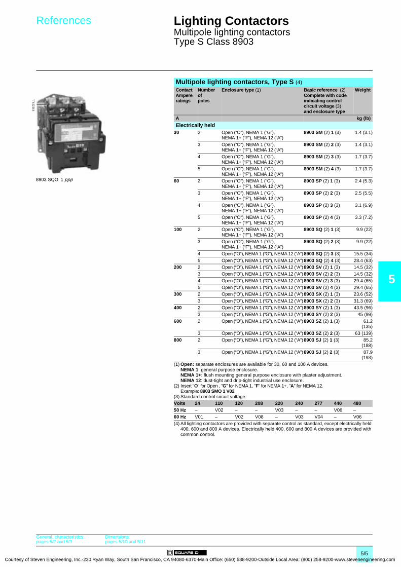
Courtesy of S
References 0 Lighting Contactors 0
Multipole lighting contactorsType S Class 8903
5
Multipole lighting contactors, Type S (4)Contact Ampere ratings
Number of poles
Enclosure type (1) Basic reference (2)Complete with code indicating control circuit voltage (3)and enclosure type
Weight
A kg (lb)
Electrically held30 2 Open (“O”), NEMA 1 (“G”),
NEMA 1+ (“F”), NEMA 12 (“A”)8903 SM (2) 1 (3) 1.4 (3.1)
3 Open (“O”), NEMA 1 (“G”), NEMA 1+ (“F”), NEMA 12 (“A”)
8903 SM (2) 2 (3) 1.4 (3.1)
4 Open (“O”), NEMA 1 (“G”), NEMA 1+ (“F”), NEMA 12 (“A”)
8903 SM (2) 3 (3) 1.7 (3.7)
5 Open (“O”), NEMA 1 (“G”), NEMA 1+ (“F”), NEMA 12 (“A”)
8903 SM (2) 4 (3) 1.7 (3.7)
60 2 Open (“O”), NEMA 1 (“G”), NEMA 1+ (“F”), NEMA 12 (“A”)
8903 SP (2) 1 (3) 2.4 (5.3)
3 Open (“O”), NEMA 1 (“G”), NEMA 1+ (“F”), NEMA 12 (“A”)
8903 SP (2) 2 (3) 2.5 (5.5)
4 Open (“O”), NEMA 1 (“G”), NEMA 1+ (“F”), NEMA 12 (“A”)
8903 SP (2) 3 (3) 3.1 (6.9)
5 Open (“O”), NEMA 1 (“G”), NEMA 1+ (“F”), NEMA 12 (“A”)
8903 SP (2) 4 (3) 3.3 (7.2)
100 2 Open (“O”), NEMA 1 (“G”), NEMA 1+ (“F”), NEMA 12 (“A”)
8903 SQ (2) 1 (3) 9.9 (22)
3 Open (“O”), NEMA 1 (“G”), NEMA 1+ (“F”), NEMA 12 (“A”)
8903 SQ (2) 2 (3) 9.9 (22)
4 Open (“O”), NEMA 1 (“G”), NEMA 12 (“A”) 8903 SQ (2) 3 (3) 15.5 (34)
5 Open (“O”), NEMA 1 (“G”), NEMA 12 (“A”) 8903 SQ (2) 4 (3) 28.4 (63)200 2 Open (“O”), NEMA 1 (“G”), NEMA 12 (“A”) 8903 SV (2) 1 (3) 14.5 (32)
3 Open (“O”), NEMA 1 (“G”), NEMA 12 (“A”) 8903 SV (2) 2 (3) 14.5 (32)
4 Open (“O”), NEMA 1 (“G”), NEMA 12 (“A”) 8903 SV (2) 3 (3) 29.4 (65)5 Open (“O”), NEMA 1 (“G”), NEMA 12 (“A”) 8903 SV (2) 4 (3) 29.4 (65)
300 2 Open (“O”), NEMA 1 (“G”), NEMA 12 (“A”) 8903 SX (2) 1 (3) 23.6 (52)
3 Open (“O”), NEMA 1 (“G”), NEMA 12 (“A”) 8903 SX (2) 2 (3) 31.3 (69)400 2 Open (“O”), NEMA 1 (“G”), NEMA 12 (“A”) 8903 SY (2) 1 (3) 43.5 (96)
3 Open (“O”), NEMA 1 (“G”), NEMA 12 (“A”) 8903 SY (2) 2 (3) 45 (99)
600 2 Open (“O”), NEMA 1 (“G”), NEMA 12 (“A”) 8903 SZ (2) 1 (3) 61.2(135)
3 Open (“O”), NEMA 1 (“G”), NEMA 12 (“A”) 8903 SZ (2) 2 (3) 63 (139)800 2 Open (“O”), NEMA 1 (“G”), NEMA 12 (“A”) 8903 SJ (2) 1 (3) 85.2
(188)3 Open (“O”), NEMA 1 (“G”), NEMA 12 (“A”) 8903 SJ (2) 2 (3) 87.9
(193)(1) Open: separate enclosures are available for 30, 60 and 100 A devices.
NEMA 1: general purpose enclosure.NEMA 1+: flush mounting general purpose enclosure with plaster adjustment.NEMA 12: dust-tight and drip-tight industrial use enclosure.
(2) Insert "O" for Open , "G" for NEMA 1, "F" for NEMA 1+, "A" for NEMA 12. Example: 8903 SMO 1 V02.
(3) Standard control circuit voltage:Volts 24 110 120 208 220 240 277 440 48050 Hz – V02 – – V03 – – V06 –60 Hz V01 – V02 V08 – V03 V04 – V06(4) All lighting contactors are provided with separate control as standard, except electrically held
400, 600 and 800 A devices. Electrically held 400, 600 and 800 A devices are provided with common control.
5312
23_1
8903 SQO 1 ppp
General, characteristics:pages 5/2 and 5/3
Dimensions:pages 5/10 and 5/11
5/5teven Engineering, Inc.-230 Ryan Way, South San Francisco, CA 94080-6370-Main Office: (650) 588-9200-Outside Local Area: (800) 258-9200-www.stevenengineering.com
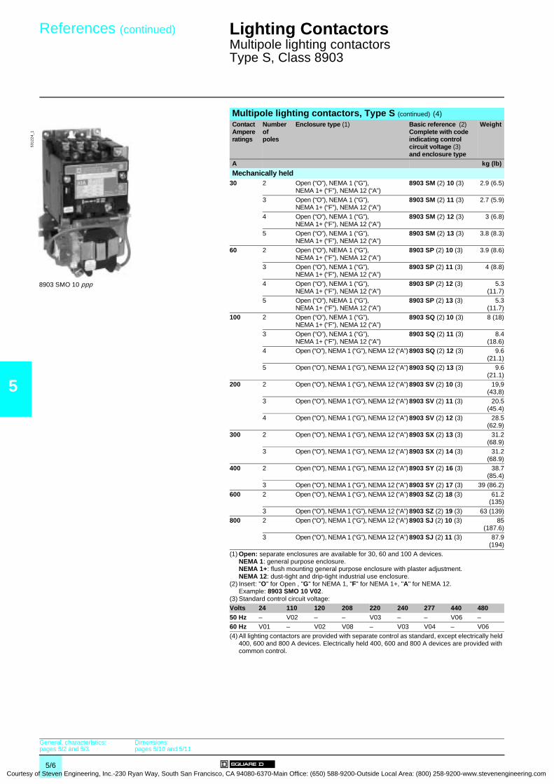
5
Courtesy
References (continued) 0 Lighting Contactors 0
Multipole lighting contactorsType S, Class 8903
Multipole lighting contactors, Type S (continued) (4) Contact Ampere ratings
Number of poles
Enclosure type (1) Basic reference (2)Complete with code indicating control circuit voltage (3)and enclosure type
Weight
A kg (lb)
Mechanically held30 2 Open (“O”), NEMA 1 (“G”),
NEMA 1+ (“F”), NEMA 12 (“A”)8903 SM (2) 10 (3) 2.9 (6.5)
3 Open (“O”), NEMA 1 (“G”), NEMA 1+ (“F”), NEMA 12 (“A”)
8903 SM (2) 11 (3) 2.7 (5.9)
4 Open (“O”), NEMA 1 (“G”), NEMA 1+ (“F”), NEMA 12 (“A”)
8903 SM (2) 12 (3) 3 (6.8)
5 Open (“O”), NEMA 1 (“G”), NEMA 1+ (“F”), NEMA 12 (“A”)
8903 SM (2) 13 (3) 3.8 (8.3)
60 2 Open (“O”), NEMA 1 (“G”), NEMA 1+ (“F”), NEMA 12 (“A”)
8903 SP (2) 10 (3) 3.9 (8.6)
3 Open (“O”), NEMA 1 (“G”), NEMA 1+ (“F”), NEMA 12 (“A”)
8903 SP (2) 11 (3) 4 (8.8)
4 Open (“O”), NEMA 1 (“G”), NEMA 1+ (“F”), NEMA 12 (“A”)
8903 SP (2) 12 (3) 5.3(11.7)
5 Open (“O”), NEMA 1 (“G”), NEMA 1+ (“F”), NEMA 12 (“A”)
8903 SP (2) 13 (3) 5.3(11.7)
100 2 Open (“O”), NEMA 1 (“G”), NEMA 1+ (“F”), NEMA 12 (“A”)
8903 SQ (2) 10 (3) 8 (18)
3 Open (“O”), NEMA 1 (“G”), NEMA 1+ (“F”), NEMA 12 (“A”)
8903 SQ (2) 11 (3) 8.4(18.6)
4 Open (“O”), NEMA 1 (“G”), NEMA 12 (“A”) 8903 SQ (2) 12 (3) 9.6(21.1)
5 Open (“O”), NEMA 1 (“G”), NEMA 12 (“A”) 8903 SQ (2) 13 (3) 9.6(21.1)
200 2 Open (“O”), NEMA 1 (“G”), NEMA 12 (“A”) 8903 SV (2) 10 (3) 19,9(43,8)
3 Open (“O”), NEMA 1 (“G”), NEMA 12 (“A”) 8903 SV (2) 11 (3) 20.5(45.4)
4 Open (“O”), NEMA 1 (“G”), NEMA 12 (“A”) 8903 SV (2) 12 (3) 28.5(62.9)
300 2 Open (“O”), NEMA 1 (“G”), NEMA 12 (“A”) 8903 SX (2) 13 (3) 31.2(68.9)
3 Open (“O”), NEMA 1 (“G”), NEMA 12 (“A”) 8903 SX (2) 14 (3) 31.2(68.9)
400 2 Open (“O”), NEMA 1 (“G”), NEMA 12 (“A”) 8903 SY (2) 16 (3) 38.7(85.4)
3 Open (“O”), NEMA 1 (“G”), NEMA 12 (“A”) 8903 SY (2) 17 (3) 39 (86.2)
600 2 Open (“O”), NEMA 1 (“G”), NEMA 12 (“A”) 8903 SZ (2) 18 (3) 61.2(135)
3 Open (“O”), NEMA 1 (“G”), NEMA 12 (“A”) 8903 SZ (2) 19 (3) 63 (139)800 2 Open (“O”), NEMA 1 (“G”), NEMA 12 (“A”) 8903 SJ (2) 10 (3) 85
(187.6)3 Open (“O”), NEMA 1 (“G”), NEMA 12 (“A”) 8903 SJ (2) 11 (3) 87.9
(194)(1) Open: separate enclosures are available for 30, 60 and 100 A devices.
NEMA 1: general purpose enclosure.NEMA 1+: flush mounting general purpose enclosure with plaster adjustment.NEMA 12: dust-tight and drip-tight industrial use enclosure.
(2) Insert: "O" for Open , "G" for NEMA 1, "F" for NEMA 1+, "A" for NEMA 12. Example: 8903 SMO 10 V02.
(3) Standard control circuit voltage:Volts 24 110 120 208 220 240 277 440 48050 Hz – V02 – – V03 – – V06 –60 Hz V01 – V02 V08 – V03 V04 – V06(4) All lighting contactors are provided with separate control as standard, except electrically held
400, 600 and 800 A devices. Electrically held 400, 600 and 800 A devices are provided with common control.
5312
24_1
8903 SMO 10 ppp
General, characteristics:pages 5/2 and 5/3
Dimensions:pages 5/10 and 5/11
5/6 of Steven Engineering, Inc.-230 Ryan Way, South San Francisco, CA 94080-6370-Main Office: (650) 588-9200-Outside Local Area: (800) 258-9200-www.stevenengineering.com
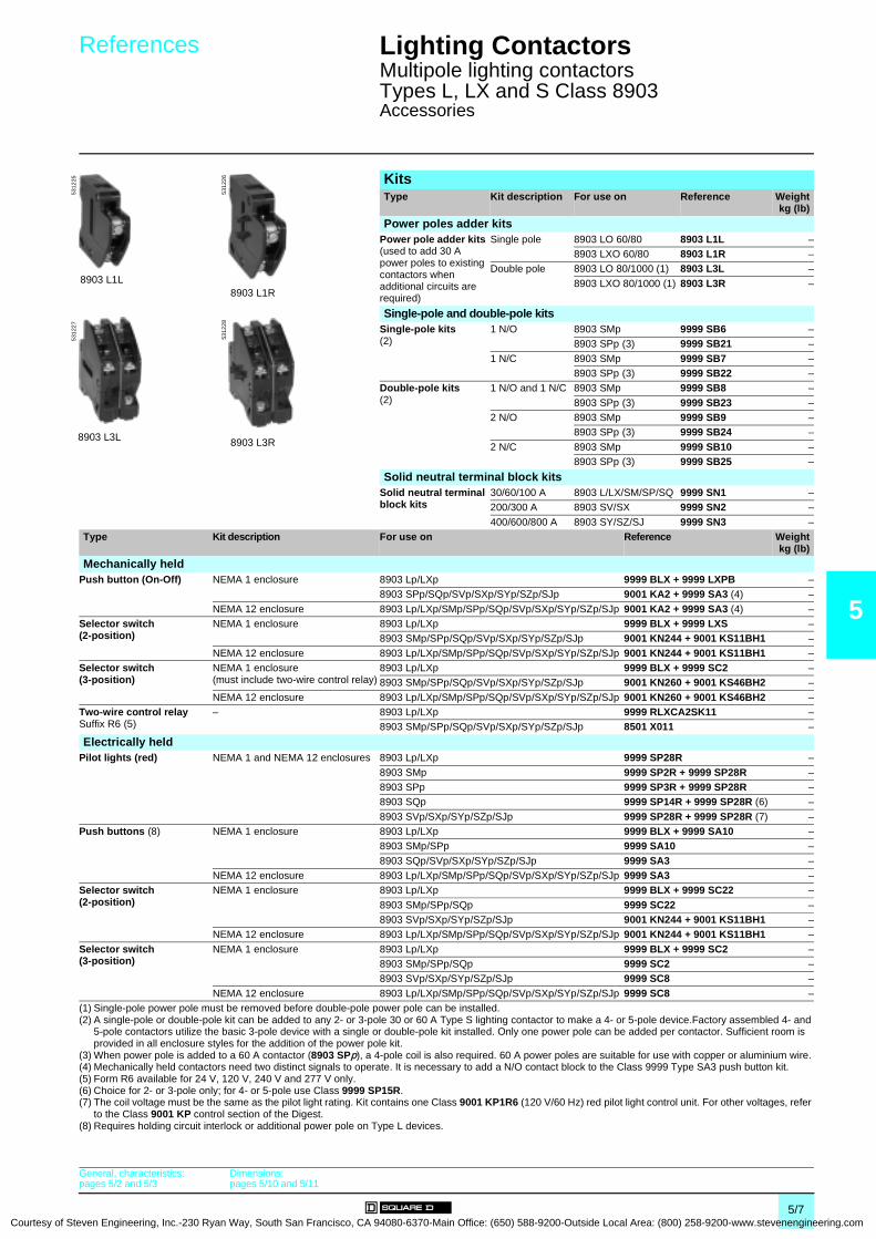
Courtesy of S
References 0 Lighting Contactors 0
Multipole lighting contactorsTypes L, LX and S Class 8903Accessories
5
KitsType Kit description For use on Reference Weight
kg (lb)
Power poles adder kitsPower pole adder kits (used to add 30 A power poles to existing contactors when additional circuits are required)
Single pole 8903 LO 60/80 8903 L1L –8903 LXO 60/80 8903 L1R –
Double pole 8903 LO 80/1000 (1) 8903 L3L –
8903 LXO 80/1000 (1) 8903 L3R –
Single-pole and double-pole kitsSingle-pole kits(2)
1 N/O 8903 SMp 9999 SB6 –8903 SPp (3) 9999 SB21 –
1 N/C 8903 SMp 9999 SB7 –8903 SPp (3) 9999 SB22 –
Double-pole kits(2)
1 N/O and 1 N/C 8903 SMp 9999 SB8 –
8903 SPp (3) 9999 SB23 –2 N/O 8903 SMp 9999 SB9 –
8903 SPp (3) 9999 SB24 –
2 N/C 8903 SMp 9999 SB10 –8903 SPp (3) 9999 SB25 –
8903 L1L
5312
25
8903 L1R
5312
26
8903 L3L
5312
27
8903 L3R
5312
28
Solid neutral terminal block kitsSolid neutral terminal block kits
30/60/100 A 8903 L/LX/SM/SP/SQ 9999 SN1 –200/300 A 8903 SV/SX 9999 SN2 –
400/600/800 A 8903 SY/SZ/SJ 9999 SN3 –Type Kit description For use on Reference Weight
kg (lb)
Mechanically heldPush button (On-Off) NEMA 1 enclosure 8903 Lp/LXp 9999 BLX + 9999 LXPB –
8903 SPp/SQp/SVp/SXp/SYp/SZp/SJp 9001 KA2 + 9999 SA3 (4) –
NEMA 12 enclosure 8903 Lp/LXp/SMp/SPp/SQp/SVp/SXp/SYp/SZp/SJp 9001 KA2 + 9999 SA3 (4) –Selector switch(2-position)
NEMA 1 enclosure 8903 Lp/LXp 9999 BLX + 9999 LXS –8903 SMp/SPp/SQp/SVp/SXp/SYp/SZp/SJp 9001 KN244 + 9001 KS11BH1 –
NEMA 12 enclosure 8903 Lp/LXp/SMp/SPp/SQp/SVp/SXp/SYp/SZp/SJp 9001 KN244 + 9001 KS11BH1 –Selector switch(3-position)
NEMA 1 enclosure(must include two-wire control relay)
8903 Lp/LXp 9999 BLX + 9999 SC2 –8903 SMp/SPp/SQp/SVp/SXp/SYp/SZp/SJp 9001 KN260 + 9001 KS46BH2 –
NEMA 12 enclosure 8903 Lp/LXp/SMp/SPp/SQp/SVp/SXp/SYp/SZp/SJp 9001 KN260 + 9001 KS46BH2 –Two-wire control relaySuffix R6 (5)
– 8903 Lp/LXp 9999 RLXCA2SK11 –8903 SMp/SPp/SQp/SVp/SXp/SYp/SZp/SJp 8501 X011 –
Electrically heldPilot lights (red) NEMA 1 and NEMA 12 enclosures 8903 Lp/LXp 9999 SP28R –
8903 SMp 9999 SP2R + 9999 SP28R –8903 SPp 9999 SP3R + 9999 SP28R –8903 SQp 9999 SP14R + 9999 SP28R (6) –
8903 SVp/SXp/SYp/SZp/SJp 9999 SP28R + 9999 SP28R (7) –Push buttons (8) NEMA 1 enclosure 8903 Lp/LXp 9999 BLX + 9999 SA10 –
8903 SMp/SPp 9999 SA10 –
8903 SQp/SVp/SXp/SYp/SZp/SJp 9999 SA3 –NEMA 12 enclosure 8903 Lp/LXp/SMp/SPp/SQp/SVp/SXp/SYp/SZp/SJp 9999 SA3 –
Selector switch(2-position)
NEMA 1 enclosure 8903 Lp/LXp 9999 BLX + 9999 SC22 –
8903 SMp/SPp/SQp 9999 SC22 –8903 SVp/SXp/SYp/SZp/SJp 9001 KN244 + 9001 KS11BH1 –
NEMA 12 enclosure 8903 Lp/LXp/SMp/SPp/SQp/SVp/SXp/SYp/SZp/SJp 9001 KN244 + 9001 KS11BH1 –
Selector switch(3-position)
NEMA 1 enclosure 8903 Lp/LXp 9999 BLX + 9999 SC2 –8903 SMp/SPp/SQp 9999 SC2 –8903 SVp/SXp/SYp/SZp/SJp 9999 SC8 –
NEMA 12 enclosure 8903 Lp/LXp/SMp/SPp/SQp/SVp/SXp/SYp/SZp/SJp 9999 SC8 –(1) Single-pole power pole must be removed before double-pole power pole can be installed.(2) A single-pole or double-pole kit can be added to any 2- or 3-pole 30 or 60 A Type S lighting contactor to make a 4- or 5-pole device.Factory assembled 4- and
5-pole contactors utilize the basic 3-pole device with a single or double-pole kit installed. Only one power pole can be added per contactor. Sufficient room is provided in all enclosure styles for the addition of the power pole kit.
(3) When power pole is added to a 60 A contactor (8903 SPp), a 4-pole coil is also required. 60 A power poles are suitable for use with copper or aluminium wire.(4) Mechanically held contactors need two distinct signals to operate. It is necessary to add a N/O contact block to the Class 9999 Type SA3 push button kit.(5) Form R6 available for 24 V, 120 V, 240 V and 277 V only.(6) Choice for 2- or 3-pole only; for 4- or 5-pole use Class 9999 SP15R.(7) The coil voltage must be the same as the pilot light rating. Kit contains one Class 9001 KP1R6 (120 V/60 Hz) red pilot light control unit. For other voltages, refer
to the Class 9001 KP control section of the Digest.(8) Requires holding circuit interlock or additional power pole on Type L devices.
General, characteristics:pages 5/2 and 5/3
Dimensions:pages 5/10 and 5/11
5/7teven Engineering, Inc.-230 Ryan Way, South San Francisco, CA 94080-6370-Main Office: (650) 588-9200-Outside Local Area: (800) 258-9200-www.stevenengineering.com

5
Courtesy
References 0 Lighting Contactors 0
Multipole lighting contactorsTypes L, LX and S Class 8903Variants
VariantsType Enclosure
typeFor use on Description Suffix to be added
to the lighting contactor reference (1)
Weightkg (lb)
"ON-OFF" push button NEMA 1, Mechanically held Pulsed contact A3 –NEMA 12
"ON-OFF" push button Any Electrically held With holding circuit interlock A12 –
"HAND-OFF-AUTO" selector switch NEMA 1, Electrically held, (2) C –NEMA 12 Mechanically held
"ON-OFF" selector switch NEMA 1, Electrically held, (2) C6 –NEMA 12 Mechanically held
Control circuit fuses Any Electrically held, 1 fuse F –Mechanically held 2 fuses F4 –
Control circuit transformers standard capacity (50/60 Hz) (3)
NEMA 1, Electrically held, Fuses: 2 (primary), 0 (secondary) F4T –NEMA 12 Mechanically held Fuses: 2 (primary), 1 (secondary) FF4T –
Additional capacity(50/60 Hz) Two fuses in primary and one fuse in secondary (3)
NEMA 1, Electrically held, 100 VA additional capacity FF4T11 –NEMA 12 Mechanically held 200 VA additional capacity FF4T12 –
300 VA additional capacity FF4T13 –Noise reduced enclosure and shock mounted panel
Any Electrically held – G4 –
Addition of photoelectric receptacle NEMA 1, Electrically held – G10 –NEMA 12 With photo-cell installed G101 –
Mechanically held And relay R6 (4) G10R6 –With photo-cell installed (4) G101R6 –
Addition of terminal blocks(other than standard) (5)
Any Electrically held, Wired G56pp –Mechanically held Unwired G50pp –
Bracketing for internally mounted pilot device
Any Electrically held, – G53 –Mechanically held
Addition of time clock NEMA 1, Electrically held, 24 hour (120-127 V only) K14 –NEMA 12 Mechanically held 24 hour w/day omission (120-127 V only) K141 –
7 day (120-127 V only) K142 –Addition of solid neutral terminal block NEMA 1, Electrically held, – N –
NEMA 12 Mechanically held(1) Example: 8903 LXG 20 V02 A3.(2) To substitute a key operated selector switch, use suffix "C33" and specify positions, legend marking and key removal. This suffix must be used with another
selector switch suffix.(3) Control circuit transformer selection table:Primary-secondary 120-24 208-120 240-24 240-120 277-120 480-24 480-120 480-240 600-120
60 Hz V89 V84 V82 V80 V85 V83 V81 V87 V86
(4) Available for 24 V, 120 V, 240 V and 277 V applications only.(5) At the end of suffix, pp represents the number of terminals needed.
General, characteristics:pages 5/2 and 5/3
Dimensions:pages 5/10 and 5/11
5/8 of Steven Engineering, Inc.-230 Ryan Way, South San Francisco, CA 94080-6370-Main Office: (650) 588-9200-Outside Local Area: (800) 258-9200-www.stevenengineering.com
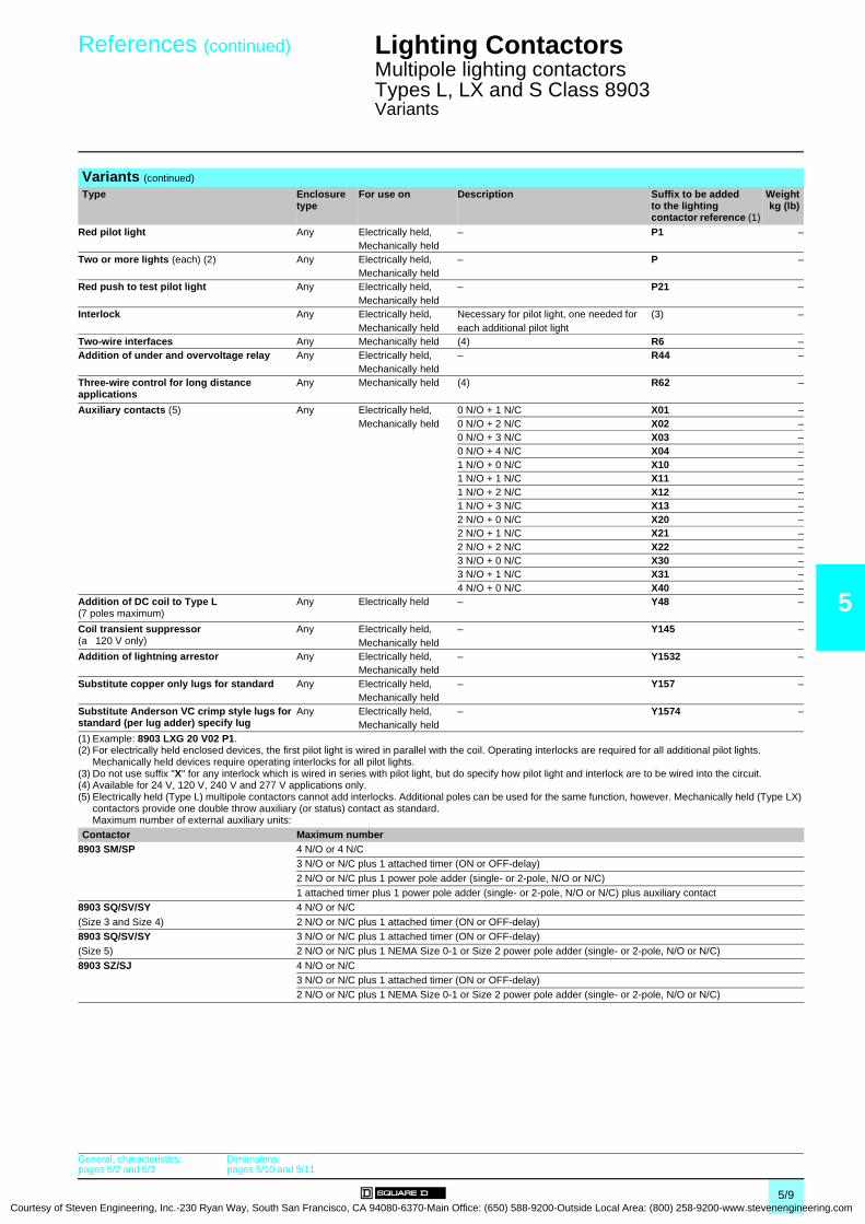
Courtesy of S
References (continued) 0 Lighting Contactors 0
Multipole lighting contactorsTypes L, LX and S Class 8903Variants
5
Variants (continued)
Type Enclosure type
For use on Description Suffix to be added to the lighting contactor reference (1)
Weightkg (lb)
Red pilot light Any Electrically held, – P1 –Mechanically held
Two or more lights (each) (2) Any Electrically held, – P –Mechanically held
Red push to test pilot light Any Electrically held, – P21 –Mechanically held
Interlock Any Electrically held, Necessary for pilot light, one needed for (3) –Mechanically held each additional pilot light
Two-wire interfaces Any Mechanically held (4) R6 –Addition of under and overvoltage relay Any Electrically held, – R44 –
Mechanically heldThree-wire control for long distance applications
Any Mechanically held (4) R62 –
Auxiliary contacts (5) Any Electrically held, 0 N/O + 1 N/C X01 –Mechanically held 0 N/O + 2 N/C X02 –
0 N/O + 3 N/C X03 –0 N/O + 4 N/C X04 –1 N/O + 0 N/C X10 –1 N/O + 1 N/C X11 –1 N/O + 2 N/C X12 –1 N/O + 3 N/C X13 –2 N/O + 0 N/C X20 –2 N/O + 1 N/C X21 –2 N/O + 2 N/C X22 –3 N/O + 0 N/C X30 –3 N/O + 1 N/C X31 –4 N/O + 0 N/C X40 –
Addition of DC coil to Type L (7 poles maximum)
Any Electrically held – Y48 –
Coil transient suppressor(a 120 V only)
Any Electrically held, – Y145 –Mechanically held
Addition of lightning arrestor Any Electrically held, – Y1532 –Mechanically held
Substitute copper only lugs for standard Any Electrically held, – Y157 –Mechanically held
Substitute Anderson VC crimp style lugs for standard (per lug adder) specify lug
Any Electrically held, – Y1574 –Mechanically held
(1) Example: 8903 LXG 20 V02 P1.(2) For electrically held enclosed devices, the first pilot light is wired in parallel with the coil. Operating interlocks are required for all additional pilot lights.
Mechanically held devices require operating interlocks for all pilot lights.(3) Do not use suffix "X" for any interlock which is wired in series with pilot light, but do specify how pilot light and interlock are to be wired into the circuit. (4) Available for 24 V, 120 V, 240 V and 277 V applications only.(5) Electrically held (Type L) multipole contactors cannot add interlocks. Additional poles can be used for the same function, however. Mechanically held (Type LX)
contactors provide one double throw auxiliary (or status) contact as standard.Maximum number of external auxiliary units:
Contactor Maximum number8903 SM/SP 4 N/O or 4 N/C
3 N/O or N/C plus 1 attached timer (ON or OFF-delay)
2 N/O or N/C plus 1 power pole adder (single- or 2-pole, N/O or N/C)1 attached timer plus 1 power pole adder (single- or 2-pole, N/O or N/C) plus auxiliary contact
8903 SQ/SV/SY 4 N/O or N/C
(Size 3 and Size 4) 2 N/O or N/C plus 1 attached timer (ON or OFF-delay)8903 SQ/SV/SY 3 N/O or N/C plus 1 attached timer (ON or OFF-delay)(Size 5) 2 N/O or N/C plus 1 NEMA Size 0-1 or Size 2 power pole adder (single- or 2-pole, N/O or N/C)
8903 SZ/SJ 4 N/O or N/C3 N/O or N/C plus 1 attached timer (ON or OFF-delay)2 N/O or N/C plus 1 NEMA Size 0-1 or Size 2 power pole adder (single- or 2-pole, N/O or N/C)
General, characteristics:pages 5/2 and 5/3
Dimensions:pages 5/10 and 5/11
5/9teven Engineering, Inc.-230 Ryan Way, South San Francisco, CA 94080-6370-Main Office: (650) 588-9200-Outside Local Area: (800) 258-9200-www.stevenengineering.com
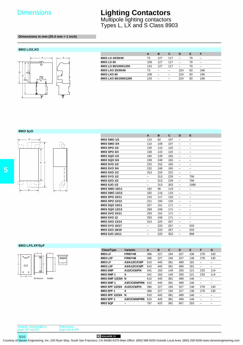
5
Courtesy
Dimensions 0
Lighting Contactors 0
Multipole lighting contactorsTypes L, LX and S Class 8903
Dimensions in mm (25.4 mm = 1 inch)
8903 LO/LXOA B C D E F
8903 LO 20/30/40 73 127 117 – 79 –8903 LO 60 108 127 117 – 79 –8903 LO 80/1000/1200 143 127 117 – 79 –
8903 LXO 20/30/40 73 – – 224 83 1968903 LXO 60 108 – – 224 83 1968903 LXO 80/1000/1200 143 – – 224 83 196
8903 SpOA B C D E
8903 SMO 1/2 110 82 107 – –
8903 SMO 3/4 110 108 107 – –8903 SPO 1/2 135 110 125 – –8903 SPO 3/4 158 143 125 – –
8903 SQO 1/2 180 139 165 – –8903 SQO 3/4 199 248 165 – –8903 SVO 1/2 232 152 165 – –
8903 SVO 3/4 232 248 165 – –8903 SXO 1/2 313 220 222 – –8903 SYO 1/2 – 313 229 – 706
8903 SZO 1/2 – 313 229 – 7068903 SJO 1/2 – 313 303 – 10858903 SMO 10/11 182 96 119 – –
8903 SMO 12/13 182 116 119 – –8903 SPO 10/11 210 117 133 – –8903 SPO 12/13 221 150 133 – –
8903 SQO 10/11 257 151 171 – –8903 SQO 12/13 268 248 171 – –8903 SVO 10/11 293 152 171 – –
8903 SVO 12 293 248 171 – –8903 SXO 13/14 313 220 267 – –8903 SYO 16/17 – 220 267 – 533
8903 SZO 18/19 – 220 267 – 5338903 SJO 10/11 – 220 303 – 898
8903 LF/LXF/SpF Class/Type Variants A B C D E F G
8903 LF F/R6/Y48 386 227 194 327 138 278 130
8903 LXF F/R6/Y48 386 227 194 327 138 278 1308903 LF A3/A12/C/C6/P 610 445 381 489 181 – –8903 LXF A3/A12/C/C6/P 610 445 381 489 181 – –
8903 SMF A12/C/C6/P/X 341 183 149 283 121 233 1148903 SMF 1 X 341 183 149 283 121 233 1148903 SMF 1/2/3/4 N 610 445 381 489 146 – –
8903 SMF 1 A3/C/C6/N/P/R6 610 445 381 489 146 – –8903 SPF 1/2/3/4 A12/C/C6/P/X 386 227 194 327 138 278 1308903 SPF 1 X 386 227 194 327 138 278 130
8903 SPF 1/2/3/4 N 610 445 381 489 146 – –8903 SPF 1 A3/C/C6/N/P/R6 610 445 381 489 146 – –8903 SQF – 787 425 362 667 203 – –
EA
DF
C
2.2557
B
Mtg
Mtg
Mtg
D
CB
A E
A
B
E G
D F C
Enclosure Saddle
General, characteristics:pages 5/2 and 5/3
References:pages 5/4 to 5/9
5/10 of Steven Engineering, Inc.-230 Ryan Way, South San Francisco, CA 94080-6370-Main Office: (650) 588-9200-Outside Local Area: (800) 258-9200-www.stevenengineering.com
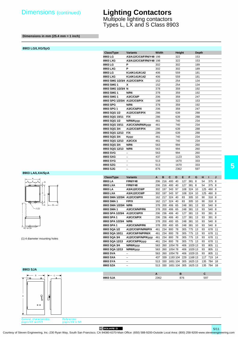
Courtesy of S
Dimensions (continued)
0
Lighting Contactors 0
Multipole lighting contactorsTypes L, LX and S Class 8903
Dimensions in mm (25.4 mm = 1 inch)
5
8903 LG/LXG/SpGClass/Type Variants Width Height Depth
8903 LG A3/A12/C/C6/F/R6/Y48 198 322 1538903 LXG A3/A12/C/C6/F/R6/Y48 198 322 1538903 LG P 302 302 189
8903 LXG P 302 302 1898903 LG K14/K141/K142 406 559 1818903 LXG K14/K141/K142 406 559 181
8903 SMG 1/2/3/4 A12/C/C6/P/X 152 254 1348903 SMG 1 X 152 254 1348903 SMG 1/2/3/4 N 378 359 192
8903 SMG 1 N/R6 378 359 1928903 SMG 1 A3/C/C6/P 206 359 2478903 SPG 1/2/3/4 A12/C/C6/P/X 198 322 153
8903 SPG N/R6 378 359 1928903 SPG 1 A3/C/C6/P/X 206 359 2478903 SQG 1/2 A12/C/C6/F/P/X 286 639 288
8903 SQG 10/11 F/X 286 639 2888903 SQG 1/2 N/R6/Kppp 461 740 2348903 SQG 10/11 A3/C/C6/N/R6/Kppp 461 740 234
8903 SQG 3/4 A12/C/C6/F/P/X 286 639 2888903 SQG 12/13 F/X 286 639 2888903 SQG 3/4 Kppp 461 740 234
8903 SQG 12/13 A3/C/C6 461 740 2348903 SQG 3/4 N/R6 563 994 2608903 SQG 12/13 N/R6 563 994 260
8903 SVG – 563 994 2608903 SXG – 437 1123 325
8903 SYG – 513 1670 3338903 SZG – 513 1670 3338903 SJG – 876 2362 597
8903 LA/LXA/SpAClass/Type Variants A B C D E F G H I J
8903 LA F/R6/Y48 206 216 400 40 127 381 8 54 375 88903 LXA F/R6/Y48 206 216 400 40 127 381 8 54 375 88903 LA A3/A12/C/C6/P 302 197 343 97 108 324 10 125 460 8
8903 LXA A3/A12/C/C6/P 302 197 343 97 108 324 10 125 460 88903 SMA 1/2/3/4 A12/C/C6/P/X 162 217 324 40 83 305 10 90 318 88903 SMA 1 F/P/X 162 217 324 40 83 305 10 90 318 8
8903 SMA 1/2/3/4 N/R6 378 200 406 65 248 381 13 93 540 88903 SMA 1 A3/C/C6/N/P/R6 378 200 406 65 248 381 13 93 540 88903 SPA 1/2/3/4 A12/C/C6/P/X 206 236 406 40 127 381 13 93 391 8
8903 SPA 1 A3/C/C6/P/X 206 236 406 40 127 381 13 93 391 88903 SPA 1/2/3/4 N/R6 378 200 400 65 248 381 10 93 540 88903 SPA 1 A3/C/C6/N/P/R6 378 200 400 65 248 381 10 93 540 8
8903 SQA 1/2 A12/C/C6/F/N/R6/P/X 461 234 800 78 305 775 13 93 678 118903 SQA 10/11 A3/C/C6/F/N/P/R6/X 461 234 800 78 305 775 13 93 678 118903 SQA 3/4 A12/C/C6/F/N/P/Kppp 461 234 800 78 305 775 13 93 678 11
8903 SQA 12/13 A3/C/C6/P/Kppp 461 234 800 78 305 775 13 93 678 118903 SQA 3/4 N/R6/Kppp 563 260 1054 78 406 1029 13 93 805 118903 SQA 12/13 N/R6/Kppp 563 260 1054 78 406 1029 13 93 805 11
8903 SVA – 563 260 1054 78 406 1029 15 93 805 118903 SXA – 437 339 1193 104 229 1168 13 117 719 148903 SYA – 513 330 1651 104 305 1625 13 135 784 18
8903 SZA – 513 330 1651 104 305 1625 13 135 784 18
8903 SJAA B C
8903 SJA 2362 876 597
A
D E D G
FC
G
I
H
B
J (1)
(1) 4 diameter mounting holes
B C
A
General, characteristics:pages 5/2 and 5/3
References:pages 5/4 to 5/9
5/11teven Engineering, Inc.-230 Ryan Way, South San Francisco, CA 94080-6370-Main Office: (650) 588-9200-Outside Local Area: (800) 258-9200-www.stevenengineering.com

6/0Courtesy of Steven Engineering, Inc.-230 Ryan Way, South San Francisco
, CA 94080-6370-Main Office: (650) 588-9200-Outside Local Area: (800) 258-9200-www.stevenengineering.com
Contents
Courtesy of Steven Engineering, Inc.-230 Ryan Way, South San Francisco, CA
6 - Manual Starters and Switches
6
b Manual starters and switches
v General . . . . . . . . . . . . . . . . . . . . . . . . . . . . . . . . . . . . . . . . . . . . . . . . page 6/2
v Characteristics . . . . . . . . . . . . . . . . . . . . . . . . . . . . . . . . . . . . . . . . . . . page 6/3
b Single units Type F
v References . . . . . . . . . . . . . . . . . . . . . . . . . . . . . . . . . . . . . . . . . . . . . page 6/4
b Duplex units Type F
v References . . . . . . . . . . . . . . . . . . . . . . . . . . . . . . . . . . . . . . . . . . . . . page 6/5
b Non-reversing Type K
v References . . . . . . . . . . . . . . . . . . . . . . . . . . . . . . . . . . . . . . . . . . . . . page 6/7
b Integral motor power non-reversing Types T and M
v References . . . . . . . . . . . . . . . . . . . . . . . . . . . . . . . . . . . . . . . . . . . . . page 6/8
b Reversing drum switches
v References . . . . . . . . . . . . . . . . . . . . . . . . . . . . . . . . . . . . . . . . . . . . . page 6/9
b Manual starters and switches
v Accessories . . . . . . . . . . . . . . . . . . . . . . . . . . . . . . . . . . . . . . . . . . . . . page 6/9
v Dimensions . . . . . . . . . . . . . . . . . . . . . . . . . . . . . . . . . . . . . . . . . . . . page 6/10
6/1 94080-6370-Main Office: (650) 588-9200-Outside Local Area: (800) 258-9200-www.stevenengineering.com
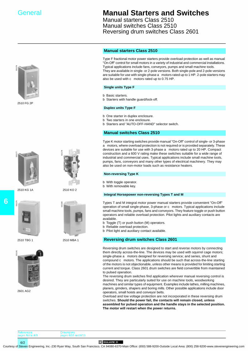
6
Courtesy
General 0 Manual Starters and Switches 0
Manual starters Class 2510Manual switches Class 2510Reversing drum switches Class 2601
Type F fractional motor power starters provide overload protection as well as manual "On-Off" control for small motors in a variety of industrial and commercial installations. Typical applications include fans, conveyors, pumps and small machine tools.They are available in single- or 2-pole versions. Both single-pole and 2-pole versions are suitable for use with single-phase a motors rated up to 1 HP. 2-pole starters may also be used with c motors rated up to 0.75 HP.
b Basic starters. b Starters with handle guard/lock-off.
b One starter in duplex enclosure.b Two starters in one enclosure.b Starters and "AUTO-OFF-HAND" selector switch.
Type K motor starting switches provide manual "On-Off" control of single- or 3-phase a motors, where overload protection is not required or is provided separately. These devices are suitable for use with 3-phase a motors rated up to 20 HP. Compact construction and a 600 V rating make these switches suitable for a wide range of industrial and commercial uses. Typical applications include small machine tools, pumps, fans, conveyors and many other types of electrical machinery. They may also be used on non-motor loads such as resistance heaters.
b With toggle operator. b With removable key.
Types T and M integral motor power manual starters provide convenient "On-Off" operation of small single-phase, 3-phase or c motors. Typical applications include small machine tools, pumps, fans and conveyors. They feature toggle or push button operators and reliable overload protection. Pilot lights and auxiliary contacts are available. b Toggle (T) or push button (M) operators.b Reliable overload protection.b Pilot light and auxiliary contact available.
Reversing drum switches are designed to start and reverse motors by connecting them directly across-the-line. The devices may be used with squirrel cage motors; single-phase a motors designed for reversing service; and series, shunt and compound c motors. The applications should be such that across-the-line starting of the motors is not objectionable, unless other means is provided for limiting starting current and torque. Class 2601 drum switches are field convertible from maintained to pulsed operation. The reversing drum switches find application wherever manual reversing control is desired. They are particularly suited for use on machine tools, woodworking machines and similar types of equipment. Examples include lathes, milling machines, planers, grinders, shapers and boring mills. Other possible applications include door operators, small hoists and conveyor belts.Overload and low voltage protection are not incorporated in these reversing drum switches. Should the power fail, the contacts will remain closed, unless assembled for pulsed operation and the handle stays in the selected position. The motor will restart when the power returns.
Manual starters Class 2510
Single units Type F
Duplex units Type F
Manual switches Class 2510
Non-reversing Type K
Integral Horsepower non-reversing Types T and M
Reversing drum switches Class 2601
5311
76
2510 FG 2P
5311
77
2510 KG 1A
5311
78
2510 KO 2
5311
79
2510 TBG 1
5311
80
2510 MBA 1
5311
81
2601 AG2
References:pages 6/4 to 6/9
Dimensions:pages 6/10 and 6/11
6/2 of Steven Engineering, Inc.-230 Ryan Way, South San Francisco, CA 94080-6370-Main Office: (650) 588-9200-Outside Local Area: (800) 258-9200-www.stevenengineering.com
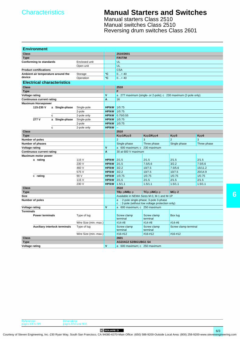
Courtesy of S
Characteristics 0 Manual Starters and Switches 0
Manual starters Class 2510Manual switches Class 2510Reversing drum switches Class 2601
6
EnvironmentClass 2510/2601Type F/K/T/M
Conforming to standards Enclosed unit ULOpen unit UL
Product certifications CSA
Ambient air temperature around the device
Storage °C 0…+ 40Operation °C 0…+ 40
Electrical characteristicsClass 2510Type F
Voltage rating V a 277 maximum (single- or 2-pole); c 230 maximum (2-pole only)
Continuous current rating A 16Maximum Horsepower
115-230 V a Single-phase Single-pole HP/kW 1/0.75
2-pole HP/kW 1/0.75c 2-pole only HP/kW 0.75/0.55
277 V a Single-phase Single-pole HP/kW 1/0.75
2-pole HP/kW 1/0.75c 2-pole only HP/kW –
Class 2510Type Kpp1/Kpp3 Kpp2/Kpp4 Kpp5 Kpp6
Number of poles 2 3 2 3Number of phases Single phase Three phase Single phase Three phase
Voltage rating V a 600 maximum; c 230 maximumContinuous current rating A 30 at 600 V maximum
Maximum motor powera rating 115 V HP/kW 2/1.5 2/1.5 2/1.5 2/1.5
230 V HP/kW 2/1.5 7.5/5.6 3/2.2 7.5/5.6
460 V HP/kW 3/2.2 10/7.5 7.5/5.6 15/11.2575 V HP/kW 3/2.2 10/7.5 10/7.5 20/14.9
c rating 90 V HP/kW 1/0.75 1/0.75 1/0.75 1/0.75
115 V HP/kW 2/1.5 2/1.5 2/1.5 2/1.5230 V HP/kW 1.5/1.1 1.5/1.1 1.5/1.1 1.5/1.1
Class 2510Type TBp p/MBp p TCp p/MCp p MCp 2
Size Available in NEMA Sizes M-0, M-1 and M-1PNumber of poles a : 2-pole single-phase; 3-pole 3-phase
c : 2-pole (without low voltage protection only)Voltage rating V a 600 maximum; c 250 maximum
TerminalsPower terminals Type of lug Screw clamp
terminalScrew clamp terminal
Box lug
Wire Size (min.-max.) #14-#8 #14-#8 #14-#6Auxiliary interlock terminals Type of lug Screw clamp
terminalScrew clamp terminal
Screw clamp terminal
Wire Size (min.-max.) #16-#12 #16-#12 #16-#12
Class 2601Type AG2/AG2 S2/BG1/BG1 S4
Voltage rating V a 600 maximum; c 250 maximum
References:pages 6/4 to 6/9
Dimensions:pages 6/10 and 6/11
6/3teven Engineering, Inc.-230 Ryan Way, South San Francisco, CA 94080-6370-Main Office: (650) 588-9200-Outside Local Area: (800) 258-9200-www.stevenengineering.com
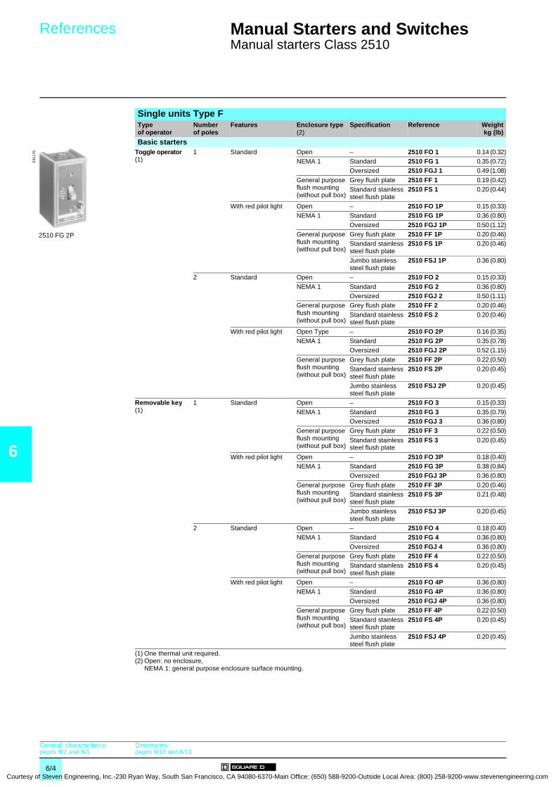
6
Courtesy
References 0 Manual Starters and Switches 0
Manual starters Class 2510
Single units Type FType of operator
Number of poles
Features Enclosure type (2)
Specification Reference Weightkg (lb)
Basic startersToggle operator (1)
1 Standard Open – 2510 FO 1 0.14 (0.32)NEMA 1 Standard 2510 FG 1 0.35 (0.72)
Oversized 2510 FGJ 1 0.49 (1.08)
General purpose flush mounting (without pull box)
Grey flush plate 2510 FF 1 0.19 (0.42)Standard stainless steel flush plate
2510 FS 1 0.20 (0.44)
With red pilot light Open – 2510 FO 1P 0.15 (0.33)NEMA 1 Standard 2510 FG 1P 0.36 (0.80)
Oversized 2510 FGJ 1P 0.50 (1.12)General purpose flush mounting (without pull box)
Grey flush plate 2510 FF 1P 0.20 (0.46)Standard stainless steel flush plate
2510 FS 1P 0.20 (0.46)
Jumbo stainless steel flush plate
2510 FSJ 1P 0.36 (0.80)
2 Standard Open – 2510 FO 2 0.15 (0.33)
NEMA 1 Standard 2510 FG 2 0.36 (0.80)Oversized 2510 FGJ 2 0.50 (1.11)
General purpose flush mounting (without pull box)
Grey flush plate 2510 FF 2 0.20 (0.46)
Standard stainless steel flush plate
2510 FS 2 0.20 (0.46)
With red pilot light Open Type – 2510 FO 2P 0.16 (0.35)NEMA 1 Standard 2510 FG 2P 0.35 (0.78)
Oversized 2510 FGJ 2P 0.52 (1.15)
General purpose flush mounting (without pull box)
Grey flush plate 2510 FF 2P 0.22 (0.50)Standard stainless steel flush plate
2510 FS 2P 0.20 (0.45)
Jumbo stainless steel flush plate
2510 FSJ 2P 0.20 (0.45)
Removable key (1)
1 Standard Open – 2510 FO 3 0.15 (0.33)
NEMA 1 Standard 2510 FG 3 0.35 (0.79)Oversized 2510 FGJ 3 0.36 (0.80)
General purpose flush mounting (without pull box)
Grey flush plate 2510 FF 3 0.22 (0.50)
Standard stainless steel flush plate
2510 FS 3 0.20 (0.45)
With red pilot light Open – 2510 FO 3P 0.18 (0.40)NEMA 1 Standard 2510 FG 3P 0.38 (0.84)
Oversized 2510 FGJ 3P 0.36 (0.80)
General purpose flush mounting (without pull box)
Grey flush plate 2510 FF 3P 0.20 (0.46)Standard stainless steel flush plate
2510 FS 3P 0.21 (0.48)
Jumbo stainless steel flush plate
2510 FSJ 3P 0.20 (0.45)
2 Standard Open – 2510 FO 4 0.18 (0.40)NEMA 1 Standard 2510 FG 4 0.36 (0.80)
Oversized 2510 FGJ 4 0.36 (0.80)General purpose flush mounting (without pull box)
Grey flush plate 2510 FF 4 0.22 (0.50)Standard stainless steel flush plate
2510 FS 4 0.20 (0.45)
With red pilot light Open – 2510 FO 4P 0.36 (0.80)
NEMA 1 Standard 2510 FG 4P 0.36 (0.80)Oversized 2510 FGJ 4P 0.36 (0.80)
General purpose flush mounting (without pull box)
Grey flush plate 2510 FF 4P 0.22 (0.50)
Standard stainless steel flush plate
2510 FS 4P 0.20 (0.45)
Jumbo stainless steel flush plate
2510 FSJ 4P 0.20 (0.45)
(1) One thermal unit required.(2) Open: no enclosure,
NEMA 1: general purpose enclosure surface mounting.
2510 FG 2P
5311
76
General, characteristics:pages 6/2 and 6/3
Dimensions:pages 6/10 and 6/11
6/4 of Steven Engineering, Inc.-230 Ryan Way, South San Francisco, CA 94080-6370-Main Office: (650) 588-9200-Outside Local Area: (800) 258-9200-www.stevenengineering.com

Courtesy of S
References (continued) 0 Manual Starters and Switches 0
Manual starters Class 2510
6
Single units Type F (continued)Type of operator
Number of poles
Features Enclosure type (2)
Specification Reference Weightkg (lb)
Starters with handle guard/lock-offToggle operator (1)
1 Standard NEMA 1 (3) Standard 2510 FG 5 0.36 (0.80)
Oversized 2510 FGJ 5 0.50 (1.11)With red pilot light NEMA 1 (3) Standard 2510 FG 5P 0.37 (0.82)
Oversized 2510 FGJ 5P 0.52 (1.15)
2 Standard NEMA 1 (3) Standard 2510 FG 6 0.37 (0.82)Oversized 2510 FGJ 6 0.51 (1.13)
With red pilot light NEMA 1 (3) Standard 2510 FG 6P 0.38 (0.84)
Oversized 2510 FGJ 6P 0.53 (1.17)
Duplex units Type FOne starter in duplex enclosure
Toggle operator (1)
2 Standard NEMA 1 Standard 2510 FG 02 0.50 (1.10)
With red pilot light NEMA 1 Standard 2510 FG 02P 0.51 (1.12)Removable key (1)
2 With red pilot light NEMA 1 Standard 2510 FG 04P 0.51 (1.12)
Two starters in one enclosureToggle operator (1)
2 for each starter
Standard NEMA 1 Standard 2510 FG 22 0.70 (1.54)General purpose flush mounting (without pull box)
Grey flush plate 2510 FF 22 0.70 (1.54)
With red pilot light on each starter
NEMA 1 Standard 2510 FG 22P 0.70 (1.54)General purpose flush mounting (without pull box)
Grey flush plate 2510 FF 22P 0.70 (1.54)Standard stainless steel flush plate
2510 FS 22P 0.70 (1.54)
Removable key (4)
2 for each starter
With red pilot light on each starter
NEMA 1 Standard 2510 FG 44P 0.70 (1.54)General purpose flush mounting (without pull box)
Grey flush plate 2510 FF 44P 0.70 (1.54)Standard stainless steel flush plate
2510 FS 44P 0.70 (1.54)
Starters and "AUTO-OFF-HAND" selector switch (a only)Toggle operator (1)
1 Standard NEMA 1 Standard 2510 FG 71 0.81 (1.79)General purpose flush mounting (without pull box)
Grey flush plate 2510 FF 71 0.73 (1.61)
With red pilot light NEMA 1 Standard 2510 FG 71P 0.72 (1.59)General purpose flush mounting (without pull box)
Grey flush plate 2510 FF 71P 0.80 (1.76)
Standard stainless steel flush plate
2510 FS 71P 0.80 (1.76)
2 Standard NEMA 1 Standard 2510 FG 72 0.80 (1.76)General purpose flush mounting (without pull box)
Grey flush plate 2510 FF 72 0.80 (1.76)
With red pilot light NEMA 1 Standard 2510 FG 72P 0.80 (1.76)General purpose flush mounting (without pull box)
Grey flush plate 2510 FF 72P 0.80 (1.76)Standard stainless steel flush plate
2510 FS 72P 0.80 (1.76)
Removable key (1)
2 With red pilot light NEMA 1 Standard 2510 FG 74P 0.80 (1.76)
General purpose flush mounting (without pull box)
Grey flush plate 2510 FF 74P 0.80 (1.76)Standard stainless steel flush plate
2510 FS 74P 0.80 (1.76)
(1) One thermal unit required.(2) NEMA 1: general purpose enclosure surface mounting.(3) For general purpose flush mounting enclosure (without pull box), order basic starter plus separate handle guard kit, reference
is 2510 FL1.(4) Two thermal units required.
General, characteristics:pages 6/2 and 6/3
Dimensions:pages 6/10 and 6/11
6/5teven Engineering, Inc.-230 Ryan Way, South San Francisco, CA 94080-6370-Main Office: (650) 588-9200-Outside Local Area: (800) 258-9200-www.stevenengineering.com
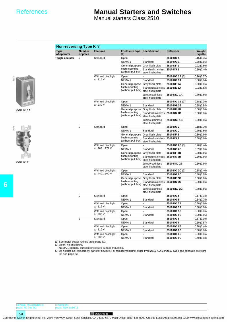
6
Courtesy
References 0 Manual Starters and Switches 0
Manual starters Class 2510
Non-reversing Type K (1)Type of operator
Number of poles
Features Enclosure type (2)
Specification Reference Weightkg (lb)
Toggle operator 2 Standard Open – 2510 KO 1 0.15 (0.35)NEMA 1 Standard 2510 KG 1 0.38 (0.85)
General purpose flush mounting (without pull box)
Grey flush plate 2510 KF 1 0.22 (0.50)Standard stainless steel flush plate
2510 KS 1 0.20 (0.46)
With red pilot light a 115 V
Open – 2510 KO 1A (3) 0.16 (0.37)NEMA 1 Standard 2510 KG 1A 0.38 (0.84)
General purpose flush mounting (without pull box)
Grey flush plate 2510 KF 1A 0.30 (0.66)Standard stainless steel flush plate
2510 KS 1A 0.23 (0.52)
Jumbo stainless steel flush plate
2510 KSJ 1A 0.30 (0.66)
With red pilot light a 230 V
Open – 2510 KO 1B (3) 0.18 (0.39)NEMA 1 Standard 2510 KG 1B 0.38 (0.84)
General purpose flush mounting (without pull box)
Grey flush plate 2510 KF 1B 0.30 (0.66)Standard stainless steel flush plate
2510 KS 1B 0.30 (0.66)
Jumbo stainless steel flush plate
2510 KSJ 1B 0.30 (0.66)
3 Standard Open – 2510 KO 2 0.18 (0.39)NEMA 1 Standard 2510 KG 2 0.30 (0.66)
General purpose flush mounting (without pull box)
Grey flush plate 2510 KF 2 0.30 (0.66)Standard stainless steel flush plate
2510 KS 2 0.30 (0.66)
With red pilot light a 208…277 V
Open – 2510 KO 2B (3) 0.20 (0.44)
NEMA 1 Standard 2510 KG 2B 0.39 (0.86)General purpose flush mounting (without pull box)
Grey flush plate 2510 KF 2B 0.30 (0.66)Standard stainless steel flush plate
2510 KS 2B 0.30 (0.66)
Jumbo stainless steel flush plate
2510 KSJ 2B 0.30 (0.66)
With red pilot light a 440…600 V
Open – 2510 KO 2C (3) 0.18 (0.40)
NEMA 1 Standard 2510 KG 2C 0.40 (0.88)General purpose flush mounting (without pull box)
Grey flush plate 2510 KF 2C 0.30 (0.66)Standard stainless steel flush plate
2510 KS 2C 0.30 (0.66)
Jumbo stainless steel flush plate
2510 KSJ 2C 0.30 (0.66)
2 Standard Open – 2510 KO 5 0.17 (0.38)
NEMA 1 Standard 2510 KG 5 0.34 (0.75)With red pilot light a 115 V
Open – 2510 KO 5A 0.30 (0.66)NEMA 1 Standard 2510 KG 5A 0.30 (0.66)
With red pilot light a 230 V
Open – 2510 KO 5B 0.30 (0.66)NEMA 1 Standard 2510 KG 5B 0.30 (0.66)
3 Standard Open – 2510 KO 6 0.17 (0.39)
NEMA 1 Standard 2510 KG 6 0.39 (0.87)With red pilot light a 115 V
Open – 2510 KO 6B 0.20 (0.44)NEMA 1 Standard 2510 KG 6B 0.30 (0.66)
With red pilot light a 230 V
Open – 2510 KO 6C 0.30 (0.66)NEMA 1 Standard 2510 KG 6C 0.40 (0.88)
(1) See motor power ratings table page 6/3.(2) Open: no enclosure,
NEMA 1: general purpose enclosure surface mounting.(3) Do not use as replacement parts for devices. For replacement unit, order Type 2510 KO 1 or 2510 KO 2 and separate pilot light
kit, see page 6/9.
2510 KG 1A
5311
77
2510 KO 2
5311
78
General, characteristics:pages 6/2 and 6/3
Dimensions:pages 6/10 and 6/11
6/6 of Steven Engineering, Inc.-230 Ryan Way, South San Francisco, CA 94080-6370-Main Office: (650) 588-9200-Outside Local Area: (800) 258-9200-www.stevenengineering.com
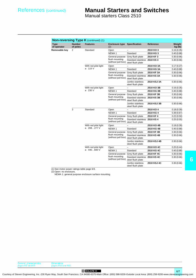
Courtesy of S
References (continued) 0 Manual Starters and Switches 0
Manual starters Class 2510
6
Non-reversing Type K (continued) (1)Type of operator
Number of poles
Features Enclosure type (2)
Specification Reference Weightkg (lb)
Removable key 2 Standard Open – 2510 KO 3 0.16 (0.35)NEMA 1 Standard 2510 KG 3 0.40 (0.88)
General purpose flush mounting (without pull box)
Grey flush plate 2510 KF 3 0.30 (0.66)Standard stainless steel flush plate
2510 KS 3 0.30 (0.66)
With red pilot light a 115 V
Open – 2510 KO 3A 0.17 (0.37)NEMA 1 Standard 2510 KG 3A 0.40 (0.88)
General purpose flush mounting (without pull box)
Grey flush plate 2510 KF 3A 0.30 (0.66)Standard stainless steel flush plate
2510 KS 3A 0.30 (0.66)
Jumbo stainless steel flush plate
2510 KSJ 3A 0.30 (0.66)
With red pilot light a 230 V
Open – 2510 KO 3B 0.16 (0.35)NEMA 1 Standard 2510 KG 3B 0.40 (0.88)
General purpose flush mounting (without pull box)
Grey flush plate 2510 KF 3B 0.30 (0.66)Standard stainless steel flush plate
2510 KS 3B 0.30 (0.66)
Jumbo stainless steel flush plate
2510 KSJ 3B 0.30 (0.66)
3 Standard Open – 2510 KO 4 0.18 (0.39)NEMA 1 Standard 2510 KG 4 0.39 (0.87)
General purpose flush mounting (without pull box)
Grey flush plate 2510 KF 4 0.22 (0.50)Standard stainless steel flush plate
2510 KS 4 0.25 (0.55)
With red pilot light a 208…277 V
Open – 2510 KO 4B 0.18 (0.39)
NEMA 1 Standard 2510 KG 4B 0.40 (0.88)General purpose flush mounting (without pull box)
Grey flush plate 2510 KF 4B 0.30 (0.66)Standard stainless steel flush plate
2510 KS 4B 0.30 (0.66)
Jumbo stainless steel flush plate
2510 KSJ 4B 0.30 (0.66)
With red pilot light a 440…600 V
Open – 2510 KO 4C 0.20 (0.44)
NEMA 1 Standard 2510 KG 4C 0.40 (0.88)General purpose flush mounting (without pull box)
Grey flush plate 2510 KF 4C 0.30 (0.66)Standard stainless steel flush plate
2510 KS 4C 0.30 (0.66)
Jumbo stainless steel flush plate
2510 KSJ 4C 0.30 (0.66)
(1) See motor power ratings table page 6/3.(2) Open: no enclosure,
NEMA 1: general purpose enclosure surface mounting.
General, characteristics:pages 6/2 and 6/3
Dimensions:pages 6/10 and 6/11
6/7teven Engineering, Inc.-230 Ryan Way, South San Francisco, CA 94080-6370-Main Office: (650) 588-9200-Outside Local Area: (800) 258-9200-www.stevenengineering.com
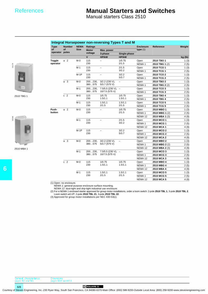
6
Courtesy
References 0 Manual Starters and Switches 0
Manual starters Class 2510
Integral Horsepower non-reversing Types T and MTypeof operator
Number ofpoles
NEMA Size
Ratings Enclosure type (1)
Reference WeightMotor voltage
Max. power3-phase Single-phase
V HP/kW HP/kW kg (lb)Toggle operator
a 2 M-0 115230
– 1/0.752/1.5
Open 2510 TBO 1 1 (3)
NEMA 1 2510 TBG 1 (2) 2 (5)M-1 115
230– 2/1.5
3/2.2Open 2510 TCO 1 1 (3)NEMA 1 2510 TCG 1 2 (5)
M-1P 115230
– 3/2.25/3.7
Open 2510 TCO 2 1 (3)NEMA 1 2510 TCG 2 2 (5)
a 3 M-0 200…230, 380…575
3/2.2 (230 V), 5/3.7 (575 V)
– Open 2510 TBO 2 1 (3)
NEMA 1 2510 TBG 2 (2) 2 (5)M-1 200…230,
380…5757.5/5.5 (230 V), 10/7.5 (575 V)
– Open 2510 TCO 3 1 (3)NEMA 1 2510 TCG 3 2 (5)
c 2 M-0 115230
1/0.751.5/1.1
1/0.751.5/1.1
Open 2510 TBO 4 1 (3)NEMA 1 2510 TBG 4 2 (5)
M-1 115230
1.5/1.12/1.5
1.5/1.12/1.5
Open 2510 TCO 5 1 (3)
NEMA 1 2510 TCG 5 2 (5)Push- button
a 2 M-0 115230
– 1/0.752/1.5
Open 2510 MBO 1 1 (3)NEMA 1 2510 MBG 1 (2) 2 (5)
NEMA 12 2510 MBA 1 (3) 4 (9)M-1 115
230– 2/1.5
3/2.2Open 2510 MCO 1 1 (3)NEMA 1 2510 MCG 1 2 (5)
NEMA 12 2510 MCA 1 4 (9)M-1P 115
230– 3/2.2
5/3.7Open 2510 MCO 2 1 (3)NEMA 1 2510 MCG 2 2 (5)
NEMA 12 2510 MCA 2 4 (9)a 3 M-0 200…230,
380…5753/2.2 (230 V), 5/3.7 (575 V)
– Open 2510 MBO 2 1 (3)
NEMA 1 2510 MBG 2 (2) 2 (5)NEMA 12 2510 MBA 2 (3) 4 (9)
M-1 200…230, 380…575
7.5/5.5 (230 V), 10/7.5 (575 V)
– Open 2510 MCO 3 1 (3)
NEMA 1 2510 MCG 3 2 (5)NEMA 12 2510 MCA 3 4 (9)
c 2 M-0 115230
1/0.751.5/1.1
1/0.751.5/1.1
Open 2510 MBO 4 1 (3)
NEMA 1 2510 MBG 4 2 (5)NEMA 12 2510 MBA 4 4 (9)
M-1 115230
1.5/1.12/1.5
1.5/1.12/1.5
Open 2510 MCO 5 1 (3)
NEMA 1 2510 MCG 5 2 (5)NEMA 12 2510 MCA 5 4 (9)
(1) Open: no enclosure.NEMA 1: general purpose enclosure surface mounting.NEMA 12: dust-tight and drip-tight industrial use enclosure.
(2) For a NEMA 1 enclosed starter approved for group motor installations, order a loom switch: 2-pole 2510 TBL 1, 3-pole 2510 TBL 2. Loom switch w/LVP: 2-pole 2510 TBL 21, 3-pole 2510 TBL 22.
(3) Approved for group motor installations per NEC 430-53(c).
2510 TBG 1
5311
79
2510 MBA 1
5311
80
General, characteristics:pages 6/2 and 6/3
Dimensions:pages 6/10 and 6/11
6/8 of Steven Engineering, Inc.-230 Ryan Way, South San Francisco, CA 94080-6370-Main Office: (650) 588-9200-Outside Local Area: (800) 258-9200-www.stevenengineering.com
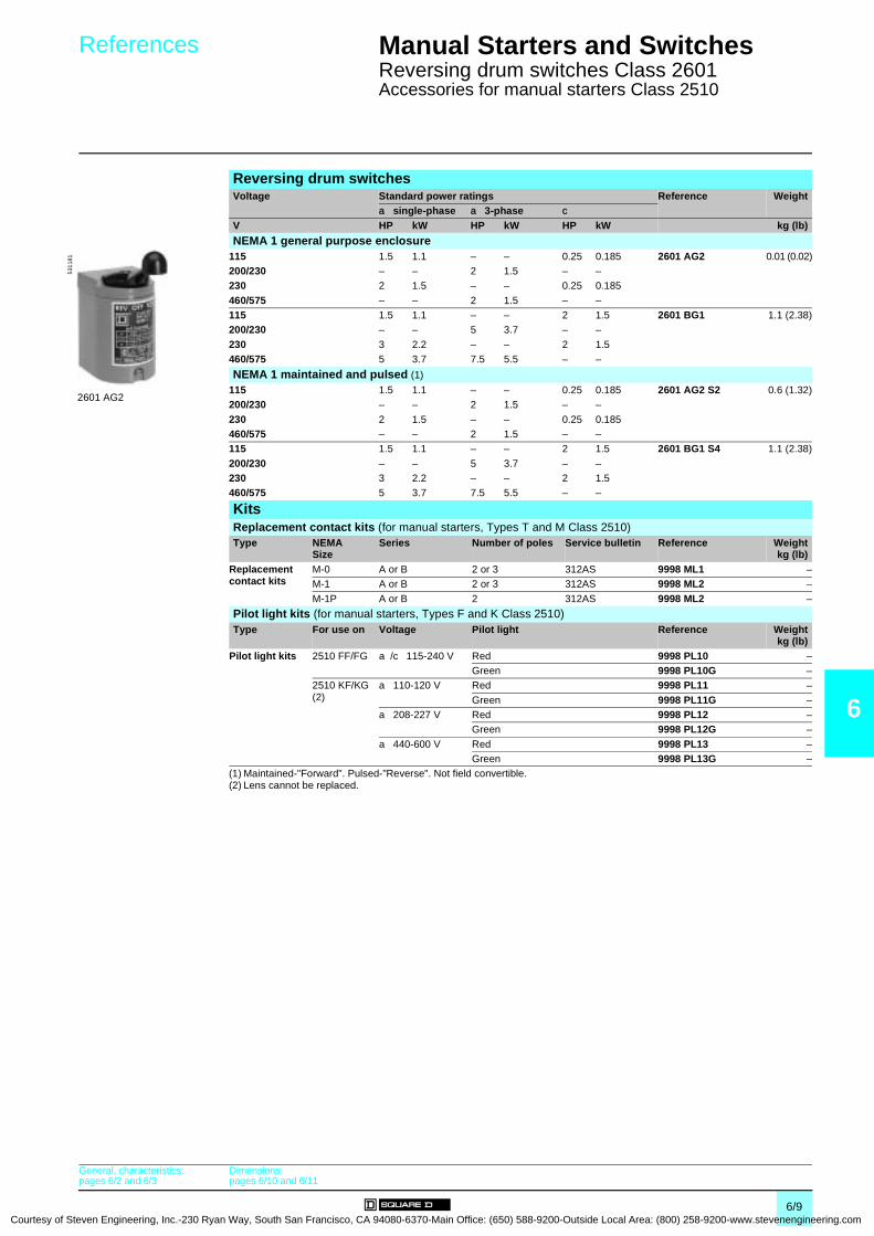
Courtesy of S
References 0 Manual Starters and Switches 0
Reversing drum switches Class 2601Accessories for manual starters Class 2510
6
Reversing drum switchesVoltage Standard power ratings Reference Weight
a single-phase a 3-phase cV HP kW HP kW HP kW kg (lb)
NEMA 1 general purpose enclosure115 1.5 1.1 – – 0.25 0.185 2601 AG2 0.01 (0.02)200/230 – – 2 1.5 – –230 2 1.5 – – 0.25 0.185
460/575 – – 2 1.5 – –115 1.5 1.1 – – 2 1.5 2601 BG1 1.1 (2.38)200/230 – – 5 3.7 – –
230 3 2.2 – – 2 1.5460/575 5 3.7 7.5 5.5 – –
NEMA 1 maintained and pulsed (1)
115 1.5 1.1 – – 0.25 0.185 2601 AG2 S2 0.6 (1.32)200/230 – – 2 1.5 – –
230 2 1.5 – – 0.25 0.185460/575 – – 2 1.5 – –115 1.5 1.1 – – 2 1.5 2601 BG1 S4 1.1 (2.38)
200/230 – – 5 3.7 – –230 3 2.2 – – 2 1.5460/575 5 3.7 7.5 5.5 – –
KitsReplacement contact kits (for manual starters, Types T and M Class 2510)Type NEMA
SizeSeries Number of poles Service bulletin Reference Weight
kg (lb)Replacementcontact kits
M-0 A or B 2 or 3 312AS 9998 ML1 –M-1 A or B 2 or 3 312AS 9998 ML2 –
M-1P A or B 2 312AS 9998 ML2 –
Pilot light kits (for manual starters, Types F and K Class 2510)Type For use on Voltage Pilot light Reference Weight
kg (lb)Pilot light kits 2510 FF/FG a/c 115-240 V Red 9998 PL10 –
Green 9998 PL10G –2510 KF/KG (2)
a 110-120 V Red 9998 PL11 –
Green 9998 PL11G –a 208-227 V Red 9998 PL12 –
Green 9998 PL12G –
a 440-600 V Red 9998 PL13 –Green 9998 PL13G –
(1) Maintained-"Forward". Pulsed-"Reverse". Not field convertible.(2) Lens cannot be replaced.
2601 AG2
5311
81
General, characteristics:pages 6/2 and 6/3
Dimensions:pages 6/10 and 6/11
6/9teven Engineering, Inc.-230 Ryan Way, South San Francisco, CA 94080-6370-Main Office: (650) 588-9200-Outside Local Area: (800) 258-9200-www.stevenengineering.com
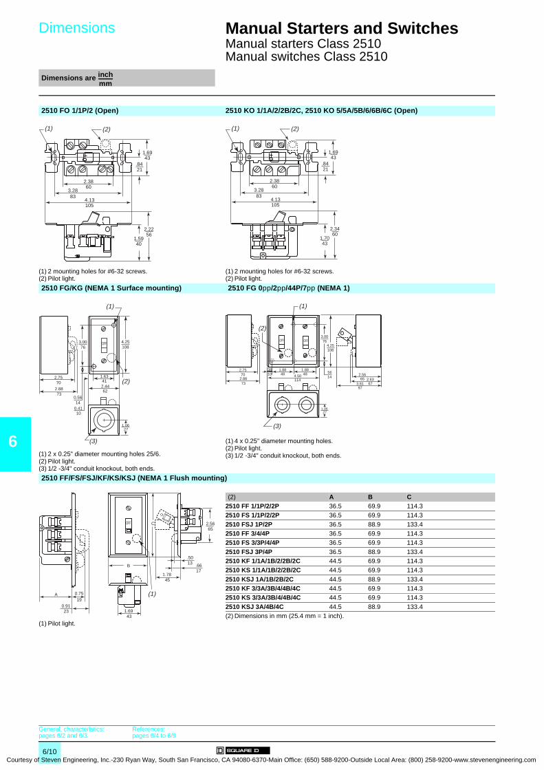
6
Courtesy
Dimensions 0
Manual Starters and Switches 0
Manual starters Class 2510Manual switches Class 2510
Dimensions are inchmm------------
2510 FO 1/1P/2 (Open) 2510 KO 1/1A/2/2B/2C, 2510 KO 5/5A/5B/6/6B/6C (Open)
(1) 2 mounting holes for #6-32 screws.(2) Pilot light.
(1) 2 mounting holes for #6-32 screws.(2) Pilot light.
2510 FG/KG (NEMA 1 Surface mounting) 2510 FG 0pp/2pp/44P/7pp (NEMA 1)
(1) 2 x 0.25" diameter mounting holes 25/6.(2) Pilot light.(3) 1/2 -3/4" conduit knockout, both ends.
(1) 4 x 0.25" diameter mounting holes.(2) Pilot light.(3) 1/2 -3/4" conduit knockout, both ends.
2510 FF/FS/FSJ/KF/KS/KSJ (NEMA 1 Flush mounting)
(1) Pilot light.
(2) A B C2510 FF 1/1P/2/2P 36.5 69.9 114.32510 FS 1/1P/2/2P 36.5 69.9 114.3
2510 FSJ 1P/2P 36.5 88.9 133.42510 FF 3/4/4P 36.5 69.9 114.32510 FS 3/3P/4/4P 36.5 69.9 114.3
2510 FSJ 3P/4P 36.5 88.9 133.42510 KF 1/1A/1B/2/2B/2C 44.5 69.9 114.32510 KS 1/1A/1B/2/2B/2C 44.5 69.9 114.3
2510 KSJ 1A/1B/2B/2C 44.5 88.9 133.42510 KF 3/3A/3B/4/4B/4C 44.5 69.9 114.32510 KS 3/3A/3B/4/4B/4C 44.5 69.9 114.3
2510 KSJ 3A/4B/4C 44.5 88.9 133.4(2) Dimensions in mm (25.4 mm = 1 inch).
(1) (2)
1.6943
.8421
2.2256
1.5940
2.3860
3.2883
4.13105
(1) (2)
1.6943
.8421
2.3460
1.7043
2.3860
3.2883
4.13105
1.0627
4.25108
3.0076
2.7570
2.8873
0.5614
0.4110
1.63412.4462
OFF
(1)
(2)
(3)
1.0627
4.25108
3.0076
2.7570
2.8873
1.8848 4.50
114
OFF
(1)
OFF
1.8848
3810 56
142.5665 2.63
673.8197
(2)
(3)
.5013
2.5665
.6617
1.7845
1.6943
B
(1)
COFF
0.9123
0.7519
A
General, characteristics:pages 6/2 and 6/3
References:pages 6/4 to 6/9
6/10 of Steven Engineering, Inc.-230 Ryan Way, South San Francisco, CA 94080-6370-Main Office: (650) 588-9200-Outside Local Area: (800) 258-9200-www.stevenengineering.com
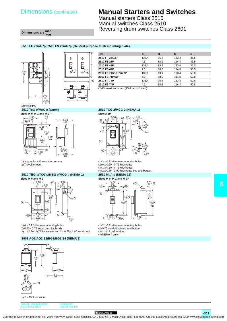
Courtesy of S
Dimensions (continued)
0
Manual Starters and Switches 0
Manual starters Class 2510Manual switches Class 2510Reversing drum switches Class 2601 Dimensions are inch
mm------------
6
2510 FF 22/44/7p, 2510 FS 22/44/7p (General purpose flush mounting plate)
(1) Pilot light.
(2) A B C D2510 FF 22/22P 133.4 95.3 133.4 36.52510 FS 22P 4.6 88.9 114.3 36.5
2510 FF 44P 133.4 95.3 133.4 36.52510 FS 44P 4.6 88.9 114.3 36.52510 FF 71/71P/72/72P 133.4 19.1 133.4 50.8
2510 FS 71P/72P 4.6 88.9 114.3 50.82510 FF 74P 133.4 95.3 133.4 50.82510 FS 74P 4.6 88.9 114.3 50.8
(2) Dimensions in mm (25.4 mm = 1 inch).
2510 TpO p/MpO p (Open) 2510 TCG 2/MCG 2 (NEMA 1)Sizes M-0, M-1 and M-1P
(1) 3 prov. for #10 mounting screws.(2) Travel to reset.
Size M-1P
(1) 3 x 0.22 diameter mounting holes.(2) 6 x 0.50 - 0.75 knockouts(3) 1 x 0.50 - 0.75 knockouts(4) 2 x 0.75 - 1.00 knockouts Top and bottom.
2510 TBG p/TCG p/MBG p/MCG p (NEMA 1) 2510 MpA p (NEMA 12)Sizes M-0 and M-1
(1) 4 x 0.22 diameter mounting holes.(2) 0.50 - 0.75 knockouts Each side.(3) 1 x 0.50 - 0.75 knockouts and 2 x 0.75 - 1.00 knockouts
Sizes M-0, M-1 and M-1P
(1) 2 x 0.31 diameter mounting holes.(2) 0.75 conduit hub top and bottom.(3) 2 x 0.31 wide slots.(4) NEMA 4 only.
2601 AG2/AG2 S2/BG1/BG1 S4 (NEMA 1)
(1) 2 x 50" knockouts
0.9123
0.7519
D
2.5665
A (1)
C
B
OFF OFF
4.03102
3.50891.75
44
.6918 1.13
29
.4411
3.97101
5.72145
5.13130
1.2532
1.1329
.287
(2)(1)
3.3886
5.00127
1.0827
1.0025
1.0025
1.0827
10.00264
8.13207
1.0025
.9424
.8822
.9424
4.131056.00152
1.6943
.228
(1) (1)
(2)
(3)(4)
2.1354
3.91
1.0226
1.1429
1.0226
8.63219
5.75148
1.4437
1.0025
3.0076
5.00127
.228
(1)(2)
1.0627
22
(3)
1.2732
.4712
1.3133
.3810
10.92277
10.75273
10.00254
5.76148
2.8973
5.781473.25
83
(1)
(2)
(3) (4)
(4)
(4)
(4)
2.6868
4.00102
5.38137
2.9174
4.61117
(1)
General, characteristics:pages 6/2 and 6/3
References:pages 6/4 to 6/9
6/11teven Engineering, Inc.-230 Ryan Way, South San Francisco, CA 94080-6370-Main Office: (650) 588-9200-Outside Local Area: (800) 258-9200-www.stevenengineering.com

7/0Courtesy of Steven Engineering, Inc.-230 Ryan Way, South San Francisco
, CA 94080-6370-Main Office: (650) 588-9200-Outside Local Area: (800) 258-9200-www.stevenengineering.com
Contents
Courtesy of Steven Engineering, Inc.-230 Ryan Way, South San Francisco, CA
7 - Accessories
7
b Separate enclosures
v References . . . . . . . . . . . . . . . . . . . . . . . . . . . . . . . . . . . . . . . . . . . . . page 7/2
b Magnetic coils
v References . . . . . . . . . . . . . . . . . . . . . . . . . . . . . . . . . . . . . . . . . . . . . page 7/8
b Replacement parts kits
v References . . . . . . . . . . . . . . . . . . . . . . . . . . . . . . . . . . . . . . . . . . . . page 7/12
b Cover-mounted control units
v References . . . . . . . . . . . . . . . . . . . . . . . . . . . . . . . . . . . . . . . . . . . . page 7/14
b Auxiliary contacts
v References . . . . . . . . . . . . . . . . . . . . . . . . . . . . . . . . . . . . . . . . . . . . page 7/18
b Power pole adder kits, Timer attachments, Control circuit fuse holders, Transient
suppression modules
v References . . . . . . . . . . . . . . . . . . . . . . . . . . . . . . . . . . . . . . . . . . . . page 7/20
b Compression lugs, Terminal blocks
v References . . . . . . . . . . . . . . . . . . . . . . . . . . . . . . . . . . . . . . . . . . . . page 7/21
7/1 94080-6370-Main Office: (650) 588-9200-Outside Local Area: (800) 258-9200-www.stevenengineering.com
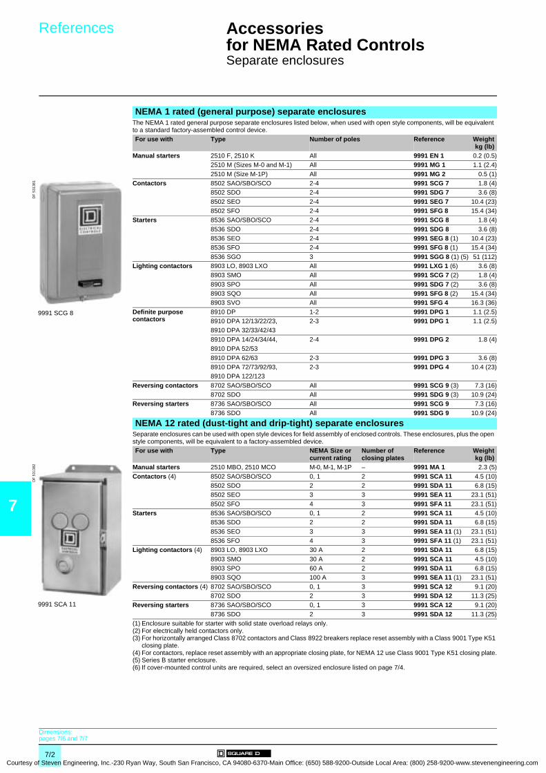
7
Courtesy
References Accessories for NEMA Rated Controls 0
Separate enclosures
NEMA 1 rated (general purpose) separate enclosuresThe NEMA 1 rated general purpose separate enclosures listed below, when used with open style components, will be equivalent to a standard factory-assembled control device.For use with Type Number of poles Reference Weight
kg (lb)Manual starters 2510 F, 2510 K All 9991 EN 1 0.2 (0.5)
2510 M (Sizes M-0 and M-1) All 9991 MG 1 1.1 (2.4)
2510 M (Size M-1P) All 9991 MG 2 0.5 (1)Contactors 8502 SAO/SBO/SCO 2-4 9991 SCG 7 1.8 (4)
8502 SDO 2-4 9991 SDG 7 3.6 (8)
8502 SEO 2-4 9991 SEG 7 10.4 (23)8502 SFO 2-4 9991 SFG 8 15.4 (34)
Starters 8536 SAO/SBO/SCO 2-4 9991 SCG 8 1.8 (4)
8536 SDO 2-4 9991 SDG 8 3.6 (8)8536 SEO 2-4 9991 SEG 8 (1) 10.4 (23)8536 SFO 2-4 9991 SFG 8 (1) 15.4 (34)
8536 SGO 3 9991 SGG 8 (1) (5) 51 (112)Lighting contactors 8903 LO, 8903 LXO All 9991 LXG 1 (6) 3.6 (8)
8903 SMO All 9991 SCG 7 (2) 1.8 (4)
8903 SPO All 9991 SDG 7 (2) 3.6 (8)8903 SQO All 9991 SFG 8 (2) 15.4 (34)8903 SVO All 9991 SFG 4 16.3 (36)
Definite purpose contactors
8910 DP 1-2 9991 DPG 1 1.1 (2.5)8910 DPA 12/13/22/23, 2-3 9991 DPG 1 1.1 (2.5)8910 DPA 32/33/42/43
8910 DPA 14/24/34/44, 2-4 9991 DPG 2 1.8 (4)8910 DPA 52/53
8910 DPA 62/63 2-3 9991 DPG 3 3.6 (8)8910 DPA 72/73/92/93, 2-3 9991 DPG 4 10.4 (23)8910 DPA 122/123
Reversing contactors 8702 SAO/SBO/SCO All 9991 SCG 9 (3) 7.3 (16)8702 SDO All 9991 SDG 9 (3) 10.9 (24)
Reversing starters 8736 SAO/SBO/SCO All 9991 SCG 9 7.3 (16)
8736 SDO All 9991 SDG 9 10.9 (24)
NEMA 12 rated (dust-tight and drip-tight) separate enclosures Separate enclosures can be used with open style devices for field assembly of enclosed controls. These enclosures, plus the open style components, will be equivalent to a factory-assembled device.For use with Type NEMA Size or
current ratingNumber of closing plates
Reference Weightkg (lb)
Manual starters 2510 MBO, 2510 MCO M-0, M-1, M-1P – 9991 MA 1 2.3 (5)
Contactors (4) 8502 SAO/SBO/SCO 0, 1 2 9991 SCA 11 4.5 (10)8502 SDO 2 2 9991 SDA 11 6.8 (15)8502 SEO 3 3 9991 SEA 11 23.1 (51)
8502 SFO 4 3 9991 SFA 11 23.1 (51)Starters 8536 SAO/SBO/SCO 0, 1 2 9991 SCA 11 4.5 (10)
8536 SDO 2 2 9991 SDA 11 6.8 (15)
8536 SEO 3 3 9991 SEA 11 (1) 23.1 (51)8536 SFO 4 3 9991 SFA 11 (1) 23.1 (51)
Lighting contactors (4) 8903 LO, 8903 LXO 30 A 2 9991 SDA 11 6.8 (15)
8903 SMO 30 A 2 9991 SCA 11 4.5 (10)8903 SPO 60 A 2 9991 SDA 11 6.8 (15)8903 SQO 100 A 3 9991 SEA 11 (1) 23.1 (51)
Reversing contactors (4) 8702 SAO/SBO/SCO 0, 1 3 9991 SCA 12 9.1 (20)8702 SDO 2 3 9991 SDA 12 11.3 (25)
Reversing starters 8736 SAO/SBO/SCO 0, 1 3 9991 SCA 12 9.1 (20)
8736 SDO 2 3 9991 SDA 12 11.3 (25)(1) Enclosure suitable for starter with solid state overload relays only.(2) For electrically held contactors only.(3) For horizontally arranged Class 8702 contactors and Class 8922 breakers replace reset assembly with a Class 9001 Type K51
closing plate.(4) For contactors, replace reset assembly with an appropriate closing plate, for NEMA 12 use Class 9001 Type K51 closing plate.(5) Series B starter enclosure.(6) If cover-mounted control units are required, select an oversized enclosure listed on page 7/4.
9991 SCG 8
DF
531
381
9991 SCA 11
DF
531
382
Dimensions:pages 7/6 and 7/7
7/2 of Steven Engineering, Inc.-230 Ryan Way, South San Francisco, CA 94080-6370-Main Office: (650) 588-9200-Outside Local Area: (800) 258-9200-www.stevenengineering.com
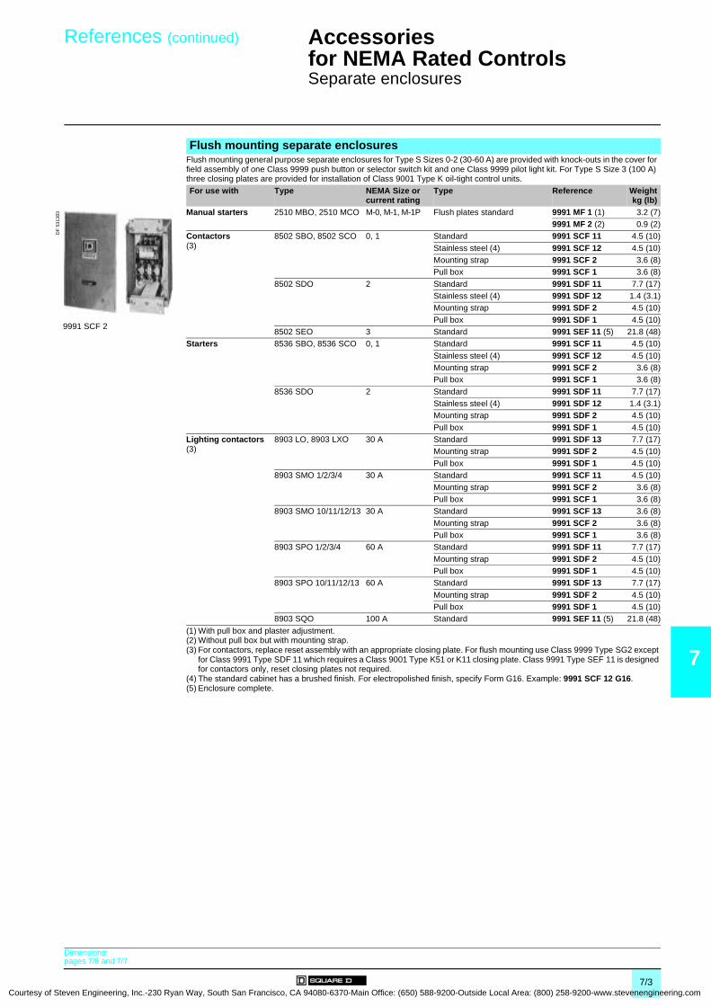
Courtesy of S
References (continued) Accessories for NEMA Rated Controls 0
Separate enclosures
7
Flush mounting separate enclosures Flush mounting general purpose separate enclosures for Type S Sizes 0-2 (30-60 A) are provided with knock-outs in the cover for field assembly of one Class 9999 push button or selector switch kit and one Class 9999 pilot light kit. For Type S Size 3 (100 A) three closing plates are provided for installation of Class 9001 Type K oil-tight control units.
For use with Type NEMA Size or current rating
Type Reference Weightkg (lb)
Manual starters 2510 MBO, 2510 MCO M-0, M-1, M-1P Flush plates standard 9991 MF 1 (1) 3.2 (7)9991 MF 2 (2) 0.9 (2)
Contactors(3)
8502 SBO, 8502 SCO 0, 1 Standard 9991 SCF 11 4.5 (10)
Stainless steel (4) 9991 SCF 12 4.5 (10)Mounting strap 9991 SCF 2 3.6 (8)Pull box 9991 SCF 1 3.6 (8)
8502 SDO 2 Standard 9991 SDF 11 7.7 (17)Stainless steel (4) 9991 SDF 12 1.4 (3.1)Mounting strap 9991 SDF 2 4.5 (10)
Pull box 9991 SDF 1 4.5 (10)8502 SEO 3 Standard 9991 SEF 11 (5) 21.8 (48)
Starters 8536 SBO, 8536 SCO 0, 1 Standard 9991 SCF 11 4.5 (10)
Stainless steel (4) 9991 SCF 12 4.5 (10)Mounting strap 9991 SCF 2 3.6 (8)Pull box 9991 SCF 1 3.6 (8)
8536 SDO 2 Standard 9991 SDF 11 7.7 (17)Stainless steel (4) 9991 SDF 12 1.4 (3.1)Mounting strap 9991 SDF 2 4.5 (10)
Pull box 9991 SDF 1 4.5 (10)Lighting contactors(3)
8903 LO, 8903 LXO 30 A Standard 9991 SDF 13 7.7 (17)Mounting strap 9991 SDF 2 4.5 (10)
Pull box 9991 SDF 1 4.5 (10)8903 SMO 1/2/3/4 30 A Standard 9991 SCF 11 4.5 (10)
Mounting strap 9991 SCF 2 3.6 (8)Pull box 9991 SCF 1 3.6 (8)
8903 SMO 10/11/12/13 30 A Standard 9991 SCF 13 3.6 (8)
Mounting strap 9991 SCF 2 3.6 (8)Pull box 9991 SCF 1 3.6 (8)
8903 SPO 1/2/3/4 60 A Standard 9991 SDF 11 7.7 (17)
Mounting strap 9991 SDF 2 4.5 (10)Pull box 9991 SDF 1 4.5 (10)
8903 SPO 10/11/12/13 60 A Standard 9991 SDF 13 7.7 (17)
Mounting strap 9991 SDF 2 4.5 (10)Pull box 9991 SDF 1 4.5 (10)
8903 SQO 100 A Standard 9991 SEF 11 (5) 21.8 (48)
(1) With pull box and plaster adjustment.(2) Without pull box but with mounting strap.(3) For contactors, replace reset assembly with an appropriate closing plate. For flush mounting use Class 9999 Type SG2 except
for Class 9991 Type SDF 11 which requires a Class 9001 Type K51 or K11 closing plate. Class 9991 Type SEF 11 is designed for contactors only, reset closing plates not required.
(4) The standard cabinet has a brushed finish. For electropolished finish, specify Form G16. Example: 9991 SCF 12 G16.(5) Enclosure complete.
9991 SCF 2
DF
531
383
Dimensions:pages 7/6 and 7/7
7/3teven Engineering, Inc.-230 Ryan Way, South San Francisco, CA 94080-6370-Main Office: (650) 588-9200-Outside Local Area: (800) 258-9200-www.stevenengineering.com

7
Courtesy
References Accessories for NEMA Rated Controls 0
Separate enclosures for addition of control circuit transformer, Control circuit transformers
Separate enclosures for addition of control circuit transformerThe Class 9991 enclosures listed below will accept an open type Class 8502 or 8536, Type S, NEMA Size 0, 1, 1P or 2 contactor or starter, together with a fused-control circuit transformer (suffix F4T) to allow field assembly of enclosed controllers. In the cover of the Class 9991 Type SCG 1 enclosure, knock-outs are provided for field addition of Class 9999 cover-mounted control units. All other Class 8502 and 8536 enclosures include a panel with space and drilling for an open-type device and a fused-control circuit transformer. In addition, three closing plates are included in each cover for easy installation of Class 9001 Type K or SK control units. Oversized enclosures for open type Class 8903 Type L and LX and Type S (30 and 60 A) electrically and mechanically held lighting contactors include a panel with space and drilling for an open-type contactor and fused-control circuit transformer (suffix F4T) and/or an auxiliary relay for use with single pole pilot devices (suffix R6). When an auxiliary relay is required, use a Class 8501 Type XO 11 relay. Three closing plates are provided as standard for easy installation of Class 9001 Type K or SK control units.
Note : a Class 9991 Type SCG 1 NEMA 1 rated separate enclosure can also be used for Class 8903 Type SMO (30 A) electrically held lighting contactor if suffix F4T (control transformer), with or without cover control units, is required.
For use with Type NEMA Size or current rating
Number of poles
Enclosure type (1) Reference Weightkg (lb)
Contactors (2) 8502 SAO/SBO/SCO 0, 1 1…5 NEMA 1 9991 SCG 1 3.6 (8)NEMA 12 9991 SCA 4 8.3 (18.2)
8502 SDO 2 2…5 NEMA 1 9991 SDG 4 9.5 (21)
NEMA 12 9991 SDA 4 10.4 (23)Starters 8536 SAO/SBO/SCO 0, 1 1…5 NEMA 1 9991 SCG 1 3.6 (8)
NEMA 12 9991 SCA 4 8.3 (18.2)
8536 SDO 2 2…5 NEMA 1 9991 SDG 4 9.5 (21)NEMA 12 9991 SDA 4 10.4 (23)
Lighting contactors
8903 LO, 8903 LXO 30 A All NEMA 1 9991 SDG 3 6.8 (15)
NEMA 12 9991 SDA 3 9.1 (20)8903 SMO 30 A 1…5 NEMA 1 9991 SDG 3 6.8 (15)
NEMA 12 9991 SDA 3 9.1 (20)
8903 SPO 60 A 2…5 NEMA 1 9991 SDG 3 6.8 (15)NEMA 12 9991 SDA 3 9.1 (20)
Control circuit transformersFor use with Type NEMA Size or
current ratingNumber of poles
Transformer type Reference Weightkg (lb)
Contactors (2) 8502 SAO/SBO/SCO 0, 1 1…3 Standard, 50 VA 9070 T50 –Extra capacity, 100 VA 9070 T100 (3) –Extra capacity, 150 VA 9070 T150 (3) –
4 and 5 Standard, 100 VA 9070 T100 (3) –Extra capacity, 150 VA 9070 T150 (3) –
8502 SDO 2 2…5 Standard, 100 VA 9070 T100 –
Extra capacity, 150 VA 9070 T150 –Extra capacity, 300 VA 9070 T300 –
Starters 8536 SAO/SBO/SCO 0, 1 1…3 Standard, 50 VA 9070 T50 –
Extra capacity, 100 VA 9070 T100 (3) –Extra capacity, 150 VA 9070 T150 (3) –
4 and 5 Standard, 100 VA 9070 T100 (3) –
Extra capacity, 150 VA 9070 T150 (3) –8536 SDO 2 2…5 Standard, 100 VA 9070 T100 –
Extra capacity, 150 VA 9070 T150 –Extra capacity, 300 VA 9070 T300 –
Lighting contactors
8903 LO 30 A All Standard, 50 VA 9070 T50 –
8903 LXO 30 A All Standard, 50 VA 9070 T50 –Extra capacity, 100 VA 9070 T100 (3) –Extra capacity, 150 VA 9070 T150 (3) –
8903 SMO 30 A 1…3 Standard, 100 VA 9070 T100 (3) –Extra capacity, 150 VA 9070 T150 (3) –
4 and 5 Standard, 100 VA 9070 T100 –
Extra capacity, 150 VA 9070 T150 –Extra capacity, 300 VA 9070 T300 –
8903 SPO 60 A 2…5 Standard, 100 VA 9070 T100 –
Extra capacity, 150 VA 9070 T150 –Extra capacity, 300 VA 9070 T300 –
(1) NEMA 1: general purpose enclosure. NEMA 12: dust-tight and drip-tight industrial-use enclosure.(2) For contactors (Class 8502), a separate closing plate is provided with each enclosure to replace the reset mechanism with the
exception of Class 9991 Type SCG 1 which requires a separate reset closing plate Class 9999 Type SG2.(3) For mounting in 9991 SCG 1 enclosure, a Class 9991 Type S1 adapter bracket is also required.
9991 SCG 1
DF
531
389
Dimensions:pages 7/6 and 7/7
7/4 of Steven Engineering, Inc.-230 Ryan Way, South San Francisco, CA 94080-6370-Main Office: (650) 588-9200-Outside Local Area: (800) 258-9200-www.stevenengineering.com

Courtesy of S
References Accessories for NEMA Rated Controls 0
Fuse block, Control unit kits
7
Fuse block (for use with Class CC fuses)For use with Type NEMA Size or
current ratingReference Weight
kg (lb)Contactors 8502 SBO/SCO/SDO 0…2 9999 SFR 4 –Starters 8536 SBO/SCO/SDO 0…2 9999 SFR 4 –
Lighting contactors
8903 LO/LXO/SMO/SPO 30…60 A 9999 SFR 4 –
Control unit kitsClass 9001 Type K oil-tight/water-tight control units can be easily installed in NEMA 12 rated separate enclosures provided with closing plates.When installing control units simply remove the closing plates and install the appropriate Class 9001 Type K components. Convenient control unit kits complete with assembled and pre-wired operators for quick installation are available as Class 9999 user modification kits.Class 9001 Type SK NEMA 4X corrosion resistant control units may be used as an alternative.
KitsControl function
Kit contents Reference Weightkg (lb)Description Reference Quantity
"Start-Stop" Start operator 9001 KR 1B 1 9999 SA 3 –
push button Stop operator 9001 KR 1R 1"Start" legend plate 9001 KN 201 1"Stop" legend plate 9001 KN 202 1
Contact block 9001 KA 1 2"Hand-Off-Auto" Selector operator switch 9001 KS 43B 1 9999 SC 8 –selector switch "Hand-Off-Auto" legend plate 9001 KN 260 1
Contact block 9001 KA 1 1Pilot light (120 V)
Red pilot light 9001 KP 1R31 1 9999 SP 28R –
Dimensions:pages 7/6 and 7/7
7/5teven Engineering, Inc.-230 Ryan Way, South San Francisco, CA 94080-6370-Main Office: (650) 588-9200-Outside Local Area: (800) 258-9200-www.stevenengineering.com
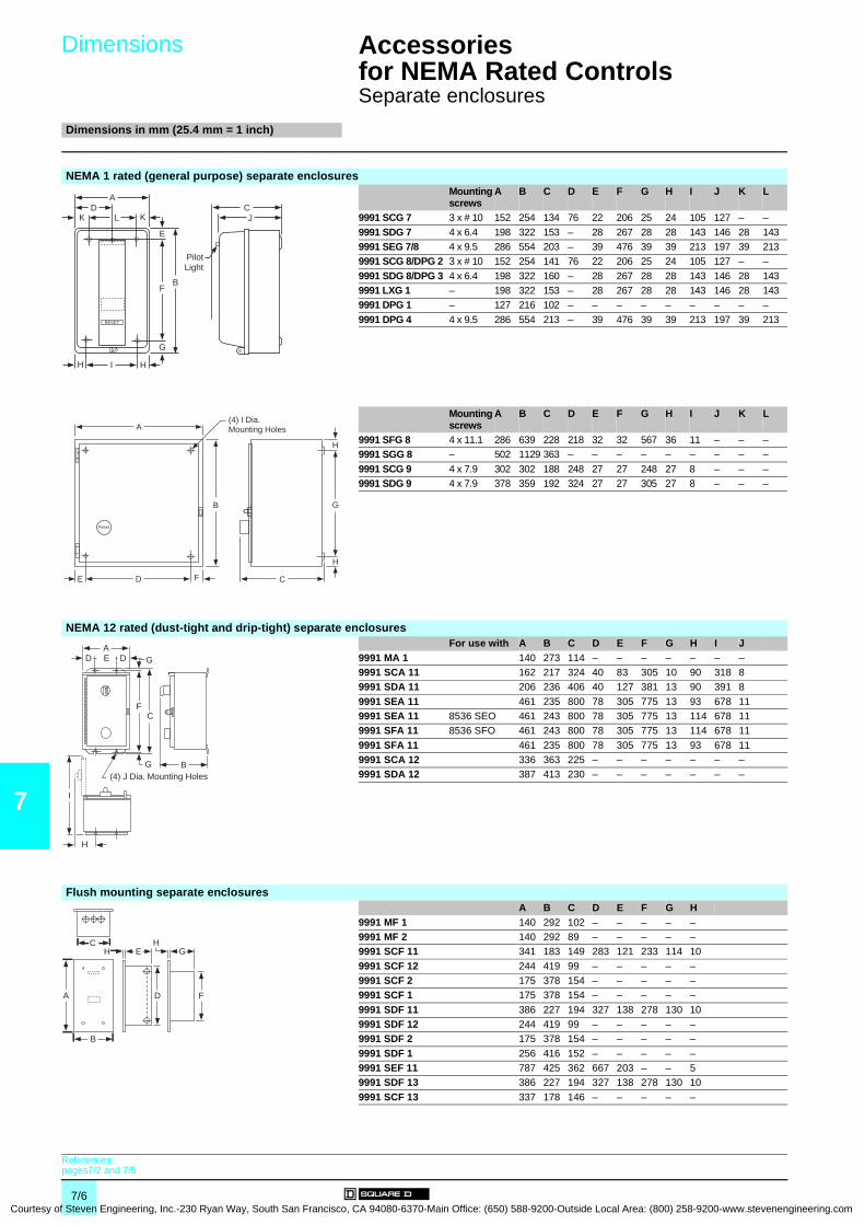
7
Courtesy
Dimensions
Accessories for NEMA Rated Controls 0
Separate enclosures
Dimensions in mm (25.4 mm = 1 inch)
NEMA 1 rated (general purpose) separate enclosuresMounting screws
A B C D E F G H I J K L
9991 SCG 7 3 x # 10 152 254 134 76 22 206 25 24 105 127 – –
9991 SDG 7 4 x 6.4 198 322 153 – 28 267 28 28 143 146 28 1439991 SEG 7/8 4 x 9.5 286 554 203 – 39 476 39 39 213 197 39 2139991 SCG 8/DPG 2 3 x # 10 152 254 141 76 22 206 25 24 105 127 – –
9991 SDG 8/DPG 3 4 x 6.4 198 322 160 – 28 267 28 28 143 146 28 1439991 LXG 1 – 198 322 153 – 28 267 28 28 143 146 28 1439991 DPG 1 – 127 216 102 – – – – – – – – –
9991 DPG 4 4 x 9.5 286 554 213 – 39 476 39 39 213 197 39 213
Mounting screws
A B C D E F G H I J K L
9991 SFG 8 4 x 11.1 286 639 228 218 32 32 567 36 11 – – –9991 SGG 8 – 502 1129 363 – – – – – – – – –
9991 SCG 9 4 x 7.9 302 302 188 248 27 27 248 27 8 – – –9991 SDG 9 4 x 7.9 378 359 192 324 27 27 305 27 8 – – –
NEMA 12 rated (dust-tight and drip-tight) separate enclosuresFor use with A B C D E F G H I J
9991 MA 1 140 273 114 – – – – – – –9991 SCA 11 162 217 324 40 83 305 10 90 318 89991 SDA 11 206 236 406 40 127 381 13 90 391 8
9991 SEA 11 461 235 800 78 305 775 13 93 678 119991 SEA 11 8536 SEO 461 243 800 78 305 775 13 114 678 119991 SFA 11 8536 SFO 461 243 800 78 305 775 13 114 678 11
9991 SFA 11 461 235 800 78 305 775 13 93 678 119991 SCA 12 336 363 225 – – – – – – –9991 SDA 12 387 413 230 – – – – – – –
Flush mounting separate enclosuresA B C D E F G H
9991 MF 1 140 292 102 – – – – –9991 MF 2 140 292 89 – – – – –9991 SCF 11 341 183 149 283 121 233 114 10
9991 SCF 12 244 419 99 – – – – –9991 SCF 2 175 378 154 – – – – –9991 SCF 1 175 378 154 – – – – –
9991 SDF 11 386 227 194 327 138 278 130 109991 SDF 12 244 419 99 – – – – –9991 SDF 2 175 378 154 – – – – –
9991 SDF 1 256 416 152 – – – – –9991 SEF 11 787 425 362 667 203 – – 59991 SDF 13 386 227 194 327 138 278 130 10
9991 SCF 13 337 178 146 – – – – –
AD
K L K
E
BF
H I H
G
RESET
CJ
PilotLight
A
B
E D F
Reset
C
H
G
H
(4) I Dia.Mounting Holes
AD E D G
FC
G B
H
I
(4) J Dia. Mounting Holes
C
A
B
H E G
D F
H
References:pages7/2 and 7/5
7/6 of Steven Engineering, Inc.-230 Ryan Way, South San Francisco, CA 94080-6370-Main Office: (650) 588-9200-Outside Local Area: (800) 258-9200-www.stevenengineering.com
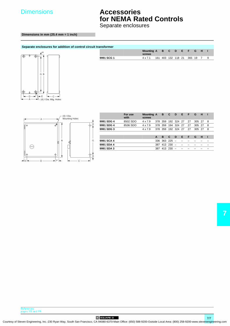
Courtesy of S
Dimensions
Accessories for NEMA Rated Controls 0
Separate enclosures
Dimensions in mm (25.4 mm = 1 inch)
7
Separate enclosures for addition of control circuit transformerMounting screws
A B C D E F G H I
9991 SCG 1 4 x 7.1 161 403 132 118 21 365 19 7 9
For use with
Mounting screws
A B C D E F G H I
9991 SDG 4 8502 SDO 4 x 7.9 378 359 192 324 27 27 305 27 89991 SDG 4 8536 SDO 4 x 7.9 378 359 194 324 27 27 305 27 89991 SDG 3 4 x 7.9 378 359 192 324 27 27 305 27 8
A B C D E F G H I9991 SCA 4 336 363 225 – – – – – –
9991 SDA 4 387 413 230 – – – – – –9991 SDA 3 387 413 230 – – – – – –
H
BG
CDA (4) I Dia. Mtg. Holes
E
A
B
E D F
Reset
C
H
G
H
(4) I Dia.Mounting Holes
References:pages 7/2 and 7/5
7/7teven Engineering, Inc.-230 Ryan Way, South San Francisco, CA 94080-6370-Main Office: (650) 588-9200-Outside Local Area: (800) 258-9200-www.stevenengineering.com

7
Courtesy
References Accessories for NEMA Rated Controls 0
Magnetic coils
Replacement a.c. magnetic coils for magnetic contactors and startersEquipment to be serviced Frequency Voltage Reference WeightDevice Type NEMA Size
or current rating
Number of poles
Hz V kg (lb)Latch coils for present design magnetic contactors and starters Classes: 8502, 8536, 8538, 8539, 8702, 8736, 8903, 8910
LLX
30 A30 A
2 to 62 to 4
50 24 9998 L 24 –110-115 9998 L 44 –120 9998 L 45 –
208 9998 L 52 –220 9998 L 53 –240 9998 L 54 –
380 9998 L 60 –440 9998 L 62 –480 9998 L 63 –
550 9998 L 65 –600 9998 L 66 –
60 24 9998 L 23 –
120 9998 L 44 –208 9998 L 50 –240 9998 L 53 –
277 9998 L 55 –300 9998 L 56 –480 9998 L 62 –
600 9998 L 65 –LLX
30 A30 A
8 to 126 to 12
50 24 9998 LH 24 –
110-115 9998 LH 44 –120 9998 LH 45 –220 9998 LH 53 –
240 9998 LH 54 –440 9998 LH 62 –480 9998 LH 63 –
550 9998 LH 65 –60 24 9998 LH 23 –
120 9998 LH 44 –
208 9998 LH 50 –240 9998 LH 53 –277 9998 LH 55 –
300 9998 LH 56 –480 9998 LH 62 –600 9998 LH 65 –
SA (1)Series B
00 All 50 110-115 9998 SAC 45 –220 9998 SAC 54 –440 9998 SAC 62 –
550 9998 SAC 65 –60 24 9998 SAC 23 –
120 9998 SAC 45 –
208 9998 SAC 52 –240 9998 SAC 54 –277 9998 SAC 55 –
380 9998 SAC 59 –480 9998 SAC 62 –600 9998 SAC 65 –
(1) For use on Type S Series B devices only.
7/8 of Steven Engineering, Inc.-230 Ryan Way, South San Francisco, CA 94080-6370-Main Office: (650) 588-9200-Outside Local Area: (800) 258-9200-www.stevenengineering.com
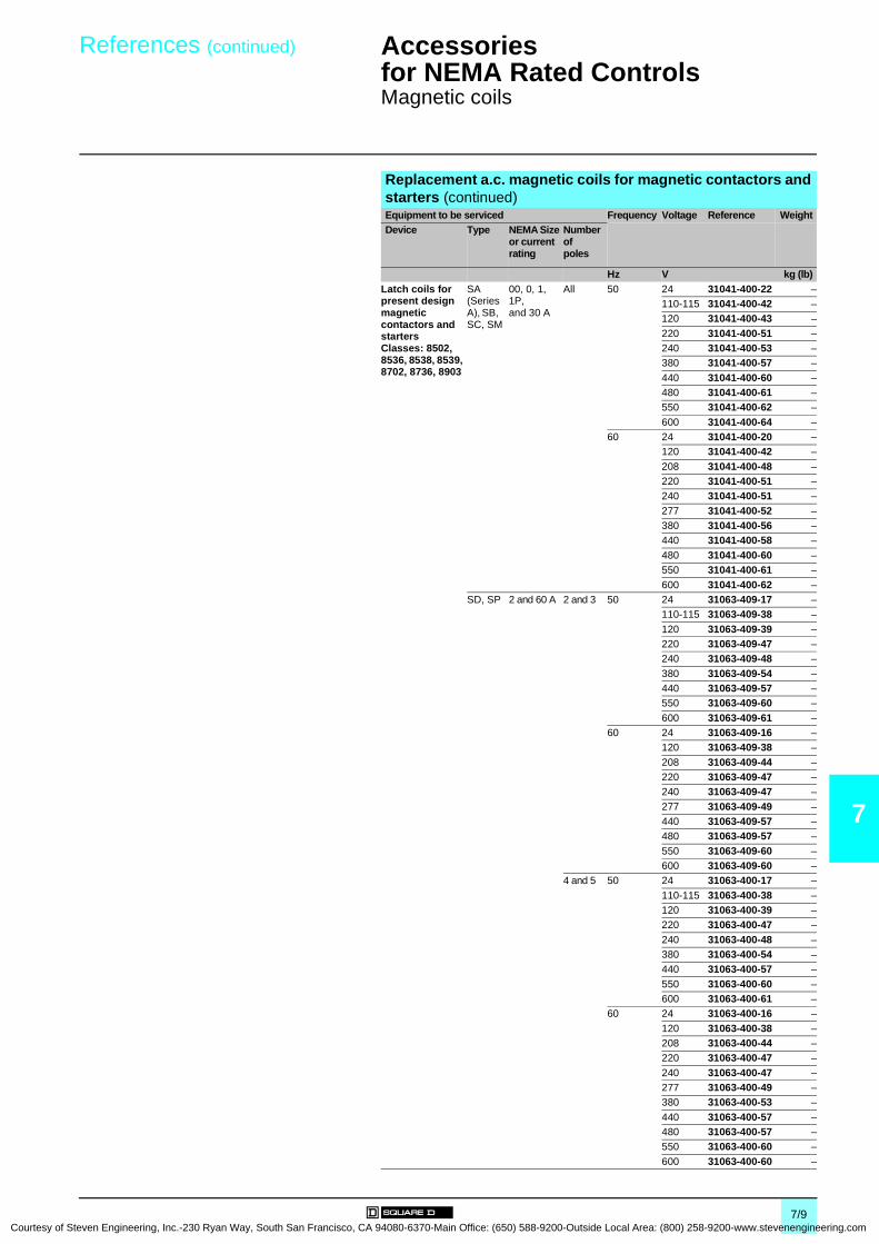
Courtesy of S
References (continued) Accessories for NEMA Rated Controls 0
Magnetic coils
7
Replacement a.c. magnetic coils for magnetic contactors and starters (continued)Equipment to be serviced Frequency Voltage Reference WeightDevice Type NEMA Size
or current rating
Number of poles
Hz V kg (lb)Latch coils for present design magnetic contactors and starters Classes: 8502, 8536, 8538, 8539, 8702, 8736, 8903
SA(Series A), SB, SC, SM
00, 0, 1, 1P,and 30 A
All 50 24 31041-400-22 –110-115 31041-400-42 –120 31041-400-43 –
220 31041-400-51 –240 31041-400-53 –380 31041-400-57 –
440 31041-400-60 –480 31041-400-61 –550 31041-400-62 –
600 31041-400-64 –60 24 31041-400-20 –
120 31041-400-42 –
208 31041-400-48 –220 31041-400-51 –240 31041-400-51 –
277 31041-400-52 –380 31041-400-56 –440 31041-400-58 –
480 31041-400-60 –550 31041-400-61 –
600 31041-400-62 –SD, SP 2 and 60 A 2 and 3 50 24 31063-409-17 –
110-115 31063-409-38 –
120 31063-409-39 –220 31063-409-47 –240 31063-409-48 –
380 31063-409-54 –440 31063-409-57 –550 31063-409-60 –
600 31063-409-61 –60 24 31063-409-16 –
120 31063-409-38 –
208 31063-409-44 –220 31063-409-47 –240 31063-409-47 –
277 31063-409-49 –440 31063-409-57 –480 31063-409-57 –
550 31063-409-60 –600 31063-409-60 –
4 and 5 50 24 31063-400-17 –
110-115 31063-400-38 –120 31063-400-39 –220 31063-400-47 –
240 31063-400-48 –380 31063-400-54 –440 31063-400-57 –
550 31063-400-60 –600 31063-400-61 –
60 24 31063-400-16 –
120 31063-400-38 –208 31063-400-44 –220 31063-400-47 –
240 31063-400-47 –277 31063-400-49 –380 31063-400-53 –
440 31063-400-57 –480 31063-400-57 –550 31063-400-60 –
600 31063-400-60 –
7/9teven Engineering, Inc.-230 Ryan Way, South San Francisco, CA 94080-6370-Main Office: (650) 588-9200-Outside Local Area: (800) 258-9200-www.stevenengineering.com

7
Courtesy
References (continued) Accessories for NEMA Rated Controls 0
Magnetic coils
Replacement a.c. magnetic coils for magnetic contactors and starters (continued)Equipment to be serviced Frequency Voltage Reference WeightDevice Type NEMA Size
or current rating
Number of poles
Hz V kg (lb)Latch coils for present design magnetic contactors and starters Classes: 8502, 8536, 8538, 8539, 8702, 8736, 8903, 8910
SE, 3, 20 A 2 and 3 50 24 31074-400-17 –SQ, and 100 A 110-115 31074-400-38 –DPA 12 120 31074-400-39 –
220 31074-400-47 –240 31074-400-48 –380 31074-400-54 –
440 31074-400-57 –550 31074-400-60 –600 31074-400-61 –
60 24 31074-400-16 –120 31074-400-38 –208 31074-400-44 –
220 31074-400-47 –240 31074-400-47 –277 31074-400-49 –
380 31074-400-53 –440 31074-400-57 –480 31074-400-57 –
500 31074-400-58 –550 31074-400-60 –
600 31074-400-60 –4 and 5 50 110-115 31091-400-38 –
120 31091-400-39 –
220 31091-400-47 –240 31091-400-48 –380 31091-400-54 –
440 31091-400-57 –480 31091-400-58 –550 31091-400-60 –
600 31091-400-61 –60 120 31091-400-38 –
208 31091-400-44 –
220 31091-400-47 –240 31091-400-47 –277 31091-400-49 –
380 31091-400-53 –440 31091-400-57 –480 31091-400-57 –
550 31091-400-60 –600 31091-400-60 –
Latch coils for present design magnetic contactors and starters Classes: 8502, 8536, 8538, 8539, 8702, 8736, 8903
SF, SV 4 and 200 A
All 50 110-115 31091-400-38 –
120 31091-400-39 –220 31091-400-47 –240 31091-400-48 –
380 31091-400-54 –440 31091-400-57 –480 31091-400-58 –
550 31091-400-60 –600 31091-400-61 –
60 120 31091-400-38 –
208 31091-400-44 –240 31091-400-47 –277 31091-400-49 –
380 31091-400-53 –480 31091-400-57 –600 31091-400-60 –
7/10 of Steven Engineering, Inc.-230 Ryan Way, South San Francisco, CA 94080-6370-Main Office: (650) 588-9200-Outside Local Area: (800) 258-9200-www.stevenengineering.com
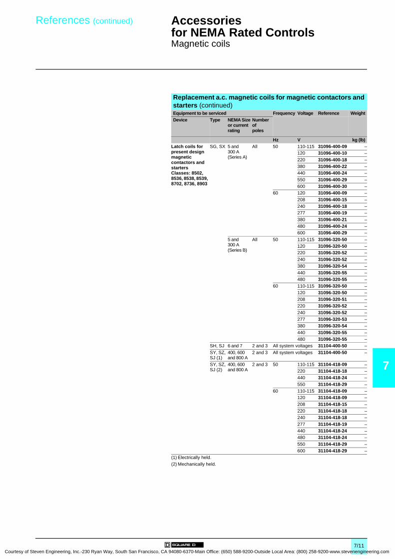
Courtesy of S
References (continued) Accessories for NEMA Rated Controls 0
Magnetic coils
7
Replacement a.c. magnetic coils for magnetic contactors and starters (continued)Equipment to be serviced Frequency Voltage Reference WeightDevice Type NEMA Size
or current rating
Number of poles
Hz V kg (lb)Latch coils for present design magnetic contactors and starters Classes: 8502, 8536, 8538, 8539, 8702, 8736, 8903
SG, SX 5 and 300 A(Series A)
All 50 110-115 31096-400-09 –120 31096-400-10 –
220 31096-400-18 –380 31096-400-22 –440 31096-400-24 –
550 31096-400-29 –600 31096-400-30 –
60 120 31096-400-09 –
208 31096-400-15 –240 31096-400-18 –277 31096-400-19 –
380 31096-400-21 –480 31096-400-24 –600 31096-400-29 –
5 and 300 A(Series B)
All 50 110-115 31096-320-50 –120 31096-320-50 –220 31096-320-52 –
240 31096-320-52 –380 31096-320-54 –
440 31096-320-55 –480 31096-320-55 –
60 110-115 31096-320-50 –
120 31096-320-50 –208 31096-320-51 –220 31096-320-52 –
240 31096-320-52 –277 31096-320-53 –380 31096-320-54 –
440 31096-320-55 –480 31096-320-55 –
SH, SJ 6 and 7 2 and 3 All system voltages 31104-400-50 –
SY, SZ, SJ (1)
400, 600 and 800 A
2 and 3 All system voltages 31104-400-50 –
SY, SZ, SJ (2)
400, 600 and 800 A
2 and 3 50 110-115 31104-418-09 –220 31104-418-18 –440 31104-418-24 –
550 31104-418-29 –60 110-115 31104-418-09 –
120 31104-418-09 –
208 31104-418-15 –220 31104-418-18 –240 31104-418-18 –
277 31104-418-19 –440 31104-418-24 –480 31104-418-24 –
550 31104-418-29 –600 31104-418-29 –
(1) Electrically held.
(2) Mechanically held.
7/11teven Engineering, Inc.-230 Ryan Way, South San Francisco, CA 94080-6370-Main Office: (650) 588-9200-Outside Local Area: (800) 258-9200-www.stevenengineering.com

7
Courtesy
References Accessories for NEMA Rated Controls 0
Replacement parts kits
Magnetic contactor and starter contact kits for present designsClass 9998 replacement parts kits are available for servicing Square D relays, contactors and starters. Each kit contains the necessary movable and stationary contacts, contact springs (when required; NEMA Size 3 and above do not include contact springs, and springs are not available), and additional hardware required to service the devices listed below. When servicing devices having more poles than contained in the corresponding kit, it may be necessary to order an additional kit.Equipment to be serviced Reference WeightClass Type NEMA Size or
current ratingNumber of poles in kit
kg (lb)
8502, 8536, 8538, 8539, 8702, 8736, 8903
SA (Series B) 00 3 9998 SJ 1 –
SB 0 3 9998 SL 2 –4 9998 SL 12 –
SB, SC (power pole adder)
0 and 1 1 9998 SL 22 –
SC 1 and 1P 3 9998 SL 3 –
1 4 9998 SL 13 –SD 2 3 9998 SL 4 –
4 9998 SL 14 –
SD (power pole adder)
2 1 9998 SL 24 –
SE 3 2 9998 SL 6 –3 9998 SL 7 –
SF 4 2 9998 SL 8 –
3 9998 SL 9 –SG 5 2 9998 SL 10 –
3 9998 SL 11 –
SH 6 2 9998 SL 25 –3 9998 SL 26 –
SJ 7 2 9998 SL 30 –
3 9998 SL 31 –L (Series C) and LX (Series B)
30 A 4 9998 RA 5B –
8903 SM 30 A 3 9998 SL 3 –
4 9998 SL 13 –SP 60 A 3 9998 SL 4 –
4 9998 SL 14 –
SQ 100 A 2 9998 SL 6 –3 9998 SL 7 –
SV 200 A 2 9998 SL 8 –
3 9998 SL 9 –SX 300 A 2 9998 SL 10 –
3 9998 SL 11 –
SY 400 A 2 9998 SL 25 –3 9998 SL 26 –
SZ 600 A 2 9998 SL 32 –
3 9998 SL 33 –SJ 800 A 2 9998 SL 30 –
3 9998 SL 31 –
Manual starter contact kitsEquipment to be serviced Reference WeightClass Type NEMA Size Number of
poles in kitkg (lb)
2510 M, T M-0 3 9998 ML 1 –
M-1 and M-1P 3 9998 ML 2 –
Replacement control transformers (150 VA)Equipment to be serviced Voltage Reference WeightClass Type NEMA Size 50 Hz 60 Hz
V V kg (lb8502, 8536 S 6 220/440-110 240/480-120 31104-512-50 –
– 208-120 31104-512-52 –– 277-120 31104-512-53 –
380-110 – 31104-512-54 –550-110 600-120 31104-512-51 –110-110 120-120 31104-512-55 –
220-110 240-120 31104-512-56 –
7/12 of Steven Engineering, Inc.-230 Ryan Way, South San Francisco, CA 94080-6370-Main Office: (650) 588-9200-Outside Local Area: (800) 258-9200-www.stevenengineering.com
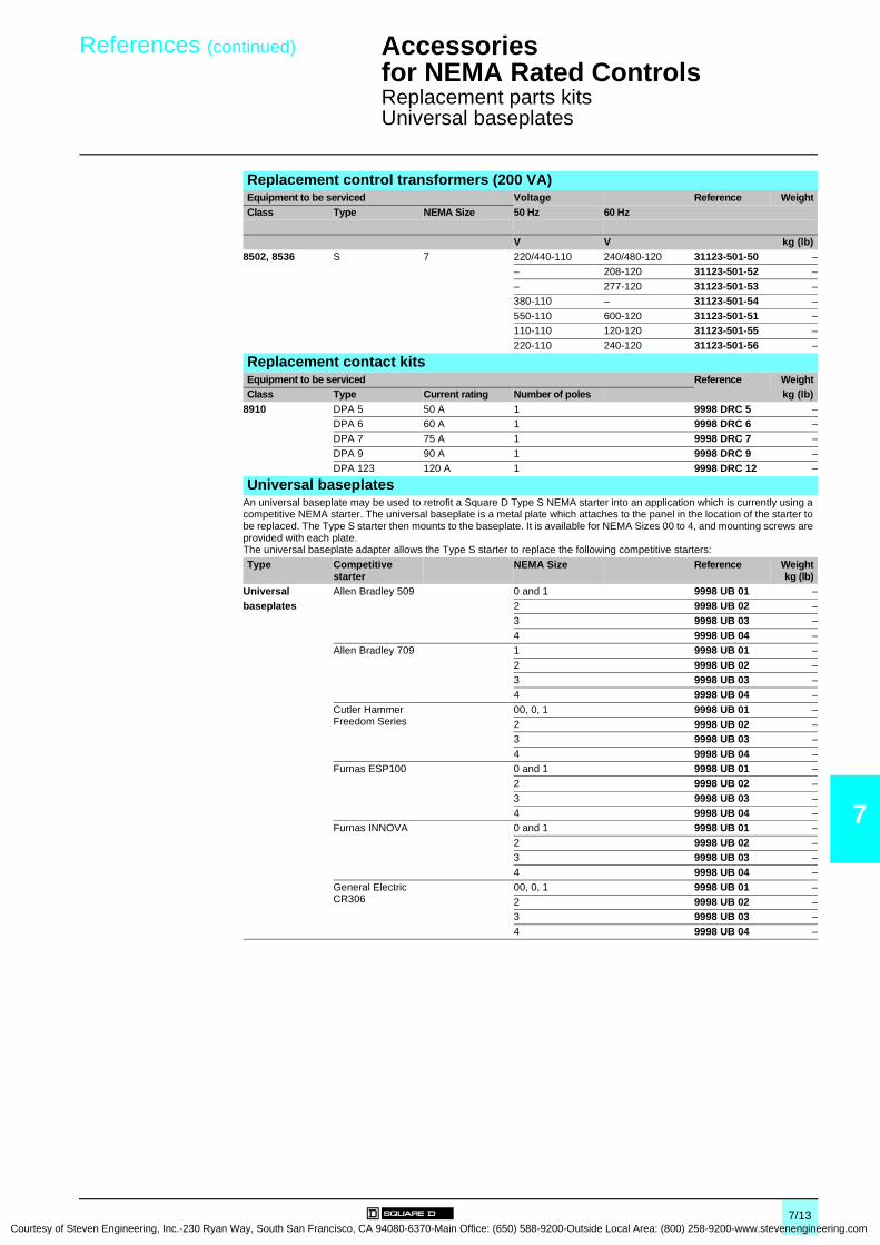
Courtesy of S
References (continued) Accessories for NEMA Rated Controls 0
Replacement parts kitsUniversal baseplates
7
Replacement control transformers (200 VA)Equipment to be serviced Voltage Reference WeightClass Type NEMA Size 50 Hz 60 Hz
V V kg (lb)8502, 8536 S 7 220/440-110 240/480-120 31123-501-50 –
– 208-120 31123-501-52 –– 277-120 31123-501-53 –380-110 – 31123-501-54 –
550-110 600-120 31123-501-51 –110-110 120-120 31123-501-55 –220-110 240-120 31123-501-56 –
Replacement contact kitsEquipment to be serviced Reference WeightClass Type Current rating Number of poles kg (lb)
8910 DPA 5 50 A 1 9998 DRC 5 –DPA 6 60 A 1 9998 DRC 6 –DPA 7 75 A 1 9998 DRC 7 –
DPA 9 90 A 1 9998 DRC 9 –DPA 123 120 A 1 9998 DRC 12 –
Universal baseplatesAn universal baseplate may be used to retrofit a Square D Type S NEMA starter into an application which is currently using a competitive NEMA starter. The universal baseplate is a metal plate which attaches to the panel in the location of the starter to be replaced. The Type S starter then mounts to the baseplate. It is available for NEMA Sizes 00 to 4, and mounting screws are provided with each plate.The universal baseplate adapter allows the Type S starter to replace the following competitive starters:
Type Competitive starter
NEMA Size Reference Weightkg (lb)
Universal Allen Bradley 509 0 and 1 9998 UB 01 –baseplates 2 9998 UB 02 –
3 9998 UB 03 –4 9998 UB 04 –
Allen Bradley 709 1 9998 UB 01 –
2 9998 UB 02 –3 9998 UB 03 –4 9998 UB 04 –
Cutler Hammer Freedom Series
00, 0, 1 9998 UB 01 –2 9998 UB 02 –3 9998 UB 03 –
4 9998 UB 04 –Furnas ESP100 0 and 1 9998 UB 01 –
2 9998 UB 02 –
3 9998 UB 03 –4 9998 UB 04 –
Furnas INNOVA 0 and 1 9998 UB 01 –
2 9998 UB 02 –3 9998 UB 03 –4 9998 UB 04 –
General Electric CR306
00, 0, 1 9998 UB 01 –2 9998 UB 02 –3 9998 UB 03 –
4 9998 UB 04 –
7/13teven Engineering, Inc.-230 Ryan Way, South San Francisco, CA 94080-6370-Main Office: (650) 588-9200-Outside Local Area: (800) 258-9200-www.stevenengineering.com

7
Courtesy
References Accessories for NEMA Rated Controls 0
Cover-mounted control unit kits
NEMA 1 rated push button cover-mounted control unit kitsClass 9999 cover-mounted push button, selector switch and pilot light control unit kits can be easily field installed in a NEMA 1 or 12 rated Type S contactor or starter enclosure cover. Knockouts or removable closing plates are provided with many enclosure covers for convenient field installation of control units. Kits are supplied with leads and clearly illustrated instructions.The Class 9999 cover-mounted control unit kits are identical to the units which are factory installed.For use with Description Reference WeightClass Type NEMA Size or
current ratingNumber of poles
kg (lb)
8502 and 8536 SA, SB, SCSDSE
00, 0, 1 and 1P23
AllAllAll
Start-Stop 9999 SA2 –On-Off 9999 SA10 –
SF to SJ 4 to 7 All Start-Stop 9999 SA3 –
On-Off 9999 SA3 –8538, 8539, 8702, 8736 SB and SC
SDSESF
0 and 1234
AllAllAllAll
Start-Stop 9999 SA2 –On-Off 9999 SA10 –
SG to SJ 5 to 7 All Start-Stop 9999 SA3 –
On-Off 9999 SA3 –8903 (electrically held) LX (1) 30 A All On-Off 9999 LXPB (2) –
SMSPSQ
30 A60 A100 A
AllAllAll
Start-Stop 9999 SA2 (3) –
On-Off 9999 SA10 (3) –
SJ, SV, SX, SY and SZ
200 to 800 A All Start-Stop 9999 SA3 (3) –On-Off 9999 SA3 (3) –
NEMA 1 rated selector switch cover-mounted control unit kitsFor use with Description Reference WeightClass Type NEMA Size or
current ratingNumber of poles
kg (lb)
8502 and 8536 SA, SB, SCSDSE
00, 0, 1 and 1P23
AllAllAll
Hand-Off-Auto 9999 SC2 –On-Off 9999 SC22 –
8502 and 8536 SF to SJ 4 to 7 All Hand-Off-Auto 9999 SC8 –
8538, 8539, 8702, 8736 SB and SCSDSESF
0 and 1234
AllAllAllAll
Hand-Off-Auto 9999 SC2 –On-Off 9999 SC22 –
SG to SJ 5 to 7 All Hand-Off-Auto 9999 SC8 –8903 (electrically held) LX (1) 30 A All On-Off 9999 LXS (2) –
SM 30 A All Hand-Off-Auto 9999 SC2 –SPSQ
60 A100 A
AllAll
On-Off 9999 SC22 –
SJ, SV, SX, SYand SZ
200 to 800 A All Hand-Off-Auto 9999 SC8 –
(1) For Class 8903 Type LX NEMA 12 rated control unit kits, refer to the Class 8903 section.(2) To mount a control unit in a NEMA 1 rated enclosure, a Class 9999 Type BLX bracket is also required.(3) Also requires N/O auxiliary contact for holding circuit contact when used on Class 8903 electrically held lighting contactors.
9999 SA2
DF
531
371
9999 SA3
DF
531
372
9999 SC2
DF
531
373
7/14 of Steven Engineering, Inc.-230 Ryan Way, South San Francisco, CA 94080-6370-Main Office: (650) 588-9200-Outside Local Area: (800) 258-9200-www.stevenengineering.com

Courtesy of S
References (continued) Accessories for NEMA Rated Controls 0
Cover-mounted control unit kits
7
NEMA 1 rated red pilot light (1) cover-mounted control unit kitsFor use with Description Reference WeightClass Type NEMA Size or
current ratingNumber of poles
kg (lb)
8502 and 8536 SA, SB and SC
00, 0, 1 and 1P All With control transformer 9999 SP 2R –
Standard 9999 SP 2R –SD 2 All With control transformer 9999 SP 13R –
Standard 9999 SP 3R –
SE 3 2 and 3 With control transformer 9999 SP 4R –Standard 9999 SP 4R –
SE 3 4 and 5 With control transformer 9999 SP 28R (3) –
Standard 9999 SP 5R –SF 4 All With control transformer 9999 SP 28R (3) –
Standard 9999 SP 15R –
SG to SJ 5 to 7 All With control transformer 9999 SP 28R (3) –Standard 9999 SP 28R (3) –
8538, 8539, 8702, 8736 SB and SC 0 and 1 All With control transformer 9999 SP 12R –
Standard 9999 SP 12R –SD 2 All With control transformer 9999 SP 13R –
Standard 9999 SP 13R –
SE 3 All With control transformer 9999 SP 14R –Standard 9999 SP 14R –
SF 4 All With control transformer 9999 SP 15R –
Standard 9999 SP 15R –SG to SJ 5 to 7 All With control transformer 9999 SP 28R (3) –
Standard 9999 SP 28R (3) –
8903 (electrically held) LX (2) 30 A All With control transformer 9999 SP 28R (3) –SM 30 A All With control transformer 9999 SP 2R –
Standard 9999 SP 2R –SP 60 A All With control transformer 9999 SP 13R –
Standard 9999 SP 13R –
SQ 100 A 2 and 3 With control transformer 9999 SP 28R (3) –Standard 9999 SP 14R –
4 and 5 With control transformer 9999 SP 28R (3) –
Standard 9999 SP 15R –SJ, SV, SX, SY and SZ
200 to 800 A All With control transformer 9999 SP 28R (3) –Standard 9999 SP 28R (3) –
(1) For green lens only order Class 9999 Type SPG1, except for Class 9999 Type SP 28R order Class 9001 Type G31.(2) For Class 8903 Type LX NEMA 12 rated control unit kits, refer to the Class 8903 section.(3) The coil voltage must be the same as the pilot light rating. The kit contains one Class 9001 Type KP1R31120V, 60 Hz red pilot
light control unit. For other voltages, refer to the Class 9001 Type KP section of the Digest..
9999 SP 2R
DF
531
374
7/15teven Engineering, Inc.-230 Ryan Way, South San Francisco, CA 94080-6370-Main Office: (650) 588-9200-Outside Local Area: (800) 258-9200-www.stevenengineering.com

7
Courtesy
References (continued) Accessories for NEMA Rated Controls 0
Cover-mounted control unit kits
NEMA 12 rated push button cover-mounted control unit kitsFor use with Description (1) Reference WeightClass Type NEMA Size or
current ratingNumber of poles
kg (lb)
8502, 85368538, 8539, 8702, 87368903 (electrically held)
SA, SB, SCSDSESFSG to SJSB and SCSDSESFSG to SJLX (2)SMSPSQSJ, SV, SX, SYand SZ
00, 0, 1 and 1P2345 to 70 and 12345 to 730 A30 A60 A100 A200 to 800 A
AllAllAllAllAllAllAllAllAllAllAllAllAllAllAll
Start-Stopor On-Off
9999 SA3 –
NEMA 12 rated selector switch cover-mounted control unit kitsFor use with Description (1) Reference WeightClass Type NEMA Size or
current ratingNumber of poles
kg (lb)
8502, 85368538, 8539, 8702, 87368903 (electrically held)
SA, SB, SCSDSESFSG to SJSB and SCSDSESFSG to SJLX (2)SMSPSQSJ, SV, SX, SY and SZ
00, 0, 1 and 1P2345 to 70 and 12345 to 730 A30 A60 A100 A200 to 800 A
AllAllAllAllAllAllAllAllAllAllAllAllAllAllAll
Hand-Off-Auto 9999 SC8 –
(1) User made openings are required in order to field install these modification kits on standard 8502, 8536 Type S Sizes 0 to 2, and 8903 Sizes 30 to 60 A NEMA 12 rated enclosures
(2) For Class 8903 Type LX NEMA 12 rated control unit kits, refer to the Class 8903 section.
7/16 of Steven Engineering, Inc.-230 Ryan Way, South San Francisco, CA 94080-6370-Main Office: (650) 588-9200-Outside Local Area: (800) 258-9200-www.stevenengineering.com
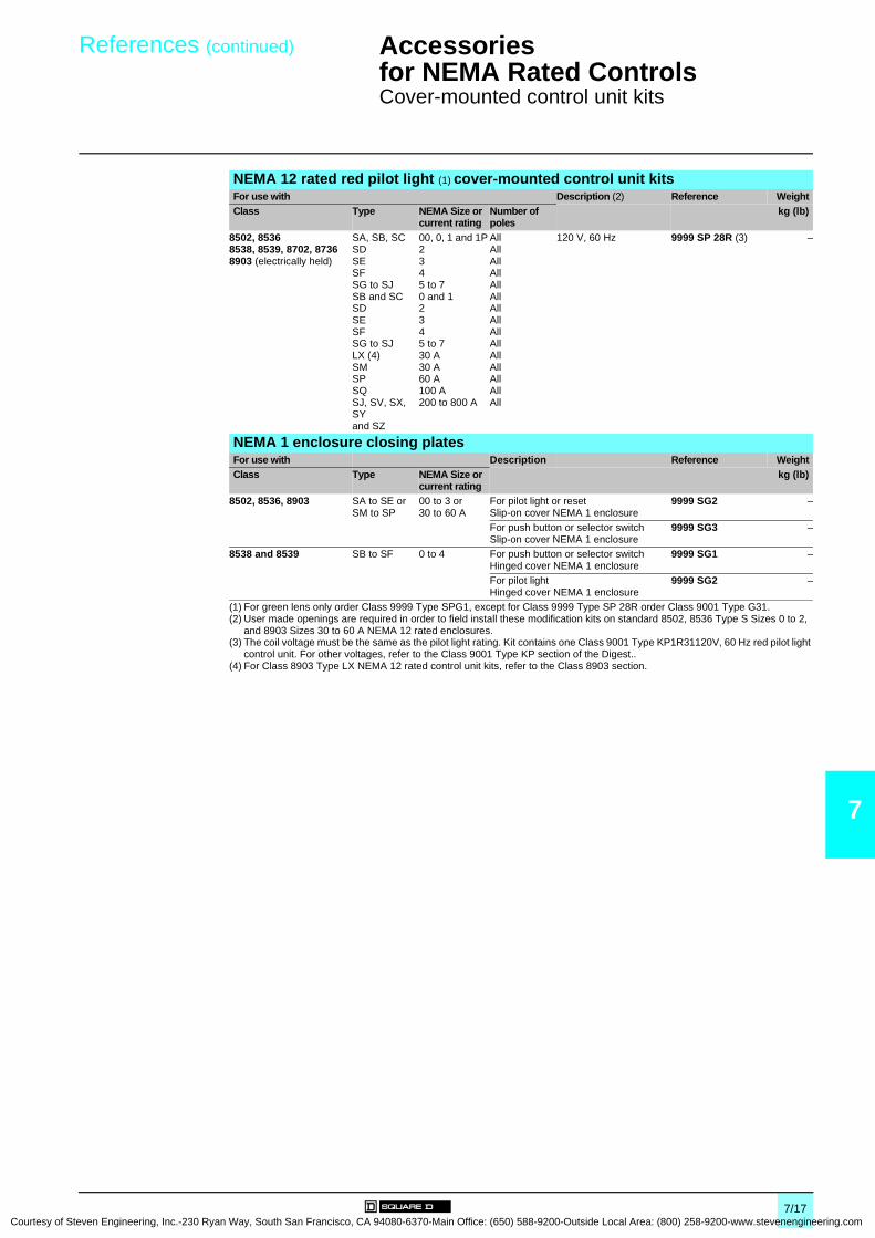
Courtesy of S
References (continued) Accessories for NEMA Rated Controls 0
Cover-mounted control unit kits
7
NEMA 12 rated red pilot light (1) cover-mounted control unit kitsFor use with Description (2) Reference WeightClass Type NEMA Size or
current ratingNumber of poles
kg (lb)
8502, 85368538, 8539, 8702, 87368903 (electrically held)
SA, SB, SCSDSESFSG to SJSB and SCSDSESFSG to SJLX (4)SMSPSQSJ, SV, SX, SYand SZ
00, 0, 1 and 1P2345 to 70 and 12345 to 730 A30 A60 A100 A200 to 800 A
AllAllAllAllAllAllAllAllAllAllAllAllAllAllAll
120 V, 60 Hz 9999 SP 28R (3) –
NEMA 1 enclosure closing platesFor use with Description Reference WeightClass Type NEMA Size or
current ratingkg (lb)
8502, 8536, 8903 SA to SE or SM to SP
00 to 3 or30 to 60 A
For pilot light or resetSlip-on cover NEMA 1 enclosure
9999 SG2 –
For push button or selector switchSlip-on cover NEMA 1 enclosure
9999 SG3 –
8538 and 8539 SB to SF 0 to 4 For push button or selector switchHinged cover NEMA 1 enclosure
9999 SG1 –
For pilot lightHinged cover NEMA 1 enclosure
9999 SG2 –
(1) For green lens only order Class 9999 Type SPG1, except for Class 9999 Type SP 28R order Class 9001 Type G31.(2) User made openings are required in order to field install these modification kits on standard 8502, 8536 Type S Sizes 0 to 2,
and 8903 Sizes 30 to 60 A NEMA 12 rated enclosures.(3) The coil voltage must be the same as the pilot light rating. Kit contains one Class 9001 Type KP1R31120V, 60 Hz red pilot light
control unit. For other voltages, refer to the Class 9001 Type KP section of the Digest..(4) For Class 8903 Type LX NEMA 12 rated control unit kits, refer to the Class 8903 section.
7/17teven Engineering, Inc.-230 Ryan Way, South San Francisco, CA 94080-6370-Main Office: (650) 588-9200-Outside Local Area: (800) 258-9200-www.stevenengineering.com

7
Courtesy
Characteristics,references
Accessories for NEMA Rated Controls 0
Auxiliary contacts
CharacteristicsClass 9999Type SX 11/SX 12
Contact ratingsMaximum current (50/60 Hz)
Make(35% power factor)
Break(35% power factor)
Continuous current
a 120 V or less A 30 3 3a 120…600 V 3600 VA 360 VA 3 A
Class 9999Type SX 6 to SX 10/SX 13 to SX 17
Contact ratingsMaximum current (50/60 Hz)
Make(35% power factor)
Break(35% power factor)
Continuous current
a 120 V or less A 60 6 10
a 120…600 V 7200 VA 720 VA 10 A
ReferencesInternal contact kits
Class 9999 Type SX 11 internal contact kit is a replacement unit for the N/O holding circuit contact supplied as standard on Type S Sizes 00 to 2 three-phase starters and contactors. The Class 9999 Type SX 12 is a replacement unit for the N/C electrical contact which is supplied as standard on Type S Sizes 00 to 2 mechanically interlocked devices. Internal contacts are also used on Class 2510 Types M and T manual starters. The internal contacts can be used for other applications as long as the electrical rating is not exceeded.For use with Internal non-convertible
contactsReference Weight
Class Type NEMA Size kg (lb)8502, 8702, 8536, 8736 SA to SD 00 to 2 1 N/O contact 9999 SX 11 (1) –
1 N/C contact 9999 SX 12 (1) –
External contact kitsClass 9999 Type SX 6 external auxiliary contact is supplied as standard for the N/O holding circuit contact on Type S Sizes 3 to 7 contactors and starters. Additional auxiliary contacts can be added to Type S contactors, starters and lighting contactors. These contacts mount on either side of the basic contactor and are available with convertible or non-convertible contacts. The contacts of the convertible version can be changed from N/O to N/C or vice versa in the field. The non-convertible version has fixed contacts, either N/O or N/C. To determine the number of auxiliary contacts which can be added to each Type S contactor or starter, refer to the contactor and starter section.
For use with External field convertible contacts
Reference WeightClass Type NEMA Size kg (lb)
8502, 8702, 8536, 8736 SA to SJ 00 to 7 1 N/O contact 9999 SX 6 –
1 N/C contact 9999 SX 7 –1 N/O and 1 N/C isolated contacts 9999 SX 8 –1 N/O overlapping contact 9999 SX 9 (2) –
1 N/C overlapping contact 9999 SX 10 (2) –For use with External non-convertible
contactsReference Weight
Class Type NEMA Size kg (lb)8502, 8702, 8536, 8736 SA to SJ 00 to 7 1 N/O contact 9999 SX 13 –
1 N/C contact 9999 SX 14 –1 N/O and 1 N/C isolated contacts 9999 SX 15 –
1 N/O overlapping contact 9999 SX 16 (2) –1 N/C overlapping contact 9999 SX 17 (2) –
(1) Types SX 11 and SX 12 are not applicable on NEMA Sizes 3 or larger. Internal contacts can also be used on Class 2510 Types M and T manual starters.
(2) Types SX 9 and SX 10 or Types SX 16 and SX 17 must be used together and mounted on the same side of the contactor. They are suitable for applications where it is necessary for a normally open contact to overlap a normally closed contact.
9999 SX 11
DF
531
376
9999 SX 6
DF
531
375
7/18 of Steven Engineering, Inc.-230 Ryan Way, South San Francisco, CA 94080-6370-Main Office: (650) 588-9200-Outside Local Area: (800) 258-9200-www.stevenengineering.com

Courtesy of S
References Accessories for NEMA Rated Controls 0
Auxiliary contacts, Adapter, Remote reset module
7
Isolated auxiliary contacts for Motor Logic solid state overload relaysOverload relay auxiliary contacts are available factory installed or in kit form for field installation on Motor Logic solid state overload relays.These contacts may be used for isolated alarm contact applications.
For use with External field convertible contact
Reference WeightClass Type NEMA Size kg (lb)
9065 SS, SR, SF, ST 00B to 7 N/O or N/C auxiliary contact 9999 AC 04 –
AdapterThe adapter enables the Motor Logic solid state overload relay to be mounted on a 35 mm mounting rail.For use with Reference WeightClass Type NEMA Size kg (lb)
9065 SS or SF 00B, 00C, 0 and 1 9999 DA 01 –
Remote reset moduleThe remote reset module can be easily field installed on solid state overload relays. This module will allow the overload relay to be reset from a remote location.
For use with Description Reference WeightClass Type NEMA Size kg (lb)
9065 SS, SR, SF, ST 00B to 7 Remote reset module 9999 RR 04 (1) –
SS, SR, SF, ST 3 and 4 Top mounting bracket 9999 RB 34 (1) (2) –(1) a 120 V power required.(2) To be used for mounting the remote reset module on the top of the solid state overload relay.
7/19teven Engineering, Inc.-230 Ryan Way, South San Francisco, CA 94080-6370-Main Office: (650) 588-9200-Outside Local Area: (800) 258-9200-www.stevenengineering.com
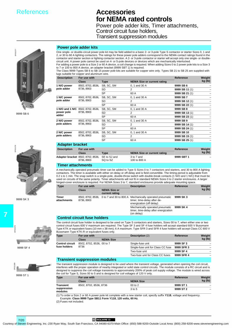
7
Courtesy
References Accessories for NEMA rated controls 0
Power pole adder kits, Timer attachments,Control circuit fuse holders, Transient suppression modules
Power pole adder kitsOne single- or double-circuit power pole kit may be field added to a basic 2- or 3-pole Type S contactor or starter Sizes 0, 1 and 2, or 30 to 60 A lighting contactors. The ratings for these power pole adders correspond to the NEMA contact ratings found in the contactor and starter section or lighting contactor section. A 2- or 3-pole contactor or starter will accept only one single- or double-circuit unit. A power pole cannot be used on 4- or 5-pole devices or devices which are mechanically interlocked.For adding a power pole to a Size 2 or 60 A device, a coil change is required. When adding Sizes 0 to 2 power pole kits to a Size 3 to 7 or 100 to 800 A device, an adapter bracket (9999 SBT 1) is required.The Class 9999 Types SB 6 to SB 15 power pole kits are suitable for copper wire only. Types SB 21 to SB 25 are supplied with lugs suitable for copper and aluminum wire.Description For use with Reference Weight
kg (lb)Class Type NEMA Size or current rating1 N/O power pole adder
8502, 8702, 8536, 8736, 8903
SB, SC, SM 0, 1 and 30 A 9999 SB 6 –SD 2 9999 SB 11 (1) –SP 60 A 9999 SB 21 (1) –
1 N/C power pole adder
8502, 8702, 8536, 8736, 8903
SB, SC, SM 0, 1 and 30 A 9999 SB 7 –SD 2 9999 SB 12 (1) –SP 60 A 9999 SB 22 (1) –
1 N/O and 1 N/C power pole adder
8502, 8702, 8536, 8736, 8903
SB, SC, SM 0, 1 and 30 A 9999 SB 8 –SD 2 9999 SB 13 (1) –SP 60 A 9999 SB 23 (1) –
2 N/O power pole adders
8502, 8702, 8536, 8736, 8903
SB, SC, SM 0, 1 and 30 A 9999 SB 9 –SD 2 9999 SB 14 (1) –SP 60 A 9999 SB 24 (1) –
2 N/C power pole adders
8502, 8702, 8536, 8736, 8903
SB, SC, SM 0, 1 and 30 A 9999 SB 10 –SD 2 9999 SB 15 (1) –SP 60 A 9999 SB 25 (1) –
Adapter bracketDescription For use with Reference Weight
kg (lb)Class Type NEMA Size or current ratingAdapter bracket 8502, 8702, 8536,
8736, 8903SE to SJ and SQ to SZ
3 to 7 and 100 to 800 A
9999 SBT 1 –
Timer attachmentsA mechanically operated pneumatic timer can be added to Type S Sizes 0 to 7 contactors and starters, and 30 to 800 A lighting contactors. The timer is available with either on-delay or off-delay and is field convertible. The timing period is adjustable from 0.2 s to 1 min. The snap switch is a single-pole, double-throw switch with double-break contacts (1 N/O and 1 N/C) that must be used on circuits of the same polarity. Timer attachments will not fit in standard NEMA Sizes 0 to 2 starter enclosures. A larger hinged-cover enclosure is required. For NEMA Sizes 3 to 7, standard enclosures provide adequate mounting space.Type For use with Description Reference Weight
kg (lb)Class NEMA Size orcurrent rating
Timer attachments
8502, 8702, 8536, 8736, 8903
0 to 7 and 30 to 800 A Mechanically operated pneumatic timer, time-delay after de-energization (off delay)
9999 SK 3 –
Mechanically operated pneumatic timer, time-delay after energization (on delay)
9999 SK 4 –
Control circuit fuse holdersThe control circuit fuse holder is designed to be used on Type S contactors and starters, Sizes 00 to 7, when either one or two control circuit fuses 600 V maximum are required. The Type SF 3 and SF 4 fuse holders will accept standard 600 V Bussmann Type KTK or equivalent fuses (10 mm x 38 mm); 6 A maximum. Type SFR 3 and SFR 4 fuse holders will accept Class CC 600 V Bussmann Type KTK-R or equivalent fuses only.Type For use with Description (2) Reference Weight
kg (lb)Class NEMA SizeControl circuit fuse holders
8502, 8702, 8536, 8736
00 to 7 Single-fuse unit 9999 SF 3 –Single-fuse unit for Class CC fuse 9999 SFR 3 –
Two-fuse unit 9999 SF 4 –Two-fuse unit for Class CC fuses 9999 SFR 4 –
Transient suppression modulesThe transient suppression module is designed to be used where the transient voltage, generated when opening the coil circuit, interferes with the proper operation of nearby integrated or solid state control circuits. The module consists of a RC circuit and is designed to suppress the coil voltage transients to approximately 200% of peak coil supply voltage. The module is wired across the coil for Type S, Sizes 00 to 5 and is designed for coil voltages of 120 V only.Type For use with Reference Weight
kg (lb)Class NEMA SizeTransient suppression modules
8502, 8702, 8536, 8736 00 to 2 9999 ST 1 –3 to 5 9999 ST 2 –
(1) To order a Size 2 or 60 A power pole kit complete with a new starter coil, specify suffix Y118, voltage and frequency.Example: Class 9999 Type SB11 Form Y118, 120 volts, 60 Hz.
(2) Fuses not included.
9999 SB 6
DF
5313
77
9999 SK 3
DF
5313
78
9999 SF 4
DF
5313
79
9999 ST 1
DF
5313
80
7/20 of Steven Engineering, Inc.-230 Ryan Way, South San Francisco, CA 94080-6370-Main Office: (650) 588-9200-Outside Local Area: (800) 258-9200-www.stevenengineering.com

Courtesy of S
References Accessories for NEMA rated controls 0
Compression lugsTerminal block
7
Compression lugsA Class 9999 Type AL hardware kit is required to install Versa-Crimp® compression lugs on Class 8903 Type S, 100 to 800 A, lighting contactors. The lugs are suitable for both copper and aluminum wire.One VCEL lug is required for each line or load terminal. Each Class 9999 Type AL hardware kit includes mounting hardware for 3 terminals, line or load side.Example: to install compression lugs on a 300 A 3-pole device, line and load sides, order 6 x VCEL-060-12H1 lugs and 2 x Class 9999 Type AL 11 hardware kits.
For use with Versa-Crimpcatalogue number
Material Wire range (min.-max.)
Number of poles
Reference Weightkg (lb)Class Type Current rating
8903 SQ 100 A VCEL-021-14S1 Al/Cu 8-1/0 – (1) –
SV 200 A VCEL-022-516H1 Al/Cu 1-2/0 2 poles 9999 AL 13 –3 poles 9999 AL 14 –4 poles 9999 AL 15 –
VCEL-024-516H1 Al/Cu 2/0-4/0 2 poles 9999 AL 13 –3 poles 9999 AL 14 –4 poles 9999 AL 15 –
VCEL-030-516H1 MCM Al/Cu 4-300 2 poles 9999 AL 13 –3 poles 9999 AL 14 –4 poles 9999 AL 15 –
SX 300 A VCEL-050-12H1 MCM Al/Cu 2/0-500 – 9999 AL 11 –VCEL-060-12H1 MCM Al 400-600 – 9999 AL 11 –
MCM Cu 400-500 – 9999 AL 11 –
VCEL-075-12H1 MCM Al 500-750 – 9999 AL 11 –MCM Cu 500 – 9999 AL 11 –
SY, SZ 400, 600 A VCEL-060-12H2 (2) MCM Al 400-600 – 9999 AL 12 –
MCM Cu 400-500 – 9999 AL 12 –VCEL-075-12H2 (2) MCM Al 500-750 – 9999 AL 12 –
MCM Cu 500 – 9999 AL 12 –SJ 800 A – – – – (3) –
Terminal blockThe terminal block provides easy wiring of a "Hand-Off-Auto" selector switch or "Start-Stop" push buttons with separate control. The terminal block requires no panel space. It simply snaps on Type S Sizes 00 to 4 contactors and starters by two tabs and is secured to the left hand coil terminal.For use with Reference Weight
kg (lb)Class Type NEMA Size8502, 8702, 8536, 8736 SA to SF 00 to 4 9999 T7 –(1) Not required.(2) One or two lugs may be mounted on each terminal.(3) Compression lugs for these devices are available only as a factory modification. Order: suffix Y1574. Specify wire size up to
750 MCM Al or 500 MCM Cu and number of terminals.
Class 8903 with compression lugs installed
DF
5313
89
9999 T7
DF
5313
90
7/21teven Engineering, Inc.-230 Ryan Way, South San Francisco, CA 94080-6370-Main Office: (650) 588-9200-Outside Local Area: (800) 258-9200-www.stevenengineering.com

8/0Courtesy of Steven Engineering, Inc.-230 Ryan Way, South San Francisco
, CA 94080-6370-Main Office: (650) 588-9200-Outside Local Area: (800) 258-9200-www.stevenengineering.com
Contents
Courtesy of Steven Engineering, Inc.-230 Ryan Way, South San Francisco, CA
8 - Services
8
Schneider Electric worldwideb Addresses . . . . . . . . . . . . . . . . . . . . . . . . . . . . . . . . . . . . . . . . . . pages 7/2 to 7/5
8/1 94080-6370-Main Office: (650) 588-9200-Outside Local Area: (800) 258-9200-www.stevenengineering.com

8
Courtesy
Schneider Electric worldwide 0
Updated: 18-07-2003
Algeria b Schneider Electric voie A Lot C22Zone industrielle Rouiba - Alger
Tel. : +213 21 92 97 02 à 09Fax : +213 21 92 97 00 à 01
Argentina b Schneider Argentina Viamonte 2850 - 1678 Caseros(provincia Buenos Aires)
Tel.: +54 1 716 88 88Fax: +54 1 716 88 33
www.schneider-electric.com.ar
Australia b Schneider Electric (Australia) Pty. Limited
2 Solent CircuitNorwest Business ParkBaulkham Hill _ NSW 2153
Tel.: +61 298 51 28 00Fax: +61 296 29 83 40
www.schneider.com.au
Austria b Schneider Austria Ges.m.b.H. Birostrasse 111239 Wien
Tel.: +431 610 540Fax: +431 610 54 54
www.schneider-electric.at
Bahamas b Schneider Electric Union VillagePO Box 3901 - Nassau
Tel. : +1 242 327 42 91Fax : +1 242 327 42 91
www.squared.com
Bahrain b Schneider Electric Floor 1 - Juma BuildingAbu Horaira AvenuePO Box 355 - 304 Manama
Tel.: +97 322 7897Fax: +97 321 8313
Belarus b Schneider Electric Industries SA Prospect Macherova 5, of. 202220004 Minsk
Tel. : +375 172 23 75 50Fax : +375 172 23 97 61
Belgium b Schneider Electric nv/sa Dieweg 3B - 1180 Brussels
Tel.: +3223737711Fax: +3223753858
www.schneider-electric.be
Brazil b Schneider Electric Brasil Ltda. Avenida Das Nações Unidas 23223Jurubatuba - CEP 04795-907São Paulo-SP
Tel.: +55 55 24 52 33Fax: +55 55 22 51 34
www.schneider-electric.com.br
Bulgaria b Schneider Electric Expo 2000, Boulevard Vaptzarov1407 Sofiav
Tel.: +3592 919 42Fax: +3592 962 44 39
www.schneiderelectric.bg
Cameroon b Schneider Electric Cameroun 166, rue de l'Hôtel de VilleBP12087 - Douala
Tel.: +237 343 38 84Fax: +237 343 11 94
Canada b Schneider Canada 19, Waterman AvenueM4 B1Y2 Toronto - Ontario
Tel.: +1 416 752 8020Fax: +1 416 752 4203
www.schneider-electric.ca
Chile b Schneider Electric Chile S.A. Avda. Pdte Ed. Frei Montalva, 6001-31 Conchali - Santiago
Tel.: +56 2 444 3000Fax: +56 2 423 9335
www.schneider-electric.co.cl
China b Schneider Beijing Landmark bldg-Room 18018 North Dong Sanhuan RdChaoyang District 100004 Beijing
Tel.: +86 10 65 90 69 07Fax: +86 10 65 90 00 13
www.schneider-electric.com.cn
Colombia b Schneider Electric de Colombia S.A.
Calle 45A #102-48Bogota DC
Tel.: +57 1 426 97 00Fax: +57 1 426 97 40
Costa Rica b Schneider Centroamérica Ltda. 1.5 kmts oeste de la Embajada Americana,Pavas, San José, Costa Rica C.A.Apartado: 4123-1000 San Jose
Tel.: +506 232-60-55Fax: +506 232-04-26
www.schneider-ca.com
Croatia b Schneider Electric SA Fallerovo Setaliste 22HR - 10000 Zagreb
Tel.: +385 1 367 100Fax: +385 1 367 111
Cuba b Schneider Electric Bureau de Liaison de La HavaneCalle 36- N°306-Apto1Entre 3ra y 5ta Avenida MiramarPlaya Habana
Tel.: +53 724 15 59Fax: +53 724 12 17
Cyprus b Schneider Electric Cyprus 28 General Timayia AvenueKyriakos Building, Block #A301Larnaca 6046
Tel.: +00357 248 12646Fax: +00357 246 37382
Czech Republic b Schneider Electric CZ, s.r.o. Thámova 13Praha 8 - 186 00
Tel.: +420 2 810 88 111Fax: +420 2 24 81 08 49
www.schneider-electric.cz
Denmark b Schneider Electric A/S Baltorpbakken 14DK-2750 Ballerup
Tel.: +45 44 73 78 88Fax: +45 44 68 5255
www.schneider-electric.dk
Dominican Republic b Schneider Electric Calle Jacinto ManonEsq. Federico GeraldinoEdificio D' Roca Plaza Suite 402,Ens. Paraiso - Santo Domingo
Tel.: +1 809 334 66 63Fax: +1 809 334 66 68
Ecuador b Schneider Electric Ecuador SA Av.Republica del Salvador 1082 y Nac Edificio Mansion BlancaQuito
Tel. : +593 2 224 42 42Fax : +593 2 224 42 94
Egypt b Schneider Electric Egypt sae 68, El Tayaran StreetNasr City, 11371 - Cairo
Tel.: +20 24 01 01 19Fax: +20 24 01 66 87
www.schneider.com.eg
Estonia b Lexel Electric Ehitajate tee 110EE 12618 Talinn
Tel. : +372 650 97 00Fax : +372 650 97 22
Finland b Schneider Electric Oy Sinimäentie 1402630 Espoo
Tel. : +358 9 527 000Fax : +358 9 5270 0376
www.schneider-electric.fi
France b Schneider Electric SA 5, rue Nadar92500 Rueil Malmaison
Tel.: +33 (0)1 41 29 82 00Fax: +33 (0)1 47 51 80 20
www.schneider-electric.fr
Germany b Schneider Electric GmbH Gothaer Straße 29D-40880 Ratingen
Tel.: +49210 240 40Fax: +492 10 240 49 256
www.schneiderelectric.de
Ghana b Schneider Electric Ghana PMB Kia3rd Floor Opeibea HouseAirport Commercial CenterLiberation road - Accra
Tel. : +233 21 70 11 687Fax : +233 21 77 96 22
Greece b Schneider Electric AE 14th km - RN Athens-LamiaGR - 14564 Kifissia
Tel.: +302 106 29 52 00Fax: +302 106 29 52 10
www.schneider-electric.com.gr
8/2 of Steven Engineering, Inc.-230 Ryan Way, South San Francisco, CA 94080-6370-Main Office: (650) 588-9200-Outside Local Area: (800) 258-9200-www.stevenengineering.com

Schneider Electric worldwide 0
8
Courtesy of S
Updated: 18-07-2003
Haiti b Schneider Electric Calle Jacinto ManonEsq. Federico GeraldinoEdificio D' Roca Plaza Suite 402,Ens. Paraiso - Santo Domingo
Tel.: +809 334 66 63Fax: +809 334 66 68
Hong Kong b Schneider Electric (Hong Kong) Ltd
Room 3108-28, 31th Floor,Sun Hung Kai Centre,30 Harbour Road, Wanchai
Tel.: +852 25 65 06 21Fax: +852 28 11 10 29
Hungary b Schneider Electric Hungária Villamossági Rt.
Fehérvári út 108 – 112H-1116 Budapest
Tel.: +36 1 382 26-06Fax: +36 1 206 1429
www.schneider-electric.hu
India b Schneider Electric India Max House, 1 Dr Jha Marg, Okhla110 020 New Dehli
Tel. : +91 11 631 85 84Tel. : +91 11 631 71 61
www.schneiderelectric-in.com
Indonesia b P.T. Schneider Indonesia Ventura Building 7th FloorJalan R.A. Kartini Kav.26Cilandak - 12430 Jakarta
Tel.: +62 +21 750 44 06Fax: +62 +21 750 44 15/ 16
www.schneider-electric.co.id
Iran (Islamic Republic of) b Telemecanique Iran 1047 Avenue VALI ASSRP.O. Box 15875-3547 15116 Teheran
Tel.: +98 218 71 01 42Fax: +98 218 71 81 87
Irak b Schneider Electric Industries SA 38050 Grenoble Cedex 9 Tel.: +33 04 76 60 54 27Fax: +33 04 76 60 56 60
Ireland b Schneider Electric Ireland Maynooth RoadCellbridge - Co. Kildare
Tel.: +353+0 1 6012200Fax: +353+0 1 6012201
www.schneiderelectric.ie
Italy b Schneider Electric S.p.A. Centro Direzionale ColleoniPalazzo Sirio - Viale Colleoni, 720041 Agrate Brianza (Mi)
Tel.: +39 39 655 8111Fax: +39 39 605 6237
www.schneiderelectric.it
Ivory Coast b Schneider Electric Afrique de l'Ouest
Rue Pierre et Marie Curie18 BP 2027 Abidjan 18
Tel.: +225 21 75 00 10Fax: +225 21 75 00 30
Jamaïca b Schneider Electric Shop#5, Plaza Dunrobin30 Dunrobin AvenueKingstown
Tel. : +1876 755 41 27Tel. : +931 87 74
Japan b Schneider Electric Japan Ltd Torigoe F. Bldg1-8-2, TorigoeTaito-Ku - 111-0054 Tokyo
Tel.: +81 358 35 35 81Fax: +81 358 35 35 85
www.schneider-electric.co.jp
Jordan b Schneider Electric Industr. Jordan Jordan University StreetAbu Al Haj Commercial Complex2nd Floor - Office # 202Amman
Tel.: 962 65 16 78 87Fax: 962 65 16 79 1
Kazakhstan b Schneider Electric Kazakhstan Liaison Office
Prospekt Abaia 157 off 9480009 Almaty
Tel. : +7 327 250 93 88Tel. : +7 327 250 63 70
Kenya b Schneider East Africa Power Technics ComplexMonbasa Road - PO Box 46345Nairobi
Tel. : +254 2.824.156Fax : +254 2.824.157
Korea b Schneider Electric Korea Ltd 3Floor, Cheil Bldg., 94-46, 7-KaYoungdeungpodong, Youngdeungpo-ku150-037 Seoul
Tel. : +82 2 2630 9700Fax : +82 2 2630 9800
www.csinfo.co.kr/schneider/
Kuwait b Schneider Electric Kuwait Al Gaas Tower - Sharq 2nd FloorPO Box 20092 - 13 061 Safat
Tel.: +965 240 75 46Fax: +965 240 75 06
Latvia b Lexel Electric 60A A.Deglava str.LV1035 Riga
Tel. : +371 780 23 74/75Fax : +371 754 62 80
Lebanon b Schneider Electric Liban Tabaris, Avenue Charles MalekImmeuble Ashada, 8P.O. Box 166223 - Beyrouth
Tel. : +961 1 20 46 20Tel. : +961 1 20 31 19
Lithuania b Lexel Electric 44, Verkiu str.LT-2012 Vilnius
Tel. : +370 278 59 59/61Fax : +370 278 59 60
Malaysia b Schneider Electric (Malaysia) Sdn Bhd
No.11 Jalan U1/19, Seksyen U1Hicom-Glenmarie Industrial Park40150 Shah AlamSelangor Darul Ehsan
Tel. : (603) 7883 6333Fax : (603) 7883 6188
www.schneider-electric.com.my
Martinique b Schneider Electric Schneider ElectricImmeuble Cottrell - ZI de la Lézarde97232 Le Lamentin
Tel.: +05 96 51 06 00Fax: +05 96 51 11 26
Mauritius b Schneider Electric Route côtièreCalodyne - Mauritius
Tel.: 230 282 18 83Fax: 230 282 18 84
Mexico b Groupe Schneider Mexico Calz. Rojo Gomez N° 1121-ACol. Guadalupe del MoralMéxico, D.F. - C.P. 09300
Tel.: +525 686 30 00Fax: +525 686 24 09
www.schneider-electric.com.mx
Morocco b Schneider Electric Maroc 26, rue Ibnou KhalikaneQuartier Palmiers20100 Casablanca
Tel.: +212 299 08 48 to 57Fax: +212 299 08 67 and 69
www.schneider.co.ma
Netherlands b Schneider Electric BV Waarderweg 40 - Postbus 8362003 RV Haarlem
Tel.: +31 23 512 4124Fax: +31 23 512 4100
www.schneider-electric.nl
New Zealand b Schneider Electric (NZ) Ltd 14 Charann Place AvondaleP.O. Box 15355 - New LynnAuckland
Tel. : +64 9 829 04 90Fax : +64 9 829 04 91
www.schneider-electric.co.nz
Nigeria b Schneider Electric Nigeria Limited Biro plaza - 8th Floor - Plot 634Abeyemo Alakija StreetVictoria Islan - Lagos
Tel. : +234 1 2702973Fax : +234 1 2702976
8/3teven Engineering, Inc.-230 Ryan Way, South San Francisco, CA 94080-6370-Main Office: (650) 588-9200-Outside Local Area: (800) 258-9200-www.stevenengineering.com
Schneider Electric worldwide 0
8
Courtesy
Updated: 18-07-2003
Norway b Schneider Electric Norge A/S Solgaard Skog 2Postboks 128 - 1501 Moss
Tel.: +47 6924 9700Fax: +47 6925 7871
www.schneider-electric.no
Oman b Schneider Electric CA c/o Arab Development CoPO Box 439 - 113 Muscat
Tel.: +968 77 163 64Fax: +968 77 104 49
Pakistan b Schneider Electric Pakistan 43-L, 2nd floor, M.M. Alam Road,Gulberg II - Lahore
Tel.: +92 42 5754471 à 73Fax: +92 42 5754474
Peru b Schneider Electric Peru S.A. Los Telares n°231 Urb. Vulcano, Ate Lima 03
Tel.: +511 348 44 11Fax: +511 348 05 23
www.schneider-electric.com.pe
Philippines b Schneider Electric Philippines, Inc 5th Floor, ALCO Building391 Sen, Gil Puyat AvenueMakati 1209
Tel. : +632 896 6063Fax : +632 896 7229
Poland b Schneider Electric Polska Sp.zo.o. ul. Lubinowa 4a03-878 - Warszawa
Tel.: +48 22 511 8 200Fax: +48 22 511 8 210
www.schneider-electric.pl
Portugal b Schneider Electric Portugal Av.do Forte, 3Edificio Suécia II, Piso 3-ACP 2028 Carnaxide2795 Linda-A-Velha
Tel.: +351 21 416 5800Fax: +351 21 416 5857
www.schneiderelectric.pt
Qatar b Schneider Electric Qatar Branch c/o Khalifa BinFahred Al ThaniTrad.and Co - P.O. Box 4484Doha
Tel.: +97 4424358Fax: +97 4424358
Reunion b Schneider Electric Immeuble Futura, 190, rue des 2 canonsBP 646 - 97497 Sainte Clothilde
Tel.: +262 28 14 28Fax: +262 28 39 37
Romania b Schneider Electric Bd Ficusului n°42Apimondia, Corp.A, et.1, Sector 1Bucuresti
Tel.: +401 203 06 50Fax: +401 232 15 98
www.schneider-electric.ro
Russian Federation b Schneider Electric ZAO Enisseyskaya 37129 281 Moscow
Tel.: +7095 797 40 00Fax: +7095 797 40 03
www.schneider-electric.ru
Saudi Arabia b Schneider Electric Second Industrial CityP.O. Box 89249 - 11682 Riyadh
Tel.: +966 1 265 1515Fax: +966 1 265 1860
Senegal b Schneider Electric Sénégal BP 15952 - Dakar-FannRond point N'Gor - Dakar
Tel.: +221 820 68 05Fax: +221 820 58 50
Singapore b Schneider Electric Singapore Pte Ltd
10 Ang Mo Kio Street 65#02-17/20 TechPointSingapore 569059
Tel.: +65 484 78 77Fax: +65 484 78 00
www.schneider-electric.com.sg
Slovak Republic b Schneider Electric Slovakia spol s.r.o.
Borekova 10SK-821 06 Bratislava
Tel. : +02 45 52 40 10 and 40 30Fax : +02 45 52 40 00
www.schneider-electric.sk
Slovenia b Schneider Electric, d.o.o. Dunasjka 471000 Ljubljana
Tel. : +386 1 23 63 555Fax : +386 1 23 63 559
www.schneider-electric.si
South Africa b Schneider Electric South Africa (PTY) Ltd
Private Bag X139Halfway House1685 - Midrand.
Tel.: +27 11 254 6400Fax: +27 11 315 8830
www.schneider-electric.co.za
Spain b Schneider Electric España, S.A. Pl. Dr. Letamendi, 5-708007 Barcelona
Tel.: +34 93 484 3100Fax: +34 93 484 3308
www.schneiderelectric.es
Sri Lanka b Schneider Electric Industries SA Liaison office SRI LankaLevel 3B Valiant towers46/7 Nawam MawathaColombo 2
Tel. : +94 77 48 54 89 www.schneiderelectric-in.com
Sweden b Schneider Electric AB Djupdalsvägen 17/1919129 Sollentuna
Tel.: +46 8 623 84 00Fax: +46 8 623 84 85
www.schneider-electric.se
Switzerland b Schneider Electric (Switzerland) S.A.
Schermenwaldstrasse 11CH - 3063 Ittigen
Tel.: +41 31 917 3333Fax: +41 31 917 3355
www.schneider-electric.ch
Syrian Arab Republic b Schneider Electric Syria Elba Street - MalkiGheibeh and Qassas bldg, 1st floorPO Box 33876Damascus
Tel. : +963 11 37 49 88 00Fax : +963 11 37 17 55 9
Taiwan, Republic of China b Schneider Electric Taiwan Co Ltd 2FI., N°37, Ji-Hu Road, Nei-Hu Dist.,Taipei 114
Tel. : +886 2 8751 6388Fax : +886 2 8751 6389
www.schneider-electric.com.tw
Thailand b Schneider (Thailand) Ltd 20th Floor Richmond Building75 Sukhumvit 26 Road, KlongtoeyBangkok 10110
Tel.: +662 204 9888Fax: +662 204 9816
www.schneider-electric.co.th
Tunisia b Schneider Electric Tunisie Rue du Lac Oubeira1053 Les Berges du LacTunis
Tel.: +216 71 960 477Fax: +216 71 960 342
Turkey b Schneider Elektrik Sanayi Ve Ticaret A.S.
Tütüncü Mehmet Efendi Cad. N°:110 Kat 1-2 - 81080 Göztepe – Istanbul
Tel.: +90 21 63 86 95 70 Fax: +90 21 63 86 38 75
www.schneiderelectric.com.tr
Turkmenistan b Schneider Electric Turkmenistan Liaison Office
rue Neitralny Turkmenistan 28,off.326/32774 000 Achgabad
Tel. : +993 12 46 29 52Fax : +993 12 46 29 52
Ukraine b Schneider Electric Rue Krechtchalik 2252601 Kiev
Tel.: +380 44 462 04 25Fax: +380 44 462 04 24
www.schneider-electric.com.ua
United Arab Emirates b Schneider Electric Abu Dhabi PO Box 29580Office Floor 2/Lulu StreetAl Marina Plaza TowerAbu Dhabi
Tel.: +9712 6 339444Fax: +9712 6 316606
8/4 of Steven Engineering, Inc.-230 Ryan Way, South San Francisco, CA 94080-6370-Main Office: (650) 588-9200-Outside Local Area: (800) 258-9200-www.stevenengineering.com
Schneider Electric worldwide 0
8
Courtesy of S
Updated: 18-07-2003
United Kingdom b Schneider Electric Ltd Braywick House EastWindsor Road - MaidenheadBerkshire SL6 1 DN
Tel.: +44 (0)1 628 508 500Fax: +44 (0)1 628 508 508
www.schneider.co.uk
United States b Schneider Electric North American Division1415 Roselle RoadPalatine - IL 60067
Tel.: +1 847 397 2600Fax: +1 847 925 7500
www.squared.com
Uruguay b Schneider Electric Uruguay S.A. Ramon Masini 3190Montevideo
Tel. : +59 82 707 2392 Fax : +59 82 707 2184
Venezuela b Schneider Mg SD TE, S.A Calle 162/ Piso 2Edificio Centro CynamidLa Urbina, 1070 - 75319 Caracas
Tel.: +58 2 241 13 44Fax: +58 2 243 60 09
www.schneider-electric.com.ve
Viet Nam b R.R.O. of Schneider Electric Industries S.A.S. in Vietnam
Unit 808, 8th FloorMe Linh Point Tower2 Ngo Duc Ke Street, District 1Ho Chi Minh City
Tel.: +84 8 829 60 72Fax: +84 8 829 60 67
Yougoslavia b Schneider Electric Jugoslavija d.o.o.
Ratarski put 27d11186 Belgrade
Tel.: +381 11 192 414Fax: +381 11 107 125
Zambia b Schneider Zambia Zambia Officec/o Matipi Craft Center BuildingPlot 1036 - Accra RoadPO Box 22792 - Kitwe
Tel.: +260 222 22 52Fax: +260 222 83 89
Zimbabwe b Schneider Electric Zimbabwe Liaison Office75A Second Street(corner Livingstone Avenue)Harare
Tel.: +263 4 707 179/180Fax: +263 4 707 176
For all the other countries, contacts are ensured by the Regional Divisions (see below).
Africa & Middle-East Zone
Arabic Peninsula Region b Schneider Electric Second Industrial CityP.O. Box 8924911682 Riyadh - Saudi Arabia
Tel.: +(966) 1 265 15 15Fax: +(966)1 265 18 60
Middle-East Region b Schneider Elektrik A.S. Sanayi Ve Ticaret A.S.Tütüncü Mehmet Efendi Cad. N°:110 Kat. 1-281080 Götztepe-IstanbulTurkey
Tel.: +(90) 2163 86 95 70Fax: +(90) 21 63 86 38 75
www.schneider-electric.com.tr
North-East Africa Region b Schneider Electric Egypt 68, El Tayaran Street Nasr City, 11371Cairo - Egypt
Tel.: +(20) 24 01 01 19Fax: +(20) 24 01 66 87
www.schneider.com.eg
North-West Africa Region b Schneider Electric Maroc 26, rue Ibnou Khalikane Quartier Palmiers20100 Casablanca - Morocco
Tel.: +(212) 299 08 48 à 57Fax: +(212) 299 08 67 et 69
www.schneider.co.ma
South Africa Region b Schneider Electric South Africa (PTY) Ltd
Cnr Bekker & Montrose roads1685 - Midrand.South Africa
Tel.: +(27) 11 254 6400Fax: +(27) 11 315 8830
www.schneider-electric.co.za
South Asia Region b Schneider Electric India Pvt Ltd. D-27 South Extension Part II110 049 New Dehli - India
Tel.: +(91) 116 25 76 58Fax: +(91) 116 25 80 80
www.schneiderelectric.in.com
Asian Zone
Great China b Schneider Beijing Landmark bldg-Room 1801 8 North Dong Sanhuan Rd, Chaoyang District100004 Beijing - China
Tel.: +(86) 10 65 90 69 07Fax: +(86) 10 65 90 00 13
www.schneider-electric.com.cn
South-East Asia b Schneider South East Asia (HQ) Pte Ltd.
460 Alexandra Road#15-01 PSA building119963 Singapore
Tel.: +(65) 270 23 66Fax: +(65) 273 46 10
European Zone
ECE-CIS Countries b Schneider Electric ZAO Enisseyskaya 37129 281 Moscow - Russia
Tel.: +7095 797 40 00Fax: +7095 797 40 03
www.schneider-electric.ru
Nordic countries b Schneider Electric A/S Baltorpbakken 14DK - 2750 Ballerup - Denmark
Tel.: +(45) 44 73 7888Fax: +(45) 44 68 5255
www.schneider-electric.dk
East Adriatic countries b Schneider Electric SA Fallerovo Setaliste 2210000 Zagreb - Croatia
Tel.: +(385) 1 3667 100Fax: +(385) 1 3667 111
www.schneider-electric.hr
North-America Zone
b Schneider Electric North American Division
1415 Roselle RoadPalatine IL 60067- USA
Tel.: +(1) 847 397 2600Fax: +(1) 847 925 7500
www.squared.com
South America & Caribbean Zone
b Schneider Electric Emp. Partic. Head Office Zone
Avenida Brigadeiro Faria Lima1478 15° A01451-913 São Paulo-SP - Brazil
Tel.: +(55) 11 816 45 00Fax: +(55) 11 813 09 43
www.schneider.com.br
Pacific Zone
b Schneider Electric (Australia) Pty. Limited
2, Solent CircuitNorwest Business ParkNSW 2153 Baulkham HillAustralia
Tel.: +(61) 298 51 28 00Fax: +(61) 296 29 83 10
www.schneider.com.au
8/5teven Engineering, Inc.-230 Ryan Way, South San Francisco, CA 94080-6370-Main Office: (650) 588-9200-Outside Local Area: (800) 258-9200-www.stevenengineering.com

Schneider Electric Industries SAS
Headquaters
89, bd Franklin Roosevelt 92506 Rueil Malmaison Cedex France
http://www.schneider-electric.com
Due to the evolving nature regarding both the standards and equipment, we can only be held responsible for any technical information detailed in this catalogue, either in text or graphic form, following confirmation by our services.
Photos : Schneider Electric Industries
© 2004 Schneider Electric All Rights Reserved
8502
CT
0401
Mar
ch 2
004
Courtesy of Steven Engineering, Inc.-230 Ryan Way, South San Francisco, CA 94080-6370-Main Office: (650) 588-9200-Outside Local Area: (800) 258-9200-www.stevenengineering.com