Negligible creep temperature curve verification for...
15
Report EUR 27780 EN Stefan Holmström Contribution to CEN/TC 54/WG 59 CREEP MaCoSyMA deliverable 2015-8 2016 Negligible creep temperature curve verification for steels 10CrMoV9-10 and X2CrMoNiMo17-12-2 Please replace with an image illustrating your report and align it with this one. Please remove this text box from your cover.
Transcript of Negligible creep temperature curve verification for...

Report EUR 27780 EN
Stefan Holmström
Contribution to
CEN/TC 54/WG 59 CREEP
MaCoSyMA deliverable 2015-8
2016
Negligible creep temperature curve verification for steels 10CrMoV9-10 and X2CrMoNiMo17-12-2
Please replace with an image illustrating your report and align it with this one. Please remove this text box from your cover.

European Commission
Joint Research Centre
Institute for Energy and Transport
Contact information
Stefan Holmström
Address: Joint Research Centre, Westerduinweg 3, NL-1755 LE Petten, the Netherlands
E-mail: [email protected]
Tel.: +31 224 565069
JRC Science Hub
https://ec.europa.eu/jrc
Legal Notice
This publication is a Validated Methods, Reference Methods and Measurements Report by the Joint Research Centre,
the European Commission’s in-house science service. It aims to provide evidence-based scientific support to the European
policy-making process. The scientific output expressed does not imply a policy position of the European Commission.
Neither the European Commission nor any person acting on behalf of the Commission is responsible for the use which
might be made of this publication.
JRC96754
EUR 27780 EN
ISBN 978-92-79-57126-8 (PDF)
ISSN 1831-9424 (online)
doi: 10.2790/208315
Luxembourg: Publications Office of the European Union, 2016
© European Union, 2016
Reproduction is authorised provided the source is acknowledged.
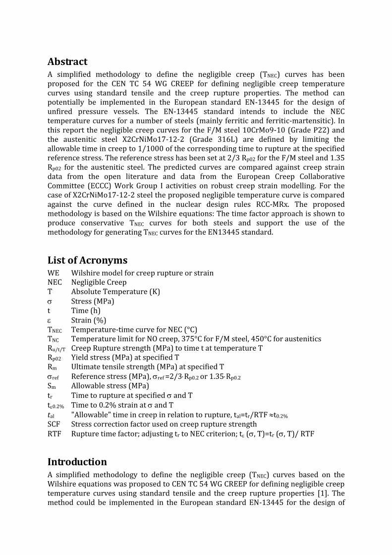
Abstract
A simplified methodology to define the negligible creep (TNEC) curves has been proposed for the CEN TC 54 WG CREEP for
defining negligible creep temperature curves using standard tensile and the creep rupture properties. The method can
potentially be implemented in the European standard EN-13445 for the design of unfired pressure vessels. The EN-13445
standard intends to include the NEC temperature curves for a number of steels (mainly ferritic and ferritic-martensitic). In
this report the negligible creep curves for the F/M steel 10CrMo9-10 (Grade P22) and the austenitic steel X2CrNiMo17-12-
2 (Grade 316L) are defined by limiting the allowable time in creep to 1/1000 of the corresponding time to rupture at the
specified reference stress. The reference stress has been set at 2/3 Rp02 for the F/M steel and 1.35 Rp02 for the austenitic
steel. The predicted curves are compared against creep strain data from the open literature and data from the European
Creep Collaborative Committee (ECCC) Work Group I activities on robust creep strain modelling. For the case of
X2CrNiMo17-12-2 steel the proposed negligible temperature curve is compared against the curve defined in the nuclear
design rules RCC-MRx. The proposed methodology is based on the Wilshire equations: The time factor approach is shown
to produce conservative TNEC curves for both steels and support the use of the methodology for generating TNEC curves for
the EN13445 standard.
AbstractA simplified methodology to define the negligible creep (TNEC) curves has been proposed for the CEN TC 54 WG CREEP for defining negligible creep temperature curves using standard tensile and the creep rupture properties. The method can potentially be implemented in the European standard EN-13445 for the design of unfired pressure vessels. The EN-13445 standard intends to include the NEC temperature curves for a number of steels (mainly ferritic and ferritic-martensitic). In this report the negligible creep curves for the F/M steel 10CrMo9-10 (Grade P22) and the austenitic steel X2CrNiMo17-12-2 (Grade 316L) are defined by limiting the allowable time in creep to 1/1000 of the corresponding time to rupture at the specified reference stress. The reference stress has been set at 2/3 Rp02 for the F/M steel and 1.35 Rp02 for the austenitic steel. The predicted curves are compared against creep strain data from the open literature and data from the European Creep Collaborative Committee (ECCC) Work Group I activities on robust creep strain modelling. For the case of X2CrNiMo17-12-2 steel the proposed negligible temperature curve is compared against the curve defined in the nuclear design rules RCC-MRx. The proposed methodology is based on the Wilshire equations: The time factor approach is shown to produce conservative TNEC curves for both steels and support the use of the methodology for generating TNEC curves for the EN13445 standard.
List of Acronyms WE Wilshire model for creep rupture or strain NEC Negligible Creep T Absolute Temperature (K) Stress (MPa) t Time (h) Strain (%) TNEC Temperature-time curve for NEC (°C) TNC Temperature limit for NO creep, 375°C for F/M steel, 450°C for austenitics Ru/t/T Creep Rupture strength (MPa) to time t at temperature T Rp02 Yield stress (MPa) at specified T Rm Ultimate tensile strength (MPa) at specified T ref Reference stress (MPa), ref =2/3Rp0.2 or 1.35Rp0.2
Sm Allowable stress (MPa) tr Time to rupture at specified and T t0.2% Time to 0.2% strain at and T tal "Allowable" time in creep in relation to rupture, tal=tr/RTF t0.2% SCF Stress correction factor used on creep rupture strength RTF Rupture time factor; adjusting tr to NEC criterion; t (, T)=tr (, T)/ RTF
Introduction A simplified methodology to define the negligible creep (TNEC) curves based on the Wilshire equations was proposed to CEN TC 54 WG CREEP for defining negligible creep temperature curves using standard tensile and the creep rupture properties [1]. The method could be implemented in the European standard EN-13445 for the design of

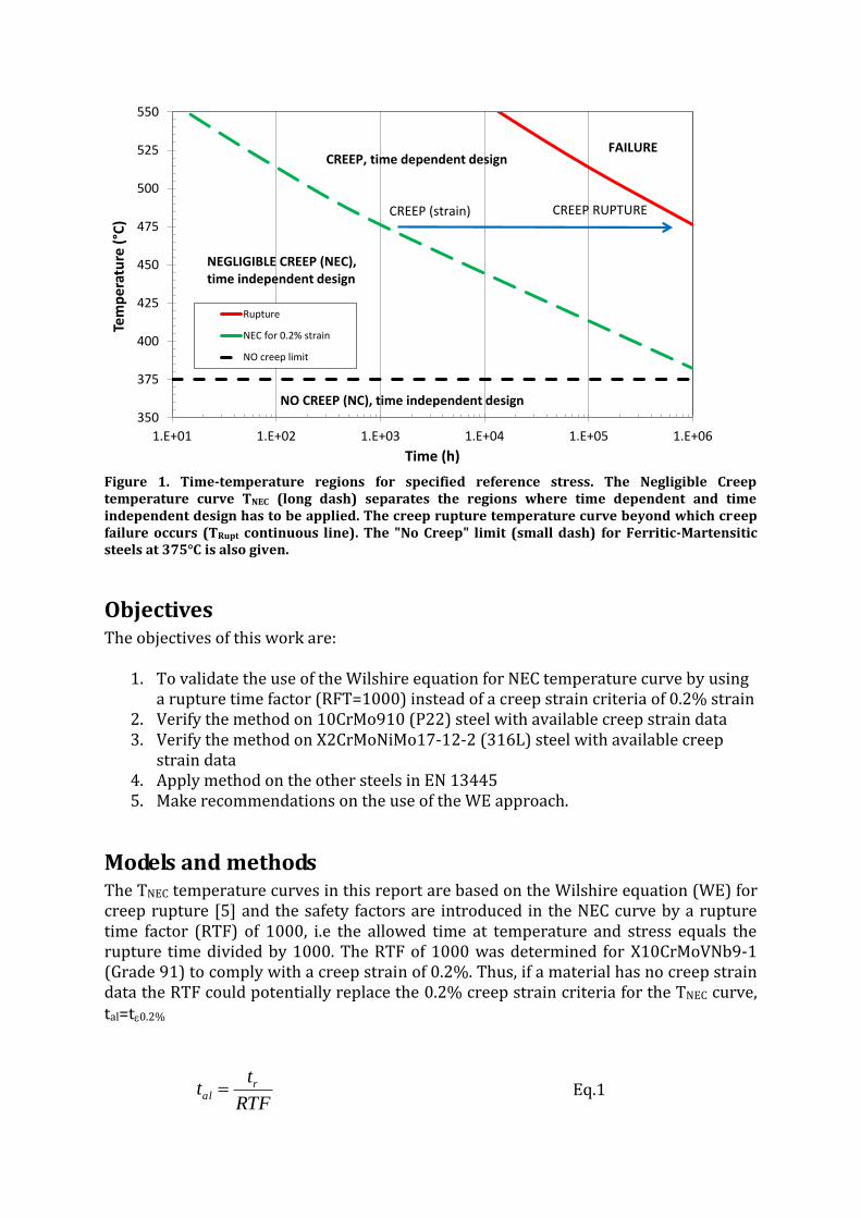
unfired pressure vessels [2]. In this report the negligible creep curves for the F/M steel 10CrMo9-10 (Grade P22) and the austenitic steel X2CrNiMo17-12-2 (Grade 316L) are defined by limiting the allowable time in creep to 1/1000 of the corresponding time to rupture at reference stresses of 2/3 Rp02 for 10CrMo9-10 and 1.35 Rp02 for X2CrNiMo17-12-2. The selected rupture time factor 1/1000 (RTF) is based on the thorough assessment on steel X10CrMoVNb9-1 (Grade 91), where time to 0.2% in strain coincides with 1/1000 of the time to rupture. The predicted curves are compared against creep strain data found in the open literature and data from the European Creep Collaborative Committees (ECCC) Work Group I activities on robust creep strain modelling [3]. For the case of X2CrNiMo17-12-2 steel the proposed negligible temperature curve is also compared with the one defined in the nuclear design rules RCC-MRx [4]. Simplified TNEC curves have been constructed assuming the 1/1000 time to rupture and then tested against available creep strain data to verify that the method is conservative in accumulated creep strain, i.e. below 0.2% in strain. A schematic presentation of the TNEC curve is given in Figure 1. In the case of the stainless steel X2CrMoNiMo17-12-2, the acquired TNEC curve is compared with the creep strain prediction model and existing TNEC curve of the nuclear RCC-MRx design code. In EN 13445-3 (6.2.1), i.e. the nominal design stress for normal operating load cases shall not exceed the smaller of the two following values:
the minimum yield strength or 0,2 % proof strength at calculation temperature, as given in the technical specification for the material, divided by the safety factor 1,5
the minimum tensile strength at 20 °C, as given in the technical specification for the material, divided by a safety factor 2.4.
In this work the first definition of design stress has been used as reference stress for NEC, i.e. 2/3 Rp02, since material properties at elevated temperature clearly must be more relevant to creep than room temperature properties.
350
375
400
425
450
475
500
525
550
1.E+01 1.E+02 1.E+03 1.E+04 1.E+05 1.E+06
Tem
pe
ratu
re (
°C)
Time (h)
Rupture
NEC for 0.2% strain
NO creep limit
NEGLIGIBLE CREEP (NEC),time independent design
NO CREEP (NC), time independent design
CREEP (strain)
FAILURE
CREEP RUPTURE
CREEP, time dependent design
Figure 1. Time-temperature regions for specified reference stress. The Negligible Creep temperature curve TNEC (long dash) separates the regions where time dependent and time independent design has to be applied. The creep rupture temperature curve beyond which creep failure occurs (TRupt continuous line). The "No Creep" limit (small dash) for Ferritic-Martensitic steels at 375°C is also given.
Objectives The objectives of this work are:
1. To validate the use of the Wilshire equation for NEC temperature curve by using a rupture time factor (RFT=1000) instead of a creep strain criteria of 0.2% strain
2. Verify the method on 10CrMo910 (P22) steel with available creep strain data 3. Verify the method on X2CrMoNiMo17-12-2 (316L) steel with available creep
strain data 4. Apply method on the other steels in EN 13445 5. Make recommendations on the use of the WE approach.
Models and methods The TNEC temperature curves in this report are based on the Wilshire equation (WE) for creep rupture [5] and the safety factors are introduced in the NEC curve by a rupture time factor (RTF) of 1000, i.e the allowed time at temperature and stress equals the rupture time divided by 1000. The RTF of 1000 was determined for X10CrMoVNb9-1 (Grade 91) to comply with a creep strain of 0.2%. Thus, if a material has no creep strain data the RTF could potentially replace the 0.2% creep strain criteria for the TNEC curve, tal=t0.2%
RTF
tt ral Eq.1

The WE for temperature at specified stress and time to strain or rupture is:
u
r
m TR
Qtk
R))exp((exp
Eq.2
where is the reference stress Rm the ultimate tensile strength, i.e. /Rm.is the normalized stress, Q the activation energy, R the gas constant, T the absolute temperature and tal is the allowable time at the negligible creep temperature. For the 10CrMo9-10 steel the ultimate tensile strength (Rm) is not given in the standard (10028-2) and the normalization is done by approximating the Rm by multiplying the tensile strength Rp02 with a factor (C in Eq.3) of 2.5. In the case of X2CrNiMo17-12-2 the tensile strength to yield ratio is much higher and a factor of 3.8 is used
u
p
alRCk
tR
QT
1
02
)ln(1
ln
Eq.3
10CrMo9-10 (Grade 22, 1.7380)
The 10CrMo9-10 steel is a classic pressure vessel steel grade for use in elevated temperature service. The steel is a classic material choice in the power and oil industry for moderate stresses up to 590°C. The creep properties are inferior to the more alloyed steel variants used today. The negligible creep temperature curve for 10CrMo9-10 was defined in the previous report [1] using the EN-10028 table values [6]. As mentioned before, in the absence of tensile strength values in the standard the WE is normalized by 2.5 Rp02. The WE master curve is shown in Figure 2. Note that the most conservative isochronous rupture strength values (here the 10 000 h strength) has been chosen for defining the WE curve and the TNEC is extracted from the location of the crosshairs.

0
0.1
0.2
0.3
0.4
0.5
0.6
0.7
0.8
0.9
1
-42 -40 -38 -36 -34 -32
/2
.5R
p0
2
ln(tr/exp(-Q/RT))
WE Rupture model
WE-NEC nodel
EN 10028 rupture
Figure 2. EN10028 creep strength data for 10CrMo910. The WE plot is calculated with Q=300 000 J/mol normalized with 2.5 Rp02. The target reference stress (2/3 Rp02) is the horizontal line at 0.27
normalized stress and the vertical line defines the location where the TNEC curve retrieved.
The solved TNEC curve for the thickest pipes (150-200 mm) of 10CrMo910 is shown in Figure 3. The corresponding curves from the previous assessment for different product thickness are shown in Figure 4. The difference in the curves is the factor of normalizing the stress values, i.e 2.5 or 1.9 of yield (Rp02). It can be seen this has very little impact on the final TNEC curve. The most conservative of the acquired TNEC curves can be chosen to represent the material to avoid separate curves for the different thicknesses.

360
380
400
420
440
460
480
500
520
540
1.E+01 1.E+02 1.E+03 1.E+04 1.E+05 1.E+06
Tem
pe
ratu
re (
°C)
Time (h)
P22-rupture
RFT=1000
NO creep limit
Figure 3. 10CrMo910 rupture and negligible creep temperature curves TNEC for thicknesses 150-250 mm. The WE model parameters Q=300 000 J/mol, WE normalization by 2.5·Rp02 , RTF=1000
and the most conservative prediction is by using 10 000h rupture strengths.
360
380
400
420
440
460
480
500
520
540
1.E+01 1.E+02 1.E+03 1.E+04 1.E+05 1.E+06
Tem
pe
ratu
re (
°C)
Time (h)
Rupture 60-100 mmRupture 150-250 mmRupture 100-150 mmRupture 40-60 mmRupture 16-40 mmRupture <16 mmWE rupture based model; RTF=1000WE rupture based model; RTF=1000WE rupture based model; RTF=1000WE rupture based model; RTF=1000WE rupture based model; RTF=1000WE rupture based model; RTF=1000NO creep limit
Figure 4. 10CrMo910 rupture (upper right corner) and negligible creep temperature curves TNEC for thicknesses 16, 16-40, 40-60, 60-100, 100-150 and 150-250 mm. The WE model parameters
Q=300 000 J/mol, WE normalization by 1.9·Rp02 and RTF=1000.
Now the curve is to be validated by comparison against the assessment results from three separate data sets containing time to strain data. The first data set is a small data set consisting of 30 creep curves previously assessed for several creep strain models in the ECCC inter-comparison actions [3]. This data set

has a maximum rupture time of 3000 h with five isotherms between 510 and 600°C and a stress range of 120-280 MPa. The data set designation is ECCC-1. The second data set is single heat data set from NIMS, Japan [7]. The heat designated as MAF consists of 36 data points ranging in temperature between 450 and 650°C and in stress between 14 and 333 MPa. In the given data (time to a total strain) the smallest total strain given is 0.5%. There are 4 data points that can be used for time to 0.2% creep strain by subtracting the initial strain at loading. The data set designation is NIMS-MAF. The third assessed data set is a multi-heat data set also previously assessed by the ECCC WG1 [8]. This data set consists of 178 creep rupture tests conducted to rupture with both time to strain from test interruption and continuous measurement. Note that not all tests have the 0.2% strain recorded and it is unclear in some cases if the recorded strain is the total strain at time of measurement, the permanent creep strain at test interruption (unloaded). The temperature range of the data set was 450°C - 600°C and the stress range 31 - 465 MPa. The data set designation is ECCC-2. Since there are no heat-by-heat tensile properties available the same mean EN10028 yield stress (multiplied by 2.5) has been used for stress normalization of all the data sets. A model for creep strain of 0.2% is constructed from the above described data sets. The model for time to 0.2% creep strain and the one for rupture are shown in Figure 5. The corresponding TNEC curve at the reference stress is shown in Figure 6 together with strain data situated close to the reference stress (10%). As it can be seen from the plots, using a RTF of 1000 is conservative enough to show for NO test results below the proposed TNEC curve and it can be concluded that the RTF approach gives a safe TNEC curve for also 10CrMo9-10.
0.00
0.10
0.20
0.30
0.40
0.50
0.60
0.70
0.80
0.90
1.00
-49 -47 -45 -43 -41 -39 -37 -35 -33
/2
.5·R
p0
2
ln(tr/·exp(-Q/RT))
EN 10028 rupture data
EN 10028 WE model
ECCC-1
ECCC-2
NIMS MAF
strain model -0.2%
RTF=1000
Figure 5. All available time to 0.2% strain, data sets ECCC-1, ECCC-2 and the NIMS MAF data. In comparison to the WE model for the EN10028 rupture data (continues blue), the 0.2% strain

model (continues red) and the RTF corrected model for NEC determination (dashed red line). The NEC curve is determined at the intersection line of the reference stress (small dots). Note that NO data point is below the RTF line.
350
375
400
425
450
475
500
525
550
575
600
625
650
675
700
1 10 100 1,000 10,000 100,000 1,000,000
Tem
per
atu
re (
°C)
Time to 0.2% strain or tr/RTF
t02 (h)T-tr; sref=Rp02/1.5ln(te*exp(-Q/RT))T-0.2%; sref=Rp02/1.5T-tr/RFT; sref=Rp02/1.5
Figure 6. The proposed TNEC curve for 10CrMo9-10 and ECCC-2 multi-heat data (time to 0.2% strain) at target reference stress Rp0.2/1.5 10%.
X2CrNiMo17-12-2 (Grade 316L, 1.4404)
X2CrNiMo17-12-2 (316L) is a low carbon version (0.03%) of the austenitic stainless steel 316 with high pitting corrosion resistance and excellent resistance to salts. For the stainless steel case the same methodology has been used as for the other steels. The rupture time factor RTF=1000 used at a reference stress of 1.35·Rp02, i.e. 1.5 times the allowable stress given in RCC-MRx. The allowable stress Sm is 0.9 Rp02 thus giving the reference stress as 1.35 times the yield stress. It is to be noted that the 2/3 yield criterion used for F/M steels cannot be used for austenitic steels since the yield to tensile strength ratio are entirely different for these two classes of steel. The TNEC curve based on the standard rupture strength values can be compared to the existing TNEC curve of RCC-MRx and available creep strain data. The creep strain data is from the same ECCC round robin [3] for creep strain modelling as the above assessed 10CrMo9-10 data. The data set is designated as ECCC-3. Note that this material data was designated as X2CrNiMoN18-13, indicating that the chemical composition is closer to 316L(N) steel than 316L. The addition of nitrogen is expected to enhance the creep properties above 650°C and below this temperature the 316L and the 316L(N) are expected to have equal creep rupture properties. The negligible creep definitions in the current nuclear design codes as well as the corresponding reference stresses are defined in Table 1 for austenitic stainless steel. These definitions are formulated taking into account steels that exhibit cycling hardening. Table 1. Nuclear design code NEC definitions for austenitic stainless steels:
Based on: Code Reference stress NEC criterion Time fraction ASME NH 1.5·Sy* (R=0.67) tu/tr ≤ 0.1 Creep strain ASME NH 1.25·Sy (R=0.8) ≤ 0.2 %

Time fraction (App. RB3216)
RCC-MRx - ti/Ti ≤ 1
Creep strain RCC-MRx 1.25·Sy (R=0.8) 1·Sm**
≤ 0.03% ≤ 0.01%
Relaxation RCC-MRx 3·Sy/E *** 1.5·Sm
1-0/rel = 10% 1-0/rel = 20%
Creep strain Japanese design (Fast reactor)
1.5·Sm ≤ 0.03%
Strain Relaxation
R5 1.5·Sy
1.35·Sy 0.03% 1-0/rel = 20%
*Sy is the yield (0.2%) stress, **Sm is the allowable stress defined by the design code at specified temperature, Note that SmRm (Rm being ultimate tensile strength) and SmRT/t.(RT/t being the rupture strength for given temperature and rupture time, i.e. 100 kh or 200 kh in standards).*** determined as the stress to produce a total strain of 3Sy/E on the average monotonic curve.
For the normalization of stress the mean yield stress of X2CrNiMo17-12-2 from RCC-MRx is used. For the temperatures above 550°C the Rp02 had to be estimated from the corresponding values of steel 316L(N), i.e. X2CrNiMo17-12-2 (N) in RCC-MRx. The creep rupture strength values used for the WE model are those from the ECCC data sheet [9] since RCC-MRx only has stress rupture values for 500-600°C.
0
0.1
0.2
0.3
0.4
0.5
0.6
0.7
0.8
0.9
1
-45 -40 -35 -30 -25
/3
.8R
po
2
ln(trexp(-Q/RT)) Figure 7. Creep strength values from the ECCC data sheet for X2CrNiMo17-12-2 for temperatures below 650°C. The WE plot is calculated with Q=300 000 J/mol normalized and normalizing with 3.8 Rp02. The dashed line indicates the reference stress (0.36 normalized stress).

0
0.1
0.2
0.3
0.4
0.5
0.6
0.7
0.8
0.9
1
-49 -44 -39 -34 -29
/3
.8·R
p0
2
ln(tr/·exp(-Q/RT))
RCC-MRx 0.2% pred
RCC-MRx data sheet
ECCC Data sheet
ECCC-3 strain 0.2%
ECCC
RCC-MRx
RTF=1000
TNEC
Figure 8. TNEC prediction for X2CrNiMo17-12-2 by using the RTF=1000 at the reference stress of 1.35 Rp02 (red large dash). is shown in the crosshairs. Note that the model is conservative at the
reference stress
In Figure 9 the TNEC curve is shown in comparison to the RCC-MRx defined curve based on relaxation data. The one based on standard strength values with the rupture time factor correction is somewhat less conservative than the RCC-MRx one at times less than 10 000 h but more conservative for the long term duration.
350
375
400
425
450
475
500
525
550
575
600
625
650
675
700
1 10 100 1000 10000 100000 1000000
Te
mp
erat
ure
(°C
)
Time to rupture or tr/RTF
T-tr; sref=Rp02*1.35
T-tr/RFT; sref=Rp02*1.35
RCC-MRx
No Creep (NC)

Figure 9. The TNEC prediction based on rupture data sheets for X2CrNiMo17-12-2 in comparison to the RCC-MRx curve.
350
375
400
425
450
475
500
525
550
575
600
10 100 1000 10000 100000 1000000
Tem
per
atu
re (
°C)
Time to rupture tr, tr/RTF and predicted t0.2%
T-tr; sref=Rp02*1.35
RCC-MRx 0.2% creep strain (316LN)
T-tr/RFT; sref=Rp02*1.35
No Creep (NC)
Figure 10. The TNEC prediction based on rupture data sheets for X2CrNiMo17-12-2 in comparison to RCC-MRx predictions for 0.2% (primary) creep strain of 316L(N). Note that the low temperature predictions of RCC-MRx were done with 316LN steel parameters. The reference stress has been corrected by an additional factor of 1.25 to compensate for the higher yield stress of 316L(N).
Conclusions The Wilshire based creep model approach for determining the negligible creep
curves based on rupture time factor correction (RTF=1000) has been used toverify the approach on two more materials.
TNEC curves on were defined for 10CrMo910 (P22) F/M steel and X2CrNiMo17-12-2 (316L) austenitic steel based on rupture strength tables and tensilestrengths.
The reference stresses for the curves were 2/3·Rp02 for 10CrMo910 and1.35·Rp02 for X2CrNiMo17-12-2.
The TNEC curves acquired by the simplified approach were shown to beconservative for both materials.
It is shown that the safety margin acquired from the time factor tr/1000 gives"sufficient" conservatism for these materials.
It is proposed that the TNEC curves are calculated for all material thicknesses inEN-10028 and the most conservative one is selected to represent the material inquestion.
The corresponding curves can also be constructed for materials in Annex R ofEN-13445 if consensus can be found on where the tensile properties (yield) foreach material are defined.
Europe Direct is a service to help you find answers to your questions about the European Union
Freephone number (*): 00 800 6 7 8 9 10 11
(*) Certain mobile telephone operators do not allow access to 00 800 numbers or these calls may be billed.
A great deal of additional information on the European Union is available on the Internet.
It can be accessed through the Europa server http://europa.eu.
How to obtain EU publications
Our publications are available from EU Bookshop (http://bookshop.europa.eu),
where you can place an order with the sales agent of your choice.
The Publications Office has a worldwide network of sales agents.
You can obtain their contact details by sending a fax to (352) 29 29-42758.
European Commission
EUR 27780 EN – Joint Research Centre – Institute for Energy and Transport
Title: Negligible creep temperature curve verification for steels 10CrMoV9-10 and X2CrMoNiMo17-12-2
Author(s): Stefan Holmström
Luxembourg: Publications Office of the European Union
2016 –14 pp. – 21.0 x 29.7 cm
EUR – Scientific and Technical Research series – ISSN 1831-9424 (online)
ISBN 978-92-79-57126-8 (PDF)
doi: 10.2790/208315

ISBN 978-92-79-57126-8
doi: 10.2790/208315
JRC Mission
As the Commission’s in-house science service, the Joint Research Centre’s mission is to provide EU policies with independent, evidence-based scientific and technical support throughout the whole policy cycle.
Working in close cooperation with policy Directorates-General, the JRC addresses key societal challenges while stimulating innovation through developing new methods, tools and standards, and sharing its know-how with the Member States, the scientific community and international partners.
Serving society Stimulating innovation Supporting legislation
LD
-NA
-27
78
0-E
N-N