Negative Ion TPC as the LC Main Tracker G. Bonvicini, Jan. 2003 Overview Early Simulations (by A....
18
Negative Ion TPC as the LC Main Tracker G. Bonvicini, Jan. 2003 • Overview • Early Simulations (by A. Schreiner) • Also in the collaboration J. Martoff and R. Ayad (Temple), D. Snowden-Ifft (Occidental)
-
Upload
quincy-wooster -
Category
Documents
-
view
214 -
download
0
Transcript of Negative Ion TPC as the LC Main Tracker G. Bonvicini, Jan. 2003 Overview Early Simulations (by A....

Negative Ion TPCas the LC Main Tracker
G. Bonvicini, Jan. 2003
• Overview
• Early Simulations (by A. Schreiner)
• Also in the collaboration J. Martoff and R. Ayad (Temple), D. Snowden-Ifft (Occidental)

What is a NITPC?
• It is a TPC where the primary ionization and the avalanche are made of electrons, but the drift is done by negative ions
• Uses any electronegative gas, with thermal electron capture and ion stripping (at high E) cross section of order 10^7 Barn, and appreciable gain
• Three such gases are known: CS2, biacetyl and methylchloride
• NI gas tubes first studied and operated in 1953

NITPC in modern times (post 1995)
• Developed by J. Martoff and collaborators
• DRIFT collaboration (1998-): 1m3 NITPC to study dark matter (seeks annual, daily, and directional signature of dark matter) (Boulby, UK) – a very robust detector
• DRIFT-II proposed: 9m3 He/CS2 80/20 detector

Properties of the NITPC
• Thermal diffusion at all E-fields:
• Good gain (10^4 at 7700V)• Drift velocity approx. 20m/sec
(at 1 kV/cm) drift• Negligible Lorentz angle allows
radial, azimuthal drift• Properties conspire to allow
“single electron detection”• Extreme photon and electron
quenching
( )70
( / )
L cmmE kV cm

Motivation of the NITPC
• Improve event information by detecting single electrons (F. Villa, NIM 217, 273,1983, J. Huth and D. Nygren, NIM 241, 375, 1985, G. Bonvicini, Hellaz Note 93-01) – momentum resolution, two-track separation, and tracking efficiency
• Decrease material and cost through the use of novel detector planes
• Keep alive the TPC option for the far future (E=1 TeV)

Simulations
• In progress• One event is 1+GByte• GEANT4 crashes on events this big• We are writing an algorithm to reject
background hits before tracking• Main tracker for TESLA discussed below• Temporarily, we have abandoned the axial
and radial TPC and concentrated on the azimuthal TPC

Parameter TPC NITPC Comments
objectiveCentral Tracker in Tesla;
B=3 Tesla
geometryazimuthal: r=0.5-2m,
z=-2.7-+2.7m
materialgas:
Ar(100%)
gas: He/CS2(80/20) +6·0.5% X0
(membr)
For multiple scattering
<ldrift> 1.35 m 33 cm
NITPC is devided into 12 sectionsazimuthally and TPC into 2 along z
l_dif(<ldrift>) 4 mm0.4 mm for E=1kV/cm in
NITPCtr_dif(<ldrift>) 0.68 mm
Ns of samples/trac
k144 104 depends on the gas
Ni of ioniz. e per
measurement 140 1
z_meas 3 mm0.4 mm meas=dif/SQRT(Ni)
azim_meas 0.1 mm

5-section axial TPC 12-section azimuthal TPC
read out planes do not produce background at all
(Here are only 2% of background at Tesla)

regular TPC

TPC detector plane (azimuthal TPC)
• A modified version of a Micromegas detector plane (Gorodetzky-Giomataris)
• Blue pads are ganged NW-SE, white pads are ganged NE-SW (angle to wire is 60 degrees)
• Hits are recorded as a triplet

TPC backgrounds (TESLA)
• Incoherent noise backgrounds
• Approximately 2X10^9 “wire pixels” due to long drift
• Pulse height matching: 1) strip-strip; 2) wire-(s1+s2) (not done yet)
3
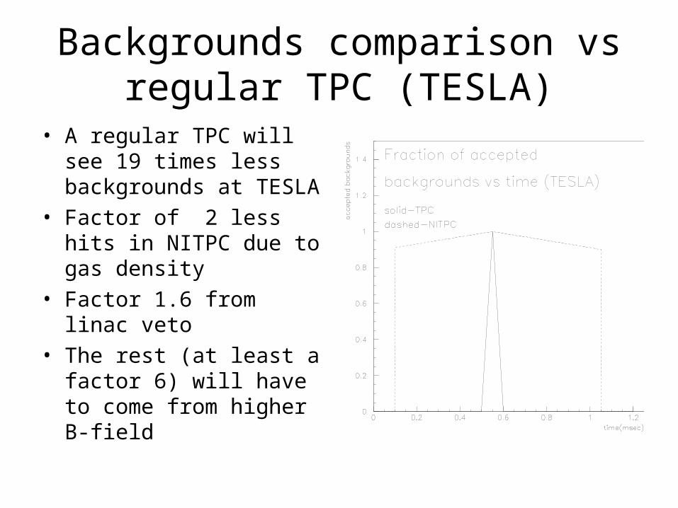
Backgrounds comparison vs regular TPC (TESLA)
• A regular TPC will see 19 times less backgrounds at TESLA
• Factor of 2 less hits in NITPC due to gas density
• Factor 1.6 from linac veto• The rest (at least a factor
6) will have to come from higher B-field

Simulated wire occupancies (backgrounds = 6XNLC)
Using Maruyama’s ntuples, FADC bucket = 100 nsec, no cuts)

background
signal in backgroundaverage strip occupancy is 11%
radius [cm]

Momentum resolution comparison with reg. TPC
(both large TPC, using Bruce Schumm’ s program, red=NITPC,
blue=reg. TPC)


Space charge
• An issue if a wire/strip detector plane is used
• For gain = 10^4, n=3X10^7, V=100 kV, Delta(V)=17V
• Some drift velocity saturation also helps

Conclusions
• The NITPC niche: small, low cost, low material, very competitive momentum resolution and pattern recognition
• Working point is relatively well defined
• Early studies point to manageable backgrounds