NEEDLE ROLLER BEARINGS - Bianchi Industrial
288
Recognizing that conservation of the global environment is the top-priority challenge for the world’s population, Nippon Thompson will conduct its activities with consideration of the environment as a corporate social responsibility, reduce its negative impact on the environment, and help foster a rich global environment. ISO 9001 & 14001 Quality system registration certificate • The specifications and dimensions of products in this catalog are subject to change without prior notice. • When these products are exported, the exporter should confirm a forwarding country and a use, and, in case of falling under the customer's requirements, take necessary procedures such as export permission application. • Although all data in this catalog has been carefully compiled to make the information as complete as possible, NIPPON THOMPSON CO., LTD. shall not be liable for any damages whatsoever, direct or indirect, based upon any information in this catalog. NIPPON THOMPSON CO., LTD. makes no warranty, either express or impiled, including the impiled warranty of merchantability or fitness for a particular purpose. • Reproduction and conversion without permission are prohibited. CAT-1586E NEEDLE ROLLER BEARINGS
Transcript of NEEDLE ROLLER BEARINGS - Bianchi Industrial
CAT-1586E
CAT-1586E
NEEDLE ROLLER BEARINGS
NEED
LE R
OLLER
BE
AR
ING
S
Recognizing that conservation of the global environment is the top-priority challenge for the world’s population, Nippon Thompson will conduct its activities with consideration of the environment as a corporate social responsibility, reduce its negative impact on the environment, and help foster a rich global environment.
ISO 9001 & 14001 Quality system registration certificate
• The specifications and dimensions of products in this catalog are subject to change without prior notice.
• When these products are exported, the exporter should confirm a forwarding country and a use, and, in case of falling under the customer's requirements, take necessary procedures such as export permission application.
• Although all data in this catalog has been carefully compiled to make the information as complete as possible, NIPPON THOMPSON CO., LTD. shall not be liable for any damages whatsoever, direct or indirect, based upon any information in this catalog. NIPPON THOMPSON CO., LTD. makes no warranty, either express or impiled, including the impiled warranty of merchantability or fitness for a particular purpose.
• Reproduction and conversion without permission are prohibited.
CAT-1586E
CAT-1586E
NEEDLE ROLLER BEARINGS
NEED
LE R
OLLER
BE
AR
ING
SRecognizing that conservation of the global environment is the top-priority challenge for the world’s population, Nippon Thompson will conduct its activities with consideration of the environment as a corporate social responsibility, reduce its negative impact on the environment, and help foster a rich global environment.
ISO 9001 & 14001 Quality system registration certificate
• The specifications and dimensions of products in this catalog are subject to change without prior notice.
• When these products are exported, the exporter should confirm a forwarding country and a use, and, in case of falling under the customer's requirements, take necessary procedures such as export permission application.
• Although all data in this catalog has been carefully compiled to make the information as complete as possible, NIPPON THOMPSON CO., LTD. shall not be liable for any damages whatsoever, direct or indirect, based upon any information in this catalog. NIPPON THOMPSON CO., LTD. makes no warranty, either express or impiled, including the impiled warranty of merchantability or fitness for a particular purpose.
• Reproduction and conversion without permission are prohibited.

J15CRBHV
K37PBK11K15K23
SBGESBB
J19J19
CRBCCRB
J23CRBTJ17CRBFV J25CRBTF
K58K59K59
SNASNMSNPT
I25I31I35I39I43
CF…BCFKRCFE…BCFKRECFES…B
I45I49I49I51I53
CF…WBCF-RU1CF-FU1CF-SFU…BCF…G
I55I57I61I65
CF…/SGCFSCFS…WNUCF…B
I67I67I77I22
CRCR…BCRH…BCL
K38K39K42
PHSPOSPHSA
J27CRBS
K49K51
LHSALHS
I101I103
NURTCRY
(R)NASTNARTNART…/SG
(I89)I90I93I99
M55
D75(D83)D89

Gifu factory main entrance
Assembling process in a clean room

1
This catalog adopts the SI system (system of international units) in conformance with ISO (International Organization for Standardization) Standard 1000.
In the table of dimensions, standard products are referred to using identification numbers marked with . The products are reputed for high quality, reasonable price and quick delivery. The identification numbers marked with refer to our semi-standard products.The specifications and dimensions of products in this catalogue are subject to change without prior notice.
The IKO Needle Roller Bearing Series are manufactured through a control system that alleviates
their impact on the global environment to meet the quality requirements of ISO 14001 in
compliance with the quality requirements level of ISO 9001 for quality improvement.
The standard products listed in this catalog comply with the specifications of the ten hazardous
materials mentioned cited in the European RoHS Directive.
CAT-1586E

2 3
A
B
C
D
E
F
G
H
I
J
K
L
M
TA・TLA・BA・BHA
KT・KT…N
KT…EG・KTV…EG
NA・TAFI・TRI・BRI
TAF…/SG
NAF
NAG・NAU・TRU・NAS
NTB・AS・AZK・WS・GS
NAX・NBX・NATA・NATB
IRT・IRB・LRT・LRB
CF…B・CFKR・CFS・NUCF…B・CR…B・CR
CF…/SG
NAST・NART・NURT・CRY
NART…/SG
CRBHV・CRBFV・CRBC・CRB・CRBT・CRBTF・CRBS
SB・GE・SBB
PB・PHS・POS・PHSA
LHSA・LHS
SNA・SNM・SNPT
OS・DS・WR・AR・Needle Roller
Description of Each Series & Table of Dimensions
Shell Type Needle Roller Bearings
Needle Roller Cages for general usage
Needle Roller Cages for engine connecting rods
Machined Type Needle Roller Bearings
C-Lube Machined Type Needle Roller Bearings
Needle Roller Bearings with separable cage
Roller Bearings
Thrust Bearings
Combined Type Needle Roller Bearings
Inner Rings
Cam Followers
C-Lube Cam Followers
Roller Followers
C-Lube Roller Followers
Crossed Roller Bearings
Spherical Bushings
Pilloballs
L-balls
Super Flexible Nozzles
Parts For Needle Roller Bearings
Characteristics of Needle Roller Bearings
Types and Features of Bearings
Outline of Bearing Selection
Basic Dynamic Load Rating and Life
Basic Static Load Rating and Static Safety Factor
Calculation of Bearing Loads
Boundary Dimensions and Identification Number
Accuracy
Clearance
Fit
Design of Shaft and Housing
Lubrication
Friction and Allowable Rotational Speed
Operating Temperature Range
Handling of Bearings
General Explanation
1
1
17
1
75
79
1
1
1
1
1
55
81
99
1
1
29
45
55
1
B
C
C
D
D
D
E
F
G
H
I
I
I
I
J
K
K
K
K
L
A 3
A 5
A 16
A 17
A 21
A 22
A 26
A 30
A 37
A 39
A 44
A 49
A 56
A 57
A 57
M33Miscellaneous Tables
M59Alphabetical Index

A1 A2
Nippon Thompson Co., Ltd. is a bearing manufacturer that launched the technical development of needle roller bearings for the first time in Japan and is proud of the high quality level and abundant varieties of its products.Needle roller bearings are bearings for rotary motion that incorporate needle- shaped thin rollers instead of ordinary bearing balls or rollers. Compared with other rolling bearings, they are small-sized and lightweight but have a large load capacity. They are widely used with high reliability in the fields of automobiles, industrial machinery, OA equipment, etc. as resource-saving type bearings that make the whole machine compact.

A3 A4
A
B
C
D
E
F
G
H
I
J
K
L
M
Bearings can be classified into two main types, namely rolling bearings and sliding bearings. Rolling bearings
can be subdivided further into ball bearings and roller bearings according to the rolling elements.
IKO Needle Roller Bearings are high-precision rolling bearings with a low sectional height, incorporating needle
rollers as the rolling element. They have the following features.
Merits of Rolling Bearings
Compared with sliding bearings, rolling bearings
have the following merits:
Radial ballbearings
Thrust ballbearings
Radial rollerbearings
Thrust rollerbearings
Bal
l bea
rin
gs
Ro
ller
bea
rin
gs
Metals, bushings, others
Deep groove ball bearings
Angular contact ball bearings
Self-aligning ball bearings
Others
Thrust ball bearings with flat back face
Thrust ball bearings with aligning seat washer
Double-direction angular contact thrust ball bearings
Others
Needle roller bearings
Cylindrical roller bearings
Tapered roller bearings
Self-aligning roller bearings
Others
Thrust needle roller bearings
Thrust cylindrical roller bearings
Thrust tapered roller bearings
Others
Classification of bearings
Characteristics of Needle Roller Bearings
Stable accuracy can be maintained for long periods.
Owing to less wear, stable accuracy can be maintained for long periods.
Static and kinetic friction is low.
Since the difference between static friction and kinetic friction is small and the frictional coefficient is also small, drive units or machines can be made more compact and lightweight, saving machine costs and power consumption.
Machine reliability is improved.
Since the bearing life can be estimated based on rolling fatigue, machine reliability is improved.
Lubrication is simplified.
Since grease lubrication is sufficient in most cases, lubrication can be simplified for easy maintenance.
Merits of Needle Roller Bearings
Compared with other rolling bearings, IKO Needle
Roller Bearings have the following advantages:
Rotating torque is small, improving mechanical efficiency.
Since the rotating radius is small, the rotating torque is also small under the same frictional conditions, thus improving mechanical efficiency.
With a low sectional height, they can withstand heavy loads.
Since they have a low sectional height compared with other rolling bearings and yet can withstand heavy loads, machines can be made more compact and lightweight, thus saving costs.
Inertia is minimized.
Since the bearing volume and weight are small, the moment of inertia of the bearing is minimized when it is put in motion.
Most suited to oscillating motions.
Many rolling elements are arranged at a small spacing pitch, and this configuration is most suited to oscillating motions.
Ro
llin
g b
eari
ng
s
Bea
rin
gs
Slid
ing
bea
rin
gs

A
B
C
D
E
F
G
H
I
J
K
L
M
A5 A6
C-Lube Machined Type Needle Roller Bearings TAF… /SG
Classification of Bearings
Combined Type Needle Roller Bearings
Thrust Roller Bearings
Shell Type Needle Roller Bearings
Needle Roller Cages
Machined Type Needle Roller Bearings
Roller Bearings
Thrust Needle Roller Bearings
NAFW, RNAFW
with Three-point Contact Ball Bearing
with Angular Contact Ball Bearing
with Thrust Roller Bearing
with Thrust Ball Bearing
Roller Bearings for Sheaves
Needle Roller Bearings with Separable Cage
Needle Roller Cages for Engine Connecting Rods
Needle Roller Cages for General Usage
TA, TAM
TLA, TLAM
BA, BAM
BHA, BHAM
YT
YTL
YB
YBH
KT, KT…N
KTW
KT…EG
KTV…EG
NA, RNA
TAFI, TAF
TRI, TR
BRI, BR
GTRI, GTR
NAF, RNAF
NAU
NAG
TRU
NAS
NTB
AZK, AZ
NAXI, NAX
NBXI, NBX
NATA
NATB
IKO Bearings can be roughly classified into radial bearings and thrust bearings according to applicable load direction. Radial Bearings are grouped into Shell Type Needle Roller Bearings, Machined Type Needle Roller Bearings, and various other types. Thrust Bearings are grouped into Thrust Needle Roller Bearings and Thrust Roller Bearings.Follower Bearings that are used for cam mechanisms and linear motion are grouped into Cam Followers and Roller Followers.
Crossed Roller Bearings are special shape bearings that can simultaneously receive loads in all directions with a single bearing.Bearings other than rolling bearings, such as self-aligning Spherical Bushings that can support radial loads and axial loads and PILLOBALLs and L-Balls that are used for link mechanisms, are also available.
Types and Features of BearingsR
adia
l Bea
rin
gs
Thru
stBe
arin
gsCo
mbi
ned T
ype
Bear
ings
High Rigidity Type Crossed Roller Bearings (V) CRBHV
CF…B, CFKR
CFES…B
CFE…B, CFKRE
CF…WB
CF-RU1, CF-FU1
CF-SFU…B
NUCF…B
CR, CR…B, CRH
NURT
Mounting Holed Type High Rigidity Crossed Roller Bearings (V) CRBFV
CRBC, CRB
Mounting Holed Type Super Slim Crossed Roller Bearings CRBTF
NAST, RNAST
NART, CRY
C-Lube Machined Type Needle Roller Bearings TAF… /SG
Classification of Bearings
Combined Type Needle Roller Bearings
Thrust Roller Bearings
Shell Type Needle Roller Bearings
Needle Roller Cages
Machined Type Needle Roller Bearings
Roller Bearings
Thrust Needle Roller Bearings
NAFW, RNAFW
with Three-point Contact Ball Bearing
with Angular Contact Ball Bearing
with Thrust Roller Bearing
with Thrust Ball Bearing
Roller Bearings for Sheaves
Needle Roller Bearings with Separable Cage
Needle Roller Cages for Engine Connecting Rods
Needle Roller Cages for General Usage
TA, TAM
TLA, TLAM
BA, BAM
BHA, BHAM
YT
YTL
YB
YBH
KT, KT…N
KTW
KT…EG
KTV…EG
NA, RNA
TAFI, TAF
TRI, TR
BRI, BR
GTRI, GTR
NAF, RNAF
NAU
NAG
TRU
NAS
NTB
AZK, AZ
NAXI, NAX
NBXI, NBX
NATA
NATB
IKO Bearings can be roughly classified into radial bearings and thrust bearings according to applicable load direction. Radial Bearings are grouped into Shell Type Needle Roller Bearings, Machined Type Needle Roller Bearings, and various other types. Thrust Bearings are grouped into Thrust Needle Roller Bearings and Thrust Roller Bearings.Follower Bearings that are used for cam mechanisms and linear motion are grouped into Cam Followers and Roller Followers.
Crossed Roller Bearings are special shape bearings that can simultaneously receive loads in all directions with a single bearing.Bearings other than rolling bearings, such as self-aligning Spherical Bushings that can support radial loads and axial loads and PILLOBALLs and L-Balls that are used for link mechanisms, are also available.
Types and Features of Bearings
Rad
ial B
eari
ng
sTh
rust
Bear
ings
Com
bine
d Typ
eBe
arin
gs
High Rigidity Type Crossed Roller Bearings (V) CRBHV
CF…B, CFKR
CFES…B
CFE…B, CFKRE
CF…WB
CF-RU1, CF-FU1
CF-SFU…B
NUCF…B
CR, CR…B, CRH
NURT
Mounting Holed Type High Rigidity Crossed Roller Bearings (V) CRBFV
CRBC, CRB
Mounting Holed Type Super Slim Crossed Roller Bearings CRBTF
NAST, RNAST
NART, CRY

A
B
C
D
E
F
G
H
I
J
K
L
M
A7 A8
Shell Type Needle Roller Bearings are lightweight with the lowest sectional height among needle roller bearings with outer ring, because they employ a shell type outer ring made from a thin special-steel plate which is accurately drawn, carburized and quenched.Since these bearings are press-fitted into the housing, no axial positioning fixtures are required. They are ideal for use in mass-produced articles that require economy.
Shell Type Needle Roller Bearings
Radial Bearings Page B1
Needle Roller Cages for General Usage are bearings that display excellent rotational performance. Their specially shaped cages with high rigidity and accuracy, precisely guide the needle rollers.Since needle rollers with extremely small dimensional variations in diameter are incorporated and retained, Needle Roller Cages for General Usage are useful in small spaces when combined with shafts and housing bores that are heat treated and accurately ground as raceway surfaces.
Radial Bearing Page C1
Machined Type Needle Roller Bearings have an outer ring made by machining, heat treatment, and grinding. The outer ring has stable high rigidity and can be easily used even for light alloy housings.These bearings are available in various types and optimally selectable for different conditions such as heavy loads, high-speed rotation and low-speed rotation. They are most suitable for general-purpose applications.
Radial Bearing Page D1
In Needle Roller Bearings with Separable Cage, the inner ring, outer ring and Needle Roller Cage are combined, and they can be separated easily. This type has a simple structure with high accuracy. In addition, the radial clearance can be freely selected by choosing an assembly combination.These bearings have excellent rotational performance, because Needle Roller Cages are used.
Radial Bearing Page D79
Roller Bearings, in which rollers are incorporated in double rows, are non-separable heavy-duty bearings.They can withstand not only radial loads but axial loads as well, which are supported at the contacts between the shoulders of inner and outer rings and the end faces of rollers. Therefore, they are most suitable for use at the fixing side of a shaft.
Radial Bearing Page E1
Needle Roller Gages for Engine Connecting Rods are used for motor cycles, small motor vehicles, outboard marines, snow mobiles, general-purpose engines, high- speed compressors, etc. that are operated under extremely severe and complex operating conditions such as heavy shock loads, high speeds, high temperatures, and stringent lubrication.Needle Roller Cages for Engine Connecting Rods are lightweight and have high load ratings and high rigidity as well as superior wear resistance.
Radial Bearing Page C17
Needle Roller Cages for General Usage
Needle Roller Cages for Engine Connecting Rods
Machined Type Needle Roller Bearings
Roller Bearings
Needle Roller Bearings with Separable Cage

A
B
C
D
E
F
G
H
I
J
K
L
M
A9 A10
Cam Followers
Inner Rings
Thrust Bearings consist of a precisely made cage and rollers, and can receive axial loads. They have high rigidity and high load capacities and can be used in small spaces.Thrust Needle Roller Bearings use needle rollers, whileThrust Roller Bearings use cylindrical rollers.
Thrust Bearings
Thrust Bearing Page F1
Cam Followers are bearings with a stud incorporating needle rollers in a thick walled outer ring.They are designed for outer ring rotation, and the outer rings run directly on mating cam guide surfaces.Various types of Cam Followers are available. They are widely used as follower bearings for cam mechanisms and for linear motions.
Follower Bearing Page I1
Roller FollowersRoller Followers are bearings in which needle rollers are incorporated in a thick walled outer ring.These bearings are designed for outer ring rotation, and the outer rings run directly on mating cam guide surfaces.They are used as follower bearings for cam mechanisms and for linear motions.
Follower Bearing Page I81
Crossed Roller BearingsCrossed Roller Bearings are high-rigidity and compact bearings with their cylindrical rollers alternately crossed at right angles to each other between inner and outer rings. A single Crossed Roller Bearing can take loads from any directions at the same time such as radial, thrust, and moment loads.These bearings are widely used in the rotating parts of industrial robots, machine tools, medical equipment, etc. which require compactness, high rigidity and high rotational accuracy.
Crossed Roller Bearing Page J1
Combined Type Needle Roller Bearings are combinations of a radial bearing and a thrust bearing. Caged Needle Roller Bearings are used as radial bearings and Thrust Ball Bearings or Thrust Roller Bearings are used as thrust bearings.They can be subjected to radial loads and axial loads simultaneously.
Combined Type Needle Roller Bearings
Combined Type Bearing Page G1
Inner Rings are heat-treated and finished by grinding to a high degree of accuracy and are used for Needle Roller Bearings.In the case of Needle Roller Bearings, normally the shafts are heat-treated and finished by grinding and used as raceway surfaces. However, when it is impossi-ble to make shaft surfaces according to the specified surface hardness or surface roughness, Inner Rings are used.
Component part Page H1

A11 A12
A
B
C
D
E
F
G
H
I
J
K
L
M
L-Balls
Seals for Needle Roller BearingsSpherical BushingsSpherical Bushings are self-aligning spherical plain bushings, which have inner and outer rings with spherical sliding surfaces. They can take a large radial load and a bi-directional axial load at the same time.They are divided into steel-on-steel types that are suitable for applications where there are alternate loads or shock loads, and maintenance-free types which require no lubrication.
Spherical Sliding Bearing Page K1
PILLOBALLsPILLOBALLs are compact self-aligning spherical plain bushings which can support a large radial load and a bi- directional axial load at the same time.PILLOBALL Rod Ends have either a female thread in the body or a male thread on the body, so they can be easily assembled onto machines.PILLOBALLs are used in control and link mechanisms in machine tools, textile machines, packaging machines, etc.
Spherical Sliding Bearing Page K29
L-Balls are self-aligning rod-ends consisting of a special zinc die-cast alloy body and a studded ball which has its axis at right-angles to the body.They can perform tilting movement and rotation with low torque, and transmit power smoothly due to the uniform clearance between the sliding surfaces.They are used in link mechanisms in automobiles, construction machinery, farm and packaging machines, etc.
Spherical Sliding Bearing Page K45
Seals for Needle Roller Bearings have a low sectional height and consist of a sheet metal ring and special synthetic rubber.As these seals are manufactured to the same sectional height as Needle Roller Bearings, grease leakage and the penetration of foreign particles can be effectively prevented by fitting them directly to the sides of combinable bearings.
Component Part Page L1
Cir-clips for Needle Roller BearingsCir-clips for Needle Roller Bearings have been specially designed for needle roller bearings on which, in many cases, generally available Cir-clips cannot be used. They have a low sectional height and are very rigid.There are Cir-clips for shafts and for bores, and they are used for positioning to prevent bearing movement in the axial direction.
Component Part Page L17
Needle RollersNeedle Rollers are used for needle roller bearings and are rigid and highly accurate.These needle rollers are widely used as rolling elements for bearings, and also as pins and shafts.
Component Part Page L23

A
B
C
D
E
F
G
H
I
J
K
L
M
A13 A14
F1~
G1~
I1~
I81~
Bearing series Appearance Direction ofmotion
Load directionand capacity
Allowable rotational speed
Sectionalheight
ReferencepageFriction
Thrust Bearings
Combined Type Needle Roller Bearings
Cam Followers
Roller Followers
Needle roller bearings
Roller bearings
With thrust ball bearing
With thrust roller bearing
With angular contact ball bearing
With three-point contact ball bearing
Caged type
Full complement type
Separable caged type
Non-separable caged type
Non-separable full complement type
Bearing series Appearance Direction ofmotion
Load directionand capacity
Allowable rotational speed
Sectionalheight
ReferencepageFriction
Shell TypeNeedle RollerBearings
NeedleRoller Cages
Machined TypeNeedle RollerBearings
Needle RollerBearings withSeparable Cage
Roller Bearings
Caged type
Caged type
Caged type
Caged type
Fullcomplementtype
Fullcomplementtype
Fullcomplementtype
For sheaves
Forgeneral usage
For engineconnectingrods
B1~
C1~
C17~
D1~
D79~
E1~
Rotation Oscillating motion
Radial load
Axial load
Light load
Medium load
Heavy load
Especially excellent Excellent NormalSymbol
Features of Bearings

A
B
C
D
E
F
G
H
I
J
K
L
M
A15 A16
An example of procedure for bearing selection
J1~
K1~
K29~
K45~
Identify the machine and place where the bearing is to be used. Confirm the requirements for bearings such as required bearing performance, and also confirm the operating conditions and special environment conditions.
Select the bearing type suitable for the operating conditions by considering load direction and magni- tude, rigidity, friction, allowable rotational speed, bearing space, etc.
See page
A5
Select the bearing dimensions by calculating bearing load, life, static safety factor, etc.
1
2
3
4
5
6
7
8
9
Features of Bearings
Bearing series Appearance Direction ofmotion
Load directionand capacity
Allowable rotational speed
Sectionalheight
ReferencepageFriction
Crossed Roller Bearings
Spherical Bushings
PILLOBALLs
L-Balls
Caged type,Separator type
Full complement type
Slim type
Steel-on-steel type
Maintenance-free type
Maintenance-free type
Lubrication type
Insert type, Lubrication type
Die-casting type, Lubrication type
Rotation Oscillating motion
Radial load
Axial load
Light load
Medium load
Heavy load
Especially excellent Excellent NormalSymbol
IKO Bearings are available in many types and sizes. To obtain satisfactory bearing performance in machines and equipment, it is essential to select the most suitable bearing by carefully studying the requirements for the application.Although there is no particular procedure or rule for bearing selection, an example of a commonly adopted procedure is shown in the figure below.
Outline of Bearing Selection
Selection of bearing type
Selection of bearing dimensions
Selection of accuracy class, etc.
Selection of radial clearance and fit
Determination of bearing dimensions, accuracy, radial clearance and fit
Selection of lubrication and dust-proof methods
Design of surrounding part
Determination of final specifications of the bearing and the surrounding part
Confirmation of requirements and operating conditions
See page
A17
Select the accuracy as required by the machine or equipment. See page
A30
Select the radial clearance considering the fit, temperature, rotational speed, inclination of the inner and outer rings, etc.
See page
A37
Select oil or grease lubrication. After selection of lubricant, in case of oil lubrication, select the oil application method. Select the sealing method according to the lubricant.
See page
A49
Design the surrounding part based on how to mount or dismount and based on mounting dimensions. See page
A57

A
B
C
D
E
F
G
H
I
J
K
L
M
A17 A181N=0.102kgf=0.2248lbs.1mm=0.03937inch
Basic Dynamic Load Ratingand Life
CP( )
p
Operating conditions
Occasional or short term usage ・Power tools ・Agricultural machines
・Construction machinery ・Conveyors・Elevators
・Roll neck of rolling mills ・Small motors・Deck cranes・General cargo cranes・Passenger cars
・Factory motors・Machine tools・General gear units・Printing machines
・Crane sheaves・Compressors・Important gear units
Infrequent usage but requiring reliable operation
Intermittent operation but for comparatively long periods
・Escalators ・Centrifugal separators・Blowers・Wood working machines・Plastic extruding machines
・Paper making machinesOperated in excess of 8 hours per day or continuously for an extended time
・Water supply equipment・Power station equipment
Continuous use for 24 hours and accidental stops not allowed
Machine and life factor fh
〜 3 2〜 4 3〜 5 4〜 7 6〜
Basic rating life
The basic rating life is defined as the total number of revolutions that 90% of a group of identical bearings can be operated individually under the same condi-tions free from any material damage caused by rolling fatigue.For rotation at a constant rotational speed, the basic rating life can be represented by the total service hours.
Basic dynamic load rating
The basic dynamic load rating is defined as the con-stant radial load (in the case of radial bearings) or the constant axial load acting along the bearing central axis (in the case of thrust bearings) that allows a basic rating life of 1,000,000 revolutions.
Calculation of rating life
The relationship among the basic rating life, basic dynamic load rating and dynamic equivalent load (bearing load) of rolling bearings is as follows:
L10
= ……………………………………(1)
where, L10 :Basic rating life, 106 rev. C :Basic dynamic load rating, N P :Dynamic equivalent load, N p : Exponent, Roller bearing: 10/3
Ball bearing: 3Accordingly, when the rotational speed per minute is given, the basic rating life is represented as the total service hours according to the following equations:
Lh = = 500 f h ……………………(2)
f h= f n …………………………………(3)
f n = …………………………………(4)
where, Lh :Basic rating life represented by
service hours, h n :Rotational speed, min-1
f h :Life factor
f n :Velocity factorIn addition, the rating life can be calculated by obtain-
ing f h and f n from the life calculation scales of Fig. 2.
Life
Rolling bearings will suffer damage due to various causes during service. Damage such as abnormal wear, seizure, and cracks is caused by improper use, including incorrect mounting, lack of oil, dust intrusion and so on, and can be avoided by remedying these causes. However, bearings will eventually be dam-aged due to fatigue-flaking even if used properly. When a bearing rotates under load, the raceways and the rolling elements are subjected to repeated stress-es concentrated on the part close to the surface. Fatigue, therefore, occurs in the surface layer, pro-ducing damage in the form of scaling. This is called flaking (spalling). When this occurs, the bearing can no longer be used.
Bearing Life
Bearing life is defined as the total number of revolu-tions (or total service hours at a constant rotational speed) before a sign of the first flaking appears on the roll ing surface of raceway or roll ing elements. However, even when bearings of the same size, structure, material and heat treatment are subjected to the same conditions, the bearing lives will show variation (See Fig. 1.). This results from the statistical nature of the fatigue phenomenon.In selecting a bearing, it is incorrect to take an aver-age life for all bearings as the design standard. It is more practical to consider a bearing life that is reliable for the greater propor t ion of bear ings used. Therefore, the basic rating life defined in the following is used.
106L1060n
CP
p
33.3n( )
1/p
Bearing life factors for various machines
The required life of the bearing must be determined according to the machine in which the bearing is to be used and the operating conditions.Table 1 shows reference values of life factors for selecting a bearing for each machine.
Table 1 Life factor of bearings f h for various machines
Fig. 2 Scales for rating life calculation
Rotational speed
Velocity factor
Basic rating life represented by service hours
Life factor
Rotational speed
Velocity factor
Basic rating life represented by service hours
Life factor
Roller bearings10
200 1000 10000 80000
100 1000 10000
1.44
0.76 1.0 2.0 3.0 4.0 4.6
1.0 0.20
15 20
300 400 500 600 700 800 900 2000 3000 4000 6000 8000 20000 40000 60000
30 40 60 80 150 200 300 400 600 800 1500 2000 3000 4000 6000 8000 15000 20000 30000 40000 60000
1.4 1.3
0.80 0.85 0.90 0.95 1.1 1.2 1.3 1.4 1.5 1.6 1.7 1.8 1.9 2.5 3.5 4.5
1.2 1.1 0.9 0.8 0.7 0.6 0.5 0.4 0.3 0.28 0.24 0.22 0.18 0.16 0.14 0.12 0.106
min-1
nfn
hLhfh
10
200 1000 10000 80000
100 1000 10000
1.49
0.74 1.0 2.0 3.0 4.0 5.0 5.4
1.0 0.20 0.10
15 20
300 400 500 600 700 800 900 2000 3000 4000 6000 8000 20000 4000030000 60000
30 40 60 80 150 200 300 400 600 800 1500 2000 3000 4000 6000 8000 15000 20000 30000 40000 60000
1.4 1.3
0.80 0.90 1.1 1.2 1.3 1.4 1.5 1.6 1.7 1.8 1.9 2.5 3.5 4.5
1.2 1.1 0.9 0.8 0.7 0.6 0.5 0.4 0.3 0.28 0.24 0.22 0.18 0.16 0.14 0.12 0.09 0.082
min-1
nfn
hLhfh
Ball bearings
Fig. 1 Variation of rolling fatigue life
Failu
re p
roba
bility
den
sity
(Fre
quen
cy o
f fai
lure
)
Bas
ic r
atin
g lif
e
Ave
rage
life
Rolling fatigue life

A
B
C
D
E
F
G
H
I
J
K
L
M
A19 A201N=0.102kgf=0.2248lbs.1mm=0.03937inch
Life of oscillating bearing
The life of an oscillating bearing can be obtained from equation (5).
LOC=
………………………………(5)
where, LOC: Basic rat ing l i fe of osci l lat ing
bearing, 106 cycles 2θ: Oscillating angle, deg. (See Fig.3)
P : Dynamic equivalent load, NTherefore, when the oscillating frequency n 1min-1 is given, the basic rating life as represented by total
oscillating hours can be obtained by substituting n 1 for n in equation (2) on page A17.When 2θ is small, an oil film cannot be formed easily between the contact surfaces of the raceway and the rolling elements. This may cause fretting corrosion. In this case, please consult IKO.
2θ
Fig. 3 Oscillating motion
Corrected rating life
When a rolling bearing is used in ordinary applica-tions, the basic rating life can be calculated by equa-tions (1) and (2) mentioned previously.This basic rating life applies to bearings which require a reliability of 90%, have ordinary bearing properties being made of materials of ordinary quality for rolling bearings, and are used under ordinary operating con-ditions.In some applications, however, it is necessary to obtain a rating life that applies to bearings which require high reliability, have special bearing properties or are used under special operating conditions. The corrected rating life for these special cases can be obtained from the following equation by using the
bearing life adjustment factors a1, a2 and a3, respec-tively.
Lna= a1a2a3L10 …………………………… (6)
where, Lna:Corrected rating life, 106 rev. a1 : Life adjustment factor for reliability
a2 : Life adjustment factor for special bearing properties
a3 : Life adjustment factor for operat-ing conditions
Life adjustment factor for reliability a1
The reliability of rolling bearings is defined as the pro-portion of bearings having a life equal to or greater than a certain specified value when a group of identi-cal bearings are operated under identical conditions. With respect to individual bearings, it refers to the probability of the life of a bearing being equal to or greater than a certain specified value.
The corrected rating life for a reliability of (100-n)% can be obtained using equation (6). Table 2 shows
the values of the life adjustment factor a1 for various reliabilities.
Table 2 Life adjustment factor for reliability a1
909596979899
L10L5L4L3L2L1
10.620.530.440.330.21
Reliability % Ln a1
Life adjustment factor for special bearing properties a2
The bearing life is extended or shortened according to the quality of the material, the manufacturing technol-ogy of the bearing and its internal design. For these special bearing life properties, the life is corrected by the life adjustment factor for special bearing proper-
ties a2.The table of dimensions for IKO Bearings shows the values of the basic dynamic load rating which are determined taking into consideration the fact that bearing life has been extended by improved quality of materials and advances in manufacturing technolo-gies. Therefore, the bearing life is calculated using
equation (6) usually assuming a2 = 1.
Life adjustment factor for operating conditions a3
This factor helps take into account the effects of oper-ating conditions, especially lubrication on the bearing.The bearing life is limited by the phenomenon of fatigue which occurs, in general, beneath surfaces subjected to repeated stresses. Under good lubrica-tion conditions where the rolling element and raceway surfaces are completely separated by an oil film and
surface damage can be disregarded, a3 is set to be 1. However, when conditions of lubrication are not good, namely, when the viscosity of the lubricating oil is low or the peripheral speed of the rolling elements is
especially low, and so on, a3< 1 is used.On the other hand, when lubrication is especially
good, a value of a3 > 1 can be used. When lubrica-tion is not good and a3 < 1 is used, the life adjustment factor a2 cannot generally exceed 1.
When selecting a bearing according to the basic dynamic load rating, it is recommended that a suitable
value for reliability factor a1 is chosen for each appli-cation. The selection should be made using the
(C/P) or fh values determined by machine type and based upon the actual conditions of lubrication, tem-perature, mounting, etc., which have already been experienced and observed in the same type of machines.
Limiting conditions
These bearing life equations are applicable only when the bearing is mounted and lubricated normally with-out intrusion of foreign materials and not used under extreme operating conditions.Unless these conditions are satisfied, the life may be shortened. For example, it is necessary to separately consider the effects of bearing mounting errors, excessive deformation of housing and shaft, centrifu-gal force acting on rolling elements at high-speed rev-olution, excessive preload, especially large radial internal clearance of radial bearings, etc.When the dynamic equivalent load exceeds 1/2 of the basic dynamic load rating, the life equations may not be applicable.
CP( )
p90θ
Correction of basic dynamic load rating for temperature and hardness
Temperature factor
The operating temperature for each bearing is deter-mined according to its material and structure. If spe-cial heat treatment is performed, bearings can be used at temperatures higher than +150°C. As the allowable contact stress gradually decreases when the bearing temperature exceeds 150°C, the basic dynamic load rating is lowered and can be obtained by the following equation:
C t = f t C …………………………………… (7)
where, C t : Basic dynamic load rating
considering temperature rise, N f t : Temperature factor (See Fig. 4.)
C : Basic dynamic load rating, N
Temperature
°C 150 200 250
0.750.80.850.90.951.0ft
Fig. 4 Temperature factor
Further, if the bearing is used at high temperature, i.e. 120°C or above, the amount of dimensional displace-ment gets larger. So special heat treatment is neces-sary. If needed, please contact IKO.
Hardness factor
When the shaft or housing is used as the raceway surface instead of the inner or outer ring, the surface hardness of the part used as the raceway surface should be 58〜 64HRC.If it is less than 58HRC, the basic dynamic load rating is lowered and can be obtained by the following equation:
CH = f H C…………………………………… (8)
where, CH : Basic dynamic load rating
considering hardness, N fH : Hardness factor (See Fig. 5.)
C : Basic dynamic load rating N
Hardness of raceway surface
HRC 60 50 40 30 20
0.10.20.41 0.8 0.6fH
Fig. 5 Hardness factor

A21 A221N=0.102kgf=0.2248lbs.1mm=0.03937inch
The loads acting on bearings include the weight of the machine parts supported by the bearings, the weight of the rotating body, loads produced when operating the machine, loads by belts or gears transmitting power, and various other loads.These loads can be divided into radial loads perpen-dicular to the central axis of the bearings and axial loads parallel to the central axis, and they act inde-pendently or in combination with other loads. In addi-tion, the magnitude of vibration or shocks on the bear-ings varies depending on the application of the machine. Thus, theoretically calculated loads may not always be accurate and have to be corrected by multiplying various empirical factors to obtain the actual bearing loads.
Load distribution to bearings
Table 5 shows examples of calculations where static loads are acting in radial direction.
Load factor
Although radial loads and axial loads can be obtained by calculation, it is not unusual for the actual bearing loads to exceed the calculated loads, due to vibration and shocks produced when operating the machine. The actual bearing load is obtained from the following equation, by multiplying the calculated load by the load factor:
F= fw Fc ……………………………………(10)
where, F :Bearing load, N fw :Load factor (See Table 6.)
Fc :Theoretically calculated load, N
Table 6 Load factor
Smooth operation without shocks
Electric motors, Air conditioning equipment, Measuring instruments, Machine tools
Reduction gearboxes, Vehicles, Textile machinery, Paper making machinery
Rolling mills, Rock crushers, Construc-tion machinery
Ordinary operation
Operation subjected to vibration and shocks
1 〜 1.2
1.2〜 1.5
1.5〜 3
Operating conditions Example fw
Basic Static Load Rating andStatic Safety Factor
Calculation of Bearing Loads
Basic static load rating
When a bearing at rest sustains a heavy load or a bearing rotating at a relatively low speed receives a heavy shock load, the contact stress may exceed a certain limiting value, producing a local permanent deformation in the raceways or the rolling elements, and subsequently causing noise or vibration or lower-ing the rotating performance. The basic static load rating is, therefore, determined as a guideline for the maximum allowable load for the bearing at rest, under which the permanent deformation will not exceed a certain limit value, and the lowering of the rotating performance will not occur. Its definition is given as follows.The basic static load rating is the static load that gives the contact stress shown in Table 3 at the center of the contact area of the rolling element and the race-way receiving the maximum load. A radial load con-stant in direction and magnitude is used in the case of radial bearings, while an axial load constant in magni-tude acting along the bearing central axis is used in the case of thrust bearings.
Table 3
Roller bearings
Self-aligning ball bearings
Other ball bearings
4 000
4 600
4 200
Type of bearing Contact stress MPa
Static safety factor
The basic static load rating gives the theoretical allow-able limit of the static equivalent load. Normally, this limit is corrected by considering the operating condi-tions and the requirements for the bearing. The cor-
rection factor, namely, the static safety factor f s is defined as in the following equation and its general values are shown in Table 4.
f s= ………………………………………(9)
where, C0 : Basic static load rating, N P0 : Static equivalent load, N
Table 4 Static safety factor
When high rotational accuracy is required
For ordinary operation conditions
For ordinary operation conditions not requiring very smooth rotation When there is almost no rotation
≧ 3
≧ 1.5
≧ 1
Operating conditions of the bearing f s
In case of Shell Type Needle Roller Bearings of which outer ring is drawn from a thin steel plate and then carburized and quenched, it is necessary to use a sta-tic safety factor of 3 or more.
C0P0
Table 5 Load distribution to bearings
F r1=dK r1+ bK r2
f
Fr1=
Fr2=
gK r1+ bK r2− cK r3f
aK r2+ dK r3− eK r1f
F r2=cK r1+ aK r2
f
Example Bearing load
a b
c d
f
Fr1Kr1 Kr2
Fr2
d
a b c
e f
g
Kr1 Kr2 Kr3Fr1 Fr2
A
B
C
D
E
F
G
H
I
J
K
L
M

A23 A241N=0.102kgf=0.2248lbs.1mm=0.03937inch
Bearing loads in case of belt or chain transmission
When power is transmitted by a belt or chain, the load acting on the pulley or sprocket wheel is obtained from the following equations:
T=9550000 ……………………………(11)
K t= ……………………………………(12)
where, T : Torque acting on pulley or sprocket
wheel, N-mm K t :Effective transmitting force of belt or chain, N H :Transmitting power, kW n :Rotational speed, min-1
R : Ef fec t i ve rad ius o f pu l l ey o r
sprocket wheel, mm
For belt transmission, the load K r acting on the pulley shaft is obtained from the following equation, multiply-
ing the effective transmitting force K t by the belt factor fb shown in Table 7.
K r = fb K t ………………………………………(13)
Table 7 Belt factor
V-belts
Timing belts
Plain belts (with tension pulley)
Plain belts
2 〜 2.5
1.3〜 2
2.5〜 3
4 〜 5
Type of belt fb
In the case of chain transmission, a value of 1.2 to 1.5
is taken as the chain factor corresponding to fb. The
load acting on the sprocket wheel shaft is obtained from equation (13) in the same manner as the belt transmission.
Bearing loads in case of gear transmission
When power is transmitted by gears, the force acting on the gears varies according to the type of gear. Spur gears produce radial loads only, but helical gears, bevel gears and worm gears produce axial loads in addition to radial loads. Taking the simplest case of spur gears as an example, the bearing load is obtained from the following equations:
T=9550000 ……………………………(14)
K t= ……………………………………(15)
K s=K t tan θ ………………………………(16)
K c= K t +K s =K t sec θ …………………(17)
where, T:Torque applied to gear, N-mm K t:Tangential force acting on gear, N Ks:Radial force acting on gear, N K c:Resultant normal force on gear tooth surface, N H:Transmitting power, kW n :Rotational speed, min-1
R:Pitch circle radius of drive gear, mm θ:Pressure angle of gear, deg.
Kt
Ks R
Fig. 6
In this case, the resultant normal force on the tooth surface acts as the radial force to the shaft and the magnitude of vibration or shocks varies depending on the accuracy and sur face f in ish of the gear. Therefore, the radial load K r applied to the shaft is obtained from the following equation, multiplying the
resultant normal force Kc on gear tooth surface by the gear factor fz shown in Table 8.
K r= f z K c ……………………………………(18)
Table 8 Gear factor
Precision gears (Pitch error and form error: Less than 0.02mm)
1.05〜 1.1
Ordinary machined gears(Pitch error and form error: 0.02 〜 0.1mm)
1.1 〜 1.3
Type of gear f z
Hn
TR
Hn
TR
2 2√
Mean equivalent load corresponding to fluctuating load
When the load applied to the bearing fluctuates, the bearing life is calculated by using the mean equivalent
load Fm, which is a constant load that will give the bearing a life equal to that produced under the fluctu-ating load. The mean equivalent load is obtained from the following equation:
……………………(19)
where, Fm:Mean equivalent load, N N :Total number of revolutions, rev. Fn:Fluctuating load, N p : Exponent, Roller bearing = 10/3 Ball bearing = 3
Table 9 shows examples of the calculation of mean equivalent loads for various fluctuating loads.
Fm= ∫ Fn dN1N
N
0
pp
Table 9 Mean equivalent load for the fluctuation load
p
Type of fluctuating load Mean equivalent load Fm
Step load
Monotonously changing load
Sinusoidally fluctuating load
Stationary load plus rotating load
where, N1:Total number of revolutions under load F1 rev. N2:Total number of revolutions under load F2 rev. Nn:Total number of revolutions under load Fn rev.
where, Fmax:Maximum value of fluctuating load, N Fmin :Minimum value of fluctuating load, N
Fm ≒ 0.65Fmax
Fm ≒ 0.75Fmax
where, FS:Stationary load, N FR:Rotating load, N
Fm = (F1 N1 + F2 N2 +…+ Fn Nn)1N
p p pp
Fm = (2Fmax + Fmin )13
Fm =FS + FR − FS FR
FS+ FR
F1
F2
N1 N2
NNn
Fm
Fn
F
F
Fmin
Fmax
Fm
N
Fmax
Fm
N
F
FmaxFm
N
F
Fs
FR
A
B
C
D
E
F
G
H
I
J
K
L
M

A25 A261N=0.102kgf=0.2248lbs.1mm=0.03937inch
Boundary Dimensions and Identification Number
Equivalent load
The loads applied to the bearing are divided into radi-al loads that are applied perpendicular to the central axis and axial loads that are applied in parallel to the central axis. These loads act independently or in com-bination with other loads.
Dynamic equivalent load
When both radial load and axial load are applied to the bearing simultaneously, the virtual load, acting on the center of the bearing, that will give a life equal to that under the radial load and the axial load is defined as a dynamic equivalent load.In the case of needle roller bearings, radial bearings receive only radial loads and thrust bearings receive only axial loads. Accordingly, radial loads are directly used in the life calculation of the radial bearings, while axial loads are directly used for the thrust bearings.
[For radial bearings]
P r =F r ………………………………………(20)[For thrust bearings]
P a=F a ………………………………………(21)
where, P r:Dynamic equivalent radial load, N Pa:Dynamic equivalent axial load, N F r:Radial load, N F a:Axial load, N
Static equivalent load
When both radial load and axial load are applied to the bearing simultaneously, the virtual load, acting on the center of the bearing, that will produce a maxi-mum contact stress on the contact surface between the rolling element and the raceway equal to that given by the radial load and the axial load is defined as a static equivalent load. In the case of needle roller bearings, radial bearings receive only radial loads and thrust bearings receive only axial loads. Accordingly, radial loads are directly used for the radial bearings, while axial loads are directly used for the thrust bearings.
[For radial bearings]
P0r =F r………………………………………(22)[For thrust bearings]
P0a=Fa ………………………………………(23)
where, P0r:Static equivalent radial load, N P0a:Static equivalent axial load, N F r :Radial load, N F a :Axial load, N
Boundary dimensions
Examples of symbols for quantities indicating the boundary dimensions of IKO Needle Roller Bearings are shown below. For details, see the table of dimen-sions for each model.
Machined Type Needle Roller Bearing
d : Nominal bearing bore diameter
D : Nominal bearing outside diameter
B : Nominal inner ring width
C : Nominal outer ring width
Fw : Nominal roller set bore diameter
r : Chamfer dimensions of inner and outer rings
r s min : Smal lest permissible s ingle chamfer dimensions of inner and outer rings
BC
D d
r
r
r
r
Fw
Fig. 7 Machined Type Needle Roller Bearing
Shell Type Needle Roller Bearing
D :Nominal bearing outside diameter
Fw:Nominal roller set bore diameter
C :Nominal outer ring width
C
D Fw
Fig. 8 Shell Type Needle Roller Bearing
Needle Roller Cage
Ew:Nominal roller set outside diameter
Fw:Nominal roller set bore diameter
B c:Nominal cage width
Bc
Ew Fw
Fig. 9 Needle Roller Cage
Thrust Roller Bearing
D c:Nominal cage outside diameter
d c:Nominal cage bore diameter
Dw:Nominal roller diameter
Dw
Dc
dc
Fig. 10 Thrust Roller Bearing
A
B
C
D
E
F
G
H
I
J
K
L
M

A
B
C
D
E
F
G
H
I
J
K
L
M
A27 A281N=0.102kgf=0.2248lbs.1mm=0.03937inch
Note(1) The nominal dimensions of inch series bearings are indicated in units of 1/16 inch.
Model code
Shell Type Needle Roller Bearings
Needle Roller Cages for General Usage
Needle Roller Cages for Engine Connecting Rods
Machined Type Needle Roller Bearings
Needle Roller Bearings with Separable Cage
Roller Bearings
Thrust Bearings
Combined Type Needle Roller Bearings
Cam Followers
Roller Followers
Crossed Roller Bearings
Spherical Bushings
PILLOBALLs
L-Balls
Seals for Needle Roller Bearings
Cir-clips for Needle Roller Bearings
Roller set bore diameter + Outer ring width
Roller set bore diameter + Outer ring width (1)
Roller set bore diameter + Roller set outside diameter + Cage width
Roller set bore diameter + Roller set outside diameter + Cage width
Dimension series + Bore diameter number
Roller set bore diameter + Bearing outside diameter + Bearing width
Bearing bore diameter + Bearing outside diameter + Outer ring width
Roller set bore diameter + Bearing outside diameter + Bearing width (1)
Bearing bore diameter + Bearing outside diameter + Outer ring width (1)
Roller set bore diameter + Bearing outside diameter + Bearing width
Bearing bore diameter + Bearing outside diameter + Bearing width
Dimension series + Bore diameter number
Bearing bore diameter + Bearing outside diameter + Bearing width
Bearing bore diameter + Bearing outside diameter
Bearing bore diameter + Bearing outside diameter + Bearing height
Bearing bore diameter + Bearing outside diameter + Roller diameter
Roller set bore diameter + Assembled bearing width
Inner ring bore diameter + Assembled bearing width
Dimensional series + Bore diameter number
Stud diameter
Bearing outside diameter
Bearing outside diameter (1)
Bearing bore diameter
Bearing outside diameter (1)
Bearing bore diameter + Bearing width
Inner ring bore diameter
Inner ring bore diameter (1)
Inner ring bore diameter
Screw size
Shaft diameter + Seal outside diameter + Seal width
Shaft diameter
Bore diameter
Bearing typeModel number
Indication of boundary dimensions
8 Classification symbol
(None)
P6
P5
P4
JIS Class 0
JIS Class 6
JIS Class 5
JIS Class 4
Symbol Descriptions
Table 11 Indication of boundary dimensions
Identification Number
The identification number of IKO Bearings consists of a model number and supplemental codes. The descriptions of typical codes and their arrangements are shown below. There are many codes other than those described. See the section of identification number of each bearing.
Table 10 Arrangement of identification number of bearing
1
2
3
4
5
6
7
8
Model code
Boundary dimensions
Material symbol
Cage symbol
Shield symbol Seal symbol,
Bearing ring shape symbol
Clearance symbol
Classification symbol
Model number
Supplemental code
Model codeThe model code represents the bearing series. The features of each bearing series are shown on pages A5 to A15.
Boundary dimensionsOne of the following four kinds of presentation meth-ods is used for showing boundary dimensions in the identification number, which vary depending on the bearing series. Table 11 shows the presentation methods of boundary dimensions for each model code.
(a)Dimension series + Bore diameter number
(b) Bore diameter or roller set bore diameter + Outside diameter or roller set outside diameter +
Width
(c)Bore diameter or roller set bore diameter + Width
(d)Basic diameter
Material symbol
F Stainless steel for bearing rings and rolling elements
Symbol Type of material
Cage symbol
N
V
Made of synthetic resin
No cage or full complement
Symbol Descriptions
Seal or shield symbol
Z
ZZ
U
UU
S(1)
2RS
With dust cover
With shields on both sides
With a seal on one side
With seals on both sides
With ThrustDisk SealsTM
With seals on both sides
Symbol Descriptions
Note(1) ThrustDisk SealsTM are embedded on both sides.
Bearing ring shape symbol
NR
OH (1)
J
With stop ring on outer surface of outer ring
With oil hole in bearing ring
No oil hole
Symbol Descriptions
Note(1) This differs depending on the type of bearing. See the section of each bearing.
Clearance symbol
C2
(None)
C3
C4
C5
T1
C1
C2
C2 clearance
CN clearance
C3 clearance
C4 clearance
C5 clearance
Special radial clearance(Applicable to Crossed Roller Bearings)
Symbol Descriptions
1
2
3
4
5
6
7
TA,TLA,YT,YTL
BA,BHA,YB,YBH
KT,KTW
KT…EG,KTV…EG
NA,RNA
TR,TAF,GTR
TRI,TAFI,GTRI
BR
BRI
RNAF,RNAFW
NAF,NAFW
NAU,NAG,NAS
TRU
NTB,AS,WS,GS
AZ
AZK
NAX,NBX
NAXI,NBXI
NATA,NATB
CF…B,CFS,NUCF…B
CFKR
CR…B,CR,CRH…B
NAST,NART,NURT
CRY
CRBHV,CRBFV,CRBC,CRB,CRBT,CRBTF,CRBS
SB…A,GE
SBB
PB,PHS,POS,PHSB,POSB,PHSA
LHSA,LHS
OS,DS
WR
AR

A29 A30
A
B
C
D
E
F
G
H
I
J
K
L
M
Model number
NA 02 C2 P649
Example of identification number
Bore diameter number
Dimension series
Model code
Clearance symbol
Classification symbol
(a) Example of "Dimension series + Bore diameter number"
Model number
NAX 30 Z20
Roller set bore diameter
Model code
Assembled bearing width
Shield symbol
(c) Example of "Bore diameter or roller set bore diameter + width"
Model number
CF V UU10 B
Cage symbol
Shape of stud head
Basic diameter (Stud diameter)
Model code
Seal symbol
Model number
KT 8 N5 8
Roller set outside diameter
Roller set bore diameter
Model code
Cage symbol
Cage width
(b) Example of "Bore diameter or roller set bore diameter + Outside diameter or roller set outside diameter + width"
(d) Example of "Basic diameter"
Supplementalcode
Supplementalcode
Supplementalcode
Supplementalcode
AccuracyThe accuracy of IKO Needle Roller Bearings con-
forms to JIS B 1514-1~-3 (Rolling bearings - Tolerances of bearings), and the dimensional accura-cy and rotational accuracy are specified. The speci-fied items are shown in Fig. 11.Needle Roller Bearings are classified into 4 classes of accuracy. These classes are represented by the numbers 0, 6, 5 and 4, written in order of increasing accuracy.Table 12 shows the accuracy for the inner rings of radial bearings, Table 13 shows the accuracy for the outer rings of radial bearings, Table 14 shows the tol-erances for the smallest single roller set bore diame-ter of radial bearings, and Table 15 shows the permis-sible limit values of chamfer dimensions of radial bearings. For thrust bearings, see the section on accuracy of Thrust Bearings. Note that the series of Shell Type Needle Roller Bearings, Roller Bearings, Cam Followers, Roller Followers, Combined Type Needle Roller Bearings, and Crossed Roller Bearings have special accuracy. For further details, see the section on accuracy of each bearing series.
RemarksThe meanings of the new symbols for quantities
used for accuracy of radial bearings are as
follows:
①∆ represents the deviation of a dimension from the specified value.
② V represents the variation of a dimension.
③ Suffixes s, m, and p represent a single (or
actual) measurement, a mean measurement,
and a measurement in a single radial plane,
respectively.
[Example] Vdp means the difference between
the largest and the smallest of the bore
diameters in a single radial plane (circularity).
Vdmp means the difference between the largest
and the smallest of the single plane mean bore
diameters (cylindricity).
Deviation of boundary dimensions
Accuracy of boundary dimensions
Rotationalaccuracy
Accuracy of bearings
Variation of boundary dimensions
Fig. 11 Accuracy of bearings
Single bore diameter deviation ∆ ds
Single plane mean bore diameter deviation ∆ dmp
Single outside diameter deviation ∆Ds
Single plane mean outside diameter deviation ∆Dmp
Deviation of a single inner ring width ∆Bs
Deviation of a single outer ring width ∆Cs
Bore diameter variation in a single radial plane Vdsp
Mean bore diameter variation Vdmp
Outside diameter variation in a single radial plane VDsp
Mean outside diameter variation VDmp
Inner ring width variation VBs
Outer ring width variation VCs
Radial runout of assembled bearing inner ring Kia
Assembled bearing inner ring face runout with raceway Sia
Inner ring reference face runout with bore Sd
Radial runout of assembled bearing outer ring Kea
Assembled bearing outer ring face runout with raceway Sea
Variation of outside surface generatrix inclination with outer ring reference face SD
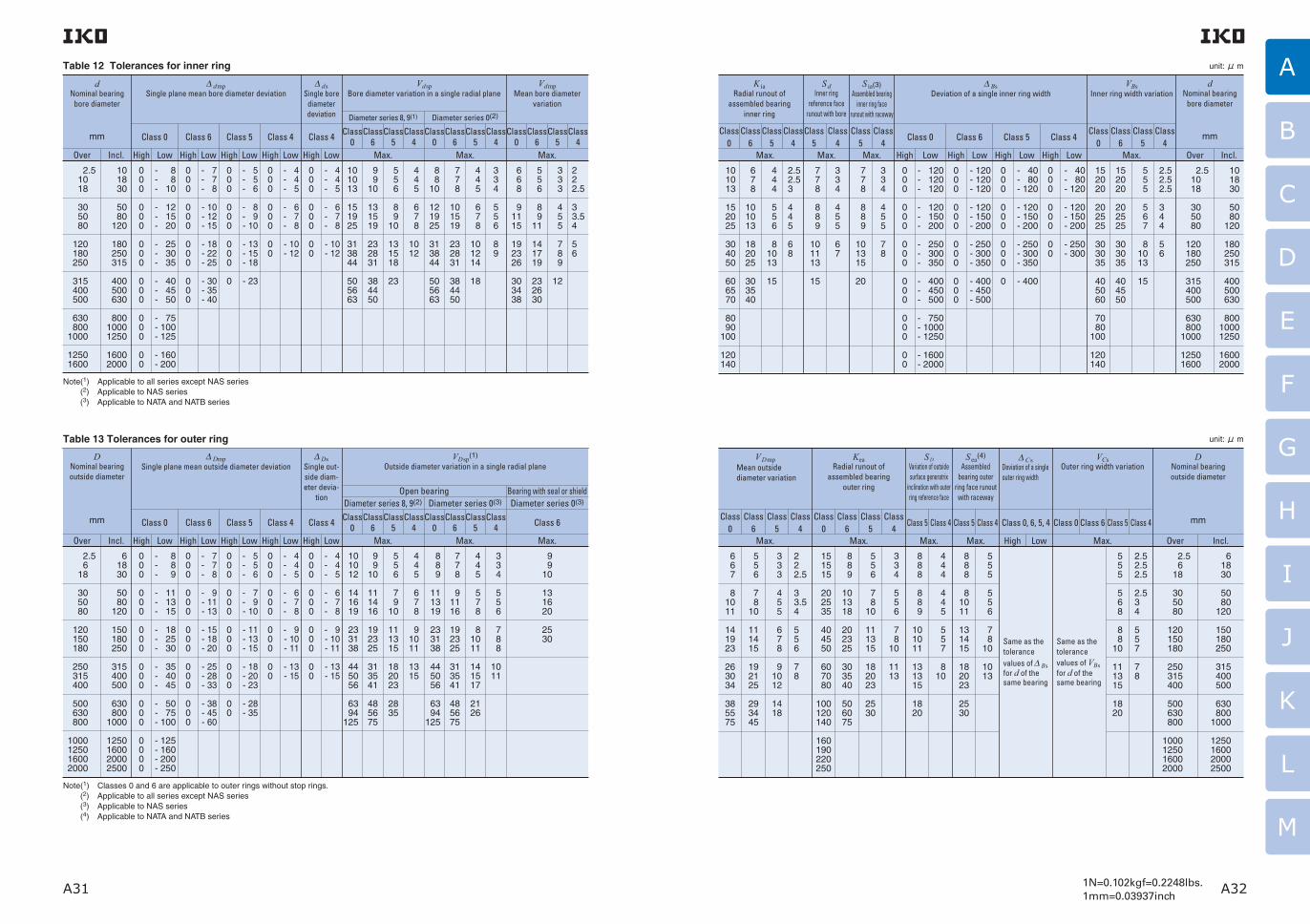
A31 A321N=0.102kgf=0.2248lbs.1mm=0.03937inch
A
B
C
D
E
F
G
H
I
J
K
L
M
Table 12 Tolerances for inner ring
dNominal bearing
bore diameter
mm
∆ dmpSingle plane mean bore diameter deviation
∆ dsSingle bore
diameter deviation
VdspBore diameter variation in a single radial plane
VdmpMean bore diameter
variation
Diameter series 8, 9(1) Diameter series 0(2)
Over Incl. High HighLow High High High
Class 0 Class 6 Class 5 Class 4 Class 4 Class4
Class5
Class6
Class0
Class0
Class0
Class6
Class6
Class5
Class5
Class4
Class4
Low Low Low Low Max. Max. Max.
2.5 10 18
30 50 80
120 180 250
315 400 500
630 8001000
12501600
101830
5080
120
180250315
400 500 630
80010001250
16002000
000
000
000
000
000
00
000
000
000
000
- 7- 7- 8
- 10- 12- 15
- 18- 22- 25
- 30- 35- 40
- 5- 5- 6
- 8- 9- 10
- 13- 15- 18
- 23
- 4- 4- 5
- 6- 7- 8
- 10- 12
- 4- 4- 5
- 6- 7- 8
- 10- 12
000
000
000
0
000
000
00
000
000
00
101013
151925
313844
505663
9 910
131519
232831
384450
5 5 6
8 910
131518
23
4 4 5
6 7 8
1012
8 810
121925
313844
505663
7 7 8
101519
232831
384450
4 4 5
6 7 8
101214
18
334
556
89
6 6 8
91115
192326
303438
5 5 6
8 911
141719
232630
3 3 3
4 5 5
7 8 9
12
222.5
33.54
56
- 8- 8- 10
- 12- 15- 20
- 25- 30- 35
- 40- 45- 50
- 75- 100- 125
- 160- 200
Note(1) Applicable to all series except NAS series(2) Applicable to NAS series(3) Applicable to NATA and NATB series
dNominal bearing
bore diameter
mm
∆ BsDeviation of a single inner ring width
SdInner ring
reference face runout with bore
S ia(3)Assembled bearing
inner ring face runout with raceway
VBsInner ring width variation
Over Incl.High Low High High High
Class 0 Class 6 Class 5 Class 4Class
5Class
4Class
5Class
4Class
0Class
6Class
5Class
4Low Low LowMax. Max. Max.
2.5 10 18
30 50 80
120 180 250
315 400 500
630 8001000
12501600
101830
5080
120
180250315
400 500 630
80010001250
16002000
000
000
000
000
000
00
000
000
000
000
- 120- 120- 120
- 120- 150- 200
- 250- 300- 350
- 400- 450- 500
- 40- 80- 120
- 120- 150- 200
- 250- 300- 350
- 400
- 40- 80- 120
- 120- 150- 200
- 250- 300
000
000
000
0
000
000
00
7 7 8
8 8 9
101113
15
334
455
67
7 7 8
8 8 9
101315
20
334
455
78
152020
202525
303035
405060
7080
100
120140
152020
202525
303035
404550
5 5 5
5 6 7
81013
15
2.52.52.5
344
56
- 120- 120- 120
- 120- 150- 200
- 250- 300- 350
- 400- 450- 500
- 750- 1000- 1250
- 1600- 2000
unit: μ m
K iaRadial runout of
assembled bearing inner ring
Max.
101013
152025
304050
606570
8090
100
120140
6 7 8
101013
182025
303540
4 4 4
5 5 6
81013
15
2.52.53
445
68
Class 0
Class 6
Class 5
Class 4
Table 13 Tolerances for outer ring
DNominal bearing outside diameter
mm
∆ DmpSingle plane mean outside diameter deviation
∆ DsSingle out-side diam-eter devia-
tion
VDsp(1)
Outside diameter variation in a single radial plane
Diameter series 8, 9(2)Open bearing
Diameter series 0(3) Diameter series 0(3)Bearing with seal or shield
Over Incl. High HighLow High High High
Class 0 Class 6 Class 5 Class 4 Class 4 Class 6Class 4
Class 5
Class 6
Class 0
Class 4
Class 5
Class 6
Class 0
Low Low Low Low Max. Max. Max.
2.5 6 18
30 50 80
120 150 180
250 315 400
500 630 800
1000125016002000
61830
5080
120
150180250
315 400 500
630800
1000
1250160020002500
000
000
000
000
000
0000
000
000
000
000
000
- 7- 7- 8
- 9- 11- 13
- 15- 18- 20
- 25- 28- 33
- 38- 45- 60
- 5- 5- 6
- 7- 9- 10
- 11- 13- 15
- 18- 20- 23
- 28- 35
- 4- 4- 5
- 6- 7- 8
- 9- 10- 11
- 13- 15
- 4- 4- 5
- 6- 7- 8
- 9- 10- 11
- 13- 15
000
000
000
000
00
000
000
000
00
000
000
000
00
101012
141619
233138
445056
6394
125
9 910
111416
192325
313541
485675
5 5 6
7 910
111315
182023
2835
8 8 9
111319
233138
445056
6394
125
4 4 5
6 7 8
91011
1315
7 7 8
91116
192325
313541
485675
4 4 5
5 7 8
81011
141517
2126
3 3 4
5 5 6
7 8 8
1011
9 910
131620
2530
- 8- 8- 9
- 11- 13- 15
- 18- 25- 30
- 35- 40- 45
- 50- 75- 100
- 125- 160- 200- 250
Note(1) Classes 0 and 6 are applicable to outer rings without stop rings.(2) Applicable to all series except NAS series(3) Applicable to NAS series(4) Applicable to NATA and NATB series
DNominal bearing outside diameter
mm
S DVariation of outside surface generatrix
inclination with outer ring reference face
S ea(4)
Assembled bearing outer
ring face runout with raceway
∆ CsDeviation of a single outer ring width
KeaRadial runout of
assembled bearing outer ring
VCsOuter ring width variation
Over Incl.High Low
Class 0
Class 6
Class 5
Class 4
Class 5 Class 4 Class 5 Class 4 Class 0, 6, 5, 4 Class 6Class 0 Class 5 Class 4
Max. Max. Max. Max.
2.5 6 18
30 50 80
120 150 180
250 315 400
500 630 800
1000125016002000
61830
5080
120
150180250
315 400 500
630800
1000
1250160020002500
151515
202535
404550
607080
100120140
160190220250
8 8 8
8 8 9
101011
131315
1820
8 8 9
101318
202325
303540
506075
4 4 4
4 4 5
5 5 7
810
5 5 6
7 810
111315
182023
2530
8 8 8
81011
131415
182023
2530
3 3 4
5 5 6
7 810
1113
5 5 5
5 5 6
7 810
1013
Same as the tolerance values of ∆ Bs for d of the same bearing
Same as the tolerance values of VBs for d of the same bearing
5 5 5
5 6 8
8 810
111315
1820
2.52.52.5
2.534
557
78
unit: μ m
VDmpMean outside diameter variation
Class 0
Class 6
Class 5
Class 4
Max.
6 6 7
81011
141923
263034
385575
5 5 6
7 810
111415
192125
293445
3 3 3
4 5 5
6 7 8
91012
1418
222.5
33.54
556
78

A33 A341N=0.102kgf=0.2248lbs.1mm=0.03937inch
A
B
C
D
E
F
G
H
I
J
K
L
M
Methods of Measurement
Measurement of IKO Needle Roller Bearings is based on JIS B 1515-1, -2 (Roll ing bearings-Tolerances). Tables 16 and 17 show some examples of the methods.Special methods are used to measure Shell Type Needle Roller Bearings. Therefore, refer to the sec-tion on accuracy for these bearings on page B3.
Table 14 Tolerances for smallest single roller set bore diameter Fws min(1) unit: μm
3 6 10 18 30 50 80120180250315400
6 10 18 30 50 80120180250315400500
+ 18 + 22+ 27+ 33+ 41+ 49+ 58+ 68+ 79+ 88+ 98+ 108
+ 10+ 13+ 16+ 20+ 25+ 30+ 36+ 43+ 50+ 56+ 62+ 68
FwNominal roller set bore diameter
mm
Over Incl. High Low
∆ Fws minDeviation of smallest single roller set bore diameter
Note(1) This is the diameter of the cylinder used instead of the inner ring, where the radial clearance becomes 0 at least in one radial direction.
Measurement methods Accuracy and definitions
Single bore diameter
Zero the gauge indicator to the appropri-ate size using gauge blocks or a master ring.In several angular directions and in a sin-gle radial plane, measure and record the largest and the smallest single bore diam-eters, d sp max and d sp min, within the mea-suring zone (excluding the zone 1.2 times the respective maximum allowable cham-fer dimensions of the inner ring face).Repeat angular measurements and record-ings in several radial planes to determine the largest and the smallest single bore diameter, d s max and d s min.
1.2r
s max
1.2r
s max
dmpMean bore diameter
in a single plane
∆ dmp
Deviation of mean bore diameter in a single
plane
VdspVariation of bore diameter
in a single plane
VdmpVariation of mean
bore diameter
∆ ds
Deviation of a single bore diameter
Calculated mean value of the maximum and minimum values of the single bore diameter within a radial plane.
dmp =
d sp:Single bore diameter in a single plane
DmpMean outside
diameter in a single plane
Calculated mean value of the maximum and minimum values of the single outside diameter within a radial plane.
Dmp =
D sp:Single outside diameter in a single plane
Deviation of mean bore diameter in a single plane and nominal bore diameter.
∆ dmp = dmp − dd: Nominal bearing bore diameter
Deviation of the maximum and minimum values of the single bore diameter within a radial plane.Vdsp = d sp max − d sp min
Deviation of the maximum and minimum values of mean bore diameter in a single plane, for individual raceway rings with essentially cylindrical bore diameter surfaces.Vdmp = dmp max − dmp min
Deviation of single bore diameter and nominal bore diameter.∆ ds = d s − dd s:Single bore diameter (distance between two parallel straight lines touching
the intersection of the single bore diameter surface and the radial plane)
Single outside diameter
Zero the gauge indicator to the appropri-ate size using gauge blocks or a master.In several angular directions and in a sin-gle radial plane, measure and record the largest and the smallest single outside diameters, Dsp max and Dsp min, within the measuring zone (excluding the zone 1.2 times the respective maximum allowable chamfer dimensions of the outer ring face).Repeat and record measurements in sev-eral radial planes to determine the largest and the smallest single outside diameter, Ds max and Ds min.
1.2r
s max
1.2r
s max
d sp max+ d sp min
2
∆ Dmp
Deviation of mean outside diameter in a single plane
VDspVariation of outside
diameter in a single plane
VDmpVariation of mean outside diameter
∆ Ds
Deviation of a single outside diameter
Deviation of mean outside diameter in a single plane and nominal outside diameter.∆ Dmp = Dmp − DD:Nominal bearing outside diameter
Deviation of the maximum and minimum values of the single outside diameter within a radial plane.VDsp = D sp max − D sp min
Deviation of the maximum and minimum values of mean outside diameter in a single plane, for individual raceway rings with essentially cylindrical outside diameter surfaces.VDmp = Dmp max − Dmp min
Deviation of single outside diameter and nominal outside diameter.∆ Ds = D s − DD s:Single outside diameter (distance between two
parallel straight lines touching the intersection of the single outside diameter surface and the radial plane)
D sp max + D sp min
2
Table 16 Measurement methods of accuracy of boundary dimensions
Table 15 Permissible limit values for chamfer dimensions of radial bearings unit: mm
0.10.150.2
0.3
0.4(1)
0.6
1
1.1
1.5
2
2.1
2.5(1)
3
456
40
40
50
120
120
80220
280
100280
280
40
40
50
120
120
80220
280
100280
280
0.55(2) 0.6 (2) 0.7 (2) 0.8 (2) 0.8 0.8 1.1 (2) 1.3 1.5 1.9 2 2.5 2.3 3 3 3.5 3.8 4 4.5 3.8 4.5 5 5 5.5 6.5 810
0.55(2) 0.6 0.8 1 1 1.2 2 2 3 3 3.5 4 4 5 4.5 5 6 6.5 7 6 6 7 8 8 91013
r s minSmallest
permissible single chamfer dimension
dNominal bore diameter
r s maxLargest permissible single chamfer dimension
Note(1) Not specified in JIS.(2) The numeric value differs from JIS.
Remark Although the exact shape of the chamfer is not specified, its profile in the axial plane must not extend beyond the imaginary circular arc of radius rs min which is tangential to the inner ring side surface and bearing bore surface or to the outer ring side surface and bearing outside sur-face. (See Fig. 12.)
Over Incl. Radial direction Axial direction
Fig. 12 Permissible values for chamfer dimensions
(Rad
ial d
irect
ion)
(Axial direction)rs max
rs m
ax
rs min
rs min
rs m
inSi
de s
urfa
ce o
f in
ner r
ing
or
oute
r rin
g
Bearing bore or bearing outside surface

A35 A361N=0.102kgf=0.2248lbs.1mm=0.03937inch
A
B
C
D
E
F
G
H
I
J
K
L
M
Table 17 Measurement methods for rotational accuracy
Measurement methods Accuracy and definitions
Single bore diameter of rolling element complement
Fasten the master gauge to a surface plate.Position the bearing on the master gauge and apply the indicator in the radial direction near the middle of the width on the ring outside surface.Measure the amount of movement of the outer ring in the radial direction by applying sufficient load on the outer ring in the same radial direction as that of the indicator and in the opposite radial direction.Record indicator readings at the extreme radial posi-tions of the outer ring. Rotate the bearing and repeat the measurement in several different angular posi-tions to determine the largest and the smallest read-
ings, Fws max and Fws min.
Measuring load
Mastergauge
Fws
Single bore diameter of roller
complement
Fws min
Smallest single bore diameter of roller
complement
∆ Bs
Deviation of a single inner ring width
In radial bearings without inner rings, the distance between two parallel straight lines touching the intersection of the inscribed circle of roller complement and the radial plane.
In radial bearings without inner rings, the minimum value of the single bore diameter of roller complement.
Remark Diameter of a cylinder where the smallest single bore diameter of roller complement has zero radial clearance in at least one radial direction.
Deviation of single inner ring width and nominal inner ring width.
∆ Bs = B s − B
VBsVariation of inner
ring width
Deviation of the maximum and minimum values of the single inner ring width for individual inner rings.
VBs = B s max − B s min
∆ Cs
Deviation of a single outer ring width
Deviation of single outer ring width and nominal outer ring width.
∆ Cs = C s − C
VCsVariation of outer
ring width
Deviation of the maximum and minimum values of the single outer ring width for individual outer rings.
VCs = C s max − C s min
Outer ring width
Bearing height
Inner ring width
Zero the gauge indicator to the appropriate height from the reference surface using gauge blocks or a master.Support one face of the inner or outer ring on three equally spaced fixed supports of equal height and provide two suitable radial supports on the bore or outside surface set at 90° to each other to centre the inner or outer ring.Position the indicator against the other face of the ring opposite one fixed support.Rotate the inner or outer ring one revolution and measure and record the largest and the smallest single inner (outer) ring width, B s max and B s min, (C s max and C s min).
∆ Ts
Deviation of the actual bearing height
Deviation of actual bearing height and nominal bearing height of the thrust bearing.
∆ Ts = T s − T
T s:Actual bearing heightT :Nominal bearing height
Measurement methodsAccuracy
Sd
Perpendicularity of inner ring
face with respect to the
bore
SD
Perpendicularity of outer ring
outside surface with respect to
the face
K ia
Radial runout of inner ring of
assembled bearing
K ea
Radial runout of outer ring of
assembled bearing
S ia
Axial runout of inner ring of assembled
bearing
S ea
Axial runout of outer ring of assembled
bearing
Use a precision arbor having a taper of approximately 1 : 5 000 on diameter.Mount the bearing assembly on the tapered arbor and place the arbor between two centres so that it can be accurately rotated.Position the indicator against the reference face of the inner ring at a radi-al distance from the arbor axis of half the mean diameter of the face.Take indicator readings while rotating the inner ring one revolution.
Support the reference face of the outer ring on a surface plate leaving the inner ring, if an assembled bearing, free. Locate the outer ring cylindrical outside surface against two supports set at 90° to each other to centre the outer ring.Position the indicator directly above one support. The indicator and the two supports are axially located at the extremes of the measurement zone (positions 1.2 times the respective maximum allowable chamfer dimen-sions of the outer ring face).Take indicator readings while rotating the outer ring one revolution.
Use a precision arbor having a taper of approximately 1 : 5 000 on diameter.Mount the bearing assembly on the tapered arbor and place the arbor between two centres so that it can be accurately rotated.Position the indicator against the outside surface of the outer ring as close as possible to the middle of the outer ring raceway.Hold the outer ring to prevent rotation but ensure its weight is supported by the rolling elements. Take indicator readings while rotating the arbor one revolution.
Use a precision arbor having a taper of approximately 1 : 5 000 on diameter.Mount the bearing assembly on the tapered arbor and place the arbor between two centres so that it can be accurately rotated.Position the indicator against the outside surface of the outer ring as close as possible to the middle of the outer ring raceway.Hold the inner ring stationary. Take indicator readings while rotating the outer ring one revolution.
Support the reference face of the outer ring on a surface plate with a pilot for centering the outside diameter of the ring. Apply a dynamically stable coaxial load to the reference face of the inner ring in order to ensure con-tact between rolling elements and raceways.Position the indicator against the reference face of the inner ring and take indicator readings while rotating the inner ring one revolution.
Support the reference face of the inner ring on a surface plate with a pilot for centering in the bore of the inner ring. Apply a dynamically stable coaxial load to the reference face of the outer ring in order to ensure con-tact between rolling elements and raceways.Position the indicator against the reference face of the outer ring and take indicator readings while rotating the outer ring one revolution.
Support the bearing on a surface plate. Zero the
gauge indicator to an appropriate height from the sur-
face plate using gauge blocks or a master.
Place a plate of known thickness on the bearing
assembly, apply a dynamically stable coaxial load, and
position the indicator over the centre of the plate.
Rotate the housing washer several times, to be sure to
reach the smallest height, and take indicator readings.
Disk master
Stopper
1.2r
s max
1.2r
s max
Load on inner ring
Load on outer ring

A37 A381N=0.102kgf=0.2248lbs.1mm=0.03937inch
A
B
C
D
E
F
G
H
I
J
K
L
M
Selection of clearance
Radial clearances of needle roller bearings change according to bearing fit, temperature difference between bearing rings and rolling elements, loads, etc., and these factors greatly influence bearing life, accuracy, noise, generation of heat, etc. If radial clearances are too large, noise and vibration will increase, and if they are too small, abnormally great forces are exerted on the contact areas between raceways and rolling elements, resulting in abnormal-ly high heat generation and a decrease in bearing life. Therefore, in the ideal case, the clearance provided before mounting should be such that it will become zero or slightly larger when the bearing has reached steady-state operation and the temperature has become constant (saturation temperature). However, it is difficult to achieve this ideal state for all bearings. Under general operating conditions, bearings with CN clearance are most widely used, and are manufac-tured to provide satisfactory performance when fitted according to Tables 21 and 22.When radial internal clearances other than CN are used, refer to Table 19.
The clearances between the bearing rings and rolling elements are known as bearing clearances. When either the inner or outer ring is fixed and a specified measuring load is applied to the free bearing ring inward and outward alternately in the radial direction, the displacement of the free bearing is referred to as the radial internal clearance. The amount of measur-ing load in this case is extremely small, and its values are specified in JIS B 1515-2 (Rolling bearings-Toler-ances-Part2:Measuring and gauging principles and methods).
Reduction of radial clearances by fit
When the inner or outer rings are interference fitted onto shafts and into housings, respectively, they expand or shrink due to elastic deformation. As the result, the radial clearances are reduced. These reduced radial clearances are called residual (inter-nal) clearances.The amount of reduction is obtained by the following equation, and it is generally 70 to 90% of the interfer-ence amount.
Table 19 Examples of selecting radial internal clearances other than CN clearance
Operating conditions Selection of clearance
When heavy loads and shock loads are applied, and amount of interference is great.
C3 or larger clearance
C2 or smaller clearance
When directionally indeterminate loads are applied, and a tight fit is required for both inner and outer rings.
When temperature of inner ring is much higher than that of outer ring.
When shaft deflection and/or mounting error to the housing are great.
When less noise and vibration are required. When a loose fit is required for both inner and outer rings. When preload is required.
∆ C=∆ F+∆ E ………………………………(24)
where, ∆ C:Amount of reduction of the radial clearance, mm
∆ F:Amount of expansion of the out-side diameter of inner ring, mm
∆ E :Amount of shrinkage of the bore diameter of outer ring, mm
1 Amount of expansion of the outside diameter of inner ring
・With solid shaft
∆ F =∆ de ………………………………(25)
・With hollow shaft
∆ F =∆ de ……(26)
where, ∆ de :Effective interference of inner ring, mm d :Bore diameter of inner ring, mm F :Outside diameter of inner ring, mm d i :Bore diameter of hollow shaft, mm
2 Amount of shrinkage of the bore diameter of outer ring
・With steel housing(D0=∞)
∆ E=∆ De ………………………………(27)
・With steel housing(D 0≠∞)
∆ E=∆ De ……(28)
where, ∆ De :Effective interference of outer ring, mm D :Outside diameter of outer ring, mm E :Bore diameter of outer ring, mm D0 :Outside diameter of housing, mm
Reduction of radial clearances due to temperature differences between inner and outer rings
Frictional heat generated by rotation is dissipated through the shafts and housings as well as through oil and air. Under general operating conditions, heat dis-sipation is larger on the housing side compared with that on the shaft side, and the temperature of the outer ring is usually lower than that of the inner ring. During operation, the temperature of the rolling ele-ments is the highest, followed by that of the inner ring and that of the outer ring. The amount of thermal expansion, therefore, varies, and the radial clearances are reduced. This reduced radial clearance is called the effective (internal) clearance, and the amount of reduction is obtained by the following equation:
dF
dF
1− (d i/d)2
1− (d/F)2 (d i/d)2
ED
ED
1− (D/D0)2
1− (E/D)2 (D/D0)2
1 Table 18 shows the radial internal clearances of Needle Roller Bearings with Inner Ring based on JIS B 1520 (Rolling bearings-Radial internal clearance). The radial internal clearances are classified into C2, CN, C3, C4, and C5, with clearances increasing in this order. CN is used under normal operating condi-tions. When a smaller range in radial internal clear-ance than the values shown in Table 18 is required, please consult IKO.
2 In the case of Shell Type Needle Roller Bearings, the correct dimensional accuracy is achieved only after the bearings are press-fitted into the specified housing bore. Therefore, the clearances shown in Table 18 are not applicable. See page B5.
3 For the radial internal clearances of Cam Followers, Roller Followers and Crossed Roller Bearings, see the relevant section for each bearing.
Clearance
10 24 30 40 50 65 80100120140160180200225250280315355400450
10 24 30 40 50 65 80100120140160180200225250280315355400450500
0 0 0 5 5
1010
15 1515
20 2535
45 4555
55 65
100110110
25 25 2530
35 4045
50 5560
70 7590
105110125130145190210220
20 20 2025
30 4040
50 5060
70 7590
105110125130145190210220
45 45 4550
60 7075
85 90
105120125145165175195205225280310330
35 35 3545
50 6065
75 85
100115120140160170190200225280310330
60 60 6070
80 90
100110125145165170195220235260275305370410440
50 50 5060
70 8090
105125145165170195220235260275305370410440
7575
75 85
100110125140165190215220250280300330350385460510550
65 7080
95110130155180200225250275305330370410455510565625
90 95
105125140165190220245275300330365395440485535600665735
dNominal bore diameter
mm
Classification of clearances
C2 CN C3 C4 C5
Remark For bearings with CN clearance, no symbol is attached to the identification number. In the case of bearings with C2, C3, C4 and C5 clearances, these symbols are attached to the identification number.
Example NA 4905 C2
Table 18 Radial internal clearances of Needle Roller Bearings
Over Incl. Min. Max. Max. Max. Max. Max.Min. Min. Min. Min.
unit: μm
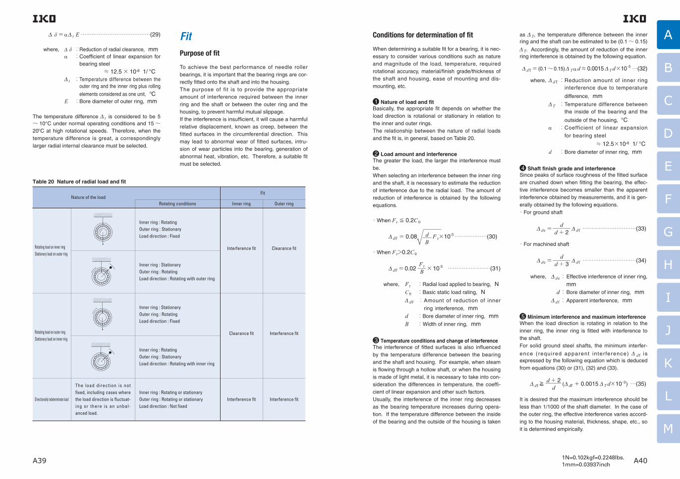
A39 A401N=0.102kgf=0.2248lbs.1mm=0.03937inch
A
B
C
D
E
F
G
H
I
J
K
L
M
∆δ=α∆ t E …………………………………(29)
where, ∆δ : Reduction of radial clearance, mm α : Coefficient of linear expansion for
bearing steel
≒ 12.5× 10⁻⁶ 1/ °C ∆ t : Temperature difference between the
outer ring and the inner ring plus rolling
elements considered as one unit, ° C E : Bore diameter of outer ring, mm
The temperature difference ∆ t is considered to be 5〜 10°C under normal operating conditions and 15〜20 °C at high rotational speeds. Therefore, when the temperature difference is great, a correspondingly larger radial internal clearance must be selected.
FitPurpose of fit
To achieve the best performance of needle roller bearings, it is important that the bearing rings are cor-rectly fitted onto the shaft and into the housing.The purpose of fit is to provide the appropriate amount of interference required between the inner ring and the shaft or between the outer ring and the housing, to prevent harmful mutual slippage.If the interference is insufficient, it will cause a harmful relative displacement, known as creep, between the fitted surfaces in the circumferential direction. This may lead to abnormal wear of fitted surfaces, intru-sion of wear particles into the bearing, generation of abnormal heat, vibration, etc. Therefore, a suitable fit must be selected.
Conditions for determination of fit
When determining a suitable fit for a bearing, it is nec-essary to consider various conditions such as nature and magnitude of the load, temperature, required rotational accuracy, material/finish grade/thickness of the shaft and housing, ease of mounting and dis-mounting, etc.
1 Nature of load and fitBasically, the appropriate fit depends on whether the load direction is rotational or stationary in relation to the inner and outer rings.The relationship between the nature of radial loads and the fit is, in general, based on Table 20.
2 Load amount and interferenceThe greater the load, the larger the interference must be.When selecting an interference between the inner ring and the shaft, it is necessary to estimate the reduction of interference due to the radial load. The amount of reduction of interference is obtained by the following equations.
・When F r≦ 0.2C0
∆ dF= 0.08 F r×10-3………………(30)
・When F r>0.2C0
∆ dF=0.02 ×10⁻³ ……………………(31)
where, F r :Radial load applied to bearing, N C0 :Basic static load rating, N ∆ dF :Amount of reduction of inner
ring interference, mm d :Bore diameter of inner ring, mm B :Width of inner ring, mm
3 Temperature conditions and change of interferenceThe interference of fitted surfaces is also influenced by the temperature difference between the bearing and the shaft and housing. For example, when steam is flowing through a hollow shaft, or when the housing is made of light metal, it is necessary to take into con-sideration the differences in temperature, the coeffi-cient of linear expansion and other such factors.Usually, the interference of the inner ring decreases as the bearing temperature increases during opera-tion. If the temperature difference between the inside of the bearing and the outside of the housing is taken
dB
F rB
dd+ 2
dd+ 3
d+ 2d
as ∆ T, the temperature difference between the inner ring and the shaft can be estimated to be (0.1〜 0.15)
∆ T. Accordingly, the amount of reduction of the inner ring interference is obtained by the following equation.
∆ dT= (0.1〜 0.15) ∆ Tαd≒ 0.0015 ∆ T d×10 -3 …(32)
where, ∆ dT : Reduction amount of inner ring interference due to temperature
difference, mm ∆ T : Temperature difference between
the inside of the bearing and the
outside of the housing, °C α : Coefficient of linear expansion
for bearing steel
≒ 12.5×10⁻⁶ 1/ °C d : Bore diameter of inner ring, mm
4 Shaft finish grade and interferenceSince peaks of surface roughness of the fitted surface are crushed down when fitting the bearing, the effec-tive interference becomes smaller than the apparent interference obtained by measurements, and it is gen-erally obtained by the following equations.・For ground shaft
∆ de= ∆ d f …………………………(33)
・For machined shaft
∆ de= ∆ d f …………………………(34)
where, ∆ de : Effective interference of inner ring, mm
d: Bore diameter of inner ring, mm ∆ d f : Apparent interference, mm
5 Minimum interference and maximum interferenceWhen the load direction is rotating in relation to the inner ring, the inner ring is fitted with interference to the shaft. For solid ground steel shafts, the minimum interfer-
ence (required apparent in ter ference) ∆ d f is expressed by the following equation which is deduced from equations (30) or (31), (32) and (33).
∆ df ≧ (∆ dF+ 0.0015 ∆ T d×10 -3) …(35)
It is desired that the maximum interference should be less than 1/1000 of the shaft diameter. In the case of the outer ring, the effective interference varies accord-ing to the housing material, thickness, shape, etc., so it is determined empirically.
Table 20 Nature of radial load and fit
Nature of the loadFit
Inner ringRotating conditions Outer ring
Rotating load on inner ringStationary load on outer ring
Rotating load on outer ringStationary load on inner ring
Directionally indeterminate load
The load direction is not fixed, including cases where the load direction is fluctuat-ing or there is an unbal-anced load.
Inner ring : RotatingOuter ring : StationaryLoad direction : Fixed
Inner ring : StationaryOuter ring : RotatingLoad direction : Rotating with outer ring
Inner ring : StationaryOuter ring : RotatingLoad direction : Fixed
Inner ring : RotatingOuter ring : StationaryLoad direction : Rotating with inner ring
Inner ring : Rotating or stationaryOuter ring : Rotating or stationaryLoad direction : Not fixed
Interference fit
Clearance fit
Interference fit
Clearance fit
Interference fit
Interference fit

A41 A421N=0.102kgf=0.2248lbs.1mm=0.03937inch
A
B
C
D
E
F
G
H
I
J
K
L
M
Selection of fit
When selecting a suitable fit, in addition to the various conditions mentioned above, it is necessary to draw on experience and practical results.Tables 21 and 22 show the most general fit data.When a thin housing or a hollow shaft is used, the interference is made larger than an ordinary fit.The fit between needle roller bearings without inner ring and shafts is based on Table 23.For the fit between Shell Type Needle Roller Bearings and housing bores, see page B5.For the fit between inner rings for Shell Type Needle Roller Bearings and shafts, see Table 22.
Table 21 Fit between needle roller bearings and housing bores (Not applicable to Shell Type Needle Roller Bearings)
Operating conditionsTolerance class of housing bore(1) Application examples (Reference)
Rotating load on outer ring
D i r e c t i o n a l l y i n d e t e r m i n a t e load
Stationary load on outer ring
Light load, normal load, requirements of high-precision rotation and high rigidity
Heavy load on thin housing, large shock load
Heavy load, normal load
Light load, fluctuating load
Large shock load
Heavy load, normal load
Normal load, light load
Shock load, heavy load
Normal load, light load
With heat conduction through shaft
P7(2)
N7(2)
M7
M7
K7
J7
J7
H7
G7
K6
Flywheels
Wheel bosses, transmission gears
Pulleys, tension pulleys
Eccentric wheels, pumps
Compressors
Crankshafts, compressors
General bearing applications, gear shafts
General bearing applications
Paper dryers
Main spindles of machine tools
Notes(1) This table applies to steel or cast iron housings. For lighter metal, a tighter fit should be selected.For split housings, do not use a fit tighter than J7.
(2) Care should be taken so that the radial internal clearance is not too small.Remark Light load, normal load and heavy load represent P≦ 0.06C, 0.06C<P≦ 0.12C, and 0.12C<P, respectively, where P is the
dynamic equivalent radial load and C is the basic dynamic load rating of the bearing to be used.
Table 22 Fit between needle roller bearings with inner ring and shafts
Operating conditionsShaft dia. mm
Over Incl.
Tolerance classof shaft(1)
Application examples (Reference)
Stationary load on inner ring
Light load, normal load, low or medium rotating speed
All shaft diameters
g6
h6
h5
Wheels on dead axles
Control lever gears
Rope sheaves
Tension pulleys
Electric appliances, Precision machinery
Machine tools, Pumps
Blowers, Transportation vehicles
General bearing applications
Pumps, Transmission gearboxes,
Wood working machinery, Internal combustion engines
Industrial vehicles, Construction machineryCrushers
−50100200
−50150200
−150
50100200−50
150200−
150−
j5k5m6(2)n6(3)
k5(4)m5,m6(2)n6(3)p6(3)
n6(3)p6(3)
Heavy load, medium rotating speed
Especially smooth operation and accuracy are required.
Light load
Normal load
Heavy loadShock load
Rotating load on inner ring or Direct ional ly indeterminate load
Notes(1) This table applies to solid steel shafts.(2) It is necessary to examine the reduction of radial internal clearances caused by the expansion of inner rings after mounting.(3) It is necessary to use bearings with radial internal clearances greater than CN clearance.(4) For NATA and NATB, do not use a tighter fit than k5.
Table 23 Tolerance class of shafts assembled with needle roller bearings without inner ring
Note(1) When the housing bore fit is tighter than K7, the shaft diameter is made smaller by considering shrinkage of roller set bore diameter after mounting.
FwNominal roller set bore diameter
mm
Radial internal clearance
Smaller than CN clearance CN clearance Larger than CN clearance
Over Incl. Tolerance class of shaft(1)
−6580
160180200
250315
6580
160
k5k5k5
k5j5j5
h5g5
h5h5g5
g5g5f6
f6f6
g6f6f6
e6e6e6
e6d6
180200250
315−

A43 A441N=0.102kgf=0.2248lbs.1mm=0.03937inch
A
B
C
D
E
F
G
H
I
J
K
L
M
Design of Shaft and HousingAccuracy and roughness of shaft and housing
Accuracy and roughness of fitting surface
Since the bearing rings of needle roller bearings are thin, their performance is easily affected by poor accuracy of shafts or housings. Under general oper-ating conditions, the fitting surfaces of shafts and housings can be finished by lathe turning. However, when the load is great and high accuracy and low noise are required, a grinding finish is required.Table 26 shows the accuracy and roughness of fitting surfaces for general use.
Accuracy and roughness of raceway surface
In case of needle roller bearings unlike other bear-ings, mating surfaces such as shaft and housing bore surfaces can be used directly as the raceway sur-faces. For such use, accuracy and roughness of the raceway surfaces are important because they will influence bearing life, noise and accuracy.In general, accuracy and roughness of raceway sur-faces are based on Table 26.
Inclination of shaft
Shafts and outer rings may have some inclination between them due to deflection of the shaft, machin-ing accuracy of shafts and housings, errors in mount-ing, etc.In this case, the use of two or more bearings in tan-dem arrangement on a single shaft should be avoid-ed. Instead, a bearing with large load ratings should be used.It is recommended that inclination of shafts be less than 1/1000.
Table 27 Tolerance class IT values for basic dimensions
Basic dimension
mm
Over Incl.
Tolerance class(1)
IT5
Tolerance μmIT6 IT7
−36
1018305080
120180250315400500
36
1018305080
120180250315400500630
45689
111315182023252730
689
1113161922252932364044
1012151821253035404652576370
Table 26 Specifications of shafts and housings for radial needle roller bearings
ItemShaft
Fitting surface Raceway surface Raceway surfaceFitting surface
Housing bore
Circularity0.3 × IT6(1)
or0.3 × IT5(1)
0.5 × IT6(2)or
0.5 × IT5(2)
0.8(3.2)
−
0.3 × IT6(1)or
0.3 × IT5(1)
0.3 × IT6(1)or
0.3 × IT5(1)
0.2(3)(0.8)
58 〜 64HRC(4)
0.3 × IT7(1)or
0.3 × IT6(1)
0.5 × IT7(2)or
0.5 × IT6(2)
1.6(6.3)
−
0.3 × IT7(1)or
0.3 × IT6(1)
0.3 × IT7(1)or
0.3 × IT6(1)
0.2(3)(0.8)
58 〜 64HRC(4)
Cylindricity
Surface roughnessμ mRa (μ mRy)
Hardness
Notes(1) 30% or less of the dimensional tolerance for shafts or housing bores is recommended.(2) 50% or less of the dimensional tolerance for shafts or housing bores is recommended.(3) When required accuracy is not critical, a surface roughness within 0.8 μmRa (3.2 μmRy ) is allowable.(4) An appropriate thickness of the hardened layer is required.
Remark For tolerance class IT, see Table 27.
Table 24 Fit values for radial bearings (JIS Class 0) (Fit with housing bore)
DNominal outside
diameter
mm
∆ Dmp
Single plane mean outside diameter
deviation
G7 H7 J7 K6 K7 M7 N7 P7
Over
36
1018305080
120150180250315400
61018305080
120150180250315400500
0000000000000
- 8- 8- 8- 9-11-13-15-18-25-30-35-40-45
- 24〜 - 4- 28〜 - 5- 32〜 - 6- 37〜 - 7- 45〜 - 9- 53〜 -10- 62〜 -12- 72〜 -14- 79〜 -14- 91〜 -15-104〜 -17-115〜 -18-128〜 -20
- 20〜 0- 23〜 0- 26〜 0- 30〜 0- 36〜 0- 43〜 0- 50〜 0- 58〜 0- 65〜 0- 76〜 0- 87〜 0- 97〜 0-108〜 0
-14〜 6-16〜 7-18〜 8-21〜 9-25〜 11-31〜 12-37〜 13-44〜 14-51〜 14-60〜 16-71〜 16-79〜 18-88〜 20
-10〜 6-10〜 7-10〜 9-11〜 11-14〜 13-17〜 15-19〜 18-22〜 21-29〜 21-35〜 24-40〜 27-47〜 29-53〜 32
-11〜 9-13〜 10-14〜 12-15〜 15-18〜 18-22〜 21-25〜 25-30〜 28-37〜 28-43〜 33-51〜 36-57〜 40-63〜 45
- 8〜 12- 8〜 15- 8〜 18- 9〜 21-11〜 25-13〜 30-15〜 35-18〜 40-25〜 40-30〜 46-35〜 52-40〜 57-45〜 63
- 4〜 16- 4〜 19- 3〜 23- 2〜 28- 3〜 33- 4〜 39- 5〜 45- 6〜 52-13〜 52-16〜 60-21〜 66-24〜 73-28〜 80
0〜 20 1〜 24 3〜 29 5〜 35 6〜 42 8〜 51 9〜 5910〜 68 3〜 68 3〜 79 1〜 88 1〜 98 0〜 108
Incl. High Low
Remark The negative value denotes a clearance and the positive value denotes an interference.
Hous
ing
Bearing
Hous
ing
Bearing
Hous
ing
Bearing
Hous
ing
Bearing
Hous
ing
Bearing
Hous
ing
Bearing
Hous
ing
Bearing
Hous
ing
Bearing
unit: μm
Table 25 Fit values for radial bearings (JIS Class 0) (Fit with shaft) d
Nominal bore diameter
mm
∆ dmp
Single plane mean bore diameter
deviation
g6 h5 h6 j5 k5 m5 m6 n6 p6
Over Incl. High Low
36
1018305080
120140160180200225250280315355400450
61018305080
120140160180200225250280315355400450500
0000000
0
0
0
0
0
-25 -39〜 11 -18〜 25 -25〜 25 -11〜 32 3〜 46 15〜 58 15〜 65 27〜 77 43〜 93
-30 -44〜 15 -20〜 30 -29〜 30 -13〜 37 4〜 54 17〜 67 17〜 76 31〜 90 50〜 109
-35 -49〜 18 -23〜 35 -32〜 35 -16〜 42 4〜 62 20〜 78 20〜 87 34〜 101 56〜 123
-40 -54〜 22 -25〜 40 -36〜 40 -18〜 47 4〜 69 21〜 86 21〜 97 37〜 113 62〜 138
-45 -60〜 25 -27〜 45 -40〜 45 -20〜 52 5〜 77 23〜 95 23〜 108 40〜 125 68〜 153
- 8- 8- 8-10-12-15-20
-12〜 4-14〜 3-17〜 2-20〜 3-25〜 3-29〜 5-34〜 8
- 5〜 8- 6〜 8- 8〜 8- 9〜 10-11〜 12-13〜 15-15〜 20
- 8〜 8- 9〜 8-11〜 8-13〜 10-16〜 12-19〜 15-22〜 20
- 2〜 11- 2〜 12- 3〜 13- 4〜 15- 5〜 18- 7〜 21- 9〜 26
1〜 141〜 151〜 172〜 212〜 252〜 303〜 38
4〜 176〜 207〜 238〜 279〜 32
11〜 3913〜 48
4〜 206〜 237〜 268〜 319〜 37
11〜 4513〜 55
8〜 2410〜 2712〜 3115〜 3817〜 4520〜 5423〜 65
12〜 2815〜 3218〜 3722〜 4526〜 5432〜 6637〜 79
Remark The negative value denotes a clearance and the positive value denotes an interference.
Shaft
Bear
ing
Shaft
Bear
ing
Shaft
Bear
ing
Shaft
Bear
ing
Shaft
Bear
ing
Shaft
Bear
ing
Shaft
Bear
ing
Shaft
Bear
ing
Shaft
Bear
ing
unit: μm
Note(1) Based on JIS B 0401.

A45 A461N=0.102kgf=0.2248lbs.1mm=0.03937inch
A
B
C
D
E
F
G
H
I
J
K
L
M
Raceway materials and heat treatment
When using shafts and housings as raceways, the fol-lowing materials are generally used. High-carbon chromium bearing steel
SUJ2 JIS G 4805 Carburizing steel SCM415〜 421 JIS G 4053 Carburizing steel SNCM 220 JIS G 4053 Carburizing steel SCr 420 JIS G 4053 Carburizing steel SNC 415, 815 JIS G 4053 Carburizing steel S 15 CK JIS G 4051In addition, S50C and S55C (JIS G 4051) can be used after through hardening or induction hardening.The hardened layer produced by tempering at +160〜+180°C after hardening must have a fine uniform martensite microstructure.When hardening the raceway surface by case hard-ening or induction hardening, a surface hardness of 58 〜 64HRC and an appropriate thickness of the hardened layer must be ensured. The minimum effective thickness of the hardened layer after heat treatment and grinding is defined as the distance from the surface to the depth where the hardness is 550HV, and it is obtained by the following equation.
Eht≧ 0.8Dw(0.1+ 0.002Dw) ……………(36)
where, Eht: Minimum effective thickness of
the hardened layer, mm Dw:Roller diameter, mmGenerally, the required effective thickness of the hardened layer is at least 0.3 mm.
Dimensions related to mounting of bearings
The dimensions of shaft and housing related to mounting of the needle roller bearings are shown in the table of dimensions for each bearing. (See Fig. 13.)
The minimum value of the shaft shoulder diameter d a which receives the inner ring, and the maximum value
of the housing shoulder diameter D a which receives the outer ring, represent the effective shoulder diame-ters (excluding the chamfered part) which make prop-er contact with the side faces of the inner and outer rings respectively.Also, the maximum value of the shaft shoulder (or
inner ring retaining piece) diameter d a is the dimen-sion related to the ease of mounting/dismounting of the shaft and inner ring to/from the housing and outer ring.
The largest permissible single corner radius r as max of the shaft and housing must be smaller than the small-
est permissible single chamfer dimension r s min of the bearing so that the side surface of the bearing can make proper contact with the shoulder. Table 28 shows the related dimensions.For dimensions of the fillet relief when finishing the shaft or housing by grinding, the values shown in Table 29 are recommended.For other dimensions related to mounting, see the related section for each bearing as required.In addition, for ease in dismounting of bearings, it is convenient to make notches in the shoulder of the shaft or housing to allow the insertion of dismounting hooks.
entry of harmful foreign substances, such as dirt, dust and water. For this reason, sealing devices must always work effectively to seal and prevent against dust penetration under all operating conditions. Also, when selecting a suitable sealing method, it is neces-sary to consider such factors as the type of lubricant, peripheral speed of the seal, operating temperature, shaft eccentricity, seal friction, etc. as well as ease of assembly and disassembly.Sealing methods are of the non-contact and contact types, and it is necessary to select the appropriate type depending on the application.
Non-contact type sealing method
There are many methods of non-contact type sealing, including the use of oi l grooves, f l ingers and labyrinths, which utilize the centrifugal force and nar-row gaps.Since they do not make direct contact with the shaft or housing, it is unnecessary to consider friction and wear, and the non-contact sealing method is suitable for high speed rotation and high operating tempera-tures. However, because of gaps, this method is not always sufficient in preventing oil leakage and dust entry when the machine is not in operation.
1 Oil grooveOil grooves are provided on either the shaft or hous-ing bore, or on both for more effective sealing (See Fig. 14.). The clearance between the shaft and the housing bore should be as small as possible, and the values shown in Table 30 are generally used, taking into consideration errors in machining and assembly, shaft deformation, etc. Three or more grooves are made with a width of 3〜 5 mm and a depth of 4〜 5 mm. If the grooves are filled with grease, it will be more effective for dust prevention.As shown in Fig. 15, helical grooves are suitable for horizontal shafts which have a fixed direction of rota-tion. Right or left handed grooves are used according to the direction of rotation, and they are used for oil lubrication normally in conjunction with a suitable anti-dust device.
Sealing
To obtain the best performance of rolling bearings, it is necessary to prevent leakage of lubricant and the
Fig. 13 Dimensions related to mounting
da Da
Fig. 14(1) (2) (3)
Table 29 Fillet relief dimensions for ground shafts and housings unit: mm
r s minSmallest permissible
single chamfer dimension
Fillet relief dimensions
t rgs b
11.11.522.134567.5
0.20.30.40.50.50.50.50.60.60.6
1.31.522.52.534567
2 2.4 3.2 4 4 4.7 5.9 7.4 8.610
h
rs min
b
trgs
Table 28 Largest permissible single corner radius of shafts and housings ras max
r s minSmallest permissible
single chamfer dimension
0.10.150.20.30.40.611.11.522.12.5345
0.10.150.20.30.40.6111.52222.534
r as maxLargest permissible single corner radius of shafts and
housings
unit: mm
Housing
Shaft
rs min
rs min
ras max
ras max
rs m
inrs
min

A47 A481N=0.102kgf=0.2248lbs.1mm=0.03937inch
A
B
C
D
E
F
G
H
I
J
K
L
M
Table 30 Clearance between grooved shaft and housing bore unit: mm
Shaft dia.
Incl. 50 mm
Over 50 mm
Clearance
0.25〜 0.4
0.5 〜 1
Fig. 17
Fig. 18
3 LabyrinthAlthough it is a little difficult to make, the labyrinth is very effective in preventing oil leakage especially at high speeds. At low speeds, filling the labyrinth with grease is effective in preventing the entry of dust. In Fig. 17, it is necessary to split the housing or cover plate into two. In Fig. 18, it is easy to assemble, and if combined with an oil seal, it improves the sealing effect.Table 31 shows the labyrinth clearances generally used.
Table 31 Labyrinth clearance unit: mm
Shaft dia.
Incl. 50 mm
Over 50 mm
Clearance
0.25〜 0.4
0.5 〜 1
1〜 2
3〜 5
Radial direction Axial direction
Contact type sealing method
In this type of sealing, the shaft is sealed by the appli-cation of pressure resulting from the elasticity of the seal material to the sealing surface of the shaft, which rotates, reciprocates or oscillates. Synthetic rubber, synthetic resin and felt are generally used as sealing materials.
1 Oil sealSynthetic rubber oil seals are the most general type of sealing used. The sealing effect is obtained when the elastic lip comes into contact with the shaft. Some lips are spring-loaded to maintain adequate pressing force.The sliding surfaces of the lip and the shaft always show frictional behavior such that the boundary lubri-cation and fluid lubrication are mixed. If there is an insufficient amount of oil between the contact sur-faces, it will cause heat generation, wear and seizure. Conversely, if the oil film is too thick, it may cause oil leakage.General oil seals are specified in JIS B 2402-1~5. IKO Oil Seals for Needle Roller Bearings (See page L1.) have a low sectional height to match the Needle Roller Bearings.Nitrile rubber is generally used as the material for oil seal lips. Table 32 shows the materials and their operating temperature ranges.The finished surface of the shaft where the seal lip makes contact must have an appropriate surface roughness, as shown in Table 33, according to the peripheral speed. It must also have accurate circular-ity, and the shaft eccentricity should be less than 0.05 mm.To increase wear resistance, the hardness of the slid-ing part of the shaft must be more than 40HRC. This can be achieved by hard-chrome plating or heat treat-ment.
Table 32 Seal materials and operating temperatures
Seal material
Synthetic rubber
Nitrile rubber
Acrylic rubber
Silicon rubber
Fluoro rubber
Tetrafluoethylene resin
Operating temperature range
− 25〜+ 120
− 15〜+ 130
− 50〜+ 180
− 10〜+ 180
− 50〜+ 220
Table 33 Peripheral speed and surface roughness of shaft
Peripheral speed m/ s
Over Incl.
− 5
10
5
10
−
0.8(3.2)
0.4(1.6)
0.2(0.8)
Surface roughness
μ mRa( μ mRy)
2 Felt sealBecause of their simple structure, felt seals have long been used to protect grease lubrication from dust. Since felt absorbs some grease during operation, it hardly causes heat generation and seizure, but it can-not be used when the peripheral speed of the shaft is high (more than 4 m/s). Where there is a high con-centration of dirt and dust, they may become attached to the contact surface of felt, sometimes scratching the shaft surface. To prevent this, two felt seals are placed apart from each other, or a felt seal is used together with a synthetic rubber seal.
(1)
(2)
2 FlingerThe oil flinger is a disk attached to the shaft which throws off oil due to the centrifugal force of rotation and thus prevents oil leakage and the entry of foreign particles. Fig. 16 (1) shows an example in which the flinger is located inside the housing, mainly to prevent oil leakage. Since it sucks in dust and dirt, it should be used in a dust free environment. Fig. 16 (2) shows an example in which the flinger is located outside the housing, and is used in combination with another sealing device, to prevent entry of foreign particles.
Fig. 15
Fig. 16
(1)
(2)

A49 A501N=0.102kgf=0.2248lbs.1mm=0.03937inch
A
B
C
D
E
F
G
H
I
J
K
L
M
Lubrication Methods of lubrication
Grease lubrication and oil lubrication are generally used for rolling bearings. In special cases, solid lubri-cants are also used.In general, grease lubrication requires the simplest sealing device. It is therefore economical, and widely used. Also, once filled with grease, the bearing can be used for a long period without replenishing the grease. However, compared with oil, its heat removal properties and cooling capacity are inferior, since grease has high flow resistance, which causes high churning heat.Oil has greater fluidity and superior heat removal properties. It is therefore suitable for high-speed operations. In addition, it is simple to filter out dust and dirt from oil. Thus it can prevent the generation of noise and vibration and increase bearing life. Another advantage of oil lubrication is that it offers the possibility for selecting the appropriate method for particular operating conditions from among various available lubrication methods. However, measures to prevent oil leakage are required. As a guideline for selection, Table 34 compares grease and oil lubrica-tion.For the lubricants used for IKO Spherical Bushings, see page K8.
Purpose of lubrication
The main purpose of bearing lubrication is to reduce friction and wear and to prevent heat generation and seizure. The lubricant and the lubricating method have a big influence on the operating performance of the bearing, and it is therefore necessary to select them suitably for the operating conditions.The effects of lubrication are as follows.
1 Reduction of friction and wearAt the contact surfaces between the race rings, rolling elements and cage of the bearing, lubrication pre-vents metal-to-metal contact, and reduces friction and wear due to sliding and rolling, in the latter of which micro-slips occur by differential slip, skew, spin, or elastic deformation.
2 Elimination of frictional heatThe lubricant removes the heat generated by friction or transferred from outside, and prevents overheating of the bearing. Circulating lubrication is generally used for this purpose.
3 Influence on bearing lifeThe bearing life is extended if the rolling contact sur-faces between the race rings and rolling elements are separated by an oil film of adequate thickness, and is shortened if the oil film is inadequate due to low oil viscosity, etc.
4 Rust preventionThe lubricant prevents rust formation on the inside and outside surfaces of the bearing.
5 Dust preventionGrease lubrication is particularly effective for dust pre-vention. Oil circulating or jet lubrication is effective in washing foreign particles away from the area around the bearing.
Table 34 Comparison between grease lubrication and oil lubrication
Item
Sealing, Housing structure
Temperature
Rotational speed
Load
Maintenance
Lubricant replacement
Lubrication performance
Dust filtration
Entry of dust and dirt
Grease lubrication(1) Oil lubrication
Simple
High temperature not allowed
Low and medium speeds
Low and medium loads
Easy
Slightly complicated
Good
Difficult
Easy measures for protection
Slightly complicated
High temperature allowed (Cooling effect by circulation)
High speed allowed
High load allowed
Elaborate(Pay special attention to oil leaks. )
Simple
Very good
Simple
Dust and dirt can be removed by filtering in circulating lubrication.
Note(1) This represents bearing grease for general use.
Grease lubrication
1 Amount of grease to be filledThe amount of grease to be filled depends on the housing structure, dimensions, type of grease used and atmosphere. Generally, filling about 1/3 to 1/2 of the free space inside of the bearing and the housing is considered to be appropriate. Too much will cause a rise in temperature, and care should be taken espe-cially at high speed rotations.In Fig. 19, several grease pockets are provided by the grease sectors on one side of the bearing. Even if the filled grease is dispersed by the centrifugal force at high rotational speeds, it is trapped by the grease pockets and diverted back into the bearing again. Old grease accumulates in the space on the opposite side of the bearing, and this can be removed periodically by taking off the cover.
2 Replenishment of greaseThe life of grease depends on its type and quality, the type and dimensions of the bearing, operating condi-tions, temperature, amount of wear, penetration of for-eign particles and water, etc.Fig. 20 shows the replenishment intervals for grease, and is used as a general guideline. The values obtained from this diagram apply to cases in which the load condition is normal, the machine body is sta-tionary, and the operating temperature on the outer surface of bearing outer ring is less than +70°C. If the temperature exceeds +70°C, as a general rule, the replenishment interval is halved for every 15°C increase.
Fig. 20 Interval for replenishment of grease
Fig. 19
Remark d is the bore diameter of the inner ring. For a bearing without an inner ring, the roller set bore
diameter Fw is used for d .
Rep
leni
shm
ent i
nter
val f
or g
reas
e,
tf
hour
s
Rotational speed, n min-1
200200
300
400500600
800
1000
1500
2000
3000
4000
50006000
8000
10000
15000
20000
400 600 1000 2000 4000 6000 10000
d=10m
m203040506080100120
140160180200240
280
300

A51 A521N=0.102kgf=0.2248lbs.1mm=0.03937inch
A
B
C
D
E
F
G
H
I
J
K
L
M
Oil lubrication
1 Oil bath lubricationThis is the most commonly used oil lubrication method, and is used for medium and low speeds. If the amount of oil is too large, heat will be generated by churning, and if the amount is too small, seizure will occur. Therefore, the correct amount of oil must be maintained. When the machine is stationary, the correct oil level in the case of a bearing mounted on a horizontal shaft, is near the center of the lowest rolling element. In the case of a vertical shaft, about 50% of the surfaces of the rolling elements should be sub-merged in oil.It is desirable to provide an oil gauge so that the oil level can be easily checked while the machine is sta-tionary or running.
2 Oil drip lubricationOil drips, which are fed down from a sight-feed oiler or along a fiber string, become an oil spray due to wind pressure generated by the rotating cage, shaft, nut, etc., or they strike the rotating parts and form an oil spray, which fills up the housing and every required part. Because oil spray removes frictional heat, this method has a more effective cooling effect than the oil bath method, and is widely used for high-speed rota-tion and medium load conditions.In the case of the sight-feed oiler (Fig. 21), the num-ber of drips can be adjusted. However, this is difficult using the string-feed method. The number of drips depends on the bearing type, rotational speed, etc., but 5 〜 6 drips per minute is generally used.
3 Oil splash lubricationIn this method, oil is splashed in all directions by the rotation of the gear or disk. This can be used for con-siderably high-speed rotations without soaking the bearing directly in oil.In the gear case where shafts and bearings are lubri-cated with the same oil, wear particles may be intro-duced into the bearing as they might get mixed with the oil. In this case, a permanent magnet is provided at the bottom of the gear case to collect metal parti-cles, or a shield plate is installed next to the bearing.Fig. 22 shows another method in which the splashed
4 Oil circulating lubricationWhen automatic lubrication is more economical because lubrication is required at many points, or when cooling is required for high rotational speed, this method is used. The oil is supplied with a pump, which can control the oil pressure, and a filter or cool-er, etc. can be set up in the circulation system, mak-ing this an ideal method of lubrication. As shown in Fig. 23, the oil supply and discharge ports are located opposite to each other, and the discharge port is made large to prevent the accumulation of oil.
5 Oil mist lubricationAfter dirt and dust are removed by a filter, the oil is turned into a spray by dry compressed air, and this lubricates the bearing. When the air and oil pass through the bearing, the air cools the bearing and the oil lubricates it. In addition, because the air inside the housing is at a higher pressure than the outside air, the entry of water and foreign particles is prevented. There are many other advantages of this method, and it is suitable for high rotational speed applications such as high speed internal grinding spindles.
6 Oil jet lubricationThis is a highly reliable lubrication method and is used under severe conditions such as ultra-high rotational speeds and high temperatures. The speed of the oil jet should be more than 20% of the peripheral speed of the inner ring raceway surface, since the air around
the bearing rotates together with the bearing forming an air wall. As shown in Fig. 24, the jet from the noz-zle blows directly into the space between the inner ring and the cage. Due to the large amount of oil being used, it is more effective to make the discharge port larger, and use the forced discharge.
When the dmn value (mean value of the bearing out-side and bore diameters in millimeter x rotational speed in min-1) is more than 1,000,000, the speed of the jet should be 10〜 20 m/s, the nozzle diameter should be about 1 mm, oil supply pressure should be 0.1〜 0.5 MPa, and the oil supply amount should be about 500 cc/min or greater. When the rotational speed is higher, the oil supply pressure and the oil amount should be higher.
Lubricants
For rolling bearings, lubricating grease or oil is gener-ally used. For special applications, solid lubricants are used.
Lubricating grease
Grease is a semi-solid lubricant made by mixing base oil (liquid lubricant) and a thickener under heat and adding additives as required.There are many types of grease according to various combinations of base oil, thickeners and additives. Grease is usually classified by thickeners and base oil. Table 35 shows the general properties of each type of grease.Reference examples of the lubricant greece brand and performance are shown on page M46.
Excellent under low temperature conditions and has superior frictional prop-erties. Suitable for small bearings used in mea-suring instru-ments.
Table 35 Properties of various types of grease
Name (Common name)
Item
Calcium grease
Cup grease
Sodium grease
Fiber grease
Aluminum grease
Mobile grease
Mixed base grease
Barium grease Lithium grease
Diester grease
Silicon grease
Bentone grease
Non-soap base grease(Non-soap grease)
Base oil
Thickener
Appearance
Pour point
Operating temperature range
Pressure resistance
Water resistance
Mechanical stability
Features and application
Mineral oil
Ca soap
Buttery
80 〜 90
− 10 〜+ 70
Strong to weak
Good
Fair
Contains about 1% water. When the tem-perature rises to more than +80°C, the water evapo-rates and the grease sepa-rates into oil and soap. This is used for medium loads.
Mineral oil
Na soap
Fibrous and
buttery
150 〜 180
− 20 〜+ 120
Strong to medium
Poor
Good
Mineral oil
Al soap
Stringy and
buttery
70 〜 90
− 10 〜+ 80
Strong
Good
Poor
Long fibrous grease cannot withstand high speeds, but has good pres-sure resis-tance proper-ties. Short fibrous grease is compara-tively good for high speeds.
It has water and rust resis-tant proper-ties, and adheres easily to metal sur-face.
Mineral oil
Na + Ca soap,Li + Ca soap
Fibrous and
buttery
160 〜 190
− 10 〜+ 100
Strong
Good, poor for Na+
Ca soap grease
Good
Usable at fairly high speeds.
Mineral oil
Ba soap
Fibrous and
buttery
150 〜 180
− 10 〜+ 135
Strong to medium
Good
Poor
It has water and heat resis-tant proper-ties. This is an all-purpose grease.
Mineral oil
Li soap
Buttery
170 〜 190
− 20 〜+ 120
Medium
Good
Excellent
This is the best all-purpose grease among soap based greases.
Diester oil
Li soap
Buttery
170 〜 190
− 50 〜+ 120
Medium
Good
Excellent
Silicon oil
Li soap
Buttery
200 〜 250
− 50 〜+ 180
Weak
Good
Excellent
Mainly used for high tem-peratures. Not suited to high speeds and heavy loads.
Mineral oil
Bentone
Buttery
200 〜
− 10 〜+ 150
Medium to weak
Good
Good
Generally good heat resis-tance. Grease having a miner-al base oil is for general use. Grease having a synthetic base oil is suitable for special use where superior heat and chem-ical resistance properties are required.
Synthetic oil
Silica gel. Polyurea,
etc.
Buttery
None
〜+ 200
Medium
Good
Good to poor
( )( )( ) ( )( )( )
oil flows along the grooves in the case and accumu-lates in the oil pockets, keeping the oil level constant. So the oil is steadily supplied to the bearing.
Fig. 22 Oil splash lubrication
Fig. 23 Oil circulating lubrication
Fig. 21 Oil drip lubrication
Fig. 24 Oil jet lubrication

A53 A541N=0.102kgf=0.2248lbs.1mm=0.03937inch
A
B
C
D
E
F
G
H
I
J
K
L
M
ISO viscosity grade(VG)
Table 36 Consistency and operating conditions of grease
NLGIconsistency number
Combined consistency Application
0
1
2
3
4
385 〜 355
340 〜 310
295 〜 265
250 〜 220
205 〜 175
For centralized lubrication,
For oscillating motion
For general use
For general use, For high temperature
For sealing with grease
Table 37 Bearing series and required viscosity of lubricating oil
Bearing series
Needle roller bearings Roller bearings
Crossed roller bearings
Thrust needle roller bearingsThrust roller bearings
Kinematic viscosity at operating temperatures
13 mm2/s or more
20 mm2/s or more
32 mm2/s or more
1 Base oilPetroleum lubricating oil is usually used as the base oil.As the lubricating performance of grease depends mainly on that of base oil, the viscosity of the base oil is an important property. In general, low viscosity is suitable for light-load and high-speed rotations, and high viscosity for heavy-load and low-speed rotations. Synthetic lubricants of the diester or silicon series are used instead of lubricants of the petroleum series in consideration of the pour point and high temperature stability.
2 ThickenerAs shown in Table 35, metal soap bases are mostly used as thickeners. In particular, Na-soap is water-soluble and emulsifies easily, and it cannot be used in damp or wet areas. The type of thickener and the pour point of grease have a close relationship. In general, the higher the pour point, the higher the max-imum usable temperature of grease. However, even when the grease uses a thickener having a high pour point, its upper operating temperature limit is low if its base oil has low heat resistance.
3 ConsistencyThis represents the hardness grade of grease. Grease becomes harder in proportion to the amount of thickener if the same thickener is used.Immediately after grease has been stirred (usually 60 times), a depression is formed in the grease in a specified time using a specified cone. The consisten-cy (combined consistency) is expressed by the value of depth of depression (mm) multiplied by 10.This value gives an estimate of the fluidity during operation with a greater value for softer grease.Table 36 shows the consistency number of grease and the relationship between the consistency and operating conditions.
running for long periods of time, its temperature rises. This results in oxidation of the lubricant and formation of oxides, which lead to corrosion of the bearing.Thus, when a bearing is to be operated for long peri-ods of time without regreasing, antioxidants are added. In addition, grease containing extreme pres-sure additives is suitable for use in places that are subjected to heavy loads.
5 Miscibility of different greasesIn principle, it is desirable to use grease of the same brand. However, when the mixing of different greases is unavoidable, greases with the same type of thick-ener and with a similar type of base oil should be used.It should be noted that if different types of grease are mixed, they may interact with each other and the con-sistency will become softer than that for the individual greases.
Lubricating oil
For rolling bearings, refined mineral oil or synthetic oil is used. To improve its properties, antioxidant addi-tives, extreme pressure additives and detergent addi-tives are added as required.When selecting lubricating oil, it is important to select oil which has adequate viscosity under operating tem-peratures. If the viscosity is too low, the formation of the oil film will be insufficient, causing abnormal wear and seizure. On the other hand, if the viscosity is too high, it will generate excessive heat or increase power loss due to viscous resistance. As a general stan-dard, oil having higher viscosity should be used for heavier loads and oil having lower viscosity should be used for higher rotational speeds.Under conditions of normal use for various bearings, the values of viscosity shown in Table 37 will be a guideline.The relationship between viscosity and temperature can be obtained from Fig. 25. Also, Table 38 shows examples of selecting lubricating oil according to the conditions of bearing use.
4 AdditivesAdditives include various types of substances, which are added to grease in small quantities to improve its characteristics. For example, when a bearing is kept
Fig. 25 Relationship between viscosity and temperature of lubricating oil
Table 38 Conditions of bearing use and examples of lubricating oil selection
Conditions
− 30 〜 0
0 〜 50
50 〜 80
80 〜 110
dmn valueLoad
10 15 22 32 46 68 100 150 220 320 460 680
Oper
atin
g te
mpe
ratu
re
Remarks ・Lubricating oils are based on JIS K 2211 (Refrigerating machine oils), JIS K 2239 (Bearing Oil), JIS K 2213 (Turbine Oil), and JIS K 2219 (Gear Oil).
・The method of lubrication in these cases is mainly oil bath lubrication or circulating lubrication. ・When the temperature is on the high side within the operating temperature range, oils of high viscosity are used. ・dmn represents the mean value of the bore and outside diameters (mm) of the bearing multiplied by the rotational speed (min-1).
Refrigerator oil
Bearing oil
Bearing oil
Bearing oil
Turbine oil
Turbine oil
Turbine oil Gear oil
Large
Small
Small
Large
Vis
cosi
ty
Redwood(sec)
Saybolt(sec)
Temperature
5000
2000
1000
500
300200
10080
60
50
40
5000
20001000
500300200
100
504030
20
10
5
4
2000
1000
500
300200
100
80
60
50
40
-20 0 20 40 60 80 100 120 140 160 °C
-20 0 20 40 60 80 100 120 160 200 240 280 320 °F
A B C D E F G H J K L M N
A : VG 7B : VG10C : VG15D : VG22E : VG32F : VG46G : VG68
H : VG100J : VG150K : VG220L : VG320M : VG460N : VG680
Centistrokes
ISO viscosity grade (Viscosity index 80)

A55 A561N=0.102kgf=0.2248lbs.1mm=0.03937inch
A
B
C
D
E
F
G
H
I
J
K
L
M
Friction and AllowableRotational SpeedFriction
Compared with sliding bearings, the starting (static) friction for rolling bearings is small, and the difference between the starting (static) friction and the kinetic friction is also small. The loss of power and tempera-ture rise in machines are thus reduced, improving the mechanical efficiency.Frictional torque is influenced by the bearing type, bearing load, rotational speed, lubricant characteris-tics, etc. It varies according to the lubricant when operated under light-loads and high-speed conditions, and according to the load when operated under heavy-loads and low-speed conditions.Frictional torque of rolling bearings is complicated because it is influenced by various factors, but for convenience, it can be expressed approximately by the following equations.
・Radial bearings M=μ P ……………………(37)
・Thrust bearings M=μ P ……………………(38)
where, M :Frictional torque, N-mm μ:Coefficient of friction
P :Bearing load, N d :Bearing bore diameter, mm d m:Mean value of bearing bore and
outside diameters, mm
The approximate coefficients of fr iction of IKO Bearings under operating conditions, in which lubrica-tion and mounting are correct and where loads are relatively large and stable, are shown in Table 40.
Allowable rotational speed
As the rotat ional speed of rol l ing bear ings is increased, the bearing temperature also increases due to the heat generated at the contact surfaces between the cage, raceways and rolling elements, until it finally leads to bearing seizure. It is therefore necessary to maintain the rotational speed of a bear-ing below a certain limit value to ensure safe opera-tion for long periods. This limit value is called the allowable rotational speed.Since the amount of heat generated is approximately proportional to the sliding speed at the contact area, this sliding speed is an approximate guide indicating the limit of the bearing rotational speed.The allowable rotational speed of bearings thus varies according to the bearing type, size, bearing load, method of lubrication, radial clearance, and other such factors.The allowable rotational speeds shown in the table of dimensions are empirical values. They are not absolute values and can be changed according to the bearing use conditions. Depending on the structure and accuracy around the bearing, the lubricant and the lubrication method, it is possible for some bear-ings to be operated at more than twice the allowable rotational speed given in the table without trouble.
d2
dm2
Table 40 Coefficient of friction
Bearing series
Needle roller bearings with cage
Full complement needle roller bearings
Thrust needle roller bearings
Thrust roller bearings
μ
0.0010 〜 0.0030
0.0030 〜 0.0050
0.0030 〜 0.0040
0.0030 〜 0.0040
C-Lube Bearing
IKO C-Lube Bearing is a bearing that is lubricated with a newly developed thermosetting solid-type lubri-cant. A large amount of lubricating oil and fine parti-cles of ultra high molecular weight polyolefin resin are solidified by heat treatment to fill the inner space of the bearing. As the bearing rotates, the lubricating oil oozes out onto the raceway in proper quantities, maintaining the lubrication performance for a long period of time.The dimension tables for C-Lube Machined Type Needle Roller Bearings, C-Lube Cam Followers, and C-Lube Roller Followers are shown on pages D77, I55, and I99.C-Lube Bearing is available in all Needle Roller Bearing series. Also C-Lube Bearings for food pro-cessing are available, using NSF H1-certified lubrica-tion oil and resin compliant with FDA standards to mit-igate any effect on human health. If needed, please contact IKO.
Features of C-Lube Bearing
・Most suitable for preventing grease dry-up in appli-cations where lubrication is difficult.
・Great reduction of maintenance work by extending the lubrication interval.・Elimination of oil contamination, making this bear-
ing most suitable for applications that would be adversely affected by oil.
Cautions for using C-Lube Bearing
・Never wash C-Lube Bearing with organic solvent and/or white kerosene which have the ability to remove fat, or leave the bearing in contact with these agents.
・The operating temperature range is -15〜+80°C. For continuous operation, the recommended oper-ating temperature is +60°C or less.
Structure of C-Lube Bearing
Solid-type lubricant
Needle roller
Outer ring
Notes(1)dmn==(bore diameter of bearing[mm]+ outside diameter of bearing[mm]) /2× rotational speed[min-1]
(2)d1n== stud diameter[mm]×rotational speed[min-1](3)dn== inner ring bore diameter[mm]×rotational speed[min-1](4)The allowable rotational speed of C-Lube Roller Followers
is applicable to use with oscillating rotation. For use with one-way or continuous rotation, please consult IKO.
・To ensure normal rotation of the bearing, apply a load of 1% or more of the basic dynamic load rating at use.
・The allowable rotational speed is different from that of the general needle roller bearings. For dmn, d1n, and dn, use the values in Table 39 or less as guide-lines.
Table 39 C-Lube Bearing dmn , d1n , dn
C-Lube Machined Type Needle Roller Bearings
C-Lube Cam Followers
C-Lube Roller Followers (4)
Allowable rotational speed
dmn (1),d1n (2),dn (3) Representative model
TAF・・・/SG
CF・・・/SGNART・・・/SG
dmn=20 000d1n =10 000dn = 8 000
Main model code

A57 A581N=0.102kgf=0.2248lbs.1mm=0.03937inch
A
B
C
D
E
F
G
H
I
J
K
L
M
Handling of BearingsOperating Temperature RangeThe allowable operating temperature range for needle roller bearings is generally -20〜 +120°C.When operating at temperatures outside this range, the operation may be limited by the allowable temper-ature range of prepacked grease, seal, cage material, etc. Further, if the bearing is used at high tempera-ture, i.e. 120°C or above, the amount of dimensional displacement gets larger. So special heat treatment is necessary.The operating temperature range for some types of bearings is different from the above. See the section for each bearing.
Precautions in handling
Since the bearing is a high-accuracy mechanical ele-ment, special attention must be paid to its handling. The following precautions should be noted when han-dling the bearings.
1 Bearings and their surrounding parts should be kept clean.Bearings and their surrounding parts must be kept clean paying special attention to dust and dirt. Tools and the working environment should also be cleaned.
2 Bearings should be handled carefully.A shock load during handling may cause scratches, indentations and even cracks or chips on the raceway surfaces and rolling elements.
3 Bearings should be mounted or dismounted with proper tools.When mounting and dismounting, tools suitable for the bearing type should be used.
4 Bearings should be protected against corrosion.Bearings are treated with anti-corrosive oil. However, when handling them with bare hands, sweat from the hands may result in future rust formation. Gloves should be worn, or hands should be dipped in mineral oil.
Mounting
Preparation
Before mounting the bearing, the dimensions and fil-lets of the shaft and housing should be checked to ensure that they conform to specifications.Bearings should be unwrapped just before mounting. In case of grease lubrication, bearings should be filled with grease without cleaning the bearings. Even in the case of oil lubrication, it is normally unnecessary to clean the bearings. However, when high accuracy is required or when using at high speeds, the bear-ings should be cleaned using cleaning oil to remove thoroughly oily contents. The cleaned bearings should not be left alone without anti-corrosive precau-tions, because bearings can easily be corroded after anti-corrosive agents are removed.Lubricating grease is prepacked in some types of bearings. Therefore, refer to the relevant section for each bearing.
Methods of mounting
Mounting methods of bearings are different according to the type of bearing and the fit. In general, mount-ing of needle roller bearings is comparatively easy. However, non-separable bearings with large interfer-ences should be handled with great care.
1 Mounting by press fitSmall and medium bearings with small interferences require a small pressing-in force for mounting, and they are mounted using a press at room temperature. The bearing should be pressed in carefully, applying a force evenly to the bearing with a fitting tool as shown in Fig. 26. For separable bearings, the inner and outer rings can be mounted separately, and the mounting work is simple. However, when installing the shaft and inner ring assembly into the outer ring, care should be taken not to damage the raceway sur-faces and rolling elements.
When mounting non-separable bearings, the inner and outer rings are pressed in simultaneously by applying a cover plate as shown in Fig. 27. It must never happen that the inner ring is press-fitted to the shaft by striking the outer ring, or the outer ring by striking the inner ring, because the raceway surfaces and rolling elements will be scratched or indented.
Fig. 27
When press fitting, the friction of the fitting surfaces can be reduced by applying high viscosity oil over the fitting surfaces.The pressing-in or pulling-out force to be applied to the bearing is given on page A59.
2 Mounting by shrink fittingThis method is used when the interference is great or when a large bearing is to be fitted. The housing is heated and thermally expanded when fitting the outer ring to the housing and the inner ring is heated and expanded when fitting it to the shaft allowing the bear-ing to be set easily within a short time. The maximum allowable temperature for the shrink fit is +120°C, and heating should be performed appropriately. Pure non-corrosive mineral oil is recommended as the heating oil for shrink fit, and insulation oil for trans-formers is considered to be the best. During cooling, the bearing also shrinks in the axial direction. Therefore, to ensure that there is no clearance between the bearing and the shoulder, an axial force must be applied continuously to the bearing until it has cooled.When the interference between the outer ring and the housing is great, an expansion fit method in which the bearing is cooled using dry ice or other cooling agent before fitting can be used. Immediately after fitting, however, moisture from the air easily condenses on the bearing. Therefore, it is necessary to take pre-ventive measures against corrosion.
Fig. 26

A59 A601N=0.102kgf=0.2248lbs.1mm=0.03937inch
A
B
C
D
E
F
G
H
I
J
K
L
M
dd+ 2
dF( ){ }
Dismounting of inner ring
In the case of bearings such as needle roller bearings in which the inner and outer rings are separable, the simplest way to press out the inner ring is by using a press as shown in Fig. 29.The puller shown in Fig. 30 is also generally used. This is designed according to the bearing size. In addition, there are a 3-hook puller (Fig. 31) and a 2- hook puller for wide-range use.
Dismounting
Dismounting of the bearings is carried out for the peri-odic inspection or repairs of machines. By inspecting the bearing, related parts or mechanisms, lubrication, etc., important data is obtained. In the same manner as in mounting, care should be taken to prevent dam-age to the bearing or other parts.A suitable dismounting method should be selected according to the type of the bearing, fit, etc. Bearings mounted by interference fit are especially difficult to dismount, and it is necessary to give due considera-tion to the structure around the bearing during the design stage.
Dismounting of outer ring
Outer rings mounted by interference fit are dismount-ed as shown in Fig. 28, by screwing in the push-out bolts evenly through several screw holes provided at places corresponding to the side face of the outer ring.
In addition to these, when it is difficult to remove the inner ring due to high shoulders, several holes for removal pins are made through the shoulder, or sev-eral hook grooves are cut in the shoulder as shown in Fig. 32 and Fig. 33.When a bearing is not to be used again after removal, it may be removed by heating with a torch lamp.
Pressing force and pulling force
Guidelines for the pressing force when pressing in the inner ring to the shaft and the pulling force when pulling it out are obtained from the following equation.
K= f k ∆ d fB 1− 2 ………(39)
where, K :Pressing or pulling force, N f k :Resistance factor determined by the coefficient of friction
When pressing in inner ring to shaft, fk=4×10⁴
When pulling out inner ring from shaft, fk=6×10⁴
d :Bore diameter of inner ring, mm ∆ df :Apparent interference, mm B :Width of inner ring, mm F :Outside diameter of inner ring, mmThe actual pressing force or pulling force may be greater than the calculated value due to mounting errors. When designing a puller, it is necessary that the puller has the strength (rigidity) to withstand more than 5 times the calculated value.
Running test
After mounting the bearing, a running test is carried out to check whether the mounting is normal. Usually, it is first checked by manual turning. Then, it is operated by power gradually from no-load and low-speed up to normal operating conditions to check for abnormalities.Noise can be checked by using a soundscope or simi-lar instrument. In this test, checks are carried out for the following abnormalities.
1 Manual turning (a) Uneven torque ……………… Improper mounting (b) Sticking and rattling … Scratches or indentations
on the raceway surface (c) Irregular noise … Penetration of dust or foreign
particles
2 Power running (a) Abnormal noise or vibration … Indentations on
the raceway surface, too great clearance (b) Abnormal temperature … Unsuitable lubricant,
improper mounting, too small clearance
Fig. 28
Fig. 29
Press
Fig. 30
Fig. 31
Fig. 32
Fig. 33

A61 A621N=0.102kgf=0.2248lbs.1mm=0.03937inch
A
B
C
D
E
F
G
H
I
J
K
L
M
Inspection of bearing
Cleaning of bearing
When inspecting a bearing after removal, the appear-ance of the bearing should be recorded first. Then, after the residual amount of lubricant is checked and a sample of lubricant is collected, the bearing should be cleaned.For cleaning, light oil or kerosene is commonly used. Cleaning is divided into rough cleaning and final cleaning, and wire gauze is set as a raised bottom in a container to prevent the bearing from touching the bottom of the container.Lubricating grease and adhering substances such as foreign particles are removed with a brush, etc., using oil for rough cleaning. Care should be taken during this process, because if the bearing is turned with foreign particles attached, the raceway surfaces may be scratched.Final cleaning is carried out by turning the bearing in cleaning oil. It is desirable that the cleaning oil is kept clean by filtering. Immediately after cleaning, the bearing must be protected against corrosion.
Inspection and evaluation of bearing
The judgement as to whether the removed bearing is reusable depends on the inspection after cleaning. Conditions of the raceway surfaces, rolling elements and fitting surfaces, wear condition of the cage, increase of bearing clearance, dimensions, rotational accuracy, etc. should be checked for damage and abnormalities.The evaluation is performed based on the experience taking into consideration the degree of damage, machine performance, importance of the machine, operating conditions, period until the next inspection, and other such factors.
Maintenance and inspection
Maintenance and inspection
Maintenance and inspection are carried out to main-tain good performance of bearings installed in the machine.Maintenance is performed by checking the machine operating conditions, checking and replenishing or replacing the lubricant, checking the bearing and related parts by periodic disassembly and other such procedures.Items for inspection of a running bearing in a machine include the bearing temperature, noise, vibration and condition of lubricant.When any abnormality is found during operation, the cause should be investigated and measures taken by referring to the section on running test on page A59. When removing a bearing, refer to the section on dis-mounting on page A59.
Damage, causes and corrective action
Rolling bearings can generally be used fully up to their rolling fatigue life if they are properly selected, mounted, operated and maintained. However, they may actually be damaged earlier than their expected lifetimes creating problems or accidents. Common causes of damage include improper mounting or han-dling, insufficient lubrication and penetration of foreign particles.It may be difficult to determine the exact cause of a problem by checking only the damaged bearing. The conditions of the machine before and after the occur-rence of the damage, the location and the operating and ambient conditions of the bearing, the structure around the bearing, etc. should also be examined. It then becomes possible to assess the cause of the damage by linking the conditions of the damaged bearing to the probable causes arising from the machine operation, and to prevent the recurrence of similar problems.Common types of damage, causes and corrective action are listed in Table 41.
Table 41 Damage, causes and corrective action
Condition of bearing damage Cause Corrective action
Flakings at opposite circumferential positions on raceway surfaces
Flakings in the vicinity of raceway surface edges and roller ends
Flakings on raceway surfaces with an interval corresponding to roller pitch
Early flaking on raceway surfaces and rolling elements
Galling on raceway surfaces and rolling surfaces of rollers
Galling between roller end faces and collar guide surfaces
Cracks in outer or inner ring
Cracked rolling elements, broken collar
Broken cage
Indentations on raceway surfaces at an interval corresponding to the pitch between rolling elements (brinelling)
Indentation on raceway surfaces and rolling surfaces of rollers
False brinelling(Phenomenon like brinelling)
Fretting Localized wear of fitted surfaces accompanied by red-brown
wear particles
Wear on raceway surfaces, collar surfaces, rolling surfaces of rollers, cages, etc.
Creep Wear on fitted surfaces
Discoloration of rolling elements and/or raceway surfaces and/or flange surfaces, Adhesion and welding, Discoloration of cage
Ripples on raceway surfaces
Rust or corrosion on bearing inside surfaces or on fitted surfaces
Improper roundness of housing bore
Improper mounting, Shaft deflection, Poor centering, Poor accuracy of shaft or housing
Great shock load when mounting, Rusting during machine stoppage
Too small clearance, Too great load, Poor lubrication, Rusting, etc.
Poor lubrication in early stage Grease consistency too hardHigh acceleration at start
Poor lubrication, Poor mounting, Large axial load
Excessive shock load, Too much interference.Poor cylindricity of shaft. Too large fillet radius,Development of thermal cracks,Development of flaking
Development of flakingShock to collar when mounting,Dropped by careless handling
Abnormal load to cage by poor mounting,Poor lubrication
Shock load applied when mounting, Excessive load while stopping
Biting of foreign substances such as metal chips and sands
Vibration when the bearing is stationary such as during transportation, Oscillating motion with small amplitude
Sliding between fitted surfaces
Penetration of foreign particles, Poor lubrication, Rust
Sliding between fitted surfaces, Insufficient tightening of sleeve
Poor lubrication, Too small clearance, Poor mounting
Melting by sparks due to electric current
Condensation of vapor in air, Penetration of corrosive substances
Correction of housing bore accuracy
Careful mounting, Careful centering, Correction of shoulders of shaft and housing for right angles
Careful mounting, Protection against rust for long periods of machine stoppage
Correct selection of fit and clearanceCorrect selection of lubricant
Selection of softer grease,Avoiding quick acceleration
Correct selection of lubricantCorrect mounting
Reevaluation of load conditions, Correction of fit, Correction of machining accuracy of shaft or sleeve, Making fillet radius smaller than the chamfer dimension of bearing
Careful handling and mounting
Minimizing mounting errors, Study of lubricating method and lubricant
Careful handling
Cleaning of housing, Improvement of sealing, Use of clean lubricant
Fixing of shaft and housing, Use of lubricating oil, Application of preload to reduce vibration
Increase of interference, Application of oil
Improvement of sealing, Cleaning of housingUse of clean lubricant
Increase of interference, Correct tightening of sleeve
Supply of proper amount of proper lubricant, Rechecking of fit and bearing clearance Rechecking of mounting dimensions and related parts
Insulation of bearing, Grounding to avoid electric current
Careful storage if under high temperature and high humidity, Protection against rust, Improvement of sealing
Flak
ing
Galli
ngBr
eaka
geDe
ntAb
norm
al w
ear
Seizu
reEle
ctric
corro
sion
Rust
, co
rros
ion

A63
TA・TLA・BA・BHA
KT
KT…EG・KTV…EG
NA・TAFI・TRI・BRI
TAF…/SG
NAF
NAG・NAU・TRU・NAS
NTB・AS・AZK・WS・GS
NAX・NBX・NATA・NATB
IRT・IRB・LRT・LRB
CF…B・CFKR・CFS・NUCF…B・CR
CF…/SG
NAST・NART・NURT・CRY
NART…/SG
CRBHV・CRBFV・CRBC・CRB・CRBT・CRBTF・CRBS
SB・GE・SBB
PB・PHS・POS・PHSA
LHSA・LHS
SNA・SNM・SNPT
OS・DS・WR・AR・Needle Roller
B1
C1
C17
D1
D75
D79
E1
F1
G1
H1
I1
I53
I81
I99
J1
K1
K29
K45
K55
L1
Shell Type Needle Roller Bearings
Needle Roller Cages for general usage
Needle Roller Cages for engine connecting rods
Machined Type Needle Roller Bearings
C-Lube Machined Type Needle Roller Bearings
Needle Roller Bearings with separable cage
Roller Bearings
Thrust Bearings
Combined Type Needle Roller Bearings
Inner Rings
Cam Followers
C-Lube Cam Followers
Roller Followers
C-Lube Roller Followers
Crossed Roller Bearings
Spherical Bushings
Pilloballs
L-balls
Super Flexible Nozzles
Parts For Needle Roller Bearings

B
B1 B2
Shell Type Caged Needle Roller Bearings
Shell Type Grease Retained Full Complement Needle Roller Bearings
Structure and featuresIKO Shell Type Needle Roller Bearings are light-weight bearings with large load ratings. They employ a shell type outer ring made from a thin special-steel plate which is accurately drawn, carburized and quenched, thus providing the lowest sectional height among the needle roller bearings.There are two types of bearings available in this series; the caged type and the full complement type. The appropriate type can be selected according to the operating conditions. The caged type has a structure in which the needle rollers are accurately guided by the cage and thrust rings. It is useful for applications at high-speed rotation. The full complement type nee-dle roller bearing, on the other hand, is suitable for heavy-load applications at low-speed rotation.Since these bearings are press-fitted into the housing, no fixtures for axial positioning are needed. They are ideal for use in mass-produced articles that require economy, and have a wide variety of applications.
Structures of Shell Type Needle Roller Bearings
Standard Caged Type
Caged and closed end type
Caged type with two seals
Grease retained full complement type
Outer ring
Thrust ring
Cage
Needle Roller
Outer ring
Thrust ring
Cage
Needle Roller
Outer ring
Thrust ring
Cage
Seal
Outer ring
Needle Roller
Needle Roller
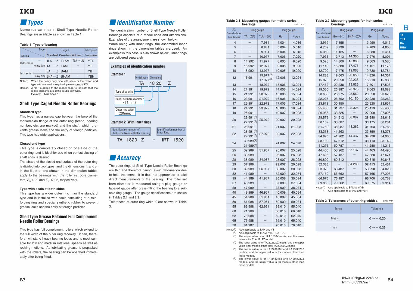
1N=0.102kgf=0.2248lbs.1mm=0.03937inchB3 B4
B TypesNumerous varieties of Shell Type Needle Roller Bearings are available as shown in Table 1.
Shell Type Caged Needle Roller Bearings
Standard typeThis type has a narrow gap between the bore of the marked-side flange of the outer ring (brand, bearing number, etc. are marked) and the shaft, which pre-vents grease leaks and the entry of foreign particles. This type has wide applications.
Closed end typeThis type is completely closed on one side of the outer ring, and is ideal for use when perfect closing of shaft ends is desired.The shape of the closed end surface of the outer ring
is divided into two types, and the dimensions t1 and t2 in the illustrations shown in the dimension tables apply to the bearings with the roller set bore diame-
ters, Fw > 22 and Fw ≦ 22, respectively.
Type with seals at both sidesThis type has a wider outer ring than the standard type and is installed with seals consisting of a rein-forcing ring and special synthetic rubber to prevent grease leaks and the entry of foreign particles.
Shell Type Grease Retained Full Complement Needle Roller Bearings
This type has full complement rollers which extend to the full width of the outer ring raceway. It can, there-fore, withstand heavy bearing loads and is most suit-able for low and medium rotational speeds as well as rocking motions. As lubricating grease is prepacked with the rollers, the bearing can be operated immedi-ately after being fitted.
Table 1 Type of bearing Type
Series
Metric series
Inch series
−Heavy duty
−Heavy duty
TLA … Z
TA … Z
BA … Z
BHA … Z
TLAM
TAM
BAM
BHAM
TLA … UU
−
−
−
YTL
YT
YB
YBH
Caged Full complement
Standard Closed end With seals (1)Grease retained
Note(1) When the heavy duty type with seals or the closed end type with one seal is required, please consult IKO.
Remark A "W" is added to the model code to indicate that the rolling elements are of the double-row type.
Example TAW 5045 Z
Identification NumberThe identification number of Shell Type Needle Roller Bearings consists of a model code and dimensions. Examples of the arrangement are shown below.When using with inner rings, the assembled inner rings shown in the dimension tables are used. An example in this case is also shown below. Inner rings are delivered separately.
AccuracyThe outer rings of Shell Type Needle Roller Bearings are thin and therefore cannot avoid deformation due to heat treatment. It is thus not appropriate to take direct measurements of the bearing. The roller set bore diameter is measured using a plug gauge or tapered gauge after press-fitting the bearing to a suit-able ring gauge. The gauge specifications are shown in Tables 2.1 and 2.2.Tolerances of outer ring width C are shown in Table 3.
Model code Dimensions
TA 18 Z
Type of bearing
20
Examples of identification number
Example 1
Example 2 (With inner ring)
Identification number ofInner Ring
TA 1820 Z IRT 1520 +
Identification number of Shell Type Needle Roller Bearing
Outer ring width(20mm)
Roller set bore diameter(18mm)
Table 2.1 Measuring gauges for metric series bearings
FwNominal roller set
bore diameter
Ring gauge
TA…Z(1) TLA…Z(2) Go No-go
Plug gauge
4
5
6
7
8
9
10
12
13
14
15
16
17
18
19
20
21
22
24
25
26
28
29
30
32
35
37
38
40
45
50
55
60
62
65
70
−
− − −
14.992
15.992
16.992
18.991
− 21.991
21.991
23.991
23.991
24.991
26.991
26.991(4) 27.991(4) 28.991
28.991(5) 29.991(5) 30.989(6) 31.989(6) 32.989
33.989
36.989
37.989
39.989
41.989
44.989
46.989
47.989
49.989
54.988
61.988
66.988
71.988
73.988
76.988
81.987
7.981
8.981
9.981
10.977
11.977
12.977
13.977
15.977(3) 17.977(3) 18.972
19.972
20.972
21.972
22.972
23.972
−
25.972
−
27.972
−
31.967
− 34.967
− 36.967
− 41.967
−
−46.967
51.961
57.961
62.961
−
−
−
−
4.004
5.004
6.004
7.005
8.005
9.005
10.005
12.006
13.006
14.006
15.006
16.006
17.006
18.006
19.007
20.007
21.007
22.007
24.007
25.007
26.007
28.007
29.007
30.007
32.009
35.009
37.009
38.009
40.009
45.009
50.009
55.010
60.010
62.010
65.010
70.010
4.016
5.016
6.016
7.020
8.020
9.020
10.020
12.024
13.024
14.024
15.024
16.024
17.024
18.024
19.028
20.028
21.028
22.028
24.028
25.028
26.028
28.028
29.028
30.028
32.034
35.034
37.034
38.034
40.034
45.034
50.034
55.040
60.040
62.040
65.040
70.040Notes(1) Also applicable to TAM and YT
(2) Also applicable to TLAM, YTL, TLA…UU(3) The upper value is for TLA 1210Z model, and the lower
value is for TLA 1212Z model.(4) The lower value is for TA 202820Z model, and the upper
value is for models other than TA 202820Z model.(5) The lower value is for TA 223016Z and TA 223020Z
models, and the upper value is for models other than those models.
(6) The lower value is for TA 243216Z and TA 243220Z models, and the upper value is for models other than those models.
unit: mmTable 2.2 Measuring gauges for inch series
bearingsFw
Nominal roller set bore diameter
Ring gauge
BA…Z(1) BHA…Z(2) Go No-go
Plug gauge
3.969
4.762
6.350
7.938
9.525
11.112
12.700
14.288
15.875
17.462
19.050
20.638
22.225
23.812
25.400
26.988
28.575
30.162
31.750
33.338
34.925
38.100
41.275
44.450
47.625
50.800
52.388
53.975
57.150
66.675
69.850
7.155
8.730
11.125
12.713
14.300
15.888
17.475
19.063
20.650
22.238
25.387
26.975
28.562
30.150
31.737
33.325
34.912
38.087
38.087
41.262
41.262
47.612
50.787
53.962
57.137
60.312
− 63.487
66.662
76.187
79.362
−
−
− 14.300
15.888
17.475
19.063
20.650
22.238
23.825
26.975
28.562
30.150
− 33.325
− 38.087
− 41.262
− 44.437
−
−57.137
−−
64.280
−
−
−
−
3.990
4.783
6.388
7.976
9.563
11.151
12.738
14.326
15.913
17.501
19.063
20.650
22.238
23.825
25.413
27.000
28.588
30.175
31.763
33.350
34.938
38.113
41.288
44.463
47.638
50.815
52.413
53.990
57.165
66.700
69.875
4.016
4.808
6.414
8.001
9.588
11.176
12.764
14.351
15.938
17.526
19.088
20.676
22.263
23.851
25.438
27.026
28.613
30.201
31.788
33.378
34.966
38.143
41.318
44.496
47.671
50.848
52.451
54.028
57.203
66.738
69.914
unit: mm
unit: mm
Notes(1) Also applicable to BAM and YB(2) Also applicable to BHAM and YBH
Table 3 Tolerances of outer ring width C
Series
Metric
Inch
Tolerance
0 〜− 0.20
0 〜− 0.25

1N=0.102kgf=0.2248lbs.1mm=0.03937inchB5 B6
B FitAs the outer ring is thin, the correct dimensions and accuracy of Shell Type Needle Roller Bearings are obtained only after they have been press-fitted into the housing bore. Bearing accuracy is directly affect-ed by housing dimensions, shape and rigidity. This should be taken into account when considering fit and accuracy. The radial clearance after fitting the bear-ing to the shaft and the housing bore varies with their tolerances.
Table 4 shows the recommended fit for Shell Type Needle Roller Bearings.Table 5 shows a calculation example of radial clear-ance after fitting. This calculation applies to bearings without inner ring to be fitted into rigid steel or cast iron housings. When the housing is made of light alloy or a thin steel pipe, it is necessary to check dimensions by actual measurement.Generally, when making the radial clearance smaller, i t is recommended that the shaft diameter be increased, without decreasing the housing bore diam-eter.
Table 4 Recommended fit
Table 5 Calculation example of radial clearance after fitting
Type of bearing
TA … Z,BA … Z,BHA … Z, TAM,BAM,BHAM,YT,YB,YBH
TLA … Z,TLAM,YTL, TLA … UU
Housing material
SteelCast iron h6
h6
h6
h6
k5(j5)
k5(j5)
k5(j5)
k5(j5)
J7
M7(N7)
N7
R7(S7)
Light alloy(Thin steel pipe)
SteelCast iron
Light alloy(Thin steel pipe)
Tolerance class
Shaft (1)
Without inner ring With inner ringHousing bore
Note(1) When housings are made of light alloy or a thin steel pipe, the roller set bore diameter is greatly affected by the housing thickness and shape. Therefore, before mass-production assembly, assembly tests should be carried out to confirm the amount of dimensional change and to determine the tolerance of the shaft which will give normal clearances.
Calculation procedure
Dimension of housing bore Max. value of housing bore (Dmax): See the dimension table. Min. value of housing bore (Dmin): See the dimension table.
Dimension of roller set bore diameter of bearing after it has been press-fitted into the housing bore Max. value of roller set bore dia.(Fwe max)=(Dmax−D0) +Fw max Min. value of roller set bore dia.(Fwe min)=(Dmin−D0) +Fw min
Dimension of shaft Max. value of shaft dia. (Fmax): See the dimension table. Min. value of shaft dia. (Fmin ): See the dimension table.
Radial clearance after mounting Max. value of radial clearance(Gr max)=Fwe max−Fmin Min. value of radial clearance(Gr min) =Fwe min−Fmax
From Table 2.1 on page B4D0 =25.972Fw max =20.028Fw min =20.007
From the dimension table on page B14, Dmax=25.993Dmin =25.972
From the equations,Fwe max=20.049Fwe min =20.007
From the dimension table on page B14,Fmax =20.000Fmin =19.987
From the equations, Gr max =0.062 Gr min =0.007 The radial clearance after mounting becomes 0.007~0.062 mm.
Example of TLA 2020 Z
unit: mm
D : Housing bore diameterFw : Roller set bore diameterF : Shaft diameterGr : Radial clearance
FG
F w D
r
Dimension of roller set bore diameter of bearing after it has been press-fitted into the ring gauge. Dimension of ring gauge (D0): See Tables 2.1 and 2.2 on page B4. Max. value of roller set bore dia. (Fw max): No-go dimension of plug gauge Min. value of roller set bore dia. (Fw min): Go dimension of plug gauge
1
2
3
4
5
Lubrication Oil HoleBearings with prepacked grease are shown in Table 6. ALVANIA GREASE S2 (Shell Lubricants Japan K.K.) is prepacked as the lubricating grease.In the case of bearings without prepacked grease, perform proper lubrication for use. If the bearings are operated without lubrication, the wear of the roller contact surfaces will increase and the bearing life will be shortened.
For Shell Type Needle Roller Bearings with an oil hole, "OH" is appended to the end of the identification number.
Example TA 2525 Z OHThe symbol "OH" is not marked on the bearing itself, but is shown on its packaging, etc. When bearings with multiple oil holes are required, please consult IKO.
MountingShell Type Needle Roller Bearings should be pressed into the housings gently using the appropriate tool as shown in Fig. 1, with their marked end surface up. As the outer ring is thin, it must never be struck directly with a hammer.Since the outer rings of Shell Type Needle Roller Bearings are firmly fitted to housing bores with inter-ference, it is unnecessary to fix them axially. Fig. 2 shows mounting examples.
Specifications of shaft and housingShell Type Needle Roller Bearings are commonly used without an inner ring. In such cases, the surface hardness of the raceway surface should be 58 〜64HRC and the surface roughness should not exceed 0.2 μ mRa. However, when the operating condition is not severe, a surface roughness 0.8μmRa or less can be used.If the surface hardness is low, the load rating must be corrected by the hardness factor shown on page A20. When the shaft cannot be heat treated and finished by grinding, the use of IKO Inner Rings for Shell Type Needle Roller Bearings (See page H1.) is recom-mended.
Static Safety FactorSince Shell Type Needle Roller Bearings employ an outer ring made from a thin steel plate which is drawn, carburized and quenched, excessively large loads must be avoided. The required static safety factor is usually more than 3.
Fig.2 Mounting examples
Fig.1 Example of mounting tool
Table 6 Bearings with prepacked greaseBearing type
Series
Metric series
Inch series
TLA,TLAM,YTL
TA,TAM,YT
BA,BAM,YB
BHA,BHAM,YBH
Full complement
Grease retainedWith sealsClosed endStandard
Caged
××××
××××
〇−−−
〇〇〇〇
〇:With prepacked grease ×:Without prepacked grease
D
Fw
-0.2-0.3
15°
-0.025

1N=0.102kgf=0.2248lbs.1mm=0.03937inchB7 B8
B
Note(1) Allowable rotational speed applies to oil lubrication. For grease lubrication, a maximum of 60% of this value is allowable.Remark Shell Type Grease Retained Full Complement Needle Roller Bearings are provided with prepacked grease. Standard type and closed
end type bearings are not provided with prepacked grease, so perform proper lubrication when using these types of bearings.
Shaftdia.
mm
Identification number
Mass (Ref. )
g
Standard
4
5
6
7
8
9
10
TA 810 ZTA 815 ZTA 820 Z
TA 912 ZTA 916 Z
TA 1010 ZTA 1012 ZTA 1015 ZTA 1020 Z
6.7 9.7 12.9
8.7 11.4
7.9 9.3 11.5 15.4
TAM 810TAM 815TAM 820
TAM 912TAM 916
TAM 1010TAM 1012TAM 1015TAM 1020
7.1 10.1 13.3
9.2 11.9
8.5 10 12.2 16
TLA 48 Z
TLA 59 Z
TLA 69 Z
TLA 79 Z
TLA 810 Z
TLA 910 ZTLA 912 Z
TLA 1010 ZTLA 1012 ZTLA 1015 Z
1.54
1.9
2.2
2.5
3.1
3.4 4
3.7 4.4 5.5
TLAM 48
TLAM 59
TLAM 69
TLAM 79
TLAM 810
TLAM 910TLAM 912
TLAM 1010TLAM 1012TLAM 1015
1.67
2
2.3
2.7
3.3
3.6 4.3
4 4.8 5.9
YTL 48
YTL 59
YT 810
YT 912
1.73
2.4
7.7
10.1
Mass (Ref. )
g
Closed end Mass (Ref. )
g
Standard Mass (Ref. )
g
Closed end Mass (Ref. )
g
Grease retained
Shaft dia. 4− 10mm
SHELL TYPE NEEDLE ROLLER BEARINGS
4.000
5.000
6.000
7.000
8.000
8.000
9.000
9.000
10.000
10.000
3.992
4.992
5.992
6.991
7.991
7.991
8.991
8.991
9.991
9.991
15.010
16.010
17.010
14.992
15.992
16.992
7.996
8.996
9.996
10.995
11.995
12.995
13.995
7.981
8.981
9.981
10.977
11.977
12.977
13.977
1 3503 010
1 8804 320
2 100
2 490
3 320
3 4705 7808 3407 530
3 5004 460
5 1406 9609 690
3 8704 9206 390
4 1505 5906 9209 990
1 0102 900
1 6004 750
1 900
2 450
3 670
2 8805 5708 9207 950
4 0405 510
4 8807 210
11 200
4 7406 4609 040
3 7805 5407 300
11 700
75 00040 000
65 00030 000
55 000
50 000
45 000
45 00045 00045 00019 000
45 00045 000
45 00045 00017 000
40 00040 00040 000
40 00040 00040 00040 000
Basic dynamic load rating
C
N
Basic static load rating
C0
N
Allowable rotational speed(1)
min-1
44
55
6
7
8
8888
99
999
101010
10101010
88
99
10
11
12
15151515
1313
161616
141414
17171717
88
99
9
9
10
10152010
1012
121612
101215
10121520
Fw D
Assembled inner ring
IRT 710IRT 712IRT 715
IRT 710IRT 712IRT 715
C
1
1
1
1
1
1.31.31.3
11
1.31.3
111
1.31.31.31.3
t2Max.
TA … Z TLA … Z TAM TLAM YT YTL
Standard mounting dimensions mm
Max. Min. Max. Min.J7
Housing bore dia.
Max. Min.N7h6
Shaft dia.
Boundary dimensionsmm
D
C
Fw D
C
Fw
t2
D
C
Fw

1N=0.102kgf=0.2248lbs.1mm=0.03937inchB9 B10
BSHELL TYPE NEEDLE ROLLER BEARINGS
Note(1) Allowable rotational speed applies to oil lubrication. For grease lubrication, a maximum of 60% of this value is allowable.Remark Shell Type Grease Retained Full Complement Needle Roller Bearings are provided with prepacked grease. Standard type and closed
end type bearings are not provided with prepacked grease, so perform proper lubrication when using these types of bearings.
Shaftdia.
mm
Identification number
Mass (Ref. )
g
Standard
12
13
14
15
TA 1212 ZTA 1215 ZTA 1220 ZTA 1225 Z
TA 1416 ZTA 1420 Z
TA 1510 ZTA 1512 ZTA 1515 ZTA 1520 ZTA 1525 Z
10.5 13.1 17.3 21.5
18.4 23
10.8 12.9 15.9 21 25
TAM 1212TAM 1215TAM 1220TAM 1225
TAM 1416TAM 1420
TAM 1510TAM 1512TAM 1515TAM 1520TAM 1525
11.5 14 18.3 22.5
19.6 24
12.3 14.3 17.3 22.5 26.5
TLA 1210 Z
TLA 1212 Z
TLA 1312 Z
TLA 1412 ZTLA 1416 Z
TLA 1512 ZTLA 1516 ZTLA 1522 Z
4.3
8.6
9.2
9.8 13.2
10.4 14 19.1
TLAM 1210
TLAM 1212
TLAM 1312
TLAM 1412TLAM 1416
TLAM 1512TLAM 1516TLAM 1522
4.7
9.4
10.1
10.8 14.3
11.5 15.2 20.5
YTL 1210
YT 1212
5.1
12.8
Mass (Ref. )
g
Closed end Mass (Ref. )
g
Standard Mass (Ref. )
g
Closed end Mass (Ref. )
g
Grease retained
Shaft dia. 12− 15mm
12.000
12.000
12.000
13.000
14.000
14.000
15.000
15.000
11.989
11.989
11.989
12.989
13.989
13.989
14.989
14.989
15.995
17.995
18.993
19.993
20.993
15.977
17.977
18.972
19.972
20.972
19.012
22.012
22.012
18.991
21.991
21.991
4 3507 470
6 420
6 0007 440
10 70013 80011 800
6 760
7 0808 950
10 50013 900
7 3809 330
13 600
5 2907 1208 830
12 70016 300
5 81011 800
7 490
6 3108 320
13 30018 30015 200
8 170
8 84012 000
12 00017 200
9 52012 90020 900
5 6808 310
11 00017 60024 200
35 00013 000
35 000
35 00035 00035 00035 00013 000
30 000
30 00030 000
30 00030 000
25 00025 00025 000
25 00025 00025 00025 00025 000
Basic dynamic load rating
C
N
Basic static load rating
C0
N
Allowable rotational speed(1)
min-1
1212
12
1212121212
13
1414
1414
151515
1515151515
1616
18
1919191919
19
2020
2222
212121
2222222222
1010
12
1215202512
12
1216
1620
121622
1012152025
Fw D
Assembled inner ring
IRT 810IRT 810
IRT 812
IRT 812IRT 815
IRT 812
IRT 1012
IRT 1012-2IRT 1016-2
IRT 1016-2IRT 1020-2
IRT 1212IRT 1216IRT 1222
IRT 1010-1IRT 1012-1IRT 1015-1IRT 1020-1IRT 1025-1
C
1
1.3
1.31.31.31.3
1.3
1.31.3
1.31.3
1.31.31.3
1.31.31.31.31.3
t2Max.
TA … Z TLA … Z TAM TLAM YT YTL
Boundary dimensionsmm
Standard mounting dimensions mm
Max. Min. Max. Min.J7
Housing bore dia.
Max. Min.N7h6
Shaft dia.
D
C
Fw D
C
Fw
t2
D
C
Fw

1N=0.102kgf=0.2248lbs.1mm=0.03937inchB11 B12
BSHELL TYPE NEEDLE ROLLER BEARINGS
Note(1) Allowable rotational speed applies to oil lubrication. For grease lubrication, a maximum of 60% of this value is allowable.Remark Shell Type Grease Retained Full Complement Needle Roller Bearings are provided with prepacked grease. Standard type and closed
end type bearings are not provided with prepacked grease, so perform proper lubrication when using these types of bearings.
Shaftdia.
mm
Identification number
Mass (Ref. )
g
Standard
17
18
19
TA 1715 ZTA 1720 ZTA 1725 Z
TA 1813 ZTA 1815 ZTA 1817 ZTA 1819 ZTA 1820 ZTA 1825 Z
TA 1916 ZTA 1920 Z
20 25
17.6 23.5 29
16.4 18.5 21 23.5 24.5 30.5
23 29
TAM 1715TAM 1720TAM 1725
TAM 1813TAM 1815TAM 1817TAM 1819TAM 1820TAM 1825
TAM 1916TAM 1920
19.5 25 31
18.5 20.5 23 25.5 26.5 32.5
25.5 31
TLA 1712 Z
TLA 1812 ZTLA 1816 Z
11.5
12 16.2
TLAM 1712
TLAM 1812TLAM 1816
YT 1715YT 1725
13
13.7 17.9
20.5 35.5
Mass (Ref. )
g
Closed end Mass (Ref. )
g
Standard Mass (Ref. )
g
Closed end Mass (Ref. )
g
Grease retained
16
TA 1616 ZTA 1620 Z
22 27
TAM 1616TAM 1620
10.9 14.8 20
TLA 1612 ZTLA 1616 ZTLA 1622 Z
12.2 16.1 21.5
TLAM 1612TLAM 1616TLAM 1622
Shaft dia. 16− 19mm
17.000
17.000
18.000
18.000
19.000
16.989
16.989
17.989
17.989
18.987
24.012
25.012
27.012
23.991
24.991
26.991
22.993
23.993
22.972
23.972
7 960
9 66013 90017 90016 60027 200
8 23010 400
9 10010 10011 90013 70014 50018 600
12 20016 100
25 000
25 00025 00025 0009 0009 000
20 00020 000
20 00020 00020 00020 00020 00020 000
20 00020 000
Basic dynamic load rating
C
N
Basic static load rating
C0
N
Allowable rotational speed(1)
min-1
17
161616
1616
222222
2424
121622
1620
1.31.31.3
16.000 15.989 21.993 21.9727 6709 700
14 200
10 900
12 70020 40028 10026 00049 000
11 50015 600
12 00013 60016 90020 20021 80030 000
15 70022 600
10 20013 80022 400
25 00025 00025 000
IRT 1212-1IRT 1216-1IRT 1222-1
1.31.3
16.000 15.989 24.012 23.991 11 10014 700
13 30019 100
25 00025 000
IRT 1216-1IRT 1220-1
1717171717
1818
181818181818
1919
23
2424242424
2424
252525252525
2727
12
1520251525
1216
131517192025
1620
Fw D
Assembled inner ring
IRT 1215-2IRT 1220-2IRT 1225-2IRT 1215-2IRT 1225-2
IRT 1512IRT 1516
IRT 1513IRT 1515IRT 1517IRT 1519IRT 1520IRT 1525
IRT 1516-1IRT 1520-1
C
1.3
1.31.31.3
1.31.3
1.31.31.31.31.31.3
1.31.3
t2Max.
TA … Z TLA … Z TAM TLAM YT
Boundary dimensionsmm
Standard mounting dimensions mm
Max. Min. Max. Min.J7
Housing bore dia.
Max. Min.N7h6
Shaft dia.
D
C
Fw D
C
Fw
t2
D
C
Fw

1N=0.102kgf=0.2248lbs.1mm=0.03937inchB13 B14
B
TA 2116 ZTA 2120 Z
TAM 2116TAM 2120
25 31.5
28 34.5
SHELL TYPE NEEDLE ROLLER BEARINGS
Note(1) Allowable rotational speed applies to oil lubrication. For grease lubrication, a maximum of 60% of this value is allowable.Remark Shell Type Grease Retained Full Complement Needle Roller Bearings are provided with prepacked grease. Standard type and closed
end type bearings are not provided with prepacked grease, so perform proper lubrication when using these types of bearings.
Shaftdia.
mm
Identification number
Mass (Ref. )
g
Standard
20
21
TA 2015 ZTA 2020 ZTA 2025 ZTA 2030 Z
TA 202820 Z
20 26.5 33 39.5
30
TAM 2015TAM 2020TAM 2025TAM 2030
TAM 202820
22.5 29 35.5 42
32.5
YT 2015YT 2025
YT 202820
YT 2116YT 2120
23.5 41
37.5
TLA 2012 ZTLA 2016 ZTLA 2020 ZTLA 2030 Z
13.2 17.8 22 33
TLAM 2012TLAM 2016TLAM 2020TLAM 2030
15.2 19.9 24 35
Mass (Ref. )
g
Closed end Mass (Ref. )
g
Standard Mass (Ref. )
g
Closed end Mass (Ref. )
g
Grease retained
31 39
Shaft dia. 20− 21mm
20.000
20.000
20.000
21.000
19.987
19.987
19.987
20.987
27.012
28.012
29.012
26.991
27.991
28.991
25.993
25.972
8 74011 10014 50022 300
10 40015 00019 20023 10018 40030 000
16 90026 800
13 30017 60022 10027 500
12 90017 50024 70042 900
14 60023 40032 20041 00030 90058 300
24 30044 600
18 10025 90035 20046 800
20 00020 00020 00020 000
20 00020 00020 00020 0007 5007 500
20 0007 500
19 00019 0007 0007 000
Basic dynamic load rating
C
N
Basic static load rating
C0
N
Allowable rotational speed(1)
min-1
20202020
202020202020
2020
21212121
26262626
272727272727
2828
29292929
12162030
152025301525
2020
16201620
Fw D
Assembled inner ring
IRT 1716IRT 1720IRT 1730
IRT 1515-2IRT 1520-2IRT 1525-2IRT 1530-2IRT 1515-2IRT 1525-2
IRT 1520-2IRT 1520-2
IRT 1716-1IRT 1720-1IRT 1716-1IRT 1720-1
C
1.31.31.31.3
1.31.31.31.3
1.3
1.31.3
t2Max.
TA … Z TLA … Z TAM TLAM YT
Boundary dimensionsmm
Standard mounting dimensions mm
Max. Min. Max. Min.J7
Housing bore dia.
Max. Min.N7h6
Shaft dia.
D
C
Fw D
C
Fw
t2
D
C
Fw

1N=0.102kgf=0.2248lbs.1mm=0.03937inchB15 B16
BSHELL TYPE NEEDLE ROLLER BEARINGS
Note(1) Allowable rotational speed applies to oil lubrication. For grease lubrication, a maximum of 60% of this value is allowable.Remark Shell Type Grease Retained Full Complement Needle Roller Bearings are provided with prepacked grease. Standard type and closed
end type bearings are not provided with prepacked grease, so perform proper lubrication when using these types of bearings.
Shaftdia.
mm
Identification number
Mass (Ref. )
g
Standard
22
24
TA 2210 ZTA 2215 ZTA 2220 ZTA 2225 ZTA 2230 Z
TA 223016 ZTA 223020 Z
TA 2420 ZTA 2428 Z
TA 243216 ZTA 243220 Z
15 21.5 29 35.5 42.5
26 32.5
31 43.5
28 35.5
TAM 2210TAM 2215TAM 2220TAM 2225TAM 2230
TAM 223016TAM 223020
TAM 2420TAM 2428
TAM 243216TAM 243220
18.1 24.5 32 38.5 45.5
29 35.5
35 47
32 39
TLA 2212 ZTLA 2216 ZTLA 2220 Z
15.6 21.5 26.5
TLAM 2212TLAM 2216TLAM 2220
18.1 24 29
YT 223016YT 223020
YT 2428
YT 243216YT 243220
32 40.5
54
34.5 43.5
Mass (Ref. )
g
Closed end Mass (Ref. )
g
Standard Mass (Ref. )
g
Closed end Mass (Ref. )
g
Grease retained
Shaft dia. 22− 24mm
22.000
22.000
22.000
24.000
24.000
21.987
21.987
21.987
23.987
23.987
29.012
30.012
31.014
32.014
28.991
29.991
30.989
31.989
27.993
27.972
9 23011 70015 300
6 65011 10016 00019 70023 800
13 20017 50022 60028 200
17 00024 50036 800
14 20018 80023 70029 500
14 30019 30027 300
8 50016 40026 30034 30043 700
18 20026 10036 80048 900
29 20046 70079 900
20 50029 40040 10053 200
18 00018 00018 000
18 00018 00018 00018 00018 000
18 00018 0007 0007 000
16 00016 0006 500
16 00016 0006 5006 500
Basic dynamic load rating
C
N
Basic static load rating
C0
N
Allowable rotational speed(1)
min-1
222222
2222222222
22222222
242424
24242424
282828
2929292929
30303030
313131
32323232
121620
1015202530
16201620
202828
16201620
Fw D
Assembled inner ring
IRT 1716-2IRT 1720-2
IRT 1710-2IRT 1715-2IRT 1720-2IRT 1725-2IRT 1730-2
IRT 1716-2IRT 1720-2IRT 1716-2IRT 1720-2
IRT 2020IRT 2028IRT 2028
IRT 2016IRT 2020IRT 2016IRT 2020
C
1.31.31.3
1.31.31.31.31.3
1.31.3
3.43.4
3.43.4
t1,t2Max.
TA … Z TLA … Z TAM TLAMt1 (Fw≧24)t2 (Fw≦22)
YT
Boundary dimensionsmm
Standard mounting dimensions mm
Max. Min. Max. Min.J7
Housing bore dia.
Max. Min.N7h6
Shaft dia.
D
C
Fw D
C
FwD
t
t
2
1
C
Fw

1N=0.102kgf=0.2248lbs.1mm=0.03937inchB17 B18
BSHELL TYPE NEEDLE ROLLER BEARINGS
Note(1) Allowable rotational speed applies to oil lubrication. For grease lubrication, a maximum of 60% of this value is allowable.Remarks1. "W" in the identification number indicates that rolling elements are arranged in double rows. 2. Shell Type Grease Retained Full Complement Needle Roller Bearings are provided with prepacked grease. Standard type and
closed end type bearings are not provided with prepacked grease, so perform proper lubrication when using these types of bearings.
Shaftdia.
mm
Identification number
Mass (Ref. )
g
Standard
25
TA 2510 ZTA 2515 ZTA 2520 ZTA 2525 ZTA 2530 Z
TA 2616 ZTA 2620 Z
TA 2820 ZTA 2830 Z
19.1 28.5 36.5 45.5 54.5
30.5 38
45 67.5
TAM 2510TAM 2515TAM 2520TAM 2525TAM 2530
TAM 2616TAM 2620
TAM 2820TAM 2830
23 32.5 40.5 49 58.5
34.5 42.5
50 72.5
TLA 2512 ZTLA 2516 ZTLA 2520 ZTLA 2526 ZTLAW2538Z
TLA 2816 ZTLA 2820 Z
19.7 26 32 41.5 58.5
28.5 35.5
TLAM 2512TLAM 2516TLAM 2520TLAM 2526TLAMW2538
TLAM 2816TLAM 2820
23.5 29.5 36 45.5 62
33.5 40.5
YTL 2526
YT 2510YT 2515YT 2520YT 2525
YT 2616YT 2620
YT 2820
51.5
22.5 33 45 57
37 46.5
56.5
Mass (Ref. )
g
Closed end Mass (Ref. )
g
Standard Mass (Ref. )
g
Closed end Mass (Ref. )
g
Grease retained
26
28
Shaft dia. 25− 28mm
25.000
25.000
25.000
26.000
28.000
28.000
24.987
24.987
24.987
25.987
27.987
27.987
33.014
33.014
34.014
37.014
32.989
32.989
33.989
36.989
31.992
34.992
31.967
34.967
9 44012 80016 90022 60028 90035 000
7 99013 40019 50024 10029 100
15 50022 70030 20037 200
15 20020 10024 70030 800
13 80018 300
21 20033 00034 700
13 90020 50029 30042 50058 50075 800
9 90019 30031 10040 80052 000
23 60038 30055 40072 500
22 90032 80043 30057 500
23 50033 600
32 30056 90061 700
15 00015 00015 00015 00015 0006 000
15 00015 00015 00015 00015 000
6 0006 0006 0006 000
15 00015 0006 0006 000
13 00013 000
13 00013 000
5 500
Basic dynamic load rating
C
N
Basic static load rating
C0
N
Allowable rotational speed(1)
min-1
252525252525
2525252525
25252525
26262626
2828
282828
323232323232
3333333333
33333333
34343434
3535
373737
121620263826
1015202530
10152025
16201620
1620
203020
Fw D
Assembled inner ring
IRT 2020-1IRT 2026-1IRT 2038-1IRT 2026-1
IRT 2010-1IRT 2015-1IRT 2020-1IRT 2025-1IRT 2030-1
IRT 2010-1IRT 2015-1IRT 2020-1IRT 2025-1
IRT 2216IRT 2220IRT 2216IRT 2220
IRT 2220-1
IRT 2220-1IRT 2230-1IRT 2220-1
C
2.82.82.82.82.8
3.43.43.43.43.4
3.43.4
2.82.8
3.43.4
t1Max.
TA … Z TLA … Z TAM TLAM YT YTL
Boundary dimensionsmm
Standard mounting dimensions mm
Max. Min. Max. Min.J7
Housing bore dia.
Max. Min.N7h6
Shaft dia.
D
C
Fw D
C
FwD
C
Fw
t1

1N=0.102kgf=0.2248lbs.1mm=0.03937inchB19 B20
BSHELL TYPE NEEDLE ROLLER BEARINGS
Note(1) Allowable rotational speed applies to oil lubrication. For grease lubrication, a maximum of 60% of this value is allowable.Remarks1. "W" in the identification number indicates that rolling elements are arranged in double rows. 2. Shell Type Grease Retained Full Complement Needle Roller Bearings are provided with prepacked grease. Standard type and
closed end type bearings are not provided with prepacked grease, so perform proper lubrication when using these types of bearings.
Shaftdia.
mm
Identification number
Mass (Ref. )
g
Standard
29
30
32
35
TA 2920 ZTA 2930 Z
TA 3013 ZTA 3015 ZTA 3020 ZTA 3025 ZTA 3030 Z
TA 3220 ZTA 3230 Z
TA 3512 ZTA 3515 ZTA 3520 ZTA 3525 ZTA 3530 Z
47 70
36.5 42 54.5 68 80
57.5 86
38.5 48 62.5 78 97
TAM 2920TAM 2930
TAM 3013TAM 3015TAM 3020TAM 3025TAM 3030
TAM 3220TAM 3230
TAM 3512TAM 3515TAM 3520TAM 3525TAM 3530
52 75.5
42.5 47.5 60 73.5 85.5
63.5 97.5
46 56 70 85.5 105
TLA 3012 ZTLA 3016 ZTLA 3018 ZTLA 3020 ZTLA 3026 ZTLAW3038 Z
TLA 3512 ZTLA 3516 ZTLA 3520 Z
23.5 30.5 34.5 38 49 69
27 35 43.5
TLAM 3012TLAM 3016TLAM 3018TLAM 3020TLAM 3026TLAMW3038
TLAM 3512TLAM 3516TLAM 3520
29 36 40 43.5 54.5 74.5
34.5 42.5 51
YT 2920
YT 3220
58.5
71.5
Mass (Ref. )
g
Closed end Mass (Ref. )
g
Standard Mass (Ref. )
g
Closed end Mass (Ref. )
g
Grease retained
Shaft dia. 29− 35mm
29.000
30.000
30.000
32.000
35.000
35.000
28.987
29.987
29.987
31.984
34.984
34.984
38.014
40.014
42.014
45.014
37.989
39.989
41.989
44.989
36.992
41.992
36.967
41.967
22 00034 20035 500
10 40014 10016 40018 60024 80031 900
13 50016 80024 50031 60036 700
25 40039 50039 900
11 60015 70020 700
14 80018 50027 00034 80040 600
34 20060 30064 100
16 60024 50029 80035 10050 90070 200
16 80022 40036 30050 30060 700
38 60068 40070 100
20 00029 60042 300
19 90026 50043 10059 70072 600
13 00013 0005 000
12 00012 00012 00012 00012 00012 000
12 00012 00012 00012 00012 000
11 00011 0004 500
10 00010 00010 000
10 00010 00010 00010 00010 000
Basic dynamic load rating
C
N
Basic static load rating
C0
N
Allowable rotational speed(1)
min-1
292929
303030303030
3030303030
323232
353535
3535353535
383838
373737373737
4040404040
424242
424242
4545454545
203020
121618202638
1315202530
203020
121620
1215202530
Fw D
Assembled inner ring
IRT 2520IRT 2530IRT 2520
IRT 2520-1IRT 2526-1IRT 2538-1
IRT 2515-1IRT 2520-1IRT 2525-1IRT 2530-1
IRT 2820IRT 2830IRT 2820
IRT 3012
IRT 3020
IRT 3012IRT 3015IRT 3020IRT 3025IRT 3030
C
3.43.4
2.82.82.82.82.82.8
3.43.43.43.43.4
3.43.4
2.82.82.8
3.43.43.43.43.4
t1Max.
TA … Z TLA … Z TAM TLAM YT
Boundary dimensionsmm
Standard mounting dimensions mm
Max. Min. Max. Min.J7
Housing bore dia.
Max. Min.N7h6
Shaft dia.
D
C
Fw D
C
FwD
C
Fw
t1
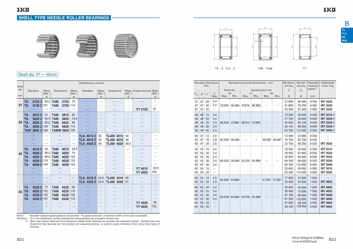
1N=0.102kgf=0.2248lbs.1mm=0.03937inchB21 B22
BSHELL TYPE NEEDLE ROLLER BEARINGS
Note(1) Allowable rotational speed applies to oil lubrication. For grease lubrication, a maximum of 60% of this value is allowable.Remarks1. "W" in the identification number indicates that rolling elements are arranged in double rows. 2. Shell Type Grease Retained Full Complement Needle Roller Bearings are provided with prepacked grease. Standard type and
closed end type bearings are not provided with prepacked grease, so perform proper lubrication when using these types of bearings.
Shaftdia.
mm
Identification number
Mass (Ref. )
g
Standard
37
38
40
45
TA 3720 ZTA 3730 Z
TA 3815 ZTA 3820 ZTA 3825 ZTA 3830 ZTAW 3845 Z
TA 4015 ZTA 4020 ZTA 4025 ZTA 4030 ZTA 4040 Z
TA 4520 ZTA 4525 ZTA 4530 ZTA 4540 Z
64.5 101
51 65.5 82.5 104 149
54 69.5 86.5 110 144
77 102 122 161
TAM 3720TAM 3730
TAM 3815TAM 3820TAM 3825TAM 3830TAMW 3845
TAM 4015TAM 4020TAM 4025TAM 4030TAM 4040
TAM 4520TAM 4525TAM 4530TAM 4540
73 110
60 74.5 96 114 159
63.5 79 102 120 154
90 115 135 174
TLA 4012 ZTLA 4016 ZTLA 4020 Z
TLA 4516 ZTLA 4520 Z
30 39 49
43.5 54.5
TLAM 4012TLAM 4016TLAM 4020
TLAM 4516TLAM 4520
40 49 58.5
56 67
YT 3720
YT 4015YT 4025
YT 4520YT 4525
81
63.5 109
96 122
Mass (Ref. )
g
Closed end Mass (Ref. )
g
Standard Mass (Ref. )
g
Closed end Mass (Ref. )
g
Grease retained
Shaft dia. 37− 45mm
37.000
38.000
40.000
40.000
45.000
45.000
36.984
37.984
39.984
39.984
44.984
44.984
47.014
48.014
50.014
55.018
46.989
47.989
49.989
54.988
46.992
51.991
46.967
51.961
27 80041 80043 300
19 00027 70035 60043 10055 700
12 40016 70022 100
19 50028 40036 60044 30056 70033 40055 300
17 80023 400
30 60039 40047 70061 30047 80059 100
9 5009 5004 000
9 0009 0009 0009 0009 000
8 5008 5008 500
8 5008 5008 5008 5008 5004 0004 000
7 5007 500
7 5007 5007 5007 5003 5003 500
45 40076 70081 300
28 00045 60063 10080 600
112 000
22 80033 70048 200
29 40047 80066 20084 600
116 00059 800
114 000
37 80054 000
54 60075 60096 600
133 00098 200
129 000
Basic dynamic load rating
C
N
Basic static load rating
C0
N
Allowable rotational speed(1)
min-1
373737
3838383838
404040
40404040404040
4545
454545454545
474747
4848484848
474747
50505050505050
5252
555555555555
203020
1520253045
121620
15202530401525
1620
202530402025
Fw D
Assembled inner ring
IRT 3220IRT 3230IRT 3220
IRT 3215-1IRT 3220-1IRT 3225-1IRT 3230-1IRT 3245-1
IRT 3520
IRT 3515IRT 3520IRT 3525IRT 3530IRT 3540IRT 3515IRT 3525
IRT 4020
IRT 4020IRT 4025IRT 4030IRT 4040IRT 4020IRT 4025
C
3.43.4
3.43.43.43.43.4
2.82.82.8
3.43.43.43.43.4
2.82.8
3.43.43.43.4
t1Max.
TA … Z TLA … Z TAM TLAM YT
Boundary dimensionsmm
Standard mounting dimensions mm
Max. Min. Max. Min.J7
Housing bore dia.
Max. Min.N7h6
Shaft dia.
D
C
Fw D
C
Fw
t1
D
C
Fw

1N=0.102kgf=0.2248lbs.1mm=0.03937inchB23 B24
BSHELL TYPE NEEDLE ROLLER BEARINGS
Note(1) Allowable rotational speed applies to oil lubrication. For grease lubrication, a maximum of 60% of this value is allowable.Remarks1. "W" in the identification number indicates that rolling elements are arranged in double rows. 2. Shell Type Grease Retained Full Complement Needle Roller Bearings are provided with prepacked grease. Standard type and
closed end type bearings are not provided with prepacked grease, so perform proper lubrication when using these types of bearings.
Shaftdia.
mm
Identification number
Mass (Ref. )
g
Standard
50
55
60
62
TA 5012 ZTA 5015 ZTA 5020 ZTA 5025 ZTA 5030 ZTA 5040 ZTAW 5045 Z
TA 5520 ZTA 5525 ZTA 5530 ZTA 5540 ZTAW 5545 ZTAW 5550 Z
TA 6025 ZTA 6030 ZTA 6040 ZTAW 6045 ZTAW 6050 Z
TA 6212 Z
62.5 78 107 134 161 210 230
116 145 175 230 250 280
158 191 250270 305
78
TAM 5012TAM 5015TAM 5020TAM 5025 TAM 5030TAM 5040TAMW 5045
TAM 5520TAM 5525TAM 5530TAM 5540TAMW 5545TAMW 5550
TAM 6025TAM 6030TAM 6040TAMW 6045TAMW 6050
TAM 6212
78 98.5 123 150 178 230 245
136 165 195 250 270 300
182 215 275 295 330
107
TLA 5020 ZTLA 5025 Z
TLA 5520 ZTLA 5525 Z
69 86
75 98.5
TLAM 5020TLAM 5025
TLAM 5520TLAM 5525
84.5 107
98.5 118
Mass (Ref. )
g
Closed end Mass (Ref. )
g
Standard Mass (Ref. )
g
Closed end Mass (Ref. )
g
Grease retained
Shaft dia. 50− 62mm
50.000
50.000
55.000
55.000
60.000
62.000
49.984
49.984
54.981
54.981
59.981
61.981
62.018
67.018
72.018
74.018
61.988
66.988
71.988
73.988
57.991
62.991
57.961
62.961
28 80036 900
17 70025 80038 00049 10059 50076 50076 700
29 80038 300
39 60051 20062 00080 00079 90091 500
54 70066 30085 70085 40097 800
20 100
6 5006 500
6 5006 5006 5006 5006 5006 5006 500
5 5005 500
5 5005 5005 5005 5005 5005 500
5 0005 0005 0005 0005 000
4 500
64 10088 400
24 00039 00064 00089 000
114 000157 000158 000
69 40095 700
69 70097 000
124 000172 000172 000205 000
108 000139 000193 000193 000229 000
30 300
Basic dynamic load rating
C
N
Basic static load rating
C0
N
Allowable rotational speed(1)
min-1
5050
50505050505050
5555
555555555555
6060606060
62
5858
62626262626262
6363
676767676767
7272727272
74
2025
12152025304045
2025
202530404550
2530404550
12
Fw D
Assembled inner ring
IRT 4520IRT 4525
IRT 4512IRT 4515IRT 4520IRT 4525IRT 4530IRT 4540IRT 4545
IRT 5020-1IRT 5025-1
IRT 5020-1IRT 5025-1IRT 5030-1IRT 5040-1IRT 5045-1IRT 5050-1
IRT 5025IRT 5030IRT 5040IRT 5045IRT 5050
IRT 5212
C
2.82.8
3.43.43.43.43.43.43.4
2.82.8
3.43.43.43.43.43.4
3.43.43.43.43.4
3.4
t1Max.
TA … Z TLA … Z TAM TLAM
Boundary dimensionsmm
Standard mounting dimensions mm
Max. Min. Max. Min.J7
Housing bore dia.
Max. Min.N7h6
Shaft dia.
D
C
Fw D
C
Fw
t1

1N=0.102kgf=0.2248lbs.1mm=0.03937inchB25 B26
BSHELL TYPE NEEDLE ROLLER BEARINGS
Note(1) Allowable rotational speed applies to oil lubrication. For grease lubrication, a maximum of 60% of this value is allowable.Remarks1. "W" in the identification number indicates that rolling elements are arranged in double rows. 2. Shell Type Grease Retained Full Complement Needle Roller Bearings are provided with prepacked grease. Standard type and
closed end type bearings are not provided with prepacked grease, so perform proper lubrication when using these types of bearings.
Shaftdia.
mm
Identification number
Mass (Ref. )
g
Standard
65
70
TA 6525 ZTA 6530 ZTAW 6545 ZTAW 6550 Z
TA 7025 ZTA 7030 ZTA 7040 ZTAW 7050 Z
169205290330
181220290350
TAM 6525TAM 6530TAMW 6545TAMW 6550
TAM 7025TAM 7030TAM 7040TAMW 7050
197230315355
215250320380
Mass (Ref. )
g
Closed end Mass (Ref. )
g
Standard Mass (Ref. )
g
Closed end Mass (Ref. )
g
Grease retained
Shaft dia. 65− 70mm
65.000
70.000
64.981
69.981
77.018
82.022
76.988
81.987
56 50068 50088 300
101 000
58 50070 90092 000
105 000
116 000149 000207 000246 000
124 000159 000222 000262 000
4 0004 0004 0004 000
3 5003 5003 5003 500
Basic dynamic load rating
C
N
Basic static load rating
C0
N
Allowable rotational speed(1)
min-1
65656565
70707070
77777777
82828282
25304550
25304050
Fw D
Assembled inner ring
IRT 5525IRT 5530IRT 5545IRT 5550
IRT 6025IRT 6030IRT 6040IRT 6050
C
3.43.43.43.4
3.43.43.43.4
t1Max.
TA … Z TAM
Boundary dimensionsmm
Standard mounting dimensions mm
Max. Min. Max. Min.J7
Housing bore dia.
Max. Min.N7h6
Shaft dia.
D
C
Fw D
C
Fw
t1

1N=0.102kgf=0.2248lbs.1mm=0.03937inchB27 B28
B
3.8
1.6
SHELL TYPE NEEDLE ROLLER BEARINGS
Inch Series
YB 2.5 2.5YB 2.5 4
33.64.35.4
3.54.25.76.37
2.12.53.5
3.33.94.65.7
3.94.66.16.77.4
2.73.7
6.3
6.6
8.6
Shaft dia.
mm(inch)
Note(1) Allowable rotational speed applies to oil lubrication. For grease lubrication, a maximum of 60% of this value is allowable.Remark Shell Type Grease Retained Full Complement Needle Roller Bearings are provided with prepacked grease. Standard type and closed
end type bearings are not provided with prepacked grease, so perform proper lubrication when using these types of bearings.
Standard Closed end Standard Closed end Grease retainedMass (Ref. )
g
Mass (Ref. )
g
Mass (Ref. )
g
Mass (Ref. )
g
Mass (Ref. )
g
Identification number
3.969( 532)
3.45.37.29.1
3.24.6
0.640.96
YB 344.762
( 316)BA 44BA 45 ZBA 47 Z
BAM 45BAM 47
YB 45YB 47
6.350( 14)
BA 55 ZBA 56 ZBA 57 ZBA 59 Z
BAM 55BAM 56BAM 57BAM 59
YB 55
7.938( 516)
BA 65 ZBA 66 ZBA 68 ZBA 69 ZBA 610 Z
BAM 65BAM 66BAM 68BAM 69BAM 610
9.525
( 38)
BHA 57 Z BHAM 57
YB 64YB 66YB 68YB 610
BHA 68 Z BHAM 68 8.2
Shaft dia. 3.969− 9.525mm
9.525( 3 8)
7.938( 516)
3.969( 532)3.969( 532)
15.875( 5 8)
14.288( 916)
7.144( 932) 7.144( 932)
12.70(.500)
11.13(.438)
3.96(.156) 6.35(.250)
1.3
1.3
9.525
7.938
3.969
9.516
7.929
3.961
15.885
14.298
7.152
15.867
14.280
7.137
4 880
4 150
1 3502 320
4 740
3 730
1 2202 440
40 000
45 000
40 00040 000
4.762( 316) 8.731(1132) 6.35(.250) 4.762 4.754 8.739 8.724 2 770 2 700 30 000
6.350( 1 4)6.350( 1 4)6.350( 1 4)6.350( 1 4)6.350( 1 4)
11.112( 716)11.112( 716)11.112( 716)11.112( 716)11.112( 716)
6.35(.250) 7.92(.312)11.13(.438) 7.92(.312)11.13(.438)
111
6.350 6.341 11.122 11.104
1 7701 5102 6504 4506 320
1 3901 1202 3104 8707 650
55 00055 00055 00025 00025 000
7.938( 516)7.938( 516)7.938( 516)7.938( 516)7.938( 516)
12.700( 1 2)12.700( 1 2)12.700( 1 2)12.700( 1 2)12.700( 1 2)
7.92(.312) 9.52(.375)11.13(.438)14.27(.562) 7.92(.312)
1111
7.938 7.929 12.710 12.692
1 8802 6203 3104 1905 110
1 5602 3903 2204 3606 090
45 00045 00045 00045 00020 000
9.525( 3 8)
9.525( 3 8)
9.525( 3 8)
9.525( 3 8)
9.525( 3 8)
14.288( 916)
14.288( 916)
14.288( 916)
14.288( 916)
14.288( 916)
7.92(.312) 9.52(.375)12.70(.500)14.27(.562)15.88(.625)
11111
9.525 9.516 14.298 14.280
2 2203 0904 1904 9405 660
2 0103 0804 5605 6306 700
40 00040 00040 00040 00040 000
9.525( 3 8)
9.525( 3 8)
9.525( 3 8)
9.525( 3 8)
14.288( 916)
14.288( 916)
14.288( 916)
14.288( 916)
6.35(.250) 9.52(.375)12.70(.500)15.88(.625)
9.525 9.516 14.298 14.2804 4706 9209 210
11 300
5 3609 410
13 60017 800
16 00016 00016 00016 000
Basic dynamic load rating
C
N
Basic static load rating
C0
N
Allowable rotational speed(1)
min-1
Boundary dimensions mm(inch)
Fw D C
Standard mounting dimensions mm
Max. Min. Max. Min.
Shaft dia.
h6
Housing bore dia.
J7t2Max.
Assembledinner ring
BA … Z BHA … Z BAM BHAM YB
D
C
Fw D
C
Fw
t2
D
C
Fw
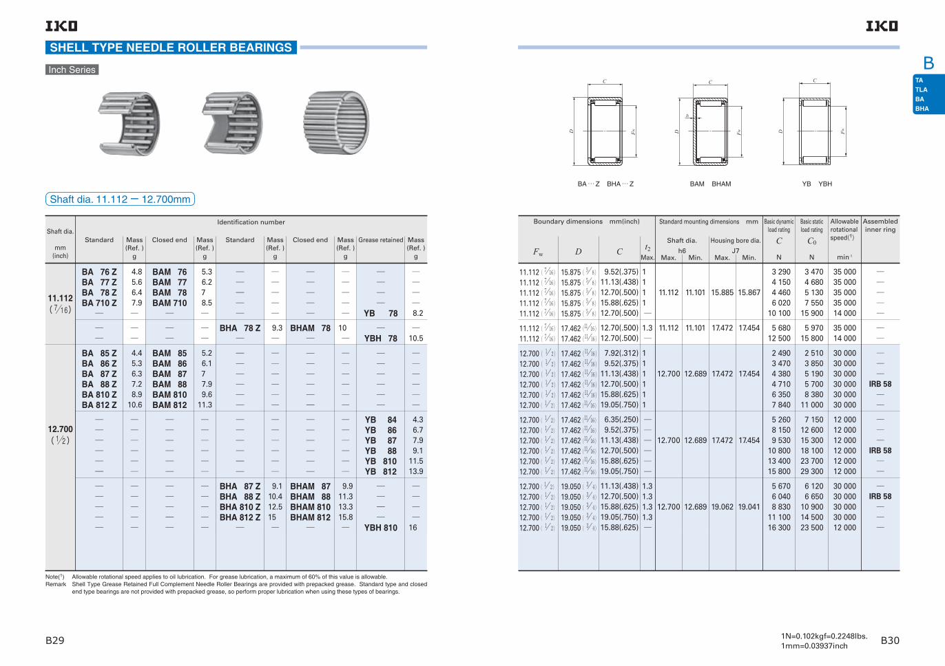
1N=0.102kgf=0.2248lbs.1mm=0.03937inchB29 B30
BSHELL TYPE NEEDLE ROLLER BEARINGS
Inch Series
Shaft dia.
mm(inch)
Note(1) Allowable rotational speed applies to oil lubrication. For grease lubrication, a maximum of 60% of this value is allowable.Remark Shell Type Grease Retained Full Complement Needle Roller Bearings are provided with prepacked grease. Standard type and closed
end type bearings are not provided with prepacked grease, so perform proper lubrication when using these types of bearings.
Standard Closed end Standard Closed end Grease retainedMass (Ref. )
g
Mass (Ref. )
g
Mass (Ref. )
g
Mass (Ref. )
g
Mass (Ref. )
g
Identification number
BA 76 ZBA 77 ZBA 78 ZBA 710 Z
BAM 76BAM 77BAM 78BAM 710
YB 78
4.45.36.37.28.9
10.6
4.85.66.47.9
11.112( 716)
5.2 6.17
7.9 9.611.3
5.3 6.27
8.5
9.110.412.515
9.911.313.315.8
4.3 6.7 7.9 9.111.513.9
16
8.2
BHA 78 Z
BHAM 78
YBH 78
9.3
10
10.5
BA 85 ZBA 86 ZBA 87 ZBA 88 ZBA 810 ZBA 812 Z
BAM 85BAM 86BAM 87BAM 88BAM 810BAM 812
12.700( 12)
YB 84YB 86YB 87YB 88YB 810YB 812
BHA 87 ZBHA 88 ZBHA 810 ZBHA 812 Z
BHAM 87BHAM 88BHAM 810BHAM 812
YBH 810
Shaft dia. 11.112− 12.700mm
11.112( 716)11.112( 716)11.112( 716)11.112( 716)11.112( 716)
15.875( 5 8)15.875( 5 8)15.875( 5 8)15.875( 5 8)15.875( 5 8)
9.52(.375)11.13(.438)12.70(.500)15.88(.625)12.70(.500)
1 1 1 1
11.112 11.101 15.885 15.867
3 2904 1504 4606 020
10 100
3 4704 6805 1307 550
15 900
35 00035 00035 00035 00014 000
11.112( 716)11.112( 716)
17.462(1116)17.462(1116)
12.70(.500)12.70(.500)
1.3
11.112 11.101 17.472 17.454 5 68012 500
5 97015 800
35 00014 000
12.700( 1 2)12.700( 1 2)12.700( 1 2)12.700( 1 2)12.700( 1 2)12.700( 1 2)
17.462(1116)17.462(1116)17.462(1116)17.462(1116)17.462(1116)17.462(1116)
7.92(.312) 9.52(.375)11.13(.438)12.70(.500)15.88(.625)19.05(.750)
1 1 1 1 1 1
12.700 12.689 17.472 17.454
2 4903 4704 3804 7106 3507 840
2 5103 8505 1905 7008 380
11 000
30 00030 00030 00030 00030 00030 000
IRB 58
12.700( 1 2)
12.700( 1 2)
12.700( 1 2)
12.700( 1 2)
12.700( 1 2)
12.700( 1 2)
17.462(1116)
17.462(1116)
17.462(1116)
17.462(1116)
17.462(1116)
17.462(1116)
6.35(.250) 9.52(.375)11.13(.438)12.70(.500)15.88(.625)19.05(.750)
12.700 12.689 17.472 17.454
5 2608 1509 530
10 80013 40015 800
7 15012 60015 30018 10023 70029 300
12 00012 00012 00012 00012 00012 000
IRB 58
12.700( 1 2)
12.700( 1 2)
12.700( 1 2)
12.700( 1 2)
12.700( 1 2)
19.050( 3 4)
19.050( 3 4)
19.050( 3 4)
19.050( 3 4)
19.050( 3 4)
11.13(.438)12.70(.500)15.88(.625)19.05(.750)15.88(.625)
1.3 1.3 1.3 1.3
12.700 12.689 19.062 19.041
5 6706 0408 830
11 10016 300
6 1206 650
10 90014 50023 500
30 00030 00030 00030 00012 000
IRB 58
Basic dynamic load rating
C
N
Basic static load rating
C0
N
Allowable rotational speed(1)
min-1
Boundary dimensions mm(inch)
Fw D C t2Max.
Assembledinner ring
Standard mounting dimensions mm
Max. Min. Max. Min.
Shaft dia.
h6
Housing bore dia.
J7
BA … Z BHA … Z BAM BHAM YB YBH
D
C
Fw D
C
Fw
t2
D
C
Fw

1N=0.102kgf=0.2248lbs.1mm=0.03937inchB31 B32
B
12.614.91824
13.916.219.325
15.3
BHA 108 ZBHA 1010 ZBHA 1012 ZBHA 1016 Z
BHAM 108BHAM 1010BHAM 1012BHAM 1016
YBH 108
5.3 7.6 8.710.812.915.117.3
6.5 8.7 9.9121416.218.4
6.71116.9
BA 105 ZBA 107 ZBA 108 ZBA 1010 ZBA 1012 ZBA 1014 ZBA 1016 Z
BAM 105BAM 107BAM 108BAM 1010BAM 1012BAM 1014BAM 1016
YB 105YB 108YB 1012
SHELL TYPE NEEDLE ROLLER BEARINGS
Shaft dia.
mm(inch)
Note(1) Allowable rotational speed applies to oil lubrication. For grease lubrication, a maximum of 60% of this value is allowable.Remark Shell Type Grease Retained Full Complement Needle Roller Bearings are provided with prepacked grease. Standard type and closed
end type bearings are not provided with prepacked grease, so perform proper lubrication when using these types of bearings.
Standard Closed end Standard Closed end Grease retainedMass (Ref. )
g
Mass (Ref. )
g
Mass (Ref. )
g
Mass (Ref. )
g
Mass (Ref. )
g
Identification number
Inch Series
BA 95 ZBA 96 ZBA 97 ZBA 98 ZBA 910 ZBA 912 Z
BAM 95BAM 96BAM 97BAM 98BAM 910BAM 912
YB 98YB 910YB 912
4.9 5.9 6.9 7.9 9.911.7
14.288( 916)
5.8 6.8 7.8 8.910.812.6
10.112.715.4
BHA 98 ZBHA 910 ZBHA 912 Z
BHAM 98BHAM 910BHAM 912
11.413.616.3
12.514.717.4
15.875( 58)
Shaft dia. 14.288− 15.875mm
1.31.31.31.31.31.31.3
15.875 15.864 20.650 20.629
25 00025 00025 00025 00025 00025 00025 0009 5009 5009 500
IRB 68-1
IRB 612-1IRB 714IRB 716
IRB 68-1IRB 612-1
1.31.31.31.3
15.875 15.864 22.237 22.216
25 00025 00025 00025 0009 500
IRB 68-1
IRB 612-1IRB 716IRB 68-1
15.875( 5 8)15.875( 5 8)
15.875( 5 8)
15.875( 5 8)
15.875( 5 8)
15.875( 5 8)
15.875( 5 8)
15.875( 5 8)
15.875( 5 8)
15.875( 5 8)
15.875( 5 8)
15.875( 5 8)
15.875( 5 8)
15.875( 5 8)
15.875( 5 8)
14.288( 916)14.288( 916)14.288( 916)14.288( 916)14.288( 916)14.288( 916)14.288( 916)14.288( 916)14.288( 916)
20.638(1316)20.638(1316)
20.638(1316)
20.638(1316)
20.638(1316)
20.638(1316)
20.638(1316)
20.638(1316)
20.638(1316)
20.638(1316)
22.225( 7 8)
22.225( 7 8)
22.225( 7 8)
22.225( 7 8)
22.225( 7 8)
19.050( 3 4)19.050( 3 4)19.050( 3 4)19.050( 3 4)19.050( 3 4)19.050( 3 4)19.050( 3 4)19.050( 3 4)19.050( 3 4)
7.92( .312)11.13( .438)12.70( .500)15.88( .625)19.05( .750)22.22( .875)25.40(1.000) 7.92( .312)12.70( .500)19.05( .750)
12.70( .500)15.88( .625)19.05( .750)25.40(1.000)12.70( .500)
7.92( .312) 9.52( .375)11.13( .438)12.70( .500)15.88( .625)19.05( .750)12.70( .500)15.88( .625)19.05( .750)
1.31.31.31.31.31.3
14.288 14.277 19.062 19.041
2 8705 0405 4207 3209 020
10 70012 3007 580
12 30017 800
6 68010 20012 70017 40015 000
2 7603 8504 8605 2207 0508 690
11 60014 30016 800
3 2206 6607 310
10 70014 10017 50020 80012 20022 70036 600
8 02013 80018 50027 60022 400
2 9704 5606 1406 7409 910
13 00020 40026 70033 000
30 00030 00030 00030 00030 00030 00011 00011 00011 000
IRB 68
IRB 612IRB 68
IRB 612
14.288( 916)14.288( 916)14.288( 916)
20.638(1316)20.638(1316)20.638(1316)
12.70( .500)15.88( .625)19.05( .750)
1.31.31.3
14.288 14.277 20.650 20.6296 3809 280
11 600
7 33011 90015 900
30 00030 00030 000
IRB 68
IRB 612
Basic dynamic load rating
C
N
Basic static load rating
C0
N
Allowable rotational speed(1)
min-1
Boundary dimensions mm(inch)
Fw D C t2Max.
Assembledinner ring
Standard mounting dimensions mm
Max. Min. Max. Min.
Shaft dia.
h6
Housing bore dia.
J7
BA … Z BHA … Z BAM BHAM YB YBH
D
C
Fw D
C
Fw
t2
D
C
Fw

1N=0.102kgf=0.2248lbs.1mm=0.03937inchB33 B34
BSHELL TYPE NEEDLE ROLLER BEARINGS
1013.51720.523.527
11.715.218.6222528.5
8.517.822.527
26.5 28.5
7 9.511.814
8.410.813.215.4
18.3
11.913.71619.3
13.515.317.621
Shaft dia.
mm(inch)
Note(1) Allowable rotational speed applies to oil lubrication. For grease lubrication, a maximum of 60% of this value is allowable.Remark Shell Type Grease Retained Full Complement Needle Roller Bearings are provided with prepacked grease. Standard type and closed
end type bearings are not provided with prepacked grease, so perform proper lubrication when using these types of bearings.
Standard Closed end Standard Closed end Grease retainedMass (Ref. )
g
Mass (Ref. )
g
Mass (Ref. )
g
Mass (Ref. )
g
Mass (Ref. )
g
Identification number
Inch Series
BA 116 ZBA 118 ZBA 1110 ZBA 1112 Z
BAM 116BAM 118BAM 1110BAM 1112
YB 111217.462( 1116)
BHA 117 ZBHA 118 ZBHA 1110 ZBHA 1112 Z
BHAM 117BHAM 118BHAM 1110BHAM 1112
BA 126 ZBA 128 ZBA 1210 ZBA 1212 ZBA 1214 ZBA 1216 Z
BAM 126BAM 128BAM 1210BAM 1212BAM 1214BAM 1216
19.050
( 34)
YB 124YB 128YB 1210YB 1212
BHA 1212 Z BHAM 1212
Shaft dia. 17.462− 19.050mm
1.3
1.31.31.31.31.31.3
19.050
19.050
19.037
19.037
27.000
25.412
26.979
25.391
IRB 812-1
IRB 88-1IRB 810-1IRB 812-1IRB 814-1IRB 816-1
19.050
19.037 25.412 25.391
IRB 88-1IRB 810-1IRB 812-1
19.050( 3 4)
19.050( 3 4)19.050( 3 4)
19.050( 3 4)
19.050( 3 4)
19.050( 3 4)
19.050( 3 4)
19.050( 3 4)
19.050( 3 4)
19.050( 3 4)
19.050( 3 4)
17.462(1116)17.462(1116)17.462(1116)17.462(1116)17.462(1116)
26.988(1 116)
25.400(1 )25.400(1 )25.400(1 )25.400(1 )25.400(1 )25.400(1 )
25.400(1 )25.400(1 )25.400(1 )25.400(1 )
22.225( 7 8)22.225( 7 8) 22.225( 7 8)22.225( 7 8)22.225( 7 8)
19.05( .750)
9.52( .375)12.70( .500)15.88( .625)19.05( .750)22.22( .875)25.40(1.000)
6.35( .250)12.70( .500)15.88( .625)19.05( .750)
9.52( .375)12.70( .500)15.88( .625)19.05( .750)19.05( .750)
1.31.31.31.3
17.462 17.451 22.237 22.216
16 600
5 0406 9109 500
11 90014 20016 300
7 82016 60020 50024 100
4 5306 1408 280
10 20018 700
22 600
5 8508 780
13 20017 70022 20026 500
10 20026 90035 30043 400
5 9808 850
13 00017 00040 300
20 000
20 000 20 000 20 000 20 000 20 000 20 000
8 0008 0008 0008 000
25 00025 00025 00025 0008 500
IRB 86IRB 88
IRB 812IRB 812
17.462(1116)17.462(1116)17.462(1116)17.462(1116)
23.812( 1516)23.812( 1516)23.812( 1516)23.812( 1516)
11.13( .438)12.70( .500)15.88( .625)19.05( .750)
1.31.31.31.3
17.462 17.451 23.824 23.803
6 8607 320
10 50013 200
8 5309 270
14 90019 900
25 00025 00025 00025 000
IRB 88
IRB 812
Basic dynamic load rating
C
N
Basic static load rating
C0
N
Allowable rotational speed(1)
min-1
Boundary dimensions mm(inch)
Fw D C t2Max.
Assembledinner ring
Standard mounting dimensions mm
Max. Min. Max. Min.
Shaft dia.
h6
Housing bore dia.
J7
BA … Z BHA … Z BAM BHAM YB
D
C
Fw D
C
Fw
t2
D
C
Fw

1N=0.102kgf=0.2248lbs.1mm=0.03937inchB35 B36
BSHELL TYPE NEEDLE ROLLER BEARINGS
11.515.623.5273134.542.5
13.817.82629.533.53744.5
20.53141.5
10.714.518.2222528.535.5
12.616.42023.52730.537.5
14.119.1
2023.528.5
22.525.530.5
30.537
253039.5
27.532.542
39
Shaft dia.
mm(inch)
Note(1) Allowable rotational speed applies to oil lubrication. For grease lubrication, a maximum of 60% of this value is allowable.Remark Shell Type Grease Retained Full Complement Needle Roller Bearings are provided with prepacked grease. Standard type and closed
end type bearings are not provided with prepacked grease, so perform proper lubrication when using these types of bearings.
Standard Closed end Standard Closed end Grease retainedMass (Ref. )
g
Mass (Ref. )
g
Mass (Ref. )
g
Mass (Ref. )
g
Mass (Ref. )
g
Identification number
Inch Series
BA 136 ZBA 138 ZBA 1310 ZBA 1312 ZBA 1314 ZBA 1316 ZBA 1320 Z
BAM 136BAM 138BAM 1310BAM 1312BAM 1314BAM 1316BAM 1320
YB 136YB 138
20.638( 1316)
BHA 138 ZBHA 1310 ZBHA 1312 Z
BHAM 138BHAM 1310BHAM 1312
YBH 1310YBH 1312
BA 146 ZBA 148 ZBA 1412 ZBA 1414 ZBA 1416 ZBA 1418 ZBA 1422 Z
BAM 146BAM 148BAM 1412BAM 1414BAM 1416BAM 1418BAM 1422
YB 148YB 1412YB 1416
22.225( 78)
BHA 1410 ZBHA 1412 ZBHA 1416 Z
BHAM 1410 BHAM 1412BHAM 1416
YBH 1412
Shaft dia. 20.638− 22.225mm
20.638(1316)20.638(1316)20.638(1316)20.638(1316)20.638(1316)20.638(1316)20.638(1316)20.638(1316)20.638(1316)
26.988(1 116)26.988(1 116)26.988(1 116)26.988(1 116)26.988(1 116)26.988(1 116)26.988(1 116)26.988(1 116)26.988(1 116)
9.52( .375)12.70( .500)15.88( .625)19.05( .750)22.22( .875)25.40(1.000)31.75(1.250) 9.52( .375)12.70( .500)
1.31.31.31.31.31.31.3
20.638 20.625 27.000 26.979
5 2307 1709 870
12 40014 70016 90021 20013 00017 400
6 3009 450
14 20019 00023 80028 50038 10020 10029 200
19 00019 00019 00019 00019 00019 00019 0007 5007 500
IRB 98IRB 910IRB 912IRB 914IRB 916IRB 920
IRB 98
20.638(1316)20.638(1316)20.638(1316)20.638(1316)20.638(1316)
28.575(1 1 8)28.575(1 1 8)28.575(1 1 8)28.575(1 1 8)28.575(1 1 8)
12.70( .500)15.88( .625)19.05( .750)15.88( .625)19.05( .750)
1.31.31.3
20.638 20.625 28.587 28.566
9 50013 80017 30022 90027 200
11 20018 20024 40036 30045 300
19 00019 00019 0007 5007 500
IRB 98IRB 910IRB 912IRB 910IRB 912
22.225( 7 8)
22.225( 7 8)
22.225( 7 8)
22.225( 7 8)
30.162(1 316)30.162(1 316)30.162(1 316)30.162(1 316)
15.88( .625)19.05( .750)25.40(1.000)19.05( .750)
14 30018 00023 60028 200
19 50026 10036 90049 000
18 00018 00018 0007 000
IRB 1012IRB 1016IRB 1012
22.225( 7 8)
22.225( 7 8)
22.225( 7 8)
22.225( 7 8)
22.225( 7 8)
22.225( 7 8)
22.225( 7 8)
22.225( 7 8)
22.225( 7 8)
22.225( 7 8)
28.575(1 1 8)28.575(1 1 8)28.575(1 1 8)28.575(1 1 8)28.575(1 1 8)28.575(1 1 8)28.575(1 1 8)28.575(1 1 8)28.575(1 1 8)28.575(1 1 8)
9.52( .375)12.70( .500)19.05( .750)22.22( .875)25.40(1.000)28.58(1.125)34.92(1.375)12.70( .500)19.05( .750)25.40(1.000)
3.43.43.4
2.82.82.82.82.82.82.8
22.225
22.225
22.212
22.212
30.176
28.587
30.151
28.566
5 4307 440
12 80015 30017 60019 80024 10018 10026 30033 800
6 74010 10020 40025 50030 50035 60045 70031 40050 70070 200
18 00018 00018 00018 00018 00018 00018 0007 0007 0007 000
IRB 106IRB 108IRB 1012IRB 1014IRB 1016
IRB 1022IRB 108IRB 1012IRB 1016
Basic dynamic load rating
C
N
Basic static load rating
C0
N
Allowable rotational speed(1)
min-1
Boundary dimensions mm(inch)
Fw D Ct1t2
Max.
Assembledinner ring
Standard mounting dimensions mm
Max. Min. Max. Min.
Shaft dia.
h6
Housing bore dia.
J7
BA … Z BHA … Z YB YBH BAM BHAMt1 (Fw≧22.225)t2 (Fw≦20.638)
D
t
t
2
1
C
FwD
C
Fw D
C
Fw

1N=0.102kgf=0.2248lbs.1mm=0.03937inchB37 B38
BSHELL TYPE NEEDLE ROLLER BEARINGS
13.115.417.72226.53135.544
1618.320.52529.533.53846.5
2334.546.5
242833.539.54556.567.5
27313742.54859.571
2944.559.5
16.520.533
192335.5
Shaft dia.
mm(inch)
Note(1) Allowable rotational speed applies to oil lubrication. For grease lubrication, a maximum of 60% of this value is allowable.Remark Shell Type Grease Retained Full Complement Needle Roller Bearings are provided with prepacked grease. Standard type and closed
end type bearings are not provided with prepacked grease, so perform proper lubrication when using these types of bearings.
Standard Closed end Standard Closed end Grease retainedMass (Ref. )
g
Mass (Ref. )
g
Mass (Ref. )
g
Mass (Ref. )
g
Mass (Ref. )
g
Identification number
Inch Series
BA 158 ZBA 1510 ZBA 1516 Z
BAM 158BAM 1510BAM 1516
23.812( 1516)
BA 166 ZBA 167 Z BA 168 ZBA 1610 ZBA 1612 ZBA 1614 ZBA 1616 ZBA 1620 Z
BAM 166BAM 167BAM 168BAM 1610BAM 1612BAM 1614BAM 1616BAM 1620
YB 168YB 1612YB 161625.400
(1)
BHA 168 ZBHA 1610 ZBHA 1612 ZBHA 1614 ZBHA 1616 ZBHA 1620 ZBHA 1624 Z
BHAM 168BHAM 1610BHAM 1612BHAM 1614BHAM 1616BHAM 1620BHAM 1624
YBH 168YBH 1612YBH 1616
BA 1710 ZBA 1716 Z
BAM 1710BAM 1716
23.537
26.988(1 116)
26.540.5
Shaft dia. 23.812− 26.988mm
2.82.82.82.82.82.82.82.83.43.43.43.43.43.43.4
25.400(1 )25.400(1 )25.400(1 )25.400(1 )25.400(1 )25.400(1 )25.400(1 )25.400(1 )25.400(1 )25.400(1 )25.400(1 )
25.400(1 )25.400(1 )25.400(1 )25.400(1 )25.400(1 )25.400(1 )25.400(1 )25.400(1 )25.400(1 )25.400(1 )
23.812( 1516)23.812( 1516)23.812( 1516)
31.750(1 1 4)31.750(1 1 4)31.750(1 1 4)31.750(1 1 4)31.750(1 1 4)31.750(1 1 4)31.750(1 1 4)31.750(1 1 4)31.750(1 1 4)31.750(1 1 4)31.750(1 1 4)
33.338(1 516)33.338(1 516)33.338(1 516)33.338(1 516)33.338(1 516)
33.338(1 516)
33.338(1 516)
33.338(1 516)
33.338(1 516)
33.338(1 516)
30.162(1 316)30.162(1 316)30.162(1 316)
9.52( .375)11.13( .438)12.70( .500)15.88( .625)19.05( .750)22.22( .875)25.40(1.000)31.75(1.250)12.70( .500)19.05( .750)25.40(1.000)
12.70( .500)15.88( .625)19.05( .750)22.22( .875)25.40(1.000)31.75(1.250)38.10(1.500)12.70( .500)19.05( .750)25.40(1.000)
12.70( .500)15.88( .625)25.40(1.000)
2.82.82.8
25.400
25.400
23.812
25.387
25.387
23.799
31.764
33.352
30.176
31.739
33.327
30.151
6 0107 7208 240
11 30014 20016 90019 40024 40019 40028 20036 300
10 20015 30019 30023 00026 40033 20039 40020 90030 70039 900
8 00011 00018 900
8 02011 10012 00018 10024 30030 40036 30048 50036 00058 00080 300
13 10022 10029 70037 20044 50059 60074 40034 10056 10078 400
11 40017 10034 300
15 00015 00015 00015 00015 00015 00015 00015 0006 0006 0006 000
15 00015 00015 00015 00015 00015 00015 0006 0006 0006 000
16 00016 00016 000
IRB 128
IRB 1212IRB 1214IRB 1216IRB 1220IRB 128IRB 1212IRB 1216
IRB 128
IRB 1212IRB 1214IRB 1216IRB 1220
IRB 128IRB 1212IRB 1216
IRB 1110IRB 1116
Basic dynamic load rating
C
N
Basic static load rating
C0
N
Allowable rotational speed(1)
min-1
Boundary dimensions mm(inch)
Fw D C t1Max.
Assembledinner ring
26.988(1 116)
26.988(1 116)
33.338(1 516)
33.338(1 516)
15.88( .625)25.40(1.000)
2.82.8
26.988 26.975 33.352 33.327 11 60020 000
19 20038 300
14 00014 000
Standard mounting dimensions mm
Max. Min. Max. Min.
Shaft dia.
h6
Housing bore dia.
J7
BA … Z BHA … Z BAM BHAM YB YBH
D
C
Fw D
C
FwD
C
Fw
t1

1N=0.102kgf=0.2248lbs.1mm=0.03937inchB39 B40
B
32.552
37.557
42.5
BA 1910 ZBA 1916 Z
BAM 1910BAM 1916
YB 1910
SHELL TYPE NEEDLE ROLLER BEARINGS
Shaft dia.
mm(inch)
Note(1) Allowable rotational speed applies to oil lubrication. For grease lubrication, a maximum of 60% of this value is allowable.Remark Shell Type Grease Retained Full Complement Needle Roller Bearings are provided with prepacked grease. Standard type and closed
end type bearings are not provided with prepacked grease, so perform proper lubrication when using these types of bearings.
Standard Closed end Standard Closed end Grease retainedMass (Ref. )
g
Mass (Ref. )
g
Mass (Ref. )
g
Mass (Ref. )
g
Mass (Ref. )
g
Identification number
Inch Series
BA 186 ZBA 188 ZBA 1812 ZBA 1816 ZBA 1820 Z
BAM 186BAM 188BAM 1812BAM 1816BAM 1820
YB 188YB 1812YB 1816
14.519.529.53948.5
28.575(1 18)
18.1233342.552
25.538.551.5
BHA 1812 ZBHA 1816 ZBHA 1818 ZBHA 1820 Z
BHAM 1812BHAM 1816BHAM 1818BHAM 1820
456067.573.5
496471.578
30.162(1 316)
Shaft dia. 28.575− 30.162mm
30.162(1 316)30.162(1 316)30.162(1 316)
Basic dynamic load rating
C
N
Basic static load rating
C0
N
Allowable rotational speed(1)
min-1
Boundary dimensions mm(inch)
Fw D C t1Max.
Assembledinner ring
28.575(1 1 8)28.575(1 1 8)28.575(1 1 8)28.575(1 1 8)28.575(1 1 8)28.575(1 1 8)28.575(1 1 8)28.575(1 1 8)
38.100(1 1 2)38.100(1 1 2)38.100(1 1 2)
34.925(1 3 8)34.925(1 3 8)34.925(1 3 8)34.925(1 3 8)34.925(1 3 8)34.925(1 3 8)34.925(1 3 8)34.925(1 3 8)
15.88( .625)25.40(1.000)15.88( .625)
9.52(. 375)12.70( .500)19.05( .750)25.40(1.000)31.75(1.250)12.70( .500)19.05( .750)25.40(1.000)
2.82.8
2.82.82.82.82.8
30.162
28.575
30.146
28.562
38.114
34.939
38.089
34.914
15 00025 80028 400
6 3308 680
15 00020 50025 70020 70030 00038 700
22 50045 30053 600
8 91013 40026 90040 30053 90040 50065 30090 400
12 00012 0005 000
13 00013 00013 00013 00013 0005 5005 5005 500
IRB 148IRB 1412IRB 1416IRB 1420IRB 148IRB 1412IRB 1416
28.575(1 1 8)28.575(1 1 8)28.575(1 1 8)28.575(1 1 8)
38.100(1 1 2)38.100(1 1 2)38.100(1 1 2)38.100(1 1 2)
19.05( .750)25.40(1.000)28.58(1.125)31.75(1.250)
3.43.43.43.4
28.575 28.562 38.114 38.089
22 50030 90034 90037 100
32 20048 60056 60061 100
13 00013 00013 00013 000
IRB 1412IRB 1416
IRB 1420
Standard mounting dimensions mm
Max. Min. Max. Min.
Shaft dia.
h6
Housing bore dia.
J7
BA … Z BHA … Z BAM BHAM YB
D
C
Fw D
C
FwD
C
Fw
t1

1N=0.102kgf=0.2248lbs.1mm=0.03937inchB41 B42
BSHELL TYPE NEEDLE ROLLER BEARINGS
28.535.543
3541.549
BA 218 ZBA 2110 ZBA 2112 Z
BAM 218BAM 2110BAM 2112
33.338(1 516)
Shaft dia.
mm(inch)
Note(1) Allowable rotational speed applies to oil lubrication. For grease lubrication, a maximum of 60% of this value is allowable.Remark Shell Type Grease Retained Full Complement Needle Roller Bearings are provided with prepacked grease. Standard type and closed
end type bearings are not provided with prepacked grease, so perform proper lubrication when using these types of bearings.
Standard Closed end Standard Closed end Grease retainedMass (Ref. )
g
Mass (Ref. )
g
Mass (Ref. )
g
Mass (Ref. )
g
Mass (Ref. )
g
Identification number
Inch Series
BA 208 ZBA 2010 ZBA 2012 ZBA 2016 ZBA 2020 Z
BAM 208BAM 2010BAM 2012BAM 2016BAM 2020
21.52732.54353.5
31.750(1 14)
2631.53747.558
YB 2010YB 2012YB 2016YB 2018YB 2020
3542.5576468
BHA 208 ZBHA 2012 ZBHA 2016 ZBHA 2020 Z
BHAM 208BHAM 2012BHAM 2016BHAM 2020
34.549.56681.5
4054.57186.5
Shaft dia. 31.750− 33.338mm
33.338(1 516)33.338(1 516
33.338(1 516)
41.275(1 5 8)
41.275(1 5 8)
41.275(1 5 8)
12.70( .500)15.88( .625)19.05( .750)
2.82.82.8
33.338 33.322 41.289 41.26411 10015 40019 300
15 80023 90032 100
11 00011 00011 000
IRB 168-1IRB 1610-1IRB 1612-1
Basic dynamic load rating
C
N
Basic static load rating
C0
N
Allowable rotational speed(1)
min-1
Boundary dimensions mm(inch)
Fw D C t1Max.
Assembledinner ring
31.750(1 1 4)31.750(1 1 4)31.750(1 1 4)31.750(1 1 4)31.750(1 1 4)
38.100(1 1 2)38.100(1 1 2)38.100(1 1 2)
38.100(1 1 2)38.100(1 1 2)
12.70( .500)15.88( .625)19.05( .750)25.40(1.000)31.75(1.250)
2.82.82.82.82.8
31.750 31.734 38.114 38.089
9 10012 50015 70021 50026 900
14 70022 20029 60044 30059 200
12 00012 00012 00012 00012 000
IRB 168IRB 1610IRB 1612IRB 1616IRB 1620
31.750(1 1 4)31.750(1 1 4)31.750(1 1 4)31.750(1 1 4)31.750(1 1 4)
38.100(1 1 2)
38.100(1 1 2)38.100(1 1 2)38.100(1 1 2)
38.100(1 1 2)
15.88( .625)19.05( .750)25.40(1.000)28.58(1.125)31.75(1.250)
31.750 31.734 38.114 38.089
27 00031 80040 90045 30049 400
59 00072 500
100 000114 000128 000
4 5004 5004 5004 5004 500
IRB 1610IRB 1612IRB 1616
IRB 1620
31.750(1 1 4)31.750(1 1 4)31.750(1 1 4)31.750(1 1 4)
41.275(1 5 8)
41.275(1 5 8)
41.275(1 5 8)
41.275(1 5 8)
12.70( .500)19.05( .750)25.40(1.000)31.75(1.250)
3.43.43.43.4
31.750 31.734 41.289 41.264
13 70024 10033 20040 000
17 60036 40055 00069 600
12 00012 00012 00012 000
IRB 168IRB 1612IRB 1616IRB 1620
Standard mounting dimensions mm
Max. Min. Max. Min.
Shaft dia.
h6
Housing bore dia.
J7
BA … Z BHA … Z BAM BHAM YB
D
C
Fw D
C
FwD
C
Fw
t1

1N=0.102kgf=0.2248lbs.1mm=0.03937inchB43 B44
B
BA 248 ZBA 2410 ZBA 2412 ZBA 2414 ZBA 2416 ZBA 2420 Z
BAM 248BAM 2410BAM 2412BAM 2414BAM 2416BAM 2420
38.548.558.5697997.5
47.5 57.5 67.5 78 88106
38 51.5 91105131
YB 246YB 248YB 2414YB 2416YB 2420
SHELL TYPE NEEDLE ROLLER BEARINGS
Shaft dia.
mm(inch)
Note(1) Allowable rotational speed applies to oil lubrication. For grease lubrication, a maximum of 60% of this value is allowable.Remark Shell Type Grease Retained Full Complement Needle Roller Bearings are provided with prepacked grease. Standard type and closed
end type bearings are not provided with prepacked grease, so perform proper lubrication when using these types of bearings.
Standard Closed end Standard Closed end Grease retainedMass (Ref. )
g
Mass (Ref. )
g
Mass (Ref. )
g
Mass (Ref. )
g
Mass (Ref. )
g
Identification number
Inch Series
BA 228 ZBA 2212 ZBA 2216 ZBA 2220 Z
BAM 228BAM 2212BAM 2216BAM 2220
YB 228YB 2212YB 2220
23.535.547.559
34.925(1 38)
29 41 53 64
30.5 46 77.5
BHA 228 ZBHA 2210 ZBHA 2212 ZBHA 2216 ZBHA 2220 Z
BHAM 228BHAM 2210BHAM 2212BHAM 2216BHAM 2220
3744537187
4350597798.5
38.100(1 12)
Shaft dia. 34.925− 38.100mm
38.100(1 1 2)38.100(1 1 2)38.100(1 1 2)38.100(1 1 2)38.100(1 1 2)38.100(1 1 2)
47.625(1 7 8)47.625(1 7 8)47.625(1 7 8)47.625(1 7 8)47.625(1 7 8)47.625(1 7 8)
12.70( .500)15.88( .625)19.05( .750)22.22( .875)25.40(1.000)31.75(1.250)
2.82.82.82.82.82.8
38.100 38.084 47.639 47.614
12 90017 80022 50026 70031 10039 000
17 90027 10036 60045 60055 40074 200
9 0009 0009 0009 0009 0009 000
IRB 2010
IRB 2014IRB 2016IRB 2020
38.100(1 1 2)38.100(1 1 2)38.100(1 1 2)38.100(1 1 2)38.100(1 1 2)
47.625(1 7 8)47.625(1 7 8)47.625(1 7 8)47.625(1 7 8)47.625(1 7 8)
9.52( .375)12.70( .500)22.22( .875)25.40(1.000)31.75(1.250)
38.100 38.084 47.639 47.614
21 00028 70048 90055 10066 800
34 10050 900
101 000118 000151 000
4 0004 0004 0004 0004 000
IRB 2014IRB 2016IRB 2020
Basic dynamic load rating
C
N
Basic static load rating
C0
N
Allowable rotational speed(1)
min-1
Boundary dimensions mm(inch)
Fw D C t1Max.
Assembledinner ring
34.925(1 3 8)34.925(1 3 8)34.925(1 3 8)34.925(1 3 8)34.925(1 3 8)34.925(1 3 8)34.925(1 3 8)
41.275(1 5 8)41.275(1 5 8)41.275(1 5 8)41.275(1 5 8)41.275(1 5 8)41.275(1 5 8)41.275(1 5 8)
12.70( .500)19.05( .750)25.40(1.000)31.75(1.250)12.70( .500)19.05( .750)31.75(1.250)
2.82.82.82.8
34.925 34.909 41.289 41.264
9 77016 90023 10028 90023 00033 40052 000
16 60033 50050 20067 10049 50079 800
141 000
10 00010 00010 00010 0004 5004 5004 500
IRB 188IRB 1812IRB 1816IRB 1820IRB 188IRB 1812IRB 1820
34.925(1 3 8)34.925(1 3 8)34.925(1 3 8)34.925(1 3 8)34.925(1 3 8)
44.450(1 3 4)44.450(1 3 4)44.450(1 3 4)44.450(1 3 4)44.450(1 3 4)
12.70( .500)15.88( .625)19.05( .750)25.40(1.000)31.75(1.250)
3.43.43.43.43.4
34.925 34.909 44.464 44.439
14 10019 70024 80034 10041 200
18 80028 80038 80058 40074 200
10 00010 00010 00010 00010 000
IRB 188
IRB 1812IRB 1816IRB 1820
Standard mounting dimensions mm
Max. Min. Max. Min.
Shaft dia.
h6
Housing bore dia.
J7
BA … Z BHA … Z BAM BHAM YB
D
C
Fw D
C
FwD
C
Fw
t1

1N=0.102kgf=0.2248lbs.1mm=0.03937inchB45 B46
B
50104128155180
66119144170196
130
BA 328 ZBA 3216 ZBA 3220 ZBA 3224 ZBAW3228Z
BAM 328BAM 3216BAM 3220BAM 3224BAMW3228
YB 3216
67.5 91112136
79.5103125148
195
210
119
BA 2812 ZBA 2816 ZBA 2820 ZBA 2824 Z
BAM 2812BAM 2816BAM 2820BAM 2824
YB 2816
BHA 2824 Z BHAM 2824
SHELL TYPE NEEDLE ROLLER BEARINGS
Shaft dia.
mm(inch)
Note(1) Allowable rotational speed applies to oil lubrication. For grease lubrication, a maximum of 60% of this value is allowable.Remarks1. "W" in the identification number indicates that rolling elements are arranged in double rows. 2. Shell Type Grease Retained Full Complement Needle Roller Bearings are provided with prepacked grease. Standard type and
closed end type bearings are not provided with prepacked grease, so perform proper lubrication when using these types of bearings.
Standard Closed end Standard Closed end Grease retainedMass (Ref. )
g
Mass (Ref. )
g
Mass (Ref. )
g
Mass (Ref. )
g
Mass (Ref. )
g
Identification number
Inch Series
BA 268 ZBA 2610 ZBA 2616 ZBA 2620 Z
BAM 268BAM 2610BAM 2616BAM 2620
YB 2610
41 52 85105
41.275(1 58)
51.5 62.5 95.5115
69
44.450(1 34)
BA 308 ZBA 3010 ZBA 3012 ZBA 3016 Z
BAM 308BAM 3010BAM 3012BAM 3016
YB 3012
47.5 60 72.5 97.5
47.625(1 78)
61 74 86.5112
95
50.800(2)
BHA 3312 ZBHA 3316 ZBHA 3324 Z
BHAM 3312BHAM 3316BHAM 3324
52.388(2 116)
104139205
122157225
Shaft dia. 41.275− 52.388mm
Basic dynamic load rating
C
N
Basic static load rating
C0
N
Allowable rotational speed(1)
min-1
BA … Z BHA … Z
Boundary dimensions mm(inch)
Fw D C
BAM BHAM YB
Assembledinner ring
44.450(1 3 4)44.450(1 3 4)44.450(1 3 4)44.450(1 3 4)44.450(1 3 4)
44.450(1 3 4)
50.800(2 )50.800(2 )50.800(2 )50.800(2 )50.800(2 )50.800(2 )
41.275(1 5 8)41.275(1 5 8)41.275(1 5 8)41.275(1 5 8)41.275(1 5 8)
53.975(2 1 8)53.975(2 1 8)53.975(2 1 8)53.975(2 1 8)53.975(2 1 8)
57.150(2 1 4)
60.325(2 3 8)60.325(2 3 8)60.325(2 3 8)60.325(2 3 8)60.325(2 3 8)60.325(2 3 8)
50.800(2 )50.800(2 )50.800(2 )50.800(2 )50.800(2 )
19.05( .750)25.40(1.000)31.75(1.250)38.10(1.500)25.40(1.000)
38.10(1.500)
12.70( .500)25.40(1.000)31.75(1.250)38.10(1.500)44.45(1.750)25.40(1.000)
12.70( .500)15.88( .625)25.40(1.000)31.75(1.250)15.88( .625)
2.82.82.82.8
3.4
2.82.82.82.82.8
2.82.82.82.8
44.450
44.450
50.800
41.275
44.434
44.434
50.781
41.259
53.993
57.168
60.343
50.818
53.963
57.138
60.313
50.788
25 20034 80043 60052 00059 500
72 200
15 40037 10046 60055 50057 90064 100
13 70018 90033 00041 40037 000
44 50067 40090 200
113 000136 000
135 000
24 70076 500
102 000128 000136 000156 000
19 80030 00061 40082 10071 700
7 5007 5007 5007 5003 500
7 500
6 0006 0006 0006 0006 0002 500
8 0008 0008 0008 0003 500
IRB 2412IRB 2416
IRB 2424IRB 2416
IRB 2424
IRB 2616IRB 2720
IRB 2628IRB 2616
IRB 2210
IRB 2220IRB 2210
47.625(1 7 8)47.625(1 7 8)47.625(1 7 8)47.625(1 7 8)47.625(1 7 8)
57.150(2 1 4)57.150(2 1 4)57.150(2 1 4)57.150(2 1 4)57.150(2 1 4)
12.70( .500)15.88( .625)19.05( .750)25.40(1.000)19.05( .750)
2.82.82.82.8
47.625 47.609 57.168 57.138
14 70020 30025 70035 40047 800
22 80034 50046 70070 600
105 000
7 0007 0007 0007 0003 000
IRB 248-1IRB 2410-1
52.388(2 116)52.388(2 116)52.388(2 116)
64.294(21732)64.294(21732)64.294(21732)
19.05( .750)25.40(1.000)38.10(1.500)
3.43.43.4
52.388 52.369 64.312 64.28236 40050 60073 900
62 10094 700
154 000
6 0006 0006 000
Standard mounting dimensions mm
Max. Min. Max. Min.
Shaft dia.
h6
Housing bore dia.
J7t1Max.
D
C
Fw D
C
FwD
C
Fw
t1
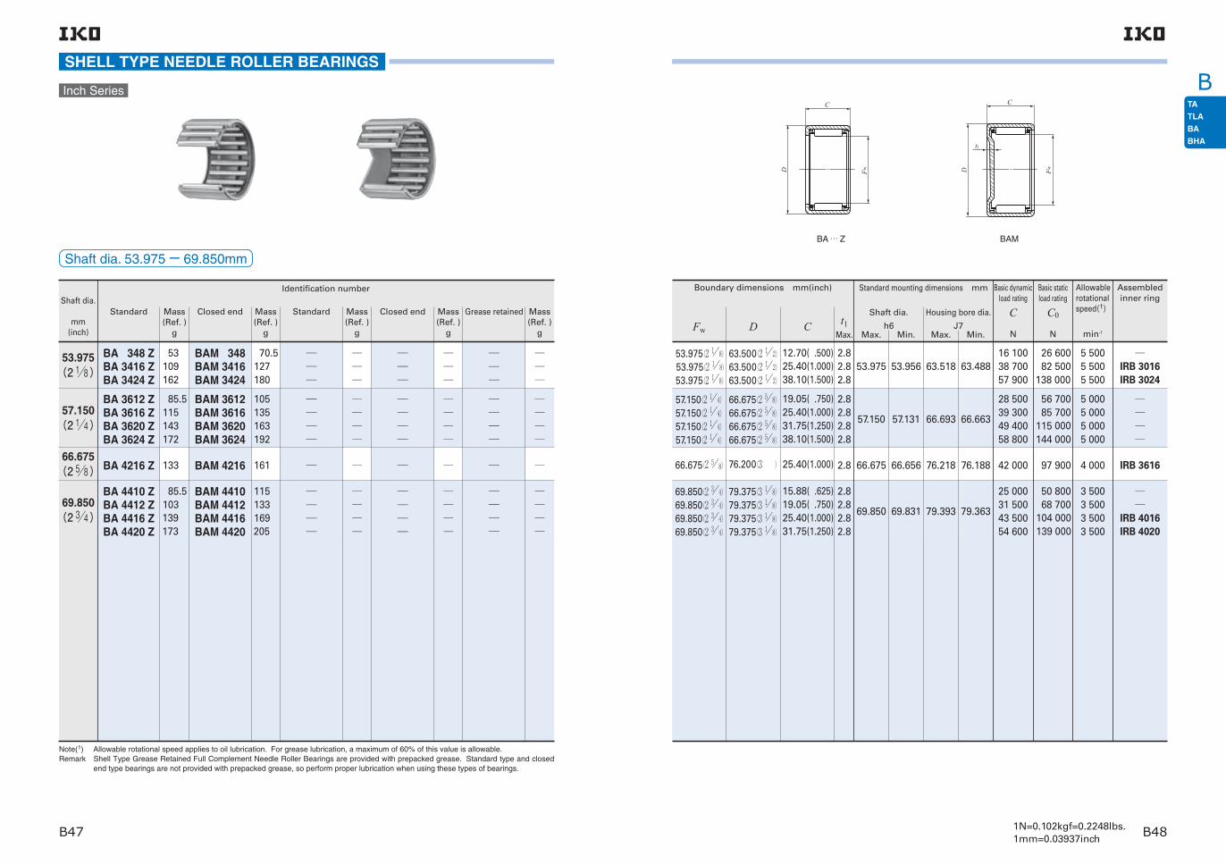
1N=0.102kgf=0.2248lbs.1mm=0.03937inchB47 B48
B
85.5115143172
85.5103139173
105135163192
115133169205
BA 3612 ZBA 3616 ZBA 3620 ZBA 3624 Z
BA 4410 ZBA 4412 ZBA 4416 ZBA 4420 Z
BAM 4410BAM 4412BAM 4416BAM 4420
SHELL TYPE NEEDLE ROLLER BEARINGS
Shaft dia.
mm(inch)
Note(1) Allowable rotational speed applies to oil lubrication. For grease lubrication, a maximum of 60% of this value is allowable.Remark Shell Type Grease Retained Full Complement Needle Roller Bearings are provided with prepacked grease. Standard type and closed
end type bearings are not provided with prepacked grease, so perform proper lubrication when using these types of bearings.
Standard Closed end Standard Closed end Grease retainedMass (Ref. )
g
Mass (Ref. )
g
Mass (Ref. )
g
Mass (Ref. )
g
Mass (Ref. )
g
Identification number
Inch Series
BA 348 ZBA 3416 ZBA 3424 Z
BAM 348BAM 3416BAM 3424
53109162
70.5127180
BAM 3612BAM 3616BAM 3620BAM 3624
BA 4216 Z BAM 4216 13366.675
(2 58) 161
53.975(2 18)
57.150(2 14)
69.850(2 34)
Shaft dia. 53.975− 69.850mm
69.850(2 3 4)69.850(2 3 4)69.850(2 3 4)69.850(2 3 4)
79.375(3 1 8)79.375(3 1 8)79.375(3 1 8)79.375(3 1 8)
15.88( .625)19.05( .750)25.40(1.000)31.75(1.250)
2.82.82.82.8
69.850 69.831 79.393 79.363
25 00031 50043 50054 600
50 80068 700
104 000139 000
3 5003 5003 5003 500
IRB 4016IRB 4020
57.150(2 1 4)57.150(2 1 4)57.150(2 1 4)57.150(2 1 4)
66.675(2 5 8)66.675(2 5 8)66.675(2 5 8)66.675(2 5 8)
19.05( .750)25.40(1.000)31.75(1.250)38.10(1.500)
2.82.82.82.8
57.150 57.131 66.693 66.663
28 50039 30049 40058 800
56 70085 700
115 000144 000
5 0005 0005 0005 000
Basic dynamic load rating
C
N
Basic static load rating
C0
N
Allowable rotational speed(1)
min-1
BA … Z
Boundary dimensions mm(inch)
Fw D C t1Max.
BAM
Assembledinner ring
53.975(2 1 8)53.975(2 1 8)53.975(2 1 8)
63.500(2 1 2)63.500(2 1 2)63.500(2 1 2)
12.70( .500)25.40(1.000)38.10(1.500)
2.82.82.8
53.975 53.956 63.518 63.48816 10038 70057 900
26 60082 500
138 000
5 5005 5005 500
IRB 3016IRB 3024
66.675(2 5 8) 76.200(3 )
25.40(1.000) 2.8 66.675 66.656 76.218 76.188 42 000 97 900 4 000 IRB 3616
Standard mounting dimensions mm
Max. Min. Max. Min.
Shaft dia.
h6
Housing bore dia.
J7
D
C
Fw D
C
Fw
t1

1N=0.102kgf=0.2248lbs.1mm=0.03937inchB49 B50
BSHELL TYPE NEEDLE ROLLER BEARINGS
Note(1) Allowable rotational speed applies to grease lubrication.Remark The type with seals is provided with prepacked grease.
Shaft dia.
mm
Identification number
12
14
15
16
18
20
22
25
28
30
35
40
45
50
TLA 1216 UU
TLA 1416 UU
TLA 1516 UU
TLA 1616 UU
TLA 1816 UU
TLA 2016 UUTLA 2020 UU
TLA 2216 UUTLA 2220 UU
TLA 2516 UUTLA 2520 UU
TLA 2820 UU
TLA 3016 UUTLA 3020 UU
TLA 3516 UUTLA 3520 UU
TLA 4016 UUTLA 4020 UU
TLA 4520 UU
TLA 5026 UU
11.7
13.3
14
14.8
16.3
17.8 22.5
19.4 25
26 33
36.5
30.5 39
35 45
39.5 50.5
56
89
Standard mounting dimensions mm
Max. Min. Max. Min. N7
Housing bore dia.
12
14
15
18
16
2020
2222
2525
28
3030
3535
45
50
4040
18
20
21
24
22
2626
2828
3232
35
3737
4242
52
58
4747
16
16
16
16
16
1620
1620
1620
20
1620
1620
20
26
1620
12.000
14.000
15.000
18.000
16.000
20.000
22.000
25.000
28.000
30.000
35.000
45.000
50.000
40.000
11.989
13.989
14.989
17.989
15.989
19.987
21.987
24.987
27.987
29.987
34.984
44.984
49.984
39.984
17.995
19.993
20.993
23.993
21.993
25.993
27.993
31.992
34.992
36.992
41.992
51.991
57.991
46.992
17.977
19.972
20.972
23.972
21.972
25.972
27.972
31.967
34.967
36.967
41.967
51.961
57.961
46.967
Boundary dimensions mm
D CFw
Mass (Ref. )
gh6
Shaft dia.
Shaft dia. 12− 50mm
With seals
6 420
7 080
7 380
7 670
8 230
8 74011 100
9 23011 700
9 44012 800
13 800
10 40014 100
11 60015 700
12 40016 700
17 800
28 800
7 490
8 840
9 520
10 200
11 500
12 90017 500
14 30019 300
13 90020 500
23 500
16 60024 500
20 00029 600
22 80033 700
37 800
64 100
14 000
12 000
11 000
11 000
9 000
9 0009 000
8 0008 000
7 0007 000
6 000
5 5005 500
5 0005 000
4 5004 500
4 000
3 500
Basic dynamic load rating
C
N
Basic static load rating
C0
N
Allowable rotational speed(1)
min-1
TLA … UU
D
C
Fw

C
C1 C2
High carbon steel cage type
Synthetic resin cage type
IKO Needle Roller Cages for General Usage are bearings which display excellent rotational perfor-mance. Needle rollers with extremely small dimen-sional variations in diameter are incorporated and retained in their specially shaped cages with high rigidity and accuracy, which precisely guide the nee-dle rollers. When combined with shafts and housing bores that are heat treated and accurately ground as raceway surfaces, Needle Roller Cages for General Usage are particularly useful in small spaces. In addition, since they are lightweight and have high rigidity as well as a large lubricant holding capacity, they can withstand severe operating conditions such as high speed rotation and shock loads, and they are used in a wide range of applications.
Structures of Needle Roller Cages for General Usage
Cage
Needle roller
Cage
Needle roller
High carbon steel cage type
Needle roller
Cage
Synthetic resin cage type
Structure and Features

C
1N=0.102kgf=0.2248lbs.1mm=0.03937inchC3 C4
KT 50 58 25 N C3
Model codeSupplemental
code
Supplemental code
Dimensions
KT 15 10 C3
Type of bearing
20
Tolerance of mean value of roller dia. (Refer to Table 2.)
Cage width(10mm)
Roller set outside diameter(20mm)
Roller set bore diameter(15mm)
Model code Dimensions
Type of bearing
Tolerance of mean value of roller dia. (Refer to Table 2.)
Cage width(25mm)
Roller set outside diameter(58mm)
Roller set bore diameter(50mm)
Examples of identification number
Example 1
Example 2
TypesNeedle Roller Cages for General Usage are available in the types shown in Table 1.For applications such as crank shafts where these bearings are difficult to install, it is also possible to make split type bearings.If such bearings are required, please contact IKO.For Needle Roller Cages for Engine Connecting Rods (KT…EG and KTV…EG), see page C17.
The identification number of Needle Roller Cages for General Usage consists of a model code, dimensions and any supplemental codes. The arrangement examples are shown below.
Identification Number
AccuracyThe diameter tolerances of needle rollers of Needle Roller Cages for General Usage are classified by classification symbols shown in Table 2. If a classifi-cation symbol is not indicated in an identification num-ber, the classification symbol "C3" is applied.When two or more bearings are used in tandem arrangement on the same shaft, it is necessary to select bearings of the same classification symbol to obtain an even load distribution.
The tolerance of the cage width Bc is -0.20〜 -0.55 mm.
C 3
B 2
B 4
B 6
B 8
B10
0〜− 30〜− 2
− 2〜− 4− 4〜− 6− 6〜− 8− 8〜− 10
Classification symbolTolerance of mean value of needle roller
diameter
Table 2 Diameter tolerances of needle rollers unit: μ m
Table 1 Model of bearing
ItemModel of bearing
Single row needle roller
Double row needle roller
High carbon steel cage type
KT KTW
Synthetic resin cage type
KT…N −
Radial clearances of Needle Roller Cages for General Usage are determined by the dimensional accuracy of the raceways and needle rollers. Table 3 shows the recommended fits for the operating conditions.
Fit
Specifications of shaft and housing
Operating temperature range
For the raceways, a surface hardness of 58〜 64HRC and a surface roughness 0.2μmRa or less are desir-able. However, when the operating conditions are not severe, a surface roughness 0.8μmRa or less can be used.When the surface hardness is low, it is necessary to correct the load rating by the hardness factor speci-fied on page A20.
MountingThe dimensions related to mounting of Needle Roller Cages for General Usage are shown in Figs. 1 and 2.When mounting Needle Roller Cages for General Usage, they are axially positioned by using, for exam-ple, Cir-clips for shaft and housing bore (WR and AR on page L17) as shown in Figs. 3, 4 and 5.For high rotational speed applications, a heat treated and ground spacer is positioned between the cage and the cir-clip as shown in Fig. 5 so that the cage does not make direct contact with the cir-clip. In this case, the cir-clip is normally mounted on the non-rotating side.Fig. 3 shows a mounting example in the case of outer ring rotation, and Figs. 4 and 5 show examples in the case of inner ring rotation.
When high operating accuracy is required. When shock loads and oscillating motions are applied.
For general use
When the temperature is high, or mounting errors are large.
j5 h5
h5
g6
g5
f6
Shaft
Operating conditions
Tolerance class of shaft
Fw≦ 68mm Fw> 68mm
Table 3 Recommended fits of shaft to the housing bore diameter G6
Remark When setting the required radial clearance according to the operating conditions, the clearance can easily be obtained by selecting and matching the tolerances of needle rollers, shaft and housing bore. When variation of the clearance does not create any problems, h6 and G7 are used for shaft and housing bore, respectively.
Fig.1
Fig.2
Fig.3
Fig.4
Fig.5
The operating temperature range for high carbon steel cage types is -20 to 120°C. The maximum allow-able temperature for synthetic resin cage types is +110 C, and +100 C when they are continuously operated.
Dw
Dw
Bc H11
2| 3
Dw
Dw
Bc H11
2| 3

C
1N=0.102kgf=0.2248lbs.1mm=0.03937inchC5 C6
NEEDLE ROLLER CAGES FOR GENERAL USAGE
Shaft dia. 3− 14mm
Shaftdia.
mm
Mass (Ref.)
g
Basic dynamic load rating
C
N
Basic static load rating
C0
N
Identification number
Fw Ew Bc
Note(1) Allowable rotational speed applies to oil lubrication. For grease lubrication, a maximum of 50% of this value is allowable.Remark For synthetic resin cage types, "N" is added at the end of the identification number. For sizes not listed in the dimension tables, please
contact IKO.
Allowable rotational speed(1)
min-1
Boundary dimensionsmm
3 KT 367N 0.39 3 6 7 1 480 990 140 000
4 KT 477N 0.47 4 7 7 1 800 1 300 100 000
5 KT 587NKT 588N
0.53 0.66
55
88
78
2 0702 420
1 6001 950
85 00085 000
6KT 697NKT 698NKT 6910KT 61013
0.63 0.75 1.45 2.7
6666
999
10
78
1013
2 3102 7003 0104 410
1 9002 3202 6603 720
75 00075 00075 00075 000
7 KT 7108NKT 71010
0.86 1.69
77
1010
810
2 9603 340
2 6903 130
65 00065 000
8
KT 8118NKT 81110KT 81110NKT 81113KT 8128KT 81211
0.96 1.9 1.2 2.5 2.1 3
888888
111111121212
81010138
11
3 1903 6303 6304 5003 6304 630
3 0603 6003 6004 7503 0404 170
60 00060 00060 00060 00060 00060 000
9
KT 91210KT 91213
2.1 2.8
99
1212
1013
3 9004 840
4 0705 370
55 00055 000
10
KT 10138KT 101310KT 101313KT 101410KT 101412KT 101413KT 101415
1.9 2.3 3 3.2 3.8 4.2 4.8
10101010101010
13131314141414
8101310121315
3 3704 1605 1604 9005 9406 1007 080
3 4704 5506 0004 6806 0006 2007 520
50 00050 00050 00050 00050 00050 00050 000
11 KT 111410 2.5 11 14 10 4 400 5 020 45 000
High carbon steel cage type Synthetic resin cage typeKT ( … N)
Shaftdia.
mm
Mass (Ref.)
g
Basic dynamic load rating
C
N
Basic static load rating
C0
N
Boundary dimensionsmm
Identification number
Fw Ew Bc
Allowable rotational speed(1)
min-1
12
KT 12158KT 121510KT 121512KT 121513KT 121514KT 121610KT 121613KT 121618KT 121710KT 121812KT 121820
2.2 2.7 3.2 3.6 3.8 4 5.2 7 5.1 7.8 13.2
1212121212121212121212
1515151515161616171818
810121314101318101220
3 7504 6205 5905 7306 2005 6507 0209 7906 1709 030
13 700
4 2005 4907 0207 2508 0105 8907 800
11 9005 7408 460
14 400
40 00040 00040 00040 00040 00040 00040 00040 00040 00040 00040 000
13KT 131710KT 131815KT 131816
4.3 8.2 8.7
131313
171818
101516
5 9909 660
10 300
6 50010 40011 400
40 00040 00040 000
14
KT 14188KT 141810KT 141811KT 141813KT 141816KT 141910KT 141916KT 141918KT 142012KT 142017
3.7 4.6 5.2 6 7.3 5.9 9.4 10.5 8.712.4
14141414141414141414
18181818181919192020
8101113161016181217
5 1106 3206 5207 8609 7507 130
11 10012 4009 790
13 300
5 4107 1107 4109 410
12 4007 180
12 60014 7009 680
14 400
35 00035 00035 00035 00035 00035 00035 00035 00035 00035 000
Ew Fw
Bc

C
1N=0.102kgf=0.2248lbs.1mm=0.03937inchC7 C8
NEEDLE ROLLER CAGES FOR GENERAL USAGE
Shaftdia.
mm
Mass (Ref.)
g
Basic dynamic load rating
C
N
Basic static load rating
C0
N
Boundary dimensionsmm
Identification number
Fw Ew Bc
Note(1) Allowable rotational speed applies to oil lubrication. For grease lubrication, a maximum of 50% of this value is allowable.
Allowable rotational speed(1)
min-1
15
KT 15199KT 151910KT 151911KT 151913KT 151917KT 151918KT 152010KT 152115
4.4 4.9 5.5 6.4 8.2 8.7 6.3 11.9
1515151515151515
1919191919192021
910111317181015
6 1206 6306 8508 250
10 90011 5007 580
12 600
6 9507 7208 040
10 20014 60015 6007 920
13 500
35 00035 00035 00035 00035 00035 00035 00035 000
16
KT 162010KT 162013KT 162016KT 162017KT 162118KT 162120KT 162125KT 162212KT 162214KT 162217KT 162220KT 162420
5.2 6.8 8.3 8.7 12 13.6 16.6 9.7 11.5 13.8 16.5 23.5
161616161616161616161616
202020202121212222222224
101316171820251214172020
6 9308 620
10 70011 40014 00014 70018 30010 50011 60014 20015 90018 500
8 33011 00014 60015 70017 70018 90025 10010 90012 50016 10018 60019 000
30 00030 00030 00030 00030 00030 00030 00030 00030 00030 00030 00030 000
17
KT 172110KT 172113KT 172115KT 172117KT 172220KT 172311KT 172315KT 172418
5.5 7.2 8.2 9.3 14 9.6 13.1 18.6
1717171717171717
2121212122232324
1013151720111518
7 2208 980
10 40011 80015 50010 10013 30016 500
8 95011 80014 40016 90020 50010 50015 10018 000
30 00030 00030 00030 00030 00030 00030 00030 000
Shaft dia. 15− 18mm
High carbon steel cage typeKT
Shaftdia.
mm
Mass (Ref.)
g
Basic dynamic load rating
C
N
Basic static load rating
C0
N
Boundary dimensionsmm
Identification number
Fw Ew Bc
Allowable rotational speed(1)
min-1
18
KT 18228KT 182210KT 182213KT 182216KT 182412KT 182416KT 182417KT 182420KT 182517KT 182519KT 182522KT 182614KT 182620
4.7 5.8 7.6 9.2 11 14.8 15.7 18.7 18.8 21 24.5 18.1 26
18181818181818181818181818
22222222242424242525252626
8101316121617201719221420
6 0607 5009 330
11 60011 80015 10016 00017 90016 70018 70020 60014 60020 000
7 2709 560
12 70016 70013 10017 90019 40022 40018 60021 40024 20014 40021 600
30 00030 00030 00030 00030 00030 00030 00030 00030 00030 00030 00030 00030 000
Ew Fw
Bc

C
1N=0.102kgf=0.2248lbs.1mm=0.03937inchC9 C10
NEEDLE ROLLER CAGES FOR GENERAL USAGE
Shaftdia.
mm
Mass (Ref.)
g
Basic dynamic load rating
C
N
Basic static load rating
C0
N
Boundary dimensionsmm
Identification number
Fw Ew Bc
Note(1) Allowable rotational speed applies to oil lubrication. For grease lubrication, a maximum of 50% of this value is allowable.
Allowable rotational speed(1)
min-1
20
KT 202410KT 202413KT 202417KTW 202422KT 202525KTW 202531.6KTW 202540KT 202611KT 202612KT 202614KT 202617KT 202620KT 202624KT 202627KT 202814KT 202820KT 203225
6.3 8.3 10.6 14.6 19.7 26.5 32.5 11.1 12 14.2 17 20.5 24 26.5 20 29 49.5
2020202020202020202020202020202020
2424242425252526262626262626282832
10 13 17 22 25 31.6 40 11 12 14 17 20 24 27 14 20 25
7 7109 590
12 60013 70019 90021 70027 50011 20012 40013 70016 80018 70022 50026 00015 70021 50030 800
10 20013 50019 30021 30029 80033 20044 90012 50014 30016 40021 20024 40030 90037 30016 10024 20030 500
25 00025 00025 00025 00025 00025 00025 00025 00025 00025 00025 00025 00025 00025 00025 00025 00025 000
21 KT 212610KT 212611
8.5 9.6
2121
2626
10 11
9 0909 390
11 00011 500
25 00025 000
Shaft dia. 20− 24mm
High carbon steel cage type
Shaftdia.
mm
Mass (Ref.)
g
Basic dynamic load rating
C
N
Basic static load rating
C0
N
Boundary dimensionsmm
Identification number
Fw Ew Bc
Allowable rotational speed(1)
min-1
22
KT 222610KT 222613KT 222617KTW 222625KT 222720KT 222726KT 222817KT 222912KT 222916KT 222917KT 222918KT 222920KT 223015KT 223230KT 223232
6.9 9.1 11.6 17.7 17.9 22.5 18.4 16.1 21 22.5 23.5 26.5 23.5 52.5 56
222222222222222222222222222222
262626262727282929292929303232
101317252026171216171820153032
8 22010 20013 50017 10017 40022 50017 50012 90017 60018 70019 80020 90017 90036 40038 800
11 50015 20021 60029 40025 70035 80023 00014 00020 90022 60024 40026 10019 70042 70046 300
25 00025 00025 00025 00025 00025 00025 00025 00025 00025 00025 00025 00025 00025 00025 000
23KT 232824KT 232913KT 233015KT 233016
22 15.1 21 22
23232323
28293030
24131516
21 60013 80017 30018 600
34 50017 20020 80022 600
20 00020 00020 00020 000
24
KT 242813KT 242816KTW 242834KT 242913KT 243020
9.9 12 27 12.8 23.5
2424242424
2828282930
1316341320
10 80013 40021 60012 70020 300
16 80022 20040 70017 60028 500
20 00020 00020 00020 00020 000
KT KTW
Ew Fw
Bc
Ew Fw
Bc

C
1N=0.102kgf=0.2248lbs.1mm=0.03937inchC11 C12
NEEDLE ROLLER CAGES FOR GENERAL USAGE
Shaftdia.
mm
Mass (Ref.)
g
Basic dynamic load rating
C
N
Basic static load rating
C0
N
Boundary dimensionsmm
Identification number
Fw Ew Bc
Note(1) Allowable rotational speed applies to oil lubrication. For grease lubrication, a maximum of 50% of this value is allowable.Remark For synthetic resin cage types, "N" is added at the end of the identification number. For sizes not listed in the dimension tables, please
contact IKO.
Allowable rotational speed(1)
min-1
25
KT 252910KT 252913KT 253013KT 253016KT 253017KT 253020KT 253113KT 253116KT 253117KT 253120KT 253216KT 253224KT 253515KT 253525KT 253530
7.9 10.3 13.3 16.2 17.1 20 16.2 19.6 20.5 25 23.5 35 33 48 58
252525252525252525252525252525
292930303030313131313232353535
101313161720131617201624152530
8 94011 10013 10016 30017 30018 60014 30017 80019 00021 20019 40027 70022 60032 50039 100
13 30017 60018 60024 60026 60029 10018 40024 40026 50030 50024 50038 70023 80037 90048 000
20 00020 00020 00020 00020 00020 00020 00020 00020 00020 00020 00020 00020 00020 00020 000
26 KT 263013KT 263832
10.7 79.5
2626
3038
1332
11 40047 200
18 40055 300
19 00019 000
28
KT 283313KT 283317KT 283327KT 283417KT 283516KT 283528KT 283620KT 284138
14.8 18.9 29 23 26 44.5 38.5 110
2828282828282828
3333333435353641
1317271716282038
13 80018 30026 30020 30020 10033 20026 50058 700
20 70029 50047 30029 90026 50050 60034 70071 100
18 00018 00018 00018 00018 00018 00018 00018 000
Shaft dia. 25− 32mm
High carbon steel cage type Synthetic resin cage type
KT 293825N29 40.7 29 38 25 35 800 47 800 17 500
Shaftdia.
mm
Mass (Ref.)
g
Basic dynamic load rating
C
N
Basic static load rating
C0
N
Boundary dimensionsmm
Identification number
Fw Ew Bc
Allowable rotational speed(1)
min-1
30
KT 303513KT 303516KT 303517KT 303524KT 303527KT 303613KT 303620KT 303630KT 303715KT 303716KT 303720KT 303723KT 303818KT 303824KT 304232KTW 304237
15.6 18.9 20 28.5 31.5 19.1 29.5 41.5 26 27.5 35 39.5 36.5 48.5 93 117
30303030303030303030303030303030
35353535353636363737373738384242
13161724271320301516202318243237
14 10017 50018 70024 90027 90015 80023 30033 20019 50020 80024 70028 50026 20033 20054 00055 900
21 70028 70031 10045 10052 10022 10036 50057 50026 00028 40035 40042 50034 80047 20068 10071 300
17 00017 00017 00017 00017 00017 00017 00017 00017 00017 00017 00017 00017 00017 00017 00017 000
32
KT 323713KT 323717KT 323723KT 323813KT 323820KT 323916KT 323920KT 324519KT 324525KT 324532KT 324550
16.7 21.5 28.5 20.5 31.5 29 37 63.5 84.5 109 162
3232323232323232323232
3737373838393945454545
1317231320162019253250
14 90019 60024 40016 80024 80021 60025 60033 70045 60058 50081 500
23 70033 90044 80024 40040 30030 20037 70035 90053 00073 000
111 000
16 00016 00016 00016 00016 00016 00016 00016 00016 00016 00016 000
KT ( … N) KTW
Ew Fw
Bc
Ew Fw
Bc
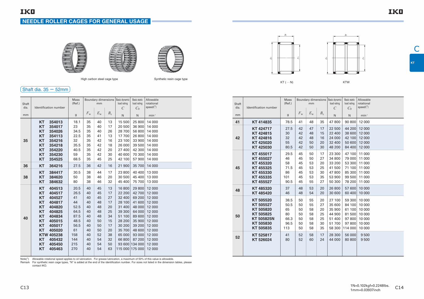
C
1N=0.102kgf=0.2248lbs.1mm=0.03937inchC13 C14
Shaftdia.
mm
Mass (Ref.)
g
Basic dynamic load rating
C
N
Basic static load rating
C0
N
Boundary dimensionsmm
Identification number
Fw Ew Bc
Note(1) Allowable rotational speed applies to oil lubrication. For grease lubrication, a maximum of 50% of this value is allowable.Remark For synthetic resin cage types, "N" is added at the end of the identification number. For sizes not listed in the dimension tables, please
contact IKO.
Allowable rotational speed(1)
min-1
35
KT 354013KT 354017KT 354026KT 354113KT 354216KT 354218KT 354220KT 354230KT 354525
18.1 23 34.5 22.5 32 35.5 40.5 59 68.5
353535353535353535
404040414242424245
131726131618203025
15 50020 50028 70017 70023 10026 00027 40040 60042 100
25 80036 90056 80026 80033 90039 50042 30070 30057 900
14 00014 00014 00014 00014 00014 00014 00014 00014 000
36 KT 364216 27.5 36 42 16 21 900 35 700 14 000
38KT 384417KT 384620KT 384632
30.5 50 80
383838
444646
172032
23 80030 50045 400
40 40045 40075 700
13 00013 00013 000
40
KT 404513KT 404517KT 404527KT 404817KT 404820KT 404825KT 404834KT 405015KT 405017KT 405020KTW 405238KT 405432KT 405450KT 405463
20.5 26.5 41 44 52.5 64.5 87.5 48.5 56.5 61 158 144 215 270
4040404040404040404040404040
4545454848484850505052545454
1317271720253415172038325063
16 80022 20032 40028 10031 40039 30051 10028 20030 20035 70065 00066 80093 600
115 000
29 80042 70069 20041 60048 00064 00089 60035 90039 20048 60093 00087 200
134 000175 000
12 00012 00012 00012 00012 00012 00012 00012 00012 00012 00012 00012 00012 00012 000
NEEDLE ROLLER CAGES FOR GENERAL USAGE
Shaft dia. 35− 52mm
High carbon steel cage type Synthetic resin cage type
Shaftdia.
mm
Mass (Ref.)
g
Basic dynamic load rating
C
N
Basic static load rating
C0
N
Boundary dimensionsmm
Identification number
Fw Ew Bc
Allowable rotational speed(1)
min-1
41 KT 414835 78.5 41 48 35 47 800 90 800 12 000
42
KT 424717KT 424815KT 424816KT 425020KT 425030
27.5 30 32 55 80.5
4242424242
4748485050
1715162030
22 50022 40024 00032 40048 200
44 20038 60042 10050 60084 400
12 00012 00012 00012 00012 000
45
KT 455017KT 455027KT 455320KT 455325KT 455330KT 455335KT 455527
29.5 46 58 71.5 86 101 90.5
45454545454545
50505353535355
17272025303527
23 30034 80033 20041 50047 80053 90050 300
47 10079 00053 30071 10085 30099 50078 200
11 00011 00011 00011 00011 00011 00011 000
48 KT 485320KT 485420
37 46
4848
5354
2020
26 80030 600
57 60060 400
10 00010 000
50
KT 505520KT 505527KT 505820KT 505825
KT 505825NKT 505830KT 505835
38.5 50.5 65 80 66.3 96.5 113
50505050505050
55555858585858
20272025253035
27 10035 60035 90044 90051 40051 70058 300
59 30084 10061 10081 50097 80097 800
114 000
10 00010 00010 00010 00010 00010 00010 000
52 KT 525817KT 526024
41 80
5252
5860
1724
28 30044 000
56 00080 800
9 500 9 500
KT ( … N) KTW
Ew Fw
Bc
Ew Fw
Bc

C
1N=0.102kgf=0.2248lbs.1mm=0.03937inchC15 C16
Shaftdia.
mm
Mass (Ref.)
g
Basic dynamic load rating
C
N
Basic static load rating
C0
N
Boundary dimensionsmm
Identification number
Fw Ew Bc
Note(1) Allowable rotational speed applies to oil lubrication. For grease lubrication, a maximum of 50% of this value is allowable.
Allowable rotational speed(1)
min-1
55
KT 556020KT 556027KT 556120KT 556315KT 556320KT 556325
42.5 55.5 52 52.5 71 87
555555555555
606061636363
202720152025
28 60037 60032 60029 40037 40046 800
66 00093 90068 50048 70066 40088 600
9 0009 0009 0009 0009 0009 000
58 KT 586320KT 586420
44.5 54.5
5858
6364
2020
29 30033 600
69 40072 500
8 5008 500
60
KT 606520KT 606820KT 606825KT 606827KT 607236
45.5 76.5 94101205
6060606060
6568686872
2020252736
29 70038 90048 60052 40086 700
71 10071 70095 600
105 000152 000
8 5008 5008 5008 5008 500
63 KT 637120 79.5 63 71 20 39 500 74 400 8 000
65 KT 657320KT 657330
83.5124
6565
7373
2030
41 20059 300
79 600127 000
7 5007 500
68 KT 687620 86.5 68 76 20 41 800 82 200 7 500
70 KT 707820KT 707830
89 132
7070
7878
2030
42 50061 200
84 900136 000
7 0007 000
72 KT 728020 91.5 72 80 20 43 200 87 500 7 000
75
KT 758320KT 758325KT 758330KT 758335
94.5 116 141 164
75757575
83838383
20253035
43 80054 80063 10071 200
90 200120 000144 000168 000
6 5006 5006 5006 500
NEEDLE ROLLER CAGES FOR GENERAL USAGE
Shaft dia. 55− 100mm
High carbon steel cage type
Shaftdia.
mm
Mass (Ref.)
g
Basic dynamic load rating
C
N
Basic static load rating
C0
N
Boundary dimensionsmm
Identification number
Fw Ew Bc
Allowable rotational speed(1)
min-1
80KT 808822KT 808825KT 808830
110 123 149
808080
888888
222530
49 70056 40065 000
108 000127 000153 000
6 0006 0006 000
85KT 859112KT 859325KT 859330
44.5 130 157
858585
919393
122530
25 20057 80066 600
56 700134 000161 000
6 0006 0006 000
90 KT 909825KT 909830
138 167
9090
9898
2530
60 40069 600
145 000174 000
5 5005 500
95 KT 9510330 175 95 103 30 70 900 182 000 5 500
100 KT 10010830 184 100 108 30 72 500 191 000 4 500
KT
Ew Fw
Bc

C
C17 C18
Needle Roller Cages for Big End
Needle Roller Cages for Small End
Structure and FeaturesIKO Needle Roller Cages for Engine Connecting Rods are bearings for use in engine connecting rods. These bearings have superior performance proven in high performance engines of racing motor cycles, and are widely used in small motor vehicles, motor cycles, outboard marines, snow mobiles, high-speed com-pressors, etc. and also in general-purpose engines.Bearings for engine connecting rods are used under extremely severe and complex operating conditions such as heavy shock loads, high speeds, high tem-peratures and stringent lubrication.Needle Roller Cages for Engine Connecting Rods are lightweight, and have high load ratings and high rigidi-ty as well as superior wear resistance to withstand these severe conditions.
Structures of Needle Roller Cages for Engine Connecting Rods
Cage
Needle roller
Cage
Needle roller
TypesIn Needle Roller Cages for Engine Connecting Rods, the types shown in Table 1 are available.
Table 1 Types
Type For big end For small end
Model code KT…EG KTV…EG

C
1N=0.102kgf=0.2248lbs.1mm=0.03937inchC19 C20
The identification number of Needle Roller Cages for Engine Connecting Rods consists of a model code, dimensions and any supplemental codes as shown below.
Identification Number
The diameter tolerances of needle rollers of Needle Roller Cages for Engine Connecting Rods are classi-fied as shown in Table 2. When the classification symbol is not indicated in the identification number, the classification symbol "B2" is applied.
The tolerance of the cage width Bc is − 0.2〜− 0.4 mm. But cages with marks in the Bc column in the dimension tables are manufactured with the following width tolerances.
:0〜− 0.2 mm :− 0.1〜− 0.3 mm
Accuracy
Needle Roller Cages for Big End KT…EG
These roller cages are subjected to acceleration and deceleration during their rotating and epicyclic motion due to crank shaft rotation. To withstand such condi-tions, they are made of a special alloy and are light-weight with high rigidity.They are guided on their outer periphery surface with superior lubricating properties. For the purpose of using them under severe condi-tions such as high rotational speed and stringent lubri-cation, bearings plated with non-ferrous metals are also available on request.High-load capacity and high-rigidity cages to be used for racing motor cycles (See the photo bellow.), split needle cages for solid (one-piece) type crank-shafts and other special specification cages of various types are also available. Please consult IKO when required.
Needle Roller Cages for Small End KTV…EG
These roller cages oscillates at high speeds within a limited loading zone under heavy shock loads. Thus, these cages are designed to be lightweight and have high rigidity with a well-balanced structure. In these cages, a number of needle rollers having a small diameter are incorporated to reduce the rolling con-tact stress in the loading zone.Needle Roller Cages for Small End are classified into two types, the outer surface guide type and the inner surface guide type. This classification is shown in the table of dimensions.In the outer surface guide type, the cage is guided by the sliding contact between the inner surface of the connecting rod and the outer surface of the cage.In the inner surface guide type, the cage is guided by the sliding contact between the outer surface of the pin and the inner surface of the cage.
Model codeSupplemental
codeDimensions
KT 22 16 EG B2
Type of bearing
28
Tolerance of mean value of roller dia. (See Table 2.)
Examples of identification number
Roller set bore diameter(22mm)
Roller set outside diameter(28mm)
Width of cage(16mm)
High-load capacity and high-rigidity cage KTZ … EG
ClearanceRadial internal clearances are selected according to the type of engine and the operating conditions (rota-tional speed, load, lubricating conditions, etc.). If a bearing is used with an inadequate clearance, bearing troubles such as seizure, early flaking and noise increase may occur, leading to an engine failure. Therefore, it is necessary to select the clearance carefully according to test results and experience.
Table 2 Tolerances of needle roller diameter
ClassClassification
symbol(1)Tolerance of mean value of
roller dia. (2)
Standard
Semi-standard
B 2B 4
B 6B 8B10
0〜− 2− 2〜− 4
− 4〜− 6− 6〜− 8− 8〜− 10
Notes(1) The classification symbol is indicated at the end of the identification number.
(2) Tolerances for circularity are based on JIS B 1506
(Rolling bearings - Rollers).
unit: μ m
FitTo obtain the recommended clearance shown in Table 3, it is general practice to match a connecting rod, crank pin or piston pin and needle roller cage of suitable tolerances for assembly.
Precautions for Use
Fig.1
When designing a connecting rod, crank pin and pis-ton pin, the following precautions should be taken, because the raceways are subjected to loads under extremely severe conditions.1 Material
It is recommended to use carburizing steel because the raceways are subjected to fluctuating loads with frequent and heavy shock loads. Generally, chromi-um molybdenum steel is used. Nickel chromium molybdenum steel is also used.2 Hardness
The recommended surface hardness of the raceway is 697〜800HV (60〜64HRC). While the effective hardening depth differs depending on the applica-tions, the general value is 0.6〜1.2 mm.3 Surface roughness
To minimize initial wear and to extend life, it is recom-mended that the surface roughness of the crank pin and piston pin be 0.1μmRa or less, and the surface roughness of the connecting rod large end and small end bores be 0.2μmRa or less.4 Accuracy
Circularity and cylindricity of connecting rod, piston pin and crank pin are as shown in Table 4. 5 Parallelism and torsional accuracy of connect-
ing rod boresL±0.02 mm and E±0.02 mm shown in Fig. 1 indi-cate the parallelism and torsional accuracy between the big end and small end bores of the connecting rod, respectively. The tolerance range is 0.04 mm or less per 100 mm in case of a general-purpose engine and 0.02 mm or less for a high-speed engine such as a racing motorcycle engine. When these accuracy conditions are not satisfied, the axial forces on the needle roller cage and connecting rod will increase, directly leading to a failure such as seizure. Careful consideration is required.
Recommended radial internal clearances are shown in Table 3. When operating at high speeds, it is rec-ommended to select the upper limit of the clearance.
Table 3 Recommended radial internal clearance
Shaft dia.mm
Over
−1830
183040
3〜 15
(dp− 6) 〜 dp
(dp− 8) 〜 dp
(dp− 12) 〜 dp
Incl.
Big end Small end
Remark dp is obtained using the following equation for roller pitch circle diameter in millimeters, and changing the unit from millimeters to micrometers.
Roller pitch circle dia. =
Example KT 222814 EG for big end Recommended clearance is; 17〜 25μm
unit: μ m
Fw +Ew
2
Table 4 Accuracy of connecting rod, piston pin and crank pin
Range of dia. mm
Over
−1830
183040
123
234
234
345
Incl.Circularity
MAX.Cylindricity
MAX.Circularity
MAX.Cylindricity
MAX.
Crank pin diameter d1Piston pin diameter d2
Big end bore D1Small end bore D2
Remark Refer to Fig.1 for the dimension symbols.
unit: μ m
D1
L L
D2
dd
21
±0.
02±
0.02
100
50 50
E
E

C
1N=0.102kgf=0.2248lbs.1mm=0.03937inchC21 C22
Shaftdia.
mm
Mass (Ref.)
g
Basic dynamic load rating
C
N
Basic static load rating
C0
N
Boundary dimensionsmm
Identification number
Fw Ew Bc
8 KT 8128 EG 2.1 8 12 8 3 280 2 660
10 KT 101410 EG 3.2 10 14 10 4 900 4 680
12 KT 121610 EGKT 121710 EG
3.8 5.3
1212
1617
10 10
5 6506 670
5 8906 380
14 KT 14199.7 EGKT 141910 EG
5.7 5.7
1414
1919
9.7 10
6 1206 640
5 8806 530
15 KT 15199 EGKT 152010 EG
4.2 6.1
1515
1920
9 10
5 7907 100
6 4607 260
16 KT 162211.5 EGKT 162212 EG
9.5 9.7
1616
2222
11.5 12
7 50010 60011 800
9 66010 900
18KT 182210 EGKT 182411.6 EGKT 182412 EG
5.7 11 11
181818
222424
10 11.6 12
9 55010 500
9 56011 50013 100
20KT 202612 EGKT 202614 EGKT 202814 EG
12 13.8 20
202020
262628
12 14 14
12 40013 00015 700
14 30015 20016 100
22KT 222814 EGKT 222816 EGKT 222912 EGKT 223215 EG
14.9 17.5 15.2 30
22222222
28282932
14 16 12 15
13 60015 70012 90021 300
16 60019 80014 00021 500
23
24
3032
KT 243015 EGKT 243016 EGKT 243120 EGKT 303818 EGKT 324220 EG
17.9 18.2 28
35.5 54
242424
3032
303031
3842
15 16 20
18 20
14 20016 30020 800
24 90031 900
18 00021 50026 400
32 60039 400
KT … EG
KT 232913 EG 14.9 23 29 13 12 800 15 600
Needle Roller Cages for Big End
NEEDLE ROLLER CAGES FOR ENGINE CONNECTING RODS
Shaft dia. 8− 32mm
Ew Fw
Bc
KTV … EG
Shaft dia. 9− 18mm
Needle Roller Cages for Small End
Shaftdia.
mm
Mass (Ref.)
g
Basic dynamic load rating
C
N
Basic static load rating
C0
N
Boundary dimensionsmm
Identification number
Fw Ew Bc
9 KTV 91211.5 EGKTV 91214 EG
2.8 3.5
9 9
1212
11.5 14
3 9004 440
4 0704 810
10KTV 101316 EGKTV 101410 EGKTV 101411 EGKTV 101412.5 EG
4.5 3.8 4.1 4.8
10 10 10 10
13141414
16 10 11 12.5
4 4004 5205 0605 590
4 8804 2204 8805 540
10.5 KTV 10.51415 EG 5.1 10.5 14 15 5 710 6 270
12KTV 121514.3 EGKTV 121613 EGKTV 121615.5 EG
4.3 5.6 6.8
12 12 12
151616
14.3 13 15.5
5 8407 0207 600
7 3907 8008 600
14KTV 141812 EGKTV 141816.5 EGKTV 141822 EG
6 8.2 10.8
14 14 14
181818
12 16.5 22
6 7809 1809 950
7 76011 50012 600
16 KTV 162019 EGKTV 162022 EG
10.6 12.7
16 16
2020
19 22
10 80011 400
14 60015 700
18 KTV 182223.5 EGKTV 182321 EG
14.9 16.4
18 18
2223
23.5 21
13 00014 400
19 30018 900
Cage guide type
Outer surface guideInner surface guide
Inner surface guideInner surface guideOuter surface guideInner surface guide
Outer surface guide
Outer surface guideOuter surface guideOuter surface guide
Inner surface guideOuter surface guideInner surface guide
Outer surface guideInner surface guide
Inner surface guideInner surface guide
Ew
Bc
Fw

D
D1 D2
Machined Type Caged Needle Roller Bearings
Machined Type Guide Needle Roller Bearings
Structure and FeaturesIKO Machined Type Needle Roller Bearings are bear-ings with a low sectional height and large load ratings. The outer ring has high rigidity and can easily be used even for light alloy housings. These bearings are available in metric series and inch series, both of which have the caged type and the full complement type. It is therefore possible to select a suitable bear-ing for use under various conditions such as heavy loads and high-speed or low-speed rotations. In addi-tion, there are bearings with and without an inner ring. As the type without inner ring uses a shaft as the raceway surface, a compact design is possible.
Structures of Machined Type Needle Roller Bearings
Outer ring
Cage
Needle roller
Outer ring
Cage
Needle roller
Inner ring
Outer ring
Needle roller
Seal
Cage
Outer ring
Mallet-shaped roller
Stop ring
NA49
GTR
RNA49…UU
RNA49

D
D3 D41N=0.102kgf=0.2248lbs.1mm=0.03937inch
TypesMachined Type Needle Roller Bearings are available in various types shown in Table 1.
Caged Needle Roller Bearings
This type of bearing combines a collared outer ring with the IKO's unique lightweight rigid cage and nee-dle rollers. During operation, needle rollers are guid-ed precisely by the cage, and an ideal load distribu-tion is obtained.The metric series consists of the NA48 and NA49 series of ISO Standard, NA69 and TAFI series which are based on the international dimension series, and the heavy duty TRI series which is widely used in Japan. The TAFI series has a sectional height as low as that of the shell type and is used for light loads.The inch series or BRI series is based on the specifi-cations of ANSI Standard of USA.
Caged Needle Roller Bearings without Inner Ring As shown in the section "Design of shaft and housing" on page A44, any desired radial clearance can be selected by assembling this type of bearing with a shaft which is heat-treated and finished by grinding.These bearings are free from the effects on dimen-sional accuracy caused by assembling an inner ring,
so that the rotational accuracy is improved. Also, the shaft rigidity can be improved as the shaft diameter can be increased by an amount corresponding to the inner ring thickness.
Caged Needle Roller Bearings with Inner RingThis type of bearing is used when the shaft cannot be heat-treated and finished by grinding. The outer and inner rings are separable and a small relief clearance is provided on both sides of the inner ring raceway to facilitate bearing mounting. In the TRI and BRI series, the width of the inner ring is larger than that of the outer ring.Due to heat expansion during operation or mounting errors, the inner or outer ring may be shifted axially and the whole length of the rollers may not be in con-tact with the raceway. Therefore, attention should be
paid to the allowable axial shift S as shown in the table of dimensions.
Needle Roller Bearings with SealThese bearings are sealed types of the NA49, NA69 and BRI series bearings, in which a seal is installed on one side (type with one seal) or both sides (type with two seals) of the bearing. The seal is made of special synthetic rubber and effectively prevents dust penetration and grease leakage.
Guide Needle Roller Bearings
These bearings are full complement type bearings and use mallet-shaped rollers which are guided accu-rately by the guide rail located at the center of the outer ring raceway and the guide groove of the mallet-shaped roller. This minimizes skewing (tilting of the roller from its rotating axis), which is normally a weak point of full complement bearings, and improves the rotational accuracy. This type of bearing is especially suitable for heavy loads, shock loads and oscillating motions.Bearings with and without inner rings are available. In bearings with an inner ring, the width of the inner ring is larger than that of the outer ring.
Table 1.1 Type of bearing (Standard type)Type
Series
Inch series
Dimension series 49
Dimension series 69
Dimension series 48
For heavy duty
For light duty
RNA 49
RNA 69
RNA 48
TR
TAF
BR
NA 49
NA 69
NA 48
TRI
TAFI
BRI
GTR
− −
GTRI
Caged Needle Roller Bearings
Guide Needle Roller Bearings
Without inner ring With inner ring Without inner ring With inner ring
Met
ric s
erie
s Identification Number
Model codeSupplemental
codeClassification
symbolDimensions
NA 49 UU
Type of bearing
05 C2 P6
Examples of identification number
Example 1 Example 2
Bore diameter number
Seal symbol (With seals on both sides)
Dimension series
Clearance symbol (C2 clearance)
Accuracy class (Class 6)
Model code Dimensions
BRI 24 16
Type of bearing
37
Bearing bore diameter(24×1/16=11/2 inches)
Outer ring width(16×1/16=1 inch)
Bearing outside diameter(37×1/16=25/16 inches)
Accuracy
Table 2 Accuracy of inner and outer rings of inch series BR and BRII
d or D Nominal bearing bore dia.
or outside dia. mm
∆dmpSingle plane mean
bore diameter deviation
∆DmpSingle plane mean outside diameter
deviation
∆Bs(∆Cs)Deviation of a single inner (or outer) ring
width
KiaRadial runout of
assembled bearing inner ring
KeaRadial runout of
assembled bearing outer ring
− 19.05030.16250.80082.550
120.650
19.050 30.16250.80082.550
120.650 184.150
00000−
− 10 − 13 − 13 − 15− 20
−
− − 13 − 13 − 15 − 20 − 25
− 130 − 130 − 130 − 130 − 130 − 130
− 00000
000000
101315202530
−1520253545
unit: μ m
Over Incl. High Low Low LowHigh High Max. Max.
Remark d for ∆dmp, ∆Bs, ∆Cs and Kia, and D for ∆Dmp and Kea
Table 1.2 Type of bearing (With seal)Type
Series
Inch series
Dimension series 49
Two side seals
One side seal
Two side seals
One side seal
Two side seals
One side seal
Dimension series 69
RNA 49…UU
RNA 49…U
RNA 69…UU
RNA 69…U
BR …UU
−
NA 49…UU
NA 49…U
NA 69…UU
NA 69…U
BRI …UU
−
−
− −− −
−
Caged Needle Roller Bearings
Guide Needle Roller Bearings
Without inner ring With inner ring Without inner ring With inner ring
Met
ric s
erie
s
The identification number of Machined Type Needle Roller Bearings consists of a model code, dimen-sions, any supplemental codes and a classification symbol. Examples are shown below.
Machined Type Needle Roller Bearings are manufac-tured based on JIS (See page A31.). The tolerances for the smallest single roller set bore diameter of bear-ings without inner ring are based on Table 14 on page A33. For BR and BRI series, the accuracy is based on Table 2 and the tolerances for the smallest single roller set bore diameter are based on Table 3.

D
D5 D61N=0.102kgf=0.2248lbs.1mm=0.03937inch
ClearanceRadial internal clearances of Machined Type Needle Roller Bearings are made to the CN clearance shown in Table 18 on page A37. Radial internal clearances of BRI series are based on Table 4.
LubricationBearings with prepacked grease are shown in Table 5. ALVANIA GREASE S2 (Shell Lubricants Japan K.K.) is prepacked as the lubricating grease.In the case of bearings without prepacked grease, perform proper lubrication. Operating them without lubrication will increase the wear of the rolling contact surfaces and shorten their lives.
FitThe recommended fits for Machined Type Needle Roller Bearings are shown in Tables 22 to 24 on pages A41 and A42.
Table 3 Tolerances for smallest single roller setbore diameter Fws min of inch series BR
Fw Nominal roller set bore diameter
mm
∆Fws minDeviation of smallest single roller
set bore diameter
− 18.03430.22641.91050.03870.10480.010
18.03430.22641.91050.03870.10480.010
102.108
unit: μ m
Over Incl.
+ 43+ 46+ 48+ 51+ 53+ 58+ 61
+ 20+ 23+ 25+ 25+ 28+ 28+ 31
High Low
Table 4 Radial internal clearance of inch series BRI
FwNominal roller set bore diameter
mmRadial internal clearance
− 18.03425.90830.22635.05241.91050.03870.10480.010
100.076
18.03425.90830.22635.05241.91050.03870.10480.010
100.076 102.108
unit: μ m
Over Incl.
33414648505056566368
66768286899299
104 117 127
Min. Max.
Oil HoleTable 6.1 shows the number of oil holes of the outer ring and Table 6.2 shows the number of oil holes of the inner ring.When an outer ring with an oil hole is especially required for the type without an oil hole, add "−OH" before the clearance symbol in the identification num-ber. When an outer ring with an oil hole and an oil groove is required for the type without an oil hole, attach "−OG" before the clearance symbol. Example: TAFI 203216− OH C2 P6When an outer ring with multiple oil holes or an inner ring with an oil hole(s) is required, please consult IKO.
MountingMounting dimensions for Machined Type Needle Roller Bearings are shown in the table of dimensions.
Matched Set BearingsWhen using two or more Machined Type Needle Roller Bearings adjacent to each other on the same shaft, it is necessary to obtain an even load distribu-tion. On request, a set of bearings is available, in which bearings are matched to obtain an even load distribution.
Table 6.2 Number of oil holes of the inner ring
Bearing type
Metric series
Inch series
Metric series
Caged Needle Roller Bearings
Guide Needle Roller Bearings
NATRI TAFI
GTRI
With a seal on one sideWith seals on both sidesStandard type
Number of oil holes of the inner ring
00−−−−
00−11−
000120
BRI
Nominal bearing bore diameter d mm
d≦ 76.20076.200< d
Remark The type with an oil hole(s) is provided with an oil groove.
Table 6.1 Number of oil holes of the outer ring
Bearing type
Metric series
Inch series
Metric series
Caged Needle Roller Bearings
Guide Needle Roller Bearings
RNA,NATR,TRI
GTR,GTRI
With a seal on one sideWith seals on both sidesStandard type
Number of oil holes of the outer ring
1−−−−−−
1−−−11−
1101121
TAF,TAFI
BR,BRI
Nominal roller set bore diameter Fw mm
Fw ≦ 26 26 < Fw
Fw ≦ 69.85069.850 < Fw
Remark The type with an oil hole(s) is provided with an oil groove.
Table 5 Bearings with prepacked grease
Bearing type
Metric series
Inch seriesMetric series
Caged Needle Roller
Bearings
Guide Needle Roller Bearings
RNA, NATR, TRI TAF, TAFI, TAF/SGBR, BRI
GTR, GTRI
With a seal on one side
With seals on both sides
Standard type
×−−−
−
〇−−〇
−
××××
×
〇:With prepacked grease ×:Without prepacked grease
Extended Life Specification Machined Type Needle Roller Bearings
With inner ring Without inner ring
d=10 〜 75mm Fw=14 ~ 85mm
NA 4900 〜 4915 RNA 4900 〜 4915
NA 6901 〜 6915 RNA 6901 〜 6915
TAFI 102216 〜 7510535 TAF 142216 〜 8510535
TRI 153320 〜 7510845 TR 203320 〜 8310845
d Fw
Table 7 Applicable Production Size
Standard heat-treated products Extended life specification products
Model number : NA4904
Load : 10,500 N
Lubrication : Cleaning oil lubricated
Cum
ulat
ive
dam
age
rate
%
Life h
Fig. 1 Life Test ResultRemark This table shows the result of life testing under
load conditions at 50% of the basic dynamic rating.The Extended Life Specification with special heat treatment lasted 5 times longer or more in L10 life compared to the standard heat-treated products.
Extended Life Specification Machined Type Needle Roller Bearings are treated with a newly developed special heat treatment that enhances the bearing's surface hardness and toughness, and suppresses the generation and growth of damage on the surface. Significant life extension can be achieved under high load or under the condition of lubrication contaminated with foreign substances.In a life comparison test, as shown in Figure 1, IKO's special heat treated Extended Life Specification products lasted 5 times longer than standard heat-treated products.Extended Life Specification Machined Type Needle Roller Bearings, available according to the "Applicable Production Size" shown in Table 7, are made to order upon request.

D
D7 D81N=0.102kgf=0.2248lbs.1mm=0.03937inch
Shaft dia. 5− 15mm
MACHINED TYPE NEEDLE ROLLER BEARINGS
Without Inner Ring
80 00080 00080 000
555
101011
101210
0.20.20.15
2 4203 0802 420
1 9502 6601 950
8.48.49.8
60 00060 00060 000
777
131414
101012
0.150.20.2
2 9603 6004 610
2 6902 9604 050
11.812.412.4
50 00050 00050 000
888
151515
101216
0.150.20.2
3 9605 0607 080
3 4204 6907 220
13.813.413.4
45 00045 00045 000
999
161617
121610
0.20.20.15
5 4907 6804 530
5 3308 2103 650
14.414.415.8
40 00040 00040 000
101010
171719
121611
0.20.20.2
5 8808 2306 180
5 9709 1905 030
15.415.417.4
35 00035 00035 000
121212
191920
121611
0.30.30.3
6 6109 2506 600
7 26011 2006 310
171718
70 00070 000
66
1212
1012
0.150.2
2 7003 440
2 3203 170
10.810.4
30 00030 000
1515
2323
1620
0.30.3
12 30015 600
14 90020 200
2121
30 00030 00030 000
141414
222222
131620
0.30.30.3
9 23011 70014 800
10 10013 70018 600
202020
Shaft dia.
mm
Identification number Mass (Ref.)
g
RNA 49 RNA 69 RNA 48 TAF TR GTR
Boundary dimensions mm Allowable rotational speed(2)
min-1Fw D C rs min
(1)
RNA49 TAFRNA69(Fw ≦ 35)
Standard mounting dimension
DaMax.mm
Basic dynamic load rating
C
N
Basic static load rating
C0
N
RNA 493
TAF 51010TAF 51012
5 3.4 4.2 4.6
RNA 495
TAF 71410TAF 71412
7 5.9 6.9 8.3
RNA 496
TAF 81512TAF 81516
8 7.4 9.112.9
RNA 497
TAF 91612TAF 91616
9 9.813.2 9.3
RNA 498
TAF 101712TAF 101716
1010.714.312.6
RNA 499
TAF 121912TAF 121916
1212.216.313.6
RNA 494
TAF 61212
6 5.3
6.4
TAF 152316TAF 152320
15 22.5
28
RNA 4900
TAF 142216TAF 142220
1416.52126.5
Notes(1) Minimum allowable value of chamfer dimension r (2) Allowable rotational speed applies to oil lubrication. For grease lubrication, a maximum of 60% of this value is allowable.Remarks1. TAF series with a roller set bore diameter Fw of 26 mm or less have no oil hole. In others, the outer ring has an oil groove and an
oil hole. 2. No grease is prepacked. Perform proper lubrication.
D Fw
C
r
r
Da

D
D9 D101N=0.102kgf=0.2248lbs.1mm=0.03937inch
Shaft dia. 16− 22mm
MACHINED TYPE NEEDLE ROLLER BEARINGS
Without Inner Ring
25 00025 00025 00025 000
16161616
24242424
13162022
0.30.30.30.3
22222222
20 00020 00020 00020 000
20202020
28282828
13162023
0.30.30.30.3
26262626
18 00018 00018 00018 000
22222222
30303030
13162023
0.30.30.30.3
28282828
25 00025 000
1717
2525
1620
0.30.3
2323
20 0007 500
2020
3333
2020
0.30.3
3131
19 00019 000
2121
2929
1620
0.30.3
2727
18 0007 000
2222
3434
2525
0.30.3
3232
20 00020 000
1919
2727
1620
0.30.3
2525
20 00020 00020 000
181818
262626
131620
0.30.30.3
242424
Boundary dimensions mm
Fw D C rs min(1)
GTR
Shaft dia.
mm
Identification number Mass (Ref.)
g
RNA 49 RNA 69 RNA 48 TAF TR GTR
16
RNA 4901
RNA 6901
TAF 162416TAF 162420
18.1232930
TAF 172516TAF 172520
17 24.5
30.5
RNA 49/14
TAF 182616TAF 182620
1819.925.532
TAF 192716TAF 192720
19 27
34
20
RNA 4902
RNA 6902
TAF 202816TAF 202820
21.527.535.537
TR 203320
GTR 203320
TAF 212916TAF 212920
21 29
36
22
RNA 4903
RNA 6903
TAF 223016TAF 223020
23.53037.540.5
TR 223425
GTR 223425
73.587
RNA49 TAF TRRNA69(Fw ≦ 35)
59.569
Notes(1) Minimum allowable value of chamfer dimension r (2) Allowable rotational speed applies to oil lubrication. For grease lubrication, a maximum of 60% of this value is allowable.Remarks1. TAF series with a roller set bore diameter Fw of 26 mm or less have no oil hole. In others, the outer ring has an oil groove and an
oil hole. 2. No grease is prepacked. Perform proper lubrication.
9 66012 30015 50017 100
11 10015 10020 40023 000
10 60013 40017 000
12 80017 50023 600
14 00017 700
18 70025 300
10 90013 90017 60019 300
13 80018 80025 40028 800
24 30029 200
26 50037 200
14 40018 200
20 00027 100
12 90016 300
16 30022 000
29 10037 900
36 80057 800
11 70014 90018 90020 800
15 60021 20028 70032 500
Allowable rotational speed(2)
min-1
Standard mounting dimension
DaMax.mm
Basic dynamic load rating
C
N
Basic static load rating
C0
N
D Fw
C
r
r
DaD Fw
C
r
r

D
D11 D121N=0.102kgf=0.2248lbs.1mm=0.03937inch
Shaft dia. 24− 30mm
MACHINED TYPE NEEDLE ROLLER BEARINGS
Without Inner Ring
15 00015 000
14 00014 000
13 0005 000
17 00017 000
2626
2929
3030
2424
3434
3838
4444
3232
1620
2030
2525
1620
0.30.3
0.30.3
0.30.3
0.30.3
3232
3636
4242
3030
16 00016 00016 00016 000
25252525
33333737
16201730
0.30.30.30.3
31313535
14 00014 00014 00014 000
28282828
37373939
20301730
0.30.30.30.3
35353737
13 00013 00013 00013 000
30303030
40404242
20301730
0.30.30.30.3
38384040
16 00016 0006 0006 000
25252525
38383838
20252025
0.30.30.30.3
36363636
Boundary dimensions mm
Fw D C rs min(1)
Shaft dia.
mm
Identification number Mass (Ref.)
g
RNA 49 RNA 69 RNA 48 TAF TR GTR
25
RNA 4904
RNA 6904
TAF 253316TAF 253320
TR 253820TR 253825
GTR 253820GTR 253825
28
RNA 49/22
RNA 69/22
TAF 283720TAF 283730
30
RNA 4905
RNA 6905
TAF 304020TAF 304030
TAF 243216TAF 243220
24
33.5 42 55.5 95.5
71 89 81.5104
51.5 83.5 56.5 97.5
64.5 97.5 64111
32 40.5
TAF 263416TAF 263420
26 34.5
43.5
TAF 293820TAF 293830
29 57
85
TR 304425
GTR 304425
115133
GTRRNA49 TAF TRRNA69(Fw ≦ 35)
Notes(1) Minimum allowable value of chamfer dimension r (2) Allowable rotational speed applies to oil lubrication. For grease lubrication, a maximum of 60% of this value is allowable.Remarks1. TAF series with a roller set bore diameter Fw of 26 mm or less have no oil hole. In others, the outer ring has an oil groove and an
oil hole. 2. No grease is prepacked. Perform proper lubrication.
15 30019 400
22 50030 500
28 90034 80033 30042 400
35 00044 40046 50063 700
16 30020 600
24 90033 800
21 70031 10021 40036 300
37 10058 90028 90056 900
21 60030 900
37 20059 100
25 10036 00023 70042 100
40 10063 90030 70064 300
15 80020 00021 00035 400
23 70032 10025 00048 900
37 90047 000
52 10076 500
Standard mounting dimension
DaMax.mm
Basic dynamic load rating
C
N
Basic static load rating
C0
N
Allowable rotational speed(2)
min-1
D Fw
C
r
r
DaD Fw
C
r
r

D
D13 D141N=0.102kgf=0.2248lbs.1mm=0.03937inch
Shaft dia. 32− 40mm
MACHINED TYPE NEEDLE ROLLER BEARINGS
Without Inner Ring
12 00012 00012 00012 000
32323232
42424545
20301730
0.30.30.30.3
25 70036 80024 50041 800
42 20067 20032 70064 800
40404343
11 00011 00011 00011 000
35353535
45454747
20301730
0.30.30.30.3
26 90038 60025 20043 000
46 20073 60034 70069 000
43434545
10 00010 00010 00010 000
40404040
50505252
20302036
0.30.30.60.6
29 40042 30031 20053 500
54 10086 20047 80095 700
48484848
4 50032 45 30 0.3 58 000 101 00043
11 0004 500
3535
4848
3030
0.30.3
47 40061 100
72 300110 000
4646
11 00011 000
3737
4747
2030
0.30.3
28 20040 500
50 10079 800
4545
11 00011 000
3838
4848
2030
0.30.3
28 10040 300
50 20080 000
4646
11 0004 000
3838
5252
3030
0.60.6
50 80064 200
81 100121 000
4848
10 0003 500
4040
5555
2020
0.60.6
37 40044 300
55 70073 600
5151
Boundary dimensions mm
Fw D C rs min(1)
Shaft dia.
mm
Identification number Mass (Ref.)
g
RNA 49 RNA 69 RNA 48 TAF TR GTR
32
RNA 49/28
RNA 69/28
TAF 324220TAF 324230
68102 76.5133
35
RNA 4906
RNA 6906
TAF 354520TAF 354530
73.5112 72.5125
40
RNA 49/32
RNA 69/32
TAF 405020TAF 405030
83125 96172
GTR 324530 152
TR 354830
GTR 354830
139163
TAF 374720TAF 374730
37 77.5
117
TAF 384820TAF 384830
38
79119
TR 385230
GTR 385230
168195
TR 405520
GTR 405520
129144
GTRRNA49 TAF TRRNA69(Fw ≦ 35)
RNA69
Notes(1) Minimum allowable value of chamfer dimension r (2) Allowable rotational speed applies to oil lubrication. For grease lubrication, a maximum of 60% of this value is allowable.Remarks1. The outer ring has an oil groove and an oil hole. 2. No grease is prepacked. Perform proper lubrication.
Allowable rotational speed(2)
min-1
Standard mounting dimension
DaMax.mm
Basic dynamic load rating
C
N
Basic static load rating
C0
N
D F w
C
r
r
D Fw
C
r
r
DaD Fw
C
r
r
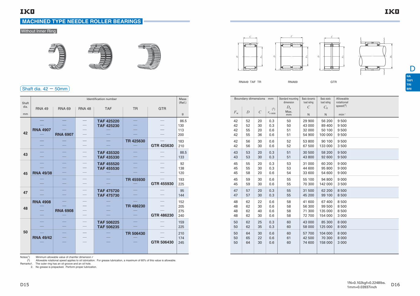
D
D15 D161N=0.102kgf=0.2248lbs.1mm=0.03937inch
Shaft dia. 42− 50mm
MACHINED TYPE NEEDLE ROLLER BEARINGS
Without Inner Ring
9 5009 5009 5009 500
42424242
52525555
20302036
0.30.30.60.6
50505151
9 5003 500
4242
5656
3030
0.60.6
5252
8 5008 5008 5003 000
48484848
62626262
22304030
0.60.60.60.6
58585858
9 0003 500
4545
5959
3030
0.60.6
5555
8 5008 500
4747
5757
2030
0.30.3
5555
8 0008 000
5050
6262
2535
0.30.3
6060
9 0009 0009 000
454545
555558
203020
0.30.30.6
535354
8 0008 0003 000
505050
646564
302230
0.60.60.6
606160
Boundary dimensions mm
Fw D C rs min(1)
Shaft dia.
mm
Identification number Mass (Ref.)
g
RNA 49 RNA 69 RNA 48 TAF TR GTR
42
RNA 4907
RNA 6907
TAF 425220TAF 425230
86.5130113200
48RNA 4908
RNA 6908
TR 486230
GTR 486230
TR 425630
GTR 425630
183210
TAF 435320TAF 435330
43 88.5
133
TAF 506225TAF 506235
50
159225
RNA 49/42
TR 506430
GTR 506430
210174245
TR 455930
GTR 455930
193225
RNA 49/38
TAF 455520TAF 455530
45
92138120
TAF 475720TAF 475730
47 95
144
152205275240
9 5009 500
4343
5353
2030
0.30.3
5151
GTRRNA49 TAF TR RNA69
Notes(1) Minimum allowable value of chamfer dimension r (2) Allowable rotational speed applies to oil lubrication. For grease lubrication, a maximum of 60% of this value is allowable.Remarks1. The outer ring has an oil groove and an oil hole. 2. No grease is prepacked. Perform proper lubrication.
29 90043 00032 00054 900
56 20089 40050 100
100 000
30 50043 800
58 20092 600
43 00058 000
85 300125 000
53 80067 500
90 100133 000
31 00044 60033 600
60 20095 80054 600
55 10070 300
94 800142 000
31 50045 200
62 20099 100
41 60056 30071 30072 700
67 40099 500
135 000154 000
57 70042 50074 600
104 00070 300
158 000
Allowable rotational speed(2)
min-1
Standard mounting dimension
DaMax.mm
Basic dynamic load rating
C
N
Basic static load rating
C0
N
D F w
C
r
r
D Fw
C
r
r
DaD Fw
C
r
r

D
D17 D181N=0.102kgf=0.2248lbs.1mm=0.03937inch
Shaft dia. 52− 68mm
MACHINED TYPE NEEDLE ROLLER BEARINGS
Without Inner Ring
7 5007 5007 500
6 5006 5006 500
7 5007 500
555555
606060
5252
686870
727275
6868
253522
253522
2240
0.30.30.6
0.30.30.6
0.60.6
666666
707071
6464
7 0007 000
5858
7272
2240
0.60.6
6868
7 0002 500
5858
7777
4545
11
7272
6 5002 500
6262
8181
3838
11
7676
6 5006 500
6363
8080
2545
11
7575
6 0006 0006 000
656565
787882
253525
0.60.61
747477
6 0006 0006 0006 000
68686868
82828585
25352545
0.60.611
78788080
Boundary dimensions mm
Fw D C rs min(1)
Shaft dia.
mm
Identification number Mass (Ref.)
g
RNA 49 RNA 69 RNA 48 TAF TR GTR
RNA 6909
RNA 4909
52 197
355
RNA 6910
RNA 4910
58
179320
TR 628138
GTR 62813862 460
520
RNA 6911
RNA 4911
63 265
475
TR 587745
GTR 587745
515590
RNA 49/48
TAF 556825TAF 556835
55193255188
RNA 49/52
TAF 607225TAF 607235
60187260205
RNA 49/58
TAF 657825TAF 657835
65225315275
68
RNA 4912
RNA 6912
TAF 688225TAF 688235
250350285510
RNA49 TAF TR RNA69
Notes(1) Minimum allowable value of chamfer dimension r (2) Allowable rotational speed applies to oil lubrication. For grease lubrication, a maximum of 60% of this value is allowable.Remarks1. The outer ring has an oil groove and an oil hole. 2. No grease is prepacked. Perform proper lubrication.
GTR
43 50074 600
73 300147 000
46 20079 200
82 100164 000
49 60067 00058 900
112 000164 000101 000
45 40061 20044 300
94 000138 00076 300
104 000135 000
191 000280 000
47 50064 10047 100
103 000151 00085 100
92 000118 000
166 000241 000
57 60098 700
97 200194 000
54 80072 00060 200
103 000
117 000166 000105 000211 000
Allowable rotational speed(2)
min-1
Standard mounting dimension
DaMax.mm
Basic dynamic load rating
C
N
Basic static load rating
C0
N
D F w
C
r
r
D Fw
C
r
r
DaD Fw
C
r
r

D
D19 D201N=0.102kgf=0.2248lbs.1mm=0.03937inch
Shaft dia. 70− 85mm
MACHINED TYPE NEEDLE ROLLER BEARINGS
Without Inner Ring
Shaft dia.
mm
Identification number Mass (Ref.)
g
RNA 49 RNA 69 RNA 48 TAF TR GTR
TR 708945
GTR 708945
RNA 6913
RNA 4913
72
TAF 739025TAF 739035
73
RNA 49/62
TAF 708525TAF 708535
70
605690
325585
335475
280395320
RNA 49/68
TAF 759225TAF 759235
75345485470
TR 8310845
GTR 831084583 995
1 090
80
RNA 4914
RNA 6914
TAF 809525TAF 809535
315445495910
85
RNA 4915
RNA 6915
TAF 8510525
TAF 8510535
435525610960
Notes(1) Minimum allowable value of chamfer dimension r (2) Allowable rotational speed applies to oil lubrication. For grease lubrication, a maximum of 60% of this value is allowable.Remarks1. The outer ring has an oil groove and an oil hole. 2. No grease is prepacked. Perform proper lubrication.
55 50073 00061 500
120 000171 000109 000
62 700108 000
113 000227 000
76 30086 200
102 000138 000
145 000169 000210 000331 000
114 000147 000
228 000336 000
61 10080 400
127 000181 000
62 10081 70079 900
131 000186 000147 000
59 40078 10083 200
134 000
137 000195 000158 000311 000
146 000190 000
270 000396 000
5 5002 000
5 5005 500
5 5005 500
5 0005 0005 0005 000
4 5004 5004 5004 500
5 5005 5005 500
7070
7373
7272
80808080
85858585
707070
8989
9090
9090
9595
100100
105105105105
858588
4545
2535
2545
25353054
25303554
253525
11
11
11
1111
1111
0.60.61
8484
8585
8585
90909595
100100100100
818183
5 5005 5005 500
757575
929295
253530
111
878790
5 0001 800
8383
108108
4545
11
103103
Boundary dimensions mm
Fw D C rs min(1)
GTRRNA49 TAF TR RNA69
Allowable rotational speed(2)
min-1
Standard mounting dimension
DaMax.mm
Basic dynamic load rating
C
N
Basic static load rating
C0
N
D F w
C
r
r
D Fw
C
r
r
DaD Fw
C
r
r

D
D21 D221N=0.102kgf=0.2248lbs.1mm=0.03937inch
Shaft dia. 90− 105mm
MACHINED TYPE NEEDLE ROLLER BEARINGS
Without Inner Ring
Shaft dia.
mm
Identification number Mass (Ref.)
g
RNA 49 RNA 69 RNA 48 TAF TR GTR
RNA 49/82
TAF 9511526
TAF 9511536
95
90
RNA 4916
RNA 6916
TAF 9011025
TAF 9011035
495575690
455550640
1 010
105
RNA 4918
RNA 6918
TAF 10512526
TAF 10512536
545740760
1 360
RNA 4917
RNA 6917
TAF 10012026
TAF 10012036
525705725
1 300
TR 9311850
GTR 931185093 1 210
1 340
TR 10012550
GTR 10012550
100
1 2901 440
TR 9512045
GTR 9512045
1 1201 230
Notes(1) Minimum allowable value of chamfer dimension r (2) Allowable rotational speed applies to oil lubrication. For grease lubrication, a maximum of 60% of this value is allowable.Remarks1. The outer ring has an oil groove and an oil hole. 2. No grease is prepacked. Perform proper lubrication.
GTRRNA49 TAF TR RNA69
77 30087 300
103 000143 000
150 000175 000217 000351 000
79 70090 000
106 000
159 000186 000231 000
155 000204 000
305 000455 000
82 400110 000110 000173 000
168 000244 000244 000467 000
165 000224 000
329 000509 000
172 000234 000
355 000549 000
Boundary dimensions mm
Fw D C rs min(1)
90909090
9393
110110110110
118118
25303554
5050
1111
11
105105105105
113113
4 5004 5004 5004 500
4 5001 600
959595
115115115
263036
111
110110110
4 0004 0004 000
9595
120120
4545
1.51.5
112112
4 0001 600
100100100100
120120120120
26353663
11.111.1
115113.5115113.5
4 0004 0004 0004 000
100100
105105105105
125125
125125125125
5050
26353663
1.51.5
11.111.1
117117
120118.5120118.5
4 0001 500
4 0004 0004 0004 000
178 000258 000258 000490 000
84 700113 000113 000178 000
Allowable rotational speed(2)
min-1
Standard mounting dimension
DaMax.mm
Basic dynamic load rating
C
N
Basic static load rating
C0
N
D F w
C
r
r
D Fw
C
r
r
DaD Fw
C
r
r

D
D23 D241N=0.102kgf=0.2248lbs.1mm=0.03937inch
106 000116 000134 000182 000
240 000271 000324 000514 000
145 000233 000315 000
329 000414 000614 000
93 200 239 000
152 000 357 000
96 900 259 000
187 000 435 000
183 000245 000
395 000603 000
116 000 340 000
307 000409 000
625 000923 000
Boundary dimensions mm
Fw D C rs min(1)
110110110110
110110
130130130130
135135
30354063
5050
11.111.1
1.51.5
125123.5125123.5
127127
3 5003 5003 5003 500
3 5001 400
115115115
140153153
405050
1.11.51.5
133.5145145
3 5003 5001 300
120 140 30 1 135 3 500
125 150 40 1.1 143.5 3 000
130 150 30 1 145 3 000
135
140140
145
150150150
155
160
165
170
165
178178
165
180188188
175
190
190
210
45
6060
35
506060
35
50
40
60
1.1
1.51.5
1.1
1.51.51.5
1.1
1.5
1.1
2
158.5
170170
158.5
172180180
168.5
182
183.5
201
3 000
3 0001 100
3 000
2 5002 5001 000
540 000675 000989 000
215 000320 000423 000
363 000
580 000
446 000
712 000
120 000
224 000
168 000
324 000
2 500
2 500
2 500
2 500
GTRRNA49 RNA48TAF TR
RNA69
Allowable rotational speed(2)
min-1
Standard mounting dimension
DaMax.mm
Basic dynamic load rating
C
N
Basic static load rating
C0
N
MACHINED TYPE NEEDLE ROLLER BEARINGS
Without Inner Ring
Notes(1) Minimum allowable value of chamfer dimension r (2) Allowable rotational speed applies to oil lubrication. For grease lubrication, a maximum of 60% of this value is allowable.Remarks1. The outer ring has an oil groove and an oil hole. 2. No grease is prepacked. Perform proper lubrication.
Shaft dia.
mm
Identification number Mass (Ref.)
g
RNA 49 RNA 69 RNA 48 TAF TR GTR
110
115
120
125
130
135
140
145
150
155
160
165
170
RNA 4919
RNA 4920
RNA 4922
RNA 4924
RNA 4926
RNA 4928
RNA 4930
RNA 4826
RNA 4828
RNA 4830
TR 15018860
GTR 15018860
RNA 6919
RNA 4822
RNA 4824
TAF 11013030
TAF 11013040
TR 11013550
TR 11515350
TR 14017860
GTR 11013550
GTR 11515350
GTR 14017860
1 4001 560
1 1902 3502 600
790
1 280
850
1 930
3 3203 730
1 100
2 3603 5403 970
1 170
2 500
1 750
4 090
660770880
1 420
Shaft dia. 110− 170mm
D F w
C
r
r
D Fw
C
r
r
DaD Fw
C
r
r

D
D25 D261N=0.102kgf=0.2248lbs.1mm=0.03937inch
474 000
761 000
567 000
810 000
602 000
989 000
726 000
1 020 000
766 000
1 120 000
833 000
1 200 000
173 000
337 000
211 000
347 000
218 000
434 000
249 000
440 000
255 000
518 000
266 000
536 000
1 150 0001 320 000
345 000565 000
1 220 000
1 900 000
1 550 000
2 040 000
1 900 000
2 650 000
2 040 000
354 000
847 000
486 000
877 000
610 000
1 130 000
635 000
Boundary dimensions mm
Fw D C rs min(1)
175
180
185
190
195
205
210
215
220
225
240
245
200
220
215
230
225
250
240
260
250
280
270
300
40
60
45
60
45
69
50
69
50
80
50
80
1.1
2
1.1
2
1.1
2
1.5
2
1.5
2.1
1.5
2.1
193.5
211
208.5
221
218.5
241
232
251
242
269
262
289
2 500
1 900
1 900
1 900
1 900
1 900
1 800
1 700
1 600
1 600
1 500
1 400
265265
300320
6080
22.1
291309
1 3001 300
285
290
305
310
330
340
350
320
360
350
380
380
420
400
60
100
69
100
80
118
80
2
2.1
2
2.1
2.1
3
2.1
311
349
341
369
369
407
389
1 100
1 100
950
950
900
850
750
RNA49 RNA48
Standard mounting dimension
DaMax.mm
Allowable rotational speed(2)
min-1
Basic dynamic load rating
C
N
Basic static load rating
C0
N
MACHINED TYPE NEEDLE ROLLER BEARINGS
Without Inner Ring
Notes(1) Minimum allowable value of chamfer dimension r (2) Allowable rotational speed applies to oil lubrication. For grease lubrication, a maximum of 60% of this value is allowable.Remarks1. The outer ring has an oil groove and an oil hole. 2. No grease is prepacked. Perform proper lubrication.
Shaft dia.
mm
Identification number Mass (Ref.)
g
RNA 49 RNA 69 RNA 48 TAF TR GTR
175
180
185
190
195
205
210
215
220
225
240
245
265
285
290
305
310
330
340
350
RNA 4932
RNA 4934
RNA 4936
RNA 4938
RNA 4940
RNA 4944
RNA 4948
RNA 4848
RNA 4952
RNA 4956
RNA 4960
RNA 4852
RNA 4856
RNA 4860
RNA 4864
RNA 4832
RNA 4834
RNA 4836
RNA 4838
RNA 4840
RNA 4844
1 850
4 310
2 700
4 530
2 840
6 250
3 380
6 500
3 520
10 400
3 820
11 200
5 67012 000
6 070
21 200
9 750
22 500
13 200
33 400
14 100
Shaft dia. 175− 350mm
D Fw
C
r
r
Da

D
D27 D281N=0.102kgf=0.2248lbs.1mm=0.03937inch
Boundary dimensions mm
Fw D C rs min(1)
360
370
380
390
400
415
430
450
470
490
440
420
460
440
480
480
520
540
560
600
118
80
118
80
118
100
140
140
140
160
3
2.1
3
2.1
3
2.1
4
4
4
4
427
409
447
429
467
469
504
524
544
584
750
700
700
650
600
600
500
500
500
400
RNA49 RNA48
2 830 000
2 140 000
3 020 000
2 320 000
3 200 000
2 860 000
4 030 000
4 270 000
4 510 000
5 140 000
1 170 000
651 000
1 220 000
680 000
1 260 000
951 000
1 540 000
1 590 000
1 640 000
1 910 000
Standard mounting dimension
DaMax.mm
Basic dynamic load rating
C
N
Basic static load rating
C0
N
Allowable rotational speed(2)
min-1
MACHINED TYPE NEEDLE ROLLER BEARINGS
Without Inner Ring
Notes(1) Minimum allowable value of chamfer dimension r (2) Allowable rotational speed applies to oil lubrication. For grease lubrication, a maximum of 60% of this value is allowable.Remarks1. The outer ring has an oil groove and an oil hole. 2. No grease is prepacked. Perform proper lubrication.
Shaft dia.
mm
Identification number Mass (Ref.)
g
RNA 49 RNA 69 RNA 48 TAF TR GTR
360
370
380
390
400
415
430
450
470
490
RNA 4964
RNA 4968
RNA 4972
RNA 4976
RNA 4980
RNA 4984
RNA 4988
RNA 4868
RNA 4872
RNA 4876
35 200
14 800
37 000
15 600
38 700
27 900
56 400
58 800
61 200
86 900
Shaft dia. 360− 490mm
D Fw
C
r
r
Da

D
D29 D301N=0.102kgf=0.2248lbs.1mm=0.03937inch
MACHINED TYPE NEEDLE ROLLER BEARINGS
2 9605 0607 080
2 690 4 690 7 220
4 5305 8808 230
3 6505 9709 190
6 180 5 030
6 6109 2506 600
7 26011 2006 310
9 23011 70014 800
10 10013 70018 600
9 66012 30015 50017 100
11 10015 10020 40023 000
3 9605 4907 680
3 4205 3308 210
With Inner Ring
131515
101216
0.150.20.2
788
0.50.50.5
6.2 6.6 6.6
6.7 7.7 7.7
60 00050 00050 000
LRT 5710LRT 5812LRT 5816
11.813.413.4
151616
101216
0.150.20.2
899
0.50.50.5
7.2 7.6 7.6
7.7 8.7 8.7
50 00045 00045 000
LRT 6810LRT 6912LRT 6916
13.814.414.4
171717
101216
0.150.20.2
91010
0.50.50.5
8.2 8.6 8.6
8.7 9.7 9.7
45 00040 00040 000
LRT 7910LRT 71012LRT 71016
15.815.415.4
191920
121611
0.30.30.3
121212
0.50.50.5
111111
11.511.511.5
35 00035 00035 000
LRT 91212LRT 91216LRT 91211
171718
222222
131620
0.30.30.3
141414
0.50.50.5
121212
131313
30 00030 00030 000
LRT 101413LRT 101416LRT 101420
202020
19 11 0.2 10 0.5 9.6 9.9 40 000 LRT 8101117.4
24242424
13162022
0.30.30.30.3
16161616
0.50.50.50.5
14141414
15151515
25 00025 00025 00025 000
LRT 121613LRT 121616LRT 121620LRT 121622
22222222
Boundary dimensions mm Standard mounting dimensions mm
Assembled inner ring
D C B rs min Fw S Min. Max. Da
Max. (1) da(2)
Notes(1) Minimum allowable value of chamfer dimension r (2) Allowable axial shift amount of inner ring to outer ring (3) Allowable rotational speed applies to oil lubrication. For grease lubrication, a maximum of 60% of this value is allowable.Remarks1. TAFI series with a bore diameter d of 22 mm or less have no oil hole. In others, the outer ring has an oil groove and an oil hole. 2. No grease is prepacked. Perform proper lubrication.
Shaft dia.
mm
Identification number Mass (Ref.)
g
NA 49 NA 69 NA 48 TAFI TRI GTRId
NA 495
TAFI 51512TAFI 51516
7.311.916.7
555
5
NA 496
TAFI 61612TAFI 61616
9.11317.5
666
NA49 TAFI NA69(d ≦ 30)
NA 497
TAFI 71712TAFI 71716
11.214.319.2
777
7
NA 499
TAFI 91912TAFI 91916
16.722.516.7
999
9
NA 4901
NA 6901
TAFI 122416TAFI 122420
26.533.542.544.5
12121212
12
NA 4900
TAFI 102216TAFI 102220
243038
101010
10
NA 498 15 88
6
Basic dynamic load rating
C
N
Basic static load rating
C0
N
Allowable rotational speed(3)
min-1
Shaft dia. 5− 12mm
D F wd
C
r
r
r
r
S
Dada
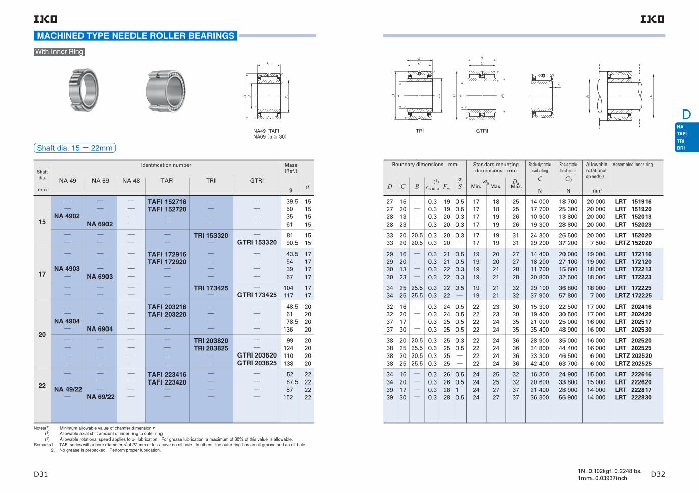
D
D31 D321N=0.102kgf=0.2248lbs.1mm=0.03937inch
Shaft dia. 15− 22mm
MACHINED TYPE NEEDLE ROLLER BEARINGS
43.5 54 39 67
17171717
104117
1717
52 67.5 87152
22222222
With Inner Ring
27272828
16201323
0.30.30.30.3
19192020
0.50.50.30.3
17171717
18181919
20 00020 00020 00020 000
LRT 151916LRT 151920LRT 152013LRT 152023
25252626
3333
2020
20.520.5
0.30.3
2020
0.3
1717
1919
20 0007 500
LRT 152020LRTZ 152020
3131
3434
2525
25.525.5
0.30.3
2222
0.5
1919
2121
18 0007 000
LRT 172225LRTZ 172225
3232
29293030
16201323
0.30.30.30.3
21212222
0.50.50.30.3
19191919
20202121
19 00019 00018 00018 000
LRT 172116LRT 172120LRT 172213LRT 172223
27272828
32323737
16201730
0.30.30.30.3
24242525
0.50.50.50.5
22222222
23232424
17 00017 00016 00016 000
LRT 202416LRT 202420LRT 202517LRT 202530
30303535
38383838
20252025
20.525.520.525.5
0.30.30.30.3
25252525
0.30.5
22222222
24242424
16 00016 0006 0006 000
LRT 202520LRT 202525LRTZ 202520LRTZ 202525
36363636
34343939
16201730
0.30.30.30.3
26262828
0.50.510.5
24242424
25252727
15 00015 00014 00014 000
LRT 222616LRT 222620LRT 222817LRT 222830
32323737
Boundary dimensions mm Standard mounting dimensions mm
Assembled inner ring
D C B rs min Fw S Min. Max. Da
Max. (1) da(2)
Shaft dia.
mm
Identification number Mass (Ref.)
g
NA 49 NA 69 NA 48 TAFI TRI GTRId
NA 4902
NA 6902
TAFI 152716TAFI 152720
39.5 50 35 61
1515151515
TRI 153320
GTRI 153320
81 90.5
1515
17
NA 4903
NA 6903
TAFI 172916TAFI 172920
TRI 173425
GTRI 173425
NA 4904
NA 6904
TAFI 203216TAFI 203220
48.5 61 78.5136
20202020
TRI 203820TRI 203825
GTRI 203820GTRI 203825
99124110138
20202020
20
NA 49/22
NA 69/22
TAFI 223416TAFI 223420
22
Notes(1) Minimum allowable value of chamfer dimension r (2) Allowable axial shift amount of inner ring to outer ring (3) Allowable rotational speed applies to oil lubrication. For grease lubrication, a maximum of 60% of this value is allowable.Remarks1. TAFI series with a bore diameter d of 22 mm or less have no oil hole. In others, the outer ring has an oil groove and an oil hole. 2. No grease is prepacked. Perform proper lubrication.
TRI NA49 TAFI NA69(d ≦ 30)
GTRI
Basic dynamic load rating
C
N
Basic static load rating
C0
N
16 30020 60021 40036 300
14 00017 70010 90019 300
24 90033 80028 90056 900
18 70025 30013 80028 800
14 40018 20011 70020 800
20 00027 10015 60032 500
29 10037 900
36 80057 800
15 30019 40021 00035 400
22 50030 50025 00048 900
28 90034 80033 30042 400
35 00044 40046 50063 700
24 30029 200
26 50037 200
Allowable rotational speed(3)
min-1
D F wd
C
r
r
r
r
S
DadaD
BC
r
r
r
r
Fwd
BC
r
r
r
r
D d Fw

D
D33 D341N=0.102kgf=0.2248lbs.1mm=0.03937inch
Shaft dia. 25− 32mm
MACHINED TYPE NEEDLE ROLLER BEARINGS
21 60030 90023 70042 100
37 20059 10030 70064 300
25 70036 80024 50041 800
42 20067 20032 70064 800
58 000 101 000
26 90038 60025 20043 000
46 20073 60034 70069 000
72 300110 000
37 90047 000
52 10076 500
With Inner Ring
38384242
20301730
0.30.30.30.3
29293030
0.510.50.5
27272727
28282929
14 00014 00013 00013 000
LRT 252920LRT 252930LRT 253017LRT 253030
36364040
42424545
20301730
0.30.30.30.3
32323232
0.5111
30303030
31313131
12 00012 00012 00012 000
LRT 283220LRT 283230LRT 283217LRT 283230
40404343
45454747
20301730
0.30.30.30.3
35353535
0.30.50.50.5
32323232
34343434
11 00011 00011 00011 000
LRT 303520LRT 303530LRT 303517LRT 303530
43434545
4444
2525
25.525.5
0.30.3
3030
0.5
2727
2929
13 0005 000
LRT 253025LRTZ 253025
4242
4848
3030
30.530.5
0.30.3
3535
1
3232
3434
11 0004 500
LRT 303530-1LRTZ 303530
4646
45 30 30.5 0.3 32 30 31 4 500 LRTZ 28323043
474752
203020
0.30.30.6
373740
0.30.50.5
343436
363639
11 00011 00010 000
LRT 323720LRT 323730LRT 324020
454548
525252
303630
30.5
30.5
0.60.60.6
384038
0.50.3
363636
373937
11 00010 0004 000
50 10079 80047 800
47 40061 100
LRT 323830LRT 324036LRTZ 323830
484848
Boundary dimensions mm Standard mounting dimensions mm
Assembled inner ring
D C B rs min Fw S Min. Max. Da
Max. (1) da(2)
Notes(1) Minimum allowable value of chamfer dimension r (2) Allowable axial shift amount of inner ring to outer ring (3) Allowable rotational speed applies to oil lubrication. For grease lubrication, a maximum of 60% of this value is allowable.Remarks1. The outer ring has an oil groove and an oil hole. 2. No grease is prepacked. Perform proper lubrication.
Shaft dia.
mm
Identification number Mass (Ref.)
g
NA 49 NA 69 NA 48 TAFI TRI GTRId
NA 4905
NA 6905
TAFI 253820TAFI 253830
82123 92.5160
2525252525
NA 49/28
NA 69/28
TAFI 284220TAFI 284230
96.5145101176
28282828
28
TRI 254425
GTRI 254425
157175
2525
GTRI 284530 196 28
NA 4906
NA 6906
TAFI 304520TAFI 304530
112171106184
3030303030
TRI 304830
GTRI 304830
199225
3030
NA 49/32
TAFI 324720TAFI 324730
121180165
323232
32
NA 69/32
TRI 325230
GTRI 325230
245295270
323232
TRI NA49 TAFI NA69(d ≦ 30)
GTRINA69
Basic dynamic load rating
C
N
Basic static load rating
C0
N
Allowable rotational speed(3)
min-1
50 80053 50064 200
81 10095 700
121 000
28 20040 50031 200
D F wd
C
r
r
r
r
D F w
C
r
r
r
r
d D
BC
r
r
r
r
Fwd Dada
S
BC
r
r
r
r
D d Fw

D
D35 D361N=0.102kgf=0.2248lbs.1mm=0.03937inch
Shaft dia. 35− 45mm
MACHINED TYPE NEEDLE ROLLER BEARINGS
136205
3838
300285520335
45454545
149225
4242
230320
4545
305340
4242
With Inner Ring
Shaft dia.
mm
Identification number Mass (Ref.)
g
NA 49 NA 69 NA 48 TAFI TRI GTRId
NA 4907
NA 6907
TAFI 355020TAFI 355030
129192178320
3535353535
TAFI 385320TAFI 385330
38
NA 4908
NA 6908
TRI 405930
GTRI 405930
270245440300
40404040
NA 4909
NA 6909
TRI 456430
GTRI 456430
TRI 355630
GTRI 355520GTRI 355630
280191310
353535
TAFI 405520TAFI 405530
143215
4040
40
TAFI 425720TAFI 425730
42
TAFI 456225TAFI 456235
45
NA49 TAFI NA69
Notes(1) Minimum allowable value of chamfer dimension r (2) Allowable axial shift amount of inner ring to outer ring (3) Allowable rotational speed applies to oil lubrication. For grease lubrication, a maximum of 60% of this value is allowable.Remarks1. The outer ring has an oil groove and an oil hole. 2. No grease is prepacked. Perform proper lubrication.
TRI 426230
GTRI 426230
50505555
20302036
0.30.30.60.6
40404242
0.30.50.50.3
37373939
39394141
10 00010 0009 5009 500
LRT 354020LRT 354030LRT 354220LRT 354236
48485151
59626259
30224030
30.5
30.5
0.60.60.60.6
45484845
10.50.3
44444444
44.5474744.5
9 0008 5008 5003 500
LRT 404530-1LRT 404822LRT 404840LRTZ 404530
55585855
64686864
30224030
30.5
30.5
0.60.60.60.6
50525250
10.50.3
49494949
49.5515149.5
8 0007 5007 5003 000
LRT 455030LRT 455222LRT 455240LRTZ 455030
60646460
565556
302030
30.520.530.5
0.60.60.6
424042
0.5
393939
4139.541
9 5003 5003 500
LRT 354230LRTZ 354020LRTZ 354230
525152
5353
2030
0.30.3
4343
0.30.5
4040
4242
9 5009 500
LRT 384320LRT 384330
5151
5555
2030
0.30.3
4545
0.30.5
4242
4444
9 0009 000
LRT 404520LRT 404530
5353
5757
2030
0.30.3
4747
0.30.5
4444
4646
8 5008 500
LRT 424720LRT 424730
5555
6262
3030
30.530.5
0.60.6
4848
0.5
4646
4747
8 5003 000
LRT 424830LRTZ 424830
5858
6262
2535
0.30.3
5050
0.51
4747
4949
8 0008 000
LRT 455025LRT 455035
6060
Boundary dimensions mm Standard mounting dimensions mm
Assembled inner ring
D C B rs min Fw S Min. Max. Da
Max. (1) da(2)
TRI GTRI
85 300125 000
104 00073 300
147 000158 000
54 100 86 200 50 100100 000
58 20092 600
60 20095 800
94 80067 400
135 000142 000
62 20099 100
99 500154 000
90 10073 600
133 000
43 00058 000
57 70043 50074 60074 600
29 40042 30032 00054 900
30 50043 800
31 00044 600
55 10041 60071 30070 300
31 50045 200
56 30072 700
53 80044 30067 500
Basic dynamic load rating
C
N
Basic static load rating
C0
N
Allowable rotational speed(3)
min-1
D F wd
C
r
r
r
r
D Fw
C
r
r
r
r
d D
BC
r
r
r
r
Fwd Dada
S
BC
r
r
r
r
D d Fw

D
D37 D381N=0.102kgf=0.2248lbs.1mm=0.03937inch
Shaft dia. 50− 70mm
MACHINED TYPE NEEDLE ROLLER BEARINGS
With Inner Ring
Shaft dia.
mm
Identification number Mass (Ref.)
g
NA 49 NA 69 NA 48 TAFI TRI GTRId
NA 4910
NA 6910
TAFI 506825TAFI 506835
270365295530
5050505050
NA 4912
NA 6912
TAFI 608225TAFI 608235
395560440785
6060606060
NA 4914
NA 6914
TAFI 709525TAFI 709535
540755765
1 400
70707070
70
NA 4911
NA 6911
TAFI 557225TAFI 557235
275380410730
5555555555
TRI 558138
GTRI 558138
650710
5555
TRI 608945
GTRI 608945
9601 050
6060
NA 4913
NA 6913
TAFI 659035
470710840
656565
65
TRI 507745
GTRI 507745
755825
5050
NA49 TAFI NA69
Notes(1) Minimum allowable value of chamfer dimension r (2) Allowable axial shift amount of inner ring to outer ring (3) Allowable rotational speed applies to oil lubrication. For grease lubrication, a maximum of 60% of this value is allowable.Remarks1. The outer ring has an oil groove and an oil hole. 2. No grease is prepacked. Perform proper lubrication.
8181
3838
38.538.5
11
6262
1.5
6060
60.560.5
6 5002 500
LRT 556238LRTZ 556238
7676
909090
253545
111
727372
110.5
707070
70.57170.5
5 5005 5005 500
LRT 657225LRT 657335LRT 657245
858585
68687272
25352240
0.30.30.60.6
55555858
0.510.50.3
52525454
54545757
7 5007 5007 0007 000
LRT 505525LRT 505535LRT 505822LRT 505840
66666868
7777
4545
45.545.5
11
5858
2
5555
5757
7 0002 500
LRT 505845LRTZ 505845
7272
72728080
25352545
0.30.311
60606363
0.5110.5
57576060
59596161
6 5006 5006 5006 500
LRT 556025LRT 556035LRT 556325LRT 556345
70707575
82828585
25352545
0.60.611
68686868
0.3110.5
64646565
66666666
6 0006 0006 0006 000
LRT 606825LRT 606835LRT 606825-1LRT 606845
78788080
9595
100100
25353054
1111
80808080
0.311.51
75757575
78787878
5 0005 0005 0005 000
LRT 708025LRT 708035LRT 708030LRT 708054
90909595
8989
4545
45.545.5
11
7070
2
6565
6868
5 5002 000
LRT 607045LRTZ 607045
8484
Boundary dimensions mm Standard mounting dimensions mm
Assembled inner ring
D C B rs min Fw S Min. Max. Da
Max. (1) da(2)
TRI GTRI
59 40078 10083 200
134 000
45 40061 20046 20079 200
137 000195 000158 000311 000
94 000138 00082 100
164 000
47 50064 10057 60098 700
103 000151 00097 200
194 000
92 000118 000
166 000241 000
54 80072 00060 200
103 000
117 000166 000105 000211 000
114 000147 000
228 000336 000
62 70080 400
108 000
113 000181 000227 000
104 000135 000
191 000280 000
Basic dynamic load rating
C
N
Basic static load rating
C0
N
Allowable rotational speed(3)
min-1
D F wd
C
r
r
r
r
D Fw
C
r
r
r
r
d D
BC
r
r
r
r
Fwd Dada
S
BC
r
r
r
r
D d Fw

D
D39 D401N=0.102kgf=0.2248lbs.1mm=0.03937inch
Shaft dia. 75− 90mm
MACHINED TYPE NEEDLE ROLLER BEARINGS
With Inner Ring
105105105105
25303554
1111
85858585
0.51.51.51
80808080
83 83 83 83
4 5004 5004 5004 500
LRT 758525LRT 758530LRT 758535LRT 758554
100100100100
110110110110
25303554
1111
90909090
0.51.51.51
85858585
88 88 88 88
4 5004 5004 5004 500
LRT 809025LRT 809030LRT 809035LRT 809054
105105105105
115115120120
26363563
111.11.1
9595
100100
1210.5
909091.591.5
93 93 98 98
4 0004 0004 0004 000
LRT 859526LRT 859536LRT 8510035LRT 8510063
110110113.5113.5
118120118120
50455045
50.545.550.545.5
11.511.5
93959395
32.5
90939093
91 93.5 91 93.5
4 5004 0001 6001 600
LRT 859350LRT 859545LRTZ 859350LRTZ 859545
113112113112
108108
4545
45.545.5
11
8383
2.5
8080
81 81
5 0001 800
LRT 758345LRTZ 758345
103103
120120125
263635
111.1
100100105
121
959596.5
98 98103
4 0004 0004 000
LRT 9010026LRT 9010036LRT 9010535
115115118.5
125125125
506350
50.5
50.5
1.51.11.5
100105100
30.5
9896.598
98.5103 98.5
4 0004 0001 500
LRT 9010050LRT 9010563LRTZ 9010050
117118.5117
Boundary dimensions mm Standard mounting dimensions mm
Assembled inner ring
D C B rs min Fw S Min. Max. Da
Max.(1) da(2)
Shaft dia.
mm
Identification number Mass (Ref.)
g
NA 49 NA 69 NA 48 TAFI TRI GTRId
NA 4915
NA 6915
TAFI 7510525
TAFI 7510535
675810945
1 480
7575757575
NA 4917
NA 6917
TAFI 8511526TAFI 8511536
7751 0801 2802 340
85858585
85
TRI 8511850TRI 8512045
GTRI 8511850GTRI 8512045
1 6401 6101 7801 720
85858585
NA 4916
NA 6916
TAFI 8011025
TAFI 8011035
710855995
1 560
80808080
80
NA 4918
TAFI 9012026TAFI 9012036
8201 1401 350
909090
90
NA 6918
TRI 9012550
GTRI 9012550
1 8702 4602 020
909090
TRI 7510845
GTRI 7510845
1 3401 440
7575
Notes(1) Minimum allowable value of chamfer dimension r (2) Allowable axial shift amount of inner ring to outer ring (3) Allowable rotational speed applies to oil lubrication. For grease lubrication, a maximum of 60% of this value is allowable.Remarks1. The outer ring has an oil groove and an oil hole. 2. No grease is prepacked. Perform proper lubrication.
TRI NA49 TAFI GTRINA69
172 000178 000234 000
76 30086 200
102 000138 000
355 000490 000549 000
145 000169 000210 000331 000
77 30087 300
103 000143 000
150 000175 000217 000351 000
79 700106 000110 000173 000
159 000231 000244 000467 000
165 000155 000224 000204 000
329 000305 000509 000455 000
82 400110 000113 000
168 000244 000258 000
146 000190 000
270 000396 000
Basic dynamic load rating
C
N
Basic static load rating
C0
N
Allowable rotational speed(3)
min-1
D F wd
C
r
r
r
r
D Fw
C
r
r
r
r
d D
BC
r
r
r
r
Fwd Dada
S
BC
r
r
r
r
D d Fw

D
D41 D421N=0.102kgf=0.2248lbs.1mm=0.03937inch
MACHINED TYPE NEEDLE ROLLER BEARINGS
2 8806 380
150150
With Inner Ring
125125130130
26363563
111.11.1
105105110110
1210.5
100100101.5101.5
103103108108
4 0004 0003 5003 500
LRT 9510526LRT 9510536LRT 9511035LRT 9511063
120120123.5123.5
130130
3040
11
110110
0.51.5
105105
108108
3 5003 500
LRT 10011030LRT 10011040
125125
135140135
504050
50.5
50.5
1.51.11.5
110115110
31
108106.5108
108.5113108.5
3 5003 5001 400
LRT 10011050LRT 10011540LRTZ 10011050
127133.5127
153153
5050
50.550.5
1.51.5
115115
3
113113
113.5113.5
3 5001 300
LRT 10511550LRTZ 10511550
145145
140150
3040
11.1
120125
11
115116.5
118123
3 5003 000
LRT 11012030LRT 11012540
135143.5
150165
3045
11.1
130135
12
125126.5
128133
3 0003 000
LRT 12013030LRT 12013545
145158.5
178178
6060
60.560.5
1.51.5
140140
2.5
133133
138138
3 0001 100
LRT 12514060LRTZ 12514060
170170
165180
3550
1.11.5
145150
12.5
136.5138
143148
3 0002 500
LRT 13014535LRT 13015050
158.5172
188188
6060
60.560.5
1.51.5
150150
2.5
143143
148148
2 5001 000
LRT 13515060LRTZ 13515060
180180
175190
3550
1.11.5
155160
12.5
146.5148
153158
2 5002 500
LRT 14015535LRT 14016050
168.5182
190210
4060
1.12
165170
1.53
156.5159
163168
2 5002 500
LRT 15016540LRT 15017060
183.5201
Boundary dimensions mm Standard mounting dimensions mm
Assembled inner ring
D C B rs min Fw S Min. Max. Da
Max.(1) da(2)
Shaft dia.
mm
Identification number Mass (Ref.)
g
NA 49 NA 69 NA 48 TAFI TRI GTRId
NA 4919
NA 6919
TAFI 9512526TAFI 9512536
8601 1901 4202 580
95959595
95
TAFI 10013030TAFI 10013040
1 0401 380
100100
100
TRI 10515350
GTRI 10515350
3 0203 270
105105
105
NA 4922
NA 4822
1 2002 120
110110
110
NA 4924
NA 4824
1 3002 960
120120
120
TRI 12517860
GTRI 12517860
4 7805 180
125125
125
NA 4926
NA 4826
1 9604 030
130130
130
TRI 13518860
GTRI 13518860
5 1005 530
135135
135
NA 4928
NA 4828
2 1004 290
140140
140
NA 4930
NA 4830
150
NA 4920
TRI 10013550
GTRI 10013550
2 0401 9602 200
100100100
TRINA49 TAFINA48
GTRINA69
Notes(1) Minimum allowable value of chamfer dimension r (2) Allowable axial shift amount of inner ring to outer ring (3) Allowable rotational speed applies to oil lubrication. For grease lubrication, a maximum of 60% of this value is allowable.Remarks1. The outer ring has an oil groove and an oil hole. 2. No grease is prepacked. Perform proper lubrication.
116 000215 000
320 000423 000
120 000224 000
168 000324 000
84 700113 000116 000182 000
340 000540 000
675 000989 000
363 000580 000
446 000712 000
178 000258 000271 000514 000
183 000145 000245 000
395 000329 000603 000
233 000315 000
414 000614 000
93 200152 000
239 000357 000
96 900187 000
259 000435 000
307 000409 000
625 000923 000
106 000134 000
240 000324 000
Basic dynamic load rating
C
N
Basic static load rating
C0
N
Allowable rotational speed(3)
min-1
Shaft dia. 95− 150mm
D F wd
C
r
r
r
r
D Fw
C
r
r
r
r
d
D
BC
r
r
r
r
Fwd Dada
S
BC
r
r
r
r
D d Fw

D
D43 D441N=0.102kgf=0.2248lbs.1mm=0.03937inch
MACHINED TYPE NEEDLE ROLLER BEARINGS
With Inner Ring
200220
4060
1.12
175180
1.53
166.5169
173178
2 5001 900
LRT 16017540LRT 16018060
193.5211
215230
4560
1.12
185190
1.53
176.5179
183188
1 9001 900
LRT 17018545LRT 17019060
208.5221
225250
4569
1.12
195205
1.53
186.5189
193203
1 9001 900
LRT 18019545LRT 18020569
218.5241
240260
5069
1.52
210215
1.53
198199
208213
1 8001 700
LRT 19021050LRT 19021569
232251
250280
5080
1.52.1
220225
1.54
208211
218223
1 6001 600
LRT 20022050LRT 20022580
242269
270300
5080
1.52.1
240245
1.54
228231
238243
1 5001 400
LRT 22024050LRT 22024580
262289
300320
6080
22.1
265265
24
249251
262262
1 3001 300
LRT 24026560LRT 24026580
291309
350380
69100
22.1
305310
2.54
289291
302307
950 950
LRT 28030569LRT 280310100
341369
320360
60100
22.1
285290
24
269271
282287
1 1001 100
LRT 26028560LRT 260290100
311349
380420
80118
2.13
330340
2.54
311313
327337
900 850
LRT 30033080LRT 300340118
369407
400440
80118
2.13
350360
2.54
331333
347357
750 750
LRT 32035080LRT 320360118
389427
420460
80118
2.13
370380
2.54
351353
367377
700 700
LRT 34037080LRT 340380118
409447
Boundary dimensions mm Standard mounting dimensions mm
Assembled inner ring
D C B rs min Fw S Min. Max. Da
Max.(1) da(2)
NA49 NA48
Shaft dia.
mm
Identification number Mass (Ref.)
g
NA 49 NA 69 NA 48 TAFI TRI GTRId
NA 4932
NA 4832
3 0506 750
160160
160
NA 4934
NA 4834
4 1207 110
170170
170
NA 4936
NA 4836
4 34010 200
180180
180
NA 4938
NA 4838
5 76010 700
190190
190
NA 4940
NA 4840
6 04015 400
200200
200
NA 4944
NA 4844
6 57016 700
220220
220
NA 4952
NA 4852
11 00031 100
260260
260
NA 4956
NA 4856
15 80033 100
280280
280
NA 4960
NA 4860
22 30051 400
300300
300
NA 4964
NA 4864
23 70054 400
320320
320
NA 4968
NA 4868
25 00057 300
340340
340
NA 4948
NA 4848
10 20018 000
240240
240
Notes(1) Minimum allowable value of chamfer dimension r (2) Allowable axial shift amount of inner ring to outer ring (3) Allowable rotational speed applies to oil lubrication. For grease lubrication, a maximum of 60% of this value is allowable.Remarks1. The outer ring has an oil groove and an oil hole. 2. No grease is prepacked. Perform proper lubrication.
173 000337 000
211 000347 000
218 000434 000
249 000440 000
255 000518 000
266 000536 000
345 000565 000
354 000847 000
486 000877 000
610 0001 130 000
635 0001 170 000
651 0001 220 000
474 000761 000
567 000810 000
602 000989 000
726 0001 020 000
766 0001 120 000
833 0001 200 000
1 150 0001 320 000
1 220 0001 900 000
1 550 0002 040 000
1 900 0002 650 000
2 040 0002 830 000
2 140 0003 020 000
Basic dynamic load rating
C
N
Basic static load rating
C0
N
Allowable rotational speed(3)
min-1
Shaft dia. 160− 340mm
D F wd
C
r
r
r
r
Dada
S

D
D45 D461N=0.102kgf=0.2248lbs.1mm=0.03937inch
MACHINED TYPE NEEDLE ROLLER BEARINGS
With Inner Ring
440480
80118
2.13
390400
2.54
371373
387397
650600
LRT 36039080LRT 360400118
429467
480520
100140
2.14
415430
35
391396
412427
600500
LRT 380415100LRT 380430140
469504
540 140 4 450 5 416 447 500 LRT 400450140524
560 140 4 470 5 436 467 500 LRT 420470140544
600 160 4 490 5 456 487 400 LRT 440490160584
Boundary dimensions mm Standard mounting dimensions mm
Assembled inner ring
D C B rs min Fw S Min. Max. Da
Max.(1) da(2)
Shaft dia.
mm
Identification number Mass (Ref.)
g
NA 49 NA 69 NA 48 TAFI TRI GTRId
NA 4972
NA 4872
26 40060 200
360360
360
NA 4976
NA 4876
44 60090 300
380380
380
NA 4980 94 400 400400
NA 4984 98 500 420420
NA 4988 131 000 440440
NA49 NA48
Notes(1) Minimum allowable value of chamfer dimension r (2) Allowable axial shift amount of inner ring to outer ring (3) Allowable rotational speed applies to oil lubrication. For grease lubrication, a maximum of 60% of this value is allowable.Remarks1. The outer ring has an oil groove and an oil hole. 2. No grease is prepacked. Perform proper lubrication.
680 0001 260 000
951 0001 540 000
1 590 000
1 640 000
1 910 000
2 320 0003 200 000
2 860 0004 030 000
4 270 000
4 510 000
5 140 000
Basic dynamic load rating
C
N
Basic static load rating
C0
N
Allowable rotational speed(3)
min-1
Shaft dia. 360− 440mm
D F wd
C
r
r
r
r
Dada
S

D
D47 D481N=0.102kgf=0.2248lbs.1mm=0.03937inch
Allowable rotational speed(2)
min-1
BR
Notes(1) Maximum permissible corner radius of the housing (2) Allowable rotational speed applies to oil lubrication. For grease lubrication, a maximum of 60% of this value is allowable.Remarks1. The outer ring has an oil groove and an oil hole. 2. No grease is prepacked. Perform proper lubrication.
Shaft dia.mm
(inch)
Identification number
Mass (Ref.)
g
Standard mounting dimensions mm
Boundary dimensions mm(inch)
DaMax.
ras max
(1)
15.875(58)19.050(34)22.225(78)25.400(1)28.575
(118)31.750
(114)34.925
(138)38.100
(112)41.275
(158)
44.450(134)
47.625(178)
49
56 75
63 84.5
69 92.5
102128
110138
119149
149187
158199
170215250
225
15.875( 5 8)
19.050( 3 4)19.050( 3 4)
22.225( 7 8)22.225( 7 8)
25.400(1 )25.400(1 )
28.575(1 1 8)28.575(1 1 8)
31.750(1 1 4)31.750(1 1 4)
34.925(1 3 8)34.925(1 3 8)
38.100(1 1 2)38.100(1 1 2)
41.275(1 5 8)41.275(1 5 8)
44.450(1 3 4)44.450(1 3 4)44.450(1 3 4)
47.625(1 7 8)
28.575(1 1 8)
31.750(1 1 4)31.750(1 1 4)
34.925(1 3 8)34.925(1 3 8)
38.100(1 1 2)38.100(1 1 2)
41.275(1 5 8)41.275(1 5 8)
44.450(1 3 4)44.450(1 3 4)
47.625(1 7 8)47.625(1 7 8)
52.388(2 116)52.388(2 116)
55.562(2 316)55.562(2 316)
58.738(2 516)58.738(2 516)60.325(2 3 8)
61.912(2 716)
19.050( 3 4)
19.050( 3 4)25.400(1 )
19.050( 3 4)25.400(1 )
19.050( 3 4)25.400(1 )
25.400(1 )31.750(1 1 4)
25.400(1 )31.750(1 1 4)
25.400(1 )31.750(1 1 4)
25.400(1 )31.750(1 1 4)
25.400(1 )31.750(1 1 4)
25.400(1 )31.750(1 1 4)31.750(1 1 4)
31.750(1 1 4)
24.5
26.526.5
29.729.7
32.932.9
3636
39.239.2
42.442.4
45.145.1
48.348.3
51.551.553.1
54.7
BR 101812
BR 122012BR 122016
BR 142212BR 142216
BR 162412BR 162416
BR 182616BR 182620
BR 202816BR 202820
BR 223016BR 223020
BR 243316BR 243320
BR 263516BR 263520
BR 283716BR 283720BR 283820
BR 303920
0.6
11
11
11
11
11
11
1.51.5
1.51.5
1.51.51.5
1.5
18 900
21 70027 600
23 00029 100
25 30032 100
34 90043 200
36 00044 600
38 50047 700
43 70054 200
44 80055 600
47 50058 90058 900
60 100
19 700
24 40033 100
27 10036 800
31 90043 300
49 90065 600
53 50070 300
60 00078 900
66 90088 200
70 90093 400
78 200103 000103 000
108 000
25 000
20 00020 000
18 00018 000
16 00016 000
14 00014 000
13 00013 000
11 00011 000
11 00011 000
9 5009 500
9 0009 0009 000
8 500
Fw D C
Without Inner Ring, Inch Series
Basic dynamic load rating
C
N
Basic static load rating
C0
N
MACHINED TYPE NEEDLE ROLLER BEARINGS
Shaft dia. 15.875−47.625mm
D Fw
C
Da
ra

D
D49 D501N=0.102kgf=0.2248lbs.1mm=0.03937inch
Allowable rotational speed(2)
min-1
Basic dynamic load rating
C
N
Basic static load rating
C0
N
Notes(1) Maximum permissible corner radius of the housing (2) Allowable rotational speed applies to oil lubrication. For grease lubrication, a maximum of 60% of this value is allowable.Remarks1. In bearings with a roller set bore diameter Fw of 69.850 mm or less, the outer ring has an oil groove and an oil hole. In others, the
outer ring has an oil groove and two oil holes. 2. No grease is prepacked. Perform proper lubrication.
Shaft dia. mm
(inch)
Identification
number
Mass (Ref.)
g
Standard mounting dimensions mm
Boundary dimensions mm(inch)
DaMax.
ras max
(1)Fw D C
Without Inner Ring, Inch Series
MACHINED TYPE NEEDLE ROLLER BEARINGS
50.800(2)
190240
50.800(2 )50.800(2 )
65.088(2 916)65.088(2 916)
25.400(1 )31.750(1 1 4)
57.8 57.8
BR 324116BR 324120
1.51.5
57.150(214)
435510
57.150(2 1 4)57.150(2 1 4)
76.200(3 )76.200(3 )
38.100(1 1 2)44.450(1 3 4)
69 69
BR 364824BR 364828
1.51.5
63.500(212)
475555
63.500(2 1 2)63.500(2 1 2)
82.550(3 1 4)82.550(3 1 4)
38.100(1 1 2)44.450(1 3 4)
74.3 74.3
BR 405224BR 405228
22
69.850(234)
510600
69.850(2 3 4)69.850(2 3 4)
88.900(3 1 2)88.900(3 1 2)
38.100(1 1 2)44.450(1 3 4)
80.7 80.7
BR 445624BR 445628
22
76.200(3)
555650
76.200(3 )76.200(3 )
95.250(3 3 4)95.250(3 3 4)
38.100(1 1 2)44.450(1 3 4)
87 87
BR 486024BR 486028
22
82.550(314)
9901 140
82.550(3 1 4)82.550(3 1 4)
107.950(4 1 4)107.950(4 1 4)
44.450(1 3 4)50.800(2 )
99.7 99.7
BR 526828BR 526832
22
88.900(312) 1 220 88.900(3
1 2) 114.300(4
1 2) 50.800(2 ) 106.1BR 567232 2
95.250(334) 1 290 95.250(3
3 4) 120.650(4
3 4) 50.800(2 ) 111.4BR 607632 2.5
101.600(4) 1 370 101.600(4 ) 127.000(5 ) 50.800(2 ) 117.8BR 648032 2.5
90 300105 000
98 700114 000
141 000154 000
169 000
94 600110 000
105 000122 000
162 000
176 000
51 00063 200
158 000191 000
189 000228 000
259 000290 000
342 000
174 000210 000
211 000255 000
316 000
368 000
89 400118 000
7 0007 000
5 5005 500
5 0005 000
4 000
6 5006 500
5 5005 500
4 500
4 000
8 0008 000
BR
Shaft dia. 50.800−101.600mm
D Fw
C
Da
ra

D51 D521N=0.102kgf=0.2248lbs.1mm=0.03937inch
D
Notes(1) Allowable axial shift amount of inner ring to outer ring (2) Maximum permissible corner radius of the shaft or housing (3) Allowable rotational speed applies to oil lubrication. For grease lubrication, a maximum of 60% of this value is allowable.Remarks1. The inner ring and the outer ring each have an oil groove and an oil hole. 2. No grease is prepacked. Perform proper lubrication.
Shaft dia. mm
(inch)
Identification
number
Mass (Ref.)
g
Boundary dimensions mm(inch)
d D C B Fw S(1)
With Inner Ring, Inch Series
MACHINED TYPE NEEDLE ROLLER BEARINGS
9.525(38) 67.5 9.525( 3
8) 28.575(1
1 8) 19.050( 3
4) 15.875( 5 8) 0.319.300BRI 61812
12.700(12)
79.5106
12.700( 1 2)12.700( 1 2)
31.750(1 1 4)31.750(1 1 4)
19.050( 3 4)25.400(1 )
19.050( 3 4)19.050( 3 4)
0.30.5
19.30025.650
BRI 82012BRI 82016
15.875(58)
91122
15.875( 5 8)15.875( 5 8)
34.925(1 3 8)34.925(1 3 8)
19.050( 3 4)25.400(1 )
22.225( 7 8)22.225( 7 8)
0.30.5
19.30025.650
BRI 102212BRI 102216
19.050(34)
102136
19.050( 3 4)19.050( 3 4)
38.100(1 1 2)38.100(1 1 2)
19.050( 3 4)25.400(1 )
25.400(1 )25.400(1 )
0.30.5
19.30025.650
BRI 122412BRI 122416
22.225(78)
152190
22.225( 7 8)22.225( 7 8)
41.275(1 5 8)41.275(1 5 8)
25.400(1 )31.750(1 1 4)
28.575(1 1 8)28.575(1 1 8)
0.50.5
25.65032.000
BRI 142616BRI 142620
25.400(1)
166210
25.400(1 )25.400(1 )
44.450(1 3 4)44.450(1 3 4)
25.400(1 )31.750(1 1 4)
31.750(1 1 4)31.750(1 1 4)
0.50.5
25.65032.000
BRI 162816BRI 162820
28.575(118)
182225
28.575(1 1 8)28.575(1 1 8)
47.625(1 7 8)47.625(1 7 8)
25.400(1 )31.750(1 1 4)
34.925(1 3 8)34.925(1 3 8)
0.50.5
25.65032.000
BRI 183016BRI 183020
31.750(114)
220275
31.750(1 1 4)31.750(1 1 4)
52.388(2 116)52.388(2 116)
25.400(1 )31.750(1 1 4)
38.100(1 1 2)38.100(1 1 2)
0.50.5
25.65032.000
BRI 203316BRI 203320
34.925(138)
235295
34.925(1 3 8)34.925(1 3 8)
55.562(2 316)55.562(2 316)
25.400(1 )31.750(1 1 4)
41.275(1 5 8)41.275(1 5 8)
0.50.5
25.65032.000
BRI 223516BRI 223520
38.100(112)
250315350380
38.100(1 1 2)38.100(1 1 2)38.100(1 1 2)38.100(1 1 2)
58.738(2 516)58.738(2 516)60.325(2 3 8)61.912(2 716)
25.400(1 )31.750(1 1 4)31.750(1 1 4)31.750(1 1 4)
44.450(1 3 4)44.450(1 3 4)44.450(1 3 4)47.625(1 7 8)
0.50.50.50.5
25.65032.00032.00032.000
BRI 243716BRI 243720BRI 243820BRI 243920
41.275(158)
325410
41.275(1 5 8)41.275(1 5 8)
65.088(2 916)65.088(2 916)
25.400(1 )31.750(1 1 4)
50.800(2 )50.800(2 )
0.50.5
25.65032.000
BRI 264116BRI 264120
Shaft dia. 9.525− 41.275mm
Allowable rotational speed(3)
min-1
Assembled inner ring
BRI
(2)
Standard mounting dimensions mm
Min. Max.
DaMax.
ras max
da
Basic dynamic load rating
C
N
Basic static load rating
C0
N
14 14.5 24.5 0.6 18 900
21 70027 600
23 00029 100
25 30032 100
34 90043 200
36 00044 600
38 50047 700
43 70054 200
44 80055 600
47 50058 90058 90060 100
51 00063 200
19 700
24 40033 100
27 10036 800
31 90043 300
49 90065 600
53 50070 300
60 00078 900
66 90088 200
70 90093 400
78 200103 000103 000108 000
89 400118 000
25 000 LRB 61012
17.517.5
1818
26.526.5
11
20 00020 000
LRB 81212LRB 81216
2121
21.221.2
29.729.7
11
18 00018 000
LRB 101412LRB 101416
2424
24.424.4
32.932.9
11
16 00016 000
LRB 121612LRB 121616
2727
27.527.5
3636
11
14 00014 000
LRB 141816LRB 141820
30.530.5
30.730.7
39.239.2
11
13 00013 000
LRB 162016LRB 162020
33.533.5
33.933.9
42.442.4
11
11 00011 000
LRB 182216LRB 182220
3737
37.137.1
45.145.1
1.51.5
11 00011 000
LRB 202416LRB 202420
40.240.2
40.240.2
48.348.3
1.51.5
9 5009 500
LRB 222616LRB 222620
43.343.343.343.3
43.443.443.443.4
51.551.553.154.7
1.51.51.51.5
9 0009 0009 0008 500
LRB 242816LRB 242820LRB 242820LRB 243020
4848
4949
57.857.8
1.51.5
8 0008 000
LRB 263216LRB 263220
D d F w
BC
da
ra
ra
Da
S

D53 D541N=0.102kgf=0.2248lbs.1mm=0.03937inch
D
MACHINED TYPE NEEDLE ROLLER BEARINGS
Shaft dia. mm
(inch)
Identification number
Mass (Ref.)
g
Boundary dimensions mm(inch)
d D C B Fw S(1)
With Inner Ring, Inch Series
Notes(1) Allowable axial shift amount of inner ring to outer ring (2) Maximum permissible corner radius of the shaft or housing (3) Allowable rotational speed applies to oil lubrication. For grease lubrication, a maximum of 60% of this value is allowable.Remarks1. In bearings with a bearing bore diameter, d, of 57.150 mm or less, the outer ring has an oil groove and an oil hole. In bearings with
a bearing bore diameter, d, of 76.200 mm or less, the inner ring has an oil groove and an oil hole. In others, the inner ring and the outer ring each have an oil groove and two oil holes.
2. No grease is prepacked. Perform proper lubrication.
44.450(134)
735855
44.450(1 3 4)44.450(1 3 4)
76.200(3 )76.200(3 )
38.100(1 1 2)44.450(1 3 4)
57.150(2 1 4)57.150(2 1 4)
11
38.35044.700
BRI 284824BRI 284828
50.800(2)
810945
50.800(2 )50.800(2 )
82.550(3 1 4)82.550(3 1 4)
38.100(1 1 2)44.450(1 3 4)
63.500(2 1 2)63.500(2 1 2)
11
38.35044.700
BRI 325224BRI 325228
57.150(214)
8851 040
57.150(2 1 4)57.150(2 1 4)
88.900(3 1 2)88.900(3 1 2)
38.100(1 1 2)44.450(1 3 4)
69.850(2 3 4)69.850(2 3 4)
11
38.35044.700
BRI 365624BRI 365628
63.500(212)
9651 130
63.500(2 1 2)63.500(2 1 2)
95.250(3 3 4)95.250(3 3 4)
38.100(1 1 2)44.450(1 3 4)
76.200(3 )76.200(3 )
11
38.35044.700
BRI 406024BRI 406028
69.850(234)
1 5201 740
69.850(2 3 4)69.850(2 3 4)
107.950(4 1 4)107.950(4 1 4)
44.450(1 3 4)50.800(2 )
82.550(3 1 4)82.550(3 1 4)
1.53
44.70051.050
BRI 446828BRI 446832
76.200(3) 1 860 76.200(3 ) 114.300(4 1 2) 50.800(2 ) 88.900(3 1 2) 351.050BRI 487232
82.550(314) 1 980 82.550(3 1 4) 120.650(4 3 4) 50.800(2 ) 95.250(3 3 4) 351.050BRI 527632
88.900(312) 2 120 88.900(3 1 2) 127.000(5 ) 50.800(2 ) 101.600(4 ) 351.050BRI 568032
Shaft dia. 44.450−88.900mm
Basic dynamic load rating
C
N
Basic static load rating
C0
N
Assembled inner ring
BRI
(2)
Standard mounting dimensions mm
Min. Max.
DaMax.
ras max
da
52.552.5
5555
69 69
1.51.5
90 300105 000
94 600 110 000
98 700114 000
105 000122 000
141 000154 000
162 000
169 000
176 000
158 000191 000
174 000210 000
189 000228 000
211 000255 000
259 000290 000
316 000
342 000
368 000
7 0007 000
LRB 283624LRB 283628
5858
6161
74.3 74.3
22
6 5006 500
LRB 324024LRB 324028
6565
6767
80.7 80.7
22
5 5005 500
LRB 364424LRB 364428
7171
7373
87 87
22
5 5005 500
LRB 404824LRB 404828
7777
7979
99.7 99.7
22
5 0005 000
LRB 445228LRB 445232
83.5 86 106.1 2 4 500 LRB 485632
91 93 111.4 2.5 4 000 LRB 526032
97 99 117.8 2.5 4 000 LRB 566432
Allowable rotational speed(3)
min-1
D d F w
BC
da
ra
ra
Da
S

D55 D561N=0.102kgf=0.2248lbs.1mm=0.03937inch
D
MACHINED TYPE NEEDLE ROLLER BEARINGS
With Seal, Without Inner Ring
Shaft dia. 14− 45mm
Standard mounting dimension
Da
Max. mm
Allowable rotational speed(2)
min-1
Basic dynamic load rating
C
N
Basic static load rating
C0
N
Notes(1) Minimum allowable value of chamfer dimension r (2) Allowable rotational speed applies to grease lubrication.Remarks1. The outer ring has an oil groove and an oil hole. 2. Bearings are provided with prepacked grease. Bearings with a seal on one side are not provided with prepacked grease. Perform
proper lubrication for use.
g D C rs minFw(1)
Shaft dia.
mm
Identification number Mass (Ref.)
g
With two seals With one seal With one sealWith two seals
14
16
18
20
22
25
28
30
32
35
40
42
45
RNA 4900UU
RNA 4901UU
RNA 49/14UU
RNA 4902UU
RNA 4903UU
RNA 4904UU
RNA 49/22UU
RNA 4905UU
RNA 49/28UU
RNA 4906UU
RNA 49/32UU
RNA 4907UU
RNA 49/38UU
RNA 6901UU
RNA 6902UU
RNA 6903UU
RNA 6904UU
RNA 69/22UU
RNA 6905UU
RNA 69/28UU
RNA 6906UU
RNA 69/32UU
RNA 6907UU
RNA 4900U
RNA 4901U
RNA 49/14U
RNA 4902U
RNA 4903U
RNA 4904U
RNA 49/22U
RNA 4905U
RNA 49/28U
RNA 4906U
RNA 49/32U
RNA 4907U
RNA 49/38U
RNA 6901U
RNA 6902U
RNA 6903U
RNA 6904U
RNA 69/22U
RNA 6905U
RNA 69/28U
RNA 6906U
RNA 69/32U
RNA 6907U
16.3 14
1616
18
2222
2020
2525
2828
3030
3232
3535
4040
45
4242
22
2424
26
3030
2828
3737
3939
4242
4545
4747
5252
58
5555
13
1322
13
1323
1323
1730
1730
1730
1730
1730
2036
20
2036
0.3
0.30.3
0.3
0.30.3
0.30.3
0.30.3
0.30.3
0.30.3
0.30.3
0.30.3
0.60.6
0.6
0.60.6
20
2222
24
2828
2626
3535
3737
4040
4343
4545
4848
54
5151
8 080
8 47015 500
9 260
10 30019 800
9 57018 500
18 00033 000
18 30033 800
20 30039 200
21 00038 900
21 50040 100
29 40050 300
31 600
30 10051 600
8 490
9 32020 400
10 800
13 10030 600
11 60027 100
20 50044 600
23 70052 000
25 10058 700
26 80059 100
28 40063 000
44 20088 300
50 400
46 30092 600
14 000
12 00012 000
11 000
8 5008 500
9 5009 500
7 5007 500
7 0007 000
6 5006 500
6 0006 000
5 5005 500
5 0005 000
4 000
4 5004 500
17.9 30
19.7
21.5 37.5
23 40.5
54.5 95.5
55.5 97.5
63 111
75.5 133
71 125
94.5 170
112 200
119
Boundary dimensionsmm
D C rs minFw(1)
RNA49 … UURNA69 … UU(Fw ≦ 35)
RNA49 … URNA69 … U(Fw ≦ 35)
RNA69 … UU RNA69 … U
D Fw
C
r
r
D Fw
C
r
r
D Fw
C
r
r
D Fw
C
r
r
Da

D57 D581N=0.102kgf=0.2248lbs.1mm=0.03937inch
D
Notes(1) Minimum allowable value of chamfer dimension r (2) Allowable rotational speed applies to grease lubrication.Remarks1. The outer ring has an oil groove and an oil hole. 2. Bearings are provided with prepacked grease. Bearings with a seal on one side are not provided with prepacked grease. Perform
proper lubrication for use.
MACHINED TYPE NEEDLE ROLLER BEARINGS
With Seal, Without Inner Ring
Shaft dia. 48− 85mm
Shaft dia.
mm
Identification number Mass (Ref.)
g
With two seals With one seal With one sealWith two seals
48
50
52
55
58
60
63
65
68
70
72
75
80
85
RNA 4908UU
RNA 6908UU
RNA 6908U
RNA 6909U
RNA 6910U
RNA 6911U
RNA 6912U
RNA 6913U
RNA 6914U
RNA 6915U
−
RNA 6909UU
RNA 6910UU
RNA 6911UU
RNA 6912UU
RNA 6913UU
RNA 6914UU
RNA 6915UU
RNA 49/42UU
RNA 4909UU
RNA 49/48UU
RNA 4910UU
RNA 49/52UU
RNA 4911UU
RNA 49/58UU
RNA 4912UU
RNA 49/62UU
RNA 4913UU
RNA 49/68UU
RNA 4914UU
RNA 4915UU
RNA 4908U
RNA 49/42U
RNA 4909U
RNA 49/48U
RNA 4910U
RNA 49/52U
RNA 4911U
RNA 49/58U
RNA 4912U
RNA 49/62U
RNA 4913U
RNA 49/68U
RNA 4914U
RNA 4915U
4848
50
5252
5858
55
60
6363
65
6868
70
7272
8080
8585
75
6262
65
6868
7272
70
75
8080
82
8585
88
9090
100100
105105
95
2240
22
2240
2240
22
22
2545
25
2545
25
2545
3054
3054
30
0.6 0.6
0.6
0.6 0.6
0.6 0.6
0.6
0.6
1 1
1
1 1
1
1 1
1 1
1 1
1
5858
61
6464
6868
66
71
7575
77
8080
83
8585
9595
100100
90
37 20063 700
38 000
38 90066 600
41 30070 800
39 600
42 100
52 20089 400
53 400
54 50093 400
55 700
56 80097 400
76 900124 000
79 600128 000
73 900
58 400117 000
60 900
63 400127 000
71 100142 000
66 100
73 600
85 700171 000
89 200
92 800186 000
96 300
99 800200 000
143 000281 000
153 000299 000
133 000
4 0004 000
4 000
3 5003 500
3 5003 500
3 500
3 000
3 0003 000
3 000
3 0003 000
2 500
2 5002 500
2 5002 500
2 0002 000
2 500
150270
173
197355
187
177320
200
265470
275
285505
320
325580
465
495910
520960
Boundary dimensionsmm
Allowable rotational speed(2)
min-1D C rs minFw
(1)
RNA49 … UU RNA49 … U RNA69 … UU RNA69 … U
Standard mounting dimension
Da
Max. mm
Basic dynamic load rating
C
N
Basic static load rating
C0
N
D Fw
C
r
r
D Fw
C
r
r
D Fw
C
r
r
D Fw
C
r
r
Da

D59 D601N=0.102kgf=0.2248lbs.1mm=0.03937inch
D
Notes(1) Minimum allowable value of chamfer dimension r (2) Allowable rotational speed applies to grease lubrication.Remarks1. The outer ring has an oil groove and an oil hole. 2. Bearings are provided with prepacked grease. Bearings with a seal on one side are not provided with prepacked grease. Perform
proper lubrication for use.
MACHINED TYPE NEEDLE ROLLER BEARINGS
With Seal, Without Inner Ring
Shaft dia. 90− 160mm
Shaft dia.
mm
Identification number Mass (Ref.)
g
With two seals With one seal With one sealWith two seals
90
95
100
105
110
115
125
135
150
160
RNA 4916UU
RNA 6916UU
RNA 6916U
RNA 6917U
RNA 6918U
RNA 6919U
RNA 6917UU
RNA 6918UU
RNA 6919UU
RNA 49/82UU
RNA 4917UU
RNA 4918UU
RNA 4919UU
RNA 4920UU
RNA 4922UU
RNA 4924UU
RNA 4926UU
RNA 4928UU
RNA 4916U
RNA 49/82U
RNA 4917U
RNA 4918U
RNA 4919U
RNA 4920U
RNA 4922U
RNA 4924U
RNA 4926U
RNA 4928U
9090
95
100100
110110
105105
115
125
135
150
160
110110
115
120120
130130
125125
140
150
165
180
190
3054
30
3563
3563
3563
40
40
45
50
50
1 1
1
1.1 1.1
1.1 1.1
1.1 1.1
1.1
1.1
1.1
1.5
1.5
5451 010
570
6951 300
7301 360
7601 420
1 280
1 200
1 940
2 360
2 510
Boundary dimensionsmm
D C rs minFw(1)
RNA49 … UU
105 105
110
113.5 113.5
123.5 123.5
118.5 118.5
133.5
143.5
158.5
172
182
80 700132 000
83 200
103 000168 000
109 000177 000
106 000172 000
134 000
140 000
178 000
206 000
214 000
158 000317 000
168 000
225 000448 000
250 000493 000
238 000471 000
297 000
322 000
410 000
511 000
549 000
2 0002 000
2 000
1 9001 900
1 7001 700
1 8001 800
1 700
1 500
1 400
1 300
1 200
Allowable rotational speed(2)
min-1
RNA49 … U RNA69 … UU RNA69 … U
Standard mounting dimension
Da
Max. mm
Basic dynamic load rating
C
N
Basic static load rating
C0
N
D Fw
C
r
r
D Fw
C
r
r
D Fw
C
r
r
D Fw
C
r
r
Da

D61 D621N=0.102kgf=0.2248lbs.1mm=0.03937inch
D
Notes(1) Minimum allowable value of chamfer dimension r (2) Allowable rotational speed applies to grease lubrication.Remarks1. The outer ring has an oil groove and an oil hole. 2. Bearings are provided with prepacked grease. Bearings with a seal on one side are not provided with prepacked grease. Perform
proper lubrication for use.
MACHINED TYPE NEEDLE ROLLER BEARINGS
With Seal, With Inner Ring
Shaft dia. 10− 40mm
Shaft dia.
mm
Identification number Mass (Ref.)
g
With two seals With one seal With one sealWith two seals
10
12
15
17
20
22
25
28
30
32
35
40
NA 4900UU
NA 6901U
NA 6902U
NA 6903U
NA 6904U
NA 69/22U
NA 6905U
NA 69/28U
NA 6906U
NA 69/32U
NA 6907U
NA 6908U
NA 6901UU
NA 6902UU
NA 6903UU
NA 6904UU
NA 69/22UU
NA 6905UU
NA 69/28UU
NA 6906UU
NA 69/32UU
NA 6907UU
NA 6908UU
NA 4901UU
NA 4902UU
NA 4903UU
NA 4904UU
NA 49/22UU
NA 4905UU
NA 49/28UU
NA 4906UU
NA 49/32UU
NA 4907UU
NA 4908UU
NA 4900U
NA 4901U
NA 4902U
NA 4903U
NA 4904U
NA 49/22U
NA 4905U
NA 49/28U
NA 4906U
NA 49/32U
NA 4907U
NA 4908U
10
1212
1515
2020
1717
2222
2525
2828
3030
3232
3535
4040
22
2424
2828
3737
3030
3939
4242
4545
4747
5252
5555
6262
13
1322
1323
1730
1323
1730
1730
1730
1730
2036
2036
2240
14
1423
1424
1831
1424
1831
1831
1831
1831
2137
2137
2341
24.5
27.5 45.5
36 62.5
39.5 68.5
78.5 137
92.5 162
87.5 153
101 177
106 185
167 300
179 320
245 440
Boundary dimensionsmm
D C Bd
NA49 … UUNA69 … UU(d ≦ 30)
12
1414
1717
2222
1919
2424
2727
3030
3232
3636
3939
4444
13
1515
1919
2424
2121
2727
2929
3131
3434
3939
4141
4747
20
2222
2626
3535
2828
3737
4040
4343
4545
4848
5151
5858
8 080
8 47015 500
9 57018 500
18 00033 000
10 30019 800
18 30033 800
20 30039 200
21 00038 900
21 50040 100
29 40050 300
30 10051 600
37 20063 700
14 000
12 00012 000
9 5009 500
7 5007 500
8 5008 500
7 0007 000
6 5006 500
6 0006 000
5 5005 500
5 0005 000
4 5004 500
4 0004 000
Allowable rotational speed(2)
min-1
0.3
0.30.3
0.30.3
0.30.3
0.30.3
0.30.3
0.30.3
0.30.3
0.30.3
0.60.6
0.60.6
0.60.6
Fw
14
1616
2020
2525
2222
2828
3030
3232
3535
4040
4242
4848
rs min(1)
Assembled inner ring
LRTZ 101414
LRTZ 121614LRTZ 121623
LRTZ 152014LRTZ 152024
LRTZ 172214LRTZ 172224
LRTZ 202518LRTZ 202531
LRTZ 222818LRTZ 222831
LRTZ 253018LRTZ 253031
LRTZ 283218LRTZ 283231
LRTZ 303518LRTZ 303531
LRTZ 324021LRTZ 324037
LRTZ 354221LRTZ 354237
LRTZ 404823LRTZ 404841
Standard mounting dimensions mm
Min. Max.
DaMax.
da
NA49 … UNA69 … U(d ≦ 30)
NA69 … UU NA69 … U
Basic dynamic load rating
C
N
Basic static load rating
C0
N
8 490
9 32020 400
11 60027 100
13 10030 600
20 50044 600
23 70052 000
25 10058 700
26 80059 100
28 40063 000
44 20088 300
46 30092 600
58 400117 000
D d Fw
CB
r
r
r
r
D Fwd
BC
r
r
r
r
D Fwd
BC
r
r
r
r
BC
r
r
r
r
D d Fw da Da

D63 D641N=0.102kgf=0.2248lbs.1mm=0.03937inch
D
Notes(1) Minimum allowable value of chamfer dimension r (2) Allowable rotational speed applies to grease lubrication.Remarks1. The outer ring has an oil groove and an oil hole. 2. Bearings are provided with prepacked grease. Bearings with a seal on one side are not provided with prepacked grease. Perform
proper lubrication for use.
MACHINED TYPE NEEDLE ROLLER BEARINGS
With Seal, With Inner Ring
Shaft dia. 45− 110mm
Shaft dia.
mm
Identification number Mass (Ref.)
g
With two seals With one seal With one sealWith two seals
45
50
55
60
65
70
75
80
85
90
95
100
110
NA 4909UU
NA 6909UU
NA 6909U
NA 6910U
NA 6911U
NA 6912U
NA 6913U
NA 6914U
NA 6915U
NA 6916U
NA 6917U
NA 6918U
NA 6919U
NA 6910UU
NA 6911UU
NA 6912UU
NA 6913UU
NA 6914UU
NA 6915UU
NA 6916UU
NA 6917UU
NA 6918UU
NA 6919UU
NA 4910UU
NA 4911UU
NA 4912UU
NA 4913UU
NA 4914UU
NA 4915UU
NA 4916UU
NA 4917UU
NA 4918UU
NA 4919UU
NA 4920UU
NA 4922UU
NA 4909U
NA 4910U
NA 4911U
NA 4912U
NA 4913U
NA 4914U
NA 4915U
NA 4916U
NA 4917U
NA 4918U
NA 4919U
NA 4920U
NA 4922U
4545
5050
5555
6565
6060
7070
7575
8080
8585
9090
9595
100
110
6868
7272
8080
9090
8585
100100
105105
110110
120120
125125
130130
140
150
2240
2240
2545
2545
2545
3054
3054
3054
3563
3563
3563
40
40
2341
2341
2646
2646
2646
3155
3155
3155
3664
3664
3664
41
41
49 49
54 54
60 60
70 70
65 65
75 75
80 80
85 85
91.5 91.5
96.5 96.5
101.5 101.5
106.5
116.5
51 51
57 57
61 61
70.5 70.5
66 66
78 78
83 83
88 88
98 98
103 103
108 108
113
123
64 64
68 68
75 75
85 85
80 80
95 95
100 100
105 105
113.5 113.5
118.5 118.5
123.5 123.5
133.5
143.5
38 900 66 600
41 30070 800
52 20089 400
56 80097 400
54 50093 400
76 900124 000
79 600128 000
80 700132 000
103 000168 000
106 000172 000
109 000177 000
134 000
140 000
63 400127 000
71 100142 000
85 700171 000
99 800200 000
92 800186 000
143 000281 000
153 000299 000
158 000317 000
225 000448 000
238 000471 000
250 000493 000
297 000
322 000
3 5003 500
3 5003 500
3 0003 000
2 5002 500
3 0003 000
2 5002 500
2 0002 000
2 0002 000
1 9001 900
1 8001 800
1 7001 700
1 700
1 500
290520
295530
415730
445785
475845
8151 480
7701 400
8601 570
1 3002 360
1 3602 480
1 4202 600
1 980
2 150
Boundary dimensionsmm
Allowable rotational speed(2)
min-1D C Bd
0.6 0.6
0.6 0.6
1 1
1 1
1 1
1 1
1 1
1 1
1.1 1.1
1.1 1.1
1.1 1.1
1.1
1.1
Fw
5252
5858
6363
7272
6868
8080
8585
9090
100100
105105
110110
115
125
rs min(1)
Assembled inner ring
LRTZ 455223LRTZ 455241
LRTZ 505823LRTZ 505841
LRTZ 556326LRTZ 556346
LRTZ 606826LRTZ 606846
LRTZ 657226LRTZ 657246
LRTZ 708031LRTZ 708055
LRTZ 758531LRTZ 758555
LRTZ 809031LRTZ 809055
LRTZ 8510036LRTZ 8510064
LRTZ 9010536LRTZ 9010564
LRTZ 9511036LRTZ 9511064
LRTZ 10011541
LRTZ 11012541
Standard mounting dimensions mm
Min. Max.
DaMax.
da
NA49 … UU NA49 … U NA69 … UU NA69 … U
Basic dynamic load rating
C
N
Basic static load rating
C0
N
D d Fw
CB
r
r
r
r
D Fwd
BC
r
r
r
r
D Fwd
BC
r
r
r
r
da Da
BC
r
r
r
r
D d Fw

D65 D661N=0.102kgf=0.2248lbs.1mm=0.03937inch
D
Notes(1) Minimum allowable value of chamfer dimension r (2) Allowable rotational speed applies to grease lubrication.Remarks1. The outer ring has an oil groove and an oil hole. 2. Bearings are provided with prepacked grease. Bearings with a seal on one side are not provided with prepacked grease. Perform
proper lubrication for use.
MACHINED TYPE NEEDLE ROLLER BEARINGS
With Seal, With Inner Ring
Shaft dia.
mm
Identification number Mass (Ref.)
g
With two seals With one seal With one sealWith two seals
120
130
140
NA 4924UU
NA 4926UU
NA 4928UU
NA 4924U
NA 4926U
NA 4928U
120
130
140
165
180
190
45
50
50
46
51
51
126.5
138
148
133
148
158
158.5
172
182
178 000
206 000
214 000
410 000
511 000
549 000
1 400
1 300
1 200
2 990
4 080
4 340
Boundary dimensionsmm
Allowable rotational speed(2)
min-1D C Bd
1.1
1.5
1.5
Fw
135
150
160
rs min(1)
Assembled inner ring
LRTZ 12013546
LRTZ 13015051
LRTZ 14016051
Standard mounting dimensions mm
Min. Max.
DaMax.
da
NA49 … UU NA49 … U
Basic dynamic load rating
C
N
Basic static load rating
C0
N
Shaft dia. 120− 140mm
D Fwd
BC
r
r
r
r
da DaD d Fw
CB
r
r
r
r

D67 D681N=0.102kgf=0.2248lbs.1mm=0.03937inch
D
MACHINED TYPE NEEDLE ROLLER BEARINGS
With Seal, Without Inner Ring, Inch Series
Shaft dia. 15.875−50.800mm
Notes(1) Maximum permissible corner radius of the housing (2) Allowable rotational speed applies to grease lubrication.Remarks1. The outer ring has an oil groove and an oil hole. 2. Bearings are provided with prepacked grease. 3. If one side sealed type are needed, please contact IKO.
54
Allowable rotational speed(2)
min-1
Shaft dia.mm
(inch)
Identification number
With two seals
Mass (Ref.)
g
Standard mounting dimensions mm
Boundary dimensions mm(inch)
DaMax.
ras max(1)
Fw D C
15.875(58)19.050(34)22.225(78)25.400(1)28.575
(118)31.750
(114)34.925
(138)38.100
(112)41.275
(158)44.450
(134)47.625
(178)50.800(2)
68
76
83
115
124
134
168
179
193
202
216
15.875( 5 8)
19.050( 3 4)
22.225( 7 8)
25.400(1 )
28.575(1 1 8)
31.750(1 1 4)
34.925(1 3 8)
38.100(1 1 2)
41.275(1 5 8)
44.450(1 3 4)
47.625(1 7 8)
50.800(2 )
28.575(1 1 8)
31.750(1 1 4)
34.925(1 3 8)
38.100(1 1 2)
41.275(1 5 8)
44.450(1 3 4)
47.625(1 7 8)
52.388(2 116)
55.562(2 316)
58.738(2 516)
61.912(2 716)
65.088(2 916)
25.400(1 )
25.400(1 )
25.400(1 )
25.400(1 )
31.750(1 1 4)
31.750(1 1 4)
31.750(1 1 4)
31.750(1 1 4)
31.750(1 1 4)
31.750(1 1 4)
31.750(1 1 4)
31.750(1 1 4)
24.5
26.5
29.7
32.9
36.0
39.2
42.4
45.1
48.3
51.5
54.7
57.8
BR 101816 UU
BR 122016 UU
BR 142216 UU
BR 162416 UU
BR 182620 UU
BR 202820 UU
BR 223020 UU
BR 243320 UU
BR 263520 UU
BR 283720 UU
BR 303920 UU
BR 324120 UU
0.6
1.0
1.0
1.0
1.0
1.0
1.0
1.5
1.5
1.5
1.5
1.5
18 300
20 700
21 600
23 600
34 900
36 000
38 500
43 700
44 800
47 500
48 500
51 000
20 000
24 400
26 900
31 300
49 900
53 500
60 000
66 900
70 900
78 200
82 100
89 400 4 000
12 000
10 000
9 000
8 000
7 000
6 500
5 500
5 500
4 500
4 500
4 000
Basic dynamic load rating
C
N
Basic static load rating
C0
N
BR … UU
C
D Fw Da
ra

D69 D701N=0.102kgf=0.2248lbs.1mm=0.03937inch
D
MACHINED TYPE NEEDLE ROLLER BEARINGS
With Seal, Without Inner Ring, Inch Series
Shaft dia. 57.150−95.250mm
Notes(1) Maximum permissible corner radius of the housing (2) Allowable rotational speed applies to grease lubrication.Remarks1. The outer ring has an oil groove and an oil hole. 2. Bearings are provided with prepacked grease. 3. If one side sealed type are needed, please contact IKO.
459
Allowable rotational speed(2)
min-1
Shaft dia.mm
(inch)
Identification number
With two seals
Mass (Ref.)
g
Standard mounting dimensions mm
Boundary dimensions mm(inch)
DaMax.
ras max(1)
Fw D C
57.150(214)63.500
(212)69.850
(234)76.200(3)82.550
(314)88.900
(312)95.250
(334)
499
540
585
891
1 098
1 161
57.150(2 1 4)
63.500(2 1 2)
69.850(2 3 4)
76.200(3 )
82.550(3 1 4)
88.900(3 1 2)
95.250(3 3 4)
76.200(3 )
82.550(3 1 4)
88.900(3 1 2)
95.250(3 3 4)
107.950(4 1 4)
114.300(4 1 2)
120.650(4 3 4)
44.450(1 3 4)
44.450(1 3 4)
44.450(1 3 4)
44.450(1 3 4)
44.450(1 3 4)
50.800(2 )
50.800(2 )
69.0
74.3
80.7
87.0
99.7
106.1
111.4
BR 364828 UU
BR 405228 UU
BR 445628 UU
BR 486028 UU
BR 526828 UU
BR 567232 UU
BR 607632 UU
1.5
2.0
2.0
2.0
2.0
2.0
2.5
90 300
94 600
98 700
105 000
109 000
142 000
148 000
158 000
174 000
189 000
211 000
227 000
265 000
287 000
3 500
3 000
2 500
2 500
2 500
2 000
2 000
Basic dynamic load rating
C
N
Basic static load rating
C0
N
BR … UU
C
D Fw Da
ra
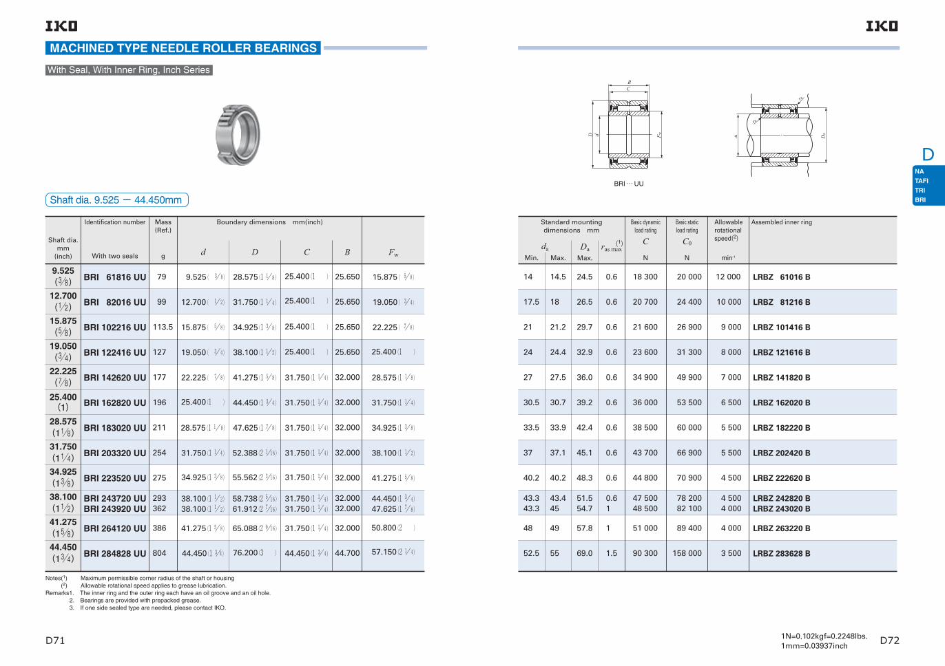
D71 D721N=0.102kgf=0.2248lbs.1mm=0.03937inch
D
MACHINED TYPE NEEDLE ROLLER BEARINGS
With Seal, With Inner Ring, Inch Series
Shaft dia. 9.525− 44.450mm
Allowable rotational speed(2)
min-1
Assembled inner ring
(1)
Min. Max.
DaMax.
ras maxda
Basic dynamic load rating
C
N
Basic static load rating
C0
N
Notes(1) Maximum permissible corner radius of the shaft or housing (2) Allowable rotational speed applies to grease lubrication.Remarks1. The inner ring and the outer ring each have an oil groove and an oil hole. 2. Bearings are provided with prepacked grease. 3. If one side sealed type are needed, please contact IKO.
Shaft dia.mm
(inch)
Identification number Mass (Ref.)
g
Boundary dimensions mm(inch)
d D C B Fw
9.525(38)12.700(12)15.875(58)19.050(34)22.225(78)25.400(1)28.575
(118)31.750
(114)34.925
(138)38.100
(112)41.275
(158)44.450
(134)
BRI 61816 UU
BRI 82016 UU
BRI 102216 UU
BRI 122416 UU
BRI 142620 UU
BRI 162820 UU
BRI 183020 UU
BRI 203320 UU
BRI 223520 UU
BRI 243720 UUBRI 243920 UU
BRI 264120 UU
BRI 284828 UU
79
99
113.5
127
177
196
211
254
275
293362
386
804
9.525( 3 8) 28.575(1 1 8)
12.700( 1 2) 31.750(1 1 4)
15.875( 5 8) 34.925(1 3 8)
19.050( 3 4) 38.100(1 1 2)
22.225( 7 8) 41.275(1 5 8)
25.400(1 ) 44.450(1 3 4)
28.575(1 1 8) 47.625(1 7 8)
31.750(1 1 4) 52.388(2 116)
34.925(1 3 8) 55.562(2 316)
38.100(1 1 2)38.100(1 1 2)
58.738(2 516)61.912(2 716)
41.275(1 5 8) 65.088(2 916)
44.450(1 34) 76.200(3 )
25.400(1 )
25.400(1 )
25.400(1 )
25.400(1 )
31.750(1 1 4)
31.750(1 1 4)
31.750(1 1 4)
31.750(1 1 4)
31.750(1 1 4)
31.750(1 1 4)31.750(1 1 4)
31.750(1 1 4)
44.450(1 3 4)
25.650
25.650
25.650
25.650
32.000
32.000
32.000
32.000
32.000
32.00032.000
32.000
44.700
15.875( 5 8)
19.050( 3 4)
22.225( 7 8)
25.400(1 )
28.575(1 1 8)
31.750(1 1 4)
34.925(1 3 8)
38.100(1 1 2)
41.275(1 5 8)
44.450(1 3 4)47.625(1 7 8)
50.800(2 )
57.150(2 1 4)
With two seals
14
17.5
21
24
27
30.5
33.5
37
40.2
43.343.3
48
52.5
14.5
18
21.2
24.4
27.5
30.7
33.9
37.1
40.2
43.445
49
55
24.5
26.5
29.7
32.9
36.0
39.2
42.4
45.1
48.3
51.554.7
57.8
69.0
0.6
0.6
0.6
0.6
0.6
0.6
0.6
0.6
0.6
0.61
1
1.5
18 300
20 700
21 600
23 600
34 900
36 000
38 500
43 700
44 800
47 50048 500
51 000
90 300
20 000
24 400
26 900
31 300
49 900
53 500
60 000
66 900
70 900
78 20082 100
89 400
158 000
12 000
10 000
9 000
8 000
7 000
6 500
5 500
5 500
4 500
4 5004 000
4 000
3 500
LRBZ 61016 B
LRBZ 81216 B
LRBZ 101416 B
LRBZ 121616 B
LRBZ 141820 B
LRBZ 162020 B
LRBZ 182220 B
LRBZ 202420 B
LRBZ 222620 B
LRBZ 242820 BLRBZ 243020 B
LRBZ 263220 B
LRBZ 283628 B
BRI … UU
Standard mounting dimensions mm
BC
D d Fw Da
ra
ra
da

D73 D741N=0.102kgf=0.2248lbs.1mm=0.03937inch
D
MACHINED TYPE NEEDLE ROLLER BEARINGS
With Seal, With Inner Ring, Inch Series
Shaft dia. 50.800−82.550mm
Allowable rotational speed(2)
min-1
Assembled inner ring
(1)
Standard mounting dimensionsmm
Min. Max.
DaMax.
ras maxda
Basic dynamic load rating
C
N
Basic static load rating
C0
N
Notes(1) Maximum permissible corner radius of the shaft or housing (2) Allowable rotational speed applies to grease lubrication.Remarks1. The inner ring and the outer ring each have an oil groove and an oil hole. 2. Bearings are provided with prepacked grease. 3. If one side sealed type are needed, please contact IKO.
Shaft dia.mm
(inch)
Identification number Mass (Ref.)
g
Boundary dimensions mm(inch)
d D C B Fw
50.800(2)57.150
(214)63.500
(212)69.850
(234)76.200(3)82.550
(314)
BRI 325228 UU
BRI 365628 UU
BRI 406028 UU
BRI 446828 UU
BRI 487232 UU
BRI 527632 UU
889
980
1 065
1 421
1 738
1 851
50.800(2 ) 82.550(3 1 4)
57.150(2 1 4) 88.900(3 1 2)
63.500(2 1 2) 95.250(3 3 4)
69.850(2 3 4) 107.950(4 1 4)
76.200(3 ) 114.300(4 1 2)
82.550(3 1 4) 120.650(4 3 4)
44.450(1 3 4)
44.450(1 3 4)
44.450(1 3 4)
44.450(1 3 4)
50.800(2 )
50.800(2 )
44.700
44.700
44.700
44.700
51.050
51.050
63.500(2 1 2)
69.850(2 3 4)
76.200(3 )
82.550(3 1 4)
88.900(3 1 2)
95.250(3 3 4)
With two seals
58
65
71
77
83.5
91
61
67
73
79
86
93
74.3
80.7
87.0
99.7
106.1
111.4
1.5
1.5
1.5
1.5
1.5
1.5
94 600
98 700
105 000
109 000
142 000
148 000
174 000
189 000
211 000
227 000
265 000
287 000
3 000
2 500
2 500
2 500
2 000
2 000
LRBZ 324028 B
LRBZ 364428 B
LRBZ 404828 B
LRBZ 445228 B
LRBZ 485632 B
LRBZ 526032 B
BRI … UU
BC
D d Fw Da
ra
ra
da

D
D75 D76
Structure and featuresC-Lube Machined Type Needle Roller Bearing is a bearing that is lubricated with a newly developed thermosetting solid-type lubricant. A large amount of lubricating oil and fine particles of ultra high molecular weight polyolefin resin are solidified by heat treatment to fill the inner space of the bearing. As the bearing rotates, the lubricating oil oozes out onto the raceway in proper quantities, maintaining the lubrication performance for a long period of time.C-Lube Machined Type Needle Roller Bearings are bearings with a low sectional height and large load ratings. The outer ring has high rigidity and can easily be used even for light alloy housings.
FitThe recommended fits for C-Lube Machined Type Needle Roller Bearings are shown in Tables 21 to 23 on pages A41 and A42.
Allowable Rotational SpeedThe allowable rotational speed of C-Lube Machined Type Needle Roller Bearing is affected by mounting and operating conditions. The reference dmn value (1) is 20,000.
Note(1) dmn value = (Bore diameter of bearing [mm] + Outside diameter of bearing [mm])/2 x rotational speed [min-1]
AccuracyC-Lube Machined Type Needle Roller Bearings are manufactured based on JIS (See page A31.). The tolerances for the smallest single roller set bore diam-eter of bearings without inner ring are based on Table 14 on page A33.
TypeC-Lube Machined Type Needle Roller Bearing is available in type shown in Table 1.
Identification numberThe identification number of C-Lube Machined Type Needle Roller Bearing consists of model code, dimen-sions and classification symbol. Example is shown below.
Mounting
Precaution for Use
LubricationAs the internal space of C-Lube Machined Type Needle Roller Bearing is filled with thermosetting solid-type lubricant C-Lube, regreasing is not possible due to the structure.
Oil holeTable 2 shows the number of oil holes on the outer ring.
TAF 12 1219 P6 /SGModel code Dimensions Model code
Type of bearing
(12mm)
(19mm)
Accuracy class (Class 6)
Bearing width
Nominal outside diameter
Example of identification number
Classification symbol
Roller set bore diameter(12mm)
TAF…/SG(1)
Structure of C-Lube Machined Type Needle Roller Bearing
Cage
Needle roller
Outer ring
Table 2 Number of oil holes of outer ring
Nominal roller set bore diameterFwmm
Number of hole holes of outer ring
Fw≦26 26<Fw
0
1Remark If there is oil hole on the outer ring, care must be
exercised not to let oil holes within the load range.
Table 1 Type of bearing
Type
Series
Metric series For light duty TAF・・・/SG
Needle bearing with cage
Without inner ring
1 Mounting dimensions for C-Lube Machined Type Needle Roller Bearings are shown in the table of dimensions.
2 When mounting, pay special attention to avoid locating the oil hole within the loading zone. This may lead to a short bearing life.
1 Do not wash C-Lube Machined Type Needle Roller Bearing with organic solvent and/or white kerosene, which have the ability of removing fat nor leave them in contact with the above agents.
2 To ensure normal rotation of the C-Lube Machined Type Needle Roller Bearing, apply a load of 1% or over of the dynamic load rating at use.
3 The operating temperature range is -15〜+80˚C. For continuous operation, the recommended oper-ating temperature is +60˚C or less.
4 When using two or more C-Lube Machined Type Needle Roller Bearings adjacent to each other on the same shaft, it is necessary to obtain an even load distribution. On request, a set of bearings is available, in which bearings are matched to obtain an even load distribution.
Further, C-Lube Machined Type Needle Roller Bearing for food machinery is also available. If need-ed, please contact IKO.
Note(1) Thermosetting solid-type lubricant fills inner space of the bearing.

D77 D781N=0.102kgf=0.2248lbs.1mm=0.03937inch
D
Shaft dia. 10−45mm
C-LUBE MACHINED TYPE NEEDLE ROLLER BEARINGS
Without Inner Ring
Shaft dia.
Identification number
Fw D C rs min(1)
TAF … /SGFw>26
TAF … /SGFw≦26
Standard mounting dimension
Da
Max.mm
Basic dynamic load rating
C
N
Basic static load rating
C0
N
TAF 101712/SGTAF 101716/SG
TAF 121912/SGTAF 121916/SG
TAF 142216/SGTAF 142220/SG
TAF 152316/SGTAF 152320/SG
TAF 162416/SGTAF 162420/SG
TAF 182616/SGTAF 182620/SG
TAF 192716/SGTAF 192720/SG
TAF 202816/SGTAF 202820/SG
TAF 212916/SGTAF 212920/SG
TAF 223016/SGTAF 223020/SG
TAF 243216/SGTAF 243220/SG
TAF 253316/SGTAF 253320/SG
1114.7
12.516.8
2227.5
23.529
2430
26.533
2835.5
28.537
3037.5
3139
3342
3543.5
10
12
14
15
16
18
19
21
22
24
25
20
Note(1) Minimum allowable value of chamfer dimension r.Remarks1. Models with a nominal roller set bore diameter Fw of 26mm or less are provided without oil holes. other models are provided with
one oil hole and oil groove. 2. This bearing can not be re-lubricated as thermosetting solid-type lubricant C-Lube fills inner space of the bearing.
Mass (Ref.)
g
Boundary dimensions mm
1010
1212
1414
1515
1616
1818
1919
2020
2121
2222
2424
2525
1717
1919
2222
2323
2424
2626
2727
2828
2929
3030
3232
3333
1216
1216
1620
1620
1620
1620
1620
1620
1620
1620
1620
1620
0.20.2
0.30.3
0.30.3
0.30.3
0.30.3
0.30.3
0.30.3
0.30.3
0.30.3
0.30.3
0.30.3
0.30.3
15.415.4
1717
2020
2121
2222
2424
2525
2626
2727
2828
3030
3131
5 8808 230
6 6109 250
11 70014 800
12 30015 600
12 30015 500
13 40017 000
14 00017 700
13 90017 600
14 40018 200
14 90018 900
15 30019 400
15 80020 000
5 9709 190
7 26011 200
13 70018 600
14 90020 200
15 10020 400
17 50023 600
18 70025 300
18 80025 400
20 00027 100
21 20028 700
22 50030 500
23 70032 100
Shaft dia.
Identification number
Fw D C rs min(1)
Standard mounting dimension
Da
Max.mm
Basic dynamic load rating
C
N
Basic static load rating
C0
N
TAF 293820/SGTAF 293830/SG
TAF 304020/SGTAF 304030/SG
TAF 354520/SGTAF 354530/SG
TAF 405020/SGTAF 405030/SG
TAF 455520/SGTAF 455530/SG
59 88
67101
76.5116.5
86130
95.5144
29
30
35
40
45
Mass (Ref.)
g
Boundary dimensions mm
2929
3030
3535
4040
4545
3838
4040
4545
5050
5555
2030
2030
2030
2030
2030
0.30.3
0.30.3
0.30.3
0.30.3
0.30.3
3636
3838
4343
4848
5353
21 60030 900
25 10036 000
26 90038 600
29 40042 300
31 00044 600
37 20059 100
40 10063 900
46 20073 600
54 10086 200
60 20095 800
C
r
r
D Fw
C
r
r
D Fw Da

D79 D80
DNeedle Roller Bearings with Separable Cage - Without Inner Ring
Needle Roller Bearings with Separable Cage - With Inner Ring
Structure and FeaturesIn IKO Needle Roller Bearings with Separable Cage, the inner ring, outer ring and IKO Needle Roller Cage are combined, and they can be separated easily. This type has a simple structure with high accuracy. In addition, the radial clearance can be freely chosen by selecting and combining these component parts. As Needle Roller Cages are used, these bearings have excellent rotational performance.These bearings are most suitable for mass-production high accuracy products such as machine tools, textile machinery, and printing machines.
Structures of Needle Roller Bearings with Separable Cage
Outer ring
Needle roller cage
Outer ring
Needle roller cage
Outer ring
Inner ring
Needle roller cage
Outer ring
Inner ring
Needle roller cage
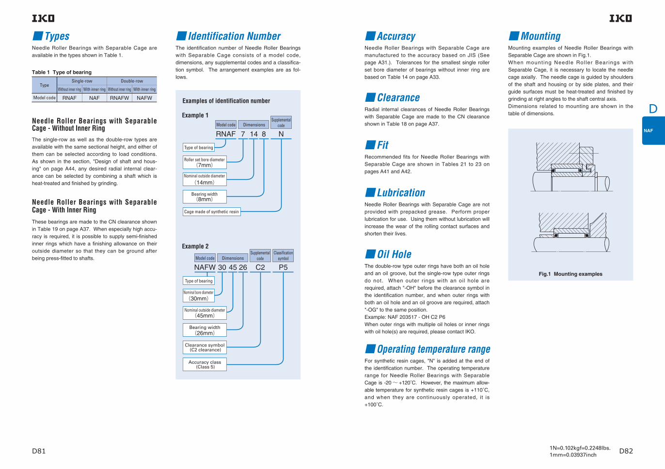
D81 D821N=0.102kgf=0.2248lbs.1mm=0.03937inch
D
RNAF 7 14 8
NAFW 30 2645 C2 P5
N
(45mm)
(30mm)
(7mm)
(14mm)
(8mm)
Examples of identification number
Example 1
Example 2
Model code DimensionsSupplemental
code
Model code DimensionsSupplemental
code
Type of bearing
Cage made of synthetic resin
Classificationsymbol
Accuracy class (Class 5)
Clearance symbol (C2 clearance)
Bearing width
Type of bearing
Nominal outside diameter
Roller set bore diameter
Nominal outside diameter
Bearing width
Nominal bore diameter
(26mm)
TypesNeedle Roller Bearings with Separable Cage are available in the types shown in Table 1.
The identification number of Needle Roller Bearings with Separable Cage consists of a model code, dimensions, any supplemental codes and a classifica-tion symbol. The arrangement examples are as fol-lows.
Identification NumberMounting examples of Needle Roller Bearings with Separable Cage are shown in Fig.1.When mount ing Needle Rol ler Bear ings wi th Separable Cage, it is necessary to locate the needle cage axially. The needle cage is guided by shoulders of the shaft and housing or by side plates, and their guide surfaces must be heat-treated and finished by grinding at right angles to the shaft central axis.Dimensions related to mounting are shown in the table of dimensions.
Mounting
LubricationNeedle Roller Bearings with Separable Cage are not provided with prepacked grease. Perform proper lubrication for use. Using them without lubrication will increase the wear of the rolling contact surfaces and shorten their lives.
Oil HoleThe double-row type outer rings have both an oil hole and an oil groove, but the single-row type outer rings do not. When outer rings with an oil hole are required, attach "-OH" before the clearance symbol in the identification number, and when outer rings with both an oil hole and an oil groove are required, attach "-OG" to the same position.Example: NAF 203517 - OH C2 P6When outer rings with multiple oil holes or inner rings with oil hole(s) are required, please contact IKO.
FitRecommended fits for Needle Roller Bearings with Separable Cage are shown in Tables 21 to 23 on pages A41 and A42.
Operating temperature rangeFor synthetic resin cages, "N" is added at the end of the identification number. The operating temperature range for Needle Roller Bearings with Separable Cage is -20〜 +120˚C. However, the maximum allow-able temperature for synthetic resin cages is +110˚C, and when they are continuously operated, it is +100˚C.
Accuracy
Needle Roller Bearings with Separable Cage - Without Inner RingThe single-row as well as the double-row types are available with the same sectional height, and either of them can be selected according to load conditions. As shown in the section, "Design of shaft and hous-ing" on page A44, any desired radial internal clear-ance can be selected by combining a shaft which is heat-treated and finished by grinding.
Needle Roller Bearings with Separable Cage - With Inner RingThese bearings are made to the CN clearance shown in Table 19 on page A37. When especially high accu-racy is required, it is possible to supply semi-finished inner rings which have a finishing allowance on their outside diameter so that they can be ground after being press-fitted to shafts.
Needle Roller Bearings with Separable Cage are manufactured to the accuracy based on JIS (See page A31.). Tolerances for the smallest single roller set bore diameter of bearings without inner ring are based on Table 14 on page A33.
Fig.1 Mounting examples
Table 1 Type of bearing
Type
Model code RNAFW NAFWRNAF NAF
Double-row
Without inner ring With inner ring
Single-row
Without inner ring With inner ring
ClearanceRadial internal clearances of Needle Roller Bearings with Separable Cage are made to the CN clearance shown in Table 18 on page A37.
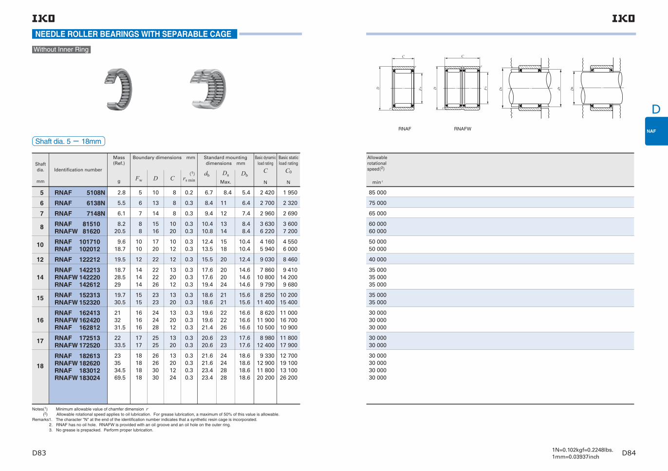
D83 D841N=0.102kgf=0.2248lbs.1mm=0.03937inch
D
NEEDLE ROLLER BEARINGS WITH SEPARABLE CAGE
Without Inner Ring
Shaftdia.
mm
Mass (Ref.)
g
Basic dynamic load rating
C
N
Basic static load rating
C0
N
Boundary dimensions mm
Identification number
Fw D Cdb Da
Max.
Dbrs min(1)
Standard mounting dimensions mm
Notes(1) Minimum allowable value of chamfer dimension r (2) Allowable rotational speed applies to oil lubrication. For grease lubrication, a maximum of 50% of this value is allowable.Remarks1. The character "N" at the end of the identification number indicates that a synthetic resin cage is incorporated. 2. RNAF has no oil hole. RNAFW is provided with an oil groove and an oil hole on the outer ring. 3. No grease is prepacked. Perform proper lubrication.
RNAF RNAFW
5 RNAF 5108N 5 10 8 0.2 6.7 8.4 5.4 2 420 1 950 2.8
6 RNAF 6138N 6 13 8 0.3 8.4 11 6.4 2 700 2 320 5.5
7 RNAF 7148N 7 14 8 0.3 9.4 12 7.4 2 960 2 690 6.1
8 RNAF 81510RNAFW 81620
88
1516
1020
0.30.3
10.410.8
1314
8.48.4
3 6306 220
3 6007 200
8.220.5
10 RNAF 101710RNAF 102012
1010
1720
1012
0.30.3
12.413.5
1518
10.410.4
4 1605 940
4 5506 000
9.618.7
12 RNAF 122212 12 22 12 0.3 15.5 20 12.4 9 030 8 46019.5
14RNAF 142213RNAFW 142220RNAF 142612
141414
222226
132012
0.30.30.3
17.617.619.4
202024
14.614.614.6
7 86010 8009 790
9 41014 2009 680
18.728.529
15 RNAF 152313RNAFW 152320
1515
2323
1320
0.30.3
18.618.6
2121
15.615.6
8 25011 400
10 20015 400
19.730.5
16RNAF 162413RNAFW 162420RNAF 162812
161616
242428
132012
0.30.30.3
19.619.621.4
222226
16.616.616.6
8 62011 90010 500
11 00016 70010 900
213231.5
17 RNAF 172513RNAFW 172520
1717
2525
1320
0.30.3
20.620.6
2323
17.617.6
8 98012 400
11 80017 900
2233.5
18RNAF 182613RNAFW 182620RNAF 183012RNAFW 183024
18181818
26263030
13201224
0.30.30.30.3
21.621.623.423.4
24242828
18.618.618.618.6
9 33012 90011 80020 200
12 70019 10013 10026 200
233534.569.5
Allowable rotational speed(2)
min-1
85 000
75 000
65 000
60 00060 000
50 00050 000
40 000
35 00035 00035 000
35 00035 000
30 00030 00030 000
30 00030 000
30 00030 00030 00030 000
Shaft dia. 5− 18mm
D Fw
C
r
r
C
r
r
D Fw Da db Db

D85 D861N=0.102kgf=0.2248lbs.1mm=0.03937inch
D
NEEDLE ROLLER BEARINGS WITH SEPARABLE CAGE
RNAF RNAFW
Without Inner Ring
Shaftdia.
mm
Mass (Ref.)
g
Basic dynamic load rating
C
N
Basic static load rating
C0
N
Boundary dimensions mm
Identification number
Fw D Cdb Da
Max.
Dbrs min(1)
Standard mounting dimensions mm
Notes(1) Minimum allowable value of chamfer dimension r (2) Allowable rotational speed applies to oil lubrication. For grease lubrication, a maximum of 50% of this value is allowable.Remarks1. RNAF has no oil hole. RNAFW is provided with an oil groove and an oil hole on the outer ring. 2. No grease is prepacked. Perform proper lubrication.
Allowable rotational speed(2)
min-1
25 00025 00025 00025 000
25 00025 00025 00025 000
20 00020 00020 00020 000
18 00018 000
17 00017 00017 00017 000
14 00014 00014 00014 000
12 00012 00012 00012 000
20RNAF 202813RNAFW 202826RNAF 203212RNAFW 203224
20202020
28283232
13261224
0.30.30.30.3
23.623.625.425.4
26263030
20.620.620.620.6
9 59016 40012 40021 200
13 50027 10014 30028 600
25 49.5 37.5 75
22RNAF 223013RNAFW 223026RNAF 223516RNAFW 223532
22222222
30303535
13261632
0.30.30.30.3
25.625.627.827.8
28283333
22.622.622.622.6
10 20017 50017 60030 200
15 20030 30020 90041 800
27 53.5 58.5117
25RNAF 253517RNAFW 253526RNAF 253716RNAFW 253732
25252525
35353737
17261632
0.30.30.30.3
29.529.530.430.4
33333535
25.625.625.625.6
17 30022 40019 40033 200
26 60037 20024 50049 000
51 78 57114
28 RNAF 284016RNAFW 284032
2828
4040
1632
0.30.3
33.433.4
3838
28.628.6
20 10034 400
26 50053 000
62.5125
30RNAF 304017RNAFW 304026RNAF 304216RNAFW 304232
30303030
40404242
17261632
0.30.30.30.3
34.534.535.435.4
38384040
30.630.630.630.6
18 70024 20020 80035 700
31 10043 40028 40056 800
59 90.5 66132
35RNAF 354517RNAFW 354526RNAF 354716RNAFW 354732
35353535
45454747
17261632
0.30.30.30.3
39.539.540.440.4
43434545
35.635.635.635.6
20 50026 60023 10039 500
36 90051 50033 90067 800
67.5103 75.5151
40
RNAF 405017RNAFW 405034RNAF 405520RNAFW 405540
40404040
50505555
17342040
0.30.30.30.3
43.543.545.245.2
48485353
40.840.840.840.8
22 20038 00031 40053 900
42 70085 40048 00096 000
76152140280
Shaft dia. 20− 40mm
D Fw
C
r
r
C
r
r
D Fw Da db Db

D87 D881N=0.102kgf=0.2248lbs.1mm=0.03937inch
D
NEEDLE ROLLER BEARINGS WITH SEPARABLE CAGE
Without Inner Ring
Shaftdia.
mm
Mass (Ref.)
g
Basic dynamic load rating
C
N
Basic static load rating
C0
N
Boundary dimensions mm
Identification number
Fw D Cdb Da
Max.
Dbrs min(1)
Standard mounting dimensions mm
Notes(1) Minimum allowable value of chamfer dimension r (2) Allowable rotational speed applies to oil lubrication. For grease lubrication, a maximum of 50% of this value is allowable.Remarks1. RNAF has no oil hole. RNAFW is provided with an oil groove and an oil hole on the outer ring. 2. No grease is prepacked. Perform proper lubrication.
45RNAF 455517RNAFW 455534RNAF 456220RNAFW 456240
45454545
55556262
17342040
0.30.30.30.3
48.5 48.5 50.9 50.9
53536060
45.8 45.8 45.8 45.8
23 30039 90033 20056 900
47 10094 20053 300
107 000
83.5 167 184 370
50RNAF 506220RNAFW 506240RNAF 506520RNAFW 506540
50505050
62626565
20402040
0.30.30.30.6
54.2 54.2 55.2 55.2
60606361
50.8 50.8 50.8 50.8
27 10046 40035 90061 500
59 300119 00061 100
122 000
138 275 170 340
55RNAF 556820RNAFW 556840RNAF 557220RNAFW 557240
55555555
68687272
20402040
0.30.311
59.5 59.5 60.9 60.9
66666767
55.8 55.8 55.8 55.8
28 60049 00037 40064 100
66 000132 00066 400
133 000
167 335 220 440
60 RNAF 607820RNAFW 607840
6060
7878
2040
11
66.3 66.3
7373
60.8 60.8
38 90066 700
71 700143 000
255 510
65 RNAF 658530RNAFW 658560
6565
8585
3060
1.51.5
72 72
7777
66 66
59 300102 000
127 000255 000
470 945
70 RNAF 709030RNAFW 709060
7070
9090
3060
1.51.5
77 77
8282
71 71
61 200105 000
136 000272 000
5001 000
75 RNAF 759530RNAFW 759560
7575
9595
3060
1.51.5
82 82
8787
76 76
63 100108 000
144 000289 000
5301 060
80 RNAF 8010030RNAFW 8010060
8080
100100
3060
1.51.5
87 87
9292
81 81
65 000111 000
153 000306 000
5601 120
85 RNAF 8510530 85 105 30 1.5 92 97 86 66 600 161 000 590
90 RNAF 9011030 90 110 30 1.5 97 102 91 69 600 174 000 625
95100
RNAF 9511530RNAF 10012030
95
100
115
120
30
30
1.5
1.5
102
107
107
112
96
101
70 900
72 500
182 000
191 000
655
685
Shaft dia. 45− 100mm
RNAF RNAFW
Allowable rotational speed(2)
min-1
11 00011 00011 00011 000
10 00010 00010 00010 000
9 0009 0009 0009 000
8 5008 500
7 5007 500
7 0007 000
6 5006 500
6 0006 000
6 000
5 500
5 500
4 500
D Fw
C
r
r
C
r
r
D Fw Da db Db

D89 D901N=0.102kgf=0.2248lbs.1mm=0.03937inch
D
NEEDLE ROLLER BEARINGS WITH SEPARABLE CAGE
With Inner Ring
Shaftdia.
mm
Mass (Ref.)
g
Boundary dimensions mm
Identification number
d D C Fwdb Da
Max.
Dbrs min(1)
Standard mounting dimensions mm
Notes(1) Minimum allowable value of chamfer dimension r (2) Allowable rotational speed applies to oil lubrication. For grease lubrication, a maximum of 50% of this value is allowable.Remarks1. NAF has no oil hole. NAFW is provided with an oil groove and an oil hole on the outer ring. 2. No grease is prepacked. Perform proper lubrication.
6 NAF 61710 6 17 10 0.3 10 8 9.712.4 15 10.4 13.5
7 NAF 72012 7 20 12 0.3 10 9 9.713.5 18 10.4 22.5
9 NAF 92212 9 22 12 0.3 12 11 11.515.5 20 12.4 24
10NAF 102213NAFW 102220NAF 102612
101010
222226
132012
0.30.30.3
141414
121212
131313
17.617.619.4
202024
14.614.614.6
26 40 36
12NAF 122413NAFW 122420NAF 122812
121212
242428
132012
0.30.30.3
161616
141414
151515
19.619.621.4
222226
16.616.616.6
29.5 45.5 40
15NAF 152813NAFW 152826NAF 153212
151515
282832
132612
0.30.30.3
202020
171717
191919
23.623.625.4
262630
20.620.620.6
38.5 77.5 50.5
17NAF 173013NAFW 173026NAF 173516NAFW 173532
17171717
30303535
13261632
0.30.30.30.3
22222222
19191919
21212121
25.625.627.827.8
28283333
22.622.622.622.6
42.5 84.5 77.5155
20NAF 203517NAFW 203526NAF 203716NAFW 203732
20202020
35353737
17261632
0.30.30.30.3
25252525
22222222
24242424
29.529.530.430.4
33333535
25.625.625.625.6
74114 79158
25
NAF 254017NAFW 254026NAF 254216NAFW 254232
25252525
40404242
17261632
0.30.30.30.3
30303030
27272727
29292929
34.534.535.435.4
38384040
30.630.630.630.6
87.5135 94186
Min. Max.
da
Shaft dia. 6− 25mm
NAF NAFW
Basic dynamic load rating
C
N
Basic static load rating
C0
N
Allowable rotational speed(2)
min-1
4 160 4 550 50 000 LRT 61010
5 940 6 000 50 000 LRT 71012-1
9 030 8 460 40 000 LRT 91212
7 86010 8009 790
9 41014 2009 680
35 00035 00035 000
LRT 101413LRT 101420LRT 101412
8 62011 90010 500
11 00016 70010 900
30 00030 00030 000
LRT 121613LRT 121620LRT 121612
9 59016 40012 400
13 50027 10014 300
25 00025 00025 000
LRT 152013LRT 152026LRT 152012
10 20017 50017 60030 200
15 20030 30020 90041 800
25 00025 00025 00025 000
LRT 172213LRT 172226LRT 172216LRT 172232
17 30022 40019 40033 200
26 60037 20024 50049 000
20 00020 00020 00020 000
LRT 202517LRT 202526LRT 202516LRT 202532
18 70024 20020 80035 700
31 10043 40028 40056 800
17 00017 00017 00017 000
LRT 253017LRT 253026LRT 253016LRT 253032
Assembledinner ring
Da
db Db daD Fwd
C
r
r
r
r
D d Fw
C
r
r
r
r

D91 D921N=0.102kgf=0.2248lbs.1mm=0.03937inch
D
NEEDLE ROLLER BEARINGS WITH SEPARABLE CAGE
Shaft dia. 30− 65mm
With Inner Ring
Shaftdia.
mm
Mass (Ref.)
g
Boundary dimensions mm
Identification number
d D C Fwdb Da
Max.
Dbrs min(1)
Standard mounting dimensions mm
Notes(1) Minimum allowable value of chamfer dimension r (2) Allowable rotational speed applies to oil lubrication. For grease lubrication, a maximum of 50% of this value is allowable.Remarks1. NAF has no oil hole. NAFW is provided with an oil groove and an oil hole on the outer ring. 2. No grease is prepacked. Perform proper lubrication.
30NAF 304517NAFW 304526NAF 304716NAFW 304732
30303030
45454747
17261632
0.30.30.30.3
35353535
32323232
34343434
39.539.540.440.4
43434545
35.635.635.635.6
101155107215
Basic dynamic load rating
C
N
Basic static load rating
C0
N
Allowable rotational speed(2)
min-1
20 50026 60023 10039 500
36 90051 50033 90067 800
14 00014 00014 00014 000
LRT 303517LRT 303526LRT 303516LRT 303532
35NAF 355017NAFW 355034NAF 355520NAFW 355540
35353535
50505555
17342040
0.30.30.30.3
40404040
37373737
39393939
43.543.545.245.2
48485353
40.840.840.840.8
115230186375
22 20038 00031 40053 900
42 70085 40048 00096 000
12 00012 00012 00012 000
LRT 354017LRT 354034LRT 354020LRT 354040
40NAF 405517NAFW 405534NAF 406220NAFW 406240
40404040
55556262
17342040
0.30.30.30.3
45454545
42424242
44444444
48.548.550.950.9
53536060
45.845.845.845.8
128255235475
23 30039 90033 20056 900
47 10094 20053 300
107 000
11 00011 00011 00011 000
LRT 404517LRT 404534LRT 404520LRT 404540
45NAF 456220NAFW 456240NAF 457220NAFW 457240
45454545
62627272
20402040
0.30.311
50505555
47475050
49495454
54.254.260.960.9
60606767
50.850.855.855.8
196390340685
27 10046 40037 40064 100
59 300119 00066 400
133 000
10 00010 0009 0009 000
LRT 455020LRT 455040LRT 455520LRT 455540
50NAF 506820NAFW 506840NAF 507820NAFW 507840
50505050
68687878
20402040
0.30.311
55556060
52525555
54545959
59.559.566.366.3
66667373
55.855.860.860.8
230465390775
28 60049 00038 90066 700
66 000132 00071 700
143 000
9 0009 0008 5008 500
LRT 505520LRT 505540LRT 506020LRT 506040
55 NAF 558530NAFW 558560
5555
8585
3060
1.51.5
6565
6363
63.563.5
7272
7777
6666
6901 380
59 300102 000
127 000255 000
7 5007 500
LRT 556530LRT 556560
60 NAF 609030NAFW 609060
6060
9090
3060
1.51.5
7070
6868
68.568.5
7777
8282
7171
7401 480
61 200105 000
136 000272 000
7 0007 000
LRT 607030LRT 607060
65 NAF 659530NAFW 659560
6565
9595
3060
1.51.5
7575
7373
73.573.5
8282
8787
7676
7901 580
63 100108 000
144 000289 000
6 5006 500
LRT 657530LRT 657560
Assembledinner ring
NAF NAFW
Min. Max.
da
Da
db Db daD Fwd
C
r
r
r
r
D d Fw
C
r
r
r
r

D93 D941N=0.102kgf=0.2248lbs.1mm=0.03937inch
D
NEEDLE ROLLER BEARINGS WITH SEPARABLE CAGE
With Inner Ring
Shaftdia.
mm
Mass (Ref.)
g
Boundary dimensions mm
Identification number
d D C Fwdb Da
Max.
Dbrs min(1)
Standard mounting dimensions mm
Notes(1) Minimum allowable value of chamfer dimension r (2) Allowable rotational speed applies to oil lubrication. For grease lubrication, a maximum of 50% of this value is allowable.Remarks1. NAF has no oil hole. NAFW is provided with an oil groove and an oil hole on the outer ring. 2. No grease is prepacked. Perform proper lubrication.
70 NAF 7010030NAFW 7010060
7070
100100
3060
1.51.5
8080
7878
78.578.5
8787
9292
8181
8351 680
Basic dynamic load rating
C
N
Basic static load rating
C0
N
Allowable rotational speed(2)
min-1
65 000111 000
153 000306 000
6 0006 000
LRT 708030-1LRT 708060
75 NAF 7510530 75 105 30 1.5 85 83 83.592 97 86885 66 600 161 000 6 000 LRT 758530-1
80 NAF 8011030 80 110 30 1.5 90 88 88.597 102 91935 69 600 174 000 5 500 LRT 809030-1
85 NAF 8511530 85 115 30 1.5 95 93 93.5102 107 96985 70 900 182 000 5 500 LRT 859530
90 NAF 9012030 90 120 30 1.5 100 98 98.5107 112 1011 040 72 500 191 000 4 500 LRT 9010030
Assembledinner ring
NAF NAFW
Min. Max.
da
Shaft dia. 70− 90mm
Da
db Db daD Fwd
C
r
r
r
r
D d Fw
C
r
r
r
r

E
E1 E2
Caged Roller Bearings
Full Complement Roller Bearings
Roller Bearings for Sheaves
IKO Roller Bearings in which rollers are incorporated in two rows are non-separable heavy-duty bearings. They can withstand not only radial loads but axial loads as well, which are supported at the contacts between the shoulders of inner and outer rings and the end faces of rollers. Therefore, they are most suitable for use at the fixing side of a shaft. Like nee-dle roller bearings, they are also compact.Roller bearings include the caged type, full comple-ment type and the type for sheaves, and any bearings suitable for the operating conditions can be selected. In particular, these bearings are used for heavy-duty machines such as construction machinery, and indus-trial machinery.
Structures of Roller Bearings
Outer ring
Roller
Stepped spring
Side plate for inner ring
Side plate for inner ring
Side plate for inner ring
Inner ring
Cage
Outer ring
Roller
Inner ring
Seal
Outer ring
Roller
Inner ring
Shield
Stop ring
Outer ring
Roller
Stepped spring
Inner ring
Structure and Features

E
1N=0.102kgf=0.2248lbs.1mm=0.03937inchE3 E4
NAG 49 10 UU P6
NAS 50 10 ZZNR
Examples of identification number
Example 1
Example 2
Model code
Model code
Dimensions
Dimensions
Supplemental code
Supplemental code
Classification symbol
Type of bearing
Type of bearing
Shield symbol (With shields on both sides)
Bearing ring shape symbol (With stop rings on outer ring)
Dimension series
Dimension series
Bore diameter number
Bore diameter number
Seal symbol (With seals on both sides)
Accuracy class (Class 6)
TypesThe types of Roller Bearings shown in Table 1 are available.
The identification number of Roller Bearings consists of a model code, dimensions, any supplemental codes and a classification symbol. The arrangement examples are shown below.
Identification Number
Caged Roller Bearings
These bearings are suitable for high-speed rotations and fluctuating loads. Also, as the axial distance between the double-row rollers is comparatively large, large moment loads can be supported.Caged roller bearings with seal incorporate seals on both sides. Synthetic resin rubber seals are excellent in the prevention of dust penetration and grease leak-age, providing an excellent sealing effect.
Full Complement Roller Bearings
These bearings are suitable for low-speed rotations or oscillating motions and heavy loads. Similar to the caged type, the structure is advantageous for support-ing moment loads.The bearings with seal incorporate seals on both sides.
Roller Bearings for Sheaves
These bearings are the double-row full complement type with a low sectional height designed for use in sheaves. There are two types; the sealed type and the shield type. They can withstand heavy radial loads and shock loads at comparatively low-speed rotations, and can also withstand axial loads.They can easily be fixed axially to sheaves using the stop rings of the outer ring. As the width of the inner ring is designed to be larger than that of the outer ring, they require no spacer between sheaves. The structure is stable because the double-row rollers can withstand the moment loads caused by rope transi-tion.The surfaces of these bearings are treated to have high corrosion resistance.
Table 1 Type of bearing
Type
Series
Standard
With seal
With shield
NAU49TRU
NAU49 … UUTRU … UU
NAG49
NAS50 … UUNR
NAS50 … ZZNR
NAG49 … UU
Caged typeFull
complement type
For sheaves
AccuracyRoller Bearings are manufactured in accordance with JIS (See page A31.). A side plate for inner ring is assembled on one side of caged or full complement roller bearings. The tolerance of bore diameter of the side plate is shown below. Tolerances of Roller Bearings for Sheaves represent the values before surface treatment. The tolerance of internal distance between cir-clips is shown below.
Tolerance of bore diameter of the side plate d: E7Tolerance of internal distance between cir-clips C1: 0〜+0.4mm
ClearanceRoller Bearings are manufactured to the CN clear-ance shown in Table 18 on page A37. However, Roller Bearings for Sheaves are manufactured so that proper operating clearances are obtained after being mounted with a specified fit.
FitThe recommended fits for Roller Bearings are shown in Tables 21 to 22 on pages A41 and A42. The rec-ommended fits for Roller Bearings for Sheaves are shown in Table 2.
LubricationBearings with prepacked grease are shown in Table 3. For Caged Roller Bearings and Full Complement Roller Bearings, ALVANIA GREASE S2 (Shell Lubricants Japan K.K.) is prepacked as the lubricating grease. For Roller Bearings for Sheaves, ALVANIA GREASE EP2 (Shell Lubricants Japan K.K.) is pre-packed as the lubricating grease.In the case of bearings without prepacked grease, perform proper lubrication for use. Operating without lubrication will increase the wear of the rolling contact surfaces and shorten their lirees.
Oil HoleThe number of oil holes of the inner and outer rings is shown in Table 4.
Operating Temperature RangeThe operating temperature range for Roller Bearings is −20〜+120. However, the maximum allow-able temperature for Roller Bearings for Sheaves is +110.
Table 2 Recommended fits for Roller Bearings for Sheaves
Tolerance class of shaft
g6 N7
Tolerance class of housing bore
Table 3 Bearings with prepacked grease
Type
Caged type
Full complement type
For sheaves
NAU ,TRU
NAG
NAS
With shieldsWith sealsStandard
××−
〇〇〇
−−〇
〇:With prepacked grease ×:Without prepacked grease
Table 4 Number of oil holes of the inner ring and outer ring
Type
Caged type
Full complement type
For sheaves
NAUd≦ 17
17< d
d≦ 17
17< d
Nominal bore diameter d mm
TRU
NAG
NAS
With shieldsNumber of oil holes
of the inner ringWith sealsStandard
Number of oil holes of the outer ring
0
2
2
0
2
0
2
2
0
2
0
0
0
0
0 2
Remark The bearings with oil holes are also provided with an oil groove.

E
1N=0.102kgf=0.2248lbs.1mm=0.03937inchE5 E6
Axial Load CapacityAxial load capacity is not determined from the basic dynamic load rating based on rolling fatigue, but is determined by the amount of heat generated by slid-ing contact between the ends of rollers and guide shoulders of the inner and outer rings. It is therefore limited by the load conditions, sliding speeds, lubrica-tion methods, etc.The axial load capacity of Roller Bearings is obtained from the following equation.If the axial load increases in comparison with the radi-al load, it will start to interfere with the smooth rolling motion. The axial load should therefore be within 20% of the radial load.
Calculation example
When a roller bearing for sheaves NAS 5016 ZZ NR
is run at n = 250 min-1 under grease lubrication and subjected to an intermittent axial load, the axial load capacity is calculated as follows.
As the bearing bore diameter is 80 mm, fA = 18000 is obtained from the axial load capacity line of Fig. 1 (ii).
a= 1
dm≒ 80+ 125
= 102.5
2
dmn= 102.5 x 250 ≒ 25600
From Fig. 2, fv ≒ 0.87Therefore, the axial load capacity CA is obtained.CA= fv a fA = 0.87×1×18000 ≒ 15700 N
800000
600000
400000
200000
100000
80000
60000
40000
20000
100008000
6000
4000
2000
1000800600
400
200
10010 20 40 60 80 100 200 400
CA=fv a fA ……………………………………(1) where, CA:Axial load capacity N
fv:Speed correction factor
fv is obtained from Fig.2 by calculat-
ing the dmn value.
dmn = dm×n dm: Mean value of bearing bore
and outside diameters mm
n :Rotational speed min-1
When dmn ≦ 1000, fv = 1.
a: Value determined by type of bearing
(See Table 5. ) fA:Axial load capacity factor (See Fig.1.)
Fig. 1 Axial load capacity factor
Table 5 Value by type of bearing
Type of bearing
NAS 50
NAG 49
NAU 49,TRU
1
0.78
0.7
a
(dm≒d+D) 2
Fig. 3 Mounting examples
MountingUnlike needle roller bearings, Caged and Full Complement Roller Bearings are non-separable.As shown in Fig. 3 (1), the inner ring should be press-fitted until it makes close contact with the shaft shoul-der, and fixed axially with a nut. Dimensions of the shoulders of the shaft and housing should be based
on J and EW shown in the table of dimensions, respectively.In the case of Roller Bearings for Sheaves, as shown in Fig. 3 (2), the outer ring should be fixed by stop rings after being press-fitted into the sheaves, and the inner ring should be fixed securely in the axial direc-tion.
(2)
(1)
300000
200000
100000
50000
5000
1000 1.0
0.98
0.95
0.90
0.80
0.70
0.60
0.40
0.20
0
0.30
0.30
10000
Grease lubricationOil lubrication
dmn fv
Fig. 2 Speed correction factor

E
1N=0.102kgf=0.2248lbs.1mm=0.03937inchE7 E8
ROLLER BEARINGS
g d D C rs min J(1)
Notes(1) Minimum allowable value of chamfer dimension r(2) Allowable rotational speed applies to oil lubrication. For grease lubrication, a maximum of 60% of this value is allowable.
Considering that the axial load acts under practical operating conditions, up to 1/10 of this value is recommended for actual use.Remarks1. The NAG and NAU series with a bore diameter d of 17 mm or less have no oil hole. In others, the outer ring has an oil groove and
two oil holes. 2. No grease is prepacked. Perform proper lubrication.
Shaftdia.mm
Full complement type
Caged type
Mass (Ref.)
Identification number
Ew
25.5 24.5
28.5 27.5
38 36.5 80.5
41 39.5 100
76.5 76 96.5 122
89.5 89 154
173
103 102 197
260
172 168 270
10
12
15
17
20
25
28
30
32
35
NAG 4900
NAG 4901
NAG 4902
NAG 4903
NAG 4904
NAG 4905
NAG 4906
NAG 4907
NAU 4900
NAU 4901
NAU 4902
NAU 4903
NAU 4904
NAU 4905
NAU 4906
NAU 4907
TRU 153320
TRU 173425
TRU 203820TRU 203825
TRU 254425
TRU 284530
TRU 304830
TRU 325230
TRU 355630
1010
1212
151515
171717
20202020
252525
28
303030
32
353535
2222
2424
282833
303034
37373838
424244
45
474748
52
555556
1313
1313
131320
131325
17172025
171725
30
171730
30
202030
0.30.3
0.30.3
0.30.30.3
0.30.30.3
0.30.30.30.3
0.30.30.3
0.3
0.30.30.3
0.6
0.60.60.6
15.515.5
1717
212119.5
22.522.521.5
24242525
29.529.530.5
31.5
343435
38
404040
18.518.5
2020
242427
25.525.529.5
31.531.532.532.5
373738
39.5
41.541.542.5
46
494949
(1)
Boundary dimensionsmm
NAG49(d ≦ 17)
Shaft dia. 10− 35mm
Caged Roller BearingsFull Complement Roller Bearings
D d JEw
C
r
r
r
r
NAG49 NAU49 TRU
9 6506 580
10 3006 950
11 8007 950
10 400
12 3008 240
18 000
15 60010 70012 10018 700
17 50011 90021 000
28 700
19 40013 00029 400
29 800
28 70019 50032 200
10 8006 470
12 0007 120
15 2009 020
10 400
16 5009 670
21 600
18 90011 30013 40023 600
23 20013 90028 900
43 800
27 60016 20046 600
44 200
43 80026 30049 800
17 00030 000
15 00025 000
12 00020 00020 000
11 00019 00018 000
9 50016 00016 00016 000
7 50013 00013 000
12 000
6 50012 00011 000
10 000
5 50010 00010 000
Basic dynamicload rating
C
N
Basic static load rating
C0
N
Allowable rotational speed(2)
min-1
NAU49(d ≦ 17)
C
r
r
r
r
D d JEw D
C
r
r
r
r
d d JE7
Ew
C
r
r
r
r
D d d JE7
Ew

E
1N=0.102kgf=0.2248lbs.1mm=0.03937inchE9 E10
ROLLER BEARINGS
Caged Roller BearingsFull Complement Roller Bearings
Notes(1) Minimum allowable value of chamfer dimension r(2) Allowable rotational speed applies to oil lubrication. For grease lubrication, a maximum of 60% of this value is allowable.
Considering that the axial load acts under practical operating conditions, up to 1/10 of this value is recommended for actual use.
Remarks1. The outer ring has an oil groove and two oil holes.
2. No grease is prepacked. Perform proper lubrication.
Shaftdia.mm
Full complement type
Caged type
Mass (Ref.)
Identification number
g
(1)
Boundary dimensionsmm
225265220
40NAG 4908
NAU 4908
TRU 405930
404040
625962
223022
0.6 0.6 0.6
46 45 46
56 52.5 56
29042 TRU 426230 42 62 30 0.6 48 56.5
265295260
45NAG 4909
NAU 4909
TRU 456430
454545
686468
223022
0.6 0.6 0.6
51 50.5 51
61 58.5 61
270265710
50NAG 4910
NAU 4910
TRU 507745
505050
727277
222245
0.6 0.6 1
55.5 55.5 58
65.5 65.5 69
395385615
55NAG 4911
NAU 4911
TRU 558138
555555
808081
252538
1 1 1
61.5 61.5 61.5
72.5 72.5 72.5
425415880
60NAG 4912
NAU 4912
TRU 608945
606060
858589
252545
1 1 1
67 67 69.5
77.5 77.5 81.5
455440
65 NAG 4913
NAU 4913
6565
9090
2525
1 1
72 72
83 83
725705
70 NAG 4914
NAU 4914
7070
100100
3030
1 1
79 79
91.5 91.5
775750
1 24075
NAG 4915
NAU 4915
TRU 7510845
757575
105105108
303045
1 1 1
83.5 83.5 85.5
95.5 95.5 98.5
81579080 NAG 4916
NAU 4916
8080
110110
3030
1 1
89.5 89.5
102 102
Shaft dia. 40− 80mm
d D C rs min J Ew
Basic dynamicload rating
C
N
Basic static load rating
C0
N
Allowable rotational speed(2)
min-1
49 50062 50029 400
5 0008 5008 500
34 60034 70023 400
57 800 8 00034 600
54 70059 70032 800
4 5008 0008 000
36 40032 60024 800
59 90036 200
134 000
4 0007 0007 000
38 20026 20075 700
77 70047 000
104 000
3 5006 5006 500
48 10033 00061 400
84 30051 400
152 000
3 5006 0006 000
50 30034 70088 100
93 00057 100
3 0005 500
53 20036 900
139 00084 600
3 0005 000
77 70053 700
146 00088 200
190 000
2 5005 0004 500
80 00054 800
103 000
157 00095 500
2 5004 500
83 00057 200
NAG49 NAU49 TRU
D
C
r
r
r
r
d d JE7
Ew
C
r
r
r
r
D d d JE7
Ew

E
1N=0.102kgf=0.2248lbs.1mm=0.03937inchE11 E12
ROLLER BEARINGS
Caged Roller BearingsFull Complement Roller Bearings
Notes(1) Minimum allowable value of chamfer dimension r(2) Allowable rotational speed applies to oil lubrication. For grease lubrication, a maximum of 60% of this value is allowable.
Considering that the axial load acts under practical operating conditions, up to 1/10 of this value is recommended for actual use.
Remarks1. The outer ring has an oil groove and two oil holes.
2. No grease is prepacked. Perform proper lubrication.
Shaftdia.mm
Full complement type
Caged type
Mass (Ref.)
Identification number
g
(1)
Boundary dimensionsmm
1 1901 5301 1501 500
85
NAG 4917
NAU 4917
TRU 8511850
TRU 8512045
85858585
120118120120
35503545
1.5 1 1.5 1.5
96 94.5 96 96.5
110107.5110110
1 2501 2101 740
90NAG 4918
NAU 4918
TRU 9012550
909090
125125125
353550
1.5 1.5 1.5
101 101 101
115.5115.5114
1 3001 27095 NAG 4919
NAU 4919
9595
130130
3535
1.5 1.5
106 106
120.5120.5
1 8501 9001 770
100NAG 4920
NAU 4920
TRU 10013550
100100100
140135140
405040
1.5 1.5 1.5
114.5 112 114.5
129.5125.5129.5
2 890105 TRU 10515350 105 153 50 1.5 120 138
2 0101 930110 NAG 4922
NAU 4922
110110
150150
4040
1.5 1.5
123 123
138.5138.5
2 7802 680120 NAG 4924
NAU 4924
120120
165165
4545
1.5 1.5
136 136
153.5153.5
4 490125 TRU 12517860 125 178 60 1.5 143.5 162
3 7503 610130 NAG 4926
NAU 4926
130130
180180
5050
2 2
147 147
165.5165.5
4 790135 TRU 13518860 135 188 60 1.5 154 172.5
3 9903 840140 NAG 4928
NAU 4928
140140
190190
5050
2 2
157.5 157.5
176176
Shaft dia. 85− 140mm
d D C rs min J Ew
200 000222 000120 000215 000
2 5004 0004 0004 000
Allowable rotational speed(2)
min-1
111 000114 00075 400
110 000
211 000130 000240 000
2 5004 0004 000
114 00079 500
119 000
222 000136 000
2 0004 000
117 00081 000
292 000264 000181 000
2 0003 5003 500
152 000124 000106 000
286 000 3 500159 000
322 000200 000
1 9003 500
161 000113 000
431 000268 000
1 7003 000
208 000146 000
408 000 3 000211 000
495 000304 000
1 6002 500
240 000166 000
442 000 2 500220 000
531 000327 000
1 5002 500
249 000174 000
NAG49 NAU49 TRU
Basic dynamicload rating
C
N
Basic static load rating
C0
N
D
C
r
r
r
r
d d JE7
Ew
C
r
r
r
r
D d d JE7
Ew

E
1N=0.102kgf=0.2248lbs.1mm=0.03937inchE13 E14
ROLLER BEARINGS
Notes(1) Minimum allowable value of chamfer dimension r(2) Allowable rotational speed applies to grease lubrication. Considering that the axial load acts under practical operating conditions,
up to 1/10 of this value is recommended for actual use.Remarks1. The NAG and NAU series with a bore diameter, d, of 17 mm or less have no oil hole. In others, the outer ring has an oil groove
and two oil holes.2. The bearings with seals are provided with prepacked grease.
Shaftdia.mm
Full complementtype
Caged type
Mass (Ref.)
Identification number
g
(1)
Boundary dimensions mm
25.5NAG 4900UU 10 22 13 0.3 15.5
28.5NAG 4901UU 12 24 13 0.3 17
38 80.5
NAG 4902UU
TRU 153320UU
1515
2833
1320
0.30.3
21 19.5
41 100
NAG 4903UU
TRU 173425UU
1717
3034
1325
0.30.3
22.5 21.5
76.5 76 96.5 122
NAG 4904UU
NAU 4904UU
TRU 203820UUTRU 203825UU
20202020
37373838
17172025
0.30.30.30.3
24 24 25 25
89.5 89 154
NAG 4905UU
NAU 4905UU
TRU 254425UU
252525
424244
171725
0.30.30.3
29.5 29.5 30.5
173 TRU 284530UU 28 45 30 0.3 31.5
103 102 197
NAG 4906UU
NAU 4906UU
TRU 304830UU
303030
474748
171730
0.30.30.3
34 34 35
260 TRU 325230UU 32 52 30 0.6 38
172 168 270
NAG 4907UU
NAU 4907UU
TRU 355630UU
353535
555556
202030
0.60.60.6
40 40 40
225 265 220
NAG 4908UU
NAU 4908UU
TRU 405930UU
404040
625962
223022
0.60.60.6
46 45 46
12
15
17
20
25
28
30
32
35
40
10
Shaft dia. 10− 40mm
Caged Roller BearingsFull Complement Roller Bearings
d D C r s min J
With SealWith Seal
19.5 9 650 10 800 10 000
21 10 300 12 000 9 000
25 27
11 80010 400
15 20010 400
7 0009 500
26.5 29.5
12 30018 000
16 50021 600
6 5008 500
31.5 31.5 32.5 32.5
15 60010 70012 10018 700
18 90011 30013 40023 600
5 5008 0007 5007 500
37 37 38
17 50011 90021 000
23 20013 90028 900
4 5006 5006 000
39.5 28 700 43 800 6 000
41.5 41.5 42.5
19 40013 00029 400
27 60016 20046 600
4 0005 5005 500
46 29 800 44 200 5 000
49 49 49
28 70019 50032 200
43 80026 30049 800
3 5004 5004 500
56 52.5 56
34 60034 70023 400
49 50062 50029 400
3 0004 0004 000
Allowable rotational speed(2)
min-1
NAG49 … UU(d ≦ 17)
NAG49 … UU NAU49 … UUTRU … UU
Basic dynamicload rating
C
N
Basic static load rating
C0
NEw
D d JEw
C
r
r
r
r
D Jd dE7
Ew
C
r
r
r
r
C
D dEw JdE7
r
r
r
r

E
1N=0.102kgf=0.2248lbs.1mm=0.03937inchE15 E16
Notes(1) Minimum allowable value of chamfer dimension r(2) Allowable rotational speed applies to grease lubrication. Considering that the axial load acts under practical operating conditions,
up to 1/10 of this value is recommended for actual use.Remarks1. The outer ring has an oil groove and two oil holes.
2. The bearings with seals are provided with prepacked grease.
Shaftdia.mm
Full complementtype
Caged type
Mass (Ref.)
Identification number
g d D C rs min J(1)
Boundary dimensions mm
290 TRU 426230UU 42 62 30 0.6 48
265295260
NAG 4909UU
NAU 4909UU
TRU 456430UU
454545
686468
223022
0.60.60.6
51 50.5 51
45
42
270265710
50NAG 4910UU
NAU 4910UU
TRU 507745UU
505050
727277
222245
0.60.61
55.5 55.5 58
395385615
55NAG 4911UU
NAU 4911UU
TRU 558138UU
555555
808081
252538
111
61.5 61.5 61.5
425415880
60NAG 4912UU
NAU 4912UU
TRU 608945UU
606060
858589
252545
111
67 67 69.5
455440
65 NAG 4913UU
NAU 4913UU
6565
9090
2525
11
72 72
725705
70 NAG 4914UU
NAU 4914UU
7070
100100
3030
11
79 79
775750
1 24075
NAG 4915UU
NAU 4915UU
TRU 7510845UU
757575
105105108
303045
111
83.5 83.5 85.5
81579080 NAG 4916UU
NAU 4916UU
8080
110110
3030
11
89.5 89.5
ROLLER BEARINGS
Caged Roller BearingsFull Complement Roller Bearings
With SealWith Seal
Shaft dia. 42− 80mm
56.5 34 600 57 800 4 000
61 58.5 61
36 40032 60024 800
54 70059 70032 800
2 5003 5003 500
Basic dynamicload rating
C
N
Basic static load rating
C0
N
Allowable rotational speed(2)
min-1Ew
65.5 65.5 69
38 20026 20075 700
59 90036 200
134 000
2 5003 5003 500
72.5 72.5 72.5
48 10033 00061 400
77 70047 000
104 000
2 0003 0003 000
77.5 77.5 81.5
50 30034 70088 100
84 30051 400
152 000
2 0003 0003 000
83 83
53 20036 900
93 00057 100
1 9002 500
91.5 91.5
77 70053 700
139 00084 600
1 8002 500
95.5 95.5 98.5
80 00054 800
103 000
146 00088 200
190 000
1 7002 5002 000
102 102
83 00057 200
157 00095 500
1 6002 000
NAG49 … UU NAU49 … UUTRU … UU
D Jd dE7
Ew
C
r
r
r
r
C
D dEw JdE7
r
r
r
r

E
1N=0.102kgf=0.2248lbs.1mm=0.03937inchE17 E18
Notes(1) Minimum allowable value of chamfer dimension r(2) Allowable rotational speed applies to grease lubrication. Considering that the axial load acts under practical operating conditions,
up to 1/10 of this value is recommended for actual use.Remarks1. The outer ring has an oil groove and two oil holes.
2. The bearings with seals are provided with prepacked grease.
Shaftdia.mm
Full complementtype
Caged type
Mass (Ref.)
Identification number
g
(1)
Boundary dimensions mm
1 1901 5301 1501 500
85NAG 4917UU
NAU 4917UU
TRU 8511850UU
TRU 8512045UU
85858585
120118120120
35503545
1.511.51.5
96 94.5 96 96.5
1 2501 2101 740
90NAG 4918UU
NAU 4918UU
TRU 9012550UU
909090
125125125
353550
1.51.51.5
101 101 101
1 3001 270
95 NAG 4919UU
NAU 4919UU
9595
130130
3535
1.51.5
106 106
1 8501 9001 770
100NAG 4920UU
NAU 4920UU
TRU 10013550UU
100100100
140135140
405040
1.51.51.5
114.5 112 114.5
2 890105 TRU 10515350UU 105 153 50 1.5 120
2 0101 930
110 NAG 4922UU
NAU 4922UU
110110
150150
4040
1.51.5
123 123
2 7802 680
120 NAG 4924UU
NAU 4924UU
120120
165165
4545
1.51.5
136 136
4 490125 TRU 12517860UU 125 178 60 1.5 143.5
3 7503 610
130 NAG 4926UU
NAU 4926UU
130130
180180
5050
22
147 147
4 790135 TRU 13518860UU 135 188 60 1.5 154
3 9903 840
140 NAG 4928UU
NAU 4928UU
140140
190190
5050
22
157.5 157.5
Shaft dia. 85− 140mm
d D C rs min J
ROLLER BEARINGS
Caged Roller BearingsFull Complement Roller Bearings
With SealWith Seal
Allowable rotational speed(2)
min-1
110 107.5 110 110
111 000114 00075 400
110 000
200 000222 000120 000215 000
1 5002 0002 0002 000
115.5 115.5 114
114 00079 500
119 000
211 000130 000240 000
1 4001 9001 900
120.5 120.5
117 00081 000
222 000136 000
1 3001 800
129.5 125.5 129.5
152 000124 000106 000
292 000264 000181 000
1 2001 7001 700
138 159 000 286 000 1 600
138.5 138.5
161 000113 000
322 000200 000
1 1001 600
153.5 153.5
208 000146 000
431 000268 000
1 0001 400
162 211 000 408 000 1 400
165.5 165.5
240 000166 000
495 000304 000
9501 300
172.5 220 000 442 000 1 300
176 176
249 000174 000
531 000327 000
9001 200
NAG49 … UU NAU49 … UUTRU … UU
Basic dynamicload rating
C
N
Basic static load rating
C0
NEw
D Jd dE7
Ew
C
r
r
r
r
C
D dEw JdE7
r
r
r
r
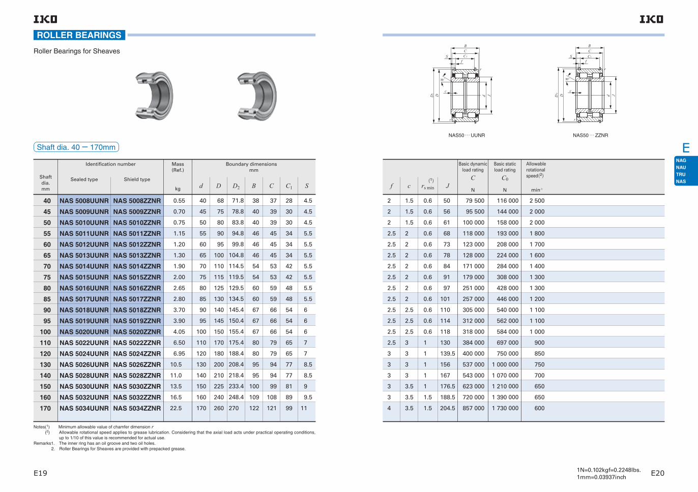
E
1N=0.102kgf=0.2248lbs.1mm=0.03937inchE19 E20
ROLLER BEARINGS
Roller Bearings for Sheaves
Notes(1) Minimum allowable value of chamfer dimension r(2) Allowable rotational speed applies to grease lubrication. Considering that the axial load acts under practical operating conditions,
up to 1/10 of this value is recommended for actual use.Remarks1. The inner ring has an oil groove and two oil holes.
2. Roller Bearings for Sheaves are provided with prepacked grease.
Shaftdia.mm
Sealed type Shield type
Mass (Ref.)
Identification number
kg
Boundary dimensions mm
0.55NAS 5008UUNR NAS 5008ZZNR 40 68 71.8 38 37 28 4.540 0.70NAS 5009UUNR NAS 5009ZZNR 45 75 78.8 40 39 30 4.545 0.75NAS 5010UUNR NAS 5010ZZNR 50 80 83.8 40 39 30 4.550 1.15NAS 5011UUNR NAS 5011ZZNR 55 90 94.8 46 45 34 5.555 1.20NAS 5012UUNR NAS 5012ZZNR 60 95 99.8 46 45 34 5.560 1.30NAS 5013UUNR NAS 5013ZZNR 65 100 104.8 46 45 34 5.565 1.90NAS 5014UUNR NAS 5014ZZNR 70 110 114.5 54 53 42 5.570 2.00NAS 5015UUNR NAS 5015ZZNR 75 115 119.5 54 53 42 5.575 2.65NAS 5016UUNR NAS 5016ZZNR 80 125 129.5 60 59 48 5.580 2.80NAS 5017UUNR NAS 5017ZZNR 85 130 134.5 60 59 48 5.585 3.70NAS 5018UUNR NAS 5018ZZNR 90 140 145.4 67 66 54 690 3.90NAS 5019UUNR NAS 5019ZZNR 95 145 150.4 67 66 54 695 4.05NAS 5020UUNR NAS 5020ZZNR 100 150 155.4 67 66 54 6100 6.50NAS 5022UUNR NAS 5022ZZNR 110 170 175.4 80 79 65 7110 6.95NAS 5024UUNR NAS 5024ZZNR 120 180 188.4 80 79 65 712010.5NAS 5026UUNR NAS 5026ZZNR 130 200 208.4 95 94 77 8.513011.0NAS 5028UUNR NAS 5028ZZNR 140 210 218.4 95 94 77 8.514013.5NAS 5030UUNR NAS 5030ZZNR 150 225 233.4 100 99 81 915016.5NAS 5032UUNR NAS 5032ZZNR 160 240 248.4 109 108 89 9.516022.5NAS 5034UUNR NAS 5034ZZNR 170 260 270 122 121 99 11170
Shaft dia. 40− 170mm
d D D2 B C C1 S(1)
Allowable rotational speed(2)
min-1
2 1.5 0.6 50 79 500 116 000 2 500
2 1.5 0.6 56 95 500 144 000 2 000
2 1.5 0.6 61 100 000 158 000 2 000
2.5 2 0.6 68 118 000 193 000 1 800
2.5 2 0.6 73 123 000 208 000 1 700
2.5 2 0.6 78 128 000 224 000 1 600
2.5 2 0.6 84 171 000 284 000 1 400
2.5 2 0.6 91 179 000 308 000 1 300
2.5 2 0.6 97 251 000 428 000 1 300
2.5 2 0.6 101 257 000 446 000 1 200
2.5 2.5 0.6 110 305 000 540 000 1 100
2.5 2.5 0.6 114 312 000 562 000 1 100
2.5 2.5 0.6 118 318 000 584 000 1 000
2.5 3 1 130 384 000 697 000 900
3 3 1 139.5 400 000 750 000 850
3 3 1 156 537 000 1 000 000 750
3 3 1 167 543 000 1 070 000 700
3 3.5 1 176.5 623 000 1 210 000 650
3 3.5 1.5 188.5 720 000 1 390 000 650
4 3.5 1.5 204.5 857 000 1 730 000 600
NAS50 … UUNR NAS50 … ZZNR
Basic dynamicload rating
C
N
Basic static load rating
C0
Nf c rs min J
CC
B
S
D d JD
f
c
r
r
30 °
2
1
CC
B
Sf
30
DD
c
°
d J
r
r
2
1

E
1N=0.102kgf=0.2248lbs.1mm=0.03937inchE21 E22
ROLLER BEARINGS
Roller Bearings for Sheaves
Notes(1) Minimum allowable value of chamfer dimension r(2) Allowable rotational speed applies to grease lubrication. Considering that the axial load acts under practical operating conditions,
up to 1/10 of this value is recommended for actual use.Remarks1. The inner ring has an oil groove and two oil holes.
2. Roller Bearings for Sheaves are provided with prepacked grease.
Shaftdia.mm
Sealed type Shield type
Mass (Ref.)
Identification number
kg
Boundary dimensions mm
30.0NAS 5036UUNR NAS 5036ZZNR 180 280 294 136 135 110 12.5180 31.5NAS 5038UUNR NAS 5038ZZNR 190 290 306 136 135 110 12.5190 40.5NAS 5040UUNR NAS 5040ZZNR 200 310 326 150 149 120 14.5200 52.0NAS 5044UUNR NAS 5044ZZNR 220 340 356 160 159 130 14.5220 55.5NAS 5048UUNR NAS 5048ZZNR 240 360 376 160 159 130 14.5240 85.0NAS 5052UUNR NAS 5052ZZNR 260 400 416 190 189 154 17.5260 90.9NAS 5056UUNR NAS 5056ZZNR 280 420 440 190 189 154 17.5280
Shaft dia. 180− 280mm
d D D2 B C C1 S(1)
Allowable rotational speed(2)
min-1
5 3.5 1.5 217 1 070 000 2 140 000 550
5 3.5 1.5 225 1 120 000 2 230 000 500
5 3.5 1.5 242 1 310 000 2 650 000 500
6 4 1.5 260 1 510 000 3 110 000 450
6 4 1.5 278.5 1 570 000 3 350 000 400
7 5 2 312 2 130 000 4 510 000 350
7 5 2 335 2 210 000 4 860 000 350
NAS50 … UUNR NAS50 … ZZNR
Basic dynamicload rating
C
N
Basic static load rating
C0
Nf c rs min J
CC
B
S
D d JD
f
c
r
r
30 °
2
1
CC
B
Sf
30
DD
c
°
d J
r
r
2
1
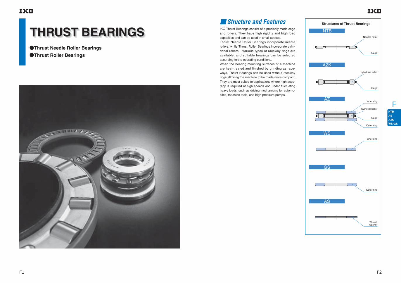
F
F1 F2
Thrust Needle Roller Bearings
Thrust Roller Bearings
Structure and FeaturesIKO Thrust Bearings consist of a precisely made cage and rollers. They have high rigidity and high load capacities and can be used in small spaces.Thrust Needle Roller Bearings incorporate needle rollers, while Thrust Roller Bearings incorporate cylin-drical rollers. Various types of raceway rings are available, and suitable bearings can be selected according to the operating conditions.When the bearing mounting surfaces of a machine are heat-treated and finished by grinding as race-ways, Thrust Bearings can be used without raceway rings allowing the machine to be made more compact. They are most suited to applications where high accu-racy is required at high speeds and under fluctuating heavy loads, such as driving mechanisms for automo-biles, machine tools, and high-pressure pumps.
Structures of Thrust Bearings
Needle roller
Cage
Cylindrical roller
Cage
Inner ring
Cylindrical roller
Outer ring
Inner ring
Outer ring
Thrust washer
Cage
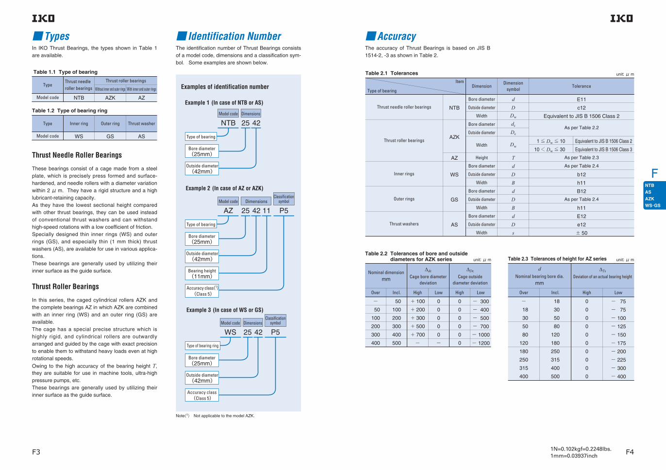
F
1N=0.102kgf=0.2248lbs.1mm=0.03937inchF3 F4
TypesIn IKO Thrust Bearings, the types shown in Table 1 are available.
The identification number of Thrust Bearings consists of a model code, dimensions and a classification sym-bol. Some examples are shown below.
Identification Number
Thrust Needle Roller Bearings
These bearings consist of a cage made from a steel plate, which is precisely press formed and surface-hardened, and needle rollers with a diameter variation within 2 μ m. They have a rigid structure and a high lubricant-retaining capacity.As they have the lowest sectional height compared with other thrust bearings, they can be used instead of conventional thrust washers and can withstand high-speed rotations with a low coefficient of friction.Specially designed thin inner rings (WS) and outer rings (GS), and especially thin (1 mm thick) thrust washers (AS), are available for use in various applica-tions.These bearings are generally used by utilizing their inner surface as the guide surface.
Thrust Roller Bearings
In this series, the caged cylindrical rollers AZK and the complete bearings AZ in which AZK are combined with an inner ring (WS) and an outer ring (GS) are available.The cage has a special precise structure which is highly rigid, and cylindrical rollers are outwardly arranged and guided by the cage with exact precision to enable them to withstand heavy loads even at high rotational speeds.
Owing to the high accuracy of the bearing height T, they are suitable for use in machine tools, ultra-high pressure pumps, etc.These bearings are generally used by utilizing their inner surface as the guide surface.
Table 1.1 Type of bearing
Type
Model code NTB AZK AZ
Thrust roller bearingsThrust needle roller bearings Without inner and outer rings With inner and outer rings
Table 1.2 Type of bearing ring
Type
Model code WS GS AS
Outer ring Thrust washerInner ring
Model code Dimensions
NTB 25
Type of bearing
42
Examples of identification number
Example 1 (In case of NTB or AS)
Example 2 (In case of AZ or AZK)
Model code Dimensions
AZ 25 11
Type of bearing
42 P5
Classificationsymbol
Bearing height(11mm)
Outside diameter(42mm)
Bore diameter(25mm)
Accuracy class(1) (Class 5)
Example 3 (In case of WS or GS)
Model code Dimensions
WS 25 42 P5
Accuracy class (Class 5)
Bore diameter(25mm)
Outside diameter(42mm)
Type of bearing ring
Bore diameter(25mm)
Outside diameter(42mm)
Classificationsymbol
Note(1) Not applicable to the model AZK.
AccuracyThe accuracy of Thrust Bearings is based on JIS B 1514-2, -3 as shown in Table 2.
Table 2.1 TolerancesItem
Type of bearing
Thrust needle roller bearings
Thrust roller bearings
Inner rings
Outer rings
Thrust washers
NTB
AZK
AZ
WS
GS
AS
dD
Dw
dc
Dc
Dw
TdDBdDBdDs
E11
c12
Equivalent to JIS B 1506 Class 2
As per Table 2.2
As per Table 2.3
As per Table 2.4
b12
h11
B12
As per Table 2.4
h11
E12
e12
± 50
Bore diameter
Outside diameter
Width
Bore diameter
Outside diameter
Width
Height
Bore diameter
Outside diameter
Width
Bore diameter
Outside diameter
Width
Bore diameter
Outside diameter
Width
DimensionDimension
symbolTolerance
unit: μ m
Table 2.2 Tolerances of bore and outside diameters for AZK series
Nominal dimensionmm
Over
− 50
100
200
300
400
50
100
200
300
400
500
+ 100
+ 200
+ 300
+ 500
+ 700
−
0
0
0
0
0
−
0
0
0
0
0
0
− 300
− 400
− 500
− 700
− 1000
− 1200
Incl. High Low High Low
∆dc
Cage bore diameter deviation
∆Dc
Cage outside diameter deviation
unit: μ m Table 2.3 Tolerances of height for AZ series
dNominal bearing bore dia.
mm
Over
− 18
30
50
80
120
180
250
315
400
18
30
50
80
120
180
250
315
400
500
0
0
0
0
0
0
0
0
0
0
− 75
− 75
− 100
− 125
− 150
− 175
− 200
− 225
− 300
− 400
Incl. High Low
∆Ts
Deviation of an actual bearing height
unit: μ m
Equivalent to JIS B 1506 Class 2
Equivalent to JIS B 1506 Class 3
1 ≦ Dw ≦ 10
10 < Dw ≦ 30

F
1N=0.102kgf=0.2248lbs.1mm=0.03937inchF5 F6
Table 2.5 Permissible limit values for chamfer dimension
Table 2.4 Tolerances and allowable values for WS and GS
d or D (1) Nominal bearing bore
dia. or outside dia.
mm
∆dmp
Single plane mean bore diameter deviation
Vdsp
Bore diameter variation in a sin-gle radial plane
∆Dmp
Single plane mean outside diameter deviation
VDsp
Outside diameter variation in a sin-gle radial plane
Inner ring or outer ringOuter ringInner ring
Si or Se (2)Bearing ring thickness variation
Class 0 Class 6 Class 5
− 18
30
50
80
120
180
250
315
400
18
30
50
80
120
180
250
315
400
500
0
0
0
0
0
0
0
0
0
0
− 8− 10
− 12
− 15
− 20
− 25
− 30
− 35
− 40
− 45
6
8
9
11
15
19
23
26
30
34
− 11
− 13
− 16
− 19
− 22
− 25
− 30
− 35
− 40
− 45
0
0
0
0
0
0
0
0
0
0
5
5
6
7
8
9
10
13
15
18
10
10
10
10
15
15
20
25
30
30
8
10
12
14
17
19
23
26
30
34
3
3
3
4
4
5
5
7
7
9
unit: μ m
Over Incl. High Low Max. LowHigh Max. Max.
Notes(1) d for ∆dmp and Vdp, and D for ∆Dmp and VDp, respectively. d for thickness variations of inner and outer rings .
(2) di for thickness variations of rings for NAX(l) and NBX(l) .
unit: mm
Bearing bore or bearing outside surface
(Axial direction)
(Rad
ial d
irec
tio
n)
Sid
e su
rfac
e o
f in
ner
rin
g o
r o
ute
r ri
ng
r s m
ax
rs min
rs max
rs min
r s m
in
0.3
0.6
1
1.1
1.5
2
2.1
3
4
5
0.8
1.5
2.2
2.7
3.5
4
4.5
5.5
6.5
8
rs minRadial and axial directions
rs max
FitThe recommended fits for Thrust Bearings are shown in Table 3.
MountingWhen mounting Thrust Bearings, the following items should be considered. 1 When inner and outer rings are not used, the hard-ness of the raceway surfaces should be 58〜 64HRC, the effective hardening depth should be adequate,
and the surface roughness should be less than 0.2μmRa. 2 When mounting inner and outer rings to shaft and housing bore, dimensions related to mounting should be based on the dimension tables.Also, the mounting surfaces should be finished at right angles to the center axis and they should be suf-ficiently rigid. 3 To avoid elastic deformation, the thrust washer AS must be seated uniformly on its mating surface.A small warp in an AS washer will be corrected auto-matically when an axial load is applied. 4 Thrust Roller Bearings are combinations of a cop-per alloy component and cylindrical rollers. When handling the AZK itself, care should be taken to pre-vent deformations, blemishes, etc.
Thrust needle roller bearings
Thrust roller bearings
Inner rings
Outer rings
Thrust washers
NTB
AZK
AZ
WS
GS
AS
h8
h6
h6
h8
H7
H7
Type of bearingTolerance class
Shaft Housing bore
Table 3 Recommended fits
Fig.1 Mounting examples

F
1N=0.102kgf=0.2248lbs.1mm=0.03937inchF7 F8
THRUST BEARINGS
Thrust Needle Roller Bearings
Notes(1) Minimum allowable value of chamfer dimension r(2) Allowable rotational speed applies to oil lubrication. For grease lubrication, a maximum of 25% of this value is allowable.
Shaftdia.
mm
Thrust washerThrust needle roller bearing
Identification number
Mass (Ref.)
g
10
12
15
16
17
18
20
25
30
35
40
45
50
55
60
65
70
75
80
85
GS 1024
GS 1226
GS 1528
GS 1629
GS 1730
GS 1831
GS 2035
GS 2542
GS 3047
GS 3552
GS 4060
GS 4565
GS 5070
GS 5578
GS 6085
GS 6590
GS 7095
GS 75100
GS 80105
GS 85110
WS 1024
WS 1226
WS 1528
WS 1629
WS 1730
WS 1831
WS 2035
WS 2542
WS 3047
WS 3552
WS 4060
WS 4565
WS 5070
WS 5578
WS 6085
WS 6590
WS 7095
WS 75100
WS 80105
WS 85110
AS 1024
AS 1226
AS 1528
AS 1629
AS 1730
AS 1831
AS 2035
AS 2542
AS 3047
AS 3552
AS 4060
AS 4565
AS 5070
AS 5578
AS 6085
AS 6590
AS 7095
AS 75100
AS 80105
AS 85110
Outer ringInner ring
8
8.9
9.3
9.8
10.2
10.7
13.8
21
24
31.5
42.5
53.5
58.5
93
105
124
132
153
162
170
Mass (Ref.)
g
Mass (Ref.)
g
2.9
3.2
3.4
3.6
3.7
3.9
5
6.9
7.9
8.9
12.1
13.3
14.5
18.5
22
23.5
25
26.5
28
29.5
NTB 1024
NTB 1226
NTB 1528
NTB 1629
NTB 1730
NTB 1831
NTB 2035
NTB 2542
NTB 3047
NTB 3552
NTB 40603
NTB 4565
NTB 5070
NTB 5578
NTB 6085
NTB 6590
NTB 7095
NTB 75100
NTB 80105
NTB 85110
3.3
3.8
4.1
4.3
4.5
4.7
6.1
8.2
9.4
10.6
22
24.5
26.5
33.5
38.5
41.5
61
65
68.5
72
Shaft dia. 10− 85mm
d D Dw s B rs min
10
12
15
16
17
18
20
25
30
35
40
45
50
55
60
65
70
75
80
85
24
26
28
29
30
31
35
42
47
52
60
65
70
78
85
90
95
100
105
110
2
2
2
2
2
2
2
2
2
2
3
3
3
3
3
3
4
4
4
4
1
1
1
1
1
1
1
1
1
1
1
1
1
1
1
1
1
1
1
1
2.75
2.75
2.75
2.75
2.75
2.75
2.75
3
3
3.5
3.5
4
4
5
4.75
5.25
5.25
5.75
5.75
5.75
0.3
0.3
0.3
0.3
0.3
0.3
0.3
0.6
0.6
0.6
0.6
0.6
0.6
0.6
1
1
1
1
1
1
14
16
18
19
20
21
23
29
34
39
45
50
55
61
66
71
75
80
85
90
22
24
26
27
28
29
33
40
45
50
57
62
67
75
82
87
91
96
101
106
7 820
8 340
8 830
9 070
9 320
9 550
11 700
14 400
15 400
16 300
24 200
25 900
27 600
32 400
38 200
40 100
47 400
48 400
49 500
50 300
23 900
26 900
29 900
31 400
32 900
34 400
46 500
64 700
73 300
81 900
108 000
121 000
135 000
171 000
219 000
237 000
244 000
256 000
267 000
279 000
15 000
13 000
12 000
11 000
11 000
10 000
9 000
7 500
6 500
5 500
5 000
4 500
4 000
4 000
3 500
3 000
3 000
3 000
2 500
2 500
Ci Ce(1)
Basic dynamic load rating
C
N
Basic static load rating
C0
N
Allowable rotational speed(2)
min-1
Boundary dimensionsmm
NTB AS WS GS
D
Dw
d i e
C C
S
De1
2
dE12
B
r
dDb
12 D d
B
r
B12

F
1N=0.102kgf=0.2248lbs.1mm=0.03937inchF9 F10
THRUST BEARINGS
Thrust Needle Roller Bearings
Notes(1) Minimum allowable value of chamfer dimension r(2) Allowable rotational speed applies to oil lubrication. For grease lubrication, a maximum of 25% of this value is allowable.
Shaftdia.
mm
Thrust washerThrust needle roller bearing
Identification number
Mass (Ref.)
g
90
100
110
120
130
GS 90120
GS 100135
GS 110145
GS 120155
GS 130170
WS 90120
WS 100135
WS 110145
WS 120155
WS 130170
AS 90120
AS 100135
Outer ringInner ring
250
350
380
410
660
Mass (Ref.)
g
Mass (Ref.)
g
38
50
NTB 90120
NTB 100135
NTB 110145
NTB 120155
NTB 130170
92
119
129
139
225
Shaft dia. 90− 130mm
90
100
110
120
130
120
135
145
155
170
4
4
4
4
5
1
1
6.5
7
7
7
9
1
1
1
1
1
96
107
117
127
137
116
131
141
151
165
64 500
80 300
83 200
87 900
120 000
394 000
541 000
578 000
634 000
839 000
2 500
2 000
2 000
1 800
1 700
(1)
Allowable rotational speed(2)
min-1
Boundary dimensionsmm
NTB AS WS GS
d D Dw s B rs min Ci Ce
Basic dynamic load rating
C
N
Basic static load rating
C0
N
D
Dw
d i e
C C
S
De1
2
dE12
B
r
dDb
12 D d
B
r
B12

F
1N=0.102kgf=0.2248lbs.1mm=0.03937inchF11 F12
THRUST BEARINGS
Thrust Roller Bearings
Notes(1) Minimum allowable value of chamfer dimension r(2) Allowable rotational speed applies to oil lubrication. For grease lubrication, a maximum of 25% of this value is allowable.
Shaftdia.
mm
Thrust roller bearing
Mass (Ref.)
g
Thrust roller bearing
Identification number
10
12
15
17
20
25
30
35
40
45
50
55
60
65
AZ 10249
AZ 12269
AZ 15289
AZ 17309
AZ 203510
AZ 254211
AZ 304711AZ 305216
AZ 355212AZ 356218
AZ 406013AZ 406819
AZ 456514AZ 457320
AZ 507014AZ 507822
AZ 557816AZ 559025
AZ 608517AZ 609526AZ 6013026
AZ 659018AZ 6510027
AZK 10243.5
AZK 12263.5
AZK 15283.5
AZK 17303.5
AZK 20354.5
AZK 25425
AZK 30475AZK 30527.5
AZK 35525AZK 35627.5
AZK 40606AZK 40689
AZK 45656AZK 45739
AZK 50706AZK 507811
AZK 55786AZK 559011
AZK 60857.5AZK 609511AZK 6013010
AZK 65907.5AZK 6510011
WS 1024
WS 1226
WS 1528
WS 1730
WS 2035
WS 2542
WS 3047WS 3052
WS 3552WS 3562
WS 4060WS 4068
WS 4565WS 4573
WS 5070WS 5078
WS 5578WS 5590
WS 6085WS 6095WS 60130
WS 6590WS 65100
GS 1024
GS 1226
GS 1528
GS 1730
GS 2035
GS 2542
GS 3047GS 3052
GS 3552GS 3562
GS 4060GS 4068
GS 4565GS 4573
GS 5070GS 5078
GS 5578GS 5590
GS 6085GS 6095GS 60130
GS 6590GS 65100
24.6
26.5
28
30.5
45.5
70
79 160
99 260
139 310
169 360
185 430
275 725
345 7702 090
380 860
8.6
8.7
9.4
10.1
17.9
28
31 70
36 98
54132
62144
68194
89275
135290790
132310
8
8.9
9.3
10.2
13.8
21
24 45
31.5 81
42.5 89
53.5108
58.5118
93225
105240650
124275
Mass (Ref.)
g
Inner ring Outer ring Mass (Ref.)
g
Shaft dia. 10− 65mm
d
10
12
15
17
20
25
3030
3535
4040
4545
5050
5555
606060
6565
D
24
26
28
30
35
42
4752
5262
6068
6573
7078
7890
8595
130
90100
rs min Ci Ce
21
23
25
27
33
39
4449
4958
5764
6269
6774
7585
8190
119
8695
21 13
23 16
25 18
27 20
33 23
39 28
4448
3336
4957
3943
5764
4446
6269
4951
6773
5456
7584
6063
8189
119
666880
8694
7173
8 990 19 100
23 900
23 900
28 600
48 700
60 700
81 00095 700
91 100135 000
133 000195 000
133 000227 000
148 000232 000
192 000332 000
224 000332 000634 000
247 000379 000
10 400
10 200
11 400
19 000
22 700
27 40038 400
29 10047 900
41 70068 700
40 80075 700
43 30084 300
51 700108 000
64 600106 000158 000
68 300116 000
18 000
16 000
14 000
13 000
11 000
9 000
8 0007 500
7 0006 500
6 0005 500
5 5005 000
5 0004 500
4 5004 000
4 0004 0003 000
4 0003 500
(1)
Standard mounting dimensions mm
DaMax.
daMin.
Basic dynamic load rating
C
N
Basic static load rating
C0
N
Allowable rotational speed(2)
min-1T dc Dc Dw B
9 10.04 23.6 3.5 2.75 0.3 13
15
17
19
22
28
3335
3842
4445
4950
5455
5963
656879
7073
0.3
0.3
0.3
0.3
0.6
0.6 0.6
0.6 1
0.6 1
0.6 1
0.6 1
0.6 1
1 1 1.5
1 1
2.75
2.75
2.75
2.75
3
3 4.25
3.5 5.25
3.5 5
4 5.5
4 5.5
5 7
4.75 7.5 8
5.25 8
3.5
3.5
3.5
4.5
5
5 7.5
5 7.5
6 9
6 9
6 11
6 11
7.5 11 10
7.5 11
25.6
27.6
29.6
34.6
41.6
46.551.5
51.561.5
59.567.5
64.572.5
69.577.5
77.589.5
84.594.5
129.5
89.599.5
12.04
15.04
17.04
20.04
25.05
30.0530.05
35.0535.05
40.0540.05
45.0545.05
50.0550.05
55.0555.05
60.0560.0560.05
65.0565.05
9
9
9
10
11
1116
1218
1319
1420
1422
1625
172626
1827
Boundary dimensionsmm
AZ AZK WS GS
da Da
B
r
dDb
12 D d
B
r
B12
D
T
d d D
B12
b12
r
r
D d
icc
C C
Dw
e

F
1N=0.102kgf=0.2248lbs.1mm=0.03937inchF13 F14
THRUST BEARINGS
Thrust Roller Bearings
Notes(1) Minimum allowable value of chamfer dimension r(2) Allowable rotational speed applies to oil lubrication. For grease lubrication, a maximum of 25% of this value is allowable.
Shaftdia.
mm
Thrust roller bearing
Mass (Ref.)
g
Thrust roller bearing
Identification number
70
75
80
85
90
100
110
120
130
AZ 709518AZ 7010527AZ 7014026
AZ 7510019AZ 7511027
AZ 8010519AZ 8011528AZ 8015026
AZ 8511019AZ 8512531
AZ 9012022AZ 9013535AZ 9016026
AZ 10013525AZ 10015038AZ 10019039
AZ 11014525AZ 11016040AZ 11020039
AZ 12015525AZ 12017542AZ 12022039
AZ 13017030AZ 13018542AZ 13023039
AZK 70957.5AZK 7010511AZK 7014010
AZK 751007.5AZK 7511011
AZK 801057.5AZK 8011511AZK 8015010
AZK 851107.5AZK 8512512
AZK 901209AZK 9013514AZK 9016010
AZK 10013511AZK 10015015AZK 10019015
AZK 11014511AZK 11016017AZK 11020015
AZK 12015511AZK 12017518AZK 12022015
AZK 13017012AZK 13018518AZK 13023015
WS 7095WS 70105WS 70140
WS 75100WS 75110
WS 80105WS 80115WS 80150
WS 85110WS 85125
WS 90120WS 90135WS 90160
WS 100135WS 100150WS 100190
WS 110145WS 110160WS 110200
WS 120155WS 120175WS 120220
WS 130170WS 130185WS 130230
GS 7095GS 70105GS 70140
GS 75100GS 75110
GS 80105GS 80115GS 80150
GS 85110GS 85125
GS 90120GS 90135GS 90160
GS 100135GS 100150GS 100190
GS 110145GS 110160GS 110200
GS 120155GS 120175GS 120220
GS 130170GS 130185GS 130230
420 905 2 250
465 960
495 1 060 2 500
530 1 460
790 2 040 2 710
1 190 2 720 5 960
1 350 3 220 6 400
1 450 4 020 7 730
2 180 4 300 8 240
156 325 890
159 340
171 370 920
190 510
290 750 1 000
490 980 2 120
590 1 320 2 280
630 1 640 2 730
860 1 760 2 940
132 290 680
153 310
162 345 790
170 475
250 645 855
350 870 1 920
380 950 2 060
410 1 190 2 500
660 1 270 2 650
Mass (Ref.)
g
Inner ring Outer ring Mass (Ref.)
g
Shaft dia. 70− 130mm
707070
7575
808080
8585
909090
100100100
110110110
120120120
130130130
95105140
100110
105115150
110125
120135160
135150190
145160200
155175220
170185230
182726
1927
192826
1931
223526
253839
254039
254239
304239
9199
129
96104
101109139
106118
115128149
129142177
139153187
149167206
163177216
767890
8183
8688
100
9195
97101110
108113120
118121130
128133142
140143152
72 000114 000169 000
71 100123 000
74 500122 000180 000
77 800145 000
99 700181 000189 000
136 000219 000333 000
142 000282 000388 000
149 000313 000415 000
176 000333 000440 000
269 000379 000713 000
269 000427 000
292 000427 000792 000
314 000513 000
390 000626 000871 000
522 000796 000
1 420 000
569 0001 030 0001 770 000
617 0001 160 0001 980 000
741 0001 290 0002 180 000
3 5003 5003 000
3 5003 000
3 0003 0002 500
3 0003 000
3 0002 5002 500
2 5002 5002 000
2 5002 0002 000
2 0002 0001 800
2 0001 9001 700
(1)
Standard mounting dimensions mm
Allowable rotational speed(2)
min-1
70.05 70.05 70.05
94.5 104.5 139.5
7.51110
5.25 8 8
1 1 1.1
757889
8083
858899
9095
97100109
108112119
118120129
128132141
140142151
91100129
96105
101110139
106119
116129149
130143179
140154188
150168207
164178217
1 1
1 1 1.5
1 1
1 1.1 1.5
1 1.1 1.5
1 1.1 2
1 1.1 2.1
1 1.5 2.1
5.75 8
5.75 8.5 8
5.75 9.5
6.5 10.5 8
7 11.5 12
7 11.5 12
7 12 12
9 12 12
7.511
7.51110
7.512
91410
111515
111715
111815
121815
99.5 109.5
104.5 114.5 149.5
109.5 124.5
119.5 134.5 159.5
134.5 149.5 189.3
144.5 159.5 199.3
154.5 174.5 219
169.5 184.5 229
75.05 75.05
80.05 80.05 80.05
85.05 85.05
90.05 90.05 90.05
100.05100.05100.1
110.1110.1110.1
120.1120.1120.1
130.1130.1130.1
Boundary dimensionsmm
AZ AZK WS GS
d D rs min Ci CeDa
Max.da
Min.
Basic dynamic load rating
C
N
Basic static load rating
C0
NT dc Dc Dw B
da Da
B
r
dDb
12 D d
B
r
B12
D
T
d d D
B12
b12
r
r
D d
icc
C C
Dw
e

F
1N=0.102kgf=0.2248lbs.1mm=0.03937inchF15 F16
THRUST BEARINGS
Thrust Roller Bearings
Shaftdia.
mm
Thrust roller bearing
Mass (Ref.)
g
Thrust roller bearing
Identification number
140
150
160
170
180
190
200
220
240
260
280
AZ 14018031AZ 14019542AZ 14024039
AZ 15019031AZ 15020542AZ 15025039
AZ 16020031AZ 16027039
AZ 17023045AZ 17028039
AZ 18024045AZ 18031039
AZ 19025548AZ 19032039
AZ 20026548AZ 20034039
AZ 22029050AZ 22036052
AZ 24031554AZ 24038052
AZ 26034055AZ 26042080
AZ 28044080
WS 140180WS 140195WS 140240
WS 150190WS 150205WS 150250
WS 160200WS 160270
WS 170230WS 170280
WS 180240WS 180310
WS 190255WS 190320
WS 200265WS 200340
WS 220290WS 220360
WS 240315WS 240380
WS 260340WS 260420
WS 280440
GS 140180GS 140195GS 140240
GS 150190GS 150205GS 150250
GS 160200GS 160270
GS 170230GS 170280
GS 180240GS 180310
GS 190255GS 190320
GS 200265GS 200340
GS 220290GS 220360
GS 240315GS 240380
GS 260340GS 260420
GS 280440
2 4104 5608 680
2 5604 8409 140
2 71010 800
6 22011 300
6 54014 600
8 06015 000
8 43017 200
10 40024 000
13 20026 500
15 40051 600
54 600
9201 8603 100
9801 9803 260
1 0303 840
2 4204 020
2 5405 200
3 1005 280
3 2506 120
4 2808 000
5 5209 440
6 60018 200
19 200
7451 3502 790
7901 4302 940
8403 480
1 9003 640
2 0004 700
2 4804 860
2 5905 540
3 0608 000
3 8408 530
4 40016 700
17 700
Mass (Ref.)
g
Inner ring Outer ring Mass (Ref.)
g
Shaft dia. 140− 280mm
AZK 26034025AZK 26042030
AZK 28044030
AZK 14018012AZK 14019518AZK 14024015
AZK 15019012AZK 15020518AZK 15025015
AZK 16020012AZK 16027015
AZK 17023019AZK 17028015
AZK 18024019AZK 18031015
AZK 19025520AZK 19032015
AZK 20026520AZK 20034015
AZK 22029022AZK 22036020
AZK 24031524AZK 24038020
Notes(1) Minimum allowable value of chamfer dimension r(2) Allowable rotational speed applies to oil lubrication. For grease lubrication, a maximum of 25% of this value is allowable.
140140140
150150150
160160
170170
180180
190190
200200
220220
240240
260260
280
180195240
190205250
200270
230280
240310
255320
265340
290360
315380
340420
440
314239
314239
3139
4539
4539
4839
4839
5052
5452
5580
80
173187226
183197236
193255
220265
230293
244303
254322
278342
302362
326400
420
150153162
160163172
170184
184194
194205
206215
216228
237247
257267
279291
311
184 000353 000435 000
181 000349 000459 000
189 000519 000
406 000543 000
426 000619 000
470 000647 000
465 000710 000
557 000943 000
695 000977 000
739 0001 430 000
1 420 000
798 0001 420 0002 180 000
798 0001 420 0002 380 000
855 0002 850 000
1 730 0003 070 000
1 870 0003 710 000
2 080 0003 980 000
2 080 0004 580 000
2 530 0005 520 000
3 250 0005 910 000
3 510 0007 490 000
7 490 000
1 9001 8001 600
1 8001 7001 500
1 7001 400
1 5001 300
1 4001 200
1 3001 200
1 3001 100
1 3001 000
1 1001 000
1 000900
800
(1)
Standard mounting dimensions mm
Allowable rotational speed(2)
min-1
140.1140.1140.1
179.5 194.5 239
121815
9.5 12 12
1 1.5 2.1
150152161
160162171
170183
183193
193204
205214
215227
236246
256266
278289
309
174188227
184198237
194256
221266
231294
245304
255323
280343
304363
328402
422
1 1.5 2.1
1 3
1.5 3
1.5 3
2 4
2 4
2 4
2 4
2.1 5
5
9.5 12 12
9.5 12
13 12
13 12
14 12
14 12
14 16
15 16
15 25
25
121815
1215
1915
1915
2015
2015
2220
2420
2530
30
189.5 204.5 249
199.5 269
229 279
239 308
254 318
264 338
289 358
314 378
339 418
438
150.1150.1150.1
160.1160.1
170.1170.1
180.1180.1
190.1190.1
200.15200.15
220.15220.15
240.15240.15
260.15260.15
280.15
Boundary dimensionsmm
AZ AZK WS GS
d D rs min Ci CeD a
Max.d a
Min.
Basic dynamic load rating
C
N
Basic static load rating
C0
NT d c D c Dw B
da Da
B
r
dDb
12 D d
B
r
B12
D
T
d d D
B12
b12
r
r
D d
icc
C C
Dw
e

G
G1 G2
Needle Roller Bearings with Thrust Ball Bearing
Needle Roller Bearings with Thrust Roller Bearing
Needle Roller Bearings with Angular Contact Ball Bearing
Needle Roller Bearings with Three-point Contact Ball Bearing
Structure and FeaturesIKO Combined Type Needle Roller Bearings are com-binations of a radial bearing and a thrust bearing. Caged needle roller bearings are used as radial bear-ings and thrust ball bearings or thrust roller bearings are used as thrust bearings. They are compact and very economical, and can be subjected to radial loads and axial loads simultaneously.They are widely used for machine tools, textile machinery, and industrial machinery.
Structures of Combined Type Needle Roller Bearings
Dust cover
Thrust ball bearingBearing ring for thrust bearing
Inner ring
Radial needle roller bearing
Radial needle roller bearing
Thrust roller bearing
Needle roller cage
Needle roller cage
Inner ring(B)
Ball cage (Angular contact type)
Ball cage (3-point contact type)
Bearing ring for thrust bearing
Outer ring
Outer ring
Outer ring
Outer ring
Inner ring(A)
Inner ring
Inner ring
TypesThe types of Combined Type Needle Roller Bearings shown in Table 1 are available.
Table 1.1 Type of bearing
Type
With dust cover
NBX … Z NBXI … ZNAX … Z NAXI … ZNBX NBXINAX NAXI
Combined with thrust roller bearing
Combined with thrust ball bearing
Without inner ring With inner ringWithout inner ring With inner ring
Table 1.2 Type of bearing
Type
Model code NATBNATA
Combined with three-point contact ball bearing
Combined with angular contact ball bearing
Needle Roller Bearings with Thrust Ball Bearing
In this series, needle roller bearings are combined with thrust ball bearings to receive thrust loads.In bearings with a dust cover, the dust cover is formed from a thin steel plate and fixed to a groove cut on the outer cylindrical surface of the outer ring collar. The cover forms a labyrinth with the thrust raceway ring, and is therefore effective in preventing leakage of grease and penetration of dust and dirt.In the case of bearings without an inner ring, the toler-
ances of roller set bore diameter Fw are shown in Table 14 on page A33. Therefore, the required radial internal clearances can be selected by combining the bearings with shafts that have been heat-treated and finished by grinding as shown in Table 23 on page A42 and Table 26 on page A44.

G
G3 G41N=0.102kgf=0.2248lbs.1mm=0.03937inch
Model code Dimensions
NAXI 17
Type of bearing
30
Examples of identification number
Example 1
Example 2 Model code Dimensions
NATA 59
Type of bearing
05
Z P6
Supplemental code
Classification symbol
Bearing bore diameter(17mm)
Dimension series
Bore diameter number
With dust cover
Accuracy class(Class 6)
Assembled bearing width(30mm)
The identification number of Combined Type Needle Roller Bearings consists of a model code, dimen-sions, any supplemental codes and a classification symbol. Some examples are shown below.
Identification NumberNeedle Roller Bearings with Thrust Roller Bearing
In this series, needle roller bearings are combined with thrust roller bearings to receive thrust loads.Their axial load ratings are greater than those of bear-ings that are combined with thrust ball bearings. Also, elastic deformation of the rolling contact surfaces under load is minimal. Furthermore, the thrust bear-ing section is finished to high accuracy, and therefore high rotational accuracy is obtained in the case of both vertical and horizontal shafts.Like the needle roller bearings with thrust ball bearing, this series also includes bearings with a dust cover and bearings with an inner ring.
Needle Roller Bearings with Angular Con-tact Ball Bearing
In this series, caged needle roller bearings are com-bined with angular contact ball bearings to receive thrust loads. These bearings conform to the interna-tional dimension series #59, which is based on the ISO Standard. They can withstand heavy radial loads and unidirectional axial loads simultaneously.When the axial load exceeds 25% of the radial load, the radial load will be induced in the angular contact ball bearing, and bearing life will be affected. The relationship between the two loads must therefore be taken into careful consideration.
Needle Roller Bearings with Three-point Contact Ball Bearing
These bearings can withstand heavy radial loads and bi-directional axial loads at the same time during high-speed rotation.Since the non-interchangeable inner rings are sepa-rated at the center of the ball raceway surface, they must be firmly tightened against the shaft in the axial direction. The axial clearance of this bearing is 0.1〜0.3 mm, and like NATA59, the axial load should not exceed 25% of the radial load.
AccuracyDimensional accuracy and rotational accuracy of Combined Type Needle Roller Bearings are based on Table 2 below and Tables 12 and 13 on page A31. The tolerances for the smallest single roller set bore diameter of bearings without inner ring are based on Table 14 on page A33. Thickness variations of thrust rings of NAX(I) and NBX(I) are based on Table 2.4 on page F5.Bore diameter of the small width inner ring of NATB59 is made for a transition fit with k5 tolerance shaft.
Fig.1 shows mounting examples of Combined Type Needle Roller Bearings. When applying preload to the NAX and NBX models, it is recommended that thrust raceway rings are not tightened directly with nuts, but are tightened using springs as shown in Fig. 2.Mounting two NATA models symmetrically allows them to be subjected to two-way axial loads. When mounting these models, an axial clearance of 0.2〜0.3 mm should be provided in the angular contact ball bearings so that radial loads are not applied to the angular contact ball bearings.Dimensions related to mounting should be based on the table of dimensions.
Mounting
FitThe recommended fits for Combined Type Needle Roller Bearings are shown in Table 3.
ClearanceCombined Type Needle Roller Bearings are manufac-tured to have the radial internal clearance CN shown in Table 18 on page A37.
Rating LifeIn Combined Type Needle Roller Bearings, caged needle roller bearings are subjected to radial loads while thrust bearings receive axial loads. Therefore, it is necessary to calculate their lives respectively (page A17).
LubricationGrease is not prepacked in Combined Type Needle Roller Bearings, so perform proper lubrication for use. Operating without lubrication will increase the wear of the rolling contact surfaces and shorten the bearing life.
Fig.1 Mounting examples
Fig.2 Mounting example when applying preload
Table 2 TolerancesItem
Type ofbearing
NAX(I)(1)
NBX(I)(1)
NATB59
Bore dia. of bearing ring for thrust bearing
Assembled bearing width
Bearing height of thrust bearing
Width of inner ring
di E7
0− 0.25
0− 0.20
0− 0.3
L
H
B
Dimension symbol
ToleranceDimension
unit: mm
Note(1) Also applicable to bearings with dust cover
Table 3 Recommended fitsItem
Type of bearing
NAX(I)(1)NBX(I)(1)
NATA59NATB59
h5,k5
k5 K6,M6
M6(2)k5(2)
Housing bore
Tolerance class
Shaft
Without inner ring With inner ring
Notes(1) The housing bore for the thrust bearing must be machined to be more than 0.5 mm larger than the out-side diameters D1 and D2 to ensure that it does not incur radial loads.
(2) If the fit is made tighter than specified in this table, radial loads will act upon the thrust bearing, limiting its function.
Oil HoleThe outer ring of Combined Type Needle Roller Bearings has an oil groove and an oil hole. When outer rings with multiple oil holes or inner rings with oil hole(s) are required, please contact IKO.

G
G5 G61N=0.102kgf=0.2248lbs.1mm=0.03937inch
COMBINED TYPE NEEDLE ROLLER BEARINGS
Shaft dia. 10− 70mm
Needle Roller Bearings with Thrust Ball Bearing Needle Roller Bearings with Thrust Roller Bearing
Without Inner RingWithout Inner Ring
Notes(1) Minimum allowable value of chamfer dimension r (2) Allowable rotational speed applies to oil lubrication. For grease lubrication, a maximum of 70% of this value is allowable in the
NAX series, and a maximum of 25% of this value is allowable in the NBX series.Remarks1. The outer ring has an oil groove and an oil hole. 2. No grease is prepacked. Perform proper lubrication.
Shaft dia.
mm
With dust cover
Identification number
10
12
15
17
20
25
30
35
40
45
50
60
70
Mass (Ref.)
g
Mass (Ref.)
g
With dust cover Mass (Ref.)
g
NAX 1023
NAX 1223
NAX 1523
NAX 1725
NAX 2030
NAX 2530
NAX 3030
NAX 3530
NAX 4032
NAX 4532
NAX 5035
NAX 6040
NAX 7040
38.5
43.5
47.5
54
85.5
131
145
169
219
264
287
417
555
NBX 1523
NBX 1725
NBX 2030
NBX 2530
NBX 3030
NBX 3530
NBX 4032
NBX 4532
NBX 5035
54
61
94
143
160
186
240
293
315
501
NBX 1523Z
NBX 1725Z
NBX 2030Z
NBX 2530Z
NBX 3030Z
NBX 3530Z
NBX 4032Z
NBX 4532Z
NBX 5035Z
55
63
97.5
147
166
193
248
302
325
538
NAX 1023Z
NAX 1223Z
NAX 1523Z
NAX 1725Z
NAX 2030Z
NAX 2530Z
NAX 3030Z
NAX 3530Z
NAX 4032Z
NAX 4532Z
NAX 5035Z
NAX 6040Z
40
45.5
48.5
56
89
135
151
176
227
273
297
454
606
Mass (Ref.)
g
NAX
NBX 6040
NBX 6040Z
NAX 7040Z
D DFwd i
lHL
r
r
1
1
Fw
10
12
1515
1717
2020
2525
3030
3535
4040
4545
5050
6060
70
19
21
2424
2626
3030
3737
4242
4747
5252
5858
6262
7272
85
24 25
27
2929
3131
3636
4343
4848
5353
6161
66.566.5
71.571.5
86.586.5
96.5
26
2828
3030
3535
4242
4747
5252
6060
6565
7070
8585
95
23
23
2323
2525
3030
3030
3030
3030
3232
3232
3535
4040
40
10 18 8 230
9 250
12 30012 300
12 90012 900
17 60017 600
20 00020 000
25 10025 100
26 90026 900
29 40029 400
31 00031 000
42 20042 200
47 50047 500
55 500
10 000
9 670
9 930 10 200
10 80011 400
14 20019 000
19 60022 700
20 40027 400
21 20029 100
26 90041 700
27 90040 800
28 80043 300
41 40064 600
43 100
9 190
11 200
14 90014 900
16 30016 300
25 40025 400
32 10032 100
40 10040 100
46 20046 200
54 10054 100
60 20060 200
83 40083 400
103 000103 000
120 000
11 100
11 100
12 20023 900
14 50028 600
19 70048 700
29 70060 700
33 60081 000
37 60091 100
50 000133 000
55 100133 000
60 100148 000
89 700224 000
101 000
9 500
9 000
8 50014 000
8 50013 000
7 50011 000
7 0009 000
6 5008 000
6 0007 000
5 5006 000
5 0005 500
4 5005 000
4 0004 000
3 500
20
2326
2528
2933
3540
4045
4550
5257
5762
6267
7582
85
12
1515
1717
2020
2525
3030
3535
4040
4545
5050
6060
70
9 6.5
6.5
6.5 6.5
8 8
10.5 10.5
9.5 9.5
9.5 9.5
9 9
10 10
9 9
10 10
12 12
11
0.3
0.3
0.30.3
0.30.3
0.30.3
0.60.6
0.60.6
0.60.6
0.60.6
0.60.6
0.60.6
11
1
9
99
99
1010
1111
1111
1212
1313
1414
1414
1717
18
H l1 rs min d iD D1 D2 L(1)
Standard mounting dimension
daMin.mm
Basic dynamic load rating C
Basic static load ratingC0
Allowable rotational speed(2)
min-1
Boundary dimensionsmm
Radial
N
Axial
N
Radial
N
Axial
N
NAX … Z NBX NBX … Z
D2
D DFwd i1
lHL
r
r
1
D2
da
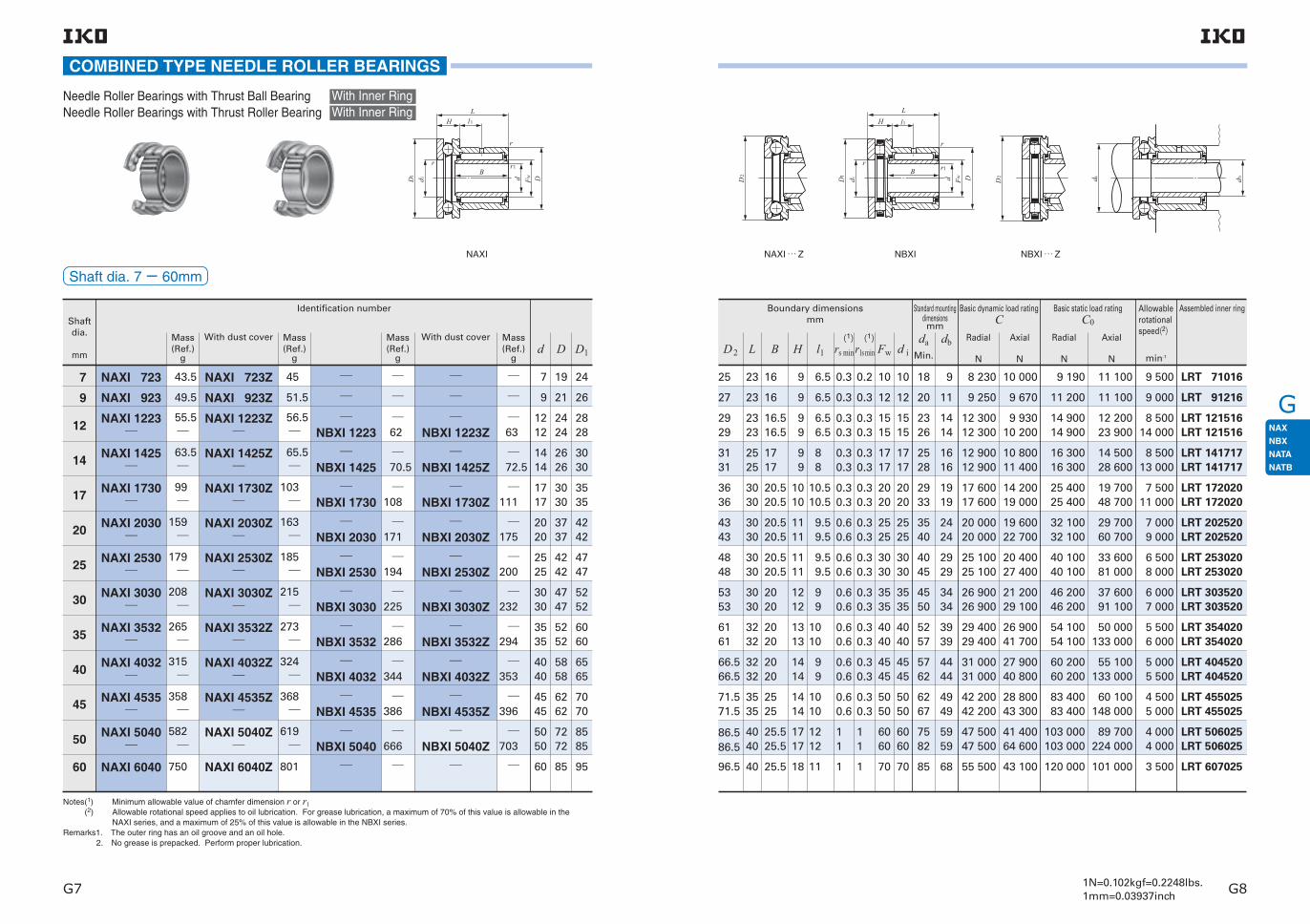
G
G7 G81N=0.102kgf=0.2248lbs.1mm=0.03937inch
COMBINED TYPE NEEDLE ROLLER BEARINGS
Shaft dia. 7− 60mm
Needle Roller Bearings with Thrust Ball Bearing Needle Roller Bearings with Thrust Roller Bearing
With Inner RingWith Inner Ring
Notes(1) Minimum allowable value of chamfer dimension r or r1 (2) Allowable rotational speed applies to oil lubrication. For grease lubrication, a maximum of 70% of this value is allowable in the
NAXI series, and a maximum of 25% of this value is allowable in the NBXI series.Remarks1. The outer ring has an oil groove and an oil hole. 2. No grease is prepacked. Perform proper lubrication.
Shaft dia.
mm
With dust cover
Identification number
7
9
12
14
17
20
25
30
35
40
45
50
60
Mass (Ref.)
g
Mass (Ref.)
g
With dust cover Mass (Ref.)
g
43.5
49.5
55.5
63.5
99
159
179
208
265
315
358
750
45
51.5
56.5
65.5
103
163
185
215
273
324
368
801
62
70.5
108
171
194
225
286
344
386
63
72.5
111
175
200
232
294
353
396
NBXI 1223Z
NBXI 1425Z
NBXI 1730Z
NBXI 2030Z
NBXI 2530Z
NBXI 3030Z
NBXI 3532Z
NBXI 4032Z
NBXI 4535Z
NAXI 723Z
NAXI 923Z
NAXI 1223Z
NAXI 1425Z
NAXI 1730Z
NAXI 2030Z
NAXI 2530Z
NAXI 3030Z
NAXI 3532Z
NAXI 4032Z
NAXI 4535Z
Mass (Ref.)
gd
7
9
1212
1414
1717
2020
2525
3030
3535
4040
4545
60
D
19
21
2424
2626
3030
3737
4242
4747
5252
5858
6262
85
D1
24
26
2828
3030
3535
4242
4747
5252
6060
6565
7070
95
NAXI
NAXI 6040Z
582
NAXI 5040Z
619
666
NBXI 5040Z
703
5050
7272
8585
NAXI 723
NAXI 923
NAXI 1223
NAXI 1425
NAXI 1730
NAXI 2030
NAXI 2530
NAXI 3030
NAXI 3532
NAXI 4032
NAXI 4535
NAXI 5040
NAXI 6040
NBXI 1223
NBXI 1425
NBXI 1730
NBXI 2030
NBXI 2530
NBXI 3030
NBXI 3532
NBXI 4032
NBXI 4535
NBXI 5040
D DFwd di
lHL
Br
r
r
1
1
1
25
27
2929
3131
3636
4343
4848
5353
6161
66.566.5
71.571.5
86.586.5
96.5
23
23
2323
2525
3030
3030
3030
3030
3232
3232
3535
4040
40
18 8 230
9 250
12 30012 300
12 90012 900
17 60017 600
20 00020 000
25 10025 100
26 90026 900
29 40029 400
31 00031 000
42 20042 200
47 50047 500
55 500
10 000
9 670
9 93010 200
10 80011 400
14 20019 000
19 60022 700
20 40027 400
21 20029 100
26 90041 700
27 90040 800
28 80043 300
41 40064 600
43 100
9 500 LRT 71016
LRT 91216
LRT 121516LRT 121516
LRT 141717LRT 141717
LRT 172020LRT 172020
LRT 202520LRT 202520
LRT 253020LRT 253020
LRT 303520LRT 303520
LRT 354020LRT 354020
LRT 404520LRT 404520
LRT 455025LRT 455025
LRT 506025LRT 506025
LRT 607025
9 000
8 50014 000
8 50013 000
7 50011 000
7 0009 000
6 5008 000
6 0007 000
5 5006 000
5 0005 500
4 5005 000
4 0004 000
3 500
9 190
11 200
14 90014 900
16 30016 300
25 40025 400
32 10032 100
40 10040 100
46 20046 200
54 10054 100
60 20060 200
83 40083 400
103 000103 000
120 000
11 100
11 100
12 20023 900
14 50028 600
19 70048 700
29 70060 700
33 60081 000
37 60091 100
50 000133 000
55 100133 000
60 100148 000
89 700224 000
101 000
20
2326
2528
2933
3540
4045
4550
5257
5762
6267
7582
85
9
11
1414
1616
1919
2424
2929
3434
3939
4444
4949
5959
68
rs minD2
16
16
16.516.5
1717
20.520.5
20.520.5
20.520.5
2020
2020
2020
2525
25.525.5
25.5
6.5
6.5
6.5 6.5
8 8
10.5 10.5
9.5 9.5
9.5 9.5
9 9
10 10
9 9
10 10
12 12
11
B l1L
9
9
99
99
1010
1111
1111
1212
1313
1414
1414
1717
18
0.3
0.3
0.30.3
0.30.3
0.30.3
0.60.6
0.60.6
0.60.6
0.60.6
0.60.6
0.60.6
11
1
0.2
0.3
0.30.3
0.30.3
0.30.3
0.30.3
0.30.3
0.30.3
0.30.3
0.30.3
0.30.3
11
1
H
10
12
1515
1717
2020
2525
3030
3535
4040
4545
5050
6060
70
10
12
1515
1717
2020
2525
3030
3535
4040
4545
5050
6060
70
Fw d i(1)
r1s min(1)
Standard mounting dimensionsmm
daMin.
db
Basic dynamic load rating C
Basic static load rating C0
Allowable rotational speed(2)
min-1
Boundary dimensionsmm
Radial
N
Axial
N
Radial
N
Axial
N
Assembled inner ring
NAXI … Z NBXI NBXI … Z
D2
D DFwd di
lHL
Br
r
r
1
1
1
D2 d da b
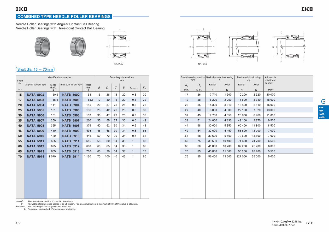
G
G9 G101N=0.102kgf=0.2248lbs.1mm=0.03937inch
COMBINED TYPE NEEDLE ROLLER BEARINGS
Shaft dia. 15− 70mm
Needle Roller Bearings with Angular Contact Ball BearingNeedle Roller Bearings with Three-point Contact Ball Bearing
Notes(1) Minimum allowable value of chamfer dimension r (2) Allowable rotational speed applies to oil lubrication. For grease lubrication, a maximum of 60% of this value is allowable.Remarks1. The outer ring has an oil groove and an oil hole. 2. No grease is prepacked. Perform proper lubrication.
Shaft dia.
mm
Identification number
15
17
20
25
30
35
40
45
50
55
60
65
70
Angular contact type
NATA 5902
NATA 5903
NATA 5904
NATA 5905
NATA 5906
NATA 5907
NATA 5908
NATA 5909
NATA 5910
NATA 5911
NATA 5912
NATA 5913
NATA 5914
50.5
55.5
111
131
151
250
355
410
420
585
625
665
1 070
Mass (Ref.)
g
Three-point contact type
NATB 5902
NATB 5903
NATB 5904
NATB 5905
NATB 5906
NATB 5907
NATB 5908
NATB 5909
NATB 5910
NATB 5911
NATB 5912
NATB 5913
NATB 5914
53
58.5
115
136
157
260
375
435
445
615
660
710
1 130
Mass (Ref.)
gd
15
17
20
25
30
35
40
45
50
55
60
65
70
C
18
18
23
23
23
27
30
30
30
34
34
34
40
B rs min(1)
20
20
25
25
25
30
34
34
34
38
38
38
45
Fw
20
22
25
30
35
42
48
55
58
63
68
75
80
0.3
0.3
0.3
0.3
0.3
0.6
0.6
0.6
0.6
1
1
1
1
D
28
30
37
42
47
55
62
68
72
80
85
90
100
Boundary dimensionsmm
NATA59
D Fw d
r
r
r
r
C
17
19
22
27
32
39
44
49
54
60
65
70
75
26
28
35
40
45
51
58
64
68
75
80
85
95
7 710
8 220
14 300
15 800
17 700
24 000
30 600
32 600
33 600
39 500
41 800
43 800
56 400
1 900
2 050
3 810
4 300
4 550
4 890
5 350
5 450
5 660
10 400
10 700
11 000
13 500
20 000
18 000
16 000
13 000
11 000
9 500
8 500
7 000
7 000
6 500
6 000
5 500
5 000
Standard mounting dimensionsmm
da
Min.
Da
Max.
Basic dynamic load rating C
Basic static load rating C0
Allowable rotational speed(2)
min-1
Radial
N
Axial
N
Radial
N
Axial
N
10 200
11 500
18 400
22 100
26 800
42 100
60 400
68 500
72 500
74 400
82 200
90 200
127 000
2 920
3 340
6 110
7 520
8 460
9 870
11 800
12 700
13 600
24 700
26 700
28 700
35 000
NATB59
D Fw d
r
r
r
r
CB
D d a
a
D d a
a

H
H1 H2
Inner Rings for Shell Type Needle Roller Bearings
Inner Rings for General Usage
IKO Inner Rings are heat-treated and finished by grinding to a high degree of accuracy. In the case of needle roller bearings, normally, the shafts are heat-treated and finished by grinding, and used as the raceway surfaces. However, when it is impossible to make shaft surfaces according to the specified sur-face hardness or surface roughness, inner rings are used.Inner rings include those for Shell Type Needle Roller Bearings and those for general use and are available in a variety of dimensions. When shafts move axially or seals are used adjacent to bearings, wide inner rings can be selected.Inner rings can also be used economically as bush-ings without requiring any additional machining.
Structure and Features
Gentle taper relief
Small chamfer
Gentle taper relief
Small chamfer
Shapes of Inner Rings
TypesFor Inner Rings, the types shown in Table 1 are avail-able.
Table 1.1 Inner Rings for Shell Type Needle Roller Bearings
Series Model codes of assembled bearings
Metric series
Inch series
IRT
IRB
TA … Z,TLA … ZTAM,TLAM,YT,YTLBA … Z,BHA … ZBAM,BHAM,YB,YBH
Remark For Inner Rings for Shell Type Needle Roller Bearings with Seal, please consult IKO.
Table 1.2 Inner Rings for General Usage
Series Model codes of assembled bearings
Metric series
Inch series
LRT
LRTZ
LRB
LRBZ … B
RNA 49,RNA 69RNA 48,TAF,TRRNAF,NAX,NBXRNA 49 … UU,RNA 69 … UUGTRBR
BR … UU

H
H3 H41N=0.102kgf=0.2248lbs.1mm=0.03937inch
Identification numberThe identification number of Inner Rings consists of a model code and dimensions. An example is shown below.
Model code Dimensions
LRT 20 2024
Example of identification number
Type of inner ring
Inner ring width(20mm)
Outside diameter of inner ring(24mm)
Bore diameter of inner ring(20mm)
AccuracyDimensional accuracy of Inner Rings is based on Table 2. Inner Rings for Shell Type Needle Roller Bearings are manufactured so that exact radial internal clearances can be obtained when assembled with Shell Type Needle Roller Bearings. Inner Rings for General Usage produce CN clearance when used in the assembled bearings shown in Table 1.2. LRB and LRBZ … B models produce the radial internal clear-ances shown in Table 4 on page D5. When clearances other than CN clearance or accura-cy other than Class 0 are required, please consult IKO.
Table 6 Tolerances of outside diameters for LRT and LRTZ (When the clearance is CN clearance)
dBore diameter of inner ring mm
FOutside diameter of inner ring mm
3< F ≦ 6 6< F ≦ 10 10< F ≦ 18 18< F ≦ 30 30< F ≦ 50 50< F ≦ 80
Over Incl. High Low High Low High Low High Low High Low High Low−243040506580
100120140160180200225250280315355400450
243040506580
100120140160180200225250280315355400450500
− 10 − 27 − 7 − 23 − 4 − 18+ 5
0− 4− 9− 19− 5
00
− 12− 12
− 11− 21− 26
0− 10− 10
Table 2 Tolerances for inner ring
Model code Tolerance
IRTLRT,LRTZ
IRBLRBLRBZ … B
JIS Class 0(See the table 12, page A31)
Based on Table 3
Based on Table 4
Remark Tolerances of outside diameter of inner ring are based on Table 5.
∆dmpSingle plane
mean bore
diameter deviation
∆BsDeviation of a
single inner ring
width
KiaRadial runout of
assembled
bearing inner ring
High Low High Low Max.
00000
000
1010131520
00
− 250− 250− 250− 250− 250
− 13− 13− 13− 13− 13
dNominal inside diameter
of inner ring
mmOver Incl.
2.510183050
1018305080
Table 3 Tolerances of IRB
dNominal inside diameter
of inner ringmm
Over Incl.
−19.05030.16250.80082.550
19.050 30.162 50.800 82.550120.650
∆dmpSingle plane
mean bore
diameter deviation
∆BsDeviation of a
single inner ring
width
High Low High Low
KiaRadial runout of
assembled
bearing inner ring
Max.
00000
000
1013152025
00
− 130− 130− 130− 130− 130
− 10− 13− 13− 15− 20
Table 4 Tolerances of LRB,LRBZ…B
unit: μ m
unit: μ m
FitThe recommended fits between Inner Rings and shafts are shown in Table 22 on page A42.
Oil Hole The number of oil holes is shown in Table 8.When Inner Rings with an oil hole are especially required for a model without an oil hole, attach an "OH" to the end of the identification number when ordering.Example: LRT 202420 OH For Inner Rings with multiple oil holes, please consult IKO.
Table 5 Tolerances of outside diameter of inner ring
Model code Tolerance
IRT
IRB
LRT,LRTZ
LRB,LRBZ … B
g5
0〜− 13
Based on Table 6
Based on Table 7
unit: μ m
Table 7 Tolerances of outside diameters of LRB and LRBZ … BNominal outside diameter
of inner ringmm
Over Incl.
Tolerance
High Low
−18.03425.908
30.22635.05250.038
80.010100.076
18.03425.90830.226
35.05250.03880.010
100.076102.108
− 13− 18− 23
− 23− 25− 28
− 32− 37
− 23− 30− 36
− 38− 41− 46
− 56− 66
unit: μ m
Table 8 Number of oil holes
Bearing typeNumber
of oil holes
For Shell Type Needle Roller Bearings
For General Usage
Metric series
Inch series
Metric series
Inch series
IRT
IRB
LRT
LRTZ
LRB d≦ 76.200
76.200<d LRBZ … B
0
0
0
0
1
2
1
Bore diameter of inner ring d mm
Remark Inner rings with an oil hole are provided with an oil groove.
FOutside diameter of inner ring mm
80< F ≦ 120 120< F ≦ 180 180< F ≦ 250 250< F ≦ 315 315< F ≦ 400 400< F ≦ 500
High Low High Low High Low High Low High Low High Low
dBore diameter ofinner ring mm
Over Incl.−243040506580
100120140160180200225250280315355400450
243040506580
100120140160180200225250280315355400450500
unit: μ m
− 107− 127− 182
− 68− 83
− 128
− 87− 107
− 54− 69
− 46− 66
− 25− 40
− 22− 37
− 7− 17
− 14− 14
− 4− 27− 32
− 17
− 55 − 86
− 142− 152
− 122− 202− 222
− 172
− 52− 27

H
H5 H61N=0.102kgf=0.2248lbs.1mm=0.03937inch
Shaft dia. 7− 17mm
Inner Rings for Shell Type Needle Roller Bearings
Note(1) Minimum allowable value of chamfer dimension rRemark No oil hole is provided.
Shaft dia.
mm
Mass (Ref.)
Identification number
g d F B rs min Min. Max.TA … Z(TAM)
TLA … Z(TLAM)
YTYTL
7
8
10
12
15
IRT 710IRT 712IRT 715
IRT 810IRT 812IRT 815
IRT 1012IRT 1012-2IRT 1016-2IRT 1020-2IRT 1010-1IRT 1012-1IRT 1015-1IRT 1020-1IRT 1025-1
IRT 1212IRT 1216IRT 1222IRT 1212-1IRT 1216-1IRT 1220-1IRT 1222-1IRT 1215-2IRT 1220-2IRT 1225-2
IRT 1512IRT 1513
3.2 3.9 4.8
777
888
101010101010101010
12121212121212121212
1515
101010
121212
131414141515151515
15151516161616171717
1818
10.512.515.5
10.512.515.5
12.512.516.520.510.512.515.520.525.5
12.516.522.512.516.520.522.515.520.525.5
12.513.5
0.30.30.3
9 9 9
9.7 9.7 9.7
11 11 11
12.7 13 13 13 14 14 14 14 14
14.5 14.5 14.5 15 15 15 15 16 16 16
17.5 17.5
101010
121212121212121212
14141414141414141414
1717
0.30.30.3
0.30.30.30.30.30.30.30.30.3
0.30.30.30.30.30.30.30.30.30.3
0.30.3
5.1 6 7.5
5.2 7.2 9.611.9 7.9 9.411.715.519.3
6.1 8.111 8.511.213.915.213.61822.5
7.5 8.1
TA 1010ZTA 1012ZTA 1015Z
TA 1212ZTA 1215Z
TA 1416ZTA 1420ZTA 1510ZTA 1512ZTA 1515ZTA 1520ZTA 1525Z
TA 1512Z
TA 1616ZTA 1620Z
TA 1715ZTA 1720ZTA 1725Z
TA 1813Z
TLA 1010ZTLA 1012ZTLA 1015Z
TLA 1210ZTLA 1212Z
TLA 1312ZTLA 1412ZTLA 1416Z
TLA 1512Z
TLA 1512ZTLA 1516ZTLA 1522ZTLA 1612ZTLA 1616Z
TLA 1622Z
TLA 1812Z
YTL 1210YT 1212
YT 1715
YT 1725
(1)
Boundary dimensions mm
Standard mounting dimension mm
Assembled bearings
d a
INNER RINGS
Note(1) Minimum allowable value of chamfer dimension rRemark No oil hole is provided.
Shaft dia.
mm
Mass (Ref.)
Identification number
g d F B rs min Min. Max.TA … Z(TAM)
TLA … Z(TLAM)
YTYTL
15
17
IRT 1515IRT 1516IRT 1517IRT 1519IRT 1520IRT 1525IRT 1516-1IRT 1520-1IRT 1515-2IRT 1520-2
IRT 1525-2IRT 1530-2
IRT 1716IRT 1720
IRT 1730IRT 1716-1IRT 1720-1IRT 1710-2IRT 1715-2IRT 1716-2IRT 1720-2
IRT 1725-2IRT 1730-2
9.3 9.910.511.712.315.213.616.816.421.5
2732
11.113.7
20.515.118.812.418.319.424
3036
15151515151515151515
1515
1717
17171717171717
1717
18181818181819192020
2020
2020
20212122222222
2222
15.516.517.519.520.525.516.520.515.520.5
25.530.5
16.520.5
30.516.520.510.515.516.520.5
25.530.5
0.30.30.30.30.30.30.30.30.30.3
0.30.3
17171717171717171717
1717
17.517.517.517.517.517.518181919
1919
19.519.5
19.5202021212121
2121
1919
19191919191919
1919
0.30.3
0.30.30.30.30.30.30.3
0.30.3
TA 1815Z
TA 1817ZTA 1819ZTA 1820ZTA 1825ZTA 1916ZTA 1920ZTA 2015ZTA 2020ZTA 202820ZTA 2025ZTA 2030Z
TA 2020ZTA 202820ZTA 2030ZTA 2116ZTA 2120ZTA 2210ZTA 2215ZTA 223016ZTA 2220ZTA 223020ZTA 2225ZTA 2230Z
TLA 1816Z
TLA 2020Z
TLA 2030Z
TLA 2016ZTLA 2020Z
TLA 2030Z
TLA 2216ZTLA 2220Z
YT 2015 YT 202820
YT 2025
YT 202820
YT 2116 YT 2120
YT 223016 YT 223020
(1)
Boundary dimensionsmm
Standard mounting dimension mm
Assembled bearings
d a
IRT
F d
B
r
r
d a

H
H7 H81N=0.102kgf=0.2248lbs.1mm=0.03937inch
Shaft dia. 20− 45mm
Inner Rings for Shell Type Needle Roller Bearings
Note(1) Minimum allowable value of chamfer dimension rRemark No oil hole is provided.
Shaft dia.
mm
Mass (Ref.)
Identification number
g d F B rs min Min. Max.TA … Z(TAM)
TLA … Z(TLAM)
YTYTL
20
22
25
28
30
IRT 2016IRT 2020
IRT 2028IRT 2010-1IRT 2015-1IRT 2020-1IRT 2025-1IRT 2026-1IRT 2030-1IRT 2038-1
IRT 2216IRT 2220IRT 2220-1IRT 2230-1
IRT 2520IRT 2530IRT 2515-1IRT 2520-1IRT 2525-1IRT 2526-1IRT 2530-1IRT 2538-1
IRT 2820IRT 2830
IRT 3012IRT 3015
17.522
30.514.3212834.53641.552.5
19.1243755.5
26.54025.53442.54450.564
29.544
24.530.5
TA 243216ZTA 2420ZTA 243220ZTA 2428ZTA 2510ZTA 2515ZTA 2520ZTA 2525Z
TA 2530Z
TA 2616ZTA 2620ZTA 2820ZTA 2830Z
TA 2920ZTA 2930ZTA 3015ZTA 3020ZTA 3025Z
TA 3030Z
TA 3220ZTA 3230Z
TA 3512ZTA 3515Z
TLA 2520Z
TLA 2526Z
TLAW 2538Z
TLA 2820Z
TLA 3020Z
TLA 3026Z
TLAW 3038Z
TLA 3512Z
YT 243216YT 243220
YT 2428YT 2510YT 2515YT 2520YT 2525YTL 2526
YT 2616YT 2620YT 2820
YT 2920
YT 3220
(1)
Boundary dimensions mm
Standard mounting dimension mm
Assembled bearings
d a
2020
2020202020202020
22222222
2525252525252525
2828
3030
2424
2425252525252525
16.520.5
28.510.515.520.525.526.530.538.5
26262828
2929303030303030
3232
3535
16.520.520.530.5
20.530.515.520.525.526.530.538.5
20.530.5
12.515.5
0.30.3
0.30.30.30.30.30.30.30.3
0.30.30.30.3
0.30.30.30.30.30.30.30.3
0.30.3
0.60.6
2222
2222222222222222
24242424
2727272727272727
3030
3434
23 23
23 24 24 24 24 24 24 24
25 25 27 27
28 28 29 29 29 29 29 29
31 31
34.5 34.5
INNER RINGS
Note(1) Minimum allowable value of chamfer dimension rRemark No oil hole is provided.
Shaft dia.
mm
Mass (Ref.)
Identification number
g d F B rs min Min. Max.TA … Z(TAM)
TLA … Z(TLAM)
YTYTL
30
32
35
40
45
IRT 3020IRT 3025IRT 3030
IRT 3220IRT 3230IRT 3215-1IRT 3220-1IRT 3225-1IRT 3230-1IRT 3245-1
IRT 3515IRT 3520IRT 3525IRT 3530IRT 3540
IRT 4020IRT 4025IRT 4030IRT 4040
IRT 4512IRT 4515IRT 4520IRT 4525IRT 4530IRT 4540IRT 4545
40 50 60
20.525.530.5
20.530.515.520.525.530.545.5
15.520.525.530.540.5
20.525.530.540.5
12.515.520.525.530.540.545.5
0.60.60.6
343434
34.5 34.5 34.5
36.5 36.5 37 37 37 37 37
39.5 39.5 39.5 39.5 39.5
45.5 45.5 45.5 45.5
49.5 49.5 49.5 49.5 49.5 49.5 49.5
36363636363636
3939393939
44444444
49494949494949
0.60.60.60.60.60.60.6
0.60.60.60.60.6
0.60.60.60.6
0.60.60.60.60.60.60.6
42.5 63.5 39.5 52 64.5 77.5 115
35 46.5 58 69 91.5
52.5 65.5 78.5 104
36 44.5 59 73 87.5 116 131
TA 3520ZTA 3525ZTA 3530Z
TA 3720ZTA 3730ZTA 3815ZTA 3820ZTA 3825ZTA 3830ZTAW 3845Z
TA 4015ZTA 4020ZTA 4025ZTA 4030ZTA 4040Z
TA 4520ZTA 4525ZTA 4530ZTA 4540Z
TA 5012ZTA 5015ZTA 5020ZTA 5025ZTA 5030ZTA 5040ZTAW 5045Z
TLA 3520Z
TLA 4020Z
TLA 4520Z
TLA 5020ZTLA 5025Z
YT 3720
YT 4015
YT 4025
YT 4520YT 4525
(1)
Boundary dimensions mm
Standard mounting dimension mm
Assembled bearings
d a
303030
32323232323232
3535353535
40404040
45454545454545
353535
37373838383838
4040404040
45454545
50505050505050
IRT
F d
B
r
r
d a

H
H9 H101N=0.102kgf=0.2248lbs.1mm=0.03937inch
5050505050505050505050
5555555555556060606060
20.525.530.540.545.550.525.530.540.545.550.5
0.60.60.60.60.60.61.51.51.51.51.5
5454545454545858585858
54.5 54.5 54.5 54.5 54.5 54.5 59 59 59 59 59
52 62 12.5 1.5 60 60.5
55555555
65656565
25.530.545.550.5
1.51.51.51.5
63636363
63.5 63.5 63.5 63.5
60606060
70707070
25.530.540.550.5
1.51.51.51.5
68686868
68.5 68.5 68.5 68.5
Shaft dia. 50− 60mm
Inner Rings for Shell Type Needle Roller Bearings
Note(1) Minimum allowable value of chamfer dimension rRemark No oil hole is provided.
Shaft dia.
mm
Mass (Ref.)
Identification number
gd F B rs min Min. Max.
TA … Z(TAM)
TLA … Z(TLAM)
YTYTL
50
52
55
60
IRT 5020-1IRT 5025-1IRT 5030-1IRT 5040-1IRT 5045-1IRT 5050-1IRT 5025IRT 5030IRT 5040IRT 5045IRT 5050
IRT 5212
IRT 5525IRT 5530IRT 5545IRT 5550
IRT 6025IRT 6030IRT 6040IRT 6050
65 81 96.5 128 144 160 169 205 270 300 335
86
185 220 330 365
200 240 320 395
TA 5520ZTA 5525ZTA 5530ZTA 5540ZTAW 5545ZTAW 5550ZTA 6025ZTA 6030ZTA 6040ZTAW 6045ZTAW 6050Z
TA 6212Z
TA 6525ZTA 6530ZTAW 6545ZTAW 6550Z
TA 7025ZTA 7030ZTA 7040ZTAW 7050Z
TLA 5520ZTLA 5525Z
(1)
Boundary dimensions mm
Standard mounting dimension mm
Assembled bearings
d a
IRT
INNER RINGS
F d
B
r
r
d a
Note(1) Maximum allowable fillet corner radius of shaft Remark No oil hole is provided.
Shaft dia.
mm(inch)
Mass (Ref.)
Identification number
g d F B Min. Max. Max. BA … Z(BAM)
BHA … Z(BHAM)
YBYBH
Boundary dimensionsmm(inch)
Standard mounting dimensions mm
Assembled bearings
d a ras max
Shaft dia. 7.938− 15.875mm
Inner Rings for Shell Type Needle Roller Bearings
7.938( 516) IRB 58 BA 88Z BHA 88Z YB 88
YB 98YB 108YBH 108YB 912YB 1012YB 108YBH 108YB 1012
YB 1112YB 128YB 1210YB 1212
YB 138YBH 1310YBH 1312
YB 148YB 1412
8 11.313.08 11.7 0.3 7.938( 5 16) 12.700( 1 2)
9.525( 38)
11.112( 716)
12.700( 12)
14.288( 916)
15.875( 58)
IRB 68IRB 68-1
IRB 612IRB 612-1IRB 78
IRB 712IRB 714IRB 716IRB 86IRB 88IRB 812IRB 88-1IRB 810-1IRB 812-1IRB 814-1IRB 816-1IRB 98IRB 910IRB 912IRB 914IRB 916IRB 920IRB 106IRB 108IRB 1012
BA 98ZBA 108Z
BA 912ZBA 1012ZBA 108Z
BA 1012ZBA 1014ZBA 1016ZBA 116ZBA 118ZBA 1112ZBA 128ZBA 1210ZBA 1212ZBA 1214ZBA 1216ZBA 138ZBA 1310ZBA 1312ZBA 1314ZBA 1316ZBA 1320Z
BA 146ZBA 148ZBA 1412Z
BHA 98ZBHA 108Z
BHA 1012ZBHA 108Z
BHA 1012Z
BHA 1016Z
BHA 118ZBHA 1112Z
BHA 1212Z
BHA 138ZBHA 1310ZBHA 1312Z
BHA 1412Z
8.912.6
13.218.810.1
1517.419.9
8.511.216.715.819.623.527.531
17.321.5263034.543
14.518.928
12.812.8
12.812.814.4
14.414.414.4
16.916.916.916.916.916.916.916.9
191919191919
20.720.720.7
13.0813.08
19.4319.4313.08
19.4322.6025.78
9.9013.0819.4313.0816.2519.4322.6025.78
13.0816.2519.4322.6025.7832.13
9.90 13.0819.43
13.214
13.21414.8
14.814.814.8
16.916.916.917.517.517.517.517.5
19.619.619.619.619.619.6
21.221.221.2
0.30.3
0.30.30.3
0.30.30.3
0.30.30.30.60.60.60.60.6
0.60.60.60.60.60.6
0.60.60.6
9.525( 3 8) 9.525( 3 8)
9.525( 3 8) 9.525( 3 8)
11.112( 7 16)
11.112( 7 16)11.112( 716)11.112( 7 16)
12.700( 1 2)12.700( 1 2)12.700( 1 2)12.700( 1 2)12.700( 1 2)12.700( 1 2)12.700( 1 2)12.700( 1 2)
14.288( 916)14.288( 916)14.288( 9 16)14.288( 916)14.288( 916)14.288( 9 16)
15.875( 5 8)15.875( 5 8)15.875( 5 8)
22.225( 7 8)22.225( 7 8)22.225( 7 8)
20.638(1316)20.638(1316)20.638(1316)20.638(1316)20.638(1316)20.638(1316)
14.288( 916)15.875( 5 8)
14.288( 916)15.875( 5 8)
15.875( 5 8)
15.875( 5 8)15.875( 5 8)15.875( 5 8)
17.462(1116)17.462(1116)17.462(1116)19.050( 3 4)19.050( 3 4)19.050( 3 4)19.050( 3 4)19.050( 3 4)
(1)
Inch Series
IRB
dF
B
da
ra

H
H11 H121N=0.102kgf=0.2248lbs.1mm=0.03937inch
Shaft dia. 15.875−63.500mm
Inner Rings for Shell Type Needle Roller Bearings
Note(1) Maximum allowable fillet corner radius of shaft Remark No oil hole is provided.
Shaft dia.
mm(inch)
Mass (Ref.)
Identification number
g d F B Min. Max. Max.BA … Z(BAM)
BHA … Z(BHAM)
YBYBH
Boundary dimensionsmm(inch)
Standard mounting dimensions mm
Assembled bearings
d a ras max
YB 1416
YB 168YBH 168YB 1612YBH 1612
YB 1616YBH 1616
YB 1616YBH 1616
YB 188YB 1812YB 1816
15.875( 58)17.462
( 1116)
19.050( 34)
20.638( 1316)
22.225( 78)
IRB 1014IRB 1016IRB 1022IRB 1110IRB 1116
IRB 128
IRB 1212
IRB 1214IRB 1216
IRB 1220
IRB 1316
IRB 148IRB 1412IRB 1416IRB 1420
BA 1414ZBA 1416ZBA 1422Z
BA 1510ZBA 1516Z
BA 168Z
BA 1612Z
BA 1614ZBA 1616Z
BA 1620Z
BA 1616Z
BA 188ZBA 1812ZBA 1816ZBA 1820Z
BHA 1416Z
BHA 168Z
BHA 1612Z
BHA 1614ZBHA 1616Z
BHA 1620Z
BHA 1616Z
BHA 1812ZBHA 1816ZBHA 1820Z
3337.551.5
25.540.5
22
33
38.543.5
54.5
34
2537.55062.5
20.720.720.7
22.322.3
23.9
23.9
23.923.9
23.9
24.9
27272727
22.6025.7835.30
16.2525.78
13.08
19.43
22.6025.78
32.13
25.78
13.0819.4325.7832.13
21.221.221.2
22.822.8
24.4
24.4
24.424.4
24.4
24.9
27.527.527.527.5
0.60.60.6
0.60.6
0.6
0.6
0.60.6
0.6
0.6
0.60.60.60.6
15.875( 5 8)15.875( 5 8)15.875( 5 8)
17.462( 1116)17.462( 1116)
19.050( 3 4)
19.050( 3 4)
19.050( 3 4)19.050( 3 4)
19.050( 3 4)
20.638( 1316)
22.225( 7 8)22.225( 7 8)22.225( 7 8)22.225( 7 8)
25.400(1 )
28.575(1 1 8)28.575(1 1 8)28.575(1 1 8)28.575(1 1 8)
22.225( 7 8)22.225( 7 8)22.225( 7 8)
23.812( 1516)23.812( 1516)
25.400(1 )
25.400(1 )
25.400(1 )25.400(1 )
25.400(1 )
(1)
YB 2010YB 2012YB 2016
25.400(1)
IRB 168IRB 1610IRB 1612IRB 1616IRB 1620IRB 168-1IRB 1610-1IRB 1612-1
BA 208ZBA 2010ZBA 2012ZBA 2016ZBA 2020ZBA 218ZBA 2110ZBA 2112Z
BHA 208Z
BHA 2012ZBHA 2016ZBHA 2020Z
28.535.542.5567036.545.554.5
3030303030303030
13.0816.2519.4325.7832.1313.0816.2519.43
30.730.730.730.730.732.132.132.1
0.60.60.60.60.60.60.60.6
25.400(1 )25.400(1 )25.400(1 )25.400(1 )25.400(1 )25.400(1 )25.400(1 )25.400(1 )
31.750(1 1 4)31.750(1 1 4)31.750(1 1 4)31.750(1 1 4)31.750(1 1 4)33.338(1 516)33.338(1 516)33.338(1 516)
Inch Series
INNER RINGS
IRB
Note(1) Maximum allowable fillet corner radius of shaft Remark No oil hole is provided.
Shaft dia.
mm(inch)
Mass (Ref.)
Identification number
g d F B Min. Max. Max. BA … Z(BAM)
BHA … Z(BHAM)
YBYBH
Boundary dimensionsmm(inch)
Standard mounting dimensions mm
Assembled bearings
d a ras max
YB 228YB 2212
YB 2220
YB 2414YB 2416YB 2420
YB 2610
28.575(1 18)
31.750(1 14)
34.925(1 38)
IRB 188IRB 1812IRB 1816IRB 1820IRB 2010IRB 2014IRB 2016IRB 2020IRB 2210IRB 2220
BA 228ZBA 2212ZBA 2216ZBA 2220Z
BA 2410ZBA 2414ZBA 2416ZBA 2420Z
BA 2610ZBA 2620Z
BHA 228ZBHA 2212ZBHA 2216ZBHA 2220Z
31.5 47 62.5 78
43 60 68.5 85.5
47 93.5
33.233.233.233.2
37373737
40.240.2
13.0819.4325.7832.13
16.2522.6025.7832.13
16.2532.13
33.933.933.933.9
37.137.137.137.1
40.240.2
0.60.60.60.6
0.60.60.60.6
0.60.6
28.575(1 1 8)28.575(1 1 8)28.575(1 1 8)28.575(1 1 8)
31.750(1 1 4)31.750(1 1 4)31.750(1 1 4)31.750(1 1 4)
34.925(1 3 8)34.925(1 3 8)
YB 2816
36.512(1 716)IRB 2316 BA 2816Z 99 42.525.78 43.2 0.636.512(1 716)
38.100(1 12)
IRB 2412IRB 2416IRB 2424IRB 248-1IRB 2410-1
BA 2812ZBA 2816ZBA 2824ZBA 308ZBA 3010Z
BHA 2824Z
62 81 121 64 79.5
43.343.343.344.544.5
19.4325.7838.4813.0816.25
43.443.443.445.545.5
0.60.60.611
38.100(1 1 2)38.100(1 1 2)38.100(1 1 2)38.100(1 1 2)38.100(1 1 2)
41.275(1 5 8)41.275(1 5 8)
44.450(1 3 4)
44.450(1 3 4)44.450(1 3 4)44.450(1 3 4)47.625(1 7 8)47.625(1 7 8)
34.925(1 3 8)34.925(1 3 8)34.925(1 3 8)34.925(1 3 8)
38.100(1 1 2)38.100(1 1 2)38.100(1 1 2)38.100(1 1 2)
(1)
41.275(1 58)
IRB 2616IRB 2628
BA 3216ZBAW 3228Z
136235
47.547.5
25.7844.83
48.548.5
11
41.275(1 5 8)41.275(1 5 8)
50.800(2 )50.800(2 )
42.862(11116) IRB 2720 BA 3220Z
146 48.532.13 49.5 0.642.862(1 1116)50.800(2 )
47.625(1 78)
IRB 3016IRB 3024
BA 3416ZBA 3424Z
100149
52.952.9
25.7838.48
52.952.9
0.60.6
47.625(1 7 8)47.625(1 7 8)
53.975(2 1 8)53.975(2 1 8)
57.150(214) IRB 3616 BA 4216Z
183 63.525.78 64.5 157.150(2 1 4) 66.675(2 5 8)
63.500(212)
IRB 4016IRB 4020
BA 4416ZBA 4420Z
131164
68.768.7
25.7832.13
68.868.8
0.60.6
63.500(2 1 2)63.500(2 1 2)
69.850(2 3 4)69.850(2 3 4)
dF
B
da
ra

H
H13 H141N=0.102kgf=0.2248lbs.1mm=0.03937inch
Note(1) Minimum allowable value of chamfer dimension rRemark No oil hole is provided.
Shaft dia.
mm
Mass (Ref.)
Identification number
g d F B rs min Min. Max.
5
6
7
8
9
10
12
LRT 5710LRT 5812LRT 5816
LRT 6810LRT 6912LRT 6916LRT 61010
LRT 7910LRT 71012LRT 71012-1LRT 71016
LRT 81011
LRT 91211LRT 91212LRT 91216
LRT 101412LRT 101413
LRT 101416LRT 101420
LRT 121516LRT 121612LRT 121613
LRT 121616LRT 121620
LRTZ 101414
LRTZ 121614
1.4 2.8 3.8
1.7 3.2 4.3 3.9
1.9 3.6 3.6 4.9
2.4
3.1 4.5
6
7 7.5 8.2
911.5
8 8.5 8.5 9.610.513.5
5 5 5
6 6 6 6
7 7 7 7
8
9 9 9
1010101010
121212121212
7 8 8
8 9 910
9101010
10
121212
1414141414
151616161616
10 12 16
10 12 16 10
10 12 12 16
11
11 12 16
12 13 14 16 20
16.5 12 13 14 16 20
0.150.20.2
6.2 6.6 6.6
6.7 7.7 7.7
RNA 495TAF 81512TAF 81516
0.150.20.20.3
7.2 7.6 7.6 8
7.7 8.7 8.7 9.7
RNA 496TAF 91612TAF 91616RNAF 101710
0.150.20.30.2
8.2 8.6 9 8.6
8.7 9.7 9.7 9.7
RNA 497TAF 101712RNAF 102012TAF 101716 NAX 1023
0.2 9.6 9.9 RNA 498
0.30.30.3
111111
11.511.511.5
RNA 499TAF 121912 RNAF 122212TAF 121916 NAX 1223
0.30.30.30.30.3
1212121212
1313131313
RNAF 142612RNA 4900 RNAF 142213RNA 4900 UUTAF 142216TAF 142220 RNAFW142220
0.30.30.30.30.30.3
141414141414
14.51515151515
NAX 1523 NBX 1523RNAF 162812RNA 4901 RNAF 162413RNA 4901 UUTAF 162416TAF 162420 RNAFW162420
(1)
Boundary dimensions mm
Standard mounting dimension mm
Assembled bearings
d a
Shaft dia. 5− 20mm
Inner Rings for General Usage
INNER RINGS
LRT LRTZ
Note(1) Minimum allowable value of chamfer dimension rRemark No oil hole is provided.
Shaft dia.
mm
Mass (Ref.)
Identification number
g d F B rs min Min. Max.
12
14
15
17
20
LRT 121622
LRT 141717
LRT 151916LRT 151920LRT 152012LRT 152013
LRT 152020
LRT 152023
LRT 152026
LRT 172020LRT 172116LRT 172120LRT 172213
LRT 172216LRT 172223
LRT 172225
LRT 172226LRT 172232
LRT 202416LRT 202420
LRTZ 121623
LRTZ 152014
LRTZ 152020
LRTZ 152024
LRTZ 172214
LRTZ 172224
LRTZ 172225
14.5 15.5
9.5
12.5 16 12 13.5 14.5 21.5 21.5 24 25 28
13.5 14.5 18 15.5 16.5 19 26.5 28 30 30 31 38
16.5 20.5
1212
14
15151515151515151515
171717171717171717171717
2020
1616
17
19192020202020202020
202121222222222222222222
2424
22 23
17
16 20 12 13 14 20.5 20.5 23 24 26
20.5 16 20 13 14 16 23 24 25.5 25.5 26 32
16 20
0.30.3
1414
15 15
RNA 6901RNA 6901 UU
0.3 16 16.5 NAX 1725 NBX 1725
0.30.30.30.30.30.30.30.30.30.3
17171717171717171717
18 18 19 19 19 19 19 19 19 19
TAF 192716TAF 192720RNAF 203212RNA 4902 RNAF 202813RNA 4902 UUTR 203320GTR 203320RNA 6902RNA 6902 UURNAFW 202826
0.30.30.30.30.30.30.30.30.30.30.30.3
191919191919191919191919
19.5 20 20 21 21 21 21 21 21 21 21 21
NAX 2030 NBX 2030TAF 212916TAF 212920RNA 4903 RNAF 223013RNA 4903 UURNAF 223516RNA 6903RNA 6903 UUTR 223425GTR 223425RNAFW 223026RNAFW 223532
0.30.3
2222
23 23
TAF 243216TAF 243220
(1)
Boundary dimensions mm
Standard mounting dimension mm
Assembled bearings
d a
F d
B
r
r
dF
B
r
r
d a

H
H15 H161N=0.102kgf=0.2248lbs.1mm=0.03937inch
Note(1) Minimum allowable value of chamfer dimension rRemark No oil hole is provided.
Shaft dia.
mm
Mass (Ref.)
Identification number
g d F B rs min Min. Max.
20
22
25
LRT 202516LRT 202517
LRT 202520
LRT 202525
LRT 202526LRT 202530
LRT 202532
LRT 222616LRT 222620LRT 222817
LRT 222830
LRT 252920LRT 252930LRT 253016LRT 253017
LRT 253020LRT 253025
LRT 253026LRT 253030
LRTZ 202518
LRTZ 202520
LRTZ 202525
LRTZ 202531
LRTZ 222818
LRTZ 222831
LRTZ 253018
LRTZ 253025
22 23 24 28
28 35 35 36 40.5 41.5 44
17.5 24 30.5 32 55 55
25 38 28 28.5 29.5 34 42 42 44.5 49
20202020
20202020202020
222222222222
25252525252525252525
25252525
25252525252525
262628282828
29293030303030303030
16 17 18 20.5
20.5 25.5 25.5 26 30 31 32
16 20 17 18 30 31
20 30 16 17 18 20.5 25.5 25.5 26 30
0.30.30.30.3
0.30.30.30.30.30.30.3
22 22 22 22
22 22 22 22 22 22 22
24242424
24242424242424
RNAF 253716RNA 4904 RNAF 253517RNA 4904 UUTR 253820 NAX 2530NBX 2530GTR 253820TR 253825GTR 253825RNAFW 253526RNA 6904RNA 6904 UURNAFW 253732
0.30.30.30.30.30.3
24 24 24 24 24 24
252527272727
TAF 263416TAF 263420RNA 49 / 22RNA 49 / 22 UURNA 69 / 22RNA 69 / 22 UU
0.30.30.30.30.30.30.30.30.30.3
27 27 27 27 27 27 27 27 27 27
28282929292929292929
TAF 293820TAF 293830RNAF 304216RNA 4905 RNAF 304017RNA 4905 UUNAX 3030 NBX 3030TR 304425GTR 304425RNAFW 304026RNA 6905
(1)
Boundary dimensions mm
Standard mounting dimension mm
Assembled bearings
d a
Inner Rings for General Usage
Shaft dia. 20− 32mm
INNER RINGS
Note(1) Minimum allowable value of chamfer dimension rRemark No oil hole is provided.
Shaft dia.
mm
Mass (Ref.)
Identification number
g d F B rs min Min. Max.
25
28
30
32
LRT 253032
LRT 283217
LRT 283220 LRT 283230
LRT 303516 LRT 303517
LRT 303520
LRT 303526 LRT 303530 LRT 303530-1
LRT 303532
LRT 323720 LRT 323730 LRT 323830
LRT 324020
LRT 324036
LRTZ 253031
LRTZ 283218
LRTZ 283230LRTZ 283231
LRTZ 303518
LRTZ 303530LRTZ 303531
LRTZ 323830
LRTZ 324021
LRTZ 324037
5154
24.5 25.5 28.5
434344
31.5 33.5
35 38.5
525959596164
43.563777769
72.5123130
2525
282828282828
30303030
303030303030
3232323232323232
3030
323232323232
35353535
353535353535
3737383840404040
31 32
17 18 20 30 30.5 31
16 17 18 20
26 30 30.5 30.5 31 32
20 30 30.5 30.5 20 21 36 37
0.30.3
2727
2929
RNA 6905 UURNAFW 304232
0.30.30.30.30.30.3
303030303030
313131313131
RNA 49 / 28RNA 49 / 28 UUTAF 324220RNA 69 / 28 TAF 324230GTR 324530RNA 69 / 28 UU
0.30.30.30.3 0.30.30.30.30.30.3
32323232
323232323232
34343434
343434343434
RNAF 354716RNA 4906 RNAF 354517RNA 4906 UUTAF 354520 NAX 3530NBX 3530RNAFW 354526RNA 6906 TAF 354530TR 354830GTR 354830RNA 6906 UURNAFW 354732
0.30.30.60.60.60.60.60.6
3434363636363636
3636373739393939
TAF 374720TAF 374730TR 385230GTR 385230RNA 49/32RNA 49/32 UURNA 69/32RNA 69/32 UU
(1)
Boundary dimensions mm
Standard mounting dimension mm
Assembled bearings
d a
LRT LRTZ
F d
B
r
r
dF
B
r
r
d a

H
H17 H181N=0.102kgf=0.2248lbs.1mm=0.03937inch
Note(1) Minimum allowable value of chamfer dimension rRemark No oil hole is provided.
Shaft dia.
mm
Mass (Ref.)
Identification number
g d F B rs min Min. Max.
35
38
40
LRT 354017 LRT 354020
LRT 354030 LRT 354034 LRT 354040 LRT 354220
LRT 354230
LRT 354236
LRT 384320 LRT 384330
LRT 404517 LRT 404520
LRT 404530 LRT 404530-1
LRT 404534 LRT 404540 LRT 404822
LRT 404840
LRTZ 354020
LRTZ 354221
LRTZ 354230
LRTZ 354237
LRTZ 404530
LRTZ 404823
LRTZ 404841
39 46
46 67 78 95 65 67 97 100 120 120
47.5 72
44.5 51
77 77 77 88 105 93 95 165 170
3535
35353535353535353535
3838
4040
404040404040404040
4040
40404040424242424242
4343
4545
454545454548484848
17 20
20.5 30 34 40 20 21 30.5 30.5 36 37
20 30
17 20 30 30.5 30.5 34 40 22 23 40 41
0.30.3
0.60.30.30.30.60.60.60.60.60.6
37 37
39 37 37 37 39 39 39 39 39 39
39 39
39.5 39 39 39 41 41 41 41 41 41
RNAF 405017TAF 405020 RNAF 405520NAX 4032 NBX 4032GTR 405520TAF 405030RNAFW 405034RNAFW 405540RNA 4907RNA 4907 UUTR 425630GTR 425630RNA 6907RNA 6907 UU
0.30.3
40 40
42 42
TAF 435320TAF 435330
0.30.3
0.30.60.60.30.30.60.60.60.6
42 42
42 44 44 42 42 44 44 44 44
44 44
44 44.5 44.5 44 44 47 47 47 47
RNAF 455517TAF 455520 RNAF 456220NAX 4532 NBX 4532TAF 455530TR 455930GTR 455930RNAFW 455534RNAFW 456240RNA 4908RNA 4908 UURNA 6908RNA 6908 UU
(1)
Boundary dimensionsmm
Standard mounting dimension mm
Assembled bearings
d a
Shaft dia. 35− 50mm
Inner Rings for General Usage
INNER RINGS
Note(1) Minimum allowable value of chamfer dimension rRemark No oil hole is provided.
Shaft dia.
mm
Mass (Ref.)
Identification number
g d F B rs min Min. Max.
42
45
50
LRT 424720LRT 424730LRT 424830
LRT 455020LRT 455025
LRT 455030
LRT 455035LRT 455040LRT 455222
LRT 455240
LRT 455520LRT 455540
LRT 505520LRT 505525LRT 505535LRT 505540LRT 505822
LRT 505840
LRT 505845
LRT 506020
LRTZ 424830
LRTZ 455030
LRTZ 455223
LRTZ 455241
LRTZ 505823
LRTZ 505841
LRTZ 505845
5481
100100
5871
909095
1158893
165170120245
6377
110130116118210215235235135
42424242
4545
45454545454545454545
5050505050505050505050
47474848
5050
50505050525252525555
5555555558585858585860
20 30 30.5 30.5
20 25
30.5 30.5 35 40 22 23 40 41 20 40
20 25 35 40 22 23 40 41 45.5 45.5 20
0.30.30.60.6
44444646
46 46 47 47
TAF 475720TAF 475730TR 486230GTR 486230
0.30.3
0.60.60.30.30.6 0.60.60.611
4747
49494747494949495050
49 49
49.5 49.5 49 49 51 51 51 51 54 54
RNAF 506220TAF 506225 NAX 5035NBX 5035TR 506430GTR 506430TAF 506235RNAFW 506240RNA 4909RNA 4909 UURNA 6909RNA 6909 UURNAF 557220RNAFW 557240
0.30.30.30.30.60.60.60.6111
5252525254545454555555
54 54 54 54 57 57 57 57 57 57 59
RNAF 556820TAF 556825TAF 556835RNAFW 556840RNA 4910RNA 4910 UURNA 6910RNA 6910 UUTR 587745GTR 587745RNAF 607820
(1)
Boundary dimensionsmm
Standard mounting dimension mm
Assembled bearings
d a
LRT LRTZ
F d
B
r
r
dF
B
r
r
d a

H
H19 H201N=0.102kgf=0.2248lbs.1mm=0.03937inch
Inner Rings for General Usage
INNER RINGS
Note(1) Minimum allowable value of chamfer dimension rRemark No oil hole is provided.
Shaft dia.
mm
Mass (Ref.)
Identification number
g d F B rs min Min. Max.
50
55
60
65
LRT 506025LRT 506040
LRT 556025LRT 556035LRT 556238
LRT 556325
LRT 556345
LRT 556530LRT 556560
LRT 606825LRT 606825-1
LRT 606835LRT 606845
LRT 607025LRT 607030LRT 607045
LRT 607060
LRT 657225
LRT 657245
LRT 657335
LRTZ 556238
LRTZ 556326
LRTZ 556346
LRTZ 606826
LRTZ 606846
LRTZ 607045
LRTZ 657226
LRTZ 657246
165265
88120190190145150255260220435
150150160210275280195240355360480
145150255265235
5050
55555555555555555555
6060606060606060606060
6565656565
6060
60606262636363636565
6868686868687070707070
7272727273
25.5 40
25 35 38.5 38.5 25 26 45 46 30 60
25 25 26 35 45 46 25.5 30 45.5 45.5 60
25 26 45 46 35
11
55 55
NAX 6040 NBX 6040RNAFW 607840
0.30.31111111.51.5
57 57 60 60 60 60 60 60 63 63
TAF 607225TAF 607235TR 628138GTR 628138RNA 4911RNA 4911 UURNA 6911RNA 6911 UURNAF 658530RNAFW 658560
0.6110.61111.5111.5
11111
64 65 65 64 65 65 65 68 65 65 68
70 70 70 70 70
59 59
59 59 60.5 60.5 61 61 61 61 63.5 63.5
66 66 66 66 66 66 68 68.5 68 68 68.5
70.5 70.5 70.5 70.5 71
TAF 688225RNA 4912RNA 4912 UUTAF 688235RNA 6912RNA 6912 UUNAX 7040RNAF 709030TR 708945GTR 708945RNAFW 709060
RNA 4913RNA 4913 UURNA 6913RNA 6913 UUTAF 739035
(1)
Boundary dimensions mm
Standard mounting dimension mm
Assembled bearings
d a
Shaft dia. 50− 80mm
LRT LRTZ
F d
B
r
r
dF
B
r
r
d a
Note(1) Minimum allowable value of chamfer dimension rRemark No oil hole is provided.
Shaft dia.
mm
Mass (Ref.)
Identification number
g d F B rs min Min. Max.
65
70
75
80
LRT 657530LRT 657560
LRT 708025LRT 708030LRT 708030-1
LRT 708035LRT 708054
LRT 708060
LRT 758345
LRT 758525LRT 758530LRT 758530-1
LRT 758535LRT 758554
LRT 809025LRT 809030LRT 809030-1
LRT 809035LRT 809054
LRTZ 708031
LRTZ 708055
LRTZ 758345
LRTZ 758531
LRTZ 758555
LRTZ 809031
LRTZ 809055
260520
225275275275310490500560
350350240290290300335520530
255310310315355550560
6565
7070707070707070
757575757575757575
80808080808080
7575
8080808080808080
838385858585858585
90909090909090
30 60
25 30 30 31 35 54 55 60
45.5 45.5 25 30 30 31 35 54 55
25 30 30 31 35 54 55
1.51.5
7373
73.5 73.5
RNAF 759530RNAFW 759560
111.511111.5
7575787575757578
78 78 78.5 78 78 78 78 78.5
TAF 809525RNA 4914RNAF 8010030RNA 4914 UUTAF 809535RNA 6914RNA 6914 UURNAFW 8010060
11111.51111
111.51111
808080808380808080
85858885858585
81 81 83 83 83.5 83 83 83 83
88 88 88.5 88 88 88 88
TR 8310845GTR 8310845TAF 8510525RNA 4915RNAF 8510530RNA 4915 UUTAF 8510535RNA 6915RNA 6915 UU
TAF 9011025RNA 4916RNAF 9011030RNA 4916 UUTAF 9011035RNA 6916RNA 6916 UU
(1)
Standard mounting dimension mm
Assembled bearings
d a
Boundary dimensionsmm

H
H21 H221N=0.102kgf=0.2248lbs.1mm=0.03937inch
Note(1) Minimum allowable value of chamfer dimension rRemark No oil hole is provided.
Shaft dia.
mm
Mass (Ref.)
Identification number
g d F B rs min Min. Max.
85
90
95
LRT 859350
LRT 859526LRT 859530LRT 859536LRT 859545
LRT 8510035
LRT 8510063
LRT 9010026LRT 9010030LRT 9010036LRT 9010050
LRT 9010535
LRT 9010563
LRT 9510526LRT 9510536LRT 9511035
LRT 9511063
LRTZ 859350
LRTZ 859545
LRTZ 8510036
LRTZ 8510064
LRTZ 9010050
LRTZ 9010536
LRTZ 9010564
LRTZ 9511036
LRTZ 9511064
440440280330390490490575605
1 0401 060
295355415580580610630
1 1001 120
315430650660
1 1601 180
8585858585858585858585
909090909090909090
959595959595
93939595959595
100100100100
100100100100100105105105105
105105110110110110
50.5 50.5 26 30 36 45.5 45.5 35 36 63 64
26 30 36 50.5 50.5 35 36 63 64
26 36 35 36 63 64
1111.511.51.51.11.11.11.1
90 90 90 93 90 93 93 91.5 91.5 91.5 91.5
91 91 93 93.5 93 93.5 93.5 98 98 98 98
TR 9311850GTR 9311850TAF 9511526RNAF 9511530TAF 9511536TR 9512045GTR 9512045RNA 4917RNA 4917 UURNA 6917RNA 6917 UU
11.511.51.51.11.11.11.1
95 98 95 98 98 96.5 96.5 96.5 96.5
98 98.5 98 98.5 98.5 103 103 103 103
TAF 10012026RNAF 10012030TAF 10012036TR 10012550GTR 10012550RNA 4918RNA 4918 UURNA 6918RNA 6918 UU
111.11.11.11.1
100 100 101.5 101.5 101.5 101.5
103 103 108 108 108 108
TAF 10512526TAF 10512536RNA 4919RNA 4919 UURNA 6919RNA 6919 UU
(1)
Boundary dimensionsmm
Standard mounting dimension mm
Assembled bearings
d a
Shaft dia. 85− 140mm
Inner Rings for General Usage
INNER RINGS
Note(1) Minimum allowable value of chamfer dimension rRemark No oil hole is provided.
Shaft dia.
mm
Mass (Ref.)
Identification number
g d F B rs min Min. Max.
100
105
110
120
125
LRT 10011030LRT 10011040LRT 10011050
LRT 10011540
LRT 10511550
LRT 11012030LRT 11012540
LRT 12013030LRT 12013545
LRT 12514060
LRTZ 10011050
LRTZ 10011541
LRTZ 10511550
LRTZ 11012541
LRTZ 12013546
LRTZ 12514060
380500640640770780
670670
410840870
4501 0301 050
1 4601 460
100100100100100100
105105
110110110
120120120
125125
110110110110115115
115115
120125125
130135135
140140
304050.550.54041
50.550.5
304041
304546
60.560.5
111.51.51.11.1
105105108108106.5106.5
108108108.5108.5113113
TAF 11013030TAF 11013040TR 11013550GTR 11013550RNA 4920RNA 4920 UU
1.51.5
113113
113.5113.5
TR 11515350GTR 11515350
11.11.1
11.11.1
1.51.5
115116.5116.5
125126.5126.5
133133
118123123
128133133
138138
RNA 4822RNA 4922RNA 4922 UU
RNA 4824RNA 4924RNA 4924 UU
TR 14017860GTR 14017860
130
135
LRT 13014535LRT 13015050
LRT 13515060
LRTZ 13015051
LRTZ 13515060
8601 6701 720
1 5601 560
130130130
135135
145150150
150150
355051
60.560.5
1.11.51.5
1.51.5
136.5138138
143143
143148148
148148
RNA 4826RNA 4926RNA 4926 UU
TR 15018860GTR 15018860
140LRT 14015535LRT 14016050
LRTZ 14016051
9301 7901 830
140140140
155160160
355051
1.11.51.5
146.5148148
153158158
RNA 4828RNA 4928RNA 4928 UU
(1)
Boundary dimensionsmm
Standard mounting dimension mm
Assembled bearings
d a
LRT LRTZ
F d
B
r
r
dF
B
r
r
d a

H
H23 H241N=0.102kgf=0.2248lbs.1mm=0.03937inch
Shaft dia. 150− 440mm
Inner Rings for General Usage
Note(1) Minimum allowable value of chamfer dimension rRemark No oil hole is provided.
Shaft dia.
mm
Mass (Ref.)
Identification number
g d F B rs min Min. Max.
150
160
170
180
190
LRT 15016540LRT 15017060
LRT 16017540LRT 16018060
LRT 17018545LRT 17019060
LRT 18019545LRT 18020569
LRT 19021050LRT 19021569
1 1302 290
1 2002 440
1 4202 580
1 5003 950
2 3804 200
150150
160160
170170
180180
190190
165170
175180
185190
195205
210215
4060
4060
4560
4569
5069
1.12
156.5159
163168
RNA 4830RNA 4930
1.12
166.5169
173178
RNA 4832RNA 4932
1.12
1.12
1.52
176.5179
186.5189
198199
183188
193203
208213
RNA 4834RNA 4934
RNA 4836RNA 4936
RNA 4838RNA 4938
200
220
LRT 20022050LRT 20022580
LRT 22024050LRT 22024580
2 5205 000
2 7505 500
200200
220220
220225
240245
5080
5080
1.52.1
1.52.1
208211
228231
218223
238243
RNA 4840RNA 4940
RNA 4844RNA 4944
240
260
280
300
320
LRT 24026560LRT 24026580
LRT 26028560LRT 260290100
LRT 28030569LRT 280310100
LRT 30033080LRT 300340118
LRT 32035080LRT 320360118
4 5306 000
4 9309 900
6 05010 600
9 10018 000
9 60019 200
240240
260260
280280
300300
320320
265265
285290
305310
330340
350360
6080
60100
69100
80118
80118
22.1
22.1
22.1
2.13
2.13
249251
269271
289291
311313
331333
262262
282287
302307
327337
347357
RNA 4848RNA 4948
RNA 4852RNA 4952
RNA 4856RNA 4956
RNA 4860RNA 4960
RNA 4864RNA 4964
(1)
Boundary dimensionsmm
Standard mounting dimension mm
Assembled bearings
d a
INNER RINGS
Note(1) Minimum allowable value of chamfer dimension rRemark No oil hole is provided.
Shaft dia.
mm
Mass (Ref.)
Identification number
g d F B rs min Min. Max.
340
360
380
400420
440
LRT 34037080LRT 340380118
LRT 36039080LRT 360400118
LRT 380415100LRT 380430140
LRT 400450140
LRT 420470140
10 20020 300
10 80021 500
16 70033 900
35 600
37 300
340340
360360
380380
400
420
370380
390400
415430
450
470
80118
80118
100140
140
140
2.13
351353
367377
RNA 4868RNA 4968
2.13
371373
387397
RNA 4872RNA 4972
2.14
4
4
391396
416
436
412427
447
467
RNA 4876RNA 4976
RNA 4980
RNA 4984
LRT 440490160 44 100 440 490 160 4 456 487 RNA 4988
(1)
Boundary dimensionsmm
Standard mounting dimension mm
Assembled bearings
d a
LRT
F d
B
r
r
d a

H
H25 H261N=0.102kgf=0.2248lbs.1mm=0.03937inch
Inner Rings for General Usage
Note(1) Maximum allowable fillet corner radius of shaft Remark LRB and LRBZ…B are provided with an oil groove and an oil hole.
Shaft dia.
mm(inch)
Mass (Ref.)
Identification number
gd F B Min. Max. Max.
9.525( 38)
LRB 61012
LRBZ 61016 B
12.700( 12)
LRB 81212LRB 81216
LRBZ 81216 B
15.875( 58)
LRB 101412LRB 101416
LRBZ 101416 B
19.050( 34)
LRB 121612LRB 121616
LRBZ 121616 B
22.225( 78)
LRB 141816LRB 141820
LRBZ 141820 B
(1)
Boundary dimensionsmm(inch)
Standard mounting dimensions mm
d a ras max
18.525
19.30025.650
1414
17.517.517.5
212121
242424
272727
14.514.5
0.60.6
110.6
110.6
110.6
110.6
181818
21.221.221.2
24.424.424.4
27.527.527.5
19.30025.65025.650
19.30025.65025.650
19.30025.65025.650
25.65032.00032.000
9.525( 3 8) 9.525( 3 8)
12.700( 1 2)12.700( 1 2)12.700( 1 2)
15.875( 5 8)15.875( 5 8)15.875( 5 8)
19.050( 3 4)19.050( 3 4)19.050( 3 4)
22.225( 7 8)22.225( 7 8)22.225( 7 8)
15.875( 5 8)15.875( 5 8)
19.050( 3 4)19.050( 3 4)19.050( 3 4)
22.225( 7 8)22.225( 7 8)22.225( 7 8)
25.400(1 )25.400(1 )25.400(1 )
28.575(1 1 8)28.575(1 1 8)28.575(1 1 8)
23.53131
2837.537.5
334444
506262
Shaft dia. 9.525− 22.225mm
INNER RINGS
Inch Series
Assembled bearings
BR 101812BR 101816UU
BR 122012BR 122016BR 122016UU
BR 142212BR 142216BR 142216UU
BR 162412BR 162416BR 162416UU
BR 182616BR 182620BR 182620UU
LRB LRBZ … B
dF
B
da
ra
dF
B

H
H27 H281N=0.102kgf=0.2248lbs.1mm=0.03937inch
Note(1) Maximum allowable fillet corner radius of shaft Remark LRB and LRBZ…B are provided with an oil groove and an oil hole.
Shaft dia.
mm(inch)
Mass (Ref.)
Identification number
gd F B Min. Max. Max.
28.575(1 18)
LRB 182216LRB 182220
LRBZ 182220 B
31.750(1 14)
LRB 202416LRB 202420
LRBZ 202420 B
34.925(1 38)
LRB 222616LRB 222620
LRBZ 222620 B
38.100(1 12)
LRB 242816LRB 242820LRB 243020
LRBZ 242820 BLRBZ 243020 B
(1)
Boundary dimensionsmm(inch)
Standard mounting dimensions mm
d a ras max
637777
25.65032.00032.000
33.533.533.5
373737
40.240.240.2
43.343.343.343.343.3
33.933.933.9
110.6
1.51.50.6
1.51.50.6
1.51.51.50.61
37.137.137.1
40.240.240.2
43.443.44543.445
25.65032.00032.000
25.65032.00032.000
25.65032.00032.00032.00032.000
28.575(1 1 8)28.575(1 1 8)28.575(1 1 8)
31.750(1 1 4)31.750(1 1 4)31.750(1 1 4)
34.925(1 3 8)34.925(1 3 8)34.925(1 3 8)
38.100(1 1 2)38.100(1 1 2)38.100(1 1 2)38.100(1 1 2)38.100(1 1 2)
34.925(1 3 8)34.925(1 3 8)34.925(1 3 8)
38.100(1 1 2)38.100(1 1 2)38.100(1 1 2)
41.275(1 5 8)41.275(1 5 8)41.275(1 5 8)
44.450(1 3 4)44.450(1 3 4)47.625(1 7 8)44.450(1 3 4)47.625(1 7 8)
718686
779696
80100155100160
Shaft dia. 25.400− 38.100mm
25.400(1)
LRB 162016LRB 162020
LRBZ 162020 B
30.530.530.5
110.6
30.730.730.7
25.65032.00032.000
25.400(1 )25.400(1 )25.400(1 )
31.750(1 1 4)31.750(1 1 4)31.750(1 1 4)
567272
INNER RINGS
Inner Rings for General Usage Inch Series
Assembled bearings
BR 223016BR 223020BR 223020UU
BR 243316BR 243320BR 243320UU
BR 263516BR 263520BR 263520UU
BR 283716BR 283720 BR 283820BR 303920BR 283720UUBR 303920UU
BR 202816BR 202820BR 202820UU
LRBZ … BLRB
dF
B
da
ra
dF
B
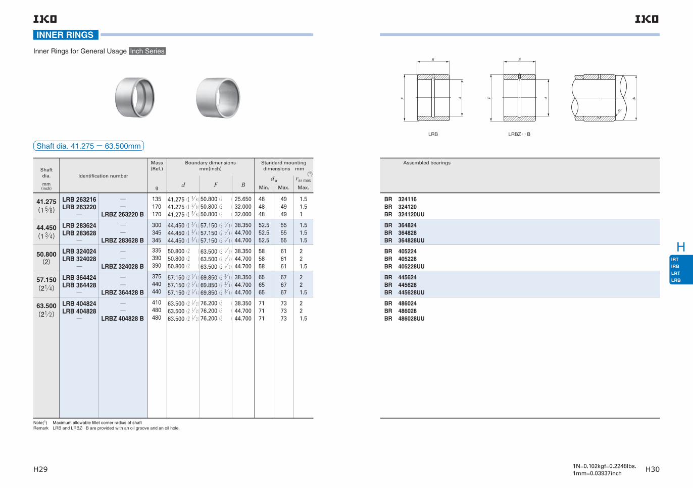
H
H29 H301N=0.102kgf=0.2248lbs.1mm=0.03937inch
Note(1) Maximum allowable fillet corner radius of shaft Remark LRB and LRBZ…B are provided with an oil groove and an oil hole.
Shaft dia.
mm(inch)
Mass (Ref.)
Identification number
g d F B Min. Max. Max.
50.800(2)
LRB 324024LRB 324028
LRBZ 324028 B
57.150(214)
LRB 364424LRB 364428
LRBZ 364428 B
63.500(212)
LRB 404824LRB 404828
LRBZ 404828 B
(1)
Boundary dimensionsmm(inch)
Standard mounting dimensions mm
d a ras max
335390390
38.35044.70044.700
585858
656565
717171
616161
221.5
221.5
221.5
676767
737373
38.35044.70044.700
38.35044.70044.700
50.800(2 )50.800(2 )50.800(2 )
57.150(2 1 4)57.150(2 1 4)57.150(2 1 4)
63.500(2 1 2)63.500(2 1 2)63.500(2 1 2)
63.500(2 1 2)63.500(2 1 2)63.500(2 1 2)
69.850(2 3 4)69.850(2 3 4)69.850(2 3 4)
76.200(3 )76.200(3 )76.200(3 )
375440440
410480480
Shaft dia. 41.275− 63.500mm
41.275(1 58)
LRB 263216LRB 263220
LRBZ 263220 B
44.450(1 34)
LRB 283624LRB 283628
LRBZ 283628 B
25.65032.00032.000
38.35044.70044.700
41.275(1 5 8)41.275(1 5 8)41.275(1 5 8)
44.450(1 3 4)44.450(1 3 4)44.450(1 3 4)
50.800(2 )50.800(2 )50.800(2 )
57.150(2 1 4)57.150(2 1 4)57.150(2 1 4)
135170170
300345345
484848
52.552.552.5
1.51.51
1.51.51.5
494949
555555
INNER RINGS
Inner Rings for General Usage Inch Series
Assembled bearings
LRBZ … BLRB
BR 405224BR 405228BR 405228UU
BR 445624BR 445628BR 445628UU
BR 486024BR 486028BR 486028UU
BR 324116BR 324120BR 324120UU
BR 364824BR 364828BR 364828UU
dF
B
da
ra
dF
B

H
H31 H321N=0.102kgf=0.2248lbs.1mm=0.03937inch
Shaft dia. 69.850− 88.900mm
Inner Rings for General Usage
Note(1) Maximum allowable fillet corner radius of shaft Remark LRB with inner ring bore diameter d of 76.200 mm or less and LRBZ…B are provided with an oil groove and an oil hole. Other models are provided with an oil groove and two oil holes.
Shaft dia.
mm(inch)
Mass (Ref.)
Identification number
g d F B Min. Max. Max.
LRBZ 445228 B
69.850(234)
LRB 445228LRB 445232
76.200(3)
LRB 485632
LRBZ 485632 B
82.550(314)88.900(312)
LRB 526032
LRB 566432
LRBZ 526032 B
(1)
Boundary dimensionsmm(inch)
Standard mounting dimensions mm
d a ras max
77 77 77
83.5 83.5
91 91
97
221.5
21.5
2.51.5
2.5
797979
8686
9393
99
44.70051.05044.700
51.05051.050
51.05051.050
51.050
69.850(2 3 4)69.850(2 3 4)69.850(2 3 4)
76.200(3 )76.200(3 )
82.550(3 1 4)82.550(3 1 4)
88.900(3 1 2)
82.550(3 1 4) 82.550(3 1 4) 82.550(3 1 4)
88.900(3 1 2) 88.900(3 1 2)
95.250(3 3 4) 95.250(3 3 4)
101.600(4 )
530600530
640640
690690
750
INNER RINGS
Inch Series
Assembled bearings
BR 526828BR 526832BR 526828UU
BR 567232BR 567232UU
BR 607632BR 607632UU
BR 648032
LRBZ … BLRB
dF
B
da
ra
dF
B

CFCFKRCFSNUCFCR
I
I1 I2
Standard Type Cam FollowersStainless Steel Made Cam FollowersEccentric Type Cam FollowersSolid Eccentric Stud Type Cam FollowersThrust Disk Type Cam FollowersCentralized Lubrication Type Cam FollowersEasy Mounting Type Cam Followers
Cam Follower GC-Lube Cam FollowersMiniature Type Cam FollowersStainless Steel Made Miniature Cam FollowersThrust Disk Type Miniature Cam FollowersCylindrical Roller Cam FollowersInch series Cam Followers
IKO Cam Followers are bearings with a stud incorpo-rating needle rollers in a thick walled outer ring. These bearings are designed for outer ring rotation, and have superior rotational performance with a small coefficient of friction and high load capacity. As studs already have threads or steps, they are easy to mount.Cam Followers are follower bearings for cam mecha-nisms and linear motions and have high rigidity and
Structure and Features
Structure of Cam Followers
Standard Type Cam Follower(1) Thrust Disk Type Cam Follower
Seal
Cage
Stud
Side plate
Needle roller
Outer ring
Seal
Thrust disk
Cage
Stud
Side plate
Needle roller
Outer ring
Cylindrical Roller Cam Follower
Shield plate
Stud
Side plate
Cylindrical roller
Outer ring
Miniature Type Cam Follower
Cage
Stud
Side plate
Needle roller
Outer ring
C-Lube Cam Followers(1)
CF…WBUUR/SG
Cage
Seal
Thrust washer
Stud
Side plate
Needle roller
Outer ring
Standard Type Cam Follower CFKR
CFKR…UU
Stud
Side plate
Needle roller
Outer ring
CageSeal
high accuracy. They are, therefore, used widely for machine tools, industrial robots, electronic devices, and OA equipment.Stainless steel made Cam Followers are superior in corrosion resistance and suitable for applications in environments where oil cannot be used or water splashed, and in clean rooms.
Note(1) Thermosetting solid-type lubricant C-Lube fills inner space of the bearing.

CFCFKRCFSNUCFCR
I
I3 I41N=0.102kgf=0.2248lbs.1mm=0.03937inch
TypesFor Cam Followers, the types shown in Table 1 are available.
Table 1 Type of Cam FollowersItem
Bearing Model
With cage Full complement
Crowned outer ring Cylindrical outer ring Crowned outer ring Cylindrical outer ring
Standard Type Cam FollowerCF…BCFKR
High carbon steel made
Stud Head Hex Hole
Shield type CF … B R CF … B CF …V B R CF … V B
Sealed type CF … B UUR CF … B UU CF …V B UU R CF … V B UU
Stainless steel madeShield type CF …F B R CF …F B Sealed type CF …F B UUR CF …F B UU
High carbon steel made Double Hex Hole Shield type CFKR… R CFKR CFKR…V R CFKR… V
Sealed type CFKR… UUR CFKR … UU CFKR…V UU R CFKR… V UU
Eccentric Type Cam FollowersCFE…BCFKRE
High carbon steel made
Stud Head Hex HoleShield type CFE… B R CFE… B CFE…V B R CFE… V B
Sealed type CFE… B UUR CFE… B UU CFE…V B UU R CFE… V B UU
Double Hex Hole Shield type CFKRE… R CFKRE CFKRE…V R CFKRE… V
Sealed type CFKRE… UUR CFKRE… UU CFKRE…V UU R CFKRE… V UU
Solid Eccentric Stud Type Cam FollowersCFES…B
High carbon steel made With hexagon holeShield type CFES… B R CFES… B
Sealed type CFES… B UUR CFES… B UU
Thrust Disk Type Cam FollowersCF…WB
High carbon steel made
With hexagon hole
Shield type CF … WB R Sealed type CF … WB UUR
Stainless steel madeShield type CF …F WB R Sealed type CF …F WB UUR
Centralized Lubrication Type Cam FollowersCF-RU1, CF-FU1
High carbon steel made With screwdriver slot Sealed type CF-RU1 CF-FU1
Easy Mounting Type Cam FollowersCF-SFU…B
High carbon steel made With hexagon hole Sealed type CF-SFU… B
Cam Follower GCF…G High carbon steel made With hexagon hole Shield type CF …G
C-Lube Cam FollowersCF…WB…/SG
High carbon steel made With hexagon hole Sealed type CF …WB…/SG
Miniature Type Cam FollowersCFS
High carbon steel madeWith hexagon hole Shield type
CFS CFS… V
Stainless steel made CFS…F CFS…F V
Thrust Disk Type Miniature Cam FollowersCFS…W
High carbon steel madeWith hexagon hole Shield type
CFS… W CFS…WV
Stainless steel made CFS…F W
Cylindrical Roller Cam FollowersNUCF…B
High carbon steel made With hexagon hole Shield type NUCF… B R
Inch series Cam FollowersCR
High carbon steel made
With hexagon hole
Shield type CR … B R CR …B CR …V B R CR … V B
Sealed type CR … B UU R CR …B UU CR …V B UU R CR … V B UU
Sealed type with integrated thrust washer
CR …V B S R CR … V B S
With screwdriver slotShield type CR … R CR CR …V R CR … V
Sealed type CR … UU R CR … UU CR …V UU R CR … V UU
Inch series Cam FollowersCRH…B
High carbon steel made With hexagon holeShield type CRH…V B R CRH… V B
Sealed type CRH…V B UU R CRH… V B UU
Standard Type Cam FollowersThese are the basic type bearings in IKO Cam Follower
series. Standard Type Cam Followers CF…B with stud
diameters ranging from 3 mm to 30 mm are available,
and are suitable for a wide range of applications.
Standard Type Cam Followers CFKR have sockets with
hexagon holes on both stud ends, which allow mounting
with a hexagon wrench from either side.
Eccentric Type Cam FollowersThe eccentric stud can be rotated to create a uniform line,
enabling easy adjustment for even load distribution
across the outer ring outer surface.
Eccentricity is 0.4 (CFE)〜 1.5 mm.
Solid Eccentric Stud Type Cam FollowersThe eccentric stud can be rotated to create a uniform line,
enabling easy adjustment for even load distribution across
the outer ring outer surface.
These are eccentric cam followers with an integrated stud
that can be mounted in the same mounting holes as
those for Standard Type Cam Followers.
Eccentricity is from 0.25 mm to 0.6 mm.
Thrust Disk Type Cam FollowersThe thrust disk seal, made of special synthetic resin with
excellent abrasion and heat resistance, is incorporated in
the sliding contact area between the shoulders of the
outer ring and the stud head and side plate. This prevents
friction and abrasion inside the bearing due to axial loads
caused by mounting errors.
Centralized Lubrication Type Cam FollowersThese bearings have one or two pipe-threaded holes in
the stud. Thus, this series is suitable when centralized
lubrication is required.
Lubrication method of Hex Head Cam Followers〈Types〉Standard Type, Eccentric Type, Solid Eccentric Stud Type, Thrust Disk Type,
Easy Mounting Type, Cylindrical Roller Type.
Stud dia.
Re-greasing fitting is incorporated in the stud head. Grease nipple is incorporated in the stud head.
Stud dia.(1)
Remark : All Easy Mounting Type have a 1way port.Note (1) CFKR and CFKRE can be lubricated from both head part and thread side.
Also, a grease nipple is built into the stud head.
Easy Mounting Type Cam FollowersThese bearings have a stepped tapered portion on the stud. When mounting the Cam Follower, it is easy to fix its location by tightening a set screw to the stepped por-tion. Thus, this type is suitable when a large number of Cam Followers are used in a machine such as a pallet changer.
C-Lube Cam FollowersThese bearings are lubricated with a newly developed thermosetting solid-type lubricant which fills the inner space of the bearing. This lubricant provides long-term maintenance free.
Miniature Type Cam FollowersThese are compactly designed bearings, incorporating very thin needle rollers in an outer ring with a small out-side diameter. They are used in electronic devices, OA equipment, small index devices, etc.
Cylindrical Roller Cam FollowersThese bearings are full complement type bearings incor-porating double rows of full complement cylindrical rollers in the outer ring, and can withstand large radial loads.Additionally, the outer ring is guided by the outer ring shoulder and the end face of cylindrical rollers to the axial direction.
Inch series Cam FollowersTwo types, CR and CRH, are available in the Inch series Cam Followers. Black oxide film treatment is made on CRH models. CR with ThrustDisk SealsTM prevents the ingress of for-eign substances as well as friction and abrasion on the interior of the bearing caused by axial load generated due to mounting errors.

CFCFKRCFSNUCFCR
I
I5 I6
Internal Structures and Shapes
Roller guide methodCam Followers include the caged type and the full complement type . The caged type has a small coeffi-cient of friction and is suitable for high speed rota-tions, while the full complement type is suitable for heavy loads at low speed rotations.
Type of materialIn addition to high carbon steel products, stainless steel products are also available. Stainless steel prod-ucts are suited for applications where oil cannot be used or where water splashes, and in cleanrooms.
Seal structureAvailable Cam Followers include the shield type, the sealed type, and type with ThrustDisk SealsTM. In the shield type, labyrinths are formed by the narrow clear-ances between the outer ring and the stud flange, and between the outer ring and the side plate. The sealed type incorporates seals in the narrow clearances (the shield type labyrinths) to prevent the ingress of for-eign substances. The sealed type with ThrustDisk SealsTM prevents grease leakage and the ingress of foreign substances into the bearing interior. It also prevents friction and abrasion on the interior of the bearing caused by axial load generated due to mount-ing errors.
Shape of outer ring outside surfaceThe outside surface of the outer r ing of Cam Followers, which makes direct contact with the mat-ing cam guide surface, is either crowned or cylindri-cal. The crowned outer rings are effective in moderat-ing the edge load due to mounting errors. The cylin-drical outer rings have a large contact area with the mating cam guide surface, and are suitable for appli-cations in which the applied load is large or the cam guide surface hardness is low.
The Cam Follower series has various types, such as high carbon steel type, stainless steel type, caged type, full complement type, shield type, sealed type,
type with crowned outer ring, type with cylindrical outer ring, etc.
Identification numberSome examples of the identification number of Cam Followers are shown below. For applicable material symbol, roller guide method, seal structure and shape of outer ring outside surface, refer dimension table of each series.
10CF
R
V
UU
10CF
R
UU R
W
B
B
B
W
V3CFS P6F
With cage typeFull complement type
Roller guide methodNo symbolV
High carbon steel madeStainless steel made
MaterialNo symbolF
With crowned outer ringWith cylindrical outer ring
Shape of outer ring outside surfaceR
No symbol
Classification symbolNo symbolP6
P5
P4
Class 0Class 6Class 5Class 4
Applicable to Miniature CFS series
Example 1
Example 2
Example 4
8CF /SGExample 3
SizeThe value indicates a stud diameter. (unit: mm)For Double Hex Hole Cam Followers, the outside diameter of the outer ring is indicated.In the inch series, the outside diameter of the outerring in units of 1/16 inch is indicated.
Standard Type Cam Follower(Stud Head Hex Hole)Standard Type Cam Follower(Double Hex Hole )Eccentric Type Cam Followers(Stud Head Hex Hole)Eccentric Type Cam Followers(Double Hex Hole )Solid Eccentric Stud Type Cam FollowersThrust Disk Type Cam FollowersCentralized Lubrication Type Cam Followers(Crowned outer ring)Centralized Lubrication Type Cam Followers(Cylindrical outer ring)Easy Mounting Type Cam FollowersCam Follower GC-Lube Cam FollowersMiniature Type Cam FollowersThrust Disk Type Miniature Cam FollowersCylindrical Roller Cam FollowersInch series Cam Followers(With screwdriver slot)Inch series Cam Followers(Stud Head Hex Hole)Inch series Cam Followers(Stud Head Hex Hole)
Model code
CF…BCFKRCFE…BCFKRECFES…BCF…WBCF-RU1CF-FU1CF-SFU…BCF…GCF…WB…/SGCFSCFS…WNUCF…BCRCR…BCRH…B
Shield typeSealed typeSealed type with integrated thrust washer
Seal structureNo symbolUU
S(1)Notes(1) Applicable only to Inch Series Cam Followers CR (Stud Head Hex Hole)
Examples of identification number
《Sealed type with integrated thrust washer》(1)
Part A enlarged view
Part A
Notes(1) Applicable only to Inch Series Cam Followers CR (Stud Head Hex Hole)
《Stainless steel made》《High carbon steel made》
《Full complement》《With cage》
《Shield type》 《 Sealed type》
《Crowned outer ring》 《Cylindrical outer ring》
RR

CFCFKRCFSNUCFCR
I
I7 I81N=0.102kgf=0.2248lbs.1mm=0.03937inch
AccuracyThe accuracy of Cam Followers is shown in Table 2, Table 3.1, Table 3.2 and Table 3.3. Cam Followers with special accuracy are also available. When they are required, please contact IKO.
Note(1) Applicable to Cam Followers other than Miniature Type Cam Followers and Inch Series Cam Followers.
Note(1) Applicable to Cam Followers other than Miniature Type Cam Followers and Inch Series Cam Followers.
Table 2 TolerancesSeries
Dimensions and symbols
Outside dia. of outer ring D
Stud dia. d1
Width of outer ring C
0-50
h7 h6 +25 0
0-120
0-120
0-130
0-50
See Table 3.3See Table 3.1 See Table 3.2
Metric CF(1)
Crowned outer ring Cylindrical outer ring
Inch series CF
Crowned outer ring Cylindrical outer ring
Miniature series CF
unit: μ m
Table 3.1 Tolerances and allowable values of outer rings (Metric CF cylindrical outer rings(1))
DNominal outside dia. of outer ring
mm
Over Incl. High Low
∆DmpSingle plane mean outside dia. deviation
6
18
30
50
80
18
30
50
80
120
0
0
0
0
0
- 8- 9-11
-13
-15
10
12
14
16
19
6
7
8
10
11
15
15
20
25
35
VDspOutside dia.
variation in a single radial plane (Max.)
VDmpMean outside dia.
variation (Max.)
Kea Radial runout of
assembled bearing outer ring (Max.)
unit: μ m
Table 3.2 Tolerances and allowable values of outer rings (Miniature series CF)
∆DmpSingle plane mean outside dia. deviation
Class 0
High Low Low Low LowHigh High High
Class 6 Class 5 Class 4 Class 0 Class 6 Class 5 Class 4
0 -8 0 -7 0 -5 0 -4 15 8 5 4
Kea Radial runout of assembled bearing outer ring
(Max.)
unit: μ m
Table 3.3 Tolerances and allowable values of outer rings (Inch series CF cylindrical outer ring)
DNominal outside dia. of outer ring
mm
Over Incl. High Low
∆DmpSingle plane mean outside dia.
deviation
6
18
30
50
80
18
30
50
80
120
0 -25
10
12
14
16
19
6
7
8
10
11
15
15
20
25
35
VDspOutside dia.
variation in a single radial plane (Max.)
VDmpMean outside dia.
variation (Max.)
Kea Radial runout of
assembled bearing outer ring (Max.)
unit: μ m
ClearanceThe radial internal clearances of Cam Followers are shown in Table 4.
Table 4 Radial internal clearance unit: μ m
Note (1) Also applicable to full complement type, type with crowned outer ring, sealed type, and type with hexagon hole. (2) Applicable to all Cam Followers other than Miniature Type Cam Followers, Cylindrical Roller Cam Followers and Inch Series Cam
Followers. (3) Applicable to all Miniature Type Cam Followers.
FitTables 5 and 6 show recommended tolerances of mounting holes for Cam Follower studs. Since the Cam Follower is supported in a cantilever position, the mounting hole diameter should be prepared with-out play between the stud and the hole especially when heavy shock loads are applied.
Table 5 Recommended fit
Type
Metric CF
Miniature series CF
Cylindrical Roller Cam Followers
Inch series CF
H7
H6
H7
F7
Tolerance class of mounting hole for stud
Table 6 Dimensional tolerances of mounting hole
Nominal outside dia. of studmm
F7 H6 H7
Over Incl. Over Incl. Over Incl. Over Incl.
− 3
6
10
18
30
3
6
10
18
30
50
+16 +22
+28
+34
+41
+50
+ 6+10
+13
+16
+20
+25
+ 6+ 8+ 9+11
+13
+16
0
0
0
0
0
0
+10 +12
+15
+18
+21
+25
0
0
0
0
0
0
unit: μ m
Identification number (1) Radial internal clearance
Metric CF series (2)
Miniature CFS series CF (3)
Cylindrical Roller Cam Followers NUCF…B
Inch series CF Min. Max.
CF 3〜CF 5 CFS1.4 〜CFS5 CR 8, CR 8-1, CRH 8-1, CRH 9 3 17
CF 6 CFS6 CR10, CR10-1, CRH10-1, CRH11 5 20
CF 8〜CF12-1CFKR22〜CFKR32 CR12〜CR22, CRH12〜CRH22 5 25
CF16〜CF20-1CFKR35〜CFKR52 CR24〜CR36, CRH24〜CRH36 10 30
CF24〜CF30-2CFKR62〜CFKR90 CR48, CRH40〜CRH56 10 40
CRH64 15 50
NUCF10 R〜NUCF24 R 20 45
NUCF24-1R〜NUCF30-2R 25 50

CFCFKRCFSNUCFCR
I
I9 I101N=0.102kgf=0.2248lbs.1mm=0.03937inch
Maximum Allowable Static LoadThe applicable load on Cam Followers is, in some cases, limited by the bending strength and shear strength of the stud and the strength of the outer ring instead of the load rating of the needle roller bearing. Therefore, the maximum allowable static load that is limited by these strengths is specified.
Track CapacityTrack capacity is defined as the load which can be con-tinuously applied on a Cam Follower placed on a steel cam guide surface without causing deformation or indentation on the cam guide surface when the outer ring of the Cam Follower makes contact with the mat-ing cam guide surface (plane). The track capacities shown in Tables 7.1 and 7.2 are applicable when the hardness of the mating cam guide surface is 40HRC (Tensile strength 1250N/mm2). When the hardness of the mating cam guide surface differs from 40HRC, the track capacity is obtained by multiplying the value by the track capacity factor shown in Table 8.If lubrication between the outer ring and the mating cam guide surface is insufficient, seizure and/or wear may occur depending on the application. Therefore, attention must be paid to lubrication and surface roughness of the mating cam guide especially for high-speed rotations such as cam mechanisms.For lubrication between the outer ring and the mating cam guide surface, C-Lube Unit for Cam Followers is recommended. (See page Ⅰ20.)
Notes(1) Applicable to Cam Followers other than Miniature Type Cam Followers and Inch Series Cam Followers. (2) This table is applicable to all Miniature Type Cam Followers.
Table 7.1 Track load capacity
Type of bearing
Metric
CF (1)
Miniature
series CF (2)
Identification number
with crowned outer ring
CF 3 R
CF 4 R
CF 5 R
CF 6 R
CF 8 R
CF10 R・CFKR22R
CF10-1R・CFKR26R
CF12 R・CFKR30R
CF12-1R・CFKR32R
CF16 R・CFKR35R
CF18 R・CFKR40R
CF20 R・CFKR52R
CF20-1R・CFKR47R
CF24 R・CFKR62R
CF24-1R・CFKR72R
CF30 R・CFKR80R
CF30-1R・CFKR85R
CF30-2R・CFKR90R
−−−−−−−
542
712
794
1 040
1 330
1 610
2 030
2 470
2 710
3 060
3 660
5 190
4 530
6 580
8 020
9 220
9 990
10 800
−−−−−−−
CF 3
CF 4
CF 5
CF 6
CF 8
CF10 ・CFKR22
CF10-1・CFKR26
CF12 ・CFKR30
CF12-1・CFKR32
CF16 ・CFKR35
CF18 ・CFKR40
CF20 ・CFKR52
CF20-1・CFKR47
CF24 ・CFKR62
CF24-1・CFKR72
CF30 ・CFKR80
CF30-1・CFKR85
CF30-2・CFKR90
CFS1.4
CFS2
CFS2.5
CFS3
CFS4
CFS5
CFS6
1 360
1 790
2 210
3 400
4 040
4 680
5 530
7 010
7 480
11 200
14 500
23 200
21 000
34 300
39 800
52 700
56 000
59 300
128
220
298
485
799
1 210
1 680
Track capacity
Identification number
with cylindrical outer ring
Track capacity
unit: N
Table 7.2 Track capacity
Identification number
with crowned outer ring
CR 8 R
CR 8-1R
−CR10 R
CR10-1R
−CR12 R
CR14 R
CR16 R
CR18 R
CR20 R
CR22 R
CR24 R
CR26 R
CR28 R
CR30 R
CR32 R
CR36 R
−−−−−−
Type of bearing
Inch series
CF (1)
770
770
−1 030
1 030
−1 340
1 630
1 970
2 300
2 680
3 050
3 410
3 820
4 210
4 610
5 050
5 900
−−−−−−
CR 8
CR 8-1
−CR10
CR10-1
−CR12
CR14
CR16
CR18
CR20
CR22
CR24
CR26
CR28
CR30
CR32
CR36
−−
CR48
−−−
−CRH 8-1
CRH 9
−CRH10-1
CRH11
CRH12
CRH14
CRH16
CRH18
CRH20
CRH22
CRH24
CRH26
CRH28
CRH30
CRH32
CRH36
CRH40
CRH44
CRH48
CRH52
CRH56
CRH64
2 140
2 360
−3 210
3 480
−4 500
5 250
7 280
7 710
10 700
11 800
15 400
16 700
21 000
22 500
30 900
34 700
−−
64 300
−−−
−2 360
2 650
−3 480
3 830
4 500
5 250
7 280
7 710
10 700
11 800
15 400
16 700
21 000
22 500
30 900
34 700
45 000
49 500
64 300
69 600
87 000
113 000
Track capacity
Identification number
with cylindrical outer ring
Identification number
with cylindrical outer ring
Track capacity
−CRH 8-1R
CRH 9 R
−CRH10-1R
CRH11 R
CRH12 R
CRH14 R
CRH16 R
CRH18 R
CRH20 R
CRH22 R
CRH24 R
CRH26 R
CRH28 R
CRH30 R
CRH32 R
CRH36 R
CRH40 R
CRH44 R
CRH48 R
CRH52 R
CRH56 R
CRH64 R
−401
469
−579
658
853
1 050
1 420
1 660
2 160
2 450
3 410
3 820
4 210
4 610
5 690
6 640
8 970
10 200
11 400
12 700
14 100
16 800
Identification number
with crowned outer ring
Track capacity
Track capacity
unit: N
Table 8 Track capacity factor
Hardness
HRC Tensile strength
N/mm2
Track capacity factor
With cylindrical outer ring
With crowned outer ring
20
25
30
35
38
40
42
44
46
48
50
52
54
56
58
760
840
950
1 080
1 180
1 250
1 340
1 435
1 530
1 635
1 760
1 880
2 015
2 150
2 290
0.22
0.31
0.45
0.65
0.85
1.00
1.23
1.52
1.85
2.27
2.80
3.46
4.21
5.13
6.26
0.37
0.46
0.58
0.75
0.89
1.00
1.15
1.32
1.51
1.73
1.99
2.29
2.61
2.97
3.39
Notes(1) This table is applicable to all Inch series CF.

CFCFKRCFSNUCFCR
I
I11 I121N=0.102kgf=0.2248lbs.1mm=0.03937inch
LubricationGrease-prepacked Cam Followers are shown in Table 10. The lubricating grease prepacked in these bear-ings is ALVANIA GREASE S2 (Shell Lubricants Japan K.K.).For Cam Followers without prepacked grease, grease should be packed through the oil hole in the stud for use. If they are used without grease, wear of rolling contact surfaces may take place, leading to a short bearing life.
Allowable Rotational SpeedThe allowable rotational speed of Cam Followers is affected by mounting and operating conditions. For
reference, Table 9 shows d1n values when only pure radial loads are applied. Considering that axial loads also act under actual operating conditions, the recom-
mended d1n value is 1/10 of the value shown in the table.
In case of C-Lube Cam Follower, d1n value is 10000 or less.
Table 9 d1n values of Cam Followers(1)Lubricant
Type
Caged type
Full complement type
Cylindrical Roller Cam Follower
84 000
42 000
66 000
140 000
70 000
110 000
Grease Oil
Note(1) d1n value= d1× n where, d1(2) : Stud diameter mm n : Rotational speed min-1
(2) For Eccentric Type Cam Followers, thread diameter G as shown in the dimension table is applicable.
Table 10 Bearings with prepacked grease 〇:Prepacked ×:Not prepacked
Notes(1) For Eccentric Type Cam Followers, thread diameter G as shown in the dimension table is applicable. (2) C-Lube, a thermosetting solid-type lubricant, fills the inner space of the bearing.
Item
Series Size of stud diameter d1(1) mm
With cage
Full complementShield type Sealed type
With hexagon hole With screwdriver slot With hexagon hole With screwdriver slotStandard Type Cam Follower
CF…BCFKR 3 〜 5
〇
− 〇 −
−Eccentric Type Cam Followers
CFE…BCFKRE 6 〜 10
〇Solid Eccentric Stud Type Cam Followers CFES…B
12 〜 30 ×Thrust Disk Type Cam Followers CF…WB
Centralized Lubrication Type Cam Followers
CF-RU1, CF-FU1 − − − 〇 −
Easy Mounting Type Cam Followers CF-SFU…B − − 〇 − −Cam Follower G CF…G 〇 − − − −C-Lube Cam Followers CF…WB…/SG(2) − − × − −Miniature Type Cam Followers
CFSCFS…W 〇 − − − 〇
Cylindrical Roller Cam Followers NUCF…B − − − − 〇
Inch series Cam Followers
CR, CR…B 〇 〇 〇 〇 〇CRH…B − − − − 〇
Oil HoleThe position of oil hole is shown in Table 11.Perform greasing quietly by fitting a lubrication nozzle indicated in Table 12 to a straight type grease gun in JIS B 9808 and pressing the nozzle against the grease nipple or re-greasing fitting.Due to their structures, lubrication is not possible for sizes 3 and 4 Standard Type Cam Followers CF…B, C-Lube Cam Followers, Cam Followers G and Miniature CFS series.
Notes(1) In case of Eccentric Type Cam Followers, thread diameter G shown in the table of dimensions is applicable in place of stud dia. and the oil hole on the outer surface of the stud cannot be used for lubrication.
(2) Grease nipple is incorporated in the hexagon hole. Re-greasing can be made from the stud head and the stud end by press fitting a supplied grease nipple into the stud end. See page Ⅰ4.
(3) Re-lubrication can be made from the re-greasing fitting that is inserted into the hexagon hole. See page Ⅰ4. (4) Tapped holes for oil connectors are provided at the stud end and hole of the head. (5) Re-greasing can be made from the grease nipple in the hexagon hole.
Table 11 Position of oil hole 〇:Oil hole is prepared.
Oil hole positionSeriesSize of stud diameter d1 (1) mm
①Head
②Stud
outside surface
③Stud end
③
②
①
Standard Type Cam FollowerEccentric Type Cam FollowersSolid Eccentric Stud Type Cam FollowersThrust Disk Type Cam Followers
CF…BCFE…B
CFES…B
CF…WB
d1 < 5 − − −
5≦ d1 ≦ 10 〇 (3) − −
10< d1 〇 (2) 〇 〇Standard Type Cam Follower CFKR d1 ≦ 10 〇 (2) − 〇Eccentric Type Cam Followers CFKRE 10< d1 〇 (2) 〇 〇Centralized Lubrication Type Cam Followers CF-RU1, CF-FU1(4)
d1 ≦ 12 〇 − − 12< d1 〇 〇 〇
Easy Mounting Type Cam Followers CF-SFU…B
d1 ≦ 10 〇 (3) − − 10< d1 〇 (5) − −
Cam Follower G CF…G − − −C-Lube Cam Followers CF…WB…/SG − − −Miniature Type Cam Followers CFS
CFS…W − − −
Cylindrical Roller Cam Followers NUCF…B d1 ≦ 10 〇 (3) − − 10< d1 〇 (2) 〇 〇
Inch series Cam Followers
CR…BWith hexagon hole
d1 ≦ 6.35 − − − 6.35< d1 − 〇 〇
CRWith screwdriver slot
d1 ≦ 6.35 〇 − − 6.35< d1 〇 〇 〇
CRH…BWith hexagon hole
d1 ≦7.938 − − −7.938< d1 − 〇 〇

CFCFKRCFSNUCFCR
I
I13 I141N=0.102kgf=0.2248lbs.1mm=0.03937inch
Table 12 Type and Dimension of Lubrication Nozzles
Type DimensionApplicable grease nipple and
re-grease fitting
B-5120R
NPT4-1
NPT6-1
NPB2
NPB3
NPB3-1
NPB4
NPF3 (1)
NPF6-1 (1)Re-grease fitting (1)
NPF4-1 (1)
NPF6-1 (1)
A-5120V
A-5240V
B-5120V
B-5240V
φ5
PT1/8
120 29Width acrossflats 12
Width acrossflats 12
φ5
PT1/8
240 29Width acrossflats 12
Width acrossflats 12
A-5126T
A-5120R
PT1/8
29120
R2.5
φ5
Width acrossflats 12Width across
flats 12
φ1.
5
PT1/8
29
φ5
126
17°
Width acrossflats 12
Width across flats 12
PT1/8
φ5
φ5
29120
R2.5
Width acrossflats 12
Width acrossflats 12
φ5
φ5
PT1/8
120 29Width acrossflats 12Width across
flats 12
φ5
PT1/8
240 29Width acrossflats 12Width across
flats 12
φ5
Body of grease gun
Lubrication Nozzle
Note(1) HSP-3(Yamada Corporation)can be used for them.Remark The above nozzles can be atached on the standard grease gun shown below. If required, please consult to IKO with type of lubrication nozzle.
AccessoriesSeriesSize of stud dia. d1
mm
Grease nipple
Plug NutSpring washer
Standard Type Cam FollowerEccentric Type Cam FollowersSolid Eccentric Stud Type Cam FollowersThrust Disk Type Cam Followers
CF…BCFE…BCFES…BCF…WB
d1 ≦ 10 − − 〇 −(2)
10< d1 〇 − 〇 −(2)
Standard Type Cam FollowerEccentric Type Cam Followers
CFKRCFKRE
〇 − 〇 −(2)
Centralized Lubrication Type Cam Followers CF-RU1, CF-FU1 − − 〇 −
Easy Mounting Type Cam Followers CF-SFU…B − − − −Cam Follower G CF…G − − 〇 −C-Lube Cam Followers CF…WB…/SG − − 〇 −Miniature Type Cam Followers CFS, CFS…W − − 〇 −
Cylindrical Roller Cam Followers NUCF…B d1 ≦ 10 − − 〇 − 10< d1 〇 − 〇 −
Inch series Cam Followers
CR…BWith hexagon hole
d1 ≦ 6.35 − − 〇 − 6.35< d1 〇 〇 〇 −
CRWith screwdriver slot − 〇 〇 〇 −
CRH…BWith hexagon hole
d1≦ 7.938 − − 〇 −7.938< d1 〇 〇 〇 −
Note(1) For Eccentric Type Cam Follower, thead diameter G is applied.Remark: The standard grease nipple (brass) is included in the Stainless Steel Made Cam Follower.
When a stainless steel grease nipple is required, please contact IKO.
AccessoriesCam Follower accessories are shown in Table 13. Grease nipple dimensions are shown in Table 14 and Table 15. Dimensions of plug for unused oil hole and dimensions of plug inserter are shown in Table 16. Nut dimensions are shown in Table 17 and Table 18.
Table 13 Accessories 〇:Attached
(1)
Table 14 Dimensions of grease nipple for Standard Type Cam Followers (1)
Identification numberDimensions of grease nipple mm Stud diameter d1 (2) Dimension of inserter mm
d D L W mm d0 +0.05−0.05
NPF3(3) 3 4 4.5 1.3 10 4.1
NPF4-1 4 5 5 1.5 12〜16 5.3
NPF6-1 6 7 8 2 18〜30 7.3
Notes (1) Applicable to Cam Followers other than Inch series Cam Followers. (2) For Eccentric Type Cam Followers, thread diameter G as shown in the dimension table is applicable. (3) Only applicable to Standard Type Cam Follower CFKR, and Eccentric Type Cam Follower CFKRE sizes 22 and 26.Remark The same grease nipple as the accessory is integrated in the hexagon hole on the head.
LW
Dd d0
Inserter
Stud
Grease nipple

CFCFKRCFSNUCFCR
I
I15 I161N=0.102kgf=0.2248lbs.1mm=0.03937inch
Note(1) Shows representative types.
Table 16 Dimensions of plug for Inch series Cam Followers
Identification number
Dimensions of plug mm Dimension of inserter mmApplicable bearings (1)
Inserter
Stud
D t B d 0 −0.1
USB2F 3.18 0.3 3.3 2.3 CR 8 〜CR10-1
USB3F 4.76 0.4 4.3 3.7 CR12〜CR36, CRH12 〜CRH44
USB4F 6.35 0.5 4.8 5.2 CR48, CRH48〜CRH64
Table 15 Dimensions of grease nipple for Inch series Cam Followers
Identification number
Dimensions mmApplicable Cam Followers
NPB2NPB3NPB3-1NPB4
3.184.764.766.35
d D D1 L L1 W 7.5 7.5 7.5 8
6 6 6 6
9 1012.513
5.5 5.5 5.5 6
1.5 1.5 1.552
CR8〜 CR10-1, CRH8-1〜 CRH11CR12〜 CR22, CRH12〜 CRH22 CR24〜 CR36, CRH24〜 CRH44 CR48, CRH48〜 CRH64
Note(1) For Eccentric Type Cam Followers, thread diameter G as shown in the dimension table is applicable. Note(2) Applicable to Standard Type Cam Follower CFKR, and Eccentric Type Cam Follower CFKRE.
Table 17 Metric series nut dimensions
Model of bearingStud diameter
d1(1)Nut dimensions mm
G
s
(e)
m
G m s e
CF CFKR CFES CFE
CFKRE CF…W CF-RU1 CF-FU1 CF…G
CF…WB…/SG CFS
CFS…W NUCF…B
1.4 M 1.4×0.3 1.1 3 3.25
2 M 2 ×0.4 1.6 4 4.6
2.5 M 2.5×0.45 2 5 5.8
3 M 3 ×0.5 2.4 5.5 6.4
4 M 4 ×0.7 3.2 7 8.1
5 M 5 ×0.8 4 8 9.2
6 M 6 ×1 5 10 11.5
8 M 8 ×1.25 6.5 13 15
10 M10 ×1.0(2)M10 ×1.25 8 17 19.6
12 M12 ×1.5 10 19 21.9
16 M16 ×1.5 13 24 27.7
18 M18 ×1.5 15 27 31.2
20 M20 ×1.5 16 30 34.6
24 M24 ×1.5 19 36 41.6
30 M30 ×1.5 24 46 53.1
Table 19 Dimension of NPT type grease nipple
Code numberDimension of grease nipple mm Size of stud dia. d1(1)
mmd D D1 L L1 W
NPT4-1
NPT6-1
4
6
8
8
6
6
12
14
6
8
2
4
12 〜 16
18 〜 30
Example of Identification Number
CF 12 BUU / NP
Special SpecificationThe grease nipple supplied with Metric series Cam Follower with hexagon socket as an accessory may be replaced with the NPT type grease nipple indicated in Table 19 upon your request. If required, please order with supplemental code, "/NP" at the end of identification number.
Note(1) For Eccentric Type Cam Follower CFE, thread diameter G is applied.
Remark Not applicable to Standard Type Cam Follower CFKR, and Eccentric Type Cam Follower CFKRE.
Table 20 Dimension of assembled NPT type grease nipple
Code numberDimension mm Size of stud dia. d1(1)
mmB4 B5
NPT4-1
NPT6-1
6
8
2
4
12 〜 16
18 〜 30
Note(1) For Eccentric Type Cam Follower CFE, thread diameter G is applied.
Table 18 Inch series nut dimensions
Model of bearing Stud diameter d1(inch)
Nut dimensions mm
(e)
s
G
m
G UNF m s e
CR CRH
4.826 No.10-32 4 8 9.2
6.35 ( /1 4) 1/ 4-28 5.5 10 11.5
7.938 ( /516) 5/16-24 6.5 12 13.8
9.525 ( /3 8) 3/ 8-24 8 14 16.2
11.112 ( /716) 7/16-20 10 17 19.5
12.7 ( /1 2) 1/ 2-20 11 19 21.9
15.875 ( /5 8) 5/ 8-18 14 23 26.5
19.05 ( /3 4) 3/ 4-16 16 26 30
22.225 ( /7 8) 7/ 8-14 19 32 37
25.4 (1 ) 1 -14UNS 22 36 41.4
28.575 (1 /1 8) 1 1/ 8-12 24 41 47.1
31.75 (1 /1 4) 1 1/ 4-12 27 46 53.5
38.1 (1 /1 2) 1 1/ 2-12 33 55 63.5
44.45 (1 /3 4) 1 3/ 4-12UN 38 65 75.1
50.8 (2 ) 2 -12UN 44 75 86.6

CFCFKRCFSNUCFCR
I
I17 I181N=0.102kgf=0.2248lbs.1mm=0.03937inch
Operating Temperature RangeOperating temperature range of Cam Followers is -20°C ~ +120°C. However, note that the maximum allowable temperature varies in models shown in Table 21.
MountingMake the center axis of the mount ing hole perpendicular to the moving direction of the Cam Follower and match the side shoulder accurately with the seating surface indicated by dimension f in the table of dimensions. (See Fig. 1) The chamfered mounting hole should be as small as possible (C0.5 or so). When mounting Cam Followers, do not hit the flange head of the Cam Follower directly with a hammer, etc. This may lead to a bearing failure such as irregular rotation or cracking. If the Cam Follower outer ring is not in good contact w i th the ma t ing runn ing su r face then we recommend use of a crowned outer ring type.
Fig. 1 Seating surface
Oil Hole
Load
Fig. 2 Oil hole position and loading direction
Table 21 Limitation of operating temperature range
Notes(1) 100°C when used continuously. (2) Below 60°C is recommended for long use.
The mark on the flange head of the stud indicates the posit ion of the oi l hole on the raceway. Avoid locating the oil hole within the loading zone. This may lead to a short bearing life. (See Fig. 2.) The hole located in the middle part of the stud perpendicular to the stud center axis is used for greasing or locking.
1
2
When tightening the nut, the tightening torque should not exceed the values shown in the table of dimensions. If the tightening torque is too large, it is possible that the threaded portion of the stud will be broken. When there is a possibility of loosening, a special nut such as a lock nut, spring washer, or self-locking nut should be used.
When direct-fixing the Cam Follower without nuts for mounting as shown in Fig. 4, it may be difficult to achieve sufficient tightening torque. If the screw then loosens, stress may concentrate on the thread, causing the stud to break. Such a method is not recommended.
4
5
Stud dia.or eccentric collar diameter
Load
EccentricitySolid Eccentric Stud Type Cam Followers and Eccentric Type Cam Followers, are mounted in reference position where mark on the head of stud is located as Fig.5. The outer ring position can be adjusted appropriately by turning the stud with a screwdriver or hexagon bar wrench using the screwdriver slot or hexagon hole of the stud head. The stud is fixed with a nut and a spring washer, etc. The tightening torque should not exceed the values of maximum tightening torque shown in the table of dimensions.When shock loads are applied and the adjusted eccentricity has to be ensured, it is recommended to make holes in the housing, stud and eccentric collar, and fix the stud with a dowel pin as shown in Fig. 6. However, when the stud diameter is less than 8 mm (Eccentric collar diameter 11 mm), it is difficult to make a hole in the stud because the stud is through-hardened.
Fig. 5 Reference position for adjusting of Solid Eccentric Stud Type Cam Followers and Eccentric Type Cam Follwers
Dowel pin
Fig. 6 Mounting example of Solid Eccentric Stud Type Cam Follower
6
Fig. 3 Methods of mounting
Fig. 4 Methods of mounting
When mounting Cam Followers, fix in place by holding the hexagon hole or screwdriver slot with a hex wrench or slotted screwdriver and use a wrench to tighten on a nut. (See Fig. 3) I f mounting by turning the hexagon hole or screwdriver slot i tself , the hexagon hole or screwdriver slot of the Cam Follower may become damaged.
3
Item
Model Stud diameter d1 mm
With cage Full complement
Shield type
Sealed type
ThrustDisk SealsTM
Miniature Type Cam Followers CFSThrust Disk Type Miniature Cam Followers CFS … W
d1 = 2 − 20°C 〜 110°C(1) - -
Standard Type Cam Followers CF … BThrust Disk Type Cam Followers CF … WB
d1 = 3,4 − 20°C 〜 110°C(1) -
-d1 = 5 − 20°C 〜
120°C− 20°C 〜 80°C
Standard Type Cam Followers / Stainless Steel Made CF … FB
Thrust Disk Type Cam Followers / Stainless Steel Made CF … FWB
3 ≦ d1 ≦ 5 − 20°C 〜 110°C(1)
− 20°C 〜 80°C
-
C-Lube Cam FollowersCF … WB … /SG 5 ≦ d1 ≦ 20 − − 15°C 〜
80°C(2) -
Inch Series Cam FollowersThrustDisk SealsTM
CR … VBS4.826≦d1≦9.525 - - − 20°C 〜
80°C
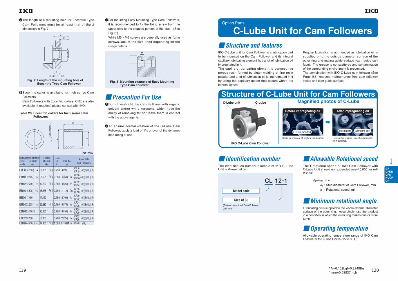
CFCFKRCFSNUCFCR
I
I19 I201N=0.102kgf=0.2248lbs.1mm=0.03937inch
The length of a mounting hole for Eccentric Type
Cam Followers must be at least that of the S dimension in Fig. 7.
S
G1B2
S=B2−G1+0.5
Fig. 7 Length of the mounting hole of Eccentric Type Cam Follower
Eccentric callor is available for Inch series Cam Followers.Cam Followers with Eccentric collars, CRE are also available. If required, please consult with IKO.
EB 8
EB10
EB12
EB16
EB20
EB24
EB28
EB32
EB48
6.350
9.525
12.700
15.875
17.450
22.225
25.400
30.150
44.450
( 3⁄8 )
( 1⁄2 )
( 5⁄8 )
( 7⁄8 )
(1 )
(1 3⁄4 )
6.350
9.525
12.700
15.875
17.450
22.225
25.400
30.150
44.450
( 1⁄4 )
( 3⁄8 )
( 1⁄2 )
( 5⁄8 )
( 7⁄8 )
(1 )
(1 3⁄4 )
0.250
0.380
0.380
0.760
0.760
0.760
0.760
0.760
1.520
4.826
6.350
9.525
11.112
12.700
15.875
19.050
22.225
31.750
( 1⁄4 )
( 3⁄8 )
( 7⁄16)
( 1⁄2 )
( 5⁄8 )
( 3⁄4 )
( 7⁄8 )
(1 1⁄4 )
CR 8CR 8-1CR10CR10-1CR12CR14CR16CR18CR20CR22CR24CR26CR28CR30CR32CR36CR48
(V)(B)(UU)(R)
(V)(B)(UU)(R)
(V)(B)(UU)(R)
(V)(B)(UU)(R)
(V)(B)(UU)(R)
(V)(B)(UU)(R)
(V)(B)(UU)(R)
(V)(B)(UU)(R)
VUU
Table 20 Eccentric collars for Inch series Cam Followers
Identificalnumberof collar
Outer diameter of collar
de
Length of collar
B3
Eccentricityε
Stud dia.d
ApplicableCam Followers
unit: mm
For mounting Easy Mounting Type Cam Followers, it is recommended to fix the fixing screw from the upper side to the stepped portion of the stud. (See Fig. 8.)While M5 - M6 screws are generally used as fixing screws, adjust the size used depending on the usage criteria.
Fig. 8 Mounting example of Easy Mounting Type Cam Follower
Precaution For UseDo not wash C-Lube Cam Follower with organic solvent and/or white kerosene, which have the ability of removing fat nor leave them in contact with the above agents.
To ensure normal rotation of the C-Lube Cam Follower, apply a load of 1% or over of the dynamic load rating at use.
8
7 9
1
2
( 1⁄4 )
Option Parts
C-Lube Unit for Cam Followers
Identification numberThe identification number example of IKO C-Lube Unit is shown below.
Allowable Rotational speedThe Rotational speed of IKO Cam Follower with C-Lube Unit should not exceeded d1n=10,000 for ref-erence.
d1n=d1× nd1 : Stud diameter of Cam Follower, mm
n : Rotational speed, min-1
Minimum rotational angleLubricating oil is supplied to the whole external diameter surface of the outer ring. Accordingly, use the product in a condition in which the outer ring makes one or more turns.
Operating temperatureAllowable operating temperature range of IKO Cam Follower with C-Lube Unit is -15 to 80˚C.
C-Lube unit C-Lube
IKO C-Lube Cam Follower
Magnified photos of C-Lube
Before impregnating oil
Fusion- bonded
Resin particles are strongly fusion bonded. Lubricant is retained in cavities amongstresin particles.
Resin part Lubricant part
After impregnating oil
Structure of C-Lube Unit for Cam Followers
Model code
Size of CL(Size of combined Cam Follower)unit :mm
Structure and featuresIKO C-Lube unit for Cam Follower is a lubrication part to be mounted on the Cam Follower and its integral capillary lubricating element has a lot of lubrication oil impregnated in it.The capillary lubricating element is consecutive porous resin formed by sinter molding of fine resin powder and a lot of lubrication oil is impregnated in it by using the capillary action that occurs within the internal space.
Regular lubrication is not needed as lubrication oil is supplied onto the outside diameter surface of the outer ring and mating guide surface (cam guide sur-face). The grease is not scattered and contamination of the surrounding environment is prevented.The combination with IKO C-Lube cam follower (See Page I55) realizes maintenance-free cam follower inside and cam guide surface.

CFCFKRCFSNUCFCR
I
I21 I221N=0.102kgf=0.2248lbs.1mm=0.03937inch
Precaution for useDo not wash with organic solvent and/or white kerosene, which have the ability of removing fat nor leave them in contact with the above agents.
Do not apply a load onto the C-Lube Unit directly.
To ensure normal rotation of the Cam Follower, apply a load of 1% or over of the dynamic load rating at use.Also, the outer ring needs to be rotate over a revolution to supply lubricant on entire outer diameter surface.
The maximum allowable load on IKO Cam Follower with C-Lube Unit is, 80% of the maximum allowable load of the needle bearing. C-Lube Unit may be damaged and influenced to the smooth rotation and lubricating performance by excessive load.
After assembling C-Lube Unit and Cam Followers in the machine, please confirm that C-Lube unit provides oil correctly to the cam guide surface before actual operation.
Do not use in the environment which contamination of l iquid and/or harmful foreign matter are expected.
Replace with new C-Lube Unit when inside oil finishes completely. Re-lubrication is not possible.
MountingSet the C-Lube Unit perpendicularly to the center axis of Cam Follower and fix together with Cam Follower by tightening nut. (See Fig. 9.)
Load
Position of C-Lube Unit is adjustable. C-Lube Unit must be positioned avoiding loading direction. (See Fig. 10.)
Fig. 9 Mounting of C-Lube Unit
When tightening the nut, the tightening torque should not be exceeded the value maximum tightening torque on dimension table. In case loosening of the nut is predicted due to vibration, using lock nut, spring washer and other special washer are recommended.
Fig. 10 Load direction of Cam Follwer
1 1
3
2
3
2
4
5
6
7
Table 21 Dimensions of C-Lube Unit for Cam Followers
Note(1) Only representative identification numbers are shown in the table, but applicable to all Cam Followers other than Miniature Type Cam Followers, Cylindrical Roller Cam Followers and Inch Series Cam Followers. It is recommended to use together with C-Lube Cam Followers in order to make maintenance-free more effective.
Remark Load on the Cam Follower with the C-Lube unit equipped must be up to 80% of the maximum allowable static load of the Cam Follower to be combined. For the maximum allowed static load of each Cam Follower, please see the dimension tables of respective models.
Model numberModel number(1)
Boundary Dimensions mm
D B
Boundary Dimensions mm Applicable Cam Followers
CL 5
CL 6
CL 8
CL 10
CL 10-1
CL 12
CL 12-1
CL 16
CL 18
CL 20
CL 20-1
12.4
15.4
18.4
21
21
29
29
33.8
38.8
45.8
45.8
W H T t1
10.7
12.6
14.2
17
19.2
21
22
27.4
30.4
38.4
35.4
12.1
14
14
15.5
15.5
17.5
17.5
23.4
25.4
29.9
29.9
1.5
1.5
1.5
2
2
2
2
2.5
2.5
3
3
13
16
19
22
26
30
32
35
40
52
47
10
12.2 max
12.2 max
13.2 max
13.2 max
15.2 max
15.2 max
19.6 max
21.6 max
25.6 max
25.6 max
CF 5 B
CF 6 B
CF 8 B
CF 10 BCFKR 22CF 10-1 BCFKR 26CF 12 BCFKR 30CF 12-1 BCFKR 32CF 16 BCFKR 35CF 18 BCFKR 40CF 20 BCFKR 52CF 20-1 BCFKR 47

CFCFKRCFSNUCFCR
I
I23 I241N=0.102kgf=0.2248lbs.1mm=0.03937inch
Option Parts
Way for Cam FollowerThe accuracy of the mating cam guide that comes in contact with the outer ring of Cam Followers has a large influ-ence on the guide performance of Cam Followers and machinery. A specially designed high-precision Way for Cam Follower should be used in order to achieve sufficient perfor-mance from the Cam Followers. Fixed with bolts for simple assembly and available in 2 models - A type or B type - depending on the mounting direction.
Identification number Model Types
Model Number
TRLA - - -
Overall Length
800
Width
49
Height
22
Table of Dimensions
L
N
W
H
hn (Pieces)
100 100
4-C0.5
4-C0.5
200
d 2 d 1
Material: SKS3 equivalentSurface hardness: 40HRC or more
《Way A Type》
Identification numberBoundary Dimensions mm
Applicable Cam FollowersL(n) W H N d1 d2 h
TRLA- 600-40-22 600(3)
40
22 12 9 14 11
Stud dia. 3~ 8mmTRLA- 800-40-22 800(4)
TRLA-1000-40-22 1000(5)
TRLA- 600-49-22 600(3)
49 Stud dia.10~18mmTRLA- 800-49-22 800(4)
TRLA-1000-49-22 1000(5)
TRLA- 600-64-22 600(3)
64 Stud dia.20~30mmTRLA- 800-64-22 800(4)
TRLA-1000-64-22 1000(5)
Remark For other dimensions, please contact IKO.
L
N
W
H
hn (Pieces)
100 1004-C0.5
4-C0.5
200
d 2
d 1
Material: SKS3 equivalentSurface hardness: 40HRC or more
《Way B Type》
Identification numberBoundary Dimensions mm
Applicable Cam FollowersL(n) W H N d1 d2 h
TRLB- 600-34-22 600(3)
34 22 17 9 14 11 Stud dia. 3~12mmTRLB- 800-34-22 800(4)
TRLB-1000-34-22 1000(5)
TRLB- 600-50-40 600(3)
50 40 25 11 17 13 Stud dia.16~30mmTRLB- 800-50-40 800(4)
TRLB-1000-50-40 1000(5)
Remark For other dimensions, please contact IKO.
Introduction of Special Support ExamplesIntroducing special support examples for Ways for Cam Follower. A variety of shapes are supported in addition to the special support examples. For details, please contact IKO.
CF
CF
Way
Way
CF
CF
Way
Way
《Way A Type》 《Way B Type》

CFCFKRCFSNUCFCR
I
I25 I261N=0.102kgf=0.2248lbs.1mm=0.03937inch
Note(1) Minimum allowable value of chamfer dimension rRemarks1. Models with a stud diameter d1 of 4 mm or less have no oil hole. For models with a stud dia. 5 to 10mm, oil hole (re-greasing
fitting) is provided at the head. Other models are provided with an oil hole (grease nipple) at the head and an oil hole each on the outside surface and end surface of the stud.
2. Shield type models with a stud diameter d1 of 10mm or less and the sealed type models are provided with prepacked grease. Other models are not provided with prepacked grease. Perform proper lubrication for use.
Standard Type Cam Followers CF…B With Cage/Stud Head Hex Hole
Stud dia.
mmWith crowned
outer ring
Shield typeWith cylindrical
outer ringWith crowned
outer ringWith cylindrical
outer ring
Mass (Ref.)
Identification number
g
3
4
5
6
8
CF 3 BR
CF 4 BR
CF 5 BR
CF 6 BR
CF 8 BRCF 8 BRM
CF 8 BCF 8 BM
CF 10 BRCF 10 BRMCF 10-1 BRCF 10-1 BRM
CF 12 BRCF 12-1 BR
CF 16 BR
CF 18 BR
CF 20 BRCF 20-1 BR
CF 24 BRCF 24-1 BR
CF 30 BRCF 30-1 BRCF 30-2 BR
CF 3 BUUR
CF 4 BUUR
CF 5 BUUR
CF 6 BUUR
CF 10 BUURCF 10 BUURMCF 10-1 BUURCF 10-1 BUURM
CF 8 BUURCF 8 BUURM
CF 8 BUUCF 8 BUUM
CF 10 BUUCF 10 BUUMCF 10-1 BUUCF 10-1 BUUM
CF 12 BUURCF 12-1 BUUR
CF 16 BUUR
CF 18 BUUR
CF 20 BUURCF 20-1 BUUR
CF 24 BUURCF 24-1 BUUR
CF 30 BUURCF 30-1 BUURCF 30-2 BUUR
CF 12 BUUCF 12-1 BUU
CF 16 BUU
CF 18 BUU
CF 20 BUUCF 20-1 BUU
CF 24 BUUCF 24-1 BUU
CF 30 BUUCF 30-1 BUUCF 30-2 BUU
CF 3 B
CF 4 B
CF 5 B
CF 6 B
CF 3 BUU
CF 4 BUU
CF 5 BUU
CF 6 BUU
CF 10 BCF 10 BMCF 10-1 BCF 10-1 BM
CF 12 BCF 12-1 B
CF 16 B
CF 18 B
CF 20 BCF 20-1 B
CF 24 BCF 24-1 B
CF 30 BCF 30-1 BCF 30-2 B
10
12
16
18
20
24
30
Sealed type
4.3 10
12
13
16
1919
22222626
3032
35
40
5247
6272
808590
7
8
9
11
1111
12121212
1414
18
20
2424
2929
353535
3 M 3×0.5
M 4×0.7
M 5×0.8
M 6×1
M 8×1.25M 8×1
M10×1.25M10×1M10×1.25M10×1
M12×1.5M12×1.5
M16×1.5
M18×1.5
M20×1.5M20×1.5
M24×1.5M24×1.5
M30×1.5M30×1.5M30×1.5
4
5
6
88
10101010
1212
16
18
2020
2424
303030
7.4
10.3
18.5
28.528.5
45456060
95105
170
250
460385
8151 140
1 8702 0302 220
Stud dia. 3−30mm
D C d1 G
CAM FOLLOWERS
CF … BR
H
B1
G1
D
d1
B B2
C1
G
C
g2
B3
g 1
R=500BR=500
H
C
B2
B1
G1
C1
D G
d 1
CF … BRStud dia d1 3-10mm Stud dia d1 12-30mm
5
6
7.5
8
10 10 12
12 12 12
13 13
17
19
21 21
25 25
32 32 32
9
11
13
16
20 20
23 23 23 23
25 25
32.5
36.5
40.5 40.5
49.5 49.5
63 63 63
6 6
8
8
9 9
1111
151515
0.5
0.5
0.5
0.6
0.6 0.6
0.6 0.6 0.6 0.6
0.6 0.6
0.8
0.8
0.8 0.8
0.8 0.8
1 1 1
44
4
6
66
66
666
33
3
3
44
44
444
2
2.5
3
3
4 4
4 4 4 4 6 6
6
8
8 8
12 12
17 17 17
0.2
0.3
0.3
0.3
0.3 0.3
0.3 0.3 0.3 0.3
0.6 0.6
0.6
1
1 1
1 1
1 1 1
6.8
8.3
9.3
11
13 13
16 16 16 16
21 21
26
29
34 34
40 40
49 49 49
0.34
0.78
1.6
2.7
6.5 7.1
13.8 14.7 13.8 14.7
21.9 21.9
58.5
86.2
119 119
215 215
438 438 438
1 500
2 070
2 520
3 660
4 2504 250
5 4305 4305 4305 430
7 9107 910
12 000
14 800
20 70020 700
30 50030 500
45 40045 40045 400
1 020
1 590
2 140
3 650
4 7404 740
6 8906 8906 8906 890
9 7909 790
18 300
25 200
34 60034 600
52 60052 600
85 10085 10085 100
384
834
1 260
1 950
4 6204 620
6 8906 8906 8906 890
9 7909 790
18 300
25 200
34 60034 600
52 00052 000
85 10085 10085 100
8
9
10
12.2max
12.2max12.2max
13.2max13.2max13.2max13.2max
15.2max15.2max
19.6max
21.6max
25.6max25.6max
30.6max30.6max
37 max37 max37 max
17
20
23
28.2max
32.2max 32.2max
36.2max 36.2max 36.2max 36.2max
40.2max 40.2max
52.1max
58.1max
66.1max 66.1max
80.1max 80.1max
100 max100 max100 max
(1)
Boundary dimensions mm
CF … B CF … BUUR CF … BUU
G1 B2 B3 C1 g1 g2 H rs minB B1
Mounting dimension
fMin.
mm
Maximum tightening
torque
N-m
Basic dynamic load rating
C
N
Basic static load rating
C0
N
Maximum allowable static load
N

CFCFKRCFSNUCFCR
I
I27 I281N=0.102kgf=0.2248lbs.1mm=0.03937inch
Stud dia.
mmWith crowned
outer ring
Shield typeWith cylindrical
outer ringWith crowned
outer ringWith cylindrical
outer ring
Mass (Ref.)
Identification number
g D C d1
6
8
10
12
16
18
20
24
30
CF 6 VBR
CF 8 VBRCF 8 VBRM
CF 10 VBRCF 10 VBRMCF 10-1 VBRCF 10-1 VBRM
CF 12 VBRCF 12-1 VBR
CF 16 VBR
CF 18 VBR
CF 20 VBRCF 20-1 VBR
CF 24 VBRCF 24-1 VBR
CF 30 VBRCF 30-1 VBRCF 30-2 VBR
CF 6 VBUUR
CF 8 VBUURCF 8 VBUURM
CF 10 VBUURCF 10 VBUURMCF 10-1 VBUURCF 10-1 VBUURM
CF 12 VBUURCF 12-1 VBUUR
CF 16 VBUUR
CF 18 VBUUR
CF 20 VBUURCF 20-1 VBUUR
CF 24 VBUURCF 24-1 VBUUR
CF 30 VBUURCF 30-1 VBUURCF 30-2 VBUUR
CF 6 VBUU
CF 8 VBUUCF 8 VBUUM
CF 10 VBUUCF 10 VBUUMCF 10-1 VBUUCF 10-1 VBUUM
CF 12 VBUUCF 12-1 VBUU
CF 16 VBUU
CF 18 VBUU
CF 20 VBUUCF 20-1 VBUU
CF 24 VBUUCF 24-1 VBUU
CF 30 VBUUCF 30-1 VBUUCF 30-2 VBUU
CF 6 VB
CF 8 VBCF 8 VBM
CF 10 VBCF 10 VBMCF 10-1 VBCF 10-1 VBM
CF 12 VBCF 12-1 VB
CF 16 VB
CF 18 VB
CF 20 VBCF 20-1 VB
CF 24 VBCF 24-1 VB
CF 30 VBCF 30-1 VBCF 30-2 VB
Sealed type
19
2929
46466161
97107
173
255
465390
8201 140
1 8702 0302 220
16
1919
22222626
3032
35
40
5247
6272
808590
11
1111
12121212
1414
18
20
2424
2929
353535
6
8 8
10101010
1212
16
18
2020
2424
303030
Note(1) Minimum allowable value of chamfer dimension rRemarks1. Models with a stud diameter d1 of 10 mm or less have an oil hole (re-greasing fitting) at the head. Other models are provided with
an oil hole (grease nipple) at the head and an oil hole each on the outside surface and end surface of the stud. 2. Provided with prepacked grease.
Stud dia. 6−30mm
CAM FOLLOWERS
Standard Type Cam Followers CF…B Full Complement Type/Stud Head Hex Hole
CF … VBR
H
B1
G1
D
d1
B B2
C1
G
C
g2
B3
g 1
R=500BR=500
H
C
B2
B1
G1
C1
D G
d 1
CF … VBRStud dia. d1 6-10mm Stud dia. d1 12-30mm
G1
8
1010
12121212
1313
17
19
2121
2525
323232
B2
16
20 20
23 23 23 23
25 25
32.5
36.5
40.5 40.5
49.5 49.5
63 63 63
B3
66
8
8
99
1111
151515
3
44
4444
66
6
8
88
1212
171717
C1 g1 g2 H
0.6
44
4
6
66
66
666
33
3
3
44
44
444
0.6 0.6
0.6 0.6 0.6 0.6
0.6 0.6
0.8
0.8
0.8 0.8
0.8 0.8
1 1 1
0.3
0.3 0.3
0.3 0.3 0.3 0.3
0.6 0.6
0.6
1
1 1
1 1
1 1 1
rs min
11
1313
16161616
2121
26
29
3434
4040
494949
2.7
6.5 7.1
13.8 14.7 13.8 14.7
21.9 21.9
58.5
86.2
119 119
215 215
438 438 438
6 980
8 1708 170
9 5709 5709 5709 570
13 50013 500
20 700
25 300
33 20033 200
46 60046 600
67 70067 70067 700
8 500
11 20011 200
14 50014 50014 50014 500
19 70019 700
37 600
51 300
64 50064 500
92 00092 000
144 000144 000144 000
1 950
4 6204 620
8 650 8 6508 650 8 650
13 20013 200
23 200
31 100
37 500 37 500
52 00052 000
85 900 85 90085 900
Bmax
12.2
12.212.2
13.213.213.213.2
15.215.2
19.6
21.6
25.625.6
30.630.6
373737
B1max
28.2
32.2 32.2
36.2 36.2 36.2 36.2
40.2 40.2
52.1
58.1
66.1 66.1
80.1 80.1
100 100 100
(1)
Mounting dimension
fMin.
mm
Maximum tightening
torque
N-m
Basic dynamic load rating
C
N
Basic static load rating
C0
N
Maximum allowable static load
N
Boundary dimensions mm
G
M 6×1
M 8×1.25M 8×1
M10×1.25M10×1M10×1.25M10×1
M12×1.5M12×1.5
M16×1.5
M18×1.5
M20×1.5M20×1.5
M24×1.5M24×1.5
M30×1.5M30×1.5M30×1.5
CF … VB CF … VBUUR CF … VBUU

CFCFKRCFSNUCFCR
I
I29 I301N=0.102kgf=0.2248lbs.1mm=0.03937inch
Stud dia.
mm
Mass (Ref.)
Identification number
g
3
4
5
6
8
10
12
16
18
20
CF 3 FBR
CF 4 FBR
CF 5 FBR
CF 6 FBUUR
CF 8 FBUUR
CF 16 FBUUR
CF 18 FBUUR
CF 3 FB
CF 4 FB
CF 5 FB
CF 3 FBUUR
CF 4 FBUUR
CF 5 FBUUR
CF 3 FBUU
CF 4 FBUU
CF 5 FBUU
CF 6 FB
CF 8 FB
CF 16 FB
CF 18 FB
4.3
7.4
10.3
18.5
28.5
45 60
95105
170
250
460385
10
12
13
16
19
2226
3032
35
40
5247
7
8
9
11
11
12
14
18
20
24
3
4
5
6
8
10
12
16
18
20
M 3×0.5
M 4×0.7
M 5×0.8
M 6×1
M 8×1.25
M10×1.25
M12×1.5
M16×1.5
M18×1.5
M20×1.5
5
6
7.5
8
10
12
13
17
19
21
With crowned outer ring
Shield typeWith cylindrical
outer ringWith crowned
outer ring
Sealed typeWith cylindrical
outer ring
Note(1) Minimum allowable value of chamfer dimension rRemarks1. Models with a stud diameter d1 of 4 mm or less have no oil hole. For models with a stud dia. 5 to 10 mm, oil hole (re-greasing
fitting) is provided at the head. Other models are provided with an oil hole (grease nipple) at the head and an oil hole each on the outside surface and end surface of the stud.
2. Shield type models with a stud diameter d1 of 10 mm or less and the sealed type models are provided with prepacked grease. Other models are not provided with prepacked grease. Perform proper lubrication for use.
D C d1 G G1
CAM FOLLOWERS
Standard Type Cam Followers CF…B / Stainless Steel Made With Cage/Stud Head Hex Hole
Stud dia. 3−20mm
CF 10 FBRCF 10-1 FBR
CF 12 FBR CF 12-1 FBR
CF 20 FBRCF 20-1 FBR
CF 10 FBCF 10-1 FB
CF 12 FB CF 12-1 FB
CF 20 FBCF 20-1 FB
CF 10 FBUURCF 10-1 FBUUR
CF 12 FBUURCF 12-1 FBUUR
CF 20 FBUURCF 20-1 FBUUR
CF 6 FBUU
CF 8 FBUU
CF 16 FBUU
CF 18 FBUU
CF 10 FBUUCF 10-1 FBUUCF 12 FBUUCF 12-1 FBUU
CF 20 FBUUCF 20-1 FBUU
H
B1
D
d1
B B2
C1
G
C
g2
B3
g 1
G1
R=500BR=500
H
C
B2
B1
G1
C1
D G
d 1
CF … FBRStud dia. d1 3-10mm
CF … FBRStud dia. d1 12-20mm
CF 6 FBR
CF 8 FBR
CF 16 FBR
CF 18 FBR
9
11
13
16
20
23
25
32.5
36.5
40.5
6
8
8
9
0.5
0.5
0.5
0.6
0.6
0.6
0.6
0.8
0.8
0.8
4
4
6
8
3
3
3
4
2
2.5
3
3
4
5
6
6
8
8
0.2
0.3
0.3
0.3
0.3
0.3
0.6
0.6
1
1
6.8
8.3
9.3
11
13
16
21
26
29
34
0.34
0.78
1.6
2.7
6.5
13.8
21.9
58.5
86.2
119
1 200
1 650
1 930
2 930
3 400
4 340
6 330
9 620
11 800
16 500
813
1 270
1 730
2 920
3 790
5 510
7 830
14 700
20 200
27 700
384
834
1 260
1 950
3 790
5 510
7 830
14 700
20 200
27 700
(1)
Boundary dimensions mm
8
9
10
12.2max
12.2max
13.2max
15.2max
19.6max
21.6max
25.6max
17
20
23
28.2max
32.2max
36.2max
40.2max
52.1max
58.1max
66.1max
CF … FB CF … FBUUR CF … FBUU
B2 B3 C1 g1 g2 rs min B B1
Mounting dimension
fMin.
mm
Maximum tightening
torque
N-m
Basic dynamic load rating
C
N
Basic static load rating
C0
N
Maximum allowable static load
N
H
f

CFCFKRCFSNUCFCR
I
I321N=0.102kgf=0.2248lbs.1mm=0.03937inchI31
Stud diameter
mm
Identification number(1) Mass (Ref.)
Boundary dimensions mm Mounting dimension
fMin. mm
Maximum tightening
torque
N-m
Basic dynamic
load rating
CN
Basic static load
rating
C0
N
Maximum allowable static load
N
Shield type Sealed typeD C d1 G G1
Bmax
B1max B2 B3 C1 g1 g2 H (2)
rs minCrowned outer ring Cylindrical outer ring Crowned outer ring Cylindrical outer ring g
10 CFKR 22 RCFKR 26 R
CFKR 22CFKR 26
CFKR 22 UURCFKR 26 UUR
CFKR 22 UUCFKR 26 UU
4358
2226 12 10 M10×1.0 12 13.2 36.2 23 0.6 3 5 0.3 16 13.0 5 430 6 890 6 890
12 CFKR 30 RCFKR 32 R
CFKR 30CFKR 32
CFKR 30 UURCFKR 32 UUR
CFKR 30 UUCFKR 32 UU
94104
3032 14 12 M12×1.5 13 15.2 40.2 25 6 0.6 4 3 6 0.6 21 21.9 7 910 9 790 9 790
16 CFKR 35 R CFKR 35 CFKR 35 UUR CFKR 35 UU 165 35 18 16 M16×1.5 17 19.6 52.1 32.5 8 0.8 4 3 8 0.6 26 58.5 12 000 18 300 18 300
18 CFKR 40 R CFKR 40 CFKR 40 UUR CFKR 40 UU 248 40 20 18 M18×1.5 19 21.6 58.1 36.5 8 0.8 6 3 8 1 29 86.2 14 800 25 200 25 200
20 CFKR 47 RCFKR 52 R
CFKR 47CFKR 52
CFKR 47 UURCFKR 52 UUR
CFKR 47 UUCFKR 52 UU
378453
4752 24 20 M20×1.5 21 25.6 66.1 40.5 9 0.8 6 4 10 1 34 119 20 700 34 600 34 600
24 CFKR 62 RCFKR 72 R
CFKR 62CFKR 72
CFKR 62 UURCFKR 72 UUR
CFKR 62 UUCFKR 72 UU
7951 120
6272 29 24 M24×1.5 25 30.6 80.1 49.5 11 0.8 6 4 14 1 40 215 30 500 52 600 52 000
30CFKR 80 RCFKR 85 RCFKR 90 R
CFKR 80CFKR 85CFKR 90
CFKR 80 UURCFKR 85 UURCFKR 90 UUR
CFKR 80 UUCFKR 85 UUCFKR 90 UU
1 8602 0202 210
808590
35 30 M30×1.5 32 37 100 63 15 1 6 4 14 1 49 438 45 400 85 100 85 100
Note(1) The identification number indicates the outer ring outside diameter. (2) Minimum allowable value of chamfer dimension r.Remark Grease is pre-packed if the stud diameter d1 of the shield type is 10 mm or less or if the seal structure is the sealed type. Other models
are not provided with pre-packed grease. Perform proper lubrication for use.
CAM FOLLOWERS
Standard Type Cam Followers CFKR With Cage/Stud Head Hex Hole
Stud dia. 10−30mm Outside dia. of outer ring D 22, 26 mm
R=500
B1
B B2
C1
G1
d 1
H
G
g 1
grease nipple
C
D
H
CFKR CFKR … UUR CFKR … UU
CAM FOLLOWERS
f
r
r
r
r
R=500
Outside dia. of outer ring D 30 - 90 mm
R=500
grease nipple
B B2
C1
G
C
g2
B3
H
B1
G1
D
H
g 1
d 1
CFKR … RCFKR … R

CFCFKRCFSNUCFCR
I
I341N=0.102kgf=0.2248lbs.1mm=0.03937inchI33
Stud diameter
mm
Identification number(1) Mass (Ref.)
Boundary dimensions mm Mounting dimension
fMin. mm
Maximum tightening
torque
N-m
Basic dynamic
load rating
CN
Basic static load
rating
C0
N
Maximum allowable static load
N
Shield type Sealed typeD C d1 G G1
Bmax
B1max B2 B3 C1 g1 g2 H (2)
rs minCrowned outer ring Cylindrical outer ring Crowned outer ring Cylindrical outer ring g
10 CFKR 22 VRCFKR 26 VR
CFKR 22 VCFKR 26 V
CFKR 22 VUURCFKR 26 VUUR
CFKR 22 VUUCFKR 26 VUU
44 59
2226 12 10 M10×1.0 12 13.2 36.2 23 0.6 3 5 0.3 16 13.0 9 570 14 500 7 920
12 CFKR 30 VRCFKR 32 VR
CFKR 30 VCFKR 32 V
CFKR 30 VUURCFKR 32 VUUR
CFKR 30 VUUCFKR 32 VUU
96 106
3032 14 12 M12×1.5 13 15.2 40.2 25 6 0.6 4 3 6 0.6 21 21.9 13 500 19 700 13 200
16 CFKR 35 VR CFKR 35 V CFKR 35 VUUR CFKR 35 VUU 168 35 18 16 M16×1.5 17 19.6 52.1 32.5 8 0.8 4 3 8 0.6 26 58.5 20 700 37 600 23 200
18 CFKR 40 VR CFKR 40 V CFKR 40 VUUR CFKR 40 VUU 253 40 20 18 M18×1.5 19 21.6 58.1 36.5 8 0.8 6 3 8 1 29 86.2 25 300 51 300 31 100
20 CFKR 47 VRCFKR 52 VR
CFKR 47 VCFKR 52 V
CFKR 47 VUURCFKR 52 VUUR
CFKR 47 VUUCFKR 52 VUU
383 458
4752 24 20 M20×1.5 21 25.6 66.1 40.5 9 0.8 6 4 10 1 34 119 33 200 64 500 37 500
24 CFKR 62 VRCFKR 72 VR
CFKR 62 VCFKR 72 V
CFKR 62 VUURCFKR 72 VUUR
CFKR 62 VUUCFKR 72 VUU
8001 120
6272 29 24 M24×1.5 25 30.6 80.1 49.5 11 0.8 6 4 14 1 40 215 46 600 92 000 52 000
30CFKR 80 VRCFKR 85 VRCFKR 90 VR
CFKR 80 VCFKR 85 VCFKR 90 V
CFKR 80 VUURCFKR 85 VUURCFKR 90 VUUR
CFKR 80 VUUCFKR 85 VUUCFKR 90 VUU
1 8602 0202 210
808590
35 30 M30×1.5 32 37 100 63 15 1 6 4 14 1 49 438 67 700 144 000 85 900
CAM FOLLOWERS
Standard Type Cam Followers CFKR Full Complement Type/Stud Head Hex Hole
Note(1) The identification number indicates the outer ring outside diameter. (2) Minimum allowable value of chamfer dimension r.Remark Provided with prepacked grease.
Stud dia.10−30mm Outside dia. of outer ring D 22, 26 mm
R=500
B1
B B2
C1
G1
d 1
H
G
g 1
C
D
H
grease nipple
CFKR … V CFKR … VUUR CFKR … VUU
f
r
r
r
r
R=500
CAM FOLLOWERS
Outside dia. of outer ring D 30 - 90 mm
R=500 B B2
C1
G
C
g2
B3
H
B1
G1
D
H
g 1
d 1
grease nipple
CFKR … VRCFKR … VR

CFCFKRCFSNUCFCR
I
I35 I361N=0.102kgf=0.2248lbs.1mm=0.03937inch
Outside diameter of
eccentric collarmm
With crowned outer ring
Shield typeWith cylindrical
outer ringWith crowned
outer ringWith cylindrical
outer ring
Mass (Ref.)
Identification number
g
9
11
13
16
22
24
27
33
41
CFE 6 BR
CFE 8 BR
CFE 10 BRCFE 10-1 BR
CFE 12 BRCFE 12-1 BR
CFE 16 BR
CFE 18 BR
CFE 20 BRCFE 20-1 BR
CFE 24 BRCFE 24-1 BR
CFE 30 BRCFE 30-1 BRCFE 30-2 BR
CFE 6 BUUR
CFE 8 BUUR
CFE 10 BUURCFE 10-1 BUUR
CFE 12 BUURCFE 12-1 BUUR
CFE 16 BUUR
CFE 18 BUUR
CFE 6 BUU
CFE 8 BUU
CFE 10 BUUCFE 10-1 BUU
CFE 12 BUUCFE 12-1 BUU
CFE 16 BUU
CFE 18 BUU
CFE 6 B
CFE 8 B
CFE 10 BCFE 10-1 B
CFE 12 BCFE 12-1 B
CFE 16 B
CFE 18 B
CFE 20 BUURCFE 20-1 BUUR
CFE 24 BUURCFE 24-1 BUUR
CFE 30 BUURCFE 30-1 BUURCFE 30-2 BUUR
CFE 20 BUUCFE 20-1 BUU
CFE 24 BUUCFE 24-1 BUU
CFE 30 BUUCFE 30-1 BUUCFE 30-2 BUU
CFE 20 BCFE 20-1 B
CFE 24 BCFE 24-1 B
CFE 30 BCFE 30-1 BCFE 30-2 B
Sealed type
20.5
32
49.5 65
105 115
190
280
500 425
895 1 220
2 030 2 190 2 380
16
19
2226
3032
35
40
5247
6272
808590
11
11
1212
1414
18
20
2424
2929
353535
9
11
1313
1616
22
24
2727
3333
414141
Note(1) Minimum allowable value of chamfer dimension rRemarks1. Models with a thread diameter G of 10 mm or less have an oil hole (re-greasing fitting) at the head. Other models are provided with
an oil hole (grease nipple) at the head and an oil hole on the end surface of the stud. 2. Shield type models with a stud thread diameter G of 10 mm or less and the sealed type models are provided with prepacked
grease. Other models are not provided with prepacked grease. Perform proper lubrication for use.
Outside diameter of eccentric collar 9−41mm
D C de
CAM FOLLOWERS
Eccentric Type Cam Followers CFE…B With Cage/Stud Head Hex Hole
B
R=500
H
C
B2
B1
G1
C1
D G de
B3
(Ecc
entri
city)
ε
CFE … BROutside diameter of eccentric collar de 9-13mm
8.5
10.5
12.5 12.5
13.5 13.5
17
19
21 21
16
20
23 23
25 25
32.5
36.5
40.5 40.5
7.5
9.5
10.510.5
11.511.5
15.5
17.5
19.519.5
3
4
44
66
6
8
88
H
0.6
44
4
6
66
0.4
0.4
0.40.4
0.80.8
0.8
0.8
0.80.8
0.6
0.6 0.6
0.6 0.6
0.8
0.8
0.8 0.8
0.3
0.3
0.3 0.3
0.6 0.6
0.6
1
1 1
11
13
1616
2121
26
29
3434
2.7
6.5
13.8 13.8
21.9 21.9
58.5
86.2
119 119
3 660
4 250
5 4305 430
7 9107 910
12 000
14 800
20 70020 700
3 650
4 740
6 8906 890
9 7909 790
18 300
25 200
34 60034 600
1 950
4 620
6 8906 890
9 7909 790
18 300
25 200
34 60034 600
12.2
12.2
13.2 13.2
15.2 15.2
19.6
21.6
25.6 25.6
28.2
32.2
36.2 36.2
40.2 40.2
52.1
58.1
66.1 66.1
(1)
Boundary dimensions mm
M 6×1
M 8×1.25
M10×1.25M10×1.25
M12×1.5M12×1.5
M16×1.5
M18×1.5
M20×1.5M20×1.5
24 24
49.5 49.5
25.525.5
1212
66
0.80.8
0.8 0.8
1 1
4040
215 215
30 50030 500
52 60052 600
52 00052 000
30.6 30.6
80.1 80.1
M24×1.5M24×1.5
30.5 30.5 30.5
63 63 63
32.532.532.5
171717
666
1.51.51.5
1 1 1
1 1 1
494949
438 438 438
45 40045 40045 400
85 10085 10085 100
85 10085 10085 100
37 37 37
100100100
M30×1.5M30×1.5M30×1.5
εB3 B2 C1 g1 G1 rs minB
maxB1
max
Mounting dimension
fMin.
mm
Maximum tightening
torque
N-m
Basic dynamic load rating
C
N
Basic static load rating
C0
N
Maximum allowable static load
N
G
Ecce
ntric
ity
C
R=500G1B3
C1
B2B
de
g1
G
B1
D
H
CFE … B CFE … BUU
f
CFE … BR
r
r
r
r
(Ecc
entri
city)
ε
Outside diameter of eccentric collar de 16-41mm

CFCFKRCFSNUCFCR
I
I37 I381N=0.102kgf=0.2248lbs.1mm=0.03937inch
Outside diameter of
eccentric collarmm
With crowned outer ring
Shield typeWith cylindrical
outer ringWith crowned
outer ringWith cylindrical
outer ring
Mass (Ref.)
Identification number
g
9
11
13
16
22
24
27
33
41
CFE 6 VBR
CFE 8 VBR
CFE 10 VBRCFE 10-1 VBR
CFE 12 VBRCFE 12-1 VBR
CFE 16 VBR
CFE 18 VBR
CFE 20 VBRCFE 20-1 VBR
CFE 24 VBRCFE 24-1 VBR
CFE 30 VBRCFE 30-1 VBRCFE 30-2 VBR
CFE 6 VBUUR
CFE 8 VBUUR
CFE 10 VBUURCFE 10-1 VBUUR
CFE 12 VBUURCFE 12-1 VBUUR
CFE 16 VBUUR
CFE 18 VBUUR
CFE 6 VBUU
CFE 8 VBUU
CFE 10 VBUUCFE 10-1 VBUU
CFE 12 VBUUCFE 12-1 VBUU
CFE 16 VBUU
CFE 18 VBUU
CFE 6 VB
CFE 8 VB
CFE 10 VBCFE 10-1 VB
CFE 12 VBCFE 12-1 VB
CFE 16 VB
CFE 18 VB
CFE 20 VBUURCFE 20-1 VBUUR
CFE 24 VBUURCFE 24-1 VBUUR
CFE 30 VBUURCFE 30-1 VBUURCFE 30-2 VBUUR
CFE 20 VBUUCFE 20-1 VBUU
CFE 24 VBUUCFE 24-1 VBUU
CFE 30 VBUUCFE 30-1 VBUUCFE 30-2 VBUU
CFE 20 VBCFE 20-1 VB
CFE 24 VBCFE 24-1 VB
CFE 30 VBCFE 30-1 VBCFE 30-2 VB
Sealed type
21
32.5
50.5 66
107 117
193
285
505 430
900 1 220
2 030 2 190 2 380
16
19
2226
3032
35
40
5247
6272
808590
11
11
1212
1414
18
20
2424
2929
353535
9
11
1313
1616
22
24
2727
3333
414141
Note(1) Minimum allowable value of chamfer dimension rRemarks1. Models with a thread diameter G of 10 mm or less have an oil hole (re-greasing fitting) at the head. Other models are provided with
an oil hole (grease nipple) at the head and an oil hole on the end surface of the stud. 2. Provided with prepacked grease.
D C de
CAM FOLLOWERS
Eccentric Type Cam Followers CFE…B Full Complement Type/Stud Head Hex Hole
Outside diameter of eccentric collar 9−41mm
B
R=500
H
C
B2
B1
G1
C1
D G de
B3
(Ecc
entri
city)
ε
CFE … VBROutside diameter of eccentric collar de 9-13mm
8.5
10.5
12.5 12.5
13.5 13.5
17
19
21 21
16
20
23 23
25 25
32.5
36.5
40.5 40.5
7.5
9.5
10.510.5
11.511.5
15.5
17.5
19.519.5
3
4
44
66
6
8
88
H
0.6
44
4
6
66
0.4
0.4
0.40.4
0.80.8
0.8
0.8
0.80.8
0.6
0.6 0.6
0.6 0.6
0.8
0.8
0.8 0.8
0.3
0.3
0.3 0.3
0.6 0.6
0.6
1
1 1
11
13
1616
2121
26
29
3434
2.7
6.5
13.8 13.8
21.9 21.9
58.5
86.2
119 119
6 980
8 170
9 5709 570
13 50013 500
20 700
25 300
33 20033 200
8 500
11 200
14 50014 500
19 70019 700
37 600
51 300
64 50064 500
1 950
4 620
8 6508 650
13 20013 200
23 200
31 100
37 50037 500
12.2
12.2
13.2 13.2
15.2 15.2
19.6
21.6
25.6 25.6
28.2
32.2
36.2 36.2
40.2 40.2
52.1
58.1
66.1 66.1
(1)
Boundary dimensions mm
M 6×1
M 8×1.25
M10×1.25M10×1.25
M12×1.5M12×1.5
M16×1.5
M18×1.5
M20×1.5M20×1.5
24 24
49.5 49.5
25.525.5
1212
66
0.80.8
0.8 0.8
1 1
4040
215 215
46 60046 600
92 00092 000
52 00052 000
30.6 30.6
80.1 80.1
M24×1.5M24×1.5
30.5 30.5 30.5
63 63 63
32.532.532.5
171717
666
1.51.51.5
1 1 1
1 1 1
494949
438 438 438
67 70067 70067 700
144 000144 000144 000
85 90085 90085 900
37 37 37
100100100
M30×1.5M30×1.5M30×1.5
εB3 B2 C1 g1 G1 rs minB
maxB1
max
Mounting dimension
fMin.
mm
Maximum tightening
torque
N-m
Basic dynamic load rating
C
N
Basic static load rating
C0
N
Maximum allowable static load
N
G
Ecce
ntric
ity
C
g1
deG
B1
C1
B2B
R=500G1B3
D
H
CFE … VB CFE … VBUUCFE … VBR
fr
r
r
r
(Ecc
entri
city)
ε
Outside diameter of eccentric collar de 16-41mm

CFCFKRCFSNUCFCR
I
I39 I401N=0.102kgf=0.2248lbs.1mm=0.03937inch
Note(1) The identification number indicates the outer ring outside diameter. (2) Minimum allowable value of chamfer dimension r.Remark Grease is pre-packed if the eccentric collar outer diameter de of the shield type is 13 mm or less or if the seal structure is the sealed
type. Other models are not provided with pre-packed grease. Perform proper lubrication for use.
CAM FOLLOWERS
Eccentric Type Cam Followers CFKRE With Cage/Double Hex Hole
Outside diameter of eccentric collar 13−35mmCFKRE … R
Outside diameter of eccentric collar de 13mmCFKRE … UURCFKRE CFKRE … UUCFKRE … R
Outside diameter of eccentric collar de 15〜35mm
C
B
B1
B3
B2
G1
C1
G
g 1
d eD
R=500
grease nipple
H
R=500
r
rr
r
ε(E
ccen
tric
ity)
f
H
C
B
B1
B3
B2
G1
C1
G
g 1
d eD
R=500
grease nipple
HH
C
B
B1
B3
B2
G1
C1
G
g 1
d eD
R=500
grease nipple
H
R=500
r
rr
r
ε(E
ccen
tric
ity)
f
H
C
B
B1
B3
B2
G1
C1
G
g 1
d eD
R=500
grease nipple
HH
Outside diameter of
eccentric collarmm
Identification number(1) Mass (Ref.)
Boundary dimensions mm
Ecce
ntric
ity Mounting dimension
f
Maximum tightening
torque
Basic dynamic load rating
C
Basic static load rating
C0
Maximum allowable static loadShield type Sealed type
g D C de G G1 Bmax
B1max
B2 B3 C1 g1 H (1)rs min
Crowned outer ring
Cylindrical outer ring
Crowned outer ringCylindrical outer
ringε Min.
mm N-m N N N
13 CFKRE 22 RCFKRE 26 R
CFKRE 22CFKRE 26
CFKRE 22 UURCFKRE 26 UUR
CFKRE 22 UUCFKRE 26 UU
4762
2226
12 13 M10×1.0 12 13.2 36.2 23 10 0.6 3 5 0.3 0.5 16 13.0 5 430 6 890 6 890
15 CFKRE 30 R CFKRE 32 R
CFKRE 30 CFKRE 32
CFKRE 30 UUR CFKRE 32 UUR
CFKRE 30 UU CFKRE 32 UU
100110
30 32
14 15 M12×1.5 13 15.2 40.2 25 11 0.6 4 6 0.6 0.5 21 21.9 7 910 9 790 9 790
20 CFKRE 35 R CFKRE 35 CFKRE 35 UUR CFKRE 35 UU 177 35 18 20 M16×1.5 17 19.6 52.1 32.5 14 0.8 4 8 0.6 1 26 58.5 12 000 18 300 18 300
22 CFKRE 40 R CFKRE 40 CFKRE 40 UUR CFKRE 40 UU 264 40 20 22 M18×1.5 19 21.6 58.1 36.5 16 0.8 6 8 1 1 29 86.2 14 800 25 200 25 200
24 CFKRE 47 R CFKRE 52 R
CFKRE 47 CFKRE 52
CFKRE 47 UUR CFKRE 52 UUR
CFKRE 47 UU CFKRE 52 UU
397472
47 52
24 24 M20×1.5 21 25.6 66.1 40.5 18 0.8 6 10 1 1 34 119 20 700 34 600 34 600
28 CFKRE 62 R CFKRE 72 R
CFKRE 62 CFKRE 72
CFKRE 62 UUR CFKRE 72 UUR
CFKRE 62 UU CFKRE 72 UU
8231 150
62 72
29 28 M24×1.5 25 30.6 80.1 49.5 22 0.8 6 14 1 1 40 215 30 500 52 600 52 000
35CFKRE 80 R CFKRE 85 R CFKRE 90 R
CFKRE 80 CFKRE 85 CFKRE 90
CFKRE 80 UUR CFKRE 85 UUR CFKRE 90 UUR
CFKRE 80 UU CFKRE 85 UU CFKRE 90 UU
1 9202 0802 270
80 85 90
35 35 M30×1.5 32 37 100 63 29 1 6 14 1 1.5 49 438 45 400 85 100 85 100

CFCFKRCFSNUCFCR
I
I41 I421N=0.102kgf=0.2248lbs.1mm=0.03937inch
Note(1) The identification number indicates the outer ring outside diameter. (2) Minimum allowable value of chamfer dimension r.Remark Grease is prepacked.
CAM FOLLOWERS
Eccentric Type Cam Followers CFKRE Full complement/Double Hex Hole
Outside diameter of eccentric collar 13−35mmCFKRE … VR
Outside diameter of eccentric collar de 13mmCFKRE … VUUCFKRE … V CFKRE … VUURCFKRE … VR
Outside diameter of eccentric collar de 15〜35mm
C
B
B1
B3
B2
G1
C1
C
B
B1
B3
B2
G1
C1
G
g 1 g 1
d eD
R=500R=500
HG d e H
R=500
r
rr
r
ε(E
ccen
tric
ity)
f
H D H
grease nipple grease nipple
C
B
B1
B3
B2
G1
C1
C
B
B1
B3
B2
G1
C1
G
g 1 g 1
d eD
R=500R=500
HG d e H
R=500
r
rr
r
ε(E
ccen
tric
ity)
f
H D H
grease nipple grease nipple
Outside diameter of
eccentric collarmm
Identification number(1) Mass (Ref.)
Boundary dimensions mm
Ecce
ntric
ity Mounting dimension
f
Maximum tightening
torque
Basic dynamic load rating
C
Basic static load rating
C0
Maximum allowable static loadShield type Sealed type
g D C de G G1 Bmax
B1max
B2 B3 C1 g1 H (2)rs min
Crowned outer ring
Cylindrical outer ring
Crowned outer ringCylindrical outer
ringε Min.
mm N-m N N N
13 CFKRE 22 VRCFKRE 26 VR
CFKRE 22 VCFKRE 26 V
CFKRE 22 VUURCFKRE 26 VUUR
CFKRE 22 VUUCFKRE 26 VUU
4863
2226 12 13 M10×1.0 12 13.2 36.2 23 10 0.6 3 5 0.3 0.5 16 13.0 9 570 14 500 7 920
15 CFKRE 30 VR CFKRE 32 VR
CFKRE 30 V CFKRE 32 V
CFKRE 30 VUUR CFKRE 32 VUUR
CFKRE 30 VUU CFKRE 32 VUU
101111
30 32 14 15 M12×1.5 13 15.2 40.2 25 11 0.6 4 6 0.6 0.5 21 21.9 13 500 19 700 13 200
20 CFKRE 35 VR CFKRE 35 V CFKRE 35 VUUR CFKRE 35 VUU 180 35 18 20 M16×1.5 17 19.6 52.1 32.5 14 0.8 4 8 0.6 1 26 58.5 20 700 37 600 23 200
22 CFKRE 40 VR CFKRE 40 V CFKRE 40 VUUR CFKRE 40 VUU 269 40 20 22 M18×1.5 19 21.6 58.1 36.5 16 0.8 6 8 1 1 29 86.2 25 300 51 300 31 100
24 CFKRE 47 VR CFKRE 52 VR
CFKRE 47 V CFKRE 52 V
CFKRE 47 VUUR CFKRE 52 VUUR
CFKRE 47 VUU CFKRE 52 VUU
402477
47 52 24 24 M20×1.5 21 25.6 66.1 40.5 18 0.8 6 10 1 1 34 119 33 200 64 500 37 500
28 CFKRE 62 VR CFKRE 72 VR
CFKRE 62 V CFKRE 72 V
CFKRE 62 VUUR CFKRE 72 VUUR
CFKRE 62 VUU CFKRE 72 VUU
8281 150
62 72 29 28 M24×1.5 25 30.6 80.1 49.5 22 0.8 6 14 1 1 40 215 46 600 92 000 52 000
35CFKRE 80 VR CFKRE 85 VR CFKRE 90 VR
CFKRE 80 V CFKRE 85 V CFKRE 90 V
CFKRE 80 VUUR CFKRE 85 VUUR CFKRE 90 VUUR
CFKRE 80 VUU CFKRE 85 VUU CFKRE 90 VUU
1 9202 0802 270
80 85 90
35 35 M30×1.5 32 37 100 63 29 1 6 14 1 1.5 49 438 67 700 144 000 85 900

CFCFKRCFSNUCFCR
I
I43 I441N=0.102kgf=0.2248lbs.1mm=0.03937inch
Stud dia.
mmWith crowned
outer ring
Shield typeWith cylindrical
outer ringWith crowned
outer ringWith cylindrical
outer ring
Mass (Ref.)
Identification number
g
6
8
10
12
16
18
CFES 6 BR
CFES 8 BR
CFES 10 BRCFES 10-1 BR
CFES 12 BRCFES 12-1 BR
CFES 16 BR
CFES 18 BR
CFES 6 BUUR
CFES 8 BUUR
CFES 10 BUURCFES 10-1 BUUR
CFES 12 BUURCFES 12-1 BUUR
CFES 16 BUUR
CFES 18 BUUR
CFES 6 BUU
CFES 8 BUU
CFES 10 BUUCFES 10-1 BUU
CFES 12 BUUCFES 12-1 BUU
CFES 16 BUU
CFES 18 BUU
CFES 6 B
CFES 8 B
CFES 10 BCFES 10-1 B
CFES 12 BCFES 12-1 B
CFES 16 B
CFES 18 B
Sealed type
18.5
28.5
45 60
95 105
170
250
16
19
2226
3032
35
40
11
11
1212
1414
18
20
6
8
1010
1212
16
18
Note(1) Minimum allowable value of chamfer dimension rRemarks1. Models with a stud diameter d1 of 10 mm or less have an oil hole (re-greasing fitting) at the head. Other models are provided with
an oil hole (grease nipple) at the head and an oil hole each on the outside surface and end surface of the stud. 2. Shield type models with a stud diameter d1 of 10 mm or less and the sealed type models are provided with prepacked grease.
Other models are not provided with prepacked grease. Perform proper lubrication for use.
Stud dia. 6−18mm
D C d1
Solid Eccentric Stud Type Cam Followers
CAM FOLLOWERS
B
R=500
H
C
B1
B2
G1
C1
D G
d 1
(Ecc
entri
city)
ε
CFES … BRStud dia. d1 6-10mm
With Cage/Stud Head Hex Hole
8
10
1212
1313
17
19
16
20
23 23
25 25
32.5
36.5
66
8
8
3
4
44
66
6
8
0.6
44
4
6
33
3
3
0.6
0.60.6
0.60.6
0.8
0.8
0.3
0.3
0.3 0.3
0.6 0.6
0.6
1
11
13
1616
2121
26
29
2.7
6.5
13.8 13.8
21.9 21.9
58.5
86.2
3 660
4 250
5 4305 430
7 9107 910
12 000
14 800
3 650
4 740
6 8906 890
9 7909 790
18 300
25 200
1 980
4 670
6 8906 890
9 7909 790
18 300
25 200
12.2
12.2
13.213.2
15.215.2
19.6
21.6
28.2
32.2
36.236.2
40.240.2
52.1
58.1
(1)
Boundary dimensions mm
M 6×1
M 8×1.25
M10×1.25M10×1.25
M12×1.5M12×1.5
M16×1.5
M18×1.5
Eccentricity
ε
0.25
0.25
0.30.3
0.40.4
0.5
0.6
G1 B2 B3 C1 g1 g2 H rs minBmax
B1max
Mounting dimension
fMin.
mm
Maximum tightening
torque
N-m
Basic dynamic load rating
C
N
Basic static load rating
C0
N
Maximum allowable static load
N
G
CFES … BR CFES … B CFES … BUU
Cr
r
r
r
ε (E
ccen
tric
ity)
H
GD
g2
g 1
d 1
B3
C1
BB1
B2
G1
R=500 R=500
f
r
r
r
r
f
(Ecc
entri
city)
ε
Stud dia. d1 12-18mm

CFCFKRCFSNUCFCR
I
I45 I461N=0.102kgf=0.2248lbs.1mm=0.03937inch
45 60
28.5
18.5
22
26
19
16
12
12
11
11
10
10
8
6
M10×1.25
M10×1.25
M 8×1.25
M 6×1
12 12
10
8
95
105
170
250
460
385
35
40
52
47
18
20
24
24
16
18
20
20
17
19
21
21
M16×1.5
M18×1.5
M20×1.5
M20×1.5
30
32
14
14
12
12
M12×1.5
M12×1.5
13 13
6 CF 6 WBUURCF 6 WBR
8 CF 8 WBUURCF 8 WBR
10
CF 10 WBUUR
CF 10-1 WBUUR
CF 12 WBUUR
CF 12-1 WBUUR
CF 10 WBR
CF 10-1 WBR
CF 12 WBR
CF 12-1 WBR
CF 16 WBR
CF 18 WBR
CF 20 WBR
CF 20-1 WBR
CF 16 WBUUR
CF 18 WBUUR
CF 20 WBUUR
CF 20-1 WBUUR
12
16
18
20
3
4
5
CF 3 WBR CF 3 WBUUR 4.3 10 7 3 5M 3×0.5
CF 4 WBR CF 4 WBUUR 7.4 12 8 4 6M 4×0.7
CF 5 WBR CF 5 WBUUR 10.3 13 9 5 7.5M 5×0.8
CAM FOLLOWERS
Thrust Disk Type Cam Followers With Cage/Stud Head Hex Hole
Stud dia. 3−20mm
Stud dia.
mm
Identification number
Shield type Sealed type
Mass (Ref.)
g
Boundary dimensions mm
G1GD C d1
Remarks1. Models with a stud diameter d1 of 4 mm or less have no oil hole. For Models with a stud dia. 5 to 10 mm, oil hole (re-greasing fitting) is provided at the head. Other models are provided with an oil hole (grease nipple) at the head and an oil hole each on the outside surface and end surface of the stud.
2. Shield type models with a stud diameter d1 of 10 mm or less and the sealed type models are provided with prepacked grease. Other models are not provided with prepacked grease. Perform proper lubrication for use.
CF … WBR CF … WBR
R=500
g 1
B3
g2
C
G
C1
B2B
d1
D
G1
B1
H
BR=500
H
C
B2
B1
G1
C1
D G
d 1
Stud dia. d1 3-10mm Stud dia. d1 12-20mm
28.2max 16 0.6 3 11 2.7 3 660 3 650 1 950
32.2max 20 0.6 4 13 6.5 4 250 4 740 4 620
36.2max36.2max
0.6
0.6
4 4
16
16
6 890
6 890
13.8
13.8
5 430
5 430
6 890
6 890
12.2max
12.2max
13.2max13.2max
15.2max15.2max
40.2max40.2max
25
25
6
6
4
4
0.6
0.6
3
3
6
6
21
21
9 790
9 790
21.9
21.9
7 910
7 910
9 790
9 790
32.5
36.5
40.5 40.5
8
8
9
9
0.8
0.8
0.8
0.8
4
6
6
6
3
3
4
4
6
8
8
8
26
29
34
34
58.5
86.2
119
119
12 000
14 800
20 700
20 700
18 300
25 200
34 600
34 600
18 300
25 200
34 600
34 600
19.6max
21.6max
25.6max25.6max
52.1max
58.1max
66.1max66.1max
23
23
8 17 9 0.5 2 6.8 0.34 1 500 1 020 384
9 20 11 0.5 2.5 8.3 0.78 2 070 1 590 834
10 23 13 0.5 3 9.3 1.6 2 520 2 140 1 260
H
CF … WBUUR
B3B2 C1 g1 g2B B1
Mounting dimension
fMin.
mm
Maximum tightening
torque
N-m
Basic dynamic load rating
C
N
Basic static load rating
C0
N
Maximum allowable static load
N
f

CFCFKRCFSNUCFCR
I
I47 I481N=0.102kgf=0.2248lbs.1mm=0.03937inch
3
4
5
CF 3 FWBR CF 3 FWBUUR 4.3 10 7 3 5M 3×0.5
CF 4 FWBR CF 4 FWBUUR 7.4 12 8 4 6M 4×0.7
CF 5 FWBR CF 5 FWBUUR 10.3 13 9 5 7.5M 5×0.8
Stud dia.
mm
Identification number
Shield type Sealed type
Mass (Ref.)
g
Boundary dimensions mm
G1GD C d1
Remarks1. Models with a stud diameter d1 of 4 mm or less have no oil hole. For Models with a stud dia. 5 mm, oil hole (re-greasing fitting) is provided at the head.
2. Provided with prepacked grease.
Stud dia. 3−5mm
CAM FOLLOWERS
Thrust Disk Type Cam Followers / Stainless Steel Made With Cage/Stud Head Hex Hole
CF … FWBR
8 17 9 0.5 2 6.8 0.34 1 200 813 384
9 20 11 0.5 2.5 8.3 0.78 1 650 1 270 834
10 23 13 0.5 3 9.3 1.6 1 930 1 730 1 260
HB3B2 C1 g1 g2B B1
Mounting dimension
fMin.
mm
Maximum tightening
torque
N-m
Basic dynamic load rating
C
N
Basic static load rating
C0
N
Maximum allowable static load
N
CF … FWBUUR
f

CFCFKRCFSNUCFCR
I
I49 I501N=0.102kgf=0.2248lbs.1mm=0.03937inch
Stud dia.
mm
Identification number Mass (Ref.)
g
Boundary dimensions mm
With crowned outer ring
6 CF-FU1- 6 CF-RU1- 6 28.5
95 105
250
8151 140
18.5
19
3032
40
6272
16
11
1414
20
2929
11
8
1212
18
2424
6
M 8×1.25
M12×1.5M12×1.5
M18×1.5
M24×1.5M24×1.5
M 6×1
With cylindrical outer ring
10
1313
19
2525
8
8 CF-FU1- 8CF-RU1- 8
10 CF-FU1-10CF-FU1-10-1
CF-RU1-10CF-RU1-10-1
45 60
2226
1212
1010
M10×1.25M10×1.25
1212
12 CF-FU1-12CF-FU1-12-1
CF-RU1-12CF-RU1-12-1
16 CF-RU1-16 CF-FU1-16 170 35 18 16 M16×1.5 17
18 CF-RU1-18 CF-FU1-18
20 CF-RU1-20CF-RU1-20-1
CF-FU1-20CF-FU1-20-1
460 385
5247
2424
2020
M20×1.5M20×1.5
2121
24 CF-RU1-24CF-RU1-24-1
CF-FU1-24CF-FU1-24-1
30CF-RU1-30CF-RU1-30-1CF-RU1-30-2
CF-FU1-30CF-FU1-30-1CF-FU1-30-2
1 8702 0302 220
808590
353535
303030
M30×1.5M30×1.5M30×1.5
323232
CF-RU1
Note(1) Minimum allowable value of chamfer dimension rRemarks1. Models with a stud diameter d1 of 12 mm or less are provided with a lubrication tapped hole on the stud head only. Other models
are provided with one lubrication tapped hole each on the head and end surface of the stud. 2. Provided with prepacked grease.
G1GD C d1
CAM FOLLOWERS
Centralized Lubrication Type Cam Followers With Cage/Stud Head Hex Hole
Stud dia. 6−30mm
13.213.2
15.215.2
12.2
36.2 36.2
40.2 40.2
28.2
2323
2525
16
0.60.6
0.60.6
0.6
M6×0.75 0.3
0.3
0.60.6
0.3
1616
2121
11
13.8 13.8
23.9 23.9
2.7
5 430 5 430
7 910 7 910
3 660
6 890 6 890
9 790 9 790
3 650
6 8906 890
9 7909 790
1 950
12.2 32.2 20 0.6 0.3 13 6.5 4 250 4 740 4 620
19.6 52.1 32.5 8 0.8 3
PT1/8
PT1/8
0.6 26 58.5 12 000 18 300 18 300
21.6 58.1 36.5 8 0.8 3 1 29 86.2 14 800 25 200 25 200
25.625.6
66.1 66.1
40.540.5
9 9
0.80.8
44
11
3434
119 119
20 70020 700
34 60034 600
34 60034 600
30.630.6
80.1 80.1
49.549.5
1111
0.80.8
44
11
4040
215 215
30 50030 500
52 60052 600
52 00052 000
373737
100100100
636363
151515
111
444
111
494949
438 438 438
45 40045 40045 400
85 10085 10085 100
85 10085 10085 100
(1)
CF-FU1
M2B3B2 C1 g2 M1 rs minBmax
B1max
Mounting dimension
fMin.
mm
Maximum tightening
torque
N-m
Basic dynamic load rating
C
N
Basic static load rating
C0
N
Maximum allowable static load
N

CFCFKRCFSNUCFCR
I
I51 I521N=0.102kgf=0.2248lbs.1mm=0.03937inch
CF-SFU … B CF-SFU … B
Note(1) Minimum allowable value of chamfer dimension rRemarks1. Models with a stud diameter d1 of 10 mm or less have an oil hole (re-greasing fitting) at the head. Other models are provided with
an oil hole (grease nipple) at the head. 2. Provided with prepacked grease.
CAM FOLLOWERS
Easy Mounting Type Cam Followers With Cage/Stud Head Hex Hole
Stud dia. 6−20mm
Stud dia.
mm
Identification number
Mass (Ref.)
g
Boundary dimensions mm
6 CF-SFU- 6 B
19
40
3032
16
29
235
94104
19.5
11
20
1414
11
8
18
1212
6
12.2
21.6
15.215.2
12.2
32
46.5
3535
32
19.8
24.9
19.819.8
19.8
0.6
0.8
0.60.6
0.6
5
10
55
5
8 CF-SFU- 8 B
16 CF-SFU-16 B 35164 18 16 19.6 44.5 24.9 0.8 10
18 CF-SFU-18 B
20 CF-SFU-20 BCF-SFU-20-1 B
5247
435360
2424
2020
25.625.6
50.550.5
24.924.9
0.80.8
1010
10 CF-SFU-10 BCF-SFU-10-1 B
2226
44 59
1212
1010
13.213.2
3333
19.819.8
0.60.6
55
12 CF-SFU-12 BCF-SFU-12-1 B
L1B2 C1Bmax
B1max
D C d1
C
H
D
rr
e
C1
B1
B2B
L1
d 1
L2
90°
B
90°
H
C
B2
B1
L2L1
C1
Dr
e
d 1
r
Stud dia. d1 6-10mm Stud dia. d1 12-20mm
+ 0.015 0
+ 0.018 0
(1)Tolerance
tMin.
fMin.
h (Ref.)
Mounting dimensions mm
10
10
1010
10
4
8
66
3
0.5
1
11
0.3
8
18
1212
6 + 0.012
0
20
25
2020
20
13
29
2121
11
10
15
1010
10
4 250
14 800
7 9107 910
3 660
4 740
25 200
9 7909 790
3 650
4 620
25 200
9 7909 790
1 950
10 6 1 16 25 26 15 12 000 18 300 18 300
1010
88
11
2020
+ 0.021 0
2525
3434
1515
20 70020 700
34 60034 600
34 60034 600
1010
44
0.50.5
0.3
1
0.60.6
0.3
0.6
11
0.30.3
1010
2020
1616
1010
5 4305 430
6 8906 890
6 8906 890
rs min D1L2 H e
Basic dynamic load rating
C
N
Basic static load rating
C0
N
Maximum allowable static load
N
th
D1
f

CFCFKRCFSNUCFCR
I
I53 I541N=0.102kgf=0.2248lbs.1mm=0.03937inch
Stud dia.
mm
Identification number
Mass (Ref.)
g
Boundary dimensions mm
6 8
16
18
10
12
20
CF 6 G
CF 8 G
CF 10 G
CF 10-1 G
CF 12 G
CF 12-1 G
CF 16 G
CF 18 G
CF 20 G
CF 20-1 G
16
19
22
26
30
32
35
40
52
47
11
11
12
12
14
14
18
20
24
24
6
8
10
10
12
12
16
18
20
20
19.5
29.5
47.5
61.5
95.0
105
175
255
470
400
M 6×1
M 8×1.25
M10×1.25
M10×1.25
M12×1.5
M12×1.5
M16×1.5
M18×1.5
M20×1.5
M20×1.5
8
10
12
12
13
13
17
19
21
21
12.2
12.2
13.2
13.2
15.2
15.2
19.6
21.6
25.6
25.6
28.2
32.2
36.2
36.2
40.2
40.2
52.1
58.1
66.1
66.1
Note(1) Minimum allowable value of chamfer dimension r.Remarks1. This type of bearings cannot be re-lubricated due to the structure. If the environment requires re-lubrication, please use Standard
Type Cam Followers.Remarks2. Provided with prepacked grease.
B1max
G1 Bmax
D GC d1
Stud dia. 6−20mmCF … G
CAM FOLLOWERS
Cam Follower G With Cage/Stud Head Hex Hole
G
B2B
r
H
B1
C1
C
G1
d1
rD
3
4
4
4
6
6
6
8
8
8
11
13
16
16
21
21
26
29
34
34
0.6
0.6
0.6
0.6
0.6
0.6
0.8
0.8
0.8
0.8
16
20
23
23
25
25
32.5
36.5
40.5
40.5
0.3
0.3
0.3
0.3
0.6
0.6
0.6
1
1
1
Mounting dimension
fMin.
mm
1 950
4 620
6 890
6 890
9 790
9 790
18 300
25 200
34 600
34 600
3 650
4 740
6 890
6 890
9 790
9 790
18 300
25 200
34 600
34 600
3 660
4 250
5 430
5 430
7 910
7 910
12 000
14 800
20 700
20 700
2.7
6.5
13.8
13.8
23.9
23.9
61.1
89.2
125
125
B2 C1 H (1)rs min
Maximum tightening
torque
N-m
Basic dynamic load rating
C
N
Basic static load rating
C0
N
Maximum allowable static
load
N
f

CFCFKRCFSNUCFCR
I
I55 I561N=0.102kgf=0.2248lbs.1mm=0.03937inch
C-Lube Cam Followers With Cage / Stud Head Hex Hole
Stud dia. 5−20mm
CAM FOLLOWERS
Remark This bearing cannot be re-lubricated as thermosetting solid-type lubricant C-Lube fills its inner space.
Stud dia.
mm
Mass(Ref.)
Identification number
g
5
6
8
10
12
16
18
20
CF 5 WBUUR/SG
CF 6 WBUUR/SG
CF 8 WBUUR/SG CF 10 WBUUR/SGCF 10-1 WBUUR/SG
CF 12 WBUUR/SGCF 12-1 WBUUR/SGCF 16 WBUUR/SGCF 18 WBUUR/SG
CF 20 WBUUR/SGCF 20-1 WBUUR/SG
10.3
18.5
28.5 45 60
95 105
170
250
460 385
13
16
19
2226
3032
35
40
5247
9
11
11
1212
1414
18
20
2424
M 5×0.8
M 6×1
M 8×1.25
M10×1.25M10×1.25
M12×1.5M12×1.5
M16×1.5
M18×1.5
M20×1.5M20×1.5
5
6
8
1010
1212
16
18
2020
D C d1 G G1 B B1
7.5
8
10
1212
1313
17
19
2121
10
12.2 max
12.2 max
13.2 max
13.2 max
15.2 max
15.2 max
19.6 max
21.6 max
25.6 max
25.6 max
23
28.2 max
32.2 max
36.2 max
36.2 max
40.2 max
40.2 max
52.1 max
58.1 max
66.1 max
66.1 max
Boundary dimensions mm
CF … WB … /SG
C
H
D G
G1
d 1
C1B2
B1
BR=500
B2 C1 H
Mounting dimension
fMin.
mm
Maximum tightening
torque
N-m
Basic dynamic load rating
C
N
Basic static load rating
C0
N
Maximumallowablestatic load
N
13
16
20
2323
2525
32.5
36.5
40.540.5
0.5
0.6
0.6
0.60.6
0.60.6
0.8
0.8
0.80.8
3
3
4
44
66
6
8
88
9.3
11
13
1616
2121
26
29
3434
1.6
2.7
6.5
13.8 13.8
21.9 21.9
58.5
86.2
119119
2 520
3 660
4 250
5 430 5 430
7 910 7 910
12 000
14 800
20 70020 700
2 140
3 650
4 740
6 890 6 890
9 790 9 790
18 300
25 200
34 60034 600
1 260
1 950
4 620
6 890 6 890
9 790 9 790
18 300
25 200
34 60034 600

CFCFKRCFSNUCFCR
I
I57 I581N=0.102kgf=0.2248lbs.1mm=0.03937inch
Stud dia.
mm
Identification number Mass (Ref.)
g
Boundary dimensions mm
With cage
2.5 CFS 2.5 V
CFS 2.5
4 4
2 2
7 7
1 1
8 8
6 6
10 10
5 5
55
44
66
33
44
33
55
2.52.5
M4 ×0.7M4 ×0.7
M3 ×0.5M3 ×0.5
M5 ×0.8M5 ×0.8
M2.5 ×0.45M2.5 ×0.45
Full complement
44
33
55
2.52.5
3 CFS 3 V
CFS 3
4 CFS 4 V
CFS 4
5 CFS 5 V
CFS 5
6 CFS 6 V
CFS 6
13 13
12 12
77
66
M6 ×1M6 ×1
66
B
77
5.55.5
88
4.54.5
9.59.5
CFS
Full Complement Type/Stud Head Hex Hole
Remarks1. No oil hole is provided. 2. Provided with prepacked grease.
2 CFS 2
CFS 2 V
0.60.6
4.5 4.5
2.52.5
2 2
M2 ×0.4M2 ×0.4
22
44
G G1D C d1
CAM FOLLOWERS
Miniature Type Cam Followers With Cage/Stud Head Hex Hole
Stud dia. 2−6mm
Basic dynamic load rating
C
N
Basic static load rating
C0
N
Maximum allowable static load
N
B1 HC1
11.511.5
1818
9.5 9.5
66
1010
55
0.70.7
1.01.0
0.70.7
1.31.3
22
0.90.9
5.85.8
9.69.6
4.84.8
33.5 33.5
158 158
18.7 18.7
484484
1 5701 570
351360
1515
88
1.01.0
1.51.5
7.77.7
77.7 77.7
919919
21.521.5
1212
1.21.2
2.52.5
11.611.6
268 268
2 1502 150
B2
Mounting dimension
fMin.
mm
Maximum tightening
torque
N-m
CFS … V
8 8
4 4
0.70.7
0.90.9
4.34.3
9.1 9.1
202229
6291 420
1 5703 180
4281 000
6111 790
1 8504 700
3511 080
1 1202 370
1 1203 000
2 0904 610
2 2006 250
288768
202734
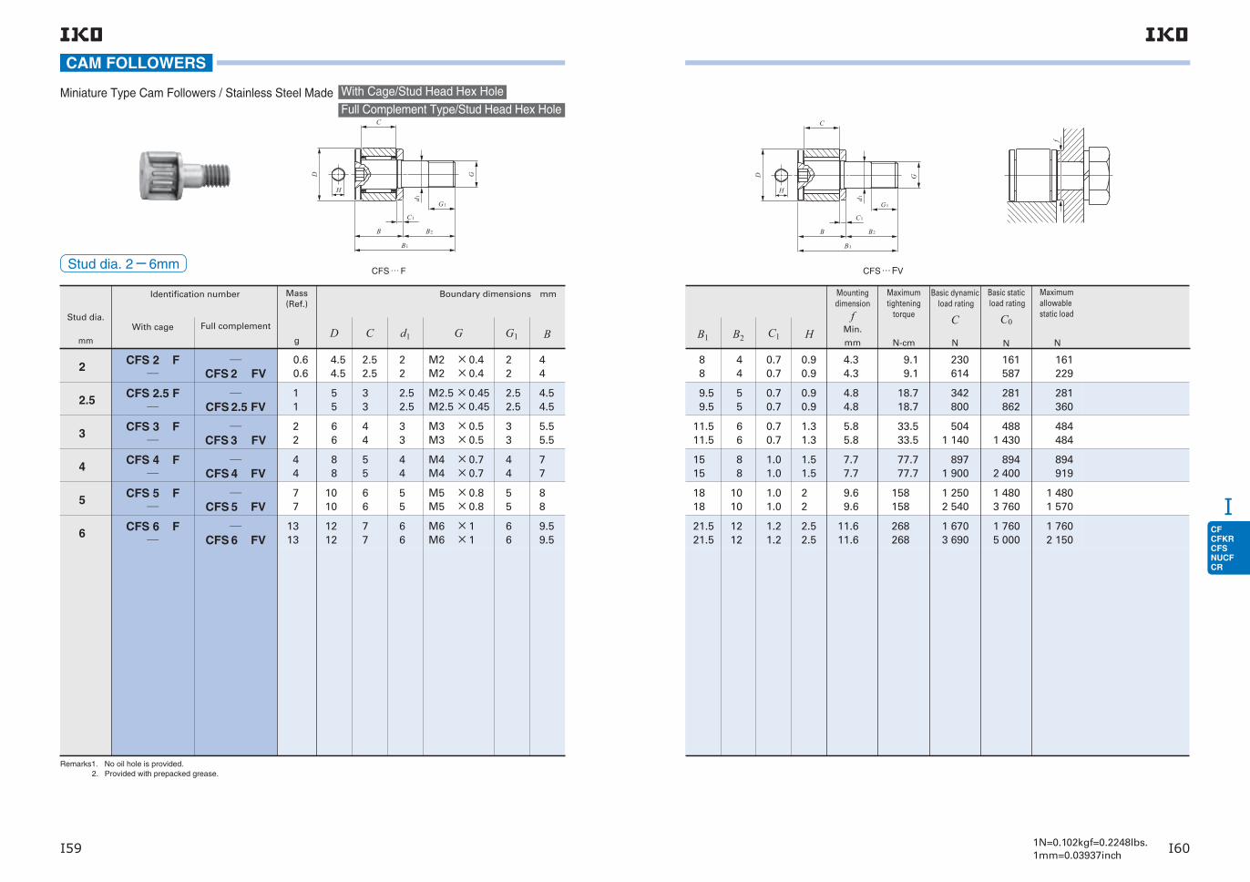
CFCFKRCFSNUCFCR
I
I59 I601N=0.102kgf=0.2248lbs.1mm=0.03937inch
Stud dia.
mm
Identification number Mass (Ref.)
g
Boundary dimensions mm
With cage
2.5
2
CFS 2.5 FV
CFS 2 FV
CFS 2.5 F
CFS 2 F
2 2
7 7
1 1
0.60.6
66
1010
55
4.54.5
44
66
33
2.52.5
33
55
2.52.5
22
M3 ×0.5M3 ×0.5
M5 ×0.8M5 ×0.8
M2.5 ×0.45M2.5 ×0.45
M2 ×0.4M2 ×0.4
Full complement
33
55
2.52.5
22
3 CFS 3 FV
CFS 3 F
4 CFS 4 FV
CFS 4 F
4 4
88
55
44
M4 ×0.7M4 ×0.7
44
5 CFS 5 FV
CFS 5 F
6 CFS 6 FV
CFS 6 F
1313
1212
77
66
M6 ×1M6 ×1
66
5.55.5
88
4.54.5
44
77
9.59.5
Remarks1. No oil hole is provided. 2. Provided with prepacked grease.
BG G1D C d1
CAM FOLLOWERS
Full Complement Type/Stud Head Hex HoleMiniature Type Cam Followers / Stainless Steel Made With Cage/Stud Head Hex Hole
Stud dia. 2−6mmCFS … F
11.511.5
1818
9.5 9.5
8 8
66
1010
55
44
0.70.7
1.01.0
0.70.7
0.70.7
1.31.3
22
0.90.9
0.90.9
5.85.8
9.69.6
4.84.8
4.34.3
33.5 33.5
158 158
18.7 18.7
9.1 9.1
5041 140
1 2502 540
342800
230614
4881 430
1 4803 760
281862
161587
484484
1 4801 570
281360
161229
1515
88
1.01.0
1.51.5
7.77.7
77.7 77.7
8971 900
8942 400
894919
21.521.5
1212
1.21.2
2.52.5
11.611.6
268 268
1 6703 690
1 7605 000
1 7602 150
CFS … FV
Basic dynamic load rating
C
N
Basic static load rating
C0
N
Maximum allowable static load
N
B1 HC1B2
Mounting dimension
fMin.
mm
Maximum tightening
torque
N-cm

CFCFKRCFSNUCFCR
I
I61 I621N=0.102kgf=0.2248lbs.1mm=0.03937inch
Stud dia.
mm
Identification number
With cage Full complement
Mass(Ref.)
g
Boundary dimensions mm
1.4
2
2.5
3
4
5
6
CFS 2 W
CFS 2.5 W
CFS 3 W
CFS 4 W
CFS 5 W
CFS 6 W
CFS 1.4 WV
0.35
0.6
1
2
4
7
13
4
4.5
5
6
8
10
12
1.7
2.5
3
4
5
6
7
1.4
2
2.5
3
4
5
6
M1.4 ×0.3
M2 ×0.4
M2.5 ×0.45
M3 ×0.5
M4 ×0.7
M5 ×0.8
M6 ×1
1.4
2
2.5
3
4
5
6
3.7
4.5
5
6.5
8
9
10.5
Remarks1. No oil hole is provided. 2. Provided with prepacked grease.
BG G1D C d1
Thrust Disk Type Miniature Cam Followers
CAM FOLLOWERS
Stud dia. 1.4−6mm CFS1.4 WV
Full Complement Type/Stud Head Hex Hole
With Cage/Stud Head Hex Hole
7
8.5
10
12.5
16
19
22.5
3.3
4
5
6
8
10
12
0.7
0.7
0.7
0.7
1
1
1.2
0.9
0.9
0.9
1.3
1.5
2
2.5
3.8
4.3
4.8
5.8
7.7
9.6
11.6
3.0
9.1
18.7
33.5
77.7
158
268
481
288
428
629
1120
1570
2090
385
202
351
611
1120
1850
2200
105
194
313
399
785
1370
1920
Basic static load rating
C0
NB1 HC1B2
Mounting dimension
fMin.
mm
Maximum tightening
torque
N-cm
Maximum allowable static load
N
B1
B2
C1
G1
d1
GD
C
H
B
f
Basic dynamic load rating
C
N
CFS … W

CFCFKRCFSNUCFCR
I
I63 I641N=0.102kgf=0.2248lbs.1mm=0.03937inch
CFS … FW
B1
B2
C1
G1
d1
GD
C
H
B
Stud dia.
mm
Identification number
Mass(Ref.)
g
Boundary dimensions mm
2 CFS 2 FW 0.6 4.5 2.5 2 M2 ×0.4 2 4.5
2.5 CFS 2.5 FW 1 5 3 2.5 M2.5 ×0.45 2.5 5
3 CFS 3 FW 2 6 4 3 M3 ×0.5 3 6.5
4 CFS 4 FW 4 8 5 4 M4 ×0.7 4 8
5 CFS 5 FW 7 10 6 5 M5 ×0.8 5 9
6 CFS 6 FW 13 12 7 6 M6 ×1 6 10.5
Remarks1. No oil hole is provided. 2. Provided with prepacked grease.
Stud dia. 2−6mm
BG G1D C d1
Thrust Disk Type Miniature Cam Followers・Stainless Steel Made With Cage/Stud Head Hex Hole
CAM FOLLOWERS
8.5
10
12.5
16
19
22.5
4 0.7 0.9 4.3 9.1 230 161 161
5 0.7 0.9 4.8 18.7 342 281 281
6 0.7 1.3 5.8 33.5 504 488 399
8 1.0 1.5 7.7 77.7 897 894 785
10 1.0 2 9.6 158 1 250 1 480 1 370
12 1.2 2.5 11.6 268 1 670 1 760 1 760
f
Basic dynamic load rating
C
N
Basic static load rating
C0
N
Maximum allowable static load
N
B1 HC1B2
Mounting dimension
fMin.
mm
Maximum tightening
torque
N-cm

CFCFKRCFSNUCFCR
I
I65 I661N=0.102kgf=0.2248lbs.1mm=0.03937inch
Remarks1. For models with a stud diameter d1 of 10mm, oil hole (re-greasing fitting) is provided at the head. Other models are provided with an oil hole (grease nipple) at the head and an oil hole each on the outside surface and end surface of the stud.
2. Provided with prepacked grease.
CAM FOLLOWERS
Cylindrical Roller Cam Followers Full Complement Type/Stud Head Hex Hole
Stud dia. 10−30mm
Stud dia.
mm
Identification number
Mass (Ref.)
g
Boundary dimensions mm
10 NUCF 10 BRNUCF 10-1 BR
8697
244
7891 020
4458
3032
40
6272
2226
1414
20
2929
1212
1212
18
2424
1010
M12×1.5M12×1.5
M18×1.5
M24×1.5M24×1.5
M10×1.25M10×1.25
1313
19
2525
1212
15.215.2
21.6
30.630.6
13.213.2
40.2 40.2
58.1
80.1 80.1
36.2 36.2
2525
36.5
49.549.5
2323
12 NUCF 12 BRNUCF 12-1 BR
16 NUCF 16 BR 167 35 18 16 M16×1.5 17 19.6 52.1 32.5
18 NUCF 18 BR
20 NUCF 20 BRNUCF 20-1 BR
457384
5247
2424
2020
M20×1.5M20×1.5
2121
25.625.6
66.1 66.1
40.540.5
24 NUCF 24 BRNUCF 24-1 BR
30 NUCF 30 BRNUCF 30-2 BR
1 6001 970
8090
3535
3030
M30×1.5M30×1.5
3232
3737
100100
6363
G B2G1 Bmax
B1max
D C d1
CB3
G1C1
B2B
H
R=500B1
g2
g 1
d 1
GD
R=500B
H
C
G1C1
B1
B2
D G
d 1
NUCF … BRNUCF … BRStud dia. d1 10mm Stud dia. d1 12-30mm
66
8
1111
0.60.6
0.8
0.80.8
0.60.6
44
6
66
33
3
44
1717
22
3844
1212
21.9 21.9
86.2
215 215
13.8 13.8
14 00014 000
25 200
58 20063 900
10 40010 400
13 40013 400
30 900
75 30088 800
11 50011 500
5 6509 040
20 300
35 20057 000
5 3009 210
8 0.8 4 3 20 58.5 23 400 27 300 11 800
99
0.80.8
66
44
3127
119 119
43 10038 900
58 10049 000
30 00027 200
1515
11
66
44
4545
438 438
90 30090 300
121 000121 000
98 30098 300
Mounting dimension
fMin.
mm
Maximum tightening
torque
N-mg1 g2
66
8
1212
44
6
88
1717
HB3 C1
Basic dynamic load rating
C
N
Basic static load rating
C0
N
Maximum allowable static load
N
f

CFCFKRCFSNUCFCR
I
I67 I681N=0.102kgf=0.2248lbs.1mm=0.03937inch
CR … BR
Stud dia.mm
(inch)
Mass (Ref.)
g
Identification number
4.826
With crowned outer ring
With cylindrical outer ring
With crowned outer ring
With cylindrical outer ring
6.350(14)9.525
(38)11.112
(716)12.700(12)15.875(58)19.050(34)22.225(78)
Shield type Sealed type
Remarks1. Models with a stud diameter d1 of 6.35 mm or less have no oil hole. Other models are provided with one oil hole each on the outside surface and end surface of the stud.
2. Provided with prepacked grease. 3. For the maximum allowable static load, please contact IKO.
CR 8 BRCR 8-1 BR
CR 8 BCR 8-1 B
CR 8 BUURCR 8-1 BUUR
CR 8 BUUCR 8-1 BUU
CR 10 BRCR 10-1 BR
CR 10 BCR 10-1 B
CR 10 BUURCR 10-1 BUUR
CR 10 BUUCR 10-1 BUU
CR 12 BRCR 14 BR
CR 12 BCR 14 B
CR 12 BUURCR 14 BUUR
CR 12 BUUCR 14 BUU
CR 16 BRCR 18 BR
CR 16 BCR 18 B
CR 16 BUURCR 18 BUUR
CR 16 BUUCR 18 BUU
CR 20 BRCR 22 BR
CR 20 BCR 22 B
CR 20 BUURCR 22 BUUR
CR 20 BUUCR 22 BUU
CR 24 BRCR 26 BR
CR 24 BCR 26 B
CR 24 BUURCR 26 BUUR
CR 24 BUUCR 26 BUU
CR 28 BRCR 30 BR
CR 28 BCR 30 B
CR 28 BUURCR 30 BUUR
CR 28 BUUCR 30 BUU
CR 32 BRCR 36 BR
CR 32 BCR 36 B
CR 32 BUURCR 36 BUUR
CR 32 BUUCR 36 BUU
8.731 9.525
4.826 4.826
No.10-32No.10-32
6.350 6.350
910
10.31911.112
6.350 6.350
14 - 28 14 - 28
7.938 7.938
1921
12.70012.700
9.525 9.525
38 - 24 38 - 24
9.525 9.525
3546
15.87515.875
11.11211.112
716 - 20716 - 20
12.70012.700
7399
19.05019.050
12.70012.700
12 - 20 12 - 20
15.87515.875
132157
22.22522.225
15.87515.875
58 - 18 58 - 18
19.05019.050
225260
25.40025.400
19.05019.050
34 - 16 34 - 16
22.22522.225
365410
31.75031.750
22.22522.225
( 14)( 14)
( 38)( 38)
(716)(716)
( 12)( 12)
( 58)( 58)
( 34)( 34)
( 78)( 78)
78 - 14 78 - 14
25.40025.400
( 14)( 14)
( 516)( 516)
( 38)( 38)
( 12)( 12)
( 58)( 58)
( 34)( 34)
( 78)( 78)
(1 )(1 )
615750
( 12)( 12)
( 58)( 58)
( 34)( 78)
(1 )(118)
(114)(138)
(112)(158)
(134)(178)
(2 )(214)
12.70012.700
15.87515.875
19.05022.225
25.40028.575
31.75034.925
38.10041.275
44.45047.625
50.80057.150
( 1132)( 38)
( 1332)( 716)
( 12)( 12)
( 58)( 58)
( 34)( 34)
( 78)( 78)
(1 )(1 )
(1 14)(1 14)
Stud dia. 4.826− 22.225mm
GUNF
G1D C d1
CAM FOLLOWERS
Inch Series Cam Followers With Cage/Stud Head Hex Hole
B
g
g
d
C
H
G
C
BB
R=500
GD
3
1
1
1
1
2
2
CR … B
2 1402 140
3 6703 670
5 1105 810
10 80011 600
16 00016 000
24 30024 300
38 20038 200
63 90063 900
Boundary dimensions mm(inch)
Bmax
B2 B3 C1 g1 g2 H r
12.700( 12)15.875( 58)
0.794(132)0.794(132)
10.2(0.40)10.9(0.43)
0.397(164)0.397(164)
8.334( 2164) 8.334( 2164)
1.4 1.4
2 5202 520
( ) ( )
( ) ( )
( ) ( )
15.875( 58)19.050( 34)
0.794(132)0.794(132)
11.8(0.46)12.5(0.49)
0.397(164)0.397(164)
11.509( 2964)11.509( 2964)
3.4 3.4
3 6503 650
( ) ( )
( ) ( )
( ) ( )
22.225( 78)22.225( 78)
0.794(132)0.794(132)
14.2(0.56)14.2(0.56)
0.794(132)0.794(132)
13.494( 1732)15.081( 1932)
10.8 10.8
4 4204 790
2.381(332)2.381(332)
4.762(316)4.762(316)
6.350( 14)6.350( 14)
25.400(1 )25.400(1 )
0.794(132)0.794(132)
17.3(0.68)17.3(0.68)
1.191(364)1.588(116)
17.859( 4564)19.050( 34)
17.4 17.4
8 8109 180
3.175( 18)3.175( 18)
4.762(316)4.762(316)
6.350( 14)6.350( 14)
31.750(114)31.750(114)
0.794(132)0.794(132)
20.4(0.80)20.4(0.80)
1.588(116)1.588(116)
1.588(116)1.588(116)
21.828( 5564)21.828( 5564)
27.7 27.7
14 20014 200
3.175( 18)3.175( 18)
4.762(316)4.762(316)
7.938(516)7.938(516)
38.100(112)38.100(112)
0.794(132)0.794(132)
23.6(0.93)23.6(0.93)
26.196(1 364)26.196(1 364)
55.7 55.7
18 60018 600
3.969(532)3.969(532)
4.762(316)4.762(316)
9.525( 38)9.525( 38)
44.450(134)44.450(134)
0.794(132)0.794(132)
26.8(1.06)26.8(1.06)
1.588(116)1.588(116)
32.543(1 932)32.543(1 932)
100 100
25 10025 100
3.969(532)3.969(532)
4.762(316)4.762(316)
11.112(716)11.112(716)
50.800(2 )50.800(2 )
0.794(132)0.794(132)
33.5(1.32)33.5(1.32)
1.588(116)1.588(116)
37.306(11532)37.306(11532)
162 162
32 50032 500
4.762(316)4.762(316)
4.762(316)4.762(316)
3.175( 18)3.175( 18)
3.175( 18)3.175( 18)
4.762(316)4.762(316)
6.350( 14)6.350( 14)
6.350( 14)6.350( 14)
7.938(516) 7.938(516)
7.938(516) 7.938(516)
11.112(716)11.112(716)
12.700( 12)12.700( 12)
CR … BUU
Basic dynamic load rating
C
N
Basic static load rating
C0
N
Mounting dimension
fMin.
mm(inch)
Maximum tightening
torque
N-m
CR … BUUR
r
r
R=500
r
r
f

CFCFKRCFSNUCFCR
I
I69 I701N=0.102kgf=0.2248lbs.1mm=0.03937inch
CR … R
Mass (Ref.)
g
4.826 8.731 9.525
4.826 4.826
No.10-32No.10-32
6.350 6.350
910
6.350(14)
10.31911.112
6.350 6.350
14 - 28 14 - 28
7.938 7.938
1921
9.525(38)
12.70012.700
9.525 9.525
38 - 24 38 - 24
9.525 9.525
3546
11.112(716)
15.87515.875
11.11211.112
716 - 20716 - 20
12.70012.700
7399
12.700(12)
19.05019.050
12.70012.700
12 - 20 12 - 20
15.87515.875
132157
15.875(58)
22.22522.225
15.87515.875
58 - 18 58 - 18
19.05019.050
225260
19.050(34)
25.40025.400
19.05019.050
34 - 16 34 - 16
22.22522.225
365410
22.225(78)
31.75031.750
22.22522.225
( 14)( 14)
( 38)( 38)
(716)(716)
( 12)( 12)
( 58)( 58)
( 34)( 34)
( 78)( 78)
78 - 14 78 - 14
25.40025.400
( 14)( 14)
( 516)( 516)
( 38)( 38)
( 12)( 12)
( 58)( 58)
( 34)( 34)
( 78)( 78)
(1 )(1 )
615750
( 12)( 12)
( 58)( 58)
( 34)( 78)
(1 )(118)
(114)(138)
(112)(158)
(134)(178)
(2 )(214)
12.70012.700
15.87515.875
19.05022.225
25.40028.575
31.75034.925
38.10041.275
44.45047.625
50.80057.150
( 1132)( 38)
( 1332)( 716)
( 12)( 12)
( 58)( 58)
( 34)( 34)
( 78)( 78)
(1 )(1 )
(1 14)(1 14)
Remarks1. Models with a stud diameter d1 of 6.35 mm or less (marked *) are provided with an oil hole on the stud head only. Other models are provided with one oil hole each on the head, outside surface and end surface of the stud.
2. Provided with prepacked grease. 3. For the maximum allowable static load, please contact IKO.
Stud dia.mm
(inch)
Identification number
With crowned outer ring
With cylindrical outer ring
With crowned outer ring
With cylindrical outer ring
Shield type Sealed type
CR 8 RCR 8-1 R
CR 8CR 8-1
CR 8 UURCR 8-1 UUR
CR 8 UUCR 8-1 UU
CR 10 RCR 10-1 R
CR 10CR 10-1
CR 10 UURCR 10-1 UUR
CR 10 UUCR 10-1 UU
CR 12 RCR 14 R
CR 12CR 14
CR 12 UURCR 14 UUR
CR 12 UUCR 14 UU
CR 16 RCR 18 R
CR 16CR 18
CR 16 UURCR 18 UUR
CR 16 UUCR 18 UU
CR 20 RCR 22 R
CR 20CR 22
CR 20 UURCR 22 UUR
CR 20 UUCR 22 UU
CR 24 RCR 26 R
CR 24CR 26
CR 24 UURCR 26 UUR
CR 24 UUCR 26 UU
CR 28 RCR 30 R
CR 28CR 30
CR 28 UURCR 30 UUR
CR 28 UUCR 30 UU
CR 32 RCR 36 R
CR 32CR 36
CR 32 UURCR 36 UUR
CR 32 UUCR 36 UU
GUNF
G1D C d1
CAM FOLLOWERS
Inch Series Cam Followers With Cage/With Screwdriver Slot
Stud dia. 4.826− 22.225mm
B
g
g
d
g
1
C
G
C
B
R=500
GD
3
1
1
1
1
B2
2
CR … UUCR
2 1402 140
3 6703 670
5 1105 810
10 80011 600
16 00016 000
24 30024 300
38 20038 200
63 90063 900
Boundary dimensions mm(inch)
12.700( 12)15.875( 58)
0.794(132)0.794(132)
10.2(0.40)10.9(0.43)
0.397(164)0.397(164)
8.334( 2164) 8.334( 2164)
1.4 1.4
2 5202 520
( ) ( )
*3.175( 18)*3.175( 18)
( ) ( )
15.875( 58)19.050( 34)
0.794(132)0.794(132)
11.8(0.46)12.5(0.49)
0.397(164)0.397(164)
11.509( 2964)11.509( 2964)
3.4 3.4
3 6503 650
( ) ( )
*3.175( 18)*3.175( 18)
( ) ( )
22.225( 78)22.225( 78)
0.794(132)0.794(132)
14.2(0.56)14.2(0.56)
0.794(132)0.794(132)
13.494( 1732)15.081( 1932)
10.8 10.8
4 4204 790
2.381(332)2.381(332)
4.762(316)4.762(316)
6.350( 14)6.350( 14)
25.400(1 )25.400(1 )
0.794(132)0.794(132)
17.3(0.68)17.3(0.68)
1.191(364)1.588(116)
17.859( 4564)19.050( 34)
17.4 17.4
8 8109 180
3.175( 18)3.175( 18)
4.762(316)4.762(316)
6.350( 14)6.350( 14)
31.750(114)31.750(114)
0.794(132)0.794(132)
20.4(0.80)20.4(0.80)
1.588(116)1.588(116)
21.828( 5564)21.828( 5564)
27.7 27.7
14 20014 200
3.175( 18)3.175( 18)
4.762(316)4.762(316)
7.938(516)7.938(516)
38.100(112)38.100(112)
0.794(132)0.794(132)
23.6(0.93)23.6(0.93)
1.588(116)1.588(116)
26.196(1 364)26.196(1 364)
55.7 55.7
18 60018 600
3.969(532)3.969(532)
4.762(316)4.762(316)
9.525( 38)9.525( 38)
44.450(134)44.450(134)
0.794(132)0.794(132)
26.8(1.06)26.8(1.06)
1.588(116)1.588(116)
32.543(1 932)32.543(1 932)
100 100
25 10025 100
3.969(532)3.969(532)
4.762(316)4.762(316)
11.112(716)11.112(716)
50.800(2 )50.800(2 )
0.794(132)0.794(132)
33.5(1.32)33.5(1.32)
1.588(116)1.588(116)
37.306(11532)37.306(11532)
162 162
32 50032 500
4.762(316)4.762(316)
4.762(316)4.762(316)
12.700( 12)12.700( 12)
CR … UUR
Bmax
B2 B3 C1 g1 g2 r
Basic dynamic load rating
C
N
Basic static load rating
C0
N
Mounting dimension
fMin.
mm(inch)
Maximum tightening
torque
N-m
r
r
R=500
r
r f

CFCFKRCFSNUCFCR
I
I71 I721N=0.102kgf=0.2248lbs.1mm=0.03937inch
Mass (Ref.)
g
4.826 8.731 9.525
4.826 4.826
No.10-32No.10-32
6.350 6.350
910
6.350(14)
10.31911.112
6.350 6.350
14 - 28 14 - 28
7.938 7.938
1921
9.525(38)
12.70012.700
9.525 9.525
38 - 24 38 - 24
9.525 9.525
3647
11.112(716)
15.87515.875
11.11211.112
716 - 20716 - 20
12.70012.700
74101
12.700(12)
19.05019.050
12.70012.700
12 - 20 12 - 20
15.87515.875
137160
15.875(58)
22.22522.225
15.87515.875
58 - 18 58 - 18
19.05019.050
230265
19.050(34)
25.40025.400
19.05019.050
34 - 16 34 - 16
22.22522.225
372418
22.225(78)
31.75031.750
22.22522.225
( 14)( 14)
( 38)( 38)
(716)(716)
( 12)( 12)
( 58)( 58)
( 34)( 34)
( 78)( 78)
78 - 14 78 - 14
25.40025.400
( 14)( 14)
( 516)( 516)
( 38)( 38)
( 12)( 12)
( 58)( 58)
( 34)( 34)
( 78)( 78)
(1 )(1 )
627759
( 12)( 12)
( 58)( 58)
( 34)( 78)
(1 )(118)
(114)(138)
(112)(158)
(134)(178)
(2 )(214)
12.70012.700
15.87515.875
19.05022.225
25.40028.575
31.75034.925
38.10041.275
44.45047.625
50.80057.150
( 1132)( 38)
( 1332)( 716)
( 12)( 12)
( 58)( 58)
( 34)( 34)
( 78)( 78)
(1 )(1 )
(1 14)(1 14)
Stud dia.mm
(inch)
Identification number
With crowned outer ring
With cylindrical outer ring
With crowned outer ring
With cylindrical outer ring
Shield type Sealed type
CR 8 VBRCR 8-1 VBR
CR 8 VBCR 8-1VB
CR 8 VBUURCR 8-1 VBUUR
CR 8 VBUUCR 8-1 VBUU
CR 10 VBRCR 10-1 VBR
CR 10 VBCR 10-1VB
CR 10 VBUURCR 10-1 VBUUR
CR 10 VBUUCR 10-1 VBUU
CR 12 VBRCR 14 VBR
CR 12 VBCR 14 VB
CR 12 VBUURCR 14 VBUUR
CR 12 VBUUCR 14 VBUU
CR 16 VBRCR 18 VBR
CR 16 VBCR 18 VB
CR 16 VBUURCR 18 VBUUR
CR 16 VBUUCR 18 VBUU
CR 20 VBRCR 22 VBR
CR 20 VBCR 22 VB
CR 20 VBUURCR 22 VBUUR
CR 20 VBUUCR 22 VBUU
CR 24 VBRCR 26 VBR
CR 24 VBCR 26 VB
CR 24 VBUURCR 26 VBUUR
CR 24 VBUUCR 26 VBUU
CR 28 VBRCR 30 VBR
CR 28 VBCR 30 VB
CR 28 VBUURCR 30 VBUUR
CR 28 VBUUCR 30 VBUU
CR 32 VBRCR 36 VBR
CR 32 VBCR 36 VB
CR 32 VBUURCR 36 VBUUR
CR 32 VBUUCR 36 VBUU
Remarks1. Models with a stud diameter d1 of 6.35 mm or less have no oil hole. Other models are provided with one oil hole each on the outside surface and end surface of the stud.
2. Provided with prepacked grease. 3. For the maximum allowable static load, please contact IKO.
GUNF
G1D C d1
CR … VBR
CAM FOLLOWERS
Inch Series Cam Followers Full Complement Type/Stud Head Hex Hole
Stud dia. 4.826−22.225mm
H
R=500
D
B
G
d
C
B3
g 1
1
C1
G1
B 2
g2
4 7505 410
7 6608 530
12 30012 300
22 70022 700
31 70031 700
40 10040 100
55 60055 600
80 60080 600
Boundary dimensions mm(inch)
12.700( 12)15.875( 58)
0.794(132)0.794(132)
10.2(0.40)10.9(0.43)
0.397(164)0.397(164)
8.334( 2164) 8.334( 2164)
1.4 1.4
4 2604 710
( ) ( )
( ) ( )
( ) ( )
15.875( 58)19.050( 34)
0.794(132)0.794(132)
11.8(0.46)12.5(0.49)
0.397(164)0.397(164)
11.509( 2964)11.509( 2964)
3.4 3.4
5 8306 340
( ) ( )
( ) ( )
( ) ( )
22.225( 78)22.225( 78)
0.794(132)0.794(132)
14.2(0.56)14.2(0.56)
0.794(132)0.794(132)
13.494( 1732)15.081( 1932)
10.8 10.8
8 7108 710
2.381(332)2.381(332)
4.762(316)4.762(316)
6.350( 14)6.350( 14)
25.400(1 )25.400(1 )
0.794(132)0.794(132)
17.3(0.68)17.3(0.68)
1.191(364)1.588(116)
17.859( 4564)19.050( 34)
17.4 17.4
13 10013 100
3.175( 18)3.175( 18)
4.762(316)4.762(316)
6.350( 14)6.350( 14)
31.750(114)31.750(114)
0.794(132)0.794(132)
20.4(0.80)20.4(0.80)
1.588(116)1.588(116)
21.828( 5564)21.828( 5564)
27.7 27.7
23 60023 600
3.175( 18)3.175( 18)
4.762(316)4.762(316)
7.938(516)7.938(516)
38.100(112)38.100(112)
0.794(132)0.794(132)
23.6(0.93)23.6(0.93)
1.588(116)1.588(116)
26.196(1 364)26.196(1 364)
55.7 55.7
28 20028 200
3.969(532)3.969(532)
4.762(316)4.762(316)
9.525( 38)9.525( 38)
44.450(134)44.450(134)
0.794(132)0.794(132)
26.8(1.06)26.8(1.06)
1.588(116)1.588(116)
32.543(1 932)32.543(1 932)
100 100
35 30035 300
3.969(532)3.969(532)
4.762(316)4.762(316)
11.112(716)11.112(716)
50.800(2 )50.800(2 )
0.794(132)0.794(132)
33.5(1.32)33.5(1.32)
1.588(116)1.588(116)
37.306(11532)37.306(11532)
162 162
45 70045 700
4.762(316)4.762(316)
4.762(316)4.762(316)
3.175( 18)3.175( 18)
3.175( 18)3.175( 18)
4.762(316)4.762(316)
6.350( 14)6.350( 14)
6.350( 14)6.350( 14)
7.938(516) 7.938(516)
7.938(516) 7.938(516)
11.112(716)11.112(716)
12.700( 12)12.700( 12)
Bmax
B2 B3 C1 g1 g2 H r
Basic dynamic load rating
C
N
Basic static load rating
C0
N
Mounting dimension
fMin.
mm(inch)
Maximum tightening
torque
N-m
CR … VB CR … VBUUCR … VBUUR
r
r
R=500
r
r f

CFCFKRCFSNUCFCR
I
I73 I741N=0.102kgf=0.2248lbs.1mm=0.03937inch
Full Complement Type/Stud Head Hex HoleInch Series Cam Followers
Remarks1. Models with a stud diameter d1 of 6.35 mm or less have no oil hole. Other models are provided with one oil hole each on the outside surface and end surface of the stud.
2. Provided with prepacked grease. 3. For the maximum allowable static load, please contact IKO.
f
G1
D
C
B3
g2 g 1
G
B2
C1
d 1
R=500
H
B
r
r
CR…VBSR CR…VBS
f
G1
D
C
B3
g2 g 1
G
B2
C1
d 1
R=500
H
B
r
r
Stud dia. 4.826−9.525mm
Studdia.mm
(inch)
Identification number Mass (Ref.)
g
Boundary dimensions mm(inch) Mountingdimension
fMin.
mm(inch)
Maximumtightening
torque
Basic dynamicload rating
Basic staticload rating
Sealed type with ThrustDisk SealsTM
D C d1 GUNF
G1 Bmax
B2 B3 C1 g1 g2 H rC C0
With crowned outer ring With cylindrical outer ring N-m N N
4.826CR 8 VBSR CR 8 VBS 9 12.700 ( 1 2) 8.731 ( 11
32) 4.826 No.10-32 6.350 ( 1 4) 10.2 (0.40)12.700 ( 1 2) ( ) 0.794 (1 32) ( ) ( ) 3.175 (1 8) 0.397 (1 64) 8.334 ( 2164) 1.4 3 790 4 100
CR 8-1 VBSR CR 8-1 VBS 10 12.700 ( 1 2) 9.525 ( 3 8) 4.826 No.10-32 6.350 ( 1 4) 10.9 (0.43)15.875 ( 5 8) ( ) 0.794 (1 32) ( ) ( ) 3.175 (1 8) 0.397 (1 64) 8.334 ( 2164) 1.4 4 260 4 750
6.350 (14)
CR 10 VBSR CR 10 VBS 19 15.875 ( 5 8) 10.319 ( 1332) 6.350 (1 4) 1 4-28 7.938 ( 5 16) 11.8 (0.46)15.875 ( 5 8) ( ) 0.794 (1 32) ( ) ( ) 3.175 (1 8) 0.397 (1 64) 11.509 ( 29
64) 3.4 5 310 6 780
CR 10-1 VBSR CR 10-1 VBS 21 15.875 ( 5 8) 11.112 ( 7 16) 6.350 (1 4) 1 4-28 7.938 ( 5 16) 12.5 (0.49) 19.050 ( 3 4) ( ) 0.794 (1 32) ( ) ( ) 3.175 (1 8) 0.397 (1 64) 11.509 ( 2964) 3.4 5 830 7 660
9.525 (38)
CR 12 VBSR CR 12 VBS 34 19.050 ( 3 4) 12.700 ( 1 2) 9.525 (3 8) 3 8-24 9.525 ( 3 8) 14.2 (0.56)22.225 ( 7 8) 6.350 (1 4) 0.794 (1 32) 4.762 (3 16) 2.381 (3 32) 4.762 (3 16) 0.794 (1 32) 13.494 ( 1732) 10.8 7 400 11 100
CR 14 VBSR CR 14 VBS 45 22.225 ( 7 8) 12.700 ( 1 2) 9.525 (3 8) 3 8-24 9.525 ( 3 8) 14.2 (0.56)22.225 ( 7 8) 6.350 (1 4) 0.794 (1 32) 4.762 (3 16) 2.381 (3 32) 4.762 (3 16) 0.794 (1 32) 15.081 ( 1932) 10.8 7 400 11 100
CAM FOLLOWERS

CFCFKRCFSNUCFCR
I
I75 I761N=0.102kgf=0.2248lbs.1mm=0.03937inch
Mass (Ref.)
g
4.826 8.731 9.525
4.826 4.826
No.10-32No.10-32
6.350 6.350
910
6.350(14)
10.31911.112
6.350 6.350
14 - 28 14 - 28
7.938 7.938
1921
9.525(38)
12.70012.700
9.525 9.525
38 - 24 38 - 24
9.525 9.525
3647
11.112(716)
15.87515.875
11.11211.112
716 - 20716 - 20
12.70012.700
74101
12.700(12)
19.05019.050
12.70012.700
12 - 20 12 - 20
15.87515.875
137160
15.875(58)
22.22522.225
15.87515.875
58 - 18 58 - 18
19.05019.050
230265
19.050(34)
25.40025.400
19.05019.050
34 - 16 34 - 16
22.22522.225
372418
22.225(78)31.750
(114)
31.75031.750
44.450
22.22522.225
31.750
( 14)( 14)
( 38)( 38)
( 716)( 716)
( 12)( 12)
( 58)( 58)
( 34)( 34)
( 78)( 78)
(1 14)
78 - 14 78 - 14
1 14 - 12
25.40025.400
31.750
( 14)( 14)
( 516)( 516)
( 38)( 38)
( 12)( 12)
( 58)( 58)
( 34)( 34)
( 78)( 78)
(1 )(1 )
(1 14)
627759
1 960
( 12)( 12)
( 58)( 58)
( 34)( 78)
(1 )(118)
(114)(138)
(112)(158)
(134)(178)
(2 )(214)
(3 )
12.70012.700
15.87515.875
19.05022.225
25.40028.575
31.75034.925
38.10041.275
44.45047.625
50.80057.150
76.200
( 1132)( 38)
( 1332)( 716)
( 12)( 12)
( 58)( 58)
( 34)( 34)
( 78)( 78)
(1 )(1 )
(1 14)(1 14)
(1 34)
Stud dia.mm
(inch)
Identification number
With crowned outer ring
With cylindrical outer ring
With crowned outer ring
With cylindrical outer ring
Shield type Sealed type
CR 8 VRCR 8-1 VR
CR 8 VCR 8-1 V
CR 8 VUURCR 8-1 VUUR
CR 8 VUUCR 8-1 VUU
CR 10 VRCR 10-1 VR
CR 10 VCR 10-1 V
CR 10 VUURCR 10-1 VUUR
CR 10 VUUCR 10-1 VUU
CR 12 VRCR 14 VR
CR 12 VCR 14 V
CR 12 VUURCR 14 VUUR
CR 12 VUUCR 14 VUU
CR 16 VRCR 18 VR
CR 16 VCR 18 V
CR 16 VUURCR 18 VUUR
CR 16 VUUCR 18 VUU
CR 20 VRCR 22 VR
CR 20 VCR 22 V
CR 20 VUURCR 22 VUUR
CR 20 VUUCR 22 VUU
CR 24 VRCR 26 VR
CR 24 VCR 26 V
CR 24 VUURCR 26 VUUR
CR 24 VUUCR 26 VUU
CR 28 VRCR 30 VR
CR 28 VCR 30 V
CR 28 VUURCR 30 VUUR
CR 28 VUUCR 30 VUU
CR 32 VRCR 36 VR
CR 32 VCR 36 V
CR 32 VUURCR 36 VUUR
CR 32 VUUCR 36 VUU
CR 48 VUU
Remarks1. Models with a stud diameter d1 of 6.35 mm or less (marked *) are provided with an oil hole on the stud head only. Other models are provided with one oil hole each on the head, outside surface and end surface of the stud.
2. Provided with prepacked grease. 3. For the maximum allowable static load, please contact IKO.
GUNF
G1D C d1
CR … VR
CAM FOLLOWERS
Inch Series Cam Followers Full Complement Type/With Screwdriver Slot
Stud dia. 4.826−31.750mm
C
R=500
D
d 1
B
G
B3
g 1
g 1
G1
C1
B 2
g2
4 7505 410
7 6608 530
12 30012 300
22 70022 700
31 70031 700
40 10040 100
55 60055 600
80 60080 600
172 000
Boundary dimensions mm(inch)
12.700( 12)15.875( 58)
0.794(132)0.794(132)
10.2(0.40)10.9(0.43)
0.397(164)0.397(164)
8.334( 2164) 8.334( 2164)
1.4 1.4
4 2604 710
( ) ( )
*3.175( 18)*3.175( 18)
( ) ( )
15.875( 58)19.050( 34)
0.794(132)0.794(132)
11.8(0.46)12.5(0.49)
0.397(164)0.397(164)
11.509( 2964)11.509( 2964)
3.4 3.4
5 8306 340
( ) ( )
*3.175( 18)*3.175( 18)
( ) ( )
22.225( 78)22.225( 78)
0.794(132)0.794(132)
14.2(0.56)14.2(0.56)
0.794(132)0.794(132)
13.494( 1732)15.081( 1932)
10.8 10.8
8 7108 710
2.381(332)2.381(332)
4.762(316)4.762(316)
6.350( 14)6.350( 14)
25.400(1 )25.400(1 )
0.794(132)0.794(132)
17.3(0.68)17.3(0.68)
1.191(364)1.588(116)
17.859( 4564)19.050( 34)
17.4 17.4
13 10013 100
3.175( 18)3.175( 18)
4.762(316)4.762(316)
6.350( 14)6.350( 14)
31.750(114)31.750(114)
0.794(132)0.794(132)
20.4(0.80)20.4(0.80)
1.588(116)1.588(116)
21.828( 5564)21.828( 5564)
27.7 27.7
23 60023 600
3.175( 18)3.175( 18)
4.762(316)4.762(316)
7.938(516)7.938(516)
38.100(112)38.100(112)
0.794(132)0.794(132)
23.6(0.93)23.6(0.93)
1.588(116)1.588(116)
26.196(1 364)26.196(1 364)
55.7 55.7
28 20028 200
3.969(532)3.969(532)
4.762(316)4.762(316)
9.525( 38)9.525( 38)
44.450(134)44.450(134)
0.794(132)0.794(132)
26.8(1.06)26.8(1.06)
1.588(116)1.588(116)
32.543(1 932)32.543(1 932)
100 100
35 30035 300
3.969(532)3.969(532)
4.762(316)4.762(316)
11.112(716)11.112(716)
50.800(2 )50.800(2 )
63.500(212)
0.794(132)0.794(132)
1.588(116)
33.5(1.32)33.5(1.32)
46.4(1.83)
1.588(116)1.588(116)
2.381(332)
37.306(11532)37.306(11532)
51.991(2 364)
162 162
500
45 70045 700
77 600
4.762(316)4.762(316)
4.762(316)
4.762(316)4.762(316)
6.350( 14)
12.700( 12)12.700( 12)
15.875( 58)
Bmax
B2 B3 C1 g1 g2 r
Basic dynamic load rating
C
N
Basic static load rating
C0
N
Mounting dimension
fMin.
mm(inch)
Maximum tightening
torque
N-m
CR … V CR … VUUR CR … VUU
r
r
R=500
r
r f

CFCFKRCFSNUCFCR
I
I77 I781N=0.102kgf=0.2248lbs.1mm=0.03937inch
CRH … VBR
Remarks1. Models with a stud diameter d1 of 7.938 mm or less have no oil hole. Other models are provided with one oil hole each on the outside surface and end surface of the stud.
2. Provided with prepacked grease. 3. For the maximum allowable static load, please contact IKO.
CAM FOLLOWERS
Inch Series Heavy Duty Cam Followers Full Complement Type/Stud Head Hex Hole
Stud dia. 6.350−50.800mm
Mass (Ref.)
g
6.350(14)7.938
(516)11.112
(716)15.875(58)19.050(34)22.225(78)25.400( 1 )28.575
(118)
Stud dia.mm
(inch)
Identification number
Shield type Sealed type
CRH 8-1 VBUURCRH 9 VBUUR
CRH 8-1 VBRCRH 9 VBR
CRH 10-1 VBUURCRH 11 VBUUR
CRH 10-1 VBRCRH 11 VBR
CRH 12 VBUURCRH 14 VBUUR
CRH 12 VBRCRH 14 VBR
CRH 16 VBUURCRH 18 VBUUR
CRH 16 VBRCRH 18 VBR
CRH 20 VBUURCRH 22 VBUUR
CRH 20 VBRCRH 22 VBR
CRH 24 VBUURCRH 26 VBUUR
CRH 24 VBRCRH 26 VBR
CRH 28 VBUURCRH 30 VBUUR
CRH 28 VBRCRH 30 VBR
CRH 32 VBUURCRH 36 VBUUR
CRH 32 VBRCRH 36 VBR
9.525 9.525
6.350 6.350
14 - 28 14 - 28
6.350 6.350
1215
11.11211.112
7.938 7.938
516 - 24 516 - 24
7.938 7.938
2327
12.70012.700
11.11211.112
716 - 20 716 - 20
9.525 9.525
3949
15.87515.875
15.87515.875
58 - 18 58 - 18
12.70012.700
93109
19.05019.050
19.05019.050
34 - 16 34 - 16
15.87515.875
176200
22.22522.225
22.22522.225
78 - 14 78 - 14
19.05019.050
296329
25.40025.400
25.40025.400
1- 141- 14
22.22522.225
463508
31.75031.750
28.57528.575
( 14)( 14)
( 516)( 516)
( 716)( 716)
( 58)( 58)
( 34)( 34)
( 78)( 78)
(1 )(1 )
(118)(118)
1 18 - 121 18 - 12
25.40025.400
( 14)( 14)
( 516)( 516)
( 38)( 38)
( 12)( 12)
( 58)( 58)
( 34)( 34)
( 78)( 78)
(1 )(1 )
722858
( 12)( 916)
( 58)( 1116)
( 34)( 78)
(1 )(1 18)
(1 14)(1 38)
(1 12)(1 58)
(1 34)(1 78)
(2 )(2 14)
12.70014.288
15.87517.462
19.05022.225
25.40028.575
31.75034.925
38.10041.275
44.45047.625
50.80057.150
( 38)( 38)
( 716)( 716)
( 12)( 12)
( 58)( 58)
( 34)( 34)
( 78)( 78)
(1 )(1 )
(114)(114)
31.750(114)38.100
(112)44.450
(134)50.800( 2 )
CRH 40 VBUURCRH 44 VBUUR
CRH 48 VBUURCRH 52 VBUUR
CRH 56 VBUUR
CRH 64 VBUUR
CRH 40 VBRCRH 44 VBR
CRH 48 VBRCRH 52 VBR
CRH 56 VBR
CRH 64 VBR
38.10038.100
44.45044.450
50.800
57.150
31.75031.750
38.10038.100
44.450
50.800
(114)(114)
(112)(112)
(134)
(2 )
1 14 - 121 14 - 12
1 12 - 121 12 - 12
1 34 - 12UN
2- 12 UN
(118)(118)
(114)(114)
(138)
(112)
1 2601 460
2 1002 380
3 240
4 960
(2 12)(2 34)
(3 )(3 14)
(3 12)
(4 )
63.50069.850
76.20082.550
88.900
101.600
(112)(112)
(134)(134)
(2 )
(214)
28.57528.575
31.75031.750
34.925
38.100
11.1(0.44)11.1(0.44)
12.8(0.50)12.8(0.50)
14.6(0.57)14.6(0.57)
17.9(0.70)17.9(0.70)
21.0(0.83)21.0(0.83)
24.3(0.96)24.3(0.96)
27.4(1.08)27.4(1.08)
34.2(1.35)34.2(1.35)
40.0(1.57)40.0(1.57)
46.4(1.83)46.4(1.83)
52.8(2.08)
59.4(2.34)
Bmax
GUNF
G1D C d1
UNSUNS
With crowned outer ring
With crowned outer ring
B B2
C1
D
H
G1
d1
g2
B3
C
R
G
g 1
5 4105 410
8 5308 530
12 30012 300
22 70022 700
31 70031 700
40 10040 100
55 60055 600
80 60080 600
Boundary dimensions mm(inch)
15.875( 58) 15.875( 58)
0.794( 132) 0.794( 132)
180( 7)180( 7)
8.334( 2164) 8.334( 2164)
3.4 3.4
4 7104 710
( ) ( )
( ) ( )
( ) ( )
19.050( 34) 19.050( 34)
0.794( 132) 0.794( 132)
200( 8)200( 8)
11.112( 716) 11.112( 716)
6.8 6.8
6 3406 340
( ) ( )
( ) ( )
( ) ( )
22.225( 78) 22.225( 78)
0.794( 132) 0.794( 132)
250(10)250(10)
13.494( 1732) 13.494( 1732)
17.6 17.6
8 7108 710
2.381( 332) 2.381( 332)
4.762( 316) 4.762( 316)
6.350( 14) 6.350( 14)
25.400(1 ) 25.400(1 )
1.588( 116) 1.588( 116)
300(12)300(12)
18.256( 2332) 18.256( 2332)
57.8 57.8
13 10013 100
2.381( 332) 2.381( 332)
4.762( 316) 4.762( 316)
6.350( 14) 6.350( 14)
31.750(114) 31.750(114)
1.588( 116) 1.588( 116)
360(14)360(14)
24.209( 6164) 24.209( 6164)
103 103
23 60023 600
2.381( 332) 2.381( 332)
4.762( 316) 4.762( 316)
7.938( 516) 7.938( 516)
38.100(112) 38.100(112)
1.588( 116) 1.588( 116)
500(20)500(20)
26.988(1 116) 26.988(1 116)
162 162
28 20028 200
2.381( 332) 2.381( 332)
4.762( 316) 4.762( 316)
9.525( 38) 9.525( 38)
44.450(134) 44.450(134)
1.588( 116) 1.588( 116)
500(20)500(20)
32.941(11964) 32.941(11964)
258 258
35 30035 300
2.381( 332) 2.381( 332)
4.762( 316) 4.762( 316)
11.112( 716) 11.112( 716)
50.800(2 ) 50.800(2 )
1.588( 116) 1.588( 116)
600(24)600(24)
37.306(11532) 37.306(11532)
356 356
45 70045 700
3.175( 18) 3.175( 18)
4.762( 316) 4.762( 316)
3.175( 18) 3.175( 18)
3.175( 18) 3.175( 18)
4.762( 316) 4.762( 316)
6.350( 14) 6.350( 14)
6.350( 14) 6.350( 14)
7.938( 516) 7.938( 516)
7.938( 516) 7.938( 516)
11.112( 716) 11.112( 716)
12.700( 12) 12.700( 12)
116 000116 000
172 000172 000
239 000
317 000
57.150(214) 57.150(214)
63.500(212) 63.500(212)
69.850(234)
88.900(312)
1.588( 116) 1.588( 116)
1.588( 116) 1.588( 116)
1.588( 116)
1.588( 116)
760(30)760(30)
760(30)760(30)
760(30)
760(30)
40.878(13964) 40.878(13964)
51.991(2 364) 51.991(2 364)
59.928(22364)
64.691(23564)
500 500
892 892
1450
2190
61 40061 400
77 60077 600
111 000
142 000
3.175( 18) 3.175( 18)
3.175( 18) 3.175( 18)
3.175( 18)
3.175( 18)
4.762( 316) 4.762( 316)
6.350( 14) 6.350( 14)
6.350( 14)
6.350( 14)
12.700( 12) 12.700( 12)
19.050( 34) 19.050( 34)
19.050( 34)
19.050( 34)
14.288( 916) 14.288( 916)
15.875( 58) 15.875( 58)
17.462(1116)
19.050( 34)
B2 B3 C1 g1 g2 H R
Basic dynamic load rating
C
N
Basic static load rating
C0
N
Mounting dimension
fMin.
mm(inch)
Maximum tightening
torque
N-m
CRH … VBUUR
R
f
R
f

CFCFKRCFSNUCFCR
I
I79 I801N=0.102kgf=0.2248lbs.1mm=0.03937inch
Mass (Ref.)
g
6.350(14)7.938
(516)11.112
(716)15.875(58)19.050(34)22.225(78)25.400( 1 )28.575
(118)
Stud dia.mm
(inch)
Identification number
Shield type Sealed type
CRH 8-1 VBUUCRH 9 VBUU
CRH 8-1 VBCRH 9 VB
CRH 10-1 VBUUCRH 11 VBUU
CRH 10-1 VBCRH 11 VB
CRH 12 VBUUCRH 14 VBUU
CRH 12 VBCRH 14 VB
CRH 16 VBUUCRH 18 VBUU
CRH 16 VBCRH 18 VB
CRH 20 VBUUCRH 22 VBUU
CRH 20 VBCRH 22 VB
CRH 24 VBUUCRH 26 VBUU
CRH 24 VBCRH 26 VB
CRH 28 VBUUCRH 30 VBUU
CRH 28 VBCRH 30 VB
CRH 32 VBUUCRH 36 VBUU
CRH 32 VBCRH 36 VB
Remarks1. Models with a stud diameter d1 of 7.938 mm or less have no oil hole. Other models are provided with one oil hole each on the outside surface and end surface of the stud.
2. Provided with prepacked grease. 3. For the maximum allowable static load, please contact IKO.
9.525 9.525
6.350 6.350
14 - 28 14 - 28
6.350 6.350
1215
11.11211.112
7.938 7.938
516 - 24 516 - 24
7.938 7.938
2327
12.70012.700
11.11211.112
716 - 20 716 - 20
9.525 9.525
3949
15.87515.875
15.87515.875
58 - 18 58 - 18
12.70012.700
93109
19.05019.050
19.05019.050
34 - 16 34 - 16
15.87515.875
176200
22.22522.225
22.22522.225
78 - 14 78 - 14
19.05019.050
296329
25.40025.400
25.40025.400
1- 141- 14
22.22522.225
463508
31.75031.750
28.57528.575
( 14)( 14)
( 516)( 516)
( 716)( 716)
( 58)( 58)
( 34)( 34)
( 78)( 78)
(1 )(1 )
(118)(118)
1 18 - 121 18 - 12
25.40025.400
( 14)( 14)
( 516)( 516)
( 38)( 38)
( 12)( 12)
( 58)( 58)
( 34)( 34)
( 78)( 78)
(1 )(1 )
722858
( 12)( 916)
( 58)( 1116)
( 34)( 78)
(1 )(1 18)
(1 14)(1 38)
(1 12)(1 58)
(1 34)(1 78)
(2 )(2 14)
12.70014.288
15.87517.462
19.05022.225
25.40028.575
31.75034.925
38.10041.275
44.45047.625
50.80057.150
( 38)( 38)
( 716)( 716)
( 12)( 12)
( 58)( 58)
( 34)( 34)
( 78)( 78)
(1 )(1 )
(114)(114)
31.750(114)38.100
(112)44.450
(134)50.800( 2 )
CRH 40 VBUUCRH 44 VBUU
CRH 48 VBUUCRH 52 VBUU
CRH 56 VBUU
CRH 64 VBUU
CRH 40 VBCRH 44 VB
CRH 48 VBCRH 52 VB
CRH 56 VB
CRH 64 VB
38.10038.100
44.45044.450
50.800
57.150
31.75031.750
38.10038.100
44.450
50.800
(114)(114)
(112)(112)
(134)
(2 )
1 14 - 121 14 - 12
1 12 - 121 12 - 12
1 34 - 12UN
2- 12
(118)(118)
(114)(114)
(138)
(112)
1 2601 460
2 1002 380
3 240
4 960
(2 12)(2 34)
(3 )(3 14)
(3 12)
(4 )
63.50069.850
76.20082.550
88.900
101.600
(112)(112)
(134)(134)
(2 )
(214)
28.57528.575
31.75031.750
34.925
38.100
11.1(0.44)11.1(0.44)
12.8(0.50)12.8(0.50)
14.6(0.57)14.6(0.57)
17.9(0.70)17.9(0.70)
21.0(0.83)21.0(0.83)
24.3(0.96)24.3(0.96)
27.4(1.08)27.4(1.08)
34.2(1.35)34.2(1.35)
40.0(1.57)40.0(1.57)
46.4(1.83)46.4(1.83)
52.8(2.08)
59.4(2.34)
Bmax
GUNF
G1D C d1
UNSUNS
UN
CRH … VB
CAM FOLLOWERS
Inch Series Heavy Duty Cam Followers Full Complement Type/Stud Head Hex Hole
Stud dia. 6.350−50.800mm
With cylindrical outer ring
With cylindrical outer ring
r
H
D
B
G
C
r B3
g 1
d1
C1
G1
B2
g2
5 4105 410
8 5308 530
12 30012 300
22 70022 700
31 70031 700
40 10040 100
55 60055 600
80 60080 600
Boundary dimensions mm(inch)
15.875( 58) 15.875( 58)
0.794( 132) 0.794( 132)
0.397( 164)0.397( 164)
8.334( 2164) 8.334( 2164)
3.4 3.4
4 7104 710
( ) ( )
( ) ( )
( ) ( )
19.050( 34) 19.050( 34)
0.794( 132) 0.794( 132)
0.397( 164)0.397( 164)
11.112( 716) 11.112( 716)
6.8 6.8
6 3406 340
( ) ( )
( ) ( )
( ) ( )
22.225( 78) 22.225( 78)
0.794( 132) 0.794( 132)
0.794( 132)0.794( 132)
13.494( 1732) 13.494( 1732)
17.6 17.6
8 7108 710
2.381( 332) 2.381( 332)
4.762( 316) 4.762( 316)
6.350( 14) 6.350( 14)
25.400(1 ) 25.400(1 )
1.588( 116) 1.588( 116)
1.191( 364)1.588( 116)
18.256( 2332) 18.256( 2332)
57.8 57.8
13 10013 100
2.381( 332) 2.381( 332)
4.762( 316) 4.762( 316)
6.350( 14) 6.350( 14)
31.750(114) 31.750(114)
1.588( 116) 1.588( 116)
1.588( 116)1.588( 116)
24.209( 6164) 24.209( 6164)
103 103
23 60023 600
2.381( 332) 2.381( 332)
4.762( 316) 4.762( 316)
7.938( 516) 7.938( 516)
38.100(112) 38.100(112)
1.588( 116) 1.588( 116)
1.588( 116)1.588( 116)
26.988(1 116) 26.988(1 116)
162 162
28 20028 200
2.381( 332) 2.381( 332)
4.762( 316) 4.762( 316)
9.525( 38) 9.525( 38)
44.450(134) 44.450(134)
1.588( 116) 1.588( 116)
1.588( 116)1.588( 116)
32.941(11964) 32.941(11964)
258 258
35 30035 300
2.381( 332) 2.381( 332)
4.762( 316) 4.762( 316)
11.112( 716) 11.112( 716)
50.800(2 ) 50.800(2 )
1.588( 116) 1.588( 116)
1.588( 116)1.588( 116)
37.306(11532) 37.306(11532)
356 356
45 70045 700
3.175( 18) 3.175( 18)
4.762( 316) 4.762( 316)
3.175( 18) 3.175( 18)
3.175( 18) 3.175( 18)
4.762( 316) 4.762( 316)
6.350( 14) 6.350( 14)
6.350( 14) 6.350( 14)
7.938( 516) 7.938( 516)
7.938( 516) 7.938( 516)
11.112( 716) 11.112( 716)
12.700( 12) 12.700( 12)
116 000116 000
172 000172 000
239 000
317 000
57.150(214) 57.150(214)
63.500(212) 63.500(212)
69.850(234)
88.900(312)
1.588( 116) 1.588( 116)
1.588( 116) 1.588( 116)
1.588( 116)
1.588( 116)
2.381( 332)2.381( 332)
2.381( 332)2.381( 332)
2.381( 332)
2.381( 332)
40.878(13964) 40.878(13964)
51.991(2 364) 51.991(2 364)
59.928(22364)
64.691(23564)
500 500
892 892
1 450
2 190
61 40061 400
77 60077 600
111 000
142 000
3.175( 18) 3.175( 18)
3.175( 18) 3.175( 18)
3.175( 18)
3.175( 18)
4.762( 316) 4.762( 316)
6.350( 14) 6.350( 14)
6.350( 14)
6.350( 14)
12.700( 12) 12.700( 12)
19.050( 34) 19.050( 34)
19.050( 34)
19.050( 34)
14.288( 916) 14.288( 916)
15.875( 58) 15.875( 58)
17.462(1116)
19.050( 34)
B2 B3 C1 g1 g2 H r
Basic dynamic load rating
C
N
Basic static load rating
C0
N
Mounting dimension
fMin.
mm(inch)
Maximum tightening
torque
N-m
CRH … VBUU
r
r
f

I
I81 I82
Separable Roller Followers
Non-separable Roller Followers
High carbon steel made
Stainless steel made
C-Lube Roller Followers
Cylindrical Roller Followers
IKO Roller Followers are bearings designed for outer ring rotation, in which needle rollers are incorporated in a thick walled outer ring. Both crowned and cylin-drical outer rings are available. The outer rings run directly on mating cam guide surfaces, and the crowned outer ring is effective in relieving the edge load caused by mounting errors. The cylindrical outer ring, on the other hand, has a large contact area with the mating cam guide surface and is suitable for appli-cations involving large loads or low cam guide surface hardness.In Roller Followers, there are two types of bearings available, the caged type and the full complement type. The caged type is useful for applications at high-speed rotation. The full complement type, on the other hand, is suitable for heavy-load applications at low-speed rotation or oscillating motions.Roller Followers include separable and non-separable types. Also, in addition to the open type, shield type and sealed type are available. The clearances between the side plates and outer ring of the shield type are narrow, and form labyrinths. In the sealed type, special synthetic rubber seals are assembled in these clearances, and they are effective in preventing penetration of dust and dirt.These bearings are available in a variety of types to suit almost any kind of application. They are widely used for cam mechanisms and for linear motions of conveying equipment.
Structures of Roller Followers
Outer ring
Inner ring
Needle roller
Cage
Outer ring
Side plate
Inner ring
Needle roller
Outer ring
Side plate
Inner ring
Needle roller
Seal
Outer ring
Shield plate
Inner ring
Side plate
Cylindrical roller
Cage
Structure of Separable Roller Follower
Structure of Separable Roller Follower
Structure of Non-separable Roller Follower
Structure of Cylindrical Roller Follower
Structure and Features

I
I83 I841N=0.102kgf=0.2248lbs.1mm=0.03937inch
TypesIn Roller Followers, types shown in Table 1 are avail-able.
Separable Roller Followers
These bearings are assembled by combining an outer ring, inner ring and Needle Roller Cage, which can be separated from one another. Thus, handling is easy. Oil lubrication is also easy, making them suitable for high-speed rotations.There are two types: type without inner ring RNAST and type with inner ring NAST. The type with inner ring includes open type, shield type, and sealed type.
Non-separable Roller Followers
These non-separable type bearings have side plates fixed on both sides of the inner ring, and include the caged type and the full complement type. Both shield type and sealed type are available. As well, these bearings also offer a highly corrosion-resistant stain-less steel specification, of which the products are suit-able for applications where rust prevention oil is not preferred, such as in cleanroom environments.Inch series Non-separable Roller Followers are full complement type bearings with black oxide surface treatment.
Table 1 Type of Roller Followers
Type
Metric series
Inch seriesNon-separable Roller Followers
CRY
C-Lube Roller Followers
NART…/SG
Cylindrical Roller Followers
NURT
Non-separable Roller Followers
NART
Separable Roller Followers
RNAST,NAST
Without inner ring
With inner ring
High carbon steel made
Stainless steel made
RNAST … R
NAST … R
NAST … ZZ R
NAST … ZZUUR
NART … R
NART … UU R
NART … F R
NART … FUU R
NART … UUR/SG
RNAST
NAST
NAST … ZZ
NAST … ZZUU
NART … V RNART … VUUR
NURT … R
CRY … V RCRY … VUUR
NURT
CRY … VCRY … VUU
Open type
Open type
Shield type
Sealed type
Shield type
Sealed type
Shield type
Sealed type
Sealed type
Shield type
Shield type
Sealed type
With cage Full complement type
Crowned outer ring Cylindrical outer ring Crowned outer ring Cylindrical outer ring
C-Lube Roller Followers
These Roller Followers are lubricated with C-Lube, an IKO original thermosetting solid-type lubricant which fills the inner space of the bearing. C-Lube is lubricant made of a lot of lubricant and fine particles of super-high molecular polyolefin that are solidified by heat treatment. As the bearing rotates, the lubricant oozes out onto the raceway in proper quantities, maintaining the lubrication performance for a long period of time.
Cylindrical Roller Followers
These bearings are full complement type bearings incorporat ing double rows of ful l complement cylindrical rollers in the outer ring, and can withstand large radial loads.Additionally, the outer ring is guided by the outer ring shoulder and the end face of cylindrical rollers to the axial direction.
Examples of identification number
NAST RZZUU10
NART RUUV10
NART R
R
15
NART F UU
UU
12
Example 1
Example 2
Example 3
Example 4
Model code
Metric series
Inch series
RNASTNASTNARTNART…/SGNURTCRY
Without inner ringWith inner ring
Separable Roller Follower
Non-separable Roller FollowerC-Lube Roller FollowerCylindrical Roller FollowerNon-separable Roller Follower
SizeThe size indicates the bore diameter of the inner ring. (unit: mm)In the inch series, the outer diameter of the outer ring is indicated in units of 1/16 inch.
High carbon steel madeStainless steel made
Type of materialNo symbolF(1)
With cageFull complement type
Roller guide methodNo symbolV
Seal structure (Separable Roller Follower)No symbolZZZZUU
Open typeShield typeSealed type
Shape of outer ring outside surfaceRNo symbol
With crowned outer ringWith cylindrical outer ring
Seal structure (Other Roller Follower)No symbolUU
Shield typeSealed type
/SG
Note(1) Applicable to Non-separable Roller Followers only
Identification NumberSome examples of the identification number of Roller Followers are shown below.

I
I85 I861N=0.102kgf=0.2248lbs.1mm=0.03937inch
AccuracyDimensional accuracy and rotational accuracy of Roller Followers are based on Tables 2, 3 and 4. Tolerances for the smallest single roller set bore diameter of Separable Roller Followers are shown in Table 5. Roller Followers with special accuracy can also be manufactured. Please contact IKO.
Table 4 Tolerances and allowable values of outer rings (Metric series)D
Nominal outside dia. of outer ring
mm
∆Dmp
Single plane mean outside dia. deviation
VDp (1)Outside dia. variation in
a single radial plane
(Max.)
VDmp (1)Mean outside dia. variation
(Max.)
Kea (1) Radial runout of assembled
bearing outer ring
(Max.)
VCsWidth variation
(Max.)Over Incl. High Low
6
18
30
50
80
18
30
50
80
120
0
0
0
0
0
− 8− 9− 11
− 13
− 15
10
12
14
16
19
6
7
8
10
11
15
15
20
25
35
Same as the tolerance values of VBs for d of the inner of the same bearing
unit: μ m
Note(1) Also applicable to the inch series.
Table 3 Tolerances and allowable values of inner rings (Metric series)d
Nominal bore dia.
mm
∆dmpSingle plane mean bore dia.
deviation
VdpBore dia. variation in a single radial plane
(Max.)
VdmpMean bore dia.
variation
(Max.)
Kia Radial runout of assembled
bearing inner ring
(Max.)
VBsWidth variation
(Max.)Over Incl. High Low
2.5
10
18
30
10
18
30
50
0
0
0
0
− 8− 8− 10
− 12
10
10
13
15
6
6
8
9
10
10
13
15
15
20
20
20
unit: μ m
Table 2 TolerancesSeries
Dimensions and symbols
Metric series Inch series
Crowned outer ring
Crownedouter ring
Cylindricalouter ring
Cylindricalouter ring
Bore dia. of inner ring d
Outside dia. of outer ring D
Width of outer ring C
Width of inner ring B
Width of bearing B
Roller set bore dia. Fw
0− 50
0− 120
0− 120
h12
See Table 5.
See Table 3.
−h12
See Table 4. 0− 50
0− 25
0− 130
−
+ 130
− 250
−
+ 5− 10
+ 2− 12
+ 5
− 10
unit: μ m
Separable Roller Follower
d≦ 19.05
19.05< d
Non-separable Roller Follower
Cylindrical Roller Follower
Separable Roller Follower
ClearanceRadial internal clearances of Roller Followers are based on Table 6.
FitRoller Followers are generally used under the loading conditions in which the load direction is fixed in rela-tion to the inner ring and rotates in relation to the outer ring. The recommended fits for shafts are shown in Table 7. Those for the inch series are shown in the dimension table.
Maximum allowable static loadThe load that is applicable to Roller Followers is, in some cases, determined by the strength of the outer ring rather than by the load rating of the needle roller bearing. Therefore, the maximum allowable load that is limited by the strength of outer ring is specified.
Table 5 Tolerances of smallest single roller set bore diameter Fws minFw
Nominal roller set bore diameter
mm
∆Fws min
Deviation of smallest single roller set bore diameter
Over Incl. High Low
6
10
18
30
50
10
18
30
50
80
+ 22
+ 27
+ 33
+ 41
+ 49
+ 13
+ 16
+ 20
+ 25
+ 30
unit: μ m
Table 6 Radial internal clearanceIdentification number (1)
Metric series
Separable Roller Followers
Non-separable Roller Followers (2)
Cylindrical Roller Followers
Non-separable Roller Followers
Min. Max.
Inch series
Radial internal clearance
NAST 6R
NAST 8R〜 NAST12R
NAST15R〜 NAST25R
NAST30R〜 NAST40R
NAST45R, NAST50R
−−−−−
NART 5R
NART 6R〜 NART12R
NART15R〜 NART20R
NART25R〜 NART40R
NART45R, NART50R
−−−−−
−−−−−
NURT15R〜 NURT30-1R
NURT35R〜 NURT40-1R
NURT45R〜 NURT50-1R
−−
−−−−
−−−−
CRY12R〜 CRY56R
CRY64R
5
5
10
10
15
20
25
30
35
45
20
25
30
40
50
45
50
60
60
70
unit: μ m
Note (1) Also applicable to the full complement type, cylindrical outer ring type, shield type and sealed type. (2) Also applicable to C-Lube Roller Followers.
Note (1) Also applicable to C-Lube Roller Followers.
Table 7 Recommended fit (Metric series)
Type Tolerance class of shaft
Separable Roller Followerswithout inner ring
with inner ring
k5,k6
g6,h6Non-separable Roller Followers(1)
Cylindrical Roller Followers

I
I87 I881N=0.102kgf=0.2248lbs.1mm=0.03937inch
Track Capacity (Tensile strength 1250N/mm2). When the hardness of the mating cam guide surface differs from 40HRC, the track capacity is obtained by multiplying the value by the track capacity factor shown in Table 9.If lubrication between the outer ring and the mating cam guide surface is insufficient, seizure and/or wear may occur depending on the application. Therefore, pay attention to lubrication and surface roughness of the mating cam guide especially in the case of high-speed rotation such as for cam mechanisms.
Track capacity is defined as the load that can be con-tinuously applied on a Roller Follower placed on a steel cam guide surface without causing deformation and indentation on the cam guide surface when the outer ring of the Roller Follower makes contact with the mat-ing cam guide surface (plane). The track capacities shown in Tables 8.1 and 8.2 are applicable when the hardness of the mating cam guide surface is 40HRC
Table 8.1 Track capacity (Metric series)Roller Followers with crowned outer ring Roller Followers with cylindrical outer ring
Identification number (1) Separable Roller
FollowersNon-separable (3)Roller Followers
CylindricalRoller Followers
Track capacity
Identification number
Track capacity
Identification number (2)
Track capacity
Identification number
Track capacity
RNAST 5R(R)NAST 6R(R)NAST 8R(R)NAST10R(R)NAST12R(R)NAST15R
−(R)NAST17R
−(R)NAST20R
−(R)NAST25R
−(R)NAST30R
−(R)NAST35R
−(R)NAST40R
−(R)NAST45R
−(R)NAST50R
−
NART 5R NART 6R NART 8R NART10R NART12R NART15R−
NART17R−
NART20R−
NART25R−
NART30R−
NART35R−
NART40R −
NART45R −
NART50R−
−−−−−
NURT15 R NURT15-1R NURT17 R NURT17-1R NURT20 R NURT20-1R NURT25 R NURT25-1R NURT30 R NURT30-1R NURT35 R NURT35-1R NURT40 R NURT40-1R NURT45 R NURT45-1R NURT50 R NURT50-1R
1 040 1 330 1 850 2 470 2 710 3 060 3 910 3 660 4 530 4 530 5 190 5 190 6 580 6 580 8 020 8 020 9 220 9 220 10 800 9 990 12 40010 80014 000
RNAST 5 (R)NAST 6 (R)NAST 8 (R)NAST10 (R)NAST12 (R)NAST15
− (R)NAST17
− (R)NAST20
− (R)NAST25
− (R)NAST30
−(R)NAST35
− (R)NAST40
− (R)NAST45
− (R)NAST50
−
2 310 3 550 3 980 5 610 5 990 6 550−
10 900−
12 800−
14 100−
22 100−
25 700−
26 900−
28 500−
30 200−
−NAST 6ZZNAST 8ZZNAST10ZZNAST12ZZNAST15ZZ
−NAST17ZZ
−NAST20ZZ
−NAST25ZZ
−NAST30ZZ
−NAST35ZZ
−NAST40ZZ
−NAST45ZZ
−NAST50ZZ
−
− 3 550 4 490 6 890 7 350 8 030 −
11 700−
13 800−
15 300−
22 100−
25 700−
30 300−
32 200−
34 000−
−−−−−
NURT15 NURT15-1 NURT17 NURT17-1 NURT20 NURT20-1 NURT25 NURT25-1 NURT30 NURT30-1 NURT35 NURT35-1 NURT40 NURT40-1 NURT45 NURT45-1 NURT50 NURT50-1
−−−−−
11 50013 70013 60016 00020 00022 10022 10026 40031 60036 70036 70040 80044 20049 70047 00055 30049 70060 800
unit: N
Notes(1) Also applicable to the full complement type, shield type, and sealed type. (3) Also applicable to C-Lube Roller Followers. (2) Also applicable to the sealed type.
Table 8.2 Track capacity (Inch series)
Identification number (1)
Track capacity
Identification number (1)
Track capacity
CRY12RCRY14RCRY16RCRY18RCRY20RCRY22RCRY24RCRY26RCRY28RCRY30RCRY32RCRY36RCRY40RCRY44RCRY48RCRY52RCRY56RCRY64R
853 1 050 1 420 1 660 2 160 2 450 3 410 3 820 4 210 4 610 5 690 6 640 8 97010 20011 40012 70014 10016 800
CRY12CRY14 CRY16 CRY18 CRY20 CRY22 CRY24 CRY26 CRY28 CRY30 CRY32 CRY36 CRY40 CRY44 CRY48 CRY52 CRY56 CRY64
4 490 5 240 7 270 7 700 10 700 11 800 15 400 16 700 21 000 22 500 30 800 34 700 44 900 49 400 64 300 69 600 87 000113 000
unit: N
Note(1) Also applicable to the sealed type.
Table 9 Track capacity factor
HardnessHRC
Tensile strengthN/mm2
Track capacity factor
Cylindrical outer ringCrowned outer ring
202530353840424446485052545658
760840950
1 0801 1801 2501 3401 4351 5301 6351 7601 8802 0152 1502 290
0.220.310.450.650.851.001.231.521.852.272.803.464.215.136.26
0.370.460.580.750.891.001.151.321.511.731.992.292.612.973.39
Crowned outer ring Cylindrical outer ring
Allowable Rotational SpeedThe allowable rotational speed of Roller Followers is
affected by mounting and operating conditions. For dn value with only pure radial load applied, use values in Table 10 or less as a guideline. Considering that axial loads also act under actual
operating conditions, the recommended dn value is 1/10 of the value shown in the table. For use with oscillating rotation, use a C-Lube Roller
Follower dn value of 8,000 or less as a guideline. For use with one-way or continuous rotation, please con-sult IKO.
LubricationIn Sealed Type Roller Followers, Heavy Duty Type Roller Followers and Inch series Roller Followers, ALVANIA GREASE S2 (Shell Lubricants Japan K.K.) is prepacked as the lubricating grease.For Roller Followers without prepacked grease, grease or oil should be supplied through the oil hole of the inner ring for use. If they are used without lubri-cation, wear of rolling contact surfaces may take place, leading to a short bearing life.
Oil HoleOpen Type Separable Roller Followers have no oil hole. Inner rings of other types of Metric series Roller Followers have an oil hole. Inch series inner rings have an oil groove and an oil hole.
Mounting
Table 10 dn values of Roller Followers (1) Lubricant
TypeGrease Oil
Caged type
Full complement type
Cylindrical Roller Follower
84 000
42 000
72 000
140 000
70 000
120 000
Note(1) dn value= d× n where, d:Bore diameter of bearing mm n:Rotational speed min-1
Fig. 1 Mating seating dimension "a"
Fig. 2 Position of oil hole and load direction
Fig. 3 Mounting example of Roller Follower without inner ring
In case of shield and sealed types, match the side surface correctly to the mating seating surface indi-
cated by the dimension a shown in the dimension table, and fix them. (See Fig. 1.) When mounting Roller Followers, pay special atten-tion to avoid locating the oil hole of the inner ring within the loading zone. This may lead to a short bearing life. (See Fig. 2.)When mounting Sealed Type Separable Roller Followers, do not cause the side plates to come off. If they come off, set them again in place taking care to avoid damaging the seal lips.
In case of Roller Followers without an inner ring, the shaft requires heat treatment and grinding fin-ish. The recommended surface hardness of the shaft is 58〜 64HRC, and the recommended rough-ness of the shaft is 0.2μmRa or less.Also, the outer ring and cage are guided by side surfaces of the mounting parts. Therefore, it is rec-ommended that the side surfaces of the mounting parts be finished by grinding or at least by machin-ing.(See Fig. 3.)In Non-separable Roller Followers, the side plates are press-fitted. Therefore, when mounting the Roller Followers, do not push the side plates/outer rings.Pushing on the side plates or outer rings may cause unsatisfactory product performance.
Oil hole
Load
2
1
3
5
4

I
I89 I901N=0.102kgf=0.2248lbs.1mm=0.03937inch
Note(1) Minimum allowable value of chamfer dimension rRemarks1. No oil hole is provided. 2. Not provided with prepacked grease. Perform proper lubrication for use.
Shaft dia.
mm
Identification number
Crowned outer ring Cylindrical outer ring
7
10
12
14
16
20
22
25
30
38
42
50
55
60
RNAST 5 R
RNAST 6 R
RNAST 8 R
RNAST 10 R
RNAST 12 R
RNAST 15 R
RNAST 17 R
RNAST 20 R
RNAST 25 R
RNAST 30 R
RNAST 35 R
RNAST 40 R
RNAST 45 R
RNAST 50 R
RNAST 5
RNAST 6
RNAST 8
RNAST 10
RNAST 12
RNAST 15
RNAST 17
RNAST 20
RNAST 25
RNAST 30
RNAST 35
RNAST 40
RNAST 45
RNAST 50
8.9
13.9
23.5
42.5
49.5
50
90
135
152
255
375
420
460
500
7
10
12
14
16
20
22
25
30
38
42
50
55
60
Boundary dimensions mm
Fw
16
19
24
30
32
35
40
47
52
62
72
80
85
90
D
7.8
9.8
9.8
11.8
11.8
11.8
15.8
15.8
15.8
19.8
19.8
19.8
19.8
19.8
C
0.3
0.3
0.6
1
1
1
1
1
1
1
1
1.5
1.5
1.5
2 710
4 160
5 650
9 790
10 500
12 400
17 600
19 400
20 800
30 500
32 400
35 900
37 400
38 900
2 390
4 550
5 890
9 680
10 900
14 300
20 900
24 500
28 400
45 400
50 600
61 100
66 400
71 700
Mass (Ref.)
g
Basic dynamic load rating
C
N
Basic static load rating
C0
N
Open typers min(1)
RNAST … R RNAST
Separable Roller Followers, Open Type With Cage/Without Inner Ring
Shaft dia. 7−60mm
ROLLER FOLLOWERS
Shaft dia. 6−50mm
Note(1) Minimum allowable value of chamfer dimension r or r 1Remarks1. No oil hole is provided.Remarks2. Not provided with prepacked grease. Perform proper lubrication for use.
Shaft dia.
mm
Identification number
Crowned outer ring Cylindrical outer ring
6
8
10
12
15
17
20
25
30
35
40
45
50
NAST 6 R
NAST 8 R
NAST 10 R
NAST 12 R
NAST 15 R
NAST 17 R
NAST 20 R
NAST 25 R
NAST 30 R
NAST 35 R
NAST 40 R
NAST 45 R
NAST 50 R
NAST 6
NAST 8
NAST 10
NAST 12
NAST 15
NAST 17
NAST 20
NAST 25
NAST 30
NAST 35
NAST 40
NAST 45
NAST 50
17.8
28
49.5
58
62
109
157
180
320
440
530
580
635
6
8
10
12
15
17
20
25
30
35
40
45
50
Boundary dimensions mm
d
19
24
30
32
35
40
47
52
62
72
80
85
90
D
10
10
12
12
12
16
16
16
20
20
20
20
20
B
9.8
9.8
11.8
11.8
11.8
15.8
15.8
15.8
19.8
19.8
19.8
19.8
19.8
C
0.3
0.6
1
1
1
1
1
1
1
1
1.5
1.5
1.5
rs min
0.3
0.3
0.3
0.3
0.3
0.3
0.3
0.3
0.6
0.6
1
1
1
r1s min
10
12
14
16
20
22
25
30
38
42
50
55
60
4 160
5 650
9 790
10 500
12 400
17 600
19 400
20 800
30 500
32 400
35 900
37 400
38 900
4 550
5 890
9 680
10 900
14 300
20 900
24 500
28 400
45 400
50 600
61 100
66 400
71 700
LRT 61010 S
LRT 81210 S
LRT 101412 S
LRT 121612 S
LRT 152012 S
LRT 172216 S
LRT 202516 S
LRT 253016 S
LRT 303820 S
LRT 354220 S
LRT 405020 S
LRT 455520 S
LRT 506020 S
Mass (Ref.)
g
Basic dynamic load rating
C
N
Basic static load rating
C0
N
Open typeFw
(1)(1)
NASTNAST … R
Assembled inner ring
Separable Roller Followers, Open Type With Cage/With Inner Ring
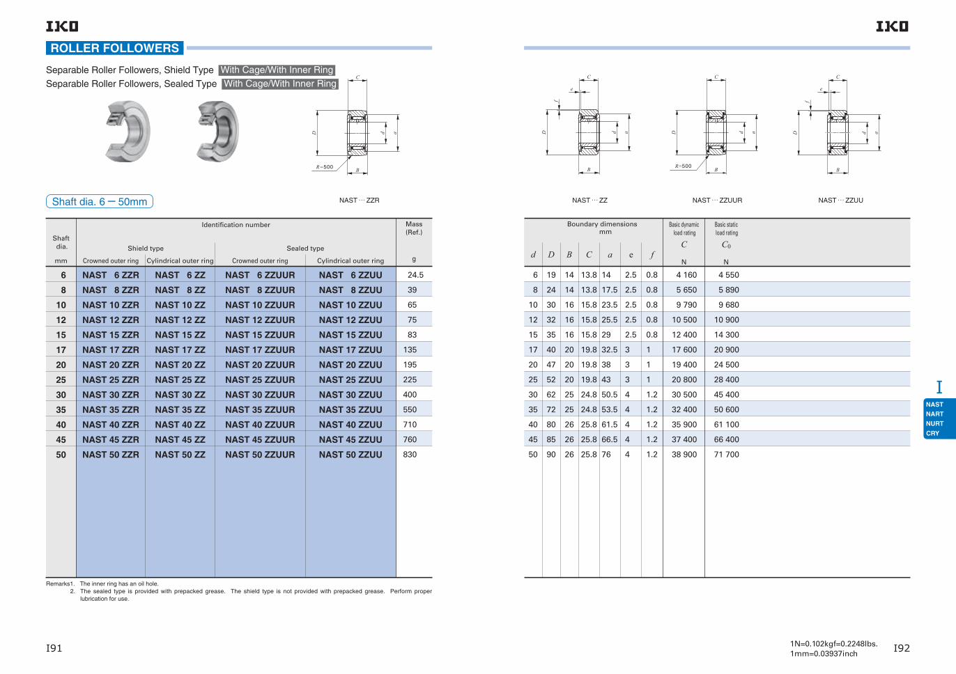
I
I91 I921N=0.102kgf=0.2248lbs.1mm=0.03937inch
Remarks1. The inner ring has an oil hole. 2. The sealed type is provided with prepacked grease. The shield type is not provided with prepacked grease. Perform proper
lubrication for use.
Shaft dia.
mm
Identification number
Crowned outer ring Cylindrical outer ring
6
8
10
12
15
17
20
25
30
35
40
45
50
NAST 6 ZZR
NAST 8 ZZR
NAST 10 ZZR
NAST 12 ZZR
NAST 15 ZZR
NAST 17 ZZR
NAST 20 ZZR
NAST 25 ZZR
NAST 30 ZZR
NAST 35 ZZR
NAST 40 ZZR
NAST 45 ZZR
NAST 50 ZZR
Crowned outer ring
NAST 6 ZZUUR
NAST 8 ZZUUR
NAST 10 ZZUUR
NAST 12 ZZUUR
NAST 15 ZZUUR
NAST 17 ZZUUR
NAST 20 ZZUUR
NAST 25 ZZUUR
NAST 30 ZZUUR
NAST 35 ZZUUR
NAST 40 ZZUUR
NAST 45 ZZUUR
NAST 50 ZZUUR
Cylindrical outer ring
NAST 6 ZZUU
NAST 8 ZZUU
NAST 10 ZZUU
NAST 12 ZZUU
NAST 15 ZZUU
NAST 17 ZZUU
NAST 20 ZZUU
NAST 25 ZZUU
NAST 30 ZZUU
NAST 35 ZZUU
NAST 40 ZZUU
NAST 45 ZZUU
NAST 50 ZZUU
NAST 6 ZZ
NAST 8 ZZ
NAST 10 ZZ
NAST 12 ZZ
NAST 15 ZZ
NAST 17 ZZ
NAST 20 ZZ
NAST 25 ZZ
NAST 30 ZZ
NAST 35 ZZ
NAST 40 ZZ
NAST 45 ZZ
NAST 50 ZZ
24.5
39
65
75
83
135
195
225
400
550
710
760
830
Mass (Ref.)
g
Shield type Sealed type
NAST … ZZR
ROLLER FOLLOWERS
Separable Roller Followers, Shield Type With Cage/With Inner Ring
Separable Roller Followers, Sealed Type With Cage/With Inner Ring
Shaft dia. 6−50mm
6
8
10
12
15
17
20
25
30
35
40
45
50
Boundary dimensions mm
d
19
24
30
32
35
40
47
52
62
72
80
85
90
D
14
14
16
16
16
20
20
20
25
25
26
26
26
B
13.8
13.8
15.8
15.8
15.8
19.8
19.8
19.8
24.8
24.8
25.8
25.8
25.8
14
17.5
23.5
25.5
29
32.5
38
43
50.5
53.5
61.5
66.5
76
2.5
2.5
2.5
2.5
2.5
3
3
3
4
4
4
4
4
0.8
0.8
0.8
0.8
0.8
1
1
1
1.2
1.2
1.2
1.2
1.2
C a e f
4 160
5 650
9 790
10 500
12 400
17 600
19 400
20 800
30 500
32 400
35 900
37 400
38 900
4 550
5 890
9 680
10 900
14 300
20 900
24 500
28 400
45 400
50 600
61 100
66 400
71 700
Basic dynamic load rating
C
N
Basic static load rating
C0
N
NAST … ZZ NAST … ZZUUR NAST … ZZUU

I
I93 I941N=0.102kgf=0.2248lbs.1mm=0.03937inch
ROLLER FOLLOWERS
Shaft dia. 5−40mm
Remarks1. The inner ring has an oil hole. 2. The sealed type is provided with prepacked grease. The shield type is not provided with prepacked grease. Perform proper
lubrication for use.
Shaft dia.
mm
Identification number
With cage Full complement
5
6
8
10
12
15
17
20
25
30
35
40
NART 5 R
NART 6 R
NART 8 R
NART 10 R
NART 12 R
NART 15 R
NART 17 R
NART 20 R
NART 25 R
NART 30 R
NART 35 R
NART 40 R
NART 5 VR
NART 6 VR
NART 8 VR
NART 10 VR
NART 12 VR
NART 15 VR
NART 17 VR
NART 20 VR
NART 25 VR
NART 30 VR
NART 35 VR
NART 40 VR
NART 5 UUR
NART 6 UUR
NART 8 UUR
NART 10 UUR
NART 12 UUR
NART 15 UUR
NART 17 UUR
NART 20 UUR
NART 25 UUR
NART 30 UUR
NART 35 UUR
NART 40 UUR
NART 5 VUUR
NART 6 VUUR
NART 8 VUUR
NART 10 VUUR
NART 12 VUUR
NART 15 VUUR
NART 17 VUUR
NART 20 VUUR
NART 25 VUUR
NART 30 VUUR
NART 35 VUUR
NART 40 VUUR
14.5 15.1
20.5 21.5
41.5 42.5
64.5 66.5
71 73
102106
149155
250255
285295
470485
640655
845865
With cage Full complement
Mass (Ref.)
g
Crowned outer ring Crowned outer ring
Shield type Sealed type
NART … R
Non-separable Roller Followers ·
High carbon steel made
With Cage/With Inner Ring
Full Complement Type/With Inner Ring
5 5
6 6
8 8
1010
1212
1515
1717
2020
2525
3030
3535
4040
1616
1919
2424
3030
3232
3535
4040
4747
5252
6262
7272
8080
1212
1212
1515
1515
1515
1919
2121
2525
2525
2929
2929
3232
1111
1111
1414
1414
1414
1818
2020
2424
2424
2828
2828
3030
1212
1414
17.517.5
23.523.5
25.525.5
2929
32.532.5
3838
4343
50.550.5
53.553.5
61.561.5
3 6506 810
4 2507 690
5 64011 800
8 03015 600
8 58016 800
13 70025 200
17 60032 000
23 00041 600
24 70045 500
33 60059 900
35 70063 100
44 90076 300
3 6808 370
4 74010 300
5 90015 600
7 54018 100
8 47020 500
16 40036 400
21 00046 300
30 70067 300
35 40079 100
51 400110 000
57 400121 000
81 500164 000
3 6807 310
4 74010 300
5 90015 600
7 54017 500
8 47018 600
16 40024 000
21 00033 100
30 70067 300
35 40079 100
51 40092 500
57 400121 000
81 500164 000
Boundary dimensions mm
d D B C a
Basic dynamic load rating
C
N
Basic static load rating
C0
N
Maximum allowable static load
N
NART … VR NART … UUR NART … VUUR

I
I95 I961N=0.102kgf=0.2248lbs.1mm=0.03937inch
Remarks1. The inner ring has an oil hole. 2. The sealed type is provided with prepacked grease. The shield type is not provided with prepacked grease. Perform proper
lubrication for use.
Shaft dia.
mm
Identification number
With cage Full complement
45
50
NART 45 R
NART 50 R
NART 45 VR
NART 50 VR
NART 45 UUR
NART 50 UUR
NART 45 VUUR
NART 50 VUUR
915935
9801 010
With cage Full complement
Mass (Ref.)
g
Crowned outer ring Crowned outer ring
Shield type Sealed type
NART … R
ROLLER FOLLOWERS
Non-separable Roller Followers ·
High carbon steel made
With Cage/With Inner Ring
Full Complement Type/With Inner Ring
Shaft dia. 45−50mm
5050
4545
8585
9090
3232
3232
3030
3030
66.566.5
7676
46 80080 300
48 60084 300
88 600181 000
88 600181 000
95 600198 000
95 600198 000
Boundary dimensions mm
Maximum allowable static load
N
d D B C a
Basic dynamic load rating
C
N
Basic static load rating
C0
N
NART … VR NART … UUR NART … VUUR

I
I97 I981N=0.102kgf=0.2248lbs.1mm=0.03937inch
Shaft dia.
mm
Identification number Mass (Ref.)Boundary dimensions
mmBasic dynamic
load rating
CN
Basic static load rating
C0
N
Maximum allowable static load
NShield type Sealed type g d D B C a
5 NART 5 FR NART 5 FUUR 13 5 16 12 11 12 2 930 2 920 2 920
6 NART 6 FR NART 6 FUUR 19 6 19 12 11 14 3 400 3 790 3 790
8 NART 8 FR NART 8 FUUR 39 8 24 15 14 17.5 4 340 5 510 5 510
10 NART 10 FR NART 10 FUUR 61 10 30 15 14 22.5 6 330 7 830 7 830
12 NART 12 FR NART 12 FUUR 67 12 32 15 14 25.5 6 510 8 400 8 400
15 NART 15 FR NART 15 FUUR 99 15 35 19 18 27.5 9 620 14 700 14 700
17 NART 17 FR NART 17 FUUR 146 17 40 21 20 31 11 800 20 200 20 200
20 NART 20 FR NART 20 FUUR 241 20 47 25 24 36.5 16 500 27 700 27 700
25 NART 25 FR NART 25 FUUR 269 25 52 25 24 43 19 800 28 300 28 300
30 NART 30 FR NART 30 FUUR 447 30 62 29 28 50 26 900 41 200 41 200
R500
D d
C
a D d
C
a
B BR500
ROLLER FOLLOWERS
Non-separable Roller Followers · Stainless Steel Made With Cage/With Inner Ring
Remarks1. The inner ring has an oil hole. 2. The sealed type is provided with prepacked grease. The shield type is not provided with prepacked grease. Perform proper
lubrication for use.
Shaft dia. 5−30mm NART … FR
R500
D d
C
a D d
C
a
B BR500
ROLLER FOLLOWERS
NART … FUUR

I
I99 I1001N=0.102kgf=0.2248lbs.1mm=0.03937inch
NART … UUR/SG
C
B
dD a
R=500
ROLLER FOLLOWERS
C-Lube Roller Followers With Cage/With Inner Ring
Shaft dia. 5−20mm
Remark This bearing cannot be re-lubricated as thermosetting solid-type lubricant C-Lube fills its inner space.
1N=0.102kgf=0.2248lbs.1mm=0.03937inch
Shaft dia.
mm
Identification number Mass (Ref.)
Boundary dimensions mm
Basic dynamic load rating
C
N
Basic static load rating
C0
N
Maximum allowable static load
NSealed type d D B C a
g
5 NART 5 UUR / SG 14.5 5 16 12 11 12 3 650 3 680 3 680
6 NART 6 UUR / SG 20.5 6 19 12 11 14 4 250 4 740 4 740
8 NART 8 UUR / SG 41.5 8 24 15 14 17.5 5 640 5 900 5 900
10 NART 10 UUR / SG 64.5 10 30 15 14 23.5 8 030 7 540 7 540
12 NART 12 UUR / SG 71 12 32 15 14 25.5 8 580 8 470 8 470
15 NART 15 UUR / SG 102 15 35 19 18 29 13 700 16 400 16 400
17 NART 17 UUR / SG 149 17 40 21 20 32.5 17 600 21 000 21 000
20 NART 20 UUR / SG 250 20 47 25 24 38 23 000 30 700 30 700
ROLLER FOLLOWERS

I
I101 I1021N=0.102kgf=0.2248lbs.1mm=0.03937inch
Boundary dimensions mm
NURT … R
Cylindrical Roller Followers Full Complement Type/With Inner Ring
Shaft dia. 15−50mm
Note(1) Minimum allowable value of chamfer dimension r or r1Remarks1. The inner ring has an oil hole. 2. Provided with prepacked grease.
Shaft dia.
mm
Identification number
15
17
20
25
30
35
40
45
50
NURT 15 RNURT 15-1 R
NURT 17 RNURT 17-1 R
NURT 20 RNURT 20-1 R
NURT 25 RNURT 25-1 R
NURT 30 RNURT 30-1 R
NURT 35 RNURT 35-1 R
NURT 40 RNURT 40-1 R
NURT 45 RNURT 45-1 R
NURT 50 RNURT 50-1 R
NURT 15 NURT 15-1
NURT 17NURT 17-1
NURT 20 NURT 20-1
NURT 25NURT 25-1
NURT 30NURT 30-1
NURT 35NURT 35-1
NURT 40 NURT 40-1
NURT 45 NURT 45-1
NURT 50NURT 50-1
Mass (Ref.)
g (1)
100160
147222
245321
281450
466697
630840
8171 130
8831 400
9501 690
1515
1717
2020
2525
3030
3535
4040
4545
5050
3542
4047
4752
5262
6272
7280
8090
85100
90110
1919
2121
2525
2525
2929
2929
3232
3232
3232
1818
2020
2424
2424
2828
2828
3030
3030
3030
2020
2222
2727
3131
3838
4444
4949
5353
5858
0.60.6
11
11
11
11
11
11
11
11
d D B C a rs minCrowned outer ring Cylindrical outer ring
ROLLER FOLLOWERS
Basic dynamic load rating
C
N
Basic static load rating
C0
N
Maximum allowable static load
N
(1)
23 40023 400
25 20025 200
38 90038 900
43 10043 100
58 20058 200
63 90063 900
86 50086 500
91 50091 500
96 30096 300
27 30027 300
30 90030 900
49 00049 000
58 10058 100
75 30075 300
88 80088 800
122 000122 000
135 000135 000
148 000148 000
11 80027 300
20 30030 900
27 20049 000
30 00058 100
35 20075 300
57 00088 800
75 300122 000
78 700135 000
82 100148 000
0.30.3
0.30.3
0.30.3
0.30.3
0.30.3
0.60.6
0.60.6
0.60.6
0.60.6
r1s min
r1r1
C
B
r
r
d aD
NURT

I
I103 I1041N=0.102kgf=0.2248lbs.1mm=0.03937inch
ROLLER FOLLOWERS
Non-separable Roller Followers, Inch Series Full Complement Type / With Inner Ring
Shaft dia. 6.350−31.750mm CRY … VR
Remarks1. The inner ring has an oil groove and an oil hole. 2. Provided with prepacked grease.
Shaft dia.
mm(inch)
Identification number
Shield typeCrowner outer ring
Sealed typeCrowned outer ring
6.350(14)7.938(516)9.525(38)
11.112(716)12.700(12)
15.875(58)
19.050(34)
25.400( 1 )
28.575(118)31.750(114)
CRY 12 VRCRY 14 VR
CRY 16 VRCRY 18 VR
CRY 20 VRCRY 22 VR
CRY 24 VRCRY 26 VR
CRY 28 VRCRY 30 VR
CRY 32 VRCRY 36 VR
CRY 40 VRCRY 44 VR
CRY 48 VRCRY 52 VR
CRY 56 VR
CRY 64 VR
CRY 12 VUURCRY 14 VUUR
CRY 16 VUURCRY 18 VUUR
CRY 20 VUURCRY 22 VUUR
CRY 24 VUURCRY 26 VUUR
CRY 28 VUURCRY 30 VUUR
CRY 32 VUURCRY 36 VUUR
CRY 40 VUURCRY 44 VUUR
CRY 48 VUURCRY 52 VUUR
CRY 56 VUUR
CRY 64 VUUR
2434
6.350( 14)6.350( 14)
7.938( 516)7.938( 516)
9.525( 38)9.525( 38)
11.112( 716)11.112( 716)
12.700( 12)12.700( 12)
15.875( 58)15.875( 58)
19.050( 34)19.050( 34)
25.400(1 )25.400(1 )
28.575(118)
31.750(114)
5672
103128
176210
276321
442575
8351 031
1 3701 640
2 160
3 190
Mass(Ref.)
Boundary dimensions mm(inch)
g d
19.050( 34)22.225( 78)
12.700( 12)12.700( 12)
15.875( 58)15.875( 58)
19.050( 34) 19.050( 34)
25.400(1 )28.575(118)
31.750(114) 34.925(138)
38.100(112)41.275(158)
44.450(134)47.625(178)
50.800(2 )57.150(214)
63.500(212)69.850(234)
76.200(3 )82.550(314)
88.900(312)
101.600(4 )
D
14.288(0.5625)14.288(0.5625)
17.463(0.6875)17.463(0.6875)
20.638(0.8125)20.638(0.8125)
23.813(0.9375)23.813(0.9375)
26.988(1.0625)26.988(1.0625)
33.338(1.3125)33.338(1.3125)
39.688(1.5625)39.688(1.5625)
46.038(1.8125)46.038(1.8125)
52.388(2.0625)
58.738(2.3125)
B
22.225( 78)22.225( 78)
25.400(1 )25.400(1 )
31.750(114)31.750(114)
38.100(112)38.100(112)
44.450(134)44.450(134)
50.800(2 )
57.150(214)
C
D
C
R
a
B
d
CRY … VUUR
14.4(0.567)14.4(0.567)
19.6(0.772)19.6(0.772)
25.0(0.984)25.0(0.984)
28.8(1.134)28.8(1.134)
32.7(1.287)32.7(1.287)
36.0(1.417)36.0(1.417)
43.3(1.705)43.3(1.705)
54.0(2.125)54.0(2.125)
61.9(2.437)
71.0(2.797)
250(10)250(10)
300(12)300(12)
360(14)360(14)
500(20)500(20)
500(20)500(20)
600(24)600(24)
760(30)760(30)
760(30)760(30)
760(30)
760(30)
8 7108 710
6.3326.332
7.9207.920
9.507 9.507
11.09511.095
12.68212.682
15.85715.857
19.03219.032
25.37725.377
28.522
31.727
6.3426.342
7.9307.930
9.517 9.517
11.10511.105
12.69212.692
15.86715.867
19.04219.042
25.39025.390
28.565
31.740
6.3486.348
7.9357.935
9.5239.523
11.11011.110
12.69812.698
15.87315.873
19.04819.048
25.39725.397
28.572
31.747
6.3586.358
7.9457.945
9.5339.533
11.12011.120
12.70812.708
15.88315.883
19.05819.058
25.41025.410
28.585
31.760
6.3536.353
7.9407.940
9.5289.528
11.11511.115
12.70812.708
15.88315.883
19.05819.058
25.40825.408
28.583
31.758
6.3636.363
7.9507.950
9.5389.538
11.12511.125
12.71812.718
15.89315.893
19.06819.068
25.42025.420
28.595
31.770
13 10013 100
23 60023 600
28 20028 200
35 30035 300
45 70045 700
61 40061 400
77 60077 600
111 000
142 000
12 30012 300
22 70022 700
31 70031 700
40 10040 100
55 60055 600
80 60080 600
116 000116 000
172 000172 000
239 000
317 000
a R
Basic dynamic load rating
C
N
Basic static load rating
C0
N
Shaft dia. mm
Push fit Drive fit Press fit
Min. Min. Min.Max. Max. Max.
a
C
D
R
d
B

I
I105 I1061N=0.102kgf=0.2248lbs.1mm=0.03937inch
CRY … V
ROLLER FOLLOWERS
Non-separable Roller Followers, Inch Series Full Complement Type /With Inner Ring
Shaft dia. 6.350−31.750mm
Remarks1. The inner ring has an oil groove and an oil hole. 2. Provided with prepacked grease.
Shaft dia.
mm(inch)
Identification number
Shield typeCylindrical outer ring
Sealed typeCylindrical outer ring
6.350(14)7.938(516)9.525(38)
11.112(716)12.700(12)
15.875(58)
19.050(34)
25.400( 1 )
28.575(118)31.750(114)
CRY 12 VCRY 14 V
CRY 16 VCRY 18 V
CRY 20 VCRY 22 V
CRY 24 VCRY 26 V
CRY 28 VCRY 30 V
CRY 32 VCRY 36 V
CRY 40 VCRY 44 V
CRY 48 VCRY 52 V
CRY 56 V
CRY 64 V
CRY 12 VUUCRY 14 VUU
CRY 16 VUUCRY 18 VUU
CRY 20 VUUCRY 22 VUU
CRY 24 VUUCRY 26 VUU
CRY 28 VUUCRY 30 VUU
CRY 32 VUUCRY 36 VUU
CRY 40 VUUCRY 44 VUU
CRY 48 VUUCRY 52 VUU
CRY 56 VUU
CRY 64 VUU
2434
6.350( 14)6.350( 14)
7.938( 516)7.938( 516)
9.525( 38)9.525( 38)
11.112( 716)11.112( 716)
12.700( 12)12.700( 12)
15.875( 58)15.875( 58)
19.050( 34)19.050( 34)
25.400(1 )25.400(1 )
28.575(118)
31.750(114)
5672
103128
176210
276321
442575
8351 031
1 3701 640
2 160
3 190
Mass(Ref.)
Boundary dimensions mm(inch)
g d
19.050( 34)22.225( 78)
12.700( 12)12.700( 12)
15.875( 58)15.875( 58)
19.050( 34) 19.050( 34)
25.400(1 )28.575(118)
31.750(114) 34.925(138)
38.100(112)41.275(158)
44.450(134)47.625(178)
50.800(2 )57.150(214)
63.500(212)69.850(234)
76.200(3 )82.550(314)
88.900(312)
101.600(4 )
D
14.288(0.5625)14.288(0.5625)
17.463(0.6875)17.463(0.6875)
20.638(0.8125)20.638(0.8125)
23.813(0.9375)23.813(0.9375)
26.988(1.0625)26.988(1.0625)
33.338(1.3125)33.338(1.3125)
39.688(1.5625)39.688(1.5625)
46.038(1.8125)46.038(1.8125)
52.388(2.0625)
58.738(2.3125)
B
22.225( 78)22.225( 78)
25.400(1 )25.400(1 )
31.750(114)31.750(114)
38.100(112)38.100(112)
44.450(134)44.450(134)
50.800(2 )
57.150(214)
C
C
B
r
r
D d a
CRY … VUU
14.4(0.567)14.4(0.567)
19.6(0.772)19.6(0.772)
25.0(0.984)25.0(0.984)
28.8(1.134)28.8(1.134)
32.7(1.287)32.7(1.287)
36.0(1.417)36.0(1.417)
43.3(1.705)43.3(1.705)
54.0(2.125)54.0(2.125)
61.9(2.437)
71.0(2.797)
0.794( 132)0.794( 132)
1.191( 364)1.588( 116)
1.588( 116)1.588( 116)
1.588( 116)1.588( 116)
1.588( 116)1.588( 116)
1.588( 116)1.588( 116)
2.381( 332)2.381( 332)
2.381( 332)2.381( 332)
2.381( 332)
2.381( 332)
8 7108 710
6.3326.332
7.9207.920
9.507 9.507
11.09511.095
12.68212.682
15.85715.857
19.03219.032
25.37725.377
28.522
31.727
6.3426.342
7.9307.930
9.517 9.517
11.10511.105
12.69212.692
15.86715.867
19.04219.042
25.39025.390
28.565
31.740
6.3486.348
7.9357.935
9.5239.523
11.11011.110
12.69812.698
15.87315.873
19.04819.048
25.39725.397
28.572
31.747
6.3586.358
7.9457.945
9.5339.533
11.12011.120
12.70812.708
15.88315.883
19.05819.058
25.41025.410
28.585
31.760
6.3536.353
7.9407.940
9.5289.528
11.11511.115
12.70812.708
15.88315.883
19.05819.058
25.40825.408
28.583
31.758
6.3636.363
7.9507.950
9.5389.538
11.12511.125
12.71812.718
15.89315.893
19.06819.068
25.42025.420
28.595
31.770
13 10013 100
23 60023 600
28 20028 200
35 30035 300
45 70045 700
61 40061 400
77 60077 600
111 000
142 000
12 30012 300
22 70022 700
31 70031 700
40 10040 100
55 60055 600
80 60080 600
116 000116 000
172 000172 000
239 000
317 000
a r
Basic dynamic load rating
C
N
Basic static load rating
C0
N
Shaft dia. mm
Push fit Drive fit Press fit
Min. Min. Min.Max. Max. Max.
C
B
r
r
D d a

JCRBHVCRBFVCRB(C)CRBTCRBTFCRBS
J1 J2
High Rigidity Type Crossed Roller Bearings V
Mounting Holed Type High Rigidity Crossed Roller Bearings V
Standard Type Crossed Roller Bearings
Super Slim Type Crossed Roller Bearings
Mounting Holed Type Super Slim Crossed Roller Bearings
Slim Type Crossed Roller Bearings
Structure and FeaturesIKO Crossed Roller Bearings are compact bearings with their rollers alternately crossed at right angles to each other between inner and outer rings. They can take loads from any directions at the same time such as radial, thrust and moment loads. The rollers make line-contact with raceway surfaces, and, therefore, elastic deformation due to bearing loads is very small.These bearings are widely used in the rotating parts of industrial robots, machine tools, medical equip-ment, etc., which require compactness, high rigidity and high rotational accuracy.In addition, bearings made of stainless steel or those with inner and outer rings provided with mounting holes are also available on request. Please contact IKO.
Outer ring
RollerSeparator
Inner ring
Outer ring
Roller
Inner ring
Outer ring separationprevention boltSeal
Structure of Crossed Roller Bearings
Separator
Outer ring
Roller
Inner ring
CRBHV AHigh Rigidity Type Crossed Roller Bearings V
Super Slim Type Crossed Roller Bearings
Standard Type Crossed Roller Bearings
Slim Type Crossed Roller BearingsMounting Holed Type Super Slim Crossed Roller Bearings
Cage
Outer ring
Inner ring
Roller
Mounting Holed Type High Rigidity Crossed Roller Bearings V
Outer ring
RollerSeparator
Inner ring
CRBTF…A
CRBFV…A
CRBS
Outer ring
RollerSeparator
Inner ring

JCRBHVCRBFVCRB(C)CRBTCRBTFCRBS
1N=0.102kgf=0.2248lbs.1mm=0.03937inchJ3 J4
TypesCrossed Roller Bearings are available in the types shown in Table 1.
High Rigidity Type Crossed Roller Bearings V
Both inner and outer rings have a solid one-piece construction. Therefore, high accuracy and high rigid-ity are achieved, and mounting errors can be mini-mized. As separators are incorporated between the cylindrical rollers for smooth rotation, these bearings are suitable for applications where rotational speed is comparatively high.
Mounting Holed TypeHigh Rigidity Crossed Roller Bearings
Mounting holes are prepared on outer ring and inner ring providing easy mounting together with high rigidity and high accuracy.
Standard Type Crossed Roller Bearings
The outer ring is made of two split pieces, which are bolted together to prevent separation during trans-portation or mounting. So, handling is easy.
Super Slim Type Crossed Roller Bearings
This Type is extremely compact bearing having 5.5mm of sectional height and 5mm of width. Separators are incorporated between Cylindrical rollers for smooth rotation. These compactness, light-ness and smoothness contribute downsizing of the machine and saving driving power.
Mounting Holed Type Super Slim Crossed Roller Bearings
These bearings are extremely compact and light-weight at a width of just 5 mm, with both outer and inner rings integrated (non-separable), and mounting holes in the rings for easy mounting to equipment.
Slim Type Crossed Roller Bearings
These bearings are slim bearings having a small out-side diameter, in comparison with the bore diameter, and a narrow width. The type with cage and the type with separator provide smooth rotation and are suit-able for applications where rotational speed is com-paratively high.
Table 1 Crossed Roller Bearing Type
CC0
Features of Super Slim Type Crossed Roller Bearing CRBT
Sectional shape
Super Slim Slim High rigidity
Width
5mm
5.5mm
CRBT
58
13
5.5 8
15
mmmmmmNNg
61 5 5.5 2280 3200 32.3 0.11 0.38
66 8 8 4900 6170 84 0.29 1.00
80 13 15 17300 20900 290 1.00 3.45
CRBS508 CRBHV5013A
CRBFV, CRBTF
High rigidity and high accuracy
The world's thinnest roller type!
Very low cross sectional height of 5.5 mm
Significant weight saving by 38% in comparison
with conventional types was realized
Weight reduction is thoroughly pursued. The mass ratio is 0.38 and significant weight saving was realized in comparison with conventional slim type CRBS (bearing bore diameter 50 mm).
Features of Mounting Holed Type Crossed Roller Bearings CRBFV, CRBTF
The single structure to reduce the mounting errors is adopted for both inner and outer rings. Further, mounting holes for direct fixing on mating mounting surface are available. So high rigidity and high accuracy guide can be easily realized, being less subject to the structure of the housing and the accuracy.
Contributing to miniaturization
It can be easily mounted to a device with bolts without need for housing and fixing plate, so surrounding parts of the bearing can be made compact.Further, it allows for reduction of the number of parts and assembly processes, which contributes to miniaturization and weight saving of devices.
The cross sectional height is reduced by 69% in comparison with CRBS, which was the thinnest before (bearing bore diameter 50 mm).The width is also as small as 5 mm and the cross sectional area is reduced by 43% in comparison with conventional products.
Comparison of bearing bore diameter 50 mm
Item
Series
CRBT505A
Outer diameter
Sectional height
Mass
Compared with CRBS
Complex mounting structure is not required
Easy bolt-on installation
With mounting holes
No division for both inner and outer rings and high rigidity single structure
Mounting Holed Type High Rigidity Crossed Roller Bearing VMounting Holed Type Super Slim Crossed Roller Bearings
Single structure for both inner and outer rings!
Compared with CRBHV
Type With Cage With Separator Full Complement
High Rigidity Type Crossed Roller Bearings
CRBHV
Open type CRBHV … A
Sealed type CRBHV … AUU
Mounting Holed Type High Rigidity Crossed Roller Bearings V
CRBFV
Open type CRBFV … A
Sealed type CRBFV … AUU
Standard Type Crossed Roller Bearings
CRBC, CRB
Open type CRBC CRB
Sealed type CRBC…UU CRB… UU
Super Slim Type Crossed Roller Bearings
CRBTOpen type CRBT … A
Mounting Holed Type Super Slim Crossed Roller Bearings
CRBTFOpen type CRBTF … A
Slim Type Crossed Roller Bearings
CRBS
Open type CRBS CRBS…V
Sealed type CRBS …AUU CRBS…VUU

JCRBHVCRBFVCRB(C)CRBTCRBTFCRBS
1N=0.102kgf=0.2248lbs.1mm=0.03937inchJ5 J6
Identification numberThe identification number of Crossed Roller Bearings consists of a model code, dimensions, any supple-mental codes and a classification symbol. Some examples are shown below.
Model codeSupplemental
codeClassification
symbolDimensions
150CRBHV C1A25 UU
30CRBT C1A5
C1 P6UU
Example 1
Example 2
Example 3
115 DCRBFV C1A28 UUExample 5
150CRBS C1A8 UUExample 4
150CRBC 25
RP6
P6
DimensionThe dimension indicates the bore diameter of the bearing. (unit : mm)The dimension indicates the bearing width. (unit : mm)
Supplemental code - 1(1)TNo symbolD
Supplemental code - 2No symbolUUU
Supplemental code - 3T1 : T1 clearanceC1 : C1 clearanceC2 : C2 clearanceNo symbol : Normal clearance
With female threaded mounting holes on the inner ringWith counter-bored mounting holes on both inner ring and outer ring in the same direction.With counter-bored mounting holes on both inner ring and outer ring in the opposite direction.
Open typeSealed typeOne side sealed type
For application,please see table 2.
For application,please see table 3.
Note(1) Applicable to Mounting Holed Type Crossed Roller Bearings. Note that with female threaded mounting holes on the inner ring (T) is only applicable for Mounting Holed Type Super Slim Crossed Roller Bearings.
Classification symbolNo symbolP6P5P4P2RP6RP5RP4RP2
Accuracy class 0Accuracy class 6Accuracy class 5Accuracy class 4Accuracy class 2Rotational accuracy class 6 Rotational accuracy class 5 Rotational accuracy class 4 Rotational accuracy class 2
For application, please see table 4.
Rotational accuracy class···classes specifying accuracy standards for only rotationalaccuracy (radial runout, axial runout).
Model codeCRBHV …ACRBFV …ACRBCCRBCRBT …ACRBTF …ACRBSCRBS …ACRBS …V
High Rigidity Type Crossed Roller Bearings V (With Separator)Mounting Holed Type High Rigidity Crossed Roller Bearings V (With Separator)Standard Type Crossed Roller Bearings (With Cage)Standard Type Crossed Roller Bearings (Full complement)Super Slim Type Crossed Roller Bearings (With Separator)Mounting Holed Type Super Slim Crossed Roller Bearings (With Separator)Slim Type Crossed Roller Bearings (With Cage)Slim Type Crossed Roller Bearings (With Separator)Slim Type Crossed Roller Bearings (Full complement)
Examples of identification number
Internal Structures and ShapesVarious types are lined up in Crossed Roller Bearing series, including the type with cage, the type with sep-arator, open type, sealed type, etc..
Roller guide methodCrossed Roller Bearings include the type with cage, type with separator and full complement type. The type with cage and the type with separator have a small coefficient of friction and are suitable for com-
Seal structureCrossed Roller Bearings include the open type and sealed type. The sealed type bearing incorporates seals made of special synthetic rubber that have
《Open type》 《Sealed type》
《Full complement》《With Separator》《With Cage》
excellent sealing performance against dust and dirt penetration and grease leakage. However, excess grease may be discharged during initial operations.
paratively high speed rotations, while the full comple-ment type is suitable for heavy load applications at low speed rotations.
Outer ring
Outer ring separation prevention bolt
Inner ring
Roller
Inner ring
Roller Outer ring
Separator
Outer ring
Outer ring separation prevention bolt
Inner ring
Roller
Cage
Seal
Outer ring
Outer ring separation prevention bolt
Inner ring
Roller
Inner ring
Roller Outer ring
Separator
Outer ring
Outer ring separation prevention bolt
Inner ring
Roller
Cage
Seal

JCRBHVCRBFVCRB(C)CRBTCRBTFCRBS
1N=0.102kgf=0.2248lbs.1mm=0.03937inchJ7 J8
Dynamic Equivalent LoadThe direction of basic dynamic load rating of Crossed Roller Bearing is the radial direction. When a load in any direction other than the direction of basic dynamic load rating or a complex load is applied, calculate the dynamic equivalent load to calculate the rating life.
Pr=X Fr + 2M
+YFa …………………(1) Dpw
where, Pr : Dynamic equivalent radial load, N Fr : Radial load, N Fa : Axial load, N M : Moment, N-mm Dpw : Pitch circle diameter of roller set, mm
Dpw≒ d+ D
2 X : Radial load factor (Refer to Table 5.) Y : Axial load factor (Refer to Table 5.)
Fig. 1 Load direction
Static Equivalent LoadThe direction of basic static load rating of Crossed Roller Bearing is the radial direction. When a load in any direction other than the direction of basic static load rating or a complex load is applied, calculate the static equivalent load to calculate the static safety fac-tor.
P0r= Fr + 2M
+ 0.44 Fa …………………(2) Dpw
where, P0r : Static equivalent radial load, N Fr : Radial load, N Fa : Axial load, N M : Moment, N -mm Dpw : Pitch circle diameter of roller set, mm
Dpw≒ d+ D
2
( )
( )
( )
Table 5 Radial load factor and axial load factor
Conditions
Fa
Fr + 2M/Dpw ≦ 1.5 1 0.45
0.67 0.67 Fa
Fr + 2M/Dpw > 1.5
X Y
Table 2 Seal Specification
Table 3 Clearance Specification
Table 4 Accuracy Class
2.5 2.5 2.5 2.5 2.5 5 5 7 8 101215
3 4 4 5 6 6 8 1012141620
4 5 5 6 8 8 101315182025
8 1010131818202530354050
131520253030405060657080
2.5 2.5 2.5 2.5 2.5 5 5 7 8 101215
3 4 4 5 6 6 8 1012141620
4 5 5 6 8 8 101315182025
8 1010131818202530354050
131520253030405060657080
Low
−100−100−100−100−120−120−120−150−200−200−200−200
High
0 0 0 0 0 0 0 0 0 0 0 0
Low
− 75 − 75 − 75 − 75 −100−100−100−120−150−150−150−150
High
0 0 0 0 0 0 0 0 0 0 0 0
Low
− 5− 6− 7− 8−10 −10 −12−−−−−
High
0 0 0 0 0 0 0−−−−−
Low
− 6− 8− 9−10 −13 −13 −15 −18 −23−−−
High
0 0 0 0 0 0 0 0 0−−−
Low
− 8−10 −12 −15 −18 −18 −22 −25 −30 −35 −40−
High
0 0 0 0 0 0 0 0 0 0 0−
Low
−10 −12 −15 −20 −25 −25 −30 −35 −40 −45 −50 −75
High
0 0 0 0 0 0 0 0 0 0 0 0
Over
dNominal bore
diameter
mm
∆dmp(1)Single plane mean bore dia. deviation
∆BsDeviation of
a single inner ring
width
∆Cs(2)Deviation of
a single outer ring
width
KiaRadial run-out of assembled
bearing inner ring
SiaAssembled bearing inner ring
face run-out with raceway
18 30 50 80120 150 180 250 315 400 500 630
Incl.
30 50 80120 150 180 250 315 400 500 630 800
Table 6 Tolerances and allowable values of inner rings and tolerances of outer ring width
Class 0RP6-2
P6 P5 P4
Notes(1) For accuracy class P2 and other classes without a numerical description, the highest grade numerical value among the lower accura-cy classes in the same nominal bore diameter range is applied.
(2) For High Rigidity Type Crossed Roller Bearings V, the tolerances for deviation of a single inner ring width are applicable to those of a single outer ring width.
Remark The accuracy specified in this table is not applicable to (Mounting Holed Type) Super Slim Crossed Roller Bearings, Slim Type Crossed Roller Bearings, and Mounting Holed Type High Rigidity Crossed Roller Bearings V.
unit: μ m
KeaRadial run-out of assembled bearing
outer ring
SeaAssembled bearing outer ring face
run-out with raceway
∆Dmp(1)Single plane mean outside dia. deviation
30
50
80
120
150
180
250
315
400
500
630
800
1000
Over
DNominal outside
diametermm
50
80
120
150
180
250
315
400
500
630
800
1000
1030
Incl.
0
0
0
0
0
0
0
0
0
0
0
0
0
High
Class 0RP6-2
P6 P5 P4
− 11
− 13
− 15
− 18
− 25
− 30
− 35
− 40
− 45
− 50
− 75
−100
−125
Low
0
0
0
0
0
0
0
0
0
0
0
0
−
High
− 9
−11
−13
−15
−18
−20
−25
−28
−33
−38
−45
−60
−
Low
0
0
0
0
0
0
0
0
0
0
−−−
High
− 7
− 9
−10
−11
−13
−15
−18
−20
−23
−28
−−−
Low
0
0
0
0
0
0
0
−−−−−−
High
− 6
− 7
− 8
− 9
−10
−11
−13
−−−−−−
Low
20
25
35
40
45
50
60
70
80
100
120
120
120
Class 0
10
13
18
20
23
25
30
35
40
50
60
75
75
P6RP6
7
8
10
11
13
15
18
20
23
25
30
35
35
P5 RP5
5
5
6
7
8
10
11
−−−−−−
P4(2)RP4
2.5
4
5
5
5
7
7
−−−−−−
P2(2)RP2
20
25
35
40
45
50
60
70
80
100
120
120
120
Class 0
10
13
18
20
23
25
30
35
40
50
60
75
75
P6RP6
7
8
10
11
13
15
18
20
23
25
30
35
35
P5 RP5
5
5
6
7
8
10
11
−−−−−−
P4(2)RP4
2.5
4
5
5
5
7
7
−−−−−−
P2(2)RP2
Table 7 Tolerances and allowable values of outer ring
Notes(1) For accuracy class P2 and other classes without a numerical description, the highest grade numerical value among the lower accura-cy classes in the same nominal bore diameter range is applied.
(2) P4 and P2 apply to High Rigidity Type Crossed Roller Bearings V. For Standard Type Crossed Roller Bearings, the tolerance values for P5 are applicable to P4 and P2.
Remark The accuracy specified in this table is not applicable to (Mounting Holed Type) Super Slim Crossed Roller Bearings, Slim Type Crossed Roller Bearings, and Mounting Holed Type High Rigidity Crossed Roller Bearings V.
unit: μ m
AccuracyThe accuracy of Crossed Roller Bearings, Mounting Holed Type Super Slim Crossed Roller Bearings, Slim Type Crossed Roller Bearings and Mounting Holed
Type High Rigidity Crossed Roller Bearings V is shown below in Table 6 - 10.2.Bearings with special accuracy are also options. Please consult IKO.
P6RP6
Class 0
P2RP2
P4RP4
P5RP5
P6RP6
Class 0
P2RP2
P4RP4
P5RP5
Model codeNo
Symbol UU U
CRBHV … A 〇 〇 −CRBFV … A 〇 〇 −CRBC 〇 〇 〇CRB 〇 〇 〇CRBT … A 〇 − −CRBTF … A 〇 − −CRBS 〇 − −CRBS … A − 〇 〇CRBS … V 〇 〇 〇
Model code T1 C1 C2No
Symbol
CRBHV … A 〇 〇 〇 −CRBFV … A 〇 〇 〇 −CRBC 〇 〇 〇 −CRB 〇 〇 〇 −CRBT … A − 〇 − −CRBTF … A − 〇 − −CRBS 〇 〇 − 〇CRBS … A 〇 〇 − 〇CRBS … V 〇 〇 − 〇
Model codeNo
SymbolP6
RP6P5
RP5P4
RP4P2
RP2
CRBHV … A 〇 〇 〇 〇 〇CRBFV … A 〇 〇 〇 〇 〇CRBC 〇 〇 〇 〇 〇CRB 〇 〇 〇 〇 〇CRBT … A 〇 − − − −CRBTF … A 〇 − − − −CRBS 〇 − − − −CRBS … A 〇 − − − −CRBS … V 〇 − − − −
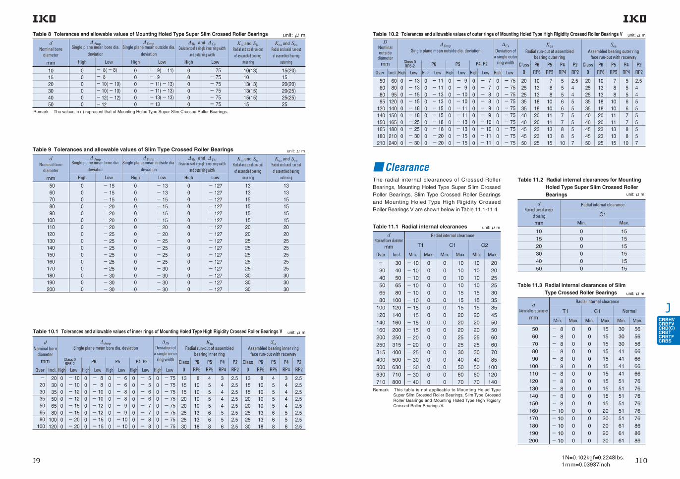
JCRBHVCRBFVCRB(C)CRBTCRBTFCRBS
1N=0.102kgf=0.2248lbs.1mm=0.03937inchJ9 J10
unit: μ m
13131515151520202525252525303030
13131515151520202525252525303030
− 127− 127− 127− 127− 127− 127− 127− 127− 127− 127− 127− 127− 127− 127− 127− 127
0 0 0 0 0 0 0 0 0 0 0 0 0 0 0 0
− 13 − 13 − 15 − 15 − 15 − 15 − 20 − 20 − 25 − 25 − 25 − 25 − 30 − 30 − 30 − 30
0 0 0 0 0 0 0 0 0 0 0 0 0 0 0 0
− 15 − 15 − 15 − 20 − 20 − 20 − 20 − 25 − 25 − 25 − 25 − 25 − 25 − 30 − 30 − 30
0 0 0 0 0 0 0 0 0 0 0 0 0 0 0 0
50 60 70 80 90100 110 120 130 140 150 160 170 180 190 200
Kia and Sia Radial and axial run-out
of assembled bearing inner ring
∆Bs and ∆CsDeviations of a single inner ring width
and outer ring width
∆DmpSingle plane mean outside dia.
deviation
∆dmpSingle plane mean bore dia.
deviation
dNominal bore
diameter
mm
Kea and Sea Radial and axial run-out
of assembled bearing outer ring
Table 9 Tolerances and allowable values of Slim Type Crossed Roller Bearings
High Low High Low High Low
∆dmpSingle plane mean bore dia. deviation
Class 0RP6-2
High Low
P6
High Low
P5 P4, P2
High Low High Low
Class 0
P6RP6
P5 RP5
P4RP4
P2RP2
Class 0
P6RP6
P5 RP5
P4RP4
P2RP2
KiaRadial run-out of assembled
bearing inner ring
SiaAssembled bearing inner ring
face run-out with raceway
dNominal bore
diametermm
Over Incl.
∆BsDeviation of
a single inner ring width
High Low
−203035506580
100
203035506580
100120
00000000
− 10− 10− 12− 12− 15− 15− 20− 20
Table 10.1 Tolerances and allowable values of inner rings of Mounting Holed Type High Rigidity Crossed Roller Bearings V unit: μ m
00000000
− 8− 8− 10− 10− 12− 12− 15− 15
00000000
− 6− 6− 8− 8− 9− 9− 10− 10
00000000
− 5− 5− 6− 6− 7− 7− 8− 8
00000000
− 75− 75− 75− 75− 75− 75− 75− 75
1315152020252530
810101010131318
45555668
34444556
2.52.52.52.52.52.52.52.5
1315152020252530
810101010131318
45555668
34444556
2.52.52.52.52.52.52.52.5
∆dmpSingle plane mean bore dia.
deviation
High Low
dNominal bore
diameter
mm
101520304050
000000
− 8( − 8)− 8− 10( − 10)− 10( − 10)− 12( − 12)− 12
Table 8 Tolerances and allowable values of Mounting Holed Type Super Slim Crossed Roller Bearings unit: μ m∆Dmp
Single plane mean outside dia. deviation
High Low
000000
− 9( − 11)− 9− 11( − 13)− 11( − 13)− 13( − 13)− 13
∆Bs and ∆CsDeviations of a single inner ring width
and outer ring width
High Low
000000
− 75− 75− 75− 75− 75− 75
Kia and Sia Radial and axial run-out
of assembled bearing inner ring
10(13)1013(13)13(15)15(15)15
Kea and Sea Radial and axial run-out
of assembled bearing outer ring
15(20)1520(20)20(25)25(25)25
∆DmpSingle plane mean outside dia. deviation
Class 0RP6-2
High Low
P6
High Low
P5 P4, P2
High Low High Low
Class 0
P6RP6
P5 RP5
P4RP4
P2RP2
Class 0
P6RP6
P5 RP5
P4RP4
P2RP2
KeaRadial run-out of assembled
bearing outer ring
SeaAssembled bearing outer ring
face run-out with raceway
DNominal outside
diametermm
Over Incl.
∆CsDeviation of
a single outer ring width
High Low
50608095
120140150165180210
608095
120140150165180210240
0000000000
− 13− 13− 15− 15− 18− 18− 25− 25− 30− 30
Table 10.2 Tolerances and allowable values of outer rings of Mounting Holed Type High Rigidity Crossed Roller Bearings V unit: μ m
0000000000
− 11− 11− 13− 13− 15− 15− 18− 18− 20− 20
0000000000
− 9− 9− 10− 10− 11− 11− 13− 13− 15− 15
0000000000
− 7− 7− 8− 8− 9− 9− 10− 10− 11− 11
0000000000
− 75− 75− 75− 75− 75− 75− 75− 75− 75− 75
20252535354040454550
10131318182020232325
7 8 810101111131315
555667788
10
2.5445555557
20252535354040454550
10131318182020232325
7 8 810101111131315
555667788
10
2.5445555557
ClearanceThe radial internal clearances of Crossed Roller Bearings, Mounting Holed Type Super Slim Crossed Roller Bearings, Slim Type Crossed Roller Bearings and Mounting Holed Type High Rigidity Crossed Roller Bearings V are shown below in Table 11.1-11.4.
− 30 40 50 65 80100 120 140 160 200 250 315 400 500 630 710
dNominal bore diameter
mm
Radial internal clearance
Table 11.1 Radial internal clearances
Over
30 40 50 65 80100 120 140 160 200 250 315 400 500 630 710 800
− 10 − 10 − 10 − 10 − 10 − 10 − 15 − 15 − 15 − 15 − 20 − 20 − 25 − 30 − 30 − 30 − 40
0 0 0 0 0 0 0 0 0 0 0 0 0 0 0 0 0
0 0 0 0 0 0 0 0 0 0 0 0 0 0 0 0 0
1010101015151520202025253040506070
1010101015151520202025253040506070
20 20 25 25 30 35 35 45 50 50 60 60 70 85100 120 140
Incl. Min.
T1 C1 C2
Max. Min. Max. Min. Max.
Remark This table is not applicable to Mounting Holed Type Super Slim Crossed Roller Bearings, Slim Type Crossed Roller Bearings and Mounting Holed Type High Rigidity Crossed Roller Bearings V.
unit: μ m
56565666666666767676767676868686
dNominal bore diameter
mm
Table 11.3 Radial internal clearances of Slim Type Crossed Roller Bearings
Max.
30303041414141515151515151616161
Min.
15151515151515151515152020202020
Max.
0 0 0 0 0 0 0 0 0 0 0 0 0 0 0 0
Min.
0 0 0 0 0 0 0 0 0 0 0 0 0 0 0 0
Max.
− 8− 8− 8− 8− 8− 8− 8− 8− 8− 8− 8− 10 − 10 − 10 − 10 − 10
Min.
T1
Radial internal clearance
C1 Normal
50 60 70 80 90100 110 120 130 140 150 160 170 180 190 200
unit: μ m
Radial internal clearance
C1
Min.
dNominal bore diameter
of bearingmm
101520304050
000000
Max.
151515151515
Table 11.2 Radial internal clearances for Mounting Holed Type Super Slim Crossed Roller Bearings unit: μ m
Remark The values in ( ) represent that of Mounting Holed Type Super Slim Crossed Roller Bearings.

JCRBHVCRBFVCRB(C)CRBTCRBTFCRBS
1N=0.102kgf=0.2248lbs.1mm=0.03937inchJ11 J12
Radial internal clearance
Table 12.1 Recommended fits for Crossed Roller Bearings under normal load
C1 clearance
C2 clearance
Tolerance class
h5
j5
Shaft Housing bore Shaft Housing bore
Inner ring rotating load Outer ring rotating load
H7
H7
g5
g5
J7(1)J7(1)
Note(1) It is recommended that a slight interference fit adjusted to the actual measured dimensions of the bearing is used.
dNominal bore diameter
mm
Table 12.2 Recommended fits for Slim Type Crossed Roller Bearings with normal clearances (Dimensional tolerances of shaft and housing bore)
50 60 70 80 90100 110 120 130 140 150 160 170 180 190 200
High
Shaft
Inner ring rotating load Outer ring rotating load
Housing bore Shaft Housing bore
+ 15+ 15+ 15+ 20+ 20+ 20+ 20+ 25+ 25+ 25+ 25+ 25+ 25+ 30+ 30+ 30
Low
0 0 0 0 0 0 0 0 0 0 0 0 0 0 0 0
High
+ 13+ 13+ 15+ 15+ 15+ 15+ 20+ 20+ 25+ 25+ 25+ 25+ 30+ 30+ 30+ 30
Low
0 0 0 0 0 0 0 0 0 0 0 0 0 0 0 0
High
− 15 − 15 − 15 − 20 − 20 − 20 − 20 − 25 − 25 − 25 − 25 − 25 − 25 − 30 − 30 − 30
Low
− 30 − 30 − 30 − 40 − 40 − 40 − 40 − 50 − 50 − 50 − 50 − 50 − 50 − 60 − 60 − 60
High
− 13 − 13 − 15 − 15 − 15 − 15 − 20 − 20 − 25 − 25 − 25 − 25 − 30 − 30 − 30 − 30
Low
− 25 − 25 − 30 − 30 − 30 − 30 − 40 − 40 − 50 − 50 − 50 − 50 − 60 − 60 − 60 − 60
unit: μ m
FitThe standard fits of Crossed Roller Bearings are shown in Table 12.1, and recommended fits for Slim Type Crossed Roller Bearings with normal clearances are shown in Table 12.2. For Super Slim Type Crossed Roller Bearings, it is recommended to use a slight inter-ference fit adjusted to the actual measured dimensions. For large bearings, fit based on the actual measured dimensions of the bearings is recommended, and fit allowance should be chosen as small as possible in accordance with the tolerance class given in Table 12.1. When complex loads or shock loads are applied or when high rotational accuracy and rigidity of the bearing are required, it is recommended to use a slight interference fit adjusted to the actual measured dimen-sions for both inner and outer rings.For the interference fit, the radial internal clearance after the fit decreases by approximately 70% to 90% of the interference amount. To avoid excessive pre-load due to fit, it is recommended to use a slight inter-ference fit adjusted to the actual measured dimen-sions for both T1 and C1 clearances.
2020253035354550
dNominal bore diameter
mmOver Incl.
Table 11.4 Radial internal clearances of Mounting Holed Type High Rigidity Crossed Roller Bearings V
Max.
1010101515152020
Min.
1010101515152020
Max.
00000000
Min.
00000000
Max.
− 10− 10− 10− 10− 10− 15− 15− 15
Min.
T1
Radial internal clearance
C1 C2
− 20 25 35 65 80 95110
20 25 35 65 80 95110125
unit: μ m
Allowable rotational speedAllowable rotational speeds of Crossed Roller Bearings are affected by mounting and operating con-ditions. The values in general operation are shown in Table 13.
Table 13 dmn values(1)of Crossed Roller BearingsLubricant
Type
With cage orwith separator
Full complement
Open type
Sealed type
Open type
Sealed type
75 000
60 000
50 000
40 000
150 000
−
75 000
−
Grease Oil
Note(1) ・dmn value= dm× n where, dm : Mean value of bearing bore and outside diameters, mm n : Number of rotations per minute, min-1
Rotational torqueRotational torque of IKO Crossed Roller Bearings are lower than that of plain bearings and the difference between the static torque and the dynamic (kinetic) torque is small. Therefore, these bearings minimize power consumption and operating temperature rise of machinery and increase the overall efficiency of machines.The rotational torque is affected by many factors, but
the following equations can be used expediently. DpwT = μP0r——— 2 where, T : Rotational torque, N・mm μ : Friction coefficient (Approx. 0.010) P0r : Static equivalent radial load, N Dpw : Pitch circle diameter, mm
d + DDpw ≒———— 2
LubricationThese bearings are generally lubricated with grease. Grease is supplied through the clearance between the inner ring and the outer ring.Grease specification is shown in Table 14, ALVANIA GREASE EP2 (Shell Lubricants Japan K.K.) is prepacked as the lubricating grease.For bearings without prepacked grease, supply grease or oil for use. Operating without grease or oil will increase the wear of the rolling contact surfaces and cause a short bearing life.
Table 14 Bearings with prepacked grease:With prepacked grease ×:Without prepacked grease
When using a special grease, carefully examine the grease properties and contents such as base oil vis-cosity and extreme pressure additives. In this case, please contact IKO.
Oil HoleFor Crossed Roller Bearings, oil holes and oil grooves can be provided on bearing rings if requested. Not applicable to the Super Slim Type (Mounting Holed Type). When an oil hole is required on the outer ring, attach "-OH" before the clearance symbol in the identification number. When an oil hole and an oil groove are required on the outer ring, attach "-OG" at the same place in the identification number. For an oil hole on the inner ring, attach "/OH", and for an oil hole and an oil groove on the inner ring, attach "/OG", at the same place in the identification number. High Rigidity Type Crossed Roller Bearings V and Mounting Holed Type High Rigidity Type Crossed Roller Bearings V have an oil groove and two oil holes on the outer ring as standard. Table 15 shows availability of oil holes for each bearing type.
Table 15 Oil holes
Notes(1) CRBHV … A and CRBFV … A are provided with an oil groove and two oil holes on the outer ring.
Remark n denotes the number of oil holes not exceeding 4. For one oil hole, number is not indicated.When preparing multiple oil holes, please contact IKO.
( )
Model code
Seal specification
Open type(No symbol)
Sealed type
(UU)
One sidesealed type
(U)
CRBHV … A × 〇 −CRBFV … A × 〇 −CRBC × 〇 ×
CRB × 〇 ×
CRBT … A 〇 − −CRBTF … A 〇 − −CRBS × − −CRBS … A − 〇 ×
CRBS … V × 〇 ×
Bearing typeOil hole code
/nOH /nOG -nOH -nOG
CRBHV … A 〇 〇 − −(1)
CRBFV … A − − − −(1)
CRBC 〇 〇 〇 〇CRB 〇 〇 〇 〇CRBT … A − − − −CRBTF … A − − − −CRBS 〇 − 〇 −CRBS … A 〇 − 〇 −CRBS … V 〇 − 〇 −

JCRBHVCRBFVCRB(C)CRBTCRBTFCRBS
J13 J14
When the rigidity of the mounting parts is not suffi-cient, stress concentration will occur at the contact area between the rollers and raceways, and the bear-ing performance will be deteriorated significantly.Therefore, it is necessary to carefully examine the rigidity of housing and the strength of fixing bolts when a large moment will be applied.The shoulder height diameters (da and Da) that are related to mounting should certainly satisfy the values shown in the dimension tables. When these dimen-sions are incorrect, deformations of inner and outer rings will occur and the bearing performance will be deteriorated remarkably.
Fig. 2 Mounting example
1 The inner and outer rings should be securely fixed in the axial direction by using fixing plates, etc. Recommended thickness of the fixing plate is 1/2 or more of the bearing width B. The dimensions in the axial direction of the housing bore and the fixing
Mounting
2. Mounting Holed Type High Rigidity Crossed Roller Bearings V, Mounting Holed Type Super Slim Crossed Roller Bearings
1. Other than Mounting Holed Type Crossed Roller Bearings V
1 Mounting Holed Type High Rigidity Crossed Roller Bearings V, Mounting Holed Type Super Slim Crossed Roller Bearings can be mounted directly to the mount-ing surface by fixing bolts. (See Fig. 3, Fig. 4)2 If large number of radial load and/or moment is expected, it is recommended to prepare flange part. (See Fig.5)3 Mounting Holed Type High Rigidity Crossed Roller Bearings V, Mounting Holed Type Super Slim Crossed Roller Bearings have a plug for hole for inserting cylin-drical rollers. When mounting the bearings, locate the plug at a position that is not included in the maximum loading zone. The plug location can be found by the pin pressed at the side of the outer ring.
Operating Temperature RangeThe operating temperature range for Crossed Roller Bearings is − 20〜+ 120 . However, the maxi-mum allowable temperature for types with separator and with seal is+ 110 , and+ 100 when they are continuously operated.
Example 1 When the inner ring has 4 oil holes
CRBC 10020 / 4OH C1 4 Oil holes In inner ring
Example 2 When the outer ring has a single oil hole
CRBC 10020 - OH C1
1 Oil hole In outer ring
plates should be determined to get a secure fixing while considering the dimension of bearing width which is given a minus tolerance. (See Fig.2)2 The depth of the housing bore is recommended to be equal to or larger than the bearing width.3 Separation prevention bolts for the outer ring of Standard Type Crossed Roller Bearings are provided to prevent separation of two halves of the outer ring during transportation or mounting. When mounting, they should be loosened slightly.4 High Rigidity Type Crossed Roller Bearings V, Super Slim Type Crossed Roller Bearings and Slim Type Crossed Roller Bearings have a plug for hole for inserting rollers. When mounting the bearings, locate the plug at a position that is not included in the maxi-mum loading zone. The plug location can be found by the pin pressed at the side of the outer ring.
Tightening torque of mounting boltsThe standard tightening torque values for Mounting Holed Type High Rigidity Crossed Roller Bearings V, Mounting Holed Type Super Slim Crossed Roller Bearings mounting bolts are shown in Table 16. When machines or equipment are subjected to severe vibra-tion, shock, large fluctuating load, or moment load, the bolts should be tightened with a torque 1.2 to 1.5 times higher than the standard torque values shown. If the mating member material is cast iron or alumi-num, reduce the tightening torque depending on the strength characteristics of the mating member materi-al. Please do not tighten with too much torque as abnor-mal frictional torque or short life may occur.
Double Row Angular Contact Roller BearingWe manufacture Double Row Angular Contact Roller Bearings to order. If needed, please contact IKO. Double Row Angular Contact Roller Bearings have a large number of cylindrical rollers with a large contact area with a raceway and an excellent load capability, between the inner and outer rings arranged in a dou-ble row of raceways. This underpins even higher rigidi-ty and lower torque than High Rigidity Type Crossed Roller Bearings V. The mounting holes in both inner and outer rings facil-itate installation to your machines and equipment. Further, the integrated structure (non split) construct-ed in both inner and outer rings can avoid installation errors, yielding extra-high-rigidity and high-accuracy guiding performance without being affected by other peripheral structures such as housing or pressure plate.For lubrication, use the two oil holes on the outer ring outer surface shown in Fig. 6.
Above values are for Carbon steel bolt (Strength division 12.9)
Table 16 Tightening torque of mounting bolts
Bolt size Tighteningtorque
N・m
M2.5 × 0.4
M3 × 0.5
M4 × 0.7
M5 × 0.8
M8 × 1.25
0.58
1.7
4.0
7.9
32 Structure of Double-acting Angular Roller Bearing
Outer ring
Separator
Cylindrical roller
Inner ring
B
D d
Rc1/8
A-O-A'
A
A'
OPCD
1
PCD
2
(Oil hole)
Fig. 7 Manufacturing example
Table 17 Example of manufacturing dimensions
Boundary dimensionsmm
Basic static load rating
C0N
Basic dynamic load rating
CN
160
210
350
d D B rmin PCD1 PCD2
295
380
540
35
40
50
2
2.5
2.5
184
240
385
270
350
505
167 000
313 000
725 000
60 300
108 000
235 000
Inject greaseInject grease
Grease
Inject grease 1 Inject grease 2
Grease Grease
Fig. 3 Example of direct mounting to the mating surface of Mounting Holed Type High Rigidity Crossed Roller Bearings V
Fig. 4 Example of direct mounting to the mating surface of Mounting Holed Type Super Slim Crossed Roller Bearings
Fig. 5 Example of mounting to the housing of Mounting Holed Type High Rigidity Crossed Roller Bearings V
Fig. 6 Grease

JCRBHVCRBFVCRB(C)CRBTCRBTFCRBS
1N=0.102kgf=0.2248lbs.1mm=0.03937inch J161N=0.102kgf=0.2248lbs.1mm=0.03937inchJ15 J16
CRBHV … A
High Rigidity Type Crossed Roller Bearings V Open Type/With Separator
Shaft dia. 20− 300mm
Sealed Type/With Separator
CRBHV … AUU
CROSSED ROLLER BEARINGS
Shaft dia.
mm
Mass (Ref.)
kg
Boundary dimensions mm
d D B rmin(1)
Mounting dimensions mm
d a Da
20
25
30
35
40
45
50
60
70
80
90
100
110
120
130
140
150
200
250
300
CRBHV 208 A
CRBHV 258 A
0.04
0.05
0.12
0.13
0.15
0.16
0.29
0.33
0.38
0.74
0.81
1.45
1.56
2.62
2.82
2.96
3.16
4.00
4.97
5.29
20
25
30
35
40
45
50
60
70
80
90
100
110
120
130
140
150
200
250
300
36
41
55
60
65
70
80
90
100
120
130
150
160
180
190
200
210
260
310
360
8
8
10
10
10
10
13
13
13
16
16
20
20
25
25
25
25
25
25
25
0.3
0.3
0.3
0.3
0.3
0.3
0.6
0.6
0.6
0.6
0.6
0.6
0.6
1
1
1
1
1
1.5
1.5
24
29
36.5
41.5
46.5
51.5
56
66
76
88
98
110
120
132
142
152
162
212
262
312
31
36
48.5
53.5
58.5
63.5
74
84
94
112
122
140
150
168
178
188
198
248
298
348
Identification number
Sealed Type
CRBHV 208 A UU
CRBHV 258 A UU
Basic dynamic load rating
C
N
Basic static load rating
C0
N
2 910
3 120
7 600
7 900
8 610
8 860
17 300
18 800
20 100
32 100
33 100
50 900
52 400
73 400
75 900
81 900
84 300
92 300
102 000
112 000
2 430
2 810
8 370
9 130
10 600
11 300
20 900
24 300
27 700
43 400
46 800
72 200
77 400
108 000
115 000
130 000
138 000
169 000
207 000
245 000
Open Type
High Rigidity Type Crossed Roller Bearings V
CRBHV 3010 A
CRBHV 3510 A
CRBHV 4010 A
CRBHV 4510 A
CRBHV 5013 A
CRBHV 6013 A
CRBHV 7013 A
CRBHV 8016 A
CRBHV 9016 A
CRBHV 10020 A
CRBHV 11020 A
CRBHV 12025 A
CRBHV 13025 A
CRBHV 14025 A
CRBHV 15025 A
CRBHV 20025 A
CRBHV 25025 ACRBH 30025 A
CRBHV 3010 A UU
CRBHV 3510 A UU
CRBHV 4010 A UU
CRBHV 4510 A UU
CRBHV 5013 A UU
CRBHV 6013 A UU
CRBHV 7013 A UU
CRBHV 8016 A UU
CRBHV 9016 A UU
CRBHV 10020 A UU
CRBHV 11020 A UU
CRBHV 12025 A UU
CRBHV 13025 A UU
CRBHV 14025 A UU
CRBHV 15025 A UU
CRBHV 20025 A UU
CRBHV 25025 A UUCRBH 30025 A UU
Note(1) Minimum allowable single value of chamfer dimension rRemarks1. The outer ring has an oil groove and two oil holes. 2. No grease is prepacked for Open Type. Perform proper lubrication. Grease is prepacked for Sealed Type. 3. If one side sealed type are needed, please contact IKO.

JCRBHVCRBFVCRB(C)CRBTCRBTFCRBS
1N=0.102kgf=0.2248lbs.1mm=0.03937inchJ17 J18
CROSSED ROLLER BEARINGS
Mounting Holed Type High Rigidity Crossed Roller Bearings V
Open Type/With Separator
Sealed Type/With Separator
Shaft dia. 10− 115mmCRBFV … AT CRBFV … ATUU CRBFV … A CRBFV … AUU CRBFV … AD CRBFV … ADUU
Note(1) Minimum allowable single value of chamfer diameter r1 and r2.Remarks1. The outer ring has an oil groove and two oil holes. 2. No grease is prepacked for Open Type. Perform proper lubrication. Grease is prepacked for Sealed Type. 3. If one side sealed type are needed, please contact IKO.
Shaft dia.
mm
Boundary dimensions mm
Mass(Ref.)
kg d D B
Identification number
Open Type Sealed Type
10 CRBFV 108 AT CRBFV 108 AT UU 0.12 10 52 8 0.3 0.3
20 CRBFV 2012 AT CRBFV 2012 AT UU 0.31 20 70 12 0.3 0.3
25 CRBFV 2512 AT CRBFV 2512 AT UU 0.40 25 80 12 0.6 0.6
35 CRBFV 3515 AT CRBFV 3515 AT UU 0.66 35 95 15 0.6 0.6
55 CRBFV 5515 AT CRBFV 5515 AT UU 0.96 55 120 15 0.6 0.6
80
CRBFV 8022 AT CRBFV 8022 AT UU 2.63
80 165 22 0.6 1CRBFV 8022 A CRBFV 8022 A UU2.60
CRBFV 8022 AD CRBFV 8022 AD UU
90
CRBFV 9025 AT CRBFV 9025 AT UU 4.83
90 210 25 1.5 1.5CRBFV 9025 A CRBFV 9025 A UU4.67
CRBFV 9025 AD CRBFV 9025 AD UU
115
CRBFV 11528 AT CRBFV 11528 AT UU 6.81
115 240 28 1.5 1.5CRBFV 11528 A CRBFV 11528 A UU6.63
CRBFV 11528 AD CRBFV 11528 AD UU
139
Basic dynamic load rating
C
N
Mounting holes mm Mountingdimensions
mm
97
112
da Da
16
28
35
45
65
42
57
67
83
105
2 910
7 600
8 610
17 300
20 100
2 430
8 370
10 600
20 900
27 700
6-φ3.4 throughφ6.5 counter bore depth 3.3
6-φ3.4 throughφ6.5 counter bore depth 3.3
6-φ3.4 throughφ6.5 counter bore depth 3.3
8-φ4.5 throughφ8 counter bore depth 4.4
8-φ5.5 throughφ9.5 counter bore depth 5.4
148
187
217
51 100
73 400
72 000
108 000
24
36.5
46.5
56
76
107
132
162
31
48.5
58.5
74
94
137
168
198 84 300 138 000
10-φ5.5 throughφ9.5 counter bore depth 5.4
12-φ9 throughφ14 counter bore depth 12
12-φ9 throughφ14 counter bore depth 13.5
Inner ring Outer ring
PCD1 PCD2Mounting holes Mounting holes
Basic static load rating
C0
N
12-M8 through
12-M8 through
10- φ 5.5 throughφ 9.5 counter boredepth 5.4
12- φ 9 throughφ 14 counter boredepth 12
12- φ 9 throughφ 14 counter boredepth 13.5
4-M3 through
6-M3 through
6-M3 through
8-M4 through
8-M5 through
10-M5 through
r1min(1)
r2min(1)
Mounting Holed Type High Rigidity Crossed Roller Bearing V

JCRBHVCRBFVCRB(C)CRBTCRBTFCRBS
1N=0.102kgf=0.2248lbs.1mm=0.03937inchJ19 J20
CROSSED ROLLER BEARINGSStandard Type Crossed Roller BearingsOpen Type/With Cage Open Type/Full Complement Type
Sealed Type/With Cage Sealed Type/Full Complement Type
Shaft dia. 30− 200mm CRBC CRBC … UU CRB CRB … UU
Shaft dia.
mm
Boundary dimensionsmm
d D B
Note(1) Minimum allowable single value of chamfer dimension rRemarks1. No oil hole is provided. 2. No grease is prepacked for Open Type. Perform proper lubrication. Grease is prepacked for Sealed Type.
Identification numberWith Cage Full complement
Mass (Ref.)
kgOpen Type Sealed Type Open Type Sealed Type
Basic dynamic load rating
CN
Basic static load rating
C0N
CRB
30
40
50
60
70
80
90
100
110
120
130
140
150
200
CRBC 3010
CRBC 4010
CRBC 5013
CRBC 6013
CRBC 7013
CRBC 8016
CRBC 9016
CRBC 10020
CRBC 11020
CRBC 12025
CRBC 13025
CRBC 14025
CRBC 15025CRBC 15030
CRBC 20025CRBC 20030CRBC 20035
CRBC 3010 UU
CRBC 4010 UU
CRBC 5013 UU
CRBC 6013 UU
CRBC 7013 UU
CRBC 8016 UU
CRBC 9016 UU
CRBC 10020 UU
CRBC 11020 UU
CRBC 12025 UU
CRBC 13025 UU
CRBC 14025 UU
CRBC 15025 UUCRBC 15030 UUCRBC 20025 UU
CRB 3010
CRB 4010
CRB 5013
CRB 6013
CRB 7013
CRB 8016
CRB 9016
CRB 10020
CRB 11020
CRB 12025
CRB 13025
CRB 14025
CRB 15025CRB 15030
CRB 20025CRB 20030CRB 20035
CRB 3010 UU
CRB 4010 UU
CRB 5013 UU
CRB 6013 UU
CRB 7013 UU
CRB 8016 UU
CRB 9016 UU
CRB 10020 UU
CRB 11020 UU
CRB 12025 UU
CRB 13025 UU
CRB 14025 UU
CRB 15025 UUCRB 15030 UU
CRB 20025 UU
0.12
0.15
0.29
0.33
0.38
0.74
0.81
1.45
1.56
2.62
2.82
2.96
3.165.30
4.006.709.58
30
40
50
60
70
80
90
100
110
120
130
140
150150
200200200
55
65
80
90
100
120
130
150
160
180
190
200
210230
260280295
10
10
13
13
13
16
16
20
20
25
25
25
2530
253035
5 290
5 980
14 200
15 400
17 000
24 300
25 900
39 400
41 200
59 900
61 000
64 100
65 00085 900
75 300133 000168 000
6 350
8 040
18 400
21 500
25 500
37 500
42 100
61 100
66 700
95 400
99 800
108 000
113 000144 000
148 000234 000282 000
Basic dynamic load rating
CN
Basic static load rating
C0N
d a Darmin
Mounting dimensions mm
CRBC
0.3
0.3
0.6
0.6
0.6
0.6
1
1
1
1.5
1.5
1.5
1.51.5
222
34
44
55
64
75
86
98
108
118
132
140
151
160166
208218221
44
54
71
81
91
107
118
134
144
164
172
183
192202
239262274
3 830
4 280
10 700
11 600
12 300
18 200
19 400
31 500
33 500
47 700
49 200
50 700
53 80069 200
60 200108 000137 000
4 130
5 140
12 600
14 600
16 700
25 500
28 600
45 100
50 700
70 500
74 800
79 200
87 700108 000
110 000178 000215 000
(1)

JCRBHVCRBFVCRB(C)CRBTCRBTFCRBS
1N=0.102kgf=0.2248lbs.1mm=0.03937inchJ21 J22
CROSSED ROLLER BEARINGSStandard Type Crossed Roller Bearings
Shaft dia. 250− 800mm CRBC 25025CRBC 30025
CRBC 25025UUCRBC 30025UU
Open Type/With Cage Open Type/Full Complement Type
Sealed Type/With Cage Sealed Type/Full Complement Type
CRBC CRBCRB 25025CRB 30025
CRB 25025UUCRB 30025UU
Shaft dia.
mm
Boundary dimensionsmm
d D B
Note(1) Minimum allowable single value of chamfer dimension rRemarks1. No oil hole is provided. 2. No grease is prepacked for Open Type. Perform proper lubrication. Grease is prepacked for Sealed Type.
Identification number
With Cage Full complement
Mass (Ref.)
kgOpen Type Sealed Type Open Type Sealed Type
Basic dynamic load rating
CN
Basic static load rating
C0N
CRBBasic dynamic
load ratingCN
Basic static load rating
C0N
d a Darmin(1)
Mounting dimensions mm
CRBC
CRBC 40035CRBC 40040CRBC 40070
CRBC 50040CRBC 50050CRBC 50070
CRBC 60040CRBC 60070CRBC 600120
CRBC 70045CRBC 70070CRBC 700150
CRBC 80070CRBC 800100
CRBC 30025CRBC 30035CRBC 30040
400
500
600
700
800
300
CRB 40035CRB 40040CRB 40070
CRB 50040CRB 50050CRB 50070
CRB 60040CRB 60070CRB 600120
CRB 70045CRB 70070CRB 700150
CRB 80070CRB 800100
CRB 30025CRB 30035CRB 30040
14.5 23.5 72.4
26.0 41.7 86.1
30.6 102 274
46.5 115 478
109 247
5.88 13.4 17.2
400400400
500500500
600600600
700700700
800800
300300300
480510580
600625680
700780870
815880
1 020
9501 030
360395405
354070
405070
4070
120
4570
150
70100
253540
2.52.52.5
2.52.52.5
333
333
44
2.52.52.5
250 4.97 8.10 14.8
250250250
310330355
253040
2.52.52.5
414423430
517531530
621630643
730731751
831840
310318321
457483532
573592633
676734817
785834953
907972
341372381
133 000222 000470 000
212 000247 000536 000
231 000591 000
1 250 000
250 000630 000
1 660 000
417 000936 000
73 800163 000194 000
300 000455 000811 000
497 000561 000
1 020 000
581 0001 230 0002 210 000
681 0001 390 0003 010 000
1 090 0002 040 000
162 000299 000351 000
165 000270 000576 000
259 000306 000653 000
287 000700 000
1 490 000
313 000766 000
1 980 000
513 0001 140 000
91 900205 000235 000
400 000590 000
1 060 000
648 000747 000
1 330 000
774 0001 540 0002 800 000
917 0001 810 0003 820 000
1 440 0002 640 000
217 000408 000451 000
259265271
290310330
67 200116 000179 000
136 000208 000299 000
83 900146 000215 000
183 000283 000382 000
CRBC 25025 UU
CRBC 30025 UU
CRB 25025 UU
CRB 30025 UU
CRBC 25025CRBC 25030CRBC 25040
CRB 25025CRB 25030CRB 25040

JCRBHVCRBFVCRB(C)CRBTCRBTFCRBS
1N=0.102kgf=0.2248lbs.1mm=0.03937inchJ23 J24
CRBT … A
CROSSED ROLLER BEARINGS
Super Slim Type Crossed Roller Bearings
Shaft dia. 10− 50mm
Open Type/With Separator
Shaft dia.
mm
Basic dynamic load rating
CN
Basic static load rating
C0N
Boundary dimensionsmm
d D B d a Darmin(1)
Mounting dimensions mm
Note(1) Minimum allowable single value of chamfer dimension r .Remarks1. No oil hole is provided. 2. Grease is prepacked.
Identification number Mass (Ref.)
g
10
15
20
3040
50
CRBT 105 A
CRBT 155 A
CRBT 205 A
CRBT 305 A
11.9
9.0
14.8
20.7
26.5
15
10
20
30
40
26
21
31
41
51
5
5
5
5
5
0.15
0.15
0.15
0.15
0.15
17.5
12.5
22.5
32.5
42.5
22
17
27
37
47
1 320
1 120
1 400
1 770
2 000
1 110
1 290
1 970
2 520CRBT 405 A32.3 50 61 5 0.15 52.5 57 2 280 3 200CRBT 505 A
811

JCRBHVCRBFVCRB(C)CRBTCRBTFCRBS
1N=0.102kgf=0.2248lbs.1mm=0.03937inchJ25 J26
CRBTF … A
CROSSED ROLLER BEARINGS
Mounting Holed Type Super Slim Crossed Roller Bearings
Shaft dia 10− 40mm
Open type/With Separator
Note(1) Minimum allowable single value of chamfer dimension r .Remarks1. No oil hole is provided. 2. Grease is prepacked.
D d
PCD
1
PCD
2
Brr
r
r
d aDa
Shaft dia.
mm
Identification number Mass (Ref.)
Boundary dimensionsmm
Mounting holes mm Mounting dimensions mm
Basic dynamic load ratingC
Basic static load ratingC0
g d D B (1)rmin
Inner ring Outer ring
PCD1 Mounting holes PCD a Mounting holes d a Da N N
10 CRBTF 105 AT 46 10 43 5 0.15 16 6-M2.5 through 356-φ2.9 throughφ5.5 counter bore depth 2.8
21.5 28 1 500 1 410
20 CRBTF 205 AT 66 20 53 5 0.15 26 6-M2.5 through 456-φ2.9 throughφ5. 5 counter bore depth 2.8
31.5 38 1 890 2 150
30 CRBTF 305 AT 83 30 63 5 0.15 36 8-M2.5 through 558-φ2.9 throughφ5.5 counter bore depth 2.8
41.5 47.5 2 140 2 750
40 CRBTF 405 AT 103 40 73 5 0.15 46 8-M2.5 through 658-φ2.9 throughφ5.5 counter bore depth 2.8
51.5 58 2 440 3 490

JCRBHVCRBFVCRB(C)CRBTCRBTFCRBS
1N=0.102kgf=0.2248lbs.1mm=0.03937inchJ27 J28
CROSSED ROLLER BEARINGSSlim Type Crossed Roller Bearings
Shaft dia. 50− 200mm CRBS
Open Type/With Cage Open Type/Full Complement Type
Sealed Type/With Separator Sealed Type/Full Complement Type
CRBS … AUU… VUU
CRBS … V
Shaft dia.
mm
Note(1) Minimum allowable single value of chamfer dimension r(2) No grease is prepacked. Perform proper lubrication.(3) Grease is prepacked.
Remark No oil hole is provided.
Identification number Mass (Ref.)
g
With Cage With Separator
Open Type Sealed Type Open Type Sealed Type
Full complementBasic dynamic load rating
CN
Basic static load ratingC0N
6 930
7 600
8 190
8 790
9 310
9 850
10 300
10 900
11 200
11 700
12 100
26 900
27 800
28 600
29 300
30 000
9 800
11 700
13 600
15 500
17 400
19 300
21 200
23 000
24 600
26 800
28 700
58 200
61 600
65 200
68 600
72 200
50
60
70
80
90
100
110
120
130
140
150
160
170
180
190
200
CRBS 508
CRBS 608
CRBS 708
CRBS 808
CRBS 908
CRBS 1008
CRBS 1108
CRBS 1208
CRBS 1308
CRBS 1408
CRBS 1508
CRBS 16013
CRBS 17013
CRBS 18013
CRBS 19013
CRBS 20013
CRBS 508 V
CRBS 608 V
CRBS 708 V
CRBS 808 V
CRBS 908 V
CRBS 1008 V
CRBS 1108 V
CRBS 1208 V
CRBS 1308 V
CRBS 1408 V
CRBS 1508 V
CRBS 16013 V
CRBS 17013 V
CRBS 18013 V
CRBS 19013 V
CRBS 20013 V
84
94
108
122
135
152
163
184
199
205
220
620
675
710
740
780
CRBS 508 A UU
CRBS 608 A UU
CRBS 708 A UU
CRBS 808 A UU
CRBS 908 A UU
CRBS 1008 A UU
CRBS 1108 A UU
CRBS 1208 A UU
CRBS 1308 A UU
CRBS 1408 A UU
CRBS 1508 A UU
CRBS 16013 A UU
CRBS 17013 A UU
CRBS 18013 A UU
CRBS 19013 A UU
CRBS 20013 A UU
CRBS 508 V UU
CRBS 608 V UU
CRBS 708 V UU
CRBS 808 V UU
CRBS 908 V UU
CRBS 1008 V UU
CRBS 1108 V UU
CRBS 1208 V UU
CRBS 1308 V UU
CRBS 1408 V UU
CRBS 1508 V UU
CRBS 16013 V UU
CRBS 17013 V UU
CRBS 18013 V UU
CRBS 19013 V UU
CRBS 20013 V UU
Basic dynamic load ratingCN
Basic static load ratingC0N
Boundary dimensionsmm
d D B d a Darmin(1)
Mounting dimensions mm
50
60
70
80
90
100
110
120
130
140
150
160
170
180
190
200
66
76
86
96
106
116
126
136
146
156
166
186
196
206
216
226
8
8
8
8
8
8
8
8
8
8
8
13
13
13
13
13
0.4
0.4
0.4
0.4
0.4
0.4
0.4
0.4
0.4
0.4
0.4
0.6
0.6
0.6
0.6
0.6
54
64
74
84
94
104
114
124
134
144
154
166
176
186
196
206
61
71
81
91
101
111
121
131
141
151
161
179
189
199
209
219
4 900
5 350
5 740
6 130
6 490
6 850
7 160
7 530
7 860
8 060
8 350
20 300
20 900
21 500
22 100
22 500
6 170
7 310
8 440
9 590
10 700
11 900
13 000
14 100
15 300
16 400
17 500
39 900
42 200
44 600
46 900
49 300
Basic dynamic load ratingCN
Basic static load ratingC0N
4 680
5 350
5 740
6 130
6 490
6 530
6 850
7 070
7 270
7 510
7 810
19 400
20 000
21 900
22 900
23 300
5 810
7 310
8 440
9 590
10 700
11 100
12 300
13 000
13 800
14 900
16 000
37 700
39 900
45 700
49 200
51 600
CRBS(2)With cage
CRBS…AUU(3)With Separator
CRBS…V(2)CRBS…VUU(3)
Full complement

K
K1 K2
Steel-on-steel Spherical Bushings
Maintenance-free Spherical Bushings
Structure and FeaturesIKO Spherical Bushings are self-aligning spherical plain bushings that have inner and outer rings with spherical sliding surfaces, and can take a large radial load and a bi-directional axial load at the same time. There are many types of Spherical Bushings, but they are basically divided into steel-on-steel types and maintenance-free types according to the kind of slid-ing surfaces.Steel-on-steel Spherical Bushings have inner and outer rings of high carbon chromium bearing steel, of which sliding surfaces are phosphate-treated and then dry-coated with molybdenum disulfide (MoS2). They can, therefore, operate with low torque, and have excellent wear resistance and large load capaci-ty. They are especially suitable for applications where there are alternate loads and shock loads. They have wide applications mainly in industrial and construction machinery.Maintenance-free Spherical Bushings consist of an outer ring which has a special PTFE liner reinforced with copper alloy meshes on the sliding surface, and a spherical inner ring of which sliding surface has a hard chromium plating. Creep deformation due to compressive load is small, and wear resistance is superior. Thus, they are maintenance-free and can be used for extended periods of time without re-lubri-cation. They are especially suitable in cases where fixed directional loads are applied and are used main-ly in food processing machines and construction machinery and in other applications in which the use of oil is undesirable or lubrication is not possible.
Structures of Spherical Bushings
Outer ring (MoS2 coating)
Inner ring(MoS2 coating)
Steel-on-steel type
Outer ring (MoS2 coating)
Inner ring (MoS2 coating)
Seal (Polyurethane)
Outer ring
Outer ring
Special PTFE liner (Reinforced with copper alloy meshes)
Inner ring(Chromium plating)
Inner ring(Chromium plating)
Seal(Synthetic resin)
Special PTFE liner(Reinforced with copper alloy meshes)
Steel-on-steel type
Maintenance-free type
Maintenance-free type
TypesSpherical Bushings are available in various types shown in Table 1.
Table 1 Type of bearingType
Series
Metric
Inch
SB
SB … A
GE … E,ES
GE … G,GS
SBB
−
−
GE … ES-2RS
GE … GS-2RS
SBB … -2RS
GE … EC
−
GE … EC-2RS
−
Maintenance-free
Without seals With seals
Steel-on-steel
Without seals With seals

K
K3 K41N=0.102kgf=0.2248lbs.1mm=0.03937inch
Steel-on-steel Spherical Bushings SB
These bushings have an outer ring split into halves. The split outer ring and the inner ring are held togeth-er by a snap ring placed in the groove around the outer periphery of the outer ring.
Steel-on-steel Spherical Bushings SB … A
These bushings have an outer ring split only at one position, and therefore, the outer and inner rings will not separate. Handling before mounting and mount-ing to the housing are simple. The boundary dimen-sions are the same as those of the SB type.Therefore, SB and SB … A types are dimensionally interchange-able, but the radial internal clearances of the SB … A type are smaller than those of the SB type.
Steel-on-steel Spherical Bushings GE … E,GE … ES
The dimension series of these types conform to ISO standards and they can be used internationally. The outer ring is split at one position. The GE … E and GE … ES types are available. These are classified by bushing size.The GE … ES type can be provided with seals, which are double-lip type polyurethane seals effective for prevention against grease leakage and dust penetra-tion. The sealed type is indicated by the suffix "-2RS" at the end of the identification number.
Steel-on-steel Spherical Bushings GE … G,GE … GS
As compared with the GE … E and GE … ES types, these bushings have larger load capacities and larger permissible tilting angles. The dimension series also conform to ISO standards, and they can be used internationally. The outer ring is split at one position. The GE … G and GE … GS types are available. They are classified by bushing size.The GE … GS type can be provided with seals, which are double-lip type polyurethane seals effective for prevention against grease leakage and dust penetra-tion. The sealed type is indicated by the suffix "-2RS" at the end of the identification number.
Steel-on-steel Spherical Bushings SBB
These are inch series bushings. The outer ring is split at one position.These bushings can be provided with seals, which are double-lip type polyurethane seals effective for pre-vention against grease leakage and dust penetration. The sealed type is indicated by the suffix "-2RS" at the end of the identification number.
Maintenance-free Spherical Bushings GE … EC
These bushings have the same boundary dimensions as the GE … ES type and can be used internationally. A special PTFE liner reinforced with copper alloy meshes is used on the sliding surface. Therefore, creep deformation due to compressive loads is small, and wear resistance is superior. These bushings are used as maintenance-free bushings.These bushings can be provided with synthetic resin seals which are effective in preventing dust penetra-tion. They are indicated by the suffix "-2RS" at the end of the identification number.Spherical Bushings with superior rust prevention properties, which can be used in a corrosive environ-ment or in an environment where water splashes, are also available on request. Please consult IKO.
Identification numberThe identification number of Spherical Bushings con-sists of a model code, a size and any supplemental codes. Examples are shown below.
ClearanceThe radial internal clearances of Spherical Bushings are the values before splitting the outer ring, and are shown in Tables 4, 5 and 6. The radial internal clear-ances of the inch series are shown in the dimension table.Clearances other than these can also be prepared on request. Please consult IKO.
AccuracyThe tolerances of Steel-on-steel Spherical Bushings of the metric series is shown in Table 2.The tolerances of the GE type are applicable to bush-ings before splitting the outer ring and after surface treatment.The tolerances of the SB and SB…A types are applic-able to bushings before splitting the outer ring and before surface treatment.The tolerances of the GE…EC type are applicable to bushings before splitting the outer ring.The tolerances of the Spherical Bushings of the inch series are shown in Table 3. The tolerances of the bore diameter are applicable to bushings after surface treatment, while other tolerances are applicable to bushings before splitting the outer ring and before surface treatment.Although minor dimensional changes may occur dur-ing surface treatment, they have negligible influence on the overall performance.
unit: μ mTable 2 Tolerances of inner and outer rings of metric series (JIS Class 0)
d or D(1)Nominal bore dia.
or outside dia. mm
Over Incl. High Low High Low High Low
2.5
6
18
30
50
80
120
150
180
250
315
400
6
18
30
50
80
120
150
180
250
315
400
500
0
0
0
0
0
0
0
0
0
0
0
0
− 8− 8− 10
− 12
− 15
− 20
− 25
− 25
− 30
− 35
− 40
− 45
−− 8− 9− 11
− 13
− 15
− 18
− 25
− 30
− 35
− 40
− 45
− 120
− 120
− 120
− 120
− 150
− 200
− 250
− 250
− 300
− 350
− 400
− 450
−0
0
0
0
0
0
0
0
0
0
0
0
0
0
0
0
0
0
0
0
0
0
0
∆dmpSingle plane
mean bore dia. deviation
∆DmpSingle plane mean outside dia. deviation
∆Bs or ∆CsDeviation of a single inner ring width or
outer ring width
Note(1) d for ∆dmp, ∆Bs and ∆Cs and D for ∆Dmp, respectively.
unit: μ mTable 3 Tolerances of inner and outer rings of inch series SBB
d or D(1)Nominal bore dia. or
outside dia.mm
Over Incl. Low High Low High Low
−50.800
76.200
80.962
120.650
152.400
177.800
50.800
76.200
80.962
120.650
152.400
177.800
222.250
0
0
0
0
0
−−
− 13
− 15
− 20
− 20
− 25
−−
− 13
− 15
− 15
− 20
− 25
− 25
− 30
− 130
− 130
− 130
− 130
− 130
− 130
− 130
0
0
0
0
0
0
0
0
0
0
0
0
0
0
∆dmpSingle plane mean bore
dia. deviation
∆DmpSingle plane mean outside dia. deviation
∆Bs or ∆CsDeviation of a single inner ring width or
outer ring width
Note(1) d for ∆dmp, ∆Bs and ∆Cs and D for ∆Dmp, respectively.
High
unit: μ mTable 4 Radial internal clearance of SB and SB … A types (Steel-on-steel)
SB type
Min. Max. Min. Max.
12152022253035404550556065707580859095
100110115120130150
70
75
85
90
95
100
110
120
125
140
150
160
170
185
200
215
32
40
60
85
100
68
82
50 100
120
72 142
165
192
dNominal bore dia.
mm
SB … A type

K
K5 K61N=0.102kgf=0.2248lbs.1mm=0.03937inch
dNominal bore dia.
mm
GE…EGE…ES
GE…GGE…GS
4568
101215172025303540455060708090
100110120140160180200220240260280300
32 68
40
50
60
72
85
100
110
82
100
120
142
165
192
214
Radial internal clearance
Min. Max.
Remark Also applicable to bushings with seals.
−−−
68
101215172025303540455060708090
100110120140160180200220240260280
unit: μ m
Table 6 Radial internal clearance of GE … EC type (Maintenance-free)
dNominal bore dia.
mm
1517202530354045506070
0 40
0 50
0 60
0 72
Radial internal clearance
Min. Max.
Remark Also applicable to bushings with seals.
FitThe recommended fits for Spherical Bushings are shown in Tables 7 and 8.
Selection of Spherical Bushings
Table 7 Recommended fits for Steel-on-steel Spherical Bushings
Condition
Normal operation
With directionally indeterminate load
h6,j6
m6,n6
H7,J7
M7,N7
Tolerance class
Shaft Housing bore
Remark N7 tolerance is recommended for light metal housings.
Table 8 Recommended fits for Maintenance-free Spherical Bushings
Tolerance class of shaft
h6,j6 H7,J7,K7
Tolerance class of housing bore
Remark K7 tolerance is recommended for light metal housings.
Selection between the steel-on-steel type and the maintenance-free type is made considering the oper-ating conditions such as load, lubrication, tempera-ture, and sliding velocity.
Load capacity
1 Dynamic load capacityThe dynamic load capacity Cd is the maximum allow-able load that can be applied on a spherical bushing under oscillating motion. It is obtained on the basis of the contact pressure on the spherical surfaces. The dynamic load capacity is also used for calculating the life of spherical bushings.The recommended value of bushing load is obtained by multiplying the dynamic load capacity Cd by a numerical factor, which differs depending on the bushing type and the load condition. A guideline for selection is shown in Table 9.
Table 9 Guide for determination of load
Type of bushing
Steel-on-steel
Maintenance-free
≦ 0.3Cd
≦ Cd
≦ 0.6Cd
≦ 0.5Cd
Load direction
Constant Alternate
When the magnitude of load exceeds the value given in Table 9, please consult IKO.The dynamic load capacity Cdt considering the influ-ence of bushing temperature can be obtained from the following equation using the temperature factor.
Cdt=ft Cd ……………………………………(1) where, Cdt:Dynamic load capacity considering temperature increase N
ft:Temperature factor (Refer to Table 10.)
Cd:Dynamic load capacity N (Refer to the dimension tables.)
unit: μ mTable 5 Radial internal clearance of GE type (Steel-on-steel)
1 2 4 6 10 20 40 60 100 2001
2
4
68
10
20
40
6080
100
V mm/s
pN
/mm
2
2 Static load capacityThe static load capacity Cs is the maximum static load that can be applied on the spherical bushing without breaking inner and outer rings or causing any perma-nent deformation severe enough to render the bush-ing unusable.It must be noted that if the magnitude of the applied load becomes comparable to the static load capacity of bushing, the stresses in the shaft or housing may also reach to their limits. This possibility must be taken into consideration in the design.
Equivalent radial loadSpherical Bushings can take radial and axial loads at the same time. When the magnitude and direction of loads are constant, the equivalent radial load can be obtained from the following equation.
P= Fr + YFa …………………………………(2) where, P:Equivalent radial load N
Fr :Radial load N
Fa:Axial load N
Y:Axial load factor (Refer to Table 11.)
Table 10 Temperature factor ft
Type of bushing
Steel-on-steel
Maintena nce-free
Without seals
With seals
Without seals
With seals
1
1
1
1
1
−
1
−
1
−
0.9
−
1
−
0.75
−
1
−
0.55
−
0.7
−
−
−
Temperature
− 30+ 80
+ 80+ 90
+ 90+ 100
+ 100+ 120
+ 120+ 150
+ 150+ 180
Table 11 Axial load factor YFa/Fr
Type of bushing
Steel-on-steel
Maintenance-free
1
1
2
2
3
3 Unusable
4 5 Unusable
0.1 0.2 0.3 0.4 0.5 > 0.5
Before attempting to calculate the life, make sure that the operating conditions are within the permissible range by referring to the pV diagram in Fig.1. When the operating conditions are out of the permis-sible range, please consult IKO. The contact pressure p and the sliding velocity V are obtained from the following equations.
p=
100P ……………………………………(3)
Cdt
V=5.82×10⁻⁴dkβf ………………………(4) where, p:Contact pressure N/mm2
P:Equivalent radial load N (Refer to equation (2). )
Cdt:Dynamic load capacity considering temperature increase N
(Refer to equation (1).)
V:Sliding velocity mm/s
dk:Sphere diameter mm
(Refer to the dimension tables.)
2β:Oscillating angle degrees (Refer to Fig.2.)
when β<5°, β=5 when rotating, β=90 f:Number of oscillations per minute min-1
Life
The life of Spherical Bushings is defined as the total number of oscillating motions before the bushings cannot be operated normally because of wear, increase in internal clearance, increase in sliding torque, rise of operating temperature, etc.As the actual life is affected by many factors such as the material of the sliding surface, the magnitude and direction of load, lubrication, sliding velocity, etc., the calculated life can be used as a practical measure of expected service life. 1 Life of Steel-on-steel spherical bushings[1]Confirmation of pV value
Fig.1 pV diagram of Steel-on-steel spherical bushings
Fig.2 Oscillating angle
Co
nta
ct p
ress
ure
Sliding velocity
When alternate loads are applied, this range is also permissible.
Permissible range
Oscillating angle
β β

K
K7 K81N=0.102kgf=0.2248lbs.1mm=0.03937inch
1 2 4 6 10 20 40 60 100 200
1
2
4
6
810
20
40
60
100
V mm/s
pN
/mm
2
0.20.01
0.02
0.030.040.05
0.1
0.2
0.30.40.5
0.5 1
1
2
345
5 10 50 100150
V mm /s
b3[2]Life calculationThe life of steel-on-steel spherical bushings can be calculated from the following equations.
G=
3.18b1b2b3 Cdt ×105 …………… (5) dkβ P
Lh=
G ……………………………………(6)
60f
where, G:Life (Total number of oscillations)
b1:Load directional factor (Refer to Table 12.)
b2:Lubrication factor (Refer to Table 13.)
b3:Sliding velocity factor (Refer to Fig.3.)
Cdt:Dynamic load capacity considering temperature increase N(Refer to equation (1).)
P:Equivalent radial load N (Refer to equation (2).)
Lh:Life in hours h
f:Number of oscillations per minute min-1
Table 12 Load directional factor b1 (Steel-on-steel)
Load direction
Load directional factor b1 1 5
Constant Alternate
Table 13 Lubrication factor b2
Periodical lubrication
Lubrication factor b2 1 15
None Regular
Fig.3 Sliding velocity factor
Fig.4 pV diagram of Maintenance-free spherical bushings
( )2
2 Life of Maintenance-free spherical bushings[1]Confirmation of pV valueBefore attempting to calculate the life, make sure that the operating conditions are within the permissible
range by referring to the pV diagram in Fig.4. When the operating conditions are out of the permis-sible range, please consult IKO.
The contact pressure p and the sliding velocity V are obtained from equations (3) and (4) shown on page K6.
[2]Life calculationThe life of maintenance-free spherical bushings is
obtained from the total sliding distance S which is given in Fig.5 for the contact pressure p obtained from equation (3). The total number of oscillations and life in hours can be obtained from the following equations.
G= 16.67× b1
Sf …………………………(7)
V
Lh= G
……………………………………(8) 60f
where, G:Life (Total number of oscillations)
b1:Load directional factor (Refer to Table 14.)
S:Total sliding distance m (Refer to Fig.5.)
f:Number of oscillations per minute min-1
V:Sliding velocity mm/s Lh:Life in hours h
Table 14 Load directional factor b1 (Maintenance-free)
Load direction
Load directional factor b1 1 0.2(1)
Constant Alternate
Note(1) This value is applicable when the load changes com-paratively slowly. When the load changes rapidly, please consult IKO, as the factor degreases sharply.
Sliding velocity
Slid
ing
vel
oci
ty f
acto
r
Load directi
on : Alte
rnate
Load
dire
ction
: Con
stant
Co
nta
ct p
ress
ure
Sliding velocity
When alternate loads are applied, this range is also permissible.
Permissible range
√
Fig.5 Total sliding distance against contact pressure of Maintenance-free spherical bushings
LubricationSteel-on-steel Spherical Bushings require periodic grease lubrication as a general rule. During initial operation, it is recommended to shorten the lubrica-tion interval. Lithium soap based grease (NLGI con-sistency No.2) containing molybdenum disulfide (MoS2) is widely used as the lubrication grease. For Maintenance-free Spherical Bushings, lubrication is not required. However, supplying lithium soap based grease before operation can extend the life of the Spherical Bushing. Also, to protect the bearing from foreign substances and corrosion, it is effective to fill the area around the bearing with grease.
Oil HoleThe number of oil holes on inner and outer rings is shown in Table 15.
Table 15 Number of oil holes on inner and outer rings
Bushing type
0
2
2
0
Steel-on-steel Spherical Bushings
Metric series
GE … E
GE … G
SB,SB … A
GE … ES,GE … GS
SBB
GE …
EC
Inch series
Maintenance-freeSpherical Bushings
Metric series
Number of oil holes on inner and outer rings
Remark Types with oil holes are also provided with oil grooves on inner and outer rings.
Co
nta
ct p
ress
ure
Total sliding distance
1 2 5 10
10
0
20
30
40
50
60
70
80
90
100
10320 50 100 200 500 1000 ×
S
N
m
mm
/2
p
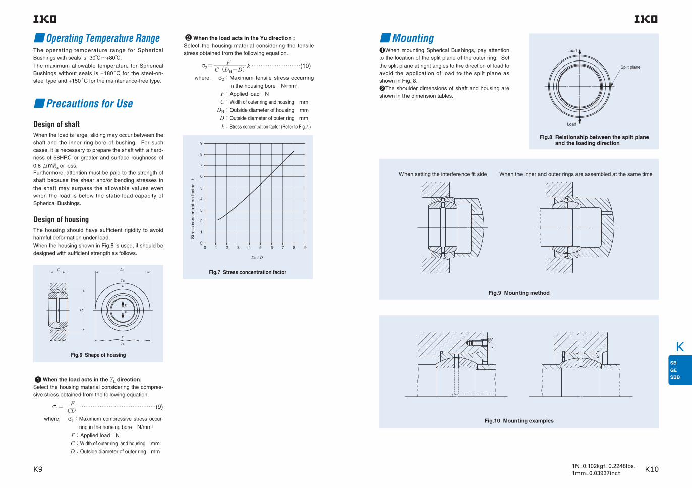
K
K9 K101N=0.102kgf=0.2248lbs.1mm=0.03937inch
Operating Temperature RangeThe operating temperature range for Spherical Bushings with seals is -30 C〜+80 C.The maximum allowable temperature for Spherical Bushings without seals is +180 C for the steel-on-steel type and +150 C for the maintenance-free type.
Precautions for Use
Design of shaftWhen the load is large, sliding may occur between the shaft and the inner ring bore of bushing. For such cases, it is necessary to prepare the shaft with a hard-ness of 58HRC or greater and surface roughness of
0.8 μmRa or less.Furthermore, attention must be paid to the strength of shaft because the shear and/or bending stresses in the shaft may surpass the allowable values even when the load is below the static load capacity of Spherical Bushings.
Design of housingThe housing should have sufficient rigidity to avoid harmful deformation under load. When the housing shown in Fig.6 is used, it should be designed with sufficient strength as follows.
Fig.6 Shape of housing
Fig.7 Stress concentration factor
1 When the load acts in the YL direction; Select the housing material considering the compres-sive stress obtained from the following equation.
σ1= F
……………………………………(9) CD
where, σ1: Maximum compressive stress occur-
ring in the housing bore N/mm2
F:Applied load N
C:Width of outer ring and housing mm
D:Outside diameter of outer ring mm
2 When the load acts in the Yu direction ;Select the housing material considering the tensile stress obtained from the following equation. σ2=
F k ………………………(10) C(DH−D)
where, σ2: Maximum tensile stress occurring
in the housing bore N/mm2
F:Applied load N
C:Width of outer ring and housing mm
DH:Outside diameter of housing mm
D:Outside diameter of outer ring mm
k:Stress concentration factor (Refer to Fig.7.)
Str
ess
con
cen
trat
ion
fac
tor
D
C
FF
DH
YU
YL
10 2 3 4 5 6 7 8 9
1
0
2
3
4
5
6
7
8
9
D DH /
k
Mounting
Fig.8 Relationship between the split plane and the loading direction
Fig.9 Mounting method
Fig.10 Mounting examples
1 When mounting Spherical Bushings, pay attention to the location of the split plane of the outer ring. Set the split plane at right angles to the direction of load to avoid the application of load to the split plane as shown in Fig. 8. 2 The shoulder dimensions of shaft and housing are shown in the dimension tables.
When setting the interference fit side When the inner and outer rings are assembled at the same time
Split plane
Load
Load

K
K11 K121N=0.102kgf=0.2248lbs.1mm=0.03937inch
SPHERICAL BUSHINGS
Shaft dia. 12− 100mm
Steel-on-steel Spherical Bushings
Notes(1) Minimum allowable value of chamfer dimensions r1 and r2 (2) When Spherical Bushings are used with full tilting angle, the shaft shoulder dimesion must be less than the maximum value of da.Remarks1. The inner ring and the outer ring have an oil groove and two oil holes, respectively. 2. No grease is prepacked. Perform proper lubrication.
Shaft dia.
mm
Identification number
d D B C dk rs min(1)
Boundary dimensionsmm
Mass (Ref.)
kg
0.019120.028150.053200.085220.116250.225300.300350.375400.600450.870501.26551.70602.05652.22703.02753.98804.29854.71906.05957.42
12
15
20
22
25
30
35
40
45
50
55
60
65
70
75
80
85
90
95
100
22
26
32
37
42
50
55
62
72
80
90
100
105
110
120
130
135
140
150
160
11
13
16
19
21
27
30
33
36
42
47
53
55
58
64
70
74
76
82
88
9
11
14
16
18
23
26
28
31
36
40
45
47
50
55
60
63
65
70
75
18
22
28
32
36
45
50
55
62
72
80
90
94
100
110
120
125
130
140
150
0.3
0.3
0.3
0.3
0.3
0.6
0.6
0.6
0.6
0.6
0.6
0.6
0.6
0.6
0.6
0.6
0.6
0.6
0.6
1
7
6
4
6
5
6
5
6
5
5
5
6
5
5
5
5
6
5
5
5100
SB 12A
SB 15A
SB 20A
SB 22A
SB 25A
SB 30A
SB 35A
SB 40A
SB 45A
SB 50A
SB 55A
SB 60A
SB 65A
SB 70A
SB 75A
SB 80A
SB 85A
SB 90A
SB 95A
SB 100A
SB 122211
SB 152613
SB 203216
SB 223719
SB 254221
SB 305027
SB 355530
SB 406233
SB 457236
SB 508042
SB 559047
SB 6010053
SB 6510555
SB 7011058
SB 7512064
SB 8013070
SB 8513574
SB 9014076
SB 9515082
SB 10016088
α
Permissible tilting angle
degree
Mounting dimensionsmm
Min. Max. Max. Min.
Static loadcapacity
Cs
N
14
17.5
22.5
24.5
27.5
34.5
39.5
44
49.5
54.5
59.5
64.5
69.5
74.5
79.5
84.5
89.5
94.5
99.5
105.5
14
17.5
23
25.5
29
36
40
44
50.5
58.5
64.5
72.5
76
81.5
89.5
97.5
100.5
105.5
113.5
121.5
19.5
23.5
29.5
34.5
39.5
45.5
50.5
57.5
67.5
75.5
85.5
95.5
100.5
105.5
115.5
125.5
130.5
135.5
145.5
154.5
17
21
26
30
34
42
46.5
51.5
58
67
74.5
83.5
87
93
102
112
116
121
130
139
15 900
23 700
38 400
50 200
63 500
101 000
127 000
151 000
188 000
254 000
314 000
397 000
433 000
490 000
593 000
706 000
772 000
829 000
961 000
1 100 000
95 300
142 000
231 000
301 000
381 000
609 000
765 000
906 000
1 130 000
1 530 000
1 880 000
2 380 000
2 600 000
2 940 000
3 560 000
4 240 000
4 630 000
4 970 000
5 770 000
6 620 000
(2)
SBSB … A
Dynamic loadcapacity
Cd
N
D
BC
r2
d
dk
r2
r1
r1
α
α
D
BC
r2
d
dk
r2
r1
r1
α
α
Da
da
da Da

K
K13 K141N=0.102kgf=0.2248lbs.1mm=0.03937inch
Shaft dia. 110− 150mm
SPHERICAL BUSHINGS
Shaft dia.
mm
Identification number
d D B C dk rs min(1)
Boundary dimensionsmm
Mass (Ref.)
kg α
Permissible tilting angle
degree
Notes(1) Minimum allowable value of chamfer dimensions r1 and r2 (2) When Spherical Bushings are used with full tilting angle, the shaft shoulder dimension must be less than the maximum value of da.Remarks1. The inner ring and the outer ring have an oil groove and two oil holes, respectively. 2. No grease is prepacked. Perform proper lubrication.
8.5511010.311512.412013.813017.0150
110
115
120
130
150
170
180
190
200
220
93
98
105
110
120
80
85
90
95
105
160
165
175
185
205
1
1
1
1
1
SB 110A
SB 115A
SB 120A
SB 130A
SB 150A
SB 11017093
SB 11518098
SB 120190105
SB 130200110
SB 150220120
5
5
5
5
5
Steel-on-steel Spherical Bushings
Mounting dimensionsmm
Min. Max. Max. Min.
Static loadcapacity
Cs
N
115.5
120.5
125.5
135.5
155.5
130
132.5
140
148.5
166
164.5
174.5
184.5
194.5
214.5
149
152
162
171
189
1 260 000
1 380 000
1 540 000
1 720 000
2 110 000
7 530 000
8 250 000
9 270 000
10 300 000
12 700 000
(2)
SBSB … A
Dynamic loadcapacity
Cd
N
D
BC
r2
d
dk
r2
r1
r1
α
α
D
BC
r2
d
dk
r2
r1
r1
α
α
Da
da
da Da

K
K15 K161N=0.102kgf=0.2248lbs.1mm=0.03937inch
Notes(1) Minimum allowable value of chamfer dimensions r1 and r2 (2) When Spherical Bushings are used with full tilting angle, the shaft shoulder dimension must be less than the maximum value of da.Remarks1. GE…E has no oil hole. Others are provided with an oil groove and two oil holes on the inner ring and outer ring, respectively. 2. No grease is prepacked. Perform proper lubrication.
Shaft dia. 4− 100mm
Shaft dia.
mm
Identification number
d D B C dk r1s min r2s min(1)
Boundary dimensionsmm
Mass (Ref.)
kg
0.3
0.3
0.3
0.3
0.3
0.3
0.3
0.3
0.3
0.6
0.6
0.6
0.6
0.6
0.6
1
1
1
1
1
0.3
0.3
0.3
0.3
0.3
0.3
0.3
0.3
0.3
0.6
0.6
1
1
1
1
1
1
1
1
1
16
13
13
15
12
11
8
10
9
7
6
6
7
7
6
6
6
6
5
7
5
7
6
4
4
4
4
4
4
3
4
4
3
5
α α1(1)
Permissible tilting angle
degree
GE … E
0.00340.00450.00460.00880.012100.017120.032150.049170.065200.115250.160300.258350.315400.413450.560501.10601.54702.29802.82904.43
4
5
6
8
10
12
15
17
20
25
30
35
40
45
50
60
70
80
90
100
12
14
14
16
19
22
26
30
35
42
47
55
62
68
75
90
105
120
130
150
5
6
6
8
9
10
12
14
16
20
22
25
28
32
35
44
49
55
60
70
3
4
4
5
6
7
9
10
12
16
18
20
22
25
28
36
40
45
50
55
8
10
10
13
16
18
22
25
29
35.5
40.7
47
53
60
66
80
92
105
115
130100
GE 4E
GE 5E
GE 6E
GE 8E
GE 10E
GE 12E
GE 15ES
GE 17ES
GE 20ES
GE 25ES
GE 30ES
GE 35ES
GE 40ES
GE 45ES
GE 50ES
GE 60ES
GE 70ES
GE 80ES
GE 90ES
GE 100ES
GE 15ES-2RS
GE 17ES-2RS
GE 20ES-2RS
GE 25ES-2RS
GE 30ES-2RS
GE 35ES-2RS
GE 40ES-2RS
GE 45ES-2RS
GE 50ES-2RS
GE 60ES-2RS
GE 70ES-2RS
GE 80ES-2RS
GE 90ES-2RS
GE 100ES-2RS
Without seals With seals
SPHERICAL BUSHINGS
Steel-on-steel Spherical Bushings
D
BC
r2
d
dK
r2
r1
r1
α
α
Mounting dimensionsmm
Min. Max. Max. Min.
Static loadcapacity
Cs
N
6
7.5
8
10
12.5
14.5
17.5
19.5
22.5
29
34
39.5
44.5
49.5
54.5
65.5
75.5
85.5
95.5
105.5
6
8
8
10
13
15
18
20.5
24
29
34
39.5
45
50.5
56
66.5
77.5
89
98
109.5
9.5
11.5
11.5
13.5
16.5
19.5
23.5
27.5
32.5
37.5
42.5
49.5
56.5
62.5
69.5
84.5
99.5
114.5
124.5
144.5
8
10
10
13
15.5
17
22.5
26
30.5
37
41.5
48
54.5
60
66
79
91
103
112
127
2 350
3 920
3 920
6 370
9 410
12 400
19 400
24 500
34 100
55 700
71 800
92 200
114 000
147 000
181 000
282 000
361 000
463 000
564 000
701 000
14 100
23 500
23 500
38 200
56 500
74 100
117 000
147 000
205 000
334 000
431 000
553 000
686 000
883 000
1 090 000
1 690 000
2 170 000
2 780 000
3 380 000
4 210 000
(2)
GE … ES-2RSGE … ES
Dynamic loadcapacity
Cd
N
D
BC
r2
d
dk
r2
r1
r1
α
α
D
BC
r2
d
dk
r2
r1
r1
α1
α1
Da da
da Da

K
K17 K181N=0.102kgf=0.2248lbs.1mm=0.03937inch
Shaft dia. 110− 300mm
Shaft dia.
mm
Identification number
d D B C dk r1s min r2s min(1)
Boundary dimensionsmm
Mass (Ref.)
kg
4.94110 8.12120 11.4140 14.4160 18.9180 28.1200 36.1220 40.4240 52.0260 66.0280 76.0300
110
120
140
160
180
200
220
240
260
280
300
160
180
210
230
260
290
320
340
370
400
430
70
85
90
105
105
130
135
140
150
155
165
55
70
70
80
80
100
100
100
110
120
120
140
160
180
200
225
250
275
300
325
350
375
1
1
1
1
1.1
1.1
1.1
1.1
1.1
1.1
1.1
1
1
1
1
1.1
1.1
1.1
1.1
1.1
1.1
1.1
6
6
7
8
6
7
8
8
7
6
7
4
4
5
6
5
6
6
6
6
5
6
GE 110ES
GE 120ES
GE 140ES
GE 160ES
GE 180ES
GE 200ES
GE 220ES
GE 240ES
GE 260ES
GE 280ES
GE 300ES
GE 110ES-2RS
GE 120ES-2RS
GE 140ES-2RS
GE 160ES-2RS
GE 180ES-2RS
GE 200ES-2RS
GE 220ES-2RS
GE 240ES-2RS
GE 260ES-2RS
GE 280ES-2RS
GE 300ES-2RS
α α1(1)
Permissible tilting angle
degree
Notes(1) Minimum allowable value of chamfer dimensions r1 and r2 (2) When Spherical Bushings are used with full tilting angle, the shaft shoulder dimension must be less than the maximum value of da.Remarks1. The inner ring and the outer ring have an oil groove and two oil holes, respectively. 2. No grease is prepacked. Perform proper lubrication.
Without seals With seals
SPHERICAL BUSHINGS
Steel-on-steel Spherical Bushings
Mounting dimensionsmm
Min. Max. Max. Min.
Static loadcapacity
Cs
N
115.5
125.5
145.5
165.5
187
207
227
247
267
287
307
121
135.5
155.5
170
199
213.5
239.5
265
288
313.5
336.5
154.5
174.5
204.5
224.5
253
283
313
333
363
393
423
138
154
176
195
221
244
269
296
320
345
371
755 000
1 100 000
1 240 000
1 570 000
1 770 000
2 450 000
2 700 000
2 940 000
3 510 000
4 120 000
4 410 000
4 530 000
6 590 000
7 410 000
9 410 000
10 600 000
14 700 000
16 200 000
17 700 000
21 000 000
24 700 000
26 500 000
(2)
GE … ES-2RSGE … ES
Dynamic loadcapacity
Cd
N
D
BC
r2
d
dk
r2
r1
r1
α
α
D
BC
r2
d
dk
r2
r1
r1
α1
α1
Da da
da Da

K
K19 K201N=0.102kgf=0.2248lbs.1mm=0.03937inch
GE … G
Shaft dia. 6− 120mm
Shaft dia.
mm
Identification number
d D B C dk r1s min r2s min(1)
Boundary dimensionsmm
Mass (Ref.)
kg
0.0106 0.0158 0.02210 0.04112 0.05915 0.08317 0.15520 0.21525 0.33030 0.40035 0.51540 0.66045 1.5050 2.0560 3.0070 3.6080 5.4190 6.15100 9.70110 15.5
6
8
10
12
15
17
20
25
30
35
40
45
50
60
70
80
90
100
110
120
16
19
22
26
30
35
42
47
55
62
68
75
90
105
120
130
150
160
180
210
9
11
12
15
16
20
25
28
32
35
40
43
56
63
70
75
85
85
100
115
5
6
7
9
10
12
16
18
20
22
25
28
36
40
45
50
55
55
70
70
13
16
18
22
25
29
35.5
40.7
47
53
60
66
80
92
105
115
130
140
160
180
0.3
0.3
0.3
0.3
0.3
0.3
0.3
0.6
0.6
0.6
0.6
0.6
0.6
1
1
1
1
1
1
1
0.3
0.3
0.3
0.3
0.3
0.3
0.6
0.6
1
1
1
1
1
1
1
1
1
1
1
1
21
21
18
18
16
19
17
17
17
16
17
15
17
17
16
14
15
14
12
16
13
16
16
15
16
15
14
13
16
15
14
13
14
12
11
15120
GE 6G
GE 8G
GE 10G
GE 12G
GE 15GS
GE 17GS
GE 20GS
GE 25GS
GE 30GS
GE 35GS
GE 40GS
GE 45GS
GE 50GS
GE 60GS
GE 70GS
GE 80GS
GE 90GS
GE 100GS
GE 110GS
GE 120GS
GE 15GS-2RS
GE 17GS-2RS
GE 20GS-2RS
GE 25GS-2RS
GE 30GS-2RS
GE 35GS-2RS
GE 40GS-2RS
GE 45GS-2RS
GE 50GS-2RS
GE 60GS-2RS
GE 70GS-2RS
GE 80GS-2RS
GE 90GS-2RS
GE 100GS-2RS
GE 110GS-2RS
GE 120GS-2RS
α α1(1)
Permissible tilting angle
degree
Notes(1) Minimum allowable value of chamfer dimensions r1 and r2 (2) When Spherical Bushings are used with full tilting angle, the shaft shoulder dimension must be less than the maximum value of da.Remarks1. GE…G has no oil hole. Others are provided with an oil groove and two oil holes on the inner ring and outer ring, respectively. 2. No grease is prepacked. Perform proper lubrication.
Without seals With seals
SPHERICAL BUSHINGS
Steel-on-steel Spherical Bushings
D
r1
BC
r2
d
dK
r2
r1
α
α
Mounting dimensionsmm
Min. Max. Max. Min.
Static loadcapacity
Cs
N
8.5
10.5
12.5
14.5
17.5
19.5
22.5
29.5
34
39.5
44.5
49.5
54.5
65.5
75.5
85.5
95.5
105.5
115.5
125.5
9
11.5
13
16
19
21
25
29.5
34
39.5
44.5
50
57
67
78
87
98
111
124.5
138.5
13.5
16.5
19.5
23.5
27.5
32.5
37.5
42.5
49.5
56.5
62.5
69.5
84.5
99.5
114.5
124.5
144.5
154.5
174.5
204.5
13
15.5
17
21
26
30.5
37
41.5
48
54.5
60
66
79
91
103
112
127
138
154
176
6 370
9 410
12 400
19 400
24 500
34 100
55 700
71 800
92 200
114 000
147 000
181 000
282 000
361 000
463 000
564 000
701 000
755 000
1 100 000
1 240 000
38 200
56 500
74 100
117 000
147 000
205 000
334 000
431 000
553 000
686 000
883 000
1 090 000
1 690 000
2 170 000
2 780 000
3 380 000
4 210 000
4 530 000
6 590 000
7 410 000
(2)
GE … GS-2RSGE … GS
Dynamic loadcapacity
Cd
N
D
BC
r2
d
dk
r2
r1
r1
α
α
D
BC
r2
d
dk
r2
r1
r1
α1
α1
Da da
da Da

K
K21 K221N=0.102kgf=0.2248lbs.1mm=0.03937inch
Shaft dia. 140− 280mm
Shaft dia.
mm
Identification number
d D B C dk r1s min r2s min(1)
Boundary dimensionsmm
Mass (Ref.)
kg
19.214025.416034.718043.820051.322066.124081.826097.4280
140
160
180
200
220
240
260
280
230
260
290
320
340
370
400
430
130
135
155
165
175
190
205
210
80
80
100
100
100
110
120
120
200
225
250
275
300
325
350
375
1
1
1.1
1.1
1.1
1.1
1.1
1.1
1
1.1
1.1
1.1
1.1
1.1
1.1
1.1
16
16
14
15
16
15
15
15
15
14
13
14
14
14
14
14
GE 140GS
GE 160GS
GE 180GS
GE 200GS
GE 220GS
GE 240GS
GE 260GS
GE 280GS
GE 140GS-2RS
GE 160GS-2RS
GE 180GS-2RS
GE 200GS-2RS
GE 220GS-2RS
GE 240GS-2RS
GE 260GS-2RS
GE 280GS-2RS
α α1(1)
Permissible tilting angle
degree
Notes(1) Minimum allowable value of chamfer dimensions r1 and r2 (2) When Spherical Bushings are used with full tilting angle, the shaft shoulder dimension must be less than the maximum value of da.Remarks1. The inner ring and the outer ring have an oil groove and two oil holes, respectively. 2. No grease is prepacked. Perform proper lubrication.
Without seals With seals
SPHERICAL BUSHINGS
Steel-on-steel Spherical Bushings
Mounting dimensionsmm
Min. Max. Max. Min.
Static loadcapacity
Cs
N
145.5
165.5
187
207
227
247
267
287
152
180
196
220
243.5
263.5
283.5
310.5
224.5
253
283
313
333
363
393
423
195
221
244
269
296
320
345
371
1 570 000
1 770 000
2 450 000
2 700 000
2 940 000
3 510 000
4 120 000
4 410 000
9 410 000
10 600 000
14 700 000
16 200 000
17 700 000
21 000 000
24 700 000
26 500 000
(2)
GE … GS-2RSGE … GS
Dynamic loadcapacity
Cd
N
D
BC
r2
d
dk
r2
r1
r1
α
α
D
BC
r2
d
dk
r2
r1
r1
α1
α1
Da da
da Da

K
K23 K241N=0.102kgf=0.2248lbs.1mm=0.03937inch
Identification number
Note(1) Maximum allowable corner radius of the shaft or housing Remarks1. The value with mark * is applicable to types without seals. For types with seals, the value is 0.4 mm. 2. The inner ring and the outer ring have an oil groove and two oil holes, respectively. 3. No grease is prepacked. Perform proper lubrication.
Inch SeriesSteel-on-steel Spherical Bushings
12.700( 12)15.875( 58)19.050( 34)22.225( 78)25.400(1)31.750(114)34.925(138)38.100(112)44.450(134)50.800(2)57.150(214)63.500(212)
SBB 8
SBB 10
SBB 12
SBB 14
SBB 16
SBB 20
SBB 22
SBB 24
SBB 28
SBB 32
SBB 36
SBB 40
SBB 12-2RS
SBB 14-2RS
SBB 16-2RS
SBB 20-2RS
SBB 22-2RS
SBB 24-2RS
SBB 28-2RS
SBB 32-2RS
SBB 36-2RS
SBB 40-2RS
0.020
0.036
0.057
0.088
0.125
0.234
0.349
0.424
0.649
0.939
1.32
1.85
12.700( 12)
15.875( 58)
19.050( 34)
22.225( 78)
25.400(1 )
31.750(114)
34.925(138)
38.100(112)
44.450(134)
50.800(2 )
57.150(214)
63.500(212)
22.225( 78)
26.988(1 116)
31.750(1 14)
36.512(1 716)
41.275(1 58)
50.800(2 )
55.562(2 316)
61.912(2 716)
71.438(21316)
80.962(3 316)
90.488(3 916)
100.012(31516)
11.10( .437)
13.89( .547)
16.66( .656)
19.43( .765)
22.22( .875)
27.76(1.093)
30.15(1.187)
33.32(1.312)
38.89(1.531)
44.45(1.750)
50.01(1.969)
55.55(2.187)
9.52( .375)
11.91( .469)
14.27( .562)
16.66( .656)
19.05( .750)
23.80( .937)
26.19(1.031)
28.58(1.125)
33.32(1.312)
38.10(1.500)
42.85(1.687)
47.62(1.875)
Mass (Ref.)
kg
Boundary dimensionsmm(inch)
d D B CWithout seal With seals
Shaft dia.
mm(inch)
Shaft dia. 12.700− 63.500mm
SPHERICAL BUSHINGS
Dynamic loadcapacity
Cd
N
Static loadcapacity
Cs
Ndk
Radial internal clearance
mmMin./Max. d1
Mounting dimensionsmm
18 ( .709)
23 ( .906)
27.5(1.083)
32 (1.260)
36 (1.417)
45 (1.772)
49 (1.929)
55 (2.165)
64 (2.520)
73 (2.874)
82 (3.228)
91 (3.583)
0.05 / 0.15
0.05 / 0.15
0.08 / 0.18
0.08 / 0.18
0.08 / 0.18
0.08 / 0.18
0.08 / 0.18
0.08 / 0.18
0.08 / 0.18
0.08 / 0.18
0.10 / 0.20
0.10 / 0.20
14.0
17.9
21.4
25.0
28.0
35.1
38.5
43.3
50.4
57.6
64.9
72.0
0.2
0.2
0.6
0.6
0.6
0.6
0.6
0.6
0.6
0.6
0.6
0.6
0.6
0.8
*0.8
*0.8
*0.8
0.8
0.8
0.8
0.8
0.8
0.8
0.8
16 800
26 900
38 500
52 300
67 300
105 000
126 000
154 000
209 000
273 000
345 000
425 000
101 000
161 000
231 000
314 000
404 000
630 000
755 000
925 000
1 250 000
1 640 000
2 070 000
2 550 000
ras maxMax.
(1) rbs maxMax.
(1)
SBB … -2RSSBB SBB … -2RSSBB
Permissible tilting angle
D
BC
rb
d1d
dk
ra
D
BC
rb
d1d
dk
ra
12° 7°
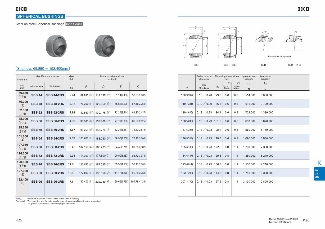
K
K25 K261N=0.102kgf=0.2248lbs.1mm=0.03937inch
Identification number
Note(1) Maximum allowable corner radius of the shaft or housing Remarks1. The inner ring and the outer ring have an oil groove and two oil holes, respectively. 2. No grease is prepacked. Perform proper lubrication.
69.850(234)
76.200(3)82.550
(314)88.900
(312)95.250
(334)101.600(4)
107.950(414)114.300(412)120.650(434)127.000(5)
152.400(6)
SBB 44
SBB 48
SBB 52
SBB 56
SBB 60
SBB 64
SBB 68
SBB 72
SBB 76
SBB 80
SBB 96
SBB 44-2RS
SBB 48-2RS
SBB 52-2RS
SBB 56-2RS
SBB 60-2RS
SBB 64-2RS
SBB 68-2RS
SBB 72-2RS
SBB 76-2RS
SBB 80-2RS
SBB 96-2RS
2.44
3.12
3.92
4.83
5.87
7.07
8.46
9.94
11.6
13.5
17.6
69.850(234)
76.200(3 )
82.550(314)
88.900(312)
95.250(334)
101.600(4 )
107.950(414)
114.300(412)
120.650(434)
127.000(5 )
152.400(6 )
111.125(438)
120.650(434)
130.175(518)
139.700(512)
149.225(578)
158.750(614)
168.275(658)
177.800(7 )
187.325(738)
196.850(734)
222.250(834)
61.11(2.406)
66.68(2.625)
72.24(2.844)
77.77(3.062)
83.34(3.281)
88.90(3.500)
94.46(3.719)
100.00(3.937)
105.56(4.156)
111.12(4.375)
120.65(4.750)
52.37(2.062)
57.15(2.250)
61.90(2.437)
66.68(2.625)
71.42(2.812)
76.20(3.000)
80.95(3.187)
85.72(3.375)
90.47(3.562)
95.25(3.750)
104.78(4.125)
Mass (Ref.)
kg
Boundary dimensionsmm(inch)
d D B CWithout seal With seals
Shaft dia.
mm(inch)
Shaft dia. 69.850− 152.400mm
SPHERICAL BUSHINGS
Inch SeriesSteel-on-steel Spherical Bushings
Dynamic loadcapacity
Cd
N
Static loadcapacity
Cs
Ndk
Radial internal clearance
mmMin./Max. d1
Mounting dimensionsmm
100(3.937)
110(4.331)
119(4.685)
128(5.039)
137(5.394)
146(5.748)
155(6.102)
164(6.457)
173(6.811)
183(7.205)
207(8.150)
0.10 / 0.20
0.10 / 0.20
0.13 / 0.23
0.13 / 0.23
0.13 / 0.23
0.13 / 0.23
0.13 / 0.23
0.13 / 0.23
0.13 / 0.23
0.13 / 0.23
0.13 / 0.23
79.0
86.5
94.1
101.6
108.4
115.8
122.6
129.8
136.8
144.9
167.5
0.6
0.6
0.6
0.6
0.6
0.6
0.8
0.8
0.8
0.8
0.8
0.8
0.8
0.8
0.8
0.8
0.8
1.1
1.1
1.1
1.1
1.1
514 000
616 000
722 000
837 000
960 000
1 090 000
1 230 000
1 380 000
1 530 000
1 710 000
2 130 000
3 080 000
3 700 000
4 330 000
5 020 000
5 760 000
6 550 000
7 380 000
8 270 000
9 210 000
10 300 000
12 800 000
ras maxMax.
(1)rbs maxMax.
(1)
SBB … -2RSSBB SBB … -2RSSBB
Permissible tilting angle
D
BC
rb
d1d
dk
ra
D
BC
rb
d1d
dk
ra
12° 7°

K
K27 K281N=0.102kgf=0.2248lbs.1mm=0.03937inch
Shaft dia. 15− 70mm
Maintenance-free Spherical Bushings
Shaft dia.
mm
Identification number
d D B C dk r1s min r2s min(1)
Boundary dimensionsmm
Mass (Ref.)
kg
0.032150.049170.065200.115250.160300.258350.315400.413450.56050
1.1060 1.5470
15
17
20
25
30
35
40
45
50
60
70
26
30
35
42
47
55
62
68
75
90
105
12
14
16
20
22
25
28
32
35
44
49
9
10
12
16
18
20
22
25
28
36
40
22
25
29
35.5
40.7
47
53
60
66
80
92
0.3
0.3
0.3
0.6
0.6
0.6
0.6
0.6
0.6
1
1
0.3
0.3
0.3
0.6
0.6
1
1
1
1
1
1
8
10
9
7
6
4
4
4
4
4
3
4
GE 15EC
GE 17EC
GE 20EC
GE 25EC
GE 30EC
GE 30EC-2RS
GE 35EC-2RS
GE 40EC-2RS
GE 45EC-2RS
GE 50EC-2RS
GE 60EC-2RS
GE 70EC-2RS
α α1(1)
Permissible tilting angle
degree
Notes(1) Minimum allowable value of chamfer dimensions r1 and r2 (2) When Spherical Bushings are used with full tilting angle, the shaft shoulder dimension must be less than the maximum value of da.Remark No oil hole is provided.
Without seals With seals
SPHERICAL BUSHINGS
Mounting dimensionsmm
Min. Max. Max. Min.
Static loadcapacity
Cs
N(2)
GE … EC-2RSGE … EC
Dynamic loadcapacity
Cd
N
17.5
19.5
22.5
29
34
39.5
44.5
49.5
54.5
65.5
75.5
18
20.5
24
29
34
39.5
45
50.5
56
66.5
77.5
23.5
27.5
32.5
37.5
42.5
49.5
56.5
62.5
69.5
84.5
99.5
21.5
24.5
28
34
41.5
48
54.5
60
66
79
91
19 400
24 500
34 100
55 700
71 800
92 200
114 000
147 000
181 000
282 000
361 000
48 500
61 300
85 300
139 000
180 000
230 000
286 000
368 000
453 000
706 000
902 000
D
BC
r2
d
dk
r2
r1
r1
α
α
D
BC
r2
d
dk
r2
r1
r1
α1
α1
Da
da
da Da
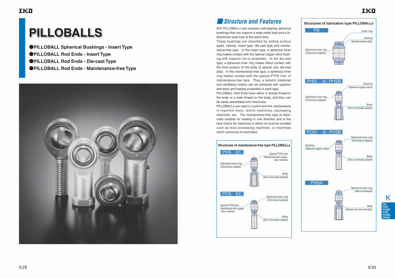
K
K29 K30
PILLOBALL Spherical Bushings - Insert Type
PILLOBALL Rod Ends - Insert Type
PILLOBALL Rod Ends - Die-cast Type
PILLOBALL Rod Ends - Maintenance-free Type
Structure and FeaturesIKO PILLOBALLs are compact self-aligning spherical bushings that can support a large radial load and a bi-directional axial load at the same time.These bushings are classified by sliding surface types, namely, insert type, die-cast type and mainte-nance-free type. In the insert type, a spherical inner ring makes contact with the special copper alloy bush-ing with superior run-in properties. In the die-cast type, a spherical inner ring makes direct contact with the bore surface of the body of special zinc die-cast alloy. In the maintenance-free type, a spherical inner ring makes contact with the special PTFE liner of maintenance-free type. Thus, a smooth rotational and oscillatory motion can be achieved with superior anti-wear and loading properties in each type.PILLOBALL Rod Ends have either a female thread in the body or a male thread on the body, and they can be easily assembled onto machines.PILLOBALLs are used in control and link mechanisms in machine tools, texti le machines, packaging machines, etc. The maintenance-free type is espe-cially suitable for loading in one direction and is the best choice for machines in which oil must be avoided such as food processing machines, or machines which cannot be re-lubricated.
Structures of maintenance-free type PILLOBALLs
Special PTFE liner(Reinforced with copper
alloy meshes)
Body (Zinc chromate plated)
Spherical inner ring(Chromium plated)
Body(Zinc chromate plated)
Spherical inner ring(Chromium plated)
Special PTFE liner(Reinforced with copper alloy meshes)
Structures of lubrication type PILLOBALLs
Outer ring
Bushing(Special copper alloy)
Bushing(Special copper alloy)
Body(Zinc chromate plated)
Spherical inner ring(Chromium plated)
Body(Zinc chromate plated)
Spherical inner ring(Mirror-finished)
Spherical inner ring(Chromium plated)
Spherical inner ring(Chromium plated)
Bushing(Special copper alloy)
Body(Special zinc die-cast alloy)
PHS( A)
POS( A)
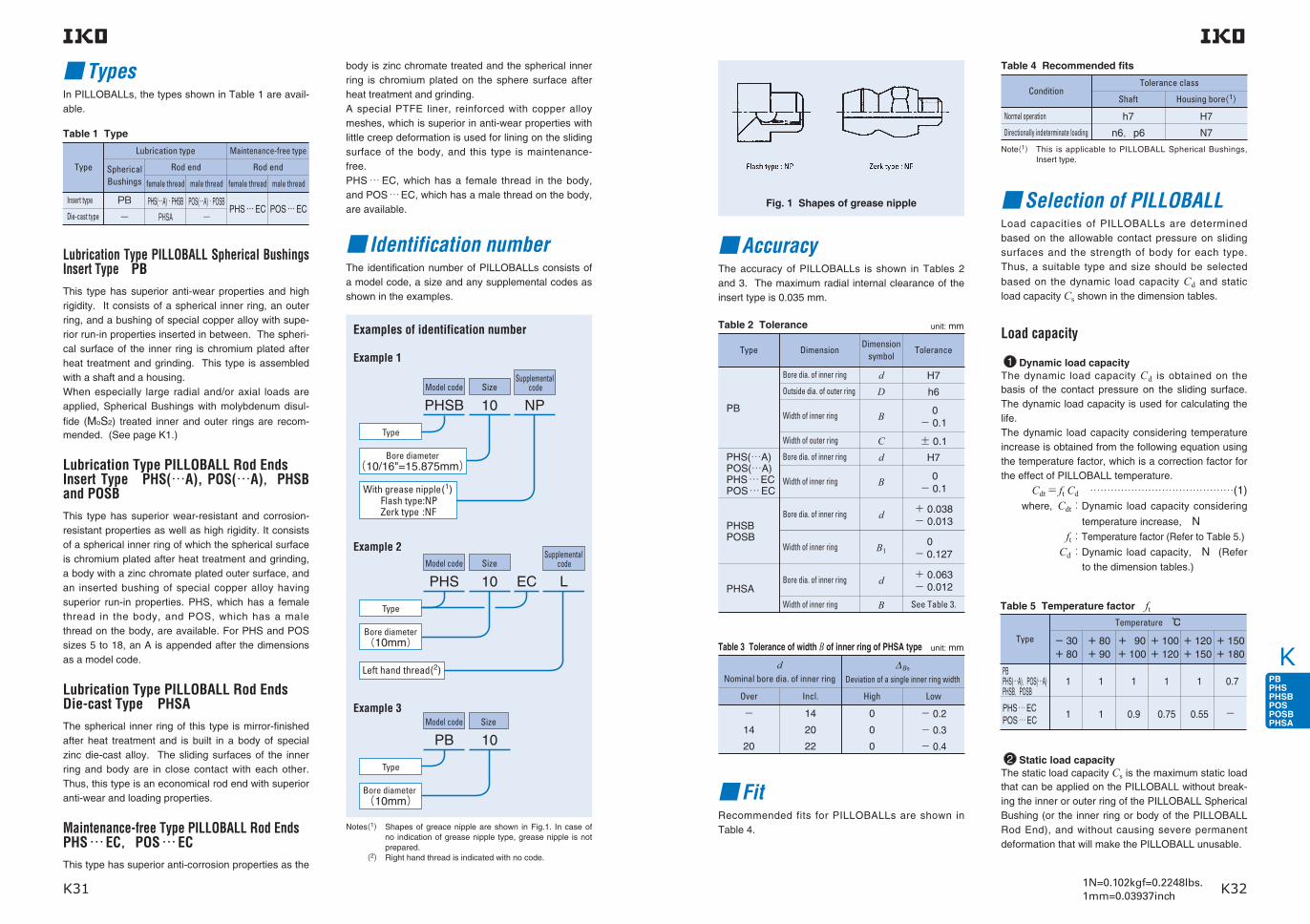
K
K31 K321N=0.102kgf=0.2248lbs.1mm=0.03937inch
TypesIn PILLOBALLs, the types shown in Table 1 are avail-able.
Lubrication Type PILLOBALL Spherical Bushings Insert Type PBThis type has superior anti-wear properties and high rigidity. It consists of a spherical inner ring, an outer ring, and a bushing of special copper alloy with supe-rior run-in properties inserted in between. The spheri-cal surface of the inner ring is chromium plated after heat treatment and grinding. This type is assembled with a shaft and a housing.When especially large radial and/or axial loads are applied, Spherical Bushings with molybdenum disul-
fide (MoS2) treated inner and outer rings are recom-mended. (See page K1.)
Lubrication Type PILLOBALL Rod EndsInsert Type PHS(…A), POS(…A),PHSB and POSBThis type has superior wear-resistant and corrosion-resistant properties as well as high rigidity. It consists of a spherical inner ring of which the spherical surface is chromium plated after heat treatment and grinding, a body with a zinc chromate plated outer surface, and an inserted bushing of special copper alloy having superior run-in properties. PHS, which has a female thread in the body, and POS, which has a male thread on the body, are available. For PHS and POS sizes 5 to 18, an A is appended after the dimensions as a model code.
Lubrication Type PILLOBALL Rod Ends Die-cast Type PHSAThe spherical inner ring of this type is mirror-finished after heat treatment and is built in a body of special zinc die-cast alloy. The sliding surfaces of the inner ring and body are in close contact with each other. Thus, this type is an economical rod end with superior anti-wear and loading properties.
Maintenance-free Type PILLOBALL Rod EndsPHS … EC,POS … ECThis type has superior anti-corrosion properties as the
body is zinc chromate treated and the spherical inner ring is chromium plated on the sphere surface after heat treatment and grinding.A special PTFE liner, reinforced with copper alloy meshes, which is superior in anti-wear properties with little creep deformation is used for lining on the sliding surface of the body, and this type is maintenance-free.PHS … EC, which has a female thread in the body, and POS … EC, which has a male thread on the body, are available.
Identification numberThe identification number of PILLOBALLs consists of a model code, a size and any supplemental codes as shown in the examples.
Examples of identification number
Example 1
Example 2Model code
Supplemental codeSize
PHS 10
Type
EC L
Bore diameter (10mm)
Model code Size
PB 10
Type
Example 3
Bore diameter (10mm)
Left hand thread(2)
Model codeSupplemental
codeSize
PHSB 10
Type
NP
Bore diameter (10/16"=15.875mm)
With grease nipple(1)
Zerk type :NFFlash type:NP
Table 1 Type
Type
Insert type
Die-cast type
PB
−PHS(…A)・PHSB
PHSAPOS(…A)・POSB
− PHS … EC POS … EC
Lubrication type Maintenance-free type
Rod end Rod end
female thread female threadmale thread male thread
Spherical Bushings
Notes(1) Shapes of greace nipple are shown in Fig.1. In case of no indication of grease nipple type, grease nipple is not prepared.
(2) Right hand thread is indicated with no code.
Selection of PILLOBALLLoad capacities of PILLOBALLs are determined based on the allowable contact pressure on sliding surfaces and the strength of body for each type. Thus, a suitable type and size should be selected
based on the dynamic load capacity Cd and static load capacity Cs shown in the dimension tables.
AccuracyThe accuracy of PILLOBALLs is shown in Tables 2 and 3. The maximum radial internal clearance of the insert type is 0.035 mm.
FitRecommended fits for PILLOBALLs are shown in Table 4.
Load capacity
1 Dynamic load capacityThe dynamic load capacity Cd is obtained on the basis of the contact pressure on the sliding surface. The dynamic load capacity is used for calculating the life.The dynamic load capacity considering temperature increase is obtained from the following equation using the temperature factor, which is a correction factor for the effect of PILLOBALL temperature.
Cdt= ft Cd ……………………………………(1) where, Cdt: Dynamic load capacity considering
temperature increase, N ft:Temperature factor (Refer to Table 5.)
Cd: Dynamic load capacity, N (Refer to the dimension tables.)
unit: mmTable 2 Tolerance
Type DimensionDimension
symbolTolerance
PB
Bore dia. of inner ring
Outside dia. of outer ring
Width of inner ring
Width of outer ring
Bore dia. of inner ring
Bore dia. of inner ring
Width of inner ring
Width of inner ring
Bore dia. of inner ring
Width of inner ring
dD
H7
h6
0− 0.1
± 0.1
H7
+ 0.038− 0.013
0− 0.127
0− 0.1
+ 0.063− 0.012
See Table 3.
B
Cd
d
B1
B
d
B
PHS(…A)POS(…A)PHS … ECPOS … EC
PHSBPOSB
PHSA
unit: mmTable 3 Tolerance of width B of inner ring of PHSA type
dNominal bore dia. of inner ring
Over Incl. High Low
∆Bs
Deviation of a single inner ring width
−14
20
14
20
22
0
0
0
− 0.2
− 0.3
− 0.4
Table 4 Recommended fits
ConditionTolerance class
Shaft Housing bore(1)
Normal operation
Directionally indeterminate loading
h7
n6,p6
H7
N7
Note(1) This is applicable to PILLOBALL Spherical Bushings, Insert type.
2 Static load capacity The static load capacity Cs is the maximum static load that can be applied on the PILLOBALL without break-ing the inner or outer ring of the PILLOBALL Spherical Bushing (or the inner ring or body of the PILLOBALL Rod End), and without causing severe permanent deformation that will make the PILLOBALL unusable.
Table 5 Temperature factor ft
Type
PBPHS(…A),POS(…A)PHSB,POSB
PHS … ECPOS … EC
1
1
1
1
1
0.9
1
0.75
1
0.55
0.7
−
Temperature
− 30+ 80
+ 80+ 90
+ 90+ 100
+ 100+ 120
+ 120+ 150
+ 150+ 180
Fig. 1 Shapes of grease nipple

K
K33 K341N=0.102kgf=0.2248lbs.1mm=0.03937inch
11
52
2
4
6
8
10
10
5020
20
40
60
100 200
V mm s/
Nmm
/2
p
As the actual life is affected by many factors such as the material of the sliding surface, the magnitude and direction of load, lubrication, sliding velocity, etc., the calculated life can be used as a measure of expected service life.
1 Life of lubrication type PILLOBALLs PB・PHS(…A)・POS(…A)・PHSB・POSB[1]Confirmation of pV valueBefore attempting to calculate the life, make sure that the operating conditions are within the permissible
range by referring to the pV diagram in Fig.2. When the operating conditions are out of the permis-sible range, please consult IKO.
The contact pressure p and the sliding velocity V are obtained from the following equations.
p= 50P ………………………………………(3)
CdtV=5.82×10⁻⁴dkβ f ……………………(4)
where, p:Contact pressure, N/mm2
P: Equivalent radial load, N (Refer to equation (2).)
Cdt:Dynamic load capacity considering
temperature increase, N(Refer to equation (1).)
V:Sliding velocity, mm/s dk: Sphere diameter, mm
(Refer to the dimensional tables.)
2β:Oscillating angle degrees (Refer to Fig.3.)
when β< 5°, β= 5 when rotating, β= 90 f :Number of oscillations per minute, min-1
Equivalent radial load
PILLOBALLs can take radial and axial loads at the same time. When the magnitude and direction of loads are constant, the equivalent radial load can be obtained by the following equation.
P= Fr+ YFa…………………………………(2) where, P:Equivalent radial load, N Fr:Radial load, N Fa:Axial load, N Y:Axial load factor (Refer to Table 7.)
Table 7 Axial load factor YFa/Fr
Type
PBPHS(…A),POS(…A)PHSB,POSB
PHS … ECPOS … EC
1
1 2 3
2 3 4 5 Unusable
0.1 0.2 0.3 0.4 0.5 > 0.5
Fig. 2 pV diagram of lubrication type PILLOBALLs
Table 6 Maximum operating load
Type
PB
PHS(…A),POS(…A),PHSB,POSB
PHSA
PHS … EC,POS … EC
≦ 0.3Cd
≦ 0.3Cd
≦ 0.3Cs
≦ 0.6Cd
≦ 0.2Cs
≦ 0.2Cs
Load direction
Constant Alternate
Remark Cd is the dynamic load capacity and Cs is the static load capacity.
≦ 0.16Cs
Maximum Operating Load
The recommended value of bushing load is obtained
by multiplying the dynamic load capacity Cd by a numerical factor, which differs depending on the bushing type and load condition. For PILLOBALL Rod
Ends, the static load capacity Cs must also be con-sidered in determining the applicable bushing load.Table 6 shows the guidelines for maximum operating load of PILLOBALLs. When axial loads are added in addition to radial loads, bending stress occurs in the body. Pay attention to this bending stress.
Life
The life of PILLOBALLs is defined as the total number of oscillating motions during which the PILLOBALLs can be operated without failure or malfunction due to wear, increase in internal clearance, increase in slid-ing torque and operating temperature, etc.
Unusable
Co
nta
ct p
ress
ure
Sliding velocity
Permissible range
11
2
4
68
2 5 10 20 50 100 200
10
20
40
6080
Nmm
mm
/2
p
V s/
0.2 0.5 1 5 10 50 100 1500.05
0.1
0.2
0.30.40.5
1
2
345
8
b3
V mm/s
2 Life of maintenance-free type PILLOBALLs PHS … EC・POS … EC[1]Confirmation of pV valueBefore attempting to calculate the life, make sure that the operating conditions are within the permissible
range by referring to the pV diagram in Fig.5. When the operating conditions are out of the permis-sible range, please consult IKO.
The contact pressure p and sliding velocity V are obtained from equations (3) and (4) on page K6.
Table 8 Load directional factor b1 and lubrication factor b2 for lubrication type PILLOBALLs
Load directional factor b1Load direction
Constant Alternate None Regular
1 5 1 15
Lubrication factor b2Periodical lubrication
Fig. 3 Oscillating angle Fig. 4 Sliding velocity factor for lubrication type PILLOBALLs
[2]Life calculationThe life of lubrication type PILLOBALLs can be calcu-lated by the following equations.
G= 3.18b1b2b3
Cdt ×105 ……………(5) dkβ P
Lh= G ……………………………………(6)
60f
where, G:Life (Total number of oscillations)
b1:Load directional factor (Refer to Table 8.)
b2:Lubrication factor (Refer to Table 8.)
b3:Sliding velocity factor (Refer to Fig. 4.)
Cdt: Dynamic load capacity considering
temperature increase, N(Refer to equation (1).)
P:Equivalent radial load, N (Refer to equation (2).)
Lh:Life in hours, h f :Number of oscillations per minute, min-1
√ ̄ ̄ ( )2
Fig. 5 pV diagram for maintenance-free type PILLOBALL Rod Ends
Slid
ing
vel
oci
ty f
acto
r
Sliding velocity
Load direction Alternate
Load
direc
tion
Consta
nt
Co
nta
ct p
ress
ure
Sliding velocity
Permissible range
Oscillating angle
β β
ββ
Oscillating angle

K
K35 K361N=0.102kgf=0.2248lbs.1mm=0.03937inch
10 1020 50 100 200 500 1000 × 3
S m
10
0
20
30
40
50
Nmm
/2
p
LubricationMaintenance-free type PILLOBALL Rod Ends have a sliding surface lined with a self-lubricating lining. Therefore, they can be used without lubrication.Lubrication type PILLOBALLs are not provided with prepacked grease. Perform proper lubrication for use. Operating without lubrication will increase the wear of the sliding contact surfaces and cause seizure.
Oil Hole and Grease NippleTable 10 shows the specifications of oil hole and grease nipple on the outer ring or body. Further, lubrication nozzle models compatible with the grease nipple are shown in Table 11.For PILLOBALLs without an oil hole and grease nip-ple, apply grease directly on the spherical surface.
Table 10 Specifications of oil hole and grease nipple
Type
1 oil hole + oil groove
None
With grease nipple
None
1 oil hole
With grease nipple
None(1)
With grease nipple
None
PB
PHS(…A) d≦ 4
4< d d≦ 4
4< d≦ 6
6< dPOS(…A)
PHSA
PHSB・POSB
PHS … EC,POS … EC
Specification
Table 9 Load directional factor for maintenance-free type PILLOBALLs b1
Load direction
1 0.2(1)Load directional factor b1
Constant Alternate
Note(1) This value is applicable when the load changes compara-tively slowly. When the load changes rapidly, please con-sult IKO, as the factor degreases sharply.
Note(1) Grease Nipple is available for size 4 or larger with sup-plemental code.
[2]Life calculation The life of maintenance-free type PILLOBALL Rod
Ends is obtained from the total sliding distance S which is given in Fig.5 for the contact pressure p obtained from equation (3).The total number of oscillations and life in hours can be obtained from the following equations. G= 16.67× b1×
Sf ………………………(7) V
Lh= G ……………………………………(8)
60f
where, G:Life (Total number of oscillations)
b1: Load directional factor (Refer to Table 9.)
S:Total sliding distance m f :Number of oscillations per minute min-1
V:Sliding velocity mm/s Lh:Life in hours h
Fig. 6 Contact pressure and total sliding distance for maintenance-free type PILLOBALL Rod Ends
Bore diameter of inner ring d mm
Con
tact
pre
ssur
e
Total sliding distance
Table 11 Types and Dimension of Lubrication NozzlesType Dimension
B-5120R
A-5126T
A-5120R
Lubrication Nozzle
Body of grease gun
Remark HSP-3(Yamada Corporation)can be used for them.The above nozzles can be atached on the standard grease gun shown below.
Operating Temperature RangeThe maximum allowable temperature for Lubrication type PILLOBALLs is +180 C for the insert type and +80 C for the die-cast type.The maximum allowable temperature for Maintenance-free type PILLOBALL Rod Ends is +150 C.
Precautions for Use 1 Tightening depthThe recommended tightening depth of the screw into the PILLOBALL Rod End body is shown below. Insert type and maintenance-free type: 1.25 times the nominal thread dia. or more. Die-cast type: 2 times the nominal thread dia. or more.
2 Allowable tilting angleThe allowable tilting angle differs depending on the
mounting structure as shown in Table 12 and Table 13.
Table 12 Allowable tilting angle
dBore diameter
mm
3
4
5
6
8
10
12
14
16
18
20
22
25
28
30
7
7
8
8
8
8
8
10
9
9
9
10
9
9
10
13
13
13
13
14
14
13
16
15
15
15
15
15
15
17
−−7
7
8
8
8
9
9
9
9
9
−−−
−−13
13
14
14
13
16
15
15
15
15
−−−
PB(1),PHS(…A),POS(…A)PHS … EC,POS … EC
PHSA
α1 α2α1 α2
unit: degree
Note(1) In the case of the PB series, α2 is applicable in general.
With female thread
PHSB 2
PHSB 2.5
PHSB 3
PHSB 4
PHSB 5
PHSB 6
PHSB 7
PHSB 8
PHSB 10
PHSB 12
PHSB 16
POSB 2
POSB 2.5
POSB 3
POSB 4
POSB 5
POSB 6
POSB 7
POSB 8
POSB 10
POSB 12
POSB 16
8
7
6
7
6
6
7
6
7
6
7
16
12
10
13
10
11
11
9
11
10
14
With male thread
α1 α2
unit: degreeTable 13 Allowable tilting angle for inch series
α1α2

K
K37 K381N=0.102kgf=0.2248lbs.1mm=0.03937inch
Identification number
Mass (Ref.)
g
Dynamic load capacity
Cd
N
Static load capacity
Cs
N
Boundary dimensions mm
dBall dia.
mm(inch)
rs min(1)
Note(1) Minimum allowable value of chamfer dimensions r1 and r2Remarks1. The outer ring has an oil groove and an oil hole. 2. No grease is prepacked. Perform proper lubrication.
PB
D C B d1
PB 5 5 8.5
PB 6 6 13
PB 8 8 24
PB 10 10 39
PB 12 12 58
PB 14 14 84
PB 16 16 111
PB 18 18 160
PB 20 20 210
PB 22 22 265
PB 25 25 390
PB 28 28 410
PB 30 30 610
16
18
22
26
30
34
38
42
46
50
56
62
66
6
6.75
9
10.5
12
13.5
15
16.5
18
20
22
25
25
8
9
12
14
16
19
21
23
25
28
31
35
37
7.7
9
10.4
12.9
15.4
16.9
19.4
21.9
24.4
25.8
29.6
32.3
34.8
0.2
0.2
0.2
0.2
0.2
0.3
0.3
0.3
0.3
0.3
0.6
0.6
0.6
3 270
4 200
7 010
9 810
13 100
16 800
21 000
25 700
30 800
37 400
46 200
58 400
62 300
7 850
10 100
16 800
23 500
31 400
40 400
50 400
61 600
74 000
89 700
111 000
140 000
149 000
11.112( 716)12.700( 12)15.875( 58)19.050( 34)22.225( 78)25.400(1 )28.575(1 18)31.750(1 14)34.925(1 38)38.100(1 12)42.862(11116)47.625(1 78)50.800(2 )
Lubrication Type PILLOBALL Spherical Bushings Insert Type
PILLOBALL
D d d
B
C
r
r
r
r
2
2
1
1
1
PHS(…A)
Identification number
PHS 3
PHS 4
PHS 5A
PHS 6A
PHS 8A
PHS 10A
PHS 12A
PHS 14A
PHS 16A
PHS 18A
PHS 20
PHS 22
PHS 25
PHS 28
PHS 30
Mass (Ref.)
g
5.7
11.9
16.5
25
43
72
107
160
210
295
380
490
750
950
1 130
3
4
5
6
8
10
12
14
16
18
20
22
25
28
30
12
14
16
18
22
26
30
34
38
42
46
50
60
66
70
4.5
5.3
6
6.75
9
10.5
12
13.5
15
16.5
18
20
22
25
25
M 3×0.5
M 4×0.7
M 5×0.8
M 6×1
M 8×1.25
M10×1.5
M12×1.75
M14×2
M16×2
M18×1.5
M20×1.5
M22×1.5
M24×2
M27×2
M30×2
6
7
8
9
12
14
16
19
21
23
25
28
31
35
37
5.2
6.5
7.7
9
10.4
12.9
15.4
16.9
19.4
21.9
24.4
25.8
29.6
32.3
34.8
10
12
14
14
17
21
24
27
33
36
40
43
48
53
56
3
4
4
5
5
6.5
6.5
8
8
10
10
12
12
12
15
5.5
8
9
11
14
17
19
22
22
27
30
32
36
41
41
5
8
9
10
12.5
15
17.5
20
22
25
27.5
30
33.5
37
40
6.5
9.5
11
13
16
19
22
25
27
31
34
37
42
46
50
0.2
0.2
0.2
0.2
0.2
0.2
0.2
0.2
0.2
0.2
0.2
0.2
0.6
0.6
0.6
27
31
35
39
47
56
65
74
83
92
100
109
124
136
145
21
24
27
30
36
43
50
57
64
71
77
84
94
103
110
Dynamic load capacity
Cd
N
Static load capacity
Cs
N
1 750
2 480
3 270
4 200
7 010
9 810
13 100
16 800
21 000
25 700
30 800
37 400
46 200
58 400
62 300
3 670
4 680
5 730
6 910
10 200
13 300
16 900
20 900
25 400
30 200
35 500
41 700
72 700
87 000
92 200
Ball dia.mm
(inch)
7.938( 516) 9.525( 38)11.112( 716)12.700( 12)15.875( 58)19.050( 34)22.225( 78)25.400(1 )28.575(1 18)31.750(1 14)34.925(1 38)38.100(1 12)42.862(11116)47.625(1 78)50.800(2 )
dThread
G d2 C1 B d1 l4 h1 l3 l5 W d3 dL r1smin(1)
Boundary dimensions mm
Note(1) Minimum allowable value of chamfer dimension r1 Remarks1. Neither oil hole nor grease nipple is provided for PHS with an inner ring bore diameter d of 4 mm or less. For others, a grease nipple is provided on the body. 2. No grease is prepacked. Perform proper lubrication. 3. When a metric fine thread specification for inner ring bore deameter d of 8 mm to 14 mm is required, please contact IKO.
Lubrication Type PILLOBALL Rod Ends Insert Type/With Female Thread
GW
BC
h1
d
rr
d d
d
dL
3
l5
ll
2
1
1
1
3
1
4

K
K39 K401N=0.102kgf=0.2248lbs.1mm=0.03937inch
Identification number
Mass (Ref.)
g
Dynamic load capacity
Cd
N
Static load capacity
Cs
N
Boundary dimensions mm
d
Note(1) Minimum allowable value of chamfer dimension r1 Remarks1. Neither oil hole nor grease nipple is provided for POS with an inner ring bore diameter d of 4 mm or less. For those with an inner ring bore diameter d of 5 to 6 mm, an oil hole is provided on the body. For others, a grease nipple is
provided on the body. 2. No grease is prepacked. Perform proper lubrication. 3. When a metric fine thread specification for inner ring bore deameter d of 8 mm to 14 mm is required, please contact IKO.
POS(…A)
POS 3
POS 4
POS 5A
POS 6A
POS 8A
POS 10A
POS 12A
POS 14A
POS 16A
POS 18A
POS 20
POS 22
POS 25
POS 28
POS 30
35.0
48.1
512.5
619
832
1054
1285
14126
16185
18260
20340
22435
25650
28875
301 070
M 3×0.5
M 4×0.7
M 5×0.8
M 6×1
M 8×1.25
M10×1.5
M12×1.75
M14×2
M16×2
M18×1.5
M20×1.5
M22×1.5
M24×2
M27×2
M30×2
ThreadG d2
Ball dia.mm
(inch)C1 B d1 l2 h l1
12
14
16
18
22
26
30
34
38
42
46
50
60
66
70
4.5
5.3
6
6.75
9
10.5
12
13.5
15
16.5
18
20
22
25
25
6
7
8
9
12
14
16
19
21
23
25
28
31
35
37
5.2
6.5
7.7
9
10.4
12.9
15.4
16.9
19.4
21.9
24.4
25.8
29.6
32.3
34.8
0.2
0.2
0.2
0.2
0.2
0.2
0.2
0.2
0.2
0.2
0.2
0.2
0.6
0.6
0.6
7.938( 516) 9.525( 38)11.112( 716)12.700( 12)15.875( 58)19.050( 34)22.225( 78)25.400(1 )28.575(1 18)31.750(1 14)34.925(1 38)38.100(1 12)42.862(11116)47.625(1 78)50.800(2 )
1 750
2 480
3 270
4 200
7 010
9 810
13 100
16 800
21 000
25 700
30 800
37 400
46 200
58 400
62 300
1 220
2 060
3 340
4 730
8 640
13 300
16 900
20 900
25 400
30 200
35 500
41 700
72 700
87 000
92 200
33
37
41
45
53
61
69
77
85
93
101
109
124
136
145
27
30
33
36
42
48
54
60
66
72
78
84
94
103
110
15
17
20
22
25
29
33
36
40
44
47
51
57
62
66
r1s min(1)
PILLOBALL
Lubrication Type PILLOBALL Rod Ends Insert Type/With Male Thread
h
d dl
l
dB
G
C
rr
2
1
1
1
1
1
2
Identification number
Mass (Ref.)
g
Boundary dimensionsmm(inch)
Note(1) rs min stands for minimum allowable value of chamfer r. Remark No grease is prepacked. Perform proper lubrication.
PHSB
PHSB 2
PHSB 2.5
PHSB 3
PHSB 4
PHSB 5
PHSB 6
PHSB 7
PHSB 8
PHSB 10
PHSB 12
PHSB 16
6.8
11
14
23
36
59
82
132
191
286
998
3.175( .1250)
3.967( .1562)
4.826( .1900)
6.350( .2500)
7.938( .3125)
9.525( .3750)
11.112( .4375)
12.700( .5000)
15.875( .6250)
19.050( .7500)
25.400(1.0000)
-32UNC( .1380)
-32UNC( .1640)
-32UNF( .1900)
-28UNF( .2500)
-24UNF( .3125)
-24UNF( .3750)
-20UNF( .4375)
-20UNF( .5000)
-18UNF( .6250)
-16UNF( .7500)
-12UNF(1.2500)
11.91( .469)
14.27( .562)
15.88( .625)
19.05( .750)
22.23( .875)
25.40(1.000)
28.58(1.125)
33.32(1.312)
38.10(1.500)
44.45(1.750)
69.85(2.750)
4.75( .187)
5.56( .219)
6.35( .250)
7.14( .281)
8.74( .344)
10.31( .406)
11.10( .437)
12.70( .500)
14.27( .562)
17.45( .687)
25.40(1.000)
6.35( .250)
7.14( .281)
7.92( .312)
9.53( .375)
11.10( .437)
12.70( .500)
14.27( .562)
15.88( .625)
19.05( .750)
22.23( .875)
34.93(1.375)
4.75( .187)
6.32( .249)
7.77( .306)
9.02( .355)
11.35( .447)
13.13( .517)
14.88( .586)
17.73( .698)
21.31( .839)
24.84( .978)
32.23(1.269)
26.57(1.046)
29.36(1.156)
34.93(1.375)
42.85(1.687)
46.02(1.812)
53.98(2.125)
60.33(2.375)
70.64(2.781)
82.55(3.250)
95.25(3.750)
139.70(5.500)
4.75( .187)
4.75( .187)
4.75( .187)
4.75( .187)
4.75( .187)
6.35( .250)
6.35( .250)
6.35( .250)
7.92( .312)
7.92( .312)
11.07( .436)
20.62( .812)
22.23( .875)
26.97(1.062)
33.32(1.312)
34.93(1.375)
41.28(1.625)
46.02(1.812)
53.98(2.125)
63.50(2.500)
73.03(2.875)
104.78(4.125)
9.53( .375)
9.53( .375)
14.27( .562)
19.05( .750)
19.05( .750)
23.80( .937)
26.97(1.062)
30.15(1.187)
38.10(1.500)
44.45(1.750)
53.98(2.125)
6.35( .250)
7.14( .281)
7.92( .312)
9.53( .375)
11.10( .437)
14.27( .562)
15.88( .625)
19.05( .750)
22.23( .875)
25.40(1.000)
38.10(1.500)
6.35( .250)
7.14( .281)
7.92( .312)
9.53( .375)
11.10( .437)
14.27( .562)
15.88( .625)
19.05( .750)
22.23( .875)
25.40(1.000)
38.10(1.500)
7.92( .312)
8.74( .344)
10.31( .406)
11.89( .468)
12.70( .500)
17.45( .687)
19.05( .750)
22.23( .875)
25.40(1.000)
28.58(1.125)
44.45(1.750)
0.3( .012)
0.3( .012)
0.3( .012)
0.5( .020)
0.5( .020)
0.5( .020)
0.5( .020)
0.5( .020)
0.5( .020)
0.5( .020)
0.5( .020)
Inch series PILLOBALL Rod Ends Insert Type/With Female Thread
7.938( 516)
9.525( 38)
11.112( 716)
13.097( 3364)
15.875( 58)
18.256( 2332)
20.638( 1316)
23.812( 1516)
28.575(1 18)
33.338(1 516)
47.625(1 78)
1 850
2 600
3 460
4 590
6 800
9 230
11 200
14 800
20 000
28 500
59 300
5 840
8 210
9 090
13 200
16 500
21 600
26 100
36 200
39 300
55 000
86 800
dThread
Sclass 3B
DBall dia.mm
(inch)B B1 d1 L l L1 L2 W D1 D2 rsmin
(1)
Dynamic load
capacityCd
N
Static load
capacityCs
N
D
D1L 1
d 1
L 2
l
dL
D2
BB1
SW
rr

K
K41 K421N=0.102kgf=0.2248lbs.1mm=0.03937inch
POSB
Inch series PILLOBALL Rod Ends
Identification number
Mass(Ref.)
g
Boundary dimensionsmm(inch)
Note(1) rs min stands for minimum allowable value of chamfer r. Remark No grease is prepacked. Perform proper lubrication.
POSB 2
POSB 2.5
POSB 3
POSB 4
POSB 5
POSB 6
POSB 7
POSB 8
POSB 10
POSB 12
POSB 16
5.4
9.1
14
23
36
54
77
122
186
295
1 129
-32UNC( .1380)
-32UNC( .1640)
-32UNF( .1900)
-28UNF( .2500)
-24UNF( .3125)
-24UNF( .3750)
-20UNF( .4375)
-20UNF( .5000)
-18UNF( .6250)
-16UNF( .7500)
-12UNF(1.2500)
3.175( .1250)
3.967( .1562)
4.826( .1900)
6.350( .2500)
7.938( .3125)
9.525( .3750)
11.112( .4375)
12.700( .5000)
15.875( .6250)
19.050( .7500)
25.400(1.0000)
d
11.91( .469)
14.27( .562)
15.88( .625)
19.05( .750)
22.23( .875)
25.40(1.000)
28.58(1.125)
33.32(1.312)
38.10(1.500)
44.45(1.750)
69.85(2.750)
D
4.75( .187)
5.56( .219)
6.35( .250)
7.14( .281)
8.74( .344)
10.31( .406)
11.10( .437)
12.70( .500)
14.27( .562)
17.45( .687)
25.40(1.000)
B
6.35( .250)
7.14( .281)
7.92( .312)
9.53( .375)
11.10( .437)
12.70( .500)
14.27( .562)
15.88( .625)
19.05( .750)
22.23( .875)
34.93(1.375)
B1
4.75( .187)
6.32( .249)
7.77( .306)
9.02( .355)
11.35( .447)
13.13( .517)
14.88( .586)
17.73( .698)
21.31( .839)
24.84( .978)
32.23(1.269)
d1
29.77(1.172)
35.71(1.406)
39.70(1.563)
49.20(1.937)
58.72(2.312)
61.93(2.438)
68.28(2.688)
78.59(3.094)
85.73(3.375)
95.25(3.750)
139.70(5.500)
L
23.80( .937)
28.58(1.125)
31.75(1.250)
39.67(1.562)
47.63(1.875)
49.23(1.938)
53.98(2.125)
61.93(2.438)
66.68(2.625)
73.03(2.875)
104.78(4.125)
L1
12.70( .500)
15.88( .625)
19.05( .750)
25.40(1.000)
31.75(1.250)
31.75(1.250)
34.93(1.375)
38.10(1.500)
41.28(1.625)
44.45(1.750)
53.98(2.125)
L2
0.3( .012)
0.3( .012)
0.3( .012)
0.5( .020)
0.5( .020)
0.5( .020)
0.5( .020)
0.5( .020)
0.5( .020)
0.5( .020)
0.5( .020)
ThreadS
class 3A
7.938 ( 516)
9.525( 38)
11.112( 716)
13.097( 3364)
15.875( 58)
18.256( 2332)
20.638( 1316)
23.812( 1516)
28.575(1 18)
33.338(1 516)
47.625(1 78)
Ball dia.mm
(inch)
1 850
2 600
3 460
4 590
6 800
9 230
11 200
14 800
20 000
28 500
59 300
Dynamic load
capacityCd
N
2 160
3 370
4 850
8 870
14 200
21 600
26 100
36 200
39 300
55 000
112 000
Static load
capacityCs
Nrs min(1)
PILLOBALL
Insert Type/With Male Thread
L 1
LL 2
D B
S
rr dd 1
B1
PHSA
Identification number
PHSA 5
PHSA 6
PHSA 8
PHSA 10
PHSA 12
PHSA 14
PHSA 16
PHSA 18
PHSA 20
PHSA 22
Mass (Ref.)
g
17
25
45
70
105
155
190
290
400
500
5
6
8
10
12
14
16
18
20
22
17
19.5
24
28
32
36
40
45
49
54
6
6.75
9
10.5
12
13.5
15
16.5
18
20
M 5×0.8
M 6×1
M 8×1.25
M10×1.5
M12×1.75
M14×2
M16×2
M18×1.5
M20×1.5
M22×1.5
8
9
12
14
16
19
21
23
25
28
7.7
9
10.4
12.9
15.4
16.9
19.4
21.9
24.4
25.8
16
16
19
23
27
30
36
40
43
47
4
5
5
6.5
6.5
8
8
10
10
12
9
11
14
17
19
22
22
27
30
32
9
10
12.5
15
17.5
20
22
25
27.5
30
11
13
16
19
22
25
27
31
34
37
0.2
0.2
0.2
0.2
0.2
0.3
0.3
0.3
0.3
0.3
35.5
39.7
48
57
66
75
84
93.5
101.5
111
27
30
36
43
50
57
64
71
77
84
Static load capacity
Cs
N
5 470
6 760
10 200
13 100
16 400
20 000
23 900
28 800
33 400
40 400
Ball dia.mm
(inch)
11.112( 716)12.700( 12)15.875( 58)19.050( 34)22.225( 78)25.400(1 )28.575(1 18)31.750(1 14)34.925(1 38)38.100(1 12)
dThread
G d2 C1 B d1 l4 h1 l3 l5 W d3 dL r1s min(1)
Boundary dimensions mm
Note(1) Minimum allowable value of chamfer dimension r1 Remarks1. A grease nipple is provided on the body. 2. No grease is prepacked. Perform proper lubrication. 3. When a metric fine thread specification for inner ring bore deameter d of 8 mm to 14 mm is required, please contact IKO.
Lubrication Type PILLOBALL Rod Ends Die-cast Type/With Female Thread
h
d
dL
l5
r
d
GW
BC
r
dl
l
2
1
1
1
1
1
4
3
d3
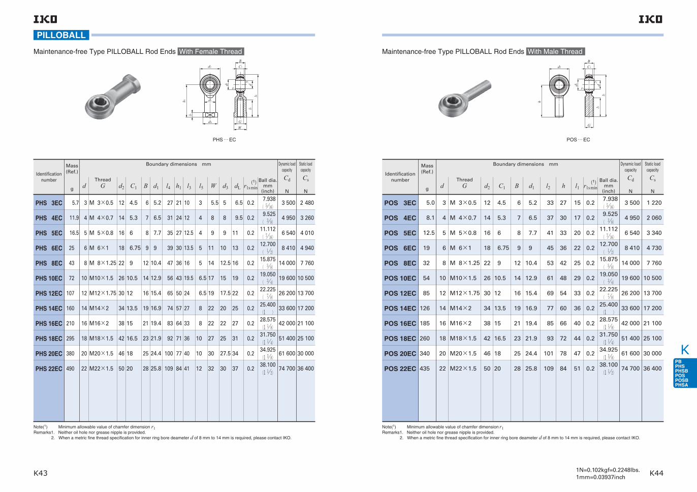
K
K43 K441N=0.102kgf=0.2248lbs.1mm=0.03937inch
Note(1) Minimum allowable value of chamfer dimension r1 Remarks1. Neither oil hole nor grease nipple is provided. 2. When a metric fine thread specification for inner ring bore deameter d of 8 mm to 14 mm is required, please contact IKO.
PHS … EC
Identification number
PHS 3EC
PHS 4EC
PHS 5EC
PHS 6EC
PHS 8EC
PHS 10EC
PHS 12EC
PHS 14EC
PHS 16EC
PHS 18EC
PHS 20EC
PHS 22EC
Mass (Ref.)
g
5.7
11.9
16.5
25
43
72
107
160
210
295
380
490
3
4
5
6
8
10
12
14
16
18
20
22
12
14
16
18
22
26
30
34
38
42
46
50
4.5
5.3
6
6.75
9
10.5
12
13.5
15
16.5
18
20
M 3×0.5
M 4×0.7
M 5×0.8
M 6×1
M 8×1.25
M10×1.5
M12×1.75
M14×2
M16×2
M18×1.5
M20×1.5
M22×1.5
6
7
8
9
12
14
16
19
21
23
25
28
5.2
6.5
7.7
9
10.4
12.9
15.4
16.9
19.4
21.9
24.4
25.8
10
12
12.5
13.5
16
19.5
24
27
33
36
40
41
3
4
4
5
5
6.5
6.5
8
8
10
10
12
5.5
8
9
11
14
17
19
22
22
27
30
32
5
8
9
10
12.5
15
17.5
20
22
25
27.5
30
6.5
9.5
11
13
16
19
22
25
27
31
34
37
0.2
0.2
0.2
0.2
0.2
0.2
0.2
0.2
0.2
0.2
0.2
0.2
27
31
35
39
47
56
65
74
83
92
100
109
21
24
27
30
36
43
50
57
64
71
77
84
Dynamic load capacity
Cd
N
Static load capacity
Cs
N
3 500
4 950
6 540
8 410
14 000
19 600
26 200
33 600
42 000
51 400
61 600
74 700
2 480
3 260
4 010
4 940
7 760
10 500
13 700
17 200
21 100
25 100
30 000
36 400
Ball dia.mm
(inch)
7.938( 516) 9.525( 38)11.112( 716)12.700( 12)15.875( 58)19.050( 34)22.225( 78)25.400(1 )28.575(1 18)31.750(1 14)34.925(1 38)38.100(1 12)
dThread
G d2 C1 B d1 l4 h1 l3 l5 W d3 dL r1s min(1)
Boundary dimensions mm
PILLOBALL
Maintenance-free Type PILLOBALL Rod Ends With Female Thread
h
d
d
dL
l
r
d
GW
BC
r
dl
l
3
2
1
1
1
1
1
5
4
3
POS … EC
Note(1) Minimum allowable value of chamfer dimension r1 Remarks1. Neither oil hole nor grease nipple is provided. 2. When a metric fine thread specification for inner ring bore deameter d of 8 mm to 14 mm is required, please contact IKO.
Identification number
Mass (Ref.)
g
Static load capacity
Cs
N
Boundary dimensions mm
POS 3EC
POS 4EC
POS 5EC
POS 6EC
POS 8EC
POS 10EC
POS 12EC
POS 14EC
POS 16EC
POS 18EC
POS 20EC
POS 22EC
5.0
8.1
12.5
19
32
54
85
126
185
260
340
435
3 500
4 950
6 540
8 410
14 000
19 600
26 200
33 600
42 000
51 400
61 600
74 700
1 220
2 060
3 340
4 730
7 760
10 500
13 700
17 200
21 100
25 100
30 000
36 400
Dynamic load capacity
Cd
Nd
3
4
5
6
8
10
12
14
16
18
20
22
M 3×0.5
M 4×0.7
M 5×0.8
M 6×1
M 8×1.25
M10×1.5
M12×1.75
M14×2
M16×2
M18×1.5
M20×1.5
M22×1.5
ThreadG d2
Ball dia.mm
(inch)C1 B d1 l2 h l1
12
14
16
18
22
26
30
34
38
42
46
50
4.5
5.3
6
6.75
9
10.5
12
13.5
15
16.5
18
20
6
7
8
9
12
14
16
19
21
23
25
28
5.2
6.5
7.7
9
10.4
12.9
15.4
16.9
19.4
21.9
24.4
25.8
0.2
0.2
0.2
0.2
0.2
0.2
0.2
0.2
0.2
0.2
0.2
0.2
7.938( 516)
9.525( 38)
11.112( 716)
12.700( 12)
15.875( 58)
19.050( 34)
22.225( 78)
25.400(1 )
28.575(1 18)
31.750(1 14)
34.925(1 38)
38.100(1 12)
33
37
41
45
53
61
69
77
85
93
101
109
27
30
33
36
42
48
54
60
66
72
78
84
15
17
20
22
25
29
33
36
40
44
47
51
r1s min(1)
Maintenance-free Type PILLOBALL Rod Ends With Male Thread
h
d1 dl1
l2
d2
B
G
C1
r1
r1

K
K45 K46
L-Balls
L-Ball Dust Cover
Structure and Features
Types
IKO L-Balls are self-aligning rod-ends consisting of a special zinc die-cast alloy body and a studded ball which has its axis at right angles to the body.They can perform tilting movement, oscillating move-ment and rotation with low torque, and transmit power smoothly due to uniform clearance between the slid-ing surfaces.Their superior wear resistance assures stable accura-cy for long periods of time, and maintenance is sim-ple. They are very economical bearings.For these reasons, they are widely used in link mech-anisms in automobiles, construction machinery, farm and packaging machines, etc.
Structures of L-Ball LHSA
Structure of L-Ball LHS
Body
Body
Body
Body
Bushing(Copper alloy)
Ball-stud
Ball-stud
Dust cover
Ball-stud
Ball-stud
Dust cover(Fixed to the body)
Bushing (Low carbon steel)
Bushing(Copper alloy)
and upwards
LHSA 5, 6
L-Balls are available in various types as shown in Table 1.
Table 1 Type of L-Balls
Type L-BallL-Ball dust
cover
Model code LHSA LHS PRC
L-Ball LHSAThese are compact rod-ends in which the spherical part of the ball-stud are held by the special zinc die-cast alloy body. There is a dust cover on the stud side and good quality lithium soap base grease is pre-packed. They can be run for long periods of time without re-lubrication and have excellent lubrication and anti-dust properties.As shown in the structural drawing, these rod-ends are classified into 3 types by size. In addition, the ball-studs of LHSA 10 and lower are formed in one solid body, but those of LHSA 12 and higher, which are used under large loads, have the stud friction-welded to a high precision steel ball to give greater resistance to wear.
L-Ball LHSThese rod-ends have a friction-welded ball-stud, and a special zinc die-cast alloy body which houses the spherical surface of the high precision steel ball. There is an almost complete contact across the slid-ing surfaces, and the uniform clearance guarantees a stable bearing life.An L-Ball dust cover can be attached to these rod-ends. If the rod-ends are lubricated with lithium soap
base grease, they have excellent lubrication and anti-dust properties and can run for long periods of time without re-lubrication.When the L-Ball LHS is delivered with a dust cover on request, lithium soap base grease is prepacked.

K
K47 K481N=0.102kgf=0.2248lbs.1mm=0.03937inch
L-Ball Dust Cover PRCThis is for the L-Ball LHS series. It is made of special synthetic rubber which has excellent resistance to oil and ozone. The cover offers very effective dust pro-tection and prevents grease leakage.
Identification NumberThe identification number of L-Balls consists of a model code, a size and any supplemental codes as shown in the examples.
Model code Size
LHSA 8
Type
Examples of identification number
Example 1 (Female thread of the dody : In case of right-hand threaded)
Size of thread(M8)
Model code SizeSupplemental
code
LHSA 8 L
Left-handed thread
Example 2 (Female thread of the body : In case of left threaded)
Model code SizeSupplemental
code
LHS 8 D
Example 3 (when a dust cover PRC is attached to LHS)
With dust cover
AccuracyThe accuracy of L-Balls is shown in Table 2.
Table 2 Tolerance
Type Dimension symbol Tolerance
LHSA
LHS
r1
V
r1
V
± 0.5
0− 0.2(1)
± 0.4
h9
unit: mm
Note(1) This dimensional tolerance applies to LHSA 5 and higher.
LHSA LHS
V
r1
r1
V
1 Tightening depth It is recommended that the tightening depth of the
screw into the body is more than twice the nominal diameter of thread.
2 Allowable tilting angle The allowable tilting angle is shown in Table 4.
Selection of L-BallsThe static load capacity and maximum operating load of L-Balls are determined in consideration of the strength of the ball stud and the body. Accordingly, L-Balls are selected on the basis of the static load
capacity Cs shown in the dimension table and the maximum operating load shown in Table 3.
Static load capacity
The static load capacity Cs shown in the dimension table represents the allowable axial force F which is determined by the mechanical strength of the ball-stud at the section 'A' under the bending moment due
to the force F as illustrated in Fig. 1. If F increases beyond the static load capacity, deformation will begin at A, leading to breakage.
Maximum operating load
The strength of the body must also be taken into con-sideration when L-Balls are operated in a high-tem-perature or low-temperature atmosphere or receive repetitive loads of long duration or shock loads. A guideline for maximum operating load of L-Balls is shown in Table 3. When the fixing bolt in the main body is fixed and a load is applied in the direction of
F′, the bending stress in the fixing bolt must be taken into consideration.
LubricationLHSA is prepacked with lubricating grease ALVANIA GREASE S2 (Shell Lubricants Japan K.K.). LHS is not provided with prepacked grease. Perform proper lubrication.Operating LHS without lubrication will increase the wear of the sliding contact surface or cause seizure.
Operating Temperature RangeThe maximum allowable temperature for L-Balls is +80 .
Precautions for Use
Table 4 Allowable tilting angle
Nominal dia. mmV
LHSAα
LHSα
4 5 6 810121416182022
15171718191920−−−−
−15171819192020212021
unit: degree
Table 3 Maximum operating load
Identification number
Maximum operating load
Identification number
Maximum operating load
LHSA 4LHSA 5LHSA 6LHSA 8LHSA10LHSA10MLHSA12LHSA14−−
8401 1801 0801 9002 1702 1702 7903 540−−
LHS 5LHS 6LHS 8LHS10LHS12LHS14LHS16LHS18LHS20LHS22
8801 0801 6302 1002 6203 1903 8204 6105 3406 460
unit: N
Fig. 1
A
α α
V
F
F′

K
K49 K501N=0.102kgf=0.2248lbs.1mm=0.03937inch
L-BALL
5.5
8
8
10
12
12
14
17
19.5
32.5
32.5
41.5
49
49
64
72
10
12
12
16
19
19
22
25
8
10
10
13
15
15
17.5
20
8
10
10
14
17
17
19
22
4
5
5
5
6.5
6.5
6.5
8
8
16
16
19
23
23
27
30
18
30
30
36
43
43
50
57
25
38.5
39.5
48
57
57
67
76
14
17
19
24
28
28
34
38
4
5
6
8
10
10
12
14
M 4×0.7
M 5×0.8
M 6×1
M 8×1.25
M10×1.25
M10×1.5
M12×1.75
M14×2
11
27
27
64
106
106
180
260
Identification number
Mass (Ref.)
g S V D L L1 L2 l1 W1
14
17
17
19
22
W2 D1 D2 r P
LHSA 4
LHSA 5
LHSA 6
LHSA 8
LHSA 10
LHSA 10M
LHSA 12
LHSA 14
Boundary dimensions mm
Thread
* **
**Remarks1. The item marked * is manufactured with a neck diameter of φ3.4. The item marked is manufactured with a diameter of φ5.5
instead of a width across flats. 2. Provided with prepacked grease.
880
1 180
1 670
4 380
7 400
7 400
9 900
14 600
8
11.112
11.112
15
19.05
19.05
22.225
25.4
5
10
10
12.5
17
17
20
22
7
13
13
17
21
21
30
33.5
球面外輪
シールド形r2
7
12
12
14.5
16
16
20
22.5
r1 r3
Ball dia.
Static load capacity
Cs
N
LL1
L2
21
S
S
D
P 11
D1
V
W1
D2
D2
W1
W2
3
LHSA 4LHSA 5LHSA 6
LHSA 8LHSA 10LHSA 10MLHSA 12LHSA 14

K
K51 K521N=0.102kgf=0.2248lbs.1mm=0.03937inch
Remark No grease is prepacked. Perform proper lubrication.
Identification number
Mass (Ref.)
g S V D B L L1 L2 l1 W D1 D2 r P
LHS 5
LHS 6
LHS 8
LHS 10
LHS 12
LHS 14
LHS 16
LHS 18
LHS 20
LHS 22
22
32
60
102
160
227
300
445
580
765
M 5×0.8
M 6×1
M 8×1.25
M10×1.5
M12×1.75
M14×2
M16×2
M18×1.5
M20×1.5
M22×1.5
5
6
8
10
12
14
16
18
20
22
35.5
39.7
48
57
66
75
84
93.5
101.5
111
27
30
36
43
50
57
64
71
77
84
4
5
5
6.5
6.5
8
8
10
10
12
9
10
12.5
15
17.5
20
22
25
27.5
30
30.5
36.5
44
52.5
61
69
74
84
90.5
99
16
16
19
23
27
30
36
40
43
47
9
11
14
17
19
22
22
27
30
32
11
13
16
19
22
25
27
31
34
37
8
10
11
13
17
17
19
22
24
27
17
19.5
24
28
32
36
40
45
49
54
6
6.75
9
10.5
12
13.5
15
16.5
18
20
Boundary dimensions mm
Thread
L-BALL
10
11.5
14.5
17
20
22.5
24.5
27.5
30
32.5
15
18.5
21.5
26
30
33.5
35.5
40.5
43
47.5
11
14
15
18
20
22
23
25
27
30
11.112
12.7
15.875
19.05
22.225
25.4
28.575
31.75
34.925
38.1
2 080
3 290
4 900
7 640
12 400
14 600
19 500
25 600
31 600
39 800
r1 r2 r3
Ball dia.
Static load capacity
Cs
N
LHS
r
r
r
r
D
L
P S l
L
L
B S W
D
D
1
23
2
1
2
1
1

K
K54K53
L-BALL
Identification number
X
PRC 5
PRC 6
PRC 8
PRC 10
PRC 12
PRC 14
PRC 16
PRC 18
PRC 20
PRC 22
20
22
27
31
36
40
44
49
54
59
Y
29
31
38.5
45.5
53
60
68
74.5
82
89.5
E
10
11
13.5
15.5
18
20
22
24.5
27
29.5
F
19
20
25
30
35
40
46
50
55
60
Z
16
19
24
27
32
36.5
40
46
50
53.5
G
8
9.5
12
14
16.5
19
20.5
23.5
25.5
27.5
H
8
9.5
12
13
15.5
17.5
19.5
22.5
24.5
26
Boundary dimensions mm
PRC
L-Ball Dust Cover
X
Y
E F
GH
Z
1N=0.102kgf=0.2248lbs.1mm=0.03937inch

K
K55 K56
IKO Super Flexible Nozzle is a compact nozzle for use on a machine tool to supply and spray cutting oil exactly at the required positions. The angle of the nozzle can be changed easily and freely. Therefore, oil supply can be concentrated upon the working area, and cooling and lubrication can be performed effectively. As a result, cutting resistance is reduced and superior finish is obtained, achieving high machining accuracy. Also, tool life is longer. The Super Flexible Nozzle is used in many places such as at the spindle end of Machining Center and at the tool holder of N/C lathe.
The features of Super Flexible Nozzle are as follows. 1 A spherical bushing is incorporated to adjust the tilt-ing angle of nozzle easily. 2 The Super Flexible Nozzle is compact in size, and the design on parts around the spindle and tool can be made simple. 3 The nozzle length is short, and winding of cutting chips around the nozzle will not occur. 4 By using a number of Super Flexible Nozzles, cut-ting oil can be supplied and cutting chips can be removed more effectively. 5 The press fitting type and screw fitting type are available. The press fitting type is economical.
Structures of Super Flexible Nozzles
Body(Zinc die-cast alloy)
Body(Zinc die-cast alloy)
Nozzle
Body(Steel)
Nozzle
Hollow ball
Body(Steel)
Nozzle
Hollow ball
Hollow ball
Hollow ball
Metric thread
O-ring
Taper pipe thread
O-ring
[Without nozzle]
[With nozzle]
Structure and Features

K
K57 K581N=0.102kgf=0.2248lbs.1mm=0.03937inch
TypesSuper Flexible Nozzles shown in Table 1 are avail-able.
Model code Size
SNM 10 20
Example of identification number
Type of nozzle
Dimension from shoulder surface to nozzle top:※(20mm)
Nozzle bore or thread size: (M10×1.25)
-
Table 1 Type of Super Flexible Nozzle
Type
Press fitting type
Screw fitting type
Without nozzle
With nozzle
With metric threads
With taper pipe threads
SNA
SNM
SNPT
Model code
Identification NumberThe identification number of Super Flexible Nozzle consists of a model code and a size. An example is shown as follows.
Precautions for UseWhen the press fitting type Super Flexible Nozzle is used, a φ 15 (H8) bore for fitting hole must be prepared and fitting is made from the 30°chamfered end of the outer body. In this case, the body portion should be pushed for press fitting.When the screw fitting type Super Flexible Nozzle is used and prevention of oil leakage from the fitting part is required, it is recommended to wind sealing tape on the thread portion or use rubber packing for the shoul-der face of the outer body.The direction of lubrication can be adjusted by insert-ing a screwdriver, etc. in the bore of the nozzle.
Special SpecificationsSuper Flexible Nozzles with special length are also available. In this case, specify the necessary nozzle length in units of 1 mm, but do not exceed the maxi-
mum length shown in the dimension table as "L". Super Flexible Nozzles with curved nozzle end or with special bore diameter are also available. In this case, please contact IKO by preparing a drawing or sketch with necessary specifications.
※In case of press fitting type without nozzle, this dimension is not indicated.
+ 0.027 0
Press Fitting Type Without Nozzle
SNA
SNA
Identification number
Allowable tilting angle
αdegree
Boundary dimensions mm
d
Ball dia.
mm(inch)D L1 L2 C r
SNA 4
SNA 6
36
24
415 7 1 6 2
611.112(716)
Identification number
Boundary dimensions mm
d D L L1 L2 C r d1
SNA 3-L
SNA 4-L
3
415
6 15 32
6 16 407 1 6 2 6
Allowable tilting angle
αdegree
Ball dia.
mm(inch)
2411.112(716)
Press Fitting Type With Nozzle
SUPER FLEXIBLE NOZZLE
r
D d
CL1
L2
αα
30°
d (d1)
αα
rC
D
L1
L2
L
30°

K59
SUPER FLEXIBLE NOZZLE
SNM SNPT
Screw Fitting Type
Identification number
Boundary dimensions mm
d S L L1
SNM 10-L
SNPT 1/4-L
SNM 20-L
SNPT 3/8-L
SNM 24-L
SNPT 1/2-L
4
6
8
M10×1.25
PT 1/4
PT 3/8
PT 1/2
M20×1.5
M24×2.0
20 40 60
30 50 70
40 60 80
9
13
18
L2 d1
13 6
18 8
23 10
d2
6
10
12
B
17
24
32
(Ref.)
19.6
27.7
37
L3
10.5
15
19
Allowable tilting angle
αdegree
Ball dia.
mm(inch)
35
12.700( 12)
19.050( 34)
25.400(1 )
Thread Width across flats
Width across corners
L1
L2
L3
L
S
B d2 d (d1 )
α
α
S
1N=0.102kgf=0.2248lbs.1mm=0.03937inch
Seals for Needle Roller BearingsCir-clips for Needle Roller BearingsNeedle Rollers

L
L1 L21N=0.102kgf=0.2248lbs.1mm=0.03937inch
FeaturesIKO Seals for Needle Roller Bearings have a low sectional height and consist of a sheet metal ring and special synthetic rubber. As these seals are manufactured to the same sec-tional height as IKO Needle Roller Bearings, grease leakage and the penetration of foreign particles can be effectively prevented by fitting them directly to the sides of combinable bearings shown in the dimension table. When fitting seals to needle roller bearings with inner ring, wide inner rings (see page H2) must be used, as shown in the mounting examples.
TypesSeals for Needle Roller Bearings are available as shown in Table1.
Identification NumberThe identification number of Seals for Needle Roller Bearings consists of a model code and dimensions. An example of an identification number is shown as follows.
Model code Dimensions
DS 20 428
Example of identification number
Shaft dia.(20mm)
Type of seal
Outside dia. of seal(28mm)
Width of seal(4mm)
AccuracyTolerances of Seals for Needle Roller Bearings are based on JIS B 2402-1.Tolerances of outside diameter and width are based on Tables 2 and 3, respectively.
Table 1 Seal type
Type Single lip Double lips
Structure
Model code OS DS Table 2 Tolerance of outside diameterNominal outside diameter
Over Incl. High Low
Tolerance
−30
50
80
30
50
80
120
+ 0.09
+ 0.11
+ 0.14
+ 0.17
+ 0.04
+ 0.05
+ 0.06
+ 0.08
unit: mm
Table 3 Tolerance of widthNominal size of width
Over Incl. High Low
Tolerance
−6
6
10
+ 0.2
+ 0.3
− 0.2
− 0.3
unit: mm
Metal ring
Lip
Metal ring
Main lipSecondary lip
MountingWhen inserting the shaft, damage to the lip should be prevented by chamfering the end of the shaft, as shown in the upper part of Fig. 1. When this cannot be performed, a mounting bushing should be used, as shown in the lower part of Fig.1. When press fitting the seal to the housing, do not strike it directly, but fit it gently, using a suitable tool. To prevent early wear and heat generation at the seal surface, it is necessary to thickly coat the tip of the lip for the OS type, or to fill the space between the two lips for the DS type, with bearing grease.
Precautions for Use
Fig.1
30°
3mm
1 For the single lip OS type, the lip has to face inward when using the seal to prevent grease leakage, and outward to prevent the penetration of foreign particles. The DS type of double-lips is effective for prevention of grease leakage and dust penetration. However, when the main purpose is to prevent grease leakage, the main lip should face inward, and when used main-ly to prevent dust penetration, it should face outward. 2 The permissible temperature range is -20 〜+100 . For use at higher or lower temperatures, a special seal is required. Please contact IKO for further infor-mation. 3 The limiting peripheral speed of shaft depends on the conditions of use, but is normally 6 to 8 m/s. Double this speed is possible if the conditions (lubri-cation, temperature, shaft finish, etc.) are good.
Fig.2 Mounting examples
Secondary lip Main lip
Bushing for mounting
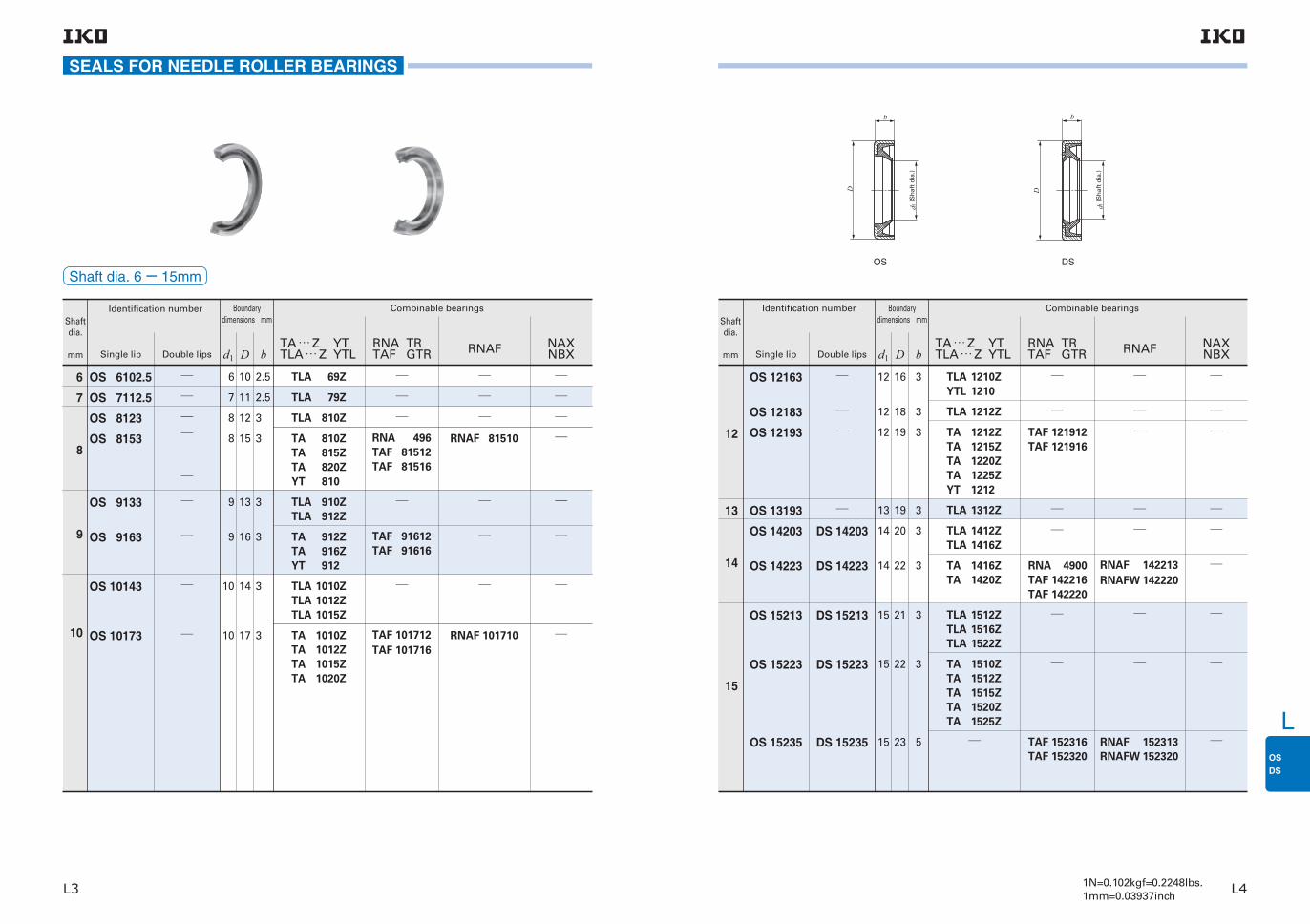
L
L3 L41N=0.102kgf=0.2248lbs.1mm=0.03937inch
Shaft dia.
mm Single lip Double lips d1 D bTA … Z YTTLA … Z YTL
RNA TRTAF GTR RNAF NAX
NBX
Identification number Boundary dimensions mm
Combinable bearings
6
7
8
9
10
OS 6102.5
OS 7112.5
OS 8123
OS 8153
OS 9133
OS 9163
OS 10143
OS 10173
RNA 496TAF 81512TAF 81516
TAF 91612TAF 91616
TAF 101712TAF 101716
RNAF 81510
RNAF 101710
6
7
8
8
9
9
10
10
10
11
12
15
13
16
14
17
2.5
2.5
3
3
3
3
3
3
TLA 69Z
TLA 79Z
TLA 810Z
TA 810ZTA 815ZTA 820ZYT 810
TLA 910ZTLA 912Z
TA 912ZTA 916ZYT 912
TLA 1010ZTLA 1012ZTLA 1015Z
TA 1010ZTA 1012ZTA 1015ZTA 1020Z
SEALS FOR NEEDLE ROLLER BEARINGS
Shaft dia. 6− 15mm
D
d
b
1
D
d
b
1
OS DS
Shaft dia.
mm Single lip Double lips d1 D bTA … Z YTTLA … Z YTL
RNA TRTAF GTR RNAF NAX
NBX
Identification number Boundary dimensions mm
Combinable bearings
12
13
14
15
OS 12163
OS 12183
OS 12193
OS 13193
OS 14203
OS 14223
OS 15213
OS 15223
OS 15235
DS 14203
DS 14223
DS 15213
DS 15223
DS 15235
12
12
12
13
14
14
15
15
15
16
18
19
19
20
22
21
22
23
3
3
3
3
3
3
3
3
5
TLA 1210ZYTL 1210
TLA 1212Z
TA 1212ZTA 1215ZTA 1220ZTA 1225ZYT 1212
TLA 1312Z
TLA 1412ZTLA 1416Z
TA 1416ZTA 1420Z
TLA 1512ZTLA 1516ZTLA 1522Z
TA 1510ZTA 1512ZTA 1515ZTA 1520ZTA 1525Z
TAF 121912TAF 121916
RNA 4900TAF 142216TAF 142220
TAF 152316TAF 152320
RNAF 142213RNAFW 142220
RNAF 152313RNAFW 152320
(Sh
aft
dia
.)
(Sh
aft
dia
.)
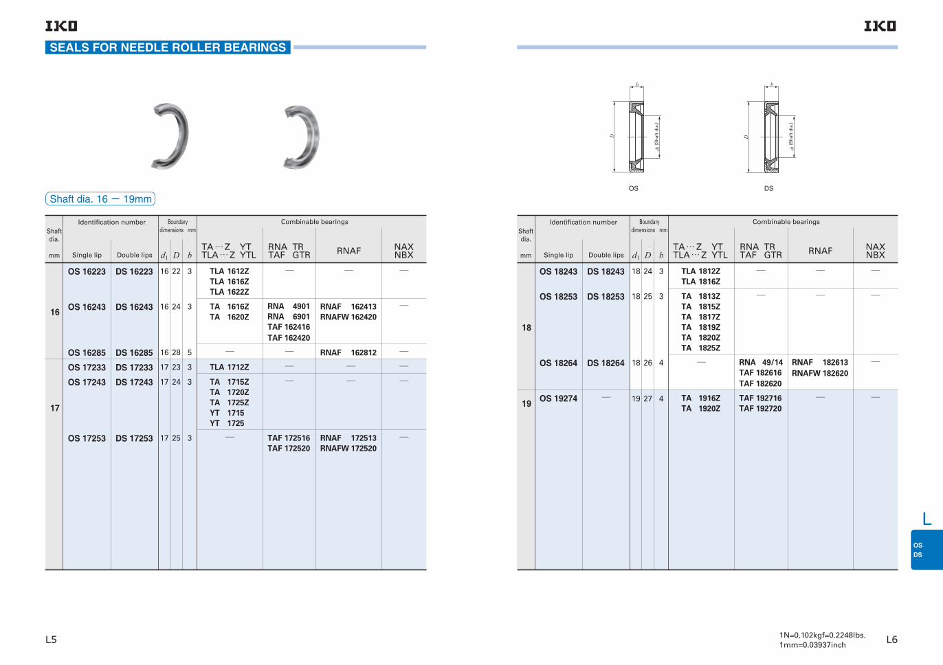
L
L5 L61N=0.102kgf=0.2248lbs.1mm=0.03937inch
Shaft dia.
mm Single lip Double lips d1 D bTA … Z YTTLA … Z YTL
RNA TRTAF GTR RNAF NAX
NBX
Identification number Boundary dimensions mm
Combinable bearings
16
17
OS 16223
OS 16243
OS 16285
OS 17233
OS 17243
OS 17253
DS 16223
DS 16243
DS 16285
DS 17233
DS 17243
DS 17253
16
16
16
17
17
17
22
24
28
23
24
25
3
3
5
3
3
3
TLA 1612ZTLA 1616ZTLA 1622Z
TA 1616ZTA 1620Z
TLA 1712Z
TA 1715ZTA 1720ZTA 1725ZYT 1715YT 1725
RNA 4901RNA 6901TAF 162416TAF 162420
TAF 172516TAF 172520
RNAF 162413RNAFW 162420
RNAF 162812
RNAF 172513RNAFW 172520
SEALS FOR NEEDLE ROLLER BEARINGS
Shaft dia. 16− 19mm
Shaft dia.
mm Single lip Double lips d1 D bTA … Z YTTLA … Z YTL
RNA TRTAF GTR RNAF NAX
NBX
Identification number Boundary dimensions mm
Combinable bearings
18
19
OS 18243
OS 18253
OS 18264
OS 19274
DS 18243
DS 18253
DS 18264
18
18
18
19
24
25
26
27
3
3
4
4
TLA 1812ZTLA 1816Z
TA 1813ZTA 1815ZTA 1817ZTA 1819ZTA 1820ZTA 1825Z
TA 1916ZTA 1920Z
RNA 49/14TAF 182616TAF 182620
TAF 192716TAF 192720
RNAF 182613RNAFW 182620
OS DS
D
d
b
1
D
d
b
1
(Sh
aft
dia
.)
(Sh
aft
dia
.)

L
L7 L81N=0.102kgf=0.2248lbs.1mm=0.03937inch
SEALS FOR NEEDLE ROLLER BEARINGS
Shaft dia. 20− 24mm
Shaft dia.
mm Single lip Double lips d1 D bTA … Z YTTLA … Z YTL
RNA TRTAF GTR RNAF NAX
NBX
Identification number Boundary dimensions mm
Combinable bearings
20
21
TLA 2012ZTLA 2016ZTLA 2020ZTLA 2030Z
TA 2015ZTA 2020ZTA 2025ZTA 2030ZYT 2015YT 2025
TA 202820ZYT 202820
TA 2116ZTA 2120ZYT 2116YT 2120
RNA 4902RNA 6902TAF 202816TAF 202820
TAF 212916TAF 212920
RNAF 202813RNAFW 202826
RNAF 203212RNAFW 203224
RNAF 203212RNAFW 203224
NAX 2030NBX 2030
26
27
28
30
32
32
29
4
4
4
4
4
6
4
20
20
20
20
20
20
21
OS 20264
OS 20274
OS 20284
OS 20304
OS 20324
OS 20326
OS 21294
DS 20264
DS 20274
DS 20284
DS 20304
DS 20324
DS 20326
DS 21294
Shaft dia.
mm Single lip Double lips d1 D bTA … Z YTTLA … Z YTL
RNA TRTAF GTR RNAF NAX
NBX
Identification number Boundary dimensions mm
Combinable bearings
22
24
OS 22284
OS 22294
OS 22304
OS 24314
OS 24324
DS 22284
DS 22304
DS 24314
DS 24324
22
22
22
24
24
28
29
30
31
32
4
4
4
4
4
TLA 2212ZTLA 2216ZTLA 2220Z
TA 2210ZTA 2215ZTA 2220ZTA 2225ZTA 2230Z
TA 223016ZTA 223020ZYT 223016YT 223020
TA 2420ZTA 2428ZYT 2428
TA 243216ZTA 243220ZYT 243216YT 243220
RNA 4903RNA 6903TAF 223016TAF 223020
TAF 243216TAF 243220
RNAF 223013RNAFW 223026
OS DS
D
d
b
1
D
d
b
1
(Sh
aft
dia
.)
(Sh
aft
dia
.)

L
L9 L101N=0.102kgf=0.2248lbs.1mm=0.03937inch
Shaft dia.
mm Single lip Double lips d1 D bTA … Z YTTLA … Z YTL
RNA TRTAF GTR RNAF NAX
NBX
Identification number Boundary dimensions mm
Combinable bearings
25
OS 25324
OS 25334
OS 25356
OS 25376
OS 26344
DS 25324
DS 25334
DS 25356
DS 25376
DS 26344
25
25
25
25
26
32
33
35
37
34
4
4
6
6
4
TLA 2512ZTLA 2516ZTLA 2520ZTLA 2526ZTLAW 2538ZYTL 2526
TA 2510ZTA 2515ZTA 2520ZTA 2525ZTA 2530ZYT 2510YT 2515YT 2520YT 2525
TA 2616ZTA 2620ZYT 2616YT 2620
TAF 253316TAF 253320
RNA 4904RNA 6904
TAF 263416TAF 263420
RNAF 253517RNAFW 253526
RNAF 253716RNAFW 253732
NAX 2530NBX 2530
26
SEALS FOR NEEDLE ROLLER BEARINGS
Shaft dia. 25− 29mm
Shaft dia.
mm Single lip Double lips d1 D bTA … Z YTTLA … Z YTL
RNA TRTAF GTR RNAF NAX
NBX
Identification number Boundary dimensions mm
Combinable bearings
28
29
OS 28354
OS 28374
OS 28396
OS 28406
OS 29384
DS 28354
DS 28374
DS 28396
DS 28406
DS 29384
28
28
28
28
29
35
37
39
40
38
4
4
6
6
4
TLA 2816ZTLA 2820Z
TA 2820ZTA 2830ZYT 2820
TA 2920ZTA 2930ZYT 2920
TAF 283720TAF 283730
RNA 49/22RNA 69/22
TAF 293820TAF 293830
RNAF 284016RNAFW 284032
OS DS
D
d
b
1
D
d
b
1
(Sh
aft
dia
.)
(Sh
aft
dia
.)

L
L11 L121N=0.102kgf=0.2248lbs.1mm=0.03937inch
Shaft dia. 30− 38mm
Shaft dia.
mm Single lip Double lips d1 D bTA … Z YTTLA … Z YTL
RNA TRTAF GTR RNAF NAX
NBX
Identification number Boundary dimensions mm
Combinable bearings
30
32
OS 30374
OS 30404
OS 30426
OS 32424
OS 32456
DS 30374
DS 30404
DS 30426
DS 32424
DS 32456
30
30
30
32
32
37
40
42
42
45
4
4
6
4
6
TLA 3012ZTLA 3016ZTLA 3018ZTLA 3020ZTLA 3026ZTLAW 3038Z
TA 3013ZTA 3015ZTA 3020ZTA 3025ZTA 3030Z
TA 3220ZTA 3230ZYT 3220
TAF 304020TAF 304030
RNA 4905RNA 6905
TAF 324220TAF 324230
RNA 49/28RNA 69/28GTR 324530
RNAF 304017RNAFW 304026
RNAF 304216RNAFW 304232
NAX 3030NBX 3030
SEALS FOR NEEDLE ROLLER BEARINGS
Shaft dia.
mm Single lip Double lips d1 D bTA … Z YTTLA … Z YTL
RNA TRTAF GTR RNAF NAX
NBX
Identification number Boundary dimensions mm
Combinable bearings
35
37
38
OS 35424
OS 35454
OS 35476
OS 37474
OS 38484
OS 38506
DS 35424
DS 35454
DS 35476
DS 37474
DS 38484
DS 38506
35
35
35
37
38
38
42
45
47
47
48
50
4
4
6
4
4
6
TLA 3512ZTLA 3516ZTLA 3520Z
TA 3512ZTA 3515ZTA 3520ZTA 3525ZTA 3530Z
TA 3720ZTA 3730ZYT 3720
TA 3815ZTA 3820ZTA 3825ZTA 3830ZTAW 3845Z
TAF 354520TAF 354530
RNA 4906RNA 6906
TAF 374720TAF 374730
TAF 384820TAF 384830
RNAF 354517RNAFW 354526
RNAF 354716RNAFW 354732
NAX 3530NBX 3530
OS DS
D
d
b
1
D
d
b
1
(Sh
aft
dia
.)
(Sh
aft
dia
.)

L
L13 L141N=0.102kgf=0.2248lbs.1mm=0.03937inch
Shaft dia.
mm Single lip Double lips d1 D bTA … Z YTTLA … Z YTL
RNA TRTAF GTR RNAF NAX
NBX
Identification number Boundary dimensions mm
Combinable bearings
40
42
OS 40474
OS 40504
OS 40526
OS 40556
OS 42557
DS 40474
DS 40504
DS 40526
DS 40556
DS 42557
40
40
40
40
42
47
50
52
55
55
4
4
6
6
7
TLA 4012ZTLA 4016ZTLA 4020Z
TA 4015ZTA 4020ZTA 4025ZTA 4030ZTA 4040ZYT 4015YT 4025
TAF 405020TAF 405030
RNA 49/32RNA 69/32
TR 405520GTR 405520
RNA 4907RNA 6907
RNAF 405017RNAFW 405034
RNAF 405520RNAFW 405540
NAX 4032NBX 4032
SEALS FOR NEEDLE ROLLER BEARINGS
Shaft dia. 40− 50mm
Shaft dia.
mm Single lip Double lips d1 D bTA … Z YTTLA … Z YTL
RNA TRTAF GTR RNAF NAX
NBX
Identification number Boundary dimensions mm
Combinable bearings
45
48
50
OS 45524
OS 45554
OS 45627
OS 48627
OS 50584
OS 50624
OS 50657
DS 45524
DS 45554
DS 45627
DS 48627
DS 50584
DS 50624
DS 50657
45
45
45
48
50
50
50
52
55
62
62
58
62
65
4
4
7
7
4
4
7
TLA 4516ZTLA 4520Z
TA 4520ZTA 4525ZTA 4530ZTA 4540ZYT 4520YT 4525
TLA 5020ZTLA 5025Z
TA 5012ZTA 5015ZTA 5020ZTA 5025ZTA 5030ZTA 5040ZTAW 5045Z
TAF 455520TAF 455530
RNA 4908RNA 6908TR 486230GTR 486230
TAF 506225TAF 506235
RNA 49/42
RNAF 455517RNAFW 455534
RNAF 456220RNAFW 456240
RNAF 506220RNAFW 506240
RNAF 506520RNAFW 506540
NAX 5035NBX 5035
OS DS
D
d
b
1
D
d
b
1
(Sh
aft
dia
.)
(Sh
aft
dia
.)

L
L15 L161N=0.102kgf=0.2248lbs.1mm=0.03937inch
Shaft dia.
mm Single lip Double lips d1 D bTA … Z YTTLA … Z YTL
RNA TRTAF GTR RNAF NAX
NBX
Identification number Boundary dimensions mm
Combinable bearings
52
55
58
60
62
63
OS 52687
OS 55674
OS 55687
OS 55727
OS 58727
OS 60724
OS 60787
OS 62744
OS 63807
DS 52687
DS 55674
DS 55687
DS 58727
DS 60724
DS 60787
DS 62744
DS 63807
52
55
55
55
58
60
60
62
63
68
67
68
72
72
72
78
74
80
7
4
7
7
7
4
7
4
7
TA 5520ZTA 5525ZTA 5530ZTA 5540ZTAW 5545ZTAW 5550Z
TA 6025ZTA 6030ZTA 6040ZTAW 6045ZTAW 6050Z
TA 6212Z
RNA 4909RNA 6909
TAF 556825TAF 556835
RNA 4910RNA 6910
TAF 607225TAF 607235
RNA 4911RNA 6911
RNAF 556820RNAFW 556840
RNAF 557220RNAFW 557240
RNAF 607820RNAFW 607840
NAX 6040NBX 6040
SEALS FOR NEEDLE ROLLER BEARINGS
Shaft dia. 52− 72mm
Shaft dia.
mm Single lip Double lips d1 D bTA … Z YTTLA … Z YTL
RNA TRTAF GTR RNAF NAX
NBX
Identification number Boundary dimensions mm
Combinable bearings
65
68
70
72
OS 65774
OS 65857
OS 68857
OS 70824
OS 70907
OS 72907
DS 65774
DS 65857
DS 68857
DS 70824
DS 70907
DS 72907
65
65
68
70
70
72
77
85
85
82
90
90
4
7
7
4
7
7
TA 6525ZTA 6530ZTAW 6545ZTAW 6550Z
TA 7025ZTA 7030ZTA 7040ZTAW 7050ZYT 7025YT 7030YT 7040
RNA 4912RNA 6912
RNA 4913RNA 6913
RNAF 658530RNAFW 658560
RNAF 709030RNAFW 709060
OS DS
D
d
b
1
D
d
b
1
(Sh
aft
dia
.)
(Sh
aft
dia
.)

L
L17 L181N=0.102kgf=0.2248lbs.1mm=0.03937inch
FeaturesIKO Cir-clips for Needle Roller Bearings have been specially designed for needle roller bearings on which, in many cases, generally available Cir-clips cannot be used. They have a low sectional height and are very rigid. They are made of spring steel. There are Cir-clips for shafts and for bores, and they are used for positioning to prevent bearing movement in the axial direction.
TypesCir-clips for Needle Roller Bearings are available as shown in Table. 1.
Identification numberThe identification number of Cir-clips consists of a model code and a size as shown below.
Model code Size
WR 20
Examples of identification number
Shaft dia.(20mm)
Example 1
Type of Cir-clip
Model code Size
AR 35
Bore dia.(35mm)
Example 2
Type of Cir-clip
Table 1 Type of Cir-clip
Type For shaft For bore
Shape
Model code WR AR
m
in-1
mm
700006000050000
40000
30000
20000
10000
800070006000
5000
4000
3000
2000
1000
800700600500
400
300
200
10020 40 60 80 100 120 140 160 180
Fig.1 Allowable rotational speed
Allowable Rotational SpeedCir-clips for Needle Roller Bearings are fixed in the groove with a certain amount of pressure on the bot-tom of the groove. In the case of Cir-clips for shaft WR type, the centrifugal force causes a decrease in the gripping pressure. Therefore, when using them at high rotational speeds, it is necessary to first check the allowable rotational speed shown in Fig.1.
MountingThe mounting dimensions for Cir-clips for Needle Roller Bearings are shown in the dimension table. When using these Cir-clips to restrict the movement of the needle roller cage in the axial direction, it is rec-ommended that a spacer be used between the Cir-clip and the cage. Spacers are not required at low rotational speeds. When it is difficult to reach Cir-clips with dismounting tools and disassembly is difficult, or when the fre-quency of dismounting is high, it is necessary to con-sider the use of a retaining ring (JIS B 2804), although they have a higher sectional height.
Allo
wab
le r
ota
tio
nal
sp
eed
Shaft dia.

L
L19 L201N=0.102kgf=0.2248lbs.1mm=0.03937inch
Identification number
Boundary dimensions mm
WR 4WR 5WR 6WR 7WR 8WR 9WR 10WR 11WR 12WR 13WR 14WR 15WR 16WR 17WR 18WR 19WR 20WR 21WR 22WR 23WR 24WR 25WR 26WR 28WR 29WR 30WR 32WR 35WR 36WR 37WR 38WR 40
4 5 6 7 8 91011121314151617181920212223242526282930323536373840
3.7 4.7 5.6 6.5 7.4 8.4 9.410.211.212.113.11415161717.918.719.720.721.722.523.524.526.527.528.530.233.234.235.236.237.8
0.811.11.21.31.31.31.31.31.31.51.751.751.751.751.751.751.751.751.751.751.751.752.32.32.32.32.32.32.32.32.3
0.50.50.70.71111111.21.21.21.21.21.21.21.21.21.21.21.21.21.51.51.51.51.51.51.51.51.5
3.8 4.8 5.7 6.7 7.6 8.6 9.610.511.512.513.514.415.416.417.418.419.220.221.222.223242527282930.833.834.835.836.838.5
0−0.09
0−0.11
0−0.13
0−0.16
Groove dia.
Tolerance
Shaft dia.
D D3(Max.)
e f D1
Identification number
Boundary dimensions mm
WR 42WR 43WR 45WR 47WR 50WR 52WR 55WR 60WR 63WR 65WR 68WR 70WR 75WR 80WR 82WR 85WR 90WR 95WR 100WR 105WR 110WR 115WR 120WR 125WR 130WR 135WR 140WR 145WR 150WR 155WR 160WR 165
424345475052556063656870758082859095
100105110115120125130135140145150155160165
39.840.842.844.847.849.852.657.660.662.665.467.472.477.479.382879297
101.7106.7111.7116.7121.7126.7131.6136.6141.6146.6151.6156.6161.6
2.32.32.32.32.32.32.32.32.32.32.82.82.82.83.43.43.43.43.43.43.43.43.43.43.44444444
1.51.51.51.51.51.51.51.51.51.522222.52.52.52.52.52.52.52.52.52.52.52.52.52.52.52.52.52.5
40.541.543.545.548.550.553.558.561.563.566.268.273.278.280.283889398
102.7107.7112.7117.7122.7127.7132.4137.4142.4147.4152.4157.4162.4
0−0.16
0−0.19
0−0.22
0−0.25
Groove dia.
Tolerance
Shaft dia.
D D3(Max.)
e f D1
For Shaft
CIR-CLIPS FOR NEEDLE ROLLER BEARINGS
Shaft dia. 4− 390mm
WR
Identification number
Boundary dimensions mm
WR 170WR 175WR 180WR 185WR 190WR 195WR 200WR 210WR 220WR 230WR 240WR 260WR 265WR 270WR 280WR 285WR 300WR 305WR 320WR 330WR 340WR 350WR 360WR 370WR 390
170175180185190195200210220230240260265270280285300305320330340350360370390
166.6171.6175.6180.6185.6190.6195.6205.6215.6225.6235.6253258263273278293298313323333343353363383
445555555557.57.57.57.57.57.57.57.57.57.57.57.57.57.5
2.52.533333333344444444444444
167.4172.4177182187192197207217227237255260265275280295300315325335345355365385
0−0.25
0−0.32
0−0.29
0−0.36
Groove dia.
Tolerance
Shaft dia.
D D3(Max.)
e f D1
e
Df
60°
3
m
m = f +0.1mm(min.)
D D1

L
L21 L221N=0.102kgf=0.2248lbs.1mm=0.03937inch
Identification number
Boundary dimensions mm
AR 7AR 8AR 9AR 10AR 11AR 12AR 13AR 14AR 15AR 16AR 17AR 18AR 19AR 20AR 21AR 22AR 23AR 24AR 25AR 26AR 27AR 28AR 29AR 30AR 31AR 32AR 33AR 34AR 35AR 37AR 38AR 39
789
1011121314151617181920212223242526272829303132333435373839
7.5 8.5 9.510.611.612.713.814.815.816.817.818.919.92122232425.226.227.228.229.230.231.432.433.434.435.436.438.839.840.8
111.11.21.31.31.31.31.31.61.61.751.751.751.751.751.751.751.751.751.751.751.752.32.32.32.32.32.32.32.32.3
0.80.80.80.8111111.21.21.21.21.21.21.21.21.21.21.21.21.21.21.51.51.51.51.51.51.51.51.5
7.3 8.3 9.310.411.412.413.514.515.516.517.518.519.620.621.622.623.624.825.826.827.828.829.831323334353638.239.240.2
+0.09 0
+0.11 0
+0.13 0
+0.16 0
Groove dia.
Tolerance
Bore dia.
D D3(Min.)
e f D1
Identification number
Boundary dimensions mm
AR 40AR 42AR 43AR 44AR 45AR 47AR 48AR 50AR 52AR 53AR 55AR 57AR 58AR 60AR 62AR 65AR 68AR 70AR 72AR 73AR 75AR 76AR 78AR 80AR 81AR 82AR 83AR 85AR 86AR 88AR 90AR 92
4042434445474850525355575860626568707273757678808182838586889092
41.843.844.845.846.848.849.851.854.355.357.359.360.362.364.367.370.372.374.675.677.678.680.682.683.684.685.687.688.6919395
2.32.32.32.32.32.32.32.32.32.32.32.32.32.32.32.32.32.32.82.82.82.82.82.82.82.82.82.82.83.43.43.4
1.51.51.51.51.51.51.51.51.51.51.51.51.51.51.51.51.51.5222222222222.52.52.5
41.243.244.245.246.248.249.251.253.554.556.558.559.561.563.566.569.571.573.874.876.877.879.881.882.883.884.886.887.8909294
+0.16 0
+0.19 0
+0.22 0
Groove dia.
Tolerance
Bore dia.
D D3(Min.)
e f D1
For Bore
CIR-CLIPS FOR NEEDLE ROLLER BEARINGS
Bore dia. 7− 440mm
AR
Identification number
Boundary dimensions mm
AR 93AR 95AR 97AR 98AR 100AR 102AR 103AR 105AR 107AR 108AR 110AR 112AR 113AR 115AR 117AR 118AR 120AR 123AR 125AR 127AR 130AR 133AR 135AR 137AR 140AR 143AR 145AR 150AR 153AR 160AR 163AR 165
93959798
100102103105107108110112113115117118120123125127130133135137140143145150153160163165
96 98100101103105.3106.3108.3110.3111.3113.3115.3116.3118.3120.3121.3123.3126.3128.3130.3133.3136.3138.3140.3143.6146.6148.6153.6156.6163.6166.6168.6
3.43.43.43.43.43.43.43.43.43.43.43.43.43.43.43.43.43.43.43.43.43.43.43.444444444
2.52.52.52.52.52.52.52.52.52.52.52.52.52.52.52.52.52.52.52.52.52.52.52.52.52.52.52.52.52.52.52.5
95 97 99100102104.3105.3107.3109.3110.3112.3114.3115.3117.3119.3120.3122.3125.3127.3129.3132.3135.3137.3139.3142.6145.6147.6152.6155.6162.6165.6167.6
+0.22 0
+0.25 0
Groove dia.
Tolerance
Bore dia.
D D3(Min.)
e f D1
Identification number
Boundary dimensions mm
AR 170AR 173AR 175AR 180AR 183AR 190AR 195AR 200AR 205AR 210AR 215AR 220AR 225AR 230AR 235AR 240AR 245AR 250AR 260AR 270AR 280AR 300AR 320AR 325AR 355AR 375AR 395AR 415AR 420AR 440
170173175180183190195200205210215220225230235240245250260270280300320325355375395415420440
173.6176.6178.6183.6186.6194.5199.5204.5209.5214.5219.5224.5229.5234.5239.5244.5249.5254.5267277287307327332362382402422427447
4444455555555555557.57.57.57.57.57.57.57.57.57.57.57.5
2.52.52.52.52.53333333333333444444444444
172.6175.6177.6182.6185.6193198203208213218223228233238243248253265275285305325330360380400420425445
+0.25 0
+0.29 0
+0.32 0
+0.4 0
+0.36 0
Groove dia.
Tolerance
Bore dia.
D D3(Min.)
e f D1
f
e
D
90°
3
m
m = f + 0.1mm(min.)
D D1

L
L23 L241N=0.102kgf=0.2248lbs.1mm=0.03937inch
FeaturesIKO Needle Rollers are made of high carbon chromi-um bearing steel. They are rigid and highly accurate and are finished to a hardness of 58HRC or more (See Table 1.) and a surface roughness of 0.1 μmRa or less.These needle rollers are widely used as rolling ele-ments for bearings, and also as pins and shafts.Please contact IKO, if Needle Rollers made of stain-less steel are required.
End ShapesNeedle Rollers come in spherical and flat end shapes, as shown in Table 2. Please contact IKO, if other shapes are required.
AccuracyThe dimensional accuracy of Needle Rollers conforms to JIS B 1506 (Rolling bearings-Rollers), and is shown in Table 3. The selective classification for the mean diameter tol-erance is shown in Table 4. The selective classifica-tion rollers according to Table 4 can be provided as requested.
Table 2 Shapes of ends
Type Spherical end Flat end
Shapes
Symbol A F
Table 1 Hardness
Nominal diameterDw mm
Over Incl. HRC HV
Hardness
−3
3
−(60〜 67)58〜 66
697〜 900
(653〜 865)Remarks1. Hardness is flat surface hardness. 2. The values in parentheses are converted values for
reference.
Table 4 Classification of needle rollers
Classification symbol Tolerance for mean dia.
C 3
B 2
B 4
B 6
B 8
B10
0〜− 3 0〜− 2− 2〜− 4− 4〜− 6− 6〜− 8− 8〜− 10
unit: μ m
Table 3 Dimensional accuracy of needle rollers
Class
Diameter varia-tion in a single
radial plane(1)VDwp
(Max.)
Circularity(1)
∆R(Max.)
Gauge lot diameter variation(1)
VDwL(Max.)
Deviation of a single
length(2)∆Lws
2
3
5
1
1.5
2
1
1.5
2.5
2
3
5
h13
h13
h13
unit: μ m
Notes(1) Applicable to the measurement at the center of roller length
(2) Tolerance is based on the classification according to the nominal length Lw.
Remark Any measured diameter along the total length of roller must not be larger than the actual maximum diameter at the center of roller length by the amount exceeding the values given below.
0.5 μ m for Class 2 0.8 μ m for Class 3 1 μ m for Class 5
Use as Full-complement BearingsFor normal rotation, Needle Roller Bearings with cage are most suitable, but for low rotational speeds and for oscillating movement, full-complement bearings are also used. If Needle Rollers are combined with a shaft and a housing which have been hardened and ground to form a suitable raceway surface, the combined assembly can be used as a full-complement bearing which has a large load capacity and a low sectional height. (See page A44, Design of shaft and housing.)Normally in this case, the radial clearance is made a little larger than that of a bearing with cage and the circumferential clearance is made to be approximately 1/10 of the diameter of needle rollers. When the bearing is used under severe conditions, please con-tact IKO for further information.

L25
Remark For the names of the needle rollers, nominal dimensions are used. Needle Rollers other than those shown in the dimension table can also be manufactured. Please contact IKO for further information.
Nominal dimensions mm
1
1.5
2
2.5
3
5.8 6.8 7.8 9.8
5.8 6.8 7.8 9.811.813.8
6.8 7.8 9.811.813.815.817.819.8
7.8 9.811.813.815.817.819.821.823.8
9.811.813.815.817.819.821.823.825.827.829.8
0.030.040.050.06
0.080.090.10.130.160.18
0.160.190.230.280.330.380.420.47
0.290.360.440.510.590.660.730.810.88
0.520.630.740.840.951.061.161.271.381.481.59
LwDw
Mass (Ref.)
g
Nominal dimensions mm
3.5
4
4.5
11.813.815.817.819.821.823.825.827.829.831.834.8
11.813.815.817.819.821.823.825.827.829.831.834.837.839.8
17.819.821.823.825.829.831.834.837.839.844.8
0.8611.151.291.441.581.731.882.12.22.32.5
1.121.311.51.691.882.12.32.52.62.833.33.63.8
2.12.42.62.93.13.63.84.24.54.85.4
LwDw
Mass (Ref.)
g
Nominal dimensions mm
5
6
15.817.819.821.823.825.827.829.831.834.837.839.849.8
17.819.821.823.825.827.829.834.839.849.859.8
2.3 2.6 2.9 3.2 3.5 3.8 4.1 4.4 4.7 5.2 5.6 5.9 7.4
3.9 4.3 4.8 5.2 5.5 6 6.4 7.5 8.610.813
LwDw
Mass (Ref.)
g
Needle Rollers
Roller dia. 1− 6mm
Lw
Dw
M33Miscellaneous Tables

M
M33 M34
Conversion Table of Units
Comparison table between SI units (system of international units), CGS units and gravitational system of units
Item
System of units
SI units
CGS units
Grav. units
mcmm
kgg
kgf・s2/m
sss
m/s2
Galm/s2
Ndynkgf
Padyn/cm2
kgf/m2
Padyn/cm2
kgf/m2
Length Mass Time Acceleration Force Stress Pressure
Conversion rates into SI units
Item Unit name Symbol Conversion rate into SI SI unit name Symbol
Frequency and number of oscillations per time
Rotational speed
Angular velocity
Acceleration
Force
Moment of force
Stress and pressure
Angle
Length
Area
Volume
Mass
Time
Velocity
Degree
Minute
Second
Meter
Micronmeter
Angstrom
X-ray unit
Nautical mile
Square meter
Are
Hectare
Cubic meter
Liter
Kilogram
Ton
Atomic mass unit
Second
Minute
Hour
Day
Meter per second
Knot
Cycle
Rotation per minute
Radian per second
Meter per square second
G
Kilogram force
Ton force
Dyne
Kilogram force-meter
Kilogram force per square meter
Kilogram force per square centimeter
Kilogram force per square millimeter
Radian
Meter
Square meter
Cubic meter
Kilogram
Second
Meter per second
Hertz
Per second
Radian per second
Meter per square second
Newton
Newton-meter
Pascal
°’”
mµÅ
n mile
m2
aha
m3
l, L
kgtu
sminhd
m/skn
s-1
min-1
rad/s
m/s2
G
kgftf
dyn
kgf・mkgf/m2
kgf/cm2
kgf/mm2
rad
m
m2
m3
kg
s
m/s
Hz
s-1
rad/s
m/s2
N
N・m
Pa
π/180π/10 800π/648 000
110-6
10-10
≈1.002 08×10-13
1852
1102
104
110-3
1103
≈1.660 57×10-27
1603 60086 400
11 852/3 600
1
1/60
1
19.806 65
9.806 659 806.6510-5
9.806 65
9.806 659.806 65×104
9.806 65×106
Werg/s
kgf・m/s
Jerg
kgf・m
K°C°C
Pa・sP
kgf・s/m2
m2/sSt
m2/s
WbMx—
TGs—
A/mOe—
Kinematic viscosityViscosityTemperaturePowerEnergy Magnetic ux Magnetic ux density Magnetic eld intensity
Item Unit name Symbol Conversion rate into SI SI unit name Symbol
Power
Viscosity
Kinematic viscosity
Temperature
Radioactivity
Exposure dose
Absorbed dose
Dose equivalent
Magnetic ux
Magnetic ux density
Magnetic eld intensity
Quantity of electricity
Electric potential difference
Electrostatic capacity
(Electric) resistance
(Electric) conductance
Inductance
Current
Pressure
Energy
Hydro-column meter
Mercurial column millimeter
Torr
Atmosphere
Bar
Erg
IT calorie
Kilogram force - meter
Kilowatt hour
Horse power hour (French)
Electron volt
Watt
Horse power (French)
Kilogram force -meter per second
Poise
Centipoise
Kilogram force-second per square meter
Stokes
Centistokes
Degree
Curie
Roentgen
Rad
Rem
Maxwell
Gamma
Gauss
Oersted
Coulomb
Volt
Farad
Ohm
Siemens
Henry
Ampere
Pascal
Joule
Watt
Pascal-second
Square meter per second
Kelvin
Becquerel
Coulomb per kilogram
Gray
Sievert
Weber
Tesla
Ampere per meter
Coulomb
Volt
Farad
Ohm
Siemens
Henry
Ampere
mH2OmmHgTorratmbar
ergcalIT
kgf・mkW・hPS・h
eV
WPS
kgf・m/s
PcP
kgf・s/m2
StcSt
°C
CiR
radrem
Mx
γGs
Oe
CVFΩSHA
Pa
J
W
Pa・s
m2/s
K
BqC/kgGySv
Wb
T
A/m
CVFΩSHA
9 806.65101 325/760101 325/760101 325105
10-7
4.186 89.806 653.600×10⁶
≈2.647 79×106
≈1.602 19×10-19
1≈735.59.806 65
10-1
10-3
9.806 65
10-4
10-6
+273.15
3.7×10¹⁰
2.58×10⁻⁴
10-2
10-2
10-8
10-9
10-4
103/4π1111111

M
M35 M36
Inch-mm Conversion Table
1 / 64”1 / 32”3 / 64”1 / 16”
5 / 64”3 / 32”7 / 64”1 / 8”
9 / 64”5 / 32”
11 / 64”3 / 16”
13 / 64”7 / 32”
15 / 64”1 / 4”
17 / 64”9 / 32”
19 / 64”5 / 16”
21 / 64”11 / 32”23 / 64”
3 / 8”
25 / 64”13 / 32”27 / 64”
7 / 16”
29 / 64”15 / 32”31 / 64”
1 / 2”
33 / 64”17 / 32”35 / 64”
9 / 16”
37 / 64”19 / 32”39 / 64”
5 / 8”
41 / 64”21 / 32”43 / 64”11 / 16”
45 / 64”23 / 32”47 / 64”
3 / 4”
49 / 64”25 / 32”51 / 64”13 / 16”
53 / 64”27 / 32”55 / 64”
7 / 8”
57 / 64”29 / 32”59 / 64”15 / 16”
61 / 64”31 / 32”63 / 64”
00.0156250.0312500.0468750.062500
0.0781250.0937500.1093750.125000
0.1406250.1562500.1718750.187500
0.2031250.2187500.2343750.250000
0.2656250.2812500.2968750.312500
0.3281250.3437500.3593750.375000
0.3906250.4062500.4218750.437500
0.4531250.4687500.4843750.500000
0.3970.7941.1911.588
1.9842.3812.7783.175
3.5723.9694.3664.762
5.1595.5565.9536.350
6.7477.1447.5417.938
8.3348.7319.1289.525
9.92210.31910.71611.112
11.50911.90612.30312.700
25.40025.79726.19426.59126.988
27.38427.78128.17828.575
28.97229.36929.76630.162
30.55930.95631.35331.750
32.14732.54432.94133.338
33.73434.13134.52834.925
35.32235.71936.11636.512
36.90937.30637.70338.100
50.80051.19751.59451.99152.388
52.78453.18153.57853.975
54.37254.76955.16655.562
55.95956.35656.75357.150
57.54757.94458.34158.738
59.13459.53159.92860.325
60.72261.11961.51661.912
62.30962.70663.10363.500
76.20076.59776.99477.39177.788
78.18478.58178.97879.375
79.77280.16980.56680.962
81.35981.75682.15382.550
82.94783.34483.74184.138
84.53484.93185.32885.725
86.12286.51986.91687.312
87.70988.10688.50388.900
101.600101.997102.394102.791103.188
103.584103.981104.378104.775
105.172105.569105.966106.362
106.759107.156107.553107.950
108.347108.744109.141109.538
109.934110.331110.728111.125
111.522111.919112.316112.712
113.109113.506113.903114.300
127.000127.397127.794128.191128.588
128.984129.381129.778130.175
130.572130.969131.366131.762
132.159132.556132.953133.350
133.747134.144134.541134.938
135.334135.731136.128136.525
136.922137.319137.716138.112
138.509138.906139.303139.700
152.400152.797153.194153.591153.988
154.384154.781155.178155.575
155.972156.369156.766157.162
157.559157.956158.353158.750
159.147159.544159.941160.338
160.734161.131161.528161.925
162.322162.719163.116163.512
163.909164.306164.703165.100
177.800178.197178.594178.991179.388
179.784180.181180.578180.975
181.372181.769182.166182.562
182.959183.356183.753184.150
184.547184.944185.341185.738
186.134186.531186.928187.325
187.722188.119188.516188.912
189.309189.706190.103190.500
203.200203.597203.994204.391204.788
205.184205.581205.978206.375
206.772207.169207.566207.962
208.359208.756209.153209.550
209.947210.344210.741211.138
211.534211.931212.328212.725
213.122213.519213.916214.312
214.709215.106215.503215.900
inch
0” 1” 2” 3” 4” 5” 6” 7” 8”
Fraction Decimal
0.5156250.5312500.5468750.562500
0.5781250.5937500.6093750.625000
0.6406250.6562500.6718750.687500
0.7031250.7187500.7343750.750000
0.7656250.7812500.7968750.812500
0.8281250.8437500.8593750.875000
0.8906250.9062500.9218750.937500
0.9531250.9687500.984375
13.09713.49413.89114.288
14.68415.08115.47815.875
16.27216.66917.06617.462
17.85918.25618.65319.050
19.44719.84420.24120.638
21.03421.43121.82822.225
22.62223.01923.41623.812
24.20924.60625.003
38.49738.89439.29139.688
40.08440.48140.87841.275
41.67242.06942.46642.862
43.25943.65644.05344.450
44.84745.24445.64146.038
46.43446.83147.22847.625
48.02248.41948.81649.212
49.60950.00650.403
63.89764.29464.69165.088
65.48465.88166.27866.675
67.07267.46967.86668.262
68.65969.05669.45369.850
70.24770.64471.04171.438
71.83472.23172.62873.025
73.42273.81974.21674.612
75.00975.40675.803
89.29789.69490.09190.488
90.88491.28191.67892.075
92.47292.86993.26693.662
94.05994.45694.85395.250
95.64796.04496.44196.838
97.23497.63198.02898.425
98.82299.21999.616
100.012
100.409100.806101.203
114.697115.094115.491115.888
116.284116.681117.078117.475
117.872118.269118.666119.062
119.459119.856120.253120.650
121.047121.444121.841122.238
122.634123.031123.428123.825
124.222124.619125.016125.412
125.809126.206126.603
140.097140.494140.891141.288
141.684142.081142.478142.875
143.272143.669144.066144.462
144.859145.256145.653146.050
146.447146.844147.241147.638
148.034148.431148.828149.225
149.622150.019150.416150.812
151.209151.606152.003
165.497165.894166.291166.688
167.084167.481167.878168.275
168.672169.069169.466169.862
170.259170.656171.053171.450
171.847172.244172.641173.038
173.434173.831174.228174.625
175.022175.419175.816176.212
176.609177.006177.403
190.897191.294191.691192.088
192.484192.881193.278193.675
194.072194.469194.866195.262
195.659196.056196.453196.850
197.247197.644198.041198.438
198.834199.231199.628200.025
200.422200.819201.216201.612
202.009202.406202.803
216.297216.694217.091217.488
217.884218.281218.678219.075
219.472219.869220.266220.662
221.059221.456221.853222.250
222.647223.044223.441223.838
224.234224.631225.028225.425
225.822226.219226.616227.012
227.409227.806228.203
inch
0” 1” 2” 3” 4” 5” 6” 7” 8”
Fraction Decimal
1 inch = 25.4 mm 1 inch = 25.4 mm

M
M37 M38
Hardness Conversion Table (Reference)Rockwell C
scale hardnessLoad 1471N
HRC
Shore hardness
HS
Vickers' hardness
HV
Brinell hardness
Standard ball Tungsten carbide ball
Rockwell hardness
A scaleLoad 588.4N
Diamond circular cone
B scaleLoad 980.7N
1/16" ball
6867666564
6362616059
5857565554
5352515049
4847464544
4342414039
940900865832800
772746720697674
653633613595577
560544528513498
484471458446434
423412402392382
—————
—————
—————
—(500)(487)(475)(464)
451442432421409
400390381371362
—————
—————
—————
—————
—————
—————
9795929188
8785838180
7876757472
7169686766
6463626058
5756555452
———
(739)(722)
(705)(688)(670)(654)(634)
615595577560543
525512496481469
455443432421409
400390381371362
85.685.084.583.983.4
82.882.381.881.280.7
80.179.679.078.578.0
77.476.876.375.975.2
74.774.173.673.172.5
72.071.570.970.469.9
Rockwell C scale hardness
Load 1471N
HRC
Shore hardness
HS
Vickers' hardness
HV
Brinell hardness
Standard ball Tungsten carbide ball
Rockwell hardness
A scaleLoad 588.4N
Diamond circular cone
B scaleLoad 980.7N
1/16" ball
3837363534
3332313029
2827262524
23222120
(18)(16)(14)(12)
(10) (8) (6) (4) (2) (0)
372363354345336
327318310302294
286279272266260
254248243238
230222213204
196188180173166160
353344336327319
311301294286279
271264258253247
243237231226
219212203194
187179171165158152
——
(109.0)(108.5)(108.0)
(107.5)(107.0)(106.0)(105.5)(104.5)
(104.0)(103.0)(102.5)(101.5)(101.0)
100.0 99.0 98.5 97.8
96.7 95.5 93.9 92.3
90.7 89.5 87.1 85.5 83.5 81.7
5150494847
4644434241
4140383837
36353534
33323129
282726252424
353344336327319
311301294286279
271264258253247
243237231226
219212203194
187179171165158152
69.468.968.467.967.4
66.866.365.865.364.7
64.363.863.362.862.4
62.061.561.060.5
————
——————

M
M39 M40
Tolerance of Shaft Diameter
Nominal Diameter
mmNominal Diameter
mmb12 c12 d6 e6 e12 f5 f6 g5 g6 h5 h6 h7 h8 h9 h10 h11
Incl. High Low High Low High Low High Low High Low High Low High Low High Low High Low High Low High Low High Low High Low High Low High Low High LowOver Incl.Over
—
3
6
10
18
30
40
50
65
80
100
120
140
160
180
200
225
250
280
315
355
400
450
3
6
10
18
30
40
50
65
80
100
120
140
160
180
200
225
250
280
315
355
400
450
500
—
3
6
10
18
30
40
50
65
80
100
120
140
160
180
200
225
250
280
315
355
400
450
3
6
10
18
30
40
50
65
80
100
120
140
160
180
200
225
250
280
315
355
400
450
500
-140
-140
-150
-150
-160
-170
-180
-190
-200
-220
-240
-260
-280
-310
-340
-380
-420
-480
-540
-600
-680
-760
-840
- 60
- 70
- 80
- 95
-110
-120
-130
-140
-150
-170
-180
-200
-210
-230
-240
-260
-280
-300
-330
-360
-400
-440
-480
- 20
- 30
- 40
- 50
- 65
- 80
-100
-120
-145
-170
-190
-210
-230
- 26
- 38
- 49
- 61
- 78
- 96
-119
-142
-170
-199
-222
-246
-270
- 14
- 20
- 25
- 32
- 40
- 50
- 60
- 72
- 85
-100
-110
-125
-135
- 20
- 28
- 34
- 43
- 53
- 66
- 79
- 94
-110
-129
-142
-161
-175
- 14
- 20
- 25
- 32
- 40
- 50
- 60
- 72
- 85
-100
-110
-125
-135
-114
-140
-175
-212
-250
-300
-360
-422
-485
-560
-630
-695
-765
- 12
- 18
- 22
- 27
- 33
- 41
- 49
- 58
- 68
- 79
- 88
- 98
-108
- 6
-10
-13
-16
-20
-25
-30
-36
-43
-50
-56
-62
-68
-10
-15
-19
-24
-29
-36
-43
-51
-61
-70
-79
-87
-95
- 6
-10
-13
-16
-20
-25
-30
-36
-43
-50
-56
-62
-68
- 2
- 4
- 5
- 6
- 7
- 9
-10
-12
-14
-15
-17
-18
-20
- 6
- 9
-11
-14
-16
-20
-23
-27
-32
-35
-40
-43
-47
- 2
- 4
- 5
- 6
- 7
- 9
-10
-12
-14
-15
-17
-18
-20
- 8
-12
-14
-17
-20
-25
-29
-34
-39
-44
-49
-54
-60
- 4
- 5
- 6
- 8
- 9
-11
-13
-15
-18
-20
-23
-25
-27
- 6
- 8
- 9
-11
-13
-16
-19
-22
-25
-29
-32
-36
-40
-10
-12
-15
-18
-21
-25
-30
-35
-40
-46
-52
-57
-63
-14
-18
-22
-27
-33
-39
-46
-54
-63
-72
-81
-89
-97
- 25
- 30
- 36
- 43
- 52
- 62
- 74
- 87
-100
-115
-130
-140
-155
- 40
- 48
- 58
- 70
- 84
-100
-120
-140
-160
-185
-210
-230
-250
- 60
- 75
- 90
-110
-130
-160
-190
-220
-250
-290
-320
-360
-400
0
0
0
0
0
0
0
0
0
0
0
0
0
0
0
0
0
0
0
0
0
0
0
0
0
0
0
0
0
0
0
0
0
0
0
0
0
0
0
0
0
0
0
0
0
0
0
0
0
0
0
0
0
0
0
0
0
0
0
0
0
0
0
0
0
0
0
0
0
0
0
0
0
0
0
0
0
0
0
0
0
0
0
0
0
0
0
0
0
0
0
- 240
- 260
- 300
- 330
- 370
- 420
- 430
- 490
- 500
- 570
- 590
- 660
- 680
- 710
- 800
- 840
- 880
-1000
-1060
-1170
-1250
-1390
-1470
- 160
- 190
- 230
- 275
- 320
- 370
- 380
- 440
- 450
- 520
- 530
- 600
- 610
- 630
- 700
- 720
- 740
- 820
- 850
- 930
- 970
-1070
-1110
unit : μm
Nominal Diameter
mmNominal Diameter
mmh12 js5 j5 js6 j6 j7 k5 k6 m5 m6 n5 n6 p6
Incl. High Low High Low High Low High Low High Low High Low High Low High Low High Low High Low High Low High Low High LowOver Incl.Over
—
3
6
10
18
30
40
50
65
80
100
120
140
160
180
200
225
250
280
315
355
400
450
3
6
10
18
30
40
50
65
80
100
120
140
160
180
200
225
250
280
315
355
400
450
500
—
3
6
10
18
30
40
50
65
80
100
120
140
160
180
200
225
250
280
315
355
400
450
3
6
10
18
30
40
50
65
80
100
120
140
160
180
200
225
250
280
315
355
400
450
500
+2
+3
+4
+5
+5
+6
+6
+6
+7
+7
+7
+7
+7
0
+1
+1
+1
+2
+2
+2
+3
+3
+4
+4
+4
+5
-100
-120
-150
-180
-210
-250
-300
-350
-400
-460
-520
-570
-630
+ 2
+ 2.5
+ 3
+ 4
+ 4.5
+ 5.5
+ 6.5
+ 7.5
+ 9
+10
+11.5
+12.5
+13.5
- 2
- 2.5
- 3
- 4
- 4.5
- 5.5
- 6.5
- 7.5
- 9
-10
-11.5
-12.5
-13.5
+ 3
+ 4
+ 4.5
+ 5.5
+ 6.5
+ 8
+ 9.5
+11
+12.5
+14.5
+16
+18
+20
- 3
- 4
- 4.5
- 5.5
- 6.5
- 8
- 9.5
-11
-12.5
-14.5
-16
-18
-20
+ 6
+ 8
+10
+12
+13
+15
+18
+20
+22
+25
+26
+29
+31
- 4
- 4
- 5
- 6
- 8
-10
-12
-15
-18
-21
-26
-28
-32
+ 4
+ 6
+ 7
+ 8
+ 9
+11
+12
+13
+14
+16
+16
+18
+20
- 2
- 2
- 2
- 3
- 4
- 5
- 7
- 9
-11
-13
-16
-18
-20
- 2
- 2
- 2
- 3
- 4
- 5
- 7
- 9
-11
-13
-16
-18
-20
+ 4
+ 6
+ 7
+ 9
+11
+13
+15
+18
+21
+24
+27
+29
+32
0
+1
+1
+1
+2
+2
+2
+3
+3
+4
+4
+4
+5
+ 6
+ 9
+10
+12
+15
+18
+21
+25
+28
+33
+36
+40
+45
+ 6
+ 9
+12
+15
+17
+20
+24
+28
+33
+37
+43
+46
+50
+ 2
+ 4
+ 6
+ 7
+ 8
+ 9
+11
+13
+15
+17
+20
+21
+23
+ 8
+12
+15
+18
+21
+25
+30
+35
+40
+46
+52
+57
+63
+ 2
+ 4
+ 6
+ 7
+ 8
+ 9
+11
+13
+15
+17
+20
+21
+23
+ 8
+13
+16
+20
+24
+28
+33
+38
+45
+51
+57
+62
+67
+ 4
+ 8
+10
+12
+15
+17
+20
+23
+27
+31
+34
+37
+40
+10
+16
+19
+23
+28
+33
+39
+45
+52
+60
+66
+73
+80
+ 4
+ 8
+10
+12
+15
+17
+20
+23
+27
+31
+34
+37
+40
+ 12
+ 20
+ 24
+ 29
+ 35
+ 42
+ 51
+ 59
+ 68
+ 79
+ 88
+ 98
+108
+ 6
+12
+15
+18
+22
+26
+32
+37
+43
+50
+56
+62
+68
0
0
0
0
0
0
0
0
0
0
0
0
0
h13
-140
-180
-220
-270
-330
-390
-460
-540
-630
-720
-810
-890
-970
0
0
0
0
0
0
0
0
0
0
0
0
0
unit : μm
High Low

M
M41 M42
Tolerance of Housing Bore Diameter
Nominal Diameter
mmNominal Diameter
mmB12 E7 E11 E12 F6 F7 G6 G7 H6 H7 H8 H9 H10 H11 JS6 J6
Incl. High Low High Low High Low High Low High Low High Low High Low High Low High Low High Low High Low High Low High Low High Low High Low High LowOver Incl.Over
—
3
6
10
18
30
40
50
65
80
100
120
140
160
180
200
225
250
280
315
355
400
450
3
6
10
18
30
40
50
65
80
100
120
140
160
180
200
225
250
280
315
355
400
450
500
—
3
6
10
18
30
40
50
65
80
100
120
140
160
180
200
225
250
280
315
355
400
450
3
6
10
18
30
40
50
65
80
100
120
140
160
180
200
225
250
280
315
355
400
450
500
-4
-3
-4
-5
-5
-6
-6
-6
-7
-7
-7
-7
-7
0
0
0
0
0
0
0
0
0
0
0
0
0
+ 240
+ 260
+ 300
+ 330
+ 370
+ 420
+ 430
+ 490
+ 500
+ 570
+ 590
+ 660
+ 680
+ 710
+ 800
+ 840
+ 880
+1000
+1060
+1170
+1250
+1390
+1470
+ 24
+ 32
+ 40
+ 50
+ 61
+ 75
+ 90
+107
+125
+146
+162
+182
+198
+ 14
+ 20
+ 25
+ 32
+ 40
+ 50
+ 60
+ 72
+ 85
+100
+110
+125
+135
+ 74
+ 95
+115
+142
+170
+210
+250
+292
+335
+390
+430
+485
+535
+ 14
+ 20
+ 25
+ 32
+ 40
+ 50
+ 60
+ 72
+ 85
+100
+110
+125
+135
+114
+140
+175
+212
+250
+300
+360
+422
+485
+560
+630
+695
+765
+ 14
+ 20
+ 25
+ 32
+ 40
+ 50
+ 60
+ 72
+ 85
+100
+110
+125
+135
+ 12
+ 18
+ 22
+ 27
+ 33
+ 41
+ 49
+ 58
+ 68
+ 79
+ 88
+ 98
+108
+ 6
+10
+13
+16
+20
+25
+30
+36
+43
+50
+56
+62
+68
+ 16
+ 22
+ 28
+ 34
+ 41
+ 50
+ 60
+ 71
+ 83
+ 96
+108
+119
+131
+ 6
+10
+13
+16
+20
+25
+30
+36
+43
+50
+56
+62
+68
+ 8
+12
+14
+17
+20
+25
+29
+34
+39
+44
+49
+54
+60
+ 2
+ 4
+ 5
+ 6
+ 7
+ 9
+10
+12
+14
+15
+17
+18
+20
+12
+16
+20
+24
+28
+34
+40
+47
+54
+61
+69
+75
+83
+ 2
+ 4
+ 5
+ 6
+ 7
+ 9
+10
+12
+14
+15
+17
+18
+20
+ 6
+ 8
+ 9
+11
+13
+16
+19
+22
+25
+29
+32
+36
+40
0
0
0
0
0
0
0
0
0
0
0
0
0
+10
+12
+15
+18
+21
+25
+30
+35
+40
+46
+52
+57
+63
0
0
0
0
0
0
0
0
0
0
0
0
0
+14
+18
+22
+27
+33
+39
+46
+54
+63
+72
+81
+89
+97
+ 2
+ 5
+ 5
+ 6
+ 8
+10
+13
+16
+18
+22
+25
+29
+33
0
0
0
0
0
0
0
0
0
0
0
0
0
+ 25
+ 30
+ 36
+ 43
+ 52
+ 62
+ 74
+ 87
+100
+115
+130
+140
+155
0
0
0
0
0
0
0
0
0
0
0
0
0
+ 40
+ 48
+ 58
+ 70
+ 84
+100
+120
+140
+160
+185
+210
+230
+250
0
0
0
0
0
0
0
0
0
0
0
0
0
+ 60
+ 75
+ 90
+110
+130
+160
+190
+220
+250
+290
+320
+360
+400
+ 3
+ 4
+ 4.5
+ 5.5
+ 6.5
+ 8
+ 9.5
+11
+12.5
+14.5
+16
+18
+20
- 3
- 4
- 4.5
- 5.5
- 6.5
- 8
- 9.5
-11
-12.5
-14.5
-16
-18
-20
+140
+140
+150
+150
+160
+170
+180
+190
+200
+220
+240
+260
+280
+310
+340
+380
+420
+480
+540
+600
+680
+760
+840
Nominal Diameter
mmNominal Diameter
mmJS7 J7 K5 K6 K7 M6 M7 N6 N7 P6 P7 R7 S7
Incl. High Low High Low High Low High Low High Low High Low High Low High Low High Low High Low High Low High Low High LowOver Incl.Over
—
3
6
10
18
30
40
50
65
80
100
120
140
160
180
200
225
250
280
315
355
400
450
3
6
10
18
30
40
50
65
80
100
120
140
160
180
200
225
250
280
315
355
400
450
500
—
3
6
10
18
30
40
50
65
80
100
120
140
160
180
200
225
250
280
315
355
400
450
3
6
10
18
30
40
50
65
80
100
120
140
160
180
200
225
250
280
315
355
400
450
500
0
0
+1
+2
+1
+2
+3
+2
+3
+2
+3
+3
+2
+ 5
+ 6
+ 7
+ 9
+10
+12
+15
+17
+20
+23
+26
+28
+31
- 5
- 6
- 7
- 9
-10
-12
-15
-17
-20
-23
-26
-28
-31
+ 4
+ 6
+ 8
+10
+12
+14
+18
+22
+26
+30
+36
+39
+43
- 6
- 6
- 7
- 8
- 9
-11
-12
-13
-14
-16
-16
-18
-20
- 4
- 5
- 5
- 6
- 8
- 9
-10
-13
-15
-18
-20
-22
-25
0
+2
+2
+2
+2
+3
+4
+4
+4
+5
+5
+7
+8
- 6
- 6
- 7
- 9
-11
-13
-15
-18
-21
-24
-27
-29
-32
0
+ 3
+ 5
+ 6
+ 6
+ 7
+ 9
+10
+12
+13
+16
+17
+18
-10
- 9
-10
-12
-15
-18
-21
-25
-28
-33
-36
-40
-45
- 2
- 1
- 3
- 4
- 4
- 4
- 5
- 6
- 8
- 8
- 9
-10
-10
- 8
- 9
-12
-15
-17
-20
-24
-28
-33
-37
-41
-46
-50
-2
0
0
0
0
0
0
0
0
0
0
0
0
-12
-12
-15
-18
-21
-25
-30
-35
-40
-46
-52
-57
-63
- 4
- 5
- 7
- 9
-11
-12
-14
-16
-20
-22
-25
-26
-27
-10
-13
-16
-20
-24
-28
-33
-38
-45
-51
-57
-62
-67
- 4
- 4
- 4
- 5
- 7
- 8
- 9
-10
-12
-14
-14
-16
-17
-14
-16
-19
-23
-28
-33
-39
-45
-52
-60
-66
-73
-80
- 6
- 9
-12
-15
-18
-21
-26
-30
-36
-41
-47
-51
-55
-12
-17
-21
-26
-31
-37
-45
-52
-61
-70
-79
-87
-95
- 6
- 8
- 9
-11
-14
-17
-21
-24
-28
-33
-36
-41
-45
- 10
- 11
- 13
- 16
- 20
- 25
- 30
- 32
- 38
- 41
- 48
- 50
- 53
- 60
- 63
- 67
- 74
- 78
- 87
- 93
-103
-109
- 20
- 23
- 28
- 34
- 41
- 50
- 60
- 62
- 73
- 76
- 88
- 90
- 93
-106
-109
-113
-126
-130
-144
-150
-166
-172
- 14
- 15
- 17
- 21
- 27
- 34
- 42
- 48
- 58
- 66
- 77
- 85
- 93
-105
-113
-123
-138
-150
-169
-187
-209
-229
- 24
- 27
- 32
- 39
- 48
- 59
- 72
- 78
- 93
- 101
-117
-125
-133
-151
-159
-169
-190
-202
-226
-244
-272
-292
- 16
- 20
- 24
- 29
- 35
- 42
- 51
- 59
- 68
- 79
- 88
- 98
-108
unit : μm
unit : μm

M43 M44
N-lbf Conversion Table1N = 0.224809 lbf 1lbf = 4.44822 N
How to use : For example, to convert 20 N into lbf, find the number 20 in the center of the first column. By referring to the lbf column on the right, it will be found that 20 N equals 4.496 lbf. To convert 20 lbf into N, refer to the N column on the left and it will be found that 20 lbf equals 88.964 N.
N-kgf Conversion Table1N = 0.1019716 kgf 1kgf = 9.80665 N
How to use : For example, to convert 20 N into kgf, find the number 20 in the center of the first column. By referring to the kgf column on the right, it will be found that 20 N equals 2.0394 kgf. To convert 20 kgf into N, refer to the N column on the left and it will be found that 20 kgf equals 196.13 N.
4.448 8.89613.34517.79322.241
26.68931.13835.58640.03444.482
48.93053.37957.82762.27566.723
71.17175.62080.06884.51688.964
93.41397.861102.31106.76111.21
115.65120.10124.55129.00133.45
137.89142.34146.79
0.2250.4500.6740.8991.124
1.3491.5741.7982.0232.248
2.4732.6982.9233.1473.372
3.5973.8224.0474.2714.496
4.7214.9465.1715.3955.620
5.8456.0706.2956.5196.744
6.9697.1947.419
151.24155.69160.14164.58169.03
173.48177.93182.38186.83191.27
195.72200.17204.62209.07213.51
217.96222.41226.86231.31235.76
240.20244.65249.10253.55258.00
262.44266.89271.34275.79280.24
284.69289.13293.58
7.6437.8688.0938.3188.543
8.7688.9929.2179.4429.667
9.89210.11610.34110.56610.791
11.01611.24011.46511.69011.915
12.14012.36412.58912.81413.039
13.26413.48913.71313.93814.163
14.38814.61314.837
298.03302.48306.93311.38315.82
320.27324.72329.17333.62338.06
342.51346.96351.41355.86360.31
364.75369.20373.65378.10382.55
386.99391.44395.89400.34404.79
409.24413.68418.13422.58427.03
431.48435.93440.37
15.06215.28715.51215.73715.961
16.18616.41116.63616.86117.085
17.31017.53517.76017.98518.210
18.43418.65918.88419.10919.334
19.55819.78320.00820.23320.458
20.68220.90721.13221.35721.582
21.80622.03122.256
1 2 3 4 5
6 7 8 910
1112131415
1617181920
2122232425
2627282930
313233
3435363738
3940414243
4445464748
4950515253
5455565758
5960616263
646566
6768697071
7273747576
7778798081
8283848586
8788899091
9293949596
979899
N lbf N lbf N lbf
9.806619.61329.42039.22749.033
58.84068.64778.45388.26098.066
107.87117.68127.49137.29147.10
156.91166.71176.52186.33196.13
205.94215.75225.55235.36245.17
254.97264.78274.59284.39294.20
304.01313.81323.62
0.10200.20390.30590.40790.5099
0.61180.71380.81580.91771.0197
1.12171.22371.32561.42761.5296
1.63151.73351.83551.93752.0394
2.14142.24342.34532.44732.5493
2.65132.75322.85522.95723.0591
3.16113.26313.3651
333.43343.23353.04362.85372.65
382.46392.27402.07411.88421.69
431.49441.30451.11460.91470.72
480.53490.33500.14509.95519.75
529.56539.37549.17558.98568.79
578.59588.40598.21608.01617.82
627.63637.43647.24
3.46703.56903.67103.77293.8749
3.97694.07894.18084.28284.3848
4.48684.58874.69074.79274.8946
4.99665.09865.20065.30255.4045
5.50655.60845.71045.81245.9144
6.01636.11836.22036.32226.4242
6.52626.62826.7301
657.05666.85676.66686.47696.27
706.08715.89725.69735.50745.31
755.11764.92774.73784.53794.34
804.15813.95823.76833.57843.37
853.18862.99872.79882.60892.41
902.21912.02921.83931.63941.44
951.25961.05970.86
6.8321 6.9341 7.0360 7.1380 7.2400
7.3420 7.4439 7.5459 7.6479 7.7498
7.8518 7.9538 8.0558 8.1577 8.2597
8.3617 8.4636 8.5656 8.6676 8.7696
8.8715 8.9735 9.0755 9.1774 9.2794
9.3814 9.4834 9.5853 9.6873 9.7893
9.8912 9.993210.0952
1 2 3 4 5
6 7 8 910
1112131415
1617181920
2122232425
2627282930
313233
3435363738
3940414243
4445464748
4950515253
5455565758
5960616263
646566
6768697071
7273747576
7778798081
8283848586
8788899091
9293949596
979899
N kgf N kgf N kgf
M

M45 M46
Temperature Conversion Table C = (F-32) F = 32+ C
How to use : For example, to convert 20˚C into ˚F, find the number 20 in the center of the first column. By referring the ˚F column on the right, it will be found that 20˚C equals 68.0˚F. To convert 20˚F into ˚C, refer to the ˚C column on the left and it will be found that 20˚F equals -6.7˚C.
-73.3-62.2-51.1-40.0-28.9
-17.8-17.2-16.7-16.1-15.6
-15.0-14.4-13.9-13.3-12.8
-12.2-11.7-11.1-10.6-10.0
- 9.4 - 8.9 - 8.3 - 7.8 - 7.2
- 6.7 - 6.1 - 5.6 - 5.0 - 4.4
- 3.9 - 3.3 - 2.8
-148.0-112.0- 76.0- 40.0
- 4.0
32.0 33.8 35.6 37.4 39.2
41.0 42.8 44.6 46.4 48.2
50.0 51.8 53.6 55.4 57.2
59.0 60.8 62.6 64.4 66.2
68.0 69.8 71.6 73.4 75.2
77.0 78.8 80.6
-100- 80- 60- 40- 20
0 1 2 3 4
5 6 7 8 9
10 11 12 13 14
15 16 17 18 19
20 21 22 23 24
25 26 27
˚C ˚F
-2.2-1.7-1.1-0.6
0
0.61.11.72.22.8
3.33.94.45.05.6
6.16.77.27.88.3
8.99.4
10.0 10.6 11.1
11.7 12.2 12.8 13.3 13.9
14.4 15.0 15.6
82.4 84.2 86.0 87.8 89.6
91.4 93.2 95.0 96.8 98.6
100.4102.2104.0105.8107.6
109.4111.2113.0114.8116.6
118.4120.2122.0123.8125.6
127.4129.2131.0132.8134.6
136.4138.2140.0
2829303132
3334353637
3839404142
4344454647
4849505152
5354555657
585960
˚C ˚F
16.116.717.217.818.3
18.919.420.020.621.1
21.722.222.823.323.9
24.425.025.626.126.7
27.227.828.328.929.4
30.030.631.131.732.2
32.833.333.9
141.8143.6145.4147.2149.0
150.8152.6154.4156.2158.0
159.8161.6163.4165.2167.0
168.8170.6172.4174.2176.0
177.8179.6181.4183.2185.0
186.8188.6190.4192.2194.0
195.8197.6199.4
6162636465
6667686970
7172737475
7677787980
8182838485
8687888990
919293
˚C ˚F
34.435.035.636.136.7
37.237.843.348.954.4
60.065.671.176.782.2
87.893.3
121.1 149 177
204 232 260 288 316
343 371 399 427 454
482 510 538
201.2 203.0 204.8 206.6 208.4
210.2212230248266
284302320338356
374392482572662
752842932
1022 1112
1202 1292 1382 1472 1562
1652 1742 1832
94 95 96 97 98
99100110120130
140150160170180
190200250300350
400450500550600
650700750800850
900950
1000
˚C ˚F
5-99-5
Note( 1 ) : Figures in parentheses show the maximum allowable temperature in very short time operation, and they are not applicable for continuous
operation.Remark When using these products, see individual manufacturer's catalogs.
So
rtG
ener
al p
urp
ose
Low
tem
per
atur
eW
ide
tem
pera
ture
rang
eE
xtre
me
pre
ssur
eO
ther
s
Thickener of metallic
soap
Con-sistency
Dropping point (˚C)
Servicerange(
1 )
(˚C)RemarksName Supplier
ALVANIA GREASE S1
ALVANIA GREASE S2
ALVANIA GREASE S3
DAPHNE GREASE MP NO.2
COSMO GREASE DYNAMAX No.2
MULTINOC GREASE 2
ALVANIA GREASE RA-J
BEACON 325
ISOFLEX LDS 18 SPECIAL A
ISOFLEX SUPER LDS 18
LT GREASE No.2
TEMPREX N3
AEROSHELL GREASE 7
MULTEMP PS No.2
MULTEMP SRL
MULTINOC WIDE No.2
ALVANIA EP GREASE 2
MOLYKOTE BR2-PLUS
MOLUB-ALLOY #777-2
G 40M
G 40H
KRYTOX 240AD
BARRIERTA L55/2
BARRIERTA IMI/V
DOLIUM GREASE R
STAMINA GREASE RL2
SHELL LUBRICANTS JAPAN
SHELL LUBRICANTS JAPAN
SHELL LUBRICANTS JAPAN
IDEMITSU
COSMO
JXTG NIPPON OIL & ENERGY
SHELL LUBRICANTS JAPAN
EMG LUBRICANTS
KLÜBER
KLÜBER
JXTG NIPPON OIL & ENERGY
EMG LUBRICANTS
SHELL LUBRICANTS JAPAN
KYODO YUSHI
KYODO YUSHI
JXTG NIPPON OIL & ENERGY
SHELL LUBRICANTS JAPAN
TORAY/DOW CORNING
CASTROL
SHIN-ETSU
SHIN-ETSU
CHEMOURS
KLÜBER
KLÜBER
SHELL LUBRICANTS JAPAN
SHELL LUBRICANTS JAPAN
323
283
242
276
280
278
252
280
280
280
275
235
288
275
242
247
276
265
280
260
220
275
No.2
No.2
281
268
General, Centralized greasing
General, Centralized greasing
General
General
General
General
Low temperature
Low temperature, Low torque
Grease names and the characteristics (Reference)
Li
Li
Li
Li
Li
Li
Li
Li
Li
Li
Li
Li Complex
Microgel
Li
Li
Li+special Na
Li
Li
Li
Li
Li
Fluorinated
Fluorinated
Fluorinated
Polyurea
Polyurea
182
185
185
195
188
212
183
193
≧185
≧185
181
≧300
≧260
190
192
203
187
185
182
≧200
≧200
None
None
None
249
271
-35~+120
-25~+120
-20~+135
-20~+120
-20~+120
-30~+125
-40~+130
-60~+130
-60~+130
-50~+150
-73~+149
-50~+130
-50~+150
-40~+135
-20~+110
-30~+150
0~+135
-30~+200
-30~+200
-30~+288
-50~+220
-30~+150
-20~+180
(+200)-20~+160
(+250)-35~+220
(+160)-60~+120
Low temperature, High speed,Extreme pressureLow temperature, Highspeed,Low noise
Low temperature
Wide temperature range, HightemperatureWide temperature range, LowtemperatureWide temperature range, For lowtemperature & low noiseWide temperature range, For lowtemperature & low noise
Wide temperature range
Extreme pressure, Centralizedgreasing
With MoS2, Extreme pressure
With MoS2, Extreme pressure
Wide temperatur range, Superior at high temperature with stable anti-oxidation and water proof, Chemically inertWide temperatur range, Superior at high temperature with stable anti-oxidation and water proof, Chemically inert
Stabl at high temperature, Chemically inert, Anti-solventGeneral, Low evaporation at high temperature, Chemically inert
For high vacuum
Heat resistant, Superior at high temperature with stable anti-oxidationHeat resistant, Superior at high temperature with stable anti-oxidation
M

Linear Motion Rolling Guide Series, Configuration of General Catalog
REDRED
Linear Motion Rolling Guide Series General Catalog Consists of and , the two volumes.REDRED(CAT-1584E)
BLUEBLUE(CAT-1583E)
BLUEBLUE
Rail Guide TypeEndless Linear Motion Type
Rail Guide TypeLimited Linear Motion Type
Shaft Guide TypeEndless Linear Motion TypeLimited Linear Motion Type + Rolling Motion Type
Flat Guide TypeEndless Linear Motion TypeLimited Linear Motion Type
【Models】
Rail Guide TypeCrossed Roller Way
CRW(G)(…H)CRWU(G)
Rail Guide TypeLinear Slide Unit
BWU・BSP(G)BSU…A
Shaft Guide TypeLinear Ball Spline
MAG・LSAG
Shaft Guide TypeLinear Bushing
LMG・LM・LMS
Shaft Guide TypeStroke Rotary Bushing
ST・STSI・BG
Flat Guide TypeRoller Way & Flat Roller Cage
RW・SR・GSNFT・FTW…A
【Models】
CAT-1583E CAT-1584E
C-Lube Linear Way MLLinear Way L
ML・LWL
C-Lube Linear Way MLV
MLV
C-Lube Linear Way MV
MV
C-Lube Linear Way MELinear Way E
ME・LWE
C-Lube Linear Way MHLinear Way H
MH・LWH
Linear Way F
LWF
C-Lube Linear Way MULLinear Way U
MUL・LWU
C-Lube Linear Roller Way Super MXLinear Roller Way Super X
MX・LRXLinear Roller Way X
LRWXLinear Way Module
LWLM・LRWM
LINEAR MOTION ROLLING GUIDE
LINE
AR
MO
TION
RO
LLING
GU
IDE LINEAR MOTION
RED
RED
Recognizing that conservation of the global environment is the top-priority challenge for the world’s population, Nippon Thompson will conduct its activities with consideration of the environment as a corporate social responsibility, reduce its negative impact on the environment, and help foster a rich global environment.
ISO 9001 & 14001 Quality system registration certificate
• The specifications and dimensions of products in this catalog are subject to change without prior notice.
• When these products are exported, the exporter should confirm a forwarding country and a use, and, in case of falling under the customer's requirements, take necessary procedures such as export permission application.
• Although all data in this catalog has been carefully compiled to make the information as complete as possible, NIPPON THOMPSON CO., LTD. shall not be liable for any damages whatsoever, direct or indirect, based upon any information in this catalog. NIPPON THOMPSON CO., LTD. makes no warranty, either express or impiled, including the impiled warranty of merchantability or fitness for a particular purpose.
• Reproduction and conversion without permission are prohibited.
LINEAR MOTION ROLLING GUIDE
LINE
AR
MO
TION
RO
LLING
GU
IDE LINEAR MOTION
BLUE
BLUE
Recognizing that conservation of the global environment is the top-priority challenge for the world’s population, Nippon Thompson will conduct its activities with consideration of the environment as a corporate social responsibility, reduce its negative impact on the environment, and help foster a rich global environment.
ISO 9001 & 14001 Quality system registration certificate
• The specifications and dimensions of products in this catalog are subject to change without prior notice.
• When these products are exported, the exporter should confirm a forwarding country and a use, and, in case of falling under the customer's requirements, take necessary procedures such as export permission application.
• Although all data in this catalog has been carefully compiled to make the information as complete as possible, NIPPON THOMPSON CO., LTD. shall not be liable for any damages whatsoever, direct or indirect, based upon any information in this catalog. NIPPON THOMPSON CO., LTD. makes no warranty, either express or impiled, including the impiled warranty of merchantability or fitness for a particular purpose.
• Reproduction and conversion without permission are prohibited.
M47 M48
M

The surface of capillary lubricating element is always covered with the lubrication oil.Lubrication oil is continuously supplied to the surface of rolling elements by surface tension in the contact of capillary lubricating element surface and rolling elements.On the surface of capillary lubricating element with which the rolling elements make contact, new lubrication oil is always supplied from the other sections.
The lubrication oil is supplied directly to the rolling elements, not to the track rail.When rolling elements make contact with the capillary lubri-cating element integrated with the circulation path of slide unit rolling elements, the lubrication oil is supplied to surfaces of rolling elements and carried to the loading area through circulation of rolling elements.This results in adequate lubrication oil being properly main-tained in the loading area and lubrication performance will last for a long time.
Track railSlide unit stroke direction
Cylindrical rollers
C-Lube
Cylindrical rollers
C-LubeCapillary
Cylindrical rollers
C-Lube
Compact
C-Lube Linear Way and C-Lube Linear Roller Way do not generate slide resistance unlike lubri-cation parts external to the slide unit that make contact with the track rail.Driving force follow-up property is superior and energy is saved by improvement of accuracy and reduction of friction loss.
As C-Lube Linear Way and C-Lube Linear Roller Way are integrated with lubrication part C-Lube, their slide units are not long unlike types with external lubrication parts.Replacement of conventional parts is easy free from constraints of mounting space and stroke length.
Smooth
Traveling distance mm
Fric
tiona
l res
ista
nce
N
0
1.0
2.0
3.0
0 50 100 150
ML9 standard preload
C-Lube Linear Way
External lubrication parts
Features of Maintenance Free Series
C-Lube Linear Roller WayC-Lube Linear Way
C-Lube integrated
Maintenance freeThis endures running over 20,000 km without oil feeding with lubrication oil in the C-Lube only.Furthermore, grease is pre-packed in the slide unit so long term maintenance free can be realized.
0 20 000km 40 000 60 000 80 000 100 000
4.9 km lubrication shortage damageLinear WayLWL9
C-Lube Linear WayML9
C-Lube Linear WayME25
C-Lube Linear Roller WayMXG45
Durability test result
Oil supply test result
As lubrication oil in C-Lube is supplied by the amount necessary to maintain lubrication perfor-mance of the rolling guide, the consumption of lubrication oil is reduced and lubrication perfor-mance is maintained even when it run for a long period.
Traveling distance km
Eco-friendly
Running of 86,000 km without failure
Running of 46,000 km without failure
Running of 89,000 km without failure
Running of 71,000 km without failure
Running of 56,000 km without failure
Traveling distance km
Lubr
icat
ion
oil s
uppl
y am
ount
wt%
0 20 000km 40 000 60 000 80 000 100 0000
20
40
60
80
100 No pre-packed greaseNo applied load
ML9ML12ML15
Features of C-Lube Linear Way and C-Lube Linear Roller WayFeatures of C-Lube Linear Way and C-Lube Linear Roller Way Long term maintenance free is realized with oil impregnated with C-Lube only !!
*1. Typical device life is assumed. Re-greasing may be necessary depending on use conditions.
Linear way using conventional lubrication parts
The aquamarine end plate is the symbol of maintenance free.
Original and world's first
structure with [C-Lube]Original and world's first
structure with [C-Lube]No C-Lube(No grease)
C-Lube integratedHigh-speed at 240 m/minNo grease
C-Lube integratedHigh acceleration / deceleration 26GNo grease
C-Lube integratedLoad of 0.09CNo grease
C-Lube integratedLoad of 0.1CNo grease
C-Lube integratedLoad of 0.1CNo grease
Light and smooth motion is achieved!Light and smooth motion is achieved!
Eco-friendly specification reducing usage of lubrication oil!
Eco-friendly specification reducing usage of lubrication oil!
Compact design taking into account compactness!
Compact design taking into account compactness!
Maintenance free is achieved until the end of device life
*1
!Maintenance free is achieved
until the end of device life*1
!
Frictional resistance test result
Lubrication oil is carried through circulation of rolling elements
Lubrication oil is directly supplied to surfaces of the rolling elements
Lubrication oil filmSurface tension
Gentle to The EarthLong term maintenance free is realized with
oil impregnated with C-Lube only !!
M49 M50
M

C-Lube Linear Way MLC-Lube Linear Way MLVLinear Way L
C-Lube Linear Way MELinear Way ELow Decibel Linear Way E
C-Lube Linear Way MHLinear Way H
Micro Linear Way L
1, 2, 3, 5, 7, 9, 12, 15, 20, 25
4, 6, 10, 14, 18, 24, 30, 42
Standard type
Wide type
Size
MELWE
METLWET
MESLWES
15, 20, 25, 30, 35, 45
Size
8, 10, 12, 15, 20, 25, 30, 35, 45, 55, 65
Flange typemounting from bottom
MHLWH
Flange typemounting from top(1)
MHTLWHT
Block typemounting from top
MHDLWHD
Compact block typemounting from top
MHSLWHS
Size
C
No symbol
G
L
Length of slide unit
Size
Short
Standard
Long
Extra long
C
No symbol
G
Length of slide unitShort
Standard
Long
C
No symbol
G
L
Short
Standard
Long
Extra long
Length of slide unit
Models and Size Variations
A variety of models and size variations
Thanks to the structure with two rows of balls to contact with the way at four points, stable accuracy and rigidity can be achieved even in applica-tions where load has variable direction and size or complex load is applied, despite its very small body.
Standard type Wide type
Versatile linear motion rolling guide that has achieved utility pursuing com-pactness in every aspect. Low decibel types with resin separator to prevent direct contact between balls are also available.
High rigidity linear motion rolling guides designed to evenly support high load capacity by incorporating large-diameter balls. Stable accuracy and rigidity can be achieved even in applications where load with variable direc-tion and size and complex load are applied.
Ball Type Compact Series
Ball Type High Rigidity Series
Ball Type Miniature Series
As the lineup of track rail width from 1 mm to 6 mm is available, you can select an optimal product for the specifications of your machine and device. For LWL1, world's smallest size is realized: track rail width of 1 mm, slide unit width of 4 mm and assembly height of 2.5 mm.
MLLWL
MLFLWLF
Note (1) Some models may be mounted from bottom.
Flange typemounting from bottom
Flange typemounting from top
Block typemounting from top
C-Lube Linear Way MV
20, 25, 30
SizeStandard
Length of slide unit
Despite its extra low profile and extra light weight, this linear motion rolling guide has the maximum load rating among the ball types while achieving high load capacity.
Ball Type Low Profile/Light Weight Series
M51 M52
M

Length of slide unit
10, 12, 15, 20, 25, 30, 35, 45, 55, 65, 85, 100
Size
C
Short
No symbol
Standard
G
Long
L
Extra long
Four-row roller guide of world's smallest size Track rail width of 10 mm
Four-row roller guide of world's smallest size Track rail width of 10 mm
LRXD10…SLStainless steel made
C-Lube Linear Way MULLinear Way U
Linear Way F C-Lube Linear Roller Way Super MXLinear Roller Way Super X
Flange typemounting from top / bottom
Low profile flange typemounting from top
MX(1)
LRX(1)MXN
Low profile block typemounting from top
MXNS
Block typemounting from top
MXDLRXD
Compact block typemounting from top
MXSLRXS
Note (1) Size 20 series allows only for mounting from top and model mounting from bottom is MXH and LRXH.
Linear motion rolling guide that has achieved the highest level of perfor-mance in all characteristics utilizing the roller's superior characteristic, such as rigidity, load capacity, running accuracy and vibration damping property. With extra long unit with the maximum slide unit length, load capacity and rigidity are improved and running performance with super high accuracy is realized.
Roller Type
Size
25, 30
25, 30
40, 50, 60, 86, 100, 130
MUL
LWUL
LWU
Size
40,60,90
33,37,42,69
33,37,42
LWFH
LWFF
LWFS
Linear motion rolling guide of the structure with way inside the track rail of U-shaped section and slide unit therein. With the U-shaped track rail, rigid-ity against the track rail moment load and torsion is significantly improved.
Ball Type U-Shaped Track Rail Series
Ball Type Wide Type Series
As wide track rail is used and the distance between the load points is long, this is a linear motion rolling guide suitable to single-row use due to the structure resistant to across-the-width moment load. It is also resistant to complex load.
Small typeMULLWUL
Standard typeLWU
Flange typemounting from top / bottom
StandardLength of slide unit
StandardLength of slide unit
LWFH
Flange typemounting from top / bottom
Block typemounting from top
LWFF LWFS
Models and Size Variations
A variety of models and size variations
Nosymbol
Nosymbol Super high rigidity
Super high load capacity
High running performance
Excellent frictional characteristics
M53 M54
M

M55 M56
TU Series Precision Positioning Ta-ble TU is a compact and slim po-
sitioning table with good load bal-
ance and high resistance to com-
plex loads, in which the side table
is arranged inside the U-shape
track rail. Six types with a track
rail width of 25~ 130mm are
available. Each slide table length
can be selected as required. Dif-
ferent table specifications includ-
ing ball screw, motor, sensor, etc. can be selected. This allows each user to configure the
most suitable positioning table for each application.
Abundant options meet diversified market needs such as a motor loopback specification, table
with bellows, table with bridge cover, and table finished by black chrome surface treatment.
Linear Motor Table LTThe Linear Motor Table LT is
a compact and lightweight direct-
drive positioning table with a very
small sectional height in which an AC
servo-motor and an optional linear
scale are integrated in a moving table
and a bed made of aluminum alloy.
The Linear Motor Table LT
employs a C-shaped magnet yoke,
and a coil board is sandwiched be-
tween two stator magnets. It pro-
vides a high thrust of 450N though its height is only 40 mm. The moving table is as light as 1.5 kg but
provides high thrust. It permits high acceleration and deceleration exceeding 10 G. (In the case of
LT150 CG.) Also, High Thrust Series LT…H outputs 900N thrust.
Using advanced servo technology, this product achieves high static stability and high-speed stability.
Mechatronics SeriesMechatronics Series
IKO
IKO
IKO
M
Presentation of Mechatronics Series
Precision Positioning Table
Light weight precision positioning table
made of high-strength aluminum alloy.
Built-in C-Lube for long-term maintenance-
free service.
TE B
Very compact positioning table that
is 20mm high(sectional) and 17mm
wide driven by a ground ball screw.
+/-0.5micron repeatability is achieved
with 60 mm stroke length.
TM
Micro Precision Positioning Table
IKO

Introduction of Technical Service Site
"IKO Technical Service Site" can be accessed from our home page. The site provides various tools for
selecting Linear Ways and Linear Roller Ways. Please utilize these tools for assistance when selecting
products. Additionally the site also provides CAD data and product catalogs for the Needle Series,
Linear Motion Rolling Guide Series, and Mechatronics Series for download. Please utilize them to
improve your design efficiency.
1. Technical calculationsFor Linear Way/Linear Roller Way load and life calculation, you
can obtain the calculated load and the rating life by entering the
operating conditions.
Also you can derive the motor torque required for operation and
the effective thrust force during operation in the sections of
motor torque calculation and calculation of effective thrust force
of linear motor tables respectively, and output the calculation
results in PDF format, as well as save the histories.
2. Selection of Identification NumberBy selecting such specification as model code, dimensions, part code, material
code, preload symbol, classification symbol, interchangeable code and
supplemental code of Linear ways/Linear roller ways, you can easily specify
the identification number used for ordering.
Also you can browse the CAD data of the selected products, calculate the load,
and output the selection results in PDF format, as well as save the histories.
4. Downloading Catalog and Operation Manual
3. Downloading CAD data
There are two types of figures, brief figure and detailed figure. The
brief figure shows only the external view lines, and the detailed
figure shows the detailed lines. The drawing consists of three
drawings: front view, side view and plain view. The scale shows
only the original size (1:1), and it does not show dimension lines.
2-dimensional CAD data (DXF file)
It is linked to the mechanical parts CAD library
"PART community". Entering the rail dimension
and option contents to the detail, you can view
the 2D/3D CAD data suitable for the specification
for free of charge.
3-dimensional CAD data
You can download product catalogs of needle series, linear motion rolling guide series and mechatronics
series, operation manuals of precision positioning tables and various electrical components in PDF format,
as well as support software for precision positioning tables. If you would like a copy of our catalog, please
visit the IKO official website and apply for the catalog, or contact our regional office or sales office nearby.
M57 M58
M

M59 M60
Cir-clips for Needle Roller Bearings
Thrust Bearings
Thrust Bearings
Thrust Bearings
Shell Type Needle Roller Bearings
Shell Type Needle Roller Bearings
Shell Type Needle Roller Bearings
Shell Type Needle Roller Bearings
Shell Type Needle Roller Bearings
Shell Type Needle Roller Bearings
Machined Type Needle Roller Bearings
Machined Type Needle Roller Bearings
Machined Type Needle Roller Bearings
Machined Type Needle Roller Bearings
Cam Followers
Cam Followers
Cam Followers
Cam Followers
Cam Followers
Cam Followers
Cam Followers
Cam Followers
Cam Followers
Cam Followers
Cam Followers
Cam Followers
Cam Followers
Cam Followers
Cam Followers
Cam Followers
Cam Followers
Cam Followers
Cam Followers
Cam Followers
Cam Followers
Cam Followers
Cam Followers
Cam Followers
Cam Followers
C-Lube Cam Followers
Cam Followers
Cam Followers
Cam Followers
Cam Followers
Cam Followers
Cam Followers
Cam Followers
Cam Followers
Cam Followers
Cam Followers
Cam Followers
Cam Followers
Cam Followers
Cam Followers
Cam Followers
Cam Followers
Cam Followers
Cam Followers
Cam Followers
Cam Followers
Cam Followers
Cam Followers
Cam Followers
Cam Followers
Cam Followers
Cam Followers
Cam Followers
Cam Followers
Cam Followers
Cam Followers
Cam Followers
Miniature Type Cam Followers
Miniature Type Cam Followers
Miniature Type Cam Followers
Miniature Type Cam Followers
Miniature Type Cam Followers
Miniature Type Cam Followers
Miniature Type Cam Followers
C-Lube Unit for Cam Followers
Cam Followers
Cam Followers
Cam Followers
Cam Followers
Cam Followers
Cam Followers
Cam Followers
Cam Followers
Cam Followers
Cam Followers
Cam Followers
Cam Followers
Cam Followers
Cam Followers
Cam Followers
Cam Followers
Cam Followers
Cam Followers
Crossed Roller Bearings
Crossed Roller Bearings
Crossed Roller Bearings
Crossed Roller Bearings
Crossed Roller Bearings
Crossed Roller Bearings
Crossed Roller Bearings
Crossed Roller Bearings
Crossed Roller Bearings
Crossed Roller Bearings
Crossed Roller Bearings
Crossed Roller Bearings
Crossed Roller Bearings
Cam Followers
Cam Followers
Cam Followers
Cam Followers
Roller Followers
Roller Followers
Roller Followers
Roller Followers
Seals for Needle Roller Bearings
Spherical Bushings
Spherical Bushings
Spherical Bushings
Spherical Bushings
Spherical Bushings
Spherical Bushings
L21
F7
F11
F11
B27
B27
B45
B45
B27
B27
D47
D67
D51
D71
I25
I25
I25
I25
I25
I25
I25
I25
I29
I29
I29
I29
I47
I47
I53
I27
I27
I27
I27
I27
I27
I27
I27
I45
I45
I55
I49
I49
I51
I35
I35
I35
I35
I37
I37
I37
I37
I43
I43
I43
I43
I31
I31
I33
I33
I33
I33
I31
I31
I39
I39
I41
I41
I41
I41
I39
I39
I57
I59
I63
I59
I57
I61
I61
I22
I69
I67
I67
I67
I67
I69
I69
I69
I75
I71
I73
I73
I71
I71
I71
I75
I75
I75
J19
J19
J19
J19
J17
J15
J15
J27
J27
J27
J27
J23
J25
I79
I77
I79
I77
I105
I103
I105
I103
L4
K15
K27
K27
K15
K15
K19
A
AR
AS
AZ
AZK
B
BA…Z
BAM
BAMW
BAW…Z
BHA…Z
BHAM
BR
BR…UU
BRI
BRI…UU
C
CF…B
CF…BM
CF…BR
CF…BRM
CF…BUU
CF…BUUM
CF…BUUR
CF…BUURM
CF…FB
CF…FBR
CF…FBUU
CF…FBUUR
CF…FWBR
CF…FWBUUR
CF…G
CF…VB
CF…VBM
CF…VBR
CF…VBRM
CF…VBUU
CF…VBUUM
CF…VBUUR
CF…VBUURM
CF…WBR
CF…WBUUR
CF…WBUUR/SG
CF-FU1
CF-RU1
CF-SFU…B
CFE…B
CFE…BR
CFE…BUU
CFE…BUUR
CFE…VB
CFE…VBR
CFE…VBUU
CFE…VBUUR
CFES…B
CFES…BR
CFES…BUU
CFES…BUUR
CFKR
CFKR…R
CFKR…V
CFKR…VR
CFKR…VUU
CFKR…VUUR
CFKR…UU
CFKR…UUR
CFKRE
CFKRE…R
CFKRE…V
CFKRE…VR
CFKRE…VUU
CFKRE…VUUR
CFKRE…UU
CFKRE…UUR
CFS
CFS…F
CFS…FW
CFS…FV
CFS…V
CFS…W
CFS…WV
CL
CR
CR…B
CR…BR
CR…BUU
CR…BUUR
CR…R
CR…UU
CR…UUR
CR…V
CR…VB
CR…VBS
CR…VBSR
CR…VBR
CR…VBUU
CR…VBUUR
CR…VR
CR…VUU
CR…VUUR
CRB
CRB…UU
CRBC
CRBC…UU
CRBFV
CRBHV…A
CRBHV…AUU
CRBS
CRBS…AUU
CRBS…V
CRBS…VUU
CRBT…A
CRBTF…A
CRH…VB
CRH…VBR
CRH…VBUU
CRH…VBUUR
CRY…V
CRY…VR
CRY…VUU
CRY…VUUR
D
DS
G
GE…E
GE…EC
GE…EC-2RS
GE…ES
GE…ES-2RS
GE…G
M

M61 M62
Spherical Bushings
Spherical Bushings
Thrust Bearings
Machined Type Needle Roller Bearings
Machined Type Needle Roller Bearings
Inner Rings
Inner Rings
Needle Roller Cages for General Usage
Needle Roller Cages for Engine Connecting Rods
Needle Roller Cages for Engine Connecting Rods
Needle Roller Cages for General Usage
L-Balls
L-Balls
Inner Rings
Inner Rings
Inner Rings
Inner Rings
Inner Rings
Machined Type Needle Roller Bearings
Machined Type Needle Roller Bearings
Machined Type Needle Roller Bearings
Machined Type Needle Roller Bearings
Machined Type Needle Roller Bearings
Needle Roller Bearings with Separable Cage
Needle Roller Bearings with Separable Cage
Roller Bearings
Roller Bearings
Roller Followers
Roller Followers
Roller Followers
Roller Followers
C-Lube Roller Followers
Roller Followers
Roller Followers
Roller Bearings
Roller Bearings
Roller Followers
Roller Followers
Roller Followers
Roller Followers
Roller Followers
Roller Followers
Combined Type Needle Roller Bearings
Combined Type Needle Roller Bearings
Roller Bearings
Roller Bearings
Combined Type Needle Roller Bearings
Combined Type Needle Roller Bearings
Combined Type Needle Roller Bearings
Combined Type Needle Roller Bearings
Combined Type Needle Roller Bearings
Combined Type Needle Roller Bearings
Combined Type Needle Roller Bearings
Combined Type Needle Roller Bearings
Thrust Needle bearings
Cam Followers
Roller Followers
Roller Followers
Seals for Needle Roller Bearings
PILLOBALLs
PILLOBALLs
PILLOBALLs
PILLOBALLs
PILLOBALLs
PILLOBALLs
PILLOBALLs
PILLOBALLs
PILLOBALLs
Machined Type Needle Roller Bearings
Machined Type Needle Roller Bearings
Machined Type Needle Roller Bearings
Machined Type Needle Roller Bearings
Machined Type Needle Roller Bearings
Needle Roller Bearings with Separable Cage
Needle Roller Bearings with Separable Cage
Roller Followers
Roller Followers
Spherical Bushings
Spherical Bushings
Spherical Bushings
Spherical Bushings
Super Flexible Nozzle
Super Flexible Nozzle
Super Flexible Nozzle
Shell Type Needle Roller Bearings
Machined Type Needle Roller Bearings
C-Lube Machined Type Needle Roller Bearings
Machined Type Needle Roller Bearings
Shell Type Needle Roller Bearings
Shell Type Needle Roller Bearings
Shell Type Needle Roller Bearings
Shell Type Needle Roller Bearings
Shell Type Needle Roller Bearings
Shell Type Needle Roller Bearings
Shell Type Needle Roller Bearings
Shell Type Needle Roller Bearings
Machined Type Needle Roller Bearings
Machined Type Needle Roller Bearings
Roller Bearings
Roller Bearings
Cir-clips for Needle Roller Bearings
Thrust Bearings
Shell Type Needle Roller Bearings
Shell Type Needle Roller Bearings
Shell Type Needle Roller Bearings
Shell Type Needle Roller Bearings
K19
K19
F7
D9
D31
H10
H5
C5
C21
C22
C9
K51
K49
H25
H25
H25
H13
H13
D41
D29
D61
D29
D61
D89
D89
E7
E13
I97
I97
I93
I93
I99
I93
I93
E19
E19
I90
I90
I91
I91
I91
I91
G9
G9
E7
E13
G5
G5
G7
G7
G5
G5
G7
G7
F7
I65
I101
I101
L3
K37
K38
K43
K42
K40
K39
K41
K44
K53
D23
D7
D55
D9
D55
D83
D83
I89
I89
K11
K11
K23
K23
K58
K59
K59
B7
D7
D77
D29
B7
B21
B21
B49
B7
B7
B17
B17
D9
D31
E7
E13
L19
F7
B27
B29
B7
B7
GE…GS
GE…GS-2RS
GS
GTR
GTRI
I
IRB
IRT
K
KT
KT…EG
KTV…EG
KTW
L
LHS
LHSA
LRB
LRBZ
LRBZ…B
LRT
LRTZ
N
NA 48
NA 49
NA 49…UU
NA 69
NA 69…UU
NAF
NAFW
NAG 49
NAG 49…UU
NART…FR
NART…FUUR
NART…R
NART…UUR
NART…UUR/SG
NART…VR
NART…VUUR
NAS 50…UUNR
NAS 50…ZZNR
NAST
NAST…R
NAST…ZZ
NAST…ZZR
NAST…ZZUU
NAST…ZZUUR
NATA 59
NATB 59
NAU 49
NAU 49…UU
NAX
NAX…Z
NAXI
NAXI…Z
NBX
NBX…Z
NBXI
NBXI…Z
NTB
NUCF…BR
NURT
NURT…R
O
OS
P
PB
PHS
PHS…EC
PHSA
PHSB
POS
POSB
POS…EC
PRC
R
RNA 48
RNA 49
RNA 49…UU
RNA 69
RNA 69…UU
RNAF
RNAFW
RNAST
RNAST…R
S
SB
SB…A
SBB
SBB…-2RS
SNA
SNM
SNPT
T
TA…Z
TAF
TAF…/SG
TAFI
TAM
TAMW
TAW…Z
TLA…UU
TLA…Z
TLAM
TLAMW
TLAW…Z
TR
TRI
TRU
TRU…UU
W
WR
WS
Y
YB
YBH
YT
YTL
M

IKO Linear Motion Rolling Guides are manufactured through a control system
that alleviates their impact on the global environment to meet the quality
requirements of ISO 14001 in compliance with the quality requirements level
of ISO 9001 for quality improvement.
The standard products listed in this catalog comply with the specifications of
the ten hazardous materials cited in the European RoHS Directive.
Gentle to The EarthNippon Thompson Co., Ltd. is working to develop global environment-friendly products.
It is committed to developing products that make its customers’ machinery and
equipment more reliable, thereby contributing to preserving the global environment.
This development stance manifests well in the keyword “Oil Minimum.”
Our pursuit of Oil Minimum has led to the creation of
IKO’s proprietary family of lubricating parts as “C-Lube.”
Products Underpin SustainTechnology LeapsNippon Thompson Co., Ltd. was the first Japanese manufacturer to develop needle bearings on its own and has since expanded into the arena of linear motion rolling guides (Linear Motion Series and Mechatro Series) on the support of its advanced expertise. The company now offers a vast assortment of ingenious products, including the world’s first C-Lube Maintenance-Free Series, to address increasingly diversified customer needs and thus sustain technology leaps.
C-Lube Maintenance-Free Series Products Evolving from the “Oil Minimum” ConceptWe have developed lubricating parts impregnated with a large amount of lubricant as C-Lube Series to save the customer’s oiling management workload and built them into bearings and linear motion rolling guides.The C-Lube Series not only keeps products maintenance-free for long by giving them an optimal and minimal amount of a lubricant for an extended period of time but also contributes greatly to preserving the global environment.
Needle BearingsMachine elements essential to any industry
Linear Motion Rolling Guides/Linear Motion SeriesAvailable in broad sizes, from minimum to extra-large
Linear Motion Rolling Guides/Mechatro SeriesA merger of precision machining expertise and electronics
M63 M64
M

CAT-1586E C All rights reserved AKA
Printed in China 2020.09
Although all data in this catalog has been carefully compiled to make the information as complete as possible, NIPPON THOMPSON CO., LTD. shall not be liable for any damage whatsoever, direct or indirect, based on on any of the information contained in this catalog.NIPPON THOMPSON CO., LTD. makes no warranty, either express or implied, including the implied warranty of merchantability or fitness for a particular purpose.
NIPPON THOMPSON CO., LTD.
M65

SERVICE NETWORK OF PRODUCTS
Head Office : 19-19, Takanawa 2-chome, Minato-ku,Tokyo, 108-8586, Japan
Phone : +81 (0)3-3448-5850 Fax : +81 (0)3-3447-7637 E-mail : [email protected] URL : https://www.ikont.co.jp/eg/ Plant : Gifu, Kamakura
NIPPON THOMPSON CO., LTD. (JAPAN) IKO INTERNATIONAL, INC. (U.S.A.)East Coast Operations (Sales Head Office) 91 Walsh Drive, Parsippany, NJ, 07054, U.S.A. Phone : +1-973-402-0254 Toll Free : +1-800-922-0337 Fax : +1-973-402-0441 E-mail : [email protected] Operations 101 Mark Street, Unit-G, Wood Dale, IL, 60191, U.S.A. Phone : +1-630-766-6464 Toll Free : +1-800-323-6694 Fax : +1-630-766-6869 E-mail : [email protected]
Minnesota Sales Office 1500 McAndrews Road West, Suite 210, Burnsville, MN, 55337, U.S.A. Phone : +1-952-892-8415 Toll Free : +1-800-323-6694 Fax : +1-952-892-1722 E-mail : [email protected] Coast Operations 9830 Norwalk Boulevard, Suite 198, Santa Fe Springs, CA, 90670, U.S.A. Phone : +1-562-941-1019 Toll Free : +1-800-252-3665 Fax : +1-562-941-4027 E-mail : [email protected]
Silicon Valley Sales Office 1500 Wyatt Drive, Suite 10, Santa Clara, CA, 95054, U.S.A. Phone : +1-408-492-0240 Toll Free : +1-800-252-3665 Fax : +1-408-492-0245 E-mail : [email protected] Operations 3235 Satellite Boulevard Building 400, Suite 230 Duluth, GA 30096, U.S.A. Phone : +1-770-418-1904 Toll Free : +1-800-874-6445 Fax : +1-770-418-9403 E-mail : [email protected] Operations 8105 N. Beltline Road, Suite 130, lrving, TX, 75063, U.S.A. Phone : +1-972-929-1515 Toll Free : +1-800-295-7886 Fax : +1-972-915-0060 E-mail : [email protected]
NIPPON THOMPSON EUROPE B.V. (EUROPE) The Netherlands (Sales Head Office) Keersopstraat 35, 3044 EX, Rotterdam, The Netherlands Phone : +31 (0)10-462 68 68 E-mail : [email protected] Branch Mündelheimer Weg 54, 40472 Düsseldorf, Germany Phone : +49 (0)211-41 40 61 Fax : +49 (0)211-42 76 93 E-mail : [email protected]
Regensburg Sales Office Im Gewerbepark D 30, 93059 Regensburg, Germany Phone : +49 (0)941-20 60 70 Fax : +49 (0)941-20 60 719 E-mail : [email protected]
Neunkirchen Sales Office Gruben Str. 95c, 66540 Neunkirchen, Germany Phone : +49 (0)6821-99 98 60 Fax : +49 (0)6821-99 98 626 E-mail : [email protected]. Branch 2 Vincent Avenue, Crownhill, Milton Keynes, Bucks, MK8 0AB, United Kingdom Phone : +44 (0)1908-566144 Fax : +44 (0)1908-565458 E-mail : [email protected] Branch Autovia Madrid-Barcelona, Km. 43,700 Polig. Ind. AIDA - Nove A-8, Ofic. 2-1 19200 Azuqueca de Henares, (Guadalajara) Spain Phone : +34 949-26 33 90 Fax : +34 949-26 31 13 E-mail : [email protected] Branch Bâtiment le Raphaël-Paris, Nord 2, 22 avenue des Nations BP54394 Villepinte 95943 ROISSY C.D.G Cedex France Phone : +33 (0)1-48 16 57 39 Fax : +33 (0)1-48 16 57 46 E-mail : [email protected]
IKO THOMPSON KOREA CO.,LTD. (KOREA)201, Worldvision Bldg., 77-1, Yeouinaru-ro,Yeongdeungpo-gu, Seoul, Korea Phone : +82 (0)2-6337-5851Fax : +82 (0)2-6337-5852E-mail : [email protected]
IKO THOMPSON ASIA CO., LTD. (THAILAND) 1-7 Zuellig House, 3rd Floor, Silom Road, Silom, Bangrak, Bangkok 10500, Thailand Phone : +66 (0)2-637-5115 FAX : +66 (0)2-637-5116 E-mail : [email protected]
Recognizing that conservation of the global environment is the top-priority challenge for the world’s population, Nippon Thompson will conduct its activities with consideration of the environment as a corporate social responsibility, reduce its negative impact on the environment, and help foster a rich global environment.
ISO 9001 & 14001 Quality system registration certificate
• The specifications and dimensions of products in this catalog are subject to change without prior notice.
• When these products are exported, the exporter should confirm a forwarding country and a use, and, in case of falling under the customer's requirements, take necessary procedures such as export permission application.
• Although all data in this catalog has been carefully compiled to make the information as complete as possible, NIPPON THOMPSON CO., LTD. shall not be liable for any damages whatsoever, direct or indirect, based upon any information in this catalog. NIPPON THOMPSON CO., LTD. makes no warranty, either express or impiled, including the impiled warranty of merchantability or fitness for a particular purpose.
• Reproduction and conversion without permission are prohibited.
IKO THOMPSON BEARINGS CANADA, INC. (CANADA) 731-2425, Matheson Boulevard East, 7th floor, Mississauga, Ontario, L4W 5K4, Canada Phone : +1-905-361-2872 Fax : +1-905-361-6401 E-mail : [email protected]
IKO BRASIL SERVIÇOS EMPRESARIAIS EIRELI (BRAZIL) Rua Frei Caneca 1407, Condominio Edificio Barão de Monte Cedro, Cjs. 801/802, Consolação, São Paulo- SP Cep : 01307-909 Phone : +55 (0)11-2366-3033 E-mail : [email protected]
IKO-THOMPSON (SHANGHAI) LTD. (CHINA)Shanghai (Sales Head Office) 1608-10, MetroPlaza No.555, LouShanGuan Road, ChangNing District, Shanghai, People's Republic of China, 200051 Phone : +86 (0)21-3250-5525 Fax : +86 (0)21-3250-5526 E-mail : [email protected] Branch Room1506, Jingtai Tower, NO.24, Jianguomenwai Avenue, Chaoyang District, Beijing People's Republic of China, 100022 Phone : +86 (0)10-6515-7681 Fax : +86 (0)10-6515-7689 E-mail : [email protected] Branch Room 834, Garden Tower, Garden Hotel 368 Huanshi East Road, Yuexiu District, Guangzhou, Guangdong People's Republic of China, 510064 Phone : +86 (0)20-8384-0797 Fax : +86 (0)20-8381-2863 E-mail : [email protected] Branch Room 2300, Truroll Plaza No.72, Wusheng Road, Qiao kou District, Wuhan, Hubei, People's Republic of China, 430033 Phone : +86 (0)27-8556-1610 Fax : +86 (0)27-8556-1630 E-mail : [email protected] Branch Room1808, KEENSTAR Building 18, Chuangye 2nd Rd 248, Bao'an, Shenzhen, Guangdong, People's Republic of China, 518081 Phone : +86 (0)755-2265-0553 Fax : +86 (0)755-2298-0665 E-mail : [email protected]
Ningbo Office Room 3406, Zhongnongxin Building, No.181, Zhongshan East Road, Haishu Ward, Ningbo, Zhejiang, People's Republic of China, 315000 Phone : +86 (0)574-8718-9535 Fax : +86 (0)574-8718-9533 E-mail : [email protected] Qingdao Office Room 1111, Building 9, Qingdao Science and Technology City, No. 7 Wuyang Road, North District, Qingdao City, Shandong, People's Republic of China, 266045 Phone : +86 (0)532-8670-2246 FAX : +86 (0)532-8670-2242 E-mail : [email protected] Shenyang Office 2-1203 Tower I. City Plaza Shenyang NO.206, Nanjing North Street, Heping District, Shenyang, People's Republic of China, 110001 Phone : +86 (0)24-2334-2662 FAX : +86 (0)24-2334-2442 E-mail : [email protected]