Needle Roller Bearings · 1. Bearing Types and Features 7. Mounting is made easier because press...
184
Needle Roller Bearings
Transcript of Needle Roller Bearings · 1. Bearing Types and Features 7. Mounting is made easier because press...

Needle Roller Bearings

NSK NEEDLE BEARING
TECHNICALINFORMATION
Cage & Needle RollerAssemblies
Drawn Cup NeedleRoller Bearings
Solid Needle RollerBearings
Inner Rings for NeedleRoller Bearings
Thrust Bearings
Cam Followers
Roller Followers
Needle Rollers
Spherical PlainBearings
Needle Roller Bearingsfor Universal Joints
Drawn Cup RollerClutches
Oil Seals for NeedleRoller Bearings
Example Figures andAppendices
A6~
B4~
B36~
B88~
B128~
B162~
B176~
B190~
B198~
B208~
B220~
B228~
B238~
C1~
FWJFWFWJ
F,FHNFHB,BH
RNA48RNA49RNA59RNA69HJ
FIRIR
FNTANTA
FB
FCRFCJCR
FCRSFCJSCRS
FYCRFYCJYCR
FSFSF
FSBBSBB
ZY NSA
A F P T C M
FC
VC KC
RC FCB RCB
FYCRSFYCJSYCRS
FG FHFTRATRA
FTRBTRB
FTRCTRC
FTRDTRD
FTRETRE
TRF
IR
RLM RNAF RNAFW RNA---TT LM NAF NAFW NA---TT
MF,MFHM,MH
FJ,FJL,FJHJ,JH,DB
MFJ,MFJLMFJHMJ,MJH
FWF---WFBNWJC
FBN---W
YYHDD
MFY
NA48NA49NA59NA69HJ+IR
FJT,FJTTFJLT,FJLTTFJHTT
MFJTMFJLT
FJPJP

Introduction
Newly Revised & Updated NSK Needle Roller Bearing Catalog
Welcome to the latest edition of the NSK Needle Roller Bearing catalog(Catalog No. E1419c). Our new catalog has been revised and updated tobetter meet the needs of our customers.
NSK needle roller bearings enjoy a favorable reputation and are wellaccepted in the industrial machinery marketplace. NSK will continue to meetthe future needs of industry by further developing automation-relatedproducts that are more compact, lightweight, consume less energy, andoffer extended maintenance-free performance.
This newly revised NSK needle roller bearing catalog has been enhancedwith a wealth of information that spans many years of amassing empiricaldata from many sources around the world.
We are convinced that this catalog will prove to be more helpful to youin selecting the optimum bearing for your application. Choose the optimalNSK needle roller bearing for your application from among the types andfeatures offered in this catalog. Please feel free to contact us with anyfeedback, comments or suggestions you may have.

Needle Roller Bearings
CAT.No.E1419c

APPENDICES
Appendix 1 Conversion Table from SI(International Units) System...................... C48
Appendix 2 N-kgf Conversion Table ........................... C50Appendix 3 kg-lb Conversion Table ............................ C51Appendix 4 °C-°F Conversion Table............................ C52Appendix 5 Viscosity Conversion Table ...................... C53Appendix 6 Inch-mm Conversion Table ...................... C54Appendix 7 Hardness Conversion Table (Reference)... C56Appendix 8 Physical and Mechanical Properties of
Materials .................................................. C57Appendix 9 Tolerances for Shaft Diameters ................ C58Appendix 10 Tolerances for Housing Bore Diameters ... C60Appendix 11 Values of Standard Tolerance Grades IT.. C62Appendix 12 Speed Factor fn ....................................... C64Appendix 13 Fatigue Life Factor fh and Fatigue Life
L・Lh....................................................... C65Appendix 14 Boundary Dimensions of Radial Bearings... C66Appendix 15 Boundary Dimensions of Thrust Bearings... C67
A 4 A 5
BEARING TABLES Page
Cage & Needle Roller Assemblies .......... B004Drawn Cup Needle Roller Bearings ........ B036Solid Needle Roller Bearings .................. B088Inner Rings for Needle Roller Bearings ... B128Thrust Bearings...................................... B162Cam Followers ....................................... B176Roller Followers...................................... B190Needle Rollers........................................ B198Spherical Plain Bearings......................... B208Needle Roller Bearings for Universal Joints .. B220Drawn Cup Roller Clutches .................... B228Oil Seals for Needle Bearings ................. B238
EXAMPLE FIGURES Page
・ Motor Vehicles .................................. C02・ Construction and Cargo Handling
Equipment......................................... C09・ Agricultural Machinery ....................... C19・ Machine Tools................................... C20・ Business Machines ........................... C26・ Electric and Pneumatic Equipment .... C30・ Two-Stroke Engines.......................... C39・ Hydraulic Machines ........................... C41・ Others............................................... C44
TECHNICAL INFORMATION Page
1. Bearing Types and Features............. A061.1 Cage & Needle Roller Assemblies .... A061.2 Drawn Cup Needle Roller Bearings.. A061.3 Solid Needle Roller Bearings............ A081.4 Thrust Bearings ............................... A081.5 Cam Followers and Roller Followers A091.6 Needle Rollers ................................. A091.7 Spherical Plain Bearings .................. A101.8 Needle Roller Bearings for Universal
Joints .............................................. A101.9 Drawn Cup Roller Clutches.............. A11
2. Bearing Life and Basic Load Rating .. A122.1 Bearing Life ..................................... A122.2 Basic Dynamic Load Rating............. A122.3 Life Equation.................................... A132.4 Static Load Rating ........................... A152.5 Maximum Permissible Load of Drawn
Cup Needle Roller Bearings, Pmax .... A16
3. Bearing Loads .................................... A173.1 Equivalent Load............................... A173.2 Calculation of Bearing Loads ........... A173.3 Average Load .................................. A18
4. Bearing Selection .............................. A204.1 Bearing Types ................................. A204.2 Machinery in which Bearings are
Used and Projected Life .................. A224.3 Limiting Speed................................. A224.4 Internal Clearance of
Rolling Bearings............................... A234.5 Bearing Accuracy ............................ A25
5. Shaft and Housing Design................ A305.1 Fitting .............................................. A305.2 Accuracy and Roughness................ A345.3 Materials and Heat Treatment of
Raceway Surface............................. A355.4 Abutment and Fillet Dimensions....... A35
6. Lubrication and Lubricating Methods .. A376.1 Friction and Lubrication ................... A376.2 Lubricants ....................................... A376.3 Lubricating Methods........................ A41
7. Bearing Seals ..................................... A437.1 Oil Seals .......................................... A437.2 Oil Grooves...................................... A437.3 Flingers (Slingers)............................. A447.4 Labyrinth Seals ................................ A44
8. Bearing Handling............................... A458.1 Precautions for Proper Handling of
Bearings .......................................... A458.2 Mounting ......................................... A458.3 Insertion and Removal Force ........... A468.4 Operating Inspection ....................... A478.5 Dismounting .................................... A478.6 Cleaning .......................................... A48
NSK NEEDLE BEARING NSK NEEDLE BEARING
CONTENTS

A 6 A 7
1. Bearing Types and Features
7. Mounting is made easier because pressfitting can be performed with an arbor pressor the like.
8. Lubricating the bearing is easy and alubrication hole can also be provided uponrequest.
9. If a closed type is used at the shaft end,savings can be made on the housing endcover.
10. The full complement roller bearing carriesthe load on many rollers and thusmaximizes load capacity.
11. Among full complement roller bearings,bearings whose rollers are held in place bygrease before assembly have the maximumload capacity because the rollers have thelongest possible length.
12. The cage of the needle bearing accuratelyguides the rollers at the pitch diameter ofthe rollers. The surface of the cage ishardened to reduce frictional torque andincrease rigidity and wear resistance.
13. The unique structure of the cage allowsextensive space for storing lubricant, thusenabling smooth lubricant circulation andincreasing grease life.
Needle roller bearings are a type of rollerbearings and are classified as either radial orthrust depending on the direction of the loadthey support. Needle roller bearings includebearings whose rollers slightly exceed the sizerange of needle rollers as stipulated by ISO.
Needle roller bearings include drawn cupand solid radial bearings, as well asapplication-specific cam followers, rollerfollowers. Thrust bearings include thrust needlebearings. Although not classified as a rollingbearing, there is also a spherical slidingbearing that supports radial and axial loads.
This catalog presents the various types ofneedle bearings and their features. For easyreference, the numbers in each section from1.1 through 1.0 correspond to the numbers inFigs. 1.1 through 1.9.
1.1 Cage & Needle Roller Assemblies
1. The cage has a unique structure thatfacilitates handling by holding the rollerssecurely in place.
2. The outside surface of the cage serves as aguide face and helps create favorablelubricating conditions.
3. The cage guides the rollers accurately toensure that stable roller movement ismaintained.
4. The single-piece cage has high strengthand rigidity and facilitates the freecirculation of lubricant.
5. High load capacity is possible due to thepresence of many rollers of relatively longlength.
6. To prevent stress concentrations on bothends of the rollers (edge loads), appropriatecrowning is applied.
1.2 Drawn Cup Needle Roller Bearings
1. NSK drawn cup needle roller bearings areavailable in two types: caged and fullcomplement. Drawn cup outer rings aremade of carefully selected alloy steel sheet.They are surface-hardened after precisepressing, giving them a unique structure.
2. The outer ring is precisely pressed and is intight line contact with the rollers. Optimumheat treatment gives the raceway surfaceuniform strength and the ability to carryheavy loads.
3. The low height of the bearings saves spaceso machines can be made more compactand lightweight.
4. The bent part of the drawn cup outer ringsecurely holds the rollers and/or cage andacts as a labyrinth seal that prevents boththe entry of dust and dirt and lubricantleakage. At the same time, it enhances thestrength of the outer ring end faces.
5. When the shaft has adequate hardness andis finished to proper dimensional accuracy,the inner ring can be omitted and space inthe radial direction can be saved.
6. As securing in the axial direction isachieved by press fitting, a locating snapring, collar, housing shoulder or the like isnot required. This simplifies the housingstructure and facilitates low-cost design.
NSK NEEDLE BEARING NSK NEEDLE BEARING
Fig. 1.1 Cage & Needle Roller Assemblies Fig. 1.2 Drawn Cup Needle Roller Bearings

A 9
1.5 Cam Followers and RollerFollowers
1. The thick-walled outer ring made of high-carbon chromium bearing steel, which isfinished by grinding after hardening, hashigh shock resistance and is highly resistantto deformation.
2. The cam follower has lubrication holes inthree places. Lubrication can be providedeasily from any of these three locations.
3. Crowning is applied to the rollers in order toavoid edge loading.
4. The labyrinth seal structure reduces friction.In addition, a special thrust washer isintegrated in order to enhance heat seizureresistance.
5. Increasing shock resistance, the shaft of thecam follower has a hardened racewaysurface.
6. The roller follower can carry heavy loadsbecause both ends are supported.
1.6 Needle Rollers
There are a variety of end faces availablefrom which an appropriate shape can beselected for specific applications.
1. Rounded rollers are the most widely used.2. Flat rollers have a longer effective load-
carrying length.3. Crank pin rollers are suitable for where the
corner of the shaft or housing step isconsiderably rounded.
4. Appropriate crowning can be applied forvarious usage conditions.
NSK NEEDLE BEARINGBEARING TYPES AND FEATURES
A 8
1.3 Solid Needle Roller Bearings
1. The bearing ring can sustain high shockloads because it is precisely ground afterbeing heat treated.
2. Providing high load capacity, many rollersare held in the outer ring by strongintegrated ribs.
3. The unique single-piece cage is alsoexcellent for high speeds as the cageaccurately guides the rollers at the rollerpitch diameter at both ends of the rollers.
4. Considerable space is allotted for lubricantand lubricant life is long.
5. The cage is surface treated, increasingwear resistance and rigidity.
6. Appropriate crowning is applied to therollers to avoid edge load.
7. Outer rings provided with a lubricationgroove and lubrication hole facilitate thereplenishment of lubricant.
8. As the size variation per unit of rollerdiameter is small, the distribution of theroller load is favorable and bearing life islong.
1.4 Thrust Bearings
1.4.1 Thrust Needle Bearings
1. Making compact design feasible, the heightof the cross-section is similar to that of aconventional thrust washer.
2. The cage, which is made of two steelsheets precisely pressed, holds andaccurately guides the rollers. The cage issurface hardened to increase wearresistance and rigidity.
3. There are thrust washers of variousthicknesses available to meet therequirements of different applications.
Fig. 1.3 Solid Needle Roller Bearings
Fig. 1.5 Cam Followers and
Roller Followers Fig. 1.6 Needle RollersFig. 1.4 Thrust Bearings

A 11
1.9 Drawn Cup Roller Clutches
There are three types with a clutch only: FC,FCL and RC; and three types with a clutch andbearing combined: FCB, RCB and FCBN.
1. The unique structure of the drawn cup outerring makes the clutch lightweight andcompact.
2. The height of the cross-section is the sameas standard drawn cup needle bearingsand the torque capacity is high.
3. Performance is accurate and friction torqueis low during overrunning.
4. Installation can be done in the same way asfor drawn cup needle bearings, that is, bysimply press fitting the unit into the housing.
NSK NEEDLE BEARINGBEARING TYPES AND FEATURES
A 10
1.7 Spherical Plain Bearings
1. Since the structure is composed simply ofan inner ring with spherical outside and anouter ring with a spherical bore, this bearingis ideal for applications where the inner andouter rings are misaligned.
2. Carefully selected high-carbon chromiumbearing steel is used, and high loadcapacity is achieved thanks to idealhardening.
3. Bearings with single-cut outer rings are notseparable even without snap rings.
4. Bearings with double-cut outer rings areassembled by a wire snap ring into a singlebody.
5. The lubrication grooves and lubricationholes provided in the inner and outer ringsfacilitate re-lubrication.
6. After phosphate coating, a coating ofmolybdenum disulfide is applied to thewhole surface.
1.8 Needle Roller Bearings forUniversal Joints
Needle roller bearings for universal jointsinclude two types: drawn cup and solid.
1. While the tightening method is mainly usedfor securing drawn cup needle bearings ina yoke hole, another method employs arose washer and bearing assembly iscarried out using special equipment.Universal joints made by assembling drawncup needle bearings have the followingcharacteristics:(a) It is possible to impose a light preload
between the bearing inner bottom andcross shaft end.
(b) It is possible to have the cross shaft,s
rotating center aligned with the shaftcenter.
(c) Universal joints made in this way areeconomical and contribute to makingproducts more compact and lightweight.
2. As solid needle bearings can sustainheavier loads than drawn cup needlebearings, universal joints with solid needlebearings are suitable for medium andheavy-duty motor vehicles.
Fig. 1.8 Needle Roller Bearings
for Universal Joints Fig. 1.9 Drawn Cup Roller ClutchesFig. 1.7 Spherical Plain Bearings
1.1 Drawn cup bearing(secured by tightening method)
1.2 Drawn cup bearing(secured by rose washer)
2 Solid bearing

A 12 A 13
2. Bearing Life and Basic Load Rating
2.3 Life Equation
The following relation exists between thebasic dynamic load rating, the bearing load andthe rating fatigue life of roller bearings:
........................(2.3)
where, L : Rating fatigue life (106-revolutionunit)
P : Bearing load (equivalent load)(N), {kgf}
Cr, Ca : Basic dynamic load rating ofradial bearing and thrust bearing(N), {kgf}
When the bearing is rotating at a certainspeed n (min-1), it is convenient to express thefatigue life of the bearing in hours. Whenfatigue life is expressed in hours, 500 hours isreferred to as standard,
33.3min-1×60min×500h=106rev
In other words, the basic dynamic load ratingC, which gives a life of 106 revolutions, givesthe life of 500 hours at 33.3min-1
Lh : Fatigue life hours of bearing (h)....As shown in Fig. 2.2 and Appendix 13
fh : Fatigue life factor....As shown in Fig. 2.2 and Appendix 13
fn : Speed factor....As shown in Fig. 2.2 and Appendix 12
With the above, the relation betweenequations 2.4, 2.5 and 2.6 is obtained.
........................................(2.4)
...................(2.5)
......................................(2.6)
2.1 Bearing Life
Like other rolling bearings, needle rollerbearings cannot be used forever and canfracture for various reasons. If bearings areincorrectly mounted, lubrication is improper orbearings are exposed to dust and moisture dueto poor sealing, they will eventually fail toperform satisfactorily. Even if bearings areproperly mounted and operated correctly withsufficient lubrication, when rolling bearings areoperated under load, the inner and outer ringraceways and rolling elements are subjected torepeated cyclic stress. Because of metalfatigue of the rolling contact surfaces of theraceways and rolling elements, scaly particlesmay separate from the bearing material. Thisphenomenon is called “flaking”. Bearing fatiguelife is defined by the total number of revolutionsafter which the bearing surface will start flakingdue to stress. If the speed is constant, thefatigue life is often expressed by the totalnumber of operating hours. As shown in Fig.
2.1, even for seemingly identical bearings,which are of the same type, size and material,and receive the same heat treatment and otherprocessing, the rolling fatigue life varies greatlyeven under identical operating conditions. Thisis because the flaking of materials due tofatigue is subject to many other variables.Consequently, “rating fatigue life” is used inpreference to actual rolling fatigue life.Suppose a number of bearings of the sametype are operated individually under the same
conditions. After a certain period of time, 10%of them fail as a result of flaking caused byrolling fatigue. The total number of revolutionsat this point is defined as the basic rating lifeor, if the speed is constant, the basic rating lifeis often expressed by the total number ofoperating hours completed.
2.2 Basic Dynamic Load Rating
The basic load rating is defined as theconstant load applied on bearings withstationary outer rings that the inner rings orshafts can endure for a rating life of one millionrevolutions (106 rev). The basic load rating ofradial bearings is defined as a central radialload of constant direction and magnitude, whilethe basic load rating of thrust bearings isdefined as an axial load of constant magnitudein the same direction as the central axis. Thebasic load ratings of roller bearings are definedin ISO 281 and can be calculated by Equation2.1 and 2.2. The basic load ratings Cr and Ca
listed in the dimension tables of NSK needlebearings are calculated in accordance withISO, but amended with development ofbearing materials and manufacturing quality.
...........(2.1)
For thrust roller bearings
..........................(2.2)
where, Cr, Ca : Basic dynamic load rating (N){kgf}
i : Number of roller rows per bearingα: Nominal contact angleZ : Number of rolling elements per
rowDw : Roller diameterLwe : Effective length of rollerbm : Rating factor depending on
normal material andmanufacture quality
fc, fca : Coefficients determined bycontact surface shape betweenroller and bearing ring,processing accuracy andbearing material
NSK NEEDLE BEARING NSK NEEDLE BEARING
Fig. 2.2 Speed Factor and Life Factor
n fn fh Lh
Fig. 2.1
Failure Probability and Bearing Life
Life
Ave
rage
LifeR
atin
g Li
fe
Failu
re P
roba
bilit
y
Rot
atio
n sp
eed
Spe
ed fa
ctor
Life
fact
or
Life
hou
rs
Cr= bm fc (iLwe cosα ) Z Dw
79
34
2927
Ca= bm fca Lwe Z Dw
79
34
2927
L= ( ― ) L= ( ― ) Cr
PCa
P
103
103 or
Lh= 500 fh
103
fh= fn・― ― fh= fn・― ― Cr
PCa
Por
fn= ( ―― ― ) 33.3n
310

A 15
improvements in bearing steel.NSK now uses vacuum degassed bearing
steel, and the results of tests by NSK show thatlife is greatly improved when compared withearlier materials. The basic load ratings Cr andCa listed in the bearing tables were calculatedconsidering the extended life achieved byimprovements in materials and manufacturingtechniques. Consequently, when estimating lifeusing Equation 2.9, it is sufficient to assumea1 = 1.
The life adjustment factor for operatingconditions, a3, is used to adjust for variousfactors, particularly lubrication. If there is nomisalignment between the inner and outer ringsand the thickness of the lubricating film in thecontact zones of the bearing is sufficient, it ispossible for a3 to be greater than one; however,a3 is less than one in the following cases:
・When the viscosity of the lubricant in thecontact zones between the raceways androlling elements is low.
・When the circumferential speed of therolling elements is very slow.
・When the bearing temperature is high.・When the lubricant is contaminated by
water or foreign matter.・When misalignment of the inner and outer
rings is excessive.
It is difficult to determine the proper value fora3 for specific operating conditions becausethere are still many unknowns. Since the specialbearing property factor a2 is also influenced bythe operating conditions, there is a proposal tocombine a2 and a3 into one quantity (a2 ×a3),and not consider them independently. In thiscase, under normal lubricating and operatingconditions, the product (a2 ×a3) should beassumed equal to one. However, if the viscosityof the lubricant is too low, the value drops to aslow as 0.2.
If there is no misalignment and a lubricantwith high viscosity is used so sufficient fluid-filmthickness is secured, the product of (a2 ×a3)can be as high as two.
When selecting a bearing based on the basicload rating, it is best to choose a reliabilityfactor (a1) appropriate for the projected use andan empirically determined C/P or fh valuederived from past results for lubrication,temperature, mounting conditions, etc. in similarmachines.
2.4 Static Load Rating
2.4.1 Static Load Ratings
When subjected to an excessive load or astrong shock load, rolling bearings may incur alocal permanent deformation of the rollingelements and permanent deformation of therolling elements raceway surface if the elasticlimit is exceeded. The nonelastic deformationincreases in area and depth as the loadincreases, and when the load exceeds a certainlimit, the smooth running of the bearing isimpeded.
The basic static load rating is defined as thatstatic load which produces the followingcalculated contact stress at the center of thecontact area between the rolling elementsubjected to the maximum stress and theraceway surface.
For roller bearings 4 000 MPa{408 kgf/mm2}
In this most heavily stressed contact area, thesum of the permanent deformation of the rollingelement and that of the raceway is nearly0.0001 times the rolling element,s diameter. Thebasic static load rating C0 is written C0r for radialbearings and C0a for thrust bearings in thebearing tables.
In addition, following the modification of thecriteria for basic static load rating by ISO, thenew C0 values for NSK
,s roller bearings became
about 1.5 to 1.9 times the past values.Consequently, the values of the permissiblestatic load factor, fs, have also changed, soplease pay attention to this.
NSK NEEDLE BEARINGBEARING LIFE AND BASIC LOAD RATING
A 14
2.3.1 Temperature Adjustment for Basic
Dynamic Load Rating
If rolling bearings are used at hightemperature, the hardness of the bearing steeldecreases. Consequently, the basic load rating,which depends on the physical properties of thematerial, also decreases. Therefore, the basicload rating should be adjusted for highertemperatures using the following equation.
Ct = ft・C ..............................................(2.7)
where, Ct : Basic load rating aftertemperature correction(N), {kgf}
ft : Temperature factor(See Table 2.1)
C : Basic load rating beforetemperature adjustment(N), {kgf}
2.3.2 Hardness Factor, fH
The raceway surface should be HRC58 to 64and hardened to the proper depth. Methods forhardening the raceway surface include fullhardening, carburized hardening or inductionhardening. A decrease in hardness results in a
rapid reduction in the fatigue life of the bearing.When hardness is lower than HRC58, it isnecessary to correct the basic dynamic loadrating by multiplying it by the hardness factor,fH, shown in Fig. 2.3.
2.3.3 Correction of Basic Rating Life
As described previously, the equation forcalculating the basic rating life of roller bearingsis:
.........................................(2.8)
The L10 Life is defined as the basic rating lifewith a statistical reliability of 90%. Dependingon the machines in which the bearings areused, sometimes a reliability higher than 90%may be required.
However, recent improvements in bearingmaterial have greatly extended the fatigue life.In addition, the development of the Elasto-Hydrodynamic Theory of Lubrication proves thatthe thickness of the lubricating film in thecontact zone between rings and rollingelements greatly influences bearing life. Toreflect such improvements in the calculation offatigue life, the basic rating life is adjustedusing the following adjustment factors:
Lna = a1a2a3 L10......................................(2.9)
where,Lna : Adjusted rating life in whichreliability, material improvements,lubricating condition, etc. areconsidered
L10 : Basic rating life with a reliabilityof 90%
a1 : Life adjustment factor forreliability
a2 : Life adjustment factor for specialbearing properties
a3 : Life adjustment factor foroperating conditions
The life adjustment factor for reliability, a1, islisted in Table 2.2 for reliabilities higher than90%.
The life adjustment factor for special bearingproperties, a2, is greater than one because of
L10= ( ― ) CP
10― 3
Fig. 2.3 Hardness Factor
Hardness, HRC
Har
dnes
s fa
ctor
, fH
BearingTemperature
TemperatureFactor
125 150 175 200 250
1.00 1.00 0.95 0.90 0.75
℃
ft
Table 2.1 Temperature Factor, ft
Reliability (%)
a1
95 96 97 98 99
0.62
90
1.00 0.53 0.44 0.33 0.21
Table 2.2 Reliability Factor, a1

A 17
3. Bearing Loads
3.1 Equivalent Load
While in some cases the loads applied tobearings are purely radial or axial loads, in mostcases the loads are a combination of both. Inaddition, loads usually fluctuate in bothmagnitude and direction. For this reason, theloads actually applied to bearings cannot beused for bearing life calculations. A hypotheticalload that has a constant magnitude and passesthrough the center of the bearing (and will givethe same bearing life that the bearing wouldattain under actual conditions of load androtation) should therefore be estimated. Such ahypothetical load is called the equivalent load.
In the case of radial needle bearings, as theonly load that can be applied is radial, thedynamic equivalent load can be obtained fromthe following equation:
P = Fr ...................................................(3.1)
where, P : Dynamic equivalent load (N),{kgf}
Fr : Radial load imposed on bearing(N), {kgf}
3.2 Calculation of Bearing Loads
The loads applied to bearings generallyinclude the weight of the body to be supportedby the bearings, the weight of the revolvingelements themselves, the transmission power ofgears and belting and the load produced by theoperation of the machine in which the bearingsare used. These loads can be theoreticallycalculated, but some of them are difficult toestimate. Therefore, it becomes necessary tocorrect the estimates using empirically deriveddata.
3.2.1 Load Factor
When a radial or axial load has beenmathematically calculated, the actual load onthe bearing may be greater than the calculatedload because of vibration and shock presentduring operation of the machine. Actual loadsmay be calculated using the followingequations:
Fr = fw・Frc }.........................................(3.2)Fa = fw・Fac
where, Fr, Fa : Loads applied on bearing (N),{kgf}
Frc, Fac : Theoretically calculated load(N), {kgf}
fw : Load factor
The values given in Table 3.1 are usuallyused for the load factor, fw
3.2.2 Bearing Loads in Belt or Chain
Transmission Applications
The force acting on the pulley or sprocketwheel when power is transmitted by a belt orchain is calculated using the followingequations:
M = 9 550 000H/n .....(N・mm) }.........(3.3)= 974 000H/n .....{kgf・mm}Pk = M/r ...............................................(3.4)
where, M : Torque acting on pulley orsprocket wheel (N・mm),{kgf・mm}
Pk : Effective force transmitted by beltor chain (N), {kgf}
H : Power transmitted (kW)n : Speed (min-1)r : Effective radius of pulley or
sprocket wheel (mm)
When calculating the load on a pulley shaft,the belt tension must be included. Thus, to
NSK NEEDLE BEARINGBEARING LIFE AND BASIC LOAD RATING
A 16
2.4.2 Permissible Static Load Factor
The permissible static equivalent load onbearings varies depending on the basic staticload rating and also the application andoperating conditions.
The permissible static load factor, fs, is asafety factor that is applied to the basic staticload rating, and it is defined by the ratio inEquation 2.10. The generally recommendedvalues of fs are listed in Table 2.3. Conformingto the modification of the static load rating, thevalues of fs were revised, especially forbearings for which the values of C0 wereincreased, please keep this in mind whenselecting bearings.
...............................................(2.10)
where, C0 : Basic static load rating (N), {kgf}P0 : Static equivalent load (N), {kgf}
2.5 Maximum Permissible Load ofDrawn Cup Needle RollerBearings Pmax
The drawn cup (outer ring) of a needlebearing is made of a thin-wall special steelsheet that is hardened by carburizing afterpress-forming. Dynamic loads beyond themaximum permissible load, Pmax, in the BearingTables should not be imposed. For static loads,the permissible load is up to 1.3 times Pmax.
fs =― C0
P0
Operating Conditions
Low-noise applications
Bearings subjected tovibration and shock loads
Standard operating conditions
3
2
1.5
Lower Limit of fs
Table 2.3 Values of Permissible Static Load Factor, fs
Operating Conditions Typical Applications
Electric motors,Machine tools,Air conditioners
1 to 1.2
1.2 to 1.5
1.5 to 3
Air blowers,Compressors,Elevators, Cranes,Papermakingmachines
Constructionequipment, Crushers,Vibrating screens,Rolling mills
Smooth operationfree from shock
Normal operation
Operationaccompanied byshock and vibration
fw
Table 3.1 Values of Load Factor, fw

A 19
(2) When the load fluctuates almost linearly(Fig. 3.2), an approximate value for theaverage load may be calculated as follows:
..............................(3.11)
where, Fmin: Minimum value of fluctuatingload (N), {kgf}
Fmax: Maximum value of fluctuatingload (N), {kgf}
(3) When the load fluctuation is similar to asine wave, an approximate value for theaverage load may be calculated from thefollowing equation:
In the case of Fig. 3.3
Fm≒ 0.65Fmax ...................................(3.12)
In the case of Fig. 3.4
Fm≒ 0.75Fmax ...................................(3.13)
NSK NEEDLE BEARINGBEARING LOADS
A 18
calculate the actual load, Kb, in the case of abelt transmission, the effective transmittingpower is multiplied by the belt factor, fb, whichrepresents the belt tension. Values of fb fordifferent types of belts are shown in Table 3.2.
Kb= fb・Pk ..........................................(3.5)
In the case of a chain transmission, thevalues corresponding to fb should be 1.25 to1.5.
3.2.3 Bearing Loads in Gear Transmission
Applications
The loads imposed on gears in geartransmissions vary according to the type ofgear. In the simplest case of spur gears, theload is calculated as follows:
M = 9 550 000H/n.......(N・mm) }.........(3.6)= 974 000H/n.......{kgf・mm}Pk = M/r ................................................(3.7)Sk = Pktan θ .........................................(3.8)Kc = ..........................(3.9)
where, M : Torque applied to gear(N・mm), {kgf・mm}
Pk : Tangential force on gear (N),{kgf}
Sk : Radial force on gear (N), {kgf}Kc : Combined force imposed on gear
(N), {kgf}H : Power transmitted (kW)n : Speed (min-1)r : Pitch circle radius of drive gear
(mm)θ: Pressure angle
In addition to the theoretical load calculatedabove, vibration and shock (which depend onhow accurately the gear is finished) should beincluded by multiplying the theoreticallycalculated load by the gear factor, fg.
The values of fg should generally be those inTable 3.3. When vibration from other sourcesaccompanies gear operation, the actual load isobtained by multiplying the load factor by thisgear factor.
3.3 Average Load
3.3.1 Average of Fluctuating Load
When the load applied to bearings fluctuates,an average load that will yield the same bearinglife as the fluctuating load should be calculated.(1) When the relation between load and
rotating speed is divided into the followingsteps (Fig. 3.1):
Load F1 : Speed n1; Operating time t1
Load F2 : Speed n2; Operating time t2
Load Fn : Speed nn; Operating time tn
Then, the average load, Fm, may becalculated using the following equation:
Fm =
.......................(3.10)
where, Fm : Average fluctuating load (N),{kgf}
.........
F1 n1t1+ F2 n2t2+ + Fn nntn
n1t1+ n2t2+……+ nntn
103
103
103
103 …
1Fm≒― ( Fmin
+ 2Fmax)
3
Type of Belt
Toothed belts
V belts
Flat belts with tension pulleys
Flat belts
1.3 to 2
2 to 2.5
2.5 to 3
4 to 5
fb
Table 3.2 Belt Factor, fb
Gear Finish Accuracy
Precision ground gears
Ordinary machined gears
1 to 1.1
1.1 to 1.3
fg
Table 3.3 Values of Gear Factor, fg
Fig. 3.1
Incremental Load Variation
Fig. 3.2
Simple Load Fluctuation
Fig. 3.3 Fig. 3.4
Sinusoidal Load Variation
Pk2+ Sk
2= Pk secθ

A 20 A 21
4. Bearing Selection
Friction torque of a full complement rollerbearing:
pitch circle radius bearing0.0025 × ×of rollers load
Friction torque of cage assembly:pitch circle radius bearing0.0015 × ×of rollers load
While full complement roller bearings can beoperated at considerably high speeds (see thelimiting speeds shown in the Bearing Tables),bearings with cages are recommended for high-speed applications. Bearings with cages arealso preferable for applications where shaftdeflection or mounting error is relatively highbecause their rollers are accurately guided andcrowned.
4.1.2 Comparison between Drawn Cup and
Solid Bearings
Employing a thick, hardened bearing ring,solid bearings can sustain high shock loadsand continuous loads. Drawn cup bearings arenot to be used beyond the maximumpermissible load shown in the Bearing Tables.
Although solid bearings of high rigidity canbe used with double-cut, split housings, drawncup bearings are affected by bore accuracyand housing rigidity due to their thin outer ring.Therefore, double-cut, split housings should beavoided.
When mounting solid bearings, positioning isrequired to be in line with the shoulder of thehousing hole or a snap ring. However, withdrawn cup bearings, as through-holes aresufficient for housings, bore processing is easierand more economical.
4.1 Bearing Types
It is important to select the needle rollerbearing that is most suited to the particularapplication. One must fully understand thestructure and characteristics of a selectedbearing to determine whether it is appropriatefor a given application.
When selecting needle bearings, thefollowing factors should be considered:(1) Amount, direction and condition of bearing
load(2) Rotating speed and which ring is rotating(3) Required bearing life(4) Ambient temperature of bearing(5) Accuracy of bearings(6) Degree of friction(7) Noise(8) Vertical shaft or horizontal shaft(9) Lubricating method and sealing device
(10) Mounting and dismounting(11) Space for mounting(12) Finishing accuracy, rigidity, and materials
of shaft and housing(13) Cost requirements
Weighing these factors along with thecharacteristics of specific bearings, the bestbearing for a particular application can beselected.
The characteristics of various NSK needleroller bearings are compared in Table 4.1.
4.1.1 Comparison of Bearings with Cages
and Full Complement Bearings
Comparing bearings of the same size, fullcomplement bearings, both at rest and whenrotating, have a higher load rating andmaximum permissible load than bearings withcages, and are therefore preferred for mostapplications.
As the rollers are accurately guided inbearings with a cage and no friction occursbetween the rollers, the friction torque is lowerthan in the full complement roller bearings.
Under ideal lubrication conditions and normalload, approximate friction torque can beobtained with the following equation.
NSK NEEDLE BEARING NSK NEEDLE BEARING
Bearing Type
―― FCJ,FYCJ
FNTA,NTA
RNA, HJ,RLM, etc.
F, B,BH, etc.
FJ,FJL,J, JH, etc.
FWJ, WJ,FBN, etc.
High
None
High
Very high
Medium
Very high
Very low
Very low
High
Medium
None
Low
Very high
Medium
Very high
Very low
Very low
High
High
None
Low
Medium
Low
Medium
Low
Very low
High
High
None
High
Very high
Medium
Very high
Very low
Medium
Moderate
None
High
High
High
Low
Low
Low
Very low
High
Very high
None
Very high
Medium
Low
Medium
Low
Very low
Very high
Medium
None
Low
High
Medium
High
Very low
Medium
Moderate
High
None
Low
Low
Low
Low
Low
Medium
Moderate
FCR, CR,FYCR, YCR
Cam Follower/Roller Follower
With CageWith Cage Needle
NeedleRoller
ThrustSolidDrawn CupCage &NeedleRollers Full
ComplementWith Cage FullComplement
Radial Load Capacity
Axial Load Capacity
Maximum Permissible Load
Limiting Speed
Permissible ShaftDeflection andMounting Error
Grease Life
Friction Torque
Cross-Section Height
Cost performance
Characteristics
Table 4.1 Comparison of Characteristics of Needle Roller Bearings
Operating PeriodsA3 2 to 4 3 to 5 4 to 7 B6
Fatigue Life Factor, fh
Infrequently used oronly for short periods
・Small motors forhome applianceslike vacuumcleaners andwashing machines・Hand power tools
・Rolling mill rollnecks
・Agriculturalequipment
・Motors for homeheaters and airconditioners・Construction
equipment
・Small motors・Deck cranes・General cargo
cranes・Pinion stands・Passenger cars
・Escalators
・Conveyors・Elevator cable
sheaves
・Factory motors・Machine tools・Transmissions・Vibrating screens・Crushers
・Centrifugalseparators・Air conditioning
equipment・Blowers・Woodworking
machines・Large motors・Axle boxes on
railway rolling stock
・Crane sheaves・Compressors・Specialized
transmissions
・Mine hoists・Press flywheels・Railway traction
motors・Locomotive axle
boxes
・Papermakingmachines
・Waterworks pumps・Electric power
stations・Mine draining
pumps
Used only occasionallybut reliability isimportant
Used intermittently forrelatively long periods
Used intermittently formore than eight hoursdaily
Used continuously andhigh reliability isimportant
Table 4.2 Fatigue Life Factors, fh, for Various Bearing Applications

A 23
load, lubricating method, and coolingconditions, including those of the bearing,ssurroundings. When bearing load, P, exceeds8% of the basic load rating, C, the limitingspeed shown in the Bearing Tables must becorrected by multiplying it by the correctionfactor in Fig. 4.1.
In the Bearing Tables, the limiting speeds foroil lubrication are shown for each bearing. Forgrease lubrication, consider 60 to 70% of the oillubrication values as a guide. Please consultNSK for further details.
4.4 Internal Clearance of RollingBearings
The internal clearance of rolling bearingsduring operation is one of the key featuresaffecting bearing characteristics such as lifespan, heat generation, vibration and noise.Internal clearance is the space between the
raceway ring and the rolling elements. Thedistance the free ring moves when a specificmeasured radial load is applied is defined asthe radial measured clearance. In rollerbearings, since elastic deformation caused bythe measured load can be ignored, themeasured clearance and geometric clearance(radial internal clearance) are considered to bethe same.
Values for the radial internal clearance ofmetric solid needle bearings withinterchangeable components are listed in Table
4.3. These are classified from smallestclearance to largest into C2, CN, C3, C4 andC5. When the clearance range of bearings withinterchangeable rings is too wide, matchedbearings with the clearances listed in Table 4.4
(page A23) are available.The radial internal clearances of inch needle
bearings with inner rings, HJ + IR, are shown inTable 4.5 (page A25). HJ + IR needle bearings
NSK NEEDLE BEARINGBEARING SELECTION
A 22
4.2 Machinery in which Bearings areUsed and Projected Life
It is not advisable to select bearings withunnecessarily high load ratings, for suchbearings may be too large and uneconomical.In addition, the bearing life alone should not bethe deciding factor in the selection of bearings.The strength, rigidity, and design of the shaft onwhich the bearings are to be mounted shouldalso be considered. Bearings are used in awide range of applications and the design lifevaries with specific applications and operatingconditions. Table 4.2 gives empirical fatigue lifefactors derived from operating experience forvarious applications.
4.3 Limiting Speed
Rolling bearings are subject to speedlimitations. When bearings are operating, thehigher the speed, the higher the bearing
temperature due to friction. The limiting speedis the empirically obtained value for themaximum speed at which bearings can becontinuously operated without failing fromseizure or generation of excessive heat.Naturally, limiting speeds (in min-1) varydepending on such factors as bearing type anddimensions, cage type and material, bearing
Fig. 4.1
Correction of Limiting Speed by Bearing Load
Cor
rect
ion
fact
or
C/P
Bearing Bore Diameterd (mm)
Clearance
C 2 CN C 3 C 4 C 5
minover incl max min max min max min max min max
-1024
304050
6580
100
120140160
180200225
250280315
355400
102430
405065
80100120
140160180
200225250
280315355
400450
000
55
10
101515
152025
354545
555565
100110
252525
303540
455055
607075
90105110
125130145
190210
202020
253040
405050
607075
90105110
125130145
190210
454545
506070
758590
105120125
145165175
195205225
280310
353535
455060
657585
100115120
140160170
190200225
280310
606060
708090
100110125
145165170
195220235
260275305
370410
505050
607080
90105125
145165170
195220235
260275305
370410
757575
85100110
125140165
190215220
250280300
330350385
460510
-6570
8095
110
130155180
200225250
275305330
370410455
510565
-9095
105125140
165190220
245275300
330365395
440485535
600665
Table 4.3 Interchangeable Radial Internal Clearances of Metric Solid Needle Roller Bearingsunit :pm
Bearing Bore Diameterd (mm)
Clearance
CC 2 CC CC 3 CC 4 CC 5
minover incl max min max min max min max min max
Table 4.4 Matched Radial Internal Clearance of Metric Solid Needle Roller Bearingsunit :pm
61014
182430
405065
80100120
140160180
200225250
280315355400
101418
243040
506580
100120140
160180200
225250280
315355400450
101010
101012
151520
252530
353540
455055
60657585
202020
202525
303540
455060
657580
90100110
120135150170
202020
202525
303540
455060
657580
90100110
120135150170
303030
303540
455060
708090
100110120
135150165
180200225255
353535
354045
505570
8095
105
115125140
155170185
205225255285
454545
455055
657590
105125135
150165180
200215240
265295330370
454545
455055
657590
105120135
150165180
200215240
265295330370
555555
556070
8090
110
125145160
180200220
240265295
325360405455
-6565
657080
95110130
155180200
225250275
305330370
410455510565
-7575
758095
110130150
180205230
260285315
350380420
470520585650

A 25
4.4.4 Radial Internal Clearance of Drawn
Cup Needle Roller Bearings
Because the correct form and dimensionalaccuracy of drawn cup needle bearings isachieved only after press fitting into a specifichousing bore, the method for selecting theinternal clearance of solid needle bearingscannot be applied to drawn cup bearings.Please refer to page B39 for the internalclearances of drawn cup needle bearings.
4.5 Bearing Accuracy
NSK needle roller bearings are manufacturedin conformity with the accuracy classes setdown by ISO. Class 0 is adequate for generaluse, while bearings with higher accuracy, suchas Classes 6, 5, and 4, are recommended foruse when extremely low runout is required,when the rotating speed is high, and/or whenless friction and shaft fluctuation are required.As various factors, such as bearing type,internal clearance, lubrication, and mounting,should be considered when selecting higher-accuracy bearings, please consult NSK.
As defined by ISO, the boundary dimensionsfor radial bearings, tolerances for boundarydimensions and running accuracy, and limits forchamfer dimensions are shown in Table 4.7.Regarding high-accuracy bearings of Class 6and higher, please consult NSK.
NSK NEEDLE BEARINGBEARING SELECTION
A 24
are wide and clearance values are determinedbroadly based on previous experience to be onthe safe side. As the values in Table 4.3 and4.4 are also used for cylindrical roller bearings,which are narrower, CN clearance is notcommonly used for needle bearings, which arewider and produced in various structures.
Clearance at a certain temperature and underparticular rotation conditions, even underconditions where the load causes no elasticdeformation, is defined as the effectiveclearance. Theoretically, bearing life is longestwhen the effective clearance is slightly negative.It is, however, difficult to operate all bearingsunder these ideal conditions and if the propernegative clearance is exceeded, bearing lifesignificantly decreases. The effective clearance,therefore, should generally be set as positive.Fitting conditions, temperature conditions andmounting error should be taken intoconsideration in clearance selection.
4.4.1 Fitting Condition
Radial clearance is reduced by expansion orcontraction of the bearing rings when fittingeither an inner or an outer ring onto a shaft orinto a housing with interference. This decreasedvalue, obtained by the calculation shown inTable 5.1 (page A31), is approximately 75 to90% of interference.
As the fitting surface is finished with a certaintolerance, it is advisable that calculation of thedecreased value in internal clearance due tofitting be dealt with statistically.
4.4.2 Bearings and Circumference
Temperature Conditions
Frictional heat generated by bearing rotationis released through shafts and housings. Sinceheat is released more readily through thehousing, the temperature of the inner ring androlling elements is higher than that of the outerring. This difference in temperature is largerwhen the shaft is heated or the housing iscooled. Radial internal clearance is reduced bythe difference in heat expansion resulting fromthe temperature difference between the innerand outer rings. The value of this clearancereduction in rolling bearings is calculated by the
following equation:
...............................(4.1)
where, δt: Decreased value of radial internalclearance by temperaturedifference between inner andouter ring (mm)
α: Coefficient of linear expansion ofbearing steel (12.5 × 10⁻⁶ )
dt: Temperature difference betweeninner and outer rings (°C)
D: Nominal outside diameter (mm)d: Nominal bore diameter (mm)
4.4.3 Shaft Deflection and Mounting Error
of Bearings
When shaft deflection and mounting error arelarge, it is necessary to select a larger bearingclearance. For metric solid needle bearings, forexample, when the fitting of the inner and outerrings is tight (i.e., tighter than the values of kand K ) care should be taken to select aclearance of C 3 or CC 3 and larger from Tables
4.3 and 4.4, in order to prevent insufficientradial internal clearance.
For solid needle bearings, which are oftenused without an inner ring, various radialinternal clearances are obtained by selectingshaft tolerances, as shown in Table 4.6.
1δ t t≒― α d( 3D+ d)4
Note: For internal clearances other than the valuesshown in this table, please consult NSK.
min
ClearanceNominal Dimension of Roller’sInscribed Circle Diameter, Fw
mm (inch)
maxover incl
15.87525.40028.575
34.92541.27547.625
69.85076.20095.250
101.600114.300139.700
152.400165.100196.850
209.550234.950
5/81
1 1/8
1 3/81 5/81 7/8
2 3/43
3 3/4
44 1/25 1/2
66 1/27 3/4
8 1/49 1/4
(((
(((
(((
(((
(((
((
)))
)))
)))
)))
)))
))
15.87525.400
28.57534.92541.275
47.62569.85076.200
95.250101.600114.300
139.700152.400165.100
196.850209.550
5/81
1 1/81 3/81 5/8
1 7/82 3/4
3
3 3/44
4 1/2
5 1/26
6 1/2
7 3/48 1/4
((
(((
(((
(((
(((
((
))
)))
)))
)))
)))
))
―― 334146
485050
565663
686871
767684
8487
66778286889199
104117122127132137142154159162
Table 4.5 Interchangeable Radial Internal
Clearance of Inch Solid Needle
Roller Bearingsunit: pm
Nominal Dimension ofRoller’s Inscribed
Circle Diameter, Fw
(mm) C 2 CN C 3 C 4
over incl
6
180
315
180
315
490
k5
j6
h6
g5
f6
e6
f6
e6
d6
e6
d6
c6
Table 4.6 Fitting Tolerances and Radial
Internal Clearance of Shafts
Assembled with Solid Needle
Roller Bearings without Inner
Rings
Note: For tight fitting of the outer ring (class K andhigher) select a smaller shaft dimension inconsideration of the contraction of theinscribed circle diameter after assembly.

BEARING SELECTION
A 26 A 27
NSK NEEDLE BEARING
Nominal BoreDiameter
d
(mm)
ddmp(
2) dds(
2) Vdp(
2)
Normal Class 6 Class 5 Class 4Class 4Diameter
SeriesDiameter
SeriesDiameter
Series
Normal Class 6 Class 5 Class 4
0,1,2,3,4 9 0,1 2,3,4 9 0,1 9 0,1,2,3,4 9 0,1,2,3,42,3,4
Diameter Series Diameter Series Normal Class6
Class5
Class4 Normal Class
6Class
5Class
4Class
5Class
4
Single Bearing
NormalClass 6
Class 5Class 4
Inner Ring (orOuter Ring) (3) Inner Ring
ddmp(
2) dBs(or d
Cs )(3) VBs(or V
Cs) Kia S
d
over incl
0.62.5
10
183050
80120150
180250315400
2.51018
305080
120150180
250315400500
101010
131519
253131
38445056
888
101219
253131
38445056
666
89
11
151919
23263034
999
101315
192323
28313844
777
81015
192323
28313844
555
689
111414
17192326
555
689
101313
151823-
444
567
81010
121418-
444
567
81010
12---
333
455
688
9---
666
89
11
151919
23263034
555
689
111414
17192326
333
345
577
89
12-
121520
202025
253030
30354050
121520
202025
253030
30354045
555
556
788
101315-
101010
131520
253030
40506065
567
81010
131818
20253035
444
455
688
101315-
777
888
91010
111315-
333
445
566
7---
2.52.52.5
344
566
8---
2.52.52.5
2.534
455
6---
222
2.533.5
455
6---
high low high low high low high low high low high low high lowmax max max max maxmax max max max max max max max max max max max max
(1)
Normal Class6
Class5
Class4
Tolerances for
Table 4.7.1 Tolerances for Inner Rings
Radial Bearings
and Widths of Outer Rings
Nominal OutsideDiameter
D
(mm)
dDmp d
DsV
Dp
Normal Class 6 Class 5 Class 4Class 4
Open Type Open TypeNormal Class 6 Class 5 Class 4
0,1,2,3,4 7,8,9 0,1 2,3,4 7,8,9 0,1 7,8,9 0,1,2,3,4 7,8,9 0,1,2,3,42,3,4
Open Type Open TypeNormal Class
6Class
5Class
4 Normal Class6
Class5
Class4
Class5
Class4
Class5
Class4
VDmp K
ea SD
VCs
(2)
over incl
2.56
18
305080
120150180
250315400500
61830
5080
120
150180250
315400500630
101012
141619
233138
44505663
889
111319
233138
44505663
667
81011
141923
26303438
99
10
111416
192325
31354148
778
91116
192325
31354148
556
78
10
111415
19212529
556
79
10
111315
18202328
445
578
81011
14151721
445
678
91011
1315--
334
556
788
1011--
667
81011
141923
26303438
556
78
10
111415
19212529
333
455
678
9101214
151515
202535
404550
607080
100
889
101318
202325
30354050
556
78
10
111315
18202325
888
889
101011
13131518
444
445
557
810--
555
568
88
10
11131518
2.52.52.5
2.534
557
78--
334
556
78
10
1113--
222.5
33.54
556
78--
high low high low high low high low high low max max max max max max max max max max max max max max max max
(1)
Table 4.7.2 Tolerances for Outer Rings
DiameterSeries
DiameterSeries
DiameterSeriesDiameter Series Diameter Series
Notes (1) 2.5 mm is included in the group.(2) The tolerances for outer ring width variation of bearings of Classes Normal and 6 are shown in Table 4.7.1.
Remarks The outside diameter “no-go side” tolerances (low) specified in this table do not necessarily apply within adistance of 1.2 times the chamfer dimension r (max) from the ring face.
Notes (1) 0.6 mm is included in the group.(2) Applicable to bearings with cylindrical bores.(3) Tolerance for width deviation and tolerance limits for the width variation of the outer ring should be the same
for a given bearing. Tolerances for the width variation of the outer ring of Class 5, 4, and 2 are shown inTable 4.7.2.
Remarks The cylindrical bore diameter “no-go side” tolerance limits (high) specified in this table do not necessarilyapply within a distance of 1.2 times the chamfer dimension r (max) from the ring face.
unit: pm
unit: pm
0 - 80 - 80 - 8
0 -100 -120 -15
0 -200 -250 -25
0 -300 -350 -400 -45
0 - 70 - 70 - 7
0 - 80 -100 -12
0 -150 -180 -18
0 -220 -250 -300 -35
0 - 50 - 50 - 5
0 - 60 - 80 - 9
0 -100 -130 -13
0 -150 -180 -23- -
0 - 40 - 40 - 4
0 - 50 - 60 - 7
0 - 80 -100 -10
0 -12- -- -- -
0 - 40 - 40 - 4
0 - 50 - 60 - 7
0 - 80 -100 -10
0 -12- -- -- -
0 - 80 - 80 - 9
0 -110 -130 -15
0 -180 -250 -30
0 -350 -400 -450 -50
0 - 70 - 70 - 8
0 - 90 -110 -13
0 -150 -180 -20
0 -250 -280 -330 -38
0 - 50 - 50 - 6
0 - 70 - 90 -10
0 -110 -130 -15
0 -180 -200 -230 -28
0 - 40 - 40 - 5
0 - 60 - 70 - 8
0 - 90 -100 -11
0 -130 -15- -- -
0 - 40 - 40 - 5
0 - 60 - 70 - 8
0 - 90 -100 -11
0 -130 -15- -- -
0 - 400 -1200 -120
0 -1200 -1200 -150
0 -2000 -2500 -250
0 -3000 -3500 -4000 -450
0 - 400 - 400 - 80
0 -1200 -1200 -150
0 -2000 -2500 -250
0 -3000 -3500 -4000 -

A 29
BEARING SELECTION
A 28
d Nominal bearing bore diameterdds Deviation of a single bore diameterddmp Single plane mean bore diameter
deviationVdp Bore diameter variation in a single radial
planeVdmp Mean bore diameter variation
dBs Deviation of a single inner ring widthVBs Inner ring width variation
Kia Radial runout of assembled bearing innerring
Sd Inner ring reference face (backface,where applicable) runout with bore
D Nominal bearing outside diameterdDs Deviation of a single outside diameter
dDmp Single plane mean outside diameterdeviation
VDp Outside diameter variation in a singleradial plane
VDmp Mean outside diameter variation
dCs Deviation of a single outer ring widthVCs Outer ring width variation
Kea Radial runout of assembled bearingouter ring
SD Variation of bearing outside surfacegeneratrix inclination with outer ringreference face (backface)
Symbols for Boundary Dimensions and Running Accuracy Chamfer Dimension Limits (for Metric Design Bearings)
Remarks For bearings with nominal widths lessthan 2 mm, the value of r (max) in theaxial direction is the same as that in theradial direction.
PermissibleChamfer
Dimension forInner/Outer Rings
r (min)
Nominal BoreDiameter
d
over incl RadialDirection
AxialDirection
PermissibleChamfer
Dimension forInner/Outer Rings
r (max)
0.150.2
--
--
0.30.5
0.3 -40
40-
0.60.8
11
0.5 - - 1.2 1.7
0.6 -40
40-
11.3
22
1 -50
50-
1.51.9
33
1.1 -120
120-
22.5
3.54
1.5 -120
120-
2.33
45
2-80
220
80220-
33.53.8
4.556
2.5-
100280
100280-
3.84.55
667
2.1 -280
280-
44.5
6.57
3 -280
280-
55.5
88
4 - - 6.5 9
0.60.8
Table 4.8.1 Chamfer Dimension Limits for
Radial BearingsUnits: mm
r (max)
r (min)
r (m
ax)
r (m
in)
r (min)
Ring
(Axial Direction)
(Rad
ial D
irect
ion)
Bore Surface orOutside Surface
Sid
e Fa
ce o
fIn
ner/
Out
er R
ing
r : Chamfer Dimension of Inner/Outer Ring
Remarks The precise shape of chamfer surfaces hasnot been specified but its profile in the axialplane shall not intersect an arc of radius r(min) touching the side face of an inner ringand bore surface, or the side face of anouter ring and outside surface.
NSK NEEDLE BEARING

A 31
to be about (0.1 to 0.15) dT in case that theshaft is cooled. The decrease in the interferenceof the inner ring due to this temperaturedifference ddT may be calculated using Equation5.4:
ddT= (0.10 to 0.15) dT・α・d
≒ 0.0015 dT・d× 10-3 (mm) ......(5.4)
where,ddT : Decrease in interference of innerring due to temperaturedifference (mm)
dT : Temperature difference betweenbearing interior and surroundingparts (°C)
α: Coefficient of linear expansion ofbearing steel = 12.5 × 10⁻⁶ (1/°C)
d : Nominal bearing bore diameter(mm)
In addition, depending on the temperaturedifference between the outer ring and housing,or difference in their coefficients of linearexpansion, the interference may increase.
5.1.5 Deformation and Stress Caused by
Fitting
When mounting a bearing with aninterference fit, deformation and stress of therings result. Calculations of surface pressure,stress, and expansion and contraction of innerand outer rings during fitting are the same asthose of a thick cylinder to which is appliedinternal or external pressure. Thesecalculations are compiled and shown in Table
5.1. The modulus of longitudinal elasticity andPoisson,s ratio of shaft and housing arecalculated as the inner and outer rings are the
A 30
5. Shaft and Housing Design
The function of the bearing cannot beachieved fully without adequate design of thebearing abutment, even though appropriatebearings can be selected from a wide range ofbearing types. In particular, the raceway ring ofneedle bearings is very thin compared withother roller bearings, so special considerationshould be taken regarding shaft and housingdesign and fitting.
5.1 Fitting
5.1.1 Purpose of Fitting
The purpose of fitting is to fix an inner ring orouter ring into the shaft or housing and toprevent harmful circumferential slipping, whichis called “creep.” Creep between fittingsurfaces causes wear and results in abrasivemetallic particles entering the bearing, whichleads to abnormal temperature rise andvibration. Fitting is also necessary for obtainingthe correct form and dimensional accuracy fordrawn cup needle bearings.
5.1.2 Type and Volume of Load
It is necessary to know which ring, inner orouter, rotates against the load. In the case ofan inner ring rotating load, creep occurs whenthe fitting between the inner ring and shaft isnot tight enough. Because creep cannot beprevented simply by fixing the inner ring axially,the fitting for the inner ring and shaft needs tobe tight. However, relatively loose fitting isoften employed to make mounting anddismounting easier. In this case, the fittingsurfaces must be well lubricated to preventfretting and scoring.
In the case of an outer ring rotating load, thefitting between the outer ring and housingshould be tight. For loads of indeterminatedirection, such as unbalanced loads, vibrationloads, and irregular dimensional loads, tightfitting of both the inner and outer rings isrecommended.
In accordance with the size of the load, theinner ring is compressed in the radial directionand becomes relatively wider while interferencedecreases. The interference must not, however,be allowed to disappear due to the radial load.
The decrease in interference, ddF, is estimatedusing the following equation:
......(5.1)
where,ddF: Decrease in interference of theinner ring (mm)
d: Nominal bore diameter (mm)B: Nominal inner ring width (mm)Fr: Radial load applied on bearing
(N), {kgf}
5.1.3 Effective Interference and Finish of
Shaft and Housing
Since the roughness of fitted surfaces isreduced during fitting, the effective interferencebecomes less than the apparent interference.The amount of this interference decrease variesdepending on the roughness of the surfacesand may be estimated using the followingequations:
For ground shafts...........................(5.2)
For machined shafts...........................(5.3)
where, dd: Effective interference (mm)dda: Apparent interference (mm)
d : Bearing nominal bore diameter(mm)
According to Equations 5.2 and 5.3, theeffective interference of bearings with a borediameter of 30 to 150 mm is about 95% of theapparent interference.
5.1.4 Interference Variation Caused by
Temperature Difference between
Bearing and Shaft or Housing
The effective interference decreases due tothe increasing bearing temperature duringoperation. If the temperature difference betweenthe bearing and housing is dT (°C), then thetemperature difference between the fittedsurfaces of the shaft and inner ring is estimated
NSK NEEDLE BEARING
ddd
F= 0.08 ― Fr× 10- 3 …… ( N) B
ddd
F= 0.25 ― Fr× 10- 3…… {kgf}B
}
ddd ≒― ―― dd a( mm)
d+ 2
ddd ≒― ―― dd a( mm)
d+ 3
NSK NEEDLE BEARING
Inner ring and shaft Outer ring and housing
Surface pressure pm
(MPa) (kgf/mm2)
Hollow shaft
Solid shaft
Circumferential stress at inner ring borefitting surface is maximum.
Circumferential stress at outer ring boresurface is maximum.
Expansion of innerring racewaydDi (mm)
Contraction of outerring racewaydDe (mm)
Maximum stressσt max
(MPa) (kgf/mm2)
Symbols
Housing outside diameter
pm kdDi = 2d―――――
Ei 1 -k2
= dd・k ―――――1 -k2k02
1 -k02
= dd・k
(hollow shaft)
(solid shaft)
pm 1dDe= 2D―――――
Ee 1 -h2
= dD・h ―――――1 -h2h02
1 -h02
σt max= pm―――1 -k 21 +k 2
σt max= pm―――1 -h2
2
d : Shaft diameter, inner ring bored0 : Hollow shaft boreDi : Inner ring raceway diameterk= d/Di, k0= d 0/dEi : Inner ring Young,s modulus,
208 000 MPa {21 200 kgf/mm2}Es : Shaft Young,s modulusmi : Inner ring poisson,s number, 3.33ms : Shaft poisson,s number
D : Housing bore diameter, outer ringoutside diameter
D0 : Housing outside diameterDe : Outer ring raceway diameterh= De /D, h0= D/D0
Ee : Outer ring Young,s modulus208 000 MPa {21 200 kgf/mm2}
Eh : Housing Young,s modulusme : Outer ring poisson,s number, 3.33mh : Housing poisson,s number
Table 5.1 Fit Calculations
dd 1pm= ― ― ― ― ――――――――――――――――― ― d
――― - ――― + 2 ―――― ―+ ― ― ― ― ― ms- 1ms Es
mi- 1miEi
k02
Es(1- k02)
1Ei(1- k2)[ [ ] ]
dd 1pm= ― ― ――――――― ――――――――― d
――― - ――― + ―――― ― ms- 1ms Es
mi- 1miEi
2Ei(1- k2)[ [ ] ]
dD 1pm= ― ― ― ― ――――――――――――――――― ― D
――― - ――― + 2 ―――― ―+ ― ― ― ― ― me- 1me Ee
mh- 1mh Eh
h2
Ee(1 - h2)1
Eh(1- h02)[ [ ] ]

A 33
NSK NEEDLE BEARINGSHAFT AND HOUSING DESIGN
A 32
same. Circumferential stress at the inner ringbore surface should be equal to or less than127 N/mm2, {13 kgf/mm2}.
Table 5.1 does not apply to drawn cupneedle bearings.
5.1.6 Recommended Fitting
As discussed above, selecting appropriatefitting requires knowledge of various conditionssuch as the actual volume and type of loadapplied to the bearing, temperature conditions,and other conditions affected by fitting.However, it is very difficult to obtain accuratedata for all factors involved. Fitting, therefore, isoften determined based on previous experienceand records. Standard fittings for needlebearings are shown in Tables 5.2 and 5.3.Generally, when mounting a bearing in a thin-wall housing or on a hollow shaft, tighter fittingis required.
A split housing cannot be used with drawncup needle bearings. If there are noalternatives, a bearing press-fitted into acylindrical sleeve can be used. It isrecommended not to use fitting tighter than thatof JS7 (J7) for solid bearings in split housings.
The fitting examples shown in Tables 5.2 and5.3 (page A33) can be applied to solid shaftsand steel or cast iron thick-wall housings. Formounting needle bearings on hollow shafts andin thin-wall or light metal housings, fitting shouldbe tighter than the values shown in Tables 5.2
and 5.3. When higher bearing accuracy isespecially required, it is necessary to enhancethe accuracy of the shafts and housings.
As correct form and dimensional accuracy ofthe outer ring of drawn cup needle bearings areobtained only after press fitting into a specifichousing bore, please refer to page B40 forfittings for drawn cup needle bearings.However, for the fittings for the inner ring andshaft being used for drawn cup needlebearings, refer to the values in Table 5.2.
Tolerances for shafts and housing borediameters are listed in Appendices 9 and 10 atthe end of this volume.
Load Conditions
Rotating OuterRing Load
Medium-speed rotationwith light or normal loadMedium-speed rotationwith heavy load
Accuracy required
Wheels on stationary axles,rope sheaves, tension pulleys,idle gears
g6
h6
h5
h5 or js5 ( j5)
js5 ( j5)
k6
m6
js5 ( j5) or k5
m5
m6
n6
p6
n6
p6
Electric appliances,precision machinery,machine tools, pumps,blowers, transport vehicles
General bearings, pumps,main bearings of mediumand large engines,woodworking machinery, gears
Industrial vehicles, constructionequipment, crushers
Light loads(less than or equal to 0.06 Cr(1))
Normal loads(0.06 to 0.13 Cr(1))
Heavy load (more than0.13 Cr(1)) or shock loads
Rotating InnerRing Load orIndeterminateDirectional Load
Examples Shaft Diameter (mm) Tolerance of Shaft
Table 5.2 Fittings between Inner Rings and Shafts of Needle Roller Bearings
Note (1) Cr represents the basic dynamic load rating of each bearing. Remarks 1. This table is applicable only to solid steel shafts.
2. For metric bearings, bearings with clearance larger than CN are used when the fitting is greater than k.
Remarks 1. This table is not applicable to drawn cup needle bearings.2. This table is applicable to steel and cast iron housings. For light metal housings, fitting should be tighter than in
this table.3. For metric bearings, bearings with clearance larger than CN are used when the fitting is greater than K.
Table 5.3 Fittings between Solid Needle Roller Bearings and Housing Bores
Load Conditions
Rotating OuterRing Load
Light or variable loads
Normal or heavy loads
Heavy shock load
Accurate running under lightloads
Light or normal loads
Normal or Heavy Loads
Shock loads
Accurate running under lightor normal loads
Light or normal load
Loads of all kings
Shock loads
Conveyors, rope sheaves, tension pulleys
Wheel hubs, crankshafts, connecting rods
Flywheels
Main spindles of machine tools
Crankshafts, pumps, compressors,large high-speed gears, blowers
Eccentric cams
Main spindles of machine tools
Gears, plummer blocks
General applications
Industrial vehicles, construction equipment, crushers
M7
N7
P7
K6
JS7 (J7)
K7
M7
JS6 (J6)
H7
H7 or G7
JS7 (J7)
IndeterminateDirectional Load
Rotating InnerRing Load
Examples Tolerance of Bores
All shaft diameters
A 18
A 50
From more than 50 to 150
B 150
A 50
From more than 50 to 100
From more than 100 to 150
From more than 150 to 200
> 200
From more than 50 to 150
> 150

A 35
5.3 Materials and Heat Treatment ofRaceway Surface
The raceway rings and rollers of needlebearings are repeatedly stressed on theirrelatively small contact surfaces. The materialsfor raceway rings, rollers and shafts andhousings that function as raceways musttherefore have high hardness, resistance topermanent deformation and long rolling fatiguelife. These materials are also required to beresistant to wear and shock, and have gooddimensional stabilization. Common materialsused for shafts and housings that function asbearing raceways include:
High-carbon chromium bearing steel(for through hardening)
SUJ2 (JIS G 4805)Carbon steel for machine construction(for carburizing)
S15CK (JIS G 4051)Chrome molybdenum steel (for carburizing)
SCM415 to 421 (JIS G 4053)Chrome steel (for carburizing)
SCr415, 420 (JIS G 4053)Nickel chrome steel (for carburizing)
SNC415 to 815 (JIS G 4053)Nickel chrome molybdenum steel(for carburizin)
SNCM220, 415, 420 (JIS G 4053)
Other materials, such as S50C and S55C,can be utilized with through hardening orinduction hardening.
The hardened layer, which is tempered at 160to 180°C after hardening, has to develop amartensite structure that has an evendistribution of very fine carbides. In the case ofcemented or induction hardening of theraceway surface, the surface hardness shouldnot only be HRC58 to 64 (HRC60 to 64 ispreferable), but also the hardened layers withVickers hardness of HV653 (HRC58) andHV550 (HRC52.3) have to reach appropriatedepths. When the values of hardness arebelow these values, bearing fatigue lifesignificantly decreases (see page A14). Thehardened layer depth (up to HV550) aftergrinding finish is estimated by using the
following equation:t≧ (0.08 to 0.10) Dw ............................(5.5)
where, t : Effective hardened layer depth(mm)
Dw: Roller diameter (mm)
Core hardness is generally HRC30 to 45.
5.4 Abutment and Fillet Dimensions
The outer ring of solid needle bearingsshould be positioned in the axial direction usingthe housing shoulder, collar and snap ring.When mounting, the unmarked side shouldtouch the housing shoulder.
The radius ra at the rounded fillet of thehousing should be less than the minimum valueof the bearing,s chamfer dimension r. Whenmounting the inner ring on the shaft, the sameconsideration should be taken (refer to Table
5.5).
NSK NEEDLE BEARINGSHAFT AND HOUSING DESIGN
A 34
5.2 Accuracy and Roughness
5.2.1 Accuracy and Roughness of Fitting
Surfaces
Since the raceway rings of needle bearingsare extremely thin, the raceway surface isgreatly affected by the accuracy of the shaftand housing. For general operating conditions,a turned finish, smooth bored finish, or reamingfinish is acceptable. For high accuracy and lownoise under heavy load, however, a grindingfinish is required.
A finish roughness of less than1.6pmRa isdesirable. As a split housing may deform theouter ring of a thin-wall needle bearing, careshould be exercised with the bearing,s finish,such as putting a relief on the machiningsurface of the mating parts. Accuracy androughness for machining surfaces are shown inTable 5.4.
5.2.2 Accuracy and Roughness of the
Raceway Surface
The shaft and housing bore are often used asraceway surfaces of needle bearings in order toachieve the most compact bearing design andenhance shaft rigidity, load capacity andaccuracy. In this case, accuracy and
roughness of the raceway surface greatly affectthe life, noise and accuracy of bearings.Therefore, shape, accuracy and roughness haveto be treated with great care. In particular,harmful circumferential waviness and apolygonal shape are not desirable. Accuracyand roughness for raceway surfaces are shownin Table 5.4. These values may be changeddepending on the desired performance.
5.2.3 Shaft Inclination
Shaft inclination caused by external forceelastic deflection and mounting error should beless than the values indicated below. If shaftinclination exceeds the values in the table,please consult NSK.
Bearing Width(mm)
Permissible Inclination (mm/mm)
With Cage Full Complement
A 25
(25) to 50
> 50
0.0015
0.0010
0.0005
0.0010
0.0005
0.0005
Minimum PermissibleChamfer Dimension r
Fillet Radius ra ofShaft and Housing (max)
0.150.20.30.50.611.11.522.12.534
0.150.20.30.50.6111.52222.53
Table 5.5 Fillet Radius ra of Shaft
and HousingUnits: mm
Table 5.4 Shaft and Housing Specifications of Radial Needle Roller Bearings
(Cage & Needle Roller Assemblies/Drawn Cup Bearings/Solid Bearings)
CategoryRaceway Surface Fitting Surface Raceway Surface Fitting Surface
Shaft Housing Bore
Out-of-Roundness Tolerance
Cylindricity Tolerance
Roughness Ra
Hardness
IT3――2
IT3――2
0.4
IT3 IT4―― to ――2 2
IT3 IT4―― to ――2 2
0.8
IT3――2
IT3――2
0.8
IT4 IT5―― to ――2 2
IT4 IT5―― to ――2 2
1.6
HRC58 to 64 (HRC60to 64 is desirable)Appropriate depth ofhardening is required.
HRC58 to 64 (HRC60to 64 is desirable)Appropriate depth ofhardening is required.
―― ――
Remarks 1. Specifications for shafts and housings of connecting rod cage and roller assemblies are referred to on pagesB10 and B11.
2. For standard tolerances (IT), which are generally recommended according to the radius method, please refer toAppendix 14 (page C66).

A 37
6. Lubrication and Lubricating Methods
6.1 Friction and Lubrication
Low friction in a bearing means low powerloss and temperature rise, which togetherenable machines to achieve higher speeds.Friction in a machine may vary depending onbearing type, structure, dimensions, as well asthe finishing accuracy of the rolling and slidingcontact surfaces. It is also influenced byoperational conditions, such as bearing load,rotating speed and lubrication. With light loadand high-speed rotation, lubrication largelyaffects the starting torque, while with heavy loadand low rotating speed, the load
,s effect
dominates. Torque converts itself into thermalenergy causing temperature rise in bearings.The degree of temperature rise is determinedby the difference between the amount of heatgenerated and that dissipated. When bearingtemperature exceeds 120°C, the characteristicsof the bearing
,s material are changed and the
lubricating agent is deteriorated.
6.1.1 Purposes of Lubrication
The main purposes of lubrication are toreduce friction and wear inside bearings thatmay cause premature failure. The effects oflubrication may be briefly explained as follows:
(1) Reduction of Friction and Wear
In needle bearings, it is necessary tolubricate the area where sliding occurs betweenthe raceway surface and rollers due to rollerskew and elastic deformation during operationin order to reduce sliding friction and wearbetween the cage and rollers, the cage andguide surface of the rotating ring, and the rollerend face and the ring
,s rib face.
(2) Extension of Fatigue Life
The rolling fatigue life of bearings dependsgreatly upon the viscosity and film thicknessbetween the rolling contact surfaces. A heavyfilm thickness prolongs the fatigue life, but it isshortened if the viscosity of the oil is too low sothe film thickness is insufficient.
(3) Dissipation of Frictional Heat and
Cooling
Circulation lubrication may be used to carryaway frictional heat or heat transferred fromoverheating and the oil from deteriorating.
(4) Others
Adequate lubrication also helps to preventforeign material from entering the bearings andguards against corrosion or rusting.
6.2 Lubricants
6.2.1 Lubricating Grease
Grease is a semi-solid lubricant consisting ofa base oil and a thickener. The main types andgeneral properties of grease are shown in Table
6.1. It should be remembered that differentbrands of the same type of grease may havedifferent properties.
(1) Base Oil
Mineral oils or synthetic oils such as siliconeor diester oil are mainly used as the base oil forgrease. The lubrication properties of greasedepend mainly on the characteristics of its baseoil. Therefore, the viscosity of the base oil is justas important when selecting grease as whenselecting an oil. Usually, greases made withlow-viscosity base oils are more suitable forhigh speeds and low temperatures, whilegreases made with high-viscosity base oils aremore suited for high temperatures and heavyloads. However, as the thickener also influencesthe lubricating properties of grease, theselection criteria for grease are not the same asfor lubricating oil.
(2) Thickener
Thickeners for lubricating grease includeseveral types of metallic soaps, inorganicthickeners such as silica gel and bentonite, andheat-resistant organic thickeners such aspolyurea and fluoric compounds. The type ofthickener is closely related to the greasedropping point ( 1 ): generally, grease with a highdropping point also has high-temperaturecapability. This said, grease does not have a
SHAFT AND HOUSING DESIGN
A 36
The shoulder height h should be less thanthe width of the side face of the outer ring andless than the thickness of the inner ring. Itshould also have sufficient surface contact. Theshaft and housing shoulder need to be finishedwith a right angle against the shaft center (Fig.
5.1).The marked side of drawn cup needle
bearings should be in contact with the mountingjig, and mounted onto the step-less throughhole. Drawn cup needle bearings should notbe positioned in the axial direction by either asnap ring or collar. The side face of the drawncup outer ring has to be 0.25 mm or moreshorter than the housing,s side face in order to
protect the bending part of the outer ring,s sideface (Fig. 5.2).
Other abutment and fillet dimensions arepresented in the introductory section for eachseries. Please refer to the related sections asrequired.
Fig. 5.1
Fig. 5.2
0.25 mm or more
NSK NEEDLE BEARING

A 39
high working temperature unless its base oil isheat-resistant. The highest possible workingtemperature for grease should be determinedconsidering the heat resistance of the base oil.The water resistance of grease depends uponthe type of thickener. Sodium soap grease orcompound grease containing sodium soapemulsifies when exposed to water or highhumidity and therefore cannot be used wheremoisture is prevalent.
(3) Additives
Grease often contains various additives suchas antioxidants, corrosion inhibitors, andextreme pressure additives to give it specialproperties. It is recommended that extremepressure additives be used in heavy loadapplications. For long use without
replenishment, an antioxidant should be added.
(4) Consistency
Consistency refers to the “softness” ofgrease. Table 6.2 shows the relation betweenconsistency and working conditions.
(5) Mixing Different Types of Grease
In general, different brands of grease mustnot be mixed. Mixing grease with different typesof thickeners may destroy its composition andphysical properties. Even if the thickeners are ofthe same type, possible differences in additivesmay cause detrimental effects.
6.2.2 Lubricating Oil
Highly refined mineral or synthetic oil is usedas lubricant for rolling bearings. The first pointto consider when selecting lubricating oil isappropriate viscosity. This varies depending onthe type of needle bearings. Under regularoperating conditions, lubricating oil with aviscosity of 13 mm2/s (cSt) or more at theoperating temperature should be selected. Forthrust bearings, oil with a higher viscosityshould be chosen. Generally, higher rotationalspeeds require lower viscosity and larger loadsand larger bearing sizes require higherviscosity.
In addition to proper viscosity, characteristicsrequired of lubricating oil include cleanliness,resistance to corrosion, high lubricationperformance, superior oxidation resistance,fluidity at low temperatures and pressureresistance. Fig. 6.1 shows the temperature-viscosity chart for general oil. The viscositychange at a given operating temperature, aswell as the appropriate viscosity can bedetermined from this curve. The method forselecting lubricating oil under various operatingconditions is illustrated in Table 6.3.
NSK NEEDLE BEARINGLUBRICATION AND LUBRICATING METHODS
A 38
170 to 195
-20 to + 110
70
Good
Fair
Good
Good
General purposegrease used fornumerousapplications
Good lowtemperature andtorquecharacteristics.Often used forsmall motors andinstrumentbearings. Payattention to rustcaused byinsulation varnish.
Mainly for high-temperatureapplications.Unsuitable forbearings for highand low speeds orheavy loads orthose havingnumerous sliding-contact areas (rollerbearings, etc.)
Long and shortfiber types areavailable. Longfiver grease isunsuitable for highspeeds. Attentionto water and hightemperature isrequired.
Extreme pressuregrease containinghigh-viscositymineral oil andextreme pressureadditive (Pb soap,etc.) has highpressure resistance.
Often used for rollerbearings and largeball bearings.
170 to 195
-50 to + 130
100
Good
Fair
Good
Good
200 to 210
-50 to + 160
60
Good
Poor
Good
Poor
170 to 210
-20 to + 130
70
Good
Fair
Poor
Poor to Good
70 to 90
-20 to + 60
40
Poor
Poor
Good
Good
160 to 190
-20 to + 80
70
Good
Fair to Good
Poor for Na SoapGrease
Fair to Good
Name(Popular name)
Thickener
Base Oil
Properties
Dropping Point, °C
Working Temperatures,°C
Working Speed, % (1 )
Mechanical Stability
Pressure Resistance
Water Resistance
Rust Prevention
Remarks
Lithium Grease Sodium Grease(Fiber Grease)
Calcium Grease(Cup Grease) Mixed Base Grease
Li Soap
Mineral Oil Diester Oil,Polyatomic Ester Oil Silicon Oil Mineral Oil Mineral Oil Mineral Oil
Na Soap Ca SoapNa+Ca Soap,Li+Ca Soap,etc.
Table 6.1 Grease Properties
Note (1) The values listed are percentages of the limiting speeds given in the bearing tables.Remarks The grease properties shown here can vary between brands.
180 to 300
-20 to + 130
70
Good
Fair to Good
Good
Fair to Good
Suitable for extremepressuresmechanically stable
Mineral oil base grease is middle and hightemperature purpose lubricant. Synthetic oilbase grease is recommended for low or hightemperature. Some silicone and fluoric oil-based greases have poor rust prevention and noise performance.
B230
-10 to + 130
70
Good
Fair
Good
Fair to Good
B230
A + 220
40 to 100
Good
Fair
Good
Fair to Good
Complex Grease Non-Soap Based Grease(Non-Soap Grease)
Mineral Oil Mineral Oil
Synthetic Oil (Ester Oil,Polyatomic Ester OIl,Synthetic HydrocarbonOil, Silicone Oil, FluoricOil)
Ca Complex Soap,Al Complex Soap,Li Complex Soap,etc.
Urea, Bentonite, Carbon Black, FluoricCompounds, Heat Resistant OrganicCompound, etc.
ConsistencyNumber
Consistency (1)1/10 mm
WorkingConditions(Application)
・For centralizedoiling・When fretting is
likely to occur
・For centralizedoiling・When fretting is
likely to occur・For low
temperature
・For general use ・For general use・For high
temperature
・For hightemperature・For grease seals
0 1 2 3 4
355 to 385 310 to 340 265 to 295 220 to 250 175 to 205
Table 6.2 Consistency and Working Conditions
Note (1) Consistency: Depth into grease attained by a cone when pressed with a specified weight, indicated in unitsof 1/10 mm. The larger the value, the softer the grease.
Note (1) The grease dropping point is thattemperature at which a grease heatedin a specified small containerbecomes sufficiently fluid to drip.

A 41
6.3 Lubricating Methods
6.3.1 Comparison of Grease Lubrication
and Oil Lubrication
The lubrication methods for rolling bearingsare generally classified into grease lubricationand oil lubrication. Grease lubrication can lastfrom six months to two years before beingreplenished. It is therefore ideal for reducingmaintenance. However, oil lubrication ispreferred if the design allows because of itsmany advantages over grease, including higherlimiting speed, longer lubricant life and bettercooling properties. Table 6.4 compares greaseand oil lubrication.
6.3.2 Grease Lubrication
With grease lubrication, the internal space inthe housing is required to be only 1.5 times thebearing
,s volume. Generally, the bearing is fully
packed with grease before mounting and theamount packed into the housing is 1/4 to 1/3the volume of the free internal space. When theinternal space of the housing is less than 1.5times the bearing
,s volume, it is appropriate that
the filling amount for the housing be 1/2 to 2/3the volume of the free space including thebearing itself. Grease should be supplied notonly to the space inside the housing, but to theinside of the bearing as well.
If too much grease is supplied, churning ofthe grease will result and the bearing
,s
temperature will rise. This causes deteriorationand softening of the grease resulting in leakage.Generally, once grease is packed, refilling isn
,t
necessary for a long period of time. However,the housing should be designed for easyrefilling and changing of grease. When frequentrefilling of grease is required, such as at highrotating speeds, a grease nipple should beinstalled and use of a grease gun for refilling isadvisable.
6.3.3 Replenishing Interval
Even if high-quality grease is used, there isdeterioration of its properties with time soperiodic replenishment is required. Fig. 6.2
shows the replenishment time intervals forvarious bearing types running at differentspeeds. This figure applies only if thetemperature of the bearing is less than 70°C;the replenishment time interval must be reducedby half for every 15°C temperature rise of thebearings.
The refilling intervals shown in Fig. 6.2 are forapplications where the entry of damagingforeign debris such as dust, dirt and water islimited. Therefore, when such damaging
LUBRICATION AND LUBRICATING METHODS
A 40
Fig. 6.2 Grease Replenishment Intervals
Fig. 6.1 Temperature-Viscosity Chart
Temperature
Vis
cosi
ty
Redwood(Seconds)
Saybolt(Seconds)
ISO Viscosity Gradeassumed V.l.80
Speed, n
Gre
ase
Rep
leni
shm
ent I
nter
val,
h
OperatingTemperature Speed Light or Average Load Heavy or Shock Load
-30 to 0°C
0 ~ 50°C
50 ~ 80°C
80 ~ 110°C
Less than limiting speed
Less than 50% of limitingspeed
50 to 100% of limitingspeed
More than limiting speed
Less than 50% of limitingspeed
50 to 100% of limitingspeed
More than limiting speed
Less than 50% of limitingspeed
50 to 100% of limitingspeed
More than limiting speed
ISO VG 15, 22, 32 (refrigeratingmachine oil)
ISO VG 32, 46, 68 (bearing oil,turbine oil)
ISO VG 15, 22, 32 (bearing oil,turbine oil)
ISO VG 10, 15, 22 (bearing oil)
ISO VG 100, 150, 220 (bearing oil)
ISO VG 46, 68, 100 (bearing oil,turbine oil)
ISO VG 32, 46, 68 (bearing oil,turbine oil)
ISO VG 320, 460 (bearing oil)
ISO VG 150, 220 (bearing oil)
ISO VG 68, 100 (bearing oil,turbine oil)
―
ISO VG 46, 68, 100 (bearing oil,turbine oil)
ISO VG 22, 32, 46 (bearing oil,turbine oil)
―
ISO VG 150, 220, 320 (bearing oil)
ISO VG 68, 100, 150 (bearing oil,turbine oil)
―
ISO VG 460, 680 (bearing oil,gear oil)
ISO VG 220, 320 (bearing oil)
―
Table 6.3 Examples of Selection of Lubricating Oils
Remarks 1. For the limiting speed, use the values listed in the bearing tables.2. Refer to Refrigerating Machine Oils (JIS K 2211), Bearing Oils (JIS K 2239), Turbine Oils (JIS K 2213),
Gear Oils (JIS K 2219).3. If the operating temperature is near the high end of the temperature range listed in the left column,
select a high viscosity oil.4. If the operating temperature is lower than -30°C or higher than 110°C, it is advisable to consult NSK.
Item Grease Lubrication Oil Lubrication
Limiting Speed Low andnormal speed All speeds
LubricatingPerformance Good Superior
Cooling Effect Poor Good
Lubricant Life Relatively short Relatively long
Change ofLubricant Complicated Easy
Seal Easy Complicated
Lubricant Leakage Less Slightly more
Oil Film Strength Relatively poor Good
Filtration ofForeign Matter Difficult Easy
Table 6.4 Comparison of Grease
and Oil Lubrication
NSK NEEDLE BEARING

A 43
7. Bearing Seals
To ensure the longest possible life of abearing, it may be necessary to provide sealsto prevent leakage of lubricant and entry ofdust, water and other harmful material likemetallic particles. The seals must be free fromexcessive running friction and the probability ofseizure. They should also be easy to assembleand disassemble. It is necessary to select asuitable seal for each application consideringthe lubricating method.
Contact seals are effective because of thecontact they maintain with the shaft. They aremade of synthetic rubber, synthetic resin, felt orother materials, depending on operatingconditions and type of lubricant. Oil seals withsynthetic rubber lips are the most common.
7.1 Oil Seals
Synthetic rubber oil seals are usually used inenvironments where large amounts of dust, dirt,water and other foreign matter can easily enterbearings. Oil seals are standardized in JISB2402. Suitable oil seals for NSK drawn cupneedle roller bearings are listed in the bearingtables on page B242.
When mounting a synthetic rubber oil seal,lubricant should be applied to the seal lipbecause wear and heat generation easily occurif there is no oil film between the seal lip andshaft. When oil seals are used at highperipheral surface speed or under high internalpressure, the contact surface of the shaft mustbe smoothly finished and the shaft eccentricityshould be 0.02 to 0.05 mm or less.
The contact surface of the shaft should behardened to enhance its resistance to wear.Generally, hardness of the shaft surface shouldbe higher than HRC40. However, under high-wear conditions, it should be higher thanHRC55.
Permissible peripheral speeds andtemperature ranges are shown in Table 7.1,and criteria for the relationship between shatperipheral surface speed and the roughness ofcontact surfaces are shown in Table 7.2.
7.2 Oil Grooves
Oil grooves, flingers and labyrinths functionas non-contact seals. Sealing is achieved byseveral grooves provided on either or both theshaft and housing. Applying grooves on bothsurfaces is more efficient for oil lubrication. Theclearance between the shaft and housingshould be as small as possible. Recommendedclearance values are shown in Table 7.3.
The recommended groove width isapproximately 3 to 5 mm, with a depth of about4 to 5 mm.
When using only grooves for sealing, three ormore of them should be used. This sealingmethod is frequently used to prevent leakage of
NSK NEEDLE BEARINGLUBRICATION AND LUBRICATING METHODS
A 42
influences are present, it is necessary toshorten the refilling interval.
6.3.4 Oil Lubrication
(1) Oil Bath Lubrication
Oil bath lubrication is a widely used methodin the case of low or medium speeds. The oillevel should be at the center of the lowest roller.It is desirable to provide a sight gauge so theproper oil level may be maintained.
(2) Splash Lubrication
With this lubricating method, oil is splashedonto the bearing by a gear or rotating discinstalled near the bearing. The entry of oil intothe bearing depends on the position of thebearing, bearing type, how the splash isproduced, and other factors. Improperlubrication at the beginning of rotation occurs insome cases due to the insufficient supply of oil.The reduction gear with an oil reservoir anddevice for maintaining the oil level shown in Fig.
6.3 provides an example of how to prevent suchinsufficient initial-stage lubrication.
Another effective method of splash lubricationinvolves an oil reservoir with a V-shaped oilgroove and the positioning of the oil drain in ahigh location. Additionally, installing a devicewith a magnetic plug to protect against thepenetration of wear particles generated bygears is effective.
(3) Circulating Lubrication
Circulating lubrication is commonly used forhigh-speed operation requiring bearing coolingand for bearings used at high temperatures. Asshown in Fig. 6.4, oil is supplied by the pipe onthe right side, it travels through the bearing anddrains out through the pipe on the left. Afterbeing cooled in a reservoir, it returns to thebearing through a pump and filter. The oildischarge pipe should be larger than the supplypipe so an excessive amount of oil will not backup in the housing.
(4) Drip Feed Lubrication
This method uses an oiler from which a smallamount of oil drips into the bearing. Theamount of oil supplied varies depending onbearing type. For smaller bearings, the oilsupply rate is generally one drop every three toeight seconds. This method can be used atrelatively high speeds for normal or light loads.
(5) Other Oil Lubrication Methods
Other methods include jet lubrication and oilmist lubrication. For needle bearings, however,these are not commonly used because of thelimitation on limiting speed and space in thevicinity of the bearing.
Fig. 6.4 Circulating LubricationFig. 6.3 Splash Lubrication
Seal Materials
SyntheticRubber
Tetrafluoroethylene Resin
Nitrile RubberAcrylic RubberSilicone RubberFluorine Rubber
A 16A 25A 32A 32
-25 to +100-15 to +130-70 to +200-30 to +200
-50 to +220A 15
PermissiblePeripheral
Speed (m/s)
OperatingTemperatureRange (°C)(1)
Table 7.1 Permissible Peripheral Speeds
and Temperature Ranges
for Oil Seals
Note (1) The upper limit of the temperature range may beraised by about 20°C when operating at shortintervals.
Peripheral Speed (m/s) Surface Roughness Ra
A 5(5) to 10> 10
0.80.40.2
Table 7.2 Shaft Peripheral Speed and
Roughness of Contact Surfaces
Nominal Shaft Diameter Radial Clearance
A 50 0.25 to 0.4
(50) to 200 0.5 to 1.5
Table 7.3 Clearances between Shaft and
Housing for Oil-Groove SealsUnits: mm

A 45
8. Bearing Handling
8.1 Precautions for Proper Handling ofBearings
Rolling bearings are high-precision machineparts and must be handled accordingly. Even ifhigh-quality bearings are used, their expectedperformance cannot be achieved if they are nothandled properly. The main precautions to beobserved are as follows:
(1) Keep Bearings and Surrounding Area
Clean
Dust and dirt, even if invisible to the nakedeye, have harmful effects on bearings. It isnecessary to prevent the entry of dust and dirtby keeping the bearings and their environmentas clean as possible.
(2) Handle Bearings Carefully
Heavy shocks during handling may causebearings to be scratched or otherwisedamaged, possibly resulting in their failure.Excessively strong impacts may causebrinelling, breaking, or cracking.
(3) Use Proper Tools
Always use the proper equipment whenhandling bearings and avoid general-purposetools.
(4) Prevent Corrosion
As perspiration from hands and various othercontaminants may cause corrosion, keep handsclean when handling bearings. Wear gloves ifpossible. Take care to prevent rusting ofbearings caused by corrosive gasses.
8.2 Mounting
Mounting methods vary depending onbearing type and conditions. It is important tofully understand each bearing and handle itproperly. In this section, general mountingmethods are described. Please note thatspecial precautions apply when mounting drawncup needle bearings (see page B41).
(1) Press Fits
Fitting with a press is very common. Themounting dolly is placed onto a raceway ring(an inner or outer bearing ring) that is on theinsertion side, then the ring is pushed up intoposition slowly by a press. An example for anouter ring is shown in Fig. 8.1.
(2) Shrink Fits
When mounting an inner ring onto a shaft,shrink fitting is widely used. The maximumheating temperature of the bearing must be no
BEARING SEALS
A 44
oil when the presence of dust and foreignparticles is relatively low. Oil grooves areefficient for both oil and grease lubrication atlow-speed operation. Filling the groove withgrease of a consistency of approximately 200 ismost effective.
7.3 Flingers (Slingers)
Flingers use centrifugal force to throw off oiland dust, and at the same time act as a pumpto prevent the leakage of oil and entry of dust.
As shown in Fig. 7.2, a flinger used forpreventing the entry of dust is effective whencombined with other bearing seals. However,due to the fact that the centrifugal force of theflinger pulls the oil inside the housing, careshould be exercised during design.
7.4 Labyrinth Seals
Among non-contact methods, the labyrinthseal is the most effective and appropriate forpreventing oil leakage from a high-speed shaft.The clearance values shown in Table 7.4 forlabyrinth seals are recommended. The sealingeffect can be enhanced by filling the clearancewith grease. Various structures for labyrinthseals exist. An example is shown in Fig. 7.3.
Fig. 7.2 Flingers
Fig. 7.3 Labyrinth Seal
Fig. 8.1Simultaneous Press Fitting of Outer Rings
Fig. 8.2Heat Temperature Differences andThermal Expansion of Inner Ring
Nominal Bore Diameter, d
Bor
e E
xpan
sion
Tem
pera
ture
Diff
eren
ce
Table 7.4 Clearance for Labyrinth Seals
Units: mm
Nominal ShaftDiameter
A 50
(50) to 200
0.25 to 0.4
0.5 to 1.5
1 to 2
2 to 5
Clearance
Radial Axial
pm
Fig. 7.1 Oil Grooves
NSK NEEDLE BEARING

A 47
are considered only as guide values. Whendesigning withdrawal tools, rigidity tolerancesshould be 5 to 6 times the values found in thefigures.
8.4 Operating Inspection
After mounting has been completed, arunning test should be conducted to determineif the bearing has been properly mounted. Anysharp increase in speed to normal levels shouldbe avoided as this could cause damage in thebearing in the event of improper mounting orheat seizure of the bearing in the event ofincorrect lubrication.
During the operating inspection, it isnecessary to check for the following items todetermine if there are any abnormalities:
(1) Manual Inspection
・Sticking (dust and dirt, flaws)・Uneven torque (improper mounting)・Excessive torque (inadequate clearance,
high seal friction)
(2) Powered Operating Inspection
・Abnormal noise (dust and dirt, flaws,incorrect lubrication, excessive orinsufficient residual clearance)
・Operating temperature saturation,temperature rise per unit hours (incorrectlubrication, improper mounting)
During the powered inspection, graduallyincrease speed while ensuring that noabnormalities appear at each stage. Only thepowered operating inspection is necessary forlarge bearings.
8.5 Dismounting
Bearings are dismounted for periodicinspections and other purposes. When thebearing is planned to be reused afterdismounting or to have its condition examined,dismounting has to be carried out with extracare. When the fit is tight, dismounting isdifficult. Therefore, careful consideration shouldbe taken in designing the structure of thebearing vicinity.
When dismounting bearings, speciallydesigned withdrawal tools (Fig. 8.5) or presses(Fig. 8.6) are to be used.
NSK NEEDLE BEARINGBEARING HANDLING
A 46
more than 120°C. When the bearing is cooleddown after mounting, the inner ring contracts inthe axial direction, creating a clearancebetween the inner ring and shoulder. Toprevent this clearance from occurring, the innerring and shoulder should be kept in tightcontact with each other using a nut. Therelationship between heat temperaturedifferences, bearing dimensions and the amountof inner ring expansion is shown in Fig. 8.2.
(3) Driving Fits
When interference is low in bearings withsmall dimensions, driving fitting is sometimesused during mounting. In this method, ahammer (made of resin) is used to drive thering in. The mounting dolly is placed on thering
,s surface, and force must be applied
evenly to its entire surface. However, thismethod is not generally recommended becauseit often causes bearing damage.
8.3 Insertion and Removal Force
Insertion force, which is the force to press thebearing onto a shaft or into a housing withinterference, and removal force, which is theforce to remove the bearing from a shaft orhousing, are calculated using the followingequation.
K=μpmπd (or D)・B.........................(8.1)
where, K: Insertion force or removal force(N), {kgf}
pm: Surface pressure on the fittingsurface (refer to Table 5.1)(N/mm2), {kgf/mm2}
d: Nominal bore diameter (mm)D: Nominal outside diameter (mm)B: Nominal inner (outer) ring width
(mm)μ: Sliding friction coefficient of shaft
and inner ring, or of housing andouter ring (from Table 8.1)
The value pm in equation 8.1 is calculatedfrom the value found in Table 5.1. However, inthe case of an inner ring and shaft, the value k
in Table 5.1 varies, depending on bearing typeand dimension series, between 0.7 to 0.9.Assuming k= 0.8, the line graphs shown in Fig.
8.3 are calculated when the shaft is solid (i.e., k0= 0).
Likewise, the insertion and removal forcescalculated for outer rings and the housings at h= 0.9 and h0≒ 0 are shown in Fig. 8.4.
The actual insertion and removal force maysignificantly exceed calculated values due tomounting error. The values in Fig. 8.3 and 8.4
Fig. 8.3Insertion and Removal Force for Inner Ring
mm
B
Fig. 8.4Insertion and Removal Force for Outer Ring
Fig. 8.5Dismounting of Inner Ring Using
Withdrawal ToolFig. 8.6
Dismounting of Inner Ring by Press
Press
Nominal Inner Ring Width B
Effecti
ve
Interf
erenc
e,
Inse
rtio
n Fo
rce,
K (μ
=0.
12)
Rem
oval
For
ce, K
(μ=
0.18
)
Inner Ring Thickness Ratiok = 0.8
mmNominal Outer Ring Width B
Inse
rtio
n Fo
rce,
K (μ
=0.
12)
Rem
oval
For
ce, K
(μ=
0.18
)Outer Ring Thickness Ratioh = 0.9
Housing Outside Diameter,D0 = ∞
Effecti
ve
Interf
erenc
e,
When inner ring is pressed onto cylindricalshaft or outer ring is pressed into housing bore
0.12
When inner ring is removed from cylindricalshaft or outer ring is removed from housing bore
0.18
μ
Table 8.1 Coefficient of Sliding Friction
for Insertion and Removal

BEARING HANDLING
A 48
8.6 Cleaning
When a dismounted bearing is being reused,the bearing should be cleaned to removeharmful foreign matter such as sand metallicparticles, sludge and deteriorated lubricant.Light oil or kerosene is generally used as acleaning agent. The cleaning procedure shouldbe divided into a rough wash and a finishingwash, and a container with an elevated metalnet should be used so that the bearing doesnot contact the bottom of the container.
Maintaining the cleanliness of the cleaning oilis very important. It should therefore becirculated through a filter at all times.

BEARING TABLES

B 3B 2 B 3B 2
BEARING TABLE CONTENTS
CAGE & NEEDLE ROLLER ASSEMBLIES ................................................................................ B 4 - B 35Metric Design Cage and Roller Assemblies
Inscribed Circle Diameter 4-150 mm ............................ B 12 - B 29Inch Design Cage and Roller Assemblies
Inscribed Circle Diameter 9.525-127.000 mm .............. B 30 - B 33Cage & Needle Roller Assemblies for Large Ends of Connecting Rods
Inscribed Circle Diameter 12 - 30 mm............................ B 34 □Cage & Needle Roller Assemblies for Small Ends of Connecting Rods
Inscribed Circle Diameter 9 - 19 mm............................ B 35 □
DRAWN CUP NEEDLE ROLLER BEARINGS ........................................................................... B 36 - B 87METRIC DESIGN ................................................................................................................................ B 46 - B 63
Open Type with Cage, Closed End Type with Cage
Inscribed Circle Diameter 10 - 55 mm ............................ B 46 - B 53Sealed Type with Cage Inscribed Circle Diameter 8 - 50 mm............................ B 54 - B 57Thin, Open Type with Cage Inscribed Circle Diameter 18 - 82 mm............................ B 58 - B 59Full Complement Open Type and Full Complement Closed End Type
Inscribed Circle Diameter 8 - 55 mm............................ B 60 - B 63INCH DESIGN ..................................................................................................................................... B 64 - B 79
Open Type with Cage, Closed End Type with Cage
Inscribed Circle Diameter 9.525 - 50.800 mm .............. B 64 - B 67Full Complement Open Type and Full Complement Closed End Type
Inscribed Circle Diameter 11.112 - 50.800 mm .............. B 68 - B 75Full Complement, Grease-Retained Roller Type
Inscribed Circle Diameter 3.969 - 47.625 mm .............. B 76 - B 79EXTRA SMALL・MINIATURE ........................................................................................................... B 80 - B 87
Metric Design Open Type with Cage and Closed End Type with Cage
Inscribed Circle Diameter 3 - 9 mm ......................... B 80 - B 81Metric Design Full Complement Open Type and Full Complement Closed End Type
Inscribed Circle Diameter 3.036 - 9 mm ......................... B 82 - B 83Inch Design Open Type with Cage and Closed End Type with Cage
Inscribed Circle Diameter 3.175 - 9.525 mm .................. B 84 - B 85Inch Design Full Complement Open Type and Full Complement Closed End Type
Inscribed Circle Diameter 3.175 - 9.525 mm .................. B 86 - B 87
SOLID NEEDLE ROLLER BEARINGS ......................................................................................... B 88 - B127METRIC DESIGN ................................................................................................................................ B 96 - B121
RLM・LM, RNA・NA Inscribed Circle Diameter 8 - 115 mm ........................ B 96 - B109RNA・NA Inscribed Circle Diameter 120 - 490 mm ........................ B110 - B113RNAF・NAF, RNAFW・NAFW Inscribed Circle Diameter 10 - 100 mm ........................ B114 - B117RNA…TT, NA…TT Inscribed Circle Diameter 14 - 125 mm ........................ B118 - B121
INCH DESIGN ..................................................................................................................................... B122 - B127HJ, HJ+IR Inscribed Circle Diameter 15.875 - 234.950 mm............ B122 - B127
INNER RINGS FOR NEEDLE ROLLER BEARINGS................................................................ B128 - B161DRAWN CUP TYPE ............................................................................................................................ B130 - B137
Metric Design (FIR) Bore Diameter 7 - 45 mm .............................................. B130 - B135Inch Design (IR) Bore Diameter 9.525 - 38.100 mm ................................ B136 - B137
SOLID TYPE ........................................................................................................................................ B138 - B161Metric Design (FIR) Bore Diameter 5 - 220 mm ............................................ B138 - B151Metric Design (FIR) Bore Diameter 8 - 50 mm .............................................. B152 - B155Inch Design (IR) Bore Diameter 9.525 - 203.200 mm .............................. B156 - B161
THRUST BEARINGS ........................................................................................................................ B162 - B175CAGE & NEEDLE ROLLER ASSEMBLIES FOR THRUST NEEDLE BEARINGS............................... B168 - B171
Metric Design Bore Diameter 10 - 100 mm .......................................... B168 - B169Inch Design Bore Diameter 6.350 - 104.775 mm .............................. B170 - B171
THRUST NEEDLE BEARINGS WITH INTEGRATED RACEWAY WASHERS ................................... B172 - B175Metric Design (FB) Bore Diameter 20 - 55 mm ......................................... B172 - B173Metric Design (FH, FG) Bore Diameter 22.6 - 43 mm ......................................... B174 - B175
CAM FOLLOWERS ........................................................................................................................... B176 - B189Metric Design Outside Diameter 10 - 90 mm........................................ B182 - B185Inch Design Outside Diameter 12.700 - 152.400 mm........................ B186 - B189
ROLLER FOLLOWERS..................................................................................................................... B190 - B197Metric Design Bore Diameter 5 - 50 mm .............................................. B194 - B195Inch Design Bore Diameter 6.350 - 57.150 mm ................................ B196 - B197
NEEDLE ROLLERS............................................................................................................................ B198 - B207Metric Design Roller Diameter 1 - 5 mm ............................................... B200 □Inch Design Roller Diameter 0.792 - 6.350 mm ................................. B207 □
SPHERICAL PLAIN BEARINGS .................................................................................................... B208 - B219Metric Design Bore Diameter 12 - 160 mm .......................................... B214 - B217Inch Design Bore Diameter 12.700 - 152.400 mm ............................ B218 - B219
NEEDLE ROLLER BEARINGS FOR UNIVERSAL JOINTS .................................................. B220 - B227Drawn Cup Type Inscribed Circle Diameter 10 - 21.3 mm ........................ B224 - B225Solid Type Inscribed Circle Diameter 12.170 - 32.600 mm .............. B226 - B227
DRAWN CUP ROLLER CLUTCHES ............................................................................................ B228 - B237FC, FLC, RC Inscribed Circle Diameter 4 - 30 mm ............................. B234 - B235FCB, FCBN, RCB Inscribed Circle Diameter 4 - 30 mm ............................. B236 - B237
OIL SEALS FOR NEEDLE ROLLER BEARINGS ...................................................................... B238 - B242Single-Lip Synthetic Rubber Seals................................................................................................... B242 □Double-Lip Synthetic Rubber Seals ................................................................................................. B242 □
Page Page
NSK NEEDLE BEARING NSK NEEDLE BEARING

B 5
NSK cage & Needle roller assemblies consist of a complement of needlerollers held in place by a cage. Their unitized design makes for easyhandling and installation. With no inner or outer ring, the low cross-sectionprovides maximum load-carrying capability within the smallest envelope.Properly lubricated, they can operate at high speeds thanks to the uniquecage, which guides the rollers precisely. The controlled contour rollers incage & Needle roller assemblies have an optimum profile which reducesend stresses, allows operation under moderate misalignment and prolongsbearing life.
DESIGN AND TYPES
The most common cage used in cage & Needle roller assemblies is theM-type. M-type cages are either pressed from steel plate or machined.These cages undergo surface hardening after processing to attain highwear resistance and rigidity. The cages facilitate optimum lubricationconditions because lubricant can be easily replenished. Other cagesinclude those made by precision pressing, welded cages and polyamidemolded cages. Welded cages, which are produced by welding pressedsteel, as especially suited for mass production. Applying its considerableexperience and knowledge, NSK supplies cage & Needle roller assembliesof the highest quality.
Codes for the various types of cage & Needle roller assemblies areshown in Table 1. There are many types of cage & Needle rollerassemblies other than those in Table 1, including split cages. Cage &Needle roller assemblies for engine connecting rods are included on pageB9 as one of a special series.
NSK NEEDLE BEARING
B 4 B 5B 4
CAGE & NEEDLE ROLLER ASSEMBLIESPages
Metric Design Cage & Needle Roller Assemblies
Inscribed Circle Diameter 4-150 mm ...................... B12-B29
Inch Design Cage & Needle Roller Assemblies
Inscribed Circle Diameter 9.525-127.000 mm ........ B30-B33
Cage & Needle Roller Assemblies for Large Ends of Connecting Rods
Inscribed Circle Diameter 12-30 mm ............................... B34
Cage & Needle Roller Assemblies for Small Ends of Connecting Rods
Inscribed Circle Diameter 9-19 mm ................................. B35

B 7
NSK NEEDLE BEARINGCAGE & NEEDLE ROLLER ASSEMBLIES
B 6 B 7B 6
(Example) FWD-202620
Table 1 Cage & Needle Roller Assembly Codes
Cage Type
Single Row
M Cage
FBN Cage
Welded Cage
Polymide Cage
M Cage
FBN Cage
Welded Cage
Polymide Cage
WFJ, FWF
FBN
FWJC, FWJW
FBNP
FWF ... W,FDJ
FBN ... W
FDJC
FBNP ... W
WJ
―
WJC
―
DJ
―
DJC
―
Double Row
Code
Metric Inch
An example of a bearing number is as follows:
Width (mm)Circumscribed Circle Diameter (mm)Inscribed Circle Diameter (mm)Code
2
3
5
0
0
0
-5
-5
-5
1
1.5
2
1
1.5
2.5
2
3
5
h13
h13
h13
Deviation inlength, (2 )
dLWS
Diameter Variationwithin
Gauge Lot, (1 )VDWL
max
Deviation fromCircular Form, (1 )
dR
max
Diameter Variationin a Single
Radial Plane, (1 )VDWP
max
Tolerance inAverage Value of
Diameter
high low
Class
Note (1) Applies at the center of roller’s length.(2) Depends on Lw classification. h13 is shown in Table 5, page B201.
Remarks Deviation between the actual measured diameter at any point over the entire length of roller andthe actual maximum diameter at the center of the entire length must not exceed the followingvalues:
Class 2: 0.5 pmClass 3: 0.8 pmClass 5: 1 pm
Table 2 Accuracy of Needle RollersUnits: pm
Item
Out-of-RoundnessTolerance
IT3――2IT3――2
0.4
HRC58 to 64Appropriate depth ofhardened layer required
IT3――2IT3――2
0.8
HRC58 to 64Appropriate depth ofhardened layer required
Cylindricity Tolerance
Hardness
Roughness, Ra
Shaft Housing
Table 3 Accuracy and Hardness for Shaft and Housing
Remarks For details, please refer to Section 5.2 on page A34 and Section 5.3 onpage A35.
Type
Metric
Inch
Tolerance for b
Bc+0.2
0
Bc+0.4+0.2
Table 4 Tolerances for Guide Width, b
Fig. 1
For inch bearings, each dimension is expressed with two digit wholenumbers in units of 1/16 of an inch following the type code.
ACCURACY STANDARDS
NSK cage & Needle roller assemblies use rollers classified as JIS thirdclass or higher. Roller accuracy is shown in Table 2.
APPLICATION
Mounting
(1) With cage & Needle roller assemblies, the shaft and housing aregenerally used as raceway rings. It is important to satisfy the finishaccuracy and hardness requirements in Table 3.
(2) Guide width for cage & Needle roller assembliesThe tolerances for the guide width, b, are based on cage width, Bc, and
shown in Table 4 (see Fig. 1).
(3) Fillet RadiusThe fillet radius of the shaft and housing shoulder in contact with the cage
end surface should not interfere with the cage itself.

B 9
NSK NEEDLE BEARING
B 9
CAGE & NEEDLE ROLLER ASSEMBLIES
B 8B 8
High Accuracy,Oscillating Motion
NormalHigh Temperature,
Large Shaft Deflection,Mounting Error
OperatingConditions
Fitting Tolerance for Housing Bore G6
j5
h5
G6
h5
G6
f6g5
Fitting Tolerancefor Shaft
Fw≦ 50mm
Fw> 50mm
Table 5 Fitting Tolerances for Shafts and Housing Bores
Cage Width (mm)
<― 25
(25) to 50
> 50
0.0015
0.0010
0.0005
Permissible Inclination (mm/mm)max
Table 6 Shaft Inclination
Fitting Tolerances for Shafts and Housing Bores
Fitting tolerances for shafts and housing bores under various operatingconditions are shown in Table 5.
Shaft Inclination
Permissible shaft inclinations from elastic deflection by external force andmounting error are shown in Table 6. When shaft inclination exceeds that inthis table, please consult NSK because it is necessary to change the amountof the rollers' crowning and increase the internal clearance.
Cage & Needle roller assemblies for connecting rods used in smallgeneral-purpose engines such as those in compact cars, motorcycles,outboard marine motors, snow-mobiles and chain-saws operate in harshconditions characterized by shock loads, complex motion, hightemperatures, and lubrication difficulties. Cage & Needle rollerassemblies FWF ... E, FBN ... E are specially designed for suchconditions. Cage & Needle roller assemblies for connecting rods containa highly rigid and wear-resistant lightweight cage and high-accuracyrollers with special crowning.
TYPES
Cage & Needle Roller Assemblies for the Large Ends ofConnecting Rods FWF ... E
FWF ... E Cage & Needle roller assemblies for large ends ofconnecting rods are lightweight and highly rigid. Their outside surface isaccurately finished to maintain proper guide clearance during operation.Special steel that is hardened to the proper depth by carbonitriding isused as material for the cages. Depending on operating conditions, wear resistance is enhanced by surface treatment with non-ferrous metal.
For integrated one-piece crankshafts, split cage & Needle rollerassemblies are also manufactured.
Cage & Needle Roller Assemblies for the Small Ends ofConnecting Rods FBN ... E
Owing to their high static load rating, cage & Needle roller assembliesfor small ends of connecting rods contain many long rollers withdiameters of 1.5 to 2.5 mm, lowering the contact pressure within the loadzone. Depending on the structure of the engine, a bore surface-guidedor outside diameter-guided cage is used.
Cage & Needle Roller Assemblies for Connecting Rods

B 11
NSK NEEDLE BEARINGCAGE & NEEDLE ROLLER ASSEMBLIES
B 10
Diameter Classification(mm)
over
―
18
30
18
30
40
5
6
8
3
4
4
4
4
5
2
2
3
inclOut-of-roundness
maxCylindricity
maxOut-of-roundness
maxCylindricity
max
Large/Small End Bore Crank Pin/Gudgeon Pin
Table 1 Out-of-Roundness and Cylindricity of RacewayUnits: pm
Shaft DiameterClassification (mm)
over
6
10
18
30
10
18
30
―
―
12
14
18
―
24
28
34
5
6
7
―
15
18
20
―
incl min max min max
Large End Small End
Table 2 Recommended Radial Internal Clearance
Units: pm
APPLICATIONS
Specifications for Connecting Rods,Crank Pins and Gudgeon Pins
The small and large end bores of the connecting rod, which function as theraceway surface of the cage & Needle roller assemblies, and the outsidediameter of the crank pin and gudgeon pin must have the following specifica-tions in order to obtain the beat performance, even under harsh operatingconditions, from cage & Needle roller assemblies for connecting rods.
(1) Raceway Surface Roughness
The roughness of the raceway surface of the crank pin and gudgeon pin,which can lead to premature wear under severe operating conditions, shouldbe approximately 0.1pmRmax. Roughness for the large end bore and smallend bore of the connecting rod should be 0.25pmRa or less.
(2) Raceway Surface Hardness and Effective Hardened Layer Depth
The surface hardness of the raceway should be HRC60 to 64. Theeffective hardened layer depth (depth to HV550) varies depending on loadconditions, but should range from 0.6 to 1.2 mm.
(3) Raceway Accuracy
Requirements for out-of-roundness and cylindricity of the raceway are listedin Table 1.
(4) Parallelism for Large and Small End Bores of Connecting Rods
Improper parallelism between the large end bore and small end bore of theconnecting rod decreases engine performance. The two bores therefore haveto be finished with a high degree of accuracy. It is recommended thatparallelism is less than or equal to 0.04 mm for each 100 mm for normal andlow speeds, and less than or equal to 0.02 mm for each 100 mm for highspeeds.
(5) Abutment Tolerance for Mounting
Radial internal clearance in cage & Needle roller assemblies for connectingrod large and small ends should be determined by engine type,characteristics, and operating conditions. In general, h5 for the pistondiameter, G6 for the samall end bore, g5 or f5 for the crank pin diameter, and G6 for the large end bore should be applied. When the radial internalclearance has to be strictly limited, it is recommended to use the values inTable 2. As to the large end, the upper limit of the internal clearanceshould be the target value under high-speed rotation.

B 13
NSK NEEDLE BEARINGCAGE & NEEDLE ROLLER ASSEMBLIES
B 12
FWF
FBN ● FBNP
Inscribed Circle Diameter 4 - 12 mm
45
6
7
8
9
10
11
12
78
99
10
1010
111111
1212
131313
131414
1416
14
151515
151616
1718
78
81013
810
81013
1013
81011
138
10
1312
10
91012
131013
1312
1 7102 330
2 2002 9804 300
2 8403 650
3 0503 5004 750
3 7505 100
3 4503 9504 450
5 4003 7505 350
6 5007 700
3 950
4 3504 3505 400
5 9505 7007 350
8 2509 150
1 2201 860
1 7802 6303 600
2 5603 550
2 9003 4505 150
3 8505 750
3 6004 3005 000
6 3503 3005 300
6 7506 650
4 350
5 1005 1006 750
7 6005 9508 350
8 3508 650
175237
224305435
290375
310360485
380520
355405455
550385545
660785
400
445445555
605580750
840935
124189
182268365
261360
296355525
395585
365435505
650340540
690680
440
520520690
775610850
855885
0.51.0
1.21.52.8
1.31.6
1.41.82.6
2.02.6
2.02.22.4
2.92.53.1
4.06.0
2.6
2.42.63.1
3.43.64.6
6.06.9
120 00095 000
75 00075 00080 000
67 00067 000
56 00056 00056 000
50 00050 000
45 00045 00045 000
45 00045 00045 000
45 00048 000
40 000
36 00036 00036 000
36 00038 00038 000
38 00038 000
*FBNP-477*FBNP-588
*FBNP-698*FBNP-6910*FBNP-61013
*FBNP-7108*FBNP-71010
*FBNP-8118*FBNP-81110*FBNP-81113
*FBNP-91210*FBNP-91213
FBN-10138FBN-101310FBN-101311
FBN-101313FBN-10148FWF-101410
FWF-101413FWF-101612
FBN-111410
FBN-12159FBN-121510FBN-121512
FBN-121513FWF-121610FWF-121613
FWF-121713FWF-121812
Boundary Dimensions(mm)
Fw Ew Bc
Basic Load Ratings(N) {kgf}
Cr Cor Cr Cor
LimitingSpeeds(min-1)
Oil
Bearing Numbers
Mass(g)
approx-0.2-0.55
φEw φFw φFwφEw
Bc Bc
FWF FBN, FBNP
* These bearings have polyamide cages. The maximum permissible operating temperaturefor these bearings is 100°C for continued operation and 120°C for short periods.

B 15
NSK NEEDLE BEARINGCAGE & NEEDLE ROLLER ASSEMBLIES
B 14
FWF ● FWJ
Inscribed Circle Diameter 14 - 17 mm
14
15
16
17
181818
18182020
191919
20212121
202020
212121
212222
222222
2224
212121
21212223
101113
17201217
101317
13151721
101317
131726
271213
172022
2420
101315
16172017
6 7506 6508 050
10 70012 100
9 85013 400
7 0508 400
11 200
9 95012 60013 40016 300
7 3508 800
11 700
10 50013 00020 000
20 80010 50010 900
14 70017 00018 700
20 30020 800
7 65010 20010 800
11 50011 50015 40015 100
7 7507 6009 750
14 10016 400
9 80014 600
8 40010 50015 200
11 30013 60014 80018 900
9 00011 30016 300
12 30016 20028 200
29 60010 90011 500
16 90020 30022 900
25 60022 200
9 65014 00015 000
16 30016 30020 40017 800
690675820
1 0901 2301 0101 370
720860
1 140
1 0101 2801 3701 660
750895
1 190
1 0701 3302 040
2 1201 0701 120
1 5001 7301 900
2 0702 120
7801 0401 100
1 1701 1701 5701 540
790775995
1 4301 6701 0001 490
8551 0701 550
1 1501 3801 5101 930
9201 1501 660
1 2501 6602 880
3 0001 1201 180
1 7202 0702 340
2 6102 270
9851 4201 530
1 6701 6702 0801 810
4.14.55.3
6.910
7.811
4.35.67.4
7.2101214
4.66.07.8
7.71015
168.79.4
121416
1720
4.86.37.5
8.08.2
1614
32 00032 00032 000
32 00032 00032 00032 000
28 00028 00028 000
30 00030 00030 00030 000
26 00026 00026 000
28 00028 00028 000
28 00028 00028 000
28 00028 00028 000
28 00030 000
26 00026 00026 000
26 00026 00026 00026 000
FWF-141810FWF-141811FWF-141813
FWF-141817FWF-141820FWF-142012FWF-142017
FWF-151910FWF-151913FWF-151917
FWF-152013FWF-152115FWF-152117FWF-152121A
FWF-162010FWF-162013FWF-162017
FWF-162113FWF-162117FWF-162126
FWF-162127FWF-162212FWF-162213
FWF-162217FWF-162220FWF-162222
FWF-162224FWF-162420
FWF-172110FWJ-172113FWF-172115
FWF-172116FWF-172117FWF-172220FWF-172317
φEw φFw
Bc
FWF, FWJ
Boundary Dimensions(mm)
Fw Ew Bc
Basic Load Ratings(N) {kgf}
Cr Cor Cr Cor
LimitingSpeeds(min-1)
Oil
Bearing Numbers
Mass(g)
approx-0.2-0.55

B 17
NSK NEEDLE BEARINGCAGE & NEEDLE ROLLER ASSEMBLIES
B 16
FWF ● FWJ
FWF…W
FBN…W
Inscribed Circle
Diameter 17.57 - 21 mm
FWF…W FBN…W
φEw φFw
Bc
φEw φFw
Bc
17.57
18
19
19.1
20
21
22.623.6
222222
222324
242424
252525
23232431
31.1
242424
252626
262626
2628
2525
2132
101317
282012
131720
141722
13172824
24
101317
401213
161720
2420
1317
16 60029 300
7 9009 450
12 600
16 10016 60011 700
12 80017 40018 900
14 20016 50021 300
9 90012 30023 80031 500
31 000
8 0009 700
12 400
30 00012 20013 100
16 60018 00019 200
23 20019 800
10 50013 100
22 70042 000
10 30012 90018 600
25 40022 90013 000
14 60021 60024 100
15 20018 30025 500
13 90018 50037 00031 500
30 500
10 70013 70018 800
50 50014 10015 500
21 00023 20025 200
32 00021 700
15 50020 600
1 7002 990
805965
1 280
1 6401 6901 190
1 3001 7701 930
1 4501 6802 170
1 0101 2602 4203 200
3 150
815990
1 260
3 0501 2501 340
1 7001 8301 960
2 3602 020
1 0701 340
2 3204 300
1 0501 3101 900
2 5902 3401 320
1 4902 2102 460
1 5501 8602 600
1 4201 8803 7503 200
3 150
1 0901 4001 910
5 1501 4401 580
2 1402 3702 570
3 2502 210
1 5802 100
1325
5.16.68.7
16139.6
101416
131921
7.09.1
1945
46
5.67.39.5
291011
141518
2128
7.610
24 00026 000
24 00024 00024 000
24 00024 00024 000
24 00024 00024 000
24 00024 00024 000
22 00022 00022 00026 000
24 000
20 00020 00020 000
22 00022 00022 000
22 00022 00022 000
22 00022 000
20 00020 000
FWF-172221ZFWJ-172332Z
FWF-182210FWF-182213FWF-182217
FBN-182228WFWF-182320FWF-182412
FWF-182413FWJ-182417FWF-182420
FWF-182514FWF-182517FWF-182522
FWF-192313FWF-192317FWJ-192428FWF-193124
FWJ-193124Z
FWF-202410FWF-202413FWF-202417
FWF-202540WFWF-202612FWF-202613
FWF-202616FWJ-202617FWF-202620
FWF-202624FWF-202820
FWF-212513FWF-212517
φEw φFw
Bc
FWF, FWJ
Boundary Dimensions(mm)
Fw Ew Bc
Basic Load Ratings(N) {kgf}
Cr Cor Cr Cor
LimitingSpeeds(min-1)
Oil
Bearing Numbers
Mass(g)
approx-0.2-0.55

B 19
NSK NEEDLE BEARINGCAGE & NEEDLE ROLLER ASSEMBLIES
B 18
FWF ● FWJ
FBN
FBN…W
Inscribed Circle
Diameter 22 - 26 mm
22
23
24
25
26
262626
262728
28282930
28
282828
2930
292929
303030
303131
313132
323333
303030
101113
172013
17231614
24
131725
1317
101317
131720
251317
202416
242024
131724
8 6008 600
10 300
13 00018 00013 700
17 30023 60017 10017 400
22 400
10 50014 60015 900
10 70017 900
9 35011 30014 800
13 50017 20018 800
23 60015 00019 200
22 10026 50018 700
28 30028 40033 000
10 40014 40017 900
12 20012 20015 300
20 70027 00016 700
22 70034 00020 20019 000
36 000
16 10024 70027 400
14 10024 300
14 10018 00025 500
19 50026 40029 700
39 50019 50026 800
32 00040 50023 500
40 00037 00045 000
16 20024 90032 500
880880
1 050
1 3301 8401 390
1 7602 4101 7501 770
2 280
1 0701 4901 620
1 0901 830
9501 1501 510
1 3801 7501 920
2 4101 5201 950
2 2502 7001 910
2 8802 9003 400
1 0601 4701 820
1 2401 2401 560
2 1102 7601 700
2 3103 4502 0601 930
3 700
1 6502 5102 800
1 4302 480
1 4401 8302 600
1 9802 6903 050
4 0501 9902 740
3 3004 1502 390
4 0503 7504 600
1 6602 5403 350
6.17.27.9
101612
16221824
20
8.61119
1114
6.98.9
12
111415
211718
212620
303036
9.31220
19 00019 00019 000
19 00020 00020 000
20 00020 00020 00020 000
19 000
17 00017 00017 000
18 00018 000
17 00017 00017 000
17 00017 00017 000
17 00017 00017 000
17 00017 00017 000
17 00018 00018 000
16 00016 00016 000
FWF-222610FWF-222611FWF-222613
FWF-222617FWF-222720FWF-222813
FWF-222817FWF-222823FWF-222916FWF-223014
FWF-232824
FWF-242813FWF-242817FBN-242825W
FBN-242913FWF-243017
FWF-252910FWF-252913FWF-252917
FWF-253013FWF-253017FWF-253020
FWF-253025FWF-253113FWF-253117
FWF-253120FWF-253124FWF-253216
FWF-253224FWJ-253320FWJ-253324
FWF-263013FWF-263017FBN-263024
φEw φFw
Bc
FWF, FWJ FBN FBN…W
φEw φFw
Bc
φEw φFw
Bc
Boundary Dimensions(mm)
Fw Ew Bc
Basic Load Ratings(N) {kgf}
Cr Cor Cr Cor
LimitingSpeeds(min-1)
Oil
Bearing Numbers
Mass(g)
approx-0.2-0.55

B 21
NSK NEEDLE BEARINGCAGE & NEEDLE ROLLER ASSEMBLIES
B 20
FWF ● FWJ
FWF…W
FBN…W
Inscribed Circle
Diameter 28 - 34 mm
FBN…W
φEw φFw
Bc
28
29
30
32
34
333333
333334
3536
343434
353535
353636
363737
38383840
363737
373737
383839
3940
39
131720
262717
2020
172427
131720
271420
261620
18202725
291317
232728
202616
2020
23
13 70017 10021 900
27 10028 10019 900
25 20026 200
17 50025 40026 600
14 00018 70021 000
28 70018 40024 300
29 60022 20026 000
25 50025 90038 50038 500
22 30015 10018 500
24 30031 50025 200
24 90033 00022 900
27 30028 400
25 100
20 40027 10037 500
49 00051 50029 100
35 50034 000
28 40046 00048 500
21 60031 50036 000
54 00026 90038 500
49 50031 00038 000
34 00034 50057 50049 500
46 50024 40031 500
44 50063 00047 000
40 50059 00033 000
41 00039 500
47 500
1 4001 7402 240
2 7602 8602 020
2 5702 670
1 7902 5902 710
1 4301 9102 140
2 9201 8702 480
3 0002 2702 650
2 6002 6403 9503 950
2 2701 5401 880
2 4803 2502 570
2 5403 4002 330
2 7802 890
2 560
2 0802 7603 800
5 0005 2502 970
3 6503 450
2 9004 6504 950
2 2003 2003 700
5 5002 7503 950
5 0503 1503 850
3 4503 5005 8505 050
4 7502 4803 200
4 5506 4004 800
4 1506 0003 350
4 2004 000
4 850
131620
252620
2233
172427
141821
281825
332430
32354768
321419
253031
273525
3237
27
15 00015 00015 000
15 00015 00015 000
15 00016 000
14 00014 00014 000
14 00014 00014 000
14 00014 00014 000
14 00014 00014 000
14 00014 00014 00015 000
13 00013 00013 000
13 00013 00013 000
13 00013 00013 000
13 00013 000
12 000
FWF-283313FWF-283317FWJ-283320
FWF-283326FWF-283327FWF-283417
FWF-283520FWF-283620
FWF-293417FWF-293424FWF-293427
FWF-303513FWF-303517AFWF-303520
FWF-303527FWF-303614FWF-303620
FWF-303626FWF-303716FWF-303720
FWF-303818FWF-303820FWF-303827FWF-304025
FBN-323629WAFWF-323713FWJ-323717
FWJ-323723FWJ-323727FWF-323728W
FWF-323820FWF-323826FWJ-323916
FWF-323920FWF-324020
FWJ-343923
φEw φFw
Bc
FWF, FWJ FWF…W
φEw φFw
Bc
Boundary Dimensions(mm)
Fw Ew Bc
Basic Load Ratings(N) {kgf}
Cr Cor Cr Cor
LimitingSpeeds(min-1)
Oil
Bearing Numbers
Mass(g)
approx-0.2-0.55

B 23
NSK NEEDLE BEARINGCAGE & NEEDLE ROLLER ASSEMBLIES
B 22
FWF ● FWJ
FBN
Inscribed Circle
Diameter 35 - 38.1 mm
35
36
37
38
38.1
404040
404040
404042
42424244
41414848
424242
424244
434343
444646
50.8
131720
252627
3032.716
18203018
2630.522.525
1314.517
273018
131727
272032
24.7
14 90020 50026 400
27 20027 20031 500
34 00030 50022 700
25 90030 00043 00029 600
30 00032 00045 50048 500
16 50015 40020 300
31 50035 50026 500
16 40020 40032 500
39 00031 50047 500
50 500
24 60037 00051 000
53 00053 00064 000
71 50061 00033 500
39 50047 50075 50039 500
61 00066 00057 50062 500
28 40026 00037 000
66 00077 00041 500
28 50038 00068 500
76 50047 00080 500
64 000
1 5202 0902 690
2 7702 7703 200
3 5003 1002 310
2 6403 0504 3503 000
3 0503 2504 6504 950
1 6801 5702 070
3 2503 6502 700
1 6702 0803 300
4 0003 2004 850
5 150
2 5003 7505 200
5 4005 4006 500
7 3006 2503 400
4 0004 8507 7004 050
6 2506 7005 9006 350
2 9002 6503 800
6 7007 8504 200
2 9003 8507 000
7 8004 8008 200
6 500
162026
303132
344028
31345441
31377280
161521
344332
172235
424375
93
12 00012 00012 000
12 00012 00012 000
12 00012 00012 000
12 00012 00012 00012 000
11 00011 00012 00012 000
11 00011 00011 000
11 00011 00011 000
11 00011 00011 000
11 00011 00011 000
11 000
FWF-354013FWF-354017FWJ-354020
FBN-354025FBN-354026FWF-354027
FWF-354030FBN-354032ZFWF-354216
FWF-354218FWJ-354220FWF-354230FWF-354418
FWF-364126FWJ-364130ZFWF-364822ZFWF-364825
FWF-374218FWJ-374214ZAFWJ-374217
FWJ-374227FWF-374230FWF-374418
FWF-384313FWF-384317FWF-384327
FWJ-384427FWF-384620FWF-384632
FWJ-385024Z
φEw φFw
Bc
FWF, FWJ FBN
φEw φFw
Bc
Boundary Dimensions(mm)
Fw Ew Bc
Basic Load Ratings(N) {kgf}
Cr Cor Cr Cor
LimitingSpeeds(min-1)
Oil
Bearing Numbers
Mass(g)
approx-0.2-0.55

B 25
NSK NEEDLE BEARING
FWF…W
φEw φFw
Bc
CAGE & NEEDLE ROLLER ASSEMBLIES
B 24
FWF ● FWJ
FWF…W
FBN
Inscribed Circle
Diameter 40 - 52 mm
40
42
43
45
46
47
48
50
5152
454545
454648
4848
474750
484849
505051
5353
52
52525255
5354
555555
565858
5660
131727
303020
2534
172720
172731
172735
2025
37
17273028
23.520
202730
202025
50.824
15 70021 00032 000
35 00035 00032 500
40 50053 500
19 60030 50033 000
22 80033 50044 000
21 60034 00046 000
34 00044 000
43 500
23 40034 50036 50051 500
30 00029 800
26 90035 00039 500
28 10038 50048 500
60 00046 000
27 50040 00068 000
77 00067 00049 500
66 50095 000
37 00065 00052 500
45 50075 00092 000
43 00077 50099 500
55 00077 000
94 000
48 50079 50086 00096 000
67 00058 500
59 00083 00096 500
54 50067 50090 500
166 00086 000
1 6102 1503 250
3 6003 5503 300
4 1505 450
2 0003 1003 400
2 3303 4504 450
2 2003 5004 700
3 4504 500
4 450
2 3903 5003 7505 250
3 0503 050
2 7503 6004 000
2 8703 9504 950
6 1004 700
2 8004 0506 900
7 8506 8005 050
6 8009 700
3 7506 6005 350
4 6507 6509 400
4 3507 900
10 100
5 6007 850
9 600
4 9008 1508 7509 800
6 8505 950
6 0508 4509 800
5 6006 9009 200
16 9008 750
182336
405045
5676
243847
253955
264161
5062
75
27434773
4739
375056
516177
9546
10 00010 00010 000
10 00010 00010 000
10 00010 000
10 00010 00010 000
9 5009 5009 500
9 0009 0009 000
9 5009 500
9 000
8 5008 5008 5009 000
8 5008 500
8 0008 0008 000
8 0008 5008 500
8 0008 000
FWF-404513FWF-404517AFWF-404527
FWJ-404530FWF-404630FWF-404820
FWF-404825FWF-404834
FBN-424717FBN-424727FWF-425020
FWF-434817FWF-434827FWJ-434931
FWF-455017FWF-455027FWJ-455135
FWF-455320FWF-455325
FWF-465237W
FWF-475217FWF-475227FWF-475230FWF-475528
FBN-485323ZFWF-485420
FWF-505520FWF-505527FWF-505530
FBN-505620FWF-505820FWF-505825
FWF-515650WZFWF-526024
φEw φFw
Bc
FWF, FWJ FBN
φEw φFw
Bc
Boundary Dimensions(mm)
Fw Ew Bc
Basic Load Ratings(N) {kgf}
Cr Cor Cr Cor
LimitingSpeeds(min-1)
Oil
Bearing Numbers
Mass(g)
approx-0.2-0.55

B 27
NSK NEEDLE BEARINGCAGE & NEEDLE ROLLER ASSEMBLIES
B 26
FWF
FWF…W
FBN
Inscribed Circle
Diameter 55 - 73 mm
FWF…W
φEw φFw
Bc
55
56
57
58
60
65
68
70
72
73
606060
61616363
6161
73
6465
656565
666667
68686868
707073
7474
767678
7879
7979
202730
20302025
3033.5
30
4026.5
202741
203023
20232527
203030
2030
203030
4021
2030
27 50036 00041 000
31 00047 00040 00050 000
38 50041 000
89 500
54 00045 000
29 00038 00050 500
33 00050 00041 500
41 50047 50052 00051 500
27 90044 50061 000
33 00052 000
35 50053 50063 000
60 00042 000
36 00055 000
62 50089 000
105 000
64 000109 000
73 00097 500
97 500105 000
129 000
132 00095 000
69 00098 500
141 000
71 500122 000
86 500
78 00094 000
105 000103 000
67 500123 000132 000
74 000135 000
82 500141 000140 000
163 00093 000
85 500147 000
2 8003 7004 200
3 1504 7504 1005 100
3 9504 150
9 150
5 5004 600
2 9603 9005 150
3 3505 1004 250
4 2004 8505 3005 250
2 8504 5506 200
3 3505 300
3 6005 4506 400
6 1004 300
3 6505 600
6 3509 100
10 700
6 50011 1007 4509 950
9 95010 700
13 100
13 5009 700
7 05010 00014 400
7 30012 4008 800
7 9509 600
10 70010 500
6 90012 50013 400
7 55013 700
8 45014 40014 300
16 7009 500
8 70015 000
415561
53817085
6270
77
10481
446291
578773
73849198
4872
120
6091
6293
125
14579
6597
7 5007 5007 500
7 5007 5007 5007 500
7 1007 100
7 500
7 1007 100
6 7006 7006 700
6 7006 7006 700
6 7006 7006 7006 700
6 3006 3006 300
6 0006 000
5 6005 6006 000
5 6005 600
5 6005 600
FWF-556020FWF-556027FWF-556030
FWF-556120FWF-556130FWF-556320FWF-556325
FWF-566130FWF-566133Z
FWF-577330A
FWF-586440WFWF-586526Z
FWF-606520FWF-606527FWF-606541W
FWF-606620FWF-606630FWF-606723
FWF-606820FWF-606823FWF-606825FWF-606827
FBN-657020FWF-657030FWF-657330
FBN-687420FWF-687430
FWF-707620FWF-707630FWF-707830
FWF-727840WFWF-727921
FBN-737920FWF-737930
φEw φFw
Bc
FWF FBN
φEwφFw
Bc
Boundary Dimensions(mm)
Fw Ew Bc
Basic Load Ratings(N) {kgf}
Cr Cor Cr Cor
LimitingSpeeds(min-1)
Oil
Bearing Numbers
Mass(g)
approx-0.2-0.55

B 29
NSK NEEDLE BEARINGCAGE & NEEDLE ROLLER ASSEMBLIES
B 28
FWF
FBN
Inscribed Circle
Diameter 75 - 150 mm
75
78
80
85
9095
100
105
110115
120125
130135
145150
818183
85
868688
929393
98103
108
113113
118123
128133
138143
153160
203030
40
203030
302530
3030
30
2730
3035
2535
2538
3043
37 00054 50065 000
76 500
38 00057 00069 000
64 00059 00071 000
70 00069 500
75 500
69 50072 500
78 50092 500
69 50093 500
71 500107 000
89 000149 000
89 500147 000151 000
207 000
94 000160 000166 000
169 000139 000176 000
177 000177 000
201 000
183 000193 000
218 000274 000
192 000284 000
205 000345 000
281 000475 000
3 7505 5506 650
7 850
3 8505 8507 050
6 5006 0507 250
7 1507 100
7 700
7 1007 400
8 0009 450
7 1009 550
7 30010 900
9 05015 200
9 10015 00015 400
21 100
9 60016 30017 000
17 20014 20017 900
18 00018 100
20 500
18 70019 700
22 30028 000
19 60029 000
20 90035 500
28 70048 000
66100135
160
71105145
130125150
160175
185
165185
195235
190255
220275
290505
5 3005 3005 600
5 300
5 0005 0005 000
4 8004 8004 800
4 5004 300
4 000
3 8003 800
3 6003 400
3 4003 200
3 0003 000
2 8002 600
FBN-758120FWF-758130FWF-758330
FWF-788540
FWF-808620FWF-808630FWF-808830
FWF-859230FWF-859325FWF-859330
FWF-909830FWF-9510330
FWF-10010830
FWF-10511327FWF-10511330
FWF-11011830FWF-11512335
FWF-12012825FWF-12513335
FWF-13013825FWF-13514338
FWF-14515330FWF-15016043
φEw φFw
Bc
FWF FBN
φEw φFw
Bc
Boundary Dimensions(mm)
Fw Ew Bc
Basic Load Ratings(N) {kgf}
Cr Cor Cr Cor
LimitingSpeeds(min-1)
Oil
Bearing Numbers
Mass(g)
approx-0.2-0.55

B 31
NSK NEEDLE BEARINGCAGE & NEEDLE ROLLER ASSEMBLIES (INCH DESIGN)
B 30
WJ
WJC
WJP
Inscribed Circle
Diameter 9.525 - 44.450 mm
φEw φFw
Bc
WJC, WJP
9.525
12.700
14.288
15.875
19.05020.63822.225
25.400
28.575
31.750
34.925
38.100
41.275
44.450
12.70012.700
15.87515.875
17.462
19.05022.22522.225
25.40026.98828.575
33.33833.338
38.10038.100
41.27541.27541.27541.275
44.45044.450
47.62547.62547.625
57.150
53.97553.97553.975
0.50000.5000
0.62500.6250
0.6875
0.75000.87500.8750
1.00001.06251.1250
1.31251.3125
1.50001.5000
1.62501.62501.62501.6250
1.75001.7500
1.87501.87501.8750
2.2500
2.12502.12502.1250
9.5212.70
12.7015.88
12.70
12.7015.8822.22
25.4022.2225.40
19.0525.40
25.4031.75
19.0525.4031.7538.10
25.4031.75
25.4031.7538.10
42.86
19.0525.4038.10
0.37500.5000
0.50000.6250
0.5000
0.50000.62500.8750
1.00000.87501.0000
0.75001.0000
1.00001.2500
0.75001.00001.25001.5000
1.00001.2500
1.00001.25001.5000
1.6875
0.75001.00001.5000
3 9005 450
6 3508 000
6 900
7 10015 40021 100
26 60024 60029 000
27 80036 500
42 00051 500
33 00044 00053 50063 000
45 50055 500
47 00057 50068 000
96 500
39 00051 50074 500
4 0006 150
8 10010 900
9 350
10 00017 30025 900
36 50033 50042 500
36 00051 500
56 50073 500
42 50061 00079 50098 000
66 00085 500
70 50091 500
113 000
130 000
58 00083 500
134 000
400555
645815
705
7251 5702 150
2 7102 5102 960
2 8303 700
4 3005 250
3 3504 4505 5006 450
4 6505 700
4 8005 8506 900
9 850
4 0005 2507 600
410625
8251 110
955
1 0201 7702 640
3 7503 4504 350
3 7005 250
5 7507 500
4 3506 2508 100
10 000
6 7008 750
7 2009 350
11 500
13 300
5 9508 500
13 700
45 00045 000
34 00034 000
30 000
26 00028 00028 000
22 00020 00020 000
17 00017 000
15 00015 000
14 00014 00014 00014 000
12 00012 000
11 00011 00011 000
11 000
9 5009 5009 500
34
46
6
61318
252128
3543
5872
516173
105
6783
7890
120
205
6284
145
WJC-060806WJC-060808
WJC-081008WJC-081010
WJC-091108
WJC-101208WJ-101410WJ-101414
WJ-121616WJ-131714WJ-141816
WJ-162112WJ-162116
WJ-182416WJ-182420
WJ-202612WJ-202616WJ-202620WJ-202624
WJ-222816WJ-222820
WJ-243016WJ-243020WJ-243024
*WJP-263627
WJ-283412WJ-283416WJ-283424
0.3750
0.5000
0.5625
0.6250
0.75000.81250.8750
1.0000
1.1250
1.2500
1.3750
1.5000
1.6250
1.7500
Boundary Dimensions(mm, inch)
Fw Ew Bc0
-0.38
Basic Load(N)
Cr Cor
Ratings{kgf}
Cr Cor
LimitingSpeeds(min-1)
Oil
Bearing Numbers
Mass(g)
approx
WJ
φEw φFw
Bc
* These bearings have polyamide cages. The maximum permissible operating temperaturefor these bearings is 100°C for continued operation and 120°C for short periods.
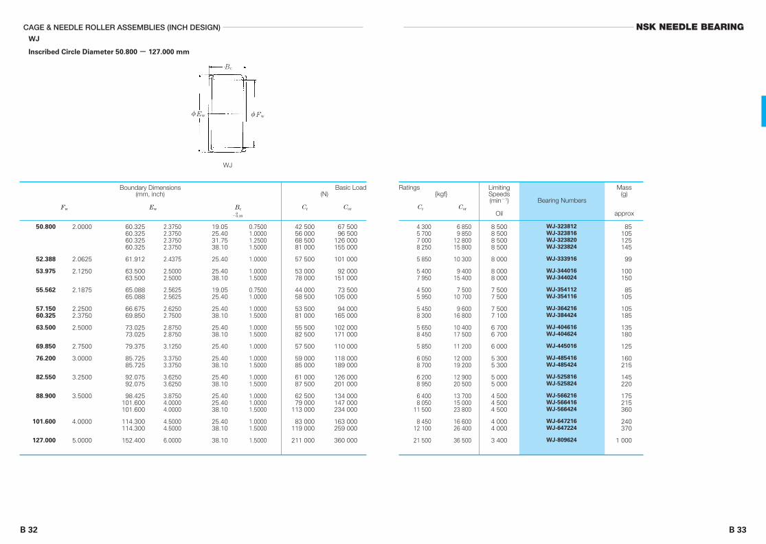
B 33
NSK NEEDLE BEARINGCAGE & NEEDLE ROLLER ASSEMBLIES (INCH DESIGN)
B 32
WJ
Inscribed Circle Diameter 50.800 - 127.000 mm
50.800
52.388
53.975
55.562
57.15060.325
63.500
69.850
76.200
82.550
88.900
101.600
127.000
60.32560.32560.32560.325
61.912
63.50063.500
65.08865.088
66.67569.850
73.02573.025
79.375
85.72585.725
92.07592.075
98.425101.600101.600
114.300114.300
152.400
2.37502.37502.37502.3750
2.4375
2.50002.5000
2.56252.5625
2.62502.7500
2.87502.8750
3.1250
3.37503.3750
3.62503.6250
3.87504.00004.0000
4.50004.5000
6.0000
19.0525.4031.7538.10
25.40
25.4038.10
19.0525.40
25.4038.10
25.4038.10
25.40
25.4038.10
25.4038.10
25.4025.4038.10
25.4038.10
38.10
0.75001.00001.25001.5000
1.0000
1.00001.5000
0.75001.0000
1.00001.5000
1.00001.5000
1.0000
1.00001.5000
1.00001.5000
1.00001.00001.5000
1.00001.5000
1.5000
42 50056 00068 50081 000
57 500
53 00078 000
44 00058 500
53 50081 000
55 50082 500
57 500
59 00085 000
61 00087 500
62 50079 000
113 000
83 000119 000
211 000
67 50096 500
126 000155 000
101 000
92 000151 000
73 500105 000
94 000165 000
102 000171 000
110 000
118 000189 000
126 000201 000
134 000147 000234 000
163 000259 000
360 000
4 3005 7007 0008 250
5 850
5 4007 950
4 5005 950
5 4508 300
5 6508 450
5 850
6 0508 700
6 2008 950
6 4008 050
11 500
8 45012 100
21 500
6 8509 850
12 80015 800
10 300
9 40015 400
7 50010 700
9 60016 800
10 40017 500
11 200
12 00019 200
12 90020 500
13 70015 00023 800
16 60026 400
36 500
8 5008 5008 5008 500
8 000
8 0008 000
7 5007 500
7 5007 100
6 7006 700
6 000
5 3005 300
5 0005 000
4 5004 5004 500
4 0004 000
3 400
85105125145
99
100150
85105
105185
135180
125
160215
145220
175215360
240370
1 000
WJ-323812
WJ-323816
WJ-323820
WJ-323824
WJ-333916
WJ-344016
WJ-344024
WJ-354112
WJ-354116
WJ-364216
WJ-384424
WJ-404616
WJ-404624
WJ-445016
WJ-485416
WJ-485424
WJ-525816
WJ-525824
WJ-566216
WJ-566416
WJ-566424
WJ-647216
WJ-647224
WJ-809624
2.0000
2.0625
2.1250
2.1875
2.25002.3750
2.5000
2.7500
3.0000
3.2500
3.5000
4.0000
5.0000
WJ
φEw φFw
Bc
Boundary Dimensions(mm, inch)
Fw Ew Bc0
-0.38
Basic Load(N)
Cr Cor
Ratings{kgf}
Cr Cor
LimitingSpeeds(min-1)
Oil
Bearing Numbers
Mass(g)
approx

B 35
NSK NEEDLE BEARINGCAGE & NEEDLE ROLLER ASSEMBLIES
B 34
For Large Ends of Connecting Rods
Inscribed Circle Diameter 12 - 30 mm
For Small Ends of Connecting Rods
Inscribed Circle Diameter 9 - 19 mm
1214
1516
1616
1818
1818
1921
202021
21
222222
23
910
12
14
15
16
17
18
19
11.512.7
14.313
15.516
1216.5
1820
1818
2223.520
23
172223.6
23.7
4 2005 900
6 4007 250
8 5008 500
6 9509 250
10 7009 550
11 30012 900
13 70014 90014 200
14 800
11 50014 20015 400
16 000
4 5005 950
8 4008 200
10 00010 000
8 05011 600
14 00012 000
15 30013 900
20 00022 30018 100
22 500
16 50021 60024 100
25 800
430605
655740
865865
710945
1 090975
1 1501 310
1 4001 5201 450
1 510
1 1701 4401 570
1 630
460610
855835
1 0201 020
8201 180
1 4301 230
1 5601 420
2 0402 2801 840
2 290
1 6802 2002 460
2 630
3.55.0
4.86.4
7.07.5
6.58.5
11.513
1113
141516
16
121516
17
FBN-91211Z-EFBN-101412Z-E
FBN-121514Z-EFBN-121613-E
FBN-121615Z-EFBN-121616-E
FBN-141812-EFBN-141816Z-E
FBN-141818-EFBN-141820-E1
FBN-151918-EFBN-152118-E
FBN-162022-EFBN-162023Z-EFBN-162120-E
FBN-172123-E
FBN-182217-EFBN-182222-EFBN-182223Z-E
FBN-192323Z-E
φEw φFw
Bc
FBN…E
161920
192021
2122
2324
262628
282932
31
303031
323536.75
3738
1214
15
16
18
20
22
23
24
252829.75
30
101012
91010
1112
1412
121718
141516
16
151720
161616.5
1618
6 1007 8008 900
5 6507 3007 950
8 6509 500
11 80010 000
12 20016 80018 100
13 90016 30019 700
17 600
15 60017 90021 600
17 70018 40019 600
21 90025 500
6 5008 0508 600
6 2507 6007 500
9 6009 600
14 80010 600
14 10021 20019 400
17 10019 00019 400
19 400
20 30024 30027 800
21 90023 70026 000
30 50034 000
620795910
575745810
880965
1 2001 020
1 2501 7101 840
1 4201 6602 010
1 800
1 5901 8302 200
1 8101 8801 990
2 2302 600
665820880
640775765
980980
1 5101 080
1 4402 1601 970
1 7401 9301 970
1 980
2 0702 4802 840
2 2302 4102 650
3 1003 450
4.06.28.3
4.16.08.5
7.59.5
1011
131725
141931
23
171930
242528
2935
FWF-121610-EFWF-141910-EFWF-142012-E
FWF-15199-EFWF-152010-EFWF-152110-E
FWF-162111-EFWF-162212-E
FWF-182314-EFWF-182412-E
FWF-202612-EFWF-202617-EFWF-202818-E
FWF-222814-EFWF-222915-EFWF-223216-E
FWF-233116-E
FWF-243015-EFWF-243017-EFWF-243120-E
FWF-253216-EFWF-283516-EFWF-293616Z-E
FWF-303716-EFWF-303818-E
Boundary Dimensions(mm)
Fw Ew Bc
Basic Load Ratings(N) {kgf}
Cr Cor Cr Cor
Bearing Numbers
Mass(g)
approx-0.2-0.4
Boundary Dimensions(mm)
Fw Ew Bc
Basic Load Ratings(N) {kgf}
Cr Cor Cr Cor
Bearing Numbers
Mass(g)
approx-0.2-0.4
φEw φFw
Bc
FWF…E
Please consult NSK when making a selection.

B 37
NSK NEEDLE BEARING
B 36 B 37
DRAWN CUP NEEDLE ROLLER BEARINGSMETRIC DESIGN
Open Type with Cage and Closed End Type with Cage
Inscribed Circle Diameter 10-55 mm ................................ B46-B53
Sealed Type with Cage Inscribed Circle Diameter 8-50 mm ................................ B54-B57
Thin, Open Type with Cage Inscribed Circle Diameter 18-82 mm ................................ B58-B59
Full Complement Open Type and Full Complement Closed End Type
Inscribed Circle Diameter 8-55 mm ................................ B60-B63
INCH DESIGN
Open Type with Cage and Closed End Type with Cage
Inscribed Circle Diameter 9.525-50.800 mm .................. B64-B67
Full Complement Open Type and Full Complement Closed End Type
Inscribed Circle Diameter 11.112-50.800 mm .................. B68-B75
Full Complement and Grease-Retained Roller Type
Inscribed Circle Diameter 3.969-47.625 mm .................. B76-B79
EXTRA SMALL・MINIATURE
Metric Design Open Type with Cage and Closed End Type with Cage
Inscribed Circle Diameter 3-9 mm .................................... B80-B81
Full Complement Metric Design Open Type and Full Complement Closed End Type
Inscribed Circle Diameter 3.036-9 mm ............................. B82-B83
Inch Design Open Type with Cage and Closed End Type with Cage
Inscribed Circle Diameter 3.175-9.525 mm ...................... B84-B85
Inch Design Full Complement Open Type and Full Complement Closed End Type
Inscribed Circle Diameter 3.175-9.525 mm ...................... B86-B87
NSK drawn cup needle roller bearings (with a cage and full complement ofrollers) have a unique outer ring structure. They have the following features: thethinnest outer ring among rolling bearings, high load capacity, high maximumpermissive load owing to the use of carefully selected special alloy steel plates, asurface-hardened cage with high resistance to wear, high limiting speed, and easeof mounting.
DESIGN AND TYPES
NSK drawn cup needle roller bearings consist of an outer ring made of carefullyselected alloy steel that is surface-hardened after precise pressing, rollers made ofvacuum-degassed bearing steel that are given a grinding finish after through-hardening, and a cage that guides the rollers correctly on the pitch diameter.
The bent lip of the drawn cup, which is the outer ring, improves rigidity, holds therollers and cage in place, and functions as a labyrinth seal to prevent foreign matterfrom entering and lubrication from leaking. The inside of the outer ring's bending partis hardened, and has sufficient wear resistance against the contact of the roller orcage.
Pages

DRAWN CUP NEEDLE ROLLER BEARINGS
B 38 B 39
INTERNAL CLEARANCE
The radial internal clearance when a drawn cup needle bearing is mounted in ahousing varies depending on the bearing, shaft and housing bore tolerances.Therefore, the tolerances for the shaft and housing bore should be narrower whenreducing the range of radial internal clearance.
When the dimensional tolerance for each part is as shown in Fig. 1 (Example of F-
3020-1), the radial internal clearance ranges from 0.015 to 0.074 mm.
APPLICATION
Shaft and housing specifications
For drawn cup needle bearings, the shaft is generally used as a substitute for theinner ring. Since the outer ring of drawn cup needle bearings is made of a thin steelplate, the correct shape and dimensional accuracy are achieved after press fitting theregular housing. The dimensional accuracy and hardness of the shaft and housingbore directly affect bearing performance. Therefore, the following specificationsshould be satisfied.
(1) Accuracy, Roughness and Hardness
Accuracy, roughness and hardness of the shaft and housing bore should satisfy thespecifications shown in Table 2.
(2) Shaft Inclination
Shaft inclination due to deflection by external force and mounting error of thebearing should be within the values found in Table 3.
NSK NEEDLE BEARING
The bearing numbers of NSK drawn cup bearings are shown incombination with bearing codes and dimension numbers.
The bearing codes are shown in Table 1.
(Example) FJ-1612-OH
Special Specifications
The bearing is manufactured in accordance with special specifications dependingon operating conditions. In this case, the code is indicated with the bearing numberfollowed by a hyphen and a letter or alphanumeric combination.
(Example) OH .... outer ring with oil hole
ACCURACY
Although standard drawn cup needle bearings perform well for general use,higher-accuracy drawn cup needle bearings are sometimes required such as whendispersion of radial internal clearance needs to be sharply decreased, when eccentriceffects should be minimized, or when using only a few bearings to share the loadevenly. However, standard bearings are still sufficient for almost all other occasions.Considering the higher cost of high-accuracy bearings, please consult NSK whenselecting such bearings.
MetricThe first one or two digits indicate the shaft’sdimensions, and the following digits indicate the width,both expressed in mm units.
The first one or two digits indicate the shaft’sdimensions, and the following digits indicate the width,both expressed in units of 1/16 of an inch. With closedends, the number "1" is added following the dimensionnumber.
Inch
The dimension number has the following meaning:
Items
StandardSeries
Metric FJ, FJP MFJ F, NF, DD MF, MNF
J, JP MJ B, Y M
FJL, FJH MFJL, MFJH FH, NFH MFH
JH MJH BH, YH MH
Inch
Metric
Inch
High LoadSeries
With Cage Assembly
Open Closed End Closed EndOpen
Full Complement
Table 1 Bearing Codes
Special Specification Code
CodeFJ means a metric open-type bearing with a cage.
Width Dimension } Dimension NumberShaft Dimension
Fig. 1 Radial Internal Clearance
Bearing Inscribed Circle Diameter(when pressing into ring gauge of φ36.972)
φ30+0.041+0.020
Shaft Diameter
φ30 h6 0-0.013Housing Bore Diameter
φ37 N7 -0.008-0.033
Radial Clearance0.015 to 0.074 mmSquare Mean Value0.027 to 0.062 mm
Category Shaft Housing Bore
Out-of-RoundnessTolerance
IT3――2IT4 IT5―― to ――2 2
IT3――2IT4 IT5―― to ――2 2
0.4
HRC58 to 64 (HRC60 to 64is favorable) Proper depth ofhardening layer required
―
1.6
Cylindricity Tolerance
Roughness, Ra
Hardness
Remarks For details, refer to Section 5.2 on page A34 and Section 5.3 on page A35.
Table 2 Accuracy, Roughness, and Hardness

B 41
MOUNTING
When an drawn cup needle roller bearing is pressed into a housing bore, it isnecessary to use an appropriate jig to prevent deformation of and damage to theouter ring, as shown in Fig. 2. The following precautions apply when mounting:(1) The marked-side face should be placed onto the shoulder of the jig.(2) A hand press should be used for press fitting. Avoid using a hammer or other
such instruments. (3) No snap ring or shoulder to determine the position of the bearing is necessary.
However, when using a housing with a shoulder, the bearing side face should nottouch the shoulder, in order to prevent bearing deformation.
(4) The guide and locaing stopper (Fig. 2) are installed in order to apply pressfitting accurately. The ball detent shown in Fig. 2 helps the jig hold the bearingand prevent roller inclination while facilitating mounting work.
Inspection of Drawn Cup Needle Bearings
Deformation to a certain degree due to heat treatment is inevitable even though theouter ring of drawn cup needle bearings is processed by precise deep drawing.However, once the bearing is pressed into the regular housing, this deformation iscorrected and the bearing performs to the full potential. Therefore, it is notappropriate to measure the drawn cup outside diameter before mounting. Correctinspection is carried out according to following procedures:(1) The bearing that is to be subject to the test is pressed into a ring gauge of given
dimensions.(2) The inscribed circle diameter at the GO and NO-GO plug gauges is inspected.
Metric inspection gauge dimensions are shown in Table 5.Table 6 shows tolerance for the roller inscribed circle diameter based on ISO
standards.For bearings based on ISO standards, "-1" is added at the end of the bearing
number. Table 7 shows inch inspection gauge dimensions.
NSK NEEDLE BEARINGDRAWN CUP NEEDLE ROLLER BEARINGS
B 40
(3) Housing Rigidity
To maintain the accuracy of drawn cup needle bearings, it is necessary to designthe housing thick enough to minimize deformation when load is applied.
Split housings can only be used with drawn cup needle bearings after press fittingthe bearing into a cylindrical sleeve.
FITTINGDrawn cup needle bearings perform as designed only after proper fitting. It is
necessary to use the fitting tolerances shown in Table 4 for the shaft and housing bore.The figures in Table 4 are for fits when housing materials are rigid steel or cast iron.The fit should be adjusted as follows in accordance with operating conditions:
(1) Oscillating motion
In order to reduce radial internal clearance, the shaft's fitting tolerance should bejs6 ( j 6).
(2) Outer ring rotation
For metric bearings, the fitting tolerances of the shaft and housing bore should bef6 and R7, respectively.
For inch bearings, 0.013 mm should be reduced from both fitting tolerances ofshaft and housing bore.
(3) The housing is made from light alloy or steel with a thickness of less than
6 mm.
The fitting tolerances of housing bore should be minimized to approximately 0.013to 0.025 mm, provided that the optimized value should be determined by mountinginto the actual housing because the value may vary depending on housing materialand shape. Please contact NSK for details.
Locating Stopper
Marked Side of BearingRecommended Jig DimensionsA = Housing Bore Diameter -0.4 mmB = Shaft Diameter -0.08 mmC = 0.25 mm (Min.)D = Bearing Width -0.8 mmE = Approximatery 1/2 D
Table 3 Permissible Shaft Inclination
Bearing Width (mm)
over
25
50
25
50
0.0015
0.0010
0.0005
0.0010
0.0005
0.0005
incl With Cage Full Complement
Permissible Inclination (mm/mm)
CategoryFitting Tolerance
Shaft
h6
h6
N7
J7
Nominal OutsideDiameter D, mm
over
7.144( 9/32)
8.731(11/32)
7.144( 9/32)
8.731(11/32)
+0.013
0
0
+0.013
incl high low
Tolerance, mm
h6
Housing Bore
MetricF, FJ
FJL
B, BH,
J, JH,
Y, YH
Inch
J7 J7
Table 4 Recommended Fits
Fig. 2 Example of Jig

B 43
NSK NEEDLE BEARINGDRAWN CUP NEEDLE ROLLER BEARINGS
B 42
45678
91012
FH1213
14NF14
151617
182022
NFH2224
NFH2425283032
3540455055
7.9968.9969.996
10.99511.995
12.99513.99515.99517.99518.993
19.99318.99320.99321.99322.972
23.97225.97227.97230.987―
31.96731.96734.96736.967―
41.96746.96751.96157.96162.961
4.0235.0236.0287.0318.031
9.03110.03112.03112.03113.034
14.03414.03415.03416.03417.013
18.01320.01322.01324.01524.013
24.01325.01328.01330.01332.013
35.01340.01345.01350.01355.013
4.0485.0486.0537.0568.056
9.05610.05612.05612.05613.059
14.05914.05915.05916.05917.038
18.03820.03822.03824.03524.038
24.03825.03828.03830.03832.038
35.04340.04345.04350.04355.043
――――
15.010
16.01017.01019.012――
22.012―
22.01224.01223.991
24.99126.99128.991―
30.989
―32.98936.98939.98941.989
44.98949.98954.98861.98866.988
Plug GaugeBore Diameter of Ring Gauge
GO Gauge NO-GO GaugeF,MF,FH,MFH,NF,MNF,NFH,FJ,MFJ
FJL, MFJL
Remarks This is the gauge dimension for inspection of minimum diameter, Fw, of roller inscribedcircle diameter.
Nominal RollerInscribed Circle
Diameter, Fw
Table 5 Inspection Gauge Dimensions (General Metric)Units: mm
Note (1) When using a cylinder instead of an inner ring, Fw min is thediameter of the cylinder at which the internal clearance is zero in atleast one radial direction. (Fw min is the minimum diameter of eachinscribed circle diameter where deviation is suspected.)
Remarks To measure the roller inscribed circle diameter, use the followungplug gauges:GO gauge: The same dimensions as the minimum tolerance of theroller inscribed circle diameter, Fw
NO-GO gauge: The dimensions should be the maximum toleranceof roller inscribed circle diameter, Fw, plus 0.002 mm
Units: mm
34567
8H 8
9H 910
H1012
H121314
1516171820
2225283035
40455055
6.4847.9848.9849.984
10.980
11.98013.98012.98014.98013.980
15.98015.98017.98018.97619.976
20.97621.97622.97623.97625.976
27.97631.97234.97236.97241.972
46.97251.96757.96762.967
3.0074.0105.0106.0107.013
8.0138.0139.0139.013
10.013
10.01312.01612.01613.01614.016
15.01616.01617.01618.01620.020
22.02025.02028.02030.02035.025
40.02545.02550.02555.030
3.0214.0285.0286.0287.031
8.0318.0319.0319.031
10.031
10.03112.03412.03413.03414.034
15.03416.03417.03418.03420.041
22.04125.04128.04130.04135.050
40.05045.05050.05055.060
Nominal RollerInscribed Circle
Diameter, Fw
Bore Diameterof Ring Gauge
Tolerance for Roller InscribedCircle Diameter, Fw(1)
min max
Table 6 Ring Gauge of Drawn Cup Needle Roller Bearings
and Tolerance of Roller Inscribed Circle Diameter (ISO Standerds)
FJ, FJH, MFJ and MFJH
F, FH, MF and MFH[ ]

B 45
Drawn Cup Needle Bearings with Seals
Drawn cup needle roller-bearing with seals can be sealed on one or both sides.The bearings are packed with lithium soap-based grease and can be operatedunder regular conditions in normal operating ranges for long periods withoutreplenishment. The seale made of nitrile synthetic rubber reinforced with a steelplate and serves as a guide for the side face of the cage. The operatingtemperature range is limited because of the rubber seal, ranging from -10°C to+100°C for continuous use from -25°C to +120°C for short periods of use.
The various types of drawn cup needle bearings with seals are shown inTable 8.
NSK NEEDLE BEARINGDRAWN CUP NEEDLE ROLLER BEARINGS
B 44
6.3637.1558.730
11.12512.713
14.30015.88817.47519.06320.650
22.23825.38726.97528.56230.150
31.73733.32534.91238.08738.087
41.26241.26247.61250.78753.962
57.13760.312
14.30015.88817.47519.06320.650
22.23823.82526.97528.56230.150
33.32538.08741.26244.437
3.175( 1/8 )3.969( 5/32 )4.762( 3/16 )6.350( 1/4 )7.938( 5/16 )
9.525( 3/8 )11.112( 7/16 )12.700( 1/2 )14.288( 9/16 )15.875( 5/8 )
17.462( 11/16 )19.050( 3/4 )20.638( 13/16 )22.225( 7/8 )23.812( 15/16 )
25.400( 1 )26.988(1 1/16)28.575(1 1/8)30.162(1 3/16)31.750(1 1/4)
33.338(1 5/16)34.925(1 3/8)38.100(1 1/2)41.275(1 5/8)44.450(1 3/4)
47.625(1 7/8)50.800( 2 )
7.938( 5/16 )9.525( 3/8 )
11.112( 7/16 )12.700( 1/2 )14.288( 9/16 )
15.875( 5/8 )17.462( 11/16 )19.050( 3/4 )20.638( 13/16 )22.225( 7/8 )
25.400( 1 )28.575(1 1/8)31.750(1 1/4)34.925(1 3/8)
3.1953.9904.7836.3887.976
9.56311.15112.73814.32615.913
17.50119.06320.65022.23823.825
25.41327.00028.58830.17531.763
33.35034.93838.11341.28844.463
47.63850.815
7.9769.563
11.15112.73814.326
15.91317.50119.06320.65022.238
25.41328.58831.76334.938
3.2204.0154.8086.4138.001
9.58811.17612.76314.35115.938
17.52619.08820.67522.26323.850
25.43827.02528.61330.20031.788
33.37834.96638.14341.31844.496
47.67150.848
8.0019.588
11.17612.76314.351
15.93817.52619.08820.67522.263
25.43828.61331.78834.966
Plug GaugeBore Diameter ofRing Gauge
Nominal Roller InscribedCircle Diameter, Fw GO Gauge NO-GO Gauge
Plug GaugeBore Diameter ofRing Gauge
Nominal Roller InscribedCircle Diameter, Fw GO Gauge NO-GO Gauge
Units: mm
Units: mm
BH, MH, JH, MJH and YH
B, M, J, MJ, Y and JP
Table 7 Inspection Gauge Dimensional Table (Inch)
Code Description
Drawn cup with seal on one side
Drawn cup with seals on both sides
Closed end, drawn cup with seal on one side
FJT, FJLT, FJHT
FJTT, FJLTT, FJHTT
MFJT, MFJLT, MFJHT
Table 8 Types of Drawn Cup Needle Roller Bearings with Seals

B 47
NSK NEEDLE BEARINGDRAWN CUP NEEDLE ROLLER BEARINGS
B 46
With Cage
FJ ● FJH (Open Type)
FJL
MFJ ● MFJH (Closed Type)
MFJL
Inscribed Circle Diameter 10 - 16 mm
141416
17171717
161819
191919
19
20202222
212121
222222
2222
2222
2424
101510
10121520
101212
152025
12
12161620
101216
101215
2025
1216
1620
3 5005 5504 900
4 9005 7007 850
11 200
4 1506 4506 650
9 20013 00016 600
6 950
6 5009 500
11 60015 100
5 8507 650
11 000
6 4507 450
10 300
14 70018 700
7 10010 400
13 10017 100
360570500
500580800
1 140
420655675
9351 3301 690
710
665970
1 1801 540
595780
1 120
655760
1 050
1 5001 900
7251 060
1 3301 740
1 7603 1502 100
1 9902 4103 6505 750
2 2103 0502 950
4 5007 0009 550
3 400
3 2505 3005 7008 050
2 7703 9006 200
2 8803 5005 300
8 30011 300
3 7506 050
6 7009 500
32 00032 00034 000
36 00036 00036 00036 000
26 00028 00028 000
28 00028 00028 000
26 000
24 00024 00024 00024 000
22 00022 00022 000
22 00022 00022 000
22 00022 000
20 00020 000
20 00020 000
FJ-1010FJ-1015LFJH-1010
FJ-1210FJH-1212
FJ-1312
FJ-1412FJ-1416
FJ-1510FJ-1512FJ-1516
FJ-1612FJ-1616
FIR-071010FIR-071015FIR-071010
FIR-071010FIR-071012FIR-071015
―
FIR-081210FIR-081212FIR-081212
FIR-081215――
FIR-101312
FIR-101412FIR-101416FIR-101416FIR-101420
FIR-101510FIR-101512FIR-121516
FIR-101510FIR-101512FIR-101515
FIR-101520FIR-101525
FIR-121612FIR-121616
FIR-121616FIR-121620
―――
――――
―――
―――
―
――――
―FIR-121512
―
―FIR-121512
―
――
――
――
FJL-1010FJL-1012LFJL-1015FJL-1020
FJL-1212L
FJL-1215FJL-1220FJL-1225L
FJL-1416FJL-1420L
FJL-1510LFJL-1512LFJL-1515
FJL-1520FJL-1525L
FJL-1616LFJL-1620L
MFJ-1010―
MFJH-1010
MFJ-1210MFJH-1212
MFJ-1312
MFJ-1412MFJ-1416
―MFJ-1512MFJ-1516
MFJ-1612MFJ-1616
MFJL-1010MFJL-1012LMFJL-1015MFJL-1020
MFJL-1212L
MFJL-1215MFJL-1220MFJL-1225L
MFJL-1416LMFJL-1420L
MFJL-1510LMFJL-1512LMFJL-1515
MFJL-1520MFJL-1525L
MFJL-1616LMFJL-1620L
179325214
203246375585
225310300
455715975
345
335540580820
283400635
294355540
8451 150
380620
685970
3.65.46.1
7.08.4
1114
4.17.79.8
121620
8.6
10131721
8.11013
9.81214
2024
1114
1924
4.1―6.6
7.89.3
1216
4.59.0
11
141924
9.5
11141924
―1114
111316
2227
1215
2127
0.8―1.0
1.01.01.01.0
0.81.01.0
1.01.01.0
1.0
1.01.01.11.1
―1.01.0
1.01.01.0
1.01.0
1.01.0
1.11.1
10
12
13
14
15
16
Boundary Dimensions(mm)
Fw D C C2
max
Basic DynamicLoad Ratings
(N) {kgf}
Cr
Limiting Loads(N) {kgf}
Pmax
LimitingSpeeds(min-1)
Oil
Bearing Numbers
Open ClosedFJ FJL MFJ MFJLFJH MFJH
Mass(g)
approxOpen Closed
Matching Inner Rings
0-0.25
φD φFw
C
φD φFw
C
Closed TypeOpen Type
C2

B 49
NSK NEEDLE BEARINGDRAWN CUP NEEDLE ROLLER BEARINGS
B 48
With Cage
FJ (Open Type)
FJL
MFJ (Closed Type)
MFJL
Inscribed Circle Diameter 17 - 25 mm
232324
2424
242425
25252525
262626
27272727
282828
292929
2929
323232
333333
3333
121615
2025
121613
15172025
121620
15202530
121620
101520
2530
162026
101520
2530
8 45012 10010 800
15 40019 600
7 65011 200
9 300
11 40013 30016 10020 500
8 15011 90015 300
12 30017 50022 30026 800
8 65012 60016 200
7 95012 70018 100
23 00027 700
15 20019 80026 200
8 80015 40021 900
28 00033 500
8601 2301 110
1 5702 000
7801 140
945
1 1601 3601 6402 090
8351 2101 560
1 2601 7902 2702 730
8801 2901 660
8101 3001 840
2 3502 820
1 5502 0202 670
8951 5702 240
2 8503 450
4 4507 1005 700
8 95012 200
4 2006 8004 700
6 1007 5009 600
13 100
4 6507 550
10 500
6 90010 90014 80018 700
5 1508 350
11 500
4 0007 300
11 500
15 70019 800
9 35013 10018 800
4 3008 800
13 900
19 00024 100
19 00019 00020 000
20 00020 000
18 00018 00018 000
18 00018 00018 00018 000
16 00016 00016 000
16 00016 00016 00016 000
14 00014 00014 000
15 00015 00015 000
15 00015 000
13 00013 00013 000
13 00013 00013 000
13 00013 000
FJ-1712FJ-1716
FJ-1812FJ-1816
FJ-2012FJ-2016FJ-2020
FJ-2212FJ-2216FJ-2220
FJ-2516FJ-2520FJ-2526
――
FIR-121715
FIR-121720FIR-121725
FIR-151812FIR-151816
―
FIR-151815―
FIR-151820FIR-151825
FIR-172012FIR-172016FIR-152020
FIR-152015FIR-152020FIR-152025FIR-152030
FIR-172212FIR-172216FIR-172220
FIR-172210FIR-172215FIR-172220
FIR-172225FIR-172230
FIR-202516FIR-202520FIR-202526
FIR-202510FIR-202515FIR-202520
FIR-202525FIR-202530
―――
――
―――
――――
――
FIR-172020
―FIR-172020
――
―――
―――
――
―――
―――
――
FJL-1715
FJL-1720LFJL-1725L
FJL-1813
FJL-1815FJL-1817LFJL-1820LFJL-1825
FJL-2015LFJL-2020FJL-2025LFJL-2030L
FJL-2210LFJL-2215LFJL-2220L
FJL-2225LFJL-2230L
FJL-2510FJL-2515FJL-2520
FJL-2525LFJL-2530
MFJ-1712MFJ-1716
MFJ-1812MFJ-1816
MFJ-2012MFJ-2016MFJ-2020
MFJ-2212MFJ-2216MFJ-2220
MFJ-2516MFJ-2520MFJ-2526
MFJL-1715
MFJL-1720LMFJL-1725L
MFJL-1813
MFJL-1815MFJL-1817LMFJL-1820LMFJL-1825
MFJL-2015MFJL-2020MFJL-2025LMFJL-2030L
MFJL-2210LMFJL-2215LMFJL-2220L
MFJL-2225LMFJL-2230L
MFJL-2510MFJL-2515LMFJL-2520
MFJL-2525LMFJL-2530
455720580
9101 240
430695480
620765975
1 330
475770
1 070
7051 1101 5101 910
525850
1 180
405745
1 170
1 6002 020
9551 3401 920
435895
1 420
1 9402 460
101416
2127
121614
17202228
131722
19243037
141923
132027
3340
243140
172635
4352
111618
2430
141816
19222531
151924
21273341
172226
152230
3744
273443
192939
4858
1.01.01.0
1.01.0
1.01.01.0
1.01.01.01.0
1.01.01.0
1.01.01.01.0
1.01.01.0
1.01.01.0
1.01.0
1.01.01.0
1.01.01.0
1.01.0
17
18
20
22
25
φD φFw
C
Closed TypeOpen Type
C2
φD φFw
C
Boundary Dimensions(mm)
Fw D C C2
max
Basic DynamicLoad Ratings
(N) {kgf}
Cr
Limiting Loads(N) {kgf}
Pmax
LimitingSpeeds(min-1)
Oil
Bearing Numbers
Open Closed
FJ FJL MFJ MFJL
Mass(g)
approxOpen Closed
Matching Inner Rings
0-0.25

B 51
NSK NEEDLE BEARINGDRAWN CUP NEEDLE ROLLER BEARINGS
B 50
With Cage
FJ (Open Type)
FJL
MFJ (Closed Type)
MFJL
Inscribed Circle Diameter 28 - 40 mm
353535
3737
373737
40404040
4242
424242
424545
454545
474747
50505050
162026
2030
162026
15202530
2030
121620
261215
202530
162026
15202530
15 60020 50026 900
25 40039 000
15 60019 40026 000
17 20025 80033 50041 000
26 70042 500
12 00018 10023 600
31 50013 20018 200
27 40036 00043 500
18 60023 50031 500
19 90029 90039 00047 500
1 5902 0902 750
2 5904 000
1 5901 9702 660
1 7502 6303 4504 200
2 7204 300
1 2301 8502 410
3 2001 3501 860
2 7903 6504 450
1 8902 4003 200
2 0303 0503 9504 850
9 95014 20020 200
15 50027 100
10 10013 30019 500
9 10015 30021 60027 800
16 20029 400
7 55012 80017 900
25 8006 650
10 100
17 00024 00031 000
13 60018 50026 900
11 60019 60027 60035 500
11 00011 00011 000
11 00011 000
10 00010 00010 000
11 00011 00011 00011 000
10 00010 000
9 0009 0009 000
9 0009 0009 000
9 0009 0009 000
7 5007 5007 500
8 0008 0008 0008 000
FJ-2816FJ-2820FJ-2826
FJ-3016LFJ-3020FJ-3026
FJ-3512FJ-3516FJ-3520
FJ-3526
FJ-4016FJ-4020FJ-4026
FIR-222816FIR-222820FIR-222826
FIR-222820FIR-222830
―FIR-253020FIR-253026
FIR-253015FIR-253020FIR-253025FIR-253030
FIR-283220FIR-283230
FIR-303512―
FIR-303520
FIR-303526FIR-303512FIR-303515
FIR-303520FIR-303525FIR-303530
―FIR-354020FIR-354026
FIR-354015FIR-354020FIR-354025FIR-354030
―――
――
―――
――――
――
―――
―――
―――
―――
――――
FJL-2820LFJL-2830L
FJL-3015LFJL-3020LFJL-3025LFJL-3030L
FJL-3220FJL-3230
FJL-3512FJL-3515
FJL-3520LFJL-3525LFJL-3530L
FJL-4015LFJL-4020LFJL-4025LFJL-4030L
MFJ-2816MFJ-2820MFJ-2826
MFJ-3016LMFJ-3020MFJ-3026
MFJ-3512MFJ-3516MFJ-3520
MFJ-3526
MFJ-4016MFJ-4020MFJ-4026
MFJL-2820LMFJL-2830L
MFJL-3015LMFJL-3020LMFJL-3025LMFJL-3030L
MFJL-3220MFJL-3230
MFJL-3512MFJL-3515
MFJL-3520LMFJL-3525LMFJL-3530L
MFJL-4015LMFJL-4020LMFJL-4025LMFJL-4030L
1 0201 4502 060
1 5802 760
1 0301 3601 990
9251 5602 2002 840
1 6503 000
7701 3001 830
2 630680
1 030
1 7402 4503 150
1 3901 8902 740
1 1802 0002 8103 650
273445
4465
263546
49526578
5582
24.33241
543644
607490
344660
506784
100
313849
4872
313950
55587286
6291
303845
584049
6782
100
435165
557493
110
1.01.01.0
1.01.0
1.01.01.0
1.31.31.31.3
1.31.3
1.01.01.0
1.01.31.3
1.31.31.3
1.01.01.0
1.31.31.31.3
28
30
32
35
40
φD φFw
C
Closed TypeOpen Type
C2
φD φFw
C
Boundary Dimensions(mm)
Fw D C C2
max
Basic DynamicLoad Ratings
(N) {kgf}
Cr
Limiting Loads(N) {kgf}
Pmax
LimitingSpeeds(min-1)
Oil
Bearing Numbers
Open Closed
FJ FJL MFJ MFJL
Mass(g)
approxOpen Closed
Matching Inner Rings
0-0.25

B 53
NSK NEEDLE BEARINGDRAWN CUP NEEDLE ROLLER BEARINGS
B 52
With Cage
FJ (Open Type)
FJL
MFJ (Closed Type)
MFJL
Inscribed Circle Diameter 45 - 55 mm
525252
555555
585862
62626262
63636767
162026
202530
202412
15202530
20243040
19 90025 50034 000
31 00040 50049 500
28 90036 00021 200
24 20037 00048 50059 500
30 00037 50062 50081 500
2 0302 6003 450
3 2004 1505 050
2 9403 7002 160
2 4703 8004 9506 050
3 1003 8506 3508 350
15 40021 20030 500
21 30030 00038 500
23 10030 50011 600
13 80023 70033 50043 500
25 10033 50047 50067 000
6 7006 7006 700
7 1007 1007 100
6 3006 3006 300
6 3006 3006 3006 300
5 6005 6005 6005 600
FJ-4516FJ-4520FJ-4526
FJ-5020LFJ-5024
FJ-5520FJ-5524
―FIR-404520FIR-404526
FIR-404520FIR-404525FIR-404530
FIR-455020―
FIR-455012
FIR-455015FIR-455020FIR-455025FIR-455030
――――
―――
―――
―――
――――
――――
FJL-4520LFJL-4525LFJL-4530L
FJL-5012L
FJL-5015LFJL-5020LFJL-5025LFJL-5030L
FJL-5530LFJL-5540L
MFJ-4516MFJ-4520MFJ-4526
MFJ-5020MFJ-5024
MFJ-5520MFJ-5524
MFJL-4520LMFJL-4525LMFJL-4530L
MFJL-5012L
MFJL-5015LMFJL-5020LMFJL-5025LMFJL-5030L
MFJL-5530LMFJL-5540L
1 5702 1603 100
2 1703 0503 950
2 3503 1501 180
1 4002 4203 4504 450
2 5603 4004 8506 850
395368
7494
110
566960
75100125150
6072
155195
505974
82105125
718466
83110140165
7990
180220
1.01.01.0
1.31.31.3
1.11.11.3
1.31.31.31.3
1.11.11.31.3
45
50
55
φD φFw
C
φD φFw
C
Closed TypeOpen Type
C2
Boundary Dimensions(mm)
Fw D C C2
max
Basic DynamicLoad Ratings
(N) {kgf}
Cr
Limiting Loads(N) {kgf}
Pmax
LimitingSpeeds(min-1)
Oil
Bearing Numbers
Open Closed
FJ FJL MFJ MFJL
Mass(g)
approxOpen Closed
Matching Inner Rings
0-0.25

B 55
NSK NEEDLE BEARINGDRAWN CUP NEEDLE ROLLER BEARINGS
B 54
Sealed Type With Cage
FJT (Open Type ● One-Side
)Sealed Type
FJHT
FJLT
FJTT (Open Type ● Both-Side
)Sealed Type
FJHTT
FJLTT
MFJT (Closed Type ● Sealed Type)
MFJLT
Inscribed Circle
Diameter 8 - 22 mm
1215
1417
161819
2022
212222
222224
24
242525
26262727
28282929
1212
1212
121414
1419
141318
141823
18
141820
14181823
14181823
1414
1414
141616
1622
161621
162026
21
162123
16202126
16202126
0.81.0
0.81.0
0.81.01.0
1.01.1
1.01.01.0
1.01.01.1
1.0
1.01.01.0
1.01.01.01.0
1.01.01.01.0
2 8404 400
3 5004 900
4 1506 4506 650
6 50011 600
7 6506 450
10 300
7 10010 40017 100
10 800
7 65011 40013 300
8 15011 90012 30017 500
8 65012 60012 70018 100
289450
360500
420655675
6651 180
780655
1 050
7251 0601 740
1 110
7801 1601 360
8351 2101 2601 790
8801 2901 3001 840
1 2701 770
1 7601 990
2 2103 0502 950
3 2505 700
3 9002 8805 300
3 7506 0509 500
5 700
4 2006 1007 500
4 6507 5506 900
10 900
5 1508 3507 300
11 500
22 00022 000
19 00019 000
15 00015 00015 000
13 00013 000
12 00012 00012 000
11 00011 00011 000
11 000
10 00010 00010 000
9 5009 5009 5009 500
8 5008 5008 5008 500
3.16.4
4.17.5
5.18.7
11
1118
111115
121525
17
131821
14182025
16212229
3.56.8
4.68.0
6.19.7
12
1319
121216
131616
18
151922
17212227
18232430
3.67.0
4.68.3
5.59.2
12
1220
121217
131628
19
152022
16202228
19242432
FJT-812
FJT-1012
FJT-1212FJHT-1214
FJT-1414
FJT-1514
FJT-1614FJT-1618
FJT-1814
FJT-2014FJT-2018
FJT-2214FJT-2218
FJTT-814
FJTT-1014
FJTT-1214FJHTT-1216
FJTT-1416
FJTT-1516
FJTT-1616FJTT-1620
FJTT-1816
FJTT-2016FJTT-2020
FJTT-2216FJTT-2220
MFJT-812
MFJT-1012
MFJT-1212MFJHT-1214
MFJT-1414
MFJT-1514
MFJT-1614MFJT-1618
MFJT-1814
MFJT-2014MFJT-2018
MFJT-2214MFJT-2218
FJLT-812
FJLT-1012
FJLT-1214
FJLT-1419
FJLT-1513FJLT-1518
FJLT-1623
FJLT-1718
FJLT-1818FJLT-1820
FJLT-2018FJLT-2023
FJLT-2218FJLT-2223
FJLTT-814
FJLTT-1014
FJLTT-1216
FJLTT-1422
FJLTT-1516FJLTT-1521
FJLTT-1626
FJLTT-1721
FJLTT-1821FJLTT-1823
FJLTT-2021FJLTT-2026
FJLTT-2221FJLTT-2226
MFJLT-812
MFJLT-1012
MFJLT-1214
MFJLT-1419
MFJLT-1513MFJLT-1518
MFJLT-1623
MFJLT-1718
MFJLT-1818MFJLT-1820
MFJLT-2018MFJLT-2023
MFJLT-2218MFJLT-2223
130181
179203
225310300
335580
400294540
380620970
580
430620765
475770705
1 110
525850745
1 170
8
10
12
14
15
16
17
18
20
22
Boundary Dimensions(mm)
Fw D C3 C4 C2max
Basic DynamicLoad Ratings(N) {kgf}
Cr
Limiting Loads(N) {kgf}
Pmax
LimitingSpeeds(1)
(min-1)
Bearing
OpenFJT FJTTFJHT FJHTT
Numbers
Closed Open ClosedMFJT FJLT FJLTT MFJLT
Mass (g)approx
FJT FJTT MFJTFJHT FJLTT MFJLTFJLT FJHTT0
-0.250
-0.25
φD φFw
C3
Closed TypeOpen Type
C2
FJTT, FJHTT, FJLTTFJT, FJHT, FJLT
φD φFw
C3
φD φFw
C4
Note (1) This is the value when the speed at the seal contact surface is 10 m/sec under inner ring rotation. Under outer ring rotation, the limiting speed is half this value.
Remarks Standard grease is packed in the sealed drawn cup needle roller bearings unless otherwise specified.

B 57
NSK NEEDLE BEARINGDRAWN CUP NEEDLE ROLLER BEARINGS
B 56
Sealed Type With Cage
FJT (Open Type ● One-Side
)Sealed Type
FJLT
FJTT (Open Type ● Both-Side
)Sealed Type
FJLTT
MFJT (Closed Type ● Sealed Type)
MFJLT
Inscribed Circle
Diameter 25 - 50 mm
φD φFw
Closed TypeOpen Type
C2
FJTT, FJLTTFJT, FJLT
φD φFw
C3
φD φFw
C4 C3
323333
3537
374040
424545
475050
5255
62
181823
1823
222328
221828
221828
2223
28
202126
2026
242631
242131
242131
2426
31
1.01.11.1
1.01.0
1.01.31.3
1.01.31.3
1.01.31.3
1.01.3
1.3
15 20015 40021 900
15 60025 400
19 40025 80033 500
23 60018 20036 000
23 50019 90039 000
25 50031 000
48 500
1 5501 5702 240
1 5902 590
1 9702 6303 450
2 4101 8603 650
2 4002 0303 950
2 6003 200
4 950
9 3508 800
13 900
9 95015 500
13 30015 30021 600
17 90010 10024 000
18 50011 60027 600
21 20021 300
33 500
7 5007 5007 500
6 7006 700
6 3006 3006 300
5 3005 3005 300
4 5004 5004 500
4 0004 000
3 800
282837
2946
405568
464777
525488
6178
130
303139
3249
425770
495080
555791
6482
135
313141
3350
446075
505285
575997
6786
145
FJT-2518
FJT-2818
FJT-3022
FJT-3522
FJT-4022
FJT-4522
FJTT-2520
FJTT-2820
FJTT-3024
FJTT-3524
FJTT-4024
FJTT-4524
MFJT-2518
MFJT-2818
MFJT-3022
MFJT-3522
MFJT-4022
MFJT-4522
FJLT-2518FJLT-2523
FJLT-2823
FJLT-3023FJLT-3028
FJLT-3518FJLT-3528
FJLT-4018FJLT-4028
FJLT-4523
FJLT-5028
FJLTT-2521FJLTT-2526
FJLTT-2826
FJLTT-3026FJLTT-3031
FJLTT-3521FJLTT-3531
FJLTT-4021FJLTT-4031
FJLTT-4526
FJLTT-5031
MFJLT-2518MFJLT-2523
MFJLT-2823
MFJLT-3023MFJLT-3028
MFJLT-3518MFJLT-3528
MFJLT-4018MFJLT-4028
MFJLT-4523
MFJLT-5028
955895
1 420
1 0201 580
1 3601 5602 200
1 8301 0302 450
1 8901 1802 810
2 1602 170
3 450
25
28
30
35
40
45
50
Boundary Dimensions(mm)
Fw D C3 C4 C2max
Basic DynamicLoad Ratings(N) {kgf}
Cr
Limiting Loads(N) {kgf}
Pmax
LimitingSpeeds(1)
(min-1)
Bearing
Open
FJT FJTT
Numbers
Closed Open Closed
MFJT FJLT FJLTT MFJLT
Mass (g)approx
FJT FJTT MFJTFJLT FJLTT MFJLT0
-0.250
-0.25
Note (1) This is the value when the speed at the seal contact surface is 10 m/sec under inner ring rotation. Under outer ring rotation, the limiting speed is half this value.
Remarks Standard grease is packed in the sealed drawn cup needle roller bearings unless otherwise specified.

B 59
NSK NEEDLE BEARINGDRAWN CUP NEEDLE ROLLER BEARINGS
B 58
With Cage
Thin Type
DB
Inscribed Circle Diameter 18 - 82 mm
Boundary Dimensions(mm)
Fw D C
18 23 9.5 5 050 515 2 820 288 18 00033 39 26 22 500 2 300 19 500 1 980 9 500
39 45 12 6 500 665 4 200 430 8 00055 61 12 9 900 1 010 8 050 820 5 600
82 88 12 9 400 955 8 400 855 3 600
0–0.25
BearingNumbers
Mass(g)
approx
DB501801 7.5DB503303A 44.4
DB503901 23DB505501 35
DB508201 52
φD φFw
C
Basic DynamicLoad Ratings
(N) {kgf}
Cr
Limiting Loads
(N) {kgf}
Pmax
LimitingSpeeds(min-1)
Oil

B 61
NSK NEEDLE BEARINGDRAWN CUP NEEDLE ROLLER BEARINGS
B 60
Full Complement Type
F ● FH (Open Type)
NF
MF ● MFH (Closed Type)
MNF
Inscribed Circle Diameter 8 - 20 mm
1415
1416
161618
19
202020
1919
21212121
2222
232323
2424
262626
1010
1010
101212
12
121316
1620
10121416
1216
121620
1216
121620
5 5506 100
5 8006 650
6 4507 9509 000
9 550
9 45010 40013 300
12 90016 100
8 05010 30012 40014 500
10 20014 400
11 30015 80020 200
10 90015 300
11 50016 20020 500
565625
595680
660810920
975
9651 0601 360
1 3101 640
8201 0501 2701 480
1 0401 460
1 1501 6102 060
1 1101 560
1 1701 6502 090
2 9803 350
4 0503 700
4 7006 2005 700
6 100
6 3507 2009 850
10 40013 800
5 0006 9008 800
10 700
7 10011 100
7 75012 00016 300
7 90012 300
8 70013 50018 300
10 00010 000
5 6009 000
5 0005 0007 500
7 100
6 0006 0006 000
5 3005 300
6 0006 0006 0006 000
5 3005 300
5 6005 6005 600
5 0005 000
4 5004 5004 500
FH-810FH-910
F-1010FH-1010
F-1210F-1212FH-1212
F-1312
F-1412F-1413F-1416
NF-1416NF-1420
F-1510F-1512F-1514F-1516
F-1612F-1616
F-1712F-1716F-1720
F-1812F-1816
F-2012F-2016F-2020
MFH-810MFH-910
MF-1010MFH-1010
MF-1210MF-1212MFH-1212
MF-1312
MF-1412MF-1413MF-1416
MNF-1416MNF-1420
MF-1510MF-1512MF-1514MF-1516
MF-1612MF-1616
MF-1712MF-1716MF-1720
MF-1812MF-1816
MF-2012MF-2016MF-2020
――
FIR-071010FIR-071010
FIR-081210FIR-081212FIR-081212
FIR-101312
FIR-101412FIR-101413
―
FIR-101416FIR-101420
FIR-101510FIR-101512
―FIR-121516
FIR-121612FIR-121616
――
FIR-121720
FIR-151812FIR-151816
FIR-172012FIR-172016FIR-152020
――
――
―――
―
―――
――
―FIR-121512
――
――
―――
――
――
FIR-172020
305340
415375
480630580
625
645735
1 000
1 0601 410
510705895
1 090
7251 130
7901 2201 670
8051 250
8851 3801 870
6.06.4
4.76.9
5.56.6
10
11
121318
1216
10121517
1418
141823
1419
172228
6.36.8
5.07.3
5.46.8
11
12
141519
1317
12141618
1520
152024
1622
192530
1.91.8
1.61.9
1.61.61.9
1.9
2.22.22.2
1.61.6
1.81.81.81.8
2.22.2
1.81.81.8
2.22.2
2.22.22.2
89
10
12
13
14
15
16
17
18
20
φD φFw
C
φD φFw
C
Closed TypeOpen Type
C1
Boundary Dimensions(mm)
Fw D C C1
max
Basic DynamicLoad Ratings
(N) {kgf}
Cr
Limiting Loads
(N) {kgf}
Pmax
LimitingSpeeds(min-1)
Oil
Bearing Numbers
Open ClosedF, FH MF, MFHNF MNF
Mass(g)
approxOpen Closed
Matching Inner Rings
0-0.25

B 63
NSK NEEDLE BEARINGDRAWN CUP NEEDLE ROLLER BEARINGS
B 62
Full Complement Type
F (Open Type)
NFH
MF (Closed Type)
Inscribed Circle Diameter 22 - 55 mm
28282828
31
323232
35353535
37373737
42424242
474747
525252
5858
6363
10121620
25
162026
12162026
14162026
12162026
162026
162026
2024
2024
9 40012 10017 10021 600
31 500
20 20025 90034 000
14 80021 30027 30035 500
18 90022 10028 40037 000
16 90024 00031 00040 000
25 70032 50043 000
27 30035 00045 500
39 50048 000
41 50050 500
9601 2301 7402 200
3 250
2 0602 6403 450
1 5102 1702 7803 650
1 9302 2502 9003 800
1 7202 4503 1504 100
2 6203 3504 350
2 7903 5504 650
4 0504 900
4 2505 150
6 8509 500
14 80020 000
28 700
16 20022 20031 500
11 20017 90024 60034 500
15 50018 90026 20037 000
14 00022 00030 00042 500
24 90034 00048 000
27 80038 50054 000
41 50053 000
45 50058 000
4 0004 0004 0004 000
4 800
4 5004 5004 500
4 0004 0004 0004 000
3 8003 8003 8003 800
3 4003 4003 4003 400
3 0003 0003 000
2 6002 6002 600
2 8002 800
2 4002 400
F-2210F-2212F-2216F-2220
NFH-222A
F-2516F-2520F-2526
F-2812F-2816F-2820F-2826
F-3014F-3016F-3020F-3026
F-3512F-3516F-3520F-3526
F-4016F-4020F-4026
F-4516F-4520F-4526
F-5020F-5024
F-5520F-5524
MF-2210MF-2212MF-2216MF-2220
―
MF-2516MF-2520MF-2526
MF-2812MF-2816MF-2820MF-2826
MF-3014MF-3016MF-3020MF-3026
MF-3512MF-3516MF-3520MF-3526
MF-4016MF-4020MF-4026
MF-4516MF-4520MF-4526
MF-5020MF-5024
MF-5520MF-5524
FIR-172210FIR-172212FIR-172216FIR-172220
―
FIR-202516FIR-202520FIR-202526
―FIR-222816FIR-222820FIR-222826
――
FIR-253020FIR-253026
FIR-303512―
FIR-303520FIR-303526
―FIR-354020FIR-354026
―FIR-404520FIR-404526
――
――
――――
―
―――
――――
――――
――――
―――
―――
――
――
700970
1 5102 040
2 930
1 6502 2603 200
1 1501 8202 5103 550
1 5901 9302 6703 750
1 4202 2403 1004 350
2 5403 4504 900
2 8403 9005 500
4 2505 400
4 6505 950
14182430
45
314052
26354457
30354661
31425370
486079
536788
8198
88105
17212733
―
354355
32404862
34405166
38496076
566988
647899
95110
105125
2.22.22.22.2
―
2.52.52.5
2.52.52.52.5
2.52.52.52.5
2.52.52.52.5
2.52.52.5
2.52.52.5
2.82.8
2.82.8
22
24
25
28
30
35
40
45
50
55
φD φFw
C
Closed TypeOpen Type
C1
φD φFw
C
Boundary Dimensions(mm)
Fw D C C1
max
Basic DynamicLoad Ratings
(N) {kgf}
Cr
Limiting Loads
(N) {kgf}
Pmax
LimitingSpeeds(min-1)
Oil
Bearing Numbers
Open Closed
F, NFH MF
Mass(g)
approxOpen Closed
Matching Inner Rings
0-0.25

B 65
NSK NEEDLE BEARINGDRAWN CUP NEEDLE ROLLER BEARINGS (INCH DESIGN)
B 64
With Cage
J (Open Type)
JH
MJ (Closed Type)
MJH
Inscribed Circle Diameter 9.525 - 19.050 mm
J-78
J-85J-88J-812
J-97J-98*J-910-F
J-108J-1010J-1012
J-1112
J-126J-128J-1210
J-1212
MJH-681
MJH-781
MJH-871MJH-881MJH-8121
MJH-98*MJH-9121-F
MJH-10101MJH-10161
MJH-11101MJH-11121
MJH-12121
MJ-781
MJ-851MJ-881―
MJ-971MJ-981*MJ-9101-F
MJ-1081MJ-10101MJ-10121
MJ-11121
――
MJ-12101
MJ-12121
JH-68
JH-78
JH-87JH-88JH-812
JH-98*JH-912-F
JH-1010JH-1016
JH-1110JH-1112
JH-1212
―
――
―――
―――
―IR-68―
IR-68―
IR-68-1―
IR-612-1
――
―――
―IR-88―
IR-812IR-812
―
――
―――
―――
―――
――
―――
――
―――
―――
――
8.2
6.49.1
5.47.37.7
9.51015
7.38.29.1
1114
8.61013
1525
161617
8.21216
2024
8.6
7.39.5
6.48.2―
111317
8.69.5
10
1316
101214
1827
181820
――19
2026
Bearing Numbers
Open Closed
J JH MJ MJH
Mass(g)
approxOpen Closed
Matching Inner Rings
0.3750
0.4375
0.5000
0.5625
0.6250
0.6875
0.7500
15.875
15.87517.462
17.46217.46217.462
19.05019.05019.050
19.05019.05019.050
20.63820.638
20.63820.63820.638
22.22522.225
22.22523.81223.812
25.40025.40025.400
25.40026.988
0.6250
0.62500.6875
0.68750.68750.6875
0.75000.75000.7500
0.75000.75000.7500
0.81250.8125
0.81250.81250.8125
0.87500.8750
0.87500.93750.9375
1.00001.00001.0000
1.00001.0625
12.70
12.7012.70
7.9212.7019.05
11.1312.7019.05
11.1312.7015.88
12.7019.05
12.7015.8819.05
15.8825.40
19.0515.8819.05
9.5212.7015.88
19.0519.05
0.5000
0.50000.5000
―0.50000.7500
―0.50000.7500
―0.50000.6250
0.50000.7500
0.50000.62500.7500
0.62501.0000
0.75000.62500.7500
0.37500.50000.6250
0.75000.7500
1.0
1.01.0
1.01.0―
1.01.01.0
1.01.01.0
1.01.0
1.01.01.0
1.01.0
1.01.01.0
――1.0
1.01.0
6 650
5 8007 150
3 1506 350
10 100
6 4507 600
12 400
5 3506 2508 200
8 05013 100
6 7508 850
11 600
11 60019 900
11 50012 10015 000
5 95010 00012 600
15 60019 200
675
595730
325650
1 030
655775
1 260
545640835
8201 330
685900
1 190
1 1902 030
1 1701 2301 530
6101 0201 280
1 5901 950
3 000
3 1003 300
1 4403 5006 450
2 9303 6006 800
2 8603 5005 000
3 9507 350
3 9505 6008 050
6 40012 800
8 0506 8509 000
2 8005 4507 250
9 60010 900
310
315340
147360655
298370690
292360510
400750
405570820
6551 300
820700915
285555740
9801 110
38 000
30 00030 000
26 00026 00026 000
26 00026 00026 000
22 00022 00022 000
24 00024 000
20 00020 00020 000
20 00020 000
18 00019 00019 000
17 00017 00017 000
17 00018 000
9.525
11.112
12.700
14.288
15.875
17.462
19.050
Boundary Dimensions(mm, inch)
Fw D C C2max
Basic DynamicLoad Ratings(N) {kgf}
Cr
Limiting Loads
(N) {kgf}
Pmax
LimitingSpeeds(min-1)
Oil0-0.25
φD φFw
C
Closed Type
φD φFw
C
Open Type
C2
Remarks Sealed bearings are available upon the request. * These bearings have polyamide cages. The maximum permissible operating temperaturefor these bearings is 100°C for continued operation and 120°C for short periods.

B 67
NSK NEEDLE BEARINGDRAWN CUP NEEDLE ROLLER BEARINGS (INCH DESIGN)
B 66
With Cage
J (Open Type)
JH
MJ (Closed Type)
MJH
Inscribed Circle Diameter 20.638 - 50.800 mm
J-1314
J-146J-148J-1412
J-1416
J-1612J-1616
J-188J-1812J-1816
J-2012J-2016
J-228
J-2412J-2416J-2420
J-2616
J-2812J-2816J-2824
J-3016J-3216
MJH-13121
MJH-14121MJH-14161
MJH-16121MJH-16161
MJH-18121MJH-18161MJH-18181
―
MJH-20161―
MJH-22121MJH-22161
―
―――
MJ-14161
―MJ-16161
MJ-1881MJ-18121MJ-18161
MJ-20121MJ-20161
MJ-2281
MJ-24121MJ-24161MJ-24201
MJ-26161
MJ-28121MJ-28161MJ-28241
MJ-30161MJ-32161
JH-1312
JH-1412JH-1416
JH-1612JH-1616
JH-1812JH-1816JH-1818
JH-2012
JH-2016JH-2020
JH-2212JH-2216
――
――
IR-1012
IR-1016IR-1012IR-1016
IR-1212IR-1216IR-1212IR-1216
――
IR-1416
―IR-1416―
IR-1612IR-1616―
IR-1616―
―IR-1812IR-1816
―IR-1916IR-1920
―
―IR-2316IR-2324
――
――
―――
―――
IR-1312IR-1316IR-1312IR-1316
――
IR-1516
―IR-1516―
―――
――
―――
―IR-2016IR-2020
―
―IR-2426IR-2424
――
2529
111625
333142
28363446
273047
456271
436166
7075
685373
5881
105
89
9192
140
9699
―31
―――
363647
―404051
303551
526978
4665―
76―
776181
6890
115
96
105105155
135165
0.8125
0.8750
1.0000
1.1250
1.2500
1.3750
1.5000
1.6250
1.7500
1.87502.0000
26.98828.575
28.57528.57528.575
28.57530.16230.162
31.75031.75033.33833.338
34.92534.92534.925
38.10038.10038.100
38.10038.10041.275
41.27541.275
41.27544.45044.450
47.62547.62547.625
50.800
53.97553.97553.975
57.15060.325
1.06251.1250
1.12501.12501.1250
1.12501.18751.1875
1.25001.25001.31251.3125
1.37501.37501.3750
1.50001.50001.5000
1.50001.50001.6250
1.62501.6250
1.62501.75001.7500
1.87501.87501.8750
2.0000
2.12502.12502.1250
2.25002.3750
22.2219.05
9.5212.7019.05
25.4019.0525.40
19.0525.4019.0525.40
12.7019.0525.40
19.0525.4028.58
19.0525.4019.05
25.4031.75
12.7019.0525.40
19.0525.4031.75
25.40
19.0525.4038.10
25.4025.40
0.87500.7500
0.37500.50000.7500
1.00000.75001.0000
0.75001.00000.75001.0000
0.50000.75001.0000
0.75001.00001.1250
0.75001.00000.7500
1.00001.2500
0.50000.75001.0000
0.75001.00001.2500
1.0000
0.75001.00001.5000
1.00001.0000
―1.3
―――
1.01.31.3
―1.01.31.3
1.01.01.0
1.31.31.3
1.01.0―
1.3―
1.01.31.3
1.31.31.3
1.3
1.31.31.3
1.31.3
19 40018 900
6 60011 00017 900
23 80018 40025 500
18 20025 00020 80027 700
11 70019 10026 200
23 50032 00036 500
19 90027 40024 200
34 00042 500
12 40026 40036 500
28 50039 50049 500
39 500
29 70040 00060 000
41 50042 500
1 9801 930
6751 1201 830
2 4201 8802 600
1 8602 5502 1202 830
1 2001 9502 670
2 3903 2503 700
2 0302 7902 470
3 5004 350
1 2602 6903 750
2 9004 0005 050
4 000
3 0504 1006 100
4 2004 350
12 90011 100
3 3006 350
11 900
17 00011 00016 700
12 40018 70013 00018 900
7 25013 60020 400
14 00020 70024 600
14 70022 10014 900
23 20031 000
8 15016 80025 600
19 00028 90039 000
29 500
21 00031 00052 000
32 00034 500
1 3201 130
335645
1 210
1 7301 1201 700
1 2701 9101 3301 930
7401 3802 080
1 4202 1102 510
1 5002 2501 520
2 3603 150
8301 7102 610
1 9302 9503 950
3 000
2 1403 1505 300
3 3003 500
16 00016 000
14 00014 00014 000
14 00015 00015 000
12 00012 00013 00013 000
11 00011 00011 000
11 00011 00011 000
10 00010 00010 000
10 00010 000
9 0009 0009 000
8 5008 5008 500
7 500
7 1007 1007 100
6 7006 300
20.638
22.225
25.400
28.575
31.750
34.925
38.100
41.275
44.450
47.62550.800
φD φFw
C
Open Type
φD φFw
C
Closed Type
C2
Bearing Numbers
Open Closed
J JH MJ MJH
Mass(g)
approxOpen Closed
Matching Inner Rings
Boundary Dimensions(mm, inch)
Fw D C C2max
Basic DynamicLoad Ratings(N) {kgf}
Cr
Limiting Loads
(N) {kgf}
Pmax
LimitingSpeeds(min-1)
Oil0-0.25
Remarks Sealed bearings are available upon the request.

B 69
NSK NEEDLE BEARINGDRAWN CUP NEEDLE ROLLER BEARINGS (INCH DESIGN)
B 68
Full Complement Type
B (Open Type)
BH
M (Closed Type)
MH
Inscribed Circle Diameter 11.112 - 15.875 mm
B-76B-77B-78
B-710
B-85B-86B-87
B-88B-810B-812
B-95B-96B-97
B-98B-910B-912
B-105B-107B-108
B-1010B-1012
MH-781
―MH-881MH-8101MH-8121
――
MH-9121
MH-1081
―MH-10121
―
――
M-781
―
M-851M-861M-871
M-881M-8101M-8121
M-951M-961M-971
M-981M-9101M-9121
M-1051M-1071M-1081
M-10101M-10121
BH-78
BH-87BH-88BH-810BH-812
BH-98BH-910BH-912
BH-108
BH-1010BH-1012BH-1016
―――
――
―――
―――
――――
―――
IR-68―
IR-612
IR-68―
IR-612
――
IR-68-1
―IR-612-1IR-68-1
―IR-612-1―
―――
――
―――
―――
――――
―――
―――
―――
―――
―――
―――
5.46.47.3
9.510
5.46.47.3
8.21113
7.3111418
5.76.47.7
9.11214
121620
5.98.6
10
131613
172130
――8.2
―11
6.47.38.2
9.11214
―131619
7.17.79.1
101316
――21
7.71112
151815
―23―
0.4375
0.5000
0.5625
0.6250
15.87515.87515.875
15.87517.462
17.46217.46217.462
17.46217.46217.462
19.05019.05019.05019.050
19.05019.05019.050
19.05019.05019.050
20.63820.63820.638
20.63820.63820.638
20.63820.63822.225
22.22522.22522.225
0.62500.62500.6250
0.62500.6875
0.68750.68750.6875
0.68750.68750.6875
0.75000.75000.75000.7500
0.75000.75000.7500
0.75000.75000.7500
0.81250.81250.8125
0.81250.81250.8125
0.81250.81250.8750
0.87500.87500.8750
9.5211.1312.70
15.8812.70
7.929.52
11.13
12.7015.8819.05
11.1312.7015.8819.05
7.929.52
11.13
12.7015.8819.05
12.7015.8819.05
7.9211.1312.70
15.8819.0512.70
15.8819.0525.40
0.3750―
0.5000
0.62500.5000
―0.3750―
0.50000.62500.7500
―0.50000.62500.7500
―0.3750―
0.50000.62500.7500
0.50000.62500.7500
――
0.5000
0.62500.75000.5000
0.62500.75001.0000
――2.0
―2.3
2.02.02.0
2.02.02.0
―2.32.32.3
2.02.02.0
2.02.02.0
――2.3
2.02.02.0
2.02.02.3
―2.3―
6 0507 3508 600
10 9009 850
5 1006 5507 950
9 25011 80014 100
9 00010 70013 80016 700
5 4007 0008 500
9 90012 50015 100
11 40014 80017 900
5 7508 950
10 500
13 30016 00012 200
15 70019 00025 200
620750875
1 1101 000
520665810
9451 2001 440
9201 0901 4001 700
550710865
1 0101 2801 540
1 1701 5101 830
585915
1 070
1 3501 6301 240
1 6001 9402 570
3 9005 0006 100
8 3006 000
3 2004 4005 650
6 9009 350
11 800
5 4006 7009 350
11 900
3 5504 9006 300
7 65010 40013 200
7 40010 30013 200
3 9006 9008 400
11 40014 500
8 150
11 30014 50020 800
400510625
850610
325450575
700955
1 210
550685950
1 220
360500640
7801 0601 340
7551 0501 350
395705860
1 1701 480
830
1 1501 4702 120
6 0006 0006 000
6 0008 500
5 3005 3005 300
5 3005 3005 300
7 5007 5007 5007 500
5 0005 0005 000
5 0005 0005 000
7 1007 1007 100
4 5004 5004 500
4 5004 5006 300
6 3006 3006 300
11.112
12.700
14.288
15.875
φD φFw
C
C1
Closed Type
φD φFw
C
Open Type
Bearing Numbers
Open Closed
B BH M MH
Mass(g)
approxOpen Closed
Matching Inner Rings
Boundary Dimensions(mm, inch)
Fw D C C1max
Basic DynamicLoad Ratings(N) {kgf}
Cr
Limiting Loads
(N) {kgf}
Pmax
LimitingSpeeds(min-1)
Oil0-0.25

B 71
NSK NEEDLE BEARINGDRAWN CUP NEEDLE ROLLER BEARINGS (INCH DESIGN)
B 70
Full Complement Type
B (Open Type)
BH
M (Closed Type)
MH
Inscribed Circle
Diameter 17.462 - 23.812 mm
B-116B-118B-1110
B-1112
B-126B-128B-1210B-1212
B-136B-138B-1314
B-1316
B-146B-148B-1412
B-1416B-1418
B-158B-1516
――
MH-11101―
MH-1381MH-13101MH-13121
MH-14101
MH-14121MH-14161
M-1161M-1181M-11101
M-11121
M-1261M-1281M-12101M-12121
―M-1381M-13141
M-13161
M-1461M-1481M-14121
M-14161―
―M-15161
BH-117BH-118
BH-1110BH-1112
BH-138BH-1310BH-1312
BH-1410
BH-1412BH-1416
―――
―――
――
―IR-88―
IR-812
―――
――――
――
IR-1012
IR-1016――
IR-1012―
――
―――
―――
――
――――
―――
――――
―――
―――
――
――
101114
171317
2025
10152025
121732
37222635
131829
405030
3640
2041
121417
20――
23―
13182328
―2036
40242937
172233
43―35
4143
―46
0.6875
0.7500
0.8125
0.8750
0.9375
22.22522.22522.225
22.22523.81223.812
23.81223.812
25.40025.40025.40025.400
26.98826.98826.988
26.98828.57528.57528.575
28.57528.57528.575
28.57528.57530.162
30.16230.162
30.16230.162
0.87500.87500.8750
0.87500.93750.9375
0.93750.9375
1.00001.00001.00001.0000
1.06251.06251.0625
1.06251.12501.12501.1250
1.12501.12501.1250
1.12501.12501.1875
1.18751.1875
1.18751.1875
9.5212.7015.88
19.0511.1312.70
15.8819.05
9.5212.7015.8819.05
9.5212.7022.22
25.4012.7015.8819.05
9.5212.7019.05
25.4028.5815.88
19.0525.40
12.7025.40
0.37500.50000.6250
0.7500―
0.5000
0.62500.7500
0.37500.50000.62500.7500
0.37500.50000.8750
1.00000.50000.62500.7500
0.37500.50000.7500
1.00001.12500.6250
0.75001.0000
0.50001.0000
2.02.02.0
2.0――
2.3―
2.32.32.32.3
―2.32.3
2.32.82.82.8
2.32.32.3
2.3―2.8
2.82.8
―2.3
7 80011 00014 000
16 80010 80012 800
16 60020 100
9 15013 50017 40021 100
9 60014 10025 700
29 20014 10018 80023 200
10 00014 70022 900
30 50034 00019 400
24 00032 500
15 20031 500
7951 1201 430
1 7101 1001 310
1 6902 050
9351 3701 7702 150
9751 4402 620
2 9801 4401 9202 360
1 0201 4902 340
3 1003 4501 980
2 4403 300
1 5503 200
5 8509 200
12 500
15 8007 1008 850
12 30015 700
5 8009 550
13 30017 000
6 25010 20022 200
26 2009 100
13 20017 300
6 70011 00019 500
28 00032 50014 100
18 40027 100
11 70029 800
600935
1 270
1 610725900
1 2501 600
595975
1 3501 730
6351 0502 270
2 670930
1 3501 760
6801 1201 990
2 8603 3001 430
1 8802 770
1 1903 050
4 0004 0004 000
4 0006 0006 000
6 0006 000
5 3005 3005 3005 300
5 0005 0005 000
5 0006 0006 0006 000
4 8004 8004 800
4 8004 8005 600
5 6005 600
4 5004 500
17.462
19.050
20.638
22.225
23.812
φD φFw
C
C1
Closed Type
Bearing Numbers
Open Closed
B BH M MH
Mass(g)
approxOpen Closed
Matching Inner Rings
Boundary Dimensions(mm, inch)
Fw D C C1max
Basic DynamicLoad Ratings(N) {kgf}
Cr
Limiting Loads
(N) {kgf}
Pmax
LimitingSpeeds(min-1)
Oil0-0.25
φD φFw
C
Open Type

B 73
NSK NEEDLE BEARINGDRAWN CUP NEEDLE ROLLER BEARINGS (INCH DESIGN)
B 72
Full Complement Type
B (Open Type)
BH
M (Closed Type)
MH
Inscribed Circle
Diameter 25.400 - 31.750 mm
B-166B-167B-168
B-1610B-1612B-1616
B-1710
B-186B-188B-1812
B-1816
B-1910B-1916
B-208B-2010B-2012
B-2016B-2020
MH-1681―
MH-16121
―MH-16161
―MH-16241
MH-18121MH-18161
―MH-18201
MH-2081MH-20121MH-20161MH-20201
―M-1671M-1681
M-16101M-16121M-16161
M-17101
M-1861M-1881M-18121
M-18161
M-19101―
M-2081M-20101M-20121
M-20161M-20201
BH-168BH-1610BH-1612
BH-1614BH-1616BH-1620BH-1624
BH-1812BH-1816
BH-1818BH-1820
BH-208BH-2012BH-2016BH-2020
――
IR-128
―IR-1212IR-1216
IR-128―
IR-1212
―IR-1216IR-1220IR-1224
―
―――
IR-1416―
IR-1416
――
――
――
IR-1612
IR-1616―
―IR-1612IR-1616―
―――
―IR-1312IR-1316
――
IR-1312
―IR-1316――
―
―――
IR-1516―
IR-1516
――
――
―――
――
――――
141720
263244
253340
48557085
27
152335
485575
8698
3562
243239
5468
285780
105
―2225
313749
30―45
―60―91
32
202840
546282
―105
41―
313845
6074
326286
110
1.0000
1.0625
1.1250
1.1875
1.2500
31.75031.75031.750
31.75031.75031.750
33.33833.33833.338
33.33833.33833.33833.338
33.338
34.92534.92534.925
34.92538.10038.100
38.10038.100
38.10038.100
38.10038.10038.100
38.10038.100
41.27541.27541.27541.275
1.25001.25001.2500
1.25001.25001.2500
1.31251.31251.3125
1.31251.31251.31251.3125
1.3125
1.37501.37501.3750
1.37501.50001.5000
1.50001.5000
1.50001.5000
1.50001.50001.5000
1.50001.5000
1.62501.62501.62501.6250
9.5211.1312.70
15.8819.0525.40
12.7015.8819.05
22.2225.4031.7538.10
15.88
9.5212.7019.05
25.4019.0525.40
28.5831.75
15.8825.40
12.7015.8819.05
25.4031.75
12.7019.0525.4031.75
0.3750―
0.5000
0.62500.75001.0000
0.50000.62500.7500
0.87501.00001.25001.5000
0.6250
0.37500.50000.7500
1.00000.75001.0000
1.12501.2500
0.62501.0000
0.50000.62500.7500
1.00001.2500
0.50000.75001.00001.2500
―2.32.3
2.32.32.3
2.8―2.8
―2.8―2.8
2.3
2.32.32.3
2.33.03.0
―3.0
2.8―
2.32.32.3
2.32.3
3.03.03.03.0
10 70013 30015 700
20 30024 70032 500
15 80021 00025 900
30 50035 00043 50051 500
21 000
11 40016 80026 200
35 00030 00041 000
46 00051 000
23 00038 500
17 70022 90027 700
37 00045 500
18 40031 50043 00053 500
1 0901 3501 610
2 0702 5103 350
1 6102 1402 650
3 1003 6004 4505 250
2 140
1 1601 7102 680
3 5503 0504 150
4 7005 200
2 3503 900
1 8102 3302 830
3 7504 600
1 8803 2004 4005 450
7 5509 950
12 400
17 20022 00031 500
10 90015 90020 800
25 70030 50040 50050 500
18 200
8 40013 80024 500
35 50022 90034 000
39 50045 500
18 50035 500
15 20021 10027 000
39 00050 500
12 50025 00037 50049 500
7701 0101 260
1 7502 2403 250
1 1201 6202 120
2 6203 1004 1005 150
1 850
8551 4102 500
3 6002 3403 500
4 0504 600
1 8903 650
1 5502 1502 760
3 9505 150
1 2802 5503 8005 050
4 0004 0004 000
4 0004 0004 000
5 0005 0005 000
5 0005 0005 0005 000
4 000
3 8003 8003 800
3 8005 3005 300
5 3005 300
4 3004 300
3 4003 4003 400
3 4003 400
5 0005 0005 0005 000
25.400
26.988
28.575
30.162
31.750
φD φFw
C
C1
Closed Type
φD φFw
C
Open Type
Bearing Numbers
Open Closed
B BH M MH
Mass(g)
approxOpen Closed
Matching Inner Rings
Boundary Dimensions(mm, inch)
Fw D C C1max
Basic DynamicLoad Ratings(N) {kgf}
Cr
Limiting Loads
(N) {kgf}
Pmax
LimitingSpeeds(min-1)
Oil0-0.25

B 75
NSK NEEDLE BEARINGDRAWN CUP NEEDLE ROLLER BEARINGS (INCH DESIGN)
B 74
Full Complement Type
B (Open Type)
BH
M (Closed Type)
MH
Inscribed Circle
Diameter 33.338 - 50.800 mm
B-218B-2110
B-228B-2212B-2216
B-2220
B-248B-2410B-2412
B-2414B-2416B-2420
B-268B-2610B-2616B-2620
B-2812B-2816B-2820B-2824
B-308B-3012B-3016
B-328B-3216B-3220
B-3224B-3228
――
MH-22121MH-22161
―
M-2181M-21101
M-2281M-22121M-22161
M-22201
M-2481M-24101M-24121
M-24141M-24161M-24201
―M-26101
―M-26201
M-28121M-28161
―M-28241
M-3081―
M-30161
M-3281M-32161M-32201
M-32241M-32281
BH-228BH-2210
BH-2212BH-2216BH-2220
――
―IR-1812IR-1816
IR-1820――
IR-1812IR-1816IR-1820
―――
―IR-1916IR-1920
―――
IR-2220
―IR-2316―
IR-2324
―――
―――
――
――
―――
―――
―――
―――
―IR-2016IR-2020
――――
―IR-2416―
IR-2424
―――
―――
――
3240
274358
742943
5887
115
395469
8192
120
405789
140
78110140170
5282
110
51120150
185220
3846
344965
83――
6695―
486378
90100130
―74―
155
92125―
190
73―
130
72140175
205240
1.3125
1.3750
1.5000
1.6250
1.7500
1.8750
2.0000
41.27541.275
41.27541.27541.275
41.27544.45044.450
44.45044.45044.450
47.62547.62547.625
47.62547.62547.625
50.80050.80050.80050.800
53.97553.97553.97553.975
57.15057.15057.150
60.32560.32560.325
60.32560.325
1.62501.6250
1.62501.62501.6250
1.62501.75001.7500
1.75001.75001.7500
1.87501.87501.8750
1.87501.87501.8750
2.00002.00002.00002.0000
2.12502.12502.12502.1250
2.25002.25002.2500
2.37502.37502.3750
2.37502.3750
12.7015.88
12.7019.0525.40
31.7512.7015.88
19.0525.4031.75
12.7015.8819.05
22.2225.4031.75
12.7015.8825.4031.75
19.0525.4031.7538.10
12.7019.0525.40
12.7025.4031.75
38.1044.45
0.50000.6250
0.50000.75001.0000
1.25000.50000.6250
0.75001.00001.2500
0.50000.62500.7500
0.87501.00001.2500
0.50000.62501.00001.2500
0.75001.00001.25001.5000
0.50000.75001.0000
0.50001.00001.2500
1.50001.7500
2.82.8
2.32.32.3
2.3――
3.03.0―
3.03.03.0
3.03.03.0
―3.0―3.0
3.03.0―3.0
3.0―3.0
3.03.03.0
3.03.0
18 30024 400
18 60029 20038 500
47 50020 10027 200
33 50046 00057 000
20 90038 20035 000
41 50048 00059 500
21 50029 20049 50061 500
37 50051 00064 00076 000
23 50039 50054 000
24 00055 00069 000
82 00094 000
1 8602 490
1 9002 9703 950
4 8502 0502 770
3 4504 7005 850
2 1302 8803 600
4 2504 8506 050
2 2002 9805 0506 300
3 8505 2506 5007 750
2 4004 0505 500
2 4505 6507 000
8 3509 600
14 00020 300
16 60029 50042 500
55 50014 10020 800
27 50041 00054 000
15 20022 50029 700
37 00044 00058 500
16 20024 00047 50063 000
34 00050 50067 50084 000
18 70036 50054 000
19 70057 50076 000
95 000114 000
1 4302 070
1 6903 0004 350
5 6501 4402 120
2 8004 1505 550
1 5502 2903 050
3 7504 5006 000
1 6602 4504 8506 400
3 4505 1506 8508 550
1 9103 7005 550
2 0105 8507 750
9 70011 600
4 0004 000
3 0003 0003 000
3 0004 5004 500
4 5004 5004 500
4 0004 0004 000
4 0004 0004 000
3 8003 8003 8003 800
3 6003 6003 6003 600
3 4003 4003 400
3 2003 2003 200
3 2003 200
33.338
34.925
38.100
41.275
44.450
47.625
50.800
φD φFw
C
C1
Closed Type
φD φFw
C
Open Type
Bearing Numbers
Open Closed
B BH M MH
Mass(g)
approxOpen Closed
Matching Inner Rings
Boundary Dimensions(mm, inch)
Fw D C C1max
Basic DynamicLoad Ratings(N) {kgf}
Cr
Limiting Loads
(N) {kgf}
Pmax
LimitingSpeeds(min-1)
Oil0-0.25

B 77
NSK NEEDLE BEARINGDRAWN CUP NEEDLE ROLLER BEARINGS (INCH DESIGN)
B 76
Full Complement Type (Grease-Retained Roller Type)
Y
YH
Inscribed Circle Diameter 3.969 - 20.638 mm
Y-2 1/221/2Y-2 1/24
Y-34
Y-45Y-47
Y-55
Y-64Y-66Y-68Y-610
Y-78YH-78
Y-84Y-86Y-87
Y-88Y-810Y-812YH-810
Y-98Y-910Y-912
Y-105Y-108Y-1012YH-108
Y-1112
Y-124Y-128Y-1210Y-1212
Y-136Y-138YH-1310YH-1312
0.41.4
2.3
3.24.5
4.1
3.25.57.39.1
8.211
5.47.38.2
9.1111416
9.51215
6.4111715
24
8.2172227
13192837
Bearing Numbers
Mass(g)
approx
―
0.1875
0.2500
0.3125
0.3750
0.4375
0.5000
0.5625
0.6250
0.6875
0.7500
0.8125
7.1447.144
8.731
11.11211.112
12.700
14.28814.28814.28814.288
15.87517.462
17.46217.46217.462
17.46217.46217.46219.050
19.05019.05019.050
20.63820.63820.63822.225
22.225
25.40025.40025.40025.400
26.98826.98828.57528.575
――
―
0.43750.4375
0.5000
0.56250.56250.56250.5625
0.62500.6875
0.68750.68750.6875
0.68750.68750.68750.7500
0.75000.75000.7500
0.81250.81250.81250.8750
0.8750
1.00001.00001.00001.0000
1.06251.06251.12501.1250
3.966.35
6.35
7.9211.13
7.92
6.359.52
12.7015.88
12.7012.70
6.359.52
11.13
12.7015.8819.0515.88
12.7015.8819.05
7.9212.7019.0512.70
19.05
6.3512.7015.8819.05
9.5212.7015.8819.05
―0.2500
0.2500
――
―
0.25000.37500.50000.6250
0.50000.5000
0.25000.3750―
0.50000.62500.75000.6250
0.50000.62500.7500
―0.50000.75000.5000
0.7500
0.25000.50000.62500.7500
0.37500.50000.62500.7500
1 2602 300
2 560
4 1505 950
4 750
4 0006 5008 750
10 800
9 55011 400
4 7007 6509 000
10 30012 70015 00014 600
11 00013 60016 000
7 05011 60017 00013 300
17 900
6 25010 80018 60022 100
11 30015 50021 30025 600
129235
261
420605
485
410660890
1 100
9751 160
480780915
1 0501 3001 5301 480
1 1201 3801 640
7201 1801 7301 360
1 820
6401 1001 8902 250
1 1501 5802 1702 610
5801 260
1 350
2 3003 700
2 760
2 2504 2006 1008 050
7 0007 250
2 8905 3506 600
7 85010 30012 80010 300
8 75011 50014 200
5 0509 600
15 7009 350
17 100
3 6507 350
14 70018 400
7 90011 90015 50019 600
59128
137
234375
281
229425625820
715740
295550675
8001 0501 3101 050
8901 1701 450
515980
1 600955
1 740
370750
1 5001 880
8051 2101 5802 000
10 00010 000
10 000
10 00010 000
8 000
7 1007 1007 1007 100
6 0008 500
5 3005 3005 300
5 3005 3005 3007 500
5 0005 0005 000
4 5004 5004 5006 000
4 000
5 3005 3005 3005 300
5 0005 0006 0006 000
3.969
4.762
6.350
7.938
9.525
11.112
12.700
14.288
15.875
17.462
19.050
20.638
Boundary Dimensions(mm, inch)
Fw D C
Basic DynamicLoad Ratings
(N) {kgf}
Cr
Limiting Loads
(N) {kgf}
Pmax
LimitingSpeeds(min-1)
Oil0-0.25
φD φFw
C
Remarks 1. In this type of bearing, a special grease holds the rollers in place until mounting.2. Metric series bearings are available. Please consult NSK.

B 79
NSK NEEDLE BEARINGDRAWN CUP NEEDLE ROLLER BEARINGS (INCH DESIGN)
B 78
Full Complement Type (Grease-Retained Roller Type)
Y
YH
Inscribed Circle
Diameter 22.225 - 47.625 mm
Y-148Y-1412Y-1416YH-1412
Y-168Y-1612Y-1616
YH-168YH-1612YH-1616
Y-188Y-1812Y-1816
Y-1910
Y-2010Y-2012Y-2016
Y-2018Y-2020
Y-228Y-2212Y-2220
Y-246Y-248Y-2414
Y-2416Y-2420
Y-2610Y-2816Y-3012
20314238
233547
304358
263852
43
344257
6472
364776
344889
100125
73120115
0.8750
1.0000
1.1250
1.1875
1.2500
1.3750
1.5000
1.62501.75001.8750
28.57528.57528.57530.162
31.75031.75031.750
33.33833.33833.338
34.92534.92534.925
38.100
38.10038.10038.100
38.10038.100
41.27541.27541.275
47.62547.62547.625
47.62547.625
50.80053.97557.150
1.12501.12501.12501.1875
1.25001.25001.2500
1.31251.31251.3125
1.37501.37501.3750
1.5000
1.50001.50001.5000
1.50001.5000
1.62501.62501.6250
1.87501.87501.8750
1.87501.8750
2.00002.12502.2500
12.7019.0525.4019.05
12.7019.0525.40
12.7019.0525.40
12.7019.0525.40
15.88
15.8819.0525.40
28.5831.75
12.7019.0531.75
9.5212.7022.22
25.4031.75
15.8825.4019.05
0.50000.75001.00000.7500
0.50000.75001.0000
0.50000.75001.0000
0.50000.75001.0000
0.6250
0.62500.75001.0000
1.12501.2500
0.50000.75001.2500
0.37500.50000.8750
1.00001.2500
0.62501.00000.7500
15 90023 70031 00025 500
17 20025 50033 000
18 80028 60037 500
18 30027 20035 500
26 500
24 30028 90037 500
41 50045 500
20 00029 70047 000
16 90024 70044 500
51 00062 500
33 00054 50043 000
1 6202 4103 1502 600
1 7502 6003 400
1 9202 9203 850
1 8702 7803 600
2 700
2 4802 9403 850
4 2504 650
2 0403 0504 800
1 7302 5204 550
5 2006 350
3 3505 5504 400
12 70021 10029 60020 500
14 30023 90033 500
13 80023 60033 500
16 00026 60037 500
22 200
23 50029 30041 000
47 00053 000
19 30032 00058 000
11 60018 90040 500
48 00062 000
27 90055 00041 000
1 2902 1503 0002 090
1 4602 4303 400
1 4002 4103 400
1 6302 7103 800
2 260
2 4002 9904 200
4 8005 400
1 9603 2505 900
1 1901 9304 150
4 8506 350
2 8405 6004 200
4 5004 5004 5005 300
4 0004 0004 000
5 0005 0005 000
3 6003 6003 600
4 300
3 2003 2003 200
3 2003 200
2 8002 8002 800
4 0004 0004 000
4 0004 000
3 8003 6003 400
22.225
25.400
28.575
30.162
31.750
34.925
38.100
41.27544.45047.625
φD φFw
C
Bearing Numbers
Mass(g)
approx
Boundary Dimensions(mm, inch)
Fw D C
Basic DynamicLoad Ratings
(N) {kgf}
Cr
Limiting Loads
(N) {kgf}
Pmax
LimitingSpeeds(min-1)
Oil0-0.25
Remarks 1. In this type of bearing, a special grease holds the rollers in place until mounting.2. Metric series bearings are available. Please consult NSK.

B 81
NSK NEEDLE BEARINGDRAWN CUP NEEDLE ROLLER BEARINGS
B 80
Miniature Bearings with Cages
FJ ● FJH ● FJL (Open Type)
FJP
MFJ ● MFJH (Closed Type)
MFJL
Inscribed Circle Diameter 3 - 9 mm
*FJP-36*FJP-48
FJ-58LFJ-59
FJ-69FJ-79
FJ-88-2FJ-810FJH-810
FJ-910FJH-910
FJL-810FJL-815FJL-820
FJL-912LFJL-916
――
―MFJ-59
MFJ-69MFJ-79
―MFJ-810MFJH-810
MFJ-910MFJH-910
MFJL-810LMFJL-815LMFJL-820L
MFJL-912LMFJL-916L
0.91.3
1.61.7
2.22.3
2.32.75.2
6.08.9
15
3.25.77.7
11
――
―1.9
2.42.7
―3.25.5
6.69.9
13
3.66.18.5
12
6.58
99
1011
121214
151515
13151616
――
―0.8
0.80.8
―0.81
111
0.8111
68
89
99
81010
101520
10101216
1 2301 720
1 5501 860
2 3202 550
2 5802 8404 300
4 4007 100
10 100
3 3004 5505 1507 800
125175
158190
237260
263289435
450720
1 020
335465525795
465670
585745
9851 110
1 1501 2701 770
1 7703 2505 100
1 6001 9102 1403 650
100 00075 000
71 00071 000
56 00048 000
40 00043 00045 000
45 00045 00045 000
36 00040 00040 00040 000
4769
6076
101113
118130180
181330520
163194219370
34
5
67
8
9
φD φFw
C
φD φFw
C
C2
Closed Type
FJ, FJH, FJL FJP
Open Type
φD φFw
C
Boundary Dimensions(mm)
Fw D C C2
max
Basic DynamicLoad Ratings
(N) {kgf}
Cr
Limiting Loads
(N) {kgf}
Pmax
LimitingSpeeds(min-1)
Oil
Bearing Numbers
Open ClosedFJP, FJ FJL MFJ MFJLFJH MFJH
Mass(g)
approxOpen Closed0
-0.25
* These bearings have polyamide cages. The maximum permissible operating temperaturefor these bearings is 100°C for continued operation and 120°C for short periods.

B 83
NSK NEEDLE BEARINGDRAWN CUP NEEDLE ROLLER BEARINGS
B 82
Full Complement Miniature Bearings
F (Open Type)
MF (Closed Type)
MFY
DD (Open Type ● Closed Type)
Inscribed Circle Diameter 3.036 - 9 mm
DD500302DD500304
―F-48
F-58―
F-59
F-68F-69
―F-79
F-88―
F-810F-812
―F-910
――
DD500401MF-48
MF-58MFY-57MF-59
MF-68MF-69
DD500701MF-79
MF-88MFY-88MF-810MF-812
MFY-99MF-910
1.42.0
―1.4
1.8―2.0
2.12.3
―2.7
2.7―3.63.8
―4.1
――
1.51.8
2.22.12.3
2.72.8
2.83.2
3.23.34.14.7
4.14.5
Bearing Numbers
Open Closed
F, DD MF, MFY, DD
Mass(g)
approxOpen Closed
7.0357.035
88
999
1010
1111
12121212
1313
6.659.2
68
879
89
7.59
88
1012
910
――
0.81.7
1.70.81.7
1.71.7
0.81.7
1.70.81.71.7
0.81.7
1 6302 330
2 2402 470
2 7903 0003 250
3 1503 700
4 1004 100
3 8504 7505 0006 200
5 6505 400
167238
229252
285305335
325380
420420
390485510635
575550
8551 360
1 1501 300
1 5201 6701 860
1 7802 170
2 4802 480
2 2802 9903 2004 200
3 8503 650
87138
117132
155170190
181221
253253
233305325430
395370
12 00012 000
12 00012 000
10 00010 00010 000
8 5008 500
7 5007 500
7 1007 1007 1007 100
6 0006 000
3.036
4
5
6
7
8
9
Boundary Dimensions(mm)
Fw D C C1 , C2max
Basic DynamicLoad Ratings
(N) {kgf}
Cr
Limiting Loads
(N) {kgf}
Pmax
LimitingSpeeds(min-1)
Oil0-0.25
φD φFw
C
φD φFw
C
C1 C2
Closed TypeOpen TypeOpen Type
φD φFw
C
φD φFw
C
MFY, DDMFFDD

B 85
NSK NEEDLE BEARING
φD φFw
C
C2
Closed Type
DRAWN CUP NEEDLE ROLLER BEARINGS (INCH DESIGN)
B 84
Miniature Bearings with Cages
J ● JP (Open Type)
JH
MJ ● MJH (Closed Type)
Inscribed Circle
Diameter 3.175 - 9.525 mm
*JP-23-FV*JP-2 1/2 3-FV
*JP-33-FVJ-36
*JP-44-FVJ-45J-47
J-55J-57JH-57
J-65J-68
――
―MJ-361
―MJ-451MJ-471
MJ-551MJ-571MJH-571
MJ-651MJ-681
0.50.5
0.92.3
1.82.33.6
3.04.15.9
3.25.4
――
―2.7
―2.74.1
3.34.56.4
3.65.9
Bearing Numbers
Open Closed
J, JP, JH MJ, MJH
Mass(g)
approxOpen Closed
0.1250―
0.1875
0.2500
0.3125
0.3750
6.3507.144
8.7318.731
11.11211.11211.112
12.70012.70014.288
14.28814.288
0.2500―
――
0.43750.43750.4375
0.50000.50000.5625
0.56250.5625
4.784.78
4.789.52
6.357.92
11.13
7.9211.1311.13
7.9212.70
――
―0.3750
0.2500――
―――
―0.5000
――
―1.0
―1.01.0
1.01.01.0
1.01.0
890910
1 0902 290
2 0401 9403 300
2 3003 9004 700
2 6205 250
9193
111234
208198335
235400480
267535
320320
370970
775720
1 430
9001 7901 950
1 0802 640
75 00075 000
75 00075 000
56 00056 00056 000
43 00043 00045 000
36 00036 000
3232
3899
7974
146
92183199
110270
3.1753.969
4.762
6.350
7.938
9.525
Boundary Dimensions(mm, inch)
Fw D C C2
max
Basic DynamicLoad Ratings
(N) {kgf}
Cr
Limiting Loads
(N) {kgf}
Pmax
LimitingSpeeds(min-1)
Oil0-0.25
φD φFw
C
J, JH
φD φFw
C
JPOpen Type
* These bearings have polyamide cages. The maximum permissible operating temperaturefor these bearings is 100°C for continued operation and 120°C for short periods.

B 87
NSK NEEDLE BEARINGDRAWN CUP NEEDLE ROLLER BEARINGS (INCH DESIGN)
B 86
Full Complement Miniature Bearings
B ● BH (Open Type)
M ● MH (Closed Type)
Inscribed Circle
Diameter 3.175 - 9.525 mm
φD φFw
C
C1
B-24
B-2 1/2 4B-2 1/2 5
B-34B-36
B-44B-45B-46B-47
B-55B-56B-57
B-59
B-65B-66B-67
B-68B-69B-610
BH-57
BH-68
M-241
M-2 1/2 41M-2 1/2 51
M-341M-361
M-441M-451MC-461M-471
M-551M-561M-571
M-591
M-651M-661―
M-681―
M-6101
MH-571
MH-681
0.9
0.91.4
1.82.3
2.32.73.44.1
3.64.55.0
6.46.4
4.15.05.9
6.87.78.69.1
1.4
1.41.8
2.32.7
2.73.23.94.5
4.14.85.4
6.86.8
4.55.4―
7.3―9.19.5
Bearing Numbers
Open Closed
B BH M MH
Mass(g)
approxOpen Closed
0.1250
―
0.1875
0.2500
0.3125
0.3750
6.350
7.1447.144
8.7318.731
11.11211.11211.11211.112
12.70012.70012.700
12.70014.288
14.28814.28814.288
14.28814.28814.28815.875
0.2500
――
――
0.43750.43750.43750.4375
0.50000.50000.5000
0.50000.5625
0.56250.56250.5625
0.56250.56250.56250.6250
6.35
6.357.92
6.359.52
6.357.929.52
11.13
7.929.52
11.13
14.2711.13
7.929.52
11.13
12.7014.2715.8812.70
0.2500
0.2500―
0.25000.3750
0.2500―
0.3750―
―0.3750―
――
―0.3750―
0.5000―
0.62500.5000
1.3
1.31.3
1.81.8
2.02.02.02.0
2.02.02.0
2.02.3
2.02.0―
2.0―2.02.3
1 640
1 9302 520
2 1003 600
2 4903 3504 3505 250
3 8505 0006 050
8 0506 650
4 3005 5506 750
7 8508 950
10 0008 950
167
197257
214365
254345440535
395510615
820680
440565690
800915
1 020910
835
1 0001 420
1 0402 090
1 2001 7602 4403 150
2 1202 9303 750
5 4003 700
2 4703 4004 400
5 3506 3007 3005 300
85
102144
106213
122180249320
216299385
555375
252350450
545645740540
12 000
10 00010 000
10 00010 000
10 00010 00010 00010 000
8 0008 0008 000
8 00011 000
7 1007 1007 100
7 1007 1007 100
10 000
3.175
3.969
4.762
6.350
7.938
9.525
Boundary Dimensions(mm, inch)
Fw D C C1
max
Basic DynamicLoad Ratings(N) {kgf}
Cr
Limiting Loads
(N) {kgf}
Pmax
LimitingSpeeds(min-1)
Oil0-0.25
φD φFw
C
Open Type Closed Type

B 89
NSK NEEDLE BEARING
B 88 B 89
SOLID NEEDLE ROLLER BEARINGSMETRIC DESIGN
RLM・LM, RNA・NA Inscribed Circle Diameter 8-115 mm ................................... B 96-B109
RNA・NA Inscribed Circle Diameter 120-490 mm ................................... B110-B113
RNAF・NAF, RNAFW・NAFW Inscribed Circle Diameter 10-100 mm ................................... B114-B117
RNA…TT, NA…TT Inscribed Circle Diameter 14-125 mm ................................... B118-B121
INCH DESIGN
HJ, HJ+IR Inscribed Circle Diameter 15.875-234.950 mm ....................... B122-B127
Solid needle roller bearings are high-accuracy bearings with maximumload capacity within a limited space for various operating conditions.
Made of carefully selected vacuum-degassed bearing steel or carburizingsteel, the raceway rings are finished with accurate grinding after heattreatment. The outer rings have strong integrated ribs and contain high-accuracy rollers that have the proper crowning finish. Lightweight andextremely strong, the cage guides the rollers accurately and smoothly.
DESIGN AND TYPES
Solid needle roller bearings come in various types ranging from the lightto heavy load use of the metric bearings to heavy load use of inchbearings. Each type is available in series with and without an inner ring,and both series are shown in the same bearing table. Types of solidneedle roller bearings are shown in Table 1, while the composition ofbearing numbers is shown in Table 2.
Among NSK solid needle roller bearings, the RNA, NA49, 59, 69 and 48series follow the international dimension system that conforms to ISOstandards.
HJ, HJ + IR series of inch bearings are widely used globally and conformto the MIL standards of the U.S.A.
RLM and LM types are bearings whose section height is close to that ofdrawn cup needle bearings.
Pages

B 91
NSK NEEDLE BEARINGSOLID NEEDLE ROLLER BEARINGS
B 90
Pressure DistributionWhen Mounted with Inclination
Pressure Distributionunder Proper Mounting
Accurate Roller Guide onthe Roller Pitch Diameter
Outer Ring with Strong Integrated RibsHighly Reliable Materialswith Accurate Grinding Finish
Non-Crowned Roller
Proper Roller Crowning
Smooth Guidance of the Cage
Sufficient Retained Lubricant
Cage Finished Surface Treatment afterAccurate Processing WorkHighly Rigid, Wear-Resistant and Lightweight
Crowned Roller
Fig. 1 Features of Solid Needle Roller Bearings
Bearing Code
SeriesWithout
Inner RingWith
Inner Ring
ShaftDiameter (mm)
Description
Metric
Inch
RLM
RNA49
RNA59
RNA69
RNA48
RNAF, RNAFW
RNA…TT
HJ
LM
NA49
NA59
NA69
NA48
NAF, FAFW
NA ... TT
HJ + IR
8 to 110
5 to 90
8 to 490
8 to 440
20 to 160
15 to 140
16 to 110
12 to 95
120 to 415
110 to 380
10 to 100
10 to 90
10 to 120
15.875 to 234.950
9.525 to 203.200
Single-row, section height less than or equal todimensional series 49, for light loads
Single-row, dimensional series 49, for normal loads
Single-row, dimensional series 59, same sectionheight as series 49 with wider width, for heavy loads
Single-row, dimensional series 69, same sectionheight as series 49, wider than series 59, for heavy loads
Single-row, dimensional series 48, smaller sectionheight than series 49, for light to normal loads
Single or double-row, separate type,for normal to heavy loads
With seal
Single-row, section height slightly greater,with wider width series, for heavy loads
Table 1 Bearing Types
Type CodeComposition of Bearing Number Examples
WithoutInner Ring
WithInner Ring
RLM
RNA
RNAF
HJ
LM
NA
NAF
HJ + IR
RLM2520, RLM304020
LM2520, LM304020
RNA4905, RNA6908, RNA4830
NA4905, NA6908, NA4830
RNAF253517
NAF203517
HJ-243316
HJ-243316+IR-202416
Type code, inscribed circle diameter, and widthor code, inscribed circle diameter,outside diameter, and width (expressed in mm)
Type code, dimension series, and bore number(48, 49, 59, 69) (00 ~ 88)
Type code, inscribed circle diameter,outside diameter, and width (expressed in mm)
Type code, bore diameter, outside diameter,and width (expressed in mm)
Type code, hyphen, inscribed circle diameter,outside diameter, and width
(expressed in integers in units of 1/16 inch)
Following HJ bearing number, + inner ring code,hyphen, bore diameter, inner ring raceway diameter,and width (expressed in integers in units of 1/16 inch)
Table 2 Bearing Numbers for Solid Needle Roller Bearings
Remarks For full complement RLM, LM, RNA and NA, the letter "V" is followed by the bearing number.
RNAF and NAF are different from other solid bearings in that they have aseparable inner ring, outer ring, and cage and rollers, which can all becombined to allow the optional radial internal clearance to be chosen. Formost operating conditions, they can be easily mounted.
Bearings with seals are also manufactured; please consult NSK.Typical structure and features of solid needle roller bearings are shown in
Fig. 1.
ACCURACY
All NSK solid needle roller bearings, excluding inch bearings HJ and HJ+ IR, conform to ISO, and dimensional accuracy and rotating accuracy arein accordance with ISO (refer to pages A26 and A27). When highlyaccurate bearings are especially required, bearings in Class 6 or higher arealso available.
Tolerance values for inch bearings HJ and HJ + IR are shown in Table 3.
Tolerances for inscribed Circle Diameter
NSK metric needle roller bearings are primarily manufactured within theinscribed circle diameter tolerance class F6 (refer to Table 4 on page B92).RLM and LM types that have a small section height, however, are whithinF7. Tolerances for the inscribed circle diameter of inch needle bearingsare shown in Table 5 on page B93.

B 93
SOLID NEEDLE ROLLER BEARINGS
B 92
Nominal Bore Diameter, d, orNominal Outside Diameter, D
(mm)
Single Plane MeanBore Diameter
Deviation, ddmp
Single Plane MeanOutside DiameterDeviation, dDmp
Inner Ring WidthDeviation,dBs
Outer Ring WidthDeviation,dCs
Radial Runoutof AssembledInner Ring, K ia
Radial Runoutof Assembled
Outer Ring, Kea
over incl high low high low high low high max maxlow
7.938 (5/16)
19.050 (3/4)
30.162 (1 3/16)
50.800 (2)
82.550 (3 1/4)
107.950 (4 1/4)
120.650 (4 3/4)
177.800 (7)
184.150 (7 1/4)
203.200 (8)
260.350 (10 1/4)
19.050 (3/4)
30.162 (1 3/16)
50.800 (2)
82.550 (3 1/4)
107.950 (4 1/4)
120.650 (4 3/4)
177.800 (7)
184.150 (7 1/4)
203.200 (8)
260.350 (10 1/4)
317.500 (12 1/2)
0
0
0
0
0
0
0
0
0
―
―
-10
-13
-13
-15
-20
-20
-25
-30
-30
―
―
―
0
0
0
0
0
0
0
0
0
0
―
-13
-13
-15
-20
-20
-25
-25
-30
-30
-36
+250
+250
+250
+250
+250
+380
+380
+380
+380
―
―
+120
+120
+120
+120
+120
+250
+250
+250
+250
―
―
―
0
0
0
0
0
0
0
0
0
0
―
-130
-130
-130
-130
-130
-130
-130
-130
-130
-130
10
13
15
20
25
25
30
30
40
―
―
―
15
20
25
35
35
45
45
50
50
60
Table 3 Tolerances for Inch Bearings HJ, HJ + IRUnits: pm
Note ddmp, dBs and Kia are found from the dimension category of d, and dDmp, dCs and Kea are from the dimension category of D.
Nominal Inscribed CircleDiameter, Fw (mm)
Deviation (F6) of Minimum Diameter,Fw min , of Roller InscribedCircle Diameter ( 1 ) (pm)
over incl high low
6
10
18
30
50
80
120
180
250
315
400
+ 22
+ 27
+ 33
+ 41
+ 49
+ 58
+ 68
+ 79
+ 88
+ 98
+108
+13
+16
+20
+25
+30
+36
+43
+50
+56
+62
+68
10
18
30
50
80
120
180
250
315
400
500
Table 4 Inscribed Circle Diameter for Metric Solid Needle Roller Bearings
Note (1) When using a cylinder instead of an inner ring, Fw min is the diameterof the cylinder at which the internal clearance is zero in at least oneradial direction. (Fw min is the minimum diameter of each inscribedcircle diameter where deviation is suspected.)
Nominal Inscribed Circle Diameter,Fw (mm)
Deviation (F6) of Minimum Diameter,Fw min , of Roller Inscribed Circle
Diameter ( 1 ) (pm)
over incl high low
―15.875 (5/8)
28.575 (1 1/8)
41.275 (1 5/8)
47.625 (1 7/8)
69.850 (2 3/4)
76.200 (3)
101.600 (4)
114.300 (4 1/2)
152.400 (6)
165.100 (6 1/2)
196.850 (7 3/4)
+43+46+48+51
+53+58+61
+66+69+74
+76+81
+20+23+25+25
+28+28+30
+30+33+33
+36+36
15.875 (5/8)
28.575 (1 1/8)
41.275 (1 5/8)
47.625 (1 7/8)
69.850 (2 3/4)
76.200 (3)
101.600 (4)
114.300 (4 1/2)
152.400 (6)
165.100 (6 1/2)
196.850 (7 3/4)
234.950 (9 1/4)
Table 5 Tolerance of Inscribed Circle Diameter
for Inch Solid Needle Roller Bearings
Note (1) When using a cylinder instead of an inner ring, Fw min is the diameterof the cylinder at which the internal clearance is zero in at least oneradial direction. (Fw min is the minimum diameter of each inscribedcircle diameter where deviation is suspected.)
IT3――2IT3――2
0.4 0.8 1.6
HRC58 to 64Appropriate depthof hardening layerrequired
IT3 IT4―― to ――2 2IT4 IT5―― to ――2 2IT4 IT5―― to ――2 2
―― ――
Housing BoreShaft
Category
Out-of-Roundness Tolerance
Cylindrical Tolerance
Roughness, Ra
Hardness
Raceway Surface Fitting Surface
Table 6 Accuracy and Hardness of Shaft and Housing
Note (1) Please refer to Section 5.2 on page A34 and Section 5.3 on page A35 forfurther details.
APPLICATION
Specifications of Shaft and Housing
The shaft and housing bore should be finished with recommendeddimensional tolerance. Accuracy, surface roughness, and hardness shouldsatisfy the conditions shown in Table 6.
Shaft Inclination
Shaft inclination due to deflection by external force and mounting error ofthe bearing should be the same as or less than the values found in Table 7.
NSK NEEDLE BEARING
IT3 IT4―― to ――2 2

B 95
NSK NEEDLE BEARING
Fig. 3 Example of Mounting for RNAF and NAF
Fig. 2 Example of Mounting
SOLID NEEDLE ROLLER BEARINGS
B 94
Bearing Width(mm)
Permissible Inclination(mm /mm)
over incl With cage
―
25
50
25
50
―
0.0015
0.0010
0.0005
Table 7 Shaft Inclination
Fitting Tolerance
CodeShaft or Inner Ring Rotation
ShaftHousing
BoreShaft
HousingBore
Outer Ring Rotation
RLM, RNARNAFHJ
LM, NANAFHJ+IR
WithoutInner Ring
WithInner Ring
h5 (Fw ≦ 80)g6 (180 ≧ Fw > 80)f6 (Fw > 180)
H7 N7
H7 g6 N7k5 (d ≦ 50)m5 (d> 50)
g5 (Fw ≦ 80)f6 (180 ≧ Fw > 80)e6 (Fw > 180)
Table 8 Recommended Fittings for Solid Needle Roller BearingsUnits: mm
Remarks For metric needle bearings with an inner ring, if the inner and outer rings are fittedtighter than class k and K, respectively, a bearing with an internal clearance greaterthan CN clearance should be selected.
hcCategory of D/Fw
Nominal InscribedCircle Diameter, Fw
over incl
8
12
22
30
55
12
22
30
55
100
0.150.3
0.20.3
0.30.4
0.30.5
0.5
1.352.8
1.82.8
2.23.2
2.23.6
3.6
D/Fw < 2.0D/Fw ≧ 2.0
D/Fw < 1.59D/Fw ≧ 1.59
D/Fw < 1.48D/Fw ≧ 1.48
D/Fw < 1.34D/Fw ≧ 1.34
―
Table 9 Abutment and Fillet Dimensions for RNAF and NAFUnits: mm
Fitting
Depending on the application, the outer ring of NSK solid needle rollerbearings is used with either a transitional fit or a tight fit.
Recommended fittings for solid needle roller bearings are shown inTable 8.
Please refer to Tables 5.2 and 5.3 on page A33 to fully consider operatingconditions and choose the appropriate fittings.
For needle bearings without an inner ring, various radial inner clearancesare achieved by selecting the proper shaft tolerance from Table 4.6 on pageA25.
Mounting
Solid needle roller bearings generally require the shaft and housingshoulder to fix the inner and outer rings and prevent them from moving inthe axial direction during operation (Fig. 2).
The unmarked surface of both the inner and outer rings should be placedonto the shaft or housing shoulder when mounting. The diameter of the shaftshoulder should be smaller than the outside diameter of the inner ring.Because the RNAF and NAF types do not have ribs, abutment and filletdimensions should be carefully observed when designing the bearingsurroundings. Examples of mounting, abutment and fillet dimensions areshown in Fig. 3 and Table 9.

B 97
NSK NEEDLE BEARINGSOLID NEEDLE ROLLER BEARINGS
B 96
RLM ● LM
RNA ● NA
Inscribed Circle
Diameter 8 - 15 mm
15151515
161617
151717
171719
171919
191920
222222
222222
202020
222222
2323
10121516
121610
101012
151611
121215
162011
121316
162022
81520
121520
1620
4 3005 5006 5507 100
6 1507 9004 700
4 5005 3506 750
8 0508 6506 550
6 1507 3008 700
9 40012 000
7 050
9 3509 150
12 100
11 60015 50016 300
4 0508 100
11 100
8 3009 900
13 600
12 30015 500
3 8004 6005 8006 350
5 4007 4504 350
4 9004 6506 200
7 8008 6006 000
7 6507 1508 950
9 85013 500
6 850
9 1509 950
12 700
13 60017 50020 900
4 80011 70017 400
8 90011 10016 800
14 80020 100
60 00045 00045 00045 000
40 00040 00050 000
36 00036 00036 000
36 00036 00048 000
30 00030 00030 000
30 00030 00038 000
24 00032 00024 000
32 00024 00032 000
24 00024 00024 000
24 00024 00024 000
24 00024 000
―5―5
6――
――7
―78
888
9―9
―1010
101010
101010
101010
――
―12―16
12――
――12
―1611
12.212.215.2
16―11
―1316.2
1620.222
8.215.220.2
12.215.220.2
――
0.00700.00830.0100.011
0.00920.0110.0091
0.00550.00820.0097
0.0120.0130.012
0.00760.0110.014
0.0140.0180.013
0.0140.0160.019
0.0220.0240.027
0.00610.0110.015
0.0130.0160.021
0.0210.026
―0.011―
0.015
0.013――
――
0.014
―0.0180.015
0.0130.0170.021
0.022―
0.017
―0.0240.028
0.0310.0360.040
0.0120.0220.030
0.0220.0270.036
――
RLM81512-1RLM815RLM81516-1
RLM912RLM916
RLM1010RLM101710RLM101712-1
RLM101715RLM101716-1
RLM1212RLM121912RLM121915
RLM121916-1RLM121920-1
RLM1412
RLM1416
RLM1420
RLM158RLM1515RLM1520
RLM152212RLM152215RLM152220
RLM152316-1RLM152320-1
RNA496
RNA497
RNA498
RNA499
RNA4900
RNA5900
RNA6900
―LM81512-1―
LM81516-1
LM91612-1――
――
LM101712-1
―LM101716-1NA498
LM1212LM121912LM121915
LM121916-1―
NA499
―NA4900LM1416
NA5900LM1420NA6900
LM158LM1515LM1520
LM152212LM152215LM152220
――
440560670720
625805470
460545685
820885670
625745885
9551 220
720
955930
1 230
1 1901 5801 660
415825
1 130
8451 0101 390
1 2501 590
390470590650
550760445
500470635
795875615
780730915
1 0101 380
700
9351 0101 300
1 3901 7902 130
4901 1901 770
9051 1401 710
1 5102 050
0.150.150.30.15
0.30.30.15
0.30.30.15
0.30.150.2
0.30.30.3
0.30.30.3
0.30.30.3
0.30.30.3
0.30.30.3
0.30.30.3
0.30.3
8
9
10
12
14
15
Boundary Dimensions(mm)
Fw D C rmin
Basic Load Ratings(N) {kgf}
Cr Cor Cr Cor
BoundaryDimensions
(mm)
d B
Mass (kg)
approxWithout With
Inner Ring Inner Ring
LimitingSpeeds(min-1)
Oil
Bearing Numbers
Without Inner Ring With Inner Ring
RLM RNA49 RNA59 RNA69 LM・NA
Remarks 1. For information on inner rings, refer to page B129.2. If a full complement roller bearing is required, please contact NSK.
φD φd
C
r
r
B
φD φd
C
r
r
B
φD φFw
C
r
φD φFw
C
r
RNARLM
WithoutInner Ring
NALM
WithInner Ring

B 99
NSK NEEDLE BEARINGSOLID NEEDLE ROLLER BEARINGS
B 98
RLM ● LM
RNA ● NA
Inscribed Circle
Diameter 16 - 21 mm
242424
2424
222224
242525
252525
25262626
2727
27272727
272828
282828
2929
131616
2022
102015
251620
151720
25131620
1620
10152020
251316
182023
1620
10 10012 90012 800
16 50017 900
5 85011 80011 000
18 20013 60016 200
11 50013 30015 800
19 00010 50012 70016 100
14 30018 300
7 95011 90016 40016 400
19 80010 80014 400
15 70018 20019 300
14 90019 100
11 70014 20016 000
19 50024 500
7 95019 50013 200
25 30015 50021 900
14 30017 20021 500
27 30012 70016 20022 000
17 00023 400
9 15015 40023 20023 200
29 50013 60019 700
21 90023 50028 600
18 50025 400
28 00022 00028 000
22 00028 000
20 00020 00020 000
20 00020 00020 000
20 00020 00020 000
20 00024 00020 00020 000
18 00018 000
18 00018 00018 00018 000
18 00022 00018 000
22 00018 00022 000
17 00017 000
121212
1212
121212
12――
151515
15―――
1515
15151515
1515―
151515
1717
1316.216
20.222
10.220.215.2
25.2――
15.217.220.2
25.2―――
16.220.2
10.215.220.220
25.213―
1820.223
16.220.2
0.0180.0210.024
0.0270.030
0.00800.0160.018
0.0300.0230.029
0.0190.0210.025
0.0320.0200.0240.030
0.0250.031
0.0140.0210.0280.028
0.0350.0210.026
0.0320.0330.039
0.0270.034
0.0270.0320.035
0.0410.045
0.0170.0340.032
0.052――
0.0280.0310.037
0.047―――
0.0390.048
0.0250.0370.0490.048
0.0610.035―
0.0510.0550.064
0.0420.053
RLM1616
RLM1620
RLM1710RLM1720RLM172415
RLM172425RLM172516-1RLM172520-1
RLM1815RLM1817RLM1820
RLM1825
RLM182616-1RLM182620-1
RLM1916RLM1920
RLM2010RLM2015RLM2020RLM2020
RLM2025
RLM202816-1
RLM202820
RLM2116RLM2120
RNA4901
RNA49/14
RNA4902
RNA5901
RNA5902
RNA6901
RNA6902
NA4901LM1616NA5901
LM1620NA6901
LM1710LM1720LM172415
LM172425――
LM1815LM1817LM1820
LM1825―――
LM1916LM1920
LM2010LM2015LM2020LM2020-1
LM2025NA4902―
NA5902LM202820NA6902
LM2116LM2120
1 0301 3101 310
1 6801 830
5951 2001 120
1 8501 3901 650
1 1701 3501 610
1 9401 0701 3001 640
1 4601 870
8101 2201 6701 670
2 0101 1001 470
1 6001 8601 960
1 5201 950
1 1901 4501 630
1 9902 500
8101 9901 350
2 5801 5802 230
1 4501 7502 190
2 7801 2901 6502 250
1 7302 380
9301 5702 3702 370
3 0001 3902 010
2 2402 4002 920
1 8802 590
0.30.30.3
0.30.3
0.30.30.5
0.50.30.3
0.50.50.5
0.50.30.30.3
0.50.5
0.50.50.50.5
0.50.30.3
0.30.50.3
0.50.5
16
17
18
19
20
21
Boundary Dimensions(mm)
Fw D C rmin
Basic Load Ratings(N) {kgf}
Cr Cor Cr Cor
BoundaryDimensions
(mm)
d B
Mass (kg)
approxWithout With
Inner Ring Inner Ring
LimitingSpeeds(min-1)
Oil
Bearing Numbers
Without Inner Ring With Inner Ring
RLM RNA49 RNA59 RNA69 LM・NA
Remarks 1. For information on inner rings, refer to page B129.2. If a full complement roller bearing is required, please contact NSK.
φD φFw
C
r
φD φFw
C
r
φD φd
C
r
r
B
φD φd
C
r
r
B
RNARLM
WithoutInner Ring
NALM
WithInner Ring

B 101
NSK NEEDLE BEARINGSOLID NEEDLE ROLLER BEARINGS
B 100
RLM ● LM
RNA ● NA
Inscribed Circle
Diameter 22 - 29 mm
292929
303030
3030
31313232
323232
333333
373737
34
353537
37393939
38383838
152025
131618
2023
20281620
122025
162025
172330
20
202520
30172330
20203030
12 90017 70021 300
11 60015 60016 800
20 00020 700
18 20023 70016 10020 700
10 30018 80022 700
16 80021 50025 900
19 70027 80036 500
21 400
19 90023 90024 200
34 00022 40028 30037 000
25 10023 40035 50032 000
17 50026 40033 500
15 40019 80024 800
27 20032 500
28 10039 50021 30029 200
13 70029 70037 500
22 60031 00039 500
22 90035 50050 500
31 000
33 00042 00033 500
52 50030 50041 50058 500
36 00036 50055 50054 000
16 00016 00016 000
20 00016 00020 000
16 00020 000
15 00015 00015 00015 000
14 00014 00014 000
14 00014 00014 000
18 00018 00018 000
13 000
12 00012 00012 000
12 00015 00015 00015 000
12 00012 00012 00012 000
171717
171717
1717
20202020
202020
―2020
202020
22
222222
22222222
25252525
15.220.225.2
1316.218
20.223
20.228.216.220.2
12.220.225.2
―20.225.2
172330
16.2
20.225.220.2
30.2172330
20.22030.230.2
0.0230.0300.038
0.0230.0280.034
0.0350.041
0.0330.0460.0300.038
0.0200.0340.042
0.0320.0400.050
0.0550.0890.098
0.041
0.0380.0470.050
0.0750.0560.0910.096
0.0520.0520.0780.078
0.0410.0540.068
0.0380.0450.055
0.0600.068
0.0540.0760.0480.060
0.0360.0610.076
―0.0680.085
0.0770.120.14
0.065
0.0620.0920.087
0.130.0860.1350.15
0.0790.0780.1180.117
RLM2215RLM2220RLM2225
RLM223016
RLM223020
RLM2420RLM2428RLM243216RLM243220
RLM2512RLM2520RLM2525
RLM253316-1RLM253320RLM253325
RLM2620
RLM2820RLM2825RLM283720
RLM283730
RLM2920RLM293820-1RLM2930RLM293830
RNA4903
RNA4904
RNA49/22
RNA5903
RNA5904
RNA59/22
RNA6903
RNA6904
RNA69/22
LM2215LM2220LM2225
NA4903LM223016NA5903
LM223020NA6903
LM2420LM2428LM243216LM243220
LM2512LM2520LM2525
―LM253320LM253325
NA4904NA5904NA6904
LM2620
LM2820LM2825LM283720
LM283730NA49/22NA59/22NA69/22
LM2920LM293820-1LM2930LM293830
1 3101 8102 170
1 1901 5901 720
2 0302 110
1 8602 4201 6502 110
1 0501 9202 310
1 7102 1902 640
2 0102 8303 700
2 180
2 0302 4402 460
3 4502 2902 8903 800
2 5602 3903 6003 250
1 7802 6903 400
1 5702 0202 530
2 7803 300
2 8704 0002 1702 980
1 4003 0503 850
2 3003 1504 050
2 3403 6505 150
3 200
3 3504 2503 450
5 3503 1504 2006 000
3 6503 7005 6505 550
0.50.50.5
0.30.50.3
0.50.3
0.50.50.50.5
0.50.50.5
0.50.50.5
0.30.30.3
0.5
0.50.30.5
0.50.30.30.3
0.50.50.50.3
22
24
25
26
28
29
Boundary Dimensions(mm)
Fw D C rmin
Basic Load Ratings(N) {kgf}
Cr Cor Cr Cor
BoundaryDimensions
(mm)
d B
Mass (kg)
approxWithout With
Inner Ring Inner Ring
LimitingSpeeds(min-1)
Oil
Bearing Numbers
Without Inner Ring With Inner Ring
RLM RNA49 RNA59 RNA69 LM・NA
Remarks 1. For information on inner rings, refer to page B129.2. If a full complement roller bearing is required, please contact NSK.
φD φFw
C
r
φD φFw
C
r
φD φd
C
r
r
B
φD φd
C
r
r
B
RNARLM
WithoutInner Ring
NALM
WithInner Ring

B 103
NSK NEEDLE BEARINGSOLID NEEDLE ROLLER BEARINGS
B 102
RLM ● LM
RNA ● NA
Inscribed Circle
Diameter 30 - 38 mm
373737
404040
424242
4242
454545
424245
4545
474747
474747
48484848
152025
202530
172330
2030
172330
203020
2530
172330
203030
15202530
14 80020 30024 500
25 00030 00035 000
21 40030 00039 500
25 80036 500
22 20031 50041 000
22 30031 00027 500
33 00038 500
23 90033 50044 000
28 20039 50039 500
20 90029 00035 00041 000
23 00034 50044 000
36 00046 00056 000
26 80041 50059 000
38 00059 000
28 70044 50063 500
41 00063 50042 500
54 50066 000
32 50050 50071 500
45 00069 50069 500
30 50047 00060 00073 000
12 00012 00012 000
12 00012 00012 000
14 00014 00014 000
11 00011 000
13 00013 00013 000
10 00010 00010 000
10 00010 000
12 00012 00012 000
9 5009 5009 500
9 0009 0009 0009 000
252525
252525
252525
2828
282828
303030
3030
303030
323232
32323232
15.220.225.2
20.225.230.2
172330
20.230.2
172330
20.230.220.2
25.230.2
172330
20.330.330
15.320.325.330.3
0.0300.0400.050
0.0600.0750.090
0.0630.100.11
0.0640.096
0.0760.110.13
0.0460.0700.069
0.0860.10
0.0720.110.13
0.0720.110.11
0.0560.0740.0930.11
0.0550.0730.092
0.0930.120.14
0.0910.140.16
0.0900.14
0.0990.1450.175
0.0850.130.11
0.1350.16
0.1050.150.19
0.1150.1750.17
0.0940.1250.160.195
RLM3015RLM3020RLM3025
RLM304020RLM304025RLM304030
RLM3220RLM3230
RLM3520RLM3530RLM354520
RLM354525RLM354530
RLM3720RLM3730RLM374730-1
RLM3815RLM3820RLM3825RLM3830
RNA4905
RNA49/28
RNA4906
RNA5905
RNA59/28
RNA5906
RNA6905
RNA69/28
RNA6906
LM3015LM3020LM3025
LM304020LM304025LM304030
NA4905NA5905NA6905
LM3220LM3230
NA49/28NA59/28NA69/28
LM3520LM3530LM354520
LM354525LM354530
NA4906NA5906NA6906
LM3720LM3730LM374730-1
LM3815LM3820LM3825LM3830
1 5002 0702 490
2 5503 1003 600
2 1803 1004 050
2 6303 700
2 2703 2004 200
2 2703 2002 800
3 4003 950
2 4303 4504 500
2 8804 0504 050
2 1302 9603 6004 150
2 3403 5504 500
3 6504 6505 700
2 7404 2506 050
3 9006 050
2 9304 5506 450
4 2006 4504 350
5 5506 750
3 3005 1507 300
4 5507 1007 100
3 1504 8006 1007 450
0.50.50.5
0.50.50.5
0.30.30.3
0.50.5
0.30.30.3
0.50.50.5
0.50.5
0.30.30.3
0.60.60.6
0.60.60.60.6
30
32
35
37
38
Boundary Dimensions(mm)
Fw D C rmin
Basic Load Ratings(N) {kgf}
Cr Cor Cr Cor
BoundaryDimensions
(mm)
d B
Mass (kg)
approxWithout With
Inner Ring Inner Ring
LimitingSpeeds(min-1)
Oil
Bearing Numbers
Without Inner Ring With Inner Ring
RLM RNA49 RNA59 RNA69 LM・NA
Remarks 1. For information on inner rings, refer to page B129.2. If a full complement roller bearing is required, please contact NSK.
φD φFw
C
r
φD φFw
C
r
φD φd
C
r
r
B
φD φd
C
r
r
B
RNARLM
WithoutInner Ring
NALM
WithInner Ring

B 105
NSK NEEDLE BEARINGSOLID NEEDLE ROLLER BEARINGS
B 104
RLM ● LM
RNA ● NA
Inscribed Circle
Diameter 40 - 50 mm
505050
505052
5252
525255
5555
5353
55555558
5757
626262
606062
626262
6265
152020
253020
2736
203020
2736
2030
20253020
2030
223040
203020
252530
3522
21 40029 70029 700
36 00042 00029 900
40 50056 000
32 00044 50030 500
41 50057 500
32 00044 500
31 00037 50043 50034 000
33 00046 500
39 00054 50072 000
33 00046 50035 500
43 00043 00050 000
66 50043 000
32 00049 00049 000
62 50076 50045 000
66 000101 000
54 50084 50047 500
69 500106 000
55 00084 500
53 50068 50083 50056 000
59 50091 500
61 50095 000
137 000
60 50094 00060 500
77 50077 50094 500
136 00072 000
9 0009 0009 000
9 0009 000
10 000
10 00010 000
8 5008 500
10 000
10 00010 000
8 0008 000
8 0008 0008 0009 500
7 5007 500
9 0009 0009 000
7 1007 1007 100
7 1007 1007 100
7 1008 500
353535
353532
3232
――35
3535
3838
404040―
4242
404040
424242
424542
45―
15.320.320
25.330.320
2736
――20
2736
2030
20.325.330.3―
2030
223040
20.330.320.3
25.32530.3
35―
0.0580.0780.125
0.0970.120.092
0.150.17
0.0810.120.11
0.1750.20
0.0820.125
0.0860.110.130.12
0.0890.14
0.150.230.265
0.0980.150.12
0.1550.1550.18
0.210.17
0.0920.1250.125
0.1550.190.16
0.240.29
――
0.17
0.250.315
0.1320.199
0.140.170.21―
0.120.22
0.240.3550.435
0.190.280.21
0.2650.220.315
0.31―
RLM4015RLM4020RLM405020-1
RLM4025RLM4030
RLM425220-1RLM425230-1
RLM435320-1RLM435330-1
RLM4520RLM4525RLM4530
RLM475720-1RLM475730-1
RLM5020RLM5030RLM506220
RLM506225RLM506225RLM506230
RLM506235-1
RNA49/32
RNA4907
RNA49/38
RNA4908
RNA49/42
RNA59/32
RNA5907
RNA5908
RNA69/32
RNA6907
RNA6908
LM4015LM4020LM405020-1
LM4025LM4030NA49/32
NA59/32NA69/32
――
NA4907
NA5907NA6907
LM435320-1LM435330-1
LM4520LM4525LM4530―
LM475720-1LM475730-1
NA4908NA5908NA6908
LM5020LM5030LM506220
LM506225LM506225-1LM506230
LM506235-1―
2 1803 0503 050
3 6504 2503 050
4 1005 700
3 2504 5503 100
4 2005 850
3 2504 550
3 1503 8004 4503 500
3 3504 700
3 9505 5507 350
3 3504 7503 600
4 4004 4005 100
6 8004 400
3 3005 0005 000
6 4007 8004 600
6 75010 300
5 6008 6004 800
7 10010 900
5 6008 600
5 5007 0008 5005 700
6 0509 350
6 3009 700
13 900
6 1509 5506 150
7 9007 9009 600
13 9007 300
0.60.60.6
0.60.60.6
0.60.6
0.30.30.6
0.60.6
0.30.3
0.60.60.60.6
0.30.3
0.60.60.6
0.60.60.6
0.60.60.6
0.60.6
40
42
43
45
47
48
50
Boundary Dimensions(mm)
Fw D C rmin
Basic Load Ratings(N) {kgf}
Cr Cor Cr Cor
BoundaryDimensions
(mm)
d B
Mass (kg)
approxWithout With
Inner Ring Inner Ring
LimitingSpeeds(min-1)
Oil
Bearing Numbers
Without Inner Ring With Inner Ring
RLM RNA49 RNA59 RNA69 LM・NA
Remarks 1. For information on inner rings, refer to page B129.2. If a full complement roller bearing is required, please contact NSK.
φD φFw
C
r
φD φFw
C
r
φD φd
C
r
r
B
φD φd
C
r
r
B
RNARLM
WithoutInner Ring
NALM
WithInner Ring

B 107
SOLID NEEDLE ROLLER BEARINGS
B 106
RLM ● LM
RNA ● NA
Inscribed Circle
Diameter 52 - 73 mm
686868
656567
67686870
727272
707272
727275
808080
7882
828285
8585
88
909090
9090
223040
304020
25253522
223040
402530
354022
253445
3525
253525
3445
25
253445
2535
41 00057 00076 000
49 00064 00038 000
46 00048 00063 50045 000
42 50059 50079 000
66 00050 00058 000
65 50073 00048 000
53 50073 50093 500
67 50060 500
56 50078 00056 000
77 50098 000
63 000
58 50081 000
103 000
64 50088 500
67 500104 000149 000
104 000146 000
68 000
87 00092 500
132 00078 000
73 500113 000163 000
156 00099 500
120 000
142 000162 000
87 500
87 500133 000181 000
151 000105 000
112 000169 000
95 500
145 000197 000
113 000
103 000157 000213 000
117 000177 000
8 0008 0008 000
6 3006 3006 300
6 3006 3006 3007 500
7 1007 1007 100
6 0006 0006 000
6 0006 0007 100
6 7006 7006 700
5 3006 300
5 0005 0006 300
6 3006 300
6 000
5 6005 6005 600
4 8004 800
454545
454545
455050―
505050
505550
5550―
555555
――
606060
6060
―
656565
―65
223040
30.340.320.3
25.32535―
223040
40.32530.3
3540.3―
253445
――
253525
3445
―
253445
―35
0.190.270.335
0.160.2150.13
0.1650.180.250.18
0.180.250.32
0.2350.1750.21
0.2450.280.20
0.260.370.475
0.290.27
0.230.3250.28
0.4150.485
0.31
0.320.480.53
0.3050.43
0.280.390.495
0.340.460.25
0.320.270.37―
0.2950.4050.53
0.5050.260.41
0.370.545―
0.400.560.73
――
0.390.540.435
0.6250.76
―
0.4650.6750.79
―0.67
RLM5530RLM5540RLM556720
RLM556725RLM556825-1RLM556835-1
RLM6040RLM607225RLM607230
RLM607235-1RLM607240
RLM657835-1
RLM688225-1RLM688235-1
RLM739025-1RLM739035-1
RNA4909
RNA49/48
RNA4910
RNA49/52
RNA4911
RNA49/58
RNA4912
RNA49/62
RNA4913
RNA5909
RNA5910
RNA5911
RNA5912
RNA5913
RNA6909
RNA6910
RNA6911
RNA6912
RNA6913
NA4909NA5909NA6909
LM5530LM5540LM556720
LM556725LM556825-1LM556835-1―
NA4910NA5910NA6910
LM6040LM607225-1LM607230
LM607235-1LM607240―
NA4911NA5911NA6911
――
LM688225-1LM688235-1NA4912
NA5912NA6912
―
NA4913NA5913NA6913
―LM739035-1
4 1505 8007 750
5 0006 5503 850
4 7004 9006 5004 600
4 3506 0508 050
6 7505 1005 900
6 7007 4504 900
5 4507 5009 550
6 9006 200
5 7507 9505 700
7 90010 000
6 450
5 9508 250
10 500
6 5509 000
6 90010 60015 200
10 60014 9006 900
8 8509 450
13 5007 950
7 50011 50016 600
15 90010 10012 300
14 40016 6008 900
8 95013 60018 500
15 40010 700
11 50017 3009 750
14 80020 100
11 500
10 50016 00021 800
12 00018 000
0.60.60.6
0.60.60.6
0.60.50.30.6
0.60.60.6
0.60.30.6
0.30.60.6
111
0.61
0.60.61
11
1
111
11
52
55
58
60
63
65
68
70
72
73
Boundary Dimensions(mm)
Fw D C rmin
Basic Load Ratings(N) {kgf}
Cr Cor Cr Cor
BoundaryDimensions
(mm)
d B
Mass (kg)
approxWithout With
Inner Ring Inner Ring
LimitingSpeeds(min-1)
Oil
Bearing Numbers
Without Inner Ring With Inner Ring
RLM RNA49 RNA59 RNA69 LM・NA
Remarks 1. For information on inner rings, refer to page B129.2. If a full complement roller bearing is required, please contact NSK.
NSK NEEDLE BEARING
φD φFw
C
r
φD φFw
C
r
φD φd
C
r
r
B
φD φd
C
r
r
B
RNARLM
WithoutInner Ring
NALM
WithInner Ring
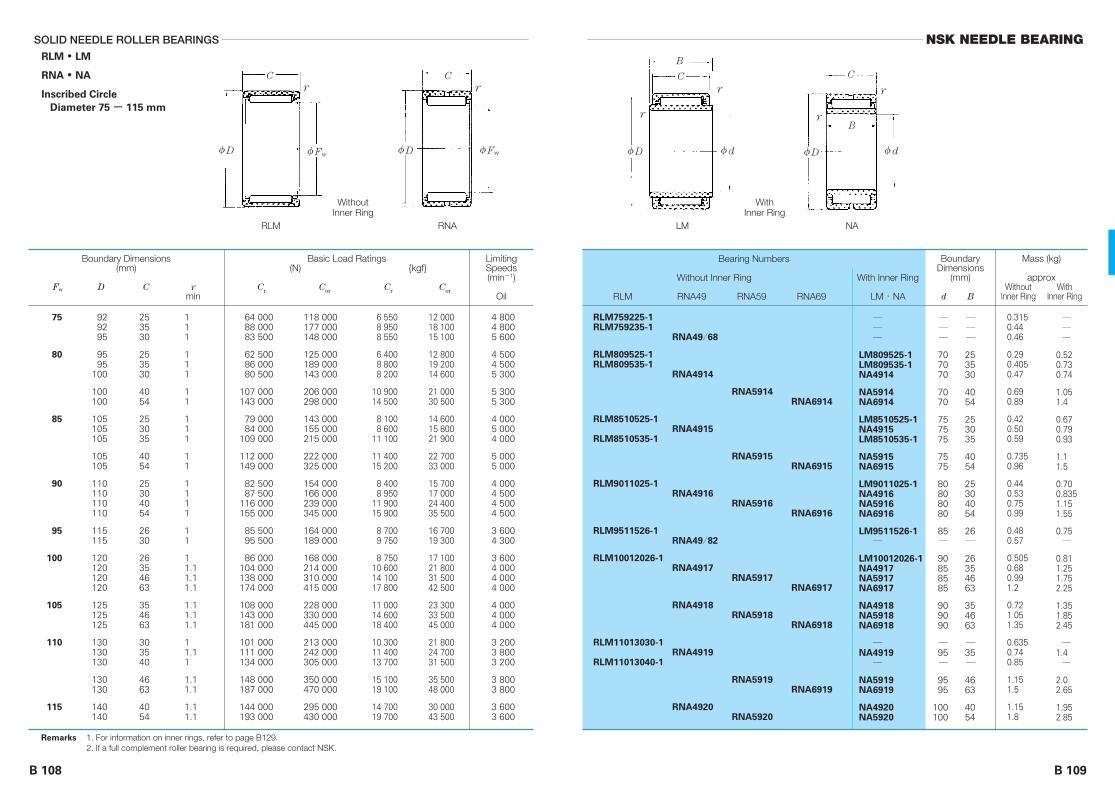
φD φFw
C
r
φD φFw
C
r
B 109
NSK NEEDLE BEARINGSOLID NEEDLE ROLLER BEARINGS
B 108
RLM ● LM
RNA ● NA
Inscribed Circle
Diameter 75 - 115 mm
929295
9595
100
100100
105105105
105105
110110110110
115115
120120120120
125125125
130130130
130130
140140
253530
253530
4054
253035
4054
25304054
2630
26354663
354663
303540
4663
4054
64 00088 00083 500
62 50086 00080 500
107 000143 000
79 00084 000
109 000
112 000149 000
82 50087 500
116 000155 000
85 50095 500
86 000104 000138 000174 000
108 000143 000181 000
101 000111 000134 000
148 000187 000
144 000193 000
118 000177 000148 000
125 000189 000143 000
206 000298 000
143 000155 000215 000
222 000325 000
154 000166 000239 000345 000
164 000189 000
168 000214 000310 000415 000
228 000330 000445 000
213 000242 000305 000
350 000470 000
295 000430 000
4 8004 8005 600
4 5004 5005 300
5 3005 300
4 0005 0004 000
5 0005 000
4 0004 5004 5004 500
3 6004 300
3 6004 0004 0004 000
4 0004 0004 000
3 2003 8003 200
3 8003 800
3 6003 600
―――
707070
7070
757575
7575
80808080
85―
90858585
909090
―95―
9595
100100
―――
253530
4054
253035
4054
25304054
26―
26354663
354663
―35―
4663
4054
0.3150.440.46
0.290.4050.47
0.690.89
0.420.500.59
0.7350.96
0.440.530.750.99
0.480.57
0.5050.680.991.2
0.721.051.35
0.6350.740.85
1.151.5
1.151.8
―――
0.520.730.74
1.051.4
0.670.790.93
1.11.5
0.700.8351.151.55
0.75―
0.811.251.752.25
1.351.852.45
―1.4―
2.02.65
1.952.85
RLM759225-1RLM759235-1
RLM809525-1RLM809535-1
RLM8510525-1
RLM8510535-1
RLM9011025-1
RLM9511526-1
RLM10012026-1
RLM11013030-1
RLM11013040-1
RNA49/68
RNA4914
RNA4915
RNA4916
RNA49/82
RNA4917
RNA4918
RNA4919
RNA4920
RNA5914
RNA5915
RNA5916
RNA5917
RNA5918
RNA5919
RNA5920
RNA6914
RNA6915
RNA6916
RNA6917
RNA6918
RNA6919
―――
LM809525-1LM809535-1NA4914
NA5914NA6914
LM8510525-1NA4915LM8510535-1
NA5915NA6915
LM9011025-1NA4916NA5916NA6916
LM9511526-1―
LM10012026-1NA4917NA5917NA6917
NA4918NA5918NA6918
―NA4919―
NA5919NA6919
NA4920NA5920
6 5508 9508 550
6 4008 8008 200
10 90014 500
8 1008 600
11 100
11 40015 200
8 4008 950
11 90015 900
8 7009 750
8 75010 60014 10017 800
11 00014 60018 400
10 30011 40013 700
15 10019 100
14 70019 700
12 00018 10015 100
12 80019 20014 600
21 00030 500
14 60015 80021 900
22 70033 000
15 70017 00024 40035 500
16 70019 300
17 10021 80031 50042 500
23 30033 50045 000
21 80024 70031 500
35 50048 000
30 00043 500
111
111
11
111
11
1111
11
11.11.11.1
1.11.11.1
11.11
1.11.1
1.11.1
75
80
85
90
95
100
105
110
115
Boundary Dimensions(mm)
Fw D C rmin
Basic Load Ratings(N) {kgf}
Cr Cor Cr Cor
BoundaryDimensions
(mm)
d B
Mass (kg)
approxWithout With
Inner Ring Inner Ring
LimitingSpeeds(min-1)
Oil
Bearing Numbers
Without Inner Ring With Inner Ring
RLM RNA49 RNA59 RNA69 LM・NA
Remarks 1. For information on inner rings, refer to page B129.2. If a full complement roller bearing is required, please contact NSK.
φD φd
C
r
r
B
φD φd
C
r
r
B
RNARLM
WithoutInner Ring
NALM
WithInner Ring

B 111
NSK NEEDLE BEARINGSOLID NEEDLE ROLLER BEARINGS
B 110
RNA ● NA
Inscribed Circle Diameter 120 - 265 mm
140
150150
150
165165
165
180180
175
190190
190210200
220215230
225250240
260250280
270300300320
30
4054
30
4560
35
5067
35
5067
406040
604560
456950
695080
50806080
99 500
149 000200 000
105 000
192 000253 000
127 000
228 000299 000
133 000
235 000310 000
180 000315 000184 000
325 000224 000340 000
230 000400 000268 000
415 000274 000525 000
286 000545 000375 000590 000
214 000
315 000460 000
238 000
395 000565 000
315 000
515 000725 000
340 000
545 000775 000
440 000645 000465 000
695 000540 000745 000
565 000940 000705 000
1 000 000740 000
1 140 000
805 0001 230 0001 070 0001 400 000
3 400
3 2003 200
3 200
3 0003 000
2 800
2 8002 800
2 600
2 6002 600
2 4002 4002 200
2 2002 2002 200
2 0002 0001 900
1 9001 8001 900
1 7001 7001 5001 600
110
110110
120
120120
130
130130
140
140140
150150160
160170170
180180190
190200200
220220240240
0.67
1.251.95
0.71
1.92.7
0.92
2.33.3
0.98
2.453.55
1.63.91.75
4.12.554.3
2.656.23.2
6.453.359.7
3.65105.45
11.5
1.1
2.13.05
1.15
2.94.05
1.8
4.05.55
1.9
4.256.0
2.756.252.95
6.64.06.95
4.2105.6
10.55.9
15
6.4515.51017.5
RNA4822
RNA4824
RNA4826
RNA4828
RNA4830
RNA4832
RNA4834
RNA4836
RNA4838
RNA4840
RNA4844
RNA4848
RNA4922
RNA4924
RNA4926
RNA4928
RNA4930
RNA4932
RNA4934
RNA4936
RNA4938
RNA4940
RNA4944
RNA4948
RNA5922
RNA5924
RNA5926
RNA5928
NA4822
NA4922NA5922
NA4824
NA4924NA5924
NA4826
NA4926NA5926
NA4828
NA4928NA5928
NA4830NA4930NA4832
NA4932NA4834NA4934
NA4836NA4936NA4838
NA4938NA4840NA4940
NA4844NA4944NA4848NA4948
10 100
15 20020 300
10 700
19 60025 800
12 900
23 20030 500
13 600
24 00031 500
18 30032 00018 700
33 50022 90034 500
23 50041 00027 300
42 00027 90053 500
29 10055 50038 50060 500
21 900
32 50047 000
24 300
40 50058 000
32 000
52 50074 000
35 000
55 50079 000
45 00066 00047 000
71 00055 00076 000
58 00096 00072 000
102 00075 500
116 000
82 000125 000109 000142 000
1
1.11.1
1
1.11.1
1.1
1.51.5
1.1
1.51.5
1.121.1
21.12
1.121.5
21.52.1
1.52.122.1
120
125
130
135
145
150
155
160
165170175
180185190
195205210
215220225
240245265
Boundary Dimensions(mm)
Fw D B, C rmin
Basic Load Ratings(N) {kgf}
Cr Cor Cr Cor
BoundaryDimensions
(mm)
d
Mass (kg)
approxWithout With
Inner Ring Inner Ring
LimitingSpeeds(min-1)
Oil
Bearing Numbers
Without Inner Ring With Inner Ring
RNA48 RNA49 RNA59 NA
Remarks 1. For information on inner rings, refer to page B129.2. If a full complement roller bearing is required, please contact NSK.
φD φFw
C
r
RNA
φD φd
C
r
r
NA
B

B 113
NSK NEEDLE BEARINGSOLID NEEDLE ROLLER BEARINGS
B 112
RNA ● NA
Inscribed Circle Diameter 285 - 490 mm
320360350
380380420
400440420
460440480
480520540
560600
60100
69
10080
118
80118
80
11880
118
100140140
140160
395 000870 000510 000
905 000660 000
1 150 000
675 0001 190 000
690 000
1 240 000705 000
1 280 000
1 030 0001 550 0001 600 000
1 660 0001 980 000
1 160 0001 910 0001 390 000
2 050 0001 810 0002 630 000
1 900 0002 820 0001 990 000
3 000 0002 080 0003 200 000
2 940 0003 750 0004 000 000
4 250 0004 750 000
1 4001 4001 300
1 3001 2001 200
1 1001 1001 100
1 1001 0001 000
1 000950900
900850
260260280
280300300
320320340
340360360
380380400
420440
5.919.59.5
20.51330
13.53214
33.51535.5
25.550.552.5
54.581.5
1129.515.5
312248.5
23.551.524.5
542657
42.585.589
92.5125
RNA4852
RNA4856
RNA4860
RNA4864
RNA4868
RNA4872
RNA4876
RNA4952
RNA4956
RNA4960
RNA4964
RNA4968
RNA4972
RNA4976RNA4980
RNA4984RNA4988
NA4852NA4952NA4856
NA4956NA4860NA4960
NA4864NA4964NA4868
NA4968NA4872NA4972
NA4876NA4976NA4980
NA4984NA4988
40 00088 50052 000
92 50067 500
117 000
69 000122 00070 500
126 00072 000
130 000
105 000158 000164 000
170 000202 000
118 000194 000142 000
209 000185 000269 000
194 000288 000203 000
305 000212 000325 000
299 000385 000410 000
435 000485 000
22.12
2.12.13
2.132.1
32.13
2.144
44
285290305
310330340
350360370
380390400
415430450
470490
Boundary Dimensions(mm)
Fw D B, C rmin
Basic Load Ratings(N) {kgf}
Cr Cor Cr Cor
BoundaryDimensions
(mm)
d
Mass (kg)
approxWithout With
Inner Ring Inner Ring
LimitingSpeeds(min-1)
Oil
Bearing Numbers
Without Inner Ring With Inner Ring
RNA48 RNA49 RNA59 NA
Remarks 1. For information on inner rings, refer to page B129.2. If a full complement roller bearing is required, please contact NSK.
φD φFw
C
r
RNA
φD φd
C
r
r
NA
B

B 115
NSK NEEDLE BEARINGSOLID NEEDLE ROLLER BEARINGS
B 114
Single-Row,RNAF
Without Inner Ring
Double-Row,RNAFW
Without Inner Ring
Single-Row,NAF
With Inner Ring
Double-Row,NAFW
With Inner Ring
Inscribed Circle
Diameter 10 - 30 mm
1720
22
222226
2323
242428
2525
26263030
28283232
30303535
35353737
4040
40404242
1012
12
132012
1320
132012
1320
13201224
13261224
13261632
17261632
1632
17261632
3 9507 700
9 150
8 05011 400
9 850
8 40012 100
8 80012 60010 500
10 20013 100
9 45013 60011 70020 100
9 70016 60012 20020 900
10 30017 60016 60029 400
14 80019 40018 70032 000
20 20034 500
18 70024 00022 20038 000
4 3006 650
8 650
9 75015 200
9 800
10 50016 800
11 30018 00010 900
14 00019 300
12 90020 50013 00026 000
13 70027 50014 10028 200
15 30030 50019 50040 500
25 50036 00023 50047 000
26 80053 500
31 50043 00031 00062 000
45 00048 000
38 000
32 00032 00032 000
28 00028 000
26 00026 00028 000
26 00026 000
24 00024 00024 00024 000
20 00020 00022 00022 000
19 00019 00020 00020 000
17 00017 00017 00017 000
15 00015 000
14 00014 00014 00014 000
――
―
101010
――
121212
――
――――
151515―
17171717
20202020
――
25252525
――
―
132012
――
132012
――
――――
132612―
13261632
17261632
――
17261632
0.0100.018
0.021
0.0190.0300.027
0.0210.032
0.0220.0340.032
0.0220.035
0.0240.0370.0360.072
0.0260.0510.0380.076
0.0280.0560.0610.12
0.0540.0800.0600.12
0.0670.13
0.0640.0960.0690.14
――
―
0.0270.0420.034
――
0.0310.0480.040
――
――――
0.0400.0790.050―
0.0440.0870.0800.16
0.0770.1150.0820.16
――
0.0920.140.0950.19
RNAF 101710RNAF 102012
RNAF 122212
RNAF 142213RNAFW142220RNAF 142612
RNAF 152313RNAFW152320
RNAF 162413RNAFW162420RNAF 162812
RNAF 172513RNAFW172520
RNAF 182613RNAFW182620RNAF 183012RNAFW183024
RNAF 202813RNAFW202826RNAF 203212RNAFW203224
RNAF 223013RNAFW223026RNAF 223516RNAFW223532
RNAF 253517RNAFW253526RNAF 253716RNAFW253732
RNAF 284016RNAFW284032
RNAF 304017RNAFW304026RNAF 304216RNAFW304232
――
―
NAF 102213NAFW 102220NAF 102612
――
NAF 122413NAFW 122420NAF 122812
――
――――
NAF 152813NAFW 152826NAF 153212
―
NAF 173013NAFW 173026NAF 173516NAFW 173532
NAF 203517NAFW 203526NAF 203716NAFW 203732
――
NAF 254017NAFW 254026NAF 254216NAFW 254232
405785
935
8201 1601 010
8601 230
8951 2901 070
1 0401 340
9651 3801 1902 050
9901 6901 2502 140
1 0501 8001 7002 990
1 5101 9701 9103 250
2 0603 550
1 9102 4502 2703 900
435680
885
9951 5501 000
1 0701 710
1 1501 8401 120
1 4201 970
1 3102 0901 3202 650
1 4002 8001 4402 880
1 5603 1001 9804 100
2 6003 6502 3904 800
2 7305 450
3 2004 4003 1506 300
0.30.3
0.3
0.30.30.3
0.30.3
0.30.30.3
0.30.3
0.30.30.30.3
0.30.30.30.3
0.30.30.30.3
0.30.30.30.3
0.30.3
0.30.30.30.3
10
12
14
15
16
17
18
20
22
25
28
30
))
))
((((
Boundary Dimensions(mm)
Fw D C rmin
Basic Load Ratings(N) {kgf}
Cr Cor Cr Cor
BoundaryDimensions
(mm)
d B
Mass (kg)
approxWithout With
Inner Ring Inner Ring
LimitingSpeeds(min-1)
Oil
Bearing Numbers
Without Inner Ring
Bearing Numbers
With Inner Ring
Remarks For information on inner rings, refer to page B129.
φFwφD
Cr
φFwφD
Cr
φD φd
C
r
r
B
φD φd
C
r
r
B
RNAFWRNAF
WithoutInner Ring
NAFWNAF
WithInner Ring

B 117
NSK NEEDLE BEARINGSOLID NEEDLE ROLLER BEARINGS
B 116
454545
4747
50505555
55556262
62626565
68687272
7878
8585
9090
9595
100100
105
110115120
131726
1632
17342040
17342040
20402040
20402040
2040
3060
3060
3060
3060
30
303030
14 90020 50025 600
22 70039 000
21 00036 00032 50055 500
21 60037 00034 00058 000
26 90046 00038 50066 000
27 50047 00040 00068 500
41 50071 000
61 000104 000
63 000108 000
65 000112 000
69 000119 000
71 000
70 00069 50075 500
24 60037 00049 000
33 50066 500
40 00080 00049 50099 500
43 00085 50055 000
110 000
59 000118 000
67 500135 000
62 500125 000
73 000146 000
78 000156 000
132 000263 000
140 000281 000
151 000300 000
166 000335 000
176 000
177 000177 000201 000
12 00012 00012 000
12 00012 000
10 00010 00010 00010 000
9 0009 0009 5009 500
8 0008 0008 5008 500
7 5007 5007 5007 500
6 7006 700
6 3006 300
6 0006 000
5 6005 600
5 0005 000
4 800
4 5004 3004 000
303030
3030
35353535
40404040
4545――
50504545
5050
5555
6060
6565
7070
75
808590
131726
1632
17342040
17342040
2040――
20402040
2040
3060
3060
3060
3060
30
303030
0.0530.0730.105
0.0780.16
0.0840.1650.150.295
0.0920.180.1650.325
0.140.280.1750.36
0.1650.340.2250.455
0.2650.535
0.4950.99
0.531.05
0.5751.15
0.601.2
0.625
0.6650.6950.73
0.0780.1050.155
0.110.22
0.120.240.1950.385
0.1350.2650.2150.43
0.1950.395――
0.230.4650.3450.695
0.400.80
0.711.4
0.7651.5
0.8251.65
0.871.7
0.915
0.971.01.05
RNAF 354513RNAF 354517RNAFW354526
RNAF 354716RNAFW354732
RNAF 405017RNAFW405034RNAF 405520RNAFW405540
RNAF 455517RNAFW455534RNAF 456220RNAFW456240
RNAF 506220RNAFW506240RNAF 506520RNAFW506540
RNAF 556820RNAFW556840RNAF 557220RNAFW557240
RNAF 607820RNAFW607840
RNAF 658530RNAFW658560
RNAF 709030RNAFW709060
RNAF 759530RNAFW759560
RNAF 8010030RNAFW8010060
RNAF 8510530
RNAF 9011030RNAF 9511530RNAF 10012030
NAF 304513NAF 304517NAFW 304526
NAF 304716NAFW 304732
NAF 355017NAFW 355034NAF 355520NAFW 355540
NAF 405517NAFW 405534NAF 406220NAFW 406240
NAF 456220NAFW 456240
――
NAF 506820NAFW 506840NAF 457220NAFW 457240
NAF 507820NAFW 507840
NAF 558530NAFW 558560
NAF 609030NAFW 609060
NAF 659530NAFW 659560
NAF 7010030NAFW 7010060
NAF 7510530
NAF 8011030NAF 8511530NAF 9012030
1 5202 0902 610
2 3103 950
2 1503 7003 3005 650
2 2003 8003 4505 950
2 7504 7003 9506 750
2 8004 8004 1007 000
4 2007 250
6 20010 600
6 40011 000
6 65011 400
7 05012 100
7 250
7 1507 1007 700
2 5003 7505 000
3 4006 800
4 0508 1505 050
10 100
4 3508 7505 600
11 200
6 05012 1006 900
13 800
6 35012 7007 450
14 900
7 95015 900
13 40026 800
14 30028 600
15 40031 000
17 00034 000
17 900
18 00018 10020 500
0.30.30.3
0.30.3
0.30.30.30.3
0.30.30.30.3
0.30.30.30.6
0.60.60.60.6
11
11
11
11
11
1
111
35
40
45
50
55
60
65
70
75
80
85
9095
100
Single-Row,RNAF
Without Inner Ring
Double-Row,RNAFW
Without Inner Ring
Single-Row,NAF
With Inner Ring
Double-Row,NAFW
With Inner Ring
Inscribed Circle
Diameter 35 - 100 mm
))
))
((((
Boundary Dimensions(mm)
Fw D C rmin
Basic Load Ratings(N) {kgf}
Cr Cor Cr Cor
BoundaryDimensions
(mm)
d B
Mass (kg)
approxWithout With
Inner Ring Inner Ring
LimitingSpeeds(min-1)
Oil
Bearing Numbers
Without Inner Ring
Bearing Numbers
With Inner Ring
Remarks For information on inner rings, refer to page B129.
φFwφD
Cr
φFwφD
Cr
φD φd
C
r
r
B
φD φd
C
r
r
B
RNAFWRNAF
WithoutInner Ring
NAFWNAF
WithInner Ring

B 119
NSK NEEDLE BEARINGSOLID NEEDLE ROLLER BEARINGS
B 118
RNA…TT (Sealed, Without Inner Ring)
NA…TT (Sealed, With Inner Ring)
Inscribed Circle Diameter 14 - 52 mm
φD φd
C
NA…TT
B
22
2424
26
2828
3030
3737
3939
4242
4545
4747
5252
5555
586262
656868
13
1322
13
1323
1323
1730
1730
1730
1730
1730
2036
2036
202240
222240
7 350
8 10015 400
8 400
8 70017 500
9 35018 800
16 80033 000
17 80033 500
19 90030 000
18 90037 000
20 40040 000
28 00051 500
29 70053 000
30 50034 50067 000
36 50036 50070 500
7 500
8 85020 300
9 600
10 30025 300
11 60028 500
18 70044 000
22 90051 500
24 60041 500
23 40055 500
26 40062 500
41 50091 000
45 50095 500
47 50053 500
124 000
58 00058 500
136 000
13 000
11 00011 000
10 000
9 5009 500
8 5008 500
7 5007 500
6 7006 700
6 3006 300
5 6005 600
5 3005 300
4 5004 500
4 5004 500
4 0003 8003 800
3 8003 6003 600
10
1212
―
1515
1717
2020
2222
2525
2828
3030
3232
3535
―4040
―4545
14
1423
―
1424
1424
1831
1831
1831
1831
1831
2137
2137
―2341
―2341
0.016
0.0180.030
0.020
0.0210.039
0.0230.041
0.0550.098
0.0560.096
0.0630.11
0.0760.13
0.0720.13
0.0920.17
0.110.20
0.120.150.265
0.170.190.335
0.025
0.0280.046
―
0.0360.065
0.0390.069
0.0780.14
0.0880.15
0.0930.165
0.100.18
0.1050.19
0.1650.295
0.1750.32
―0.2450.44
―0.2850.50
RNA4900TT
RNA4901TTRNA6901TT
RNA49/14TT
RNA4902TTRNA6902TT
RNA4903TTRNA6903TT
RNA4904TTRNA6904TT
RNA49/22TTRNA69/22TT
RNA4905TTRNA6905TT
RNA49/28TTRNA69/28TT
RNA4906TTRNA6906TT
RNA49/32TTRNA69/32TT
RNA4907TTRNA6907TT
RNA49/38TTRNA4908TTRNA6908TT
RNA49/42TTRNA4909TTRNA6909TT
NA4900TT
NA4901TTNA6901TT
―
NA4902TTNA6902TT
NA4903TTNA6903TT
NA4904TTNA6904TT
NA49/22TTNA69/22TT
NA4905TTNA6905TT
NA49/28TTNA69/28TT
NA4906TTNA6906TT
NA49/32TTNA69/32TT
NA4907TTNA6907TT
―NA4908TTNA6908TT
―NA4909TTNA6909TT
750
8251 580
860
8901 780
9551 920
1 7103 350
1 8203 400
2 0303 100
1 9303 750
2 0804 050
2 8605 250
3 0505 400
3 1003 5506 800
3 7503 7007 150
765
9002 070
975
1 0502 580
1 1902 910
1 9104 500
2 3305 250
2 5104 250
2 3905 650
2 6906 350
4 2509 250
4 6509 700
4 8505 450
12 700
5 9505 950
13 800
0.3
0.30.3
0.3
0.30.3
0.30.3
0.30.3
0.30.3
0.30.3
0.30.3
0.30.3
0.60.6
0.60.6
0.60.60.6
0.60.60.6
14
16
18
20
22
25
28
30
32
35
40
42
4548
5052
Boundary Dimensions(mm)
Fw D C rmin
Basic Load Ratings(N) {kgf}
Cr Cor Cr Cor
BoundaryDimensions
(mm)
d B
Mass (kg)
approxWithout With
Inner Ring Inner Ring
LimitingSpeeds(min-1)
Grease
Numbers
WithInner Ring
Bearing
WithoutInner Ring
Remarks 1. For information on inner rings, refer to page B129.2. Standard greaes is packed in sealed solid bearings unless otherwise specified.
φD φFw
Cr
RNA…TT

B 121
NSK NEEDLE BEARINGSOLID NEEDLE ROLLER BEARINGS
B 120
φD φd
C
NA…TT
B
707272
8080
8585
9090
100100
105105
110110
120120
125125
130130
140
150
222240
2545
2545
2545
3054
3054
3054
3563
3563
3563
40
40
38 50038 00073 000
47 50090 000
50 00094 500
52 50099 000
70 000130 000
77 000136 000
76 500141 000
94 500167 000
98 000173 000
101 000181 000
131 000
136 000
63 50063 500
148 000
76 000172 000
82 500187 000
89 500203 000
120 000264 000
139 000286 000
139 000305 000
189 000395 000
201 000420 000
214 000450 000
261 000
279 000
3 4003 2003 200
3 0003 000
2 8002 800
2 6002 600
2 2002 200
2 2002 200
2 0002 000
1 9001 900
1 8001 800
1 7001 700
1 600
1 500
―5050
5555
6060
6565
7070
7575
8080
8585
9090
9595
100
110
―2341
2646
2646
2646
3155
3155
3155
3664
3664
3664
41
41
0.180.180.32
0.260.475
0.280.485
0.320.53
0.470.89
0.500.96
0.530.99
0.681.2
0.721.35
0.741.5
1.15
1.25
―0.300.535
0.4050.735
0.440.765
0.470.795
0.751.4
0.801.5
0.8451.55
1.252.25
1.352.45
1.42.65
1.95
2.1
RNA49/48TTRNA4910TTRNA6910TT
RNA4911TTRNA6911TT
RNA4912TTRNA6912TT
RNA4913TTRNA6913TT
RNA4914TTRNA6914TT
RNA4915TTRNA6915TT
RNA4916TTRNA6916TT
RNA4917TTRNA6917TT
RNA4918TTRNA6918TT
RNA4919TTRNA6919TT
RNA4920TT
RNA4922TT
―NA4910TTNA6910TT
NA4911TTNA6911TT
NA4912TTNA6912TT
NA4913TTNA6913TT
NA4914TTNA6914TT
NA4915TTNA6915TT
NA4916TTNA6916TT
NA4917TTNA6917TT
NA4918TTNA6918TT
NA4919TTNA6919TT
NA4920TT
NA4922TT
3 9003 8507 450
4 8509 200
5 1009 600
5 35010 100
7 15013 200
7 85013 800
7 80014 400
9 60017 100
10 00017 700
10 30018 500
13 400
13 800
6 4506 500
15 100
7 75017 500
8 45019 100
9 10020 700
12 20026 900
14 10029 100
14 20031 500
19 30040 000
20 50043 000
21 80046 000
26 600
28 500
0.60.60.6
11
11
11
11
11
11
1.11.1
1.11.1
1.11.1
1.1
1.1
5558
63
68
72
80
85
90
100
105
110
115
125
Sealed, WithoutRNA…TT
Inner Ring
Sealed, WithNA…TT
Inner Ring
Inscribed Circle
Diameter 55 - 125 mm
((
))
Boundary Dimensions(mm)
Fw D C rmin
Basic Load Ratings(N) {kgf}
Cr Cor Cr Cor
BoundaryDimensions
(mm)
d B
Mass (kg)
approxWithout With
Inner Ring Inner Ring
LimitingSpeeds(min-1)
Grease
Numbers
WithInner Ring
Bearing
WithoutInner Ring
Remarks 1. For information on inner rings, refer to page B129.2. Standard greaes is packed in sealed solid bearings unless otherwise specified.
φD φFw
Cr
RNA…TT

B 123
NSK NEEDLE BEARINGSOLID NEEDLE ROLLER BEARINGS (INCH DESIGN)
B 122
HJ (Single-Row, Without Inner Ring)
HJ + IR (Single-Row, With Inner Ring)
Inscribed Circle Diameter 15.875 - 44.450 mm
φD φd
C
raHJ+IR
B
0.6250
0.7500
0.8750
1.0000
1.1250
1.2500
1.3750
1.5000
1.6250
1.7500
28.575
31.75031.750
34.925
34.925
38.10038.100
41.275
41.275
44.45044.450
47.62547.625
52.38852.388
55.56255.562
58.738
58.738
19.05
19.0525.40
19.05
25.40
19.0525.40
25.40
31.75
25.4031.75
25.4031.75
25.4031.75
25.4031.75
25.40
31.75
1.1250
1.25001.2500
1.3750
1.3750
1.50001.5000
1.6250
1.6250
1.75001.7500
1.87501.8750
2.06252.0625
2.18752.1875
2.3125
2.3125
0.7500
0.75001.0000
0.7500
1.0000
0.75001.0000
1.0000
1.2500
1.00001.2500
1.00001.2500
1.00001.2500
1.00001.2500
1.0000
1.2500
1 890
2 0202 730
2 260
3 050
2 4703 350
3 600
4 500
3 7004 600
3 9504 900
4 6505 850
4 8006 000
4 900
6 150
1 980
2 2303 300
2 670
3 950
3 1004 600
5 250
6 950
5 6007 400
6 2508 250
7 0009 300
7 4009 850
7 800
10 400
0.6
11
111
111
1111
11
11
1.51.51.5
1.51.51.5
1.51.5
1.51.51.5
9.525
12.70012.700
15.87517.46215.875
19.05019.05020.638
22.22523.81222.22523.812
25.40025.400
28.57528.575
31.75030.16231.750
33.33833.33834.925
36.51238.100
34.92536.51238.100
0.3750
0.50000.5000
0.62500.68750.6250
0.75000.75000.8125
0.87500.93750.87500.9375
1.00001.0000
1.12501.1250
1.25001.18751.2500
1.31251.31251.3750
1.43751.5000
1.37501.43751.5000
19.05
19.0525.40
19.0519.0525.40
19.0525.4025.40
25.4025.4031.7531.75
25.4031.75
25.4031.75
25.4031.7531.75
25.4031.7531.75
25.4025.40
31.7531.7531.75
0.7500
0.75001.0000
0.75000.75001.0000
0.75001.00001.0000
1.00001.00001.25001.2500
1.00001.2500
1.00001.2500
1.00001.25001.2500
1.00001.25001.2500
1.00001.0000
1.25001.25001.2500
0.050
0.0540.073
0.0640.0640.082
0.0680.0910.091
0.100.100.130.13
0.110.14
0.120.155
0.1550.1950.195
0.160.200.20
0.170.17
0.2150.2150.215
0.068
0.0810.11
0.0900.0870.115
0.100.1350.125
0.150.140.1950.18
0.170.215
0.1850.23
0.230.300.285
0.2550.320.30
0.270.265
0.360.340.315
HJ-101812
HJ-122012HJ-122016
HJ-142212
HJ-142216
HJ-162412HJ-162416
HJ-182616
HJ-182620
HJ-202816HJ-202820
HJ-223016HJ-223020
HJ-243316HJ-243320
HJ-263516HJ-263520
HJ-283716
HJ-283720
IR-061012
IR-081212IR-081216
IR-101412IR-111412IR-101416
IR-121612IR-121616IR-131616
IR-141816IR-151816IR-141820IR-151820
IR-162016IR-162020
IR-182216IR-182220
IR-202416IR-192420IR-202420
IR-212616IR-212620IR-222620
IR-232816IR-242816
IR-222820IR-232820IR-242820
18 600
19 80026 800
22 100
29 900
24 20032 500
35 500
44 000
36 50045 500
38 50048 000
46 00057 000
47 00058 500
48 000
60 000
19 400
21 90032 000
26 200
38 500
30 50045 000
51 500
68 000
55 00072 500
61 00081 000
68 50091 000
72 50096 500
76 500
102 000
30 000
24 00024 000
20 000
20 000
17 00017 000
15 000
15 000
13 00013 000
12 00012 000
11 00011 000
10 00010 000
9 500
9 500
15.875
19.050
22.225
25.400
28.575
31.750
34.925
38.100
41.275
44.450
φD φFw
C
HJ
Remarks 1. For bearings with inner rings, the inner ring number is written separately from the Bearing number.Example: HJ-202816 + IR-162016
2. If a full complement roller bearing is required, please contact NSK.
BearingNumbers
WithoutInner Ring
Mass (kg)
approxWithout With
Inner Ring Inner Ring
MatchingInner Rings
Boundary Dimensions(mm, inch)
Fw D C
Boundary Dimensions(mm, inch)
d B
*(mm)
ramax
Basic Load Ratings(N) {kgf}
Cr Cor Cr Cor
LimitingSpeeds(min-1)
Oil
* Fillet Radius of Shaft,Housing

B 125
NSK NEEDLE BEARINGSOLID NEEDLE ROLLER BEARINGS (INCH DESIGN)
B 124
HJ (Single-Row, Without Inner Ring)
HJ + IR (Single-Row, With Inner Ring)
Inscribed Circle Diameter 47.625- 101.600 mm
φD φd
C
raHJ+IR
B
1.87502.0000
2.2500
2.5000
2.7500
3.0000
3.2500
3.5000
3.7500
4.0000
61.91265.088
65.088
76.20076.200
82.550
82.550
88.90088.90088.900
95.25095.250
107.950107.950
114.300
120.650
127.000
31.7525.40
31.75
38.1044.45
38.10
44.45
25.4038.1044.45
38.1044.45
44.4550.80
50.80
50.80
50.80
2.43752.5625
2.5625
3.00003.0000
3.2500
3.2500
3.50003.50003.5000
3.75003.7500
4.25004.2500
4.5000
4.7500
5.0000
1.25001.0000
1.2500
1.50001.7500
1.5000
1.7500
1.00001.50001.7500
1.50001.7500
1.75002.0000
2.0000
2.0000
2.0000
6 5005 300
6 600
9 10010 500
9 800
11 300
6 70010 20011 800
10 80012 600
16 40018 600
18 900
19 800
20 600
11 4009 000
12 000
16 40019 800
18 700
22 600
11 80020 30024 500
22 60027 300
30 50036 000
37 500
40 500
43 500
1.51.5
1.51.51.51.5
1.51.5
22
22
2222
222
22
22
2.52.5
2.52.52.5
39.68842.862
38.10039.68841.27542.862
44.45044.450
49.21250.800
49.21250.800
―57.15055.56257.150
63.50060.32563.500
69.85069.850
74.61276.200
79.37582.550
82.55085.72588.900
1.56251.6875
1.50001.56251.62501.6875
1.75001.7500
1.93752.0000
1.93752.0000
―2.25002.18752.2500
2.50002.37502.5000
2.75002.7500
2.93753.0000
3.12503.2500
3.25003.37503.5000
31.7525.40
31.7531.7531.7531.75
38.1044.45
38.1038.10
44.4544.45
―38.1044.4544.45
38.1044.4544.45
44.4550.80
50.8050.80
50.8050.80
50.8050.8050.80
1.25001.0000
1.25001.25001.25001.2500
1.50001.7500
1.50001.5000
1.75001.7500
―1.50001.75001.7500
1.50001.75001.7500
1.75002.0000
2.00002.0000
2.00002.0000
2.00002.00002.0000
0.2250.185
0.2350.2350.2350.235
0.450.525
0.5250.525
0.5750.575
0.4850.5950.650.65
0.610.680.68
1.051.2
1.21.2
1.31.3
1.41.41.4
0.360.305
0.4550.430.4050.38
0.7550.88
0.900.865
1.00.975
―0.971.151.1
1.051.251.15
1.551.8
1.951.9
2.22.0
2.52.32.15
HJ-303920HJ-324116
HJ-324120
HJ-364824HJ-364828
HJ-405224
HJ-405228
HJ-445616HJ-445624HJ-445628
HJ-486024HJ-486028
HJ-526828HJ-526832
HJ-567232
HJ-607632
HJ-648032
IR-253020IR-273216
IR-243220IR-253220IR-263220IR-273220
IR-283624IR-283628
IR-314024IR-324024
IR-314028IR-324028
―IR-364424IR-354428IR-364428
IR-404824IR-384828IR-404828
IR-445228IR-445232
IR-475632IR-485632
IR-506032IR-526032
IR-526432IR-546432IR-566432
63 50052 000
65 000
89 000103 000
96 000
111 000
66 000100 000116 000
106 000123 000
161 000182 000
186 000
194 000
202 000
112 00088 000
117 000
161 000194 000
183 000
221 000
116 000199 000240 000
221 000268 000
300 000350 000
370 000
400 000
430 000
9 0008 500
8 500
7 5007 500
6 700
6 700
6 0006 0006 000
5 6005 600
5 0005 000
4 800
4 500
4 000
47.62550.800
57.150
63.500
69.850
76.200
82.550
88.900
95.250
101.600
φD φFw
C
HJ * Fillet Radius of Shaft,Housing
Remarks 1. For bearings with inner rings, the inner ring number is written separately from the Bearing number.Example: HJ-202816 + IR-162016
2. If a full complement roller bearing is required, please contact NSK.
BearingNumbers
WithoutInner Ring
Mass (kg)
approxWithout With
Inner Ring Inner Ring
MatchingInner Rings
Boundary Dimensions(mm, inch)
Fw D C
Boundary Dimensions(mm, inch)
d B
*(mm)
ra
max
Basic Load Ratings(N) {kgf}
Cr Cor Cr Cor
LimitingSpeeds(min-1)
Oil

B 127
NSK NEEDLE BEARINGSOLID NEEDLE ROLLER BEARINGS (INCH DESIGN)
B 126
HJ (Single-Row, Without Inner Ring)
HJ + IR (Single-Row, With Inner Ring)
Inscribed Circle Diameter 107.950- 234.950 mm
φD φd
C
raHJ+IR
B
4.2500
4.5000
5.0000
5.5000
5.7500
6.0000
6.5000
7.25007.75008.2500
8.75009.2500
133.350
152.400152.400
165.100165.100
165.100
177.800177.800
184.150
190.500190.500
203.200203.200
231.775244.475257.175
269.875282.575
50.80
57.1563.50
50.8057.15
63.50
63.5076.20
76.20
63.5076.20
63.5076.20
76.2076.2076.20
76.2076.20
5.2500
6.00006.0000
6.50006.5000
6.5000
7.00007.0000
7.2500
7.50007.5000
8.00008.0000
9.12509.6250
10.1250
10.625011.1250
2.0000
2.25002.5000
2.00002.2500
2.5000
2.50003.0000
3.0000
2.50003.0000
2.50003.0000
3.00003.00003.0000
3.00003.0000
20 900
29 60033 000
28 40032 000
35 500
36 00042 500
43 500
38 00045 000
39 50046 500
54 50056 50058 500
60 50062 000
45 500
53 50061 500
52 50061 000
70 000
73 00091 000
94 500
81 500101 000
87 000109 000
117 000125 000133 000
142 000150 000
2.52.5
2.52.5
2.52.52.52.5
2.52.5
3
33
33
333
44
88.90095.250
95.25095.250
―101.600107.950101.600
114.300114.300
120.650
127.000127.000
139.700139.700
152.400165.100177.800
190.500203.200
3.50003.7500
3.75003.7500
―4.00004.25004.0000
4.50004.5000
4.7500
5.00005.0000
5.50005.5000
6.00006.50007.0000
7.50008.0000
50.8050.80
57.1563.50
―57.1557.1563.50
63.5076.20
76.20
63.5076.20
63.5076.20
76.2076.2076.20
76.2076.20
2.00002.0000
2.25002.5000
―2.25002.25002.5000
2.50003.0000
3.0000
2.50003.0000
2.50003.0000
3.00003.00003.0000
3.00003.0000
1.51.5
2.753.05
2.42.92.93.3
3.64.25
4.55
3.94.75
4.154.75
7.17.57.95
8.358.6
2.652.5
4.154.6
―4.954.455.55
6.17.2
7.7
6.658.1
7.28.4
121313.5
14.515
HJ-688432
HJ-729636HJ-729640
HJ-8010432HJ-8010436
HJ-8010440
HJ-8811240HJ-8811248
HJ-9211648
HJ-9612040HJ-9612048
HJ-10412840HJ-10412848
HJ-11614648HJ-12415448HJ-13216248
HJ-14017048HJ-14817848
IR-566832IR-606832
IR-607236IR-607240
―IR-648036IR-688036IR-648040
IR-728840IR-728848
IR-769248
IR-809640IR-809648
IR-8810440IR-8810448
IR-9611648IR-10412448IR-11213248
IR-12014048IR-12814048
205 000
290 000325 000
279 000315 000
350 000
350 000415 000
425 000
375 000445 000
385 000460 000
535 000555 000575 000
590 000610 000
445 000
525 000600 000
515 000600 000
685 000
715 000890 000
925 000
795 000995 000
855 0001 060 000
1 140 0001 230 0001 310 000
1 390 0001 470 000
3 800
3 8003 800
3 4003 400
3 400
3 0003 000
2 800
2 8002 800
2 4002 400
2 2002 0002 000
1 9001 800
107.950
114.300
127.000
139.700
146.050
152.400
165.100
184.150196.850209.550
222.250234.950
φD φFw
C
HJ
Remarks 1. For bearings with inner rings, the inner ring number is written separately from the Bearing number.Example: HJ-202816 + IR-162016
2. If a full complement roller bearing is required, please contact NSK.
* Fillet Radius of Shaft,Housing
BearingNumbers
WithoutInner Ring
Mass (kg)
approxWithout With
Inner Ring Inner Ring
MatchingInner Rings
Boundary Dimensions(mm, inch)
Fw D C
Boundary Dimensions(mm, inch)
d B
*(mm)
ra
max
Basic Load Ratings(N) {kgf}
Cr Cor Cr Cor
LimitingSpeeds(min-1)
Oil

B 129
NSK NEEDLE BEARING
B 129
Table 1 Types of Inner Ring
Code Details
FIR
IR
Metric needle bearing combination
Inch needle bearing combination
B 128
INNER RINGS FOR NEEDLE ROLLER BEARINGSDRAWN CUP TYPE
Metric Design (FIR) Bore Diameter 7-45 mm ........................................................... B130-B135
Inch Design (IR) Bore Diameter 9.525-38.100 mm ............................................. B136-B137
SOLID TYPE
Metric Design (FIR) Bore Diameter 5-220 mm ......................................................... B138-B151
Metric Design (FIR) Bore Diameter 8-50 mm ........................................................... B152-B155
Inch Design (IR) Bore Diameter 9.525-203.200 mm ........................................... B156-B161
For use when shafts cannot be finished with proper accuracy andhardness, NSK produces inner rings that are made from carefully selectedbearing steel and finished with heat treatment and grinding work.
TYPE
The various types of inner rings for needle roller bearings are shown inTable 1.
ACCURACY
Dimensional accuracy of the inner rings of NSK needle roller bearingsconforms with ISO (refer to pages A26 and A27). Tolerances for inch innerrings are shown in the dimensional table for drawn cup bearings, and inTable 3 on page B92 for solid bearings.
MOUNTING
The inner ring is mounted with the unmarked side placed onto the shaftshoulder.
Fitting tolerance for the drawn cup needle bearing shaft should be h6 orjs6 (j6). When requesting a tight fit for the inner ring, please consult NSK.
Each shaft fitting tolerance for the inner ring for solid needle bearings isshown in Table 5.2 on page A33.
Pages

B 131
NSK NEEDLE BEARINGINNER RINGS FOR DRAWN CUP NEEDLE ROLLER BEARINGS
B 130
FIR
Bore Diameter 7 - 15 mm
FH-1010――
―FJ-1212―
F-1312F-1412F-1413
―――
F-1512―――
F-1512F-1516F-1612
F-1616――
――
F-1812―
F-1816
―――
F-2020――
FJ-1010―
FJ-1015
FJ-1210FJH-1212―
FJ-1312FJ-1412―
―――
FJ-1512―――
FJ-1512FJ-1516FJ-1612
FJ-1616――
――
FJ-1812―
FJ-1816
―――
FJ-2020――
FJL-1010FJL-1012LFJL-1015
―FJL-1212LFJL-1215
―――
FJL-1416LFJL-1420LFJL-1510L
FJL-1512LFJL-1515FJL-1520FJL-1525L
FJL-1512L――
FJL-1616LFJL-1620LFJL-1715
FJL-1720LFJL-1725L
―FJL-1815―
FJL-1820LFJL-1825FJL-2015
FJL-2020FJL-2025LFJL-2030L
Matching Drawn Cup Needle Roller Bearings
F FJ FJL
7
8
10
12
15
101010
121212
131414
141415
15151515
151516
161617
1717
181818
181820
202020
10.512.512.5
10.512.515.5
12.512.513.5
16.520.510.5
12.515.520.525.5
12.516.512.5
16.520.515.5
20.525.5
12.515.516.5
20.525.515.5
20.525.530.5
0.30.30.3
0.30.30.3
0.30.30.3
0.30.30.3
0.30.30.30.3
0.30.30.3
0.30.30.3
0.30.3
0.30.30.3
0.30.30.3
0.30.30.3
3.33.94.8
5.16.17.6
5.37.37.9
9.712
8.0
9.5121619
6.28.28.6
111414
1823
7.69.4
10
121517
222733
FIR-071010FIR-071012FIR-071015
FIR-081210FIR-081212FIR-081215
FIR-101312FIR-101412FIR-101413
FIR-101416FIR-101420FIR-101510
FIR-101512FIR-101515FIR-101520FIR-101525
FIR-121512FIR-121516FIR-121612
FIR-121616FIR-121620FIR-121715
FIR-121720FIR-121725
FIR-151812FIR-151815FIR-151816
FIR-151820FIR-151825FIR-152015
FIR-152020FIR-152025FIR-152030
φd
r
B
φF
Mass(g)
approx
Boundary Dimensions(mm)
d F B rh5 min
Inner Ring Numbers
NSK NEEDLE BEARING

B 133
NSK NEEDLE BEARINGINNER RINGS FOR DRAWN CUP NEEDLE ROLLER BEARINGS
B 132
F-2012F-2016F-2020
F-2210F-2212―
F-2216F-2220――
――
F-2516
F-2520―
F-2526―
F-2816F-2820F-2826―
―F-3020―
F-3026―
――
F-3512―
F-3520
―F-3526―
FJ-2012FJ-2016FJ-2020
―FJ-2212―
FJ-2216FJ-2220――
――
FJ-2516
FJ-2520―
FJ-2526―
FJ-2816FJ-2820FJ-2826―
―FJ-3020―
FJ-3026―
――
FJ-3512―
FJ-3520
―FJ-3526―
――
FJL-2020
FJL-2210L―
FJL-2215L
―FJL-2220LFJL-2225LFJL-2230L
FJL-2510FJL-2515L―
FJL-2520FJL-2525L―
FJL-2530
―FJL-2820L―
FJL-2830L
FJL-3015LFJL-3020LFJL-3025L
―FJL-3030L
FJL-3220FJL-3230
FJL-3512FJL-3515FJL-3520L
FJL-3525L―
FJL-3530L
Matching Drawn Cup Needle Roller Bearings
F FJ FJL
FIR
Bore Diameter 17 - 30 mm
17
20
22
25
28
30
202020
222222
22222222
252525
25252525
28282828
303030
3030
3232
353535
353535
12.516.520.5
10.512.515.5
16.520.525.530.5
10.515.516.5
20.525.526.530.5
16.520.526.530.5
15.520.525.5
26.530.5
20.530.5
12.515.520.5
25.526.530.5
0.30.30.3
0.30.30.3
0.30.30.30.3
0.30.30.3
0.30.30.30.3
0.30.30.30.3
0.30.30.3
0.30.3
0.30.3
0.60.60.6
0.60.60.6
8.51114
121518
20243036
142123
28353642
30384956
263443
4451
3045
253141
515361
FIR-172012FIR-172016FIR-172020
FIR-172210FIR-172212FIR-172215
FIR-172216FIR-172220FIR-172225FIR-172230
FIR-202510FIR-202515FIR-202516
FIR-202520FIR-202525FIR-202526FIR-202530
FIR-222816FIR-222820FIR-222826FIR-222830
FIR-253015FIR-253020FIR-253026
FIR-253026FIR-253030
FIR-283220FIR-283230
FIR-303512FIR-303515FIR-303520
FIR-303525FIR-303526FIR-303530
φd
r
B
φF
Mass(g)
approx
Boundary Dimensions(mm)
d F B rh5 min
Inner Ring Numbers

B 135
NSK NEEDLE BEARINGINNER RINGS FOR DRAWN CUP NEEDLE ROLLER BEARINGS
B 134
―F-4020―
F-4026―
F-4520―
F-4526―
―――
――
―FJ-4020―
FJ-4026―
FJ-4520―
FJ-4526―
――
FJ-5020
――
FJL-4015LFJL-4020LFJL-4025L
―FJL-4030L
FJL-4520LFJL-4525L―
FJL-4530L
FJL-5012LFJL-5015LFJL-5020L
FJL-5025LFJL-5030L
Matching Drawn Cup Needle Roller Bearings
F FJ FJL
FIR
Bore Diameter 35 - 45 mm
35
40
45
404040
4040
45454545
505050
5050
15.520.525.5
26.530.5
20.525.526.530.5
12.515.520.5
25.530.5
0.60.60.6
0.60.6
0.60.60.60.6
0.60.60.6
0.60.6
364758
6170
53666779
364559
7489
FIR-354015FIR-354020FIR-354025
FIR-354026FIR-354030
FIR-404520FIR-404525FIR-404526FIR-404530
FIR-455012FIR-455015FIR-455020
FIR-455025FIR-455030
φd
r
B
φF
Mass(g)
approx
Boundary Dimensions(mm)
d F B rh5 min
Inner Ring Numbers

B 137
NSK NEEDLE BEARINGINNER RINGS FOR DRAWN CUP NEEDLE ROLLER BEARINGS (INCH DESIGN)
B 136
B-98B-108B-912B-1012
B-128B-1212
B-1412B-1416
B-168B-1612B-1616
――
B-1612B-1616
B-1816B-1816
B-2012B-2016
B-2212B-2216B-2220
B-2416B-2420
B-2416B-2420
B-2620
B-2816B-2824
B-2816B-2824
BH-98BH-108BH-912BH-1012
――
BH-1412―
BH-168BH-1612BH-1616
BH-1620BH-1624
BH-1612BH-1616
BH-1816BH-1816
BH-2012BH-2016
BH-2212BH-2216BH-2220
――
――
―
――
――
J-98J-108―
J-1012
J-128J-1212
J-1412J-1416
―J-1612J-1616
――
J-1612J-1616
J-1816J-1816
J-2012J-2016
―――
J-2416J-2420
J-2416J-2420
―
J-2816J-2824
J-2816J-2824
JH-98―――
―JH-1212
JH-1412JH-1416
―JH-1612JH-1616
――
JH-1612JH-1616
JH-1816JH-1816
―JH-2016
JH-2212JH-2216―
――
――
―
――
――
Matching Drawn CupNeedle Roller Bearings
B BH J JH
IR
Bore Diameter 9.525 - 38.100 mm
9.525
12.700
15.875
19.050
20.638
22.22523.812
25.400
28.575
30.162
31.750
34.925
36.512
38.100
0.3750
0.5000
0.6250
0.7500
0.8125
0.87500.9375
1.0000
1.1250
1.1875
1.2500
1.3750
1.4375
1.5000
14.28815.87514.28815.875
19.05019.050
22.22522.225
25.40025.40025.400
25.40025.400
25.40025.400
28.57528.575
31.75031.750
34.92534.92534.925
38.10038.100
38.10038.100
41.275
44.45044.450
44.45044.450
13.0813.0819.4319.43
13.0819.43
19.4325.78
13.0819.4325.78
32.1338.48
19.4325.78
25.7825.78
19.4225.78
19.4325.7832.13
25.7832.13
25.7832.13
32.13
25.7838.48
25.7838.48
9.1131319
1624
2938
233444
5566
2635
5139
4357
486479
85105
7087
95
100150
83125
0.60.60.60.6
1.01.0
1.01.0
1.01.01.0
1.01.0
1.01.0
1.01.0
1.01.0
1.01.01.0
1.01.0
1.51.5
1.5
1.51.5
1.51.5
0.56250.62500.56250.6250
0.75000.7500
0.87500.8750
1.00001.00001.0000
1.00001.0000
1.00001.0000
1.12501.1250
1.12501.1250
1.37501.37501.3750
1.50001.5000
1.50001.5000
1.6250
1.75001.7500
1.75001.7500
IR-68IR-68-1IR-612IR-612-1
IR-88IR-812
IR-1012IR-1016
IR-128IR-1212IR-1216
IR-1220IR-1224
IR-1312IR-1316
IR-1416IR-1516
IR-1612IR-1616
IR-1812IR-1816IR-1820
IR-1916IR-1920
IR-2016IR-2020
IR-2220
IR-2316IR-2324
IR-2416IR-2424
φd
B
ra
φF
Boundary Dimensions(mm, inch)
d F B
FilletRadius of
Shaft (mm)ra
max
Mass(g)
approx
Inner RingNumbers
0–0.25
0–0.013
0– 0.013
Remarks Inner rings can be used with Y and YH types (pages B76~B79).

B 139
NSK NEEDLE BEARINGINNER RINGS FOR SOLID NEEDLE ROLLER BEARINGS
B 138
RLM81512-1RLM81516-1
RLM101712-1RLM101716-1
RLM121916-1
RNA4900RNA4900TT
RNA5900
RNA6900
RNA4901RNA4901TT
RNA5901
RNA6901RNA6901TT
RNA4902RNA4902TT
RNA5902RNA5902RNA6902TT
RNAF142612RNAF142213
RNAF162812RNAF162413
RNAF203212RNAF202813
RNAFW142220
RNAFW162420
RNAFW202826
Matching Solid Needle Roller Bearings
RLM RNA RNAF RNAFW
FIR
Bore Diameter 5 - 15 mm
5
7
9
10
12
15
88
1010
12
141414
141414
161616
16161616
202020
20202020
1216
1216
16
121314
162022
121314
16202223
121314
18232426
0.150.15
0.150.15
0.3
0.30.30.3
0.30.30.3
0.30.30.3
0.30.30.30.3
0.30.30.3
0.30.30.30.3
0.0030.004
0.0040.005
0.006
0.0070.0080.008
0.0090.0120.013
0.0080.0090.010
0.0110.0140.0150.016
0.0130.0140.015
0.0190.0250.0260.028
FIR-5812-1FIR-5816-1
FIR-71012-1FIR-71016-1
FIR-91216-1
FIR-101412-1FIR-101413-1FIR-101414-1
FIR-101416-1FIR-101420-1FIR-101422-1
FIR-121612-1FIR-121613-1FIR-121614-1
FIR-121616-1FIR-121620-1FIR-121622-1FIR-121623-1
FIR-152012-1FIR-152013-1FIR-152014-1
FIR-152018-1FIR-152023-1FIR-152024-1FIR-152026-1
φd
r
B
φF
Mass(kg)
approx
Boundary Dimensions(mm)
d F B rmin
Inner Ring Numbers

B 141
NSK NEEDLE BEARINGINNER RINGS FOR SOLID NEEDLE ROLLER BEARINGS
B 140
RLM293820-1
RNA4903RNA4903TT
RNA5903RNA6903RNA6903TT
RNA4904RNA4904TT
RNA5904
RNA6904
RNA6904TT
RNA49/22RNA49/22TTRNA59/22
RNA69/22RNA69/22TT
RNA4905
RNA4905TTRNA5905
RNA6905RNA6905TT
RNAF223013
RNAF223516
RNAF253716RNAF253517
RNAF304216RNAF304017
RNAFW223026RNAFW223532
RNAFW253526
RNAFW253732
RNAFW304026
RNAFW304232
Matching Solid Needle Roller Bearings
RLM RNA RNAF RNAFW
FIR
Bore Diameter 17 - 25 mm
17
20
22
25
222222
222222
2222
252525
252525
2525
282828
2828
293030
303030
303030
131416
182324
2632
161718
232630
3132
171823
3031
201617
182326
303132
0.30.30.3
0.30.30.3
0.30.3
0.30.30.3
0.30.30.3
0.30.3
0.30.30.3
0.30.3
0.30.30.3
0.30.30.3
0.30.30.3
0.0160.0170.019
0.0220.0270.029
0.0310.038
0.0220.0230.025
0.0320.0360.041
0.0430.044
0.0310.0330.042
0.0550.057
0.0260.0270.029
0.0300.0390.044
0.0510.0520.054
FIR-172213-1FIR-172214-1FIR-172216-1
FIR-172218-1FIR-172223-1FIR-172224-1
FIR-172226-1FIR-172232-1
FIR-202516-1FIR-202517-1FIR-202518-1
FIR-202523-1FIR-202526-1FIR-202530-1
FIR-202531-1FIR-202532-1
FIR-222817-1FIR-222818-1FIR-222823-1
FIR-222830-1FIR-222831-1
FIR-252920-1FIR-253016-1FIR-253017-1
FIR-253018-1FIR-253023-1FIR-253026-1
FIR-253030-1FIR-253031-1FIR-253032-1
φd
r
B
φF
Mass(kg)
approx
Boundary Dimensions(mm)
d F B rmin
Inner Ring Numbers

B 143
NSK NEEDLE BEARINGINNER RINGS FOR SOLID NEEDLE ROLLER BEARINGS
B 142
RLM374730-1
RLM435320-1RLM435330-1
RNA49/28RNA49/28TTRNA59/28
RNA69/28RNA69/28TT
RNA4906
RNA4906TTRNA5906
RNA6906RNA6906TT
RNA49/32RNA49/32TT
RNA59/32RNA69/32RNA69/32TT
RNA4907RNA4907TT
RNA5907RNA6907RNA6907TT
RNAF354513RNAF354716RNAF354517
RNAF405017RNAF405520
RNAFW354526
RNAFW354732
RNAFW405034
RNAFW405540
Matching Solid Needle Roller Bearings
RLM RNA RNAF RNAFW
FIR
Bore Diameter 28 - 38 mm
28
30
32
35
38
323232
3232
353535
353535
353535
374040
404040
404040
404242
424242
4343
171823
3031
131617
182326
303132
302021
273637
172034
402021
273637
2030
0.30.30.3
0.30.3
0.30.30.3
0.30.30.3
0.30.30.3
0.30.60.6
0.60.60.6
0.30.30.3
0.30.60.6
0.60.60.6
0.30.3
0.0250.0260.034
0.0440.046
0.0260.0320.034
0.0360.0460.052
0.0600.0620.064
0.0630.0710.074
0.0950.1270.131
0.0390.0460.078
0.0920.0660.069
0.0890.1190.122
0.0500.074
FIR-283217-1FIR-283218-1FIR-283223-1
FIR-283230-1FIR-283231-1
FIR-303513-1FIR-303516-1FIR-303517-1
FIR-303518-1FIR-303523-1FIR-303526-1
FIR-303530-1FIR-303531-1FIR-303532-1
FIR-323730-1FIR-324020-1FIR-324021-1
FIR-324027-1FIR-324036-1FIR-324037-1
FIR-354017-1FIR-354020-1FIR-354034-1
FIR-354040-1FIR-354220-1FIR-354221-1
FIR-354227-1FIR-354236-1FIR-354237-1
FIR-384320-1FIR-384330-1
φd
r
B
φF
Mass(kg)
approx
Boundary Dimensions(mm)
d F B rmin
Inner Ring Numbers

B 145
NSK NEEDLE BEARINGINNER RINGS FOR SOLID NEEDLE ROLLER BEARINGS
B 144
RLM475720-1RLM475730-1
RLM506225RLM506235-1
RLM556825-1RLM556835-1
RNA4908RNA4908TT
RNA5908RNA6908RNA6908TT
RNA4909RNA4909TT
RNA5909RNA6909RNA6909TT
RNA4910RNA4910TT
RNA5910RNA6910RNA6910TT
RNAF455517RNAF456220
RNAF506220
RNAF556820
RNAF607820
RNAFW455534
RNAFW456240
RNAFW506240
RNAFW557240
RNAFW556840
RNAFW607840
Matching Solid Needle Roller Bearings
RLM RNA RNAF RNAFW
FIR
Bore Diameter 40 - 50 mm
40
42
45
50
454545
454848
484848
4747
505050
505252
52525255
555555
555858
585858
6060
172034
402223
304041
2030
202535
402223
30404140
202535
402223
304041
2040
0.30.30.3
0.30.60.6
0.60.60.6
0.30.3
0.30.30.6
0.30.60.6
0.60.60.60.6
0.60.50.3
0.60.60.6
0.60.60.6
11
0.0440.0520.089
0.1040.0950.099
0.1290.1730.177
0.0550.082
0.0580.0730.102
0.1160.0920.096
0.1250.1660.1710.245
0.0640.0800.113
0.1290.1160.122
0.1590.2120.217
0.1350.270
FIR-404517-1FIR-404520-1FIR-404534-1
FIR-404540-1FIR-404822-1FIR-404823-1
FIR-404830-1FIR-404840-1FIR-404841-1
FIR-424720-1FIR-424730-1
FIR-455020-1FIR-455025-1FIR-455035-1
FIR-455040-1FIR-455222-1FIR-455223-1
FIR-455230-1FIR-455240-1FIR-455241-1FIR-455540-1
FIR-505520-1FIR-505525-1FIR-505535-1
FIR-505540-1FIR-505822-1FIR-505823-1
FIR-505830-1FIR-505840-1FIR-505841-1
FIR-506020-1FIR-506040-1
φd
r
B
φF
Mass(kg)
approx
Boundary Dimensions(mm)
d F B rmin
Inner Ring Numbers

B 147
NSK NEEDLE BEARINGINNER RINGS FOR SOLID NEEDLE ROLLER BEARINGS
B 146
RLM607225RLM607235-1
RLM688225-1
RLM688235-1
RLM739035-1
RLM809525-1
RLM809535-1
RNA4911
RNA4911TTRNA5911RNA6911
RNA6911TT
RNA4912RNA4912TTRNA5912
RNA6912RNA6912TT
RNA4913RNA4913TTRNA5913
RNA6913RNA6913TT
RNA4914RNA4914TT
RNA5914RNA6914
RNA6914TT
RNAF658530
RNAF709030
RNAF759530
RNAF8010030
RNAFW658560
RNAFW709060
RNAFW759560
RNAFW8010060
Matching Solid Needle Roller Bearings
RLM RNA RNAF RNAFW
FIR
Bore Diameter 55 - 70 mm
55
60
65
70
606063
636363
636565
686868
686868
7070
727272
727273
7575
808080
808080
8080
253525
263445
463060
252634
354546
3060
252634
454635
3060
253031
354054
5560
0.30.31
111
111
111
0.611
11
111
111
11
111
111
11
0.0880.1230.145
0.1500.1970.260
0.2660.2210.441
0.1570.1630.213
0.2200.2820.289
0.2390.478
0.1470.1530.200
0.2640.2700.237
0.2570.515
0.2300.2760.285
0.3220.3680.496
0.5050.551
FIR-556025-1FIR-556035-1FIR-556325-1
FIR-556326-1FIR-556334-1FIR-556345-1
FIR-556346-1FIR-556530-1FIR-556560-1
FIR-606825-1AFIR-606826-1FIR-606834-1
FIR-606835-1FIR-606845-1FIR-606846-1
FIR-607030-1FIR-607060-1
FIR-657225-1FIR-657226-1FIR-657234-1
FIR-657245-1FIR-657246-1FIR-657335-1
FIR-657530-1FIR-657560-1
FIR-708025-1FIR-708030-1FIR-708031-1
FIR-708035-1FIR-708040-1FIR-708054-1
FIR-708055-1FIR-708060-1
Mass(kg)
approx
Boundary Dimensions(mm)
d F B rmin
Inner Ring Numbers
φd
r
B
φF

B 149
NSK NEEDLE BEARINGINNER RINGS FOR SOLID NEEDLE ROLLER BEARINGS
B 148
RLM8510525-1
RLM8510535-1
RLM9011025-1
RLM9511526-1
RLM10012026-1
RNA4915RNA4915TT
RNA5915RNA6915RNA6915TT
RNA4916RNA4916TT
RNA5916RNA6916RNA6916TT
RNA4917
RNA4917TTRNA5917RNA6917RNA6917TT
RNA4918
RNA4918TTRNA5918RNA6918
RNA4919RNA4919TTRNA5919
RNA6919RNA6919TT
RNA4920RNA4920TTRNA5920
RNAF8510530
RNAF9011030
RNAF9511530
RNAF10012030
Matching Solid Needle Roller Bearings
RLM RNA RNAF RNAFW
FIR
Bore Diameter 75 - 100 mm
75
80
85
90
95
100
858585
85858585
909090
909090
9595
100
100100100100
100100105
105105105
110110110
110110
115115115
253031
35405455
253031
405455
263035
36466364
263035
364663
353646
6364
404154
111
1111
111
111
111.1
1.11.11.11.1
111.1
1.11.11.1
1.11.11.1
1.11.1
1.11.11.1
0.2450.2940.304
0.3430.3920.5290.539
0.2600.3120.323
0.4170.5620.573
0.2870.3310.595
0.6120.7821.0711.088
0.3030.3490.627
0.6450.8241.129
0.6590.6780.867
1.1871.206
0.7900.8101.067
FIR-758525-1FIR-758530-1FIR-758531-1
FIR-758535-1FIR-758540-1FIR-758554-1FIR-758555-1
FIR-809025-1FIR-809030-1FIR-809031-1
FIR-809040-1FIR-809054-1FIR-809055-1
FIR-859526-1FIR-859530-1FIR-8510035-1
FIR-8510036-1FIR-8510046-1FIR-8510063-1FIR-8510064-1
FIR-9010026-1FIR-9010030-1FIR-9010535-1
FIR-9010536-1FIR-9010546-1FIR-9010563-1
FIR-9511035-1FIR-9511036-1FIR-9511046-1
FIR-9511063-1FIR-9511064-1
FIR-10011540-1FIR-10011541-1FIR-10011554-1
φd
r
B
φF
Mass(kg)
approx
Boundary Dimensions(mm)
d F B rmin
Inner Ring Numbers

B 151
NSK NEEDLE BEARINGINNER RINGS FOR SOLID NEEDLE ROLLER BEARINGS
B 150
RNA4822RNA4922RNA4922TTRNA5922
RNA4824RNA4924RNA5924
RNA4826RNA4926RNA5926
RNA4828RNA4928RNA5928
RNA4830RNA4930
RNA4832RNA4932
RNA4834RNA4934
RNA4836RNA4936
RNA4838RNA4938
RNA4840RNA4940
RNA4844RNA4944
Matching Solid Needle Roller Bearings
RLM RNA RNAF RNAFW
FIR
Bore Diameter 110 - 220 mm
110
120
130
140
150
160
170
180
190
200
220
120125125125
130135135
145150150
155160160
165170
175180
185190
195205
210215
220225
240245
30404154
304560
355067
355067
4060
4060
4560
4569
5069
5080
5080
11.11.11.1
11.11.1
1.11.51.5
1.11.51.5
1.12
1.12
1.12
1.12
1.52
1.52.1
1.52.1
0.4230.8640.8851.166
0.4591.0541.406
0.8841.7152.298
0.9491.8382.463
1.1582.352
1.2312.499
1.4682.646
1.5514.068
2.4504.280
2.5735.207
2.8185.697
FIR-11012030-1FIR-11012540-1FIR-11012541-1FIR-11012554-1
FIR-12013030-1FIR-12013545-1FIR-12013560-1
FIR-13014535-1FIR-13015050-1FIR-13015067-1
FIR-14015535-1FIR-14016050-1FIR-14016067-1
FIR-15016540-1FIR-15017060-1
FIR-16017540-1FIR-16018060-1
FIR-17018545-1FIR-17019060-1
FIR-18019545-1FIR-18020569-1
FIR-19021050-1FIR-19021569-1
FIR-20022050-1FIR-20022580-1
FIR-22024050-1FIR-22024580-1
Mass(kg)
approx
Boundary Dimensions(mm)
d F B rmin
Inner Ring Numbers
φd
r
B
φF

B 153
NSK NEEDLE BEARINGINNER RINGS FOR SOLID NEEDLE ROLLER BEARINGS
B 152
RLM1212
RLM1416RLM1420RLM158
RLM1515RLM1520
RLM1616RLM1620RLM1710
RLM1720
RLM1815RLM1817RLM1820
RLM1825RLM1916RLM1920
RLM2010RLM2015RLM2020RLM2025
RLM2116RLM2120RLM2215
RLM2220RLM2225
RLM2420RLM2428
RLM2512RLM2520RLM2525
RLM121912RLM121915
RLM152212RLM152215RLM152220
RLM172415
RLM172425
RLM202820
RLM223016RLM223020
RLM243216
RLM253320RLM253325
Matching Solid Needle Roller Bearings
RLM
FIR
Bore Diameter 8 - 20 mm
8
10
12
15
17
20
1212
141415
151515
161617
171717
181818
181919
20202020
212122
222222
242424
252525
12.215.2
16.220.2
8.2
12.215.220.2
16.220.210.2
15.220.225.2
15.217.220.2
25.216.220.2
10.215.220.225.2
16.220.225.2
16.220.225.2
16.220.228.2
12.220.225.2
0.30.3
0.30.30.3
0.30.30.3
0.30.30.3
0.50.50.5
0.50.50.5
0.50.50.5
0.50.50.50.5
0.50.50.5
0.50.50.5
0.50.50.5
0.50.50.5
5.97.4
9.511.9
6.2
9.311.615.5
11.113.9
9.0
13.517.922.4
9.210.412.3
15.313.516.8
10.916.321.727
15.118.818.2
19.424.130.1
17.521.830.4
16.827.834.7
FIR-81212-2FIR-81215-2
FIR-101416-2FIR-101420-2FIR-10158-2
FIR-101512-2FIR-101515-2FIR-101520-2
FIR-121616-2FIR-121620-2FIR-121710-2
FIR-121715-2FIR-121720-2FIR-121725-2
FIR-151815-2FIR-151817-2FIR-151820-2
FIR-151825-2FIR-151916-2FIR-151920-2
FIR-152010-2FIR-152015-2FIR-152020-2FIR-152025-2
FIR-172116-2FIR-172120-2FIR-172215-2
FIR-172216-2FIR-172220-2FIR-172225-2
FIR-202416-2FIR-202420-2FIR-202428-2
FIR-202512-2FIR-202520-2FIR-202525-2
φd
r
B
φF
Mass(g)
approx
Boundary Dimensions(mm)
d F B rmin
Inner Ring Numbers

B 155
NSK NEEDLE BEARINGINNER RINGS FOR SOLID NEEDLE ROLLER BEARINGS
B 154
RLM2620RLM2820RLM2825
RLM2920RLM2930RLM3015
RLM3020RLM3025
RLM3220RLM3230
RLM3520
RLM3530
RLM3720RLM3730RLM3815
RLM3820RLM3825RLM3830
RLM4015RLM4020RLM4025RLM4030
RLM4520RLM4525RLM4530
RLM5020
RLM5030
RLM5530RLM5540
RLM6040
RLM283720
RLM283730
RLM304020RLM304025
RLM354520RLM354525RLM354530
RLM506220RLM506225RLM506230
RLM607230RLM607240
Matching Solid Needle Roller Bearings
RLM
FIR
Bore Diameter 22 - 50 mm
22
25
28
30
32
35
40
42
45
50
26282828
292930
3030
3232
353535
373738
383838
40404040
454545
505050
5555
6060
20.220.225.230.2
20.230.215.2
20.225.2
20.230.2
20.225.230.2
20.330.315.3
20.325.330.3
15.320.325.330.3
20.325.330.3
20.325.330.3
30.340.3
30.340.3
0.50.50.50.5
0.50.50.5
0.50.5
0.50.5
0.50.50.5
0.60.60.6
0.60.60.6
0.60.60.60.6
0.60.60.6
0.60.60.6
0.60.6
0.60.6
23.837.146.355.5
26.74025.6
3442.5
29.744.4
40.250.260.1
42.96439.4
52.265.178
35.146.658.169.6
52.965.978.9
91.5114137
186247
204272
FIR-222620-2FIR-222820-2FIR-222825-2FIR-222830-2
FIR-252920-2FIR-252930-2FIR-253015-2
FIR-253020-2FIR-253025-2
FIR-283220-2FIR-283230-2
FIR-303520-2FIR-303525-2FIR-303530-2
FIR-323720-2FIR-323730-2FIR-323815-2
FIR-323820-2FIR-323825-2FIR-323830-2
FIR-354015-2FIR-354020-2FIR-354025-2FIR-354030-2
FIR-404520-2FIR-404525-2FIR-404530-2
FIR-425020-2FIR-425025-2FIR-425030-2
FIR-455530-2FIR-455540-2
FIR-506030-2FIR-506040-2
φd
r
B
φF
Mass(g)
approx
Boundary Dimensions(mm)
d F B rmin
Inner Ring Numbers

B 157
NSK NEEDLE BEARINGINNER RINGS FOR SOLID NEEDLE ROLLER BEARINGS (INCH DESIGN)
B 156
0.0180.0270.037
0.0260.033
0.023
0.0320.044
0.0340.0500.065
0.0400.050
0.0600.075
0.0650.075
0.105
0.0750.090
0.0950.12
0.100.145
0.100.125
0.0950.100.22
0.1350.195
HJ-101812HJ-122012HJ-122016
HJ-142212HJ-142216
HJ-142212
HJ-162412HJ-162416
HJ-162416HJ-182616HJ-182620
HJ-182616HJ-182620
HJ-202816HJ-202820
HJ-223016HJ-223020
HJ-243320
HJ-243316HJ-243320
HJ-263516HJ-263520
HJ-263520HJ-283720
HJ-283716HJ-283720
HJ-283716HJ-283720HJ-324120
HJ-303920HJ-324120
0.611
11
1
11
111
11
11
11
1.5
1.51.5
1.51.5
1.51.5
1.51.5
1.51.51.5
1.51.5
Matching Solid NeedleRoller Bearings
HJ
Mass(kg)
approx
FilletRadius of
Shaft (mm)ra
max
IR
Bore Diameter 9.525 - 39.688 mm
9.52512.700
15.875
17.462
19.050
20.63822.225
23.812
25.400
28.575
30.162
31.750
33.338
34.925
36.512
38.100
39.688
0.37500.5000
0.6250
0.6875
0.7500
0.81250.8750
0.9375
1.0000
1.1250
1.1875
1.2500
1.3125
1.3750
1.4375
1.5000
1.5625
0.62500.75000.7500
0.87500.8750
0.8750
1.00001.0000
1.00001.12501.1250
1.12501.1250
1.25001.2500
1.37501.3750
1.5000
1.50001.5000
1.62501.6250
1.62501.7500
1.75001.7500
1.75001.75002.0000
1.87502.0000
15.87519.05019.050
22.22522.225
22.225
25.40025.400
25.40028.57528.575
28.57528.575
31.75031.750
34.92534.925
38.100
38.10038.100
41.27541.275
41.27544.450
44.45044.450
44.45044.45050.800
47.62550.800
19.0519.0525.40
19.0525.40
19.05
19.0525.40
25.4025.4031.75
25.4031.75
25.4031.75
25.4031.75
31.75
25.4031.75
25.4031.75
31.7531.75
25.4031.75
25.4031.7531.75
31.7531.75
IR-061012IR-081212IR-081216
IR-101412IR-101416
IR-111412
IR-121612IR-121616
IR-131616IR-141816IR-141820
IR-151816IR-151820
IR-162016IR-162020
IR-182216IR-182220
IR-192420
IR-202416IR-202420
IR-212616IR-212620
IR-222620IR-222820
IR-232816IR-232820
IR-242816IR-242820IR-243220
IR-253020IR-253220
φd
ra
B
φF
Boundary Dimensions(mm, inch)
d F BInner Ring Numbers

B 159
NSK NEEDLE BEARINGINNER RINGS FOR SOLID NEEDLE ROLLER BEARINGS (INCH DESIGN)
B 158
0.170.120.145
0.3050.355
0.3750.425
0.340.400.50
0.3750.45
0.57
0.440.47
0.500.60
0.750.700.90
0.701.1
0.90
0.751.15
1.01.41.55
2.052.25
1.55
HJ-324120HJ-324116HJ-324120
HJ-364824HJ-364828
HJ-405224HJ-405228
HJ-405224HJ-405228HJ-445628
HJ-445624HJ-445628
HJ-486028
HJ-486024HJ-486028
HJ-526828HJ-526832
HJ-567232HJ-567232HJ-607632
HJ-607632HJ-648032
HJ-648032
HJ-648032HJ-688432
HJ-688432HJ-729636HJ-729640
HJ-8010436HJ-8010440
HJ-8010436
1.51.51.5
1.51.5
22
222
22
2
22
22
222.5
2.52.5
2.5
2.52.5
2.52.52.5
2.52.5
2.5
Matching Solid NeedleRoller Bearings
HJ
Mass(kg)
approx
FilletRadius of
Shaft (mm)ra
max
IR
Bore Diameter 41.275 - 107.950 mm
41.27542.862
44.450
49.212
50.800
55.562
57.150
60.325
63.500
69.850
74.61276.20079.375
82.550
85.725
88.900
95.250
101.600
107.950
1.62501.6875
1.7500
1.9375
2.0000
2.1875
2.2500
2.3750
2.5000
2.7500
2.93753.00003.1250
3.2500
3.3750
3.5000
3.7500
4.0000
4.2500
2.00002.00002.0000
2.25002.2500
2.50002.5000
2.50002.50002.7500
2.75002.7500
3.0000
3.00003.0000
3.25003.2500
3.50003.50003.7500
3.75004.0000
4.0000
4.00004.2500
4.25004.50004.5000
5.00005.0000
5.0000
50.80050.80050.800
57.15057.150
63.50063.500
63.50063.50069.850
69.85069.850
76.200
76.20076.200
82.55082.550
88.90088.90095.250
95.250101.600
101.600
101.600107.950
107.950114.300114.300
127.000127.000
127.000
31.7525.4031.75
38.1044.45
38.1044.45
38.1044.4544.45
38.1045.45
44.45
38.1044.45
44.4550.80
50.8050.8050.80
50.8050.80
50.80
50.8050.80
50.8057.1563.50
57.1563.50
57.15
IR-263220IR-273216IR-273220
IR-283624IR-283628
IR-314024IR-314028
IR-324024IR-324028IR-354428
IR-364424IR-364428
IR-384828
IR-404824IR-404828
IR-445228IR-445232
IR-475632IR-485632IR-506032
IR-526032IR-526432
IR-546432
IR-566432IR-566832
IR-606832IR-607236IR-607240
IR-648036IR-648040
IR-688036
φd
ra
B
φF
Boundary Dimensions(mm, inch)
d F BInner Ring Numbers

B 161
NSK NEEDLE BEARINGINNER RINGS FOR SOLID NEEDLE ROLLER BEARINGS (INCH DESIGN)
B 160
2.52.95
3.152.753.35
3.053.65
4.95.55.55
6.156.4
HJ-8811240HJ-8811248
HJ-9211648HJ-9612040HJ-9612048
HJ-10412840HJ-10412848
HJ-11614648HJ-12415448HJ-13216248
HJ-14017048HJ-14817848
2.52.5
333
33
333
44
Matching Solid NeedleRoller Bearings
HJ
Mass(kg)
approx
FilletRadius of
Shaft (mm)ra
max
IR
Bore Diameter 114.300 - 203.200 mm
114.300
120.650127.000
139.700
152.400165.100177.800
190.500203.200
4.5000
4.75005.0000
5.5000
6.00006.50007.0000
7.50008.0000
5.50005.5000
5.75006.00006.0000
6.50006.5000
7.25007.75008.2500
8.75009.2500
139.700139.700
146.050152.400152.400
165.100165.100
184.150196.850209.550
222.250234.950
63.5076.20
76.2063.5076.20
63.5076.20
76.2076.2076.20
76.2076.20
IR-728840IR-728848
IR-769248IR-809640IR-809648
IR-8810440IR-8810448
IR-9611648IR-10412448IR-11213248
IR-12014048IR-12814848
φd
ra
B
φF
Boundary Dimensions(mm, inch)
d F BInner Ring Numbers

B 162 B 163
NSK NEEDLE BEARING
B 163
Fig. 1
THRUST BEARINGSCAGE & NEEDLE ROLLER ASSEMBLIES FOR THRUST NEEDLE BEARINGS
Metric Design Bore Diameter 10-100 mm ................................................. B168-B169
Inch Design Bore Diameter 6.350-104.775 mm ..................................... B170-B171
THRUST NEEDLE BEARINGS WITH INTEGRATED RACEWAY WASHERS
Metric Design (FB) Bore Diameter 20-55 mm ................................................... B172-B173
Metric Design (FH, FG) Bore Diameter 22.6-43 mm ................................................ B174-B175
Thrust needle bearings type comes in metric and inch designs.The cage & Needle roller assembly for the thrust needle bearing is a
cage that has two pieces joined together (refer to Fig. 1), to which surfacehardening is applied after the precision press processing of a steel plate,and in which high accuracy rollers are incorporated, in order to achieverigidity and wear resistance. Many rollers are retained securely in the cage,taking large axial load, and yet rotating smoothly. Mounting space is sosmall that it is easy to replace a conventional sliding thrust washer.Different thicknesses of various types of thrust raceway washers areavailable in this cage & Needle roller assembly, which allows selection ofthe appropriate thickness suited for bearing peripheral mounting conditions.
Pages

B 165
NSK NEEDLE BEARINGTHRUST BEARINGS
B 164
Code
Metric
Inch
FNTA
FB, FG, FH
NTA, NTC
Cage & Needle roller assemblies for thrust needle bearings
Thrust needle bearings with integrated raceway washers
Cage & Needle roller assemblies for thrust needle bearings
Description
Table 1 Bearing Types
The composition of bearing numbers is as follows:(Example) FNTA-2035
Outside Diameter (mm)Bore Diameter (mm)Type Code
Table 2 Raceway Washers of Thrust Needle BearingsUnits: mm
Metric
Type Thickness ThicknessType
Inch
FTRA
FTRB
FTRC
FTRD
FTRE
―
1.0
1.5
2.0
2.5
3.0
―
TRA
TRB
TRC
TRD
TRE
TRF
0.8
1.6
2.4
3.2
4.0
4.8
Type
Several types of thrust bearings are shown in Table 1.For inch bearings, the dimension number is expressed in integers in units
of 1/16 inch.Raceway washers are available for use when the raceway surface cannot
be hardened by heat treatment and ground to the proper finish.Types of raceway washers used for cage & Needle roller assemblies in
thrust needle bearings are shown in Table 2.
Other than the rings shown in Table 2, raceway washers with flanges at thebore or outside are also available.
Accuracy
Thrust Needle Bearings
NSK metric FNTA cage & Needle roller assemblies conform with ISOcriteria, and the fitting tolerance of the cage born diameter is E11 and thatof the outside diameter is c12.
The dimensional tolerances for inch NTA cage & Needle rollerassemblies, and metric and inch thrust raceway washers are shown in thedimensional table. The accuracy class of the rollers is Class 3 of ISO.

B 167
NSK NEEDLE BEARINGTHRUST BEARINGS
B 166
Fig. 2 Fig. 3
Classification
Thrust Needle Bearing Cage & NeedleRoller Assembly
Thrust Needle Bearing RacewayWasher
TypeCage or Raceway
Washer Guide
Fitting Class or Tolerance
Shaft Housing Bore
FNTABore
Outside
Bore
Outside
Bore
Outside
Bore
Outside
NTA
NTC
FTRA ― FTRE
TRA ― TRF
h8
―
0-0.075
Dc+over 1.0
H10
Dc+over 1.0
H10
Dc+over 1.0
H10
Dc+over 1.0
H10
―
h8
―
0-0.075
―
Table 4 Recommended Fitting for Thrust BearingUnits: mm
Remarks Dc in the table to the bore and outside surface of the cage.Please consult NSK regarding fitting of bearing types other than those shown in Table 4.
Application
Thrust Needle Bearings
When using FNTA and NTA cage & Needle roller assemblies, using thegear side as a raceway ring saves bearing space (refer to Fig. 2).
In general, the accuracy, surface roughness, and hardness of the racewaycomponents should satisfy the specifications shown in Table 3.
When a cage & Needle roller assembly cannot be used by itself, a thrustraceway washer should be employed. The raceway washer should beselected after considering washer support face and the volume of the load.The thrust raceway washer should be set to prevent sliding between thecontact surfaces.
When the area supporting the raceway washer is sufficiently large, a thinraceway washer, such as the FTRA and TRA types, can be used. It shouldbe noted that even if the washers of the FTRA and TRA types are warped, anaxial load of more than approximately 196 N{20 kgf}will flatten them.
When the support face of the shaft or housing is small (refer to Fig. 3).FTRE and TRD types, which are thick-wall raceway washers, or any of theother thicker types should be used. In any case, to bring out the fullperformance of the bearing, the squareness of the support face should beensured and sufficient space is needed in the support face.
For squareness of the raceway washer support face, the values shown inTable 3 are applied. Please consult NSK regarding shape and accuracy.
Bearing Guide
The cages used in FNTA and NTA cage & Needle roller assemblies areguided by the shaft along their extended cage bore.
Bore diameter tolerance is smaller than that for the outside diameter, andas relative speed at the guide face is slow, the bore guiding method iseffective. When the outside of the cage is guided, it is necessary for thehousing guide surface to be hardened, at least on its surface, to protect itfrom wear.
Fitting
Recommended fittings for thrust needle bearings is shown in Table 4.Squareness A
Squareness B
Roughness, (1) Ra
0.5/1000 (mm/mm )
1.0/1000 (mm/mm )
0.4
HRC 58 to 64 (HRC60 to 64 is favorable)
Table 3 Specifications of Thrust Bearing Raceway Surface
Notes (1) Refer to Section 5.2 on page A34 for details.(2) Refer to Section 5.3 on page A35 for details.
Hardness, (2)
―
―

B 169
NSK NEEDLE BEARINGTHRUST BEARINGS
B 168
Thrust Needle Bearings
FNTA (Thrust Cage & Needle Roller Assemblies)
FTRA (Thrust Bearing Rings s = 1.0)
FTRB (s = 1.5)
FTRC (s = 2.0)
FTRD (s = 2.5)
FTRE (s = 3.0)
Bore Diameter 10 - 100 mm
242626
282930
313542
475260
657078
859095
100105110
120135
222
222
222
223
333
334
444
44
7 7508 3508 050
7 9508 2008 400
8 60011 90014 800
16 50017 30026 900
28 70030 50037 000
43 00045 50059 000
60 00063 00064 500
80 00098 500
23 00026 30025 400
25 80027 10028 400
29 70047 00066 000
79 00088 000
122 000
137 000152 000201 000
252 000274 000320 000
335 000365 000380 000
515 000695 000
790855825
810835855
8751 2201 510
1 6801 7702 740
2 9303 1003 750
4 4004 6006 000
6 1506 4506 550
8 15010 000
17 00016 00016 000
15 00014 00014 000
13 00012 000
9 500
8 5008 0006 700
6 3005 6005 300
4 8004 5004 300
4 0003 8003 600
3 4003 000
FNTA-1024FNTA-1226FNTA-1326
FNTA-1528FNTA-1629FNTA-1730
FNTA-1831FNTA-2035FNTA-2542
FNTA-3047FNTA-3552FNTA-4060
FNTA-4565FNTA-5070FNTA-5578
FNTA-6085FNTA-6590FNTA-7095
FNTA-75100FNTA-80105FNTA-85110
FNTA-90120FNTA-100135
*FTRA-1024FTRA-1226FTRA-1326
FTRA-1528FTRA-1629FTRA-1730
FTRA-1831FTRA-2035FTRA-2542
FTRA-3047FTRA-3552FTRA-4060
FTRA-4565FTRA-5070FTRA-5578
FTRA-6085FTRA-6590FTRA-7095
FTRA-75100FTRA-80105FTRA-85110
FTRA-90120FTRA-100135
FTRB-1024FTRB-1226FTRB-1326
FTRB-1528FTRB-1629FTRB-1730
FTRB-1831FTRB-2035FTRB-2542
FTRB-3047FTRB-3552FTRB-4060
FTRB-4565FTRB-5070FTRB-5578
FTRB-6085FTRB-6590FTRB-7095
FTRB-75100FTRB-80105FTRB-85110
FTRB-90120FTRB-100135
FTRC-1024FTRC-1226FTRC-1326
FTRC-1528FTRC-1629FTRC-1730
FTRC-1831FTRC-2035FTRC-2542
FTRC-3047FTRC-3552FTRC-4060
FTRC-4565FTRC-5070FTRC-5578
FTRC-6085FTRC-6590FTRC-7095
FTRC-75100FTRC-80105FTRC-85110
FTRC-90120FTRC-100135
―――
FTRD-1528FTRD-1629FTRD-1730
FTRD-1831FTRD-2035FTRD-2542
FTRD-3047FTRD-3552FTRD-4060
FTRD-4565FTRD-5070FTRD-5578
FTRD-6085FTRD-6590FTRD-7095
FTRD-75100FTRD-80105FTRD-85110
FTRD-90120FTRD-100135
―――
FTRE-1528FTRE-1629FTRE-1730
FTRE-1831FTRE-2035FTRE-2542
FTRE-3047FTRE-3552FTRE-4060
FTRE-4565FTRE-5070FTRE-5578
FTRE-6085FTRE-6590FTRE-7095
FTRE-75100FTRE-80105FTRE-85110
FTRE-90120FTRE-100135
2 3502 6802 590
2 6302 7702 900
3 0504 8006 750
8 1008 950
12 400
14 00015 50020 500
25 70028 00033 000
34 50037 50039 000
52 50071 000
222424
262728
293340
4550.557
626775
8287.592.5
97.5102.5107.5
117.5132.5
11.513.514.5
16.517.518.5
19.521.526.5
31.536.542
4751.557
61.566.571.5
76.581.586.5
91.5101.5
2.33.43.3
3.53.73.8
4.05.47.7
8.99.7
18
202229
353852
545863
80105
2.93.33.1
3.53.63.8
3.95.17.0
7.99.1
12
131519
222425
272830
3850
101213
151617
182025
303540
455055
606570
758085
90100
φDc
(1)c12 φDpφDc1
(1)E11
φDw
FNTA FTRA
s0–0.005
–0.25–0.75 φDP1
+0.30+0.05 φDe φD i
FTRB FTRC FTRD FTRE
BearingNumbers
Roller ContactSurfaces(mm)
De D i
min max
Mass approx
(g)
FNTA FTRA
Boundary Dimensions(mm)
DC1,DP1 DC,DP DW
Matching Bearing Rings
s=1.0 s=1.5 s=2.0 s=2.5 s=3.0
Basic Load Ratings(N) {kgf}
Ca Coa Ca Coa
LimitingSpeeds(min-1)
Oil0-0.08
±0.05 0-0.08
0-0.08
0-0.08
Note (1) For tolerance classes c12 and E11, please refer to pages C58 and C60, respectively. * The tolerance of this bearing’s bore diameter is +0.025 to+0.175 mm and its outside diameter tolerance is-0.040 to-0.370 mm.

B 171
NSK NEEDLE BEARINGTHRUST BEARINGS (INCH DESIGN)
B 170
Thrust Needle Bearings
NTA (Thrust Cage & Needle Roller Assemblies)
NTC
TRA (Thrust Bearing Rings s = 0.8)
TRB (s = 1.6)
TRC (s = 2.4)
TRD (s = 3.2)
TRE (s = 4.0)
Bore Diameter 6.350 - 104.775 mm
0.2500―
0.3750
0.5000―
0.62500.7500
0.8750
1.00001.1250
1.25001.3750
1.50001.7500
2.00002.1250
2.2500
2.50002.7500
3.00003.2500
3.75004.1250
17.45019.05020.625
23.80025.400
28.57531.750
36.50042.850
39.67544.450
49.20052.375
55.55063.500
69.85073.025
76.20079.375
82.55092.075
95.250104.775
117.475128.575
―0.7500―
―1.0000
1.12501.2500
――
―1.7500
――
―2.5000
2.75002.8750
3.00003.1250
3.25003.6250
3.75004.1250
4.6250―
1.9841.9841.984
1.9841.984
1.9841.984
1.9841.984
1.9841.984
1.9841.984
1.9841.984
1.9841.984
1.9843.175
1.9843.175
1.9843.175
3.1753.175
―――
――
――
――
――
――
――
――
―0.1250
―0.1250
―0.1250
0.12500.1250
4 4004 9505 200
6 1506 600
8 1009 000
11 60016 300
12 00014 800
17 70018 700
20 40020 400
21 10021 400
21 80033 500
22 40042 500
23 70046 000
50 00057 000
1 0101 2301 350
1 7902 020
2 7203 250
4 7507 600
5 1006 950
9 05010 000
11 40011 900
12 80013 300
13 80017 500
14 70025 300
16 60029 200
34 00041 000
9 90012 10013 200
17 60019 800
26 60032 000
46 50074 500
50 00068 000
88 50098 000
112 000117 000
126 000131 000
135 000172 000
145 000248 000
163 000287 000
335 000405 000
24 00022 00020 000
18 00017 000
15 00013 000
11 0009 500
10 0009 000
8 0007 500
7 5006 700
6 0005 600
5 3005 000
5 0004 500
4 3003 800
3 4003 200
NTA-411NTA-512NTA-613
NTA-815NTA-916
NTA-1018NTA-1220
NTA-1423NTC-1427
NTA-1625NTA-1828
NTA-2031NTA-2233
NTA-2435NTA-2840
NTA-3244NTA-3446
NTA-3648NTA-3650 (1)
NTA-4052NTA-4458 (1)
NTA-4860NTA-5266 (1)
NTA-6074 (1)NTA-6681 (1)
TRA-411
TRA-512
TRA-613
TRA-815
TRA-916
TRA-1018
TRA-1220
TRA-1423
―
TRA-1625
TRA-1828
TRA-2031
TRA-2233
TRA-2435
TRA-2840
TRA-3244
TRA-3446
TRA-3648
―
TRA-4052 (2)TRA-4458 (2)
TRA-4860 (2)TRA-5266 (2)
TRA-6074 (2)TRA-6681 (2)
TRB-411
TRB-512
TRB-613
TRB-815
TRB-916
TRB-1018
TRB-1220
TRB-1423
TRB-1427
TRB-1625
TRB-1828
TRB-2031
TRB-2233
TRB-2435
TRB-2840
TRB-3244
TRB-3446
TRB-3648
―
TRB-4052 (2)TRB-4458 (2)
TRB-4860 (2)―
TRB-6074 (2)―
TRC-411
―TRC-613
TRC-815
TRC-916
TRC-1018
TRC-1220
TRC-1423
TRC-1427
TRC-1625
TRC-1828
TRC-2031
TRC-2233
TRC-2435
TRC-2840
TRC-3244
TRC-3446
TRC-3648
―
TRC-4052 (2)TRC-4458 (2)
――
TRC-6074 (2)TRC-6681 (2)
―――
――
TRD-1018
TRD-1220
TRD-1423
TRD-1427
TRD-1625
TRD-1828
TRD-2031
TRD-2233
TRD-2435
TRD-2840
TRD-3244
TRD-3446
TRD-3648
―
TRD-4052 (2)TRD-4458 (2)
TRD-4860 (2)TRD-5266 (2)
TRD-6074 (2)TRD-6681 (2)
―――
――
TRE-1018
TRE-1220
――
TRE-1625
―
―TRE-2233
――
――
――
――
――
――
450505530
625670
825915
1 1801 660
1 2201 510
1 8001 910
2 0802 080
2 1502 190
2 2203 450
2 2904 350
2 4104 700
5 1005 800
1617.519
2223.5
2730
34.541
3842.5
47.550.5
53.560
66.569.5
72.576.5
7989
92102
114.5125.5
7.59
10.5
1415.5
1720
23.525
26.529.5
3336
3945.5
5255
58.558.5
64.571.5
77.584
97106.5
1.41.81.8
2.32.7
3.24.1
5.09.1
5.98.6
9.510
1114
1516
1729
1937
2242
5062
1.41.41.4
1.82.3
2.73.2
4.1―
4.55.9
6.87.3
7.79.5
1112
12―
1418
1620
2327
6.3507.9259.525
12.70014.275
15.87519.050
22.225
25.40028.575
31.75034.925
38.10044.450
50.80053.975
57.150
63.50069.850
76.20082.550
95.250104.775
φDp
NTANTC
TRA
sφDw
0–0.005
–0.25–0.76φDc
–0.25–0.52 φDc1
+0.18+0.05
φDp1+0.30+0.05 φDe φD i
TRB TRC TRD TRE
BearingNumbers
Roller ContactSurfaces
(mm)De D i
min max
Mass (g)
approxNTA TRA
Boundary Dimensions(mm, inch)
DC1,DP1 DC,DP DW
Matching Bearing Rings
s=0.8 s=1.6 s=2.4 s=3.2 s=4.0
Basic Load Ratings(N) {kgf}
Ca Coa Ca Coa
LimitingSpeeds(min-1)
Oil+0.01-0.04
0-0.08
+0.01-0.07
0-0.08
-0.01-0.09
Notes (1) Tolerance of cage bore diameter is +0.05 to +0.25mm, and tolerance of cage outside diameter is-0.25 to -0.64mm.
(2) Tolerance of bearing ring bore diameter is +0.05 to -0.43mm.

B 173
NSK NEEDLE BEARINGTHRUST BEARINGS
B 172
Thrust Needle Bearings
FB (With Integrated Raceway Washers)
FTRA (Thrust Bearing Rings s = 1.0)
FTRB (s = 1.5)
FTRC (s = 2.0)
FTRD (s = 2.5)
FTRE (s = 3.0)
Bore Diameter 20 - 55 mm
FTRA-2035
FTRA-3047FTRA-3553
FTRA-4060FTRA-4565
FTRA-5070FTRA-5575
FTRB-2035
FTRB-3047FTRB-3553
FTRB-4060FTRB-4565
FTRB-5070FTRB-5575
FTRC-2035
FTRC-3047FTRC-3553
FTRC-4060FTRC-4565
FTRC-5070FTRC-5575
FTRD-2035
FTRD-3047FTRD-3553
FTRD-4060FTRD-4565
FTRD-5070FTRD-5575
FTRE-2035
FTRE-3047FTRE-3553
FTRE-4060FTRE-4565
FTRE-5070FTRE-5575
31
4348.5
5560.5
65.570.5
21
3136.5
4146
5156
13
1619
2527
3032
35
4753
6065
7075
2.8
2.82.8
2.82.8
2.82.8
9 450
12 70015 600
20 20020 400
21 20022 500
34 500
56 50077 000
112 000117 000
126 000140 000
965
1 3001 590
2 0602 080
2 1602 290
13 000
9 0008 000
7 1006 300
6 0005 600
FB502002
FB503002FB503503
FB504001FB504501
FB505002FB505501
3 550
5 7507 850
11 40011 900
12 80014 300
20
3035
4045
5055
φDc
(1)E11φD
FB FTRA
s
–0.05–0.30 φDP1
+0.30+0.05
φDp–0.25–0.75 φDP1
+0.30+0.05
T1+0.030–0.036
φDeφD i
FTRB FTRC FTRD FTRE
BearingNumbers
Roller ContactSurfaces
(mm)De D i
min max
Mass (g)
approx
Boundary Dimensions(mm)
DC,DP1 DC,DP T1
Matching Bearing Rings
s=1.0 s=1.5 s=2.0 s=2.5 s=3.0
Basic Load Ratings(N) {kgf}
Ca Coa Ca Coa
LimitingSpeeds(min-1)
Oil0-0.08
±0.05 0-0.08
0-0.08
0-0.08
Note (1) For tolerance classes E11, please refer to pages C60.

B 175
NSK NEEDLE BEARINGTHRUST BEARINGS
B 174
Thrust Needle Bearings
FH (With Integrated Raceway Washers)
FG
Bore Diameter 22.6 - 43 mm
φD φD φDc1φD1φd
T T1
Example 1 Example 2
φd1 φd φDc
BT1
Example 3
―――
――――
28.5753035
384245
48.45258
―――
――
38.745.953
54.02707878.1
46.324753
57.361.9864
68.4872.178
4552.548
47.860
―――
――――
―――
―――
―――
455248
4860.05
3.8943.6043.8
3.604444
3.812.8242.824
2.813.812.8
3.812.812.8
2.7942.812.794
2.7942.8
―――
――――
―――
―――
―――
3.433.433.43
3.433.43
10 10015 30013 700
11 40020 30020 40010 200
19 80012 70015 600
15 60024 70020 400
25 00021 00023 300
13 20017 20013 400
13 40016 900
4 1007 2506 700
5 35012 20012 8005 350
7 6005 7507 850
7 95011 20011 900
11 90012 80015 200
6 1008 9506 450
6 4509 350
40 00071 00066 000
52 500120 000125 000
52 500
74 50056 50077 000
78 000110 000117 000
117 000126 000149 000
60 00088 00063 000
63 00091 500
11 0009 0008 000
7 5006 0005 3005 300
9 0009 0008 000
7 5006 7006 300
6 0005 6005 300
9 0007 5008 500
8 5006 700
FH502201AFH502702AFH503604-1
FH503901AFH504801FH505802FH506401
FG502602FG503006FG503502
FG503804FG504201FG504501
FG504801FG505203FG505801
FG501903FG502801FG503002
FG503301FG504302
1 0301 5601 400
1 1602 0702 0801 040
2 0201 3001 590
1 5902 5202 080
2 5502 1402 380
1 3401 7601 370
1 3701 720
111
1111
222
222
222
333
33
16.520.224.1
20.542.444.632.7
20.214.818.2
20.931.723.2
35.528.131.8
19.82316.3
14.120.9
22.627.736
39.3548.858.564.4
26.23035
38.54245
48.45258
192830.5
33.543
Bearing Numbers Example
Mass (g)
approx
Boundary Dimensions(mm)
d,D1 DC1 D,d1 DC T,T1 B
Basic Load Ratings(N) {kgf}
Ca Coa Ca Coa
LimitingSpeeds(min-1)
Oil

B 176 B 177
NSK NEEDLE BEARING
Code
Metric
Inch
Details
FCR
FCRS
FCJ
FCJS
CR
CRS
Full complement, without seal
Full complement, with seal, with thrust washer
With Cage, without seal
With Cage, with seal, with thrust washer
Full complement
Full complement, with seal, with thrust washer
Table 1 Bearing Types
CAM FOLLOWERS (STUD TYPE TRACK ROLLERS)
Metric Design Outside Diameter 10-90 mm .................................................................. B182-B185
Inch Design Outside Diameter 12.700-152.400 mm .................................................. B186-B189
Cam followers, which are equipped with a thick-wall outer ring, crownedrollers, and a stud with a hardened raceway surface, are especially toughand can sustain shock loads.
Types
Cam followers are available in the standard types shown in Table 1.These standard bearings have a screwdriver slot built into the stud head,while the outer ring has a cylindrical outside surface.
Bearings of the following unique specifications are available formanufacture upon request:
1. Hexagonal socket of the stud head (refer to the Bearing Table)2. Eccentric bush fixed to the stud to make it an eccentric stud (refer to
the Bearing Table) 3. An outer ring with a spherical outside surface (refer to page B179)These specifications are indicated in the bearing number. Please use the
Formulation of Bearing Numbers as indicated on the following page whenplacing orders.
In addition to the above, products with their exposed surfaces treated witha black oxide layer to enhance corrosion resistance, as well as products ofspecial shapes and specifications, can also be manufactured. Please contactNSK for further details.
Pages

B 179
NSK NEEDLE BEARINGCAM FOLLOWERS
B 178
R
Bearing Number
All Bearing Numbers
R
500
Table 2 Spherical Radius, R, of Metric BearingsUnits: mm
Table 3 Spherical Radius, R, of Inch BearingsUnits: mm
Bearing Number ( 1 ) R R RBearing Number ( 1 ) Bearing Number ( 1 )
CRC-8
CRC-8-1
CRC-10
CRC-10-1
CRC-12
CRC-14
CRC-16
CRC-18
150
180
180
200
250
250
300
300
CRC-20
CRC-22
CRC-24
CRC-26
CRC-28
CRC-30
CRC-32
CRC-36
360
360
500
500
500
500
600
600
CRC-40
CRC-44
CRC-48
CRC-52
CRC-56
CRC-64
CRC-80
CRC-96
760
760
760
760
760
760
1200
1400
Note (1) This uses CRC bearings as an example. However, since dimension series are the same, the R dimensionsshown in the above table should also be applied to CRSC bearings.
Table 4 Cam Follower Dimensional TolerancesUnits: pm
Type
Metric
Inch
Stud Diameter Deviation,ddmp,
or Fitting Tolerance
Single Plane Mean OutsideDiameter Deviation. dDmpCylindricalOutside
SphericalOutside
Deviation ofOuter Ring Width C,
dCs
FCR, FCRS,FCJ, FCJS
According toISO Class 0
According to ISO Class 0
CR, CRS
h7
+250
0-25
0-50
0-130
0-50
Formulation of Bearing Numbers
(Example) FCRE-16 Full complement, with screwdriver slot, witheccentric bush, outside diameter of outer ring is16 mm
FCJSB-16 With cage, with seal/thrust washer, with hexagonalsocket, outside diameter of outer ring is 16 mm
FCRSBE-16R Full complement, with seal/thrust washer, withhexagonal socket, with eccentric bush, outsidediameter of outer ring is 16 mm and the outer ringhas a spherical outside surface
(Example) CRE-8 Full complement, with screwdriver slot, witheccentric bush, outside diameter of outer ring is12.700 mm (8/16 inch)
CRSB-8 Full complement, with seal/thrust washer, withhexagonal socket, outside diameter of outer ring is12.700 mm (8/16 inch)
CRSBCE-8 Full complement, with seal/thrust washer, withhexagonal socket, with eccentric bush, outsidediameter of outer ring is 12.700 mm (8/16 inch) andthe outer ring has a spherical outside surface
Omitted: Outer ring has acylindrical outside surface.
R: Outer ring has a spherical outsidesurface.
Outside diameter of outer ring in mmOmitted: Without bushE: With eccentric bush
Omitted: Stud head with screwdriver slotB: Stud head with hexagonal socket
FCR
FCRS
FCJ
FCJS
B E 16 RMetric
Outside diameter of outer ring in1/16-inch units(Example)
8=8/16 =1/2"16=16/16=1"32=32/16=2"36=36/16=21/4"
Omitted: Without bushE: With eccentric bush
Omitted: Outer ring has a cylindrical outsidesurface.
C: Outer ring has a spherical outside surface.Omitted: Stud head with screw driver slotB: Stud head with hexagonal socket
CR
CRSB C E 8Inch
Spherical Radius of Outer Ring Outside
Spherical radii for metric bearings are shown in Table 2 and for inchbearings in Table 3.
Accuracy
NSK cam followers are manufactured with the dimensional tolerancesshown in Table 4. Running accuracy is subject to ISO Class 0 and isalways applied to the bearing before surface treatment.

B 181
NSK NEEDLE BEARINGCAM FOLLOWERS
B 180
Accessories
NSK cam followers include a sealing plug but the nut, washer andgrease nipple are available as accessories. When ordering, please add thepart code shown in Table 5 after the bearing number.
Applications
Fitting
The recommended fittings for the mounting area of cam follower studsare shown in Table 6. Since cam followers use cantilever mounting, thefitting for the stud and mounting hole should be assembled with as littleplay as possible. In case there is interference in the fitting of the stud andmounting hole, the center of the stud end should be inserted with a press.The side plate should be securely fixed onto the plane surface square tothe center axis, without play. In order to get a sufficient support face forthe side plate, the dimension of the shoulder should be larger than thevalue of F shown in the bearing table. Play in the mounting part should beavoided because it would not only cause inclination to the stud but alsocreate considerable deflection when a load is imposed. The load wouldalso be unevenly imposed on the rollers due to edge contact between theouter ring and track (on which the outer ring runs).
Maximum Permissible Load
The maximum radial load that the cam follower can carry is determined bythe bearing strength and shear strength of the stud rather than the load ratingfor needle bearings. This value is given in the bearing table as the maximumpermissible load.
The cam follower can deliver a performance of the maximum strength ofstud by mounting securely to the side plate so as to minimize overhang. It isnecessary, therefore, to minimize chamfering at the corner of the studmounting hole and avoid burrs.
Permissible Track Load
The permissible load of the track is determined by compression strength orhardness. The permissible load of the track shown in the bearing table isthe value of a track made of steel with a hardness of HRC40.
Table 7 indicates the permissible load coefficient of the track for eachhardness.
The permissible load of the track for each hardness can be obtained bymultiplying the permissible load of the track shown in the bearing table bythe permissible load coefficient of the track corresponding to each hardness.
Maximum Clamp Torque
Since the stud of the cam follower receives bending stress and tensilestress from the bearing load, the screw clamp torque should not exceed thevalue shown in the bearing table. The clamp torque (maximum) in thebearing table is the value when the thread is lubricated and the value whendry should be approximately doubled.
Pre-packed Grease
The cam follower with a seal is pre-lubricated with lithium soap-basedgrease and the working temperature range is -10 to +110°C.
Type Sealing Plug Grease Nut Washer Nipple
FCR, FCJ, CR
FCRS, FCJS, CRS
Included
Included
Not pre-packedI N Z
pre-packed
Table 5 Part Code of Accessories
[Example] FCR-16 + I N Z
NippleWasherNut
Type
Metric
Inch
FCR, FCJ, FCRS, FCJS
CR, CRS
JS7 (J7)
F7
Fitting Tolerance ofMounting Hole
Table 6 Recommended Fitting for Stud Mounting Part
Hardness (HRC) Coefficient
20
25
30
35
40
45
50
55
58
0.4
0.5
0.6
0.8
1.0
1.4
1.9
2.6
3.2
Table 7 Permissible Load Coefficient of Track

φD φd
C
φM1φM1
G1
G
φM2
B1
B2
B3
FCR
r
B 183
NSK NEEDLE BEARINGCAM FOLLOWERS
B 182
FCR (Full Complement)
Full Complement, Sealed,FCRS ( )With Thrust Washer
FCJ (With Cage)
Sealed, With Cage andFCJS ( )Thrust Washer
Outside Diameter 10 - 62 mm
7
88
1111
1111
1212
1212
1414
1414
1818
2020
2424
2424
2929
3
44
66
88
1010
1010
1212
1212
1616
1818
2020
2020
2424
M3X0.5
M4X0.7M4X0.7
M6X1.0M6X1.0
M8X1.25M8X1.25
M10X1.25M10X1.25
M10X1.25M10X1.25
M12X1.5M12X1.5
M12X1.5M12X1.5
M16X1.5M16X1.5
M18X1.5M18X1.5
M20X1.5M20X1.5
M20X1.5M20X1.5
M24X1.5M24X1.5
5
66
88
1010
1212
1212
1313
1313
1717
1919
2121
2121
2525
―
――
――
――
――
――
66
66
88
88
99
99
1111
―
――
――
――
――
――
33
33
33
33
44
44
44
―
――
4(1)4(1)
4(1)4(1)
4(1)4(1)
4(1)4(1)
66
66
66
66
88
88
88
17
2020
2828
3232
3636
3636
4040
4040
5252
5858
6666
6666
8080
0.3
0.30.3
0.30.3
0.30.3
0.30.3
0.30.3
0.60.6
0.60.6
0.60.6
11
11
11
11
FCJB-10
FCJ-12FCJB-12
FCR-16FCJ-16
FCR-19FCJ-19
FCR-22FCJ-22
FCR-26FCJ-26
FCR-30FCJ-30
FCR-32FCJ-32
FCR-35FCJ-35
FCR-40FCJ-40
FCR-47FCJ-47
FCR-52FCJ-52
FCR-62FCJ-62
FCRS-16FCJS-16
FCRS-19FCJS-19
FCRS-22FCJS-22
FCRS-26FCJS-26
FCRS-30FCJS-30
FCRS-32FCJS-32
FCRS-35FCJS-35
FCRS-40FCJS-40
FCRS-47FCJS-47
FCRS-52FCJS-52
FCRS-62FCJS-62
9
1111
1616
2020
2323
2323
2525
2525
32.532.5
36.536.5
40.540.5
40.540.5
49.549.5
10
12
16
19
22
26
30
32
35
40
47
52
62
1 390
1 9701 970
5 8002 830
6 6003 450
8 5504 350
8 5504 350
12 5007 200
12 5007 200
18 6009 700
20 50010 300
28 20019 200
28 20019 200
40 00024 900
142
201201
590288
670355
875445
875445
1 280735
1 280735
1 900990
2 0901 050
2 8801 950
2 8801 950
4 1002 540
28
6464
226226
550550
1 0601 060
1 0601 060
1 4501 450
1 4501 450
4 0004 000
5 9505 950
8 4508 450
8 4508 450
15 20015 200
2.9
6.56.5
2323
5656
108108
108108
148148
148148
410410
605605
860860
860860
1 5501 550
590
1 0501 050
2 3602 360
4 2004 200
6 5506 550
6 5506 550
9 2509 250
9 2509 250
17 00017 000
21 70021 700
26 40026 400
26 40026 400
38 50038 500
60
107107
240240
425425
665665
665665
945945
945945
1 7401 740
2 2202 220
2 6902 690
2 6902 690
3 9503 950
1 320
1 8601 860
3 3503 350
4 1504 150
5 3005 300
6 0006 000
7 8007 800
8 0508 050
11 80011 800
14 30014 300
20 80020 800
22 90022 900
34 00034 000
135
190190
340340
425425
540540
610610
795795
820820
1 2001 200
1 4601 460
2 1202 120
2 3402 340
3 4503 450
0.005
0.0080.008
0.0200.018
0.0310.030
0.0470.045
0.0600.058
0.0880.086
0.0990.096
0.170.165
0.250.24
0.390.38
0.470.455
0.800.79
2.5
―2.5
44
44
55
55
66
66
1010
1010
1212
1212
1414
―
――
88
1010
1111
1111
1212
1212
15.515.5
17.517.5
19.519.5
19.519.5
24.524.5
―
――
99
1111
1313
1313
1717
1717
2222
2424
2727
2727
3434
―
――
0.50.5
0.50.5
0.50.5
0.50.5
11
11
11
11
11
11
11
7.5
99
1111
1313
1515
1515
2020
2020
2424
2626
3131
3131
4545
X
B4
E
FCRS FCRB FCRE
0–0.25
0–0.05φd1
φF
ra(2)
Bearing Numbers
FCR FCRSFCJ FCJS
Mass (kg)
approx
BoundaryDimensions (mm)
D C d
Dimensions(mm)
ScrewG G1 B1 B2 B3 M2 M1 r
min
Basic DynamicLoad Ratings
(N) {kgf}
Cr
Limiting Loads
(N) {kgf}
Pmax
Eccentric BushDimensions
(mm) ( 4 )
B4 d1 E
*1
(mm)
X
*2
(mm)
Fmin
Limiting TrackLoads
(N) {kgf}
TighteningTorque ( 5 )
(N・cm) {kgf・cm}
max max
*1 Dimensions of Hexagonal Socked (width across flats) (3)*2 Shoulder Dimensions
Note (1) Only the head of the stud has an oil hole.Remarks Standard grease is packed in sealed cam followers, but not in cam followers without seals.
Notes (2) Should not be greater than r (min).(3) Applicable to FCRB only.(4) Applicable to FCRE only.(5) These values are for when the screw is oiled; they should be approximately doubled when the screw is dry.

φD φd
C
φM1φM1
G1
G
φM2
B1
B2
B3
FCR
r
B 185
NSK NEEDLE BEARINGCAM FOLLOWERS
B 184
FCR (Full Complement)
Full Complement, Sealed,FCRS ( )With Thrust Washer
FCJ (With Cage)
Sealed, With Cage andFCJS ( )Thrust Washer
Outside Diameter 72 - 90 mm
2929
3535
3535
3535
2424
3030
3030
3030
M24X1.5M24X1.5
M30X1.5M30X1.5
M30X1.5M30X1.5
M30X1.5M30X1.5
2525
3232
3232
3232
1111
1515
1515
1515
44
44
44
44
88
88
88
88
8080
100100
100100
100100
11
11
11
11
FCR-72FCJ-72
FCR-80FCJ-80
FCR-85FCJ-85
FCR-90FCJ-90
FCRS-72FCJS-72
FCRS-80FCJS-80
FCRS-85FCJS-85
FCRS-90FCJS-90
49.549.5
6363
6363
6363
72
80
85
90
40 00024 900
60 50039 000
60 50039 000
60 50039 000
4 1002 540
6 2004 000
6 2004 000
6 2004 000
15 20015 200
30 50030 500
30 50030 500
30 50030 500
1 5501 550
3 1203 120
3 1203 120
3 1203 120
38 50038 500
61 00061 000
61 00061 000
61 00061 000
3 9503 950
6 2006 200
6 2006 200
6 2006 200
38 00038 000
52 00052 000
55 50055 500
59 00059 000
3 8603 860
5 3005 300
5 6505 650
6 0006 000
1.051.05
1.551.55
1.751.75
1.951.95
1414
1717
1717
1717
24.524.5
3131
3131
3131
3434
4040
4040
4040
11
1.51.5
1.51.5
1.51.5
4545
5252
5252
5252
X
FCRS FCRB FCRE
0–0.25
0–0.05φd1
φF
ra(2)
B4
E
Bearing Numbers
FCR FCRSFCJ FCJS
Mass (kg)
approx
BoundaryDimensions (mm)
D C d
Dimensions(mm)
ScrewG G1 B1 B2 B3 M2 M1 r
min
Basic DynamicLoad Ratings
(N) {kgf}
Cr
Limiting Loads
(N) {kgf}
Pmax
Eccentric BushDimensions
(mm) ( 4 )
B4 d1 E
*1
(mm)
X
*2
(mm)
Fmin
Limiting TrackLoads
(N) {kgf}
TighteningTorque ( 5 )
(N・cm) {kgf・cm}
max max
*1 Dimensions of Hexagonal Socked (width across flats) (3)*2 Shoulder Dimensions
Remarks Standard grease is packed in sealed cam followers, but not in cam followers without seals. Notes (2) Should not be greater than r (min).(3) Applicable to FCRB only.(4) Applicable to FCRE only.(5) These values are for when the screw is oiled; they should be approximately doubled when the screw is dry.

B 187
NSK NEEDLE BEARINGCAM FOLLOWERS (INCH DESIGN)
B 186
CR (Full Complement)
Full Complement, Sealed,CRS ( )With Thrust Washer
Outside Diameter 12.700 - 152.4 mm
0.5000
0.6250
0.75000.87501.0000
1.12501.25001.3750
1.50001.62501.7500
1.87502.00002.2500
2.50002.75003.0000
3.25003.50004.0000
5.00006.0000
8.749.52
10.3111.13
12.7012.7015.88
15.8819.0519.05
22.2222.2225.40
25.4031.7531.75
38.1038.1044.45
44.4550.8057.15
69.8582.55
4.8264.826
6.3506.350
9.5259.525
11.112
11.11212.70012.700
15.87515.87519.050
19.05022.22522.225
25.40025.40031.750
31.75034.92538.100
50.80063.500
――
0.25000.2500
0.37500.37500.4375
0.43750.50000.5000
0.62500.62500.7500
0.75000.87500.8750
1.00001.00001.2500
1.25001.37501.5000
2.00002.5000
10-3210-32
1/4-281/4-28
3/8-243/8-24
7/16-20
7/16-201/2-201/2-20
5/8-185/8-183/4-16
3/4-167/8-147/8-14
1-14(1)1-14(1)
1 1/4-12
1 1/4-121 3/8-121 1/2-12
2-12(2)2 1/2-12(2)
6.46.4
7.97.9
9.59.5
12.7
12.715.915.9
19.019.022.2
22.225.425.4
28.628.631.8
31.834.938.1
65.176.2
22.826.8
27.331.3
36.136.142.4
42.452.252.2
61.661.671.2
71.283.983.9
96.996.9
109.6
109.6122.3147.7
200.9237.5
12.7015.88
15.8819.05
22.2222.2225.40
25.4031.7531.75
38.1038.1044.45
44.4550.8050.80
57.1557.1563.50
63.5069.8588.90
128.59152.40
――
――
6.356.356.35
6.357.947.94
9.529.52
11.11
11.1112.7012.70
14.2914.2915.88
15.8817.4619.05
22.2225.40
――
――
2.42.43.2
3.23.23.2
4.04.04.0
4.04.84.8
4.84.84.8
4.84.84.8
4.84.8
3.2(3)3.2(3)
3.2(3)3.2(3)
4.84.84.8
4.84.84.8
4.84.84.8
4.84.84.8
4.84.86.4
6.46.46.4
6.46.4
CR-8CR-8-1
CR-10CR-10-1
CR-12CR-14CR-16
CR-18CR-20CR-22
CR-24CR-26CR-28
CR-30CR-32CR-36
CR-40CR-44CR-48
CR-52CR-56CR-64
CRB-80CRB-96
CRS-8CRS-8-1
CRS-10CRS-10-1
CRS-12CRS-14CRS-16
CRS-18CRS-20CRS-22
CRS-24CRS-26CRS-28
CRS-30CRS-32CRS-36
CRS-40CRS-44CRS-48
CRS-52CRS-56CRS-64
CRSB-80CRSB-96
12.700
15.875
19.05022.22525.400
28.57531.75034.925
38.10041.27544.450
47.62550.80057.150
63.50069.85076.200
82.55088.900
101.600
127.000152.400
3 8004 200
5 3505 800
8 8508 850
11 200
11 20018 50018 500
21 70021 70027 700
27 70041 50041 500
52 50052 50076 000
76 00099 000
126 000
198 000283 000
385430
545595
900900
1 140
1 1401 8901 890
2 2202 2202 830
2 8304 2504 250
5 3505 3507 750
7 75010 10012 800
20 20028 800
1 3401 340
2 6402 640
5 9005 9006 950
6 9509 6009 600
15 90015 90023 600
23 60032 50032 500
43 00043 00067 000
67 00081 50098 000
176 000277 000
136136
269269
600600710
710975975
1 6201 6202 400
2 4003 3503 350
4 4004 4006 850
6 8508 3509 950
18 00028 200
2 0502 260
2 9203 200
4 5505 1506 550
7 45010 40011 500
15 00016 30020 000
21 50029 10033 000
41 00045 50060 000
64 50081 500
107 000
154 000226 000
209230
298325
465525670
7601 0601 170
1 5301 6602 040
2 1902 9703 350
4 2004 6506 100
6 6008 300
10 900
15 70023 000
φD φd
C
φM1φM1
G1
G
M2
B1
B2
B3
CR CRS
X
E
CRB CRE
0–0.25
φd1±0.025
E
B4
Bearing Numbers
CR CRS
Boundary Dimensions(mm, inch)
D C d
Dimensions(mm)
ScrewUNF G1 B1 B2 B3 M2 M1
G
Basic DynamicLoad Ratings
(N) {kgf}
Cr
Limiting Loads
(N) {kgf}
Pmax
Limiting Track Loads
(N) {kgf}
Notes (1) USN screws are used in place of UNF screws.(2) UN screws are used in place of UNF screws.(3) Only the head of the stud has an oil hole.
Remarks Standard grease is packed in sealed cam followers, but not in cam followers without seals.
Abutment and fillet dimensions, and tightening torque are shown on the next page.

B 189
NSK NEEDLE BEARINGCAM FOLLOWERS (INCH DESIGN) (continued)
B 188
CR-8CR-8-1
CR-10CR-10-1
CR-12CR-14CR-16
CR-18CR-20CR-22
CR-24CR-26CR-28
CR-30CR-32CR-36
CR-40CR-44CR-48
CR-52CR-56CR-64
CRB-80CRB-96
CRS-8CRS-8-1
CRS-10CRS-10-1
CRS-12CRS-14CRS-16
CRS-18CRS-20CRS-22
CRS-24CRS-26CRS-28
CRS-30CRS-32CRS-36
CRS-40CRS-44CRS-48
CRS-52CRS-56CRS-64
CRSB-80CRSB-96
3.183.18
3.183.18
4.764.766.35
6.356.356.35
7.947.947.94
7.9411.1111.11
12.7012.7015.88
15.8815.8819.05
22.2225.40
9090
226226
630630
1 700
1 7002 3102 310
4 4004 4008 500
8 50010 20010 200
15 30015 30023 100
23 10028 20034 000
34 00034 000
9.29.2
2323
6464
173
173236236
450450865
86510401040
156015602360
236028803450
34503450
0.0100.010
0.0190.020
0.0340.0440.073
0.0890.1350.16
0.240.2750.385
0.430.620.755
1.151.351.9
2.22.94.3
8.715
―9.52
―11.10
12.7012.7012.70
12.7015.8815.88
19.0519.0522.22
22.2225.4025.40
28.5828.5831.75
31.7534.9250.80
――
―6.350
―9.525
12.70012.70015.875
15.87517.45017.450
22.22522.22525.400
25.40030.15030.150
34.92534.92544.450
44.45046.02550.800
――
―0.25
―0.38
0.380.380.76
0.760.760.76
0.760.760.76
0.760.760.76
0.760.761.52
1.521.521.52
――
7.57.5
9.19.1
12.712.715.1
15.119.019.0
22.622.626.6
26.630.630.6
34.934.944.4
44.448.857.9
82.699.2
0.250.25
0.40.4
0.40.40.8
0.80.80.8
0.80.81
11.31.3
2.32.32.3
2.32.32.3
44
X
B4
CRB CRE
0–0.25
φd1±0.025
E
φF
ra
Mass (kg)
approx
Boundary Dimensions
CR CRS
Eccentric Bush Dimensions(mm) ( 5 )
B4 d1 E
ShoulderDimensions
(mm)F
min
*1
(mm)
X
*2
(mm)
ra
min
Tightening Torque ( 6 )
(N・cm) {kgf・cm}
max max
*1 Dimensions of Hexagonal Socked (width across flats) (4) *2 Fillet Radius of Housing
Notes (4) Applicable to CRB only.(5) Applicable to CRE only.
Notes (6) These values are for when the screw is oiled;they should be approximately doubled when the screw is dry.

B 190
NSK NEEDLE BEARING
B 191
Type
Metric
Inch
Details
FYCR
FYCRS
FYCJ
FYCJS
YCR
YCRS
Full complement
With seal, full complement, with thrust washer
With cage
With seal, with cage, with thrust washer
Full complement
With seal, full complement, with thrust washer
Table 1 Bearing Types
ROLLER FOLLOWERS (YOKE TYPE TRACK ROLLERS)Pages
Metric Design Bore Diameter 5-50 mm ..................................................................... B194-B195
Inch Design Bore Diameter 6.350-57.150 mm ....................................................... B196-B197
The roller follower with a thick-wall outer ring and crowned roller has alarge load capacity which enables it to carry shock loads. Handling is easysince it it non-separating and applications such as track rollers, cams androcker arms are wide.
Types
NSK roller rollowers are available in the types shown in Table 1. All ofthe bearings in Table 1 have a cylindrical outside. Bearings of thefollowing specifications are available and can be manufactured uponrequest:
1. Outer ring with a spherical exteriorIn this case, your order should be placed in the following manner:
(1) For metric bearings, R should be added to the end of bearingnumber.Examples: FYCR-5R, FYCJ-5R
FYCRS-5R, FYCJS-5R
(2) For inch bearings, C should be added to the end of the bearingtype code.Examples: YCRC-12
YCRSC-12
Spherical radius of outer ring is shown in page B193.2. Exposed surface treated with a black oxide layerIn addition to the above, products of special shape and specifications are
available and can be manufactured upon order. Please contact NSK forfurther details.

ROLLER FOLLOWERS
B 192
NSK NEEDLE BEARING
B 193
RNominal BoreDiameter, d
(mm)
Single Plane MeanBore Diameter
Deviation, ddmp
Single Plane Mean OutsideDiameter Deviation, dDmp Outer Ring Width
Deviation, dCs
Overall Inner RingWidth Deviation,
dBsCylindricalOutside Surface
SphericalOutside Surface (1)
over incl high low high low high low high low high low
―
19.05
19.05
57.15
+5
+2
0
0
-25
-25
0
0
0
0
-130
-130
+130
+130
-256
-250
-50
-50
-10
-13
Table 2 Tolerances for Inch BearingsUnits: pm
Note (1) Metric bearings have the same dimension tolerance.
Bearing Number
All Bearing Numbers
R
500
Table 4 Spherical Radius, R, of Metric Bearing OutsideUnits: mm
Bearing Number (1)
YCRC-12YCRC-14YCRC-16YCRC-18YCRC-20
YCRC-22YCRC-24YCRC-26YCRC-28YCRC-30
R
250250300300360
360500500500500
Bearing Number (1)
YCRC-32YCRC-36YCRC-40YCRC-44YCRC-48
YCRC-52YCRC-56YCRC-64YCRC-80YCRC-96
R
600600760760760
760760760
12001400
Table 5 Spherical Radius, R, of Inch Bearing OutsideUnits: mm
Note (1) While YCRC bearing numbers are listed here, the values ofR also apply to YCRSC bearings.
Accuracy
NSK metric roller followers are manufactured in compliance with ISOClass 0 (refer to pages A26 and A27), and inch followers in compliancewith the tolerances shown in Table 2. Running accuracy complies withISO Class 0 in both cases.
The deviations for the above apply to the bearings before surfacetreatment.
Applications
Fitting
Roller followers are generally used with a transition or loose fit for the shaftbecause their outer ring rotates. With heavy loads, however, it isrecommended to harden the shaft and use it with a tight fit. In order toprevent the bearing from moving in the axial direction, both ends of the innerring should be securely fixed to the plane surface, square to the center axis.In order to sufficiently support the side plate, the dimension of the shouldershould be larger than the value of F in the bearing table.
Recommended fittings are shown in Table 3.
Permissible Track Load
Permissible track load values are the same as those for cam followers.Please refer to the explanation on permissible track load on page B181.
Pre-Packed Grease
Roller followers with seals are pre-lubricated with lithium soap-basedgrease and the working temperature range is -10 to +110°C.
Spherical Radius of Outer Ring Outside
Spherical radii for metric bearings are shown in Table 4 and for inchbearings in Table 5.
Load
Light Load/Normal Load
Heavy Load
Fitting Tolerance of Shaft
g6 or h6
k6
Table 3 Recommended Shaft Fittings

NSK NEEDLE BEARING
B 195
ROLLER FOLLOWERS
B 194
FYCR (Full Complement)
Full Complement, Sealed,FYCRS ( )With Thrust Washer
FYCJ (With Cage)
Sealed, With Cage andFYCJS ( )Thrust Washer
Bore Diameter 5 - 50 mm
FYCR-5FYCJ-5
FYCR-6FYCJ-6
FYCR-8FYCJ-8
FYCR-10FYCJ-10
FYCR-12FYCJ-12
FYCR-15FYCJ-15
FYCR-17FYCJ-17
FYCR-20FYCJ-20
FYCR-25FYCJ-25
FYCR-30FYCJ-30
FYCR-35FYCJ-35
FYCR-40FYCJ-40
FYCR-45FYCJ-45
FYCR-50FYCJ-50
FYCRS-5FYCJS-5
FYCRS-6FYCJS-6
FYCRS-8FYCJS-8
FYCRS-10FYCJS-10
FYCRS-12FYCJS-12
FYCRS-15FYCJS-15
FYCRS-17FYCJS-17
FYCRS-20FYCJS-20
FYCRS-25FYCJS-25
FYCRS-30FYCJS-30
FYCRS-35FYCJS-35
FYCRS-40FYCJS-40
FYCRS-45FYCJS-45
FYCRS-50FYCJS-50
5 8002 830
6 5503 450
10 1005 700
11 7006 950
12 6007 650
18 70012 200
21 10013 700
28 90018 200
32 50022 200
47 50031 500
49 50033 000
54 50038 500
57 50040 000
60 50041 500
8 0002 620
9 9003 600
15 0006 000
18 5008 200
21 0009 650
29 30014 100
35 00016 700
50 00022 600
60 00031 000
96 00047 000
106 00052 500
126 00067 500
139 00073 000
152 00078 000
590288
665355
1 030580
1 190705
1 280780
1 9101 250
2 1601 390
2 9401 850
3 3002 270
4 8003 200
5 0503 400
5 6003 950
5 8504 100
6 1504 200
815267
1 010365
1 530610
1 890835
2 140985
2 9901 440
3 6001 700
5 1002 310
6 1003 150
9 8004 800
10 8005 350
12 8006 900
14 1007 450
15 5007 950
5
6
8
10
12
15
17
20
25
30
35
40
45
50
1616
1919
2424
3030
3232
3535
4040
4747
5252
6262
7272
8080
8585
9090
1111
1111
1414
1414
1414
1818
2020
2424
2424
2828
2828
3030
3030
3030
1212
1212
1515
1515
1515
1919
2121
2525
2525
2929
2929
3232
3232
3232
0.30.3
0.30.3
0.30.3
0.60.6
0.60.6
0.60.6
11
11
11
11
11
11
11
11
φD φDφd φd
r r
C CB B
FYCR FYCRS
φF
3 3503 350
4 1504 150
6 5006 500
7 8007 800
8 0508 050
11 80011 800
14 30014 300
20 80020 800
22 90022 900
33 00033 000
36 50036 500
43 50043 500
46 50046 500
49 50049 500
340340
425425
665665
795795
820820
1 2001 200
1 4601 460
2 1202 120
2 3402 340
3 3503 350
3 7003 700
4 4504 450
4 7504 750
5 0505 050
0.0160.014
0.0220.020
0.0440.042
0.0690.067
0.0760.074
0.1050.097
0.1450.14
0.2550.245
0.2850.275
0.480.47
0.640.635
0.880.865
0.930.91
0.9950.965
1010
1212
1414
1717
1919
2323
2525
2929
3434
5151
5858
6666
7272
7676
Bearing Numbers
FYCR FYCRSFYCJ FYCJS
Mass (kg)
approx
Boundary Dimensions(mm)
d D C B rmin
Basic Load Ratings(N) {kgf}
Cr Cor Cr Cor
ShoulderDimensions
(mm)F
min
Limiting TrackLoads
(N) {kgf}
0-0.38
Remarks Standard grease is packed in sealed cam followers, but not in cam followers without seals.

NSK NEEDLE BEARING
B 197
ROLLER FOLLOWERS (INCH DESIGN)
B 196
YCR (Full Complement)
Full Complement, Sealed,YCRS ( )With Thrust Washer
Bore Diameter 6.350 - 57.150 mm
0.2500
0.3125
0.3750
0.4375
0.5000
0.6250
0.7500
1.0000
1.1250
1.2500
1.7500
2.2500
19.05022.225
25.40028.575
31.75034.925
38.10041.275
44.45047.625
50.80057.150
63.50069.850
76.20082.550
88.900
101.600
127.000
152.400
0.75000.8750
1.00001.1250
1.25001.3750
1.50001.6250
1.75001.8750
2.00002.2500
2.50002.7500
3.00003.2500
3.5000
4.0000
5.0000
6.0000
12.7012.70
15.8815.88
19.0519.05
22.2222.22
25.4025.40
31.7531.75
38.1038.10
44.4544.45
50.80
57.15
69.85
82.55
14.2914.29
17.4617.46
20.6420.64
23.8123.81
26.9926.99
33.3433.34
39.6939.69
46.0446.04
52.39
58.74
73.02
85.72
0.50000.5000
0.62500.6250
0.75000.7500
0.87500.8750
1.00001.0000
1.25001.2500
1.50001.5000
1.75001.7500
2.0000
2.2500
2.7500
3.2500
8 8508 850
11 20011 200
18 50018 500
21 70021 700
27 70027 700
41 50041 500
52 50052 500
76 00076 000
99 000
126 000
198 000
283 000
14 40014 400
20 80020 800
32 00032 000
42 00042 000
60 00060 000
85 50085 500
118 000118 000
172 000172 000
228 000
285 000
435 000
645 000
6.350
7.938
9.525
11.112
12.700
15.875
19.050
25.400
28.575
31.750
44.450
57.150
900900
1 1401 140
1 8901 890
2 2202 220
2 8302 830
4 2504 250
5 3505 350
7 7507 750
10 100
12 800
20 200
28 800
1 4701 470
2 1202 120
3 2503 250
4 2504 250
6 1506 150
8 7508 750
12 00012 000
17 60017 600
23 300
29 100
44 500
65 500
YCR-12YCR-14
YCR-16YCR-18
YCR-20YCR-22
YCR-24YCR-26
YCR-28YCR-30
YCR-32YCR-36
YCR-40YCR-44
YCR-48YCR-52
YCR-56
YCR-64
YCR-80
YCR-96
YCRS-12YCRS-14
YCRS-16YCRS-18
YCRS-20YCRS-22
YCRS-24YCRS-26
YCRS-28YCRS-30
YCRS-32YCRS-36
YCRS-40YCRS-44
YCRS-48YCRS-52
YCRS-56
YCRS-64
YCRS-80
YCRS-96
4 5505 150
6 5507 450
10 40011 500
15 00016 300
20 00021 500
29 10033 000
41 00045 500
60 00064 500
81 500
107 000
154 000
226 000
465525
670760
1 0601 170
1 5301 660
2 0402 190
2 9703 350
4 2004 650
6 1006 600
8 300
10 900
15 700
23 000
0.0270.036
0.0680.077
0.110.135
0.1850.225
0.290.365
0.4750.60
0.8151.0
1.41.65
2.25
3.2
6.0
9.95
12.712.7
15.115.1
19.019.0
22.622.6
26.626.6
30.630.6
34.934.9
44.444.4
48.8
57.9
82.6
99.2
0.40.4
0.80.8
0.80.8
0.80.8
1.11.1
1.31.3
2.32.3
2.32.3
2.3
2.3
4.1
4.1
φD φDφd φd
ra ra
C CB B
YCR YCRS
φF
Bearing Numbers
YCR YCRS
Mass (kg)
approx
Boundary Dimensions(mm, inch)
d D C B
Basic Load(N)
Cr Cor
Ratings{kgf}
Cr Cor
Limiting Track Loads(N) {kgf}
FilletRadius(mm)
ra
max
ShoulderDimensions
(mm)F
min
Remarks Standard grease is packed in sealed cam followers, but not in cam followers without seals.

NSK NEEDLE BEARING
B 199B 198
NEEDLE ROLLERSPages
Metric Design Roller Diameter 1-5 mm ............................................................................. B200
Inch Design Roller Diameter 0.792-6.350 mm ............................................................... B207
NSK needle rollers are made of carefully selected degassed bearing steeland given a precise grinding finish after heat treatment. Provided with thefollowing characteristics, they have a wide range of applications, includinggears, small engines and universal joints:(1) Most economical when applied as a full complement bearing(2) Very high load capacity(3) Smaller mounting space(4) Rollers with special crowning
Types
Needle rollers come in the types shown in Table 1.
Accuracy
NSK metric needle rollers are manufactured in compliance with ISO.Dimensions are shown in Table 2 and dimension accuracy in Table 3, 4and 5.
Inch needle rollers are manufactured with a standard diameter toleranceof 0 to -5pm. Needle rollers with a diameter tolerance of 0 to -3pm and0 to -2pm are also available and manufactured upon request. Pleaseconsult NSK for further details.
End Face Shape Type Code Details
Rounded
Flat
Conical
Trunnion
Crank Pin
Stepped
A
F
T
C
P
M
General
General and large effective length
Suitable for roller to be held in shaft or housing
Suitable for roller to be held in shaft or housing
Suitable for large fillet radius, R, at the shoulder of mounting area
Suitable for roller to be held in shaft or housing
Table 1 Needle Roller End Face Shapes and Codes

NSK NEEDLE BEARING
B 201
NEEDLE ROLLERS
B 200
Nominal Size Dw
1 × 5.81 × 6.81 × 7.81 × 9.81.5× 5.81.5× 6.81.5× 7.81.5× 9.81.5× 11.81.5× 13.82 × 6.82 × 7.82 × 9.82 × 11.82 × 13.82 × 15.82 × 17.82 × 19.82.5× 7.82.5× 9.82.5× 11.82.5× 13.82.5× 15.82.5× 17.82.5× 19.82.5× 21.82.5× 23.83 × 9.83 × 11.83 × 13.83 × 15.83 × 17.83 × 19.83 × 21.83 × 23.83 × 25.83 × 27.83 × 29.83.5× 11.83.5× 13.83.5× 15.83.5× 17.8
11111.51.51.51.51.51.5222222222.52.52.52.52.52.52.52.52.5333333333333.53.53.53.5
5.86.87.89.85.86.87.89.8
11.813.8
6.87.89.8
11.813.815.817.819.8
7.89.8
11.813.815.817.819.821.823.8
9.811.813.815.817.819.821.823.825.827.829.811.813.815.817.8
0.10.10.10.10.10.10.10.10.10.10.10.10.10.10.10.10.10.10.10.10.10.10.10.10.10.10.10.10.10.10.10.10.10.10.10.10.10.10.10.10.10.1
0.0350.0420.0480.0600.0800.0930.1050.1350.1600.1900.1650.1900.2400.2900.3350.3850.4350.4850.3000.3750.4500.5250.6050.6800.7550.8350.9100.5400.6500.7600.8700.9801.101.201.301.401.551.650.8851.051.201.35
Lwr(1)(min)
Mass (kg)(Reference)
per1,000 pieces
Nominal Size Dw
3.5× 19.83.5× 21.83.5× 23.83.5× 25.83.5× 27.83.5× 29.83.5× 31.83.5× 34.84 × 13.84 × 15.84 × 17.84 × 19.84 × 21.84 × 23.84 × 25.84 × 27.84 × 29.84 × 31.84 × 34.84 × 37.84 × 39.84.5× 17.84.5× 19.84.5× 21.84.5× 23.84.5× 25.84.5× 29.84.5× 31.84.5× 34.84.5× 37.84.5× 39.85 × 19.85 × 21.85 × 23.85 × 25.85 × 27.85 × 29.85 × 31.85 × 34.85 × 37.85 × 39.85 × 49.8
3.53.53.53.53.53.53.53.544444444444444.54.54.54.54.54.54.54.54.54.555555555555
19.821.823.825.827.829.831.834.813.815.817.819.821.823.825.827.829.831.834.837.839.817.819.821.823.825.829.831.834.837.839.819.821.823.825.827.829.831.834.837.839.849.8
0.10.10.10.10.10.10.10.10.10.10.10.10.10.10.10.10.10.10.10.10.10.10.10.10.10.10.10.10.10.10.10.10.10.10.10.10.10.10.10.10.10.1
1.501.651.801.952.102.252.402.601.351.551.751.952.152.352.552.702.903.103.403.703.902.202.452.702.953.203.703.954.304.704.903.003.353.653.954.254.554.855.305.756.107.60
Lwr(1)(min)
Mass (kg)(Reference)
per1,000 pieces
φDw φDw
Lw
Lw
r
r
Table 2 Nominal Size and Dimension of Needle RollersUnits: mm Units: mm
Note (1) Suitable for rollers with a flat end face.Remarks 1. The figure shows the end faces with round and flat surfaces.
2. The minimum dimension and the maximum dimension of the fillet radius R of the end faces of the round surface
are ―― and ――, respectively.Dw
2Lw
2
DW
r (min) r (max)over incl
―
1
3
1
3
5
0.1
0.1
0.1
0.4
0.6
0.9
Table 3 Tolerances of Chamfer Dimension of Needle RollersUnits: mm
Remarks To be applied to the roller with a flat end face.
Class
2
3
5
Mean DiameterTolerance
0
0
0
-5
-5
-5
DiameterVariation in
Single Plane, (1)
dDWP
maxhigh low
1
1.5
2
1
1.5
2.5
2
3
5
h13
h13
h13
Deformation, (1)
dR
max
Variation WithinGauge Lot
Diameter, (1)
VDWL
max
LengthDeviation, (2)
dLWS
Table 4 Tolerances of Dimension and Shape of Needle RollersUnits: pm
Notes (1) To be applied at the center of a roller,s length.
(2) According to Lw division. h13 is shown in Table 5 .Remarks For the overall length of the roller, any actual measured diameter shall not exceed the
actual maximum diameter at the center of the length of the roller by more than thefollowing values :
Class 2: 0.5 pmClass 3: 0.8 pmClass 5: 1 pm
Basic Design
over incl
h13
high low
3
6
10
18
30
6
10
18
30
50
0
0
0
0
0
-0.18
-0.22
-0.27
-0.33
-0.39
Table 5 Dimension Tolerance of LengthUnits: mm
r
r

NSK NEEDLE BEARING
B 203
NEEDLE ROLLERS
B 202
Lw
Dw
Dpw
Dd
d c
d r
Lwe
Code Details Calculation Equation
Z
K
d c
d r
Dpw
D
d
Dw
Lwe
Lw
Number of rollers
Kordal coefficient
Circumference clearance (min)
Radial internal clearance (min)
Roller pitch diameter
Housing bore diameter (min)
Shaft diameter (max)
Roller diameter (max)
Roller effective length
Roller length (max)
(refer to Table 9)
According to Table 7 and Table 8
According to Table 7 and Table 8
In case of round surface roller, Lwe≒Lw-( ~ )
Dpw=KDw+d c/π=D-Dw=d+d r+Dw
D=Dpw+Dw=(K+1)Dw+d c /π=d+d r+2Dw
d=Dpw-Dw-d r=(K-1)Dw+d c /π-d r=D-2Dw-d r
Dw=Dpw-d-d r= = =D-Dpw=Dpw-d c/π――――――
K
d+d r-d c/π――――――――(K-1)D-d c/π――――――(K+1)
Dw――2Dw――4
Table 6 Design Standards
Nominal ShaftDiameter
over
CircumferenceClearance,
dc
Radial InternalClearance,
drincl
3
6
10
18
30
50
80
3
6
10
18
30
50
80
120
0.08
0.08
0.08
0.08
0.08
0.16
0.16
0.16
0.006
0.008
0.009
0.011
0.013
0.016
0.019
0.022
Table 7 Minimum Clearance under
Normal Rotational ConditionUnits: mm
Table 8 Minimum Clearance under
Application ConditionsUnits: mm
Application PartCircumferenceClearance, dc
Radial InternalClearance, dr
Universal Joint Value in Table 7
Value in Table 7
Value in ( )× 2Table 7
Value in ( )× 2Table 7
Value in ( )× 3Table 7
Value in ( )× 1/2Table 7
0.21 0.015
Pilot
Counter Shaft
Planetary Gear
Z K Z K Z K
6
7
8
9
10
11
12
13
14
15
16
17
18
19
20
21
22
23
24
25
2.00000
2.30477
2.61313
2.92380
3.23607
3.54947
3.86370
4.17858
4.49395
4.80973
5.12583
5.44219
5.75877
6.07553
6.39245
6.70951
7.02667
7.34394
7.66130
7.97873
26
27
28
29
30
31
32
33
34
35
36
37
38
39
40
41
42
43
44
45
8.29623
8.61379
8.93141
9.24907
9.56677
9.88452
10.20230
10.52011
10.83795
11.15582
11.47371
11.79163
12.10957
12.42752
12.74550
13.06349
13.38149
13.69951
14.01754
14.33559
46
47
48
49
50
51
52
53
54
55
56
57
58
59
60
14.65365
14.97171
15.28979
15.60788
15.92597
16.24408
16.56219
16.88031
17.19844
17.51657
17.83471
18.15286
18.47101
18.78916
19.10732
Table 9 Value of K
Applications
When a needle roller is applied as a full complement bearing, pastperformance generally demonstrates that the application of 35 rollers or lessat a ratio of roller length, Lw, to roller diameter, Dw, of 4 ≦ Lw/Dw≦ 8produces good results. However, with combinations other than the above,many application results have been obtained. In general, good performancecan be produced by applying fewer rollers with a larger roller diameter fornormal rotation, and more rollers with smaller roller diameter for oscillation.
Needle Roller Design Guidelines
A standard needle roller is used as a full complement bearing. It ispossible to easily obtain the approximate shaft diameter and housing borediameter for each value of roller diameter and number of rollers from thegraphs in Fig. 1 to Fig. 4 (B204-B206). For detailed design, shaftdiameter and housing bore diameter can be obtained in accordance withthe design standard shown in Table 6. For these calculations, therecommended radial internal clearance, dr, and circumference clearance,dc, for each application condition are shown in Table 7 and Table 8 andthe Kordal coefficient, K = 1/sin (180°/Z), in Table 9. For each shaftand housing bore tolerance class, H6 and h5 are recommended.
180°K=1/sin――
Z

NSK NEEDLE BEARING
B 205
NEEDLE ROLLERS
B 204
Num
ber
of R
olle
rs
Shaft Diameter
Fig. 1 Roller Number and Shaft Diameter for Standard Metric Roller Diameter
Fig. 2 Number of Rollers and Housing Bore Diameter for Standard Metric Roller Diameter
Roller Diameter
Num
ber
of R
olle
rs
Housing Bore Diameter
Roller Diameter
Z K Z K
8
9
10
11
12
13
14
15
16
3.67633
3.97094
4.27277
4.57895
4.88797
5.19892
5.51128
5.82467
6.13885
17
18
19
20
21
22
23
24
25
6.45365
6.76893
7.08461
7.40061
7.71688
8.03337
8.35005
8.66689
8.98387
Table 10 Keystone Constant
Assembly of Rollers by Keystone
When it is necessary to hold the rollers with the keystone method duringthe process of installing them in the housing, whether or not the rollers aresecurely held can be checked by the following equation:
Dw (min) × Y> D (max)
where,Dw (min) : Minimum roller diameter dimension D (max) : Maximum housing bore dimensionY : Keystone constant (refer to Table 10)
Specifications of Shaft and Housing
As needle rollers are applied directly to theshaft and housing bore, it is necessary to havethe shaft and housing bore conform to uniformspecifications. For these specifications, pleaserefer to the section on cage and rollerassemblies on page B7.
Product Number of Rollers
Note Product number is shown with nominal size, roller end type code,accuracy class, and special code, as necessary.
(Example) 2 × 9.8 A G3 R
Nominal Size Roller EndType Code
(refer to Table 1)
Special CodeR: Crowning
Accuracy ClassG5: Class 5G3: Class 3G2: Class 2
mm
mm
mm
mm

NSK NEEDLE BEARING
B 207
NEEDLE ROLLERS
B 206
Fig. 3 Number of Rollers and Shaft Diameter for Standard Inch Roller Diameter
Fig. 4 Number of Rollers and Housing Bore Diameter for Standard Inch Roller Diameter
Num
ber
of R
olle
rs
Shaft Diameter
Roller DiameterN
umbe
r of
Rol
lers
Housing Bore Diameter
Roller Diameter
Specification (mm)ProductNumber
Mass per1,000 pieces,
kg (approx)Diameter,
Dw
Length,Lw
Specification (mm)ProductNumber
Mass per1,000 pieces,
kg (approx)Diameter,
Dw
Length,Lw
0.792 3.054.064.83
5.596.357.117.87
1.191 4.064.835.59
6.357.117.87
9.6511.18
1.588 6.357.117.87
9.6511.1812.70
14.2215.7519.05
1.984 7.879.65
11.18
12.7014.2215.75
19.0522.35
2.283 9.6511.1812.70
14.2215.7519.05
22.3525.40
2.779 11.1812.7014.22
15.7519.0522.35
25.4028.45
Q-8266Q-8267Q-8100
Q-8268Q-8101Q-8269Q-8102
Q-8271Q-8272Q-8273
Q-8103Q-8274Q-8104
Q-8105Q-8106
Q-8276Q-8277S-1414-Q
Q-8107Q-8108Q-1821
Q-8109H-368-QQ-8284
Q-8286Q-8287Q-8110
Q-8111Q-8112Q-8049
Q-8114Q-8289
Q-8290Q-8291Q-8292
Q-8115Q-8116H-230-Q
Q-8037Q-8294
Q-8296Q-8297Q-8298
Q-8118Q-8119Q-8120
Q-8121Q-8303
0.0120.0160.019
0.0210.0240.0270.030
0.0350.0420.048
0.0550.0620.068
0.0840.097
0.0980.1100.120
0.1500.1700.195
0.2200.2450.295
0.1900.2300.270
0.3050.3400.380
0.4600.540
0.3350.3900.440
0.4950.5450.660
0.7750.880
0.5300.6000.670
0.7450.9001.05
1.201.35
3.175 12.7014.2215.75
19.0522.3525.40
28.4531.7535.05
3.967 15.7519.0522.35
25.4028.4531.75
35.0538.10
4.762 19.0522.3525.4028.45
31.7535.0538.1044.45
5.558 22.3525.4028.45
31.7535.0538.10
44.4550.80
6.350 25.4028.4531.75
35.0538.1044.45
50.8057.1563.50
M-484-QQ-8304Q-8371
C-407-QQ-8122B-1316-Q
Q-8123C-437-QQ-8310
Q-8254Q-8314Q-8315
Q-8124Q-8316E-151-Q
Q-8317R-315-Q
Q-8320Q-8321C-436-QQ-8322
G-529-QQ-8323P-377-QC-951-Q
Q-8328Q-8125Q-8329
Q-8126Q-8330Q-8127
Q-8332Q-8334
C-435-QQ-8336O-197-Q
Q-8337F-236-QC-434-Q
W-430-QG-613-QQ-8340
0.7800.8750.970
1.151.401.55
1.751.952.15
1.501.852.15
2.452.753.05
3.353.65
2.663.113.553.99
4.444.885.336.11
4.204.805.35
6.006.607.20
8.409.60
6.257.007.80
8.659.40
11.0
12.514.015.5
Table 11 Nominal Size and Dimension of Inch Needle Rollers
Remarks 1. Rollers in the table are manufactured with thefollowing tolerances:Mean value of roller diameters: 0 to -0.005 mmRoller length: 0 to -0.5 mm
2. All roller end faces in the table have arounded end.
Please consult NSK for selection.
mm
mm
mm
mm

NSK NEEDLE BEARING
B 209B 208
Code
Metric
FSF Outer ring, single-cut
Outer ring, single-cut with seal
Outer ring, double-cut splitAfter the inner ring is mounted, it is fitted with a snap ring.
Outer ring, single-cut
Outer ring, single-cut with seal
Outer ring, double-cut splitAfter the inner ring is mounted, it is fitted with a snap ring.
FSFTT
FSBB
SF
SF ... TT
SBB
Inch
Details
Table 1 Bearing Types
SPHERICAL PLAIN BEARINGSPages
Metric Design Bore Diameter 12-160 mm .............................................................. B214-B217
Inch Design Bore Diameter 12.700-152.400 mm ................................................ B218-B219
Spherical plain bearings are self-aligning. They are designed to carryheavy radial loads and combinations of radial and axial loads and to adjustthe inclination of the inner ring and outer ring.
They are widely used in industrial and construction machinery andequipment that is characterized by low-speed oscillation and operation.
Design and Types
The simple structure consists of an inner ring with a spherical outsidesurface of the same diameter mounted to a single or double-cut split outerring with a ground, spherical bore surface. Both inner and outer rings aremade of high-carbon chromium bearing steel, fully hardened to HRC55 ormore, and given a precise grinding finish. All the surfaces of the inner andouter rings are given phosphate surface treatment and covered with a coatingof molybdenum disulfide.
The bearing codes and the details are shown in Table 1. Bearing numbersare formulated as follows. (Please note that inch bearings have their ownbearing number formula that differs from metric bearings.)
Although the bearing table shows FSF and SF bearings with single-cutouter ring, FSBB and SBB types with a double-cut split outer ring are alsoavailable.
Special spherical plain bearings, e.g., thrust spherical plain bearings,extended inner ring spherical plain bearings and spherical plain bearingsmade of special materials are also available. Please contact NSK for furtherdetails.
(Example) 20 FSF 32
Outside Diameter (mm)CodeBore Diameter (mm)

NSK NEEDLE BEARING
B 211
SPHERICAL PLAIN BEARINGS
B 210
Table 2.1 Dimensional Tolerances of Inner Ring Bore Diameter
and Width (Inch)Units: pm
Nominal Bore Diameter, d (mm)Single Plane Mean
Bore DiameterDeviation, ddmp (1)
Deviation of asingle inner ring with
dBs
over incl high low high low
11.112(7/16)
50.800(2)
76.200(3)
120.650(4 3/4)
50.800(2)
76.200(3)
120.650(4 3/4)
152.400(6)
0
0
0
0
-130
-130
-130
-130
0
0
0
0
-13
-20
-20
-25
Note (1) Value after surface treatment
Table 2.2 Dimensional Tolerances of Outer Ring Outside Diameter
and Width (Inch)Units: pm
Nominal Outside Diameter, D (mm)Single Plane MeanOutside DiameterDeviation, dDmp (1)
Deviation of a singleouter ring withdCs
over incl high low high low
20.638(13/16)
50.800(2)
80.962(3 3/16)
120.650(4 3/4)
177.800(7)
50.800(2)
80.962(3 3/16)
120.650(4 3/4)
177.800(7)
222.250(8 3/4)
0
0
0
0
0
-130
-130
-130
-130
-130
0
0
0
0
0
-13
-15
-20
-25
-30
Note (1) Value before surface treatment and outer ring splitting
Accuracy
The dimensional tolerances of NSK's metric spherical plain bearings arein accordance with the accuracy of ISO of radial bearings (refer to pagesA26 and A27). However, dimensional tolerance values are before surfacetreatment and outer ring splitting. For FSBB bearings, the dimensionaltolerance of the inner ring bore diameter is the value after surfacetreatment.
The dimensional tolerances of Inch spherical plain bearings are shown inTable 2.1 and Table 2.2.
Applications
Dynamic Load Capacity (Cd)
The dynamic load capacity shown in the Bearing Table indicates themaximum load that the bearing can carry under the following conditions:
1. Intermittent motion and load2. Appropriate lubrication and periodic oiling3. Appropriate fittings4. Proper design of shaft and housingIn the case of continuous operation with the same load, however, the
bearing load is required to be 75% of the dynamic load capacity or less.For the permissible sliding speed of bearings, which depends on bearing
load, lubrication, heat generation, sliding contact surface condition and otherfactors, the PV value is shown here as a guide:
PV≦ 24.5 (N/mm2・m/min)PV≦ 2.5 {kgf/mm2・m/min}where,
P (N/mm2): Value obtained from the bearing load divided by theprojected area of sliding surface
V (m/mim): Sliding speedSpecial care is needed in lubrication, fitting and other areas in connection
with such motion as high-frequency micro oscillation. Please consult NSK forfurther details.
Maximum Permissible load (Cs)
The maximum permissible load shown in the bearing table is the maximumstatic load that can be imposed on the bearing. If the load carried by thebearing is close to the maximum permissible load, the stress produced on theshaft or housing may reach its limit. Care should be taken accordingly.
Radial Internal Clearance
Depending on bearing dimensions, bearings are manufactured with radialinternal clearance of between 0.09 mm to 0.27 mm before mounting.
Permissible Misalignment
Generally, the permissible misalignment of a spherical sliding bearing islimited by the bearing's surrounding structure. Shown in the bearing table isthe angle that allows inclination without any reduction in the permissible loadon a single spherical plain bearings.

NSK NEEDLE BEARING
B 213
SPHERICAL PLAIN BEARINGS
B 212
φd φD
C E
Y
X
E/D
1.2
1.4
1.6
K
1.8
2.0
2.2
E/D
1.8
2.0
2.5
K
2.4
2.7
3.2
E/D
3.0
4.0
5.0
K
3.7
4.7
5.5
Table 4 Values of Coefficient K
Fig. 1
Fitting
Recommended fittings for application of spherical plain bearings areshown in Table 3.
Design of Shaft and Housing
Shaft
In general, because oscillating and rotating motion is generated betweenthe shaft and inner ring bore surface as the load becomes larger, it isimportant to establish a standard shaft hardness and surface roughness. It isrequired, therefore, for the shaft to have a hardness of HRC58 or more and arouthness of 0.8pmRa. In addition, in order minimize shaft deflection, thesupport part of the shaft should be placed close to the inner ring.
With axial loads, the shoulder of the shaft in contact with the side face ofthe inner ring, which serves to support the load, requires sufficient strengthand hardness. When rotating or oscillating motion is involved, the surface incontact with the side face of the inner ring should be finished to a roughnessof 0.8pmRa.
Housing
The housing should be rigid enough to avoid deformation caused byexternal load.
The critical points of design when using the housing shape shown Fig. 1
are as follows. In case the external load works in the X direction, thecompressive strength of the housing materials should be greater than thevalue of the load divided by the bearing projected area (C× D).
When the external load works in the Y direction, the tensile strength of thehousing should be greater than the value of the imposed load multiplied by
. The values of coefficient K are shown in Table. 4.K―――――C(E-D)
Load Condition
Light Load
Heavy Load
Fitting Tolerance
Shaft Housing Bore
m6
Metric bearing f6
Inch bearing g6
H7
N7
Table 3 Recommended Fittings
Lubrication
The inner and outer rings are provided with an oil groove and oil hole.Lubricant should be supplied to the fitting and spherical surface of the shaftthrough either the shaft or housing. The lubrication interval varies dependingon conditions such as magnitude of load, oscillating speed, oscillating angle,ambient condition and sealing condition.
As the load capacity of the bearing is determined by the oil film strength ofthe lubricant to be used, selection of lubricant is important. In general, alubricant containing extreme pressure additives is recommended.

NSK NEEDLE BEARING
B 215
SPHERICAL PLAIN BEARINGS
B 214
FSF
Bore Diameter 12 - 65 mm
2222
2626
30
3235
37
4242
4750
5555
6262
6872
7580
90
90100
105
79
911
10
1412
16
1618
1823
2026
2228
2531
2836
40
3645
47
1011
1213
14
1616
19
2021
2227
2530
2833
3236
3542
47
4453
55
0.30.3
0.30.3
0.3
0.30.3
0.3
0.30.3
0.30.6
0.60.6
0.60.6
0.60.6
0.60.6
0.6
10.6
0.6
0.30.3
0.30.3
0.3
0.30.3
0.3
0.30.3
0.30.6
0.30.6
0.30.6
0.30.6
0.30.6
0.6
0.30.6
0.6
1818
2222
25
2829
32
35.536
40.745
4750
5355
6062
6672
80
8090
94
7 3507 550
11 70012 600
16 200
21 10021 900
28 800
35 00037 500
47 50057 500
64 50073 500
83 50095 500
106 000116 000
129 000151 000
185 000
197 000229 000
259 000
750770
1 2001 290
1 650
2 1502 240
2 930
3 5503 800
4 8505 850
6 5507 500
8 5509 750
10 80011 800
13 10015 400
18 900
20 10023 400
26 400
31 00037 000
46 50054 000
56 500
89 00073 500
114 000
114 000133 000
156 000224 000
199 000286 000
243 000325 000
330 000385 000
400 000565 000
670 000
615 000875 000
940 000
3 1503 750
4 7505 500
5 750
9 0507 500
11 600
11 70013 500
15 90022 800
20 20029 100
24 80033 500
34 00039 500
41 00057 500
68 000
62 50089 000
96 000
12
15
17
20
22
25
30
35
40
45
50
55
60
65
12FSF2212FSF22-1
15FSF2615FSF26-1
17FSF30
20FSF3220FSF35
22FSF37
25FSF4225FSF42-1
30FSF4730FSF50
35FSF5535FSF55-1
40FSF6240FSF62-1
45FSF6845FSF72
50FSF7550FSF80
55FSF90
60FSF9060FSF100
65FSF105
11.58.5
9.57
11
5.59.5
7
86
76.5
7.56
7.56.5
86
76
6
76.5
6
14.914.2
18.417.7
20.7
22.924.1
25.7
29.329.2
34.236
39.740
4544
50.750.4
55.958.4
64.7
66.872.7
76
0.0170.019
0.0320.035
0.049
0.0530.065
0.085
0.110.13
0.1550.235
0.2350.305
0.330.395
0.430.615
0.5750.90
1.25
1.11.7
2.05
φD φd φd1
C
U
B
r
α
r1
Boundary Dimensions(mm)
d D C B r r1 Umin min
Load CapacitiesDynamic Loads Limiting Loads(N) {kgf} (N) {kgf}
Cd Cs
Bearing Numbers
Mass(kg)
approx
Inner Ring SideFace Diameters
(mm)d1
approx
LimitingInclination
Angles(o)α

NSK NEEDLE BEARING
B 217
SPHERICAL PLAIN BEARINGS
B 216
FSF
Bore Diameter 70 - 160 mm
φD φd φd1
C
U
B
r
α
r1
105110
120
120130
135
130140
150
150160
160170
180
180190
200210
220230
4050
55
4560
63
5065
70
5575
5580
85
7090
9570
10580
4958
64
5570
74
6076
82
7088
7093
98
85105
11090
120105
10.6
0.6
10.6
0.6
1.10.6
0.6
1.11
1.11
1
1.11
12
12
0.30.6
0.6
0.30.6
0.6
10.6
0.6
11
11
1
11
11
11
92100
110
105120
125
115130
140
130150
140160
165
155175
185180
205200
256 000293 000
345 000
330 000410 000
455 000
385 000500 000
575 000
510 000640 000
560 000750 000
815 000
745 000925 000
1 040 000920 000
1 330 0001 250 000
26 10029 800
35 500
33 50042 000
46 500
39 00051 000
58 500
52 00065 500
57 00076 000
83 500
76 00094 500
106 00094 000
136 000128 000
775 0001 110 000
1 380 000
1 000 0001 660 000
1 810 000
1 220 0001 970 000
2 260 000
1 460 0002 580 000
1 660 0002 980 000
2 880 000
1 970 0003 250 000
3 600 0002 610 000
4 300 0003 250 000
79 500113 000
140 000
102 000169 000
185 000
125 000201 000
230 000
149 000263 000
169 000305 000
294 000
201 000330 000
370 000266 000
440 000330 000
70
75
80
85
90
95
100
110
115
120
130140
150160
70FSF10570FSF110
75FSF120
80FSF12080FSF130
85FSF135
90FSF13090FSF140
95FSF150
100FSF150100FSF160
110FSF160110FSF170
115FSF180
120FSF180120FSF190
130FSF200140FSF210
150FSF220160FSF230
6.55.5
5.5
6.56
6
66
6
7.56
75.5
5.5
6.56
5.57
58
7881
89
8997
101
98105
113
110121
121130
133
130140
149156
166170
1.552.2
3.0
2.34.0
4.25
2.74.7
6.05
4.47.4
4.88.55
10.5
7.812.5
1411
1714
Boundary Dimensions(mm)
d D C B r r1 Umin min
Load CapacitiesDynamic Loads Limiting Loads(N) {kgf} (N) {kgf}
Cd Cs
Bearing Numbers
Mass(kg)
approx
Inner Ring SideFace Diameters
(mm)d1
approx
LimitingInclination
Angles(o)α

NSK NEEDLE BEARING
B 219
SPHERICAL PLAIN BEARINGS (INCH DESIGN)
B 218
SF
Bore Diameter 12.700 - 152.400 mm
0.50000.62500.7500
0.87501.0000
1.25001.37501.5000
1.75002.00002.2500
2.50002.75003.0000
3.25003.50003.7500
4.00004.25004.5000
4.75005.00006.0000
22.22526.98831.750
36.51241.275
50.80055.56261.912
71.43880.96290.488
100.012111.125120.650
130.175139.700149.225
158.750168.275177.800
187.325196.850222.250
0.87501.06251.2500
1.43751.6250
2.00002.18752.4375
2.81253.18753.5625
3.93754.37504.7500
5.12505.50005.8750
6.25006.62507.0000
7.37507.75008.7500
9.5211.9114.27
16.6619.05
23.8026.1928.58
33.3238.1042.85
47.6252.3757.15
61.9066.6871.42
76.2080.9585.72
90.4795.25
104.78
18.2622.8327.43
31.9536.50
45.5949.2054.74
63.8873.0282.17
91.19100.33109.52
118.74128.02136.91
146.05155.58164.46
173.36182.63207.16
11.1013.8916.66
19.4322.22
27.7630.1533.32
38.8944.4550.01
55.5561.1166.68
72.2477.7783.34
88.9094.46
100.00
105.56111.12120.65
12 00018 70027 000
36 50048 000
74 50089 500
108 000
147 000192 000243 000
300 000365 000430 000
505 000585 000675 000
770 000865 000970 000
1 080 0001 200 0001 560 000
1 2201 9102 750
3 7504 900
7 6009 100
11 000
15 00019 60024 800
30 50037 00044 000
51 50060 00069 000
78 50088 50099 000
110 000122 000159 000
37 00058 00083 000
113 000148 000
231 000273 000335 000
455 000590 000750 000
925 0001 200 0001 330 000
1 570 0001 820 0002 080 000
2 370 0002 680 0002 990 000
3 350 0003 700 0004 650 000
3 8005 9008 500
11 60015 100
23 60027 80034 000
46 50060 50076 500
94 500114 000136 000
160 000186 000212 000
242 000274 000305 000
340 000380 000475 000
12.70015.87519.050
22.22525.400
31.75034.92538.100
44.45050.80057.150
63.50069.85076.200
82.55088.90095.250
101.600107.950114.300
120.650127.000152.400
5SF86SF107SF12
8SF1410SF16
12SF2013SF2215SF24
17SF2820SF3222SF36
25SF4027SF4430SF48
32SF5235SF5637SF60
40SF6442SF6845SF72
47SF7650SF8060SF96
76.56.5
6.56.5
6.566.5
6.56.56.5
6.56.56
666
666
665.5
0.0200.0360.057
0.0880.125
0.2350.350.425
0.650.941.3
1.852.453.1
3.94.855.9
7.18.459.95
11.513.517.5
14.317.821.4
25.028.6
35.738.943.3
50.057.265.1
72.279.486.5
94.1100.8108.0
115.8122.9130.0
137.4144.5167.4
---
--
---
---
-0.60.6
0.60.60.6
0.60.80.8
0.80.80.8
0.60.80.8
0.80.8
0.80.80.8
0.80.80.8
0.80.80.8
0.80.80.8
0.81.11.1
1.11.11.1
φD φd φd1
C
U
B
rb
α
ra
Boundary Dimensions(mm, inch)
d D C B U
LoadDynamic Loads(N) {kgf}
Cd
CapacitiesLimiting Loads
(N) {kgf}
Cs
BearingNumbers
Mass(kg)
approx
Inner Ring SideFace Diameters
(mm)d1
approx
LimitingInclination
Angles(o)α
Fillet Radii(mm)
Shaft(1) Housing(1)ra rb
max max
Note (1) For bearings 5SF8 through 25SF40 inclusive, the shaft is undercut so there is no fillet radius ra.

B 220
NSK NEEDLE BEARING
B 221
NEEDLE ROLLER BEARINGS FOR UNIVERSAL JOINTSPages
Drawn Cup Type Inscribed Circle Diameter 10-21.3 mm ............................... B224-B225
Solid Type Inscribed Circle Diameter 12.170-32.600 mm .................... B226-B227
Needle roller bearings for universal joints are available as drawn cup andsolid. The drawn cup needle bearing has a large load capacity in spite ofits small cross-sectional height. Since the material for the drawn cup (outer ring) is a special alloy steel sheet developed by the bearing performswell regarding fatigue and shock resistance. If this drawn cup needlebearing is applied, an economical universal joint with a large torquecapacity can be designed.
A method for fixing a drawn cup needle bearing to the yoke hole is thetightening method (staking method). In some cases, the method of fixationwith a rose washer is adopted. In any case, mounting is carried out usingdedicated assembly equipment.
As the universal joint uses solid needle bearings in many cases and hasdemonstrated a high shock resistance, the bearing is particularly well-suitedfor use in universal joints in medium and large trucks.

NSK NEEDLE BEARING
B 223
NEEDLE ROLLER BEARINGS FOR UNIVERSAL JOINTS
B 222
Types
Needle rolling bearings for universal joints are available in the types inTable 1.
Drawn Cup Needle Roller Bearings for Universal Joints
These bearings are assembled into universal joints with their own dedicatedassembly equipment.
Universal joints have the following characteristics:(1) It is possible to give a light preload between the joint spider end face
and the bearing bottom.(2) It is possible to align the joint spider rotating center with the shaft
rotating center as necessary.(3) Smaller size, lighter weight and working energy efficiency contribute to a
reduced cost.
Fitting
For each fitting tolerance of the joint spider and yoke hole, k6 and F7 arerecommended respectively.
Accuracy, Roughness and Hardness of the Joint Spider and Yoke Hole
Drawn cup needle bearings form a correct raceway track for the needlerollers only after press fitting into a yoke hole of specified dimensions. It istherefore necessary to finish the yoke hole accurately according to thedimensions specified. Accuracy, roughness and hardness of the joint spiderand yoke hole are the same as standard drawn cup needle bearings (pleaserefer to page B39). However, yoke hardness is required to be HRC23 to 28.
Solid Needle Roller Bearings for Universal Joints
These bearings have proven past performance and are fixed to the yokehole with a snap ring or detent plate. Because they are solid with a thick-wallouter ring, the bearing is well-suited for use in universal joints in medium andlarge vehicles on which a heavy load is imposed.
Accuracy
The dimensional tolerance of each part varies depending on each bearing.Please consult NSK for details.
Fitting
As for the fittings between the bearing outside diameter and yoke hole, atransient or tight fit is commonly applied and the shaft diameter should bedetermined so that the radial minimum internal clearance is maintained atabout 0.005 mm. For each bearing number, please consult NSK.
Code Details
ZYClosed end drawn cup needle bearing that is fixedto the yoke by tightening or with a rose washer.
Closed end solid needle bearing that is fixed tothe yoke with a snap ring or a detent plate. Theouter ring has a sealing structure that variesdepending on the fixation method.
NSA
Table 1 Bearing Types

NSK NEEDLE BEARING
B 225
ZY-108ZY-109ZY-1210
ZY-1411ZY-1612ZY-1813ZY-2115
6.96.6
10
12141737
16.01615.01618.020
20.02022.02024.62029.002
10.01410.01112.073
14.00916.00918.00921.316
10.03610.02612.095
14.03516.03518.03521.337
DRAWN CUP NEEDLE ROLLER BEARINGS FOR UNIVERSAL JOINTS
B 224
ZY
Inscribed Circle Diameter 10 - 21.3 mm
DRAWN CUP NEEDLE ROLLER BEARINGS FOR UNIVERSAL JOINTS
161518
20222429
8.959.359.95
11.8512.9713.8515.80
10.159.35
10.50
12.0913.3514.3515.80
1.301.751.30
2.252.372.253.00
1167.5
8.189.68
10.68
10
12
14161821.3
6 6005 8508 300
9 85011 90013 40017 900
675600845
1 0001 2101 3701 820
3 7503 9005 350
6 8008 850
10 60014 000
380395550
695900
1 0801 430
Boundary Dimensions(mm)
Fw D C C1 C2 D1
BearingNumbers
Mass(g)
approx
Ring GageDimensions
(mm)
Plug Gage Dimensions(mm)
Go End No-Go End
Basic DynamicLoad Ratings
(N) {kgf}Cr
Limiting Loads
(N) {kgf}Pmax
φD φD1 φFw
C1
C2
C

NSK NEEDLE BEARING
B 227
1 2001 2401 360
1 1401 7301 490
1 5202 1802 430
2 9203 600
3 9004 450
1 8701 7702 040
1 8602 5302 760
2 8603 9504 800
6 4007 500
8 5009 100
NSA02001NSA02601NSA02424
NSA024ANSA02901NSA02803
NSA02903NSA03301NSA03501
NSA04002NSA04204
NSA04604NSA04803
221
333
322
24
44
244028
385449
548090
135165
205225
φD φFw φDbφFw
C
t t
C
m h
l
Example 3 Example 4
SOLID NEEDLE ROLLER BEARINGS FOR UNIVERSAL JOINTS
B 226
NSA
Inscribed Circle Diameter 12.170 - 32.600 mm
20.52623.813
252928
293335
4042
4648
161615
16.817.518.5
17.521.223
25.530
31.533.2
242
3.33.53.5
3.544
46
76
---
8.59.5
10
9.5--
--
--
---
2.522
2--
--
--
---
---
---
-18
2524
---
---
---
-2
32
11 80012 20013 400
11 20016 90014 600
14 90021 40023 800
28 60035 500
38 00043 500
18 40017 40020 000
18 20024 90027 100
28 00038 50047 000
62 50073 500
83 50089 500
12.17014.27014.724
14.80017.00017.780
18.46021.94123.020
26.99528.600
30.51732.600
φD φDφFw φFw
C
t t
C
Example 1 Example 2
Boundary Dimensions(mm)
Fw D C
Dimensions(mm)
t l m b h
Basic Load(N)
Cr Cor
Ratings{kgf}
Cr Cor
BearingNumbers Example
Mass(g)
approx

NSK NEEDLE BEARING
B 229B 228
Type
Metric
Inch
Code Details
FC
FCL
FCB
FCBN
RC
RCB
RC-FS
RCB-FS
For torque transmissions only, containing stainless steel spring
For torque transmissions only, containing stainless steel spring
For torque transmissions and imposing of radial load, containing stainless steel spring
Narrow width type. For torque transmission and imposing of radial load, containing stainless steel spring
For torque transmission only, containing plastic spring
For torque transmission and imposing of radial load, containing plastic spring
For torque transmission only, containing a stainless steel spring
For torque transmission and imposing of radial load, and containing a stainless steel spring
Table 1 Types of Drawn Cup Roller Clutches
Remarks Drawn cup metric roller clutches have a standard structure of a spring pushing multiple rollers. In addition, the Ktype with a structure of a spring pushing a single roller is available for low torque (K is attached to the end of theproduct number).
DRAWN CUP ROLLER CLUTCHESPages
FC, FLC, RC Shaft Diameter 4-30 mm ...................................... B234-B235
FCB, FCBN, RCB Shaft Diameter 4-30 mm ...................................... B236-B237
Drawn cup roller clutches are very compact one-way clutches with aunique drawn cup outer ring. In spite of their lightweight and small sectionheight, torque capacity is high. Operation is accurate and the frictiontorque when overrunning is small. Mounting is as eazy as drawn cupneedle bearings.
Design and Types
Drawn cup roller clutches are composed of an outer ring, which formsthe cam face on the drawn cup bore surface by precise deep drawing, aswell as rollers, a cage and a spring.
The types of drawn cup roller clutches are shown in Table 1 and thestates of engagement and overruns are shown in Fig. 1 and Fig. 2.
The metric FCP series for low-torque transmissions and plastic housingsare available. Please consult NSK for further details.

NSK NEEDLE BEARING
B 231
DRAWN CUP ROLLER CLUTCHES
B 230
Fig. 2 Clutch OverrunBy the relative rotation of the clutch and the
shaft mounted to housing, the roller operates freefrom the wedge face and overruns. In this case,the housing and the clutch overrun in a clockwisedirection and the shaft overruns in acounterclockwise direction.
Fig. 1 Clutch in EngagementWith the force of the spring mounted inside
the clutch produced by the relative rotation of theclutch and the shaft mounted to the housing, theroller contacts the wedge face and engages it.The engagement directions are oppositedepending on whether the shaft or housing isdriven.
Housing Housing
HousingHousing
(Driving) Resting
Resting
(Driven)
(Driven)
(Driving)
ShaftShaft
Shaft Shaft
(Overrunning direction)
(Overrunning direction)
Item
Out-of-Roundness Tolerance
Cylindrical Tolerance
Roughness, Ra
Hardness
Shaft Housing
IT3――2IT3――2
0.4
HRC58 to 64
IT4 IT5―― to ――2 2IT4 IT5―― to ――2 2
1.6
―
Table 2 Accuracy, Roughness and Hardness
Note Please refer to Section 5.2 on page A34 and Section 5.3 onpage A35 for further details.
Type
Metric
Inch
FC, FCLFCB, FCBN
RC (FS)RCB (FS)
h6
h6
N7
J7
Fitting Tolerance
Shaft Housing Bore
Table 3 Fittings for Drawn Cup Roller Clutches
Applications
Specifications of Shaft and Housing
(1) Accuracy, Roughness and HardnessDrawn cup roller clutches do not usually use an inner ring but use the shaft
as the raceway ring. Made of a thin steel plate, they perform best only withpress fitting into a normal housing. Therefore, the dimensional accuracy andhardness of the shaft and housing are required to satisfy the specificationsshown below (Table 2).
(2) Housing RigidityIn order to obtain the best performance from drawn cup roller clutches, the
housing must have sufficient thickness and be designed to avoid deformationeven if torque and radial loads are imposed. Special attention should bepaid material quality and wall thickness of the housing. Housing materialusually consists of steel. However, if cast iron housing is used, themaximum load torque value must not exceed 70% of torque capacity. For aluminum housing, the same value must not exceed 50% of torquecapacity.
Even with steel housings, the outside diameter shoud be larger than theminimum outside diameter dimension of the housing shown in the bearingtable.
Fitting
Drawn cup roller clutches can perform as designed only when used withstandard fittings. Therefore, the shaft and housing bore should be finished tothe recommended fitting dimensions shown in Table 3. The recommendedvalues shown in Table 3 are for steel, provided that the housing outerdiameter is larger than the minimum dimension shown in the bearing table.
Depending on application conditions, a fitting change may be required.

NSK NEEDLE BEARING
B 233
DRAWN CUP ROLLER CLUTCHES
B 232
Mounting
For press fitting of drawn cup roller clutches into the housing bore, it isnecessary to prevent the outer ring from deformation and damage by usingan appropriate jig as shown Fig. 4. Precautions for mounting are describedbelow:
(1) Use a hand press or similar for press fitting. Avoid applying blows witha hammer or similar instrument. (Fig. 3)
(2) Place the roller clutch side face on the marked side onto the jigshoulder. For accurate press fitting, provide a stopper for the locationsand guide. (Fig. 4)
(3) A snap ring and shoulder for positioning the roller clutch are notrequired. When press fitting the roller clutch into the housing with ashoulder or a closed and, care should be taken not to have the side faceof the roller clutch contact the shoulder or the bottom. (Fig. 5)
(4) When assembling the shaft, keep rotating it while mounting. A largechamfer for the corner of the shaft is advisable. (Fig. 6)
Operating Temperature and Engagement Speed
The operating temperature of drawn cup roller clutches should be 90°C orless for a standard plastic spring and 120°C or less for a stainless steelspring.
When engagement speed exceeds 200 cycles per minute and whenoperation of the spring is impaired by low temperatures, a clutch with astainless steel spring must be applied.
Lubrication
Oil lubrication is generally recommended and, in the conditions describedbelow, it is required.○ Overrunning○ High engagement speed○ Very low transmitting torque○ High operating temperatureAs grease lubrication is common, NSK produces bearings packed with
standard grease.Grease containing extreme pressure additives should be avoided as it may
cause slippage.Hardening of grease due to deterioration and formation of sludge impair
the lock performance of the clutch. Extreme caution must be taken fordeterioration of lubricant.
Please consult NSK regarding the lubricant to be applied.
Engagement Direction
Clutch engagement takes place when rotating the housing in the directionof the arrow (←LOCK) marked on the side face of the drawn cup outer ring.(Refer to Fig. 7)
Cautions in Application
Some machines using a one-way clutch generate inertia during operation.In such cases, it is necessary to accurately determine the load torqueimposed on the clutch.
In some cases, the torque actually imposed on the clutch is a far greatervalue than the value calculated based on the power source such as a motoror brake. Sometimes the transient response at the instant the clutch islocked, in particular, is this excessive load torque. (This is caused by theinertia force of the whole motion system surrounding the mounted clutch andtherefore can hardly be calculated beforehand.)
If such a case is anticipated, it is necessary to select a clutch aftermeasuring the impact value and correctly grasping the torque imposed on theclutch. In any case, the torque imposed on the clutch should not exceed thetorque capacity as shown in the bearing table.
If vibration is involved, the clutch function may be destroyed. Therefore,either refrain from using roller clutches when vibration is involved or attach aneffective protection device. Furthermore, for those parts where an accidentmay cause injury or critical damage, add effective protection devices to theexisting equipment.
Fig. 3
Fig. 4
A: Housing bore diameter -0.04 mmB: Shaft diameter -0.45 mmC: Insertion amount from housing side face
(minimum 0.25 mm)
15°
C
O Ring
A
B
Fig. 5
Chamfer
Minimuminsertion amount
0.25 mm
Fig. 6 Fig. 7
Large Chamfer

NSK NEEDLE BEARING
B 235
DRAWN CUP ROLLER CLUTCHES
B 234
FC・FCL
RC
Shaft Diameter 4 - 30 mm
0.2500
0.3750
0.5000
0.6250
0.7500
1.0000
81010
11.11211.112
1214
15.87515.875
1416
18
19.05019.050
20
22.22522.225
22
25.40025.400
2632
33.33833.338
37
0.43750.4375
0.62500.6250
0.75000.7500
0.87500.8750
1.00001.0000
1.31251.3125
61212
12.7012.70
1212
12.7012.70
1212
16
12.7012.70
16
15.8815.88
16
15.8815.88
1620
15.8815.88
20
0.50000.5000
0.50000.5000
0.50000.5000
0.62500.6250
0.62500.6250
0.62500.6250
0.312.451.96
1.961.96
3.244.02
5.105.10
4.415.30
13.24
8.348.34
14.22
16.1816.18
20.59
22.0622.06
30.8968.65
46.5846.58
95.12
0.0320.2500.200
0.2000.200
0.3300.410
0.5200.520
0.4500.540
1.350
0.8500.850
1.450
1.6501.650
2.100
2.2502.250
3.1507.000
4.7504.750
9.700
46
6.350
8
9.525
10
12
12.700
14
15.875
16
19.050
2025
25.400
30
0-0.25
0.904.12.7
3.63.6
3.36.8
7.77.7
3.99.1
12
9.19.1
16
1414
18
1515
2134
2626
42
121414
1616
1820
2222
2325
27
2828
29
3030
31
3636
3846
4848
51
F-48F-68F-68
B-45B-45
F-810FH-810
BH-68BH-68
F-1010FH-1010
FH-1212
BH-88BH-88
F-1412
BH-108BH-108
F-1612
B-1210B-1210
F-2012F-2516
BH-168BH-168
F-3020
―FJ-69FJ-69
J-45J-45
FJ-810FJH-810
JH-68JH-68
FJ-1010FJH-1010
FJH-1212
JH-88JH-88
FJ-1412
JH-108JH-108
FJ-1612
J-1210J-1210
FJ-2012FJ-2516
JH-1612JH-1612
FJ-3020
FC-4K(1)FC-6FC-6K(1)
――
FCL-8K(1)FC-8
――
FCL-10K(1)FC-10
FC-12
――
FC-14K(1)
――
FC-16
――
FC-20FC-25
――
FC-30
―――
RC-040708RC-040708-FS(2)
――
RC-061008RC-061008-FS(2)
――
―
RC-081208RC-081208-FS(2)
―
RC-101410RC-101410-FS(2)
―
RC-121610RC-121610-FS(2)
――
RC-162110RC-162110-FSS(2)
―
φD φFw
C
FC
φD φFw
C
RC
Boundary Dimensions(mm)
Fw D C
Torque Capacities(N・m) {kgf・m}
Roller Clutch Numbers
Metric Design Inch design
Mass(g)
approx
MinimumOutside
Diametersof Housing
(mm)
Matching Support NeedleRoller Bearing Numbers
Full Complement With Cage
Notes (1) The suffix K indicates low-torque products.(2) Even if the suffix FS is not marked on the product, it can be distinguished from others because its cage is
always red.Remarks For stock availability, please contact NSK.Please consult NSK when making a selection.
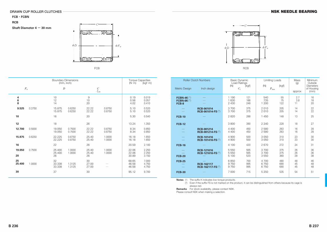
NSK NEEDLE BEARING
B 237
DRAWN CUP ROLLER CLUTCHES
B 236
FCB・FCBN
RCB
Shaft Diameter 4 - 30 mm
1 1901 6302 430
3 7003 700
2 820
3 800
4 4004 400
4 9004 900
4 100
5 5505 5505 100
6 8509 7509 750
7 000
121166248
375375
288
390
450450
500500
420
565565520
700995995
715
FCBN-4K(1)FCBN-6K(1)FCB-8
――
FCB-10
FCB-12
――
――
FCB-16
――
FCB-20
FCB-25――
FCB-30
―――
RCB-061014RCB-061014-FS(2)
―
―
RCB-081214RCB-081214-FS(2)
RCB-101416RCB-101416-FS(2)
―
RCB-121616RCB-121616-FS(2)
―
―RCB-162117RCB-162117-FS(2)
―
540735
1 200
2 0102 010
1 450
2 240
2 5802 580
3 0503 050
2 670
3 7003 7003 550
4 7006 7506 750
5 250
5575
122
205205
148
228
263263
310310
272
375375360
480690690
535
2.73.8
11
1414
13
18
1616
2323
24
262628
484545
54
161820
2222
25
27
2828
3030
31
363638
464848
51
0.3750
0.5000
0.6250
0.7500
1.0000
101214
15.87515.875
16
18
19.05019.050
22.22522.225
22
25.40025.40026
3233.33833.338
37
0.62500.6250
0.75000.7500
0.87500.8750
1.00001.0000
1.31251.3125
91020
22.2222.22
20
26
22.2222.22
25.4025.40
26
25.4025.4026
3027.0027.00
30
0.87500.8750
0.87500.8750
1.00001.0000
1.00001.0000
――
0.190.564.02
5.105.10
5.30
13.24
8.348.34
16.1816.18
20.59
22.0622.0630.89
68.6546.5846.58
95.12
0.0190.0570.410
0.5200.520
0.540
1.350
0.8500.850
1.6501.650
2.100
2.2502.2503.150
7.0004.7504.750
9.700
468
9.525
10
12
12.700
15.875
16
19.050
20
2525.400
30
C
FCB
φD φFw
C
RCB
0-0.25
Boundary Dimensions(mm, inch)
Fw D C
Torque Capacities(N・m) {kgf・m}
Roller Clutch Numbers
Metric Design Inch design
Mass(g)
approx
MinimumOutside
Diametersof Housing
(mm)
Basic DynamicLoad Ratings
(N) {kgf}Cr
Limiting Loads
(N) {kgf}Pmax
Notes (1) The suffix K indicates low-torque products.(2) Even if the suffix FS is not marked on the product, it can be distinguished from others because its cage is
always red.Remarks For stock availability, please contact NSK.Please consult NSK when making a selection.
φD φFw

NSK NEEDLE BEARING
B 239B 238
Nominal Outside Diameter
over incl
Tolerance
high low
Nominal Width
over incl
Width Tolerance
high low
―
30
30
120
+0.30
+0.35
+0.10
+0.10
- 6 +0.2 -0.2
Table 2 Outside Diameter ToleranceUnits: mm
Table 3 Width ToleranceUnits: mm
OIL SEALS FOR NEEDLE BEARINGSPages
Single-Lip Synthetic Rubber Seals ............................................................................................................. B242
Double-Lip Synthetic Rubber Seals............................................................................................................ B242
Needle roller bearing oil seals are manufactured to meet the sectionheight of drawn cup needle bearings. It is possible, therefore, to mountthem onto the side face of a needle bearing without specially machining thehousing bore.
The oil seals of VC and KC bearings serve as packing because theiroutside circumferences are rubber and facilitate easy mounting.
Types
The types of needle roller bearing oil seals are shown in Table 1.
Accuracy
The dimensional tolerance of oil seals complies with ISO6194 (JIS B 2402).The outside diameter and the width tolerances are shown in Table 2 andTable 3, respectively.
Type Details
VC
KC
Synthetic rubber
Synthetic rubber
Single lip
Double lip
Table 1 Types of Oil Seals

NSK NEEDLE BEARING
B 241
OIL SEALS FOR NEEDLE BEARINGS
B 240
Fig. 3 Typical Examples of Oil Seal Mounting
APPLICATIONS
Mounting
When single-lip VC bearings are mounted, the lip should be bent inward toprevent lubricant leakage and outward to prevent entry of foreign matter.
Double-lip KC bearings, which have good sealing properties and highresistance to foreign particles, emphasize the prevention of entry of foreignmatter and are provided with sufficient interference, so the main lip should bebent outward.
As wear and heat are easily generated if there is no oil film between theseal lip and the shaft, a coating of oil must be applied to the seal whenmounting.
When press fitting the seal into the housing as prescribed, any shock thatmay cause deformation to the seal should be avoided. It is recommended touse a press-fitting jig that is capable of equally pushing the whole back faceof the seal (Fig. 1).
Mounting on Shaft
If there is no slope in the shaft end or there is a key way or screw thread,the lip can be protected from any damage or peeling by using a bush asshown in Fig. 2, since the bore diameter of the seal is less than the shaftdiameter.
Coating grease onto the lip can make mounting easier and protect it. It isrecommended that the shaft end to which the seal is mounted should bechamfered at about 30 degrees.
Limiting Speed
Limiting speed, which varies depending on the eccentricity of the shaft incontact and roughness of the finished face, is generally 10 m/sec for VC and6 m/sec for KC bearings. In the case of outer ring rotation, it should be harf ofthe above values. The maximum operating temperature is about 120°C forshort periods of operation.
A typical example of oil seal mounting is shown in Fig. 3.
a+B=b-(1 to 2)mmd=D-(0.1 to 0.3)mm
B
D
d
b
a
Fig. 1
Fig. 2

NSK NEEDLE BEARING
■EXAMPLE FIGURES
■APPENDICES
FIGURES Page
・ MOTOR VEHICLES .................................................................................. C 2
・ CONSTRUCTION AND CARGO HANDLING EQUIPMENT ....................... C 9
・ AGRICULTURAL MACHINERY................................................................. C19
・ MACHINE TOOLS.................................................................................... C20
・ BUSINESS MACHINES ............................................................................ C26
・ ELECTRIC AND PNEUMATIC EQUIPMENT.............................................. C30
・ TWO-STROKE ENGINES ......................................................................... C39
・ HYDRAULIC MACHINES.......................................................................... C41
・ OTHERS .................................................................................................. C44
APPENDICES
APPENDIX 1 CONVERSION TABLE FROM SI
(INTERNATIONAL UNITS) SYSTEM ...................................... C48
APPENDIX 2 N-kgf CONVERSION TABLE................................................. C50
APPENDIX 3 kg-lb CONVERSION TABLE.................................................. C51
APPENDIX 4 °C-°F CONVERSION TABLE ................................................. C52
APPENDIX 5 VISCOSITY CONVERSION TABLE........................................ C53
APPENDIX 6 inch-mm CONVERSION TABLE............................................ C54
APPENDIX 7 HARDNESS CONVERSION TABLE (REFERENCE)................ C56
APPENDIX 8 PHYSICAL AND MECHANICAL PROPERTIES OF MATERIALS .. C57
APPENDIX 9 TOLERANCES FOR SHAFT DIAMETERS.............................. C58
APPENDIX 10 TOLERANCES FOR HOUSING BORE DIAMETERS .............. C60
APPENDIX 11 VALUES OF STANDARD TOLERANCE GRADES IT ............. C62
APPENDIX 12 SPEED FACTOR fn ............................................................... C64
APPENDIX 13 FATIGUE LIFE FACTOR fh AND FATIGUE LIFE L・Lh ........... C65
APPENDIX 14 BOUNDARY DIMENSIONS OF RADIAL BEARINGS.............. C66
APPENDIX 15 BOUNDARY DIMENSIONS OF THRUST BEARINGS ............ C67
OIL SEALS FOR NEEDLE BEARINGS
B 242
8
9
10
11
1215
1316
1417
161819
19
2022
2122
2224
2324
2425
2627
2829
3233
3537
3740
42
4245
4750
5255
62
2.5
2.5
2.5
2.5
2.53
2.53
2.53
2.533
3
33
33
33
33
33
44
44
44
44
44
4
44
44
44
4
4
5
6
7
8
9
10
12
13
14
15
16
17
18
20
22
25
28
30
32
35
40
45
50
BoundaryDimensions (mm)d D B
Oil Seal Numbers
VC KC
VC-4825
VC-5925
VC-61025
VC-71125
VC-81225VC-8153
VC-91325VC-9163
VC-101425VC-10173
VC-121625VC-12183VC-12193
VC-13193
VC-14203VC-14223
VC-15213VC-15223
VC-16223VC-16243
VC-17233VC-17243
VC-18243VC-18253
VC-20264VC-20274
VC-22284VC-22294
VC-25324VC-25334
VC-28354VC-28374
VC-30374VC-30404
VC-32424
VC-35424VC-35454
VC-40474VC-40504
VC-45524VC-45554
VC-50624
―
―
―
―
――
――
――
―――
―
KC-14203KC-14223
KC-15213KC-15223
KC-16223KC-16243
KC-17233KC-17243
KC-18243KC-18253
KC-20264KC-20274
KC-22284KC-22294
KC-25324KC-25334
KC-28354KC-28374
KC-30374KC-30404
KC-32424
KC-35424KC-35454
KC-40474KC-40504
KC-45524KC-45554
KC-50624
φD φd
φD φd
B
B
VC
KC
Please consult NSK when making a selection.

C 2 C 3
EXAMPLE FIGURES NSK NEEDLE BEARING
MOTOR VEHICLES
Fig. 1 Transmission Pilot
This illustrates the application of cage & needle roller assemblies inthe transmission pilot. Due to considerable misalignment, it isdesirable to provide a radial internal clearance of at least 0.038mm.
Fig. 2 Constant Mesh Transmission
This illustrates the application of needle rollers to the countershaftor main idler gear. In many cases, cage & needle roller assembliesare applied instead of needle rollers.
Fig. 3 Automatic Transmission
This illustrates a typical application in automatic transmissions.In particular, since thrust from the output shaft is expected, athrust needle roller bearing with a large roller diameter is appliedto the output shaft. A full complement is applied to the planetarygear. These rollers are usually treated with special crowning.
Fig. 4 Manual Steering System

C 4 C 5
EXAMPLE FIGURES NSK NEEDLE BEARING
Fig. 5 Ball Screw Steering Sector Shaft
For large trucks and buses, solid bearings are used. Forpassenger cars, however, drawn cup needle roller bearings areapplied in many cases.
Fig. 6 Power Steering Systems
Drawn cup needle roller bearings and thrust needle rollerbearings are applied to the hydraulic mechanism in powersteering systems.
Fig. 7 Torque Converter

C 6 C 7
EXAMPLE FIGURES NSK NEEDLE BEARING
Fig. 8 Air Pump (3-vane)
In order to reduce size and weight, drawn cup needle rollerbearings with a cage are applied to the vanes and rotor shaft.A two-vane type is also available.
Fig. 9 Kingpin
Drawn cup needle roller bearings areapplied to the kingpin. In some cases,a g rease n ipp le i s a t tached fo rlubrication.
Fig. 10 Clutch Finger
Fig. 13 Universal Joint
(Example of Drawn Cup Bearing Application)
This illustrates an application of drawn cup needle rollerbearings in a universal joint to reduce size, weight andcost.
Fig. 12 Engine Camshaft Follower
Fig. 11 Universal Joint (Example of Solid Bearing Application)

Input Shaft
C 8 C 9
EXAMPLE FIGURES
CONSTRUCTION AND CARGO HANDLING EQUIPMENT
NSK NEEDLE BEARING
Fig. 14 Automotive Air-Conditioner Compressor
This illustrates the application in the compressor of a swash plateair conditioner, with a characteristic structure involving supportby a thrust bearing.
Fig. 15 Alternator (AC Generator)
A drawn cup needle roller bearing with a cage is applied on theopposite side of the pulley to reduce size, weight and cost.
Fig. 16 Planetary Gear Transmission
For transmission in heavy construction and agriculturalmachinery, needle rollers are generally applied inside theplanetary gear and placed in two rows for stability. Forassembly reasons, cage & needle roller assemblies are alsoused.

C 10 C 11
EXAMPLE FIGURES NSK NEEDLE BEARING
Input Shaft
Fig. 18 Detailed Drawing of Clutch Pack
Two units of cage & needle roller assemblies are commonlyapplied to the gear support of the clutch pack. This bearingusually runs with a light load or without any load and does notrun if a load is imposed.In such an application, a bearing with a static load rating of 4 to7 times that of the static load should be selected.
Fig. 17 Constant Mesh Transmission
(Using Clutch Pack)
This illustrates the constant mesh transmission in termsof the intermediate shaft of a large-size front end loaderwith rubber tires. Speed change is facilitated by a discclutch pack. Cage & needle roller assemblies are appliedto this intermediate shaft.
Input Shaft
Input Shaft
Reverse Idler Gear
Fig. 20 Six-Speed Transmission
The figure shows a six-speed sliding mesh transmission, which is basically athree-speed transmission with a two-speed power shift in the earlier stage.
Fig. 19 Three-Speed Transmission
The figure shows an example of the three-speed transmission of a garden tractor or the like.Cage & needle roller assemblies are applied to the countershaft and planetary gear. Cage &needle roller assemblies are also used as clutch support on the right-hand side of a one-wayclutch.

C 12 C 13
EXAMPLE FIGURES NSK NEEDLE BEARING
Fig. 22 Final Reduction Gear
The structure is similar to Fig. 21.Two rows of cage & needle roller assembliesare also applied to this device to enhancethe stability of the gears. Rollers treatedwith a proper crowning are recommended.
Fig. 21 Final Reduction Gear
for Large Tractor
For rubber-tire tractors used in construction,a planetary final reduction gear is used asshown in the figure. In this case, since theload is large and space is limited, cage &needle roller assemblies are used inconsideration of the large load capacity,compact size, assembly, and service.
Input Shaft
Fig. 23 Final Reduction Gear
In some cases, a final reduction gear ispositioned close to the differential gears asshown in this figure. Instead of cage & needleroller assemblies, a single needle roller bearingis integrated into the two rows and the rollersare kept separate by a hardened spacer. It isabsolutely essential that the needle rollers havethe proper crowning.
Fig. 24 Auxiliary Gearbox
This illustrates an application of cage & needle roller assemblies tothe planetary gears of an auxiliary gearbox.

C 14 C 15
EXAMPLE FIGURES NSK NEEDLE BEARING
B―B
A
A
B
B
Input Shaft
Fig. 25 Governor
The governor of a diesel engine is one of theparts where fretting corrosion or false brinellingis easily caused by vibration. In the figure, adrawn cup, full complement bearing is appliedto the pivot arm.
Fig. 27 Hydraulic Pump Drive Unit
For hydraulic pump drive units in equipment such as largescrapers, which generally use aluminum or copper alloy metal, ifforced lubrication is not possible, the application of a needle rollerbearing facilitates lubrication as shown in the figure.
Fig. 26 Sheave for Cargo
Handling Vehicle
Fig. 28 Two-Speed Transmission PTO Unit
The power take-off (PTO) of a large two-speed tractor foragricultural use is successfully designed very compactly with acombination of drawn cup needle roller bearings and thrustbearings.
Fig. 29 Truck Roller in Forklifts
Fig. 31 Control System Linkage
Fig. 30 Forklift and Truck Roller

C 16 C 17
EXAMPLE FIGURES NSK NEEDLE BEARING
A
A
C
C
B
B
Fig. 32 Control Lever System
For the control lever system in equipment such as constructionmachinery, there has been a switch from plain metal to needleroller bearings for smoother performance and lubrication.Depending on the applicable part, due consideration is soughtfor enabling re-lubrication. Detailed cross-sectional drawings foreach part are shown on the following page.
Fig. 32.1 Cross-Section A-A
Fig. 32.2 Cross-Section B-B
Fig. 32.3 Cross-Section C-C

C 18 C 19
EXAMPLE FIGURES
AGRICULTURAL MACHINERY
NSK NEEDLE BEARING
Fig. 33 Hydraulic Cylinder for Bulldozer Blade Operation
Fig. 34 Scraper Linkage
Fig. 35 Hydraulic Cylinder for Shovel Operation
Fig. 36 Grain Reaping Machine
Fig. 37 Tractor Bolster
A compact thrust needle roller bearing isapplied to the thrust pad of a tractor bolster.A drawn cup needle roller bearing is also usedat the same time for smoother operation.
Fig. 38 Pitman
For superior wear resistance and operating efficiency, a drawn cupneedle roller bearing is applied to the pitman crank and crankpin.

C 20 C 21
EXAMPLE FIGURES
MACHINE TOOLS
NSK NEEDLE BEARING
Fig. 39 Machine Tool Gearbox
Fig. 40 Feeding Handle for Machine Tool
Fig. 41 Multi-Spindle Drill
In the case of multiple spindles occupying a limited space,such as a multiple spindle drilling machine, a drawn cupneedle roller bearing is recommended.
Fig. 42 Roller Leveler

C 22 C 23
EXAMPLE FIGURES NSK NEEDLE BEARING
Fig. 43 Back-Up Roll and Working Roll
Fig. 44 Crane Wheel
Fig. 45 Worm Driving Shaft
Fig. 46 Small Drill Press Spindle

C 24 C 25
EXAMPLE FIGURES NSK NEEDLE BEARING
Fig. 47 Gearbox
Fig. 48 Gearbox
Fig. 49 Conveyer Driving Reduction Gear

C 26 C 27
EXAMPLE FIGURES
BUSINESS MACHINES
NSK NEEDLE BEARING
Fig. 50 Magnetic Tape Driving Pulley for Electronic Computers
Fig. 51 Copying Machine Side Frame
Fig. 52 Copying Machine Side Frame
The application of a closed drawn cup needle roller bearing tothe shaft end contributes to cost reduction and enhancement ofseal performance.
Fig. 53 Copying Machine Paper Feed Mechanism

C 28 C 29
EXAMPLE FIGURES NSK NEEDLE BEARING
Fig. 55 Speed Reducer for Business Machines
Fig. 54 Copying Machine Side Frame
(In Case of Frequent Misalignment)
In case misalignment cannot be avoided, thespherical housing may be used as shown inthe figure.
Fig. 57 Copying Machine
Paper Feed Roll Mechanism
Fig. 58 Copying Machine Drive Roll (With Small Roll Diameter)
Fig. 56 Copying Machine Paper Feed Roll

C 31C 30
EXAMPLE FIGURES
ELECTRIC AND PNEUMATIC EQUIPMENT
Fig. 59 Electric Drill
The application of a drawn cup needle roller bearing contributesto shortening the distance between shafts and reduces size andweight.A needle roller bearing with a cage is applied to the motor shaftdue to high-speed rotation.
Fig. 60 Electric Polisher
Fig. 61 Hedge Trimmer
The figure shows the crankshaft of a hedge trimmer. A hardenedsteel ball is used as the center shaft because an axial loadthrough worm gears is imposed there.
Fig. 62 Circular Saw
Since ball bearings are commonly applied to motor fan shafts,the housing space on the right-hand side of the spindle shaft isconsiderably limited. Accordingly, drawn cup needle rollerbearings are used in many cases. In order to prevent grease inthe gearbox from entering into the motor, a closed type bearingis applied.
NSK NEEDLE BEARING

C 32 C 33
EXAMPLE FIGURES NSK NEEDLE BEARING
Fig. 64 Shaper Saw
Fig. 63 Angular Saw
Fig. 65 Rivetter
Fig. 66 Planetary Gears of Air Drill

C 34 C 35
EXAMPLE FIGURES NSK NEEDLE BEARING
Fig. 68 Polisher
It is possible to use the housing as a throughhole by changing the drawn cup needle rollerbearing on the upper part of the spindle shaftto a closed type.
Fig. 69 Nut Setter
Fig. 67 Jig Saw
Two drawn cup needle rollerbearings are applied to supportthe blade and counter balancedriving gears.
Fig. 70 Agitator Shaft Fig. 71 Pulley Support
This is a good example of low-cost design,showing that a single drawn cup needle rollerbearing with a seal can deliver stableperformance without maintenance over a longperiod of time to facilitate long life.
Fig. 72 Agitator Shaft

C 36 C 37
EXAMPLE FIGURES NSK NEEDLE BEARING
Fig. 74 Spank Agitator
Fig. 73 Spank Mechanism
This is a typical example of a vertical agitatorin which a ball bearing was replaced with aneedle roller bearing to reduce size.
Fig. 76 Washer and Dryer Two-Speed Transmission
Fig. 75 Washer and Dryer
Fan-Drive Pulley

C 38 C 39
EXAMPLE FIGURES
TWO-STROKE ENGINES
NSK NEEDLE BEARING
Fig. 77 Washer and Dryer Two-Speed Transmission
Fig. 78 Washing Machine Basket Drive Shaft
Fig. 79 Chain Saw Engine
Many drawn cup needle roller bearings are applied to the chainsaw engine, contributing to its lighter weight. Application of adrawn cup roller clutch to the starter allows further simplificationof operation.

C 40 C 41
EXAMPLE FIGURES
HYDRAULIC MACHINES
NSK NEEDLE BEARING
Fig. 80 Two-Stroke Engine
This illustrates the application of a solidneedle roller bearing to the crankshaft,increasing load capacity and facilitating amore compact size.
Fig. 81 Outboard Motor Lower Unit
Fig. 82 Gear Pump
A solid needle roller bearing is commonly applied to high-pressure gear pumps. Since the load is large and problemssuch as edge load may be caused by shaft deflection, crowningshould be applied to the rollers.
Fig. 83 Gear Pump
The comparatively low-pressure gear pump operates satisfactorily witha drawn cup needle roller bearing. It also serves to reduce cost.

C 42 C 43
EXAMPLE FIGURES NSK NEEDLE BEARING
Fig. 84 Gear Pump
Fig. 85 Axial Piston Pump
Fig. 86 Axial Piston Pump
For high-pressure axial piston pumps, NTH thrust roller bearings,which have a large load capacity, are recommended.Although this example uses a copper alloy bush for the borediameter guide face of the thrust roller bearing, a bush wouldnot be required should the guide face be hardened and groundto HRC58 or more.
Fig. 87 Hydraulic Transmission
This illustrates a hydraulic transmission combining a variabledisplacement axial piston pump and a fixed displacement gearmotor.A drawn cup needle roller bearing is applied to the pivotingportion and the gear motor of the rotating swash plate of theaxial piston pump.

C 45
NSK NEEDLE BEARING
C 44
EXAMPLE FIGURES
OTHERS
Fig. 88 Magic Hand
The application of a thrust needle rollerbearing to a magic hand or artificial armfacilitates smooth operation.
Fig. 89 Oil Well Equipment (Pump Jack)
Fig. 90 Oil Well Equipment (Pump Jack)
Fig. 91 Valve

C 46
EXAMPLE FIGURES
Fig. 92 Electric Guitar Tremolo
Fig. 93 Meat Saw for Hamburgers

C 48 C 49
APPENDICES NSK NEEDLE BEARING
Units
SI
Length Mass Time Temp. Accelera-tion Force Stress Pressure Energy Power
m kg s K, °C m/s2 N Pa Pa J W
cm
m
s
s
g
kgf・s2/m
°C
°C
Gal
m/s2
dyn
kgf
dyn/cm2
kgf/m2
dyn/cm2
kgf/m2
erg
kgf・m
erg/s
kgf・m/s
CGS System
EngineeringUnit System
UnitSystem
Appendix 1 Conversion Table from SI (International Units) System
Comparison of SI, CGS, and Engineering Units
Parameter
Angle
Length
Area
Volume
Time
Frequency
Speed of Rotation
Speed
Acceleration
Mass
Force
Torque or Moment
Stress
Radian
Meter
Square meter
Cubic meter
Second
Hertz
Revolution per second
Meter per second
Meter per second per second
Kilogram
Newton
Newton・meter
Pascal
rad
m
m2
m3
s
Hz
s-1
m/s
m/s2
kg
N
N・m
Pa(N/m2)
DegreeMinuteSecond
MicronAngstrom
AreHectare
LiterDeciliter
MinuteHourDay
Cycle
Revolution per minute
Kilometer per hourKnot
Galg
Ton
Kilogram-forceTon-forceDyne
Kilogram-force meter
Kilogram-force per square centimeterKilogram-force per square milimeter
180/π10 800/π648 000/π
106
1010
10-2
10-4
103
104
1/601/3 6001/86 400
1
60
3 600/1 0003 600/1 852
102
1/9.806 65
10-3
1/9.806 651/(9.806 65 × 103 )105
1/9.806 65
1/(9.806 65 × 104 )1/(9.806 65 × 106 )
°’”
p
Å
aha
l, Ldl, dL
minhd
s-1
rpm
km /hkn
Galg
t
kgftfdyn
kgf・m
kgf /cm2
kgf /mm2
SI Units
Names of Units Symbols Names of Units Symbols
Units other than SI Conversion Factorsfrom SI Units
Conversion Factors from SI UnitsParameter
Pressure
Energy
Work
Viscosity,Viscosity Index
Kinematic Viscosity,Kinematic Viscosity Index
Temperature
Electric Current,Magnetomotive Force
Voltage,Electromotive Force
Magnetic FieldStrength
Magnetic FluxDensity
Electrical Resistance
Pascal(Newton per square meter)
Joule(Newton-meter)
Watt(Joule per second)
Pascal second
Square meter per second
Kelvin, Degree Celsius
Ampere
Volt
Ampere per meter
Tesla
Ohm
Pa(N/m2)
J(N・m)
W(J/s)
Pa・s
m2/s
K, °C
A
V
A/m
T
Ω
Kilogram-force per square meterWater ColumnMercury ColumnTorrBarAtmosphere
ErgCalorie (International)Kilogram-force meterKilowatt hourFrench horse power hour
Kilogram-force meter per secondKilocalorie per hourFrench horse power
Poise
StokesCentistokes
Degree,
Ampere
(Watts per ampere)
Oersted
GaussGamma
(Volts per ampere)
1/9.806 651/(9.806 65 × 103 )760/(1.013 25 × 105 )760/(1.013 25 × 105 )10-5
1/(1.013 25 × 105 )
107
1/4.186 81/9.806 651/(3.6 × 106 )~~ 3.776 72 × 10-7
1/9.806 651/1.163~~ 1/735.498 8
10
104
106
(See Note (1))
1
1
4π/103
104
109
1
kgf/m2
mH2OmmHgTorrbaratm
ergcalIT
kgf・mkW・hPS・h
kgf・m/skcal/hPS
P
StcSt
°C
A
(W/A)
Oe
Gsγ
(V/A)
SI Units
Names of Units Symbols Names of Units Symbols
Units other than SI Conversion Factorsfrom SI Units
Conversion Factors from SI Units (Continued)
Note (1) The conversion from TK intoθ°C is θ = T-273.15 but for a temperature difference, it is dT = dθ. However, dT and dθrepresent temperature differences measured using the Kelvin and Celsius scales respectively.
Remarks The names and symbols in ( ) are equivalent to those directly above them or on their left.Example of conversion 1N = 1/9.806 65kgf
Prefixes Used In SI System
Multiples Prefix Symbols Multiples Prefix Symbols
1018
1015
1012
109
106
103
102
10
EPT
GMk
hda
ExaPetaTera
GigaMegaKiro
HectoDeca
DeciCentiMilli
MicroNanoPico
FemtoAto
10-1
10-2
10-3
10-6
10-9
10-12
10-15
10-18
dcm
p
np
fa

C 51
NSK NEEDLE BEARING
C 50
APPENDICES
N
9.806619.61329.42039.22749.033
58.84068.64778.45388.26098.066
107.87117.68127.49137.29147.10
156.91166.71176.52186.33196.13
205.94215.75225.55235.36245.17
254.97264.78274.59284.39294.20
304.01313.81323.62
0.10200.20390.30590.40790.5099
0.61180.71380.81580.91771.0197
1.12171.22371.32561.42761.5296
1.63151.73351.83551.93752.0394
2.14142.24342.34532.44732.5493
2.65132.75322.85522.95723.0591
3.16113.26313.3651
12345
6789
10
1112131415
1617181920
2122232425
2627282930
313233
kgf N
333.43343.23353.04362.85372.65
382.46392.27402.07411.88421.69
431.49441.30451.11460.91470.72
480.53490.33500.14509.95519.75
529.56539.37549.17558.98568.79
578.59588.40598.21608.01617.82
627.63637.43647.24
3.46703.56903.67103.77293.8749
3.97694.07894.18084.28284.3848
4.48684.58874.69074.79274.8946
4.99665.09865.20065.30255.4045
5.50655.60845.71045.81245.9144
6.01636.11836.22036.32226.4242
6.52626.62826.7301
3435363738
3940414243
4445464748
4950515253
5455565758
5960616263
646566
kgf N
657.05666.85676.66686.47696.27
706.08715.89725.69735.50745.31
755.11764.92774.73784.53794.34
804.15813.95823.76833.57843.37
853.18862.99872.79882.60892.41
902.21912.02921.83931.63941.44
951.25961.05970.86
6.83216.93417.03607.13807.2400
7.34207.44397.54597.64797.7498
7.85187.95388.05588.15778.2597
8.36178.46368.56568.66768.7696
8.87158.97359.07559.17749.2794
9.38149.48349.58539.68739.7893
9.89129.9932
10.095
6768697071
7273747576
7778798081
8283848586
8788899091
9293949596
979899
kgf kg
0.4540.9071.3611.8142.268
2.7223.1753.6294.0824.536
4.9905.4435.8976.3506.804
7.2577.7118.1658.6189.072
9.5259.979
10.43310.88611.340
11.79312.24712.70113.15413.608
14.06114.51514.969
2.2054.4096.6148.818
11.023
13.22815.43217.63719.84222.046
24.25126.45528.66030.86533.069
35.27437.47939.68341.88844.092
46.29748.50250.70652.91155.116
57.32059.52561.72963.93466.139
68.34370.54872.753
12345
6789
10
1112131415
1617181920
2122232425
2627282930
313233
lb kg
15.42215.87616.32916.78317.237
17.69018.14418.59719.05119.504
19.95820.41220.86521.31921.772
22.22622.68023.13323.58724.040
24.49424.94825.40125.85526.308
26.76227.21627.66928.12328.576
29.03029.48429.937
74.95777.16279.36681.57183.776
85.98088.18590.39092.59494.799
97.00399.208
101.41103.62105.82
108.03110.23112.44114.64116.84
119.05121.25123.46125.66127.87
130.07132.28134.48136.69138.89
141.10143.30145.51
3435363738
3940414243
4445464748
4950515253
5455565758
5960616263
646566
lb kg
30.39130.84431.29831.75132.205
32.65933.11233.56634.01934.473
34.92735.38035.83436.28736.741
37.19537.64838.10238.55539.009
39.46339.91640.37040.82341.277
41.73042.18442.63843.09143.545
43.99844.45244.906
147.71149.91152.12154.32156.53
158.73160.94163.14165.35167.55
169.76171.96174.17176.37178.57
180.78182.98185.19187.39189.60
191.80194.01196.21198.42200.62
202.83205.03207.23209.44211.64
213.85216.05218.26
6768697071
7273747576
7778798081
8283848586
8788899091
9293949596
979899
lb
1 N=0.1019716 kgf
1 kgf=9.80665 N1 kg=2.2046226 lb1 lb=0.45359237 kg
Appendix 2 N-kgf Conversion Table Appendix 3 kg-lb Conversion Table
(Method of using this table) For example, to convert 10N into kgf, read the figure in the rightkgf column adjacent to the 10 in the center column in the 1stblock. This means that 10N is 1.0197kgf. To convert 10kgf into N,read the figure in the left N column of the same row, whichindicates that the answer is 98.066N.
(Method of using this table) For example, to convert 10kg into lb, read the figure in the right lbcolumn adjacent to the 10 in the center column in the 1st block.This means that 10kg is 22.046lb. To convert 10lb into kg, readthe figure in the left kg column of the same row, which indicatesthat the answer is 4.536kg.

C 53
NSK NEEDLE BEARING
C 52
APPENDICES
C= (F-32)
F=32+ C
℃
-73.3-62.2-51.1-40.0-34.4
-28.9-23.3-17.8-17.2-16.7
-16.1-15.6-15.0-14.4-13.9
-13.3-12.8-12.2-11.7-11.1
-10.6-10.0- 9.4- 8.9- 8.3
- 7.8- 7.2- 6.7- 6.1- 5.6
- 5.0- 4.4- 3.9- 3.3- 2.8
- 2.2- 1.7- 1.1- 0.6
-148.0-112.0- 76.0- 40.0- 22.0
- 4.014.032.033.835.6
37.439.241.042.844.6
46.448.250.051.853.6
55.457.259.060.862.6
64.466.268.069.871.6
73.475.277.078.880.6
82.484.286.087.8
-100- 80- 60- 40- 30
- 20- 10
012
34567
89
101112
1314151617
1819202122
2324252627
28293031
˚F ℃
0.00.61.11.72.2
2.83.33.94.45.0
5.66.16.77.27.8
8.38.99.4
10.010.6
11.111.712.212.813.3
13.914.415.015.616.1
16.717.217.818.318.9
19.420.020.621.1
89.691.493.295.096.8
98.6100.4102.2104.0105.8
107.6109.4111.2113.0114.8
116.6118.4120.2122.0123.8
125.6127.4129.2131.0132.8
134.6136.4138.2140.0141.8
143.6145.4147.2149.0150.8
152.6154.4156.2158.0
3233343536
3738394041
4243444546
4748495051
5253545556
5758596061
6263646566
67686970
˚F ℃
21.722.222.823.323.9
24.425.025.626.126.7
27.227.828.328.929.4
30.030.631.131.732.2
32.833.333.934.435.0
35.636.136.737.237.8
38.338.939.440.040.6
41.141.742.242.8
159.8161.6163.4165.2167.0
168.8170.6172.4174.2176.0
177.8179.6181.4183.2185.0
186.8188.6190.4192.2194.0
195.8197.6199.4201.2203.0
204.8206.6208.4210.2212.0
213.8215.6217.4219.2221.0
222.8224.6226.4228.2
7172737475
7677787980
8182838485
8687888990
9192939495
96979899
100
101102103104105
106107108109
˚F ℃
43.346.148.951.754.4
57.260.065.671.176.7
82.287.893.398.9
104.4
110.0115.6121.1148.9176.7
204232260288316
343371399427454
482510538593649
704760816871
230239248257266
275284302320338
356374392410428
446464482572662
752842932
10221112
12021292138214721562
16521742183220122192
2372255227322912
110115120125130
135140150160170
180190200210220
230240250300350
400450500550600
650700750800850
900950
1 0001 1001 200
1 3001 4001 5001 600
˚F
5―9
9―5
Appendix 4 °C-°F Conversion Table Appendix 5 Viscosity Conversion Table
(Method of using this table) For example, to convert 38°C into °F, read the figure in the right °Fcolumn adjacent to the 38 in the center column in the 2nd block.This means that 38°C is 100.4°F. To convert 38°F into °C, read thefigure in the left °C column of the same row, which indicates thatthe answer is 3.3°C.
KinematicViscositymm2/s
SayboltUniversalSUS (sec)
100˚F 210˚F 50℃ 100℃
No.1 TypeRedwood
R (sec)Engler
E (degree)
SayboltUniversalSUS (sec)
100˚F 210˚F 50℃ 100℃
No.1 TypeRedwood
R (sec)Engler
E (degree)
23456
789
1011
1213141516
1718192021
2223242526
2728293031
323334
32.636.039.142.345.5
48.752.055.458.862.3
65.969.673.477.281.1
85.189.293.397.5
102
106110115119123
128132137141145
150154159
32.836.339.442.645.8
49.052.455.859.262.7
66.470.173.977.781.7
85.789.894.098.2
102
107111115120124
129133138142146
150155160
30.833.335.938.541.1
43.746.349.152.155.1
58.261.464.768.071.5
75.078.682.185.889.5
93.397.1
101105109
112116120124128
132136140
31.233.736.539.141.7
44.347.050.052.956.0
59.162.365.669.172.6
76.179.783.687.491.3
95.198.9
103107111
115119123127131
135139143
1.141.221.311.401.48
1.561.651.751.841.93
2.022.122.222.322.43
2.542.642.762.872.98
3.103.223.343.463.58
3.703.823.954.074.20
4.324.454.57
3536373839
4041424344
4546474849
5055606570
7580859095
100120140160180
200250300
163168172177181
186190195199204
208213218222227
231254277300323
346371394417440
464556649742834
9271 1591 391
164170173178183
187192196201205
210215219224228
233256279302326
349373397420443
467560653747840
9331 1671 400
144148153156160
164168172176180
184188193197201
205225245266286
306326347367387
408490571653734
8161 0201 224
147151155159164
168172176180185
189193197202206
210231252273294
315336357378399
420504588672757
8411 0511 241
4.704.834.965.085.21
5.345.475.595.725.85
5.986.116.246.376.50
6.637.247.908.559.21
9.8910.511.211.812.5
13.215.818.421.123.7
26.332.939.5
Remarks 1mm2/s=1cSt
KinematicViscositymm2/s

C 55
NSK NEEDLE BEARING
C 54
APPENDICES
inch 0 1
Fraction Decimal mm
01/641/323/641/165/643/327/641/89/645/32
11/643/16
13/647/32
15/641/4
17/649/32
19/645/16
21/6411/3223/64
3/825/6413/3227/64
7/1629/6415/3231/64
1/233/6417/3235/64
9/1637/5419/3239/64
5/841/6421/3243/6411/1645/6423/3247/64
3/449/6425/3251/6413/1653/6427/3255/64
7/857/6429/3259/6415/1661/6431/3263/64
0.0000000.0156250.0312500.0468750.0625000.0781250.0937500.1093750.1250000.1406250.1562500.1718750.1875000.2031250.2187500.2343750.2500000.2656250.2812500.2968750.3125000.3281250.3437500.3593750.3750000.3906250.4062500.4218750.4375000.4531250.4687500.4843750.5000000.5156250.5312500.5468750.5625000.5781250.5937500.6093750.6250000.6406250.6562500.6718750.6875000.7031250.7187500.7343750.7500000.7656250.7812500.7968750.8125000.8281250.8437500.8593750.8750000.8906250.9062500.9218750.9375000.9531250.9687500.984375
0.0000.3970.7941.1911.5881.9842.3812.7783.1753.5723.9694.3664.7625.1595.5565.9536.3506.7477.1447.5417.9388.3348.7319.1289.5259.992
10.31910.71611.11211.50911.90612.30312.70013.09713.49413.89114.28814.68415.08115.47815.87516.27216.66917.06617.46217.85918.25618.65319.05019.44719.84420.24120.63821.03421.43121.82822.22522.62223.01923.41623.81224.20924.60625.003
25.40025.79726.19426.59126.98827.38427.78128.17828.57528.97229.36929.76630.16230.55930.95631.35331.75032.14732.54432.94133.33833.73434.13134.52834.92535.32235.71936.11636.51236.90937.30637.70338.10038.49738.89439.29139.68840.08440.48140.87841.27541.67242.06942.46642.86243.25943.65644.05344.45044.84745.24445.64146.03846.43446.83147.22847.62548.02248.41948.81649.21249.60950.00650.403
50.80051.19751.59451.99152.38852.78453.18153.57853.97554.37254.76955.16655.56255.95956.35656.75357.15057.54757.94458.34158.73859.13459.53159.92860.32560.72261.11961.51661.91262.30962.70663.10363.50063.89764.29464.69165.08865.48465.88166.27866.67567.07267.46967.86668.26268.65969.05669.45369.85070.24770.64471.04171.43871.83472.23172.62873.02573.42273.81974.21674.61275.00975.40675.803
76.20076.59776.99477.39177.78878.18478.58178.97879.37579.77280.16980.56680.96281.35981.75682.15382.55082.94783.34483.74184.13884.53484.93185.32885.72586.12286.51986.91687.31287.70988.10688.50388.90089.29789.69490.09190.48890.88491.28191.67892.07592.47292.86993.26693.66294.05994.45694.85395.25095.64796.04496.44196.83897.23497.63198.02898.42598.82299.21999.616
100.012100.409100.806101.203
101.600101.997102.394102.791103.188103.584103.981104.378104.775105.172105.569105.966106.362106.759107.156107.553107.950108.347108.744109.141109.538109.934110.331110.728111.125111.522111.919112.316112.712113.109113.506113.903114.300114.697115.094115.491115.888116.284116.681117.078117.475117.872118.269118.666119.062119.459119.856120.253120.650121.047121.444121.841122.238122.634123.031123.428123.825124.222124.619125.016125.412125.809126.206126.603
127.000127.397127.794128.191128.588128.984129.381129.778130.175130.572130.969131.366131.762132.159132.556132.953133.350133.747134.144134.541134.938135.334135.731136.128136.525136.922137.319137.716138.112138.509138.906139.303139.700140.097140.494140.891141.288141.684142.081142.478142.875143.272143.669144.066144.462144.859145.256145.653146.050146.447146.844147.241147.638148.034148.431148.828149.225149.622150.019150.416150.812151.209151.606152.003
152.400152.797153.194153.591153.988154.384154.781155.178155.575155.972156.369156.766157.162157.559157.956158.353158.750159.147159.544159.941160.338160.734161.131161.528161.925162.322162.719163.116163.512163.909164.306164.703165.100165.497165.894166.291166.688167.084167.481167.878168.275168.672169.069169.466169.862170.259170.656171.053171.450171.847172.244172.641173.038173.434173.831174.228174.625175.022175.419175.816176.212176.609177.006177.403
2 3 4 5 6 inch 7 8
Fraction Decimal mm
01/641/323/641/165/643/327/641/89/645/32
11/643/16
13/647/32
15/641/4
17/649/32
19/645/16
21/6411/3223/64
3/825/6413/3227/64
7/1629/6415/3231/64
1/233/6417/3235/64
9/1637/5419/3239/64
5/841/6421/3243/6411/1645/6423/3247/64
3/449/6425/3251/6413/1653/6427/3255/64
7/857/6429/3259/6415/1661/6431/3263/64
0.0000000.0156250.0312500.0468750.0625000.0781250.0937500.1093750.1250000.1406250.1562500.1718750.1875000.2031250.2187500.2343750.2500000.2656250.2812500.2968750.3125000.3281250.3437500.3593750.3750000.3906250.4062500.4218750.4375000.4531250.4687500.4843750.5000000.5156250.5312500.5468750.5625000.5781250.5937500.6093750.6250000.6406250.6562500.6718750.6875000.7031250.7187500.7343750.7500000.7656250.7812500.7968750.8125000.8281250.8437500.8593750.8750000.8906250.9062500.9218750.9375000.9531250.9687500.984375
177.800178.197178.594178.991179.388179.784180.181180.578180.975181.372181.769181.166182.562182.959183.356183.753184.150184.547184.944185.341185.738186.134186.531186.928187.325187.722188.119188.516188.912189.309189.706190.103190.500190.897191.294191.691192.088192.484192.881193.278193.675194.072194.469194.866195.262195.659196.056196.453196.850197.247197.644198.041198.438198.834199.231199.628200.025200.422200.819201.216201.612202.009202.406202.803
203.200203.597203.994204.391204.788205.184205.581205.978206.375206.772207.169207.566207.962208.359208.756209.153209.550209.947210.344210.741211.138211.534211.931212.328212.725213.122213.519213.916214.312214.709215.106215.503215.900216.297216.694217.091217.488217.884218.281218.678219.075219.472219.869220.266220.662221.059221.456221.853222.250222.647223.044223.441223.838224.234224.631225.028225.425225.822226.219226.616227.012227.409227.806228.203
228.600228.997229.394229.791230.188230.584230.981231.378231.775232.172232.569232.966233.362233.759234.156234.553234.950235.347235.744236.141236.538236.934237.331237.728238.125238.522238.919239.316239.712240.109240.506240.903241.300241.697242.094242.491242.888243.284243.681244.078244.475244.872245.269245.666246.062246.459246.856247.253247.650248.047248.444248.841249.238249.634250.031250.428250.825251.222251.619252.016252.412252.809253.206253.603
254.000254.397254.794255.191255.588255.984256.381256.778257.175257.572257.969258.366258.762259.159259.556259.953260.350260.747261.144261.541261.938262.334262.731263.128263.525263.922264.319264.716265.112265.509265.906266.303266.700267.097267.494267.891268.288268.684269.081269.478269.875270.272270.669271.066271.462271.859272.256272.653273.050273.447273.844274.241274.638275.034275.431275.828276.225276.622277.019277.416277.812278.209278.606279.003
279.400279.797280.194280.591280.988281.384281.781282.178282.575282.972283.369283.766284.162284.559284.956285.353285.750286.147286.544286.941287.338287.734288.131288.528288.925289.322289.719290.116290.512290.909291.306291.703292.100292.497292.894293.291293.688294.084294.481294.878295.275295.672296.069296.466296.862297.259297.656298.053298.450298.847299.244299.641300.038300.434300.831301.228301.625302.022302.419302.816303.212303.609304.006304.403
304.800305.197305.594305.991306.388306.784307.181307.578307.975308.372308.769309.166309.562309.959310.356310.753311.150311.547311.944312.341312.738313.134313.531313.928314.325314.722315.119315.516315.912316.309316.706317.103317.500317.897318.294318.691319.088319.484319.881320.278320.675321.072321.469321.866322.262322.659323.056323.453323.850324.247324.644325.041325.438325.834326.231326.628327.050327.422327.819328.216328.612329.009329.406329.803
9 10 11 12
1″=25.4mm
Appendix 6 inch-mm Conversion Table

C 57
NSK NEEDLE BEARING
C 56
APPENDICES
RockwellC Scale
Hardness(1 471N){150kgf}
VickersHardness
Brinell Hardness
Standard Ball TungstenCarbide Ball
Rockwell Hardness
A Scale
Load 588.4N{60kgf}
BraleIndenter
B Scale
Load 980.7N{100kgf}
1.588mmBall(1/16in)
940900865832800
772746720697674
653633613595577
560544528513498
484471458446434
423412402392382
372363354345336
327318310302294
286279272266260
254248243238
230222213204
196188180173166160
―――――
―――――
―――――
―500487475464
451442432421409
400390381371362
353344336327319
311301294286279
271264258253247
243237231226
219212203194
187179171165158152
―――
739722
705688670654634
615595577560543
525512496481469
455443432421409
400390381371362
353344336327319
311301294286279
271264258253247
243237231226
219212203194
187179171165158152
ShoreHardness
85.685.084.583.983.4
82.882.381.881.280.7
80.179.679.078.578.0
77.476.876.375.975.2
74.774.173.673.172.5
72.071.570.970.469.9
69.468.968.467.967.4
66.866.365.865.364.7
64.363.863.362.862.4
62.061.561.060.5
――――
――――――
―――――
―――――
―――――
―――――
―――――
―――――
――
(109.0)(108.5)(108.0)
(107.5)(107.0)(106.0)(105.5)(104.5)
(104.0)(103.0)(102.5)(101.5)(101.0)
100.099.098.597.8
96.795.593.992.3
90.789.587.185.583.581.7
9795929188
8785838180
7876757472
7169686766
6463626058
5756555452
5150494847
4644434241
4140383837
36353534
33323129
282726252424
6867666564
6362616059
5857565554
5352515049
4847464544
4342414039
3837363534
3332313029
2827262524
23222120
(18)(16)(14)(12)
(10)(8)(6)(4)(2)(0)
Appendix 7 Hardness Conversion Table (Reference) Appendix 8 Physical and Mechanical Properties of Materials
Materials
Bearing Steel (hardened)
Martensitic Stainless SteelSUS 440C
Mild (C=0.12 to 0.20%)Steel
Hard (C=0.3 to 0.5%)Steel
Austenitic Stainless SteelSUS 304
Cast Iron
Gray IronFC200
Spheroidalgraphite Iron
FCD400
Aluminum
Zinc
Copper
(Annealed)
Brass
(Machined)
SpecificGravity
7.83
7.68
7.86
7.84
8.03
7.3
7.0
2.69
7.14
8.93
8.5
Coefficientof Linear
Expansion(0°to 100°C)
Hardness(Brinell)
Modulusof LinearElasticity
(MPa){kgf/mm2}
Tensile Strength(MPa)
{kgf/mm2}
Yield Point(MPa)
{kgf/mm2}
Elongation(%)
12.5×10⁻⁶
10.1×10⁻⁶
11.6×10⁻⁶
11.3×10⁻⁶
16.3×10⁻⁶
10.4×10⁻⁶
11.7×10⁻⁶
23.7×10⁻⁶
31×10-6
16.2×10⁻⁶
19.1×10⁻⁶
650 to 740
580
100 to 130
160 to 200
150
Less than223
Less than201
15 to 26
30 to 60
50
45
85 to 130
208 000{21 200}
200 000{20 400}
206 000{21 000}
206 000{21 000}
193 000{19 700}
98 100{10 000}
70 600{7 200}
92 200{9 400}
123 000{12 500}
103 000{10 500}
1 570 to 1 960{160 to 200}
1 960{200}
373 to 471{38 to 48}
539 to 686{55 to 70}
588{60}
More than200{20}
More than400{41}
78{8}
147{15}
196{20}
294 to 343{30 to 35}
363 to 539{37 to 55}
―
1 860{190}
216 to 294{22 to 30}
333 to 451{34 to 46}
245{25}
―
―
34{3.5}
―
69{7}
―
―
―
24 to 36
14 to 26
60
―
More than12
35
30 to 40
15 to 20
65 to 75
15 to 50
Remarks The hardness of hardened bearing steel and martensitic stainless steel is usually expressed using the Rockwell CScale, but for comparison, it is converted into Brinell hardness.

C 59
NSK NEEDLE BEARING
C 58
APPENDICES
DiameterClassification
(mm)a c d e f g h
a13 c12 d6 e6 f5 f6 g5 g6 h5 h6 h7 h8 h9 h10
Single PlaneMean BoreDeviation(Normal)ddmpover incl
3
6
10
14
18
24
30
40
50
65
80
100
120
140
160
180
200
225
250
280
315
355
400
450
6 0- 8
-270-450
-280-500
-290-560
-300-630
- 310- 700
- 320- 710
- 340- 800
- 360- 820
- 380- 920
- 410- 959
- 460-1 090
- 520-1 150
- 580-1 210
- 660-1 380
- 740-1 460
- 820-1 540
- 920-1 730
-1 050-1 860
-1 200-2 090
-1 350-2 240
-1 500-2 470
-1 650-2 620
- 70-190
- 80-230
- 95-275
-110-320
- 120- 370
- 130- 380
- 140- 440
- 150- 450
- 170- 520
- 180- 530
- 200- 600
- 210- 610
- 230- 630
- 240- 700
- 260- 720
- 280- 740
- 300- 820
- 330- 850
- 360- 930
- 400- 970
- 440-1 070
- 480-1 110
- 30- 38
- 40- 49
- 50- 61
- 65- 78
- 80- 96
-100-119
-120-142
-145-170
-170-199
-190-222
-210-246
-230-270
- 20- 28
-10-15
-13-19
-16-24
-20-29
-25-36
-30-43
-36-51
-43-61
-50-70
-56-79
-62-87
-68-95
- 10- 18
- 13- 22
- 16- 27
- 20- 33
- 25- 41
- 30- 49
- 36- 58
- 43- 68
- 50- 79
- 56- 88
- 62- 98
- 68-108
- 4- 9
- 5-11
- 6-14
- 7-16
- 9-20
-10-23
-12-27
-14-32
-15-35
-17-40
-18-43
-20-47
- 4-12
- 5-14
- 6-17
- 7-20
- 9-25
-10-29
-12-34
-14-39
-15-44
-17-49
-18-54
-20-60
0- 5
0- 8
0-12
0-18
0- 30
0- 48
0- 6
0- 9
0-15
0-22
0- 36
0- 58
0- 8
0-11
0-18
0-27
0- 43
0- 70
0- 9
0-13
0-21
0-33 0
- 520
- 84
0-11
0-16
0-25
0-39
0- 62
0-100
0-13
0-19
0-30
0-46
0- 74
0-120
0-15
0-22
0-35
0-54
0- 87
0-140
0-18
0-25
0-40
0-63
0-100
0-160
0-20
0-29
0-46
0-72
0-115
0-185
0-23
0-32
0-52
0-81
0-130
0-210
0-25
0-36
0-57
0-89
0-140
0-230
0-27
0-40
0-63
0-97
0-155
0-250
- 25- 34
- 32- 43
- 40- 53
- 50- 66
- 60- 79
- 72- 94
- 85-110
-100-129
-110-142
-125-161
-135-175
0- 8
0- 8
0-10
0-12
0-15
0-20
0-25
0-30
0-35
0-40
0-45
10
14
18
24
30
40
50
65
80
100
120
140
160
180
200
225
250
280
315
355
400
450
500
DiameterClassification
(mm)js
js5 js6 over incl
3
6
10
14
18
24
30
40
50
65
80
100
120
140
160
180
200
225
250
280
315
355
400
450
6±2.5
± 3
± 4
±4.5
±5.5
±6.5
±7.5
± 9
±10
±11.5
±12.5
±13.5
± 4
10
14
18
24
30
40
50
65
80
100
120
140
160
180
200
225
250
280
315
355
400
450
500
j
j5 j6
+ 3- 2
+ 6- 2
k
k5 k6
+ 6+ 1
+ 9+ 1
m
m5 m6
+ 9+ 4
+12+ 4
n
n5 n6
+13+ 8
+16+ 8
p
p5 p6
+17+12
+ 20+ 12
r
r6 r7
+ 23+ 15
±4.5 + 4- 2
+ 7- 2
+ 7+ 1
+10+ 1
+12+ 6
+15+ 6
+16+10
+19+10
+21+15
+ 24+ 15
+ 28+ 19
+ 34+ 23
+ 41+ 28
+ 50+ 34
+ 60+ 41
+ 62+ 43
+ 73+ 51
+ 76+ 54
+ 88+ 63
+ 90+ 65
+ 93+ 68
+106+ 77
+109+ 80
+113+ 84
+126+ 94
+130+ 98
+144+108
+150+114
+166+126
+172+132
±5.5 + 5- 3
+ 8- 3
+ 9+ 1
+12+ 1
+15+ 7
+18+ 7
+20+12
+23+12
+26+18
+ 29+ 18
±6.5 + 5- 4
+ 9- 4
+11+ 2
+15+ 2
+17+ 8
+21+ 8
+24+15
+28+15
+31+22
+ 35+ 22
± 8 + 6- 5
+11- 5
+13+ 2
+18+ 2
+20+ 9
+25+ 9
+28+17
+33+17
+37+26
+ 42+ 26
±9.5 + 6- 7
+12- 7
+15+ 2
+21+ 2
+24+11
+30+11
+33+20
+39+20
+45+32
+ 51+ 32
±11 + 6- 9
+13- 9
+18+ 3
+25+ 3
+28+13
+35+13
+38+23
+45+23
+52+37
+ 59+ 37
±12.5 + 7-11
+14-11
+21+ 3
+28+ 3
+33+15
+40+15
+45+27
+52+27
+61+43
+ 68+ 43
±14.5 + 7-13
+16-13
+24+ 4
+33+ 4
+37+17
+46+17
+51+31
+60+31
+70+50
+ 79+ 50
±16 + 7-16 ±16 +27
+ 4+36+ 4
+43+20
+52+20
+57+34
+66+34
+79+56
+ 88+ 56
±18 + 7-18 ±18 +29
+ 4+40+ 4
+46+21
+57+21
+62+37
+73+37
+87+62
+ 98+ 62
±20 + 7-20 ±20 +32
+ 5+45+ 5
+50+23
+63+23
+67+40
+80+40
+95+68
+108+ 68
+ 27+ 15
+ 34+ 19
+ 41+ 23
+ 49+ 28
+ 59+ 34
+ 71+ 41
+ 73+ 43
+ 86+ 51
+ 89+ 54
+103+ 63
+105+ 65
+108+ 68
+123+ 77
+126+ 80
+130+ 84
+146+ 94
+150+ 98
+165+108
+171+114
+189+126
+195+132
for Shaft DiametersAppendix 9 TolerancesUnits: pm

C 61
NSK NEEDLE BEARING
C 60
APPENDICES
Housing Bore DiametersAppendix 10 Tolerances forUnits: pm
DiameterClassification
(mm)E F G H
E10 E11 F6 F7 F8 G6 G7 H5 H6 H7 H8 H9 H10
Single PlaneMean O. D.Deviation(Normal)dDmpover incl
3
6
10
14
18
24
30
40
50
65
80
100
120
140
160
180
200
225
250
280
315
355
400
450
6 0- 8
+ 68+ 20
+ 83+ 25
+102+ 32
+124+ 40
+150+ 50
+ 95+ 20
+115+ 25
+142+ 32
+170+ 40
+210+ 50
+180+ 60
+250+ 60
+212+ 72
+292+ 72
+245+ 85
+335+ 85
+285+100
+390+100
+320+110
+430+110
+355+125
+485+125
+385+135
+535+135
+ 18+ 10
+ 22+ 13
+ 27+ 16
+ 33+ 20
+ 41+ 25
+ 49+ 30
+ 58+ 36
+ 68+ 43
+ 79+ 50
+ 88+ 56
+ 98+ 62
+108+ 68
+ 22+ 10
+ 28+ 10
+ 35+ 13
+ 43+ 16
+ 53+ 20
+ 64+ 25
+ 76+ 30
+ 90+ 36
+106+ 43
+122+ 50
+137+ 56
+151+ 62
+165+ 68
+12+ 4
+14+ 5
+17+ 6
+20+ 7
+25+ 9
+29+10
+34+12
+39+14
+44+15
+46+17
+54+18
+60+20
+16+ 4
+20+ 5
+24+ 6
+28+ 7
+34+ 9
+40+10
+47+12
+54+14
+61+15
+69+17
+75+18
+83+20
+ 50
+ 60
+ 80
+ 90
+110
+130
+150
+180
+200
+230
+250
+270
+ 80+12
0+18
0+ 30
0+ 48
0
+ 90+15
0+22
0+ 36
0+ 58
0
+110+18
0+27
0+ 43
0+ 70
0
+130+21
0+33
0+ 52
0+ 84
0
+160+25
0+39
0+ 62
0+100
0
+190+30
0+46
0+ 74
0+120
0
+220+35
0+54
0+ 87
0+140
0
+250+40
0+63
0+100
0+160
0
+290+46
0+72
0+115
0+185
0
+320+52
0+81
0+130
0+210
0
+360+57
0+89
0+140
0+230
0
+400+63
0+97
0+155
0+250
0
+ 28+ 13
+ 34+ 16
+ 41+ 20
+ 50+ 25
+ 60+ 30
+ 71+ 36
+ 83+ 43
+ 96+ 50
+108+ 56
+119+ 62
+131+ 68
0- 8
0- 8
0- 9
0-11
0-13
0-15
0-18
(D≦150)
0-25
(D>150)
0-30
0-35
0-40
0-45
10
14
18
24
30
40
50
65
80
100
120
140
160
180
200
225
250
280
315
355
400
450
500
DiameterClassification
(mm)JS
JS6 JS7 over incl
3
6
10
14
18
24
30
40
50
65
80
100
120
140
160
180
200
225
250
280
315
355
400
450
6± 4
±4.5
±5.5
±6.5
± 8
±9.5
±11
±12.5
±14.5
±16
±18
±20
± 6
10
14
18
24
30
40
50
65
80
100
120
140
160
180
200
225
250
280
315
355
400
450
500
J
J6 J7
+ 5- 3 ± 6
K
K6 K7
+ 2- 6
+ 3- 9
M
M6 M7
- 1- 9
0-12
N
N6 N7
- 5-13
- 4-16
P
P6 P7
- 9-17
- 8- 20
R
R6 R7
- 12- 20
± 7 + 5- 4
+ 8- 7
+ 2- 7
+ 5-10
- 3-12
0-15
- 7-16
- 4-19
-12-21
- 9- 24
- 16- 25
- 20- 31
- 24- 37
- 29- 45
- 35- 54
- 37- 56
- 44- 66
- 47- 69
- 56- 81
- 58- 83
- 61- 86
- 68- 97
- 71-100
- 75-104
- 85-117
- 89-121
- 97-133
-103-139
-113-153
-119-159
± 9 + 6- 5
+10- 8
+ 2- 9
+ 6-12
- 4-15
0-18
- 9-20
- 5-23
-15-26
- 11- 29
±10.5 + 8- 5
+12- 9
+ 2-11
+ 6-15
- 4-17
0-21
-11-24
- 7-28
-18-31
- 14- 35
±12.5 +10- 6
+14-11
+ 3-13
+ 7-18
- 4-20
0-25
-12-28
- 8-33
-21-37
- 17- 42
±15 +13- 6
+18-12
+ 4-15
+ 9-21
- 5-24
0-30
-14-33
- 9-39
-26-45
- 21- 51
±17.5 +16- 6
+22-13
+ 4-18
+10-25
- 6-28
0-35
-16-38
-10-45
-30-52
- 24- 59
±20 +18- 7
+26-14
+ 4-21
+12-28
- 8-33
0-40
-20-45
-12-52
-36-61
- 28- 68
±23 +22- 7
+30-16
+ 5-24
+13-33
- 8-37
0-46
-22-51
-14-60
-41-70
- 33- 79
±26 +25- 7
+36-16
+ 5-27
+16-36
- 9-41
0-52
-25-57
-14-66
-47-79
- 36- 88
±28.5 +29- 7
+39-18
+ 7-29
+17-40
-10-46
0-57
-26-62
-16-73
-51-87
- 41- 98
±31.5 +33- 7
+43-20
+ 8-32
+18-45
-10-50
0-63
-27-67
-17-80
-55-95
- 45-108
- 11- 23
- 13- 28
- 16- 34
- 20- 41
- 25- 50
- 30- 60
- 32- 62
- 38- 73
- 41- 76
- 48- 88
- 50- 90
- 53- 93
- 60-106
- 63-109
- 67-113
- 74-126
- 78-130
- 87-144
- 93-150
-103-166
-109-172

C 63
NSK NEEDLE BEARING
C 62
APPENDICES
Basic Size(mm)
Standard
over incl Tolerances (pm)
IT1
―
3
6
10
18
30
50
80
120
180
250
315
400
500
630
800
1 000
1 250
1 600
2 000
2 500
3
6
10
18
30
50
80
120
180
250
315
400
500
630
800
1 000
1 250
1 600
2 000
2 500
3 150
0.8
1
1
1.2
1.5
1.5
2
2.5
3.5
4.5
6
7
8
9
10
11
13
15
18
22
26
1.2
1.5
1.5
2
2.5
2.5
3
4
5
7
8
9
10
11
13
15
18
21
25
30
36
2
2.5
2.5
3
4
4
5
6
8
10
12
13
15
16
18
21
24
29
35
41
50
3
4
4
5
6
7
8
10
12
14
16
18
20
22
25
28
33
39
46
55
68
4
5
6
8
9
11
13
15
18
20
23
25
27
32
36
40
47
55
65
78
96
6
8
9
11
13
16
19
22
25
29
32
36
40
44
50
56
66
78
92
110
135
10
12
15
18
21
25
30
35
40
46
52
57
63
70
80
90
105
125
150
175
210
14
18
22
27
33
39
46
54
63
72
81
89
97
110
125
140
165
195
230
280
330
25
30
36
43
52
62
74
87
100
115
130
140
155
175
200
230
260
310
370
440
540
40
48
58
70
84
100
120
140
160
185
210
230
250
280
320
360
420
500
600
700
860
60
75
90
110
130
160
190
220
250
290
320
360
400
440
500
560
660
780
920
1 100
1 350
IT2 IT3 IT4 IT5 IT6 IT7 IT8 IT9 IT10 IT11
Basic Size(mm)
Grades
over inclTolerances (mm)
IT12 IT13 IT14 IT15 IT16 IT17 IT18
―
3
6
10
18
30
50
80
120
180
250
315
400
500
630
800
1 000
1 250
1 600
2 000
2 500
3
6
10
18
30
50
80
120
180
250
315
400
500
630
800
1 000
1 250
1 600
2 000
2 500
3 150
0.10
0.12
0.15
0.18
0.21
0.25
0.30
0.35
0.40
0.46
0.52
0.57
0.63
0.70
0.80
0.90
1.05
1.25
1.50
1.75
2.10
0.14
0.18
0.22
0.27
0.33
0.39
0.46
0.54
0.63
0.72
0.81
0.89
0.97
1.10
1.25
1.40
1.65
1.95
2.30
2.80
3.30
0.25
0.30
0.36
0.43
0.52
0.62
0.74
0.87
1.00
1.15
1.30
1.40
1.55
1.75
2.00
2.30
2.60
3.10
3.70
4.40
5.40
0.40
0.48
0.58
0.70
0.84
1.00
1.20
1.40
1.60
1.85
2.10
2.30
2.50
2.80
3.20
3.60
4.20
5.00
6.00
7.00
8.60
0.60
0.75
0.90
1.10
1.30
1.60
1.90
2.20
2.50
2.90
3.20
3.60
4.00
4.40
5.00
5.60
6.60
7.80
9.20
11.00
13.50
1.00
1.20
1.50
1.80
2.10
2.50
3.00
3.50
4.00
4.60
5.20
5.70
6.30
7.00
8.00
9.00
10.50
12.50
15.00
17.50
21.00
1.40
1.80
2.20
2.70
3.30
3.90
4.60
5.40
6.30
7.20
8.10
8.90
9.70
11.00
12.50
14.00
16.50
19.50
23.00
28.00
33.00
Remarks 1. Standard tolerance grades IT14 to IT18 shall not be used for basic sizes less than or equal to 1 mm.2. Values for standard tolerance grades IT1 to IT5 for basic sizes over 500 mm are included for experimental use.
Appendix 11 Values of Standard Tolerance Grades IT

C 65
NSK NEEDLE BEARING
C 64
APPENDICES
Speedn (min-1)
Speed Factor fn
BallBearings
RollerBearings
1011121314
1516171819
2021222324
2526272829
30313233.334
3638404244
4648505560
6570758085
9095
100110120
130140150160170
1.491.451.411.371.34
1.301.281.251.231.21
1.191.171.151.131.12
1.101.091.071.061.05
1.041.021.011.000.993
0.9750.9570.9410.9260.912
0.8980.8860.8740.8460.822
0.8000.7810.7630.7470.732
0.7180.7050.6930.6720.652
0.6350.6200.6060.5930.581
1.441.391.361.331.30
1.271.251.221.201.18
1.171.151.131.121.10
1.091.081.071.051.04
1.031.021.011.000.994
0.9770.9610.9470.9330.920
0.9080.8960.8850.8610.838
0.8180.8000.7840.7690.755
0.7420.7300.7190.6990.681
0.6650.6500.6370.6250.613
Speedn (min-1)
Speed Factor fn
BallBearings
RollerBearings
180190200220240
260280300320340
360380400420440
460480500550600
650700750800850
900950
1 0001 0501 100
1 1501 2001 2501 3001 400
1 5001 6001 7001 8001 900
2 0002 1002 2002 3002 400
2 5002 6002 7002 8002 900
0.5700.5600.5500.5330.518
0.5040.4920.4810.4710.461
0.4520.4440.4370.4300.423
0.4170.4110.4050.3930.382
0.3720.3620.3540.3470.340
0.3330.3270.3220.3170.312
0.3070.3030.2990.2950.288
0.2810.2750.2700.2650.260
0.2550.2510.2470.2440.240
0.2370.2340.2310.2280.226
0.6030.5930.5840.5680.553
0.5400.5280.5170.5070.498
0.4900.4820.4750.4680.461
0.4550.4490.4440.4310.420
0.4100.4010.3930.3850.378
0.3720.3660.3600.3550.350
0.3460.3410.3370.3330.326
0.3190.3130.3070.3020.297
0.2930.2890.2850.2810.277
0.2740.2710.2680.2650.262
Speedn (min-1)
Speed Factor fn
BallBearings
RollerBearings
3 0003 2003 4003 6003 800
4 0004 2004 4004 6004 800
5 0005 2005 4005 6005 800
6 0006 2006 4006 6006 800
7 0007 2007 4007 6007 800
8 0008 5009 0009 500
10 000
11 00012 00013 00014 00015 000
16 00017 00018 00019 00020 000
22 00024 00026 00028 00030 000
32 00034 00036 00038 00040 000
0.2590.2540.2500.2450.242
0.2380.2340.2310.2280.225
0.2220.2200.2170.2150.213
0.2110.2090.2070.2050.203
0.2010.1990.1980.1960.195
0.1930.1900.1860.1830.181
0.1760.1710.1670.1630.160
0.1570.1540.1510.1490.147
0.1430.1390.1360.1330.130
0.1270.1250.1230.1210.119
Ball Bearings fn=(0.03n)-1/3
Roller Bearings fn=(0.03n)-3/10
Appendix 12 Speed Factor fn Appendix 13 Fatigue Life Factor fh and Fatigue Life L・Lh
Ball Bearings L=(C /P)3Lh=500fh
3
Roller Bearings L=(C /P)10/3Lh=500fh
10/3
C/P or fh Ball Bearing Life Roller Bearing Life
L(106 rev)
Lh
(h)L
(106 rev)Lh
(h)
0.700.750.800.850.90
0.951.001.051.101.15
1.201.251.301.351.40
1.451.501.551.601.65
1.701.751.801.851.90
1.952.002.052.102.15
2.202.252.302.352.40
2.452.502.552.602.65
2.702.752.802.852.90
2.953.003.053.103.15
3.203.253.303.353.40
0.340.420.510.610.73
0.861.001.161.331.52
1.731.952.202.462.74
3.053.383.724.104.49
4.915.365.836.336.86
7.418.008.629.269.94
10.611.412.213.013.8
14.715.616.617.618.6
19.720.822.023.124.4
25.727.028.429.831.3
32.834.335.937.639.3
172211256307365
429500579665760
864977
1 1001 2301 370
1 5201 6901 8602 0502 250
2 4602 6802 9203 1703 430
3 7104 0004 3104 6304 970
5 3205 7006 0806 4906 910
7 3507 8108 2908 7909 300
9 84010 40011 00011 60012 200
12 80013 50014 20014 90015 600
16 40017 20018 00018 80019 700
0.300.380.480.580.70
0.841.001.181.371.59
1.842.102.402.723.07
3.453.864.314.795.31
5.866.467.097.778.50
9.2610.110.911.912.8
13.814.916.117.318.5
19.821.222.724.225.8
27.429.130.932.834.8
36.838.941.143.445.8
48.350.853.556.359.1
152192238291352
421500588687797
9181 0501 2001 3601 530
1 7301 9302 1502 4002 650
2 9303 2303 5503 8904 250
4 6305 0405 4705 9306 410
6 9207 4608 0308 6309 250
9 91010 60011 30012 10012 900
13 70014 60015 50016 40017 400
18 40019 50020 60021 70022 900
24 10025 40026 80028 10029 600
C/P or fh Ball Bearing Life Roller Bearing Life
L(106 rev)
Lh
(h)L
(106 rev)Lh
(h)
3.453.503.553.603.65
3.703.753.803.853.90
3.954.004.054.104.15
4.204.254.304.354.40
4.454.504.554.604.65
4.704.754.804.854.90
4.955.005.105.205.30
5.405.505.605.705.80
5.906.006.507.007.50
8.008.509.009.50
10.0
11.012.013.014.015.0
41.142.944.746.748.6
50.752.754.957.159.3
61.664.066.468.971.5
74.176.879.582.385.2
88.191.194.297.3
101
104107111114118
121125133141149
157166176185195
205216275343422
512614729857
1 000
1 3301 7302 2002 7403 380
20 50021 40022 40023 30024 300
25 30026 40027 40028 50029 700
30 80032 00033 20034 50035 700
37 00038 40039 80041 20042 600
44 10045 60047 10048 70050 300
51 90053 60055 30057 00058 800
60 60062 50066 30070 30074 400
78 70083 20087 80092 60097 600
103 000108 000137 000172 000211 000
256 000307 000365 000429 000―
―――――
62.065.168.271.574.9
78.381.985.689.493.4
97.4102106110115
120124129134140
145150156162168
174180187193200
207214228244260
276294312331351
371392513656826
1 0201 2501 5201 8202 150
2 9603 9605 1706 6108 320
31 00032 50034 10035 80037 400
39 20041 00042 80044 70046 700
48 70050 80052 90055 20057 400
59 80062 20064 60067 20069 800
72 50075 20078 00080 90083 900
87 00090 10093 30096 60099 900
103 000107 000114 000122 000130 000
138 000147 000156 000165 000175 000
186 000196 000256 000328 000413 000
512 000627 000758 000908 000―
―――――

C 67
NSK NEEDLE BEARING
C 66
APPENDICES
BoreDiameter
d
D* 38
B
48 58 68 38~68
r (min)
Dimension Series
Diameter Series 8
0.61
1.52
2.5
34567
89
101215
1720222528
3032354045
5055606570
7580859095
100105110120130
140150160170180
190200220240260
280300320340360
380400420440
2.5345679
111314161719212426323437404244475258657278859095
100110115120125130140150165175190200215225240250270300320350380400420440480500520540
1.41.5
22.32.6
34566667777
10101010101010101012131415151515191919191923232626303034343737374545526060606075757575
――――――――――
889999
12―12―12―121213151718202020202525252525303035354040454550505060606980808080
100100100100
――――――――――――――――1616161616161616182023242727272734343434344040464654546060676767808095
109109109109136136136136
――――――――――――――――2222222222222222232730323636363645454545455454636371718080909090
109109125145145145145180180180180
0.050.050.050.080.080.10.10.150.150.150.20.20.30.30.30.30.30.30.30.30.30.30.30.30.30.30.30.30.60.60.60.611111111.11.11.11.11.11.11.51.51.52222.12.12.12.12.12.12.12.1
D* 39
B
49 59 69 39~69
r (min)
Dimension Series
Diameter Series 9
―45678
1113151719202224283037394245475255626872808590
100105110120125130140145150165180190210220230250260280300320360380420440460480520540560600
―2.32.6
33.5
4567799
10101010131313131315151616161919192323232626263030303437374545455252606060757590909090
106106106118
―――――――101010111113131313171717171720202222222525253030303535354040404550506060606969808080
100100118118118118140140140160
――――――――――――16161818232323232327273030303434344040404646465454546067678080809595
109109109136136160160160160190190190218
――――――――――――2222232330303030303636404040454545545454636363717171809090
109109109125125145145145180180218218218218250250250290
―0.1(1)0.15(1)0.15(1)0.15(1)
0.15(1)0.15(1)0.15(2)0.15(2)0.15(2)
0.2(2)0.30.30.30.30.30.30.30.30.30.30.60.60.60.60.61111111.11.11.11.11.11.11.11.51.5222222.12.12.12.12.133334444
D* 30
B
40 50 60 30~60
r (min)
Dimension Series
Diameter Series 0
――
6789
12141719222426283235424447525558626875809095
100110115125130140145150160170180200210225240260280290310340360400420460480520540560600620650
――
33.5
45679
10111212121314161616181920202123232626263030343437373741454652535660677475829092
104106118121133134135148150157
――――――――――14151616171822222224252627283030353535404045455050505660606969758090
100100109118118140140160160180180180200200212
――――――――――19202121232430303032343536384040464646545460606767677580809595
100109122136136150160160190190218218243243243272272280
――――――――――2527292930324040404345474850545463636371718080909090
100109109125125136145160180180200218218250250290290325325325355355375
――
0.150.150.150.150.20.20.30.30.30.30.30.30.30.30.60.60.60.61111111.11.11.11.11.11.11.11.51.51.5222222.12.12.12.12.12.1334444555556
BoreDiameter
d
D* 70
H
Dimension Series
Diameter Series 0
468
1012
1517202530
3540455055
6065707580
8590
100
1216182022
2628323742
4752606570
7580859095
100105120
45555
55666
66777
77777
779
67777
77888
89
101010
1010101010
101014
0.30.30.30.30.3
0.30.30.30.30.3
0.30.30.30.30.3
0.30.30.30.30.3
0.30.30.6
―――――――――――――――――――――――
90 10 r (min) D* 71
H
Dimension Series
Diameter Series 1
―――2426
2830354247
5260657078
859095
100105
110120135
―――66
66788
8999
10
1111111111
111416
―――99
99
101111
1213141416
1718181919
192225
―――0.30.3
0.30.30.30.60.6
0.60.60.60.60.6
11111
111
――――――――――――――――――――――21
91 11 r (min) D* 72
H
Dimension Series
Diameter Series 2
1620222628
3235404752
6268737890
95100105110115
125135150
66677
889
1010
1213131316
1616161616
182023
899
1111
1212141516
1819202225
2627272728
313538
0.30.30.30.60.6
0.60.60.60.60.6
11111
11111
11.11.1
――――――――――――――21
2121212121
242730
92 12 r (min)
Notes (1) Chamfer dimensions for dimension series 39 only.(2) For dimension series 39, chamfer dimensions are 0.2 mm for bore diameters of 5 and 6 mm and 0.3 mm for bore
diameters of 7 and 8 mm.
Appendix 14 Boundary Dimensions of Radial BearingsUnits: mm
Appendix 15 Boundary Dimensions of Thrust BearingsUnits: mm
*:Outside Diameter
*:Outside Diameter

NSK LTD.-HEADQUARTERS, TOKYO, JAPAN www.nsk.comNissei Bldg., 1-6-3 Ohsaki, Shinagawa-ku, Tokyo 141-8560, Japan
INDUSTRIAL MACHINERY BEARINGS DIVISION-HEADQUARTERSP: 03-3779-7227 F: 03-3779-7644 C: 81
AFTERMARKET BUSINESS DIVISION-HEADQUARTERSP: 03-3779-8893 F: 03-3779-7644 C: 81
AUTOMOTIVE BUSINESS DIVISION-HEADQUARTERSP: 03-3779-7189 F: 03-3779-7917 C: 81
PRECISION MACHINERY & PARTS DIVISION-HEADQUARTERSP: 03-3779-7163 F: 03-3779-7644 C: 81
AfricaSouth Africa:NSK SOUTH AFRICA (PTY) LTD.JOHANNESBURG 25 Galaxy Avenue, Linbro Business Park, Sandton, Gauteng, P.O. Box 1157, Kelvin, 2054, South Africa
P: 011-458-3600 F: 011-458-3608 C: 27
Asia and OceaniaAustralia:NSK AUSTRALIA PTY. LTD. www.au.nsk.comMELBOURNE 11 Dalmore Drive, Scoresby, Victoria 3179, Australia
P: 03-9764-8302 F: 03-9764-8304 C: 61SYDNEY 24-28 River Road West, Parramatta, New South Wales 2150, Australia
P: 02-8843-8100 F: 02-9893-8406 C: 61BRISBANE 1/69 Selhurst Street, Coopers Plains, Queensland 4108, Australia
P: 07-3347-2600 F: 07-3345-5376 C: 61PERTH Unit 1, 71 Tacoma Circuit, Canning Vale, Western Australia 6155, Australia
P: 08-9434-1311 F: 08-9434-1318 C: 61China:NSK HONG KONG LTD.HONG KONG RM 814, World Commerce Centre, Harbour City, T.S.T, KLN, Hong Kong
P: 2739-9933 F: 2739-9323 C: 852SHENZHEN Room 8B08-09, Jueshi Tower, Jiabing Road, Luohu, Shenzhen, China (518001)
P: 0755-25904886 F: 0755-25904883 C: 86KUNSHAN NSK CO., LTD.OFFICE/PLANT 258 South Huang Pu Jiang Rd., Kunshan Economic & Technical Development Zone, Jiang Su, China (215335)
P: 0512-5771-5654 F: 0512-5771-5689 C: 86CHANGSHU NSK NEEDLE BEARING CO., LTD.OFFICE/PLANT No. 66 Dongnan Road, Changshu Southeast Economic Development Zone,
Changshu City, Jiangsu, China (215500)P: 0512-5230-1111 F: 0512-5230-6011 C: 86
NSK STEERING SYSTEMS DONGGUAN CO., LTD.OFFICE/PLANT High-tech Park, Shilong Road, Guanlong Section, Dongguan, China (523119)
P: 0769-2262-0960 F: 0769-2316-2867 C: 86ZHANGJIAGANG NSK PRECISION MACHINERY CO., LTD.JIANGSU PLANT No. 34 Zhenxing Road, Zhangjiagang Economic Development Zone, Zhangjiagang City,
Jiangsu, China (215600)P: 0512-5867-6496 F: 0512-5818-0970 C: 86
SUZHOU NSK BEARINGS CO., LTD.JIANGSU PLANT No. 22 Taishan Road, Suzhou New District, Jiangsu, China (215129)
P: 0512-6665-5666 F: 0512-6665-9138 C: 86NSK CHINA TECHNOLOGY CENTERJIANGSU 258 South Huang Pu Jiang Rd., Kunshan Economic & Technical Development Zone, Jiang Su, China (215335)
P: 0512-5771-5654 F: 0512-5771-0748 C: 86NSK (SHANGHAI) TRADING CO., LTD.SHANGHAI 10th Fl. Building No. A, Shanghai Far East International Plaza, 319 Xian Xia Road, Shanghai, China (200051)
P: 021-6235-0198 F: 021-6235-1033 C: 86NSK REPRESENTATIVE OFFICESBEIJING Room 2118, Beijing Fortune Bldg., 5 Dong San Huan Bei Lu, Chao Yang District, Beijing, China (100004)
P: 010-6590-8161 F: 010-6590-8166 C: 86GUANGZHOU Room 2009-2011, Guangdong Telecom Plaza, 18 Zhongshan Er Road, Guangzhou, China (510080)
P: 020-3786-4833 F: 020-3786-4501 C: 86CHENGDU Room1901, Green Land Hotel, No.99 Zhonglieci Xi Street, Chengdu, China (610016)
P: 028-8661-4200 F: 028-8661-4343 C: 86NSK (CHINA) INVESTMENT CO., LTD www.nsk.com.cnHEAD OFFICE 10th Fl. Building No. A, Shanghai Far East International Plaza, 319 Xian Xia Road, Shanghai, China (200051)
P: 021-6235-0198 F: 021-6235-1033 C: 86CHANGCHUN Room 1001, Building A, Zhongyin Building, 727 Xi'an Road, Changchun, Jilin Province, China (130061)
P: 0431-8898-8682 F: 0431-8898-8670 C: 86NSK CHINA SALES CO., LTD.SHANGHAI 10th Fl. Building No. A, Shanghai Far East International Plaza, 319 Xian Xia Road, Shanghai, China (200051)
P: 021-6235-0198 F: 021-6235-1033 C: 86TIAN JIN Room 06, 09F The Exchange Tower 2, No. 189 Nan Jing Road, Heping District, Tianjin, China (300050)
P: 022-8319-5030 F: 022-8319-5033 C: 86NSK-WARNER (SHANGHAI) CO., LTD.PLANT No. 2518 Huancheng Road (West) Fengxian District, Shanghai,China (201401)
P: 021-3365-5757 F: 021-3365-5262 C: 86AKS PRECISION BALL (HANGZHOU) CO., LTD.PLANT No. 189 Hongda Road, Qiaonan Area of Economic & Technological Development Zone,
Hangzhou, Zhejiang, China (311231)P: 0571-2280-1288 F: 0571-2280-1268 C: 86
India:RANE NSK STEERING SYSTEMS LTD.CHENNAI 14, Rajagopalan Salai, Vallancherry, Guduvancherry, Tamil-Nadu, 603 202, India
P:044-274-66002 F:044-274-66001 C:91NSK LTD. INDIA BRANCH OFFICECHENNAI Giriguja Enclave, 56, First Avenue, Shastri Nagar, Adyar, Chennai-600 020, India
P:044-2446-6862 F:044-2446-6861 C:91DELHI 311, JMD Pacific Square, Sector 15 (II), 32nd Milestone, National Highway-8, Gurgaon, Haryana (Delhi), India
P:0124-4104-530 F:0124-5104-532 C:91KOLKATA 502, Trinity Towers, 83, Topsia Road, Kolkata-700 046, India
P:033-4001-2062 F:033-4001-2064 C:91MUMBAI 321, A Wing, Ahura Centre, 82, Mahakali Caves Road, Andheri East, Mumbai-400 093, India
P:022-2838-7787 F:022-2838-5191 C:91NSK-ABC BEARINGS LTD.HEAD OFFICE Giriguja Enclave, 56, First Avenue, Shastri Nagar, Adyar, Chennai-600 020, India
P:044-2446-6862 F:044-2446-6861 C:91Indonesia:PT. NSK BEARINGS MANUFACTURING INDONESIAJAKARTA PLANT Blok M4, Kawasan Berikat MM2100 Industrial Town Cikarang Barat, Bekasi 17520, Indonesia
P: 021-898-0155 F: 021-898-0156 C: 62PT. NSK INDONESIA www.id.nsk.comJAKARTA Summitmas II, 6th Floor, JI. Jend Sudirman Kav. 61-62, Jakarta 12190, Indonesia
P: 021-252-3458 F: 021-252-3223 C: 62Korea:NSK KOREA CO., LTD. www.kr.nsk.comSEOUL 9F (West Wing) Posco Center 892, Deachi 4 Dong Kangnam-Ku, Seoul, Korea
P: 02-3287-0300 F: 02-3287-0345 C: 82CHANGWON 60 Seongsan-Dong, Changwon, Kyungsangnam-Do, KoreaPLANT P: 055-287-6001 F: 055-285-9982 C: 82Malaysia:NSK BEARINGS (MALAYSIA) SDN BHD www.my.nsk.comHEAD OFFICE No. 2, Jalan Pemaju, U1/15, Seksyen U1, Hicom Glenmarie Industrial Park,
40150 Shah Alam, Selangor, MalaysiaP: 03-7803-8859 F: 03-7806-5982 C: 60
PRAI No.36, Jalan kikik, Taman Inderawasih, 13600 Prai, Penang, MalaysiaP: 04-3902275 F: 04-3991830 C: 60
JOHOR BAHRU 88 Jalan Ros Merah 2/17, Taman Johor Jaya, 81100 Johor Bahru, Johor, MalaysiaP: 07-3546290 F: 07-3546291 C: 60
KOTA KINABALU Lot 10, Lrg Kurma 4, Likas Ind. Centre, 5/12 Miles Jln Tuaran, 88450 Inanam, Sabah, MalaysiaP: 088-421260 F: 088-421261 C: 60
IPOH Gr. Floor, 89 Jalan Bendahara, 31650 Ipoh, Perak, MalaysiaP: 05-2555000 F: 05-2553373 C: 60
NSK MICRO PRECISION (M) SDN. BHD. www.my.nsk.comMALAYSIA PLANT No.43 Jalan Taming Dua,Taman Taming Jaya 43300 Balakong, Selangor Darul Ehsan, Malaysia
P: 03-8961-3960 F: 03-8961-3968 C: 60New Zealand:NSK NEW ZEALAND LTD. www.nsk-rhp.co.nzAUCKLAND 3 Te Apunga Place, Mt. Wellington, Auckland, New Zealand
P: 09-276-4992 F: 09-276-4082 C: 64Philippines:NSK REPRESENTATIVE OFFICEMANILA 8th Floor The Salcedo Towers 169 H.V. dela Costa St.,
Salcedo Village Makati City, Philippines 1227P: 02-759-6246 F: 02-759-6249 C: 63
Singapore:NSK INTERNATIONAL (SINGAPORE) PTE LTD.SINGAPORE 238A, Thomson Road, #24-01/05, Novena Square Tower A, Singapore 307684
P: 6496-8000 F: 6250-5845 C: 65NSK SINGAPORE (PRIVATE) LTD. www.nsk-singapore.com.sgSINGAPORE 238A, Thomson Road, #24-01/05, Novena Square Tower A, Singapore 307684
P: 6496-8000 F: 6250-5845 C: 65Taiwan:TAIWAN NSK PRECISION CO., LTD.TAIPEI 11F., No. 87, Songjiang Rd., Jhongshan District, Taipei City 104, Taiwan R.O.C.
P: 02-2509-3305 F: 02-2509-1393 C: 886TAICHUNG 107-6, Sec. 3, Wen Xing Rd., Taichung 407, Taiwan R.O.C.
P: 04-2311-7978 F: 04-2311-2627 C: 886TAINAN 48, Lane 62, Fusing Rd., Sinshin Township, Tainan County 744, Taiwan R.O.C.
P: 06-589-2703 F: 06-589-2719 C: 886TAIWAN NSK TECHNOLOGY CO., LTD.TAIPEI 11F., No. 87, Songjiang Rd., Jhongshan District, Taipei City 104, Taiwan R.O.C.
P: 02-2509-3305 F: 02-2509-1393 C: 886Thailand:NSK BEARINGS (THAILAND) CO., LTD.BANGKOK 25th Floor RS Tower, 121/76-77 Rachadaphisek Rd., Dindaeng, BKK 10400, Thailand
P: 02641-2150 F: 02641-2161 C: 66NSK BEARINGS MANUFACTURING (THAILAND) CO., LTD.OFFICE/PLANT 700/430 Amata Nakorn Industrial Estate T. Donhualor, A. Muangchonburi, Chonburi 20000, Thailand
P: 038-454-010 F: 038-454-017 C: 66SIAM NSK STEERING SYSTEMS CO., LTD.OFFICE/PLANT 90 Moo 9, Wellgrow Industrial Estate, Km.36 Bangna-Trad Rd., Bangwao,
Bangpakong, Chachoengsao 24180, ThailandP: 038-522-343 F: 038-522-351 C: 66
NSK ASIA PACIFIC TECHNOLOGY CENTRE (THAILAND) CO., LTD.CHONBURI 700/430 Moo 7, Amata Nakorn Industrial Estate, T.Donhualor, A.Muangchonburi, Chonburi 20000, Thailand
P: 038-454-631 F: 038-454-634 C: 66Vietnam:NSK VIETNAM CO., LTD.HEAD OFFICE Techno Center, Room 204-205, Thang Long Industrial Park, Dong Anh District, Hanoi, Vietnam
P: 04-955-0159 F: 04-955-0158 C: 84NSK REPRESENTATIVE OFFICEHO CHI MINH CITY Suite 307, Metropolitan Building, 235 Dong Khoi Street, District 1,HCMC, Vietnam
P: 08-822-7907 F: 08-822-7910 C: 84
EuropeNSK EUROPE LTD. (EUROPEAN HEADQUARTERS) www.eu.nsk.comMAIDENHEAD Belmont Place, Belmont Road, Maidenhead, Berkshire SL6 6TB, U.K.
P: 01628-509-800 F: 01628-509-808 C: 44France:NSK FRANCE S.A.SPARIS Quartier de l’Europe, 2 Rue Georges Guynemer, 78283 Guyancourt, France
P: 01-30-57-39-39 F: 01-30-57-00-01 C: 33Germany:NSK DEUTSCHLAND GMBHHEAD OFFICE Harkortsrasse 15, D-40880 Ratingen, Germany
P: 02102-4810 F: 02102-4812-290 C: 49STUTTGART Liebknechtstrasse 33, DE-70565 Stuttgart-Vahingen, Germany
P: 0711-79082-0 F: 0711-79082-289 C: 49WOLFSBURG Heinrich-Nordhoff-Strasse 101, D-38440 Wolfsburg, Germany
P: 05361-27647-10 F: 05361-27647-70 C: 49INGOLDSTADT Ingoldstadt, D-85055 Ingoldstadt, Germany
P: 0841-901-4640 F: 0841-901-4642 C: 49NSK PRECISION EUROPE GMBHDÜSSELDORF Harkortsrasse 15, D-40880 Ratingen, Germany
P: 02102-4810 F: 02102-4812-290 C: 49NEUWEG FERTIGUNG GMBHOFFICE/PLANT Ehinger Strasse 5, D-89597 Munderkingen, Germany
P: 07393-540 F: 07393-5414 C: 49Italy:NSK ITALIA S.P.A.MILANO Via Garibaldi, 215, 20024 Garbagnate Milanese (Milano), Italy
P: 0299-5191 F: 0299-028373 C: 39INDUSTRIA CUSCINETTI S.P.A.TORINO PLANT Via Giotto 4, I-10080, S. Benigno C. se (Torino), Italy
P: 011-982-4811 F: 011-988-0284 C: 39Netherlands:NSK EUROPEAN DISTRIBUTION CENTRE B.V.
De Kroonstraat 38, 5048 AP Tilburg, NetherlandsP: 013-4647647 F: 013-4647648 C: 31
Poland:NSK EUROPE LTD. REPRESENTATIVE OFFICEWARSAW Ul. Migdalowa 4/73, 02-796, Warsaw, Poland
P: 022-645-1525 F: 022-645-1529 C: 48NSK BEARINGS POLSKA S.A.OFFICE/PLANT Ul. Jagiellonska 109, 25-734 Kielce, Poland
P: 041-366-5001 F: 041-367-0500 C: 48NSK EUROPEAN TECHNOLOGY CENTER, POLAND OFFICE
Ul. Jagiellonska 109, 25-734 Kielce, PolandP: 041-366-5812 F: 041-366-5206 C: 48
NSK STEERING SYSTEMS EUROPE (POLSKA) SP.ZO.O.CORPORATE Ul. Mariana Jachimowicza 17, 58-306 Walbrzych, PolandOFFICE/PLANT P: 074-664-4101 F: 074-664-4104 C: 48Spain:NSK SPAIN S.A.BARCELONA C/Tarragona 161, 2a Planta, 08014, Barcelona, Spain
P: 093-433-5775 F: 093-433-5776 C: 34Turkey:NSK RULMANLARI ORTA DOGU TIC. LTD. STI.ISTANBUL 19 Mayis Mah. Ataturk Cad. Ulya Engin Is Merkezi No. 68 Kat. 6, Kozyatagi
34734, Istanbul, TurkeyP: 0216-355-0398 F: 0216-355-0399 C: 90
United Kingdom:NSK BEARINGS EUROPE LTD.PETERLEE 3 Brindley Road, South West Industrial Estate, Peterlee, Co. Durham SR8 2JD, U.K.PLANT P: 0191-586-6111 F: 0191-586-3482 C: 44NEWARK Northern Road, Newark, Nottinghamshire NG24 2JF, U.K.PLANT P: 01636-605-123 F: 01636-605-000 C: 44NSK EUROPEAN TECHNOLOGY CENTRENEWARK Northern Road, Newark, Nottinghamshire NG24 2JF, U.K.
P: 01636-605-123 F: 01636-643-241 C: 44NSK UK LTD.NEWARK Northern Road, Newark, Nottinghamshire NG24 2JF, U.K.
P: 01636-605-123 F: 01636-605-000 C: 44NSK PRECISION UK LTD.PLANT Northern Road, Newark, Nottinghamshire NG24 2JF, U.K.
P: 01636-605-123 F: 01636-605-000 C: 44NSK STEERING SYSTEMS EUROPE LTD.HEAD OFFICE Belmont Place, Belmont Road, Maidenhead, Berkshire SL6 6TB, U.K.
P: 01628-509-800 F: 01628-509-808 C: 44COVENTRY Oak Court Unit 4-5, Pilgrims Walk Prologis Park, Coventry, West Midlands CV6 4QH, U.K.
P: 02476-337-100 F: 02476-339-182 C: 44PETERLEE 6/7 Doxford Drive, South West Industrial Estate, Peterlee, Co. Durham SR8 2PP, U.K.PLANT P: 0191-518-6400 F: 0191-518-6421 C: 44
North and South AmericaNSK AMERICAS, INC. (AMERICAN HEADQUARTERS)ANN ARBOR 4200 Goss Road, Ann Arbor, Michigan 48105, U.S.A.
P: 734-913-7500 F: 734-913-7511 C: 1Argentina:NSK ARGENTINA SRLBUENOS AIRES Garcia del Rio 2477 Piso 7 Oficina "A" (1429) Buenos Aires-Argentina
P: 11-4704-5100 F: 11-4704-0033 C: 54Brazil:NSK BRASIL LTDA. www.br.nsk.comHEAD OFFICE Rua 13 de Maio, 1633-14th Andar-Bela Vista-CEP 01327-905 Sao Paulo, SP, Brazil
P: 011-3269-4786 F: 011-3269-4720 C: 55SUZANO PLANT Av. Vereador Joao Batista Fitipaldi, 66, CEP 08685-000, Vila Maluf, Suzano, SP, Brazil
P: 011-4744-2527 F: 011-4744-2529 C: 55BELO HORIZONTE Rua Ceara 1431-4th andar-sala 405-Funcionarios Belo Horizonte-MG, Brazil 30150-311
P: 031-3274-2477 F: 031-3273-4408 C: 55JOINVILLE Rua Blumenau, 178-sala 910-Centro Joinville-SC, Brazil 89204-250
P: 047-3422-5445 F: 047-3422-2817 C: 55PORTO ALEGRE Av. Cristovão Colombo, 1694-sala 202-Floresta Porto Alegre-RS, Brazil 90560 001
P: 051-3222-1324 F: 051-3222-2599 C: 55RECIFE Av. Conselheiro Aguiar, 2738-6th andar-conj. 604-Boa Viagem Recife-PE, Brazil 51020-020
P: 081-3326-3781 F: 081-3326-0547 C: 55Canada:NSK CANADA INC. www.ca.nsk.comHEAD OFFICE 5585 McAdam Road, Mississauga, Ontario, Canada L4Z 1N4
P: 905-890-0740 F: 905-890-0488 C: 1MONTREAL 2150-32E Avenue, Lachine, Quebec, Canada H8T 3H7
P: 514-633-1220 F: 514-633-8164 C: 1VANCOUVER 3353 Wayburne Drive, Burnaby, British Columbia, Canada V5G 4L4
P: 604-294-1151 F: 604-294-1407 C: 1Mexico:NSK RODAMIENTOS MEXICANA, S.A. DE C.V. www.mx.nsk.comMEXICO CITY Av. Presidente Juarez No.2007 Lote 5, Col. San Jeronimo Tepetlacalco,
Tlalnepantla, Estado de Mexico, Mexico, C.P.54090P: 55-5390-4312 F: 55-5390-8175 C: 52
United States of America:NSK CORPORATION www.us.nsk.comHEAD OFFICE 4200 Goss Road, Ann Arbor, Michigan 48105, U.S.A.
P: 734-913-7500 F: 734-913-7511 C: 1NSK AMERICAN 4200 Goss Road, Ann Arbor, Michigan 48105, U.S.A.TECHNOLOGY CENTER P: 734-913-7500 F: 734-913-7511 C: 1CLARINDA PLANT 1100 N. First Street, Clarinda, lowa 51632, U.S.A.
P: 712-542-5121 F: 712-542-4905 C: 1FRANKLIN PLANT 3450 Bearing Drive, Franklin, Indiana 46131, U.S.A.
P: 317-738-5000 F: 317-738-5050 C: 1LIBERTY PLANT 1112 East Kitchel Road, Liberty, Indiana 47353, U.S.A.
P: 765-458-5000 F: 765-458-7832 C: 1NSK PRECISION AMERICA, INC. www.npa.nsk.comOFFICE/PLANT 3450 Bearing Drive, Franklin, Indiana 46131, U.S.A.
P: 317-738-5000 F: 317-738-5050 C: 1SAN JOSE 780 Montague Expressway, Suite 508, San Jose, California 95131, U.S.A.
P: 408-944-9400 F: 408-944-9405 C: 1NSK STEERING SYSTEMS AMERICA, INC. www.nssa.nsk.comOFFICE/PLANT 110 Shields Drive, Bennington, Vermont 05201, U.S.A.
P: 802-442-5448 F: 802-442-2253 C: 1ANN ARBOR 4200 Goss Road, Ann Arbor, Michigan 48105, U.S.A.
P: 734-913-7500 F: 734-913-7102 C: 1NSK-WARNER U.S.A., INC.TROY 3001 West Big Beaver Road, Suite 701, Troy, Michigan 48084, U.S.A.
P: 248-822-8888 F: 248-822-1111 C: 1NSK LATIN AMERICA, INC. www.la.nsk.comMIAMI 2500 NW 107th Avenue, Suite 300, Miami, Florida 33172, U.S.A.
P: 305-477-0605 F: 305-477-0377 C: 1
P: Phone F: Fax C: Country Code Printed in Japan
Worldwide Sales Offices and Manufacturing Plants
NSK Ltd. has a basic policy not to export any products or technology designated as controlled items by export-related laws. When exporting the products inthis brochure, the laws of the exporting country must be observed. Specifications are subject to change without notice and without any obligation on the partof the manufacturer. Every care has been taken to ensure the accuracy of the data contained in this brochure, but no liability can be accepted for any loss ordamage suffered through errors or omissions. We will gratefully acknowledge any additions or corrections.

CAT. No. E1419c 2007 E-11 Printed in Japan ©NSK Ltd. 2007