Needle Roller Bearing Series - Home - IKO International
31
A1 A2 Nippon Thompson Co., Ltd. is a bearing manufacturer that launched the technical development of needle roller bearings for the first time in Japan and is proud of the high quality level and abundant varieties of its products. Needle roller bearings are bearings for rotary motion that incorporate needle- shaped thin rollers instead of ordinary bearing balls or rollers. Compared with other rolling bearings, they are small-sized and lightweight but have a large load capacity. They are widely used with high reliability in the fields of automobiles, industrial machinery, OA equipment, etc. as resource-saving type bearings that make the whole machine compact.
Transcript of Needle Roller Bearing Series - Home - IKO International
A1 A2
Nippon Thompson Co., Ltd. is a bearing manufacturer that launched the technical development of needle roller bearings for the first time in Japan and is proud of the high quality level and abundant varieties of its products.Needle roller bearings are bearings for rotary motion that incorporate needle- shaped thin rollers instead of ordinary bearing balls or rollers. Compared with other rolling bearings, they are small-sized and lightweight but have a large load capacity. They are widely used with high reliability in the fields of automobiles, industrial machinery, OA equipment, etc. as resource-saving type bearings that make the whole machine compact.

A3 A4
A
B
C
D
E
F
G
H
I
J
K
L
M
Bearings can be classified into two main types, namely rolling bearings and sliding bearings. Rolling bearings
can be subdivided further into ball bearings and roller bearings according to the rolling elements.
IKO Needle Roller Bearings are high-precision rolling bearings with a low sectional height, incorporating needle
rollers as the rolling element. They have the following features.
Merits of Rolling Bearings
Compared with sliding bearings, rolling bearings
have the following merits:
Radial ballbearings
Thrust ballbearings
Radial rollerbearings
Thrust rollerbearings
Bal
l bea
rin
gs
Ro
ller
bea
rin
gs
Metals, bushings, others
Deep groove ball bearings
Angular contact ball bearings
Self-aligning ball bearings
Others
Thrust ball bearings with flat back face
Thrust ball bearings with aligning seat washer
Double-direction angular contact thrust ball bearings
Others
Needle roller bearings
Cylindrical roller bearings
Tapered roller bearings
Self-aligning roller bearings
Others
Thrust needle roller bearings
Thrust cylindrical roller bearings
Thrust tapered roller bearings
Others
Classification of bearings
Characteristics of Needle Roller Bearings
Stable accuracy can be maintained for long periods.
Owing to less wear, stable accuracy can be maintained for long periods.
Static and kinetic friction is low.
Since the difference between static friction and kinetic friction is small and the frictional coefficient is also small, drive units or machines can be made more compact and lightweight, saving machine costs and power consumption.
Machine reliability is improved.
Since the bearing life can be estimated based on rolling fatigue, machine reliability is improved.
Lubrication is simplified.
Since grease lubrication is sufficient in most cases, lubrication can be simplified for easy maintenance.
Merits of Needle Roller Bearings
Compared with other rolling bearings, IKO Needle
Roller Bearings have the following advantages:
Rotating torque is small, improving mechanical efficiency.
Since the rotating radius is small, the rotating torque is also small under the same frictional conditions, thus improving mechanical efficiency.
With a low sectional height, they can withstand heavy loads.
Since they have a low sectional height compared with other rolling bearings and yet can withstand heavy loads, machines can be made more compact and lightweight, thus saving costs.
Inertia is minimized.
Since the bearing volume and weight are small, the moment of inertia of the bearing is minimized when it is put in motion.
Most suited to oscillating motions.
Many rolling elements are arranged at a small spacing pitch, and this configuration is most suited to oscillating motions.
Ro
llin
g b
eari
ng
s
Bea
rin
gs
Slid
ing
bea
rin
gs
A
B
C
D
E
F
G
H
I
J
K
L
M
A5 A6
C-Lube Machined Type Needle Roller Bearings TAF… /SG
Classification of Bearings
Combined Type Needle Roller Bearings
Thrust Roller Bearings
Shell Type Needle Roller Bearings
Needle Roller Cages
Machined Type Needle Roller Bearings
Roller Bearings
Thrust Needle Roller Bearings
NAFW, RNAFW
with Three-point Contact Ball Bearing
with Angular Contact Ball Bearing
with Thrust Roller Bearing
with Thrust Ball Bearing
Roller Bearings for Sheaves
Needle Roller Bearings with Separable Cage
Needle Roller Cages for Engine Connecting Rods
Needle Roller Cages for General Usage
TA, TAM
TLA, TLAM
BA, BAM
BHA, BHAM
YT
YTL
YB
YBH
KT, KT…N
KTW
KT…EG
KTV…EG
NA, RNA
TAFI, TAF
TRI, TR
BRI, BR
GTRI, GTR
NAF, RNAF
NAU
NAG
TRU
NAS
NTB
AZK, AZ
NAXI, NAX
NBXI, NBX
NATA
NATB
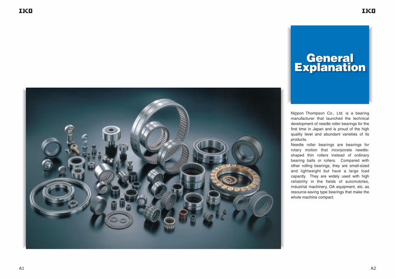
IKO Bearings can be roughly classified into radial bearings and thrust bearings according to applicable load direction. Radial Bearings are grouped into Shell Type Needle Roller Bearings, Machined Type Needle Roller Bearings, and various other types. Thrust Bearings are grouped into Thrust Needle Roller Bearings and Thrust Roller Bearings.Follower Bearings that are used for cam mechanisms and linear motion are grouped into Cam Followers and Roller Followers.
Crossed Roller Bearings are special shape bearings that can simultaneously receive loads in all directions with a single bearing.Bearings other than rolling bearings, such as self-aligning Spherical Bushings that can support radial loads and axial loads and PILLOBALLs and L-Balls that are used for link mechanisms, are also available.
Types and Features of BearingsR
adia
l Bea
rin
gs
Thru
stBe
arin
gsCo
mbi
ned T
ype
Bear
ings
High Rigidity Type Crossed Roller Bearings (V) CRBHV
CF…B, CFKR
CFES…B
CFE…B, CFKRE
CF…WB
CF-RU1, CF-FU1
CF-SFU…B
NUCF…B
CR, CR…B, CRH
NURT
Mounting Holed Type High Rigidity Crossed Roller Bearings (V) CRBFV
CRBC, CRB
Mounting Holed Type Super Slim Crossed Roller Bearings CRBTF
NAST, RNAST
NART, CRY
C-Lube Machined Type Needle Roller Bearings TAF… /SG
Classification of Bearings
Combined Type Needle Roller Bearings
Thrust Roller Bearings
Shell Type Needle Roller Bearings
Needle Roller Cages
Machined Type Needle Roller Bearings
Roller Bearings
Thrust Needle Roller Bearings
NAFW, RNAFW
with Three-point Contact Ball Bearing
with Angular Contact Ball Bearing
with Thrust Roller Bearing
with Thrust Ball Bearing
Roller Bearings for Sheaves
Needle Roller Bearings with Separable Cage
Needle Roller Cages for Engine Connecting Rods
Needle Roller Cages for General Usage
TA, TAM
TLA, TLAM
BA, BAM
BHA, BHAM
YT
YTL
YB
YBH
KT, KT…N
KTW
KT…EG
KTV…EG
NA, RNA
TAFI, TAF
TRI, TR
BRI, BR
GTRI, GTR
NAF, RNAF
NAU
NAG
TRU
NAS
NTB
AZK, AZ
NAXI, NAX
NBXI, NBX
NATA
NATB
IKO Bearings can be roughly classified into radial bearings and thrust bearings according to applicable load direction. Radial Bearings are grouped into Shell Type Needle Roller Bearings, Machined Type Needle Roller Bearings, and various other types. Thrust Bearings are grouped into Thrust Needle Roller Bearings and Thrust Roller Bearings.Follower Bearings that are used for cam mechanisms and linear motion are grouped into Cam Followers and Roller Followers.
Crossed Roller Bearings are special shape bearings that can simultaneously receive loads in all directions with a single bearing.Bearings other than rolling bearings, such as self-aligning Spherical Bushings that can support radial loads and axial loads and PILLOBALLs and L-Balls that are used for link mechanisms, are also available.
Types and Features of Bearings
Rad
ial B
eari
ng
sTh
rust
Bear
ings
Com
bine
d Typ
eBe
arin
gs
High Rigidity Type Crossed Roller Bearings (V) CRBHV
CF…B, CFKR
CFES…B
CFE…B, CFKRE
CF…WB
CF-RU1, CF-FU1
CF-SFU…B
NUCF…B
CR, CR…B, CRH
NURT
Mounting Holed Type High Rigidity Crossed Roller Bearings (V) CRBFV
CRBC, CRB
Mounting Holed Type Super Slim Crossed Roller Bearings CRBTF
NAST, RNAST
NART, CRY

A
B
C
D
E
F
G
H
I
J
K
L
M
A7 A8
Shell Type Needle Roller Bearings are lightweight with the lowest sectional height among needle roller bearings with outer ring, because they employ a shell type outer ring made from a thin special-steel plate which is accurately drawn, carburized and quenched.Since these bearings are press-fitted into the housing, no axial positioning fixtures are required. They are ideal for use in mass-produced articles that require economy.
Shell Type Needle Roller Bearings
Radial Bearings Page B1
Needle Roller Cages for General Usage are bearings that display excellent rotational performance. Their specially shaped cages with high rigidity and accuracy, precisely guide the needle rollers.Since needle rollers with extremely small dimensional variations in diameter are incorporated and retained, Needle Roller Cages for General Usage are useful in small spaces when combined with shafts and housing bores that are heat treated and accurately ground as raceway surfaces.
Radial Bearing Page C1
Machined Type Needle Roller Bearings have an outer ring made by machining, heat treatment, and grinding. The outer ring has stable high rigidity and can be easily used even for light alloy housings.These bearings are available in various types and optimally selectable for different conditions such as heavy loads, high-speed rotation and low-speed rotation. They are most suitable for general-purpose applications.
Radial Bearing Page D1
In Needle Roller Bearings with Separable Cage, the inner ring, outer ring and Needle Roller Cage are combined, and they can be separated easily. This type has a simple structure with high accuracy. In addition, the radial clearance can be freely selected by choosing an assembly combination.These bearings have excellent rotational performance, because Needle Roller Cages are used.
Radial Bearing Page D79
Roller Bearings, in which rollers are incorporated in double rows, are non-separable heavy-duty bearings.They can withstand not only radial loads but axial loads as well, which are supported at the contacts between the shoulders of inner and outer rings and the end faces of rollers. Therefore, they are most suitable for use at the fixing side of a shaft.
Radial Bearing Page E1
Needle Roller Gages for Engine Connecting Rods are used for motor cycles, small motor vehicles, outboard marines, snow mobiles, general-purpose engines, high- speed compressors, etc. that are operated under extremely severe and complex operating conditions such as heavy shock loads, high speeds, high temperatures, and stringent lubrication.Needle Roller Cages for Engine Connecting Rods are lightweight and have high load ratings and high rigidity as well as superior wear resistance.
Radial Bearing Page C17
Needle Roller Cages for General Usage
Needle Roller Cages for Engine Connecting Rods
Machined Type Needle Roller Bearings
Roller Bearings
Needle Roller Bearings with Separable Cage
A
B
C
D
E
F
G
H
I
J
K
L
M
A9 A10
Cam Followers
Inner Rings
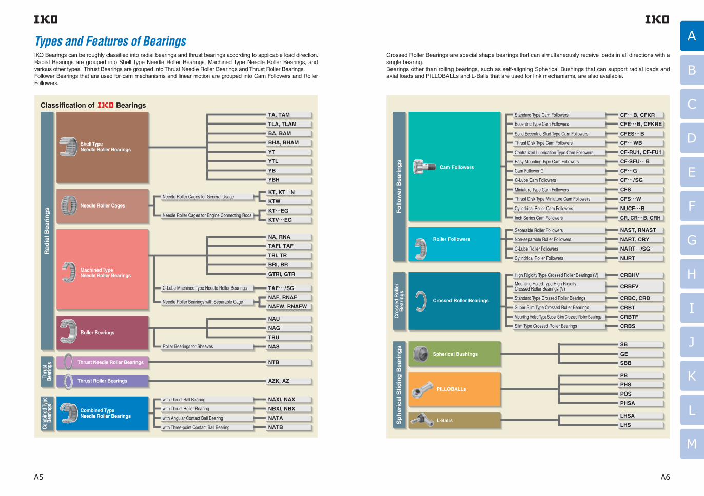
Thrust Bearings consist of a precisely made cage and rollers, and can receive axial loads. They have high rigidity and high load capacities and can be used in small spaces.Thrust Needle Roller Bearings use needle rollers, whileThrust Roller Bearings use cylindrical rollers.
Thrust Bearings
Thrust Bearing Page F1
Cam Followers are bearings with a stud incorporating needle rollers in a thick walled outer ring.They are designed for outer ring rotation, and the outer rings run directly on mating cam guide surfaces.Various types of Cam Followers are available. They are widely used as follower bearings for cam mechanisms and for linear motions.
Follower Bearing Page I1
Roller FollowersRoller Followers are bearings in which needle rollers are incorporated in a thick walled outer ring.These bearings are designed for outer ring rotation, and the outer rings run directly on mating cam guide surfaces.They are used as follower bearings for cam mechanisms and for linear motions.
Follower Bearing Page I77
Crossed Roller BearingsCrossed Roller Bearings are high-rigidity and compact bearings with their cylindrical rollers alternately crossed at right angles to each other between inner and outer rings. A single Crossed Roller Bearing can take loads from any directions at the same time such as radial, thrust, and moment loads.These bearings are widely used in the rotating parts of industrial robots, machine tools, medical equipment, etc. which require compactness, high rigidity and high rotational accuracy.
Crossed Roller Bearing Page J1
Combined Type Needle Roller Bearings are combinations of a radial bearing and a thrust bearing. Caged Needle Roller Bearings are used as radial bearings and Thrust Ball Bearings or Thrust Roller Bearings are used as thrust bearings.They can be subjected to radial loads and axial loads simultaneously.
Combined Type Needle Roller Bearings
Combined Type Bearing Page G1
Inner Rings are heat-treated and finished by grinding to a high degree of accuracy and are used for Needle Roller Bearings.In the case of Needle Roller Bearings, normally the shafts are heat-treated and finished by grinding and used as raceway surfaces. However, when it is impossible to make shaft surfaces according to the specified surface hardness or surface roughness, Inner Rings are used.
Component part Page H1
Cam Followers
Inner Rings
Thrust Bearings consist of a precisely made cage and rollers, and can receive axial loads. They have high rigidity and high load capacities and can be used in small spaces.Thrust Needle Roller Bearings use needle rollers, whileThrust Roller Bearings use cylindrical rollers.
Thrust Bearings
Thrust Bearing Page F1
Cam Followers are bearings with a stud incorporating needle rollers in a thick walled outer ring.They are designed for outer ring rotation, and the outer rings run directly on mating cam guide surfaces.Various types of Cam Followers are available. They are widely used as follower bearings for cam mechanisms and for linear motions.
Follower Bearing Page I1
Roller FollowersRoller Followers are bearings in which needle rollers are incorporated in a thick walled outer ring.These bearings are designed for outer ring rotation, and the outer rings run directly on mating cam guide surfaces.They are used as follower bearings for cam mechanisms and for linear motions.
Follower Bearing Page I77
Crossed Roller BearingsCrossed Roller Bearings are high-rigidity and compact bearings with their cylindrical rollers alternately crossed at right angles to each other between inner and outer rings. A single Crossed Roller Bearing can take loads from any directions at the same time such as radial, thrust, and moment loads.These bearings are widely used in the rotating parts of industrial robots, machine tools, medical equipment, etc. which require compactness, high rigidity and high rotational accuracy.
Crossed Roller Bearing Page J1
Combined Type Needle Roller Bearings are combinations of a radial bearing and a thrust bearing. Caged Needle Roller Bearings are used as radial bearings and Thrust Ball Bearings or Thrust Roller Bearings are used as thrust bearings.They can be subjected to radial loads and axial loads simultaneously.
Combined Type Needle Roller Bearings
Combined Type Bearing Page G1
Inner Rings are heat-treated and finished by grinding to a high degree of accuracy and are used for Needle Roller Bearings.In the case of Needle Roller Bearings, normally the shafts are heat-treated and finished by grinding and used as raceway surfaces. However, when it is impossible to make shaft surfaces according to the specified surface hardness or surface roughness, Inner Rings are used.
Component part Page H1

A11 A12
A
B
C
D
E
F
G
H
I
J
K
L
M
L-Balls
Seals for Needle Roller BearingsSpherical BushingsSpherical Bushings are self-aligning spherical plain bushings, which have inner and outer rings with spherical sliding surfaces. They can take a large radial load and a bi-directional axial load at the same time.They are divided into steel-on-steel types that are suitable for applications where there are alternate loads or shock loads, and maintenance-free types which require no lubrication.
Spherical Sliding Bearing Page K1
PILLOBALLsPILLOBALLs are compact self-aligning spherical plain bushings which can support a large radial load and a bi- directional axial load at the same time.PILLOBALL Rod Ends have either a female thread in the body or a male thread on the body, so they can be easily assembled onto machines.PILLOBALLs are used in control and link mechanisms in machine tools, textile machines, packaging machines, etc.
Spherical Sliding Bearing Page K29
L-Balls are self-aligning rod-ends consisting of a special zinc die-cast alloy body and a studded ball which has its axis at right-angles to the body.They can perform tilting movement and rotation with low torque, and transmit power smoothly due to the uniform clearance between the sliding surfaces.They are used in link mechanisms in automobiles, construction machinery, farm and packaging machines, etc.
Spherical Sliding Bearing Page K45
Seals for Needle Roller Bearings have a low sectional height and consist of a sheet metal ring and special synthetic rubber.As these seals are manufactured to the same sectional height as Needle Roller Bearings, grease leakage and the penetration of foreign particles can be effectively prevented by fitting them directly to the sides of combinable bearings.
Component Part Page L1
Cir-clips for Needle Roller BearingsCir-clips for Needle Roller Bearings have been specially designed for needle roller bearings on which, in many cases, generally available Cir-clips cannot be used. They have a low sectional height and are very rigid.There are Cir-clips for shafts and for bores, and they are used for positioning to prevent bearing movement in the axial direction.
Component Part Page L17
Needle RollersNeedle Rollers are used for needle roller bearings and are rigid and highly accurate.These needle rollers are widely used as rolling elements for bearings, and also as pins and shafts.
Component Part Page L23
A
B
C
D
E
F
G
H
I
J
K
L
M
A13 A14
F1~
G1~
I1~
I77~
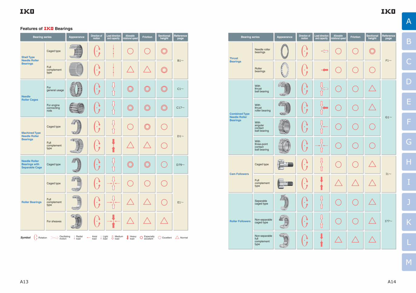
Bearing series Appearance Direction ofmotion
Load directionand capacity
Allowable rotational speed
Sectionalheight
ReferencepageFriction
Thrust Bearings
Combined Type Needle Roller Bearings
Cam Followers
Roller Followers
Needle roller bearings
Roller bearings
With thrust ball bearing
With thrust roller bearing
With angular contact ball bearing
With three-point contact ball bearing
Caged type
Full complement type
Separable caged type
Non-separable caged type
Non-separable full complement type
Bearing series Appearance Direction ofmotion
Load directionand capacity
Allowable rotational speed
Sectionalheight
ReferencepageFriction
Shell TypeNeedle RollerBearings
NeedleRoller Cages
Machined TypeNeedle RollerBearings
Needle RollerBearings withSeparable Cage
Roller Bearings
Caged type
Caged type
Caged type
Caged type
Fullcomplementtype
Fullcomplementtype
Fullcomplementtype
For sheaves
Forgeneral usage
For engineconnectingrods
B1~
C1~
C17~
D1~
D79~
E1~
Rotation Oscillating motion
Radial load
Axial load
Light load
Medium load
Heavy load
Especially excellent Excellent NormalSymbol
Features of Bearings
F1~
G1~
I1~
I77~
Bearing series Appearance Direction ofmotion
Load directionand capacity
Allowable rotational speed
Sectionalheight
ReferencepageFriction
Thrust Bearings
Combined Type Needle Roller Bearings
Cam Followers
Roller Followers
Needle roller bearings
Roller bearings
With thrust ball bearing
With thrust roller bearing
With angular contact ball bearing
With three-point contact ball bearing
Caged type
Full complement type
Separable caged type
Non-separable caged type
Non-separable full complement type
Bearing series Appearance Direction ofmotion
Load directionand capacity
Allowable rotational speed
Sectionalheight
ReferencepageFriction
Shell TypeNeedle RollerBearings
NeedleRoller Cages
Machined TypeNeedle RollerBearings
Needle RollerBearings withSeparable Cage
Roller Bearings
Caged type
Caged type
Caged type
Caged type
Fullcomplementtype
Fullcomplementtype
Fullcomplementtype
For sheaves
Forgeneral usage
For engineconnectingrods
B1~
C1~
C17~
D1~
D79~
E1~
Rotation Oscillating motion
Radial load
Axial load
Light load
Medium load
Heavy load
Especially excellent Excellent NormalSymbol
Features of Bearings

A
B
C
D
E
F
G
H
I
J
K
L
M
A15 A16
An example of procedure for bearing selection
J1~
K1~
K29~
K45~
● Identify the machine and place where the bearing is to be used.● Confirm the requirements for bearings such as required bearing performance, and also confirm the operating conditions and special environment conditions.
● Select the bearing type suitable for the operating conditions by considering load direction and magni- tude, rigidity, friction, allowable rotational speed, bearing space, etc.
See page
A5
● Select the bearing dimensions by calculating bearing load, life, static safety factor, etc.
1
2
3
4
5
6
7
8
9
Features of Bearings
Bearing series Appearance Direction ofmotion
Load directionand capacity
Allowable rotational speed
Sectionalheight
ReferencepageFriction
Crossed Roller Bearings
Spherical Bushings
PILLOBALLs
L-Balls
Caged type,Separator type
Full complement type
Slim type
Steel-on-steel type
Maintenance-free type
Maintenance-free type
Lubrication type
Insert type, Lubrication type
Die-casting type, Lubrication type
Rotation Oscillating motion
Radial load
Axial load
Light load
Medium load
Heavy load
Especially excellent Excellent NormalSymbol
IKO Bearings are available in many types and sizes. To obtain satisfactory bearing performance in machines and equipment, it is essential to select the most suitable bearing by carefully studying the requirements for the application.Although there is no particular procedure or rule for bearing selection, an example of a commonly adopted procedure is shown in the figure below.
Outline of Bearing Selection
Selection of bearing type
Selection of bearing dimensions
Selection of accuracy class, etc.
Selection of radial clearance and fit
Determination of bearing dimensions, accuracy, radial clearance and fit
Selection of lubrication and dust-proof methods
Design of surrounding part
Determination of final specifications of the bearing and the surrounding part
Confirmation of requirements and operating conditions
See page
A17
● Select the accuracy as required by the machine or equipment. See page
A30
● Select the radial clearance considering the fit, temperature, rotational speed, inclination of the inner and outer rings, etc.
See page
A37
● Select oil or grease lubrication.● After selection of lubricant, in case of oil lubrication, select the oil application method.● Select the sealing method according to the lubricant.
See page
A49
● Design the surrounding part based on how to mount or dismount and based on mounting dimensions. See page
A57

A
B
C
D
E
F
G
H
I
J
K
L
M
A17 A181N=0.102kgf=0.2248lbs.1mm=0.03937inch
Basic Dynamic Load Ratingand Life
CP( )
p
Operating conditions
Occasional or short term usage ・Power tools ・Agricultural machines
・Construction machinery ・Conveyors・Elevators
・Roll neck of rolling mills ・Small motors・Deck cranes・General cargo cranes・Passenger cars
・Factory motors・Machine tools・General gear units・Printing machines
・Crane sheaves・Compressors・Important gear units
Infrequent usage but requiring reliable operation
Intermittent operation but for comparatively long periods
・Escalators ・Centrifugal separators・Blowers・Wood working machines・Plastic extruding machines
・Paper making machinesOperated in excess of 8 hours per day or continuously for an extended time
・Water supply equipment・Power station equipment
Continuous use for 24 hours and accidental stops not allowed
Machine and life factor fh
〜 3 2〜 4 3〜 5 4〜 7 6〜
Basic rating life
The basic rating life is defined as the total number of revolutions that 90% of a group of identical bearings can be operated individually under the same condi-tions free from any material damage caused by rolling fatigue.For rotation at a constant rotational speed, the basic rating life can be represented by the total service hours.
Basic dynamic load rating
The basic dynamic load rating is defined as the con-stant radial load (in the case of radial bearings) or the constant axial load acting along the bearing central axis (in the case of thrust bearings) that allows a basic rating life of 1,000,000 revolutions.
Calculation of rating life
The relationship among the basic rating life, basic dynamic load rating and dynamic equivalent load (bearing load) of rolling bearings is as follows:
L10
= ……………………………………(1)
where, L10 :Basic rating life, 106 rev. C :Basic dynamic load rating, N P :Dynamic equivalent load, N p : Exponent, Roller bearing: 10/3
Ball bearing: 3Accordingly, when the rotational speed per minute is given, the basic rating life is represented as the total service hours according to the following equations:
Lh = = 500 f h ……………………(2)
f h= f n …………………………………(3)
f n = …………………………………(4)
where, Lh :Basic rating life represented by
service hours, h n :Rotational speed, min-1
f h :Life factor
f n :Velocity factorIn addition, the rating life can be calculated by obtain-
ing f h and f n from the life calculation scales of Fig. 2.
Life
Rolling bearings will suffer damage due to various causes during service. Damage such as abnormal wear, seizure, and cracks is caused by improper use, including incorrect mounting, lack of oil, dust intrusion and so on, and can be avoided by remedying these causes. However, bearings will eventually be dam-aged due to fatigue-flaking even if used properly. When a bearing rotates under load, the raceways and the rolling elements are subjected to repeated stress-es concentrated on the part close to the surface. Fatigue, therefore, occurs in the surface layer, pro-ducing damage in the form of scaling. This is called flaking (spalling). When this occurs, the bearing can no longer be used.
Bearing Life
Bearing life is defined as the total number of revolu-tions (or total service hours at a constant rotational speed) before a sign of the first flaking appears on the roll ing surface of raceway or roll ing elements. However, even when bearings of the same size, structure, material and heat treatment are subjected to the same conditions, the bearing lives will show variation (See Fig. 1.). This results from the statistical nature of the fatigue phenomenon.In selecting a bearing, it is incorrect to take an aver-age life for all bearings as the design standard. It is more practical to consider a bearing life that is reliable for the greater propor t ion of bear ings used. Therefore, the basic rating life defined in the following is used.
106L1060n
CP
p
33.3n( )
1/p
Bearing life factors for various machines
The required life of the bearing must be determined according to the machine in which the bearing is to be used and the operating conditions.Table 1 shows reference values of life factors for selecting a bearing for each machine.
Table 1 Life factor of bearings f h for various machines
Fig. 2 Scales for rating life calculation
Rotational speed
Velocity factor
Basic rating life represented by service hours
Life factor
Rotational speed
Velocity factor
Basic rating life represented by service hours
Life factor
Roller bearings10
200 1000 10000 80000
100 1000 10000
1.44
0.76 1.0 2.0 3.0 4.0 4.6
1.0 0.20
15 20
300 400 500 600 700 800 900 2000 3000 4000 6000 8000 20000 40000 60000
30 40 60 80 150 200 300 400 600 800 1500 2000 3000 4000 6000 8000 15000 20000 30000 40000 60000
1.4 1.3
0.80 0.85 0.90 0.95 1.1 1.2 1.3 1.4 1.5 1.6 1.7 1.8 1.9 2.5 3.5 4.5
1.2 1.1 0.9 0.8 0.7 0.6 0.5 0.4 0.3 0.28 0.24 0.22 0.18 0.16 0.14 0.12 0.106
min-1
nfn
hLhfh
10
200 1000 10000 80000
100 1000 10000
1.49
0.74 1.0 2.0 3.0 4.0 5.0 5.4
1.0 0.20 0.10
15 20
300 400 500 600 700 800 900 2000 3000 4000 6000 8000 20000 4000030000 60000
30 40 60 80 150 200 300 400 600 800 1500 2000 3000 4000 6000 8000 15000 20000 30000 40000 60000
1.4 1.3
0.80 0.90 1.1 1.2 1.3 1.4 1.5 1.6 1.7 1.8 1.9 2.5 3.5 4.5
1.2 1.1 0.9 0.8 0.7 0.6 0.5 0.4 0.3 0.28 0.24 0.22 0.18 0.16 0.14 0.12 0.09 0.082
min-1
nfn
hLhfh
Ball bearings
Fig. 1 Variation of rolling fatigue life
Failu
re p
roba
bility
den
sity
(Fre
quen
cy o
f fai
lure
)
Bas
ic r
atin
g lif
e
Ave
rage
life
Rolling fatigue life

A
B
C
D
E
F
G
H
I
J
K
L
M
A19 A201N=0.102kgf=0.2248lbs.1mm=0.03937inch
Life of oscillating bearing
The life of an oscillating bearing can be obtained from equation (5).
LOC=
………………………………(5)
where, LOC: Basic rat ing l i fe of osci l lat ing
bearing, 106 cycles 2θ: Oscillating angle, deg. (See Fig.3)
P : Dynamic equivalent load, NTherefore, when the oscillating frequency n 1min-1 is given, the basic rating life as represented by total
oscillating hours can be obtained by substituting n 1 for n in equation (2) on page A17.When 2θ is small, an oil film cannot be formed easily between the contact surfaces of the raceway and the rolling elements. This may cause fretting corrosion. In this case, please consult IKO.
2θ
Fig. 3 Oscillating motion
Corrected rating life
When a rolling bearing is used in ordinary applica-tions, the basic rating life can be calculated by equa-tions (1) and (2) mentioned previously.This basic rating life applies to bearings which require a reliability of 90%, have ordinary bearing properties being made of materials of ordinary quality for rolling bearings, and are used under ordinary operating con-ditions.In some applications, however, it is necessary to obtain a rating life that applies to bearings which require high reliability, have special bearing properties or are used under special operating conditions. The corrected rating life for these special cases can be obtained from the following equation by using the
bearing life adjustment factors a1, a2 and a3, respec-tively.
Lna= a1a2a3L10 …………………………… (6)
where, Lna:Corrected rating life, 106 rev. a1 : Life adjustment factor for reliability
a2 : Life adjustment factor for special bearing properties
a3 : Life adjustment factor for operat-ing conditions
Life adjustment factor for reliability a1
The reliability of rolling bearings is defined as the pro-portion of bearings having a life equal to or greater than a certain specified value when a group of identi-cal bearings are operated under identical conditions. With respect to individual bearings, it refers to the probability of the life of a bearing being equal to or greater than a certain specified value.
The corrected rating life for a reliability of (100-n)% can be obtained using equation (6). Table 2 shows
the values of the life adjustment factor a1 for various reliabilities.
Table 2 Life adjustment factor for reliability a1
909596979899
L10L5L4L3L2L1
10.620.530.440.330.21
Reliability % Ln a1
Life adjustment factor for special bearing properties a2
The bearing life is extended or shortened according to the quality of the material, the manufacturing technol-ogy of the bearing and its internal design. For these special bearing life properties, the life is corrected by the life adjustment factor for special bearing proper-
ties a2.The table of dimensions for IKO Bearings shows the values of the basic dynamic load rating which are determined taking into consideration the fact that bearing life has been extended by improved quality of materials and advances in manufacturing technolo-gies. Therefore, the bearing life is calculated using
equation (6) usually assuming a2 = 1.
Life adjustment factor for operating conditions a3
This factor helps take into account the effects of oper-ating conditions, especially lubrication on the bearing.The bearing life is limited by the phenomenon of fatigue which occurs, in general, beneath surfaces subjected to repeated stresses. Under good lubrica-tion conditions where the rolling element and raceway surfaces are completely separated by an oil film and
surface damage can be disregarded, a3 is set to be 1. However, when conditions of lubrication are not good, namely, when the viscosity of the lubricating oil is low or the peripheral speed of the rolling elements is
especially low, and so on, a3< 1 is used.On the other hand, when lubrication is especially
good, a value of a3 > 1 can be used. When lubrica-tion is not good and a3 < 1 is used, the life adjustment factor a2 cannot generally exceed 1.
When selecting a bearing according to the basic dynamic load rating, it is recommended that a suitable
value for reliability factor a1 is chosen for each appli-cation. The selection should be made using the
(C/P) or fh values determined by machine type and based upon the actual conditions of lubrication, tem-perature, mounting, etc., which have already been experienced and observed in the same type of machines.
Limiting conditions
These bearing life equations are applicable only when the bearing is mounted and lubricated normally with-out intrusion of foreign materials and not used under extreme operating conditions.Unless these conditions are satisfied, the life may be shortened. For example, it is necessary to separately consider the effects of bearing mounting errors, excessive deformation of housing and shaft, centrifu-gal force acting on rolling elements at high-speed rev-olution, excessive preload, especially large radial internal clearance of radial bearings, etc.When the dynamic equivalent load exceeds 1/2 of the basic dynamic load rating, the life equations may not be applicable.
CP( )
p90θ
Correction of basic dynamic load rating for temperature and hardness
Temperature factor
The operating temperature for each bearing is deter-mined according to its material and structure. If spe-cial heat treatment is performed, bearings can be used at temperatures higher than +150°C. As the allowable contact stress gradually decreases when the bearing temperature exceeds 150°C, the basic dynamic load rating is lowered and can be obtained by the following equation:
C t = f t C …………………………………… (7)
where, C t : Basic dynamic load rating
considering temperature rise, N f t : Temperature factor (See Fig. 4.)
C : Basic dynamic load rating, N
Temperature
°C 150 200 250
0.750.80.850.90.951.0ft
Fig. 4 Temperature factor
Further, if the bearing is used at high temperature, i.e. 120°C or above, the amount of dimensional displace-ment gets larger. So special heat treatment is neces-sary. If needed, please contact IKO.
Hardness factor
When the shaft or housing is used as the raceway surface instead of the inner or outer ring, the surface hardness of the part used as the raceway surface should be 58〜 64HRC.If it is less than 58HRC, the basic dynamic load rating is lowered and can be obtained by the following equation:
CH = f H C…………………………………… (8)
where, CH : Basic dynamic load rating
considering hardness, N fH : Hardness factor (See Fig. 5.)
C : Basic dynamic load rating N
Hardness of raceway surface
HRC 60 50 40 30 20
0.10.20.41 0.8 0.6fH
Fig. 5 Hardness factor
A21 A221N=0.102kgf=0.2248lbs.1mm=0.03937inch
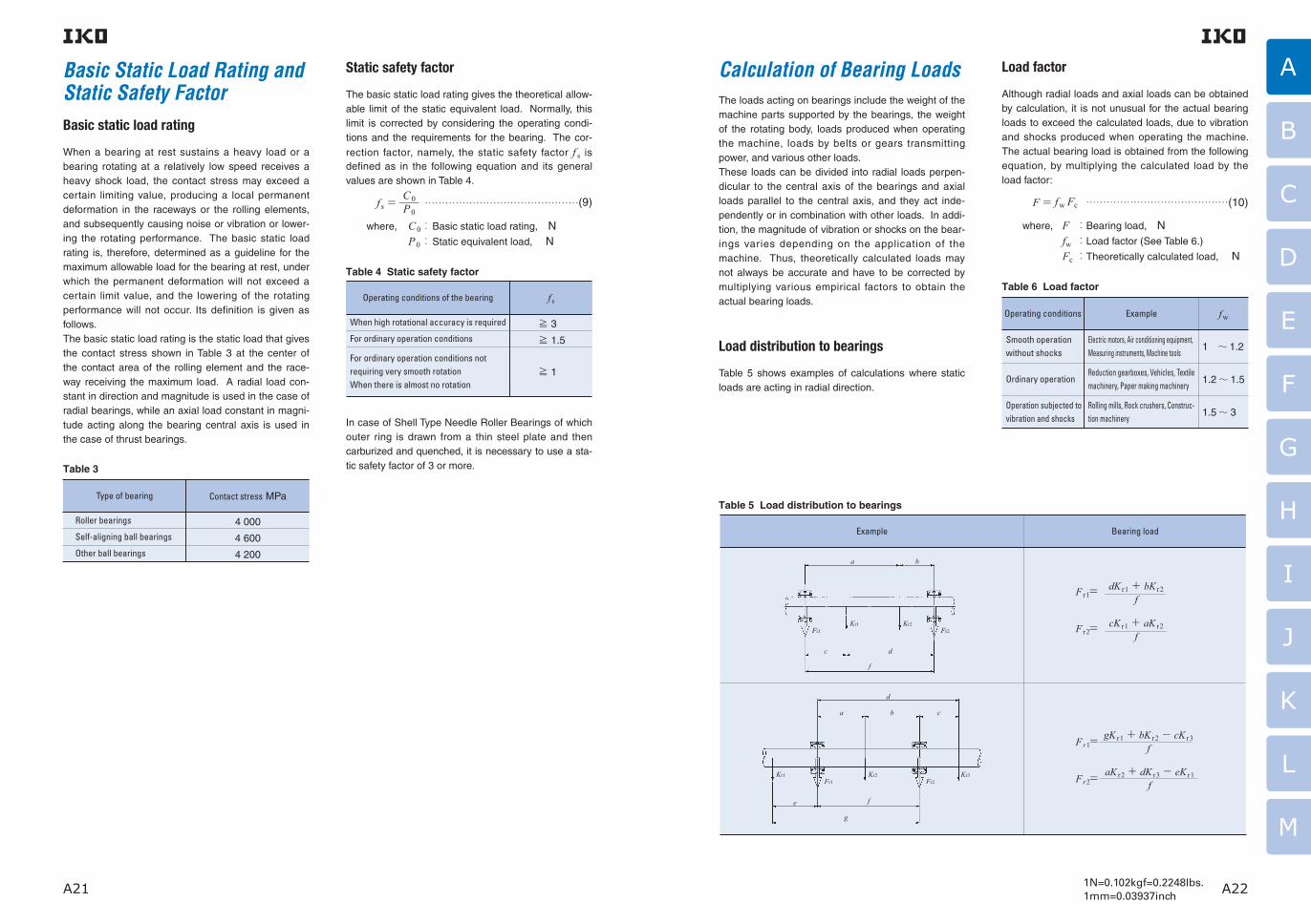
The loads acting on bearings include the weight of the machine parts supported by the bearings, the weight of the rotating body, loads produced when operating the machine, loads by belts or gears transmitting power, and various other loads.These loads can be divided into radial loads perpen-dicular to the central axis of the bearings and axial loads parallel to the central axis, and they act inde-pendently or in combination with other loads. In addi-tion, the magnitude of vibration or shocks on the bear-ings varies depending on the application of the machine. Thus, theoretically calculated loads may not always be accurate and have to be corrected by multiplying various empirical factors to obtain the actual bearing loads.
Load distribution to bearings
Table 5 shows examples of calculations where static loads are acting in radial direction.
Load factor
Although radial loads and axial loads can be obtained by calculation, it is not unusual for the actual bearing loads to exceed the calculated loads, due to vibration and shocks produced when operating the machine. The actual bearing load is obtained from the following equation, by multiplying the calculated load by the load factor:
F= fw Fc ……………………………………(10)
where, F :Bearing load, N fw :Load factor (See Table 6.)
Fc :Theoretically calculated load, N
Table 6 Load factor
Smooth operation without shocks
Electric motors, Air conditioning equipment, Measuring instruments, Machine tools
Reduction gearboxes, Vehicles, Textile machinery, Paper making machinery
Rolling mills, Rock crushers, Construc-tion machinery
Ordinary operation
Operation subjected to vibration and shocks
1 〜 1.2
1.2〜 1.5
1.5〜 3
Operating conditions Example fw
Basic Static Load Rating andStatic Safety Factor
Calculation of Bearing Loads
Basic static load rating
When a bearing at rest sustains a heavy load or a bearing rotating at a relatively low speed receives a heavy shock load, the contact stress may exceed a certain limiting value, producing a local permanent deformation in the raceways or the rolling elements, and subsequently causing noise or vibration or lower-ing the rotating performance. The basic static load rating is, therefore, determined as a guideline for the maximum allowable load for the bearing at rest, under which the permanent deformation will not exceed a certain limit value, and the lowering of the rotating performance will not occur. Its definition is given as follows.The basic static load rating is the static load that gives the contact stress shown in Table 3 at the center of the contact area of the rolling element and the race-way receiving the maximum load. A radial load con-stant in direction and magnitude is used in the case of radial bearings, while an axial load constant in magni-tude acting along the bearing central axis is used in the case of thrust bearings.
Table 3
Roller bearings
Self-aligning ball bearings
Other ball bearings
4 000
4 600
4 200
Type of bearing Contact stress MPa
Static safety factor
The basic static load rating gives the theoretical allow-able limit of the static equivalent load. Normally, this limit is corrected by considering the operating condi-tions and the requirements for the bearing. The cor-
rection factor, namely, the static safety factor f s is defined as in the following equation and its general values are shown in Table 4.
f s= ………………………………………(9)
where, C0 : Basic static load rating, N P0 : Static equivalent load, N
Table 4 Static safety factor
When high rotational accuracy is required
For ordinary operation conditions
For ordinary operation conditions not requiring very smooth rotation When there is almost no rotation
≧ 3
≧ 1.5
≧ 1
Operating conditions of the bearing f s
In case of Shell Type Needle Roller Bearings of which outer ring is drawn from a thin steel plate and then carburized and quenched, it is necessary to use a sta-tic safety factor of 3 or more.
C0P0
Table 5 Load distribution to bearings
F r1=dK r1+ bK r2
f
Fr1=
Fr2=
gK r1+ bK r2− cK r3f
aK r2+ dK r3− eK r1f
F r2=cK r1+ aK r2
f
Example Bearing load
a b
c d
f
Fr1Kr1 Kr2
Fr2
d
a b c
e f
g
Kr1 Kr2 Kr3Fr1 Fr2
A
B
C
D
E
F
G
H
I
J
K
L
M

A23 A241N=0.102kgf=0.2248lbs.1mm=0.03937inch
Bearing loads in case of belt or chain transmission
When power is transmitted by a belt or chain, the load acting on the pulley or sprocket wheel is obtained from the following equations:
T=9550000 ……………………………(11)
K t= ……………………………………(12)
where, T : Torque acting on pulley or sprocket
wheel, N-mm K t :Effective transmitting force of belt or chain, N H :Transmitting power, kW n :Rotational speed, min-1
R : Ef fec t i ve rad ius o f pu l l ey o r
sprocket wheel, mm
For belt transmission, the load K r acting on the pulley shaft is obtained from the following equation, multiply-
ing the effective transmitting force K t by the belt factor fb shown in Table 7.
K r = fb K t ………………………………………(13)
Table 7 Belt factor
V-belts
Timing belts
Plain belts (with tension pulley)
Plain belts
2 〜 2.5
1.3〜 2
2.5〜 3
4 〜 5
Type of belt fb
In the case of chain transmission, a value of 1.2 to 1.5
is taken as the chain factor corresponding to fb. The
load acting on the sprocket wheel shaft is obtained from equation (13) in the same manner as the belt transmission.
Bearing loads in case of gear transmission
When power is transmitted by gears, the force acting on the gears varies according to the type of gear. Spur gears produce radial loads only, but helical gears, bevel gears and worm gears produce axial loads in addition to radial loads. Taking the simplest case of spur gears as an example, the bearing load is obtained from the following equations:
T=9550000 ……………………………(14)
K t= ……………………………………(15)
K s=K t tan θ ………………………………(16)
K c= K t +K s =K t sec θ …………………(17)
where, T:Torque applied to gear, N-mm K t:Tangential force acting on gear, N Ks:Radial force acting on gear, N K c:Resultant normal force on gear tooth surface, N H:Transmitting power, kW n :Rotational speed, min-1
R:Pitch circle radius of drive gear, mm θ:Pressure angle of gear, deg.
Kt
Ks R
Fig. 6
In this case, the resultant normal force on the tooth surface acts as the radial force to the shaft and the magnitude of vibration or shocks varies depending on the accuracy and sur face f in ish of the gear. Therefore, the radial load K r applied to the shaft is obtained from the following equation, multiplying the
resultant normal force Kc on gear tooth surface by the gear factor fz shown in Table 8.
K r= f z K c ……………………………………(18)
Table 8 Gear factor
Precision gears (Pitch error and form error: Less than 0.02mm)
1.05〜 1.1
Ordinary machined gears(Pitch error and form error: 0.02 〜 0.1mm)
1.1 〜 1.3
Type of gear f z
Hn
TR
Hn
TR
2 2√
Mean equivalent load corresponding to fluctuating load
When the load applied to the bearing fluctuates, the bearing life is calculated by using the mean equivalent
load Fm, which is a constant load that will give the bearing a life equal to that produced under the fluctu-ating load. The mean equivalent load is obtained from the following equation:
……………………(19)
where, Fm:Mean equivalent load, N N :Total number of revolutions, rev. Fn:Fluctuating load, N p : Exponent, Roller bearing = 10/3 Ball bearing = 3
Table 9 shows examples of the calculation of mean equivalent loads for various fluctuating loads.
Fm= ∫ Fn dN1N
N
0
pp
Table 9 Mean equivalent load for the fluctuation load
p
Type of fluctuating load Mean equivalent load Fm
Step load
Monotonously changing load
Sinusoidally fluctuating load
Stationary load plus rotating load
where, N1:Total number of revolutions under load F1 rev. N2:Total number of revolutions under load F2 rev. Nn:Total number of revolutions under load Fn rev.
where, Fmax:Maximum value of fluctuating load, N Fmin :Minimum value of fluctuating load, N
Fm ≒ 0.65Fmax
Fm ≒ 0.75Fmax
where, FS:Stationary load, N FR:Rotating load, N
Fm = (F1 N1 + F2 N2 +…+ Fn Nn)1N
p p pp
Fm = (2Fmax + Fmin )13
Fm =FS + FR − FS FR
FS+ FR
F1
F2
N1 N2
NNn
Fm
Fn
F
F
Fmin
Fmax
Fm
N
Fmax
Fm
N
F
FmaxFm
N
F
Fs
FR
A
B
C
D
E
F
G
H
I
J
K
L
M

A25 A261N=0.102kgf=0.2248lbs.1mm=0.03937inch
Boundary Dimensions and Identification Number
Equivalent load
The loads applied to the bearing are divided into radi-al loads that are applied perpendicular to the central axis and axial loads that are applied in parallel to the central axis. These loads act independently or in com-bination with other loads.
Dynamic equivalent load
When both radial load and axial load are applied to the bearing simultaneously, the virtual load, acting on the center of the bearing, that will give a life equal to that under the radial load and the axial load is defined as a dynamic equivalent load.In the case of needle roller bearings, radial bearings receive only radial loads and thrust bearings receive only axial loads. Accordingly, radial loads are directly used in the life calculation of the radial bearings, while axial loads are directly used for the thrust bearings.
[For radial bearings]
P r =F r ………………………………………(20)[For thrust bearings]
P a=F a ………………………………………(21)
where, P r:Dynamic equivalent radial load, N Pa:Dynamic equivalent axial load, N F r:Radial load, N F a:Axial load, N
Static equivalent load
When both radial load and axial load are applied to the bearing simultaneously, the virtual load, acting on the center of the bearing, that will produce a maxi-mum contact stress on the contact surface between the rolling element and the raceway equal to that given by the radial load and the axial load is defined as a static equivalent load. In the case of needle roller bearings, radial bearings receive only radial loads and thrust bearings receive only axial loads. Accordingly, radial loads are directly used for the radial bearings, while axial loads are directly used for the thrust bearings.
[For radial bearings]
P0r =F r………………………………………(22)[For thrust bearings]
P0a=Fa ………………………………………(23)
where, P0r:Static equivalent radial load, N P0a:Static equivalent axial load, N F r :Radial load, N F a :Axial load, N
Boundary dimensions
Examples of symbols for quantities indicating the boundary dimensions of IKO Needle Roller Bearings are shown below. For details, see the table of dimen-sions for each model.
Machined Type Needle Roller Bearing
d : Nominal bearing bore diameter
D : Nominal bearing outside diameter
B : Nominal inner ring width
C : Nominal outer ring width
Fw : Nominal roller set bore diameter
r : Chamfer dimensions of inner and outer rings
r s min : Smal lest permissible s ingle chamfer dimensions of inner and outer rings
BC
D d
r
r
r
r
Fw
Fig. 7 Machined Type Needle Roller Bearing
Shell Type Needle Roller Bearing
D :Nominal bearing outside diameter
Fw:Nominal roller set bore diameter
C :Nominal outer ring width
C
D Fw
Fig. 8 Shell Type Needle Roller Bearing
Needle Roller Cage
Ew:Nominal roller set outside diameter
Fw:Nominal roller set bore diameter
B c:Nominal cage width
Bc
Ew Fw
Fig. 9 Needle Roller Cage
Thrust Roller Bearing
D c:Nominal cage outside diameter
d c:Nominal cage bore diameter
Dw:Nominal roller diameter
Dw
Dc
dc
Fig. 10 Thrust Roller Bearing
A
B
C
D
E
F
G
H
I
J
K
L
M

A27 A281N=0.102kgf=0.2248lbs.1mm=0.03937inch
Note(1) The nominal dimensions of inch series bearings are indicated in units of 1/16 inch.
Model code
Shell Type Needle Roller Bearings
Needle Roller Cages for General Usage
Needle Roller Cages for Engine Connecting Rods
Machined Type Needle Roller Bearings
Needle Roller Bearings with Separable Cage
Roller Bearings
Thrust Bearings
Combined Type Needle Roller Bearings
Cam Followers
Roller Followers
Crossed Roller Bearings
Spherical Bushings
PILLOBALLs
L-Balls
Seals for Needle Roller Bearings
Cir-clips for Needle Roller Bearings
Roller set bore diameter + Outer ring width
Roller set bore diameter + Outer ring width (1)
Roller set bore diameter + Roller set outside diameter + Cage width
Roller set bore diameter + Roller set outside diameter + Cage width
Dimension series + Bore diameter number
Roller set bore diameter + Bearing outside diameter + Bearing width
Bearing bore diameter + Bearing outside diameter + Outer ring width
Roller set bore diameter + Bearing outside diameter + Bearing width (1)
Bearing bore diameter + Bearing outside diameter + Outer ring width (1)
Roller set bore diameter + Bearing outside diameter + Bearing width
Bearing bore diameter + Bearing outside diameter + Bearing width
Dimension series + Bore diameter number
Bearing bore diameter + Bearing outside diameter + Bearing width
Bearing bore diameter + Bearing outside diameter
Bearing bore diameter + Bearing outside diameter + Bearing height
Bearing bore diameter + Bearing outside diameter + Roller diameter
Roller set bore diameter + Assembled bearing width
Inner ring bore diameter + Assembled bearing width
Dimensional series + Bore diameter number
Stud diameter
Bearing outside diameter
Bearing outside diameter (1)
Bearing bore diameter
Bearing outside diameter (1)
Bearing bore diameter + Bearing width
Inner ring bore diameter
Inner ring bore diameter (1)
Inner ring bore diameter
Screw size
Shaft diameter + Seal outside diameter + Seal width
Shaft diameter
Bore diameter
Bearing typeModel number
Indication of boundary dimensions
8 Classification symbol
(None)
P6
P5
P4
JIS Class 0
JIS Class 6
JIS Class 5
JIS Class 4
Symbol Descriptions
Table 11 Indication of boundary dimensions
Identification Number
The identification number of IKO Bearings consists of a model number and supplemental codes. The descriptions of typical codes and their arrangements are shown below. There are many codes other than those described. See the section of identification number of each bearing.
Table 10 Arrangement of identification number of bearing
1
2
3
4
5
6
7
8
Model code
Boundary dimensions
Material symbol
Cage symbol
Shield symbol Seal symbol,
Bearing ring shape symbol
Clearance symbol
Classification symbol
Model number
Supplemental code
Model codeThe model code represents the bearing series. The features of each bearing series are shown on pages A5 to A15.
Boundary dimensionsOne of the following four kinds of presentation meth-ods is used for showing boundary dimensions in the identification number, which vary depending on the bearing series. Table 11 shows the presentation methods of boundary dimensions for each model code.
(a)Dimension series + Bore diameter number
(b) Bore diameter or roller set bore diameter + Outside diameter or roller set outside diameter +
Width
(c)Bore diameter or roller set bore diameter + Width
(d)Basic diameter
Material symbol
F Stainless steel for bearing rings and rolling elements
Symbol Type of material
Cage symbol
N
V
Made of synthetic resin
No cage or full complement
Symbol Descriptions
Seal or shield symbol
Z
ZZ
U
UU
2RS
With dust cover
With shields on both sides
With a seal on one side
With seals on both sides
With seals on both sides
Symbol Descriptions
Bearing ring shape symbol
NR
OH (1)
J
With stop ring on outer surface of outer ring
With oil hole in bearing ring
No oil hole
Symbol Descriptions
Note(1) �This differs depending on the type of bearing. See the section of each bearing.
Clearance symbol
C2
(None)
C3
C4
C5
T1
C1
C2
C2 clearance
CN clearance
C3 clearance
C4 clearance
C5 clearance
Special radial clearance(Applicable to Crossed Roller Bearings)
Symbol Descriptions
1
2
3
4
5
6
7
TA,TLA,YT,YTL
BA,BHA,YB,YBH
KT,KTW
KT…EG,KTV…EG
NA,RNA
TR,TAF,GTR
TRI,TAFI,GTRI
BR
BRI
RNAF,RNAFW
NAF,NAFW
NAU,NAG,NAS
TRU
NTB,AS,WS,GS
AZ
AZK
NAX,NBX
NAXI,NBXI
NATA,NATB
CF…B,CFS,NUCF…B
CFKR
CR…B,CR,CRH…B
NAST,NART,NURT
CRY
CRBHV,CRBFV,CRBC,CRB,CRBT,CRBTF,CRBS
SB…A,GE
SBB
PB,PHS,POS,PHSB,POSB,PHSA
LHSA,LHS
OS,DS
WR
AR
A
B
C
D
E
F
G
H
I
J
K
L
M

A29 A30
A
B
C
D
E
F
G
H
I
J
K
L
M
Model number
NA 02 C2 P649
Example of identification number
Bore diameter number
Dimension series
Model code
Clearance symbol
Classification symbol
(a) Example of "Dimension series + Bore diameter number"
Model number
NAX 30 Z20
Roller set bore diameter
Model code
Assembled bearing width
Shield symbol
(c) Example of "Bore diameter or roller set bore diameter + width"
Model number
CF V UU10 B
Cage symbol
Shape of stud head
Basic diameter (Stud diameter)
Model code
Seal symbol
Model number
KT 8 N5 8
Roller set outside diameter
Roller set bore diameter
Model code
Cage symbol
Cage width
(b) Example of "Bore diameter or roller set bore diameter + Outside diameter or roller set outside diameter + width"
(d) Example of "Basic diameter"
Supplementalcode
Supplementalcode
Supplementalcode
Supplementalcode
AccuracyThe accuracy of IKO Needle Roller Bearings con-
forms to JIS B 1514-1~-3 (Rolling bearings - Tolerances of bearings), and the dimensional accura-cy and rotational accuracy are specified. The speci-fied items are shown in Fig. 11.Needle Roller Bearings are classified into 4 classes of accuracy. These classes are represented by the numbers 0, 6, 5 and 4, written in order of increasing accuracy.Table 12 shows the accuracy for the inner rings of radial bearings, Table 13 shows the accuracy for the outer rings of radial bearings, Table 14 shows the tol-erances for the smallest single roller set bore diame-ter of radial bearings, and Table 15 shows the permis-sible limit values of chamfer dimensions of radial bearings. For thrust bearings, see the section on accuracy of Thrust Bearings. Note that the series of Shell Type Needle Roller Bearings, Roller Bearings, Cam Followers, Roller Followers, Combined Type Needle Roller Bearings, and Crossed Roller Bearings have special accuracy. For further details, see the section on accuracy of each bearing series.
RemarksThe meanings of the new symbols for quantities
used for accuracy of radial bearings are as
follows:
①∆ represents the deviation of a dimension from the specified value.
② V represents the variation of a dimension.
③ Suffixes s, m, and p represent a single (or
actual) measurement, a mean measurement,
and a measurement in a single radial plane,
respectively.
[Example] Vdp means the difference between
the largest and the smallest of the bore
diameters in a single radial plane (circularity).
Vdmp means the difference between the largest
and the smallest of the single plane mean bore
diameters (cylindricity).
Deviation of boundary dimensions
Accuracy of boundary dimensions
Rotationalaccuracy
Accuracy of bearings
Variation of boundary dimensions
Fig. 11 Accuracy of bearings
Single bore diameter deviation ∆ ds
Single plane mean bore diameter deviation ∆ dmp
Single outside diameter deviation ∆Ds
Single plane mean outside diameter deviation ∆Dmp
Deviation of a single inner ring width ∆Bs
Deviation of a single outer ring width ∆Cs
Bore diameter variation in a single radial plane Vdsp
Mean bore diameter variation Vdmp
Outside diameter variation in a single radial plane VDsp
Mean outside diameter variation VDmp
Inner ring width variation VBs
Outer ring width variation VCs
Radial runout of assembled bearing inner ring Kia
Assembled bearing inner ring face runout with raceway Sia
Inner ring reference face runout with bore Sd
Radial runout of assembled bearing outer ring Kea
Assembled bearing outer ring face runout with raceway Sea
Variation of outside surface generatrix inclination with outer ring reference face SD

A31 A321N=0.102kgf=0.2248lbs.1mm=0.03937inch
A
B
C
D
E
F
G
H
I
J
K
L
M
Table 12 Tolerances for inner ring
dNominal bearing
bore diameter
mm
∆ dmpSingle plane mean bore diameter deviation
∆ dsSingle bore
diameter deviation
VdspBore diameter variation in a single radial plane
VdmpMean bore diameter
variation
Diameter series 8, 9(1) Diameter series 0(2)
Over Incl. High HighLow High High High
Class 0 Class 6 Class 5 Class 4 Class 4 Class4
Class5
Class6
Class0
Class0
Class0
Class6
Class6
Class5
Class5
Class4
Class4
Low Low Low Low Max. Max. Max.
2.5 10 18
30 50 80
120 180 250
315 400 500
630 8001000
12501600
101830
5080
120
180250315
400 500 630
80010001250
16002000
000
000
000
000
000
00
000
000
000
000
- 7- 7- 8
- 10- 12- 15
- 18- 22- 25
- 30- 35- 40
- 5- 5- 6
- 8- 9- 10
- 13- 15- 18
- 23
- 4- 4- 5
- 6- 7- 8
- 10- 12
- 4- 4- 5
- 6- 7- 8
- 10- 12
000
000
000
0
000
000
00
000
000
00
101013
151925
313844
505663
9 910
131519
232831
384450
5 5 6
8 910
131518
23
4 4 5
6 7 8
1012
8 810
121925
313844
505663
7 7 8
101519
232831
384450
4 4 5
6 7 8
101214
18
334
556
89
6 6 8
91115
192326
303438
5 5 6
8 911
141719
232630
3 3 3
4 5 5
7 8 9
12
222.5
33.54
56
- 8- 8- 10
- 12- 15- 20
- 25- 30- 35
- 40- 45- 50
- 75- 100- 125
- 160- 200
Note(1) Applicable to all series except NAS series(2) Applicable to NAS series(3) Applicable to NATA and NATB series
dNominal bearing
bore diameter
mm
∆ BsDeviation of a single inner ring width
SdInner ring
reference face runout with bore
S ia(3)Assembled bearing
inner ring face runout with raceway
VBsInner ring width variation
Over Incl.High Low High High High
Class 0 Class 6 Class 5 Class 4Class
5Class
4Class
5Class
4Class
0Class
6Class
5Class
4Low Low LowMax. Max. Max.
2.5 10 18
30 50 80
120 180 250
315 400 500
630 8001000
12501600
101830
5080
120
180250315
400 500 630
80010001250
16002000
000
000
000
000
000
00
000
000
000
000
- 120- 120- 120
- 120- 150- 200
- 250- 300- 350
- 400- 450- 500
- 40- 80- 120
- 120- 150- 200
- 250- 300- 350
- 400
- 40- 80- 120
- 120- 150- 200
- 250- 300
000
000
000
0
000
000
00
7 7 8
8 8 9
101113
15
334
455
67
7 7 8
8 8 9
101315
20
334
455
78
152020
202525
303035
405060
7080
100
120140
152020
202525
303035
404550
5 5 5
5 6 7
81013
15
2.52.52.5
344
56
- 120- 120- 120
- 120- 150- 200
- 250- 300- 350
- 400- 450- 500
- 750- 1000- 1250
- 1600- 2000
unit: μ m
K iaRadial runout of
assembled bearing inner ring
Max.
101013
152025
304050
606570
8090
100
120140
6 7 8
101013
182025
303540
4 4 4
5 5 6
81013
15
2.52.53
445
68
Class 0
Class 6
Class 5
Class 4
Table 13 Tolerances for outer ring
DNominal bearing outside diameter
mm
∆ DmpSingle plane mean outside diameter deviation
∆ DsSingle out-side diam-eter devia-
tion
VDsp(1)
Outside diameter variation in a single radial plane
Diameter series 8, 9(2)Open bearing
Diameter series 0(3) Diameter series 0(3)Bearing with seal or shield
Over Incl. High HighLow High High High
Class 0 Class 6 Class 5 Class 4 Class 4 Class 6Class 4
Class 5
Class 6
Class 0
Class 4
Class 5
Class 6
Class 0
Low Low Low Low Max. Max. Max.
2.5 6 18
30 50 80
120 150 180
250 315 400
500 630 800
1000125016002000
61830
5080
120
150180250
315 400 500
630800
1000
1250160020002500
000
000
000
000
000
0000
000
000
000
000
000
- 7- 7- 8
- 9- 11- 13
- 15- 18- 20
- 25- 28- 33
- 38- 45- 60
- 5- 5- 6
- 7- 9- 10
- 11- 13- 15
- 18- 20- 23
- 28- 35
- 4- 4- 5
- 6- 7- 8
- 9- 10- 11
- 13- 15
- 4- 4- 5
- 6- 7- 8
- 9- 10- 11
- 13- 15
000
000
000
000
00
000
000
000
00
000
000
000
00
101012
141619
233138
445056
6394
125
9 910
111416
192325
313541
485675
5 5 6
7 910
111315
182023
2835
8 8 9
111319
233138
445056
6394
125
4 4 5
6 7 8
91011
1315
7 7 8
91116
192325
313541
485675
4 4 5
5 7 8
81011
141517
2126
3 3 4
5 5 6
7 8 8
1011
9 910
131620
2530
- 8- 8- 9
- 11- 13- 15
- 18- 25- 30
- 35- 40- 45
- 50- 75- 100
- 125- 160- 200- 250
Note(1) Classes 0 and 6 are applicable to outer rings without stop rings.(2) Applicable to all series except NAS series(3) Applicable to NAS series(4) Applicable to NATA and NATB series
DNominal bearing outside diameter
mm
S DVariation of outside surface generatrix
inclination with outer ring reference face
S ea(4)
Assembled bearing outer
ring face runout with raceway
∆ CsDeviation of a single outer ring width
KeaRadial runout of
assembled bearing outer ring
VCsOuter ring width variation
Over Incl.High Low
Class 0
Class 6
Class 5
Class 4
Class 5 Class 4 Class 5 Class 4 Class 0, 6, 5, 4 Class 6Class 0 Class 5 Class 4
Max. Max. Max. Max.
2.5 6 18
30 50 80
120 150 180
250 315 400
500 630 800
1000125016002000
61830
5080
120
150180250
315 400 500
630800
1000
1250160020002500
151515
202535
404550
607080
100120140
160190220250
8 8 8
8 8 9
101011
131315
1820
8 8 9
101318
202325
303540
506075
4 4 4
4 4 5
5 5 7
810
5 5 6
7 810
111315
182023
2530
8 8 8
81011
131415
182023
2530
3 3 4
5 5 6
7 810
1113
5 5 5
5 5 6
7 810
1013
Same as the tolerance values of ∆ Bs for d of the same bearing
Same as the tolerance values of VBs for d of the same bearing
5 5 5
5 6 8
8 810
111315
1820
2.52.52.5
2.534
557
78
unit: μ m
VDmpMean outside diameter variation
Class 0
Class 6
Class 5
Class 4
Max.
6 6 7
81011
141923
263034
385575
5 5 6
7 810
111415
192125
293445
3 3 3
4 5 5
6 7 8
91012
1418
222.5
33.54
556
78

A33 A341N=0.102kgf=0.2248lbs.1mm=0.03937inch
A
B
C
D
E
F
G
H
I
J
K
L
M
Methods of Measurement
Measurement of IKO Needle Roller Bearings is based on JIS B 1515-1, -2 (Roll ing bearings-Tolerances). Tables 16 and 17 show some examples of the methods.Special methods are used to measure Shell Type Needle Roller Bearings. Therefore, refer to the sec-tion on accuracy for these bearings on page B3.
Table 14 Tolerances for smallest single roller set bore diameter Fws min(1) unit: μm
3 6 10 18 30 50 80120180250315400
6 10 18 30 50 80120180250315400500
+ 18 + 22+ 27+ 33+ 41+ 49+ 58+ 68+ 79+ 88+ 98+ 108
+ 10+ 13+ 16+ 20+ 25+ 30+ 36+ 43+ 50+ 56+ 62+ 68
FwNominal roller set bore diameter
mm
Over Incl. High Low
∆ Fws minDeviation of smallest single roller set bore diameter
Note(1) �This is the diameter of the cylinder used instead of the inner ring, where the radial clearance becomes 0 at least in one radial direction.
Measurement methods Accuracy and definitions
Single bore diameter
Zero the gauge indicator to the appropri-ate size using gauge blocks or a master ring.In several angular directions and in a sin-gle radial plane, measure and record the largest and the smallest single bore diam-eters, d sp max and d sp min, within the mea-suring zone (excluding the zone 1.2 times the respective maximum allowable cham-fer dimensions of the inner ring face).Repeat angular measurements and record-ings in several radial planes to determine the largest and the smallest single bore diameter, d s max and d s min.
1.2r
s max
1.2r
s max
dmpMean bore diameter
in a single plane
∆ dmp
Deviation of mean bore diameter in a single
plane
VdspVariation of bore diameter
in a single plane
VdmpVariation of mean
bore diameter
∆ ds
Deviation of a single bore diameter
Calculated mean value of the maximum and minimum values of the single bore diameter within a radial plane.
dmp =
d sp:Single bore diameter in a single plane
DmpMean outside
diameter in a single plane
Calculated mean value of the maximum and minimum values of the single outside diameter within a radial plane.
Dmp =
D sp:Single outside diameter in a single plane
Deviation of mean bore diameter in a single plane and nominal bore diameter.
∆ dmp = dmp − dd: Nominal bearing bore diameter
Deviation of the maximum and minimum values of the single bore diameter within a radial plane.Vdsp = d sp max − d sp min
Deviation of the maximum and minimum values of mean bore diameter in a single plane, for individual raceway rings with essentially cylindrical bore diameter surfaces.Vdmp = dmp max − dmp min
Deviation of single bore diameter and nominal bore diameter.∆ ds = d s − dd s:Single bore diameter (distance between two parallel straight lines touching
the intersection of the single bore diameter surface and the radial plane)
Single outside diameter
Zero the gauge indicator to the appropri-ate size using gauge blocks or a master.In several angular directions and in a sin-gle radial plane, measure and record the largest and the smallest single outside diameters, Dsp max and Dsp min, within the measuring zone (excluding the zone 1.2 times the respective maximum allowable chamfer dimensions of the outer ring face).Repeat and record measurements in sev-eral radial planes to determine the largest and the smallest single outside diameter, Ds max and Ds min.
1.2r
s max
1.2r
s max
d sp max+ d sp min
2
∆ Dmp
Deviation of mean outside diameter in a single plane
VDspVariation of outside
diameter in a single plane
VDmpVariation of mean outside diameter
∆ Ds
Deviation of a single outside diameter
Deviation of mean outside diameter in a single plane and nominal outside diameter.∆ Dmp = Dmp − DD:Nominal bearing outside diameter
Deviation of the maximum and minimum values of the single outside diameter within a radial plane.VDsp = D sp max − D sp min
Deviation of the maximum and minimum values of mean outside diameter in a single plane, for individual raceway rings with essentially cylindrical outside diameter surfaces.VDmp = Dmp max − Dmp min
Deviation of single outside diameter and nominal outside diameter.∆ Ds = D s − DD s:Single outside diameter (distance between two
parallel straight lines touching the intersection of the single outside diameter surface and the radial plane)
D sp max + D sp min
2
Table 16 Measurement methods of accuracy of boundary dimensions
Table 15 Permissible limit values for chamfer dimensions of radial bearings unit: mm
0.10.150.2
0.3
0.4(1)
0.6
1
1.1
1.5
2
2.1
2.5(1)
3
456
───
40──
40─
50─
120─
120─
80220─
280─
100280─
280────
────
40──
40─
50─
120─
120─
80220─
280─
100280─
280───
0.55(2) 0.6 (2) 0.7 (2) 0.8 (2) 0.8 0.8 1.1 (2) 1.3 1.5 1.9 2 2.5 2.3 3 3 3.5 3.8 4 4.5 3.8 4.5 5 5 5.5 6.5 810
0.55(2) 0.6 0.8 1 1 1.2 2 2 3 3 3.5 4 4 5 4.5 5 6 6.5 7 6 6 7 8 8 91013
r s minSmallest
permissible single chamfer dimension
dNominal bore diameter
r s maxLargest permissible single chamfer dimension
Note(1) �Not specified in JIS.(2) ��The numeric value differs from JIS.
Remark �Although the exact shape of the chamfer is not specified, its profile in the axial plane must not extend beyond the imaginary circular arc of radius rs min which is tangential to the inner ring side surface and bearing bore surface or to the outer ring side surface and bearing outside sur-face. (See Fig. 12.)
Over Incl. Radial direction Axial direction
Fig. 12 Permissible values for chamfer dimensions
(Rad
ial d
irect
ion)
(Axial direction)rs max
rs m
ax
rs min
rs min
rs m
inSi
de s
urfa
ce o
f in
ner r
ing
or
oute
r rin
g
Bearing bore or bearing outside surface

A35 A361N=0.102kgf=0.2248lbs.1mm=0.03937inch
A
B
C
D
E
F
G
H
I
J
K
L
M
Table 17 Measurement methods for rotational accuracy
Measurement methods Accuracy and definitions
Single bore diameter of rolling element complement
Fasten the master gauge to a surface plate.Position the bearing on the master gauge and apply the indicator in the radial direction near the middle of the width on the ring outside surface.Measure the amount of movement of the outer ring in the radial direction by applying sufficient load on the outer ring in the same radial direction as that of the indicator and in the opposite radial direction.Record indicator readings at the extreme radial posi-tions of the outer ring. Rotate the bearing and repeat the measurement in several different angular posi-tions to determine the largest and the smallest read-
ings, Fws max and Fws min.
Measuring load
Mastergauge
Fws
Single bore diameter of roller
complement
Fws min
Smallest single bore diameter of roller
complement
∆ Bs
Deviation of a single inner ring width
In radial bearings without inner rings, the distance between two parallel straight lines touching the intersection of the inscribed circle of roller complement and the radial plane.
In radial bearings without inner rings, the minimum value of the single bore diameter of roller complement.
Remark Diameter of a cylinder where the smallest single bore diameter of roller complement has zero radial clearance in at least one radial direction.
Deviation of single inner ring width and nominal inner ring width.
∆ Bs = B s − B
VBsVariation of inner
ring width
Deviation of the maximum and minimum values of the single inner ring width for individual inner rings.
VBs = B s max − B s min
∆ Cs
Deviation of a single outer ring width
Deviation of single outer ring width and nominal outer ring width.
∆ Cs = C s − C
VCsVariation of outer
ring width
Deviation of the maximum and minimum values of the single outer ring width for individual outer rings.
VCs = C s max − C s min
Outer ring width
Bearing height
Inner ring width
Zero the gauge indicator to the appropriate height from the reference surface using gauge blocks or a master.Support one face of the inner or outer ring on three equally spaced fixed supports of equal height and provide two suitable radial supports on the bore or outside surface set at 90° to each other to centre the inner or outer ring.Position the indicator against the other face of the ring opposite one fixed support.Rotate the inner or outer ring one revolution and measure and record the largest and the smallest single inner (outer) ring width, B s max and B s min, (C s max and C s min).
∆ Ts
Deviation of the actual bearing height
Deviation of actual bearing height and nominal bearing height of the thrust bearing.
∆ Ts = T s − T
T s:Actual bearing heightT :Nominal bearing height
Measurement methodsAccuracy
Sd
Perpendicularity of inner ring
face with respect to the
bore
SD
Perpendicularity of outer ring
outside surface with respect to
the face
K ia
Radial runout of inner ring of
assembled bearing
K ea
Radial runout of outer ring of
assembled bearing
S ia
Axial runout of inner ring of assembled
bearing
S ea
Axial runout of outer ring of assembled
bearing
Use a precision arbor having a taper of approximately 1 : 5 000 on diameter.Mount the bearing assembly on the tapered arbor and place the arbor between two centres so that it can be accurately rotated.Position the indicator against the reference face of the inner ring at a radi-al distance from the arbor axis of half the mean diameter of the face.Take indicator readings while rotating the inner ring one revolution.
Support the reference face of the outer ring on a surface plate leaving the inner ring, if an assembled bearing, free. Locate the outer ring cylindrical outside surface against two supports set at 90° to each other to centre the outer ring.Position the indicator directly above one support. The indicator and the two supports are axially located at the extremes of the measurement zone (positions 1.2 times the respective maximum allowable chamfer dimen-sions of the outer ring face).Take indicator readings while rotating the outer ring one revolution.
Use a precision arbor having a taper of approximately 1 : 5 000 on diameter.Mount the bearing assembly on the tapered arbor and place the arbor between two centres so that it can be accurately rotated.Position the indicator against the outside surface of the outer ring as close as possible to the middle of the outer ring raceway.Hold the outer ring to prevent rotation but ensure its weight is supported by the rolling elements. Take indicator readings while rotating the arbor one revolution.
Use a precision arbor having a taper of approximately 1 : 5 000 on diameter.Mount the bearing assembly on the tapered arbor and place the arbor between two centres so that it can be accurately rotated.Position the indicator against the outside surface of the outer ring as close as possible to the middle of the outer ring raceway.Hold the inner ring stationary. Take indicator readings while rotating the outer ring one revolution.
Support the reference face of the outer ring on a surface plate with a pilot for centering the outside diameter of the ring. Apply a dynamically stable coaxial load to the reference face of the inner ring in order to ensure con-tact between rolling elements and raceways.Position the indicator against the reference face of the inner ring and take indicator readings while rotating the inner ring one revolution.
Support the reference face of the inner ring on a surface plate with a pilot for centering in the bore of the inner ring. Apply a dynamically stable coaxial load to the reference face of the outer ring in order to ensure con-tact between rolling elements and raceways.Position the indicator against the reference face of the outer ring and take indicator readings while rotating the outer ring one revolution.
Support the bearing on a surface plate. Zero the
gauge indicator to an appropriate height from the sur-
face plate using gauge blocks or a master.
Place a plate of known thickness on the bearing
assembly, apply a dynamically stable coaxial load, and
position the indicator over the centre of the plate.
Rotate the housing washer several times, to be sure to
reach the smallest height, and take indicator readings.
Disk master
Stopper
1.2r
s max
1.2r
s max
Load on inner ring
Load on outer ring

A37 A381N=0.102kgf=0.2248lbs.1mm=0.03937inch
A
B
C
D
E
F
G
H
I
J
K
L
M
Selection of clearance
Radial clearances of needle roller bearings change according to bearing fit, temperature difference between bearing rings and rolling elements, loads, etc., and these factors greatly influence bearing life, accuracy, noise, generation of heat, etc. If radial clearances are too large, noise and vibration will increase, and if they are too small, abnormally great forces are exerted on the contact areas between raceways and rolling elements, resulting in abnormal-ly high heat generation and a decrease in bearing life. Therefore, in the ideal case, the clearance provided before mounting should be such that it will become zero or slightly larger when the bearing has reached steady-state operation and the temperature has become constant (saturation temperature). However, it is difficult to achieve this ideal state for all bearings. Under general operating conditions, bearings with CN clearance are most widely used, and are manufac-tured to provide satisfactory performance when fitted according to Tables 21 and 22.When radial internal clearances other than CN are used, refer to Table 19.
The clearances between the bearing rings and rolling elements are known as bearing clearances. When either the inner or outer ring is fixed and a specified measuring load is applied to the free bearing ring inward and outward alternately in the radial direction, the displacement of the free bearing is referred to as the radial internal clearance. The amount of measur-ing load in this case is extremely small, and its values are specified in JIS B 1515-2 (Rolling bearings-Toler-ances-Part2:Measuring and gauging principles and methods).
Reduction of radial clearances by fit
When the inner or outer rings are interference fitted onto shafts and into housings, respectively, they expand or shrink due to elastic deformation. As the result, the radial clearances are reduced. These reduced radial clearances are called residual (inter-nal) clearances.The amount of reduction is obtained by the following equation, and it is generally 70 to 90% of the interfer-ence amount.
Table 19 Examples of selecting radial internal clearances other than CN clearance
Operating conditions Selection of clearance
When heavy loads and shock loads are applied, and amount of interference is great.
C3 or larger clearance
C2 or smaller clearance
When directionally indeterminate loads are applied, and a tight fit is required for both inner and outer rings.
When temperature of inner ring is much higher than that of outer ring.
When shaft deflection and/or mounting error to the housing are great.
When less noise and vibration are required. When a loose fit is required for both inner and outer rings. When preload is required.
∆ C=∆ F+∆ E� ………………………………(24)
where, ∆ C:Amount of reduction of the radial clearance, mm
∆ F:Amount of expansion of the out-side diameter of inner ring, mm
∆ E :Amount of shrinkage of the bore diameter of outer ring, mm
1 Amount of expansion of the outside diameter of inner ring
・With solid shaft
∆ F =∆ de ………………………………(25)
・With hollow shaft
∆ F =∆ de ……(26)
where, ∆ de :Effective interference of inner ring, mm d :Bore diameter of inner ring, mm F :Outside diameter of inner ring, mm d i :Bore diameter of hollow shaft, mm
2 Amount of shrinkage of the bore diameter of outer ring
・With steel housing(D0=∞)
∆ E=∆ De ………………………………(27)
・With steel housing(D 0≠∞)
∆ E=∆ De ……(28)
where, ∆ De :Effective interference of outer ring, mm D :Outside diameter of outer ring, mm E :Bore diameter of outer ring, mm D0 :Outside diameter of housing, mm
Reduction of radial clearances due to temperature differences between inner and outer rings
Frictional heat generated by rotation is dissipated through the shafts and housings as well as through oil and air. Under general operating conditions, heat dis-sipation is larger on the housing side compared with that on the shaft side, and the temperature of the outer ring is usually lower than that of the inner ring. During operation, the temperature of the rolling ele-ments is the highest, followed by that of the inner ring and that of the outer ring. The amount of thermal expansion, therefore, varies, and the radial clearances are reduced. This reduced radial clearance is called the effective (internal) clearance, and the amount of reduction is obtained by the following equation:
dF
dF
1− (d i/d)2
1− (d/F)2 (d i/d)2
ED
ED
1− (D/D0)2
1− (E/D)2 (D/D0)2
1 Table 18 shows the radial internal clearances of Needle Roller Bearings with Inner Ring based on JIS B 1520 (Rolling bearings-Radial internal clearance). The radial internal clearances are classified into C2, CN, C3, C4, and C5, with clearances increasing in this order. CN is used under normal operating condi-tions. When a smaller range in radial internal clear-ance than the values shown in Table 18 is required, please consult IKO.
2 In the case of Shell Type Needle Roller Bearings, the correct dimensional accuracy is achieved only after the bearings are press-fitted into the specified housing bore. Therefore, the clearances shown in Table 18 are not applicable. See page B5.
3 For the radial internal clearances of Cam Followers, Roller Followers and Crossed Roller Bearings, see the relevant section for each bearing.
Clearance
─ 10 24 30 40 50 65 80100120140160180200225250280315355400450
10 24 30 40 50 65 80100120140160180200225250280315355400450500
0 0 0 5 5
1010
15 1515
20 2535
45 4555
55 65
100110110
25 25 2530
35 4045
50 5560
70 7590
105110125130145190210220
20 20 2025
30 4040
50 5060
70 7590
105110125130145190210220
45 45 4550
60 7075
85 90
105120125145165175195205225280310330
35 35 3545
50 6065
75 85
100115120140160170190200225280310330
60 60 6070
80 90
100110125145165170195220235260275305370410440
50 50 5060
70 8090
105125145165170195220235260275305370410440
7575
75 85
100110125140165190215220250280300330350385460510550
─ 65 7080
95110130155180200225250275305330370410455510565625
─ 90 95
105125140165190220245275300330365395440485535600665735
dNominal bore diameter
mm
Classification of clearances
C2 CN C3 C4 C5
Remark �For bearings with CN clearance, no symbol is attached to the identification number. In the case of bearings with C2, C3, C4 and C5 clearances, these symbols are attached to the identification number.
��Example NA 4905 C2
Table 18 Radial internal clearances of Needle Roller Bearings
Over Incl. Min. Max. Max. Max. Max. Max.Min. Min. Min. Min.
unit: μm

A39 A401N=0.102kgf=0.2248lbs.1mm=0.03937inch
A
B
C
D
E
F
G
H
I
J
K
L
M
∆δ=α∆ t E …………………………………(29)
where, ∆δ : Reduction of radial clearance, mm α : Coefficient of linear expansion for
bearing steel
≒ 12.5× 10⁻⁶ 1/ °C ∆ t : Temperature difference between the
outer ring and the inner ring plus rolling
elements considered as one unit, ° C E : Bore diameter of outer ring, mm
The temperature difference ∆ t is considered to be 5〜 10°C under normal operating conditions and 15〜20 °C at high rotational speeds. Therefore, when the temperature difference is great, a correspondingly larger radial internal clearance must be selected.
FitPurpose of fit
To achieve the best performance of needle roller bearings, it is important that the bearing rings are cor-rectly fitted onto the shaft and into the housing.The purpose of fit is to provide the appropriate amount of interference required between the inner ring and the shaft or between the outer ring and the housing, to prevent harmful mutual slippage.If the interference is insufficient, it will cause a harmful relative displacement, known as creep, between the fitted surfaces in the circumferential direction. This may lead to abnormal wear of fitted surfaces, intru-sion of wear particles into the bearing, generation of abnormal heat, vibration, etc. Therefore, a suitable fit must be selected.
Conditions for determination of fit
When determining a suitable fit for a bearing, it is nec-essary to consider various conditions such as nature and magnitude of the load, temperature, required rotational accuracy, material/finish grade/thickness of the shaft and housing, ease of mounting and dis-mounting, etc.
1 Nature of load and fitBasically, the appropriate fit depends on whether the load direction is rotational or stationary in relation to the inner and outer rings.The relationship between the nature of radial loads and the fit is, in general, based on Table 20.
2 Load amount and interferenceThe greater the load, the larger the interference must be.When selecting an interference between the inner ring and the shaft, it is necessary to estimate the reduction of interference due to the radial load. The amount of reduction of interference is obtained by the following equations.
・When F r≦ 0.2C0
∆ dF= 0.08 F r×10-3………………(30)
・When F r>0.2C0
∆ dF=0.02 ×10⁻³ ……………………(31)
where, F r :Radial load applied to bearing, N C0 :Basic static load rating, N ∆ dF :Amount of reduction of inner
ring interference, mm d :Bore diameter of inner ring, mm B :Width of inner ring, mm
3 Temperature conditions and change of interferenceThe interference of fitted surfaces is also influenced by the temperature difference between the bearing and the shaft and housing. For example, when steam is flowing through a hollow shaft, or when the housing is made of light metal, it is necessary to take into con-sideration the differences in temperature, the coeffi-cient of linear expansion and other such factors.Usually, the interference of the inner ring decreases as the bearing temperature increases during opera-tion. If the temperature difference between the inside of the bearing and the outside of the housing is taken
dB
F rB
dd+ 2
dd+ 3
d+ 2d
as ∆ T, the temperature difference between the inner ring and the shaft can be estimated to be (0.1〜 0.15)
∆ T. Accordingly, the amount of reduction of the inner ring interference is obtained by the following equation.
∆ dT= (0.1〜 0.15) ∆ Tαd≒ 0.0015 ∆ T d×10 -3 …(32)
where, ∆ dT : Reduction amount of inner ring interference due to temperature
difference, mm ∆ T : Temperature difference between
the inside of the bearing and the
outside of the housing, °C α : Coefficient of linear expansion
for bearing steel
≒ 12.5×10⁻⁶ 1/ °C d : Bore diameter of inner ring, mm
4 Shaft finish grade and interferenceSince peaks of surface roughness of the fitted surface are crushed down when fitting the bearing, the effec-tive interference becomes smaller than the apparent interference obtained by measurements, and it is gen-erally obtained by the following equations.・For ground shaft
∆ de= ∆ d f …………………………(33)
・For machined shaft
∆ de= ∆ d f …………………………(34)
where, ∆ de : Effective interference of inner ring, mm
d: Bore diameter of inner ring, mm ∆ d f : Apparent interference, mm
5 Minimum interference and maximum interferenceWhen the load direction is rotating in relation to the inner ring, the inner ring is fitted with interference to the shaft. For solid ground steel shafts, the minimum interfer-
ence (required apparent in ter ference) ∆ d f is expressed by the following equation which is deduced from equations (30) or (31), (32) and (33).
∆ df ≧ (∆ dF+ 0.0015 ∆ T d×10 -3) …(35)
It is desired that the maximum interference should be less than 1/1000 of the shaft diameter. In the case of the outer ring, the effective interference varies accord-ing to the housing material, thickness, shape, etc., so it is determined empirically.
Table 20 Nature of radial load and fit
Nature of the loadFit
Inner ringRotating conditions Outer ring
Rotating load on inner ringStationary load on outer ring
Rotating load on outer ringStationary load on inner ring
Directionally indeterminate load
The load direction is not fixed, including cases where the load direction is fluctuat-ing or there is an unbal-anced load.
Inner ring : RotatingOuter ring : StationaryLoad direction : Fixed
Inner ring : StationaryOuter ring : RotatingLoad direction : Rotating with outer ring
Inner ring : StationaryOuter ring : RotatingLoad direction : Fixed
Inner ring : RotatingOuter ring : StationaryLoad direction : Rotating with inner ring
Inner ring : Rotating or stationaryOuter ring : Rotating or stationaryLoad direction : Not fixed
Interference fit
Clearance fit
Interference fit
Clearance fit
Interference fit
Interference fit

A41 A421N=0.102kgf=0.2248lbs.1mm=0.03937inch
A
B
C
D
E
F
G
H
I
J
K
L
M
Selection of fit
When selecting a suitable fit, in addition to the various conditions mentioned above, it is necessary to draw on experience and practical results.Tables 21 and 22 show the most general fit data.When a thin housing or a hollow shaft is used, the interference is made larger than an ordinary fit.The fit between needle roller bearings without inner ring and shafts is based on Table 23.For the fit between Shell Type Needle Roller Bearings and housing bores, see page B5.For the fit between inner rings for Shell Type Needle Roller Bearings and shafts, see Table 22.
Table 21 Fit between needle roller bearings and housing bores (Not applicable to Shell Type Needle Roller Bearings)
Operating conditionsTolerance class of housing bore(1) Application examples (Reference)
Rotating load on outer ring
D i r e c t i o n a l l y i n d e t e r m i n a t e load
Stationary load on outer ring
Light load, normal load, requirements of high-precision rotation and high rigidity
Heavy load on thin housing, large shock load
Heavy load, normal load
Light load, fluctuating load
Large shock load
Heavy load, normal load
Normal load, light load
Shock load, heavy load
Normal load, light load
With heat conduction through shaft
P7(2)
N7(2)
M7
M7
K7
J7
J7
H7
G7
K6
Flywheels
Wheel bosses, transmission gears
Pulleys, tension pulleys
Eccentric wheels, pumps
Compressors
Crankshafts, compressors
General bearing applications, gear shafts
General bearing applications
Paper dryers
Main spindles of machine tools
Notes(1) �This table applies to steel or cast iron housings. For lighter metal, a tighter fit should be selected.��������������For split housings, do not use a fit tighter than J7.
(2) �Care should be taken so that the radial internal clearance is not too small.Remark �Light load, normal load and heavy load represent P≦ 0.06C, 0.06C<P≦ 0.12C, and 0.12C<P, respectively, where P is the
dynamic equivalent radial load and C is the basic dynamic load rating of the bearing to be used.
Table 22 Fit between needle roller bearings with inner ring and shafts
Operating conditionsShaft dia. mm
Over Incl.
Tolerance classof shaft(1)
Application examples (Reference)
Stationary load on inner ring
Light load, normal load, low or medium rotating speed
All shaft diameters
g6
h6
h5
Wheels on dead axles
Control lever gears
Rope sheaves
Tension pulleys
Electric appliances, Precision machinery
Machine tools, Pumps
Blowers, Transportation vehicles
General bearing applications
Pumps, Transmission gearboxes,
Wood working machinery, Internal combustion engines
Industrial vehicles, Construction machineryCrushers
−��50100200
−��50150200
−150
50100200−�50
150200−
150−
j5k5m6(2)n6(3)
k5(4)m5,m6(2)n6(3)p6(3)
n6(3)p6(3)
Heavy load, medium rotating speed
Especially smooth operation and accuracy are required.
Light load
Normal load
Heavy loadShock load
Rotating load on inner ring or Direct ional ly indeterminate load
Notes(1) �This table applies to solid steel shafts.(2) It is necessary to examine the reduction of radial internal clearances caused by the expansion of inner rings after mounting.(3) It is necessary to use bearings with radial internal clearances greater than CN clearance.(4) For NATA and NATB, do not use a tighter fit than k5.
Table 23 Tolerance class of shafts assembled with needle roller bearings without inner ring
Note(1) �When the housing bore fit is tighter than K7, the shaft diameter is made smaller by considering shrinkage of roller set bore diameter after mounting.
FwNominal roller set bore diameter
mm
Radial internal clearance
Smaller than CN clearance CN clearance Larger than CN clearance
Over Incl. Tolerance class of shaft(1)
−6580
160180200
250315
6580
160
k5k5k5
k5j5j5
h5g5
h5h5g5
g5g5f6
f6f6
g6f6f6
e6e6e6
e6d6
180200250
315−
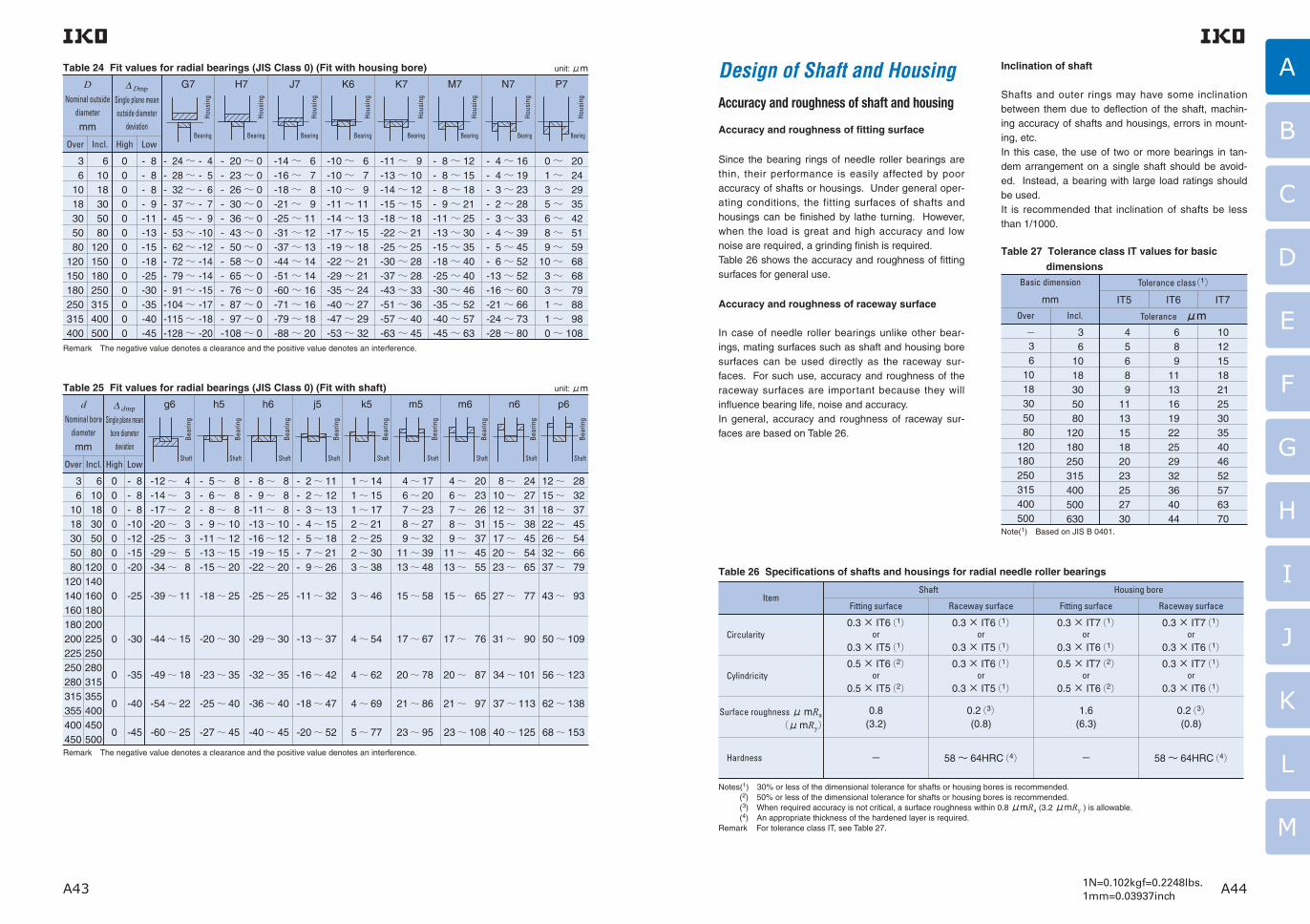
A43 A441N=0.102kgf=0.2248lbs.1mm=0.03937inch
A
B
C
D
E
F
G
H
I
J
K
L
M
Design of Shaft and HousingAccuracy and roughness of shaft and housing
Accuracy and roughness of fitting surface
Since the bearing rings of needle roller bearings are thin, their performance is easily affected by poor accuracy of shafts or housings. Under general oper-ating conditions, the fitting surfaces of shafts and housings can be finished by lathe turning. However, when the load is great and high accuracy and low noise are required, a grinding finish is required.Table 26 shows the accuracy and roughness of fitting surfaces for general use.
Accuracy and roughness of raceway surface
In case of needle roller bearings unlike other bear-ings, mating surfaces such as shaft and housing bore surfaces can be used directly as the raceway sur-faces. For such use, accuracy and roughness of the raceway surfaces are important because they will influence bearing life, noise and accuracy.In general, accuracy and roughness of raceway sur-faces are based on Table 26.
Inclination of shaft
Shafts and outer rings may have some inclination between them due to deflection of the shaft, machin-ing accuracy of shafts and housings, errors in mount-ing, etc.In this case, the use of two or more bearings in tan-dem arrangement on a single shaft should be avoid-ed. Instead, a bearing with large load ratings should be used.It is recommended that inclination of shafts be less than 1/1000.
Table 27 Tolerance class IT values for basic dimensions
Basic dimension
mm
Over Incl.
Tolerance class(1)
IT5
Tolerance μmIT6 IT7
−36
1018305080
120180250315400500
36
1018305080
120180250315400500630
45689
111315182023252730
689
1113161922252932364044
1012151821253035404652576370
Table 26 Specifications of shafts and housings for radial needle roller bearings
ItemShaft
Fitting surface Raceway surface Raceway surfaceFitting surface
Housing bore
Circularity0.3 × IT6(1)
or0.3 × IT5(1)
0.5 × IT6(2)or
0.5 × IT5(2)
0.8(3.2)
−
0.3 × IT6(1)or
0.3 × IT5(1)
0.3 × IT6(1)or
0.3 × IT5(1)
0.2(3)(0.8)
58 〜 64HRC(4)
0.3 × IT7(1)or
0.3 × IT6(1)
0.5 × IT7(2)or
0.5 × IT6(2)
1.6(6.3)
−
0.3 × IT7(1)or
0.3 × IT6(1)
0.3 × IT7(1)or
0.3 × IT6(1)
0.2(3)(0.8)
58 〜 64HRC(4)
Cylindricity
Surface roughness�μ mRa �� � ��(μ mRy)
Hardness
Notes(1) �30% or less of the dimensional tolerance for shafts or housing bores is recommended.(2) 50% or less of the dimensional tolerance for shafts or housing bores is recommended.(3) When required accuracy is not critical, a surface roughness within 0.8 μmRa (3.2 μmRy ) is allowable.(4) An appropriate thickness of the hardened layer is required.
Remark For tolerance class IT, see Table 27.
Table 24 Fit values for radial bearings (JIS Class 0) (Fit with housing bore)
DNominal outside
diameter
mm
∆ Dmp
Single plane mean outside diameter
deviation
G7 H7 J7 K6 K7 M7 N7 P7
Over
36
1018305080
120150180250315400
61018305080
120150180250315400500
0000000000000
- 8- 8- 8- 9-11-13-15-18-25-30-35-40-45
- 24〜 - 4- 28〜 - 5- 32〜 - 6- 37〜 - 7- 45〜 - 9- 53〜 -10- 62〜 -12- 72〜 -14- 79〜 -14- 91〜 -15-104〜 -17-115〜 -18-128〜 -20
- 20〜 0- 23〜 0- 26〜 0- 30〜 0- 36〜 0- 43〜 0- 50〜 0- 58〜 0- 65〜 0- 76〜 0- 87〜 0- 97〜 0-108〜 0
-14〜 6-16〜 7-18〜 8-21〜 9-25〜 11-31〜 12-37〜 13-44〜 14-51〜 14-60〜 16-71〜 16-79〜 18-88〜 20
-10〜 6-10〜 7-10〜 9-11〜 11-14〜 13-17〜 15-19〜 18-22〜 21-29〜 21-35〜 24-40〜 27-47〜 29-53〜 32
-11〜 9-13〜 10-14〜 12-15〜 15-18〜 18-22〜 21-25〜 25-30〜 28-37〜 28-43〜 33-51〜 36-57〜 40-63〜 45
- 8〜 12- 8〜 15- 8〜 18- 9〜 21-11〜 25-13〜 30-15〜 35-18〜 40-25〜 40-30〜 46-35〜 52-40〜 57-45〜 63
- 4〜 16- 4〜 19- 3〜 23- 2〜 28- 3〜 33- 4〜 39- 5〜 45- 6〜 52-13〜 52-16〜 60-21〜 66-24〜 73-28〜 80
0〜 20 1〜 24 3〜 29 5〜 35 6〜 42 8〜 51 9〜 5910〜 68 3〜 68 3〜 79 1〜 88 1〜 98 0〜 108
Incl. High Low
Remark The negative value denotes a clearance and the positive value denotes an interference.
Hous
ing
Bearing
Hous
ing
Bearing
Hous
ing
Bearing
Hous
ing
Bearing
Hous
ing
Bearing
Hous
ing
Bearing
Hous
ing
Bearing
Hous
ing
Bearing
unit: μm
Table 25 Fit values for radial bearings (JIS Class 0) (Fit with shaft) d
Nominal bore diameter
mm
∆ dmp
Single plane mean bore diameter
deviation
g6 h5 h6 j5 k5 m5 m6 n6 p6
Over Incl. High Low
36
1018305080
120140160180200225250280315355400450
61018305080
120140160180200225250280315355400450500
0000000
0
0
0
0
0
-25 -39〜 11 -18〜 25 -25〜 25 -11〜 32 3〜 46 15〜 58 15〜 65 27〜 77 43〜 93
-30 -44〜 15 -20〜 30 -29〜 30 -13〜 37 4〜 54 17〜 67 17〜 76 31〜 90 50〜 109
-35 -49〜 18 -23〜 35 -32〜 35 -16〜 42 4〜 62 20〜 78 20〜 87 34〜 101 56〜 123
-40 -54〜 22 -25〜 40 -36〜 40 -18〜 47 4〜 69 21〜 86 21〜 97 37〜 113 62〜 138
-45 -60〜 25 -27〜 45 -40〜 45 -20〜 52 5〜 77 23〜 95 23〜 108 40〜 125 68〜 153
- 8- 8- 8-10-12-15-20
-12〜 4-14〜 3-17〜 2-20〜 3-25〜 3-29〜 5-34〜 8
- 5〜 8- 6〜 8- 8〜 8- 9〜 10-11〜 12-13〜 15-15〜 20
- 8〜 8- 9〜 8-11〜 8-13〜 10-16〜 12-19〜 15-22〜 20
- 2〜 11- 2〜 12- 3〜 13- 4〜 15- 5〜 18- 7〜 21- 9〜 26
1〜 141〜 151〜 172〜 212〜 252〜 303〜 38
4〜 176〜 207〜 238〜 279〜 32
11〜 3913〜 48
4〜 206〜 237〜 268〜 319〜 37
11〜 4513〜 55
8〜 2410〜 2712〜 3115〜 3817〜 4520〜 5423〜 65
12〜 2815〜 3218〜 3722〜 4526〜 5432〜 6637〜 79
Remark The negative value denotes a clearance and the positive value denotes an interference.
Shaft
Bear
ing
Shaft
Bear
ing
Shaft
Bear
ing
Shaft
Bear
ing
Shaft
Bear
ing
Shaft
Bear
ing
Shaft
Bear
ing
Shaft
Bear
ing
Shaft
Bear
ing
unit: μm
Note(1) Based on JIS B 0401.

A45 A461N=0.102kgf=0.2248lbs.1mm=0.03937inch
A
B
C
D
E
F
G
H
I
J
K
L
M
Raceway materials and heat treatment
When using shafts and housings as raceways, the fol-lowing materials are generally used. High-carbon chromium bearing steel
SUJ2 JIS G 4805 Carburizing steel SCM415〜 421 JIS G 4053 Carburizing steel SNCM 220 JIS G 4053 Carburizing steel SCr 420 JIS G 4053 Carburizing steel SNC 415, 815 JIS G 4053 Carburizing steel S 15 CK JIS G 4051In addition, S50C and S55C (JIS G 4051) can be used after through hardening or induction hardening.The hardened layer produced by tempering at +160〜+180°C after hardening must have a fine uniform martensite microstructure.When hardening the raceway surface by case hard-ening or induction hardening, a surface hardness of 58 〜 64HRC and an appropriate thickness of the hardened layer must be ensured. The minimum effective thickness of the hardened layer after heat treatment and grinding is defined as the distance from the surface to the depth where the hardness is 550HV, and it is obtained by the following equation.
Eht≧ 0.8Dw(0.1+ 0.002Dw) ……………(36)
where, Eht: Minimum effective thickness of
the hardened layer, mm Dw:Roller diameter, mmGenerally, the required effective thickness of the hardened layer is at least 0.3 mm.
Dimensions related to mounting of bearings
The dimensions of shaft and housing related to mounting of the needle roller bearings are shown in the table of dimensions for each bearing. (See Fig. 13.)
The minimum value of the shaft shoulder diameter d a which receives the inner ring, and the maximum value
of the housing shoulder diameter D a which receives the outer ring, represent the effective shoulder diame-ters (excluding the chamfered part) which make prop-er contact with the side faces of the inner and outer rings respectively.Also, the maximum value of the shaft shoulder (or
inner ring retaining piece) diameter d a is the dimen-sion related to the ease of mounting/dismounting of the shaft and inner ring to/from the housing and outer ring.
The largest permissible single corner radius r as max of the shaft and housing must be smaller than the small-
est permissible single chamfer dimension r s min of the bearing so that the side surface of the bearing can make proper contact with the shoulder. Table 28 shows the related dimensions.For dimensions of the fillet relief when finishing the shaft or housing by grinding, the values shown in Table 29 are recommended.For other dimensions related to mounting, see the related section for each bearing as required.In addition, for ease in dismounting of bearings, it is convenient to make notches in the shoulder of the shaft or housing to allow the insertion of dismounting hooks.
entry of harmful foreign substances, such as dirt, dust and water. For this reason, sealing devices must always work effectively to seal and prevent against dust penetration under all operating conditions. Also, when selecting a suitable sealing method, it is neces-sary to consider such factors as the type of lubricant, peripheral speed of the seal, operating temperature, shaft eccentricity, seal friction, etc. as well as ease of assembly and disassembly.Sealing methods are of the non-contact and contact types, and it is necessary to select the appropriate type depending on the application.
Non-contact type sealing method
There are many methods of non-contact type sealing, including the use of oi l grooves, f l ingers and labyrinths, which utilize the centrifugal force and nar-row gaps.Since they do not make direct contact with the shaft or housing, it is unnecessary to consider friction and wear, and the non-contact sealing method is suitable for high speed rotation and high operating tempera-tures. However, because of gaps, this method is not always sufficient in preventing oil leakage and dust entry when the machine is not in operation.
1 Oil grooveOil grooves are provided on either the shaft or hous-ing bore, or on both for more effective sealing (See Fig. 14.). The clearance between the shaft and the housing bore should be as small as possible, and the values shown in Table 30 are generally used, taking into consideration errors in machining and assembly, shaft deformation, etc. Three or more grooves are made with a width of 3〜 5 mm and a depth of 4〜 5 mm. If the grooves are filled with grease, it will be more effective for dust prevention.As shown in Fig. 15, helical grooves are suitable for horizontal shafts which have a fixed direction of rota-tion. Right or left handed grooves are used according to the direction of rotation, and they are used for oil lubrication normally in conjunction with a suitable anti-dust device.
Sealing
To obtain the best performance of rolling bearings, it is necessary to prevent leakage of lubricant and the
Fig. 13 Dimensions related to mounting
da Da
Fig. 14(1) (2) (3)
Table 29 Fillet relief dimensions for ground shafts and housings unit: mm
r s minSmallest permissible
single chamfer dimension
Fillet relief dimensions
t rgs b
11.11.522.134567.5
0.20.30.40.50.50.50.50.60.60.6
1.31.522.52.534567
2 2.4 3.2 4 4 4.7 5.9 7.4 8.610
h
rs min
b
trgs
Table 28 Largest permissible single corner radius of shafts and housings ras max
r s minSmallest permissible
single chamfer dimension
0.10.150.20.30.40.611.11.522.12.5345
0.10.150.20.30.40.6111.52222.534
r as maxLargest permissible single corner radius of shafts and
housings
unit: mm
Housing
Shaft
rs min
rs min
ras max
ras max
rs m
inrs
min

A47 A481N=0.102kgf=0.2248lbs.1mm=0.03937inch
A
B
C
D
E
F
G
H
I
J
K
L
M
Table 30 Clearance between grooved shaft and housing bore unit: mm
Shaft dia.
Incl. 50 mm
Over 50 mm
Clearance
0.25〜 0.4
0.5 〜 1
Fig. 17
Fig. 18
3 LabyrinthAlthough it is a little difficult to make, the labyrinth is very effective in preventing oil leakage especially at high speeds. At low speeds, filling the labyrinth with grease is effective in preventing the entry of dust. In Fig. 17, it is necessary to split the housing or cover plate into two. In Fig. 18, it is easy to assemble, and if combined with an oil seal, it improves the sealing effect.Table 31 shows the labyrinth clearances generally used.
Table 31 Labyrinth clearance unit: mm
Shaft dia.
Incl. 50 mm
Over 50 mm
Clearance
0.25〜 0.4
0.5 〜 1
1〜 2
3〜 5
Radial direction Axial direction
Contact type sealing method
In this type of sealing, the shaft is sealed by the appli-cation of pressure resulting from the elasticity of the seal material to the sealing surface of the shaft, which rotates, reciprocates or oscillates. Synthetic rubber, synthetic resin and felt are generally used as sealing materials.
1 Oil sealSynthetic rubber oil seals are the most general type of sealing used. The sealing effect is obtained when the elastic lip comes into contact with the shaft. Some lips are spring-loaded to maintain adequate pressing force.The sliding surfaces of the lip and the shaft always show frictional behavior such that the boundary lubri-cation and fluid lubrication are mixed. If there is an insufficient amount of oil between the contact sur-faces, it will cause heat generation, wear and seizure. Conversely, if the oil film is too thick, it may cause oil leakage.General oil seals are specified in JIS B 2402-1~5. IKO Oil Seals for Needle Roller Bearings (See page L1.) have a low sectional height to match the Needle Roller Bearings.Nitrile rubber is generally used as the material for oil seal lips. Table 32 shows the materials and their operating temperature ranges.The finished surface of the shaft where the seal lip makes contact must have an appropriate surface roughness, as shown in Table 33, according to the peripheral speed. It must also have accurate circular-ity, and the shaft eccentricity should be less than 0.05 mm.To increase wear resistance, the hardness of the slid-ing part of the shaft must be more than 40HRC. This can be achieved by hard-chrome plating or heat treat-ment.
Table 32 Seal materials and operating temperatures
Seal material
Synthetic rubber
Nitrile rubber
Acrylic rubber
Silicon rubber
Fluoro rubber
Tetrafluoethylene resin
Operating temperature range ℃
− 25〜+ 120
− 15〜+ 130
− 50〜+ 180
− 10〜+ 180
− 50〜+ 220
Table 33 Peripheral speed and surface roughness of shaft
Peripheral speed m/ s
Over Incl.
− 5
10
5
10
−
0.8(3.2)
0.4(1.6)
0.2(0.8)
Surface roughness
μ mRa( μ mRy)
2 Felt sealBecause of their simple structure, felt seals have long been used to protect grease lubrication from dust. Since felt absorbs some grease during operation, it hardly causes heat generation and seizure, but it can-not be used when the peripheral speed of the shaft is high (more than 4 m/s). Where there is a high con-centration of dirt and dust, they may become attached to the contact surface of felt, sometimes scratching the shaft surface. To prevent this, two felt seals are placed apart from each other, or a felt seal is used together with a synthetic rubber seal.
(1)
(2)
2 FlingerThe oil flinger is a disk attached to the shaft which throws off oil due to the centrifugal force of rotation and thus prevents oil leakage and the entry of foreign particles. Fig. 16 (1) shows an example in which the flinger is located inside the housing, mainly to prevent oil leakage. Since it sucks in dust and dirt, it should be used in a dust free environment. Fig. 16 (2) shows an example in which the flinger is located outside the housing, and is used in combination with another sealing device, to prevent entry of foreign particles.
Fig. 15
Fig. 16
(1)
(2)

A49 A501N=0.102kgf=0.2248lbs.1mm=0.03937inch
A
B
C
D
E
F
G
H
I
J
K
L
M
Lubrication Methods of lubrication
Grease lubrication and oil lubrication are generally used for rolling bearings. In special cases, solid lubri-cants are also used.In general, grease lubrication requires the simplest sealing device. It is therefore economical, and widely used. Also, once filled with grease, the bearing can be used for a long period without replenishing the grease. However, compared with oil, its heat removal properties and cooling capacity are inferior, since grease has high flow resistance, which causes high churning heat.Oil has greater fluidity and superior heat removal properties. It is therefore suitable for high-speed operations. In addition, it is simple to filter out dust and dirt from oil. Thus it can prevent the generation of noise and vibration and increase bearing life. Another advantage of oil lubrication is that it offers the possibility for selecting the appropriate method for particular operating conditions from among various available lubrication methods. However, measures to prevent oil leakage are required. As a guideline for selection, Table 34 compares grease and oil lubrica-tion.For the lubricants used for IKO Spherical Bushings, see page K8.
Purpose of lubrication
The main purpose of bearing lubrication is to reduce friction and wear and to prevent heat generation and seizure. The lubricant and the lubricating method have a big influence on the operating performance of the bearing, and it is therefore necessary to select them suitably for the operating conditions.The effects of lubrication are as follows.
1 Reduction of friction and wearAt the contact surfaces between the race rings, rolling elements and cage of the bearing, lubrication pre-vents metal-to-metal contact, and reduces friction and wear due to sliding and rolling, in the latter of which micro-slips occur by differential slip, skew, spin, or elastic deformation.
2 Elimination of frictional heatThe lubricant removes the heat generated by friction or transferred from outside, and prevents overheating of the bearing. Circulating lubrication is generally used for this purpose.
3 Influence on bearing lifeThe bearing life is extended if the rolling contact sur-faces between the race rings and rolling elements are separated by an oil film of adequate thickness, and is shortened if the oil film is inadequate due to low oil viscosity, etc.
4 Rust preventionThe lubricant prevents rust formation on the inside and outside surfaces of the bearing.
5 Dust preventionGrease lubrication is particularly effective for dust pre-vention. Oil circulating or jet lubrication is effective in washing foreign particles away from the area around the bearing.
Table 34 Comparison between grease lubrication and oil lubrication
Item
Sealing, Housing structure
Temperature
Rotational speed
Load
Maintenance
Lubricant replacement
Lubrication performance
Dust filtration
Entry of dust and dirt
Grease lubrication(1) Oil lubrication
Simple
High temperature not allowed
Low and medium speeds
Low and medium loads
Easy
Slightly complicated
Good
Difficult
Easy measures for protection
Slightly complicated
High temperature allowed (Cooling effect by circulation)
High speed allowed
High load allowed
Elaborate(Pay special attention to oil leaks. )
Simple
Very good
Simple
Dust and dirt can be removed by filtering in circulating lubrication.
Note(1) �This represents bearing grease for general use.
Grease lubrication
1 Amount of grease to be filledThe amount of grease to be filled depends on the housing structure, dimensions, type of grease used and atmosphere. Generally, filling about 1/3 to 1/2 of the free space inside of the bearing and the housing is considered to be appropriate. Too much will cause a rise in temperature, and care should be taken espe-cially at high speed rotations.In Fig. 19, several grease pockets are provided by the grease sectors on one side of the bearing. Even if the filled grease is dispersed by the centrifugal force at high rotational speeds, it is trapped by the grease pockets and diverted back into the bearing again. Old grease accumulates in the space on the opposite side of the bearing, and this can be removed periodically by taking off the cover.
2 Replenishment of greaseThe life of grease depends on its type and quality, the type and dimensions of the bearing, operating condi-tions, temperature, amount of wear, penetration of for-eign particles and water, etc.Fig. 20 shows the replenishment intervals for grease, and is used as a general guideline. The values obtained from this diagram apply to cases in which the load condition is normal, the machine body is sta-tionary, and the operating temperature on the outer surface of bearing outer ring is less than +70°C. If the temperature exceeds +70°C, as a general rule, the replenishment interval is halved for every 15°C increase.
Fig. 20 Interval for replenishment of grease
Fig. 19
Remark d is the bore diameter of the inner ring. For a bearing without an inner ring, the roller set bore
diameter Fw is used for d .
Rep
leni
shm
ent i
nter
val f
or g
reas
e,
tf
hour
s
Rotational speed, n min-1
200200
300
400500600
800
1000
1500
2000
3000
4000
50006000
8000
10000
15000
20000
400 600 1000 2000 4000 6000 10000
d=10m
m203040506080100120
140160180200240
280
300

A51 A521N=0.102kgf=0.2248lbs.1mm=0.03937inch
A
B
C
D
E
F
G
H
I
J
K
L
M
Oil lubrication
1 Oil bath lubricationThis is the most commonly used oil lubrication method, and is used for medium and low speeds. If the amount of oil is too large, heat will be generated by churning, and if the amount is too small, seizure will occur. Therefore, the correct amount of oil must be maintained. When the machine is stationary, the correct oil level in the case of a bearing mounted on a horizontal shaft, is near the center of the lowest rolling element. In the case of a vertical shaft, about 50% of the surfaces of the rolling elements should be sub-merged in oil.It is desirable to provide an oil gauge so that the oil level can be easily checked while the machine is sta-tionary or running.
2 Oil drip lubricationOil drips, which are fed down from a sight-feed oiler or along a fiber string, become an oil spray due to wind pressure generated by the rotating cage, shaft, nut, etc., or they strike the rotating parts and form an oil spray, which fills up the housing and every required part. Because oil spray removes frictional heat, this method has a more effective cooling effect than the oil bath method, and is widely used for high-speed rota-tion and medium load conditions.In the case of the sight-feed oiler (Fig. 21), the num-ber of drips can be adjusted. However, this is difficult using the string-feed method. The number of drips depends on the bearing type, rotational speed, etc., but 5 〜 6 drips per minute is generally used.
3 Oil splash lubricationIn this method, oil is splashed in all directions by the rotation of the gear or disk. This can be used for con-siderably high-speed rotations without soaking the bearing directly in oil.In the gear case where shafts and bearings are lubri-cated with the same oil, wear particles may be intro-duced into the bearing as they might get mixed with the oil. In this case, a permanent magnet is provided at the bottom of the gear case to collect metal parti-cles, or a shield plate is installed next to the bearing.Fig. 22 shows another method in which the splashed
4 Oil circulating lubricationWhen automatic lubrication is more economical because lubrication is required at many points, or when cooling is required for high rotational speed, this method is used. The oil is supplied with a pump, which can control the oil pressure, and a filter or cool-er, etc. can be set up in the circulation system, mak-ing this an ideal method of lubrication. As shown in Fig. 23, the oil supply and discharge ports are located opposite to each other, and the discharge port is made large to prevent the accumulation of oil.
5 Oil mist lubricationAfter dirt and dust are removed by a filter, the oil is turned into a spray by dry compressed air, and this lubricates the bearing. When the air and oil pass through the bearing, the air cools the bearing and the oil lubricates it. In addition, because the air inside the housing is at a higher pressure than the outside air, the entry of water and foreign particles is prevented. There are many other advantages of this method, and it is suitable for high rotational speed applications such as high speed internal grinding spindles.
6 Oil jet lubricationThis is a highly reliable lubrication method and is used under severe conditions such as ultra-high rotational speeds and high temperatures. The speed of the oil jet should be more than 20% of the peripheral speed of the inner ring raceway surface, since the air around
the bearing rotates together with the bearing forming an air wall. As shown in Fig. 24, the jet from the noz-zle blows directly into the space between the inner ring and the cage. Due to the large amount of oil being used, it is more effective to make the discharge port larger, and use the forced discharge.
When the dmn value (mean value of the bearing out-side and bore diameters in millimeter x rotational speed in min-1) is more than 1,000,000, the speed of the jet should be 10〜 20 m/s, the nozzle diameter should be about 1 mm, oil supply pressure should be 0.1〜 0.5 MPa, and the oil supply amount should be about 500 cc/min or greater. When the rotational speed is higher, the oil supply pressure and the oil amount should be higher.
Lubricants
For rolling bearings, lubricating grease or oil is gener-ally used. For special applications, solid lubricants are used.
Lubricating grease
Grease is a semi-solid lubricant made by mixing base oil (liquid lubricant) and a thickener under heat and adding additives as required.There are many types of grease according to various combinations of base oil, thickeners and additives. Grease is usually classified by thickeners and base oil. Table 35 shows the general properties of each type of grease.Reference examples of the lubricant greece brand and performance are shown on page M46.
Excellent under low temperature conditions and has superior frictional prop-erties. Suitable for small bearings used in mea-suring instru-ments.
Table 35 Properties of various types of grease
Name (Common name)
Item
Calcium grease
Cup grease
Sodium grease
Fiber grease
Aluminum grease
Mobile grease
Mixed base grease
Barium grease Lithium grease
Diester grease
Silicon grease
Bentone grease
Non-soap base grease(Non-soap grease)
Base oil
Thickener
Appearance
Pour point ℃
Operating temperature range ℃
Pressure resistance
Water resistance
Mechanical stability
Features and application
Mineral oil
Ca soap
Buttery
80 〜 90
− 10 〜+ 70
Strong to weak
Good
Fair
Contains about 1% water. When the tem-perature rises to more than +80°C, the water evapo-rates and the grease sepa-rates into oil and soap. This is used for medium loads.
Mineral oil
Na soap
Fibrous and
buttery
150 〜 180
− 20 〜+ 120
Strong to medium
Poor
Good
Mineral oil
Al soap
Stringy and
buttery
70 〜 90
− 10 〜+ 80
Strong
Good
Poor
Long fibrous grease cannot withstand high speeds, but has good pres-sure resis-tance proper-ties. Short fibrous grease is compara-tively good for high speeds.
It has water and rust resis-tant proper-ties, and adheres easily to metal sur-face.
Mineral oil
Na + Ca soap,Li + Ca soap
Fibrous and
buttery
160 〜 190
− 10 〜+ 100
Strong
Good, poor for Na+
Ca soap grease
Good
Usable at fairly high speeds.
Mineral oil
Ba soap
Fibrous and
buttery
150 〜 180
− 10 〜+ 135
Strong to medium
Good
Poor
It has water and heat resis-tant proper-ties. This is an all-purpose grease.
Mineral oil
Li soap
Buttery
170 〜 190
− 20 〜+ 120
Medium
Good
Excellent
This is the best all-purpose grease among soap based greases.
Diester oil
Li soap
Buttery
170 〜 190
− 50 〜+ 120
Medium
Good
Excellent
Silicon oil
Li soap
Buttery
200 〜 250
− 50 〜+ 180
Weak
Good
Excellent
Mainly used for high tem-peratures. Not suited to high speeds and heavy loads.
Mineral oil
Bentone
Buttery
200 〜
− 10 〜+ 150
Medium to weak
Good
Good
Generally good heat resis-tance. Grease having a miner-al base oil is for general use. Grease having a synthetic base oil is suitable for special use where superior heat and chem-ical resistance properties are required.
Synthetic oil
Silica gel. Polyurea,
etc.
Buttery
None
〜+ 200
Medium
Good
Good to poor
( )( )( ) ( )( )( )
oil flows along the grooves in the case and accumu-lates in the oil pockets, keeping the oil level constant. So the oil is steadily supplied to the bearing.
Fig. 22 Oil splash lubrication
Fig. 23 Oil circulating lubrication
Fig. 21 Oil drip lubrication
Fig. 24 Oil jet lubrication

A53 A541N=0.102kgf=0.2248lbs.1mm=0.03937inch
A
B
C
D
E
F
G
H
I
J
K
L
M
ISO viscosity grade(VG)
Table 36 Consistency and operating conditions of grease
NLGIconsistency number
Combined consistency Application
0
1
2
3
4
385 〜 355
340 〜 310
295 〜 265
250 〜 220
205 〜 175
For centralized lubrication,
For oscillating motion
For general use
For general use, For high temperature
For sealing with grease
Table 37 Bearing series and required viscosity of lubricating oil
Bearing series
Needle roller bearings Roller bearings
Crossed roller bearings
Thrust needle roller bearingsThrust roller bearings
Kinematic viscosity at operating temperatures
13 mm2/s or more
20 mm2/s or more
32 mm2/s or more
1 Base oilPetroleum lubricating oil is usually used as the base oil.As the lubricating performance of grease depends mainly on that of base oil, the viscosity of the base oil is an important property. In general, low viscosity is suitable for light-load and high-speed rotations, and high viscosity for heavy-load and low-speed rotations. Synthetic lubricants of the diester or silicon series are used instead of lubricants of the petroleum series in consideration of the pour point and high temperature stability.
2 ThickenerAs shown in Table 35, metal soap bases are mostly used as thickeners. In particular, Na-soap is water-soluble and emulsifies easily, and it cannot be used in damp or wet areas. The type of thickener and the pour point of grease have a close relationship. In general, the higher the pour point, the higher the max-imum usable temperature of grease. However, even when the grease uses a thickener having a high pour point, its upper operating temperature limit is low if its base oil has low heat resistance.
3 ConsistencyThis represents the hardness grade of grease. Grease becomes harder in proportion to the amount of thickener if the same thickener is used.Immediately after grease has been stirred (usually 60 times), a depression is formed in the grease in a specified time using a specified cone. The consisten-cy (combined consistency) is expressed by the value of depth of depression (mm) multiplied by 10.This value gives an estimate of the fluidity during operation with a greater value for softer grease.Table 36 shows the consistency number of grease and the relationship between the consistency and operating conditions.
running for long periods of time, its temperature rises. This results in oxidation of the lubricant and formation of oxides, which lead to corrosion of the bearing.Thus, when a bearing is to be operated for long peri-ods of time without regreasing, antioxidants are added. In addition, grease containing extreme pres-sure additives is suitable for use in places that are subjected to heavy loads.
5 Miscibility of different greasesIn principle, it is desirable to use grease of the same brand. However, when the mixing of different greases is unavoidable, greases with the same type of thick-ener and with a similar type of base oil should be used.It should be noted that if different types of grease are mixed, they may interact with each other and the con-sistency will become softer than that for the individual greases.
Lubricating oil
For rolling bearings, refined mineral oil or synthetic oil is used. To improve its properties, antioxidant addi-tives, extreme pressure additives and detergent addi-tives are added as required.When selecting lubricating oil, it is important to select oil which has adequate viscosity under operating tem-peratures. If the viscosity is too low, the formation of the oil film will be insufficient, causing abnormal wear and seizure. On the other hand, if the viscosity is too high, it will generate excessive heat or increase power loss due to viscous resistance. As a general stan-dard, oil having higher viscosity should be used for heavier loads and oil having lower viscosity should be used for higher rotational speeds.Under conditions of normal use for various bearings, the values of viscosity shown in Table 37 will be a guideline.The relationship between viscosity and temperature can be obtained from Fig. 25. Also, Table 38 shows examples of selecting lubricating oil according to the conditions of bearing use.
4 AdditivesAdditives include various types of substances, which are added to grease in small quantities to improve its characteristics. For example, when a bearing is kept
Fig. 25 Relationship between viscosity and temperature of lubricating oil
Table 38 Conditions of bearing use and examples of lubricating oil selection
Conditions
− 30 〜 0℃
0 〜 50℃
50 〜 80℃
80 〜 110℃
dmn valueLoad
10 15 22 32 46 68 100 150 220 320 460 680
Oper
atin
g te
mpe
ratu
re
Remarks ・Lubricating oils are based on JIS K 2211 (Refrigerating machine oils), JIS K 2239 (Bearing Oil), JIS K 2213 (Turbine Oil), and JIS K 2219 (Gear Oil).
・The method of lubrication in these cases is mainly oil bath lubrication or circulating lubrication. ・When the temperature is on the high side within the operating temperature range, oils of high viscosity are used. ・dmn represents the mean value of the bore and outside diameters (mm) of the bearing multiplied by the rotational speed (min-1).
Refrigerator oil
Bearing oil
Bearing oil
Bearing oil
Turbine oil
Turbine oil
Turbine oil Gear oil
Large
Small
Small
Large
Vis
cosi
ty
Redwood(sec)
Saybolt(sec)
Temperature
5000
2000
1000
500
300200
10080
60
50
40
5000
20001000
500300200
100
504030
20
10
5
4
2000
1000
500
300200
100
80
60
50
40
-20 0 20 40 60 80 100 120 140 160 °C
-20 0 20 40 60 80 100 120 160 200 240 280 320 °F
A B C D E F G H J K L M N
A : VG 7B : VG10C : VG15D : VG22E : VG32F : VG46G : VG68
H : VG100J : VG150K : VG220L : VG320M : VG460N : VG680
Centistrokes
ISO viscosity grade (Viscosity index 80)

A55 A561N=0.102kgf=0.2248lbs.1mm=0.03937inch
A
B
C
D
E
F
G
H
I
J
K
L
M
Friction and AllowableRotational SpeedFriction
Compared with sliding bearings, the starting (static) friction for rolling bearings is small, and the difference between the starting (static) friction and the kinetic friction is also small. The loss of power and tempera-ture rise in machines are thus reduced, improving the mechanical efficiency.Frictional torque is influenced by the bearing type, bearing load, rotational speed, lubricant characteris-tics, etc. It varies according to the lubricant when operated under light-loads and high-speed conditions, and according to the load when operated under heavy-loads and low-speed conditions.Frictional torque of rolling bearings is complicated because it is influenced by various factors, but for convenience, it can be expressed approximately by the following equations.
・Radial bearings M=μ P ……………………(37)
・Thrust bearings M=μ P ……………………(38)
where, M :Frictional torque, N-mm μ:Coefficient of friction
P :Bearing load, N d :Bearing bore diameter, mm d m:Mean value of bearing bore and
outside diameters, mm
The approximate coefficients of fr iction of IKO Bearings under operating conditions, in which lubrica-tion and mounting are correct and where loads are relatively large and stable, are shown in Table 40.
Allowable rotational speed
As the rotat ional speed of rol l ing bear ings is increased, the bearing temperature also increases due to the heat generated at the contact surfaces between the cage, raceways and rolling elements, until it finally leads to bearing seizure. It is therefore necessary to maintain the rotational speed of a bear-ing below a certain limit value to ensure safe opera-tion for long periods. This limit value is called the allowable rotational speed.Since the amount of heat generated is approximately proportional to the sliding speed at the contact area, this sliding speed is an approximate guide indicating the limit of the bearing rotational speed.The allowable rotational speed of bearings thus varies according to the bearing type, size, bearing load, method of lubrication, radial clearance, and other such factors.The allowable rotational speeds shown in the table of dimensions are empirical values. They are not absolute values and can be changed according to the bearing use conditions. Depending on the structure and accuracy around the bearing, the lubricant and the lubrication method, it is possible for some bear-ings to be operated at more than twice the allowable rotational speed given in the table without trouble.
d2
dm2
Table 40 Coefficient of friction
Bearing series
Needle roller bearings with cage
Full complement needle roller bearings
Thrust needle roller bearings
Thrust roller bearings
μ
0.0010 〜 0.0030
0.0030 〜 0.0050
0.0030 〜 0.0040
0.0030 〜 0.0040
C-Lube Bearing
IKO C-Lube Bearing is a bearing that is lubricated with a newly developed thermosetting solid-type lubri-cant. A large amount of lubricating oil and fine parti-cles of ultra high molecular weight polyolefin resin are solidified by heat treatment to fill the inner space of the bearing. As the bearing rotates, the lubricating oil oozes out onto the raceway in proper quantities, maintaining the lubrication performance for a long period of time.The dimension tables for C-Lube Machined Type Needle Roller Bearings, C-Lube Cam Followers, and C-Lube Roller Followers are shown on pages D77, I53, and I95.C-Lube Bearing is available in all Needle Roller Bearing series. Also C-Lube Bearings for food pro-cessing are available, using NSF H1-certified lubrica-tion oil and resin compliant with FDA standards to mit-igate any effect on human health. If needed, please contact IKO.
Features of C-Lube Bearing
・Most suitable for preventing grease dry-up in appli-cations where lubrication is difficult.
・Great reduction of maintenance work by extending the lubrication interval.・Elimination of oil contamination, making this bear-
ing most suitable for applications that would be adversely affected by oil.
Cautions for using C-Lube Bearing
・Never wash C-Lube Bearing with organic solvent and/or white kerosene which have the ability to remove fat, or leave the bearing in contact with these agents.
・The operating temperature range is -15〜+80°C. For continuous operation, the recommended oper-ating temperature is +60°C or less.
Structure of C-Lube Bearing
Solid-type lubricant
Needle roller
Outer ring
Notes(1)���dmn==(bore diameter of bearing[mm]+ outside diameter of bearing[mm]) �/2× rotational speed[min-1]
(2)���d1n== stud diameter[mm]×rotational speed[min-1](3)���dn== inner ring bore diameter[mm]×rotational speed[min-1](4)���The allowable rotational speed of C-Lube Roller Followers
is applicable to use with oscillating rotation. For use with one-way or continuous rotation, please consult IKO.
・To ensure normal rotation of the bearing, apply a load of 1% or more of the basic dynamic load rating at use.
・The allowable rotational speed is different from that of the general needle roller bearings. For dmn, d1n, and dn, use the values in Table 39 or less as guide-lines.
Table 39 C-Lube Bearing dmn , d1n , dn
C-Lube Machined Type Needle Roller Bearings
C-Lube Cam Followers
C-Lube Roller Followers (4)
Allowable rotational speed
dmn (1),�d1n (2),�dn (3) Representative model
TAF・・・/SG
CF・・・/SGNART・・・/SG
dmn=20 000d1n =10 000dn = 8 000
Main model code

A57 A581N=0.102kgf=0.2248lbs.1mm=0.03937inch
A
B
C
D
E
F
G
H
I
J
K
L
M
Handling of BearingsOperating Temperature RangeThe allowable operating temperature range for needle roller bearings is generally -20〜 +120°C.When operating at temperatures outside this range, the operation may be limited by the allowable temper-ature range of prepacked grease, seal, cage material, etc. Further, if the bearing is used at high tempera-ture, i.e. 120°C or above, the amount of dimensional displacement gets larger. So special heat treatment is necessary.The operating temperature range for some types of bearings is different from the above. See the section for each bearing.
Precautions in handling
Since the bearing is a high-accuracy mechanical ele-ment, special attention must be paid to its handling. The following precautions should be noted when han-dling the bearings.
1 Bearings and their surrounding parts should be kept clean.Bearings and their surrounding parts must be kept clean paying special attention to dust and dirt. Tools and the working environment should also be cleaned.
2 Bearings should be handled carefully.A shock load during handling may cause scratches, indentations and even cracks or chips on the raceway surfaces and rolling elements.
3 Bearings should be mounted or dismounted with proper tools.When mounting and dismounting, tools suitable for the bearing type should be used.
4 Bearings should be protected against corrosion.Bearings are treated with anti-corrosive oil. However, when handling them with bare hands, sweat from the hands may result in future rust formation. Gloves should be worn, or hands should be dipped in mineral oil.
Mounting
Preparation
Before mounting the bearing, the dimensions and fil-lets of the shaft and housing should be checked to ensure that they conform to specifications.Bearings should be unwrapped just before mounting. In case of grease lubrication, bearings should be filled with grease without cleaning the bearings. Even in the case of oil lubrication, it is normally unnecessary to clean the bearings. However, when high accuracy is required or when using at high speeds, the bear-ings should be cleaned using cleaning oil to remove thoroughly oily contents. The cleaned bearings should not be left alone without anti-corrosive precau-tions, because bearings can easily be corroded after anti-corrosive agents are removed.Lubricating grease is prepacked in some types of bearings. Therefore, refer to the relevant section for each bearing.
Methods of mounting
Mounting methods of bearings are different according to the type of bearing and the fit. In general, mount-ing of needle roller bearings is comparatively easy. However, non-separable bearings with large interfer-ences should be handled with great care.
1 Mounting by press fitSmall and medium bearings with small interferences require a small pressing-in force for mounting, and they are mounted using a press at room temperature. The bearing should be pressed in carefully, applying a force evenly to the bearing with a fitting tool as shown in Fig. 26. For separable bearings, the inner and outer rings can be mounted separately, and the mounting work is simple. However, when installing the shaft and inner ring assembly into the outer ring, care should be taken not to damage the raceway sur-faces and rolling elements.
When mounting non-separable bearings, the inner and outer rings are pressed in simultaneously by applying a cover plate as shown in Fig. 27. It must never happen that the inner ring is press-fitted to the shaft by striking the outer ring, or the outer ring by striking the inner ring, because the raceway surfaces and rolling elements will be scratched or indented.
Fig. 27
When press fitting, the friction of the fitting surfaces can be reduced by applying high viscosity oil over the fitting surfaces.The pressing-in or pulling-out force to be applied to the bearing is given on page A59.
2 Mounting by shrink fittingThis method is used when the interference is great or when a large bearing is to be fitted. The housing is heated and thermally expanded when fitting the outer ring to the housing and the inner ring is heated and expanded when fitting it to the shaft allowing the bear-ing to be set easily within a short time. The maximum allowable temperature for the shrink fit is +120°C, and heating should be performed appropriately. Pure non-corrosive mineral oil is recommended as the heating oil for shrink fit, and insulation oil for trans-formers is considered to be the best. During cooling, the bearing also shrinks in the axial direction. Therefore, to ensure that there is no clearance between the bearing and the shoulder, an axial force must be applied continuously to the bearing until it has cooled.When the interference between the outer ring and the housing is great, an expansion fit method in which the bearing is cooled using dry ice or other cooling agent before fitting can be used. Immediately after fitting, however, moisture from the air easily condenses on the bearing. Therefore, it is necessary to take pre-ventive measures against corrosion.
Fig. 26

A59 A601N=0.102kgf=0.2248lbs.1mm=0.03937inch
A
B
C
D
E
F
G
H
I
J
K
L
M
dd+ 2
dF( ){ }
Dismounting of inner ring
In the case of bearings such as needle roller bearings in which the inner and outer rings are separable, the simplest way to press out the inner ring is by using a press as shown in Fig. 29.The puller shown in Fig. 30 is also generally used. This is designed according to the bearing size. In addition, there are a 3-hook puller (Fig. 31) and a 2- hook puller for wide-range use.
Dismounting
Dismounting of the bearings is carried out for the peri-odic inspection or repairs of machines. By inspecting the bearing, related parts or mechanisms, lubrication, etc., important data is obtained. In the same manner as in mounting, care should be taken to prevent dam-age to the bearing or other parts.A suitable dismounting method should be selected according to the type of the bearing, fit, etc. Bearings mounted by interference fit are especially difficult to dismount, and it is necessary to give due considera-tion to the structure around the bearing during the design stage.
Dismounting of outer ring
Outer rings mounted by interference fit are dismount-ed as shown in Fig. 28, by screwing in the push-out bolts evenly through several screw holes provided at places corresponding to the side face of the outer ring.
In addition to these, when it is difficult to remove the inner ring due to high shoulders, several holes for removal pins are made through the shoulder, or sev-eral hook grooves are cut in the shoulder as shown in Fig. 32 and Fig. 33.When a bearing is not to be used again after removal, it may be removed by heating with a torch lamp.
Pressing force and pulling force
Guidelines for the pressing force when pressing in the inner ring to the shaft and the pulling force when pulling it out are obtained from the following equation.
K= f k ∆ d fB 1− 2 ………(39)
where, K :Pressing or pulling force, N f k :Resistance factor determined by the coefficient of friction
When pressing in inner ring to shaft, fk=4×10⁴
When pulling out inner ring from shaft, fk=6×10⁴
d :Bore diameter of inner ring, mm ∆ df :Apparent interference, mm B :Width of inner ring, mm F :Outside diameter of inner ring, mmThe actual pressing force or pulling force may be greater than the calculated value due to mounting errors. When designing a puller, it is necessary that the puller has the strength (rigidity) to withstand more than 5 times the calculated value.
Running test
After mounting the bearing, a running test is carried out to check whether the mounting is normal. Usually, it is first checked by manual turning. Then, it is operated by power gradually from no-load and low-speed up to normal operating conditions to check for abnormalities.Noise can be checked by using a soundscope or simi-lar instrument. In this test, checks are carried out for the following abnormalities.
1 Manual turning (a) Uneven torque ……………… Improper mounting (b) Sticking and rattling … Scratches or indentations
on the raceway surface (c) Irregular noise … Penetration of dust or foreign
particles
2 Power running (a) Abnormal noise or vibration … Indentations on
the raceway surface, too great clearance (b) Abnormal temperature … Unsuitable lubricant,
improper mounting, too small clearance
Fig. 28
Fig. 29
Press
Fig. 30
Fig. 31
Fig. 32
Fig. 33

A61 A621N=0.102kgf=0.2248lbs.1mm=0.03937inch
A
B
C
D
E
F
G
H
I
J
K
L
M
Inspection of bearing
Cleaning of bearing
When inspecting a bearing after removal, the appear-ance of the bearing should be recorded first. Then, after the residual amount of lubricant is checked and a sample of lubricant is collected, the bearing should be cleaned.For cleaning, light oil or kerosene is commonly used. Cleaning is divided into rough cleaning and final cleaning, and wire gauze is set as a raised bottom in a container to prevent the bearing from touching the bottom of the container.Lubricating grease and adhering substances such as foreign particles are removed with a brush, etc., using oil for rough cleaning. Care should be taken during this process, because if the bearing is turned with foreign particles attached, the raceway surfaces may be scratched.Final cleaning is carried out by turning the bearing in cleaning oil. It is desirable that the cleaning oil is kept clean by filtering. Immediately after cleaning, the bearing must be protected against corrosion.
Inspection and evaluation of bearing
The judgement as to whether the removed bearing is reusable depends on the inspection after cleaning. Conditions of the raceway surfaces, rolling elements and fitting surfaces, wear condition of the cage, increase of bearing clearance, dimensions, rotational accuracy, etc. should be checked for damage and abnormalities.The evaluation is performed based on the experience taking into consideration the degree of damage, machine performance, importance of the machine, operating conditions, period until the next inspection, and other such factors.
Maintenance and inspection
Maintenance and inspection
Maintenance and inspection are carried out to main-tain good performance of bearings installed in the machine.Maintenance is performed by checking the machine operating conditions, checking and replenishing or replacing the lubricant, checking the bearing and related parts by periodic disassembly and other such procedures.Items for inspection of a running bearing in a machine include the bearing temperature, noise, vibration and condition of lubricant.When any abnormality is found during operation, the cause should be investigated and measures taken by referring to the section on running test on page A59. When removing a bearing, refer to the section on dis-mounting on page A59.
Damage, causes and corrective action
Rolling bearings can generally be used fully up to their rolling fatigue life if they are properly selected, mounted, operated and maintained. However, they may actually be damaged earlier than their expected lifetimes creating problems or accidents. Common causes of damage include improper mounting or han-dling, insufficient lubrication and penetration of foreign particles.It may be difficult to determine the exact cause of a problem by checking only the damaged bearing. The conditions of the machine before and after the occur-rence of the damage, the location and the operating and ambient conditions of the bearing, the structure around the bearing, etc. should also be examined. It then becomes possible to assess the cause of the damage by linking the conditions of the damaged bearing to the probable causes arising from the machine operation, and to prevent the recurrence of similar problems.Common types of damage, causes and corrective action are listed in Table 41.
Table 41 Damage, causes and corrective action
Condition of bearing damage Cause Corrective action
Flakings at opposite circumferential positions on raceway surfaces
Flakings in the vicinity of raceway surface edges and roller ends
Flakings on raceway surfaces with an interval corresponding to roller pitch
Early flaking on raceway surfaces and rolling elements
Galling on raceway surfaces and rolling surfaces of rollers
Galling between roller end faces and collar guide surfaces
Cracks in outer or inner ring
Cracked rolling elements, broken collar
Broken cage
Indentations on raceway surfaces at an interval corresponding to the pitch between rolling elements (brinelling)
Indentation on raceway surfaces and rolling surfaces of rollers
False brinelling(Phenomenon like brinelling)
Fretting Localized wear of fitted surfaces accompanied by red-brown
wear particles
Wear on raceway surfaces, collar surfaces, rolling surfaces of rollers, cages, etc.
Creep Wear on fitted surfaces
Discoloration of rolling elements and/or raceway surfaces and/or flange surfaces, Adhesion and welding, Discoloration of cage
Ripples on raceway surfaces
Rust or corrosion on bearing inside surfaces or on fitted surfaces
Improper roundness of housing bore
Improper mounting, Shaft deflection, Poor centering, Poor accuracy of shaft or housing
Great shock load when mounting, Rusting during machine stoppage
Too small clearance, Too great load, Poor lubrication, Rusting, etc.
Poor lubrication in early stage Grease consistency too hardHigh acceleration at start
Poor lubrication, Poor mounting, Large axial load
Excessive shock load, Too much interference.Poor cylindricity of shaft. Too large fillet radius,Development of thermal cracks,Development of flaking
Development of flakingShock to collar when mounting,Dropped by careless handling
Abnormal load to cage by poor mounting,Poor lubrication
Shock load applied when mounting, Excessive load while stopping
Biting of foreign substances such as metal chips and sands
Vibration when the bearing is stationary such as during transportation, Oscillating motion with small amplitude
Sliding between fitted surfaces
Penetration of foreign particles, Poor lubrication, Rust
Sliding between fitted surfaces, Insufficient tightening of sleeve
Poor lubrication, Too small clearance, Poor mounting
Melting by sparks due to electric current
Condensation of vapor in air, Penetration of corrosive substances
Correction of housing bore accuracy
Careful mounting, Careful centering, Correction of shoulders of shaft and housing for right angles
Careful mounting, Protection against rust for long periods of machine stoppage
Correct selection of fit and clearanceCorrect selection of lubricant
Selection of softer grease,Avoiding quick acceleration
Correct selection of lubricantCorrect mounting
Reevaluation of load conditions, Correction of fit, Correction of machining accuracy of shaft or sleeve, Making fillet radius smaller than the chamfer dimension of bearing
Careful handling and mounting
Minimizing mounting errors, Study of lubricating method and lubricant
Careful handling
Cleaning of housing, Improvement of sealing, Use of clean lubricant
Fixing of shaft and housing, Use of lubricating oil, Application of preload to reduce vibration
Increase of interference, Application of oil
Improvement of sealing, Cleaning of housingUse of clean lubricant
Increase of interference, Correct tightening of sleeve
Supply of proper amount of proper lubricant, Rechecking of fit and bearing clearance Rechecking of mounting dimensions and related parts
Insulation of bearing, Grounding to avoid electric current
Careful storage if under high temperature and high humidity, Protection against rust, Improvement of sealing
Flak
ing
Galli
ngBr
eaka
geDe
ntAb
norm
al w
ear
Seizu
reEle
ctric
corro
sion
Rust
, co
rros
ion