Scanning Near-Field Optical Microscopy of Living Cells in Liquid, Elaboration of New SNOM

488 Int. J. Nanotechnol., Vol. 9, Nos. 3–7, 2012
Copyright © 2012 Inderscience Enterprises Ltd.
Near field optical microscopy: a brief review
A.L. Lereu* CINaM CNRS – Campus de Luminy, 13288 Marseille, France Fax: +33(0)4 91 41 89 16 E-mail: [email protected] *Corresponding author
A. Passian Oak Ridge National Laboratory, Oak Ridge, TN 37831, USA
and
Department of Physics, University of Tennessee, Knoxville TN 37996-1200, USA E-mail: [email protected]
Ph. Dumas CINaM CNRS – Campus de Luminy, 13288 Marseille, France E-mail: [email protected]
Abstract: Near Field Optical Microscopy (NSOM) has evolved into a mature member of the family of scanning probe microscopy. In this article, we briefly go over the principle of NSOM, its breakthroughs and setbacks. We will describe some of the most commonly used NSOM modalities and conclude with the recent advances based on optical nanoantennas. We will then highlight the potential of this high-resolution optical microscopy for chemical and biological applications as well as for materials sciences.
Keywords: near field optical microscopy; nanoantennas; plasmons.
Reference to this paper should be made as follows: Lereu, A.L., Passian, A. and Dumas, Ph. (2012) ‘Near field optical microscopy: a brief review’, Int. J. Nanotechnol., Vol. 9, Nos. 3–7, pp.488–501.
Biographical notes: Aude L. Lereu received both her MS (2002) and PhD (2005) Degrees in Physics at the Department of Physics of the University of Burgundy, France. Her research for both degrees was carried out at Oak Ridge National Laboratory (ORNL), Oak Ridge, TN, USA. She then joined the Institut de Ciènces Fotòniques in Spain for two years and then the Fresnel institute, Marseille, France for one year followed by one year at the University of Burgundy, France. She is currently a CNRS research scientist at the CINaM in Marseille. Her expertise covers mainly the field of plasmonic and near field scanning optical microscopy for materials sciences and biological applications.

Near field optical microscopy: a brief review 489
Ali Passian received a MS in Physics in 1993 from the Royal Institute of Technology in Stockholm, Sweden. He then joined the Manne Siegbahn Institute for Atomic Physics in Stockholm, Sweden. Thereafter, he joined the Department of Physics of the University of Tennessee, Knoxville (UTK). In 2000 he received his PhD in physics for his work on collective electronic effects in Scanning Probe Microscopy carried out at ORNL. He is currently a research staff in the Measurement science and systems engineering division at ORNL and an adjunct professor of physics at UTK. His research interests include surface physics, plasmonic interactions, microscale radiometric phenomena, and linear and non-linear dynamical systems.
Philippe Dumas graduated from Ecole Normale Supérieure de la rue d’Ulm in 1984, and received his PhD in Condensed Matter in 1988. He was then a CNRS researcher until 2002. He is since 2002 professor at the University of Aix-Marseille. His expertise gathers scanning probes methods, light emission in Scanning Tunnelling Microscopy to gain information on the inelastic paths of the tunnel current. More recently, his interest has been to study individual molecules by STM and AFM. More precisely, photosensitive molecules with integrated functionality (photochromes, chromophores, …). Recently, most of his work has been dedicated to ballistic transport measurements and electron-electron scattering.
1 Introduction
Near Field Scanning Optical Microscopy (NSOM) is one way, probably the oldest way, to actually beat the diffraction limit in optical microscopy. It works in the optical near field zone where the evanescent waves, linked to sub-wavelength objects, are predominant. Access to the evanescent waves allows achieving high optical resolution. NSOM, as other members of the scanning probe microscopy (SPM) techniques, started in the eighties with different forms. Numerous review papers and books have been devoted to NSOM over the years [1–13], so we seek here to discuss the potentials of NSOM starting from its development toward its recent advancements. Indeed, progress in nanofabrication and instrumentation (detection, feedback, and optics) arrived at such advanced levels that they can now greatly contribute to the further development of NSOM [14].
We therefore briefly review the NSOM roots and underlying principle in Section 1. In Section 2, we discuss the various NSOM configurations including the most promising modalities. Finally, we will conclude, in Section 3, with a brief description of recent developments based on the concept of optical nano-antennas and some proposed NSOM applications.
2 NSOM roots and principle
2.1 NSOM roots
The rather slow development of NSOM may be summarised through the different historical steps shown in Figure 1. The conceptual idea is actually quite old as it comes from Synge’s work in 1928, as depicted in Figure 2(a)). He was the first to introduce

490 A.L. Lereu et al.
the concept of near-field optical resolution beating the diffraction limit [14]. But one had to wait until 1972 to see the first experimental demonstration in the microwaves and finally by the mid-80s we enter the optical regime. Indeed, in 1984, Lewis et al. [15] used the same configuration as proposed by Synge using a fabrication process for sub-wavelength aperture developed in 1981 by Murray et al. [16] using electron beam lithography. They made nanoholes in metallic or dielectric sheets with diameters down to 50 nm allowing demonstrating high resolution capability (down to 50 nm). In the meantime, in 1984, Pohl et al. [17] went further combining Synge’s idea with the concept of stethoscope as in medicine. They developed the first NSOM, with a configuration similar to the ones used nowadays, that was called optical stethoscope. They demonstrated a ‘revolutionary’ optical resolution down to 50 nm. They also already pointed out drawbacks, such as control of nanometric working distance (i.e., sample-hole distance), or weak depth of focus limiting this imaging technique to surface studies. However, from that point, different configurations or modalities appeared. In 1986, Ferrell et al. [18] and Courjon et al. [19] developed independently and respectively the Photon Scanning Tunnelling Microscope and Scanning Tunnelling Optical Microscope, both based on the frustrated total internal reflection. All these first studies together with progress in the probe-sample distance control (electronic feedback development) [20–25] and fabrication processes [26–30] led to the blooming of NSOM in the 1990s.
Figure 1 NSOM milestones, from concept to applications (see online version for colours)
Research groups started then to use NSOM for imaging plasmonic structures or biological samples (when combining NSOM with single molecule detection) with high resolution (below the diffraction limit). However, the complexity of use and the difficult
Near field optical microscopy: a brief review 491
interpretation of the obtained images were drawbacks that prevented a full development and use of NSOM, for example compared to Atomic Force Microscopy (AFM). Indeed, while the AFM has become a standard tool in metrology and microscopy for local characterisations, NSOM remains primarily at the level of research invoked by only a few research groups.
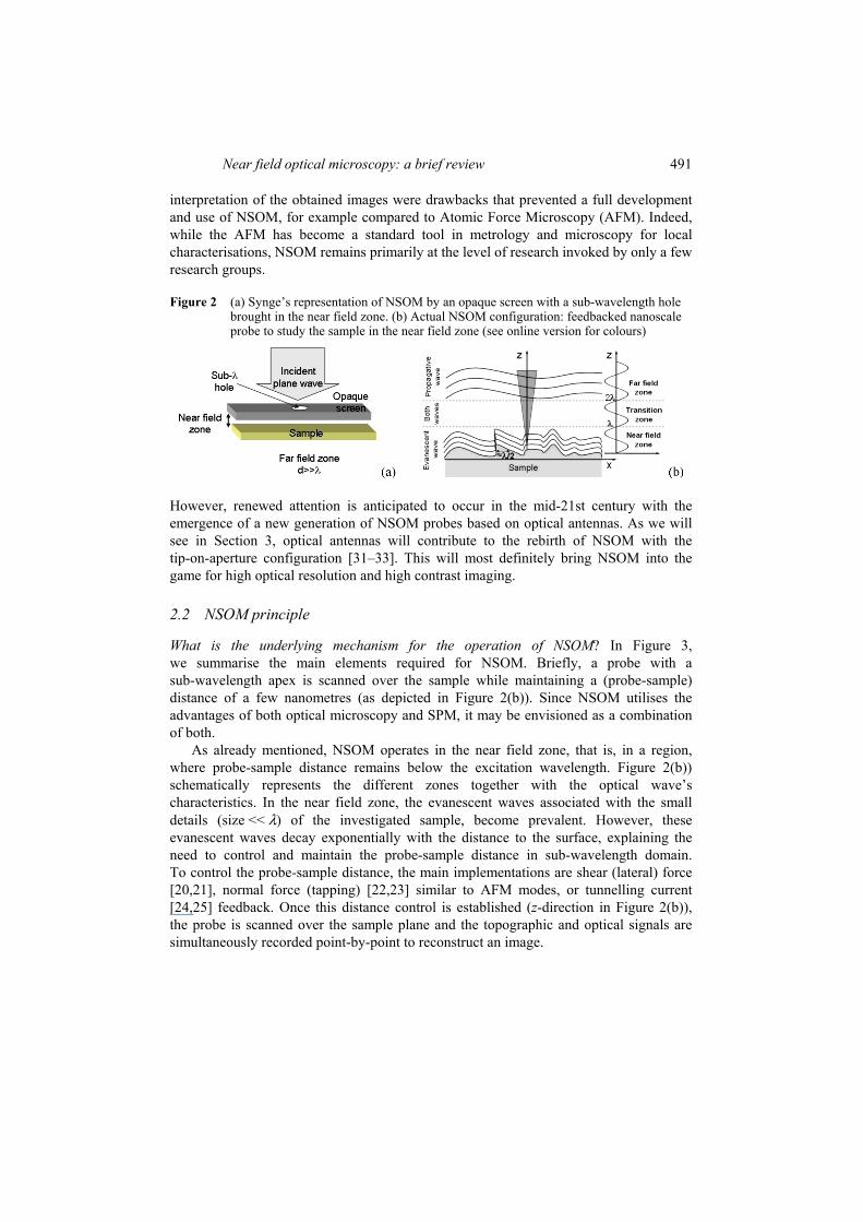
Figure 2 (a) Synge’s representation of NSOM by an opaque screen with a sub-wavelength hole brought in the near field zone. (b) Actual NSOM configuration: feedbacked nanoscale probe to study the sample in the near field zone (see online version for colours)
However, renewed attention is anticipated to occur in the mid-21st century with the emergence of a new generation of NSOM probes based on optical antennas. As we will see in Section 3, optical antennas will contribute to the rebirth of NSOM with the tip-on-aperture configuration [31–33]. This will most definitely bring NSOM into the game for high optical resolution and high contrast imaging.
2.2 NSOM principle
What is the underlying mechanism for the operation of NSOM? In Figure 3, we summarise the main elements required for NSOM. Briefly, a probe with a sub-wavelength apex is scanned over the sample while maintaining a (probe-sample) distance of a few nanometres (as depicted in Figure 2(b)). Since NSOM utilises the advantages of both optical microscopy and SPM, it may be envisioned as a combination of both.
As already mentioned, NSOM operates in the near field zone, that is, in a region, where probe-sample distance remains below the excitation wavelength. Figure 2(b)) schematically represents the different zones together with the optical wave’s characteristics. In the near field zone, the evanescent waves associated with the small details (size << λ) of the investigated sample, become prevalent. However, these evanescent waves decay exponentially with the distance to the surface, explaining the need to control and maintain the probe-sample distance in sub-wavelength domain. To control the probe-sample distance, the main implementations are shear (lateral) force [20,21], normal force (tapping) [22,23] similar to AFM modes, or tunnelling current [24,25] feedback. Once this distance control is established (z-direction in Figure 2(b)), the probe is scanned over the sample plane and the topographic and optical signals are simultaneously recorded point-by-point to reconstruct an image.

492 A.L. Lereu et al.
Figure 3 Near-field Scanning Optical Microscopy. The probe type and the feedback system are of prime importance for a given sample type. Numerous samples can be imaged and/or spectroscopically studied with the appropriate NSOM configuration (see online version for colours)
Therefore, on one hand, the main drawbacks are identified in the complexity of the technique and its slow speed of recording. But on the other hand, in addition to the high resolution achievement, one can access the morphological and ‘optical and chemical’ information simultaneously and correlate the two with the sub-wavelength precisions. This last asset is of importance to observe sub-wavelength objects such as fluorescent (chemical or biological) molecules, polymers, or quantum dots, or near field phenomena such as resonances in plasmonic devices or photonic crystals to mention a few. Several configurations have been developed over time to be adapted to the samples, and thus the associated physical effect, under study. In the upcoming section, we explain the most common NSOM configurations and the varieties of NSOM probes that also contributed to different configuration developments.
3 NSOM configurations and probes
3.1 Various configurations
The most basic form of an NSOM probe is therefore composed of an elongated optically conductive material such as a pulled optical fibre. To control and guide light a few tens of nanometre, a metal such as aluminium, can be deposited on the probe. Simplified examples of these probes are shown in Figure 4, where the TM field propagation into the probe is computed using finite element method to solve the electromagnetic wave equation. The field localisation and enhancement can be demonstrated in the static limit for spherical and ellipsoidal particles as in Figure 5 showing field confinement and enhancement at both edges of the particles in the direction of the excitation polarisation. Both the confinement and enhancement are more and more pronounced as the particles curvature becomes sharper (from Figure 5(a)–(c)). This calculation can now be adapted

Near field optical microscopy: a brief review 493
to the case of NSOM probes by considering half an ellipsoid, as shown in Figure 6 for a series of successively sharpened probes. While the actual field enhancement determination requires careful examination as the values generated can be mesh dependent, the overall field distribution is clearly demonstrated. During the evolution of NSOM, different configurations have been developed in the research laboratories around the world, giving rise to several denominations starting with Scanning Tunnelling Optical Microscope (STOM) and Photon Scanning Tunnelling Microscope (PSTM). They are based on the frustrated total internal reflection (FTIR), as illustrated by the FTIR configuration of Figure 7(b)), where the sample is illuminated with a totally reflected incident light engendering an evanescent wave. This technique is only intended for optically transparent samples. NSOM (or SNOM) is the general most commonly used terminology as it gathers all the denominations in only one. We depict in Figure 7 the most established configurations. They originate from three identified sources composing NSOM; the type of investigated sample or induced physical effect (see Section 3.3), the type of NSOM probes (see Section 3.2) and the corresponding optical path (illumination and detection).
Figure 4 Computed electromagnetic field coupled into unpulled and pulled optical fibres. (a) For uncoated fibres and (b) for Aluminium-coated fibres (see online version for colours)
Figure 5 Electric field distribution around a sphere (a) and ellipsoids with different curvatures (b) and (c). The field is enhanced and confined at the edges of the structures in the direction of the excitation field (E). This effect is more and more pronounced as the structure gets sharper and sharper (see online version for colours)
In general, the probes are categorised into two kinds: the ‘aperture’ or ‘sharp solid tip (apertureless)’ probes. They guide the optical path as they can serve either as

494 A.L. Lereu et al.
• a nano-source of light (illumination mode) that is collected in the far field, or as
• a nano-collector of light (collection mode) that is illuminated from far field, or sometimes as
• both near-field illuminator and collector (see Figure 7(a)).
In addition, the sample determines the measurements to be carried out (see Figure 7(b)) that can be: in transmission (with propagative (left of Figure 7(b)) or evanescent (right of Figure 7(b)) waves) where the sample has to be transparent, or in reflection where no condition on the sample is required. Finally, the last criterion considered to actually choose the appropriate NSOM configurations is the field of applications (or physical effect under study). For example, for fluorescence investigations, the aperture probe NSOM in illumination mode is mainly used whereas, for photonics/plasmonics studies, the aperture probe NSOM in collection or the apertureless NSOM in collection configurations are preferred. We give one example from our previous work in Section 3.3, but basically for fluorescence measurement one needs high optical contrast at the expense of the optical resolution (i.e., aperture probes) whereas in resonant phenomena, strong fields exist and therefore the optical contrast is not as critical as high resolution (i.e., apertureless probes).
Figure 6 Computed electric field at the apex of probes with different curvatures. From large curvature (a) down to the classical case for NSOM (f). In each case, the maximum of the E field (EMax) is located at the apex. As its radius decreases, E gets stronger and more localised. The inset of Figure (f) shows the E field distribution (see online version for colours)
Figure 7 The most exploited NSOM configurations. Their use is chosen with respect to the sample under study and the physical effect involved, defining the illumination mode and the corresponding NSOM probe to be used (see online version for colours)
Near field optical microscopy: a brief review 495
3.2 Variants of NSOM probes
As we mentioned above, the NSOM probes can be divided into two kinds: the aperture and apertureless types. However, here we briefly describe and distinguish NSOM probes via the constituting material and the fabrication process.
Optical fibres: The most widespread support for NSOM is pulled optical fibres that allow making apertureless and aperture probes. Starting from a pulling process that can be chemical [26,27] or mechanical [28–30], the apex of optical fibre is narrowed down to few tens of a nanometer. Thereafter, this pulled fibre can be either used directly or metal coated by vacuum deposition. One can lastly mill the apex of the covered pulled fibre, using Focused Ion Beam (FIB) [34], to fashion a well-defined aperture probe. For these latter, one usually utilises aluminium coating to create good optical guidance toward the tip apex whereas for apertureless probe gold is preferred (gold being optically interesting and inert).
Metallic tips: As in Scanning Tunnelling Microscope (STM), metallic tips are easy to make in a controlled way and with a large panel of materials using electrochemical techniques. They also benefit from the large knowledge from STM probes fabrication.
Microcantilevers: They have been developed for commercial AFM, and the NSOM technique benefited from it. They are reasonably cheap and can be reproducibly mass-produced. As for the optical fibres they can be designed as aperture or apertureless probes. For these reasons, they are mainly used in commercialised NSOM systems.
A combination of both the fibre-based and cantilever-based probes: These probes are made of bent optical fibres [35–37] used as a microcantilever. Although, these NSOM probes offer some advantages (i.e., AFM electronics), they are not extensively used as the optical losses are large due to the bent and the fabrication process is complicated and not well-developed.
3.3 Examples of NSOM uses
To briefly sum up, in order to obtain workable NSOM measurements, one needs
• a sample with interesting optical properties
• an appropriate NSOM probe
• a controlled feedback loop (see chart of Figure 3).
To give examples of NSOM applications, we concentrate only on near-field measurements pertaining to plasmonics and single molecule fluorescence imaging and spectroscopy, based on some of our early work.
NSOM and plasmonics
Looking at plasmon resonances with NSOM seems natural as the two concepts induced evanescent waves (EW); plasmon excitation implying an exponentially decaying wave at the interfaces and NSOM working in the near field zone. It actually started that way especially in the PSTM and STOM configurations but also in the earlier configurations. Large volumes of work can be found on NSOM and plasmonics and as an illustration, we briefly present some of our previous work using PSTM on thin metallic films [38–41].

496 A.L. Lereu et al.
In this work, illustrated in Figure 8, the Kretschmann configuration [42] was used to excite two counter-propagating surface plasmons at the dielectric prism and gold thin film interface. The used prism was a right angle prism in order to exploit total internal reflection to make the two surface plasmons interfere from the same extended laser beam. We thus established a plasmonic standing wave observed by PSTM. The PSTM probe (here a dielectric pulled fibre) was used to collect the signal from the established plasmonic standing wave. Different excitation wavelengths were used ranging from 488 nm up to 1550 nm highlighting various fringes separations from 185 nm up to 770 nm. We showed that plasmonic standing waves can be established over large areas with respect to the excitation wavelength. We suggested this technique as a good candidate for optical lithography, which was demonstrated as such very recently [43,44]. This field has lots of fundamental interests for light-matter interactions, as well as for applications such as plasmonic sensing, or the development of new photonic components.
Figure 8 PSTM imaging of plasmonic standing waves over 10 × 10λ. Two surface plasmons are excited simultaneously in opposite directions using the Kretschmann configuration and a 632.8 nm laser beam. θ p indicates the plasmon resonance angle (see online version for colours)
In the same field, we have studied the plasmon resonances in nanostructured films (or also called nanoantennas using aperture probes in transmission and reflection with fibre-based and microcantilever-based probes. You can find details on these observations in [45–47]. Note that numerous work were carried out on such nanostructures arrays, see [45–52] and references therein (to mention a few).
NSOM with fluorescence detection
Another domain of applications is by combining NSOM with single molecule detection [45,46,53–61]. In this field, the used NSOM configuration is mainly the aperture probe as a nano-source with detection in transmission in the far field. This configuration is preferred because illuminating local in the near field leads to a great optical contrast by eliminating any far field background. This is of great importance while imaging at the single molecule detection. This field attracted lots of research groups as fluorescent measurements are directly associated with markers utilised in biology imaging. Note also that combining NSOM with other ‘fluorescence’ techniques such Raman spectroscopy, Fourier Transform Infrared spectroscopy as well as Fluorescence correlation spectroscopy, attracted even more attention on NSOM with fluorescence detection capabilities.

Near field optical microscopy: a brief review 497
NSOM has the capability to image samples of large concentrations with high spatial resolution and to exploring faster dynamic processes (disabling the scanning aspect). However, even though the NSOM optical resolution is much better (80–100 nm) compared to confocal microscopy (widely used in biology and with a resolution around 300 nm), the complexity and delicacy of NSOM slowed down its evolution especially in biology where the observed samples are already very tricky to investigate. Note that lots of researches on NSOM also concentrate on increasing the speed of scanning to also improve the NSOM pliancy.
Two main directions can thus be considered to expand the use of NSOM in the biology field: apart from combining with other powerful techniques as cited above.
• make simpler the use of NSOM especially by using commercial probes (microcantilever-based) as in AFM
• improve even more the optical resolution to really gain in accessible information without losing optical contrast.
A question remains then, “How can we improve even more the NSOM optical resolution while keeping high optical contrast?”
To reply to this question, one has to have in mind that: aperture probes have high throughput leading therefore to high optical contrast but with resolution around 100 nm, and apertureless probes induce high resolution down to 15–20 nm but with an optical contrast disturbed by the far field illumination.
4 Toward a ‘super’ NSOM
Basically, we want to merge the best of both worlds that is high resolution (down to 15–20 nm) given by apertureless probes and background free (i.e., great optical contrast) of the aperture probes. A solution, proposed by Frey in 2002, is to graft a ‘nanoantenna’ (mimicking the apertureless probes) at the apex of an NSOM aperture probe [31,32]. This configuration was named tip-on-aperture configuration. Note that at that time, nanoantennas started to be extensively studied fundamentally and for applications in various fields. Nanoantennas [62–66] are sub-wavelength structures that can convert propagative waves into evanescent waves and conversely. Their extraordinary properties attracted lots of photonic-based developments.
In the field of NSOM, they were used to create new generations of NSOM probes. Starting from Frey’s proof-of-principle, intensive studies were carried out by Taminiau et al. [33,67] where a 25 nm resolution was reported on single molecules. Other approaches have been investigated in parallel, for example, with a bowtie milled at the end face of a NSOM microcantilever tip [68] or with a gold nanoparticles glued at the apex of an apertureless probes [69,70]. In the first case, they showed photoluminescence enhancement of a single quantum dot in the presence of the nanoantenna, whereas in the second case, they improve apertureless NSOM optical contrast by grafting a gold nanoantenna at the probe apex. These examples are just selected to highlight the added value of combining nanoantennas and NSOM probes. This is still an ongoing research but these new generations of NSOM probes have already updated NSOM capabilities toward biology applications such as cell membranes imaging [71–73]. Resolution down to 25 nm was already reported on single molecules [33,73]

498 A.L. Lereu et al.
and one expects to achieve 10 nm optical resolution. Another point that will contribute to push the NSOM toward an inescapable characterisation technique is to combine it with other techniques as we mentioned earlier. Undoubtedly, these new generations of NSOM probes, based on nanoantennas, and/or the combination of techniques will expand the NSOM capabilities and therefore will benefit its development and use.
Acknowledgements A.L. Lereu and Ph. Dumas want to acknowledge the program “Interface physique, biologie et chimie: soutien à la prise de risqué” from the CNRS and the C Nano PACA program for their financial supports. A. Passian would like to acknowledge the Laboratory Directed Research and Development (LDRD) Program of ORNL. ORNL is managed by UT-Battelle, LLC, for the US DOE under contract DE-AC05-00OR22725.
References 1 Pohl, D.W. and Novotny, L. (1994) ‘Near-field optics: light for the world of nano’,
J. Vac. Sci. Technol., B, Vol.12, pp.1441. 2 van Hulst, N.F. and Moers, M.H.P. (1996) ‘Biological applications of near-field optical
microscopy’, IEEE Eng. Med. Biol., Vol. 15, pp.51. 3 Dunn, R.C. (1999) ‘Near-field scanning optical microscopy’, Chem. Rev., Vol. 99, pp.2891. 4 Hecht, B., Sick, B., Wild, U.P., Deckert, V., Zenobi, R., Martin, O.J.F. and Pohl, D.W. (2000)
‘Scanning near-field optical microscopy with aperture probes: fundamentals and applications’, J. Chem. Phys., Vol. 112, pp.7761.
5 Kawata, S., Ohtsu, M. and Irie, M. (2001) Near-field Optics and Surface Plasmon Polaritons, Springer-Verlag, Berlin, Heidelberg.
6 De Serio, M., Zenobi, R. and Deckert, V. (2003) ‘Looking at the nanoscale: scanning near-field optical microscopy’, TrAC, Trends Anal. Chem., Vol. 22, pp.71.
7 Ohtsu, M. and Kobayashi, K. (2004) Optical Near Fields: Introduction to Classical and Quantum Theories of Electromagnetic Phenomena at the Nanoscale, Springer-Verlag, Berlin, Heidelberg.
8 Wiederrecht, G.P. (2004) ‘Near-field optical imaging of noble metal nanoparticles’, Eur. Phys. J. Appl. Phys., Vol. 28, pp.3.
9 Rasmussen, A. and Deckert, V. (2005) ‘New dimension in nano-imaging: breaking through the diffraction limit with scanning near-field optical microscopy’, Anal. Bioanal. Chem., Vol. 381, pp.165.
10 Girard, C. and Dujardin, E. (2006) ‘Near-field optical properties of top-down and bottom-up nanostructures’, J. Opt. A: Pure Appl. Opt., Vol. 8, pp.S73.
11 Girard, C. (2005) ‘Near fields in nanostructures’, Rep. Prog. Phys., Vol. 68, pp.1883. 12 Shi-fa, W. (2006) ‘Review of near field microscopy’, Front. Phys. Chin., Vol. 3, pp.263. 13 Lereu, A.L., Dumas, Ph., Garcia-Parajo, M., Passian, A., Farahi, R.H., Tetard, L. and
van Hulst, N.F. (2010) ‘Evolution of near field optical microscopy’, Proceeding ISA, IEEE-Future for Instrumentation.
14 Synge, E.H. (1928) ‘A suggested method for extending the microscopic resolution into the ultramicroscopic region’, The London, Edinburgh, and Dublin Philisophical Magazine and J. Sci., Vol. 6, pp.356.
15 Lewis, A., Isaacson, M., Harootunian, A. and Murray, A. (1984) ‘Development of a 500A spatial resolution light microscope’, Ultramicroscopy, Vol. 13, pp.227.

Near field optical microscopy: a brief review 499
16 Murray, A., Isaacson, M., Adesida, I. and, Whitehead, J. (1983) ‘Fabrication of apertures, slots, and grooves at the 8-80 nm scale in silicon and metal films’, J. Vac. Sci. Technol., Vol. 1, pp.1091.
17 Pohl, D.W., Denk, W. and Lanz, M. (1984) ‘Optical stethoscopy: image recording with resolution lambda/20’, Appl. Phys. Lett., Vol. 44, pp.651.
18 Reddick, R.C., Warmack, R.J. and Ferrell, T.L. (1989) ‘New form of scanning optical microscopy’, Phys. Rev. B, Vol. 39, pp.767.
19 Vigoureux, J.M., Girard, C. and Courjon, D. (1989) ‘General principles of scanning tunnelling optical microscopy’, Opt. Lett., Vol. 14, pp.1039.
20 Betzig, E., Finn, P.L. and Weiner, J.S. (1992) ‘Combined shear force and near-field scanning optical microscopy’, Appl. Phys. Lett., Vol. 60, pp.2484.
21 Ruiter, A.G.T., van der Werf, K.O., Veerman, J.A., Garcia-Parajo, M.F., Rensen, W.H.J. and van Hulst, N.F. (1998) ‘Tuning fork shear-force feedback’, Ultramicroscopy, Vol. 71, pp.149.
22 Antognozzi, M., Szczelkun, M.D., Round, A.N. and Miles, M.J. (2002) ‘Comparison between shear force and tapping mode AFM – High resolution imaging of DNA’, Single Mol., Vol. 3, pp.105.
23 Wetsel, G.C., Farahi, R.H., Richardson, C.J.K. and Spicer, J.B. (2001) ‘Approach interactions of scanned probes in dynamic pecking mode‘, Appl. Phys. Lett., Vol. 79, pp.2657.
24 Lieberman, K. and Lewis, A. (1993) ‘Simultaneous scanning tunnelling and optical near-field imaging with a micropipette’, Appl. Phys. Lett., Vol. 62, pp.1335.
25 Garcia-Parajo, M., Cambril, E. and Chert, Y. (1994) ‘Simultaneous scanning tunnelling microscope and collection mode scanning near-field optical microscope using gold coated optical fiber probes’, Appl. Phys. Lett., Vol. 65, pp.1498.
26 Puygranier, B.A.F. and Dawson, P. (2000) ‘Chemical etching of optical fibre tips – experiment and model’, Ultramicroscopy, Vol. 85, pp.235.
27 Ohtsu, M. (1995) ‘Photon STM: from imaging to fabrication’, Optoelectron.-Devices Technol., Vol. 10, pp.147.
28 Valaskovic, G.A., Holton, M. and Morrison, G.H. (1995) ‘Parameter control, characterization and optimization in the fabrication of optical fiber near-field probes’, Appl. Opt., Vol. 34, pp.1215.
29 Yakobson, B.I. and Paesler, M.A. (1995) ‘Kinetics, morphology and pulling regimes for sensing tips in near-field microscopy’, Ultramicroscopy, Vol. 57, pp.241.
30 Garcia-Parajo, M., Tate, T. and Chen, Y. (1995) ‘Gold-coated parabolic tapers for scanning near field optical microscopy: fabrication and optimisation’, Ultramicroscopy, Vol. 61, pp.155.
31 Frey, H.G., Keilmann, F., Kriele, A. and Guckenberger, R. (2002) ‘Enhancing the resolution of scanning near-field optical microscopy by a metal tip grown on an aperture probe’, Appl. Phys. Lett., Vol. 81, pp.5030.
32 Frey, H.G., Witt, S., Felderer, K. and Guckenberger, R. (2004) ‘High-resolution imaging of single fluorescent molecules with the optical near-field of a metal tip’, Phys. Rev. Lett., Vol. 93, pp.200801.
33 Taminiau, T.H., Moerland, R.J., Segerink, F.B., Kuipers, L. and van Hulst, N.F. (2007) ‘l/4 resonance of an optical monopole antenna probed by single molecule fluoresence’, Nano Lett., Vol. 7, pp.28.
34 Veerman, J.A., Otter, A.M., Kuipers, L. and van Hulst, N.F. (1998) ‘High definition aperture probes for near-field optical microscopy fabricated by focused ion beam milling’, Appl. Phys. Lett., Vol. 72, pp.3115.

500 A.L. Lereu et al.
35 Burgos, P., Lu, Z., Ianoul, A., Hnatovsky, C., Viriot, M.L., Johnston, L.J. and Taylor, R.S. (2003) ‘Near-field scanning optical microscopy probes: a comparison of pulled and double-etched bent NSOM probes for fluorescence imaging of biological samples’, J. Microscopy, Vol. 211, pp.37.
36 Lieberman, K., Ben-Ami, N. and Lewis, A. (1996) ‘A fully integrated near-field optical, far-field optical, and normal-force scanned probe microscope’, Rev. Sci. Instrum., Vol. 67, pp.3567.
37 Talley, C.E., Cooksey, G.A. and Dunn, R.C. (1996) ‘High resolution fluorescence imaging with cantilevered near-field fiber optic probes’, Appl. Phys. Lett., Vol. 69, pp.3809.
38 Passian, A., Ritchie, R.H., Lereu, A.L., Thundat, T. and Ferrell, T.L. (2005) ‘Curvature effects in surface plasmon dispersion and coupling’, Phys. Rev. B, Vol. 71, pp.115425.
39 Passian, A., Lereu, A.L., Wig, A., Meriaudeau, F. and Thundat, T. and Ferrell, T.L. (2005) ‘Imaging standing surface plasmons by photon tunneling’, Phys. Rev. B, Vol. 71, pp.165418.
40 Passian, A., Wig, A., Lereu, A.L., Meriaudeau, F., Thundat, T. and Ferrell, T.L. (2004) ‘Photon tunneling via surface plasmon coupling’, Appl. Phys. Lett., Vol. 85, pp.3420.
41 Passian, A., Wig, A., Lereu, A. L., Evans, P.G., Meriaudeau, F., Thundat, T. and Ferrell, T.L. (2004) ‘Probing large area surface plasmon interference in thin metal films using photon scanning tunneling microscopy’, Ultramicroscopy, Vol. 100, pp.429.
42 Kretschmann, E. (1971) ‘The determination of the optical constants of metals by excitation of surface plasmons’, Z. Phys., Vol. 241, pp.313.
43 Sreekanth, K.V. and Murukeshan, V.M. (2010) ‘Large-area maskless surface plasmon interference for one- and two-dimensional periodic nanoscale feature patterning’, JOSA A, Vol. 27, pp.95.
44 Sreekanth, K.V. and Murukeshan, V.M. (2010) ‘Single-exposure maskless plasmonic lithography for patterning of periodic nanoscale grating features‘, J Micro-Nanolithography MEMS and MOEMS, Vol. 9, pp.023007.
45 Lereu, A.L., Sanchez-Mosteiro, G., Ghenuche, P., Quidant, R. and van Hulst, N.F. (2008) ‘Individual gold dimers investigated by far and near-field imaging’, J. Microscopy, Vol. 229, pp.254.
46 Lereu, A.L., Sanchez-Mosteiro, G., Ghenuche, P., Passian, A., Quidant, R., Garcia-Parajo, M. and van Hulst, N.F. (2008) ‘Probing the local field of nanoantennas using single particle luminescence’, J. Phys. D, Vol. 100, pp.052038.
47 Lereu, A.L., Passian, A., Farahi, R.H., Abel-Tiberini, L., Tetard, L. and Thundat, T. (2011–2012) ‘Imaging and spectroscopy of arrays of optical nanorods toward polarimetric uses’, in process in Nanotechnology.
48 Imura, K. and Okamoto, H. (2006) ‘Reciprocity in scanning nearfield optical microscopy: illumination and collection modes of transmission measurements’, Opt. Lett., Vol. 31, pp.1474.
49 Mojarad, N.M., Zumofen, G., Sandoghdar, V. and Agio, M. (2009) ‘Metal nanoparticles in strongly confined beams: transmission, reaction, and absorption’, JEOS, Vol. 4, pp.09014.
50 Foteinopoulou, S., Vigneron, J. P. and Vandenbem, C. (2007) ‘Optical near-field excitations on plasmonic nanoparticle-based structures’, Opt. Express, Vol. 15, pp.4253.
51 Ghenuche, P., Cherukulappurath, S., Taminiau, T. H., van Hulst, N. F. and Quidant, R. (2008) ‘Spectroscopic mode mapping of resonant plasmon nanoantennas’, Phys. Rev. Lett., Vol. 101, pp.116805.
52 Passian, A., Koucheckian, S., Yakubovich S. and Thundat, T. (2010) ‘Properties of index transforms in modeling of nanostructures and plasmonic systems’, J. Math. Phys., Vol. 51, pp.023518.
53 Veerman, J.A., Garcia-Parajo, M.F., Kuipers, L. and Van Hulst, N.F. (1999) ‘Single molecule mapping of the optical field distribution of probes for near-field microscopy’, J. Microscopy, Vol. 194, pp.477.

Near field optical microscopy: a brief review 501
54 Enderlein, J. (2000) ‘Theoretical study of detection of a dipole emitter through an objective with high numerical aperture’, Opt. Lett., Vol. 25, pp.634.
55 Gersen, H., Garcia-parajo, M.F., Novotny, L., Veerman, J.A., Kuipers, L. and van Hulst, N.F. (2000) ‘Influencing the angular emission of a single molecule’, Phys. Rev. Lett., Vol. 85, pp.5312.
56 Yang, T.J., Lessard, G.A. and Quake, S.R. (2000) ‘An apertureless near-field microscope for fluoresence imaging’, Appl. Phys. Lett., Vol. 76, pp.378.
57 Wenger, J., Lenne, P-F., Popov, E., Rigneault, H., Dintinguer, J. and Ebbesen, T.W. (2005) ‘Single molecule fluorescence in rectangular nano-aperture’, Opt. Express, Vol. 13, pp.7035.
58 Garcia-Parajo, M.F., Koopman, M., van Dijk, E.M.P.H., Subramaniam, V. and van Hulst, N.F. (2001) ‘Photodynamical behaviour of the red fluorescent protein DsRed: a single molecule study’, Proc. Nat. Acad. Sci. U.S.A., Vol. 98, pp.14392.
59 Hernando, J., de Witte, P., van Dijk, E.M.H.P., Rowan, A., Nolte, R., Garcia-Parajo, M.F. and van Hulst, N.F. (2004) ‘Investigation of Perylene Photonic nanowires by combined single molecule fluorescence and atomic force microscopy’, Angew. Chem. Int. Ed., Vol. 43, pp.4045.
60 Hoogenboom, J.P., Hernando, J., García-Parajó, M.F. and van Hulst, N.F. (2008) ‘Memory in single emitter fluorescence blinking reveals the dynamic character of nanoscale charge tunneling’, J. Phys. Chem. C, Vol. 112, pp.3417.
61 Vallée, R.A.L., Tomczak, N., Vancso, G.J., Kuipers, L. and van Hulst, N.F. (2005) ‘Fluorescence lifetime fluctuations of single molecules probe local density fluctuations in disordered media’, J. Chem. Phys., Vol. 122, pp.114704.
62 Novotny, L. and van Hulst, N.F. (2011) ‘Antenna for light’, Nat. Photonics, Vol. 5, pp.83. 63 Bharadwaj, P., Deutsch, B. and Novotny, L. (2009) ‘Optical antennas’, Advances in Optics
and Photonics, Vol. 1, pp.438. 64 Zhao, W. and Karp, J.M. (2009) ‘Nanoantennas heat up’, Nat. Mater., Vol. 8, pp.453. 65 Novotny, L. and Hecht, B. (2006), Principles of Nano-Optics, Cambridge Univ. Press,
Cambridge. 66 Mühlschlegel, P., Eisler, H.-J., Martin, O.J.F., Hecht, B. and Pohl, D.W. (2005) ‘Resonant
optical antennas’, Science, Vol. 308, pp.1607. 67 Taminiau, T.H., Stefani, F.D., Segerink, F.B. and van Hulst, N.F. (2008) ‘Optical antennas
direct single molecule emission’, Nat. Photonics, Vol. 2, pp.234. 68 Farahani, J.N., Pohl, D.W., Eisler, H.-J. and Hecht, B. (2005) ‘Single quantum dot coupled to
a scanning optical antenna: a tunable superemitter’, Phys. Rev. Lett., Vol. 95, pp.017402. 69 Eghlidi, H., Geol Lee, K., Chen, X-W., Gotzinger, S. and Sandoghdar, V. (2009) ‘Resolution
and enhancement in nanoantenna-based fluorescence microscopy’, Nano Lett., Vol. 9, pp.4007.
70 Palomba, S. and Novotny, L. (2009) ‘Near-field imaging with a localized nonlinear light source’, Nano Lett., Vol. 9, pp.3801.
71 van Zanten, T.S., Cambi, A. and Garcia-Parajo, M.F. (2010) ‘A nanometer scale optical view on the compartmentalization of cell membranes’, Biochim. Biophys. Acta, Vol. 1798, pp.777.
72 de Bakker, B.I., Bodnár, A., van Dijk, E.M.H.P., Vámosi, G., Damjanovich, S., Waldmann, T.A. et al. (2007) ‘Nanometer-scale organization of the alpha subunits of the receptors for IL2 and IL15 in human T lymphoma cells’, J. Cell Sci., Vol. 121, pp.627.
73 Garcia-parajo, M.F. (2008) ‘Optical antennas focus in on biology’, Nat. Photonics, Vol. 2, pp.201.
The author has requested enhancement of the downloaded file. All in-text references underlined in blue are linked to publications on ResearchGate.The author has requested enhancement of the downloaded file. All in-text references underlined in blue are linked to publications on ResearchGate.


![Near-Field Optical Microscopy - Indico [Home]indico.ictp.it/event/a04179/session/16/contribution/11/material/0/0.pdf · Optical microscopy Electron microscopy' Near-field optical](https://static.fdocuments.net/doc/165x107/5ed73d31d37f9f58ca6a86bf/near-field-optical-microscopy-indico-home-optical-microscopy-electron-microscopy.jpg)