NEAP - Final Report · 1 NEAP North European CNS/ATM Applications Project FINAL REPORT FOR...
119
1 NEAP North European CNS/ATM Applications Project FINAL REPORT FOR PUBLICATION Contract: AI-97-SC.1180
Transcript of NEAP - Final Report · 1 NEAP North European CNS/ATM Applications Project FINAL REPORT FOR...
1
NEAPNorth European CNS/ATM Applications Project
FINAL REPORT FOR PUBLICATION
Contract: AI-97-SC.1180

2
DOCUMENT CONTROLVersion Status Date Page(s) affected Reason0.1 Draft 15 February 1999 New document First draft0.2 Draft 17 February 1999 Multiple Review0.3 Draft 15 May 1999 Multiple EC and partners
review1.0 Final 12 June 1999 All Released ver-
sion
DOCUMENT PURPOSE AND SCOPEThis document is Volume 3 of the Final Summary and Conclusion Report submittedafter the completion of the North European CNS/ATM Application Project (NEAP). Itprovides a detailed overview of the objectives, assumptions, methodology, testing,results, and conclusions of the Project.The Final Summary and Conclusion Report is divided into three Volumes:
1. Executive Summary,2. Final Consolidated Progress Report with an Appendix and several Annexes,3. Final Report for Publication (this volume).Each of these Volumes is a separate and standalone document with its own intendedaudience.
Together with the Executive Summary in Volume 1, Volume 2 comprises the full re-port, including all contracted documentation for all applications evaluated in the Proj-ect, and is primarily intended for the European Commission, the Project’s SteeringCommittee and the participating organisations.
Volume 3 provides a fairly detailed overview of the Project and its conclusions andrecommendations, and is intended to enable the results to be brought to a wideraudience within the aviation industry. It includes an Executive Summary intended asa broad overview of the Project. It should be noted that the structure of the ExecutiveSummary differs slightly from that of the main report in this volume.
The emphasis in the main report in this volume is on the testing and evaluation of theindividual applications and services. Care has been taken to explain the operationalcontext of the respective application, i.e. a comparison between the currently usedtechnique and that offered in the future by employing a data link. Each applicationdescription also includes the hypotheses, or assumptions, on operational benefitsand technical characteristics and properties established prior to commencement ofthe testing and evaluation activities, the results, and recommendations for future im-provements.
3
TABLE OF CONTENTS
DOCUMENT PURPOSE AND SCOPE 2 ABBREVIATIONS AND ACRONYMS 6
EXECUTIVE SUMMARY
1 SPONSORSHIP AND PARTNERS 8
2 OBJECTIVES 83 PROJECT LIFE CYCLE 8
4 TECHNOLOGY BACKGROUND 95 THE GATE-TO-GATE CONCEPT 106 NEAP APPLICATIONS 106.1 Automatic Dependent Surveillance Broadcast 10 6.2 Pilot situation awareness 106.3 Enhanced ATC surveillance 116.4 GNSS augmentation 116.5 Communications 117 TEST ENVIRONMENT 128 RELATIONSHIP WITH OTHER PROJECTS 129 METHODOLOGY 1210 APPLICATIONS 1310.1 Precision navigation 1310.2 On-ground situation awareness and taxi guidance 1410.3 In-flight situation awareness 1510.4 Enhanced surveillance for ATC 1710.5 Automatic Terminal Information Service-Broadcast 1810.6 Extended helicopter surveillance 1910.7 Runway Incursion monitoring 20
11 CERTIFICATION ROAD MAP 2111.1 Certification activities 2111.2 NEAP certification analysis 2211.3 Recommendations 2212 CONSOLIDATED CONCLUSIONS AND RECOMMENDATIONS 2312.1 General 2312.2 Conclusions 2312.3 Recommendations 24
FINAL REPORT
1 OVERVIEW 251.1 General 251.2 Partnership 251.3 Project life cycle 26
2 SETTING THE SCENE 262.1 Scope 262.2 The CNS/ATM concept 26
4
2.2.1 Automatic dependent Surveillance - Broadcast 262.2.2 Pilot situation awareness 272.2.3 Enhanced ATC surveillance 272.2.4 GNSS augmentation 272.2.5 Communications 282.3 The gate-to-gate concept 282.4 Relationship with other projects 283 APPROACH 293.1 Objectives 293.1.1 Overall objectives 293.1.2 Specific objectives 293.2 Test environment 303.3 Methodology 31
4 SCIENTIFIC AND TECHNICAL DESCRIPTION 314.1 Technology background 314.1.1 STDMA/VDL Mode 4 324.1.2 Display equipment 334.1.3 NEAN infrastructure 344.1.4 Applications and services evaluated 354.1.5 Expected benefits 354.2 Application reports 354.2.1 GNSS precision navigation capability for en-route and approach 354.2.1.1 Service description 354.2.1.2 Assumptions 384.2.1.3 Test set-up 414.2.1.4 Testing and evaluation 414.2.1.5 Results and conclusions 434.2.1.6 Recommendations for system improvements 474.2.1.7 Future plans 484.2.2 On-ground situation awareness and taxi guidance 494.2.2.1 Service description 494.2.2.2 Assumptions 504.2.2.3 Test set-up 524.2.2.4 Testing and evaluation 544.2.2.5 Results and conclusions 554.2.2.6 Recommendations for system improvements 574.2.2.7 Future plans 574.2.3 In-flight situation awareness 574.2.3.1 Service description 574.2.3.2 Assumptions 594.2.3.3 Test set-up 604.2.3.4 Testing and evaluation 634.2.3.5 Results and conclusions 644.2.3.6 Recommendations for system improvements 654.2.3.7 Future plans 654.2.4 Enhanced surveillance for ATC 664.2.4.1 Service description 664.2.4.2 Assumptions 674.2.4.3 Test set-up 684.2.4.4 Testing and evaluation 704.2.4.5 Results and conclusions 714.2.4.6 Recommendations for system improvements 734.2.4.7 Future plans 73
5
4.2.5 Automatic Terminal Information Service - Broadcast 744.2.5.1 Service description 744.2.5.2 Assumptions 764.2.5.3 Test set-up 774.2.5.4 Testing and evaluation 794.2.5.5 Results and conclusions 794.2.5.6 Recommendations for system improvements 814.2.5.7 Future plans 824.2.6 Extended helicopter surveillance 824.2.6.1 Service description 824.2.6.2 Assumptions 834.2.6.3 Test set-up 844.2.6.4 Testing and evaluation 864.2.6.5 Results and conclusions 894.2.6.6 Recommendations for system improvements 924.2.6.7 Future plans 924.2.7 Runway incursion monitoring 924.2.7.1 Service description 924.2.7.2 Assumptions 944.2.7.3 Test set-up 974.2.7.4 Testing and evaluation 994.2.7.5 Results and conclusions 1014.2.7.6 Recommendations for system improvements 1034.2.7.7 Future plans 1035 CERTIFICATION ROAD MAP 1045.1 Analysis: General overview 1045.2 Legal issues 1055.2.1 EU Council Regulation 3922/91/EEC: Aircraft and Avionics 1055.2.2 Council Directive 93/65/EEC: The Directive 1065.2.3 Other legislation 1065.2.3.1 Council Regulation 83/189/EEC: Technical Standards and Regulations 1065.2.3.2 Council Decision 93/465/EEC: The Module Directive 1065.2.4 Summary of legal survey 1075.3 Certification status of NEAP applications 1075.3.1 Station keeping using airborne situation awareness - CDTI 1075.3.1.1 FMS/EFIS integration 1085.3.1.2 The CDTI vs RDP vs visual 1085.3.2 ATIS Broadcast at European airports 1105.3.3 IPV approach with combined ADS-B/DGPS broadcast ground station 1105.4 Aircraft design considerations 1125.5 Ground infrastructure design requirements 1135.6 Required certification standards 1145.7 Ground equipment standards 1145.8 Developing a road map 1155.9 Certification costs 1155.10 Benefits and certification strategy 1155.11 Further certification work 1165.12 Summary 1175.12.1 Recommendations 1176 CONSOLIDATED CONCLUSIONS AND RECOMMENDATIONS 1176.1 Conclusions 1176.2 Recommendations 1176.3 Lessons learned 118
6
ABBREVIATIONS AND ACRONYMS
a/c aircraftACARS Aircraft Communication and
Reporting SystemACAS Aircraft Collision Avoidance
SystemACD Alert Condition DefinitionADS Automatic Dependent Surveil-
lanceADS-B ADS-BroadcastAEEC Aeronautical Electrical Engi-
neering CommitteeAFTN Aeronautical Fixed Telecom-
munications NetworkAGH Ängelholm AirportAIRLINK Product name of CWP devel-
oped by DASA NFSAOM Aircraft Operation ManualARCO AIRINC CODER (ARINC 429
converter tool)ARN Stockholm-Arlanda AirportASTERIX All purpose Structured Euro-
control Radar Information eX-change
ATC Air Traffic ControlATIS Automatic Terminal Information
ServiceATM Air Traffic ManagementATIS Automatic Terminal Information
ServiceATIS-B ATIS-BroadcastAWOP All Weather Operations Panel
B-RNAV Basic RNAV
CAT [approach] Category (I, II,III)CATCAS Copenhagen Air Traffic Control
Automated SystemCCC Cellular CNS ConceptCDTI Cockpit Display of Traffic In-
formationCDU Control and Display UnitCFIT Controlled Flight Into TerrainCM1 Crew Member #1 (Captain)CM2 Crew Member #2 (First officer)CNS Communications, Navigation,
SurveillanceCPDLC Controller-Pilot Data Link
CommunicationsCWP Controller Working Position
DAP Downlink of aircraft parametersDCAA Danish Civil Aviation Admini-
stration (SLV)
DFS Deutsche Flugsicherung GmbHDGNSS Differential GNSSDGPS Differential GPSDIAS-3100 Product name for Raytheon
SCAT-I systemDLH Deutsche LufthansaDLR Deutsche Institut für Luft und
RaumfahrtD-RIMS Distributed RIMS
EASA European Aviation SafetyAuthority
EHS Extended Helicopter Surveil-lance
EFIS Electronic Flight InstrumentSystem
EFR Extended Flight Rules (exten-sion to IFR and VFR)
ENH Enhanced Surveillance for ATCETSI European Telecommunications
Standardisation InstituteEUROCAE EURopean Organisation for Civil
Aviation Equipment
FAT Factory Acceptance TestFIS Flight Information ServicesFIS-B FIS-BroadcastFL Flight LevelFMC Flight Management ComputerFMS Flight Management SystemFREER FREE Route experiment
GBAS Ground-Based AugmentationSystem
GNSS Global Navigation SatelliteSystem
GPS Global Positioning SystemGRAS GNSS Regional Augmentation
SystemGRPU GNSS and Radar Processing
Unit
HMI Human-Machine Interface
ICAO International Civil Aviation Or-ganization
IFR Instrument Flight RulesILS Instrument Landing SystemIMC Instrument Meteorological
ConditionsIPV Instrument Approach with Ver-
tical Guidance
JAA Joint Aviation AuthoritiesJAR Joint Aviation Requirements
7
JTSO Joint Technical Standards Or-der
LINCS Product name for SAABSTDMA/VDL Mode 4 trans-ponder
LFV Luftfartsverket (SCAA)
MMI5000 Product name for cockpit dis-play manufactured by Car-menta
NAAN North Atlantic ADS-B NetworkND Navigation DisplayNDB Non-Directional BeaconNEAN North European AD-B Network
(project)NEAP North European CNS/ATM Ap-
plications ProjectNUP NEAN Update ProgrammeNM Nautical MileNPA Non-Precision ApproachNUP NEAN Update Programme
OBT Operational Benefit Test
PA precision Approach
PETAL Preliminary Eurocontrol Test ofAir/ground data Link
PFD Primary Flight Display
RIMS Runway Incursion MonitoringSystem
RAIM Receiver Autonomous IntegrityMonitoring
RMCDE Radar Message Conversionand Distribution Equipment
RTCA Requirements and TechnicalConcepts for Aviation
RNAV Area Navigation
RNP Required Navigation Perform-ance
SAR Search and RescueSAS Scandinavian AirlinesSAT Site Acceptance TestSCAA Swedish Civil Aviation Admini-
stration (SCAA)SCAT-I Special Category ISCT System Characteristics TestSLV Statens Luftfartsvaesen
(DCAA)SMR Surface Movement RadarSTAR Standard instrument Arrival
RouteSTDMA Self-organising Time Division
Multiple AccessSUPRA Support for the Use of PRes-
ently unserved Airspace
TA Traffic AdvisoryTCAS Traffic Collision Avoidance
SystemTDI Track Deviation IndicatorTEN-T Trans-European NetworkTIS Traffic Information ServicesTIS-B TIS-BroadcastTSO Technical Service OrderTWR Control Tower
VDL VHF Digital LinkVFR Visual Flight RulesVHF Very High FrequencyVMC Visual Meteorological Condi-
tions
WAN Wide Area NetworkWIAS Weather Information Auto-
mated Systems
8
EXCUTIVE SUMMARY
1 SPONSORSHIP AND PARTNERS The North European CNS/ATM Applications Project (NEAP) was sponsored by theDirectorate General VII of the Commission of the European Union within the frame-work of the Trans-European Transport Network (TEN-T).The following organisations participated in the project:
� Deutsche Lufthansa (DLH)� Scandinavian Airlines (SAS)� Deutsche Flugsicherung GmbH (DFS)� Statens Luftfartsvaesen; the Danish Civil Aviation Organisation (DCAA)� Luftfartsverket; the Swedish Civil Aviation Organisation (SCAA).
Each of the project partners was responsible for activities within a specific segmentof the project, but activities were closely co-ordinated across segment boundaries.
2 OBJECTIVESThe overall project objectives of NEAP were to investigate, specify, develop, test andevaluate civil aviation user applications and services within an integrated communi-cations, navigation and surveillance (CNS) concept. Activities focused on the follow-ing domains:
� Enhanced surveillance for Air Traffic Control (ATC)� Pilot situation awareness� GNSS (Global Navigation Satellite System) Precision navigation capability for
all phases of flight.
Each of these domains includes one or more applications that cover aspects of allphases of flight in a gate-to-gate concept. Therefore, the testing and evaluation ac-tivities included the verification of the suitability of a single technical system solutionto support ATC and aircrew from pushback to docking at the arrival gate.
The NEAP project objectives must be viewed on two levels. Overall project objectivesrelate to the suitability of a single integrated CNS system to support a range of op-erational services and multiple phases of flight. Specific objectives relate to the ca-pability and suitability of that system to support individual applications and services.Evaluation of individual applications and services also addressed the potential bene-fits to be gained by their use in a future CNS/ATM concept. Application-specific ob-jectives were also defined.
The project designation NEAP implies an applications oriented project, which meansthat emphasis was on operational suitability rather than technical performance. How-ever, applications and technical performance are closely linked - poor system techni-cal performance inevitably leads to poor operational performance and therefore lowrating by operators. International standardisation organisations also place formaltechnical requirements on applications, such as update rate, accuracy and reliability.The testing and evaluation of applications in NEAP therefore in effect also applied tothe capability of the technical system to support those applications. Therefore, testing
9
and evaluation of the system characteristics and performance formed an importantpart of NEAP activities.
3 PROJECT LIFE CYCLENEAP started on 1 September 1997 and ended on 31 December 1998.
4 TECHNOLOGY BACKGROUNDThe International Civil Aviation Organisation (ICAO) has adopted the CNS/ATM con-cept. This concept envisages the use of data link communications, satellite naviga-tion systems and automatic dependent surveillance (ADS) in the future provision ofair traffic management (ATM). When implemented, this new global system will pro-vide the aviation community with cost-effective replacement of current systems andtechnology.
A number of projects are ongoing world-wide to determine how to implement the mixof satellite, air and ground technologies in the most optimal way. To achieve thegreatest benefits from the introduction of the new technology all airspace users mustbe appropriately equipped. The required equipment has to be affordable and suitablefor all user groups. This implies that future systems will have to be based on multi-purpose, low cost equipment. The applications using this equipment must be userfriendly.
The Self-organising Time Division Multiple Access (STDMA) technology was devel-oped to meet the requirements for a low-cost data link to support a range of CNSdomains. Several national and international projects have focused on the demonstra-tion of the basic technology and its application in support of ground and airborne us-ers, and work on international standardisation is ongoing. ICAO has adopted VDL(VHF Digital Link) Mode 4 as the designation for the STDMA technology when stan-dardised for civil aviation.
STDMA was the enabling technology in NEAP, providing the necessary platform forthe testing and evaluation.
Operating in the VHF band, STDMA/VDL Mode 4 is capable of handling time-criticalinformation in well-defined time slots for air-to-air, air-to-ground and ground-to-ground data communications. Messages can be broadcast to all users or addressedto specific users (end-to-end). The primary application of the technology is ADS-Broadcast (ADS-B), which provides not only controllers, but pilots too, with a highlyaccurate display of nearby traffic. The North European ADS Broadcast Network(NEAN) project, another project sponsored by the European Commission and a sisterproject of NEAP, provides the ground and air infrastructure to allow the extensivetesting of specific CNS/ATM applications conducted within NEAP to take place. TheNEAN ground infrastructure consists of a number of ground stations that provideconsistent VHF coverage across a large part of northern Europe. A ground stationexchanges data through the STDMA/VDL Mode 4 data link with “transponder”equipment onboard aircraft and ground vehicles, and with other ground stationsthrough the ground network.User display equipment were key to the testing conducted in NEAP. Six DLH B747s,two SAS F28s and two DC9s, one MAERSK helicopter, one DLR Do-228 and severalground vehicles formed the backbone of mobile platforms used in the testing.
10
5 THE GATE-TO-GATE CONCEPTToday, a range of dissimilar and segregated communication, navigation and surveil-lance systems supports pilots and controllers in different phases of flight and air-space types. The emergence of data link services creates an opportunity to establishintegrated, “seamless” gate-to-gate services to pilots and ATC alike. In NEAP, sev-eral examples of data link applications and services, based on a single technicalplatform, were tested and evaluated.
6 NEAP APPLICATIONSThe data link applications tested and evaluated in NEAP are essential for meetingthe requirements of the future CNS/ATM system. The following applications were in-cluded in the test program (the responsible organisation is given within brackets):
� GNSS precision navigation capability for en-route and approach (SAS)� On ground situation awareness/ taxi guidance (DLH)� In-flight situation awareness (DLH)� Enhanced ATC surveillance – downlink of aircraft parameters (DFS)� Automatic Terminal Information Service broadcast; ATIS-B (DFS)� Extended helicopter surveillance (DCAA)� Runway incursion (SCAA).
Hence at least one application, or service, of each component of the CNS/ATM con-cept was included in NEAP. Combined, they demonstrate a single system solutionfor seamless gate-to-gate operations, i.e. a system that supports pilot and controllersin all phases of flight from the departure gate, through pushback, taxiing, take-off,climb, en-route, descent, approach, landing and taxiing to docking at the arrival gate.
Following is a brief, generic, description of the fundamental techniques on whichthese applications and services are based. A more detailed description of each par-ticular application/service is given later in this summary.
6.1 Automatic Dependent Surveillance - BroadcastAutomatic Dependent Surveillance - Broadcast (ADS-B) is a new aviation surveil-lance concept whereby aircraft transmit their positions (usually derived from a GNSSreceiver on-board the aircraft) over a radio data link. In a fully implemented system,position information is transmitted and received by every aircraft in the vicinity so thatall users have knowledge of their own location and the locations of all other aircraft.The position information may be displayed in the cockpit of suitably equipped aircraftto give new situation awareness capabilities. Also, ground vehicles and fixed groundstations can be equipped to transmit and receive position data, allowing surveillanceof all types of traffic and a two-way data link capability.
ADS-B is an enabling technology that can help to deliver the free flight concept toairspace users. ADS-B will provide new surveillance capabilities to ATC at reducedcost compared to conventional radar.
STDMA/VDL Mode 4 supports ADS-B for all phases of flight. For ground operations,it allows taxiing aircraft and airport vehicles to be monitored from the control tower.This could provide a safety net against unintentional runway incursion.
11
6.2 Pilot situation awarenessData link communications will remove the “party line”, i. e. the possibility for pilots tomonitor the voice communications between ATC and other aircraft. Pilots will there-fore lose their present situation awareness. ADS-B, with an appropriate cockpit dis-play (commonly known as a Cockpit Display of Traffic Information (CDTI)), gives amuch better situation awareness to help overcome this concern. ADS-B and a CDTIwill provide the pilot with full situation awareness of all surrounding traffic, includingintent as appropriate, and will also show the own aircraft position superimposed on amoving map in all phases of flight. As ADS-B also works on the ground, a CDTI maybe used to support taxiing and detect other aircraft and airport vehicles in low visibil-ity conditions.
6.3 Enhanced ATC surveillanceADS-B data transmitted will provide accurate and reliable surveillance information forground ATC. This information can be used to enhance the quality of surveillance. Forexample, position data can be supplemented with aircraft parameter data from theFMS or airborne computers. Such data can also be used by the airline technical sup-port.
6.4 GNSS augmentationWhen using GNSS data for navigation or surveillance, a GNSS augmentation systemcan be used to improve the quality of the position data. GNSS augmentation signalstransmitted by data link from satellites or ground stations provide information on thequality of the GNSS signals and correction data to overcome intentional and uninten-tional errors in the signals from the satellites. There are several possible approachesto augmentation and one is the GNSS Regional Augmentation System (GRAS). WithGRAS, a network of STDMA/VDL Mode 4 ground stations gathers data on GNSSsatellite integrity and calculates augmentation information. The augmentation infor-mation is transmitted from the ground to the aircraft, possibly using the same datalink as that used to support ADS-B and other applications.Using the STDMA/VDL Mode 4 data link to augment satellite navigation signals cangive very high accuracy of position information, for example, 1-2 m in the horizontalplane. This allows aircraft and ground vehicles to navigate in the air and on theground using the augmented position information. The service provided by GRAS willbe appropriate for most navigation applications including approach operations downto Instrument Approach with Vertical Guidance (IPV).
6.5 CommunicationsA data link can be used to transmit data in a point-to-point or broadcast fashion.Point-to-point, or addressed, transmissions can be used for controller-pilot data linkcommunications (CPDLC) for exchange of mainly routine messages.Broadcast transmissions from the ground to many aircraft simultaneously can beused to provide broadcast uplink of, for instance, meteorological data, flight informa-tion services (FIS) and traffic information services (TIS). TIS-B provides broadcastuplink of radar derived position data, and is suitable as a complement to ADS-B dur-ing transition when all aircraft have not yet been equipped. Automatic Terminal In-formation Service-Broadcast (ATIS-B) is used to transmit airport information andweather data to aircraft for display on the CDTI.
12
7 TEST ENVIRONMENTTesting was carried out in Germany, Denmark and Sweden. Ground testing activitieswere located in Frankfurt, Langen, Esbjerg/Tyra oil rig, Ängelholm and Stockholm-Arlanda. Except for a limited number of dedicated test flights, in-flight testing wasconducted on scheduled revenue flights, including North Sea helicopter operations.The project designation NEAP implies an applications oriented project. The achieve-ment of the overall and specific requirements assumed the availability of a properlyfunctioning ground and airborne infrastructure and basic services offered by that in-frastructure. The basic ground and airborne infrastructure was provided by NEAN,which provided the following data and services within its coverage area:
� ADS-B information,� differential GPS data (DGPS),� rudimentary end-to-end message delivery,� CDTI functionality onboard participating aircraft,� network management and maintenance functions,� data broadcast capability.
In addition to the dependency on the NEAN technical platform, NEAP included thedevelopment of NEAP-specific equipment and functionality. For instance, the testingof GNSS approach required the development of a new ground station at Ängelholm,an upgrade of the CDTI developed within NEAN, and integration of an additionalflight instrument.
8 RELATIONSHIP WITH OTHER PROJECTS
� NEAN. As noted above, NEAN provided the ground and airborne infrastruc-ture necessary for the testing and evaluation carried out in NEAP.
� PETAL II. Managed by Eurocontrol Brussels, PETAL II focuses on the use ofdata links for real-time CPDLC, that is, point-to-point communications be-tween ATC and aircraft. One of the data links used by PETAL II isSTDMA/VDL Mode 4, and the project is using some of the aircraft also usedby NEAP for its trials.
� FREER III. The FREER projects aim to lay the foundation for a future “freeflight” concept in which more autonomy and authority in the ATM system areplaced on the aircraft. In FREER III, experiments are carried out on the use ofan air-to-air data link to detect and resolve conflicts. Experiments include theuse of the STDMA/VDL Mode 4 data link technology and CDTI as a meansfor displaying ADS-B derived traffic and traffic advisories.
Other projects using the same technology or sharing project objectives, such asFARAWAY, DEFAMME, FAA SAFEFLIGHT 2000 and MagnetB.
9 METHODOLOGYThis section outlines the test methodology applied in NEAP.
The objective of NEAP was to evaluate the operational benefits of services associ-ated with different applications of data link techniques. In addition, the ability of the
13
data link technology (STDMA/VDL Mode 4) employed to support those applicationsand services was to be evaluated.
The evaluation of the suitability of a certain service must be based on judgementsand opinions expressed by experienced users, i.e. pilots and controllers, who were tobase their judgements on a comparison between their experience from the current(non-data link) service and the service being tested in NEAP. Moreover, certain func-tional requirements, such as Required Navigation Performance (RNP) parameters foren-route navigation and approach, must be met by the technical systems, and data tosupport technical evaluation must be collected and analysed.
Questionnaires were used to gather opinions and comments from the users and theanswers were analysed statistically. In addition to gathering “subjective” datathrough questionnaires, data from various technical sources, such as the NEAN net-work, onboard MMI and ATC systems was collected and used in the evaluation of thetechnical systems. Emphasis in testing and evaluation was placed on common “key”factors such as safety, impact on workload, technical limitations and required im-provements.
Evaluations made for individual services were used to arrive at conclusions regardingthe overall capability and suitability of a single system solution to support CNS/ATMapplications and services in all phases of flight, i.e. “a seamless gate-to-gateCNS/ATM system”.
10 APPLICATIONS10.1 Precision NavigationThis application was developed in co-operation between SAS and the SCAA.
10.1.1 Operational contextModern aircraft are capable of navigating without overflying fixed navigation aids onthe ground. Area navigation can be supported, for instance, by use of satellite navi-gation. Basic GNSS accuracy and integrity can be augmented by differential GNSS(DGNSS) signals. The presence of DGNSS is needed for more demanding approachand landing operations.
Non-Precision Approach (NPA) is a major contributor to controlled flight into terrain(CFIT) accidents. Lack of vertical guidance and poor situation awareness is a mainreason.
10.1.2 NEAP applicationThe precision navigation service tested in NEAP was supported by the STDMA/VDLMode 4 data link. Differential corrections were broadcast from ground stations andADS-B reports were received from equipped aircraft and ground vehicles.
En-route navigation and approach testing was conducted using two SAS Fokker 28son scheduled service between Stockholm-Arlanda (ARN) and Ängelholm (AGH). Theapproach into AGH was made as an Instrument Approach with Vertical guidance(IPV). Two separate Track Deviation Instruments (TDI) were installed to provide lat-eral and vertical guidance to the pilots during final approach. The TDI was used to-gether with the CDTI, which provided situation overview throughout en-route naviga-tion and approach phases of flight.
14
A new ground station was developed and installed at AGH. It used a combination ofa commercial SCAT-I system for generating differential corrections and anSTDMA/VDL Mode 4 system for providing the two-way data link capability to supportDGNSS broadcast and reception of ADS-B reports. New display equipment was in-stalled in the AGH control tower (TWR). The availability of NEAN data allowed thecontroller to view, in a seamless fashion, aircraft positions from the departure gate atARN through the en-route, approach, landing and taxiing phases into the parking po-sition at AGH.
10.1.3 Testing and evaluationTesting included the collection and evaluation of both operational and technical data.The main testing platform was the two specially equipped SAS Fokker F28s, buttesting also focused on the AGH ground station and equipment in the TWR. Systemcharacteristics were tested to assess the system’s performance and potential to sup-port seamless CNS/ATM gate-to-gate operations. The operational aspects andbenefits were assessed through questionnaires and interviews.
10.1.4 Results and conclusionsThe following bullet points summarise principal findings.
� All application-specific objectives were met, and the assumptions on expectedbenefits and system characteristics were accepted.
� The evaluated service provided potential operational benefits in terms of im-proved situation awareness for pilots and controllers.
� The system delivers support for approach and landing and potentially for seam-less gate-to-gate operations.
� The combination of ADS-B and GNSS augmentation using a single data link pro-vides an efficient solution for all phases of flight.
� The workload on the pilots with a future system is expected to be equal or re-duced compared to ILS.
� Collaborative procedures could be developed between pilots and controllers toenhance capacity in the terminal area.
A number of ATC benefits enabled by ADS-B was identified.
10.2 On-ground situation awareness and taxi guidanceThis application was developed by DLH.
10.2.1 Operational contextOne of the bottlenecks in today's growing air traffic is the ground traffic at busy air-ports. The efficiency of aircraft movements on ground, although skilfully managed byground controllers, still very much depends on the weather conditions and is far awayfrom being optimised.Previous trials have demonstrated that ADS-B based on STDMA/VDL Mode 4 worksequally well on the ground as in the air. Own position and the positions of other air-craft can be shown on a cockpit display, superimposed on a moving map of the air-port. As ADS-B reports include the identity of the transmitting aircraft or vehicles, thisinformation is included in the information presented. This leads to a much-improvedpilot awareness of nearby traffic in poor visibility.
15
By combining a cockpit display with a suitable HMI, it is possible to create a taxiguidance system that leads to more efficient, safer and weather-independent groundmovements.
10.2.2 NEAP applicationThe on-ground situation awareness and taxi guidance service evaluated in NEAP isbased on ADS-B reports transmitted and received by six DLH Boeing 747-200 air-craft, other STDMA/VDL Mode 4 equipped aircraft and airport vehicles at the Frank-furt International Airport. The ADS-B reports were based on very accurate DGNSSposition data. High-precision airport maps were used in the B747 cockpit displays.The test program included revenue ground operations of the DLH B747s at Frankfurtduring the test period.
10.2.3 Testing and evaluationTesting included collection and evaluation of operational data using questionnaires. Aset of hypotheses was established before testing as the basis for the questionnaires.
10.2.4 Results and conclusionsThe tests lead to different results depending on whether the application is viewedfrom a short or longer perspective. The degree of development and deployment inthe field is a crucial factor.
� Small benefits were achieved already with the trial equipment.� Visual reference is required for collision avoidance during ground operations, re-
quiring restrictions to be applied in low visibility conditions. Therefore a suitabletaxi guidance display is required in order to make use of the ADS-B features onground.
� Taxi guidance increases safety and may reduce taxi time on unfamiliar airports.� Taxi guidance down to CAT III conditions is possible, allowing a significantly
higher flow of ground traffic under low visibility conditions, provided that a suitabletaxi guidance display is available and operational procedures are in place.
� On-ground situation awareness allows aircraft to maintain separation independentof weather.
10.3 In-flight situation awarenessThis application was developed by DLH.
10.3.1 Operational contextToday, most major international airports face severe problems in accommodating theincreasing air traffic, especially at peak hours. The problems are even more severe inpoor weather conditions. The identification of new methods to maximise the flow ofoutbound and inbound traffic is therefore a major challenge.
To allow a weather independent constant flow of traffic, application of visual proce-dures in instrument weather conditions should be a possible option, provided thatsuitable means for providing pilots with information on surrounding traffic are inplace. This would put the pilot in the ATC information loop and enables him to takean active role in the air traffic management process.
16
If relevant surveillance information is presented in the cockpit, new operational pro-cedures could be implemented that would allow, under certain circumstances, thedelegation of separation responsibility from ATC to the cockpit. One possible “visual”procedure would be “station keeping”, where the aircrew maintains own separation toa preceding aircraft.
10.3.2 NEAP applicationThe in-flight situation awareness service tested in NEAP was based on ADS-B posi-tion reports and radar data uplinked from the ground being received by anSTDMA/VDL Mode 4 transponder in six DLH Boeing 747-200 aircraft. This informa-tion was presented on a dedicated display in the cockpit, the MMI 5000. The displayprovided precise area and airport maps on which the positions of ADS-B equippedaircraft and uplinked radar data were superimposed.
Traffic representation on the cockpit display included a label showing the aircraft’sidentity(usually the flight number), relative altitude and a prediction vector.
10.3.3 Testing and evaluationTesting included collection and evaluation of operational data using questionnaires.All tests were based on the NEAP test methodology. Hypotheses were establishedbefore testing as a basis for the development of the questionnaires. A clear distinc-tion was made between existing trial equipment and an assumed certified system,and between single flight experience and extended experience from the service be-ing evaluated.
10.3.4 Results and conclusionsThe tests lead to different results depending on whether the application is viewedfrom a short or longer perspective. The degree of development and deployment inthe field is a crucial factor.
� TIS-B (uplink of radar data) enables in-flight situation awareness in high trafficdensity airspace with few ADS-B equipped aircraft.
� ADS-B based in-flight situation awareness forms the basis for an additionalsafety net with pre-warning times much longer than for TCAS, and thereforeallows for early tactical flight path coordination rather than last minute conflictavoidance, resulting in increased safety margin and redundancy.
� In-flight situation awareness including the display of the flight number of otheraircraft allows aircrews to optimize their flight profile according to the trafficsituation (e.g. change of flight levels between company aircraft).
� Weather independent constant throughput and increased capacity is possiblethrough adaptation of VMC procedures to IMC (e.g. follow visually, climbthrough level of selected aircraft).
� Airborne station keeping with increased capacity is possible provided thatseparation responsibility is clearly defined and operational procedures are inplace.
� In-flight situation awareness closes the information loop between ATC and theaircraft allowing delegation of responsibilities to the cockpit. As a result, ADS-B based free flight scenarios in low density airspace are possible in the longterm.
� Potential to apply reduced separation minima due to enhanced surveillanceaccuracy.
17
Finally, uplink of radar data via TIS-B is a key factor in a transition phase.
10.4 Enhanced surveillance for ATCThis application was developed by DFS
10.4.1 Operational contextToday’s ATC surveillance is primarily based on radar data. With secondary radar(SSR), identity and altitude is added to the basic position data, and the tracking func-tion in modern ATC systems automatically calculates the speed, vertical attitude andtrack. The controller’s forward planning is based on current radar data combined withinformation in the flight plan. Information on a flight’s actual intentions must be com-municated by means of voice.
Increasing load on voice channels and capacity problems in high-density areas re-quire that the controller be provided with improved planning data. The onboard flightmanagement system (FMS) knows exactly the flight path of the entire flight. Accessto such precise FMS data for ATC could increase efficiency, reduce delays and costsfor airlines and provide an additional safety net.
The DFS Project JANE (Joint Air Navigation Experiments) has determined that withimproved strategic and tactical planning the potential number of conflicts (delays,sector load etc.) may be reduced significantly.
10.4.2 NEAP applicationThe Enhanced Surveillance for ATC application evaluated in NEAP was based onenhanced surveillance (ENH) data, broadcast by an appropriately equipped experi-mental aircraft and received by the NEAN ground network. Data was presented onthe controller working position (AIRLINK). The specification of DAP (Download of Air-craft Parameter) was used to select the information flags. The experimental aircraftsupported the following ARINC 429 labels (information):
� Aircraft address� SSR Mode 3A� Magnetic Heading� Roll angle (bank)� Flight Level (barometric)� Rate of Turn� Ground Speed� Wind Speed/Wind Direction
The DAP data delivered by the ARINC 429 bus system was accepted and convertedinto the STDMA/VDL Mode 4 format and subsequently broadcast every second onthe data link. Each report contained the aircraft data listed above.
10.4.3 Testing and evaluationThe flight tests were performed by the DLR experimental aircraft DO-228. The air-craft was equipped with a ARINC 429 interface card and a STDMA GNSS trans-ponder. The conversion of the aircraft data was performed by a software application.
18
10.4.4 Results and conclusionsThe results provided a perception of how ground system functions such as radartracking could be improved by using downlinked aircraft parameters. Aircraft inten-tions and manoeuvres could be detected faster than when using common radar sys-tems.
The following points summarise the principal results and conclusions.
� The evaluated STDMA/VDL Mode 4 system is capable of supporting the downlinkof aircraft parameters.
� The format used for the downlink has to be improved and adjusted to operationalrequirements
There is a unified synchronised time required for all users and systems. TheSTDMA/VDL Mode 4 system uses the GPS UTC time and could provide this time toother systems.
10.5 Automatic Terminal Information Service - BroadcastThis application was developed by DFS.
10.5.1 Operational contextOne of the standard operating procedures in today's operational environment is forpilots to obtain weather and airport information from the Terminal Information Serviceprior to departure and arrival. The Air Traffic Service Providers are providing the in-formation on the Automatic Terminal Information Service (ATIS) frequency as voiceinformation. The pilot selects the appropriate ATIS frequency and listens to the in-formation. For a written copy of the ATIS information the pilot has to write down theinformation manually.
The ATIS-B service evaluated in NEAP provided a data link broadcast service to de-liver the ATIS information into the cockpit. The pilot used the ATIS function on thecockpit display to access the information.
10.5.2 NEAP applicationThe ATIS-B service was based on the data link functionality of the NEANSTDMA/VDL Mode 4 system. The ATIS information received from the Germanweather information systems (WIAS) was automatically broadcast by all GermanNEAN ground stations. Appropriately equipped aircraft within the coverage of a Ger-man ground station would receive ATIS messages from all participating airports. Thepilot had the possibility to display the current, as well as previously received ATISmessages from different German airports using the MMI 5000 cockpit display sys-tem.
10.5.3 Testing and evaluation
The system tests were divided into a system characteristics test and an operationalbenefits test.
The system characteristics test was based on monitoring of the message flowthrough the system. Different steps were defined to;
� verify the applicability of the ATIS conversion tool,� demonstrate the ATIS reception at a selected flight, and
19
� evaluate an ATIS coverage map.
The operational benefits test was based on questionnaires developed in co-operationwith DLH. A statistical evaluation of the questions concerning the ATIS service wasdone.
10.5.4 Results and conclusionsA significant percentage of the ATIS messages were not delivered to airborne users.The main bottleneck related to the conversion process. 9 % of all ATIS messagesobtained from the AFTN could not be used for the ATIS data link service because ofan error message from the conversion module. The major problems were;� the use of a free text AFTN ATIS format, and� the use of a not exactly defined phraseology in the AFTN ATIS format.The ATIS coverage had nearly the same characteristics and range as the ADS-Bcoverage. From a technical perspective, if applying the results from the Frankfurtground station to all NEAN ground stations, aircraft within the overall NEAN coveragevolume would be able to utilize the ATIS-B service.
Pilots prefer the use of an ATIS broadcast service to using the currently offered´ATIS on-request´ service. To improve the ATIS presentation on the cockpit displaypilots strongly requested a cockpit printer and the use of standard abbreviationsrather than plain text.
10.6 Extended Helicopter SurveillanceThis application was developed by SLV.
10.6.1 Operational ContextFor helicopter operations in an uncontrolled airspace without radar coverage, situa-tion awareness for the Air Traffic Control (ATC) relies entirely upon flight plans andposition reports from the pilots using voice radio communication during the flight.
Continuously updated visual information on aircraft position will improve situationawareness and reduce the tension for ATC should a position-over-voice arrive laterthan expected. Reliable and accurate information regarding the last known positionwould improve the probability for a successful Search and Rescue (SAR) operation,especially when weather conditions are rough and visibility low.
10.6.2 NEAP applicationThe purpose of the Extended Helicopter Surveillance (EHS) service is to provide ex-tended situation awareness for air traffic controllers by providing enhanced visual ca-pabilities for a designated area of the North Sea, which is only partly covered by ra-dar. The EHS service was extended with a CDTI in a helicopter and an ADS-B-onlydisplay system on ground to obtain feedback from the helicopter pilots and operator.
The EHS service depends on ADS-B position reports broadcast by an STDMA/VDLMode 4 equipped helicopter and received by ground stations installed in Esbjerg andBørsmose - both located at the west coast of Jutland - and on the Tyra East platform.The Tyra East platform is located in the North Sea, approximately 125 nautical milesfrom the coast, outside radar coverage. The ADS-B position reports were distributedthrough the NEAN ground infrastructure and displayed together with conventional ra-dar data - when within radar coverage - on a dedicated Controller Working Position
20
(CWP). The CWP was situated in the Copenhagen ATC centre close to the control-lers providing flight information and alerting services for the area.
10.6.3 Testing and EvaluationNo special test flights were conducted for the evaluation. All tests relied on data fromregular commercial flights between Esbjerg and offshore installations in the NorthSea with a Super Puma from MAERSK HELICOPTERS.
The service evaluation included collection of both operational and technical data.Detailed technical data from all NEAN sensors used by the service were collectedand analysed and questionnaires were developed for collecting operational feedbackfrom controllers and helicopter pilots.
10.6.4 Results and ConclusionsThe Extended Helicopter Surveillance service enabled ATC to monitor a helicopter,down to flight level 10, from Esbjerg Airport to offshore installations in the North Sea,beyond radar coverage.
According to the helicopter operator, the system provides correct position to the ADS-B-only Display Station almost continuously, despite several problems encountered inthe current test implementation.
The test results indicate that a future extended surveillance solution for the examinedarea can be established using the STDMA/VDL Mode 4 technology.
10.7 Runway incursion monitoringThis application was developed by the SCAA.
10.7.1 Operational contextUnauthorised or unintentional entry onto runways and taxiways by aircraft and vehi-cles constitutes a serious threat to aviation safety. Hazardous conflict situations maydevelop between aircraft and airport ground vehicles in, for instance, snow clearingsituations when several vehicles operate on, or close to an active runway. The threatis more critical when poor visibility conditions prevent the controllers in the controltower (TWR) to visually monitor ground movements and aircraft on final approach.
10.7.2 NEAP applicationThe runway incursion (prevention) service tested in NEAP was based on ADS-B re-ports from appropriately equipped aircraft and airport vehicles being presented on adedicated display in the TWR. The Runway Incursion Monitoring System (RIMS), de-veloped for the NEAP test programme, included functions that enabled TWR con-trollers and vehicle drivers to be automatically alerted when a hazardous situationdeveloped.
The test scenarios were designed to replicate potential airport conflict situations suchas;� vehicle too close to active runway as aircraft is landing,� aircraft still on runway as next aircraft is landing.
Alert conditions that applied to these and similar situations were developed. Alertconditions included warning when a conflict risk was present, and alarm when therewas an actual conflict. Alerts generated visual and audible indications.
21
10.7.3 Testing and evaluationTesting included collection and evaluation of both operational and technical data.Scenario testing involved the TWR, specially equipped airport vehicles and a BE200flight inspection aircraft. Other STDMA/VDL Mode 4 equipped aircraft and vehiclesserved as “background traffic” that only played a passive role in the tests. Most sce-narios were designed to replicate conflicts between aircraft and ground vehicles andbetween two aircraft, both airborne and on ground. One set of scenarios was specifi-cally designed to serve as the basis for assessment by controllers and addressedmany different conflict situations. Such assessment was made through question-naires, which addressed operational aspects of individual RIMS functions and theusefulness of the system. The completed questionnaires used to draw conclusionsregarding operational benefits.
10.7.4 Results and conclusionsThe following bullet points summarise the principal results and conclusions.
� The evaluated system provided significant operational benefits in terms of safety,reduced controller workload, improved situation awareness, and improved ca-pacity in low visibility conditions.
� The evaluated system was technically viable. However, it was not possible, dur-ing the course of the trials, to implement algorithms that covered all possibleconflict situations.
� It is possible to realise, through relatively limited technical and economic means,a powerful RIMS based on ADS-B and the STDMA/VDL Mode 4 technical plat-form.
11 CERTIFICATION ROAD MAP11.1 Certification ActivitiesThe following NEAP Applications are addressed below:
� Station keeping using Airborne Situation Awareness – CDTI.� ATIS Broadcast at European Airports.� IPV approach using a combined ADS-B/DGNSS ground-station.
The Certification process has been analysed from a European perspective, assumingthat these applications will be certified in Europe before the US. The study outlines:
� the content of a certification application,� potential certification owners,� identification of required certification bodies,� possible road map for certification of applications,� potential problems,� required time for certification, EC activities to support European certification of
applications.
A legal survey was carried out of European legislation to support the certification ac-tivities.
22
11.2 NEAP Certification AnalysisAs the NEAP shows, significant benefits could be gained through the introduction ofnew CNS/ATM applications and services. However, NEAP illustrates several funda-mental problems currently preventing EU airlines and airports capitalising on the po-tential benefits. These problems and their effects are common to EuropeanCNS/ATM initiatives and include the;
� fragmented European regulatory framework,� lack of enforcement and confusion over the status of EU legislation,� critical dependence of European Regulation on the FAA and on US Industry
bodies,� dominant US influence at ICAO,� dominant position of US manufacturing interests.
Individual NEAP Application projects show that cost/effective technical solutions existfor European and world-wide capacity and safety issues. These solutions are con-strained by the lack of a coherent European regulatory framework that is needed tobring them to the market. Individual European regulatory authorities are reluctant toissue approvals on their own initiative unless based on a ‘transatlantic dialogue’ i.e.the support of the US regulatory infrastructure (including FAA, RTCA, AEEC etc.)Limited progress is only made after the most intense and careful negotiation betweena major airline and its regulatory authority – often initially resulting in ”company onlyprocedures”. This limits the availability of these solutions to the market and greatlyreduces the rate of introduction.
11.3 RecommendationsThe following key recommendations are made:
� Development of European Standards - to support VDL Mode 4 and its exploita-tion.
� These European Standards (ENs) should include:- radio performance (for TA),- data link performance,- communication services and applications,- network standards and performance requirements.
� Incorporate European standards for VDL Mode 4 into JAA JTSOs for certifica-tion/installation in aircraft.
� Development of JAA Operational Standards for ADS-B airborne applications.� Rationalisation of regulatory framework and enforcement of legislation.� Development of a certification strategy for VDL Mode 4
23
12 CONSOLIDATED CONCLUSIONS ANDRECOMMENDATIONS
12.1 GeneralLike the project objectives, the results and conclusions from NEAP should be viewedon two levels:
� The results and conclusions from the individual applications. These also includedevaluation of new operational methods. These results and conclusions are statedin the application descriptions earlier in this document.
� The results and conclusions on a “system” level based on the results and conclu-sions from the applications level. These overall results and conclusions relate tothe capability of a common technical platform, i.e. the STDMA/VDL Mode 4 tech-nology, to support applications and services through-out all phases of flight(“gate-to-gate”) and across CNS domains. They also relate to conclusions drawnwith regard to operations in a wider context.
12.2 ConclusionsThe following bullet points summarise the main findings on the system level. Theyare based on results from all applications evaluated within NEAP.Operations:� ADS-B for surveillance and as a basis for several other CNS services is feasible
in all phases of flight, including surface operations. It works equally well on differ-ent types of aircraft, helicopters and ground vehicles
� Operational use of ADS-B in airborne and ATC installations requires carefulanalysis of Human Machine Interface (HMI) issues.
� Organised broadcast services of DGNSS, TIS-B and FIS-B (e.g. ATIS) is feasibleand potentially very spectrum efficient. Coverage is the same as for ADS-B.
� Capacity and safety can be improved in unserved airspace by using ADS-B.� The operational concept of ADS-B is not complete, e.g. it lacks requirements for
efficient aircraft and ATC implementation.� Operational implementation of STDMA/ VDL Mode 4 requires close co-ordination
between ground service providers (CAA’s).� The aviation community currently lacks sufficient guidance on emerging
CNS/ATM concepts.Technical� The combination of CNS services using a common technical platform is feasible.
STDMA/VDL Mode 4 provides a suitable system solution.� STDMA/VDL Mode 4 is a feasible system solution for a ground-based regional
augmentation system (GRAS). From a technical viewpoint, uplinked GNSS aug-mentation messages can be combined with ADS-B downlink on the same datalink and channel. The combination of a SCAT-I ground station with anSTDMA/VDL Mode 4 data link is potentially a viable technical solution for GRAS.
� STDMA/ VDL Mode 4 message throughput is not fully satisfactory under all con-ditions.
24
12.3 Recommendations� Introduction of ADS-B in Europe should be accelerated, especially in unserved
airspace.� Further development of ADS-B and associated applications requires close co-
operation with airframe and ATC airport system manufacturers. Discussions tothat end should be initiated.
� Develop operational procedures related to the use of ADS-B in Europe� Initiate research on human factors regarding cockpit layout of traffic information
(CDTI).� Initiate extensive cost/benefit analyses with respect to ADS-B and other broad-
cast applications.� Analyse certification issues for ADS-B and other broadcast services. Promote the
development of European Standards (e.g. ETSI), JAA Joint Technical StandardsOrders (JTSOs) and JAA Operational Standards.
� Analyse safety, certification and operational approval aspects of using a commondata link standard and a mix of CNS applications.
25
FINAL REPORT
1 OVERVIEW1.1 GeneralThe North European CNS/ATM Applications Project (NEAP) was sponsored by theDirectorate General VII of the European Union within the framework of Trans-European Transport Network (TEN-T).
The project was a follow-on project to the North European ADS Broadcast Network(NEAN). Whereas the NEAN project focused on technical issues and the creation ofa working ground and airborne infrastructure, NEAP used that infrastructure as aplatform for testing real-life Communications, Navigation and Surveillance (CNS) ap-plications and services in support of a future air traffic management (ATM) system.
1.2 PartnershipThe following organisations participated as Partners in the project:
� Luftfartsverket; the Swedish Civil Aviation Organisation (SCAA).� Deutsche Flugsicherung GmbH (DFS)� Deutsche Lufthansa (DLH)� Scandinavian Airlines (SAS)� Statens Luftfartsvaesen; the Danish Civil Aviation Organisation (DCAA)
Each of the Project Partners was responsible for activities within a specific segmentof the project, but activities were closely co-ordinated across segment boundaries.
The SCAA was the Project Co-ordinator. As such, the SCAA was responsible forproject management and the interface with the CEC. As a Partner, the SCAA con-tributed with test environment that included the national airspace, two airports withcontrol towers, an air traffic control centre, airport vehicles and a technical test cen-tre. Manpower resources provided to the project included engineers, technicians,controllers and administrative staff. The SCAA was responsible for developing the“Runway incursion monitoring” application.
DFS contributed with the national airspace, airports and airport vehicles. Manpowerresources included engineers, technicians and ATC staff. DFS was responsible fordeveloping the “Enhanced Surveillance for ATC” and “Automatic Terminal Informa-tion Service Broadcast (ATIS-B)” applications, and for co-ordinating flight-testing forthose applications conducted by DLH and DLR (Deutsche Institut für Luft undRaumfahrt).
DLH contributed with six Boeing 747-200 aircraft, pilots and engineers and was re-sponsible for developing the “On-ground situation awareness and taxi guidance” and“In-flight situation awareness” applications including in-flight and ground testing onscheduled revenue operations in Germany and adjacent airspace.
SAS contributed with two Fokker 28 aircraft, pilots and engineers, and was responsi-ble for developing the “Precision navigation” application that included in-flight testingon scheduled revenue operations in Sweden.
26
The DCAA contributed with the national airspace, airports and a North Sea helipad.Manpower resources included engineers, technicians and controllers. The DCAAwas responsible for developing the “Extended helicopter surveillance” application andfor co-ordinating flight-testing conducted onboard a helicopter operated by MAERSKHelicopters.
1.3 Project life cycleNEAP started on 1 September 1997 and ended on 31 December 1998.
2 SETTING THE SCENE2.1 ScopeNEAP testing and evaluation activities focused on “real-world” civil aviation user ap-plications and services within an integrated CNS (Communications, Navigation, Sur-veillance) concept within the following domains
� Enhanced surveillance for ATC.� Pilot situation awareness.� GNSS precision navigation capabilities for all phases of flight, i.e. surface
movements, departure, en-route, and approach and landing operations.
One or more applications within each of these domains were developed by the NEAPpartners for the purpose of addressing ATC and aircrew aspects of different phasesof flight in a gate-to-gate concept, i.e. from pushback at the departure airport todocking at the arrival gate.
2.2 The CNS/ATM conceptThe International Civil Aviation Organisation (ICAO) has adopted the CNS/ATM con-cept. This concept envisages the use of data link communications, satellite naviga-tion systems and automatic dependent surveillance (ADS) in the future provision ofair traffic management (ATM). When implemented, this new global system will pro-vide the aviation community with cost-effective replacement of current systems andtechnology.
The use of the high-capacity Self-organising Time Division Multiple Access (STDMA)data link was key to all applications and services evaluated in NEAP. Standardisationof the STDMA data link is ongoing in the International Civil Aviation Organization(ICAO). The acronym VDL Mode 4 (VHF Digital Link Mode 4) is used by ICAO todesignate the STDMA technology. To indicate the close relationship between thetechnology used in NEAP and the future standardised technology, the acronymSTDMA/VDL Mode 4 has been used throughout this document.
A high-capacity data link is an enabler for a range of applications and services in afuture ATM system. Following is a brief, generic, description of the fundamental tech-niques on which these applications and services are based. A more detailed descrip-tion of each particular application/service is given later in the document.
2.2.1 Automatic Dependent Surveillance - BroadcastAutomatic Dependent Surveillance - Broadcast (ADS-B) is a new aviation surveil-lance concept whereby aircraft transmit their positions (usually derived from a GNSSreceiver on-board the aircraft) over a radio data link. In a fully implemented system,position information is transmitted and received by every aircraft in the vicinity so that
27
all users have knowledge of their own location and the locations of all other aircraft.The position information may be displayed in the cockpit of suitably equipped aircraftto give new situation awareness capabilities. Also, ground vehicles and fixed groundstations can be equipped to transmit and receive position data, allowing surveillanceof all types of traffic and a two-way data link capability.
ADS-B is an enabling technique that can help to deliver the free flight concept to air-space users. ADS-B will provide new surveillance capabilities to ATC at reduced costcompared to conventional radar. An ADS-B ground station is a transmitting/receivingstation without the expensive and complex rotating antennas of radar systems. Also,an ADS-B ground station is not required to make high precision measurements ofaircraft position unlike radar systems, so the cost of ground electronics is much less.
STDMA/VDL Mode 4 supports ADS-B for all phases of flight. When used to supportground operations it enables aircraft and airport vehicles to be monitored from thecontrol tower and provides a basis for much improved pilot situation awareness inlow visibility conditions. This could provide a safety net against unintentional runwayincursion.
2.2.2 Pilot situation awarenessData link communications will remove the “party line”, i. e. the possibility for pilots tomonitor the voice communications between ATC and other aircraft. Pilots will there-fore lose their present situation awareness. ADS-B, with an appropriate cockpit dis-play (commonly known as a Cockpit Display of Traffic Information (CDTI)), gives amuch better situation awareness to help overcome this concern. ADS-B and a CDTIwill provide the pilot with full situation awareness of all surrounding traffic, includingintent as appropriate, and will also show the own aircraft position superimposed on amoving map in all phases of flight. As ADS-B also works on the ground, a CDTI maybe used to support taxiing and detect other aircraft and airport vehicles in low visibil-ity conditions.
2.2.3 Enhanced ATC surveillanceADS-B data transmitted will provide accurate and reliable surveillance information forground ATC. This information can be used to enhance the quality of surveillance. Forexample, position data can be supplemented with aircraft parameter data from theFMS or airborne computers. Such data can also be used by the airline technical sup-port.
2.2.4 GNSS augmentationWhen using GNSS data for navigation or surveillance, a GNSS augmentation systemcan be used to improve the quality of the position data. GNSS augmentation signalstransmitted by data link from satellites or ground stations provide information on thequality of the GNSS signals and correction data to overcome intentional and uninten-tional errors in the signals from the satellites. There are several possible approachesto augmentation and one is the GNSS Regional Augmentation System (GRAS). WithGRAS, a network of STDMA/VDL Mode 4 ground stations gathers data on GNSSsatellite integrity and calculates augmentation information. The augmentation infor-mation is transmitted from the ground to the aircraft, possibly using the same datalink as that used to support ADS-B and other applications.
Using the STDMA/VDL Mode 4 data link to augment satellite navigation signals cangive very high accuracy of position information, for example, 1-2 m in the horizontalplane. This allows aircraft and ground vehicles to navigate in the air and on theground using the augmented position information. The service provided by GRAS will
28
be appropriate for most navigation applications including approach operations downto Instrument Approach with Vertical Guidance (IPV).
2.2.5 CommunicationsA data link can be used to transmit data in a point-to-point or broadcast fashion.Point-to-point, or addressed, transmissions can be used for controller-pilot data linkcommunications (CPDLC) for exchange of mainly routine messages.
Broadcast transmissions from the ground to many aircraft simultaneously can beused to provide broadcast uplink of, for instance, meteorological data, flight informa-tion services (FIS) and traffic information services (TIS). TIS-B provides broadcastuplink of radar derived position data, and is suitable as a complement to ADS-B dur-ing transition when all aircraft have not yet been equipped. Automatic Terminal In-formation Service-Broadcast (ATIS-B) is used to transmit airport information andweather data to aircraft for display on the CDTI.
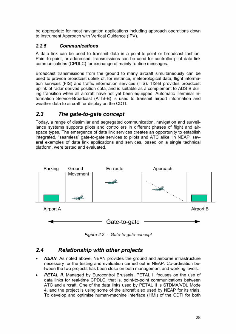
2.3 The gate-to-gate conceptToday, a range of dissimilar and segregated communication, navigation and surveil-lance systems supports pilots and controllers in different phases of flight and air-space types. The emergence of data link services creates an opportunity to establishintegrated, “seamless” gate-to-gate services to pilots and ATC alike. In NEAP, sev-eral examples of data link applications and services, based on a single technicalplatform, were tested and evaluated.
Parking Ground Movement
En-route Approach
Airport A Airport B
Gate-to-gate
Figure 2.2 - Gate-to-gate-concept
2.4 Relationship with other projects� NEAN. As noted above, NEAN provides the ground and airborne infrastructure
necessary for the testing and evaluation carried out in NEAP. Co-ordination be-tween the two projects has been close on both management and working levels.
� PETAL II. Managed by Eurocontrol Brussels, PETAL II focuses on the use ofdata links for real-time CPDLC, that is, point-to-point communications betweenATC and aircraft. One of the data links used by PETAL II is STDMA/VDL Mode4, and the project is using some of the aircraft also used by NEAP for its trials.To develop and optimise human-machine interface (HMI) of the CDTI for both
29
point-to-point and broadcast operations, co-ordination between the two projectshas taken place on a regular basis.
� FREER III. The FREER projects aim to lay the foundation for a future “free flight”concept in which more autonomy and authority in the ATM system are placed onthe aircraft. In FREER III, experiments are carried out on the use of an air-to-airdata link to detect and resolve conflicts. Experiments include the use of theSTDMA/VDL Mode 4 data link technology and CDTI as a means for displayingADS-B derived traffic and traffic advisories.
� Other projects using the same technology or sharing project objectives, such asFARAWAY, DEFAMME, FAA SAFEFLIGHT 2000 and Magnet B.
3 APPROACH3.1 ObjectivesThe NEAP project objectives must be viewed on two levels. Overall project objectivesrelate to the suitability of a single integrated CNS system to support a range of op-erational services and multiple phases of flight. Specific objectives relate to the po-tential benefits to be gained by the individual applications and their use in a futureCNS/ATM concept. The specific objectives also relate to the capability and suitabilityof the CNS system to support these applications and services.
3.1.1 Overall objectivesThe overall project objectives of NEAP were to investigate, specify, develop, test andevaluate civil aviation user applications and services within an integrated CNS con-cept. Emphasis was to be placed on gaining “real-world” experience.
Testing and evaluation activities would focus on the following domains of applicationsand services:
� Enhanced surveillance for ATC.� Pilot situation awareness.� GNSS precision navigation capabilities for all phases of flight, i.e. surface
movements, departure, en-route, and approach and landing operations.
Each of these domains includes one or more applications that address aspects of allphases of flight in a gate-to-gate concept. Therefore, testing and evaluation activitiesincluded the verification of the suitability of a single technical system solution to sup-port ATC and aircrew from pushback at the departure airport to docking at the arrivalgate. However, the applications and services were developed as stand-alone prod-ucts, and no attempt was made, or planned, to create a fully integrated gate-to-gatesystem. Nor was any attempt made, or planned, to integrate hardware and softwareused for the testing with existing operational equipment.
3.1.2 Specific objectivesThroughout the testing and evaluation conducted within each application, feedbackfrom aircrews and ATC was to be gathered for analysis. Such data would be usefulfor improvement of equipment and services and refinement of HMI. Experience fromthe testing would be used for future concept development and safety analyses.
The following specific objectives relating to one or more applications were adopted:
30
� Gathering of operational feedback on human-machine interface (HMI) aspectswith regard to the cockpit display (CDTI), including digital maps of European air-space and airports.
� Gathering of technical and operational feedback on broadcast of flight informa-tion services.
� Gathering of technical and operational feedback on a combined ADS-B andDGNSS concept for approach and landing.
� Gathering of technical and operational feedback on surveillance in previouslyunserved airspace, such as surveillance of low-altitude operations in the NorthSea.
� Preliminary analysis of safety implications of combining different CNS applica-tions in a single technical system.
� Development of preliminary operational requirements for a CNS system sup-porting gate-to-gate operations.
� Refinement of the cellular CNS concept (CCC).
In addition, application-specific objectives were defined.
The project designation NEAP implies an applications oriented project, which in turnmeans that emphasis was on operational suitability rather than technical perform-ance. However, applications and technical performance are closely linked - poorsystem technical performance inevitably leads to poor operational performance andtherefore low rating by users. International standardisation organisations also placeformal technical requirements on applications, such as update rate, accuracy and re-liability. The testing and evaluation of applications in NEAP therefore in effect alsoapplied to the capability of the technical system to support those applications.Therefore, testing and evaluation of the system characteristics and performanceformed an important part of NEAP activities.
3.2 Test environmentTesting was carried out in Germany, Denmark and Sweden. Ground testing activitieswere located in Frankfurt, Langen, Esbjerg/Tyra East oilrig, Ängelholm and Stock-holm-Arlanda. Except for a limited number of dedicated test flights, in-flight testingwas conducted on scheduled revenue flights, including North Sea helicopter opera-tions.
The achievement of the overall and specific requirements assumed the availability ofa properly functioning ground and airborne infrastructure and basic services offeredby that infrastructure.
The basic ground and airborne infrastructure was provided by NEAN, which providedthe following data and services within its coverage area:
� ADS-B information,� differential GPS data (DGPS),� rudimentary end-to-end message delivery,� CDTI functionality onboard participating aircraft,� network management and maintenance functions,� data broadcast capability.
31
In addition to the dependency on the NEAN technical platform, NEAP included de-velopment of NEAP-specific equipment and functionality. For instance, the testing ofGNSS approach required the development of a new ground station at Ängelholm, anupgrade of the CDTI developed within NEAN, and integration of an additional flightinstrument.
Six DLH B747s, two SAS F28-4000 and two DC-9-41, one MAERSK Super Pumahelicopter, one DLR Do-228 and several ground vehicles formed the backbone ofmobile platforms used in the testing activities.
3.3 MethodologyThis section outlines the test methodology applied in NEAP.
The evaluation of the suitability of a certain service must be based on judgementsand opinions expressed by experienced users, i.e. pilots and controllers, who were tobase their judgements on a comparison between their experience from the current(non-data link) service and the service being tested in NEAP. Moreover, certain func-tional requirements, such as Required Navigation Performance (RNP) parameters foren-route navigation and approach, must be met by the technical systems, and data tosupport technical evaluation must be collected and analysed.
Each of the services tested in NEAP, as well as the scenario in which the testing wasto be conducted, was clearly specified in a Service description, a Realisation planand a Test plan for each service to be tested. However, since testing of certain serv-ices took place in a live operational environment onboard commercial aircraft andhelicopters and at ATC units, the scenarios could not always be fully controlled.
The benefits expected to be gained from a particular application or service were usedas hypotheses that were to be accepted or rejected through the testing activities.Questionnaires were used to gather opinions and comments from the users, and theanswers were analysed statistically. Care was taken to ensure objectivity by not in-fluencing the answers by leading questions.
In addition to gathering “subjective” data through questionnaires, technical data fromvarious sources, such as the NEAN network, onboard MMI and ATC systems wascollected and used in the evaluation of the technical systems. Emphasis in testingand evaluation was placed on common “key” factors such as safety, impact onworkload, technical limitations and required improvements.
Evaluations made for individual services were used to arrive at conclusions regardingthe overall capability and suitability of a single system solution to support CNS/ATMapplications and services in all phases of flight, i.e. “a seamless gate-to-gateCNS/ATM system”.
4 SCIENTIFIC AND TECHNICAL DESCRIPTION4.1 Technology backgroundAll applications and services evaluated in NEAP require the use of a data link forcommunications between airborne and ground users. The STDMA/VDL Mode 4technology and the NEAN ground and air infrastructure constituted the commontechnical platform for the trials and evaluations. A brief description is given below ofthe enabling technology and infrastructure.
32
4.1.1 STDMA/VDL Mode 4A number of projects are ongoing world-wide to determine how to implement the mixof satellite, air and ground technologies in the most optimal way. To achieve thegreatest benefits from the introduction of the new technology all airspace users mustbe appropriately equipped. The required equipment has to be affordable and suitablefor all user groups. This implies that future systems will have to be based on multi-purpose, low cost equipment. The applications using this equipment must be userfriendly.
The STDMA data link technology has been developed to meet the requirements for ahigh-capacity data link to support a range of CNS domains. Several national and in-ternational projects have focused on the demonstration of the basic technology andits application in support of ground and airborne users, and work on internationalstandardisation is ongoing. ICAO has adopted VDL (VHF Digital Link) Mode 4 as thedesignation for the STDMA technology when standardised for civil aviation. Recog-nising the close relationship between the equipment used in NEAP and future, stan-dardised equipment, the designation “STDMA/VDL Mode 4” has been used through-out this document.
STDMA was the enabling technology in NEAP. Together with the ground and air in-frastructure created in NEAN it provided the necessary technical platform for thetesting and evaluation.
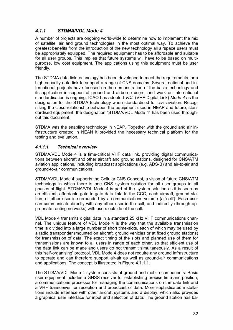
4.1.1.1 Technical overviewSTDMA/VDL Mode 4 is a time-critical VHF data link, providing digital communica-tions between aircraft and other aircraft and ground stations, designed for CNS/ATMaviation applications, including broadcast applications (e.g. ADS-B) and air-to-air andground-to-air communications.
STDMAVDL Mode 4 supports the Cellular CNS Concept, a vision of future CNS/ATMtechnology in which there is one CNS system solution for all user groups in allphases of flight. STDMA/VDL Mode 4 is part of the system solution as it is seen asan efficient, affordable gate-to-gate data link. In the CCC, each aircraft, ground sta-tion, or other user is surrounded by a communications volume (a ‘cell’). Each usercan communicate directly with any other user in the cell, and indirectly (through ap-propriate routing networks) with users outside of the cell.
VDL Mode 4 transmits digital data in a standard 25 kHz VHF communications chan-nel. The unique feature of VDL Mode 4 is the way that the available transmissiontime is divided into a large number of short time-slots, each of which may be used bya radio transponder (mounted on aircraft, ground vehicles or at fixed ground stations)for transmission of data. The exact timing of the slots and planned use of them fortransmissions are known to all users in range of each other, so that efficient use ofthe data link can be made and users do not transmit simultaneously. As a result ofthis ‘self-organising’ protocol, VDL Mode 4 does not require any ground infrastructureto operate and can therefore support air-air as well as ground-air communicationsand applications. The concept is illustrated in Figure 4.1.1.1.
The STDMA/VDL Mode 4 system consists of ground and mobile components. Basicuser equipment includes a GNSS receiver for establishing precise time and position,a communications processor for managing the communications on the data link anda VHF transceiver for reception and broadcast of data. More sophisticated installa-tions include interface with other aircraft systems and a display, which also providesa graphical user interface for input and selection of data. The ground station has ba-
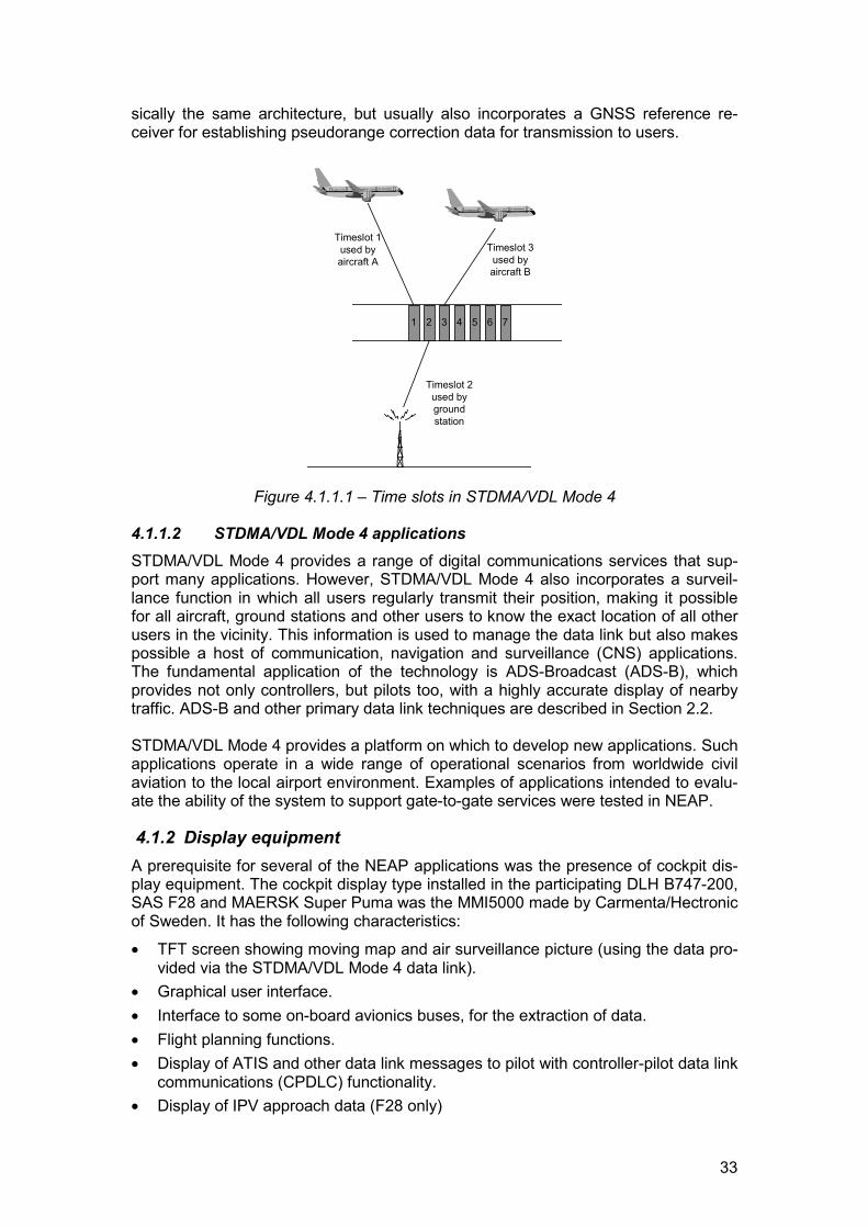
33
sically the same architecture, but usually also incorporates a GNSS reference re-ceiver for establishing pseudorange correction data for transmission to users.
3 4 75 621
Timeslot 1used byaircraft A
Timeslot 3used byaircraft B
Timeslot 2used bygroundstation
Figure 4.1.1.1 – Time slots in STDMA/VDL Mode 4
4.1.1.2 STDMA/VDL Mode 4 applicationsSTDMA/VDL Mode 4 provides a range of digital communications services that sup-port many applications. However, STDMA/VDL Mode 4 also incorporates a surveil-lance function in which all users regularly transmit their position, making it possiblefor all aircraft, ground stations and other users to know the exact location of all otherusers in the vicinity. This information is used to manage the data link but also makespossible a host of communication, navigation and surveillance (CNS) applications.The fundamental application of the technology is ADS-Broadcast (ADS-B), whichprovides not only controllers, but pilots too, with a highly accurate display of nearbytraffic. ADS-B and other primary data link techniques are described in Section 2.2.
STDMA/VDL Mode 4 provides a platform on which to develop new applications. Suchapplications operate in a wide range of operational scenarios from worldwide civilaviation to the local airport environment. Examples of applications intended to evalu-ate the ability of the system to support gate-to-gate services were tested in NEAP.
4.1.2 Display equipmentA prerequisite for several of the NEAP applications was the presence of cockpit dis-play equipment. The cockpit display type installed in the participating DLH B747-200,SAS F28 and MAERSK Super Puma was the MMI5000 made by Carmenta/Hectronicof Sweden. It has the following characteristics:
� TFT screen showing moving map and air surveillance picture (using the data pro-vided via the STDMA/VDL Mode 4 data link).
� Graphical user interface.� Interface to some on-board avionics buses, for the extraction of data.� Flight planning functions.� Display of ATIS and other data link messages to pilot with controller-pilot data link
communications (CPDLC) functionality.� Display of IPV approach data (F28 only)
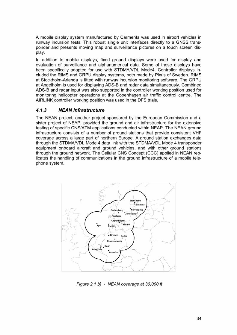
34
A mobile display system manufactured by Carmenta was used in airport vehicles inrunway incursion tests. This robust single unit interfaces directly to a GNSS trans-ponder and presents moving map and surveillance pictures on a touch screen dis-play.In addition to mobile displays, fixed ground displays were used for display andevaluation of surveillance and alphanumerical data. Some of these displays havebeen specifically adapted for use with STDMA/VDL Mode4. Controller displays in-cluded the RIMS and GRPU display systems, both made by Pixus of Sweden. RIMSat Stockholm-Arlanda is fitted with runway incursion monitoring software. The GRPUat Angelholm is used for displaying ADS-B and radar data simultaneously. CombinedADS-B and radar input was also supported in the controller working position used formonitoring helicopter operations at the Copenhagen air traffic control centre. TheAIRLINK controller working position was used in the DFS trials.
4.1.3 NEAN infrastructureThe NEAN project, another project sponsored by the European Commission and asister project of NEAP, provided the ground and air infrastructure for the extensivetesting of specific CNS/ATM applications conducted within NEAP. The NEAN groundinfrastructure consists of a number of ground stations that provide consistent VHFcoverage across a large part of northern Europe. A ground station exchanges datathrough the STDMA/VDL Mode 4 data link with the STDMA/VDL Mode 4 transponderequipment onboard aircraft and ground vehicles, and with other ground stationsthrough the ground network. The Cellular CNS Concept (CCC) applied in NEAN rep-licates the handling of communications in the ground infrastructure of a mobile tele-phone system.
Figure 2.1 b) - NEAN coverage at 30,000 ft
35
NEAN also included the fitting of a number of aircraft with airborne components forexchange and display of data with the ground and other users. A significant numberof airborne and ground users have been equipped to date with an STDMA/VDL Mode4 transponder allowing broadcast of position reports to the ground and to other air-borne users as well as reception of position reports, GNSS augmentation and otherdata.
4.1.4 Applications and services evaluated The data link applications and services tested and evaluated in NEAP are essentialfor meeting the requirements of the future CNS/ATM system. The following applica-tions were included in the test program (the responsible organisation is given withinbrackets):
� GNSS precision navigation capability for en-route and approach (SAS)� On ground situation awareness/ taxi guidance (DLH)� In-flight situation awareness (DLH)� Enhanced ATC surveillance – downlink of aircraft parameters (DFS)� Automatic Terminal Information Service broadcast; ATIS-B (DFS)� Extended helicopter surveillance (DCAA)� Runway incursion (SCAA).
Hence at least one application, or service, of each component of the CNS/ATM con-cept was included in NEAP. Combined, they provide the basis for evaluating a singlesystem solution for seamless gate-to-gate operations, i.e. a system that supports pi-lot and controllers in all phases of flight from the departure gate, through pushback,taxiing, take-off, climb, en-route, descent, approach, landing and taxiing to docking atthe arrival gate.
4.1.5 Expected benefitsAs explained in section 3.3, the expected benefits from a particular application orservice were used as hypotheses that were to be accepted or rejected through thetesting activities. Emphasis in testing and evaluation was placed on common “key”factors such as safety, impact on workload, technical limitations and required im-provements. Hypotheses, or assumptions, were also used as a basis for the testingof technical system characteristics and properties, and were used to evaluate the ca-pability of the technical platform to support the respective application.
The hypotheses established for each application is given in the following sections.
4.2 Application Reports4.2.1 GNSS precision navigation capability for en-route and ap-
proachThis application was developed in co-operation between SAS and the SCAA.
4.2.1.1 Service description4.2.1.1.1 Operational contextSatellite navigation allows aircraft to navigate with great accuracy and to fly directroutes rather than navigate between fixed navigation aids on the ground. The basicaccuracy provided by GNSS can be greatly improved by differential GNSS (DGNSS)signals transmitted by satellites or stations on the ground. The improved accuracy, as
36
well as the integrity information also provided, is needed for more demanding typesof approach and landing operations. DGNSS signals are broadcast by all NEANground stations and used to provide GNSS augmentation over a wide area.
In the NEAP tests, the aircraft position was displayed on a Cockpit Display of TrafficInformation (CDTI) whose basic functionality to support en-route navigation was de-veloped within NEAN. The current aircraft position was superimposed on a movingmap showing aeronautical airspace and airport information. ADS-B reports werecontinuously broadcast by the aircraft, and received by ground stations and other air-craft. The position of nearby STDMA/VDL Mode 4 equipped traffic was also dis-played on the CDTI. In the en-route phase, the GNSS receiver would receive aug-mentation signals from all STDMA/VDL Mode 4 ground stations in view, but only pro-cess and use those originating from the strongest, and hence most adjacent, station.During approach, augmentation signals were received from the ground station lo-cated at the destination airport.
4.2.1.1.2 NEAP applicationsThe precision navigation tests in NEAP focused on two different applications ofGNSS:
� GNSS used for en-route navigation� DGNSS used for approach.In addition, the possible safety implications of the STDMA/VDL Mode 4 data link be-ing used in a two-way fashion, i.e. for simultaneous uplink of DGNSS signals anddownlink of ADS-B data was to be evaluated. Such a service mix could be imple-mented in a future ground-based regional (or wide-area) augmentation system(GRAS) concept, and the certification aspects would therefore be addressed. Im-proved monitoring in the control tower (TWR) of aircraft making approach was alsoevaluated, and new display equipment was installed for that purpose. Activities alsoincluded evaluation of the new ground station at Ängelholm, which incorporates acommercial SCAT-I system for generation of differential corrections and anSTDMA/VDL Mode 4 station for managing the data link.
The tests were conducted using two SAS Fokker 28s on scheduled revenue servicebetween Stockholm-Arlanda (ARN) and Ängelholm in southern Sweden. The ap-proach conducted at Ängelholm was an Instrument Approach with Vertical guidance(IPV), a new type of approach procedure made possible by the introduction of satel-lite navigation. IPV is formally a non-precision approach (NPA) based on the ICAOAll Weather Operational Panel (AWOP) standards, but the improved accuracy anduse of vertical guidance from GNSS enable lower minima to be used than for con-ventional NPA based on NDB or VOR. The IPV approach procedure was selected forevaluation because it enabled a comparison to be made with the regular NDB ap-proach to runway 32 at AGH. Even though VDL Mode 4 supports RNP lateral andvertical accuracy requirements for precision approach (PA), it is not intended for sup-port of those procedures. A dedicated ground-based augmentation system (GBAS) isbeing developed and standardised by ICAO to support approach categories I, II andIII.
Two separate Track Deviation Instruments (TDI) were installed to provide ILS look-alike lateral and vertical guidance to the pilot during final approach. The TDI wasused in conjunction with the CDTI, which continued to provide situation overviewthroughout the approach. Flying en-route, the pilot used the information provided onthe CDTI to fly a direct RNAV route. The deviations from the nominal flight plannedtrack were continuously displayed on the CDTI and TDI´s. When approaching Ängel-
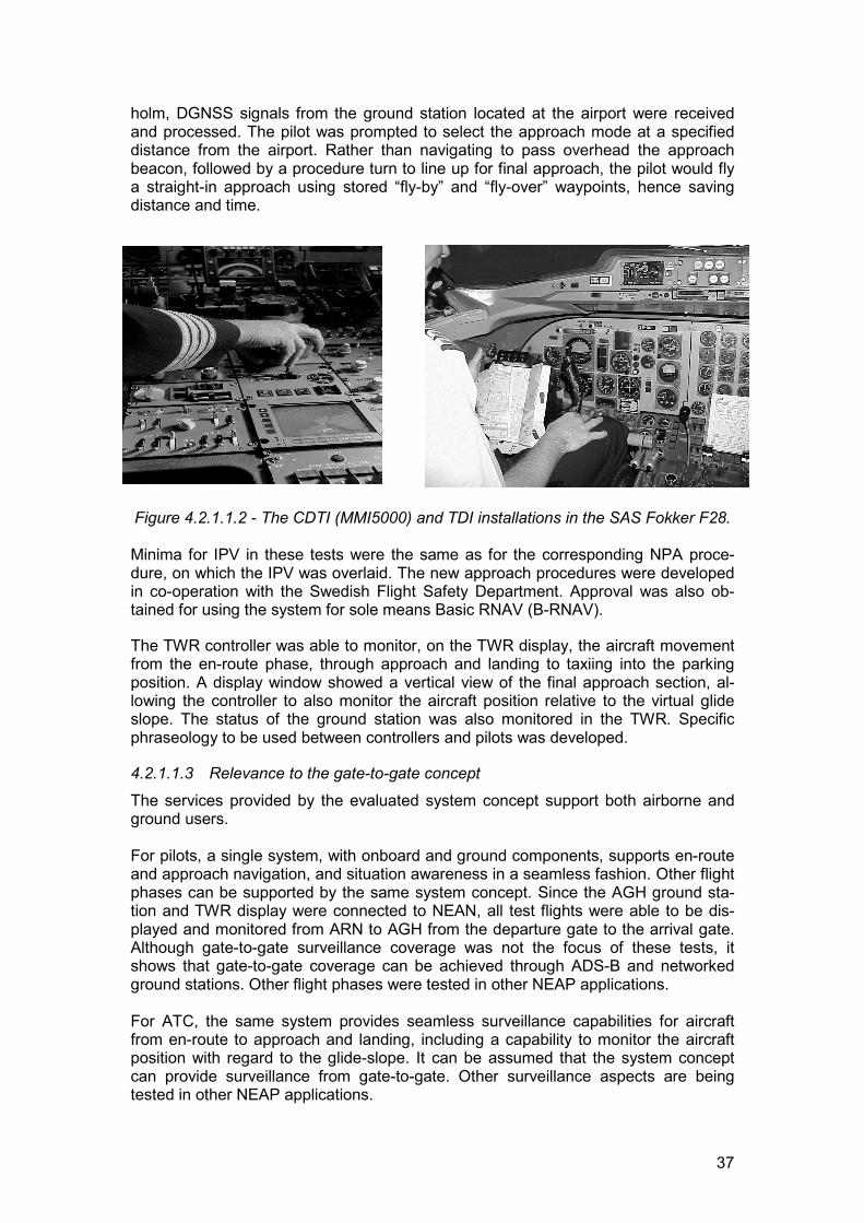
37
holm, DGNSS signals from the ground station located at the airport were receivedand processed. The pilot was prompted to select the approach mode at a specifieddistance from the airport. Rather than navigating to pass overhead the approachbeacon, followed by a procedure turn to line up for final approach, the pilot would flya straight-in approach using stored “fly-by” and “fly-over” waypoints, hence savingdistance and time.
Figure 4.2.1.1.2 - The CDTI (MMI5000) and TDI installations in the SAS Fokker F28.
Minima for IPV in these tests were the same as for the corresponding NPA proce-dure, on which the IPV was overlaid. The new approach procedures were developedin co-operation with the Swedish Flight Safety Department. Approval was also ob-tained for using the system for sole means Basic RNAV (B-RNAV).
The TWR controller was able to monitor, on the TWR display, the aircraft movementfrom the en-route phase, through approach and landing to taxiing into the parkingposition. A display window showed a vertical view of the final approach section, al-lowing the controller to also monitor the aircraft position relative to the virtual glideslope. The status of the ground station was also monitored in the TWR. Specificphraseology to be used between controllers and pilots was developed.
4.2.1.1.3 Relevance to the gate-to-gate concept
The services provided by the evaluated system concept support both airborne andground users.
For pilots, a single system, with onboard and ground components, supports en-routeand approach navigation, and situation awareness in a seamless fashion. Other flightphases can be supported by the same system concept. Since the AGH ground sta-tion and TWR display were connected to NEAN, all test flights were able to be dis-played and monitored from ARN to AGH from the departure gate to the arrival gate.Although gate-to-gate surveillance coverage was not the focus of these tests, itshows that gate-to-gate coverage can be achieved through ADS-B and networkedground stations. Other flight phases were tested in other NEAP applications.
For ATC, the same system provides seamless surveillance capabilities for aircraftfrom en-route to approach and landing, including a capability to monitor the aircraftposition with regard to the glide-slope. It can be assumed that the system conceptcan provide surveillance from gate-to-gate. Other surveillance aspects are beingtested in other NEAP applications.
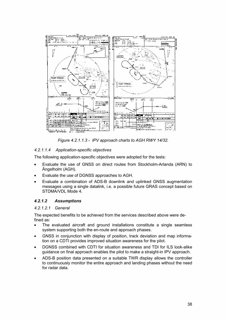
38
Figure 4.2.1.1.3 - IPV approach charts to AGH RWY 14/32.
4.2.1.1.4 Application-specific objectivesThe following application-specific objectives were adopted for the tests:
� Evaluate the use of GNSS on direct routes from Stockholm-Arlanda (ARN) toÄngelholm (AGH).
� Evaluate the use of DGNSS approaches to AGH.� Evaluate a combination of ADS-B downlink and uplinked GNSS augmentation
messages using a single datalink, i.e. a possible future GRAS concept based onSTDMA/VDL Mode 4.
4.2.1.2 Assumptions4.2.1.2.1 General
The expected benefits to be achieved from the services described above were de-fined as:� The evaluated aircraft and ground installations constitute a single seamless
system supporting both the en-route and approach phases.� GNSS in conjunction with display of position, track deviation and map informa-
tion on a CDTI provides improved situation awareness for the pilot.� DGNSS combined with CDTI for situation awareness and TDI for ILS look-alike
guidance on final approach enables the pilot to make a straight-in IPV approach.� ADS-B position data presented on a suitable TWR display allows the controller
to continuously monitor the entire approach and landing phases without the needfor radar data.
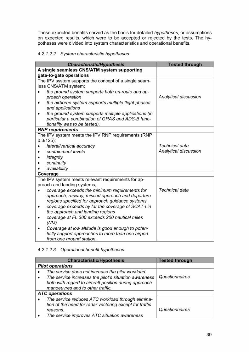
39
These expected benefits served as the basis for detailed hypotheses, or assumptionson expected results, which were to be accepted or rejected by the tests. The hy-potheses were divided into system characteristics and operational benefits.
4.2.1.2.2 System characteristic hypotheses
Characteristic/Hypothesis Tested throughA single seamless CNS/ATM system supportinggate-to-gate operationsThe IPV system supports the concept of a single seam-less CNS/ATM system;� the ground system supports both en-route and ap-
proach operation� the airborne system supports multiple flight phases
and applications� the ground system supports multiple applications (in
particular a combination of GRAS and ADS-B func-tionality was to be tested).
Analytical discussion
RNP requirementsThe IPV system meets the IPV RNP requirements (RNP0.3/125);� lateral/vertical accuracy� containment levels� integrity� continuity� availability
Technical dataAnalytical discussion
CoverageThe IPV system meets relevant requirements for ap-proach and landing systems;� coverage exceeds the minimum requirements for
approach, runway, missed approach and departureregions specified for approach guidance systems
� coverage exceeds by far the coverage of SCAT-I inthe approach and landing regions
� coverage at FL 300 exceeds 200 nautical miles(NM).
� Coverage at low altitude is good enough to poten-tially support approaches to more than one airportfrom one ground station.
Technical data
4.2.1.2.3 Operational benefit hypotheses
Characteristic/Hypothesis Tested throughPilot operations� The service does not increase the pilot workload.� The service increases the pilot’s situation awareness
both with regard to aircraft position during approachmanoeuvres and to other traffic.
Questionnaires
ATC operations� The service reduces ATC workload through elimina-
tion of the need for radar vectoring except for trafficreasons.
� The service improves ATC situation awarenessQuestionnaires
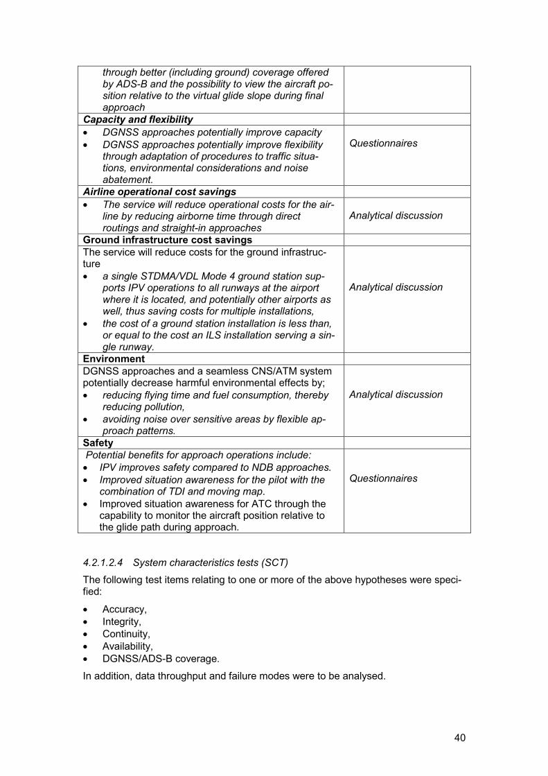
40
through better (including ground) coverage offeredby ADS-B and the possibility to view the aircraft po-sition relative to the virtual glide slope during finalapproach
Capacity and flexibility� DGNSS approaches potentially improve capacity� DGNSS approaches potentially improve flexibility
through adaptation of procedures to traffic situa-tions, environmental considerations and noiseabatement.
Questionnaires
Airline operational cost savings� The service will reduce operational costs for the air-
line by reducing airborne time through directroutings and straight-in approaches
Analytical discussion
Ground infrastructure cost savingsThe service will reduce costs for the ground infrastruc-ture� a single STDMA/VDL Mode 4 ground station sup-
ports IPV operations to all runways at the airportwhere it is located, and potentially other airports aswell, thus saving costs for multiple installations,
� the cost of a ground station installation is less than,or equal to the cost an ILS installation serving a sin-gle runway.
Analytical discussion
EnvironmentDGNSS approaches and a seamless CNS/ATM systempotentially decrease harmful environmental effects by;� reducing flying time and fuel consumption, thereby
reducing pollution,� avoiding noise over sensitive areas by flexible ap-
proach patterns.
Analytical discussion
SafetyPotential benefits for approach operations include:� IPV improves safety compared to NDB approaches.� Improved situation awareness for the pilot with the
combination of TDI and moving map.� Improved situation awareness for ATC through the
capability to monitor the aircraft position relative tothe glide path during approach.
Questionnaires
4.2.1.2.4 System characteristics tests (SCT)The following test items relating to one or more of the above hypotheses were speci-fied:
� Accuracy,� Integrity,� Continuity,� Availability,� DGNSS/ADS-B coverage.In addition, data throughput and failure modes were to be analysed.
41
4.2.1.3 Test set-up4.2.1.3.1 General The realisation of the tests required the development and installation of new equip-ment both onboard the participating aircraft and on the ground. Implementation ofnew functions and human-machine interface (HMI) in the CDTI to support terminalnavigation and approach was also required. The equipment, functions and proce-dures implemented were developed as an experimental system tailored for thesetests.
4.2.1.3.2 Airborne equipmentThe airborne STDMA/VDL Mode 4 transponders installed in NEAN were replaced bythird generation SAAB LINCS T3L/M transponders certified to JAA Form 1 non-hazardous level and designed to meet applicable ETSI, RTCA and MIL-STD re-quirements. The CDTI (the Carmenta MMI 5000, developed for NEAN) HMI wasadapted to provide approach functionality, such as alerts, prompts and messages,approach mode selection with appropriate scale settings, and a STAR (standard in-strument arrival route) database. Installation of a TDI was required to serve as theprimary instrument for IPV approaches. Lateral and vertical guidance was provided inan ILS look-alike fashion with lateral scale deflection being in accordance with theTSO-C129a, and with a vertical full deflection of 125 ft at all times.
Because of the limited space available in the F28 cockpit, the CDTI was installed inthe cockpit centre pedestal, and therefore outside the pilots´ primary field of vision.The two TDI was placed in front of each pilot on the centre panel. The additional in-strumentation was approved on a “non-interference” basis, meaning that it had nophysical connection or impact to other flight instruments.
4.2.1.3.3 Ground equipmentA ground station was installed in Ängelholm to support IPV operations. This stationincorporates as one component a commercial Raytheon DIAS-3100 SCAT-I groundstation for generation of differential GNSS corrections and integrity data. The data isoutput to a SAAB LINCS T3L/F STDMA/VDL Mode 4 ground station, which providesthe two-way data link capability for DGNSS broadcast and reception of ADS-B re-ports. The DIAS-3100 is designed to meet RTCA/DO-217 Change 2 standard andthe T3L/F to the same standards as the T3L/M described in the previous section. Thecombined station is connected to NEAN through a local server, and to a display inthe TWR. The connection to NEAN enables data to be exchanged with the networkof ground stations as well as remote monitoring and logging of the local station totake place. NEAN uses the Swedish National Aeronautical Telecommunication Net-work (NATN) for ground communications. The ground architecture is illustrated inFigure 4.2.1.3.3.
4.2.1.4 Testing and evaluation4.2.1.4.1 Test environmentÄngelholm airport is used for both military and civil air traffic. SAS operates some 60flights per week into Ängelholm. Approximately half of these flights use F28 aircraft.The airport has one instrument runway, RWY 14/32. RWY 14 is equipped with aCategory I ILS, whereas RWY 32 only has a single NDB to support instrument ap-proach. Special IPV approach procedures based on DGNSS, and overlaid on the re-spective ILS and NDB approaches, were developed and used in the NEAP tests.

42
DO-217
DIAS-3100Ground Station
GPS antennas
T3STDMA/
VDL Mode 4Ground Station
VHF antennas
Ground station
VDL-4 msg.Type 1 Diff.Korr. LocalServer
NATN
NEAN
TWRRemoteStatus
Indicator
GPUincluding
vertical view
ADS-BIntegrity msg.
Modemconnection
Figure 4.2.1.3.3 - IPV ground system architecture
Two SAS Fokker 28s on scheduled revenue service were used as platforms for theairborne testing. An SCAA Beech 200 was used for flight inspection purposes priorto the SCAA Flight Safety Department approving the final test programme. A limitednumber of SAS aircrew was trained prior to commencement of the tests. TWR con-trollers on normal duty monitored the IPV approaches on the display provided, aswell as the proper function of the ground station. Radar monitoring was also availablein the TWR. In addition, controllers at the Malmö Air Traffic Control Centre (ATCC),responsible for approach control in the Ängelholm terminal area, monitored the ap-proaches on their regular radar display.
As the tests were conducted during scheduled operations, details of the scenarioscould not be controlled.
4.2.1.4.2 Scientific approach
The test methodology included the collection and evaluation of both objective data,such as recording of ADS-B reports and technical quality of service (QoS) parame-ters, and subjective data, i.e. opinions expressed by participating pilots and control-lers in answers to questionnaires. Some hypotheses, for instance those relating tocost benefits, had to be verified by analytical discussion, often by comparison withother systems and procedures.
Recording of data was made in the MMI5000 onboard the aircraft. All data transmit-ted and received by the onboard STDMA/VDL Mode 4 transponder was recordedduring the approach and landing phase. On the ground, data recording took place inthe ground station.
A questionnaire was produced both for pilots and controllers based on the assump-tions established earlier in the project. In addition to check boxes there was room fordetailed comments. Most questions focused on the application as implemented, butsome were of the type “what if”. The latter type intended to obtain opinions about afuture operational system lacking the limitations imposed on the tested system.
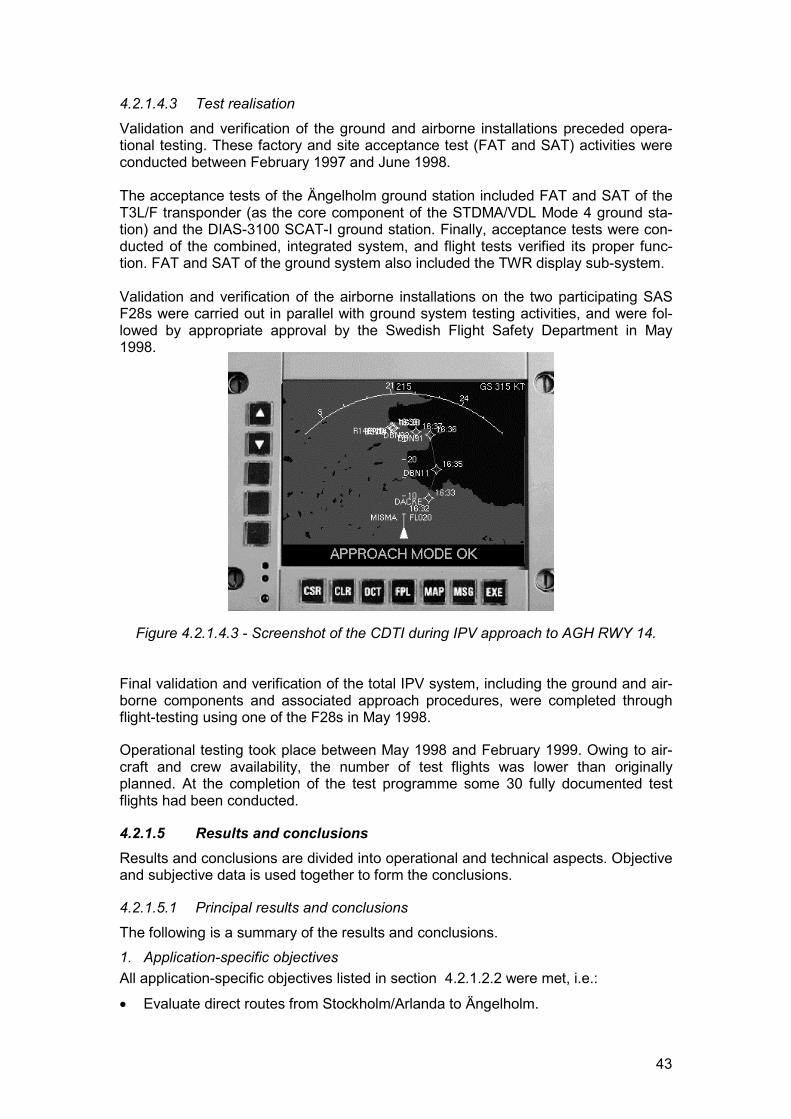
43
4.2.1.4.3 Test realisation
Validation and verification of the ground and airborne installations preceded opera-tional testing. These factory and site acceptance test (FAT and SAT) activities wereconducted between February 1997 and June 1998.
The acceptance tests of the Ängelholm ground station included FAT and SAT of theT3L/F transponder (as the core component of the STDMA/VDL Mode 4 ground sta-tion) and the DIAS-3100 SCAT-I ground station. Finally, acceptance tests were con-ducted of the combined, integrated system, and flight tests verified its proper func-tion. FAT and SAT of the ground system also included the TWR display sub-system.
Validation and verification of the airborne installations on the two participating SASF28s were carried out in parallel with ground system testing activities, and were fol-lowed by appropriate approval by the Swedish Flight Safety Department in May1998.
Figure 4.2.1.4.3 - Screenshot of the CDTI during IPV approach to AGH RWY 14.
Final validation and verification of the total IPV system, including the ground and air-borne components and associated approach procedures, were completed throughflight-testing using one of the F28s in May 1998.
Operational testing took place between May 1998 and February 1999. Owing to air-craft and crew availability, the number of test flights was lower than originallyplanned. At the completion of the test programme some 30 fully documented testflights had been conducted.
4.2.1.5 Results and conclusionsResults and conclusions are divided into operational and technical aspects. Objectiveand subjective data is used together to form the conclusions.
4.2.1.5.1 Principal results and conclusions
The following is a summary of the results and conclusions.1. Application-specific objectivesAll application-specific objectives listed in section 4.2.1.2.2 were met, i.e.:
� Evaluate direct routes from Stockholm/Arlanda to Ängelholm.
44
� Evaluate DGNSS approaches to Ängelholm.� Evaluate a combination of ADS-B and GNSS augmentation in an integrated sys-
tem using a single data link.These three applications were found to be successfully supported by the evaluatedsystem, i.e. a combination of ADS-B, DGNSS, STDMA/VDL Mode 4 and the NEANinfrastructure.
2. Expected benefitsAll assumptions on expected benefits listed in section 4.1.1.2.1 were met, i.e.:
� Single seamless system for en-route and approach.� Improved situational awareness for the pilot.� System enables the pilot to make straight-in approaches.� Continuous monitoring in TWR without radar.
3. System characteristicsAll assumptions on system characteristics listed section 4.2.1.2.2 were accepted withone exception concerning RNP requirements. This aspect is addressed in section4.2.1.5.2.
4. Operational Benefits.All assumptions on expected operational benefits listed in section 4.2.1.2.3 were ac-cepted, with the exception of the hypothesis that the IPV approach will decrease thepilot workload. This assumption is addressed in the section 4.2.1.5.2.
Operational conclusions and results
5. Seamless system.The system provides seamless support for approach and landing and forms a seam-less part in the gate-to-gate concept.
6. Safety and situation awareness.The evaluated service provided operational benefits in term of safety and improvedsituation awareness.
7. En-route navigation and direct routesSince 8 October 1998, the airspace in Scandinavia is based on B-RNAV, and ATSroutes are no longer based on “fly-over” terrestrial navigation aids. Approved by theSwedish Flight Safety Department, the two Fokker 28s are currently flying with theevaluated system in support of sole-means B-RNAV. Aircrews have not experiencedany navigation problems when using the system.
8. Combination of ADS-B and GNSS augmentationThe combination of ADS-B and GNSS augmentation in an integrated system using asingle two-way data link works well and provides an efficient solution. The servicesevaluated in this application can be expanded to include more navigation and sur-veillance services covering all phases of flight.
9. Pilot workloadThe workload on the pilots when using a future satellite-based system is expected tobe the same as, or less than for a conventional ILS system.
45
10. Collaborative proceduresAs both pilots and controllers use ADS-B derived data for situation awareness, a po-tential exists to develop new collaborative procedures between controllers and pilots.Such procedures could enhance capacity in terminal area operations.
11. ATC benefits.The acceptance of the evaluated system by controllers was very high. Benefits iden-tified by controllers included:� ground surveillance capability� potential enhancements to capacity and flexibility� gate-gate surveillance.
12. ATC view on CDTI/ADS-B in cockpit.The majority of the controllers were positive to pilots obtaining a detailed picture ofthe traffic situation through the CDTI and to the possible implications of that improvedsituation awareness, such as:� possibility to transfer separation responsibility to pilots during approach (station
keeping), including more efficient visual approaches� better understanding of the traffic flow.
Technical conclusions and results.
13. Equipment, generalAfter some initial technical problems, all equipment worked well.
14. VDL Mode 4 data link for approach and landingThe STDMA/VDL Mode 4 data link works well in support of approach and landingsystems.
15. Ground stationThe combination of a commercial SCAT-I system and an STDMA/VDL Mode 4ground station provided higher integrity, availability, continuity and accuracy than thecurrent generation of STDMA-only ground stations.
4.2.1.5.2 Comments and observationsOperational comments and observations.
1. Pilot WorkloadEarly in the project, there were some concerns in the project group that the pilotworkload would increase during these trials, as the pilots also had to monitor theconventional instruments during the approach, and the fact that the IPV representeda new procedure. To some extent the answers from the pilots confirmed this. How-ever, with a future integrated system the workload is expected to be the same as, orless than for an ordinary ILS approach.
2. Collaborative proceduresAs pilots and controllers use the same ADS-B data for navigation, surveillance andsituation awareness, a closed-loop situation is achieved, allowing better collaborationbetween air and ground. Despite some concern expressed among controllers onhow the improved pilot situation awareness would impact on their work, a large ma-jority expressed the opinion that there was a number of benefits. One benefit is thatthe co-operation between controllers and pilots will improve since pilots acquire a
46
view of the flow of traffic and an understanding of the ATC way of working. Further-more, it was anticipated that holding situations and delays would be more acceptableif pilots could see that the delays were due to high traffic load. The CDTI also pro-vides a tool for obtaining visual contact with the airport and preceding aircraft, andhence for enabling visual approach to be conducted and own separation to be main-tained to other traffic. TMA controllers in particular expressed the opinion that stationkeeping would decrease both workload and stress and a majority also thought thatefficiency would increase.
3. Intercept angle for GPS approachesBefore the trials started there was a debate amongst the pilots about the preferredintercept angle to the final approach centreline. The ICAO standard GPS interceptangle is 70o. As the evaluated IPV system is not coupled to the autopilot, some pilotssuggested that the same angle be used as for radar vectoring, i.e. 30o. To investigatethe best option, approach procedures using the two different intercept angles weredeveloped. Only a limited number of pilots has flown both approach procedures.Therefore no firm conclusions can be drawn.
4. Controlled Flight Into Terrain (CFIT) during NDB approaches50% of all Controlled Flight Into Terrain (CFIT) accidents happen during NPA proce-dures. The lack of vertical situation awareness is one of the major risk factors. Op-erational feedback from the pilots indicates that major safety benefits could be gainedby replacing current NPA procedures with IPV due to better situation awareness andoperational procedures.
5. Airline cost reductionPotential cost savings for the airlines could be achieved from not having to train pilotsfor different types of approaches. Basically the same techniques are applied whenflying IPV and ILS. The IPV approach was approximately 5 minutes shorter in timecompared to the normal racetrack NDB procedure to RWY 32.
6. Multi-runway and multi-airport coverageThe tests proved that the single ground station supported both runway ends atÄngelholm. One test flight performed an approach to Ljungbyhed airport 30 km fromÄngelholm. Continuous reception of differential corrections was maintained through-out the approach down to 50 ft, at which point the approach was aborted.
7. ATC: ADS-B benefitsThe controllers considered ADS-B to have a number of benefits over radar for sur-veillance purposes. Most controllers expressed the opinion that the precise informa-tion that DGNSS/ADS-B provides could be used to increase efficiency. Methodologymay also change due to the usually better resolution and update rate offered byADS-B. A great majority of the tower controllers believed that ADS-B based surveil-lance of ground traffic would increase efficiency, capacity and safety.
Technical comments and observations.8. RNP requirements hypothesis.Evaluation of Required Navigation Performance (RNP) was simplified compared towhat is suggested by AWOP and what would be required for certification.
47
9. Initial technical problemsThe NEAP IPV project represents a major investment in the development of newequipment, operational procedures and evaluation tools as well as aircraft and air-crew scheduling and training. Even though the fundamental concept and equipment,such as the STDMA technology and the NEAN infrastructure, were already in place,the airborne, ground and ATC equipment needed further development to support theIPV. Completely new operational procedures were developed for the purpose ofthese trials. All this was completed successfully in a very short time frame. However,the project suffered some delay due to the complexity of the task and early technicalproblems. These problems were resolved, and no remaining fundamental problemswith the concept or the equipment have been identified.
4.2.1.6 Recommendations for system improvements
General aspects and overall concept.
1. Applicability to other aircraftThese trials have been tailored for the SAS F28, and therefore the system and IPVconcept will have to be evaluated for use with other aircraft types. Moreover, evalua-tion must take into account that different aircraft have different equipment installedand use varying levels of automation.
2. TDI deflection, parallel approachesIn these trials the lateral TDI deflection depended on the distance to the ground sta-tion in three steps. En-route, the full scale deflection was 5 NM, within 30 NM of AGHit was 1 NM, and from the final approach fix 0.3 NM. Vertical deflection was 125 ft atall times. The pilot reactions to the non-angular lateral deflection and the sensitivity ofthe glide slope being unchanged throughout the approach were positive, and theprinciples were easy to adopt. This concept should be studied further and taken intoconsideration as a possible factor in parallel approaches where a potential can beidentified for closer spacing between runways.
3. Environmental impactsDue to time constraints, the evaluation of the environmental impact has not been fullyaddressed. This important area should be addressed in future projects. However,one important environmental aspect is the fact that the IPV approach to RWY 32saves approximately 5 minutes of flying time compared to the normal NDB racetrackprocedures. Reduced flight times means less pollution from exhaust gases.
4. Combination of ADS-B and GNSS augmentationThe combination of ADS-B and GNSS augmentation could form the basis for a sys-tem supporting a future dual-function GRAS concept. To fully explore this concept,further tests need to be performed, for instance for investigating network manage-ment and the possibility of distributed integrity monitoring.
Operational – ATC.
5. Pilot-ATC co-operation.The potential benefits with regard to new procedures that could be achieved throughimproved airborne situation awareness should be further analysed.
48
Technical - Aircraft installation.
6. Airborne equipment certificationThese trials were based on an experimental installation in a classic F28 cockpit. Thesystem was a stand-alone system and certified as not to interfere with other onboardsystems. In future, the system has to be certified and integrated into existing aircraftsystem architecture or installed as an add-on certified component for less complexaircraft.
Technical - Ground installation.7. Ground station architectureThe combined SCAT-I/STDMA/VDL Mode 4 ground proved to work very well. Thearchitecture is promising and the station provides high integrity together with widearea coverage and support for multiple services. It could be the basis for a certifiablesystem supporting the GRAS concept as well as NPA operations. This, however,would require:
� Full integration of the differential (DIAS-3100) and data link (T3L/F) components.This will provide an integrated system with integrated control and monitoring. Thetested system was not completely consistent in this respect.
� The DIAS-3100 SCAT-I system incorporates a “listen-back” function, which veri-fies each transmitted message to assure the integrity of transmissions. Since theSCAT-I data link was not used, this function was not used either. The T3L/F hasno “listen-back” function. To improve overall integrity, such a function should beincluded in the architecture.
Technical - TWR equipment.8. TWR display.The TWR display used in the trials was a radar display used operationally in manySwedish control towers. The vertical view provided was however a prototype. Theunit can receive and display radar data as well as ADS-B data. During the trials itwas used for ADS-B only.
The vertical view needs to be further developed in accordance with the controllersuggestions. The display has to be better integrated into the TWR control panels.During the trials, the position of the display unit was not optimal.
4.2.1.7 Future plansThe operational and technical results from the IPV trials will serve as very valuableinputs to further work, in particular in the NEAN Update Program, NUP, in which bothSAS and the SCAA will participate. One of the work packages in NUP will focus onGRAS. Within the work package, a GRAS station will be specified and developed.The experience from the IPV trials will be very valuable in this work. The architectureof the AGH ground station will be used as input for the definition of GRAS station ar-chitecture.
SAS will keep the installation on the two Fokker F28s after the completion of theNEAP project. IPV approaches into AGH will continue to be conducted. Log data andexperience will continue to be collected until the summer of 1999, at which time theaircraft type will be phased out from the SAS fleet.
The SCAA is investigating possibilities to retain the infrastructure installed at AGH,and also has a work programme for use of GPS at small airports. This program will
49
initially focus on NPA based on GPS without ground based augmentation, but a sec-ond phase will likely include ground augmentation and ADS-B. The experience fromIPV trials and GRAS will be accommodated in this work. The SCAA and SAS willtake an active role in the development of new collaborative procedures between pi-lots and controllers.
4.2.2 On-ground situation awareness & taxi guidanceThis application was developed by DLH.4.2.2.1 Service description4.2.2.1.1 Operational contextOne of the bottlenecks in today's growing air traffic is the ground traffic at busy air-ports. The efficiency of aircraft movements on ground, although skilfully managed byground controllers, still very much depends on the weather conditions and is far awayfrom being optimised.Busy airports are usually equipped with surface movement radar (SMR) allowingcontrollers to view and guide the traffic on radar display in the tower (TWR). Unlikemodern radar systems, most SMR displays do not display the identity of aircraft tar-gets, and there are no means for identifying vehicles. Therefore an increased sepa-ration is required between ground traffic during low visibility ground operation.
Previous trials have demonstrated that ADS-B based on STDMA works equally wellon the ground as in the air. The position accuracy offered by DGNSS is better thanthat of an SMR and the display is clean and not cluttered by echoes from buildingsand other structures on the airport as is often the case with SMR. As ADS-B reportsinclude the identity of the transmitting aircraft or vehicle, this information is includedin the target representation on the cockpit display. Whilst SMR only provides data tothe controller, ADS-B reports are also received by aircraft and ground vehicles.These reports are displayed to pilots to provide a much-improved awareness ofnearby traffic.
Based on this information the pilot acquires situation awareness with regard to otheraircraft and ground vehicles. By combining a cockpit display with a suitable human-machine interface (HMI), it is possible to create a taxi a taxi guidance system thatleads to more efficient, safer and weather independent ground operations.
The high-level assumption for this NEAP application was that ADS-B based onSTDMA/VDL Mode 4, with appropriate functionality, could support an on-groundsituation awareness and taxi guidance system.
4.2.2.1.2 NEAP applicationThe on-ground situation awareness and taxi guidance service tested in NEAP isbased on ADS-B reports from appropriately equipped aircraft and airport vehiclesbeing received by an STDMA/VDL Mode 4 transponder in six Boeing 747-200 aircraftand presented on a dedicated display in the cockpit. The ADS-B reports were basedon very accurate DGNSS position data. High-precision maps for Frankfurt interna-tional airport were used in the B747 cockpit displays.
The test program included all revenue ground operation of the equipped aircraft atthe Frankfurt international airport. Other STDMA/VDL Mode 4 equipped aircraft andvehicles served as "background traffic" that only played a passive role in the tests.

50
4.2.2.1.3 Relevance to the gate-to-gate conceptOn-ground situation awareness and taxi guidance facilitate aircraft movements onaprons and taxiways when taxiing to and from the runway in use in low visibility con-ditions. The functions support the first and last phases in a gate-to-gate ATM system.One objective of NEAP is to show that this and other components of a gate-to-gateconcept can be provided in a seamless fashion by the STDMA/VDL Mode 4 technicalplatform.
4.2.2.1.4 Application-specific objectivesThe following application-specific objectives were adopted for the tests:
� Evaluate the suitability of STDMA/VDL Mode 4 as the basis for on-ground situa-tion awareness and taxi guidance.
� Evaluate the concept of on-ground situation awareness and taxi guidance.� Develop and evaluate a common cockpit platform for supporting implementation
and evaluation of future on-ground situation awareness and taxi guidance func-tions.
� Demonstrate on-ground situation awareness and taxi guidance as vital compo-nents of a gate-to-gate concept.
4.2.2.2 Assumptions4.2.2.2.1 General
To allow testing of an ADS-B system in a real life environment within the limits of thepre-certification equipment, some results are based on assumptions in order to as-sess possible long-term benefits. The assumptions on a future environment were;
� a fully integrated and certified system is used,� a large number of aircraft are equipped with STDMA/VDL Mode 4 based ADS-B
system,� suitable human machine interfaces are available,� procedures have been modified and/or added to make use of the STDMA/VDL
Mode 4 based CNS/ATM system capabilities.
Throughout the evaluation it was clearly distinguished between results based on thecurrently used system and environment in which it operates, and those based on as-sumptions on a future system and environment.
4.2.2.2.2 System characteristic hypotheses
All system characteristics were evaluated by the DFS in the Enhanced surveillanceapplication.

51
Picture 4.2.2.2.1 MMI 5000 in the DLH B747-200 cockpit with taxi display
4.2.2.2.3 Operational benefit hypothesesSeveral benefits were anticipated to be gained with the STDMA/VDL Mode 4 sup-ported services provided in this NEAP application. Operational benefit tests (OBTs)were designed to verify or reject assumptions on these benefits.
Taxi GuidanceSafety STDMA/VDL Mode 4 based CNS/ATM system increases the
safety of taxi
Profitability STDMA/VDL Mode 4 based CNS/ATM system reduces costs
Punctuality STDMA/VDL Mode 4 based CNS/ATM system reduces taxi time
On-Ground Situation AwarenessSafety STDMA/VDL Mode 4 based CNS/ATM system increases the
safety of the ground operation
Profitability STDMA/VDL Mode 4 based CNS/ATM system reduces costs
Punctuality STDMA/VDL Mode 4 based CNS/ATM system saves time
All trials were tested through questionnaires distributed to each crewmember with theflight documents.
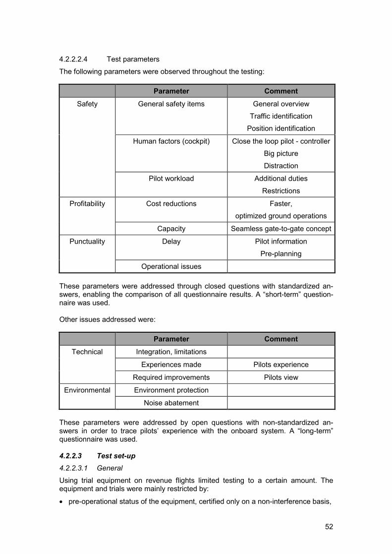
52
4.2.2.2.4 Test parametersThe following parameters were observed throughout the testing:
Parameter CommentSafety General safety items General overview
Traffic identificationPosition identification
Human factors (cockpit) Close the loop pilot - controllerBig pictureDistraction
Pilot workload Additional dutiesRestrictions
Profitability Cost reductions Faster,optimized ground operations
Capacity Seamless gate-to-gate concept
Punctuality Delay Pilot informationPre-planning
Operational issues
These parameters were addressed through closed questions with standardized an-swers, enabling the comparison of all questionnaire results. A “short-term” question-naire was used.
Other issues addressed were:
Parameter CommentTechnical Integration, limitations
Experiences made Pilots experience
Required improvements Pilots view
Environmental Environment protection
Noise abatement
These parameters were addressed by open questions with non-standardized an-swers in order to trace pilots’ experience with the onboard system. A “long-term”questionnaire was used.
4.2.2.3 Test set-up4.2.2.3.1 General
Using trial equipment on revenue flights limited testing to a certain amount. Theequipment and trials were mainly restricted by:
� pre-operational status of the equipment, certified only on a non-interference basis,
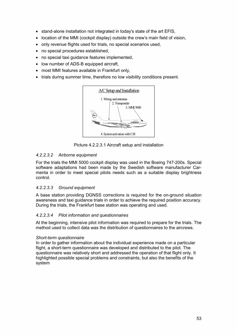
53
� stand-alone installation not integrated in today's state of the art EFIS,� location of the MMI (cockpit display) outside the crew’s main field of vision,� only revenue flights used for trials, no special scenarios used,� no special procedures established,� no special taxi guidance features implemented,� low number of ADS-B equipped aircraft,� most MMI features available in Frankfurt only,� trials during summer time, therefore no low visibility conditions present.
1. Wiring and antennas 2. Transponder 3. MMI 5000
4. System activation with C/B
A/C Setup and Installation
Lufthansa
Picture 4.2.2.3.1 Aircraft setup and installation
4.2.2.3.2 Airborne equipment
For the trials the MMI 5000 cockpit display was used in the Boeing 747-200s. Specialsoftware adaptations had been made by the Swedish software manufacturer Car-menta in order to meet special pilots needs such as a suitable display brightnesscontrol.
4.2.2.3.3 Ground equipmentA base station providing DGNSS corrections is required for the on-ground situationawareness and taxi guidance trials in order to achieve the required position accuracy.During the trials, the Frankfurt base station was operating and used.
4.2.2.3.4 Pilot information and questionnairesAt the beginning, intensive pilot information was required to prepare for the trials. Themethod used to collect data was the distribution of questionnaires to the aircrews.
Short-term questionnaireIn order to gather information about the individual experience made on a particularflight, a short-term questionnaire was developed and distributed to the pilot. Thequestionnaire was relatively short and addressed the operation of that flight only. Ithighlighted possible special problems and constraints, but also the benefits of thesystem
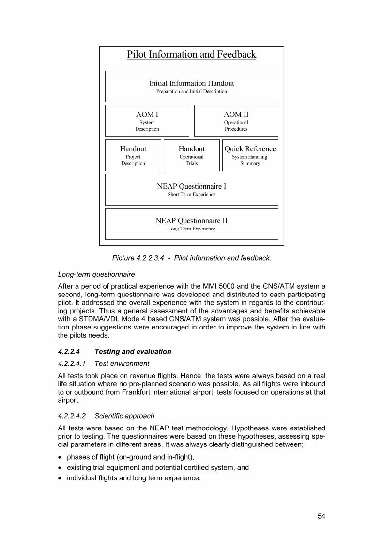
54
Initial Information HandoutPreparation and Initial Description
AOM ISystem
Description
AOM IIOperationalProcedures
HandoutProject
Description
HandoutOperational
Trials
Quick ReferenceSystem Handling
Summary
NEAP Questionnaire IShort Term Experience
NEAP Questionnaire IILong Term Experience
Pilot Information and Feedback
Picture 4.2.2.3.4 - Pilot information and feedback.
Long-term questionnaireAfter a period of practical experience with the MMI 5000 and the CNS/ATM system asecond, long-term questionnaire was developed and distributed to each participatingpilot. It addressed the overall experience with the system in regards to the contribut-ing projects. Thus a general assessment of the advantages and benefits achievablewith a STDMA/VDL Mode 4 based CNS/ATM system was possible. After the evalua-tion phase suggestions were encouraged in order to improve the system in line withthe pilots needs.
4.2.2.4 Testing and evaluation4.2.2.4.1 Test environmentAll tests took place on revenue flights. Hence the tests were always based on a reallife situation where no pre-planned scenario was possible. As all flights were inboundto or outbound from Frankfurt international airport, tests focused on operations at thatairport.
4.2.2.4.2 Scientific approach
All tests were based on the NEAP test methodology. Hypotheses were establishedprior to testing. The questionnaires were based on these hypotheses, assessing spe-cial parameters in different areas. It was always clearly distinguished between;
� phases of flight (on-ground and in-flight),� existing trial equipment and potential certified system, and� individual flights and long term experience.
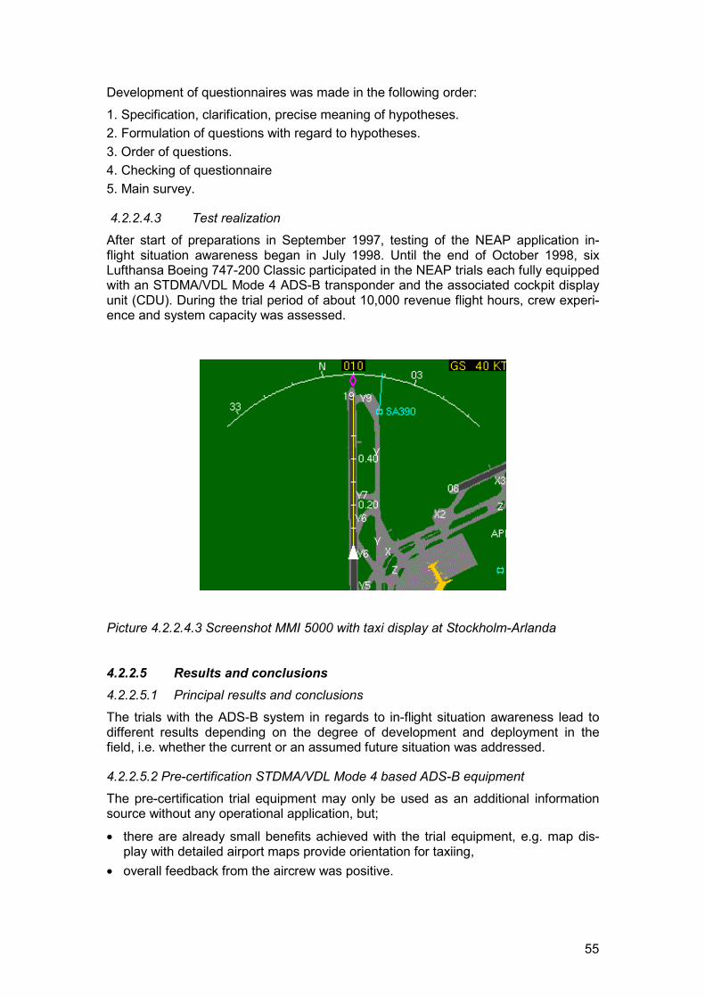
55
Development of questionnaires was made in the following order:1. Specification, clarification, precise meaning of hypotheses.2. Formulation of questions with regard to hypotheses.3. Order of questions.4. Checking of questionnaire5. Main survey.
4.2.2.4.3 Test realizationAfter start of preparations in September 1997, testing of the NEAP application in-flight situation awareness began in July 1998. Until the end of October 1998, sixLufthansa Boeing 747-200 Classic participated in the NEAP trials each fully equippedwith an STDMA/VDL Mode 4 ADS-B transponder and the associated cockpit displayunit (CDU). During the trial period of about 10,000 revenue flight hours, crew experi-ence and system capacity was assessed.
Picture 4.2.2.4.3 Screenshot MMI 5000 with taxi display at Stockholm-Arlanda
4.2.2.5 Results and conclusions4.2.2.5.1 Principal results and conclusionsThe trials with the ADS-B system in regards to in-flight situation awareness lead todifferent results depending on the degree of development and deployment in thefield, i.e. whether the current or an assumed future situation was addressed.
4.2.2.5.2 Pre-certification STDMA/VDL Mode 4 based ADS-B equipmentThe pre-certification trial equipment may only be used as an additional informationsource without any operational application, but;
� there are already small benefits achieved with the trial equipment, e.g. map dis-play with detailed airport maps provide orientation for taxiing,
� overall feedback from the aircrew was positive.
56
4.2.2.5.3 Taxi guidance display
In flight, electronic flight instrument system (EFIS) and ATC may be the only sourceof information in IMC, but during taxiing visual reference is required for collisionavoidance as far as weather permits. Therefore a suitable taxi guidance display isrequired in order to make use of the ADS-B features on ground. Possible solutionsare;
� CM1 (captain) uses the primary flight display (PFD) for taxi guidance plus naviga-tion display (ND) for airport chart and collision avoidance, CM2 (first officer)maintains visual contact, or
� windshield display.
4.2.2.5.4 Few STDMA based ADS-B equipped aircraftAs long as there is only a low number of ADS-B equipped aircraft present, as is an-ticipated during a transition phase, the following initial benefits are expected;
� taxi guidance increases safety and may reduce taxi time on unfamiliar airports,� taxi guidance down to CAT III conditions is possible, allowing a significantly higher
flow of on ground traffic under low visibility conditions, provided that;- suitable taxi guidance display is available, and- operational procedures are established,
� on-ground situation awareness reduces the possibility of runway incursions.
4.2.2.5.5 Large number of STDMA/VDL Mode 4 based ADS-B equipped aircraft
After an initial transition phase with an increased number of ADS-B equipped aircraftadditional benefits are expected, based on the above mentioned assumptions:
� on-ground situation awareness allows the crew to maintain separation to other air-craft weather independently,
� potential of reduced on-ground separation minima due to enhanced surveillanceaccuracy,
� potential for building up ADS-B based surveillance infrastructure at comparablylow costs.
Due to the mentioned limitations it is impossible to exactly quantify the amount ofachievable savings. Nevertheless remarkable benefits are expected in regards tosafety, punctuality and costs when introducing a fully developed and certifiedSTDMA/VDL Mode 4 ADS-B based CNS/ATM system.
4.2.2.5.6 Comments and observationsTo overcome today's problems with increasing air traffic a seamless gate to gateconcept is required. The CNS/ATM system presented in this project should be able tobecome the backbone of this concept. The next important step is, as the trials show,integration of such a system into the glass cockpit of a modern passenger aircraftand certification of the required system components.
The trials showed that the introduction of an onboard taxi guidance system, includingcockpit displays with improved HMI and new operational procedures, could poten-tially contribute to more efficient ground operations. The shared responsibility be-tween ATC and aircrew supported by the increased aircrew situation awareness pro-vides higher capacity and weather independent ground operations at lower costs,while today’s safety standards are maintained or even exceeded. A first step was
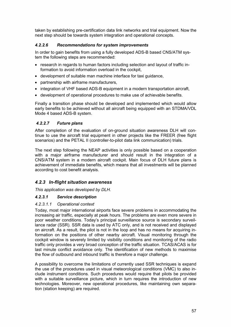
57
taken by establishing pre-certification data link networks and trial equipment. Now thenext step should be towards system integration and operational concepts.
4.2.2.6 Recommendations for system improvementsIn order to gain benefits from using a fully developed ADS-B based CNS/ATM sys-tem the following steps are recommended:
� research in regards to human factors including selection and layout of traffic in-formation to avoid information overload in the cockpit,
� development of suitable man machine interface for taxi guidance,� partnership with airframe manufacturers,� integration of VHF based ADS-B equipment in a modern transportation aircraft,� development of operational procedures to make use of achievable benefits.
Finally a transition phase should be developed and implemented which would allowearly benefits to be achieved without all aircraft being equipped with an STDMA/VDLMode 4 based ADS-B system.
4.2.2.7 Future plansAfter completion of the evaluation of on-ground situation awareness DLH will con-tinue to use the aircraft trial equipment in other projects like the FREER (free flightscenarios) and the PETAL II (controller-to-pilot data link communication) trials.
The next step following the NEAP activities is only possible based on a cooperationwith a major airframe manufacturer and should result in the integration of aCNS/ATM system in a modern aircraft cockpit. Main focus of DLH future plans isachievement of immediate benefits, which means that all investments will be plannedaccording to cost benefit analysis.
4.2.3 In-flight situation awarenessThis application was developed by DLH.
4.2.3.1 Service description4.2.3.1.1 Operational contextToday, most major international airports face severe problems in accommodating theincreasing air traffic, especially at peak hours. The problems are even more severe inpoor weather conditions. Today’s principal surveillance source is secondary surveil-lance radar (SSR). SSR data is used by ATC only, and is not received and displayedon aircraft. As a result, the pilot is not in the loop and has no means for acquiring in-formation on the positions of other nearby aircraft. Visual monitoring through thecockpit window is severely limited by visibility conditions and monitoring of the radiotraffic only provides a very broad conception of the traffic situation. TCAS/ACAS is forlast minute conflict avoidance only. The identification of new methods to maximisethe flow of outbound and inbound traffic is therefore a major challenge.
A possibility to overcome the limitations of currently used SSR techniques is expandthe use of the procedures used in visual meteorological conditions (VMC) to also in-clude instrument conditions. Such procedures would require that pilots be providedwith a suitable surveillance picture, which in turn requires the introduction of newtechnologies. Moreover, new operational procedures, like maintaining own separa-tion (station keeping) are required.
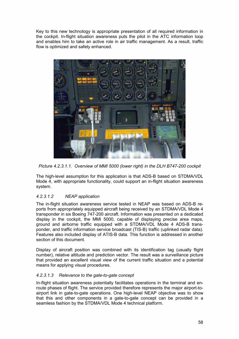
58
Key to this new technology is appropriate presentation of all required information inthe cockpit. In-flight situation awareness puts the pilot in the ATC information loopand enables him to take an active role in air traffic management. As a result, trafficflow is optimized and safety enhanced.
Picture 4.2.3.1.1. Overview of MMI 5000 (lower right) in the DLH B747-200 cockpit
The high-level assumption for this application is that ADS-B based on STDMA/VDLMode 4, with appropriate functionality, could support an in-flight situation awarenesssystem.
4.2.3.1.2 NEAP application
The in-flight situation awareness service tested in NEAP was based on ADS-B re-ports from appropriately equipped aircraft being received by an STDMA/VDL Mode 4transponder in six Boeing 747-200 aircraft. Information was presented on a dedicateddisplay in the cockpit, the MMI 5000, capable of displaying precise area maps,ground and airborne traffic equipped with a STDMA/VDL Mode 4 ADS-B trans-ponder, and traffic information service broadcast (TIS-B) traffic (uplinked radar data).Features also included display of ATIS-B data. This function is addressed in anothersection of this document.
Display of aircraft position was combined with its identification tag (usually flightnumber), relative altitude and prediction vector. The result was a surveillance picturethat provided an excellent visual view of the current traffic situation and a potentialmeans for applying visual procedures.
4.2.3.1.3 Relevance to the gate-to-gate concept
In-flight situation awareness potentially facilitates operations in the terminal and en-route phases of flight. The service provided therefore represents the major airport-to-airport link in gate-to-gate operations. One high-level NEAP objective was to showthat this and other components in a gate-to-gate concept can be provided in aseamless fashion by the STDMA/VDL Mode 4 technical platform.

59
4.2.3.1.4 Application-specific objectivesThe following application-specific objectives were adopted for the tests:
� Evaluate the concept of in-flight situation awareness.� Demonstrate in-flight situation awareness as a component of a gate-to-gate con-
cept.� Evaluate the suitability of STDMA/VDL Mode 4 as the basis for in-flight situation
awareness.� Develop and evaluate a common cockpit platform for supporting implementation
and evaluation of future if-flight situation awareness.
4.2.3.2 Assumptions4.2.3.2.1 GeneralTo allow testing of an ADS-B system in a real life environment within the limits of thepre-certification equipment, some results are based on assumptions in order to as-sess possible long term benefits. The assumptions on a future environment were;
� a fully integrated and certified system is used,� a large number of aircraft are equipped with STDMA/VDL Mode 4 based ADS-B
system,� suitable human machine interfaces are available,� procedures have been modified and/or added to make use of the STDMA/VDL
Mode 4 based CNS/ATM system capabilities.
Throughout the evaluation it was clearly distinguished between results based on thecurrently used system and environment in which it operates, and those based on as-sumptions on a future system and environment.
4.2.3.2.2 System characteristic hypotheses
All system characteristics were evaluated by the DFS in the enhanced surveillanceapplication.
4.2.3.2.3 Operational benefit hypothesesSeveral benefits were anticipated to be gained with the STDMA/VDL Mode 4 sup-ported services provided in this NEAP application. Operational benefit tests (OBTs)were designed to verify or reject assumptions on these benefits.
In flight In-Flight Situation AwarenessSafety CNS/ATM system increases the safety in flight
Profitability CNS/ATM system reduces costs
Punctuality CNS/ATM system reduces delays
All trials were tested through questionnaires distributed to each crewmember with theflight documents.
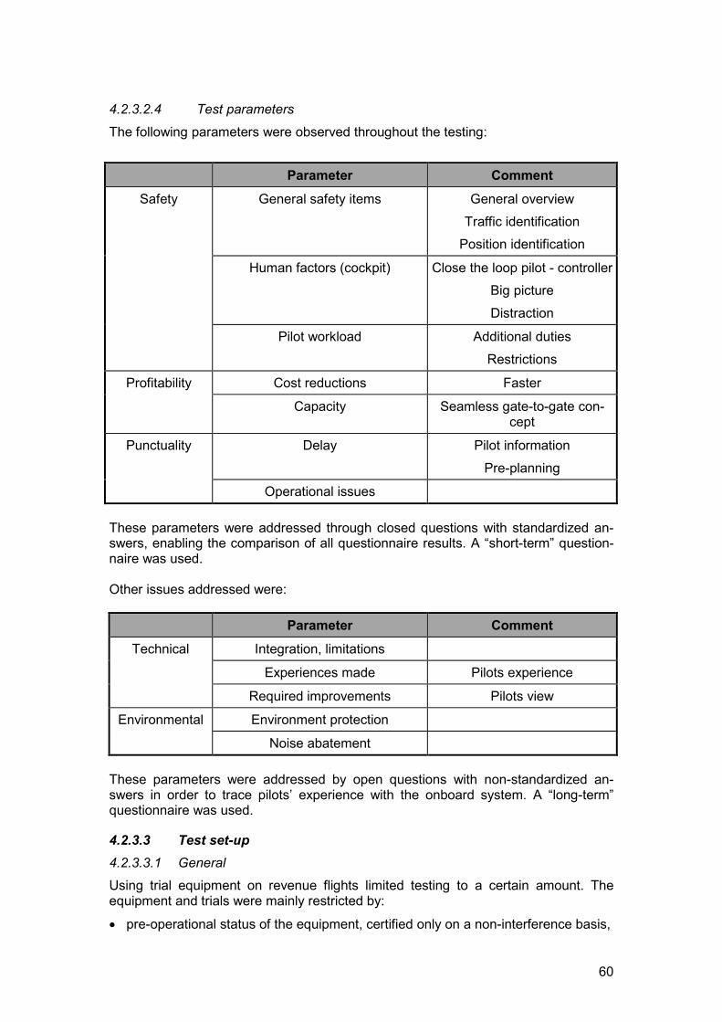
60
4.2.3.2.4 Test parameters
The following parameters were observed throughout the testing:
Parameter CommentSafety General safety items General overview
Traffic identificationPosition identification
Human factors (cockpit) Close the loop pilot - controllerBig pictureDistraction
Pilot workload Additional dutiesRestrictions
Profitability Cost reductions Faster
Capacity Seamless gate-to-gate con-cept
Punctuality Delay Pilot informationPre-planning
Operational issues
These parameters were addressed through closed questions with standardized an-swers, enabling the comparison of all questionnaire results. A “short-term” question-naire was used.
Other issues addressed were:
Parameter CommentTechnical Integration, limitations
Experiences made Pilots experience
Required improvements Pilots view
Environmental Environment protection
Noise abatement
These parameters were addressed by open questions with non-standardized an-swers in order to trace pilots’ experience with the onboard system. A “long-term”questionnaire was used.
4.2.3.3 Test set-up4.2.3.3.1 GeneralUsing trial equipment on revenue flights limited testing to a certain amount. Theequipment and trials were mainly restricted by:
� pre-operational status of the equipment, certified only on a non-interference basis,
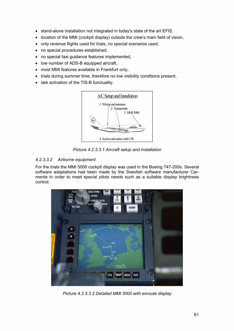
61
� stand-alone installation not integrated in today's state of the art EFIS,� location of the MMI (cockpit display) outside the crew’s main field of vision,� only revenue flights used for trials, no special scenarios used,� no special procedures established,� no special taxi guidance features implemented,� low number of ADS-B equipped aircraft,� most MMI features available in Frankfurt only,� trials during summer time, therefore no low visibility conditions present,� late activation of the TIS-B functuality.
1. Wiring and antennas 2. Transponder 3. MMI 5000
4. System activation with C/B
A/C Setup and Installation
Lufthansa
Picture 4.2.3.3.1 Aircraft setup and installation
4.2.3.3.2 Airborne equipmentFor the trials the MMI 5000 cockpit display was used in the Boeing 747-200s. Severalsoftware adaptations had been made by the Swedish software manufacturer Car-menta in order to meet special pilots needs such as a suitable display brightnesscontrol.
Picture 4.2.3.3.2 Detailed MMI 5000 with enroute display
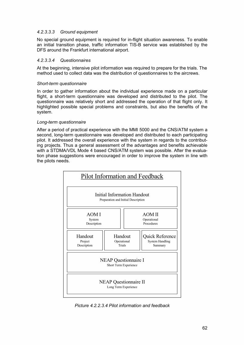
62
4.2.3.3.3 Ground equipment
No special ground equipment is required for in-flight situation awareness. To enablean initial transition phase, traffic information TIS-B service was established by theDFS around the Frankfurt international airport.
4.2.3.3.4 Questionnaires
At the beginning, intensive pilot information was required to prepare for the trials. Themethod used to collect data was the distribution of questionnaires to the aircrews.
Short-term questionnaireIn order to gather information about the individual experience made on a particularflight, a short-term questionnaire was developed and distributed to the pilot. Thequestionnaire was relatively short and addressed the operation of that flight only. Ithighlighted possible special problems and constraints, but also the benefits of thesystem.
Long-term questionnaireAfter a period of practical experience with the MMI 5000 and the CNS/ATM system asecond, long-term questionnaire was developed and distributed to each participatingpilot. It addressed the overall experience with the system in regards to the contribut-ing projects. Thus a general assessment of the advantages and benefits achievablewith a STDMA/VDL Mode 4 based CNS/ATM system was possible. After the evalua-tion phase suggestions were encouraged in order to improve the system in line withthe pilots needs.
Initial Information HandoutPreparation and Initial Description
AOM ISystem
Description
AOM IIOperationalProcedures
HandoutProject
Description
HandoutOperational
Trials
Quick ReferenceSystem Handling
Summary
NEAP Questionnaire IShort Term Experience
NEAP Questionnaire IILong Term Experience
Pilot Information and Feedback
Picture 4.2.2.3.4 Pilot information and feedback
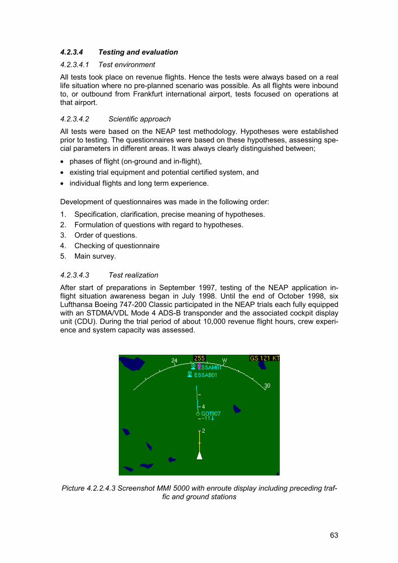
63
4.2.3.4 Testing and evaluation4.2.3.4.1 Test environmentAll tests took place on revenue flights. Hence the tests were always based on a reallife situation where no pre-planned scenario was possible. As all flights were inboundto, or outbound from Frankfurt international airport, tests focused on operations atthat airport.
4.2.3.4.2 Scientific approachAll tests were based on the NEAP test methodology. Hypotheses were establishedprior to testing. The questionnaires were based on these hypotheses, assessing spe-cial parameters in different areas. It was always clearly distinguished between;
� phases of flight (on-ground and in-flight),� existing trial equipment and potential certified system, and� individual flights and long term experience.
Development of questionnaires was made in the following order:1. Specification, clarification, precise meaning of hypotheses.2. Formulation of questions with regard to hypotheses.3. Order of questions.4. Checking of questionnaire5. Main survey.
4.2.3.4.3 Test realization
After start of preparations in September 1997, testing of the NEAP application in-flight situation awareness began in July 1998. Until the end of October 1998, sixLufthansa Boeing 747-200 Classic participated in the NEAP trials each fully equippedwith an STDMA/VDL Mode 4 ADS-B transponder and the associated cockpit displayunit (CDU). During the trial period of about 10,000 revenue flight hours, crew experi-ence and system capacity was assessed.
Picture 4.2.2.4.3 Screenshot MMI 5000 with enroute display including preceding traf-fic and ground stations
64
4.2.3.5 Results and conclusions4.2.3.5.1 Principal results and conclusionsThe trials with the ADS-B system in regards to in-flight situation awareness lead todifferent results depending on the degree of development and deployment in thefield, i.e. whether the current or an assumed future situation was addressed.
4.2.3.5.2 Pre-certification STDMA based ADS-B equipment
The pre-certification trial equipment may only be used as an additional informationsource without any operational application, but;
� there are already small benefits achieved with the trial equipment, e.g. map dis-play with detailed airport maps provide orientation for taxiing,
� overall feedback from the aircrew was positive.
4.2.3.5.3 Few STDMA based ADS-B equipped aircraft
� As long as there is only a low number of ADS-B equipped aircraft present, as an-ticipated during a transition phase, it is expected that situation awareness can ini-tially be supported by TIS-B (uplink of radar data).
4.2.3.5.4 Large number of STDMA/VDL Mode 4 based ADS-B equipped aircraft
After an initial transition phase with an increased number of ADS-B equipped aircraftadditional benefits are expected, based on the above mentioned assumptions:
� ADS-B based in-flight situation awareness provides an additional safety net withpre-warning times much longer than for TCAS, and therefore allows for early tacti-cal flight path coordination rather than last minute conflict avoidance, resulting inincreased safety margin and redundancy.
� In-flight situation awareness, including the display of other aircraft’s flight number,allows crews to optimize their flight profile according to the traffic situation (e.g.change of flight levels between company aircraft).
� Weather independent constant throughput and increased capacity is possiblethrough adaptation of VMC procedures to IMC (e.g. follow visually, climb throughlevel of selected aircraft).
� Airborne station keeping resulting in increased capacity is possible provided:- separation responsibility is clearly defined,- operational procedures are established.
� In-flight situation awareness closes the information loop between ATC and the air-craft, allowing delegation of responsibilities into the cockpit. As a result, ADS-Bbased free flight scenarios in low density airspace are possible in the long term.
� Potential to reduce separation minima due to enhanced surveillance accuracy.� Potential to establish an ADS-B based surveillance infrastructure at comparably
low costs.� Possible airspace charging structure according to required airspace capacity.� potential to create dedicated ADS-B EFR (extended flight rules) zones between
high density destinations.
Due to the mentioned limitations it is impossible to exactly quantify the amount ofachievable savings. Nevertheless remarkable benefits are expected in regards to
65
safety, punctuality and costs when introducing a fully developed and certifiedSTDMA/VDL Mode 4 ADS-B based CNS/ATM system.
4.2.3.5.5 Comments and observationsTo overcome today's problems with increasing air traffic a seamless gate-to-gateconcept is required. The CNS/ATM system presented in this project should be able tobecome the backbone of this concept. The next important step is, as the trials show,integration of such a system into the glass cockpit of a modern passenger aircraftand certification of the required system components.
The trials showed that the introduction of a new onboard system, including cockpitdisplays with improved HMI, new operational procedures and electronic flight rules(EFR), could potentially contribute to more efficient flight operations. The shared re-sponsibility between ATC and aircrew supported by the increased aircrew situationawareness provides higher capacity and weather independent operations at lowercosts, while today’s safety standards are maintained or even exceeded. A first stepwas taken by establishing pre-certification data link networks and trial equipment.Now the next step should be towards system integration and operational concepts.
4.2.3.6 Recommendations for system improvementsIn order to gain benefits using a fully developed ADS-B based CNS/ATM system thefollowing steps are recommended:
� Research in regards to human factors including selection and layout of traffic in-formation to avoid information overload in the cockpit.
� Partnership with airframe manufacturers.� Integration of VHF based ADS-B equipment in a modern transport aircraft.� Development of operational procedures to accommodate achievable benefits.� Study on extended delegation of responsibility to the cockpit.� Promote the implementation of ADS-B capability in aircraft. In the longer term the
number of ADS-B equipped aircraft should reach 95% or more to achieve maxi-mum benefits.
Finally a transition plan should be developed and implemented which would allowusers to achieve early benefits even with a limited number of aircraft being equippedwith an ADS-B system. Uplink of radar data via TIS-B is a key factor in this transitionphase.
4.2.3.7 Future plansAfter completion of the evaluation of on-ground situation awareness DLH will con-tinue to use the aircraft trial equipment in other projects like the FREER (free flightscenarios) and the PETAL II (controller-to-pilot data link communication) trials.
The next step following the NEAP activities is only possible based on a cooperationwith a major airframe manufacturer and should result in the integration of aCNS/ATM system in a modern aircraft cockpit. Main focus of DLH future plans isachievement of immediate benefits, which means that all investments will be plannedaccording to cost benefit analysis.

66
4.2.4 Enhanced Surveillance for ATCThis application was developed by DFS
4.2.4.1 Service description4.2.4.1.1 Operational context
Today’s ATC surveillance is primarily based on radar data. With secondary radar(SSR), identity and altitude is added to the basic position data, and the tracking func-tion in modern ATC systems automatically calculates the speed, vertical attitude andtrack. The controller’s forward planning is based on current radar data combined withinformation in the flight plan. Information on a flight’s actual intentions must be com-municated by means of voice.Increasing load on voice channels and capacity problems in high-density areas de-mand a solution for providing the controller with improved planning data. The on-board flight management system (FMS) knows exactly the flight path of the entireflight. Access to such precise FMS data for ATC could increase efficiency, reducedelays and costs for airlines and provide an additional safety net.
4.2.4.1.2 NEAP applicationThe Enhanced Surveillance for ATC application evaluated in NEAP was based onenhanced surveillance (ENH) data broadcast by an appropriately equipped experi-mental aircraft and received by the NEAN ground network. Data was presented onthe controller working position AIRLINK. The specification of DAP (Download of Air-craft Parameter) was used to select the information flags. The experimental aircraftsupported the following ARINC 429 labels (information):
� Aircraft address� SSR Mode 3A� Magnetic Heading� Roll angle (bank)� Flight Level (barometric)� Rate of Turn� Ground Speed� Wind Speed (Velocity)� Wind Direction
The DAP data delivered by the ARINC 429 bus system was accepted and convertedinto the STDMA/VDL Mode 4 format and then broadcast every second on theSTDMA/VDL Mode 4 radio channel. Each report contained the aircraft data men-tioned above.
4.2.4.1.3 Relevance to the gate-to-gate conceptThe service provided by the evaluated system concept support ATM in airborne op-erations.For planning purposes, particularly in the context of Airspace Management (ASM)and Air Traffic Flow Management (ATFM), access to dynamically updated informa-tion about flight intentions in a certain timeframe within the geographical area of re-sponsibility is required as comprehensively and accurately as possible (e.g. downlink
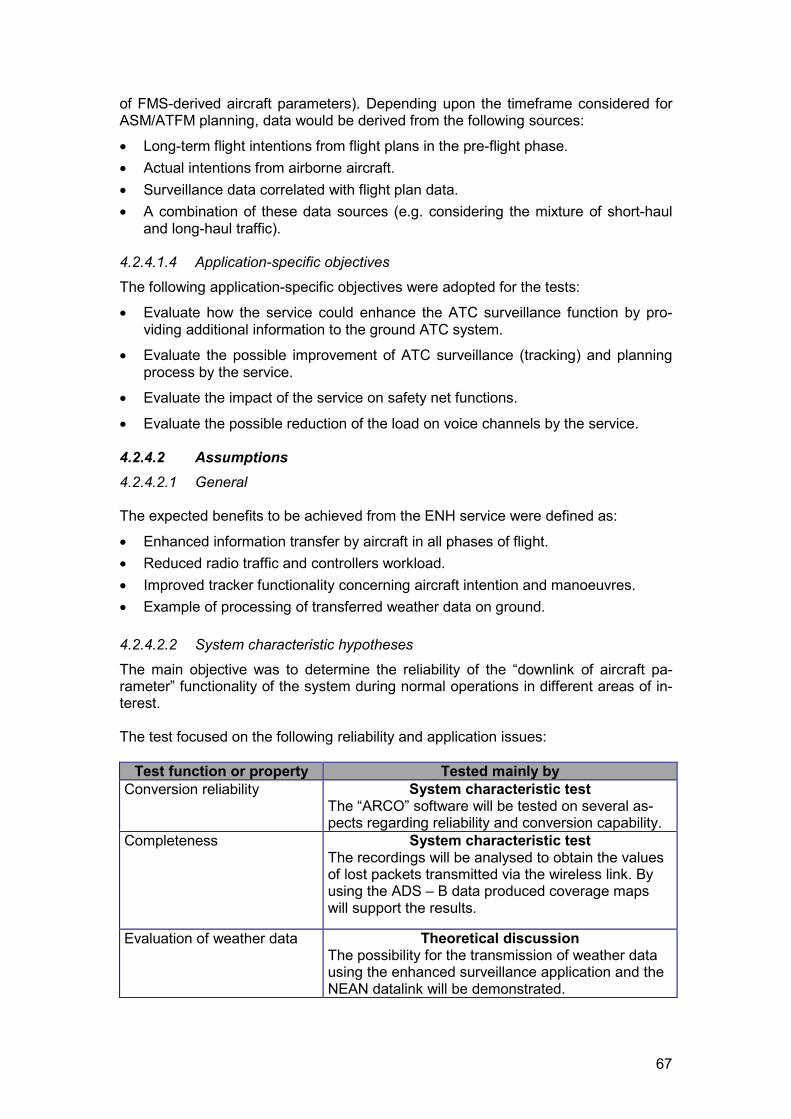
67
of FMS-derived aircraft parameters). Depending upon the timeframe considered forASM/ATFM planning, data would be derived from the following sources:
� Long-term flight intentions from flight plans in the pre-flight phase.� Actual intentions from airborne aircraft.� Surveillance data correlated with flight plan data.� A combination of these data sources (e.g. considering the mixture of short-haul
and long-haul traffic).
4.2.4.1.4 Application-specific objectives
The following application-specific objectives were adopted for the tests:
� Evaluate how the service could enhance the ATC surveillance function by pro-viding additional information to the ground ATC system.
� Evaluate the possible improvement of ATC surveillance (tracking) and planningprocess by the service.
� Evaluate the impact of the service on safety net functions.
� Evaluate the possible reduction of the load on voice channels by the service.
4.2.4.2 Assumptions4.2.4.2.1 General
The expected benefits to be achieved from the ENH service were defined as:
� Enhanced information transfer by aircraft in all phases of flight.� Reduced radio traffic and controllers workload.� Improved tracker functionality concerning aircraft intention and manoeuvres.� Example of processing of transferred weather data on ground.
4.2.4.2.2 System characteristic hypotheses
The main objective was to determine the reliability of the “downlink of aircraft pa-rameter” functionality of the system during normal operations in different areas of in-terest.
The test focused on the following reliability and application issues:
Test function or property Tested mainly byConversion reliability System characteristic test
The “ARCO” software will be tested on several as-pects regarding reliability and conversion capability.
Completeness System characteristic testThe recordings will be analysed to obtain the valuesof lost packets transmitted via the wireless link. Byusing the ADS – B data produced coverage mapswill support the results.
Evaluation of weather data Theoretical discussionThe possibility for the transmission of weather datausing the enhanced surveillance application and theNEAN datalink will be demonstrated.
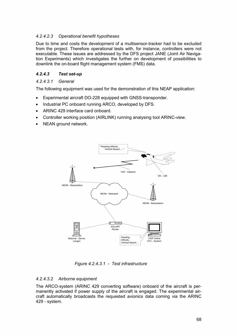
68
4.2.4.2.3 Operational benefit hypothesesDue to time and costs the development of a multisensor-tracker had to be excludedfrom the project. Therefore operational tests with, for instance, controllers were notexecutable. These issues are addressed by the DFS project JANE (Joint Air Naviga-tion Experiments) which investigates the further on development of possibilities todownlink the on-board flight management system (FMS) data.
4.2.4.3 Test set-up4.2.4.3.1 GeneralThe following equipment was used for the demonstration of this NEAP application:
� Experimental aircraft DO-228 equipped with GNSS-transponder.� Industrial PC onboard running ARCO, developed by DFS.� ARINC 429 interface card onboard.� Controller working position (AIRLINK) running analysing tool ARINC-view.� NEAN ground network.
Figure 4.2.4.3.1 - Test infrastructure
4.2.4.3.2 Airborne equipment
The ARCO-system (ARINC 429 converting software) onboard of the aircraft is per-manently activated if power supply of the aircraft is engaged. The experimental air-craft automatically broadcasts the requested avionics data coming via the ARINC429 - system.
NEAN - Basisstation
NEAN - Netzwerk
NEAN - Basisstation
National - ServerLangen
CWP AirlinkATC - System
EDLARTRouter
"Heading,Altitude, Vertical-Speed......"
Heading,Altitude,Vertical-Speed....
DO - 228
VHF - Datalink
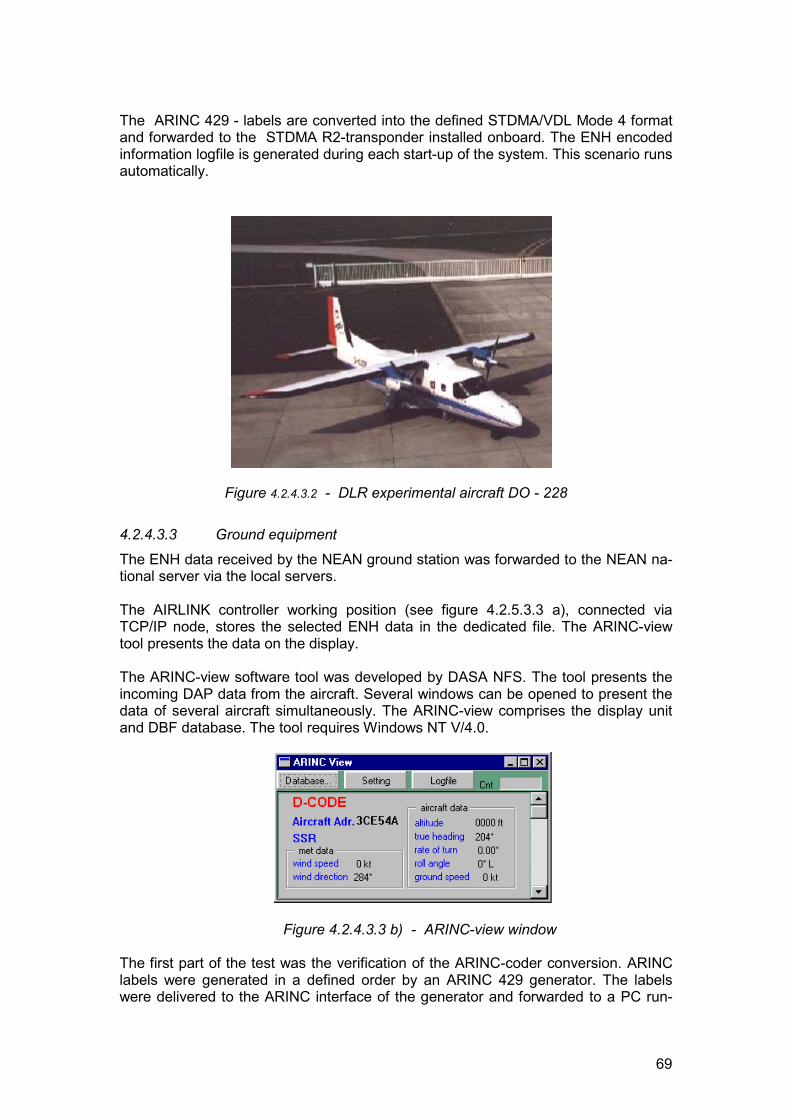
69
The ARINC 429 - labels are converted into the defined STDMA/VDL Mode 4 formatand forwarded to the STDMA R2-transponder installed onboard. The ENH encodedinformation logfile is generated during each start-up of the system. This scenario runsautomatically.
Figure 4.2.4.3.2 - DLR experimental aircraft DO - 228
4.2.4.3.3 Ground equipment
The ENH data received by the NEAN ground station was forwarded to the NEAN na-tional server via the local servers.
The AIRLINK controller working position (see figure 4.2.5.3.3 a), connected viaTCP/IP node, stores the selected ENH data in the dedicated file. The ARINC-viewtool presents the data on the display.
The ARINC-view software tool was developed by DASA NFS. The tool presents theincoming DAP data from the aircraft. Several windows can be opened to present thedata of several aircraft simultaneously. The ARINC-view comprises the display unitand DBF database. The tool requires Windows NT V/4.0.
Figure 4.2.4.3.3 b) - ARINC-view window
The first part of the test was the verification of the ARINC-coder conversion. ARINClabels were generated in a defined order by an ARINC 429 generator. The labelswere delivered to the ARINC interface of the generator and forwarded to a PC run-
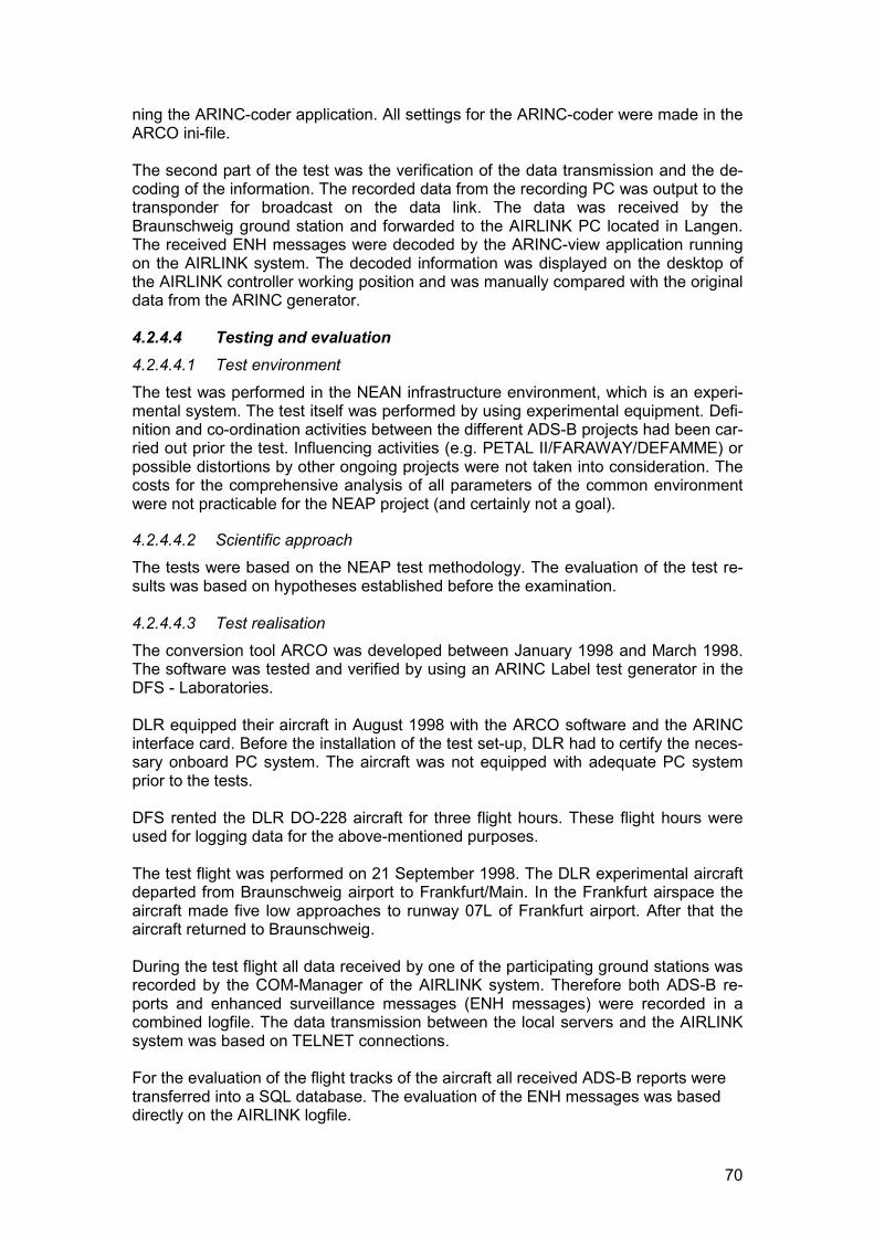
70
ning the ARINC-coder application. All settings for the ARINC-coder were made in theARCO ini-file.
The second part of the test was the verification of the data transmission and the de-coding of the information. The recorded data from the recording PC was output to thetransponder for broadcast on the data link. The data was received by theBraunschweig ground station and forwarded to the AIRLINK PC located in Langen.The received ENH messages were decoded by the ARINC-view application runningon the AIRLINK system. The decoded information was displayed on the desktop ofthe AIRLINK controller working position and was manually compared with the originaldata from the ARINC generator.
4.2.4.4 Testing and evaluation4.2.4.4.1 Test environmentThe test was performed in the NEAN infrastructure environment, which is an experi-mental system. The test itself was performed by using experimental equipment. Defi-nition and co-ordination activities between the different ADS-B projects had been car-ried out prior the test. Influencing activities (e.g. PETAL II/FARAWAY/DEFAMME) orpossible distortions by other ongoing projects were not taken into consideration. Thecosts for the comprehensive analysis of all parameters of the common environmentwere not practicable for the NEAP project (and certainly not a goal).
4.2.4.4.2 Scientific approachThe tests were based on the NEAP test methodology. The evaluation of the test re-sults was based on hypotheses established before the examination.
4.2.4.4.3 Test realisationThe conversion tool ARCO was developed between January 1998 and March 1998.The software was tested and verified by using an ARINC Label test generator in theDFS - Laboratories.
DLR equipped their aircraft in August 1998 with the ARCO software and the ARINCinterface card. Before the installation of the test set-up, DLR had to certify the neces-sary onboard PC system. The aircraft was not equipped with adequate PC systemprior to the tests.
DFS rented the DLR DO-228 aircraft for three flight hours. These flight hours wereused for logging data for the above-mentioned purposes.
The test flight was performed on 21 September 1998. The DLR experimental aircraftdeparted from Braunschweig airport to Frankfurt/Main. In the Frankfurt airspace theaircraft made five low approaches to runway 07L of Frankfurt airport. After that theaircraft returned to Braunschweig.
During the test flight all data received by one of the participating ground stations wasrecorded by the COM-Manager of the AIRLINK system. Therefore both ADS-B re-ports and enhanced surveillance messages (ENH messages) were recorded in acombined logfile. The data transmission between the local servers and the AIRLINKsystem was based on TELNET connections.
For the evaluation of the flight tracks of the aircraft all received ADS-B reports weretransferred into a SQL database. The evaluation of the ENH messages was baseddirectly on the AIRLINK logfile.
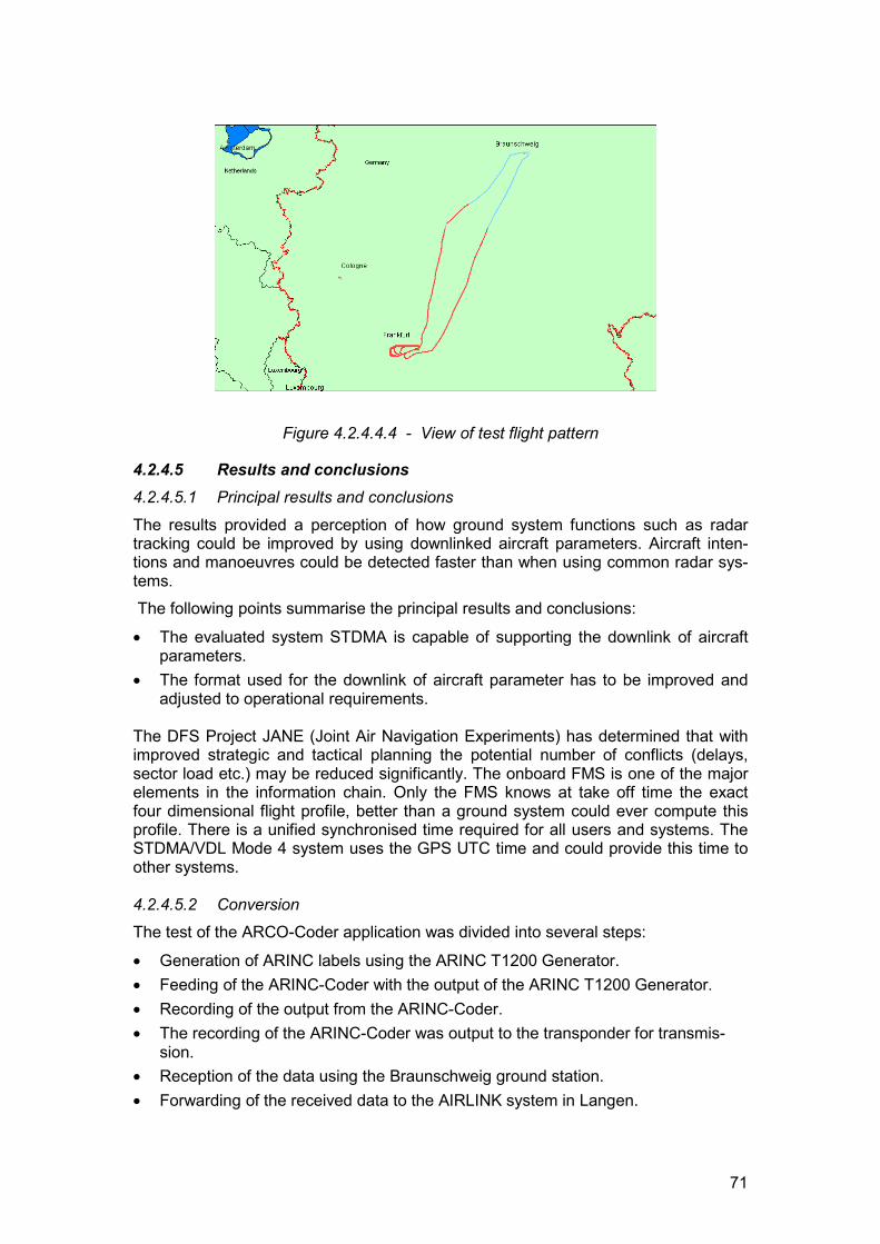
71
Figure 4.2.4.4.4 - View of test flight pattern
4.2.4.5 Results and conclusions4.2.4.5.1 Principal results and conclusions
The results provided a perception of how ground system functions such as radartracking could be improved by using downlinked aircraft parameters. Aircraft inten-tions and manoeuvres could be detected faster than when using common radar sys-tems. The following points summarise the principal results and conclusions:
� The evaluated system STDMA is capable of supporting the downlink of aircraftparameters.
� The format used for the downlink of aircraft parameter has to be improved andadjusted to operational requirements.
The DFS Project JANE (Joint Air Navigation Experiments) has determined that withimproved strategic and tactical planning the potential number of conflicts (delays,sector load etc.) may be reduced significantly. The onboard FMS is one of the majorelements in the information chain. Only the FMS knows at take off time the exactfour dimensional flight profile, better than a ground system could ever compute thisprofile. There is a unified synchronised time required for all users and systems. TheSTDMA/VDL Mode 4 system uses the GPS UTC time and could provide this time toother systems.
4.2.4.5.2 ConversionThe test of the ARCO-Coder application was divided into several steps:
� Generation of ARINC labels using the ARINC T1200 Generator.� Feeding of the ARINC-Coder with the output of the ARINC T1200 Generator.� Recording of the output from the ARINC-Coder.� The recording of the ARINC-Coder was output to the transponder for transmis-
sion.� Reception of the data using the Braunschweig ground station.� Forwarding of the received data to the AIRLINK system in Langen.
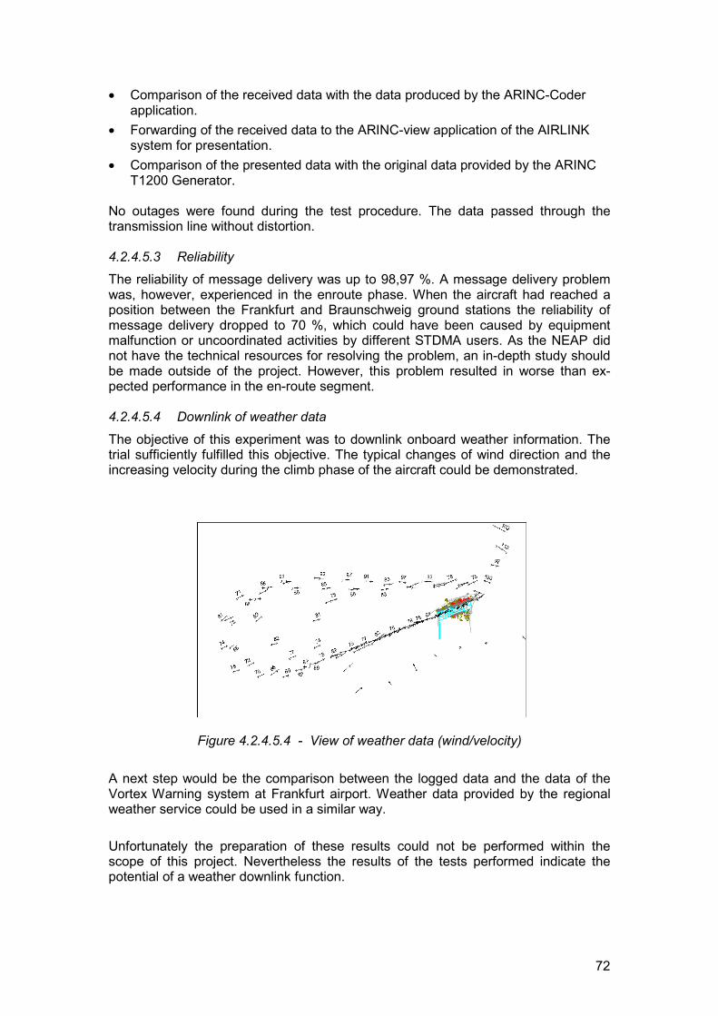
72
� Comparison of the received data with the data produced by the ARINC-Coderapplication.
� Forwarding of the received data to the ARINC-view application of the AIRLINKsystem for presentation.
� Comparison of the presented data with the original data provided by the ARINCT1200 Generator.
No outages were found during the test procedure. The data passed through thetransmission line without distortion.
4.2.4.5.3 ReliabilityThe reliability of message delivery was up to 98,97 %. A message delivery problemwas, however, experienced in the enroute phase. When the aircraft had reached aposition between the Frankfurt and Braunschweig ground stations the reliability ofmessage delivery dropped to 70 %, which could have been caused by equipmentmalfunction or uncoordinated activities by different STDMA users. As the NEAP didnot have the technical resources for resolving the problem, an in-depth study shouldbe made outside of the project. However, this problem resulted in worse than ex-pected performance in the en-route segment.
4.2.4.5.4 Downlink of weather data
The objective of this experiment was to downlink onboard weather information. Thetrial sufficiently fulfilled this objective. The typical changes of wind direction and theincreasing velocity during the climb phase of the aircraft could be demonstrated.
Figure 4.2.4.5.4 - View of weather data (wind/velocity)
A next step would be the comparison between the logged data and the data of theVortex Warning system at Frankfurt airport. Weather data provided by the regionalweather service could be used in a similar way.
Unfortunately the preparation of these results could not be performed within thescope of this project. Nevertheless the results of the tests performed indicate thepotential of a weather downlink function.

73
The broadcast methodology itself is practicable to distribute this kind of information.In fact, it could be included into the ADS-B position report.
4.2.4.5.5 Operational Benefits TestIn accordance with the NEAP Test plan, Project Jane (Joint Air Navigation Experi-ence) addresses this issue for the Enhanced Surveillance application.
4.2.4.6 Recommendations for system improvementsThe limiting factors with regard to the evaluated implementation of the EnhancedSurveillance application are;� The free text ENH message data source is limited by the current STDMA/VDL
Mode 4 text message format.� Currently only experimental equipment is available.� Standardisation of the STDMA/VDL Mode 4 format is not complete.
An in-depth analysis of the data flow is required from a process perspective to estab-lish which process contains the ”best” information at a time. With respect to the wholeATM process we only have a specific and limited knowledge. The following informa-tion systems should be integrated and used for improvements:
� FMS should be integrated into ATM systems and information flow. Only the FMSknows at take-off time the exact 4D profile (better than a ground system couldever compute this profile). Today just a limited subset of functions is used at pi-lots’ discretion. AOC only receives a few information elements, whereas ATChas no FMS information at all. Note that future FDPS should be capable of proc-essing FMS data.
� Airports and airport information systems are insufficiently integrated into theoverall ATM systems. Heartbeat of a co-operative system might be ETA or take-off time. Synchronisation has to be assured and updates may be required fromAOC in co-ordination with ATC.
� Delays are more often caused on ground than when the flight is airborne. Halfan hour before take-off is a ”black hole” from an information point of view. For in-stance, in Frankfurt the average elapsed time between pushback request/enginestart-up given and take-off varies enormously (� 15 minutes).
� A unified synchronised time is required for all users and systems. GPS time pro-vides a possible solution.
4.2.4.7 Future plansThe DFS Data link strategy was presented at the 41st Conference of the DFSSYSCOM. The strategy outlined a possible implementation of data link services asshown in Figure. 4.2.4.7.
ADS-B is a fundamental technical basis for future concepts, allowing aircraft to auto-matically broadcast air-derived data such as 4 -D position and identification at regularintervals. At the same time, signals broadcast by other aircraft can be received onboard and are then used to create a situational display of the surrounding airspace,comparable to the radar display of an air traffic controller. DFS is participating in thedevelopment of ADS-B and in the test procedures of potential transmission technolo-gies. At the moment, Mode S Extended Squitter and VDL Mode 4 might be suitablecandidates for transmitting ADS- B data.
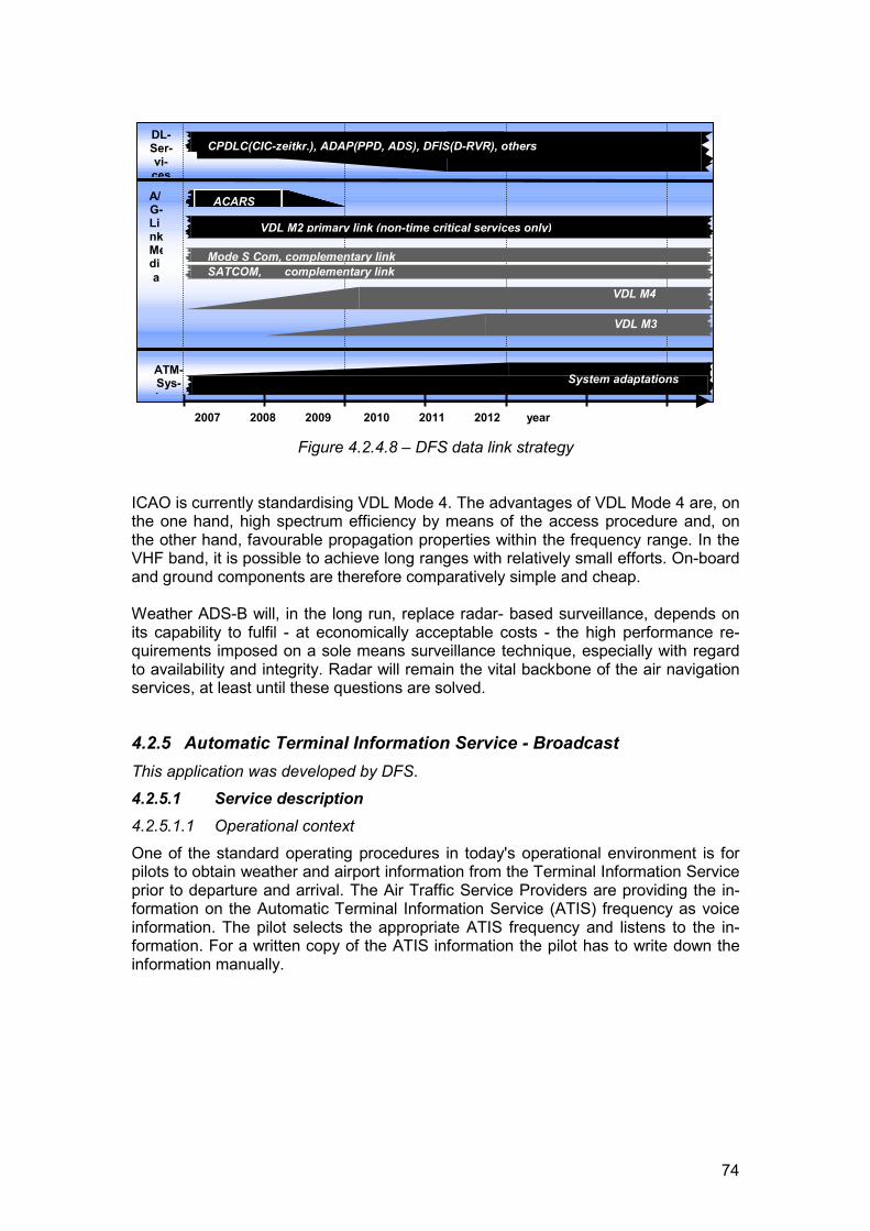
74
Figure 4.2.4.8 – DFS data link strategy
ICAO is currently standardising VDL Mode 4. The advantages of VDL Mode 4 are, onthe one hand, high spectrum efficiency by means of the access procedure and, onthe other hand, favourable propagation properties within the frequency range. In theVHF band, it is possible to achieve long ranges with relatively small efforts. On-boardand ground components are therefore comparatively simple and cheap.
Weather ADS-B will, in the long run, replace radar- based surveillance, depends onits capability to fulfil - at economically acceptable costs - the high performance re-quirements imposed on a sole means surveillance technique, especially with regardto availability and integrity. Radar will remain the vital backbone of the air navigationservices, at least until these questions are solved.
4.2.5 Automatic Terminal Information Service - BroadcastThis application was developed by DFS.4.2.5.1 Service description4.2.5.1.1 Operational contextOne of the standard operating procedures in today's operational environment is forpilots to obtain weather and airport information from the Terminal Information Serviceprior to departure and arrival. The Air Traffic Service Providers are providing the in-formation on the Automatic Terminal Information Service (ATIS) frequency as voiceinformation. The pilot selects the appropriate ATIS frequency and listens to the in-formation. For a written copy of the ATIS information the pilot has to write down theinformation manually.
A/G-LinkMedia
DL-Ser-vi-ces
2007 2008 2009 2010 2011 2012 year
VDL M2 primary link (non-time critical services only)
VDL M3
VDL M4
CPDLC(CIC-zeitkr.), ADAP(PPD, ADS), DFIS(D-RVR), others
Mode S Com, complementary linkSATCOM, complementary link
ACARS
ATM-Sys-t
System adaptations
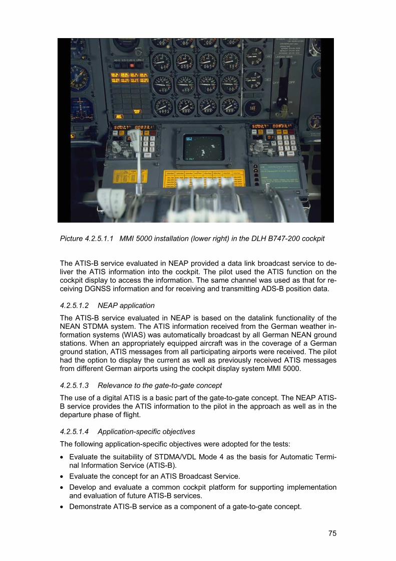
75
Picture 4.2.5.1.1 MMI 5000 installation (lower right) in the DLH B747-200 cockpit
The ATIS-B service evaluated in NEAP provided a data link broadcast service to de-liver the ATIS information into the cockpit. The pilot used the ATIS function on thecockpit display to access the information. The same channel was used as that for re-ceiving DGNSS information and for receiving and transmitting ADS-B position data.
4.2.5.1.2 NEAP application
The ATIS-B service evaluated in NEAP is based on the datalink functionality of theNEAN STDMA system. The ATIS information received from the German weather in-formation systems (WIAS) was automatically broadcast by all German NEAN groundstations. When an appropriately equipped aircraft was in the coverage of a Germanground station, ATIS messages from all participating airports were received. The pilothad the option to display the current as well as previously received ATIS messagesfrom different German airports using the cockpit display system MMI 5000.
4.2.5.1.3 Relevance to the gate-to-gate conceptThe use of a digital ATIS is a basic part of the gate-to-gate concept. The NEAP ATIS-B service provides the ATIS information to the pilot in the approach as well as in thedeparture phase of flight.
4.2.5.1.4 Application-specific objectivesThe following application-specific objectives were adopted for the tests:
� Evaluate the suitability of STDMA/VDL Mode 4 as the basis for Automatic Termi-nal Information Service (ATIS-B).
� Evaluate the concept for an ATIS Broadcast Service.� Develop and evaluate a common cockpit platform for supporting implementation
and evaluation of future ATIS-B services.� Demonstrate ATIS-B service as a component of a gate-to-gate concept.
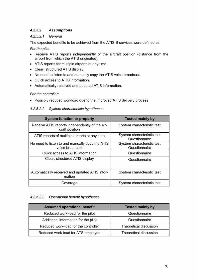
76
4.2.5.2 Assumptions4.2.5.2.1 General
The expected benefits to be achieved from the ATIS-B services were defined as:For the pilot:� Receive ATIS reports independently of the aircraft position (distance from the
airport from which the ATIS originated).� ATIS reports for multiple airports at any time.� Clear, structured ATIS display.� No need to listen to and manually copy the ATIS voice broadcast.� Quick access to ATIS information.� Automatically received and updated ATIS information.
For the controller:
� Possibly reduced workload due to the improved ATIS delivery process
4.2.5.2.2 System characteristic hypotheses
System function or property Tested mainly byReceive ATIS reports independently of the air-
craft positionSystem characteristic test
ATIS reports of multiple airports at any time System characteristic testQuestionnaire
No need to listen to and manually copy the ATISvoice broadcast
System characteristic testQuestionnaire
Quick access to ATIS information QuestionnaireClear, structured ATIS display Questionnaire
Automatically received and updated ATIS infor-mation
System characteristic test
Coverage System characteristic test
4.2.5.2.3 Operational benefit hypotheses
Assumed operational benefit Tested mainly byReduced work-load for the pilot Questionnaire
Additional information for the pilot Questionnaire
Reduced work-load for the controller Theoretical discussion
Reduced work-load for ATS employee Theoretical discussion
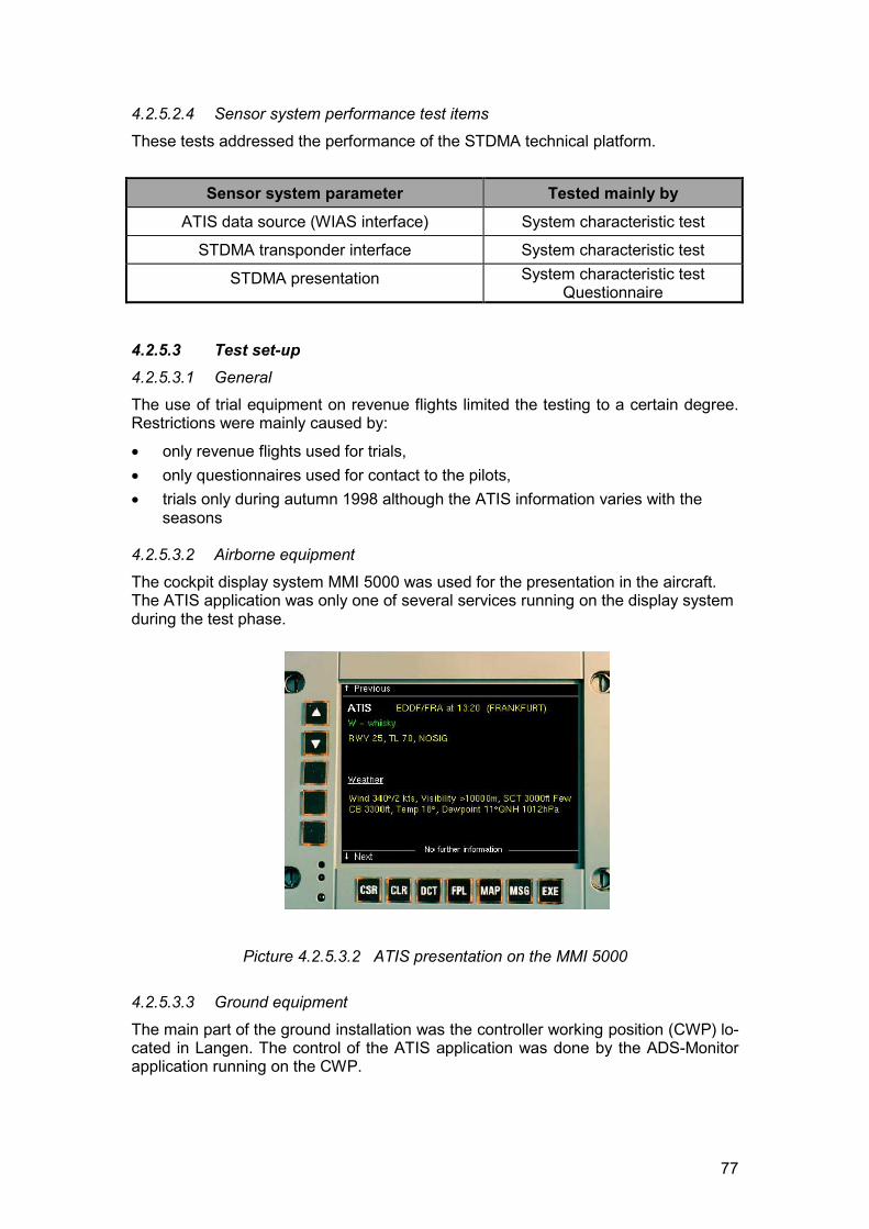
77
4.2.5.2.4 Sensor system performance test items
These tests addressed the performance of the STDMA technical platform.
Sensor system parameter Tested mainly byATIS data source (WIAS interface) System characteristic test
STDMA transponder interface System characteristic test
STDMA presentation System characteristic testQuestionnaire
4.2.5.3 Test set-up4.2.5.3.1 GeneralThe use of trial equipment on revenue flights limited the testing to a certain degree.Restrictions were mainly caused by:
� only revenue flights used for trials,� only questionnaires used for contact to the pilots,� trials only during autumn 1998 although the ATIS information varies with the
seasons
4.2.5.3.2 Airborne equipment
The cockpit display system MMI 5000 was used for the presentation in the aircraft.The ATIS application was only one of several services running on the display systemduring the test phase.
Picture 4.2.5.3.2 ATIS presentation on the MMI 5000
4.2.5.3.3 Ground equipment
The main part of the ground installation was the controller working position (CWP) lo-cated in Langen. The control of the ATIS application was done by the ADS-Monitorapplication running on the CWP.
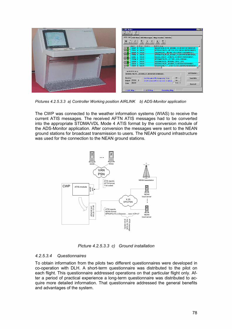
78
Pictures 4.2.5.3.3 a) Controller Working position AIRLINK b) ADS-Monitor application
The CWP was connected to the weather information systems (WIAS) to receive thecurrent ATIS messages. The received AFTN ATIS messages had to be convertedinto the appropriate STDMA/VDL Mode 4 ATIS format by the conversion module ofthe ADS-Monitor application. After conversion the messages were sent to the NEANground stations for broadcast transmission to users. The NEAN ground infrastructurewas used for the connection to the NEAN ground stations.
Picture 4.2.5.3.3 c) Ground installation
4.2.5.3.4 QuestionnairesTo obtain information from the pilots two different questionnaires were developed inco-operation with DLH. A short-term questionnaire was distributed to the pilot oneach flight. This questionnaire addressed operations on that particular flight only. Af-ter a period of practical experience a long-term questionnaire was distributed to ac-quire more detailed information. That questionnaire addressed the general benefitsand advantages of the system.
CWP ATIS-module
serie
llpo
rtet
hern
et p
ort
193.
28.1
31.6
8
...
NEANlocal server
VANPSN
ATIS reportsAFTN format,7 bit coded
ATIS reportsNEAN format$PRGPS,010,,0,Sxxxxxx ... xxxx +CR+LF
ATIS message
max. 62 byte
(6 bit ASCII)
WIAS WIAS
...
NEANlocal server
X.25DFS-PSN
NEAN basestation
79
4.2.5.4 Testing and evaluation4.2.5.4.1 Test environmentThe system test was divided up into a system characteristics test and an operationalbenefits test.
The system characteristics test was based on monitoring the message flow throughthe system. Different steps were defined:
� Applicability of the ATIS conversion tool: The ATIS conversion functionality of theADS-monitor application was verified.
� ATIS reception on a selected flight: The ATIS broadcast functionality of the ADS-monitor application was verified
� ATIS coverage: The ATIS coverage map of the Frankfurt ground station wasevaluated.
The operational benefits test was based on the questionnaires developed inco-operation with DLH. A statistical evaluation of the questions concerning the ATISservice was done. The results should produce statements concerning the functional-ity of the service:
� Reliability.� Design of presentation.� Availability.� Utilization.
As all tests were based on revenue flights by the DLH aircraft, it was not possible todefine special scenarios for the tests.
4.2.5.4.2 Scientific approach
The tests were based on the NEAP test methodology. The evaluation of the test re-sults was based on hypotheses established earlier.
4.2.5.4.3 Test realizationThe evaluation and pre-test phase of the ATIS ground installation was completed byJuly 1998. After August 1998 the application was running continuously.
Logfiles used for the ATIS coverage test were received from DLH. The logfiles wererecorded between 29 August and 16 September 1998 in five DLH B747-200 aircrafton revenue flights.
The system characteristics test concerning the applicability of the ATIS conversiontool had to be divided into two phases because preliminary results had shown thatthe error rate of the conversion routine was too high. The software of the conversionroutine was reviewed and upgraded in the first week of September. After that, thesystem performance test of the conversion tool was continued.
4.2.5.5 Results and conclusions4.2.5.5.1 Principal results and conclusionsFrom a technical point of view, the application worked without problems during thetest phase. Problems were found in the suitability of the data sources and also in thedefinition of the STDMA/VDL Mode 4 ATIS format.
80
4.2.5.5.2 Applicability of the ATIS conversion toolThe operational ATIS messages were received from the weather information systems(WIAS) by the controller working position (CWP). The ADS-monitor application run-ning on the CWP had to convert the AFTN coded messages (which are based onfree text) into the STDMA/VDL Mode 4 ATIS format (which is a fixed format). Thepurpose of this test was to verify the functionality of the conversion routine and to de-scribe possible problems.
Using the first release of the conversion tool, 25 % of all incoming AFTN ATIS mes-sages were not converted correctly into the STDMA/VDL Mode 4 ATIS format. As thehigh error rate was unacceptable for the application, an upgrade of the software wasrequired. After the software upgrade the error rate decreased to 9 %.
The main parts of the AFTN ATIS message are based on free text without using anexactly defined “phraseology” for the message elements. Therefore most of theproblems of the conversion routine were caused by deviations from the standardphraseology. The phraseology varied with time as well as between different airports(different operators).
The second problem when converting the AFTN ATIS messages into theSTDMA/VDL Mode 4 ATIS format was the limited capacity of the currently definedSTDMA ATIS format to accommodate all variations of message contents.
To reduce the error rate of the conversion routine two changes of the current defini-tions were required:
� The format and phraseology used in the operational AFTN ATIS messagesneeds to be precisely defined.
� The capacity of the currently defined STDMA/VDL Mode 4 ATIS format needs tobe enhanced.
4.2.5.5.3 ATIS reception on a selected flight
The purpose of the test was to demonstrate the functionality of the complete ATIS-Bapplication on a representative flight.
For the demonstration only the Frankfurt ground station was used for the broadcastof ATIS messages. The selected aircraft was arriving from Miami to Frankfurt airport.During the flight the aircraft was within the coverage of the Frankfurt ground stationfor 70 minutes. 15 ATIS messages were expected to be received by the aircraft, butthe logfile shows that only 14 messages actually were received. When the aircraftwas on ground at Frankfurt airport one ATIS message broadcast by the ground sta-tion was not received by the aircraft.
On the selected flight the ATIS application was usable during the whole time the air-craft was in the ATIS coverage.
4.2.5.5.4 ATIS coverageThe purpose of the test was to develop an ATIS coverage map for ATIS messagesbroadcast by the Frankfurt ground station. To evaluate the coverage map logfilesfrom five DLH B747-200 aircraft recorded between 29 August and 16 Septemberwere used.
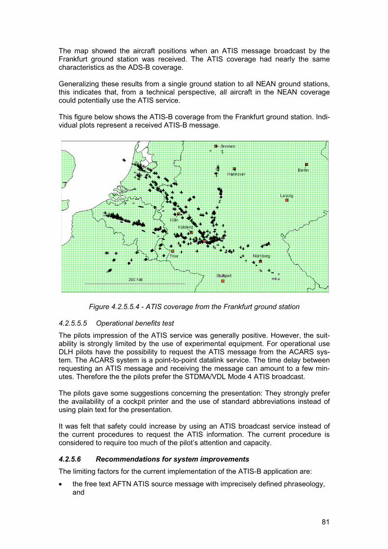
81
The map showed the aircraft positions when an ATIS message broadcast by theFrankfurt ground station was received. The ATIS coverage had nearly the samecharacteristics as the ADS-B coverage.
Generalizing these results from a single ground station to all NEAN ground stations,this indicates that, from a technical perspective, all aircraft in the NEAN coveragecould potentially use the ATIS service.
This figure below shows the ATIS-B coverage from the Frankfurt ground station. Indi-vidual plots represent a received ATIS-B message.
Figure 4.2.5.5.4 - ATIS coverage from the Frankfurt ground station
4.2.5.5.5 Operational benefits testThe pilots impression of the ATIS service was generally positive. However, the suit-ability is strongly limited by the use of experimental equipment. For operational useDLH pilots have the possibility to request the ATIS message from the ACARS sys-tem. The ACARS system is a point-to-point datalink service. The time delay betweenrequesting an ATIS message and receiving the message can amount to a few min-utes. Therefore the the pilots prefer the STDMA/VDL Mode 4 ATIS broadcast.
The pilots gave some suggestions concerning the presentation: They strongly preferthe availability of a cockpit printer and the use of standard abbreviations instead ofusing plain text for the presentation.
It was felt that safety could increase by using an ATIS broadcast service instead ofthe current procedures to request the ATIS information. The current procedure isconsidered to require too much of the pilot’s attention and capacity.
4.2.5.6 Recommendations for system improvementsThe limiting factors for the current implementation of the ATIS-B application are:
� the free text AFTN ATIS source message with imprecisely defined phraseology,and
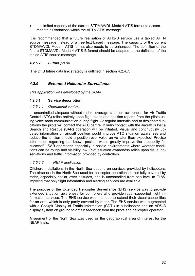
82
� the limited capacity of the current STDMA/VDL Mode 4 ATIS format to accom-modate all variations within the AFTN ATIS message.
It is recommended that a future realisation of ATIS-B service use a tabled AFTNsource message instead of a free text based message. The capacity of the currentSTDMA/VDL Mode 4 ATIS format also needs to be enhanced. The definition of thefuture STDMA/VDL Mode 4 ATIS-B format should be adapted to the definition of thetabled ATIS source message.
4.2.5.7 Future plans
The DFS future data link strategy is outlined in section 4.2.4.7.
4.2.6 Extended Helicopter Surveillance
This application was developed by the DCAA.
4.2.6.1 Service description4.2.6.1.1 Operational context
In uncontrolled airspace without radar coverage situation awareness for Air TrafficControl (ATC) relies entirely upon flight plans and position reports from the pilots us-ing voice radio communication during flight. At regular intervals and at designated lo-cations the pilots will contact the ATC centre. If radio contact with the aircraft is lost aSearch and Rescue (SAR) operation will be initiated. Visual and continuously up-dated information on aircraft position would improve ATC situation awareness andreduce the tension should a position-over-voice arrive later than expected. Preciseinformation regarding last known position would greatly improve the probability forsuccessful SAR operations especially in hostile environments where weather condi-tions can be rough and visibility low. Pilot situation awareness relies upon visual ob-servations and traffic information provided by controllers.
4.2.6.1.2 NEAP application
Offshore installations in the North Sea depend on services provided by helicopters.The airspace in the North Sea used for helicopter operations is not fully covered byradar, especially not at lower altitudes, and is uncontrolled from sea level to FL85,implying that only flight information and alerting services are available.
The purpose of the Extended Helicopter Surveillance (EHS) service was to provideextended situation awareness for controllers who provide radar-supported flight in-formation services. The EHS service was intended to extend their visual capabilitiesfor an area which is only partly covered by radar. The EHS service was augmentedwith a Cockpit Display of Traffic Information (CDTI) in a helicopter and an ADS-Bdisplay system on ground to obtain feedback from the pilots and helicopter operator.
A segment of the North Sea was used as the geographical area of interest for theNEAP trials.
83
Tyra East(Production Platform)
Esbjerg
Børsmose
Geographicalarea of interest
Denmark
Figure 4.2.6.1.2 - Geographical area of interestOnly the light-grey shaded part of the geographical area of interest is covered by ra-dar for lower flight levels.
The EHS Service was based on ADS-B position reports broadcast by anSTDMA/VDL Mode 4 equipped helicopter and received by ground stations installedin Esbjerg, Børsmose and on the Tyra East platform which is located in the NorthSea, approximately 125 nautical miles from the coast, outside radar coverage. TheADS-B position reports were distributed through the already existing North EuropeanADS-B Network (NEAN) infrastructure and finally displayed together with conven-tional radar data (when within radar coverage) on a dedicated Controller WorkingPosition (CWP). The CWP was situated in the Copenhagen ATC centre close to thecontrollers who provide traffic information and alerting services for the area.
4.2.6.1.3 Relevance to the gate-to-gate conceptThe EHS service is an ATM tool aimed at improving the controller situation aware-ness (and hence surveillance) capability during the en-route phase (from take-off toinitiation of an approach) and therefore covers one aspect of the gate-to-gate con-cept for the ATC user group.
4.2.6.1.4 Application-specific objectives
The following application-specific objectives were adopted for the evaluation:
� Evaluate the suitability of STDMA/VDL Mode 4 for extended ground surveillancetools for ATC (reliability, availability, etc.).
� Record experiences and opinions from controllers who provide radar supportedflight information services for the area.
� Record experiences and opinions from helicopter pilots regarding the CDTI.
4.2.6.2 Assumptions
Benefits expected to be achieved from the service provided by EHS were:
� Provision of a supplementary surveillance functions for an area outside radarcoverage.
� Improved situation awareness for controllers who provide flight information serv-ices.
� Enhanced functions for localising a crash site in SAR operations.� Improved situation awareness for helicopter pilots.
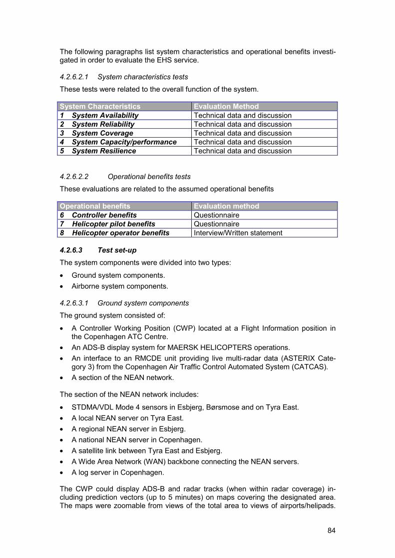
84
The following paragraphs list system characteristics and operational benefits investi-gated in order to evaluate the EHS service.
4.2.6.2.1 System characteristics testsThese tests were related to the overall function of the system.
System Characteristics Evaluation Method1 System Availability Technical data and discussion2 System Reliability Technical data and discussion3 System Coverage Technical data and discussion4 System Capacity/performance Technical data and discussion5 System Resilience Technical data and discussion
4.2.6.2.2 Operational benefits testsThese evaluations are related to the assumed operational benefits
Operational benefits Evaluation method6 Controller benefits Questionnaire7 Helicopter pilot benefits Questionnaire8 Helicopter operator benefits Interview/Written statement
4.2.6.3 Test set-upThe system components were divided into two types:
� Ground system components.� Airborne system components.
4.2.6.3.1 Ground system componentsThe ground system consisted of:
� A Controller Working Position (CWP) located at a Flight Information position inthe Copenhagen ATC Centre.
� An ADS-B display system for MAERSK HELICOPTERS operations.� An interface to an RMCDE unit providing live multi-radar data (ASTERIX Cate-
gory 3) from the Copenhagen Air Traffic Control Automated System (CATCAS).� A section of the NEAN network.
The section of the NEAN network includes:
� STDMA/VDL Mode 4 sensors in Esbjerg, Børsmose and on Tyra East.� A local NEAN server on Tyra East.� A regional NEAN server in Esbjerg.� A national NEAN server in Copenhagen.� A satellite link between Tyra East and Esbjerg.� A Wide Area Network (WAN) backbone connecting the NEAN servers.� A log server in Copenhagen.
The CWP could display ADS-B and radar tracks (when within radar coverage) in-cluding prediction vectors (up to 5 minutes) on maps covering the designated area.The maps were zoomable from views of the total area to views of airports/helipads.
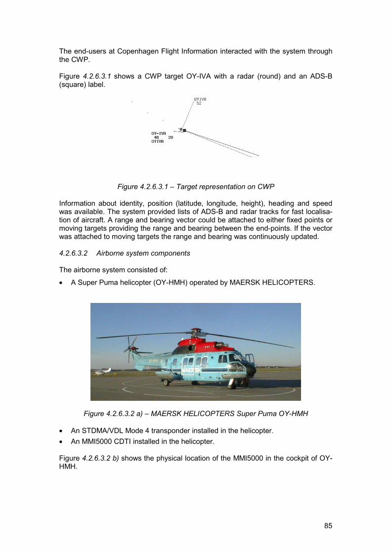
85
The end-users at Copenhagen Flight Information interacted with the system throughthe CWP.
Figure 4.2.6.3.1 shows a CWP target OY-IVA with a radar (round) and an ADS-B(square) label.
Figure 4.2.6.3.1 – Target representation on CWP
Information about identity, position (latitude, longitude, height), heading and speedwas available. The system provided lists of ADS-B and radar tracks for fast localisa-tion of aircraft. A range and bearing vector could be attached to either fixed points ormoving targets providing the range and bearing between the end-points. If the vectorwas attached to moving targets the range and bearing was continuously updated.
4.2.6.3.2 Airborne system components
The airborne system consisted of:
� A Super Puma helicopter (OY-HMH) operated by MAERSK HELICOPTERS.
Figure 4.2.6.3.2 a) – MAERSK HELICOPTERS Super Puma OY-HMH
� An STDMA/VDL Mode 4 transponder installed in the helicopter.� An MMI5000 CDTI installed in the helicopter.
Figure 4.2.6.3.2 b) shows the physical location of the MMI5000 in the cockpit of OY-HMH.
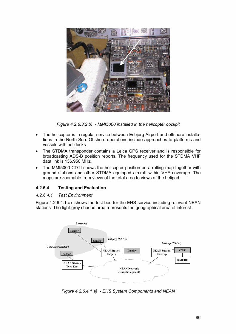
86
Figure 4.2.6.3.2 b) - MMI5000 installed in the helicopter cockpit
� The helicopter is in regular service between Esbjerg Airport and offshore installa-tions in the North Sea. Offshore operations include approaches to platforms andvessels with helidecks.
� The STDMA transponder contains a Leica GPS receiver and is responsible forbroadcasting ADS-B position reports. The frequency used for the STDMA VHFdata link is 136.950 MHz.
� The MMI5000 CDTI shows the helicopter position on a rolling map together withground stations and other STDMA equipped aircraft within VHF coverage. Themaps are zoomable from views of the total area to views of the helipad.
4.2.6.4 Testing and Evaluation4.2.6.4.1 Test Environment
Figure 4.2.6.4.1 a) shows the test bed for the EHS service including relevant NEANstations. The light-grey shaded area represents the geographical area of interest.
Kastrup (EKCH)Esbjerg (EKEB)
NEAN StationEsbjerg
Tyra East (EKGF)
NEAN Network(Danish Segment)
NEAN StationTyra East
SensorCWPNEAN Station
KastrupDisplay
Sensor
Sensor
Børsmose
RMCDE
Figure 4.2.6.4.1 a) - EHS System Components and NEAN
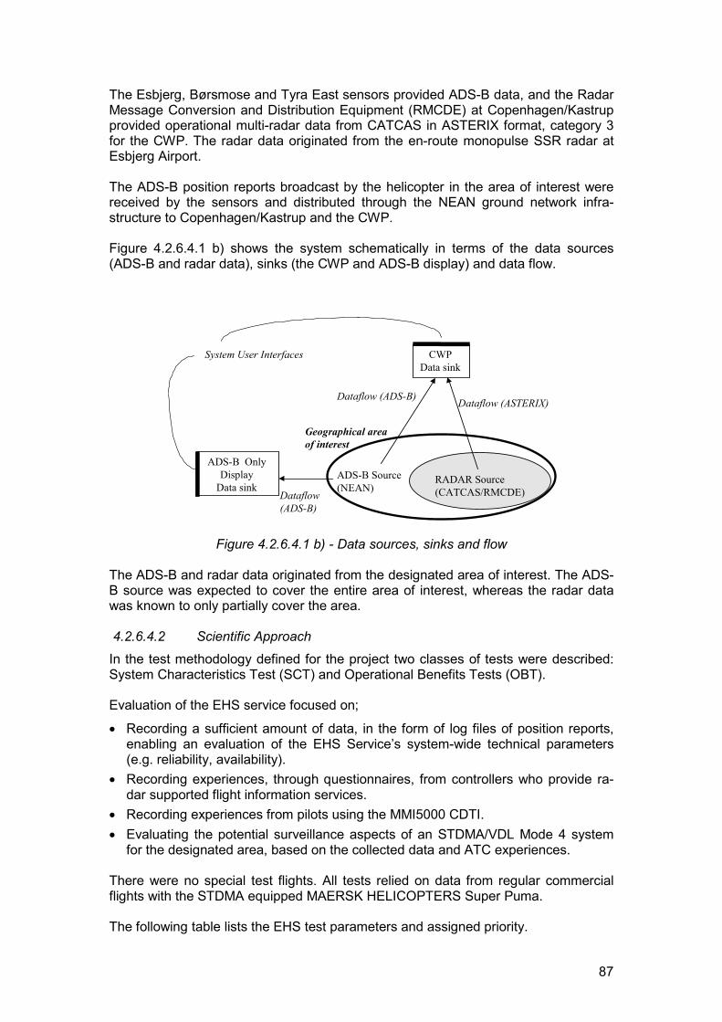
87
The Esbjerg, Børsmose and Tyra East sensors provided ADS-B data, and the RadarMessage Conversion and Distribution Equipment (RMCDE) at Copenhagen/Kastrupprovided operational multi-radar data from CATCAS in ASTERIX format, category 3for the CWP. The radar data originated from the en-route monopulse SSR radar atEsbjerg Airport.
The ADS-B position reports broadcast by the helicopter in the area of interest werereceived by the sensors and distributed through the NEAN ground network infra-structure to Copenhagen/Kastrup and the CWP.
Figure 4.2.6.4.1 b) shows the system schematically in terms of the data sources(ADS-B and radar data), sinks (the CWP and ADS-B display) and data flow.
ADS-B Source(NEAN)
RADAR Source(CATCAS/RMCDE)
Geographical areaof interest
CWPData sink
ADS-B OnlyDisplay
Data sink
System User Interfaces
Dataflow (ASTERIX)
Dataflow(ADS-B)
Dataflow (ADS-B)
Figure 4.2.6.4.1 b) - Data sources, sinks and flow
The ADS-B and radar data originated from the designated area of interest. The ADS-B source was expected to cover the entire area of interest, whereas the radar datawas known to only partially cover the area.
4.2.6.4.2 Scientific ApproachIn the test methodology defined for the project two classes of tests were described:System Characteristics Test (SCT) and Operational Benefits Tests (OBT).
Evaluation of the EHS service focused on;
� Recording a sufficient amount of data, in the form of log files of position reports,enabling an evaluation of the EHS Service’s system-wide technical parameters(e.g. reliability, availability).
� Recording experiences, through questionnaires, from controllers who provide ra-dar supported flight information services.
� Recording experiences from pilots using the MMI5000 CDTI.� Evaluating the potential surveillance aspects of an STDMA/VDL Mode 4 system
for the designated area, based on the collected data and ATC experiences.
There were no special test flights. All tests relied on data from regular commercialflights with the STDMA equipped MAERSK HELICOPTERS Super Puma.
The following table lists the EHS test parameters and assigned priority.
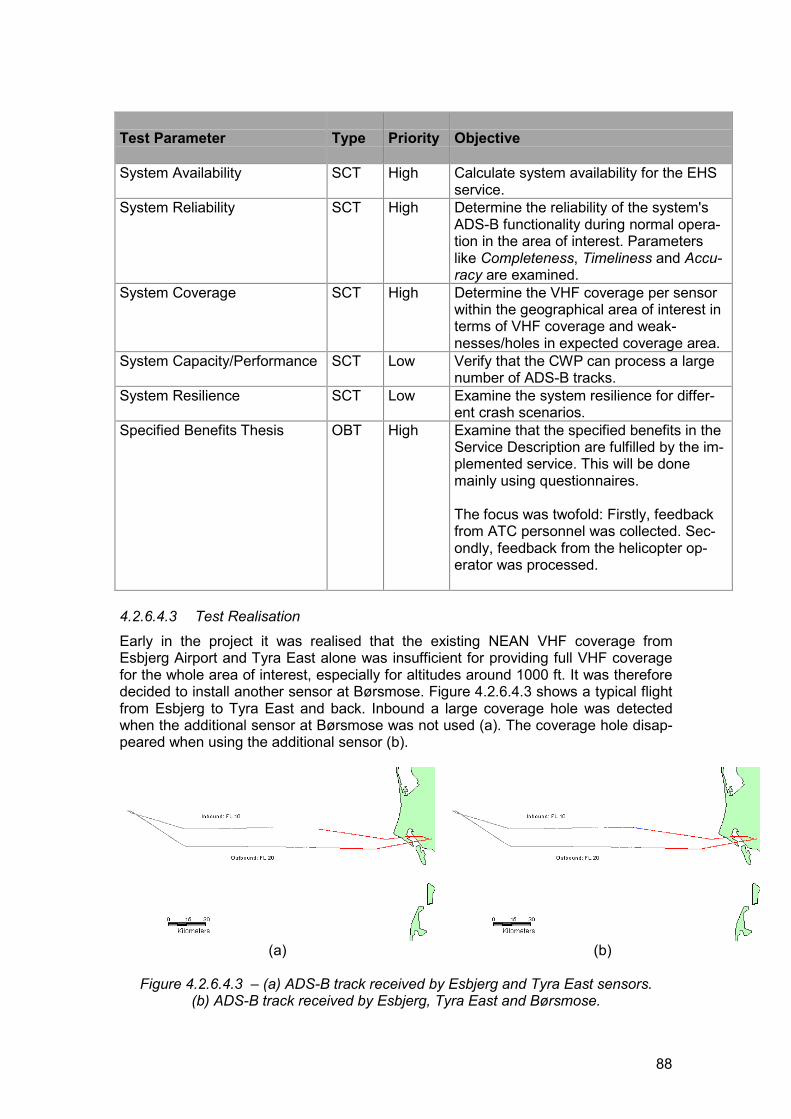
88
Test Parameter Type Priority Objective
System Availability SCT High Calculate system availability for the EHSservice.
System Reliability SCT High Determine the reliability of the system'sADS-B functionality during normal opera-tion in the area of interest. Parameterslike Completeness, Timeliness and Accu-racy are examined.
System Coverage SCT High Determine the VHF coverage per sensorwithin the geographical area of interest interms of VHF coverage and weak-nesses/holes in expected coverage area.
System Capacity/Performance SCT Low Verify that the CWP can process a largenumber of ADS-B tracks.
System Resilience SCT Low Examine the system resilience for differ-ent crash scenarios.
Specified Benefits Thesis OBT High Examine that the specified benefits in theService Description are fulfilled by the im-plemented service. This will be donemainly using questionnaires.
The focus was twofold: Firstly, feedbackfrom ATC personnel was collected. Sec-ondly, feedback from the helicopter op-erator was processed.
4.2.6.4.3 Test RealisationEarly in the project it was realised that the existing NEAN VHF coverage fromEsbjerg Airport and Tyra East alone was insufficient for providing full VHF coveragefor the whole area of interest, especially for altitudes around 1000 ft. It was thereforedecided to install another sensor at Børsmose. Figure 4.2.6.4.3 shows a typical flightfrom Esbjerg to Tyra East and back. Inbound a large coverage hole was detectedwhen the additional sensor at Børsmose was not used (a). The coverage hole disap-peared when using the additional sensor (b).
(a) (b)
Figure 4.2.6.4.3 – (a) ADS-B track received by Esbjerg and Tyra East sensors.(b) ADS-B track received by Esbjerg, Tyra East and Børsmose.
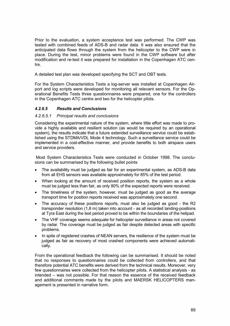
89
Prior to the evaluation, a system acceptance test was performed. The CWP wastested with combined feeds of ADS-B and radar data. It was also ensured that theanticipated data flows through the system from the helicopter to the CWP were inplace. During the test, minor problems were found in the CWP software but aftermodification and re-test it was prepared for installation in the Copenhagen ATC cen-tre.
A detailed test plan was developed specifying the SCT and OBT tests.
For the System Characteristics Tests a log-server was installed at Copenhagen Air-port and log scripts were developed for monitoring all relevant sensors. For the Op-erational Benefits Tests three questionnaires were prepared, one for the controllersin the Copenhagen ATC centre and two for the helicopter pilots.
4.2.6.5 Results and Conclusions4.2.6.5.1 Principal results and conclusions
Considering the experimental nature of the system, where little effort was made to pro-vide a highly available and resilient solution (as would be required by an operationalsystem), the results indicate that a future extended surveillance service could be estab-lished using the STDMA/VDL Mode 4 technology. Such a surveillance service could beimplemented in a cost-effective manner, and provide benefits to both airspace usersand service providers.
Most System Characteristics Tests were conducted in October 1998. The conclu-sions can be summarised by the following bullet points
� The availability must be judged as fair for an experimental system, as ADS-B datafrom all EHS sensors was available approximately for 85% of the test period.
� When looking at the amount of received position reports, the system as a wholemust be judged less than fair, as only 80% of the expected reports were received.
� The timeliness of the system, however, must be judged as good as the averagetransport time for position reports received was approximately one second.
� The accuracy of these positions reports, must also be judged as good - the R2transponder resolution (1,8 m) taken into account - as all recorded landing-positionsat Tyra East during the test period proved to be within the boundaries of the helipad.
� The VHF coverage seems adequate for helicopter surveillance in areas not coveredby radar. The coverage must be judged as fair despite detected areas with specificproblems.
� In spite of registered crashes of NEAN servers, the resilience of the system must bejudged as fair as recovery of most crashed components were achieved automati-cally.
From the operational feedback the following can be summarised. It should be notedthat no responses to questionnaires could be collected from controllers, and thattherefore potential ATC benefits were derived from the technical results. Moreover, veryfew questionnaires were collected from the helicopter pilots. A statistical analysis - asintended – was not possible. For that reason the essence of the received feedbackand additional comments made by the pilots and MAERSK HELICOPTERS man-agement is presented in narrative form.
90
� Operators were very interested in possibilities for Search and Rescue (SAR),since the system can provide improved co-ordination between remote and on-scene SAR resources.
� Issues like navigation, pilot situation awareness, the possibility of uplink of trafficand meteorological information were also seen as potential benefits.
� The experience gained by the operator was that the GNSS transponder providesinformation of the correct position of the helicopter to the ADS-B display systemalmost continuously.
� There is also a view that the system, with an onboard CDTI, could replace theuse of Non Directional Beacon (NDB) and radar in poor-weather approaches tooffshore installations.
� The helicopter pilots were critical of the human-machine interface of the MMI5000display and its physical location in the cockpit. This mostly related to the fact thatthe display was not designed specifically for helicopters.
� Operating the menu-system of the MMI5000 was generally considered time-consuming and troublesome. Flight time between platforms is often no more thana few minutes and the flight is performed at low altitude, leaving limited time foroperating the MMI5000. Using 1-2 minutes for entering new waypoints when ondeck may very well increase deck time up to 100% and cause loss of revenue.
� Integration with existing avionics was desired.� Pilots showed interest in seeing other rescue helicopters directly on the MMI5000
during SAR operations.� Equipping vessels with STDMA transponders were also seen as a potential en-
hancement to the existing environment.� Matching views 'out-of-the-window' with that provided on the MMI5000 was de-
sired, since helicopter movements - especially at low speed and in strong winds -often are sideways. In the existing implementation, the display shows the heli-copter track, but it was suggested that heading information be included to havethe map orientation aligned with the true heading.
� MMI maps should be simplified. It would be sufficient with a symbol showing aplatform’s position and orientation together with the location of the helideck. SinceIFR/IMC is not possible, too many details in the maps are more confusing thanbeneficial.
� The service enabled ATC to monitor helicopter traffic from Esbjerg Airport to off-shore installations in the North Sea, beyond radar coverage and down to 1000 ft.
4.2.6.5.2 Comments and Observations
AvailabilityAll sensors were available to the CWP for 85% of the test period. Although this is notsatisfactory for an operational system, one should take into account that the systemis a prototype not designed for high availability operation. Moreover, the system wasunattended during nights and weekends when most of the major downtime periodsoccurred. In addition, disruptive trials/experiments took place during the test period,since the project was sharing the test-bed with the NEAN project and PreliminaryEurocontrol Test of Air/ground data Link project (PETAL II).
The major outage periods were caused by the unavailability of the National Server. Ifthe national server stops then no data is available at the CWP.
91
Data Completeness
Average data completeness percentages (i.e. the received number of position reportsseen in relation to the expected number) of around 80% are quite low. To some extent,the low data completeness is related to problems in the ground station installations inEsbjerg and Børsmose, and problems on the satellite link to the Tyra East sensor. In-terestingly, this percentage did not prevent identification and use of ADS-B plots as dis-played on the CWP.
With improved ground station installations and tracking capability, the technology couldaugment existing radar surveillance at a competitive price.
TimelinessAn average message transport time of approximately one second is quite good asground system performance has not been given highest priority. It is well within the as-sumed 2 second limit. However, the high loss of messages (approximately 11%) is lesssatisfactory. A closer examination of the data indicates that the messages were lost atprimarily two places in the system:
� From the transponder and outwards (probably on the data link or in the MMI5000,as it was noticed that ping-messages leaving a local server did not always receive aresponse).
� In the ground network. Known problems in the NEAN server software caused erro-neous routing decisions resulting in packets not being sent to their proper destina-tions.
Some of the losses might also have been caused by conflicts with uplink of differentialcorrections on the same frequency. In an operational system, differential corrections areenvisaged to be uplinked on a separate channel.
Accuracy
All assumed landing positions (ADS-B positions with zero speed) were situated withinthe lateral boundaries of the helipad. Correcting for the fact that the GPS antenna loca-tion on the helicopter is offset from the helicopter centre of mass, a majority of positionswere registered between zero and three meters from the helipad centre.
The vertical positions were influenced by the vertical resolution of the transponder. Thegeoid model used by the transponder may result in biased heights. Some of the posi-tions included in plots and statistics may not be true landing spots, since the helicoptercould have been hovering, and multipath effects might also have influenced GPSmeasurements, resulting in erroneous heights. Despite these facts, the majority of as-sumed landing positions are vertically within 7 m from the helipad elevation and all arewithin 25m.
CoverageIt was possible, using ADS-B surveillance data, to follow flights at altitudes down to1,000 ft from take-off in Esbjerg airport to the landing on the production platform TyraEast.
Despite problems with the sensors in Esbjerg and Børsmose - and bearing in mindthat the system relies only on three sensors without any integrity monitoring - thecoverage seems adequate for helicopter surveillance in areas not covered by radar.
92
Capacity/Performance (CWP)In a simulation where positions from 300 simulated aircraft were fed into the CWP, thesystem did not crash but showed only a “sluggish” behaviour.
Resilience
The EHS service – from sensor to CWP – appeared to be quite resilient. The servicerestored itself in all simulated crash cases but one.
4.2.6.6 Recommendations for system improvementsFurther studies are recommended on the following topics:
� Enhanced ATC tools. ADS-B position reports provide extended coverage andhence new possibilities for improved surveillance, e.g. automatic detection of alertsituations. These new possibilities should be further investigated involving ATCpersonnel.
� Human-machine interface for helicopter pilots. The MMI5000 CDTI was devel-oped in co-operation with SAS pilots and was neither intended nor suitable forhelicopter operations.
� SAR operations. The exact knowledge of the last known position in case of a lostaircraft combined with exact knowledge of the rescue team’s own position wouldprovide new possibilities for SAR operations.
4.2.6.7 Future PlansSince the Danish Civil Aviation Administration (DCAA) began its involvement in theNEAN/NEAP projects in 1996, several initiatives have been taken to further investi-gate the use of ADS-B supported by STDMA/VDL Mode 4.
� DCAA has initiated the North Atlantic ADS-B Network project (NAAN) for con-ducting further studies of STDMA/VDL Mode 4 in the North Atlantic region, whereharsh climatic conditions makes the deployment and maintenance of traditionalsurveillance equipment expensive. It is expected that up to nine reference sta-tions will be distributed over Greenland, Iceland, The Faeroe Islands, UnitedKingdom, Ireland and Norway.
� DCAA is participating in NEAN Update Programme (NUP), which will follow up onthe initial steps taken in NEAN.
� Future operational systems being specified by DCAA will consider ADS-B as anoption.
� The future CNS concept is under consideration by the DCAA, and technologieslike STDMA/VDL Mode 4 and ADS-B are being discussed.
4.2.7 Runway incursion monitoringThis application was developed by the SCAA.4.2.7.1 Service description4.2.7.1.1 Operational context
Unauthorised or unintentional entry onto runways and taxiways by aircraft and vehi-cles constitutes a serious threat to aviation safety. Hazardous conflict situations maydevelop between aircraft and airport ground vehicles in, for instance, snow clearingsituations when several vehicles operate on, or close to an active runway. The threatis more critical when poor visibility conditions prevent the controllers in the control
93
tower (TWR) to visually monitor ground movements and aircraft on final approach.Busy airports are usually equipped with surface movement radar (SMR) allowingcontrollers to view the traffic on radar display in the TWR. However, an SMR is amajor investment, and most airports still lack this equipment. Also, unlike modern ra-dar systems, most SMR displays do not display the identity of aircraft targets, andthere are no means for identifying vehicles. The lack of identity indications on theSMR, and the absence of alerts and other supporting functions, require the controllerto closely monitor the traffic on the display screen and mentally associate the targetswith aircraft and vehicle callsigns kept on paper strips. The SMR therefore requiresconstant attention and vigilance by the controller.
Previous trials have demonstrated that ADS-B based on STDMA/VDL Mode4 worksequally well on the ground as in the air. The position accuracy offered by DGNSS isbetter than that of an SMR and the display is clean and not cluttered by echoes frombuildings and other structures on the airport as is often the case with SMR. As ADS-B reports include the identity of the transmitting aircraft or vehicle, this information isincluded in the target representation on the TWR display. Whilst SMR only providesdata to the controller, ADS-B reports are also received by aircraft and ground vehi-cles. These reports can be displayed to pilots and drivers to provide a much-improved awareness of nearby traffic. Moreover, the gap that normally exists be-tween the terminal radar and SMR is not present in ADS-B, which constitutes aseamless system covering both the air and ground segments.
The high-level assumption is that ADS-B based on STDMA/VDL Mode 4, with appro-priate functionality, could support a safety enhancing runway incursion preventionsystem.
4.2.7.1.2 NEAP application
The runway incursion (prevention) service tested in NEAP is based on ADS-B reportsfrom appropriately equipped aircraft and airport vehicles being received by anSTDMA/VDL Mode4 ground station at the Stockholm-Arlanda international airportand presented on a dedicated display in the TWR and participating vehicles. TheRunway Incursion Monitoring System (RIMS), developed for the NEAP test pro-gramme, included functions that enabled TWR controllers and vehicle drivers to beautomatically alerted when a hazardous situation developed.
The test programme included the TWR and specially equipped airport vehicles. Aflight inspection BE200 aircraft participated in test scenarios that involved airbornetraffic. Other STDMA/VDL Mode4 equipped aircraft and vehicles served as “back-ground traffic” that only played a passive role in the tests.
The test scenarios were designed to replicate potential airport conflict situations suchas:
� vehicle too close to active runway as aircraft is landing,� vehicle on runway as aircraft is taking off,� aircraft still on runway as next aircraft is landing.
Alert conditions that apply to these and similar situations were developed. Alert con-ditions included warning when a conflict risk was present, and alarm when there wasan actual conflict.
Through the ADS-B reports presented on the TWR display, the controller was able tomonitor airport ground traffic, as well as air traffic in the immediate vicinity of the air-
94
port. Target representation included identity and a speed vector, allowing the con-troller to easily assess the movement. The controller was provided with a number offeatures designed to ease the monitoring of the traffic and the detection of conflicts.Display features included, for instance, a set of precise and detailed digital mapsshowing runways and taxiways with protected areas, stop bars and other relevantmap details. In addition, the controller was provided with information on runwaystatus (passive, active or busy), visibility conditions and currently used ATC proce-dures (Cat I or Cat II), as well as visual warnings and audible and visual alarms onpotential runway incursion and conflict situations. The type of alert was a function oftarget data (such as speed, heading and altitude), current runway status and ATCprocedures in use. For instance, a warning would be issued if a vehicle were inside aspecified polygon covering the active runway and adjacent areas while an aircraft onfinal approach to the same runway was 1-2 NM from touchdown in Cat I conditions.An alarm would be issued if the vehicle were still within the polygon and the aircraftwithin 1 NM from touchdown. In Cat II conditions, the specified polygon for runwayincursion was larger, and warning and alarm would be triggered 2-3 NM, and within 2NM of the runway respectively. Alerts caused the labels of the conflicting targets toflash, and the tracks to be displayed in a different colour.
RIMS functionality also included a system component in one of the test vehicles. Inorder to minimise the occurrence of potential conflicts, audible and visual alertswarned the driver when penetrating specified boundaries or coming too close to air-craft on the ground. As for the controller, the alerts were dependent on runwaystatus and ATC procedures applied. The second test vehicle, used to replicate ataxiing aircraft, was only equipped with an STDMA/VDL Mode4 transponder for gen-eration of ADS-B reports. No alert functions were implemented in the participatingaircraft.
RIMS is a distributed system in which the fixed and mobile components co-operate toprovide the total system function.
4.2.7.1.3 Relevance to the gate-to-gate systemA runway incursion monitoring system is an ATM tool for enhanced monitoring andcontrol of aircraft and ground vehicles on runways and taxiways and between suchtraffic and aircraft on final approach. RIMS therefore represents the first and last linksin a gate-to-gate ATM system. One objective of NEAP is to show that this other com-ponents of a gate-to-gate concept can be provided in a seamless fashion by theSTDMA/VDL Mode 4 technical platform.
4.2.7.1.4 Application-specific objectives
The following application-specific objectives were adopted for the tests:� Evaluate the suitability of STDMA/VDL Mode 4 as the basis for a runway incur-
sion monitoring system (RIMS).� Evaluate the concept of a distributed RIMS.� Develop and evaluate a common TWR-HMI platform for supporting implementa-
tion and evaluation of future RIMS functions.� Demonstrate RIMS as a component of a gate-to-gate concept.
4.2.7.2 Assumptions4.2.7.2.1 General
The expected benefits to be achieved from the services provided by RIMS were de-fined as:
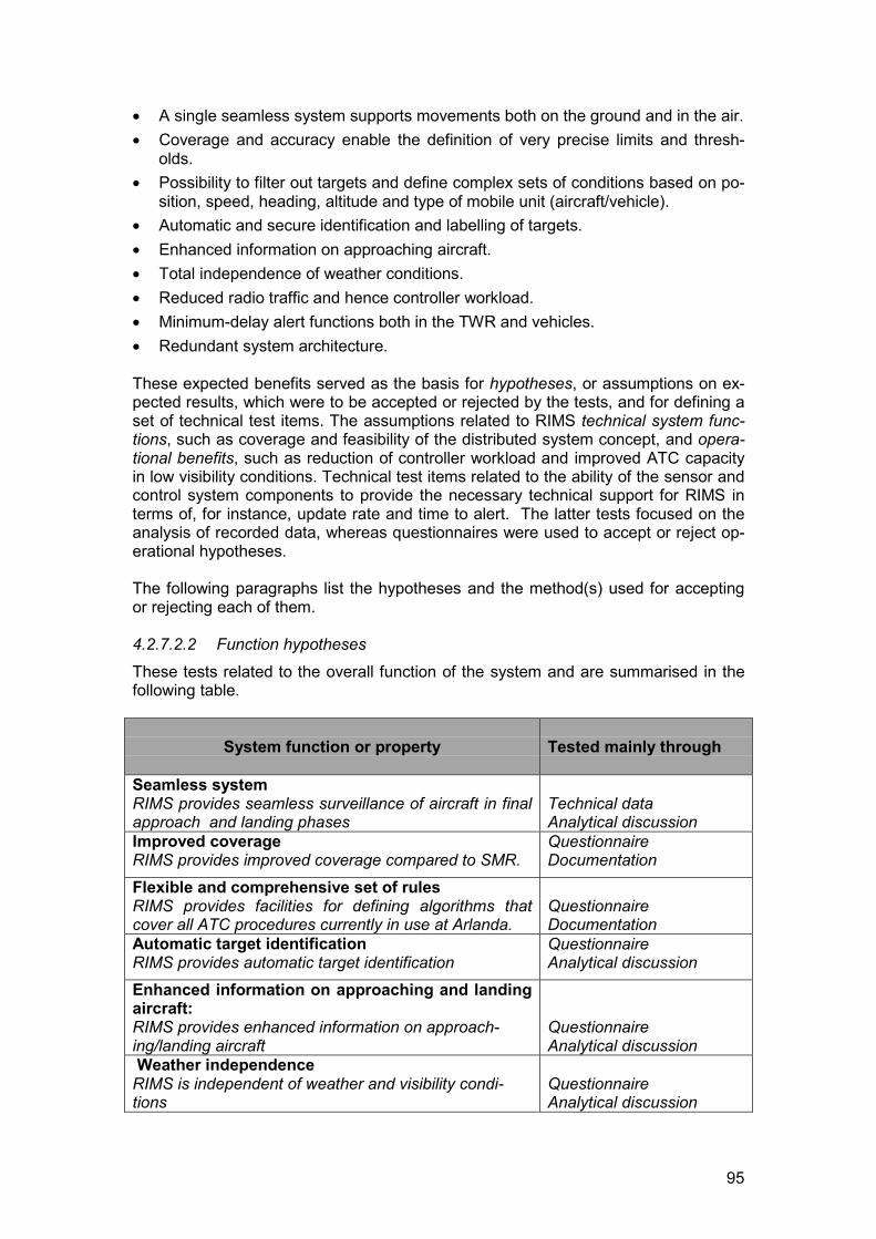
95
� A single seamless system supports movements both on the ground and in the air.� Coverage and accuracy enable the definition of very precise limits and thresh-
olds.� Possibility to filter out targets and define complex sets of conditions based on po-
sition, speed, heading, altitude and type of mobile unit (aircraft/vehicle).� Automatic and secure identification and labelling of targets.� Enhanced information on approaching aircraft.� Total independence of weather conditions.� Reduced radio traffic and hence controller workload.� Minimum-delay alert functions both in the TWR and vehicles.� Redundant system architecture.
These expected benefits served as the basis for hypotheses, or assumptions on ex-pected results, which were to be accepted or rejected by the tests, and for defining aset of technical test items. The assumptions related to RIMS technical system func-tions, such as coverage and feasibility of the distributed system concept, and opera-tional benefits, such as reduction of controller workload and improved ATC capacityin low visibility conditions. Technical test items related to the ability of the sensor andcontrol system components to provide the necessary technical support for RIMS interms of, for instance, update rate and time to alert. The latter tests focused on theanalysis of recorded data, whereas questionnaires were used to accept or reject op-erational hypotheses.
The following paragraphs list the hypotheses and the method(s) used for acceptingor rejecting each of them.
4.2.7.2.2 Function hypothesesThese tests related to the overall function of the system and are summarised in thefollowing table.
System function or property Tested mainly through
Seamless systemRIMS provides seamless surveillance of aircraft in finalapproach and landing phases
Technical dataAnalytical discussion
Improved coverageRIMS provides improved coverage compared to SMR.
QuestionnaireDocumentation
Flexible and comprehensive set of rulesRIMS provides facilities for defining algorithms thatcover all ATC procedures currently in use at Arlanda.
QuestionnaireDocumentation
Automatic target identificationRIMS provides automatic target identification
QuestionnaireAnalytical discussion
Enhanced information on approaching and landingaircraft:RIMS provides enhanced information on approach-ing/landing aircraft
QuestionnaireAnalytical discussion
Weather independenceRIMS is independent of weather and visibility condi-tions
QuestionnaireAnalytical discussion
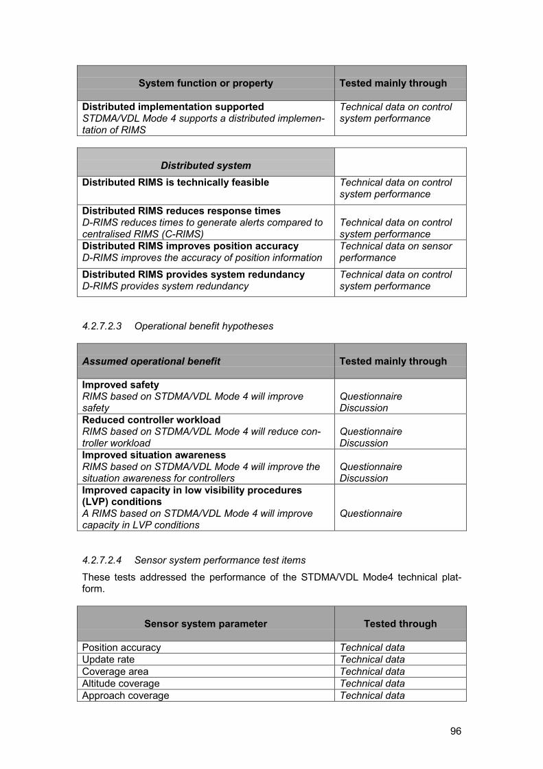
96
System function or property Tested mainly through
Distributed implementation supportedSTDMA/VDL Mode 4 supports a distributed implemen-tation of RIMS
Technical data on controlsystem performance
Distributed systemDistributed RIMS is technically feasible Technical data on control
system performanceDistributed RIMS reduces response timesD-RIMS reduces times to generate alerts compared tocentralised RIMS (C-RIMS)
Technical data on controlsystem performance
Distributed RIMS improves position accuracyD-RIMS improves the accuracy of position information
Technical data on sensorperformance
Distributed RIMS provides system redundancyD-RIMS provides system redundancy
Technical data on controlsystem performance
4.2.7.2.3 Operational benefit hypotheses
Assumed operational benefit Tested mainly through
Improved safetyRIMS based on STDMA/VDL Mode 4 will improvesafety
QuestionnaireDiscussion
Reduced controller workloadRIMS based on STDMA/VDL Mode 4 will reduce con-troller workload
QuestionnaireDiscussion
Improved situation awarenessRIMS based on STDMA/VDL Mode 4 will improve thesituation awareness for controllers
QuestionnaireDiscussion
Improved capacity in low visibility procedures(LVP) conditionsA RIMS based on STDMA/VDL Mode 4 will improvecapacity in LVP conditions
Questionnaire
4.2.7.2.4 Sensor system performance test itemsThese tests addressed the performance of the STDMA/VDL Mode4 technical plat-form.
Sensor system parameter Tested through
Position accuracy Technical dataUpdate rate Technical dataCoverage area Technical dataAltitude coverage Technical dataApproach coverage Technical data
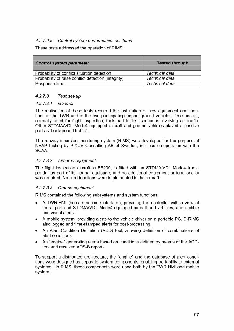
97
4.2.7.2.5 Control system performance test items
These tests addressed the operation of RIMS.
Control system parameter Tested through
Probability of conflict situation detection Technical dataProbability of false conflict detection (integrity) Technical dataResponse time Technical data
4.2.7.3 Test set-up4.2.7.3.1 GeneralThe realisation of these tests required the installation of new equipment and func-tions in the TWR and in the two participating airport ground vehicles. One aircraft,normally used for flight inspection, took part in test scenarios involving air traffic.Other STDMA/VDL Mode4 equipped aircraft and ground vehicles played a passivepart as “background traffic”.
The runway incursion monitoring system (RIMS) was developed for the purpose ofNEAP testing by PIXUS Consulting AB of Sweden, in close co-operation with theSCAA.
4.2.7.3.2 Airborne equipmentThe flight inspection aircraft, a BE200, is fitted with an STDMA/VDL Mode4 trans-ponder as part of its normal equipage, and no additional equipment or functionalitywas required. No alert functions were implemented in the aircraft.
4.2.7.3.3 Ground equipmentRIMS contained the following subsystems and system functions:
� A TWR-HMI (human-machine interface), providing the controller with a view ofthe airport and STDMA/VDL Mode4 equipped aircraft and vehicles, and audibleand visual alerts.
� A mobile system, providing alerts to the vehicle driver on a portable PC. D-RIMSalso logged and time-stamped alerts for post-processing.
� An Alert Condition Definition (ACD) tool, allowing definition of combinations ofalert conditions.
� An “engine” generating alerts based on conditions defined by means of the ACD-tool and received ADS-B reports.
To support a distributed architecture, the “engine” and the database of alert condi-tions were designed as separate system components, enabling portability to externalsystems. In RIMS, these components were used both by the TWR-HMI and mobilesystem.
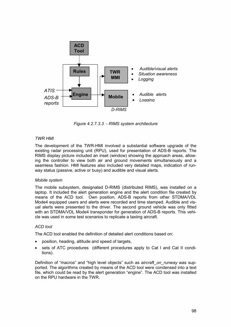
98
Figure 4.2.7.3.3 - RIMS system architecture
TWR HMI
The development of the TWR-HMI involved a substantial software upgrade of theexisting radar processing unit (RPU), used for presentation of ADS-B reports. TheRIMS display picture included an inset (window) showing the approach areas, allow-ing the controller to view both air and ground movements simultaneously and aseamless fashion. HMI features also included very detailed maps, indication of run-way status (passive, active or busy) and audible and visual alerts.
Mobile systemThe mobile subsystem, designated D-RIMS (distributed RIMS), was installed on alaptop. It included the alert generation engine and the alert condition file created bymeans of the ACD tool. Own position, ADS-B reports from other STDMA/VDLMode4 equipped users and alerts were recorded and time stamped. Audible and vis-ual alerts were presented to the driver. The second ground vehicle was only fittedwith an STDMA/VDL Mode4 transponder for generation of ADS-B reports. This vehi-cle was used in some test scenarios to replicate a taxiing aircraft.
ACD tool
The ACD tool enabled the definition of detailed alert conditions based on:
� position, heading, altitude and speed of targets, � sets of ATC procedures (different procedures apply to Cat I and Cat II condi-
tions).
Definition of “macros” and “high level objects” such as aircraft_on_runway was sup-ported. The algorithms created by means of the ACD tool were condensed into a textfile, which could be read by the alert generation “engine”. The ACD tool was installedon the RPU hardware in the TWR.
D-RIMS
� Audible/visual alerts� Situation awareness� Logging
ACDTool
Rules
Engine
TWR MMI
� Audible alerts� Logging
ATISADS-Breports
Mobile
D-RIMS

99
“Engine”The “engine” generated alerts (warning and alarms) based on the ADS-B reports andinformation in the alert condition file created through the ACD tool. Information on the“formal” runway status (active/passive) and currently applied set of ATC procedures(Cat I or Cat II) was intended to be optionally obtained through an interface to theATIS system, but this function was not implemented as planned and was replaced bymanual input only. “Busy” runway status was determined by presence of aircraft orvehicle on, or close to the runway. The engine fed the TWR-HMI with the currentrunway status.
4.2.7.4 Testing and evaluation4.2.7.4.1 Test environmentStockholm-Arlanda airport has two intersecting runways (RWY), 01/19 and 08/26.Work has commenced on a third runway parallel with 01/19. A new control tower willbe built to enable controllers to have full vision over all three runways.
Cat II ILS approach is available to runways 01 and 19, whereas RWY 26 is only fittedwith a Cat I ILS. For noise abatement reasons, runway 08 is only used for departuresand runway 26 only for landings unless otherwise required by wind and runway con-ditions.
The monitoring and control of landing and taxiing aircraft and vehicles on runwaysand taxiways in visual conditions is usually straightforward, but the complexity in-creases significantly during snow conditions when a large number of snow clearingvehicles operate on the runways and taxiways. The complexity also increases in CatII conditions when a specific set of ATC procedures are in force, impacting on, for in-stance, the minimum allowed distances between aircraft and between aircraft andvehicles and a busy runway.
Arlanda TWR is fitted with an SMR, allowing controllers to view traffic in conditionswhen visual control cannot be maintained. The SMR does not provide target identifi-cation, and does not cover the final approach areas.
An STDMA/VDL Mode4 ground station is installed at Arlanda, and tests and demon-strations of various applications have been ongoing for some years. Dual VHF in-stallations including a repeater station provides excellent ADS-B coverage of the air-port and approach areas. In order to increase safety and efficiency of the snowclearing operations, a project has was launched in early 1998 to equip some 25 vehi-cles engaged in such operations with an STDMA/VDL Mode4 transponder (and somewith a display as well). This system allows the tower controller to view, on a display inthe TWR, the location of all units and their identity. The system is also very useful forco-ordinating the operations on a tactical level by the field team-leader and on astrategic level by the “snow co-ordinator”. Both have a display providing a view ofthe airport, map features and targets with identity based on ADS-B reports fromSTDMA/VDL Mode4 equipped aircraft and vehicles.
Most of the scenarios developed for testing of the RIMS in NEAP were based on re-alistic conflict situations using the runway and taxiway system at Arlanda as the testscene.
As only dedicated vehicles and aircraft were used, it was possible to control the testscenarios in detail. However, ADS-B reports from revenue SAS STDMA/VDL Mode4equipped aircraft were used in some tests.
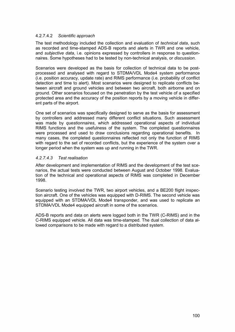
100
4.2.7.4.2 Scientific approachThe test methodology included the collection and evaluation of technical data, suchas recorded and time-stamped ADS-B reports and alerts in TWR and one vehicle,and subjective data, i.e. opinions expressed by controllers in response to question-naires. Some hypotheses had to be tested by non-technical analysis, or discussion.
Scenarios were developed as the basis for collection of technical data to be post-processed and analysed with regard to STDMA/VDL Mode4 system performance(i.e. position accuracy, update rate) and RIMS performance (i.e. probability of conflictdetection and time to alert). Most scenarios were designed to replicate conflicts be-tween aircraft and ground vehicles and between two aircraft, both airborne and onground. Other scenarios focused on the penetration by the test vehicle of a specifiedprotected area and the accuracy of the position reports by a moving vehicle in differ-ent parts of the airport.
One set of scenarios was specifically designed to serve as the basis for assessmentby controllers and addressed many different conflict situations. Such assessmentwas made by questionnaires, which addressed operational aspects of individualRIMS functions and the usefulness of the system. The completed questionnaireswere processed and used to draw conclusions regarding operational benefits. Inmany cases, the completed questionnaires reflected not only the function of RIMSwith regard to the set of recorded conflicts, but the experience of the system over alonger period when the system was up and running in the TWR.
4.2.7.4.3 Test realisationAfter development and implementation of RIMS and the development of the test sce-narios, the actual tests were conducted between August and October 1998. Evalua-tion of the technical and operational aspects of RIMS was completed in December1998.
Scenario testing involved the TWR, two airport vehicles, and a BE200 flight inspec-tion aircraft. One of the vehicles was equipped with D-RIMS. The second vehicle wasequipped with an STDMA/VDL Mode4 transponder, and was used to replicate anSTDMA/VDL Mode4 equipped aircraft in some of the scenarios.
ADS-B reports and data on alerts were logged both in the TWR (C-RIMS) and in theC-RIMS equipped vehicle. All data was time-stamped. The dual collection of data al-lowed comparisons to be made with regard to a distributed system.

101
�
����������������
��
���������
�
��
�����
��
�
�
��������
���
�
������
����
������
��
��
�
�����������
����������
�
���������
�
�
������������
�
�������
�
����
�
�����������
�
�����������
�
���������������������
�
�����������
�
�����������
�
������������
�
������
���
�
���������������
�
���
���
��
��
�
�
�����
�����
������
�
��
����������
��
��������
�������
�����
��
����������������������������������������������������������������
����
����������������������������������������������������������������������
�
�
����������������������������
���������
��
���������������������������������
�
��������
��
����������������
�
������
�����
�����
����
��
���������������������������������������������������������������������������������������������������������������������������������������������������������������������������������������������������������������������������������������������������������������������
���
���
��
���
�
��
�
�
���������
�
����������
�
�
�������
����
�
�����������
�� ����������
�
����������
�
�
���
�����
��
��
��
��
����
�
��������������
�
�������
�����
�
��������������
���������������
�����������������������
���
�
�����
�������
�����
���
���
�
����
��
��
��
���������
�����
�
����
���
�
����������
����
�������
�
��
�������
������
�
������������
�
���������
�
�
����������
�
�
������������
�
����������
�
� ������
����������������
����
�������������������
�������������������������������������
���� ���������
�
������������
������
�
��
����������
�
��������������
�����������
���� ���������������������
����������������������
�
�
�
����
�
�����������������������
����� ��
���������������
��������������������������������������������������
����������������
�
�����
�������
��
������
����� ���
����
����������
�
����� � ���
� �� �������
��
�
���������
��
�
��������
�� �
�
������
�� �� ���
�
�� � �����
��
�������������
�����������
����������
�
�����������
�
�����������
�
�����������
���������
��
������������
�
�� �������
��
�
���������
� ����� ����
�
����� �� ����
�
�
������������
�
�� ������ �
�
�
�����������
��������
���
�����������
��������
���
�����������
�
�����������
����������
�
���������
�������������������
�������������
�
������������������������
�
����������
����
����������������
�
�����������
Figure 4.2.7.4.3 - Track of the test vehicle in one of the test scenarios. The ADS-Bposition reports were logged on the mobile transponder (own position).
One set of scenarios was based on recorded ADS-B data and addressed many dif-ferent conflict situations. These scenarios were shown on the TWR HMI to groups ofcontrollers who were afterwards asked to fill out a questionnaire that addressed vari-ous operational aspects with regard to safety, workload, situation awareness, andlow visibility procedures. The controllers were also invited to give general observa-tions and comments on individual RIMS functions and the usefulness of the system.
4.2.7.5 Results and conclusions4.2.7.5.1 Principal results and conclusionsThe following bullet points summarise the principal results and conclusions. Com-ments are provided in subsequent paragraphs.
� All assumptions on system functions and properties were accepted, with the ex-ception of the hypothesis on Flexible and comprehensive set of rules. That func-tion is addressed below.
� All assumptions on expected operational benefits were accepted.� It is possible to realise, through relatively limited technical and economic means,
a powerful RIMS based on ADS-B and the STDMA/VDL Mode 4 technical plat-form. For full benefits, however, both aircraft and ground vehicles should betransponder equipped.
� Full operational implementation of a distributed system (i.e. with C-RIMS and D-RIMS components) would offer significant benefits in terms of enhanced safetyand improved situation awareness for controllers, vehicle drivers and pilots at
102
Arlanda. Obviously, such benefits would be dependent on the number of appro-priately equipped vehicles and aircraft.
� Significant safety benefits would also be achieved from the operational imple-mentation of only a C-RIMS (i.e. alerts would be provided to the controller but notto mobile users) provided that the mobile users are transponder equipped.
4.2.7.5.2 Comments and observationsOverall system function
As expected, tests with regard to coverage, automatic target identification, and en-hanced information on landing/approaching aircraft fulfilled relevant criteria. Cover-age of airport and approach areas fulfilled ICAO requirements for a seamless transi-tion.
However, the syntax used for defining the the detailed algorithms for the ATC proce-dures did not cover all situations, and could not be successfully modified during thecourse of the trials. The ATC procedures were used in the definition of alert condi-tions by means of the ACD tool. In some cases, alert “oscillations” occurred as a re-sult of condition definitions using relative parameters. The corresponding hypothesiswas rejected as a consequence of the demonstrated problems.
With regard to STDMA/VDL Mode 4 support of a distributed implementation of RIMS,the measured throughput of ADS-B messages between aircraft and the base stationand between aircraft and vehicle was 98% or better in both cases. This confirms thefeasibility of a distributed concept. Other assumptions addressing the distributedsystem concept were also accepted.
Responses to questionnaires
The controllers´ general opinion of the RIMS was overwhelmingly positive, with “yes”answers reaching 100% on high-level questions, such as;
� Do you think that an operational implementation of RIMS could improve thesafety in the runway areas?
� Do you think that RIMS improves the situation awareness?
A lower percentage, 67%, of the controllers believed that RIMS could reduce theworkload in the TWR. Those who believed so were appreciative of the completesystem (100%), the seamless display of airborne and ground traffic (88%) and theautomatic alerts (100%). 91% believed that RIMS could improve the capacity duringlow visibility operations.
Questions on aspects of possible future control techniques, such as…
� Do you think vehicles could be allowed to use parts of the taxiway system underown supervision if they were equipped with a D-RIMS system?
� Do you think RIMS could reduce the voice-com traffic between controllers and thevehicle drivers? and
� Could RIMS support a “strip-less TWR”?
…resulted in 65, 48 and 89% “yes” answers respectively. 86% believed that the hu-man-machine interface worked properly, whereas a minority 15% believed that “thesystem could cover all procedures and [conflict] situations”.
103
Verbal comments indicated that an operational RIMS would be particularly useful inheavy traffic, snow clearance situations, at night, in reduced visibility situations,“when there are many vehicles on the runway and one is forgotten”, “when a vehicleis repeatedly entering and leaving the runway and you get out of synch” and as abackup and safety net.
Sensor system performanceThese assumptions related to the performance of the STDMA/VDL Mode4 technicalplatform. Post-processing of recorded data gave the following results:
Position accuracy (lateral): in the order of 2 m (95%)Update rate: 1.7 sec (95%)Coverage; runways, taxiways: report throughput better than 97.8% in all
locationsCoverage; approach area report throughput from aircraft better thanup to 500 feet altitude: 98.8% both to base station and vehicleAltitude coverage: same as above
The update rate does not comply with ICAO provisional requirements, which is 1 sec.The other performance parameters comply with these requirements.
Control system performanceThese assumptions related to the operation of RIMS. Analysis of recorded datashowed that the probability of conflict detection was 100%, and the probability offalse conflict detection was zero. However, as noted above, algorithms that coveredthe entire set of ATC procedures could not be defined, and the figure therefore ap-plies to conflict situations actually used in the system.
The mean time to alert, i.e. the elapsed time between the occurrence of the conflictand the alert being displayed in the TWR and vehicle was less than 1 second. Thedelay was greater in the TWR, probably due to fluctuations of the load on the serverand LAN.
4.2.7.6 Recommendations for system improvements It is recommended that further studies be made on the following topics:
� “Oscillating alerts”. These studies should preferably be based on transpondersincorporating a GNSS receiver with higher update rate and accuracy.
� Conflict situations. Further analysis of what conflict situations could be detected,and the precise conditions that apply to those situations.
� Integration between RIMS and SMR.
4.2.7.7 Future plansAn analysis of the feasibility to certify and approve RIMS for operational use will beinitiated. Industry will be encouraged to participate and take the lead in the develop-ment of a RIMS based on ADS-B technology.
Operational use of ADS-B to support monitoring of ground traffic is being imple-mented at Stockholm-Arlanda. A pre-operational system is being tested under opera-tional conditions during the 1998-99 winter season. The system, known asSNOWCARD, is mainly intended to facilitate monitoring in the TWR of vehicle trafficduring snow clearing operations when often a large number of vehicles operate on
104
runways, taxiways and aprons under limited visibility conditions. The system is alsobeing used for tactical and strategic co-ordination between the snow clearing co-ordination facility and the on-field team leader. Management of operations is facili-tated by the presence of a situation display in the co-ordination facility and teamleader’s vehicle, allowing the location of all units to be continuously monitored byboth parties.
It is planned to upgrade to VDL Mode 4 equipment complying with ICAO standards inthe year 2000. In addition to aircraft equipment and ground stations, such an upgradewill also include equipment in ground vehicles at Arlanda and elsewhere.
5. CERTIFICATION ROAD MAP
Certification issues were raised as an essential element of NEAP in order to identifyand resolve potential regulatory problems that might impede or delay bringing NEAPapplications to the market. The Certification study was carried out as a relativelysmall investigation, rather than attempting to solve all the certification issues thatmight arise in the very wide-ranging nature of the NEAP applications. Not all NEAPapplications were covered and those that are covered, are not addressed in greatdetail. A more comprehensive treatment will be necessary in other programmes,such as the NEAN Update Programme (NUP).
The following NEAP Applications are covered by this report:
� Station Keeping using Airborne Situation Awareness – CDTI.� ATIS Broadcast at European Airports.� RNP Approach using a combined ADS-B/DGPS broadcast ground-station.
The Certification process has been analysed from a European perspective, assumingthat the applications will be certified in Europe before the US. The study outlines:
� The content of a certification application.� Potential certification owners.� Identification of required certification bodies.� Possible road map for certification of applications.� Potential problems.� Required time for certification.� Proposed EC activities supporting European certification of these applications.
A legal survey was carried out to identify European legislation supporting certifica-tion.
5.1 Analysis: General overviewNEAP Certification studies illustrate fundamental problems inhibiting EU airlines andairports capitalising on the benefits of CNS/ATM technologies. These include the:
� Fragmented European Regulatory Framework� Lack of enforcement and confusion over the status of existing EU legislation� Critical dependence of European Regulation on the FAA and US Industry bodies� Predominance of US influence at ICAO� Dominant position of US manufacturing interests
NEAP Application projects also show that Europe is able to develop cost/effectivesolutions for global capacity and safety issues. The exploitation of these solutions isconstrained by the limitations of European Regulations, affecting and limiting their
105
access to the market. Specifically, by a regulatory system that assumes that suchsolutions will emanate from the US and seems profoundly unable to respond toEuropean developed technology.
This situation is further exacerbated by the inability of the regulatory authorities todevise, co-ordinate and implement regulatory instruments to enable the wide-scaleintroduction of CNS/ATM technologies and solutions. This has been illustrated inmany other areas, including recent European “Mandates” e.g. ACAS/TCAS, 8.33kHzradio etc. - where implementation of these mandates has been impeded by the lackof FAA TSOs. This demonstrates the critical European dependence on US regula-tions and condemns Europe to follow, rather than lead.
The reactive nature of regulation has lead to its failure to grasp key issues, including:
� The uncertain status of GPS, allowing partial use - but well short of full exploita-tion.
� Need for Europe-wide effort to support exploitation of CNS/ATM solutions.� Poor regulatory support for digital and software related technologies.� The vested interests of Service Providers.� The confusion between technological preferences and regulatory requirements.� The lack of effective standardisation support.
5.2 Legal issuesA survey of relevant European legislation shows that appropriate legislation doesexist to support the certification of aircraft and avionics and ATM applications. How-ever, a key problem is the lack of implementation and enforcement of this legislationand the uncertain status of many of its elements. The two most significant items areEU Council Regulation 3922/91/EEC for aircraft and EC Council Directive 93/65/EECfor ATM systems and equipment.
5.2.1 EU Council Regulation 3922/91/EEC: Aircraft and AvionicsEU Council Regulation 3922/91/EEC adopts Joint Aviation Requirements and makesthem mandatory on member States. It sets out the technical requirements and ad-ministrative procedures to be applied to aircraft and aircraft products to ensure theirfree movement in the market. It is directly binding on member States. These re-quirements cover the design, manufacture, maintenance and operation of aircraft andthe persons and organisations involved in those tasks. Some JARs are still underdevelopment and are to be notified to the Commission for inclusion in the CouncilRegulation when complete.
Currently, it appears that the member States and the JAA believe that this CouncilRegulation is not presently legally effective as, apart from JAR 145, none of the JARcodes have been translated into the "11 official languages". Although it is debatablewhether such translation is actually required (it is not required for any other TechnicalRegulations), this has effectively stalled the process of adopting JARs - making theworking of this Directive unsatisfactory. In the author’s opinion, only the title of aregulation must be published in the 11 versions of the European journal - not the text.
In addition to the above, the legal status of many of the 'standards' used to certify in-dividual products, is even less clear. These 'standards' are at the end of a long chainof JARS, AMJs (acceptable means of compliance), JTSOs (Joint Technical Stan-dards Orders) which in turn, refer in general terms to other 'standards' such as RTCAor Eurocae documents. Many of these indirectly referred RTCA documents are of ageneral nature, which can lead to significant variations in interpretation. It is surpris-

106
ing, given the adoption of the JAR Codes, that an effort has not been made to adoptthese technical standards into EU legislation, e.g. as European Standards.
Little work is currently being done to clarify and resolve this unsatisfactory position. Itmay be that in the medium to long term, this situation may be resolved by the crea-tion of the European Aviation Safety Authority (EASA). However, that leaves a longand significant period during which there will be many technical and operationalchanges in aviation, for which the regulatory environment in Europe will be quite un-satisfactory. This will result in significant economic disadvantage for Europe, whichmay be potentially damaging to the capacity and efficiency of the Air Traffic Systemand to European manufacturing industry.
5.2.2 Council Directive 93/65/EEC: The ATM DirectiveCouncil Directive 93/65/EEC is intended to hasten the harmonisation process inEurope in the field of Air Traffic Management (ATM), to enable competition and thefree movement of ATM equipment. In particular, the Directive allows the Commis-sion to adopt ‘Eurocontrol Standards’ and technical specifications into Communitylaw, making them mandatory on member States. Each State is responsible for im-plementing legislation and identifying an enforcement authority. An initial list ofEurocontrol Standards is given in the Annex to the Directive. The Directive alsopermits the EC to issue Mandates to the official Standardisation Bodies to developEuropean Standards complementary to Eurocontrol Standards.
There has been very limited progress in the development and adoption of Eurocon-trol Standards. Benefits have been even less tangible. Eurocontrol Standards havenot been subject to 'open development' and wider industry input to their developmenthas been very limited. Significantly, little effort has been made to develop EuropeanStandards complementary to the Eurocontrol Standards – implying that European in-dustry may be losing the procurement benefits to be gained and that little successhas been achieved in opening this market.
5.2.3 Other legislation5.2.3.1 Council Regulation 83/189/EEC: Technical Standards and Regula-
tionsCouncil Regulation 83/189/EEC lays down the procedure for the notification byStates of National Standards to the European Commission and to the EuropeanStandards Institutions. It requires member States to notify the European Commis-sion of new Standards and gives the Commission the power to take action if there isa risk of barriers being created, including the power to request the European Stan-dards Institutions to develop a European Standard within a given time limit. ThisCouncil Directive is fundamental in the field of Standardisation and is used as the ba-sis for developing an open market between member States, by the removal of tech-nical barriers to trade caused by individual State's technical regulations. In thissense, this Regulation can be considered as part of the foundation for much of EUpolicy.
5.2.3.2 Council Decision 93/465/EEC: The Module DirectiveCouncil Decision 93/465/EEC specifies the generic procedures for conformity as-sessment to be applied across all technical harmonisation Directives. In essence, itdetails the different procedures that may be used in conformity assessment from selfcertification through to third party Type Approval. It lays out the roles, proceduresand guidelines to be applied by Notified Bodies. The actual text consists of only twoshort articles, the main body being the annexes which specify the 8 conformity as-
107
sessment modules. Each module specifies an 'approval procedure', with differentlevels of assurance, testing, proof etc. The relationship between manufacturer andnotified bodies is clearly specified.
This Directive provides the framework processes and procedures to be applied forthe certification in all industry sectors, including Aeronautical equipments, systemsand services.
5.2.4 Summary of legal surveyEU legislation should set out the framework in which equipment, systems and serv-ices can be certified. Yet this legislation is disputed by the member States and notenforced by the EC, leading to uncertainty and confusion. The result of this legalconfusion, is that member States apply a mixture of JARS and National legislation incertification, with no uniform interpretation of requirements. Furthermore, the proc-ess still relies critically on regulations and standards developed in the US, with littlecorresponding standardisation machinery in Europe to support the certification ofEuropean CNS/ATM technologies and solutions. It is also clear that the Public Pro-curement problems endemic to this market, have yet to be solved.
� Europe is broadly suffering from “regulatory paralysis”.
5.3 Certification status of NEAP applicationsNEAP applications are currently limited in their operational potential by the “No Haz-ard/No Credit” certification given to the GNSS Transponder and the difficulty of ob-taining certification to a higher operational capability e.g. for Communication, Naviga-tion and Surveillance functions. The current regulatory structure leaves this as a Na-tional function, but most National Authorities are unwilling to move forward withoutInternational consensus. However, no framework exists to establish such consen-sus, other than that embodied in organisations such as the FAA, ARINC and theRTCA. European bodies such as the JAA and Eurocae are a pale shadow in com-parison.
As an example, Lufthansa has worked with its National Authority, the LBA, to obtainoperational certification for applications such as FMS approaches, initially as ‘com-pany only’ approvals. Lufthansa has been obliged to follow a careful step-by-steppath to achieve its goals. Lufthansa has had the benefit of the tacit support of Airbus,and been able to base FMS approaches on the existing certification of the naviga-tional capabilities of its aircraft and Flight Management System (FMS).
However, obtaining certification for the integration of the GNSS transponder with theFMS and EFIS (critical for operational approval of safety related functions) within thecurrent regulatory framework, can only occur with the active co-operation and com-mitment of the Airframe Manufacturers (e.g. Airbus and Boeing). This means that,not only do airlines have to be convinced of the benefits, but it is also necessary toconvince the Airframe manufacturers that it is in their commercial and business inter-ests too. Separate business cases have to be made for new and retrofit aircraft re-spectively.
5.3.1 Station keeping using airborne situation awareness – CDTITwo situation awareness services were investigated by Lufthansa:
� On-Ground Situation Awareness/Taxi Guidance� In-Flight (En-route) Situation Awareness.
108
Only the in-flight aspects are addressed below.
Lufthansa’s rationale for this investigations was given briefly as: ‘The increasingnumber of aircraft and their use of the limited availability of airspace as well as airportrunways, taxiways and gate positions are a growing concern for airlines. Therefore itbecomes increasingly important to make best use of available resources. Establish-ment of an integrated planning from gate-to-gate will be a major challenge for all par-ticipating parties’.The Scope and Objective of this task within NEAP is given as the improvement ofpilot’s in-flight situation awareness with the aid of Cockpit Display of Traffic Informa-tion (CDTI). This task takes advantage of the fact that today's aircraft have a veryprecise knowledge of their present position as well as their intentions - much moreaccurately than other aircraft or ground systems could ever calculate or predict.Thus the distribution of this data via ADS-B, will allow better surveillance and im-proved conflict detection by all suitably equipped aircraft - with strategic (conflict) so-lutions, at long range, as the goal.
Station keeping applications require careful clarification of the role of the CDTI inmonitoring separations between aircraft, careful drafting of the Flight Manual and ap-propriate crew training. It is closely related to Airborne Separation Assurance func-tions. To date, functions such as Collision Avoidance and Terrain Warnings havebeen provided as standalone functions and have not been fully integrated into theaircraft – despite the need for non-conflicting cockpit guidance to pilots. Stationkeeping can also be provided as a standalone function. Indeed, this may be desir-able in order to achieve short-term benefits in older aircraft. It can also be seen asan initial step towards a fully integrated solution in the longer term.
5.3.1.1 FMS/EFIS integrationTo provide such integration requires the extension of the functionality of the FMS andappropriate interfaces to both the FMS and EFIS. This ideally requires an Opera-tional Concept to enable proper definition of requirements. The co-operation of air-craft and FMS/EFIS manufacturers is essential. Necessarily, some reluctance on thepart of proprietary manufacturers is to be expected due to their direct and vested in-terest in the result. Due to the effort required to achieve integration, the operationalconcept will have to accommodate a wider range of functions than that for simpleStation-Keeping e.g. Conflict Negotiation, In-Trail Climbs and Approach and Land-ing.
5.3.1.2 The CDTI vs RDP vs visualThe CDTI offers the potential for sophisticated monitoring of aircraft, due to the avail-ability of real-time ADS-B data via VDL Mode 4. Ground ATC displays used for thisfunction employ lower resolution displays, often with unreliable and less frequent ra-dar data, (compared with that potentially available from VDLmode4/ADS-B) to pro-vide separations to under 3 nautical miles longitudinal separation. Radar displaysare also relatively ‘dumb’ – concentrating on signal processing and target identifica-tion functions. Indeed, radar separations are performed purely by visual estimationby controllers using such traffic display systems. More sophisticated Short TermConflict Alert (STCA) functions are only just being developed (but still rely on rela-tively imperfect data).
Equally, pilots are permitted to maintain visual separation from other aircraft, in cir-cumstances which may involve significant visual ‘approximation’ (e.g. distances,relative speeds, descent rates etc.). Thus, in principle, station-keeping using CDTI
109
should be achievable, subject to concerns regarding pilot workload and the respec-tive responsibilities of the pilot and ATC. This needs to be tested. However, regula-tory authorities are likely to be reluctant and slow to directly certify this capability.Much of this reluctance relates to liability issues. Pilots may already be (informally)using TCAS displays for this purpose.
A key question is the interface to the FMS and its role in monitoring separations.This is important for many reasons e.g. the need to present consistent information tothe pilot.
Currently, responsibility for aircraft separation lies with ATC authorities in controlledairspace. Outside controlled airspace or in airspace without adequate surveillanceservices, separations have been increased to minimise risk. This increased separa-tion reduces airspace capacity and increases airline costs. Transferring the functionto the cockpit introduces additional potential liabilities to airlines and aircraft manu-facturers. Thus airlines, manufacturers and regulatory authorities must carry outseveral independent but related calculations:
a) They must ensure that the potential increase in risk from reduced separations is,at least, offset by the calculated improvements in the position of both aircraft andassurance and monitoring of their relative separation.
b) The increased liability from the transfer of the separation function to the cockpitis met by the commercial benefits of increased capacity and efficiency.
c) That Crew Resource Management is not adversely affected.
There is a need to establish a JAA Working Group to address these aircraft functionsin order to develop consensus in the User community and establish flight crew “bestpractice”. The development of appropriate electronic Flight Rules (EFR) is desirableand a debate is required about the designation of airspace to enable benefits to beachieved.
The station-keeping application raises key issues for certification, including:
� Integration of VDL Mode 4 in the aircraft.� CDTI interfaces and certification.� Where does the station keeping function ‘live’?� Transition issues e.g. uplinking of radar data.� Designation of Airspace e.g. EFR
Certification of this function will depend on aircraft equipage. This may imply opera-tional limitations, but does not prevent exploitation. Straightforward safety benefitsinclude:
� Improved pilot orientation and situation awareness.� Additional and redundant conflict monitoring.� Potential for improved and more accurate conflict monitoring.� Improved range leading to improved resolution times.� Transition strategy available with up-linked radar data.� Reduced ATC workload.
110
5.3.2 ATIS Broadcast at European airportsThe provision of ATIS is not specifically limited by the communication medium and isprovided in many different ways at different airports in different countries. There areno obvious restrictions on the means of providing ATIS that affect this application.Thus providing ATIS via VDL Mode 4 should present no special difficulties or certifi-cation problems. Technically, the certification of ATIS is a National function, with re-quirements depending on the National legislation in place. Some States have little orno formal regulatory requirements in place at all – largely because ATIS is most oftenprovided by the National Aviation Administration. It may be necessary to fill this legal‘gap’ in some States.
Significant automation is possible e.g. with Meteorological ground-stations. Certifica-tion of Met equipment and their interfaces may be a market issue (requiring Euro-pean Standards to overcome public procurement problems) and in certain cases(e.g. IRVR) a safety and certification issue.
However, the format and presentation of ATIS is an issue and would benefit by acommon standard to ensure that data is presented correctly in the cockpit. Loss ofATIS is an operational issue, corruption or incorrect representation of ATIS may be asafety and certification issue.
� The development of a European Standard for ATIS as a VDL Mode 4 service,would seem sensible and would assist in the convergence of National practices.
ATIS Broadcast also provides a relatively simple and straightforward avenue to cer-tify early standalone functions and also provides a platform to investigate integrationand interfacing with the aircraft EFIS/FMS for some relatively non-critical functions.
Co-operation between European ATS providers on the provision and coverage ofATIS is essential.
5.3.3 IPV approach with combined ADS-B/DGPS broadcast groundstation.
The potential benefits for IPV approach using a combination of ADS-B/DGNSSgroundstation are very significant and could lead to dramatic changes in operationsand costs at European airports. This particular NEAP application investigates thepotential benefits of DGNSS Instrument Approach with vertical guidance at Angel-holm airport in Sweden and also the benefits of direct routes between Swedish air-ports.
Certification of ground equipment in this trial, depended on the modification of FAASCAT-I equipment requirements and RTCA specifications. This was done to:
� To provide a ‘fast track’ solution.� To ease acceptance of the trials.
Certification requires, at least, the following components:
� Certification of the Ground Infrastructure� Certification of Aircraft Equipment:� Published changes to Airspace and Procedures, including phraseology� Flight Inspection Requirements
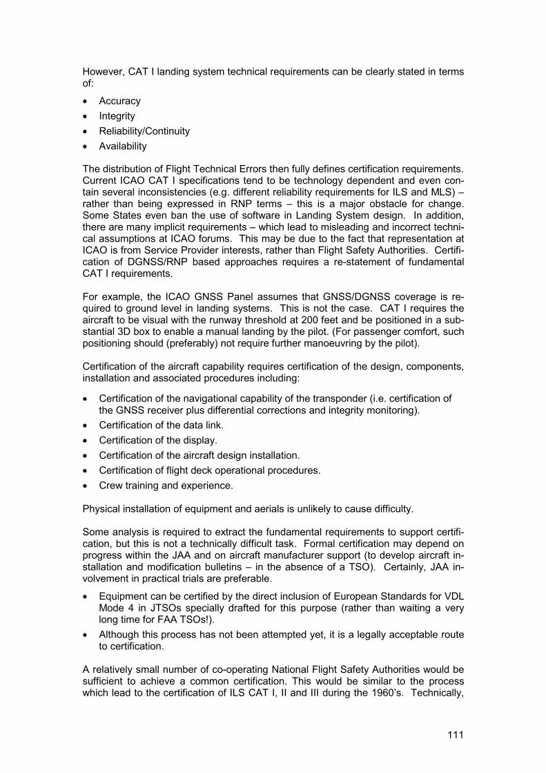
111
However, CAT I landing system technical requirements can be clearly stated in termsof:
� Accuracy� Integrity� Reliability/Continuity� Availability
The distribution of Flight Technical Errors then fully defines certification requirements.Current ICAO CAT I specifications tend to be technology dependent and even con-tain several inconsistencies (e.g. different reliability requirements for ILS and MLS) –rather than being expressed in RNP terms – this is a major obstacle for change.Some States even ban the use of software in Landing System design. In addition,there are many implicit requirements – which lead to misleading and incorrect techni-cal assumptions at ICAO forums. This may be due to the fact that representation atICAO is from Service Provider interests, rather than Flight Safety Authorities. Certifi-cation of DGNSS/RNP based approaches requires a re-statement of fundamentalCAT I requirements.
For example, the ICAO GNSS Panel assumes that GNSS/DGNSS coverage is re-quired to ground level in landing systems. This is not the case. CAT I requires theaircraft to be visual with the runway threshold at 200 feet and be positioned in a sub-stantial 3D box to enable a manual landing by the pilot. (For passenger comfort, suchpositioning should (preferably) not require further manoeuvring by the pilot).
Certification of the aircraft capability requires certification of the design, components,installation and associated procedures including:
� Certification of the navigational capability of the transponder (i.e. certification ofthe GNSS receiver plus differential corrections and integrity monitoring).
� Certification of the data link.� Certification of the display.� Certification of the aircraft design installation.� Certification of flight deck operational procedures.� Crew training and experience.
Physical installation of equipment and aerials is unlikely to cause difficulty.
Some analysis is required to extract the fundamental requirements to support certifi-cation, but this is not a technically difficult task. Formal certification may depend onprogress within the JAA and on aircraft manufacturer support (to develop aircraft in-stallation and modification bulletins – in the absence of a TSO). Certainly, JAA in-volvement in practical trials are preferable.
� Equipment can be certified by the direct inclusion of European Standards for VDLMode 4 in JTSOs specially drafted for this purpose (rather than waiting a verylong time for FAA TSOs!).
� Although this process has not been attempted yet, it is a legally acceptable routeto certification.
A relatively small number of co-operating National Flight Safety Authorities would besufficient to achieve a common certification. This would be similar to the processwhich lead to the certification of ILS CAT I, II and III during the 1960’s. Technically,
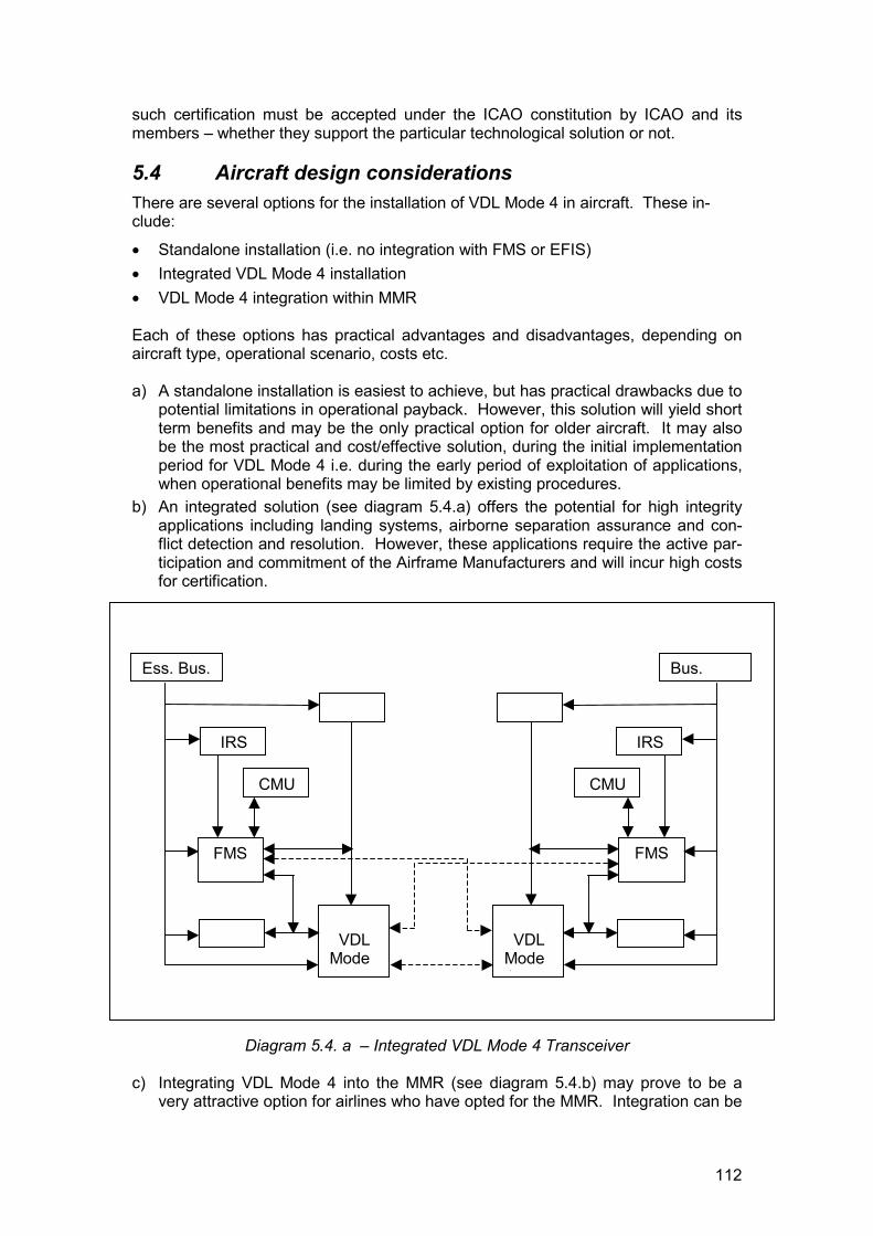
112
such certification must be accepted under the ICAO constitution by ICAO and itsmembers – whether they support the particular technological solution or not.
5.4 Aircraft design considerationsThere are several options for the installation of VDL Mode 4 in aircraft. These in-clude:
� Standalone installation (i.e. no integration with FMS or EFIS)� Integrated VDL Mode 4 installation� VDL Mode 4 integration within MMR
Each of these options has practical advantages and disadvantages, depending onaircraft type, operational scenario, costs etc.
a) A standalone installation is easiest to achieve, but has practical drawbacks due topotential limitations in operational payback. However, this solution will yield shortterm benefits and may be the only practical option for older aircraft. It may alsobe the most practical and cost/effective solution, during the initial implementationperiod for VDL Mode 4 i.e. during the early period of exploitation of applications,when operational benefits may be limited by existing procedures.
b) An integrated solution (see diagram 5.4.a) offers the potential for high integrityapplications including landing systems, airborne separation assurance and con-flict detection and resolution. However, these applications require the active par-ticipation and commitment of the Airframe Manufacturers and will incur high costsfor certification.
Diagram 5.4. a – Integrated VDL Mode 4 Transceiver
c) Integrating VDL Mode 4 into the MMR (see diagram 5.4.b) may prove to be avery attractive option for airlines who have opted for the MMR. Integration can be
Ess. Bus.
IRS
FMS
CMU
VDLMode4
Bus.
IRS
FMS
CMU
VDLMode4
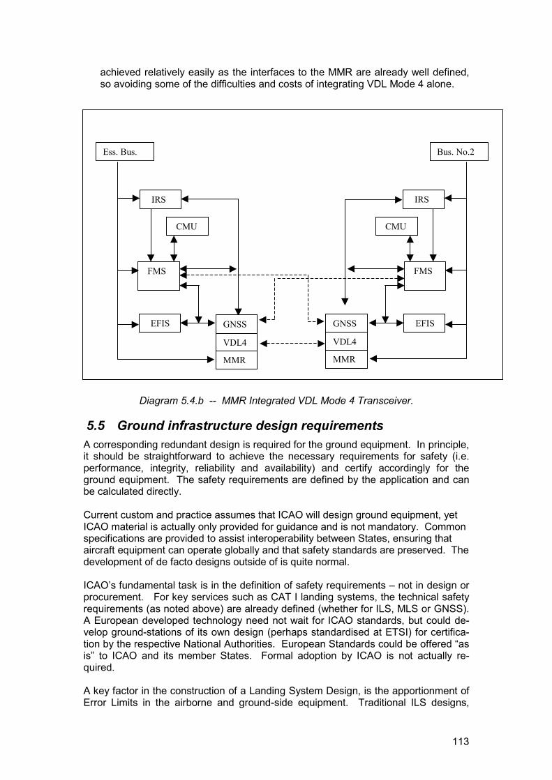
113
achieved relatively easily as the interfaces to the MMR are already well defined,so avoiding some of the difficulties and costs of integrating VDL Mode 4 alone.
Diagram 5.4.b -- MMR Integrated VDL Mode 4 Transceiver.
5.5 Ground infrastructure design requirementsA corresponding redundant design is required for the ground equipment. In principle,it should be straightforward to achieve the necessary requirements for safety (i.e.performance, integrity, reliability and availability) and certify accordingly for theground equipment. The safety requirements are defined by the application and canbe calculated directly.
Current custom and practice assumes that ICAO will design ground equipment, yetICAO material is actually only provided for guidance and is not mandatory. Commonspecifications are provided to assist interoperability between States, ensuring thataircraft equipment can operate globally and that safety standards are preserved. Thedevelopment of de facto designs outside of is quite normal.
ICAO’s fundamental task is in the definition of safety requirements – not in design orprocurement. For key services such as CAT I landing systems, the technical safetyrequirements (as noted above) are already defined (whether for ILS, MLS or GNSS).A European developed technology need not wait for ICAO standards, but could de-velop ground-stations of its own design (perhaps standardised at ETSI) for certifica-tion by the respective National Authorities. European Standards could be offered “asis” to ICAO and its member States. Formal adoption by ICAO is not actually re-quired.
A key factor in the construction of a Landing System Design, is the apportionment ofError Limits in the airborne and ground-side equipment. Traditional ILS designs,
Ess. Bus.
IRS
FMS
CMU
EFIS
Bus. No.2
IRS
FMS
CMU
EFISGNSS
VDL4
MMR
GNSS
VDL4
MMR
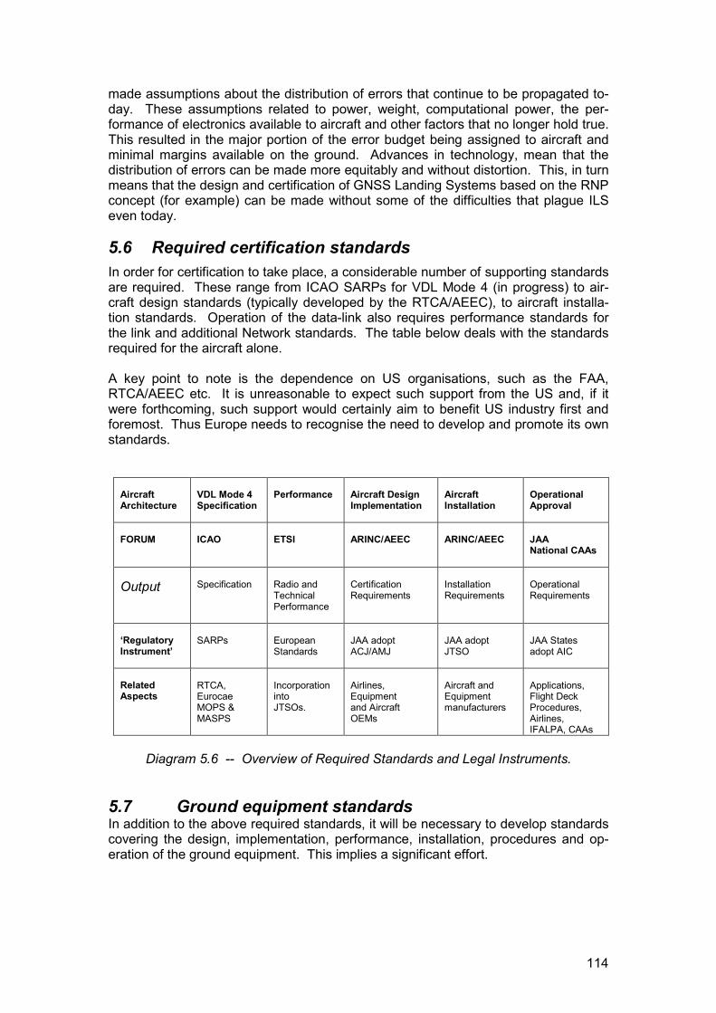
114
made assumptions about the distribution of errors that continue to be propagated to-day. These assumptions related to power, weight, computational power, the per-formance of electronics available to aircraft and other factors that no longer hold true.This resulted in the major portion of the error budget being assigned to aircraft andminimal margins available on the ground. Advances in technology, mean that thedistribution of errors can be made more equitably and without distortion. This, in turnmeans that the design and certification of GNSS Landing Systems based on the RNPconcept (for example) can be made without some of the difficulties that plague ILSeven today.
5.6 Required certification standardsIn order for certification to take place, a considerable number of supporting standardsare required. These range from ICAO SARPs for VDL Mode 4 (in progress) to air-craft design standards (typically developed by the RTCA/AEEC), to aircraft installa-tion standards. Operation of the data-link also requires performance standards forthe link and additional Network standards. The table below deals with the standardsrequired for the aircraft alone.
A key point to note is the dependence on US organisations, such as the FAA,RTCA/AEEC etc. It is unreasonable to expect such support from the US and, if itwere forthcoming, such support would certainly aim to benefit US industry first andforemost. Thus Europe needs to recognise the need to develop and promote its ownstandards.
AircraftArchitecture
VDL Mode 4Specification
Performance Aircraft DesignImplementation
AircraftInstallation
OperationalApproval
FORUM ICAO ETSI ARINC/AEEC ARINC/AEEC JAANational CAAs
Output Specification Radio andTechnicalPerformance
CertificationRequirements
InstallationRequirements
OperationalRequirements
‘RegulatoryInstrument’
SARPs EuropeanStandards
JAA adoptACJ/AMJ
JAA adoptJTSO
JAA Statesadopt AIC
RelatedAspects
RTCA,EurocaeMOPS &MASPS
IncorporationintoJTSOs.
Airlines,Equipmentand AircraftOEMs
Aircraft andEquipmentmanufacturers
Applications,Flight DeckProcedures,Airlines,IFALPA, CAAs
Diagram 5.6 -- Overview of Required Standards and Legal Instruments.
5.7 Ground equipment standardsIn addition to the above required standards, it will be necessary to develop standardscovering the design, implementation, performance, installation, procedures and op-eration of the ground equipment. This implies a significant effort.
115
5.8 Developing a road mapIn order to develop a roadmap for Certification, it is important to recognise the verylarge number of possible applications that are possible. In addition to this, must beadded the analysis required to identify the certification levels required for each appli-cation. Safety critical applications may seem an attractive target to demonstratemaximum benefits but they are also the most difficult to achieve and require wideconsensus on standards and operational procedures.
An essential step is to place the VDL Mode 4 applications within a possible imple-mentation plan. From this plan can be synthesised the required standards and theoperational evaluations that are required (matched with the appropriatecost/benefits). Strategies then have to be developed for achieving certification toobtain a maximum operational return on the investment made within the shortest fea-sible time. Certification of safety related applications should ideally be tied to newaircraft purchases as this reduces the cost and makes their absorption within theoverall cost of the aircraft purchase more acceptable.
5.9 Certification costsThe Airframe Manufacturers role is critical to certification, as most of the work andthe costs incurred to provide regulatory approval will be carried out by them (i.e. Air-bus or Boeing). These certification costs can be VERY high and may exceed thecost of the installed equipment itself (certification costs can run into many millions).These costs are also tied to the commercial interests and objectives of the airframemanufacturer - a fact which has serious consequences in itself. An airline wouldhave to consider the cost/benefits to their operation VERY carefully before makingsuch a commitment.
A key issue in certification costs relates to the lifecycle of an aircraft. It is usuallyeasier to certify technology on new aircraft prior to delivery, as the cost is relativelysmall compared to the overall cost of the aircraft (and can be recovered against thetotal operational life of the aircraft). Manufacturer support is readily available at thistime – largely because the manufacturer has an incentive to assist, in order to securethe sale. However, certification of a retro-fit is another matter. The costs are gener-ally much higher and must take account of factors such as down-time during retro-fit,but more significantly must be met from airline revenues – with a much shorter re-covery cycle (typically two years) than that applied at purchase. These are criticalfactors in any Certification Plan.
As noted, certification costs are best absorbed in new aircraft purchases.
5.10 Benefits and certification strategyThe individual NEAP Applications have demonstrated the potential benefits ofSTDMA/VDL Mode 4 and the very wide range of applications possible. These bene-fits give very clear indications that safety, capacity and efficiency would be improved– and with lower infrastructure costs. These provide attractive arguments for thebenefits of VDL Mode 4. Benefits can be gained from partial equipage i.e. with amixed fleet of equipped and non-equipped aircraft. However, benefits are greaterwhen significant numbers of aircraft are properly equipped. This is a common char-acteristic of most attempts to improve capacity in the Air Traffic Management Systemand has caused delay and disruption to many of Eurocontrol’s recent programmes(e.g. 8.33kHz radio, ACAS/TCAS etc. have required mandatory equipage of all air-craft to work at all).
116
Mixed operations can have their pitfalls. Equally, many airlines would complain, ifsome aircraft were given priority or benefit over others merely due to their equipage.There is some justification for this view, as older aircraft are more difficult and moreexpensive to modify and update than new (and have a shorter remaining operationallife to recover such costs). In general, airlines prefer mandatory carriage with fullycertified equipment, backed up by clearly defined benefits. Certification must alsomake clear the operational qualifications and limitations of the equipment (i.e. what itmay and may not be used for).
For maximum benefits to be derived from the implementation of VDL Mode 4 appli-cations, it would be advisable to introduce certified applications in such a way as toaccommodate equipped and non-equipped aircraft, and new certified aircraft along-side retrofit aircraft. This requires a Certification strategy that takes these factors intoaccount as part of an implementation programme. Such a strategy has to make itpossible for airlines to gain benefits if equipped, but not be penalised during normaloperations if not equipped – providing a simple operational and financial incentive.
The strategy should include the safety classification of applications and the means tomitigate the certification overhead for safety related and safety critical applications.
Equally, it is essential that such a strategy not penalise older aircraft (which form themajority of the aircraft population) by beginning with applications that required a fullyintegrated solution i.e. the Certification Strategy must permit ‘standalone’ and retrofitsolutions in the first instance. However, by setting out a programme of implementa-tion and benefits, such a strategy would encourage airlines to procure fully integratedsolutions in new aircraft purchases. Given the very long periods required for the im-plementation of any change programme in aviation, such a strategy could be devel-oped as a natural consequence of proper planning and a co-ordinated implementa-tion between Air Traffic Providers and Airlines – truly Collaborative ATM.
A Certification Cost/Benefit strategy has been outlined by the author.
5.11 Further certification workA more detailed and properly funded study of the certification issues associated withVDL Mode 4 applications is required. This study is required in order to provide sup-port and rapidly reduce the time to certification and operational implementation ofVDL Mode 4 applications. An especially useful function that such a task would pro-vide, is the co-ordination of certification of different applications which would reduceboth the time and the cost of achieving individual certifications (e.g. co-ordinate airand ground component certification).
5.12 SummaryIn general then, the support of the airframe manufacturer is essential and it is easierto certify in new aircraft than in old. Retrofit costs are higher than those for new air-craft. The benefits from VDL Mode 4 applications can be obtained, even with partialequipage - but the benefits improve for all, when a significant number of aircraft areequipped. In general, it is more difficult to justify certification costs for technologiesthat increase long term capacity as these do not always translate into short termeconomic benefits. An essential element of an implementation programme must in-clude the development of a Certification strategy that takes account of fundamentalcost/benefit issues without unduly penalising older aircraft or requiring fully integratedsolutions in the transition phases of CNS/ATM development.
117
5.12.1 RecommendationsThe following key recommendations are made:
� Urgent development of European Standards - to support VDL Mode 4 and its ex-ploitation. These European Standards (ENs) should include:- radio performance characteristics, to support radio Type Approval.- data link performance characteristics.- Cockpit Display and Traffic Information (CDTI)- communication services and applications- network standards and performance requirements
� Incorporation of these European Standards for VDL Mode 4 into JAA Joint Tech-nical Standards Orders (JTSOs) for certification and installation in aircraft.
� Development of JAA Operational Standards for ADS-B airborne applications.� Safety analysis and classification of applications.� Development of a more detailed Certification Study in the NEAN Update Pro-
gramme (NUP).� Development of a Certification Strategy for VDL Mode 4 to be incorporated as
part of a general implementation strategy.� The Certification Strategy should take account of cost/benefit issues.
6 CONSOLIDATED CONCLUSIONS AND RECOMMENDATIONSLike the project objectives, the results and conclusions from NEAP should be viewedon two levels:
� The results and conclusions from the individual applications. These also includedevaluation of new operational methods. These results and conclusions are statedin the application descriptions earlier in this document.
� The results and conclusions on a “system” level based on the results and conclu-sions from the applications level. These overall results and conclusions relate tothe capability of a common technical platform, i.e. the STDMA/VDL Mode 4 tech-nology, to support applications and services through-out all phases of flight(“gate-to-gate”) and across CNS domains. They also relate to conclusions drawnwith regard to operations in a wider context.
Likewise, the recommendations made in this section below relate to the system level.
118
6.1 ConclusionsThe following bullet points summarise the main findings on the system level. Theyare based on results from all applications evaluated within NEAP.Operations:� Surveillance, both for ATC and cockpit, provided by ADS-B is feasible in all
phases of flight, including surface operations. It works equally well on differenttypes of aircraft, helicopters and ground vehicles.
� ADS-B can support several applications currently being developed, e.g. AirborneSituation Awareness – AIRSAW and Advanced Surface Movement Guidanceand Control – A-SMGCS.
� Operational use of ADS-B in airborne and ATC installations requires carefulanalysis of Human Machine Interface (HMI) issues.Capacity and safety can beimproved in unserved airspace by using ADS-B.
� Capacity and safety can be improved in unserved airspace by using ADS-B.� Uplink of radar based information i.e. TIS-B is needed when introducing ADS-B
applications in the cockpit.� The operational concept of ADS-B is not complete and needs to be developed
further taking into account the actual and expected European ATM requirementsin terms of capacity and safety.
� Operational implementation of STDMA/ VDL Mode 4 requires close co-ordinationbetween ground service providers (CAA’s).
� The aviation community currently lacks sufficient guidance on emergingCNS/ATM concepts.
Technical� The combination of CNS broadcast services using a common technical platform
is feasible. STDMA/VDL Mode 4 provides a suitable system solution.� Organised broadcast services of DGNSS, TIS-B and FIS-B (e.g. ATIS) is feasible
and potentially very spectrum efficient. Coverage is the same as for ADS-B.� STDMA/VDL Mode 4 is a feasible system solution for a ground-based regional
augmentation system (GRAS). The combination of a SCAT-1 ground stationwith an STDMA/VDL Mode 4 data link is potentially a viable technical solution forGRAS.
� STDMA/VDL Mode 4 message throughput is not fully satisfactory under all condi-tions and needs further investigation and validation.
6.2 RecommendationsThe following bullet points summarise the high-level recommendations made:
� Introduction of ADS-B in Europe should be encouraged, especially in unservedairspace where near term benefits can be expected.
� Further development of ADS-B and associated applications requires close co-operation with airframe, ATC and airport system manufacturers. Discussions tothat end should be initiated.
� Develop operational procedures related to the use of ADS-B in Europe� Initiate research on human factors regarding cockpit layout of traffic information
(CDTI).� Initiate extensive cost/benefit analyses with respect to ADS-B and other broad-
cast applications.
119
� Analyse certification issues for ADS-B and other broadcast services. Promote thedevelopment of European Standards (e.g. ETSI), JAA Joint Technical StandardsOrders (JTSOs) and JAA Operational Standards.
� Analyse certification issues for ADS-B and other broadcast services. Promote thedevelopment of European Standards (e.g. ETSI), JAA Joint Technical StandardsOrders (JTSOs) and JAA Operational Standards.
� Analyse safety, certification and operational approval aspects of using a commondata link standards and a mix of different applications.
6.3 Lessons learned
The NEAP project was conducted in a short time frame(15 months). Another aspectswas the fairly broad scope of work including both technical and operational develop-ment. The results were achieved with a tremendous effort by the partners. Based onexperiences from the project work a number of lessons learned can be mentioned:
� Proof of concept trials, like NEAP, can be set-up and completed on a short timescale.
� A clear operational concept is required as a basis for the operational and techni-cal assessment.
� Time and effort must be spent on defining the applications and services as wellas the potential benefits.
� Liaison with other activities in the field e.g. industry, Eurocontrol, EC-projects, USactivities is important to avoid duplication of work.
� Avoid mixing of technical and operational evaluation methods.� Differentiate between prototype systems and operational systems and the impact
on the evaluation.� It is important to have the support from both airlines, airports and ATC when con-
ducting CNS/ATM projects.� Support and commitment from manufacturer of air(avionics and airframer) and
ground equipment is essential.