NDT of Composites - overvie - Robert Smith.pdf · Current 3D characterisation of composites and...
39
Current 3D characterisation of composites and importance of metrics Robert Smith, Luke Nelson, Martin Mienczakowski, Ningbo Xie and Stephen Hallett University of Bristol Ultrasonics and NDT Group 1
Transcript of NDT of Composites - overvie - Robert Smith.pdf · Current 3D characterisation of composites and...

Current 3D characterisation of composites
and
importance of metrics
Robert Smith, Luke Nelson, Martin Mienczakowski,
Ningbo Xie and Stephen Hallett
University of Bristol
Ultrasonics and NDT Group 1

• Introduction
• Ultrasonic 3D imaging of composites
• Analytic signal
• Ply drops, tape gaps, tape overlaps
• Delaminations
• Wrinkles, waviness, etc
• Fibre-orientation mapping
• NDT-based FE performance modelling
• Importance of metrics
Content

• Ultimate aim is to underpin lighter designs:
• Full 3D inversion of material properties and defects
• NDT-based performance prediction of as-manufactured, or damaged components
• ‘Chicken and Egg’ problem
• NDT implementation requires ‘pull’ from OEMs
• New designs require established NDT technology.
• Preliminary phase: solve a current problem
• Better-informed concessions – enhanced ‘imaging’
Introduction
Ultrasonics and NDT Group 3

• Ultrasonic 3D imaging of composites (Fellowship)
• EPSRC Fellowship in Manufacturing 2013-2018
• Seeking partners:
• End-users to demonstrate the algorithms
• Supply-chain for embedding the algorithms in software
• Impact acceleration project:
• Algorithm Deployment Support Service at MTC
• Software-engineering document generation
• Validation tests
Introduction
Ultrasonics and NDT Group 4

Ultrasonic 3D imaging of compositesReference:
R.A. Smith, L.J. Nelson, M.J. Mienczakowski and P. D. Wilcox,
“Ultrasonic tracking of ply drops in composite laminates.”
AIP Conf. Proc. 1706, 050006 (2016); http://dx.doi.org/10.1063/1.4940505
QNDE conference date: 26–31 July 2015, Minneapolis.

Full-waveform data acquisition…
Ultrasonics and NDT Group 6
Ultrasonic 3D imaging of composites
Ply reflections

𝝋
𝑨• Analytic signal conversion algorithm,
giving:
• Instantaneous Amplitude (envelope)
• Instantaneous Phase
• Instantaneous Frequency (Phase/time)
Ultrasonic 3D imaging of composites

3D tracking of resin inter-ply layers
• Ply-drop coupons
• X-ray CT: 49 kV, 20 μm voxel size, 4 shots
8

• Ply tracking – simulated data
• Uses Instantaneous Amplitude, phase & frequency
• Superimposes FWE, BWE (red) and resin layers (green)
• Identification, classification and tracking of ply drops, tape gaps and tape overlaps
Ultrasonic 3D imaging of composites
Deep reduction in instantaneous frequency
Instantaneous frequency
Instantaneous amplitude with ply tracking

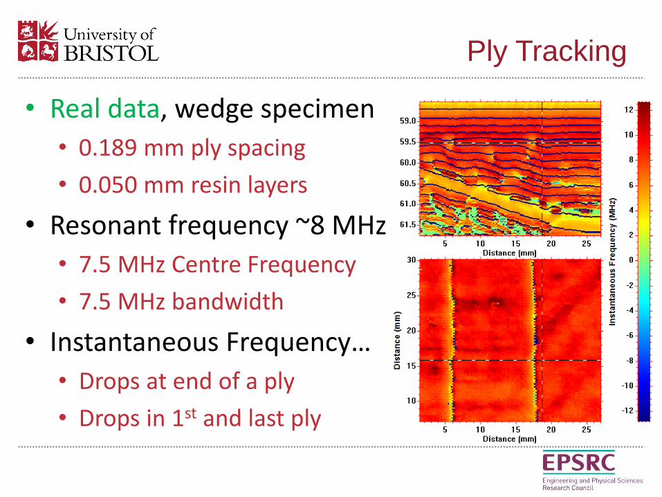
• Real data, wedge specimen
• 0.189 mm ply spacing
• 0.050 mm resin layers
• X-ray CT scan…
Ply Tracking
49 kV, 4-shots per projection, 20 μm voxel size

• Real data, wedge specimen
• 0.189 mm ply spacing
• 0.050 mm resin layers
• Resonant frequency ~8 MHz
• 7.5 MHz Centre Frequency
• 7.5 MHz bandwidth
• Conventional B-scan…
Ply Tracking

• Real data, wedge specimen
• 0.189 mm ply spacing
• 0.050 mm resin layers
• Resonant frequency ~8 MHz
• 7.5 MHz Centre Frequency
• 7.5 MHz bandwidth
• Instantaneous phase…
Ply Tracking

• Real data, wedge specimen
• 0.189 mm ply spacing
• 0.050 mm resin layers
• Resonant frequency ~8 MHz
• 7.5 MHz Centre Frequency
• 7.5 MHz bandwidth
• Ply tracking from Phase
• Instantaneous Amplitude with ply tracking…
Ply Tracking
Greyscale: amplitude. Green: Resin layer. Red: front or back surface.
• Real data, wedge specimen
• 0.189 mm ply spacing
• 0.050 mm resin layers
• Resonant frequency ~8 MHz
• 7.5 MHz Centre Frequency
• 7.5 MHz bandwidth
• Instantaneous Frequency…
• Drops at end of a ply
• Drops in 1st and last ply
Ply Tracking

Tape gaps and overlaps

• Defect Characterisation
• Simulated delaminations
• Identification of delaminations as air-backed BWE
Ultrasonic 3D imaging of composites
Simulated data for delaminations in an 8-ply compositeGreen: Resin layer. Red: front, back or delamination. Note: multiple reflections are not colour coded
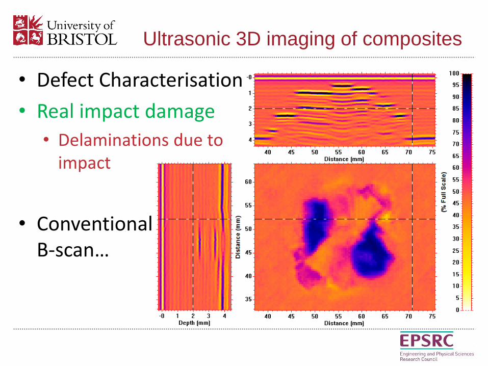
• Defect Characterisation
• Real impact damage
• Delaminations due to impact
• Conventional B-scan…
Ultrasonic 3D imaging of composites

• Defect Characterisation
• Delaminations due to impact damage
• Instantaneous amplitude withPly tracking…
Ultrasonic 3D imaging of composites
Green: Resin layer. Red: front, back or delamination. Note: multiple reflections are not colour coded

• Defect Characterisation
• Delaminations due to impact damage
• Instantaneous amplitude withPly tracking…
Ultrasonic 3D imaging of composites
Red: front, back or delamination. Note: multiple reflections are not colour coded
Video:

• Defect Characterisation
• Mapping of out-of-plane wrinkles
• Quantification of the wrinkle properties recently shown to be important for strength
Ultrasonic 3D imaging of composites
Real component with mapping of ply angle through wrinkles.
Simulated wrinkle with mapping of resin layers (green).

• Quantitative 3D fibre orientation ‘inversion’
Ultrasonics and NDT Group
21
α,β – out-of-plane
fibre angle
Surface Heights
3D non-destructive characterisation
γ – in-plane
fibre angle
C-scanB-scan

• Quantitative ply surface height…
3D non-destructive characterisation
Ultrasonics and NDT Group
22

• Vector Field
• Fibre-tow maps of ‘streamlines’ (analogy with fluid dynamics), vectors, F
3D Vector Map of Fibre-tow orientation
Ultrasonics and NDT Group

• 3D map of
• Fibre tows
• 3D orientation
3D Vector Map of Fibre-tow orientation
Ultrasonics and NDT Group
Dr Luke Nelson, Research Associate

Importance of metrics

• NDT-based performance modelling
• Example: Out-of-plane Wrinkling
• Ningbo Xie, Supratik Mukhopadhyay and Stephen Hallett, University of Bristol:
Importance of metrics

NDT-based prediction of strength
27
Ultrasonics and NDT Group

NDT-based prediction of strength
28
Ultrasonics and NDT Group

Wrinkle Shape Parameters Analysis
29
Ultrasonics and NDT Group
𝐷𝑖𝑠𝑝𝑙𝑎𝑐𝑒𝑚𝑒𝑛𝑡 = 𝐴𝑒− 𝑥2 𝑊12cos
2𝜋𝑥
𝐿
Wrinkle shape along x-direction: Wrinkle shape along y-direction (w2):
X (fibre-direction)
(thickness-direction)Z
(width-direction)y
A: amplitudeL: wavelengthθ: maximum angle
x
Gaussian envelope (w1):governs wrinkle volume
Cosine phase: defines wrinkle shape

• Constant volume
• Effect of shape of wrinkle
• Wavelength, L
• Amplitude, A=0.5 mm
• Maximum angle, ϕ
Importance of metrics
L = 5 mm
L = 4 mm
L = 3 mm
L = 2 mm

Wrinkle Shape Parameters Analysis
31
Ultrasonics and NDT Group
The depiction of Gaussian amplitude distributions:
𝐴𝑖 = 𝐴𝑒− 𝑖−𝑖𝑚𝑖𝑑2/𝑛2
Gaussian reduction:
decrease continuously
decrease continuously
Knock-down of failure stress:
Co
mp
ress
ion
Fai
lure
Str
ess
Kn
ock
-do
wn
(M
Pa)
Knock-down = tested pristine value (643.5 MPa ) - model value
For a wrinkle region with fixed volume, maximum angle is the major parameter for determining compression strength.
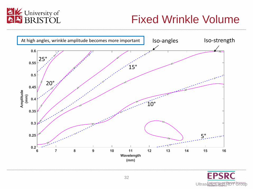
Fixed Wrinkle Volume
32
Ultrasonics and NDT Group
Iso-angles Iso-strengthAt high angles, wrinkle amplitude becomes more important
5°
10°
15°
20°
25°

• Fixed Wrinkle Volume – effect of amplitude, wavelength and angle
• Comparison of Sine and Cosine Shape
• Fixed Maximum Angle, effect of length, width and height of wrinkle.
Sine and Cosine Shape
33
Ultrasonics and NDT Group

• Cosine Shape & Sine Shape with Fixed Angle
34
Ultrasonics and NDT Group
-0.2
-0.15
-0.1
-0.05
0
0.05
0.1
0.15
0.2
0.25
0 5 10 15 20
Dis
pla
cem
ent,
mm
X-direction
Sine-Shape:
Cosine-Shape:
𝐷𝑖𝑠𝑝𝑙𝑎𝑐𝑒𝑚𝑒𝑛𝑡 = 𝐴𝑒− 𝑥2 𝑊12cos
2𝜋𝑥
𝐿
𝐷𝑖𝑠𝑝𝑙𝑎𝑐𝑒𝑚𝑒𝑛𝑡 = 𝐴𝑒− 𝑥2 𝑊12sin
2𝜋𝑥
𝐿
Sine and Cosine Shape

• Volume of wrinkle
Importance of metrics
n
w1w2
Load
Load1/e wrinkle-amplitude iso-surface

• Volume of wrinkle
Importance of metrics
n
w1w2
Load
Load
300
320
340
360
380
400
0 5 10 15w1, mm
n=5plies,w2=20mm n=5plies,w2=12mm
300
350
400
450
500
0 2 4 6n, plies
w1=4mm, w2=20mm w1=6mm, w2=20mm
300
350
400
450
500
0 5 10 15 20 25
w2, mm
n=5plies, w1=4mm n=5plies, w1=10mmCo
mp
ress
ive
Stre
ngt
h (
MPa
)
Co
mp
ress
ive
Stre
ngt
h (
MPa
)C
om
pre
ssiv
e St
ren
gth
(M
Pa)

• Volume of wrinkle
• Two different effects. Strength reduced more by:
• Shorter wrinkle volume in load direction
Importance of metrics

• Volume of wrinkle
• Two different effects. Strength reduced more by:
• Shorter wrinkle volume in load direction
• Larger wrinkle cross-section perpendicular to load.
Importance of metrics
y
z Unwrinkled
Wrinkledy
z
Wrinkled
Fewer unwrinkled fibres to carry load

• New ultrasonic methods are being developed.
• 3D characterisation of material properties is possible.
• FE material models can be created from NDT data – still need to prove this end-to-end.
• Models can tell us about the most important metrics. For out-of-plane wrinkles, worst case:
• Short wrinkle in load direction
• Large wrinkle area perpendicular to load
Summary