ndaf860 - ChemicalDragon.com - Dragon's...
135
TM 11-6665-236-12 (NSN TECHNICAL MANUAL OPERATOR’S AND UNIT OPERATING MAINTENANCE MANUAL INSTRUCTIONS PAGE 2-1 RADIAC SET AN/PDR-75 6665-01-211-4217) (EIC: KYD) PAGE 3-1 OPERATOR MAINTENANCE PROCEDURES PAGE 3-5 PAGE 4-2 ORGANIZATIONAL MAINTENANCE PROCEDURES PAGE 4-3
Transcript of ndaf860 - ChemicalDragon.com - Dragon's...

TM 11-6665-236-12
(NSN
TECHNICAL MANUAL
OPERATOR’S AND UNIT OPERATING
MAINTENANCE MANUAL INSTRUCTIONSPAGE 2-1
RADIAC SETAN/PDR-75
6665-01-211-4217) (EIC: KYD)
PAGE 3-1
OPERATORMAINTENANCEPROCEDURES
PAGE 3-5
PAGE 4-2
ORGANIZATIONALMAINTENANCEPROCEDURES
PAGE 4-3

TM 11-6665-236-12
SAFETY STEPS TO FOLLOW IF SOMEONEIS THE VICTIM OF ELECTRICAL SHOCK
DO NOT TRY TO PULL OR GRAB THE INDIVIDUAL
IF POSSIBLE, TURN OFF THE ELECTRICAL POWER
IF YOU CANNOT TURN OFF THE ELECTRICALPOWER, PULL, PUSH, OR LIFT THE PERSON TOSAFETY USING A WOODEN POLE OR A ROPE ORSOME OTHER INSULATING MATERIAL
SEND FOR HELP AS SOON AS POSSIBLE
AFTER THE INJURED PERSON IS FREE OFCONTACT WITH THE SOURCE OF ELECTRICALSHOCK, MOVE THE PERSON A SHORT DISTANCEAWAY AND IMMEDIATELY START ARTIFICIALRESUSCITATION
A

TM 11-6665-236-12
WARNING
is used in the operation of this equipment.
DEATH ON CONTACT
may result if personnel fail to observe safety precautions.
Never work on electronic equipment unless there is another person nearby who isfamiliar with the operation and hazards of the equipment and who is competent inadministering first aid. When the technicians are aided by operators, they must bewarned about dangerous areas.
Whenever possible, the power supply to the equipment must be shut off beforebeginning work on the equipment. Take particular care to ground every capacitorIikely to hold a dangerous potential. When working inside the equipment, after thepower has been turned off, always ground every part before touching it.
Be careful not to contact high voltage connections of 115 or 230 V ac input whenoperating this equipment.
Whenever the nature of the operation permits, keep one hand away from theequipment to reduce the hazard of current flowing through the body.
For artificial respiration instructions, refer to FM 21-11.
B

TM 11-6665-236-12
WARNING
HIGH VOLTAGE
Potentials of up to 1200 V dc may be present within the EHTpower supply and flash unit and at terminal 606 (EHT) on theEHT power supply. This high voltage may be present even whenthe reader is not operating or is disconnected from its powersource. Operator and organizational maintenance personnelmust not remove the side cover of the reader or reader fromits metal case unless specifically instructed to do so.Death or serious injury maywith this warning.
WARNING
result from failure to comply
HIGH INTENSITY LIGHT
High intensity light is generated by the flash tube in thereader during operation of this equipment. This lightcontains large amounts of ultraviolet energy which maycause severe and permanent damage to the eyes. Do notoperate the DEPRESS FOR READING switch when thedrawer of the reader is open unless specificallyinstructed to do so.
WARNING
SEVERE ILLNESS or DEATH may result if you fail toobserve the following safety precautions. BothDENATURED and ISOPROPYL ALCOHOLS are toxic,volatile, and flammable. Use only in well ventilatedareas away from heat or open flame. Avoid ingestion,prolonged breathing of vapor, and contact with skin.
WARNING
Personal injury may result from failure to close thedrawer assembly properly. Close the drawer assembly bygrasping the drawer handle firmly with one hand,lowering the drawer cover if necessary, and pushing thedrawer into the closed position. The free hand shouldremain clear of the drawer assembly. Do not touch thetransit lock with either hand when closing the drawerassembly.
WARNING
Turn power off and remove reader from its metal case,when internal electronic components are exposed forrepair or calibration during maintenance procedures,wait at least 1 minute before touching reader. Thisprocedure is required to ensure that the high voltagecapacitor within the flash unit has time to discharge.Failure to do so may result in death or serious injury.
C

TM 11-6665-236-12
WARNING
LITHIUM BATTERIES
Lithium batteries used with the Radiac Set AN/PDR-75contain sulfur dioxide and may explode if handledimproperly. Do not short circuit, incinerate, mutilate,or attempt to charge these batteries. Serious injuryto personnel may result from failure to comply withthis warning.
Observe the following precautions when handling lithium batteries tominimize the chance of personal injury or equipment damage.
DO NOT parallel batteries without diode protection.
DO NOT short-circuit battery terminals.
DO NOT heat, incinerate, crush, puncture, disassemble, or otherwisemutilate the batteries.
DO NOT attempt to recharge the batteries.
DO NOT bypass the internal fuse or replace it with a fuse ofa different rating.
DO NOT store batteries in equipment during long periods of disuse(over 30 days).
TURN EQUIPMENT OFF immediately if you:
1) detect overheating in battery compartment
2) hear hissing sound of venting battery, or
3) smell irritating sulfur dioxide gas.
Allow battery to cool for 30 to 60 minutes before removal. Ensureadequate ventilation if venting occurs. Avoid prolonged or repeatedbreathing of fumes.
● DO NOT discard batteries. Turn them in to a DRMO (DefenseReutilization and Maintenance Office).
D

*TM 11-6665-236-12
Technical Manual HEADQUARTERSNo. 11-6665-236-12 DEPARTMENT OF THE ARMY
Washington, DC, 1 June 1995
Operator’s and Unit Maintenance Manual
RADIAC SETAN/PDR-75
(NSN 6665-01-211-4217) (EIC: KYD)
TABLE OF CONTENTSPART ONE
Page
CHAPTER 1 INTRODUCTION (C5085500) . . . . . . . . . . . . . . . . . . . . . . . . . . 1-1
Section I General Information (C5085500) . . . . . . . . . . . . . . . . . . . .1-11-1.1-2.
1-3.
1-4.1-5.
1-6.1-7.1-8.1-9.
1-10.
Scope . . . . . . . . . . . . . . . . . . . . . . . . . . . . . . . . . . 1-1Consolidated Index of ArmyPublications and Blank Forms. . . . . . . . . . . . . . . .1-2
Maintenance Forms, Records, andReports . . . . . . . . . . . . . . . . . . . . . . . . . . . . . . . .1-2
Not ApplicableReporting Equipment ImprovementRecommendations (EIR’s) . . . . . . . . . . . . . . . . . . .1-2
Nomenclature Cross-Reference List . . . . . . . . . . . . 1-2List of Abbreviations and Acronyms . . . . . . . . . . . . 1-3Glossary . . . . . . . . . . . . . . . . . . . . . . . . . . . . . . . .1-3Destruction of Army Materiel toPrevent Enemy Use . . . . . . . . . . . . . . . . . . . . . . .1-3
Preparation for Storage or Shipment . . . . . . . . . . . . 1-3
II Equipment Description and Data (C5085500) . . . . . . . . . . . 1-31-11. Equipment Characteristics,
Capabilities, and Features . . . . . . . 1-31-12. Location and Description of
Major Components . . . . . . . . . . . . . . . . . . . . . . . .1-41-13. Equipment Data . . . . . . . . . . . . . . . . . . .1-6
Ill Technical Principles of Operation (C5085500 & A3250780) . . 1-8
i*This manual supersedes TM 11-6665-236-12, 1 July 1990.

TM 11-6665-236-12TABLE OF CONTENTS (CONTINUED)
PART TWOPage
CHAPTER 1 lNTRODUCTION (A3250780) . . . . . . . . . . . . . . . . . . . . . . .1-11
Section I General Information (A3250780) . . . . . . . . . . . . . . . . . . . . 1-111-1.1 Scope . . . . . . . . . . . . . . . . . . . . . . . . . . . . . . ..1-111-2.1 Consolidated lndex of Army
Publications and Blank Forms . . . . . . . . . . . . . . .1-121-3.1 Maintenance Forms, Records, and
Reports . . . . . . . . . . . . . . . . . . . . . . . . . . . . . . .1-121-4.1 Not Applicable1-5.1 Reporting Equipment Improvement
Recommmendations (EIR’s) . . . . . . . . . . . . . . . . . .1-121-6.1 Nomenclature Cross-Reference List . . . . . . . . . . 1-121-7.1 List of Abbreviations and Acronyms . . . . . . . . . . . 1-131-8.1 Glossary . . . . . . . . . . . . . . . . . . . . . . . . . . . . . . .1-131-9.1 Destruction of Army Materiel to
Prevent Enemy Use . . . . . . . . . . . . . . . . . . . . . .1-131-10.1 Preparation for Storage or Shipment . . . . . . . . . . . 1-13
II Equipment Description and Data (A3250780) . . . . . . . . . . . 1-131-11.1 Equipment Characteristics,
Capabilities, and Features . . . . . . . . . . . . . . . . . .1-131-12.1 Location and Description of
Major Components 1-14 1-13.1 Equipment Data . . . . . . . . . . . . . . . . . . . . . . . . . . .1-16
Ill Technical Principles of Operation (C5085500 & A3250780) 1-18
PART THREE
CHAPTER 2 OPERATING lNSTRUCTIONS (C5085500) . . . . . . . . . . . . 2-1
Section
II
Ill
IV
I Description and Use of Operator’s Controlsand lndicators (C5085500) . . . . . . . . . . . . . . . . . . . . . . . . 2-1
2-1. Front Panel . . . . . . . . . . . . . . . . . . . . . . . . . . . . . . 2-12-2. Rear Panel . . . . . . . . . . . . . . . . . . . . . . . . . . . . . . 2-2
Operator Preventive Maintenance Checks andServices (PMCS) (C5085500) . . . . . . . . . . . . . . . . . . . . . 2-2
2-3. Preventive Maintenance.. . . . . . . . . . . . . . . . . . . . 2-22-4. Routine Checks . . . . . . . . . . . . . . . . . . . . . . . . . . . 2-3
Operation Under Usual Conditions (C5085500) . . . . . . . . . . 2-42-5. Preparation for Operation . . . . . . . . .. . . . . . . . . . . . 2-42-6. operation . . . . . . . . . . . . . . . . . . . . . . . . . . . . . 2-14
Operation Under Unusual Conditions (C5085500) . . . . . . . 2-232-7. Operating Precautions for Unusual
Weather . . . . . . . . . . . . . . . . . . . . . . . . . . . . . . 2-232-8. Emergency Procedures . . . . . . . . . . . . . . . . . . . . 2-23
i i

TM 11-6665-236-12
CHAPTER 2
Section I
II
Ill
IV
CHAPTER 3
Section I
II
Ill
CHAPTER 3
Section I
II
Ill
CHAPTER 4
Section I
TABLE OF CONTENTS (CONTINUED)PART FOUR
Page
OPERATING lNSTRUCTiONS (A3250780) . . . . . . . . . . . . 2-25
Description and Use of Operator's Controlsand Indicators (A3250780) . . . . . . . . . . . . . . . . . . . . . . . 2-25
2-1.1 Front Panel . . . . . . . . . . . . . . . . . . . . . . . . . . . . 2-252-2.1 Rear Panel . . . . . . . . . . . . . . . . . . . . . . . . . . . 2-26
Operator Preventive Maintenance Checks andServices (PMCS) (A3250780) . . . . . . . . . . . . . . . . . . . . 2-26
2-3.1 Preventive Maintenance . . . . . . . . . . . . . . . . . . . 2-262-4.1 Routine Checks . . . . . . . . . . . . . . . . . . . 2-27
Operation Under Usual Conditions (A3250780) . . . . . . . . . 2-282-5.1. Preparation for Operation . . . . . . . . . . . . . . . . . . 2-282-6.1. Operation . . . . . . . . . . . . . . . . . . . . . . . . . . . . . 2-38
operation Under Unusual Conditions (A3250780) . . . . . . . 2-462-7.1 Operating Precautions for Unusual
Weather . . . . . . . . . . . . . . . . . . . . . . . . . . . . . . 2-462-8.1 Emergency Procedures . . . . . . . . . . . . . . . . . . . . 2-46
PART FIVEOPERATOR MAINTENANCE (C5085500) . . . . . . . . . . . . . 3-1
Lubrication Instructions (C5085500) . . . . . . . . . . . . . . . . . . 3-1
Operator Troubleshooting Procedures (C5085500) . . . . . . . . 3-13-1. General . . . . . . . . . . . . . . . . . . . . . . . . . . . . . . 3-13-2. Troubleshooting . . . . . . . . . . . . . . . . . . . . . . . . . 3-1
Operator Maintenance Procedures (C5085500) . . . . . . . . 3-43-3. Cleaning . . . . . . . . . . . . . . . . . . . . . . . . 3-43-4. Component Replacement . . . . . . . . . . . . . . . . 3-5
PART SIXOPERATOR Maintenance (A3250780) . . . . . . . . . . . . . 3-7
Lubrication instructions (A3250780) . . . . . . . . . . . . . . . . . . 3-7
Operator Troubleshooting Procedures (A3250780) . . . . . . . . 3-73-1.1 General . . . . . . . . . . . . . .. . . . . . . .. . . . .. . . . .. 3-73-2.1 Troubleshooting . . . . . . . . . . . . . . . . . . . . . . . . . . .. . . . . . 3-7
Operator Maintenance Procedures (A3250780) . . . . . . . . . 3-103-3.1 Cleaning . . . . . . . . . . . . . . . . . . . . . . . . . . . . . . . .. . .. . .. . 3-103-4.1 Component Replacement . . . . . . . . . . . . . . . . . . 3-11
PART SEVENORGANIZATIONAL MAINTENANCE (C5085500) . . . . . . . . 4-1
Repair Parts, Special Tools and TMDE (C5085500) . . . . . . . 4-14-1. Common TooIs and Equipment . . . . . . . . . . . . . . . . 4-14-2. Special Tools and TIDE . . . . . . . . . . . . . . . . . . . . 4-14-3. Repair Parts . . . . . . . . . . . . . . . . . . . . . . . . . .. .. . .. .. . 4-1
iii
TM 11-6665-236-12TABLE OF CONTENTS (CONTINUED)
PART SEVENPage
Section II Service Upon Receipt (C5085500) . . . . . . . . . . . . . . . . . . . 4-14-4. General . . . . . . . . . . . . . . . . . . . . . . . . . . . . . . . . .4-1 4-5. Checking Unpacked Equipment . . . . . . . . . . . . . . . 4-14-6. Site and Shelter Requirements. . . . . . . . . . . . . . . . 4-1
Ill Organizational Preventive Maintenance Checksand Services (PMCS) (C5085500). . . . . . . . . . . . . . . . . . . . . 4-1
Section IV
Section V
VI
CHAPTER 4
Section I
II
Ill
Section IV
Section V
VI
Organizational Troubleshooting Procedures (C5085500) . . . 4-24-7. General . . . . . . . . . . . . . . . . . . . . . . . . . . . . . . . . .4-24-8. Troubleshooting . . . . . . . . . . . . . . . . . . . . . . . . . .4-2
Organizational Maintenance Procedures (C5085500) . . . . . . 4-34 - 9 . Repair of Radiac Set . . . . . . . . . . . . . . . . . . . . . . 4-34-10. Cleaning . . . . . . . . . . . . . . . . . . . . . . . . . . . . . . . .4-84-11. Painting . . . . . . . . . . . . . . . . . . . . . . . . . . . . . . . .4-8
Preparation for Storage or Shipment (C5085500) . . . . . . . . 4-94-12. Preparation for Storage . . . . . . . . . . . . . . . . . . . . .4-94-13. Preparation for Shipment . . . . . . . . . . . . . . . . . . . 4-9
PART EIGHTORGANIZATIONAL MAINTENANCE (A3250780) . . . . . . . 4-11
Repair Parts, Special Tools and TMDE (A3250780) . . . . . . 4-114-1.1. Common Tools and Equipment . . . . . . . . . . . . . . . 4-114-2.1. Special Tools and TIDE . . . . . . . . . . . . . . . . . . 4-114-3.1. Repair Parts . . . . . . . . . . . . . . . . . . . . . . . . . . . . 4-11
Service Upon Receipt (A3250780) . . . . . . . . . . . . . . . . . . 4-114-4.1. General . . . . . . . . . . . . . . . . . . . . . . . . . . . . . . . . 4-114-5.1. Checking Unpacked Equipment . . . . . . . . . . . . . . 4-114-6.1. Site and Shelter Requirements . . . . . . . . . . . . . . . 4-11
Organizational Preventive Maintenance Checksand Services (PMCS) (A3250780) . . . . . . . . . . . . . . . . . . . 4-11
Organizational Troubleshooting Procedures (A3250780) . . . 4-124-7.1. General . . . . . . . . . . . . . . . . . . . . . . . . . . . . . . . . 4-124-8.1. Troubleshooting . . . . . . . . . . . . . . . . . . . 4-12
Organizational Maintenance Procedures (A3250780) . . . . . 4-134-9.1. Repair of Radiac Set . . . . . . . . . . . . . . . . . . . . . . 4-134-10.1. Cleaning . . . . . . . . . . . . . . . . . . . . . . . . . . . . . . .4-204-11.1. Painting . . . . . . . . . . . . . . . . . . . . . . . . . . . . . . .4-20
Preparation for Storage or Shipment (A3250780) . . . . . . . . 4-204-12.1. Preparation for Storage . . . . . . . . . . . . . 4-204-13.1. Preparation for Shipment . . . . . . . . . . . . . . . 4-20

TM 11-6665-236-12
TABLE OF CONTENTS (CONTINUED)
PagePART NINE APPENDIX PREFERENCES . . . . . . . . . . . . . . . . . . . . . . . . A-1PART TEN APPENDIX B MAINTENANCE ALLOCATION . . . . . . . . . . . . . B-1PART ELEVEN APPENDIX C COMPONENTS OF END ITEM AND BASIC
ISSUE ITEMS LIST SECTION IIA (C5085500) . . . . . . . . . . . C-1PART TWELVE APPENDIX C COMPONENTS OF END ITEM AND BASIC
ISSUE ITEMS LIST SECTION IIA (A3250780) . . . . . . . . . . . C-5PART THIRTEEN APPENDIX D ADDITIONAL AUTHORIZATION LIST . . . . . . . . D-1PART FOURTEEN APPENDIX E EXPENDABLE/DURABLE SUPPLIES AND
MATERIELS LIST . . . . . . . . . . . . . . . . . . . . . . . . . . . . . . . E-1
PART FIFTEEN INDEX . . . . . . . . . . . . . . . . . . . . . . . . . . . . . . . . . . . . . . INDEX 1
v
TM 11-6665-236-12
How to Use This Manual
This manual tells you how to repair and maintain the AN/PDR-75.
Warnings and Cautions listed throughout the manual are summarizedbeginning on page A. Be sure to read and understand all of these beforeattempting any repair or maintenance function.
Significant subject headings are listed by page numbers on the manual’sfront cover.
individual subjects/Items are found by referring to the Subject Index in therear of this manual.
Special notes pertain to the Table of Contents and Subject Index asdescribed below. This manual contains two versions of model AN/PDR-75(C5085500 and A3250780). These two versions are electrically the sameand operate identically, but are mechanically different in construction anddesign.
a. Each of the four chapters (General Information, OperatingInstructions, Operator Maintenance, and OrganizationalMaintenance) are duplicated in this manual. There is a separatechapter for each of the above subjects for the C5085500 versionand for the A3250780 version.
b. The two versions are easily distinguishable from each other inappearance (See Front Cover illustration). If in doubt however,refer to the instruments’ I.D. plate on which the version number willbe marked (Computer Indicator C5085357 is part of C5085500version, Computer Indicator A3197293 is part of A3250780version).
c. Refer to Table 3-1 (page 3-1) and Table 3-1.1 (page 3-7) forOperator Troubleshooting.
d. The Subject Index in many cases lists two page numbers for eachsubject (e.g. 2-4/2-28). The first page number (2-4) shown refersto the C5085500 version and second (2-28) to the A3250780version.
vi

TM 11-6665-236-12
PART ONE
CHAPTER 1
INTRODUCTION (C5085500)
Section I. GENERAL INFORMATION (C5085500)
NOTE
The Radiac Detector DT-236/PDR-75 is used with, but isnot considered part of, the Radiac Set AN/PDR-75. TheRadiac Detector DT-236/PDR-75 will be discussed in thismanual in conjunction with a discussion of the radiac set.
1-1. SCOPE
Type of Manual:
Operator's and Organizational Maintenance
Model Number and Equipment
Radiac Set AN/PDR-75
Purpose of Equipment:
Name:
The Radiac Computer Indicator CP-696/PDR-75 is used to measure theaccumulated neutron and gamma radiation dose recorded by the RadiacDetector DT-236/PDR-75. The Radiac Detector DT-236/PDR-75 is worn bypersonnel who may be exposed to radiation from tactical nuclear weapons.
1-1

TM 11-6665-236-12
1-2. CONSOLIDATED INDEX OF ARMY PUBLICATIONS AND BLANK FORMS.
Refer to the latest issue of DA Pam 25-30 to determine whether there are neweditions, changes, or additional publications pertaining to the equipment.
1-3. MAINTENANCE FORMS, RECORDS, AND REPORTS.
a. Reports of Maintenance and Unsatisfactory Equipment. Department of theArmy forms and procedures used for equipment maintenance will be thoseprescribed by DA Pam 738-750 as contained in the Maintenance ManagementUpdate.b. Reports of Packaging and Handling Discrepancies. Fill out and forward SF
364 (Report of Discrepancy) (ROD) as prescribed in AR 735-11-2/DLAR4140.55/SECNAVlNST 4355.18/AFR 400-54/MCO 4430.3J.c. Transportation Discrepancy Report (TDR)(SF 361). Fill out and forward
Transportation Discrepancy Report (TDR) (SF 361) as prescribed in AR55-38/NAVSUPINST 4610.33C/AFR 75-18/MCO P4610.19D/DLAR 4500.15.
1-4. NOT APPLICABLE
1-5. REPORTING EQUIPMENT IMPROVEMENT RECOMMENDATIONS (EIR’S)If your Radiac Set AN/PDR-75 needs improvement, let us know. Send us an EIR.
You, the user, are the only one who can tell us what you don’t like about yourequipment. Let us know why you don’t like the design or performance. Put it onan SF 368 (Quality Deficiency Report). Mail it to: Commander, US ArmyCommunications-Electronics Command and Fort Monmouth, ATTN: AMSEL-PA-MA-D, Fort Monmouth, New Jersey 07703-5000. We’ll send you a reply.
1-6. NOMENCLATURE CROSS-REFERENCE LIST.
The following list contains common names used throughout this manual whenequipment components are mentioned.
Common Name Official Nomenclature
Battery and Connector Case NoneCables NoneCarrying Case Case, Carrying (C5085373)Dosimeter Detector, Radiac DT-236/PDR-75Radiac Set Radiac Set (C5085500)Reader Computer Indicator, Radiac CP-696/PDR-75
1-2
TM 11-6665-236-12
1-7. LIST OF ABBREVIATIONS AND ACRONYMS.
The following list contains the abbreviations and acronyms used throughout thismanual. Refer to MlL-STD-12 for abbreviations not contained in this list.
Abbreviation Term
CCA Circuit Card AssemblycGy CentigrayDPM Digital Panel MeterEHT Extreme High TensionPLA Plug A
1-8. GLOSSARY.
(High Voltage)
The following definitions are provided to clarify terms used throughout this manual.
Term Definition
Centigray Unit of measure of absorbed radiation(One centigray is equal to one rad)
Dose Accumulative amount of radiationproduced or absorbed
1-9. DESTRUCTION OF ARMY ELECTRONICS MATERIEL.
Destruction of Army electronics materiel to prevent enemy use shall be inaccordance with TM 750-244-2.
1-10. PREPARATION FOR STORAGE OR SHIPMENT.
Refer to paragraphs 4-12 and 4-13 for procedures covering preparation for storageor shipment.
Section Il. EQUIPMENT DESCRIPTION AND DATA (C5085500)
1-11. EQUIPMENT CHARACTERISTICS, CAPABILITIES, AND FEATURES.
Allows radiation monitoring of individual personnel
Provides large scale monitoring for statistical purposes
Gives virtually instantaneous exposure readings
Provides accurate readings for extended periods of time after exposure
May be battery operated
Portable, durable, and lightweight
Dosimeter:
Allows radiation monitoring of individual personnel
Provides accurate readings for extended periods of time after exposure
Maintenance-free and lightweight.1-3

TM 11-6665-236-12
Measuresdoses
from 0 to 999 cGy in any combination of neutron and gamma
Indicates over-range doses with flashing digital panel meter (DPM) display
Designed to nuclear survivability requirements for neutron and gammaradiation fields, electromagnetic pulse (EMP), and thermal flash and air blast
Provides a single digital display reading in cGy for combined doses ofneutron and gamma radiation
Operates from a power supply of either polarity
Dosimeter:
Measures from 0 to 999 cGy in any combination of neutron and gammadoses
Designed to nuclear survivability requirements for neutron and gammaradiation fields and electromagnetic pulses (EMP)
Front panel-mounted controls
Independent controls for digital panel meter (DPM) display and drawerassembly cover lamp
Top-mounted fabric carrying strap
Finish resists infrared detection
Dosimeter:
Base is keyed to reader drawer assembly locating plate for quick mounting
Has adjustable fabric strap
Has durable plastic base and cover
1-12. LOCATION AND DESCRIPTION OF MAJOR COMPONENTS
CARRYING CASE (1) - May contain the reader, battery and connector case, coverplate assembly, lithium battery, battery cable, and vehicle cable. Permits the radiacset to be transported in a field environment.
BATTERY AND CONNECTOR CASE (2) - Contains the lithium battery, if used, andis fried to the rear of the reader. Ensures proper positioning of the reader wheninstalled in the carrying case.
COVER PLATE ASSEMBLYsecures the lithium battery, if
1-4
(3) - Attaches to the battery and connector case andused, in the battery and connector case.
TM 11-6665-236-12
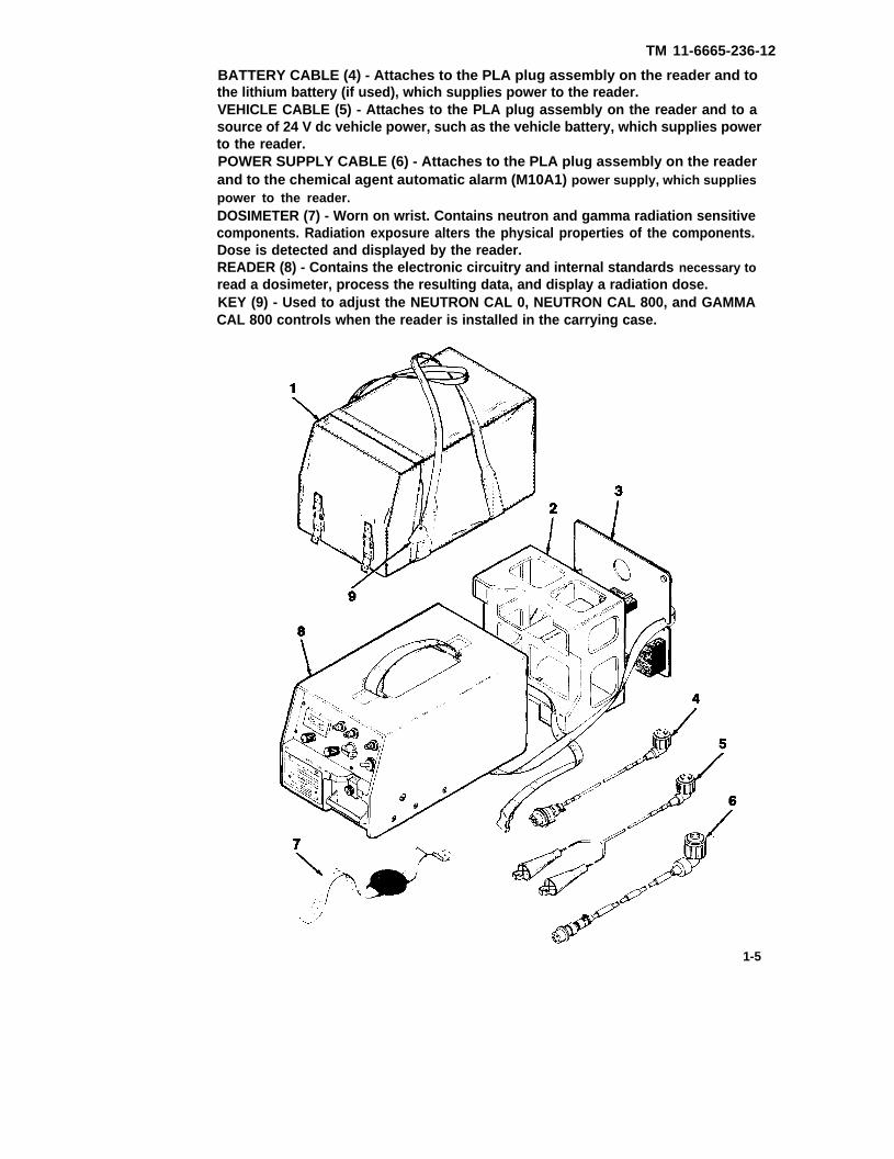
BATTERY CABLE (4) - Attaches to the PLA plug assembly on the reader and tothe lithium battery (if used), which supplies power to the reader.VEHICLE CABLE (5) - Attaches to the PLA plug assembly on the reader and to asource of 24 V dc vehicle power, such as the vehicle battery, which supplies powerto the reader.POWER SUPPLY CABLE (6) - Attaches to the PLA plug assembly on the readerand to the chemical agent automatic alarm (M10A1) power supply, which suppliespower to the reader.DOSIMETER (7) - Worn on wrist. Contains neutron and gamma radiation sensitivecomponents. Radiation exposure alters the physical properties of the components.Dose is detected and displayed by the reader.READER (8) - Contains the electronic circuitry and internal standards necessary toread a dosimeter, process the resulting data, and display a radiation dose.KEY (9) - Used to adjust the NEUTRON CAL 0, NEUTRON CAL 800, and GAMMACAL 800 controls when the reader is installed in the carrying case.
1-5

TM 11-6665-236-12
DRAWER ASSEMBLY (10) - Provides an interface between the dosimeter beingread and the reader. The dosimeter base is placed in the open drawer assembly. The drawer is then closed and a reading is taken.
FRONT PANEL ASSEMBLY (11) - Contains the controls necessary to operate andadjust the reader, and the digital panel meter (DPM), which displays radiation dose.
CARRYING STRAP (12) - Permits the reader to be carried by hand.
1-13. EQUIPMENT DATA
NOTE
Dimensions and weights provided beloware approximate.
Radiac Set (C5085500)
Length 22 inches (560 mm)
Width 13 inches (330 mm)
Height 13 inches (330 mm)
1-6

TM 11-6665-236-12
Reader (C5085357)
Length
Width
Height
Dosimeter
Diameter 1.6 inches (41 mm)
Thickness 0.5 inches (12.5 mm)
14 inches (360 mm)
8 inches (205 mm)
8 inches (205 mm)
Radiac Set 36 pounds (16.3 kg)
Reader 24 pounds (10.3 kg)
Dosimeter 1.3 ounces (36 g)
Reader 21 to 30 V dc, 1.5A (maximum), 10 W (average)
Dosimeter N/A
Accuracy (System) Within ±30 percent or ±30 cGy of true totalpercent confidence at 24 hours after dosing
dose with 95
Range 0 to 999 cGy (combined neutron and gamma dose)
Over-Range 1000 to 5000 cGy (DPM display flashes)
Temperature
Operating -26 to + 125°F (-32 to +52°C)
Storage -70 to + 160°F (-57 to +71°C)
Humidity 0 to 100 percent
1-7

TM 11-6665-236-12
Section III. TECHNICAL PRINCIPLES OF OPERATION
EXTERNAL 24 V DC SUPPLY is normally a lithium battery, vehicle battery, or chemical agent automatic alarm (M10A1 ) power supply which provides
power to the reader.
FRONT PANEL CONTROLS include the DEPRESS FOR READING switch,selector switch, NEUTRON CAL 0 control, NEUTRON CAL 800 control, andGAMMA CAL 800 control.
EHT POWER SUPPLY provides the power required to operate the flash unit.
FLASH UNIT contains a high voltage capacitor and a flash tube, and producesthe high intensity light used to excite the phosphate glass block.
1-8

TM 11-6665-236-12
PHOSPHATE GLASS BLOCK functions on the principle ofradiophotoluminescense and normally emits blue/green light when excitedby ultraviolet wavelengths; emits orange/red light, however, after exposureto gamma radiation.
PHOTODIODE converts orange/red fight to a proportional current which issensed by the gamma channel amplifier.
GAMMA CHANNEL AMPLIFIER integrates current from the photo diode andproduces a peak output voltage proportional to the gamma dose.
NEUTRON DIODE conduction characteristics are altered by exposure toneutron radiation.
NEUTRON CHANNEL AMPLIFIER processes the sampling voltage from theneutron diode.
MAIN AMPLIFIER combines and stores and signals from both the neutronchannel and gamma channel amplifiers.
POWER SUPPLY AND CONTROL CIRCUIT coordinates neutron and gammaradiation sampling in response to front panel control inputs.
DIGITAL PANEL METER displays combined neutron and gamma radiationdose determined by the main amplifier.
1-9/(1-10 blank)


TM 11-6665-236-12PART TWO
CHAPTER 1
INTRODUCTION (A3250780)
Section I. GENERAL INFORMATION (A3250780)
NOTE
The Radiac Detector DT-236/PDR-75 is used with, but isnot considered part of, the Radiac Set AN/PDR-75. TheRadiac Detector DT-236/PDR-75 will be discussed in thismanual in conjunction with a discussion of the radiac set.
1-1.1 SCOPE
Type of Manual:
Operator's and Organizational Maintenance
Model Number and Equipment Name:
Radiac Set AN/PDR-75
Purpose of Equipment:
The Radiac Computer indicator CP-696/PDR-75 is used to measure theaccumulated neutron and gamma radiation dose recorded by the RadiacDetector DT-236/PDR-75. The Radiac Detector DT-236/PDR-75 is worn bypersonnel who may be exposed to radiation from tactical nuclear weapons.
1-11

TM 11-6665-236-12
1-2.1 CONSOLIDATED INDEX OF ARMY PUBLICATIONS AND BLANK FORMS.
Refer to the latest issue of DA Pam 25-30 to determine whether there are neweditions, changes, or additional publications pertaining to the equipment.
1-3.1 MAINTENANCE FORMS, RECORDS, AND REPORTS.
a. Reports of Maintenance and Unsatisfactory Equipment. Department of theArmy forms and procedures used for equipment maintenance will be thoseprescribed by DA Pam 738-750 as contained in the Maintenance ManagementUpdate.b. Reports of Packaging and Handling Discrepancies. Fill out and forward SF
364 (Report of Discrepancy) (ROD) as prescribed in AR 735-11-2/DLAR4140.55/SECNAVlNST 4355.18/AFR 400-54/MCO 4430.3J.c. Transportation Discrepancy Report (TDR)(SF 361). Fill out and forward
Transportation Discrepancy Report (TDR) (SF 361) as prescribed in AR55-38/NAVSUPINST 4610.33C/AFR 75-18/MCO P4610.19D/DLAR 4500.15.
1-4.1 NOT APPLICABLE
1-5.1 REPORTING EQUIPMENT IMPROVEMENT RECOMMENDATIONS (EIR’S)
If your Radiac Set AN/PDR-75 needs improvement, let us know. Send us an EIR.You, the user, are the only one who can tell us what you don’t like about your equipment. Let us know why you don’t like the design or performance. Put it onan SF 368 (Quality Deficiency Report). Mail it to: Commander, US ArmyCommunications-Electronics Command and Fort Monmouth, ATTN: AMSEL-PA-M-D, Fort Monmouth, New Jersey 07703-5000. We’ll send you a reply.
1-6.1. NOMENCLATURE CROSS-REFERENCE LIST.
The following list contains common names used throughout this manual whenequipment components are mentioned.
Common Name Official Nomenclature
Cables NoneCarrying Case Case, Carrying (A3209749)Dosimeter Detector, Radiac DT-236/PDR-75Radiac Set Radiac Set (A3250780)Reader Computer Indicator, Radic CP-696/PDR-75
1-12

TM 11-6665-236-12
1-7.1 LIST OF ABBREVIATIONS AND ACRONYMS.
The following list contains the abbreviations and acronyms used throughout thismanual. Refer to MlL-STD-12 for abbreviations not contained in this list.
Abbreviation Term
CCA Circuit Card AssemblycGy CentigrayDPM Digital Panel MeterEHT Extreme High Tension (High Voltage)PLA Plug A
1-8.1 GLOSSARY.
The following definitions are provided to clarify terms used throughout this manual.
Term Definition
Centigray Unit of measure of absorbed radiation(One centigray is equal to one rad)
Dose Accumulative amount of radiationproduced or absorbed
1-9.1 DESTRUCTION OF ARMY ELECTRONICS MATERIEL.
Destruction of Army electronics materiel to prevent enemy use shall be inaccordance with TM 750-244-2.
1-10.1 PREPARATION FOR STORAGE OR SHIPMENT.
Refer to paragraphs 4-12 and 4-13 for procedures covering preparation for storageor shipment.
Section Il. EQUIPMENT DESCRIPTION AND DATA (A3250780)
1-11.1 EQUIPMENT CHARACTERISTICS, CAPABILITIES, AND FEATURES.
CHARACTERISTICSReader:
● Allows radiation monitoring of individual personnel
● Provides large scale monitoring for statistical purposes
● Gives virtually instantaneous exposure readings
● Provides accurate readings for extended periods of time after exposure
● May be battery operated
● Portable, durable, and lightweight
Dosimeter:
● Allows radiation monitoring of individual personnel
● Provides accurate readings for extended periods of time after exposure
● Maintenance-free and lightweight.1-13

TM 11-6665-236-12
Reader:
Measures from 0 to 999 cGy in any combination of neutron and gamma●
doses
● Indicates over-range doses with flashing digital panel meter (DPM) display
● Designed to nuclear survivability requirements for neutron and gammaradiation fields, electromagnetic pulse (EMP), and thermal flash and airblast
● Provides a single digital display reading in cGy for combined doses ofneutron and gamma radiation
● Operates from a power supply of either polarity
Dosimeter:
● Measures from 0 to 999 cGy in any combination of neutron and gammadoses
● Designed to nuclear survivability requirements for neutron and gammaradiation fields and electromagnetic pulses (EMP)
Reader:
● Front panel-mounted controls
● Independent controls for digital panel meter (DPM) display and drawerassembly cover lamp
● Top-mounted fabric carrying strap
● Finish resists infrared detection
Dosimeter:
● Base is keyed to reader drawer assembly locating plate for quick mounting
● Has adjustable fabric strap
● Has durable plastic base and cover
1-12.1 LOCATION AND DESCRIPTION OF MAJOR COMPONENTS
CARRYING CASE (1) - May contain the reader, carrying case base, lithium battery,battery cable, power supply cable and vehicle cable. Permits the radiac set to betransported in a field environment.
CARRYING CASE BASE (2) - Ensures proper positioning of the reader wheninstalled in the carrying case.
LITHIUM BATTERY (3) - If used, supplies power to the reader.
1-14

TM 11-6665-238-12
BATTERY CABLE (4) - Attaches to the PLA plug assembly on the reader and tothe Iithium battery (if used), which supplies power to the reader.VEHICLE CABLE (5) - Attaches to the PLA plug assembly on the reader and to asource of 24 V dc vehicle power, such as the vehicle battery, which supplies powerto the reader.POWER SUPPLY CABLE (6) - Attaches to the PLA plug assembly on the readerand to the chemical agent automatic alarm (M10A1) power supply, which suppliespower to the reader.DOSIMETER (7) - Worn on wrist. Contains neutron and gamma radiation sensitivecomponents. Radiation exposure alters the physical properties of the components.Dose is detected and displayed by the reader.READER (8) - Contains the electronic circuitry and internal standards necessary toread a dosimeter, process the resulting data, and display a radiation dose.
1-15

TM 11-6665-236-12
DRAWER ASSEMBLY (9) - Provides an interface between the dosimeter being readand the reader. The dosimeter base is placed in the open drawer assembly. Thedrawer is then closed and a reading is taken.
FRONT PANEL ASSEMBLY (10) - Contains the controls necessary to operate andadjust the reader, and digital panel meter (DPM), which displays radiation dose.
CARRYING STRAP (11) - Permits the reader to be carried by hand.
1-13.1 EQUIPMENT DATA
NOTE
Dimensions and weights provided beloware approximate.
Radiac Set (A3250780)
Length 19.56 inches (496.8 mm)
Width 10.82 inches (274.8 mm)
Height 10.19 inches (258.8 mm)
1-16
TM 11-6665-236-12
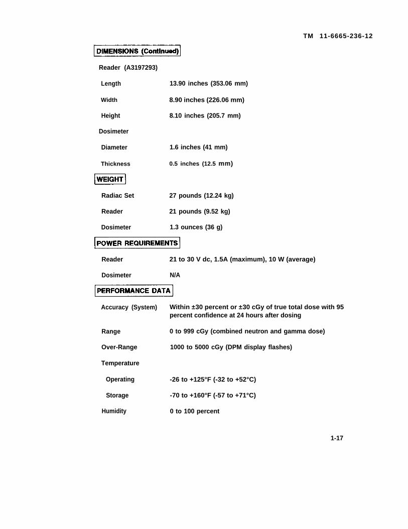
Reader (A3197293)
Length 13.90 inches (353.06 mm)
Width 8.90 inches (226.06 mm)
Height 8.10 inches (205.7 mm)
Dosimeter
Diameter 1.6 inches (41 mm)
Thickness 0.5 inches (12.5 mm)
Radiac Set 27 pounds (12.24 kg)
Reader 21 pounds (9.52 kg)
Dosimeter 1.3 ounces (36 g)
Reader 21 to 30 V dc, 1.5A (maximum), 10 W (average)
Dosimeter N/A
Accuracy (System) Within ±30 percent or ±30 cGy of true total dose with 95percent confidence at 24 hours after dosing
Range 0 to 999 cGy (combined neutron and gamma dose)
Over-Range 1000 to 5000 cGy (DPM display flashes)
Temperature
Operating -26 to +125°F (-32 to +52°C)
Storage -70 to +160°F (-57 to +71°C)
Humidity 0 to 100 percent
1-17

TM 11-6665-236-12
Section Ill. TECHNICAL PRINCIPLES OF OPERATION
Technical principles of operation are the same for C5085500 and A3250780versions and are given on pages 1-8 and 1-9.
1-18


TM 11-6665-236-12
2-0

TM 11-6665-236-12PART THREE
CHAPTER 2
OPERATING lNSTRUCTIONS (C5085500)Paragraph Page
Emergency Procedures . . . . . . . . . . . . . . . . . . . . . . . . . . . . . . . . 2-23Front Panel . . . . . . . . . . . . . . . . . . . . . . . . . . . . . . . . . . . . . . . . . . 2-1Operating Precautions for Unusual Weather . . . . . . . . . . . . . . . . . 2-23Operation . . . . . . . . . . . . . . . . . . . . . . . . . . . . . . . . . . . . . . . . . 2-14Preparation for Operation . . . . . . . . . . . . . . . . . . . . . . 2-4Preventive Maintenance . . . . . . . . . . . . . . . . . . . . . . . . . . . . . . . . . 2-2Rear Panel . . . . . . . . . . . . . . . . . . . . . . . . . . . . . . . . . . . . . . . . . . 2-2Routine Checks . . . . . . . . . . . . . . . . . . . . . . . . . . . . . . . . . . . . . . 2-3
Section l. DESCRIPTION AND USE OF OPERATOR’S CONTROLSAND INDICATORS(C5085500)
2-1. FRONT PANEL
DIGITAL PANEL METER (1) -Displays total dose of radiation in cGyunits when the selector switch is set to READ, shows reader’s supplyvoltage when the selector switch is set to SUPPLY, and verifies readercalibration when the selector switch is set to NEUTRON CAL 0, NEUTRONCAL 800, or GAMMA CAL 800.
DISPLAY CONTROL (2) - Varies brightness of digital panel meter display.
LAMP CONTROL (3) - Varies brightness of lamp in the drawer assembly.
NEUTRON CAL 0 CONTROL (4) - Sets neutron channel zero duringoperational checks and adjustments.
NEUTRON CAL 800 CONTROL (5) - Sets neutron channel sensitivityduring operational checks and adjustments.
GAMMA CAL 800 CONTROL (6) - Sets gamma channel sensitivity duringoperational checks and adjustments.
SELECTOR SWITCH (7) - Sets operational mode of the reader to OFF,SUPPLY, NEUTRON CAL 0, NEUTRON CAL 800, GAMMA CAL 800, orREAD.
READ LIGHT (8) - Lights when selector switch is set to READ and indicatesnormal operating condition.
DEPRESS FOR READING SWITCH (9) - Starts the reading cycle.
DRAWER CLOSING BLOCK (10) - Secures drawer assembly in closedposition.
DRAWER HANDLE (11) - Used to open and close drawer assembly. 2-1

TM 11-6665-236-12
2-2. REAR PANEL
HUMIDITY INDICATOR (12) - Element changes are not required.
FUSES (13) - Protect the reader from currents greater than 2 amperes.
PLUG (14) - Provides input terminal for reader's power supply.
Section Il. OPERATOR PREVENTIVE MAINTENANCE CHECKS ANDSERVICES (PMCS)(C5035500)
2-3. PREVENTIVE MAINTENANCE
a. There is no PMCS scheduled for the Radiac Set AN/PDR-75 at the operatorlevel.
b. To ensure that Radiac Set AN/PDR-75 is always ready for operation, it mustbe inspected systematically so that defects may be discovered andcorrected before they result in serious damage or failure. Note defectsdiscovered during operation of the unit and correct them as soon asoperation has ceased. Stop operation immediately when you note adeficiency that will damage the equipment. Record all deficiencies andcorrective actions taken on DA Form 2404.
c. Routing checks (refer to paragraph 2-4) are not listed as PMCS checks.They are things that you should check and correct as necessary
2-2

TM 11-6665-236-12
2-4. ROUTINE CHECKS
The operator should perform the checks listed in Table 2-1 as needed.Correct any deficiencies immediately.
Table 2-1. Routine Maintenance Checks
PROCEDURE CORRECTIVE ACTION
Check for cut, frayed, ordirty cables.
Ensure that knobs, plug cap,and drawer transit lock andscrew are not bent or broken.
Ensure that carrying strapis not frayed or broken.
Ensure that items not in useare properly stowed.
Check the carrying case forholes, rips, dirt, andgrease.
Check for corrosion or badlydamaged paint on readercase and drawer assembly.
Check front panel controls forproper operation.
Check for loose or missingscrews in case.
Ensure that DPM glass is notcracked or broken.
Forward cut or frayed cables toorganizational maintenance.
Clean dirty cables in accordance withparagraph 3-3.
Have organizational maintenancereplace bent or broken components.
Have organizational maintenancereplace frayed or broken carryingstrap.
Stow items properly.
Have organizational maintenancereplace torn or ripped carryingcase. Clean dirty carrying casein accordance with paragraph 3-3.
Forward corroded or damagedreader to general supportmaintenance.
Have organizational maintenancereplace faulty components.
Have organizational maintenancetighten or replace screws.
Forward reader 10 generalsupport maintenance.
2-3
TM 11-6665-236-12
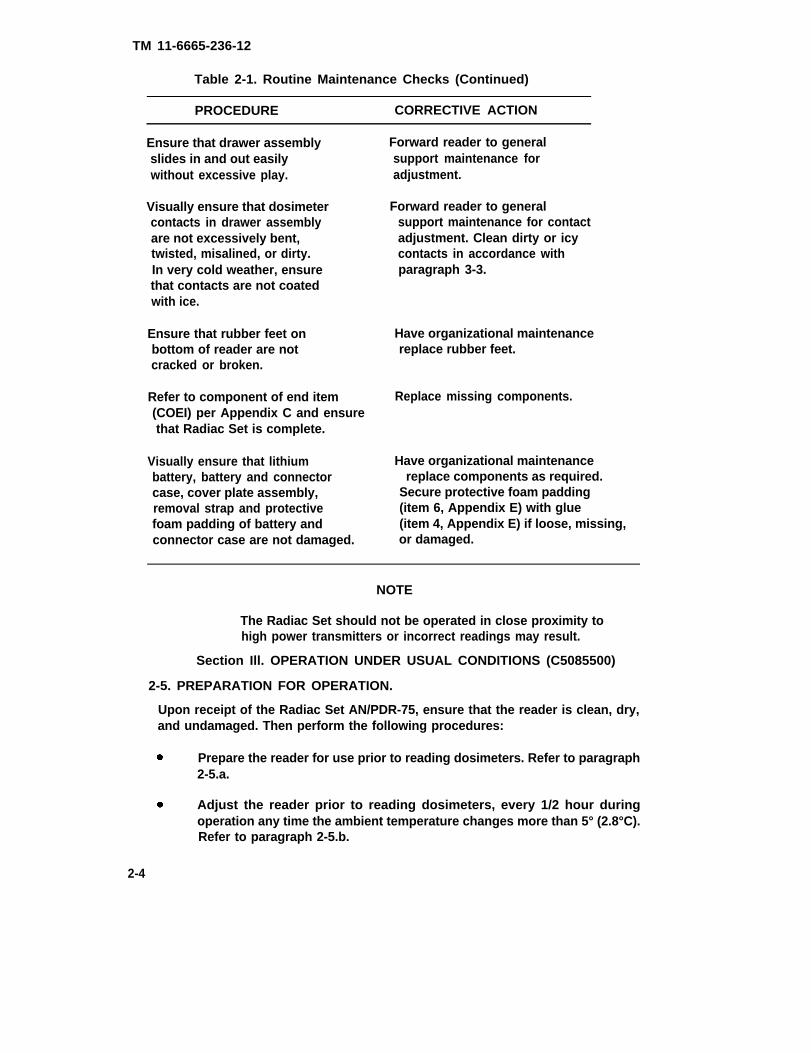
Table 2-1. Routine Maintenance Checks (Continued)
PROCEDURE CORRECTIVE ACTION
Ensure that drawer assemblyslides in and out easilywithout excessive play.
Visually ensure that dosimetercontacts in drawer assemblyare not excessively bent,twisted, misalined, or dirty.In very cold weather, ensurethat contacts are not coatedwith ice.
Ensure that rubber feet onbottom of reader are notcracked or broken.
Refer to component of end item(COEI) per Appendix C and ensurethat Radiac Set is complete.
Visually ensure that lithiumbattery, battery and connectorcase, cover plate assembly,removal strap and protectivefoam padding of battery andconnector case are not damaged.
Forward reader to generalsupport maintenance foradjustment.
Forward reader to generalsupport maintenance for contactadjustment. Clean dirty or icycontacts in accordance withparagraph 3-3.
Have organizational maintenancereplace rubber feet.
Replace missing components.
Have organizational maintenancereplace components as required.
Secure protective foam padding(item 6, Appendix E) with glue(item 4, Appendix E) if loose, missing,or damaged.
NOTE
The Radiac Set should not be operated in close proximity tohigh power transmitters or incorrect readings may result.
Section Ill. OPERATION UNDER USUAL CONDITIONS (C5085500)
2-5. PREPARATION FOR OPERATION.
Upon receipt of the Radiac Set AN/PDR-75, ensure that the reader is clean, dry,and undamaged. Then perform the following procedures:
Prepare the reader for use prior to reading dosimeters. Refer to paragraph2-5.a.
Adjust the reader prior to reading dosimeters, every 1/2 hour duringoperation any time the ambient temperature changes more than 5° (2.8°C).Refer to paragraph 2-5.b.
2-4

TM 11-6665-236-12
a. Preparation for Use.
NOTES
Refer to Table 3-1 if any of the following steps cannot beperformed as described.
Perform steps 1 through 12, below, only if reader is installedin carrying case. Otherwise, proceed to step 13.
Set carrying case on end opposite front cover flap.
2. Unfasten two straps (1) on front cover of carrying case by pressing sides ofbuckle release (2). Open case by lifting front cover flap (3).
2-5

TM 11-6665-236-12
3. Stand on side of carrying case opposite front cover hinge (4) and place bothfeet in carrying case handles (5) on either side of case. Standing onhandles will keep case stationary as reader is withdrawn.
4. Grasp reader removal strap (6) with one hand and grasp reader at edgenear front panel assembly with other hand.
2-6
TM 11-6665-236-12
CAUTION
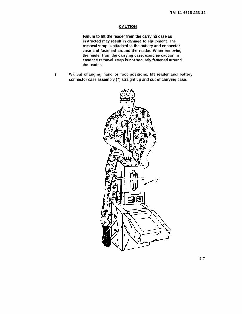
5.
Failure to lift the reader from the carrying case asinstructed may result in damage to equipment. Theremoval strap is attached to the battery and connectorcase and fastened around the reader. When removingthe reader from the carrying case, exercise caution incase the removal strap is not securely fastened aroundthe reader.
Without changing hand or foot positions, lift reader and batteryconnector case assembly (7) straight up and out of carrying case.
2-7

TM 11-6665-236-12
6. Set reader and battery and connector case assembly on work surface insame position as when removed from case (front panel facing up).
7. Unfasten removal strap (8) and remove strap from reader.
8. Grasp carrying strap (9) with one hand. Support reader at top front cornerwith other hand.
9. Tip reader and battery and connector case assembly and carefully loweruntil reader rests in normal operating position. Separate reader from batteryand connector case assembly.
2-8

TM 11-6665-236-12
10. Release captive screw (10) at center of cover plate assembly (11). Removecover plate assembly from battery and connector case (12).
11. Remove power cables (13, 14 and 21) from battery and connector case.Remove lithium battery (15) from battery and connector case, if it will beused.
12. Select appropriate power cable. Set aside other power cables, battery andconnector case, cover plate assembly, and lithium battery (if not used).
NOTE
Whenever possible, the reader should be operated out of the carryingcase.
Should it be necessary to operate the reader in the carrying case, connect theappropriate power cable as indicated in steps 13 and 14, then reassemble thebattery and connector case and the cover plate assembly. Be sure to install thelithium battery and the unused power cables, if provided, in the battery andconnector case prior to reassembly. Ensure that the cables are routed betweenfoam blocks on the cover plate assembly.
When using the battery cable for reader operation in the carrying case, the cablemust be routed from plug PLA through the battery and connector case to thelithium battery.
When using the vehicle cable for reader operation in the carrying case, the cablemust be routed from plug PLA through the battery and connector case, thenthrough the hole in the cover plate assembly, and finally through the hole in therear of the carrying case.
When using the power supply cable, the cable must be routed from plug PLAthrough the battery and connector case, then through the hole in the cover plateassembly, and finally through the hole in the rear of the carrying case.
Install the reader and the battery and connector case assembly, as a unit, in thecarrying case.
2-9

TM 11-6665-236-12
13. Remove cap (8) from PLA plug (9) on the rear panel.
NOTE
The reader operates from a power supply of either polarity.When connecting power cables to the reader plug PLA, itis not necessary to determine power supply polarity.
14. Connect the appropriate power cable to plug PLA (9) and then to the lithiumbattery (item 1, Appendix E), or vehicle power supply (24 V dc nominal), orchemical agent automatic alarm (M10A1) power supply.
15. Turn DISPLAY (10) control on the front panel fully clockwise. Turn LAMP(11) control fully counterclockwise.
16. Set selector switch (12) on front panel to SUPPLY position.
17. Press and release DEPRESS FOR READING switch (13) on front paneland ensure that reading on DPM (14) is between 200 and 300 and thatDPM display remains lit for approximately 2 to 4 seconds.
18. Press and release DEPRESS FOR READING switch (13) again and adjustDISPLAY control (10) until DPM display brightness is satisfactory.
19. Loosen screw (15) one half turn and raise block (16).
2-10
TM 11-6665-236-12
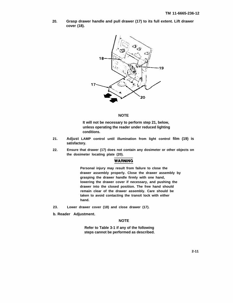
20. Grasp drawer handle and pull drawer (17) to its full extent. Lift drawercover (18).
NOTE
It will not be necessary to perform step 21, below,unless operating the reader under reduced lightingconditions.
21. Adjust LAMP control until illumination from light control film (19) issatisfactory.
22. Ensure that drawer (17) does not contain any dosimeter or other objects onthe dosimeter locating plate (20).
Personal injury may result from failure to close thedrawer assembly properly. Close the drawer assembly bygrasping the drawer handle firmly with one hand,lowering the drawer cover if necessary, and pushing thedrawer into the closed position. The free hand shouldremain clear of the drawer assembly. Care should betaken to avoid contacting the transit lock with eitherhand.
23. Lower drawer cover (18) and close drawer (17).
b. Reader Adjustment.
NOTE
Refer to Table 3-1 if any of the followingsteps cannot be performed as described.
2-11
TM 11-6665-236-12
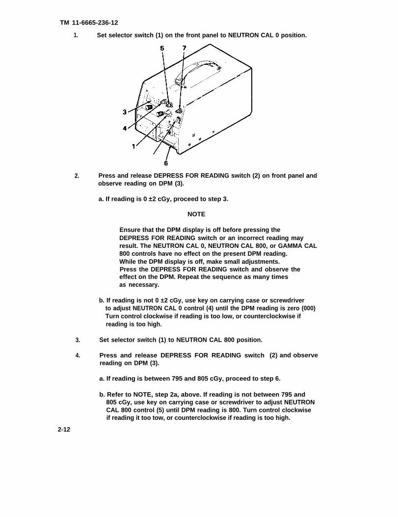
1. Set selector switch (1) on the front panel to NEUTRON CAL 0 position.
2. Press and release DEPRESS FOR READING switch (2) on front panel andobserve reading on DPM (3).
a. If reading is 0 ±2 cGy, proceed to step 3.
NOTE
Ensure that the DPM display is off before pressing theDEPRESS FOR READING switch or an incorrect reading mayresult. The NEUTRON CAL 0, NEUTRON CAL 800, or GAMMA CAL800 controls have no effect on the present DPM reading.While the DPM display is off, make small adjustments.Press the DEPRESS FOR READING switch and observe theeffect on the DPM. Repeat the sequence as many timesas necessary.
b. If reading is not 0 ±2 cGy, use key on carrying case or screwdriverto adjust NEUTRON CAL 0 control (4) until the DPM reading is zero (000)Turn control clockwise if reading is too low, or counterclockwise ifreading is too high.
3. Set selector switch (1) to NEUTRON CAL 800 position.
4. Press and release DEPRESS FOR READING switchreading on DPM (3).
(2) and observe
a. If reading is between 795 and 805 cGy, proceed to step 6.
b. Refer to NOTE, step 2a, above. If reading is not between 795 and805 cGy, use key on carrying case or screwdriver to adjust NEUTRONCAL 800 control (5) until DPM reading is 800. Turn control clockwiseif reading it too tow, or counterclockwise if reading is too high.
2-12
TM 11-6665-236-12
NOTE
Perform step 5 only if the NEUTRON CAL 800control was adjusted during step 4.
5. Repeat steps 1 through 4.
6. Set selector switch (1) to GAMMA
NOTE
CAL 800 position.
During the following procedure, ensure that thedrawer assembly is pulled out of the reader asfar as it will go. Do not touch or apply anypressure to the drawer assembly during thisprocedure or inaccurate readings may result.
7. Pull out drawer (6) to its full extent.
Ultraviolet light may cause severe and permanentdamage to the eyes. Operate the DEPRESS FORREADING switch only when the drawer assembly isin the fully open or closed position or exposureto ultraviolet light may result.
8. Press and release DEPRESS FOR READING switch (2) and observereading on DPM (3).
a. If reading is between 785 and 815 cGy, record reading andproceed to step 9.
b. Refer to NOTE, step 2a. If reading is not between 785 and 815 cGy,use key on carrying case or screwdriver to adjust GAMMA CAL 800control (7) until DPM reading is between 785 and 815 cGy. Turncontrol clockwise if reading is too few, or counterclockwise if reading is toohigh. Record final reading.
9. Press and release DEPRESS FOR READING switch (2) four more times,observing and recording reading on DPM (3) each time.
a. If the readings taken in steps 8 and 9 were all between 785 and815 cGy, proceed to step 10.
b. If the readings taken in steps 8 and 9 were not all between 785and 815 cGy, readjust GAMMA CAL 800 control as in step 8, above.Repeat steps 8 and 9 until all readings are within range.
2-13

TM 11-6665-236-12
WARNING
Personal injury may result from failure to close thedrawer assembly properly. Close the drawer assembly bygrasping the drawer handle firmly with one hand,lowering the drawer cover if necessary, and pushing thedrawer into the closed position. The free hand shouldremain clear of the drawer assembly. Do not touch thetransit lock with either hand when closing the drawerassembly.
10. Close drawer.
2.6. OPERATION
Prior to reading dosimeters, ensure that the reader has been prepared inaccordance with paragraph 2-5. Then perform the following procedures:
Read dosimeters in accordance with paragraph 2-6.a, below.
Perform post operational procedures in accordance withparagraph 2-6.b, below.
a. Reading Dosimeters.
NOTES
Refer to Table 3-1 if any of the following steps cannotbe performed as described.
Perform reader adjustment in accordance with paragraph 2-5.bevery 1/2 hour or when the ambient temperature changes morethan 5°F (2.8°C).
Ensure that dosimeters and reader are at the same temperature.If dosimeters have been transported recently from a differentenvironment, allow at least 10 minutes for temperaturestabilization prior to reading.
Ensure that dosimeters are clean, dry, and undamaged prior toreading.
1. Set selector switch (1) on front panel to READ position andensure that the indicator light (2) comes on.
2-14
TM 11-6665-236-12
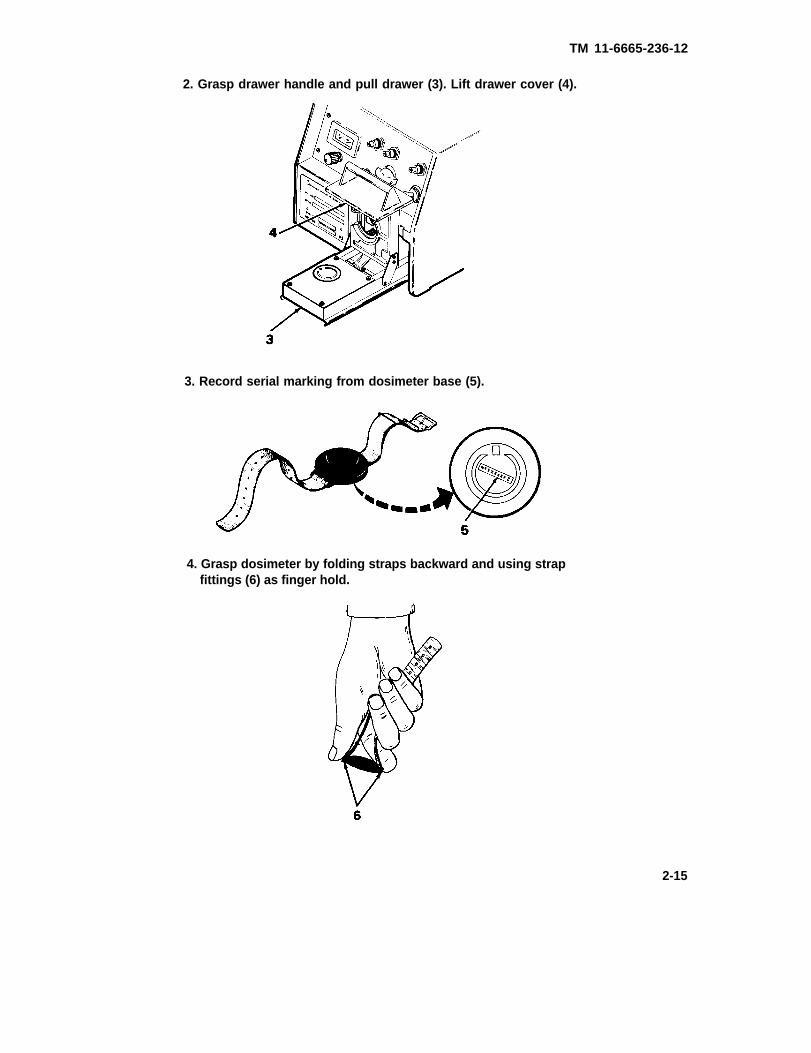
2. Grasp drawer handle and pull drawer (3). Lift drawer cover (4).
3. Record serial marking from dosimeter base (5).
4. Grasp dosimeter by folding straps backward and using strapfittings (6) as finger hold.
2-15

TM 11-6665-236-12
NOTE
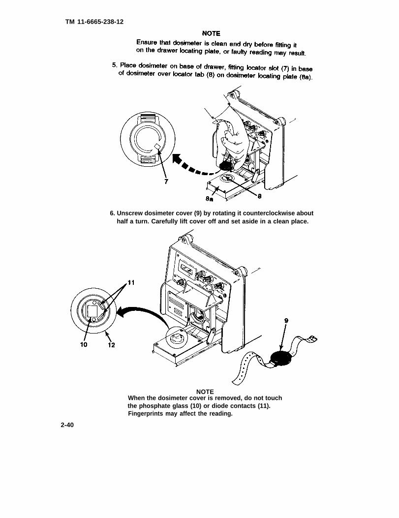
Ensure that dosimeter is clean and dry before fitting iton the drawer locating plate, or faulty reading may result
5. Place dosimeter on base of drawer, fitting locator slot (7) in baseof dosimeter over locator tab (8) on dosimeter locating plate (8a).
6. Unscrew dosimeter cover (9) by rotating it counterclockwise abouthalf a turn. Carefully Iift cover off and set aside in a clean place.
NOTE
When the dosimeter cover is removed, do not touchthe phosphate glass (10) or diode contacts (11).Fingerprints may affect the reading.
2-16
TM 11-6665-236-12
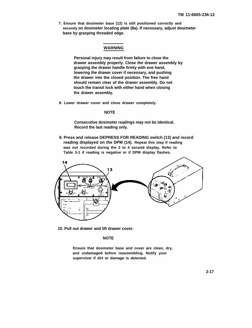
7. Ensure that dosimeter base (12) is still positioned correctly andsecurely on dosimeter locating plate (8a). If necessary, adjust dosimeterbase by grasping threaded edge.
WARNING
Personal injury may result from failure to close thedrawer assembly properly. Close the drawer assembly bygrasping the drawer handle firmly with one hand,lowering the drawer cover if necessary, and pushingthe drawer into the closed position. The free handshould remain clear of the drawer assembly. Do nottouch the transit lock with either hand when closingthe drawer assembly.
8. Lower drawer cover and close drawer completely.
NOTE
Consecutive dosimeter readings may not be identical.Record the last reading only.
9. Press and release DEPRESS FOR READING switch (13) and recordreading displayed on the DPM (14). Repeat this step if readingwas not recorded during the 2 to 4 second display. Refer toTable 3-1 if reading is negative or if DPM display flashes.
10. Pull out drawer and lift drawer cover.
NOTE
Ensure that dosimeter base and cover are clean, dry,and undamaged before reassembling. Notify yoursupervisor if dirt or damage is detected.
2-17

TM 11-6665-236-12
11. With straps folded backward and using strap fittings as finger holds, immediately screw dosimeter cover clockwise onto dosimeter base, applyingsome downward pressure. Tighten cover by rotating it approximately oneeighth of a turn past the point at which resistance is felt from the sealingring.
12. Remove dosimeter from base of drawer.
13. Repeat steps 3 through 12 for all dosimeters to be read. When fast readinghas been taken, proceed to paragraph 2-6.b, below.
b. Post-Operational Procedure
1. Ensure that final dosimeter has been removed from base of drawer.
WARNING
Personal injury may result from failure to close thedrawer assembly properly. Close the drawer assembly bygrasping the drawer handle firmly with one hand,lowering the drawer cover if necessary, and pushing thedrawer into the closed position. The free hand shouldremain clear of the drawer assembly. Do not touch thedrawer closing block with either hand when closing thedrawer assembly.
2. Lower drawer cover and close drawer.
3. Lower drawer closing block (1), and tighten screw (2) as necessary to holddrawer in closed position.
4. Set selector switch (3) to OFF position.
2-18
TM 11-6665-236-12
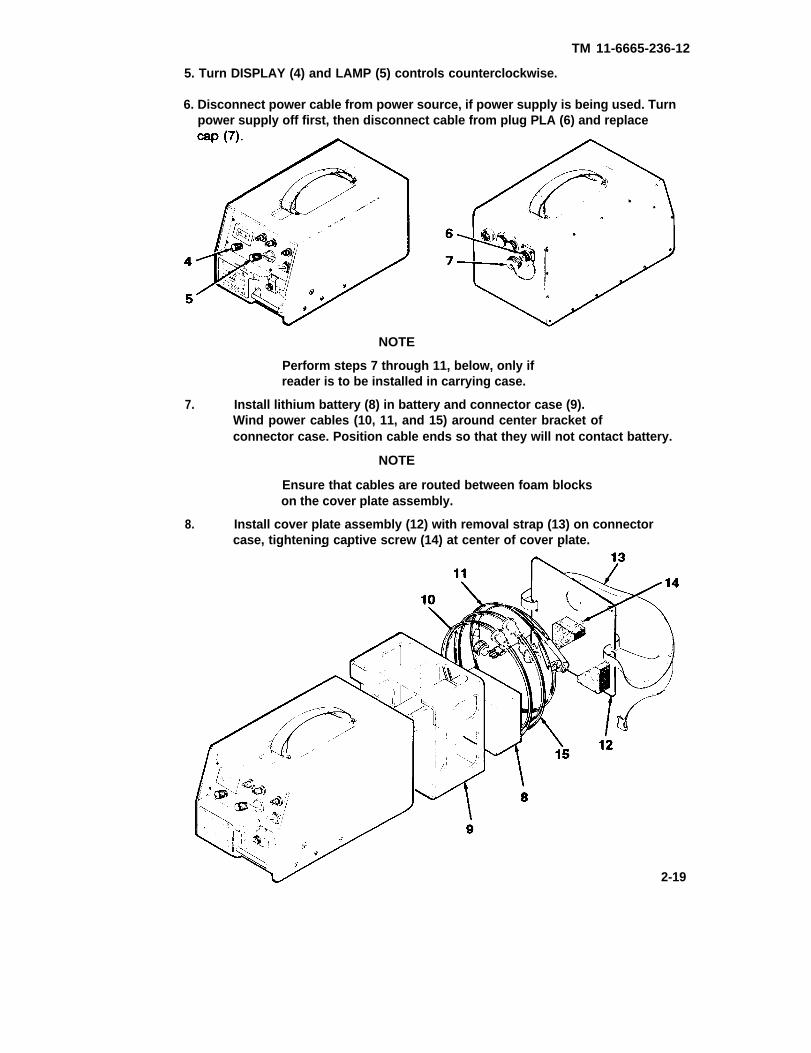
5. Turn DISPLAY (4) and LAMP (5) controls counterclockwise.
6. Disconnect power cable from power source, if power supply is being used. Turnpower supply off first, then disconnect cable from plug PLA (6) and replace
NOTE
Perform steps 7 through 11, below, only ifreader is to be installed in carrying case.
7. Install lithium battery (8) in battery and connector case (9).Wind power cables (10, 11, and 15) around center bracket ofconnector case. Position cable ends so that they will not contact battery.
NOTE
Ensure that cables are routed between foam blockson the cover plate assembly.
8. Install cover plate assembly (12) with removal strap (13) on connectorcase, tightening captive screw (14) at center of cover plate.
2-19
TM 11-6665-236-12
9. Position battery and connector case and cover plate assembly on readerand position removal strap around reader. Ensure that free ends of shorterstrap are securely fastened together at bottom of reader.
Failure to install the reader in the carrying case asinstructed may result in damage to equipment. When thereader is Iifted by the removal strap, it may fall fromthe battery and connector case unless the strap iscorrectly positioned and securely fastened.
CAUTION
Prior to placing the reader in the carrying case, ensurethat the key is placed securely under the Velcro flap ofthe carrying case or damage to the reader finish mayresult.
10. Set carrying case (16) on end opposite front cover flap (17) and open flap.Grasp removal strap (18) with one hand and grasp reader at edge near frontpanel assembly with other hand. Lift reader and carefully lower it intocarrying case.
2-20

TM 11-6665-236-12
2-21
TM 11-6665-236-12
2-22

TM 11-6665-236-12
Section IV. OPERATION UNDER UNUSUAL CONDITIONS (C5085500)
2-7. OPERATING PRECAUTIONS FOR UNUSUAL WEATHER.
Radiac Set AN/PDR-75 operates normally under the following environmentalconditions
● Storage temperature between -70 and +160°F (-57 to +71°C).
● Operating temperatures between -26 and +125°F (-32 to +52°C).
● Humidity between 0 and 100 percent.
Do not remove reader from carrying case for operation in rain, salt air, seaspray, duststorms, sandstorms, snow, or mud. During operation in rain orsnow, ensure that drawer assembly is protected from precipitation when itis in the open position. The carrying case front flap can be used to shieldthe reader from precipitation. If contaminated water (rain water, salt water,etc.) enters drawer assembly, flush out with fresh water and dry completely.Dosimeters must also be protected from precipitation. At low temperatures,ensure that ice does not remain on dosimeter contacts. Clean contactsbefore use in accordance with paragraph 3-3. Ensure that dosimeter andreader are at the same temperature. Adjust the reader frequently duringoperation in changing conditions, in accordance with paragraph 2-5.b. Afteroperation in unusual weather, ensure that radiac set passes routine checksdescribed in paragraph 2-4.
2-8. EMERGENCY PROCEDURES
If power to the reader fails, set selector switch on front panel to OFFposition and apply 21 to 30 V DC vehicle, battery, chemical agent automaticalarm (M10A1) power supply, or portable power supply as applicable.Prepare reader for operation in accordance with paragraph 2-5. Continuereading dosimeters in accordance with paragraph 2-6.
2-23

TM 11-6665-236-12
2-24

PART FOUR
CHAPTER 2
OPERATING INSTRUCTIONS (A3250780)
TM 11-6665-236-12
Paragraph Page
Emergency Procedures . . . . . . . . . . . . . . . . . . . . . . . . . . . . . ...2-45Front Panel . . . . . . . . . . . . . . . . . . . . . . . . . . . . . . . . . . . . . . ...2-25Operating Precautions for Unusual Weather . . . . . . . . . . . . . . . . . 2-45Operation . . . . . . . . . . . . . . . . . . . . . . . . . . . . . . . . . . . . . . . ...2-37Preparation for Operation . . . . . . . . . . . . . . . . . . . . . . . . . . . . . ..2-28Preventive Maintenance . . . . . . . . . . . . . . . . . . . . . . . . . . . . . . ..2-26Rear Panel . . . . . . . . . . . . . . . . . . . . . . . . . . . . . . . . . . . . . . . ..2-26Routine Checks . . . . . . . . . . . . . . . . . . . . . . . . . . . . . . . . . . ...2-27
Section l. DESCRIPTION AND USE OF OPERATOR’S CONTROLSAND INDICATORS (A3250780)
2-1.1 FRONT PANEL
DIGITAL PANEL METER (1) -Displays total dose of radiation in cGyunits when the selector switch is set to READ, shows reader’s supplyvoltage when the selector switch is set to SUPPLY, and verifies readercalibration when the selector switch is set to NEUTRON CAL 0, NEUTRONCAL 800, or GAMMA CAL 800.
DISPLAY CONTROL (2) - Varies brightness of digital panel meter display.
LAMP CONTROL (3) - Varies brightness of lamp in the drawer assembly.
NEUTRON CAL 0 CONTROL (4) - Sets neutron channel zero duringoperational checks and adjustments.
NEUTRON CAL 800 CONTROL (5) - Sets neutron channel sensitivityduring operational checks and adjustments.
GAMMA CAL 800 CONTROL (6) - Sets gamma channel sensitivity duringoperational checks and adjustments.
SELECTOR SWITCH (7) - Sets operational mode of the reader to OFF,SUPPLY, NEUTRON CAL 0, NEUTRON CAL 800, GAMMA CAL 800, orREAD.
READ LIGHT (8) - Lights when selector switch is set to READ and indicatesnormal operating condition.
DEPRESS FOR READING SWITCH (9) - Starts the reading cycle.
DRAWER CLOSING BLOCK (10) - Secures drawer assembly in closedposition.
DRAWER HANDLE (11) - Used to open and close drawer assembly.2-25
TM 11-6665-236-12
2-2.1 REAR PANEL
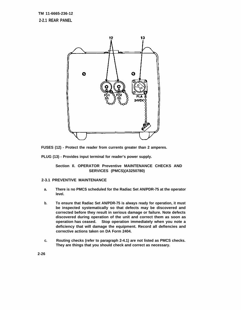
FUSES (12) - Protect the reader from currents greater than 2 amperes.
PLUG (13) - Provides input terminal for reader’s power supply.
Section Il. OPERATOR Preventive MAINTENANCE CHECKS ANDSERVICES (PMCS)(A3250780)
2-3.1 PREVENTIVE MAINTENANCE
a. There is no PMCS scheduled for the Radiac Set AN/PDR-75 at the operatorlevel.
b. To ensure that Radiac Set AN/PDR-75 is always ready for operation, it mustbe inspected systematically so that defects may be discovered andcorrected before they result in serious damage or failure. Note defectsdiscovered during operation of the unit and correct them as soon asoperation has ceased. Stop operation immediately when you note adeficiency that will damage the equipment. Record all defiencies andcorrective actions taken on DA Form 2404.
c. Routing checks (refer to paragraph 2-4.1) are not listed as PMCS checks.They are things that you should check and correct as necessary.
2-26

TM 11-6665-236-12
2-4.1 ROUTINE CHECKS
The operator should perform the checks listed in Table 2-1.1 as needed.Correct any deficiencies immediately.
Table 2-1.1. Routine Maintenance Checks
PROCEDURE CORRECTIVE ACTION
Check for cut, frayed, ordirty cables.
Ensure that knobs, plug cap,and drawer transit lock andscrew are not bent or broken.
Ensure that carrying strapis not frayed or broken.
Ensure that items not in useare properly stowed.
Check the carrying case forholes, rips, dirt, andgrease.
Check for corrosion or badlydamaged paint on readercase and drawer assembly.
Check front panel controls forproper operation.
Check for loose or missingscrews in case.
Ensure that DPM glass is notcracked or broken.
Forward cut or frayed cables toorganizational maintenance.
Clean dirty cables in accordance withparagraph 3-3.1
Have organizational maintenancereplace bent or broken components.
Have organizational maintenancereplace frayed or broken carryingstrap.
Stow items properly.
Have organizational maintenancereplace torn or ripped carryingcase. Clean dirty carrying casein accordance with paragraph 3-3.1.
Forward corroded or damagedreader to general supportmaintenance.
Have orgranizational maintenancereplace faulty components.
Have organizaitonal maintenancetighten or replace screws.
Forward reader to generalsupport maintenance.
2-27
TM 11-6665-236-12
Table 2-1.1. Routine Maintenance Checks (Continued)
PROCEDURE CORRECTIVE ACTION
Ensure that drawer assemblyslides in and out easilywithout excessive play.
Visually ensure that dosimetercontacts in drawer assemblyare not excessively bent,twisted, misaligned, or dirty.In very cold weather, ensurethat contacts are not coatedwith ice.
Ensure that rubber feet onbottom of reader are notcracked or broken.
Refer to components of end item(COEI) per Appendix C and ensurethat Radiac Set is complete.
Visually ensure that the carryingcase complete assembly, lithiumbattery, and 3 cables are notdamaged.
Forward reader to generalsupport maintenance foradjustment.
Forward reader to generalsupport maintenance for contactadjustment. Clean dirty or icycontacts in accordance withparagraph 3-3.1.
Have organizational maintenancereplace rubber feet.
Replace missing components.
Have organizational maintenancereplace components as required.
NOTE
The radiac set should not be operated in close proximity tohigh power transmitters or incorrect readings may result.
Section Ill. OPERATION UNDER USUAL CONDITIONS (A3250780)
2-5.1 PREPARATION FOR OPERATION.
Upon receipt of the Radiac Set AN/PDR-75, ensure that the reader is clean, dry,and undamaged. Then perform the following procedures:
● Prepare the reader for use prior to reading dosimeters. Refer to paragraph2-5.1a.
● Adjust the reader prior to reading dosimeters, every 1/2 hour duringoperation any time the ambient temperature changes more than 5° (2.8°C).Refer to paragraph 2-5.1 b.
2-28

TM 11-6665-236-12
a.
●
●
1.
2.
Preperation for Use.
NOTES
Refer to Table 3-1.1 if any of the following steps cannot beperformed as described.
Perform steps 1 through 7, below, only if reader is installedin carrying case. Otherwise, proceed to step 8.
Set carrying case on end opposite front cover flap.
Unfasten two straps (1) on front cover of carrying case by pressing sides ofbuckle release (2). Open case by lifting front cover flap (3).
2-29

TM 11-6665-236-12
3. Stand on side of carrying case opposite front cover hinge (4) and place bothfeet in carrying ease handles (5) on either side of case. Standing onhandles will keep case stationary as reader is withdrawn.
4. Grasp drawer handle (6) and protective side flange (7) on front panel faceof reader.
2-30

TM 11-6665-236-12
2-31

TM 11-6665-236-12
6. Remove Carrying Case Base (14),battery (18) out of Carrying Case.
cables (15, 16 and 17) and lithium
7. Select appropriate power cable. Set aside other power cables, carryingcase base, and Iithium battery.
NOTES
● Whenever possible, the reader should be operatedout of the carrying case.
● If lithium battery is to be used to power thereader in the carrying case, route battery cablefrom reader through the carrying case base (14) tothe battery (18). Reassemble all parts and readerinto the carrying case. See 7a, b, c, d and e, nextpage, for more detail.
● If either a power supply or vehicle power is to beused to power the reader in the carrying case, routethe appropriate cable through the carrying case base(14) and out the bottom flap in the carrying case.Reassemble all parts and reader into the carrying case.
2-32

TM 11-6665-236-12
a. Connect battery cable (9) to lithium battery (10) in the carrying case (11).
b. Connect opposite end of battery cable (9) to reader (12) (Power Off) afterfeeding cable thru carrying case base (13).
c. Reinstall carrying case base (13) in carrying case (11).
d. Open rear flap and install reader (12) while pulling excess cable thru therear flap.
e. Tuck the excess cable back thru rear flap and close.
2-33
TM 11-6665-236-12
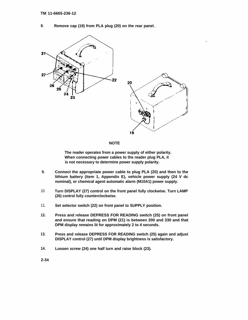
8. Remove cap (19) from PLA plug (20) on the rear panel.
NOTE
The reader operates from a power supply of either polarity.When connecting power cables to the reader plug PLA, itis not necessary to determine power supply polarity.
9. Connect the appropriate power cable to plug PLA (20) and then to thelithium battery (item 1, Appendix E), vehicle power supply (24 V dcnominal), or chemical agent automatic alarm (M10A1) power supply.
10. Turn DISPLAY (27) control on the front panel fully clockwise. Turn LAMP(26) control fully counterclockwise.
11. Set selector switch (22) on front panel to SUPPLY position.
12. Press and release DEPRESS FOR READING switch (25) on front paneland ensure that reading on DPM (21) is between 200 and 330 and thatDPM display remains lit for approximately 2 to 4 seconds.
13. Press and release DEPRESS FOR READING switch (25) again and adjustDISPLAY control (27) until DPM display brightness is satisfactory.
14. Loosen screw (24) one half turn and raise block (23).
2-34

TM 11-6665-236-12
15. Grasp drawer handle and pull drawer (31) to its full extent. Lift drawercover (28).
It will not be necessary to perform step 16, below,unless operating the reader under reduced lightingconditions.
16. Adjust LAMP control until illumination from light control film (29) issatisfactory.
17. Ensure that drawer (31) does not contain any dosimeter or other objects onthe dosimeter locating plate (30).
WARNING
Personal injury may result from failure to close thedrawer assembly property. Close the drawer assembly bygrasping the drawer handle firmly with one hand,lowering the drawer cover if necessary, and pushing thedrawer into the closed position. The free hand shouldremain clear of the drawer assembly. Care should betaken to avoid contacting the drawer closing block witheither hand.
18. Lower drawer cover (28) and close drawer (31).
b. Reader Adjustment.
NOTE
Refer to Table 3-1.1 if any of the followingsteps cannot be performed as described.
2-35

TM 11-6666-236-12
1. Set selector switch (1) on the front panel to NEUTRON CAL 0 position.
2. Press and release DEPRESSobserve reading on DPM (3).
FOR READING switch (2) on front panel and
a. If reading is 0 ±2 cGy, proceed to step 3.
NOTE
Ensure that the DPM display is off before pressing theDEPRESS FOR READING switch or an incorrect reading mayresult. The NEUTRON CAL 0, NEUTRON CAL 800, or GAMMA CAL800 controls have no effect on the present DPM reading.While the DPM display is off, make small adjustments.Press the DEPRESS FOR READING switch and observe theeffect on the DPM. Repeat the sequence as many timesas necessary.
b. If reading is not 0 ±2 cGy, adjust NEUTRON CAL 0 control (4) until theDPM reading is zero (000). Turn control clockwise if reading is too few,or counterclockwise if reading is too high.
3. Set selector switch (1) to NEUTRON CAL 800 position.
4. Press and release DEPRESS FOR READING switch (2) and observereading on DPM (3).
a. If reading is between 795 and 805 cGy, proceed to step 6.
b. Refer to NOTE, step 2a, above. If reading is not between 795 and805 cGy, adjust NEUTRON CAL 800 control (5) until DPM reading is800. Turn control clockwise if reading it too low, or counterclockwise ifreading is too high.
2-36

TM 11-6665-236-12
NOTE
Perform step 5 only if the NEUTRON CAL 800control was adjusted during step 4.
5. Repeat steps 1 through 4.
6. Set selector switch (1) to GAMMA CAL 800 position.
NOTE
During the following procedure, ensure that thedrawer assembly is pulled out of the reader asfar as it will go. Do not touch or apply anypressure to the drawer assembly during thisprocedure or inaccurate readings may result.
7. Pull out drawer (6) to its full extent.
WARNING
Ultraviolet light may cause severe and permanentdamage to the eyes. Operate the DEPRESS FORREADING switch only when the drawer assembly isin the fully open or closed position or exposureto ultraviolet light may result.
8. Press and release DEPRESS FOR READING switch (2) and observereading on DPM (3).
a. If reading is between 785 and 815 cGy, record reading andproceed to step 9.
b. Refer to NOTE, step 2a. If reading is not between 785 and 815 cGy,adjust GAMMA CAL 800 control (7) until DPM reading is between 785 and815 cGy. Turn control clockwise if reading is too few, or counterclockwiseif reading is too high. Record final reading.
9. Press and release DEPRESS FOR READING switch (2) four more times,observing and recording reading on DPM (3) each time.
a. If the readings taken in steps 8 and 9 were all between 785 and815 cGy, proceed to step 10.
b. If the readings taken in steps 8 and 9 were not all between 785and 815 cGy, readjust GAMMA CAL 800 control as in step 8, above.Repeat steps 8 and 9 until all readings are within range.
2-37

TM 11-6665-236-12
WARNING
Personal injury may result from failure to close thedrawer assembly properly. Close the drawer assembly bygrasping the drawer handle firmly with one hand,lowering the drawer cover if necessary, and pushing thedrawer into the closed position. The free hand shouldremain clear of the drawer assembly. Do not touch thetransit lock with either hand when closing the drawerassembly.
10. Close drawer.
2.6.1 OPERATION (A3197293)
Prior to reading dosimeters, ensure that the reader has been prepared inaccordance with paragraph 2-5.1. Then perform the following procedures:
● Read dosimeters in accordance with paragraph 2-6.1a, below.
● Perform post operational procedures in accordance withparagraph 2-6.1 b.
a. Reading Dosimeters.
NOTES
● Refer to Table 3-1.1 if any of the following steps cannotbe performed as described.
● Perform reader adjustment in accordance with paragraph 2-5.1bevery 1/2 hour or when the ambient temperature changes morethan 5°F (2.8°C).
● Ensure that dosimeters and reader are at the same temperature.If dosimeters have been transported recently from a differentenvironment, allow at least 10 minutes for temperaturestabilization prior to reading.
● Ensure that dosimeters are clean, dry, and undamaged prior toreading.
1. Set selector switch (1) on front panel to READ position andensure that the indicator light (2) comes on.
2-38

TM 11-6665-236-12
2. Grasp drawer handle and pull drawer (3). Lift drawer cover (4).
3. Record serial marking from dosimeter base (5).
4. Grasp dosimeter by folding straps backward and using strapfitings (6) as finger hold.
2-39
TM 11-6665-238-12
6. Unscrew dosimeter cover (9) by rotating it counterclockwise abouthalf a turn. Carefully lift cover off and set aside in a clean place.
NOTEWhen the dosimeter cover is removed, do not touchthe phosphate glass (10) or diode contacts (11).Fingerprints may affect the reading.
2-40

TM 11-6865-236-12
7. Ensure that dosimeter base (12) is still positioned correctly andsecurely on dosimeter locating plate (8a). If necessary, adjust dosimeterbase by grasping threaded edge.
WARNING
Personal injury may result from failure to close thedrawer assembly property. Close the drawer assembly bygrasping the drawer handle firmly with one hand,lowering the drawer cover if necessary, and pushingthe drawer into the closed position. The free handshould remain clear of the drawer assembly. Do nottouch the transit lock with either hand when closingthe drawer assembly.
8. Lower drawer cover and close drawer completely.
NOTE
Consecutive dosimeter readings may not be identical.Record the last reading only.
9. Press and release DEPRESS FOR READING switch (13) and recordreading displayed on the DPM (14). Repeat this step if readingwas not recorded during the 2 to 4 second display. Refer toTable 3-1.1 if reading is negative or if DPM display flashes.
10. Pull out drawer and lift drawer cover.
NOTE
Ensure that dosimeter base and cover are clean, dry,and undamaged before reassembling. Notify yoursupervisor if dirt or damage is detected.
2-41

TM 11-6665-236-12
11. With straps folded backward and using strap fittings as finger holds,immediately screw dosirneter cover clockwise onto dosimeter base,applying some downward pressure. Tighten cover by rotating itapproximately one eighth of a turn past the point at whichresistance is felt from the seating ring.
12. Remove dosimeter from base of drawer.
13. Repeat steps 3 through 12 for all dosimeters to be read. When lastreading has been taken, proceed to paragraph 2-6.1b, below.
b. Post-Operational Procedure
1. Ensure that final dosimeter has been removed from base of drawer.
WARNING
Personal injury may result from failure to close thedrawer assembly properly. Close the drawer assembly bygrasping the drawer handle firmly with one hand,lowering the drawer cover if necessary, and pushing thedrawer into the closed position. The free hand shouldremain clear of the drawer assembly. Do not touch thedrawer closing block with either hand when closing the drawerassembly to prevent injury to fingers.
3. Lower drawer closing block (1), and tighten screw (2) as necessary to holddrawer in closed position.
4. Set selector switch (3) to OFF position.
2-42

TM 11-6665-236-12
NOTE
Perform steps 7 through 9, only ifreader is to be installed in carrying case.
7. Place lithium battery (9) into recess at bottom of carrying case (10) as shown.Tightly coil 3 (three) power cables (11, 12 and 13) separately and store in bottomof carrying case (10). Position cable ends so that they will not contact battery,and damage cable ends.
8.
9.
VIEW OF CARRYING CASE12“ VELCRO STRAP WITH FLAP IN OPEN POSITION
(READER AND CARRYINGCASE BASE REMOVED)
Reinstall Carrying Case Base (8) onto 4 corner mounting blocks in CarryingCase (10).
Replace Reader into Carrying Case (10).2-43
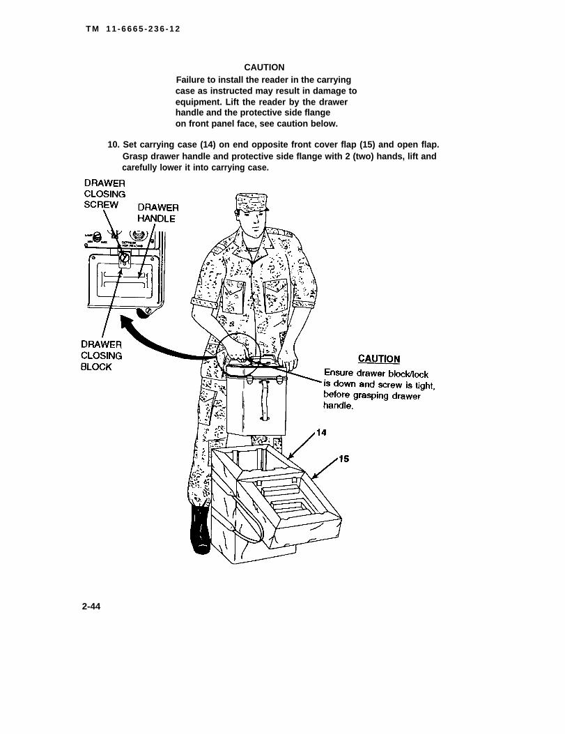
T M 1 1 - 6 6 6 5 - 2 3 6 - 1 2
CAUTIONFailure to install the reader in the carryingcase as instructed may result in damage toequipment. Lift the reader by the drawerhandle and the protective side flangeon front panel face, see caution below.
10. Set carrying case (14) on end opposite front cover flap (15) and open flap.Grasp drawer handle and protective side flange with 2 (two) hands, lift andcarefully lower it into carrying case.
2-44

TM 11-6665-236-12
2-45

TM 11-6665-236-12
Section IV. OPERATION UNDER UNUSUAL CONDITIONS (A3250780)
2-7.1 OPERATING PRECAUTIONS FOR UNUSUAL WEATHER.
Radiac Set AN/PDR-75 operates normally under the following environmentalconditions
● Storage temperature between -70 and +160°F (-57 to +71°C).
● Operating temperatures between -26 and +125°F (-32 to +52°C).
● Humidity between 0 and 100 percent.
Do not remove reader from carrying case for operation in rain, salt air, seaspray, duststorms, sandstorms, snow, or mud. During operation in rain orsnow, ensure that drawer assembly is protected from precipitation when itis in the open position. The carrying case front flap can be used to shieldthe reader from precipitation. If contaminated water (rain water, salt water,etc.) enters drawer assembly, flush out with fresh water and dry completely.Dosirneters must also be protected from precipitation. At low temperatures,ensure that ice does not remain on dosimeter contacts. Clean contactsbefore use in accordance with paragraph 3-3.1. Ensure that dosirneter andreader are at the same temperature. Adjust the reader frequently duringoperation in changing conditions, in accordance with paragraph 2-5.1b.After operation in unusual weather, ensure that radiac set passes routinechecks described in paragraph 2-4.1.
2-8.1 EMERGENCY PROCEDURES
If power to the reader fails, set selector switch on front panel to OFFposition and apply 21 to 30 V DC vehicle, battery, chemical agent automaticalarm (M10A1) power supply, or portable power supply as applicable.Prepare reader for operation in accordance with paragraph 2-5.1. Continuereading dosimeters in accordance with paragraph 2-6.1.
2-46
TM 11-6665-236-12PART FIVECHAPTER 3
OPERATOR MAINTENANCE (C5085500)
Section I. LUBRICATION INSTRUCTIONS (C5085500)
No lubrication is required for maintenance of the Radiac Set AN/PDR-75.
Section II. OPERATOR TROUBLESHOOTING PROCEDURES (C5085500)
3-1. GENERAL.
Table 3-1 fists the common malfunctions which you may find during the operationor maintenance of the Radiac Set AN/PDR-75 or its components. You shouldperform the tests or inspections and corrective actions in the order listed.
This manual cannot fist all malfunctions that may occur, nor all tests or inspectionsand corrective actions. If a rnalfunction is not listed or is not corrected by listedcorrective actions, notify your supervisor.
After performing CORRECTIVE ACTION, verify that the MALFUNCTION has beeneliminated.
3-2. TROUBLESHOOTING
Table 3-1. Operator Troubleshooting
MALFUNCTIONTEST OR INSPECTION
CORRECTIVE ACTION
1. DIGITAL PANEL METER DOES NOT LIGHT WHEN DEPRESS FORREADING SWITCH IS PRESSED.
Step 1.
Step 2.
Step 3.
Step 4.
Set selector switch to READ position and ensure that READ lightis on.
If READ fight is on, proceed to step 2. If READ fight is not on,proceed to step 3.
Press and release the DEPRESS FOR READING switch after thefollowing action and recheck the DPM.
Turn DISPLAY control fully counterclockwise and then fullyclockwise.
Press and release the DEPRESS FOR READING switch after eachof the following actions and recheck the DPM.
Set selector switch to OFF position. Ensure that power cable isconnected properly and that cable connectors are clean andtightened. Return selector switch to original position.
If battery is in use, set selector switch to OFF position. Replacebattery in accordance with paragraph 3-4. Return selector switchto original position.
If failure persists, notify organizational maintenance.
3-1

TM 11-6665-236-12
Table 3-1. Operator Troubleshootlng (Continued)
MALFUNCTIONTEST OR INSPECTION
CORRECTIVE ACTION
2.
3.
4.
DIGITAL PANEL METER READING IS NOT BETWEEN 200 AND 330WHEN SELECTOR SWITCH IS SET TO SUPPLY POSITION
Step 1. If DPM reading is above 330 or if DPM is flashing, perform all of thefollowing actions and then recheck the reading. If failure persists,notify organizational maintenance.
If applicable, set selector switch to OFF position and ensurethat vehicle power supply is rated at 21 to 30 V dc or thatportable power supply is set for 21 to 30 V dc.
Connect reader to battery or correct power supply (21 to 30V dc).
Step 2. If DPM reading is below 200, recheck the reading after each of thefollowing actions. If failure persists, notify organizationalmaintenance.
If applicable, set selector switch to OFF position and ensure that vehicle power supply is rated at 21 to 30 V dc or thatportable power supply is set for 21 to 30 V dc.
Set selector switch to OFF position. Ensure that powercable is connected properly and that cable connectors areclean and tightened. Return selector switch to SUPPLYposition.
If battery is in use, set selector switch to OFF position.Replace battery in accordance with paragraph 3-4. Returnselector switch to SUPPLY position.
DIGITAL PANEL METER READING DOES NOT LAST FOR 2 TO 4SECONDS.
Notify general support maintenance.
NO LIGHT EXISTS INSIDE DRAWER. BUT DIGITAL PANEL METERLIGHTS WHEN DEPRESS FOR READING SWITCH IS PRESSED.
Step 1. Perform the following action and recheck the light.
Turn LAMP control fully counterclockwise and then fullyclockwise.
Step 2. If failure persists, notify general support maintenance.3-2

TM 11-6665-236-12
Table 3-1. Operator Troubleshooting (Continued)
MALFUNCTIONTEST OR INSPECTION
CORRECTIVE ACTION
5. PROPER DIGITAL PANEL METER READINGS CANNOT BE OBTAINEDDURING READER ADJUSTMENT
Step 1. Perform the following action and try the adjustment again.
Set selector switch to SUPPLY position and ensure thatDPM reading is between 200 and 330. If DPM reading isnot between 200 and 330, refer to MALFUNCTION 2.
Step 2. If failure persists, notify general support maintenance.
6. INDICATOR LIGHT DOES NOT COME ON WHEN SWITCH IUS SETTO READ POSITION.
Step 1. Set selector switch to SUPPLY position and ensure that DPMreading is between 200 and 330.
If DPM reading is not between 200 and 330, refer toMALFUNCTION 2.
Step 2. If failure persists, notify general support maintenance.
7. DRAWER ASSEMBLY DOES NOT OPEN OR CLOSE EASILY.
Step 1. Perforrn the following actions and try to close the drawer again.
If dosirneter is installed, reposition dosimeter securely ondosirneter locating plate.
Ensure that drawer is free of foreign objects and that transitlock block is not obstructing drawer movement.
Step 2. If failure persists, notify general support maintenance.
6. DIGITAL PANEL METER FLASHES WHILE READING DOSIMETER.
Step 1. Perform reader adjustment in accordance with paragraph 2-5.b.
if failure persists, proceed to step 2.
Step 2. Reposition dosimeter in accordance with paragraph 2-6aand ensure that dosimeter contacts in drawer assemblyare clean (refer to paragraph 3-3) and are positioned againstdosimeter when drawer cover is closed. (Check by looking throughcutout on top of drawer cover).
If failure persists, proceed to step 3.
3-3

TM 11-6665-236-12
Table 3-1. Operator Troubleshooting (Continued)
MALFUNCTIONTEST OR INSPECTION
CORRECTIVE ACTION
8. DIGITAL PANEL METER FLASHES WHILE READING DOSIMETER(CONTINUED).
Step 3. Try reading three more dosimeters from the same batch.
If some readings are successful, continue readingdosimeters and record numbers on bases of dosimetersthat cannot be read.
If display flashes during all three readings, notify yoursupervisor.
9. DIGITAL PANEL METER SHOWS EXCESSIVE NEGATIVE READING (-10TO -99).
Refer to MALFUNCTION 8, steps 1 and 2.
If failure persists, notify general support maintenance.
Section Ill. OPERATOR MAINTENANCE PROCEDURES (C5085500)
Paragraph Page
Battery Replacement . . . . . . . . . . . . . . . . . . . . . . . . . . ...3-5Cleaning
3-3. CLEANING
. . . . . . . . . . . . . . . . . . . . . . . . . . . . . . . . . . . . . . 3-4
WARNING
3-4

TM 11-6665-236-12
a. Reader Case and Drawer Assembly. Clean the external metal case of light dirtusing soap and water. Clean off grease using a small amount of isopropyl alcohol(item 10, Appendix E) on a cloth. Brush any dust or dirt out of the drawer assemblyusing a soft brush. Clean the inside of the drawer assembly using a lint free clothdampened with water. In case of extreme contamination, drawer assembly may beflushed with clean water.
b. Dosimeter Contacts. Gently scrape ice from the dosimeter contacts, ifnecessary, ensuring that contacts do not become bent, broken, or misaligned.Clean dosimeter contacts with a cloth dampened with isopropyl alcohol.
c. Cables. Clean cables using a cloth dampened with isopropyl alcohol. Cableconnectors that are difficult to clean with a cloth should be cleaned with a shortbristle brush.
d. Carrying Case. Brush any dirt from carrying case using a stiff bristle brush. Useisopropyl alcohol (item 10, Appendix E) on any spots of grease.
3-4. COMPONENT REPLACEMENT.
a. Battery Replacement.
1. Refer to paragraph 2-5.a and remove reader (1), battery and connectorcase (2), and cover plate assembly (3) from carrying case (4) as required.
2. Remove cover plate assembly (3) by releasing captive screw (5).
WARNING
LITHIUM BATTERIES
Lithium batteries used with the Radiac Set AN/PDR-75contain sulfur dioxide and may explode if handledimproperly. Do not short circuit, incinerate, mutilate,or attempt to charge these batteries. Serious injury topersonnel may result from failure to comply with this warning.
3-5
TM 11-6665-236-12
3. Remove old battery (6) from battery and connector case (2) and disconnectbattery cable (7) if applicable.
4. Install new battery (item 1, Appendix E) and original battery cable (7) inbattery and connector case (2). Connect battery cable to battery and readeras required.
5. Replace cover plate assembly (3) and tighten captive screw (5).
6. Reinstall reader (1), battery and connector case (2), and cover plateassembly (3) in carrying case (4) as a unit.
3-6

TM 11-6665-236-12PART SIXCHAPTER 3
OPERATOR MAINTENANCE (A3250780)
Section I. LUBRICATION INSTRUCTIONS (A3250780)
No lubrication is required for maintenance of the Radiac Set AN/PDR-75.
Section IL OPERATOR TROUBLESHOOTING PROCEDURES (A3250780)
3-1.1 GENERAL.
Table 3-1.1 lists the common malfunctions which you may find during the operat ionor maintenance of the Radiac Set AN/PDR-75 or its components. You shouldperform the tests or inspections and corrective actions in the order listed.
This manual cannot list all malfunctions that may occur, nor all tests or inspectionsand corrective actions. If a malfunction is not listed or is not corrected by listedcorrective actions, notify your supervisor.
After performing CORRECTIVE ACTION, verify that the MALFUNCTION has beeneliminated.
3-2.1 TROUBLESHOOTING
Table 3-1.1 Operator Troubleshooting
MALFUNCTIONTEST OR INSPECTION
CORRECTIVE ACTION
1. DIGITAL PANEL METER DOES NOT LIGHT WHEN DEPRESS FORREADING SWITCH IS PRESSED.
Step 1. Set selector switch to READ position and ensure that READ lightis on.
If READ light is on, proceed to step 2. If READ light is not on,proceed to step 3.
Step 2. Press and release the DEPRESS FOR READING switch after thefollowing action and recheck the DPM.
Turn DISPLAY control fully counterclockwise and then fullyclockwise.
Step 3. Press and release the DEPRESS FOR READING switch after eachof the following actions and recheck the DPM.
If battery is in use, set selector switch to OFF position. Replacebattery in accordance with paragraph 3-4.1. Return selector switchto original position.
Step 4. If failure persists, notify organizational maintanence3-7

TM 11-6665-236-12Table 3-1.1 Operator Troubleshooting (Continued)
MALFUNCTIONTEST OR INSPECTION
CORRECTIVE ACTiON
2. DIGITAL PANEL METER READING IS NOT BETWEEN 200 AND 330WHEN SELECTOR SWITCH IS SET TO SUPPLY POSITION
Step 1. if DPM reading is above 330 or if DPM is flashing, perform all ofthe following actions and then recheck the reading. If failurepersists, notify organizational maintenance.
If applicable, set selector switch to OFF position andensure that vehicle power supply is rated at 21 to 30 V dcor that portable power supply is set for 21 to 30 V dc.
Connect reader to battery or correct power supply (21 to 30V dc).
Step 2. If DPM reading is below 200, recheck the reading after each of thefollowing actions. If failure persists, notify organizationalmaintenance.
If applicable, set selector switch to OFF position andensure that vehicle power supply is rated at 21 to 30 V dcor that portable power supply is set for 21 to 30 V dc.
Set selector switch to OFF position. Ensure that powercable is connected properly and that cable connectors areclean and tightened. Return selector switch to SUPPLYposition.
If battery is in use, set selector switch to OFF position.Replace battery in accordance with paragraph 3-4.1.Return selector switch to SUPPLY position.
3. DIGITAL PANEL METER READING DOES NOT LAST FOR 2 TO 4SECONDS.
Notify general support maintenance.
4. NO LIGHT EXISTS INSIDE DRAWER, BUT DIGITAL PANEL METERLIGHTS WHEN DEPRESS FOR READING SWITCH IS PRESSED.
Step 1. Perform the following action and recheck the light
Step 2. If failure persists, notify general support maintenance
3-8

TM 11-6665-236-12
Table 3-1.1 Operator Troubleshooting (Continued)
MALFUNCTIONTEST OR INSPECTION
CORRECTIVE ACTION
5.
6.
7.
a.
PROPER DIGITAL PANEL METER READINGS CANNOT BE OBTAINEDDURING READER ADJUSTMENT
Step 1. Perform the following action and try the adjustment again.
Set selector switch to SUPPLY position and ensure thatDPM reading is between 200 and 330. If DPM reading isnot between 200 and 330, refer to MALFUNCTION 2.
Step 2. If failure persists, notify general support maintenance.
INDICATOR LIGHT DOES NOT COME ON WHEN SWITCH IS SETTO READ POSITION.
Step 1. Set selector switch to SUPPLY position and ensure that DPMreading is between 200 and 330.
If DPM reading is not between 200 and 330, refer toMALFUNCTION 2.
Step 2. If failure persists, notify general support maintenance.
DRAWER ASSEMBLY DOES NOT OPEN OR CLOSE EASILY.
Step 1. Perform the following actions and try to close the drawer again.
If dosimeter is installed, reposition dosimeter securely ondosimeter locating plate.
Ensure that drawer is free of foreign objects and thatdrawer closing block is not obstructing drawer movement.
Step 2. If failure persists, notify general support maintenance.
DIGITAL PANEL METER FLASHES WHILE READING DOSIMETER.
Step 1. Perform reader adjustment in accordance with paragraph 2-5.1b.
If failure persists, proceed to step 2.
step 2. Reposition dosimeter in accordance with paragraph 2-6.1a andensure that dosimeter contacts in drawer assembly are clean (referto paragraph 3-3.1) and are positioned against dosimeter whendrawer cover is closed. (Check by looking through cutout on top ofdrawer cover).
If failure persists, proceed to step 3.3-9

TM 11-6665-236-12
Table 3-1.1 Operator Troubleshooting (Continued)
MALFUNCTIONTEST OR INSPECTION
CORRECTIVE ACTION
8.
9.
DIGITAL PANEL METER FLASHES WHILE READING DOSIMETER(CONTINUED).
step 3. Try reading three more dosimeters from the same batch.
If some readings are successful, continue readingdosimeters and record numbers on bases of dosimetersthat cannot be read.
If display flashes during all three readings, notify yoursupervisor.
DIGITAL PANEL METER SHOWS EXCESSIVE NEGATIVE READING (-10TO -99).
Refer to MALFUNCTION 8, steps 1 and 2.
If failure persists, notify general support maintenance.
Section Ill. OPERATOR MAINTENANCE PROCEDURES (A3250780)
Paragraph Page
Battery Replacement . . . . . . . . . . . . . . . . . . . . . . . . . ...3-13Cleaning
3-3.1 CLEANING
SEVERE
. . . . . . . . . . . . . . . . . . . . . . . . . . . . . . . . . . . . . 3-12
WARNING
ILLNESS or DEATH may result if you fail toobserve the following safety precautions. BothDENATURED and ISOPROPYL ALCOHOLS are toxic,volatile, and flammable. Use only in well ventilatedareas away from heat or open flame. Avoid ingestion,prolonged breathing of vapor, and contact with skin.
3-10

TM 11-6665-236-12
a. Reader Case and Drawer Assembly. Clean the external metal case of light dirtusing soap and water. Clean off grease using a small amount of isopropyl alcohol(item 10, Appendix E) on a cloth. Brush any dust or dirt out of the drawer assemblyusing a soft brush. Clean the inside of the drawer assembly using a lint free clothdampened with water. In case of extreme contamination, drawer assembly maybeflushed with clean water.
b. Dosimeter Contacts. Gently scrape ice from the dosimeter contacts, ifnecessary, ensuring that contacts do not become bent, broken, or misaligned.Clean dosimeter contacts with a cloth dampened with isopropyl alcohol.
c. Cables. Clean cables using a cloth dampened with isopropyl alcohol. Cableconnectors that are difficult to clean with a cloth should be cleaned with a shortbristle brush.
d. Carrying Case. Brush any dirt from carrying case using a stiff bristle brush. Useisopropyl alcohol (item 10, Appendix E) on any spots of grease.
3-4.1 COMPONENT REPLACEMENT.
a. Battery Replacement.
1. Refer to paragraph 2-5.1a for removal of reader (1 ), and carrying case base(5) from carrying case (2).
WARNINGLITHIUM BATTERIES
Lithium batteries used with the Radiac Set AN/PDR-75 containsulfur dioxide and may explode if handled improperly. Do notshort circuit, incinerate, mutilate, or attempt to charge thesebatteries. Serious injury to personnel may result from failureto comply with this warning.
3-11

TM 11-6665-236-12
2. Remove old battery (4) and carrying case base (5) and disconnect batterycable (3) if applicable.
3. Install new battery (item 1, Appendix E) and original battery cable (3) inbottom of carrying case base (2). Route battery cable (3) through carryingcase base (5) to battery (4) and reader (1) as required.
4. Replace carrying case base (5) and battery (4) in carrying case (2).
5. Reinstall reader (1) in carrying case (2) as a unit.
3-12

TM 11-6665-236-12
PART SEVEN
CHAPTER 4
ORGANIZATIONAL MAINTENANCE (C5085500)
Section I. REPAIR PARTS, SPECIAL TOOLS, AND TMDE (C5085500)
4-1. COMMON TOOLS AND EQUIPMENT.
Authorized common tools and equipment are listed in the Modified Table ofOrganization and Equipment (MTOE) applicable to your unit.
4-2. SPECIAL TOOLS AND TMDE
Special tools and TMDE are listed in Appendix B in this manual, and in TM 11-6665-236-40P.
4-3. REPAIR PARTS.
Repair parts are listed and illustrated in TM 11-6665-236-20P coveringorganizational maintenance for this equipment.
Section Il. SERVICE UPON RECEIPT (C5085500)
4-4. GENERAL
There are no special unpacking requirements for the Radiac Set AN/PDR-75.
4-5. CHECKING UNPACKED EQUIPMENT.
Follow preparation for use instructions in paragraph 2-5. prior to using the RadiacSet AN/PDR-75. Check unpacked equipment in accordance with the routine checksin paragraph 2-4.
4-6. SITE AND SHELTER REQUIREMENTS.
The Radiac Set AN/PDR-75 must be operated in an environment conforming to therequirements for temperature and humidity as outlined in paragraph 1-13. Theradiac set requires readjustment during use whenever the ambient temperaturechanges more than 5°F (2.8°C). Optimum results will be achieved when the radiacset is operated in an environment in which the temperature can be expected toremain relatively stable.
NOTE
The radiac set should not be operated in close proximityto high power transmitters or incorrect readings may result.
Section Ill. ORGANIZATIONAL PREVENTIVE MAINTENANCE CHECKS ANDSERVICES (PMCS)(C5085500)
There is no PMCS scheduled for the Radiac Set AN/PDR-75 at the organizationallevel. To ensure that the radiac set is always ready for operation, it is inspectedsystematically so that defects may be discovered and corrected before they resultin serious damage or failure, Perform routine checks (refer to paragraph 2-4 whenpossible during organizational maintenance procedures and correct defects asnecessary, Record all deficiencies and corrective actions taken on DA Form 2404.
4-1
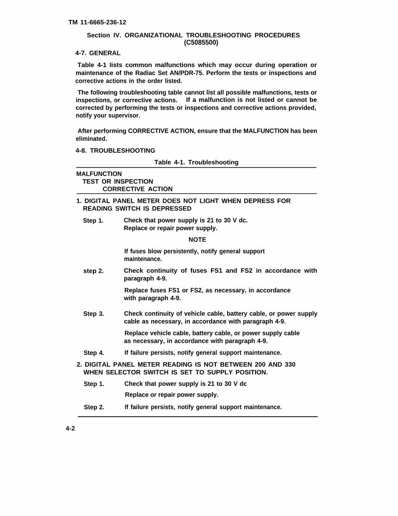
TM 11-6665-236-12
Section IV. ORGANIZATIONAL TROUBLESHOOTING PROCEDURES(C5085500)
4-7. GENERAL
Table 4-1 Iists common malfunctions which may occur during operation ormaintenance of the Radiac Set AN/PDR-75. Perform the tests or inspections andcorrective actions in the order listed.
The following troubleshooting table cannot list all possible malfunctions, tests orinspections, or corrective actions. If a malfunction is not listed or cannot becorrected by performing the tests or inspections and corrective actions provided,notify your supervisor.
After performing CORRECTIVE ACTION, ensure that the MALFUNCTION has beeneliminated.
4-8. TROUBLESHOOTING
Table 4-1. Troubleshooting
MALFUNCTIONTEST OR INSPECTION
CORRECTIVE ACTION
1. DIGITAL PANEL METER DOES NOT LIGHT WHEN DEPRESS FORREADING SWITCH IS DEPRESSED
Step 1. Check that power supply is 21 to 30 V dc.Replace or repair power supply.
NOTE
If fuses blow persistently, notify general supportmaintenance.
step 2. Check continuity of fuses FS1 and FS2 in accordance withparagraph 4-9.
Replace fuses FS1 or FS2, as necessary, in accordancewith paragraph 4-9.
Step 3. Check continuity of vehicle cable, battery cable, or power supplycable as necessary, in accordance with paragraph 4-9.
Replace vehicle cable, battery cable, or power supply cableas necessary, in accordance with paragraph 4-9.
Step 4. If failure persists, notify general support maintenance.
2. DIGITAL PANEL METER READING IS NOT BETWEEN 200 AND 330WHEN SELECTOR SWITCH IS SET TO SUPPLY POSITION.
Step 1. Check that power supply is 21 to 30 V dc
Replace or repair power supply.
Step 2. If failure persists, notify general support maintenance.
4-2

TM 11-6665-236-12
Section V. ORGANIZATIONAL MAINTENANCE PROCEDURES (C5085500)
ParagRAph Page
4-9a. General . . . . . . . . . . . . . . . . . . . . . . . . . . . . . . . ...4-34-9b. Fuses . . . . . . . . . . . . . . . . . . . . . . . . . . . . . . . . . . . .4-34-9c. Vehicle Cable . . . . . . . . . . . . . . . . . . . . . . . . . . . ...4-34-9d. Battery Cable . . . . . . . . . . . . . . . . . . . . . . . . . . . ...4-44-9e. Power Suppfy Cabin.... . . . . . . . . . . . . . . . . . . ...4-54-9f. Drawer Block and Screw Replacement . . . . . . . . . . . . 4-54-9g. Front Panel Knob Replacement . . . . . . . . . . . . . . . . . 4-64-9h. Plug PLA Cap Replacement . . . . . . . . . . . . . . . . ...4-74-9i. Carrying Strap Replacement . . . . . . . . . . . . . . . .4-74-9j. Rubber Foot Replacement . . . . . . . . . . . . . . . . . . ...4-84-10. Cleaning . . . . . . . . . . . . . . . . . . . . . . . . . . . . . . . ...4-84-11. Painting . . . . . . . . . . . . . . . . . . . . . . . . . . . . . . . ...4-8
4-9. REPAIR OF RADIAC SET.
a. General. Repair of the Radiac Set AN/PDR-75 at the organizational level isindicated by the above paragraph and page listing and the maintenance allocationchart in Appendix B.
b. Fuses. Repair fuses FS1 and FS2 as follows:
1. Remove fuse cap (1) and fuse (2) from the reader (3).
2. Using multimeter AN/PSM-45 or equivalent, check continuity of fuses FS1and FS2.
3. Replace fuses FS1 and FS2 as necessary (See Appendix E).
4. Replace fuse cap if damaged.
5. With fuse (2) installed in fuse cap (1), install the fuse and cap assembly inthe reader (3).
c. Vehicle Cable. Repair the vehicle cable as follows
1. Disconnect the vehicle cable from the reader and vehicle power source.4-3
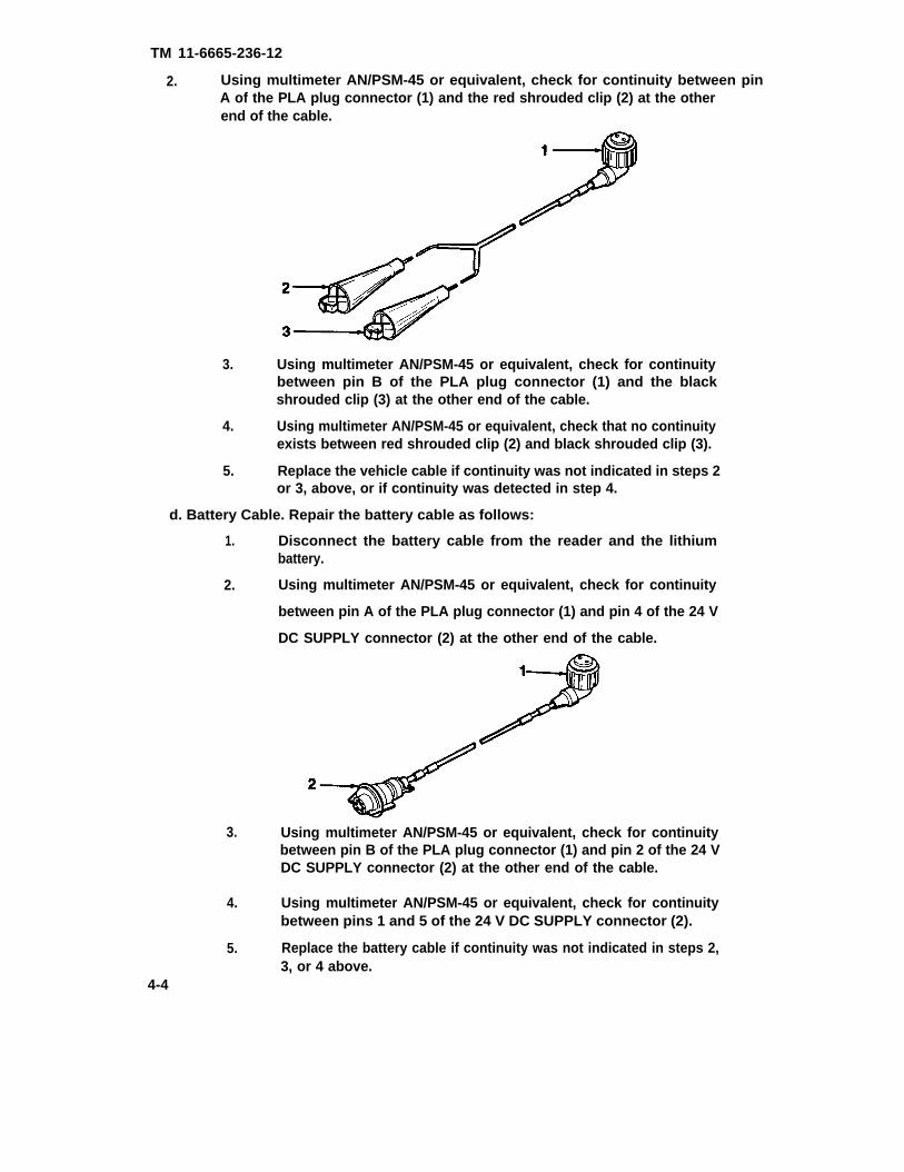
TM 11-6665-236-12
2. Using multimeter AN/PSM-45 or equivalent, check for continuity between pinA of the PLA plug connector (1) and the red shrouded clip (2) at the otherend of the cable.
3. Using multimeter AN/PSM-45 or equivalent, check for continuitybetween pin B of the PLA plug connector (1) and the blackshrouded clip (3) at the other end of the cable.
4. Using multimeter AN/PSM-45 or equivalent, check that no continuityexists between red shrouded clip (2) and black shrouded clip (3).
5. Replace the vehicle cable if continuity was not indicated in steps 2or 3, above, or if continuity was detected in step 4.
d. Battery Cable. Repair the battery cable as follows:
1. Disconnect the battery cable from the reader and the lithiumbattery.
2. Using multimeter AN/PSM-45 or equivalent, check for continuity
between pin A of the PLA plug connector (1) and pin 4 of the 24 V
DC SUPPLY connector (2) at the other end of the cable.
3. Using multimeter AN/PSM-45 or equivalent, check for continuitybetween pin B of the PLA plug connector (1) and pin 2 of the 24 VDC SUPPLY connector (2) at the other end of the cable.
4. Using multimeter AN/PSM-45 or equivalent, check for continuitybetween pins 1 and 5 of the 24 V DC SUPPLY connector (2).
5. Replace the battery cable if continuity was not indicated in steps 2,3, or 4 above.
4-4

TM 11-6665-236-12
6. Using multimeter AN/PSM-45 or equivalent, check that no continuity existsbetween pins 2 and 4 of the 24 V DC SUPPLY connector (2).
7. Replace the battery cable if continuity was indicated in step 6, above.
e. Power Supply Cable. Repair the power supply cable as follows
1. Disconnect the power supply cable from the reader and the chemical agentautomatic alarm (M10A1) power supply.
2. Using multimeter AN/PSM-45 or equivalent, check for continuity between pinA of the PLA plug connector(2) at the end of the cable.
(1) and pin B of the power supply connector
3. Using multimeter AN/PSM-45 or equivalent, check for continuity between pinB of the PLA plug connector (1) and pin E of the power supply connector(2) at the other end of the cable.
4. Replace the power supply cable if continuity was not indicated in step 2 or3, above.
5. Using multimeter AN/PSM-45 or equivalent, check that no continuity existsbetween pins B and E of the power supply connector (2).
6. Replace the power supply cable if continuity was indicated in step 5, above.
f. Drawer Block and Screw Replacement.
1. Remove screw (9), block (10), washer (11), and spring (12) from reader.
2. Stack new block (10), washer (11), and spring (12) onto new screw (9) andinstall all four components in the reader as a unit.
4-5
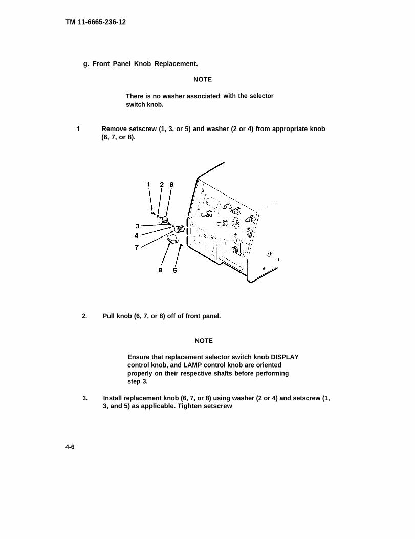
TM 11-6665-236-12
g. Front Panel Knob Replacement.
NOTE
There is no washer associatedswitch knob.
with the selector
Remove setscrew (1, 3, or 5) and washer (2 or 4) from appropriate knob(6, 7, or 8).
2. Pull knob (6, 7, or 8) off of front panel.
NOTE
Ensure that replacement selector switch knob DISPLAYcontrol knob, and LAMP control knob are orientedproperly on their respective shafts before performingstep 3.
3. Install replacement knob (6, 7, or 8) using washer (2 or 4) and setscrew (1,3, and 5) as applicable. Tighten setscrew
4-6

TM 11-6665-236-12
h. Plug PLA Cap Replacement.
1. Remove screw (1) and washer (2) attaching cap chain (3) to reader.
2. Attach new cap chain (3) to reader using screw (1) and washer (2).
i. Carrying Strap Replacement.
1. Remove four screws (1) and washers (2) holding two bars (3) in place.
2. Slide bars (3) out of old carrying strap (4)
3. Slide bars (3) into replacement carrying strap (4) and attach handlereader using four screws (1) and washers (2).
to
4-7

TM 11-6665-236-12
j. Rubber Foot Replacement.
1. Remove screw (1) and rubber foot (2) from bottom of reader.
2. Press screw (1) into new rubber foot (2) and install the two as a unit.Tighten screw, ensuring that it is snugly seated in the new rubber foot.
4-10. CLEANING.
Refer to paragraph 3-3 for
4-11. PAINTING.
instructions on cleaning the Radiac Set AN/PDR-75.
NOTE
Do not paint undamaged surface areas or parts of thereader such as knobs or digital panel meter (DPM)display glass that were not painted to begin with.
Painting of the Radiac Set AN/PDR-75 at the organizational level is limited to touch-up painting of the reader. Inspect painted surfaces of the reader for damage andclean damaged surfaces in accordance with cleaning instructions in paragraph 3-3.Prepare damaged reader surfaces for painting by lightly sanding these areas withsandpaper (item 8, Appendix E). Apply two light coats of paint (item 7, AppendixE), allowing the paint to dry between coats. Refer to TB 43-0118, Field Instructionsfor Painting and Preserving Electronics Command Equipment.
4-8
TM 11-6665-236-12
Section VI. PREPARATION FOR STORAGE OR SHIPMENT (C5085500)
4-12. PREPARATION FOR STORAGE.
Perform the following steps prior to storing the Radiac Set AN/PDR-75.
a. Perform the routine checks of the Radiac Set listed in paragraph 2-4., then followpreparation for operation instructions in paragraph 2-5. to ensure that the Radiac Setis operational.
CAUTION
The lithium battery must be removed from the Radiac Setprior to storage or shipment since prolonged storage withthe lithium battery installed may damage the equipment.
b. Remove the lithium battery from the battery and connector case in accordancewith paragraph 3-4.
c. Install the reader, battery and connector case, cover plate assembly and removalstrap, vehicle cable, battery cable, and power supply cable in the carrying case inaccordance with paragraph 2-6b.
4-13. PREPARATION FOR SHIPMENT.
Perform the following steps prior to shipping the Radiac Set AN/PDR-75:
a. Remove the lithium battery from the connector case in accordance withparagraph 3-4.
b. Install the reader, battery and connector case, cover plate assembly and strap,vehicle cable, battery cable, and power supply cable in the carrying case inaccordance with paragraph 2-6b.
4-9/(4-10 blank)

TM 11-6665-236-12PART EIGHT
CHAPTER 4
ORGANIZATIONAL MAINTENANCE (A3250780)
Section I. REPAIR PARTS, SPECIAL TOOLS, AND TMDE (A3250780)
4-1.1 COMMON TOOLS AND EQUIPMENT.
Authorized common tools and equipment are listed in the Modified Table ofOrganization and Equipment (MTOE) applicable to your unit.
4-2.1 SPECIAL TOOLS AND TMDE
Special tools and TMDE are listed in Appendix B in this manual, and in TM 11-6665-236-40P.
4-3.1 REPAIR PARTS.
Repair parts are listed and illustrated in TM 11-6665-236-20P coveringorganizational maintenance for this equipment.
Section Il. SERVICE UPON RECEIPT (A3250780)
4-4.1 GENERAL
There are no special unpacking requirements for the Radiac Set AN/PDR-75.
4-5.1 CHECKING UNPACKED EQUIPMENT.
Follow preparation for use instructions in paragraph 2-5.1 prior to using the RadiacSet AN/PDR-75. Check unpacked equipment in accordance with the routine checksin paragraph 2-4.1.
4-6.1 SITE AND SHELTER REQUIREMENTS.
The Radiac Set AN/PDR-75 must be operated in an environment conforming to therequirements for temperature and humidity as outlined in paragraph 1-13.1. Theradiac set requires readjustment during use whenever the ambient temperaturechanges more than 5°F (2.8°C). Optimum results will be achieved when the radiacset is operated in an environment in which the temperature can be expected toremain relatively stable.
NOTE
The radiac set should not be operated in close proximityto high power transmitters or incorrect readings may result.
Section Ill. ORGANIZATIONAL PREVENTIVE MAINTENANCE CHECKS ANDSERVICES (PMCS) (A3250780)
There is no PMCS scheduled for the Radiac Set AN/PDR-75 at the organizationallevel. To ensure that the radiac set is always ready for operation, it is inspectedsystematically so that defects may be discovered and corrected before they resultin serious damage or failure. Perform routine checks (refer to paragraph 2-4.1 whenpossible during organizational maintenance procedures and correct defects asnecessary. Record all deficiencies and corrective actions taken on DA Form 2404.
4-11
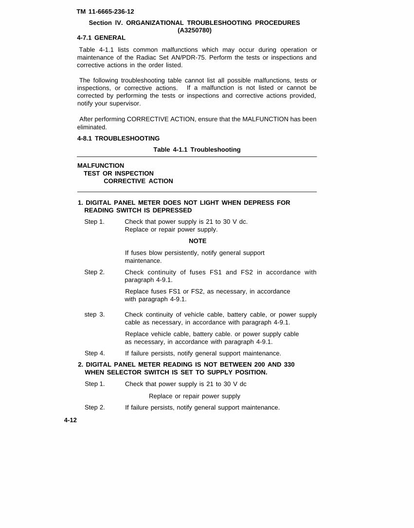
TM 11-6665-236-12
Section lV. ORGANIZATIONAL TROUBLESHOOTING PROCEDURES(A3250780)
4-7.1 GENERAL
Table 4-1.1 lists common malfunctions which may occur during operation ormaintenance of the Radiac Set AN/PDR-75. Perform the tests or inspections andcorrective actions in the order listed.
The following troubleshooting table cannot list all possible malfunctions, tests orinspections, or corrective actions. If a malfunction is not listed or cannot becorrected by performing the tests or inspections and corrective actions provided,notify your supervisor.
After performing CORRECTIVE ACTION, ensure that the MALFUNCTION has beeneliminated.
4-8.1 TROUBLESHOOTING
Table 4-1.1 Troubleshooting
MALFUNCTIONTEST OR INSPECTION
CORRECTIVE ACTION
1. DIGITAL PANEL METER DOES NOT LIGHT WHEN DEPRESS FORREADING SWITCH IS DEPRESSED
Step 1. Check that power supply is 21 to 30 V dc.Replace or repair power supply.
NOTE
If fuses blow persistently, notify general supportmaintenance.
Step 2. Check continuity of fuses FS1 and FS2 in accordance withparagraph 4-9.1.
Replace fuses FS1 or FS2, as necessary, in accordancewith paragraph 4-9.1.
step 3. Check continuity of vehicle cable, battery cable, or powercable as necessary, in accordance with paragraph 4-9.1.
Replace vehicle cable, battery cable. or power supply cableas necessary, in accordance with paragraph 4-9.1.
Step 4. If failure persists, notify general support maintenance.
2. DIGITAL PANEL METER READING IS NOT BETWEEN 200 AND 330WHEN SELECTOR SWITCH IS SET TO SUPPLY POSITION.
Step 1. Check that power supply is 21 to 30 V dc
Replace or repair power supply
Step 2. If failure persists, notify general support maintenance.
4-12
supply

TM 11-6665-236-12
Section V. ORGANIZATIONAL MAINTENANCE PROCEDURES (A3250780)
Paragraph Page
4-9.1a.4-9.1b.4-9.1c.4-9.1d.4-9.1e.4-9.1f.4-9.1g.4-9.1 h.4-9.1i.4-9.1j.4-9.1k.4-9.1l.4-10.1.4-11.1.
General . . . . . . . . . . . . . . . . . . . . . . . . . . . . . . . . . . . . . . . . . 4-13Fuses . . . . . . . . . . . . . . . . . . . . . . . . . . . . . . . . . . . . . . . . . . . 4-13Vehicle Cable . . . . . . . . . . . . . . . . . . . . . . . . . . .. 4-13Battery Cable . . . . . . . . . . . . . . . . . . . . . . . . . . .. 4-14Power Supply Cable . . . . . . . . . . . . . . . . . . . . . . .4-15Drawer Block and Screw Replacement . . . . . . . . . 4-15Front Panel Knob Replacement . . . . . . . . . . . . . . . 4-16Plug PLA Cap Replacement . . . . . . . . . . . . . . . . .4-17Opening Unit for Servicing . . . . . . . . . . . . . . . . . .4-17Carrying Strap Replacement . . . . . . . . 4-17Rubber Foot Replacement . . . . . . . . . . . . . . . . . .4-18Closing Unit after Servicing. . . . . . . . . . . . . . . . . . 4-19Cleaning . . . . . . . . . . . . . . . . . . . . . . . . . . . . . . . . . . . . . . . . . 4-20Painting . . . . . . . . . . . . . . . . . . . . . . . . . . . . . . . . . . . . . . 4-20
4-9.1 REPAIR OF RADIAC SET.
a. General. Repair of the Radiac Set AN/PDR-75 at the organizational level isindicated by the above paragraph and page listing and the maintenance allocationchart in Appendix B.
b. Fuses. Repair fuses FS1 and FS2 as follows:
1.
2.
3.
4.
5,
Remove fuse cap (1) and fuse (2) from the reader (3).
Using multimeter AN/PSM-45 or equivalent, check continuity of fuses FS1and FS2.
Replace fuses FS1 and FS2 as necessary (See Appendix E).
Replace fuse cap if damaged.
With fuse (2) installed in fuse cap (1), install the fuse and cap assembly inthe reader (3).
c. Vehicle Cable. Repair the vehicle cable as follows:
1. Disconnect the vehicle cable from the reader and vehicle power source. 4 - 1 3

TM 112.
-6665-236-12Using multimeter AN/PSM-45 or equivalent, check for continuity between pinA of the PLA plug connector (1) and the red shrouded clip (2) at the otherend of the cable.
3. Using multimeter AN/PSM-45 or equivalent, check for continuitybetween pin B of the PLA plug connector (1) and the blackshrouded clip (3) at the other end of the cable.
4. Using multimeter AN/PSM-45 or equivalent, check that no continuityexists between red shrouded clip (2) and black shrouded clip (3).
5. Replace the vehicle cable if continuity was not indicated in steps 2or 3, above, or if continuity was detected in step 4.
d. Battery Cable. Repair the battery cable as follows:
1. Disconnect the battery cable from the reader and the Iithiumbattery.
2. Using multimeter AN/PSM-45 or equivalent, check for continuitybetween pin A of the PLA plug connector (1) and pin 4 of the 24 VDC SUPPLY connector (2) at the other end of the cable.
3. Using multimeter AN/PSM-45 or equivalent, check for continuitybetween pin B of the PLA plug connector (1) and pin 2 of the 24 VDC SUPPLY connector (2) at the other end of the cable.
4. Using multimeter AN/PSM-45 or equivalent, check for continuitybetween pins 1 and 5 of the 24 V DC SUPPLY connector (2).
5. Replace the battery cable if continuity was not indicated in steps 2,3, or 4 above.
4-14

TM 11-6665-236-12
6. Using multimeter AN/PSM-45 or equivalent, check that no continuity existsbetween pins 2 and 4 of the 24 V DC SUPPLY connector (2).
7. Replace the battery cable if continuity was indicated in step 6, above.
e. Power Supply Cable. Repair the power supply cable as follows:
1.
2.
Disconnect the power supply cable from the reader and the chemical agentautomatic alarm (M10A1) power supply.
Using multimeter AN/PSM-45 or equivalent, check for continuity between pinA of the PLA plug connector (1) and pin B of the power supply connector(2) at the end of the cable.
3.
4.
5.
6.
f.
1.
Using multimeter AN/PSM-45 or equivalent, check for continuity between pinB of the PL4 plug connector (1) and pin E of the power supply connector(2) at the other end of the cable.
Replace the power supply cable if continuity was not indicated in step 2 or3, above.
Using multimeter AN/PSM-45 or equivalent, check that no continuity existsbetween pins B and E of the power supply connector (2).
Replace the power supply cable if continuity was indicated in step 5, above.
Drawer Block and Screw Replacement.
Remove screw (6), spring (7), washer (8), and block (9) from reader.
NOTE
Ensure that the block (9) installedin the following step is installed sothat the larger end rests against thereader body and the smaller end restsagainst the drawer cover.
2. Stack new block (9), washer (8), and spring (7) onto new screw (6) andinstall all four components in the reader as a unit.
4-15

TM 11-6665-236-12
g. Front Panel Knob Replacement.
NOTE
There is no washer associated with the selectorswitch knob.
1. Remove setscrew (1, 3, or 5) and washer (2 or 4) from appropriate knob(6, 7, or 8).
2. Pull knob (6, 7, or 8) off of front panel.
NOTE
Ensure that replacement selector switch knob DISPLAYcontrol knob, and LAMP control knob are orientedproperly on their respective shafts before performingstep 3.
3. Install replacement knob (6, 7, or 8) using washer (2 or 4) and setscrew (1,3, and 5) as applicable. Tighten setscrew.
4-16

h. Plug
1.
TM 11-6665-236-12
PLA Cap Replacement.
Remove screw (1) and washer (2) attaching cap chain (3) to reader.
2. Attach new cap chain (3)
i. Opening unit for servicing.
to reader using screw (1) and washer (2).
WARNING
Turn power off and remove reader from its metal case,when internal electronic components are exposed forrepair or calibration during maintenance procedures,wait at least 1 minute before touching reader. Thisprocedure is required to ensure that the high voltagecapacitor within the flash unit has time to discharge.Failure to do so may result in death or serious injury.
1. Place reader on a clean work surface in its normal operating position.Ensure that the selector switch is set to OFF and that reader isdisconnected from 21 to 30 V dc power supply.
4-17
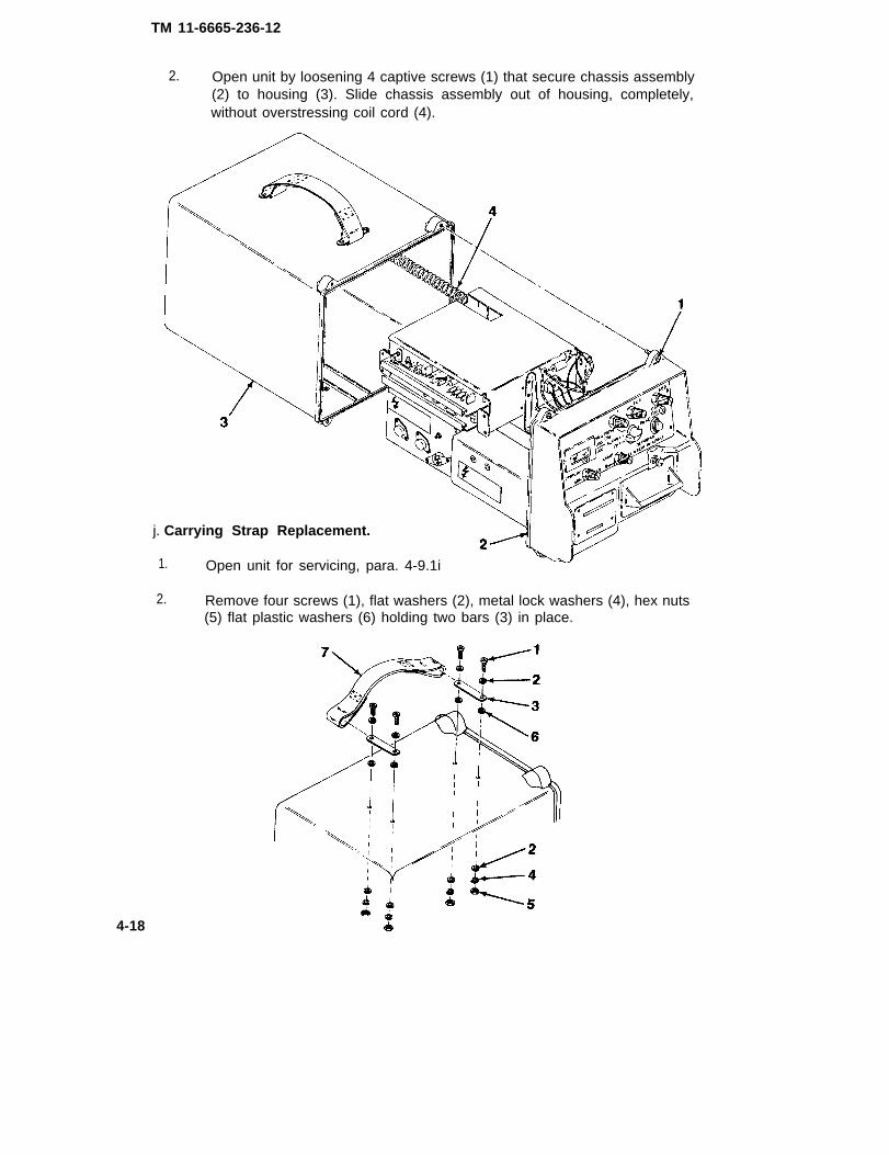
TM 11-6665-236-12
2. Open unit by loosening 4 captive screws (1) that secure chassis assembly(2) to housing (3). Slide chassis assembly out of housing, completely,without overstressing coil cord (4).
j. Carrying Strap Replacement.
1. Open unit for servicing, para. 4-9.1i
2. Remove four screws (1), flat washers (2), metal lock washers (4), hex nuts(5) flat plastic washers (6) holding two bars (3) in place.
4-18

TM 11-6665-236-12
3. Slide bars (3) out of old carrying strap (7).
4. Slide bars (3) into replacement carrying strap (7) and attach handle toreader using four screws (1) flat washers (2), metal lock washers (4) hexnuts (5) and flat plastic washers (6).
5. Close unit after servicing, para. 4-9.11.
k. Rubber Foot Replacement.
1. Open unit for servicing, para. 4-9.1i.
2. Remove screw (4) and plastic flat washer (3), hex nut (1) and rubber foot(2) from bottom of reader.
3. Replace foot by installing screw, (4), using plastic flat washer (3), frominside of reader, into new rubber foot (2), and hex nut (1).
4. Close unit after servicing, para. 4-9.11.
l. Closing unit after servicing.
1. Carefully set reader upright, slide into housing,screws.
and tighten 4 captive
4-19

TM 11-6665-236-12
4-10.1 CLEANING.
Refer to paragraph 3-3.1 for instructions on cleaning the Radiac Set AN/PDR-75.
4-11.1 PAINTING.
NOTE
Do not paint undamaged surface areas or parts of thereader such as knobs or digital panel meter (DPM)display glass that were not painted to begin with.
Painting of the Radiac Set AN/PDR-75 at the organizational level is limited to touch-up painting of the reader. Inspect painted surfaces of the reader for damage andclean damaged surfaces in accordance with cleaning instructions in paragraph 3-3.1Prepare damaged reader surfaces for painting by lightly sanding these areas withsandpaper (item 8, Appendix E). Apply two light coats of paint (item 7, AppendixE), allowing the paint to dry between coats. Refer to TB 43-0118, Field Instructionsfor Painting and Preserving Electronics Command Equipment.
Section VI. PREPARATION FOR STORAGE OR SHIPMENT (A3250780)
4-12.1 PREPARATION FOR STORAGE. (A3250780)
Perform the following steps prior to storing the Radiac Set AN/PDR-75.
a. Perform the routing checks of the radiac set listed in paragraph 2-4.1, then followpreparation for operation instructions in paragraph 2-5.1 to ensure that the radiacset is operational.
CAUTION
The Iithium battery must be removed from the radiac setprior to storage or shipment since prolonged storage withthe lithium battery installed may damage the equipment.
b. Remove the lithium battery from the carrying case in accordance with paragraph3-4.1.
c. Install the reader, carrying case base, vehicle cable, battery cable, and powersupply cable in the carrying case in accordance with paragraph 2-6.1 b.
4-13.1 PREPARATION FOR SHIPMENT.
Perform the following steps prior to shipping the Radiac Set AN/PDR-75:
a. Remove the lithium battery from the carrying case in accordance with paragraph3-4.1.
b. Install the reader, carrying case base, vehicle cable, battery cable, and powersupply cable in the carrying case in accordance with paragraph 2-6.1.b
4-20
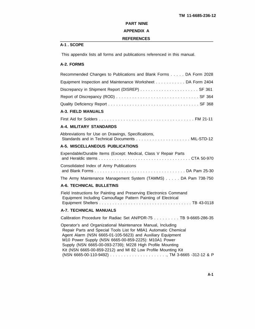
TM 11-6685-236-12
PART NINE
APPENDIX A
REFERENCES
A-1 . SCOPE
This appendix lists all forms and publications referenced in this manual.
A-2. FORMS
Recommended Changes to Publications and Blank Forms . . . . . DA Form 2028
Equipment Inspection and Maintenance Worksheet . . . . . . . . . . . DA Form 2404
Discrepancy in Shipment Report (DISREP) . . . . . . . . . . . . . . . . . . . . . . SF 361
Report of Discrepancy (ROD) . . . . . . . . . . . . . . . . . . . . . . . . . . . . . . . SF 364
Quality Deficiency Report . . . . . . . . . . . . . . . . . . . . . . . . . . . . . . . . . . SF 368
A-3. FIELD MANUALS
First Aid for Solders . . . . . . . . . . . . . . . . . . . . . . . . . . . . . . . . . . . FM 21-11
A-4. MILITARY STANDARDS
Abbreviations for Use on Drawings, Specifications,Standards and in Technical Documents . . . . . . . . . . . . . . . . . . . . MIL-STD-12
A-5. MISCELLANEOUS PUBLICATIONS
Expendable/Durable Items (Except: Medical, Class V Repair Partsand Heraldic sterns . . . . . . . . . . . . . . . . . . . . . . . . . . . . . . . . . . . CTA 50-970
Consolidated Index of Army Publicationsand Blank Forms . . . . . . . . . . . . . . . . . . . . . . . . . . . . . . . . . . DA Pam 25-30
The Army Maintenance Management System (TAMMS) . . . . . DA Pam 738-750
A-6. TECHNICAL BULLETINS
Field Instructions for Painting and Preserving Electronics CommandEquipment Including Camouflage Pattern Painting of ElectricalEquipment Shelters . . . . . . . . . . . . . . . . . . . . . . . . . . . . . . . . . . . TB 43-0118
A-7. TECHNICAL MANUALS
Calibration Procedure for Radiac Set AN/PDR-75 . . . . . . . . . TB 9-6665-286-35
Operator’s and Organizational Maintenance Manual, IncludingRepair Parts and Special Tools List for M8A1 Automatic ChemicalAgent Alarm (NSN 6665-01-105-5623) and Auxiliary EquipmentM10 Power Supply (NSN 6665-00-859-2225): M10A1 PowerSupply (NSN 6665-00-093-2739); M228 High Profile MountingKit (NSN 6665-00-859-2212) and Ml 82 Low Profile Mounting Kit(NSN 6665-00-110-9492) . . . . . . . . . . . . . . . . . . . . ., TM 3-6665 -312-12 & P
A-1

TM 11-6666-236-12
APPENDIX A (CONT.)
Organizational Maintenance Repair Parts and SpecialTools List for Radiac Set AN/PDR-75 . . . . . . . . . . . . . . . TM 11-6665-236-20P
General Support Maintenance Repair Parts and SpecialTools for Radiac Set AN/PDR-75 . . . . . . . . . . . . . . . . . . TM 11-6665-236-40P
General Support Maintenance Manualfor Radiac Set AN/PDR-75 . . . . . . . . . . . . . . . . . . . . . . .. TM 11-6665-236-40
Operator's, Organizational, Direct Support, and General SupportMaintenance Manual for Multimeter AN/PSM-45(6625-01-139-2515) . . . . . . . . . . . . . . . . . . . . . . . . . . . . TM 11-6665-3052-14
Procedures for Destruction of Electronics Materiel to PreventEnemy Use (Electronics Command) . . . . . . . . . . . . . . . . . . . .. TM 750-244-2
A-2

TM 11-6665-236-12
PART TENAPPENDIX B
MAINTENANCE Allocation CHART
Section I. lNTRODUCTION
B-1. GENERAL.
a. This section provides a general explanation of all maintenance and repairfunctions authorized at various maintenance categories.
b. The Maintenance Allocation Chart (MAC) in Section II designates overallresponsibility for the performance of maintenance functions on the identified enditem or component. The implementation of the maintenance functions upon the enditem or component will be consistent with the assigned maintenance function.
c. Section Ill lists the special tools and test equipment required for eachmaintenance function as referenced from Section Il.
d. Section IV contains supplemental instructions and explanatory notes for aparticular maintenance function as referenced from Section Il.
B-2. MAINTENANCE FUNCTION.
Maintenance functions will be limited to and defined as follows:
a. Inspect. To determine the serviceability of an item by comparing its physical,mechanical, and/or electrical characteristics with established standards throughexamination.
b. Test. To verify serviceability by measuring the mechanical or electricalcharacteristics of an item and comparing those characteristics with prescribedstandards.
c. Service. Operations required periodically to keep an item in proper operatingcondition, i.e., to clean (includes decontaminate, when required) to preserve, todrain, to paint, or to replenish fuel, lubricants, chemical fluids, hydraulic fluids,compressed air supplies or gases.
d. Adjust. To maintain within prescribed limits, by bringing into proper or exactposition, or by setting the operating characteristics to specified parameters.
e. Align. To adjust specified variable elements of an item to bring about optimumor desired performance.
f. Calibrate. To determine and cause corrections to be made or to be adjusted oninstruments or test, measuring, and diagnostic equipments used in precisionmeasurement. Consists of comparisons of two instruments, one of which is acertified standard of known accuracy, to detect and adjust any discrepancy in theaccuracy of the instrument being compared.
g. Install. The act of emplacing, seating, or fixing into position an item, part, ormodule (component or assembly) in a manner to allow the proper functioning of anequipment or system.
B-1

TM 11-6665-236-12
h. Replace. The act of substituting a serviceable like type part, subassembly ormodule (component or assembly) for an unserviceable counterpart.
i. Repair. The application of maintenance services1 or other maintenance actions2
to restore serviceability to an item by correcting specific damage, fault, malfunction,or failure in a part, subassembly, module (component or assembly) end item orsystem.
j. Overhaul. That maintenance effort (service/action) necessary to restore an itemto a completely serviceable/operational condition as prescribed by maintenancestandards in appropriate technical publications (i.e., DMWR). Overhaul is normallythe highest degree of maintenance performed by the Army. Overhaul does notnormally return an item to like new condition.
k. Rebuild. Consists of those services/actions necessary for the restoration ofunserviceable equipment to a like new condition in accordance with originalmanufacturing standards. Rebuild is the highest degree of material maintenanceapplied to Army equipment. The rebuild operation includes the act of returning tozero those age measurements (hours/miles, etc.) considered in classifying Armyequipment/components.
B-3. EXPLANATION OF COLUMNS IN THE MAC, SECTION Il.
a. Column 1, Group Number. Column 1 fists functional group code numbers, thepurpose of which is to identify components, assemblies, subassemblies, andmodules with the next higher assembly.
b. Column 2, Component/Assembly. Column 2 contains the names ofcomponents, assemblies, subassemblies, and modules on which maintenance isauthorized.
c. Column 3, Maintenance Function. Column 3 lists functions to be performed onthe item listed in Column 2. (For detailed explanation of these functions, seeparagraph B-2).
d. Column 4, Maintenance Category. Column 4 specifies, by the listing of a worktime figure in the appropriate subcolumns, the lowest level category of maintenanceauthorized to perform the function listed in Column 3. This figure represents theactive time required to perform that maintenance function at the indicated categoryof maintenance. If the number or complexity of the tasks within the listedmaintenance function vary at different maintenance categories, appropriate worktime figures will be shown for each category. The work time figure represents theaverage time in hours required to restore an item (assembly, subassembly,component, module, end item, or system) to a serviceable condition under typicalfield operating conditions. This includes preparation time, troubleshooting time, andquality assurance/quality control time in addition to the time required to perform thespecific tasks identified for the maintenance functions authorized in the maintenanceallocation chart. The symbol designations for the various categories are as follows:
1Services - inspect, test, service, adjust, align, calibrate, or replace.2Actions - welding, grinding, riveting, straightening, facing, remachining, orresurfacing.
B-2

TM 11-6665-236-12
C - Operator or crewO - Unit maintenanceF - Direct support maintenanceH - General support maintenanceD - Depot maintenance
e. Column 5, Tools and Test Equipment. Column 5 specifies, by code, thosecommon tool sets (not individual tools) and special tools, TMDE, and supportequipment required to perform the designated function. The code in this column iskeyed to the tool and test equipment list in Section Ill.
f. Column 6, Remarks. Column 6 contains, when applicable, a code, which is keyedto the remarks contained in Section IV.
B-4. EXPLANATION OF COLUMNS IN TOOL AND TEST EQUIPMENTREQUIREMENTS, SECTION Ill.
a. Column 1, Tool or Test Equipment Reference Code. The tool and testequipment reference code correlates with a code used in the MAC, Section II,Column 5.
b. Column 2, Maintenance Category. The lowest level category of maintenanceauthorized to use the tool or test equipment.
c. Column 3, Nomenclature. Name or identification of the tool or test equipment.
d. Column 4, National/Nato Stock Number. The national stock number of the toolor test equipment.
e. Column 5, Tool Number. The manufacturer’s part number.
B-5. EXPLANATION OF COLUMNS IN REMARKS, SECTION IV.
a. Column 1, Reference Code. The code listed in Column 6, Section Il.
b. Column 2, Remarks. This column lists information pertinent to the maintenancefunction being performed as indicated in the MAC, Section Il.
B-3

TM 11-6665-236-12
Section Il. MAINTENANCE ALLOCATION CHART(C5085500 and A3250780)
FORRADIAC SET AN/PDR-75
B-4

TM 11-6665-236-12
Section Ill. TOOL AND TEST EQUIPMENT REQUIREMENTS(C5085500 and A3250780)
FORRADIAC SET AN/PDR-75
B-5
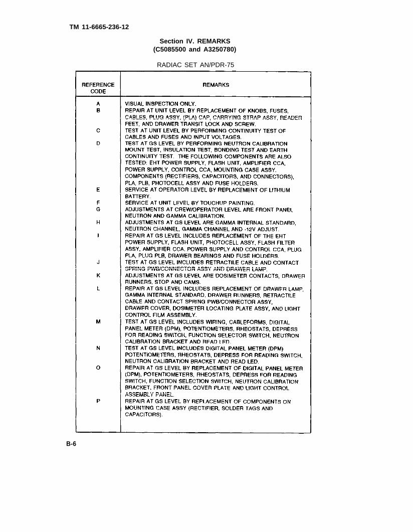
TM 11-6665-236-12
Section IV. REMARKS(C5085500 and A3250780)
RADIAC SET AN/PDR-75
B-6

TM 11-6665-236-12
PART ELEVEN
APPENDIX C
COMPONENTS OF END ITEM AND BASIC ISSUE ITEMS LISTS(C5085500 and A3250780)
Section I. INTRODUCTION
C-1. SCOPE.
This appendix lists components of end item and basic issue items for the AN/PDR-75 Radiac Set to help you inventory items required for safe and efficient operation.
C-2. GENERAL.
The Components of End Item and Basic Issue Items Lists are divided into thefollowing sections:
a. section II, Components of End Item. This listing is for information purposesonly, and is not authority to requisition replacements. These items are part of theend item, but are removed and separately packaged for transportation or shipment.As part of the end item, these items must be with the end item whenever it is issuedor transferred between property accounts. Illustrations are furnished to assist youin identifying the items.
b Section Ill, Basic Issue Items. Not applicable.
C-3. EXPLANATION OF COLUMNS.
The following provides an explanation of columns found in the tabular listings
a. Column (1) - Illustration Number (Illus Number). This column indicates thenumber used to identify the item in the illustration.
b. Column (2) - National Stock Number. Indicates the National Stock Numberassigned to the item and will be used for requisitioning purposes.
c. Column (3) - Description. Indicates the Federal item name and, if required, aminimum description to identify and locate the item. The last line for each itemindicates the CAGE (in parentheses) followed by the part number.
d. Column (4) - Unit of Measure (U/M). Indicates the measure used in performingthe actual operation/maintenance function. This measure is expressed by a two-character alphabetical abbreviation (e.g., ea, in, pr).
e. Column (5) - Quantity required (Qty rqd). Indicates the quantity of the itemauthorized to be used with/on the equipment.
C-1
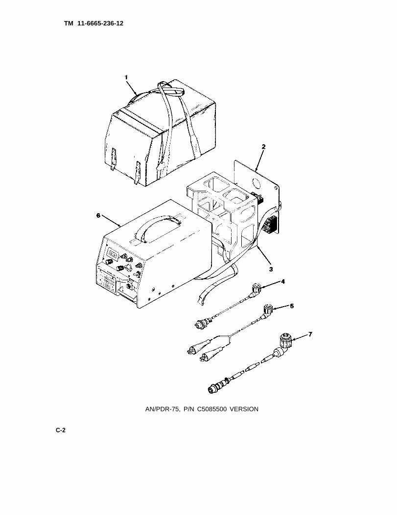
TM 11-6665-236-12
AN/PDR-75, P/N C5085500 VERSION
C-2

TM 11-6665-236-12
Section Il. COMPONENTS OF END ITEM (C5085500)
C-3

TM 11-6665-236-12
AN/PDR-75, P/N A3250780 VERSION
C-4

TM 11-6665-236-12
PART TWELVE
Section Il. COMPONENTS OF END ITEM (A3250780)
C-5/(C-6 blank)

TM 11-6665-236-12
PART THIRTEEN
APPENDIX D
ADDITIONAL AUTHORIZATION LIST
Section I. INTRODUCTION
D-1. SCOPE.
This appendix lists additional items authorized to you for the support of the RadiacSet AN/PDR-75.
D-2. GENERAL.
This list identifies items that do not have to accompany the Radiac Set AN/PDR-75and that do not have to be turned in with it. These items are all authorized to youby CTA, MTOE, TDA, or JTA.
D-3. EXPLANATION OF LISTING.
National stock numbers, descriptions, and quantities are provided to help youidentify and request the additional items you require to support this equipment. Theitems are listed in alphabetical sequence by item name under the type document(i.e., CTA, MTOE, TDA, or JTA) which authorizes the item(s) to you.
1)-1/(D-2 blank)

TM 11-6665-236-12
PART FOURTEEN
APPENDIX E
EXPENDABLE/DURABLE SUPPLIES AND MATERIALS LIST
Section I. INTRODUCTION
E-1. SCOPE.
This appendix lists expendable/durable supplies and materials you will need tooperate and maintain the Radiac Set AN/PDR-75. These items are authorized toyou by CTA 50-970, Expendable Items (Except Medical, Class V, Repair Parts, andHeraldic Items).
E-2. EXPLANATION OF COLUMNS.
a. Column 2 - Item Number. This number is assigned to the entry in the listing andis referenced in the narrative instructions to identify the material.
b. Column 2 - Level. This column identifies the lowest level of maintenance thatrequires the listed item.
C - Operator/CrewO - Unit MaintenanceH - General Support MaintenanceD - Depot
c. Column 3 - National Stock Number. This is the National stock numberassigned to the item; use it to request or requisition the item.
d. Column 4 - Description. indites the Federal item name and, if required, adescription to identify the item. The last line for each item indicates the Commercialand Government Entity Code (CAGE) in parentheses followed by the part number.
e. Column 5 - Unit of Measure (U/M). Indicates the measure used in performingthe actual maintenance function. This measure is expressed by a two-characteralphabetical abbreviation (e.g., ea, in, pr). If the unit of measure differs from the unitof issue, requisition the lowest unit of issue that will satisfy your requirements.
E-1

TM 11-6665-236-12
Section II. EXPENDABLE SUPPLIES AND MATERIALS LIST
NOTE
The National Stock Numbers that are missing from thislist have been requested and will be added by a changeto the fist upon receipt.
E-2

TM 11-6665-236-12
PART FIFTEEN
SUBJECT INDEX
Subject Page
A
Abbreviations and Acronyms, List of . . . . . . . . . . . . . . . . . . . . . . . . . . . . . . . 1-3/1-13Adjustment, Reader . . . . . . . . . . . . . . . . . . . . . . . . . . . . . . . . . . . . . . . . . .2-11/2-35
B
4-4/4-143-5/3-11
4-5/4-154-4/4-144-3/4-134-7/4-174-8/4-184-1/4-112-3/2-273-4/3-104-8/4-184-1/4-113-5/3-11
1-2/1-122-1/2-25
DData, Equipment . . . . . . . . . . . . . . . . . . . . . . ..- . . . . . . . . . . . . . . .1-6/1-16Description, Equipment . . . . . . . . . . . . . . . . . . . . . . . . . . . . . . . . . . . . . . . .1-3/1-13Description and Use of Operator’s Controls and lndicators . . . . . . . . . . . . . . . . 2-1/2-25Destruction of Army Materiel to Prevent Enemy Use . . . . . . . . . . . . . . . . . . . .1-3/1-13Dosimeters, Reading . . . . . . . . . . . . . . . . . . . . . . . . . . . . . . . . . . . . . . . . .2-14/2-38Drawer Block and Screw Replacement . . . . . . . . . . . . . . . . . . . . . . . . . . . . . . 4-5/4-15
E
2-23/2-461-3/1-131-3/1-131-2/1-12
INDEX-1

TM 11-6665-236-12
SUBJECT INDEX (CONTINUED)
Subject Page
I
Instructions, Lubrication . . . . . . . . . . . . . . . . . . . . . . . . . . . . . . . . . . . . . . . . . . 3-1/3-7Instructions,Operating . . . . . . . . . . . . . . . . . . . . . . . . . . . . . . . . . . . . . . . . . . 2-1/2-25Introduction . . . . . . . . . . . . . . . . . . . . . . . . . . . . . . . . . . . . . . . . . . . . . . . . . . 1-1/1-11
K
Knob Replacement, Front Panel. . . . . . . . . . . . . . . . . . . . . . . . . . . . . . . . . . . 4-6/4-16
L
List of Abbreviations and Acronym . . . . . . . . . . . . . . . . . . . . . . . . . . . . . . . . 1-3/1-13Location and Description of Major Components . . . . . . . . . . . . . . . . . . . . . . . . 1-4/1-14Lubrication Instructions . . . . . . . . . . . . . . . . . . . . . . . . . . . . . . . . . . . . . . . . . . 3-1/3-7
M
Maintenance Forms, Records, and Reports . . . . . . . . . . . . . . . . . . . . . . . . . . . 1-2/1-12Maintenance, Operator . . . . . . . . . . . . . . . . . . . . . . . . . . . . . . . . . . . . . . . . . . 3-1/3-7Maintenance, Organizational . . . . . . . . . . . . . . . . . . . . . . . . . . . . . . . . . . . . . 4-1/4-11Major Components, Location and Description of . . . . . . . . . . . . . . . . . . . . . . . . 1-4/1-14
N
Nomenclature Cross-Reference List. . . . . . . . . . . . . . . . . . . . . . . . . . . . . . . . 1-2/1-12
0
Operating Instructions . . . . . . . . . . . . . . . . . . . . . . . . . . . . . . . . . . . . . . . . . . 2-1/2-25Operating Precautions for Unusual Weather . . . . . . . . . . . . . . . . . . . . . . . . . 2-23/2-46Operation, Preparation for . . . . . . . . . . . . . . . . . . . . . . . . . . . . . . . . . . . . . . . 2-4/2-28Operation, Technical Principles of. . . . . . . . . . . . . . . . . . . . . . . . . . . . . . . . . . . . . . 1-8Operation Under Unusual Conditions . . . . . . . . . . . . . . . . . . . . . . . . . . . . . . 2-23/2-46Operations Under Usual Conditions . . . . . . . . . . . . . . . . . . . . . . . . . . . . . . . . 2-4/2-28Operator Maintenance . . . . . . . . . . . . . . . . . . . . . . . . . . . . . . . . . . . . . . . . . . . 3-1/3-7Operator Troubleshooting . . . . . . . . . . . . . . . . . . . . . . . . . . . . . . . . . . . . . . . . . 3-1/3-7Operator Preventive Maintenance Checks and Services (PMCS) . . . . . . . . . . . . 2-2/2-26Operator's Controls and lndication, Description and Use of . . . . . . . . . . . . . . . . 2-1/2-25Organizational Maintenance. . . . . . . . . . . . . . . . . . . . . . . . . . . . . . . . . . . . . . 4-1/4-11Organizational Preventive Maintenance Checks andServices (PMCS) . . . . . . . . . . . . . . . . . . . . . . . . . . . . . . . . . . . . . . . . . . . . . 4-1/4-11
Organizational Troubleshooting. . . . . . . . . . . . . . . . . . . . . . . . . . . . . . . . . . . 4-2/L4-12
INDEX-2

TM 11-6665-236-12
SUBJECT INDEX (CONTINUED)
Subject Page
PPainting . . . . . . . . . . . . . . . . . . . . . . . . . . . . . . . . . . . . . . . . . . . . . . . . . 4-8/4-20Parts, Repair . . . . . . . . . . . . . . . . . . . . . . . . . . . . . . . . . . . . . . . . . . . . . 4-1/4-11Plug PLA Cap Replacement . . . . . . . . . . . . . . . . . . . . . . . . . . . . . . . . . 4-7/4-17Preparation for operation . . . . . . . . . . . . . . . . . . . . . . . . . . . . . . . . . . . . 2-4/2-28Preparation for Storage or Shipment . . . . . . . . . . . . . . . . . . . . . . . . . . . . 4-9/4-20Preventive Maintenance . . . . . . . . . . . . . . . . . . . . . . . . . . . . . . . . . . . . . . . . 2-2/2-26Principles of Operation, Technical. . . . . . . . . . . . . . . . . . . . . . . . . . . . . . . . . . . . .1-8Procedures, Emergency . . . . . . . . . . . . . . . . . . . . . . . . . . . . . . . . . . . . . . . 2-23/2-46Procedures, Operator Maintenance . . . . . . . . . . . . . . . . . . . . . . . . . . . . . 3-4/3-10Procedures, Organizational Maintenance . . . . . . . . . . . . . . . . . . . . . . . . . . 4-3/4-13Power Supply; Chemical AgentAutomatic Alarm (M10A1) . . . . . . . . . . . . . . . . . . . . . . . . . . . . . . . . . . . . . . . . . . 1-8
R
Radiac Set, Repair of . . . . . . . . . . . . . . . . . . . . . . . . . . . . . . . . . . . . . . . . . . 4-3/4-13Reader Adjustment . . . . . . . . . . . . . . . . . . . . . . . . . . . . . . . . . . . . . . . . . . . 2-11/2-35Reading Dosimeters . . . . . . . . . . . . . . . . . . . . . . . . . . . . . . . . . . . . . . . . . . 2-14/2-38Rear Panel . . . . . . . . . . . . . . . . . . . . . . . . . . . . . . . . . . . . . . . . . . . . . . . . . 2-2/2-26Repair of Radiac Set . . . . . . . . . . . . . . . . . . . . . . . . . . . . . . . . . . . . . . . . . . 4-3/4-13Repair Parts, Special Tools, and TMDE . . . . . . . . . . . . . . . . . . . . . . . . . . . . . 4-1/4-11Reporting Equipment Improvement Recommendations (EIR) . . . . . . . . . . . . . . 1-2/1-12Replacement, Battery . . . . . . . . . . . . . . . . . . . . . . . . . . . . . . . . . . . . . . . . . . 3-5/3-11Raplacement, Carrying Strap. . . . . . . . . . . . . . . . . . . . . . . . . . . . . . . . . 4-7/4-17Replacement, Drawer Block and Screw . . . . . . . . . . . . . . . . . . . . . . . . . . . . 4-5/4-15Replacement, Front Panel Knob. . . . . . . . . . . . . . . . . . . . . . . . . . . . . . . . . . 4-6/4-16Replacement, Plug PLA Cap. . . . . . . . . . . . . . . . . . . . . . . . . . . . . . . . . . . . . 4-7/4-17Replacement, Rubber Foot. . . . . . . . . . . . . . . . . . . . . . . . . . . . . . . . . . . . . . 4-7/4-19Requirements, Site and Shelter. . . . . . . . . . . . . . . . . . . . . . . . . . . . . . . . . . . 4-1/4-11Routine Check . . . . . . . . . . . . . . . . . . . . . . . . . . . . . . . . . . . . . . . . . . . . . . . 2-3/2-27Rubber Foot Replacement . . . . . . . . . . . . . . . . . . . . . . . . . . . . . . . . . . . . . . 4-844-19
S
Scope . . . . . . . . . . . . . . . . . . . . . . . . . . . . . . . . . . . . . . . . . . . . . . . . . . . . . 1-1/1-11Service Upon Receipt . . . . . . . . . . . . . . . . . . . . . . . . . . . . . . . . . . . . . . . . . . 4-1/4-11Shipment, Preparation for. . . . . . . . . . . . . . . . . . . . . . . . . . . . . . . . . . . . . . . 4-9/4-20Site and Shelter Requirements . . . . . . . . . . . . . . . . . . . . . . . . . . . . . . . . . . . 4-1/4-11Special Tools and TMDE . . . . . . . . . . . . . . . . . . . . . . . . . . . . . . . . . . . . . . . 4-1/4-11Storage, Preparation for. . . . . . . . . . . . . . . . . . . . . . . . . . . . . . . . . . . . . . . . 4-9/4-20
T
Technical Principles of Operation . . . . . . . . . . . . . . . . . . . . . . . . . . . . . . . . . . . . . . 1-8Tools and Equipment, Common . . . . . . . . . . . . . . . . . . . . . . . . . . . . . . . . . . . 4-1/4-11Tools and TMDE, Special . . . . . . . . . . . . . . . . . . . . . . . . . . . . . . . . . . . . . . . 4-1/4-11Troubleshooting, operator . . . . . . . . . . . . . . . . . . . . . . . . . . . . . . . . . . . . . . . . 3-1/3-7Troubleshooting, Organizational. . . . . . . . . . . . . . . . . . . . . . . . . . . . . . . . . . . 4-2/4-12
INDEX-3

TM 11-6665-236-12
SUBJECT INDEX (CONTINUED)
Subject Page
U
Unusual Conditions, Operation Under . . . . . . . . . . . . . . . . . . . . . . . . . . . . . . 2-23/2-46Unusual Weather, Operating precautions for . . . . . . . . . . . . . . . . . . . . . . . . . 2-23/2-46Usual Conditions, Operation Under. . . . . . . . . . . . . . . . . . . . . . . . . . . . . . . . . 2-4/2-28
V
Vehicle Cable . . . . . . . . . . . . . . . . . . . . . . . . . . . . . . . . . . . . . . . . . . . . . . . . 4-3/4-13
INDEX-4

To be distributed in accordance with DA Form 12-51-E, block 0699, requirements forTM 11-6665-236-12.