(NCPS) - NASA
48
National Aeronautics and Space Administration Nuclear Cryogenic Propulsion Stage (NCPS) Task 6: Affordable Development Strategy & Space Capable Cryogenic Thermal Engine Authors: Harold Gerrish, Jeremy Kenny, David Coote, Libby Creel, and Glen Doughty
Transcript of (NCPS) - NASA
National Aeronautics and Space Administration
Nuclear Cryogenic Propulsion Stage (NCPS)Task 6: Affordable Development Strategy
& Space Capable Cryogenic Thermal EngineAuthors: Harold Gerrish, Jeremy Kenny, David Coote, Libby Creel, and Glen Doughty

AES NCPS Task 6
2
• Scope– In support of FY14 AES funded, NCPS activities
• Purpose: – Establish a methodology for evaluating and estimating technical
approaches, cost, and schedule that will be used in further studies in FY15 and beyond.
• Establish a Nuclear Rocket Engine Development Team• Develop Partnerships:
– Stennis Space Center– Center for Space Nuclear Research– Glenn Research Center– Nuclear Regulatory Commission– Department of Energy
– Establish baselines in the following areas: • Approach > Technical Solution
– Engine Test Facility – Full Containment– Low Enriched Uranium(LEU) Engine
• Cost - Cost-to-design based• Schedule - WBS Based, Unconstrained

Initial Con Ops from NERVA/SNTP
Program
Functional Facility Capability Needs
Established
Specific Quantified Facility Reqmts
Defined
Candidate Facility Solutions Identified
Trade Studies to Assess Candidates(includes cost)
Other Considerations: political, environmental ,
economic
Facility Solutions Defined and
Costed
Vehicle Concept Established by Mission Analysis(From Task#2)
Full System DDT&E Approach Defined
DDT&E Approach Cost & Key Cost Drivers Identified
Trade Studies to Assess options to Key Cost Drivers
Revised Con Ops and DDT&E Approach
Updated System DDT&E Plan with
Cost
IterativeLoop
NTP DDT&E Issues based on Expert
Opinion
Fuel Definition and Testing
(From Task 4)
Facility Solutions
DDT&E Approach & Cost
Logic Flow
Integrated Results
(Key Design Parameters)
National Aeronautics and Space Administration
Work Breakdown Structure (Study)

Apollo Interface Diagram
5

Systems Eng &Integration
1.2
Systems Management
1.2.1
ProductDevelopment
1.2.2
Sys Analysis& Integration
1.2.3
Operations1.2.4
TransferStage1.3
Project1.3.1
Sys Eng &integration
1.3.2
Structures &Thermal1.3.3
Main Prop.System1.3.4
ReactionControl Sys
1.3.5
Thrust VectorControl1.3.6
GSE &Tooling1.3.7
Cryo FluidManagement
1.3.8
Integration& Test1.3.9
Inter‐Stages& Docking1.3.10
Nuclear Engine1.4
Project1.4.1
Sys Eng &integration
1.4.2
Engine Integ & Assemb
1.4.3
Engine Test1.4.4
Engine SysHardware1.4.5
Valves &Actuators1.4.6
Engine Control Sys
1.4.7
Turbopump1.4.8
Hot GasIntegration
1.4.9
Reactor1.4.10
Avionics1.5
Project1.5.1
Sys Eng &integration
1.5.2
Command& Data1.5.3
Flight Software1.5.4
Sensors &Instrumentation
1.5.5
RadioFrequency
1.5.6
System Power1.5.7
Chamber &Nozzle1.4.11
ProgramManagement
1.1
Program1.1.1
Schedule1.1.2
Schedule1.1.3
Contracts1.1.4
Organizational1.1.5
Control1.1.6
Safety & MissionAssurance
1.1.7
Regulatory Compliance
1.1.8
Nuclear HealthPhysics1.1.9
NCPS WBS
Valves1.3.11
Cryo‐FluidManagement
1.3.12
These WBSs will be used to capture theTechnical Solutions, Schedule and Estimated Costs
Grey Font indicates that these items were taken out of scope for FY14 Study

Systems Eng &Integration
2.2
Systems Management
2.2.1
ProductDevelopment
2.2.2
Sys Analysis& Integration
2.2.3
Operations2.2.4
Testing WBSProgramManagement
2.1
Program2.1.1
Schedule2.1.2
Schedule2.1.3
Contracts2.1.4
Organizational2.1.5
Control2.1.6
Safety & MissionAssurance
2.1.7
Nuclear Policy& Security
2.1.8
Nuclear HealthPhysics2.1.9
Nuclear Test Functions
2.3
ScrubberTesting2.3.1
BoreholeTesting2.3.2
Maintenance& Disassembly
2.4
HW Shipping & Receiving
2.4.1
Cold HWStorage2.4.2
Hot HWStorage2.4.3
Facility:Cold HW Check‐out,
Assembly, Disassembly 2.4.4
Facility:Hot HW Check‐out,
Assembly, Disassembly 2.4.5
Engine TestStand2.5
Engineering2.5.2
ProgramManagement
2.5.3
Safety and MissionAssurance
2.5.4
Operations2.5.1
Test Support2.6
Cryogenic Operations
2.6.1
LaboratoryServices2.7
Science Lab2.7.1
High PressureGas Facility
2.6.2
MeasurementStds. & Cal.
2.7.2
IndustrialWater2.6.3
PowerDistribution
2.6.4
NondestructiveTest & Eval.
2.7.3
InformationSystems
2.8
Facility Ops. Services
2.9
Health Physics2.10
ContainmentTesting2.3.3
Grey Font indicates that these items were taken out of scope for FY14 Study

Testing WBS 2.3 DecompositionNuclear Test Functions
2.3
ScrubberTesting2.3.1
BoreholeTesting2.3.2
ContainmentTesting2.3.3
Office Spaces2.3.1.1
Controls &Instrumentation
2.3.1.2
Cold Eng Ass& Storage2.3.1.3
Engine On‐SiteTransportation
2.3.1.4
Hydrogen Supply2.3.1.5
Inert GasSupply2.3.1.6
Water Storage& Cooling Sys
2.3.1.7
Reserved2.3.1.8
Failure Containment
2.3.1.9
EngineTest Cell2.3.1.10
Exhaust Treatment2.3.1.11
Hot EngineRemoval & Ship
2.3.1.12
Permits& Procedures
2.3.1.13
Office Spaces2.3.2.1
Controls &Instrumentation
2.3.2.2
Cold Eng Ass& Storage2.3.2.3
Engine On‐SiteTransportation
2.3.2.4
Hydrogen Supply2.3.2.5
Inert GasSupply2.3.2.6
Water Storage& Cooling Sys
2.3.2.7
Reserved2.3.2.8
Failure Containment
2.3.2.9
EngineTest Cell2.3.2.10
Exhaust Treatment2.3.2.11
Hot EngineRemoval & Ship
2.3.2.12
Permits& Procedures
2.3.2.13
Office Spaces2.3.3.1
Controls &Instrumentation
2.3.3.2
Cold Eng Ass& Storage2.3.3.3
Engine On‐SiteTransportation
2.3.3.4
Hydrogen Supply2.3.3.5
Inert GasSupply2.3.2.6
Water Storage& Cooling Sys
2.3.3.7
Reserved2.3.3.8
Failure Containment
2.3.3.9
EngineTest Cell2.3.3.10
Exhaust Treatment2.3.3.11
Hot EngineRemoval & Ship
2.3.3.12
Permits& Procedures
2.3.3.13
Grey Font indicates that these items were taken out of scope for FY14 Study

National Aeronautics and Space Administration
Concepts of Operations

Single Page Layout of the Con‐Ops

Example: Component Development ‐ Turbo Machinery
11
These Development Plans will be used to capture theTechnical Solutions, Schedule and Estimated Costs

Example: Integrated Engine System Nuclear Hot Development –
Reactor Equipped Test Stand Ops
12
Engine Installed at Test Stand
Test Stand• Check‐Out• Maintenance
Stand Post Test‐Op
Test Stand Ops
Pre‐Fire
Test Engine“HOT”
Engine OpsPre‐Fire
EnginePost Test‐Op
Test Stand Engine Ops
These Development Plans will be used to capture theTechnical Solutions, Schedule and Estimated Costs
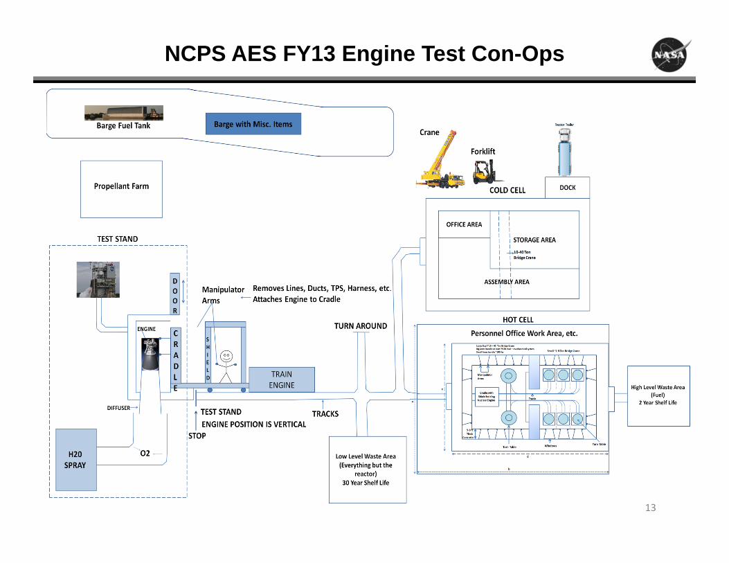
NCPS AES FY13 Engine Test Con-Ops
13

NCPS AES FY13 Hot Cell Design
14

NCPS AES FY13 Test Stand Operations
15

Total Containment NTP Exhaust System
16
How it works:• Hot hydrogen exhaust from the NTP is run into a water cooled diffuser.• The diffuser transitions the flow from supersonic to subsonic to allow more efficient burning in the afterburner• O2 rich afterburner‐burns all H2; Products include steam, excess O2 and a small fraction of noble gases (e.g., xenon and
krypton)• Heat exchanger and water spray pulls heat from steam to lower the temperature and condense• Water tank farm collects H20 and radioactive particulates. Drainage is filtered.• Heat exchanger‐cools residual gases to LN2 temperatures (freezes and collects most noble gases). Starts the flow of LOX• LOX dewar stores LO2. Drainage via boil‐off• Meets any standards/regulations for post test release
Strategy:• Fully contain NTP exhaust during burns• Slowly drain containment vessels after
radiation levels drop to favorable levels• Subscale test at significant fraction (7%)
of system needed for full‐thrust NTP testing
• Simulate NTP exhaust with hot hydrogen generator
• Full control over modular system• Develop maintenance and clean‐up
approaches

National Aeronautics and Space Administration
Functional Analysis

Functional Facility Capability Needs Summary
• Nuclear Engine Specific Test Functions– Scrubber Testing– Borehole Testing– Fully Contained Testing
• Nuclear Engine Maintenance and Disassembly Specific Test Functions
– Hardware Shipping and Receiving– Cold hardware storage– Hot hardware storage– Facility for cold hardware check‐out, assembly,
disassembly, inspections– Facility for hot hardware check‐out, assembly,
disassembly, inspections.• Engine Test Stand
– Operations– Engineering– Program Management– Safety and Mission Assurance
• Test Support– Cryogenic Operations– High Pressure Gas Facility– Industrial Water– Power Distribution
• Laboratory Services– Science Lab – Measurement Standards and Calibration– Nondestructive Test and Evaluation
• Information Systems and Computer Services• Facility Operational Services• Health Physics• E‐MAD Type Capabilities
– Transportation– Receiving and Storage– Cold Bay– Hot Bay – Equipment Maintenance– Process Cells– Hot Hold and Transfer– Hot Cells– Master Control Room– Shops– Facility Support Systems– Security– Decontamination Facilities– Shelter Area

Nuclear Engine Specific Test Functions
• Scrubber Testing– Exhaust Containment and Collection– Supersonic Diffuser– Hydrogen Injection– Turning Elbow– Subsonic Diffuser– Debris Screen
• Coarse • Fine
– Heat Exchanger– Transition Duct– HEPA Filter– Cryogenic Heat Exchanger– Activated Charcoal Nobel Gas Filter– Flare Stack– H2 Liquefaction
• Borehole Testing– Exhaust Containment– Supersonic Diffuser– Subsonic Diffuser– Water Injection
• Containment Testing– Exhaust Containment and
Collection– Supersonic Diffuser– Subsonic Diffuser– Oxygen Injection– Heat Exchanger– Turning Elbow– Transition Duct– Water Tank Farm– Water Filter– Cryogenic Heat Exchanger– Vent
Grey Font indicates that these items were taken out of scope for FY14 Study

Nuclear Engine Maintenance and Disassembly Specific Test Functions
• Hardware Shipping and Receiving• Cold hardware storage• Hot hardware storage• Facility for cold hardware check-out, assembly, disassembly, inspections
– To include component-specific workstations• Facility for hot hardware check-out, assembly, disassembly, inspections
– All processes controlled remotely via manipulator arms, cranes, etc.• Shielded transportation of hot and cold test articles/components between different
bays/cells/test stand• Shielded installation equipment for test stand installation and removal• Central Control Room
– Control of manipulators/cranes in hot areas– Management of personnel ingress/egress from area to area (shielding doors)– Radiation monitoring (gamma, neutron monitors)– 24-hour security management– Facility Support Systems
• Machine shop, electrical shop• Decontamination area• Shielded shelter area for personnel safety during hot article transportation• Health Physics/Medical area
• Note: More detail is available at the end of this section on the EMAD facility
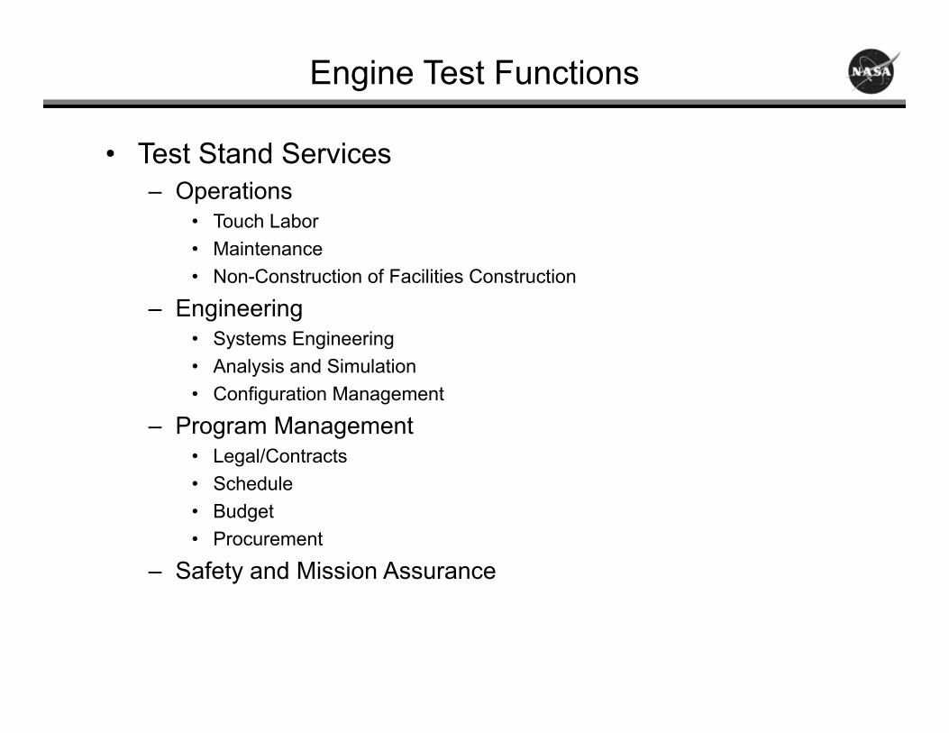
Engine Test Functions
• Test Stand Services– Operations
• Touch Labor• Maintenance• Non-Construction of Facilities Construction
– Engineering• Systems Engineering• Analysis and Simulation• Configuration Management
– Program Management• Legal/Contracts• Schedule• Budget• Procurement
– Safety and Mission Assurance

Propulsion Test Support
• Cryogenic Operations– Liquid Hydrogen
• High Pressure Gas Facility– Air Supply Systems
• Missile Grade• Confined Entry
– Helium Supply System– Nitrogen Supply System– Hydrogen Supply System– Welding and Construction Support
• Industrial Water
• Power Distribution– Nominal Operations– Emergency Power Generation

Laboratory Services
• Science Lab Services– Environmental Laboratory– Gas and Material Science Laboratory
• Measurement Standards and Calibration Laboratory– Standards Laboratory– Dimensional Laboratory– Electrical Calibration and Instrument Repair Laboratory– Pressure Laboratory– Flow Laboratory– Mechanical Laboratory– Vibration Laboratory– Temperature Laboratory– Cleaning Laboratory– Fabrication and Development Laboratory
• Nondestructive Test and Evaluation Laboratory– Radiographic Inspection– Ultrasonic Testing– Liquid Penetrant Testing– Magnetic Particle Testing– Leak Testing– Eddy-Current Testing– Visual Inspection– Hardness Testing– Bubble Leak Testing– Test Article Leak Testing

Information Systems
• Software Development
• Applications Systems
• Data Systems and IT Operations
• Telecommunications
• IT Security Services
• Information Resources Management
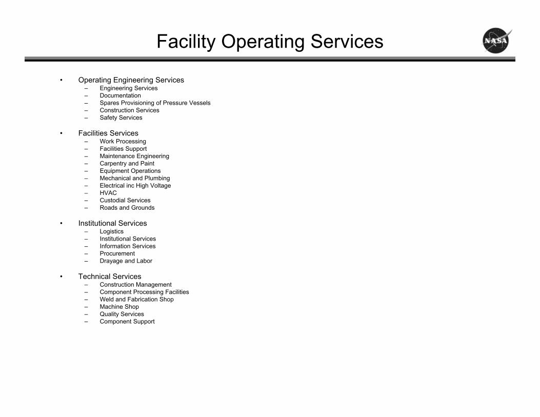
Facility Operating Services
• Operating Engineering Services– Engineering Services– Documentation– Spares Provisioning of Pressure Vessels– Construction Services– Safety Services
• Facilities Services– Work Processing– Facilities Support– Maintenance Engineering– Carpentry and Paint– Equipment Operations– Mechanical and Plumbing– Electrical inc High Voltage– HVAC– Custodial Services– Roads and Grounds
• Institutional Services– Logistics– Institutional Services– Information Services– Procurement– Drayage and Labor
• Technical Services– Construction Management– Component Processing Facilities– Weld and Fabrication Shop– Machine Shop– Quality Services– Component Support

Health Physics
• Full Health Physics Staff– Management/Health Physicists/Technicians
• Surveillance– Periodic radiological surveys of areas
• Access/Egress Control– Radiation Work Permits– Monitor all items and personnel exiting controlled areas
• Portable Radiation/Contamination Monitoring– Alpha, Beta, Gamma/X-ray, Neutron Monitors– Smears/wipes
• Fixed Radiation Monitoring– Gamma and neutron monitoring systems– Gamma monitoring system for personnel areas adjacent to process areas– Gamma monitoring for site boundary
• Airborne Contamination Monitoring– Portable samplers for personnel monitoring– Fixed area monitors
• Personnel Monitoring– Beta/gamma/neutron dosimetry– Hand and foot monitors at access/egress points– Whole body counter for determining internal deposition

Health Physics
• Counting Lab– Smear/wipe and air sample counters/scalers– Multichannel analyzer for isotopic determination of air samples and smears/wipes
• Training– Initial and periodic radiation safety training for all site staff
• Emergency Monitoring– Plume tracking– Surface airborne/radiation monitoring– Soil/vegetation monitoring
• Decontamination– Personnel– Portable items– Areas and fixed items
• Shipping /Disposal– Packaging– Shipping papers
• Training– Initial and periodic radiation safety training for all site staff

National Aeronautics and Space Administration
Nuclear Cryogenic Propulsion Stage (NCPS)Space Capable Cryogenic Thermal Engine

Space Capable Cryogenic Thermal Engine Task
29
• NCPS has begun effort to mature an engine design to aid:– Low enriched uranium (LEU) engine cycle identification which can satisfy various mission
applications– Directed choice of reactor fuel(s) to help drive and shape fuel development and testing– Matured inputs into Development Planning efforts
• Effort known as the Space Capable Cryogenic Thermal Engine (SCCTE) study– Effort based within context of Pre-Phase A / Phase A life-cycles; but not formally anchored to
all Pre-Phase A / Phase A study attributes• SCCTE effort occurring over three main phases in FY14
– System Requirements Establishment and Engine Cycle Trades• Size NTP engine that satisfies vehicle mission requirements• Top-level reactor design and engine system cycles are traded down and selected• Mainstage operation considered
– Preliminary Engine System Concept Design• Refine NTP engine design with inputs from rocket engine component engineers• Top-level reactor design and engine cycle features are finalized• Mainstage and transient operations considered
– Final Engine System Concept Design• Engine component designs are matured to a SDR level• Engine outer mold line defined• Mainstage and transient operations considered• Technical development challenges and associated risk mitigation work for development efforts defined

SCCTE Task Products
30
• Conceptual Engine Design, Power Balance, and System Requirements– Engine system analysts working with nuclear thermal reactor designers to select engine cycle, power balance, and reactor
characteristics to deliver NTR performance values• Thrust ~ 25,000 lbf; Isp ~ 900 sec• Weight and size determined from vehicle mission studies
– Engine power balance and reactor design will mature to consider both mainstage and transient operation– Engine Integration Considerations, Con Ops– Status: engine cycle selected as closed expander, tie-tube design; initial reactor sizing completed
1
2
3
4
56
9
10
12
13
14
15
16
1718
19
8
7
11
Core
Reflector
Regen. Chamber/Nozzle
RadiativeNozzle Extension
Shield
Tie Tubes (multiple)
Slats (multiple)
Pump
Turbine
Tank
Main Propellant Supply Reactor Cool-
down Supply
Tank Re-press. Supply
PSOV - propellant tank shutoff valve
NCV - nozzle control valve
SECV - support element control valve
TSCV - turbine series control valve
TBCV - turbine bypass control valve
CCV - cooldown control valve
TRSV - tank re-pressurization supply valve
PSOV
NCV
TSCV
TBCV
CCV
SECV
TRSV
SECV was added for chill-down
Closed Expander Engine Cycle Turbine Enthalpy from Tie Tubes
Notional Reactor Lattice for LEU Materials (from CSNR)
Fuel Tie Tube

SCCTE Task Products (cont.)
31
• Engine Analysis Approach Plan– Identification of traditional and unique analysis needs for NTR engine design and certification
• Review standards from ‘terrestrial’ nuclear thermal reactors to identify applicability to rocket designs• Important to address design margin and metrics (e.g., factors of safety)• Stress / structural dynamics, fluid dynamics, internal and external thermal environments, radiation
– Need to address analysis approaches to engine CDR level– Status: Reviews of historical and current nuclear reactor design approaches ongoing
Historical Analyses Approach Plan from NERVA
NERVA Engine Predicted Radiation Pattern

SCCTE Task Products (cont.)
32
• Materials Characterization and Development Plan– Understand NTR-relevant material options and existing databases– Identification of knowledge gaps in material capability based on projected engine operation– Develop material characterization plan to eliminate knowledge gaps for future NTP engine development– Status: Existing materials database compiled; working towards addressing future needs.
• Component DDT&E Plans– Develop engine component development plans based on concept design work and understanding with
nuclear-specific testing requirements• What materials do we use?• What analyses do we need?• How do we test these components?• What are the in-space operation issues?
– Engine components include:• Reactor• Chamber and nozzle• Turbopump• Valves, ducts, and lines• TVC system• Startup / shutdown pressurization systems• External shield• Avionics / controllers
– Identify Key Design Requirements, engine cycle demands, conceptual designs, and development work– Status: Reviews of prior NTR engine component developments ongoing; initial sizing beginning with
engine power balance definition.
1
2
3
4
56
9
10
12
13
14
15
16
1718
19
8
7
11
Core
Reflector
Regen. Chamber/Nozzle
RadiativeNozzle Extension
Shield
Tie Tubes (multiple)
Slats (multiple)
Pump
Turbine
Tank
Main Propellant Supply Reactor Cool-
down Supply
Tank Re-press. Supply
PSOV - propellant tank shutoff valve
NCV - nozzle control valve
SECV - support element control valve
TSCV - turbine series control valve
TBCV - turbine bypass control valve
CCV - cooldown control valve
TRSV - tank re-pressurization supply valve
PSOV
NCV
TSCV
TBCV
CCV
SECV
TRSV
SECV was added for chill-down
SCCTE Engine Cycle With Major Components
Identified

Back Up Sides
33
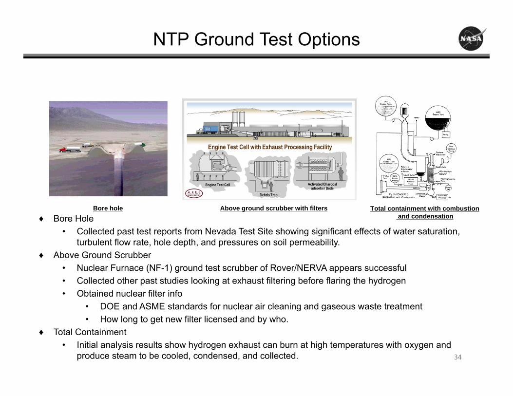
NTP Ground Test Options
34
♦ Bore Hole• Collected past test reports from Nevada Test Site showing significant effects of water saturation,
turbulent flow rate, hole depth, and pressures on soil permeability. ♦ Above Ground Scrubber
• Nuclear Furnace (NF-1) ground test scrubber of Rover/NERVA appears successful• Collected other past studies looking at exhaust filtering before flaring the hydrogen• Obtained nuclear filter info
• DOE and ASME standards for nuclear air cleaning and gaseous waste treatment• How long to get new filter licensed and by who.
♦ Total Containment• Initial analysis results show hydrogen exhaust can burn at high temperatures with oxygen and
produce steam to be cooled, condensed, and collected.
Bore hole Total containment with combustionand condensation
Above ground scrubber with filters

National Aeronautics and Space Administration
Nuclear Cryogenic Propulsion Stage (NCPS)Task 6.0
SME Issues

NTP DDT&E Issues based on Expert Opinion
Initial Con Ops from Rover/NERVA/SNTP Programs
• How to best transport a fully assembled NTP engine?• Any special tests needed to license ground transportation?
Include how to transport/dispose of hot engine components after examination.
• Is the final fuel design and fabrication going to be classified? This could affect engine assembly and disassembly.
• Where is best for engine assembly and acceptance test? Who is responsible?
• What is going to be acceptance testing? Is zero power criticality required?
• How long does it take to manufacture various engine components (e.g. fuel elements) for subsystem and system tests? Long lead components affect development schedule.

NTP DDT&E Issues based on Expert Opinion
Functional Facility Capability Needs Established:
• Is a special power pack facility needed? What are the requirements?• Is a special turbopump facility needed? What are the requirements?• Can a space reactor facility be designed to accommodate NTP, NEP,
FSP, Bi-modal? Recommend two cells for short and long duration testing.
• Can the full scale engine cold flow test facility be at MSFC?• List the current irradiation facilities to consider and what are the
capabilities, pro’s/con’s of each?• If some of the performance requirements need a prototype flight test
to qualify, should we include the flight demo as a functional capability and what do you get from it?
• How much disassembly is required to breakdown a hot engine for shipment to hot cells for close examination? How hot can the parts be for loading into special cask?

NTP DDT&E Issues based on Expert Opinion
Specific Quantified Facility Reqmts Defined:
• Start off with factors of safety (FOS) from liquid rocket engines and solid rocket motors. Future management could reduce the FOS and accept the risk.
• Does an NTP standard need to be worked before ATP with NTP development? What committee is needed?
• We need a breakdown of the facility operating requirements for each candidate.
• Can a short burn time NTP be run again after minor repairs?• Guidelines from DOE needed to determine the facility
requirements for reactor development.• Combine the engine design performance requirements with
the human rated standards and guidelines to determine the facility requirements for each ground test.

NTP DDT&E Issues based on Expert Opinion
Other Considerations:
• Who has a model to best determine how much noble gas can be released and not exceed NEPA standards?
• Determine the amount of filtering required based on NEPA and test site location.
• How long to wait after engine firing before engine can be transported or repaired? Is a graph possible showing radiation level vs time with a red line indicating acceptable level?
• Allowed dosages to the work force? Correlate to long life facility radiation expectations.
• When to have public meetings at sites requiring EIS?

E-MAD Capabilities (additional detail)
• Railroad Transport System– Manned Control Car – provides electrical power and compressed air for installation and
removal of engine from the test facility• Shielded control cab
– Engine Installation Vehicle – installs, removes, and transports engine, has tilt/positioning functions
– L-3 – locomotive, prime mover for railroad transportation system, controlled from the Manned Control Car
• Train Includes spacer cars, flatcars, special test cars, and reactor shipping instrumentation cars (controlled environment, power, lighting, equipment mounts)
• Receiving and Storage– Bonded hardware storage room– Security vault– Tool crib, storage racks & cabinets– Airlock entry way
• Cold Bay– Railroad tracks with a 360-degree turntable for rotation of transport cars to off-load onto an
auxiliary transport– 40-ton bridge crane– Access to electrical and machine shops, receiving and storage area

E-MAD Capabilities (additional detail continued)
• Hot Bay– High bay with concrete shield walls, lead glass viewing window– Tracks for entrance & exit of rail transport system– Has same 360-degree turntable capability as the Cold Bay– Handling systems designed for assembly and disassembly operations via remote
manipulator system– Handling Systems include:
• Wall-mounted• Floor-mounted
– Portable turntables, mobile carriage, railroad dolly• Overhead positioning system
– Traveling bridge, carriage, telescoping mast, auxiliary manipulator– Post Operative Cell Material Transfer System
• Transfer between cells– Periscopes for inspection and photographs– Shielded storage pit below the hot bay floor– Shielded door air-lock for transport in and out

E-MAD Capabilities (additional detail continued)
• Equipment Maintenance– Maintenance of the crane, overhead positioning system, manipulators, and other
support equipment performed in a concrete-shielded area adjacent to the hot bay
• Process Cells– Shielded– Used for disassembly of the reactor core– Operations performed using remote manipulators and overhead cranes– Operations viewed through shielded viewing windows– Steel shield door isolates the cell
• Hot Hold and Transfer Tunnel– Connects the hot bay to the disassembly and examination cells– Serves as a holding and transfer area for radioactive components– Visual observation provided by closed-circuit TV
• Hot Cells– 12 hot cells– Special car for moving material

E-MAD Capabilities (additional detail continued)
• Master Control Room– Management control center for all hot areas– Control of overhead crane, overhead positioning system, wall-mounted and floor-
mounted handling systems, shielding doors, swing-out rails and turntables– Communication and visual systems– Controls all personnel and equipment access doors
• Each access point consists of two shielding doors, and only one can be opened at a time
• Shops– Machine shop, welding shop, electrical shop– Capabilities for normal facility equipment fabrication, check-out, maintenance,
repair, overhaul– Spare parts for all specialty equipment (manipulators, cranes, rail system, etc)

E-MAD Capabilities (additional detail continued)
• Facility Support Systems– Hot water boilers for emergency power generation– Underground facility air compressors, conditioning, refrigerators, facility vacuum
pumps and chilled water distribution, heating, ventilation, etc. controlled by a central underground control room
– Electrically and radiation shielding work center for rad safe swipe and sample counting
– HVAC consists of filtration systems for removal of radioactive particulate prior to release through two exhaust stacks
• Air exhausted from hot areas is filtered to remove all particulate larger than 0.3 microns
• Hot air handling is separated from cold air handling to prevent radioactive contamination in cold areas
– Liquid waste system• Radioactive waste piped to waste holdup tanks or to a tile field (includes
floor drains from all shielded areas)
• 24-hour security personnel
• Health physics office– Management of personnel health
E-MAD Capabilities (additional detail continued)
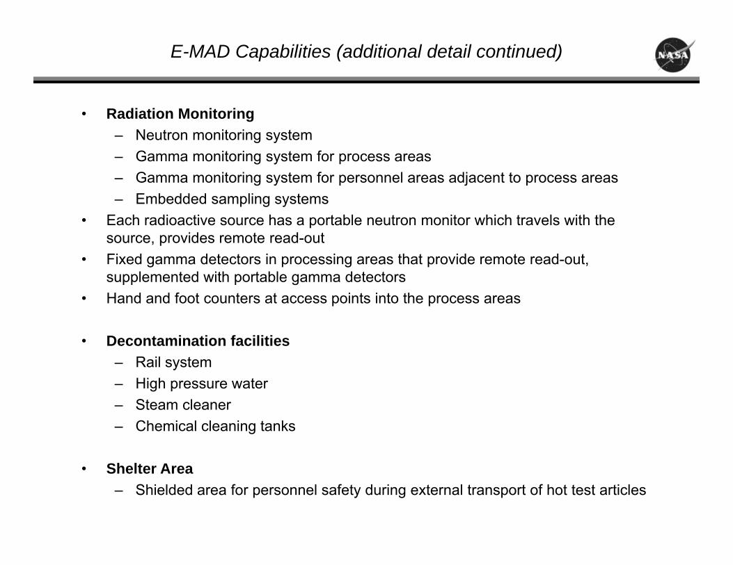
• Radiation Monitoring– Neutron monitoring system– Gamma monitoring system for process areas– Gamma monitoring system for personnel areas adjacent to process areas– Embedded sampling systems
• Each radioactive source has a portable neutron monitor which travels with the source, provides remote read-out
• Fixed gamma detectors in processing areas that provide remote read-out, supplemented with portable gamma detectors
• Hand and foot counters at access points into the process areas
• Decontamination facilities– Rail system– High pressure water– Steam cleaner– Chemical cleaning tanks
• Shelter Area– Shielded area for personnel safety during external transport of hot test articles

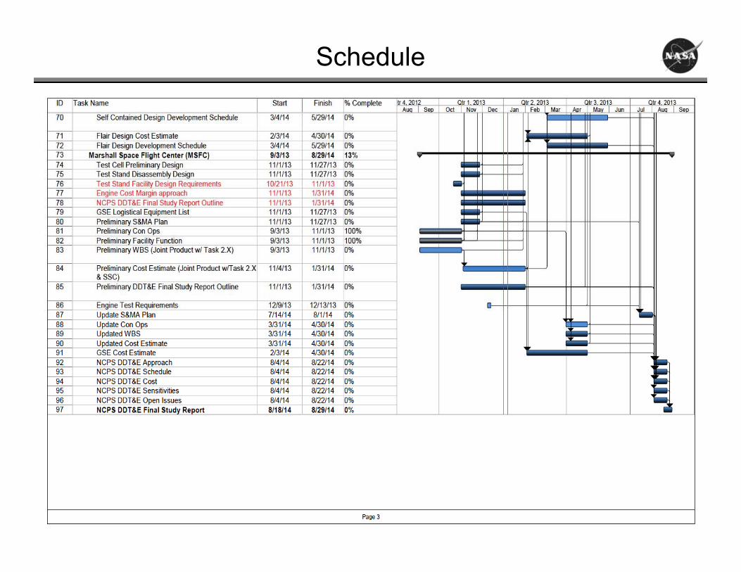
Schedule
46
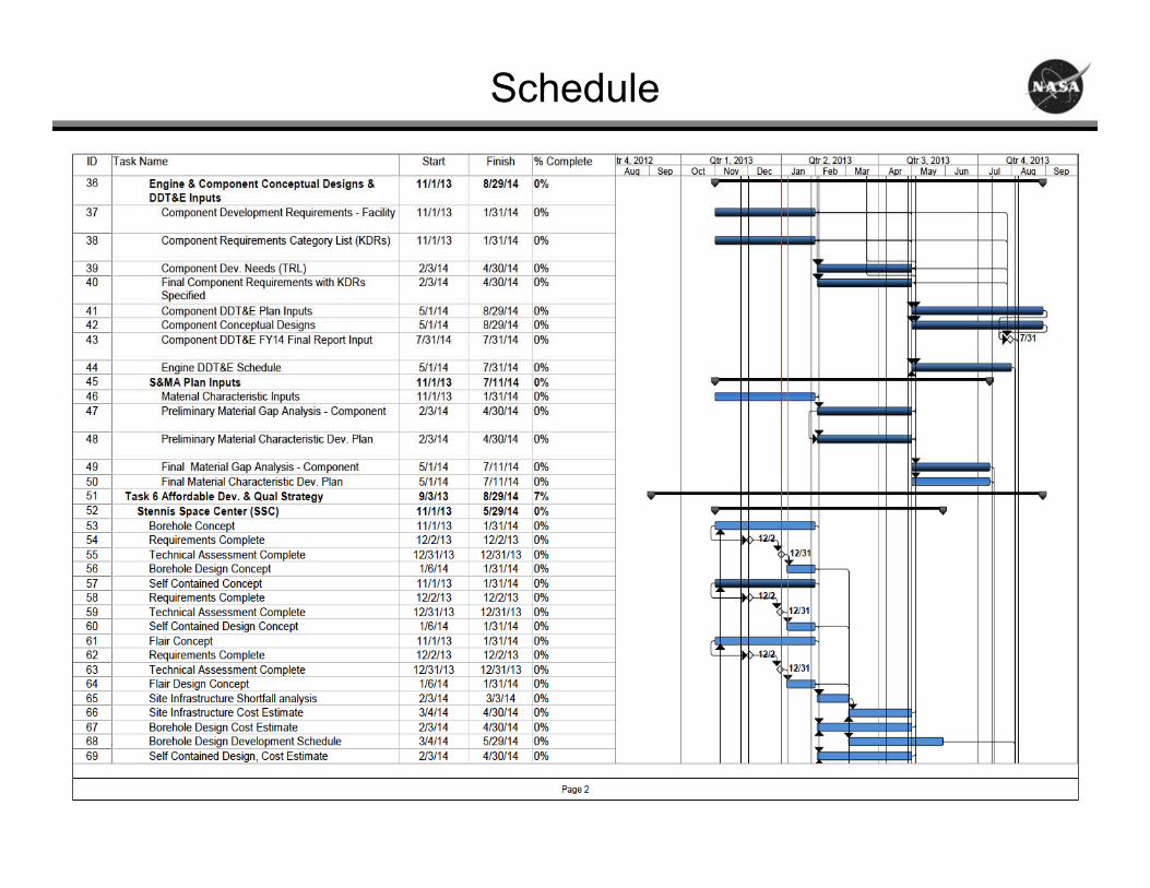
Schedule
47
Schedule
48