NCDA Design Concept Report - Mechanical … · Web viewNCDA Design Final Report Team 7: Silo Packer...
97
NCDA Design Final Report Team 7: Silo Packer TASA Engineering Design Engineers: Adel Abumohor 215 Beau Tree Dr. Wilmington, DE 19810 (302) 369-5883 (302) 475-7707 [email protected] Jeff Acheson 213 Sussex Hall Newark, DE 19717 (302) 837-8824 [email protected] Pete Sullivan 351 Paper Mill Rd. Newark, DE 19711 (302) 731-1314 [email protected] J. Michael Tate 209 Gilbert Hall A Newark, DE 19717 (302) 837-3533 [email protected] Page 1
Transcript of NCDA Design Concept Report - Mechanical … · Web viewNCDA Design Final Report Team 7: Silo Packer...

NCDA Design Final Report
Team 7: Silo PackerTASA Engineering
Design Engineers:
Adel Abumohor215 Beau Tree Dr.
Wilmington, DE 19810(302) 369-5883(302) 475-7707
Jeff Acheson213 Sussex Hall
Newark, DE 19717(302) 837-8824
Pete Sullivan351 Paper Mill Rd.Newark, DE 19711
(302) [email protected]
J. Michael Tate209 Gilbert Hall ANewark, DE 19717
(302) [email protected]
Page 1

Table of Contents
Table of Contents: 2Summary 4Introduction: 5
Background: 5Customers: 5Wants: 6Constraints: 7
Concept Generation 7System Benchmarks 7Functional Benchmarks 9Metrics 10Target Values 10Concept Generation 11
Concept Selection 14Evaluation 14
Experiments 15Constraints 17Metrics 18
Selection 19Construction 21
Fabrication 21Assembly 22
Concept Testing 23Testing Plan 23Results 24
Concept Refinement 24Redesign 24Suggested Modifications 25
Conclusion 26Drawings 28Budget 41Sketches 42
Page 2

Executive Summary:
TASA was commissioned to design and build a prototype test silo loader for Dr. Limin
Kung of the University of Delaware Department of Animal and Food Science. Agricultural
researchers use apparatus like these to fill small test silos in order to test how different bacterial
and chemical agents inhibit the spoilage of silage materials. Dr. Kung is one of a list of seven
customers, all related to agriculture, that come from both academic and commercial fields and
are involved in research similar to that done at UD. These customers desire an apparatus which
can allow them to pack a test silo quickly and easily, but with high accuracy and precision. This
apparatus must improve upon their current method of packing and meet storage requirements
and a very small budget.
We began addressing the problem by benchmarking various systems. We broke our
design into different functions like compacting devices and pressure sensors and determined
which items were the best in their particular area. In order to evaluate our benchmarks and also
our own concepts we distilled the customers wants into a list of ten metrics. We proposed
targets from our benchmarking and determined which metrics were critical to our design and
which were only peripheral to it.
We created concepts using our benchmarking as a foundation for ideas, but also reaching
beyond it for new and interesting concepts that may give us an edge on the competition. Our
concepts were grouped into four families of related ideas; extruders, horizontal pistons, vertical
pistons, and the “other” group.
We performed a series of experiments in order to test basic concepts used in all our
designs and to also determine some basic silage properties. We eliminated some designs because
their costs exceeded our budget limit. We ranked the concepts that were left against our critical
Page 3

metrics in order to get a rough comparison and then did a complete ranking of the front-runners
in order to determine which concept was truly the best analytically. We took our best concept, a
vertical pneumatic piston, and designed its various components.
We fabricated a prototype from these parts designs and then created a testing procedure
for this prototype. Using the results from the testing procedure, we charted its performance
within our metrics. We evaluated the prototype’s performance against the target values set by
the metrics and made minor redesigns to specific areas. We also showed the original prototype
to Dr. Kung, who had some of his own comments.
We then slightly redesigned and rebuilt the prototype into order to increase the design’s
performance in several metrics and in order to create a safer final product. The end result is the
final prototype which was presented on Friday, April 23.
Introduction:
Background:
Silos are widespread in agricultural use to store livestock feed due to their low cost and
simple design. The basic concept behind the silage process is that bacteria use up all the oxygen
in the silo and so the silage material (the material which is packed inside the silo) doesn’t spoil
for extended periods as long as no oxygen is allowed to enter the storage system.
Due to its widespread use in agriculture, there is a substantial amount of research
currently being done by various commercial and academic groups into how to improve the silage
process. These groups perform numerous experiments on small test silos ranging in side from
eight inch PVC pipes to 5-gallon paint buckets. These silos model the larger systems found in
agricultural use, but do not naturally pack under the weight of their silage as farm silos do. For
Page 4

this reason they are packed by personnel in these research groups, usually by some method
which utilized their own body weight.
Current packing methods are based around multiplying the users body weights by means
of a simple lever (for the small silos), and compressing the material in the large silos with the
packers’ feet. Due to the large number of these silos which must be filled, these methods often
fail to relieve the tedium and physical rigor of packing up to fifty silos at a sitting. An entire
work crew usually undertakes this task, but it is still not a pleasant duty for the individuals
involved. Also, since the packing methods are dependent upon body weight, different packers
give different packing results which is bad for research precision. These reasons demand a
design to automate the packing process.
TASA was commissioned to design and build a prototype experimental silo packer for
Dr. Limin Kung of the University of Delaware Department of Food and Animal Science. This
prototype should be able to quickly and reproducibly load a test silo without requiring extensive
manpower.
Customers:
Dr. Kung formed the basis for our customer group. We also consulted with Navin
Ranjit, one of Dr. Kung’s research assistants, in order to get the future user’s perspective. We
interviewed Richard Morris, the UD agricultural farmer whose farm will be where the proposed
apparatus will be stored and used. After this our customers branch out to other academic
researchers like Dr. Martin Stokes of the University of Maine and Dr. Joseph Harrison of
Washington State University, both of whom are doing research similar to Dr. Kung. We also
contacted commercial customers such as Chris Roden of Chr.Hansen Biosystems and Carol
Page 5

Meyers of Kemin Industries. Both of these people are with agricultural chemical and bacteria
suppliers who also perform experiments similar to Dr. Kung’s. We prioritized these customers
in Table 1 in order to enable us to create a quantitative ranking of their wants.
Table 1 – List of CustomersRank Customer Organization Rate of Importance
1 Dr. Limin Kung UD Ag Department 0.502 Navin Ranjit UD Ag Department 0.253 Richard Morris UD Ag Farmer 0.054 Dr. Martin Stokes University of Maine 0.055 Dr. Joseph Harrison Washington State University 0.056 Chris Roden Chr.Hansen Biosystems 0.057 Carol Meyers Kemin Industries 0.05
These customers expressed various different desires. We took each of our customers and
listed each of their wants, prioritized them numerically by using the weighting shown in Table
2.
Table 2 – Rate of Importance of Individual Customer WantsCustomer’s Want Rank Rate of Importance
1 0.252 0.203 0.154 0.155 0.106 0.107 0.05
The top ten of the wants mentioned are listed in Table 3 in a prioritized order. Some wants,
like reproducing desired results, stem from the design’s use as precision laboratory equipment. Other wants are
related to the desires to reduce the physical exertion and tedium of the packing process. Still other wants are
related to the desire to minimize the immediate and future expenditures on the group’s part and also ensure a long
operating life for the equipment. The Rate of Importance column, which was used to derive the final ranking of
the wants, is a normalized weighted average of each individual customer’s wants.
Table 3 – Net Customer Wants
Page 6

Final Rank Want Rate of Importance1 Reproduce Desired Results 0.2492 Not Physically Demanding 0.2283 Fast Operation 0.1314 Simple User Operation 0.0915 Low Cost 0.0766 Easy To Clean 0.0677 Easy to Repair/Manufacture 0.0618 Easy to Transport 0.0589 Variable Silo Size 0.02410 Easy to Store 0.015
The customers also expressed certain constraints that had to be met by the final design.
Our design must be able to pass through a normal doorway, be movable by two people, be able
pack a silo as fast as current methods, be able to prevent the stopper from being recessed more
than a centimeter into the silo, and be built for under five hundred dollars. Most of these
constraints are derived from physical needs of storage and methods that will be used to extract
silage from the test silos themselves.
Concept Generation:
System Benchmarking:
Our team benchmarked a wide variety of systems that perform applications similar to the
job which will be accomplished by the silo packer, these systems are shown in Table 4 in ranked
order of importance.
Table 4 – System BenchmarksRank System
1 Stokes Pneumatic Loader2 Stokes Front End Loader3 Trash Compactors4 Shot-shell and Cartridge Loaders5 Pharmaceutical Capsule Filling Machines6 Soda Can Crushers
Page 7

7 Current Apparatus
The Stokes Pneumatic Loader is a vertically mounted pneumatic piston driven by an air
compressor. Silage is put into the test silo and an attached filling tube mounted on top of the
silo. The piston then compresses the contents of the silo and the filling tube into the silo at high
pressure. A similar apparatus is also in service with Carol Myers of Kemin Industries.
The Stokes Front End Loader is used to compress the larger test silos. One five-gallon
bucket is filled with silage and another large bucket is put on top of it. A small front-end loader
then is used; its hydraulic scoop presses the top bucket into the lower one. The result is a large,
compressed silo. This works well, but the exact pressure exerted onto the silage is hard to
measure and sometimes damage can occur to the silos if the Bobcat operator is not well trained.
Trash compactors have the necessary ability to compact all types of materials. Trash
compactors do not usually put them in any sort of container however and they crush objects to
uniform volume but do not apply a uniform pressure. They do operate quickly and efficiently
however.
Shotshell and cartridge loaders have many of the characteristics we are looking for in a
design. The have a feed bin full of material, in this case gun powder, which can be precisely
loaded into a cylindrical container, in this case a bullet casing. The powder is then compressed
in the casing using a piston on a crank. The apparatus is very precise and accurate and is quite
fast as well, but is too small for our needs.
Pharmaceutical capsule filling machines precisely fill objects with a predetermined
amount of material. They do many small capsules at once with multiple pressing fingers and are
very precise because of this approach. The problem here is that these materials are not fibrous
Page 8

like silage, they are powders or grains which have better packing and filling properties. This
apparatus is also very expensive.
Soda can crushers have the right components for a manually powered silo packer if it
were scaled up properly. A lever is used to apply a pressure to an object, in this case it would
have to be the silage not the silo itself. This apparatus is cheap, but cannot exert enough
pressure and would be labor intensive.
After comparing the system benchmarks, we determined that our strongest competitor is
the Stokes Pneumatic Loader. It is less expensive that some of the other systems and its
pneumatic piston provides excellent precision and accuracy while not sacrificing power.
Functional Benchmarking:
After we completed our system benchmarking we examined our various system
benchmarks for simple component functions which they held in common. From this, we
determined specific functons which individual parts of the design would have to accomplish.
These functions are compacting, material transport, container transport, pressure sensors, and
user controllers. This section is dedicated to an overview of the research we did with these as
well.
We examined compacting devices like power presses, pneumatic pistons, extrusion
screws, and pile drivers. After comparing these to each other and our wants, we determined that
the pneumatic piston is the best practice due to its low price and excellent mix of precision and
accuracy in pressure production.
Material transport was looked at with different mechanisms from the lawnmowers and
vacuum cleaners to hydraulic rams and extrusion screws. The best practice in this category is
Page 9

the screw feeder because it reduces the number of necessary user actions and is highly
compatible with the test silo’s circular geometry.
The silo container itself can be moved through a variety of different methods from the
human hand to a conveyor. The conveyor belt is the best practice here. It is widely used,
inexpensive and is simple to use.
We looked at a multitude of products for measuring pressures ranging from piezoelectric
mats to load cells. The best practice here is the piezoelectric pressure sensor because it is the
most accurate and precise, but unfortunately it is priced much too high for our budget.
We looked at multiple ways to control our apparatus from push buttons to computer
keyboards, but we believe that the foot pedal is the best practice because it leaves the users hands
free for other activities.
Metrics:
From the list of wants we initially created upon talking to our customers, we created a list
of starting metrics that we felt would accurately measure their various desires. Table 5 consists of
a list of the top ten metrics cross-referenced with the want or wants they were derived from and their target values.
Table 5 - MetricsRank Metric Most Relevant
WantsTarget Value Target Derivation
1 Number of User Actions
Simple User Operation
3 Stokes Loader
2 Pressure Per Layer Reproducing Desired Results
100 psi Current Methods
3 Change in Pressure Reproducing Desired Results
30 psi Current Methods
4 Operating Force Not Physically Demanding
20 lbs OSHA Standards
5 Total Cost Low Cost $500 Budget6 Total Time to Fill Fast Operation 80 seconds Current Methods7 Number of Users Fast and Simple 2 Stokes Loader
Page 10

Operation 8 Storage Volume Easy to Store and
Transport36 cubic ft. Current Apparatus
9 Number of Silo Sizes
Variable Silo Size 2 Stokes Loader
10 Weight Easily Transportable
88 lbs OSHA Standards
From this list of metrics in Table 5, we determined that the most critical metrics in our
design were the pressure metrics (total and per layer), the time to fill, and the operating force.
These along with the low cost metric, which comes into play due to our low budget, form the
core that we used to roughly rank our concepts. We chose these as the chief metrics for
evaluation because they were simple, but spoke directly to many of our leading customers wants
like Reproduce Desired Results, Not Physically Demanding, and Fast Operation.
We had to discard the “Number of User Actions” want from the list of critical metrics
despite the fact is that it is our highest rated metric. It is simply not a good metric for critical
ranking because it is had to measure between concepts, and is potentially very similar for a wide
range of designs. It is also highly depended on the number of users operating the system
simultaneously.
Concept Generation:
Concept generation began by looking at the competitors and seeing what processes they
used to create their apparatuses. From there the focus was turned to the best practices in order
beat our competitors by integrating better technology or cheaper systems into our designs.
Concepts are located in several different families with branches that encompass
variations on the same idea. This tree structure logically occurs during any brainstorming
session when one idea leads to another and a good basic concept branches into many variations.
We attempted to use as many of the best practices in the creation of these concepts as possible,
Page 11

but due to budget limits many of these we not able to integrate many of these systems into the
listed concepts.
Please note that if these written descriptions are not enough to understand the concept,
there are simple schematics of the concepts listed by concepts name and number in the Sketches
Appendix. Also be advised that these are not the only designs that were conceptualized, but, for
the sake of report brevity, we chose not to include all of the six or seven different concepts that
fit in most of the families. We also wanted to convey the breadth of different design concepts
rather that focus on a single area.
1 Extrusion
The Extruders come into play because their extrusion screw allows for continuous
feeding from a storage bin. They incorporate the best material transport benchmark, but
do not include many of the others due to their nature.
1.1 Straight Extruder: This is a classic extruder design. A screw is mounted to a
motor horizontally and draws the silage from a large feed bin and moves it down
into the test silo which is mounted horizontally at the end of the screw. A
constant pressure is kept at the silo end of the screw because the silo is mounted
into a carriage which allows it to move. The screw is always feeding new silage
in at the top of the previously compacted silage, until the silo moves so far back
that it trips a kill switch.
1.2 Tapering Extruder: This is similar to the design above, only instead of a standard
screw, this unit’s screw has a section of changing radius. As the silage moves
into the silo, it has already begun compacting because of the screw taper. It
enters the silo and is completely compacted from there. The pressure would be
Page 12

regulated as above, but might not have to be as high as in the above case due to
the screw’s influence on compacting.
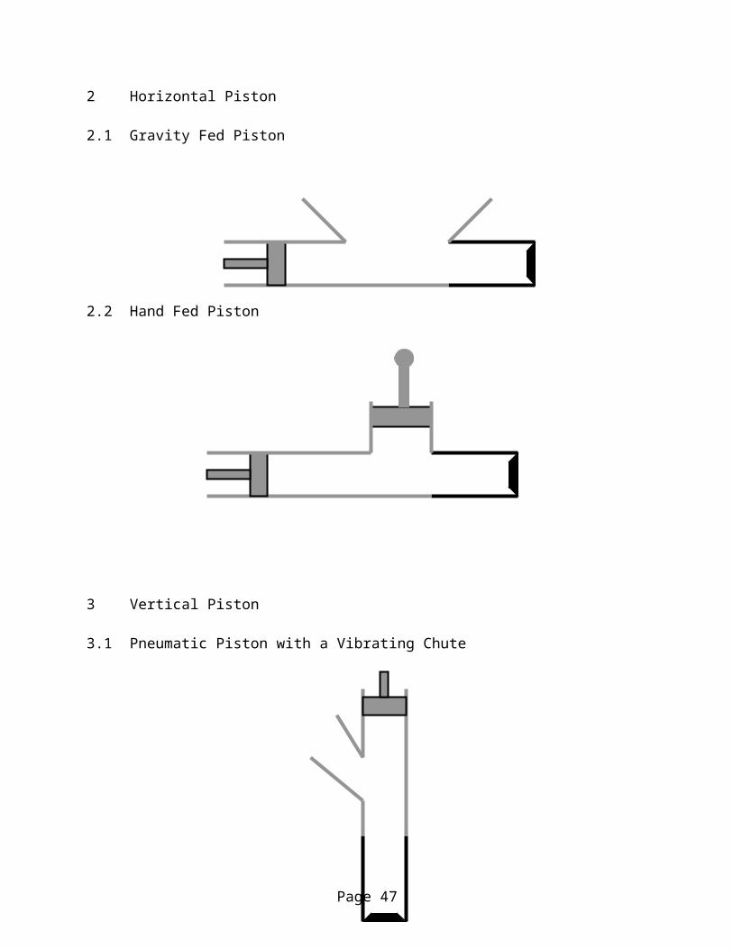
2 Horizontal Piston
These systems use the pistons which form the best compaction benchmark. They feature
a pneumatic piston and silo which are mounted horizontally.
2.1 Gravity Fed Piston: The compression chamber of the piston is filled with a mass
of silage falling from a bin above the chamber. This silage is then pressed into
the silo by the piston. The process of loading and pressing continues until the silo
is full.
2.2 Hand Fed Piston: The compression chamber of this system is filled by smaller
loads of silage than before. These loads are dropped into the compression
chamber by using a chute in the chamber’s top. This silage is then pressed into
the silo by the piston. As before, the process of loading and pressing continues
until the silo is full.
3 Vertical Piston
These systems use the pistons which form the best compaction benchmark. They feature
a pneumatic piston and silo which are mounted vertically.
3.1 Pneumatic Piston with a Vibrating Chute: The complete filling of the silo takes
several iterations of this process and between piston shots the silo is refilled by
sliding silage down into it through a chute which connects to an opening in the
Page 13

feeding area’s wall. In order to keep the silage moving this ramp is being
vibrated.
3.2 Pneumatic Piston with a Screw Feeder: This design is very similar to the above,
but the feeding chamber and silo are filled with a screw feeder from a large bin
when the piston is not in operation instead of a chute. This is different because it
will allow a much larger feeding bin than the previous concept and utilized one of
our best function benchmarks.
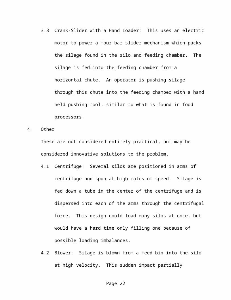
3.3 Crank-Slider with a Hand Loader: This uses an electric motor to power a four-
bar slider mechanism which packs the silage found in the silo and feeding
chamber. The silage is fed into the feeding chamber from a horizontal chute. An
operator is pushing silage through this chute into the feeding chamber with a hand
held pushing tool, similar to what is found in food processors.
4 Other
These are not considered entirely practical, but may be considered innovative solutions to
the problem.
4.1 Centrifuge: Several silos are positioned in arms of centrifuge and spun at high
rates of speed. Silage is fed down a tube in the center of the centrifuge and is
dispersed into each of the arms through the centrifugal force. This design could
load many silos at once, but would have a hard time only filling one because of
possible loading imbalances.
4.2 Blower: Silage is blown from a feed bin into the silo at high velocity. This
sudden impact partially compacts the silage and the impact of the silage filling the
silo on top of it finishes the job. This design will most likely have problems due
Page 14

to the cylindrical cross section of the silo as opposed to the rectangular cross-
section of many blowers.
4.3 Weight Press: Silage is fed into the silo through a chute and is then compacted
through the use of a piston on linear bearings. This piston is rigidly attached to a
step on the side of the apparatus. Operators apply force due to their body weight
to the step when the stand on it, the step is of course hooked to a scale so that the
force exerted by the people on the step can be kept relatively constant.
Concept Selection:
Evaluation:
Our first step in the evaluation process was to do testing on the applicability of several of
our design concepts. Using a clear plastic cylinder of roughly the same dimensions as a test silo,
we started to examine how well silage packed with the different orientations of the silo and
different sizes of the piston. After this we examined the properties of silage in relation to how it
slid and moved through channels.
Diameter Changes and Plungers Design:
The first step we took was qualitatively examine effect lips and sudden changes in
diameter had on the packing process.
1) Our initial experiment used a plunger of the same diameter as the silo’s interior and it
showed us immediate problems with such a design. As the plunger moved from the wider
diameter region into the smaller silo, it invariably jammed with silage and was unable to
Page 15

enter the silo for more the a few millimeters. Even with several people pressing on the
plunger, the silage prevented any and all movement of the plunger past the lip.
2) After this we attempted to compress the silage with a plunger that was noticeably smaller
than the interior diameter of the silo. It passed through the silage around the lip and was
successfully able to enter into the silo. Yet, as our clear test silo showed us, was able to
relatively uniformly compress the silage in the silo itself despite not covering the silos entire
cross-sectional area. This method is not perfect however, we experimented with looser and
denser packing and discovered that the more dense the packing the greater the likelihood of a
jam. We also experimented with the amount of silage that was to be packed and discovered
that the more silage that was used, the higher the chance of jamming.
3) We concluded that lips of any form should be avoided in our final design and the piston
should be smaller in radius than the silo to hopefully avoid jamming.
Orientation:
We examined silo orientation in relation to the uniformity of packing.
1) Our first trials were conducted with a vertical cylinder using small and large packing
volumes. The orientation performed well and uniformly packed the material through
repeated iterations. We noticed that once the silage was packed it tended to stay in the place,
the compacted silage moved very little when fresh silage was compacted on top of it.
2) We then switched to a horizontal packing scheme and had our fears about this orientation
confirmed, small silage loads do not pack uniformly. If a silage load is added which does
not completely fill the silo’s cross-section, the packed silage will contain air spaces that run
down the top of the silo. Repeated packing of small silage loads does not alleviate this
Page 16

problem either as the new silage does not compact the old. This silo orientation also has an
inherent lip in its design where the silage feeds into the compression chamber. If it is
overfilled the piston is more likely to jam, if it is under-filled the packing will be highly non-
uniform.
3) A horizontal silo orientation will not produce reliable results, the silo must be oriented
vertically.
Silage Properties:
We then tested some simple silage properties to see what types of silo loading
mechanisms we could use for the apparatus.
1) First we looked at silage slipping down plates of two different materials. We used the slip
angle to approximate friction for the silage. For both materials the silage began to slip at
approximately 400, a relatively high angle to pitch any kind of chute. We also noticed that
all the silage did not slip, often some residual silage was left on the plate even when it was
tilted to 900. This occurred less when the silage was compressed before it was placed on the
plate.
2) Next we attempted to throw the silage down the plate with a small initial velocity to see if it
would continue to slide. This did not occur and the silage usually stopped within a few
inches from where it touched the plate.
3) Next we examined how silage moved down a two inch wide aluminum channel. Motion was
highly dependent upon the amount of silage used and the silage slipped down the channel
under its own weight at approximately 450 of incline. We also discovered that the more
Page 17

silage, the greater the slope of the plate before the silage begins to move. This is most likely
due to contact between the silage and the walls of the channel.
4) Lastly, we examined what effect a narrowing channel has. We built a channel that narrowed
down to the two inch channel to see if such a feeding ramp would work. Results depended
on the amount of silage, as did the results for the channel, but some things were the same for
all tests. The area where the angled sides changed over to the two inch straight channel was
always trouble spot. The silage could use the angled sides for support even when the channel
was tilted to 900.
5) The conclusion we drew from these experiments is that the silage must be forcibly fed into
the compression chamber, it will not just slide there under its own weight.
Constraints:
Next we eliminated designs which did not fit our customer constraints. Our design must
be able to pass through a normal doorway, be moved by two people, pack a silo as fast as current
methods, prevent the stopper from being recessed more than a centimeter into the silo, and be
built for under five hundred dollars. After pricing the screws necessary to build the extrusion
designs, we realized that they were not possible without going over budget. The designs which
use electrical motors will require both a motor and a transmission to gear the motors down
enough to operate at the desired speed and force. This raises their price above the budget
constraints as well. The pneumatic piston designs also have problems working under the budget,
but the farm has both a portable compressor and airlines which are available to our primary
customer. This means that these items do not need to be purchased and that the pneumatic
designs fall below the budget cap.
Page 18

Metrics:
After using our constraints and the data from the experiments that were conducted, we
were able to eliminate five of the original ten proposed designs as unfeasible. The remaining
five designs were compared using our critical metrics in order to narrow the field further. Table
6 shows how they compare.
Table 6 – Critical MetricsRank Name Pressure per
Layer (PPL)(psi)
Change in PPL
(psi)
Operating Force (lbs)
Total Cost ($)
Total Time to Fill (s)
1 Piston With a Hand Feeder
100/100 5/30 15/20 600/500 65/80
2 Piston with Vibrating Chute
100/100 5/30 15/20 500/500 80/80
3 Weight Press 100/100 20/30 100+/20 300/500 80/804 Centrifuge 75/100 30/30 5/20 500/500 120/805 Blower 50/100 30/30 5/20 500/500 40/80
It is relatively obvious that the weight last three design are not in contention with the first
two due to bad reproducibility or shear repeated physical exertion. After looking at these critical
metrics, we can weed these five possible designs into two leading contenders which we will now
examine further using all of our metrics. Table 7 shows the comparison between the two designs along
with the set target values for each metric and each metric’s relative rate of importance.
Table 7 – Final Competing DesignsMetric Rate of
ImportanceTarget Value Hand Fed
Crank SliderVibrating Chute
Number of User Actions
0.145 3 3 3
Pressure Per Layer 0.124 100 psi 100 psi 100Change in Pressure 0.124 30 psi 5 psi 5 psi
Operating Force 0.112 20 lbs 15 lbs 15 lbsTotal Cost 0.110 $500 $600 $500
Total Time to Fill 0.085 80 sec 65 sec 80 sec
Page 19

Number of Users 0.067 2 2 2Storage Volume 0.061 36 cubic ft. 11.5 cubic ft. 11.5 cubic ft.
Number of Silo Sizes 0.058 2 1 1Weight 0.046 88 lbs 60 lbs 60 lbs.
As is plain to see from our metrics, the hand fed Crank-slider is better than its
competitor, the vibrating feeder in terms of the required time to fill a silo. The hand feeder
actually pushes the silage into the compression chamber, allowing for fast and reliable loading.
The vibrating chute may work well, but it will be prone to clogging if it is overfilled and it lacks
an easy means to clear these blockages. While the hand-feeder is cheaper than any system for
vibrating our loading chute, the motor and transmission for the slider crank is much more
expensive than the pneumatic cylinder.
Final Selection:
The team conducted experiments to determine silage’s material properties and used them
to determine which designs would perform well and which would most likely suffer problems
that would reduce their effectiveness. Then the team made sure than the design could be built
within or very close to our budget. We took the remaining designs that lacked significant
problems and ranked them according to our critical metrics (for brevity). Finally we took the
best parts of these designs and combined them to form the final concept which will go to
prototype.
Let us now go into more depth with the final concept. Engineering drawings are located
in the next section of the report if these text descriptions are not clear enough.
There are a few basic sections to this design; the piston, the frame, the door, the silo
mount, the silo and extension, the electrical setup, and the pneumatic equipment.
Page 20

The piston is a 16 in. stroke, 2.5 in. diameter pneumatic cylinder with a 1 in diameter
driving rod. Its large stroke length allows for a large compression chamber which can be filled
with silage and its bore size gives a high factor of safety in compression. The large driving rod
allows the piston to accept high shear loading which may be caused by silage binding around the
sides of the piston. Indepth analysis on the piston itself is in the analysis appendix.
The frame is made of two basic pieces: the beam and the plate. The tube is a vertical
piece of 0.25 in. wall, 2in by 2in steel square tubing 40 inches in length. It accepts the high
moment loads of the piston, is large and therefore easy to fasten other components to, and has a
high factor of safety to take into account any stress concentrations around bolt holes, etc. The
plate is 3/8 in steel plate. It is the surface upon which the silo sits and accepts the high bending
load of the piston. These two pieces are welded together at the base of the tube. The analysis of
the frame is in the solid mechanics analysis appendix.
The door is made of 1/16 steel sheet. Its main feature is a large opening which is cut in
the center of its length in order to allow the viewing of the piston’s position. It has 4, ¾ in.
aluminum ribs to give it bending strength along its curved surface. It also has 2 vertical side ribs
to give it strength in the axial direction and allow for easier hinge fixation. The door is attached
to the silo mounts by hinges and is held closer by an automobile trunk mechanism.
The silo mounts themselves are made of aluminum for easy machining. They have
curved surfaces which accept the silo and put it on the pistons axis. There are four mounts
placed along the 16 inch length of the silo and extension. These are bolted to the frame.
The silo and extension are made up of a standard 8 in. long by 2 in. diameter PVC test
silo. The extension is a clear plexiglass tube 8 in. long and 2 in. in internal diameter. These two
are connected using a rubber plumbing coupler. The internal diameters of both objects are the
Page 21
same. This part of the system is removable so that several silos and their extension can be filled
while another is being packed.
The electrical equipment is made up of several components. A limit switch prevents the
apparatus from operating when the door is open. A fuse protects the system from surges and
other phenomenon. A red light tells the operator when the system is live. A rocker switch
completes the circuit and energizes the solenoids in the spool valve allowing the piston to move.
The switch is spring loaded so that the piston always stops if someone is not actively using the
switch. The electrical system runs off a standard household 110 line.
The pneumatic system also has many parts. A regulator is used to monitor and vary the
pressure in the system and the resulting piston force. A safety valve protects the other parts of
the system from damage due to excessive pressure. A needle valve allows the user to alter the
speed at which the piston operates. A spool valve is connected to the electrical system and
governs the direction in which the air flows through the pneumatic cylinder.
Construction
Fabrication
This took place in the machine shop at Spencer Lab and also at the machine shop in 124
Worrilow Hall. A complete section of drawings is found in the drawings appendix.
Because the most of the components of the system were designed to be machined at
relatively low tolerances, we were able to avoid using expensive machine tools like the
Bridgeport Mills in favor of cheaper, less precise tools like a simple drill press.
Most of the parts of the pneumatic and electric systems were bought, not built. Most of
the major electrical components can be bought from Radio Shack’s standard stock. Most of the
pneumatic components can be purchased from Granger and delivered in only a day. This makes
Page 22
the system both easy to build and easy to repair if parts break due to extended use or even
misuse.
Most of the components are bolted or screwed into the final design. If they need to be
removed or replaced for any reason, this can be done quickly and easily. The steel frame itself
was welded into one piece to provide a solid piece on which all the other system components can
be attached.
Most components are made of mild steel in order to be inexpensive and strong enough to
take repeated use. A few parts, like the pistons themselves and the silo mounts, are made of
aluminum. Aluminum was used because of the relative ease of machining it for the silo mounts
and its resistance to corrosion in the case of the piston heads.
Assembly
Assembly took place at 124 Worrilow Hall. Final assembly uses a minimum number of
tools. Final assembly only required a flat head and philips head screwdriver, 7/16 in wrench, ½
in wrench, and a 9/16 in wrench.
System Testing
Testing Plan:
After the prototype was built, its performance had to be compared to the metric target
values. This required a period of testing using a specific testing plan.
1) The prototype was weighted and then a rough estimate of the storage space it will take up
was made using the exterior dimensions of the packer.
Page 23

2) The operating force was estimated after taking the force that was required to operate various
different components. The highest operating force required to operate the packer is the force
required to close the door because of the strength of the door latch.
3) Total cost was calculated from the amount spent to date.
4) The number of silo sizes can be calculated by inspection.
5) The packing time for one person packing a single silo was taken. Different individuals were
used in order to ascertain the level of skill required to operate the packer and whether the
filling time was variant with the user.
6) The packing time for a group of users was taken in order to take into account the effect
multiple packers will have on the system. The old apparatus is designed to be used with
multiple individuals packing the silos in order to speed the packing time. Our apparatus is
packed similarly since the silo and extension can be changed easily between packs.
7) Using the old apparatus we found an average mass of packed silage in a silo. Trials were
then conducted calculating the effect of the change in pressure on the packed density of the
silage. It was found that, while the packer can operate at 100 psi, it packs best at 65 psi. The
amount of silage packed is the same as with previous equipment, but the lower packing
pressure prevents the silage from blowing the lower stopper off the silo as the silage
elastically expands after it is packed.
8) We measured the variation in packing pressure by examining the dynamic fluctuation in
system pressure during the packing of several test silos.
Results:
Page 24

The results from these various experiments are reported in Table 8. As you can see the
silo packer prototype beats the targeted values in every way except in the number of silo sizes.
We consulted our primary customer and he approved of this in order to keep the final costs of
the project down since we had deliberately solved the problem for the more difficult of the test
silo types.
Page 25

Table 8 - Test DataMetric Target Value Prototype
Number of User Actions 3 3Max Pressure Per Layer 100 psi 100 psiChange in Pressure 30 psi 5 psiOperating Force 20 lbs 5 lbsTotal Cost $500 $450Total Time to Fill 80 sec 80 secNumber of Users 2 2Storage Volume 36 cubic ft. 4 cubic ft.Number of Silo Sizes 2 1Weight 88 lbs 42 lbs
The primary information learned from testing was that our machine produced results that
were comparable to the results from the old machine. This meant that the pressure per layer and
change in pressure per layer were correct because they were satisfactory in the old machine. We
also learned that our machine is significantly faster than the old machine when filling multiple
silos and at least as fast for filling a single silo while requiring less user effort to do either.
Weight and measurement tests showed that our machine fell well under the maximum values set
for both weight and volume. By filling multiple silos using a variety of user configurations, we
found that the optimum setup for minimum filling time is to have one user fill silo / sleeve units
while the other loads the pre filled units into the machine and compresses them. This test caused
us to make more filling sleeves to keep the second user busy while waiting for the first user to
finish his task.
Page 26
Redesign:
Current Improvements:
The system underwent minor changes to make small improvements in its overall
performance:
1) We added handles and knobs to make it easier to close the door and easier to use the door
release.
2) We added steel safety shields around the sides of the silo mounts and between the silo
mounts and the bottom edge of the pneumatic piston. This removes some safety concerns
because fingers cannot be placed in a position where they could be crushed by the piston.
3) We extended the length of the door so that it reaches from the base plate to the bottom of the
pneumatic piston. This removes some safety concerns because fingers cannot be placed in a
position where they could be crushed by the piston.
4) We gave all the steel parts a coat of primer and a paint job in order to prevent corrosion from
the low pH silage juice and the environment in general.
Suggested Future Improvements:
The following areas could be improved in the future:
1) The door design is rigorous and complex, more rigorous and complex than it really needs to
be. A massed produced packer should remove many of the ribs to save weight.
2) The current design uses a donated spool valve. While this reduces cost, the current valve is
larger and more powerful than is really necessary for our design. A smaller more portable
valve would be preferable if another packer were to be built.
Page 27

3) The system is rather loud. This sound comes from the exhaust of the pneumatic piston after
its direction is changed. We compensated for this by adding elbows which direct the sound
away from the users, but silencers would be a better solution to this problem because they
would baffle the sound entirely.
Conclusion
TASA was commissioned to design and build a prototype test silo loader for Dr. Limin
Kung of the University of Delaware Agricultural Department. We created a customer list and
benchmarked various systems. We broke our design into different functions like compacting
devices and pressure sensors and did further benchmarking to determine which items were the
best in their particular area. We distilled the customers wants into a list of ten metrics found.
We proposed targets from our benchmarking and determined which metrics were critical to our
design and which were only peripheral to it.
We created concepts using our benchmarking as a foundation for ideas, but also reached
beyond it for new and interesting concepts that may give us an edge on the competition. We
performed a series of experiments in order to test basic concepts used in all our designs and to
also determine some basic silage properties. We eliminated some designs and ranked the
concepts that remained. We took our best design, a vertical pneumatic piston, and designed its
various parts.
We fabricated a prototype from these parts designs and then created a testing procedure
for this prototype. Using the results from the testing procedure in order to chart its performance
within our metrics. We evaluated the prototype’s performance against the target values set by
Page 28

the metrics and made minor redesigns to specific areas. We also showed the original prototype
to Dr. Kung, who had some of his own comments.
We then slightly redesigned and rebuilt the prototype into order to increase the design’s
performance in several metrics and in order to create a safer final product. The end result was
the final prototype which was presented on Friday, April 23. The system met and in mnost case
exceeded all our customer’s wants and constraints except one, the multiple silo want. After
consultation with the primary customer this is acceptable.
Our customer is more than satisfied with our work and is looking forward to being able
to use the completed apparatus when his testing begins again this summer.
Page 29

Appendix I:
Concept Schematics:
1 Extrusion
1.1 Straight Extruder
1.2 Tapered Extruder
Page 30

2 Horizontal Piston
2.1 Gravity Fed Piston
2.2 Hand Fed Piston
3 Vertical Piston
3.1 Pneumatic Piston with a Vibrating Chute
3.2 Pneumatic Piston with a Vibrating Chute
Page 31
3.3 Crank Slider
Page 32

4 Other
4.1 Centrifuge
4.2 Blower
Page 33
4.3 Weight Press
Page 34

Appendix II:
Design Analysis
Page 35

Solid Mechanics Analysis
Bending Stress in the Main Beam
The main frame piece is a beam of 2in X 2in., 1/4in wall, steel square tubing. We need to make sure that this steel is strong enough to take any bending stresses we put on it.
M = F*l = (2.5in/2)2*125 psi*3 in.= 920 in*lbsc = 1 inI = 0.108 in4
Y of Steel = 30000 psiSafety Factor = 3.52 psi
This is a good safety factor for the beam, especially considering the stress concentrations around the bolts and other holes in the system.
Bending Stress at Weld:
The base plate joins the main beam at a weld. We need to make sure that the plate is strong enough to withstand the bending stress caused by the piston.
t = 3/8 inw = 3 in.M = F*l = (2.5in/2)2*125 psi*3 in.= 920 in*lbs
Y of Steel = 30000 psiSafety Factor = 2.3
This is a modest but acceptable safety factor on the steel plate.
Page 36

Pneumatic System Analysis
The analysis of the pneumatics system consists of the following parts:
1) Determination of pneumatic cylinder size2) Determination of piping size
The objective of this analysis was to see if ¼” piping did not have pressure losses too high.
3) Compressor engine/pump sizeThe compressor duty cycle was found to determine compressor pump size.
4) Accumulator sizeThe change in pressure in accumulator was found after an extension of pneumatic cylinder to see what accumulator size is necessary such that the pressure in the accumulator doesn’t drop too much.
Determination of Pneumatic Cylinder Size
Three choices needed to be made in choosing the pneumatic cylinder:Stroke length- A stroke length of 16 inches was chosen because the plunger needed to clear sum
of the lengths of the silo and silo sleave.Bore Size- The packing force produced by the pneumatic cylinder can be found by integrating
the cylinder pressure over the area of the bore. Also, sticking force needed to be accounted for which sometimes can be as high as 50% (Parker Fluid Power) of the total pushing force. We desired a pushing force of 300 pounds. Taking into account stickage, we found that a 3in bore cylinder was necessary. Dr. Kung adamantly refused to pay for a 3in bore cylinder. Therefore we went with the 2.5in bore cylinder.
Rod Diameter- The pneumatic cylinder manufacturer offered two rod diameter sizes for the 2.5 in bore cylinders. These were ½”, 5/8”. The ½” rod could withstand the buckling force(this analysis was done using the Parker Fluid Power charts for pneumatic cylinder buckling). However we went with the 5/8” rod based on possibly substantial side force loading during silo packing.
Page 37
Side force

Determination of Piping Size:
The purpose of this analysis is to calculate the piping size such that the pneumatic cylinder can move from the retracted position to the fully extended position in one second. The dynamic pressure losses should not add up to more than half of the inlet pressure. That is: Given an inlet pressure of 115psi, dynamic pressure loss should not be more than 58psi. At half inlet pressure, the pressure should be strong enough to ensure no stickage (Parker FluidPower recommends that 50% of the pneumatic cylinder’s power may be lost due to stickage.)
Path of Compressed Air
Page 38
1) Piggy Back Filter/regulator
2) Elbow: K=.9
11) Elbow: K=.9
3) Needle Valve
4) length 1
10) length 2
6) sudden expansion: K=.8
12) sudden expansion: K=.4
5) Elbow: K=.9
9) Elbow: K=.9
8) sudden contraction: K=.4
7) spool valve: K=4

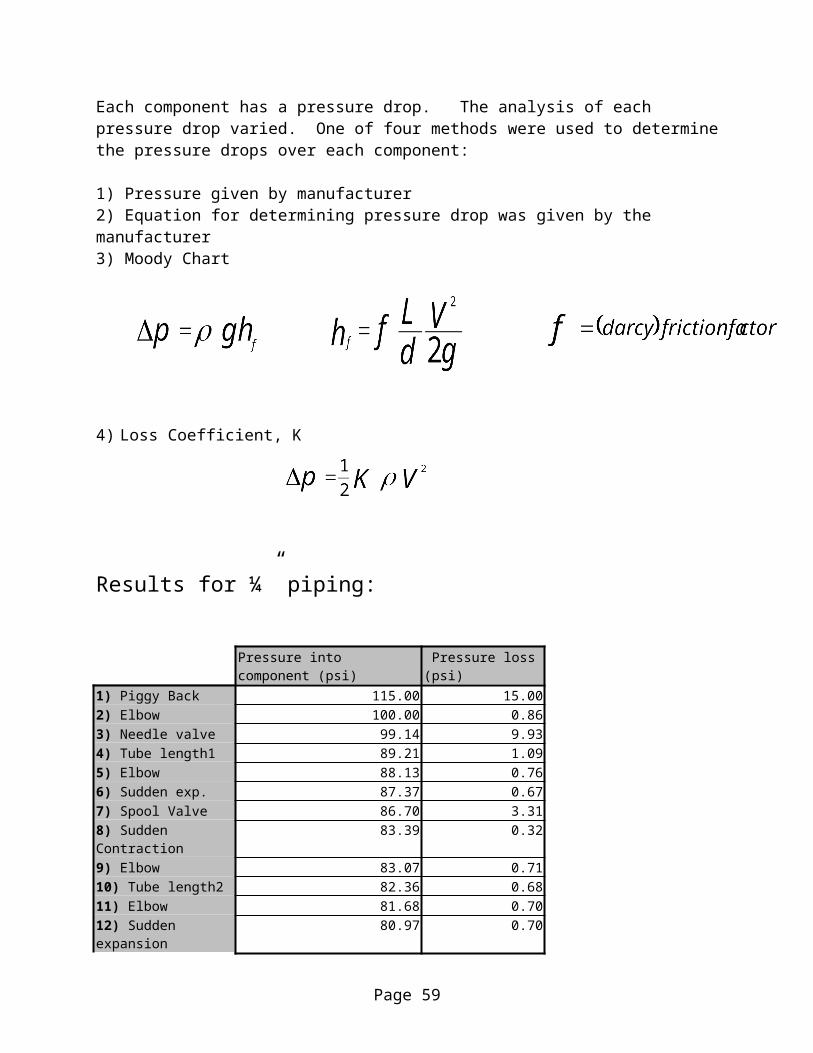
Each component has a pressure drop. The analysis of each pressure drop varied. One of four methods were used to determine the pressure drops over each component:
1) Pressure given by manufacturer2) Equation for determining pressure drop was given by the manufacturer3) Moody Chart
4) Loss Coefficient, K
Results for ¼” piping:
Pressure into component (psi) Pressure loss (psi)1) Piggy Back 115.00 15.002) Elbow 100.00 0.863) Needle valve 99.14 9.934) Tube length1 89.21 1.095) Elbow 88.13 0.766) Sudden exp. 87.37 0.677) Spool Valve 86.70 3.318) Sudden Contraction 83.39 0.329) Elbow 83.07 0.7110) Tube length2 82.36 0.6811) Elbow 81.68 0.7012) Sudden expansion 80.97 0.70Pfinal 80.28
A final pressure of 80.28psi is adequate for our purposes. Therefore ¼” piping was used. Only the circuit, which controlled the extension of the pneumatic cylinder, was analyzed as the circuit, which controlled retraction, was virtually identical. The spreadsheet analysis can be found on the following page.
Page 39

Pressure Losses Through System
P (psi) Pa (psi) G Q (SFCM) Q (m^3/s) loss: Cv Temp (R) K rho (kg/m^3) d (m) V (m/s) g (m/s^2)
L (m) mu (kg/ms)
Re f delta P (psi)
1 115 24.5 15
2 100 24.5 0.0012848 0.9 8 0.0064 40.57 0.8593267
3 99.14 15 1 24.5 0.78 530 7.9312539 9.9291097
4 89.21 7.1369251 0.0064 40.57 9.81 0.3 1.80E-05 1.02E+05 2.70E-02 1.0865463
5 88.13 24.5 0.0012848 0.9 7.0500014 0.0064 40.57 0.7572818
6 87.37 24.5 0.0012848 0.8 6.9894188 0.0064 40.57 0.6673549
7 86.7 24.5 0.0012848 4 6.9360304 0.0064 40.57 3.3112868
8 83.39 24.5 0.0012848 0.4 6.6711275 0.0064 40.57 0.3184821
9 83.07 24.5 0.0012848 0.9 6.6456489 0.0064 40.57 0.713848
10 82.36 6.5885411 0.0064 40.57 9.81 0.3 1.80E-05 9.43E+04 2.20E-02 0.6810893
11 81.68 24.5 0.0012848 0.9 6.534054 0.0064 40.57 0.7018609
12 80.97 24.5 0.0012848 0.9 6.4779051 0.0064 40.57 0.6958296
Pfinal 80.28
Page 40

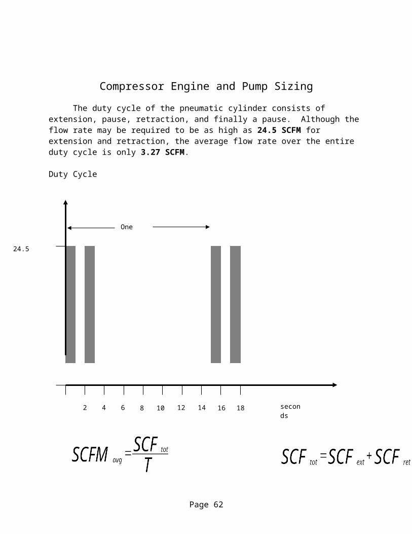
Compressor Engine and Pump Sizing
The duty cycle of the pneumatic cylinder consists of extension, pause, retraction, and finally a pause. Although the flow rate may be required to be as high as 24.5 SCFM for extension and retraction, the average flow rate over the entire duty cycle is only 3.27 SCFM.
Duty Cycle
Where SCFMavg is the average flow required to be produced by the air compressor engine. SCFtot is the total volume (not flow rate) of air used in the duty cycle in standard cubic feet. SCFext and SCFret are the volumes of compressed air displaced by the pneumatic cylinder.
Therefore since the required flow rate is 3.27 SCFM, an air compressor with an output of more than 8 SCFM will yield a safety factor of 2.45.
Page 41
2 4 6 14128 10 16 18 seconds
24.5 SCFM
One cycle
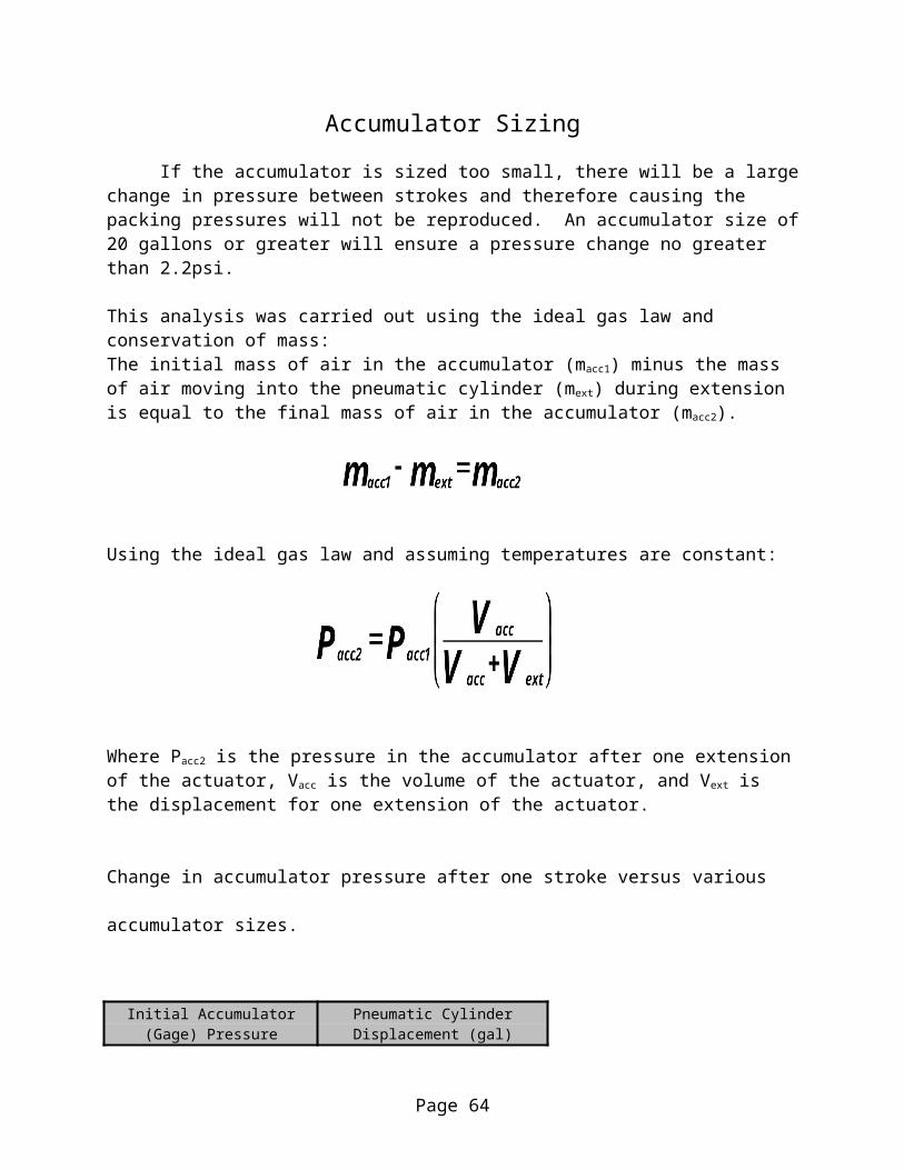
Accumulator Sizing
If the accumulator is sized too small, there will be a large change in pressure between strokes and therefore causing the packing pressures will not be reproduced. An accumulator size of 20 gallons or greater will ensure a pressure change no greater than 2.2psi.
This analysis was carried out using the ideal gas law and conservation of mass:The initial mass of air in the accumulator (macc1) minus the mass of air moving into the pneumatic cylinder (mext) during extension is equal to the final mass of air in the accumulator (macc2).
Using the ideal gas law and assuming temperatures are constant:
Where Pacc2 is the pressure in the accumulator after one extension of the actuator, Vacc is the volume of the actuator, and Vext is the displacement for one extension of the actuator.
Change in accumulator pressure after one stroke versus various accumulator sizes.
Initial Accumulator Pneumatic Cylinder (Gage) Pressure Displacement (gal)
115 0.3398
Volume of Accumulator (Gage) Pressure Change in AccumulatorAccumulator (gal) after 1 Extension Pressure (psi)
5 106.7274055 8.27259447910 110.7277704 4.27222963715 112.1203014 2.87969856220 112.8281989 2.17180109925 113.2567345 1.74326553530 113.5440247 1.4559753235 113.7500212 1.24997877740 113.9049524 1.09504757145 114.0257125 0.97428749150 114.1224836 0.877516399
Page 42

Appendix III:
Electrical and Pneumatic System Diagrams
Page 43

Circuit Diagram
Circuit Description
The circuit includes a normally open limit switch ensuring that the pneumatic cylinder will not actuate unless the safety door is shut. When the momentary switch is put in the downward position, the pneumatic cylinder will actuate downward. When the momentary switch is put in the upward position, the pneumatic cylinder will actuate upward. The 5 Amp fuse will open if there is a short hence preventing fire or shock. The LED indicates to the user that the machine is plugged in.
Page 44
LED
5 Amp Fuse
Normally Open Limit Switch
Momentary Switch
Solenoids 1 and 2
120 V AC
Schematic of the Air Flow through the Apparatus
Page 45

Appendix IV:
Engineering Drawings
Page 46
Page 47

Page 48

Page 49

Page 50

Page 51

Page 52

Page 53

Page 54

Page 55

Page 56

Page 57

Page 58
Page 59

Page 60

Page 61
Page 62
Appendix V:
Budget:
PART QTY PRICE $Pneumatic Piston 1 215.00Regulator 1 28.00Needle Valve 1 37.00Safety Valve 1 15.00Plexiglass Tubing, 6 ft. 1 60.00Rubber Couplers 9 45.003/8 in. Steel Plate 1 4.501/16 in Steel Sheet 1 3.00Hinges 2 5.00Safety Rubber 1 6.00Aluminum Silo Mounts 4 5.00Steel Square Tubing 1 30.00
TOTAL 453.50
Page 63
Appendix VI:
Final Parts List
Part No Part Name Part Quantity1 Pneumatic Piston 12 ¼ in Air Hose, 4 ft. 13 ¼ in. Pneumatic Elbows 84 ¼ in Pneumatic T-Connectors 25 Electrical Wires 6 Electrical Box 17 Limit Switch 18 Main Beam 19 Locking Mechanism 110 Door11 Frame Base 112 Door Handle 113 Pressure Regulator 114 Needle Valve 115 Safety Valve 116 Spool Valve 117 Safety Shields 218 Mounting Brackets 419 Hinges 220 Ribs 421 Safety Rubber, 1 ft 122 Piston Plunger 323 Door Frame 224 Storage Sleeves 825 Rubber Couplers 926 1 qt. Red Paint 127 1 qt. Primer 128 5 Amp Fuse 129 LED Light 130 3-Way Toggle Switch 1
Page 64

Appendix VII:
User Manual
Page 65

Setup
1. Unfold and place the table in a flat, level location.
2. Mount the machine upright on the table by means of the mounting bracket at
its base.
3. Attach the air compressor hose to the nozzle shown here.
4. Plug the machine into an electrical socket. The red light will turn on to
indicate power.
5. Set the air pressure to the proper level by pulling up the knob shown here
and turning until gauge shows the correct pressure. Push the knob back
down after adjusting. A suggested starting pressure based upon previous
testing is 65 psi.
Page 66

Usage
Preparing silo
1. Put a rubber stopper in one end of the empty silo. It is recommended that
the stopper be recessed approximately 0.25 in. into the silo. This should
reduce the likelihood of the piston loosening the bottom stopper.
2. Put the other end of the silo (the end without a stopper) into the rubber
connector of the storage sleeve.
Filling silo
1. Fill the silo and storage sleeve loosely with silage up to the top of storage
sleeve.
2. Place the silo and sleeve into the machine and close the safety door.
3. Hold the piston switch in the down position. This will cause the piston to
lower and compact the silage. Look through the observation window in the
door and release the switch once the piston stops moving. Hold the switch in
the up position until the piston has returned to its fully retracted position.
There should be an audible sound when the piston reached the fully retracted
position.
4. Open the door with the release knob, located behind the closing handle.
5. Remove the silo and sleeve and again fill loosely with silage to the top.
Repeat the above procedure until the silo is full. For maximum filling speed it
is recommended that two users work together. One user operates the piston
while the other fills a new storage sleeve and silo.
Page 67
Finishing
1. Separate the silo from the storage sleeve.
2. Use a rubber mallet to force a second rubber stopper into the open end of the
silo.
Cleanup
1. Unplug the air hose. Make sure no pressure is left in the machine by flipping
the piston switch up and down at least twice with the door closed.
2. Unplug the electrical cord.
3. Brush away any bits of silage left on the machine and its table. Wipe away
any silage juice left on the machine and table.
4. Wash out the storage sleeves. Remove and clean the piston heads.
5. Unclamp the machine from the table and put in storage.
Page 68

Troubleshooting
The piston will not move.
1. Plug in the electrical cord
2. Plug in the air hose
3. Close the safety door
4. Raise the air Pressure
5. Make sure the needle valve is open.
The bottom stopper comes off after compressing silage.
1. Send the piston back up before it stops completely.
2. Lower the air pressure.
3. Put less silage into the storage sleeve when loading for packing.
4. Recess the bottom stopper farther into the silo before packing.
Page 69

I cannot remove the silo and storage sleeve.
1. Open the safety door.
2. Make sure the piston is not lowered inside of the silo and sleeve. If the piston
is lowered, retract the piston fully using the piston switch (the air lines and
power cord must be plugged in).
I cannot shut the safety door.
1. Make sure you handle the closure lever mounted to the door at the end
farthest from the door, this end with the black ball. This will drastically reduce
the amount of force required to close the door.
2. Reposition the silo / storage sleeve unit so that it rests in the center of the
aluminum silo mounts.
3. Reposition the rubber coupler on the storage sleeve so that only
approximately 1 in. of it is located on the plexiglass itself.
4. Remove the silo / storage sleeve unit, unplug the silo packer, and clean the
silage from the interior of the silo packer. Plug the silo packer back in.
Page 70