NB-IoT Application Development Guide · NB-IoT Application Development Guide - Application Note...
47
NB-IoT Application Development Guide Technology architecture and AT command examples Application Note Abstract This document provides detailed examples of how to use AT commands with u-blox NB-IoT SARA-N2 modules series. www.u-blox.com UBX-16017368 - R05
Transcript of NB-IoT Application Development Guide · NB-IoT Application Development Guide - Application Note...

NB-IoT Application
Development Guide Technology architecture and AT command examples
Application Note
Abstract This document provides detailed examples of how to use AT commands with u-blox
NB-IoT SARA-N2 modules series.
www.u-blox.com
UBX-16017368 - R05

NB-IoT Application Development Guide - Application Note
UBX-16017368 - R05 Page 2 of 47
Document Information
Title NB-IoT Application Development Guide
Subtitle Technology architecture and AT command examples
Document type Application Note
Document number UBX-16017368
Revision and date R05 20-Jul-2018
Disclosure Restriction
This document applies to the following products:
Product name
SARA-N2 series
u-blox or third parties may hold intellectual property rights in the products, names, logos and designs included in this
document. Copying, reproduction, modification or disclosure to third parties of this document or any part thereof is only
permitted with the express written permission of u-blox.
The information contained herein is provided “as is” and u-blox assumes no liability for its use. No warranty, either express or
implied, is given, including but not limited to, with respect to the accuracy, correctness, reliability and fitness for a particular
purpose of the information. This document may be revised by u-blox at any time without notice. For the most recent
documents, visit www.u-blox.com.
Copyright © u-blox AG.

NB-IoT Application Development Guide - Application Note
UBX-16017368 - R05 Page 3 of 47
Contents Document Information ................................................................................................................................ 2
Contents .......................................................................................................................................................... 3
1 Introduction ............................................................................................................................................. 6
2 NB-IoT technology overview .............................................................................................................. 7
3 AT command response parser ........................................................................................................... 8
3.1 Unsolicited result code............................................................................................................................... 8
3.2 Best practices .............................................................................................................................................. 9
4 Registration with the NB-IoT network ......................................................................................... 10
4.1 Auto registration ....................................................................................................................................... 10
4.1.1 Configuring auto registration ........................................................................................................ 10
4.2 Manual registration with the NB-IoT network .................................................................................... 10
4.2.1 Configuring manual registration ................................................................................................... 10
4.2.2 Starting registration process, default PLMN/APN .................................................................... 10
4.2.3 Starting registration process, specified PLMN/APN ................................................................. 11
4.3 Group hopping with FW version 06.57 A07.03 ..................................................................................... 11
5 Base station scanning ........................................................................................................................ 12
5.1 Previous PLMN ........................................................................................................................................... 12
5.2 Home PLMN ................................................................................................................................................ 12
5.3 Roaming / International SIMs .................................................................................................................. 12
5.3.1 With FW 06.57 A07.03 ...................................................................................................................... 12
5.3.2 With later firmware ........................................................................................................................... 12
5.3.3 Saving the PLMN ............................................................................................................................... 12
6 RRC connection & Release assistance ......................................................................................... 13
6.1 RRC connection ......................................................................................................................................... 13
6.2 Release assistance ................................................................................................................................... 13
6.3 Current drawn in RRC connected mode ............................................................................................... 13
7 Paging, eDRX, PSM and Deep Sleep mode .................................................................................. 14
7.1 eDRX ............................................................................................................................................................ 14
7.2 Power Save Mode (PSM) .......................................................................................................................... 15
8 Monitoring module status ................................................................................................................ 16
8.1 Registration status .................................................................................................................................. 16
8.2 Base station connection (RRC connected state) ............................................................................... 16
8.3 Power Save Mode status .......................................................................................................................... 17
8.4 Connection status matrix ........................................................................................................................ 17
8.5 Viewing IP address ..................................................................................................................................... 17
8.6 Checking module statistics ..................................................................................................................... 17
9 UDP sockets .......................................................................................................................................... 19
9.1 Creating a socket ...................................................................................................................................... 19
9.2 Closing a socket ........................................................................................................................................ 19
9.3 Sending UDP data ..................................................................................................................................... 19
9.4 Receiving UDP data .................................................................................................................................. 19
NB-IoT Application Development Guide - Application Note
UBX-16017368 - R05 Page 4 of 47
9.4.1 Data arrived indicator ...................................................................................................................... 19
9.4.2 Reading data from socket ............................................................................................................... 20
9.5 Testing UDP sockets ................................................................................................................................ 20
10 Constrained Application Protocol (CoAP) ................................................................................... 21
10.1 CoAP profiles ............................................................................................................................................... 21
10.2 CoAP command .......................................................................................................................................... 21
10.3 CoAP component selection ..................................................................................................................... 22
10.4 CoAP example ............................................................................................................................................ 22
10.4.1 Configure the IP address and options in a CoAP profile ........................................................... 22
10.4.2 Select the CoAP component for AT use ....................................................................................... 22
10.4.3 Execute CoAP action ........................................................................................................................ 22
11 Non-IP Messaging ............................................................................................................................... 23
11.1 Connection process .................................................................................................................................. 23
11.2 Uplink messaging ...................................................................................................................................... 23
11.3 Downlink messaging ................................................................................................................................ 23
11.4 Downlink issue with FW 06.57 A07.03 .................................................................................................. 23
12 Operation tests ................................................................................................................................... 24
12.1 Band of operation ...................................................................................................................................... 24
12.2 SIM ............................................................................................................................................................... 24
12.3 Searching for network .............................................................................................................................. 24
12.4 Registering on the network ..................................................................................................................... 24
12.5 T3324 and T3412 timers .......................................................................................................................... 25
12.6 Power save mode ....................................................................................................................................... 25
12.7 Ping .............................................................................................................................................................. 25
12.8 Echo server ................................................................................................................................................. 25
13 Simple AT command example .........................................................................................................26
14 Debugging .............................................................................................................................................. 27
14.1 Manual debugging with +NUESTATS................................................................................................... 27
14.1.1 +NUESTATS="RADIO" ..................................................................................................................... 27
14.1.2 +NUESTATS="CELL" ....................................................................................................................... 27
14.1.3 +NUESTATS="BLER" ....................................................................................................................... 27
14.1.4 +NUESTATS="THP" ......................................................................................................................... 27
14.2 Manual debugging with URCs ................................................................................................................ 28
14.3 Debug log stream ...................................................................................................................................... 28
14.3.2 UE Monitor ......................................................................................................................................... 28
15 Power profile ......................................................................................................................................... 30
15.1 200 bytes, ECL1, without Release Assistance ....................................................................................30
15.2 200 bytes, ECL1, with Release Assistance ..........................................................................................30
15.3 Uplink allocations based on SNR ........................................................................................................... 31
15.3.1 Good SNR, coverage Class 2 ........................................................................................................... 31
15.3.2 Bad SNR, coverage Class 2 ............................................................................................................. 31
16 Design for reduced power consumption ..................................................................................... 32
16.1 Hardware design ....................................................................................................................................... 32
16.2 Release Assistance ................................................................................................................................... 32

NB-IoT Application Development Guide - Application Note
UBX-16017368 - R05 Page 5 of 47
16.3 PSM and eDRX ........................................................................................................................................... 32
16.4 Minimizing coverage Level 2 ................................................................................................................... 32
17 Network architecture mapping on AT commands .................................................................. 33
18 NB-IoT best practices........................................................................................................................ 34
18.1 Radio and network status polling .......................................................................................................... 34
18.2 Deep-sleep mode ....................................................................................................................................... 34
18.3 Message size .............................................................................................................................................. 34
18.4 Message buffer ......................................................................................................................................... 34
18.5 Application architecture .......................................................................................................................... 34
19 FOTA ....................................................................................................................................................... 36
19.1 Server ........................................................................................................................................................... 36
19.2 Configuration ............................................................................................................................................. 36
19.3 Status .......................................................................................................................................................... 36
19.4 Package download query ......................................................................................................................... 36
19.5 Example ....................................................................................................................................................... 37
20 End user test (+UTEST) .................................................................................................................... 38
20.1 Enabling / Disabling the end user test .................................................................................................. 38
20.2 Rx tests ....................................................................................................................................................... 38
20.3 Tx tests ....................................................................................................................................................... 38
21 Datagram messages with Huawei OceanConnect IoT platform ......................................... 39
21.1 Sending MO datagrams ........................................................................................................................... 39
21.2 Querying MO datagram sent status ..................................................................................................... 40
21.3 Receiving MT datagrams ........................................................................................................................ 40
21.4 Querying MT datagram received status .............................................................................................. 40
21.5 Avoiding data loss ..................................................................................................................................... 40
21.6 Send message indication +NSMI ........................................................................................................... 41
21.7 New message indications +NNMI .......................................................................................................... 41
Appendix ....................................................................................................................................................... 43
Related documents ................................................................................................................................... 46
Revision history .......................................................................................................................................... 46
Contact ........................................................................................................................................................... 47

NB-IoT Application Development Guide - Application Note
UBX-16017368 - R05 Introduction Page 6 of 47
1 Introduction This document provides guidance when developing applications for NB-IoT. It includes examples of
using AT commands used to communicate with the u-blox NB-IoT modules and how to send UDP
packets. See the SARA-N2 series AT Commands Manual [2] for detailed AT command descriptions.
The following symbols are used to highlight important information within this document:
☞ An index finger points out key information pertaining to module integration and performance.
⚠ A warning symbol indicates actions that could negatively impact or damage the module.
NB-IoT Application Development Guide - Application Note
UBX-16017368 - R05 NB-IoT technology overview Page 7 of 47
2 NB-IoT technology overview NB-IoT technology is designed such that it can be used in areas beyond the radio coverage of current
cellular standards and in devices which must run from battery power for many years. The devices
will generally send small amounts of data infrequently; a typical usage scenario might be 100 to
200 bytes sent twice per day for battery powered devices. For mains powered devices the limit is not
based on battery size, but cost and network bandwidth/resources.
The system operation is analogous to SMS in that it is a datagram-oriented, stored-and-forward
system, rather than a GPRS-like IP pipe. This is because NB-IoT devices spend most of their time
asleep, making possible the required long battery life. The system implements extended DRX cycles
for paging, but as this window will be limited to save battery life, the delivery of downlink messages
occurs mainly when the system detects that uplink messages have been received from a device
(indicating that it is awake). Here a store-and-forward system, an “IoT Platform”, is useful.
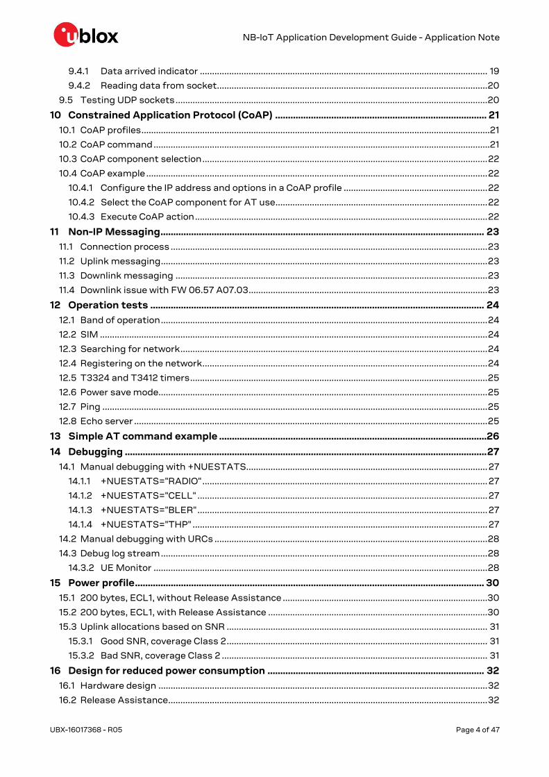
A simplified system is represented in Figure 1.
Cell Tower
IoT
Platform
Cellular
Network Customer ServerCustomer
Device
Figure 1: NB-IoT system architecture
At the far left the customer’s device contains a u-blox NB-IoT module that communicates over the
radio network with a cell tower that supports the NB-IoT network. The cellular network links the cell
tower with an IoT platform. This IoT platform stores uplink datagrams from the NB-IoT module. The
customer server communicates with the IoT platform to retrieve uplink datagrams and to send
downlink datagrams to the NB-IoT. The IoT platform holds downlink datagrams until the NB-IoT
module is awake to receive them.
The SARA-N2 series modules implement basic UDP socket commands for directly communicating
with an external service. With these commands the customer can build a simple IoT platform. With
an external processor other IoT layers could be implemented to aid this system design. SARA-N2
series modules support AT commands for general CoAP messaging. This allows the customer to not
require CoAP in their external processor.

NB-IoT Application Development Guide - Application Note
UBX-16017368 - R05 AT command response parser Page 8 of 47
3 AT command response parser This section gives some hints about how to develop an AT parser and how to handle the responses
to the AT commands and the URCs (unsolicited result code).
In this document the following naming conventions are used:
DCE (Data Communications Equipment) or MT (Mobile Terminal) is the u-blox NB-IoT module
DTE (Data Terminal Equipment) or TE (Terminal Equipment) is the terminal that sends the
command to the module
When entering AT commands, spaces are ignored. The DCE uses carriage-return line-feed pairs
(\r\n, 0x0D0A) to end lines on its output. The same termination is required on input to the DCE.
When the DCE has finished processing a command it will output a final result code (either OK or
ERROR) indicating that it is ready to accept a new command. The information text responses are
issued before the final result code.
3.1 Unsolicited result code
An unsolicited result code (URC) is a string message (provided by the DCE) that is not a response to
a previous AT command. It can be output, when enabled, at any time to inform the DTE of a specific
event or status change. The implemented URCs are as follows:
+CEREG: <stat>[,<tac>,<ci>,<AcT>] Network registration
+NPING: <retry_num>,<remote_address>,<ttl>,<rtt> Ping
+NSONMI: <socket>,<length> Received data on socket
+NNMI: <length>,<data> New message indicator
+NNMI New message indicator
+NSMI: SENT Sent message indicator
Figure 2: DTE-DCE URC flow chart
NB-IoT Application Development Guide - Application Note
UBX-16017368 - R05 AT command response parser Page 9 of 47
3.2 Best practices
The DTE shall flush the AT channel (i.e. check if there is data waiting to be read) before sending a
new AT command.
The DTE shall handle the case of unexpected spaces or line endings.
The DTE shall handle all the URCs: it can simply ignore them (not suggested) or, better, take a
proper action.
The DTE shall know what answer is expected and shall wait until it is received (i.e. final result
code only or information text response with the final result code).
The final result code marks the end of an AT command and can be OK or ERROR. When the final
result is an error, be sure to handle it before continuing with the next AT command.
The information text response format is command specific. The DTE will need explicit handling
for each one. It is suggested to consult the SARA-N2 AT Command Manual [2].
It is suggested to not strictly parse information text responses but rather to check if they
contain interesting keywords and/or parameters.
It is very useful, for debugging an application, to log all the command lines sent to the DCE and
received from it.
Create a state machine for the AT parser (e.g. idle, waiting_response, data_mode).
The DTE shall wait some time (the recommended value is at least 20 ms) after the reception of
an AT command final response or URC before issuing a new AT command to give the module the
opportunity to transmit the buffered URCs. Otherwise the collision of the URCs with the
subsequent AT command is possible.
NB-IoT Application Development Guide - Application Note
UBX-16017368 - R05 Registration with the NB-IoT network Page 10 of 47
4 Registration with the NB-IoT network Before the customer’s application can send or receive any messages to their cloud server the module
must first register on the NB-IoT network. The SARA-N2 series modules have two options for
registration, auto or manual.
After the registration process has started, it is possible to query the status using the +CEREG read
command, or by configuring the +CSCON URC.
4.1 Auto registration
By default the SARA-N2 series modules will automatically try and connect to the network. This
feature will read the SIM for the PLMN and attempt to register with the network. The device will use
the default APN from the network. The auto-connect feature can be enabled by the +NCONFIG AT
command. Reset the module to save these settings to the non-volatile memory.
4.1.1 Configuring auto registration
Command Response Description
AT+NCONFIG="AUTOCONNECT","TRUE" OK Enable the AUTOCONNECT feature.
AT+NRB Reset the module to save this setting.
4.2 Manual registration with the NB-IoT network
If the application requires more control over the registration process set the SARA-N2 series
modules into the manual registration mode. With the auto-connect feature turned off the module is
able to manually connect to a specific PLMN and specify an APN.
4.2.1 Configuring manual registration
The auto-connect feature is by default disabled by the +NCONFIG AT command. Reboot the module
to save these settings to non-volatile memory.
4.2.2 Starting registration process, default PLMN/APN
Command Response Description
AT+CFUN=1 OK Turn on the module’s radio functionality.
AT+CGATT=1 OK Start the registration process and
attach to the packet switched data
services. This will read the PLMN from
the attached SIM.
The network will provide the APN to the
module.
☞ The +CGATT AT command creates a context ID starting from zero (0).
Command Response Description
AT+NCONFIG="AUTOCONNECT","FALSE" OK Disable the AUTOCONNECT feature.
AT+NRB Reset the module to save this setting.

NB-IoT Application Development Guide - Application Note
UBX-16017368 - R05 Registration with the NB-IoT network Page 11 of 47
4.2.3 Starting registration process, specified PLMN/APN
Command Response Description
AT+CFUN=1 OK Turn on the module’s radio functionality.
AT+CGDCONT=<cid>,"IP","APN_Name" OK Configure the APN (if required).
AT+COPS=1,2,"12345" OK Start the registration process with
specifying a PLMN.
☞ Do not use the AT+CGATT command when using AT+COPS or AT+CGDCONT as it will revert the
specified PLMN/APN back to the default value.
4.3 Group hopping with FW version 06.57 A07.03
There is a known issue with FW version 06.57 A07.03: the module does not connect to a network if
the Group Hopping feature has been enabled. For more details on Group hopping feature, see 3GPP
TS 36.331 [6], section 10.1.4.1.3.

NB-IoT Application Development Guide - Application Note
UBX-16017368 - R05 Base station scanning Page 12 of 47
5 Base station scanning When the module starts the registration process it must first scan for a base station based on the
PLMN of the SIM. This scanning process is different depending if there is a previous stored PLMN,
the SIM is for the home network or if it is a roaming/international SIM.
5.1 Previous PLMN
If the module has previously camped on a cell, the PLMN will have been stored in the SIM. It will try to
use the previous PLMN when the module first turns on. If this fails it will then try the Home PLMN.
5.2 Home PLMN
The module will to try to camp on the HPLMN stored in the SIM. In the quick cell search after the
module power-on, once the PLMN is found it will start to register on that cell. If this fails it will then
try the Roaming processes.
5.3 Roaming / International SIMs
There is a different cell scanning process depending if the SIM is a Home SIM or Global SIM.
5.3.1 With FW 06.57 A07.03
If a roaming PLMN is being used, the module will perform a deep cell search of all supported bands
before trying to register on a cell using the RPLMN. This process is a deep search so that even weak
signaled cells can be found in PLMN selection. This can take over ten minutes or more depending on
the number of LTE bands supported by the module.
Because cell selection with home SIMs takes less than 2 minute normally, it might be best to try
automatic connection for 2 minutes, and then try a manual connection using
AT+COPS=1,2,"<PLMN>" – if a list of known PLMNs is available.
☞ There are no AT commands that will provide the indication about the Home or Roaming SIM.
5.3.2 With later firmware
A new firmware that resolves this issue will be released Q3 2018. Cell scanning times will be very
similar to home SIMs.
5.3.3 Saving the PLMN
Once registered the PLMN will be saved to the module so that when the module is turned on or
rebooted the long deep scan will not need to be performed again.
NB-IoT Application Development Guide - Application Note
UBX-16017368 - R05 RRC connection & Release assistance Page 13 of 47
6 RRC connection & Release assistance
6.1 RRC connection
At the first registration or when the module wakes from the power save mode (PSM), it performs a
Random Access CHannel (RACH) procedure to attach to the base station. This establishes a Radio
Resource Control (RRC) connection to the base station. Once established only the base station can
release this connection. The module cannot drop the RRC connection other than turning off the
radio using the AT+CFUN=0 command.
The base station has an “inactivity” timer for each module and if there is no activity the base station
will send a RRC release message to the module. The module should respond back to the base station
with an acknowledgment. The inactivity timer is nominally 20 s.
The module will be able to receive and send messages immediately when in connected mode.
During a RRC connection, the +CSCON AT command provide the signalling connection status. It is
also possible to enable the +CSCON URC.
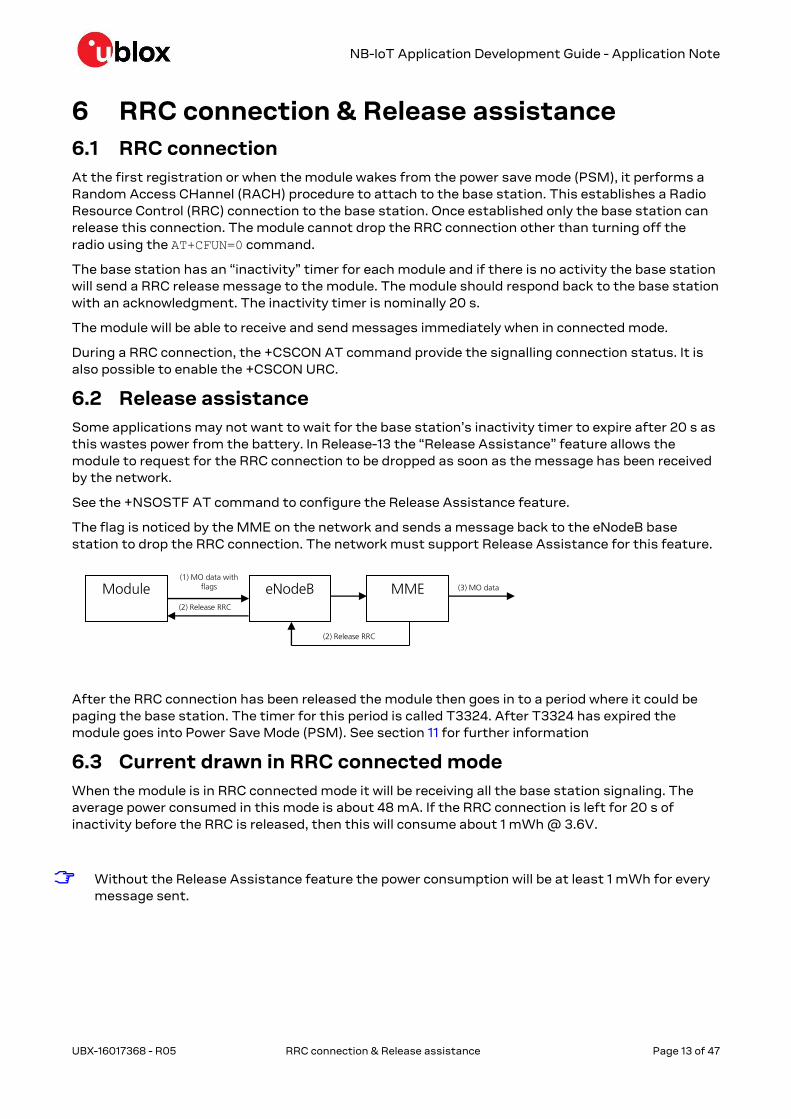
6.2 Release assistance
Some applications may not want to wait for the base station’s inactivity timer to expire after 20 s as
this wastes power from the battery. In Release-13 the “Release Assistance” feature allows the
module to request for the RRC connection to be dropped as soon as the message has been received
by the network.
See the +NSOSTF AT command to configure the Release Assistance feature.
The flag is noticed by the MME on the network and sends a message back to the eNodeB base
station to drop the RRC connection. The network must support Release Assistance for this feature.
(2) Release RRC
(3) MO dataeNodeB(1) MO data with
flagsModule MME(2) Release RRC
After the RRC connection has been released the module then goes in to a period where it could be
paging the base station. The timer for this period is called T3324. After T3324 has expired the
module goes into Power Save Mode (PSM). See section 11 for further information
6.3 Current drawn in RRC connected mode
When the module is in RRC connected mode it will be receiving all the base station signaling. The
average power consumed in this mode is about 48 mA. If the RRC connection is left for 20 s of
inactivity before the RRC is released, then this will consume about 1 mWh @ 3.6V.
☞ Without the Release Assistance feature the power consumption will be at least 1 mWh for every
message sent.
NB-IoT Application Development Guide - Application Note
UBX-16017368 - R05 Paging, eDRX, PSM and Deep Sleep mode Page 14 of 47
7 Paging, eDRX, PSM and Deep Sleep mode The NB-IoT protocol allows for power save mode (PSM), and the SARA-N2 series modules also
support a Deep Sleep mode where the module is running at very low current, ~3 µA. The module
automatically enters various states depending on the device activity. Here below are listed the
common activities and the various states it will be in after registration.
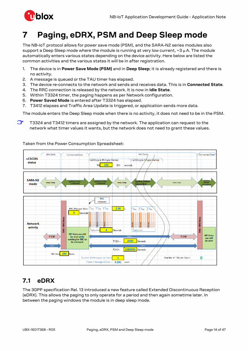
1. The device is in Power Save Mode (PSM) and in Deep Sleep; it is already registered and there is
no activity.
2. A message is queued or the TAU timer has elapsed.
3. The device re-connects to the network and sends and receives data. This is in Connected State.
4. The RRC connection is released by the network. It is now in Idle State.
5. Within T3324 timer, the paging happens as per Network configuration.
6. Power Saved Mode is entered after T3324 has elapsed.
7. T3412 elapses and Traffic Area Update is triggered, or application sends more data.
The module enters the Deep Sleep mode when there is no activity, it does not need to be in the PSM.
☞ T3324 and T3412 timers are assigned by the network. The application can request to the
network what timer values it wants, but the network does not need to grant these values.
Taken from the Power Consumption Spreadsheet:
7.1 eDRX
The 3GPP specification Rel. 13 introduced a new feature called Extended Discontinuous Reception
(eDRX). This allows the paging to only operate for a period and then again sometime later. In
between the paging windows the module is in deep sleep mode.

NB-IoT Application Development Guide - Application Note
UBX-16017368 - R05 Paging, eDRX, PSM and Deep Sleep mode Page 15 of 47
eDRX operates while the T3324 timer is running and is specified by a number of hyperframes
(10.24 s).
Power Save Mode
Paging window (~2.56 s cycle)
eDRX cycle – N Hyper-frames of 10.24 s
T3324 period
The module can still receive downlink messages when it is in the T3324 period. These messages will
be cached by the network knowing the module will awaken for the next paging window after the
eDRX cycle has completed.
☞ The application can query the network the eDRX value using the AT+CEDRXS command.
7.2 Power Save Mode (PSM)
After the T3324 timer expires the module will enter the Power Save Mode. Here the module is in deep
sleep mode and is only consuming approximately 3 µA.
In the PSM the module is not able to receive any downlink messages. If the customer’s cloud
application tries to send a downlink message to the module when it is in PSM, the network will ignore
it.
When in the PSM the module will still respond AT commands and the application does not need to
toggle any power or reset lines on the module.
Use the +NPSMR AT command to query the PSM status.
☞ Enable the +NPSMR URC for the PSM status, otherwise only the URC state will be returned.

NB-IoT Application Development Guide - Application Note
UBX-16017368 - R05 Monitoring module status Page 16 of 47
8 Monitoring module status The application can monitor the status of the module’s connection, registration and PSM state by
polling or configuring URCs. By monitoring the module status the application can behave more
efficiently, depending on the application type. For example, the application may want to know when
the module goes into Power Save Mode (PSM).
8.1 Registration status
Register the module to the NB-IoT network before to send or receive any messages. Without being
registered the module will not be able to send or receive any messages.
To check the network registration status issue the +CEREG read command. The second parameter
of the information text response (+CEREG: <mode>,<state>) provides the interested information
0: not registered, not registering
1: registered
2: not registered, but currently in the process to
3: registration denied. The application should have a re-try mechanism which does not simply try
registration immediately, but has some back-off process
4: unknown
5: registered, roaming
If the SIM used is an international SIM (roaming SIM) then the registration process can take many
minutes for the first time. Once the module is registered on that network the PLMN should be
stored in the SIM so that registration is quicker next time. The application can tell if it is using
roaming SIM by the state being “5”.
The +CEREG URC can be enabled to provide the network registration status. Depending on the
<mode> parameter it is possible to configure the interested URC parameters (i.e. <mode>=4 or 5 to
see the provided network timers). See SARA-N2 AT Commands Manual [2] for more details.
☞ Properly setting the +CEREG AT command (<modem>=3, 4 or 5) it is possible to see the
registration EMM cause value. These values are described in the 3GPP TS 24.008 [4]. Typical
causes:
o #5 IMEI not accepted
o #11 PLMN not allowed
o #12 Location Area not allowed
o #13 Roaming not allowed in this location area
o #22 Congestion
8.2 Base station connection (RRC connected state)
When a MO message is sent from the module, the module must first create a RRC connection if
there is not already established with the base station. This status can be checked using the
AT+CSCON command.
To check the signalling connection status issue the +CSCON read command. The second parameter
of the information text response (+CSCON: <n>,<state>) provides the interested information:
0: idle mode (no RRC connection)
1: connected mode (RRC connection)
To configure a URC for this command, issue the AT+CSCON=1 command. A URC will be issued at
each RRC connection status change.

NB-IoT Application Development Guide - Application Note
UBX-16017368 - R05 Monitoring module status Page 17 of 47
8.3 Power Save Mode status
The module implements the Power Save Mode (PSM) where it goes in to a “Deep Sleep” operation
consuming 3 µA. It enters the PSM after the T3324 timer expires. It is possible to query the value of
the T3324 timer with the +CEREG read command.
To check the PSM status issue the +NPSMR read command. The second parameter of the
information text response (+NPSMR: <n>[,<mode>]) provides the interested information:
0: connected or idle mode
1: Power Save Mode
☞ Enable the +NPSMR URC for the PSM state to be returned, otherwise only the URC state will be
returned.
To configure a URC for this command, issue the AT+NPSMR=1 command. When the module’s PSM
status changes, a URC is issued.
8.4 Connection status matrix
Table 1 provides an overview of the AT command described in the previous sections and their values
according with the module status:
+CEREG +CSCON +NPSMR Status
0 0 0 Module is on, but not performing any network activity
2 0 0 Module scanning for base station
2 1 0 Module starting registration process, RRC connected mode
1 or 5 1 0 Module registered, RRC connected mode
1 or 5 0 0 Module registered, RRC released, inside T3324 Period (paging/eDRX)
1 or 5 0 1 Module registered, in Power Save Mode
3 - - Registration failed
Table 1: connection status compatibility matrix
8.5 Viewing IP address
Before sending any IP data to the NB-IoT network configure the device with an IP address.
☞ Use the +CGPADDR AT command to query what the IP address of the module has been set to.
The +CGDCONT AT command lists the IP addresses for each defined PDP context.
No IP address is displayed until the module has registered to the network and has been provided
with an IP address. The application could simply poll this IP address to see when the entire
registration process has finished.
8.6 Checking module statistics
When the module is synchronized to the base station and is receiving the signaling the +NUESTATS
AT command is able to describe the radio, cell, BLER and throughput statistics.
The most useful statistic is the "RADIO" type.

NB-IoT Application Development Guide - Application Note
UBX-16017368 - R05 Monitoring module status Page 18 of 47
Command Response Description
AT+NUESTATS="RADIO" Signal power: number
Total power: number
TX power: number
TX time: number
RX time: number
Cell ID: number
ECL: number
SNR: last snr value
EARFCN: last earfcn value
PCI: last pci value
RSRQ: last RSRQ value
OK
The information text response indicates
the module condition and its
environment. The values may be useful
for monitoring purposes.
Signal power: it is the power of the wanted part of the receive signal, the NB-IoT part.
Total power: it is the radio signal strength within the receive bandwidth (both expressed in 10ths
of a decibel). From this the signal to noise ratio can be calculated.
Transmit power: it is the RF power output from the module. It may be a low number if the
received signal strength is good (and hence the module assumes that the base station is close
by).
Tx time: it is the duration for which the module’s transmitter has been switched on.
Rx time: it is the duration for which the module’s receiver has been monitored for downlink
activity (both expressed in milliseconds since the last reboot). Together these can be used to
assess the time the module spends in each state and hence estimate the power consumed by
the module.
Cell ID: it is the physical cell ID of the cell that is currently providing service to the module.
ECL: it is equivalent to "PRACH coverage enhancement level" defined in 3GPP 36.321 [3] sub
clause 5.1
☞ There are other statistics available too, for cell, BLER and throughput.
o AT+NUESTATS="CELL"
o AT+NUESTATS="BLER"
o AT+NUESTATS="THP"
See section 14.1 for further information about how to use the +NUESTATS AT command to help the
module debug.
See SARA-N2 AT commands Manual [2] for further information on +NUESTATS.
NB-IoT Application Development Guide - Application Note
UBX-16017368 - R05 UDP sockets Page 19 of 47
9 UDP sockets The SARA-N2 series modules are able to send raw data through UDP sockets to an IP address. The
data sent over the socket AT commands is not wrapped in any other layer, and the data provided is
the data that is sent.
9.1 Creating a socket
Create a socket to be able to send UDP data. A socket ID is returned.
Command Response Description
AT+NSOCR="DGRAM",17,<localport> <socketID>
OK
Create a socket with a listening port.
Returns the socket ID to be used with
other socket commands.
9.2 Closing a socket
Once a socket is no longer needed, it should be closed.
Command Response Description
AT+NSOCL=<socketID> OK Specify the socket ID to close.
9.3 Sending UDP data
Sending data to an external server is as simple as specifying the socket to use, the remote IP
address and port, and then the length of data, plus the data. The information text response provides
the number of bytes successfully sent.
☞ The maximum length of data that can be sent is 512 bytes.
Command Response Description
AT+NSOST=<socketId>,"<remote_address
>",<remote_port>,<length>,"<data>"
<socketId>,<length>
OK
Send data to the specified IP address
and port through the socket noted by
the ID.
9.4 Receiving UDP data
The data reception is performed in two steps. If the module has received data from the network on a
socket that is listening, then a URC is given. From this message, the application can read the data
on the appropriate socket and length.
9.4.1 Data arrived indicator
Command Response Description
+NSONMI:<socketId>,<length> This message is provided to tell the
application how much data is available
to read on the specified socket.
The application should read this message and then read the data from the specified socket.

NB-IoT Application Development Guide - Application Note
UBX-16017368 - R05 UDP sockets Page 20 of 47
9.4.2 Reading data from socket
The data reception is performed by means of the +NSORF AT command, using the information
given in the +NSONMI URC.
Command Response Description
AT+NSORF:<socketId>,<length> <socket>,<ip_addr>,<port>,<le
ngth>,<data>,<remaining>
OK
Provides the received data to the
application and shows how much data
is still left to read out.
9.5 Testing UDP sockets
A simple way to test UDP sockets over the NB-IoT network is to send data to an echo server.
☞ The u-blox echo server is echo.u-blox.com.
Here is an example:
Command Response Description
AT+NSOCR="DGRAM",17,14000 1
OK
Create a socket. The socket ID is 1.
Ready for next AT command.
AT+NSOST=1,"195.34.89.241",7,5,"4865
6c6c6F"
1,5
OK
Send “Hello” to u-blox echo server. Sent
5 bytes on socket ID 1.
+NSONMI:1,5 Received 5 bytes on socket ID 1
AT+NSORF=1,5 1,195.34.89.241,7,5,"48656c6c
6F",0
OK
Read 5 bytes on socket ID 1.
Received data information
provided…“Hello”.

NB-IoT Application Development Guide - Application Note
UBX-16017368 - R05 Constrained Application Protocol (CoAP) Page 21 of 47
10 Constrained Application Protocol (CoAP) The Constrained Application Protocol (CoAP) is a datagram-based client/server application protocol
for devices on the constrained network (e.g. low overhead, low-power), designed to easily translate
to HTTP for simplified integration with the web. CoAP clients can use the GET, PUT, POST and
DELETE methods using requests and responses with a CoAP server.
10.1 CoAP profiles
Configure the CoAP client contained within the module via the one of the four profiles. It is possible
to store up to four profiles in the module and select between them. Only one profile can be used at a
time.
The profiles are configured, stored and retrieved by setting parameter/value pairs by means of the
+UCOAP AT command and its <op_code> parameter that can assume these values:
0: server IP address
1: URI
2: PDU option mask configuration (option to be added in PDU header)
3: current profile number (0 to 3)
4: valid flag
5: restore profile from NVM
6: store profile to NVM
7: read all profiles
10.2 CoAP command
Issue the +UCOAPC AT command to trigger a CoAP action. The +UCOAPCD URC indicates if sending
the command request to the COAP process was successful or not.
It is possible to send data with the CoAP command and identifier. The allowed CoAP actions are:
1: GET (data and identifier parameters not allowed)
2: DELETE (data and identifier parameters not allowed)
3: PUT
4: POST
☞ GET, PUT and POST actions accept block operations.
Data included in the PUT or POST actions is in hexadecimal format. Supported identifiers:
0: text / plain
1: application / link format
2: application / xml
3: application / octet format
4: application / rdf xml
5: application / exi
6: application / json
7: application / cbor

NB-IoT Application Development Guide - Application Note
UBX-16017368 - R05 Constrained Application Protocol (CoAP) Page 22 of 47
10.3 CoAP component selection
Because the internal CoAP library is shared with other components in the module, select the right
CoAP component before use. The component can be selected using the +USELCP AT command. The
allowed components are:
0 (CDP-MNO): confirmable and non-confirmable messages are supported
1 (CoAP-AT): it can be used to send or receive confirmable messages (by means of the +UCOAPC
AT command) via CoAP over the NB-IoT platform. Only confirmable messages are supported
2 (FOTA): the Firmware Over The Air (FOTA) component uses the CoAP context to download a
FW update package from a dedicated FOTA server. For more details see section 19. Only
confirmable messages are supported.
3 (SELF-REG): The self-registration component will access to the CoAP context only at the
module boot time. After that, the CoAP context shall be available as mutually exclusive between
other components. Only confirmable messages are supported
☞ Before selecting the CoAP component, first configure and active a CoAP profile by means of the
+UCOAP AT command.
10.4 CoAP example
This example sends a CoAP message to a CoAP server. First we configure a profile, then select the
CoAP operating mode, and then execute a CoAP action.
10.4.1 Configure the IP address and options in a CoAP profile
Command Response Description
AT+UCOAP=0,"134.102.218.18","5683" OK Configure the IP address.
AT+UCOAP=1,"coap://coap.me:5683/sink" OK Configure the URI of a CoAP resource.
AT+UCOAP=2,"4","1" OK Set the “Content Format” option in the
PDU.
AT+UCOAP=2,"0","1" OK Set the “HOST” option in the PDU.
AT+UCOAP=2,"1","1" OK Set the “PORT” option in the PDU.
AT+UCOAP=2,"2","1" OK Set the “PATH” option in the PDU.
AT+UCOAP=4,"0" OK Enable profile 0.
AT+UCOAP=6,"0" OK Save profile 0.
AT+UCOAP=7,"0" OK Read and use profile 0.
☞ Always save and restore the profile before to use it. As shown in the above example:
AT+UCOAP=6,"0"; +UCOAP=7,"0".
10.4.2 Select the CoAP component for AT use
Command Response Description
AT+USELCP=1 OK Select the CoAP-AT mode.
10.4.3 Execute CoAP action
Command Response Description
AT+UCOAPC=3,"48656C6C6F20576F726C64",0 OK Execute the CoAP PUT action with “Hello
World”.
+UCOAPCD:3,"…" Result from the CoAP server.

NB-IoT Application Development Guide - Application Note
UBX-16017368 - R05 Non-IP Messaging Page 23 of 47
11 Non-IP Messaging The usage of the Non-IP method during the sending or receiving of messages saves the overhead of
needing to send a UDP IP header. The UDP header is about 48-60 bytes in length, and so an
application sending 100 bytes will actually send about 160 bytes. For devices in the extreme
coverage class 2, this can be quite costly.
When using Non-IP messaging, the Mobile Network Operator shall provide access to the messages
since they are stored by it (there is no destination IP address or port).
11.1 Connection process
Command Response Description
AT+CDGCONT=<cid>,"NONIP","nonip" OK Create a PDP context with type “NONIP”
to connect to the network for Non-IP
message.
AT+CGATT=1 OK
AT+NCONFIG="AUTOCONNECT","FALSE" OK Disable the AutoConnect feature as this
will automatically connect to the
network without Non-IP.
AT+NRB Reboot the module to store and take
effect.
11.2 Uplink messaging
Command Response Description
AT+CSODCP=<cid>,<length>,"<data>" OK Issue the +CSODCP AT command to
send an uplink message for Non-IP.
AT+CSODCP=<cid>,<length>,"<data>",<R
AI>
OK It is possible to release assistance, just
like with UDP messaging (where <RAI>
is 0, 1 or 2)
11.3 Downlink messaging
Command Response Description
AT+CRTDCP=1 OK Turn on the +CRTDCP URC to receive
downlink messages.
+CRTDCP:<cid>,<length>,"<dat
a>" When the module receives a downlink
message, the +CRTDCP URC is issued.
11.4 Downlink issue with FW 06.57 A07.03
There is an issue with Non-IP downlink messaging in A07.03 firmware. Only one downlink message
will be emitted. To work around this issue, delete the PDP context after receiving the first downlink
message and then re-create it.
1. Create a Non-IP context.
2. Receive one Non-IP data at downlink with a URC.
3. Delete the context.
4. Repeat steps 1-3.

NB-IoT Application Development Guide - Application Note
UBX-16017368 - R05 Operation tests Page 24 of 47
12 Operation tests Some tests and checks can be performed when using a new network. These can help diagnose what
network settings are configured and how the module will operate.
12.1 Band of operation
Use the +NBAND AT command to verify if the module is configured for the correct band of operation.
Band 8 = 900 MHz
Band 20 = 800 MHz
Band 28 = 700 MHz
Band 5 = 850 MHz
12.2 SIM
After the module power-on, if the AUTOCONNECT feature is enabled (see +NCONFIG AT command),
then the module will automatically start the radio (equivalent to AT+CFUN=1 command) and read
the SIM PLMN.
If the module has the AUTOCONNECT disabled, then turn the radio on first with the AT+CFUN=1
command. This will read the PLMN from the SIM and then return the "OK" final result code. If there is
a problem in reading the SIM, the +CFUN AT command will return an error result code and AT+CIMI
will not return any IMSI value from the SIM.
The IMSI can queried by using the AT+CIMI command. Make sure about the correctness of the SIM
IMSI.
If there is no response to +CIMI, or +CFUN=1 returns an error result code, then there will be a
problem with the SIM. Check to see if the SIM is a 3V SIM only, or support 1.8V. SARA-N2 series
modules only support 1.8V compatible SIMs.
☞ Use the +NPIN AT command, to lock and unlock the SIM card.
12.3 Searching for network
When the module has started the network search process, poll the +NUESTATS AT command and
view the Rx and Tx Time:
If Rx Time is increasing then the module is trying to scan for a base station.
If Tx Time is increasing then the module has found a base station and is trying to communicate
with it.
If the Total Power and Signal Power values are different than -32767 (invalid) then the module has
read the MIB and SIB signals from the base station.
Once an RRC connection is made, the +CSCON read command will return 1. Turn on the +CSCON
URC which will be output at each RRC connection change.
12.4 Registering on the network
After a RRC connection is made to the base station the module will try and register with the
network. If the module IMEI or IMSI is not allowed on the network, the module will disconnect from
that base station and continue scanning for other base stations. This can be seen if the <mode>
parameter of the +CSCON AT command shows the “1” and then “0” response without +CEREG
changing to 1 or 5 means that the module was not able to register on that network.
In case the module is registered to the network, the <status> parameter of the +CEREG AT
command will be 1 (registered) or 5 (registered & roaming).

NB-IoT Application Development Guide - Application Note
UBX-16017368 - R05 Operation tests Page 25 of 47
After a short period, if no messages are being sent from the module, the +CSCON response will be
“0” to show the RRC connection has been released by the eNodeB.
12.5 T3324 and T3412 timers
T3324 and T3412 timers are set by the network after the module registration. These timers control
the amount of time the module will be in idle mode before entering Power Save Mode (T3324) and
how long it will wait until automatically sending a Tracking Area Update message (TAU) (T3412)
The timers can be read out using the +CEREG command if the <mode> parameter is set to “4” or “5”.
The timers are encoded by a bit pattern which is described in the 3GPP documentation. An example
is available in Appendix A.
12.6 Power save mode
After the module has registered to the network and the RRC connection has been released, after
T3324 timer has expired the module will enter the PSM. It is possible to query this state by polling
the +NPSMR read command or configure the URC to automatically output this status when it
changes.
If the <mode> parameter of +NPSMR AT command differs than 1 (PSM state) it means the module
has not entered into PSM. This could mean either the T3324 timer is set to a very long period or that
the network does not support the power save mode.
12.7 Ping
Issue the +NPING AT command to check if the module is able to send and receive data.
Check to see if the network can communicate to the internet, or it is needed another accessible
server’s IP address to ping.
To ping Google’s DNS server:
AT+NPING="8.8.8.8"
To ping OpenDNS DNS server:
AT+NPING="208.67.222.222"
The information text response to the +NPING AT command will be issued after a few seconds. If the
information text response is +NPINGERR: 1, the ping has timed out.
☞ The first ping might fail because it can take a few seconds to connect to the base station. Use
the +CSCON URC to show when the module is connected.
12.8 Echo server
For a more advanced check on sending data to an external server, send data to the u-blox echo
server at echo.u-blox.com.
☞ Because there is no DNS lookup function in the SARA-N2 module series, use the IP address
server which is 195.34.89.241.
Command Response Description
AT+NSOCR="DGRAM",17,10000 0
OK
Create a UDP socket.
AT+NSOST=0,"195.34.89.241",7,5,"0102
030405"
0,5
OK
Send data on socket 0.
+NSONMI: 0,5 Receive data on socket 0.
AT+NSORF=0,5 +NSORF: 0,"195.34.89.241",7,5
,"0102030405",0
OK
Request data from socket 0.
Echo’d data received
NB-IoT Application Development Guide - Application Note
UBX-16017368 - R05 Simple AT command example Page 26 of 47
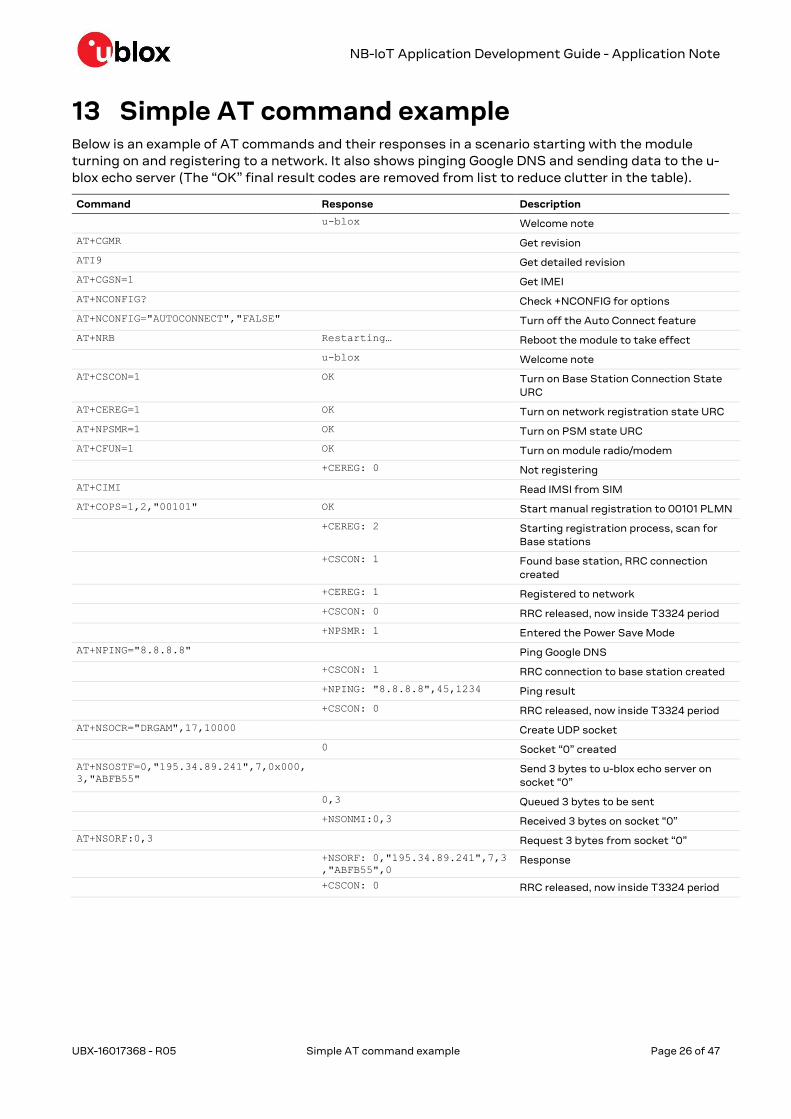
13 Simple AT command example Below is an example of AT commands and their responses in a scenario starting with the module
turning on and registering to a network. It also shows pinging Google DNS and sending data to the u-
blox echo server (The “OK” final result codes are removed from list to reduce clutter in the table).
Command Response Description
u-blox Welcome note
AT+CGMR Get revision
ATI9 Get detailed revision
AT+CGSN=1 Get IMEI
AT+NCONFIG? Check +NCONFIG for options
AT+NCONFIG="AUTOCONNECT","FALSE" Turn off the Auto Connect feature
AT+NRB Restarting… Reboot the module to take effect
u-blox Welcome note
AT+CSCON=1 OK Turn on Base Station Connection State
URC
AT+CEREG=1 OK Turn on network registration state URC
AT+NPSMR=1 OK Turn on PSM state URC
AT+CFUN=1 OK Turn on module radio/modem
+CEREG: 0 Not registering
AT+CIMI Read IMSI from SIM
AT+COPS=1,2,"00101" OK Start manual registration to 00101 PLMN
+CEREG: 2 Starting registration process, scan for
Base stations
+CSCON: 1 Found base station, RRC connection
created
+CEREG: 1 Registered to network
+CSCON: 0 RRC released, now inside T3324 period
+NPSMR: 1 Entered the Power Save Mode
AT+NPING="8.8.8.8" Ping Google DNS
+CSCON: 1 RRC connection to base station created
+NPING: "8.8.8.8",45,1234 Ping result
+CSCON: 0 RRC released, now inside T3324 period
AT+NSOCR="DRGAM",17,10000 Create UDP socket
0 Socket “0” created
AT+NSOSTF=0,"195.34.89.241",7,0x000,
3,"ABFB55"
Send 3 bytes to u-blox echo server on
socket “0”
0,3 Queued 3 bytes to be sent
+NSONMI:0,3 Received 3 bytes on socket “0”
AT+NSORF:0,3 Request 3 bytes from socket “0”
+NSORF: 0,"195.34.89.241",7,3
,"ABFB55",0 Response
+CSCON: 0 RRC released, now inside T3324 period

NB-IoT Application Development Guide - Application Note
UBX-16017368 - R05 Debugging Page 27 of 47
14 Debugging There are a few ways to debug the module’s connection and messaging problems. One way is to use
the +NUESTATS command and URCs to view the module status.
14.1 Manual debugging with +NUESTATS
The +NUESTATS AT command displays the current status of the module’s radio and cell
information. It can also display the BLER and throughput measurements. By using historical
analysis it is possible to compare the current statistics with previous statistics.
The +NUESTATS AT command only shows the last values seen by the radio in the module. Tx and Rx
timers are accumulated since the radio was turned on.
14.1.1 +NUESTATS="RADIO"
It displays the radio statistics for signal power levels, Tx and Rx times, RSRP and RSQP.
When the module first tries to register with the network, the Tx time will be zero as it will not have
instantly found a base station. The Rx time will increase to show it is scanning for a base station.
Once a base station is found it is possible to see that it is attempting to transmit to the base station
as the Tx time will start to increase. If the base station does not respond to the module’s Tx, then
the +CSCON: 1 URC will not be issued.
Once the module has an RRC connection, then the ECL, RSRP, RSRQ values allow to understand the
RF link budget between the module and base station.
The Cell ID in this response is the physical network cell ID.
14.1.2 +NUESTATS="CELL"
It displays the cell information after the module has registered with the network.
Use this to confirm to check the correctness of the EARFCN or the Cell ID. The cell ID in this
response is the eNodeB cell ID. This also provides RSRP, RSRQ, SNR and RSSI values much like the
RADIO option provides.
14.1.3 +NUESTATS="BLER"
It displays the BLER and total number of bytes transmitted and received by the RLC Layer and
Physical Layer.
Using this statistic it is possible to see if the module is having difficulty in communicating with the
base station. Even if the module is in good coverage, ECL 0, there still might be issues causing the
messages not to be sent or received. Check the Ack/Nak ratio to see a general view of the link
quality.
14.1.4 +NUESTATS="THP"
It displays the throughput measurement for the RLC and physical layers.
These values provide an indication of the efficiency of the radio link. With bad BLER, these values will
be low. With very good BLER, these values will be near the theoretical throughput of NB-IoT – and
because of this, may not change over time, as it does not take into account the time to wake up,
scan for base station, etc. This is simply over the protocol stack itself.

NB-IoT Application Development Guide - Application Note
UBX-16017368 - R05 Debugging Page 28 of 47
14.2 Manual debugging with URCs
By turning on the URCs for RRC connection, network registration and Power Save Mode status the
module will be provide information about the wake up, connection to the base station and the
network registration.
Consider to issue AT+CSCON=1, AT+CEREG=1 and AT+NPSMR=1 commands especially when first
powering on the module.
When the module starts the communication to the base station these URCs should be issued:
+CSCON: 1 Base station RRC Connection
+CEREG: 1 Registered to the network (or 5)
+NPSMR: 1 Module in Power Save Mode
See the section 12 about examples of how the statuses change when connecting and registering to
the network.
14.3 Debug log stream
The module has a second UART interface which outputs the chipset log stream. This is always
enabled and does not depend on the AT commands.
The log stream is in a binary format at a baud rate of 921600 bit/s. This is quite fast for a low
powered MCU, but this can be recorded by a Cortex-M3 running at 96 MHz, like the NXP LPC 1768 –
as it is available in the C027 application board.
14.3.1.1 Raw recording of log stream
Because the debug log stream is in a binary format, it can be quite difficult to understand the
correctness of the recording. It is possible to verify this by looking at the recorded file in a text editor
and seeing if there are any “%DBG:” tags in the binary garbage characters.
For example viewed in Notepad++:
14.3.2 UE Monitor
A dedicated debug log monitoring application called UEMonitor is available. This application can be
used to record and view the live debug output from the module. A separate user guide on this
application is available.

NB-IoT Application Development Guide - Application Note
UBX-16017368 - R05 Debugging Page 29 of 47
With UEMonitor is possible to view the cell searching, connection and message sending/receiving
processes. Some filters allow to show certain parts of the 3GPP protocol.
This tool can either view the live debug stream from the module’s debug UART (GPIO1) or from a
saved binary file.
Capturing these logs for debug purposes is highly recommended.

NB-IoT Application Development Guide - Application Note
UBX-16017368 - R05 Power profile Page 30 of 47
15 Power profile 3GPP NB-IoT has been developed for low power applications which provide more than 10 years of
operation. It is useful to view the power profile of the module when developing the application to
understand the various profiles in each coverage class, and what this means for the battery.
15.1 200 bytes, ECL1, without Release Assistance
Figure 3 shows a typical power profile of the SARA-N2 series modules sending 200 bytes in coverage
class 1, with the Release Assistance feature disabled (AT+NSOSTF with 0x000 flag, or AT+NSOST)
1: Module wakes up and scans for a base station
2: Starts the RACH process and immediately gets an allocation
3: Sends 200 bytes
4: The module waits for the RRC release by the eNodeB after its 20 s of inactivity
Figure 3: 200 bytes, ECL1, without the Release Assistance feature
15.2 200 bytes, ECL1, with Release Assistance
Figure 4 shows a typical power profile of the module sending 200 bytes in coverage class 1, with the
Release Assistance feature enabled (AT+NSOSTF 0x200 flag).
1: The module wakes up and scans for a base station
2: Starts the RACH process and immediately gets an allocation
3: Sends 200 bytes
4: eNodeB releases RRC immediately
Figure 4: 200 bytes, ECL1, with the Release Assistance feature
Total power consumed: 1075 µWh
Waiting for RRC Release: 975 uWh
Total power consumed:
100 µWh
Release Assistance gave 93%
improvement in power consumption
compared without release assistance.

NB-IoT Application Development Guide - Application Note
UBX-16017368 - R05 Power profile Page 31 of 47
15.3 Uplink allocations based on SNR
The UE is entirely under the control of the eNB and the network configuration. The UE must follow
the network settings which are broadcast inside the System Information Blocks (SIB) and the
allocations for the uplink and downlink data.
The SIB describes the method of attachment and what repetitions the UE must use to first transmit
to the base station. Once a RRC connection is made, the base station then uses the perceived SNR
to configure the uplink allocations the UE will use to transmit the messages.
Because allocations for each uplink/downlink are dynamically set by the base station it is difficult to
calculate the power consumption of a single message deployed in the field.
15.3.1 Good SNR, coverage Class 2
Figure 5 shows an example profile of sending 200 bytes in Coverage Class 2 with “good” SNR. The
first 5 transmit bursts are the random access procedure, which is specified by the SIB parameters.
The next transmission bursts are from the UE sending the 200 byte message, according to the
allocations provided by the base station.
Figure 5: Good SNR, coverage Class 2
From the debug log it was shown that the Transport Block Size (TBS) allocated where 43 bytes for
each uplink chunk, with a repetition of just one. This allowed the UE to transmit the 200 byte
message in just over 1 second, consuming 200uWh.
15.3.2 Bad SNR, coverage Class 2
Figure 6 shows is an example profile of sending 200 bytes in Coverage Class 2 with “bad” SNR:
Figure 6: Bad SNR, coverage Class 2
From the debug log it was shown that the Transport Block Size (TBS) allocated where 32 bytes for
each uplink chunk, with a repetition of 8 and 4. This time the UE transmitted the 200 byte message
in 5.5 seconds, consuming 1.07 mWh – five times that as before.

NB-IoT Application Development Guide - Application Note
UBX-16017368 - R05 Design for reduced power consumption Page 32 of 47
16 Design for reduced power consumption There are multiple factors which will contribute to the overall power consumption of the device.
Some of them are listed in the next sections.
16.1 Hardware design
PCB layout, antenna matching and location will have an effect to the overall interference received by
the module.
The antenna matching will have an effect on the current drawn when in Tx mode. Ideally the module
should consume 230 mA for +23 dBm. Antenna positioning in the product will also have a role in the
overall RF performance.
Interference to the module will increase the number of repetitions the module is configured to use
and therefore increase the Tx and Rx time.
16.2 Release Assistance
The application developers should consider the use of the Release Assistance feature. This
drastically reduces the power consumed by the module when sending data.
Applications could consider sending a special “service” type message to the cloud server which does
not use the Release Assistance feature, letting the cloud service know that the UE will be still
“online” for any downlink message that are required.
16.3 PSM and eDRX
Depending on the network configuration and permissions by the Mobile Network Operator, the PSM
and eDRX timers should be configured for the application.
Applications which only send a message once a day and do not expect to have any downlink
messages could configure eDRX to be off and enter directly the PSM.
Applications which require an acknowledgment back to the device could consider still using the
Release Assistance feature but configure a long T3324 timer and eDRX – as the UE will still be able
to be contacted within T3324 period before it goes into PSM.
16.4 Minimizing coverage Level 2
Network operators should provide enough coverage to allow devices to be mostly in coverage class 0
or 1. Depending on the NB-IoT deployment, the network could have large areas, or devices located in
deep locations which unfortunately mean they operate in Coverage Class 2.
Coverage Class 2 uses high repetitions for the RACH process and also higher coding schemes when
transmitting data and therefore fundamentally consumes more power than it would in the other
coverage classes.

NB-IoT Application Development Guide - Application Note
UBX-16017368 - R05 Network architecture mapping on AT commands Page 33 of 47
17 Network architecture mapping on AT
commands Both UDP socket commands and datagram commands use the IP data transport through the SGi.
SARA-N2
moduleeNB
SCEF
SMSC/
IWSMSC
AS
PtP tunnel for non-IP data
IP Data
SGi
T6a
SGd
MME
CSGN
SGW
S11-U
PDN
Internet
UE eNB
NAS encrypted data
Uu S1-MME
MME SGW
S11-U
UDP
NAS
RRC RRC
NAS
UDP
IP
GTP-U
S1-AP
SCTP
IP
SCTP
IP
S1-AP
IP
UDP
IP
GTP-U
PDN
GW
S5/S8 SGi
Internet
UDP
IP
GTP-U
IP
PDN
UDP
Figure 7: NB-IoT network architecture
NB-IoT Application Development Guide - Application Note
UBX-16017368 - R05 NB-IoT best practices Page 34 of 47
18 NB-IoT best practices
18.1 Radio and network status polling
The application can monitor the radio and network status. A registration or an IP address for
UDP/CoAP messages is mandatory in order to successfully send or receive data.
☞ Use the follow AT commands to query the status:
o AT+NPSMR: to query the Power Save mode.
o AT+CEREG: to query the registration status to the network.
o AT+CGPADDR: to query if the module has an IP address.
o AT+CSCON: to query the connection status to the base station. This is only useful to see if
Tx or Rx activity is happening. It should not be used to decide whether or not to send data.
18.2 Deep-sleep mode
SARA-N2 series modules are designed to enter a power save mode which allows batteries to last
longer. After the module connects to a base station to send a message, the module will stay
connected to a base station for a period of time after the last communication with the base station.
The device will then go back into deep-sleep mode.
An application that sends lots of messages throughout the day will obviously keep the module
awake and connected to a base station, consuming power.
In an ideal design the application should not require the device to send more messages than
necessary. The cloud application should not need to send the module many messages either,
although in a trial system the customer may want more activity to see the operation of the system.
In these cases high capacity batteries or continuous power supply should be used.
18.3 Message size
The module has a limited dynamic message queue size. For IoT applications, the message size
should be of the order of tens of bytes. UDP socket commands limit their payload size to 512 bytes.
There is no indication when the UDP data has been sent.
Downlink data from the cloud server must also be 512 bytes or less, because otherwise the
messages will be lost.
18.4 Message buffer
The module has an internal message buffer. If the module is unable to send the messages to the
network before this buffer is full, because the application is queueing quicker than it can send them,
then the UE will return ERROR for the +NSOST/+NSOSTF commands.
If a message cannot be sent because of communication issues between the module and eNB, the
module will attempt to send the message a second time. If this fails, the message will be dropped.
As +NSOST/+NSOSTF messages are UDP, there is no indication the message has been dropped.
18.5 Application architecture
Many developers coming from a GPRS type background may expect an always on type connection,
normally using TCP. NB-IoT is not session oriented, latencies are much higher and the device will
enter a power save mode. This is very different to always-on modems with “chatty” protocols like
TCP.
UDP sockets do not create connections to servers; UDP is a connection-less datagram protocol.
Because of this MO messages may not be received by the server and lost. The application should
take this in to consideration and provide its own acknowledgements between the UE and server.
CoAP is one protocol which can be used on top of UDP to provide this.
NB-IoT Application Development Guide - Application Note
UBX-16017368 - R05 NB-IoT best practices Page 35 of 47
For resolving the issue of sending MT messages to a very sleepy module, when a MO message is
sent to the cloud server, the cloud server will know the module is active and connected to the
network. As seen in section 7 the connection is alive until the RRC connection is released by the
network and then still contactable when paging inside the T3324 period. If there are MT messages
to be sent to the module, the cloud server should send this message in this time.
NB-IoT Application Development Guide - Application Note
UBX-16017368 - R05 FOTA Page 36 of 47
19 FOTA SARA-N2 series modules implement a FOTA solution based on CoAP. It is possible to configure the
module’s poll timer for when the module checks the FOTA CoAP server for new firmware. When the
feature is enabled and a new package is available, the module will automatically download the FOTA
update and provide URCs about its progress. The module’s firmware is not updated automatically
when the download has completed and so the application must start the upgrade process step.
19.1 Server
SARA-N2 series modules use a simple CoAP based server for their FOTA solution. This server must
be installed by the customer on their own servers.
☞ A simple Node.js example of a FOTA CoAP server is available from u-blox. Appendix B describes
the procedure on how to install this example.
19.2 Configuration
There are three steps for configuring FOTA:
Select a FOTA component
Configure the FOTA server IP address
Set the FOTA poll timer.
To set the IP address issue the AT+UCOAPS=0,<ip_addr> command. The port value is optional and
the default value is 5683.
To set the Poll timer issue the AT+UFOTAPT=<period> command. By default the period value is
immediate and can be set to every hour, every 24 hours (1 day), every 168 hours (7 days) or every 720
hours (30 days).
To select the FOTA component issue the AT+USELCP=2 command.
19.3 Status
When the FOTA process is running the module will output a +UFOTAS URC if the status changes.
The URC will describe the FOTA state, containing two values, one value for the number of blocks
remaining to be downloaded and the second value for the status.
The status can be any of 6 values:
0: No update available (Poll timer is running)
1: Poll timer has expired. The module can query the FOTA server
2: Writing the package to the module. A reboot will occur afterwards.
3: Pending transfer. The application must tell the module to resume FOTA
4: Module validating the package.
5: Module installing the package.
☞ Only when the status changes a URC will be issued. The query can be queried by means of the
+UFOTAS read command.
19.4 Package download query
To query if there is a FOTA package available to download, use AT+UFOTAPT=0. To start the
download and upgrade process, use AT+UCOAPFWT=0.

NB-IoT Application Development Guide - Application Note
UBX-16017368 - R05 FOTA Page 37 of 47
19.5 Example
Below is a typical example of the FOTA process.
In this example the application requests the FOTA process to start immediately using the
AT+UFOTAPT=0 command.
Command Response Description
+UFOTAS: 0,0 URC at module start up. The poll timer is running.
AT+USELCP=2 OK Select the FOTA component.
AT+UFOTAPT=0 OK This command should be executed if the FOTA is
in 0 state.
+UFOTAS: 0,1 URC to update that POLL timer is expired
ATI9 06.57,A07.03_ENG
OK
Know the current FW version.
AT+UCOAPS=0,"ip_addr_FOTA" Set the FOTA server IP address.
AT+CEREG? +CEREG: 0,1 Verify the module registration
AT+USELCP=2 OK Select FOTA component
AT+UFOTAS Execution command will send a query message to
server
+UFOTAS: x,3 FOTA jumped to PENDING_TRANSFER state and
number blocks to get for the update is x.
AT+UCOAPFWT=0 OK File transfer is triggered. User can give actual no
of blocks also.
+UFOTAS: x,2
AT+UFOTAS? +UFOTAS: XXX,2 User can check the current status of file transfer
by issuing +UFOTAS read command.
XXX: show the actual no block left to transfer at
the moment read command is issued
+UFOTAS: 0,4 File transfer is completed and module is
validating the package
+UFOTAS: 0,5 Validation is successful and update package is
going to be triggered
Module restart.
+UFOTAS: 0,1 After the module start up FOTA is jumped to
“POLL_TIMER_EXPIRED_STATE”.
ATI9 06.57,A07.03_DBG
OK
Verify the updated FW version.
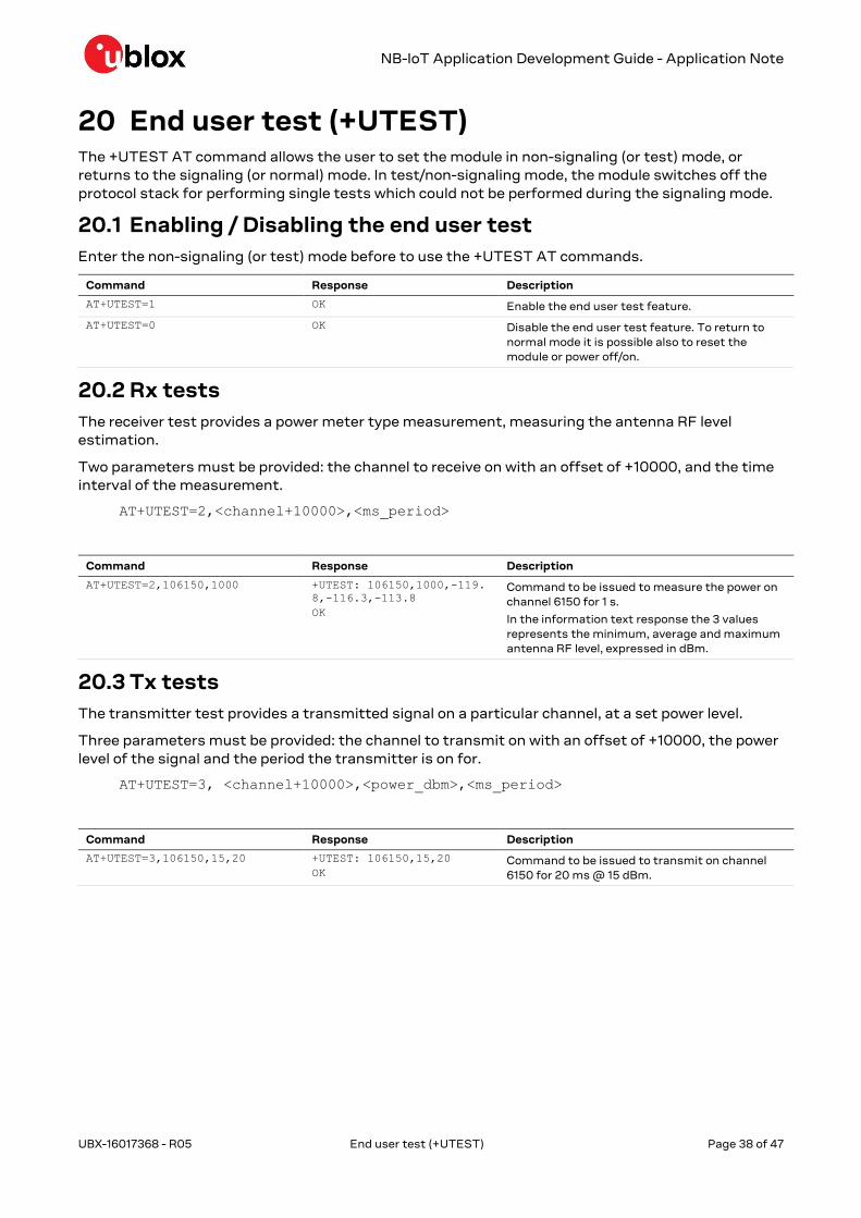
NB-IoT Application Development Guide - Application Note
UBX-16017368 - R05 End user test (+UTEST) Page 38 of 47
20 End user test (+UTEST) The +UTEST AT command allows the user to set the module in non-signaling (or test) mode, or
returns to the signaling (or normal) mode. In test/non-signaling mode, the module switches off the
protocol stack for performing single tests which could not be performed during the signaling mode.
20.1 Enabling / Disabling the end user test
Enter the non-signaling (or test) mode before to use the +UTEST AT commands.
Command Response Description
AT+UTEST=1 OK Enable the end user test feature.
AT+UTEST=0 OK Disable the end user test feature. To return to
normal mode it is possible also to reset the
module or power off/on.
20.2 Rx tests
The receiver test provides a power meter type measurement, measuring the antenna RF level
estimation.
Two parameters must be provided: the channel to receive on with an offset of +10000, and the time
interval of the measurement.
AT+UTEST=2,<channel+10000>,<ms_period>
Command Response Description
AT+UTEST=2,106150,1000 +UTEST: 106150,1000,-119.
8,-116.3,-113.8
OK
Command to be issued to measure the power on
channel 6150 for 1 s.
In the information text response the 3 values
represents the minimum, average and maximum
antenna RF level, expressed in dBm.
20.3 Tx tests
The transmitter test provides a transmitted signal on a particular channel, at a set power level.
Three parameters must be provided: the channel to transmit on with an offset of +10000, the power
level of the signal and the period the transmitter is on for.
AT+UTEST=3, <channel+10000>,<power_dbm>,<ms_period>
Command Response Description
AT+UTEST=3,106150,15,20 +UTEST: 106150,15,20
OK
Command to be issued to transmit on channel
6150 for 20 ms @ 15 dBm.
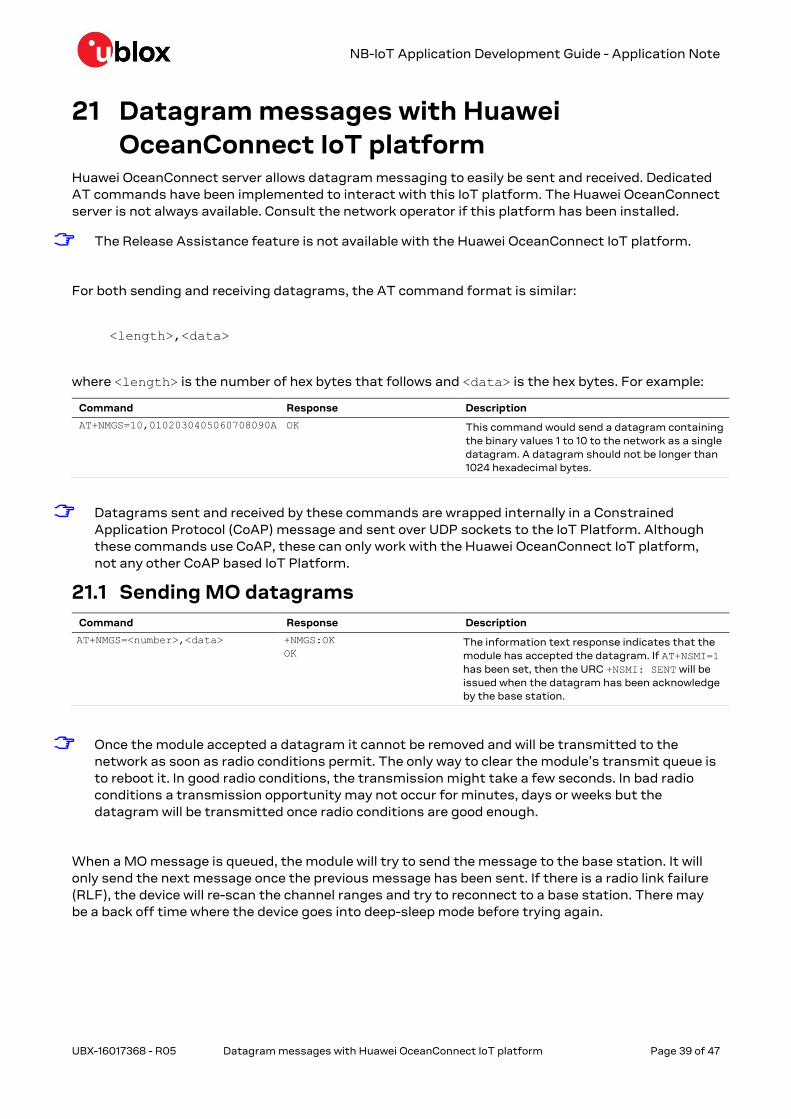
NB-IoT Application Development Guide - Application Note
UBX-16017368 - R05 Datagram messages with Huawei OceanConnect IoT platform Page 39 of 47
21 Datagram messages with Huawei
OceanConnect IoT platform Huawei OceanConnect server allows datagram messaging to easily be sent and received. Dedicated
AT commands have been implemented to interact with this IoT platform. The Huawei OceanConnect
server is not always available. Consult the network operator if this platform has been installed.
☞ The Release Assistance feature is not available with the Huawei OceanConnect IoT platform.
For both sending and receiving datagrams, the AT command format is similar:
<length>,<data>
where <length> is the number of hex bytes that follows and <data> is the hex bytes. For example:
Command Response Description
AT+NMGS=10,0102030405060708090A OK This command would send a datagram containing
the binary values 1 to 10 to the network as a single
datagram. A datagram should not be longer than
1024 hexadecimal bytes.
☞ Datagrams sent and received by these commands are wrapped internally in a Constrained
Application Protocol (CoAP) message and sent over UDP sockets to the IoT Platform. Although
these commands use CoAP, these can only work with the Huawei OceanConnect IoT platform,
not any other CoAP based IoT Platform.
21.1 Sending MO datagrams
Command Response Description
AT+NMGS=<number>,<data> +NMGS:OK
OK
The information text response indicates that the
module has accepted the datagram. If AT+NSMI=1
has been set, then the URC +NSMI: SENT will be
issued when the datagram has been acknowledge
by the base station.
☞ Once the module accepted a datagram it cannot be removed and will be transmitted to the
network as soon as radio conditions permit. The only way to clear the module’s transmit queue is
to reboot it. In good radio conditions, the transmission might take a few seconds. In bad radio
conditions a transmission opportunity may not occur for minutes, days or weeks but the
datagram will be transmitted once radio conditions are good enough.
When a MO message is queued, the module will try to send the message to the base station. It will
only send the next message once the previous message has been sent. If there is a radio link failure
(RLF), the device will re-scan the channel ranges and try to reconnect to a base station. There may
be a back off time where the device goes into deep-sleep mode before trying again.

NB-IoT Application Development Guide - Application Note
UBX-16017368 - R05 Datagram messages with Huawei OceanConnect IoT platform Page 40 of 47
21.2 Querying MO datagram sent status
Command Response Description
AT+NQMGS PENDING=1,SENT=4,ERROR=0
OK
The information text response indicates how
many datagrams have been queued, sent and not
sent.
Unlike the +NSMI: SENT indication, which shows when the datagram has been sent to the base
station, there is no indication if the core network or CDP server has received the message. The
customer will need to implement an application based reply if the notification is required to be given
back to the device; however this is not best practice for IoT type products.
21.3 Receiving MT datagrams
☞ Verify with Huawei about the use of the OceanConnect server on how to send MT datagrams
from the cloud application.
To output any received MT datagram use the +NMGR AT command.
Command Response Description
AT+NMGR <length>,<data>
OK
The information text response contains a
downlink datagram that has been received by the
module. The datagram is now removed from the
module’s queue. A datagram will not be longer
than 512 bytes.
AT+NMGR OK This indicates that no downlink datagrams are
present in the module’s queue.
One +NMGR response containing one datagram is issued for each AT+NMGR. To check for multiple
downlink datagrams, multiple AT+MGR commands must be issued. There is no indication to the
OceanConnect server if the module received the datagram.
If the +NNMI URC has been enabled, the module will send a URC on the UART interface after
receiving a MT datagram. If the module’s application, on customer device, is not prepared to read
the message as it is presented on the UART interface, the message will be lost.
Command Response Description
+NNMI:<number>,<data> The information text response contains a
downlink datagram that has been received by the
module. The datagram is removed from the
module’s queue.
21.4 Querying MT datagram received status
Command Response Description
AT+NQMGR BUFFERED=0,RECEIVED=0,DROP
PED=0
OK
The information text response indicates how
many datagrams have been received, queued and
not received.
21.5 Avoiding data loss
While the NB-IoT system is built to avoid data loss due to RF signal issues, buffers are of a finite
length and hence it is necessary to design with the limitations in mind.
In the uplink direction, it is recommended that the application on the device enables the send
message indications +NSMI URC and only puts another datagram into the module when the

NB-IoT Application Development Guide - Application Note
UBX-16017368 - R05 Datagram messages with Huawei OceanConnect IoT platform Page 41 of 47
previous datagram has been confirmed as sent. This has the added advantage that the send buffer
can be managed by the application (so, for instance, stale data is not left queued in the module).
In the downlink direction, it is recommended that the customer server does not allow datagrams to
build up on the IoT platform, i.e. the system design should be such that, for instance, transmission
of the next downlink datagram would not occur until the previous downlink datagram had been sent
on to the device. This is because, should a transfer be in progress when the radio link completely
fails, the entire downlink buffer within the network will be cleared and any datagrams forwarded to
the core network by the OceanConnect server could be lost.
If the cloud application requires notification of MT datagram delivery, the UE application must send
back an acknowledgement message itself as there is no provision within NB-IoT or the IoT platform
being used.
21.6 Send message indication +NSMI
Enables and disables indications when an upstream message is sent.
If indications are turned on, the +NSMI URC will be issued when the datagram has been successfully
sent and acknowledged by the network.
Command Response Description
AT+NSMI=0 +NSMI: OK
OK
Turns off +NSMI URC.
AT+NSMI=1 +NSMI: OK
OK
After a datagram has been successfully sent and
acknowledged by the network the module will
issue the +NSMI: SENT URC.
The state of the send message indications may be queried as follows:
Command Response Description
AT+NSMI? +NSMI=1
OK
The default value is 0, in which case no
confirmation is given. The command setting is not
stored in the module NVM hence, if the parameter
was set to 1 and is later read as 0, this means the
module has rebooted.
21.7 New message indications +NNMI
Notification of receipt of a datagram may be requested as follows:
Command Response Description
AT+NNMI=0 +NNMI:OK
OK
Turns off the +NNMI URC indications.
AT+NNMI=1 +NNMI:OK
OK
When a datagram has been received by the
module, the +NNMI: <length>,<data> URC will
be issued and the datagram will be deleted from
the module’s internal memory.
AT+NNMI=2 +NNMI:OK
OK
When a datagram has been received by the
module, the +NNMI URC will be issued but the
datagram will be retained inside the module. The
datagram may then be retrieved from the module
using AT+MGR.

NB-IoT Application Development Guide - Application Note
UBX-16017368 - R05 Datagram messages with Huawei OceanConnect IoT platform Page 42 of 47
The state of the new message indications may be queried as follows:
Command Response Description
AT+NNMI? +NNMI=1
OK
The default value is 0, in which case the module
must be polled with AT+NMGR for received
messages. This value is not stored in the module
NVM hence, if the parameter was set to 1 or 2 and
is later read as 0, this means the module has
rebooted.

NB-IoT Application Development Guide - Application Note
UBX-16017368 - R05 Appendix Page 43 of 47
Appendix
A T3324 / T3412 timer values
A.1 T3412 timer (GPRS timer 3)
The purpose of the GPRS timer 3 information element is to specify GPRS specific timer values. The
GPRS timer 3 is a type 4 information element with a 3 octet length. The GPRS timer 3 information
elements are coded as described in 3GPP TS 24.008 [4], figure 10.5.147a and table 10.5.163a.
Bits 5 to 1 represent the binary coded timer value. Bits 6 to 8 define the timer value unit for the GPRS
timer as follows:
BIT 8 7 6
0 0 0 value is incremented in multiples of 10 minutes
0 0 1 value is incremented in multiples of 1 hour
0 1 0 value is incremented in multiples of 10 hours
0 1 1 value is incremented in multiples of 2 seconds
1 0 0 value is incremented in multiples of 30 seconds
1 0 1 value is incremented in multiples of 1 minute
1 1 0 value is incremented in multiples of 320 hours (Note 1)
1 1 1 value indicates that the timer is deactivated (Note 2)
Example: "01000111" = 7 x10 hours = 70 hours
☞ NOTE 1: This timer value unit is only applicable to the T3312 extended value IE and the T3412
extended value IE (see 3GPP TS 24.301 [5]). If it is received in an integrity protected message, the
value shall be interpreted as multiples of 320 hours. Otherwise the value shall be interpreted as
multiples of 1 hour.
☞ NOTE 2: This timer value unit is not applicable to the T3412 extended value IE. If this timer value
is received, the T3412 extended value IE shall be considered as not included in the message (see
3GPP TS 24.301 [5]).
A.2 T3324 timer (GPRS timer 2)
The purpose of the GPRS timer 2 information element is to specify GPRS specific timer values, e.g.
for the timer T3302 or timer T3319. The GPRS timer 2 is a type 4 information element with a 3 octet
length. The GPRS timer 2 information elements are coded as shown in figure 10.5.147 and table
10.5.163 in 3GPP TS 24.008 [4].
Bits 5 to 1 represent the binary coded timer value. Bits 6 to 8 define the timer value unit for the GPRS
timer as follows:
BIT 8 7 6
0 0 0 value is incremented in multiples of 2 seconds
0 0 1 value is incremented in multiples of 1 minute
0 1 0 value is incremented in multiples of deci-hours
1 1 1 value indicates that the timer is deactivated
Example: "00100100" = 4 x1 minute = 4 minutes
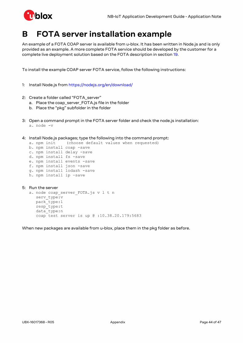
NB-IoT Application Development Guide - Application Note
UBX-16017368 - R05 Appendix Page 44 of 47
B FOTA server installation example An example of a FOTA COAP server is available from u-blox. It has been written in Node.js and is only
provided as an example. A more complete FOTA service should be developed by the customer for a
complete live deployment solution based on the FOTA description in section 19.
To install the example COAP server FOTA service, follow the following instructions:
1: Install Node.js from https://nodejs.org/en/download/
2: Create a folder called “FOTA_server”
a. Place the coap_server_FOTA.js file in the folder
b. Place the “pkg” subfolder in the folder
3: Open a command prompt in the FOTA server folder and check the node.js installation: a. node -v
4: Install Node.js packages; type the following into the command prompt: a. npm init (choose default values when requested)
b. npm install coap -save c. npm install delay -save d. npm install fs -save e. npm install events -save f. npm install json -save g. npm install lodash -save h. npm install ip –save
5: Run the server a. node coap_server_FOTA.js v l t n
serv_type:v
pack_type:l
resp_type:t
data_type:n
coap test server is up @ :10.38.20.179:5683
When new packages are available from u-blox, place them in the pkg folder as before.
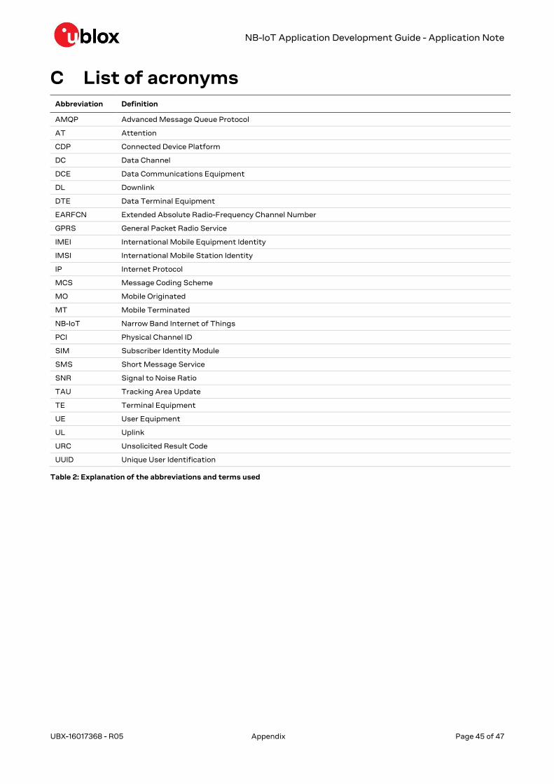
NB-IoT Application Development Guide - Application Note
UBX-16017368 - R05 Appendix Page 45 of 47
C List of acronyms Abbreviation Definition
AMQP Advanced Message Queue Protocol
AT Attention
CDP Connected Device Platform
DC Data Channel
DCE Data Communications Equipment
DL Downlink
DTE Data Terminal Equipment
EARFCN Extended Absolute Radio-Frequency Channel Number
GPRS General Packet Radio Service
IMEI International Mobile Equipment Identity
IMSI International Mobile Station Identity
IP Internet Protocol
MCS Message Coding Scheme
MO Mobile Originated
MT Mobile Terminated
NB-IoT Narrow Band Internet of Things
PCI Physical Channel ID
SIM Subscriber Identity Module
SMS Short Message Service
SNR Signal to Noise Ratio
TAU Tracking Area Update
TE Terminal Equipment
UE User Equipment
UL Uplink
URC Unsolicited Result Code
UUID Unique User Identification
Table 2: Explanation of the abbreviations and terms used

NB-IoT Application Development Guide - Application Note
UBX-16017368 - R05 Related documents Page 46 of 47
Related documents [1] u-blox SARA-N2 series Data Sheet, Docu No UBX-15025564
[2] u-blox SARA-N2 AT Commands Manual, Docu No UBX-16014887
[3] 3GPP TS 36.321 Evolved Universal Terrestrial Radio Access (E-UTRA); Medium Access Control
(MAC) protocol specification
[4] 3GPP TS 24.008 - Annex G (informative): 3GPP specific cause values for mobility management
[5] 3GPP TS 24.301 - Non-Access-Stratum (NAS) protocol for Evolved Packet System (EPS); Stage 3
[6] 3GPP TS 36.331 - Evolved Universal Terrestrial Radio Access (E-UTRA); Radio Resource Control
(RRC); Protocol specification
☞ For regular updates to u-blox documentation and to receive product change notifications,
register on our homepage (www.u-blox.com).
Revision history Revision Date Name Status / Comments
R01 25-Nov-2016 pwar Initial release
R02 02-Feb-2017 pwar Emphasis more on UDP. Include protocol states and IP transport diagrams
R03 23-Mar-2017 pwar Update NUESTATS for new B655SP2 version. Removed Neul IoT Platform
references.
R04 27-Oct-2017 pwar Updated for U06.57 A03.02 ES firmware. (B657SP2 protocol stack from
HiSilicon)
R05 20-Jul-2018 pwar Added FOTA, UTEST and CoAP sections, minor corrections.

NB-IoT Application Development Guide - Application Note
UBX-16017368 - R05 Contact Page 47 of 47
Contact For complete contact information, visit us at www.u-blox.com.
u-blox Offices
North, Central and South America
u-blox America, Inc.
Phone: +1 703 483 3180
E-mail: [email protected]
Regional Office West Coast:
Phone: +1 408 573 3640
E-mail: [email protected]
Technical Support:
Phone: +1 703 483 3185
E-mail: [email protected]
Headquarters
Europe, Middle East, Africa
u-blox AG
Phone: +41 44 722 74 44
E-mail: [email protected]
Support: [email protected]
Asia, Australia, Pacific
u-blox Singapore Pte. Ltd.
Phone: +65 6734 3811
E-mail: [email protected]
Support: [email protected]
Regional Office Australia:
Phone: +61 2 8448 2016
E-mail: [email protected]
Support: [email protected]
Regional Office China (Beijing):
Phone: +86 10 68 133 545
E-mail: [email protected]
Support: [email protected]
Regional Office China (Chongqing):
Phone: +86 23 6815 1588
E-mail: [email protected]
Support: [email protected]
Regional Office China (Shanghai):
Phone: +86 21 6090 4832
E-mail: [email protected]
Support: [email protected]
Regional Office China (Shenzhen):
Phone: +86 755 8627 1083
E-mail: [email protected]
Support: [email protected]
Regional Office India:
Phone: +91 80 405 092 00
E-mail: [email protected]
Support: [email protected]
Regional Office Japan (Osaka):
Phone: +81 6 6941 3660
E-mail: [email protected]
Support: [email protected]
Regional Office Japan (Tokyo):
Phone: +81 3 5775 3850
E-mail: [email protected]
Support: [email protected]
Regional Office Korea:
Phone: +82 2 542 0861
E-mail: [email protected]
Support: [email protected]
Regional Office Taiwan:
Phone: +886 2 2657 1090
E-mail: [email protected]
Support: [email protected]


![[NB-IOT AND LINK ADAPTATION ] - unipi.gr](https://static.fdocuments.net/doc/165x107/6195c4b3aeee0d721264c2c7/nb-iot-and-link-adaptation-unipigr.jpg)