Submarine Fans. Styles of submarine fan Schematic submarine fan.

NAVAL
POSTGRADUATE SCHOOL
MONTEREY, CALIFORNIA
THESIS
Approved for public release; distribution is unlimited
MANNING AND MAINTAINABILITY OF A SUBMARINE UNMANNED UNDERSEA VEHICLE (UUV) PROGRAM:
A SYSTEMS ENGINEERING CASE STUDY
by
Troy D. Vandenberg
September 2010
Thesis Advisor: Clifford Whitcomb Second Reader: W. G. “Jerry” Ellis

THIS PAGE INTENTIONALLY LEFT BLANK

i
REPORT DOCUMENTATION PAGE Form Approved OMB No. 0704-0188 Public reporting burden for this collection of information is estimated to average 1 hour per response, including the time for reviewing instruction, searching existing data sources, gathering and maintaining the data needed, and completing and reviewing the collection of information. Send comments regarding this burden estimate or any other aspect of this collection of information, including suggestions for reducing this burden, to Washington headquarters Services, Directorate for Information Operations and Reports, 1215 Jefferson Davis Highway, Suite 1204, Arlington, VA 22202-4302, and to the Office of Management and Budget, Paperwork Reduction Project (0704-0188) Washington DC 20503. 1. AGENCY USE ONLY (Leave blank)
2. REPORT DATE September 2010
3. REPORT TYPE AND DATES COVERED Master’s Thesis
4. TITLE AND SUBTITLE Manning and Maintainability of a Submarine Unmanned Undersea Vehicle (UUV) Program: A Systems Engineering Case Study
6. AUTHOR(S) Troy D. Vandenberg
5. FUNDING NUMBERS
7. PERFORMING ORGANIZATION NAME(S) AND ADDRESS(ES) Naval Postgraduate School Monterey, CA 93943-5000
8. PERFORMING ORGANIZATION REPORT NUMBER
9. SPONSORING /MONITORING AGENCY NAME(S) AND ADDRESS(ES) N/A
10. SPONSORING/MONITORING AGENCY REPORT NUMBER
11. SUPPLEMENTARY NOTES The views expressed in this thesis are those of the author and do not reflect the official policy or position of the Department of Defense or the U.S. Government.
12a. DISTRIBUTION / AVAILABILITY STATEMENT Approved for public release; distribution is unlimited
12b. DISTRIBUTION CODE
13. ABSTRACT (maximum 200 words)
The purpose of this thesis is to study the manning and maintainability requirements of a submarine unmanned undersea vehicle (UUV) program. This case study reviews current commercial and military applications of UUVs and applies their principles to the missions of the Navy’s submarine force. Past and current UUV efforts are lacking requirements documents and the formal systems engineering process necessary to produce a successful program of record. Therefore, they are not being funded for use by the war-fighter. The Navy must develop formal concepts of operations (CONOPS) for the missions and systems that it wants to produce and allow industry to begin development for a formal future UUV program. Furthermore, the military has developed countless unmanned systems that have been developed for use in the water, on the ground and in the air, from which the Navy can apply important lessons learned. Lastly, analysis suggests that the Navy should continue to support the use of a submarine detachment for operation and maintainability of future vehicle programs.
15. NUMBER OF PAGES
137
14. SUBJECT TERMS Unmanned Undersea Vehicles, UUV, Manning, Maintainability, Submarine Missions, Systems Engineering
16. PRICE CODE
17. SECURITY CLASSIFICATION OF REPORT
Unclassified
18. SECURITY CLASSIFICATION OF THIS PAGE
Unclassified
19. SECURITY CLASSIFICATION OF ABSTRACT
Unclassified
20. LIMITATION OF ABSTRACT
UU NSN 7540-01-280-5500 Standard Form 298 (Rev. 2-89) Prescribed by ANSI Std. 239-18

ii
THIS PAGE INTENTIONALLY LEFT BLANK

iii
Approved for public release; distribution is unlimited
MANNING AND MAINTAINABILITY OF A SUBMARINE UNMANNED UNDERSEA VEHICLE (UUV) PROGRAM: A SYSTEMS ENGINEERING CASE
STUDY
Troy D. Vandenberg Lieutenant, United States Navy
B.S., Michigan Technological University, 2003
Submitted in partial fulfillment of the requirements for the degree of
MASTER OF SCIENCE IN SYSTEMS ENGINEERING
from the
NAVAL POSTGRADUATE SCHOOL September 2010
Author: Troy D. Vandenberg
Approved by: Clifford Whitcomb, PhD Thesis Advisor
RADM W. G. “Jerry” Ellis, USN (ret) Second Reader
Clifford Whitcomb, PhD Chairman, Department of Systems Engineering

iv
THIS PAGE INTENTIONALLY LEFT BLANK

v
ABSTRACT
The purpose of this thesis is to study the manning and maintainability requirements of a
submarine unmanned undersea vehicle (UUV) program. This case study reviews current
commercial and military applications of UUVs and applies their principles to the
missions of the Navy’s submarine force. Past and current UUV efforts are lacking
requirements documents and the formal systems engineering process necessary to
produce a successful program of record. Therefore, they are not being funded for use by
the war-fighter. The Navy must develop formal concepts of operations (CONOPS) for
the missions and systems that it wants to produce and allow industry to begin
development for a formal future UUV program. Furthermore, the military has developed
countless unmanned systems that have been developed for use in the water, on the ground
and in the air, from which the Navy can apply important lessons learned. Lastly, analysis
suggests that the Navy should continue to support the use of a submarine detachment for
operation and maintainability of future vehicle programs.

vi
THIS PAGE INTENTIONALLY LEFT BLANK

vii
TABLE OF CONTENTS
I. INTRODUCTION........................................................................................................1 A. BACKGROUND ..............................................................................................1 B. PURPOSE.........................................................................................................2 C. RESEARCH QUESTIONS.............................................................................2 D. BENEFIT OF STUDY.....................................................................................3 E. SCOPE AND METHODOLOGY ..................................................................3 F. CHAPTER SUMMARY..................................................................................4
II. UUV MISSIONS AND SYSTEMS.............................................................................5 A. INTRODUCTION............................................................................................5 B. UUV MISSIONS ..............................................................................................5
1. Advantages of UUVs for Military Operations...................................5 2. UUV Sub-Pillar Missions ....................................................................6
C. UUV SYSTEMS ...............................................................................................9 1. UUV Vehicle Classes............................................................................9 2. Sample UUV Platforms .....................................................................10 3. Levels of Autonomy ...........................................................................16
D. CHAPTER SUMMARY................................................................................19
III. UUVS IN SUPPORT OF SUBMARINE MISSIONS.............................................21 A. INTRODUCTION..........................................................................................21 B. SUBMARINE UUV MISSIONS...................................................................21
1. Intelligence, Surveillance, and Reconnaissance ..............................22 2. Communications ................................................................................24 3. Anti-Submarine Warfare ..................................................................26
C. PAST AND PRESENT NAVY SUBMARINE UUV PROGRAMS ..........27 1. Near-Term Mine Reconnaissance System .......................................28 2. Long-Term Mine Reconnaissance System.......................................28 3. Mission Reconfigurable UUV ...........................................................29 4. Current Projects.................................................................................29
D. POSSIBLE SUBMARINE / UUV INTERACTIONS.................................32 1. Launch and Recovery ........................................................................32 2. Launch Without Recovery ................................................................35 3. Non-physical Interactions .................................................................36
E. CHAPTER SUMMARY................................................................................40
IV. APPLICABLE LESSONS LEARNED FROM UGVS AND UAVS .....................41 A. INTRODUCTION..........................................................................................41 B. UNMANNED GROUND VEHICLES .........................................................42
1. Brief History of the UGV ..................................................................42 2. Similarities Between UGVs and UUVs ............................................42 3. Lessons Learned from UGVs............................................................45
C. UNMANNED AERIAL VEHICLES............................................................49 1. Brief History of the UAV...................................................................49

viii
2. Similarities between UUVs and UAVs .............................................50 3. Lessons Learned from UAVs ............................................................50
D. CHAPTER SUMMARY................................................................................55
V. SYSTEMS ENGINEERING AND ANALYSIS ......................................................57 A. INTRODUCTION..........................................................................................57 B. SYSTEMS ENGINEERING APPROACH .................................................57
1. Systems Engineering Process ............................................................57 2. Feedback .............................................................................................66 3. Trade Studies......................................................................................67
C. MANNING AND MAINTAINABILITY ANALYSIS................................68 1. Manning Analysis...............................................................................69 2. Maintainability Analysis ...................................................................72
D. CHAPTER SUMMARY................................................................................79
VI. SAMPLE CONCEPTS OF OPERATIONS ............................................................81 A. INTRODUCTION..........................................................................................81 B. GROUP OF SUBMARINE-LAUNCHED UUVS.......................................81
1. Operational Situation ........................................................................81 2. Payloads ..............................................................................................83 3. Maintenance .......................................................................................85 4. Manning..............................................................................................85 5. Recommendations ..............................................................................86
C. GROUP OF LARGE DIAMETER UUVS ..................................................87 1. Operational Situation ........................................................................87 2. Payloads ..............................................................................................89 3. Maintenance .......................................................................................90 4. Manning..............................................................................................92 5. Recommendations ..............................................................................92
D. CHAPTER SUMMARY................................................................................93
VII. CONCLUSIONS AND RECOMMENDATIONS...................................................95 A. INTRODUCTION..........................................................................................95 B. CONCLUSIONS AND RECOMMENDATIONS.......................................96
1. Focus the Missions .............................................................................97 2. Learn Lessons From UGVs and UAVs ............................................98 3. Consider Manning and Maintainability ..........................................98
C. AREAS OF FURTHER RESEARCH........................................................100 1. Perform Trade Studies ....................................................................101 2. Develop and Advance Technologies ...............................................102 3. Summarize Lessons Learned ..........................................................103 4. Concentrate on Requirements ........................................................104
D. CHAPTER SUMMARY..............................................................................104
LIST OF REFERENCES....................................................................................................105
INITIAL DISTRIBUTION LIST .......................................................................................109

ix
LIST OF FIGURES
Figure 1. Initial vision of Sea Power 21 (From: Clark, 2002)...........................................8 Figure 2. REMUS 100 vehicle in use by the Navy EOD community in VSW MCM
testing (From: Clegg & Peterson, 2003) ..........................................................12 Figure 3. Schematic of Bluefin-21 BPAUV (From: Bluefin Robotics, 2009) ................13 Figure 4. ASM-X in a laboratory broken into modular components (From: DCNS,
2010) ................................................................................................................13 Figure 5. HUGIN 3000 shown on the recovery platform (From: Kleiner, 2004) ...........14 Figure 6. Slocum electric glider high-level mission CONOPS (From: Teledyne
Webb Research, 2010) .....................................................................................15 Figure 7. Relationship between mission autonomy and system complexity for
unmanned systems (From: National Research Council, 2005)........................18 Figure 8. A trade-off study methodology incorporating level of mission autonomy
as a design choice (From: National Research Council, 2005) .........................19 Figure 9. ForceNet concept showing network-centric connectivity to various
undersea assets (From: Department of the Navy, 2004)..................................22 Figure 10. Operational concept of PLUSNet (From: Martin, 2005) .................................23 Figure 11. Seaweb acoustic communication and navigational network model (From:
Rice, 2005).......................................................................................................25 Figure 12. Task Force ASW model depicting nomenclature (From: Department of the
Navy, 2004)......................................................................................................26 Figure 13. Monopole retractable antenna concept as used in the Sea Stalker UUV
(From: Mullins, 2009)......................................................................................31 Figure 14. Sea Maverick UUV shown on launch crane during JIATF South exercise
(From: United States Southern Command, 2009)............................................32 Figure 15. Visualization of UUV recovery via a single conventional torpedo tube
(From: Hardy & Barlow, 2008) .......................................................................33 Figure 16. Dry deck shelter on back of Los Angeles-class submarine (From: Rehana,
2000) ................................................................................................................35 Figure 17. Flying plug attaching to a communications dock (From: Cowen, Briest, &
Dombrowski, 1997) .........................................................................................38 Figure 18. Docking station and remote interface used in DSSN experiment (After:
Cowen, Briest, & Dombrowski, 1997) ............................................................39 Figure 19. FY2007-2013 DoD Funding for unmanned platforms (From: Button,
Kamp, Curtin, & Dryden, 2009) ......................................................................41 Figure 20. UGV technology areas (From: National Research Council, 2002) .................43 Figure 21. U.S. Navy photo of an original Interstate BQ-4/TDR (From: Parsch, 2005) ..49 Figure 22. Maintainability data as a function of sortie length for UAVs, assuming
similar levels of maintainability (From: Lockheed Martin Corporation, 2002) ................................................................................................................54
Figure 23. Relationship between redundancy and cost per flight hour for UAVs, assuming critical failure rate of 1/3 of MTBF (From: Lockheed Martin Corporation, 2002)...........................................................................................55

x
Figure 24. DAU systems engineering process model (From: Defense Acquisition University, 2001) .............................................................................................58
Figure 25. Hierarchy of requirements (From: Buede, 2000).............................................60 Figure 26. High level EFFBD for TUNAS sample UUV system (From: Brocht,
Layne, Matson, McMurtrie, Schindler, & Vandenberg, 2009)........................63 Figure 27. N2 matrix diagram for TUNAS sample UUV system (From: Brocht,
Layne, Matson, McMurtrie, Schindler, & Vandenberg, 2009)........................64 Figure 28. IDEF0 diagram template (From: Blanchard & Fabrycky, 2006).....................65 Figure 29. Trade study process (From: Defense Acquisition University, 2001) ..............68 Figure 30. Systems engineering lifecycle (From: Blanchard & Fabrycky, 2006) ............69 Figure 31. Navy enlisted classification code 9550 description (From: Bureau of
Naval Personnel, 2010)....................................................................................72 Figure 32. System operational and maintenance flow (From: Blanchard & Fabrycky,
2006) ................................................................................................................74 Figure 33. High level graphical depiction of operational situation for a group of small
submarine-launched UUVs..............................................................................82 Figure 34. High level graphical depiction of operational situation for a group of
LDUUVs..........................................................................................................88 Figure 35. Artist depiction of flexible mission bay in LCS-2 (From: Austal, 2007) ........90

xi
LIST OF TABLES
Table 1. Mapping of the nine sub-pillars to Sea Power 21 vision (After: Department of the Navy, 2004) .........................................................................8
Table 2. Definition of UUV classes for nominal levels of performance (After: Department of the Navy, 2004) .........................................................................9
Table 3. Classes of UUVs mapped to generic missions of the nine sub-pillars (After: Department of the Navy, 2004)............................................................10
Table 4. Summary of sample UUVs analyzed...............................................................11 Table 5. Task Force ASW nomenclature with descriptions (After: Department of
the Navy, 2004)................................................................................................26 Table 6. Key advantages and disadvantages of using a conventional torpedo tube
for UUV launch and recovery (After: Hardy & Barlow, 2008).......................34 Table 7. Key advantages and disadvantages of using a dry deck shelter for UUV
launch and recovery (After: Hardy & Barlow, 2008) ......................................35 Table 8. UGV example systems, capability classes, and potential mission
applications (After: National Research Council, 2002)...................................44 Table 9. Human control, human support, and health maintenance for the example
UGV systems (After: National Research Council, 2002)................................45 Table 10. Top 10 issues compiled from UGV lessons learned for MCM UUVs
(After: Blackburn, Laird, & Everett, 2001) .....................................................46 Table 11. Summary of eleven UGV and UAV lessons learned for UUVs......................56 Table 12. UNTL tactical level task measures for NTA 1.5.2.3 Conduct
Undersea/Antisubmarine Warfare (From: Department of the Navy, 2001) ....61 Table 13. Summary of logistics support elements in the systems engineering
lifecycle (After: Blanchard & Fabrycky, 2006)...............................................70 Table 14. Summary of the role of maintainability in the systems engineering
lifecycle (After: Blanchard & Fabrycky, 2006)...............................................73 Table 15. Criteria for organizational, intermediate, and depot levels of maintenance
(From: Blanchard & Fabrycky, 2006) .............................................................75 Table 16. Organizational level man-hour requirements for the HUGIN 1000 AUV
(From: C. Hancock, personal communications, April 5, 2010).......................75 Table 17. Organizational level maintenance performed on the HUGIN 1000 AUV
after each mission (From: C. Hancock, personal communications, April 5, 2010) ................................................................................................................77
Table 18. Summary of manning requirements necessary to support a group of submarine-launched UUVs..............................................................................86

xii
THIS PAGE INTENTIONALLY LEFT BLANK

xiii
EXECUTIVE SUMMARY
A. BACKGROUND
In 2004, the Navy unveiled the Sea Power 21-inspired Unmanned Undersea
Vehicle (UUV) Master Plan, which defined the nine missions of UUVs and the four
different vehicle classes that could support those missions. The Navy has made some
fundamental changes in their development, testing, and acquisition of UUVs, but even
with the Master Plan’s recommendations, years later, there is no current submarine UUV
program of record. This thesis utilized government and industry resources to focus on
the systems engineering fundamentals that are necessary to have a successful submarine
UUV program in the near future. Moreover, the intent of this thesis was to research past
and current programs and missions and provide recommendations for the manning and
maintainability aspects of the systems engineering lifecycle. To do this, the research
started with the large-scale concept of UUVs and eventually focused on the manning and
maintainability aspects that are specifically related to UUVs in support of submarine
missions.
The purpose of this thesis was to provide recommendations for the steps
necessary to have a successful submarine UUV program of record. Additionally, the
thesis discusses the impact that unmanned undersea vehicles will have on the submarine
force, focusing on the two key areas of manning and maintainability. In doing this
research, assumptions have been made that the technological challenges of deploying
UUVs from, or in tandem with, submarines are ones that will be possible to overcome.
Lastly, this thesis was completed as an UNCLASSIFIED document. Though some of the
research did involve classified discussions, presentations, and documents, they were not
used in any capacity for the final write-up. As a result, some systems, technologies,
missions, and information have been presented in a focus different or separated from
doctrine discussed directly by the United States Navy.

xiv
B. UTILIZING UUVS TO SUPPORT SUBMARINE MISSIONS
UUVs are not a new concept. The necessary technologies exist and members of
industry and military have been using forms of UUVs for many years. This does not
mean, however, that UUVs are ready to perform all missions required of their military
stakeholders. UUV missions lack importance unless there is a clear benefit to be gained
from their deployment. Three high level advantages of unmanned systems in the
maritime domain are that they can decrease cost, increase capability, and reduce risk.
The two major factors that contribute to the various types of UUVs are size and
complexity. UUVs are broken into four classes, based on their displacements. For the
intent of a submarine program, the two larger classes (as defined by the 2004 UUV
Master Plan) of Heavy Weight Vehicle (HWV) (21-inch diameter and less than 3000
pounds of displacement) and Large Vehicle (greater than 26-inch diameter and
approximately 20,000 pounds of displacement) are considered. Additionally, unmanned
system complexity is a factor of the level of autonomy, which can range between human-
operated and fully autonomous. Ideally, a UUV program would utilize a fully
autonomous vehicle, but this is one of the technical challenges currently faced by the
Navy and the industrial developers. Though the technology does exist, it requires the
confidence of the operator moving forward.
Future naval battles will rely heavily on advantages gained through the
combination of strategies, tactics, procedures, and technologies called network-centric
warfare and implemented through the strategy of ForceNet. These ideas rely heavily on
Joint Force assets working together with common communication nodes. Large-scale
undersea networks, like those adhering to ForceNet will be used heavily in the future of
undersea warfare (USW), with UUVs acting as crucial communication nodes to and from
submarine and surface assets. Out of the nine key mission areas discussed in the 2004
UUV Master Plan, three specific missions should be considered for a near-term
submarine UUV program and can be evaluated as part of the overall ForceNet image.
These missions are:

xv
• Intelligence, Surveillance, and Reconnaissance (ISR). There are four
fundamental tasks necessary to complete an ISR mission: collect,
communicate, process, and act. Due to the simplistic nature and emerging
technologies, the submarine ISR mission-set will see the first full scale use
of UUVs.
• Communications. Communication is an important aspect for all military
operations. Underwater communications are complex and pose many
problems in the area of USW. One technology is to utilize digital acoustic
communications in modem-like bursts to communicate between a
submarine and a network of UUVs acting as communication nodes. There
are multiple programs being worked on by industry that make use of this
theory and have the ability to perform the desired missions.
• Anti-Submarine Warfare (ASW). Submarines have always played a
vital role in ASW. The force multiplication factor added by UUVs will
allows them to constantly patrol and monitor areas of interest. UUVs and
friendly submarines could remain in constant communication, relaying
valuable mission and classification data, which would drastically increase
the overall effectiveness of current ASW tactics.
Though there have been past programs, and current projects, that focus on the
levels of complexity, two vehicle sizes, and three missions discussed, there is no current
UUV program of record relating to submarine operations. The extinct programs and
current projects lend themselves to lessons learned for future success. The submarine
UUV programs that have failed can be attributed to lack of requirements and improper
system development. Each of these programs, however, has given the Navy valuable
insight on the manning and maintainability requirements of future UUV programs.
The biggest technical challenges faced by past programs have been the interaction
between the submarine and UUV. Possible submarine-UUV interactions include:
• Launch and Recovery. The ability to launch and recover a UUV from a
submarine is the greatest technical challenge that has led to the failure of

xvi
at least two programs [Long-term mine reconnaissance system (LMRS)
and mission reconfigurable UUV (MRUUV)]. Emerging technologies are
coming close to making this mission possible, but both physical space and
maintenance routines are still a challenge on board a submarine.
• Launch without Recovery. Setting up a scenario with UUV system
launch via a torpedo tube, missile tube, or dry-deck shelter will allow for
covert deployment of one or more UUVs while avoiding the drawbacks
associated with space considerations to support organizational level
maintenance and technical risks of torpedo tube recovery. Upon mission
completion, the UUV could either be abandoned or recovered by use of a
support ship.
• Non-physical Interactions. Regardless of the form of deployment, there
are several possible non-physical interactions between the submarine and
UUV, including: mission control, consumer/interrogator of data, and
docking station delivery. Each of these interactions hold true for all forms
of UUV launch and recovery. Designing UUV and submarine interactions
independent of the launch source will help transition to a less “platform
centric” design of UUV systems. When systems can be designed without
the platform in mind, there is more room for growth and an increased
chance of long-term success for a program.
Additionally, Unmanned Ground Vehicles (UGVs) and Unmanned Aerial
Vehicles (UAVs) have been in use longer than UUVs. This longevity provides the UGVs
and UAVs with valuable lessons learned that can be applied to their undersea
counterparts. This thesis discusses eleven lessons learned that can apply to the manning
and maintainability practices. These lessons are:
• Uncertainty promotes survival
• Simpler solutions provide better foundations
• Many simple cooperating agents are superior to one complex agent

xvii
• Maintenance should be done at the user level
• System requirements should be clear up front
• Acquire reliability data throughout all stages of development
• Structure a process for sharing data
• Limit the number of design configurations
• Consider supportability up front
• Endurance has its benefits
• Minimize the levels of redundancy
C. SYSTEMS ENGINEERING OF A SUBMARINE UUV PROGRAM
There are four fundamental stages to system design lifecycle. This four-stage
process has analysis, verification, and feedback occurring simultaneously with each step.
All four stages are required for a program to be “Systems Engineered” correctly. To
successfully complete a mission or set of missions, the four stages of the process need to
occur in the following order:
• Develop Requirements, based on missions
• Determine Tasks, based on requirements
• Create Functions, based on tasks
• Design Components, based on functions
Proper requirement definitions are produced with the system stakeholders and are derived
from the mission requirements. Unfortunately, this stage is often not understood by the
customer and requires the attention of a formally trained Systems Engineer. Many
engineers feel the role of the systems engineering process begins at the requirements
document, when in fact the Systems Engineer should work directly with the stakeholder
to understand the requirements and eventually formalize those requirements. Current
Navy submarine UUV projects have shown success in various at sea tests, but are not part

xviii
of a formal program and have included unclear, if not completely undefined,
requirements. This shortfall has meant that even though the programs may have
performed up to the operator’s expectations, the funding line is not in place for future
development of the systems and, as a result, may leave them forever sidelined.
Feedback should not only be done internal to the system, but must be used from
similar programs to gather valuable data necessary to maximize the probability of
successfully engineering a new complex system. Lack of feedback has caused past UUV
programs, with clearly stated requirements, to develop to a certain level and then become
cancelled by the Navy, for there to be a new programs started from the beginning.
Ideally, it is not only important that a program has requirements, but it will also need to
take lessons learned from previous similar programs.
In the systems lifecycle, there are three different stages of design: conceptual,
preliminary, and detail. This incremental process allows the inter-stage feedback to
provide real time response and allows for flexibility in the growth of the design process.
Future submarine UUV systems should account for manning and maintainability during
the developmental stages of the systems engineering lifecycle.
Sample concepts of operations (CONOPS) were created to offer suggestions for
the specific types of missions the Navy should pursue for a submarine UUV program and
the manning and maintainability suggestions that would apply to these missions. The two
discussed CONOPS were:
• Group of Submarine Launched UUVs. Small, torpedo tube-launched
UUVs would be ideal to complete an ISR mission. Several of these UUVs
would be launched from a submerged submarine and would transition into
an area of interest. The lead UUV would surface and extend a mast to
collect intelligence data. The other UUVs would act as communication
nodes and relay the information to be analyzed onboard back to the
submarine. This mission would require a cadre of five individuals aboard
the submarine operating the systems and performing minimal
organizational level maintenance during the deployment.

xix
• Group of Large Diameter UUVs (LDUUVs). LDUUVs could be
launched from a Littoral Combat Ship (LCS) to complete a harbor
monitoring and tracking ASW mission. Multiple LDUUVs would be
launched and recovered from the LCS, while the submarine would remain
near the operational area and communicate with the LDUUVs, relaying
critical mission data. This scenario would require a small group of
operators on the submarine and a mix of ten Navy personnel and
contractors on board the LCS. This scenario supports longer missions and
would require that extensive maintenance be performed on board the LCS.
These CONOPS do not provide all of the solutions of decision makers, but rather gives
them a stepping point for future submarine UUV program development.
D. CONCLUSIONS AND RECOMMENDATIONS
The government is devoting much effort in the formal training and proper use of
Systems Engineers. As a result, many programs are seeing an increase in their
productivity during the early stages of lifecycle development. Unfortunately, many
programs are being researched and tested using informal processes through government
organizations like ONR and DARPA and are ultimately cancelled due to funding
concerns. Though there is a place for research and development of technologies, the
current procedures are sidelining UUV programs that have performed up to, and in some
cases beyond, operator’s expectations. Many programs in development are outside the
needs of preliminary development and must be pursued in the form of a formal program.
To ensure a successful program, the systems will need to be developed using a formal
systems engineering process. Adhering to these processes will ensure that a successful
program will retain funding.
To do this, the Navy must start with a clearly defined mission and then follow
four basic systems engineering steps to develop the ideas into systems. This will require
the government to produce ideas independent of the end product in mind. The intent of
the thesis was to analyze the impact of a submarine UUV program on the manning and

xx
maintenance of the submarine force. Outside of the systems engineering and
development process concerns discussed previously, this thesis comes to three
conclusions:
• Focus the Missions. This study shows that the Navy should only focus on
three short-term missions for a submarine UUV program: ISR,
communications, and ASW. These missions were chosen based on
operator demands, and are the missions that are most easily accomplished
with the current technologies available. The challenges (other than
budgetary ones) that face current ISR and ASW missions are longevity,
and launch and recovery. This research suggested ways of creating
programs that will gain successful mission results in the near-term, while
still adhering to the technical constraints faced by UUV developers. One
example includes the use of multiple vehicles to complete the same
mission as a single long endurance vehicle.
• Learn Lessons from UGVs and UAVs. UGVs and UAVs provide
several similarities to UUVs and were the basis for the eleven lessons
learned pertaining to the development of UUV systems. The eleven
lessons were diverse in their relation to UUVs, but all provided ideas that
should be considered during the front-end system development process
that directly relate to the manning and maintainability of a program of
record. These lessons (along with any others shared amongst the program
offices) should all be considered prior to spending more money on testing,
developing, and fielding new unmanned systems.
• Consider Manning and Maintainability. The original intent of the
research was to understand the manning and maintenance models and
concerns that UUVs would have on the submarine force. Past systems
have neglected the impact of logistics on the deployment of new systems,
and it is important that the developers of a submarine UUV program do
not forget this. The limited size, space, and crew aboard a SSN will

xxi
require these thoughts to be fully considered before the program enters the
advanced development stages. Analysis suggests that operators should
continue to be part of a cadre of submarine qualified sailors with diverse
ratings. These operators must be qualified to both operate and maintain
the systems at both the organizational and intermediate maintenance
levels.
The intent of this thesis was to focus on the abstract, high-level concepts that will
effect the manning and maintainability aspects of the systems engineering process. As a
result, the scope of this thesis has led to several areas of further research for future
studies. The future work to expand this thesis into real world applications should be done
in the areas of trade studies, technologies, lessons learned, and requirements.

xxii
THIS PAGE INTENTIONALLY LEFT BLANK

xxiii
LIST OF ACRONYMS AND ABBREVIATIONS
Ao Operational Availability ACOMMS Acoustic Communications ADO Advanced Development Office ALV Autonomous Land Vehicle ANSE American Society of Naval Engineers AUV Autonomous Underwater Vehicle BPAUV Battlespace Preparation Autonomous Underwater Vehicle C2S Command-and-Control System CBA Cost Benefit Analysis CG Guided Missile Cruiser CI Configuration Item CN3 Communications / Navigation Network Node CONOPS Concept of Operations COTS Commercial Off-the-Shelf CSG Carrier Strike Group DARPA Defense Advanced Research Projects Agency DAU Defense Acquisition University DDG Guided Missile Destroyer DDS Dry Deck Shelter DEVRON Development Squadron DoD Department of Defense DSSN Distributed Surveillance Sensor Network EFFBD Enhanced Functional Flow Block Diagram EOD Explosive Ordnance Disposal ESG Expeditionary Strike Group ET Electronics Technicians FFBD Functional Flow Block Diagram FFG Guided Missile Frigate FT Fire Control Technician FY Fiscal Year HLD Homeland Defense HWV Heavy Weight Vehicle ID Identification IDEF0 Integration Definition for Function Modeling IO Information Operations ISR Intelligence, Surveillance, and Reconnaissance JIATF Joint Interagency Task Force LCC Lifecycle Cost LCS Littoral Combat Ship LDO Limited Duty Officer LDUUV Large Diameter Unmanned Undersea Vehicle LMRS Long-term Mine Reconnaissance System

xxiv
LRU Line Replaceable Unit LWV Light Weight Vehicle MBSE Model-Based Systems Engineering MCM Mine Counter Measures MM Machinist’s Mate MMS Mission Management System MTBF Mean Time Between Failure MTBM Mean Time Between Maintenance NDIA National Defense Industrial Association NEC Navy Enlisted Classification NMRS Near-term Mine Reconnaissance System O&S Operations and Support OEF Operation Enduring Freedom OIF Operation Iraqi Freedom ONR Office of Naval Research ORD Operational Requirements Document PEO LMW Program Executive Office Littoral and Mine Warfare PLM Product Lifecycle Management PSU ARL Pennsylvania State University Applied Research
Laboratory REMUS Remote Environmental Monitoring Units ROV Remotely Operated Vehicle RSTA Reconnaissance, Surveillance, and Target Acquisition SCM Search, Classify, Map SOF Special Operations Forces SPAWAR Space and Naval Warfare Systems Command SSN Nuclear-powered Submarine SSBN Nuclear-powered Ballistic Missile Submarine SSGN Nuclear-powered Guided Missile Submarine STS Sonar Technician Subsurface TCS Time Critical Strike TUNAS Tracking of Underwater Narco-subs using Autonomous
Submersibles UAV Unmanned Aerial Vehicle UGV Unmanned Ground Vehicle UMS Unmanned Maritime System UNTL Universal Naval Task List USAF United States Air Force USN United States Navy USW Undersea Warfare UUV Unmanned Undersea Vehicle VMS Vehicle Management System VSW Very Shallow Water WHOI Woods Hole Oceanographic Institute

xxv
ACKNOWLEDGEMENTS
There are many people who have helped me in finishing this thesis and
completing my degree at the Naval Postgraduate School.
First, I would like to show gratitude to my advisors Professor Cliff Whitcomb and
RADM “Jerry” Ellis, USN (ret) who combined to help me pick a topic in my interests in
systems engineering. I am grateful for the questions they asked, contacts they provided,
and advice they gave during the entire process.
Second, I express thanks the members of both military and commercial entities
that have opened their doors to share their ideas, answer my questions, and give valuable
feedback during the writing process. Moreover, I acknowledge the leaders and members
of the American Society of Naval Engineers and National Defense Industrial Association
for offering great conferences and the means for social and professional mentoring. An
additional thank you goes out to Northrop Grumman who provided research funding to
make this and other student’s theses possible.
Third, I appreciate the fellow students who were invaluable as peers, friends, and
mentors. Much of my academic success can be attributed to MAJ Joseph Brocht, USA;
CPT Thomas McMurtrie, USA; and LT Christopher Schindler, USN who combined to
make the experience both educational and entertaining.
Last, and certainly not least, I would like to give thanks to my wife Jessica and
son Brayden. It was their understanding and support that made is possible for me to
travel and spend long hours researching, writing, and editing.

xxvi
THIS PAGE INTENTIONALLY LEFT BLANK

1
I. INTRODUCTION
A. BACKGROUND
In 2004, the Navy unveiled the Sea Power 21-inspired Unmanned Undersea
Vehicle (UUV) Master Plan, which defined nine missions of UUVs and four different
vehicle classes that could support those missions. On top of the generic missions and
vehicles, the new Master Plan defined six key recommendations for moving forward
(Department of the Navy, 2004):
1. Develop four UUV classes: Man Portable (<100 pounds), Light Weight
(~500 pounds), Heavy Weight (~3000 pounds), and Large (~20,000
pounds)
2. Develop standards and implement modularity
3. Establish a balanced UUV technology program
4. Increase experimentation in UUV technology
5. Coordinate with other unmanned vehicle programs
6. Field systems in the fleet
The Navy has made some fundamental changes in their development, testing, and
acquisition of UUVs, but even with these recommendations, years later, there is no
current submarine UUV program of record. This thesis utilized government and industry
resources to focus on the systems engineering fundamentals that are necessary to have a
successful submarine UUV program in the near future. Moreover, the intent of this thesis
was to research past and current programs and missions and provide recommendations
for the manning and maintainability aspects of the systems engineering lifecycle. To do
this, the research started with the large-scale concept of UUVs and eventually focused on
the manning and maintainability aspects that are specifically related to UUVs in support
of submarine missions.
The analysis began with generic UUV missions and systems used by both
industry and military entities. After the discussion of generic use of UUVs, the next

2
focus is on submarine missions that can be supported by UUVs, and which of past and
present Navy programs can support those missions. Next, eleven lessons learned from
unmanned ground vehicles (UGVs) and unmanned aerial vehicles (UAVs) are introduced
and discussed.
The main focus of the thesis was a systems engineering discussion with extra
emphasis put into the manning and maintainability stages of the systems engineering
lifecycle, and the impacts these stages will have on the submarine fleet after UUV
implementation. This discussion leads into the introduction of two sample concepts of
operations (CONOPS) that integrate all aspects of research of the thesis. The purposes of
the CONOPS are to lay out recommendations for the Navy as they move forward in
development of a formal UUV program.
B. PURPOSE
The purpose of this thesis was to provide recommendations for the steps
necessary to have a successful submarine UUV program of record. Additionally, the
thesis discusses the impact that unmanned undersea vehicles will have on the submarine
force, focusing on the two key areas of manning and maintainability. In doing this
research, assumptions have been made that the technological challenges of deploying
UUVs from, or in tandem with, submarines are challenges that the Navy can overcome.
C. RESEARCH QUESTIONS
This thesis addresses the following research questions as a means of research and
direction for the thesis.
1. Which UUV missions are most likely to occur in the near future? Are
these missions feasible for the Navy?
2. Which of the UUV missions are most applicable to support the submarine
force? Will these missions require deployment/retrieval from a submarine
platform?

3
3. Have unmanned ground vehicles (UGVs) and unmanned aerial vehicles
(UAVs) provided any lessons learned during their employment in military
operations?
4. Will UUVs have a detachment to support their use, or will they utilize
ship’s force? Will the operators be contractors or military? If military,
which ratings will be used to operate these systems? Will additional
ratings be necessary to accommodate the mission sets? What training is
necessary for the operators?
5. What changes in the current infrastructure for maintenance and system
support are necessary to complete the missions of both the UUVs and
submarines? Can the maintenance be done on board (operator level), or
will other vessels and facilities be required? Does the use of UUVs
change the original schedule of the host submarine?
D. BENEFIT OF STUDY
This thesis begins the valuable systems engineering necessary to develop and
deploy UUVs for use by the submarine force. Additionally, the collaborative nature of
this thesis aids in breaking down the “stove-pipe” system currently in place for UUV
development.
E. SCOPE AND METHODOLOGY
It is important to note that this thesis is UNCLASSIFIED. Though some of the
research did involve classified discussions, presentations, and documents, they were not
used in any capacity for the final write-up. As a result, some systems, technologies,
missions, and information have been presented in a focus different or separate from
doctrine discussed directly by the United States Navy (USN). These differences are
understood, but bear little relevance to the overall conclusions and recommendations
cited by this work.
This scope of research was limited to only unmanned undersea vehicles and their
impact on the submarine fleet. Though it takes lessons learned from UAVs and UGVs, it

4
will neglect the impact of these systems and the collaborative effort they can bring to the
Navy. Similarly, other vessels and missions may take advantage of UUVs in the Navy
but the research focused specifically on UUVs designed to aid with submarine missions.
The only non-submarine platforms that were researched were vessels that may be
necessary for system support or deployment [i.e., Littoral Combat Ship (LCS) or
submarine tenders].
The research began by attending conferences relevant to UUVs. These
conferences, hosted by the National Defense Industrial Association (NDIA) and the
American Society of Naval Engineers (ASNE) had the dual benefit of providing useful
information about UUV systems and created networking amongst the author and
Department of Defense (DoD) and industry contacts. After generating a list of useful
contacts after each conference, the author framed questions specific to their expertise and
conducted interviews via email, phone, and in person.
This information helped focus efforts toward the manning and maintainability
aspects of UUV operations and generated the needs and constraints faced by the
stakeholders of the future UUV systems. The interviews were followed by researching
current UUV systems (which lead to more interviews) and exploring previous impacts of
both UGVs and UAVs on their operators and maintainers. This data was analyzed and
coupled together to reach the conclusions and recommendations of this thesis and to
provide areas for additional investigations.
F. CHAPTER SUMMARY
This chapter outlined the background, purpose, research questions, benefit of
study, and scope and methodology that has gone into the development of the thesis. The
content of this section provided the focus areas necessary to direct the thesis research.

5
II. UUV MISSIONS AND SYSTEMS
A. INTRODUCTION
UUVs are not a new concept. The necessary technologies exist and members of
industry and military have been using forms of UUVs for many years. For example, a
torpedo is a type of UUV. This does not mean, however, that UUVs are ready to perform
all missions required by their military stakeholders. This chapter will outline various
UUV missions for the Navy and introduces various industry vehicles that support similar
operations. It is not the intent of this chapter to directly link military missions to specific
brands of UUVs.
B. UUV MISSIONS
1. Advantages of UUVs for Military Operations
UUV missions lack importance unless there is a clear benefit to be gained from
their deployment. To address this, dozens of unique advantages of UUVs could be listed;
instead, the list was refined to three distinct advantages of using unmanned systems in the
maritime domain. The three high level advantages of unmanned systems are decreased
cost, increased capability, and reduced risk.
a. Decreased Cost
Properly distributing UUVs will greatly reduce the cost of patrolling the
vast oceans (Heatley, Horner, & Kragelund, 2005). Though the individual systems may
cost between several hundred thousand and a few million dollars, they are much cheaper
than the SSN equivalent of over two billion dollars. Additionally, as will be discussed in
the systems engineering chapter, the manning and maintainability requirements for
individual UUVs have the ability drastically reduce the lifecycle costs (LCC) of
unmanned versus manned systems. This thesis does not evaluate a full cost benefit
analysis (CBA) of UUVs; even without this analysis it immediately is evident the cost
savings these systems provide to the military.

6
b. Increased Capability
Though cost is an initial driver for implementing unmanned systems, this
cost reduction will not happen overnight. Initial UUV deployments will actually result in
an increase in cost (and manning), since the Navy will continue to deploy manned
systems in conjunction with the new unmanned systems. What the Navy will gain,
however, is an increased capability of the systems that take advantage of UUVs. Upon
achieving “steady state,” it is projected that UUVs will increase capability and reduce
manning and decrease cost.
The missions provided by UUVs are not new to the Navy, but the
situations in which these missions can be accomplished are the capabilities the UUVs
provide. Amongst the capabilities is the access to unique environments provided by their
smaller, less detectable size, in comparison to manned systems. This versatility provides
an increased benefit in several mission sets in the littoral waterways, including mine
detection, payload delivery, and intelligence gathering. Another capability, often utilized
in UAVs, is collaborative networking. A group of UUVs can fuse sensor data and
provide communication nodes back to the manned host platform, increasing the
effectiveness of specific undersea mission areas (Fraser, 2009).
c. Reduced Risk
Unmanned systems remove the operators from the hazardous
environments in which they operate, instantly creating a safer environment for the war-
fighters. Eliminating the manned portion of these missions will additionally reduce risk
by allowing the operator to focus on mission planning, situation and knowledge
management, and decision making (Fraser, 2009).
2. UUV Sub-Pillar Missions
The 2004 UUV Master Plan outlines nine essential missions that can be linked to
UUVs, called “sub-pillars.” These sub-pillars, in “priority” order, are (Department of the
Navy, 2004):

7
1. Intelligence, Surveillance, and Reconnaissance (ISR)
2. Mine Countermeasures (MCM)
3. Anti-Submarine Warfare (ASW)
4. Inspection / Identification (ID)
5. Oceanography
6. Communication / Navigation Network Nodes (CN3)
7. Payload Delivery
8. Information Operations (IO)
9. Time Critical Strike (TCS)
a. Vision of Sea Power 21
In a 2002 article in Proceedings Magazine, the then Chief of Naval
Operations Admiral Vern Clark outlined his vision for how the future Navy will organize,
integrate, and transform itself to the 21st century. He called his new vision “Sea Power
21.” Sea Power 21 consists of three fundamental concepts of naval operational
effectiveness: Sea Strike, Sea Shield, and Sea Basing. Each of these capabilities was
constructed around the main concept of ForceNet which is the “operational construct and
architectural framework … integrating warriors, sensors, command and control,
platforms, and weapons” into a state-of-the-art combat force (Clark, 2002).

8
Figure 1. Initial vision of Sea Power 21 (From: Clark, 2002)
b. Relating Sea Power 21 to Nine Sub-Pillars
UUVs provide a key component to the vision of Sea Power 21, utilizing
the UUV advantages of reducing risk and increasing capabilities through force
multiplication. The nine sub-pillars can be grouped into categories relating directly to the
four segments of Sea Power 21, shown in Table 1. The missions that specifically relate
to submarine related missions will be further detailed in the next chapter.
Table 1. Mapping of the nine sub-pillars to Sea Power 21 vision (After: Department of the Navy, 2004)
ForceNet Sea Strike Sea Shield Sea Basing − ISR − Oceanography − CN3
− IO − TCS
− ASW − MCM − Inspection/ID
− Payload Delivery

9
C. UUV SYSTEMS
The number of missions that can be supported by UUVs is endless. This section
will discuss the four vehicle classes defined by the 2004 Navy UUV Master Plan and list
some of the many vehicles that have been developed for commercial and military use.
1. UUV Vehicle Classes
There are four vehicle classes for UUVs as defined by the 2004 Navy UUV
Master Plan. These classes are 1) Man-Portable, 2) Light Weight Vehicle (LWV), 3)
Heavy Weight Vehicle (HWV), and 4) Large Vehicle, as characterized in Table 2.
Table 2. Definition of UUV classes for nominal levels of performance (After: Department of the Navy, 2004)
Class Diameter (inches)
Displacement (pounds)
High Load Endurance (hours)
Low Load Endurance (hours)
Payload (cubic feet)
Man-Portable 3 – 9 < 100 < 10 10 – 20 < 0.25 LWV 12.75 ~ 500 10 – 20 20 – 40 1 – 3 HWV 21 < 3000 20 – 50 40 – 80 4 – 6 Large > 36 ~ 20,000 100 – 300 >> 400 15 – 30
The vehicle class diversity allows for flexibility in vehicles for meeting the nine
UUV sub-pillar capabilities outlined in the 2004 Master Plan. Each class and sub-pillar
has several different specific missions that can be accomplished, and Table 3 links some
of the generic missions of each sub-pillar to its applicable vehicle class.

10
Table 3. Classes of UUVs mapped to generic missions of the nine sub-pillars (After: Department of the Navy, 2004)
Mission Man-Portable LMV HWV Large ISR Special Purpose Harbor Tactical Persistent MCM VSW / SCM
Neutralizers Operating Area Clearance
Clandestine Recon
ASW Hold at Risk Inspection/ID HLD / Force
Protection
Oceanography Special Purpose Littoral Access Long Range CN3 VSW / SOF Mobile CN3 Payload Delivery
SOF, ASW, MCM, TCS
IO Network Attack Submarine Decoy
TCS SOF, ASW, MCM, TCS
2. Sample UUV Platforms
It is important from an economic standpoint to combine, wherever possible,
commercial and military development of UUVs. This concept was researched by an
NDIA Undersea Warfare (USW) division working group for PMS 403 in a 2004 study
entitled “Open Architecture, Dual Commercial/Military Use of Large Displacement
Unmanned Undersea Vehicles.” This study drew a main conclusion of the limitations of
21-inch HWVs from an energy storage and payload perspective. The study suggested
that large UUVs increase the operational capabilities needed by the future Navy, and
focused on various ways of deploying such systems from host platforms (to be discussed
in further detail in the next chapter). In order to be able to afford these large UUVs, the
Navy cannot be the only stakeholder. Though, at the time of the study, there was no clear
demand for large UUVs in the private sector, NDIA researchers suggested that
Government partnerships and incentives may create a future demand (National Defense
Industrial Association, 2004).
This study confirms the desire of the Navy to use commercial off-the-shelf
(COTS) systems for future UUV needs. The use of COTS systems will require today’s
UUVs to be upgraded to military standards prior to Navy use. Though this may not be an

11
easy task, current industry vehicles used by private firms and/or developed by research
institutes can provide a baseline for the technology and capabilities that will be seen in
the Navy’s future UUVs. Some of the many potential COTS vehicles are introduced in
the following pages and related to the UUVs discussed in later parts of this thesis. The
vehicles featured in Table 4 were selected due to the diverse nature with respect to each
other.
Table 4. Summary of sample UUVs analyzed
Name Length Diameter Max Depth Endurance REMUS-100 63 inches 7.5 inches 400 feet 8 hours @ 5 knots Bluefin-21 130 inches 21 inches 600 feet 18 hours @ 3 knots ASM-X 20 feet 21 inches Unknown 30 hours @ 2 knots HUGIN 3000 17 feet 3.3 feet 10000 feet 50 hours @ 4 knots Slocum Glider 5 feet 8.5 inches 3000 feet > 30 days
a. REMUS-100, Woods Hole Oceanographic Institute
Remote Environmental Monitoring Units (REMUS) is a man-portable
vehicle created by the Woods Hole Oceanographic Institute (WHOI) and is one of the
smallest UUVs operated by the Navy. The small size of the system allows for single
operator deployment without the need of a sophisticated (or expensive) launch and
recovery apparatus. One current military application of the REMUS-100 is MCM
operations by the Explosive Ordnance Disposal (EOD) community. A user evaluation
was conducted as part of their procurement strategy for Program Executive Office
Littoral Mine Warfare (PEO LMW) from 2001 – 2003, uncovering important lessons
learned and operational capabilities explicit for very shallow water (VSW) MCM.
Logging over 250 hours in 150 missions, the EOD team’s UUV Platoon was able to gain
confidence in the equipment and confirmed operational suitability prior to deploying the
vehicles during Operation Iraqi Freedom (OIF) (Clegg & Peterson, 2003).

12
Figure 2. REMUS 100 vehicle in use by the Navy EOD community in
VSW MCM testing (From: Clegg & Peterson, 2003)
b. Bluefin-21, Bluefin Robotics
Designs of military applications of UUVs are often focused toward those
with 21-inch diameters. This size is the same as a mark-48 torpedo and can often be
visualized best by the future UUV operators, as well as has an immediate benefit of being
able to be launched and recovered from a torpedo tube (though technologically this feat is
much more difficult than the average sailor would assume). The main appeal of the 21-
inch diameter UUV, however, is in regard to its logistics. The handling and maintenance
of this size of vessel is well understood and has been in practice for several years, which
has made it very common for both industry and military applications. One example is the
Bluefin Robotics Bluefin-21 Autonomous Underwater Vehicle (AUV) and the military
follow-on of the Battlespace Preparation Autonomous Underwater Vehicle (BPAUV).
The original Bluefin-21 design consists of modular variable length payload design on a
common hull and was based on the Atlantic Layer Tracking Experiment AUV, which
was used in seafloor surveys throughout the Arctic basin (Bellingham, et al., 2000). The
systems have a unique feature of battery modules which allow for quick (<2 hour)
turnaround deck time between its 18-hour deployments. When the BPAUV was
produced for Fleet Battle Exercises, the modular design was replaced with common
payloads necessary for bathymetry and bottom classification in battlespace preparation
missions (Bluefin Robotics, 2009).

13
Figure 3. Schematic of Bluefin-21 BPAUV (From: Bluefin Robotics, 2009)
c. ASM-X, DCNS
A militarized similarity to the Bluefin-21 BPAUV is the ASM-X.
Developed by the French defense contractor DCNS, the ASM-X has been designed with
F21 torpedo requirements, allowing the UUV to be launched and recovered from
submarine torpedo tubes. Once deployed, it increases the operational capability of
submarines by covertly gathering and transmitting real time intelligence information
collected during its patrol. The modular design of the vessel allows for ease of
maintenance and dynamic performance by swapping onboard payloads (DCNS, 2010).
Figure 4. ASM-X in a laboratory broken into modular components (From: DCNS,
2010)

14
d. HUGIN 3000 AUV, Kongsberg
Because of their ability to endure, the Navy has been driving away from
the smaller displacement UUVs and into the realm of the HWV and Large classes. The
HUGIN 3000, developed in Norway, is a proven commercial UUV that is being
militarized for various European navies. A large-scale vessel such as this gives the Navy
the ability to reach deep seas (up to 10,000 feet) in a reliable, covert fashion. In order to
be successful for USN operations, the vessel would have to be modified to military
specifications. The team at C&C technologies, who currently use various HUGIN
vessels for commercial mapping, believes that a militarized variant of the HUGIN 3000
would be ideal for the variety of missions being pursued by the Navy, including
surveillance, mine reconnaissance, and weapons delivery (Kleiner, 2004).
Figure 5. HUGIN 3000 shown on the recovery platform (From: Kleiner, 2004)
e. Slocum Glider, Webb Research Corporation
Propeller-less glider technology varies from traditional UUV technology.
Often referred to as underwater flight, gliders rely on varying vehicle buoyancy for

15
forward motion, constantly propelling forward while maintaining a “saw-tooth” depth
pattern. This motion decreases the accuracy of the vessel movements, but increases the
endurance drastically. Additionally, during each periodic surface the glider is able to
communicate mission data and obtain navigation coordinates via the global positioning
system. Payloads can be varied in gliders, but current systems do not focus on military
operations and consist of conductivity, temperature, and depth sensors. An overall
CONOPS graphic showing the vehicle motion and communication can be found in Figure
6 (Teledyne Webb Research, 2010).
Slocum gliders, produced by Webb Research, have two different designs,
electric and thermal. The electric gliders use alkaline batteries to change buoyancy and
have ranges up to 1500 km and endurance of around 30 days; thermal gilders use a
thermal engine making the range over 40,000 km and theoretical endurances of five years
(Teledyne Webb Research, 2010). Naval applications would most likely push toward the
electric technologies, but in either case, gliders produce the endurance benefits the Navy
desires while keeping size, maintenance requirements, and operating costs low.
Figure 6. Slocum electric glider high-level mission CONOPS (From: Teledyne
Webb Research, 2010)

16
3. Levels of Autonomy
There are six levels of autonomy in a vehicle, as defined by the Office of Naval
Research (ONR) Uninhabited Combat Air Vehicles Program (National Research Council,
2000):
• Fully autonomous. The system requires no human intervention to
perform any of the designed activities across all planned ranges of
environmental conditions.
• Mixed initiative. Both the human and the system can initiate behaviors
based on sensed data. The system can coordinate its behavior with the
human’s behaviors both explicitly and implicitly. The human can
understand the behaviors of the system in the same way that he or she
understands his or her own behaviors. A variety of means is provided to
regulate the authority of the system with respect to human operators.
• Human-supervised. The system can perform a wide variety of activities
once given top-level permissions or direction by a human. The system
provides sufficient insight into its internal operations and behaviors that it
can be understood by its human supervisor and be appropriately
redirected. The system cannot self-initiate behaviors that are not within the
scope of its current directed tasks.
• Human-delegated. The system can perform limited control activity on a
delegated basis. This level encompasses automatic flight controls, engine
controls, and other low-level automation that must be activated or
deactivated by a human and act in mutual exclusion with human operation.
• Human-assisted. The system can perform activities in parallel with
human input, thereby augmenting the ability of the human to perform the
desired activities. However, the system has no ability to act without
accompanying human input.

17
• Human-operated. All activity within the system is the direct result of
human-initiated control inputs. The system has no autonomous control of
its environment, although it may be capable of information-only responses
to sensed data.
Complications with undersea communications and sight make human-operated,
human-assisted, and human-delegated operations of a UUV to have extremely limited
capabilities. Human-supervised and mixed initiative control is possible through a
tethered undersea vehicle, but is outside of the scope of this thesis. This means that,
ideally, a UUV program would utilize a fully autonomous vehicle, but this is one of the
technical challenges currently faced by the Navy and the industrial developers. Though
the technology does exist, it requires the confidence of the operator moving forward.
This thesis will assume that the UUV systems discussed will have the ability to operate
under a fully autonomous mode. This distinction is often made by using the phrase
AUV, opposed to a Remotely Operated Vehicle (ROV), but will apply to the phrase UUV
throughout this thesis.
In an unmanned system, an increase in the mission autonomy will cause an
increase in the amount of system complexity. The relationship between the two is shown
in Figure 7, where “Mission autonomy” is a factor both of mission complexity and the
degree of autonomy, placed on a generic scale between 1 and 10. (National Research
Council, 2005).

18
Figure 7. Relationship between mission autonomy and system complexity for
unmanned systems (From: National Research Council, 2005)
With advances in technology, it is possible in the long run to see a leveling out of
the system complexity with an increase of mission autonomy. This can be noticed in the
figure above by the lessened degree of complexity for UUVs compared to UAVs. This
reduction in system complexity can be attributed to the higher degrees of autonomy in
UUVs with fewer communications (which are relatively complex) between the platform
and the host vessel / operator (National Research Council, 2005). Additionally, there is a
sizeable decrease in the complexity of balance and control in an undersea platform
travelling at less than ten knots versus a flying platform travelling at several hundred
knots.
These facts are helpful to understand when a Systems Engineer uses the level of
mission autonomy (and thus system complexity) as a design choice. System design is an
iterative evaluation of requirements and CONOPS given a varying set of design inputs.
In the case of an unmanned vehicle, the degree of autonomy capability is a direct input to
the design of the command-and-control system (C2S), mission management system
(MMS), and vehicle management system (VMS), shown in Figure 8 (National Research

19
Council, 2005). The autonomy, subsystem, and vehicle capabilities should be equally
traded to maximize the overall mission and system capability, as determined by the
Systems Engineer (in the case of Figure 8 it is determined in the example shown by
mission effectiveness, vehicle survivability, and system affordability).
Figure 8. A trade-off study methodology incorporating level of mission autonomy
as a design choice (From: National Research Council, 2005)
A successful UUV system must be designed with high levels of autonomy, and
therefore with large degrees of complexity. Though this topic is not discussed in great
detail in this thesis, this and other trade studies must be fully completed when creating a
successful submarine UUV program. A further discussion of trade studies appears in
Chapter V.
D. CHAPTER SUMMARY
This chapter reviewed the 2004 Navy UUV Master Plan and cited the nine sub-
pillar missions, vision of Sea Power 21, and the four vehicle classes. Various industry

20
UUVs were introduced to set a foundation for the types of systems and capabilities that
will be possible for use by the military. The COTS systems cited in this chapter will be
revisited during the Systems Engineering chapter. Little discussion in this thesis will
focus on the levels of autonomy beyond the short discussion in this chapter, and all
systems will be assumed to operate in a fully autonomous mode.
The sample UUV platforms are not intended to provide any recommendations for
specific vehicles or imply that these vehicles adhere to military standards. The next
chapter will focus on which missions and vehicles are most applicable for use by the
submarine force.

21
III. UUVS IN SUPPORT OF SUBMARINE MISSIONS
A. INTRODUCTION
The ability to perform missions undetected and maintain global dominance
through threat deterrence makes submarines a vital asset to the Navy’s Fleet. As UUVs
become more popular for use by the DoD, it only makes sense to combine their missions
with the missions currently completed by submarines. The construction of the Virginia
Class submarines, and the conversion of the SSBNs to SSGNs, opens the door to many
missions that can heavily involve unmanned systems. This chapter will discuss some of
the possible missions that combine UUVs and submarines and present some of the past
and present Navy programs that have merged UUVs with submarines.
B. SUBMARINE UUV MISSIONS
Future naval battles will rely heavily on advantages gained through the
combination of strategies, tactics, procedures, and technologies called network-centric
warfare and implemented through the strategy of ForceNet. These ideas rely heavily on
Joint Force assets working together with common communication nodes. Large-scale
undersea networks, like those adhering to ForceNet, will be used heavily in the future of
USW, with UUVs acting as crucial communication nodes to and from submarine and
surface assets. The following subsections will outline three different submarine missions
and the future involvement UUVs will have with those missions. Each of the three
missions (ISR, Communications, and ASW) can be evaluated as part of the overall
ForceNet image.
Many missions may require the submarine to have the ability to launch and
recover a UUV, but this is not a necessary factor in analyzing the possible mission sets.
Currently, launch and recovery efforts have been possible via torpedo tubes and vertical
launch tubes, but none of the missions discussed in this thesis require this to happen.
Moving forward in the militarization of UUVs, it is important to remove the “platform-
centric” thinking of programs and analyze how systems can interact with other systems.

22
Figure 9. ForceNet concept showing network-centric connectivity to various
undersea assets (From: Department of the Navy, 2004)
1. Intelligence, Surveillance, and Reconnaissance
One of the many examples of applying ForceNet to ISR for the submarine force is
through a program titled Persistent Littoral Undersea Surveillance Network (PLUSNet), a
multi-institution effort combining key government assets via ONR and Space and Naval
Warfare Systems Command (SPAWAR). PLUSNet is an unmanned systems approach to
undersea surveillance that involves the use of mature technologies. The system involved
an autonomously processed cable-free nested communication network with fixed and
mobile sensor nodes (Martin, 2005).
In any ISR example, including PLUSNet, there are four fundamental tasks
necessary to complete the mission: collect, communicate, process, and act. These tasks
are performed in various different ways by a number of unique systems (both manned
and unmanned). In the case of UUVs, however, one vessel has the ability—given the
appropriate payloads—to perform all four tasks on board. One UUV can include sensors

23
that collect the data, a platform that communicates and processes the data, and an
implementer on board that takes action via movement, external communication, or
weapon deployment (Fletcher, 2001). This concept is currently the main focus of UUV
platform development for the Navy, namely a single, multi-payload UUV that can handle
long (greater than 30 days) ISR missions.
Figure 10. Operational concept of PLUSNet (From: Martin, 2005)
However, one UUV does not have to have all three systems (sensor, platform, and
implementer) on board to perform the tasks, as is the case of collaboratively networked
UUV groups. Instead of having one large scale UUV with multiple payloads performing
multiple missions, the groups of small UUVs would include single payloads performing
individual missions. These UUVs would then communicate data amongst themselves
and/or a larger node (either a separate UUV or manned vessel) to gain a common
operational picture of the battlespace. Currently, DARPA has given some funding to
develop grouped UUV programs, but this is not the main focus of the submarine force.
In both cases, unmanned systems add a strategic advantage to the war-fighter and
will allow friendly forces to gather ISR information from locations otherwise currently
inaccessible or of high risk to manned systems. Possible ISR missions using these
strategies include (Department of the Navy, 2004):

24
• Persistent and tactical intelligence collection
• Chemical, biological, nuclear, radiological, and explosive detection and localization
• Near-land and harbor monitoring
• Deployment of leave-behind surveillance sensors or sensor arrays
• Specialized mapping and object detection and localization
In one example of persistent and tactical intelligence collection, a single SSGN
could deploy one or more UUVs a safe distance from the shoreline and sit out of harm’s
way while they patrol harbors, collecting ISR data and eventually returning to the host
platform to refuel, upload data, and receive necessary operator level maintenance. This
mission will free up valuable time for the submarine and the Special Operating Forces
(SOF) on board to perform other valuable missions. Ultimately, due to the simplistic
nature and emerging technologies, the submarine ISR mission-set will see the first full
scale use of UUVs.
2. Communications
Communication is an important aspect for all military operations. UGVs and
UAVs have distinct advantages of being able to easily communicate large amounts of
data over long distances in air. Underwater communications, however, are not quite as
simple and pose many problems in the area of USW. One solution to the problem of
undersea communication is a concept called “Seaweb.” Seaweb uses battery-limited
sensor technology to set up a wide-area network with expendable network nodes. In an
article entitled “Enabling Undersea ForceNET with Seaweb Acoustic Networks” in the
Biennial Review 2003, author Joseph Rice of SPAWAR San Diego concluded that:
Undersea, off-board, autonomous systems will enhance the war-fighting effectiveness of submarines, maritime patrol aircraft, amphibious forces, battle groups, and space satellites. Wide-area sensor grids, leave behind multi-static sonar sources, mine-hunting robots, and AUVs are just a few of the battery-powered, deployable devices that will augment space and naval platforms. (Rice, 2003)

25
In this concept, communication between non-tethered UUVs and submarines are
provided via underwater digital acoustic communications (ACOMMS). ACOMMS is a
short-range, modem-like communication method that is often left unencrypted (though it
could easily be encrypted). In 2005, Seaweb ran three experiments using their
expendable node technology to aid in the navigation of several types of UUVs. These
tests showed that undersea ACOMMS technologies using multiple scattered nodes are a
viable solution for naval communication. The next step for Seaweb will be to utilize the
sensor nodes to communicate to and from UUVs and submarines, as well as relay
mission specific information to and from satellites via various surface assets, as shown in
Figure 11 (Rice, 2005).
Figure 11. Seaweb acoustic communication and navigational network model (From:
Rice, 2005)
A downside of the Seaweb concept is the necessity to set up a complex undersea
communications network in unfriendly waters. In the future, the application of
submarine launched systems will allow these networks to be setup covertly. The next
step in a program will be to utilize groups of UUVs as the communication nodes. There
are multiple programs being worked on by industry that utilize this theory and have the
ability to perform the desired missions.

26
3. Anti-Submarine Warfare
The continuing submarine threat ensures ASW is a key component of maintaining
dominance of the sea. Though some ASW tactics use surface and air assets to detect,
track, and engage undersea threats, the submarine has always played a vital role in
assisting in deterring the enemy. As the enemy moves the battles closer to shore and
engages in littoral warfare, the current tactics of war fighting change. In an attempt to
understand this threat better, Task Force ASW has instituted a new focus on littoral ASW
and identified three distinct categories of ASW, outlined in Table 5 and shown in Figure
12 (Department of the Navy, 2004).
Table 5. Task Force ASW nomenclature with descriptions
(After: Department of the Navy, 2004)
Nomenclature Description Hold at Risk Monitoring all the submarines that exit a port or transit a
chokepoint. Maritime Shield Clearing and maintaining a large Carrier Strike Group (CSG or
ESG) operating area free of threat submarines. Protected Passageway Clearing and maintaining a route for an ESG from one operating
area to another free of threat submarines.
Figure 12. Task Force ASW model depicting nomenclature (From: Department of
the Navy, 2004)

27
UUVs can prove useful in all three categories described by Task Force ASW, but
will have the greatest impact in the “Hold at Risk” scenario. The force multiplication
factor added by UUVs will allow them to constantly patrol barrier choke points at low
speeds and monitor harbor traffic (Button, Kamp, Curtin, & Dryden, 2009). The general
concept for this scenario is to launch the patrolling UUVs from a surface vessel, such as
LCS, and allow them to travel to the “Hold at Risk” location undetected. Submarines can
aid in this operation by deploying the UUVs from closer in shore, still remaining
undetected but cutting down on the transit time and energy loss of the UUVs.
While on location, the UUVs have three possible variations of the “Hold at Risk”
mission. They could (Department of the Navy, 2004):
• Employ non-lethal weaponry
• Employ lethal weaponry
• Accumulate intelligence information about threat submarines (both
individually and collectively)
These variations could change, however, if the UUV is in communication with a
friendly submarine. Instead of making the determination locally whether to employ
weaponry (lethal or not), the UUVs could communicate using underwater acoustics with
the nearest SSN, allowing the decision to be made on board and relayed back to the
UUV. Additionally, the UUVs and friendly submarines could remain in constant
communication, relaying valuable mission and classification data, drastically increasing
the overall effectiveness of the Task Force ASW approach. Unfortunately, there are
severe limitations in the bandwidth and range of ACOMMS, rendering its technology
more of a risk than a benefit (in most cases).
C. PAST AND PRESENT NAVY SUBMARINE UUV PROGRAMS
Currently there is no formal UUV program of record relating to submarine
operations. There have been, however, programs of record that have been cancelled due
to various reasons. These extinct programs can provide useful insight into how the
systems will affect the lives of sailors on board submarines. In this section, four

28
different UUV programs will be succinctly discussed to provide a background and
lessons learned for the manning and maintainability requirements of future UUV
programs.
1. Near-Term Mine Reconnaissance System
The Near-term Mine Reconnaissance System (NMRS) was a contract that was
awarded to Northrop Grumman Ocean Systems via a sole source proposal. Leveraging
off of existing work done by Northrop Grumman, the NMRS was a two-vehicle platform
that was originally tested by the Navy in 1998. The two vehicles were the same diameter
and slightly shorter than a mark-48 torpedo and were able to be launched and recovered
from a single SSN torpedo tube. The NMRS proved the ability to utilize basic
autonomous operation while using a fiber-optic tether link to the submarine to send the
information gathered by its forward and side looking sonar arrays.
The program was originally designed with a very limited set of requirements to be
an immediate, simpler solution for a submarine UUV program. The program showed a
lot of promise of successfully operating an autonomous vehicle launched from a SSN, but
the funding for it was cancelled to support the Long-term Mine Reconnaissance System
(LMRS) program.
2. Long-Term Mine Reconnaissance System
When the NMRS system was announced, the Navy also announced plans to
produce a LMRS with a larger set of requirements than its predecessor. After a time-
consuming three-phase down-select process, the contract was awarded to Lockheed
Martin with the intent of a service date of FY 2005. The program ultimately did not meet
the requirements given by the Navy and was cancelled, but it is a good example of a
UUV program with a solid set of operational requirements.
The initial Operational Requirements Document (ORD) for the LMRS specified a
threshold/objective sortie reliability of 0.93/0.96 for a 40-hour mission. This reliability
included performing all mission critical activities (preparation, launch, mission, recovery,
and post-mission activities) without a mission critical failure. Additionally, there was a

29
specified threshold/objective for sortie launch availability of 0.86/0.92. The manning and
maintainability aspects of the LMRS were also clearly defined in the ORD. For
maintainability and logistics support, the LMRS was given the requirement to support a
6-month submarine patrol and do so with a 20-year operational life. The system needed
to be comprised of preventative and corrective maintenance measures at organizational,
intermediate, and depot level maintenance facilities, while utilizing ship’s force and
shore-based maintenance activities whenever possible. Lastly, the system was to be
operated by a dedicated cadre of less than 10 individuals, augmented by ship’s force
(Federation of American Scientists, 1996).
The LMRS failed due to problems with the launch and recovery mechanisms not
being as reliable as needed to perform the critical missions demanded of the system. The
program ultimately was cancelled. Unfortunately, the valuable lessons learned by
Lockheed Martin during the development have not been properly passed on for use by
future programs. Additionally, perhaps due to the shortcomings of the NMRS and LMRS
programs, the Navy has moved away from the primary focus of a UUV launched and
recovered from a torpedo tube.
3. Mission Reconfigurable UUV
A spin-off of the LMRS program was the Mission Reconfigurable UUV
(MRUUV) program. This program had the intent of using a common UUV body with
multiple modules containing specific payloads that can be varied to run different
missions, and was scheduled to enter the fleet in 2008. One main requirement of the
MRUUV was that it had to have the ability to share a common launch and recovery
system with the LMRS; the problems with the LMRS trickled down to the MRUUV
program. Although the program had a lot of potential for completing ISR missions and
creating a mission-flexible UUV, it was cancelled in 2008 due to lack of funding.
4. Current Projects
Since the Navy does not have a formal submarine UUV program of record it has,
instead, various projects that it is working on through different research funding sources
and managed by the Advanced Development Office (ADO). The new way of thinking is
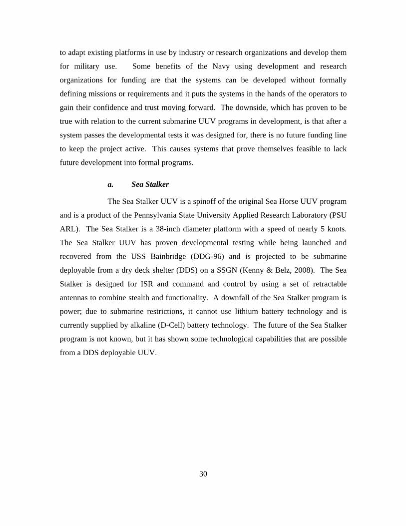
30
to adapt existing platforms in use by industry or research organizations and develop them
for military use. Some benefits of the Navy using development and research
organizations for funding are that the systems can be developed without formally
defining missions or requirements and it puts the systems in the hands of the operators to
gain their confidence and trust moving forward. The downside, which has proven to be
true with relation to the current submarine UUV programs in development, is that after a
system passes the developmental tests it was designed for, there is no future funding line
to keep the project active. This causes systems that prove themselves feasible to lack
future development into formal programs.
a. Sea Stalker
The Sea Stalker UUV is a spinoff of the original Sea Horse UUV program
and is a product of the Pennsylvania State University Applied Research Laboratory (PSU
ARL). The Sea Stalker is a 38-inch diameter platform with a speed of nearly 5 knots.
The Sea Stalker UUV has proven developmental testing while being launched and
recovered from the USS Bainbridge (DDG-96) and is projected to be submarine
deployable from a dry deck shelter (DDS) on a SSGN (Kenny & Belz, 2008). The Sea
Stalker is designed for ISR and command and control by using a set of retractable
antennas to combine stealth and functionality. A downfall of the Sea Stalker program is
power; due to submarine restrictions, it cannot use lithium battery technology and is
currently supplied by alkaline (D-Cell) battery technology. The future of the Sea Stalker
program is not known, but it has shown some technological capabilities that are possible
from a DDS deployable UUV.

31
Figure 13. Monopole retractable antenna concept as used in the Sea Stalker UUV
(From: Mullins, 2009)
b. Sea Maverick
The Sea Maverick UUV is another PSU ARL project. The Sea Maverick
is larger and faster than the Sea Stalker – 48-inch diameter with a top speed approaching
15 knots while submerged. This increase in size changes the functionality completely as
it is no longer able to be launched via a submarine DDS, therefore requiring a support
ship, like LCS, or a complex redesign for a SSGN D5 missile tube launch. In September
of 2009 the Sea Maverick UUV completed operational testing with the Joint Interagency
Task Force (JIATF) South off the coast of Key West, Florida. The UUV was deployed
using the NAWC 38 Ranger class support ship operated by the Naval Air Systems
Command (NAVAIR) and maintained mission support communications via satellite with
JIATF South (United States Southern Command, 2009). The reports of the system
performance show that it was a successful test and the operators have high hopes for the
future of the Sea Maverick system.

32
Figure 14. Sea Maverick UUV shown on launch crane during JIATF South exercise
(From: United States Southern Command, 2009)
c. Other Projects
Though it is no longer a primary focus, the Navy has not completely
moved away from the smaller, torpedo tube launched UUVs. Various projects are being
worked on but are beyond the classification level of this thesis. Some concepts include a
torpedo tube launched AUV similar to the ASM-X used by the French Navy, on which
would remain tethered to the submarine for instantaneous data transfer for ISR. Because
of complications with the recovery of the system, it can be left behind or recovered by a
platform similar to LCS.
D. POSSIBLE SUBMARINE / UUV INTERACTIONS
There are many different roles for the submarine when working in tandem with a
UUV. It is a common misconception that a program involving submarines and UUVs
will require the submarine to play an important role is all aspects of the mission of the
UUV. Though ideally this would be the case, it is more realistic to look at the
incremental interactions between submarines and UUVs. This section will outline a few
of the various interactions that could exist between the submarine and UUV.
1. Launch and Recovery
Ideally, a submarine would be able to both launch and recover a UUV. There are
several options to consider for how to manage a system that can both launch and recover

33
UUVs, including 1) torpedo tubes (conventional or oversized), 2) hangars (DDS or wet
deck), 3) vertical launch tube (D5 or other), and 4) piggy back.
The two most commonly documented ideas are via a conventional torpedo tube
and DDS. Though the LMRS was unable to develop a reliable recovery arm for a UUV,
the technology is still feasible and Figure 15 shows an example of an attachment that
could be added to a conventional torpedo tube to be used for both launch and recovery.
This example, similar to the original LMRS design, would use homing and docking sonar
guides to recover a UUV onto a recovery arm built into one of the four torpedo tubes
(Hardy & Barlow, 2008).
Figure 15. Visualization of UUV recovery via a single conventional torpedo tube
(From: Hardy & Barlow, 2008)
The technical challenges behind successfully recovering UUVs into torpedo tubes
is not the only reason the Navy is not pursuing this technology. The torpedo rooms of a
Los Angeles- and Virginia-class submarine have only four torpedo tubes and the use of
one tube (or more) for UUVs would severely limit the capability of the submarine during
a wartime scenario. Additionally, space in the torpedo room is very limited and any
equipment necessary for the UUVs would further limit the amount of torpedoes that can
be kept on-board. These and other disadvantages, as well as advantages, of using a
torpedo tube launched UUV are outlined in Table 6.

34
Table 6. Key advantages and disadvantages of using a conventional torpedo tube for UUV launch and recovery (After: Hardy & Barlow, 2008)
Key Advantages Key Disadvantages − Permits multiple types of 21 inch torpedo
type UUVs to be deployed − Assuming recovery can be undertaken
then UUV maintenance, recharging and payload reconfiguration activities are made easier inside the submarine in a clean, dry environment. When not in use the UUV is stored dry and safe.
− Potentially minimal impact on the overall submarine design in terms of arrangement and arguably easier to retrofit the system to an existing submarine.
− Potential to utilize existing torpedo discharge systems.
− Allows covert UUV deployment. − Less risk of aborted UUV recovery
fouling submarine propeller
− Constrains AUV design to 21 inch torpedo design with consequential endurance and payload capacity constraints.
− If recovery is required, recovery system will most likely take up capacity of at least one torpedo tube (unless modular recovery system design is employed that can be retrieved into the weapons stowage compartment).
− Additional stowage’s required in the weapons stowage compartment.
− Recovery is arguably more difficult when submarine is in transit.
Due to the importance of torpedoes and the robust design of the current forward
end of a submarine, a redesign of the torpedo room to accommodate for UUVs is not an
option. Fortunately, for the future development of UUVs, SOF missions have
incorporated the use of the DDS on Los Angeles-class submarines, starting with the USS
Dallas (SSN-700) in early 2000 (Rehana, 2000). Since their deployment, these external
hangars have been discussed, developed, and tested for use with UUVs. If it is the intent
of the Navy to have a submarine both launch and recover a UUV (or group of UUVs) the
viable near-term option is most likely to be a DDS, though it does come with some major
disadvantages, including reducing capability of the host submarine (increased signature,
reduced maneuverability, etc.), as shown in Table 7.

35
Figure 16. Dry deck shelter on back of Los Angeles-class submarine
(From: Rehana, 2000)
Table 7. Key advantages and disadvantages of using a dry deck shelter for UUV launch and recovery (After: Hardy & Barlow, 2008)
Key Advantages Key Disadvantages − Permits larger and greater range of AUVs
to be deployed Dry CMH weight will almost certainly preclude fitting of CMH on smaller submarines.
− UUV maintenance, recharging and payload reconfiguration activities made easier inside the DDS.
− When not in use the AUV is stored dry and safe.
− Likely to be able to retrofit such a system to an existing submarine of sufficient size
− Potential to build in most DDS and UUV support systems to allow for fast fitting to submarine
− Could be designed to support transfer of human maintainers between main pressure hull and DDS to undertaken maintenance tasks, etc
− UUV deployment and recovery system could be simpler
− DDS is likely to require complex drain down and flood systems, air and pressure management systems, etc.
− Safety justification is likely to be harder if divers are required to work in and outside the DDS.
− Recovery is arguably more difficult when submarine is in transit.
− Does not allow covert UUV deployment. − Impacts on submarine signature and
maneuverability, etc. − Potential fin wake effects for L&R whilst
in transit.
2. Launch Without Recovery
A short-term solution to having a successful submarine UUV program will be to
separate the mechanisms for launch and recovery. Whether it is from a torpedo tube,

36
missile tube, or DDS, having a submarine complete only the launch portion of the
mission will incorporate the benefits of a quick, stealthy deployment while avoiding the
technical challenges faced by recovery at speed and depth. Additionally, the lack of
submarine recovery will avoid the drawback of space considerations to support
organizational level maintenance.
There are two options to consider for the recovery portion of the experiment:
• Abandonment. This method is costly and controversial, but would be
ideal for situations where the data collected by a UUV is crucial, but the
risk of recovery is too great. The UUV system would need to have some
form of “self destruction” in order to maintain the security of the collected
data and types of technologies used. Though there are few missions that
would call for abandonment as a primary end state, it is a procedure that
should be considered in the background of most sensitive UUV
deployments in case the primary mode of retrieval does not work –
including operations in which the UUV could be entangled in the undersea
environment (i.e., fishing nets and reefs).
• Support Ship. A method being considered by the USN is the use of a
support ship, such as a Destroyer or LCS, to recover a submarine-launched
UUV after its mission has been completed. Prior to recovery, the UUV
will bury itself into the seafloor, hover, or surface, waiting for a recovery
signal from the support ship.
3. Non-physical Interactions
It is possible for a submarine UUV program to be successful without any physical
interaction amongst the two entities. In this case, the UUVs would need to be deployed
from a support ship or directly from land. Regardless of the form of deployment, there
are several possible non-physical interactions between the submarine and UUV,
including mission control, consumer and interrogator of data, and docking station
delivery.

37
The mechanism for launch and recovery will play a vital role in the set of
missions able to be accomplished by a UUV program, but each of the interactions
discussed above hold true for all forms of UUV launch and recovery. Designing UUV
and submarine interactions independent of the launch source will help transition to a less
“platform centric” design of UUV systems. When systems can be designed without the
platform in mind, there is more room for growth and an increased chance of long term
success for a program.
a. Mission Control
In the near-term, it is unlikely that a UUV will be fully autonomous and
able to complete its entire mission with no communication back to an operator. Instead,
it is more likely that the UUVs would operate under the “fixed initiative” level of
autonomy. Similar to the way UAVs are operated, UUVs will be able to perform a
majority of their functions autonomously, but will need to remain in communication with
an operator to provide and update critical mission data.
As discussed earlier, undersea communications are more difficult than
those faced by UAVs in the air and UGVs on the ground. With the exception of physical
linked communications, such as fiber optic links, successful non-acoustic undersea
communications require short distances between the transmitter and receiver. In covert
situations, a submarine operation in the area of interest (AOI) may be necessary to ensure
short distance communications. Though the concept is well understood, it is not well
studied. Submarines should be viewed as the top method of mission control in forward
UUV operating areas, even if the system was not launched from the submarine.
b. Consumer and Interrogator of Data
There are instances where submarines will require the valuable data
collected from a UUV, but not be in control of the UUV. In these cases, the submarines
will consume and interrogate the data sent from the UUV. One example of this involves
in the mine detection mission. Currently, MCM missions are the focus of many non-
submarine UUV programs. In these programs, the UUV patrols the AOI and returns to a
predetermined set point. The data collected is manually downloaded by the operator

38
through a data-link between the system and laptop computer where it is then analyzed as
necessary. With relatively slight advances in technology, these programs can evolve to
include sending the data to a submarine for consumption and interrogation by the crew
aboard the submarine. Removing the “middle man” will increase the efficiency of the
area search and provide the submarine crew with important tactical data in as short of a
time as possible, without the maintainability or manning responsibility of many of the
proposed UUV programs.
c. Docking Station Delivery
The two greatest technical challenges of a UUV program are endurance
and underwater communications. One theory that can both add to the longevity of a
UUV deployment and increase the bandwidth of communication to and from the UUV is
the use of a submerged docking station. Various systems have different theories on the
technical features of the dock and some systems only perform one of the functions, but in
all cases the high level theories remain the same.
Figure 17. Flying plug attaching to a communications dock (From: Cowen, Briest, &
Dombrowski, 1997)
One SPAWAR program that combined both charging and communication
into the same docking station was a mid-90s program entitled Distributed Surveillance
Sensor Network (DSSN). Experiments were conducted to prove the feasibility of a
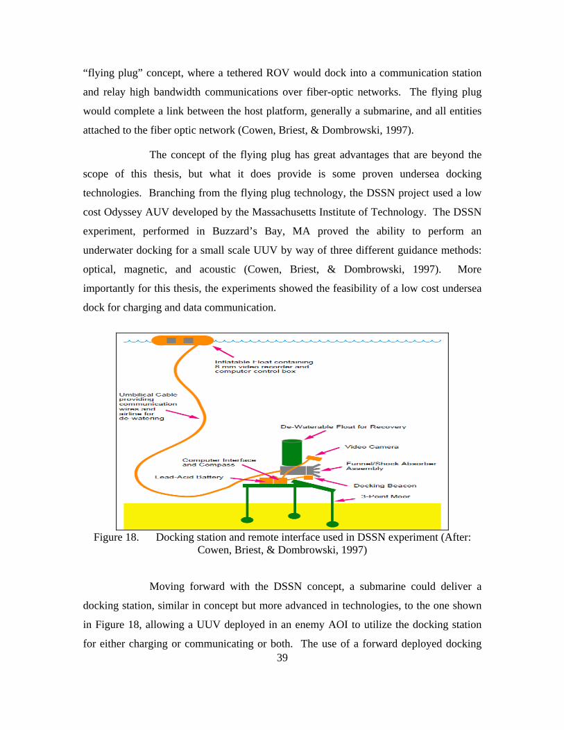
39
“flying plug” concept, where a tethered ROV would dock into a communication station
and relay high bandwidth communications over fiber-optic networks. The flying plug
would complete a link between the host platform, generally a submarine, and all entities
attached to the fiber optic network (Cowen, Briest, & Dombrowski, 1997).
The concept of the flying plug has great advantages that are beyond the
scope of this thesis, but what it does provide is some proven undersea docking
technologies. Branching from the flying plug technology, the DSSN project used a low
cost Odyssey AUV developed by the Massachusetts Institute of Technology. The DSSN
experiment, performed in Buzzard’s Bay, MA proved the ability to perform an
underwater docking for a small scale UUV by way of three different guidance methods:
optical, magnetic, and acoustic (Cowen, Briest, & Dombrowski, 1997). More
importantly for this thesis, the experiments showed the feasibility of a low cost undersea
dock for charging and data communication.
Figure 18. Docking station and remote interface used in DSSN experiment (After:
Cowen, Briest, & Dombrowski, 1997)
Moving forward with the DSSN concept, a submarine could deliver a
docking station, similar in concept but more advanced in technologies, to the one shown
in Figure 18, allowing a UUV deployed in an enemy AOI to utilize the docking station
for either charging or communicating or both. The use of a forward deployed docking

40
station would be able to keep UUVs in forward locations longer while allowing mission
supports assets, such as submarines and surface vessels, to remain outside of high risk
areas.
E. CHAPTER SUMMARY
It is important to note that this chapter was written with classification levels in
mind. It was not intended as a teaching point of the vast missions of UUVs and
submarines, but as a background to the ideas of the important role UUVs will play when
they are in tandem with submarines. Pertinent areas of the interactions section will be
revisited during the systems engineering section. The missions and programs discussed
in this chapter will be further analyzed in the Systems Engineering discussion.

41
IV. APPLICABLE LESSONS LEARNED FROM UGVS AND UAVS
A. INTRODUCTION
UGVs and UAVs have been in use longer than UUVs. This longevity provides
the UGVs and UAVs with valuable lessons learned that can be applied to their undersea
counterparts. Additionally, as shown in a report of the budgets of the DoD in FY2007-
2013 in Figure 19, unmanned maritime systems (UMS) as a whole are set to receive far
less funding than their airborne unmanned counterparts (Button, Kamp, Curtin, &
Dryden, 2009). To maximize use of the small budget, applicable lessons that can be
translated from UAVs and UGVs to UUVs can have a sizable impact on technological
development in the undersea domain.
Figure 19. FY2007-2013 DoD Funding for unmanned platforms (From: Button,
Kamp, Curtin, & Dryden, 2009)
This section will review a brief history of UGVs and UAVs, discuss their
similarities with UUVs, and provide several lessons that can be applied toward the
manning and maintainability aspect of UUVs in support of submarine missions. Each of
the eleven lessons learned are summarized quickly and will be used in support of the

42
conclusions of this thesis. Not all lessons learned can be applied in the same manner.
Additionally, not all lessons learned will be applicable to all UUV systems.
B. UNMANNED GROUND VEHICLES
1. Brief History of the UGV
The development of UGVs with nontrivial capabilities has its roots in the late
1960s with the first major development of the “Shakey” system. Though “Shakey” faced
challenges with the autonomy aspect and was considered a failed program, the system
started the mobile robot baseline. The 1980s would see the outdated program evolve into
the Defense Advanced Research Projects Agency (DARPA) program Autonomous Land
Vehicle (ALV). With a goal of using a realistic environment for research, the ALV
demonstrated artificial intelligence in mobile robots for military use. The Army’s look at
UGVs in the 1980s transitioned to use by the Department of the Navy by including
Reconnaissance, Surveillance, and Target Acquisition (RSTA) applications funded by the
Naval Ocean Systems Center, in conjunction with Marine Corps research. Similar to
modern UUV applications, RSTA programs provide battle space awareness to mission
commanders from behind enemy lines. Today, all branches of the DoD have UGV
programs spanning a variety of missions from disposing of bombs and transporting gear
to performing maintenance and gathering intelligence (Gage, 1995).
2. Similarities Between UGVs and UUVs
Modern UGVs and UUVs face similar technological development challenges.
Figure 20 shows six key areas for UGVs and further breaks down autonomous behavior.
This figure could easily replace the center block UGV with a UUV and have the same
meaning (National Research Council, 2002). This similarity leads to the potential of
many areas of overlap in progression of both technologies.

43
Figure 20. UGV technology areas (From: National Research Council, 2002)
Beyond the functional commonalities, the development cycle and mission sets for
future UGVs are similar to UUVs. In a publication for the Army titled “Technology
Development for Army Unmanned Ground Vehicles,” the National Research Council
postulates four example systems of UGVs for Army development. The four systems
discussed in great detail in the article are 1) a small robotic building and tunnel searching
vehicle (“Searcher”), 2) a small-unit logistics mover (“Donkey”), 3) an unmanned
wingman ground vehicle (“Wingman”), and 4) an autonomous hunter-killer team
(“Hunter-Killer”). These four examples, summarized in Table 8, are linked to sample
capabilities and missions (edited below to include missions most analogous to UUVs) in
a similar style to the different classes of UUVs currently being developed for the Navy.

44
Table 8. UGV example systems, capability classes, and potential mission applications (After: National Research Council, 2002)
Example System Capability Class Possible Applications Searcher Teleoperated ground
vehicle Mine detection/clearing, ordnance disposal, soldier-portable reconnaissance/surveillance
Donkey Semiautonomous preceder/follower
Supply convoy, battlefield support, reconnaissance/surveillance, physical security
Wingman Platform-centric autonomous ground vehicle
Remote sensor, counter-reconnaissance, single outpost/scout, battle damage assessment
Hunter-Killer Network-centric autonomous ground vehicle
Deep RSTA, combined arms, static area defense, reconnaissance
Not unlike UUVs (or ROVs in some cases), each example system has various
levels of human control and support as shown in Table 9. The human control of the
example UGVs, however, is significantly different from the planned use of UUVs for the
Navy. Underwater communications (especially those at speed and depth) are not as
simple and straightforward as on land line of sight communications. This difference does
change the relationship the operator can have with the platform in a UUV (vice UGV),
that does not fully discount the similarities between the two systems.

45
Table 9. Human control, human support, and health maintenance for the example UGV systems (After: National Research Council, 2002)
System Human Control Human Support Health Maintenance Searcher − Control by joystick or
touch screen − Continuous control for
planning and navigation
− Maximum of one operator and one maintenance technician per Searcher
− High physical reliability, low maintenance
Donkey − Program electronic paths to be followed
− Load and unload cargo
− Monitor communications
− Maximum of one supervisor and two maintenance technicians will be able to operate a small (10-12) donkey team
− High physical reliability, low maintenance
− Cooperative diagnostics for remote operator
− Ability to know when to call for help
Wingman − Direct new locations while en route
− Monitor sensors and other inputs
− Actively make go or no-go decisions
− Electronically direct/override movements
− No more than one assistant section leader (controller) and one maintenance technician
− Design for combat survivability
− Algorithms for self-diagnosis
Hunter-Killer
− Program various initial inputs (movement, communications, intelligence, …)
− Monitor communications for situations requiring human guidance
− Override in case of changes in situation
− Control is by on-duty staff officer at headquarters
− Non self-repair maintenance done by small groups (<10 personnel) to support up to five teams (10 killers, 50 hunters each)
− Self-repair by reconfiguring components
− Self-repair by self-reprogramming
3. Lessons Learned from UGVs
The relatively mature nature of UGVs provides some lessons learned in the
deployment of UUVs for submarine related missions. In 2001, SPAWAR San Diego
published a technical report “Unmanned Ground Vehicle (UGV) Lessons Learned”

46
which related UGV lessons to UUVs for MCM in the EOD community. The “Top 10”
issues found during their study were broken into three main categories: operations,
programmatics, and technologies as shown in Table 10 (Blackburn, Laird, & Everett,
2001). The highlighted portions of the chart have been summarized below as the three
major lessons learned that apply to submarine missions from a manning and
maintainability standpoint, and a fourth lesson independent of the “Top 10” list is added
at the end.
Table 10. Top 10 issues compiled from UGV lessons learned for MCM UUVs
(After: Blackburn, Laird, & Everett, 2001)
Category Top 10 Issues Uncertainty promotes survival* Many simple cooperating agents are superior to one complex agent*
Operations
New technology forces changes in operations Understanding between the user and the developer is critical Understanding the technology is cost-effective
Programmatics
Simpler solutions provide better foundations* Integration is not easy Communications are not dependable Automaticity is not autonomy
Technologies
The road from teleoperation to autonomy does not exist *Issues used for UGV Lessons 1-3
a. UGV Lesson 1: Uncertainty Promotes Survival
Regardless of the mission of an unmanned system, it needs to be designed
to be reliable and survivable. A robot designed for combat survivability, whether a UGV,
UAV, or UUV, will have the ability to last in the harsh war, or war-like, operational
environments. Fortunately, the random nature of unmanned control allows for
unpredictable maneuvers, formations, and behaviors, which provide advantages in hostile
environments (Blackburn, Laird, & Everett, 2001). Though this random behavior will, as
a result, decrease the chance of attrition kills (those resulting in a complete loss of the
system) of the UUV, they will also increase the chance of mission abort kills (those
resulting in an incomplete mission, regardless of cause). The take-away here is that the

47
operators will need to understand the benefits in uncertainty and will need to be trained
to balance it to assure success in the tactical settings.
b. UGV Lesson 2: Simpler Solutions Provide Better Foundations
A simple solution is often neglected because it does not address all of the
system requirements. Fundamentally, a simple solution does not have to address all of
the requirements, as long as it does not violate any of the unaddressed requirements.
Being that requirements are generally independent of one another, multiple simple
systems can be integrated together, if each addresses different requirement sets. An
example of this was addressed in the SPAWAR team’s 2001 interview with Albert
Bradley of WHOI. Discussing the issue of power capability, Mr. Bradley stated:
Most AUV designs are limited by power available. This comes out in the first "back of the envelope" design cycle. Those projects that then panic and go to the handbooks to choose "the best power source" rarely allocate enough effort to taming the exotic choice they came up with. There are enough problems to face, start a new AUV design with a simple power source. When it's working, then you can update the power system. (Blackburn, Laird, & Everett, 2001)
The end state of the simple system approach may be more practical in a UGV than in a
UUV, but it can be utilized in the developmental stages of a new system. Addressing
requirements incrementally will give operators invaluable experience with the systems
and give the war-fighter confidence when the more complex system is deployed in the
future.
c. UGV Lesson 3: Many Simple Cooperating Agents are Superior to One Complex Agent
UGV operators utilize many simple vehicles as a “strength in numbers”
approach which is different than the advantages this approach gives to the undersea
warfare communities. Though the Navy’s decision to shy away from smaller, simpler
UUVs has been made from a technical capability standpoint (mainly energy density and
payloads), the concept of using smaller, networked UUVs should not be lost.
The advantages of smaller UUVs make them a valuable asset. First, in all
measures there is less cost per platform and potential further savings with “economy of

48
scale” during production. Second, less maintenance support is necessary; this is very
applicable to submarine operations, as the UUVs can be replaced opposed to repaired
(though the logistics of this may be daunting). Next, there are fewer critical components.
As system reliability is a function of critical component reliability, reducing the number
of these allows for increased reliability through redundancy and simplicity (Blackburn,
Laird, & Everett, 2001). Last, the major concern with small UUVs is power and fuel;
though larger UUVs can have longer durations and ranges, the cooperation of the small
contingencies can offset this disadvantage.
There are times where a complex agent is a better application than many
simple cooperating ones. Prior to technologies being proven, similar to what is described
in “UGV Lesson 2,” the use of a multitude of simple and collaborative systems should be
the preference. After the technology has matured, larger and more complex systems can
and should become the priority of the stakeholders. Ultimately, the system complexity
should be considered in a formal trade study, as discussed in Chapter II.
d. UGV Lesson 4: Maintenance Should Be Done at the User Level
UUV systems, like UGVs, should be designed with line replaceable units
(LRUs). The use of LRUs does not replace the contractor, as they will still manufacture
the parts, perform advanced levels of maintenance, and provide long-term logistical
support. Additionally, LRUs minimize the contractor involvement in the maintenance,
often drastically reducing the life cycle costs (Blackburn, Laird, & Everett, 2001). This is
especially true with any maintenance that will be performed on UUVs while underway.
Modular parts and LRUs are ideal for UUVs since sailors aboard submarines (or support
vessels like LCS) have limited space, resources, and time to perform costly, complex
repairs.
A formal discussion of the three levels of maintenance (organizational,
intermediate, and depot) is presented in Chapter V. This section will promote the
appropriate use of all levels of maintenance, focusing on more than just the user level
portion. Unfortunately, especially in the case of submarines, there are size and logistical
considerations that will not always accommodate user-level maintenance. The important

49
lesson to be understood is that a successful program will incorporate various types of
maintenance and, whenever possible, the maintenance routines that can be performed at
the operator level will have compounding benefits for the entire program.
C. UNMANNED AERIAL VEHICLES
1. Brief History of the UAV
The history of airplane-like UAVs for military use by Americans can be traced to
the Interstate BQ-4/TDR as early at 1936. Originally starting as the Navy aircraft called
“assault drones”, the program originated as a suggestion for using remotely-controlled
aircraft in combat (Parsch, 2005). The 1950s-1970s would see drones evolve into use for
surveillance missions. Though many of these programs were promising, most were
cancelled due to technical problems (Tetrault, 2010). These problems caused
commanders to lose faith in UAV technology.
Figure 21. U.S. Navy photo of an original Interstate BQ-4/TDR (From: Parsch,
2005)
In 1982, the Israeli Air Force defeated the Syrian Air Force and changed the
opinions of commanders toward UAVs. Israeli forces used UAVs for decoys, jammers,
and enemy surveillance, allowing their manned aircraft to swiftly defeat 86 Syrian
aircraft with minimal losses (Tetrault, 2010). Since then, Operation Desert Storm (1990-
1991) became the stepping-stone for American use of UAVs by military forces. Modern
day UAVs include fixed wing and rotary craft that are used for a variety of missions
ranging between reconnaissance and surveillance of the “Global Hawk” to air-to-ground
combat of the “Predator.”

50
2. Similarities between UUVs and UAVs
The surveillance and communication nodes provided by UAV missions are
similar to the needs of UUVs for the submarine force. Future UUV technologies will
focus on other UAV missions beyond ISR and into the combat and combat support
realms. UAVs have been developed in a wide variety of shapes and sizes, each of which,
to some extent, support modular mission packages and LRUs.
Modern day UAVs face some of the same challenges as UUVs. First, UAVs are
limited by their communication and bandwidth. These issues vary from the types of
issues dealing with underwater communications but still have the same result in the
battlefield. Second, UAVs lack intelligent autonomy and target recognition, and without
complete “intelligent” autonomy in both UAVS and UUVs, they will not be used during
complex missions that require extremely high confidence levels of maneuvering and
target recognition. Third, operations with manned platforms pose the same problems in
UAVs as UUVs; fear of collisions call in to question the safety of both platforms. Last,
UAVs do not have a highly reliable recovery mechanism across all platforms; recovery of
UUVs at sea poses the same setbacks as UAVs (National Research Council, 2005).
3. Lessons Learned from UAVs
The operational experiences of UAVs across all branches of the DoD have had
the systems evolve drastically during OIF and Operation Enduring Freedom (OEF). This
data has been thoroughly documented and is starting to be shared amongst all interested
parties. UUV development can take many lessons from the struggles of UAVs over the
past decade.
a. UAV Lesson 1: System Requirements Should Be Clear Up Front
“UGV Lesson 2” stated that requirements can be met incrementally.
However, this does not imply that the requirements need not be stated at the beginning of
the program. UAV support for OIF and OEF required the USAF to field UAVs as
quickly as possible and therefore required a rapid acquisition strategy. As a result, all of
the requirements were not clearly defined before design and production. This has lead to

51
uncertainty in the long-term support status of the aircraft (Drew, Shaver, Lynch,
Amouzegar, & Snyder, 2005). This should not be the issue for UUVs as there is
currently not the same rapid demand faced by the Navy as was UAVs for the Air Force.
Though all requirements need not be addressed during the developmental stages of
UUVs, all should be clearly stated at the beginning of a program. This lesson will be
discussed in detail in Chapter V.
b. UAV Lesson 2: Acquire Reliability and Maintainability Data Throughout All Stages of Development
If the event arises, however, that a UUV system will require rapid
acquisition, it will be important for researchers to take advantage of every opportunity to
gather data. Reliability and maintainability data is able to be recorded and analyzed in
prototypes and first generation systems, which was not done for the USAF deployment of
UAVs (Drew, Shaver, Lynch, Amouzegar, & Snyder, 2005). This data is important for
determining manning and supportability metrics and should be analyzed for all UUV
systems tested. Additionally, UUV programs that have been cancelled will almost
always have this data available and should be shared across programs.
c. UAV Lesson 3: Structure a Process for Sharing Data
The “stove-piped” programs created in the DoD often leave good sources
of data unknown, or unavailable, to other programs. UAV conferences are starting to
break down the barriers of information and UUVs need to follow this same direction
(Drew, Shaver, Lynch, Amouzegar, & Snyder, 2005). The Navy’s PEO LMW has taken
the right steps in opening the lines of communication between UUV programs by the
creation of the ADO, but this needs to be extended to include minor programs, other
defense programs, and industry, where applicable.
From a UUV program to UUV program aspect, the data being shared
should be a combination of operational and technical data. Operational data may help
newer UUV programs to properly focus on missions, tasks, and functions. The technical
data shared amongst the two programs is perhaps the most valuable. Discussing the
success (or failure) of different sensor packages, energy sources, and data analysis

52
software will increase the probability of success of new programs. Additionally, there is
a lot of data that can and should be shared amongst UUV programs and UAV/UGV
programs. This data can also be both operational and technical, but a majority of the
important lessons learned would be in the operational sense (as the technical differences
between the two programs can be extreme). When possible, the Navy should look at
what successful UAV programs have done for maintenance and manning challenges and
lessons that can be learned. For example, some of the Navy’s foremost UUV operators
modeled their manning after what they discovered with the Predator UAV program. This
suggestion could branch into comparing airspace with waterspace management data to
find trends that will help simplify the currently complex waterspace management plans.
d. UAV Lesson 4: Limit the Number of Design Configurations
Spiral development and prototyping of UAVs have created several
different configurations supported by the USAF. Each unique design complicates the
support and maintenance of the UAV fleet (Drew, Shaver, Lynch, Amouzegar, & Snyder,
2005). In an effort to curb the cost of production, logistics, maintenance, and operation
the Navy should rethink the UUV design and limit the number of unique platforms. The
use of LRUs and modularly designed mission components should then fit the common
sized components and allow a platform to perform a variety of different missions.
Creating a single chassis that can be used amongst all programs is an ideal,
but probably an unrealistic expectation. Instead, the Navy should develop standards for
interoperability in their UUV design. These standards should include launch and
recovery design features and modular open architecture features. The standards should
not be set across all UUVs, but amongst UUVs in a size / displacement group.
e. UAV Lesson 5: Consider Supportability Up Front
Supportability should be considered an important cost driver during the
pre-concept design phase of a system. Operations and support (O&S) costs comprise the
largest individual percentage of LCC for almost every major program. Additionally,
reliability and maintainability attribute directly to the manpower calculation for
unmanned systems. O&S costs cannot be avoided, so they should not be delayed

53
(Lockheed Martin Corporation, 2002). Many programs of record that have performed
admirably during testing have been cancelled due to LCC considerations. However,
these programs could have been designed better or avoided altogether if O&S structures
had been considered initially.
In a submarine UUV program, the supportability can vary drastically.
Chapters V and VI will discuss in more detail the different options available. These
include the use of cadres of personnel to support operations as opposed to the use of
ship’s force and the maintenance being completed onboard a support ship instead of the
submarine. There are drastic differences in the system designs that can be incorporated
based on these supportability decisions, which is why they should be made early in the
system development process. These options should also be included in the trade studies
discussed.
f. UAV Lesson 6: Endurance Has its Benefits
The UAV experience has shown that longer sorties have resulted in less
maintenance due to the reduction in number of cycles and cycle-related fatigue. Research
has shown that for UAVs a 24 hour sortie length shows a significant reduction in
maintenance man-hours per flight hour (assuming a similar level of maintainability), as
shown in Figure 22 (Lockheed Martin Corporation, 2002). The conclusion of less
maintenance for longer sorties may seem obvious, but the degree to which manpower can
be reduced is an important lesson to take for UUVs.

54
Figure 22. Maintainability data as a function of sortie length for UAVs, assuming
similar levels of maintainability (From: Lockheed Martin Corporation, 2002)
UUV missions will not have the same numerical correlation to UAV
missions, but the principles still hold true. Current Navy UUV missions last roughly 6-8
hours. If this number can be increased to 48 hours, or further yet to 30 days, the impact
these systems will have on the manning aboard their host platform can be reduced
drastically – and that is not even considering the manning to launch and recover the
systems. Any time there is room to increase the mean time between maintenance
(MTBM), the change should be considered in depth because of the impact it may have on
supportability and LCC.
g. UAV Lesson 7: Minimize the Levels of Redundancy
“UGV Lesson 2” and “UGV Lesson 3” focused on simplifying the system
to potentially reduce the amount of critical components, thereby increasing system
reliability. An alternative method is to create redundancy in each critical component,
ensuring that the loss of one component does not result in a loss of the system. Though
redundancy increases the safety, survivability, and mission reliability, it is not without an
increase in cost. In order for redundancy to be cost effective, it needs to incorporate
extremely high reliability or extremely low cost. Trade studies have shown that systems
that are overly redundant become more expensive than those with minimal levels of

55
redundancy; between 2-3 levels of redundancy is generally the most cost effective
approach for UAVs, as shown in Figure 23 (Lockheed Martin Corporation, 2002),
assuming a constant mean time between failure (MTBF) rate. UUV systems will have
different reliability data, but the end result of trade studies should prove to have the same
results, namely, that risk should be balanced when considering the levels of redundancy.
Figure 23. Relationship between redundancy and cost per flight hour for UAVs, assuming critical failure rate of 1/3 of MTBF (From: Lockheed Martin Corporation,
2002)
D. CHAPTER SUMMARY
This chapter discussed the history, similarity, and lessons learned of both UGVs
and UAVs as they apply to the manning and maintainability of UUVs for use in
submarine missions. It is the intent of this chapter to be a brief introduction to sample
systems and neglects many aspects of UGV and UAV operations unrelated to the core
research of this thesis. The eleven major lessons learned are summarized in Table 11. It
is not the intent of the section to be an extensive study of UGV or UAV systems, and
further research should be done for a better understanding of the unmanned systems
discussed in the chapter.

56
Table 11. Summary of eleven UGV and UAV lessons learned for UUVs
Number Lesson Learned UGV 1 Uncertainty promotes survival UGV 2 Simpler solutions provide better foundations UGV 3 Many simple cooperating agents are superior to one complex agent UGV 4 Maintenance should be done at the user level UAV 1 System requirements should be clear up front UAV 2 Acquire reliability data throughout all stages of development UAV 3 Structure a process for sharing data UAV 4 Limit the number of design configurations UAV 5 Consider supportability up front UAV 6 Endurance has its benefits UAV 7 Minimize the levels of redundancy

57
V. SYSTEMS ENGINEERING AND ANALYSIS
A. INTRODUCTION
Prior to this chapter, this thesis has focused mainly on the gathering of data
through literature reviews, internet-based resources, conferences, meetings, and
interviews. This chapter, however, will take the ideas discussed in Chapters II-IV and
discuss where they fit in moving forward with a systems engineering approach to the
development of future formal UUV programs. This section begins with a definition of
the systems engineering process and points out some deficiencies found in the past Navy
submarine UUV programs. After discussing the systems engineering approach, there is a
section focused on the manning and maintenance requirements that will need to be
addressed to allow UUV systems to operate successfully with the submarine force.
However, the systems engineering approach outlined here is applicable to all stages of
future UUV program development.
B. SYSTEMS ENGINEERING APPROACH
Prior to laying out the specific steps necessary to make a successful UUV
program, it is important to define systems engineering and give an overview to the
generic approach taken by a Systems Engineer to solve a problem. This section will
cover the systems engineering process, feedback, and trade studies utilized by a Systems
Engineer.
1. Systems Engineering Process
One of the many methods available to understand the scope of the systems
engineering process is outlined by the Defense Acquisition University (DAU) model
shown in Figure 24. The model illustrates three distinct stages of converting the process
inputs into outputs with continual trade studies and assessments before and after each
stage (Defense Acquisition University, 2001). Though this process was created with
electrical/electronic engineering in mind, it is applicable in the systems engineering of
any type of system.

58
Figure 24. DAU systems engineering process model (From: Defense Acquisition
University, 2001)
Combining the data presented in the DAU model and many other applicable
systems engineering models, there are four fundamental stages to system design lifecycle.
This four stage process has analysis, verification, and feedback occurring simultaneously
with each step. All four stages are required for a program to be “Systems Engineered”
correctly. To successfully complete a mission or set of missions, the four stages of the
process need to occur in the following order:
• Develop Requirements, based on missions
• Determine Tasks, based on requirements
• Create Functions, based on tasks
• Design Components, based on functions

59
a. Developing Requirements
Government program development tends to be done differently than in the
civilian world, but that does not mean that the necessity for a high-level envisioning of
the process changes. When a program is created, it needs to begin by defining
requirements, and these requirements should be based on the mission of the program, and
not on the physical entities that the program wishes to create. This was true in the case of
UAVs and “UAV Lesson 1” and should continue to remain true with future UUV
programs. This means that programs should not be started with the finished product in
mind.
The requirements stage is often not understood by the customer. A
formally trained Systems Engineer will know the maxim associated with a customer
asking an engineer to build a bridge to get across the water. Many engineers would now
interpret the requirement, given by the customer, to be “build a bridge”. Unfortunately
for the customer and the engineer, building a bridge is not the real requirement. The real
requirement is: get across the water. The system developed during the process may end
up being a bridge, or it may be a ferry, tunnel, or airplane. Current UUV projects have
violated this maxim of understanding the requirements.
Proper requirement definitions are produced with the system stakeholders
and are derived from the mission requirements. The process is hierarchical with system,
component, and configuration item (CI) requirements being derived from the originating
requirements, shown in Figure 25. Many engineers consider the role of the systems
engineering process begins at the ORD, when in fact the Systems Engineer should work
directly with the stakeholder to understand the requirements and eventually turn those
requirements into an ORD (Buede, 2000).

60
Figure 25. Hierarchy of requirements (From: Buede, 2000)
Two of the current submarine UUV projects being worked on for the Navy
are the Sea Maverick and the Sea Stalker. These programs (as discussed in Chapter III)
have shown success in various at sea tests, but are not part of a formal program and have
included unclear, if not completely undefined, requirements. This shortfall has meant
that even though the programs may have performed up to the operator’s expectations, the
funding line is not in place for future development of the systems and, as a result, they
may be left forever sidelined.
b. Determining Tasks
After determining the system requirements, the next step in systems
architecting is to determine which tasks are necessary to meet the stated requirements. In
a USN system design, these tasks should be taken from the Universal Naval Task List
(UNTL), a combination of the Universal Joint Task List and the Navy Tactical Task List.
These extensive lists comprise of specific tasks necessary to complete missions at the
operational and tactical levels. The UNTL is a hierarchical list with the nomenclature for
a naval tactical level task being “NTA.”
A sample tactical level task from the UNTL that may apply to UUV
missions is “NTA 1.5.2.3 Conduct Undersea/Antisubmarine Warfare.” NTA 1.5.2.3 is the
lowest level of the “NTA 1 Deploy/Conduct Maneuver” hierarchy with sister tasks of

61
“NTA 1.5.2.1: Conduct Surface Warfare” and “NTA 1.5.2.2 Conduct Air Superiority
Warfare.” Each task is given a short description describing the specific aspects of the
task. For “Conduct Undersea/Antisubmarine Warfare” the description is:
To establish and maintain supremacy in assigned operating area through employment of assets to ensure freedom of action of friendly maritime forces in face of undersea threats such as submarines, mines, and underwater swimmers. (Department of the Navy, 2001)
The UNTL adds to the tasks various measures of performance. Some tasks have only a
few suggested measures and others are more extensive. The 22 suggested measures for
the “Conduct Undersea/Antisubmarine Warfare” task are shown in Table 12.
Table 12. UNTL tactical level task measures for NTA 1.5.2.3 Conduct Undersea/Antisubmarine Warfare (From: Department of the Navy, 2001)
M1 Percent Of assigned targets destroyed M2 Percent Of assigned targets cannot continue assigned mission M3 Number Of assigned targets launch weapons after engagement M4 Number Of assets available to prosecute subsurface threats M5 Percent Acoustic coverage while in torpedo danger zone M6 Percent Correct probable submarine classification M7 Percent Correct certain submarine classification M8 Time To search designated area M9 Time Required to communicate with friendly submarine M10 Percent Of successful communications attempts with friendly submarine M11 Percent Of Blue-on-Blue/Grey/White engagements M12 Time Of asset response time from classification of probable submarine
until ASW platform on scene M13 Percent Radar flooding within LLOA during transit/in Vital Area M14 Percent Radar flooding within ASW CIEA M15 Percent Radar flooding within torpedo danger zone M16 Percent Probable submarine (or higher) contact engaged or negated prior to
torpedo danger zone M17 Percent Probable submarine (or higher) contact within torpedo danger zone
engaged or negated prior to attack M18 Number Friendly ships sunk or damaged M19 Number Attacks against non-submarine contacts M20 Minutes SCC/SSN time to complete tactical communications M21 Y/N BELLRINGER conducted via all available means M22 Minutes From BELLRINGER to communications established

62
The creation of the UNTL has ensured the Navy is on the right track when
it comes to the determining the tasks stage of system development. Future success with
task definitions will only be guaranteed when the UNTL and UJTL are utilized during the
systems engineering development process.
c. Creating Functions
Once the tasks are identified, the next step in system development is the
definition of functions. There are various generic functional lists (similar to the UNTL
for tasks) or functions can be derived from scratch. The purpose of the functional
analysis is to define the low level activities, in the form of verbs, performed by the
system. These functions are created in a hierarchical format and then displayed in the
form of a functional hierarchy, functional flow block diagrams (FFBD), enhanced
functional flow block diagram (EFFBD), matrix (N2) diagram, and/or an Integration
Definition for Function Modeling (IDEF0) diagram.
Similar to the UUVs being developed by the Navy, a project at the Naval
Postgraduate School entitled Tracking of Underwater Narco-subs using Autonomous
Submersibles (TUNAS) created a functional analysis of a UUV for the interdiction of
semi-submersible drug submarines in the United States Southern Command region
(Brocht, Layne, Matson, McMurtrie, Schindler, & Vandenberg, 2009). Though the
mission of the system changes from a submarine deployed UUV, the high level functions
are analogous. From a high level, shown in Figure 26, the EFFBD broke down six high
level functions. A FFBD would look similar, but would not show the triggers, inputs,
and outputs linking the functions.

63
Figure 26. High level EFFBD for TUNAS sample UUV system (From: Brocht,
Layne, Matson, McMurtrie, Schindler, & Vandenberg, 2009)
An N2 matrix diagram for high level of TUNAS displays the same
information as the EFFBD, but in a different manner. Instead of showing flow between
the functions and sequential order, it aligns the functions diagonally through the diagram
and shows the input and output objects along the horizontal axes. The directions of the
arrows indicate the sequence in which data flows between the functions. TUNAS N2
matrix diagram is shown in Figure 27.

64
ExternalCommunicatio
n
1
Develop Mission
DeploymentOrder
Mission Data
2
Deploy System
3
Maneuver
ManeuverOrder
4
Surveille
SurveillanceOrder
Classificationof Target
5
Discriminate
Mission Data
PositionReport
COARecommendat
ion
6
Communicate
Figure 27. N2 matrix diagram for TUNAS sample UUV system (From: Brocht,
Layne, Matson, McMurtrie, Schindler, & Vandenberg, 2009)
N2 diagrams and EFFBDs/FFBDs show the same information presented in
different manners. The use of both of these is often considered redundant. An IDEF0
diagram, on the other hand, shows a unique perspective on the functional analysis. The
purpose of an IDEF0 is to establish system boundaries and identify interfaces and bind
the problem statement. In addition to the inputs and outputs shown above, IDEF0
diagrams include controls and mechanisms for each function. IDEF0 diagrams follow a
Input-Control-Output-Mechanism sequence illustrated in Figure 28.

65
Figure 28. IDEF0 diagram template (From: Blanchard & Fabrycky, 2006)
Past programs have done a poor job of functional analysis, but formal
training of systems engineers has led to current and future Navy programs doing a
reasonable job with these stages of the system design process. The downfall of the
current program is documentation of sources for future program use. Future UUV
systems must continue down the path of proper functional analysis, properly
documenting this analysis in order to enable the collaboration of that information with
future sister programs.
d. Designing Components
The most successful stage of system design for the DoD is the component
design phase, and this success can be attributed to the amount of experience the DoD has
during the stage. Unfortunately, when components are assigned to systems without set
missions, requirements, tasks, and functions this stage may produce components that
achieve seemingly triumphant results but do not do what the stakeholders need.
Additionally, systems are being overdesigned by including components that perform

66
functions for tasks that are not necessary or do not exist. Current UUV projects in
development are stuck at the component design phase without the benefit of the other
stages of systems engineering.
The future solution comes in the form of model-based systems engineering
(MBSE) and product lifecycle management (PLM) software. MBSE, similar to the four
stages of system design described in this section, creates traceability amongst
components, functions, and tasks. With proper MBSE, if the system developers
determine a task is not necessary and it is deleted then associated functions and
components will be flagged for review. This feature can bring about drastic cost
reductions from “over-engineering” a system from the component level. Similarly, PLM
software starts at the component level and focuses on the lifecycle of a product from
cradle to grave. This is a good way to determine the LCC of a program and predict the
manufacturing, logistics support, and transportation costs that are often hidden in the
design phases. With proper systems engineering and the use of MBSE and PLM
software, the Navy is on the right track for component design, and should apply these
concepts to future submarine UUV programs.
2. Feedback
Feedback should not only be gathered internally to the system, but must be used
from similar programs to gather valuable data necessary to maximize the probability of
successfully engineering a new complex system. The first three submarine UUV
programs discussed in Chapter III (NMRS, LMRS, and MRUUV) failed in gaining
proper inter-program feedback. Though these programs have been unsuccessful in their
goal of creating a successful UUV system for use by the Navy, there have been valuable
lessons learned from the programs that can be applied to future systems. Unfortunately,
these valuable lessons have not been properly assessed and applied to other programs
through the correct feedback chains. In the past, the Navy did not have a common
program office for communicating data and feedback amongst systems. This lack of
feedback has caused programs, with clearly stated requirements, to develop to a certain
level (the amount of development of each system has been different) and then become

67
cancelled by the Navy only to start a new program from the beginning. Ideally, it is not
only important that a program has requirements, but it will also need to take lessons
learned from previous similar programs.
3. Trade Studies
The systems design process is an iterative process, allowing programs to flourish
with the right amount of feedback. Adding to these iterations are series of trade studies,
similar to the system complexity trade study discussed in Chapter II, which will
determine the optimal system design while varying the amount and types of inputs.
Trade studies are performed to (Tauras, 1995):
• Support functional analyses and allocation of performance requirements
and design constraints,
• Define a preferred set of performance requirements satisfying identified
functional interfaces,
• Determine performance requirements for lower level functions when
higher-level performance and functional requirements cannot be readily
resolved to the lower-level, and
• Evaluate alternative functional architectures.
There is not a common standard for the performance of a trade study; one
approach taught by the DAU and implemented by the DoD is outlined in Figure 29.

68
Figure 29. Trade study process (From: Defense Acquisition University, 2001)
It is beyond the scope of this thesis to go into specific trade studies that a UUV
program will perform, but it is important to understand that that all suggestions made
throughout this thesis must be considered as only inputs (or are the result of outputs) to a
formal trade study.
C. MANNING AND MAINTAINABILITY ANALYSIS
Another approach to systems engineering is given by Benjamin S. Blanchard and
Wolter J. Fabrycky in their textbook titled Systems Engineering and Analysis, and shown
in Figure 30. In this text, the authors describe systems engineering as a lifecycle and
point out the interactions that take place amongst activities in the lifecycle. In the
lifecycle, there are distinct stages of design, shown in Figure 30. These incremental
stages allow for the inter-stage feedback to provide real time response and allows for
flexibility in the growth of the design process. Included in this figure, but not discussed

69
in the previous analysis, are the following stages: 1) production and/or construction, 2)
utilization and support, and 3) phase-out and disposal. The addition of these phases in
the systems engineering process allows for manning and maintainability aspects of the
developed systems to take part in the early developmental stages.
Figure 30. Systems engineering lifecycle (From: Blanchard & Fabrycky, 2006)
1. Manning Analysis
Future submarine UUV systems should account for manning during the
developmental stages of the systems engineering lifecycle. A 2010 study by the
Congressional Budget Office determined that O&S costs make up 49% - 56% of the LCC
for four analyzed Navy ships (MCM-1, FFG-7, DDG-51 Flight IIA, and CG-47). The
study showed that the smaller the vessel, the higher proportion personnel costs allocated
in the budget. In the case of the MCM-1 and DDG-51 Flight IIA, personnel costs
represented up to 38% and 29%, respectively, of total LCC, and procurement costs
accounted for less than 50% of the LCC in all cases (Elmendorf, 2010). Even with this

70
balance, procurement costs overshadow manning costs in the average decision during the
DoD acquisition process. As the defense budget begins to shrink, it is imperative that
future systems focus more on LCC than acquisition costs.
a. Logistics Support Elements
Manning is not always taken specifically into account when doing the
front-end design of a system, but operations and logistics support elements are. Table 13
outlines the specific applications in which logistics support, including manning
considerations, should be considered during the lifecycle for the Blanchard and Fabrycky
systems engineering model. This approach is augmented by “UAV Lesson 5” which
states that programs should consider supportability up front, including in the conceptual
design phase.
Table 13. Summary of logistics support elements in the systems engineering
lifecycle (After: Blanchard & Fabrycky, 2006)
Stage Application of Logistics Support Conceptual Design Quantitative and qualitative supportability
requirements for the system. Preliminary Design Allocation of quantitative and qualitative
supportability requirements. Preliminary supportability analysis, formal design review.
Detail Design and Development
Design support, supportability analysis, provisions and acquisition of logistic support elements, test and evaluation of logistics support capability, formal design review.
Production / Construction
Acquisition of logistic support elements; test and evaluation of logistics support capability; data collection, analysis, and corrective action.
System Utilization and Lifecycle Support
Re-provisioning and acquisition of logistic support elements; data collection, analysis, and corrective action; system / product modification (as required).
b. Use of a Dedicated Cadre
Current submarine related UUVs in use by the Navy have a specific cadre
of operators that will deploy with the systems. While deployed, the cadre, part of the

71
Submarine Development Squadron (DEVRON) 5 UUV Detachment, will operate and
maintain the UUVs with limited help of ship’s force. The continued use of dedicated
personnel working out of the same office adheres to “UAV Lesson 3” and structures a
process for sharing data between various UUV systems. Top Navy experts feel that
future UUV systems will continue to utilize the cadre detachment system until UUVs
become a completely integrated part of the submarine and are operated as a weapon or
off-board sensor, like a torpedo or towed array.
Future programs will see an immediate spike in manning due to the
operators, contractors, and intelligence specialists needed, but this spike will eventually
level off when contractors are no longer necessary to complete maintenance, intelligence
specialists are not needed for every mission, and ship’s force eventually becomes solely
the operators and maintainers of the UUVs. Due to the use of a cadre, and not only ship’s
force, the Navy must change its initial point of view of using UUVs for reducing
manning to one of increasing capability. The reduction of manning, if at all feasible, is a
long-term goal of unmanned systems, but should not be thought of as an immediate
benefit.
c. Operator Ratings and Navy Enlisted Classification Codes
A professionally trained cadre of individuals does bring some immediate
benefits to the system design, development, and deployment. First, as discussed with
“UGV Lesson 4,” maintenance can be done at the user level. Because the cadre works
with the same UUVs and are not attached to the host platform, they come with experience
in both the operating and maintaining aspects of the systems. Additionally, new Navy
enlisted classification (NEC) code for UUV operators, 9550, ensures future enlisted
operators will continue to receive specialized training for the operation and maintenance
of UUV systems.
The source ratings are limited to submarine qualified personnel of rates
are 1) Electronics Technician (ET), 2) Sonar Technician Subsurface (STS), 3) Fire
Control Technician (FT), and 4) Machinist’s Mate (MM). Because the ratings are limited
to submarine qualified personnel, the Navy can ensure that the operators will have

72
operational experience and UUV expertise. As UUVs move away from the use of
detachments for operation and maintenance, the same ratings will be available as part of
ship’s force and this will guarantee the same quality level of users as provided by the
cadre. Training of ship’s force in the operation and maintenance routines would be a
long-term goal and is not something that is currently being considered top priority.
Figure 31. Navy enlisted classification code 9550 description (From: Bureau of
Naval Personnel, 2010)
When current 9550 NEC codes report to the DEVRON 5 UUV
Detachment, they receive mainly “on-the-job” training augmented by technical manuals
reading, computer-based training, and department-wide training. All UUV operators
follow the same qualification process, as the skill sets used by the operators are
independent of their source rating. Once qualified, the operators deploy with the UUV
systems and work 12-hour shifts during their deployments, lasting an average of two
weeks each. Additionally, the operators spend 1-2 months training and planning prior to
each deployment.
The size of the deployed cadre varies depending on the system being
operated, but a general manning model would include one supervisor with at least one or
two operators per shift, giving a minimum of three operators per deployment. The
leadership of these cadres is currently a mix of Warrant Officers and Limited Duty
Officers (LDOs), and this will most likely not change for cadres of the future.
2. Maintainability Analysis
Maintainability is an important aspect of the system lifecycle to consider early as
it will effect the quantitative and qualitative requirements (such as MTBF and

73
availability) as well as the manning and logistic supply requirements. Table 14
summarizes the elements of maintainability as they apply to the systems engineering
lifecycle introduced by Blanchard and Fabrycky. As with “UAV Lesson 2,” this method
supports the importance of acquiring maintainability data throughout all stages of system
development.
Table 14. Summary of the role of maintainability in the systems engineering
lifecycle (After: Blanchard & Fabrycky, 2006)
Stage Application of Maintainability Conceptual Design Maintenance concept, quantitative and qualitative
maintainability requirements for system, maintainability planning.
Preliminary Design Allocation of maintainability requirements, maintainability analysis and trade-offs, maintenance engineering analysis, design support, maintainability predictions, formal design review and approval.
Detail Design and Development
Maintainability analysis and trade-offs, maintenance engineering analysis, design support, maintainability predictions, maintainability demonstration, formal design review and approval.
Production / Construction
Maintainability test and evaluation; maintainability data collection, analysis, and corrective action.
System Utilization and Lifecycle Support
Maintainability data collection, analysis, and evaluation; system modification (as required).
a. Organizational, Intermediate, and Depot Level Maintenance
DoD systems operate with three levels of maintenance: organizational,
intermediate, and depot, described in Figure 32. A successful maintenance plan should
incorporate all three levels of support. The manning analysis discussed how the use of a
dedicated cadre of operators supported the ability to perform organizational level
maintenance. The cadre will also support intermediate level maintenance, as it could be
performed on board a support vessel, pier-side, or at the UUV detachment headquarters.

74
For UUVs, depot level maintenance will most likely be performed by the contractor only,
easing some of the logistics support burden of the Navy when it comes to the most
complex levels of repair.
Figure 32. System operational and maintenance flow (From: Blanchard & Fabrycky,
2006)
The organizational, intermediate, and depot level concepts are then broken
into specific criteria in Table 15.

75
Table 15. Criteria for organizational, intermediate, and depot levels of maintenance (From: Blanchard & Fabrycky, 2006)
b. Sample Organizational Level Maintenance Routines on UUVs
An estimate for future maintenance routines for the Navy can be taken
from current industry vehicles. The HUGIN 1000 AUV is a smaller, militarized version
of the previously discussed HUGIN 3000 that is part of a North Atlantic Treaty
Organization MCM Group. The HUGIN 1000 has operator level maintenance consisting
of visual inspections and component flushing, and the amount of time dedicated to
routine organizational level maintenance is shown in Table 16. Short maintenance times
on board a submarine are ideal as manning, space, and time are all limiting factors when
compared to traditional industrial launch and recovery platforms. Fortunately for
comparison to future Navy UUVs, down time in industry means loss of revenue and
therefore man-hour maintenance times have been optimized to short intervals.
Table 16. Organizational level man-hour requirements for the HUGIN 1000 AUV
(From: C. Hancock, personal communications, April 5, 2010)
Maintenance Interval Man-hours Before each dive 2 men, 0.5 hours each After each dive 2 men, 1.0 hours each Every 50 hours of power-on time 2 men, 2.0 hours each Every 500 hours of power-on time, or 3rd month 2 men, 3.0 hours each

76
It is expected that military use of UUVs on board submarines will have a
slightly different maintenance schedule, as the long term interval maintenance (50 hour
and 500 hour) may be done at the intermediate level. Pre- and post- deployment
maintenance routines, however, should follow very closely to HUGIN 1000.
Maintenance done at the user level will not only require basic skill sets, but limited space
and supplies as well. The space and supply limitation will be even more restricted on
board a submarine. The post mission degree of maintenance performed on a HUGIN
1000 is on par with the type of maintenance that could be performed after UUV recovery
on a submarine, as shown in Table 17. The events shown in the table can be completed
simultaneously, ultimately reducing the length of time spent on maintenance. The
simultaneous completion of the jobs, however, would require an increase in the manning
necessary to complete the jobs. The reliability data collected by the HUGIN 1000 AUV
to determine the maintenance intervals was collected during all stages of the systems
lifecycle, as suggested by “UAV Lesson 2.”

77
Table 17. Organizational level maintenance performed on the HUGIN 1000 AUV
after each mission (From: C. Hancock, personal communications, April 5, 2010)
No Sub-System Maintenance Routine Time 1 Vehicle Hull − Clean and inspect
− Inspect shells, vehicle units, and mechanical parts
20 min
2 Propulsion Motor − Inspect oil buffer 2 min 3 Rudder Section − Inspect oil buffer for leakage 2 min 4 Air Recovery Bladder − Inspect for damages 2 min 5 Drop Weight − Inspect release mechanism 5 min 6 Flashing Light − Clean exterior with fresh water 2 min 7 Mission Start Key − Clean exterior with fresh water 2 min 8 Control Container − Rinse container 4 min 9 Battery System − Refill oil in buffer 10 min 10 Payload Container − Rinse container 4 min 11 Transponder for HiPAP − Rinse Container 2 min 12 MST Transponder − Rinse Container 2 min 13 Transducers and Containers − Perform insulation test 10 min 14 Recovery System − Flush with fresh water
− Test release and reset alarm − Check and grease the o-rings − Inspect for leakage
10 min
15 Recovery Bladder − Inspect for leakage and visible damage
5 min
16 Drop Weight − Flush the drop weight mechanism 2 min Total maintenance time: 84 min
c. Future Maintenance Ideas for Large-Scale UUVs
One problem with the Navy’s 2004 UUV Master Plan definition of a
Large Vehicle is that it places all UUVs with a diameter greater than 21 inches into a
generic category (Department of the Navy, 2004). Some UUVs, larger than 21 inches,
like the Sea Stalker at 38 inches, have the ability to be housed in a DDS on board a SSN
or SSGN, while other UUVS, like the Sea Maverick at 48 inches, do not have the ability
to be accommodated in a DDS. Additionally, when even larger UUVs are militarized, in
some cases up to 80 inches, they still fit in the generic Large Vehicle class. This poses a
problem for the current UUV operators and maintainers as they are given vehicles with a

78
high variance in capabilities that must be treated in the same fashion. For the case of this
discussion, an extra class “Very Large Vehicle” should be added to include vehicles that
are larger than those that can be accommodated in a DDS.
As the UUVs become larger, as is the case of the Very Large Vehicle,
submarines cannot be used to perform organizational level maintenance. Additionally, as
the UUVs become more complex the personnel may not be properly trained in
performing the maintenance activities or the supplies may not be available to the
operators, therefore causing the submarine to be an inadequate location to perform the
organizational level maintenance. As a result, UUVs may need to incorporate some type
of support vessel to couple with to perform routine preventative and corrective
maintenance. With the small amount of submarine tenders in the Navy, UUV
maintenance cannot be imposed on the crews of the USS Emory S. Land (AS-39) or USS
Frank Cable (AS-40). The more likely answer to which vessel to use is LCS, due to
various features of the vessel that lend to UUV support, including:
• Off-board vehicle launch and recovery system
• Large mission bay
• Mission bay lift
• Mission module packages
Contrary to some belief, the use of LCS for UUV launch, recovery, and
logistic support does not remove the need for a submarine to be involved in the loop. The
submarine aspect of LCS-submarine tandem can be used for covert launch of the UUV
(later to be recovered by LCS), undersea communications, and mission updates. A
sample CONOPS involving a SSN and LCS is covered in the next section.
d. Power Concerns and Options
One of the greatest concerns of the Navy with UUVs is power. Currently,
batteries are the source of power and will be until a better method can be developed for
undersea use. A complication in 2008 with the Advanced SEAL Delivery System
catching fire during a lithium ion battery charge has added additional constraints on the

79
types of batteries approved. The Navy has not authorized the use of lithium battery
technology onboard a SSN, which include systems housed in the DDS. Most UUVs
operated by industry, however, are successfully using lithium battery technology as their
power source and are noticing endurances that are up to an order of magnitude longer
than that of alkaline batteries.
The type of power source chosen for the future deployable UUVs will
have a drastic impact on the level of maintenance necessary at the organizational level.
Currently, the average UUV concept considers a rechargeable battery (lithium or other)
for a power source, but this should not be the only form chosen. Even if the requirements
focus on the use of batteries as a constraint, it is important to do a trade-off between
primary (single-use) and rechargeable batteries. Although the use of primary battery
technology will generally require a battery replacement at the intermediate or depot level
after each use, versus a simple recharge at the organizational level, some primary battery
UUVs have shown an endurance of nearly three times that of their rechargeable
counterparts of the same weight and volume (J. Bellingham, personal communications,
April 29, 2010). The added capability of the tripled endurance may be an acceptable
trade-off, especially when dealing with UUVs that are attached to submarines that have
limited deployment lengths. As discussed with “UAV Lesson 6,” the longer the
endurance, the greater the MTBM, and the less manning and logistics support necessary
to support the program.
D. CHAPTER SUMMARY
This section discussed the systems engineering process and went into detail on
two parts of the systems engineering lifecycle, manning and maintainability, as they
apply to a future UUV program. It is important that stakeholders fully understand the
systems engineering process if they want to make a successful submarine UUV program,
similar to those discussed in the next chapter.

80
THIS PAGE INTENTIONALLY LEFT BLANK

81
VI. SAMPLE CONCEPTS OF OPERATIONS
A. INTRODUCTION
To move forward in the development process, it needs to be understood that there
is not one “cookie cutter” CONOPS that can apply to all submarine UUV programs. This
section includes two different CONOPS that employ technologies that are reasonably
mature today. The Navy should analyze these suggestions as possible programs of
record. These CONOPS will focus mainly on the impact the programs will have on the
manning and maintainability aspects of the submarine force. These CONOPS are limited
in scope to discuss the items presented in the beginning of the chapter and were created
using a combination of published Navy ideas, literature research, and personal interviews.
They are not intended to consider all aspects of the UUVs operations. Both of the
CONOPS are set in the near future (less than 10 years) and assume only little
technological advances have been made to overcome some of the barriers in place today.
Lastly, the two CONOPS can be completed without changing the current deployment
schedules of the submarines, as the missions being completed are similar to time and
scope to current submarine missions.
B. GROUP OF SUBMARINE-LAUNCHED UUVS
1. Operational Situation
While operating near enemy waters, the latest Virginia-class SSN is equipped
with six 21-inch UUVs, similar in size and functionality to the ASM-X (see Chapter II).
The crew of the Virginia class submarine has been given orders to gather short-range,
encrypted communication data near the coast of an unfriendly nation. This data is
essential to the mission of a CSG operating in the region and therefore must be captured
in near real-time, decrypted, and relayed from the SSN to the CSG commander. The
littoral nature of the coastline near the nation has made the area inaccessible to the
submarine.
It is the decision of the commanding officer to utilize four of his available UUVs
and begins to deploy them toward the AOI. Each UUV is programmed with critical

82
mission data and sequentially shot from one predetermined torpedo tube. Each UUV will
navigate along a programmed path to a specified point of interest, all while autonomously
avoiding previously unidentified obstacles that may get in its way. The first UUV will
arrive near the communications tower and the other three UUVs will set up as
communication nodes between the first UUV and the Virginia-class submarine, as shown
in Figure 33. The data will be decrypted and analyzed in near real-time on board the SSN
by intelligence personnel and then relayed to the CSG commander. After the
commanding officer has determined that no more data will need to be collected, an order
is sent to the four deployed UUVs via ACOMMS (unless a better form of technology can
be proven) and they return to rendezvous with the SSN.
Figure 33. High level graphical depiction of operational situation for a group of
small submarine-launched UUVs

83
2. Payloads
The preference of the Navy is a fully mission configurable UUV with modular
payloads. This concept will provide both cost savings and mission flexibility in the long
term, but is not something that will be successful for a UUV of the near future. Instead, a
clearly defined mission, as shown above, will lead to specific UUV designs that will be in
place on submarines. To complete a vital ISR mission, the systems will be outfitted with
a retractable antenna that is extended to collect the encrypted, short-range
communications when the vessel breaches the surface, similar to the antennas used in the
Sea Stalker UUV.
The torpedo room on board a Virginia-class submarine was not initially designed
to launch or recover UUVs and some adjustments have been made in order to support the
new systems. Originally equipped to carry 26 tube-launched weapons, the addition of the
UUVs reduce the weapon load to 18 (6 spaces filled by UUVs and 2 by support
equipment). Unlike the LMRS program, the UUVs have been designed to be launched
and recovered in the same tube, allowing for weapons loading in 3 of the 4 available
tubes. Because the use of UUVs decreases the original capability of the weapon systems
and is thought of as an extreme detriment by some of the war-fighters, only one Virginia-
class submarine is outfitted with torpedo tube launched UUVs.
The short-term cost savings will be implemented by varying the types of systems
that will be loaded on board the Virginia-class submarine. As an example, only two of
the six UUVs will be outfitted with the retractable antenna system and the other four will
only act as communication nodes, not gather the ISR data. The communication amongst
the UUV nodes and eventually to the SSN is done using ACOMMS (or other) technology
with which all six UUVs is equipped. The supply of six UUVs would be able to perform
a maximum of four missions – two missions per UUV group and only two ISR gathering
UUVs. The amount of communication node UUVs would depend on the specific
operational situation.
A challenge faced by the utilization of the forward end of a Virginia-class
submarine to house UUVs is the lack of electrical-power distribution systems needed to

84
recharge the system’s batteries (Button, Kamp, Curtin, & Dryden, 2009). Taking this
and endurance into consideration, the UUVs discussed in this scenario are designed with
primary batteries. Although the application of single-use batteries will limit the UUVs to
only one or two missions per deployment, it has several advantages, including:
• More endurance. Primary batteries have up to three times the endurance
of secondary batteries. This means that a UUV designed to operate for
only one mission can spend more time on station and carry out more tasks
than its rechargeable equivalent.
• Less supportability. There is no need for complex electrical-power
distribution systems on board the SSN to recharge the batteries.
Additionally, there will be a need for fewer spare parts that will have to be
stored in the torpedo room.
• Less operational level maintenance. Systems will not need the operator
to charge the system, monitor the battery, or perform any upkeep on the
battery that would typically be done with a rechargeable system. Because
the systems will need to be brought back to an intermediate level facility
for battery replacement, there will be little to no operator maintenance
performed after the battery has been depleted.
Due to restrictions on board submarines, the primary batteries used will not take
advantage of lithium technology. This restriction will limit the average useful mission
length to 12-18 hours, a range of 12-15 nautical miles, and a top speed less than 5 knots.
Though this is far shorter than the 30-day ISR mission desired by the Navy, there are
several missions (similar to the one described above) that will benefit from a short range
UUV. Additionally, the ability to launch and recover from a submerged SSN will shorten
the needed ferry range and allow for more time on target.
The technologies available and mission specifics may drive the communication
range between the UUV nodes. To ensure successful communication amongst UUVs, it
may be necessary to use additional leave behind (or recoverable) communication nodes,
similar to those described in the Seaweb concept (Rice, 2005) and shown in Figure 11.

85
3. Maintenance
As mentioned earlier, very little organizational level maintenance will need to be
performed on the systems. After each deployment, the systems will need to be cleaned to
ensure that they do not deteriorate prior to the intermediate or depot level maintenance
phase. Additionally, if the UUVs are used on a second mission, a maintenance routine
similar (minus the battery upkeep) to that of the HUGIN 1000 vessel (shown in Table 17)
will need to be completed. The remainder of the maintenance executed will be on the
support systems. A majority of the focus will be on the launch/recovery system and
communication.
Even though the payloads are considered simple, the use of the UUVs for a
maximum of two deployments will allow the maintenance routines to be more complex
and require less time, thus allowing for proven systems with a lower operational
availability (Ao), as described in the equation below, in relation with MTBM and mean
down time (MDT). A lower Ao is generally considered to be a deterrent in the decision
making process. In this case, however, the higher MDT does not negatively affect the
mission and would lower the support costs of the system. This tradeoff could be the
determining factor for the the stakeholders.
4. Manning
Sailors aboard the Virginia-class submarine will not be properly trained to operate
and perform the maintenance necessary, requiring the use of a cadre of personnel to assist
the crew. This cadre, most likely from the DEVRON 5 UUV Detachment, would consist
of a supervisor and up to four sailors. The supervisor would be at a minimum rank of
Chief (E-7), but could be a Warrant Officer or junior (O-3 or below) LDO. The
sophisticated nature of the launch/recovery system and the communications would most
likely require the use of contractors to aid in the organizational level maintenance. In this

86
case, two contractors may be necessary (one for each system), but they would be able to
replace the members of the detachment. As the detachment becomes more proficient
with using the equipment, these contractors can be replaced by detachment personnel. A
summary of the crew necessary to support this mission is shown in Table 18. Lastly, the
nature of the ISR missions performed by the UUVs may also require specific intelligence
personnel to augment the crew. This is currently a typical practice on board submarines
and is not shown in the summary table.
Table 18. Summary of manning requirements necessary to support a group of
submarine-launched UUVs
Job Title (Quantity)
Description
\Supervisor (1)
− In charge of UUV detachment and interfaces with ship’s crew
− Minimum rank of E-7 − Stands watch and performs maintenance, as needed
Operator / Maintainer (2)
− Work in shifts while UUV is deployed − Perform organizational level maintenance − Rank of E-4 through E-6 − Mixture of submarine qualified rates (ET, STS, FT,
MM) Contractor (2) − Perform maintenance on support equipment
− Long term goal would be to replace with detachment
5. Recommendations
In order to develop a successful UUV program, it will need to begin with a
specific mission or set of missions. A mission configurable, multi-mission, sophisticated
UUV has great uses in the long-term future, but this should not be the short-term focus of
a Navy program. In the case of the group of small submarine-launched UUVs, a single
mission (or small set of similar missions) should be the desired intent of the Navy. An
initial trade study may show that the amount of personnel necessary to support this type
of mission is not worth the small benefit of a single mission, short endurance UUV
program. With time, the contractors will be replaced by detachment personnel, and the
detachments will be replaced by ship’s force. Eventual advances in technology will

87
allow for longer endurance and more sophistication. Though the financial facts may look
discouraging, a program similar to this is necessary to advance the UUV technology.
To counteract the relatively high cost of manning, the UUVs used in the scenario
discussed would be low cost, estimated between $300,000 and $500,000. The low cost
can be attributed to the fact that each system in the UUV group is less sophisticated than
some of the proposed multi-mission UUVs that are in development. This cost is further
reduced by limiting the group to six UUVs, only two of which have ISR gathering masts.
Though this cost would not be considered expendable, it is much cheaper than many of
the current combat systems on board a submarine.
There are a few possible variations to the scenario, and each would maintain a
similar level of maintenance and cost. First, instead of using torpedo tubes, the D5
missile tubes on board SSGN and later Virginia-class submarines could be modified to
support the launch and recovery of UUVs. Second, if the ability to recover a UUV is not
possible (via a torpedo tube or D5 missile tube) then the UUVs could be either
abandoned and self-destructed or retrieved by a surface asset (such as LCS or a DDG).
Lastly, to increase the amount of missions performed by the groups, the UUVs could be
outfitted with payloads that drop leave-behind sensors and communication nodes, as
opposed to staying on station locally.
This scenario is only one of many possible missions, payloads, and CONOPS that
can be supported by the 21-inch UUV. The important fact in moving forward is for the
Navy to focus on specific missions prior to the systems engineering of an official
program.
C. GROUP OF LARGE DIAMETER UUVS
1. Operational Situation
An operational commander has given a forward deployed LCS the order to
dispatch a series of Large Diameter UUVs (LDUUVs) to perform a “Hold at Risk” ASW
mission near an enemy submarine base. Understanding the risk of detection, the LCS
deploys two 48-inch LDUUVs similar in size to Sea Maverick UUV (see Chapter III).
The UUVs are programmed to drive into the predetermined “Hold at Risk Zone”

88
maintaining a persistent, forward barrier, while monitoring the operating area. Upon
confirming the identity of an enemy contact, the LDUUV must establish contact with a
mission commander in order to obtain mission tasking. However, stealth requirements
make it unfeasible for the LDUUV to communicate with the LCS, requiring the
operational commander to deploy a Los Angeles-class submarine into the AOI.
Figure 34. High level graphical depiction of operational situation for a group of
LDUUVs
The large size of the LCS mission bay area will allow the ship to easily carry six
48-inch LDUUVs when configured for a Hold as Risk ASW scenario. The number of
LDUUVs will allow for the systems to be broken into four different phases:
• In transit. The distance of the LCS from the AOI will vary depending on
the operational situation, but it will most likely require the LDUUV to

89
perform a long-range transit into the operating area. The duration of the
transit could require one system to always be in this phase. This phase
includes both launch and recovery.
• On station. The size of the port and demands of the mission will
determine the number of systems on station. Though the intent of the
entire program would be to have LDUUVs on station, the other three
phases will have an impact on the number of on station LDUUVs. The
amount of time on station would vary, but a realistic goal of the program
should be to allow the LDUUV to remain in the AOI for a more than one
day (2-5 days is feasible), anchoring as necessary to conserve resources.
• Off-line. Upon recovery, the system will be placed off-line for
maintenance, charging, and mission reconfiguration (if necessary). The
amount of time in this phase will depend on the vessel status, mission, and
type of batteries used.
• Standby. After the necessary maintenance and off-line phase, the systems
will remain on standby until the mission requires their use. Vehicles in
this phase will remain transit ready for quick deployment.
While in the “in transit” phase, the LDUUV will send and receive low bandwidth,
mission specific data with the Los Angeles-class submarine operating outside of the
“Hold at Risk Zone”. This communication link will allow the commanding officer to
determine which targets will be ignored, trailed, or handed off to other assets in the AOI.
The long-term situation could utilize a strike/attack option (lethal and non-lethal), but in
the short-term, the LDUUVs will only be utilized in a tracking or information gathering
mission set.
2. Payloads
There are fewer restrictions on the type of energy source used in the LDUUVs
because they will not be deployed from a submarine. The absence of this restraint will
allow the LDUUVs to be designed with state-of-the-art lithium battery technology and, as

90
a result, the LCS deployed vessels will have more endurance, faster speeds, and increased
capability in comparison to the torpedo tube launched UUVs. In an effort to increase the
number of missions performed by the LDUUVs, the batteries used will most likely be
rechargeable. With this in mind, it is important to note that the UUVs could use primary
batteries that are swapped out after each mission, though a thorough CBA may determine
that this is not the best decision, unless a mission specifically requires the use of primary
batteries.
The LDUUVs will be more expensive than the submarine-launched systems. The
added cost will be in some of the advanced payloads that will be placed on the larger
systems. The payloads will include advanced forward and side scan sonar technologies,
advanced identification and filtering software, and multiple different communication
packages. A full trade study must be performed to determine the exact systems the
LDUUVs will use, but the Navy should recognize that this CONOPS, unlike the previous
CONOPS, should prioritize advanced technologies and LCC over acquisition cost
savings.
3. Maintenance
It is theoretically possible for a modified SSGN to launch and recover a 48-inch
LDUUV, but the advent of the LCS provides several advantages that the submarine
cannot. The main benefit of using a support ship is the size of the mission bay (over
15,000 square feet in the LCS-2), allowing for a large space to perform maintenance and
store logistic support elements on board.
Figure 35. Artist depiction of flexible mission bay in LCS-2 (From: Austal, 2007)

91
The LCS would perform both organizational and intermediate level maintenance,
following a similar model to the HUGIN 1000 as summarized in Table 16. To support
long-term operations and flexible mission planning, the LCS mission bay will store
several spare parts and multiple mission payloads (sensors, communication equipment,
etc.).
Unlike the submarine-launched model, Ao is an important aspect of the LDUUV
program. The maintenance performed on board the vessel must be done in a timely
manner, increasing the amount of time the vessel can be performing the necessary
mission. It is unrealistic and not cost beneficial to have an extremely large Ao. Similar to
the LMRS program, a desired Ao should be set between 0.88 – 0.92.
The use of rechargeable batteries will play the most significant role in increasing
the MDT and decreasing the operational availability. Focusing on the use of secondary
batteries, further research should be conducted to determine if it is possible to use
batteries that are replaceable, allowing them to charge while the UUV is conducting
mission operations. The use of these would be solely dependent on the tradeoff between
charging and battery replacement time. Initial discussions with experts show that battery
swapping may be more expensive and time consuming than expected, but still offers
some room for increased availability.
The system reliability must be at the forefront of system requirements. Reliability
is driven by the number of failures, and a program that is completing sensitive missions
in unfriendly waters cannot run the risk of having high failure modes. The two design
factors than can increase reliability are robust component design and redundancy. Both
are not cost effective, but are necessary in maintaining the standards the Navy will need
for a successful program. For some cost savings, a full analysis, similar to “UAV Lesson
7,” should be performed to ensure the systems are not over designed. If the data is
similar to UAVs, three levels of redundancy will most likely prove to be the most
beneficial.

92
4. Manning
The use of a LCS and SSN will require both vessels to have manning to support
the ASW mission. Similar to the other CONOP, the manning estimates do not take into
account any intelligence personnel that may be required to complete the specific
missions.
The demand registered by the LCS will require as many as ten Navy detachment
and contractors to perform maintenance and launch and recovery supervision. The nature
of the missions will require personnel to be available around-the-clock in support of the
efforts. This number will be higher if ship’s force is unable to assist in the launch and
recovery of the LDUUVs.
Though the submarine will not be performing launch and recovery or
maintenance, the onboard manning requirement would still be comparable to the torpedo
tube launched CONOPS. The long endurance capability of each LDUUV coupled with
the cycling of systems on station could lead to an around the clock watch station for
greater than 30 days. This leads to a minimum of one supervisor and three other
detachment-based personnel to operate the communications equipment and direct
mission-tasking between the UUV and submarine. Unlike the previous CONOPS, with
minimal training the mission could be completed by ship’s force and require only one
detachment based supervisor during each deployment. Lastly, a contractor or two may be
necessary (but not required) to support maintenance on the communication system or
mission console.
5. Recommendations
The LDUUV program provides different opportunities than the submarine-
launched 21-inch UUV, but with it comes various challenges. Naval leadership would
prefer to have up to 30 days of persistent, sustained UUV operations, but this goal is not
realistic in the short term. Instead, the use of a group of vehicles that cycle between
maintenance (off-line and standby) and operation (in transit and on station) phases will
allow for the mission sets of a long endurance UUV without the technical challenges.

93
The only realistic, short-term way to service the LDUUVs is through a support
ship operation. Due to the nature of the forward deployed missions, the support ship
cannot be a research vessel, but must be a warship. With that, LCS is not the only
platform possible but it does provide some important benefits in comparison to the
alternatives, including the modular mission support and large mission bay. It is important
that Navy not only start developing a submarine UUV program that uses the LCS as a
valuable resource for operational supportability but also to focus on it at the beginning
stages of program development.
ISR is the leading mission candidate for the first submarine program of record.
Though this CONOPS focused on an ASW mission, the principles can be applied to
many of the missions outlined in the 2004 Navy UUV Master Plan (Department of the
Navy, 2004). Unlike the smaller UUVs which are low cost, short of physical space on
board, and lack logistic supportability, the LDUUV can be designed to be more mission
reconfigurable, with interchangeable payloads and sensors. Even with this ability, the
Navy should still keep their short-term focus on a single (or closely related) mission(s)
requiring the fewest number of design configurations and logistical support pieces.
D. CHAPTER SUMMARY
The purpose of this chapter was to introduce two specific CONOPS that the Navy
can consider for two successful submarine UUV programs. Time, resource, scope, and
classification constraints of this thesis have limited the amount of details in these
CONOPS, but the big picture ideas discussed should be brought to the forefront of UUV
decision making, starting with the mission definition in the systems engineering process.
With that, the important take away from this chapter is the specifically defined missions
of the UUVs, increasing the odds of a successful DoD program.

94
THIS PAGE INTENTIONALLY LEFT BLANK

95
VII. CONCLUSIONS AND RECOMMENDATIONS
A. INTRODUCTION
This thesis used government and industry resources to focus on the systems
engineering fundamentals that are necessary to have a successful submarine UUV
program of record. To do this, systems and missions needed to be researched and
discussed to ensure that both the author and reader have similar understandings to the
scope of the research. Additionally, these sections have attempted to break down the
“stove-piped” research currently taking place in the areas of commercial and militarized
UUVs. A majority of the discussion outside of the systems engineering discussion and
sample CONOPS (Chapters V and VI) is well understood by the industry’s and Navy’s
top UUV experts, but it is information that is not known, understood, or otherwise
available to some of the decision makers that are directly responsible for the success (or
failure) of current and future programs.
The systems engineering discussion and CONOPS portion of this thesis combine
the ideas that are presented in Chapters II-IV to propose actions and procedures that are
lacking in the current development of a submarine UUV program. This section will
summarize those conclusions and recommendations, and furthermore, will offer the Navy
decision makers some ideas in regards to what needs to be done to create a near-term,
formal, and successful program of record.
This section summarizes the answers to the research questions posed in the
introduction. The five questions answered by this thesis are:
1. Which UUV missions are most likely to occur in the near future? Are
these missions feasible for the Navy?
2. Which of the UUV missions are most applicable to support the submarine
force? Will these missions require deployment/retrieval from a submarine
platform?

96
3. Have unmanned ground vehicles (UGVs) and unmanned aerial vehicles
(UAVs) provided any lessons learned during their employment in military
operations?
4. Will UUVs have a detachment to support their use, or will they utilize
ship’s force? Will the operators be contractors or military? If military,
which ratings will be used to operate these systems? Will additional
ratings be necessary to accommodate the mission sets? What training is
necessary for the operators?
5. What changes in the current infrastructure for maintenance and system
support are necessary to complete the missions of both the UUVs and
submarines? Can the maintenance be done on board (operator level), or
will other vessels and facilities be required? Does the use of UUVs
change the original schedule of the host submarine?
B. CONCLUSIONS AND RECOMMENDATIONS
The government is devoting much effort in the formal training and proper
utilization of Systems Engineers. As a result, many programs are seeing an increase in
their productivity during the early stages of lifecycle development. Unfortunately, many
programs are being researched and tested using informal processes through government
organizations like ONR and DARPA and are ultimately cancelled due to funding
concerns. Though there is a place for research and development of technologies, the
current procedures are sidelining UUV programs that have performed up to, and in some
cases beyond, operator’s expectations. Many programs in development are outside the
needs of preliminary development and must be pursued in the form of a formal program.
To ensure a successful DoD program, the systems will need to be developed using a
formal systems engineering process. Adhering to these processes will ensure that a
successful program will retain funding.
To do this, the Navy must start with a clearly defined mission and then follow
four basic steps to develop the ideas into systems. These steps, in order, are: develop
requirements, determine tasks, create functions, and design components. This will

97
require the government to produce ideas independent of the end product in mind. This
means that the decision makers will have to change the desire of a “30 day submarine
launched UUV” to that of “covert UUV systems capable of sustaining a 30 day ISR
mission.” In most cases, these two sentences may appear to be the same from the point
of view of the decision makers, but will yield completely different desires and outcomes
at the developmental levels. The first requires technologies that are unproven, expensive,
and long term; the second can be completed in the near future with systems currently
under development.
The intent of the thesis was to analyze the impact of a submarine UUV program
on the manning and maintenance of the submarine force. Outside of the systems
engineering and development process concerns discussed previously, this thesis comes to
three conclusions: focus the missions, learn lessons from UGVs and UAVs, and consider
manning and maintainability.
1. Focus the Missions
The 2004 UUV Master Plan outlines nine distinct Navy missions that can be
accomplished by UUVs (Department of the Navy, 2004). Though these missions were
listed in “priority” order, they do not take into account near term feasibility or
applicability for use by the submarine force. As a result, this thesis focused on only two
of the nine missions for those that are applicable for a submarine UUV program of the
near future: ISR and ASW. Additionally, a third mission, communications (a derivation
of the Navy sub-pillar of CN3) must be accomplished to ensure success of any submarine
UUV program. These two (or three) missions are most easily accomplished with the
current technologies used by industry and government resources.
The challenges (other than budgetary considerations) that face current ISR and
ASW missions are longevity and launch/recovery. The research suggested ways of
creating programs that will gain successful mission results in the near term while still
adhering to the technical constraints faced by UUV developers.
The Navy would prefer a long endurance vehicle (30 days or more), which is not
feasible in the short-term, but this can be countered by the use of multiple UUVs rotating

98
in and out of the AOI, completing the same mission as a single long endurance vessel.
This idea comes with risks, but it is a feasible option to research and evaluate.
Additionally, there are proven launch/recovery assets possessed by foreign governments
and past Navy programs. In the short term, however, the most viable option, without
significant changes to current submarines, is either a launch without recovery option
(where the recovery could be done with the use of a support ship) or a support ship
launch and recovery.
2. Learn Lessons From UGVs and UAVs
UGVs and UAVs provide several similarities to UUVs and were the basis for
eleven lessons learned pertaining to the development of UUV systems. The eleven
lessons were diverse in their relation to UUVs, but all provided ideas that should be
considered during the front-end system development process that directly relate to the
manning and maintainability of a program of record. These lessons (along with any
others shared amongst the program offices) should all be considered prior to spending
more money on testing, developing, and fielding new unmanned systems.
3. Consider Manning and Maintainability
The original intent of the research was to understand the manning and
maintenance models and concerns that UUVs would have on the submarine force. Past
systems have neglected the impact of logistics on the deployment of new systems, and it
is important that the developers of a submarine UUV program do not forget this. The
limited size, space, and crew aboard a SSN will require these thoughts to be fully
considered before the program enters the advanced development stages.
a. Manning Models and Ratings
Unmanned systems have not had simple transitions into the military.
During the transitions, personnel are trained to be both the equipment operators and
maintenance experts. This practice has been no different in the UUV community. This
gives the Navy two options: (a) train a large number of submarine qualified enlisted,
Warrant Officer, and LDO ranks to operate and maintain the equipment, thus manning

99
each boat with qualified personnel, or (b) use a detachment of trained cadre experts to act
as temporary resources aboard the vessels utilizing the complex UUV equipment. In the
long term, when each submarine is equipped with multiple UUV systems performing a
variety of missions, the Navy will need to have some number of trained sailors serving as
ship’s force on all deployed submarines. In the short term, it is more realistic to continue
the use of UUV detachments to support the programs as they are deployed on a small
number of submarines.
Depending on the mission and operational model used, the detachment
size will vary. According to various experts, the minimum manning for a submarine
launched UUV program would be directly correlated to the number of UUV systems
operated and maintained on board the submarine. In each case, the manning model
would utilize one supervisor, plus:
• 2 personnel for 1 UUV
• 3 personnel for 2-3 UUVs
• 4 personnel for 4-6 UUVs
This model, as utilized in Chapter VI, does take into account contractors
for maintenance, but ignores the addition of intelligence personnel necessary to support
the missions. Experts estimate that the model for the LDUUV example would require 4-
5 personnel on board the submarine (no contractors necessary) and a complement of 10
on board the support vessel (including contractors). This increase in manning would
support the longer, more maintenance-intense missions of the larger UUVs.
The operator ratings vary in the UUV community, but are currently
limited to submarine qualified ET, FT, MM, and ST. The Navy has considered the idea
of creating unmanned systems ratings for both the UAV and UUV communities, but this
step is considered unnecessary and is discouraged by those in the submarine related UUV
community. Currently, the diverse experience and required submarine warfare
qualification of a current UUV operator (under NEC 9550) is valued more than a specific
rating. Additionally, there is not short-term need for very junior (E-4 and below) and
senior (E-9) personnel to demand a rating change.

100
b. Maintenance and Logistic Support
DoD systems are serviced at three different levels of maintenance:
organizational, intermediate, and depot. Submarines do not provide the space needed to
provide extensive maintenance of UUVs, making it difficult to perform the organizational
level routines common to unmanned systems. Two maintenance models can be used to
support the organizational level maintenance for a submarine UUV program:
• Limit Duty Cycles. The lack of maintenance performed by the
operators aboard submarines will limit the duty cycles that an
individual system can perform during each submarine deployment.
This option increases the intermediate level maintenance burden,
but provides the ability to perform a submarine-only launch and
recovery of UUVs.
• Utilize a Support Ship. Support ships, such as the LCS, provide
large areas to perform both organizational and intermediate level
maintenance. These options will increase the number of times a
UUV can be utilized during a deployment, but reduces the stealth
nature of the operations and may limit the number of missions that
the support ship can assist and perform. This method should be the
preferred choice for larger UUVs.
The systems developed should not be “platform centric,” allowing them to
be used with multiple launch and recovery systems (with little to no system
modification). Even with a modular approach, the systems must consider supportability
during their design phases. The power source, payload, and communications suites
should not be designed without regard of the type of organizational (and intermediate)
levels of maintenance to be performed.
C. AREAS OF FURTHER RESEARCH
The intent of this thesis has been to focus on the abstract, high-level concepts that
will affect the manning and maintainability aspects of the systems engineering process.

101
As a result, the scope of this thesis has led to several areas of further research for future
studies. The future work to expand this thesis into real world applications should be done
in the areas of trade studies, technologies, lessons learned, and requirements.
1. Perform Trade Studies
In an effort to field UUVs in the near future, several trade studies will need to be
performed using current levels of technologies. Many of the current projects being
developed for submarine use attempt to combine an abundance of “top of the line”
features that are proving to be infeasible for successful development in the short term.
Trade studies that should be performed that may directly lead to the success of a short-
term program and/or reduce LCC are to optimize MTBM, perform manning studies,
maximize mission time, and enhance communications.
a. Optimize MTBM
An increase in the MTBM will reduce the maintenance and logistics cost
but will increase the upfront acquisition costs. A trade study will need to be performed
on various maintenance metrics (mainly MTBM, but should also apply to MDT,
reliability, and number of redundant components) and compare the cost of implementing
the proposed changes and the effect that it will have on LCC. Another area that could be
involved in this study would be the number of duty cycles performed by each system.
b. Perform Manning Studies
A majority of the manning conclusions developed in this thesis came from
the opinions of experts who are currently working on the development of UUVs and
submarine UUVs. Though their opinions are highly valuable and are credible for the
basis of the discussion in this thesis, formal studies will need to be performed to
understand the trade-off between personnel and LCC. The two major questions that will
need to be answered are 1) how many systems can one operator manage simultaneously
and 2) how many personnel are required to perform the organizational and/or

102
intermediate levels of maintenance required at sea? The answers to these questions will
then need to take into account the specific ratings of the operators as well as whether they
must (or can) be detachment based personnel.
c. Maximize Mission Time, Not Endurance
A reoccurring theme in this thesis and the unmanned vehicle world has to
do with endurance. This study has suggested that the desire for long endurance missions
may be an unsubstantiated one and multiple platforms rotating in and out of the AOI may
give the same result as one platform staying on station for a long period of time. This
theory will need further analysis to determine the impact several systems have on the
overall cohesiveness of the mission. Ultimately, the goal of the programs should be to
maximize the mission time. Ideally this would be done with a high endurance vehicle,
but there are other options (especially in the short term) to consider without the costly
technical challenges of maximizing endurance.
d. Enhance Communications and Node Concepts
Undersea communications (for this thesis mainly ACOMMS is presented)
are limiting in range and bandwidth. The stated CONOPS would need to be analyzed to
determine if ACOMMS (or other) undersea communications are able to send the desired
mission data between UUV nodes, or if these platforms will need to surface and use air as
the medium for communication. In this case, the quality of the signal would need to be
balanced with the risk of using surfaced vessels and over the air signals. Additionally,
the feasibility of leave behind nodes will need to be further analyzed.
2. Develop and Advance Technologies
The area that is currently getting the most focus is the development of new
technologies and advancement of current technologies. The trade studies should be used
to determine the best solution using existing technologies, but this does not mean to say
we should ignore the many areas of growing technology that currently support UUV
missions. In both cases of current and future technologies, research should be focused on
the maturation and militarization of the technologies over the theoretical and commercial

103
nature of the technologies as done by the industry today. It is important that the
stakeholders and developers understand the difference (if there is one) between the
commercial and military standards of the technologies that are being developed.
The three technical areas that need the most research to ensure the success of a
submarine UUV program are: power (battery, fuel cell, or other), communications (above
and below the surface), and launch/recovery. These areas have been the focus extensive
research efforts, but not specifically in the realm of militarization and submarine-based
programs.
3. Summarize Lessons Learned
UUV programs can find valuable lessons learned from both UUV programs of the
past and other unmanned programs. Both of these can be derived and analyzed in
different ways and can provide valuable insight into increasing the chance of success of a
UUV submarine program of the future. The data shared amongst the programs (UUV to
UUV and UGV/UAV to UUV) should consist of both operational and technical data.
a. Lessons From Other UUV Programs
As discussed earlier, the ADO has been implemented as a means of
sharing data amongst the unmanned systems programs of the Navy. Though this thesis
used past and current programs/projects to develop ideas for future CONOPS, it did not
specifically list and describe lessons that can be learned from the successful and, perhaps
more importantly, the unsuccessful programs. Though the program offices (in this case
the ADO) know some of the key lessons they have learned, a formal list would be
extremely beneficial to all programs of the future.
b. Lessons From UGVs and UAVs
Chapter IV focused on the lessons that can be taken from UGVs and
UAVs and implement in the UUV community. This section has the ability to be
expanded into an entire study/thesis, focusing on the implementation and direct

104
correlation of these lessons. For example, Table 8 and Table 9 discuss the various UGV
vehicle classes and how they relate to human operators and similar tables could be
researched and created for UUV platforms.
Additional studies could focus on the relationship between water-space
and air-space management data, the use of a single operator to control multiple platforms,
maintenance routines, and non-lethal (and eventually lethal) engagement sequences.
4. Concentrate on Requirements
The case studies analyzed in this thesis discussed the importance of requirements,
but did not use actual USN requirements during the development of the CONOPS. Most
of the programs of the past and present have had formal requirements documents. A
future study should utilize these documents and correspondence with the program offices,
DARPA, and DEVRON 5 UUV Detachment personnel to determine a basic set of
necessary requirements for a future UUV program. These requirements should be set
independent of the vehicles, platforms, and technologies currently being explored as
UUV “projects.”
D. CHAPTER SUMMARY
This chapter provided a summary for the thesis. It expanded upon concepts that
were introduced and discussed during the body of the thesis and brought them together
for a succinct summary of the author’s opinions on how the Navy should implement a
submarine UUV program in the near future. The Navy must develop formal CONOPS
for the missions and systems that it wants to produce and allow industry to begin
development for a formal future UUV program. Furthermore, analysis suggests that the
Navy should continue to support the use of a submarine detachment for operation and
maintainability of future vehicle programs.

105
LIST OF REFERENCES
Austal. (2007, January). LCS — Capabilities Overview. Austal Trimaran Technology Publication .
Bellingham, J. G., Streitlien, K., Overland, J., Rajah, S., Stein, P., Stannard, J., et al. (2000). An Arctic Basin Observational Capability using AUVs. Oceanography , 13 (2), 64–70.
Blackburn, M., Laird, R., & Everett, H. (2001). Unmanned Ground Vehicle (UGV) Lessons Learned. San Diego: SPAWAR.
Blanchard, B., & Fabrycky, W. (2006). Systems Engineering and Analysis, 4th ed. Upper Saddle River, N.J.: Pearson Prentice Hall.
Bluefin Robotics. (2009). Bluefin-21 BPAUV. Retrieved May 4, 2010, from Bluefin Robotics: http://www.bluefinrobotics.com/bluefin_21bpauv.htm
Brocht, J., Layne, B., Matson, N., McMurtrie, T., Schindler, C., & Vandenberg, T. (2009). Tracking of Underwater Narco-subs Using Autonomous Submersibles. SE4150 Final Report . Naval Postgraduate School.
Buede, D. M. (2000). The Engineering Design of Systems. New York: John Wiley & Sons, Inc.
Bureau of Naval Personnel. (2010). Navy Enlisted Classifcation Codes. Retrieved March 29, 2010, from Naval Personnel Command: http://www.npc.navy.mil/ReferenceLibrary/NECOS/NECOSVol2/9500-9599.htm
Button, R. W., Kamp, J., Curtin, T. B., & Dryden, J. (2009). A Survey of Missions for Unmanned Undersea Vehicles. Arlington: RAND Corporation.
Clark, V. (2002, October). Sea Power 21: Projecting Decisive Joint Capabilities. U.S. Naval Institue Proceedings, 32–41.
Clegg, D., & Peterson, M. (2003). User Operational Evaluation System of Unmanned Underwater Vehicles for Very Shallow Water Mine Countermeasures. San Diego: SPAWAR.
Cowen, S., Briest, S., & Dombrowski, J. (1997, November). Annual Report to ONR: Distributed Surveillance Sensor Network — Project ONR-3220M.
DCNS. (2010). UUV Multi-mission for Submarine. ASM-X . Paris, France: DCNS.
Defense Acquisition University. (2001). Systems Engineering Fundamentals. Fort Belvoir, VA: Defense Acquisition University Press.

106
Department of the Navy. (2004). The Navy Unmanned Undersea Vehicle Master Plan. Washington, D.C.
Department of the Navy. (2001, May 1). Universal Navy Task List.
Drew, J. G., Shaver, R., Lynch, K. F., Amouzegar, M. A., & Snyder, D. (2005). Unmanned Aerial Vehicle End-to-End Support Considerations. Arlington: RAND Corporation.
Elmendorf, D. W. (2010). Letter to Senator Jeff Sessions. Washington, D.C.: Congressional Budget Office.
Federation of American Scientists. (1996, May 2). Operational Requirements Document for the Long-term Mine Reconnaissance System (LMRS), v3.1. Retrieved May 22, 2010, from Federation of American Scientists: http://www.fas.org/man/dod-101/sys/ship/weaps/docs/lmrs_ord.html
Fletcher, B. (2001). New Roles for UUVs in Intelligence, Surveillance, and Reconnaissance. San Diego: SPAWAR.
Fraser, G. (2009). Northrop Grumman "Why Unmanned." Unmanned Systems Briefing. Paris Airshow. Paris, France.
Gage, D. W. (1995, Summer). UGV History 101: A Brief History of Unmanned Ground Vehicle (UGV) Development Efforts. Unmanned Systems Magazine, Special Issue on Unmanned Ground Vehicles .
Hardy, T., & Barlow, G. (2008). Unmanned Underwater Vehicle (UUV) Deployment and Retrieval Considerations for Submarines. 9th International Naval Engineering Conference and Exhibition. Hamburg, Germany.
Heatley, A., Horner, D., & Kragelund, S. (2005). Collaborative Unmanned Vehicles for Maritime Domain Awareness. International Workshop On Underwater Robotics. Genoa, Italy.
Kenny, M., & Belz, J. (2008, October). SSGN: Supporting the Navy’s Irregular Warfare Campaign. RUSI Defence Systems, Submarines: Future Trends, 30–32.
Kleiner, A. (2004, March/April). U.S. Military Mission for the Hugin UUV. Unmanned Systems, 32–35.
Lockheed Martin Corporation. (2002). Design of UAV Systems.
Martin, D. L. (2005, October 6). Autonomous Platforms in Persistent Littoral Undersea Surveillance: Scientific and Systems Engineering Challenges.

107
Mullins, M. (2009, March 10-12). Navy Irregular Warfare Office Brief. Naval Expeditionary Forces Symposium and Expo . Virginia Beach, VA.
National Defense Industrial Association. (2004). Open Architecture, Dual Commercial/Military Use of Large Displacement Unmanned Undersea Vehicles. Arlington: PMS-403.
National Research Council. (2005). Autonomous Vehicles in Support of Naval Operations. Washington, D.C.: National Academic Press.
National Research Council. (2000). Review of ONR's Uninhabited Combat Air Vehicles Program. Washington, D.C.: National Academy of Sciences.
National Research Council. (2002). Technology Development for Army Unmanned Ground Vehicles. Washington, D.C.: National Academic Press.
Parsch, A. (2005, January 4). Interstate BQ-4/TDR. Retrieved April 21, 2010, from Directory of U.S. Military Rockets and Missiles: http://www.designation-systems.net/dusrm/app1/bq-4.html
Rehana, J. (2000, Spring). First Los Angeles-Class SSN gets Dry-Deck Shelter. Undersea Warfare Magazine, 2 (3).
Rice, J. A. (2003). Enabling Undersea ForceNet with Seaweb Acoustic Networks. San Diego: SPAWAR.
Rice, J. A. (2005, August 2). Seaweb Acoustic Com/Nav Networks. DARPA ATO Disruption Tolerant Networking Program. San Diego: SPAWAR.
Tauras, D. G. (1995). Conduct Systems Engineering Trade Studies Process. Defense Acquisition University.
Teledyne Webb Research. (2010). Slocum Glider. Retrieved May 3, 2010, from Teledyne Webb Research: http://www.webbresearch.com/slocumglider.aspx
Tetrault, C. (2010). A Short History of Unmanned Aerial Vehicles (UAVs). Retrieved April 21, 2010, from Dragan Fly Innovations, Inc.: http://www.draganfly.com/news/2009/03/04/a-short-history-of-unmanned-aerial-vehicles-uavs/
United States Southern Command. (2009, September 22). DoD and Penn State Evaluate Unmanned Underwater Vessel. Retrieved May 25, 2010, from United States Southern Command: http://www.southcom.mil/AppsSC/news.php?storyId=1961

108
THIS PAGE INTENTIONALLY LEFT BLANK

109
INITIAL DISTRIBUTION LIST
1. Defense Technical Information Center Ft. Belvoir, Virginia
2. Dudley Knox Library Naval Postgraduate School Monterey, California
3. Greg Miller Naval Postgraduate School Monterey, California