
Naval Facilities Engineering Command Alexandria, … Facilities Engineering Command ... FA23 NAVFAC...
216
Naval Facilities Engineering Command 200 Stovall Street Alexandria, Virginia 22332-2300 APPROVED FOR PUBLIC RELEASE ÄÄÄÄÄÄÄÄÄÄÄÄÄÄÄÄÄÄÄÄÄÄÄÄÄÄÄÄÄÄÄÄÄÄÄÄÄÄÄÄÄÄÄÄÄÄÄÄÄÄÄÄÄÄÄÄÄÄÄÄÄÄÄÄÄÄ SN 0525-LP-302-6080 FIXED MOORINGS DESIGN MANUAL 26.4 APRIL 1986
Transcript of Naval Facilities Engineering Command Alexandria, … Facilities Engineering Command ... FA23 NAVFAC...

Naval Facilities Engineering Command200 Stovall StreetAlexandria, Virginia 22332-2300 APPROVED FOR PUBLIC RELEASEÄÄÄÄÄÄÄÄÄÄÄÄÄÄÄÄÄÄÄÄÄÄÄÄÄÄÄÄÄÄÄÄÄÄÄÄÄÄÄÄÄÄÄÄÄÄÄÄÄÄÄÄÄÄÄÄÄÄÄÄÄÄÄÄÄÄSN 0525-LP-302-6080
FIXED MOORINGS
DESIGN MANUAL 26.4 APRIL 1986

DM-Distribution updated 9 DEC 1985 (MBC)
DISTRIBUTION: (1 copy each unless otherwise specified)SNDL39B COMCB42L2 FITRON (VF 154 only)42L3 FITRON (VF 301 only49 ADMSUPPUA2A NAVY STAFF (ONR only)A3 CHIEF OF NAVAL OPERATIONSA5 CHNAVPERSA6 COMMANDANT MC (code LFF)B2A (JCS, NSA, DLA, DNA only)B5 USCG only)C7 DEFATTOFF (Brazil & Chile only)C20I SUFWPNCENDET (Silver Spring only)C20H R & D CTR (Annapolis only)C84E NAVWPNSTA ANNEX (Fallbrook only)E3A LAB ONR (Wash.DC only)E3D2 AIR DEVELOPMENT CENTERE3D3 COASTAL SYSTEMS CENTERE3D4 OCEAN SYSTEMS CENTERE3D6 SHIP RESEARCH & DEV.CEN.E3D7 SURFACE WEAPONS CENTERE3D9 UNDERWATER SYSTEMS CENTERE3D10 NAVAL WEAPONS CENTERFA6 NAS LANT (Bermuda, Brunswick, Cecil Field, Jacksonville, Key West, Norfolk, Virginia Beach only)FA7 NAVSTA LANT (Brooklyn, Guantanamo, Keflavik, Mayport, Panama Canal, Philadelphia, Roosevelt Rds only)FA10 NAVSUBBASE LANTFA18 NAVPHIBASE LANTFA23 NAVFAC LANT(Antigua, Argentia, Brawdy, only)FA32 CBU CINCLANTFLTFB6 NAF PAC (Atsugi, El Centro, Midway, Misawa only)FB7 NAS PAC (Alameda, Fallon, Lemoore, Miramar, Moffett Field, Oak Harbor only)FB10 NAVSTA PAC (Seattle only)FB13 SUBASE PAC (Bangor only)FB21 NAVPHIBASE PACFB34 COMFLEACT (Kadena, Sasebo only)FB36 NAVFACPAC (Big Sur, Coos Head, Ferndale, and Pacific Beach only)FB48 NAVSUPPFAC PACFC3 COMNAVACT (London only)FC5 NAVSUPPACTFC7 NAVSTAFC12 NAVSUPPOFC14 NAVAIRSTAFD1 NAVAL OCEAN. COMMFE1 SECGRPHQ

FE2 SECURITY STATIONFE4 SECGRUACT (Edzell, Hanza, Homestead, Sabana Seca, Sonoma, Winter Harbor only)FF1 COMNAVDISTFF6 NAVAL OBSERVATORYFF38 NAVAL ACADEMYFF42 NAVPGSCOLFG1 COMNAVTELCOMFG2 NAVCOMMSTA (Balboa, Harold Holt, Nea Makri, Thurso, Stockton, Yokosuka, San Miguel only)FG3 NAVCOMMU (East Machias only)FG6 NAVCAMS (Norfolk only)FH1 COMNAVMEDCOMFKA1A COMNAVAIRSYSCOMFKA1B COMSPAWARSYSCOMFKA1C COMNAVFACENGCOM (Code 04M2, 20 copies)FKA1F COMNAVSUPSYSCOMFKA1G COMNAVSEASYSCOMFKA8F5 SUBASEFKM8 NSC CHEATHAM ANNEXFKM9 NSC (Oakland only)FKM13 SPCCFKM15 ASO BRASO (Philadelphia only)FKN1 LANTDIV (100 copies) CHESDIV ( 50 copies) NORTHDIV (200 copies) PACDIV (200 copies) SOUTHDIV (200 copies) WESTDIV (200 copies)FKN2 CBCFKN3 OICC (6 copies each)FKN5 PWC (5 copies each)FKN7 NAVENENVSOFKN10 NAVSUPPFACFKN11 NAVCIVENGRLABFKP1B WPNSTAFKP1E NAVUSEAWARENSTAFKP1J NAVORDSTAFKP1M NAVWPNSUPPCENFKP7 NAVSHIPYDFKQ NAVELEXCENFKR1A NASFKR1B NAVAIRREWORKFACFKR3A NAVAIRENGCENFKR3H NAVAIRPROPCENFKR4B PACMISRANFACFR3 NASFR4 NAFFR15 NAVSUPPACTFT1 CNETFT2 CNETRAFT6 NASFT18 CBUFT19 ADMINCOM (San Diego only)FT22 FCTC (Virginia Beach only)FT28 NETC

FT31 NTCFT37 NAVSCOLCECOFFFT55 NAVSCSCOLFT74 NROTCU (MIT ONLY)FT78 NAVEDTRAPRODEVCENV2 MARBKSV3 COMCABV5 MCASV8 CG MCRDV12 CG MCDECV15 MARCORDISTV17 MARCORCAMPV23 CG MCLBV25 MCAGCC
STOCKED: Naval Publications and Form Center 5801 Tabor Avenue Philadelphia, Pa. 19120
Information on how to obtain additional copies is given in References. II
RECORD OF DOCUMENT CHANGES
Instructions: DISCARD THIS SHEET AND INSERT NEW RECORD OF DOCUMENT CHANGESSHEET AS ISSUED.
This is an inventory of all changes made to this design manual. Eachchange is consecutively numbered, and each changed page in the design manualincludes the date of the change which issued it.
Change Description Date of PageNumber of Change Change ChangedÄÄÄÄÄÄÄÄÄÄÄÄÄÄÄÄÄÄÄÄÄÄÄÄÄÄÄÄÄÄÄÄÄÄÄÄÄÄÄÄÄÄÄÄÄÄÄÄÄÄÄÄÄÄÄÄÄÄÄÄÄÄÄÄÄÄÄÄÄÄÄÄÄÄÄ
26.4-i

PAGE 26.4-ii INTENTIONALLY BLANK

ABSTRACT
Basic criteria and planning guidelines for the determination of loads onfixed moorings are presented for use by qualified engineers. The contentsinclude types of fixed moorings, basic design philosophy, procedures fordetermining forces on moored vessels, procedures for determining forces onmooring elements, and example calculations.
26.4-iii

PAGE 26.4-iv INTENTIONALLY BLANK

FOREWORD
This design manual is one of a series developed from an evaluation offacilities in the shore establishment, from surveys of the availability ofnew materials and construction methods, and from selection of the bestdesign practices of the Naval Facilities Engineering Command, otherGovernment agencies, and the private sector. This manual uses, to themaximum extent feasible, national professional society, association, andinstitute standards in accordance with NAVFACENGCOM policy. Deviations fromthese criteria should not be made without prior approval of NAVFACENGCOMHeadquarters (Code 04).
Design cannot remain static any more than can the naval functions itserves or the technologies it uses. Accordingly, recommendations forimprovement are encouraged from within the Navy and from the private sectorand should be furnished to Commanding Officer, Chesapeake Division, (Code406), Naval Facilities Engineering Command, Washington Navy Yard,Washington, DC 20374. As the design manuals are revised, they are beingrestructured. A Chapter or a combination of chapters will be issued as aseparate design manual for ready reference to specific criteria.
This publication is certified as an official publication of the NavalFacilities Engineering Command and has been reviewed and approved inaccordance with SECNAVINST 5600.16.
J.P. Jones, Jr. Rear Admiral, CEC, U.S. Navy Commander Naval Facilities Engineering Command
26.4-v
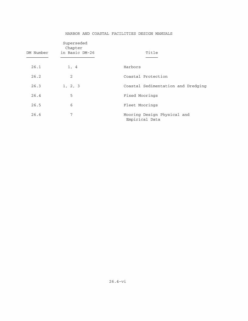
HARBOR AND COASTAL FACILITIES DESIGN MANUALS
Superseded ChapterDM Number in Basic DM-26 TitleÄÄÄÄÄÄÄÄÄ ÄÄÄÄÄÄÄÄÄÄÄÄÄÄ ÄÄÄÄÄ
26.1 1, 4 Harbors
26.2 2 Coastal Protection
26.3 1, 2, 3 Coastal Sedimentation and Dredging
26.4 5 Fixed Moorings
26.5 6 Fleet Moorings
26.6 7 Mooring Design Physical and Empirical Data
26.4-vi
FIXED MOORINGS
CONTENTS
Page ÄÄÄÄ
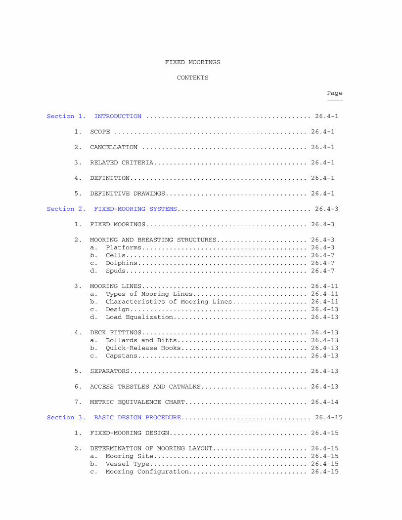
Section 1. INTRODUCTION .......................................... 26.4-1
1. SCOPE ................................................. 26.4-1
2. CANCELLATION .......................................... 26.4-1
3. RELATED CRITERIA....................................... 26.4-1
4. DEFINITION............................................. 26.4-1
5. DEFINITIVE DRAWINGS.................................... 26.4-1
Section 2. FIXED-MOORING SYSTEMS.................................. 26.4-3
1. FIXED MOORINGS......................................... 26.4-3
2. MOORING AND BREASTING STRUCTURES....................... 26.4-3 a. Platforms.......................................... 26.4-3 b. Cells.............................................. 26.4-7 c. Dolphins........................................... 26.4-7 d. Spuds.............................................. 26.4-7
3. MOORING LINES.......................................... 26.4-11 a. Types of Mooring Lines............................. 26.4-11 b. Characteristics of Mooring Lines................... 26.4-11 c. Design............................................. 26.4-13 d. Load Equalization.................................. 26.4-13
4. DECK FITTINGS.......................................... 26.4-13 a. Bollards and Bitts................................. 26.4-13 b. Quick-Release Hooks................................ 26.4-13 c. Capstans........................................... 26.4-13
5. SEPARATORS............................................. 26.4-13
6. ACCESS TRESTLES AND CATWALKS........................... 26.4-13
7. METRIC EQUIVALENCE CHART............................... 26.4-14
Section 3. BASIC DESIGN PROCEDURE................................. 26.4-15
1. FIXED-MOORING DESIGN................................... 26.4-15
2. DETERMINATION OF MOORING LAYOUT........................ 26.4-15 a. Mooring Site....................................... 26.4-15 b. Vessel Type........................................ 26.4-15 c. Mooring Configuration.............................. 26.4-15

CONTENTS
Page ÄÄÄÄ
3. EVALUATION OF ENVIRONMENTAL CONDITIONS AND ASSOCIATED LOADS...................................... 26.4-19 a. Environmental Conditions........................... 26.4-19 b. Environmental Loads................................ 26.4-24 c. Loads on Mooring Elements.......................... 26.4-27 d. Loads on Spud Moorings............................. 26.4-33 e. Berthing Loads..................................... 26.4-33
4. DESIGN OF MOORING COMPONENTS........................... 26.4-35 a. Probabilistic Approach to Design................... 26.4-35 b. Design of Mooring and Breasting Structures......... 26.4-36
5. METRIC EQUIVALENCE CHART............................... 26.4-38
Section 4. DESIGN OF FIXED MOORINGS............................... 26.4-39
1. INTRODUCTION........................................... 26.4-39
2. MOORING LAYOUT......................................... 26.4-39
3. ENVIRONMENTAL CONDITIONS............................... 26.4-39 a. Seafloor Soil Conditions........................... 26.4-39 b. Design Water Depth................................. 26.4-39 c. Design Wind........................................ 26.4-39 d. Design Current..................................... 26.4-48
4. ENVIRONMENTAL LOADS ON SINGLE MOORED VESSELS........... 26.4-49 a. Wind Load.......................................... 26.4-49 b. Current Load....................................... 26.4-60
5. ENVIRONMENTAL LOADS ON MULTIPLE MOORED VESSELS......... 26.4-68 a. Identical Vessels.................................. 26.4-68 b. Nonidentical Vessels............................... 26.4-77
6. LOADS ON MOORING ELEMENTS.............................. 26.4-81 a. Total Loads........................................ 26.4-81 b. Lateral Load and Yaw Moment........................ 26.4-83 c. Longitudinal Load.................................. 26.4-84 d. Maximum Mooring Loads.............................. 26.4-84 e. Computer Solution.................................. 26.4-89 f. Spud Moorings...................................... 26.4-89 g. Berthing Loads..................................... 26.4-89
7. DESIGN OF FIXED-MOORING STRUCTURES..................... 26.4-95 a. Breasting Structures............................... 26.4-95 b. Structural Design.................................. 26.4-98
8. METRIC EQUIVALENCE CHART............................... 26.4-98
26.4-viii

CONTENTS
Page ÄÄÄÄ
Section 5. EXAMPLE PROBLEMS....................................... 26.4-99
EXAMPLE PROBLEM 1: FIXED MOORING...................... 26.4-99
EXAMPLE PROBLEM 2: SPUD MOORING FOR FLOATING DRYDOCK.. 26.4-140
REFERENCES..................................................... References-1
GLOSSARY........................................................ Glossary-1
FIGURES
Figure Title PageÄÄÄÄÄÄ ÄÄÄÄÄ ÄÄÄÄ
1. Typical Fixed Mooring........................................ 26.4-4 2. Rigid Breasting Platform..................................... 26.4-5 3. Two Types of Flexible Breasting Platforms.................... 26.4-6 4. Breasting Cell............................................... 26.4-8 5. Dolphins..................................................... 26.4-9 6. Spud Mooring................................................. 26.4-10 7. Typical Load-Elongation Curves for Various Types of Mooring Ropes...................................................... 26.4-12 8. Basic Design Procedure for a Fixed Mooring................... 26.4-16 9. Line Angles for a Typical Fixed Mooring...................... 26.4-1710. Example Plot of Probability of Exceedence and Return Period Versus 30-Second Windspeed................................. 26.4-2211. Vessel Response to Static Wind and Current Loading........... 26.4-2812. Mooring-Load Analysis........................................ 26.4-3113. Spud Clearance Requirements.................................. 26.4-3414. Load-Deflection Curve........................................ 26.4-3715. Fixed-Mooring Layout Procedure............................... 26.4-4016. Procedure for Wind-Data Analysis............................. 26.4-4117. Windspeed Conversion Factor, CÚt¿, as a Function of Wind Duration, t................................................ 26.4-4418. Probability of Exceedence and Return Period Versus Windspeed. 26.4-4719. Coordinate System and Nomenclature for Wind and Current Loads...................................................... 26.4-5020. Recommended Yaw-Moment Coefficient for Hull-Dominated Vessels.................................................... 26.4-5521. Recommended Yaw-Moment Coefficient for Various Vessels According to Superstructure Location....................... 26.4-5622. Recommended Yaw-Moment Coefficient for Center-Island Tankers. 26.4-5723. Recommended Yaw-Moment Coefficient for Typical Naval Warships................................................... 26.4-5824. CÚyc³[infinity]¿ as a Function of LÚwL¿/B and [phi].......... 26.4-6225. CÚyc³1¿ as a Function of CÚp¿LÚwL¿/[SQRT T].................. 26.4-6326. k as a Function of [phi] and Vessel Hull Shape............... 26.4-6427. (eÚc¿/LÚwL¿) as a Function of Vessel Type and Current Angle.. 26.4-69
26.4-ix

CONTENTS
FIGURES (Continued)
Figure Title PageÄÄÄÄÄÄ ÄÄÄÄÄ ÄÄÄÄ
28. Assignment of K Coefficients for Vessel Groups of Two to Six Vessels..................................................... 26.4-7129. Wind Yarn-Moment Coefficient, KÚNw¿, for Multiple-Vessel Moorings.................................................... 26.4-7330. KÚ6¿ as a Function of Dimensionless Spacing................... 26.4-7431. KÚ7¿ as a Function of Vessel Position and Number of Vessels in Mooring..................................................... 26.4-7532. Current Yaw-Moment Coefficient, KÚNc¿, for Multiple-Vessel Moorings.................................................... 26.4-7833. Method for Resolving Yaw Moment Into Lateral Loads at Bow and Stern of Vessel......................................... 26.4-8434. Case 1........................................................ 26.4-8535. Case 2........................................................ 26.4-8636. Case 3........................................................ 26.4-8737. Mooring Analysis for Spring Lines............................. 26.4-8838. Effect of Tide................................................ 26.4-9039. Spud-Mooring Analysis......................................... 26.4-9140. Procedure for Determining Berthing Energy..................... 26.4-9241. Berthing Velocity, VÚN¿, Versus Ship Displacement and Relative Environmental Condition............................ 26.4-9342. Berthing Velocity, VÚN¿, Versus Ship Displacement and Relative Environmental Condition............................ 26.4-9443. Hydrodynamic Mass Coefficient, CÚH¿........................... 26.4-9644. Design of Breasting Structures................................ 26.4-9745. Mooring Configuration (Example Problem 1)..................... 26.4-10046. Plot of VÚR¿ for Each Direction (Example Problem 1)........... 26.4-10647. Summary of Design Wind and Current Conditions (Example Problem 1).................................................. 26.4-10748. Giant Cylindrical Fender Characteristics...................... 26.4-13549. Mooring Configuration (Example Problem 2)..................... 26.4-14150. Design Windspeeds (Example Problem 2)......................... 26.4-14651. Summary of Design Wind Conditions (Example Problem 2)......... 26.4-149
TABLES
Table Title PageÄÄÄÄÄ ÄÄÄÄÄ ÄÄÄÄ
1. Definitive Drawings for Fixed Moorings........................ 26.4-2 2. Unusual Environmental Conditions Requiring Special Analysis... 26.4-25 3. Sources of Wind Data.......................................... 26.4-42 4. Return Period for Various P(X >/= x).......................... 26.4-46 5. Selection of [theta]Úwz¿...................................... 26.4-53 6. Wind-Force Drag, Coefficient, CÚDW¿, for Floating Drydocks.... 26.4-59 7. [phi], CÚyc³[infinity]¿, CÚyc³1¿, CÚp¿LÚwL¿/[SQRT T], k, and Dimensional Properties for DTMB Models........................ 26.4-65 8. AÚR¿ for Propeller Drag....................................... 26.4-68 9. Lateral Wind-Force Coefficients for Multiple-Vessel Moorings.. 26.4-70
CONTENTS
TABLES (Continued)
Table Title PageÄÄÄÄÄ ÄÄÄÄÄ ÄÄÄÄ
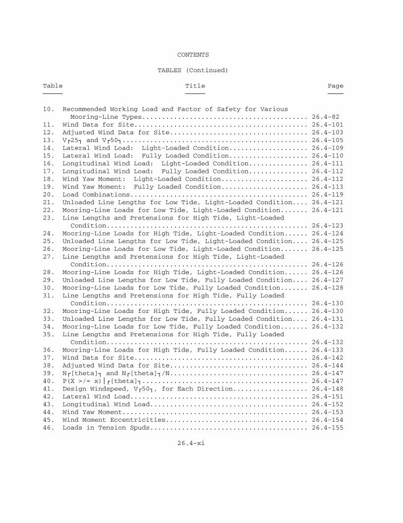
10. Recommended Working Load and Factor of Safety for Various Mooring-Line Types.......................................... 26.4-8211. Wind Data for Site............................................ 26.4-10112. Adjusted Wind Data for Site................................... 26.4-10313. VÚ25¿ and VÚ50¿............................................... 26.4-10514. Lateral Wind Load: Light-Loaded Condition.................... 26.4-10915. Lateral Wind Load: Fully Loaded Condition.................... 26.4-11016. Longitudinal Wind Load: Light-Loaded Condition............... 26.4-11117. Longitudinal Wind Load: Fully Loaded Condition............... 26.4-11218. Wind Yaw Moment: Light-Loaded Condition...................... 26.4-11219. Wind Yaw Moment: Fully Loaded Condition...................... 26.4-11320. Load Combinations............................................. 26.4-11921. Unloaded Line Lengths for Low Tide, Light-Loaded Condition.... 26.4-12122. Mooring-Line Loads for Low Tide, Light-Loaded Condition....... 26.4-12123. Line Lengths and Pretensions for High Tide, Light-Loaded Condition................................................... 26.4-12324. Mooring-Line Loads for High Tide, Light-Loaded Condition...... 26.4-12425. Unloaded Line Lengths for Low Tide, Light-Loaded Condition.... 26.4-12526. Mooring-Line Loads for Low Tide, Light-Loaded Condition....... 26.4-12527. Line Lengths and Pretensions for High Tide, Light-Loaded Condition................................................... 26.4-12628. Mooring-Line Loads for High Tide, Light-Loaded Condition...... 26.4-12629. Unloaded Line Lengths for Low Tide, Fully Loaded Condition.... 26.4-12730. Mooring-Line Loads for Low Tide, Fully Loaded Condition....... 26.4-12831. Line Lengths and Pretensions for High Tide, Fully Loaded Condition................................................... 26.4-13032. Mooring-Line Loads for High Tide, Fully Loaded Condition...... 26.4-13033. Unloaded Line Lengths for Low Tide, Fully Loaded Condition.... 26.4-13134. Mooring-Line Loads for Low Tide, Fully Loaded Condition....... 26.4-13235. Line Lengths and Pretensions for High Tide, Fully Loaded Condition................................................... 26.4-13236. Mooring-Line Loads for High Tide, Fully Loaded Condition...... 26.4-13337. Wind Data for Site............................................ 26.4-14238. Adjusted Wind Data for Site................................... 26.4-14439. NÚ[theta]¿ and NÚ[theta]¿/N................................... 26.4-14740. P(X >/= x)³Ú[theta]¿.......................................... 26.4-14741. Design Windspeed, VÚ50¿, for Each Direction................... 26.4-14842. Lateral Wind Load............................................. 26.4-15143. Longitudinal Wind Load........................................ 26.4-15244. Wind Yaw Moment............................................... 26.4-15345. Wind Moment Eccentricities.................................... 26.4-15446. Loads in Tension Spuds........................................ 26.4-155
26.4-xi

FIXED MOORINGS
Section 1. INTRODUCTION
1. SCOPE. This manual presents basic information required for theselection and design of fixed-mooring systems in protected harbors.
2. CANCELLATION. This manual, NAVFAC DM-26.4, Fixed Moorings, cancels andsupercedes Chapter 5 of the basic Design Manual 26, Harbor and CoastalFacilities, dated July 1968, and Change 1, dated December 1968.
3. RELATED CRITERIA. Certain criteria related to fixed moorings appearelsewhere in the design manual series. See the following sources:
Subject Source ÄÄÄÄÄÄÄ ÄÄÄÄÄÄ
Characteristics of Vessels DM-26.6 Fender Systems and Fixed Mooring Separators DM-25.1 Fleet Moorings DM-26.5 Foundations and Earth Structures DM-7.2 General Criteria For Waterfront Construction DM-25.6 Pier Berths, Deck Fittings, Access Facilities DM-25.1 Seawalls, Bulkheads, and Quaywalls DM-25.4 Sedimentation DM-26.3 Soil Dynamics, Deep Stabilization, and Special Geotechnical Construction DM-7.3 Soil Mechanics DM-7.1 Strength and Dimensional Characteristics of Chain, Wire, and Fiber Rope DM-26.6 Structural Engineering DM-2 Series Utility Services for Fixed Moorings DM-25.2 Water-Level Fluctuations DM-26.1 Wave Forces on Mooring Structures DM-26.2
4. DEFINITION. Navy moorings are classified as either fixed moorings orfleet moorings. A fixed mooring consists of a structural element,permanently fixed in position, to which a vessel is moored. Thesestructural elements include platforms, cells, dolphins, spuds, or othersimilar structures. A fixed mooring includes the lines, sheaves, pulleys,spuds, deck fittings of mooring and breasting structures, separators, accesstrestles, catwalks, and other appurtenances permanently attached to thestructure or provided by the station specifically for securing vessels tothe structure. Lines and appurtenances provided by vessels are not a partof the fixed mooring.
A fleet mooring consists of a structural element, not permanently fixedin position, to which a vessel is moored. Fleet moorings are discussed inDM-26.5, Fleet Moorings.
5. DEFINITIVE DRAWINGS. A list of definitive drawings for fixed mooringsis presented in Table 1.
26.4-1

TABLE 1 Definitive Drawings for Fixed Moorings
ÚÄÄÄÄÄÄÄÄÄÄÄÄÄÄÄÄÄÄÄÄÄÄÄÄÄÄÄÄÄÄÄÄÄÄÄÄÄÄÄÄÄÄÄÄÄÄÄÄÄÄÄÄÄÄÄÄÄÄÄÄÄÄÄÄÄÄÄÄ¿³ NAVFAC Drawing³³ Description Number ³ÃÄÄÄÄÄÄÄÄÄÄÄÄÄÄÄÄÄÄÄÄÄÄÄÄÄÄÄÄÄÄÄÄÄÄÄÄÄÄÄÄÄÄÄÄÄÄÄÄÄÄÄÄÄÄÄÄÄÄÄÄÄÄÄÄÄÄÄÄ´³ ³³Offshore Tanker Facility 1404350, ³³ 1404351 ³ÀÄÄÄÄÄÄÄÄÄÄÄÄÄÄÄÄÄÄÄÄÄÄÄÄÄÄÄÄÄÄÄÄÄÄÄÄÄÄÄÄÄÄÄÄÄÄÄÄÄÄÄÄÄÄÄÄÄÄÄÄÄÄÄÄÄÄÄÄÙ
26.4-2

Section 2. FIXED-MOORING SYSTEMS
1. FIXED MOORINGS. Fixed moorings vary from site to site, but the elementsof any fixed-mooring system are basically the same. A typical fixed mooringis shown in Figure 1. The basic elements common to most fixed mooringsinclude: mooring and breasting structures (including fendering), mooringlines, deck fittings, separators, and access trestles and catwalks.
2. MOORING AND BREASTING STRUCTURES. Mooring structures are designed formooring loads. Breasting structures are designed to withstand both mooringand berthing loads. Structures commonly used as mooring and/or breastingstructures are platforms, cells, and dolphins. Spuds are often used asmooring structures in moorings for floating drydocks. Each of the commonmooring and breasting structures are discussed below.
a. Platforms. Platforms generally consist of an isolated concrete,steel, or timber deck (cap) supported on concrete, steel, or timber piling.A platform may be used as either a mooring structure (mooring platform) or abreasting structure (breasting platform). Mooring platforms are notdesigned to withstand the impact of berthing. Breasting platforms normallyhave a fendering system to absorb the impact of berthing vessels and mayalso be used to secure the vessel.
Mooring and breasting platforms may be designed to behave in a rigid ora flexible manner. An example of a rigid breasting platform is shown inFigure 2; the structure consists of a concrete deck (cap) supported byvertical, as well as battered, concrete piles. This structure is designedto resist large lateral loads, which are transferred primarily to thebattered piles. The battered piles on the back side of the platform areloaded in compression (bearing), while the front batter piles are loaded intension (uplift). Because the uplift capacity of a pile is generally smallcompared to its bearing capacity, it is desirable to provide a massiveconcrete cap to resist some of the uplift load. Vertical piles are providedto support the large deadweight of the cap. The fendering system in Figure2 consists of a row of timber fender piles with a cluster of timber fenderpiles on each corner of the structure.
Two examples of flexible breasting platforms are shown in Figure 3.Both structures are supported by steel-pipe piles, which resist lateralloads. The structures differ from one another in the construction of theplatform deck. The platform in Figure 3A has a deck composed of steelgrating; the piles supporting the deck are held together with steel-pilebraces. The platform in Figure 3B has a concrete deck. The steel-pipepiles deflect under load to provide energy absorption. Thus, fenderingrequirements may be reduced compared to those for a rigid structure asberthing energy can be absorbed both in the structure and in the fenderingsystem.
Mooring and breasting platforms are generally used in lieu of cells forwater depths greater than 40 feet. Rigid platforms are often used insteadof cells in soft soils. Platforms can be designed to withstand largelateral loads and thus can accommodate large vessels.
26.4-3


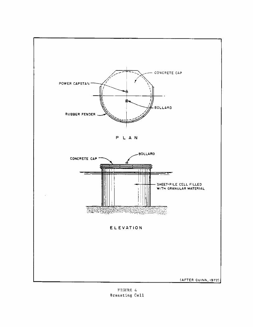
b. Cells. Mooring or breasting cells typically consist of round,isolated sheet-pile cofferdams or concrete caissons. Cells can be used asmooring or breasting structures; however, cells are most often used asbreasting structures because they can withstand very large berthing loads.
Breasting cells are rigid structures which generally require asubstantial fendering system to absorb berthing energy. Figure 4 presents atypical breasting cell. The structure consists of a cellular sheet pilefilled with granular material. The cap of the structure is concrete, andrubber fenders are provided.
Mooring or breasting cells are generally used in water depths less than40 feet. Mooring or breasting cells can be designed to accommodate largevessels.
c. Dolphins. Dolphins are generally flexible structures constructed ofeither timber piles or steel-pipe piles. Dolphins can be used as mooring orbreasting structures.
Timber-pile dolphins typically consist of timber piles driven inclusters of three to 19 or more, wrapped at their tops with galvanized wirerope and connected with bolts and chocks of wood. Three-, seven-, and19-pile mooring dolphins are shown in Figure 5A. One of the center piles ofa thick cluster is extended so that a mooring line may be fastened to it.No fendering is required for a timber-pile breasting dolphin as thestructure is quite flexible and can absorb berthing energy on its own.However, a timber-pile dolphin may fail under a berthing load when a vesselstrikes one pile of the cluster, thus preventing distribution of, the loadto the other piles. Consequently, the use of timber-pile clusters asbreasting structures should be avoided.
Steel pipe-pile dolphins may consist of either one or a group ofsteel-pipe piles. Steel pipe-pile dolphins are particularly well-suited asbreasting structures due to their flexibility. An example of a breastingdolphin with a single pipe pile is shown on the left in Figure 5B. Thisstructure consists of a relatively large, single pipe pile with acylindrical steel mooring post embedded in concrete at its top. A moderatetimber fendering system is provided to supplement the structure in absorbingberthing energy. Figure 5B also shows a typical steel pipe-pile breastingdolphin with battered steel-pipe piles for resisting lateral load. Amoderate rubber fendering system is provided. At some installations, use ofa larger, single steel-pipe pile may be more economical than use of a groupof smaller piles.
Timber-pile dolphins are typically used to moor smaller vessels than areplatforms or cells. In general, timber-pile dolphins should not be used forlateral loads greater than 30 kips or in water depths greater than 35 feet.Steel pipe-pile dolphins may be used for larger loads and, if soilconditions are favorable, may be used in water depths exceeding 40 feet.
d. Spuds. A spud is a steel member, usually an H-pile or built-upsection, used to secure a vessel to a pier or quaywall. Fixed mooringsincorporating spuds are called spud moorings. Spud moorings are often usedto moor floating drydocks, as shown in Figure 6A. Floating drydocks
26.4-7


seldom leave their mooring; consequently, spud moorings are designed formooring loads only. By definition, spuds are mooring structures.
Spuds are designed to resist either transverse loads (tension spuds) orlongitudinal loads (shear spuds). Typically, the end spuds are tensionspuds and intermediate spuds are shear spuds. Tension spuds can be designedto resist both transverse and longitudinal loads; in this case, theintermediate spuds are eliminated and only two spuds are required. Tensionspuds are connected vertically to a pier or quaywall with a shoe (Figure6B); shear spuds are connected with a spud guide. Shoes are connectionswhich resist transverse loads, whereas guides resist longitudinal loads.Both connections allow the spuds to slide vertically.
3. MOORING LINES. Vessels are secured to mooring and/or breastingstructures with mooring lines. Mooring lines are classified according tothe type of load they resist (longitudinal or lateral) and their location onthe vessel. Bow, stern, and breast lines resist lateral mooring loads andyaw moment on the vessel and are typically arranged as shown in Figure 1.Spring lines resist longitudinal mooring loads; a typical spring-linearrangement is also shown in Figure 1. The predominant load on a fixedmooring is generally the lateral load. Consequently, there are generallymore bow, stern, and breast lines than spring lines.
a. Types of Mooring Lines. There are four types of mooring lines usedto secure a vessel to a fixed mooring: natural-fiber rope, synthetic-fiberrope, wire rope, and mooring chain. Natural-fiber, synthetic-fiber, andwire rope are most often used at fixed moorings which service activevessels. Mooring chain may be used to moor inactive vessels.
b. Characteristics of Mooring Lines. The most importantcharacteristics of a mooring line are its strength, elasticity, andconstruction.
(1) Strength. For a given rope diameter, wire rope is thestrongest, followed by synthetic-fiber rope and then natural-fiber rope.Breaking strengths of several types of mooring rope are given in Tables 5through 9 of DM-26.6, Section 4.
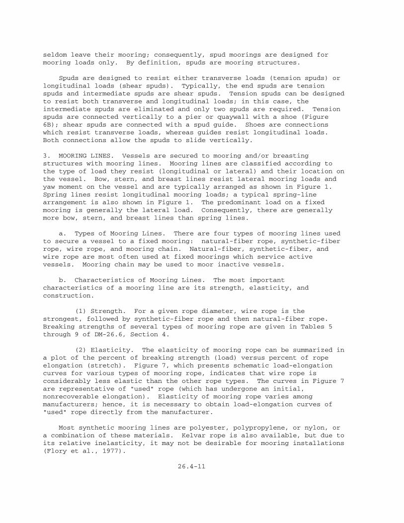
(2) Elasticity. The elasticity of mooring rope can be summarized ina plot of the percent of breaking strength (load) versus percent of ropeelongation (stretch). Figure 7, which presents schematic load-elongationcurves for various types of mooring rope, indicates that wire rope isconsiderably less elastic than the other rope types. The curves in Figure 7are representative of "used" rope (which has undergone an initial,nonrecoverable elongation). Elasticity of mooring rope varies amongmanufacturers; hence, it is necessary to obtain load-elongation curves of"used" rope directly from the manufacturer.
Most synthetic mooring lines are polyester, polypropylene, or nylon, ora combination of these materials. Kelvar rope is also available, but due toits relative inelasticity, it may not be desirable for mooring installations(Flory et al., 1977).
26.4-11

(3) Construction. Synthetic ropes vary in type of construction.For information on rope construction, see Flory et al. (1977) and Tables 5through 9 in DM-26.6. In general, eight-strand and double-braid rope arepreferred for use in moorings (Flory et al., 1977). Three-strand rope isnot recommended as it has a tendency to hockle. Hockles, which greatlyreduce the strength of a rope, result from twisting a laid rope in adirection opposite to the direction of the lay. Hockles resemble knots in arope.
c. Design. A vessel normally carries its own mooring lines;consequently, fixed-mooring design seldom involves sizing mooring lines.However, the size, length, composition, and arrangement of mooring linesaffect fixed-mooring design. Therefore, it is generally necessary todetermine the type and arrangement of mooring lines carried by the vessel(s)for which the fixed mooring is designed.
d. Load Equalization. A load-equalization system consists of anarrangement of sheaves through which a continuous line passes. The systemis designed to equalize tension in breast lines and prevent overloading ofone line. Load-equalization systems have been used to moor inactive vesselsat the U.S. Naval Shipyard, Bremerton, Washington.
4. DECK FITTINGS. Deck fittings are used to secure mooring lines tomooring and breasting structures. Some common deck fittings are describedbelow.
a. Bollards and Bitts. A bollard is a short, steel column with a baseplate. Bollards are used to secure mooring lines to mooring and breastingstructures. They are available in various shapes and for various loadcapacities. A bitt is similar to a bollard except that the bitt is a doublecolumn. For further discussion and drawings of bollards and bitts, refer toDM-25.1, Section 6.
b. Quick-Release Hooks. A quick-release hook is a device designed toallow a mooring line to be released from the hook by pulling a lever arm onthe hook with a tag line from the vessel. Quick-release hooks allow avessel to depart from its berth without shore assistance. For furtherdiscussion and drawings of quick-release hooks, refer to DM-25.1, Section 6.
c. Capstans. A Capstan is a winch with vertical spindles which areused to pull mooring lines from a vessel to shore. Capstans are necessarywhen the mooring line cannot be retrieved by hand. For further discussionand drawings of capstans, refer to DM-25.1, Section 6.
5. SEPARATORS. Separators are used in fixed moorings to prevent damage dueto movement of berthed vessels. Separators may be used between the vesseland breasting structures, as shown in Figure 1, or between adjacent vesselswhen they are moored in groups. For further discussion and drawings oftypical separators, see DM-25.1, Section 7.
6. ACCESS TRESTLES AND CATWALKS. Access trestles, provided at most fixedmoorings, are used for transfer of cargo and personnel from vessel to shore.
26.4-13

Access treaties are typically arranged as shown in Figure 1. Catwalks aregenerally provided for access by pedestrians to mooring and breastingstructures, as shown in Figure 1. For more discussion on access facilities,See DM-25.1, Section 8.
7. METRIC EQUIVALENCE CHART. The following metric equivalents weredeveloped in accordance with ASTM E-621. These units are listed in thesequence in which they appear in the text of Section 2. Conversions areapproximate.
40 feet = 12.2 meters 30 kips = 13 608 kilograms 35 feet = 10.7 meters
26.4-14

Section 3. BASIC DESIGN PROCEDURE
1. FIXED-MOORING DESIGN. Design of a fixed mooring consists of three majorsteps: determination of the mooring layout, evaluation of environmentalconditions and associated loads, and design of mooring components. A flowchart outlining the design process is shown in Figure 8. This sectiondiscusses each element of the design process qualitatively. Specific designprocedures are given in Section 4.
2. DETERMINATION OF MOORING LAYOUT.
a. Mooring Site. Fixed moorings should be located at well-protectedsites in order to minimize environmental loads. Most fixed moorings arelocated within harbors. Wherever possible, the mooring should be orientedso that the longitudinal axis of the vessel is parallel to the direction ofthe prevailing winds, waves, and/or currents.
b. Vessel Type. The vessel(s) expected to use the mooring must bedetermined. Most moorings are designed to accommodate several vessel types.Vessel characteristics, including length, breadth, draft, displacement,broadside wind area, and frontal wind area, must be determined for each ofthese vessels. These characteristics are presented in Tables 2, 3, and 4 ofDM-26.6, Section 3, for fully loaded and light-loaded conditions.
c. Mooring Configuration. Figure 9 shows a typical fixed mooring. Theconfiguration of breasting structures, mooring structures, and mooring linesdepends upon mooring usage; space available for mooring; size of vessels tobe accommodated; environmental conditions; mooring and berthing loads;tolerance for vessel movement; number, type, and size of mooring linesavailable on vessels; location of the attachment of the mooring lines on thevessel; preferential existing ship traffic patterns and turning-circleprocedures of the local harbor; and power or other existing utilityaccessibility. The book of plans for a particular vessel, which providesinformation on mooring-line attachment points (such as chocks, winches, andbollards), can be obtained from the shipyard responsible for that vessel.
(1) Breasting Structures. A minimum of two breasting structures arenormally required at a fixed mooring. Breasting-structure location affectsthe amount of berthing energy which must be absorbed by the fendering systemof the mooring. Costa (1973), in a theoretical analysis of the dynamics ofberthing, showed that the amount of berthing energy transmitted to a fender(and breasting structure) decreases as the distance between the center ofgravity of the vessel and the point of contact between the fender and thevessel increases. Therefore, the designer should place breasting structuresas far apart as possible. However, the fenders on the breasting structuresmust contact the parallel middle body of the vessel. Piaseckyj (1977)reported that the most common spacing of breasting structures was 30 percentof the overall length (LOA) of the berthing vessel, but that spacing from 22to 50 percent of the overall length has been used. Values from 30 to 50percent of overall length of the vessel are recommended. (See Figure 9.)
(2) Mooring Structures. Mooring structures should be placedsymmetrically about the transverse centerline of the mooring in order toobtain a balanced distribution of mooring loads. Mooring structures shouldbe


located so that the mooring lines are parallel to the load to be restrained.Small vessels may require only two mooring structures, while larger vesselsmay require four or more. Mooring-structure decks should be located 5 feetabove the highest water level under operational conditions (including tides,storm surge, and waves).
(3) Mooring Lines. Figure 9 shows angle requirements for bow,stern, breast, and spring lines for a typical fixed mooring. Maximummooring-line angles should be observed for an efficient mooring-linearrangement. Mascenik (1976) suggests bow and stern lines are relativelyinefficient in restraining a moored vessel due to poor orientation and longlength (higher elasticity). In many cases, well-arranged breast and springlines can provide an efficient mooring within the length of the mooredvessel. However, in some cases, bow and stern lines may be required toassist the vessel during berthing maneuvers.
(a) Bow, stern, and breast lines. Bow, stern, and breast linesare provided to resist lateral mooring loads. For bow, stern, and breastlines, the vertical angle, [theta], with the horizontal should be 25 degreesor less. (See Figure 9A.) Vertical angles of lines depend upon the heightof the mooring structure and the mooring-line length. Bow, stern, andbreast lines are more efficient in resisting lateral load for smallervertical angles.
For bow and stern lines, the horizontal angle, [alpha], with thetransverse centerline of the vessel should be 45 degrees or less. (SeeFigure 9B). For breast lines, the horizontal angle, [alpha], withthe transverse centerline of the vessel should be 15 degrees or less.
(b) Spring lines. Spring lines resist longitudinal loads. Forspring lines, the vertical angle, [theta], with the horizontal should be 25degrees or less. (See Figure 9A.) Spring lines are more efficient inresisting longitudinal load for smaller vertical angles. The horizontalangle, [beta], with the longitudinal axis of the vessel should be 10 degreesor less. (See Figure 9B.)
(c) Effect of tide and vessel displacement. Line angles areaffected by changes in tide level and changes in vessel displacement (loadedversus ballasted conditions). The designer should make sure that line-anglerequirements are maintained for anticipated fluctuations in tide level andvessel displacement. Variations in tide level and vessel displacement canresult in increased mooring-line loads unless the lines are tended (heavedin or let out at various tide levels).
The effect of tide on mooring-line tension is illustrated in thefollowing example. A 100-foot used polypropylene (8-strand) mooring linehas a vertical angle, [theta], of 10 degrees at low tide. The line has apretension of 5 percent of its breaking strength, which, according to theload-elongation curve in Figure 7, corresponds to a 1-percent elongation(99-foot unloaded length). If the vessel rises 8 feet at high tide and themooring line is not tended, the line will stretch to a length of 103.3 feet(4.3-percent elongation). From Figure 7, the mooring-line loadcorresponding to 4.3-percent elongation is 21 percent of breaking strength.Thus, the increase in tide level increases the mooring-line load 420 percentfrom its low-tide

pretension. If a wire line were used instead of the polypropylene line, itwould have reached its breaking strength when it stretched to 101.1 feet(2.1-percent extension). It is clear that tide level has an importanteffect upon mooring-line loads, even in the absence of applied wind andcurrent loads. Therefore, the effect of tide on mooring loads must beinvestigated.
(d) Effect of mooring-line composition. Fixed moorings whichincorporate wire lines are "stiff" moorings, which allow relatively littlemovement of the moored vessel under applied loading. This is advantageousat some mooring facilities where unloading operations require minimal vesselmotion. The disadvantages of fixed moorings incorporating wire lines are asfollows: the wire lines fire more difficult to tend than synthetic lines,variations in tide levels can dramatically increase line loads, and the"stiff" mooring may respond poorly to dynamic loads.
Fixed moorings which incorporate synthetic lines (that is, linescomposed of nylon, polypropylene, or polyester) are "soft" moorings, whichpermit relatively large movement of the vessel under applied loading.Synthetic lines are easier to handle than wire lines. Also, an increase inline load due to a variation in tide level is not as severe in a syntheticline as it is in a wire line. However, fixed moorings incorporatingsynthetic lines may allow large vessel movements under applied loading.
Wire lines fitted with, 35 to 50 feet of synthetic line on the shore endor vessel end of the line have been used at some commercial mooringfacilities. Wire lines fitted with these "synthetic tails" are easier tohandle than wire lines alone; furthermore, these tails give added elasticityto wire lines, which may provide for a more favorable response to dynamicloads. Finally, because they stretch, wire lines fitted with synthetictails are not subject to extreme variations in line load from tidalvariations as are wire lines without tails. However, Mascenik (1976)reported that the use of wire tails is questioned because some parting oftails has occurred. Where synthetic tails are used, they should be sizedwith a breaking strength of 140 percent of the breaking strength of the wirerope (Mascenik, 1976).
3. EVALUATION OF ENVIRONMENTAL CONDITIONS AND ASSOCIATED LOADS.
a. Environmental Conditions. Environmental conditions important tomooring design include seafloor soil conditions, water depth, winds,currents, and waves.
(1) Seafloor Soil Conditions. Seafloor soil conditions must beevaluated in order to properly select and design fixed moorings. Some typesof mooring and breasting structures can be eliminated based upongeotechnical considerations. For example, mooring platforms may be moredesirable for relatively soft soils than mooring cells. For informationconcerning geotechnical investigations, evaluation of seafloor soilconditions, and design of foundations, see DM-7.1, DM-7.2, and DM-7.3.
(2) Water Depth. Mooring-site bathymetry and water-levelfluctuations must be investigated to assure that there is adequate depth forvessels using the mooring, to determine mooring-line geometry, to determineline-load fluctuations due to tidal variations, and to determine currentloads on the

vessel. Current loads are sensitive to the ratio of vessel draft to waterdepth.
Factors contributing to water-level fluctuations include astronomicaltides, storm surge, seiche, and tsunamis. These phenomena are discussed inDM-26.1, Section 2. The design water level at a mooring site is controlledprimarily by the astronomical tide. However, the other factors mentionedabove can be significant and must be investigated.
Harbor sedimentation produces significant variations in bottomelevation. The potential for long-term changes in bottom elevation must beinvestigated. Fixed moorings should be located in areas which requireminimal maintenance dredging. Harbor shoaling and current Navy dredgingrequirements are discussed in DM-26.3.
(3) Winds. Wind loads on moored vessels are important tofixed-mooring design. The duration of a wind event affects the magnitude ofthe wind-induced load on the moored vessel. A wind gust with a speed 50percent higher than the average windspeed, but lasting only a couple ofseconds, may cause little or no response of a moored vessel. On the otherhand, repeated wind gusts with only slightly higher-than-average windspeed,with duration near the natural period of a vessel-mooring system, can excitethe vessel dynamically and result in mooring-line loads in excess of themean mooring-line loads. Hence, it is necessary to establish a standardwind duration which will provide reliable estimates of steady-state,wind-induced loads on moored vessels. Winds of longer or shorter durationshould be corrected to this level. Based upon analytical considerations andprevious experience, a 30-second-duration wind speed has been chosen as thestandard for determining wind-induced loads on moored vessels. This valueis less than the 1-minute duration recommended by Flory et al. (1977) forlarge tankers, but seems appropriate for naval vessels.
The most reliable method for determining design windspeed at a site isto analyze wind measurements taken at or near the site over an extendedperiod of time. Windspeeds are reported according to a variety ofdefinitions, including fastest-mile, peak-gust, 1-minute average, 10-minuteaverage, and hourly average. The fastest-mile windspeed is defined as thehighest measured windspeed with duration sufficient to travel 1 mile. Forexample, a reported fastest-mile windspeed of 60 miles per hour is a60-mile-per-hour wind that lasted for 1 minute. On the other hand, afastest-mile windspeed of 30 miles per hour would have lasted 2 minutes.Peak-gust windspeed measures a wind of high velocity and very shortduration.
Fastest-mile and peak-gust windspeeds are generally the most usefulmeasurements for determining design windspeeds at a mooring site, forseveral reasons. First, they represent the highest wind recorded during aperiod of observation. Secondly, they can be converted to a30-second-duration wind-speed. Finally, these measurements are availableat most naval facilities. (This is particularly true for the peak-gustwindspeed).
(a) Data sources. Sources for windspeed data are summarized inTable 3, Section 4.
26.4-20

(b) Windspeed adjustments. Windspeed data must be adjusted forelevation, duration, and overland-overwater effects in order to representconditions at the mooring site. First, the windspeed must be adjusted to astandard elevation; this is particularly true when comparing data measuredat several locations near the mooring site. The design windspeed must alsobe adjusted to an elevation suitable for determining wind loads on a mooredvessel dependent upon the geometry of that vessel. However, for thepurposes of determining the design windspeed, the wind measurements arecorrected to a standard elevation of 10 meters (33.33 feet). Secondly, thewindspeed must be corrected to a 30-second-duration windspeed. Finally,because most wind measurements are taken at inland sites over land, ratherthan at the mooring site over water, it is necessary to correct foroverland-overwater effects. These adjustments must be made before theprobabilistic analysis, discussed below, is done. Procedures for making theabove adjustments are given in Section 4.
(c) Determining maximum windspeed. In order to achieve aneconomical and safe mooring design, the maximum windspeed is determinedusing probabilistic methods. Probabilistic analysis of wind measurementstaken at or near a site will provide an estimate of how frequently a givenwindspeed will occur or be exceeded (probability of exceedence) during thedesign life of the mooring. The return period of a windspeed, estimatedfrom the probability of exceedence, is defined as the average length of timebetween occurrences of that windspeed. The concept of statistical returnperiod is useful for determining the design windspeed. For example, a50-year design windspeed indicates that a windspeed equal to or greater thanthe 50-year design windspeed will occur, on the average, once every 50years. The 50-year windspeed (windspeed with a 50-year return period) isused for design of fixed moorings, although estimates of more-frequent(1-year, 10-year) and less-frequent (75-year, 100-year) windspeeds areuseful for planning purposes. Operational criteria may require that avessel leave a mooring at a given windspeed which is less than the designwindspeed. In this case, the fixed mooring would be designed for theoperational criteria unless there is a possibility that, under somecircumstances, a vessel would remain at the mooring during higher winds.
Procedures for determining the probability of exceedence and the returnperiod for various windspeeds based upon measured data are presented inSection 4. The results of a probabilistic analysis can be convenientlypresented as shown in Figure 10, which is an example plot of probability ofexceedence (left ordinate) and return period (right ordinate) versus30-second windspeed (abscissa).
(4) Currents. Current can play a major role in the layout anddesign of a fixed mooring. Current loads on a moored vessel can be veryhigh. To reduce these loads, it is desirable to moor vessels headed intothe current. Currents may also affect the ability of a vessel to maneuverinto the mooring.
(a) Tidal currents. Tidal currents are the most common type ofcurrent in Navy harbors. They range in speed from less than 1 knot to about6 knots. Ideally, the designer should obtain data on current velocity anddirection, and on the variation of these parameters, both areally and with
26.4-21


depth. Determination of tidal currents is best achieved by directmeasurement. Where measurements are not available, current speeds may beestimated using physical or numerical models. If the harbor geometry issimple and other appropriate assumptions are valid, the procedures presentedin DM-26.1, Subsection 2.9, may be used to determine tidal-currentvelocities.
Estimates of the peak flood and ebb tidal currents for numerouslocations on the Atlantic coast of North America and the Pacific coasts ofNorth America and Asia are published in tables by the U.S. Department ofCommerce, National Ocean Survey (NOS). The published values are forspecific locations, generally within harbors. Because tidal currents canvary significantly within a harbor, currents obtained from the NOStidal-current tables must be used with caution unless they are valuesreported directly at the mooring site.
Tidal currents vary in speed and reverse direction during the tidalcycle, but the forces induced by tidal currents are normally treatedstatically. Exceptions may occur, and these must be investigated on asite-by-site basis.
(b) River discharge. Currents resulting from riverdischarge can also be significant. Estimates of currents due to riverdischarge are best achieved by direct measurement or by analysis ofexisting flow records.
(c) Wind-driven currents. Wind-driven currents are surfacecurrents which result from the stress exerted by the wind on the seasurface. Wind-driven currents generally attain a mean velocity of about 3to 5 percent of the mean windspeed at 10 meters above the sea surface. Themagnitude of the current decreases sharply with depth. The direction of thecurrent is roughly that of the wind. Wind-driven currents are seldom afactor in protected harbors, but they must be investigated when they exceed0.5 knots. Methods for estimating wind-driven currents are presented inBretschneider (1967).
(d) Probability of currents. The probabilistic nature ofcurrent speed and direction at a given site should be taken into account. Aprobabilistic estimate of the speed and direction of tidal currents can bedetermined only by extensive field measurements or through physical ornumerical modeling; however, neither time nor budget is normally availableto generate these data. Therefore, maximum flood and ebb currents should beused for fixed-mooring design unless more detailed information is available.This design criterion is reasonable for two reasons. First, these currentsoccur often; thus, there is a reasonable probability that these currentswill occur simultaneously with the design windspeed. Secondly, while avessel could conceivably be subject to higher current speeds than the peakvalues, the higher currents would be of short duration. Hence, the impactof higher-than-average peak flood or ebb current speeds would not be toogreat. The statistical probability of river flows, which may be obtainedfrom records of peak yearly flood flow, should be analyzed using theprobabilistic methods described for wind in Section 4.
(5) Waves. Waves can exert significant dynamic loads on mooredvessels and mooring elements sited in unprotected waters. This manualassumes moorings are sited in a protected harbor; therefore, dynamic

analysis of moored vessels is not considered herein. If there is doubt asto whether or
26.4-23
not a mooring is located in a protected harbor, or if prior experience atthe site indicates that wave action may affect mooring design, then waveconditions must be investigated.
Waves important to the design of fixed moorings fall into threecategories: short waves, long waves, and waves generated by passingvessels. Short waves are wind-generated waves with periods of 20 seconds orless; those generated locally are referred to as seas and those generatedgreat distances away are called swell. Moorings located in protectedharbors are generally sheltered from short waves by structures, such asbreakwaters or jetties. However, if the mooring is located near the harboropening, it may be exposed to sea and swell, and the assumption of aprotected harbor may not be valid. If the harbor is sufficiently large,local winds may generate seas within the harbor of sufficient size to affectthe moored vessel.
Waves with periods ranging from greater than 20 seconds to severalminutes are classified as long waves. Long-wave energy is capable ofcausing oscillations in a harbor. This phenomenon, called seiche, isdiscussed in DM-26.1, Subsection 2.8.
Waves generated by passing vessels can be important to the design of afixed mooring. This is particularly true when the mooring is sited in anarrow channel where other vessels pass close to the moored vessel.
In general, the most reliable methods for determining design-waveconditions use measurements taken at the site; however, this information isseldom available. Consequently, the methods described in DM-26.2, Sections1 and 2, for obtaining wave data and estimating short-wave conditions mustbe used. Methods for estimating the possibility of mooring problemsassociated with long waves are lacking. It is best to rely on previousexperience at the mooring site. In the same way, potential for problemsassociated with waves generated by passing ships must be determined based onprevious experience.
(6) Unusual Conditions. The potential for the occurrence of unusualconditions must be investigated. Design may require significant deviationsfrom the standard procedures presented in this manual. Table 2 presents asummary of unusual environmental conditions which require analysis notcovered by this manual. If the occurrence of these conditions is probable,the designer should consult the Naval Civil Engineering Laboratory (NCEL) orCHESNAVFAC-FPO-1 for specialized mooring designs.
b. Environmental Loads. Wind, currents, and waves produce loads onmoored vessels. Static wind and current loads are discussed in detailbelow. A brief discussion of dynamic loads due to waves follows.
Static loads due to wind and current are separated into lateral load,longitudinal load, and yaw moment. Flow mechanisms which influence theseloads include friction drag, form drag, circulation forces, and proximityeffects. The predominant force-generating mechanisms are friction drag andform drag. Circulation forces play a secondary role. Proximity effects areimportant in multiple-vessel moorings and in moorings sited in veryrestricted channels.
26.4-24

TABLE 2 Unusual Environmental Conditions Requiring Special Analysis
ÚÄÄÄÄÄÄÄÄÄÄÄÄÄÄÄÄÄÄÄÄÄÄÄÄÄÄÄÄÄÄÄÄÄÄÄÄÄÄÄÄÄÄÄÄÄÄÄÄÄÄÄÄÄÄÄÄÄÄÄÄÄÄÄÄÄÄÄÄÄÄÄÄ¿ ³ Condition Special Analysis Required ³ ÃÄÄÄÄÄÄÄÄÄÄÄÄÄÄÄÄÄÄÄÄÄÄÄÄÄÄÄÄÄÄÄÄÄÄÄÄÄÄÄÄÄÄÄÄÄÄÄÄÄÄÄÄÄÄÄÄÄÄÄÄÄÄÄÄÄÄÄÄÄÄÄÄ´ ³Waves[1] ........................... >/=1.5 feet for small craft ³ ³ >/=4 feet for larger vessels ³ ³ ³ ³Winds .............................. >/=60 knots ³ ³ ³ ³Hurricanes and Typhoons[1] ......... All cases where these are possible³ ³ ³ ³Seiche[1] .......................... Any evidence of seiche based upon ³ ³ prior experience ³ ³ ³ ³Currents ........................... >/=3 knots ³ ³ ³ ³Tidal Variations ................... >/=8 feet ³ ³ ³ ³Ice ................................ Free-floating ice ³ ÀÄÄÄÄÄÄÄÄÄÄÄÄÄÄÄÄÄÄÄÄÄÄÄÄÄÄÄÄÄÄÄÄÄÄÄÄÄÄÄÄÄÄÄÄÄÄÄÄÄÄÄÄÄÄÄÄÄÄÄÄÄÄÄÄÄÄÄÄÄÄÄÄÙ [1]Requires dynamic analysis
(1) Load Due to Wind. Loads on moored vessels due to wind resultprimarily from form drag. The general equation Used to determine wind loadis:
FÚw¿ = 1/2 [rho]Úa¿VÚw¿À2ÙAÚw¿CÚDW¿ (3-1)
WHERE: FÚw¿ = load due to wind
[rho]Úa¿ = mass density of air
VÚw¿ = wind velocity
AÚw¿ = projected area exposed to wind; may be either side area or end area
CÚDW¿ = wind-force drag coefficient which accounts for form drag and friction drag
The value of AÚw¿ differs for lateral load and longitudinal load: theside area is used for determining lateral load, and the end area is used fordetermining longitudinal load. The wind-force coefficient, CÚDW¿, alsodiffers for lateral load and longitudinal load: CÚDW¿ is a function of theangle at which the wind impinges upon the vessel. The value of CÚDW¿ isbased upon model-test results. Section 4 presents methods for determiningthe lateral and longitudinal wind-force drag coefficients.
(2) Load Due to Current. Current loads developed on moored vesselsresult from form drag, friction drag, and propeller drag. Lateral forcesare dominated by form drag. Form drag is dependent upon the ratio of vesseldraft
26.4-25

to water depth: as the water depth decreases, current flows around, ratherthan underneath, the vessel. Longitudinal forces due to current are causedby form drag, friction drag, and propeller drag. The general equation usedto determine current load is:
FÚc¿ = 1/2[rho]Úw¿VÚc¿À2ÙAÚc¿CÚDC¿ (3-2)
WHERE: FÚc¿ = load due to current
[rho]Úw¿ = mass density of water
VÚc¿ = current velocity
AÚc¿ = projected area exposed to current; may be either below-water side or end areas, hull surface area, or propeller area
CÚDC¿ = current-force drag coefficient
Methods for determining lateral and longitudinal current loads arepresented in Section 4. Current-load estimates are not as reliable as thosefor wind loads. However, the procedures presented in this manual provideconservative results.
(3) Load Due to Waves. Wave-induced loads on moored vessels candominate wind and current loads for moorings sited in unprotected,high-energy environments. As the mooring site is moved into protectedareas, these forces diminish, and the previously discussed wind and currentloads begin to dominate. Quantitative analysis of wave-induced forces isbeyond the scope of this manual; however, a qualitative discussion isprovided to give information on the magnitude, character, and relativeimportance of wave-induced loads.
The hydrodynamic response of a moored vessel in the presence of wavescan be resolved into an oscillatory response and a static response(wave-drift force). The oscillatory response is characterized by vesselmovements in six degrees of freedom (three translational: heave, sway, andsurge, and three rotational: yaw, pitch, and roll) with associatedmooring-line loads that occur with roughly the same period as that of theincoming waves. Theoretical analysis of the oscillatory response of amoored vessel is achieved through the coupled solution of six simultaneousequations of motion for the vessel mooring system. Solution of theseequations is complicated. An outline of the solution is presented inDM-26.1, Subsection 2.8. The static wave drift force on a moored vessel inregular waves (that is, in waves with the same height and period) is usuallysmall compared to the oscillatory wave load. However, ocean waves aregenerally irregular (that is, waves which vary in height and period) and maybe characterized by groups of high waves. The static drift force present inregular waves will slowly oscillate with the period of wave grouping inirregular waves. If the period of slow drift oscillation is close to thenatural period of the moored-ship system, then large mooring loads mayresult.
Numerical models have been used to determine wave loading on mooredvessels. Some of these numerical techniques are discussed in VanOortmerssen (1976) and Webster (1982). Physical models, although expensive

time-consuming, are considered the most reliable means for determining waveloading (Flory et al., 1977).
(4) Multiple-Vessel Moorings. Wind and current loads onmultiple-vessel moorings are greatly influenced by the sheltering effect ofthe first vessel on leeward vessels. The procedures and data necessary todetermine the loads and moments induced on multiple-moored vessels by eitherwind or currents are extremely limited. The only data that are directlyapplicable for this purpose were collected at the David Taylor Model Basin(DTMB) shortly after World War II; these were summarized graphically in theprevious edition of Design Manual 26. Altmann (1971) noted that these dataare not fully applicable to contemporary multiple-vessel mooring problemsbecause only identical vessels were examined and no systematic variation oflateral separation distance was investigated. Altmann (1971) has alsoindicated a number of deficiencies in the data themselves.
A contemporary multiple-vessel mooring arrangement consists of a tenderwith one or more identical vessels moored in parallel fashion alongside thetender. There are currently no model-test results for this type of mooringarrangement. Methods for determining loads on vessels in multiple-vesselmoorings with both identical and nonidentical vessels are presented inSection 4.
c. Loads on Mooring Elements.
(1) General. Wind and current produce a lateral load, alongitudinal load, and a yaw moment on a moored vessel. Theses loadsdisplace and rotate the vessel relative to its position before the loadswere applied (Figure 11). The applied loads are resisted by the mooringsystem made up of mooring lines, mooring structures, and breastingstructures. For static equilibrium, the applied loads must equal therestoring loads of the mooring system, according to the following equations:
Applied wind and current loads must be distributed to mooring lines andfenders to determine loads on fixed-mooring structures. Mooring lines,fenders, and fixed-mooring structures deflect under load, and provide arestoring force proportional to deflection. The elasticity of the mooring

system (mooring lines, mooring structures, and breasting structures) must beknown to evaluate loads on mooring elements.
26.4-27


Mooring-line elasticity depends upon line length, diameter, composition,and construction. Longer mooring lines are more elastic than shorter linesof the same material. Larger-diameter lines are less elastic thansmaller-diameter lines of the same material. Figure 7 provides a comparisonof the elasticity of mooring lines of varying composition. Load-elongationcurves similar to those in Figure 7 should be obtained from the mooring-linemanufacturer. The effect of mooring-line construction on mooring-lineelasticity can be determined from the manufacturer's catalogs.
Mooring-structure elasticity is considerably less than that of the linesattached to the structure. Thus, mooring structures are normally treated asrigid structures.
Breasting-structure elasticity depends upon the characteristics of itsfendering system and the characteristics of the structure itself.Information on the elasticity of the fender should be obtained from themanufacturer; some examples may be found in DM-25.1, Section 5. In somecases, the breasting structure may be designed to deflect under loading; ifso, the elasticity of the fender-structure system should be determined.(See DM-7).
Loads in mooring lines/mooring structures and breasting structures aredetermined by finding the equilibrium position of the vessel under appliedload, as outlined below:
(a) Determine the total lateral load, longitudinal load, and yaw moment on the vessel due to wind and current. (b) Determine mooring-line configuration and the properties of each of the mooring lines. Calculate a load-deflection curve for each of the mooring lines. (c) Determine breasting-structure location and select fenders. Construct a load-deflection curve for each breasting structure. (d) Assume an initial displacement and rotation of the vessel (new orientation) under the applied load. (e) Determine the deflection in each of the mooring lines and breasting structures/fenders corresponding to the vessel orientation. (f) Determine the forces in each of the mooring lines and breasting structures/fenders from the above mooring-line deflections. (g) Sum the forces and moments according to the above equations, accounting for all the mooring-line loads, breasting-structure/fender loads, and applied wind and current loads. (h) Determine if the restraining forces and moments due to all the mooring-line loads and breasting-structure/fender loads balance out the applied forces and moments due to wind and current. (i) If the above forces and moments do not balance, then the vessel is not in its equilibrium position under the applied load. A new vessel orientation must be assumed. (j) Steps (d) through (i) are repeated until the equilibrium position of the vessel is determined.
26.4-29

The above procedure can be solved using the computer program presentedin Appendix B of DM-26.5. Simplified methods for determining themooring-line loads are summarized below.
(2) Simplified Procedure for Determining Mooring Loads on MooringElements. The first step in the simplified procedure is to determine thetotal applied lateral and longitudinal loads and yaw moment and to resolvethe applied loads into lateral loads at the bow and stern of the vessel andlongitudinal load. Lateral load and longitudinal load are analyzedindividually.
Three situations occur in the analysis of lateral mooring loads. First,lateral loads at the bow and stern act in the same direction and move thevessel away from the mooring (Figure 12A). In this case, lateral mooringloads are taken entirely by the mooring lines in tension. Secondly, lateralloads at the bow and stem act in the same direction and move the vesseltoward the mooring (Figure 12a). In this case, lateral mooring loads aretaken entirely by the breasting structures. Finally, lateral loads at thebow and stern act in opposite directions; lateral load at one end of thevessel is restrained by mooring lines, while lateral load at the oppositeend of the vessel is restrained by a breasting structure (Figure 12C).Mooring-load analyses for each of the above situations are described belowas Case 1, Case 2, and Case 3, respectively.
(a) Lateral load and yarn moment--Case 1: mooring-line loads.The method used to analyze mooring-line loads is taken from "Guidelines andRecommendations for Safe Mooring of Large Ships at Piers and Sea Islands,"(Oil Companies International Marine Forum (OCIMF), 1977). This simplifiedmethod is used to determine the distribution of loads in mooring lines.However, it is an approximate method and must be used with judgment. Thedetailed procedure is given in Section 4.
Limitations of the simplified mooring-line analysis procedure are asfollows:
(1) The mooring layout must be reasonably symmetrical. (2) Vertical mooring-line angles, [theta], must be less than 25 degrees. (3) Horizontal mooring-line angles, [alpha], on bow and stern must be less than 45 degrees. (4) Mooring lines must be of identical material, construction, and diameter. (5) Mooring lines for lateral load (breast, bow, and stern) must be effectively grouped at the bow and stern. (6) Line loads are assumed to be zero when there is no applied load despite the fact that the lines are assumed to be pretensioned. (7) Synthetic and natural rope are ignored in the analysis if the vessel is moored with both synthetic or natural rope and wire rope.
This procedure assumes that mooring-line tension is linearlyproportional to line extension. In fact, mooring-line tension is generallynonlinearly proportional to line extension. However, when a smallpretension is applied to take the slack out of the line, the lines may beassumed to behave


linearly. This way, the distribution of loads among the mooring linesdepends only upon the mooring geometry.
The tension developed in any one mooring line is proportional to thequantity cos[alpha] cos[theta]/L, where [alpha] is the horizontalangle of the mooring line with the transverse axis of the vessel, [theta] isthe vertical angle of the mooring line with the horizontal, and L is thelength of the mooring line (Figure 9). The term cos[alpha] cos[theta]/Lmay be thought of as a stiffness term: the shorter the line, the higher thetension in the line. This is consistent with the fact that shorter linesare less elastic than longer lines of identical material; thus, shorterlines assume more of the load than longer lines. The component of tensionin the lateral direction is proportional to cosÚ2¿[alpha]cosÚ2¿[theta]/L. The total load in a mooring line is the sum of thedistributed applied load and the mooring-line pretension.
The simplified procedure assumes that lateral loads are restrainedprimarily by breast lines and, to a lesser degree, by bow and stern lines.The lateral restraint lines are assumed to be grouped near the bow and nearthe stern of the vessel. This allows one to analyze mooring lines at thebow and at the stern separately.
(b) Lateral load and yaw moment--Case 2: breasting-structureloads. When the applied loads move bath the bow and stern of the vesseltoward the fixed-mooring structures, the load is restrained by the breastingstructures. Lateral load is assumed to be taken by the breastingstructures. The mooring loads on the breasting structures are determinedusing the principle of static equilibrium. Typical fixed-mooringconfigurations have two breasting structures, as shown in Figure 12B. Asimple approach to analysis assumes that the vessel is "simply supported" bythe breasting structures, with the applied lateral load acting at adistance halfway between the structures. Detailed solution procedures arepresented in Section 4.
(c) Lateral load and yaw moment--Case 3: combination ofmooring-line and breasting structure loads. For certain combinations ofapplied load, a portion of the applied lateral load is restrained by abreasting structure, while the remaining portion of the lateral load isrestrained by the mooring lines at the opposite end of the vessel. Thisrequires an analysis consisting of a combination of the above two cases.The lateral load at one end of the vessel is assumed to be taken entirely bythe breasting structure as a point load. The lateral load on the oppositeend of the vessel is assumed to be, taken entirely by the mooring linesgrouped at that end of the vessel. Analysis of load distribution among themooring lines is carried out using the procedure described under Case 1,above. The lateral load taken by the breasting structure is determined bytaking moments about the breasting structure accounting for each of themooring lines which provide lateral restraint. This analysis providesreasonable results; details of this procedure are provided in Section 4.For final design at critical installations, the computer program providedin Appendix B of DM-26.5 should be used.
(d) Longitudinal load. Longitudinal load is restrained byspring lines. The method for determining the distribution of longitudinalload among, spring lines is similar to that for bow, stem, and breast linesin Case 1. However, the angle, [alpha], used for bow, stern, and breast

replaced by [beta] (the horizontal angle of the line with the longitudinalaxis of the vessel). Detailed solution procedures are presented in Section4.
(e) Maximum mooring loads. The maximum loads on mooring lines(sum of applied loads and pretension) and breasting structures must bedetermined. Maximum loads are determined by evaluating load due tocombinations of wind, current, tide level, and vessel displacement.
d. Loads on Spud Moorings. The motion of a vessel in a spud mooring isrestrained by spuds. The attachments for the vessel are considered to berigid; therefore, the process of distributing mooring loads is simplified.The following procedure is used to analyze mooring loads on spud moorings.Details of this procedure are given in Section 4.
(1) Determine the total longitudinal force, lateral force, and yaw moment. (2) Establish an initial layout of the spuds. The spuds should be located symmetrically around the centerline of the vessel. (3) Distribute the longitudinal load equally among the shear spuds. (4) Distribute the lateral load and yaw moment to each of the tension spuds by dividing the lateral load by the number of tension spuds and resolving the moment to these spuds using their respective moments of inertia (about the center of gravity of the spuds).
Figure 13 shows a tension-spud mooring at extreme high water (minimumdock draft) and at extreme low water (maximum dock draft). At extreme highwater (Figure 13A), the bottom end of the spud must extend at least 4 feetbelow the centerline of the shoe. At extreme low water (Figure 13B), thetop end of the spud must extend at least 4 feet above the centerline of theshoe. The above clearances must also be satisfied for shear spuds and theirguides.
e. Berthing Loads. A berthing vessel will approach a fixed mooringwith a certain kinetic energy, called the berthing energy. This berthingenergy must be absorbed by the berthing structure and/or its fenderingsystem. The most common method for determining berthing energy is to usethe energy equation:
KEÚB¿ = 1/2 W/gVÚN¿À2ÙCÚB¿CÚH¿ (3-6)
WHERE: KEÚB¿ = berthing energy (kinetic energy of docking vessel)
W = weight of vessel
g = gravitational acceleration
VÚN¿ = normal component of approach velocity
CÚB¿ = berthing coefficient
CÚH¿ = hydrodynamic mass coefficient
26.4-33


Determining berthing energy requires knowledge of the berthing maneuver(such as angle of approach, velocity, and effects of tugs), the mass of thevessel, the hydrodynamic effects of the vessel, and environmental loads onthe vessel. Approach velocity is difficult to predict due to theuncertainty of the berthing maneuver. Methods for selecting the approachvelocity, berthing coefficient, and hydrodynamic mass coefficient arepresented in Section 4. Due to the uncertainties involved in thecalculation of berthing energy, it is good practice to allow for reserveenergy absorption in the design of breasting structures.
4. DESIGN OF MOORING COMPONENTS.
a. Probabilistic Approach To Design. A probabilistic approach tomooring design is used to evaluate uncertainties in environmental conditionsat the mooring site, uncertainties in accurately predicting mooring forces,and uncertainties concerning material strength of the mooring-systemhardware.
(1) Uncertainties in Environmental Conditions.
(a) Windspeed. The uncertainty associated with determining adesign windspeed is reduced by using the probabilistic approach describedin Subsection 3.3.a.(3). Fixed moorings must be designed for a windspeedwith a 50-year return period, unless operational criteria dictate that thevessel leave the mooring at a windspeed less than the 50-year windspeed.For a mooring with a 5-year life expectancy, there is about a 9.6-percentchance that the mooring will be subjected to the 50-year windspeed.Similarly, there is about an 18-percent chance that a mooring with a 10-yearlife expectancy will be subjected to the 50-year windspeed. Operationalcriteria at some fixed moorings may require a vessel to leave the mooringat windspeeds less than the 50-year event. In this case, the mooring shouldbe designed for the maximum operational windspeed rather than the 50-yearwindspeed.
(b) Currents. There are generally insufficient data to performa probabilistic analysis of tidal currents. Consequently, the design tidalcurrent shall be the larger of the maximum flood or ebb current at the site.Wind-driven-current statistics can be derived from wind data.River-discharge data can be analyzed and probabilities determined usingmethods similar to those described for wind.
(2) Uncertainties in Predicting Forces. Uncertainties involved indetermining wind- and current-induced loads on moored vessels should berecognized. Wind loads are relatively accurate (+/- 10 to 15 percent ofpredicted value), while current loads are more uncertain and may be as highas +/- 30 percent of the predicted value for currents with speeds greaterthan 3 knots.
(3) Uncertainties in Material Strength. There is some uncertaintyin the actual strength of mooring lines, mooring and breasting structures,the fendering system, and the soil. Hence, a factor of safety is applied tothe design of fixed-mooring elements, and a working load, which isconsiderably less than the breaking or yield strength, is designated.
The uncertainties in mooring-line strength are associated withvariations in manufacturing quality of the line and the degradation of

mooring-line
26.4-35

strength with time as the line is exposed to the marine environment.Specific recommendations for working loads on mooring lines are presented inSection 4. Working loads for structural materials such as steel, concrete,and wood are presented in DM-2. Factors of safety concerning design offendering systems are given in DM-25.1. Factors of safety concerning soilstrength are presented in DM-7.
b. Design of Mooring and Breasting Structures. Several alternativemooring structures should be investigated. Site conditions andrestrictions, applied loads, costs, and previous experience at the site willdetermine the optimum structure to be employed in the design. Themooring-structure design is based upon the rated capacity of the deckfitting secured to the structure, in addition to other live and dead loads.
(1) Energy Absorption. Fixed-mooring systems should be capable ofabsorbing berthing and mooring energy. Berthing energy must be absorbed bybreasting structures and/or their fendering systems. Mooring energy,associated with vessel movements due to the dynamic loading of wind, waves,and current, must be absorbed by breasting and mooring structures. Dynamicanalysis of fixed moorings is not presented in this manual. The followingdiscussion is limited to analysis of the absorption of berthing energy bybreasting structures.
Berthing energy is absorbed by a breasting structure and its fenderingsystem according to the following general equation:
KEÚB¿ = KEÚs¿ + KEÚf¿ (3-7)
WHERE: KEÚB¿ = berthing energy
KEÚs¿ = berthing energy absorbed by the breasting structure
KEÚf¿ = berthing energy absorbed by the fendering system
For rigid breasting structures (such as cells and rigid platforms), theberthing energy is absorbed almost entirely by the fendering system. Forflexible breasting structures (such as steel and timber dolphins andflexible platforms), the berthing energy is absorbed by both the structureand the fendering system. Where structural and foundation conditions arefavorable, significant cost savings may be realized with a flexible design.
(2) Load-Deflection Curve. A plot of restraining force versusdeflection is known as a load-deflection curve. A schematic example of aload-deflection curve is shown in Figure 14. The load-deflection curveprovides information on the energy-absorbing capabilities of a breastingstructure. This information is obtained by applying the concepts of workand energy to the load-deflection curve. The principle of work-energydictates that the work done on the fixed-mooring system should equal thearea under the load-deflection curve. This work, equal to the berthingenergy of the vessel, must be absorbed by the mooring system.
A vessel approaches a breasting structure with a berthing energy, KEÚB¿,which must be absorbed by the breasting structure through deflection of thebreasting structure and/or its fendering system. Furthermore, a breasting
26.4-36


structure must be designed to withstand the maximum static wind and currentload (mooring energy, FÚM¿) acting on it. In general, for an economicalstructure, it is desirable to absorb the berthing energy in thefender-structure system such that the berthing load, FÚB¿, developed in thestructure is equal to the maximum static wind and current load (mooringload) on the structure (Figure 14). There may be situations where eitherthe mooring or the berthing load is dominant. For example, for an extremelyhigh berthing energy, it may not be possible to design a fendering systemsoft enough to absorb the berthing energy at a load equal to the mooringload. In this case, the load associated with berthing would be higher thanthe mooring load.
5. METRIC EQUIVALENCE CHART. The following metric equivalents weredeveloped in accordance with ASTM E-621. These units are listed in thesequence in which they appear in the text of Section 3. Conversions areapproximate.
5 feet = 1.5 meters 100 feet = 30.5 meters 99 feet = 30.2 meters 8 feet = 2.4 meters 103.3 feet = 31.5 meters 101.1 feet = 30.8 meters 35 feet = 10.7 meters 50 feet = 15.2 meters 1 mile = 1.61 kilometers 60 miles per hour = 96.6 kilometers per hour 30 miles per hour = 48.3 kilometers per hour 33.33 feet = 10 meters 1 knot = 0.5 meter per second 6 knots = 3.1 meters per second 0.5 knot = 0.26 meter per second 4 feet = 1.2 meters 3 knots = 1.5 meters per second
26.4-38

Section 4. DESIGN OF FIXED MOORINGS
1. INTRODUCTION. This section provides equations, graphs, and tablesnecessary for fixed-mooring design. Detailed procedures are presented foreach element of the design process. Section 3 provides a qualitativediscussion of the design process.
2. MOORING LAYOUT. It is assumed that the mooring site, the vessel, andthe mooring configuration are given prior to commencement of detaileddesign. It is generally necessary to investigate several mooring layoutsbecause the loads in mooring lines and on mooring and breasting structuresare not known at this stage of the design. Often the designer will have toanalyze several vessels for a given mooring configuration.
Mooring-line geometry and breasting- and mooring-structure location aredetermined using the procedure outlined in Figure 15. The mooring-lineangles must be checked at low tide for a fully-loaded vessel and at hightide for a light-loaded vessel.
3. ENVIRONMENTAL CONDITIONS.
a. Seafloor Soil Conditions. Seafloor soil conditions must beinvestigated in order to design fixed-mooring structures. Refer to DM-7 forsoil-investigation requirements.
b. Design Water Depth. Determine the bottom elevation and theanticipated range of water elevation expected at the mooring site.Bathymetric charts are usually available from National Ocean Survey (NOS).The primary cause of water-level fluctuations is the astronomical tide.Estimates of the maximum high and low water levels due to tide for mostnaval harbors are given in DM-26.1, Table 6. A summary of tide levels forU.S. locations is given in Harris (1981).
c. Design Wind. Steps for wind-data analysis, discussed below, aresummarized in Figure 16. This procedure involves some concepts ofprobability, which are discussed in Appendix A of DM-26.5.
(1) Obtain Wind Data. Collect available windspeed data for thesite. Data which give the annual maximum wind speed (extreme wind) anddirection for each year of record are required. In most situations, theannual maximum windspeeds are either fastest-mile or peak-gust values. Aminimum of 20 years of annual extreme windspeed data is desired for a goodestimate of the 50-year design windspeed.
Several possible sources for obtaining windspeed data are presented inTable 3. These are discussed below:
(a) Naval Oceanography Command Detachment. The NavalOceanography Command Detachment is a source of wind data for naval harborsworld-wide. Wind data available through the Naval Oceanography CommandDetachment are summarized in "Guide to Standard Weather Summaries andClimatic Services," NAVAIR 50-1C-534 (1980). The most useful of thestandard wind summaries available at the Naval Oceanography CommandDetachment for mooring design is the table of extreme winds. This table,available for a large number of


TABLE 3 Sources of Wind DataÚÄÄÄÄÄÄÄÄÄÄÄÄÄÄÄÄÄÄÄÄÄÄÄÄÄÄÄÄÄÄÄÄÄÄÄÄÄÄÄÄÄÄÄÄÄÄÄÄÄÄÄÄÄÄÄÄÄÄÄÄÄÄÄÄÄÄÄÄÄÄÄÄÄÄ¿³ - Naval Oceanography Command Detachment, Federal Building, Asheville, ³³ North Carolina 28801 ³³ ³³ - National Climatic Data Center (NCDC), Federal Building, Asheville, ³³ North Carolina 28801 ³³ ³³ - Naval Environmental Prediction Research Facility, Monterey, ³³ California 93940 ³³ ³³ - Wind records from local wind stations ³ÀÄÄÄÄÄÄÄÄÄÄÄÄÄÄÄÄÄÄÄÄÄÄÄÄÄÄÄÄÄÄÄÄÄÄÄÄÄÄÄÄÄÄÄÄÄÄÄÄÄÄÄÄÄÄÄÄÄÄÄÄÄÄÄÄÄÄÄÄÄÄÄÄÄÄÙ
naval sites, provides the extreme peak-gust windspeed (and its direction)for each month of each year of record. This standard summary providessufficient information to determine extreme winds for all directionscombined, but provides insufficient information to determine extreme windsfor each direction individually. Extreme peak-gust windspeed for eachdirection for each year of record is required to determine extreme winds foreach direction (for example, using eight compass points). The NavalOceanography Command Detachment is presently planning to providedirectional extreme winds as a standard product, and summaries ofdirectional extreme-wind statistics for naval harbors should be available inthe future.
(b) National Climatic Data Center (NCDC). The National ClimaticData Center has wind data for the continental United States and UnitedStates territories. Wind data available at NCDC for the continental UnitedStates are cataloged in the "National Wind Data Index" (Changerey, 1978).Extreme-wind data available at NCDC are generally fastest-mile windspeeds.Changerey (1982a, 1982b) gives extreme windspeeds (that is, 2- to 1,000-yearwinds) for a number of east coast and Great Lakes sites, some of which arenear naval facilities. The results do not give directional extreme winds,but do give extreme winds for all directions. Wind data, sufficient fordetermining directional extreme winds, are available at NCDC; the cost forthese data varies from site to site.
(c) Naval Environmental Prediction Research Facility.Climatological data for naval harbors throughout the world are presented ina series of publications from the Naval Environmental prediction ResearchFacility. Turpin and Brand (1982) provide climatological summaries of Navyharbors along the east coast of the United States. Climatological data forUnited States Navy harbors in the western Pacific and Indian Oceans aresummarized in Brand and Blelloch (1976). Climatological data for UnitedStates Navy harbors in the Mediterranean are summarized in Reiter (1975).The above publications provide information on the following: harborgeography and facilities; susceptibility of the harbor to storms, such astropical cyclones, hurricanes, and typhoons; wind conditions at the harborand the effects of local topography; wave action; storm surge; and tides.The publications have been prepared to provide guidance for determining whena vessel should leave a harbor; the publications may not be sufficientlydetailed to provide design windspeeds. However, they will help the designer
26.4-42

determine the threat of storms at the site and provide a good background onlocal climatology.
The designer must not use data from summarized hourly average windstatistics, such as those presented in the Summary of SynopticMeteorological Observations (SSMO). These average data are not annualmaximum values and do not report the infrequent, high-velocity windspeedsnecessary to predict extreme-wind events for design use. If averagesummaries are the only data available, it is best to obtain the originalobservations and analyze these data for extreme statistics.
(2) Correct for Elevation. The level at which windspeed data arerecorded varies from site to site. Windspeed data should be transformed toa standard reference level of 33.33 feet or 10 meters. Adjustments are madeusing the following equation, which accounts for the wind gradient found innature: 33.33 VÚ33.33¿ = VÚh¿ (ÄÄÄÄÄ)À1/7Ù (4-1) h
WHERE: VÚ33.33¿ = windspeed at elevation of 33.33 feet above water or ground level
VÚh¿ = windspeed at elevation h
h = elevation of recorded wind above water or ground level, in feet
(3) Correct for Duration. Figure 17 presents a graph which allowsone to correct windspeeds ranging from 1 second to 10 hours in duration to a30-second-duration windspeed. This figure gives a conversion factor, CÚt¿,which is used to determine the 30-second windspeed as follows:
VÚt¿ VÚt=30 seconds¿ = ÄÄÄÄ (4-2) CÚt¿
WHERE: VÚt=30 seconds¿ = windspeed with a 30-second duration
VÚt¿ = windspeed of given duration, t
VÚt¿ CÚt¿ = conversion factor = ÄÄÄÄÄÄÄÄÄÄÄÄÄÄ VÚt=30 seconds¿
Peak-gust windspeed statistics give no information on the duration ofthe wind event; therefore, these data cannot be accurately corrected to a30-second duration. Based on Figure 17, an 8-second peak gust is 1.1 timesfaster than a 30-second wind. As an approximation, peak-gust windspeedsshould be reduced by 10 percent to obtain the 30-second windspeed. Thiswill provide a reasonably conservative estimate of the 30-second wind speedfor fleet-mooring design. Where detailed information on the duration ofpeak gusts can be obtained (that is, from an actual wind anemometer trace atthe site), Figure 17 can be used to make more accurate estimates of30-second sustained windspeeds.
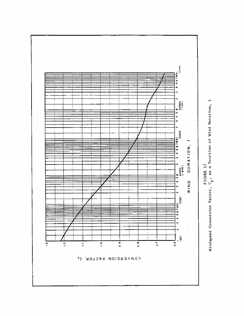

Fastest-mile wind statistics give wind duration directly. Thefastest-mile windspeed is a wind with duration sufficient to travel 1 mile.Figure 17 can be used to correct the windspeed to the 30-second-durationwind. For example, a conversion factor, CÚt¿, of 0.945 is applied to a60-mile-per-hour fastest-mile windspeed (60-second duration) to convert itto a 30-second-duration windspeed.
Figure 17 can be used to convert hourly average windspeeds to the30-second windspeed. However, unless the hourly average windspeeds areannual extreme values, they cannot be used directly to estimate extremeconditions.
(4) Correct for Overland-Overwater Effects. Windspeed data recordedat inland stations, VÚL¿, must be corrected for overland-overwater effectsin order to obtain the overwater windspeed, VÚW¿. This overland-overwatercorrection for protected harbors (fetch lengths less than or equal to 10miles) is achieved using the following equation (U.S. Army Corps ofEngineers, 1981):
VÚW¿ = 1.1 VÚL¿ (4-3)
WHERE: VÚW¿ = overwater windspeed
VÚL¿ = overland windspeed adjusted for elevation and duration
Subsection 2.3.b.(1)(c) of DM-26.2 provides an overland-overwatercorrection for fetch lengths greater than 10 miles.
(5) Determine Windspeed Probability.
(b) Determine design windspeed for each direction. Use theGumbel distribution (see Appendix A of DM-26.5 for description) to determinedesign windspeeds for each direction:

1n {- 1n [1 - P(X>/=x) ]} VÚR¿ = u - ÄÄÄÄÄÄÄÄÄÄÄÄÄÄÄÄÄÄÄÄÄÄÄÄÄ (4-6) [alpha]
26.4-45

WHERE: VÚR¿ = windspeed associated with return period (return period = 1/[P(X>/=x)])
1.282 [alpha] = ÄÄÄÄÄÄÄ (4-7) [sigma]
Ä 0.577 u = x - ÄÄÄÄÄÄÄ (4-8) [alpha]
P(X>/=x) = probability of exceedence associated with desired return period (see Table 4)
The easiest way to use Equation (4-6) is to compute the windspeed, VÚR¿,for each of the return periods given in Table 4. The results will plot as astraight line on Gumbel paper. (A blank sheet of Gumbel probability paperwhich can be photocopied for design use is provided in DM-26.5, Appendix A,Figure A-2.)
TABLE 4 Return Period for Various P(X>/=x) ÚÄÄÄÄÄÄÄÄÄÄÄÄÄÄÄÄÄÄÄÄÄÄÄÄÄÄÄÄÄÄÄÄÄÄÄÄÄÄÄÄÄÄÄÄÄÄÄÄÄÄÄ¿ ³ Return Period P(X>/=x) ³ ÃÄÄÄÄÄÄÄÄÄÄÄÄÄÄÄÄÄÄÄÄÄÄÄÄÄÄÄÄÄÄÄÄÄÄÄÄÄÄÄÄÄÄÄÄÄÄÄÄÄÄÄ´ ³ 1,000 .......... 0.001 ³ ³ 100 .......... 0.01 ³ ³ 50 .......... 0.02 ³ ³ 25 .......... 0.04 ³ ³ 20 .......... 0.05 ³ ³ 15 .......... 0.0667 ³ ³ 10 .......... 0.1 ³ ³ 5 .......... 0.2 ³ ³ 2 .......... 0.5 ³ ÀÄÄÄÄÄÄÄÄÄÄÄÄÄÄÄÄÄÄÄÄÄÄÄÄÄÄÄÄÄÄÄÄÄÄÄÄÄÄÄÄÄÄÄÄÄÄÄÄÄÄÄÙ Note: The return period is the reciprocal of the probability of exceedence.
(c) Determine directional probability. The directionalprobability can be determined if directional wind data are available.Usually, available data consist of one extreme windspeed and its directionfor each year of record. Data which provide extreme windspeed for each yearof record from each direction (say, eight compass points) are needed toaccurately determine directional probability. Nondirectional windspeed datacollected for 50 years would consist of 50 data points (that is, 50 valuesof windspeed and the direction of each), whereas 400 data points (50extreme-windspeed values from each of the eight compass points) would berequired to determine directional probability accurately. When a completedata set consisting of the yearly extreme windspeed from each of the eightcompass-point directions is available, directional probability is determinedusing the above steps given in (a) and (b) for each direction. When thedata set consists of the yearly extreme windspeed and direction of thatwindspeed, the directional probability is approximated. Steps (a) and (b)are used to develop a plot of probability of exceedence versus windspeed forall directions combined (Figure 18). Approximate the directional

probability using the following:
26.4-46


NÚ[theta]¿ P(X>/=x)³Ú[theta]¿ = P(X>/=x) ÄÄÄÄÄÄÄÄÄÄ (4-9) N
WHERE: P(X>/=x)³Ú[theta]¿ = probability of exceedence for a windspeed from direction [theta]
P(X>/=x) = probability of exceedence for windspeeds from all directions combined
NÚ[theta]¿ = number of times extreme windspeed came from direction [theta]
N = total number of extreme windspeeds
The above equation can be used to construct lines for the probability ofexceedence versus windspeed for each direction (Figure 18). The designwindspeeds are then determined from the constructed lines. Examplesillustrating this procedure are provided in Section 5.
(d) Check accuracy of Gumbel distribution. The designer maywant to determine how well the Gumbel distribution fits the data. This isdone by first ranking windspeed data from highest to lowest. The number 1is assigned to the highest windspeed on record, the number 2 to the secondhighest windspeed, and so on. The lowest windspeed will be assigned thenumber N, which is the number of extreme windspeeds on record.
Compute the probability of exceedence for each windspeed using thefollowing equation: m P(X>/=x) = ÄÄÄÄÄ (4-10) N + 1
WHERE: P(X>/=x) = probability that a variable, X (windspeed), is equal to or greater than a specified value, x, with rank m
m = rank of windspeed x
N = total number of windspeeds in the record
Plot the probability of exceedence, P(X>/=x), versus windspeed on Gumbelprobability paper. Compare the plotted data to the straight lines for theGumbel distribution determined above. If the data do not fit the Gumbeldistribution well, the designer should investigate other statisticaldistributions described in Simiu and Scanlon (1978).
d. Design Current. In the determination of probabilistic designcurrent, a conservative procedure is recommended where tidal current governsthe design. A peak flood- or ebb-current velocity should be used, inconjunction with the 50-year design wind. Values of peak ebb and floodcurrents for the Atlantic and Pacific coasts of North America and thePacific coast of Asia may be obtained from tidal current tables published byNational Ocean Survey (NOS), Rockville, MD 20852. These tables present theaverage speeds and directions of the maximum floods and maximum ebbs.Directions are given in degrees, reading clockwise from 0 to 359 degrees,and are in the directions toward which the currents flow. If there are no

current data, then
26.4-48

measurements of currents should be made. Tidal currents reverse; therefore,in the determination of maximum loads, both flood and ebb tidal currentsshould be investigated.
Moorings located in rivers may be subjected to high currents duringfloods. River-discharge statistics may be analyzed using the above methodsfor wind probability. A 50-year river velocity is recommended for design.A 50-year wind-induced current should be used in designs where wind-inducedcurrents are important.
4. ENVIRONMENTAL LOADS ON SINGLE MOORED VESSELS. This section describesmethods for determining static wind and current loads on single mooredvessels. The lateral force, longitudinal force, and yarn moment areevaluated. Figure 19 defines the coordinate system and nomenclature fordescribing these loads. The wind angle, [theta]Úw¿, and current angle,[theta]Úc¿, are defined as positive in clockwise direction. A discussion ofthe various physical phenomena involved in these procedures is provided inSection 3.
a. Wind Load. Determining wind load on single moored vessels differsfor ship-shaped vessels and floating drydocks.
(1) Ship-Shaped Vessels. The procedure for determining static windloads on ship-shaped, single moored vessels is taken from Owens and Palo(1982).
(a) Lateral wind load. Lateral wind load is determined usingthe following equation:
1 FÚyw¿ = Ä [rho]Úa¿ VÚw¿À2Ù AÚy¿ CÚyw¿ fÚyw¿([theta]Úw¿) (4-11) 2
WHERE: FÚyw¿ = lateral wind load, in pounds
[rho]Úa¿ = a mass density of air - 0.00237 slugs per cubic foot at 68deg.F
VÚw¿ = wind velocity, in feet per second
AÚy¿ = lateral projected area of ship, in square feet
CÚyw¿ = lateral wind-force drag coefficient
fÚyw¿([theta]Úw¿) = shape function for lateral load
[theta]Úw¿ = wind angle
The lateral wind-force drag coefficient depends upon the hull andsuperstructure of the vessel: ÚÚ ¿ Ú ¿ ¿ ³³ VÚS¿ ³À2Ù ³ VÚH¿ ³À2Ù ³ CÚyw¿ = 0.92 ³³ ÄÄÄÄ ³ AÚS¿ + ³ ÄÄÄÄ ³ AÚH¿³/AÚy¿ (4-12) ³³ VÚR¿ ³ ³ VÚR¿ ³ ³ ÀÀ Ù À Ù Ù

WHERE: CÚyw¿ = lateral wind-force drag coefficient
26.4-49
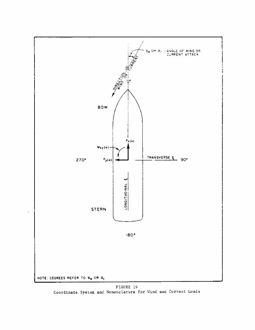

VÚS¿/VÚR¿ = average normalized wind velocity over superstructure
VÚR¿ = reference wind velocity at 33.33 feet above sea level
AÚS¿ = lateral projected area of superstructure only, in square feet
VÚH¿/VÚR¿ = average normalized wind velocity over hull
AÚH¿ = lateral projected area of hull only, in square feet
AÚy¿ = lateral projected area of ship, in square feet
The values of VÚS¿/VÚR¿ and VÚH¿/VÚR¿ are determined using the followingequations: Ú ¿ VÚS¿ ³ hÚS¿ ³ ÄÄÄÄ = ³ ÄÄÄÄ ³À1/7Ù (4-13) VÚR¿ ³ hÚR¿ ³ À Ù Ú ¿ VÚH¿ ³ hÚH¿ ³ ÄÄÄÄ = ³ ÄÄÄÄ ³À1/7Ù (4-14) VÚR¿ ³ hÚR¿ ³ À Ù
WHERE: VÚS¿/VÚR¿ = average normalized wind velocity over superstructure
hÚS¿ = average height of superstructure, in feet
hÚR¿ = reference height of windspeed (33.33 feet)
VÚH¿/VÚR¿ = average normalized wind velocity over hull
hÚH¿ = average height of hull, in feet
Details of the hull and superstructure areas of vessels can bedetermined from the book of general plans for the vessel or from Jane'sFighting Ships (1976).
Vessels secured to fixed moorings are often sheltered by the fixed

mooring itself or by landside buildings or similar structures. The designershould account for sheltering when determining the lateral projected areasof the vessel.
26.4-51

(b) Longitudinal wind load. Longitudinal wind load isdetermined using the following equation:
1 FÚxw¿ = Ä [rho]Úa¿ VÚw¿À2Ù AÚx¿ CÚxw¿ fÚxw¿([theta]Úw¿) (4-16) 2
WHERE: FÚxw¿ = longitudinal wind load, in pounds
[rho]Úa¿ = mass density of air = 0.00237 slugs per cubic foot at 68deg.F
VÚw¿ = wind velocity, in feet per second
AÚx¿ = longitudinal projected area of ship, in square feet
CÚxw¿ = longitudinal wind-force drag coefficient
fÚxw¿([theta]Úw¿) = shape function for longitudinal load
The longitudinal wind-force drag coefficient varies according to vesseltype and characteristics. Additionally, a separate wind-force dragcoefficient is provided for headwind (over the bow: [theta]Úw¿ = 0 degrees)and tailwind (over the stern: [theta]Úw¿ - 180 degrees) conditions. Theheadwind (bow) wind-force drag coefficient is designated CÚxwB¿ and thetailwind (stern) wind-force drag coefficient is designated CÚxwS¿. Thefollowing longitudinal wind-force drag coefficients are recommended forhull-dominated vessels, such as aircraft carriers, submarines, and passengerliners:
CÚxwB¿ = 0.40 (4-17)
CÚxwS¿ = 0.40 (4-18)
For all remaining types of vessels, except for specific deviations, thefollowing are recommended:
CÚxwB¿ = 0.70 (4-19)
CÚxwS¿ = 0.60 (4-20)
An increased headwind wind-force drag coefficient is recommended forcenter-island tankers:
CÚxwB¿ = 0.80 (4-21)
For ships with an excessive amount of superstructure, such as destroyers andcruisers, the recommended tailwind wind-force drag coefficient is:
CÚxwS¿ = 0.80 (4-22)
An adjustment consisting of adding 0.08 to CÚxwB¿ and CÚxwS¿ is recommendedfor all cargo ships and tankers with cluttered decks.
Longitudinal shape function, fÚxw¿([theta]Úw¿), differs over the

headwind and tailwind regions. The incident wind angle that produces no netlongitudinal force, designated [theta]Úwz¿ for zero crossing, separatesthese two regions.
26.4-52

Selection of [theta]Úwz¿ is determined by the mean location of thesuperstructure relative to midships. (See Table 5.)
TABLE 5 Selection of [theta]Úwz¿ ÚÄÄÄÄÄÄÄÄÄÄÄÄÄÄÄÄÄÄÄÄÄÄÄÄÄÄÄÄÄÄÄÄÄÄÄÄÄÄÄÄÄÄÄÄÄÄÄÄÄÄÄÄ¿ ³ Location of Superstructure [theta]Úwz¿³ ÃÄÄÄÄÄÄÄÄÄÄÄÄÄÄÄÄÄÄÄÄÄÄÄÄÄÄÄÄÄÄÄÄÄÄÄÄÄÄÄÄÄÄÄÄÄÄÄÄÄÄÄÄ´ ³ Just forward of midships ............. 80deg. ³ ³ On midships .......................... 90deg. ³ ³ Aft of midships ..................... 100deg. ³ ³ Hull-dominated ...................... 120deg. ³ ÀÄÄÄÄÄÄÄÄÄÄÄÄÄÄÄÄÄÄÄÄÄÄÄÄÄÄÄÄÄÄÄÄÄÄÄÄÄÄÄÄÄÄÄÄÄÄÄÄÄÄÄÄÙ
For many ships, including center-island tankers, [theta]Úwz¿[similar,equals]100 degrees is typical; [theta]Úwz¿[similar, equals]110 degrees isrecommended for warships.
The shape function for longitudinal load for ships with single, distinctsuperstructures and hull-dominated ships is given below. (Examples of shipsin this category are aircraft carriers, EC-2, and cargo vessels.)
The value of fÚxw¿([theta]Úw¿) is symmetrical about the longitudinal axisof the vessel. Therefore, when [theta]Úw¿>180deg., use 360deg. - [theta]Úw¿as [theta]Úw¿ in determining the shape function. For example, if[theta]Úw¿ = 330deg., use 360deg. - [theta]Úw¿ = 360deg. - 330deg. =30deg. for [theta]Úw¿.
Ships with distributed super Structures are characterized by a "humped"cosine wave. The shape function for longitudinal load is:

As explained above, use 360deg. - [theta]Úw¿ for [theta]Úw¿ when[theta]Úw¿>180deg..
(c) Wind yaw moment. Wind yaw moment is calculated using thefollowing equation:
1 MÚxyw¿ = Ä [rho]Úa¿ VÚw¿À2Ù AÚy¿ L CÚxyw¿([theta]Úw¿) (4-29) 2
WHERE: MÚxyw¿ = wind yaw moment, in foot-pounds
[rho]Úa¿ = mass density of air = 0.00237 slugs per cubic foot at 68deg.F
VÚw¿ = wind velocity, in feet per second
AÚy¿ = lateral projected area of ship, in square feet
L = length of ship
CÚxyw¿([theta]Úw¿) = normalized yaw-moment coefficient
Figures 20 through 23 provide yaw-moment coefficients for various vesseltypes.
(2) Wind Load on Floating Drydocks.
(a) Lateral wind load. lateral wind load on floating drydocks(without the maximum vessel on the blocks) is determined using thefollowing:
1 FÚyw¿ = Ä [rho]Úa¿ VÚw¿À2Ù AÚy¿ CÚDW¿ sin[theta]Úw¿ (4-30) 2
WHERE: FÚyw¿ = lateral wind load, in pounds
[rho]Úa¿ = mass density of air = 0.00237 slugs per cubic foot at 68deg.F
VÚw¿ = wind velocity, in feet per second
AÚy¿ = lateral projected area of drydock, in square feet
CÚDW¿ = wind-force drag coefficient
[theta]Úw¿ = wind angle
When a vessel within the dock protrudes above the profile of the dock,the dock should be treated as a normal, "ship-shaped" vessel. (SeeSubsection 5.3.a.(1).) Table 3 of DM-26.6 provides characteristics offloating drydocks and gives broadside wind areas for the drydocks with themaximum vessel on the blocks.
The wind-force drag coefficient, CÚDW¿, for various drydocks in various

loading conditions is presented in Table 6. The values of CÚDW¿ in Table 6are given for floating drydocks without a vessel on the blocks.
26.4-54


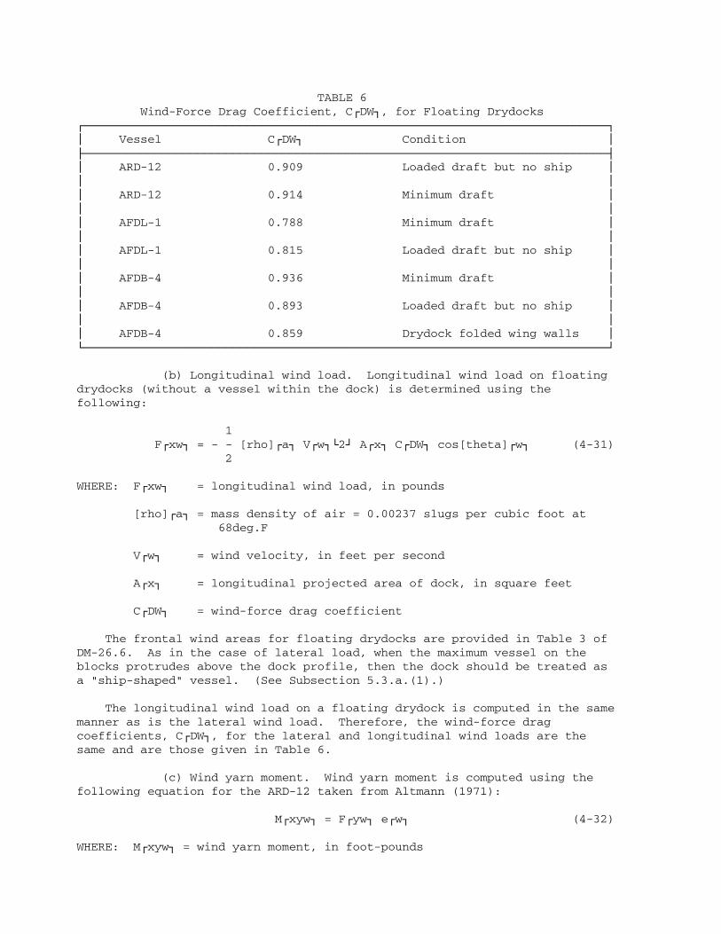
TABLE 6 Wind-Force Drag Coefficient, CÚDW¿, for Floating DrydocksÚÄÄÄÄÄÄÄÄÄÄÄÄÄÄÄÄÄÄÄÄÄÄÄÄÄÄÄÄÄÄÄÄÄÄÄÄÄÄÄÄÄÄÄÄÄÄÄÄÄÄÄÄÄÄÄÄÄÄÄÄÄÄÄÄÄÄÄÄÄÄÄÄÄÄ¿³ Vessel CÚDW¿ Condition ³ÃÄÄÄÄÄÄÄÄÄÄÄÄÄÄÄÄÄÄÄÄÄÄÄÄÄÄÄÄÄÄÄÄÄÄÄÄÄÄÄÄÄÄÄÄÄÄÄÄÄÄÄÄÄÄÄÄÄÄÄÄÄÄÄÄÄÄÄÄÄÄÄÄÄÄ´³ ARD-12 0.909 Loaded draft but no ship ³³ ³³ ARD-12 0.914 Minimum draft ³³ ³³ AFDL-1 0.788 Minimum draft ³³ ³³ AFDL-1 0.815 Loaded draft but no ship ³³ ³³ AFDB-4 0.936 Minimum draft ³³ ³³ AFDB-4 0.893 Loaded draft but no ship ³³ ³³ AFDB-4 0.859 Drydock folded wing walls ³ÀÄÄÄÄÄÄÄÄÄÄÄÄÄÄÄÄÄÄÄÄÄÄÄÄÄÄÄÄÄÄÄÄÄÄÄÄÄÄÄÄÄÄÄÄÄÄÄÄÄÄÄÄÄÄÄÄÄÄÄÄÄÄÄÄÄÄÄÄÄÄÄÄÄÄÙ
(b) Longitudinal wind load. Longitudinal wind load on floatingdrydocks (without a vessel within the dock) is determined using thefollowing:
1 FÚxw¿ = - - [rho]Úa¿ VÚw¿À2Ù AÚx¿ CÚDW¿ cos[theta]Úw¿ (4-31) 2
WHERE: FÚxw¿ = longitudinal wind load, in pounds
[rho]Úa¿ = mass density of air = 0.00237 slugs per cubic foot at 68deg.F
VÚw¿ = wind velocity, in feet per second
AÚx¿ = longitudinal projected area of dock, in square feet
CÚDW¿ = wind-force drag coefficient
The frontal wind areas for floating drydocks are provided in Table 3 ofDM-26.6. As in the case of lateral load, when the maximum vessel on theblocks protrudes above the dock profile, then the dock should be treated asa "ship-shaped" vessel. (See Subsection 5.3.a.(1).)
The longitudinal wind load on a floating drydock is computed in the samemanner as is the lateral wind load. Therefore, the wind-force dragcoefficients, CÚDW¿, for the lateral and longitudinal wind loads are thesame and are those given in Table 6.
(c) Wind yarn moment. Wind yarn moment is computed using thefollowing equation for the ARD-12 taken from Altmann (1971):
MÚxyw¿ = FÚyw¿ eÚw¿ (4-32)
WHERE: MÚxyw¿ = wind yarn moment, in foot-pounds

FÚyw¿ = lateral wind load, in pounds
eÚw¿ = eccentricity of FÚyw¿, in feet
26.4-59

3.125 eÚw¿ = L [ÄÄÄÄÄ - 0.0014 ([theta]Úw¿ - 90deg.)] for 0deg.< /= 100 [theta]Úw¿< /= 180deg. (4-33)
3.125 eÚw¿ = L [ÄÄÄÄÄ + 0.0014 ([theta]Úw¿ - 270deg.)] for 180deg.< /= 100 [theta]Úw¿< /= 360deg. (4-34)
L = length of drydock
Unlike the ARD-l2, which is asymmetrically shaped, the AFDL-1 and AFDB-4are symmetrically shaped drydocks. Therefore, from an analyticalstandpoint, the wind yaw moment on the AFDL-1 and AFDB-4 drydocks is zerowhen there is no vessel within the dock. When the vessel within the dockprotrudes above the drydock profile, the wind yaw moment is computed usingthe procedures for "ship-shaped" vessels. (See Subsection 5.3.a.(1).)
b. Current load.
(1) Lateral Current load. lateral current load is determined fromthe following equation:
1 FÚyc¿ = Ä [rho]Úw¿ VÚc¿À2Ù LÚwL¿ T CÚyc¿ sin[theta]Úc¿ (4-35) 2
WHERE: FÚyc¿ = lateral current load, in pounds
[rho]Úw¿ = mass density of water = 2 slugs per cubic foot for sea water
VÚc¿ = current velocity, in feet per second
LÚwL¿ = vessel waterline length, in feet
T = vessel draft, in feet
CÚyc¿ = lateral current-force drag coefficient
[theta]Úc¿ = current angle
The lateral current-force drag coefficient is given by:

T = vessel draft, in feet
Values of CÚyc¿³Ú[infinity]¿ are given in Figure 24 as a function of LÚwL¿/B(the ratio of vessel waterline length to vessel beam) (ordinate) andvessel block coefficient, [phi], (abscissa). The block coefficient isdefined as:
35 D [phi] = ÄÄÄÄÄÄÄÄÄ (4-37) LÚwL¿ B T
WHERE: [phi] = vessel block coefficient
D = vessel displacement, in long tons
LÚwL¿ = vessel waterline length, in feet
B = vessel beam, in feet
T = vessel draft, in feet
Values of CÚyc¿³Ú1¿ are given in Figure 25 as a function ofCÚp¿LÚwL¿/[SQRT T]. CÚp¿, the prismatic coefficient of the vessel, isdefined as:
[phi] CÚp¿ = ÄÄÄÄÄ (4-38) CÚm¿
WHERE: CÚp¿ = prismatic coefficient of vessel
[phi] = vessel block coefficient
CÚm¿ = midship section coefficient
immersed area of midship section = ÄÄÄÄÄÄÄÄÄÄÄÄÄÄÄÄÄÄÄÄÄÄÄÄÄÄÄÄÄÄÄÄ (4-39) B T
B = vessel beam, in feet
T = vessel draft, in feet
The value of the coefficient, k, is given in Figure 26 as a function of thevessel block coefficient, [phi], and vessel hull shape (block-shaped ornormal ship-shaped).
The values of the coefficients CÚyc¿³Ú[infinity]¿, CÚyc¿³Ú1¿, and k arepresented in Table 7 for each vessel originally tested by the David TaylorModel Basin, Dimensional properties of each vessel are also given in thistable.
(2) Longitudinal Current Load. Longitudinal current load proceduresare taken from Cox (1982). Longitudinal current load is determined usingthe following equation:

FÚxc¿ = FÚx form¿ + FÚx friction¿ + FÚx prop¿ (4-40)
WHERE: FÚxc¿ = total longitudinal current load
26.4-61


FÚx form¿ = longitudinal current load due to form drag
FÚx friction¿ = longitudinal current load due to skin friction drag
FÚx prop¿ = longitudinal current load due to propeller drag
Form drag is given by the following equation:
1 FÚx form¿ = - - [rho]Úw¿ VÚc¿Ú2¿ B T CÚxcb¿ cos[theta]Úc¿ (4-41) 2
WHERE: FÚx form¿ = longitudinal current load due to form drag
[rho]Úw¿ = mass density of water = 2 slugs per cubic foot for sea water
VÚc¿ = average current speed, in feet per second
B = vessel beam, in feet
T = vessel draft, in feet
CÚxcb¿ = longitudinal current form-drag coefficient = 0.1
[theta]Úc¿ = current angle
Friction drag is given by the folowing equation:
1 FÚx friction¿ = - - [rho]Úw¿ VÚc¿À2Ù S CÚxca¿ cos[theta]Úc¿ (4-42) 2
WHERE: FÚx friction¿ = longitudinal current load due to skin friction
[rho]Úw¿ = mass density of water = 2 slugs per cubic foot for sea water
VÚc¿ = average current speed, in feet per second
S = wetted surface area, in square feet 35 D = (1.7 T LÚwL¿) + (ÄÄÄÄ) (4-43) T
T = vessel draft, in feet
LÚwL¿ = waterline length of vessel, in feet
D = displacement of ship, in long tons
CÚxca¿ = longitudinal skin-friction coefficient
= 0.075/(log RÚn¿ - 2)À2Ù (4-44)
RÚn¿ = Reynolds number = VÚc¿ LÚwL¿

cos[theta]Úc¿/[upsilon] (4-45)
26.4-66

[upsilon] = kinematic viscosity of water (1.4 x 10À -5Ù square feet per second)
[theta]Úc¿ = current angle
Propeller drag is the form drag of the vessel's propeller with a lockedshaft. Propeller drag is given by the following equation:
1 FÚx prop¿ = - - [rho]Úw¿ VÚc¿À2Ù AÚp¿ CÚprop¿ cos[theta]Úc¿ (4-46) 2
WHERE: FÚx prop¿ = longitudinal current load due to propeller drag
[rho]Úw¿ = mass density of water = 2 slugs per cubic foot for sea water
VÚc¿ = average current speed, in feet per second
AÚp¿ = propeller expanded (or developed) blade area, in square feet
CÚprop¿ = propeller-drag coefficient (assumed to be 1)
[theta]Úc¿ = current angle
AÚp¿ is given by:
AÚTpp¿ AÚTpp¿ AÚp¿ = ÄÄÄÄÄÄÄÄÄÄÄÄÄÄÄÄÄ = ÄÄÄÄÄÄ (4-47) 1.067 - 0.229 p/d 0.838
WHERE: AÚp¿ = propeller expanded (or developed) blade area, in square feet
AÚTpp¿ = total projected propeller area, in square feet
p/d = propeller pitch to diameter ratio (assumed to be 1)
Table 8 shows the area ratio, AÚR¿, for six major vessel groups. (Thearea ratio is defined as the ratio of the waterline length times the beam tothe total projected propeller area.) Then, the total projected propellerarea, AÚTpp¿, can be given in terms of the area ratio as follows:
LÚwL¿ B AÚTpp¿ = ÄÄÄÄÄÄÄ (4-48) AÚR¿
WHERE: AÚTpp¿ = total projected propeller area, in square feet
LÚwL¿ = waterline length of vessel, in feet
B = vessel beam, in feet
AÚR¿ = area ratio, found in Table 8

TABLE 8 AÚR¿ for Propeller Drag ÚÄÄÄÄÄÄÄÄÄÄÄÄÄÄÄÄÄÄÄÄÄÄÄÄÄÄÄÄÄÄÄÄÄÄÄÄÄÄÄÄÄÄÄÄÄÄ¿ ³ Area Ratio, ³ ³ Vessel Type AÚR¿ ³ ÃÄÄÄÄÄÄÄÄÄÄÄÄÄÄÄÄÄÄÄÄÄÄÄÄÄÄÄÄÄÄÄÄÄÄÄÄÄÄÄÄÄÄÄÄÄÄ´ ³ Destroyer .................... 100 ³ ³ Cruiser ...................... 160 ³ ³ Carrier ...................... 125 ³ ³ Cargo ........................ 240 ³ ³ Tanker ....................... 270 ³ ³ Submarine .................... 125 ³ ÀÄÄÄÄÄÄÄÄÄÄÄÄÄÄÄÄÄÄÄÄÄÄÄÄÄÄÄÄÄÄÄÄÄÄÄÄÄÄÄÄÄÄÄÄÄÄÙ
(3) Current Yaw Moment. Procedures for determining current yawmoment are taken from Altmann (1971). Current yarn moment is determinedusing the following equation:
Ú eÚc¿ ¿ MÚxyc¿ - FÚyc¿³ ÄÄÄÄÄ ³ LÚwL¿ (4-49) À LÚwL¿ Ù
WHERE: MÚxyc¿ = current yarn moment, in foot-pounds
FÚyc¿ = lateral current load, in pounds
Ú eÚc¿ ¿ ³ ÄÄÄÄÄ ³ = ratio of eccentricity of lateral current load measured À LÚwL¿ Ù along the longitudinal axis of the vessel from amidships to vessel waterline length
eÚc¿ = eccentricity of FÚyc¿
LÚwL¿ = vessel waterline length, in feet
The value of (eÚc¿/LÚwL¿) is given in Figure 27 as a function of currentangle, [theta]Úc¿, and vessel type.
5. ENVIRONMENTAL LOADS ON MULTIPLE MOORED VESSELS. This section describesmethods for determining static wind and current loads on multiple mooredvessels. The longitudinal force, lateral force, and yaw moment areevaluated. Figure 19 defines the coordinate system and nomenclature fordescribing these loads. A discussion of the various physical phenomenainvolved in these procedures is provided in Section 3. Procedures varydepending upon whether the multiple-vessel mooring consists of identical ornonidentical vessels.
a. Identical Vessels. Altmann (1971) has formulated a procedure forestimating wind and current loads induced on nests of identical mooredvessels. The procedures provide conservative estimates of lateral loads,longitudinal loads, and yaw moment.
(1) Wind Load.
26.4-68


(a) Lateral wind load. The lateral wind load on a single vesselwithin a group of identical vessels depends upon the position of that vesselwithin the group. For example, the wind load is larger on the first (mostwindward) vessel in a group than on the interior vessels. The followingempirical equation gives lateral wind load on a group of identical vessels:
The dimensionless wind-force coefficients, KÚ1¿, KÚ2¿... KÚ5¿, arepresented in Table 9 as a function of ship type (normal or hull-dominated)and position of the vessel in the mooring. The number of K terms used inEquation (4-50) is a function of the number of ships in the mooring. If theload on only one of the vessels in the mooring is desired, then only theterm of interest is is needed. For example, if the load on the secondvessel in a group of three is needed, then only KÚ2¿ is used in Equation(4-50). The load on the entire mooring is the summation indicated byEquation (4-50). The terms KÚ1¿ and KÚ5¿, which represent the most windwardand leeward vessels in a mooring, respectively, are always used. KÚ2¿ isused for the second vessel in a group of three or more. KÚ4¿ is used forthe second-from-last vessel in a group of four or more vessels. The KÚ3¿coefficient is used for the third vessel in moorings of five or morevessels. The KÚ4¿ coefficient is used for each additional vessel inmoorings of six or more vessels. Figure 28 shows how to assign the variousK coefficients for vessel groups consisting of two to six vessels.
TABLE 9 Lateral Wind-Force Coefficients for Multiple-Vessel MooringsÚÄÄÄÄÄÄÄÄÄÄÄÄÄÄÄÄÄÄÄÄÄÄÄÄÄÄÄÄÄÄÄÄÄÄÄÄÄÄÄÄÄÄÄÄÄÄÄÄÄÄÄÄÄÄÄÄÄÄÄÄÄÄÄÄÄÄÄÄÄÄÄÄÄÄ¿³ Ship ³³ Model Ship Type KÚ1¿ KÚ2¿ KÚ3¿ KÚ4¿ KÚ5¿ ³ÃÄÄÄÄÄÄÄÄÄÄÄÄÄÄÄÄÄÄÄÄÄÄÄÄÄÄÄÄÄÄÄÄÄÄÄÄÄÄÄÄÄÄÄÄÄÄÄÄÄÄÄÄÄÄÄÄÄÄÄÄÄÄÄÄÄÄÄÄÄÄÄÄÄÄ´³ CVE-55 Hull-dominant; ³³ little superstructure 1.00 0.20 0.16[1] 0.35 0.44 ³³ SS-212 ³³ ³³ EC-2 Standard profile; ³³ considerable 1.00 0.14 0.11 0.13 0.30 ³³ DD-692 superstructure ³ÀÄÄÄÄÄÄÄÄÄÄÄÄÄÄÄÄÄÄÄÄÄÄÄÄÄÄÄÄÄÄÄÄÄÄÄÄÄÄÄÄÄÄÄÄÄÄÄÄÄÄÄÄÄÄÄÄÄÄÄÄÄÄÄÄÄÄÄÄÄÄÄÄÄÄÙ

[1]No data; suggested value
26.4-70

26.4-71
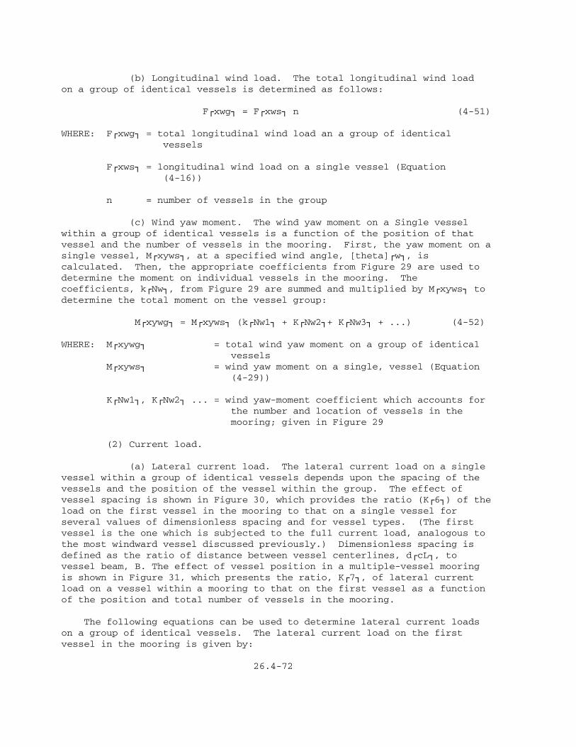
(b) Longitudinal wind load. The total longitudinal wind loadon a group of identical vessels is determined as follows:
FÚxwg¿ = FÚxws¿ n (4-51)
WHERE: FÚxwg¿ = total longitudinal wind load an a group of identical vessels
FÚxws¿ = longitudinal wind load on a single vessel (Equation (4-16))
n = number of vessels in the group
(c) Wind yaw moment. The wind yaw moment on a Single vesselwithin a group of identical vessels is a function of the position of thatvessel and the number of vessels in the mooring. First, the yaw moment on asingle vessel, MÚxyws¿, at a specified wind angle, [theta]Úw¿, iscalculated. Then, the appropriate coefficients from Figure 29 are used todetermine the moment on individual vessels in the mooring. Thecoefficients, kÚNw¿, from Figure 29 are summed and multiplied by MÚxyws¿ todetermine the total moment on the vessel group:
MÚxywg¿ = MÚxyws¿ (kÚNw1¿ + KÚNw2¿+ KÚNw3¿ + ...) (4-52)
WHERE: MÚxywg¿ = total wind yaw moment on a group of identical vessels MÚxyws¿ = wind yaw moment on a single, vessel (Equation (4-29))
KÚNw1¿, KÚNw2¿ ... = wind yaw-moment coefficient which accounts for the number and location of vessels in the mooring; given in Figure 29
(2) Current load.
(a) Lateral current load. The lateral current load on a singlevessel within a group of identical vessels depends upon the spacing of thevessels and the position of the vessel within the group. The effect ofvessel spacing is shown in Figure 30, which provides the ratio (KÚ6¿) of theload on the first vessel in the mooring to that on a single vessel forseveral values of dimensionless spacing and for vessel types. (The firstvessel is the one which is subjected to the full current load, analogous tothe most windward vessel discussed previously.) Dimensionless spacing isdefined as the ratio of distance between vessel centerlines, dÚcL¿, tovessel beam, B. The effect of vessel position in a multiple-vessel mooringis shown in Figure 31, which presents the ratio, KÚ7¿, of lateral currentload on a vessel within a mooring to that on the first vessel as a functionof the position and total number of vessels in the mooring.
The following equations can be used to determine lateral current loadson a group of identical vessels. The lateral current load on the firstvessel in the mooring is given by:
26.4-72


FÚycl¿ = 1/2 FÚycs¿ KÚ6¿ (1- cos2[theta]Úc¿) (4-53)
The lateral current load on the second vessel of a mooring with three ormore vessels is given by:
FÚyc2¿ = (FÚycl¿ @ 90deg.) [sin[theta]Úc¿ - KÚ7¿ (1 - cos2[theta]Úc¿)](4-54)
The lateral current load on each remaining vessel in a mooring, or onthe second vessel if there are only two vessels in the mooring, is given by:
FÚycz¿ = (FÚycl¿ @ 90deg.) [sin[theta]Úc¿ - KÚ7¿ (1 - 0.5 cos2[theta]Úc¿ -0.5 cos6[theta]Úc¿)] (4-55)
WHERE: FÚycl¿ = lateral current load on the first vessel in a group
FÚycs¿ = lateral current load on a single vessel at [theta]Úc¿ = 90deg. (Equation (4-35))
KÚ6¿ = spacing factor, given in Figure 30
[theta]Úc¿ = current angle
FÚyc2¿ = lateral current load on the second vessel in a group of three or more
FÚycl¿ @ 90deg. = lateral current load on the first vessel in a group at [theta]Úc¿ = 90deg.
KÚ7¿ = a factor for position and number of vessels in a mooring, given by Figure 31
FÚycz¿ = lateral current load on the zÀthÙ vessel in a mooring, or on the second vessel if there are only two vessels in the mooring
z = a position of vessel
The above equations can be used to determine the loads on eachindividual vessel or, when summed, to determine the total load on the groupof identical vessels.
(b) Longitudinal current load. The total longitudinal currentload on a group of identical vessels is determined by the followingequation:
FÚxcg¿ = FÚxcs¿ ÀnÙ (4-56)
WHERE: FÚxcg¿ = total longitudinal current load on a group of identical vessels
FÚxcs¿ = longitudinal current load on a single vessel (Equation (4-40))
n = number of vessels in the group

(c) Current yaw moment. The current yaw moment on a single vesselwithin a group of identical vessels is a function of the position of thatvessel and the number of vessels in the mooring. First, the yaw moment on asingle vessel, MÚxycs¿, at a specified current angle, [theta]Úc¿, iscalculated. Then, the appropriate coefficients from Figure 32 are used todetermine the moment on individual vessels in the mooring. Thecoefficients, KÚNc¿, from Figure 32 are summed and multiplied by MÚxycs¿ todetermine the total moment on the vessel group:
MÚxycg¿ = MÚxycs¿ (KÚNc1¿ + KÚNc2¿ + KÚNc3¿ + ...) (4-57)
WHERE: MÚxycg¿ = total current yaw moment on a group of identical vessels
MÚxycs¿ = current yaw moment on a single vessel (Equation (4-49))
KÚNc1¿, KÚNc2¿... = current yaw-moment coefficient which accounts for the number and location of vessels in the mooring, given in Figure 32
b. Nonidentical Vessels. Typical present-day multiple-vessel mooringarrangements consist of a tender with a number of identical vessels mooredalongside in parallel fashion. In these moorings, the separation distancebetween the nested vessels and the tender is small. Frequently, the nestedvessels are moored to each other and then to the tender. In this case, themooring must be able to sustain the entire loading pattern induced on allvessels. This situation requires special treatment and additional modeltesting. In the absence of proper data, or until such data becomeavailable, the following approximate procedure for estimating wind loads onmultiple moored vessels is suggested:
(1) Estimate the wind loads on the nest of identical vessels moored alongside the tender following the approach outlined above. (2) Estimate the wind loads induced on the tender as a single vessel. (3) Add the longitudinal loads linearly, since there is minimum interference between projected areas for streamlined objects in head-on winds. These additive loads constitute the longitudinal loads for the vessel group in wind. (4) Compare the projected broadside areas exposed to wind for the nested group and the tender and compare the respective lateral forces, as determined from (1) and (2), above. Compare the beam of the tender with the composite beam of the nested group. The following cases are possible:
(a) The beam of the tender is greater than half the composite beam of the nested group. (b) The beam of the tender is less than half the composite beam of the nested group.
26.4-77

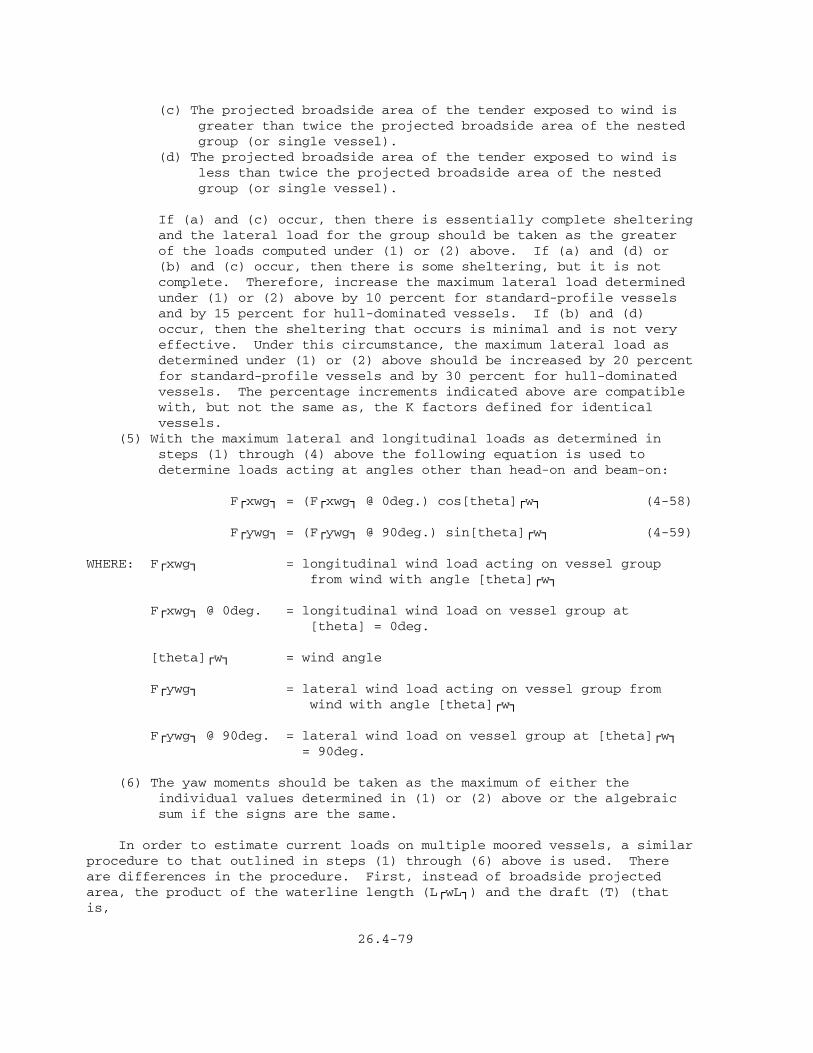
(c) The projected broadside area of the tender exposed to wind is greater than twice the projected broadside area of the nested group (or single vessel). (d) The projected broadside area of the tender exposed to wind is less than twice the projected broadside area of the nested group (or single vessel).
If (a) and (c) occur, then there is essentially complete sheltering and the lateral load for the group should be taken as the greater of the loads computed under (1) or (2) above. If (a) and (d) or (b) and (c) occur, then there is some sheltering, but it is not complete. Therefore, increase the maximum lateral load determined under (1) or (2) above by 10 percent for standard-profile vessels and by 15 percent for hull-dominated vessels. If (b) and (d) occur, then the sheltering that occurs is minimal and is not very effective. Under this circumstance, the maximum lateral load as determined under (1) or (2) above should be increased by 20 percent for standard-profile vessels and by 30 percent for hull-dominated vessels. The percentage increments indicated above are compatible with, but not the same as, the K factors defined for identical vessels. (5) With the maximum lateral and longitudinal loads as determined in steps (1) through (4) above the following equation is used to determine loads acting at angles other than head-on and beam-on:
FÚxwg¿ = (FÚxwg¿ @ 0deg.) cos[theta]Úw¿ (4-58)
FÚywg¿ = (FÚywg¿ @ 90deg.) sin[theta]Úw¿ (4-59)
WHERE: FÚxwg¿ = longitudinal wind load acting on vessel group from wind with angle [theta]Úw¿
FÚxwg¿ @ 0deg. = longitudinal wind load on vessel group at [theta] = 0deg.
[theta]Úw¿ = wind angle
FÚywg¿ = lateral wind load acting on vessel group from wind with angle [theta]Úw¿
FÚywg¿ @ 90deg. = lateral wind load on vessel group at [theta]Úw¿ = 90deg.
(6) The yaw moments should be taken as the maximum of either the individual values determined in (1) or (2) above or the algebraic sum if the signs are the same.
In order to estimate current loads on multiple moored vessels, a similarprocedure to that outlined in steps (1) through (6) above is used. Thereare differences in the procedure. First, instead of broadside projectedarea, the product of the waterline length (LÚwL¿) and the draft (T) (thatis,
26.4-79

LÚwL¿ times T) is used. Secondly, the effect of sheltering seems to bemore effective over longer beam distances in the case of current than in thecase of wind. The following change in procedure as outlined in Steps (4)and (5) above is recommended:
(4) (Changed) Compare the product LÚwL¿ T for the tender and for the nested group, and compare the respective lateral loads as determined from (1) and (2) above. Compare the beam of the tender with the composite beam of the nested group (including separation distances). The following cases are possible:
(a) The beam of the tender is greater than one-fourth of the beam of the composite group. (b) The beam of the tender is less than one-fourth of the beam of the composite group. (c) The LÚwL¿ T area of the tender exposed to current is greater than the LÚwL¿ T of the nested group. (d) The LÚwL¿ T area of the tender exposed to current is less than the LÚwL¿ T of the nested group.
If (a) and (c) occur, then there is essentially complete sheltering and the lateral load for the group should be taken as the greater of the loads computed under (1) and (2) above. If (a) and (d) or (b) and (c) occur, then there is some sheltering, but it is not complete. Therefore, increase the maximum lateral load determined under (1) or (2) above by 10 percent for all vessels. If (b) and (d) occur, then the sheltering that occurs is minimal and equivalent to that of an additional vessel in the group. Increase the maximum lateral load as determined under (1) and (2) above by 20 percent. These percentage increments are compatible with the analysis for identical vessels. These increments are not the same as, but represent, both the effect of ship spacing (KÚ6¿) and the cumulative effect of the number of ships (KÚ7¿). (5) (Changed) With the maximum lateral and longitudinal loads as determined above, the following equations are used to determine loads acting at angles other than head-on and beam-on:
FÚxcg¿ = (FÚxcg¿ @ 0deg.) cos[theta]Úc¿ (4-60)
FÚycg¿ = (FÚycg¿ @ 90deg.) sin[theta]Úc¿ (4-61)
WHERE: FÚxcg¿ = longitudinal current load acting on vessel group from current with angle [theta]Úc¿
FÚxcg¿ @ 0deg. = longitudinal current load on vessel group at [theta]Úc¿ = 0deg.
[theta]Úc¿ = current angle
26.4-80

FÚycg¿ = lateral current load acting on vessel group from current with angle [theta]Úc¿
FÚycg¿ @ 90deg. = lateral current load on vessel group at [theta]Úc¿ = 90deg.
As the dimensions of the tender vessel approach those of the vesselmoored alongside, then the analysis should be the same as that obtained byconsidering a group of identical vessels (including the tender). On theother hand, as the dimensions of the tender vessel increase relative tothose of the vessels moored alongside, the forces on the tender vesseldominate the loading pattern, and the forces induced on the nested group ofvessels are inconsequential.
Often, in fixed moorings, the separation between the nested vessels andthe tender is such that the vessels and tender act independently of eachother. In fact, it is often desirable that the moorings be independent.This is an important consideration in exposed locations. Because the tendermay not always be present, a conservative approach is one that emphasizesanalysis and design of the mooring for the nested vessels separately fromthat of the tender mooring. In this case, the procedures for predictingloads (and moments) on the group of identical vessels should be used.
6. LOADS ON MOORING ELEMENTS. Wind and current loads on mooring lines,mooring structures, and breasting structures must be determined. Simplifiedprocedures for determining loads on mooring elements are presented below.These simplified solutions are useful for preliminary design. The computerprogram presented in Appendix B of DM-26.5 is recommended for final design.
Mooring-line load analysis is presented so that mooring loads on mooringand breasting structures can be determined. Mooring lines are generallyprovided by the vessel, and selection of mooring lines is not normally partof the design process. However, the designer should check to see that themooring-line factors of safety are maintained. Recommendations for workingloads and factors of safety, which are given in DM-26.6, are summarized inTable 10. The minimum breaking strengths of various types of syntheticfiber, natural fiber, and wire rope are presented in DM-26.6, Tables 5through 9. When the factors of safety of mooring lines are too low, thedesigner should recommend stronger lines or investigate another mooringgeometry.
a. Total Loads. The first step in analyzing loads on mooring elementsis to determine the total lateral load, total longitudinal load, and totalyaw moment on the moored vessel using the following equations:
FÚyT¿ = FÚyw¿ + FÚyc¿ (4-62)
FÚxT¿ = FÚxw¿ + FÚxc¿ (4-63)
MÚxyT¿ = MÚxyw¿ + MÚxyc¿ (4-64)
WHERE: FÚyT¿ = total lateral load
FÚyw¿ = lateral wind load
FÚyc¿ = lateral current load

TABLE 10 Recommended Working Load and Factor of Safety for Various Mooring-Line Types[1]ÚÄÄÄÄÄÄÄÄÄÄÄÄÄÄÄÄÄÄÄÄÄÄÄÄÄÄÄÄÄÄÄÄÄÄÄÄÄÄÄÄÄÄÄÄÄÄÄÄÄÄÄÄÄÄÄÄÄÄÄÄÄÄÄÄÄÄÄÄÄÄÄÄÄÄÄÄÄÄ¿³ ³³ Mooring-Line Diameter ...... >/= 3/4 inch < 3/4 inch ³ÃÄÄÄÄÄÄÄÄÄÄÄÄÄÄÄÄÄÄÄÄÄÄÄÄÄÄÂÄÄÄÄÄÄÄÄÄÄÄÄÄÄÄÄÄÄÄÄÄÄÄÄÄÄÄÄÄÄÄÄÄÄÄÄÄÄÄÄÄÄÄÄÄÄÄÄÄÄÄ´³ ³ Working Working ³³ ³ Load[2] Factor Load[2] Factor ³³ Mooring-Line Material ³ (percent) of Safety[3] (percent) of Safety[3] ³ÃÄÄÄÄÄÄÄÄÄÄÄÄÄÄÄÄÄÄÄÄÄÄÄÄÄÄÁÄÄÄÄÄÄÄÄÄÄÄÄÄÄÄÄÄÄÄÄÄÄÄÄÄÄÄÄÄÄÄÄÄÄÄÄÄÄÄÄÄÄÄÄÄÄÄÄÄÄij³ Nylon ................... 11 9 8.3 12 ³³ ³³ Kelvar .................. 11 9 8.3 12 ³³ ³³ Polyester ............... 17 6 10 10 ³³ ³³ Polypropylene ........... 17 6 10 10 ³³ ³³ Polyethylene ............ 17 6 10 10 ³³ ³³ Manila .................. 17 6 10 10 ³³ ³³ Sisal ................... 17 6 10 10 ³³ ³³ Wire .................... 20 5 20 5 ³ÀÄÄÄÄÄÄÄÄÄÄÄÄÄÄÄÄÄÄÄÄÄÄÄÄÄÄÄÄÄÄÄÄÄÄÄÄÄÄÄÄÄÄÄÄÄÄÄÄÄÄÄÄÄÄÄÄÄÄÄÄÄÄÄÄÄÄÄÄÄÄÄÄÄÄÄÄÄÄÙ
[1]Working loads and factors of safety are as recommended by the Cordage Institute and from manufacturers' minimum catalog breaking strength values. These values are based upon a percentage of the minimum breaking test of new and unused rope of current manufacturers. These values are based upon normal service conditions and do not cover exceptional conditions, such as shock loads and sustained loads, nor do they cover conditions where life, limb, or valuable property are involved. In these cases, a lower working load or higher factor of safety may be advisable. A higher working load or lower factor of safety should be used only with an expert knowledge of conditions or professional estimates of risk.
[2]Percent of minimum breaking strength of mooring line.
[3]Based upon minimum breaking strength of mooring line.
26.4-82

FÚxT¿ = total longitudinal load
FÚxw¿ = longitudinal wind load
FÚxc¿ = longitudinal current load
MÚxyT¿ = total yaw moment
MÚxyw¿ = wind yaw moment
MÚxyc¿ = current yaw moment
The yaw moment is resolved into lateral loads at the bow and stern ofthe vessel using the following equations (see Figure 33):
FÚyT¿ MÚxyT¿ FÚyB¿ = ÄÄÄÄÄ + ÄÄÄÄÄÄ (4-65) 2 LÚMP¿
FÚyT¿ MÚxyT¿ FÚyS¿ = ÄÄÄÄÄ - ÄÄÄÄÄÄ (4-66) 2 LÚMP¿
WHERE: FÚyB¿ = lateral load at vessel bow
FÚyT¿ = total lateral load
MÚxyT¿ = total yaw moment
LÚMP¿ = length between mooring points
FÚyS¿ = lateral load at vessel stern
b. Lateral Load and Yaw Moment. Lateral load and yaw moment arerestrained either by mooring lines (bow, stern, or breast lines), bybreasting structures, or by a combination of mooring lines and breastingstructures. First, the signs of the lateral loads, FÚyB¿ and FÚyS¿, at thebow and stern of the vessel, respectively, are compared. Case 1 is used ifFÚyB¿ and FÚyS¿ are both negative; Case 2 is used if both are positive; andCase 3 is used if their signs are opposite. The sign convention used todetermine the appropriate case must be consistent with that given in Figure33. Note that the total mooring-line load is the sum of the applied loadand the mooring-line pretension.
(1) Case 1. When FÚyB¿ and FÚyS¿ are both negative, the lateralload is restrained entirely by mooring lines. (See Figure 12.) Theprocedure for evaluating lateral load in bow, stern, and breast lines isshown in Figure 34.
(2) Case 2. When FÚyB¿ and FÚyS¿ are both positive, the lateralload is restrained entirely by the breasting structures. Figure 35presents a simple analysis for determining loads on a fixed mooringconsisting of two breasting structures separated by a distanced LÚF¿. Amore sophisticated analysis may be required for more complicatedbreasting-structure arrangements. However, Figure 35 outlines the basicprinciples involved.

(3) Case 3. When FÚyB¿ and FÚyS¿ are opposite in sign, part of thelateral load is restrained by the mooring lines in tension, while theremainder of the lateral load is restrained by a breasting structure incompression at the opposite end of the vessel. Figure 36 outlines theprocedure for analyzing Case 3. This procedure assumes that the positivelateral load is taken by one breasting structure. This is true for fixedmoorings with two breasting structures, and provides a conservative estimateof load on the outside breasting structure for moorings with more than twobreasting structures. The computer program presented in Appendix B ofDM-26.5 should be used for situations involving more than two breastingstructures.
c. Longitudinal Load. Longitudinal loads are taken by spring lines.Figure 37 outlines the procedure for determining the load in spring lines.Note that the total mooring-line load is the sum of the applied load and themooring-line pretension.
d. Maximum Mooring Loads. Fixed-mooring elements must be designed formaximum loads. This involves determining the combinations of current load,


wind load, tide level, and vessel loading (that is, light loaded or fullyloaded) which produce the maximum load on each mooring element. Obviously,certain combinations of these variables which produce maximum loads on somemooring elements (for example, spring lines) may not produce maximum loadson other mooring elements (for example, breast lines). Therefore, a varietyof combinations of current load, wind load, tide level, and vessel loadingmust be analyzed. Note that the mooring-line preload must be considered.
Tidal currents are the most important type of current at most fixedmoorings; therefore, usually the designer only needs to investigate twocurrent directions (flood and ebb). Furthermore, wherever possible, thefixed mooring should be oriented so that the longitudinal axis of the vesselis roughly parallel with the direction of the flood and ebb currents.
Wind can generally blow from any direction at most, fixed moorings;moreover, the design windspeed may not be the same from each direction.(See Section 3.) Also, the vessel may be partially sheltered from offshorewinds by landside structures.


Tide level and vessel loading have important effects upon mooring loadswhich must be considered. Mooring calculations must be determined for bothlight-loaded and fully loaded conditions. For each of these conditions, thecombined loading due to wind load from each direction and to the flood andebb current loads at low tide is determined. Then, the procedure outlinedin Figure 38 is used to determine line loads at high tide for each of theabove conditions.
e. Computer Solution. Appendix B of DM-26.5 provides a computerprogram for fixed-mooring analysis.
f. Spud Moorings. Spud moorings are a specialized type of fixedmooring used to secure floating drydocks. The procedure for distributingmooring loads to the spuds is outlined in Figure 39.
g. Berthing Loads. Breasting structures must be designed to withstandberthing and mooring loads. The procedure for determining berthing loads,taken from DM-25.1, is outlined in Figure 40. The energy equation fordetermining the berthing or kinetic energy of a docking vessel is given asfollows: 1 W KEÚB¿ = Ä Ä VÚN¿À2Ù CÚB¿ CÚH¿ (4-67) 2 g
WHERE: KEÚB¿ = berthing energy (kinetic energy of docking vessel), in foot-pounds
W = weight of vessel, in pounds (displacement tonnage, in long tons, times 2,240 pounds)
g = gravitational acceleration (32.2 feet per secondÀ2Ù)
VÚN¿ = normal component of approach velocity, in feet per second
CÚB¿ = berthing coefficient
CÚH¿ = hydrodynamic mass coefficient
(1) Vessel Weight. The weight, W, used in Equation (4-67) is thedisplacement tonnage of the largest vessel expected to use the fixed-mooringfacility. Values of displacement tonnage for various vessel types arepresented in DM-26 6, Tables 2 through 4.
(2) Vessel Berthing Velocity and Angle of Approach. The velocity ofa docking vessel depends upon environmental conditions at the mooring andupon whether or not tug assistance is provided. The component of velocitynormal to the breasting structure depends upon the angle of approach of thevessel. For unassisted vessels, this angle is generally between 5 degreesand 15 degrees. Large vessels, assisted by tugs, generally have approachangles of less than 10 degrees. The approach velocity normal to thebreasting structure is determined as follows:
VÚN¿ = VÚA¿ sinA (4-68)
WHERE: VÚN¿ = normal component of approach velocity, in feet per second


VÚA¿ = approach velocity, in feet per second
A = angle of approach
Figures 41 and 42 provide berthing velocity normal to the breastingstructure, VÚN¿, as a function of vessel displacement and relativeenvironmental condition. Both figures include the effect of approach angle.Figure 41 is used for vessels with displacements less than or equal to20,000 long tons, while Figure 42 is used for vessels with displacementsgreater than 20,000 long tons.
(3) Berthing Coefficient. When a vessel approaches a fixed mooring,the bow or stern of the vessel will generally impinge upon one of thebreasting structures first. The reaction of this structure will cause thevessel to rotate. This rotation acts to dissipate a portion of the kineticenergy of the vessel. The berthing coefficient, CÚB¿, accounts for thisreduction in kinetic energy. For typical designs, the berthing coefficientis 0.5.


(4) Hydrodynamic Mass Coefficient. As a vessel approaches a fixedmooring, the water surrounding the vessel moves along with the vessel; thiseffectively increases the mass of the vessel. This increased mass, known asthe hydrodynamic mass of the vessel, is accounted for by the hydrodynamicmass coefficient, CÚH¿. CÚH¿ may be determined from Figure 43.
7. DESIGN OF FIXED-MOORING STRUCTURES. Mooring structures can be designedfor static wind and current loads without concern for their ability toabsorb energy. Breasting structures, on the other hand, are subjected toberthing loads, and their energy-absorbing capability must be investigatedas discussed below.
a. Breasting Structures. Figure 44 presents a design procedure forbreasting structures. This procedure involves selecting a preliminarystructure and evaluating its ability to absorb berthing energy. Thisprocess is repeated until the structure has the desired energy-absorptioncharacteristics.
(1) Maximum Mooring Load and Berthing Energy. The first step is todetermine the maximum mooring load, FÚM¿ and the berthing energy, KEÚB¿, onthe breasting structure under investigation.
(2) Rigid or Flexible Design. Breasting structures may be designedto be flexible or rigid. Examples of flexible structures are timber andsteel pipe-pile dolphins. For flexible structures, berthing energy isabsorbed by both the structure and its fendering system. Examples of rigidstructures are mooring cells and braced concrete mooring platforms. Forrigid structures, berthing energy is absorbed almost entirely by thefendering system. A flexible design may be more cost-efficient than a rigidone if structural and foundation considerations permit its use.
(3) Design of Preliminary Structure. In this step, the breastingstructure is designed for the maximum mooring load and a suitable fender ischosen. For details on the selection of fendering systems, see DM-25.1.
(4) Load-Deflection Curve. A load-deflection curve is constructedfor the breasting structure and its fender for a flexible design, or for thefender alone for a rigid design. In principle, the structure and the fenderbehave as two springs in series. A composite load-deflection curve can beconstructed by adding the deflections of the structure and of the fendertogether. Load-deflection curves for flexible breasting structures mustaccount for deflection of both the structure itself and the surroundingsoil. Load-deflection curves for fenders are available from manufacturers.Also, load-deflection curves for several types of fenders are given inSection 5 of DM-25.1.
Next, the area under the load-deflection curve equal to the berthingenergy is determined. (See Figure 14.) The berthing load, FÚB¿, associatedwith the area under the curve (that is, berthing energy) should equal themaximum mooring load, FÚM¿, for an economical structure. If FÚB¿ is greaterthan FÚM¿, then the fender and/or the structure is stiffer than it needs tobe, and a softer breasting structure and/or fender should be designed. Thiscan be done by using a smaller pile, a less elastic material for thestructure, or a softer fender.
26.4-95


If the berthing load, FÚB¿, is less than the maximum mooring load, FÚM¿,then the fender and/or structure is softer than it needs to be. As aresult, larger deflections of the structure are required to develop themaximum mooring load. Larger deflections may not be desirable; if so, astiffer structure and/or fender should be designed. However, if thelocation is relatively exposed and uncertainties exist concerning theberthing energy and design mooring loads, a softer system may be desirable.
b. Structural Design. DM-25.1 and DM-25.6 provide general criteria forthe structural design of mooring and breasting structures. See DM-25.1,Section 4, Part 4, for methods describing how to distribute horizontalberthing and mooring forces to the decks of mooring and breastingstructures.
8. METRIC EQUIVALENCE CHART. The following metric equivalents weredeveloped in accordance with ASTM E-621. These units are listed in thesequence in which they appear in the text of Section 4. Conversions areapproximate.
33.33 feet = 10 meters 1 mile = 1.61 kilometers 60 miles per hour = 96.6 kilometers per hour 10 miles = 16.1 kilometers 0.00237 slugs per cubic foot = 0.00122 gram per cubic centimeter 2 slugs per cubic foot = 1.031 grabs per cubic centimeter1.4 x 10À -5Ù square feet per second = 1.3 x 10À -6Ù square meters per second 2,240 pounds = 1 long ton = 1 016.1 kilograms 32.2 feet per secondÀ2Ù = 9.81 meters per secondÀ2Ù 20,000 long tons = 20 320 metric tons
26.4-98

Section 5. EXAMPLE PROBLEMS
EXAMPLE PROBLEM 1: FIXED MOORING
Given: a. Fixed mooring for an AOE-1. (Mooring configuration is shown in Figure 45.) b. The water depth at the site is 65 feet mean lower low water (MLLW). c. The tide range from MLLW to mean higher high water (MHHW) is 6 feet. d. Wind data for the site are given in Table 11. e. Currents are due to tides. The maximum flood-current speed, VÚc¿, is 1 knot ([theta] = 15deg.) and the maximum ebb-current speed, VÚc¿, is 1 knot ([theta] = 195deg.). f. Mooring lines are polypropylene (diameter >3/4 inch and breaking strength = 300,000 pounds) with an initial (low tide) pretension of 5,000 pounds. g. The vertical distance from vessel chock to deck elevation of mooring structures, H, is 36 feet for the light-loaded condition at low tide and 12 feet for the fully loaded condition at low tide.
Find: Design the mooring for wind, current, and berthing loads.
Solution: 1. Determine Vessel Characteristics for AOE-1 from DM-26.6, Table 2:
Overall length, L = 796 feet Waterline length LÚwL¿ = 770 feet Beam, B = 107 feet Fully loaded draft, T = 41 feet Light-loaded draft, T = 18.4 feet Fully loaded displacement, D = 53,600 long tons Light-loaded displacement, D = 18,870 long tons Fully loaded broadside wind area, AÚy¿ = 36,650 square feet Light-loaded broadside wind area, AÚy¿ = 54,600 square feet Fully loaded frontal wind area, AÚx¿ = 6,400 square feet Light-loaded frontal wind area, AÚx¿ = 8,850 square feet
2. Mooring Configuration:
a. The mooring configuration is shown in Figure 45.
b. Check vertical mooring-line angle, [theta]:
The shortest line will have the maximum vertical angle; this will occur at high tide for a light-loaded condition (H = 36 + 6 = 42 feet). From Figure 45, the shortest line is line number 9: LÚH¿ = 95 feet.
H 42 [theta] = arctan (ÄÄÄ) = arctan (ÄÄ) = 23.9deg.< 25deg.; ok LÚH¿ 95
26.4-99


EXAMPLE PROBLEM 1 (Continued)
TABLE 11 Wind Data for Site
ÚÄÄÄÄÄÄÄÄÄÄÄÄÄÂÄÄÄÄÄÄÄÄÄÄÄÄÄÄÄÄÄÄÄÄÄÄÄÄÄÄÄÄÄÄÄÄÄÄÄÄÄÄÄÄÄÄÄÄÄÄÄÄÄÄÄÄÄÄÄÄÄÄÄÄ¿³ ³ Windspeed[1] ³³ ³ (miles per hour) ³³ ÃÄÄÄÄÄÄÄÄÄÄÄÄÄÄÄÄÄÄÄÄÄÄÄÄÄÄÄÄÄÄÄÄÄÄÄÄÄÄÄÄÄÄÄÄÄÄÄÄÄÄÄÄÄÄÄÄÄÄÄij³ Year ³ N NE E SE S SW W NW ³ÃÄÄÄÄÄÄÄÄÄÄÄÄÄÁÄÄÄÄÄÄÄÄÄÄÄÄÄÄÄÄÄÄÄÄÄÄÄÄÄÄÄÄÄÄÄÄÄÄÄÄÄÄÄÄÄÄÄÄÄÄÄÄÄÄÄÄÄÄÄÄÄÄÄij³ 1950 .... 38.4 41.6 57.6 30.4 48 39.2 28.8 22.4 ³³ 1951 .... 25.6 33.6 22.4 27.2 32.8 31.2 30.4 24 ³³ 1952 .... 44.8 32 26.4 36.8 31.2 31.2 32.8 33.6 ³³ 1953 .... 36 35.2 33.6 25.6 36.8 41.6 25.6 24 ³³ 1954 .... 28 28 29.6 21.6 36.8 28 35.2 25.6 ³³ 1955 .... 25.6 36.8 28.8 24.8 24.8 28.8 33.6 25.6 ³³ 1956 .... 29.6 29.6 30.4 35.2 39.2 28 26.4 28.8 ³³ 1957 .... 24.8 28 28.8 32 36.8 21.6 27.2 22.4 ³³ 1958 .... 22.4 31.2 24.8 25.6 23.2 26.4 33.6 25.6 ³³ 1959 .... 27.2 28.8 21.6 25.6 30.4 29.6 27.2 23.2 ³³ 1960 .... 28 36.8 32.8 24 26.4 32.8 31.2 27.2 ³³ 1961 .... 32.8 28 27.2 31.2 26.4 38.4 35.2 25.6 ³³ 1962 .... 28 33.6 43.2 31.2 22.4 33.6 32 28.8 ³³ 1963 .... 49.6 41.6 36 32 22.4 24.8 40 41.6 ³³ 1964 .... 65.6 38.4 62.4 36 38.4 32.8 34.4 30.4 ³³ 1965 .... 28.8 36 45.6 28.8 31.2 33.6 38.4 36 ³³ 1966 .... 24 32 38.4 28.8 29.6 31.2 29.6 28 ³³ 1967 .... 22.4 60.8 28 23.2 24 31.2 27.2 37.6 ³³ 1968 .... 41.6 32.8 25.6 31.2 26.4 36.8 27.2 25.6 ³³ 1969 .... 46.4 41.6 24.8 22.4 28 29.6 28 32 ³³ 1970 .... 28 28 31.2 35.2 31.2 27.2 29.6 28.8 ³³ 1971 .... 21.6 29.7 19.8 31.5 25.2 39.6 30.6 42.3 ³³ 1972 .... 22.5 27 35.1 28.8 27.9 34.2 27.9 39.6 ³³ 1973 .... 24.3 38.7 36.9 24.3 23.4 31.5 43.2 30.6 ³³ 1974 .... 22.5 31.5 21.6 39.6 30.6 30.6 30.6 30.6 ³³ 1975 .... 55.8 24.3 21.6 24.3 24.3 48.6 31.5 30.6 ³³ 1976 .... 23.4 26.1 18 24.3 26.1 36 37.8 37.8 ³³ 1977 .... 23.4 23.4 19.8 23.4 18.9 27.9 29.7 25.2 ³³ 1978 .... 22.5 22.5 17.1 21.6 26.1 35.1 30.6 34.2 ³³ 1979 .... 28.8 31.5 22.5 26.1 24.3 27.9 28.8 28.8 ³ÀÄÄÄÄÄÄÄÄÄÄÄÄÄÄÄÄÄÄÄÄÄÄÄÄÄÄÄÄÄÄÄÄÄÄÄÄÄÄÄÄÄÄÄÄÄÄÄÄÄÄÄÄÄÄÄÄÄÄÄÄÄÄÄÄÄÄÄÄÄÄÄÄÄÄÙ
[1]Windspeeds were collected over water at an elevation of 43 feet. Windspeeds are peak-gust values.
26.4-101

EXAMPLE PROBLEM 1 (Continued)
3. Evaluate Environmental Conditions:
a. Seafloor Soil Conditions: This example problem illustrates the procedures for determining loads on fixed-mooring structures, but does not include structural-design calculations. Consequently, although they are important in structural design, soil conditions are not needed for this example problem.
b. Design Water Depth:
(1) Water depth at low tide, wdÚlow tide¿ = 65 feet
(2) Water depth at high tide, wdÚhigh tide¿ = 65 + 6 = 71 feet
c. Design Wind:
(1) Obtain Wind Data: Wind data obtained for the site are presented in Table 11. Note that directional data are available and directional probability may be determined accurately.
(2) Correct for Elevation:
33.33 À1/7ÙEQ. (4-1) VÚ33.33¿ = VÚh¿ (ÄÄÄÄÄ) h
33.33 À1/7Ù VÚ33.33¿ = VÚ43¿ (ÄÄÄÄÄ) = 0.964 VÚ43¿; use 0.96 VÚ43¿
Therefore, elevation correction factor = 0.96
(3) Correct for Duration: The recorded windspeeds are peak-gust values; reduce the windspeeds by 10 percent to obtain the 30-second windspeeds. Therefore, duration correction factor = 0.90.
(4) Correct for Overland-Overwater Effects: Data were collected over water; therefore, no correction is necessary.
THEREFORE: Total correction factor = (0.9) (0.96) = 0.864
Multiply each value in Table 11 by 0.864 to obtain the 30-second windspeed at 33.33 feet above the water surface. The results are shown in Table 12.
(5) Determine Windspeed Probability:
_ (a) Determine mean value, x, and standard deviation, [sigma], for each windspeed direction:

EXAMPLE PROBLEM 1 (Continued)
TABLE 12 Adjusted Wind Data for Site
ÚÄÄÄÄÄÄÄÄÄÄÄÂÄÄÄÄÄÄÄÄÄÄÄÄÄÄÄÄÄÄÄÄÄÄÄÄÄÄÄÄÄÄÄÄÄÄÄÄÄÄÄÄÄÄÄÄÄÄÄÄÄÄÄÄÄÄÄÄÄÄÄÄÄÄ¿³ ³ Windspeed ³³ ³ (miles per hour) ³³ ÃÄÄÄÄÄÄÄÄÄÄÄÄÄÄÄÄÄÄÄÄÄÄÄÄÄÄÄÄÄÄÄÄÄÄÄÄÄÄÄÄÄÄÄÄÄÄÄÄÄÄÄÄÄÄÄÄÄÄÄÄÄÄ´³ Year ³ N NE E SE S SW W NW ³ÃÄÄÄÄÄÄÄÄÄÄÄÁÄÄÄÄÄÄÄÄÄÄÄÄÄÄÄÄÄÄÄÄÄÄÄÄÄÄÄÄÄÄÄÄÄÄÄÄÄÄÄÄÄÄÄÄÄÄÄÄÄÄÄÄÄÄÄÄÄÄÄÄÄÄ´³ 1950 .... 33.2 35.9 49.8 26.3 41.5 33.9 24.9 19.4 ³³ 1951 .... 22.1 29 19.4 23.5 28.3 27 26.3 20.7 ³³ 1952 .... 38.7 27.7 22.8 31.8 27 27 28.3 29 ³³ 1953 .... 31.1 30.4 29 22.1 31.8 35.9 22.1 20.7 ³³ 1954 .... 24.2 24.2 25.6 18.7 31.8 24.2 30.4 22.1 ³³ 1955 .... 22.1 31.8 24.9 21.4 21.4 24.9 29 22.1 ³³ 1956 .... 25.6 25.6 26.3 30.4 33.9 24.2 22.8 24.9 ³³ 1957 .... 21.4 24.2 24.9 27.7 31.8 18.7 23.5 19.4 ³³ 1958 .... 19.4 27 21.4 22.1 20 22.8 29 22.1 ³³ 1959 .... 23.5 24.9 18.7 22.1 26.3 25.6 23.5 20 ³³ 1960 .... 24.2 31.8 28.3 20.7 22.8 28.3 27 23.5 ³³ 1961 .... 28.3 24.2 23.5 27 22.8 33.2 30.4 22.1 ³³ 1962 .... 24.2 29 37.3 27 19.4 29 27.7 24.9 ³³ 1963 .... 42.9 35.9 31.1 27.7 19.4 21.4 34.6 35.9 ³³ 1964 .... 56.7 33.2 53.9 31.1 33.2 28.3 29.7 26.3 ³³ 1965 .... 24.9 31.1 39.4 24.9 27 29 33.2 31.1 ³³ 1966 .... 20.7 27.7 33.2 24.9 25.6 27 25.6 24.2 ³³ 1967 .... 19.4 52.5 24.2 20 20.7 27 23.5 32.5 ³³ 1968 .... 35.9 28.3 22.1 27 22.8 31.8 23.5 22.1 ³³ 1969 .... 40.1 35.9 21.4 19.4 24.2 25.6 24.2 27.6 ³³ 1970 .... 24.2 24.2 27 30.4 27 23.5 25.6 24.9 ³³ 1971 .... 18.7 25.7 17.1 27.2 21.8 34.2 26.4 36.5 ³³ 1972 .... 19.4 23.3 30.3 24.9 24.1 29.6 24.1 34.2 ³³ 1973 .... 21 33.4 31.9 21 20.2 27.2 37.3 26.4 ³³ 1974 .... 19.4 27.2 18.7 34.2 26.4 26.4 26.4 26.4 ³³ 1975 .... 48.2 21 18.7 21 21 42 27.2 26.4 ³³ 1976 .... 20.2 22.6 15.6 21 22.6 31.1 32.7 32.7 ³³ 1977 .... 20.2 20.2 17.1 20.2 16.3 24.1 25.7 21.8 ³³ 1978 .... 19.4 19.4 14.8 18.7 22.6 30.3 26.4 29.5 ³³ 1979 .... 24.9 27.2 19.4 22.6 21 24.1 24.9 24.9 ³ÃÄÄÄÄÄÄÄÄÄÄÄÄÄÄÄÄÄÄÄÄÄÄÄÄÄÄÄÄÄÄÄÄÄÄÄÄÄÄÄÄÄÄÄÄÄÄÄÄÄÄÄÄÄÄÄÄÄÄÄÄÄÄÄÄÄÄÄÄÄÄÄÄÄÄ´³ _ ³³ x 27.14 28.48 26.26 24.57 25.16 27.91 27.2 25.81 ³³ ³³[sigma] 9.63 6.32 9.31 4.26 5.48 4.76 3.7 4.91 ³³ ³³[alpha] 0.133 0.2028 0.138 0.301 0.234 0.2693 0.347 0.261³³ ³³u 22.8 25.63 22.08 22.65 22.69 25.77 25.5 23.6 ³ÀÄÄÄÄÄÄÄÄÄÄÄÄÄÄÄÄÄÄÄÄÄÄÄÄÄÄÄÄÄÄÄÄÄÄÄÄÄÄÄÄÄÄÄÄÄÄÄÄÄÄÄÄÄÄÄÄÄÄÄÄÄÄÄÄÄÄÄÄÄÄÄÄÄÄÙ
26.4-103

EXAMPLE PROBLEM 1 (Continued)
- These values are tabulated in Table 12. Note that x and [sigma] can be calculated with most handheld calculators.
(b) Use Gumbel distribution to determine design windspeed for each direction:
(i) Compute Gumbel parameters [alpha] and u for each direction:
1.282 EQ. (4-7) [alpha] = ÄÄÄÄÄÄÄ [sigma]
_ 0.577 EQ. (4-8) u = x - ÄÄÄÄÄÄÄ [alpha]
For example, for north:
1.282 [alpha] = ÄÄÄÄÄ = 0.133 9.63
0.577 u = 27.14 - ÄÄÄÄÄ = 22.8 0.133
These values are presented in Table 12 for each direction.
(ii) Compute VÚR¿ for 25- and 50-year return periods for each direction. Plot results on Gumbel paper. (Note: 50-year return period is used for design.) Use Equation (4-6):
1n {- 1n [1 - P(X >/= x)]}EQ. (4-6) VÚR¿ = u - ÄÄÄÄÄÄÄÄÄÄÄÄÄÄÄÄÄÄÄÄÄÄÄÄÄÄ

[alpha]
For example, for north:
From Table 4, for a return period of 25 years, P(X >/= x) = 0.04, and, for a return period of 50 years, P(X >/= x) = 0.02.
1N [- 1N (1 - 0.04)]THEN: VÚ25¿ = 22.8 - ÄÄÄÄÄÄÄÄÄÄÄÄÄÄÄÄÄÄÄÄ 0.133
3.2 VÚ25¿ = 22.8 + ÄÄÄÄÄ 0.133
VÚ25¿ = 46.9 miles per hour
1n [- 1n (1 - 0.02)]AND: VÚ50¿ = 22.8 - ÄÄÄÄÄÄÄÄÄÄÄÄÄÄÄÄÄÄÄÄ 0.133
3.9 VÚ50¿ = 22.8 + ÄÄÄÄÄ 0.133
VÚ50¿ = 52.1 miles per hour
26.4-104

EXAMPLE PROBLEM 1 (Continued)
These values are presented in Table 13 and are plotted in Figure 46.
TABLE 13 VÚ25¿ and VÚ50¿
ÚÄÄÄÄÄÄÄÄÄÄÄÄÄÄÄÄÄÄÄÄÄÄÄÄÄÄÄÄÄÄÄÄÄÄÄÄÄÄÄÄÄÄÄÄÄÄÄÄÄÄÄÄÄÄÄÄÄÄÄÄÄÄÄÄÄÄÄÄÄÄÄÄÄÄ¿³ VÚ25¿ VÚ50¿ VÚ50¿ ³³ Direction (miles per hour) (miles per hour) (feet per second) ³ÃÄÄÄÄÄÄÄÄÄÄÄÄÄÄÄÄÄÄÄÄÄÄÄÄÄÄÄÄÄÄÄÄÄÄÄÄÄÄÄÄÄÄÄÄÄÄÄÄÄÄÄÄÄÄÄÄÄÄÄÄÄÄÄÄÄÄÄÄÄÄÄÄÄÄ´³ N 46.9 52.1 76.4 ³³ NE 41.4 44.9 65.8 ³³ E 45.3 50.3 73.7 ³³ SE 33.3 35.6 52.2 ³³ S 36.4 39.4 57.8 ³³ SW 37.7 40.2 58.9 ³³ W 26.6 36.7 53.8 ³³ NW 35.9 38.5 56.4 ³ÀÄÄÄÄÄÄÄÄÄÄÄÄÄÄÄÄÄÄÄÄÄÄÄÄÄÄÄÄÄÄÄÄÄÄÄÄÄÄÄÄÄÄÄÄÄÄÄÄÄÄÄÄÄÄÄÄÄÄÄÄÄÄÄÄÄÄÄÄÄÄÄÄÄÄÙ
Note: 1.467 feet per second = 1 mile per hour
d. Design Current: The design currents are due to tides.
(1) Flood current = 1 knot toward 195deg. true north ([theta]Úc¿ = = 15deg.)
(2) Ebb current = 1 knot toward 15deg. true north ([theta]Úc¿ = 195deg.)
e. A summary of design wind and current conditions is shown in Figure 47.
4. Evaluate Environmental Loads:
a. Wind Load:
(1) Lateral Wind Load: Find FÚyw¿:
EQ. (4-11) FÚyw¿ = 1/2 [rho]Úa¿VÚw¿À2Ù AÚy¿ CÚyw¿ fÚyw¿À([theta])Ù
[rho]Úa¿ = 0.00237 slugs per cubic foot
ÚÄ Ä¿ ³Ú ¿À2Ù Ú ¿À2Ù ³ ³³ VÚS¿ ³ ³ VÚH¿ ³ ³EQ. (4-12) CÚyw¿ = .092 ³³ ÄÄÄÄ ³ AÚS¿ ³ ÄÄÄÄ ³ AÚH¿ ³/AÚy¿ ³³ VÚR¿ ³ ³ VÚR¿ ³ ³ ³À Ù À Ù ³ ÀÄ Ù
Ú ¿ VÚS¿ ³ hÚS¿ ³ À1/7ÙEQ. (4-13) ÄÄÄÄ = ³ ÄÄÄÄ ³

VÚR¿ ³ hÚR¿ ³ À Ù
26.4-105


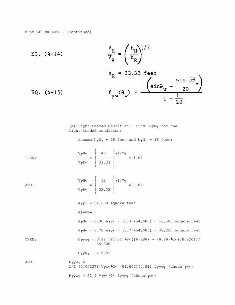
EXAMPLE PROBLEM 1 (Continued)
(a) Light-Loaded Condition: Find FÚyw¿ for the light-loaded condition:
Assume hÚS¿ = 45 feet and hÚH¿ = 15 feet:
Ú ¿ VÚS¿ ³ 45 ³Ú1/7¿THEN: ÄÄÄÄ = ³ ÄÄÄÄÄ ³ = 1.04 VÚR¿ ³ 33.33 ³ À Ù
Ú ¿ VÚH¿ ³ 15 ³Ú1/7¿AND: ÄÄÄÄ = ³ ÄÄÄÄÄ ³ = 0.89 VÚR¿ ³ 33.33 ³ À Ù
AÚy¿ = 54,600 square feet
Assume:
AÚS¿ = 0.30 AÚy¿ = (0.3)(54,600) = 16,380 square feet
AÚH¿ = 0.70 AÚy¿ = (0.7)(54,600) = 38,220 square feet
THEN: CÚyw¿ = 0.92 [(1.04)À2Ù(16,380) + (0.89)À2Ù(38,220)]/ 54,600
CÚyw¿ = 0.81
AND: FÚyw¿ = 1/2 (0.00237) VÚw¿À2Ù (54,600)(0.81) fÚyw¿([theta]Úw¿)
FÚyw¿ = 52.4 VÚw¿À2Ù fÚyw¿([theta]Úw¿)

This equation is used to determine FÚyw¿ for VÚw¿ and [theta]Úw¿ for the light-loaded condition. The results are given in Table 14.
(b) Fully Loaded Condition: Find FÚyw¿ for the fully loaded condition:
Assume hÚS¿ = 40 feet and hÚH¿ = 12 feet:
Ú ¿ VÚS¿ ³ 40 ³Ú1/7¿ ÄÄÄÄ = ³ ÄÄÄÄÄ ³ = 1.03 VÚR¿ ³ 33.33 ³ À Ù
26.4-108

EXAMPLE PROBLEM 1 (Continued)
TABLE 14 Lateral Wind Load: Light-Loaded Condition
ÚÄÄÄÄÄÄÄÄÄÄÄÄÄÄÄÄÄÄÄÄÄÄÄÄÄÄÄÄÄÄÄÄÄÄÄÄÄÄÄÄÄÄÄÄÄÄÄÄÄÄÄÄÄÄÄÄÄÄÄÄÄÄÄÄÄÄÄÄÄÄÄÄÄÄÄÄÄÄÄÄij [theta]Úw¿ VÚw¿ FÚyw¿ ³ Direction (degrees) (feet per second) fÚyw¿[theta]Úw¿ (pounds) ÃÄÄÄÄÄÄÄÄÄÄÄÄÄÄÄÄÄÄÄÄÄÄÄÄÄÄÄÄÄÄÄÄÄÄÄÄÄÄÄÄÄÄÄÄÄÄÄÄÄÄÄÄÄÄÄÄÄÄÄÄÄÄÄÄÄÄÄÄÄÄÄÄÄÄÄÄÄÄÄÄij N 0 76.4 0 0 ³ NE 45 65.8 0.782 177,415 ³ E 90 73.7 1 284,621 ³ SE 135 52.2 0.782 111,655 ³ S 180 57.8 O 0 ³ SW 225 58.9 -0.782 -142,157 ³ W 270 53.8 -1 -151,669 ³ NW 315 56.4 -0.782 -130,346 ÀÄÄÄÄÄÄÄÄÄÄÄÄÄÄÄÄÄÄÄÄÄÄÄÄÄÄÄÄÄÄÄÄÄÄÄÄÄÄÄÄÄÄÄÄÄÄÄÄÄÄÄÄÄÄÄÄÄÄÄÄÄÄÄÄÄÄÄÄÄÄÄÄÄÄÄÄÄÄÄÄÄ
Ú ¿ VÚH¿ ³ 12 ³Ú1/7¿ ÄÄÄÄ = ³ ÄÄÄÄÄ ³ = 0.86 VÚR¿ ³ 33.33 ³ À Ù
AÚy¿ = 36,650 square feet
From step (a), AÚS¿ = 16,380 square feet
AÚH¿ = AÚy¿ - AÚS¿ = 36,650 - 16,380 = 20,270 square feet
THEN: CÚyw¿ = 0.92 [(1.03)À2Ù(16,380)+(0.86)À2Ù(20,270)]/ 36,650
CÚyw¿ = 0.81
AND: FÚyw¿ = 1/2 (0.00237) VÚw¿À2Ù (36,650)(0.81) fÚyw¿([theta]Úw¿)
FÚyw¿ = 35.2 VÚw¿À2Ù fÚyw¿ ([theta]Úw¿)
This equation is used to determine FÚyw¿ for VÚw¿ and [theta]Úw¿ for the fully loaded condition. Results are given in Table 15.
(2) Longitudinal Wind Load: Find FÚxw¿:
EQ. (4-16) FÚxw¿ = 1/2 [rho]Úa¿ VÚwÀ2Ù¿ AÚx¿ CÚxw¿ fÚxw¿([theta]Úw¿)
[rho] = 0.00237 slugs per cubic foot
EQ. (4-19) For an AOE-1 CÚxwB¿ = 0.70
EQ. (4-20) CÚxwS¿ = 0.60

For vessels with distributed superstructures:
26.4-109

EXAMPLE PROBLEM 1 (Continued)
TABLE 15 Lateral Wind Load: Fully Loaded Condition
ÚÄÄÄÄÄÄÄÄÄÄÄÄÄÄÄÄÄÄÄÄÄÄÄÄÄÄÄÄÄÄÄÄÄÄÄÄÄÄÄÄÄÄÄÄÄÄÄÄÄÄÄÄÄÄÄÄÄÄÄÄÄÄÄÄÄÄÄÄÄÄÄÄÄÄÄÄÄÄÄÄij [theta]Úw¿ VÚw¿ FÚyw¿ ³ Direction (degrees) (feet per second) fÚyw¿[theta]Úw¿ (pounds) ÃÄÄÄÄÄÄÄÄÄÄÄÄÄÄÄÄÄÄÄÄÄÄÄÄÄÄÄÄÄÄÄÄÄÄÄÄÄÄÄÄÄÄÄÄÄÄÄÄÄÄÄÄÄÄÄÄÄÄÄÄÄÄÄÄÄÄÄÄÄÄÄÄÄÄÄÄÄÄÄÄij N 0 76.4 0 0 ³ NE 45 65.8 0.782 119,179 ³ E 90 73.7 1 191,196 ³ SE 135 52.2 0.782 75,005 ³ S 180 57.8 O 0 ³ SW 225 58.9 -0.782 -95,495 ³ W 270 53.8 -1 -101,884 ³ NW 315 56.4 -0.782 -87,560 ÀÄÄÄÄÄÄÄÄÄÄÄÄÄÄÄÄÄÄÄÄÄÄÄÄÄÄÄÄÄÄÄÄÄÄÄÄÄÄÄÄÄÄÄÄÄÄÄÄÄÄÄÄÄÄÄÄÄÄÄÄÄÄÄÄÄÄÄÄÄÄÄÄÄÄÄÄÄÄÄÄÄ
Ú ¿ ³ sin5[delta] ³ -³ sin[delta] - ÄÄÄÄÄÄÄÄÄÄÄ ³EQ. (4-26) fÚxw¿([theta]Úw¿) = À 10 Ù ÄÄÄÄÄÄÄÄÄÄÄÄÄÄÄÄÄÄÄÄÄÄÄÄ 1 - 1 ÄÄ 10
Ú ¿ ³ 90deg. ³EQ. (4-27) [delta]Ú(-)¿ = ³ÄÄÄÄÄÄÄÄÄÄ ³ [theta]Úw¿ + 90deg. for ³[theta]Úwz¿³ À Ù
[theta]Úw¿ < [theta]Úwz¿
Ú ¿ ³ 90deg. ³EQ. (4-28) [delta]Ú(+)¿ = ³ÄÄÄÄÄÄÄÄÄÄÄÄÄÄÄÄÄÄÄÄÄ ³[theta]Úw¿ + ³180deg. - [theta]Úwz¿ ³ À Ù
Ú ¿ ³ 90deg. [theta]Úwz¿ ³ ³ 180deg. - ÄÄÄÄÄÄÄÄÄÄÄÄÄÄÄÄÄÄÄÄ ³ ³ 180deg. - [theta]Úwz¿ ³ À Ù
for [theta]Úw¿ > [theta]Úwz¿
Use [theta]Úwz¿ = 90 degrees:
Ú ¿ ³ 90deg. ³THEN: [delta]Ú(+)¿ = ³ ÄÄÄÄÄÄ ³ [theta]Úw¿ + 90deg. = ³ 90deg. ³

À Ù
[theta]Úw¿ + 90deg.
Ú ¿ ³ 90deg. ³AND: [delta]Ú(-)¿ = ³ ÄÄÄÄÄÄÄÄÄÄÄÄÄÄÄÄ ³ [theta]Úw¿ + ³ 180deg. - 90deg. ³ À Ù
Ú ¿ ³ (90deg.) (90deg.) ³ ³ 180deg. - ÄÄÄÄÄÄÄÄÄÄÄÄÄÄÄÄÄÄ ³ ³ 180deg. - 90deg. ³ À Ù
=[theta]Úw¿ + 90deg.
(a) Light-Loaded Condition: Find FÚxw¿ for the light-loaded condition:
AÚx¿ = 8,850 square feet
THEN: FÚxw¿ = 1/2 (0.00237) VÚw¿À2Ù (8,850) CÚxw¿ fÚxw¿ ([theta]Úw¿)
FÚxw¿ = 10.49 VÚw¿À2Ù CÚxw¿ fÚxw¿ ([theta]ÀwÙ)
26.4-110

EXAMPLE PROBLEM 1 (Continued)
This equation is used to determine FÚxw¿ for VÚw¿, CÚxw¿ (CÚxwB¿ or CÚxws¿), and [theta]Úw¿ for the light-loaded condition. Results are given in Table 16.
TABLE 16 Longitudinal Wind Load: Light-Loaded Condition
ÚÄÄÄÄÄÄÄÄÄÄÄÄÄÄÄÄÄÄÄÄÄÄÄÄÄÄÄÄÄÄÄÄÄÄÄÄÄÄÄÄÄÄÄÄÄÄÄÄÄÄÄÄÄÄÄÄÄÄÄÄÄÄÄÄÄÄÄÄÄÄÄÄÄÄÄÄÄÄÄÄij [theta]Úw¿ VÚw¿ VÚx³ Direction (degrees) (feet per second) CÚx¿ fÚyw¿[theta]Úw¿ (pounÃÄÄÄÄÄÄÄÄÄÄÄÄÄÄÄÄÄÄÄÄÄÄÄÄÄÄÄÄÄÄÄÄÄÄÄÄÄÄÄÄÄÄÄÄÄÄÄÄÄÄÄÄÄÄÄÄÄÄÄÄÄÄÄÄÄÄÄÄÄÄÄÄÄÄÄÄÄÄÄÄij N 0 76.4 0.7 -1 -42,8³ NE 45 65.8 0.7 -0.864 -27,4³ E 90 73.7 0.6 0 ³ SE 135 52.2 0.6 0.864 14,8³ S 180 57.8 0.6 1 21,0³ SW 225 58.9 0.6 0.864[*] 18,8³ W 270 53.8 0.7 0 ³ NW 315 56.4 0.7 -0.864[*] -20,1ÀÄÄÄÄÄÄÄÄÄÄÄÄÄÄÄÄÄÄÄÄÄÄÄÄÄÄÄÄÄÄÄÄÄÄÄÄÄÄÄÄÄÄÄÄÄÄÄÄÄÄÄÄÄÄÄÄÄÄÄÄÄÄÄÄÄÄÄÄÄÄÄÄÄÄÄÄÄÄÄÄÄ
[*]fÚxw¿([theta]Úw¿) is symmetrical about the longitudinal axis of the vessel
(b) Fully Loaded Condition: Find FÚxw¿ for the fully loaded condition:
AÚx¿ = 6,400 square feet
THEN: FÚxw¿ = 1/2 (0.00237) VÚw¿À2Ù (6,400) CÚxw¿ fÚxw¿ ([theta]ÀwÙ)
FÚxw¿ = 7.58 VÚw¿À2Ù CÚxw¿ fÚxw¿([theta]Úw¿)
This equation is used to determine FÚxw¿ for VÚw¿, CÚxw¿ (CÚxwB¿ or CÚxwS¿), and [theta] for the fully loaded condition. Results are given in Table 17.
(3) Wind Yaw Moment: Find MÚxyw¿:
EQ. (4-29) MÚxyw¿ = 1/2 [rho]Úa¿ VÚw¿À2Ù AÚy¿ L CÚxyw¿([theta]Úw¿)
[rho]Úa¿ = 0.00237 slugs per cubic foot
L = 796 feet
CÚxyw¿([theta]ÀwÙ) is found in Figure 23.
(a) Light-Loaded Condition: Find MÚxyw¿ for the light-loaded condition:
26.4-111

EXAMPLE PROBLEM 1 (Continued)
TABLE 17 Longitudinal Wind Load: Fully Loaded Condition
ÚÄÄÄÄÄÄÄÄÄÄÄÄÄÄÄÄÄÄÄÄÄÄÄÄÄÄÄÄÄÄÄÄÄÄÄÄÄÄÄÄÄÄÄÄÄÄÄÄÄÄÄÄÄÄÄÄÄÄÄÄÄÄÄÄÄÄÄÄÄÄÄÄÄÄÄÄÄÄÄÄij [theta]Úw¿ VÚw¿ FÚx³ Direction (degrees) (feet per second) CÚx¿ fÚyw¿[theta]Úw¿ (pounÃÄÄÄÄÄÄÄÄÄÄÄÄÄÄÄÄÄÄÄÄÄÄÄÄÄÄÄÄÄÄÄÄÄÄÄÄÄÄÄÄÄÄÄÄÄÄÄÄÄÄÄÄÄÄÄÄÄÄÄÄÄÄÄÄÄÄÄÄÄÄÄÄÄÄÄÄÄÄÄÄij N 0 76.4 0.7 -1 -30,9³ NE 45 65.8 0.7 -0.864 -19,8³ E 90 73.7 0.6 0 ³ SE 135 52.2 0.6 0.864 10,7³ S 180 57.8 0.6 1 15,1³ SW 225 58.9 0.6 0.864[*] 13,6³ W 270 53.8 0.7 0 ³ NW 315 56.4 0.7 -0.864[*] -14,5ÀÄÄÄÄÄÄÄÄÄÄÄÄÄÄÄÄÄÄÄÄÄÄÄÄÄÄÄÄÄÄÄÄÄÄÄÄÄÄÄÄÄÄÄÄÄÄÄÄÄÄÄÄÄÄÄÄÄÄÄÄÄÄÄÄÄÄÄÄÄÄÄÄÄÄÄÄÄÄÄÄÄ
[*]fÚxw¿([theta]Úw¿) is symmetrical about the longitudinal axis of the vessel
AÚy¿ = 54,600 square feet
THEN: MÚxyw¿ = 1/2 (0.00237) VÚw¿À2Ù (54,600) (796) CÚxyw¿ ([theta]Úw¿)
MÚxyw¿ = 51,502 VÚw¿À2Ù CÚxyw¿([theta]Úw¿)
This equation is used to determine MÚxyw¿ for VÚw¿ and [theta]Úw¿ for the light-loaded condition. Results are given in Table 18.
TABLE 18 Wind Yarn Moment: Light-Loaded Condition
ÚÄÄÄÄÄÄÄÄÄÄÄÄÄÄÄÄÄÄÄÄÄÄÄÄÄÄÄÄÄÄÄÄÄÄÄÄÄÄÄÄÄÄÄÄÄÄÄÄÄÄÄÄÄÄÄÄÄÄÄÄÄÄÄÄÄÄÄÄÄÄÄÄÄÄÄÄÄÄÄÄij [theta]Úw¿ VÚw¿ MÚxyw¿ ³ Direction (degrees) (feet per second) CÚxyw¿([theta]Úw¿) (foot-pounds)ÃÄÄÄÄÄÄÄÄÄÄÄÄÄÄÄÄÄÄÄÄÄÄÄÄÄÄÄÄÄÄÄÄÄÄÄÄÄÄÄÄÄÄÄÄÄÄÄÄÄÄÄÄÄÄÄÄÄÄÄÄÄÄÄÄÄÄÄÄÄÄÄÄÄÄÄÄÄÄÄÄij N 0 76.4 0 0 ³ NE 45 65.8 0.105 2.3413 x 1³ E 90 73.7 0 0 ³ SE 135 52.2 -0.10 -1.4033 x 1³ S 180 57.8 0 0 ³ SW 225 58.9 0.10 1.7867 x 1³ W 270 53.8 0 0 ³ NW 315 56.4 -0.105 -1.7202 x 1ÀÄÄÄÄÄÄÄÄÄÄÄÄÄÄÄÄÄÄÄÄÄÄÄÄÄÄÄÄÄÄÄÄÄÄÄÄÄÄÄÄÄÄÄÄÄÄÄÄÄÄÄÄÄÄÄÄÄÄÄÄÄÄÄÄÄÄÄÄÄÄÄÄÄÄÄÄÄÄÄÄÄ
(b) Fully Loaded Condition: Find MÚxyw¿ for the fully loaded condition.
26.4-112

EXAMPLE PROBLEM 1 (Continued)
AÚy¿ = 35,650 square feet
THEN: MÚxyw¿ = 1/2 (0.00237) VÚw¿À2Ù (13,050) (418) CÚxyw¿ ([theta]Úw¿)
MÚxyw¿ = 6,464 VÚw¿À2Ù CÚxyw¿([theta]ÀwÙ)
This equation is used to determine MÚxyw¿ for VÚw¿ and [theta]Úw¿ for the fully loaded condition. Results are given in Table 19.
TABLE 19 Wind Yaw Moment: Fully Loaded Condition
ÚÄÄÄÄÄÄÄÄÄÄÄÄÄÄÄÄÄÄÄÄÄÄÄÄÄÄÄÄÄÄÄÄÄÄÄÄÄÄÄÄÄÄÄÄÄÄÄÄÄÄÄÄÄÄÄÄÄÄÄÄÄÄÄÄÄÄÄÄÄÄÄÄÄÄÄÄÄÄÄÄij [theta]Úw¿ VÚw¿ MÚxyw¿ ³ Direction (degrees) (feet per second) CÚxyw¿([theta]Úw¿) (foot-pounds)ÃÄÄÄÄÄÄÄÄÄÄÄÄÄÄÄÄÄÄÄÄÄÄÄÄÄÄÄÄÄÄÄÄÄÄÄÄÄÄÄÄÄÄÄÄÄÄÄÄÄÄÄÄÄÄÄÄÄÄÄÄÄÄÄÄÄÄÄÄÄÄÄÄÄÄÄÄÄÄÄÄij N 0 76.4 0 0 ³ NE 45 65.8 0.105 1.5716 x 10À³ E 90 73.7 0 0 ³ SE 135 52.2 -0.10 -9.42 x 10À³ S 180 57.8 O 0 ³ SW 225 58.9 0.10 1.1993 x 10À³ W 270 53.8 0 0 ³ NW 315 56.4 -0.105 -1.1547 x 10ÀÀÄÄÄÄÄÄÄÄÄÄÄÄÄÄÄÄÄÄÄÄÄÄÄÄÄÄÄÄÄÄÄÄÄÄÄÄÄÄÄÄÄÄÄÄÄÄÄÄÄÄÄÄÄÄÄÄÄÄÄÄÄÄÄÄÄÄÄÄÄÄÄÄÄÄÄÄÄÄÄÄÄ
b. Current Load: Note that lateral and longitudinal flood-current loads ([theta]Úc¿ = 15deg.) are computed below; lateral and longitudinal ebb-current loads are equal to the flood-current loads, but opposite in sign.
(1) Lateral Current Load: Find FÚyc¿:
EQ. (4-35) FÚyc¿ = 1/2 [rho]Úw¿ VÚc¿À2Ù LÚwL¿ T CÚyc¿ sin[theta]Úc¿
[rho]Úw¿ = 2 slugs per cubic foot
feet per second VÚc ¿ = 1 knot (1.69 ÄÄÄÄÄÄÄÄÄÄÄÄÄÄÄ ) knot
= 1.69 feet per second
³ ³EQ. (4-36) CÚyc¿ = CÚyc¿³[infinity] = (CÚyc¿³1 -
³ wd CÚyc¿³[infinity]) eÀ -k (ÄÄÄÄ - 1)Ù T
35 D
EQ. (4-37) [phi] = ÄÄÄÄÄÄÄÄÄ LÚwL¿ B T
26.4-113

EXAMPLE PROBLEM 1 (Continued)
LÚwL¿ = 770 feet
B = 107 feet
(a) Light-Loaded Condition at Low Tide: Find FÚyc¿ for the light-loaded condition at low tide:
T = 18.4 feet
wd = 65 feet
D = 18,870 long tons
Find CÚyc³[infinity]¿ from Figure 24 for [phi] and LÚwL¿/B:
(35) (18,870) [phi] = ÄÄÄÄÄÄÄÄÄÄÄÄÄÄÄÄÄÄ = 0.436 (770) (107) (18.4)
LÚwL¿/B = 770/107 = 7.2
³ CÚyc³[infinity]¿ = 0.4
³ Find CÚyc³1¿ from Figure 25 for CÚp¿ LÚwL¿/[SQRT T]:
From Table 7, use CÚp¿ = 0.758 for EC-2
CÚp¿ LÚwL¿/[SQRT T] = (0.758) (770)/[SQRT 18.4] = 136
³ CÚyc³1¿ = 7
Find k from Figure 26 for [phi] = 0.436 for a ship-shaped hull:
k = 0.75
wd 65 ÄÄ = ÄÄÄÄ = 3.53 T 18.4
THEN: CÚyc¿ = 0.4 + (7 - 0.4) e À -(0.75)(3.53 - 1)Ù = 1.39
THEREFORE: FÚyc¿ = 1/2 (2) (1.69)À2Ù (770) (18.4) (1.39) sin(15) = 14,558 pounds
(b) Fully Loaded Condition at Low Tide: Find FÚyc¿ for the fully loaded condition at low tide:

T = 41 feet
wd = 65 feet
D = 53,600 long tons
26.4-114

EXAMPLE PROBLEM 1 (Continued)
Find CÚyc³[infinity]¿ from Figure 24 for [phi] and LÚwL¿/B:
(35)(53,600) [phi] = ÄÄÄÄÄÄÄÄÄÄÄÄÄÄ = 0.56 (770)(107)(41)
LÚwL¿/B = 770/107 = 7.2
CÚyc³[infinity]¿ = 0.55
Find CÚyc³1¿ from Figure 25 for CÚp¿ LÚwL¿/[SQRT T]
From Table 7, use CÚp¿ = 0.758 for EC-2
CÚp¿ LÚwL¿/[SQRT T] = (0.758)(770)/[SQRT 41] = 91.2
CÚyc³1¿ = 5.1
Find k from Figure 26 for [phi] = 0.555 for ship-shaped hull:
k = 0.76
wd 65 ÄÄ = ÄÄ = 1.59 T 41
THEN: CÚyc¿ = 0.55 + (5.1 - 0.55) eÀ -(0.76)(1.59 - 1)Ù = 3.47
THEREFORE: FÚyc¿ = 1/2 (2)(1.69)À2Ù (770) (41)(3.47) sin(15) = 80,979 pounds
(2) Longitudinal Current Load: Find FÚxc¿:
EQ. (4-40) FÚxc¿ = FÚx form¿ + FÚx friction¿ + FÚx prop¿
EQ. (4-41) FÚx form¿ = - 1/2 [rho]Úw¿ VÚc¿À2Ù B T CÚxcb¿ cos[theta]Úc¿
[rho]Úw¿ = 2 slugs per cubic foot
VÚc¿ = 1.69 feet per second
B = 41 feet
CÚxcb¿ = 0.1
EQ. (4-42) FÚx¿ friction = - 1/2 [rho]Úw¿ VÚc¿À2Ù S CÚxca¿ cos[theta]Úc¿
35 DEQ. (4-43) S = (1.7 T LÚwL¿) + ÄÄÄÄ T

EXAMPLE PROBLEM 1 (Continued)
EQ. (4-44) CÚxca¿ = 0.075/(log RÚn¿ - 2)À2Ù
EQ. (4-45) RÚn¿ = VÚc¿ LÚwL¿ cos[theta]Úc¿/[upsilon]
LÚwL¿ = 770 feet
[upsilon] = 1.4 x 10À -5Ù square feet per second
EQ. (4-46) FÚx prop¿ = - 1/2 [rho]Úw¿ VÚc¿À2Ù AÚp¿ CÚprop¿ cos[theta]Úc¿
AÚTpp¿EQ. (4-47) AÚp¿ = ÄÄÄÄÄÄ 0.838
LÚwL¿ BEQ. (4-48) AÚTpp¿ = ÄÄÄÄÄÄÄ AÚR¿
From Table 8 for cruisers, AÚR¿ = 160
THEN: AÚTpp¿ = (770)(107)/160 = 515 square feet
515THEN: AÚp¿ = ÄÄÄÄÄ = 615 square feet 0.838
CÚprop¿ = 1
(a) Light-Loaded Condition at Low Tide: Find FÚxc¿ for the light-loaded condition at low tide:
T = 18.4 feet
D = 18,870 long tons
THEN: FÚx form¿ = - 1/2 (2)(1.69)À2Ù(107)(18.4)(0.1) cos(15deg.) = - 543 pounds
RÚn¿ = (1.69)(770) cos(15deg.)/1.4 x 10À -5Ù = 8.98 x 10À7Ù
CÚxca¿ = 0.075/[log(8.97 x 10À7Ù) -2]À2Ù = 0.0021
(35)(18,770) S = (1.7)(18.4)(770) + ÄÄÄÄÄÄÄÄÄÄÄÄÄÄ 18.4 = 59,789 square feet
THEN: FÚx friction¿ = - 1/2 (2)(1.69)À2Ù(59,789) (0.0021) cos(15deg.) = - 346 pounds
THEN: FÚx prop¿ = - 1/2 (2)(1.69)À2Ù(615) (1) cos(15deg.) = - 1,697 pounds

THEREFORE: FÚxc¿ = - 543 - 346 - 1,697 = - 2,586 pounds
26.4-116
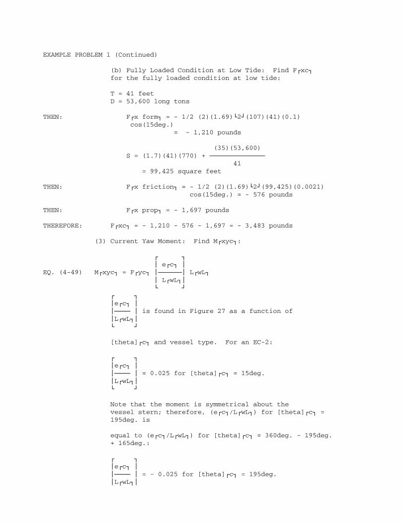
EXAMPLE PROBLEM 1 (Continued)
(b) Fully Loaded Condition at Low Tide: Find FÚxc¿ for the fully loaded condition at low tide:
T = 41 feet D = 53,600 long tons
THEN: FÚx form¿ = - 1/2 (2)(1.69)À2Ù(107)(41)(0.1) cos(15deg.) = - 1,210 pounds
(35)(53,600) S = (1.7)(41)(770) + ÄÄÄÄÄÄÄÄÄÄÄÄÄÄ 41 = 99,425 square feet
THEN: FÚx friction¿ = - 1/2 (2)(1.69)À2Ù(99,425)(0.0021) cos(15deg.) = - 576 pounds
THEN: FÚx prop¿ = - 1,697 pounds
THEREFORE: FÚxc¿ = - 1,210 - 576 - 1,697 = - 3,483 pounds
(3) Current Yaw Moment: Find MÚxyc¿:
Ú ¿ ³ eÚc¿ ³EQ. (4-49) MÚxyc¿ = FÚyc¿ ³ÄÄÄÄÄij LÚwL¿ ³ LÚwL¿³ À Ù Ú ¿ ³eÚc¿ ³ ³ÄÄÄÄ ³ is found in Figure 27 as a function of ³LÚwL¿³ À Ù
[theta]Úc¿ and vessel type. For an EC-2:
Ú ¿ ³eÚc¿ ³ ³ÄÄÄÄ ³ = 0.025 for [theta]Úc¿ = 15deg. ³LÚwL¿³ À Ù
Note that the moment is symmetrical about the vessel stern; therefore, (eÚc¿/LÚwL¿) for [theta]Úc¿ = 195deg. is
equal to (eÚc¿/LÚwL¿) for [theta]Úc¿ = 360deg. - 195deg. + 165deg.:
Ú ¿ ³eÚc¿ ³ ³ÄÄÄÄ ³ = - 0.025 for [theta]Úc¿ = 195deg. ³LÚwL¿³

À Ù
(a) Light-Loaded Condition at Low Tide: Find MÚxyc¿ for the light-loaded condition at low tide:
Flood current ([theta]Úc¿ = 15deg.):
MÚxyc¿ = (14,558)(0.025)(770) = 2.8024 x 10À5Ù foot-pounds
Ebb current ([theta]Úc¿ = 195deg.):
26.4-117

EXAMPLE PROBLEM 1 (Continued)
MÚxyc¿ = (-14,558)(-0.265)(770) = 2.9706 x 10À6Ù foot-pounds
(b) Fully Loaded Condition at Low Tide: Find MÚxyc¿ for the fully loaded condition at low tide:
Flood current ([theta]Úc¿ = 15deg.):
MÚxyc¿ = (80,979)(0.025)(770) = 1.559 x 10À6Ù foot-pounds
Ebb current ([theta]Úc¿ = 195deg.):
MÚxyc¿ = (- 80,979)(- 0.265)(770) = 1.6524 x 10À7Ù foot-pounds
5. Evaluate Loads on Mooring Elements:
a. Factor of Safety. The following analysis provides the loads in each of the mooring lines. Once these loads are known, the factors of safety are checked for each mooring line. The mooring lines used to secure the vessel are polypropylene. Table 10 indicates that the factor of safety for a polypropylene rope is 6 (for a mooring-line diameter greater than 3/4 inch).
b. Load Combinations: There are four cases of load combinations which must be analyzed in order to determine the maximum total mooring loads on the vessel:
Load Case 1: Light-loaded condition and flood current Load Case 2: Light-loaded condition and ebb current Load Case 3: Fully loaded condition and flood current Load Case 4: Fully loaded condition and ebb current
Note that, for each case, the maximum loads on the vessel occur when the directions of the wind and current forces coincide. Therefore, loads due to a flood current are combined with loads due to winds from the N, NE, E, and SE. Similarly, loads due to an ebb current are combined with loads due to winds from the S, SW, W and NW.
The load-combination calculations are summarized in Table 20. The following equations are used:
EQ. (4-62) FÚxT¿ = FÚxw¿ + FÚxc¿
EQ. (4-63) FÚyT¿ = FÚyw¿ + FÚyc¿
EQ. (4-64) MÚxyT¿ = MÚxyw¿ + MÚxyc¿
26.4-118


EXAMPLE PROBLEM 1 (Continued)
The yaw moment is resolved into lateral loads at the bow and stern using the following equations:
FÚyT¿ MÚxyT¿EQ. (4-65) FÚyB¿ = ÄÄÄÄÄ + ÄÄÄÄÄÄ 2 LÚMP¿
FÚyT¿ MÚxyt¿EQ. (4-65) FÚyS¿ = ÄÄÄÄÄ - ÄÄÄÄÄÄ 2 LÚMP¿
These loads are computed assuming LÚMP¿ = 685 feet. (FÚyB¿ and FÚyS¿ are given in Table 20.) For example, for a NE wind; CASE 1:
191,973 2.37 x 10À7Ù FÚyB¿ = ÄÄÄÄÄÄÄ + ÄÄÄÄÄÄÄÄÄÄÄÄ = 130,585 pounds 2 685
191,973 2.37 x 10À7Ù FÚyS¿ = ÄÄÄÄÄÄÄ - ÄÄÄÄÄÄÄÄÄÄÄÄ = 61,389 pounds 2 685
c. Lateral Load and Yaw Moment: Light-Loaded Condition:
(1) Case 1 (FÚyB¿ and FÚyS¿ both negative): Determine loads in lines 1, 2, 3, 4, 9, 10, 11 and 12:
(a) Low Tide: Determine vertical line angles and line lengths; H = 36 feet:
For example, for lines 1 and 12:
LÚH¿ = 150 feet
Determine vertical line angle:
H 36 [theta] = arctan (ÄÄÄÄ) = arctan (ÄÄÄ) = 13.5deg. LÚH¿ 150
Determine actual line length:
LÚH¿ 150 L = ÄÄÄÄÄÄÄÄÄÄ = ÄÄÄÄÄÄÄÄÄ = 154.3 feet cos[theta] cos(13.5)
Determine unloaded line length, LÚun1¿:
Preload = 5,000 pounds Ú ¿ ³5,000 ³ Percent of breaking strength = ³ÄÄÄÄÄÄij (100) ³300,000³
À Ù = 1.67 percent
From the load-elongation curve for used polypropylene rope (Figure 7), the percent elongation is 0.75 percent.
26.4-120

EXAMPLE PROBLEM 1 (Continued)
154.3 LÚun1¿ = ÄÄÄÄÄÄ = 153.2 feet. 1.0075
Similar calculations performed for each line are summarized in Table 21.
Table 21 Unloaded Line Lengths for Low Tide, Light-Loaded Condition
ÚÄÄÄÄÄÄÄÄÄÄÄÄÄÄÄÄÄÄÄÄÄÄÄÄÄÄÄÄÄÄÄÄÄÄÄÄÄÄÄÄÄÄÄÄÄÄÄÄÄÄÄÄÄÄÄÄÄÄÄÄÄÄÄÄÄÄÄÄÄÄÄÄÄÄ¿³ Percent of ³³ Line LÚH¿ [theta] L Preload Breaking Percent LÚun1¿³³Number (feet) (degrees) (feet) (pounds) Strength Elongation (feet)³ÃÄÄÄÄÄÄÄÄÄÄÄÄÄÄÄÄÄÄÄÄÄÄÄÄÄÄÄÄÄÄÄÄÄÄÄÄÄÄÄÄÄÄÄÄÄÄÄÄÄÄÄÄÄÄÄÄÄÄÄÄÄÄÄÄÄÄÄÄÄÄÄÄÄÄ´³ 1,12 150 13.5 154.3 5,000 1.67 0.75 153.2 ³³ 2,11 140 14.4 144.5 5,000 1.67 0.75 143.4 ³³ 3,10 100 19.8 106.3 5,000 1.67 0.75 105.5 ³³ 4, 9 95 20.8 101.6 5,000 1.67 0.75 100.8 ³ÀÄÄÄÄÄÄÄÄÄÄÄÄÄÄÄÄÄÄÄÄÄÄÄÄÄÄÄÄÄÄÄÄÄÄÄÄÄÄÄÄÄÄÄÄÄÄÄÄÄÄÄÄÄÄÄÄÄÄÄÄÄÄÄÄÄÄÄÄÄÄÄÄÄÄÙ
Determine Line Loads: According to Table 20, the maximum negative load at the vessel bow and/or stern under the light-loaded condition (Load Cases 1 and 2) results from a SW wind and ebb current [theta]Úc¿ = 195deg.):
FÚyB¿ = - 47,993 pounds
FÚyS¿ = - 108,723 pounds
(The negative signs will not be carried throughout the calculations as it is understood that a negative sign means that the line is in tension.)
Table 22 provides the resulting mooring-line loads for the above loading Using the procedure outlined in Figure 34.
Table 22 Mooring-Line Loads for Low Tide, Light-Loaded Condition
ÚÄÄÄÄÄÄÄÄÄÄÄÄÄÄÄÄÄÄÄÄÄÄÄÄÄÄÄÄÄÄÄÄÄÄÄÄÄÄÄÄÄÄÄÄÄÄÄÄÄÄÄÄÄÄÄÄÄÄÄÄÄÄÄÄÄÄÄÄÄÄÄÄÄÄÄÄÄÄÄÄij cosÀ2Ù[alpha] cosÀ2Ù[theta] ³ Line [theta] [alpha] L ÄÄÄÄÄÄÄÄÄÄÄÄÄÄÄÄÄÄÄÄÄÄÄÄÄÄÄ FÚi¿ ³Number (degrees) (degrees) (feet) L (pounds) (ÃÄÄÄÄÄÄÄÄÄÄÄÄÄÄÄÄÄÄÄÄÄÄÄÄÄÄÄÄÄÄÄÄÄÄÄÄÄÄÄÄÄÄÄÄÄÄÄÄÄÄÄÄÄÄÄÄÄÄÄÄÄÄÄÄÄÄÄÄÄÄÄÄÄÄÄÄÄÄÄÄij 1,12 13.5 18 154.3 0.005543 24,937 ³ 2,11 14.4 28 144.5 0.005062 24,625 ³ 3,10 19.8 20 106.3 0.007354 34,606 ³ 4,9 20.8 13 101.6 0.008172 37,314 ÀÄÄÄÄÄÄÄÄÄÄÄÄÄÄÄÄÄÄÄÄÄÄÄÄÄÄÄÄÄÄÄÄÄÄÄÄÄÄÄÄÄÄÄÄÄÄÄÄÄÄÄÄÄÄÄÄÄÄÄÄÄÄÄÄÄÄÄÄÄÄÄÄÄÄÄÄÄÄÄÄÄ
26.4-121

EXAMPLE PROBLEM 1 (Continued)
The fore lines (1, 2, 3, and 4) and the aft lines (9, 10, 11, and 12) are both analyzed for the largest lateral load; that is, FÚy¿ = - 108,723 pounds. This provides a conservative estimate of line loads and reduces the required number of calculations.
For example, for line 1 (and line 12):
Determine FÚ1¿:
Determine FÚT¿:
FÚT¿ = FÚ1¿ + Pretension = 24,937 + 5,000 = 29,937 pounds
Results for all lines are presented in Table 22.
The maximum mooring-line load is 42,314 pounds.

Check factor of safety:
breaking strength 300,000 Factor of safety = ÄÄÄÄÄÄÄÄÄÄÄÄÄÄÄÄÄÄ = ÄÄÄÄÄÄÄ line load 42,314
= 7.1>6; ok
(b) High Tide: Following the procedure outlined in Figure 38, determine the increase in line loads due to an increase in water level (H = 36 + 6 = 42 feet):
Calculate new line angles, line lengths, and pretensions at high tide:
For example, for lines 1 and 12:
LÚH¿ = 150 feet
26.4-122

EXAMPLE PROBLEM 1 (Continued)
Determine vertical line angle:
H 42 [theta] - arctan (ÄÄÄÄ) = arctan (ÄÄÄ) = 15.6deg. LÚH¿ 150
Determine actual line length:
LÚH¿ 150 L = ÄÄÄÄÄÄÄÄÄÄ = ÄÄÄÄÄÄÄÄÄ = 155.7 feet cos[theta] cos(15.6)
Determine percent elongation: LÚun1¿ is given in Table 21. Ú ¿ ³ L - LÚun1¿ ³ Percent elongation = ³ ÄÄÄÄÄÄÄÄÄÄ ³ (100) ³ LÚun1¿ ³ À Ù
Ú ¿ ³ 155.7 - 153.2 ³ = ³ ÄÄÄÄÄÄÄÄÄÄÄÄÄ ³ (100) ³ 153.2 ³ À Ù
Percent elongation = 1.63 percent
Determine percent of breaking strength from Figure 7 for used polypropylene rope:
Percent breaking strength = 6 percent
New pretension = (0.06)(300,000) = 18,000 pounds
Similar calculations performed for each line are summarized in Table 23.
Table 23 Line Lengths and Pretensions for High Tide, Light-Loaded Condition
ÚÄÄÄÄÄÄÄÄÄÄÄÄÄÄÄÄÄÄÄÄÄÄÄÄÄÄÄÄÄÄÄÄÄÄÄÄÄÄÄÄÄÄÄÄÄÄÄÄÄÄÄÄÄÄÄÄÄÄÄÄÄÄÄÄÄÄÄÄÄÄÄÄÄÄ¿³ Percent of ³³ Line LÚH¿ [theta] L Percent Breaking New Pretension³³Number (feet) (degrees) (feet) Elongation Strength (pounds) ³ÃÄÄÄÄÄÄÄÄÄÄÄÄÄÄÄÄÄÄÄÄÄÄÄÄÄÄÄÄÄÄÄÄÄÄÄÄÄÄÄÄÄÄÄÄÄÄÄÄÄÄÄÄÄÄÄÄÄÄÄÄÄÄÄÄÄÄÄÄÄÄÄÄÄÄ´³ 1,12 150 15.6 155.7 1.63 6 18,000 ³³ 2,11 140 16.7 146.2 1.95 8 24,000 ³³ 3,11 100 22.8 108.5 2.84 13 39,000 ³³ 4, 9 95 23.9 103.9 3.1 15 45,000 ³ÀÄÄÄÄÄÄÄÄÄÄÄÄÄÄÄÄÄÄÄÄÄÄÄÄÄÄÄÄÄÄÄÄÄÄÄÄÄÄÄÄÄÄÄÄÄÄÄÄÄÄÄÄÄÄÄÄÄÄÄÄÄÄÄÄÄÄÄÄÄÄÄÄÄÄÙ
Mooring-line loads for a high tide and a light-loaded condition are computed in a manner similar to that

used above for low tide. Results for all lines are given in Table 24.
26.4-123

EXAMPLE PROBLEM 1 (Continued)
Table 24 Mooring-Line Loads for High Tide, Light-Loaded Condition
ÚÄÄÄÄÄÄÄÄÄÄÄÄÄÄÄÄÄÄÄÄÄÄÄÄÄÄÄÄÄÄÄÄÄÄÄÄÄÄÄÄÄÄÄÄÄÄÄÄÄÄÄÄÄÄÄÄÄÄÄÄÄÄÄÄÄÄÄÄÄÄÄÄÄÄÄÄÄÄÄÄij cosÀ2Ù[alpha] cosÀ2Ù[theta] ³ Line [theta] [alpha] L ÄÄÄÄÄÄÄÄÄÄÄÄÄÄÄÄÄÄÄÄÄÄÄÄÄÄÄ FÚi¿ ³Number (degrees) (degrees) (feet) L (pounds) (ÃÄÄÄÄÄÄÄÄÄÄÄÄÄÄÄÄÄÄÄÄÄÄÄÄÄÄÄÄÄÄÄÄÄÄÄÄÄÄÄÄÄÄÄÄÄÄÄÄÄÄÄÄÄÄÄÄÄÄÄÄÄÄÄÄÄÄÄÄÄÄÄÄÄÄÄÄÄÄÄÄij 1,12 15.6 18 155.7 0.00539 25,751 ³ 2,11 16.7 28 146.2 0.00489 25,319 ³ 3,10 22.8 20 108.5 0.00692 34,946 ³ 4, 9 23.9 13 103.9 0.00764 37,527 ÀÄÄÄÄÄÄÄÄÄÄÄÄÄÄÄÄÄÄÄÄÄÄÄÄÄÄÄÄÄÄÄÄÄÄÄÄÄÄÄÄÄÄÄÄÄÄÄÄÄÄÄÄÄÄÄÄÄÄÄÄÄÄÄÄÄÄÄÄÄÄÄÄÄÄÄÄÄÄÄÄÄ
The maximum mooring-line load is 82,527 pounds.
Check factor of safety:
breaking strength 300,000 Factor safety = ÄÄÄÄÄÄÄÄÄÄÄÄÄÄÄÄÄ = ÄÄÄÄÄÄÄ line load 82,527
= 3.6<6
Therefore, unless the mooring lines are tended, the factor of safety will be less than required, and a stronger line will be required.
(2) Case 2 (FÚyB¿ and FÚyS¿ both positive): Determine breasting-structure loads using the procedure outlined in Figure 35. From Table 20, the maximum positive lateral load under the light-loaded condition is due to an E wind with a flood current:
FÚyT¿ = 299,179 pounds
MÚxyt¿ = 2.8 x 10À5Ù foot-pounds
FÚyT¿ MÚxyT¿ 299,179 2.8 x 10À5Ù
FÚA¿ = ÄÄÄÄÄ - ÄÄÄÄÄÄ = ÄÄÄÄÄÄÄ - ÄÄÄÄÄÄÄÄÄÄÄ 2 LÚF¿ 2 320
FÚA¿ = 148,715 pounds
FÚF¿ = FÚyT¿ - FÚA¿ = 299,179 - 148,715
FÚF¿ = 150,464 pounds
26.4-124

EXAMPLE PROBLEM 1 (Continued)
d. Longitudinal Load: Light-Loaded Condition:
(1) Low Tide: Determine vertical line angles and line lengths; H = 36 feet. The calculations, identical to those above for lateral load and yaw moment, are summarized in Table 25.
Table 25 Unloaded Line Lengths for Low Tide, Light-Loaded Condition
ÚÄÄÄÄÄÄÄÄÄÄÄÄÄÄÄÄÄÄÄÄÄÄÄÄÄÄÄÄÄÄÄÄÄÄÄÄÄÄÄÄÄÄÄÄÄÄÄÄÄÄÄÄÄÄÄÄÄÄÄÄÄÄÄÄÄÄÄÄÄÄÄÄÄÄ¿³ Percent of ³³ Line LÚH¿ [theta] L Preload Breaking Percent LÚun1¿ ³³Number (feet) (degrees) (feet) (pounds) Strength Elongation (feet) ³ÃÄÄÄÄÄÄÄÄÄÄÄÄÄÄÄÄÄÄÄÄÄÄÄÄÄÄÄÄÄÄÄÄÄÄÄÄÄÄÄÄÄÄÄÄÄÄÄÄÄÄÄÄÄÄÄÄÄÄÄÄÄÄÄÄÄÄÄÄÄÄÄÄÄÄ´³ 5,8 300 6.8 302.1 5,000 1.67 0.75 299.9 ³³ 6,7 260 7.9 262.5 5,000 1.67 0.75 260.5 ³ÀÄÄÄÄÄÄÄÄÄÄÄÄÄÄÄÄÄÄÄÄÄÄÄÄÄÄÄÄÄÄÄÄÄÄÄÄÄÄÄÄÄÄÄÄÄÄÄÄÄÄÄÄÄÄÄÄÄÄÄÄÄÄÄÄÄÄÄÄÄÄÄÄÄÄÙ
Determine Line Loads: According to Table 20, the maximum longitudinal load on the mooring under the light-loaded condition is FÚxT¿ = - 45,447 pounds for a N wind and a flood current. Table 26 provides the mooring-line loads obtained using the procedure outlined in Figure 37.
Table 26 Mooring-Line Loads for Low Tide, Light-Loaded Condition
ÚÄÄÄÄÄÄÄÄÄÄÄÄÄÄÄÄÄÄÄÄÄÄÄÄÄÄÄÄÄÄÄÄÄÄÄÄÄÄÄÄÄÄÄÄÄÄÄÄÄÄÄÄÄÄÄÄÄÄÄÄÄÄÄÄÄÄÄÄÄÄÄÄÄÄÄÄÄÄÄÄij cosÀ2Ù[beta] cosÀ2Ù[theta] ³ Line [theta] [beta] L ÄÄÄÄÄÄÄÄÄÄÄÄÄÄÄÄÄÄÄÄÄÄÄÄÄ FÚi¿ FÚT³Number (degrees) (degrees) (feet) L (pounds) (pouÃÄÄÄÄÄÄÄÄÄÄÄÄÄÄÄÄÄÄÄÄÄÄÄÄÄÄÄÄÄÄÄÄÄÄÄÄÄÄÄÄÄÄÄÄÄÄÄÄÄÄÄÄÄÄÄÄÄÄÄÄÄÄÄÄÄÄÄÄÄÄÄÄÄÄÄÄÄÄÄÄij 5,8 6.8 3.5 302.1 0.00325 21,361 26,3³ 6,7 7.9 3.2 262.5 0.00373 24,531 29,5ÀÄÄÄÄÄÄÄÄÄÄÄÄÄÄÄÄÄÄÄÄÄÄÄÄÄÄÄÄÄÄÄÄÄÄÄÄÄÄÄÄÄÄÄÄÄÄÄÄÄÄÄÄÄÄÄÄÄÄÄÄÄÄÄÄÄÄÄÄÄÄÄÄÄÄÄÄÄÄÄÄÄ
The maximum mooring-line load is 29,531 pounds.

Check factor of safety:
breaking strength 300,000 Factor of safety = ÄÄÄÄÄÄÄÄÄÄÄÄÄÄÄÄÄ = ÄÄÄÄÄÄÄ line load 29,531
= 10.2>6; ok
26.4-125

EXAMPLE PROBLEM 1 (Continued)
(2) High Tide: Following the procedure outlined in Figure 38, determine the increase in line loads due to an increase in water level (H = 36 + 6 = 42 feet).
New line angles, line lengths, and pretensions at high tide are calculated in a manner similar to that for the lateral load above. The results are given in Table 27.
Table 27 Line Lengths and Pretensions for High Tide, Light-Loaded Condition
ÚÄÄÄÄÄÄÄÄÄÄÄÄÄÄÄÄÄÄÄÄÄÄÄÄÄÄÄÄÄÄÄÄÄÄÄÄÄÄÄÄÄÄÄÄÄÄÄÄÄÄÄÄÄÄÄÄÄÄÄÄÄÄÄÄÄÄÄÄÄÄÄÄÄÄ¿³ Percent of ³³ Line LÚH¿ [theta] L Percent Breaking New Pretension³³Number (feet) (degrees) (feet) Elongation Strength (pounds) ³ÃÄÄÄÄÄÄÄÄÄÄÄÄÄÄÄÄÄÄÄÄÄÄÄÄÄÄÄÄÄÄÄÄÄÄÄÄÄÄÄÄÄÄÄÄÄÄÄÄÄÄÄÄÄÄÄÄÄÄÄÄÄÄÄÄÄÄÄÄÄÄÄÄÄÄ´³ 5,8 300 8 302.9 1 3.5 10,500 ³³ 6,7 260 9.2 263.4 1.1 3.75 11,250 ³ÀÄÄÄÄÄÄÄÄÄÄÄÄÄÄÄÄÄÄÄÄÄÄÄÄÄÄÄÄÄÄÄÄÄÄÄÄÄÄÄÄÄÄÄÄÄÄÄÄÄÄÄÄÄÄÄÄÄÄÄÄÄÄÄÄÄÄÄÄÄÄÄÄÄÄÙ
Mooring-line loads for a high tide and a light-loaded condition are computed in a manner similar to that used above for low tide. Results are given in Table 28.
Table 28 Mooring-Line Loads for High Tide, Light-Loaded Condition
ÚÄÄÄÄÄÄÄÄÄÄÄÄÄÄÄÄÄÄÄÄÄÄÄÄÄÄÄÄÄÄÄÄÄÄÄÄÄÄÄÄÄÄÄÄÄÄÄÄÄÄÄÄÄÄÄÄÄÄÄÄÄÄÄÄÄÄÄÄÄÄÄÄÄÄÄÄÄÄÄÄij cosÀ2Ù[beta] cosÀ2Ù[theta] ³ Line [theta] [beta] L ÄÄÄÄÄÄÄÄÄÄÄÄÄÄÄÄÄÄÄÄÄÄÄÄÄ FÚi¿ FÚT³Number (degrees) (degrees) (feet) L (pounds) (pouÃÄÄÄÄÄÄÄÄÄÄÄÄÄÄÄÄÄÄÄÄÄÄÄÄÄÄÄÄÄÄÄÄÄÄÄÄÄÄÄÄÄÄÄÄÄÄÄÄÄÄÄÄÄÄÄÄÄÄÄÄÄÄÄÄÄÄÄÄÄÄÄÄÄÄÄÄÄÄÄÄij 5,8 8 3.5 302.9 0.00323 21,431 31,9³ 6,7 9.2 3.2 263.4 0.00369 24,574 35,8ÀÄÄÄÄÄÄÄÄÄÄÄÄÄÄÄÄÄÄÄÄÄÄÄÄÄÄÄÄÄÄÄÄÄÄÄÄÄÄÄÄÄÄÄÄÄÄÄÄÄÄÄÄÄÄÄÄÄÄÄÄÄÄÄÄÄÄÄÄÄÄÄÄÄÄÄÄÄÄÄÄÄ
The maximum mooring-line load is 35,824 pounds.

Check factor of safety:
breaking strength 300,000 Factor of safety = ÄÄÄÄÄÄÄÄÄÄÄÄÄÄÄÄÄ = ÄÄÄÄÄÄÄ line load 35,824
= 8.4>6; ok
26.4-126

EXAMPLE PROBLEM 1 (Continued)
e. Lateral Load and Yarn Moment: Fully Loaded Condition:
(1) Case 1 (FÚyB¿ and FÚyS¿ both negative): Determine load in lines 1, 2, 3, 4, 9, 10, 11 and 12.
(a) Low Tide: Determine vertical line angles and line lengths; H = 12 feet.
For example, for lines 1 and 12:
LÚH¿ = 150 feet
Determine vertical line angle:
H 12 [theta] = arctan (ÄÄÄÄ) = arctan (ÄÄÄ) = 4.6deg. LÚH¿ 150
Determine actual line length:
LÚH¿ 150 L = ÄÄÄÄÄÄÄÄÄÄ = ÄÄÄÄÄÄÄÄ = 150.5 feet cos[theta] cos(4.6)
Determine unloaded line length, LÚun1¿:
Preload = 5,000 pounds Ú ¿ ³ 5,000 ³ Percent of breaking strength = ³ÄÄÄÄÄÄij(100) ³300,000³ À Ù = 1.67 percent
From the load-elongation curve for used polypropylene rope (Figure 7), the percent elongation is 0.75 percent.
150.5 LÚun1¿ = ÄÄÄÄÄÄ = 149.4 feet. 1.0075
Similar calculations performed for each line are summarized in Table 29.
Table 29 Unloaded Line Lengths for Low Tide, Fully Loaded Condition
ÚÄÄÄÄÄÄÄÄÄÄÄÄÄÄÄÄÄÄÄÄÄÄÄÄÄÄÄÄÄÄÄÄÄÄÄÄÄÄÄÄÄÄÄÄÄÄÄÄÄÄÄÄÄÄÄÄÄÄÄÄÄÄÄÄÄÄÄÄÄÄÄÄÄÄ¿³ Percent of ³³ Line LÚH¿ [theta] L Preload Breaking Percent LÚun1¿ ³³Number (feet) (degrees) (feet) (pounds) Strength Elongation (feet) ³ÃÄÄÄÄÄÄÄÄÄÄÄÄÄÄÄÄÄÄÄÄÄÄÄÄÄÄÄÄÄÄÄÄÄÄÄÄÄÄÄÄÄÄÄÄÄÄÄÄÄÄÄÄÄÄÄÄÄÄÄÄÄÄÄÄÄÄÄÄÄÄÄÄÄÄ´³ 1,12 150 4.6 150.5 5,000 1.67 0.75 149.4 ³
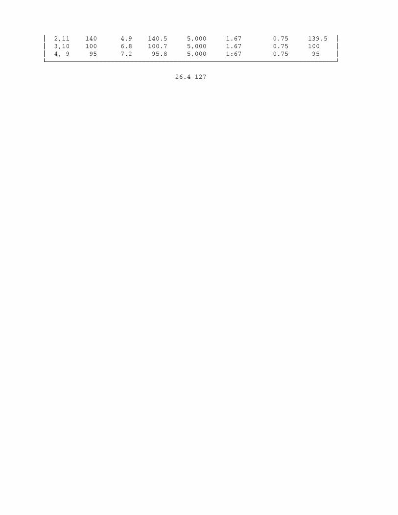
³ 2,11 140 4.9 140.5 5,000 1.67 0.75 139.5 ³³ 3,10 100 6.8 100.7 5,000 1.67 0.75 100 ³³ 4, 9 95 7.2 95.8 5,000 1:67 0.75 95 ³ÀÄÄÄÄÄÄÄÄÄÄÄÄÄÄÄÄÄÄÄÄÄÄÄÄÄÄÄÄÄÄÄÄÄÄÄÄÄÄÄÄÄÄÄÄÄÄÄÄÄÄÄÄÄÄÄÄÄÄÄÄÄÄÄÄÄÄÄÄÄÄÄÄÄÄÙ
26.4-127
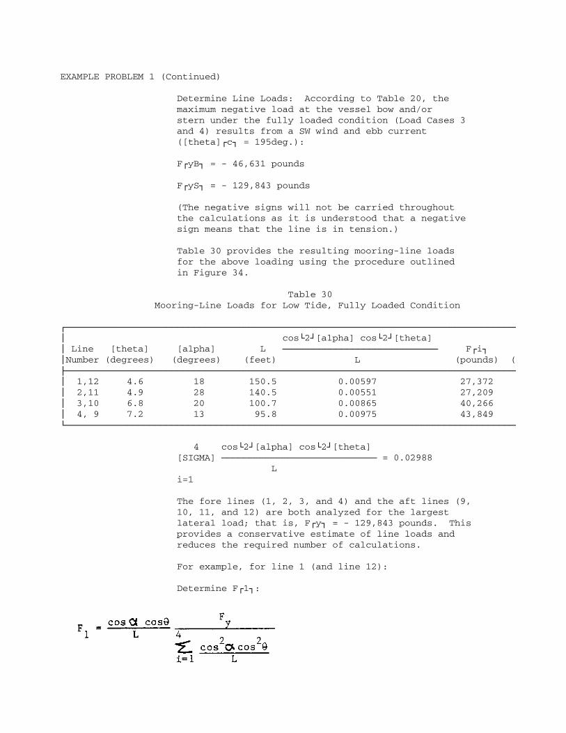
EXAMPLE PROBLEM 1 (Continued)
Determine Line Loads: According to Table 20, the maximum negative load at the vessel bow and/or stern under the fully loaded condition (Load Cases 3 and 4) results from a SW wind and ebb current ([theta]Úc¿ = 195deg.):
FÚyB¿ = - 46,631 pounds
FÚyS¿ = - 129,843 pounds
(The negative signs will not be carried throughout the calculations as it is understood that a negative sign means that the line is in tension.)
Table 30 provides the resulting mooring-line loads for the above loading using the procedure outlined in Figure 34.
Table 30 Mooring-Line Loads for Low Tide, Fully Loaded Condition
ÚÄÄÄÄÄÄÄÄÄÄÄÄÄÄÄÄÄÄÄÄÄÄÄÄÄÄÄÄÄÄÄÄÄÄÄÄÄÄÄÄÄÄÄÄÄÄÄÄÄÄÄÄÄÄÄÄÄÄÄÄÄÄÄÄÄÄÄÄÄÄÄÄÄÄÄÄÄÄÄÄij cosÀ2Ù[alpha] cosÀ2Ù[theta] ³ Line [theta] [alpha] L ÄÄÄÄÄÄÄÄÄÄÄÄÄÄÄÄÄÄÄÄÄÄÄÄÄÄÄÄ FÚi¿ ³Number (degrees) (degrees) (feet) L (pounds) (ÃÄÄÄÄÄÄÄÄÄÄÄÄÄÄÄÄÄÄÄÄÄÄÄÄÄÄÄÄÄÄÄÄÄÄÄÄÄÄÄÄÄÄÄÄÄÄÄÄÄÄÄÄÄÄÄÄÄÄÄÄÄÄÄÄÄÄÄÄÄÄÄÄÄÄÄÄÄÄÄÄij 1,12 4.6 18 150.5 0.00597 27,372 ³ 2,11 4.9 28 140.5 0.00551 27,209 ³ 3,10 6.8 20 100.7 0.00865 40,266 ³ 4, 9 7.2 13 95.8 0.00975 43,849 ÀÄÄÄÄÄÄÄÄÄÄÄÄÄÄÄÄÄÄÄÄÄÄÄÄÄÄÄÄÄÄÄÄÄÄÄÄÄÄÄÄÄÄÄÄÄÄÄÄÄÄÄÄÄÄÄÄÄÄÄÄÄÄÄÄÄÄÄÄÄÄÄÄÄÄÄÄÄÄÄÄÄ
4 cosÀ2Ù[alpha] cosÀ2Ù[theta] [SIGMA] ÄÄÄÄÄÄÄÄÄÄÄÄÄÄÄÄÄÄÄÄÄÄÄÄÄÄÄÄ = 0.02988 L i=1
The fore lines (1, 2, 3, and 4) and the aft lines (9, 10, 11, and 12) are both analyzed for the largest lateral load; that is, FÚy¿ = - 129,843 pounds. This provides a conservative estimate of line loads and reduces the required number of calculations.
For example, for line 1 (and line 12):
Determine FÚ1¿:
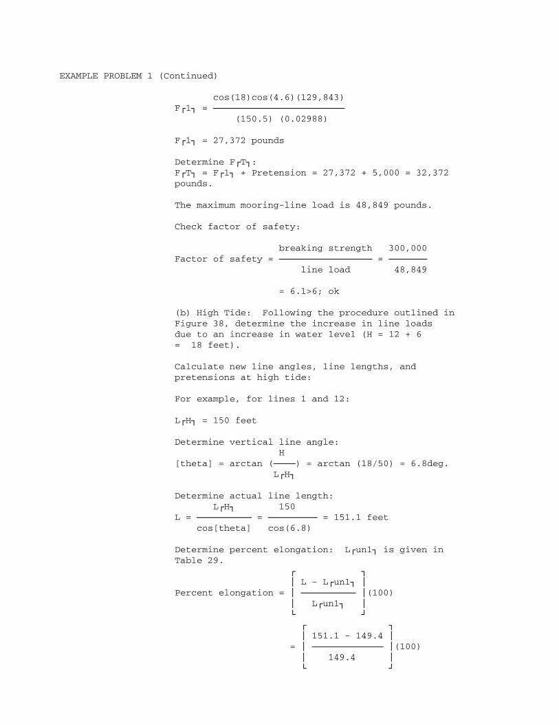
EXAMPLE PROBLEM 1 (Continued)
cos(18)cos(4.6)(129,843) FÚ1¿ = ÄÄÄÄÄÄÄÄÄÄÄÄÄÄÄÄÄÄÄÄÄÄÄÄ (150.5) (0.02988)
FÚ1¿ = 27,372 pounds
Determine FÚT¿: FÚT¿ = FÚ1¿ + Pretension = 27,372 + 5,000 = 32,372 pounds.
The maximum mooring-line load is 48,849 pounds.
Check factor of safety:
breaking strength 300,000 Factor of safety = ÄÄÄÄÄÄÄÄÄÄÄÄÄÄÄÄÄ = ÄÄÄÄÄÄÄ line load 48,849
= 6.1>6; ok
(b) High Tide: Following the procedure outlined in Figure 38, determine the increase in line loads due to an increase in water level (H = 12 + 6 = 18 feet).
Calculate new line angles, line lengths, and pretensions at high tide:
For example, for lines 1 and 12:
LÚH¿ = 150 feet
Determine vertical line angle: H [theta] = arctan (ÄÄÄÄ) = arctan (18/50) = 6.8deg. LÚH¿
Determine actual line length: LÚH¿ 150 L = ÄÄÄÄÄÄÄÄÄÄ = ÄÄÄÄÄÄÄÄÄ = 151.1 feet cos[theta] cos(6.8)
Determine percent elongation: LÚun1¿ is given in Table 29. Ú ¿ ³ L - LÚun1¿ ³ Percent elongation = ³ ÄÄÄÄÄÄÄÄÄÄ ³(100) ³ LÚun1¿ ³ À Ù Ú ¿ ³ 151.1 - 149.4 ³ = ³ ÄÄÄÄÄÄÄÄÄÄÄÄÄ ³(100) ³ 149.4 ³ À Ù

Percent elongation = 1.14 percent
Determine percent of breaking strength from Figure 7 for used polypropylene rope:
26.4-129

EXAMPLE PROBLEM 1 (Continued)
Percent breaking strength = 3.75 percent
New pretension = (0 .0375) (300,000) = 11,250 pounds
Similar calculations performed for each line are summarized in Table 31.
Table 31 Line Lengths and Pretensions For High Tide, Fully Loaded Condition
ÚÄÄÄÄÄÄÄÄÄÄÄÄÄÄÄÄÄÄÄÄÄÄÄÄÄÄÄÄÄÄÄÄÄÄÄÄÄÄÄÄÄÄÄÄÄÄÄÄÄÄÄÄÄÄÄÄÄÄÄÄÄÄÄÄÄÄÄÄÄÄÄÄÄÄ¿³ Percent of ³³ Line LÚH¿ [theta] L Percent Breaking New Pretension³³Number (feet) (degrees) (feet) Elongation Strength (pounds) ³ÃÄÄÄÄÄÄÄÄÄÄÄÄÄÄÄÄÄÄÄÄÄÄÄÄÄÄÄÄÄÄÄÄÄÄÄÄÄÄÄÄÄÄÄÄÄÄÄÄÄÄÄÄÄÄÄÄÄÄÄÄÄÄÄÄÄÄÄÄÄÄÄÄÄÄ´³ 1,12 150 6.8 151.1 1.14 3.75 11,250 ³³ 2,11 140 7.3 141.1 1.15 3.75 11,250 ³³ 3,10 100 10.2 101.6 1.6 7 21,000 ³³ 4, 9 95 10.7 96.7 0.9 8 24,000 ³ÀÄÄÄÄÄÄÄÄÄÄÄÄÄÄÄÄÄÄÄÄÄÄÄÄÄÄÄÄÄÄÄÄÄÄÄÄÄÄÄÄÄÄÄÄÄÄÄÄÄÄÄÄÄÄÄÄÄÄÄÄÄÄÄÄÄÄÄÄÄÄÄÄÄÄÙ
Mooring-line loads for a high tide and a fully loaded condition are computed in a manner similar to that used above for low tide. Results are given in Table 32.
Table 32 Mooring-Line Loads for High Tide, Fully Loaded Condition
ÚÄÄÄÄÄÄÄÄÄÄÄÄÄÄÄÄÄÄÄÄÄÄÄÄÄÄÄÄÄÄÄÄÄÄÄÄÄÄÄÄÄÄÄÄÄÄÄÄÄÄÄÄÄÄÄÄÄÄÄÄÄÄÄÄÄÄÄÄÄÄÄÄÄÄÄÄÄÄÄÄij cosÀ2Ù[alpha] cosÀ2Ù[theta] ³ Line [theta] [alpha] L ÄÄÄÄÄÄÄÄÄÄÄÄÄÄÄÄÄÄÄÄÄÄÄÄÄÄÄÄÄ FÚi¿ ³Number (degrees) (degrees) (feet) L (pounds) (ÃÄÄÄÄÄÄÄÄÄÄÄÄÄÄÄÄÄÄÄÄÄÄÄÄÄÄÄÄÄÄÄÄÄÄÄÄÄÄÄÄÄÄÄÄÄÄÄÄÄÄÄÄÄÄÄÄÄÄÄÄÄÄÄÄÄÄÄÄÄÄÄÄÄÄÄÄÄÄÄÄij 1,12 6.8 18 151.1 0.0059 28,177 ³ 2,11 7.3 28 141.1 0.0054 27,984 ³ 3,10 10.2 20 106.6 0.0080 39,115 ³ 4, 9 10.7 13 96.7 0.0095 44,638 ÀÄÄÄÄÄÄÄÄÄÄÄÄÄÄÄÄÄÄÄÄÄÄÄÄÄÄÄÄÄÄÄÄÄÄÄÄÄÄÄÄÄÄÄÄÄÄÄÄÄÄÄÄÄÄÄÄÄÄÄÄÄÄÄÄÄÄÄÄÄÄÄÄÄÄÄÄÄÄÄÄÄ
The maximum mooring-line load is 68,638 pounds.
Check factor of safety:
26.4-130

EXAMPLE PROBLEM 1 (Continued)
breaking strength 300,000 Factor of safety = ÄÄÄÄÄÄÄÄÄÄÄÄÄÄÄÄÄ = ÄÄÄÄÄÄÄ line load 68,638
= 4.4<6
Therefore, unless the mooring lines are tended, the factor of safety will be less than required, and stronger mooring line will be required.
(2) Case 2 (FÚyB¿ and FÚyS¿ both positive): Determine breasting-structure loads using the procedure outlined in Figure 35. From Table 20, the maximum positive lateral load under the fully loaded condition is due to an E wind with a flood current:
FÚyT¿ = 272,175 pounds
MÚxyt¿ = 1.59 x 10À6Ù foot-pounds
FÚyT¿ MÚxyt¿ 272,175 1.59 x 10À6Ù FÚA¿ = ÄÄÄÄÄ ÄÄÄÄÄÄ ÄÄÄÄÄÄÄ ÄÄÄÄÄÄÄÄÄÄÄÄ 2 LÚF¿ 2 320
FÚA¿ = 131,120 pounds
FÚF¿ = FÚyT¿ - FÚA¿ = 272,175 - 131,120
FÚF¿ = 141,055 pounds
f. Longitudinal Load: Fully Loaded Condition:
(1) Low Tide: Determine vertical line angles and line lengths; H = 12 feet. The calculations, identical to those above for lateral load and yaw moment, are summarized in Table 33.
Table 33 Unloaded Line Lengths for Low Tide, Fully Loaded Condition
ÚÄÄÄÄÄÄÄÄÄÄÄÄÄÄÄÄÄÄÄÄÄÄÄÄÄÄÄÄÄÄÄÄÄÄÄÄÄÄÄÄÄÄÄÄÄÄÄÄÄÄÄÄÄÄÄÄÄÄÄÄÄÄÄÄÄÄÄÄÄÄÄÄÄÄ¿³ Percent of ³³ Line LÚH¿ [theta] L Preload Breaking Percent LÚun1¿ ³³Number (feet) (degrees) (feet) (pounds) Strength Elongation (feet) ³ÃÄÄÄÄÄÄÄÄÄÄÄÄÄÄÄÄÄÄÄÄÄÄÄÄÄÄÄÄÄÄÄÄÄÄÄÄÄÄÄÄÄÄÄÄÄÄÄÄÄÄÄÄÄÄÄÄÄÄÄÄÄÄÄÄÄÄÄÄÄÄÄÄÄÄ´³ 5,8 300 2.3 300.2 5,000 1.67 0.75 298 ³³ 6,7 260 2.6 260.3 5,000 1.67 0.75 258.4 ³ÀÄÄÄÄÄÄÄÄÄÄÄÄÄÄÄÄÄÄÄÄÄÄÄÄÄÄÄÄÄÄÄÄÄÄÄÄÄÄÄÄÄÄÄÄÄÄÄÄÄÄÄÄÄÄÄÄÄÄÄÄÄÄÄÄÄÄÄÄÄÄÄÄÄÄÙ
Determine Line Loads: According to Table 20, the maximum longitudinal load on the mooring under the fully loaded
26.4-131

EXAMPLE PROBLEM 1 (Continued)
condition is FÚxT¿ = - 34,454 pounds for a N wind and a flood current. Table 34 provides the mooring-line loads obtained using the procedure outlined in Figure 37.
Table 34 Mooring-Line Loads for Low Tide, Fully Loaded Condition
ÚÄÄÄÄÄÄÄÄÄÄÄÄÄÄÄÄÄÄÄÄÄÄÄÄÄÄÄÄÄÄÄÄÄÄÄÄÄÄÄÄÄÄÄÄÄÄÄÄÄÄÄÄÄÄÄÄÄÄÄÄÄÄÄÄÄÄÄÄÄÄÄÄÄÄÄÄÄÄÄÄij cosÀ2Ù[beta] cosÀ2Ù[theta] ³ Line [theta] [beta] L ÄÄÄÄÄÄÄÄÄÄÄÄÄÄÄÄÄÄÄÄÄÄÄÄÄ FÚi¿ FÚT³Number (degrees) (degrees) (feet) L (pounds) (pouÃÄÄÄÄÄÄÄÄÄÄÄÄÄÄÄÄÄÄÄÄÄÄÄÄÄÄÄÄÄÄÄÄÄÄÄÄÄÄÄÄÄÄÄÄÄÄÄÄÄÄÄÄÄÄÄÄÄÄÄÄÄÄÄÄÄÄÄÄÄÄÄÄÄÄÄÄÄÄÄÄij 5,8 2.3 3.5 300.2 0.0033 16,122 21,1³ 6,7 2.6 3.2 260.3 0.0038 18,595 23,5ÀÄÄÄÄÄÄÄÄÄÄÄÄÄÄÄÄÄÄÄÄÄÄÄÄÄÄÄÄÄÄÄÄÄÄÄÄÄÄÄÄÄÄÄÄÄÄÄÄÄÄÄÄÄÄÄÄÄÄÄÄÄÄÄÄÄÄÄÄÄÄÄÄÄÄÄÄÄÄÄÄÄ
The maximum mooring-line load is 23,595 pounds.
Check factor of safety:
breaking strength 300,000 Factor of safety = ÄÄÄÄÄÄÄÄÄÄÄÄÄÄÄÄÄ = ÄÄÄÄÄÄÄ line load 23,595
= 12.7>6; ok
(2) High Tide: Following the procedure outlined in Figure 38, determine the increase in line loads due to an increase in water level (H = 12 + 6 = 18 feet).
New line angles, line lengths, and pretensions at high tide are calculated in a manner similar to that for the lateral load above. The results are given in Table 35.
Table 35 Line Lengths and Pretensions for High Tide, Fully Loaded Condition

ÚÄÄÄÄÄÄÄÄÄÄÄÄÄÄÄÄÄÄÄÄÄÄÄÄÄÄÄÄÄÄÄÄÄÄÄÄÄÄÄÄÄÄÄÄÄÄÄÄÄÄÄÄÄÄÄÄÄÄÄÄÄÄÄÄÄÄÄÄÄÄÄÄÄÄ¿³ Percent of ³³ Line LÚH¿ [theta] L Percent Breaking New Pretension³³Number (feet) (degrees) (feet) Elongation Strength (pounds) ³ÃÄÄÄÄÄÄÄÄÄÄÄÄÄÄÄÄÄÄÄÄÄÄÄÄÄÄÄÄÄÄÄÄÄÄÄÄÄÄÄÄÄÄÄÄÄÄÄÄÄÄÄÄÄÄÄÄÄÄÄÄÄÄÄÄÄÄÄÄÄÄÄÄÄÄ´³ 5,8 300 3.4 300.5 0.84 3.7 11,100 ³³ 6,7 260 4 260.6 0.85 3.7 11,100 ³ÀÄÄÄÄÄÄÄÄÄÄÄÄÄÄÄÄÄÄÄÄÄÄÄÄÄÄÄÄÄÄÄÄÄÄÄÄÄÄÄÄÄÄÄÄÄÄÄÄÄÄÄÄÄÄÄÄÄÄÄÄÄÄÄÄÄÄÄÄÄÄÄÄÄÄÙ
26.4-132

EXAMPLE PROBLEM 1 (Continued)
Mooring-line loads for a high tide and a light-loaded condition are computed in a manner similar to that used above for low tide. Results are given in Table 36.
Table 36 Mooring-Line Loads for High Tide, Fully Loaded ConditionÚÄÄÄÄÄÄÄÄÄÄÄÄÄÄÄÄÄÄÄÄÄÄÄÄÄÄÄÄÄÄÄÄÄÄÄÄÄÄÄÄÄÄÄÄÄÄÄÄÄÄÄÄÄÄÄÄÄÄÄÄÄÄÄÄÄÄÄÄÄÄÄÄÄÄÄÄÄÄÄÄij cosÀ2Ù[beta] cosÀ2Ù[theta] ³ Line [theta] [beta] L ÄÄÄÄÄÄÄÄÄÄÄÄÄÄÄÄÄÄÄÄÄÄÄÄÄÄÄ FÚi¿ FÚ³Number (degrees) (degrees) (feet) L (pounds) (pouÃÄÄÄÄÄÄÄÄÄÄÄÄÄÄÄÄÄÄÄÄÄÄÄÄÄÄÄÄÄÄÄÄÄÄÄÄÄÄÄÄÄÄÄÄÄÄÄÄÄÄÄÄÄÄÄÄÄÄÄÄÄÄÄÄÄÄÄÄÄÄÄÄÄÄÄÄÄÄÄÄij 5,8 3.4 3.5 300.5 0.0033 16,090 27,1³ 6,7 4 3.2 260.4 0.0038 18,561 29,6ÀÄÄÄÄÄÄÄÄÄÄÄÄÄÄÄÄÄÄÄÄÄÄÄÄÄÄÄÄÄÄÄÄÄÄÄÄÄÄÄÄÄÄÄÄÄÄÄÄÄÄÄÄÄÄÄÄÄÄÄÄÄÄÄÄÄÄÄÄÄÄÄÄÄÄÄÄÄÄÄÄÄ
The maximum mooring-line load is 29,661 pounds.
Check factor of safety:
breaking strength 300,000 Factor of safety = ÄÄÄÄÄÄÄÄÄÄÄÄÄÄÄÄÄ = ÄÄÄÄÄÄÄ line load 29,661
= 10.1>6; ok
g. Berthing Loads: Check for the fully loaded condition only as this will provide the maximum KEÚB¿. Determine KEÚB¿ using the procedure outlined in Figure 40:
(1) Determine Vessel Weight:
D = 53,600 long tons
Convert long tons to pounds to obtain W:
W = 2,240 D = (2,240)(53,600) = 1.2006 x 10À8Ù pounds
(2) Determine Normal Component of Approach Velocity:

VÚN¿ is given in Figure 42 for sheltered conditions and vessel displacement in long tons (D = 53,600 long tons):
VÚN¿ = 0.19 foot per second
(3) Determine Berthing Coefficient:
CÚB¿ = 0.5
26.4-133

EXAMPLE PROBLEM 1 (Continued)
(4) Determine Hydrodynamic Mass Coefficient:
CÚH¿ is given in Figure 43 as a function of B/wd and T/wd.
B/wd = 107/65 = 1.65
T/wd = 41/65 = 0.63
From Figure 43:
CÚH¿ = 3.65
(5) Determine KEÚB¿:
WEQ. (4-67) KEÚB¿ = 1/2 Ä VÚN¿À2Ù CÚB¿ CÚH¿ g
1.2006 x 10À8Ù KEÚB¿ = 1/2 (ÄÄÄÄÄÄÄÄÄÄÄÄÄÄ)(0.19)À2Ù(0.5)(3.65) 32.2
KEÚB¿ = 122,824 foot-pounds = 122.8 foot-kips
6. Design of Fixed-Mooring Structures:
a. Breasting structures: Design the breasting structures following the procedure outlined in Figure 44, assuming the breasting structures are rigid:
(1) Determine Maximum Mooring Load: The maximum mooring load on the breasting structures determined above is FÚM¿ = 141,055 pounds or FÚM¿ = 141 kips.
(2) Rigid or Flexible Design: For the purposes of this example problem, assume the breasting structures to be rigid.
(3) Design Structure and Select Preliminary Fendering System: A giant cylindrical fender will be used for the purposes of this example problem. As a first try, check a 3-foot section of 60-inch O.D. fender.
(4) Develop Load-Deflection Curve for Fender: The load-deflection curve for the giant cylindrical fender is shown in Figure 48 (top). An energy absorption-deflection curve is also shown in Figure 48 (bottom); the use of this curve simplifies the design process as it eliminates the need to determine the area under the load-deflection curve.
122.8 foot-kips Energy to be absorbed per foot = ÄÄÄÄÄÄÄÄÄÄÄÄÄÄÄ 3 feet

= 40.9 foot-kips per foot
26.4-134


EXAMPLE PROBLEM 1 (Continued)
From Figure 48 (bottom), the fender deflects about 28.5 inches to absorb 40.9 foot-kips per foot of length. From the load-deflection curve in Figure 48 (top), the load at 28.5 inches deflection is 45 kips per foot.
Total load, FÚB¿, in 3-foot fender due to berthing:
FÚB¿ = (3) (45) = 135 kips
FÚB¿ = 135 kips [similar, equals]FÚM¿ = 141 kips
No further iterations are required.
The following pages illustrate the use of the computer program described inAppendix B of DM-26.5 to solve Example Problem 1. The first page ofcomputer output summarizes the geometry of the mooring, and themooring-line and fender characteristics. Page 2 summarizes the loads inthe mooring elements for the vessel in a light-loaded condition under a SWwind and ebb current. Page 3 summarizes the loads in the mooring elementsfor the vessel in a light-loaded condition under an E wind and a floodcurrent.
26.4-136

FIXED MOORING ANALYSIS
EXAMPLE1
FENDER INPUT DATA:
Fender Location Minimum Maximum No. X Y Load Defl Load Defl
1 160.0 65.0 0 0.0 180000 1.8 2 -160.0 65.0 0 0.0 180000 1.8
MOORING LINE INPUT DATA:
Line Chock Coordinates Anchor Coordinates No. X Y Z X Y Z
1 410.0 0.0 36.0 450.0 140.0 0.0 2 385.0 20.0 36.0 450.0 140.0 0.0 3 290.0 40.0 36.0 250.0 140.0 0.0 4 280.0 40.0 36.0 250.0 140.0 0.0 5 140.0 50.0 36.0 -160.0 65.0 0.0 6 110.0 50.0 36.0 -160.0 65.0 0.0 7 -110.0 50.0 36.0 160.0 65.0 0.0 8 -140.0 50.0 36.0 160.0 65.0 0.0 9 -280.0 50.0 36.0 -250.0 140.0 0.0 10 -290.0 50.0 36.0 -250.0 140.0 0.0 11 -395.0 30.0 36.0 -450.0 140.0 0.0 12 -395.0 0.0 36.0 -450.0 140.0 0.0
Line Type Length Breaking Preload Steel Hawser No. Code On-deck Tail Strength Modulus Area
1 3 0.0 0.0 300000 5000 2 3 0.0 0.0 300000 5000 3 3 0.0 0.0 300000 5000 4 3 0.0 0.0 300000 5000 5 3 0.0 0.0 300000 5000 6 3 0.0 0.0 300000 5000 7 3 0.0 0.0 300000 5000 8 3 0.0 0.0 300000 5000 9 3 0.0 0.0 300000 5000 10 3 0.0 0.0 300000 5000 11 3 0.0 0.0 300000 5000 12 3 0.0 0.0 300000 5000
RESULTS FOR LOAD CASE 0 INITIAL POSITION Tide = 0
Applied Load Load Error Displacement
Surge 0.000E+00 -0 -0.0 Sway 0.000E+00 0 0.4 Yaw 0.000E+00 -172 0.0
26.4-137

MOORING ANALYSIS EXAMPLE1 Page 2
Mooring Legs
No. Horiz Load Total Load Chock-Anchor Horiz Angle
Fenders 1 14429 0.4 90.0 2 14075 0.3 90.0
Lines 1 3890 4007 145.5 74.0 2 3912 4047 136.2 61.5 3 3570 3766 107.4 111.9 4 3495 3690 104.1 106.8 5 4932 4960 300.4 177.2 6 4918 4961 270.4 176.9 7 4938 4982 270.4 3.1 8 4951 4907 300.4 2.8 9 3448 3689 94.5 71.510 3546 3777 98.2 66.011 3826 3987 122.7 116.612 4002 4115 150.1 111.5
RESULTS FOR LOAD CASE 1 L.L. SW WIND EBB CURRENT Tide = 0
Applied Load Load Error Displacement
Surge 2.145E+04 0 1.9 Sway -1.567E+05 1 -4.1 Vow 2.080E+07 86 0.3
Mooring Legs
No. Horiz Load Total Load Chock-Anchor Horiz Angle
Fenders 1 0 -3.3 90.3 2 0 -5.0 90.3
Lines 1 8977 9242 147.1 75.0 2 8018 8288 137.5 62.7 3 16835 17701 110.8 112.1 4 17138 18073 107.5 107.2 5 7696 7750 302.3 176.5 6 8026 8095 272.3 176.1 7 2733 2758 269.0 4.2 8 2922 2943 299.0 3.8 9 29296 31148 99.7 73.510 26615 28193 103.0 68.211 32477 33712 129.5 116.112 27441 28154 156.9 111.3
26.4-138

MOORING ANALYSIS EXAMPLE1 Page 3
RESULTS FOR LOAD CASE 2 L.L. E WIND FLOOD CURRENT Tide = 0
Applied Load Load Error Displacement
Surge -2.586E+03 -0 -0.3 Sway 2.992E+05 0 1.7 Vow 2.800E+05 36 0.0
Mooring Legs
No. Horiz Load Total Load Chock-Anchor Horiz Angle
Fenders 1 152268 1.7 90.0 2 149304 1.7 90.0
Lines 1 519 535 144.1 73.7 2 893 924 135.1 61.1 3 0 0 106.0 112.0 4 0 0 102.7 106.8 5 4354 4386 300.0 177.5 6 4268 4306 270. 0 177.2 7 5364 5412 270.7 2.8 8 5346 5385 300.6 2.5 9 0 0 93.4 71.010 0 0 97.1 65.411 0 0 121.3 116.812 226 232 140.7 111.6
26.4-139

EXAMPLE PROBLEM 2: SPUD MOORING FOR FLOATING DRYDOCK
Given: a. Spud mooring for an AFDM-8 with an AS-36 on the blocks. (Mooring configuration is Shown in Figure 49.) b. The water depth at the site is 60 feet mean lower low water (MLLW). c. The tide range from MLLW to mean higher high water (MHHW) is 8 feet. d. Wind data for the site are given in Table 37. e. Currents are negligible.
Find: Determine loads on the spud mooring due to wind load.
Solution: 1. Determine Vessel Characteristics for AFDM-8 from DM-26.6, Table 3:
Length on pontoons, L = 552 feet Extreme beam, B = 124 feet Maximum draft, T = 52.8 feet Draft over blocks, T = 29.6 feet Draft with vessel on blocks, T = 16 feet Maximum displacement, D = 43,300 long tons Displacement with maximum vessel on blocks, D = 27,200 long tons Light displacement, D = 7,800 long tons Broadside wind area with maximum vessel on blocks, AÚy¿ = 62,000 square feet Frontal wind area with maximum vessel on blocks, AÚx¿ = 10,800 square feet
2. Mooring Configuration: mooring configuration is shown in Figure 49.
3. Evaluate Environmental Conditions:
a. Seafloor Soil Conditions: This example problem illustrates the procedures for determining loads on fixed-mooring structures, but does not include structural-design calculations. Consequently, although they are important in structural design, soil conditions are not needed for this example problem.
b. Design Water Depth:
(1) Water depth at low tide, wdÚlow tide¿ = 60 feet
(2) Water depth at high tide, wdÚhigh tide¿ = 60 + 8 = 68 feet
c. Design Wind:
(1) Obtain Wind Data: Wind data obtained for the site are presented in Table 37. These data provide yearly maximum windspeeds for all directions combined (that is, directional data are not available). Therefore, the
26.4-140
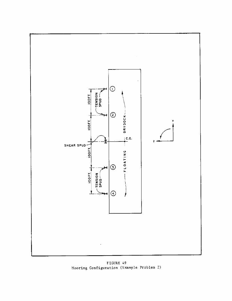

EXAMPLE PROBLEM 2 (Continued)
TABLE 37 Wind Data for Site
ÚÄÄÄÄÄÄÄÄÄÄÄÄÄÄÄÄÄÄÄÄÄÄÄÄÄÄÄÄÄÄÄÄÄÄÄÄÄÄÄÄÄÄÄÄÄÄÄÄÄÄÄÄÄÄÄÄÄÄÄÄÄÄÄÄÄÄÄÄÄÄÄÄÄÄ¿³ Peak-Gust Windspeed ³³ Year (miles per hour) Direction ³ÃÄÄÄÄÄÄÄÄÄÄÄÄÄÄÄÄÄÄÄÄÄÄÄÄÄÄÄÄÄÄÄÄÄÄÄÄÄÄÄÄÄÄÄÄÄÄÄÄÄÄÄÄÄÄÄÄÄÄÄÄÄÄÄÄÄÄÄÄÄÄÄÄÄÄ´³ 1950 62 E ³³ 1951 38 NE ³³ 1952 53 N ³³ 1953 46 SW ³³ 1954 41 S ³³ 1955 41 NE ³³ 1956 43 N ³³ 1957 41 S ³³ 1958 38 W ³³ 1959 34 S ³³ 1960 41 NE ³³ 1961 42 SW ³³ 1962 47 E ³³ 1963 54 N ³³ 1964 70 N ³³ 1965 50 E ³³ 1966 42 E ³³ 1967 65 NE ³³ 1968 46 N ³³ 1969 50 N ³³ 1970 39 SE ³³ 1971 46 NW ³³ 1972 44 NW ³³ 1973 47 W ³³ 1974 44 SE ³³ 1975 60 N ³³ 1976 42 W ³³ 1977 34 W ³³ 1978 39 SW ³³ 1979 35 NE ³ÀÄÄÄÄÄÄÄÄÄÄÄÄÄÄÄÄÄÄÄÄÄÄÄÄÄÄÄÄÄÄÄÄÄÄÄÄÄÄÄÄÄÄÄÄÄÄÄÄÄÄÄÄÄÄÄÄÄÄÄÄÄÄÄÄÄÄÄÄÄÄÄÄÄÄÙ
[1]Data were collected over water at an elevation of 43 feet.
26.4-142
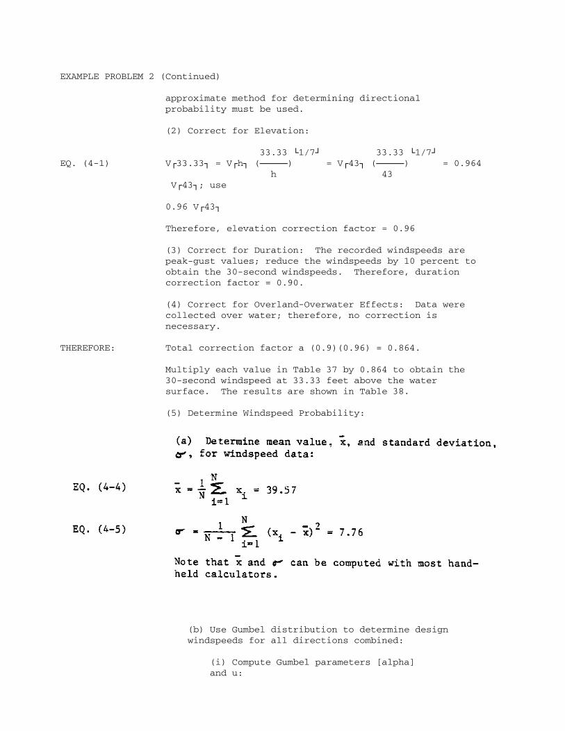
EXAMPLE PROBLEM 2 (Continued)
approximate method for determining directional probability must be used.
(2) Correct for Elevation:
33.33 À1/7Ù 33.33 À1/7ÙEQ. (4-1) VÚ33.33¿ = VÚh¿ (ÄÄÄÄÄ) = VÚ43¿ (ÄÄÄÄÄ) = 0.964 h 43 VÚ43¿; use
0.96 VÚ43¿
Therefore, elevation correction factor = 0.96
(3) Correct for Duration: The recorded windspeeds are peak-gust values; reduce the windspeeds by 10 percent to obtain the 30-second windspeeds. Therefore, duration correction factor = 0.90.
(4) Correct for Overland-Overwater Effects: Data were collected over water; therefore, no correction is necessary.
THEREFORE: Total correction factor a (0.9)(0.96) = 0.864.
Multiply each value in Table 37 by 0.864 to obtain the 30-second windspeed at 33.33 feet above the water surface. The results are shown in Table 38.
(5) Determine Windspeed Probability:
(b) Use Gumbel distribution to determine design windspeeds for all directions combined:
(i) Compute Gumbel parameters [alpha] and u:
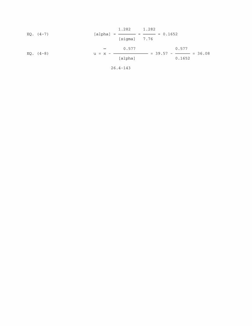
1.282 1.282EQ. (4-7) [alpha] = ÄÄÄÄÄÄÄ = ÄÄÄÄÄ = 0.1652 [sigma] 7.76
Ä 0.577 0.577EQ. (4-8) u = x - ÄÄÄÄÄÄÄÄÄÄÄÄÄÄ = 39.57 - ÄÄÄÄÄÄ = 36.08 [alpha] 0.1652
26.4-143

EXAMPLE PROBLEM 2 (Continued)
TABLE 38 Adjusted Wind Data for Site
ÚÄÄÄÄÄÄÄÄÄÄÄÄÄÄÄÄÄÄÄÄÄÄÄÄÄÄÄÄÄÄÄÄÄÄÄÄÄÄÄÄÄÄÄÄÄÄÄÄÄÄÄÄÄÄÄÄÄÄÄÄÄÄÄÄÄÄÄÄÄÄÄÄÄÄ¿³ Peak-Gust Windspeed ³³ Year (miles per hour) Direction ³ÃÄÄÄÄÄÄÄÄÄÄÄÄÄÄÄÄÄÄÄÄÄÄÄÄÄÄÄÄÄÄÄÄÄÄÄÄÄÄÄÄÄÄÄÄÄÄÄÄÄÄÄÄÄÄÄÄÄÄÄÄÄÄÄÄÄÄÄÄÄÄÄÄÄÄ´³ 1950 53.6 E ³³ 1951 32.8 NE ³³ 1952 45.8 N ³³ 1953 39.7 SW ³³ 1954 35.4 S ³³ 1955 35.4 NE ³³ 1956 37.2 N ³³ 1957 35.4 S ³³ 1958 32.8 W ³³ 1959 29.4 S ³³ 1960 35.4 NE ³³ 1961 36.3 SW ³³ 1962 40.6 E ³³ 1963 46.7 N ³³ 1964 60.5 N ³³ 1965 43.2 E ³³ 1966 36.3 E ³³ 1967 56.2 NE ³³ 1968 39.7 N ³³ 1969 43.2 N ³³ 1970 33.7 SE ³³ 1971 39.7 NW ³³ 1972 38.0 NW ³³ 1973 40.6 W ³³ 1974 38.0 SE ³³ 1975 51.8 N ³³ 1976 36.3 W ³³ 1977 29.4 W ³³ 1978 33.7 SW ³³ 1979 30.2 NE ³ ÄÄÄÄÄÄÄÄÄÄÄÄÄÄÄÄÄÄÄÄÄÄÄÄÄÄÄÄÄÄÄÄÄÄÄÄÄÄÄÄÄÄÄÄÄÄÄÄÄÄÄÄÄÄÄÄÄÄÄÄÄÄÄÄÄÄÄÄÄÄÄÄÄÄ
26.4-144

EXAMPLE PROBLEM 2 (Continued)
(ii) Compute VR for 25- and 50-year return periods:
1n {- 1n [1 - P(X >/= x)]}EQ. (4-6) VÚR¿ = u - ÄÄÄÄÄÄÄÄÄÄÄÄÄÄÄÄÄÄÄÄÄÄÄÄÄÄ [alpha]
From Table 4, for a return period of 25 years, P(X >/= x) = 0.04, and for a return period of 50 years, P(X >/= x) = 0.02.
1n [- 1n (1 - 0.04)]THEN: VÚ25¿ = 36.08 - ÄÄÄÄÄÄÄÄÄÄÄÄÄÄÄÄÄÄÄÄ 0.1652 = 55.4 miles per hour
1n [- 1n (1 - 0.02)] VÚ50¿ = 36.08 - ÄÄÄÄÄÄÄÄÄÄÄÄÄÄÄÄÄÄÄÄ 0.1652 = 59.7 miles per hour
These two points are plotted on Gumbel paper in Figure 50 and designated "all directions" on the figure.
(c) Determine directional probabilities: Find P(X >/= x) = 0, the probability of exceedence for a windspeed from direction e, where 0 is one of the eight compass points (N, NE, E, SE, S, SW, W, and NW):
NÚ[theta]¿EQ. (4-9) P(X >/= x)³Ú[theta]¿ = P(X >/= x) ÄÄÄÄÄÄÄÄÄÄ N
P(X >/= x) = 0.02 for a return period of 50 years
NÚtheta¿ is determined by counting the number of times that the extreme wind came from a particular direction (in Table 38).
N is the total number of extreme windspeeds in the data (in Table 38): N = 30
Values for NÚ[theta]¿ and NÚ[theta]¿/N are given in Table 39.
For example, for north:
7SUBSTITUTING: P(X >/= x)³Útheta¿ = (0.02)(ÄÄ) = 0.0047 30
Values of P(X >/= x)³Ú[theta]¿ for the eight compass

points are given in Table 40.
The probability of exceedence [P(X >/= x)]³Ú[theta]¿] for each compass point is plotted on Gumbel paper versus
26.4-145
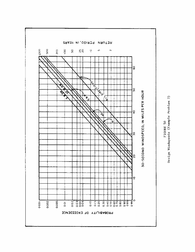
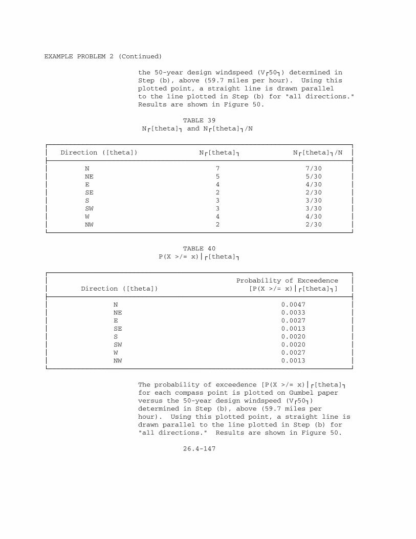
EXAMPLE PROBLEM 2 (Continued)
the 50-year design windspeed (VÚ50¿) determined in Step (b), above (59.7 miles per hour). Using this plotted point, a straight line is drawn parallel to the line plotted in Step (b) for "all directions." Results are shown in Figure 50.
TABLE 39 NÚ[theta]¿ and NÚ[theta]¿/N
ÚÄÄÄÄÄÄÄÄÄÄÄÄÄÄÄÄÄÄÄÄÄÄÄÄÄÄÄÄÄÄÄÄÄÄÄÄÄÄÄÄÄÄÄÄÄÄÄÄÄÄÄÄÄÄÄÄÄÄÄÄÄÄÄÄÄÄÄÄÄÄÄÄÄÄ¿³ Direction ([theta]) NÚ[theta]¿ NÚ[theta]¿/N ³ÃÄÄÄÄÄÄÄÄÄÄÄÄÄÄÄÄÄÄÄÄÄÄÄÄÄÄÄÄÄÄÄÄÄÄÄÄÄÄÄÄÄÄÄÄÄÄÄÄÄÄÄÄÄÄÄÄÄÄÄÄÄÄÄÄÄÄÄÄÄÄÄÄÄÄ´³ N 7 7/30 ³³ NE 5 5/30 ³³ E 4 4/30 ³³ SE 2 2/30 ³³ S 3 3/30 ³³ SW 3 3/30 ³³ W 4 4/30 ³³ NW 2 2/30 ³ÀÄÄÄÄÄÄÄÄÄÄÄÄÄÄÄÄÄÄÄÄÄÄÄÄÄÄÄÄÄÄÄÄÄÄÄÄÄÄÄÄÄÄÄÄÄÄÄÄÄÄÄÄÄÄÄÄÄÄÄÄÄÄÄÄÄÄÄÄÄÄÄÄÄÄÙ
TABLE 40 P(X >/= x)³Ú[theta]¿
ÚÄÄÄÄÄÄÄÄÄÄÄÄÄÄÄÄÄÄÄÄÄÄÄÄÄÄÄÄÄÄÄÄÄÄÄÄÄÄÄÄÄÄÄÄÄÄÄÄÄÄÄÄÄÄÄÄÄÄÄÄÄÄÄÄÄÄÄÄÄÄÄÄÄÄ¿³ Probability of Exceedence ³³ Direction ([theta]) [P(X >/= x)³Ú[theta]¿] ³ÃÄÄÄÄÄÄÄÄÄÄÄÄÄÄÄÄÄÄÄÄÄÄÄÄÄÄÄÄÄÄÄÄÄÄÄÄÄÄÄÄÄÄÄÄÄÄÄÄÄÄÄÄÄÄÄÄÄÄÄÄÄÄÄÄÄÄÄÄÄÄÄÄÄÄ´³ N 0.0047 ³³ NE 0.0033 ³³ E 0.0027 ³³ SE 0.0013 ³³ S 0.0020 ³³ SW 0.0020 ³³ W 0.0027 ³³ NW 0.0013 ³ÀÄÄÄÄÄÄÄÄÄÄÄÄÄÄÄÄÄÄÄÄÄÄÄÄÄÄÄÄÄÄÄÄÄÄÄÄÄÄÄÄÄÄÄÄÄÄÄÄÄÄÄÄÄÄÄÄÄÄÄÄÄÄÄÄÄÄÄÄÄÄÄÄÄÄÙ
The probability of exceedence [P(X >/= x)³Ú[theta]¿ for each compass point is plotted on Gumbel paper versus the 50-year design windspeed (VÚ50¿) determined in Step (b), above (59.7 miles per hour). Using this plotted point, a straight line is drawn parallel to the line plotted in Step (b) for "all directions." Results are shown in Figure 50.
26.4-147
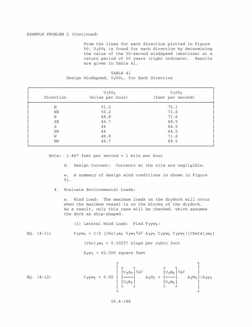
EXAMPLE PROBLEM 2 (Continued)
From the lines for each direction plotted in Figure 50, VÚ50¿ is found for each direction by determining the value of the 30-second windspeed (abscissa) at a return period of 50 years (right ordinate). Results are given in Table 41.
TABLE 41 Design Windspeed, VÚ50¿, for Each Direction
ÚÄÄÄÄÄÄÄÄÄÄÄÄÄÄÄÄÄÄÄÄÄÄÄÄÄÄÄÄÄÄÄÄÄÄÄÄÄÄÄÄÄÄÄÄÄÄÄÄÄÄÄÄÄÄÄÄÄÄÄÄÄÄÄÄÄÄÄÄÄÄÄÄÄÄ¿³ VÚ50¿ VÚ50¿ ³³ Direction (miles per hour) (feet per second) ³ÃÄÄÄÄÄÄÄÄÄÄÄÄÄÄÄÄÄÄÄÄÄÄÄÄÄÄÄÄÄÄÄÄÄÄÄÄÄÄÄÄÄÄÄÄÄÄÄÄÄÄÄÄÄÄÄÄÄÄÄÄÄÄÄÄÄÄÄÄÄÄÄÄÄÄ´³ N 51.2 75.1 ³³ NE 50.2 73.6 ³³ E 48.8 71.6 ³³ SE 46.7 68.5 ³³ S 44 64.5 ³³ SW 44 64.5 ³³ W 48.8 71.6 ³³ NW 46.7 68.5 ³ÀÄÄÄÄÄÄÄÄÄÄÄÄÄÄÄÄÄÄÄÄÄÄÄÄÄÄÄÄÄÄÄÄÄÄÄÄÄÄÄÄÄÄÄÄÄÄÄÄÄÄÄÄÄÄÄÄÄÄÄÄÄÄÄÄÄÄÄÄÄÄÄÄÄÄÙ
Note: 1.467 feet per second = 1 mile per hour
d. Design Current: Currents at the site are negligible.
e. A summary of design wind conditions is shown in Figure 51.
4. Evaluate Environmental Loads:
a. Wind Load: The maximum loads on the drydock will occur when the maximum vessel is on the blocks of the drydock. As a result, only this case will be checked, which assumes the dock as ship-shaped.
(1) Lateral Wind Load: Find FÚyw¿:
EQ. (4-11) FÚyw¿ = 1/2 [rho]Úa¿ VÚw¿À2Ù AÚy¿ CÚyw¿ fÚyw¿([theta]Úw¿)
[rho]Úa¿ = 0.00237 slugs per cubic foot
AÚy¿ = 62,000 square feet
Ú ¿ ³ Ú ¿ Ú ¿ ³ ³ ³VÚS¿³À2Ù ³VÚH¿³À2Ù ³EQ. (4-12) CÚyw¿ = 0.92 ³ ³ÄÄÄij AÚS¿ + ³ÄÄÄij AÚH¿³/AÚy¿ ³ ³VÚR¿³ ³VÚR¿³ ³ ³ À Ù À Ù ³ À Ù
26.4-148


EXAMPLE PROBLEM 2 (Continued)
Ú ¿ VÚS¿ ³hÚS¿³À1/7ÙEQ. (4-13) ÄÄÄÄ = ³ÄÄÄij VÚR¿ ³hÚR¿³ À Ù
Ú ¿ VÚH¿ ³hÚH¿³À1/7ÙEQ. (4-14) ÄÄÄÄ = ³ÄÄÄij VÚR¿ ³hÚR¿³ À Ù
hÚR¿ = 33.33 feet
Assume hÚs¿ = 50 feet and hÚH¿ = 20 feet:
Ú ¿ VÚS¿ ³ 50 ³À1/7ÙTHEN: ÄÄÄÄ = ³ÄÄÄÄij = 1.06 VÚR¿ ³33.33³ À Ù
Ú ¿ VÚH¿ ³ 20 ³À1/7ÙAND: ÄÄÄÄ = ³ÄÄÄÄij = 0.93 VÚR¿ ³33.33³ À Ù
Assume:
AÚS¿ = 0.30 AÚy¿ = (0.3)(62,000) = 18,600 square feet
AÚH¿ = 0.70 AÚy¿ = (0.7)(62,000) = 43,400 square feet
THEN: CÚyw¿ = 0.92 [(1.06)À2Ù (18,600) + (0.93)À2Ù (43,400)]/62,000
CÚyw¿ = 0.87
AND: FÚyw¿ = 1/2 (0.00237) VÚw¿À2Ù (62,000)(0.87) fÚyw¿([theta]Úw¿)
Ú ¿ ³ sin5[theta]Úw¿³ + ³sin[theta]Úw¿ - ÄÄÄÄÄÄÄÄÄÄÄÄÄij À 20 ÙEQ. (4-15) fÚyw¿([theta]Úw¿)= ÄÄÄÄÄÄÄÄÄÄÄÄÄÄÄÄÄÄÄÄÄÄÄÄÄÄÄÄÄÄÄÄÄÄ 1 - 1/20
FÚyw¿ = 63.92 VÚw¿À2Ù fÚyw¿([theta]Úw¿)
This equation is used to determine FÚyw¿ for VÚw¿ [theta]Úw¿. Results are given in Table 42.
(2) Longitudinal Wind Load: Find FÚxw¿:
EQ. (4-16) FÚxw¿ = 1/2 [rho]Úa¿ VÚw¿À2Ù AÚx¿ CÚxw¿ fÚxw¿([theta]Úw¿)
[rho]Úa¿ = 0.00237 slugs per cubic foot
26.4-150

EXAMPLE PROBLEM 2 (Continued)
TABLE 42 Lateral Wind Load
ÚÄÄÄÄÄÄÄÄÄÄÄÄÄÄÄÄÄÄÄÄÄÄÄÄÄÄÄÄÄÄÄÄÄÄÄÄÄÄÄÄÄÄÄÄÄÄÄÄÄÄÄÄÄÄÄÄÄÄÄÄÄÄÄÄÄÄÄÄÄÄÄÄÄÄ¿³ [theta]Úw¿ VÚw¿ FÚyw¿ ³³Direction (degrees) (feet per second) fÚyw¿([theta]Úw¿) (pounds) ³ÃÄÄÄÄÄÄÄÄÄÄÄÄÄÄÄÄÄÄÄÄÄÄÄÄÄÄÄÄÄÄÄÄÄÄÄÄÄÄÄÄÄÄÄÄÄÄÄÄÄÄÄÄÄÄÄÄÄÄÄÄÄÄÄÄÄÄÄÄÄÄÄÄÄÄ´³ N 0 75.1 0 0 ³³ NE 45 73.6 0.782 270,769 ³³ E 90 71.6 1 327,690 ³³ SE 135 68.5 0.782 234,544 ³³ S 180 64.5 0 0 ³³ SW 225 64.5 -0.782 -207,952 ³³ W 270 71.6 -1 -327,690 ³³ NW 315 68.5 -0.782 -234,544 ³ÀÄÄÄÄÄÄÄÄÄÄÄÄÄÄÄÄÄÄÄÄÄÄÄÄÄÄÄÄÄÄÄÄÄÄÄÄÄÄÄÄÄÄÄÄÄÄÄÄÄÄÄÄÄÄÄÄÄÄÄÄÄÄÄÄÄÄÄÄÄÄÄÄÄÄÙ
AÚx¿ = 10,800 square feet
EQ. (4-19) For AS-36, CÚxwB¿ = 0.70
EQ. (4-22) CÚxwS¿ = 0.80
Assume the AS-36 is above dock and has distributed superstructures: Ú ¿ ³ sin5[gamma]³ - ³sin[gamma] - ÄÄÄÄÄÄÄÄÄÄij À 10 ÙEQ. (4-26) fÚxw¿([theta]Úw¿) = ÄÄÄÄÄÄÄÄÄÄÄÄÄÄÄÄÄÄÄÄÄÄÄÄÄÄÄÄ 1 - 1/10
Ú ¿ ³ 90deg. ³EQ. (4-27) [gamma]Ú(-)¿ = ³ÄÄÄÄÄÄÄÄÄÄij [theta]Úw¿ + 90deg. for ³[theta]Úwz¿³ À Ù [theta]Úw¿<[theta]Úwz¿
Ú ¿ ³ 90deg. ³EQ. (4-28) [gamma]Ú(+)¿ = ³ÄÄÄÄÄÄÄÄÄÄÄÄÄÄÄÄÄÄÄÄij [theta]Úw¿ ³180deg. - [theta]Úwz¿³ À Ù Ú ¿ ³ 90deg. [theta]Úwz¿ ³ + ³180deg. - ÄÄÄÄÄÄÄÄÄÄÄÄÄÄÄÄÄÄÄÄij ³ 180deg. - [theta]Úwz¿³ À Ù for [theta]Úw¿>[theta]Úwz¿
From Table 5 (superstructure just forward of midship), [theta]Úwz¿ = 80deg..

Ú ¿ ³90deg.³THEN: [gamma](-) = ³ÄÄÄÄÄij [theta]Úw¿ + 90deg. = 1.125 ³80deg.³ À Ù [theta]Úw¿ + 90deg.
Ú ¿ ³ 90deg. ³AND: [gamma](+) = ³ÄÄÄÄÄÄÄÄÄÄÄÄÄÄÄij [theta]Úw¿ + ³180deg. - 80deg.³ À Ù Ú ¿ ³ (90deg.)(80deg.)³ ³180deg. - ÄÄÄÄÄÄÄÄÄÄÄÄÄÄÄij ³ 180deg. - 80deg.³ À Ù
= 0.9 [theta]Úw¿ + 108
26.4-151

EXAMPLE PROBLEM 2 (Continued)
THEN: FÚxw¿ = 1/2 (0.00237) VÚw¿À2Ù (10,800) CÚxw¿ fÚxw¿ ([theta]Úw¿)
FÚxw¿ = 12.8 VÚw¿À2Ù CÚxw¿ fÚxw¿ ([theta]Úw¿)
This equation is used to find FÚxw¿ for VÚw¿, CÚxw¿ (CÚxwB¿ or CÚxwS¿), and [theta]Úw¿. Results are given in Table 43.
TABLE 43 Longitudinal Wind Load
ÚÄÄÄÄÄÄÄÄÄÄÄÄÄÄÄÄÄÄÄÄÄÄÄÄÄÄÄÄÄÄÄÄÄÄÄÄÄÄÄÄÄÄÄÄÄÄÄÄÄÄÄÄÄÄÄÄÄÄÄÄÄÄÄÄÄÄÄÄÄÄÄÄÄÄ¿³Direction [theta]Úw¿ VÚw¿ FÚxw¿ ³³ (degrees) (feet per second) CÚx¿ fÚxw¿([theta]Úw¿) (pounds) ³ÃÄÄÄÄÄÄÄÄÄÄÄÄÄÄÄÄÄÄÄÄÄÄÄÄÄÄÄÄÄÄÄÄÄÄÄÄÄÄÄÄÄÄÄÄÄÄÄÄÄÄÄÄÄÄÄÄÄÄÄÄÄÄÄÄÄÄÄÄÄÄÄÄÄÄ´³ N 0 75.1 0.7 -1 -50,534 ³³ NE 45 73.6 0.7 -0.737 -35,771 ³³ E 90 71.6 0.8 0.095 4,987 ³³ SE 135 68.5 0.8 0.948 45,550 ³³ S 180 64.5 0.8 1 42,601 ³³ SW 225 64.5 0.8 0.948 40,386 ³³ W 270 71.6 0.8 0.095 -4,987 ³³ NW 315 68.5 0.7 -0.737 -30,985 ³ÀÄÄÄÄÄÄÄÄÄÄÄÄÄÄÄÄÄÄÄÄÄÄÄÄÄÄÄÄÄÄÄÄÄÄÄÄÄÄÄÄÄÄÄÄÄÄÄÄÄÄÄÄÄÄÄÄÄÄÄÄÄÄÄÄÄÄÄÄÄÄÄÄÄÄÙ
[*]fÚxw¿([theta]Úw¿) is symmetrical about the longitudinal axis of thevessel
(3) Wind Yaw Moment: Find MÚxyw¿:
EQ. (4-29) MÚxyw¿ = 1/2 [rho]Úa¿ VÚw¿À2Ù AÚy¿ L CÚxyw¿([theta]Úw¿)
[rho]Úa¿ = 0.00237 slugs per cubic foot
AÚy¿ = 62,000 square feet
L = 552 feet
CÚxyw¿([theta]Úw¿) is found in Figure 21 for a vessel with superstructure just forward of midship.
THEN: MÚxyw¿ = 1/2 (0.00237) VÚw¿À2Ù (62,000)(552) CÚxyw¿([theta]Úw¿)
MÚxyw¿ = 40,555 VÚw¿À2Ù CÚxyw¿ ([theta]Úw¿)
This equation is used to determine MÚxyw¿ for VÚw¿ and [theta]Úw¿. Results are given in Table 44.
b. Current Load: Currents are negligible.
26.4-152
EXAMPLE PROBLEM 2 (Continued)
TABLE 44 Wind Yaw Moment
ÚÄÄÄÄÄÄÄÄÄÄÄÄÄÄÄÄÄÄÄÄÄÄÄÄÄÄÄÄÄÄÄÄÄÄÄÄÄÄÄÄÄÄÄÄÄÄÄÄÄÄÄÄÄÄÄÄÄÄÄÄÄÄÄÄÄÄÄÄÄÄÄÄÄÄ¿³ [theta]Úw¿ VÚw¿ MÚxyw¿ ³³Direction (degrees) (feet per second) CÚxyw¿([theta]Úw¿) (foot-pounds) ³ÃÄÄÄÄÄÄÄÄÄÄÄÄÄÄÄÄÄÄÄÄÄÄÄÄÄÄÄÄÄÄÄÄÄÄÄÄÄÄÄÄÄÄÄÄÄÄÄÄÄÄÄÄÄÄÄÄÄÄÄÄÄÄÄÄÄÄÄÄÄÄÄÄÄÄ´³ N 0 75.1 0 0 ³³ NE 45 73.6 0.05 1.098 x 10À7Ù³³ E 90 71.6 0.0225 4.68 x 10À6Ù³³ SE 135 68.5 -0.03 -5.71 x 10À6Ù³³ S 180 64.5 0 0 ³³ SW 225 64.5 -0.03 5.06 x 10À6Ù³³ W 270 71.6 -0.0225 -4.68 x 10À6Ù³³ NW 315 68.5 -0.05 -9.5 x 10À6Ù³ÀÄÄÄÄÄÄÄÄÄÄÄÄÄÄÄÄÄÄÄÄÄÄÄÄÄÄÄÄÄÄÄÄÄÄÄÄÄÄÄÄÄÄÄÄÄÄÄÄÄÄÄÄÄÄÄÄÄÄÄÄÄÄÄÄÄÄÄÄÄÄÄÄÄÄÙ
5. Evaluate Loads on Mooring Elements:
a. Total Loads: Total loads on the mooring elements are determined using the following equations:
EQ. (4-62) FÚyT¿ = FÚyw¿ + FÚyc¿
EQ. (4-63) FÚxT¿ = FÚxw¿ + FÚxc¿
EQ. (4-64) MÚxyT¿ = MÚxyw¿ + MÚxyc¿
Since currents are negligible, the total loads on the mooring are due to winds only:
FÚyT¿ = FÚyw¿
FÚxT¿ = FÚxw¿
MÚxyt¿ = MÚxyw¿
These total loads are those loads given in Tables 42, 43, and 44.
b. Spud-Mooring Analysis: The procedure for distributing mooring loads to the spuds in a spud mooring is outlined in Figure 39.
(1) Determine e: The eccentricity, e, is determined for each loading case. For example, for a NE wind:
26.4-153

EXAMPLE PROBLEM 2 (Continued)
MÚxyT¿ 1.098 x 10À7Ù e = ÄÄÄÄÄÄ = ÄÄÄÄÄÄÄÄÄÄÄÄÄ = 40.6 feet FÚyt¿ 270,769
The values for each wind direction are given in Table 45.
Table 45 Wind Moment Eccentricities
ÚÄÄÄÄÄÄÄÄÄÄÄÄÄÄÄÄÄÄÄÄÄÄÄÄÄÄÄÄÄÄÄÄÄÄÄÄÄÄÄÄÄÄÄÄÄÄÄÄÄÄÄÄÄÄÄÄÄÄÄÄÄÄÄÄÄÄÄÄÄÄÄÄÄÄ¿³ Wind FÚyw¿ = FÚyT¿ MÚxyw¿ = MÚxyT¿ e ³³ Direction (pounds) (foot-pounds) (feet) ³ÃÄÄÄÄÄÄÄÄÄÄÄÄÄÄÄÄÄÄÄÄÄÄÄÄÄÄÄÄÄÄÄÄÄÄÄÄÄÄÄÄÄÄÄÄÄÄÄÄÄÄÄÄÄÄÄÄÄÄÄÄÄÄÄÄÄÄÄÄÄÄÄÄÄÄ´³ N 0 0 0 ³³ NE 270,769 1.098 x 10À7Ù 40.6 ³³ E 327,690 4.68 x 10À6Ù 14.3 ³³ SE 234,544 -5.71 x 10À6Ù -24.4 ³³ S 0 0 0 ³³ SW -207,952 5.06 x 10À6Ù -24.3 ³³ W -327,690 -4.68 x 10À6Ù 14.3 ³³ NW -234,544 -9.5 x 10À6Ù 40.5 ³ÀÄÄÄÄÄÄÄÄÄÄÄÄÄÄÄÄÄÄÄÄÄÄÄÄÄÄÄÄÄÄÄÄÄÄÄÄÄÄÄÄÄÄÄÄÄÄÄÄÄÄÄÄÄÄÄÄÄÄÄÄÄÄÄÄÄÄÄÄÄÄÄÄÄÄÙ
(2) Determine XÚARM¿: In this case, the C.G. of the dock coincides with the C.G. of the spuds. (See Figure 49.) Therefore, XÚARM¿ = e for each load case.
(3) Determine MÚxys¿:
MÚxys¿ = FÚyT¿XÚARM¿
For this example, XÚARM¿ = e
THEREFORE: MÚxys¿ = FÚyT¿ e
Ú ¿ ³MÚxyT¿³SUBSTITUTING: MÚxys¿ = FÚyT¿ ³ÄÄÄÄÄij ³FÚyT¿ ³ À Ù
THEN: MÚxys¿ = MÚxyT¿
(4) Determine nÚT¿, CÚi¿: The number of tension spuds, nÚT¿, is four; therefore, nÚT¿ = 4. The value of CÚi¿ for each spud is shown in Figure 49:
CÚ1¿ = 200 feet
26.4-154

EXAMPLE PROBLEM 2 (Continued)
CÚ2¿ = 100 feet
CÚ3¿ = -100 feet
CÚ4¿ = -200 feet
(5) Determine I:
(6) Determine Load in Each Tension Spud:
FÚyT¿ MÚxys¿ CÚi¿ FÚTi¿ = ÄÄÄÄÄ + ÄÄÄÄÄÄÄÄÄÄÄ nÚT¿ I
The load in each tension spud is determined for each wind direction:
For example, for tension spud 1 for a NE wind:
FÚyT¿ MÚxys¿ CÚ1¿ 270,769 FÚT1¿ = ÄÄÄÄÄ + ÄÄÄÄÄÄÄÄÄÄÄ = ÄÄÄÄÄÄÄ + nÚT¿ I 4
(1.098 x 10À7Ù)(200) ÄÄÄÄÄÄÄÄÄÄÄÄÄÄÄÄÄÄÄÄ 100,000
FÚT1¿ = 89,652 pounds
Results of this analysis are given in Table 46.
Table 46 Loads in Tension Spuds
ÚÄÄÄÄÄÄÄÄÄÄÄÄÄÄÄÄÄÄÄÄÄÄÄÄÄÄÄÄÄÄÄÄÄÄÄÄÄÄÄÄÄÄÄÄÄÄÄÄÄÄÄÄÄÄÄÄÄÄÄÄÄÄÄÄÄÄÄÄÄÄÄÄÄÄ¿³ Wind FÚyT¿ MÚxys¿ FÚT1¿ FÚT2¿ FÚT3¿ FÚT4¿ ³³ Direction (pounds) (foot-pounds) (pounds) (pounds) (pounds) (pounds) ³ÃÄÄÄÄÄÄÄÄÄÄÄÄÄÄÄÄÄÄÄÄÄÄÄÄÄÄÄÄÄÄÄÄÄÄÄÄÄÄÄÄÄÄÄÄÄÄÄÄÄÄÄÄÄÄÄÄÄÄÄÄÄÄÄÄÄÄÄÄÄÄÄÄÄÄ´

³ N 0 0 0 0 0 0 ³³ NE 270,769 1.098 x 10À7Ù 89,652 78,672 56,712 45,732 ³³ E 327,690 4.68 x 10À6Ù 91,283 86,603 77,243 72,563 ³³ SE 234,544 -5.71 x 10À6Ù 47,216 52,926 64,346 70,056 ³³ S 0 0 0 0 0 0 ³³ SW -207,952 5.06 x 10À6Ù -41,868 -46,928 -57,048 -62,108 ³³ W -327,690 -4.68 x 10À6Ù -91,283 -86,603 -77,243 -72,563 ³³ NW -234,544 -9.5 x 10À6Ù -77,636 -68,136 -49,136 -39,636 ³ÀÄÄÄÄÄÄÄÄÄÄÄÄÄÄÄÄÄÄÄÄÄÄÄÄÄÄÄÄÄÄÄÄÄÄÄÄÄÄÄÄÄÄÄÄÄÄÄÄÄÄÄÄÄÄÄÄÄÄÄÄÄÄÄÄÄÄÄÄÄÄÄÄÄÄÙ
26.4-155

EXAMPLE PROBLEM 2 (Continued)
(7) Determine Load in Shear Spud:
FÚxT¿ FÚS¿ = ÄÄÄÄÄ nÚS¿
The maximum longitudinal load on the vessel is FÚxw¿ = - 50,534 pounds (due to a N wind). (See Table 43.)
FÚxw¿ = FÚxT¿ = - 50,534 pounds
FÚxt¿ - 50,534THEN: FÚS¿ = ÄÄÄÄÄ = ÄÄÄÄÄÄÄÄ = 50,534 pounds nÚS¿ 1
26.4-156

REFERENCES
Quinn, Alonso D.; Design and Construction of Ports and Marine Structures, McGraw-Hill, New York, 1972.
Flory, John F., Benham, Frank A., Marcello, James T., Poranski, Peter F., and Woehleke, Steven P.; "Guidelines for Deepwater Port Single Point Mooring Design," Report No. EE-17E-T77, Exxon Research and Engineering Company, September 1977.
Oil Companies International Marine Forum (OCIMF); "Guidelines and Recommendations for The Safe Mooring of Large Ships at Piers and Sea Islands," Witherby and Company, Limited, London, 1977.
ASTM E-621: "Standard Practice for the Use of Metrics (SI) Units in Building Design and Construction," Annual Book of ASTM Standards, Part 18, American Society for Testing and Materials (ASTM), Philadelphia, PA, 1979.
Costa, F. Vasco; "Dynamics of Berthing Impacts," Papers Presented at NATO Advanced Study Institute on Analytical Treatment of Problems in the Berthing and Mooring of Ships, Wallingford, England, May 1973, pp. 1-26.
Piaseckyj, P. J.; "State of the Art of Fender Design," 24th International Navigation Congress, 1977.
Mascenik, J.; "Marine Research Program--Shipboard Mooring Guide," Report No. EE.8TMR.76, Exxon Engineering, March 1976.
Bretschneider, Charles L; "Estimating Wind-Driven Currents Over the Continental Shelf," Ocean Industry, June 1967, pp. 45-48.
Van Oortmerssen, G.; "The Motions of a Moored Ship in Waves," Netherlands Ship Model Basin (NSMB), Publication No. 510, Wageningen, The Netherlands, 1976.
Webster, R. L.; "SEADYN Mathematical Manual," Contract Report CR-82.019, Naval Civil Engineering Laboratory (NCEL), April 1982.
Altmann, Ronald; "Forces on Ships Moored in Protected Waters," Technical Report 7096-1, Hydronautics Incorporated, July 1971.
Harris, D. L.; "Tides and Tidal Datums in the United States," Special Report No. 7, U.S. Army Corps of Engineers, Coastal Engineering Research Center, Fort Belvoir, VA, February 1981.
National Oceanography Command Detachment; "Guide to Standard Weather Summaries and Climatic Services," NAVAIR 50-1C-534, NOCD, Asheville, NC, January 1980.
Changery, M. J.; "National Wind Data Index, Final Report," HCO/T1041-01, National Oceanic and Atmospheric Administration, National Climatic Data Center, Asheville, NC, December 1978.
References-1

Changery, M. J.; "Historical Extreme Winds for the United States--Atlantic and Gulf of Mexico Coastlines," NUREG/CR-2639, National Oceanic and Atmospheric Administration, National Climatic Data Center, Asheville, NC, May 1982a.
Changery, M. J.; "Historical Extreme Winds for the United States--Great Lakes and Adjacent Regions," NUREG/CR-2890, National Oceanic and Atmospheric Administration, National Climatic Data Center, Asheville, NC, August 1982b.
Turpin, Roger J. B., and Brand, Samson; "Hurricane Havens Handbook for the North Atlantic Ocean," Technical Report TRS2-03, Naval Environmental Prediction Research Facility, Monterey, CA, June 1982.
Brand, Samson, and Blelloch, Jack W.; "Typhoon Havens Handbook for the Western Pacific and Indian Oceans," Technical Paper 5-76, Naval Environmental Prediction Research Facility, Monterey, CA, June 1976.
Reiter, Elmar R.; "Handbook for Forecasters in the Mediterranean," Technical Paper 5-75, Naval Environmental Prediction Research Facility, Monterey, CA, November 1975.
Summary of Synoptic Meteorological Observations, prepared under the direction of the U.S. Naval Weather Service Command by the National Climatic Center, Asheville, NC. (Copies are obtainable from the National Technical Information Service, Springfield, VA 22161.)
U.S. Army Corps of Engineers; "Method of Determining Adjusted Windspeed, UÚA¿, for Wave Forecasting," Coastal Engineering Technical Note, CETN-I-5, Coastal Engineering Research Center, Fort Belvoir, VA, 1981.
Simiu, Emil, and Scanion, Robert H.; Wind Effects on Structures: An Introduction To Wind Engineering, A Wiley-Interscience Publication, New York, 1978.
Owens, R., and Palo, P. A.; "Wind-Induced Steady Loads on Moored Ships," TN: N-1628, Naval Civil Engineering Laboratory (NCEL), 1982.
Jane's Fighting Ships, edited by Captain John E. Moore, Macdonald and Jane's Publishers Ltd, London, England, 1976.
NAVFAC Documents. Department of Defense activities may obtain copies ofDesign Manuals and P-Publications from the Commanding Officer, NavalPublications and Forms Center, 5801 Tabor Avenue, Philadelphia, PA 19120.Department of Defense activities must use the Military StandardRequisitioning Procedure (MILSTRIP) using the stock control number obtainedfrom NAVSUP Publication 2002.
Commercial organizations may procure Design Manuals and P-Publications fromthe Superintendent of Documents, U.S. Government Printing Office,Washington, DC 20420.
DM-2 Series Structural Engineering DM-7.1 Soil Mechanics DM-7.2 Foundations and Earth Structures

DM-7.3 Soil Dynamics, Deep Stabilization, and Special Geotechnical Construction DM-25.1 Piers and Wharves DM-25.2 Dockside Utilities for Ship Service DM-25.4 Seawalls, Bulkheads, and Quaywalls DM-25.6 General Criteria for Waterfront Construction DM-26.1 Harbors DM-26.2 Coastal Protection DM-26.3 Coastal Sedimentation and Dredging DM-26.5 Fleet Moorings DM-26.6 Mooring Design Physical and Empirical Data
References-3

GLOSSARY
Caisson. (1) A watertight box used to surround the works involved in laying the foundation of a bridge or other structure below water. (2) A watertight box used as a closure for graving dock entrances.
Chock. A metal casting with two horn-shaped arms used for passage, guiding, or steadying of mooring or towing lines.
Cofferdam. A temporary wall serving to exclude water from any site normally under water so as to facilitate the laying of foundations or other similar work.
Degaussing. The process by which the magnetic field of a ship is neutralized.
Factor of Safety. The ratio of the breaking or ultimate strength of a mooring component to the working load of that component.
Fastest-Mile Windspeed. The highest measured windspeed with a duration sufficient to travel 1 mile.
Hawser. The mooring rope or line between a fleet-mooring buoy and the moored vessel. For a fixed mooring, the hawser is the mooring rope or line between the deck of a fixed-mooring structure and the moored vessel.
Hockle. A defect in a rope in which strands are kinked or twisted contrary to the direction of their normal lay. Usually caused by improper handling of the rope. Resembles a knot in the rope.
Hydrodynamic Mass. The mass of a berthing vessel, which includes the actual mass of the vessel itself and the mass of the water surrounding the vessel which moves with the vessel.
Mean High Water (MHW). The average height of the high waters over a 19-year period. For shorter periods of observation, corrections are applied to eliminate known variations and to reduce the results to the equivalent of a 19-year value.
Mean Higher High Water (MHHW): The average height of the higher high waters over a 19-year period. For shorter periods of observation, corrections are applied to eliminate known variations and reduce the result to the equivalent of a mean 19-year value.
Mean Lower Low Water (MLLW). The average height of the lower low waters over a 19-year period. For shorter periods of observations, corrections are applied to eliminate known variations and reduce the results to the equivalent of a mean 19-year value. Frequently abbreviated to lower low water.
Midships (Amidships). Midway between the bow and stern of a ship or vessel.
Peak-Gust Windspeed. A measure of the maximum windspeed for a given period of record; normally a high-velocity, short-duration wind.

Return Period. The average length of time between occurrences of a specified event. For example, a 50-year windspeed will occur, on the average, once every 50 years.
Sheaves. Wheels or disks with a grooved rim used as a pulley.
Tag Line. A line used to retrieve lines or activate quick-release hooks.
Tending. The laying, retrieving, or similar handling of mooring lines.
Working Load. The maximum allowable load on the mooring component. Usually, the working load is some fraction of the breaking strength of the component.
Glossary-2
* U.S. GOVERNMENT PRINTING OFFICE : 1086 0 - 163-718


![ESC/POS Command Manual - Support Technique AURES ESCPOS.pdf · ESC/POS Command Manual 3 Command Descriptions Command Notation [Name] The name of the control command. [Format] The](https://static.fdocuments.net/doc/165x107/5a9d989d7f8b9a21688cc662/escpos-command-manual-support-technique-escpospdfescpos-command-manual-3-command.jpg)


