NATUS ENERGONDraw-out Type Low Voltage Switchgear System · 2015-03-03 · 2 NATUS switchgear...
16
NATUS ENERGON Draw-out Type Low Voltage Switchgear System Geared to the future thanks to innovation and quality
Transcript of NATUS ENERGONDraw-out Type Low Voltage Switchgear System · 2015-03-03 · 2 NATUS switchgear...
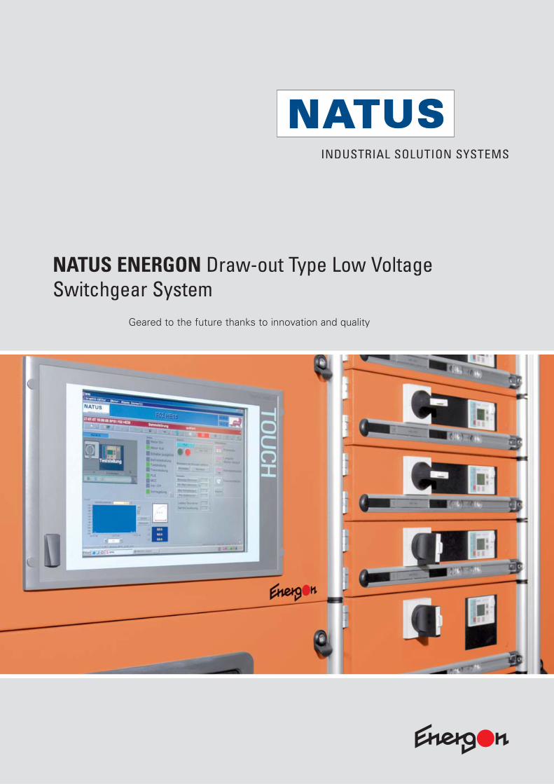
NATUS ENERGON Draw-out Type Low Voltage Switchgear System
Geared to the future thanks to innovation and quality
2
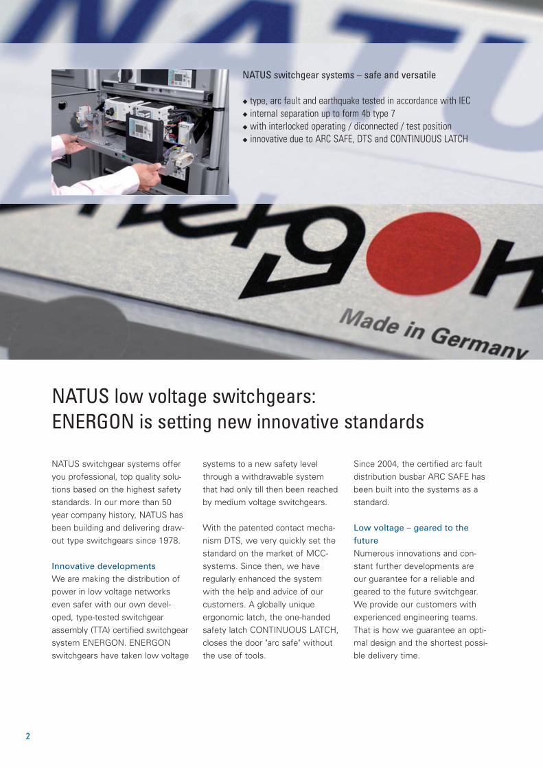
NATUS switchgear systems offeryou professional, top quality solu-tions based on the highest safetystandards. In our more than 50year company history, NATUS hasbeen building and delivering draw-out type switchgears since 1978.
Innovative developmentsWe are making the distribution ofpower in low voltage networkseven safer with our own devel-oped, type-tested switchgearassembly (TTA) certified switchgearsystem ENERGON. ENERGONswitchgears have taken low voltage
NATUS low voltage switchgears: ENERGON is setting new innovative standards
NATUS switchgear systems – safe and versatile
◆ type, arc fault and earthquake tested in accordance with IEC◆ internal separation up to form 4b type 7◆ with interlocked operating / diconnected / test position◆ innovative due to ARC SAFE, DTS and CONTINUOUS LATCH
systems to a new safety levelthrough a withdrawable systemthat had only till then been reachedby medium voltage switchgears.
With the patented contact mecha-nism DTS, we very quickly set thestandard on the market of MCC-systems. Since then, we have regularly enhanced the systemwith the help and advice of ourcustomers. A globally uniqueergonomic latch, the one-handedsafety latch CONTINUOUS LATCH,closes the door "arc safe" withoutthe use of tools.
Since 2004, the certified arc faultdistribution busbar ARC SAFE hasbeen built into the systems as astandard.
Low voltage – geared to thefutureNumerous innovations and con-stant further developments are our guarantee for a reliable andgeared to the future switchgear.We provide our customers withexperienced engineering teams.That is how we guarantee an opti-mal design and the shortest possi-ble delivery time.
3
The ENERGON-HighlightsENERGON has taken low voltage switchgears to a new level of safety and technology
NATUS – Industrial Solution Systems
SWITCH
GEARS
SERVICES
SOLUTIONS
AUTOMATION
Demanding customers across the world have
put their faith in NATUS switchgear systems,
and thus also in the quality and safety of our
solutions.
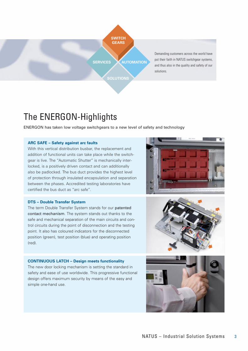
ARC SAFE – Safety against arc faults
With this vertical distribution busbar, the replacement and
addition of functional units can take place while the switch-
gear is live. The “Automatic Shutter” is mechanically inter-
locked, is a positively driven contact and can additionally
also be padlocked. The bus duct provides the highest level
of protection through insulated encapsulation and separation
between the phases. Accredited testing laboratories have
certified the bus duct as “arc safe”.
DTS – Double Transfer System
The term Double Transfer System stands for our patentedcontact mechanism. The system stands out thanks to thesafe and mechanical separation of the main circuits and con-trol circuits during the point of disconnection and the testingpoint. It also has coloured indicators for the disconnectedposition (green), test position (blue) and operating position(red).
CONTINUOUS LATCH – Design meets functionality
The new door locking mechanism is setting the standard insafety and ease of use worldwide. This progressive functionaldesign offers maximum security by means of the easy andsimple one-hand use.
4
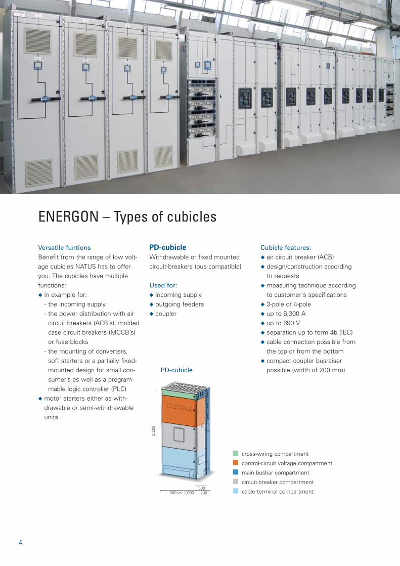
PD-cubicle
Withdrawable or fixed mounted circuit-breakers (bus-compatible)
Used for:◆ incoming supply◆ outgoing feeders◆ coupler
Versatile funtionsBenefit from the range of low volt-age cubicles NATUS has to offeryou. The cubicles have multiplefunctions:◆ in example for:
- the incoming supply- the power distribution with air
circuit breakers (ACB’s), moldedcase circuit breakers (MCCB’s)or fuse blocks
- the mounting of converters,soft starters or a partially fixed-mounted design for small con-sumer’s as well as a program-mable logic controller (PLC)
◆ motor starters either as with-drawable or semi-withdrawableunits
Cubicle features:◆ air circuit breaker (ACB) ◆ design/construction according
to requests ◆ measuring technique according
to customer's specifications◆ 3-pole or 4-pole◆ up to 6,300 A◆ up to 690 V◆ separation up to form 4b (IEC)◆ cable connection possible from
the top or from the bottom◆ compact coupler busraiser
possible (width of 200 mm)
ENERGON – Types of cubicles
2,20
0
500 vs. 1,000500700
cross-wiring compartment
control-circuit voltage compartment
main busbar compartment
circuit-breaker compartment
cable terminal compartment
PD-cubicle
5
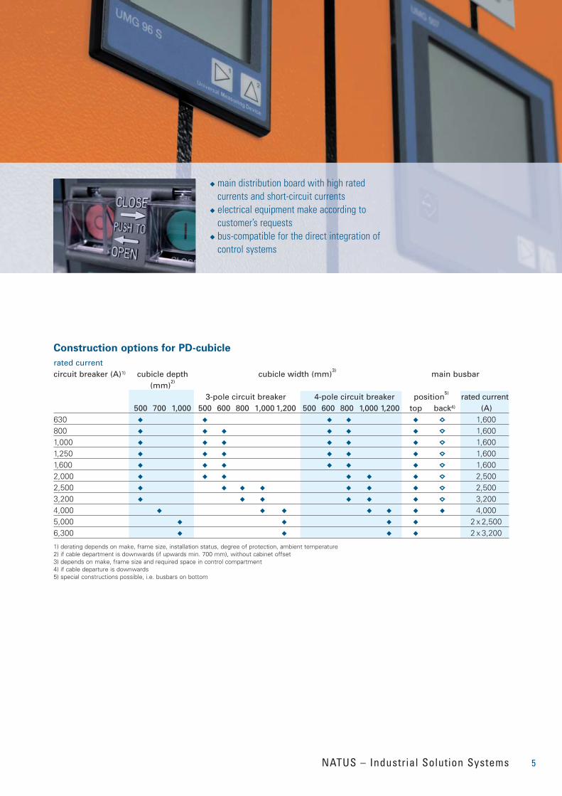
Construction options for PD-cubicle
NATUS – Industrial Solution Systems
◆ main distribution board with high rated currents and short-circuit currents
◆ electrical equipment make according to customer’s requests
◆ bus-compatible for the direct integration ofcontrol systems
rated currentcircuit breaker (A)1) cubicle depth cubicle width (mm)
3)main busbar
(mm)2)
3-pole circuit breaker 4-pole circuit breaker position5)
rated current500 700 1,000 500 600 800 1,000 1,200 500 600 800 1,000 1,200 top back4) (A)
630 ◆ ◆ ◆ ◆ ◆ 1,600800 ◆ ◆ ◆ ◆ ◆ ◆ 1,6001,000 ◆ ◆ ◆ ◆ ◆ ◆ 1,6001,250 ◆ ◆ ◆ ◆ ◆ ◆ 1,6001,600 ◆ ◆ ◆ ◆ ◆ ◆ 1,6002,000 ◆ ◆ ◆ ◆ ◆ ◆ 2,5002,500 ◆ ◆ ◆ ◆ ◆ ◆ ◆ 2,5003,200 ◆ ◆ ◆ ◆ ◆ ◆ 3,2004,000 ◆ ◆ ◆ ◆ ◆ ◆ ◆ 4,0005,000 ◆ ◆ ◆ ◆ 2 x 2,5006,300 ◆ ◆ ◆ ◆ 2 x 3,200
1) derating depends on make, frame size, installation status, degree of protection, ambient temperature2) if cable department is downwards (if upwards min. 700 mm), without cabinet offset3) depends on make, frame size and required space in control compartment4) if cable departure is downwards 5) special constructions possible, i.e. busbars on bottom
6
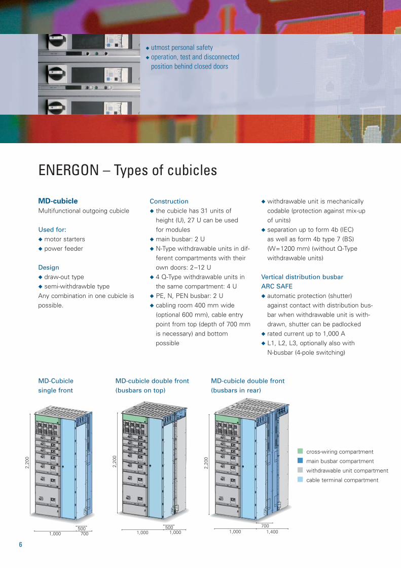
MD-cubicle
Multifunctional outgoing cubicle
Used for:◆ motor starters◆ power feeder
Design◆ draw-out type◆ semi-withdrawble typeAny combination in one cubicle ispossible.
Construction◆ the cubicle has 31 units of
height (U), 27 U can be used for modules
◆ main busbar: 2 U◆ N-Type withdrawable units in dif-
ferent compartments with theirown doors: 2–12 U
◆ 4 Q-Type withdrawable units inthe same compartment: 4 U
◆ PE, N, PEN busbar: 2 U◆ cabling room 400 mm wide
(optional 600 mm), cable entrypoint from top (depth of 700 mmis necessary) and bottom possible
◆ withdrawable unit is mechanicallycodable (protection against mix-up of units)
◆ separation up to form 4b (IEC) as well as form 4b type 7 (BS)(W=1200 mm) (without Q-Type withdrawable units)
Vertical distribution busbar ARC SAFE◆ automatic protection (shutter)
against contact with distribution bus-bar when withdrawable unit is with-drawn, shutter can be padlocked
◆ rated current up to 1,000 A◆ L1, L2, L3, optionally also with
N-busbar (4-pole switching)
2,20
0
1,000 1,400700
2,20
0
1,000 1,000500
cross-wiring compartment
main busbar compartment
withdrawable unit compartment
cable terminal compartment
◆ utmost personal safety◆ operation, test and disconnected
position behind closed doors
ENERGON – Types of cubicles
2,20
0
1,000 700500
MD-cubicle double front(busbars in rear)
MD-cubicle double front(busbars on top)
MD-Cubicle single front
7NATUS – Industrial Solution Systems
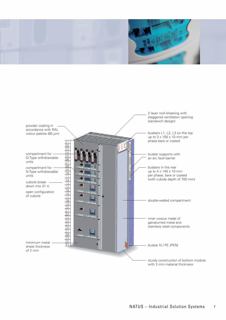
01020304050607080910111213141516171819202122
242526272829
3130
23
2 layer roof-sheeting with staggered ventilation opening (sandwich design)
powder coating in accordance with RAL colour palette (80 µm) busbars L1, L2, L3 on the top
up to 3 x 100 x 10 mm per phase bare or coated
busbars in the rear up to 4 x 140 x 10 mm per phase, bare or coated(with cubide depth of 700 mm)
compartment for Q-Type withdrawable units
compartment for N-Type withdrawable units
cubicle break-down into 31 U
open configuration of cubicle
busbar N / PE (PEN)minimum metal sheet thickness of 2 mm
sturdy construction of bottom module with 3 mm material thickness
double-walled compartment
busbar supports with an arc fault barrier
inner corpus made of galvalumed metal and stainless steel components
2,20
0
1,000/1,200 700500
8
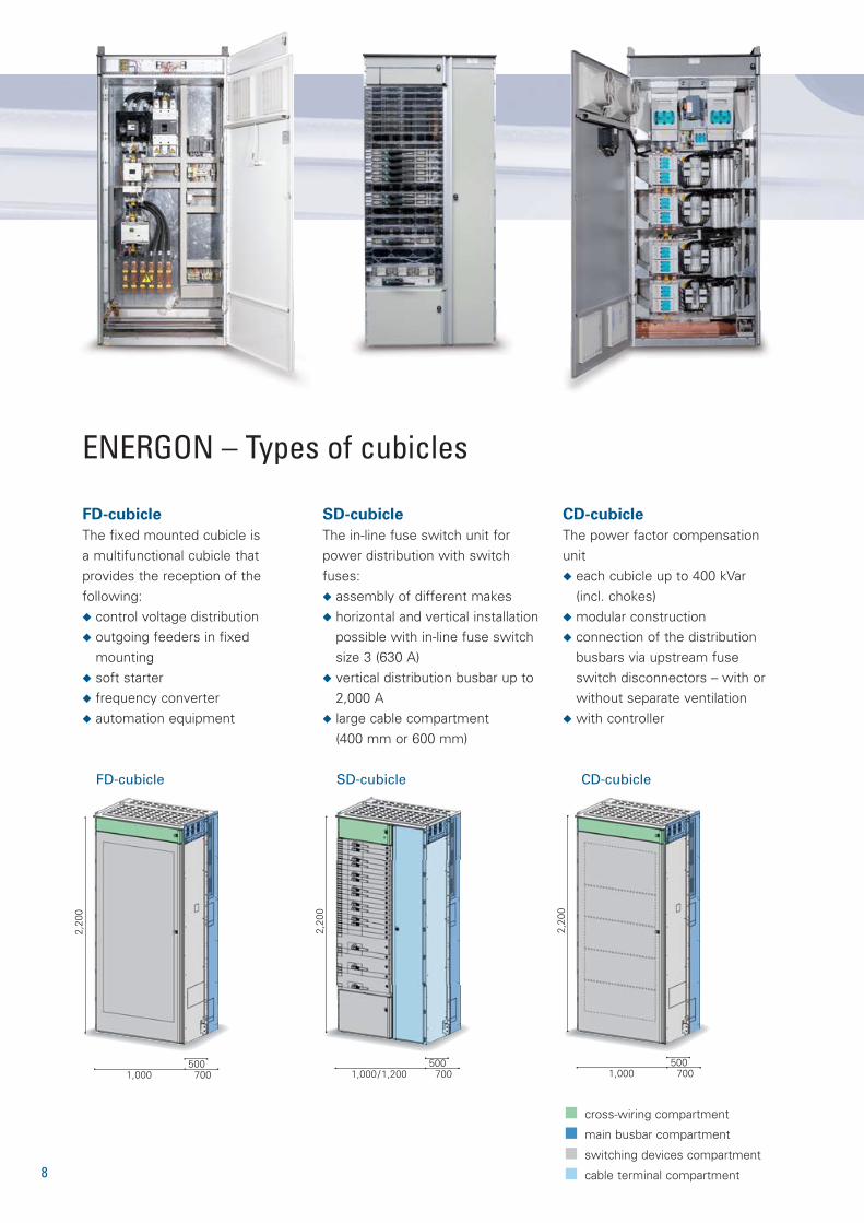
FD-cubicle
The fixed mounted cubicle is a multifunctional cubicle that provides the reception of the following:◆ control voltage distribution◆ outgoing feeders in fixed
mounting◆ soft starter◆ frequency converter ◆ automation equipment
SD-cubicle
The in-line fuse switch unit forpower distribution with switchfuses:◆ assembly of different makes◆ horizontal and vertical installation
possible with in-line fuse switchsize 3 (630 A)
◆ vertical distribution busbar up to2,000 A
◆ large cable compartment (400 mm or 600 mm)
CD-cubicle
The power factor compensationunit◆ each cubicle up to 400 kVar
(incl. chokes)◆ modular construction◆ connection of the distribution
busbars via upstream fuseswitch disconnectors – with orwithout separate ventilation
◆ with controller
SD-cubicle
ENERGON – Types of cubicles
2,20
0
1,000 700500
2,20
0
1,000 700500
CD-cubicleFD-cubicle
cross-wiring compartment
main busbar compartment
switching devices compartment
cable terminal compartment
N-Type withdrawable unit
Patented contact mechanismDTS:safe connection, user-friendly, bus-compatible◆ main switch can only be operat-
ed when the door is closed◆ cubicle door only opens in the
disconnected position (can beoverridden)
◆ unit can only be withdrawn indisconnected position
◆ unit can only be withdrawn if themain switch is disconnected
◆ disconnection contact for incom-ing and outgoing circuits on bothsides
◆ compartments can be padlockedto prevent insertion of withdraw-able units
◆ both withdrawable units and sub-sections can be exchanged orconverted while the board is live
◆ mechanical encoding ensuresprotection against mix-up of units
◆ coloured display that can beseen through a window on theunits door indicates the switch-ing status
Disconnected and test position◆ Closed door operating / discon-
nected / and test position. Therequired isolating distance is pro-vided, besides by the mainswitch, by the mobile, patentedcontact mechanism (DTS)
◆ control connector adapts tochanging needs: up to 40 poles,with additional bus contacting
ENERGON – Types of withdrawable units
9NATUS – Industrial Solution Systems
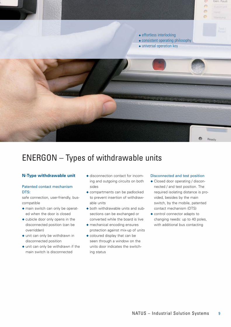
◆ effortless interlocking◆ consistent operating philosophy◆ universal operation key
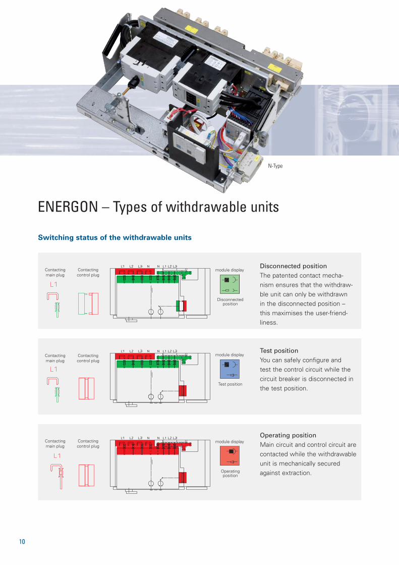
Contactingmain plug
Contactingcontrol plug
Disconnectedposition
module display
Contactingmain plug
Contactingcontrol plug
module display
Test position
Contactingmain plug
Contactingcontrol plug
module display
Operatingposition
10
Operating positionMain circuit and control circuit arecontacted while the withdrawableunit is mechanically securedagainst extraction.
Test positionYou can safely configure andtest the control circuit while thecircuit breaker is disconnected inthe test position.
Disconnected positionThe patented contact mecha-nism ensures that the withdraw-ble unit can only be withdrawnin the disconnected position –this maximises the user-friend-liness.
Switching status of the withdrawable units
ENERGON – Types of withdrawable units
N-Type
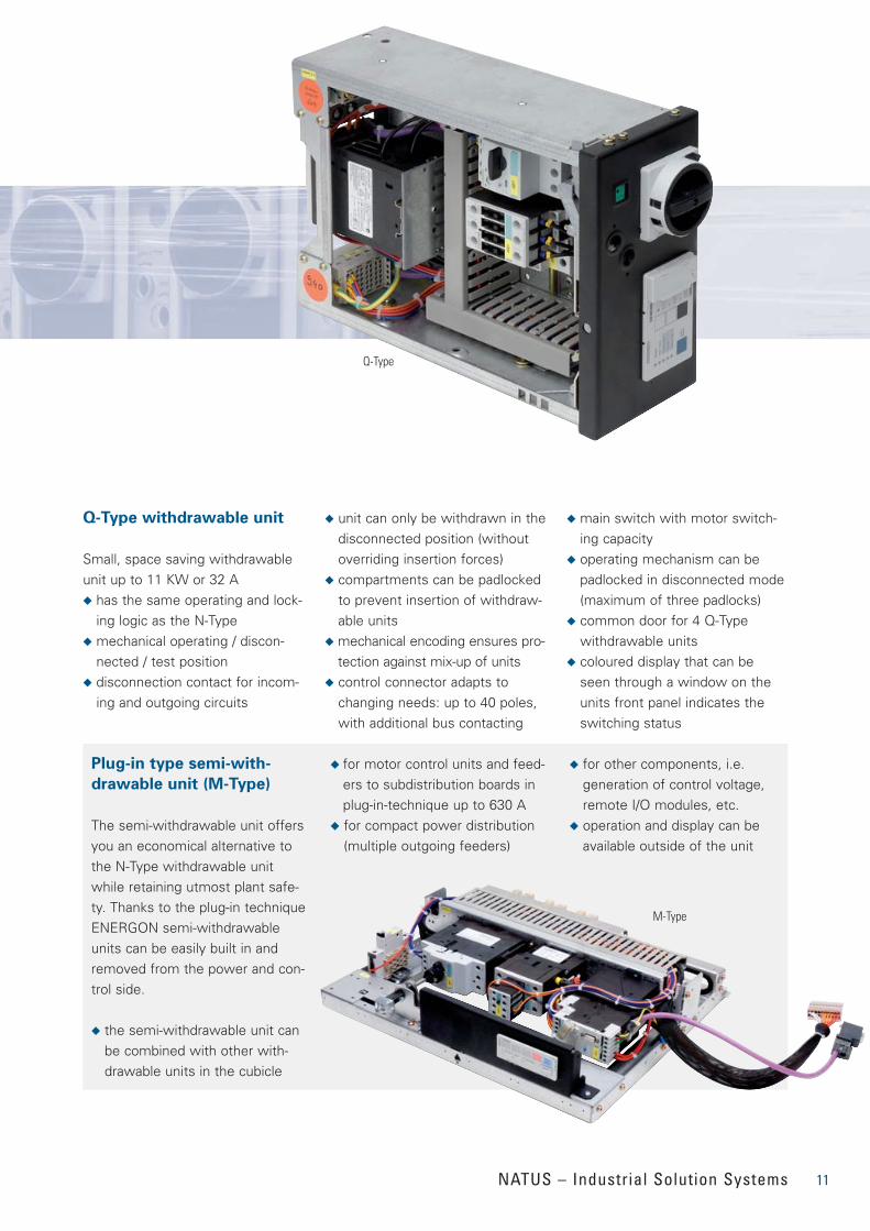
Plug-in type semi-with-
drawable unit (M-Type)
The semi-withdrawable unit offersyou an economical alternative tothe N-Type withdrawable unitwhile retaining utmost plant safe-ty. Thanks to the plug-in techniqueENERGON semi-withdrawableunits can be easily built in andremoved from the power and con-trol side.
◆ the semi-withdrawable unit canbe combined with other with-drawable units in the cubicle
◆ for motor control units and feed-ers to subdistribution boards inplug-in-technique up to 630 A
◆ for compact power distribution(multiple outgoing feeders)
◆ for other components, i.e. generation of control voltage,remote I/O modules, etc.
◆ operation and display can beavailable outside of the unit
11NATUS – Industrial Solution Systems
Q-Type withdrawable unit
Small, space saving withdrawableunit up to 11 KW or 32 A◆ has the same operating and lock-
ing logic as the N-Type◆ mechanical operating / discon-
nected / test position ◆ disconnection contact for incom-
ing and outgoing circuits
◆ unit can only be withdrawn in thedisconnected position (withoutoverriding insertion forces)
◆ compartments can be padlockedto prevent insertion of withdraw-able units
◆ mechanical encoding ensures pro-tection against mix-up of units
◆ control connector adapts tochanging needs: up to 40 poles,with additional bus contacting
◆ main switch with motor switch-ing capacity
◆ operating mechanism can bepadlocked in disconnected mode(maximum of three padlocks)
◆ common door for 4 Q-Type withdrawable units
◆ coloured display that can beseen through a window on theunits front panel indicates theswitching status
Q-Type
M-Type
12
typical rated current* rated current at 35 °C size of with-ambient temperature (A) drawable unit
unventilated ventilated
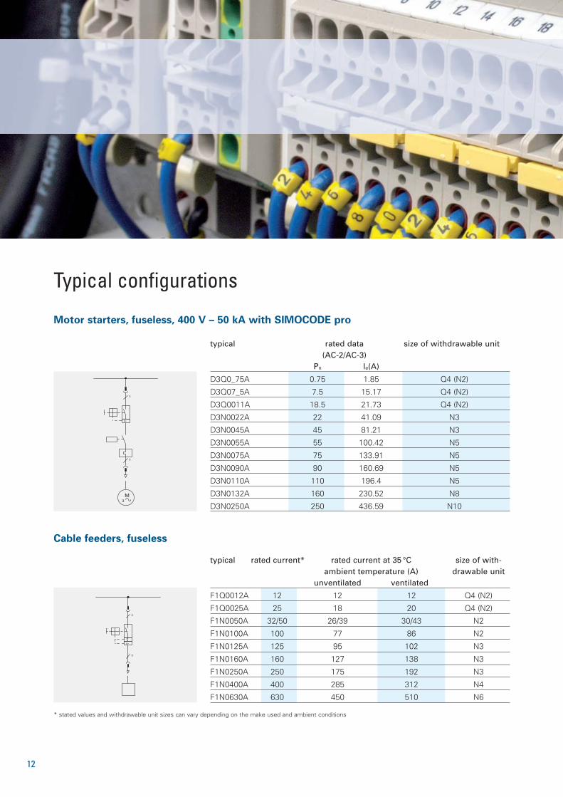
F1Q0012A 12 12 12 Q4 (N2)
F1Q0025A 25 18 20 Q4 (N2)
F1N0050A 32/50 26/39 30/43 N2
F1N0100A 100 77 86 N2
F1N0125A 125 95 102 N3
F1N0160A 160 127 138 N3
F1N0250A 250 175 192 N3
F1N0400A 400 285 312 N4
F1N0630A 630 450 510 N6
typical rated data size of withdrawable unit(AC-2/AC-3)
Pn le(A)
D3Q0_75A 0.75 1.85 Q4 (N2)
D3Q07_5A 7.5 15.17 Q4 (N2)
D3Q0011A 18.5 21.73 Q4 (N2)
D3N0022A 22 41.09 N3
D3N0045A 45 81.21 N3
D3N0055A 55 100.42 N5
D3N0075A 75 133.91 N5
D3N0090A 90 160.69 N5
D3N0110A 110 196.4 N5
D3N0132A 160 230.52 N8
D3N0250A 250 436.59 N10
Cable feeders, fuseless
3
I>
3
3M
3
I>
3
Motor starters, fuseless, 400 V – 50 kA with SIMOCODE pro
Typical configurations
* stated values and withdrawable unit sizes can vary depending on the make used and ambient conditions
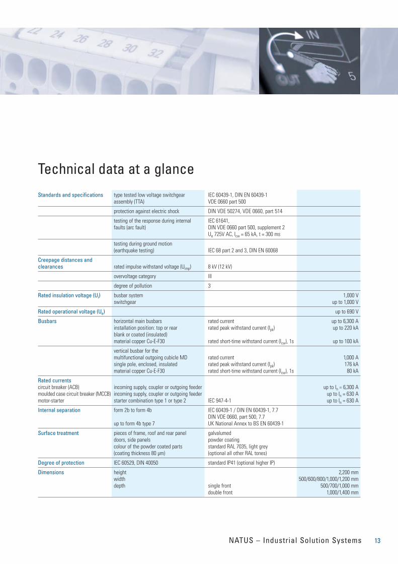
Technical data at a glance
Standards and specifications type tested low voltage switchgear IEC 60439-1, DIN EN 60439-1assembly (TTA) VDE 0660 part 500
protection against electric shock DIN VDE 50274, VDE 0660, part 514
testing of the response during internal IEC 61641, faults (arc fault) DIN VDE 0660 part 500, supplement 2
Ue 725V AC, Icw = 65 kA, t = 300 ms
testing during ground motion(earthquake testing) IEC 68 part 2 and 3, DIN EN 60068
Creepage distances and clearances rated impulse withstand voltage (Uimp) 8 kV (12 kV)
overvoltage category III
degree of pollution 3
Rated insulation voltage (Ui) busbar system 1,000 Vswitchgear up to 1,000 V
Rated operational voltage (Ue) up to 690 V
Busbars horizontal main busbars rated current up to 6,300 Ainstallation position: top or rear rated peak withstand current (Ipk) up to 220 kAblank or coated (insulated)material copper Cu-E-F30 rated short-time withstand current (Icw), 1s up to 100 kA
vertical busbar for themultifunctional outgoing cubicle MD rated current 1,000 Asingle pole, enclosed, insulated rated peak withstand current (Ipk) 176 kAmaterial copper Cu-E-F30 rated short-time withstand current (Icw), 1s 80 kA
Rated currentscircuit breaker (ACB) incoming supply, coupler or outgoing feeder up to In = 6,300 Amoulded case circuit breaker (MCCB) incoming supply, coupler or outgoing feeder up to In = 630 Amotor-starter starter combination type 1 or type 2 IEC 947-4-1 up to In = 630 A
Internal separation form 2b to form 4b IEC 60439-1 / DIN EN 60439-1, 7.7DIN VDE 0660, part 500, 7.7
up to form 4b type 7 UK National Annex to BS EN 60439-1
Surface treatment pieces of frame, roof and rear panel galvalumeddoors, side panels powder coatingcolour of the powder coated parts standard RAL 7035, light grey(coating thickness 80 µm) (optional all other RAL tones)
Degree of protection IEC 60529, DIN 40050 standard IP41 (optional higher IP)
Dimensions height 2,200 mmwidth 500/600/800/1,000/1,200 mmdepth single front 500/700/1,000 mm
double front 1,000/1,400 mm
13NATUS – Industrial Solution Systems
Änderung/rev.
0
Datum/date Name/name
Gez./drawn
Gepr./checked
Gepr./checked
1
20.08.07
20.08.07
Datum/date
A.Müller
Weich
Name/name
2
Kom.-Nr./com.-Nr.:
3
Objekt/object
Zeichn.-Nr./draw.-nr.:
5 4
Benennung/description
7 6
Typicalname/typical name
8
=
+
MCC
TOP
Blatt/sheet
9
1
von/total
1
NATUS COM.-NR.
RAL HUE
DEGREE OF PROTECTION
SHORT-CIRCUIT CURRENT
COVER PLATE
MAINS VOLTAGE
SYSTEM CONFIGURATION
50
0
:
:
:
:
:
:
:
RAL 7032
IP 41
50 kA
SEAL. STRIP
400 V
TN-C-S
3WL
1000A
600kg
transport
unit 1
3
=U 0HLE
+PMCC2_01
1000
MAIN BUSBAR
PLUG-ON DROPER BARS
HORIZONTAL N
HORIZONTAL PE
VERTIKAL N
VERTIKAL PE
3
450kg
transport
unit 2
=U 0HLE
+PMCC2_02
1000
3
:
:
:
:
:
:
3 x 1x100x10
3 x U-Pr.
1x40x10
1x40x10
30x5
50x5
450kg
transport
unit 3
=U 0HLE
+PMCC2_03
1000
3
450kg
transport
unit 4
=U 0HLE
+PMCC2_04
1000
300kg
transport
unit 5
3
=U 0HLE
+PMCC2_05
500
450kg
transport
unit 6
3
=U 0HLE
+PMCC2_06
5500
1000
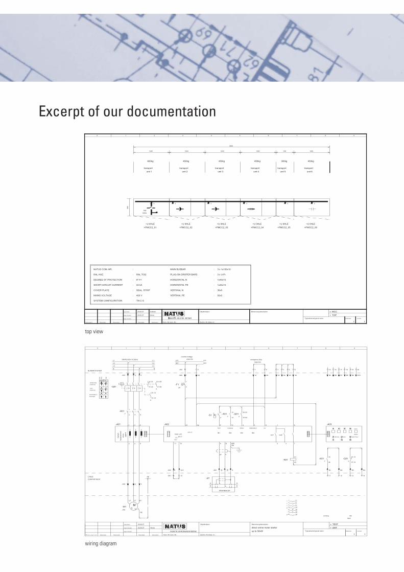
top view
0
Datum/date Name/name
Gez./drawn
Gepr./checked
Gepr./checked
1
02.08.07
02.08.07
Datum/date
Weich
Name/name
2
Kom.-Nr./com.-Nr.:
3
Objekt/object
Zeichn.-Nr./draw.-nr.:
5 4
Benennung/description
direct online motor starter
up to 50kW
7 6
Typicalname/typical name
8
=
+
TEST
ORT
Blatt/sheet
9
1
von/total
1
BUSBAR SYSTEM
CABLE
COMPARTMENT
MAIN CTRL
TEST-
POSITION
DISCONNECT-
POSITION
OPERATING-
POSITION
-X01
-X03
-X60
L1
L2
L3
N
-A01
Cur
rent
me
asur
emen
t
div
ice
3UF
71
-X01 1
-Q01
-K01.7
1
2
1
2
-X03 1
M3 ~...KW
-M1
U1 V1 W1
PE
3/N/PE/400V AC/50Hz
2
3
4
3
4
2
3
5
6
5
6
3
X1.31
X1.42
PE
.9
X1.13
X1.14
L1
L2
L3
N
.5
X1.53
X1.64
-A02
basic unit
pro C
L01
N01
T1
-X60 A9
-X61 9
PTC
Input
T2
A10
10
-X61 1
-X60 A1
2A
-F1
1
2
A1
Control Voltage
230V DC
230V AC
2
A2
A2
L01
N01
A
B
-XT
-S1
2
2
9
TEST
IN1
A
gn
-X60 E1
PROFIBUS DP
B
rt
E2
-K01.7
13
14
10
RUNNING
IN2
SPE/PE
S
A
B
-Q01.2
X1.53
X1.64
4
READY
IN3
7
A7
5
EMERGENCY
IN4
emergency stop
response
8
A8
8
24V
out1
3
A3
1
2
out2
4
A4
3
5
A5
6
A6
6
7
.1 1 2
.1 3 4
.1 5 6
.5 13 14
21 22
31 32
.8 43 44
-K01
A1
A2
15
B5
-A03
-K01.7
43
44
B1
11
running
16
B6
DEVICE
17
B7
B2
12
BUS
18
B8
19
B9
GEN.FAULT
-Q01.2
X1.13
X1.14
B3
13
CB
fault
20
B10
TEST/
RESET
B4
14
wiring diagram
Excerpt of our documentation
Änderung/rev.
0
Datum/date Name/name
Gez./drawn
Gepr./checked
Gepr./checked
1
20.08.07
20.08.07
Datum/date
A.Müller
Weich
Name/name
2
Kom.-Nr./com.-Nr.:
3
Objekt/object
Zeichn.-Nr./draw.-nr.:
5 4
Benennung/description
FRONTVIEW
7 6
Typicalname/typical name
8
=
+
MCC
ORT
Blatt/sheet
9
1
von/total
1
1
2
3
4
5
7
8
9
10
11
12
13
14
15
16
17
18
19
20
21
22
23
24
25
26
27
28
29
30
31
0 1000
6
2220.0
=
+
MCC
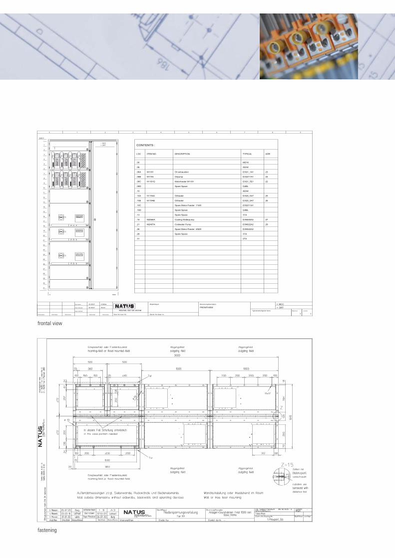
ORT CONTENTS :
LOC
.00
.06
.06A
.06B
.06C
.06D
.10
.10A
.10B
.10C
.10D
.13
.18
.21
.26
.29
.31
ITEM NO.
M1191
M1193
H1181G
H1194A
H1194B
M2466A
M2467A
DESCRIPTION
Oil exhaustion
Oilpump
Motorheater M1181
Spare Space
Oilheater
Oilheater
Spare Motor-Feeder 11kW
Spare Space
Spare Space
Cooling Waterpump
Coldwater Pump
Spare Motor-Feeder 45kW
Spare Space
TYPICAL
MD16
ADA4
D3Q1_1A1
D3Q011A1
D3Q1_5E1
Q4BL
ADA4
D3Q5_5A7
D3Q5_5A7
D3Q011A1
Q4BL
3TA
D3N045A2
D3N022A2
D3N045A2
3TA
2TA
ADR
23
24
22
25
26
27
29
frontal view
fastening
NATUS GmbH & Co.KGIndustriegelände NordLoebstraße 12, 54292 Trier, GermanyPostfach 2960, 54219 Trier, GermanyTel.: +49 (0)651-1449-0, Fax: +49 (0)651-21600E-Mail: [email protected], www.natus.de
SWITCH
GEARS
SERVICES
SOLUTIONS
AUTOMATION
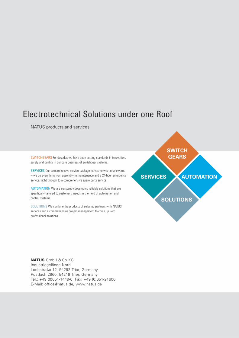
SWITCHGEARS For decades we have been setting standards in innovation,safety and quality in our core business of switchgear systems.
SERVICES Our comprehensive service package leaves no wish unanswered– we do everything from assembly to maintenance and a 24-hour emergencyservice, right through to a comprehensive spare parts service.
AUTOMATION We are constantly developing reliable solutions that are specifically tailored to customers’ needs in the field of automation and control systems.
SOLUTIONS We combine the products of selected partners with NATUS services and a comprehensive project management to come up with professional solutions.
NATUS products and services
Electrotechnical Solutions under one Roof