NATURAL GAS CENTRAL FORCED AIR HEATING SYSTEM REPAIR …liob.cpuc.ca.gov/docs/Conv WIS Revisions...
31
18-A California Conventional Home WIS Section 18 Preface © RHA • 1/1/04 (Rev. 9/15/05) (Rev. 10/6/05)Natural Gas Central Forced Air Heating System Repair & Replacement SECTION 18 PREFACE FOR NATURAL GAS CENTRAL FORCED AIR HEATING SYSTEM REPAIR AND REPLACEMENT 1. FURNACE REPAIR/REPLACEMENT INSTALLATION POLICIES 1.1. Furnace repair or replacement may be provided only when the appliance is non - operational or fails NGAT, and correction cannot be achieved with Ser- vice/Adjustment by utility gas service personnel (or their designated represen- tative). Note that NGAT fails include the following two scenarios: – The furnace is non-operable. – No furnace is present and the household uses another gas appliance for space heating. 1.2. A central furnace may be replaced only if the cost of repairing the unit would be more than 50% of the cost of replacement. 1.1. 1.3. Furnace replacements and major furnace repairs may be provided only if the residence is owner-occupied. Service/Adjustment and minor repairs may also be conducted in non - owner renter-occupied homes. 1.2. 1.4. Furnace repairs and replacements will be provided only if the fuel used by the furnace is supplied by the utility providing LIEE Program services. 1.3. 1.5. Furnace replacement will not include hazardous material abatement, ma- jor structural alteration, concrete work, painting, or floor covering. 1.6. A central furnace may be repaired only if the cost of repairing the unit would be less than 50% of the cost of replacement. A wall, floor, or direct vent fur- nace may be repaired only if the cost of repairing the unit would be less than 25% of the cost of replacement. 1.4. 1.7. An air conditioning unit may be replaced in conjunction with a furnace re- placement if: – The unit being replaced is a combined forced air heating and central AC package system, also referred to as a dual-pack (i.e., the AC and furnace is manufactured as one unit and is housed in a single sheet metal hous- ing); or – The furnace being replaced is part of a split forced air heating and AC system and the AC evaporative coil and/or the outside system cannot be matched with the new furnace.
Transcript of NATURAL GAS CENTRAL FORCED AIR HEATING SYSTEM REPAIR …liob.cpuc.ca.gov/docs/Conv WIS Revisions...

18-A California Conventional Home WIS Section 18 Preface © RHA • 1/1/04 (Rev. 9/15/05) (Rev. 10/6/05)Natural Gas Central Forced Air Heating System Repair & Replacement
SECTION 18 PREFACE FOR
NATURAL GAS CENTRAL FORCED AIR HEATING SYSTEM REPAIR AND REPLACEMENT
1. FURNACE REPAIR/REPLACEMENT INSTALLATION POLICIES
1.1. Furnace repair or replacement may be provided only when the appliance is non-operational or fails NGAT, and correction cannot be achieved with Ser-vice/Adjustment by utility gas service personnel (or their designated represen-tative). Note that NGAT fails include the following two scenarios: – The furnace is non-operable. – No furnace is present and the household uses another gas appliance for
space heating.
1.2. A central furnace may be replaced only if the cost of repairing the unit would be more than 50% of the cost of replacement.
1.1.1.3. Furnace replacements and major furnace repairs may be provided only if the residence is owner-occupied. Service/Adjustment and minor repairs may also be conducted in non-ownerrenter-occupied homes.
1.2.1.4. Furnace repairs and replacements will be provided only if the fuel used by the furnace is supplied by the utility providing LIEE Program services.
1.3.1.5. Furnace replacement will not include hazardous material abatement, ma-jor structural alteration, concrete work, painting, or floor covering.
1.6. A central furnace may be repaired only if the cost of repairing the unit would be less than 50% of the cost of replacement. A wall, floor, or direct vent fur-nace may be repaired only if the cost of repairing the unit would be less than 25% of the cost of replacement.
1.4.1.7. An air conditioning unit may be replaced in conjunction with a furnace re-placement if: – The unit being replaced is a combined forced air heating and central AC
package system, also referred to as a dual-pack (i.e., the AC and furnace is manufactured as one unit and is housed in a single sheet metal hous-ing); or
– The furnace being replaced is part of a split forced air heating and AC system and the AC evaporative coil and/or the outside system cannot be matched with the new furnace.

18-B California Conventional Home WIS Section 18 Preface © RHA • 1/1/04 (Rev. 9/15/05) (Rev. 10/6/05)Natural Gas Central Forced Air Heating System Repair & Replacement
1.5.1.8. Replaced units must be de-manufactured in compliance with all laws and regulations.
1.6.1.9. Installer must have C-20 HVAC license.
1.10. A programmable thermostat may be installed only if (a) a central furnace or central air conditioner is replaced (a programmable thermostat is required by Title 24 when a central heating system and/or a central air conditioner is re-placed), or (b) a central furnace or central air conditioner is repaired and a properly-functioning thermostat is not present.
1.11. A furnace will not be replaced is Title 24 provisions relating to alterations can-not be satisfied.
1.12. A furnace that is not abandoned or inaccessible and cannot be made oper-able through Servicing fails NGAT.
2. PROGRAMMABLE THERMOSTAT INSTALLATION POLICIES
2.1. Programmable thermostats are may be installed only in conjunction withif a central furnace or central air conditioner is repair/replacemement replaced and only when required by state or local code as part of furnace re-pair/replacement. (A programmable/setback thermostat is required by Title 24 when a central heating system and/or central air conditioner is replaced.)
2.2. Before installing a programmable thermostat, Contractor shall explain their its operation and provide the customer an opportunity to refuse the measure.
3. CENTRAL SYSTEM AIR HVAC FILTER INSTALLATION POLICIES
3.1. HVAC filters may be replaced are installed only in conjunction as part of with central forced air heating systemfurnace repair or central air conditioner re-placement.
3.2. Contractors must show customers how to remove, clean, and re-install the fil-ters.

25-A California Conventional Home WIS Section 25 Preface © RHA • 1/1/04 (Rev. 9/15/05) (Rev. 10/6/05) Natural Gas Water Heater Replacement
SECTION 25 PREFACE FOR
NATURAL GAS WATER HEATER REPLACEMENT
1. WATER HEATER REPAIR/REPLACEMENT POLICIES
1.1. Water heater repair or replacement may be provided only when the appliance is non-operational or fails NGAT, and correction cannot be achieved with Service/Adjustment by utility gas service personnel (or their designated rep-resentative).1
1.2. A water heater may be replaced only if the cost of repairing the unit would be more than 50% of the cost of replacement.
1.1.The replacement water heater must have an energy factor of 0.60 or greater.
1.3. Water heater repair or replacement may be provided only if the residence is owner-occupied. Service/Adjustment may also be conducted in renter-occupied homes.
1.4. Water heater repairs and replacements will be provided only if the fuel used by the furnace appliance is supplied by the utility providing the weatherization LIEE Program services.
1.5. Water heater replacement will not include hazardous material abatement, major structural alteration, concrete work, painting, or floor covering.
1.2.A new natural gas water heater can only replace an existing natural gas water heater that has failed a natural gas appliance test, and cannot be repaired in a manner that enables it to pass an appliance test.
1 A water heater will be considered to fail the NGAT if it has a leaky tank.

3-46 California Conventional Home WIS Ceiling Insulation Standards © RHA • 1/1/04 (Rev. 9/15/05) (Rev. 10/6/05)
NONFEASIBILITY CRITERIA FOR CEILING INSULATION (continued)
9. The structure is unsound and will not support the weight of the insulation and installer, such as: - 2" x 4" @ 48"greater than 24" OC. - Bowed and sagging joists. - Fiberboard ceiling material. - 1/4" gypsum ceiling.
10. Knob-and-Tube (K&T) Wiring is present and: - Functioning knob-and-tube wiring cannot be certified safe by a C-10
contractor. - Abandoned K&T wiring is present that cannot be disconnected and
certified as abandoned and disconnected by a C-10 contractor. - Insulation over K&T wiring (live or abandoned) is prohibited by local
code.
11. Customer refuses.
NONFEASIBILITY CRITERIA RELATING TO CATASHROPHIC DUCT LEAKS AND DISCONNECTIONS
1.The reconnection work would disturb asbestos or other hazardous material.
2.A combustion-related hazard exists with furnace or other fuel-burning appliance (e.g., excessive CO, cracked heat exchanger, backdrafting, etc.).
3.A health or safety hazard is present, such as sewage waste in the crawlspace, insect infestation, hazardous electrical wiring, or a structural hazard, etc.
4.Customer refuses.

9-8 California Conventional Home WIS Evaporative Cooler & A/C © RHA • 1/1/04 (Rev. 10/6/05) Vent Cover Standards
NONFEASIBILITY CRITERIA FOR EVAPORATIVE COOLER COVERS
1. Existing evaporative cooler vent covers are present and functionalAn existing evaporative cooler cover is functional and performing properly, even if not installed in accordance with current Installation Standards.
2. The evaporative cooler is ducted with multiple supply vents/registers and it is impossible for all of them to be equipped with covers.
3. Water damage to the ceiling or wall area around the vent/register is evident and cannot be repaired.
4. Vent/register opening is so close to the wall or ceiling that proper installation of the cover is impossible.
5. The vent(s) serving the evaporative cooler is (are)shared with a heating system.
6. External cover is already present.
7. Customer refuses installation of evaporative cooler vent covers.
NONFEASIBILITY CRITERIA FOR WALL AND WINDOW AIR CONDITIONER UNIT COVERS
1. Existing air conditioner vent covers are present and functional An existing air conditioner vent cover is functional and performing properly, even if not installed in accordance with current Installation Standards.
2. Water damage to the window or wall area around the unit/vent is evident and cannot be repaired.
3. The vent/unit is so close to the wall that proper installation of the cover is impossible.
4. Customer refuses installation of air conditioner vent covers.

14-10 California Conventional Home WIS Thread-Based Compact © RHA • 1/1/04 (Rev. 10/6/05) Fluorescent Lamp Standards
NONFEASIBILITY CRITERIA FOR THREAD-BASED COMPACT FLUORESCENT LAMPS
1. Socket/fixture is nonfunctional.
2. Fixture already has a functional CFL.
2.3. Hazardous conditions exist at the socket/fixture.
3.4. Circuit is controlled by a solid-state timer.
4.5. Circuit is controlled by a dimmer not compatible with available CFL's.
5.6. Fixture is located in a storage room, closet, or multifamily common area.
6.7. Fixture is not operable by the customer (i.e., on their electric meter/bill).
7.8. Customer refuses.

18-45 California Conventional Home WIS Natural Gas Central Forced Air Systems © RHA • 1/1/04 (Rev. 9/15/05) (Rev. 10/6/05) Repair & Replacement Standards
NONFEASIBILITY CRITERIA FOR INSTALLATION REPAIR/ REPLACEMENT REQUIRING ATTIC OR CRAWL SPACE ACCESS
1. Crawl clearance is inadequate: - Attic clearance is less than 24" between top of ceiling joists and
bottom of ridge board. - Under-floor clearance is less than 18" from the ground to bottom of
floor joist system.
2. Any of the following conditions is present in the crawl space area where access is required: - Hazardous insect or pest infestation. - Excessive ground moisture (standing water or mud). - Sewage waste is on the ground or other unsanitary condition is
present which poses a health and safety hazard.
NONFEASIBILITY CRITERIA FOR PROGRAMMABLE THERMOSTATS
1. The furnace is not being replaced or repaired.
2. The furnace is being repaired, and a properly functioning thermostat is present.
10.3. Already properly installed present and operational.
11.Furnace utilizes a millivolt system.
12.Upgraded thermostat wiring (heavier gage or more conductors) is required.
4. Customer refuses.
NONFEASIBILITY CRITERIA FOR HVAC AIR FILTER REPLACEMENT
1. The furnace will not be repaired.
2. A serviceable, reusable filter is already present.

25-10 California Conventional Home WIS Natural Gas Water Heater Replacement Standards © RHA • 1/1/04 (Rev. 9/15/05) (Rev. 10/6/05)
NONFEASIBILITY CRITERIA FOR NATURAL GAS WATER HEATER REPLACEMENT
1.Existing unit is less than 10 years old and operates properly.
1. The property is renter-occupied.
2. Fuel used by the existing unit is not supplied by the utility providing LIEE Program services.
3. The existing water heater: - Is properly functioning and Passes NGAT, or - Is inaccessible1, or - Can be feasibly repaired (i.e., cost to repair is less than 50% of the
cost to replace the unit).
2.4. Drain line for T&P valve or drain pan cannot be properly terminated to outdoors or to an approved indoor drain if required by local code, and a gas shutoff valve and pressure relief valve cannot be installed in lieu of a T&P valve and drain line.
3.5. For a unit in a confined location: Required access, clearance, or combustion air cannot be provided.
4.6. For a unit on a raised floor or in an attic: structure cannot properly and safely support the installation.
5.7. No suitable mounting locations for seismic bracing available.
6.8. A safety hazard is present which cannot be repaired (e.g., vent system defect, nonconforming gas piping, double-downdraft diverter).
7.9. A watertight pan cannot be installed under the unit when required.
10. A plumbing condition exists which prevents achieving satisfactory water pipe connections.
8.11. A whole house fan is present, the existing water heater is in the attic, and a closed combustion unit cannot be installed.
9.12. The unit is a central water heater serving more than one dwelling unit.
13. Customer refuses.
1 See Definitions

25-11 California Conventional Home WIS Natural Gas Water Heater Replacement Standards © RHA • 1/1/04 (Rev. 9/15/05) (Rev. 10/6/05)
NONFEASIBILITY CRITERIA FOR NATURAL GAS WATER HEATER REPAIR
1. The property is renter-occupied and major repairs are required beyond the scope of Service/Adjustment1 by utility gas service personnel or their designated representative.
2. Fuel used by the existing unit is not supplied by the utility providing LIEE Program services.
3. The existing water heater will be replaced. - Cost to repair is more than 50% of the cost to replace the unit. - The tank leaks.
4. A safety hazard is present which cannot be repaired.
5. Required access is not available or proper combustion air cannot be provided.
6. The tank is a central water heater serving more than one dwelling unit.
7. Customer refuses.
1 See Definitions

Section 3
3-36 California Conventional Home WIS Ceiling Insulation Standards © RHA • 1/1/04 (Rev. 9/15/05) (Rev. 10/6/05)
CATASTROPHIC DUCT LEAKS AND DISCONNECTIONS
32. GENERAL INSTALLATION CRITERIADUCT REPAIR AND SEALING - All catastrophic Duct leaks shall be sealed, and all disconnections
shall be reconnected, and needed duct repairs shall be made in accordance with WIS Section 20, Duct Sealing Standards.
-All duct reconnections and repairs shall comply with these standards and the manufacturer's instructions and local codes, with the more stringent requirements taking precedence.
SEALED WITH PRESSURE-SENSITIVE TAPE (MINIMUM 3 WRAPS)
AND DRAWBANDS
NONMETALLIC FLEXIBLE DUCT
BEADED SLEEVE/COUPLING
DRAWBANDS INSTALLED OVER TAPE AND TIGHTENED
WITH AN ADJUSTABLE TENSIONING TOOL
FLEXIBLE DUCT CORE SEALED TO FITTING WITH “181B-FX” TAPE
BEADED SLEEVE/COUPLING

Section 3
3-37 California Conventional Home WIS Ceiling Insulation Standards © RHA • 1/1/04 (Rev. 9/15/05) (Rev. 10/6/05)
33.MATERIALS FOR DUCT REPAIR AND SEALING -All Materials
• Maximum flame spread index of 25 and maximum smoke developed index of 50, per ASTM E-84, UL 723 or NFPA 255.
-Duct Mastic and Mesh Tape • Nontoxic, water-resistant mastic listed per UL 181A or 181B standards
and labeled “181A-M” or “181B-M”. • Fiberglass mesh tape, minimum 2" wide and 9x9 weave per inch.
-Metallic Pressure-Sensitive Tape • Aluminum foil tape listed per UL 181A or 181B standards and marked
“181A-P” or “181B-FX”. -Pressure-Sensitive “Butyl Tape”
• Aluminum foil tape with minimum 15 mil butyl adhesive, used to seal metal-to-metal connections.
• Marked “UL 723” or “181B-FX”. • Butyl tape without “181B-FX” marking shall not be used to seal flexible
ducts. -Cloth-Backed Duct Tapes
• Not allowed.
TABLE 3-2: REQUIRED UL 181 IDENTIFICATION
UL STANDARD SEALING MATERIAL REQUIRED UL IDENTIFICATION
PRESSURE SENSITIVE TAPE MARKED “181A-P”
HEAT ACTIVATED TAPE MARKED “181A-H” UL 181A APPLIES TO SEALANTS
USED ON RIGID FIBERGLASS DUCT BOARD
MASTIC LABELED “181A-M”
PRESSURE SENSITIVE TAPE MARKED “181B-FX” UL 181B APPLIES TO SEALANTS USED ON FLEXIBLE DUCTS MASTIC LABELED “181B-M”

Section 3
3-38 California Conventional Home WIS Ceiling Insulation Standards © RHA • 1/1/04 (Rev. 9/15/05) (Rev. 10/6/05)
33. MATERIALS FOR DUCT REPAIR AND SEALING (continued) -Insulation
• Replacement ducts exceeding 40 linear feet in unconditioned space shall be insulated with an R-value meeting the following guidelines: -Minimum R-4.2 in CEC Climate Zones 6-8. -Minimum R-6 in CEC Climate Zones 1-5 and 8-13. -Minimum R-8 in CEC Climate Zones 14-16.
-Caulks and Sealants • Caulk/sealant material and installation criteria prescribed in Section 1,
Caulking Standards, shall be followed. -Foam Board and Foam Sealant
• Not allowed as a barrier material or sealant in duct systems. -Duct Sealants for Flexible Ducts
• Tapes: “181B-FX” shall appear on the tape. • Mastics: “181B-M” shall appear on the label.
-Drawbands for Flexible Nonmetallic Ducts • Drawbands shall comply with duct manufacturer’s installation
instructions and the following specifications: -Weather- and UV-resistant duct straps/ties rated for outdoor use. -Loop tensile strength of 150 pounds minimum. -Service temperature rating of 165°F minimum.
• Drawbands shall be tightened with an adjustable tensioning tool in accordance with duct manufacturer’s instructions.
-Sheet Metal • Galvanized sheet steel, or sheet aluminum, at least 0.007" thick.
“BUTYL TAPE” WITH 15 MIL BUTYL ADHESIVE
PRESSURE SENSITIVE TAPES UL LISTED AND MARKED “181B-FX” AND “181A-P”
DUCT MASTIC UL LISTED AND LABELED “181B-M” AND “181A-M”
FIBERGLASS MESH TAPE

Section 3
3-39 California Conventional Home WIS Ceiling Insulation Standards © RHA • 1/1/04 (Rev. 9/15/05) (Rev. 10/6/05)
VAPOR BARRIER (JACKET)
FIBERGLASS SCRIM
SPRING HELIX
FLEXIBLE PLASTIC CORE
FIBERGLASS INSULATION
MIN. R-4.2
FLEXIBLE NONMETALLIC CLASS 1 DUCT
33. MATERIALS FOR DUCT REPAIR AND SEALING (continued) -New Fittings (Collars, Sleeves, etc.)
• All installed fittings shall be minimum 26 gage. • New fittings installed for Flexible Nonmetallic ducts:
-All fittings shall be beaded. -Starting collars: minimum 4" length. -Sleeve/couplings: minimum 6" length.
-Flexible Ducts • Ducts shall conform to NFPA 90B and UL 181 Class 1. • Nonmetallic insulated ducts with air-permeable core not allowed. • Vapor barrier (Jacket):
-Thickness: 2.5 mils minimum. -Permeance: 1.0 perm maximum. -Degradation Protection: UV degradation-resistant material (e.g.,
silver metalized polyester jacket). recommended. -Insulation shall have minimum thermal resistance as indicated below,
or greater if required by local code. • Natural Gas Heat
-R-4.2 in CEC climate zones (CZ) 6 – 8. -R-6 in CZ 1 – 5 and 9 – 13. -R-8 in CZ 14 – 16.
• Electric Heat -R-8 in all CZ.

Section 3
3-40 California Conventional Home WIS Ceiling Insulation Standards © RHA • 1/1/04 (Rev. 9/15/05) (Rev. 10/6/05)
34.DUCT CLOSURE SYSTEMS -All Closure Systems
• Sealants shall be applied per manufacturer’s instructions. • A complete, durable seal shall be achieved. • Pressure sensitive tapes shall be marked, and mastic containers shall
be labeled, in conformance with: -UL 181B for flexible metallic and nonmetallic ducts. -UL 181A or 181B for rigid metal ducts and components.
• Exception: Butyl tape without UL 181 markings may be used to seal rigid metal-to-metal connections, per Item 4.
-Gap Size and Sealing Materials • Sealing materials shall be selected in conformance with Table 3-3. • Flexible duct connections with gaps wider than 1/4" shall be replaced
with properly-sized duct and/or fitting. • For rigid metal ducts, gaps 1" or wider shall be repaired with a sheet
metal patch (Item 37) or sleeve. • For rigid fiberglass ducts, repairs shall be:
-Made with duct board or sheet metal and screws, and -Sealed with mastic or metallic tape.
TABLE 3-3: GAP SIZE AND APPROVED SEALING MATERIALS
FLEXIBLE METALLIC & NONMETALLIC DUCTS
RIGID METAL & FIBERGLASS DUCTS
GAP SIZE Sealing with
MASTIC Sealing with
TAPE Sealing with
MASTIC Sealing with
TAPE
≤ 1/4" Mastic Tape Mastic Tape
> 1/4" - ≤ 1" Repair
Required* Repair
Required* Mastic &
Mesh Mastic over
Tape
1" or more Repair Required*
Repair Required*
Metal Patch or Sleeve & Mastic
Metal Patch or Sleeve & Tape
*Duct and/or fitting must be replaced with proper size.

Section 3
3-41 California Conventional Home WIS Ceiling Insulation Standards © RHA • 1/1/04 (Rev. 9/15/05) (Rev. 10/6/05)
34. DUCT CLOSURE SYSTEMS (continued) -Externally-Applied Closure Systems
• Sealing materials shall: -Be centered over the joint or gap, and -Extend at least 1" onto each of the two joined/sealed surfaces.
-Internally-Placed Mastic Sealant (Core-to-Fitting Joints) • Mastic may be applied either:
-Inside the duct core, or -Onto the rigid component over which the core is attached.
• Mastic coating shall be at least 1/8" thick and 2" wide. -Sealing with Mastic and with Pressure Sensitive Tape
• Mastic and Fiberglass Mesh Tape -Mastic and mesh shall be installed as prescribed in Item 38.
• Pressure Sensitive Tapes -Tape shall be installed as prescribed in Item 39.
MASTIC APPLIED INSIDE DUCT CORE
SLEEVE
MASTIC APPLIED OVER FITTING
2"
2"
FLEX DUCT

Section 3
3-42 California Conventional Home WIS Ceiling Insulation Standards © RHA • 1/1/04 (Rev. 9/15/05) (Rev. 10/6/05)
35.REPAIRING AND SEALING FLEXIBLE NONMETALLIC DUCTS -Attachment of Duct Core to Fitting
• At least 2" of duct core shall be pulled onto the fitting, with at least 1" extending past the bead.
• Fitting must provide additional 1" wide area beyond duct core for application of tape or externally-applied mastic.
• A drawband (duct tie or metal clamp) shall be: -Placed behind the bead to secure the core onto the fitting.
• When a preexisting fitting is not beaded: -Duct core shall be secured to the fitting with internally-placed mastic
and a drawband, or -The core's wire coil shall be secured to the fitting with evenly-spaced
#8 sheet metal screws plus mastic or tape. • Each screw shall penetrate a 2" x 2" or larger strip of
metallic "181B-FX" tape externally applied to the duct core. • 3 screws for fittings under 12", 5 screws for 12" or larger.
-Sealing Methods • Mastic and Fiberglass Mesh Tape
-Mastic and mesh shall be installed as prescribed in Item 38. • Pressure Sensitive Tapes
-Tape shall be installed as prescribed in Item 39.
BEADED SLEEVE/COUPLING
UV RESISTANT DUCT TIE
(DRAWBAND)
FIBERGLASS MESH TAPE
SEAL WITH “181-M” LABELED DUCT MASTIC PLUS MESH TAPE

Section 3
3-43 California Conventional Home WIS Ceiling Insulation Standards © RHA • 1/1/04 (Rev. 9/15/05) (Rev. 10/6/05)
35. REPAIR AND SEALING FLEXIBLE NONMETALLIC DUCTS (continued) -Insulation and Vapor Barrier
• Insulation shall completely cover the duct core and fitting. • The vapor barrier (jacket) shall be pulled back over the insulation.
-Where two pieces of duct are joined (splices), the two jackets shall overlap at least 2".
-Vapor barrier shall be secured/sealed with a drawband and/or three staggered wraps of pressure sensitive tape (see Item 39).
JACKETS OVERLAP AT LEAST 2"
PRESSURE SENSITIVE TAPE (3 WRAPS)
Section 3
3-44 California Conventional Home WIS Ceiling Insulation Standards © RHA • 1/1/04 (Rev. 9/15/05) (Rev. 10/6/05)
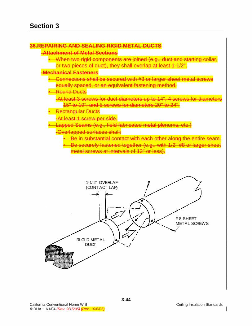
36.REPAIRING AND SEALING RIGID METAL DUCTS -Attachment of Metal Sections
• When two rigid components are joined (e.g., duct and starting collar, or two pieces of duct), they shall overlap at least 1-1/2".
-Mechanical Fasteners • Connections shall be secured with #8 or larger sheet metal screws
equally spaced, or an equivalent fastening method. • Round Ducts
-At least 3 screws for duct diameters up to 14", 4 screws for diameters 15" to 19", and 5 screws for diameters 20" to 24".
• Rectangular Ducts -At least 1 screw per side.
• Lapped Seams (e.g., field fabricated metal plenums, etc.) -Overlapped surfaces shall:
• Be in substantial contact with each other along the entire seam. • Be securely fastened together (e.g., with 1/2" #8 or larger sheet
metal screws at intervals of 12" or less).
#8 SHEET METAL SCREWS
RIGID METAL DUCT
1-1/2" OVERLAP (CONTACT LAP)

Section 3
3-45 California Conventional Home WIS Ceiling Insulation Standards © RHA • 1/1/04 (Rev. 9/15/05) (Rev. 10/6/05)
36. REPAIRING AND SEALING RIGID METAL DUCTS (continued) -Gaps 1/4" or smaller may be sealed with:
• Duct mastic, or • Metallic pressure sensitive tape.
-Gaps over 1/4" up to 1" wide shall be sealed with: • Duct mastic with embedded fiberglass mesh, or • Metallic pressure sensitive tape covered with mastic.
-Gaps over 1" wide shall be repaired with a sleeve or a sheet metal patch (per Item 37) and sealed with mastic or metallic tape.
-All Connections • Mastic and fiberglass mesh shall be installed per Item 38. • Metallic pressure sensitive tapes shall be installed per Item 39.
• TAPE OR MASTIC ON GAPS UP TO 1/4" • MASTIC & MESH, OR METALLIC TAPE COVERED BY MASTIC, ON GAPS OVER 1/4"
FLEX-TO-RIGID DUCT SLEEVE FLEX-TO-ELBOW
ELBOW SLIP-JOINTS
STARTING COLLAR
#8 SCREWS (3) EQUALLY SPACED
FLEX-TO-SLEEVE JOINTS

Section 3
3-46 California Conventional Home WIS Ceiling Insulation Standards © RHA • 1/1/04 (Rev. 9/15/05) (Rev. 10/6/05)
37.SHEET METAL PATCHES FOR RIGID METAL DUCTS -Material
• Patch material shall match the existing duct material (i.e., galvanized patch for galvanized duct, or aluminum patch for aluminum duct).
• Gauge of the patch shall equal or exceed gauge of the existing duct. -Installation
• Patch material shall: -Extend at least 1" beyond each edge of the gap, and -Overlap itself by at least 1".
• The patch shall be wrapped tightly around the duct and secured with #8 sheet metal screws. -Where the patch overlaps itself, at least 1 screw shall be installed on
each side of the gap. -At least 2 more screws shall be evenly-spaced around the duct on
each side of the gap. -Sealing
• All patch edges/gaps shall be sealed per Item 34.
SHEET METAL PATCH EXTENDING 1” BEYOND
EACH SIDE OF GAP
RIGID SHEET METAL DUCT WITH GAP >1” WIDE
#8 SHEET METAL SCREWS
PATCH MATERIAL OVERLAPS ITSELF
AT LEAST 1” OVERLAP
EDGES SEALED WITH TAPE (OR MASTIC)

Section 3
3-47 California Conventional Home WIS Ceiling Insulation Standards © RHA • 1/1/04 (Rev. 9/15/05) (Rev. 10/6/05)
38. DUCT MASTIC SEALING PROCEDURE -Rigid Metal Ducts and Components
• Mastic by itself may be used to seal gaps up to 1/8" (e.g., on adjustable elbow joints, seams in wyes, metal duct seams, etc.).
• Mastic shall be reinforced with fiberglass mesh tape when used to seal gaps larger than 1/8".
• When sealing longitudinal seams in new rigid metal ducts, mastic is required on S-and-drive, snap lock, and government lock seams.
-Flexible Metallic and Nonmetallic Ducts • Mastic used to seal core-to-fitting connections may be:
-Externally applied over the duct core and rigid fitting, or -Internally placed between the core and the fitting.
• Externally-Applied Mastic -Mastic shall be reinforced with fiberglass mesh tape when:
• A gap greater than 1/8" exists between the duct core and the fitting (starting collar, coupling, elbow, wye, etc.).
• Mastic is used to seal the outer vapor barrier (jacket).

Section 3
3-48 California Conventional Home WIS Ceiling Insulation Standards © RHA • 1/1/04 (Rev. 9/15/05) (Rev. 10/6/05)
39. SEALING WITH MASTIC -Mastic shall be applied as prescribed by manufacturer, including:
• Surface preparation/cleaning. • Temperature and moisture limitations. • Thickness and set-up time.
-Rigid Metal and fiberglass ducts and Components • Mastic by itself may be used to seal gaps up to 1/4". • Mastic shall be reinforced with fiberglass mesh tape when used to
seal gaps larger than 1/4". • Gaps larger than 1" wide shall be repaired and sealed:
-Metal ducts per Item 37. -Fiberglass ducts repaired with fiberglass duct board or sheet metal
and screws, and sealed with mastic or metallic tape. -Flexible Metallic and Nonmetallic Ducts
• Mastic used to seal core-to-fitting connections may be: -Externally applied over the duct core and rigid fitting, or -Internally placed between the core and the fitting.
• Externally-Applied Mastic -Mastic shall be reinforced with fiberglass mesh tape when:
• A gap greater than 1/4" up to 1/2" exists between the duct core and the fitting (starting collar, coupling, elbow, wye, etc.).
• Mastic is used to seal the jacket (vapor barrier).
MASTIC ALONE FOR GAPS UP TO 1/4"
UL 181 MASTIC
TRANSVERSE JOINT
MESH TAPE REINFORCE- MENT FOR GAPS OVER 1/4"

Section 3
3-49 California Conventional Home WIS Ceiling Insulation Standards © RHA • 1/1/04 (Rev. 9/15/05) (Rev. 10/6/05)
38. DUCT MASTIC SEALING PROCEDURE (continued) -Reinforcement of Mastic with Fiberglass Mesh Tape
• Mesh fabric shall be imbedded between two layers of duct mastic to form a mastic closure system. -The first layer of mastic shall:
• Be centered over the joint or gap to be sealed. • Extend at least 1" onto each of the joined surfaces. • Extend beyond the width of the mesh.
-The mesh fabric shall be: • Embedded in the mastic. • Applied at least one layer thick over the entire joint or gap. • Wrapped around the entire circumference on transverse joints
(e.g., where two sections of duct are joined together). -A second layer of mastic shall be installed over the mesh, filling the
scrim pattern completely and covering the mesh. • Mesh Tape
-Minimum 2" wide. -Weave per inch: 0.006" minimum.
FIBERGLASS MESH TAPE
FINAL MASTIC LAYER COVERS MESH
RIGID METAL DUCT
FIRST LAYER OF MASTIC IMBEDDED WITH MESH TAPE

Section 3
3-50 California Conventional Home WIS Ceiling Insulation Standards © RHA • 1/1/04 (Rev. 9/15/05) (Rev. 10/6/05)
40.SEALING WITH TAPE -Pressure Sensitive Tapes
• Tapes shall be installed as prescribed by manufacturer. • Successive wraps of tape shall be staggered and should overlap by
50 to 75% of the tape width. • At least three wraps of tape shall be applied when sealing:
-Transverse joints in round or rectangular metal ducts (the joint formed when two pieces of duct are spliced together).
-Flexible duct core-to-fitting attachments (with a drawband also installed to secure the core).
-Vapor barrier (jacket) splices on flexible ducts. • When gaps between 1/4" and 1" are sealed with tape:
-Tape shall be applied as prescribed above and then covered with duct mastic.
-The mastic shall be applied at least 1/8" thick over the installed tape to provide additional strength and durability.
-Mastic shall extend beyond the width of the tape. • Metallic pressure sensitive tape shall be used to seal rigid metal
connections.
SEALED WITH PRESSURE SENSITIVE TAPE (MINIMUM 3 WRAPS)
AND DRAWBANDS
NONMETALLIC FLEXIBLE DUCT
BEADED SLEEVE/COUPLING

Section 10
10-12 California Conventional Home WIS Duct Testing Standards © RHA • 9/15/05 (Rev. 10/6/05)
7. DUCT SEALING PROTOCOL - Standards
• Duct repairs and sealing shall be performed in accordance with WIS Section 20, Duct Sealing Standards.
- Start Criteria • Duct repair and sealing work may begin only if the Initial Total Duct
Leakage satisfies the Start Criteria in the Program P&P. - Stop Criteria
• When the LIEE Duct Sealing maximum leakage criteria must be met, one of the following LIEE P&P requirements shall be satisfied: - Target Leakage (stop) criteria, or - Economic Default (stop) criteria—all accessible leaks sealed.
• When Title 24 criteria maximum leakage must be met: - Target Leakage must be met as shown in Table 10-2. - Measurement method (C) shall be used only when Target Leakage
cannot be met using method (A) or (B). - Required data shall be recorded on the data form, including:
• Total Duct Leakage (or Leakage to Outside) CFM25 from the Initial test, performed before starting duct repair and sealing work.
• Total Duct Leakage (or Leakage to Outside) CFM25 from the Final test performed after completing duct repair and sealing work.
TABLE 10-2: TITLE 24 DUCT SEALING TARGET LEAKAGE
MEASUREMENT METHOD TARGET LEAKAGE T-24 PROCEDURE1
(A) Total Duct Leakage <15% of System Fan Flow RC.4.3.1
(B) Duct Leakage Reduction >60% Leakage Reduction2 RC.4.3.4, RC.4.3.6, and
RC.4.3.7
(C) Prescriptive Default Target Not Met but All Ac-cessible Ducts are Sealed3
RC.4.3.5, RC.4.3.6, and RC.4.3.7
1Title 24 ACM Residential Manual Appendix RC-2005 2Final duct leakage compared to Initial duct leakage, with a smoke test to confirm that all accessible leaks have been sealed. 3When leakage target cannot be met, all accessible leaks must be sealed, as confirmed by a smoke test.

15-1 California Conventional Home WIS Hard-Wired Compact © RHA • 1/1/04 (Rev. 9/15/05) (Rev. 10/6/05) Fluorescent Fixture Standards
SECTION 15
HARD-WIRED COMPACT FLUORESCENT FIXTURE STANDARDS
1. MATERIALS - Fixture must be UL listed and meet ANSI/UL Standard 935 Class-P. - CFLs must be ENERGY STAR® compliant ENERGY STAR® qualified. - Compact fluorescent lamp (CFL) tube glass and other housing
materials must be UV resistant and heat stable. - Hardwired fixtures and lamps must be fully warranted for one year
from date of purchase. - Fixture must allow for lamp replacement and utilize Title 24-
compliant high efficacy (e.g., pin-based) lamps meeting the following standards: • 40 Lumens/watt — lamps 15 watts or less • 50 Lumens/watt — lamps over15 watts to 40 watts • 60 Lumens/watt — lamps over 40 watts
2. INSTALLATION - All fixtures shall be installed:
• In accordance with the current NEC and local codes. • In a manner which prevents water from entering or accumulating
in wiring compartment, lamp holder or electrical parts. - All wiring, conduit, accessories, fasteners, and controls used in
exterior locations shall be designed for exterior use.
WALL-MOUNT FLUORESCENT FIXTURE
WITH PHOTO CELL CONTROL
CEILING-MOUNT COMPACT FLUORESCENT REPLACEMENT FIXTURE

Section 18
18-1 California Conventional Home WIS Natural Gas Central Forced Air Heating System © RHA • 1/1/04 (Rev. 9/15/05) (Rev. 10/6/05) Repair & Replacement Standards Part 1—Materials
NATURAL GAS CENTRAL FORCED AIR HEATING SYSTEMS REPAIR AND REPLACEMENT STANDARDS
PART 1: MATERIALS
1. APPROVED MATERIALS
- All materials shall be in conformance with the CBC and CMC. - Furnaces
• All units and components shall be UL listed and AGA certified. • All units shall be ENERGY STAR labeledqualified.
- Split Systems • Furnace: Minimum AFUE rating of 908078%. • Air Conditioner, if replaced in conjunction with furnace:
- Minimum EER of 11.0 5 and SEER of 13.0, with a Thermostatic Expansion Valve (TXV).
- EER shall be determined by the coil match as listed in the current ARI Directory.
- Package Units (Dual Packs): • Furnace: Minimum AFUE rating of 8078%. • Air Conditioner: Minimum EER of 1011.5 and SEER of 1213.0.
LISTED

Section 19
19-9 California Conventional Home WIS Natural Gas Wall & Floor Furnace © RHA • 1/1/04 (Rev. 9/15/05) (Rev. 10/6/05) Repair & Replacement Standards New Installation
9. THERMOSTATS
- Location and Mounting • New thermostat shall be installed at existing location unless
affected by drafts, heat from direct sun, or adjacent appliances. • Thermostat installed in a new location:
- Shall be mounted with the top of thermostat 60" above the floor when occupants are not handicapped.
- May be installed as low as 48" above the floor when an occupant uses a wheelchair.
- May be installed on the appliance housing at least 48" above the floor when: • Allowed by the manufacturer, and • Wall mounting requires wiring that is not feasible (e.g., attic not
accessible). • Thermostat shall be located on an interior wall away from direct
sunlight, doors, windows, return/supply air, appliances, and sources of electrical interference.
• Mounting bracket shall be securely attached to wall with screws for wood, or appropriate anchors for drywall and plaster.
• Any holes or damage to wall from installation or removal of thermostat shall be repaired in a workmanlike manner.
60"

Section 20
20-21 California Conventional Home WIS Duct Sealing Standards © RHA • 9/15/05 (Rev. 10/6/05) DUCT REPAIR AND SEALING
DUCT REPAIR AND SEALING
19. DUCT CLOSURE SYSTEMS - All Closure Systems
• Sealants shall be applied per manufacturer’s instructions. • A complete, durable seal shall be achieved. • Pressure sensitive tapes shall be marked, and mastic containers shall
be labeled, in conformance with: - UL 181B for flexible metallic and nonmetallic ducts. - UL 181A or 181B for rigid metal ducts and components.
• Exception: Butyl tape without UL 181 markings may be used to seal rigid metal-to-metal connections, per Item 4.
- Gap Size and Sealing Materials • Sealing materials shall be selected in conformance with Table 20-3. • Flexible duct connections with gaps wider than 1/4" shall be replaced
with properly-sized duct and/or fitting. • For rigid metal ducts, gaps 1" or wider shall be repaired with a sheet
metal patch (Item 28) or sleeve. • For rigid fiberglass ducts, repairs shall be:
- Made with duct board or sheet metal and screws, and - Sealed with mastic or metallic tape.
TABLE 20-3: GAP SIZE AND APPROVED SEALING MATERIALS
FLEXIBLE METALLIC & NONMETALLIC DUCTS
RIGID METAL & FIBERGLASS DUCT
GAP SIZE Sealing with
MASTIC Sealing with
TAPE Sealing with
MASTIC Sealing with
TAPE
≤ 1/4" Mastic Tape Mastic Tape
> 1/4" - < 1" Repair
Required* Repair
Required* Mastic &
Mesh Mastic over
Tape
1" or more Repair Required*
Repair Required*
Metal Patch or Sleeve & Mastic
Metal Patch or Sleeve & Tape
*Duct and/or fitting must be replaced with proper size.

Section 20
20-22 California Conventional Home WIS Duct Sealing Standards © RHA • 9/15/05 (Rev. 10/6/05) DUCT REPAIR AND SEALING
19. DUCT CLOSURE SYSTEMS (continued) - Externally-Applied Closure Systems
• Sealing materials shall: - Be centered over the joint or gap, and - Extend at least 1" onto each of the two joined/sealed surfaces.
- Internally-Placed Mastic Sealant (Core-to-Fitting Joints) • Mastic may be applied either:
- Inside the duct core, or - Onto the rigid component over which the core is attached.
• Mastic coating shall be at least 1/8" thick and 2" wide. - Sealing with Mastic and with Pressure Sensitive Tape
• Mastic and Fiberglass Mesh Tape - Mastic and mesh shall be installed as prescribed in Item 20.
• Pressure Sensitive Tapes - Tape shall be installed as prescribed in Item 21.
MASTIC APPLIED INSIDE DUCT CORE
SLEEVE
MASTIC APPLIED OVER FITTING
2"
2"
FLEX DUCT

Section 20
20-25 California Conventional Home WIS Duct Sealing Standards © RHA • 9/15/05 (Rev. 10/6/05) DUCT REPAIR AND SEALING
21. SEALING WITH PRESSURE SENSITIVE TAPE - All Pressure Sensitive Tapes
• Tapes shall be installed as prescribed by manufacturer, including: - Surface preparation/cleaning. - Application of pressure/rubbing. - Temperature and moisture limitations.
• Successive wraps of tape shall be staggered and should overlap by 50 to 75% of the tape width.
• At least 3 wraps of tape shall be applied when sealing: - Transverse joints at splices and connections in round or
rectangular metal ducts. - Flexible duct core-to-fitting attachments (with a drawband also
installed to secure the core). - Jacket (vapor barrier) splices on flexible ducts.
• When gaps over 1/4" up to <1" wide are sealed with tape: - Tape shall be applied as prescribed above and then covered with
duct mastic. - The mastic shall be applied at least 1/8" thick over the
installed tape to provide additional strength and durability. - Mastic shall extend beyond the width of the tape.
• Gaps 1" or wider shall be repaired and sealed per Item 19.
SEALED WITH PRESSURE-SENSITIVE TAPE (MINIMUM 3 WRAPS)
AND DRAWBANDS
NONMETALLIC FLEXIBLE DUCT
BEADED SLEEVE/COUPLING